
SECTION 6C1-2B SYMPTOMS - V6 ENGINE
CAUTION
This vehicle will be equipped with a Supplemental Restraint System (SRS). A SRS
will consist of either seat belt pre-ten sioners and a driv er’s side air bag, or seat b elt
pre-tensioners and a driver’s and front passenger’s side air bags. Refer to
CAUTIONS, Section 12M, before performing any service operation on or around SRS
components, the steering mechanism or wiring. Failure to follow the CAUTIONS
could result in SRS deployment, resulting in possible personal injury or
unnecessary SRS system repairs.
CAUTION
This vehicle may be equipped with LPG (Liquefied Petroleum Gas). In the interests
of safety, the LPG fuel system should be isolated by turning 'OFF' the manual
service valve and then draining the LPG service lines, before any service work is
carried out on the vehicle. Refer to the LPG leaflet included with the Owner's
Handbook for details or LPG Section 2 for more specific servicing information.
NOTICE
When performing any Diagnostics, make certain that the drive wheels are blocked
and the parking brake is firmly set.
When no diagnostic trouble codes have been set and the scan tool data values are within typical ranges, you should
diagnose the condition based on the symptoms of the complaint.
This Symptom Section starts with preliminary checks that must be performed in order to diagnose by symptom.
Then, intermittent conditions are discussed. These preliminary checks provide important information to assist you
with symptom diagnosis. Next, the contents of this Section presents the various symptoms and lists a series of
checks for each.
Many of the symptom diagnostics start with a very important procedure, a visual/physical inspection. Always look for
the obvious first. Some situations may warrant observing the driver. Is the driver using the correct shift lever position
or riding the brake pedal? Visually check the engine, transmission and PCM connectors. Are there any
disconnected wires or incorrectly installed components? Finally, are there obvious signs that someone may have
performed incorrect repairs? These checks take very little time; they can eliminate the time spent on a broad-base
systematic diagnosis by directing you to the problem. If they do not reveal the problem, proceed to check the other
suspect systems, as shown.
The last part of this Section contain PCM connector symptom charts. If you are diagnosing a problem, scan the
right-most column for the symptom(s) and check for the correct wire and voltage at the designated connector cavity.
Techline
PCM AND PROM
Since the PCM can have a failure which may affect only one circuit, following the Diagnostic Procedures in this
section will determine which circuit has a problem and where it is.
If a diagnostic chart indicates that the PCM connections or PCM is the cause of a problem, and the PCM is
replaced, but does not correct the problem, one of the following may be the reason:
• There is a problem with the PCM terminal connections. The diagnostic chart will say "PCM connections or PCM."
The terminals may have to be removed from the connector in order to check them properly.
• The PCM or PROM is not correct for the application. The incorrect PCM or PROM may cause a malfunction and
may or may not set a code.
• The problem is intermittent. This means that the problem is not present at the time the system is being checked.
In this case, refer to the "Symptoms" Charts and make a careful physical inspection of all components of the
system involved.
• Shorted solenoid, relay coil, or harness. Solenoids and relays are turned "ON" and "OFF" by the PCM, using
internal electronic switches called "Drivers." Each "driver" is part of a group of four (called "Quad drivers").
Failure of one driver may cause other drivers in the set to malfunction. Solenoid and relay coil resistance must
measure more than 20 ohms, in most cases. Less resistance may cause early failure of the PCM "driver."
Before replacing an PCM, be sure to check the coil resistance of all solenoids and relays controlled by the
PCM. See PCM wiring diagram for the solenoid(s) and relay(s) and the coil terminal identification.
• The PROM may be faulty. Although these rarely fail, they operate as part of the PCM. Therefore, it could be the
cause of the problem. Substitute a known good PROM.
• The replacement PCM may be faulty. After the PCM is replaced, the system should be rechecked for proper
operation. If the diagnostic chart again indicates the PCM is the problem, substitute a known good PCM.
Although this is an extremely rare condition, it could happen.
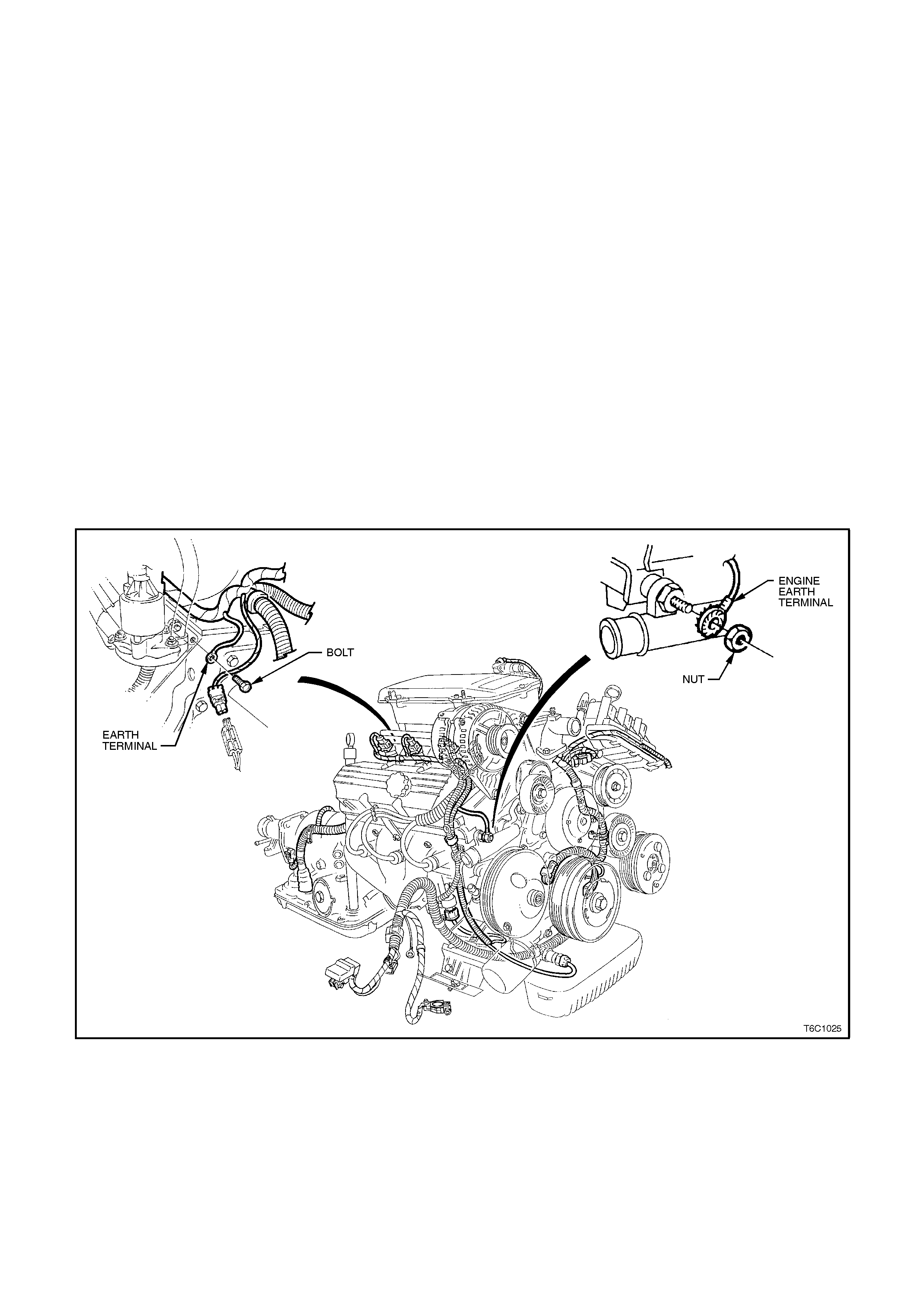
Figure 6C1-2B-1 Non-Supercharged Engine Pow e rtrain Wiring Harness to Engine Assembly Earth Location.
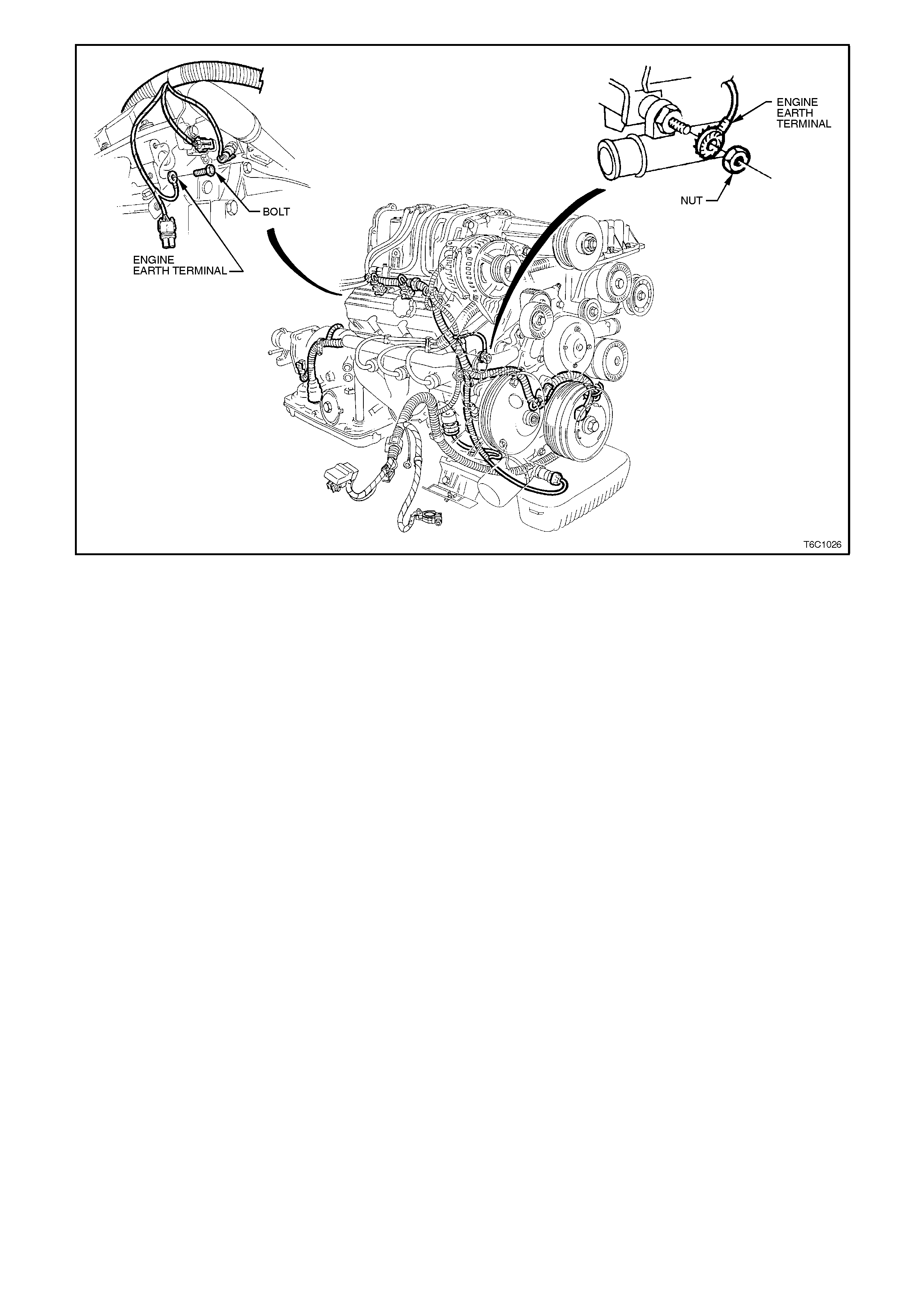
Figure 6C1-2B-2 Supercharged Engine Powertrain Wiring Harness to Engine Assembly Earth Location

IMPORTANT PRELIM INARY CHECKS
BEFORE USING THIS SECTION
Before using this Symptoms Section you should have performed the "On Board Diagnostic System Check" as
detailed in Section 6C1-2A and determined that:
1. The PCM and "Check Powertrain" lamp are operating correctly.
2. There are no diagnostic trouble codes stored.
3. There is a diagnostic trouble code stored in the PCM memory and the "Check Powertrain Lamp is not "ON."
4. The diagnostic chart for the diagnostic trouble code indicates that the trouble is intermittent.
5. Figure 6C1-2B-1 and 6C1-2B-2 illustrates the Powertrain wiring harness to engine assembly earth locations
as described in the various "SYMPTOM CHARTS" in this Section. You should become familiar with these
locations.
SYMPTOM
Verify the customer complaint, and locate the correct symptom in the table of contents. Check all the items
indicated under that symptom.
If the ENGINE CRANKS BUT WILL NOT RUN, refer to Chart A 3.1 for the Non-Supercharged Engine application
and Chart A 3.1-1 for the Supercharged Engine application in Section 6C1-2A.
VISUAL/PHYSICAL CHECK
Several of the symptom procedures call for a Careful Visual/Physical Check. The importance of this step cannot be
stressed too strongly it can lead to correcting a problem without further checks and can save valuable time. This
check should include:
• Check service records for any recent repairs that may indicate a related problem, or the current need for
scheduled maintenance.
• PCM sensors for being in their proper location.
• PCM earth circuits terminate at 2 separate eyelet terminals. On a V6 these attach to the engine at two separate
locations: the rear of the left cy linder head, and on the by-pass tube and drive belt tensioner attaching stud,
below the generator (refer figure at the beginning of this Section). They must be clean and tight. Check for earth
terminals that may be loose under the retaining nuts/bolts, or for terminals that may have been left off after
engine repair. Any repair of the wire to terminal connection must include soldering with rosin core solder.
(NEVER use acid core solder for any w iring repairs.)
• Vacuum hoses for splits, kinks, and proper connections. Check thoroughly for any type of leak or restriction.
• Air leaks at throttle body mounting area and inlet manifold sealing surfaces.
• Ignition wires for cracking, hardness, proper routing and carbon tracking.
• Wiring for proper connections, pinches and cuts.
• Check for any non genuine Holden's options or accessories that may have been fitted to the vehicle that may
cause or exaggerate the problem.

INTERMITTENTS
DEFINITION:
Problem may or may not turn "ON" the "Check Powertrain" lamp or store a DTC. DO NOT use the diagnostic code
charts for intermittent problems. When using the code charts the fault must be present to locate the problem. If a
fault is intermittent, use of diagnostic trouble code charts may result in replacement of good parts.
• Most intermittent problems are caused by faulty electrical connections or wiring. Perform careful visual/physical
check as described at the start of this Section - " IMPORTANT PRELIMINARY CHECKS".
CHECK FOR:
• Poor mating of the connector halves or terminal not fully seated in the connector body (backed out).
• Improperly formed or damaged terminal. All connector terminals in the problem circuit should be carefully
reformed or replaced to insure proper contact tension.
• Poor terminal to wire connection. This requires removing the terminal from the connector body to check as
outlined in service operations.
• PCM earth circuit terminals being loose at the engine. On a V6 engine these attach to the engine at two
separate locations: the rear of the left cylinder head, and on the by-pass tube and drive belt tensioner
attaching stud, below the generator, refer Figures 6C1-2B-1 and 6C1-2B-2 at the beginning of this Section.
• If a visual/physical check does not find the cause of the problem, the car can be driven with a voltmeter
connected to a suspected circuit. A scan tool can also be used to help detect intermittent conditions. An
abnormal voltage, or scan tool reading, when the problem occurs, indicates the problem may be in that
circuit. If the wiring and connectors check OK, and a diagnostic trouble code was stored for a circuit having
a sensor, except for DTC's 44 or 64 and 45 or 65, substitute a known good sensor and recheck.
• Loss of diagnostic code memory. To check, disconnect TP sensor and idle engine until "Check Powertrain"
lamp comes "ON." DTC 22 should be stored, and kept in memory when ignition is turned "OFF." If not, the
PCM is faulty.
• An intermittent "Check Powertrain" lamp with no stored diagnostic trouble code may on V6 be caused by:
• Ignition coil shorted to earth and arcing at spark plug wires or plugs.
• Intermittent short to + 12 volts on 0-5 volt input CKTs 451 (diagnostic request), 410 (ECT sensor), 792
(MAF sensor), 417 (TP sensor), and 472 (IAT sensor).
• Check for an electrical system interference caused by a defective relay, PCM driven solenoid, or switch.
They can cause a sharp electrical surge. Normally, the problem will occur when the faulty component is
operated.
• Check for improper installation of non-factory installed electrical options such as lights, 2 way radios, etc.
• EST wires should be routed away from spark plug wires, ignition wires, ignition module assembly and
generator. Wire from PCM to ignition should have a good connection.
• Check for open diode across A/C compressor clutch, and for other open diodes (refer to wiring diagrams
and CHART A-11.1 or CHART A-11.3 in Section 6C1-2A).
• If problem has not been found, refer to the proper symptom and perform all checks listed there.

HARD START
DEFINITION:
Engine cranks OK, but does not start for a long time. Does eventually run, or may start but immediately dies.
PRELIMINARY CHECKS
• Perform the careful visual/physical checks as described at the start of this Section - "IMPORTANT
PRELIMINARY CHECKS".
• Make sure the driver is using the correct starting procedure. Do not depress accelerator pedal during cranking.
• CHART A -3.1 for Non-Supercharged Engine and CHART A-3.1-1 for Supercharged Engine "ENGINE CRANKS
BUT WILL NOT RUN" in Section 6C1-2A. Although this chart may not exactly describe the problem, most all of
the causes of a "no start" can also cause a "hard start".
• Time or kilometers since normal engine tune-up has been performed, refer to time/distance intervals specified in
the Owner's Manual.
• PCM earth circuit terminals being loose at the engine. On a V6 engine these attach to the engine at two separate
locations: the rear of the left cy linder head, and on the by-pass tube and drive belt tensioner attaching stud,
below the generator, refer figure at the beginning of this Section.
SENSORS
CHECK:
Engine Coolant Temperature (ECT) sensor using a scan tool, compare coolant temperature with ambient
temperature on cold engine.
• If coolant temperature readings is 5 degrees greater than or less than ambient air temperature on a cold engine,
check resistance in coolant sensor circuit or sensor itself. Compare ECT resistance value to the "Diagnostic
Aids" chart on DTC 15 chart in Section 6C1-2A.
CHECK:
MAF sensor. for a shifted sensor, refer CHART A-6.1 "MAF OUTPUT CHECK" in Section 6C1-2A.
CHECK:
TP Sensor for binding or a high TP sensor voltage with the throttle closed.
IGNITION SYSTEM
CHECK:
Spark plug leads being misrouted at the coils or at the spark plugs.
CHECK:
For proper ignition voltage output with spark tester ST-125 or 7230.
CHECK:
Spark plugs. Remove spark plugs, check for wet plugs, cracks, wear, improper gap, burned electrodes, or heavy
deposits. Repair or replace as necessary.
CHECK:
Bare or shorted wires.

FUEL SYSTEM
CHECK:
Fuel pump relay operation pump should turn "ON" for 2 seconds when ignition is turned "ON." Use CHART A-4.1
for Non-Supercharged Engine , and CHART A-4.1-1 for Supercharged Engine.
CHECK:
Fuel pressure, refer to CHART A-4.3 in Section 6C1-2A.
CHECK:
Contaminated fuel or incorrect fuel.
CHECK:
If the problem occurs worse with hotter temperatures, check for leaking injectors, refer CHART A-4.3 in Section
6C1-2A.
NOTE:
A faulty in-tank fuel pump check valve will allow the fuel in the lines to drain back to the tank after engine is stopped.
To check for this condition, perform fuel system diagnosis, refer CHART A-4.3 in Section 6C1-2A.
ADDITIONAL CHECKS
CHECK:
Exhaust back pressure, refer CHART A-13 "RESTRICTED EXHAUST CHECK" in Section 6C1-2A.
CHECK:
IAC Operation, refer to CHART A-7.1 in Section 6C1-2A.
CHECK:
Basic engine problem. Camshaft timing chain for being stripped or slipped, causing valve timing to be retarded.
CHECK:
Compression. Disconnect fuse F31 before performing test.
CHECK:
Service Bulletins for updates.

SURGES AND/ OR CHUGGLES
DEFINITION:
Engine power variation under steady throttle or cruise, feels like the vehicle speeds up and slows down with no
change in the acceleration pedal.
PRELIMINARY CHECKS
• Perform the careful visual checks as described at the start of this Section - "IMPORTANT PRELIMINARY
CHECKS".
• Make sure driver understands transmission torque converter clutch, and A/C compressor operation as explained
in the Owner’s Manual.
• Time or kilometers since normal engine tune-up has been performed. Refer to time/distance intervals specified
in the Owner’s Manual.
SENSORS
CHECK:
Oxygen Sensor (O2S). The Oxygen Sensor (O2S) should respond quickly to different throttle position, if it does not,
check the Oxygen Sensor (O2S) for silicon or other contamination’s from fuel, or use of improper RTV sealant.
The sensor may have a white, powdery coating and result in a high but false signal voltage (rich exhaust indication).
The PCM will then reduce the amount of fuel delivered to the engine, causing a severe driveability problem. Also,
watch for green glycol contamination or cracking.
CHECK:
MAF sensor for proper operation, refer CHART A-6.1 “MAF OUTPUT CHECK” in Section 6C1-2A.
IGNITION SYSTEM
CHECK:
For proper ignition voltage output using spark tester ST-125 or 7230.
CHECK:
Spark plugs. Remove spark plugs, check for wet plugs, cracks, wear, improper gap, burned electrodes, or heavy
deposits. Repair or replace as necessary. Also, check spark plug wires.
CHECK:
Ignition secondary coil or wiring shorting to earth.
FUEL SYSTEM
CHECK:
Contaminated or incorrect fuel.
NOTE:
To determine if the condition is caused by a rich or lean sy stem, the car should be driven at the speed of the
complaint. Monitoring block learn and integrator will help identify a problem.
• Lean - Long Term Fuel Trim near +25%. Refer to "Diagnostic Aids" of DTC 44 or DTC 64 in Section 6C1-2A.
• Rich - Long Term Fuel Trim near - 22%. Refer to "Diagnostic Aids" of DTC 45 or DTC 65 in Section 6C1-2A.
CHECK:
Fuel pressure while condition exists, refer CHART A-4.3 in Section 6C1-2A.
CHECK:
In line fuel filter. Replace if dirty or plugged.
CHECK:
Restricted fuel injectors.

ADDITIONAL CHECKS
CHECK:
PCM earth circuits for being clean, tight and in their proper location.
CHECK:
Vacuum lines for splits, kinks, leaks and proper connections.
CHECK:
Generator output voltage. Repair if less than 9 or more than 16 volts.
CHECK:
Speedometer reading with the speed on a scan tool are equal.
CHECK:
Service Bulletins for updates.
CHECK:
Correct PROM being installed into the PCM.
CHECK:
Excessive exhaust back pressure, refer CHART A-13 "RESTRICTED EXHAUST CHECK" in Section 6C1-2A.
CHECK:
TCC operation for proper operation.

LACK OF POWER, SLUGGISH, OR SPONGY
DEFINITION:
Engine delivers less than expected power. Little or no increase in speed when accelerator pedal is pushed down
part way.
PRELIMINARY CHECKS
• Perform the careful visual/physical checks as described at the start of this Section - "IMPORTANT
PRELIMINARY CHECKS".
• Compare customer's car to similar unit. Make sure the customer has an actual problem.
• Remove air filter and check air filter for dirt, or for being plugged. Replace as necessary.
• Time or kilometers since normal engine tune-up has been performed. Refer to time/distance intervals in owner’s
handbook.
SENSORS
CHECK:
MAF sensor for proper operation, refer CHART A-6.1 "MAF OUTPUT CHECK" in Section 6C1-2A.
ENGINE MECHANICAL
CHECK:
Engine valve timing.
CHECK:
Engine for correct or worn camshaft.
CHECK:
Compression. Disconnect the fuse F31 before performing test.
CHECK:
Check Supercharger system. Refer to functional check CHART 2-6 for "Boost Control System Check" in Section
6C1-2C.
IGNITION SYSTEM
CHECK:
Secondary voltage using a shop oscilloscope or a spark tester ST-125 or 7230.
CHECK:
For ignition misfire under heavy engine load. Check each spark plug lead for excessive resistance (or open circuit),
or for faulty or cracked spark plugs.
Techline

FUEL SYSTEM
CHECK:
Restricted fuel filter, refer CHART A-4.3 in Section 6C1-2A.
CHECK:
Fuel pressure, refer CHART A -4.3 in Section 6C1-2A.
CHECK:
Contaminated fuel, refer CHART A-4.3 in Section 6C1-2A.
CHECK:
Fuel Pump Control Module check. Refer to CHART 4.1-1 in Section 6C1-2A.
ADDITIONAL CHECKS
CHECK:
PCM earth circuit for being clean, tight and in their proper locations.
CHECK:
Generator output voltage. Repair if less than 9 or more than 16 volts.
CHECK:
Exhaust system for possible restriction, refer CHART A-13 in Section 6C1-2A.
• Inspect exhaust system for damaged or collapsed pipes.
• Inspect muffler for heat distress or possible internal failure.
CHECK:
Torque Converter Clutch (TCC) for proper operation.

DETONATION/SPARK KNOCK
DEFINITION:
A mild to severe ping, usually worse under acceleration. The engine makes sharp metallic knocks that change with
throttle opening.
PRELIMINARY CHECKS
Perform the careful visual/physical checks as described at the start of this Section - " IMPORTANT PRELIMINARY
CHECKS".
NOTE:
If scan tool readings are normal (refer "On-Board Diagnostic System Check" in Section 6C1-2A) and there are no
engine mechanical faults, fill fuel tank with a premium unleaded fuel and reevaluate vehicle performance.
IGNITION SYSTEM
CHECK:
Spark plugs for proper heat range.
ENGINE MECHANICAL
CHECK:
Combustion chambers for excessive carbon build up. Remove carbon with top engine cleaner and follow
instructions on can. If the problem recurs and top engine cleaner corrects it again, look for possible causes of high
oil consumption.
CHECK:
For excessive oil in the combustion chamber.
• Valve oil seals for leaking.
CHECK:
Combustion chamber pressure by performing a compression test. Disconnect the fuse F31 before performing test.
CHECK:
For incorrect basic engine parts such as camshaft, heads, pistons, etc.

COOLING SYSTEM
Check for obvious overheating problems:
• Low engine coolant.
• Defective engine thermostat.
• Loose water pump belt.
• Restricted air flow to radiator, or restricted water flow through radiator.
• Inoperative electric cooling fan circuit, refer to CHART A-12.1 in Section 6C1-2A.
• Correct coolant solution should be a 50/50 mix of antifreeze coolant and water.
FUEL SYSTEM
CHECK:
Fuel quality and proper octane rating.
NOTE:
To determine if the condition is caused by a rich or lean sy stem, the car should be driven at the speed of the
complaint. Monitoring block learn will help identify the problem.
• Lean - Long Term Fuel Trim near +25%. Refer to "Diagnostic Aids" of DTC 44 or DTC 64 in Section 6C1-2A.
• Rich - Long Term Fuel Trim near - 22%. Refer to "Diagnostic Aids" of DTC 45 or DTC 65 in Section 6C1-2A.
CHECK:
Fuel Control Module operation. Refer to CHART A-4.1-1.
CHECK:
Fuel pressure, refer to CHART A-4.3 in Section 6C1-2A.
ADDITIONAL CHECKS
CHECK:
Vacuum leaks.
CHECK:
TCC operation, TCC applying too soon.
CHECK:
For correct PROM being installed into the PCM.
CHECK:
Service Bulletins for updates.

HESITATION, SAG, STUMBLE
DEFINITION:
Momentary lack of response as the accelerator is pushed down. Can occur at all vehicle speeds. Usually most
severe when first trying to make the car move, as from a stop sign. May cause engine to stall if severe enough.
PRELIMINARY CHECKS
Perform the careful visual/physical checks as described at the start of this Section - " IMPORTANT PRELIMINARY
CHECKS".
Time or distance interval since normal engine tune-up has performed. Refer to time/distance intervals specified in
Owner's Manual.
CHECK:
Vacuum hoses for splits, kinks, and proper connections.
CHECK:
For vacuum leaks at throttle body mounting and inlet manifold.
SENSORS
CHECK:
TP Sensor - Check TP Sensor for binding or sticking. Voltage should increase at a steady rate as throttle is moved
toward Wide Open Throttle (WOT), refer CHART A-6.2 in Section 6C1-2A.
CHECK:
MAF sensor, refer to CHART A-6.1 in Section 6C1-2A.
CHECK:
Engine coolant temperature sensor resistance. Refer to DTC 14 in Section 6C1-2A for engine coolant temperature
sensor temperature - resistance table.
IGNITION SYSTEM
CHECK:
Spark plugs for being fouled, or for there being faulty secondary wiring.
CHECK:
Ignition system earth, CKT 453.
FUEL SYSTEM
CHECK:
Fuel pressure, refer use CHART A-4.3 in Section 6C1-2A.
CHECK:
Contaminated or incorrect fuel.
CHECK:
Canister purge system for proper operation.
CHECK:
Fuel injectors. Perform injector balance test.
ADDITIONAL CHECKS
CHECK:
Service Bulletins for updates.
CHECK:
Exhaust system back pressure, refer CHART A-13 "RESTRICTED EXHAUST SYSTEM TEST" in Section 6C1-2A.
CHECK:
Engine thermostat functioning correctly and proper heat range.
CHECK:
Generator output voltage. Repair if less than 9 or more than 16 volts.

CUTS OUT, MI SSES
DEFINITION:
Steady pulsation or jerking that follows engine speed, usually more pronounced as engine load increases. The
exhaust has a steady spitting sound at idle or under load.
PRELIMINARY CHECKS
Perform the careful visual/physical checks as described at start of this Section - " IMPORTANT PRELIMINARY
CHECKS".
IGNITION SYSTEM
CHECK:
If ignition system is suspected of causing a miss at idle or cutting out under load.
CHECK:
If the previous checks did not find the problem;
Visually inspect ignition system for moisture, dust, cracks, burns, etc. Spray plug wires with fine water mist to check
for shorts.
Check for a misfiring cylinder at idle by:
1. Start engine, then disconnect IAC motor. Remove one spark plug wire at a time using insulated pliers. Do not
run engine for long periods of time with any spark plug disconnected. The unburned fuel causes the catalytic
converter to be abnormally hot, and damage may occur if allowed to run this way too long.
2. If there is an rpm drop on all cylinders (equal to within 50 RPM), go to ROUGH, UNSTABLE, OR INCORRECT
IDLE, STALLING symptom. Reconnect IAC motor.
3. If there is no rpm drop on one or more cylinders, or excessive variation in drop, check for spark on the
suspected cylinder(s) with ST-125 Spark Checking Tool or equivalent. If no spark, check plug lead for excessive
resistance (or possibly `open'). If there is spark, remove spark plug(s) in those cylinders and check for:
• Cracks - Wear
• Improper Gap - Burned Electrodes
• Heavy Deposits

ENGINE MECHANICAL
CHECK:
Compression. Perform compression check on questionable cylinder(s) found above. If compression is low, repair as
necessary. Disconnect fuse F31 before checking.
CHECK:
Base engine. Remove rocker covers. Check for bent pushrods, worn rocker arms, broken valve springs, worn
camshaft lobes and valve timing, repair as necessary.
FUEL SYSTEM
CHECK:
Fuel system - Blocked fuel filter, low pressure, refer CHART A-4.3 in Section 6C1-2A.
CHECK:
Contaminated or incorrect fuel.
CHECK:
Performance of injector. If there is good spark and compression on all cylinders, check for restricted or non-
operating fuel injectors. To check for a non-operating injector:
With the engine idling, check for clicking sound at each injector with a stethoscope or long screwdriver held on the
body of each injector. If any injector fails to make the clicking sound, disconnect the electrical connector, and
connect a suitable test light, such as BT-8329, across the harness connector terminals. If the test light
blinks with the engine idling, replace the injector. If there is no blinking light, check for an "open" wire leading to that
injector.
ADDITIONAL CHECKS
CHECK:
For EMI interference. A missing condition can be caused by Electromagnetic Interference (EMI) on the reference
circuit. EMI can usually be detected by monitoring engine RPM with a scan tool. A sudden increase in RPM with
little change in actual engine RPM change, indicates EMI is present. If the problem exists, check routing of
secondary wires, check earth circuit.
CHECK:
Inlet and exhaust manifold passage for casting flash.

ROUGH, UNSTABLE, OR I NCORRECT IDLE, STALLING
DEFINITION:
Engine runs unevenly at idle. If bad enough, the vehicle may shake. Also, the idle may vary in RPM (called
"hunting"). Either condition may be bad enough to cause stalling. Engine idles at incorrect speed.
PRELIMINARY CHECKS
Perform the careful visual/physical checks as described at the start of this Section - " IMPORTANT PRELIMINARY
CHECKS".
CHECK:
For vacuum leaks, they will cause a fast idle.
CHECK:
PCM earths for being clean, tight and in there proper location. Refer to PCM wiring diagrams.
CHECK:
Idle Air Control (IAC) system for proper operation, refer CHART A-7.1 IDLE AIR CONTROL in Section 6C1-2A.
CHECK:
For proper ignition voltage output using spark tester ST-125 or 7230.
CHECK:
Spark plugs. Remove spark plugs, checks for wet plugs cracks, wear, improper gap, burned electrodes, or heavy
deposits.
ENGINE MECHANICAL
CHECK:
Perform a cylinder compression check. Disconnect fuse F31 before checking.
CHECK:
For correct camshaft valve lift and timing or weak valve springs.
Techline

FUEL SYSTEM
CHECK:
For contaminated or incorrect fuel.
CHECK:
For injectors that are restricted or not operating.
CHECK:
For injectors leaking, or incorrect fuel pressure, refer CHART A-4.3 in Section 6C1-2A.
NOTE:
Monitoring Long term fuel trim will help identify the cause of the problem. If the system is running lean (Long Term
Fuel Trim near +25%), refer to "Diagnostic Aids" of DTC 44 or DTC 64 in Section 6C1-2A. If the system is running
rich (Long Term Fuel Trim near -22%), refer to "Diagnostic Aids" of DTC 45 or DTC 65 in Section 6C1-2A.
CHECK:
Injector balance.
CHECK:
For fuel in pressure regulator hose. If fuel is present, replace regulator assembly.
CHECK:
The Oxygen Sensor (O2S) should respond quickly to different throttle positions, if it does not, check the Oxygen
Sensor (O2S) for silicon contamination from fuel, or use of improper RTV sealant. The sensor will have a white,
powdery coating, and will result in a high but false signal voltage (rich exhaust indication). The PCM will then reduce
the amount of fuel delivered to the engine, causing a severe driveability problem.
ADDITIONAL CHECKS
CHECK:
MAF sensor, refer to CHART A-6.1 in Section 6C1-2A.
CHECK:
Throttle linkage for sticking or binding.
CHECK:
IAC operation, refer CHART A-7.1 in Section 6C1-2A.
CHECK:
A/C signal to PCM, scan tool should indicate A/C is being requested whenever A/C is selected and the blower
switch is "ON." If problem exists with A/C "ON," check A/C system operation CHART A-11.1 or CHA RT A-11.3 in
Section 6C1-2A.
CHECK:
PCV valve for proper operation by placing finger over inlet hole in valve end several times. Valve should snap back.
If not, replace valve.
CHECK:
Service Bulletins for updates.
CHECK:
For broken motor mounts.
CHECK:
Generator output voltage. Repair if less than 9 or more than 16 volts.
CHECK:
Battery cables and earth straps should be clean and secure. Erratic voltage will cause IAC to change its position
resulting in poor idle quality.

POOR FUEL ECONOMY
DEFINITION:
Fuel economy, as measured by an actual road test, is noticeably lower than expected. Also, economy is noticeably
lower than it was on this vehicle at one time, as previously shown by an actual road test.
A misfiring engine will have excessive unburned oxygen in the exhaust, and the "Closed-Loop" fuel control
system oxygen sensor will interpret a lean exhaust. The PCM will cause an increase in fuel injector
pulsewidth in attempts to overcome the lean exhaust indication.
PRELIMINARY CHECKS
Perform the careful visual checks as described at the start of this Section - " IMPORTANT PRELIMINARY
CHECKS".
Visually/physically check: Vacuum hoses for splits, kinks, and proper connections
Check owner's driving habits.
• Is A/C "ON" full time (Defroster mode "ON")?
• Are tires at co rrect pressure?
• Are excessively heavy loads being carried?
• Is acceleration too much, too often?
Check air cleaner element (filter) for dirty or being plugged.
Check for correct size tyres. Oversize tyres will cause speedometer/odometer to be "slow," and indicated fuel usage
may increase.
IGNITION SYSTEM
CHECK:
Spark plugs. Remove spark plugs, check for wet plugs, cracks, wear, improper gap, burned electrodes, or heavy
deposits. Repair or replace as necessary.
COOLING SYSTEM
CHECK:
Engine coolant level.
CHECK:
Engine thermostat for faulty part (always open) or for wrong heat range.
ENGINE MECHANICAL
CHECK:
Compression. Disconnect fuse F31 before checking.
ADDITIONAL CHECKS
CHECK:
TCC operation. A scan tool should indicate an rpm drop, when the TCC is commanded "ON."
CHECK:
For dragging brakes.
CHECK:
For exhaust system restriction, refer to CHART A-13 in Section 6C1-2A.
CHECK:
For proper calibration of speedometer.
CHECK:
Induction system and crankcase for air leaks.

BACKFIRE
DEFINITION:
Fuel ignites in inlet manifold, or in exhaust system, making loud popping noise.
PRELIMINARY CHECKS
Perform the careful visual/physical checks as described at the start of this Section - " IMPORTANT PRELIMINARY
CHECKS".
IGNITION SYSTEM
CHECK:
Proper ignition coil output voltage with spark tester ST-125 or 7230.
CHECK:
Spark plugs. Remove spark plugs, check for wet plugs, cracks, wear, improper gap, burned electrodes, or heavy
deposits. Repair or replace as necessary.
CHECK:
Spark plug wires for crossfire, also inspect distributor assembly, spark plug wires, and proper routing of plug wires.
ENGINE MECHANICAL
CHECK:
Compression - Look for sticking or leaking valves. Remove fuse F31 before performing check.
CHECK:
Valve timing.
CHECK:
Inlet and exhaust manifold passages for casting flash.
FUEL SYSTEM
CHECK:
Perform "Fuel System Diagnosis Check", refer CHART A-4.3 in Section 6C1-2A.
EXCESSIVE EXHAUST EMISSIONS OR ODOURS
DEFINITION:
Vehicle fails an emission test. Vehicle has excessive "rotten egg" smell. Excessive odours do not necessarily
indicate excessive emissions.
PRELIMINARY CHECKS
Perform "On-Board Diagnostic System Check" in Section 6C1-2A.
IGNITION SYSTEM
CHECK:
Spark plugs. Remove spark plugs, check for wet plugs, cracks, wear, improper gap, burned electrodes, or heavy
deposits. Repair or replace as necessary.
COOLING SYSTEM
If the scan tool indicates a very high engine coolant temperature and the system is running lean:
CHECK:
Engine coolant level.
CHECK:
Engine thermostat for faulty part (always open) or for wrong heat range.
CHECK:
Cooling fan operation.

FUEL SYSTEM
CHECK:
For contaminated or incorrect fuel.
NOTE:
If the system is running RICH (Long Term Fuel Trim near -22%) - Refer to "Diagnostic Aids" of DTC 45 or DTC 65
in Section 6C1-2A. If the system is running LEAN (Long Term Fuel Trim near +25%) - Refer to "Diagnostic Aids" of
DTC 44 or DTC 64 in Section 6C1-2A.
CHECK:
For properly installed fuel cap.
CHECK:
Fuel pressure, refer CHART A -4.3 in Section 6C1-2A.
CHECK:
Canister for fuel loading.
ADDITIONAL CHECKS
CHECK:
For vacuum leaks.
CHECK:
Burnt valves.
CHECK:
For lead contamination for catalytic converter (look for the removal of fuel filler neck restriction).
CHECK:
Carbon build-up. Remove carbon with top engine cleaner. Follow instructions on can.
CHECK:
For exhaust system restriction, refer CHART A-13 in Section 6C1-2A.
CHECK:
PCV valve for being plugged or stuck, or fuel in the crankcase.
CHECK:
Service Bulletins for updates.

DIESELING, RUN-ON
DEFINITION:
Engine continues to run after ignition is turned "OFF," but runs very roughly.
PRELIMINARY CHECKS
Perform the careful visual/physical checks as described at the start of this Section - " IMPORTANT PRELIMINARY
CHECKS".
FUEL SYSTEM
CHECK:
Injectors for leaking. Perform "Fuel System Diagnosis Check", refer CHART A-4.3 in Section 6C1-2A.
IGNITION SYSTEM
CHECK:
If engine runs smoothly, check ignition switch and adjustment.
RICH/LEAN SYMPTOM CHART
CIRCUIT DESCRIPTION:
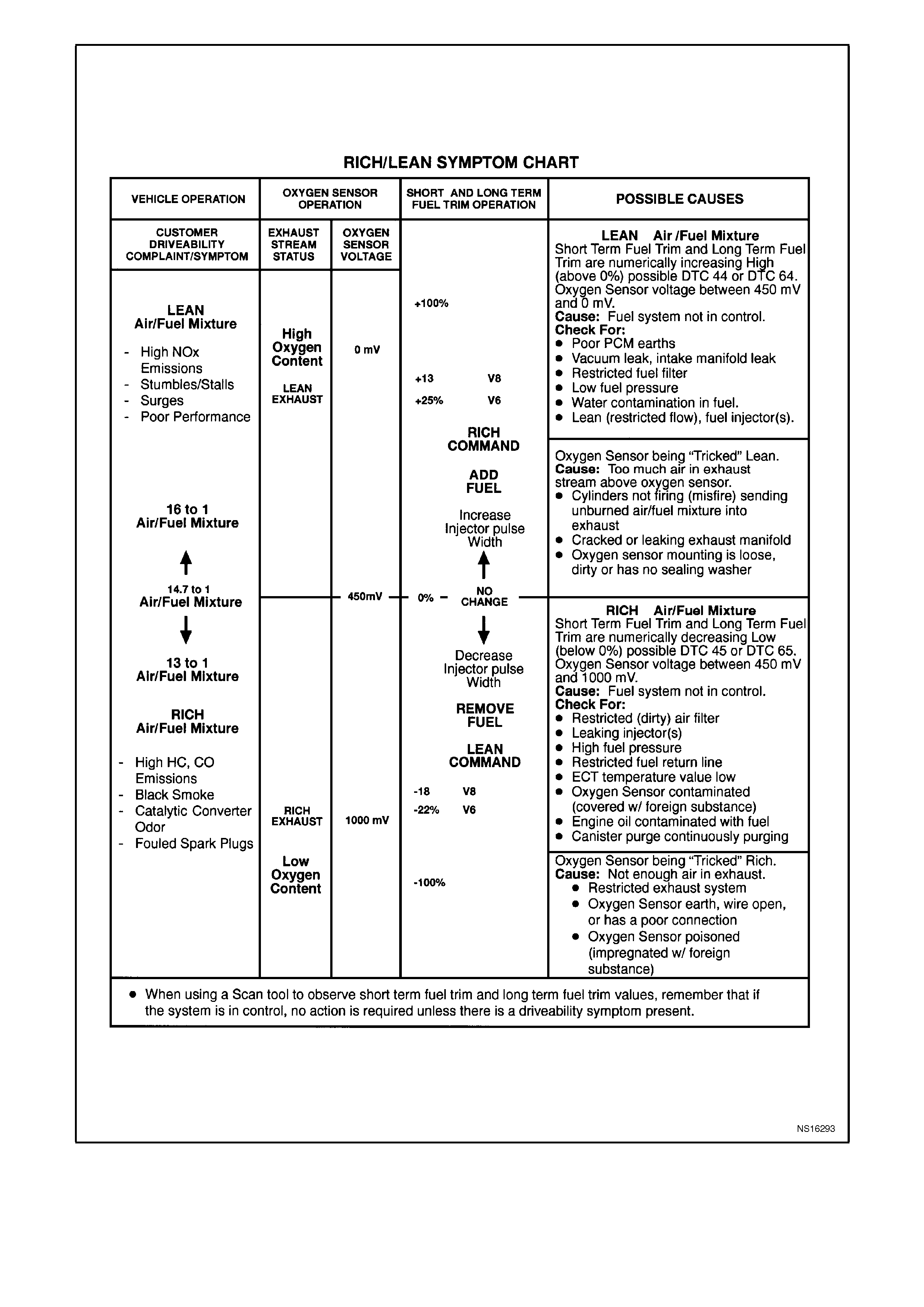
The Rich/Lean Symptom Chart is an organised approach to identifying a driveability complaint that may be caused
by an overrich or overlean operating condition. Understanding the chart and using it correctly will reduce diagnostic
time and improve customer satisfaction. Start at the left side of the chart and work to the right.
TEST DESCRIPTION:
Numbers below refer to step number(s) on the diagnostic chart.
1. This is a partial list of possible customer complaints and what the air/fuel mixture must be to cause such a
condition.
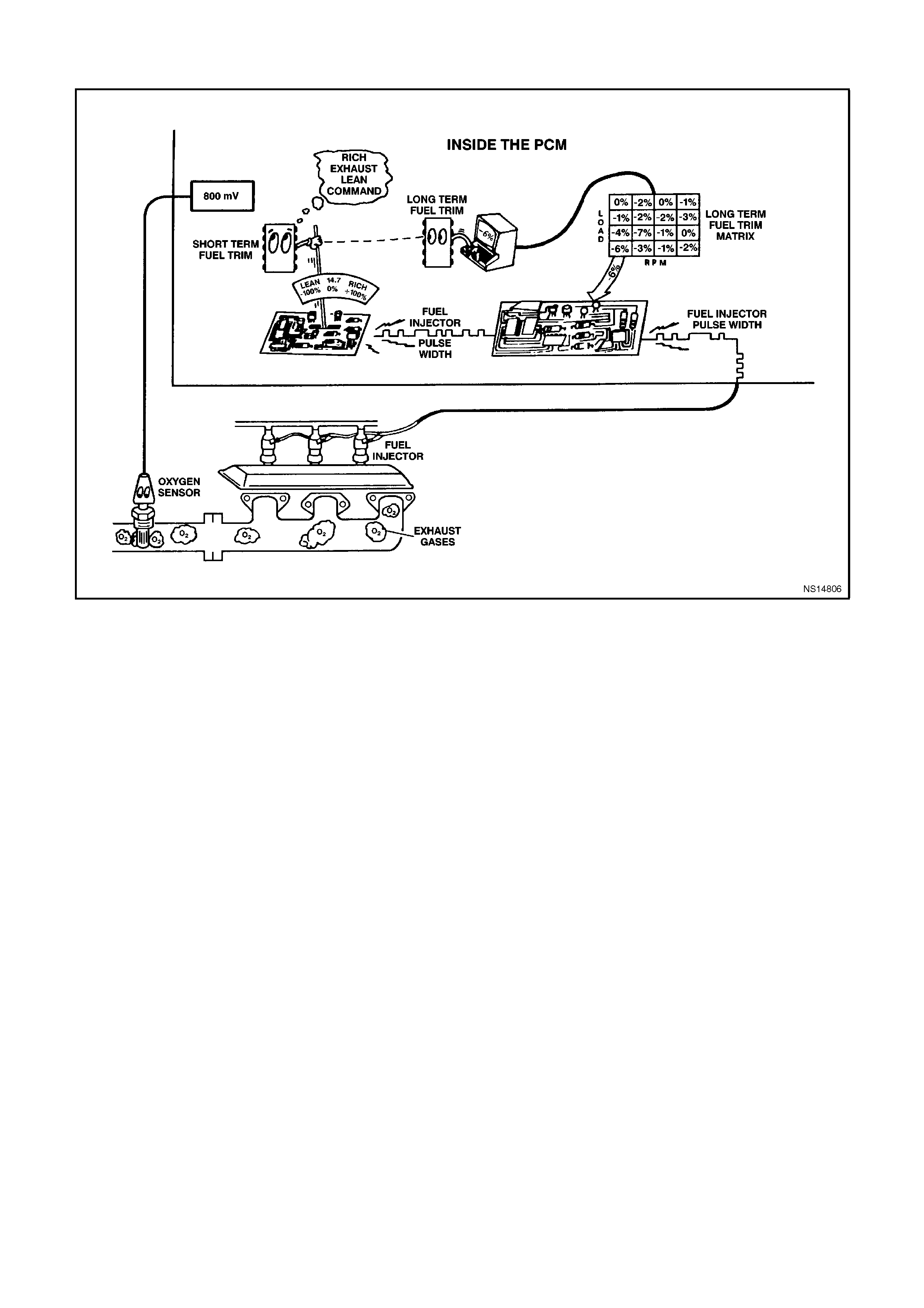
2. A lean exhaust means that there is a lot of oxygen in the exhaust stream. Lots of oxygen in the exhaust stream
means a low oxygen sensor signal voltage. Lean=lots of oxygen=low oxygen sensor signal voltage. A rich
exhaust means that there is a lot of fuel and very little oxygen in the exhaust stream.
3. The oxygen sensor signal to the PCM determines what the PCM should do to compensate for the present
condition. Depending upon the severity of the problem, the PCM will compensate for the condition by changing
the short term fuel trim and short term fuel trim values either higher or lower. An short term fuel trim value
above 0% means the PCM will add more fuel to the engine, by increasing the injector pulsewidth, thus making
a lean engine run richer. A short term fuel trim value below 0% means the PCM will decrease the amount of
fuel to the engine, by decreasing the injector pulse width, thus making a rich engine run leaner.
4. This list represents areas where you should look to find the root cause of the customer complaint. Not every
cause of the symptom is listed here, however, the items listed provide a good general description of areas to
look at.
DIAGNOSTIC AIDS:
Driveability complaints may be caused by the PCM, system components or electrical faults, however, a basic engine
problem may also present a symptom similar to an electrical failure. Remember to check the air cleaner and all the
basic engine components, there could be worn rings, worn camshaft lobes, collapsed lifters, misaligned timing
chain, vacuum leaks etc.

AUTOMATIC TRANSMISSION SYM PTOM CHARTS
OIL PRESSURE HIGH OR LOW
CHECKS CAUSES
Oil Pump Assembly Pressure regulator valve stuck
Pressure regulator valve spring
Rotor guide omitted or disassembled
Rotor cracked or broken
Reverse boost valve or sleeve stuck, damaged or incorrectly
assembled
Orifice hole in pressure regulator valve plugged
Sticking slide or excessive rotor clearance
Pressure relief ball not seated or damaged
Porosity in pump cover or body
Wrong pump cover
Pump faces not flat
Excessive rotor clearance
Oil Filter Intake pipe restricted by casting flash
Cracks in filter body or intake pipe
O-ring seal missing, cut or damaged
Wrong grease used on rebuild
Valve Body Manual valve scored or damaged
Spacer plate or gaskets incorrect, misassembled or damaged
Face not flat
2-3 Shift valve stuck
Checkballs omitted or misassembled
Pressure Control
Solenoid Valve Damage to pins
TFP Val Position Sw. Contamination
Damaged seals
Case Case to valve body face not flat
HARSH SHIFTS
CHECKS CAUSES
Throttle Position
Sensor Open or shorted circuit
Vehicle Speed Sensor Open or shorted circuit
TFP Val Position Sw. Contamination
Damaged seals
Trans Fluid
Temperature Sensor Open or shorted circuit
Engine Coolant
Temperature Sensor Open or shorted circuit
Pressure Control
Solenoid Valve Damage to pins
Contamination

INACCURATE SHIFT POINTS
CHECKS CAUSES
Oil Pump Assembly Stuck pressure regulator valve
Sticking pump slide
Valve Body Assembly Spacer plate or gaskets misassembled, damaged or incorrect
Case Porous or damaged valve body pad
2-4 Servo Assembly:
-2-4 accumulator porosity
-Damaged servo piston seals
-Apply pin damaged or improper length
2-4 Band Assembly:
-Burned
-Anchor pin not engaged
TP Sensor Disconnected
Damaged
Vehicle Speed Sensor Disconnected
Damaged
Bolt not tightened
1ST GEAR RANGE ONLY - NO UPSHIFT
CHECKS CAUSES
Valve Body The 1-2 Shift valve is sticking
The spacer plate or gaskets are mispositioned or damaged
Case The case to valve body face is damaged or is not flat
Shift Solenoid Valves Stuck or damaged
Faulty electrical connection
2-4 Servo Assembly The apply passage case is restricted or blocked
Nicks or burrs on the servo pin or on the pin bore in the case
Fourth servo pistons installed backwards
2 -4 Band Assembly The 2-4 band is worn or damaged
The band anchor pin is not engaged

SLIPS IN 1ST GEAR
CHECKS CAUSES
Forward Clutch
Assembly Clutch plates worn
Porosity or damage in forward clutch piston
Forward clutch piston inner and outer seals missing, cut or
damaged
Damaged forward clutch housing
Forward clutch housing retainer and ball assembly not sealing
or damaged
Forward Clutch
Accumulator Piston seal missing, cut or damaged
Piston out of its bore
Porosity in the piston or valve body
Stuck abuse valve
Input Housing and
Shaft Assembly Turbine shaft seals missing, cut or damaged
Valve Body 1-2 Accumulator valve stuck
Face not flat, damaged lands or interconnected passages
Spacer plate or gaskets incorrect, mispositioned or damaged
Low Roller Clutch Damage to lugs to inner ramps
Rollers not free moving
Inadequate spring tension
Damage to inner splines
Lube passage plugged
Torque Converter Stator roller clutch not holding
1-2 Accumulator
Assembly Porosity in piston or 1-2 Accumulator cover and pin assembly
Damaged ring grooves on piston
Piston seal missing, cut or damaged
Valve body to spacer plate gasket at 1-2 Accumulator cover,
missing or damaged
Leak between piston and pin
Broken 1-2 Accumulator spring
Line Pressure Refer to Oil Pressure High or Low
2-4 Servo Assembly 4th Servo piston in backward
SLIPPING OR ROUGH 1-2 SHIFT
CHECKS CAUSES
Valve Body Assembly 1-2 Shift valve train stuck
Gaskets or spacer plate incorrect, mispositioned or damaged
1-2 Accumulator valve stuck
Face not flat
2-4 Servo Assembly Apply pin too long or too short
2nd servo apply piston seal missing, cut or damaged
Restricted or missing oil passages
Servo bore in case damaged
2nd Accumulator Porosity in 1-2 accumulator housing or piston
Piston seal or groove damaged
Nicks or burrs in 1-2 accumulator housing
Missing or restricted oil passage
2-4 Band Worn or mispositioned
Oil Pump Assembly or
Case Faces not flat

NO 2-3 SHIFT OR 2-3 SHIFT SLIPS, ROUGH OR HUNTING
CHECKS CAUSES
Valve Body Assembly 1-2 Shift valve train stuck
Gaskets or spacer plate incorrect, mispositioned or damaged
1-2 Accumulator valve stuck
Face not flat
2-4 Servo Assembly Apply pin too long or too short
2nd servo apply piston seat missing, cut or damaged
Restricted or missing oil passages
Servo bore in case damaged
2nd Accumulator Porosity in 1-2 accumulator housing or piston
Piston seal or groove damaged
Nicks or burrs in 1-2 accumulator housing
Missing or restricted oil passage
2-4 Band Worn or mispositioned
Oil Pump Assembly or
Case Faces not flat
2ND/3RD GEARS ONLY OR 1ST/4TH GEARS ONLY
CHECKS CAUSES
Shift Solenoid Valves Sediment is in the valves
The electrical connection is faulty
Damaged seal
THIRD GEAR ONLY
CHECKS CAUSES
DTC 81 The electrical connection is faulty
Shorted or damaged
3-2 FLARE OR TIE-UP
CHECKS CAUSES
3-2 Shift Solenoid Shorted or damaged
Contamination
Damaged Seal

NO 3-4 SHIFT, SLIPS OR ROUGH 3-4 SHIFT
CHECKS CAUSES
Oil Pump Assembly Pump cover retainer and ball assembly omitted or damaged
Faces not flat
Valve Body Assembly Valves stuck:
-2-3 Shift valve train
-Accumulator valve
-1-2 Shift valve train
-3-2 Shift valve
Spacer plate or gasket incorrect, mispositioned or damaged
2-4 Servo Assembly Incorrect band apply pin
Missing or damaged servo seals
Porosity in piston, cov er or case
Damaged piston seal grooves
Plugged or missing orifice cup plug
Case 3rd Accumulator retainer and ball assembly leaking
Porosity in 3-4 accumulator piston or bore
3-4 Accumulator piston seal or seal grooves damaged
Plugged or missing orifice cup plug
Restricted oil passage
Input Housing
Assembly Refer to Slipping 2-3 Shift
2-4 Band Assembly Worn or Disassembled
NO REVERSE OR SLIPS IN REVERSE
CHECKS CAUSES
Input Housing
Assembly 3-4 Apply ring stuck in applied position
Forward clutch not releasing
Turbine shaft seals missing, cut or damaged
Manual Valve Link Disconnected
Valve Body Assembly 2-3 Shift valve stuck
Manual linkage not adjusted
Spacer plate and gaskets incorrect, mispositioned or damaged
Lo overrun valve stuck
Orificed cup plug restricted, missing or damaged
Reverse Input Clutch
Assembly Clutch plate worn
Reverse input housing and drum assembly cracked at weld
Clutch plate retaining ring out of groove
Return spring assembly retaining ring out of groove
Seals cut or damaged
Restricted apply passage
Porosity in piston
Belleville plate installed incorrectly
Excessive clutch plate travel
Oversized housing
Lo and Reverse Clutch Clutch plates worn
Porosity in piston
Seals damaged
Return spring assembly retaining ring mispositioned
Restricted apply passage

NO PART THROTTLE OR DELAYED DOWNSHIFTS
CHECKS CAUSES
Input Housing
Assembly 3-4 Apply ring stuck in applied position
Forward clutch not releasing
Turbine shaft seals missing, cut or damaged
Manual Valve Link Disconnected
Valve Body Assembly 2-3 Shift valve stuck
Manual linkage not adjusted
Spacer plate and gaskets incorrect, mispositioned or damaged
Lo overrun valve stuck
Orificed cup plug restricted, missing or damaged
Reverse Input Clutch
Assembly Clutch plate worn
Reverse input housing and drum assembly cracked at weld
Clutch plate retaining ring out of groove
Return spring assembly retaining ring out of groove
Seals cut or damaged
Restricted apply passage
Porosity in piston
Belleville plate installed incorrectly
Excessive clutch plate travel
Oversized housing
Lo and Reverse Clutch Clutch plates worn
Porosity in piston
Seals damaged
Return spring assembly retaining ring mispositioned
Restricted apply passage
HARSH GARAGE SHIFT
CHECKS CAUSES
Valve Body Assembly Orifice cup plug missing
Checkball missing
NO OVERRUN BRAKING - MANUAL 3-2-1
CHECKS CAUSES
External Linkage Not adjusted properly
Valve Body Assembly 4-3 Sequence valve stuck
Checkball mispositioned
Spacer plate and gaskets incorrect, damaged or mispositioned
Input Clutch Assembly Turbine shaft oil passages plugged or not drilled
Turbine shaft seal rings damaged
Turbine shaft sealing balls loose or missing
Porosity in forward or overrun clutch piston
Overrun piston seals cut or damaged
Overrun piston checkball not sealing

NO TCC APPLY
CHECKS CAUSES
Electrical 12 Volts not supplied to transmission
Outside electrical connector damaged
Inside electrical connector, wiring harness or solenoid
damaged
Electrical short (pinched solenoid wire)
Solenoid not earthed
Converter Internal damage
Oil Pump Assembly Converter clutch valve stuck or assembled backwards
Converter clutch valve retaining ring mispositioned
Pump to case gasket mispositioned
Orifice cup plug restricted or damaged
Solenoid O-ring seal cut or damaged
High or uneven bolt torque (pump body to cover)
Input Housing and
Shaft Turbine shaft O-ring seal cut or damaged
Turbine shaft retainer and ball assembly restricted or damaged
TFP Val Position
Switch Contamination
Damaged seals
Valve Body Assembly TCC signal valve stuck
Solenoid O-ring leaking
Solenoid Screen Blocked
TCC Solenoid Valve —
Engine Speed Sensor —
Engine Coolant
Temperature Sensor —
DTCs 19, 21, 22, 28,
67, 81, 83, 84 —
Automatic
Transmission Fluid
Temperature Sensor
—

TORQUE CONVERTER CLUTCH SHUDDER
CHECKS CAUSES
Electrical 12 Volts not supplied to transmission
Outside electrical connector damaged
Inside electrical connector, wiring harness or solenoid
damaged
Electrical short (pinched solenoid wire)
Solenoid not earthed
Converter Internal damage
Oil Pump Assembly Converter clutch valve stuck or assembled backwards
Converter clutch valve retaining ring mispositioned
Pump to case gasket mispositioned
Orifice cup plug restricted or damaged
Solenoid O-ring seal cut or damaged
High or uneven bolt torque (pump body to cover)
Input Housing and
Shaft Turbine shaft O-ring seal cut or damaged
Turbine shaft retainer and ball assembly restricted or damaged
TFP Val Position
Switch Contamination
Damaged seals
Valve Body Assembly TCC signal valve stuck
Solenoid O-ring leaking
Solenoid Screen Blocked
NO TCC RELEASE
CHECKS CAUSES
TCC Solenoid Valve Internal earth
Clogged exhaust orifice
Converter Internal damage
Valve Body Assembly The converter clutch apply valve is stuck in the apply position
Oil Pump Assembly The converter clutch valve is stuck
PCM External earth
DRIVES IN NEUTRAL
CHECKS CAUSES
Forward Clutch The clutch does not release
Manual Valve Link Disconnected
Case The face is not flat
Internal leakage exists
2ND GEAR START
CHECKS CAUSES
Forward Clutch Sprag
Assembly The sprag assembly is installed backward

NO PARK
CHECKS CAUSES
Parking Linkage Actuator rod assembly bent or damaged
Actuator rod spring binding or improperly crimped
Actuator rod not attached to inside detent lever
Parking lock bracket damaged or not torqued properly
Inside detent lever not torqued properly
Parking pawl binding or damaged
OIL OUT THE VENT
CHECKS CAUSES
Oil Pump Chamber in pump body rotor pocket
Miscellaneous Fluid level -overfilled
VIBRATION IN REVERSE AND WHINING NOISE IN PARK
CHECKS CAUSES
Oil Pump Chamber in pump body rotor pocket
Miscellaneous Fluid level -overfilled
RATCHETING NOISE
CHECKS CAUSES
Parking Pawl The parking pawl return spring is weak, damaged, or
misassembled
NO DRIVE IN ALL RANGES
CHECKS CAUSES
Torque Converter The converter to flex plate bolts are missing
NO DRIVE IN DRIVE RANGE
CHECKS CAUSES
Torque Converter The stator roller clutch is not holding
The converter is not bolted to the flex plate
FRONT OIL LEAK
CHECKS CAUSES
Torque Converter The welded seam is leaking
The converter hub is damaged
Torque Converter Seal The seal assembly is damaged
The garter spring is missing
DELAY IN DRIVE AND REVERSE
CHECKS CAUSES
Torque Converter Converter drainback

PCM CONNECTOR SYMPTOM CHARTS
The following Powertrain Control Module (PCM) connector Symptoms Charts identifies the function of each pin of
the PCM connector, the circuit number, the wire colour, and the cavity of the component to which the wire connects.
The left column in this chart lists the PCM connector pins in ascending order. The chart may also be entered from
the right-most column, which lists possible symptoms that may be caused by a fault in each of the circuits. If a
problem in any of these circuits will cause a Diagnostic Trouble Code to be set, the DTC's are identified in the
second column from the right edge of the chart. (However, if a DTC has been set, you should attempt to diagnose
the condition using Section 6C1-2A DIAGNOSTIC CHARTS - V6 ENGINE before diagnosing by symptom.) The
expected normal voltage for each circuit is shown for two conditions. Check the voltage with the ignition "ON" but
the engine not running, and with the engine running. Both checks are required for accurate diagnosis. Reference
notes are made for some circuits. These notes state conditions that cause varying voltages or mention unique
characteristics of the circuit. To measure the voltages, backprobe the PCM connector. Whenever backprobing, be
careful not to damage the connector. Careless backprobing may damage the connector seal and/or terminal.
Damaged pins will provide incorrect readings and cause additional system problems.
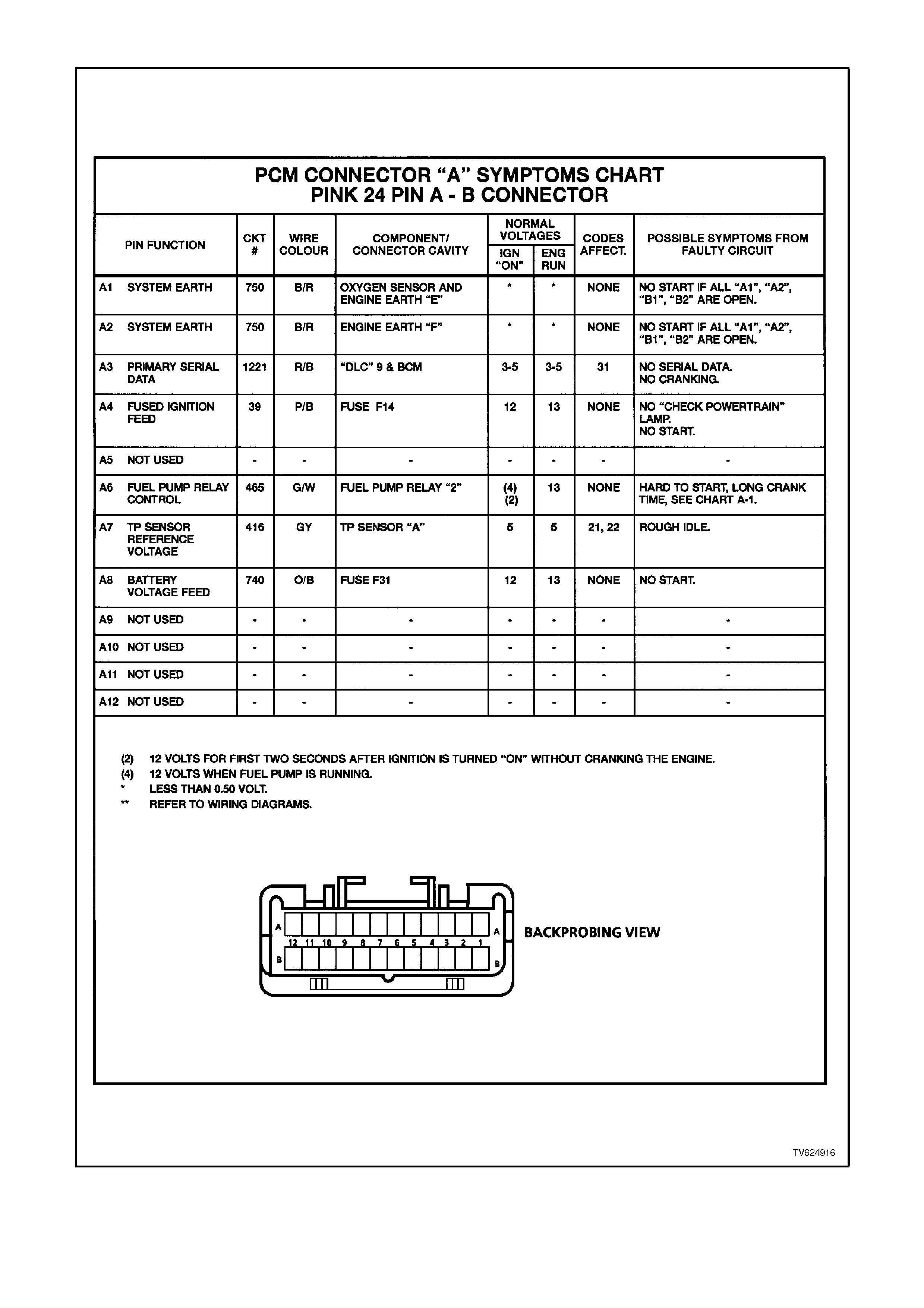
PCM CONNECTOR A
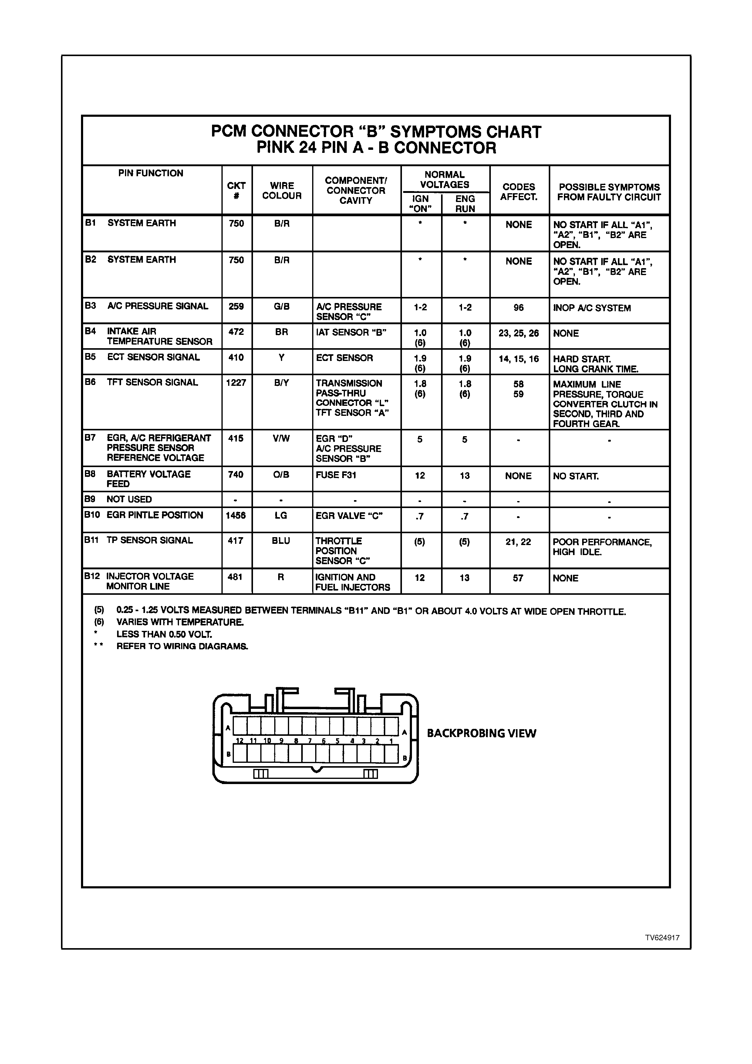
PCM CONNECTOR B
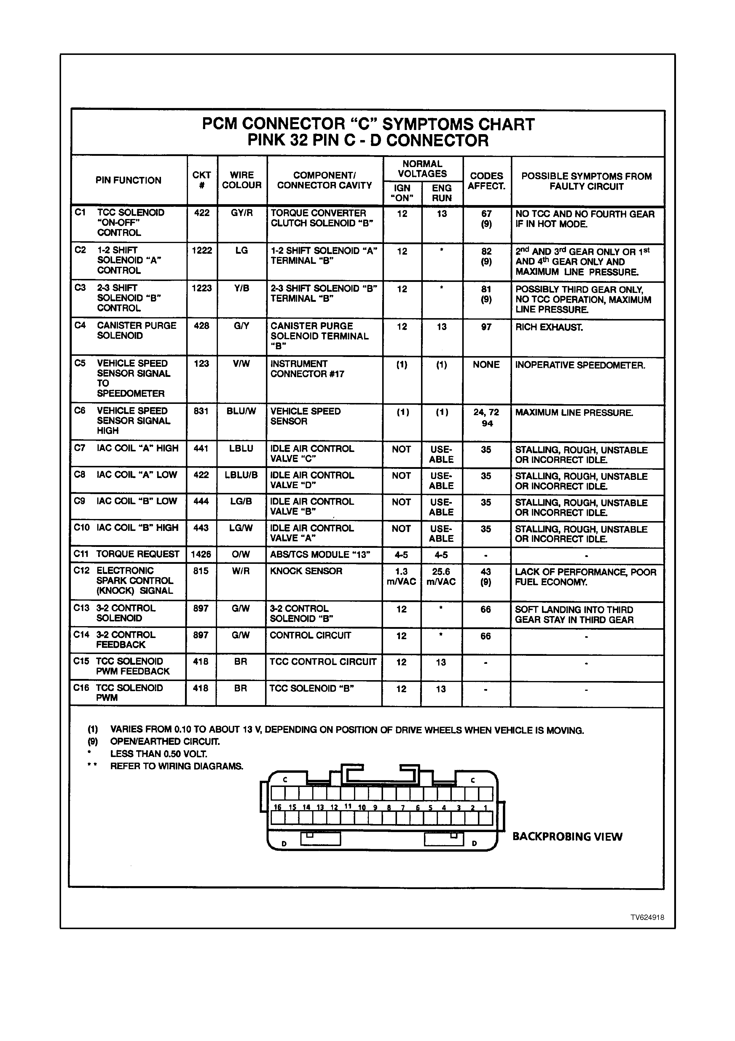
PCM CONNECTOR C
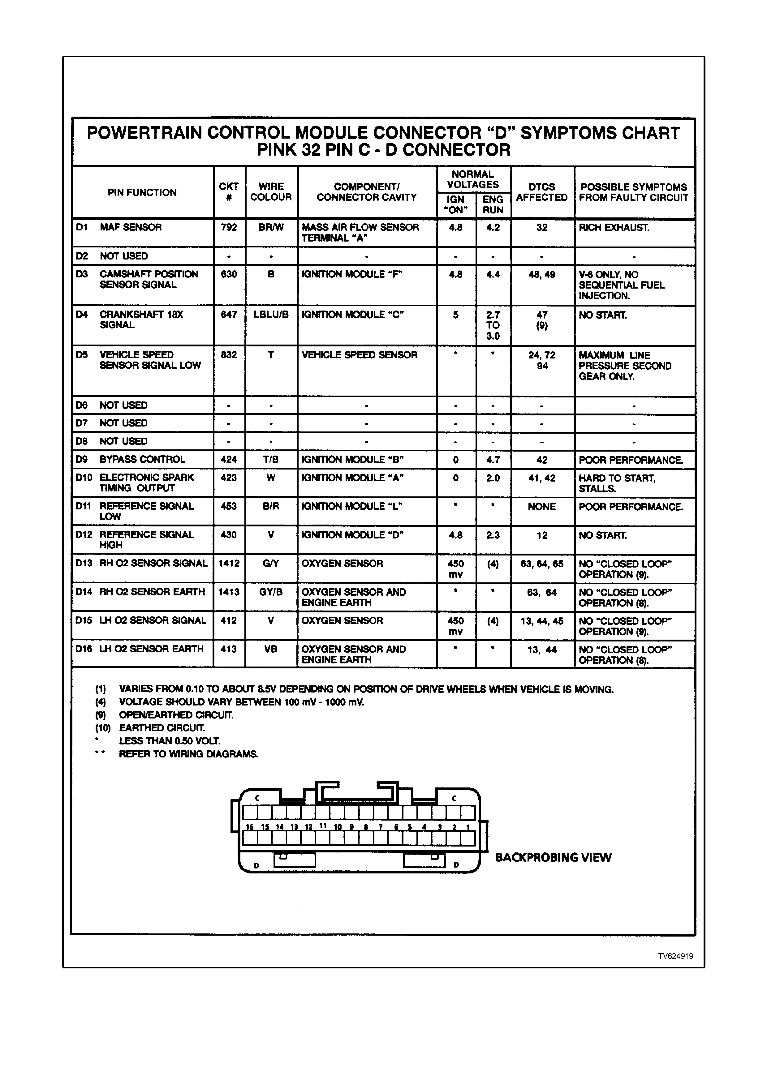
PCM CONNECTOR D
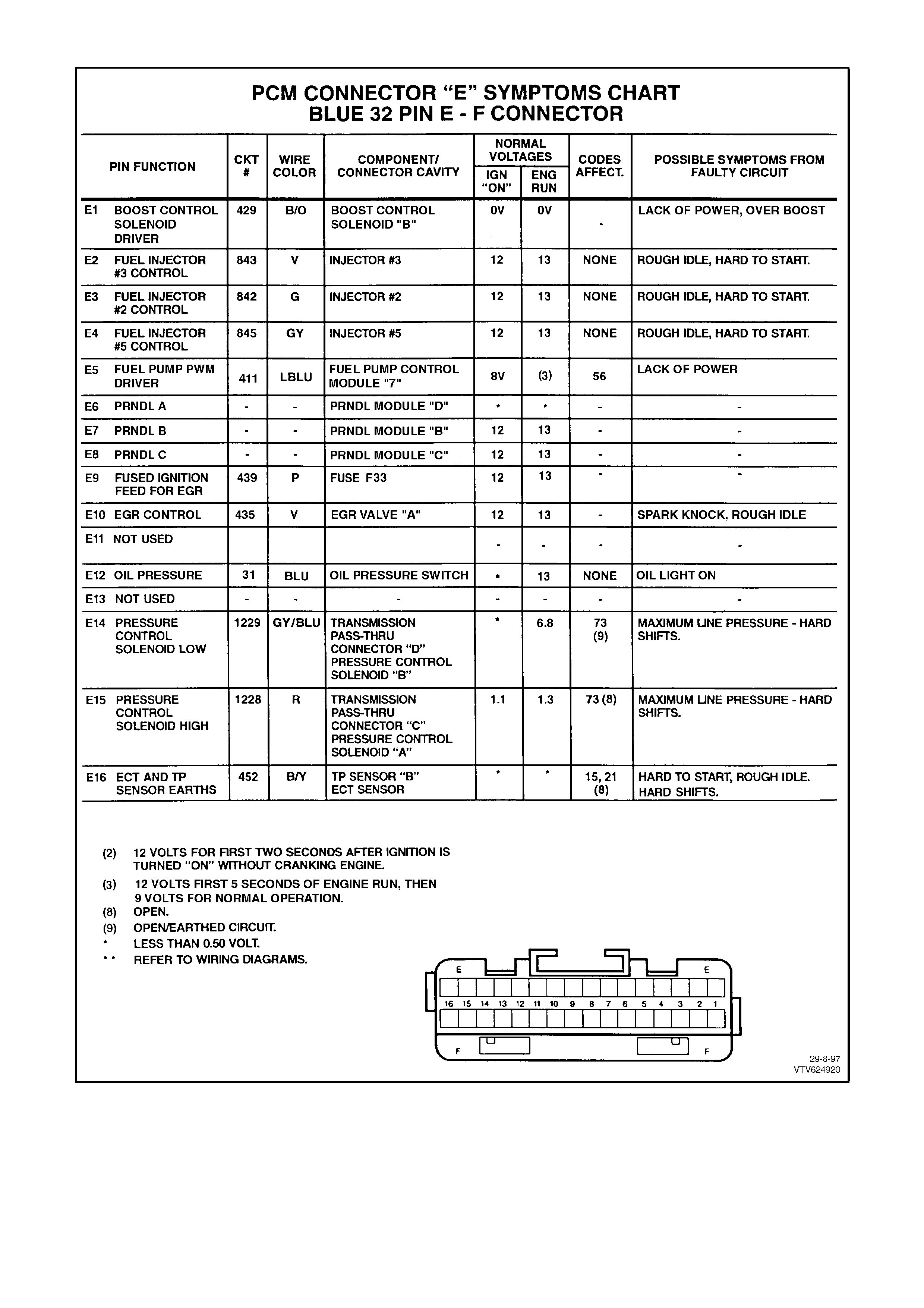
PCM CONNECTOR E
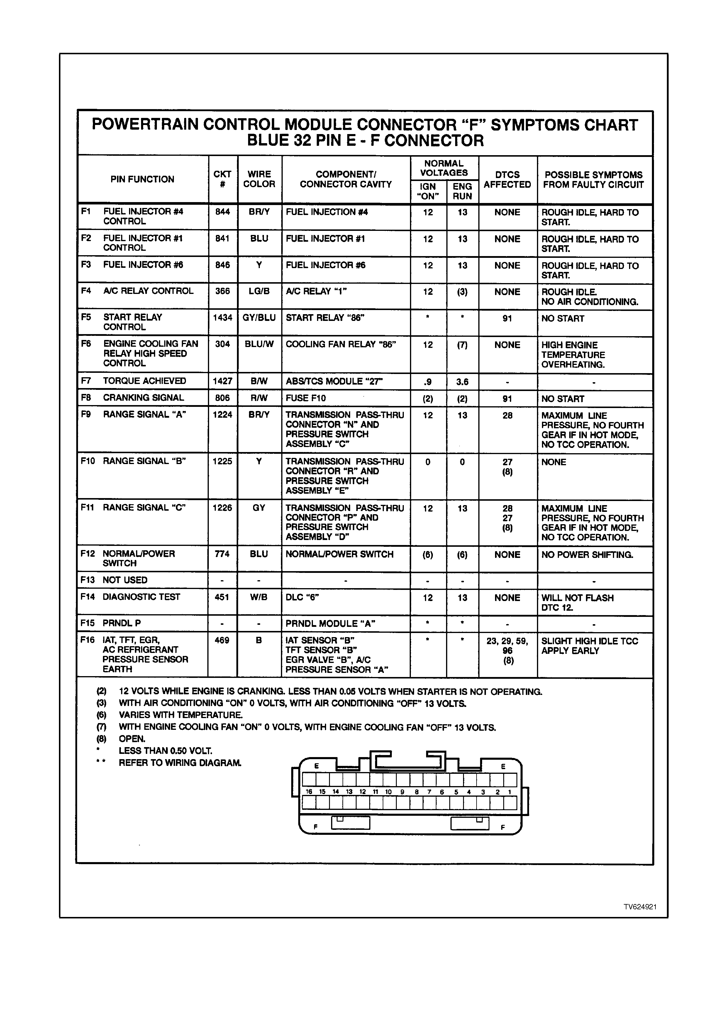
PCM CONNECTOR F
TESTING EARTHS
Unusual displays in the instrument cluster, lamps
that are dim or flash unexpectedly, unexpected
readings - gremlins? Probably not; these are
classic symptoms of earth problems.
This section discusses the importance of good
earth circuits. It starts by explaining some basic
theories. Then, you are shown how to diagnose a
solid-state circuit earth condition and how, if there
is a problem, to correct it.
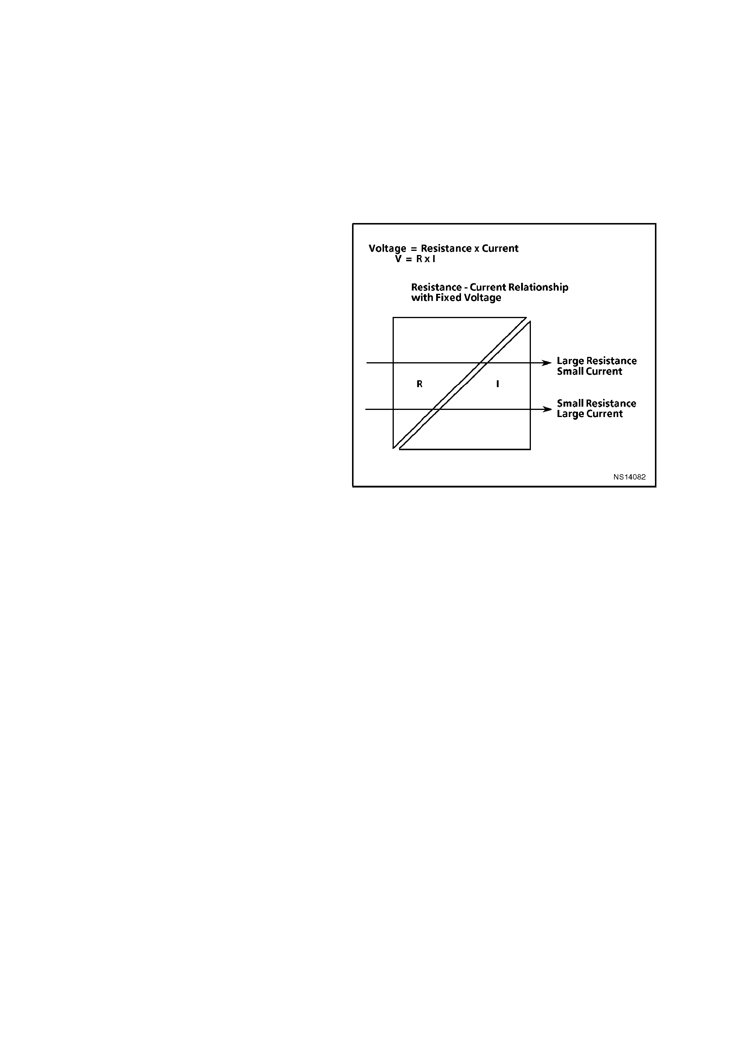
BASICS
For a circuit to operate properly, you need three
things - a good power supply to components, good
components, and good earths. Circuits are
complete systems; current must flow from
beginning to end as designed, not hindered by
unexpected resistance anywhere in the circuit.
Some technic ians realis e that the power supply to a
circuit must be free of unwanted resistance, but
have difficulty visualising why an earth circuit must
also be fr ee of unwanted resis tanc e. Curr ent f low is
through a complete circuit; it passes through and
out of a component like water flowing through a
tub. With a properly draining tub (no clogs), the
water can flow out as freely as it flow in. Current
mus t enter and leave components f reely, if they are
to perform as designed.
Figure 6C1-2B-3
Sensitive solid-state systems have their own
earths; high current devices (like motors) do not
earth at the same location. High current devices
can cause voltage spikes (sudden changes in
voltage) when turned "ON" or "OFF." To prevent
these spikes from affecting sensitive solid-state
circuits, the two different types of systems use
different earth locations. The use of a dedicated
wire to connect an isolated earth junction block to
the battery negative terminal. T his wire r educes the
effect of spikes on sensitive circuits at the earth
junction block.
Solid-state cir cuits are particularly sensitive to poor
circuit continuity because in most cases they use
low current flow. This section on earth concerns
with one solid-state device, the PCM. However, the
information included here applies to all solid-state
earth circuits.
Severe restrictions in the earth circuit can cause
resets and intermittent codes in solid-state
systems. The PCM operates devices (fuel
injectors, idle air control, etc.) and receives inputs
from low voltage sensors, manifold absolute
pressure sensor, crankshaft speed/position. These
input and output devices need good circuitry for
correct operation.
Remember, that when misadjusted or imperfect
sensors cause values to shift there are usually
driveability problems. If there is excessive
resistance in the earth circuit, the result will be the
same; shifted sensor outputs with corresponding
driveability conditions. These conditions may not be
severe enough to set diagnostic trouble codes, but
they will reduce vehicle effic iency and per form ance
and may be noticed by the customer.
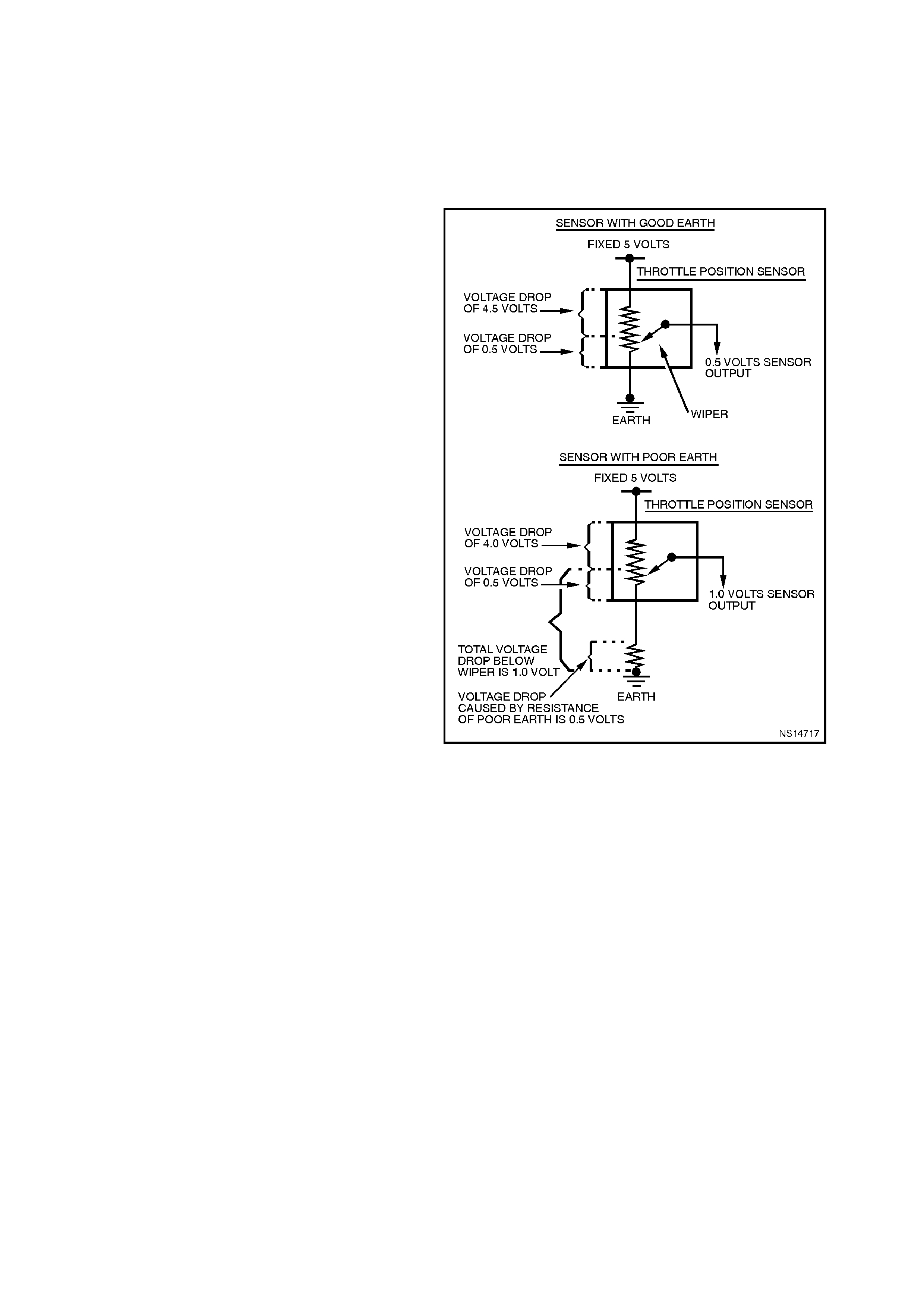
Sensor circuit earth sensitivity - an example.
Looking at the Throttle Position (TP) sensor circuit
will provide an exam ple of how a little resistance in
the earth circuit can cause problems. The
accompanying figure (Figure 6C1-2B-4) shows a
throttle position sens or f irs t with a good earth circ uit
and then with a poor connection in the earth cir cuit.
Refer to this figure as you proceed through the tex t
that follows.
A throttle position sensor consists of a resistor and
a wiper. One terminal of the resistor is connected to
a supply voltage and the other earth. As the wiper
moves along the resistor, the voltage of the wiper
terminal progressively changes. If the wiper is near
the supply voltage end of the resistor, the wiper
output will approach the supply voltage (over 4.5
volts at wide open throttle). As the wiper moves
toward the earthed end of the resistor the voltage
of the wiper output decreases to near zero (about
0.5 volts for the closed throttle in this example).
(The actual closed and wide open throttle voltage
specifications may vary for different engines.) The
sensor output should never be greater than
reference supply voltage or less then .20 volts.
(The PCM would set a diagnostic trouble code if
this occurs.)
The Figure 6C1-2B-4 shows voltage drops across
various points in the circuit. In the example with
good circuit earth, the T P sensor is shown with the
wiper in the closed throttle position. The total
voltage across the resistor in the TP sensor is 5
volts. The voltage drop from the resistor source
voltage terminal to the wiper is 4.5 volts. The
voltage drop from the wiper to the resistor earth
side is 0.5 volts. The wiper output is 0.5 volts - a
good value for this example of a closed throttle.
Now, look at the sensor with the bad signal caus ed
by resistance in the earth circuit. The throttle
positions stays the same but the sensor output
voltage changes. In this example the increased
resistanc e causes an additional voltage dr op of 0.5
volts. The voltage drop from the wiper to found is
now 1.0 volt (0.5 + 0.5 = 1.0). Because the source
voltage is a constant 5 volts, the voltage drop from
the source voltage input to the wiper can now be
only 4 volts (5.0 - 1.0 = 4.0). The PCM now
receives 1.0 volt from the TP sensor. This is not a
good value (in this example) of a closed throttle
Now you can see why good earths are needed and
how sensitive some circuits can be.
Figure 6C1-2B-4

EARTH CIRCUITS
How do you know which wires are earth wires,
which connectors they go through, and whether
they are connected to an earth junction or the
body?
Section 12P, WIRING DIAGRAMS should be
used whenever you are diagnosing any electrical
condition, including earths. The individual circuits
show the power and earth circuits for components
in specific systems.
If you suspect several c irc uits are being affec ted by
a poor or a back-feed to earth, look at the circuits
to see how the systems m ight interact. If they have
any common earth wires, that is where you should
start diagnosis.
Back-feeding is when cur rent, seeking earth, f eeds
back through inactive circ uits (the reverse dir ection
of norm al current flow) to find a path to earth. T his
can only happen when the active circuit (needing
an earth) shares a disconnected or poor earth with
an inactive circuit and the voltage supply side of the
inactive circuit feeds other components with good
earths.
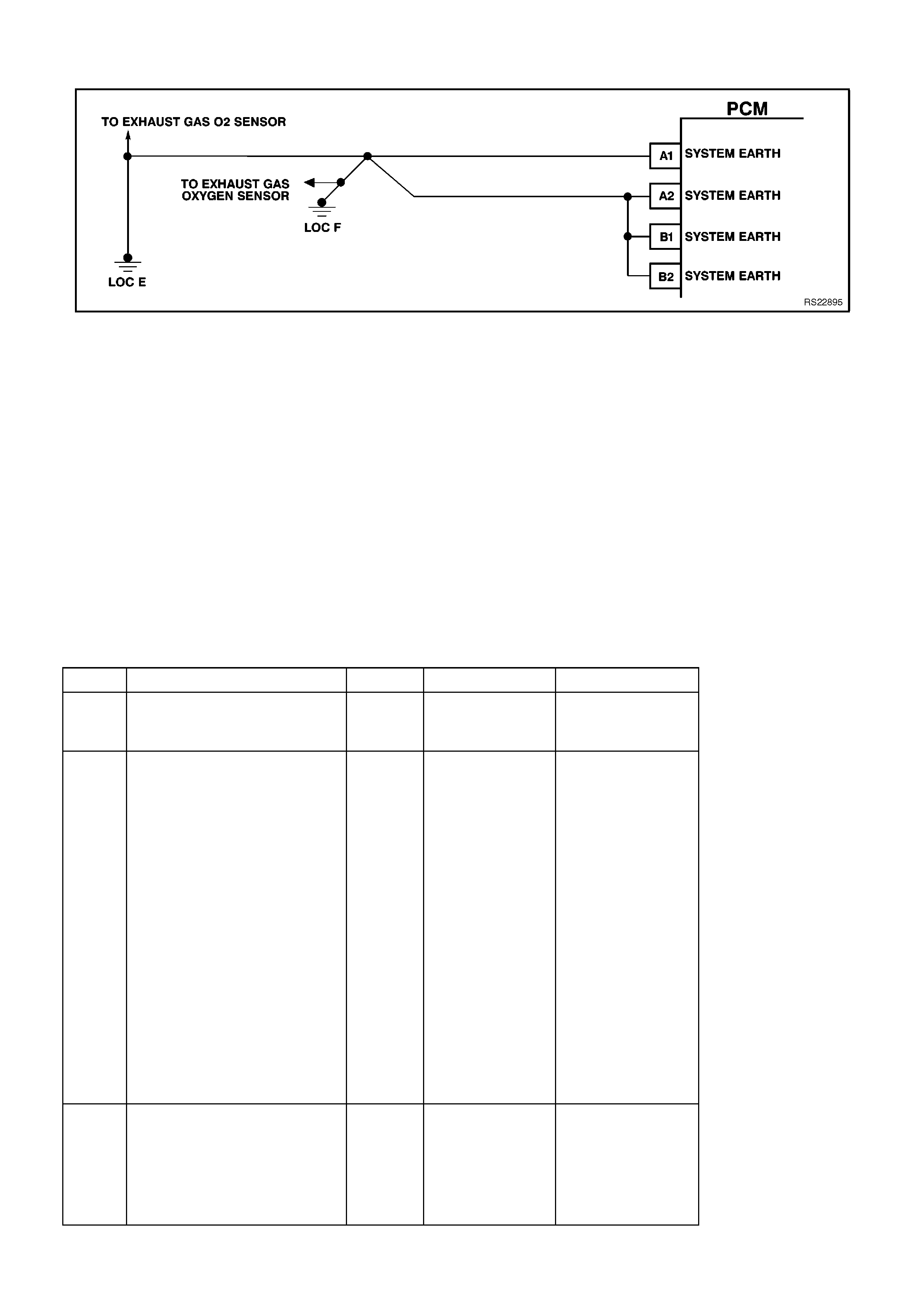
PARALLEL EARTHS
Some solid-state components use redundant earth
circuits; that is, they have more than one wire
connecting to earth. The PCM has more than one
earth circuit wire. There are several reasons for
redundant earths.
The PCM has many low-current circuits, but the
current from all these circuits (when they are
active) adds up to a larger current. Higher current
loads are managed more easily with several regular
size wires, rather than with one large diam eter wire.
Basic circuit theory shows that the effective
resistance of parallel resistors is less than any of
the individual resistors. This is true for even the
small resistance's in wires. Parallel wires provide
the lowest resistance. Because of them, in many
solid-s tate system s a problem with one of the ear th
wires would not affect the circuit; the redundant
wires could handle the cur rent load. F or other s olid-
state systems the loss of even one redundant earth
may affect operation, but the remaining earth
wire(s) may allow the vehicle to be driven.
Here is one exam ple which can prove to be diff icult
to a driveability technician. Symptom : A vehicle has
driveability symptoms. Whenever a scan tool is
hooked up and the vehicle tested, none of the
complaint symptoms are displayed.
Cause: The PCM earths are not providing a good
earth, hence the resulting driveability condition.
When a scan tool is plugged in, a good earth path
is provided for the PCM through the Data Link
Connector (DLC). The DLC uses a different earth
than the PCM. Always test for driveability
symptoms before hooking up a scan tool. If they
disappear when the scan tool is hooked up, check
the earth circuit for continuity.
The severity of the symptom(s) is proportional to
the severity of the problem in the earth circuit. A
complete open in the circuit has the most severe
effect. Use the severity of the symptom(s) as an
indication of the extent of the open in the earth
circuit.
1 1 1 1
-------- = ------- + ------- + ------- + …
R Total R 1 R 2 R 3
EXAMPLE: 2 PARALLEL CIRCUITS, ONE
WITH ONE OHM RESISTANCE AND
THE OTHER WITH TWO OHMS
RESISTANCE
1 1 1
-------- = ------- + -------
R Total 1 1 2 2
1 2 1
-------- = ------- + -------
R Total 2 2
1 3
-------- = -------
R Total 2
2
R Total = ------- W
3
Figure 6C1-2B-5
CHECKING EARTHS
Once you determine that the cause of the vehicle
symptom(s) may be caused by a bad earth, It is
time to check for poor earth with one more tool: a
high-impedance voltmeter.
The best way to check for poor earth connections in
low-current solid-state circuits is to check the
voltage drop. To do this you need a high-
impedance voltmeter rated at a minimum of 10
megaohms (10,000,000 ohms) per volt. Most
quality digital multimeters meet or exceed this
specification. Voltmeters with less impedance can
affect the circuit you are testing and also give an
incorrect reading.
Start by checking the entire suspect earth circuit.
With a voltmeter set on the 2 volt DC scale,
connect the black negative lead to the battery
negative term inal. (If you are using an auto-ranging
meter, set it to the DC volts setting. Connect the red
positive lead to the earth term inal of the com ponent
to be tested. With the circuit activated, check the
voltage drop in the circuit. If the voltage reading is
within specifications, look for a cause other than a
poor earth at this component.
If the voltage reading is too high, proceed by
isolating the cause of the high voltage drop. Move
the positive lead to the next connec tion in the earth
circuit. (Keep the negative lead connected to the
battery negative terminal.) Be sure to check both
sides of each in-line connector and both the eyelet
and the stud or screw at earth points. Repeat this
process through the earth path until the voltmeter
reading is within specif ications. T he high res istance
causing the earth problem is located between
where you obtained a good reading and the last
high reading.
When a circuit uses redundant earths be sure to
check all the earths circuits for excessive voltage
drop.
Figure 6C1-2B-6
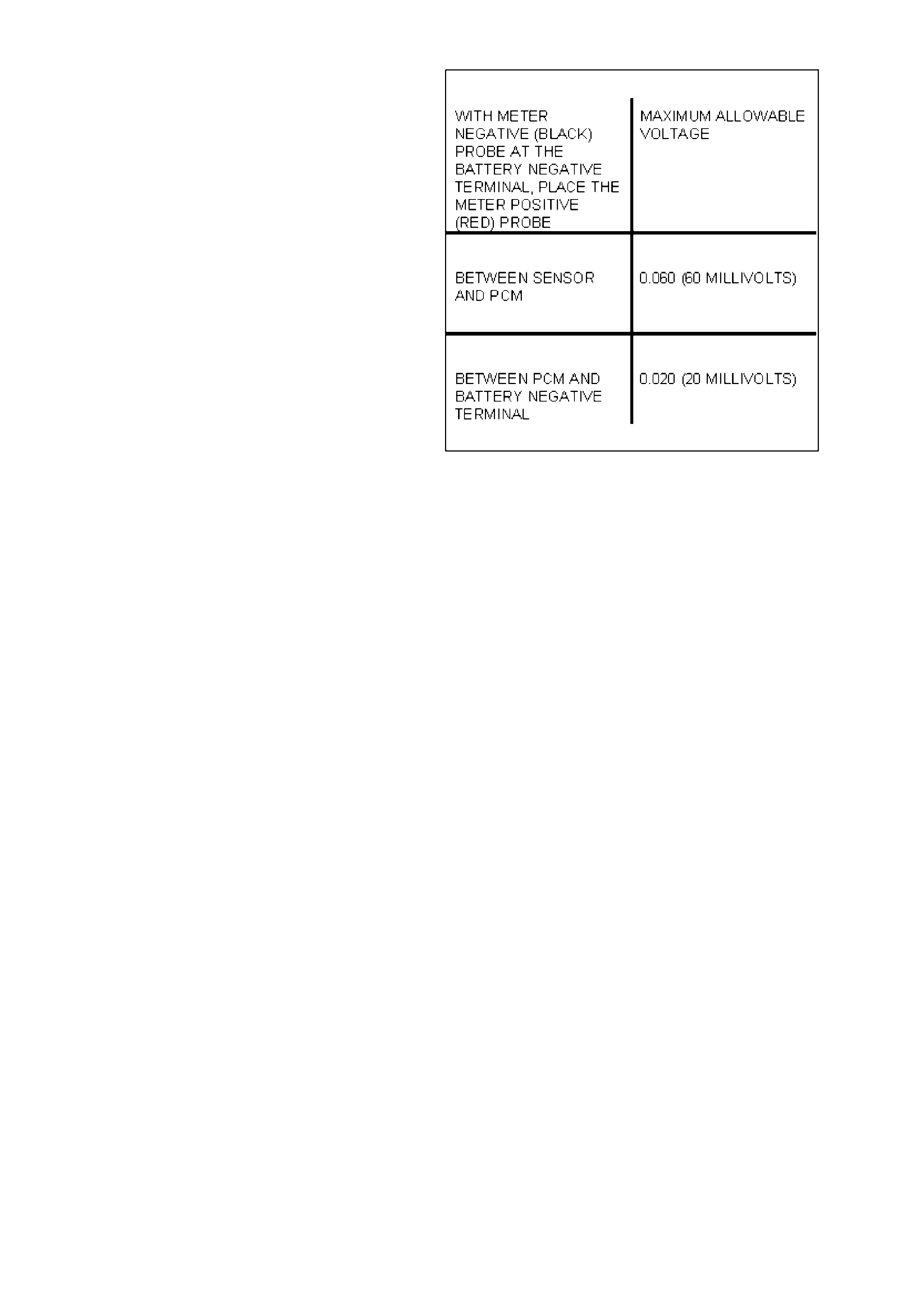
SOLID-STATE CIRCUIT VOLTAGE DROP SPECIFICATIONS
There are two acceptable maximum voltage drops
for solid-state circuits. If you are measuring the
voltage drop of a circuit that will pass through a
solid-state component before going to earth (such
as the ECT sensor circuit between the ECT sensor
and the PCM), measured voltage cannot be higher
than 0.060 volts (60 millivolts).
If you are measuring the voltage drop of a solid-
state earth circuit anywhere in the earth path at or
after the solid-state component (such as the PCM
earth circuit from the PCM to the battery), the
maximum allowable measured voltage is 0.020
volts (20 m illivolts ). If you measure a voltage above
specifications, repair the earth circuit.
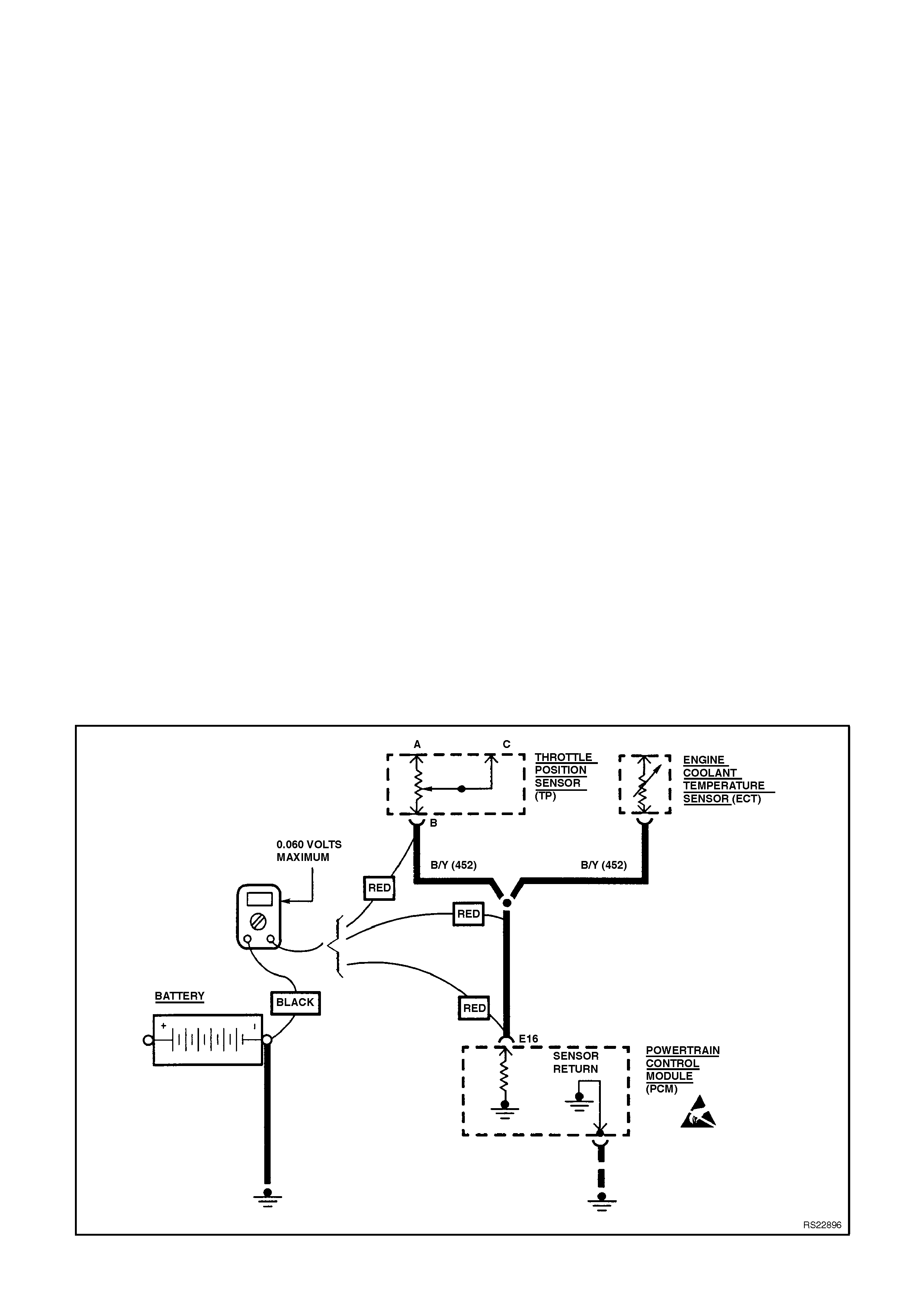
Checking the voltage drop in a solid-state sensor
circuit - an example. Look again at a throttle
position sensor circuit. W ith the voltmeter negative
lead connected to the negative battery term inal and
the ignition in RUN, check the voltages at various
points between the ECT sensor pin "B" and pin
"E16" of the PCM. A voltage reading of 0.060 volts
or less with the meter positive lead at the ECT
sensor pin "B" terminal indicates that the entire
earth circuit from the ECT sensor to the battery is
continuous and sufficiently low in resistance. A
voltage reading of 0.060 volts at "the splice" or the
PCM connector "E16" pin would also be within
specifications.
When voltage measurements are made in the
earth circuit after the PCM, the specification
changes. A voltage reading of 0.020 volts (20
m illivolts) or less is within specif ication. If voltage is
not within specifications check the different
connectors to find where the excess voltage is. Be
sure to check both sides of in-line connectors and
both the eyelet and the stud at earth points.
Figure 6C1-2B-7 Testing Voltage Drop Before the PCM
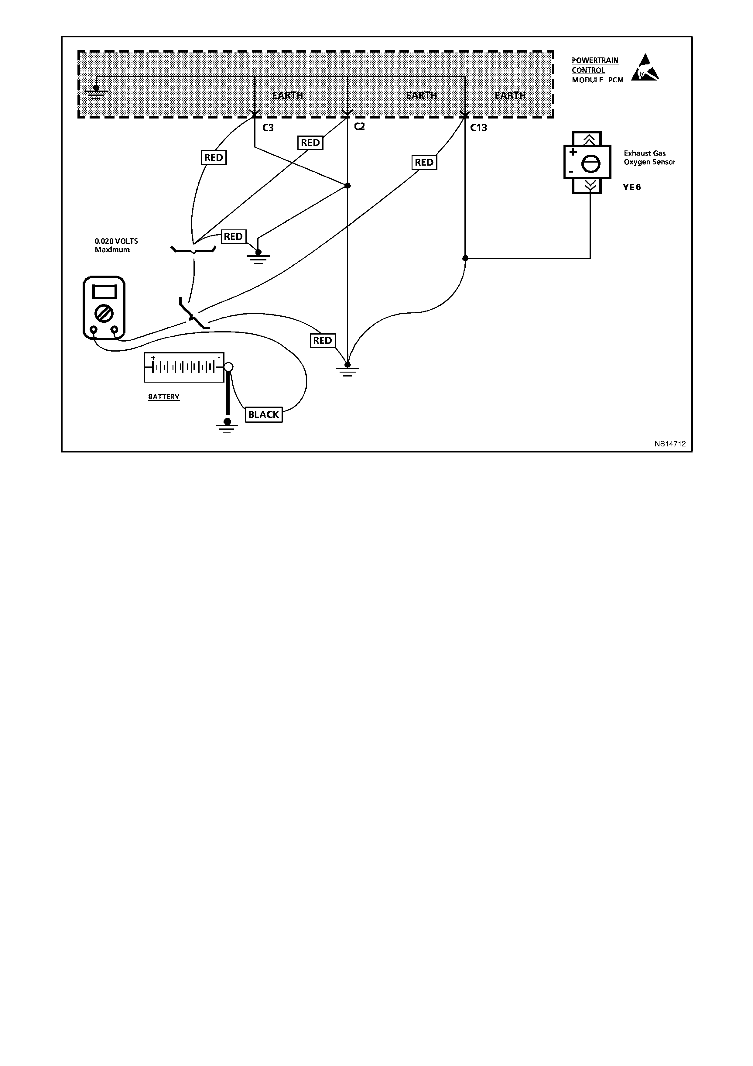
Figure 6C1-2B-8 Testing Voltage Drop After the PCM
EARTH CREDIBILITY CHECK
CIRCUIT DESCRIPTION:
The earth credibility check can be either used at the beginning of all diagnostic procedures or it can be used when
no diagnostic trouble codes are set, but a symptom still exists.
TEST DESCRIPTION:
Number(s) below refer to step number(s) on the diagnostic chart.
1. To properly test the voltage drop of the powertrain control module system earth a load must be present on the
circuit.
Using the scan tool:, select CANISTER PURGE. By turning "ON" the Purge solenoid, this will cause a sufficient
draw on the system for testing.
2. Check connectors in earth circuit to find where the excessive voltage is. Make sure to check both sides of in-
line connectors.
DIAGNOSTIC AIDS:
Because the powertrain control module operates on such small current even a minor corrosion problem will cause
problems with the system. Make sure the earths are clean and tight. Remember a good earth is about 25% of the
total systems circuit. Normally you will check the wiring for: power, continuity, the load, but rarely check the earth.
Powertrain control module system earths are very important to proper operation.
STEP ACTION VALUE YES NO
1.
Was the "On-Board
Diagnostic" (OBD) System
Check performed?
Go to Step 2. Go to OBD
System Check.
2. 1. Ignition "OFF"
2. Disconnect IAT sensor
connector.
3. Using digital volt ohm
meter set to DC voltage
scale, connect negative
lead to negative battery
cable at battery and
connect positive lead to
the black wire at the IAT
sensor connector.
4. Ignition "ON"
5. Using a scan tool, select
CANISTER PURGE.
6. Turn "ON'" Canister Purge
with up/down arrow keys.
7. Is voltage measured less
than value shown.
0.060
volts
(60 Milli-
volts)
No problem
found, continue
with symptom
diagnosis.
Go to Step 3
3. 1. Remove and thoroughly
clean the PCM earth
terminals and connection.
2. Reassemble the PCM
Earth terminals.
3. Is action complete?
Verify Repair

CORRECTING PROBLEMS IN EARTH CIRCUITS
Once a high resistance condition in a earth circuit has been located, you must determine the actual cause.
If the problem is at a connector, check for bent, corroded, or loose connector terminals. Terminals must have a
slight drag when disassembled/assembled. If they slide apart/together without resistance, they will not provide a
good connection.
If the problem is at a stud, bolt, or sheet metal screw, check for corrosion, paint, or loose connections. Paint can
be a very good insulator; good conductors, not insulators are needed for electrical connections.
Corrosion, paint, and other contaminants should be removed using a wire brush and/or emery cloth.
When assembling earth wire eyelet's on earth points, be sure an external type star washer is placed below the
wire eyelet(s). If the system is marginal, you can also place a star washer between the nut or the sheet-metal screw
and the top wire eyelet. Tighten the fastener to specification, making sure the star washer digs through any paint
into the mounting surface. Star washers also lock the fastener in place, preventing it from loosening.
All fasteners should be tightened so that the fastener head presses the earth wire eyelet or star washer to the
mounting surface and stops. Repair any stripped earth fasteners.
IMPORTANT:
Do not over-tighten sheet-metal screws. Over-tightening can enlarge the hole and create a bad earth. If the sheet-
metal is enlarged, the screw will continue to turn: drill a new correctly sized hole for the screw.