
SECTION 6C1-2C FUNCTIONAL CHECKS - V6
ENGINE
CAUTION
This vehicle will be equipped with a Supplemental Restraint System (SRS). A SRS
will consist of either seat belt pre-ten sioners and a driv er’s side air bag, or seat b elt
pre-tensioners and a driver’s and front passenger’s side air bags. Refer to
CAUTIONS, Section 12M, before performing any service operation on or around SRS
components, the steering mechanism or wiring. Failure to follow the CAUTIONS
could result in SRS deployment, resulting in possible personal injury or
unnecessary SRS system repairs.
CAUTION
This vehicle may be equipped with LPG (Liquefied Petroleum Gas). In the interests
of safety, the LPG fuel system should be isolated by turning 'OFF' the manual
service valve and then draining the LPG service lines, before any service work is
carried out on the vehicle. Refer to the LPG leaflet included with the Owner's
Handbook for details or LPG Section 2 for more specific servicing information.
NOTICE
When performing any of these Functional Checks, make certain that the drive
wheels are blocked and the parking brake is firmly set.
The following is to be used when there is a customer complaint but there are no diagnostic trouble codes set, but
one or more of the Tech 2 scan tool data values are not within typical values. Before using these charts you should
use the symptoms charts that may lead you to using this Section.
The purpose of these charts is to diagnosis Powertrain Control Module (PCM) controlled components or
subsystems that do not have diagnostic trouble codes assigned to them. Another purpose of these charts is for
technicians who feel confident that a particular part of the subsystem is not operating properly and wants to only
check that particular item for proper operation without going through lengthy diagnostic procedures.

4L60 E COMPONENT RESISTANCE CHART
COMPONENT TERMINAL WIRE
COLOUR PASS-THRU
CONNECTOR
TERMINAL
RESISTANCE
AT 20
DEGREES C
CIRCUIT
NO.
1-2 SHIFT
SOLENOID VALVE B R E* 19-24 OHMS 339
A LG A 1222
2-3 SHIFT
SOLENOID VALVE A R E* 19-24 OHMS 339
B Y B 1223
3-2 CONTROL
SOLENOID VALVE A R E* 20-24 OHMS 339
B W S 897
PRESSURE
CONTROL
SOLENOID VALVE
A V C 3-5 OHMS 1228
B LBLU D 1229
TRANSMISSION
FLUID
TEMPERATURE
SENSOR (TFT)
A BR L 3088 - 3942
OHMS 1227
B GY M 469
TCC "PWM"
SOLENOID VALVE AR E*9 - 14 OHMS 339
B BR U 418
TCC ENABLE
SOLENOID VALVE A R E* 21-26 OHMS 339
B B T 422
*Spliced internally to pin E
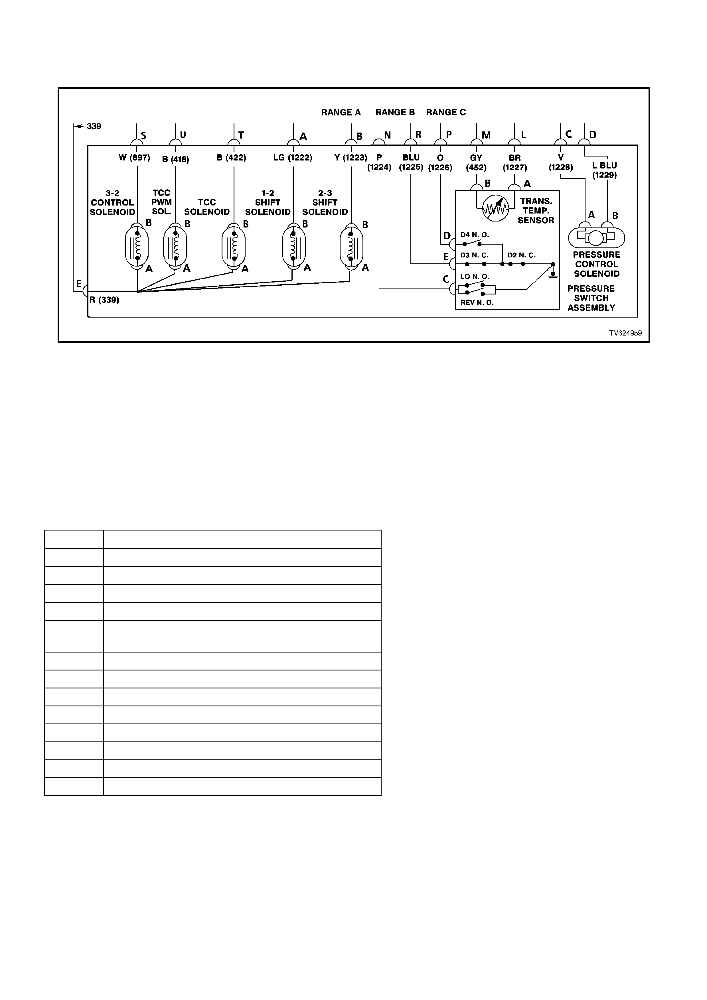
CHART 2.1 AUTOM ATIC TRANSMISSI ON WIRING
HARNESS ASSEMBLY CHECK
TOOLS REQUIRED:
J 39775 4L60-E Jumper Harness
J 39200 Digital Volt Multimeter (DVM)
J 35616 Connector Test Adapter Kit
IMPORTANT:
This procedure cannot be used for checking the Automatic Transmission Fluid Pressure Manual Valve Position
Switch (TFP Val. Position Sw.) circuit, or the Automatic Transmission Fluid Temperature (TFT) Sensor circuit. Refer
to TFP Valve Position Switch Assembly Resistance Check, for those circuits.
POWERTRAIN HARNESS TERMINAL
IDENTIFICATION
CAVITY FUNCTION
A 1-2 SHIFT SOLENOID (LOW)
B 2-3 SHIFT SOLENOID (LOW)
C PRESSURE CONTROL SOLENOID (HIGH)
D PRESSURE CONTROL SOLENOID (LOW)
E BOTH SHIFT SOLENOIDS , TCC SOLENOID,
AND 3-2 CONTROL SOLENOID (HIGH)
L TRANSMISSION FLUID TEMPERATURE HIGH
M TRANSMISSION FLUID TEMPERATURE (LOW)
N RANGE SIGNAL "A"
P RANGE SIGNAL "C"
R RANGE SIGNAL "B"
S 3-2 CONTROL SOLENOID (LOW)
T TCC SOLENOID (LOW)
U TCC PWM SOLENOID

STEP ACTION VALUE YES NO
11. Install the J 39775
Jumper Harness on
the transmission pass-
thru connector.
2. Using a J 39200 DVM
and a J 35616
Connector Test
Adapter Kit, measure
the resistance between
terminals A and E (1-2
Shift Solenoid Valve).
Is the resistance within
the specified range?
19-24 W
@ 20° C
24-31W
@ 100°
C
Go to Step 3 Go to Step 2
21. Disconnect the 1-2
Shift Solenoid Valve
(1-2 SS Valve) from
the Automatic
Transmission Wiring
Harness Assembly.
2. Using the J 39200
DVM, measure the
resistance of the 1-2
SS Valve.
Is the resistance within
the specified range?
19-24 W
@ 20° C
24-31 W
@ 100°
C
Go to Step 14 Go to Step 16
3Measure the resistance
between terminals B and
E (2-3 Shift Solenoid
Valve).
Is the resistance within
the specified range?
19-24 W
@ 20° C
24-31 W
@ 100°
C
Go to Step 5 Go to Step 4
41. Disconnect the 2-3
Shift Solenoid Valve
(2-3 SS Valve) from
the Automatic
Transmission Wiring
Harness Assembly.
2. Using the J 39200
DVM, measure the
resistance of the 2-3
SS Valve.
Is the resistance within
the specified range?
19-24 W
@ 20° C
24-31 W
@ 100°
C
Go to Step 14 Go to Step 16
5Measure the resistance
between terminals T and
E (Torque Converter
Clutch Solenoid Valve).
Is the resistance within
the specified range?
21-26 W
@ 20° C
26-33 W
@ 100°
C
Go to Step 6 Go to Step 14
6Measure the resistance
between terminals U and
E (Torque Converter
Clutch Pulse Width
Modulation Solenoid
Valve).
Is the resistance within
the specified range?
10-11 W
@ 20° C
13–15
W
@ 100°
C
Go to Step 8 Go to Step 7

STEP ACTION VALUE YES NO
71. Disconnect the TCC
PWM Solenoid. Valve
from the Automatic
Transmission Wiring
Harness Assembly.
2. Using the J 39200
DVM, measure the
resistance of the TCC
PWM Solenoid. Valve.
Is the resistance within
the specified range?
10-11 W
@ 20° C
13–15
W
@ 100°
C
Go to Step 14 Go to Step 16
8Measure the resistance
between terminals S and
E (3-2 Shift Solenoid
Valve assembly).
Is the resistance within
the specified range?
20-24 W
@ 20° C
29-32 W
@ 100°
C
Go to Step 10 Go to Step 9
91. Disconnect the 3–2
Shift Solenoid Valve
Assembly (3-2 SS
Valve Assy.) from the
Automatic
Transmission Wiring
Harness Assembly.
2. Using the J 39200
DVM, measure the
resistance of the 3-2
SS Valve Assy.
Is the resistance within
the specified range?
20-24 W
@ 20° C
29-32 W
@ 100°
C
Go to Step 14 Go to Step 16
10 Measure the resistance
between terminals C and
D (Pressure Control
Solenoid Valve).
Is the resistance within
the specified range?
3-5 W
@ 20° C
4-7 W
@ 100°
C
Go to Step 12 Go to Step 11
11 1. Disconnect the
Pressure Control
Solenoid Valve (PC
Sol. Valve) from the
Automatic
Transmission Wiring
Harness Assembly.
2. Using the J 39200
DVM, measure the
resistance of the PC
Sol. Valve.
Is the resistance within
the specified range?
3-5 W
@ 20° C
4-7 W
@ 100°
C
Go to Step 14 Go to Step 16

STEP ACTION VALUE YES NO
12 Using the J 39200 DVM
and the J 35616
Connector Test Adapter
Kit, measure the
resistance from each of
the terminals A, B, C, D,
E, S, T and U of the A/T
Wiring Harness Assembly
at the transmission pass-
thru connector to the
transmission case .
Is the resistance more
than the specified value?
250k W System OK, exit
the table Go to Step 13
13 1. Disconnect the A/T
Wiring Harness
Assembly from all the
components.
2. Measure the
resistance from each
of the component
terminals to the
transmission case .
Is the resistance more
than the specified value?
250k W Go to Step 14 Go to Step 16

STEP ACTION VALUE YES NO
14 Inspect for high resistance
or a short.
Inspect the A/T Wiring
Harness Assembly at the
transmission pass-thru
connector, and the
component connectors for
the following conditions:
• Poor electrical
connections
• Bent, backed-out, or
damaged terminals
• Weak terminal tension
• A chafed wire that
could short to bare
metal or other wiring
• A broken wire inside
the insulation
• Moisture intrusion
• Corrosion
If diagnosing for a
possible intermittent
condition, move or
massage the A/T Wiring
Harness Assembly while
observing the test
equipment for a change.
Did you find and correct
the high resistance or a
short?
— Verify the repair
Go to Step 1 Go to Step 15
15 Replace the Automatic
Transmission Wiring
Harness Assembly. Refer
to Service Operations in
Section 7C-5.
Is the action complete?
— Verify the repair
Go to Step 1 —
16 Replace the faulty
component. Refer to
Service Operations in
Section 6C1-3.
Is the action complete?
— Verify the repair
Go to Step 1 —

CHART 2.2 TRANSMISSION FLUID PRESSURE MANUAL
VALVE POSITION SWITCH CHECK
TOOLS REQUIRED:
J 39775 4L60E Jumper Harness
J 39200 Digital Volt Multimeter
J 35616 Connector Test Adapter Kit
IMPORTANT:
Whenever the transmission pass-thru connector is disconnected and the engine is running, multiple DTCs will set.
Be sure to clear these codes when you are finished with this procedure.
IMPORTANT:
This procedure tests the Automatic Transmission Fluid Pressure Manual Valve Position Switch (TFP Val. Position
Sw.) circuits and the Automatic Transmission Fluid Temperature (TFT) Sensor circuit. Do not use this procedure to
test other Automatic Transmission circuits, refer to 4L60–E Automatic Transmission Internal Wiring Harness check.

STEP ACTION VALUE YES NO
11. Install the J 39775
Jumper Harness on
the transmission side
of the pass-thru
connector.
2. Using the J 39200
DVM and the J 35616
Connector Test
Adapter Kit, measure
the resistance from
terminal N to the
transmission case .
Is the resistance greater
than the specified value?
50 k W Go to Step 3 Go to Step 2
21. Disconnect the TFP
Value Position Switch
from the A/T Wiring
Harness Assembly.
2. Measure the
resistance from
terminal C of the TFP
Value Position Switch
to the switch housing.
Is the resistance greater
than the specified value?
50 k W Go to Step 16 Go to Step 19
3Measure the resistance
from terminal R to the
transmission case .
Is the resistance less than
the specified value?
200 W Go to Step 5 Go to Step 4
41. Disconnect the TFP
Value Position Switch
from the A/T Wiring
Harness Assembly.
2. Measure the
resistance from
terminal E of the TFP
Value Position Switch
to the switch housing.
Is the resistance less than
the specified value?
200 W Go to Step 16 Go to Step 19
5Measure the resistance
from terminal P to the
transmission case .
Is the resistance greater
than the specified value?
50 k W Go to Step 7 Go to Step 6
61. Disconnect the TFP
Value Position Switch
from the A/T Wiring
Harness Assembly.
2. Measure the
resistance from
terminal D of the TFP
Value Position Switch
to the switch housing.
Is the resistance greater
than the specified value?
50 k W Go to Step 16 Go to Step 19

STEP ACTION VALUE YES NO
71. Start the engine.
2. Allow the engine to
idle.
3. Set the parking brake.
4. Place the gear selector
in Reverse.
5. Measure the
resistance from
terminal N to the
transmission case .
Is the resistance less than
the specified value?
200 W Go to Step 8 Go to Step 16
81. Place the gear selector
in Low (D1).
2. Measure the
resistance from
terminal N to the
transmission case .
Is the resistance less than
the specified value?
200 W Go to Step 9 Go to Step 16
91. Place the gear selector
in Manual Third (D3).
2. Measure the
resistance from
terminal R to the
transmission case .
Is the resistance greater
than the specified value?
50 k W Go to Step 10 Go to Step 16
10 1. Place the gear selector
in Drive (D4).
2. Measure the
resistance from
terminal P to the
transmission case .
Is the resistance less than
the specified value?
200 W Go to Step 11 Go to Step 16
11 1. Place the gear selector
in Manual Second
(D2).
2. Measure the
resistance from
terminal P to the
transmission case .
Is the resistance greater
than the specified value?
50 k W Go to Step 12 Go to Step 16
12 1. Turn the ignition OFF.
IMPORTANT:
The resistance of the TFT
Sensor is temperature
dependent, and therefore
varies far more than any
other device.
2. Measure the
resistance from
terminal L to terminal
M (TFT Sensor) of the
Jumper Harness.
Is the resistance within
the specified range?
3088-
3942 W
@ 20° C
159-
198 W
@ 100°
C
Go to Step 13 Go to Step 14

STEP ACTION VALUE YES NO
13. 1. Measure the
resistance from
terminal L to the
transmission case .
2. Measure the
resistance from
terminal M to the
transmission case .
Are both resistance’s
greater than the specified
value?
10 M W No problem
found. Exit the
table.
Go to Step 14
14 1. Disconnect the TFP
Value Position Switch
from the A/T.
2. Wiring Harness
Assembly.
IMPORTANT:
The resistance of the TFT
Sensor is temperature
dependent, and therefore
varies far more than any
other device. Refer to
Transmission Fluid
Temperature Sensor in
Section 6C1-1 - General
Information.
3. Using the J 39200
DVM, measure the
resistance between
terminal A and terminal
B of the TFP Value
Position Switch (TFT
Sensor).
Is the resistance within
the specified range?
3088–
3942 W
@ 20° C
159-
198 W
@ 100°
C
Go to Step 15 Go to Step 19
15 1. Measure the
resistance from TFP
Value Position Switch
terminal A to the
transmission case .
2. Measure the
resistance from TFP
Value Position Switch
terminal B to the
transmission case .
Are both resistance's
greater than the specified
value?
10 M W Go to Step 16 Go to Step 19

STEP ACTION VALUE YES NO
16 1. Inspect for high
resistance or a short.
2. Inspect the A/T Wiring
Harness Assembly for
poor electrical
connections at the A/T
pass-thru connector,
and at the TFP Value
Position Switch Look
for the following
problems:
• A bent terminal
• A backed out terminal
• A damaged terminal
• Poor terminal tension
3. If diagnosing for an
intermittent problem,
massage the wiring
harness while watching
the test equipment for
a change.
Did you find and correct
the high resistance or a
short?
— Verify the repair
Go to Step 1 Go to Step 17
17 1. Disconnect the TFP
Value Position Switch
from the A/T Wiring
Harness Assembly.
2. Inspect the following
circuits for an open or
short:
• Circuit 1224
• Circuit 1225
• Circuit 1226
• Circuit 1227 (TFT Hi)
• Circuit 469 (TFT Lo)
Did you find a problem?
— Go to Step 18 Go to Step 19
18 Replace the A/T Wiring
Harness Assembly.
Refer to Automatic
Transmission Wiring
Harness Assembly
Replacement, in Service
Operations Section 7C-5.
Is the action complete?
— Verify the repair
Go to Step 1 —
19 Replace the TFP Value
Position Switch.
Refer to Automatic
Transmission Fluid
Pressure Manual Valve
Position Switch
Replacement. Refer to
Service Operations in
Section 6C1-3.
Is the action complete?
— Verify the repair
Go to Step 1 —
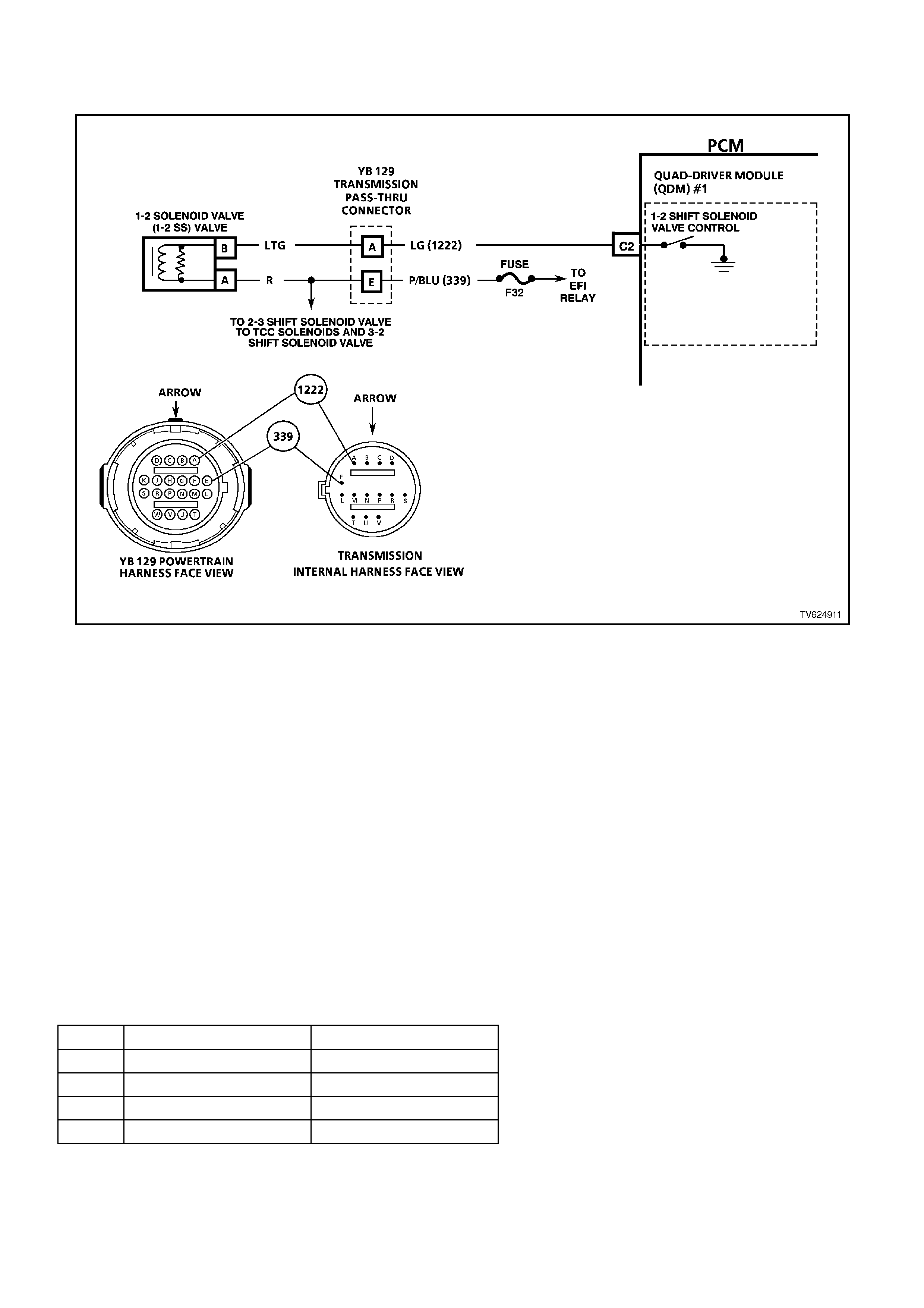
CHART 2.3 V6 PCMCHART 2.3 1-2 SHIFT SOLENOID
PERFORMANCE CHECK
CIRCUIT DESCRIPTION:
The 1-2 Shift Solenoid Valve (1-2 SS Valve) controls the fluid flow acting on the 1-2 and 3-4 shift valves. The 1-2
SS Valve is a normally-open exhaust valve that is used with the 2-3 Shift Solenoid Valve (2-3 SS Valve), in order to
allow four different shifting combinations.
This functional check is useful for diagnosing unusual shift patterns that result from a mechanical fault of the 1-2
shift solenoid or the shift valve. A 1-1-4-4 shift pattern indicates that the shift solenoid or the shift valve is stuck ON.
The stuck ON condition could be caused by the solenoid not exhausting fluid or the shift valve remaining in the
applied position. Similarly, a 2-2-3-3 shift pattern indicates that the shift solenoid or the shift valve is stuck OFF.
The stuck OFF condition could be caused by the solenoid exhausting fluid or the shift valve remaining in the non-
applied position.
TEST DESCRIPTION:
The numbers below refer to the step numbers on the diagnostic chart.
3. This step tests that the scan tool commanded all shifts and all shift solenoid valves responded correctly, but all
the shifts did not occur. Refer to the table below.
DIAGNOSTIC AIDS:
• Verify that the transmission shift speeds are within specifications.
• Other internal transmission faults may cause more than one shift to occur.
• Refer to the following chart for the correct On and Off states of the shift solenoids.
•
GEAR 1-2 SHIFT SOLENOID 2-3 SHIFT SOLENOID
1ON ON
2OFF ON
3OFF OFF
4ON OFF

STEP ACTION VALUE YES NO
1Was the On-Board
Diagnostic (OBD) System
Check performed?
— Go to Step 2 Go to OBD
System Check
21. Install the scan tool.
2. With the engine OFF,
turn the ignition switch
to the RUN position.
3. While the engine is
operating, raise the
drive wheels.
4. With the transmission
in D4 range, use the
scan tool to command
1st, 2nd, 3rd and 4th
gears while
accelerating the
vehicle. Road testing
the vehicle may be
necessary.
Did you detect a 1-1-4-4
or a 2-2-3-3 only shift
pattern?
— Go to Step 3 Go to “Diagnostic
Aids” above
3Check the shift
solenoid/hydraulic circuit
for:
• An internal
malfunction.
• Damaged seals on the
shift solenoid valves.
Refer to the symptom
diagnosis charts.
Did you find and correct a
problem?
— Go to Step 4 Go to “Diagnostic
Aids” above
4In order to verify your
repair, perform the
following procedure:
1. Select DTC.
2. Select Clear Info.
3. Operate the vehicle
under the following
conditions (only if
traffic and road
conditions permit):
• With the transmission
in D4 range, use the
scan tool to command
1st, 2nd, 3rd and 4th
gears while
accelerating the
vehicle.
Did you detect a 1-1-4-4
or 2-2-3-3 only shift
pattern?
__ Begin the
diagnosis again.
Go to Step 1
Repair Verified,
exit table
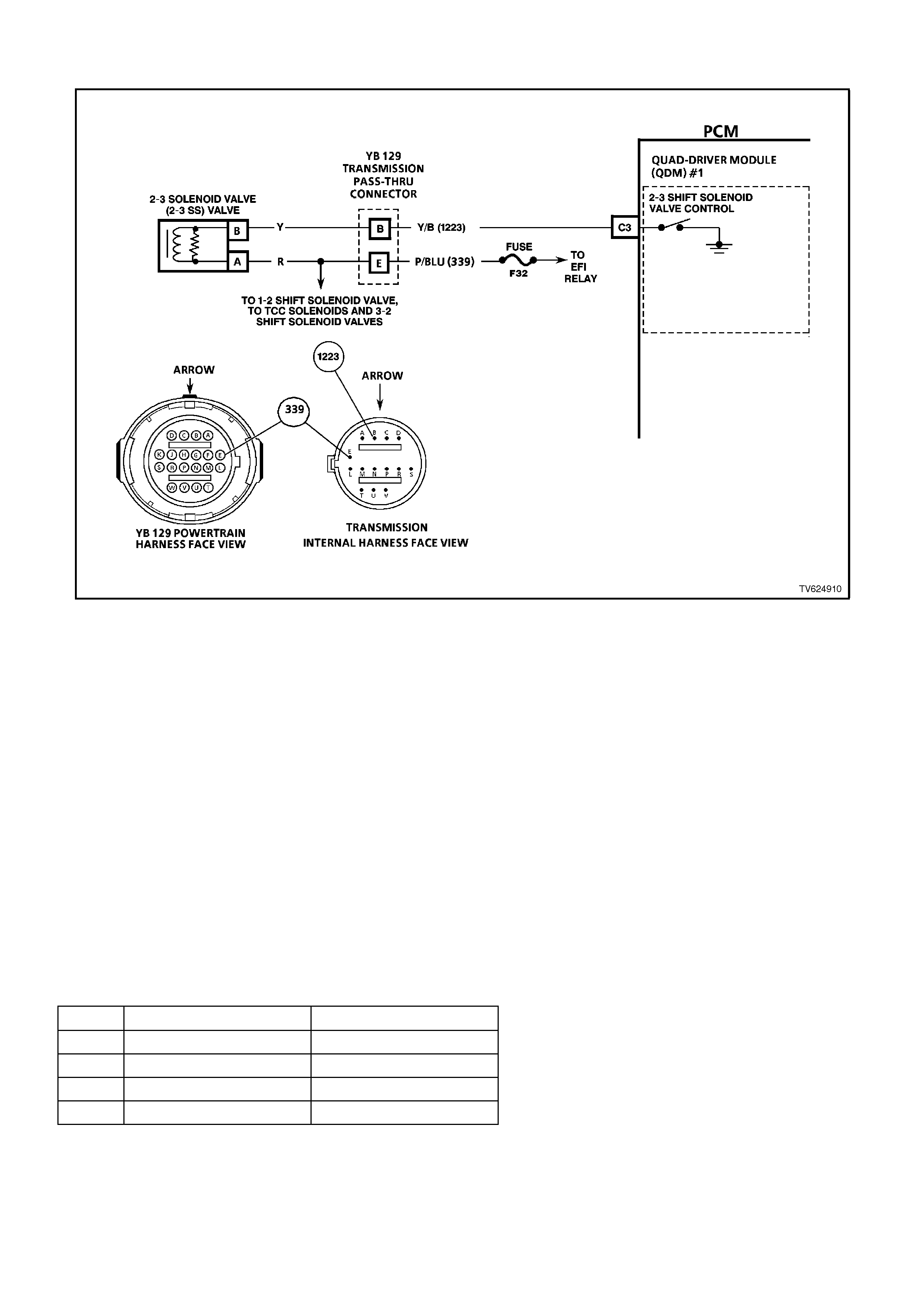
CHART 2.4 2-3 SHIFT SOLENOI D PERFORMANCE CHECK
CIRCUIT DESCRIPTION:
The 2-3 Shift Solenoid Valve (2-3 SS Valve) controls the fluid flow acting on the 2-3 shift valves. The 2-3 SS Valve
is a normally-open exhaust valve that is used with the 1-2 Shift Solenoid Valve (1-2 SS Valve) in order to allow four
different shifting combinations.
This functional check is useful for diagnosing unusual shift patterns that result from a mechanical failure of the 2-3
shift solenoid or the shift valve. A 1-2-2-1 shift pattern indicates that the shift solenoid or the shift valve is stuck ON.
The stuck ON condition could be caused by the solenoid not exhausting fluid or the shift valve remaining in the
applied position. Similarly, a 4-3-3-4 shift pattern indicates that the shift solenoid or the shift valve is stuck OFF.
The stuck OFF condition could be caused by the solenoid exhausting fluid or the shift valve remaining in the non-
applied position.
TEST DESCRIPTION:
The numbers below refer to the step numbers on the diagnostic chart.
3. This verifies that the scan tool commanded all the shifts, and all the shift solenoids responded correctly, but all
the shifts did not occur. Refer to the table below.
DIAGNOSTIC AIDS:
• Verify that the transmission shift speeds are within specifications.
• Other internal transmission faults may cause more than one shift to occur.
• Refer to the following chart for the correct On and Off states of the shift solenoids.
•
GEAR 1-2 SHIFT SOLENOID 2-3 SHIFT SOLENOID
1ON ON
2OFF ON
3OFF OFF
4ON OFF

STEP ACTION VALUE YES NO
1Was the On-Board
Diagnostic (OBD) System
Check performed?
— Go to Step 2 Go to OBD
System Check
21. Install the scan tool.
2. With the engine OFF,
turn the ignition switch
to the RUN position.
3. While the engine is
operating, raise the
drive wheels.
4. With the transmission
in D4 range, use the
scan tool to command
1st, 2nd, 3rd, and 4th
gears while
accelerating the
vehicle. Road testing
the vehicle may be
necessary.
Did you detect a 1-2-2-1
or 4-3-3-4 only shift
pattern?
— Go to Step 3 Go to “Diagnostic
Aids” above
3Check the shift
solenoid/hydraulic circuit
for:
• An internal malfunction
• Damaged seals
Refer to the symptom
diagnosis charts in
Section 6C1-2B.
Did you find and correct a
problem?
— Go to Step 4 Go to “Diagnostic
Aids” above
4In order to verify your
repair, perform the
following procedure:
1. Select DTC.
2. Select Clear Info.
3. Operate the vehicle
under the following
conditions (only if
traffic and road
conditions permit):
• With the transmission
in D4 range, use the
scan tool to command
1st, 2nd, 3rd and 4th
gears while
accelerating the
vehicle.
Did you detect a 1-2-2-1
or a 4-3-3-4 only shift
pattern?
— Begin the
diagnosis again
Go to Step 1
Repair Verified,
exit table
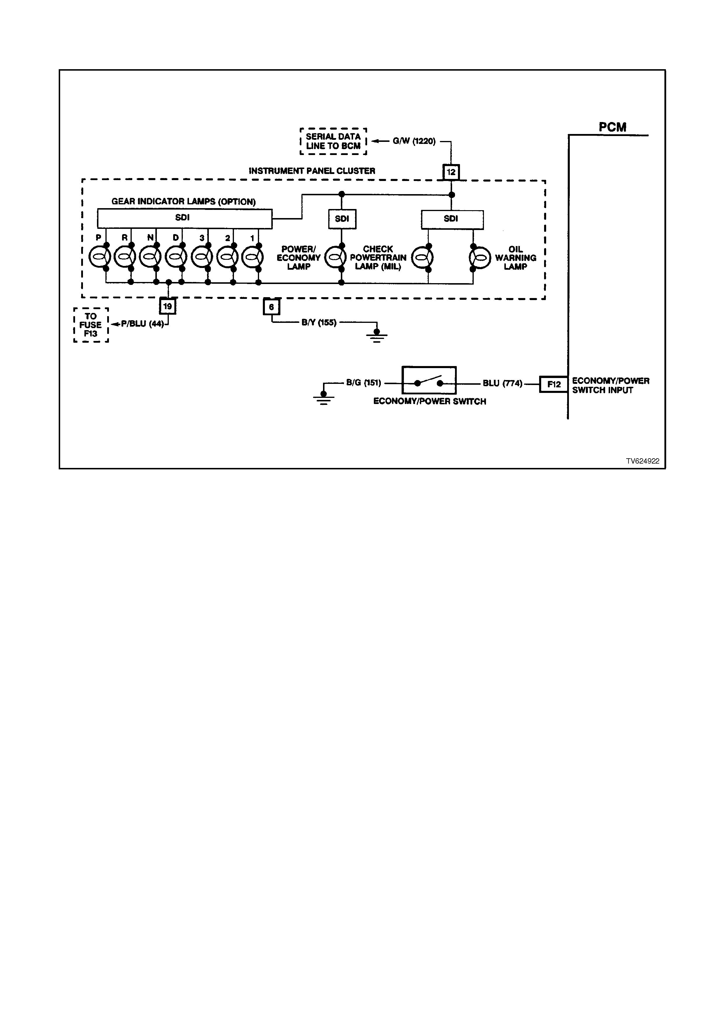
CHART 2.5 TRANSMISSION ECONOM Y/POWER SWITCH
CIRCUIT DESCRIPTION:
The driver can select two transmission shift modes, "ECONOMY" or "POWER" using a dash or center console
mounted switch. This switch is wired to the PCM and allows the driver to choose the "Economy" mode, for the best
fuel economy in all driving conditions through the increased use of TCC, or the "Power" mode which provides later
upshifts and higher line pressure in the transmission.
The PCM sends out a buffered voltage signal, about 12 volts, and monitors the status of this circuit. In the
"Economy" position, the switch is open and the PCM voltage status signal remains high at about 12 volts. The PCM
does not allow shift point changes with this condition. When the transmission switch is pressed to "Power", the
switch is closed and the PCM voltage status signal is pulled low, to about 0.5 volts. The PCM senses this voltage
drop on circuit 774 and enables power mode shifting only if other criteria such as throttle position, engine load and
engine speed are met.
TEST DESCRIPTION:
The numbers below refer to step numbers on the diagnostic chart.
2. This step tests for proper operation of the transmission POWER switch, the wiring and the PCM.
3. This step tests for proper POWER lamp illumination, when the power switch is On.
4. This step tests for a shorted power switch or a short to earth on circuit 774.
5. This step tests for an open in the bulb circuit.
10. Some interior parts must be removed to disconnect the transmission switch, refer to Section 1A1, BODY.
This step simulates a closed switch if the earth circuit is OK.

STEP ACTION VALUE YES NO
1Was the On-Board
Diagnostic (OBD) System
Check
performed?
_ Go to Step 2 Go to OBD
System Check
2With the engine OFF, turn
the ignition switch to the
RUN position.
Install the scan tool.
Place the Transmission
POWER switch in the
POWER position and
observe the scan tool
display.
Does the scan tool
display POWER?
_ Go to Step 3 Go to Step 10
3Is the POWER lamp ON,
when the scan tool
displays POWER?
_ Go to Step 4 Go to Step 5
4Place the Transmission
POWER switch in the
ECONOMY position and
observe the scan tool
display.
Does the scan tool display
ECONOMY?
_ Go to Step 6 Go to Step 7
5Check for an open in the
POWER lamp bulb, or the
bulb feed circuit.
Did you find and correct
the open condition?
_ Verify the Repair _
6Does the POWER lamp
go off, when the scan tool
displays ECONOMY?
_ No Trouble
Found.
ECONOMY/
POWER switch
electrically OK.
Refer to Section
6C1-2B
SYMPTOMS
"Intermittents".
Go to Step 8
7Disconnect the POWER
switch from the wiring
harness connector.
Does the scan tool display
ECONOMY?
_ Go to Step 12 Go to Step 9
8Check for a short to earth
on the POWER lamp
circuit in the instrument
panel cluster.
Did you find and correct
the short to earth
condition?
_ Verify the Repair _
9Check for a short to earth
in circuit 774.
Did you find and correct
the short to earth
condition?
_ Verify the Repair Go to Step 16

STEP ACTION VALUE YES NO
10 Disconnect the POWER
switch from the wiring
harness connector.
Using a fused jumper
wire, connect the two
terminals of the POWER
switch wiring harness
connector together.
Does the scan tool display
POWER?
_ Go to Step 12 Go to Step 11
11 Using a fused jumper
wire, connect circuit 774
to earth.
Does the scan tool display
POWER?
_ Go to Step 15 Go to Step 14
12 Check the POWER switch
connector for a shorted or
a loose terminal
connection.
Did you find and correct
the faulty condition?
_ Verify the Repair Go to Step 13
13 Replace the faulty
POWER switch.
Is the action complete?
_ Verify the Repair _
14 Check for an open circuit
or a faulty PCM
connection on circuit 774.
Did you find and correct
the open circuit?
_ Verify the Repair Go to Step 16
15 Check for an open in
circuit 151 to earth.
Did you find and correct
the open circuit?
_ Verify the Repair _
16 Replace the faulty PCM.
Refer to Section 6C1-3
Service Operations, for
the Security Link
procedure.
Is the action complete?
_ Verify the Repair _
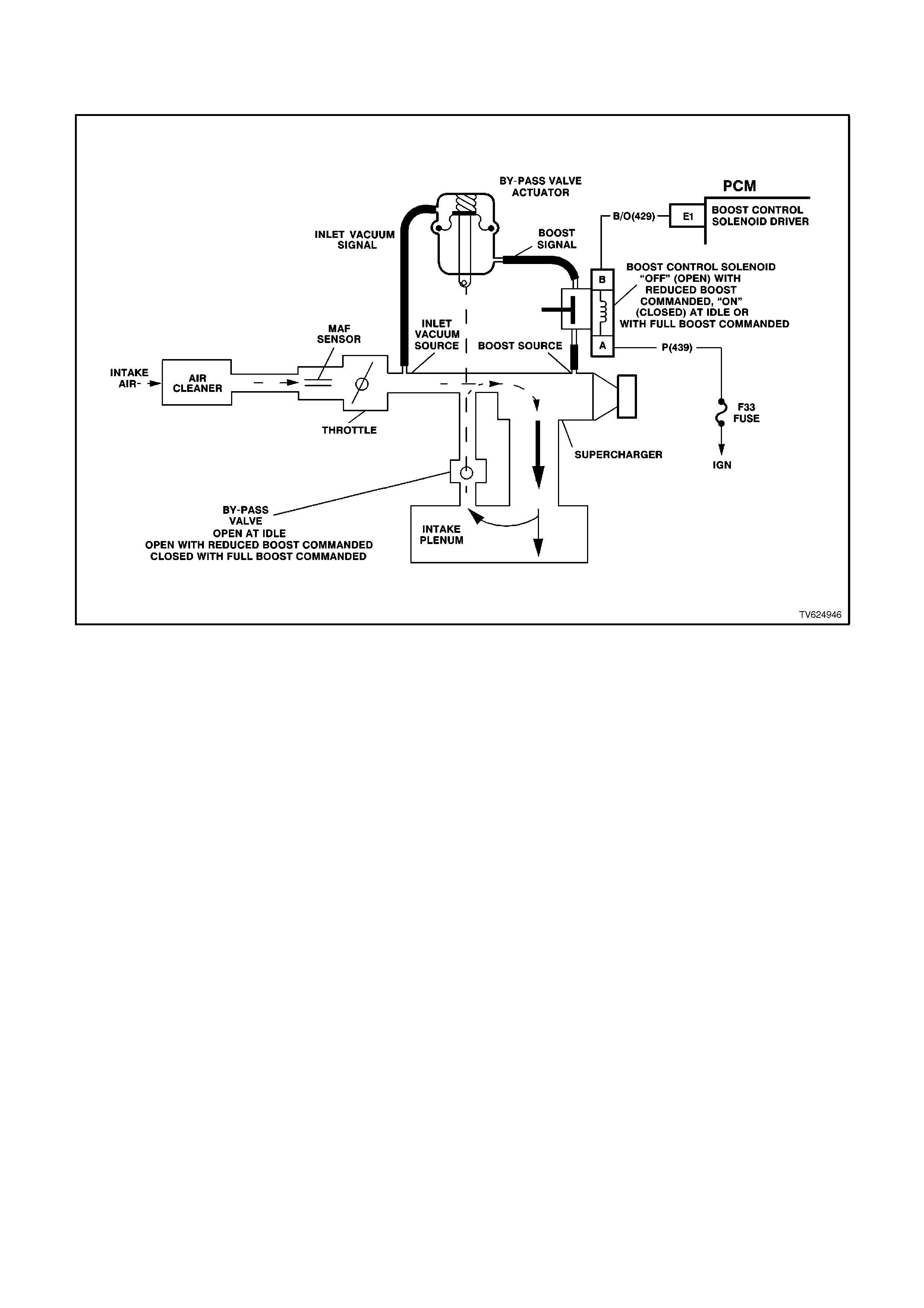
CHART 2.6 V6 PCM SUPERCHARGED ENGINE
BOOST CONTROL SYSTEM FUNCTIONAL CHECK
CIRCUIT DESCRIPTION:
Under most conditions, the PCM commands the Boost Control Solenoid to operate at 100% duty cycle ("ON") to
allow full boost pressure upon demand. However, if reverse gear is selected or the PCM detects rapid deceleration
or engine load is extremely high, reduced boost pressure is desired. Under these 3 conditions, the PCM commands
the Boost Control Solenoid to operate at a 0% duty cycle ("OFF"), which opens the bypass valve. With the bypass
valve open, boost pressure is reduced by recirculating intake air back through the supercharger inlet.
NOTICE:
When performing this diagnostic Chart, make certain that the drive wheels are blocked and the parking
brake is firmly set.
TEST DESCRIPTION:
Number(s) below refer to step number(s) on the diagnostic chart.
2. Verifies ignition feed to the Boost Control Solenoid.
3. The Boost Control Solenoid should be commanded "OFF" (0% duty cycles) with the ignition "ON", engine not
running. If the system is functioning properly, the test light should be "OFF".
4. Ensures that the PCM can control the ODM output for the Boost Control Solenoid and Boost Control Solenoid
driver circuit is not open.
5. Checks for a faulty Boost Control Solenoid (sticking open or leaking).

DIAGNOSTIC AIDS:
If this Chart has been performed and no electrical or vacuum related fault is noted, check for the following
conditions:
• Misadjusted or sticking Bypass Valve Actuator.
• Binding Bypass Valve or Bypass Valve linkage.
Refer to Section 6C1-3 SERVICE OPERATIONS for bypass valve actuator service and adjustment procedure. If
no problem is found and a driveability symptom still exists, refer to Symptoms Section 6C1-2B.
An intermittent may be caused by a poor connection, rubbed through wire insulation, or a wire broken inside the
insulation. Check for the following conditions:
Poor connection or Damaged Harness - Inspect PCM harness connector for backed out terminals, improper mating,
improperly formed or damaged terminals, poor terminal to wire connection and damaged harness.
Intermittent Test - Disconnect PCM and install a DVM to monitor voltage between the Boost Control Solenoid driver
circuit at the PCM connector and earth. With the key "ON", observe voltage while manipulating related connectors
and wiring harness. If the failure is induced, the voltage display will change. This may indicate the location of the
fault.
STEP ACTION VALUE YES NO
1. Was the "On-Board
Diagnostic" (OBD) System
Check performed?
Go to Step 2. Go to OBD
System Check in
this Section.
2. 1. Unbolt Boost Control
Solenoid from engine,
to gain axis to
solenoid.
2. Disconnect the Boost
Control Solenoid
electrical connector.
3. Ignition "ON".
4. Install a test light
between the ignition
feed circuit at the
Boost Control Solenoid
harness connector and
engine earth.
Is the test light "ON"?
Go to step 3 Go to step 11
3. Connect the test light
between the Boost
Control Solenoid harness
connector terminals.
Is the test light "ON"?
Go to step 14 Go to step 4
4. 1. Ignition "ON", engine
idling.
2. Set vehicles parking
brake.
3. With the test light still
connected to the Boost
Control Solenoid,
observe the test light.
Is the test light "ON" while
the engine is running?
Go to step 5 Go to step 16

STEP ACTION VALUE YES NO
5. 1. Reconnect the Boost
Control Solenoid
electrical connector.
2. Disconnect the boost
signal hose between
the Boost Control
Solenoid and the
Bypass Valve Actuator.
3. Connect a vacuum
gauge to read the
boost signal from the
Boost Control
Solenoid.
4. Start the engine and
idle in park.
5. Observe the vacuum
gauge reading.
Does the vacuum gauge
indicate near the specified
value?
0 cm
0 in.Hg Go to step 6 Go to step 17
6. 1. With engine still idling,
shift vehicle into
reverse gear.
2. Observe the vacuum
gauge.
Does the vacuum gauge
indicate greater than the
specified value with the
Boost Control Solenoid
turned "OFF when vehicle
is shifted into reverse
gear"?
38 cm
15 in.Hg Go to step 7 Go to step 10
7. 1. Check for a restriction
in the boost signal
hose between the
Boost Control Solenoid
and the Bypass Valve
Actuator.
2. If a problem is found,
repair as necessary.
Was a problem found.
Go to step 21 Go to step 8
8. 1. Reconnect the boost
signal hose between
the Boost Control
Solenoid and the
Bypass Valve Actuator.
2. Connect the vacuum
gauge to read the inlet
vacuum signal to the
Bypass Valve Actuator.
3. Start the engine and
idle in park.
4. Observe the vacuum
gauge reading.
Does the vacuum gauge
indicate greater than the
specified value?
38 cm
15 in.Hg Refer to
Diagnostic Aids Go to step 9

STEP ACTION VALUE YES NO
9. Repair the restriction in
the inlet vacuum signal
hose to the Bypass Valve
Actuator or blocked inlet
vacuum source.
Is action complete?
Go to step 21
10. 1. Check for a restriction
in the boost source
hose to the Boost
Control Solenoid.
2. If a problem is found,
repair as necessary.
Was a problem found?
Go to step 21 Go to step 18
11. Check the fuse for the
Boost Control Solenoid
ignition feed circuit.
Is the fuse blown?
Go to step 12 Go to step 13
12. Locate and repair short to
earth in the ignition feed
circuit.
Is action complete?
Go to step 21
13. Locate and repair open in
the ignition feed circuit to
the Boost Control
Solenoid .
Is action complete?
Go to step 21
14. 1. Ignition "OFF",
disconnect the PCM .
2. Ignition "ON", observe
the test light.
Is the test light "ON"?
Go to step 15 Go to step 20
15. Locate and repair short to
earth in Boost Control
Solenoid driver circuit.
Is action complete?
Go to step 21
16. 1. Ignition "OFF",
disconnect the PCM.
2. Ignition "ON".
3. Check the Boost
Control Solenoid driver
circuit for an open or a
short to voltage.
4. If a problem is found,
repair as necessary.
Was a problem found?
Go to step 21 Go to step 19
17. 1. Check for poor
terminal connections at
the Boost Control
Solenoid .
2. If a problem is found,
repair as necessary.
Was a problem found?
Go to step 21 Go to step 18
18. Replace the Boost Control
Solenoid .
Is action complete?
Go to step 21

STEP ACTION VALUE YES NO
19. 1. Check the Boost
Control Solenoid driver
circuit for a poor
terminal connection at
the PCM.
2. If a problem is found,
repair as necessary.
Was a problem found?
Go to step 21 Go to step 20
20. Replace the PCM.
Is action complete? Go to step 21
21. 1. Ignition "ON", engine
idling in park.
2. Disconnect inlet
vacuum signal hose to
Bypass Valve Actuator.
Bypass valve Actuator
linkage should move
when the signal hose is
removed, does it?
Go to step 22 Go to
“Diagnostic Aids”
22. 1. Ignition "OFF".
2. Connect a vacuum
gauge to the Boost
Control Solenoid.
3. Ignition "ON, engine
idling in park.
Does the vacuum gauge
indicate near the specified
value?
0 cm
0 in.Hg Go to step 23 Go to step 17
23 1. Set vehicle parking
brake.
2. Ignition "ON", engine
idling in park.
3. With vacuum gauge
still connected to Boost
Control Solenoid, shift
transmission into
reverse gear.
Does the vacuum gauge
now read at or above the
specified value when the
transmission is shifted
into reverse gear?
38 cm
15 in.Hg Go to step 24 Go to step 10
24 1. Reconnect vacuum
hose to Boost Control
Solenoid.
2. Reinstall Boost Control
Solenoid to engine.
Is action complete?
System is working
properly
Refer to
‘Diagnostic Aids‘
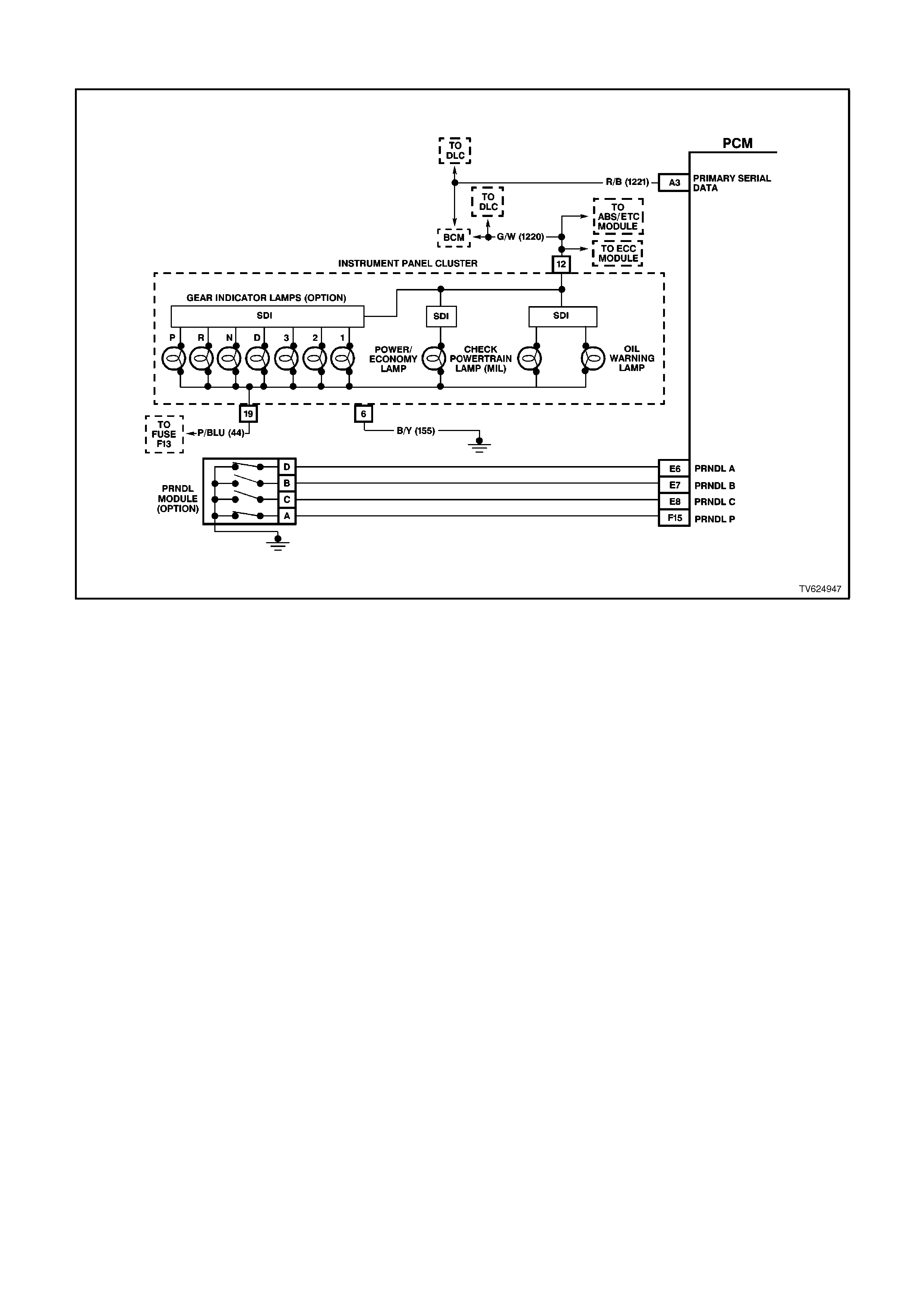
CHART 2.7 V6 PCM INSTRUMENT PANEL GEAR I NDICATOR CHECK
CIRCUIT DESCRIPTION:
The transmission PRNDL module is a mulit-signal switch which sends a signal to the PCM to indicate gear
selection. The PCM will then determine the signal from the PRNDL module and send a command vie serial data
communication to the instrument panel cluster to turn "ON" the proper gear indicator lamp for the gear that is being
selected.
The PRNDL module uses four (4) discrete circuits to pull four (4) PCM voltages low in various combinations to
indicate each gear range. The voltage level of the circuits is represented as LOW = earthed, and HIGH = open
circuit. The four (4) states display ed represents decoder P, A, B, and C inputs.
The scan tool will display all four circuits ( P, A, B, C ) and the appropriate HIGH's and LOW's to represent the gear
selected. If the gear selected does not match the HIGH LOW chart as displayed below on the scan tool, or the
instrument panel cluster gear lamp does not light up for the gear selected, there is a fault in the PRNDL select
circuit or in the instrument panel (IP) cluster.
TEST DESCRIPTION:
Number(s) below refer to step number(s) on the diagnostic chart.
4. Any circuitry that is suspected as causing the intermittent complaint, should be thoroughly checked for backed
out terminals, improper mating, broken locks, improperly formed or damaged terminals, poor terminal to wiring
connection or physical damage to the wiring harness.
5. An invalid circuit will cause the PRNDL display to go out. Jumpering each circuit to earth simulates the PRNDL
module switch operation and checks the circuitry and PCM. While the PRNDL module is disconnected and the
circuits are not jumpered to earth, the scan tool should indicate a HIGH value. A value that is indicated as LOW
with no jumper to earth indicates a earthed circuit or faulty PCM.
DIAGNOSTIC AIDS:
• Monitor a scan tool while moving related connectors and wiring harness. If a failure is indicated, the scan data
will change states from either Low to High, or from High to LOW. Moving the gear selector slowly through each
gear while monitoring the scan tool may also help isolate the problem.
• Any circuitry that is suspected as causing the intermittent complaint, should be thoroughly checked for backed
out terminals, improper mating, broken locks, improperly formed or damaged terminals, poor terminal to wiring
connection or physical damage to the wiring harness.
• When a fault has occurred, the PCM defaults to the 3rd gear until a correct combination is received by the PCM.
Therefore, some selected gear positions may not be possible until the fault is repaired.

TRANSMISSION RANGE / PRNDL SWITCH VALID INPUT COMBINATIONS
GEAR POSITION
SELECTED SCAN TOOL PRNDL DISPLAY
(P, A, B, C)
PAB C
PARK (P) LOW LOW HIGH HIGH
REVERSE
(R) HIGH LOW LOW HIGH
NEUTRAL
(N) LOW HIGH LOW HIGH
DRIVE 4
(D) HIGH HIGH LOW LOW
DRIVE (3) LOW LOW LOW LOW
DRIVE 2
(2) HIGH LOW HIGH LOW
DRIVE 1
(1) LOW HIGH HIGH LOW
STEP ACTION VALUE YES NO
1. Was the "On-Board
Diagnostic" (OBD) System
Check performed?
Go to Step 2. Go to OBD
System Check.
2. 1. Ignition "ON", engine
"OFF".
2. Install a scan tool.
3. Move the gear selector
through all it's ranges.
Does the scan tool
indicate an INVALID in
any of the ranges?
Go to Step 3 Go to Step 10
3. Compare the scan tool
values with the
Transmission
Range Switch Valid Input
Combinations table.
Are all the circuit indicated
as HIGH?
Go to Step 4 Go to Step 5
4. Check the transmission
PRNDL module switch
earth circuit for an open or
poor connection and
repair if necessary .
Was a problem found?
Verify Repair Go to Step 5

STEP ACTION VALUE YES NO
5. 1. Moving the gear
selector through all it's
ranges and note which
circuit did not
correspond with the
Transmission Range
Switch Valid Input
Combination table.
2. Disconnect the PRNDL
module electrical
connector.
3. Jumper the circuit with
the incorrect value to
earth.
Does the jumpered circuit
go from a HIGH value to a
LOW value?
Go to Step 8 Go to Step 6
6. Check the affected circuit
for an open or short to
earth and repair as
necessary.
Was a problem found?
Verify Repair Go to Step 7
7. Check for a poor
connection at the PCM
connector and repair as
necessary.
Was a problem found?
Verify Repair Go to Step 9
8. Replace the PRNDL
module.
Is action complete?
Verify Repair
9. Replace the PCM.
Is action complete? Verify Repair
10. Does the scan tool
indicate the same gear as
the IP cluster?
System OK,
refer to
“Diagnostic Aids”
Go to step 11
11. Remove IP cluster and
inspect indicator lamp for
being burnt.
Was a problem found?
Verify Repair Go to Step 12
12. Replace IP cluster.
Is action complete? Verify Repair