
SECTION 6C2-2C - FUNCTIONAL CHECKS
CAUTION
This vehicle will be equipped with a Supplemental Restraint System (SRS). A SRS
will consist of either seat belt pre-ten sioners and a driv er’s side air bag, or seat b elt
pre-tensioners and a driver’s and front passenger’s side air bags. Refer to
CAUTIONS, Section 12M, before performing any service operation on or around SRS
components, the steering mechanism or wiring. Failure to follow the CAUTIONS
could result in SRS deployment, resulting in possible personal injury or
unnecessary SRS system repairs.
Use the following when there is a customer complaint and there are no diagnostic trouble codes set or one or more
of the Tech 2 Scan tool data values are not within the typical values. Before using these charts you should use the
symptoms charts which may lead you to using this Section.
The purpose of these charts are to diagnosis powertrain control module controlled components or
subsystems that do not have diagnostic trouble codes.

4L60E COMPONENT RESISTANCE CHART
COMPONENT TERMINAL WIRE
COLOUR PASS-
THROUGH
CONNECTOR
TERMINAL
RESISTANCE @
20 DEGREES C CIRCUIT
No.
1-2 SHIFT
SOLENOID A R E* 19 - 24 OHMS 339
B LG A 1222
2-3 SHIFT
SOLENOID A R E* 19 -24 OHMS 339
B Y B 1223
3-2 CONTROL
SOLENOID A R E* 20 - 24 OHMS 339
B W S 897
PRESSURE
CONTROL
SOLENOID
AV C 3 - 5 OHMS 1228
B LBLU D 1229
TRANSMISSION
FLUID
TEMPERATURE
SENSOR
A BR L 3088 - 3942
OHMS 1227
B GY M 469
TCC PWM
SOLENOID AR E*9 - 14 OHMS 339
B BR U 418
TCC ENABLE
SOLENOID R E 21 - 26 OHMS 339
B T 422
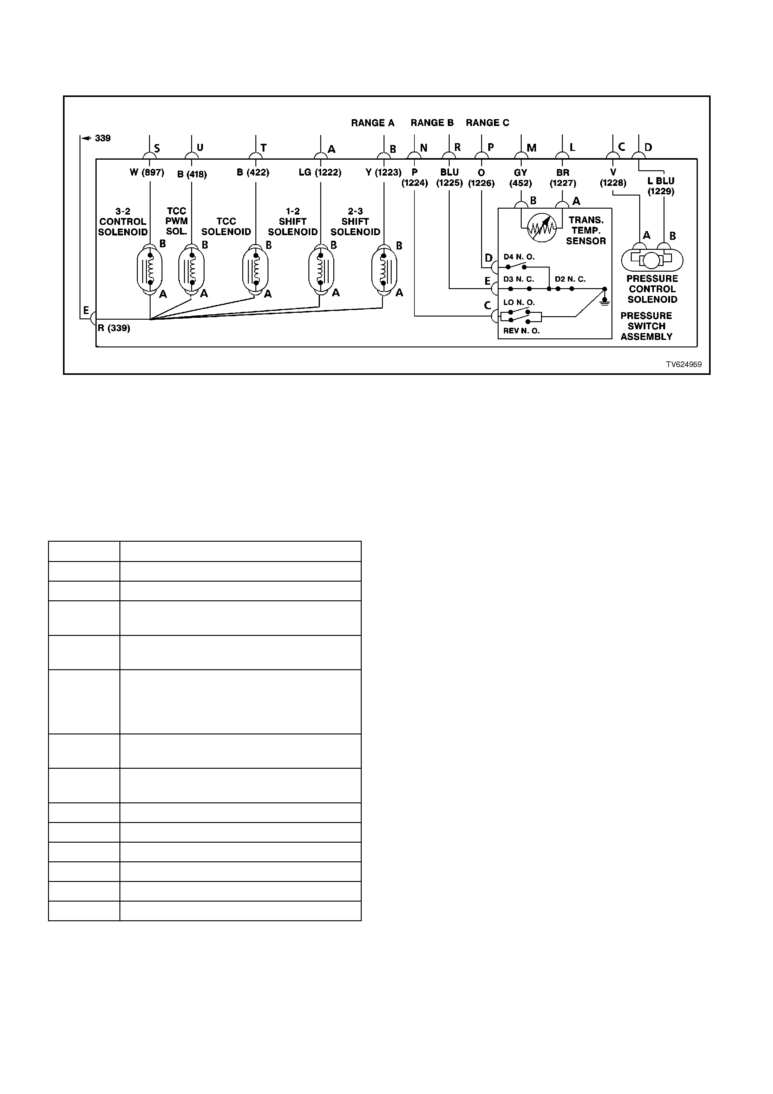
CHART 2.1 - AUTOMATIC TRANSMISSION WIRING
HARNESS ASSEMBLY CHECK
TOOLS REQUIRED:
J 39775 4L60-E Jumper Harness
J 39200 Digital Volt Multimeter (DVM)
J 35616 Connector Test Adapter Kit
IMPORTANT:
This procedure cannot be used for checking the Automatic Transmission Fluid Pressure Manual Valve Position
Switch (TFP Val. Position Sw.) circuit, or the Automatic Transmission Fluid Temperature (TFT) Sensor circuit. Refer
to the TFP Valve Position Switch Assembly Resistance Check, for those circuits.
CAVITY FUNCTION
A 1-2 SHIFT SOLENOID
B 2-3 SHIFT SOLENOID
C PRESSURE CONTROL SOLENOID
(HIGH)
D PRESSURE CONTROL SOLENOID
(LOW)
E 1-2 SHIFT SOLENOID, 2-3 SHIFT
SOLENOID, TCC ENABLE
SOLENOID, TCC PWM SOLENOID, 3-
2 CONTROL SOLENOID
L TRANS FLUID TEMPERATURE
(HIGH)
M TRANS FLUID TEMPERATURE
(LOW)
N RANGE SIGNAL A
P RANGE SIGNAL B
R RANGE SIGNAL C
S 3-2 CONTROL SOLENOID
T TCC ENABLE SOLENOID
U TCC PWM SOLENOID

STEP ACTION VALUE YES NO
11. Install the J 39775
Jumper Harness on
the transmission pass-
through connector.
2. Using a J 39200 DVM
and a J 35616
Connector Test
Adapter Kit, measure
the resistance between
terminals A and E (1-2
Shift Solenoid Valve).
Is the resistance within
the specified range?
19-24 W
@ 20° C
24-31W
@ 100°
C
Go to Step 3 Go to Step 2
21. Disconnect the 1-2
Shift Solenoid Valve
(1-2 SS Valve) from
the Automatic
Transmission Wiring
Harness Assembly.
2. Using the J 39200
DVM, measure the
resistance of the 1-2
SS Valve.
Is the resistance within
the specified range?
19-24 W
@ 20° C
24-31W
@ 100°
C
Go to Step 14 Go to Step 16
3Measure the resistance
between terminals B and
E (2-3 Shift Solenoid
Valve).
Is the resistance within
the specified range?
19-24 W
@ 20° C
24-31W
@ 100°
C
Go to Step 5 Go to Step 4
4Disconnect the 2-3 Shift
Solenoid Valve (2-3 SS
Valve) from the Automatic
Transmission Wiring
Harness Assembly.
Using the J 39200 DVM,
measure the resistance of
the 2-3 SS Valve.
Is the resistance within
the specified range?
19-24 W
@ 20° C
24-31W
@ 100°
C
Go to Step 14 Go to Step 16
5Measure the resistance
between terminals T and
E (Torque Converter
Clutch Solenoid Valve).
Is the resistance within
the specified range?
21-26 W
@ 20° C
26-33 W
@ 100°
C
Go to Step 6 Go to Step 14
6Measure the resistance
between terminals U and
E (Torque Converter
Clutch Pulse Width
Modulation Solenoid
Valve).
Is the resistance within
the specified range?
10-11 W
@ 20° C
13–15
W
@ 100°
C
Go to Step 8 Go to Step 7

STEP ACTION VALUE YES NO
71. Disconnect the TCC
PWM Sol. Valve from
the Automatic
Transmission Wiring
Harness Assembly.
2. Using the J 39200
DVM, measure the
resistance of the TCC
PWM Sol. Valve.
Is the resistance within
the specified range?
10-11 W
@ 20° C
13–15
W
@ 100°
C
Go to Step 14 Go to Step 16
8Measure the resistance
between terminals S and
E (3-2 Shift Solenoid
Valve assembly).
Is the resistance within
the specified range?
20-24 W
@ 20° C
29-32 W
@ 100°
C
Go to Step 10 Go to Step 9
91. Disconnect the 3-2
Shift Solenoid Valve
Assembly (3-2 SS
Valve Assembly.) from
the Automatic
Transmission Wiring
Harness Assembly.
2. Using the J 39200
DVM, measure the
resistance of the 3-2
SS Valve Assembly.
Is the resistance within
the specified range?
20-24 W
@ 20° C
29-32 W
@ 100°
C
Go to Step 14 Go to Step 16
10 Measure the resistance
between terminals C and
D (Pressure Control
Solenoid Valve).
Is the resistance within
the specified range?
3-5 W
@ 20° C
4-7 W
@ 100°
C
Go to Step 12 Go to Step 11
11 1. Disconnect the
Pressure Control
Solenoid Valve (PC
Sol. Valve) from the
Automatic
Transmission Wiring
Harness Assembly.
2. Using the J 39200
DVM, measure the
resistance of the PC
Sol. Valve.
Is the resistance within
the specified range?
3-5 W
@ 20° C
4-7 W
@ 100°
C
Go to Step 14 Go to Step 16

STEP ACTION VALUE YES NO
12 Using the J 39200 DVM
and the J 35616
Connector Test Adapter
Kit, measure the
resistance from each of
the terminals A, B, C, D,
E, S, T and U of the A/T
Wiring Harness
Assembly. at the
transmission pass-
through connector to the
transmission case .
Is the resistance more
than the specified value?
250k W System OK, exit
the table Go to Step 13
13 1. Disconnect the A/T
Wiring Harness
Assembly from all the
components.
2. Measure the
resistance from each
of the component
terminals to the
transmission case .
Is the resistance more
than the specified value?
250k W Go to Step 14 Go to Step 16
14 Inspect for high resistance
or a short.
Inspect the A/T Wiring
Harness Assembly. at the
transmission pass-
through connector, and
the component
connectors for the
following conditions:
• Poor electrical
connections
• Bent, backed-out, or
damaged terminals
• Weak terminal tension
• A chafed wire that
could short to bare
metal or other wiring
• A broken wire inside
the insulation
• Moisture intrusion
• Corrosion
If diagnosing for a
possible intermittent
condition, move or
massage the A/T Wiring
Harness Assembly. while
observing the test
equipment for a change.
Did you find and correct
the high resistance or a
short?
— Verify the repair
Go to Step 1 Go to Step 15

STEP ACTION VALUE YES NO
15 Replace the Automatic
Transmission Wiring
Harness Assembly. Refer
to the Service Operations
in Section 7C-5
AUTOMATIC
TRANSMISSION.
Is the action complete?
Verify the repair
Go to Step 1
16 Replace the faulty
component. Refer to
Service Operations in
Section 6C2-3.
Is the action complete?
Verify the repair
Go to Step 1
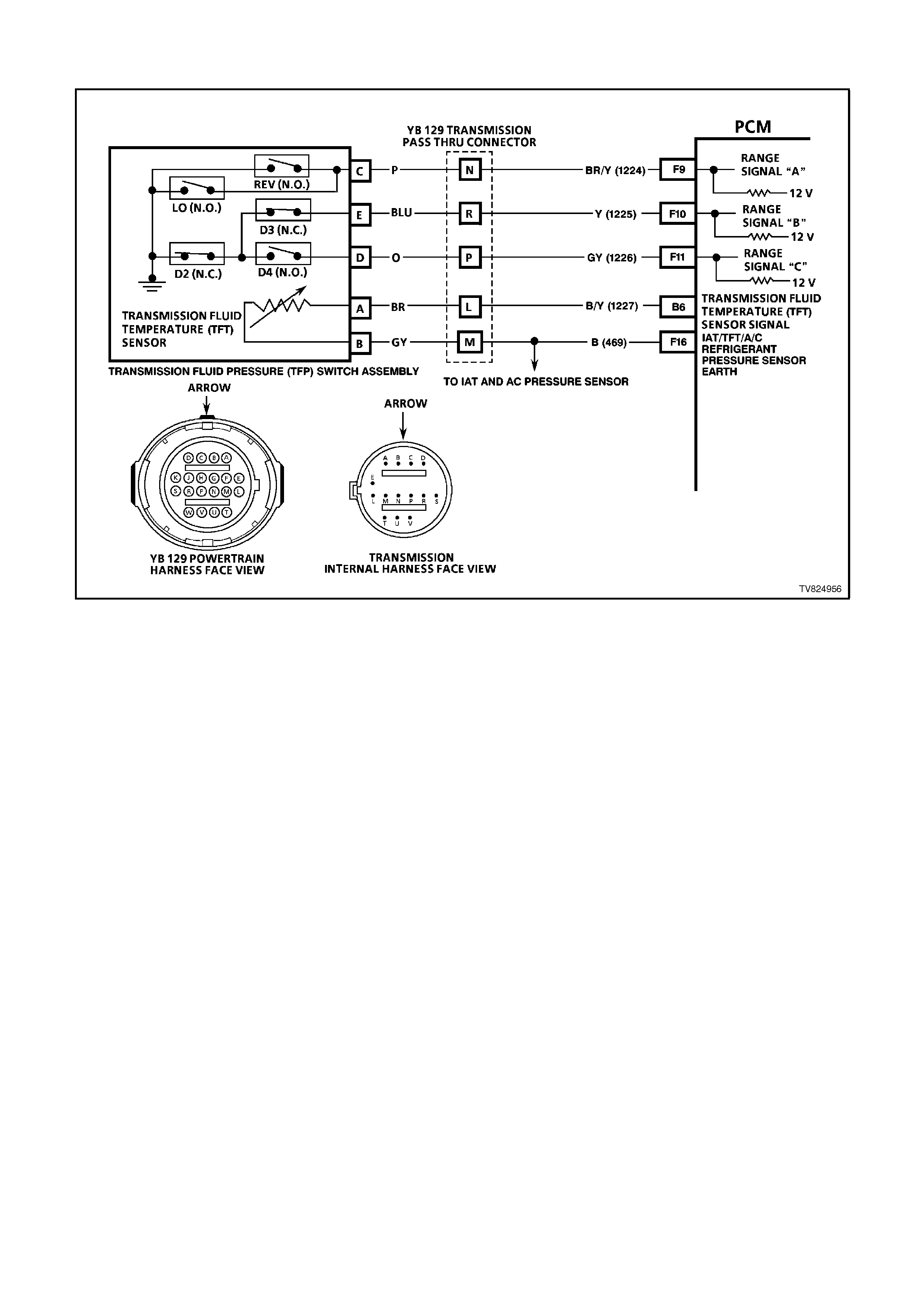
CHART 2.2 - TFP VALVE POSITION SWI TCH RESI STANCE CHECK
TOOLS REQUIRED:
J 39775 4L60E Jumper Harness
J 39200 Digital Volt Multimeter
J 35616 Connector Test Adapter Kit
IMPORTANT:
Whenever the transmission pass-through connector is disconnected and the engine is running, multiple DTCs will
set. Be sure to clear these codes when you are finished with this procedure.
IMPORTANT:
This procedure tests the Automatic Transmission Fluid Pressure Manual Valve Position Switch (TFP Val. Position
Sw.) circuits and the Automatic Transmission Fluid Temperature (TFT) Sensor circuit. Do not use this procedure to
test other Automatic Transmission circuits, refer to 4L60-E Automatic Transmission Internal Wiring Harness check.

STEP ACTION VALUE YES NO
11. Install the J 39775
Jumper Harness on
the transmission side
of the pass-through
connector.
2. Using the J 39200
DVM and the J 35616
Connector Test
Adapter Kit, measure
the resistance from
terminal N to the
transmission case .
Is the resistance greater
than the specified value?
50 k W Go to Step 3 Go to Step 2
21. Disconnect the TFP
Val. Position Sw. from
the A/T Wiring
Harness Assembly.
2. Measure the
resistance from
terminal C of the TFP
Val. Position Sw to the
switch housing.
Is the resistance greater
than the specified value?
50 k W Go to Step 16 Go to Step 19
3Measure the resistance
from terminal R to the
transmission case .
Is the resistance less than
the specified value?
200 W Go to Step 5 Go to Step 4
41. Disconnect the TFP
Val. Position Sw. from
the A/T Wiring
Harness Assembly.
2. Measure the
resistance from
terminal E of the TFP
Val. Position Sw. to the
switch housing.
Is the resistance less than
the specified value?
200 W Go to Step 16 Go to Step 19
5Measure the resistance
from terminal P to the
transmission case .
Is the resistance greater
than the specified value?
50 k W Go to Step 7 Go to Step 6
61. Disconnect the TFP
Val. Position Sw. from
the A/T Wiring
Harness Assembly.
2. Measure the
resistance from
terminal D of the TFP
Val. Position Sw. to the
switch housing.
Is the resistance greater
than the specified value?
50 k W Go to Step 16 Go to Step 19

STEP ACTION VALUE YES NO
71. Start the engine.
2. Allow the engine to
idle.
3. Set the parking brake.
4. Place the gear selector
in Reverse.
5. Measure the
resistance from
terminal N to the
transmission case .
Is the resistance less than
the specified value?
200 W Go to Step 8 Go to Step 16
81. Place the gear selector
in Low (D1).
2. Measure the
resistance from
terminal N to the
transmission case .
Is the resistance less than
the specified value?
200 W Go to Step 9 Go to Step 16
91. Place the gear selector
in Manual Third (D3).
2. Measure the
resistance from
terminal R to the
transmission case .
Is the resistance greater
than the specified value?
50 k W Go to Step 10 Go to Step 16
10 1. Place the gear selector
in Drive (D4).
2. Measure the
resistance from
terminal P to the
transmission case .
Is the resistance less than
the specified value?
200 W Go to Step 11 Go to Step 16
11 1. Place the gear selector
in Manual Second
(D2).
2. Measure the
resistance from
terminal P to the
transmission case .
Is the resistance greater
than the specified value?
50 k W Go to Step 12 Go to Step 16

STEP ACTION VALUE YES NO
12 1. Turn the ignition OFF.
IMPORTANT:
The resistance of the
TFT Sensor is
temperature
dependent, and
therefore varies more
than any other device.
2. Measure the
resistance from
terminal L to terminal
M (TFT Sensor) of the
Jumper Harness.
Is the resistance within
the specified range?
3088-
3942 W
@ 20° C
159-
198 W
@ 100°
C
Go to Step 13 Go to Step 14
13 1. Measure the
resistance from
terminal L to the
transmission case .
2. Measure the
resistance from
terminal M to the
transmission case .
Are both resistance’s
greater than the specified
value?
10 M W No problem
found. Exit the
table.
Go to Step 14
14 1. Disconnect the TFP
Val. Position Sw. from
the A/T Wiring
Harness Assembly.
IMPORTANT:
The resistance of the
TFT Sensor is
temperature
dependent, and
therefore varies far
more than any other
device. Refer to
Transmission Fluid
Temperature Sensor in
General Information.
2. Using the J 39200
DVM, measure the
resistance between
terminal A and terminal
B of the TFP Val.
Position Sw. (TFT
Sensor).
Is the resistance within
the specified range?
3088–
3942 W
@ 20°
C
159-
198 W
@ 100°
C
Go to Step 15 Go to Step 19

STEP ACTION VALUE YES NO
15 1. Measure the
resistance from TFP
Val. Position Sw.
terminal A to the
transmission case .
2. Measure the
resistance from TFP
Val. Position Sw.
terminal B to the
transmission case .
Are both resistances
greater than the specified
value?
10 M W Go to Step 16 Go to Step 19
16 1. Inspect for high
resistance or a short.
2. Inspect the A/T Wiring
Harness Assembly. for
poor electrical
connections at the A/T
pass-through
connector, and at the
TFP Val. Position
Switch. Check for the
following problems:
• A bent terminal
• A backed out
terminal
• A damaged
terminal
• Poor terminal
tension
3. If diagnosing for an
intermittent problem,
massage the wiring
harness while watching
the test equipment for
a change.
Did you find and correct
the high resistance or a
short?
Verify the repair
Go to Step 1 Go to Step 17
17 1. Disconnect the TFP
Val. Position Sw. from
the A/T Wiring
Harness Assembly.
2. Inspect the following
circuits for an open or
short:
• Circuit 1224
• Circuit 1225
• Circuit 1226
• Circuit 1227 (TFT
Hi)
• Circuit 469 (TFT
Lo)
Did you find a problem?
Go to Step 18 Go to Step 19

STEP ACTION VALUE YES NO
18 Replace the A/T Wiring
Harness Assembly.
Refer to Automatic
Transmission Wiring
Harness Assembly
Replacement, in Service
Operations in Section 7C-
5 AUTOMATIC
TRANSMISSION.
Is the action complete?
Verify the repair
Go to Step 1
19 Replace the TFP Val.
Position Sw.
Refer to Automatic
Transmission Fluid
Pressure Manual Valve
Position Switch
Replacement. Refer to
Service Operations, in
Section 6C2-3.
Is the action complete?
Verify the repair
Go to Step 1
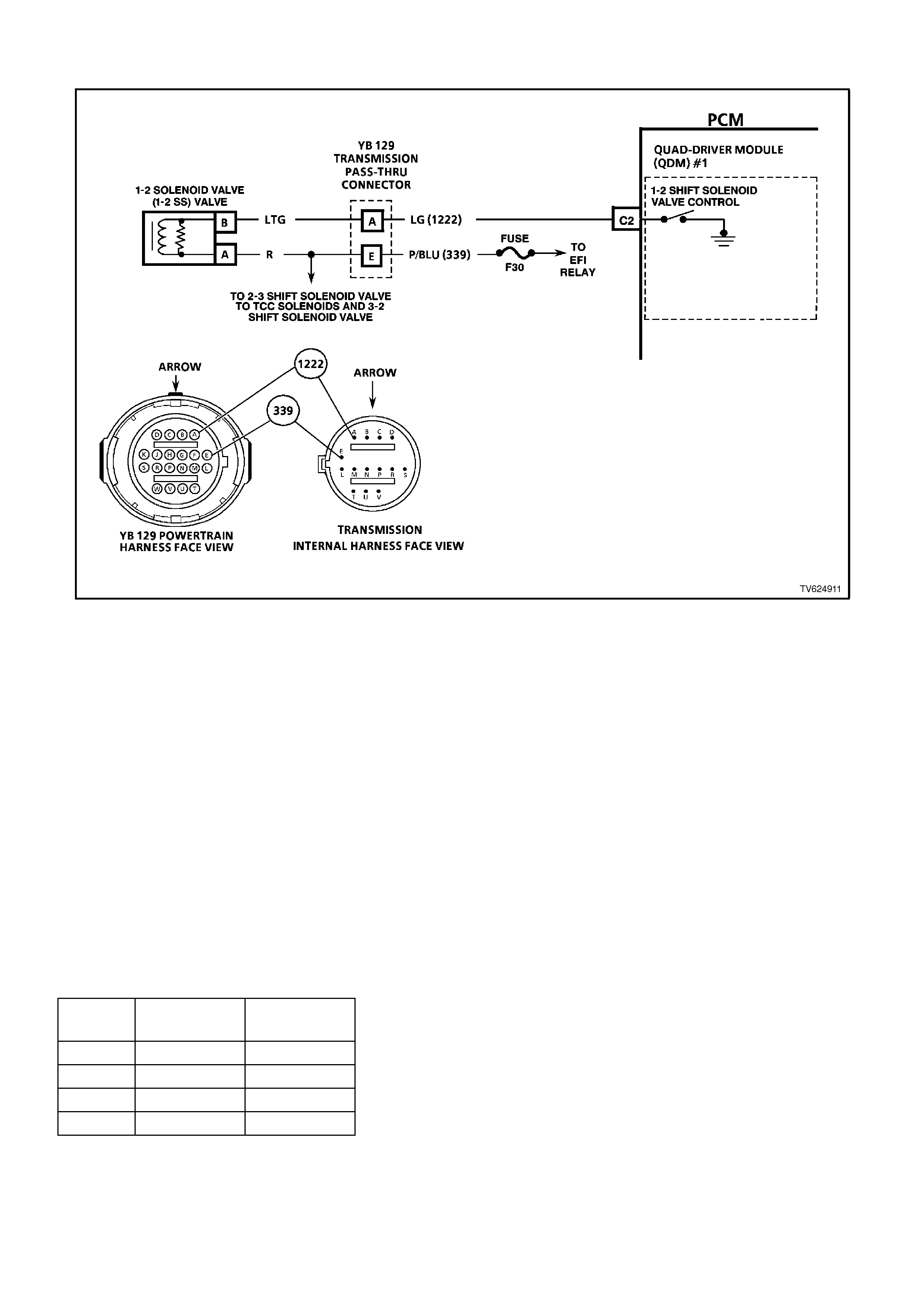
CHART 2.3 - 1-2 SHIFT SOLENOID PERFORMANCE CHECK
CIRCUIT DESCRIPTION
The 1-2 Shift Solenoid Valve (1-2 SS Valve) controls the fluid flow acting on the 1-2 and 3-4 shift valves. The 1-2 SS
Valve is a normally open valve that is used with the 2-3 Shift Solenoid Valve (2-3 SS Valve), in order to allow four
different shifting combinations.
This functional check is useful for diagnosing unusual shift patterns that result from a mechanical fault of the 1-2
shift solenoid or the shift valve. A 1-1-4-4 shift pattern indicates that the shift solenoid or the shift valve is stuck ON.
The stuck ON condition could be caused by the solenoid not exhausting the fluid or the shift valve remaining in the
applied position. Similarly, a 2-2-3-3 shift pattern indicates that the shift solenoid or the shift valve is stuck OFF. The
stuck OFF condition could be caused by the solenoid exhausting fluid or the shift valve remaining in the non-applied
position.
TEST DESCRIPTION
The numbers below refer to the step numbers on the diagnostic chart.
3. This step tests that the scan tool commanded all the shifts and all the shift solenoid valves responded correctly,
but all the shifts did not occur. Refer to the chart below.
DIAGNOSTIC AIDS:
• Verify that the transmission shift speeds are within the specifications.
• Other internal transmission faults may cause more than one shift to occur.
• Refer to the following chart for the correct On and Off states of the shift solenoids.
GEAR 1-2 SHIFT
SOLENOID 2-3 SHIFT
SOLENOID
1ON ON
2OFF ON
3OFF OFF
4ON OFF

STEP ACTION VALUE YES NO
1Was the On-Board
Diagnostic (OBD) System
Check performed?
Go to Step 2 Go to OBD
System Check
21. Install the scan tool.
2. With the engine OFF,
turn the ignition switch
to the RUN position.
3. While the engine is
operating, raise the
drive wheels.
4. With the transmission
in D4 range, use the
scan tool to command
1st, 2nd, 3rd and 4th
gears while
accelerating the
vehicle. Road testing
the vehicle may be
necessary.
Did you detect a 1-1-4-4
or a 2-2-3-3 only shift
pattern?
Go to Step 3 Go to “Diagnostic
Aids” above
3Check the shift
solenoid/hydraulic circuit
for:
• An internal
malfunction.
• Damaged seals on the
shift solenoid valves.
Refer to the symptom
diagnosis charts.
Did you find and correct
the problem?
Go to Step 4 Go to “Diagnostic
Aids” above
4In order to verify your
repair, perform the
following procedure:
1. Select DTC.
2. Select Clear Info.
3. Operate the vehicle
under the following
conditions (only if
traffic and road
conditions permit):
• With the
transmission in the
D4 range, use the
scan tool to
command the 1st,
2nd, 3rd and 4th
gears while
accelerating the
vehicle.
Did you detect a 1-1-4-4
or 2-2-3-3 only shift
pattern?
Begin the
diagnosis again.
Go to Step 1
Repair Verified,
exit table
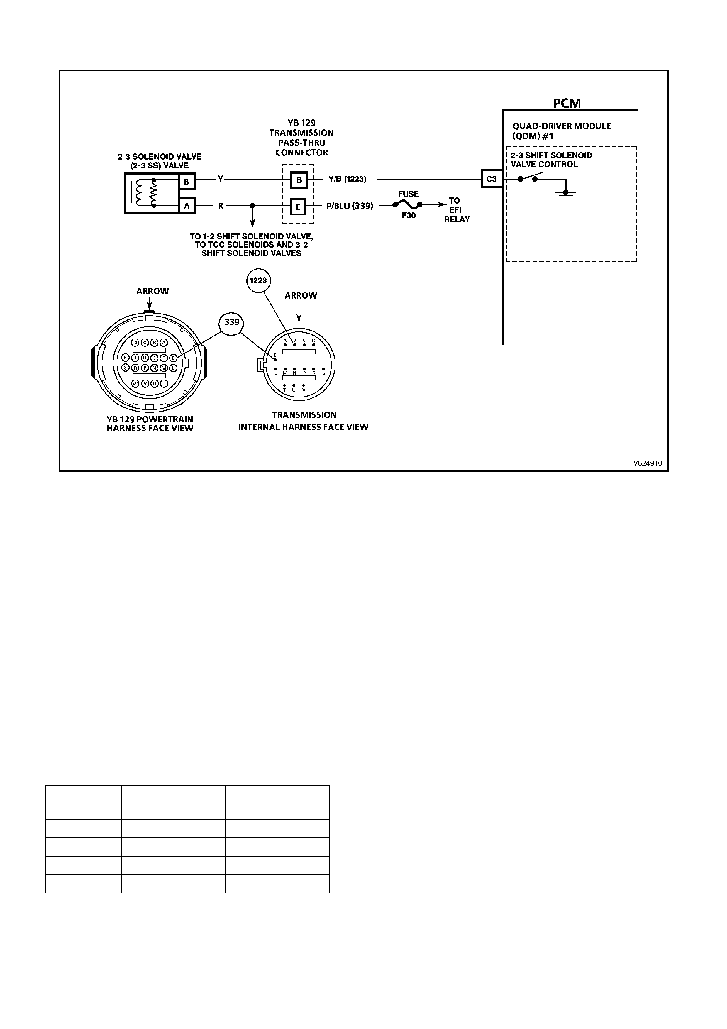
CHART 2.4 - 2-31-2 SHIFT SOLENOID PERFORMANCE CHECK 3
CIRCUIT DESCRIPTION
The 2-3 Shift Solenoid Valve (2-3 SS Valve) controls the fluid flow acting on the 2-3 shift valves. The 2-3 SS Valve
is a normally open exhaust valve that is used with the 1-2 Shift Solenoid Valve (1-2 SS Valve) in order to allow four
different shifting combinations.
This functional check is useful for diagnosing unusual shift patterns that result from a mechanical fault of the 2-3
shift solenoid or the shift valve. A 1-2-2-1 shift pattern indicates that the shift solenoid or the shift valve is stuck ON.
The stuck ON condition could be caused by the solenoid not exhausting fluid or the shift valve remaining in the
applied position. Similarly, a 4-3-3-4 shift pattern indicates that the shift solenoid or the shift valve is stuck OFF.
The stuck OFF condition could be caused by the solenoid exhausting fluid or the shift valve remaining in the non-
applied position.
TEST DESCRIPTION
The numbers below refer to the step numbers on the diagnostic chart.
3. This verifies that the scan tool commanded all the shifts, and all the shift solenoids responded correctly, but all
the shifts did not occur. Refer to the chart below.
DIAGNOSTIC AIDS:
• Verify that the transmission shift speeds are within the specifications.
• Other internal transmission faults may cause more than one shift to occur.
• Refer to the following chart for the correct On and Off states of the shift solenoids.
GEAR 1-2 SHIFT
SOLENOID 2-3 SHIFT
SOLENOID
1ON ON
2OFF ON
3OFF OFF
4ON OFF

STEP ACTION VALUE YES NO
1Was the On Board
Diagnostic (OBD) System
Check performed?
Go to Step 2 Go to OBD
System Check
21. Install the scan tool.
2. With the engine OFF,
turn the ignition switch
to the RUN position.
3. While the engine is
operating, raise the
drive wheels.
4. With the transmission
in D4 range, use the
scan tool to command
1st, 2nd, 3rd, and 4th
gears while
accelerating the
vehicle. Road testing
the vehicle may be
necessary.
Did you detect a 1-2-2-1
or 4-3-3-4 only shift
pattern?
Go to Step 3 Go to “Diagnostic
Aids” above
3Check the shift
solenoid/hydraulic circuit
for
• An internal malfunction
• Damaged seals
Refer to the symptom
diagnosis charts
Did you find and correct a
problem?
Go to Step 4 Go to “Diagnostic
Aids” above
4In order to verify your
repair, perform the
following procedure:
1. Select DTC.
2. Select Clear Info.
3. Operate the vehicle
under the following
conditions (only if
traffic and road
conditions permit):
• With the transmission
in D4 range, use the
scan tool to command
1st, 2nd, 3rd and 4th
gears while
accelerating the
vehicle.
Did you detect a 1-2-2-1
or a 4-3-3-4 only shift
pattern?
Begin the
diagnosis again
Go to Step 1
Repair Verified,
exit table
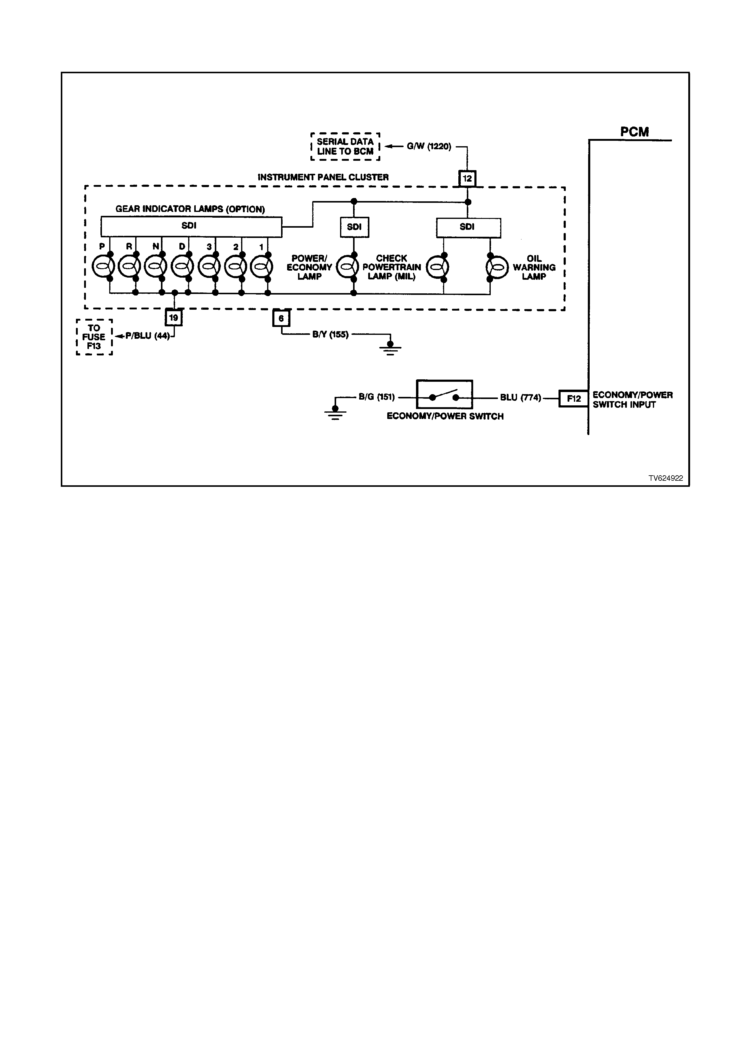
CHART 2.5 - TRANSMISSION ECONOM Y/POWER SWITCH
CIRCUIT DESCRIPTION
The driver can select two transmission shift modes, "ECONOMY" or "POWER" using a dash or center console
mounted switch. This switch is wired to the PCM and allows the driver to choose the "Economy" mode, for the best
fuel economy in all driving conditions through the increased use of TCC, or the "Power" mode which provides later
upshifts and higher line pressure in the transmission.
The PCM sends out a buffered voltage signal, about 12 volts, and monitors the status of this circuit. In the
"Economy" position, the switch is open and the PCM voltage status signal remains high at about 12 volts. The PCM
does not allow shift point changes with this condition. When the transmission switch is pressed to "Power", the
switch is closed and the PCM voltage status signal is pulled low, to about 0.5 volts. The PCM senses this voltage
drop on circuit 774 and enables power mode shifting only if other criteria such as throttle position, engine load and
engine speed are met.
TEST DESCRIPTION:
The numbers below refer to step numbers on the diagnostic chart.
2. This tests for the proper operation of the transmission POWER switch, the wiring and the PCM.
3. This tests for the proper POWER lamp illumination, when the power switch is On.
4. This tests for a shorted power switch or a short to earth on circuit 774.
5. This tests for an open in the bulb circuit.
10. Some interior parts must be removed to disconnect the transmission switch, refer to
Section 7C-4 AUTOMATIC TRANSMISSION - ON VEHICLE SERVICING. This step simulates a closed
switch if the earth circuit is OK.

STEP ACTION VALUE YES NO
1Was the On-Board
Diagnostic (OBD) System
Check performed?
Go to Step 2 Go to OBD
System Check
21. With the engine OFF,
turn the ignition switch
to the RUN position.
2. Install the scan tool.
3. Place the
Transmission POWER
switch in the POWER
position and observe
the scan tool display.
Does the scan tool display
POWER?
Go to Step 3 Go to Step 10
3Is the POWER lamp ON,
when the scan tool
displays POWER?
Go to Step 4 Go to Step 5
4Place the Transmission
POWER switch in the
ECONOMY position and
observe the scan tool
display.
Does the scan tool display
ECONOMY?
Go to Step 6 Go to Step 7
5Check for an open in the
POWER lamp bulb, or the
bulb feed circuit.
Is the Action Complete?
Verify the Repair
6Does the POWER lamp
go off, when the scan tool
displays ECONOMY?
No Trouble
Found.
ECONOMY/
POWER switch
electrically OK.
Refer to Section
6C2-2B
SYMPTOMS
"Intermittents”.
Go to Step 8
7Disconnect the POWER
switch from the wiring
harness connector.
Does the scan tool display
ECONOMY?
Go to Step 12 Go to Step 9
8Check for a short to earth
on the POWER lamp
circuit in the instrument
panel cluster.
Is the action complete?
Verify the Repair
9Check for a short to earth
in circuit 774.
Did you find and correct
the short to earth
condition?
Verify the Repair Go to Step 16

STEP ACTION VALUE YES NO
10 1. Disconnect the
POWER switch from
the wiring harness
connector.
2. Using a fused jumper
wire, connect the two
terminals of the
POWER switch wiring
harness connector
together.
Does the scan tool display
POWER?
Go to Step 12 Go to Step 11
11 Using a fused jumper
wire, connect circuit 774
to earth.
Does the scan tool display
POWER?
Go to Step 15 Go to Step 14
12 Check the POWER switch
connector for a shorted or
a loose terminal
connection.
Did you find and correct
the faulty condition?
Verify the Repair Go to Step 13
13 Replace the faulty
POWER switch.
Is the action complete?
Verify the Repair
14 Check for an open circuit
or a faulty PCM
connection on circuit 774.
Did you find and correct
the open circuit?
Verify the Repair Go to Step 16
15 Repair the open in circuit
151 to earth.
Is the action complete?
Verify the Repair
16 Replace the faulty PCM.
Refer to Section 6C2-3
Service Operations for the
Security Link procedure.
Is the action complete?
Verify the Repair