
SECTION 6C2-3 SERVICE OPERATIONS - V8 ENGINE
CAUTION
This vehicle will be equipped with a Supplemental Restraint System (SRS). A SRS
will consist of either seat belt pre-ten sioners and a driv er’s side air bag, or seat b elt
pre-tensioners and a driver’s and front passenger’s side air bags. Refer to
CAUTIONS, Section 12M, before performing any service operation on or around SRS
components, the steering mechanism or wiring. Failure to follow the CAUTIONS
could result in SRS deployment, resulting in possible personal injury or
unnecessary SRS system repairs.
NOTE:
When fasteners are removed, always reinstall them at the same location from which they were removed. If a
fastener needs to be replaced, use the correct part number fastener for that application. If the correct part number
fastener is not available, a fastener of equal size and strength (or stronger) may be used. Fasteners that are not
reused, and those requiring thread locking compound will be called out. The correct torque value must be used
when installing fasteners that require it. If the above conditions are not followed, parts of system damage could
result.
WHAT THIS SECTION CONTAINS
Service Operations, Section 6C2-3 describes the proper service procedures to repair components of the Engine
and Transmission Management system. Emphasis is placed on the proper procedures and repair of components
related to the system.
Techline
3.1 SERVICE PRECAUTIONS
The following requirements must be observed when working on vehicles:
1. Before removing any PCM system component, disconnect the battery earth lead.
2. Never start the engine without the battery being solidly connected.
3. Never disconnect the battery while the engine is running.
4. When charging the battery, disconnect the battery earth lead from the vehicle's electrical system.
5. Never subject the PCM to temperatures above 80 °C ie. paint oven. Remove the PCM if this temperature is to
be exceeded.
6. Ensure that all cable harness connectors are connected solidly and that the battery terminals are thoroughly
clean.
7. The engine management system harness connectors are designed to fit only one way. There are indexing tabs
and slots on both halves of the connector. Failure in matching the indexing tabs and slots to the connector can
cause damage to the connector, the PCM, or the other vehicle components or systems.
8. Never connect or disconnect the wire harness connector at the PCM when the ignition is ON.
9. Before attempting any electric arc welding on the vehicle, disconnect the battery leads and the PCM
connectors.
10. When steam cleaning the engine, do not direct the steam cleaning nozzle at the PCM system components.
11. Use only the test equipment specified in the diagnostic charts. Other test equipment may either give incorrect
results, or damage good components.
12. Use a digital voltmeter with an internal impedance rating of at least 10 million ohms per volt (10 megaohm/volt).
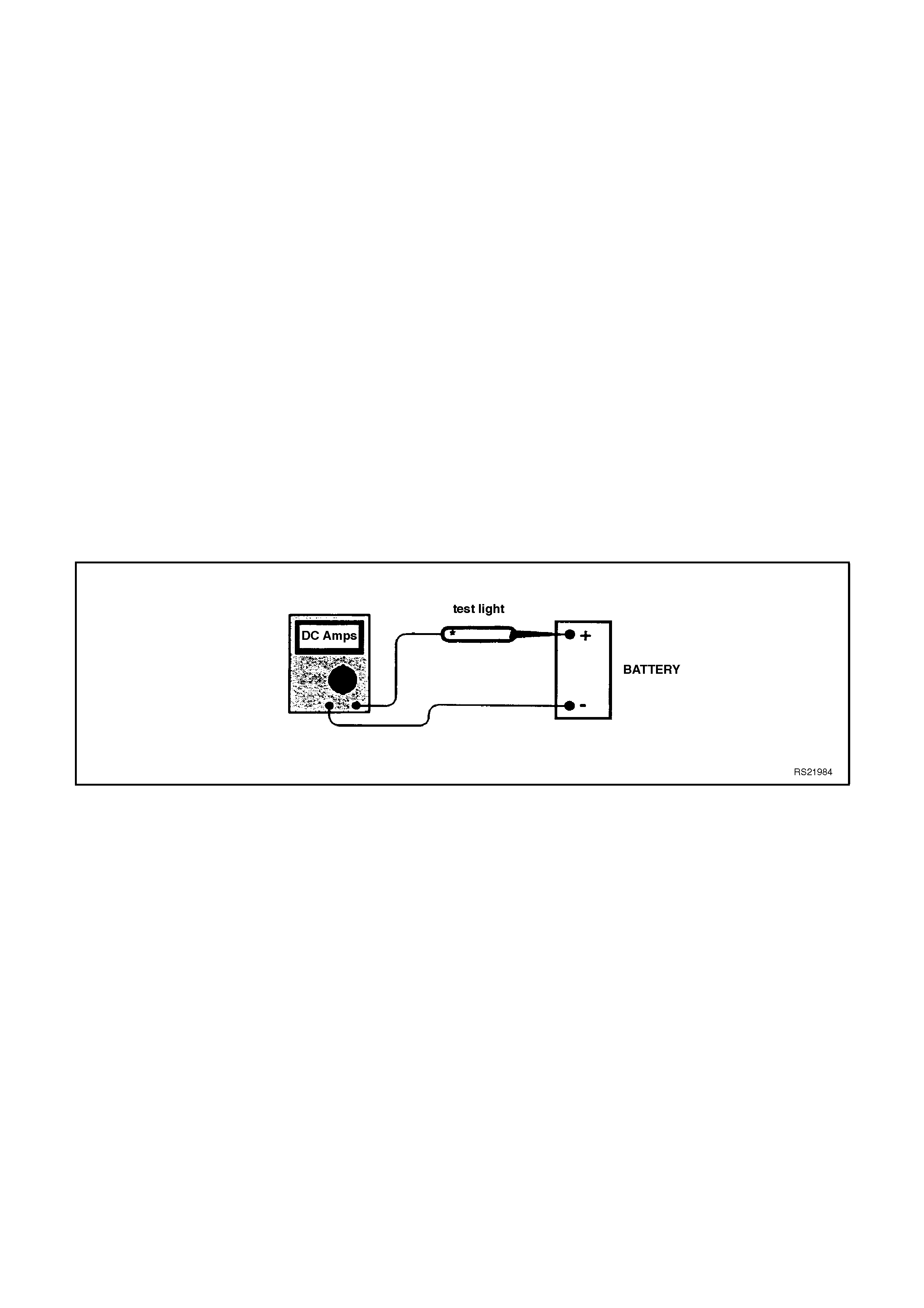
13. When a test light is specified, a "low-power" test light must be used. simple test on any test light will ensure it
to be OK for PCM circuit testing. Connect an accurate ammeter (such as the high-impedance digital
multimeter) in series with the test light being tested, and power the test light-ammeter circuit with the vehicle
battery. If the ammeter indicates less than 3/10 amp current flow (0.3 A or 300 ma), the test light is OK to use.
If the ammeter indicates more than 3/10 amp current flow (0.3A or 300 ma), the test light is NOT OK to use.
Figure 6C2-3-1 - Test Light Check
3.2 POWERTRAIN CONTROL MODULE
Service of the PCM should normally consist of
either the replacement of the PCM or the
replacement of the PROM .
If the diagnostic procedures c alls f or the PCM to be
replaced, the PROM and PCM should be checked
to see if they are correct. If they are, remove the
PROM from the faulty PCM and install the PROM in
the new service PCM. A Diagnostic Trouble Code
51 indicates that the PROM was installed
improperly or has malfunctioned. When a DTC 51
is set, check f or the proper PROM installation. The
PROM should be fully seated in the socket.
IMPORTANT:
• When replacing the production PCM with a
service PCM, transfer the broadcast code and
the production PCM number to the servic e PCM
label. This allows positive identification of the
PCM parts throughout the service life of the
vehicle.
IMPORTANT:
• To prevent internal PCM damage, the ignition
must be OFF when disconnecting or
reconnecting the power to the PCM (for
exam ple, battery cables, PCM connec tors, PCM
fuse F31, jumper cables, etc.).
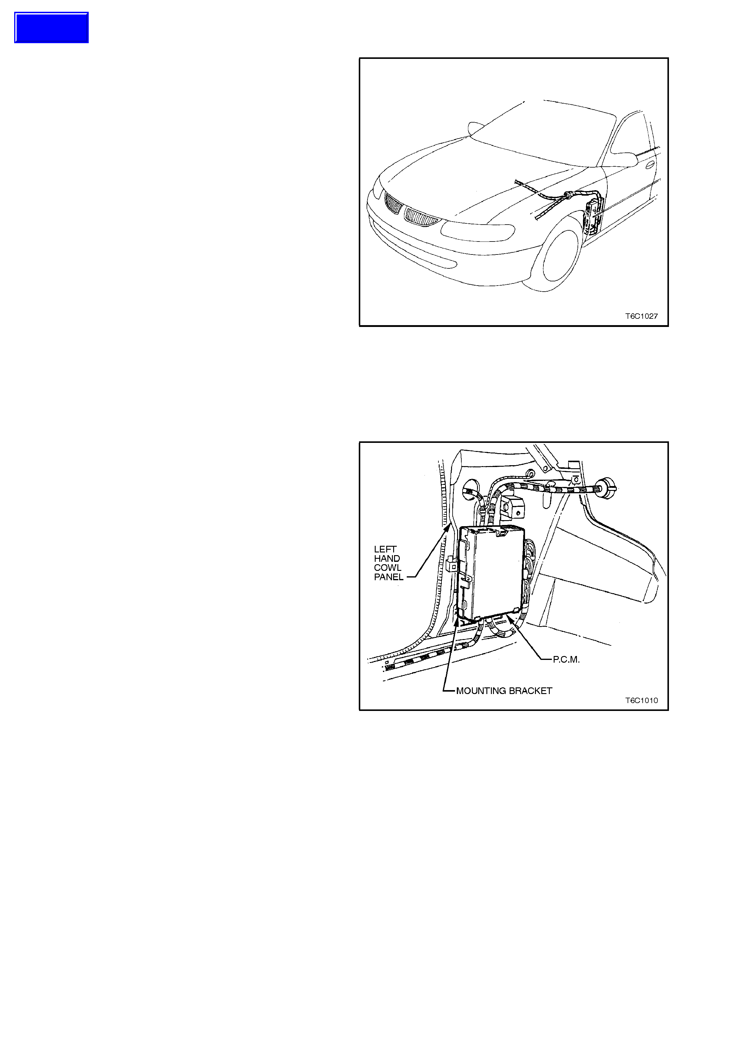
Figure 6C2-3-2 PCM Location
Figure 6C2-3-3 PCM Mounting
Techline
REMOVE
1. The battery earth lead.
2. The left hand front shroud panel lower trim
assembly, refer Section 1A, BODY.
3. Lift the mounting brack et to the PCM retaining
tang, pull the PCM out then up to remove the
PCM from the mounting bracket.
4. The wiring harness connectors from the PCM,
then remove the PCM from the vehicle.
5. If necessary, remove the PROM, refer to
3.3 PROM UNIT - REMOVAL in this Section.
IMPORTANT:
The replacement PCM’s are supplied without a
PROM. Care should be taken when removing the
PROM from the PCM. The PROM will be reus ed in
the new PCM. Do not remove the plastic cover
from the PROM. Use of unprovided removal
methods may cause damage to the PROM or the
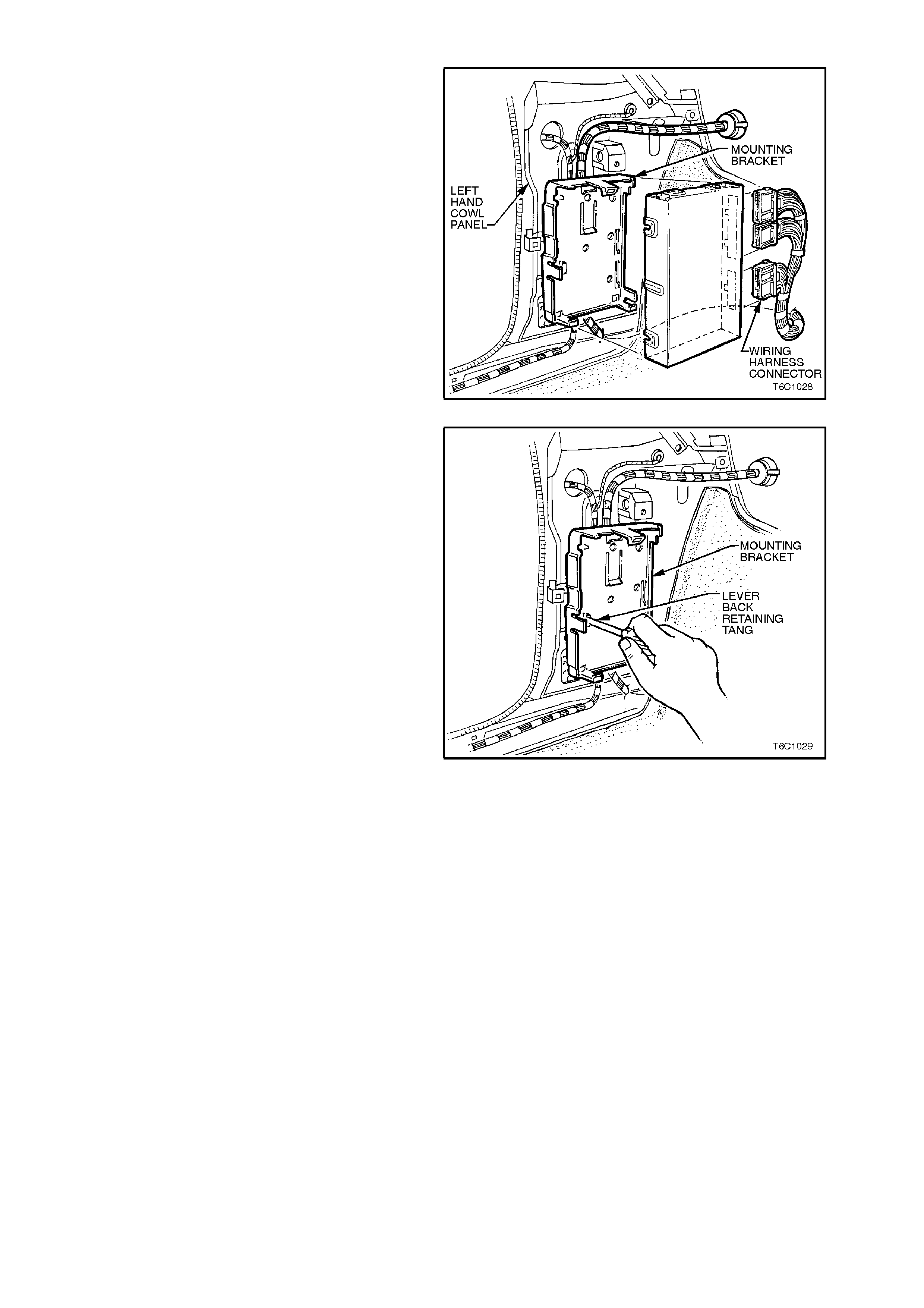
PROM socket. Figure 6C2-3-4 PCM Removal
6. If required, r em ove the PCM m ounting br ack et
by inserting a screwdriver into the retaining tan
slot. Lever the sc rewdriver to release the tang.
Pull the bracket out then down to release the
bracket from the cowl panel.
Figure 6C2-3-5 PCM Mounting Bracket Removal
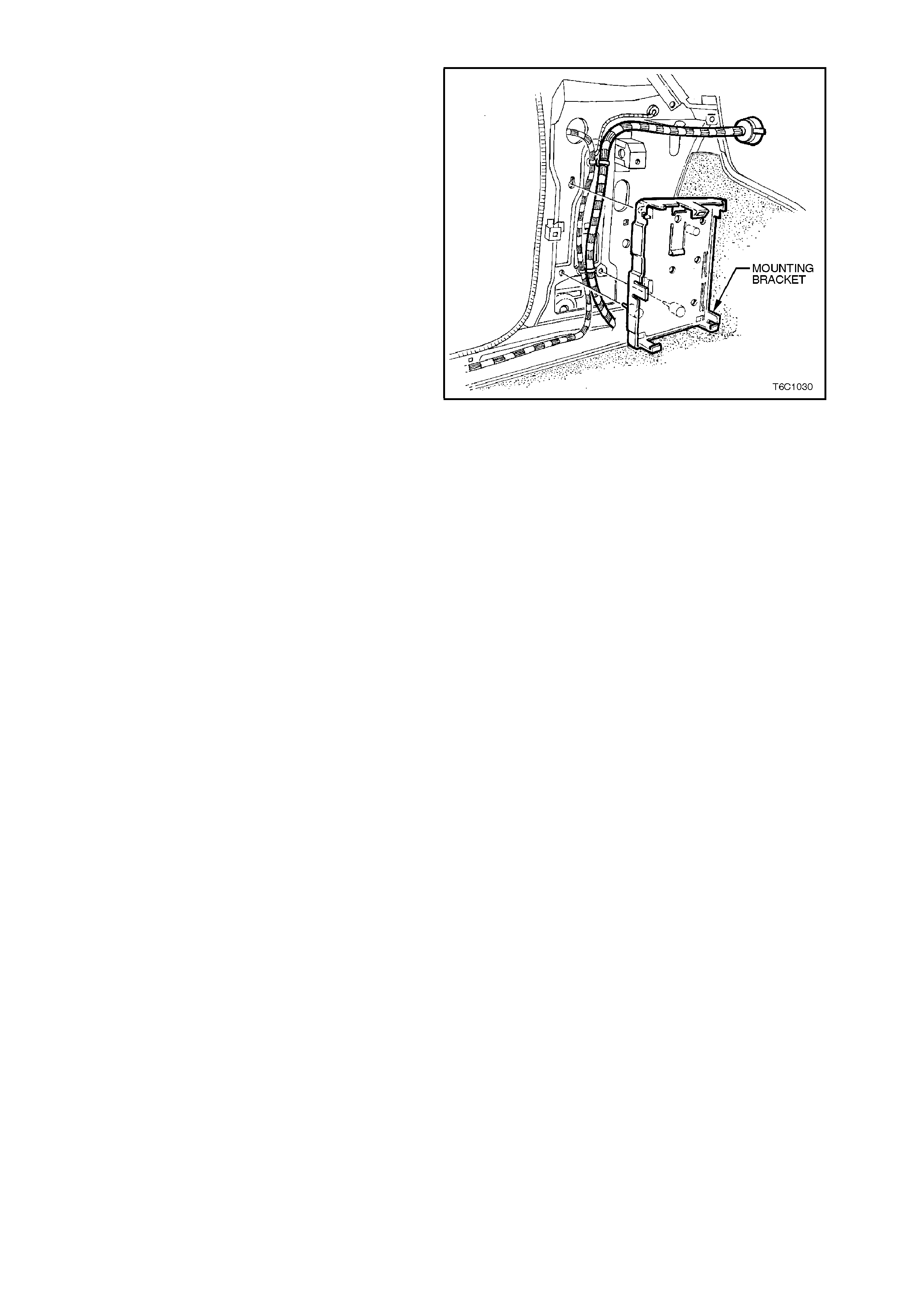
REINSTALL
1. Reinstall the PCM mounting bracket. Engaging
the bracket leg into the slotted hole in cowl
panel. Lift the brac ket and engage the bracket
lower retainers and retaining tang into cowl
panel.
2. If required, install the PROM into the new
PCM, refer to 3.3 PROM UNIT - REINSTALL
in this Section.
3. Reconnect the wiring harness connectors to
the PCM.
4. The PCM into the mounting bracket, ensuring
the wiring harness is routed in front of the
mounting bracket.
5. The cowl trim panel.
6. The battery earth lead.
7. If a new PCM was installed, perform the
Security Link procedure, 3.2 PCM SECURITY
LINK in this section. Figure 6C2-3-6 PCM Mounting Bracket Reinstallation
PCM SECURITY LINK
Once the PCM and or the BCM has been replaced,
the new PCM and or BCM must be security linked
to each other. If this procedure is not performed,
the vehicle will not crank or start.
The linking procedure is as follows:
Connect TECH 2 to DLC and select the following:
Diagnostics / (V) 1997 / VT Commodore / Body /
Body Control Module / Security / BCM Link to PCM
and follow TECH instructions.
For additional information regarding TECH 2 and
TECH 2 test modes (including this linking
procedure), refer to 3 TECH 2 DIAGNOSIS FOR
BCM in this Section.
3.3 PROM UNIT
DTC 51 indicates a faulty PROM, or an incorrect
PROM installation.
IMPORTANT:
The ignition should always be OFF when installing
or removing the PCM connectors.
REMOVE
1. The PCM from the passenger compartment,
refer to 3.2 POWERTRAIN CONTROL
MODULE - REMOVAL in this Section.
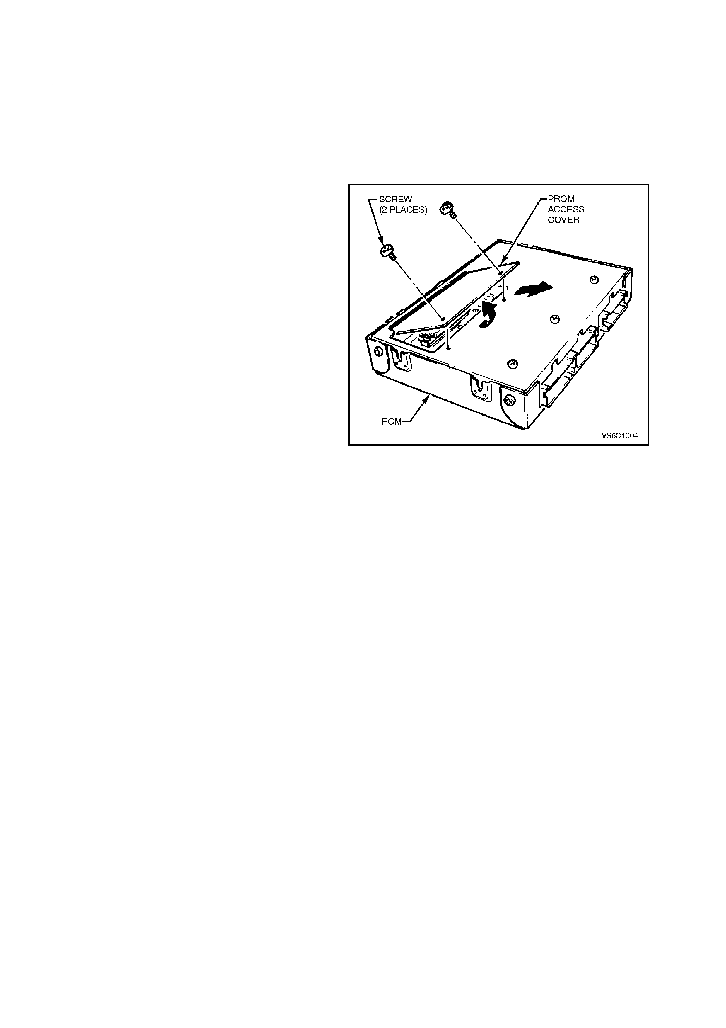
2. The PCM PROM access cover screws,
remove the access cover.
IMPORTANT:
• DO NOT remove any of the other screws.
IMPORTANT:
• DO NOT remove the cover of the PROM. Use
of unprovided PROM removal methods will
cause damage to the PROM or the PROM
socket.
Figure 6C2-3-7 PCM PROM Access Cover Removal
REINSTALL
1. Remove new PROM from its packaging and
check the part number making sure it is the
correct replacement component.
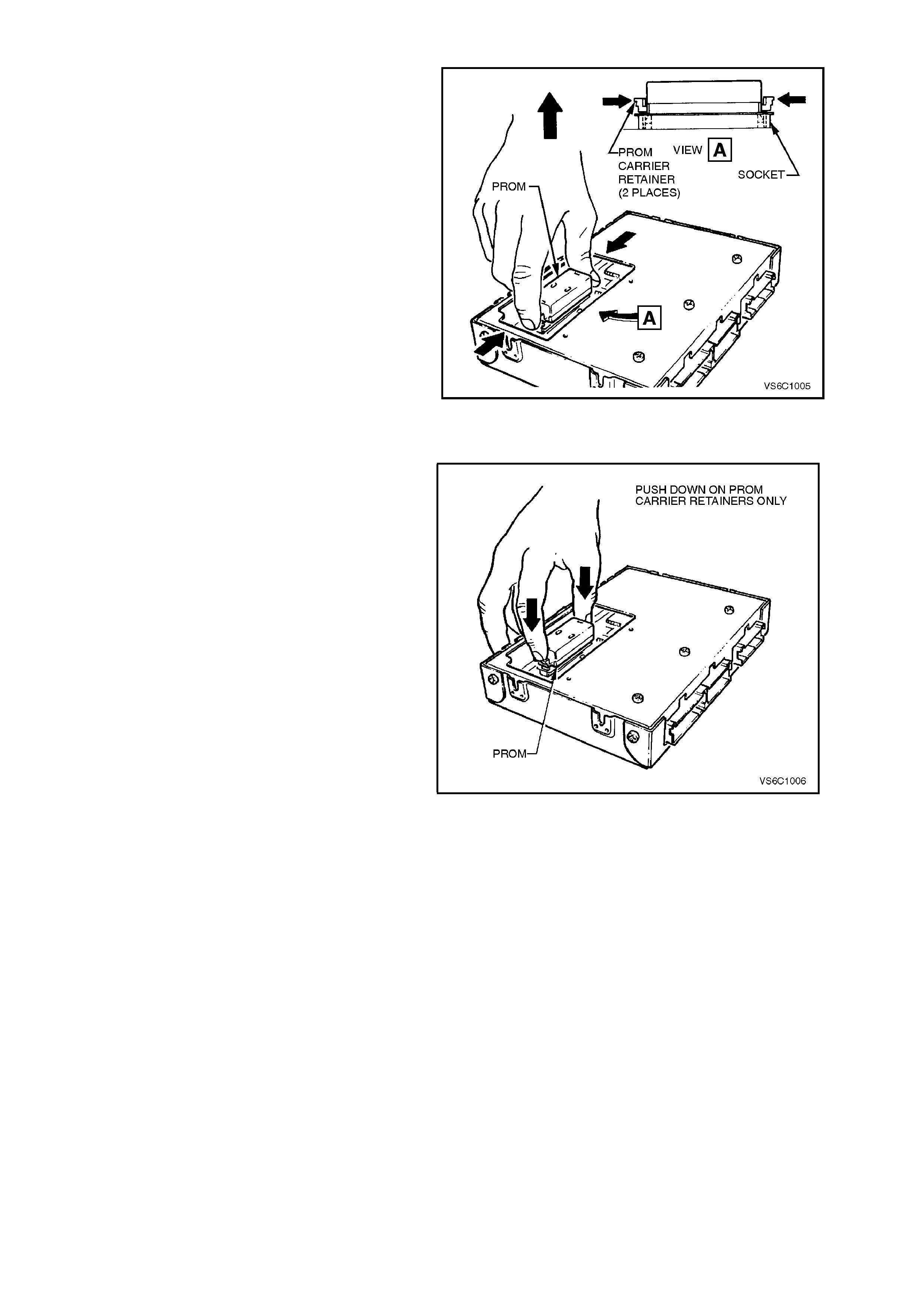
2. Install PROM in PROM socket, ensuring that
small notches in the PROM align with the
small notches in the PROM socket.
3. Gently press down on the ends of the PROM
until the retaining clips click into the PROM
socket.
4. Reinstall PROM access cover onto PCM. Use
No. 15 Torx bit (Tool No. J25359-19) to
reinstall and tighten access cover screws
securely.
5. Reinstall PCM, refer to 3.2 POWERTRAIN
CONTROL MODULE - REINSTALL in this
Section.
Figure 6C2-3-8 PCM Prom Removal
FUNCTIONAL CHECK
1. Turn the ignition ON.
2. Earth the DLC diagnostic test terminal.
A. A DTC 12 should flash four times. (No other
codes present.) This indicates that the PROM
is installed properly.
B. If a DTC 51 recurs or if the check Powertrain
Lamp (MIL) is ON constantly with no DTC's,
the PROM may not be not fully seated or the
PROM may be defective.
Figure 6C2-3-9 PROM Reinstallation
3.4 ENGINE COOLANT TEMPERATURE (ECT) SENSOR
IMPORTANT:
• Care must be taken when handling the
engine coolant t emperature sensor. Damage
to the ECT sensor will affect the operation
of the engine management system. Ensure
that the correct ECT sensor is located
before servicing. There are different engine
coolant temperature sensors: for the PCM,
the instrument panel gauge, and/or warning
lights.
REMOVE
1. Remove screw retaining engine trim front
cover and remove front cover.
2. Remove the throttle body, refer to 3.10 FUEL
CONTROL SYSTEM - THROTTLE BODY in
this Section.
3. Relieve the coolant system pressure by
removing the radiator cap in two stages.
CAUTION: DO NOT REMOVE THE RADIATOR
CAP WHEN THE ENGINE COOLANT
TEMPERATURE IS ABOVE 50 DEGREES C.
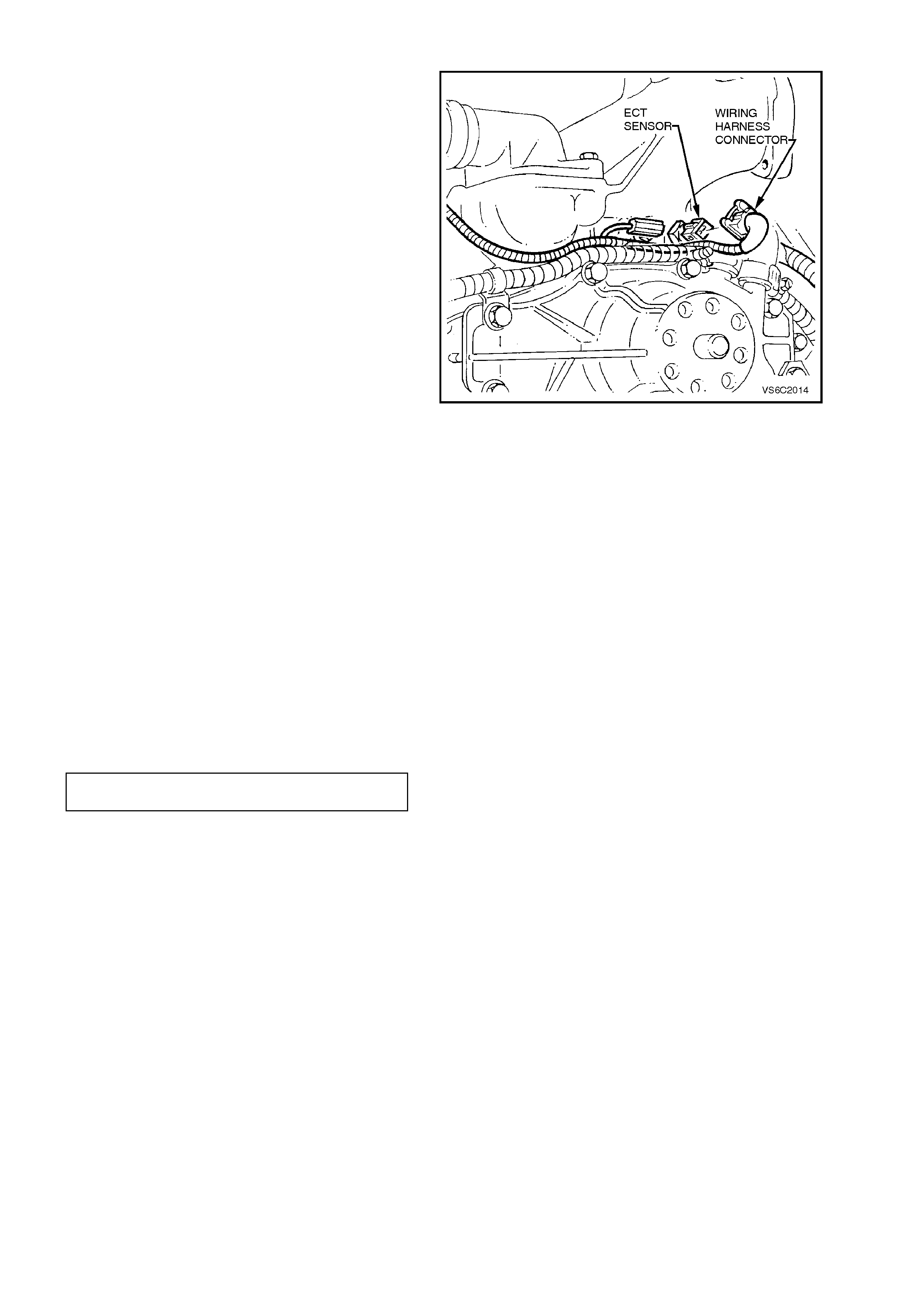
4. The ECT sensor electrical connector.
5. The ECT sensor.
Figure 6C2-3-10 ECT Sensor Removal
REINSTALL
1. Apply Loctite sealant to the ECT sensor
threads.
2. The ECT sensor.
3. The wiring harness connector to ECT sensor.
4. Refill the engine coolant system, refer to
Section 6B2 ENGINE COOLING - V8
ENGINE.
ECT SENSOR TO INLET MANIFOLD
TORQUE SPECIFICATION 15 - 20
Nm
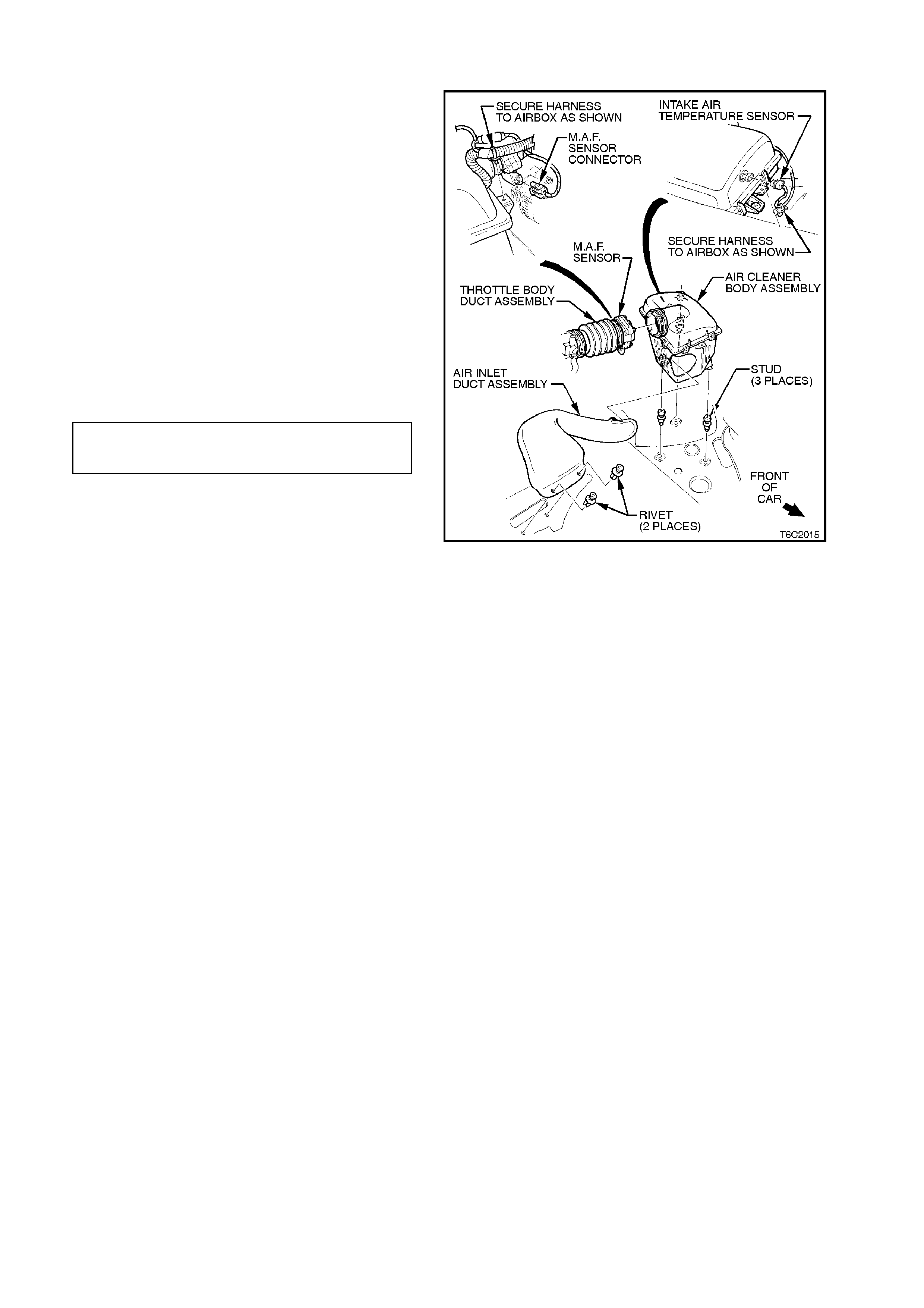
3.5 INTAKE AIR TEMPERATURE (IAT) SENSOR
IMPORTANT:
• Care must be taken when handling the IAT
sensor. Damage to the IAT sensor will affect the
proper operation of the fuel control system.
REMOVE
1. Disconnect battery earth lead.
Lift up tang on IAT sensor wiring harness
connector and pull connector from sensor.
Loosen intake air duct adaptor clamp that is
located closest to air cleaner assembly.
Disconnect air duct, with mass air flow sens or
attached, from air cleaner upper housing.
5. Unclip retaining clips holding the air cleaner
upper housing in place.
Separate the upper and lower air cleaner
housings.
NOTE:
Air filter should remain in the lower housing.
Remove air cleaner upper housing and place on
bench.
Using a pair of side cutters, cut across the IAT
sensor retainer to remove it. Once removed,
discard retainer.
Pull out IAT sensor from air cleaner upper housing.
REINSTALL
Push new IAT sensor into air cleaner upper
housing, with triangular tang on the mounting
flange locating on the mating rib of the air cleaner
upper housing.
Position the upper air cleaner housing, with the IAT
sensor on the work bench, pushing up into the air
cleaner upper housing.
Position new retainer onto IAT sensor and then
using a 20 mm socket, push the retainer fully onto
the IAT sensor.
Assemble the air filter element into the air cleaner
upper housing and place the upper housing onto
the air cleaner lower air cleaner housing, ensuring
that air filter element remains in position.
Snap retainer clips up into plac e over the top of the
air cleaner upper housing.
Reconnect wiring harness connector to IAT sensor.
Carefully assemble intake air duct and mass air
flow sensor onto air cleaner upper housing.
NOTE:
Align notch on air cleaner housing adaptor with
notch in air duct adaptor and notch in clamp.
Tighten air duct clamp securely.
Check that mass air flow sensor wiring harness
connector has remained firmly in place.
Reconnect battery earth lead.
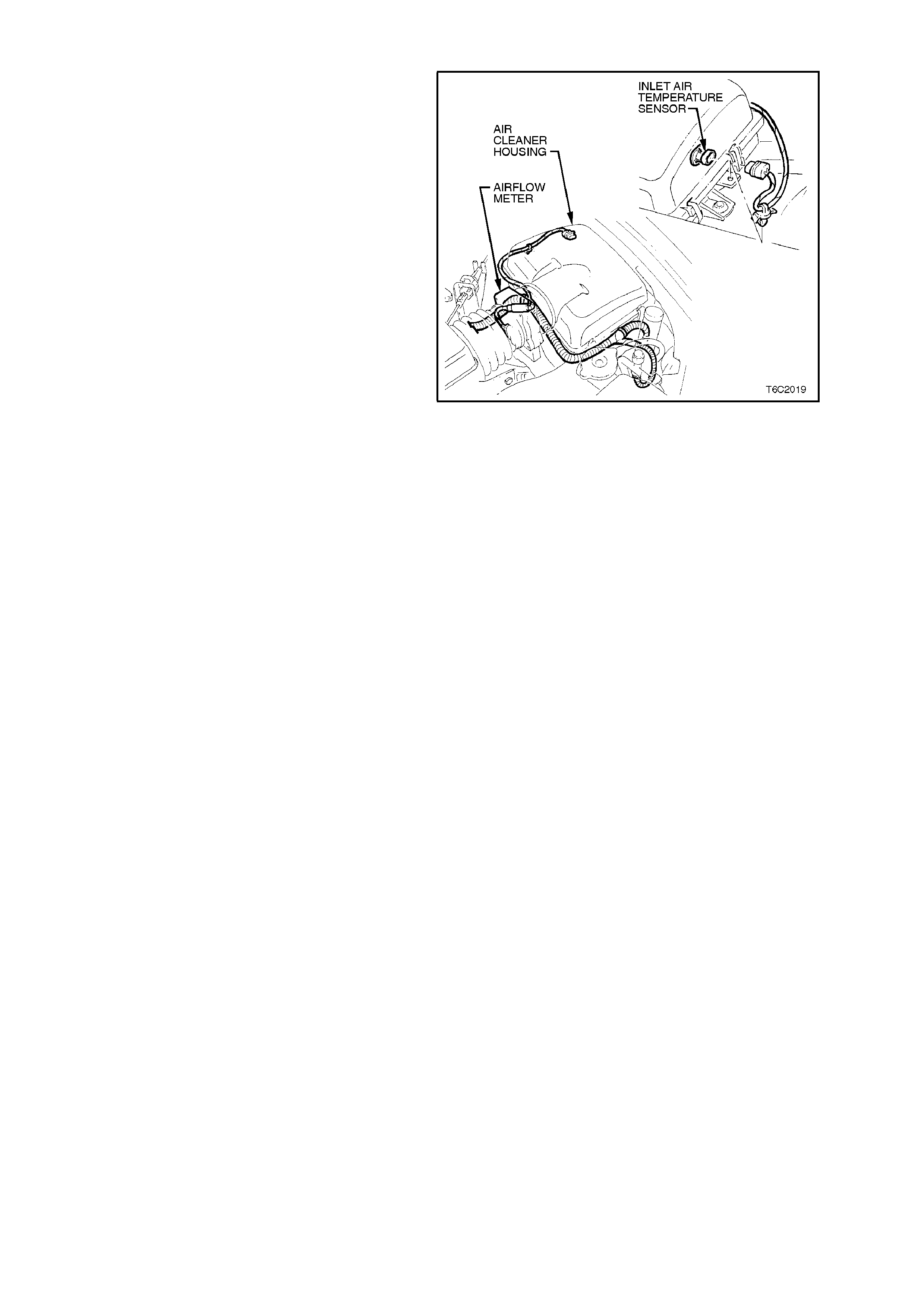
Figure 6C2-3-11 IAT Sensor Location
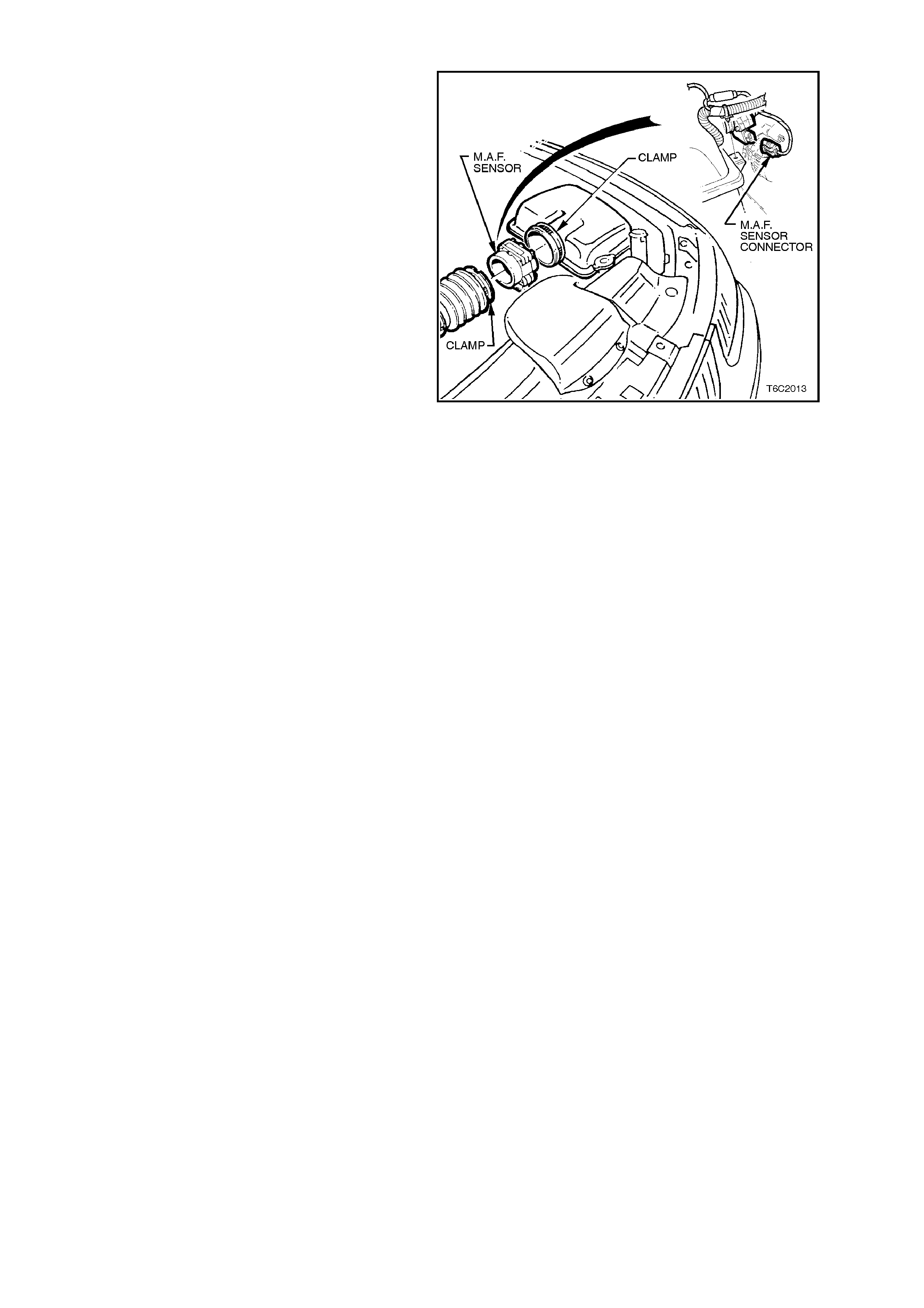
3.6 MASS AIR FLOW (MAF) SENSOR
IMPORTANT:
Care must be taken when handling MAF sensor.
Damage to MAF sensor will aff ect proper operation
of PCM control.
REMOVE
1. Disconnect battery earth lead.
2. Lift up tang on MAF sensor wiring harness
connector and pull connector from sensor.
3. Loosen clamp on air duct adaptor, closest to MAF
sensor.
4. Loosen clamp on air duct at MAF sensor and pull
back air duct from sensor.
NOTE:
Air duct adaptor (between air cleaner and MAF sensor),
both clamps, air duct and MAF sensor itself have
locating notches.
Remove MAF sensor from air duct adaptor.
REINSTALL
1. Install MAF sensor into air duct adaptor and
air duct, aligning all notches. Install clamps,
aligning notches, tighten clamps securely.
2. Reconnect MAF sensor wiring harness
connector.
3. Reconnect battery earth lead.
4. Start vehicle and check for air leaks.
Figure 6C2-3-12 MAF Sensor Removal
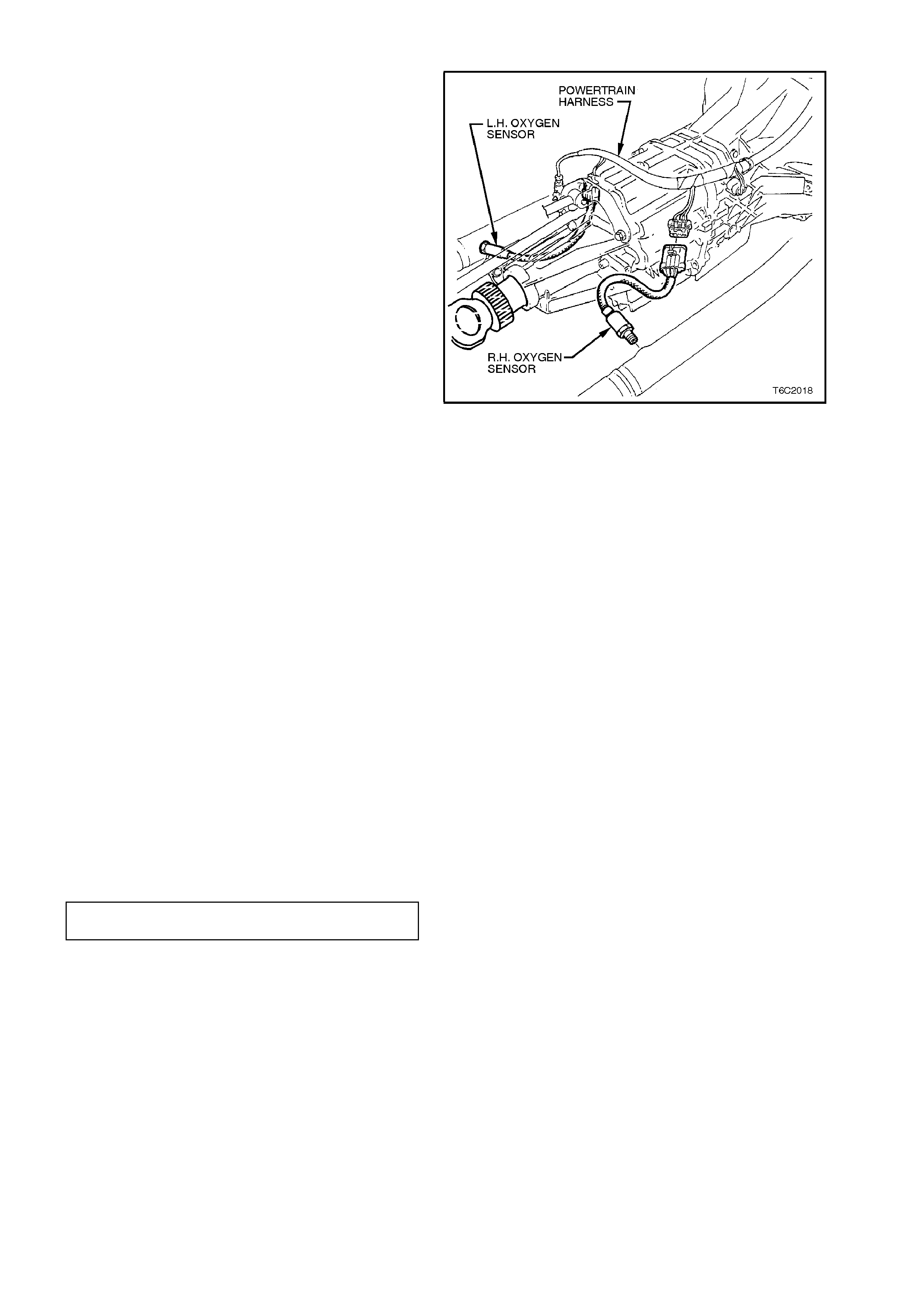
3.7 OXYGEN SENSOR
IMPORTANT:
∙The oxygen sensor has a permanently
attached pigtail and connector. This pigtail
should not be removed from the oxygen
sensor. Damage or removal of the pigtail or
the connector c ould affect the operation of the
02 sensor.
Handle the 02 sensor with care. The in-line
electrical connector and louvred end must be
kept f ree of grease, dir t or other contam inants .
Avoid using any cleaning solvents.
NOTE:
The oxygen sensor may be difficult to remove when
the engine temperature is below 60 degrees
Celsius. Excessive force may damage the threads
in the exhaust pipe, or on the sensor.
REMOVE
1. Raise the vehicle and place on suitable safety
stands. Refer to Section 3, FRONT
SUSPENSION for jacking procedure.
2. The oxygen sensor electrical connector.
3. Carefully remove the oxygen sensor, refer to
the previous IMPORTANT Note.
REINSTALL
IMPORTANT:
A special anti-seize compound is used on the
oxygen sensor threads. New or ser vice sensor s will
already have the compound applied to the threads.
If an oxygen sensor is removed from an engine,
and, if the O2 sensor is to be reinstalled, the
threads must have the specified anti-seize
compound applied before reinstallation.
1. Specified anti-seize compound is available
through the Holden's Service Parts
Organisation (HSPO) as part number
5613695.1. If necessary, coat the threads of
the oxygen sensor with the specified anti-
seize compound.
2. The oxygen sensor into exhaust pipe and
tighten to the correct torque specification.
Figure 6C2-3-13 Oxygen Sensor Location
OXYGEN SENSOR TO EXHAUST
MANIFOLD TORQUE SPECIFICATION 40 - 50
Nm
3. The oxygen sensor electrical connector .
4. Lower the vehicle.
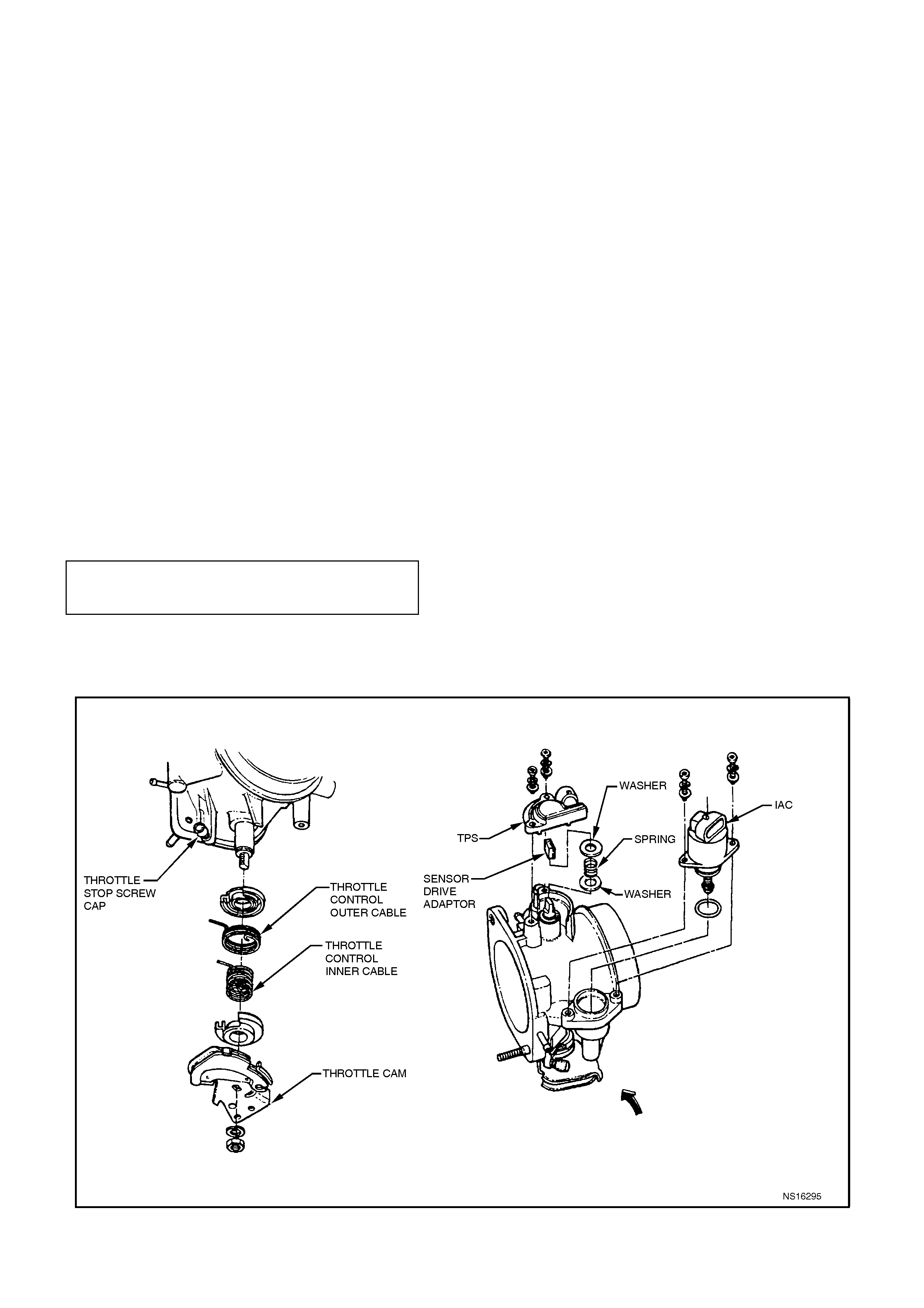
3.8 THROTTLE POSITION (TP) SENSOR
REMOVE
1. The throttle body assembly, refer
3.10, FUEL; CONTROL SYSTEM -
THROTTLE BODY - Remove in this Section.
2. The two TP Sensor attaching screws.
3. The TP sensor from throttle body, do not
loosen the drive adaptor, the washer or the
spring.
4. The drive adaptor, the washer, the spring and
the washer.
REINSTALL
1. The washer, the spring, and the drive adaptor
to throttle valve shaft.
2. With the throttle valve in the normally closed
position, install the TP Sensor onto the thr ottle
valve shaft. Then position the TP sensor 30
degrees clockwise past the throttle body
attaching screw holes.
3. Rotate the TP Sensor anti-clockwise on the
throttle body.
4. Install the TP Sensor attaching screws and
tighten to the correct torque specification.
TP SENSOR TO THROTTLE BODY
ATTACHING SCREW
TORQUE SPECIFICATION 1 - 1.5 Nm
5. The throttle body assembly, refer to
3.10 FUEL; CONTROL SYSTEM -
THROTTLE BODY - Reinstall in this Section.
Figure 6C2-3-14 - TP Sensor Installation
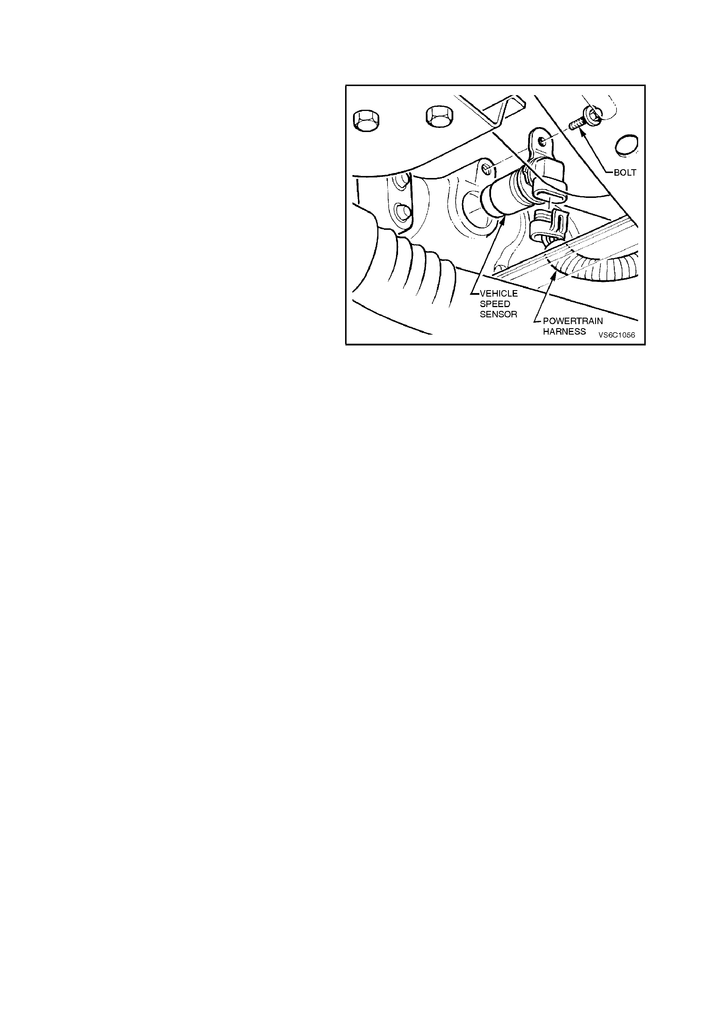
3.9 VEHICLE SPEED SENSOR
AUTOMATIC TRANSMISSION
REMOVE
1. The VSS electrical connector.
2. Place a container below the sensor to catch
any fluid that may drain.
3. The VSS to the extension housing bolt.
4. The VSS and the O-ring seal by slowly prying
the sensor from the extension housing with a
flat screwdriver.
REINSTALL
1. Coat the VSS O-ring with a thin film of
transmission fluid.
2. Install the VSS and the O-ring into the
extension housing.
3. The VSS and the extension housing bolt and
tighten to the correct torque specification.
4. Reconnect the wiring harness connec tor to the
VSS.
Refill the transmission with fluid as needed. Figure 6C2-3-15 VSS Removal
MANUAL TRANSMISSION
For vehicle speed sensor removal and reinstallation,
refer to Section 7B-2 MANUAL TRANSMISSION -
V8.
3.10 FUEL CONTROL SYSTEM
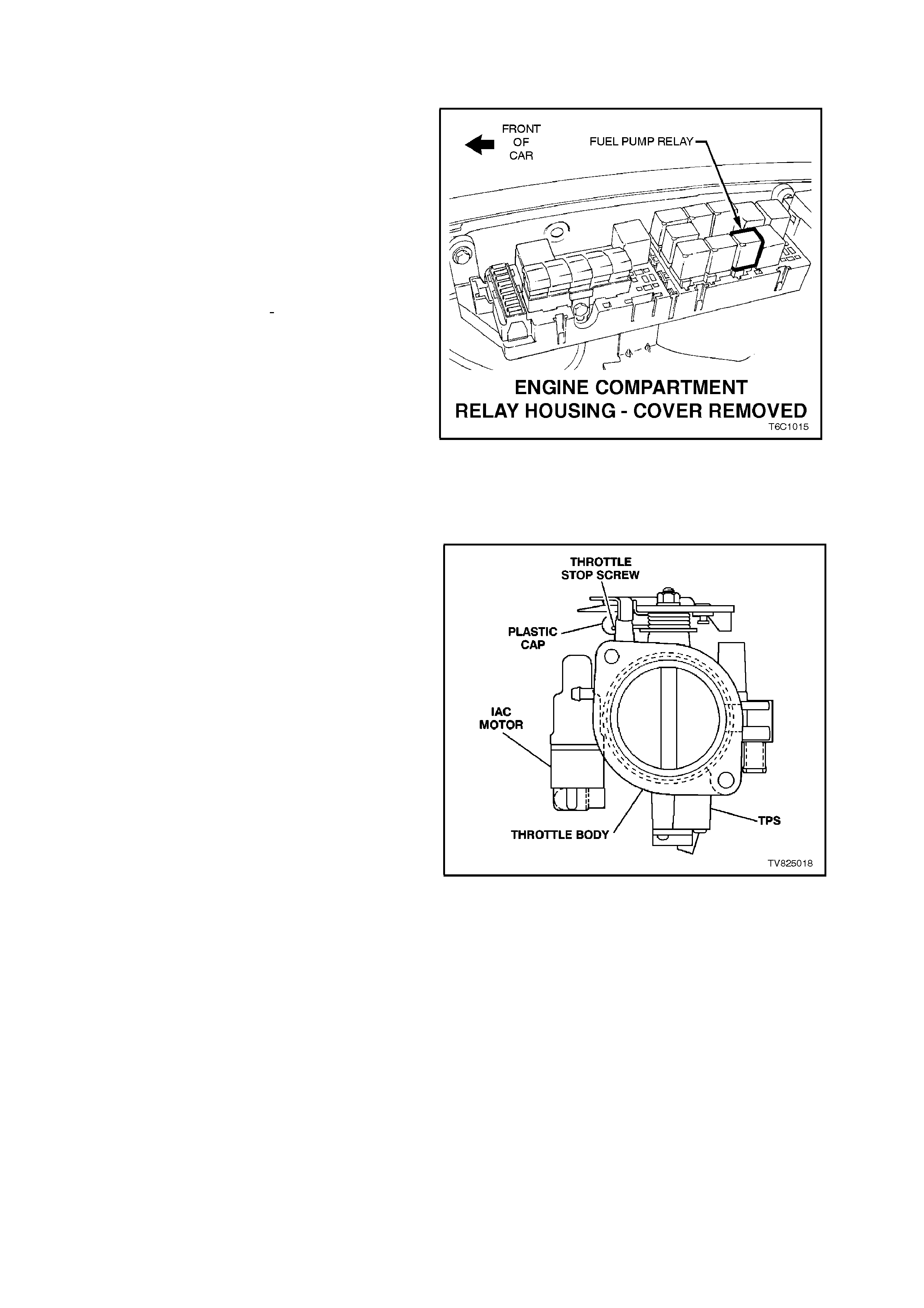
FUEL PUMP RELAY
The fuel pump relay is mounted in the relay
housing which is located under the bonnet, refer
Fig. 6C2-3-16. The relay housing is positioned
forward of the right side (driver's side) strut tower.
Other than checking for loose connectors, the only
service is a replacement.
FUEL PRESSURE RELIEF PROCEDURE
1. Remove the “Fuel Pump Relay” from the
engine compartment relay housing.
2. With the throttle closed, crank the engine -
engine may start and idle until fuel supply
remaining in the fuel line is burned. W hen the
engine stops, engage the starter again for 10
seconds to ensure dissipation of any
remaining pressure
3. Reinstall the fuel pump relay.
Unless this procedure is followed before
servicing the fuel lines or the fuel connections,
fuel spray into the engine compartment could
occur!
Figure 6C2-3-16 Fuel Pump Relay Location
THROTTLE STOP SCREW - RESET PROCEDURE
The throttle stop screw controls the minimum
throttle opening (Closed throttle position). The
throttle stop screw is preset at the factory and must
not be reset unless:
• The screw was inadvertently reset.
- OR -
• Instructed to by a diagnostic chart.
The engine idle speed, which will vary with engine
temperature and engine load, is PCM controlled
and is not adjustable.
The PCM - Idle Air Control (IAC) Valve and the
Throttle stop screw setting (RPM) are not the
same.
The throttle stop screw setting (RPM) must always
be less than the PCM controlled idle speed. This
setting is checked only after disabling the Idle Air
Control valve. The throttle stop screw setting is the
least likely cause of an abnormal idle condition,
therefore resetting the screw should only be
considered as a last resort. An incorrect setting is
likely to cause a deterioration in idle quality.
IMPORTANT:
INSPECT:
• Before any resetting is attempted, ensure that
no vacuum leaks exist. Check all the vacuum
hoses, the inlet manifold gasket, the throttle
body-to-manifold attachment, and any vacuum-
operated devices. The engine must be at
normal operating temperature before any
checking or resetting is attempted.
WITH THIS ENGINE CONTROL SYSTEM,
ANY VACUUM LEAK WILL RESULT IN A
HIGH IDLE.
Figure 6C2-3-17 Throttle Stop Screw Location

CHECK OR RESET:
1. Before performing this procedure, complete
the On-Board Diagnostic System Check.
2. Before performing steps 3 - 16, ensure that
the IAC system is functioning properly. See
CHART A-7.1 (IAC system check) before
proceeding.
3. The engine must be at the normal operating
temperature, (85°C) before continuing.
4. Apply the parking brake and block the drive
wheels. Ensure that the transmission is in
Park (auto) or neutral (manual).
5. Verify that the ignition initial base timing is
correct, refer to 3.12 IGNITION SYSTEM - V8,
Timing Adjustment in this Section.
6. Ignition ON, engine OFF. Using a Tech 2 scan
tool, command the IAC valve to 0 steps.
7. Wait 10 seconds, then disconnect the IAC
valve electrical connector.
8. Verify that the throttle cable and the throttle
linkage are not binding. The throttle lever
attached to the throttle butterfly shaft must be
able to open fully, and shut fully and freely
every time the accelerator pedal is fully
depressed and slowly released.
Refer to 3.10, FUEL CONTROL SYSTEM -
THROTTLE CABLE - ADUST in this Section if
a throttle cable adjustment is required.
9. Turn OFF all of the electrical loads.
10. Use the Tech 2 scan tool to display Engine
Speed.
11. Start the engine. If the engine will not start,
hold the throttle open slightly, and then try
again. After the engine starts, slowly allow the
throttle to fully close.
12. After 2 minutes, check that the A/C condenser
fan has cycled off, then note the engine RPM.
13. If the engine has completed less than 3,000
km, do not reset the throttle stop screw unless
the RPM is above 600. Otherwise, the engine
speed should be between 500 to 600 RPM.
If a reset is necessary, remove the plastic cap
from the throttle stop screw (reset to 500 - 550
RPM).
14. If removed, reinstall the plastic cap on the
throttle stop screw.
15. Ignition OFF, reconnect the IAC valve
electrical connector.
16. Ignition ON, clear the DTCs with a Tech 2
scan tool.
17. Start the engine, use a Tech 2 scan tool and
select the IAC reset function. Enable the "IAC
reset" in park/neutral with the A/C ON and
then the A/C OFF. If the vehicle is equipped
with an automatic transmission, apply the
service brake, place the transmission in "drive"
and enable the IAC reset with the A/C ON and
then the A/C OFF
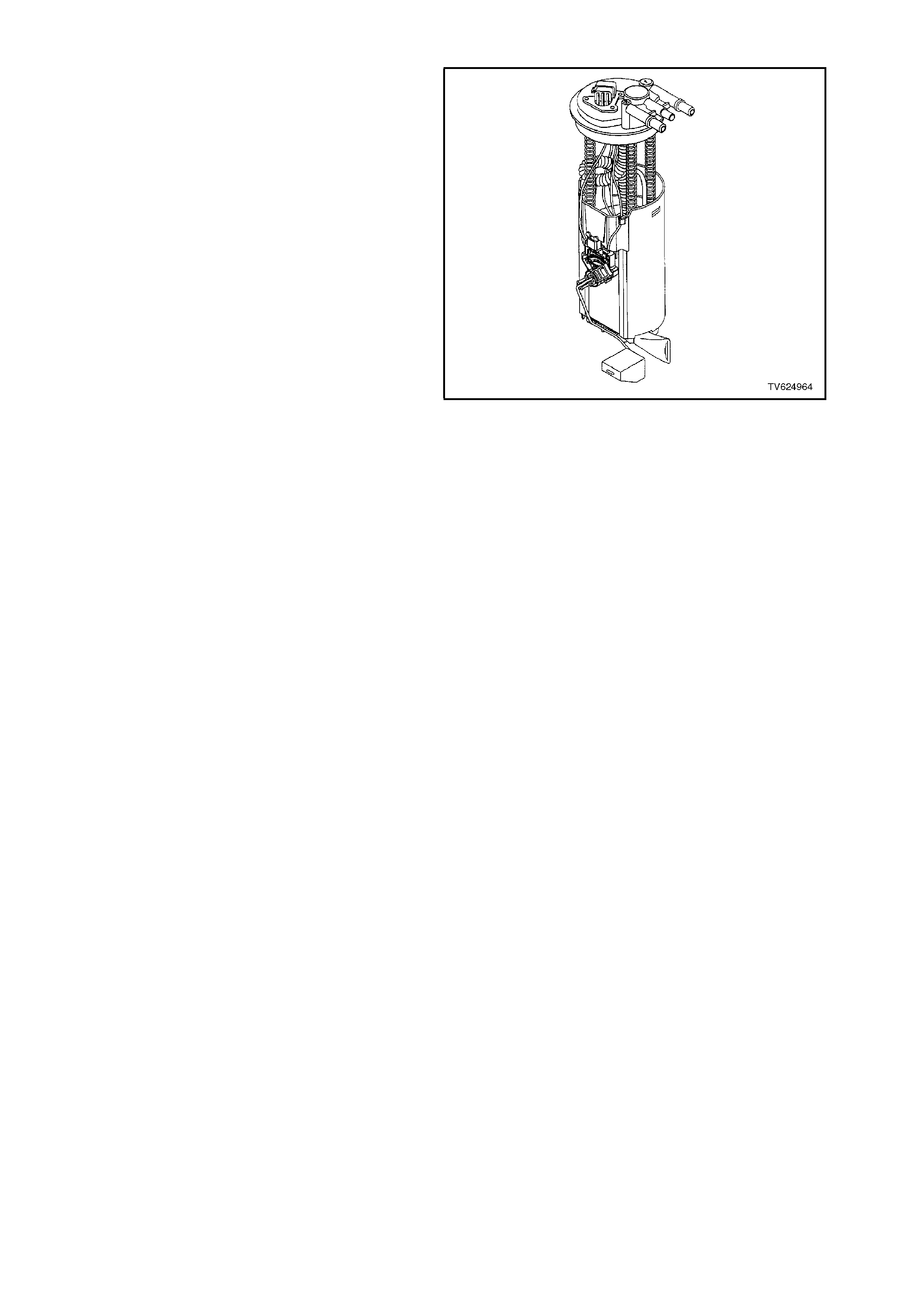
MODULAR FUEL SENDER ASSEMBLY
REMOVE
TOOL REQUIRED
J 39765, Fuel Sender Locknut Wrench
NOTE:
Do not handle the m odular f uel s ender as s embly by
the fuel pipes.
1. Relieve the fuel system pressure. Refer to the
Fuel Pressure Relief Procedure
3.10 FUEL CONTROL SYSTEM in this Section.
2. Disconnect the battery earth lead.
3. Fuel Tank Removal, refer to Sect ion 8A, FUEL
TANK for removal of fuel tank.
4. Remove the modular fuel sender retaining ring
using the J 39765 Fuel Sender Locknut
Wrench.
IMPORTANT:
W hen removing the modular fuel sender assembly
from the fuel tank, the reservoir bucket on the fuel
sender assembly will be full of fuel. The modular
fuel sender assem bly must be tipped slightly during
removal in order to avoid damage to the float.
Place any remaining fuel into an approved
container once the modular fuel sender assembly is
removed from the fuel tank.
The modular fuel sender assembly will spring-up
when the locking ring is removed.
4. Pull the modular fuel sender straight up while
draining the fuel from the reservoir.
5. Clean the fuel sender assembly O - ring
sealing surface.
6. Inspect the fuel sender assembly O - ring
sealing surface.
Figure 6C2-3-18 Modular Sender Assembly
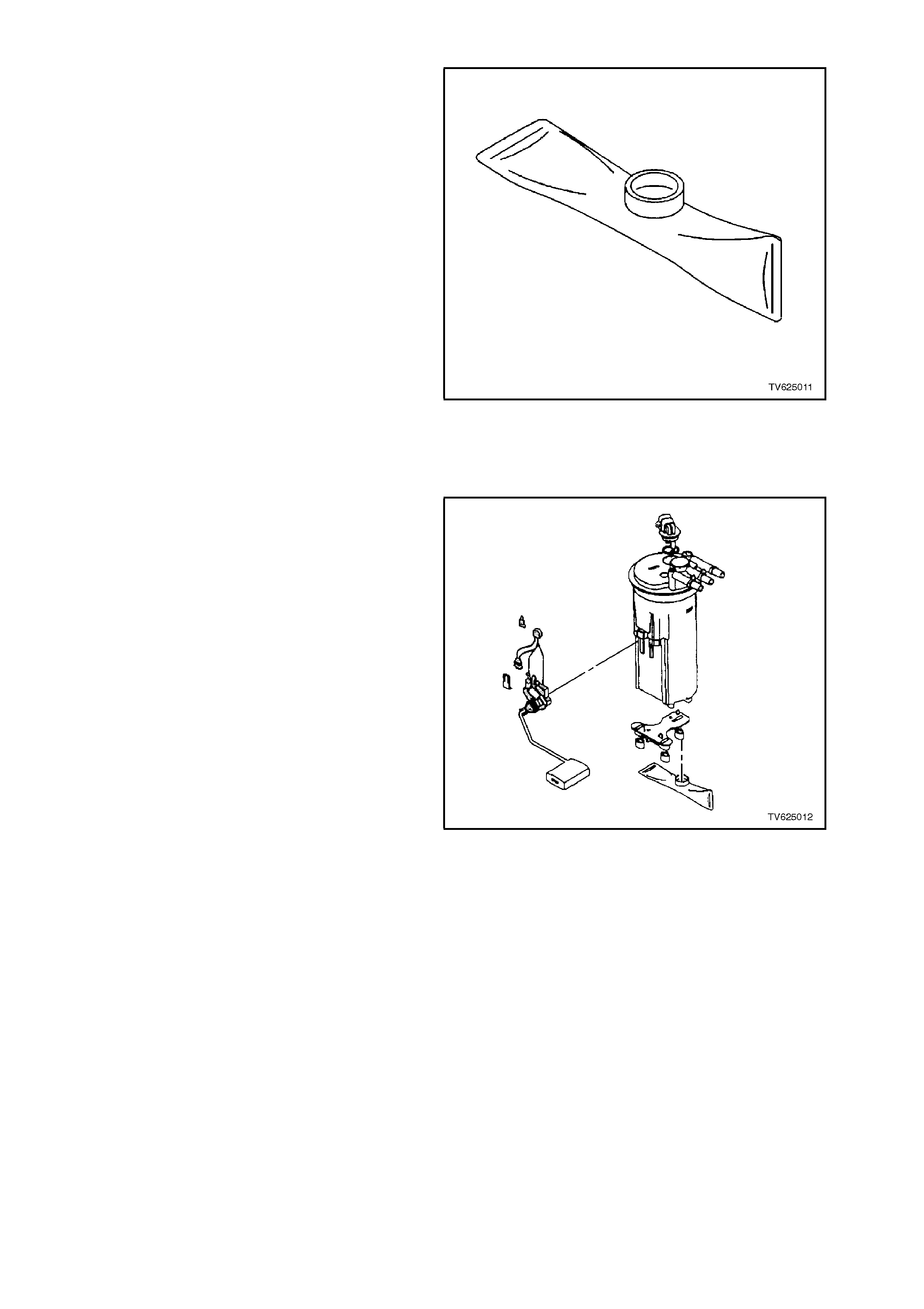
MODULAR FUEL SENDER ASSEMBLY (SERVICEABLE FUEL STRAINER AND FUEL LEVEL SENSOR)
REMOVE
NOTE:
Do not handle the m odular f uel s ender as s embly by
the fuel pipes.
1. Relieve the fuel system pressure. Refer to the
Fuel Pressure Relief Procedure,
3.10 FUEL CONTROL SYSTEM in this
section.
2. Disconnect the battery earth lead.
3. Remove fuel tank, refer to Section 8A FUEL
TANK.
4. Remove the MODULAR FUEL SENDER
ASSEMBLY. Refer to removal procedure in
this Section.
DISASSEMBLY
1. Note the position of the f uel sender strainer f or
reinstallation.
2. Support the reser voir with one hand and grasp
the fuel sender strainer with the other hand.
3. Pull the fuel strainer off of the fuel sender
assembly.
Figure 6C2-3-19 Fuel Strainer
4. Inspect the fuel sender strainer. If the fuel
sender strainer is contaminated, the fuel tank
should be cleaned.
5. Discard the fuel sender strainer after the
inspection.
6. Disassemble the electrical connectors from
the fuel level sensor assembly of the fuel
pump and the cover assembly.
7. Disassemble the fuel level sensor assembly.
REASSEMBLE
1. Assemble the fuel level sensor assembly.
2. Assemble the electrical connectors to the fuel
pump and cover assembly.
3. Assem ble the rubber pad on the bottom of the
modular fuel sender assembly.
4. Position the new fuel sender strainer on the
modular fuel sender and push on the outer
edge of the fuel sender strainer until the fuel
sender strainer is fully seated.
REINSTALL
1. Install the fuel sender assembly. Refer to
MODULAR FUEL SENDER ASSEMBLY for
reinstallation of sender assembly to fuel tank
in this Section.
2. Reinstall the fuel tank. Refer to
Section 8A FUEL TANK.
3. Reconnect the battery earth lead.
4. Inspect the fuel system for leaks.
Figure 6C2-3-20 Fuel Level Sensor Assembly

MODULAR FUEL SENDER ASSEMBLY - FUEL PUMP
REMOVE
1. Remove the Modular Fuel Sender Assembly, 3.10 FUEL CONTROL SYSTEM refer to procedure in this
Section.
2. Remove the external fuel strainer .
3. Remove the CPA #8 ( connector position assurance) from the electrical connector and disconnect the fuel
pump electrical connector. Refer to figure 6C2-3-21.
4. Gently release the tabs on the side the fuel sender to the cover assembly. Begin by squeezing the sides of the
reservoir and releasing the tab opposite the fuel level sensor. Move clockwise to release the second and third
tab in the same manner.
5. Lift the cover assembly far enough to disconnect the fuel pump electrical connection.
6. Carefully pry snap ring (#21) out of groove on the fuel pump outlet. Refer to figure 6C2-3-21 view B.
7. Rotate the fuel pump baffle (#18) counterclockwise and remove the baffle pump assembly from the retainer
(#7). Refer to figure 6C2-3-21.
8. Replace the fuel pump seal/dampener. Refer to figure 6C2-3-23.
9. Install the fuel pump outlet retainer (#21) on the fuel pump outlet (#20). Index the snap ring so that the ends
are positioned in the groove (#22) facing the fuel pump electrical connector. Refer to figure 6C2-3-21 view A
and B.
10. Install the new fuel pump and the baffle assembly onto the reservoir retainer (#7) and rotate clockwise until
seated. Refer to figure 6C2-3-21.
11. Place the fuel pump outlet (#20) over retainer (#7) so that snap ring ends (#21) face fuel pump electrical
connection and press firmly into place making certain the snap ring is seated and over each tab on the outlet.
Refer to figure 6C2-3-21.
12. Lower the retainer assembly (#7) partially into the reservoir. Line up all three sleeve tabs.
13. Install the fuel pump connector and CPA #8 to the fuel sender cover (#7). Refer to figure 6C2-3-21.
14. Install the new external fuel strainer (#14). Refer to figure 6C2-3-21.
15. Reinstall the Modular Fuel Sender Assembly to the fuel tank as outlined in the MODULAR FUEL SENDER
ASSEMBLY in this Section, and reinstall the fuel tank.
16. Inspect the fuel system for leaks.
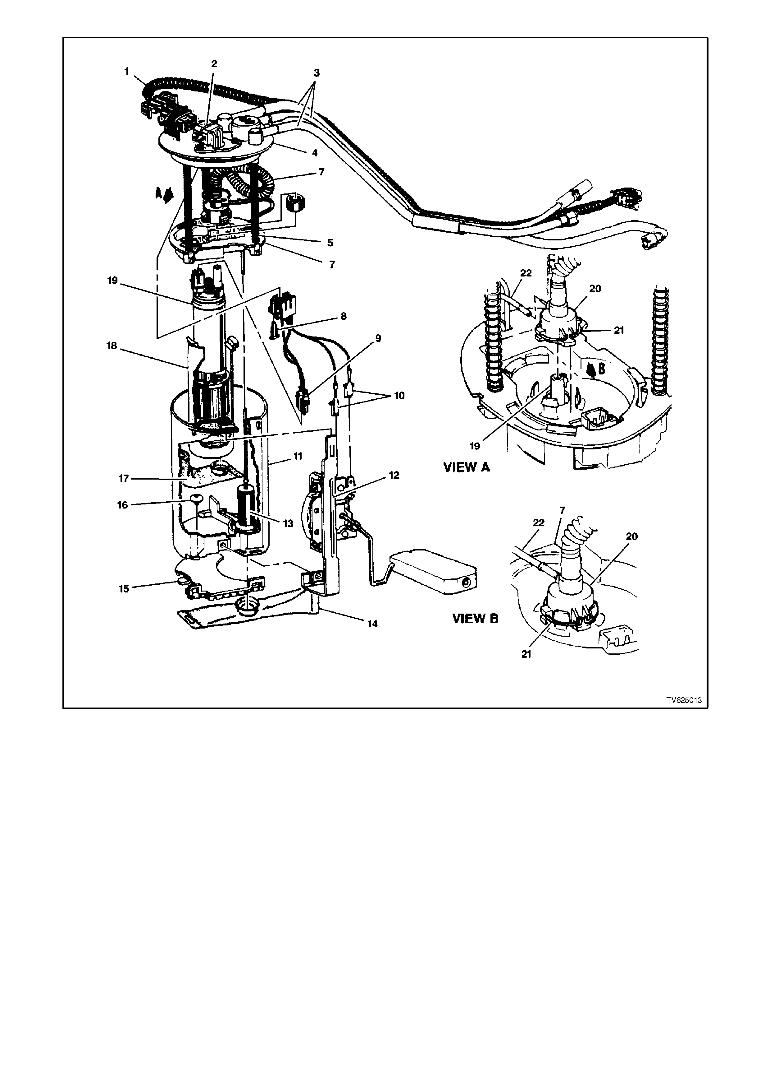
Figure 6C2-3-21 Modular Fuel Sender Assembly Expanded View
1. Harness assembly (above cover) - Fuel pump and
fuel sender wiring.
2. Connector assembly - Fuel sender wiring.
3. Fuel pipes (3).
4. Cover assembly - Fuel sender.
5. Pipe (convoluted) - Fuel sender outlet.
6. Support assembly (hollow support or guide pipes)
-Fuel pump reservoir.
7. Retainer - Fuel pump reservoir.
8. Connector Position Assurance (CPA).
9. Harness assembly (below cover) - Fuel pump.
10. Harness assembly (below cover) - Fuel level
sender.
11. Reservoir - Fuel pump fuel.
12. Sensor assembly - Fuel level.
13. Pump assembly ( jet pump assembly) - Fuel
pump reservoir.
14. Strainer (external) - Fuel sender.
15. Pad (bumper) - Fuel sender.
16. Valve (secondary umbrella valve) - Fuel
pump reservoir inlet check.
17. Strainer - Fuel pump fuel.
18. Baffle (isolator cup) - Fuel pump.
19. Pump assembly (turbine) - Fuel.
20. Outlet - Fuel pump.
21. Snap ring - Fuel pump outlet.
22. Pipe - Jet pump.
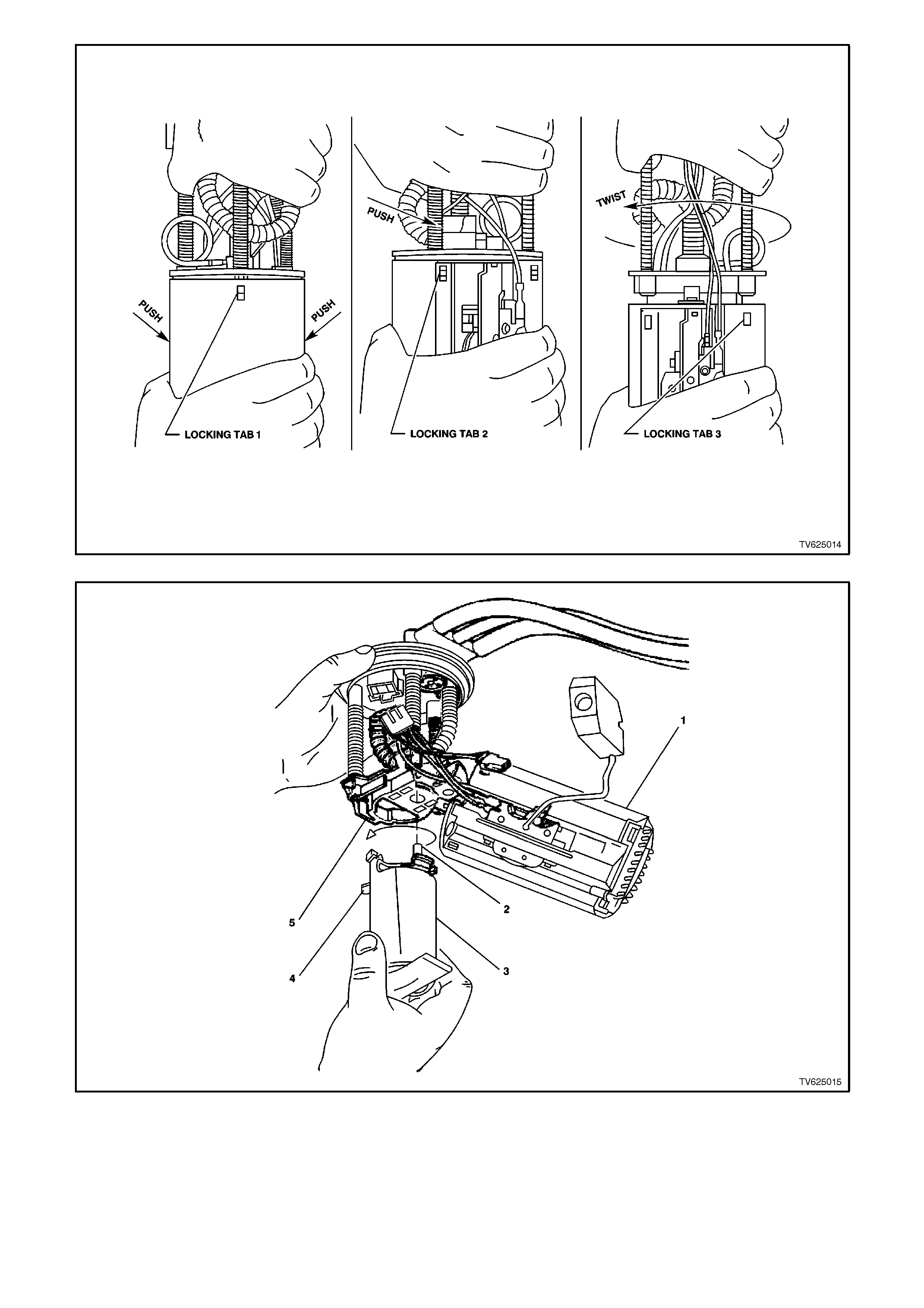
Figure 6C2-3-22 Modular Fuel Sender Assembly Grasping View
Figure 6C2-3-23 Fuel Pump Removed From Modular Sender Assembly
1. Reservoir Assembly
2. Outlet Tube
3. Fuel Pump Assembly
4. Flex Member
5. Retainer Fuel Pump Reservoir
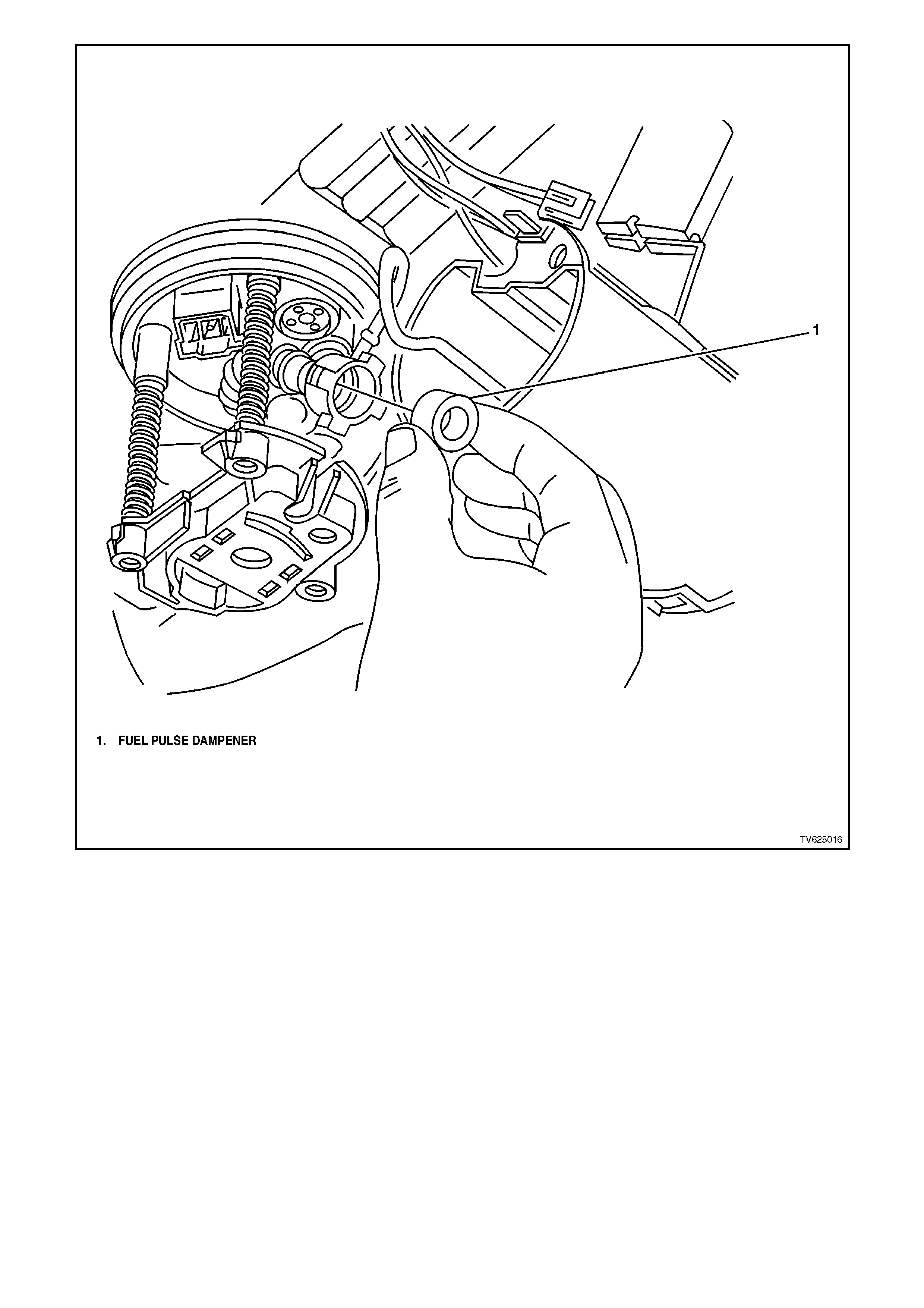
Figure 6C2-3-24 Fuel Pump Seal/Dampener
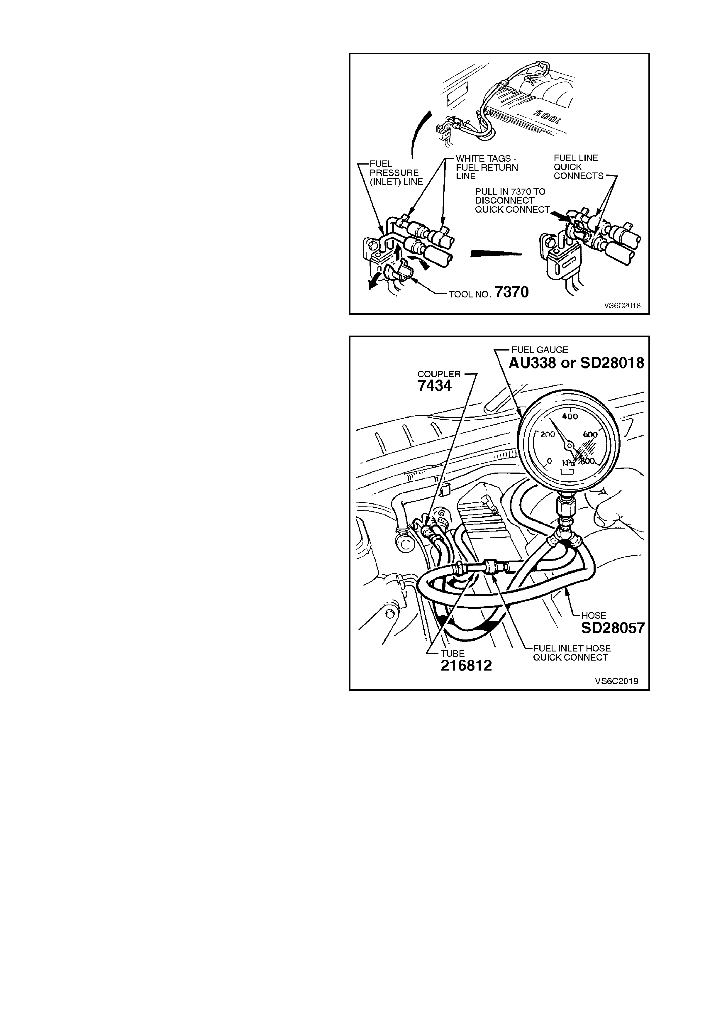
FUEL SYSTEM PRESSURE TEST
A fuel system pressur e test is part of the Diagnostic
Charts and Symptom checks. To perform this test,
follow this procedure.
CAUTION:
To reduce the risk of a fire or a personal injury,
relieve the fuel system pressure before performing
this test. See "Fuel Pressure Relief Procedure" in
this Section.
1. Relieve the fuel pressure as described in
“Fuel Pressure Relief Procedure” in this
Section. Turn the ignition OFF.
2. Install Tool No. 7370 over the fuel inlet line.
3. Close 7370 and pull into fuel line quick
connect to release it from the fuel inlet line,
pull back on the quick connect.
Figure 6C2-3-25 Fuel Pressure Test Tool
NOTE:
Before conducting the next step, inspect the tube
adaptor on the fuel pres sure gauge hose to ensure
that it is free from any damage or burrs. This is
necessary to ensure that the tube does not damage
the sealing ring in the quick connect. If the sealing
ring becomes damaged, fuel leakage will occur.
4. Install the fuel pressure gauge AU338 or
SD28018 & hose SD28057 fitted with Coupler
7434 and tube 216812 in the fuel pressure
line, between the fuel inlet line and the fuel
inlet hose quick connect.
5. Use a Tech 2 scan tool to enable the fuel
pump, so that the fuel pump can pressurise
the system.
6. The gauge reading should be between 270 -
350 kPa if not, refer to Diagnostic
CHART A-4.2 in Section 6C2-2A.
7. Relieve the fuel pressure as described in
“Fuel Pressure Relief Procedure” in this
Section.
8. Remove the fuel pressure gauge.
9. Reinstall the fuel line.
10. Check for fuel leaks as described in “LEAK
TESTING” in this Section. Figure 6C2-3-26 Fuel Pressure Gauge
FUEL FILTER
REMOVE
IMPORTANT Relieve the fuel system pressure
before servicing any fuel system connection. Refer
to the Fuel Pressure Relief Procedure in
3.10, FUEL CONTROL SYSTEM in this Section.
1. Relieve fuel pressure as described in
3.10, FUEL CONTROL SYSTEM - Fuel
Pressure Relief Procedure in this Section.
2. Disconnect batt er y earth le ad.
3. Raise rear of vehicle and support on safety
stands, refer to Section OA, GENERAL
INFORMATION in the VT Service Information.
4. Place a drain tray beneath fuel filter.
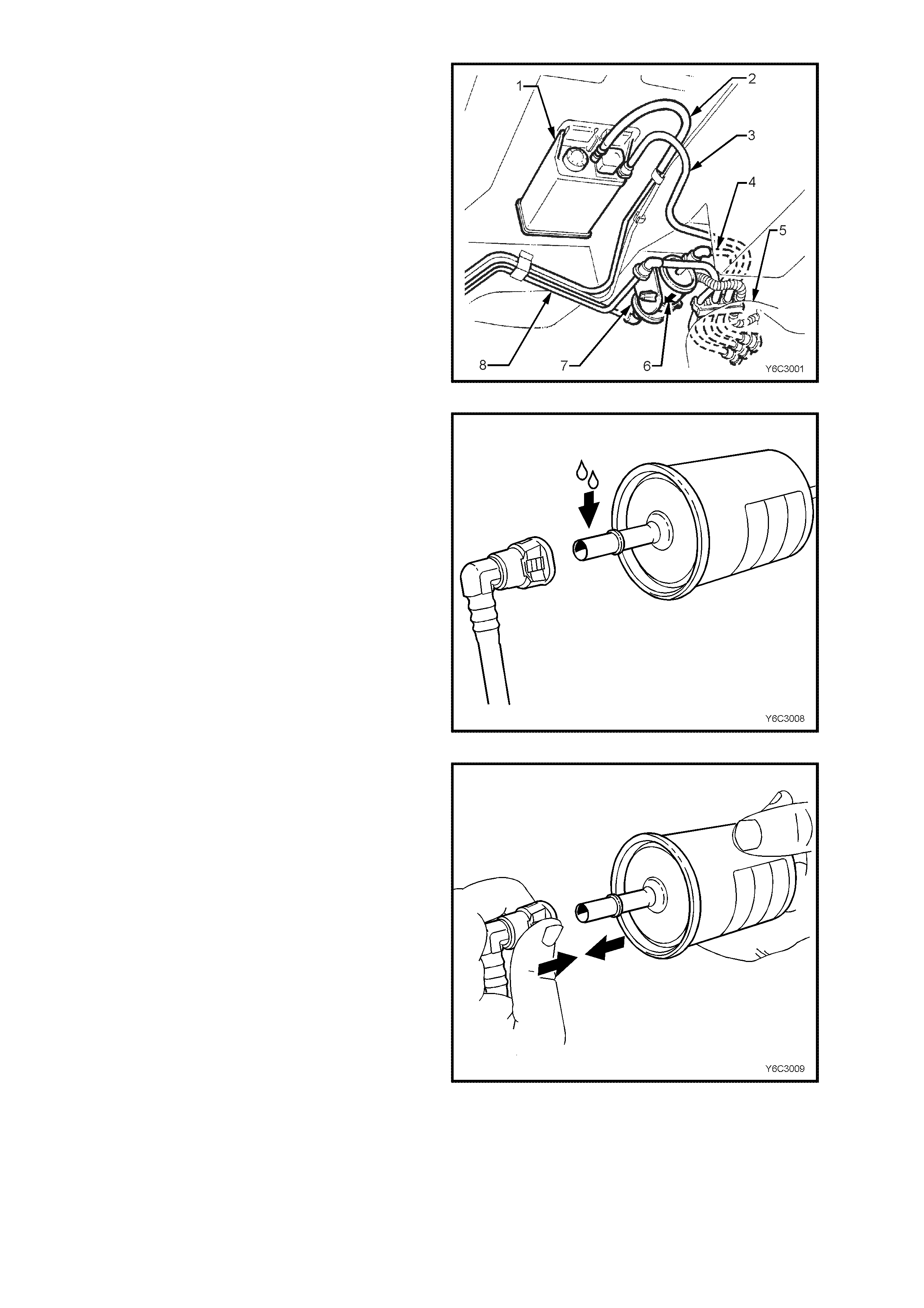
5. Remove the fuel filter from the retaining
brack et (1) with the fuel lines still connected to
the fuel filter to allow easier access.
Figure 6C1-3-27
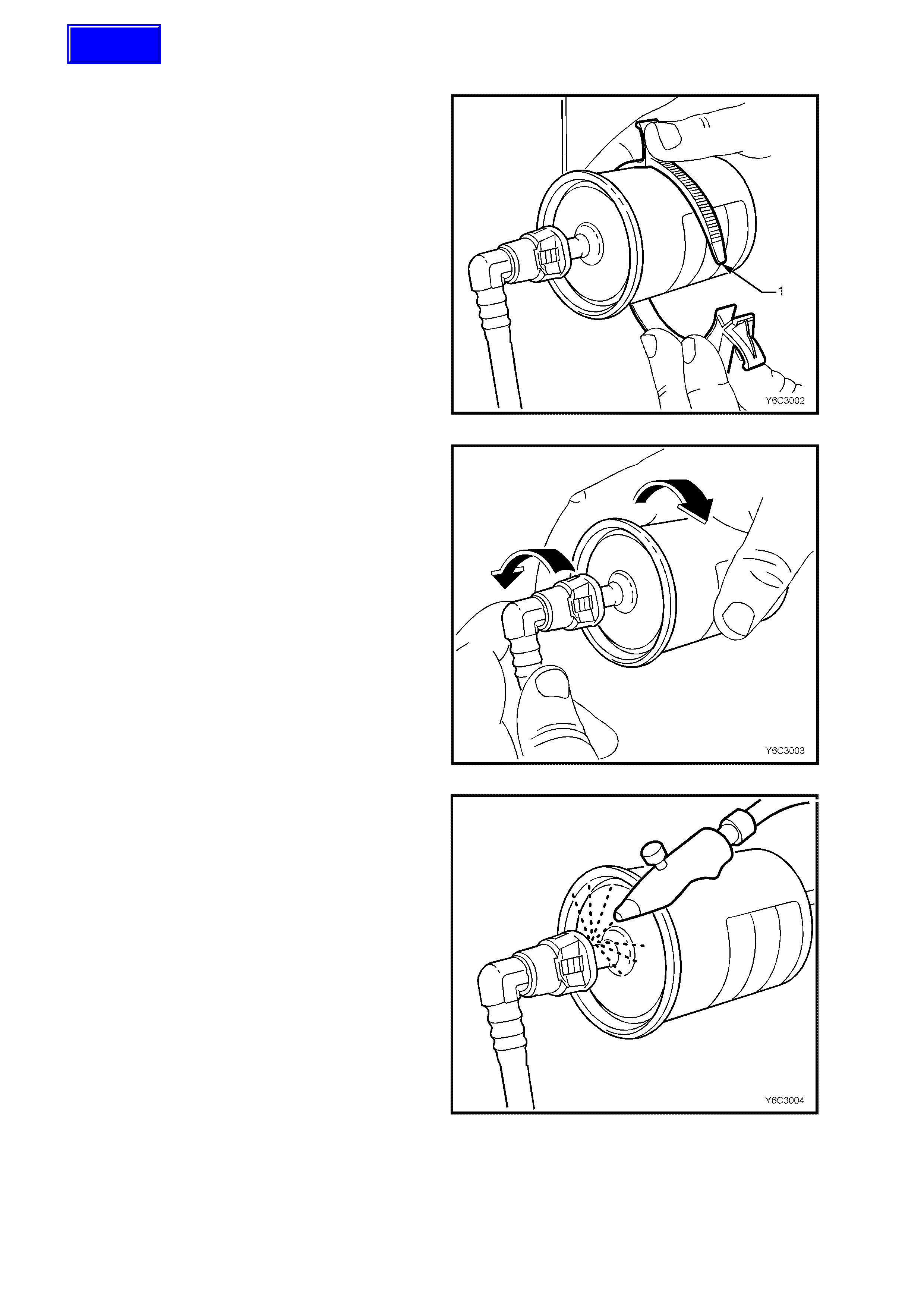
QUICK CONNECT FITTINGS
(PLASTIC COLL AR)
6. Grasp the quick-connect fittings both sides of
the fuel filter. Twist the female connectors 1/4
turn in each direction in order to loosen any dirt
within the quick-connect fitting.
Figure 6C3-3-28
7. Using compressed air, blow any dirt out of the
quick-connect fitting to aid the release of any
tension or binding on the release tabs.
IMPORTANT:
W ear safety glas ses whe n using com pres sed air in
order to prevent eye injury.
Figure 6C3-3-29
Techline
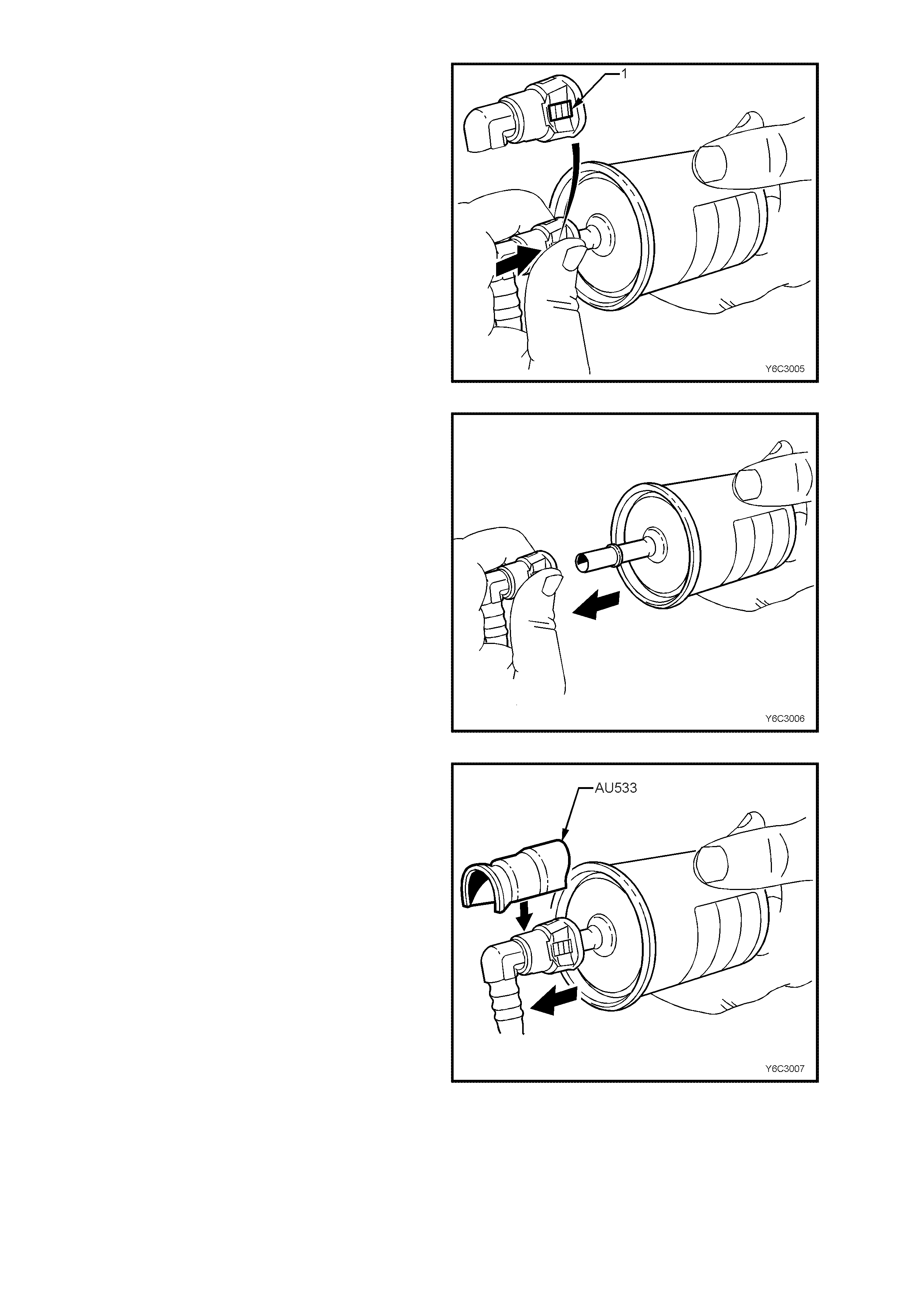
8. Hold the fuel filt er firm ly in one hand t o support
the filter.
9. Us ing your other hand, gra sp one of the qu ick-
connect fittings.
10. Squeeze the plastic retainer release tabs (1)
on each side of the fitting while pushing the
fitting fir mly toward the fue l filter to rele ase any
tension on the release tabs.
Figure 6C3-3-30
11. With the tension release tabs still held in the
squezed position, move the complete quick-
connect fitting away from the fuel filter to
separate the connector fitting from the fuel
filter.
12. Apply the same method from step 8 to 11 for
the remaining quick-connect fitting.
Figure 6C3-3-31
13. Alt ernatel y for steps 8 to 11, us e tool AU533 t o
squeeze the release tabs, release the quick
connect fittings and remove both fuel pressure
hoses from the fuel filter.
14. Remove fuel filter from vehicle and disguard
safely remembering that some fuel will still
remain in the filter.
Figure 6C3-3-32
REINST ALL
IMPORTANT The fuel filter (7) must be installed
with the flow arrow (6) on its body pointing in the
same direction as the fuel flow to the front of the
vehicle.
Figure 6C3-3-33
IMPORTANT Before connecting fuel filter quick-
connect fittings, always apply a few drops of clean
engine oil to the male ends of the fuel filter.
This will ens ure proper rec onnection and pr event a
possible fuel leak.
During normal operation, the O-ring located in the
fem ale connec tor will s wel l and may prevent pr oper
reconnection if not lubr icate d.
1. Apply a few drops of clean engine oil to each
male fuel filter end.
Figure 6C3-3-34
2. Push both the quick-connect fitting and the fuel
filter together in order to cause the retaining
tabs to snap into place. Apply this method to
both ends of the fuel filter and the respective
quick-connect fittings.
Figure 6C3-3-35
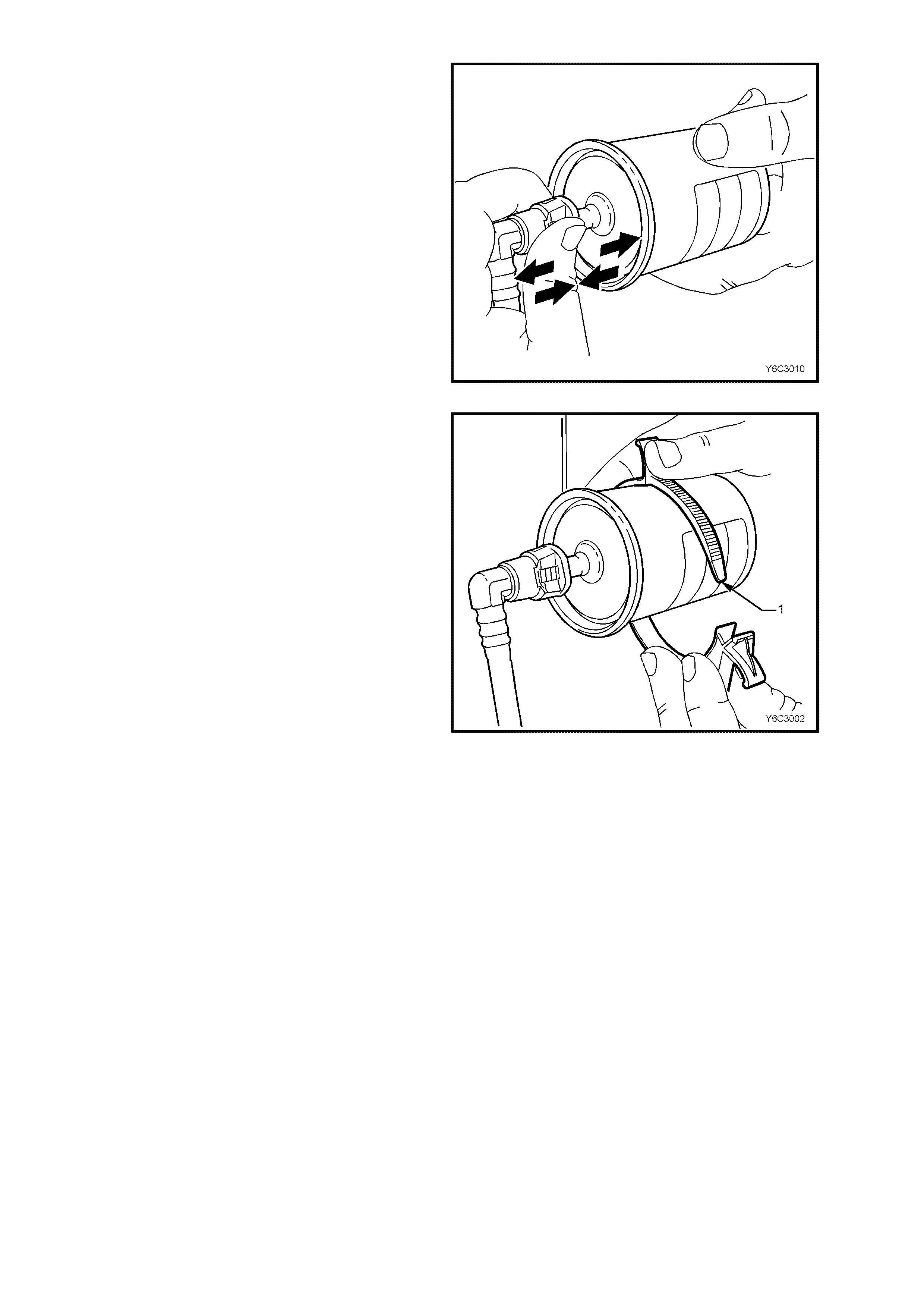
3. Once ins talled, pul l and pu sh on both t he quick -
connect fitting and the fuel filter in order to
make sure the connection is secure. Apply this
method to both ends of the fuel filter and the
respective quick-connect fittings.
Figure 6C3-3-36
4. Install a new fuel filter to a new retaining
bracket (1).
5. Connect battery earth lead.
6. Check for fuel leaks, refer to
3.10, FUEL CONTROL SYSTEM – Leak
Testing in this Section of the VT Service
Information.
7. Remove safety stands and lower vehicle.
Figure 6C1-3-37
LEAK TESTING
Prior to starting the engine, following the installation of any fuel system component, check the fuel system for leaks
using the following procedure:
WARNING: AT NO TIME MUST THE FUEL INLET HOSE OR RETURN LINE HOSE BE CLAMPED OR BENT
OVER AS THIS WILL C AUSE A PERM ANENT KINKING OF T HE INNER SEC TION OF T HE HOSE ASSEM BLY
AND WILL RESULT IN RESTRICTED FUEL FLOW.
1. Ensure that there is a sufficient level of fuel in the fuel tank.
2. Use the TECH 2 scan tool in order to turn the fuel pump ON to pressurise the system.
3. Check the fuel system for leaks, particularly at points marked in figure 6C2-3-38.
Figure 6C2-3-38 - Leak Testing
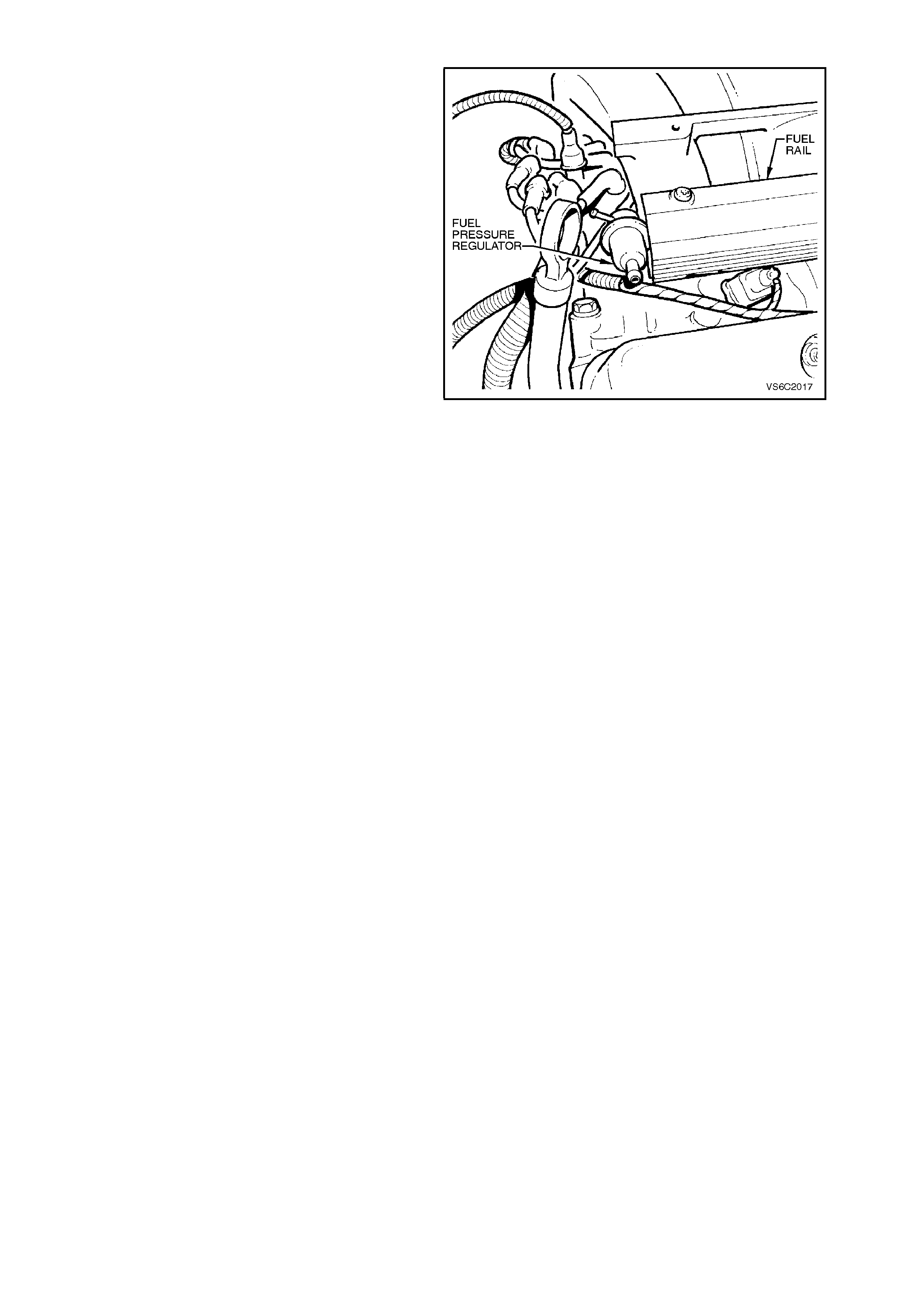
FUEL PRESSURE REGULATOR
REMOVE
1. The battery earth lead.
2. Relieve the fuel pressure as described in
3.10, FUEL CONTROL SYSTEM - Fuel
Pressure Relief Procedure in this Section.
3. The right hand engine trim cover.
4. The vacuum hose from the fuel pressure
regulator.
5. Loosen the hose clamp and remove the fuel
return hose at the fuel pressure regulator.
6. The fuel pressure regulator attaching bolt.
7. The fuel pressure regulator from the fuel rail.
IMPORTANT:
• Ensure precautions are taken to prevent dir t and
other contaminants from entering the open fuel
passages. Fittings should be capped, and holes
plugged, during servicing.
REINSTALL
1. Coat a new O-ring with engine oil. Install the
O-ring onto the fuel pressure regulator.
2. The fuel pressure regulator to the fuel rail.
3. The fuel pressure regulator to fuel rail
attaching bolt and tighten.
4. The fuel return hose and the clam p to the fuel
pressure regulator.
5. The vacuum hose to the fuel pressure
regulator.
6. The engine trim covers.
7. The battery earth lead.
8. Check for fuel leaks as described in
“LEAK TESTING” in this Section.
Figure 6C2-3-39 Fuel Pressure Regulator Location
AIR CLEA NER ASSEMBLY
REMOVE
1. The air flow duct boot clamp and the boot to
the air cleaner assembly.
2. Unclip the air cleaner lower housing from the
upper housing.
3. The air cleaner upper housing and the air f ilter
from the housing assembly.
4. The nuts securing the air cleaner lower
housing.
5. The air cleaner lower housing.
REINSTALL
1. The air cleaner lower housing onto the
mounting insulators.
2. The securing nuts and tighten to the correct
torque specification.
AIR CLEANER HOUSING
SECURING NUT 5-7 Nm
TORQUE SPECIFICATION
3. Ensure that air cleaner element is fitted
correctly into the upper housing.
4. The air cleaner upper housing assembly onto
the lower housing and reconnect the lower
housing to the upper housing.
5. Refit the air flow duct boot and tighten the boot
clamp.
Figure 6C2-3-40 Air Cleaner Housing
THROTTLE CABLE
REMOVE
1. The engine trim front cover.
2. Loosen the outer cable lock nuts to the
mounting bracket.
3. The outer cable from the mounting bracket.
4. The inner cable from the throttle body lever.
5. The instrument panel lower right side trim
assembly retainers and lower trim. Refer to
Section 1A3, INSTRUMENT PANEL &
CONSOLE.
6. The inner cable plastic spac er f r om the throttle
pedal lever.
7. The cable assembly from the engine
compartment.
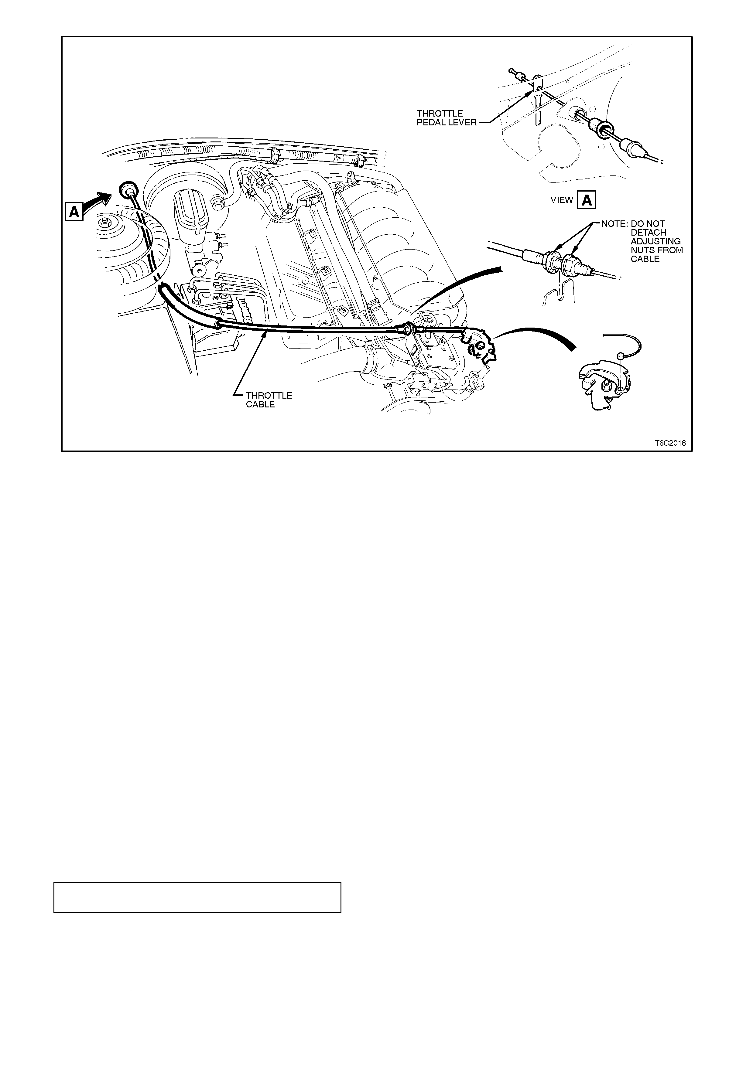
Figure 6C2-3-41 - Throttle Cable
REINSTALL OR RECONNECT
1. The outer cable into dash panel.
2. The inner cable to the throttle pedal lever.
3. The inner cable to the throttle body lever.
4. Assemble the outer cable to the mounting
bracket.
5. Adjust the throttle cable as per the following
instructions:
ADJUST
1. Remove the instrument panel lower right side
trim (if not already removed, refer to
Section 1A3 INSTRUMENT PANEL &
CONSOLE.
2. Ensure that the throttle pedal is free to move
from closed to a fully open position. Check
that the throttle pedal comes to rest at the
correct closed throttle position (against pedal
stop).
3. Adjust the outer cable lock nuts so that the
inner cable is tensioned with a deflection of
10mm to 15mm without moving the throttle
linkage from the idle stop.
4. Tighten the cable lock nuts to the correct
torque specification.
THROTTLE OUTER CABLE LOCK
NUT TORQUE SPECIFICATION 2 - 5
Nm
5. Check for Wide Open Throttle and smooth
operation of the throttle pedal.
6. Refit the instrument panel lower right side trim.
Refer to Section 1A3 INST RUM ENT PANEL
& CONSOLE.
7. The engine trim front cover.
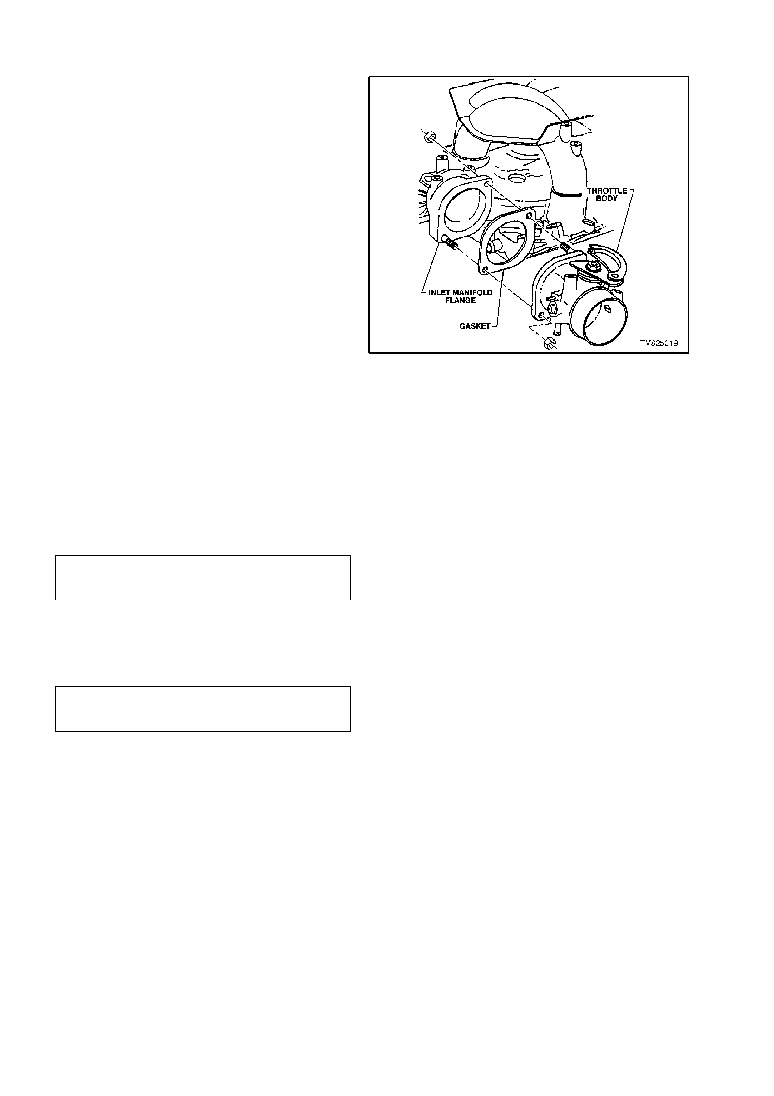
THROTTLE BODY
REMOVE
1. The screws attaching the engine trim covers
to the inlet manifold. Remove the covers.
2. Loosen then remove the air flow duct clamp
at the throttle body.
3. The purge control and the purge lines from
the throttle body.
4. The IAC valve and the TP Sensor electrical
connectors.
5. If the vehicle is fitted with cruise control,
disconnect the cruise control cable from the
throttle body lever.
6. The throttle inner cable from the throttle body
lever.
7. The throttle c able mounting brack et attaching
bolts.
8. The throttle body to the inlet manifold
attaching nuts.
9. The throttle body and discard the gasket.
CLEAN
The gasket surfaces on the throttle body and the
intake manifold.
Figure 6C2-3-42 Throttle Body
REINSTALL
1. The new throttle body gasket and the throttle
body to the inlet manifold.
2. The throttle body attaching nuts and tighten to
the torque specification.
THROTTLE BODY TO INLET
MANIFOLD ATTACHING NUT
TORQUE SPECIFICATION 15 - 20 Nm
3. The throttle cable attaching bracket and
tighten the attaching bolts to the torque
specification.
THROTTLE CABLE ATTACHING
BRACKET ATTACHING BOLT
TORQUE SPECIFICATION 2 - 5 Nm
4. The IAC valve and the TP sensor electrical
connectors.
5. The canister purge control lines to the throttle
body connections.
6. The throttle inner cable to the throttle body
lever.
7. If the vehicle is fitted with cruise control,
reconnect the cruise control cable.
8. The air flow duct boot to the throttle body and
tighten the boot clamp securely.
9. Start the engine and listen for air leaks.
10. The engine trim covers.
11. Check the throttle cable adjustment. Refer to
the procedure in this Section. If required,
check the cruise control cable adjustment.
Refer to Section 12E CRUISE CONTROL.
FUEL RAIL AND INJECTORS
REMOVE
1. The scr ews secur ing the engine trim covers to
the inlet manifold, remove the covers.
2. Relieve the fuel pressure as described in
"FUEL PRESSURE RELIEF PROCEDURE" in
this Section.
3. The battery earth lead.
4. Thoroughly clean around the fuel injector to
the inlet manifold ports.
5. The fuel lines from the dash panel
connections.
6. The vacuum hose from the fuel pressure
regulator.
7. The wiring harness connectors from the fuel
injectors.
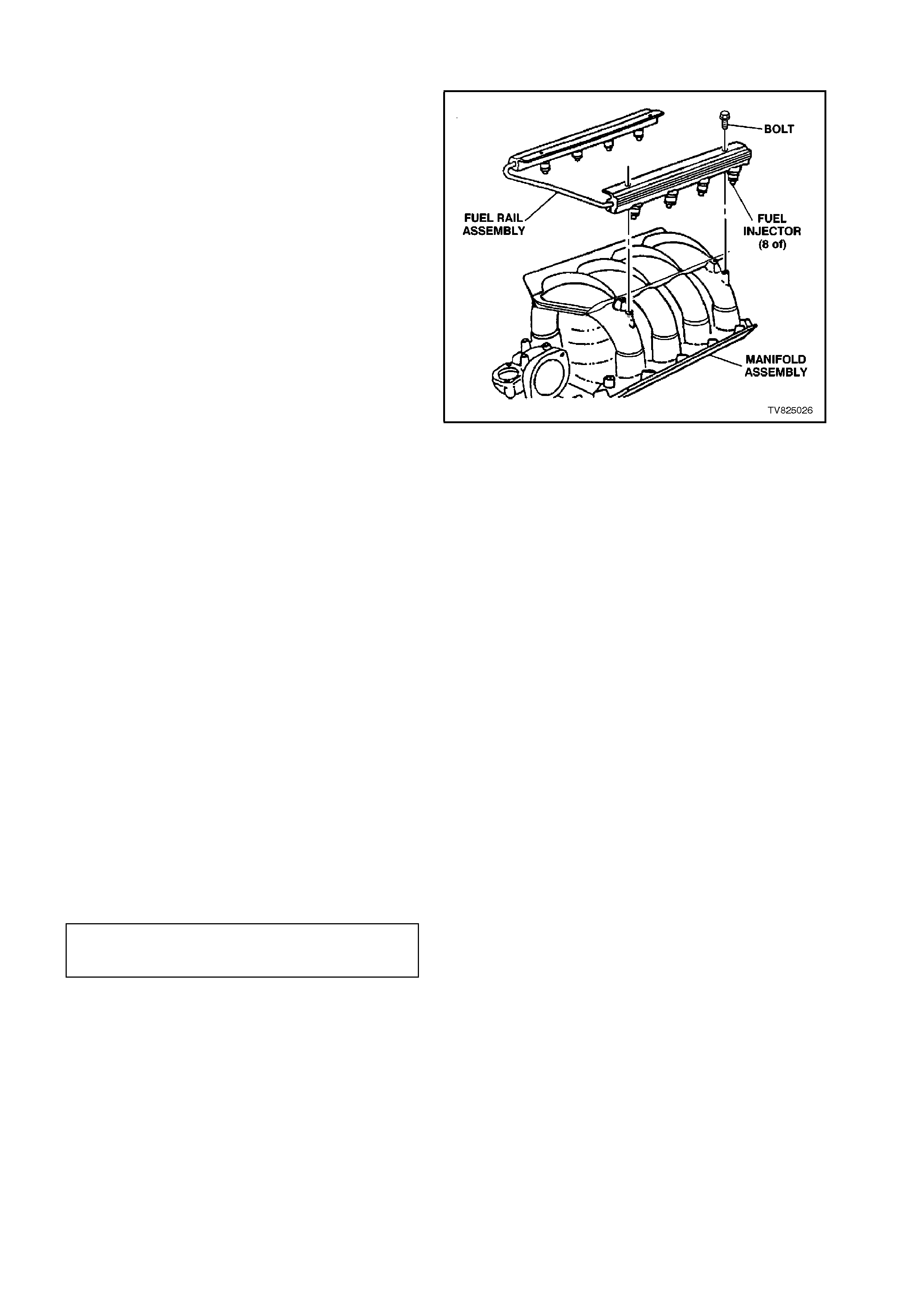
8. Rem ove the plastic ins ulators f rom the fuel rail
to the inlet manifold attaching bolt heads.
Remove the bolts attaching the fuel rail
assembly to the inlet manifold.
9. The fuel rail and the fuel injectors from the
inlet manifold.
10. The fuel injector to the fuel rail clips and
remove the fuel injectors from fuel rail.
IMPORTANT:
• When servicing the fuel rail assembly,
precautions must be taken to prevent dirt and
other contaminants from entering the fuel
passages. Cap the fittings, and passages,
during servicing.
• Anytime the fuel system is opened for service,
the O-ring seals used with related com ponent(s )
should be replaced.
Figure 6C2-3-43 Fuel Rail
REINSTALL
1. The fuel injectors using the new O - rings to
the inlet manifold. Coat the O - rings with
clean engine oil.
2. The fuel injectors to the fuel rail clips.
3. The fuel rail assembly into the inlet manifold,
caref ully placing the fuel injec tors into the inlet
manifold ports. Install and tighten the
attaching bolts to the correct torque
specification.
FUEL RAIL TO INLET MANIFOLD
ATTACHING BOLT
TORQUE SPECIFICATION 6 - 14 Nm
4. The insulators to the fuel rail to inlet manifold
attaching bolt heads.
5. The vacuum hose to the fuel pressure
regulator.
6. The fuel lines.
7. The fuel injector electrical connectors.
8. The battery earth lead.
9. Check for fuel leaks as described in
" LEAK TESTING" in this Section.
10. The engine trim covers and attaching screws.
3.11 IDLE AIR CONTROL VALVE
REMOVE
1. Remove the throttle body assembly. Refer to
3.10 FUEL CONTROL SYSTEM -
THROTTLE BODY - in this Section.
2. The IAC valve attaching screws.
3. The IAC valve from the throttle body.
CLEAN
The IAC valve sealing surfaces on the throttle body,
to assure proper seal of the O-ring and contact to
the IAC valve flange.
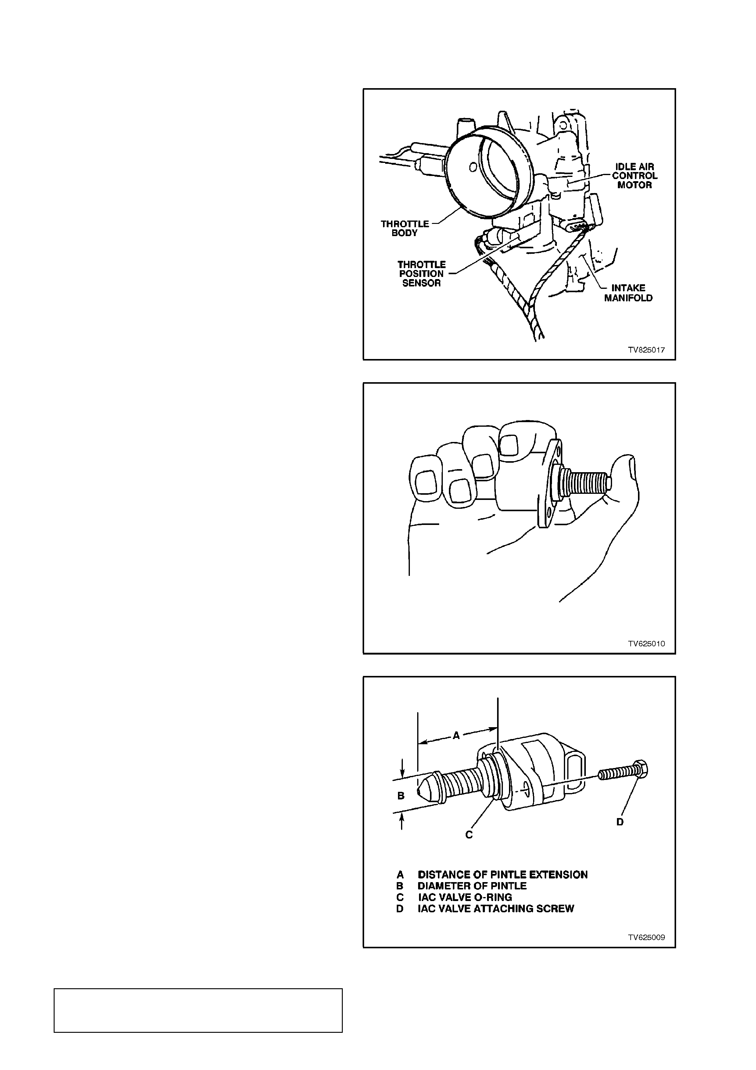
Figure 6C2-3-44 Throttle Body
NOTE:
Before installing a new IAC valve, measure the
distance "A" between tip of valve pintle and the
flange mounting surface. If the distance is greater
than 28 mm, the pintle must be r etrac ted to pr event
damage to the valve when installed. Exert firm
pressure on valve pintle to retract it. (A slight side-
to-side movement may be helpful).
REINSTALL
1. Lubricate the IAC valve O-ring with clean
engine oil. If necessary, install onto the valve
assembly.
2. The IAC valve to the throttle body.
3. The IAC valve attaching screws and tighten to
the correct torque specification.
4. The throttle body assembly. Refer to
3.10, FUEL CONTROL SYSTEM -
THROTTLE BODY - Reinstall in this Section.
5. Start the engine, then hold the throttle at
approximately 2300 RPM for 5 seconds to
"Reset" the IAC valve (PCM command).
Figure 6C2-3-45 IAC Valve Pintle
Figure 6C2-3-46 IAC Valve Pintle Reset
IAC VALVE TO THROTTLE BODY
ATTACHING SCREW
TORQUE SPECIFICATION 1 - 1.5 Nm
3.12 IGNITION SYSTEM
TIMING ADJUSTMENT
IMPORTANT:
The PCM does not know what the actual spark
timing is. The timing depends on the initial base
timing adjustment of the distributor being correct.
Therefore, if the initial bas e timing is s et inc orr ec tly,
the entire spark curve will be incorrect.
THE INITIAL BASE TIMING IS SET BY:
1. Allowing the engine to idle at 85°C.
2. Earthing the DLC diagnostic "test" enable
terminal.
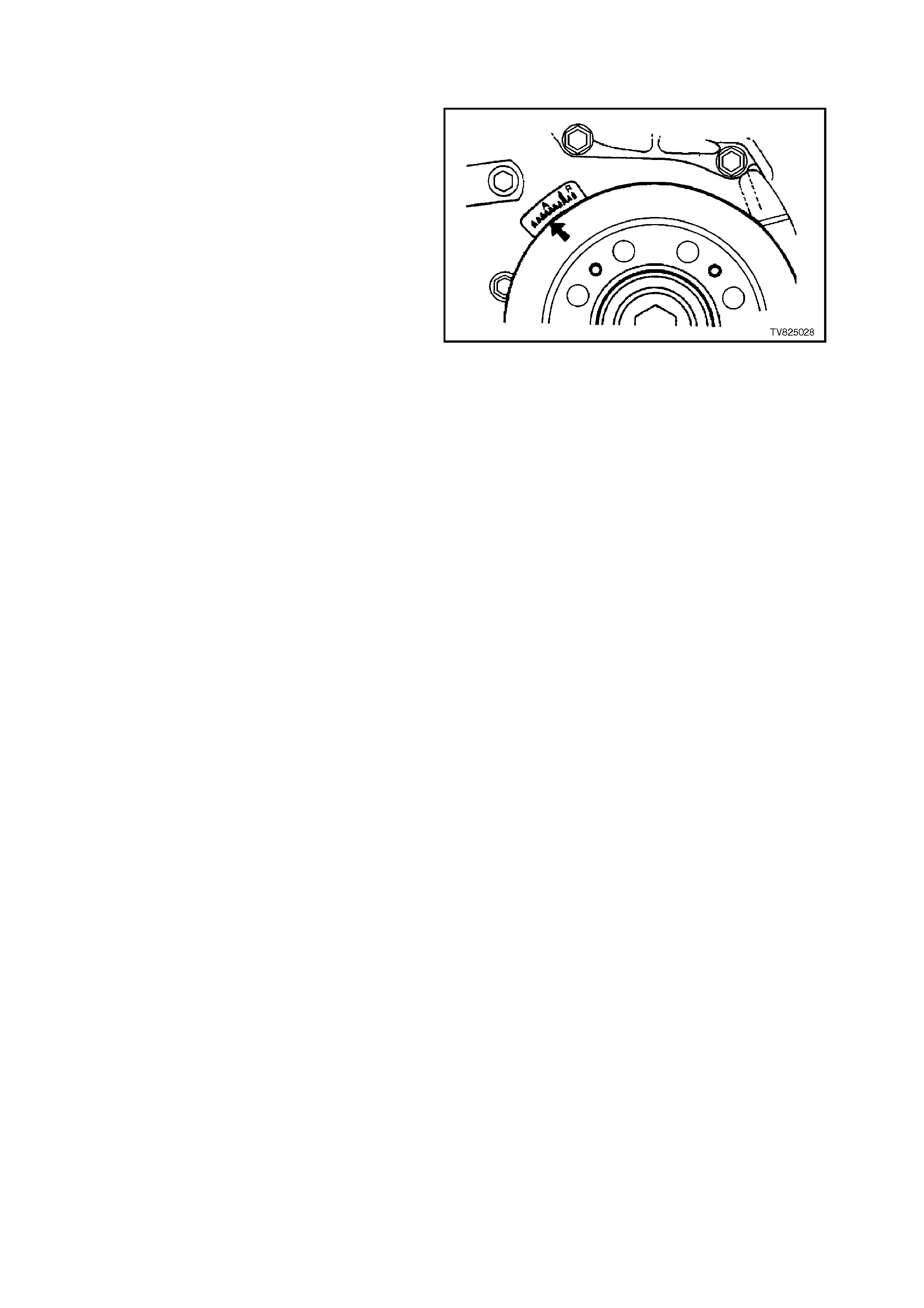
3. Check that the timing is at 10 degrees BTDC
(advanced) by using a timing light connected
to the No. 1 plug wire. Observe the timing
marks on the torsional balancer/engine timing
tab.
4. If an adjustment is necessary, loosen the
distributor hold-down clamp, and set the timing
10 degrees BTDC. Re-tighten the clamp.
5. Recheck the timing, making sure that the
timing did not change as the clamp was
tightened.
6. Remove the earth jumper at the DLC.
Figure 6C2-3-47 Ignition Timing Marks
CHECKING THE EST SPARK TIMING OPERATION
The PCM will command the spark advance to a
fixed 10 degrees BTDC when the DLC diagnostic
test enable terminal is earthed, and the engine
speed is less than 2000 RPM. This 10 degrees
fixed advance is under PCM control (EST mode),
and is not module mode timing.
To check the EST operation, run the engine with
the throttle fixed between 1600 RPM and 1800
RPM. Then earth the DLC diagnostic test enable
term inal. If the RPM changes, the EST m ode s park
timing is operating. (No RPM drop would mean the
ignition system was in the bypass mode.)
IGNITION COIL
For ser vice inf orm ation on the ignition coil, r efer to
Section 6D2-3, IGNITION SYSTEM - V8 ENGINE.
DISTRIBUTOR
REMOVE
1. Depressurise the fuel system, refer to
“Fuel Pressure Relief Procedure” in this
Section.
2. Disconnect the battery earth lead.
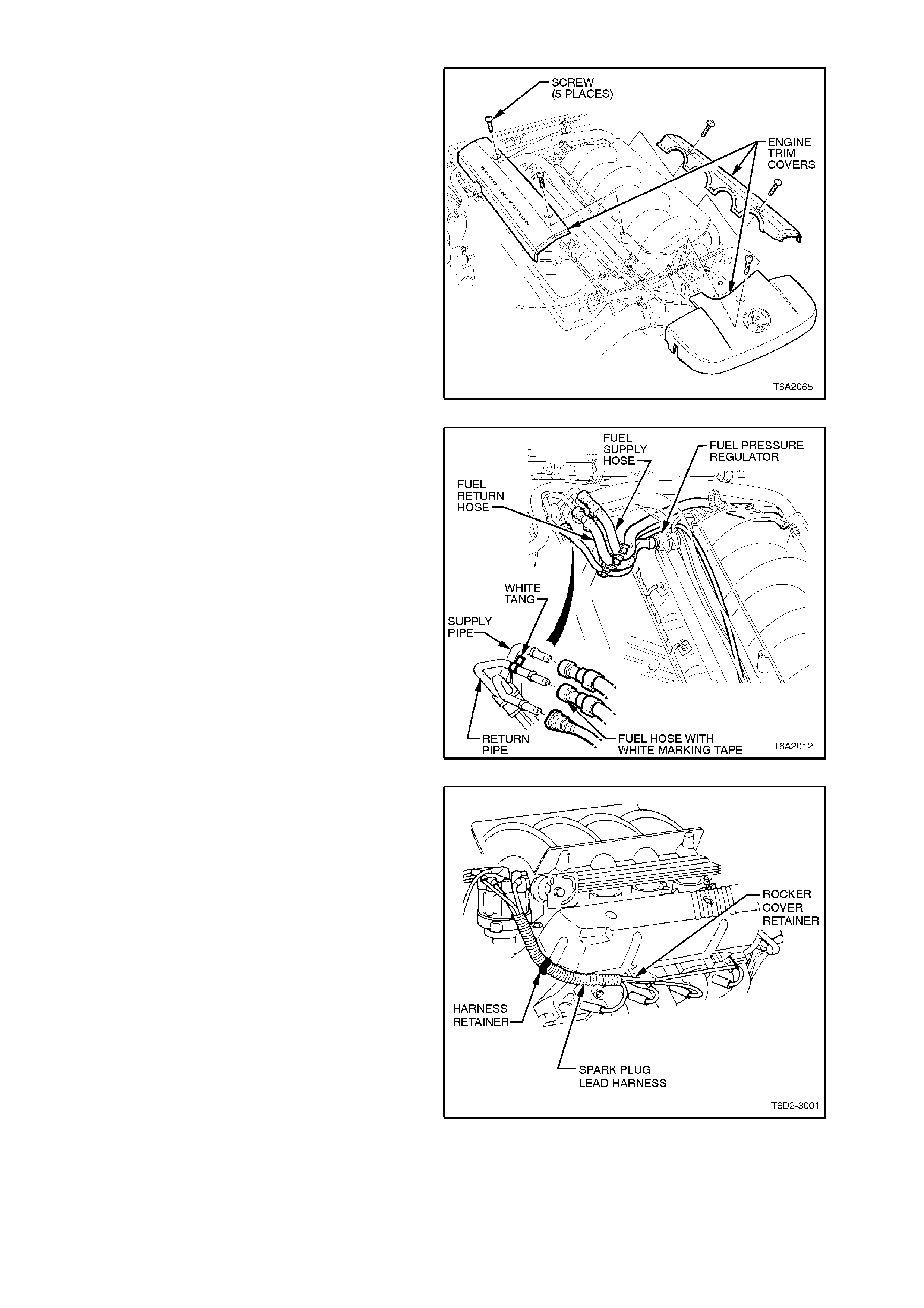
3. Remove the screw securing the engine trim
covers to the inlet manifold.
4. Remove the engine trim covers.
Figure 6C2-3-48 Engine Trim Cover Removal
5. Remove the fuel pressure (supply) line from
the fuel rail connection.
Figure 6C2-3-49 Fuel Lines
6. Disconnect the spark plug leads from the
spark plugs and the rocker covers retainers.
Open the spark plug lead harness retainers at
the end of each cylinder head.
Figure 6C2-3-50 Spark Plug Leads
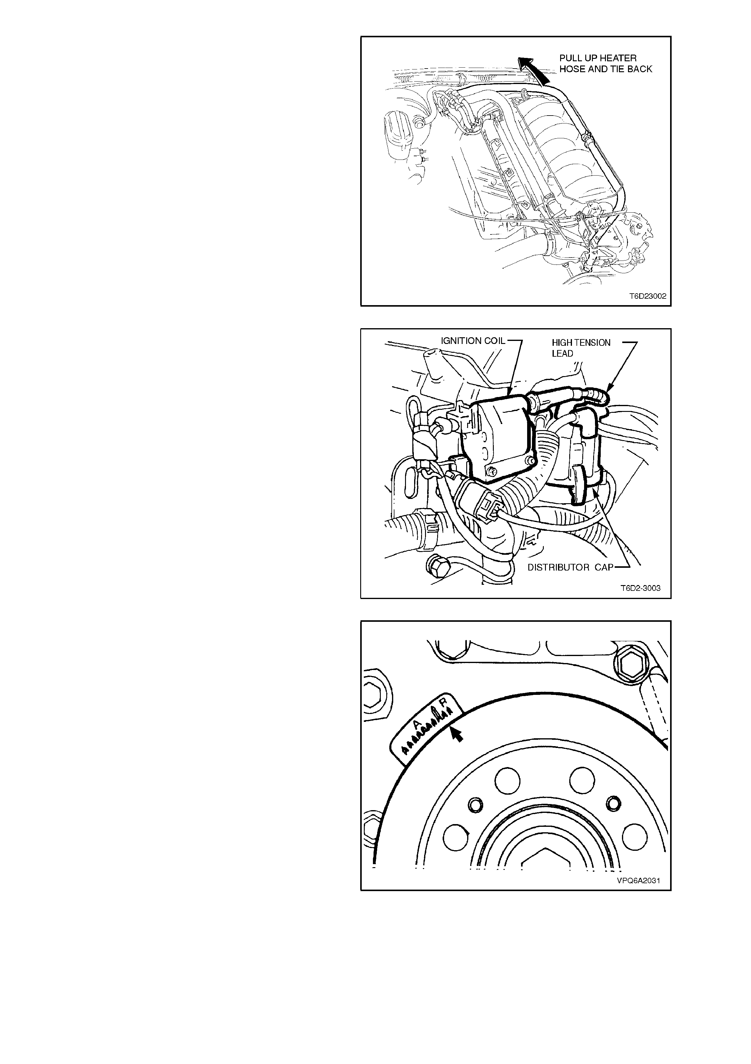
7. To improve accessibility, lift the left hand
heater hose over the inlet manifold, and tie
back.
Figure 6C2-3-51 Heater Hose Location
8. Remove the high tension coil lead from the
coil.
9. Disconnect the wiring harness connector from
distributor.
10. Push back the distributor cap retaining clips
and remove the distributor cap.
Figure 6C2-3-52 Distributor Location
11. Use a suitable size socket and bar on the
crankshaft torsional damper retaining bolt.
Rotate until the distributor rotor is on the
number one cylinder position and timing mark
on the torsional damper is on aligned at T . D.C.
position.
12. Remove the distributor rotor.
13. Remove the distributor clamp securing bolt.
Remove the retainer and the clamp.
Figure 6C2-3-53 Timing Marks
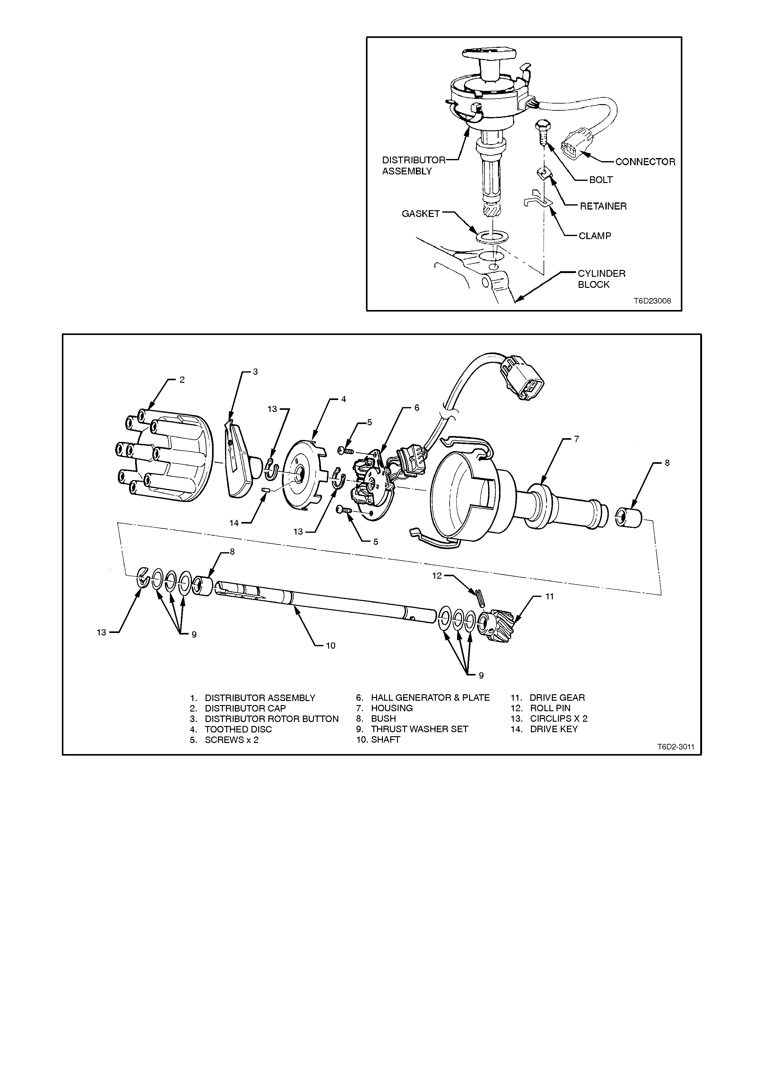
14. Remo ve the distributor and discard the s ealing
gasket.
NOTE:
Do not rotate the crankshaft after the distributor
has been removed.
Figure 6C2-3-54 Distributor Removal
Figure 6C2-55 Distributor Assembly
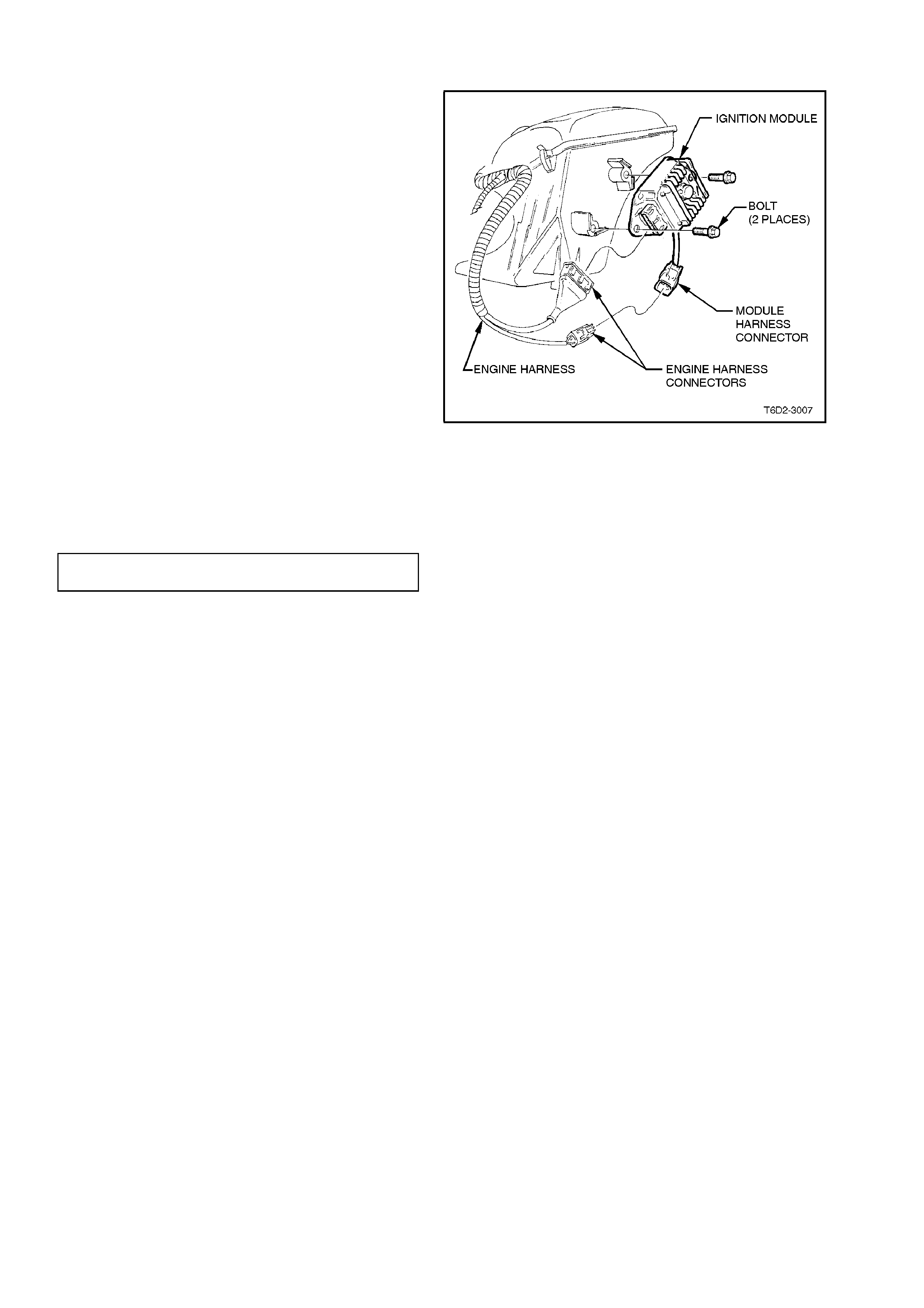
IGNITION MODULE
REMOVE
1. Ignition OFF.
2. Disconnect the battery earth lead.
3. Disconnect the IAT sensor electrical
connector.
4. Undo the air cleaner retaining clips and then
remove the air cleaner.
5. Remove the air cleaner element.
6. Loosen the two fastener s securing the air inlet
duct.
7. Remove the air cleaner base by pulling
upwards.
8. Compress the locking tang on the engine
harness to the module harness connector,
separate the connectors.
9. Remove the two bolts and nuts securing the
ignition module to the inner fender panel.
10. Remove the ignition module. Figure 6C2-3-56 Ignition Module Removal
REINSTALL
Reinstallation of the ignition module is the reverse
of the removal procedure. Tighten the ignition
module retaining nuts to the specification listed.
IGNITION MODULE RETAINING NUTS
TORQUE SPECIFICATION 3.0 - 8.0
Nm
CAMSHAFT/CRANKSHAFT SENSORS
For some operations and testing of the
camshaft/crankshaft sensor, refer to Section 6D2-
3 IGNITION SYSTEM - V8 ENGINE.
REINSTALL
Reinstallation of the distributor, cap and leads is the
reverse of rem oval procedur es, noting the following
points:
1. The timing mark on torsional damper should
be at T.D.C. position, and both valves on the
number one cylinder should be closed. If
necessary, rotate crankshaft to achieve
correct timing.
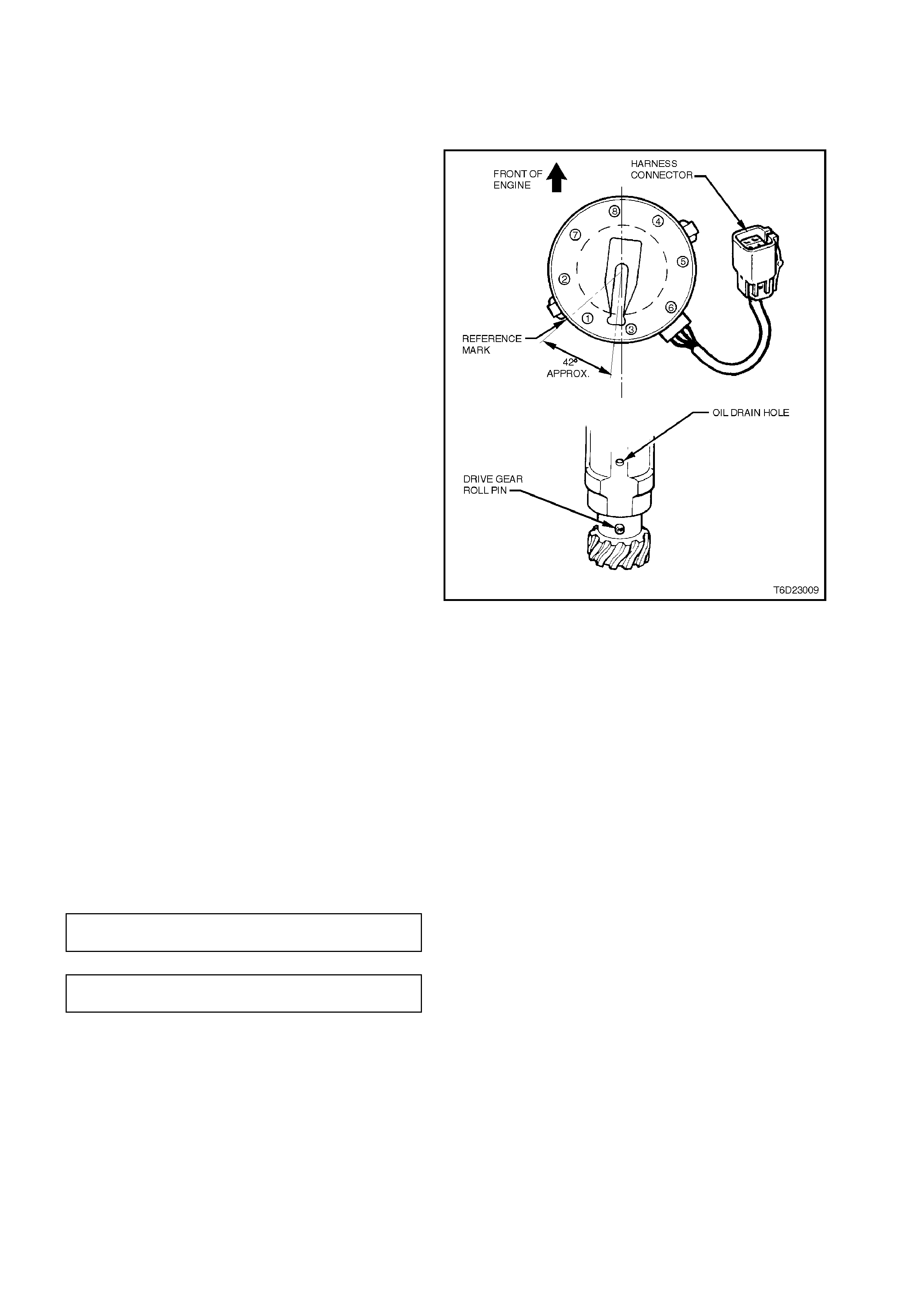
2. Install the rotor button and align with the
number one cylinder reference mark. Rotate
the rotor button counter clockwise
approximately 42 degrees until drive the gear
roll pin is aligned with the oil drain hole in the
distributor body, refer to Fig 6D2-3-57.
3. Remove the rotor button, maintaining
alignment as described in step 2.
4. Install the distributor into the block.
NOTE:
The dis tributor shaf t will rotate during ins tallation as
the helical gears mesh.
5. Install the distributor clamp, retainer and
securing bolt. Leave the bolt finger tight.
6. Ensure that the rotor button is pointing to the
number one reference mark and tighten the
clamp securing bolt.
7. Ensure that the engine harness connector is
correctly installed into distributor connector.
8. Ensure that spark plugs leads are correctly
routed, refer to Section 6D2-3 IGNITION
SYSTEM - V8 ENGINE.
9. Pressurise the fuel system, refer to
“LEAK TESTING” in this Section. Check for
leaks. Repair as necessary.
Figure 6C2-3-57 Distributor Installation
10. Check and set the ignition timing as necessary,
refer to “ TIMING ADJUSTMENT” in this
Section.
11. Tighten the distributor clamp bolt to the correct
torque specification.
DISTRIBUTOR CLAMP BOLT
TORQUE SPECIFICATION 20 - 27 Nm
CAM/CRANK POSITION SENSOR
TORQUE SPECIFICATION 2-3 Nm

3.13 1-2 SHIFT SOLENOID
Figure 6C2-3-58 - 1-2 Shift Solenoid Location
REMOVE
1. Disconnect battery earth lead.
CAUTION:
To avo id personal injury from accident al hot oil
spillage, perform fluid change only when
transmission fluid is cold.
2. Raise vehicle and support on safety stands.
Refer to Section 0A, GENERAL
INFORMATION.
3. Clean all dirt from around oil pan and
transmission case.
4. Place drain tray under transmission.
5. Loosen two bolts at the rear and one at the
front of the oil pan. Remove the remaining
bolts. While holding the oil pan, allow the front
of the oil pan to drop away, emptying oil into a
drain tray.
6. Remove remaining bolts, then lower pan and
empty fluid from pan.
7. Remove old oil pan gasket and discard.
8. Disconnect 1-2 shift solenoid (367A) electrical
connector.
9. Remove solenoid retainer (379) by using a
small flat blade screwdriver. Pry the retainer
down until it can be grasped.
NOTE:
Solenoid has a slight spr ing pres s ure behind it, and
may pop out on its own after retainer is removed.
10. Rem ove solenoid ass embly (367A) with O-ring
seal. Ensure that 1-2 s hift valve (366) r emains
in place.

REINSTALL
1. Push solenoid assembly (367A) into valve
body.
2. Hold solenoid in place with finger pressure
while installing retainer (379)
3. Reconnect 1-2 shift solenoid (367A) electrical
connector.
4. Clean oil pan and case mating surfaces.
Check that magnet is still magnetised, and
attached to the oil pan.
5. Install new gasket and reinstall oil pan.
Tighten bolts to the correct torque
specification.
TRANSMISSION OIL PAN BOLT
TORQUE SPECIFICATION 11 Nm
6. Lower vehicle and add approxim ately 4.8 litres
of DEXRON â III automatic transmission fluid.
7. Reconnect battery earth lead.
8. Check transmission fluid level. Refer to "
FLUID CHECKING PROCEDURE" in Section
6C2-2A.
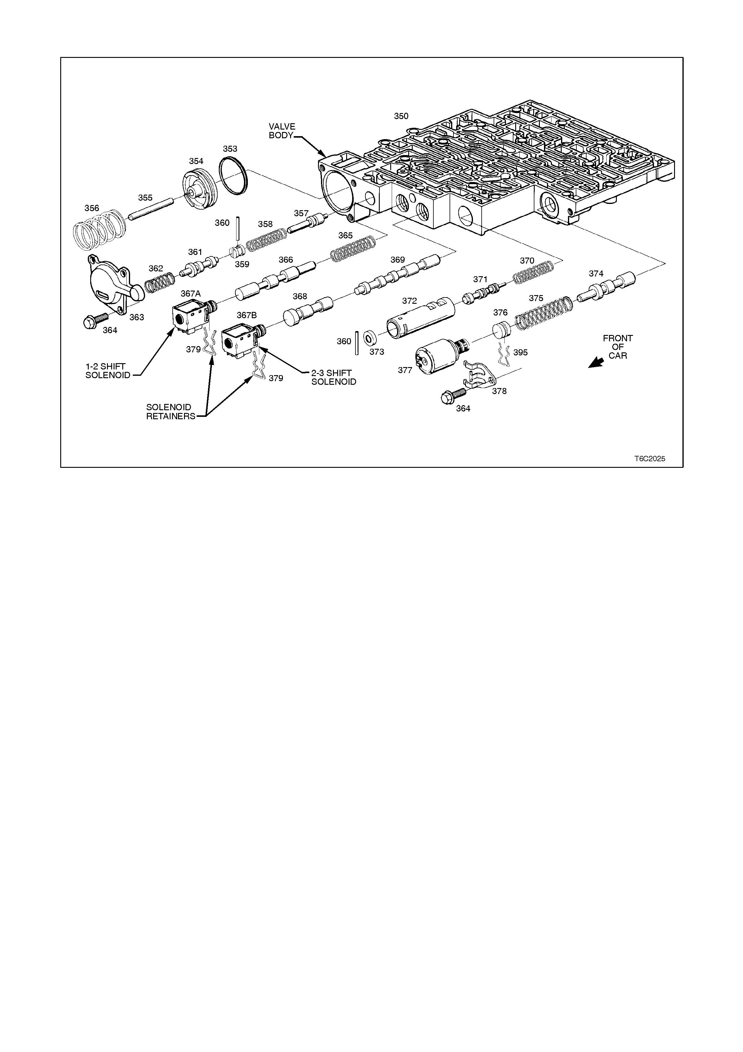
3.14 2-3 SHIFT SOLENOID
Figure 6C2-3-59 2-3 Shift Solenoid Location
REMOVE
1. Disconnect the battery earth lead.
CAUTION:
To avoid injury from accidental hot oil spillage,
perform the fluid change only when the
transmission fluid is cold.
2. Raise the vehicle and support the vehicle on
safety stands. Refer to Section 0A
GENERAL INFORMATION for the location of
the jacking points.
3. Clean all the dirt from around the oil pan and
the transmission case.
4. Place the drain tray under the transmission.
5. Hold the oil pan in place, leaving one bolt
loose at the front of the oil pan, remove the
rem aining bolts . Allow the rear of the oil pan to
drop, emptying the oil the drain tray.
6. Remove the remaining bolt and the oil pan.
Empty the fluid from the pan.
7. Remove the old oil pan gasket and discard.
8. Disconnect the 2-3 shift solenoid (367B)
electrical connector.
9. Remove the 2-3 shift solenoid retainer (379)
by using a s mall flat blade s c rewdriver . Pry the
retainer down until the retainer can be
grasped.
10. Remove the 2-3 shift solenoid assembly
(367B) with the O-ring seal. Ensure that the 2-
3 shuttle valve (368) remains in place.

REINSTALL
1. Push the 2-3 shift solenoid assembly with O-
ring (367B) into valve body.
2. Install the 2-3 shift solenoid retainer (379).
3. Reconnect the 2-3 shift solenoid electrical
connector.
4. Clean the oil pan and the case mating
surfaces. Check that magnet is still
magnetised and attached to the oil pan.
5. Install a new gasket and reinstall the oil pan.
Tighten the bolts to the correct torque
specification.
TRANSMISSION OIL PAN BOLT
TORQUE SPECIFICATION 11 Nm
6. Lower the vehicle and add approximately 5.0
litres of DEXRO N Ò III autom atic trans m ission
fluid.
7. Reconnect the battery earth lead.
8. Check the transmission fluid level. Refer to the
" FLUID CHECKING PROCEDURE" in
Section 6C2-2A.
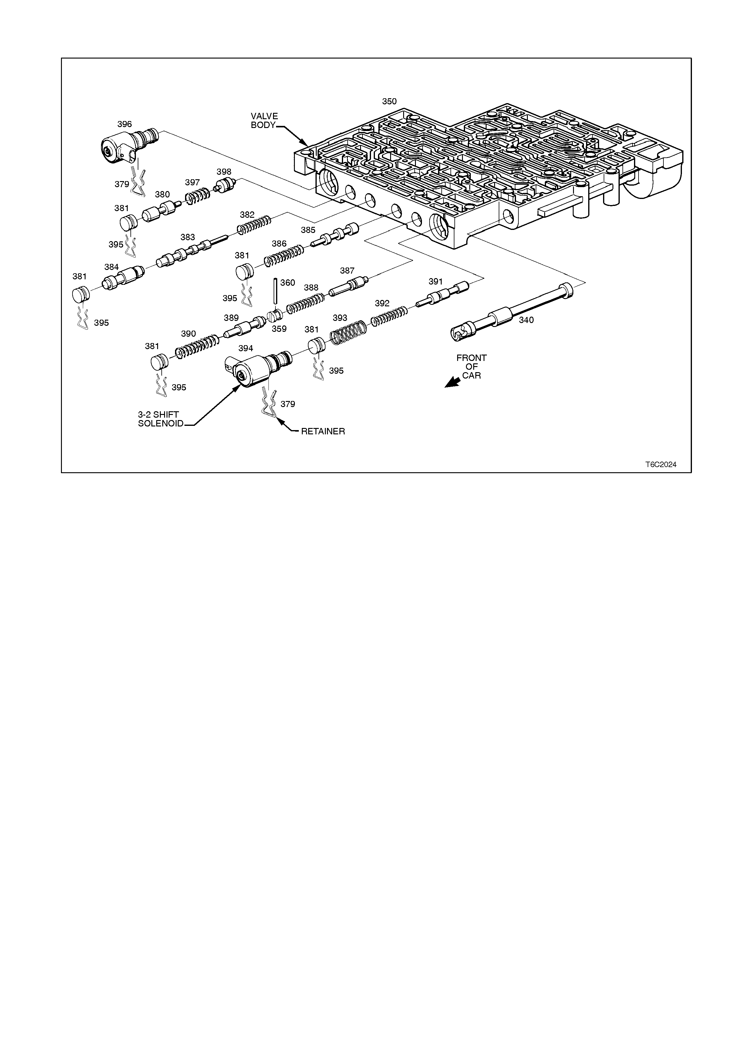
3.15 3-2 SHIFT SOLENOID
Figure 6C2-3-60 - 3-2 Shift Solenoid Location
REMOVE
1. Disconnect battery earth lead.
CAUTION:
To avo id personal injury from accident al hot oil
spillage, perform fluid change only when
transmission fluid is cold.
2. Raise vehicle and support on safety stands.
Refer to Section 0A GENERAL
INFORMATION.
3. Clean all dirt from around oil pan and
transmission case.
4. Place drain tray under transmission.
5. Loosen two bolts at the rear and one at the
front of the oil pan. Remove the remaining
bolts. While holding oil pan, allow the front of
the oil pan to drop away, emptying oil into a
drain tray.
6. Remove remaining bolts, then lower pan and
empty fluid from pan.
7. Remove old oil pan gasket and discard.
8. Remove strainer.
8. Disconnect 3-2 control solenoid (394)
electrical connector.
9. Remove solenoid retainer (379) by using a
split ring puller or similar hooked tool.
NOTE:
The solenoid has spring pressure behind it and
may pop out after retainer is removed.
10. Remove solenoid assembly (394) with O-ring
seal.

REINSTALL
1. Push solenoid ass embly with O-ring s eal (394)
into valve body
2. Hold solenoid firmly in place with finger
pressure while installing retainer (379).
3. Reconnect 3-2 control solenoid electrical
connector.
4. Install strainer.
5. Clean oil pan and case mating surfaces.
Check that magnet is still magnetised, and
attached to the oil pan.
6. Install new gasket and reinstall oil pan.
Tighten bolts to the correct torque
specification.
TRANSMISSION OIL PAN BOLT
TORQUE SPECIFICATION 11 Nm
7. Lower vehicle and add approxim ately 4.8 litres
of DEXRON â III automatic transmission fluid.
8. Reconnect the battery earth lead.
9. Check the transmission fluid level. Refer to "
FLUID CHECKING PROCEDURE" in Section
6C2-2A.
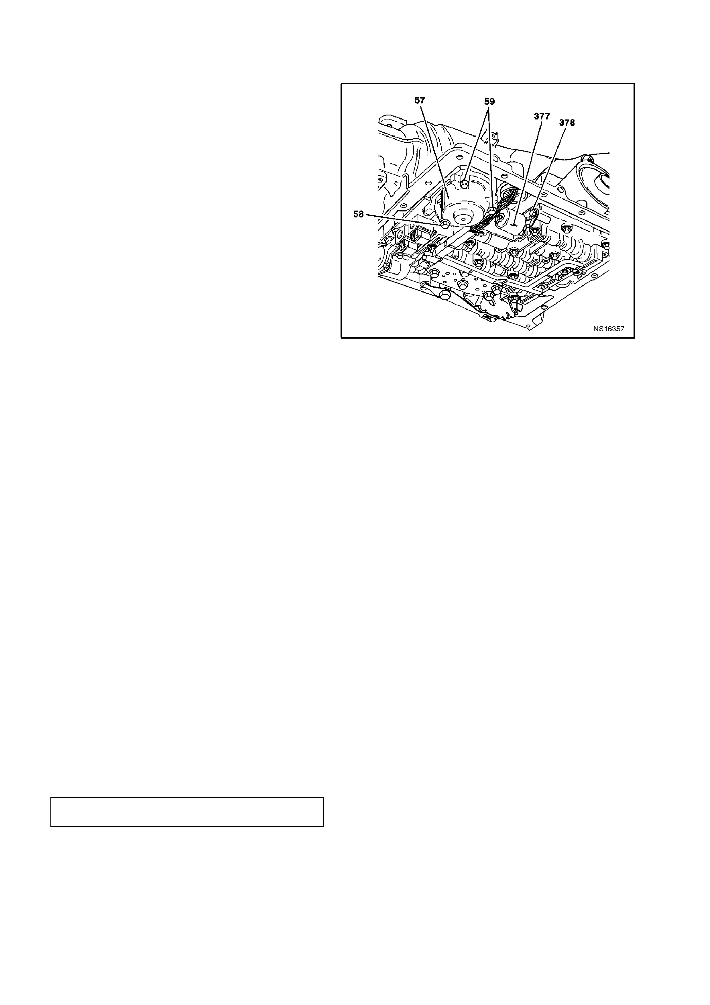
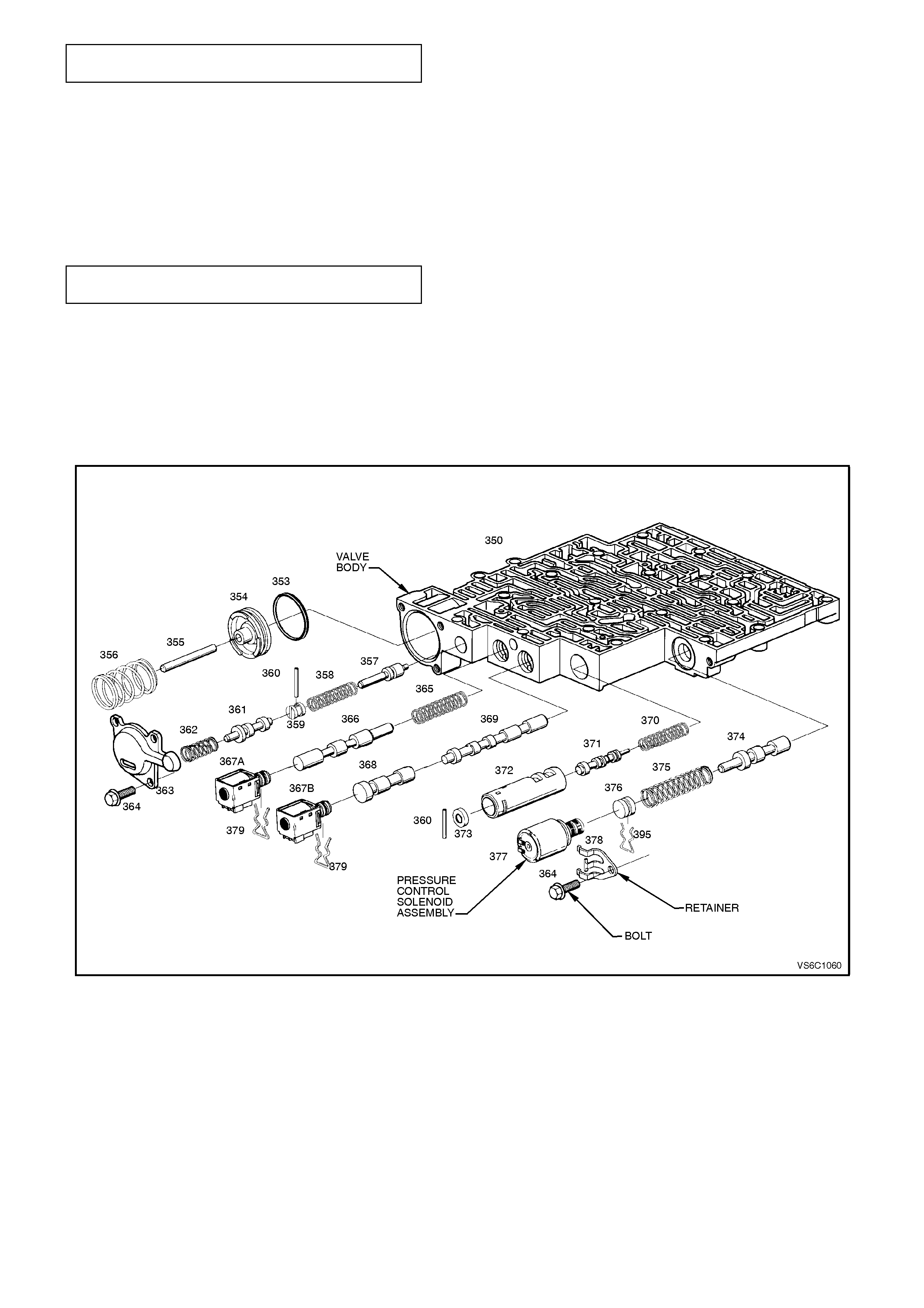
3.16 PRES S URE CONTROL SOLENOID
REMOVE
1. Disconnect the battery earth lead.
CAUTION:
To avo id personal in jury from accidental hot o il
spillage, perform fluid change only when
transmission fluid is cold.
2. Raise the vehicle and support on safety
stands. Refer to Section 0A GENERAL
INFORMATION for the location of the jacking
points.
3. Clean all the dirt from around the oil pan and
the transmission case.
4. Place the drain tray under the transmission.
5. Hold the oil pan in place, leaving one bolt
loose at the front of the oil pan. Remove the
rem aining bolts. Allow the rear of the oil pan to
drop away, emptying the oil into a drain tray.
6. Remove the remaining bolt from the oil pan
and empty the fluid from the pan.
7. Remove the old oil pan gasket and discard.
8. Remove the strainer.
9. The three 1-2 accumulator cover bolts (58)
(59).
NOTE:
Accumulator will be full of fluid
10. Remove the 1-2 accumulator cover assembly
(57).
11. Remove the pressure control solenoid (377)
electrical connector.
12. Rem ove the pressure c ontrol solenoid retainer
bolt (364), then the retainer (378).
13. Remove the pressure control solenoid
assembly (377).
Figure 6C2-3-61 Pressure Control Solenoid Location
REINSTALL
1. Install the solenoid assembly (377).
NOTE:
The solenoid has a flat cut out on one side of the
retaining flange. The flat cut out goes towards the
retaining bolt. The solenoid retainer has a matching
flat to allow the retainer to be properly installed.
2. Install the solenoid retainer (378).
3. Install the solenoid retainer bolt (364). Ensure
that the flat of the retainer allows the retainer
to be properly installed. Tighten the bolt to the
correct torque specification.
SOLENOID RETAINER BOLT
TORQUE SPECIFICATION 11 Nm
4. Install the pressure control solenoid electrical
connector.
5. Install the 1-2 accumulator cover assembly
(57).
6. Install the accumulator cover bolts (58) (59)
and then tighten to the correct torque
specification.
ACCUMULATOR COVER BOLT
TORQUE SPECIFICATION 11 Nm
7. Install the new strainer.
8. Clean the oil pan and the case mating
surfaces. Check that magnet is still
magnetised and attached to the oil pan.
9. Install the new gask et and r einstall the oil pan.
Tighten the bolts to the correct torque
specification.
TRANSMISSION OIL PAN BOLT
TORQUE SPECIFICATION 11 Nm
10. Lower the vehicle and add approximately 5.0
litres of DEXRO N Ò III autom atic trans m ission
fluid.
11. Reconnect the battery earth lead.
12. Check the transmission fluid level. Refer to the
" FLUID CHECKING PROCEDURE" in
Section 6C2-2A.
Figure 6C2-3-62 Pressure Control Solenoid Assembly
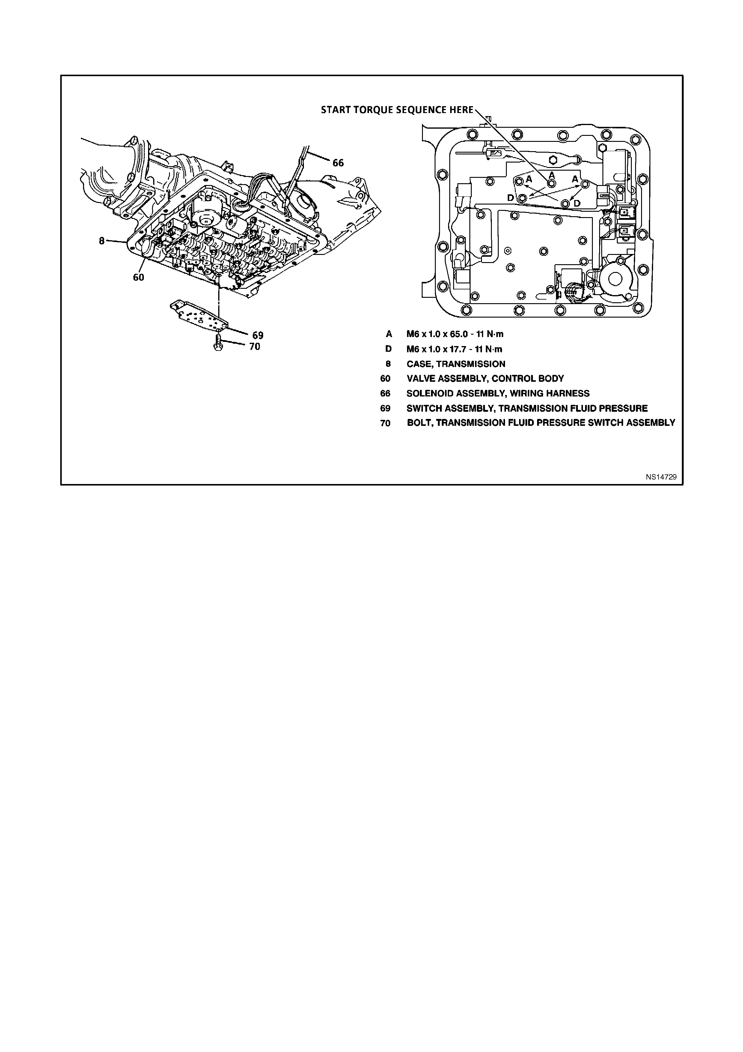
3.17 TRANSMIISSION FLUID PRESSURE (TFP) MANUAL VALVE POSITION AND
TRANSMISSION FLUID TEMPERATURE (TFT) SENSOR
Figure 6C2-3-63 - Transmission Fluid Pressure (TFP) Manual Position Switch Assembly
REMOVE
1. Disconnect the battery earth lead.
CAUTION:
To avo id personal injury from an acciden tal hot
oil spillage, perform the fluid change only when
the transmission fluid is cold.
2. Raise the vehicle and support the vehicle on
safety stands. Refer to Section 0A
GENERAL INFORMATION for location of
jacking points.
3. Remove the dirt from around the oil pan and
the transmission case.
4. Place the drain tray under the transmission.
5. Hold the oil pan in place. Leaving one bolt
loose at the front of the oil pan, remove the
rem aining bolts . Allow the rear of the oil pan to
drop away, emptying the oil into a drain tray.
6. Remove the remaining bolt and the oil pan
and empty the fluid from the pan.
7. Remove the old oil pan gasket and discard.
8. Remove the strainer.
9. Disconnect the TFP manual switch assembly
wiring harness connector.
10. Remove the five (5) TFP manual switch
assembly to the valve body bolts (70).
11. Remove the TFP manual switch assembly
(69).

REINSTALL
1. Install the TFP switch assembly (69).
2. Install the five (5) TFP manual switch
assembly retaining bolts (70). Tighten the
bolts to the correct torque specification.
TFP MANUAL SWITCH ASSEMBLY
RETAINING VALVE BODY BOLT
TORQUE SPECIFICATION 11 Nm
3. Reconnect the TFP switch assembly wiring
harness connector.
4. Reinstall the strainer.
5. Clean the oil pan and the case mating
surfaces. Check that the magnet is still
magnetised and attached to the oil pan.
6. Install the new gask et and r einstall the oil pan.
Tighten the bolts to the correct torque
specification.
TRANSMISSION OIL PAN BOLT
TORQUE SPECIFICATION 11 Nm
7. Lower the vehicle and add approximately 5.0
litres of DEXRO N Ò III autom atic trans m ission
fluid.
8. Reconnect the battery earth lead.
9. Check the transmission fluid level. Refer to the
" FLUID CHECKING PROCEDURE" in
Section 6C2-2A.

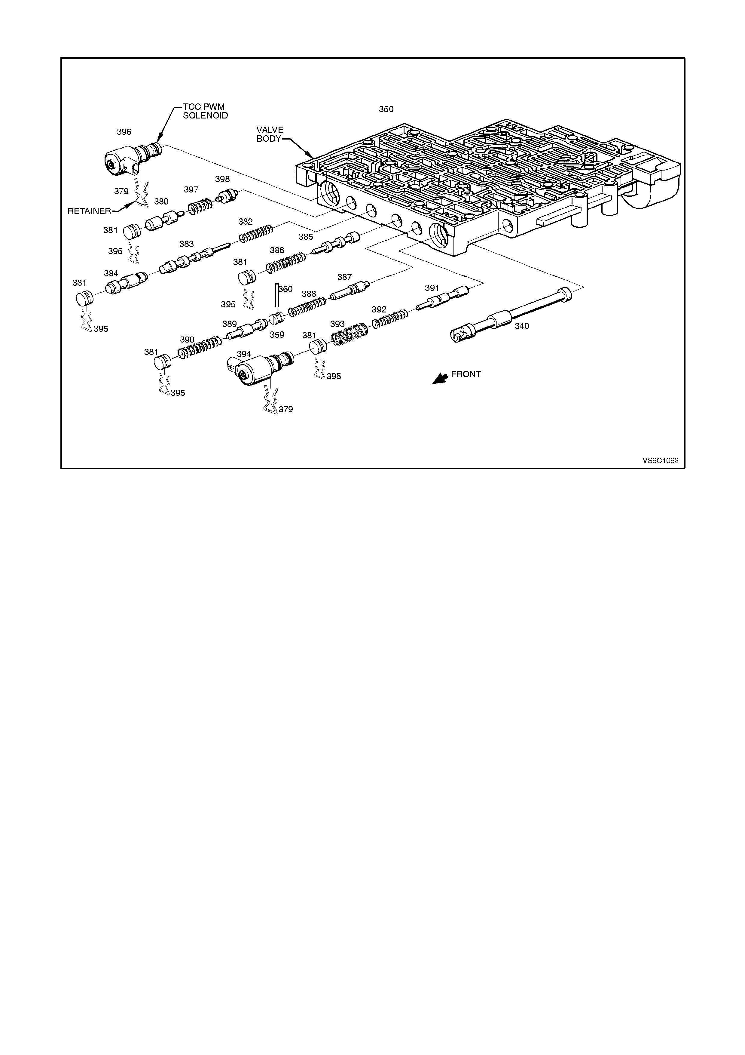
3.18 TCC "PWM" SOLENOID
Figure 6C2-3-64 - TCC "PWM" Solenoid Location
REMOVE
1. Disconnect battery earth lead.
CAUTION:
To avo id personal injury from accident al hot oil
spillage, perform a fluid change only when the
transmission fluid is cold.
2. Raise the vehicle and support the vehicle on
safety stands. Refer to Section 0A,
GENERAL INFORMATION for location of
jacking points.
3. Remove all the dirt from around the oil pan
and transmission case.
4. Place the drain tray under the transmission.
5. Loosen the two bolts at the rear and one at the
front of the oil pan. Remove the remaining
bolts. While holding oil pan, allow the front of
the oil pan to drop away, emptying oil into a
drain tray.
6. Remove the remaining bolts, then lower the
pan and empty the fluid from the pan.
7. Remove the old oil pan gasket and discard.
8. Remove the strainer.
9. Remove the TCC "PWM" solenoid (396)
electrical connector.
10. Rem ove the solenoid retainer ( 379) by using a
split ring puller or similar hooked tool.
11. Remove the TCC "PWM" solenoid assembly
(396) with O-ring seal.

REINSTALL
1. Install the TCC "PWM" solenoid assembly with
O-ring (396).
2. Install the TCC "PWM" solenoid retainer (379).
3. Install the TCC "PWM" solenoid electrical
connector.
4. Install the strainer.
5. Clean the oil pan and the case mating
surfaces. Check that the magnet is still
magnetised and attached to the oil pan.
6. Install the new gask et and r einstall the oil pan.
Tighten the bolts to the correct torque
specification.
TRANSMISSION OIL PAN BOLT
TORQUE SPECIFICATION 11 Nm
7. Lower the vehicle and add approximately 5.0
litres of DEXRO N Ò III autom atic trans m ission
fluid.
8. Reconnect the battery earth lead.
9. Check the transmission fluid level. Refer to the
" FLUID CHECKING PROCEDURE" in
Section 6C2-2A.
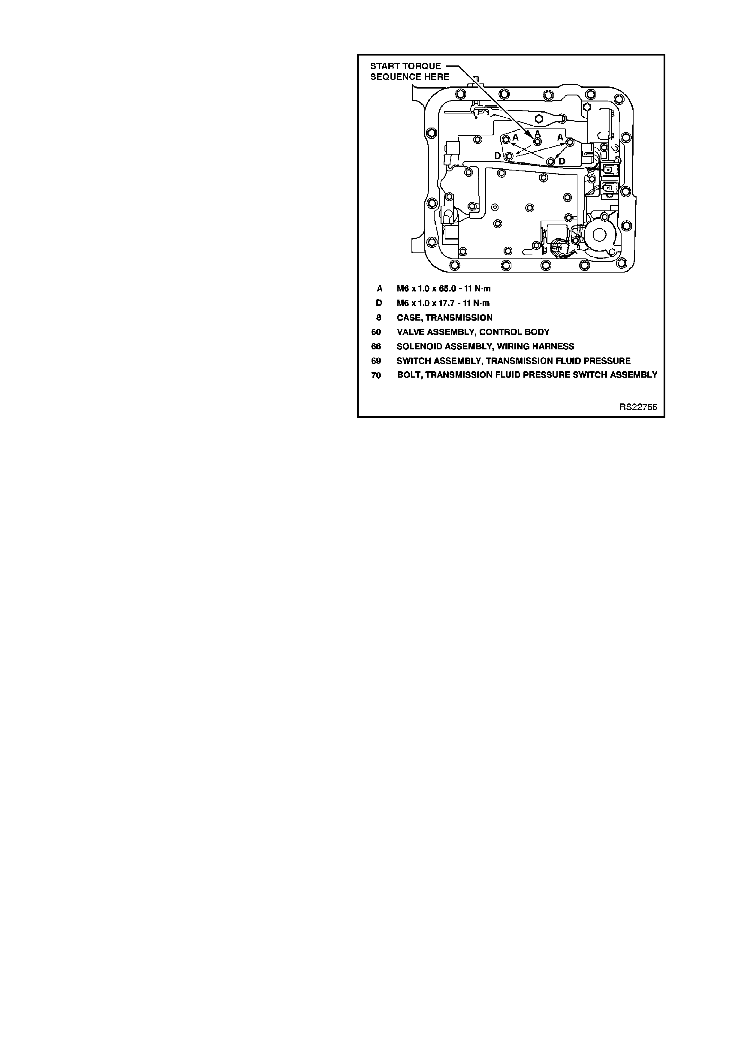
3.19 TCC ENABLE SOLENOID
Figure 6C2-3-65 TCC Enable Solenoid Location
REMOVE
1. Disconnect battery earth lead.
CAUTION:
To avo id personal in jury from an accidental hot
oil spillage, perform the fluid change only w hen
the transmission fluid is cold.
2. Raise the vehicle and support the vehicle on
safety stands. Refer to Section 0A,
GENERAL INFORMATION for location of
jacking points.
3. Remove the dirt from around the oil pan and
the transmission case.
4. Place the drain tray under the transmission.
5. Loosen the two bolts at the rear and one at the
front of the oil pan. Remove the remaining
bolts. While holding oil pan, allow the front of
the oil pan to drop away, emptying the oil into
the drain tray.
6. The remaining bolts, then lower the pan and
empty the fluid from the pan.
7. The old oil pan gasket and discard.
8. The strainer.
9. The TCC "PWM" solenoid (396) electrical
connector.
10. The TCC "PWM" solenoid retainer (379) by
using a split ring puller or similar hooked tool.
11. The TCC "PWM" solenoid assembly (396) with
O-ring seal.
12. The TCC enable solenoid assembly bolts (68).
13. The TCC enable solenoid assembly (66) with
the O-ring seal.
14. All the electrical connectors from the
components.
15. The three valve body bolts retaining wiring
harness.
16. The three 1-2 accumulator cover bolts (58)
(59).
17. The 1-2 accumulator cover assembly (57).
Figure 6C2-3-66
18. Remove pressure control solenoid (377)
electrical connector.
19. Remove pressure control solenoid retainer
(378).
20. Remove pressure control solenoid assembly
(377).
21. Place a 12 point 1-5/16" deep well socket (or
34.5 mm I.D. pipe with a slight cham fer on the
inside) over the top of the transmission pass-
through connector.
NOTE:
This may be difficult due to the clearance of the
floor pan transmission tunnel and the transmission
case.
22. Pry downward on the top of the soc ket or pipe
Using a prybar or similar shaped tool, push the
pass through connector down through and out
of the transmission case.

REINSTALL
1. Coat TCC ENABLE Solenoid O-ring with
petroleum jelly then install new wiring harness
assembly (containing new TCC ENABLE
solenoid) into transmission case.
2. Install pressure control solenoid assembly
(377).
NOTE:
Solenoid has a flat cut out on one side of it's
retaining flange. Flat cut-out goes toward retaining
bolt. Solenoid retainer has a matching flat to allow
retainer to be properly installed
3. Install pressure control solenoid retainer (378).
NOTE:
Ensure that flat of the retainer is correctly placed
into the cut-out on the solenoid flange. Tighten the
retainer bolt to 11 N m.
4. Install pressure control solenoid (377)
electrical connector.
5. Install 1-2 accumulator cover assembly (52).
6. Install three 1-2 accumulator cover bolts (58)
(59). Tighten to the correct torque
specification.
1-2 ACCUMULATOR COVER BOLT
TORQUE SPECIFICATION 11 Nm
7. Install TCC "ON-OFF" solenoid assembly (66).
8. Install TCC "ON-OFF" solenoid bolts (68).
Tighten to the correct torque specification.
TCC SOLENOID BOLT
TORQUE SPECIFICATION 11 Nm

9. Install TCC "PWM" Solenoid assembly (396).
10. Install TCC "PWM" Solenoid retainer (379).
11. Install TCC "PWM" solenoid electrical
connector.
12. Install three valve body bolts retaining wiring
harness. Tighten to the correct torque
specification.
VALVE BODY WIRING HARNESS
RETAINING BOLT
TORQUE SPECIFICATION 11 Nm
13. Install all electrical connectors onto
components.
14. Install new strainer and seal.
15. Clean oil pan and case mating surfaces.
Check that magnet is still magnetised, and
attached to the oil pan within the square
marked.
16. Install new gasket and reinstall oil pan.
Tighten bolts to the correct torque
specification.
TRANSMISSION OIL PAN BOLT
TORQUE SPECIFICATION 11 Nm
17. Lower vehicle and add approxim ately 4.8 litres
of DEXRON â III automatic transmission fluid.
18. Reconnect battery earth lead.
19. Check transmission fluid. Refer to " FLUID
CHECKING PROCEDURE" in Section 6C2-
2A.
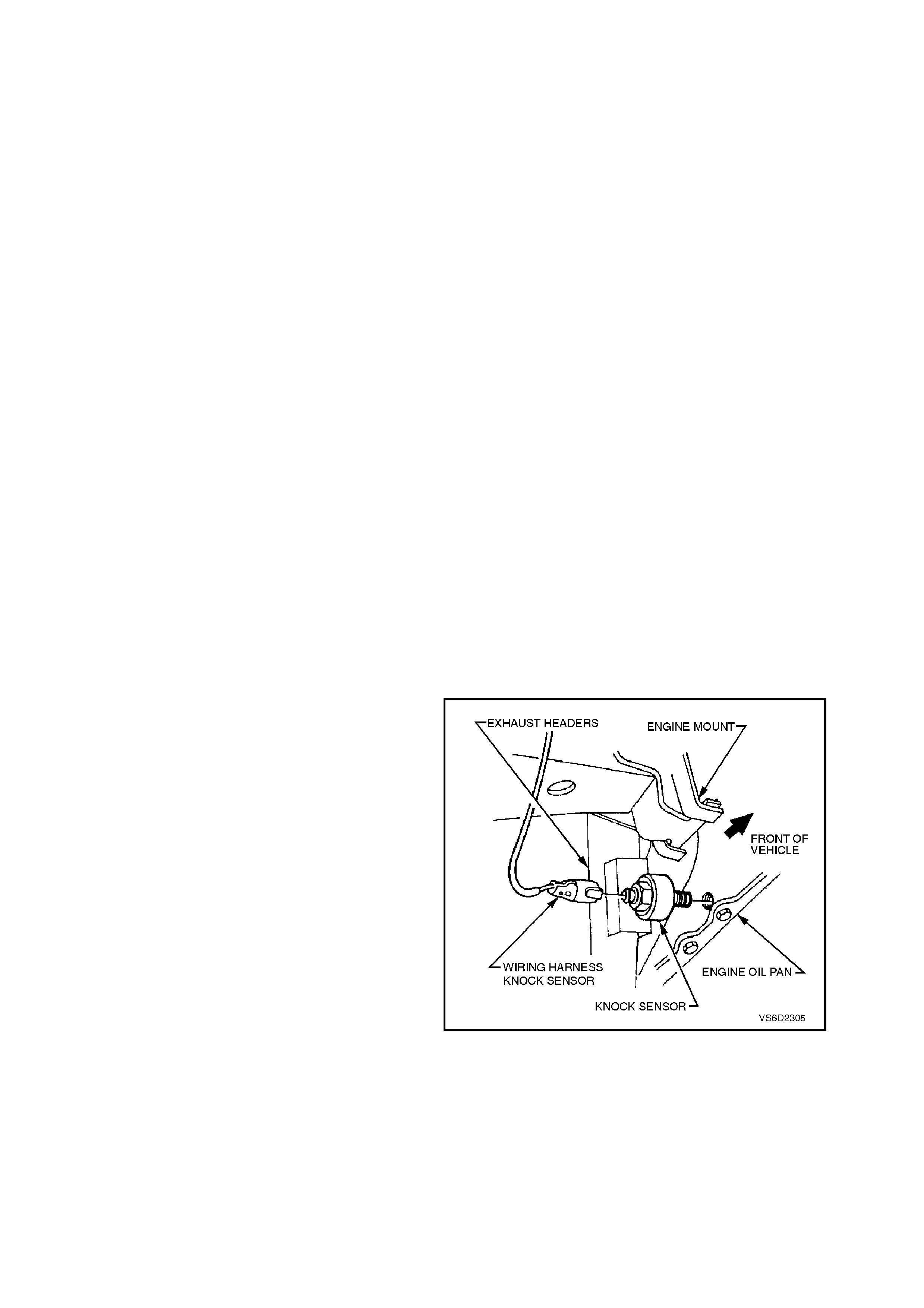
3.20 KNOCK S ENSOR
CHECKING KNOCK SENSOR OPERATION
This knock sens or will detect any mechanic al noise
or vibration transm itted from the engine. T he SNEF
module, located inside the PCM determines if the
noise is detonation, or normal mechanical noise.
The PCM can be "tricked" into thinking that
detonation is present by lightly 'rapping' on the
engine with a small hammer.
To check the knock retard function of the ignition
system, run the engine with the DLC diagnostic test
terminal NOT earthed. With the throttle fixed at a
steady 1600 RPM, quickly and repeatedly 'rap' on
the engine block, cylinder head, or inlet manifold
with a small hammer. The RPM should drop, due
to the timing advance being reduced. When you
stop 'rapping' on the engine, the RPM should com e
back to the original starting point.
REMOVE
IMPORTANT:
The knock sensor is screwed into the cylinder
block coolant jacket.
When removing the knock sensor with the
engine coolant still hot, ensure extreme caution
is taken so as to prevent any personal injury
due to hot coolant draining from the cylinder
block.
NOTE:
Extreme care should be exercised when handling
the knock sensor so as not to drop it on a hard
surface. If this should happen, the knock sensor’s
internal components can be damaged.
1. Allow the engine to cool to less than 50
degrees Celsius, then remove the radiator
cap.
2. Raise the front of the vehicle and support the
vehicle on safety stands. Ref er to Section 0A,
GENERAL INFORMATION for location of the
jacking points.
3. The knock sensor’s electrical connector.
4. Place a suitable drain tray beneath the knock
sensor location.
5. Remove the knock sensor heat shield.
6. The knock sensor from the cylinder block.
Figure 6C2-3-67 Knock Sensor Location

REINSTALL
1. Ensure that the threads for the sensor
mounting hole in the cylinder block are clean.
2. If reinstalling the original knock sensor,
inspect the sealant on the sensor’s threads. If
worn, apply a light coating of Loctite 242
(Holden's Spec ification HN1256 Class 2, Type
2) to the sensor’s threads.
NOTE:
On a new knock sensor, do not apply any sealant
to the threads. The threads are coated with a
sealant during production. Applying additional
sealant will affect the sensor's ability to detect
engine knock.
3. The knock sensor and tighten to the correct
torque specification.
4. The knock sensor heat shield.
KNOCK SENSOR TIGHTENING
TORQUE SPECIFICATION 16 - 22 Nm
The knock sensor electrical connector.
Refill the lost coolant and pressure test for leaks.
Refer to Section 6B2 ENGINE COOLING - V8
ENGINE.
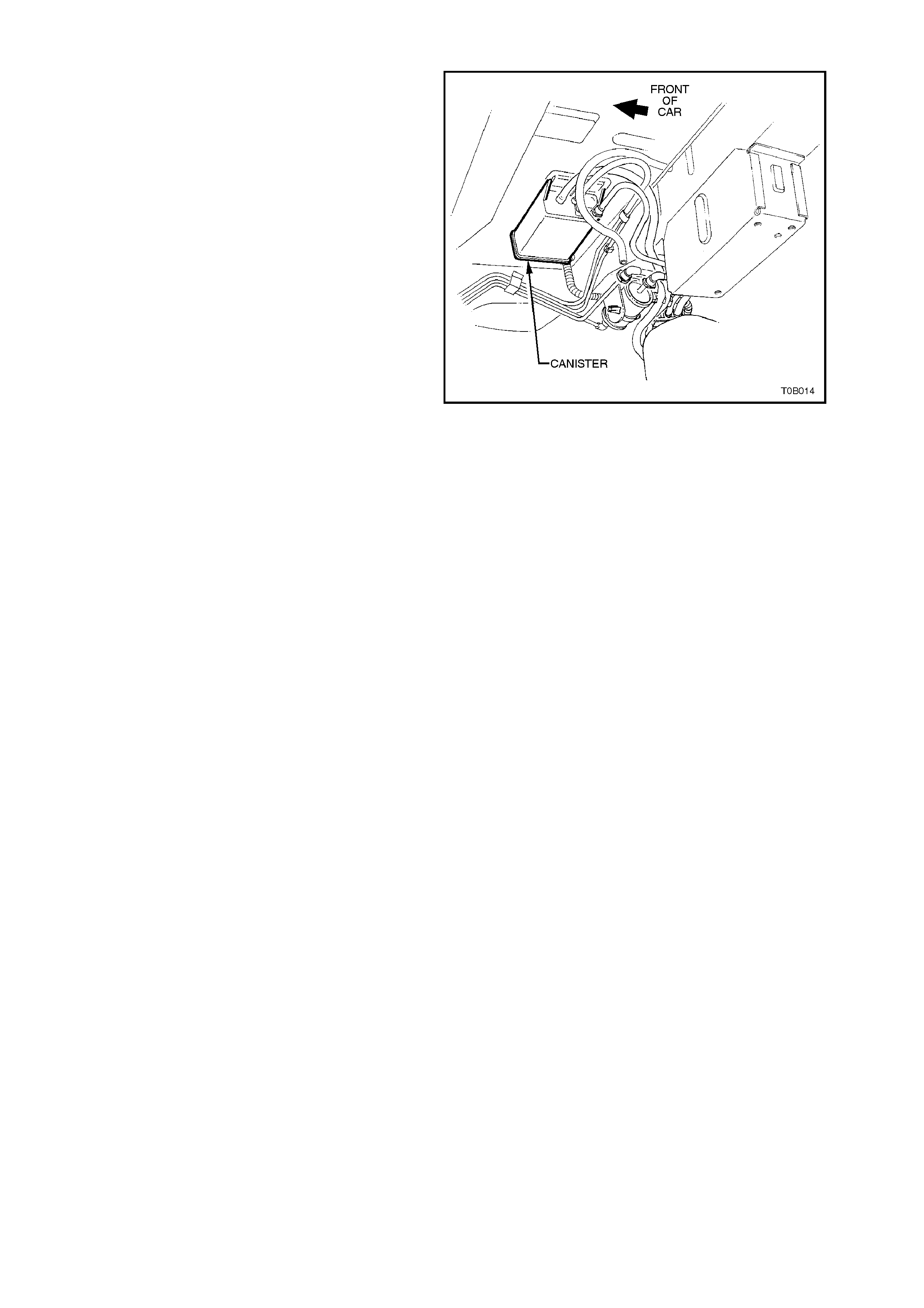
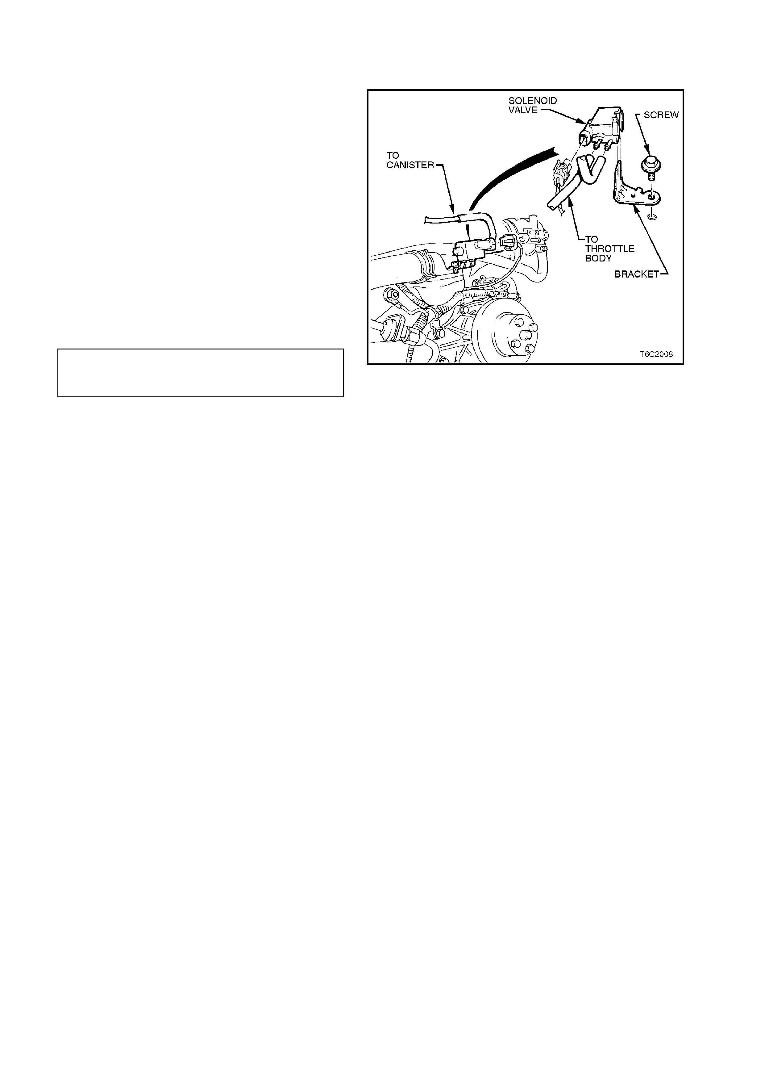
3.23 CANISTER PURGE SOLENOID
REMOVE
1. Mark the hoses on the canist er purge solenoid
(top, bottom), and pull the hoses from the
solenoid.
2. Pull up on the solenoid wiring harness
connector and pull the connector from the
solenoid.
3. Remove the bolt from the solenoid bracket.
This bolt attaches to the fr ont of the right hand
cylinder head.
4. Remove the solenoid.
REINSTALL
1. Reinstall the canister purge solenoid and
install the bracket bolt. Tighten the bolt to the
correct torque specification.
CANISTER PURGE SOLENOID
BRACKET TO CYLINDER HEAD BOLT 15-20 Nm
TORQUE SPECIFICATION
2. Reconnect the hoses and the wiring harness
connector to the canister purge solenoid.
Ensure that the connections are correct.
Figure 6C2-3-69 Canister Purge Solenoid Location
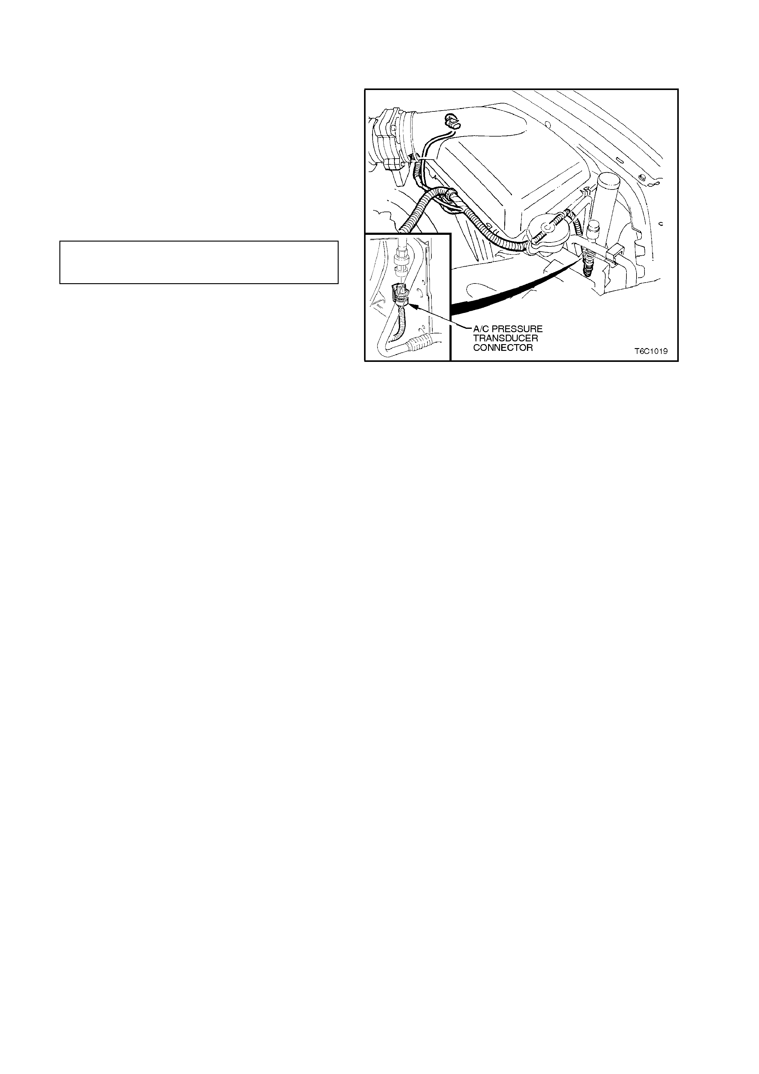
3.24 A/C REFRIGERANT P RE SSURE SENSOR
REMOVE
1. The A/C refrigerant pressure sensor electrical
connector.
2. The A/C refrigerant pressure sensor.
REINSTALL
1. The A/C refrigerant pressure sensor and
tighten to the correct specification.
A/C REFRIGERANT
PRESSURE SENSOR 5 - 7 Nm
TORQUE SPECIFICATION
2. The A/C refrigerant pressure sensor electrical
connector.
3. Check the A/C pressure and recharge if
necessary. Figure 6C2-3-70 A/C Refrigerant Pressure Sensor Location