
SECTION 6D1-3 IGNITION SYSTEM - V6 ENGINE &
V6 SUPERCHARGED ENGINE
CAUTION:
This vehicle will be equipped with a Supplemental Restraint System (SRS). A SRS will
consist of either seat belt pre-tensio ners and a driver’s side air bag , or seat belt pre-
tensioners and a driver’s and front passenger’s side air bags. Refer to CAUTIONS,
Section 12M, before performing any service operation on or around SRS
components, the steering mechanism or wiring. Failure to follow the CAUTIONS
could result in SRS deplo yment, resulting in possible p ersonal injury or unnecessary
SRS system repairs.
CAUTION:
This vehicle may be equipped with LPG (Liquefied Petroleum Gas). In the interests of
safety, the LPG fuel system should be isolated by turning 'OFF' the manual service
valve and then draining the LPG serv ice lines, before any service w ork is carried out
on the vehicle. Refer to the LPG leaflet included with the Owner's Handbook for
details or LPG Section 2 for more specific servicing information.
1. GENERAL INFORMATION
The ignition system for VT Models with V6 engines is a high energy 'distributor less' Direct Ignition System (D.I.S.).
This system uses a 'waste spark' method of spark distribution.
Each cylinder is paired with its opposing cylinder in the firing order, so that one cylinder on compression fires
simultaneously w ith its opposing cylinder on exhaust stroke. (Since the cylinder on exhaust requires very little of the
available voltage to fire its spark plug, most of the voltage is used to fire the spark plug on the cylinder on
compression).
The process reverses when the cylinders reverse roles, i.e. if cylinder No. 1 is on compression and cylinder No. 4 is
on exhaust, most of the voltage is used to fire No. 1 spark plug. With 360 degree rotation of the crankshaft, No. 4
will be on compression and No. 1 will be on exhaust, therefore, No. 4 spark plug will receive the majority of the
voltage.
1.1 GENERAL DESCRIPTION
The D.I.S. System com prises an electronic coil and
ignition module assembly, Dual Crank Sensor
(crankshaft position sensor), Camshaft Position
Sensor, Electronic Spark Control (ESC) system,
spark plugs, spark plug leads and the engine
management Powertrain Control Module (PCM).
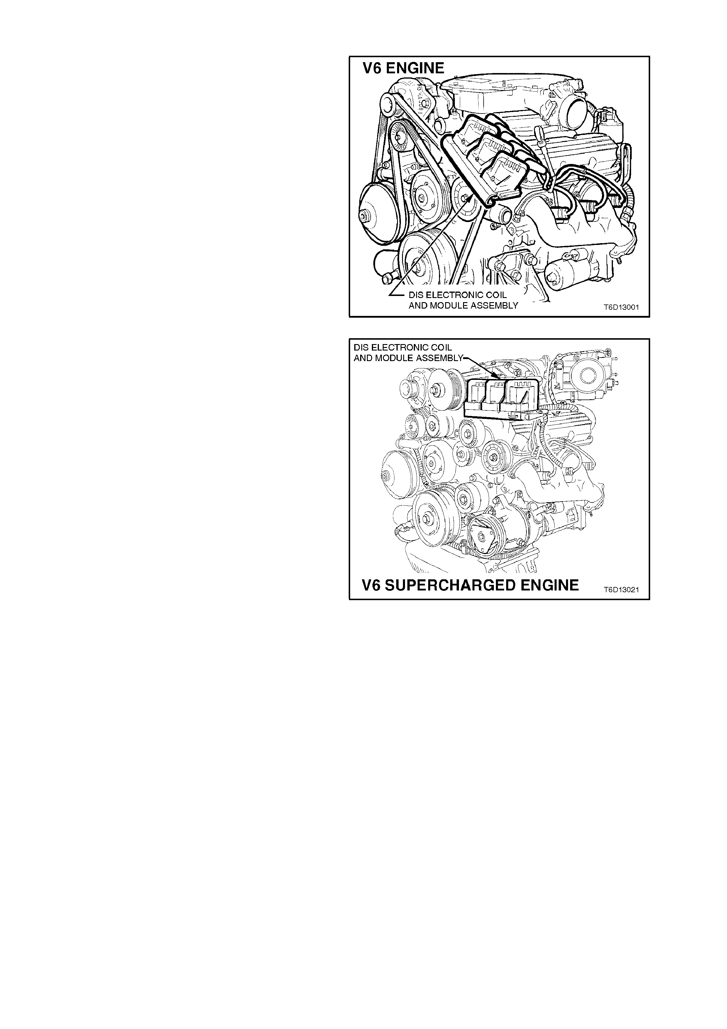
The coil pack and ignition module assembly are
mounted on a bracket attached to the front of the
left hand cylinder head. Figure 6D1-3-1 refers to
the standard V6 and Figure 6D1-3-2 refers to the
supercharged V6.
The coil pack consists of three separate and
interchangeable ignition coil assemblies. These
coils operate in the same manner as conventional
ignition coils. Three coils are needed, as each coil
fires for two cylinders.
The ignition module is located under the coil pack
and is connected to the PCM by a 14 pin wiring
harness connector.
The ignition module controls the primary circuit to
the coils, turning them ON and OFF, and controls
spark timing below 450 RPM and if PCM bypass
circuit becomes open or earthed. Refer to Section
6C1 POWERTRAIN MANAGEMENT - V6
ENGINE. The ignition module is non-repairable. If
the module must be replaced, the three coil
assemblies must be transferred to the new module.
Cylinder numbering is nominated on the top of
each coil assembly and on the top surface of the
module assembly.
Figure 6D1-3-1
Figure 6D1-3-2
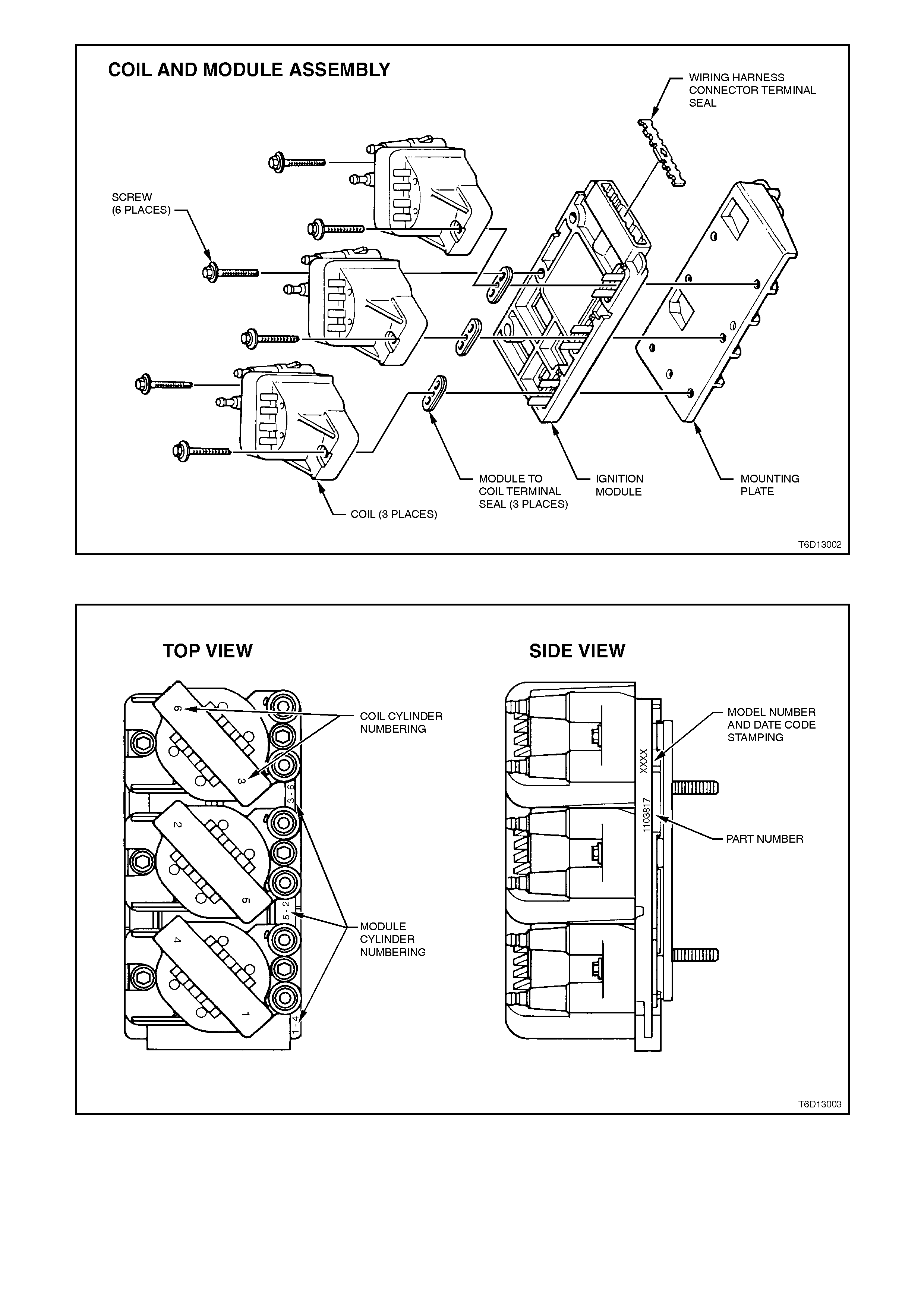
Figure 6D1-3-3
Figure 6D1-3-4
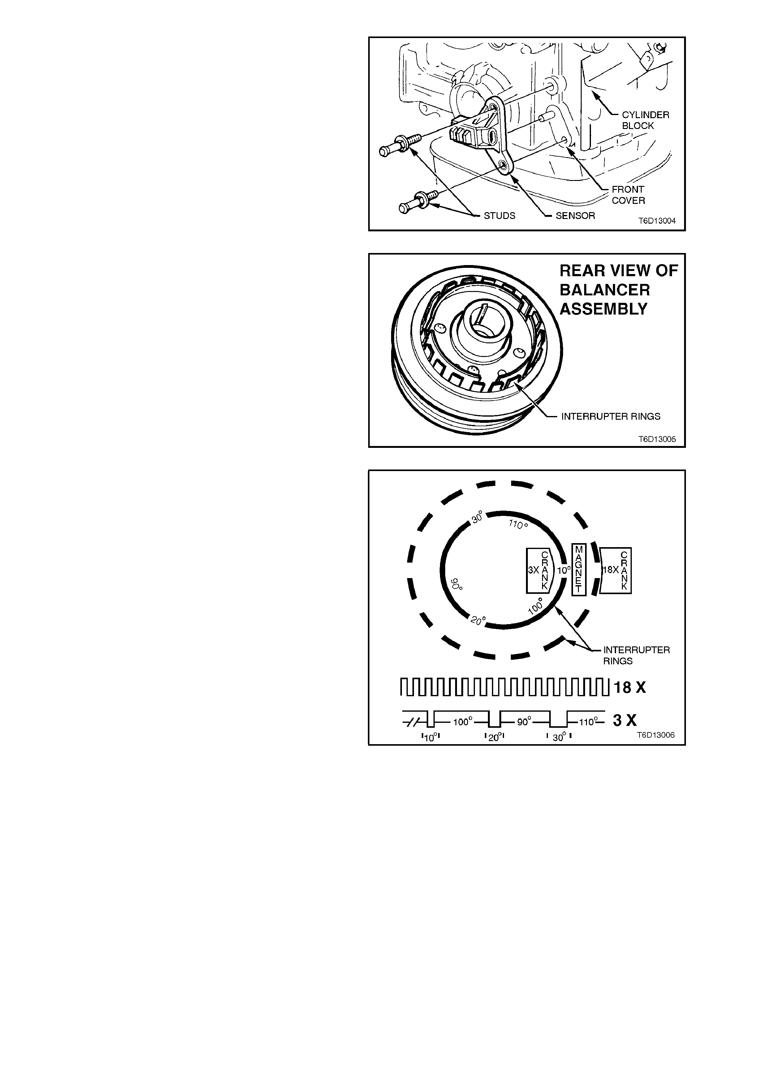
The crankshaft position sensor incorporates two
Hall effect device sensors and a centre mounted
magnet. Two interrupter rings pass through the
slots in the sensor and provide timing information,
crankshaft position and RPM to the PCM.
The crankshaft position sensor is mounted in a
bracket bolted to the front of the cylinder block,
near the crankshaft balancer.
Figure 6D1-3-5
The interrupter rings are assembled to the rear of
the crankshaft balancer assembly.
Figure 6D1-3-6
Windows in the interrupter rings activate the Hall
sensors as they provide a path for the magnetic
field between the sensor's transducer and the
centre mounted magnet. When the Hall effect
sensor is activated, it earths the signal line to the
ignition module, reducing the crank signal line's
applied voltage, which is interpreted as a crank
signal. Due to the way the crank signal is created,
the signal circuit is always either at a high or low
voltage (square wave signal).
The outer interrupter ring has eighteen, 10 degree
windows and eighteen, 10 degree teeth. The inner
ring has three windows, each of different width, a
10 degree window, 20 degree window and a 30
degree window.
With the rotation of the interrupter rings through the
Hall effect sensors, the combination of the sensors
output signals uniquely identify each of the three
cylinder pairs at a specific point in the crankshaft
rotation.
For further details on the operation of the
crank s haf t position sensor and the interr upter r ings,
refer to Section 6C1 POWERTRAIN
MANAGEMENT - V6 ENGINE.
Figure 6D1-3-7
To prevent the possibility of foreign matter being
caught up between the crankshaft position sensor
and the interrupter rings of the crank shaft balancer
assembly, a sensor shield is fitted to the front of
the engine.
The shield must be removed before removing the
crankshaft position sensor.
The Electronic Spark Control (ESC) system used
on V6 engines, modifies (retards) the spark
advance when detonation occurs. T he retard m ode
is held for 20 seconds after which the spar k contr ol
will revert back to the Electronic Spark Timing
(EST) control of the PCM.
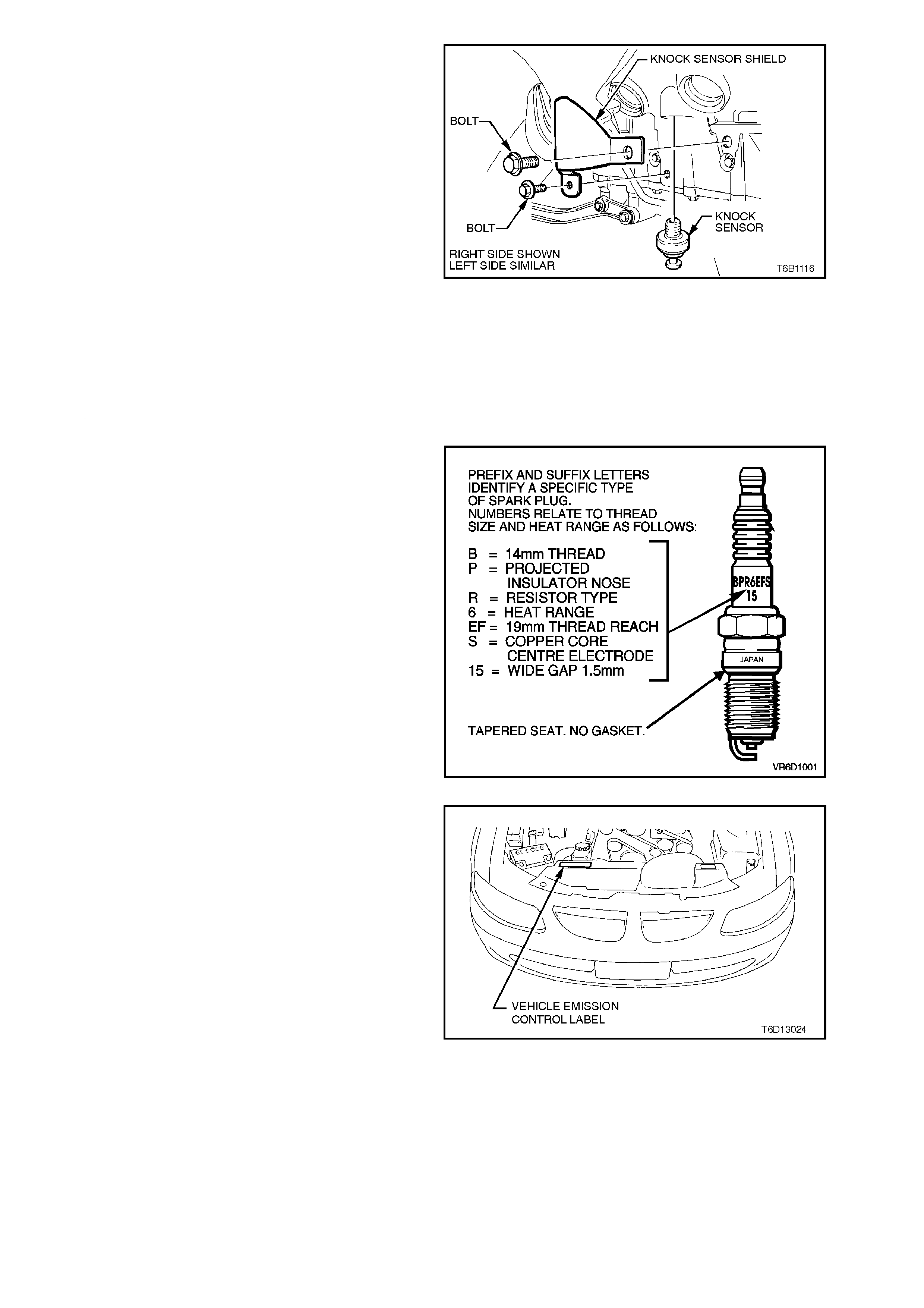
The ESC system us es a knock s ensor to detec t the
presence and intensity of engine detonation or
spark knock. The knock sensor is mounted in the
right hand side of the cylinder block, behind the oil
pressure sender unit.
The output of the knock sensor is an electrical
signal which is sent to a c ontroller, mounted on the
PCM PROM.
The controller processes the sensor signal into a
command signal to adjust the EST. T he process is
continuous so that the presence of detonation is
monitored and controlled.
If the knock sensor should fail, the ignition timing
will retard, but at a calibrated, fixed amount
determined by the PCM. Figure 6D1-3-8
Should the controller fail, one of two conditions
could apply, no retard or full retard (10 degrees
max.).
For additional inform ation on the ESC system , ref er
to Section 6C1 POWERTRAIN MANAGEMENT -
V6 ENGINE.
Resistor type, tapered seat spark plugs are used in
the V6 engine, no gasket is used on these tapered
seat plugs.
Fig. 6D1-3-9 illust rates and explains the s park plug
letter coding for NGK examples only.
Always replac e plugs with the correct plug listed on
the Vehicle Emission Control Information Label.
The label also lists the correct spark plug gap.
Refer to Fig. 6D1-3-10 for the location of the
Vehicle Emission Control Information Label.
Figure 6D1-3-9
The Vehicle Emission Control Information label is
located on the left hand side of the radiator upper
shroud.
Figure 6D1-3-10
2. SERVICE OPERATIONS
2.1 SPARK PLUG LEADS - V6 ENGINE
REMOVE AND REINSTALL
Use care when removing spark plug lead boots
from spark plugs.
NOTE:
Pull on the boot only, DO NOT pull by the lead.
When reinstalling plug leads, route leads correctly
and through the proper retainers. Failure to route
the leads corr ectly can res ult in the lead/s chaffing,
burning, or causing crossfiring of the plugs or
shorting of the leads to ground.
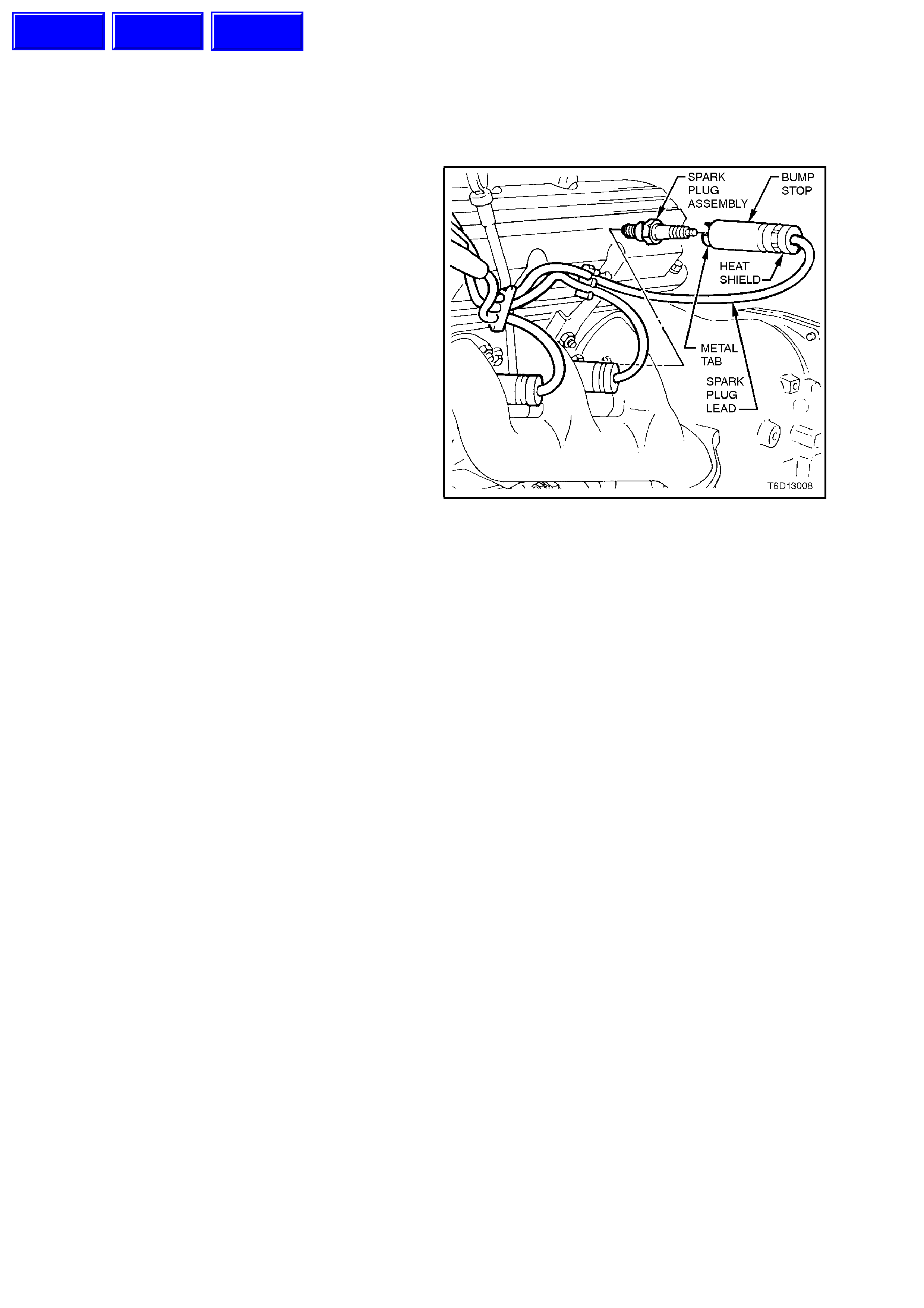
NOTE:
All spark plug leads and coil terminals are
numbered to correspond to the cylinder numbering.
Special care should be exercised when reinstalling
spark plug lead boots to ensure that the metal
terminal within the boot is fully seated on the spark
plug terminal and that the boot has not moved on
the lead. If boot movement has occurred, the boot
will give a false visual impression of being fully
seated.
Also ensure that the metal tabs at the base of the
boot heat shields are completely seated over the
spark plug hex, also that heat shields remain
seated against bump stops at cable end of boot.
The following figures illustrates the spark plug lead
routing and retention.
Figure 6D1-3-11
TEST
Remove leads, taking note of precautions as
previously outlined.
Connect an ohmmeter capable of reading to
50,000 ohms across each lead. The ohmmeter
should register less than 10,000 ohms resistance
for leads connected to cylinders 1, 3 and 5 and less
than 17,000 ohms for leads connected to cylinders
2, 4 and 6.
Replace any lead/s that has higher than specified
resistance.
Techline
Techline
Techline
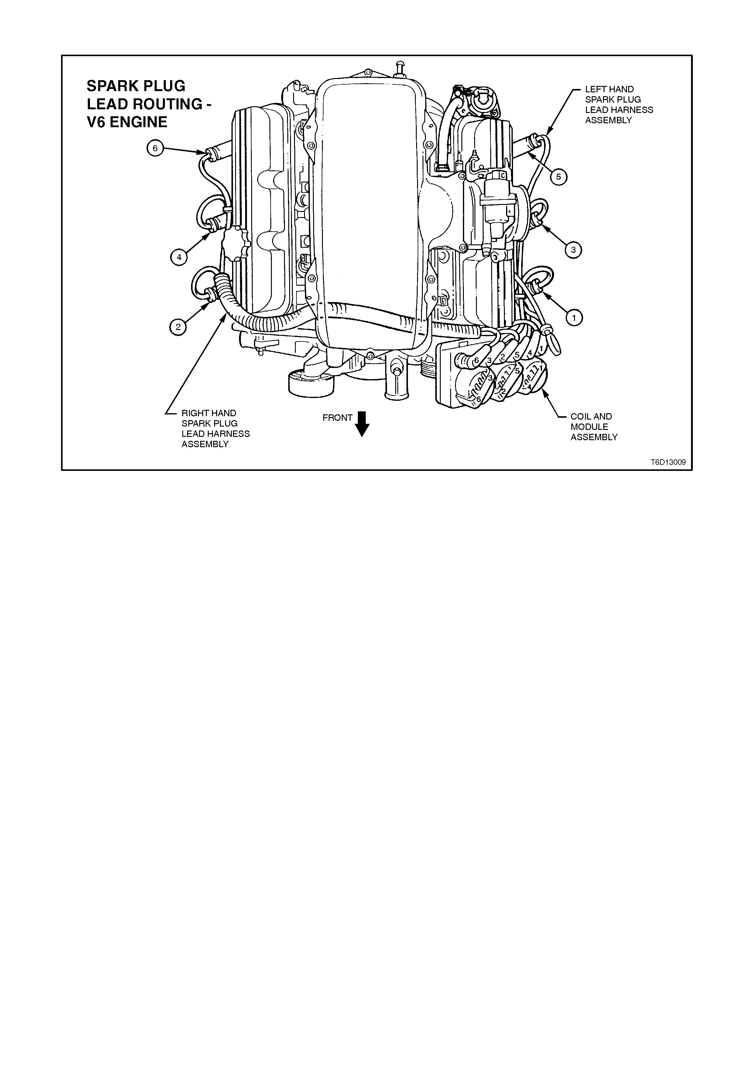
SPARK PLUG LEAD ROUTING - V6 ENGINE
Figure 6D1-3-12
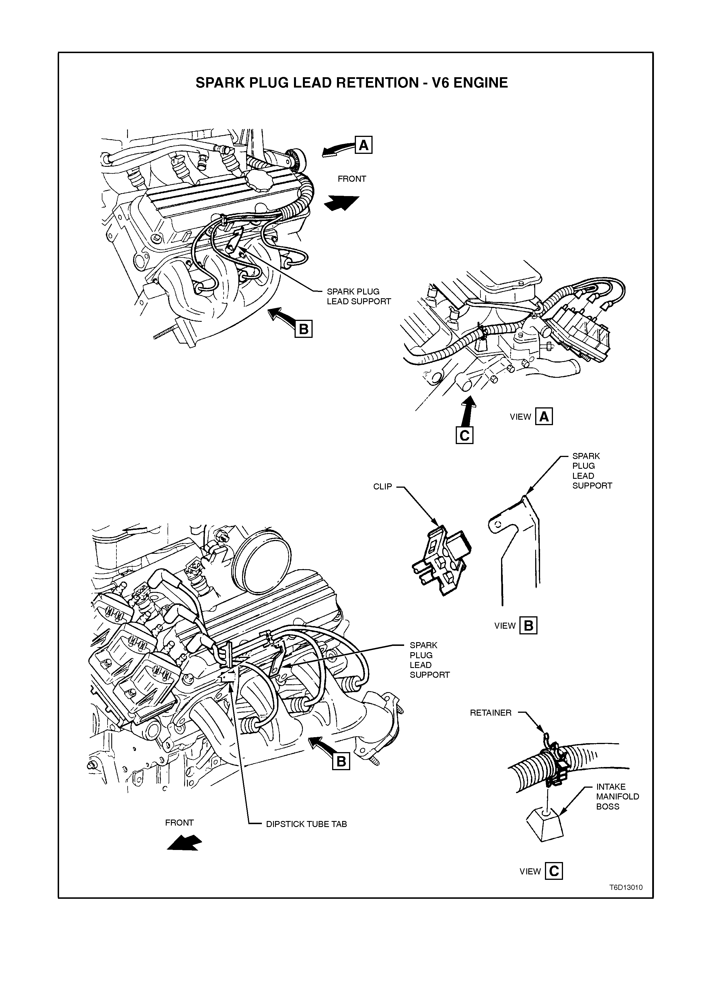
SPARK PLUG LEAD RETENTION - V6 ENGINE
Figure 6D1-3-13
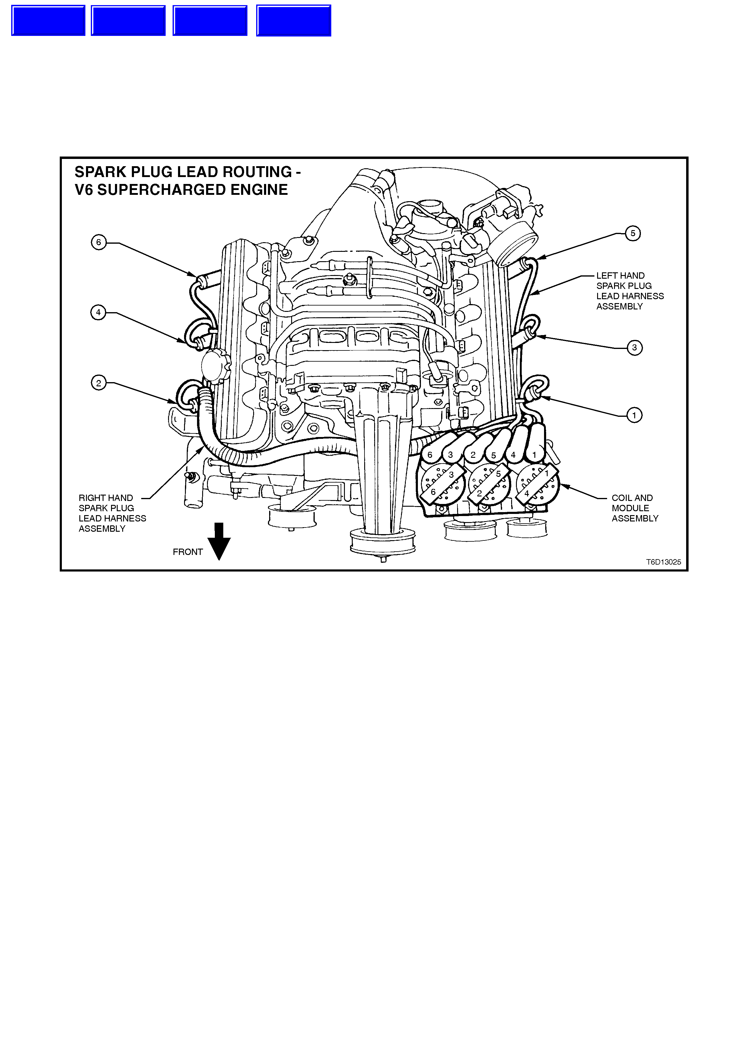
2.2 SPARK PLUG LEADS - V6 S UP E RCHARGED ENGINE
The procedure to rem ove, test and reinstall the spark plug leads on V6 supercharged engines is the sam e as non
supercharged V6 engines, noting the revised spark plug lead routing and retention, refer to Fig. 6D1-3-12 and
Fig. 6D1-3-13 in this Section.
Theref ore when rem oving, testing or reinstalling the spark plug leads on V6 superc harged engines, ref er to the non
supercharged procedures in this Section.
SPARK PLUG LEAD ROUTING - V6 SUPERCHARGED ENGINE
Figure 6D1-3-14
Techline
Techline
Techline
Techline
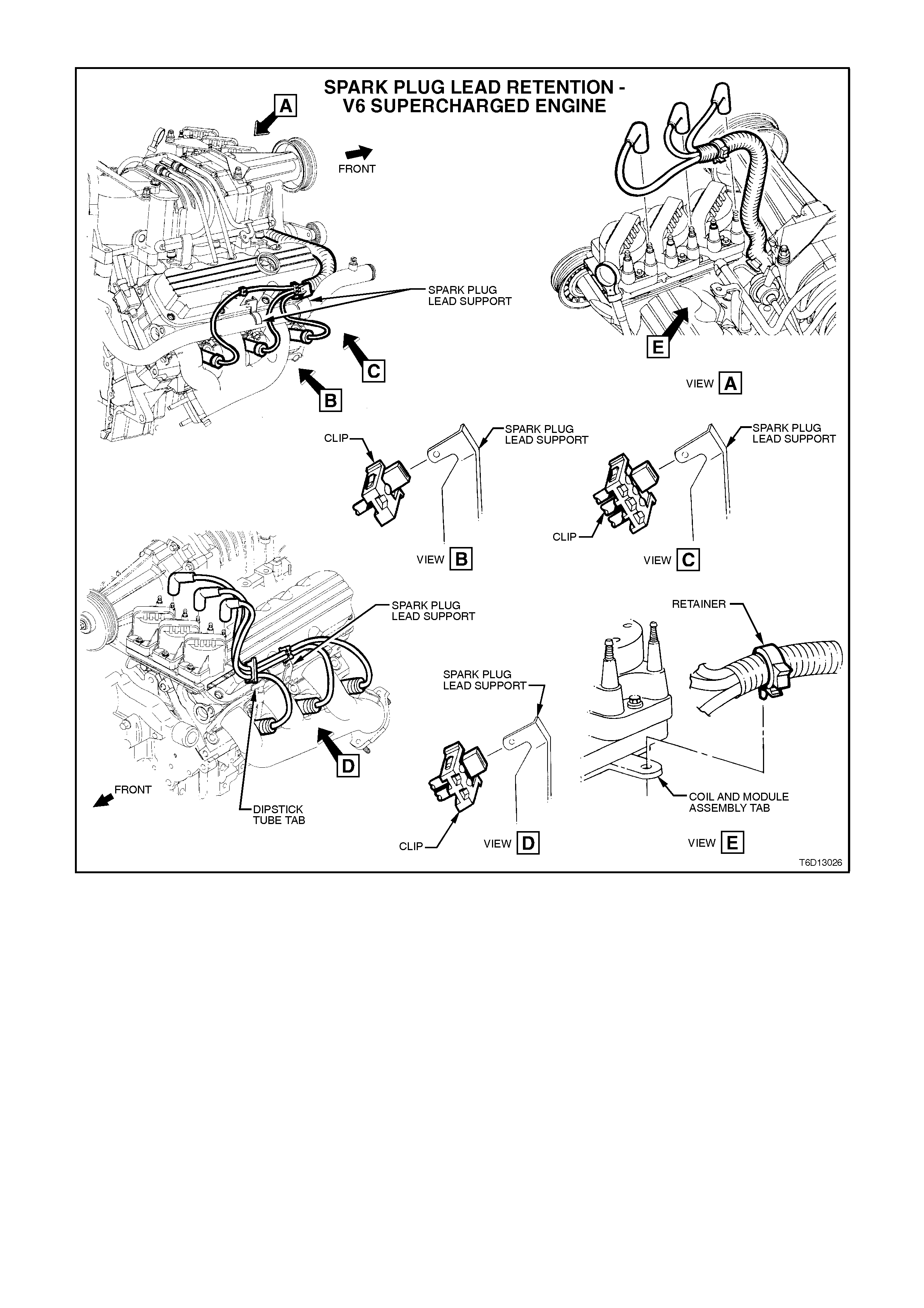
SPARK PLUG LEAD RETENTION - V6 SUPERCHARGED ENGINE
Figure 6D1-3-15
2.3 SPARK PLUGS
REMOVE
1. Disconnect spark plug leads from spark plugs,
refer to 2.1 SPARK PLUG LEADS - V6
ENGINE in this Section.
2. Unscrew and remove spark plugs using a 16
mm spark plug socket.
3. Plug spark plug holes with rag to prevent
foreign matter entering combustion chambers.
CLEAN AND ADJUST
1. Carefully inspect spark plug insulators and
electrodes. Replace any plug with cracked or
broken insulation or loose electrodes.
Refer to 3.1 SPARK PLUG DIAGNOSIS in
this Section for identification of spark plug
condition.
2. If spark plugs are oily, clean with degreasing
agent and dry with compressed air.
NOTE:
When removing spark plugs, plac e them in order of
removal. This will enable a check of individual
cylinders to be made. Engine condition to be
assessed by viewing the colour of the plug insulator
and electrode wear.
Should one or two spark plug insulators appear
different to the other spark plugs, check engine
compression (refer to Section 6A1-1 ENGINE
MECHANICAL - V6 ENGINE).
3. Clean spark plugs using a sand blast type
cleaning machine as per manufacturer's
instructions.
4. Inspect spark plugs again for defects which
may not have been apparent before cleaning.
5. Ensure that spark plug threads are clean and
in good order.
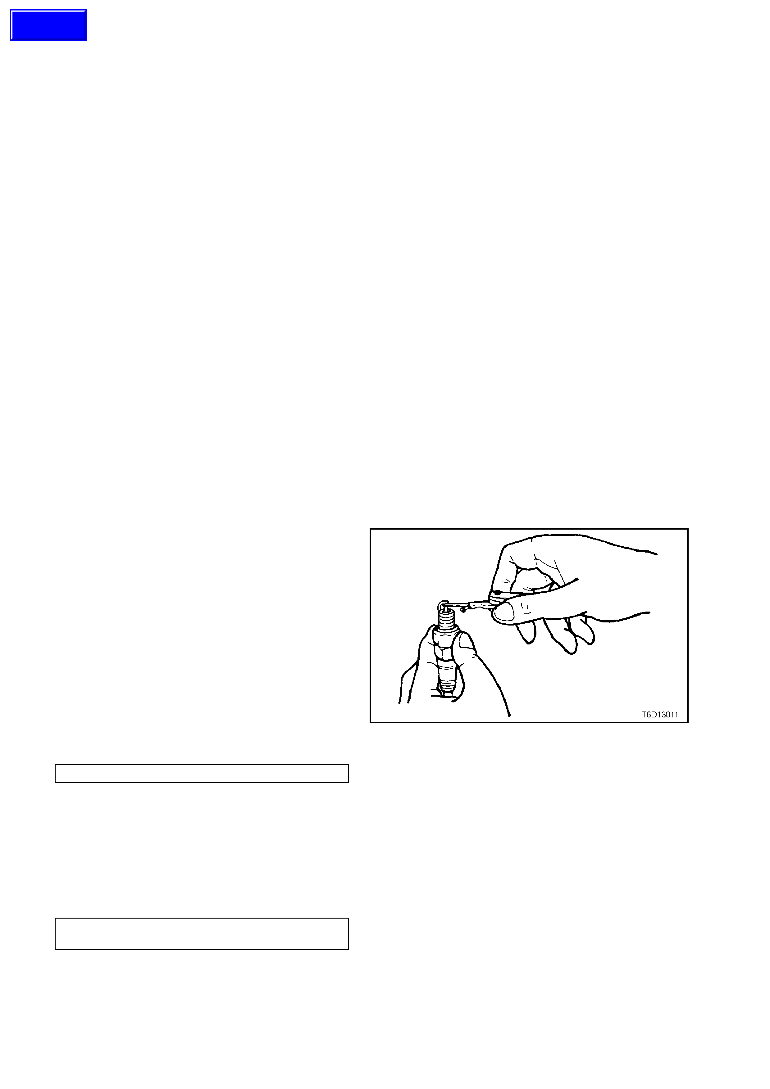
6. Use round wire feeler gauges to check gap
between spark plug electrodes.
7. Adjust gap to correct specification by bending
outer electrode.
Figure 6D1-3-16
SPARK PLUG GAP 1.5 mm
REINSTALL
1. Remove rag from spark plug holes.
2. Reinstall spark plugs and tighten to the cor r ect
torque specif ication using a 16 m m spark plug
socket.
SPARK PLUG
TORQUE SPECIFICATION 15 - 25
Nm
3. Reinstall spark plug leads.
Techline
2.4 IGNITION COIL AND MODULE ASSEMBLY
REMOVE
1. Remove battery earth lead.
2. Remove spark plug leads from coil terminals,
noting lead numbering with reference to coil
terminal numbers.
NOTE:
All spark plug leads and coil terminals are numbered to
correspond to the cylinder numbering.
If cylinder numbering does not appear on top of any
coil assembly, refer to cylinder numbering on the
module (refer to Fig 6D1-3-4 in this Section).
3. From beneath powertrain harnes s retainer at f ront
of coil and m odule assembly, gently pull down on
the retainer lower locating tangs and pull retainer
from the coil and module assembly.
4. Loosen bolt attaching 14 - pin wiring harness
connecter to module, pull connector from module.
5. Remove coil and module assembly bracket to
cylinder head attaching bolts and rem ove coil and
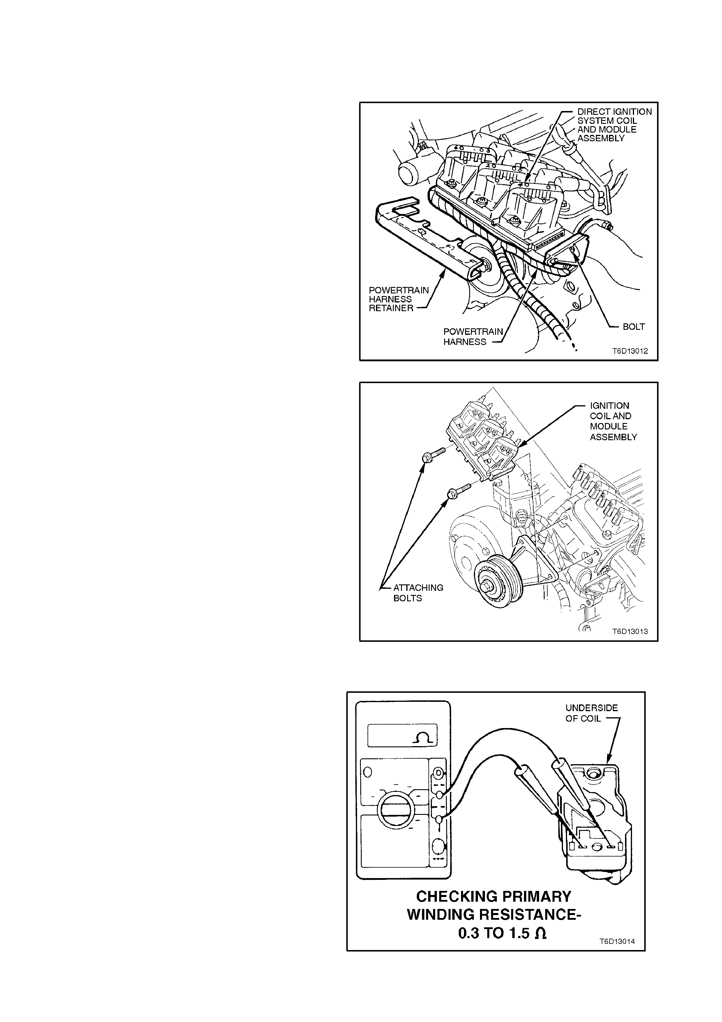
module assembly. Figure 6D1-3-17
6. Remove coil and module assembly bracket to
cylinder head attaching bolts and rem ove coil and
module assembly.
Figure 6D1-3-18
TEST
Visually inspect coil/s for any signs of external
damage or spark tracking.
Using an ohmmeter, check coil primary winding
resistance by probing into terminals from the
underside of the coil assembly.
Correct resistance of the ignition coil primary
winding must be between 0.3 and 1.5 ohms.
NOTE:
Some ohmmeter lead probes may be too large to
contact the primary winding connections inside the
coil housing, so as an aid to checking primary
winding resistance, wrap a thin piece of wire
around each ohmmeter lead probe. It is imperative
that the contact between the ohmmeter lead probe
and the wire be first clas s to ens ur e the acc ur acy of
the ohmmeter reading.
Figure 6D1-3-19
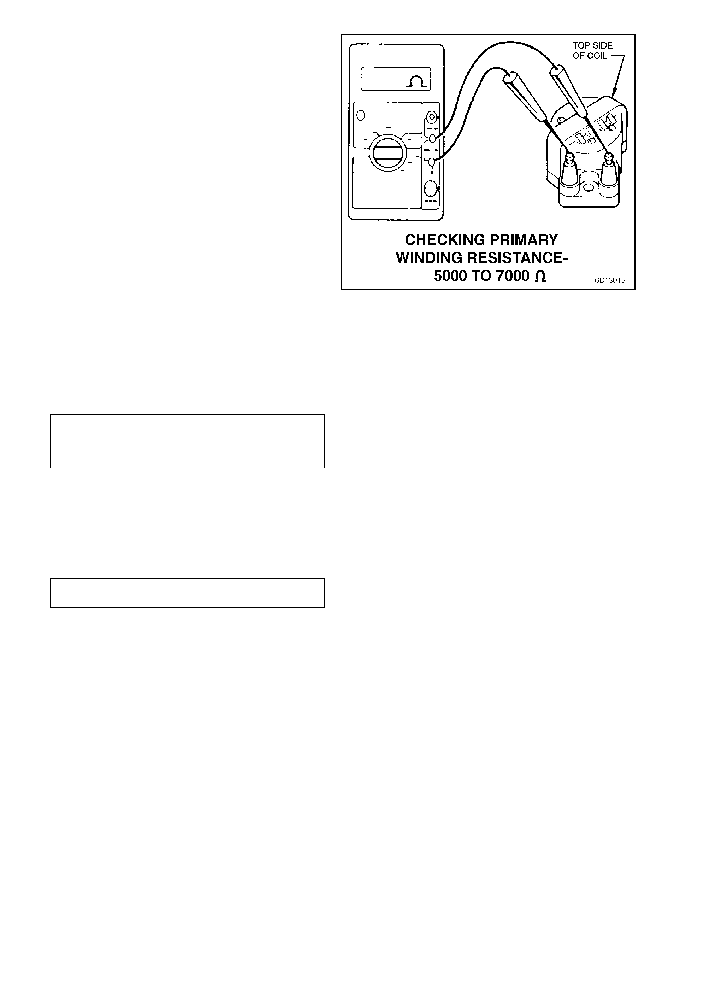
Check resistance across coil secondary winding
terminals.
Correct resistance of the ignition coil secondary
winding must be between 5000 and 7000 ohms.
Replace coil assembly if not to specification.
Figure 6D1-3-20
REINSTALL
1. Assemble coil and module assembly to
cylinder head attaching bolts. Tighten
attaching bolts to the correct torque
specification.
COIL AND MODULE ASSEMBLY
BRACKET TO CYLINDER HEAD
ATTACHING BOLT
TORQUE SPECIFICATION
40 - 50 Nm
2. Refit spark plug leads to coil terminals,
ensuring correct lead to coil terminal
relationship.
3. Reconnect battery earth lead, start engine and
ensure engine operates correctly.
WI RING HARNESS MODULE BOLT
TORQUE SPECIFICATION 0.6 - 1.2
Nm
4. Refit powertrain harness retainer to front of
coil and module assembly, ensuring that it is
securely retained.
5. Reconnect battery earth lead, start engine and
ensure engine operates correctly.
2.5 CRANKSHAFT POSITION SENSOR
REMOVE
1. Remove battery earth lead.
2. Remove crankshaft balancer, refer to
Section 6A1-1 ENGINE MECHANICAL - V6
ENGINE.
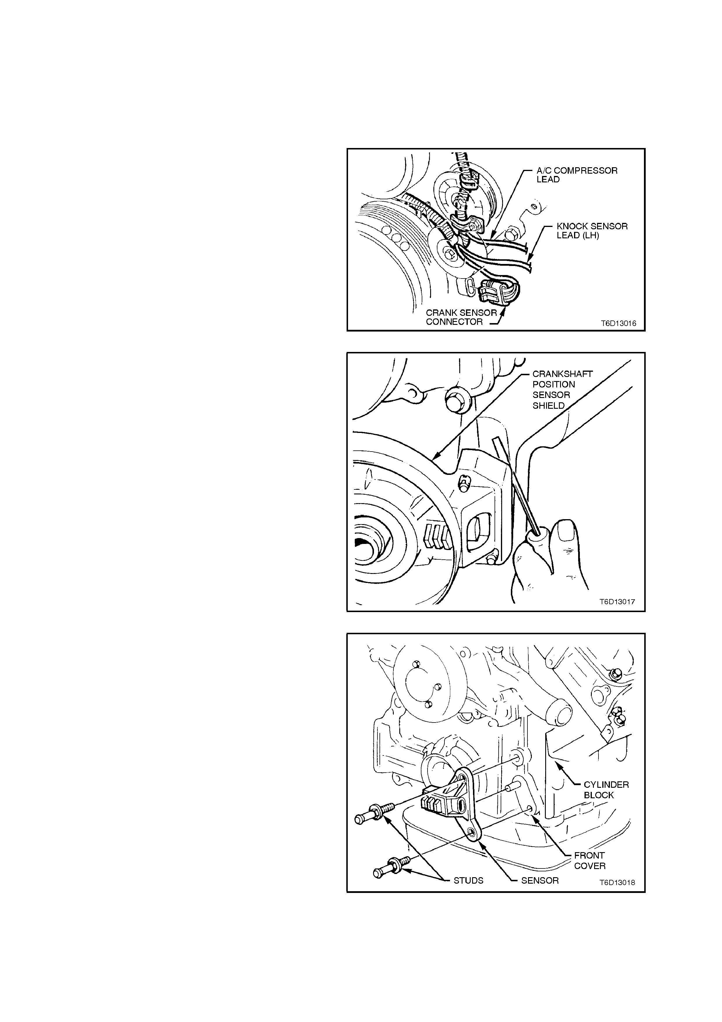
3. Using a fine bladed s c rewdriver , c arefully lever
back engine harness connector retaining tang
from crankshaft position sensor and pull
connector from sensor.
Figure 6D1-3-21
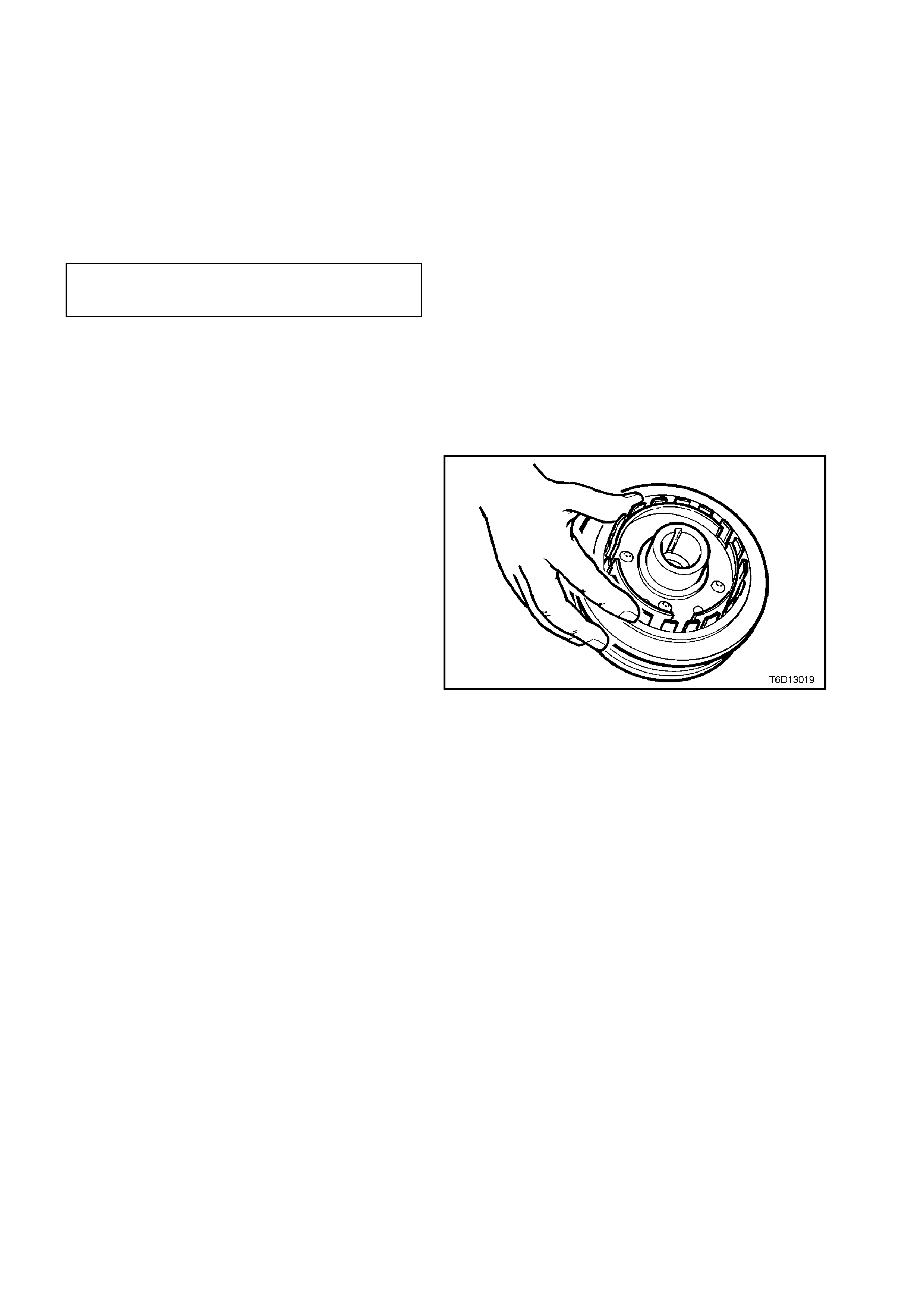
4. Using a screwdriver behind sensor shield,
lever each corner of shield from front cover
studs, remove shield.
Figure 6D1-3-22
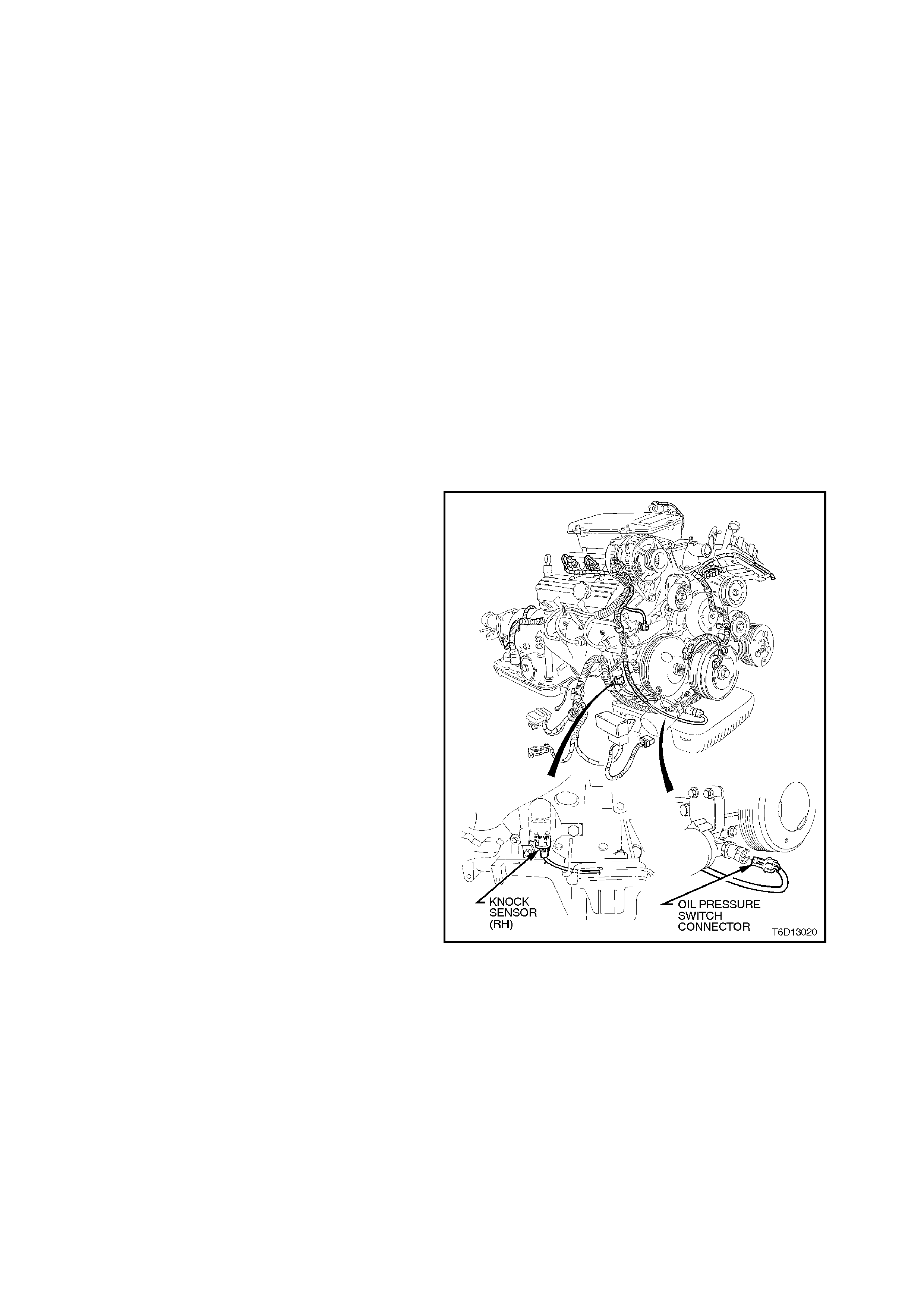
5. Remove sensor bracket to front cover
attaching studs and remove sensor assembly.
Figure 6D1-3-23
REINSTALL
1. Clean threads of sensor to front cover
attaching studs. Apply Loctite 242 or
equivalent (Holden Specification HN 1256
Class 2, Type 2) to threads of studs.
Install sens or ass em bly onto front cover dowel
pin and install attaching studs.
2. Tighten sensor bracket to front cover
attaching studs to the correct torque
specification.
SENSOR BRACKET TO FRONT
COVER ATTACHING STUD
TORQUE SPECIFICATION 20 - 30 Nm
3. Reinstall sensor shield onto front cover studs,
ensuring shield retainers fully engage over
ends of studs.
Reinstall engine harness connector to sensor,
ensuring that connector locking tang engages
fully on sensor.
4. Visually inspect interrupter rings for any
damage or distortion.
Figure 6D1-3-24
5. Reinstall crankshaft balancer, refer Section
6A1 ENGINE MECHANICAL - V6 ENGINE.
NOTE:
Do not install drive belt at this stage.
6. Rotate crankshaft so as to check that
interrupter rings do not contact sensor.
If the interrupter rings contact the sensor at
any point during balancer rotation, the
interrupter rings have excessive runout and
the balancer assembly must be replaced.
7. Reinstall drive belt and battery earth lead.
Start engine and ensure engine operates
correctly.
2.6 KNOCK SE NS OR
WARNING:
It must be noted that the knock sensors screw
into the cylinder block coolant jackets.
If removing the knock sensors with the engine
coolant still hot, ensure extreme caution is
taken so as to prevent any serious personal
injury due to hot coolant draining from the
cylinder block.
REMOVE
NOTE:
Extreme care should be exercised when handling
the knock sensor so as not to drop it on a hard
surface. If this should happen, the sensor internal
components can be damaged.
1. Allow engine to cool to ambient temperature
(less than 50° C), then remove radiator cap.
2. Disconnect battery earth lead.
3. Raise front of vehicle and support on safety
stands. Refer to Section 0A GENERAL
INFORMATION for location of jack points.
4. Squeeze together 'wide ends' of knock sensor
wiring harness connector (connector is oval
shaped) and pull connector from sensor.
Figure 6D1-3-25
5. Place a suitable drain tray beneath the knock
sensor location.
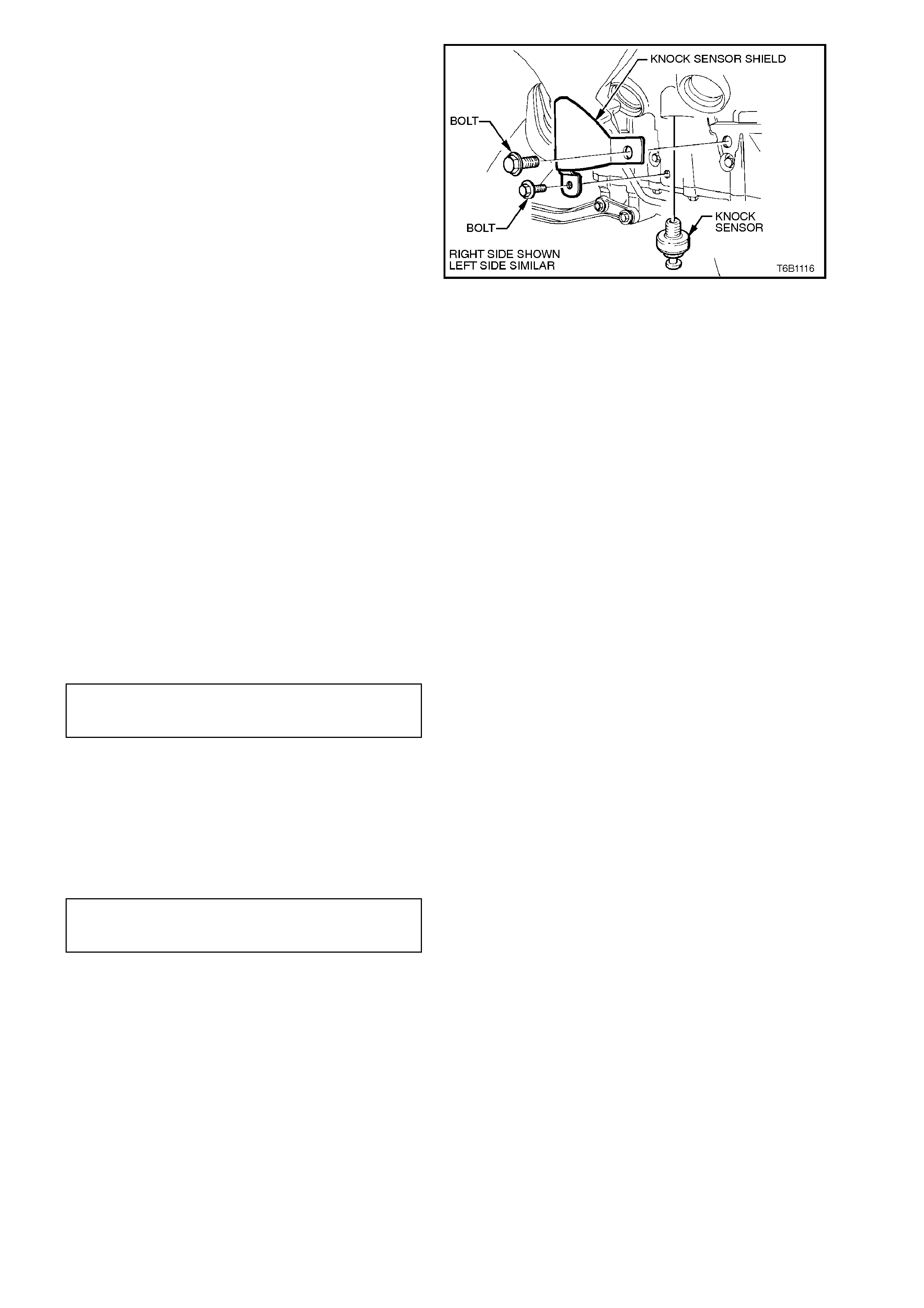
6. Remove the knock sensor heat shield
attaching bolts and heat shields.
7. Using a 22 mm socket, universal joint and
suitable length socket bars, loosen and
remove sensor from cylinder block, taking
extrem e care to avoid any draining coolant if it
is hot.
Figure 6D1-3-26
REINSTALL
1. Ensure that the threads in the sensor
mounting hole in cylinder block are clean.
2. If reinstalling original sensor, inspect sealant
on sensor threads. If worn away, apply a light
coating of Loctite 242 (Holden Specification
HN 1256 Class 2, Type 2) to sensor threads.
NOTE:
On a new sensor, do not apply sealant to threads
as threads are coated with a sealant during
production. Applying additional sealant will affect
the sensor's ability to detect engine knock.
3. Install sensor and tighten to the corr ect torque
specification.
CAUTION:
Ensure that knock sensor is never over
tightened as damage to the sensor can occur.
ESC KNOCK
SENSOR TIGHTENING
TORQUE SPECIFICATION 16 - 22 Nm
4. Reconnect wiring harness connector to
sensor. Ensure that connector is securely
fitted onto sensor.
5. If removed, reinstall knock sensor heat shield
and attaching bolts. Tighten bolts to the
correct torque specification.
KNOCK SENSOR HEAT SHIELD
ATTACHING BOLT
TORQUE SPECIFICATION 25 - 35 Nm
6. Refill cooling system and pressure test for
leaks, refer to Section 6B1 ENGINE
COOLING - V6 ENGINE.
7. Reconnect battery earth lead.

3. DIAGNOSIS
For diagnosis of the ignition system, refer to Section 6C1 POWERTRAIN MANAGEMENT - V6 ENGINE.
3.1 SPARK PLUG DIAGNOSIS
Worn or dirty plugs may give satisfactory operation while the vehicle is idling, but under load they may break down.
Faulty plugs can cause; poor fuel economy, power loss, loss of speed, hard starting and general poor engine
performance.
Spark plugs may also fail due to carbon fouling, excessive gap or a broken insulator.
Fouled plugs are indicated by black carbon deposits. The black deposits are usually the result of slow-speed driving
and short runs where the optimum engine operating temperature is seldom reached. Worn piston rings, faulty
ignition, over rich fuel mixture and spark plugs which are too cold will also result in carbon deposits.
Excessive electrode wear, usually indicates that the engine is operating at high speeds or levels that are
consistently greater than normal or that a plug which is too hot is being used. Electrode wear may also be the result
of plug overheating, caused by combustion gases leaking past the threads due to insufficient tightening of the spark
plug. Excessively lean fuel mixture will also result in excessive electrode wear.
Broken insulators are usually the result of improper installation or careless re-gapping. Broken upper insulators
usually result from a poor fitting spark plug socket or an outside blow. The cracked insulator may not show up
initially, but will, as soon as oil or moisture penetrates the crack. The crack is often just below the crimped part of
the shell and may not be visible.
Broken lower insulators usually result from careless re-gapping and generally are visible. This type of break may
result from the plug operating too 'HOT', which may happen in periods of high speed operation or under heavy
loads. When re-gapping a spark plug, always make the gap adjustment by bending the earth (side) electrode. Do
not use spark plugs with broken insulators.
When replacing spark plugs, use only genuine spark plugs of the correct heat range.
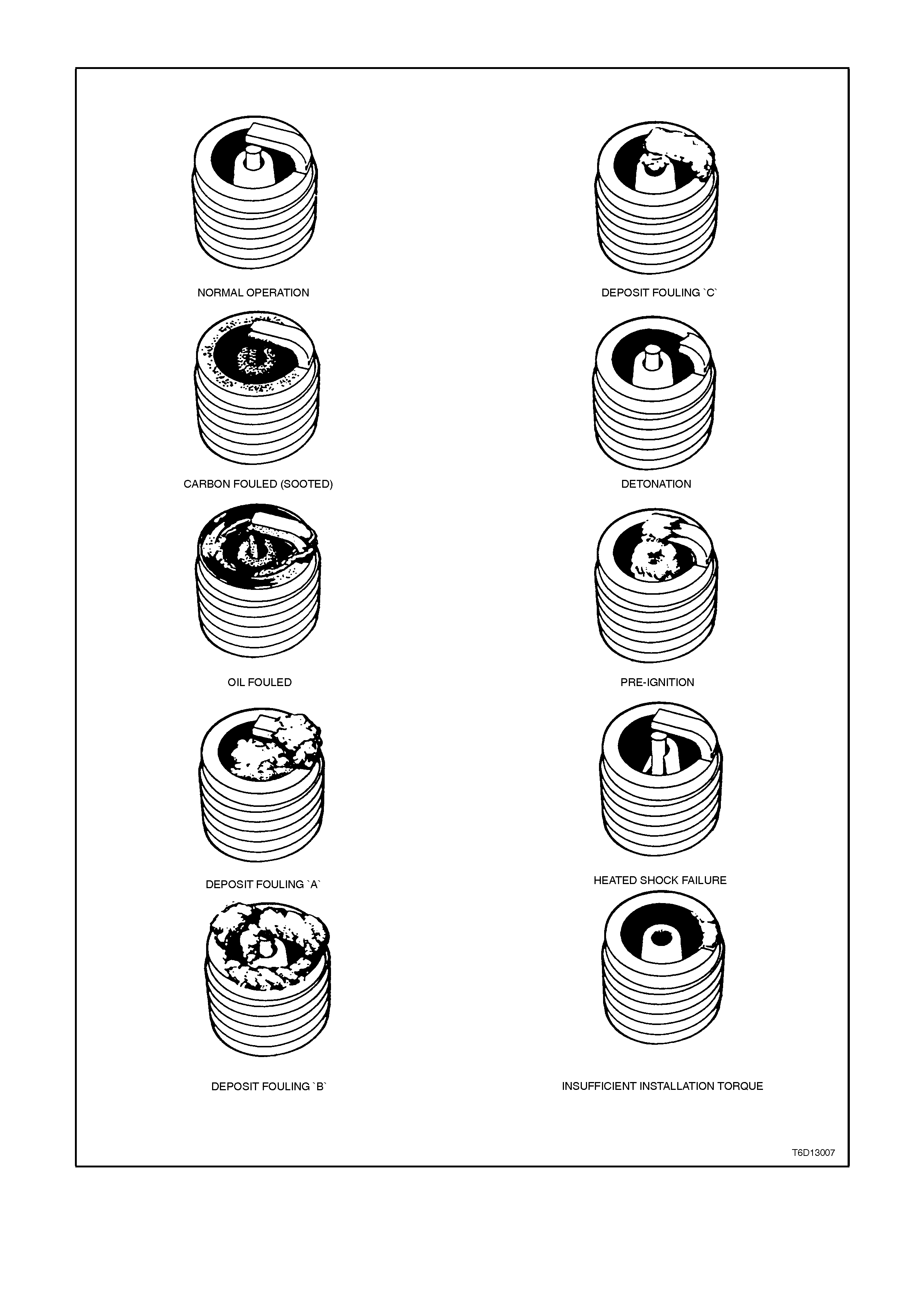
ANALYSIS OF SPARK PLUG CONDITION
Figure 6D1-3-27

NORMAL OPERATION
Refer to Fig. 6D1-3-27
Brown or greyish-tan deposits and slight electrode wear indicate correct spark plug heat range and mixed periods of
high and low speed driving.
CARBON FOULED (SOOTED)
Refer to Fig. 6D1-3-27
Dry, fluffy black carbon (soot) deposits are due to poor ignition output, weak coil or faulty spark plug leads.
Excessive idling, slow speeds under light load also can keep spark plug temperatures so low that normal
combustion deposits are not burned off.
OIL FOULED
Refer to Fig. 6D1-3-27
Wet, oily deposits with minor electrode wear may be caused by oil leaking past worn piston rings. 'Break in' of a new
or recently overhauled engine before rings are fully seated may also result in this condition.
DEPOSIT FOULING "A"
Refer to Fig. 6D1-3-27
Red brown, yellow and white coloured coatings on the insulator tip. These coatings are by-products of combustion
and come from the fuel and lubricating oil, both of which today generally contain additives. Most powdery deposits
have no adverse effect on spark plug operation; however, they may cause intermittent missing under severe
operating conditions, especially at high speeds and heavy load.
DEPOSIT FOULING "B"
Refer to Fig. 6D1-3-27
Deposits are similar to those identified as DEPOSIT FOULING "A". These deposits are by-products of combustion
and come from the fuel and lubricating oil. Excessive valve stem clearances and/or defective intake valve seals will
allow excessive oil to enter the combustion chamber. The deposits will accumulate on the portion of the spark plug
projecting into the chamber and will be heaviest on the side facing the intake valve. Defective seals should be
suspected when the condition is found in only one or two cylinders.
DEPOSIT FOULING "C"
Refer to Fig. 6D1-3-27
Most powdery deposits identified in DEPOSIT FOULING "A", have no adverse effect on the operation of the spark
plug as long as they remain in the powdery state. However, under certain conditions of operation, these deposits
melt and form a shiny glaze coating on the insulator which, when hot, acts as a good electrical conductor. This
allows the current to follow the deposits instead of jumping the gap, thus shorting out the spark plug.
DETONATION
Refer to Fig. 6D1-3-27
Commonly referred to as engine knock or ‘ping’, detonation causes severe shock inside the combustion chamber to
the adjacent parts which include spark plugs.
PRE-IGNITION
Refer to Fig. 6D1-3-27
Causes burned or blistered insulator tip and badly eroded electrodes. Excessive overheating is indicated. Cooling
system blockage or sticking valves are common causes of pre-ignition. Spark plugs which are the wrong (too hot)
heat range, or not properly installed are also a possible cause. Sustained high speed, heavy load service can
produce high temperatures which will cause pre-ignition.
HEAT SHOCK FAILURE
Refer to Fig. 6D1-3-27
A common cause of broken and cracked insulator tips. Rapid increase in tip temperature under severe operating
conditions causes the heat shock and a fracture results.
Another common cause of chipped or broken insulator tips is carelessness in re-gapping, by either bending the
centre electrode to adjust the gap, or allowing the gapping tool to exert force against the tip of the centre electrode
or insulator when bending the outer electrode to adjust the gap.
INSUFFICIENT INSTALLATION TORQUE
Refer to Fig. 6D1-3-27
Poor contact between the spark plug and the engine seat. The lack of proper heat transfer, resulting from poor seat
contact, causes overheating of the spark plug and, in many cases, severe damage as shown. Dirty threads in the
cylinder head can also result in the plug seizing before it is seated.
THREAD SEIZURE
Refer to Fig. 6D1-3-27
Recommended installation torque may be obtained without taper seat engagement in cy linder head. Operation of an
engine with this type of installation may result in spark plug overheating, causing possible damage to the spark plug
or engine.
Always ensure cy linder head and spark plug threads are free of deposits, burrs and scale.

4. SPECIFICATIONS
Ignition Coil Primary Winding Resistance 0.3 - 1.5 ohm
Ignition Coil Secondary Winding Resistance 5000 - 7000 ohm
Sealant Loctite 242, Holden
Specification HN 1256
Class 2, Type 2
Spark Plug (V6) Original Equipment NGK BPR6EFS-15
Service Replacement AC R42LTS6
Spark Plug Gap 1.5 mm
Spark Plug (V6 supercharged) Original Equipment AC 41-919
Spark Plug Gap 1.5mm +0 - 0.5
Ignition Lead Resistance (V6) Left Hand Side Less than 10,000 ohms
Right Hand Side Less than 27,000 ohms
Ignition Lead Resistance (V6 supercharged) Left Hand Side Less than 10,000 ohms
Right Hand Side Less than 17,000 ohms

5. TORQUE WRENCH SPECIFI CATIONS
Nm
Coil Securing Screws 4 - 5
Coil and Module Assembly to Support Securing Nuts 8 - 11
Coil and Module Assembly Support to Cylinder Head
Attaching Bolts 40 - 50
Wiring Harness to Module Bolt 0.6 - 1.2
Crankshaft Position Sensor to Front Cover Attaching
Studs 20 - 30
Spark Plugs 15 - 25
Knock Sensor 16 - 22
Knock Sensor Heat Shield Attaching Bolt 25 - 35