
SECTION 6D2-1CHARGING SYSTEM - V8 ENGINE
CAUTION:
This vehicle will be equipped with a Supplemental Restraint System (SRS). A SRS will
consist of either seat belt pre-tensio ners and a driver’s side air bag , or seat belt pre-
tensioners and a driver’s and front passenger’s side air bags. Refer to CAUTIONS,
Section 12M, before performing any service operation on or around SRS
components, the steering mechanism or wiring. Failure to follow the CAUTIONS
could result in SRS deplo yment, resulting in possible p ersonal injury or unnecessary
SRS system repairs.
1. GENERAL DESCRIPTI ON
A 120 amp generator is fitted to all VT Series Models with the 5.0 Litre engine.
The generator construction consists of a stator, which is of a three phase star connected output winding
construction on a ring shaped lamination pack. A rotor, which is of a twelve pole construction, carries a slip ring fed
field winding. The rotor is supported by ball bearings in both the drive and slip ring end housings.
The output of the stator is rectified by six diodes which are contained within the slip ring end plate. An additional two
diodes, in conjunction with the hybrid circuit, are connected to the star point of the stator windings. The purpose of
this circuit is to increase the generator assembly output to 120 amps. Excitation current is supplied to the rotor field
coil via the voltage regulator, brushes and slip rings. The electronic voltage regulator requires no adjustment in
service.
The generator has four external connections; the B+ lead to the battery positive terminal, the L lead to the generator
warning lamp, the S lead for battery voltage sensing and an earth connection.
The diodes and stator windings are cooled by air flow through the generator induced by a ventilating fan mounted
on rotor shaft within the drive end housing.
The internal circuitry of the generator illuminates the warning lamp in the event of the following;
1. Disconnected generator to battery sensing lead.
2. Disconnected generator to battery charging lead.
3. Battery overcharging.
4. Generator not charging.
Fig. 6D2-1-1 shows an exploded view of the 120 amp generator.
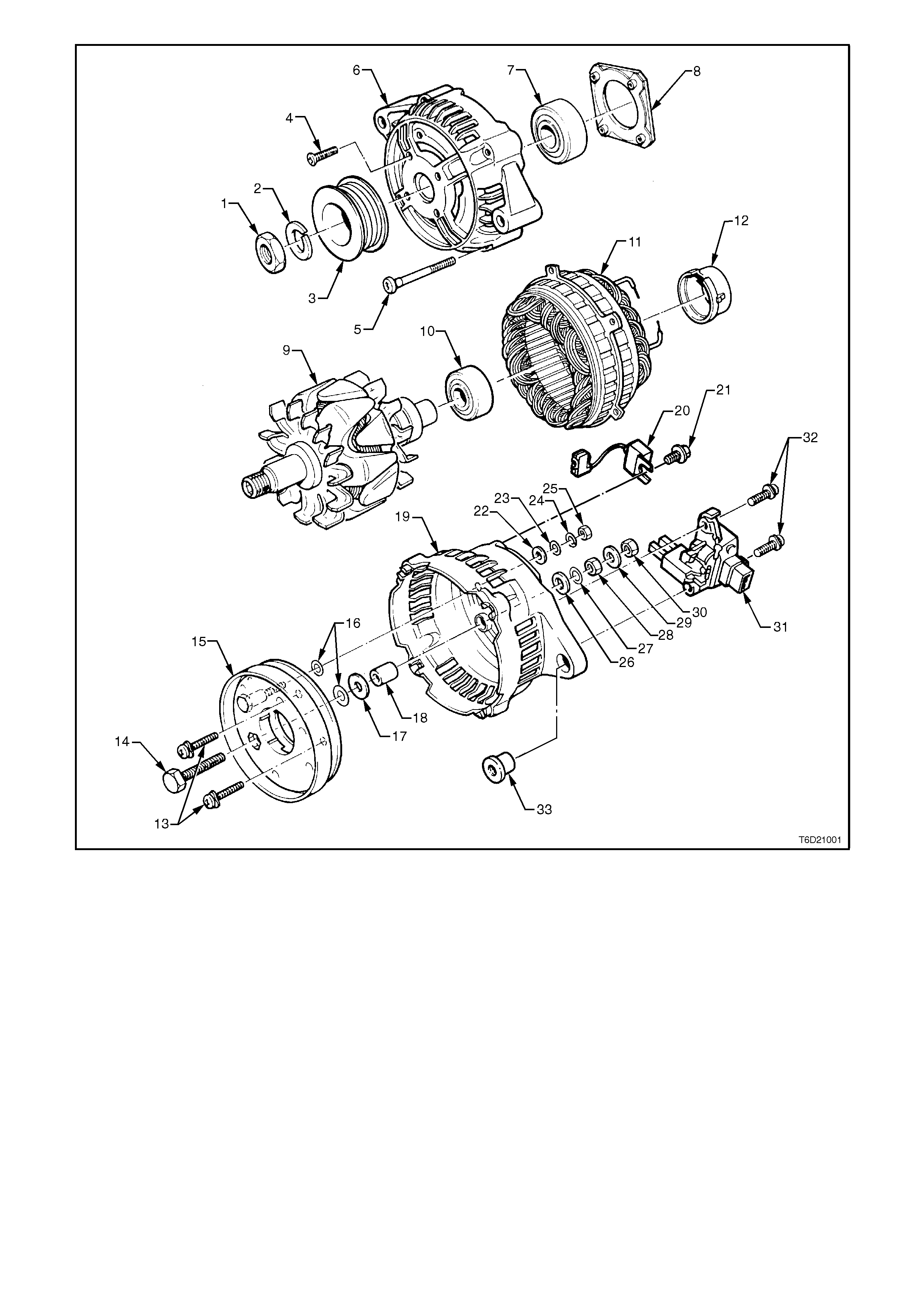
Figure 6D2-1-1
1 Nut 13 Rectifier Attaching Screws 25 D+ Terminal Attaching Nut
2 Lock Washer 14 B+ Terminal Bolt 26 Insulating Washer
3 Drive Pulley 15 Rectifier Assembly 27 Flat Washer
4 Bearing Retaining Plate Screw
(4) 16 Mica Insulating Washers 28 Nut
5 Through Bolt (4) 17 Insulating Washer 29 Flat Washer
6 Drive End Housing 18 Spacer 30 B+ Terminal Retaining Nut
7 Drive End Bearing 19 Slip Ring End Housing 31 Regulator and Brush
Assembly
8 Bearing Retaining Plate 20 Suppressor 32 Regulator and Brush Screws
9 Rotor 21 Suppressor Attaching Screw 33 Slip Ring End Housing Lug
Sleeve
10 Slip Ring End Bearing 22 Insulating Washer
11 Stator 23 Flat Washer
12 Slip Ring End Bearing Support
Ring 24 Wave Washer
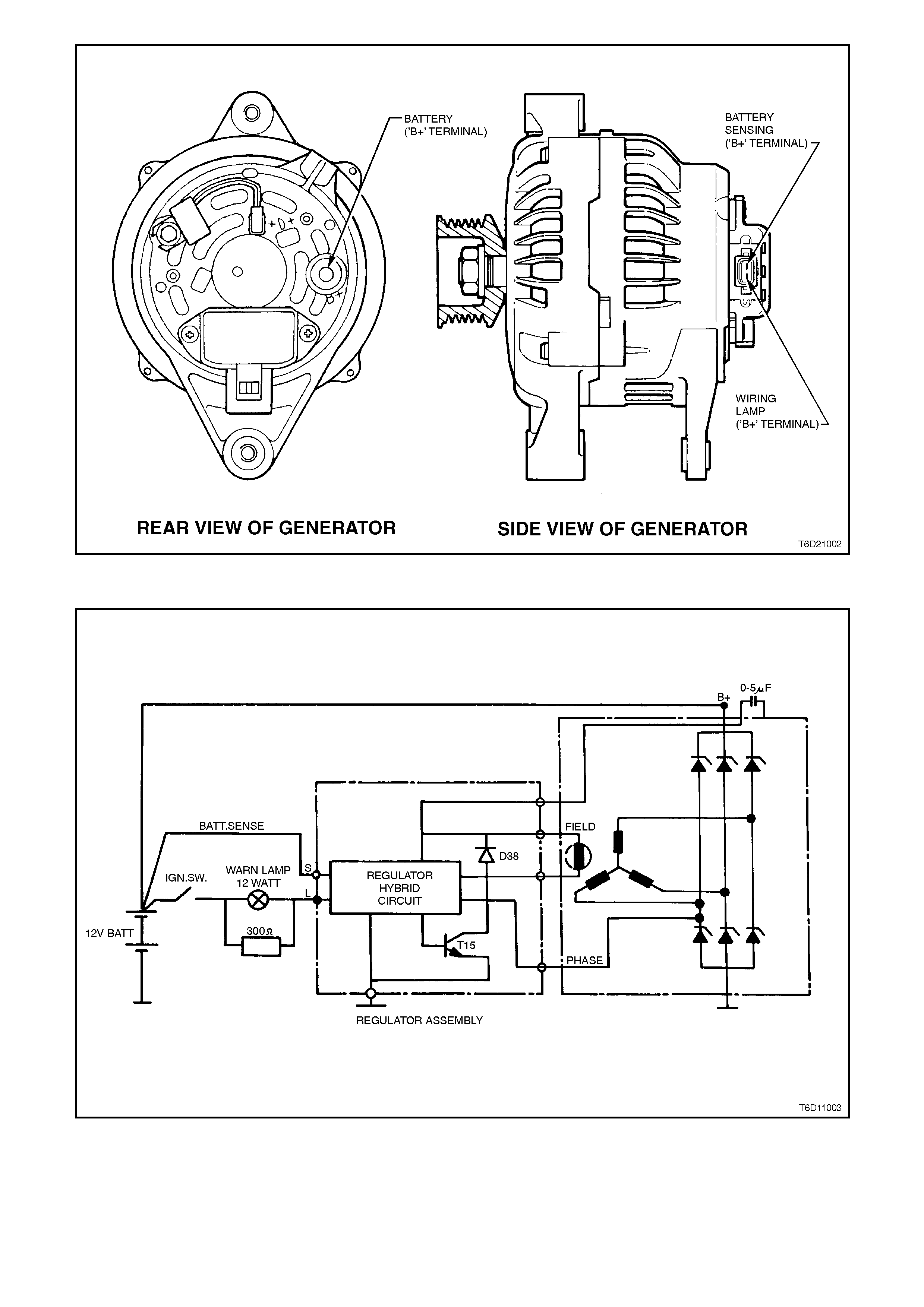
Figure 6D2-1-2
Figure 6D2-1-3

2. MI NOR SERVICE OPERATIONS
2.1 SAFETY PRECAUTIONS
Since the generator and voltage regulator are designed for use only on a negative earth system, the following
precautions must be observed. Failure to observe these precautions will result in serious damage to the generator.
1. Do not reverse the polarity of the battery connections as the generator and voltage regulator are designed for
use only on a negative earth system.
2. When installing a battery, ensure that the ignition switch is in the OFF position.
3. Fit positive (+) cable to battery positive (+) terminal first, then fit negative (-) cable to battery negative (-)
terminal.
4. When a slave battery is utilised for starting purposes, ensure both batteries are connected in parallel, i.e.
positive terminals together and negative terminals together.
5. When charging battery, disconnect both battery cables from the battery, thus isolating battery and external
charging equipment from the vehicle electrical system.
NOTE:
It is important to isolate the battery during a charging operation, as some charging equipment may produce
Transient Voltage that will damage the PCM (Powertrain Control Module) or ECM (Electronic Control Module).
6. Do not operate the generator open circuit (any terminal disconnected), or disconnect the battery cable/s while
the engine is operating.
7. Do not attempt to polarise generator.
8. Do not use a generator warning lamp bulb of more than 2 Watts (1.2 - 2.0 Watts is necessary).
9. Do not bridge, ground or cross connect the L and S terminals at the voltage regulator.
10. Do not connect the voltage regulator L terminal to the battery or ignition circuit (12 volts).
NOTE:
Always ensure that generator warning lamp illuminates when ignition switch is turned to the ON position.

2.2 MAINTENANCE AND ON VEHICLE TESTING
At regular intervals, inspect the terminals of the
generator for corrosion, loose connectors and the
wiring for damaged insulation.
Check the generator drive belt tension and
condition at the intervals specified in the VT
Owner's Handbooks.
The drive belt adjustment for the generator/water
pump is effected by pivoting the generator.
Periodically check the mounting bolts for specified
torque and rectify if necessary, refer to Section
6A2 ENGINE MECHANICAL - V8 ENGINE.
LUBRICATION
The ball bearings used in this NC-A generator are
a high tolerance type, only fully sealed bearings of
the same specification are to be used as
replacements. It is recommended that the
bearings be replaced during the reconditioning
process to restore the unit to its original
configuration.
TESTING THE GENERATOR OUTPUT AND VOLTAGE REGULATOR
NOTE:
Do not reverse the S and L connections or put the
12 volt supply to L terminal, this connection must
not be used as a supply source other than to
supply the requirements of the warning lamp (2
watts). Such action will destroy the regulator
warning lamp circuit.
Before testing the generator output, make certain
that the generator circuit is thoroughly checked for
loose or dirty connections. The generator must
always be connected to the battery during testing,
otherwise damage to the diodes could result. The
battery should be fully charged. The generator
warning light, in addition to indicating that the
generator is charging, is also necessary for initial
field excitation.
TESTING GENERATOR OUTPUT
NOTE:
Keep the duration of this test to a minimum to
avoid undue heating and high engine speed. The
battery should be fully charged to perform this
check.
RATED OUTPUT
TEMP VOLTAGE
SETTING AMPS ALTERNATOR RPM
20°C 13.5
CONSTANT 120 6000
1. Ensure that all the electrical equipment is
turned OFF, and the ignition switch is in the
OFF position.
2. Disconnect battery earth cable at battery.
3. Disconnect the generator positive lead (red
wire) from the B+ generator terminal.
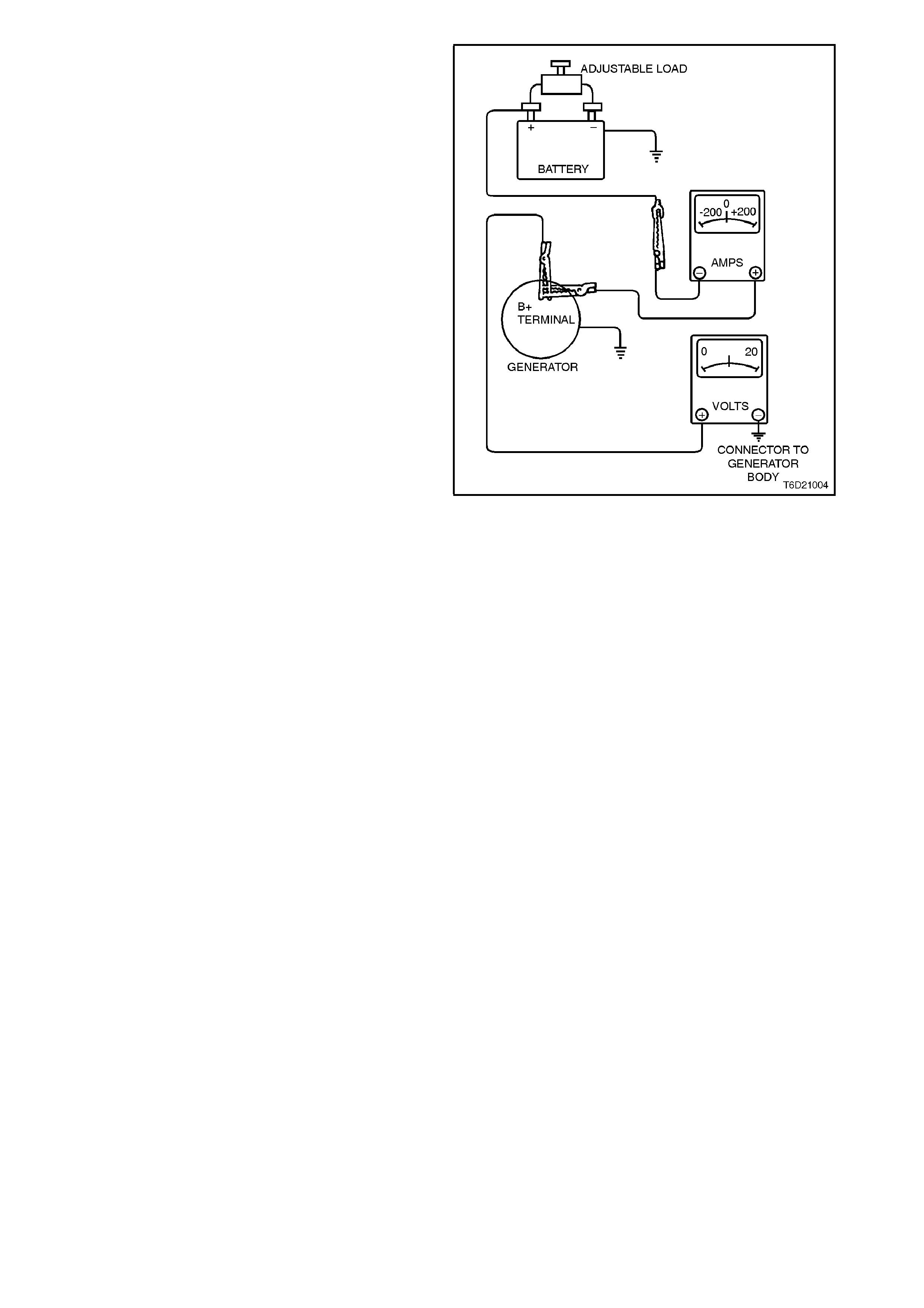
4. Connect the positive lead of an ammeter (0 - 100
Amp s cale) to the gener ator B+ term inal, and the
negative ammeter lead to the disconnected
generator positive lead (red wire).
5. Connect positive lead of a voltmeter (0 - 20 Volt
scale minimum) to the generator B+ terminal,
and negative voltmeter lead to a good ground on
generator body.
CAUTION:
Insulate the generator positive lead (red wire)
terminal to prevent contact w ith any metal part of
the vehicle. If the terminal is grounded, damage to
the charging circuit will result w hen the battery is
reconnected.
6. Reconnect the battery earth cable. Fit a loading
device across battery terminals (if sufficient
electrical loads are not available a carbon pile
resistance can be connected across the battery).
NOTE:
Loading device must have a minimum power
consumption of 1000 watts.
7. Start engine and increase engine speed until the
alternator is running at 6000 rpm.
8. Switch on electrical loads until the alternator
voltage drops to 13.5 volts. An output of 120
Amps should be achieved under these
conditions.
NOTE:
It may be necessary to adjust engine speed to
maintain alternator speed.
Figure 6D2-1-4
If generator does not pr ovide rated output, it s hould
be disassem bled and inspected for f aults, refer to
3.1 GENERATOR in this Section.

CAUTION:
On completion of the Generator OUTPUT CHECK, to prevent excessive battery discharge occurring, the
engine should be returned to idle speed and the loading device disconnected from battery terminals.
9. Disconnect the battery earth cable at battery. Remove the volt and ammeters, then reconnect the generator
positive lead (red wire) to the generator B+ terminal. Reconnect the battery earth cable to the battery.
TESTING THE VOLTAGE REGULATOR
1. Connect a voltmeter to the alternator, the positive lead to the B+ terminal and the negative lead to the
alternator casing. Select an appropriate voltage range on the meter. i.e. 20 volt range.
2. Connect an ammeter in series with the main output cable from the B+ terminal on the alternator. Select a
range which will be capable of reading 120 Amps from the alternator.
3. Note the voltmeter reading before starting the engine, this reading should increase when the engine is running,
indicating alternator output.
4. Start the engine and increaser the engine speed until the alternator is running at 4000 rpm.
5. Switch on vehicle loads of 5 - 10 Amps. (indicated on ammeter). The voltmeter should read 14.0 - 14.2 volts.
6. If voltage reading is not to specification, replace voltage regulator. Refer to 3.1 GENERATOR in this Section.
3. MAJOR SERVICE OPERATIONS
3.1 GENERATOR
REMOVE
1. Disconnect battery earth lead.
2. Remove wiring harness connector from
generator terminal block by depressing
connector retainer and pulling connector from
generator.
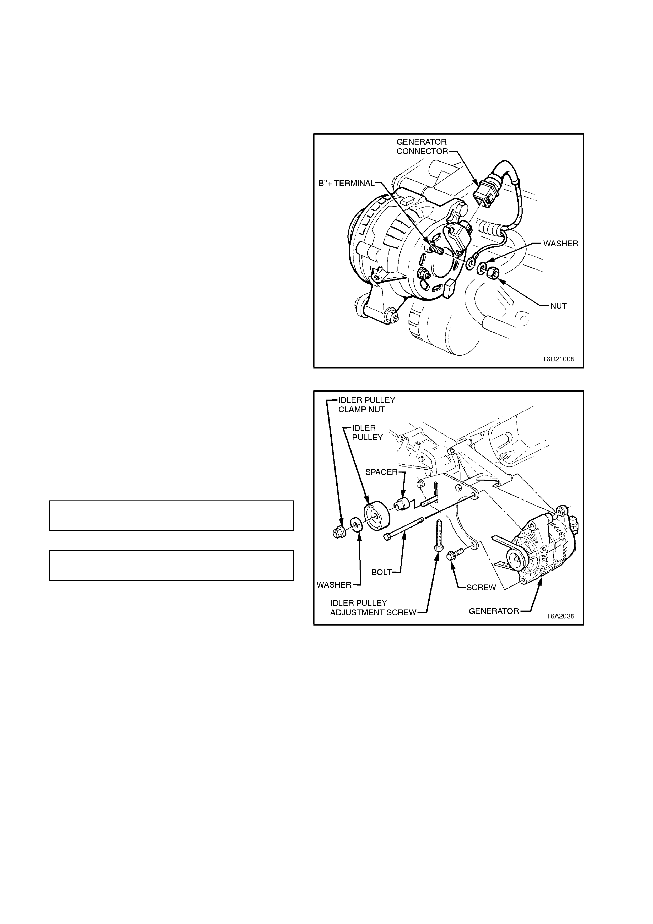
3. Pull back cap from the generator B+ terminal,
remove nut, washer and generator positive
lead (red wire).
Figure 6D2-1-5
4. Loosen generator drive belt idler pulley clamp
nut.
5. Use the idler pulley adjusting bolt to achieve
specified belt tension, then tighten clamp nut
to specified torque. Belt tension can be
checked by using Tool No. BT 3373-F, or
similar.
GENERATOR BELT 64 kg Ne w
TENSION SPECIFICATION 43 kg Used
IDLER PULLEY CLAMP NUT 35 - 65
TORQUE SPECIFICATION Nm
Figure 6D2-1-6
6. While supporting weight of generator,
withdraw generator drive end plate to
mounting bracket bolt and nut.

DISASSEMBLE
1. Mark relative positions of slip ring end plate,
stator and drive end plate. Use a permanent
marking pen, do not use a centre punch as
this can cause misalignment of the housing.
Figure 6D2-1-7
2. Remove two screws securing regulator and
brush assembly to slip ring end plate. Tilt the
regulator slightly from the plug connec tion until
the regulator clears the housing and withdraw
assembly, taking care not to damage the
brushes.
Figure 6D2-1-8
3. Remove four through bolts and washers.
4. Separate slip ring end plate and stator (as an
assembly) from rotor and drive end plate,
taking care not to put strain on the stator
wires.
Figure 6D2-1-9
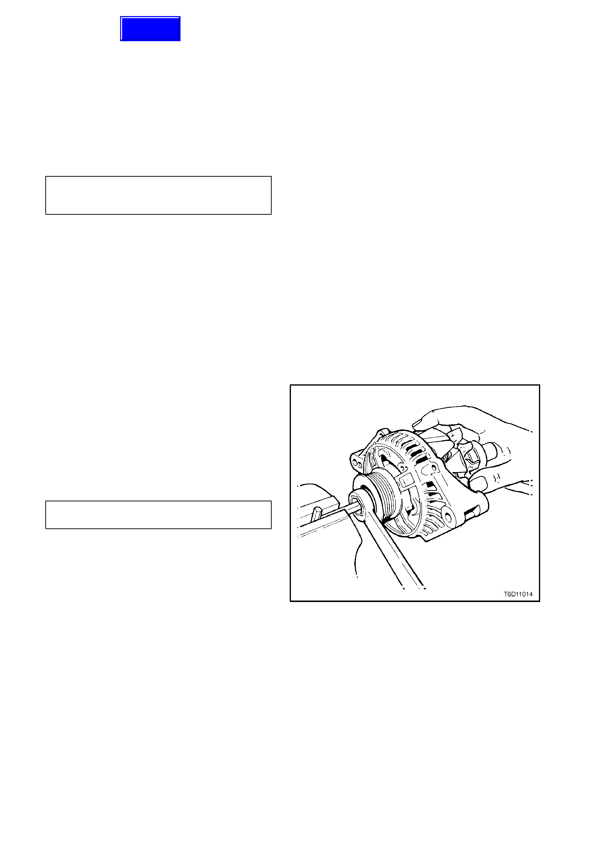
5. To remove the drive pulley, mount an 8mm.
Allen key in a vice with the long end pointing
out from the side of the vice.
Place a deep 24mm. Socket with external hex
(commercially available) onto the pulley
attaching nut and place a suitable size
spanner over socket hex.
Position drive end housing and rotor ass embly
with the internal hexagon of the rotor shaft
onto the Allen key.
Loosen drive pulley attaching nut. Remove
drive end housing from Allen key .
NOTE:
Under no circums tances is the rotor to be m ounted
in the vice as the rotor and or cooling fan will be
damaged.
Figure 6D2-1-10
6. Withdraw the pulley assembly.
NOTE:
The pulley has an integral boss which locks up
against the ball race, therefore no thrust collar is
provided.
Figure 6D2-1-11
7. Remove four screws securing bearing
retaining plate to drive end plate, remove
retaining plate.
8. Push the rotor shaf t and fr ont bearing fr om the
drive end housing
NOTE:
The rotor must not be pressed from the drive end
housing. If the rotor is pressed out, the bearing
retaining plate and drive end housing will be
damaged or distorted. Parts removed in this way
MUST be replaced if the integrity of the generator is
to be maintained.
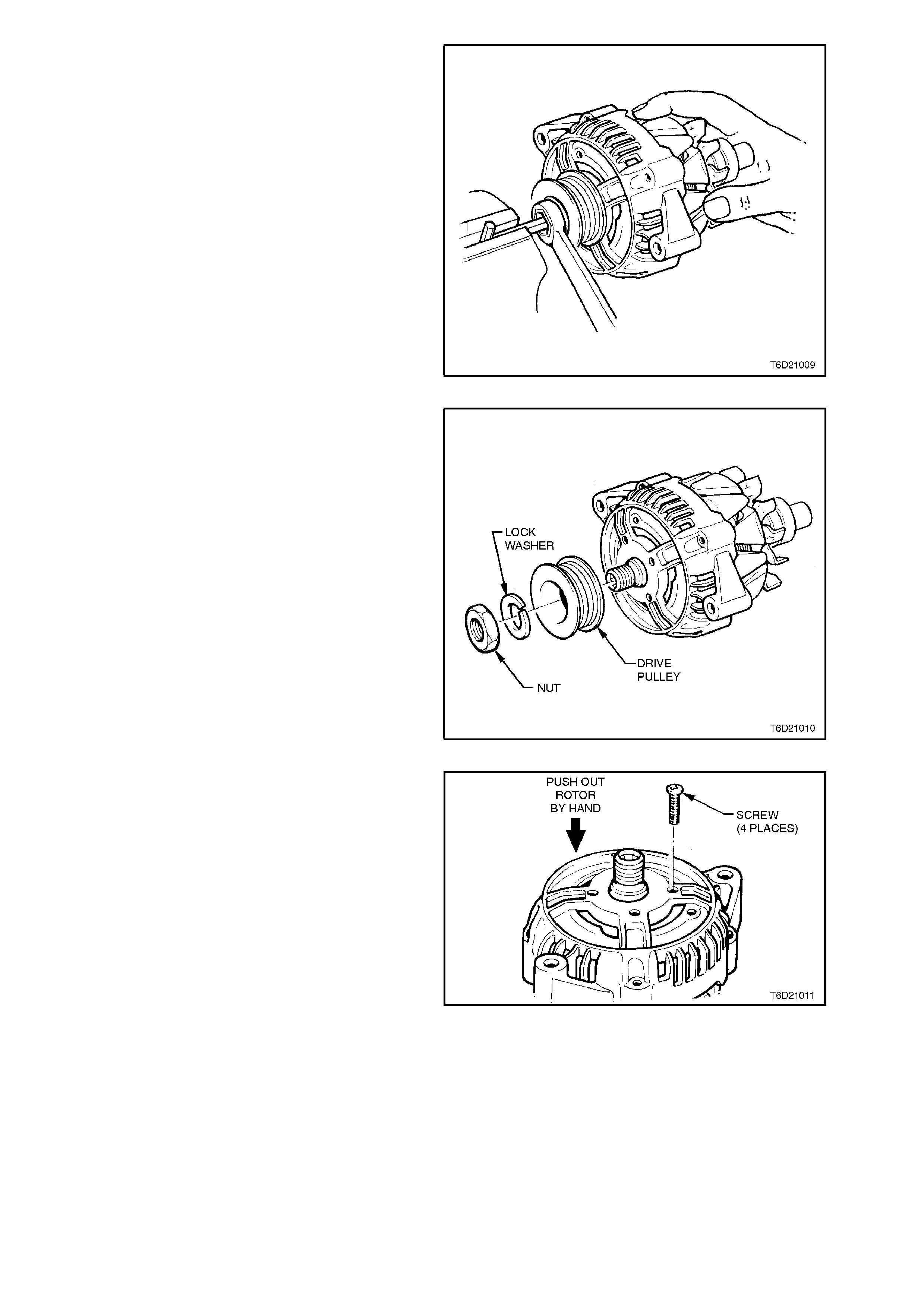
Figure 6D2-1-12
9. Using the drive end housing bearing removal
tool (Bosch tool 9981 066 601), remove drive
end bearing from rotor shaft.
NOTE:
This process will damage the bearing retaining
plate and must be replaced. As the bearings are
fine tolerance, high speed, noiseless design they
must also be replaced.
Figure 6D2-1-13
10. Using a commercially available puller, remove
slip ring end bearing from rotor shaft, taking
care not to distort the rear fan during the
process.
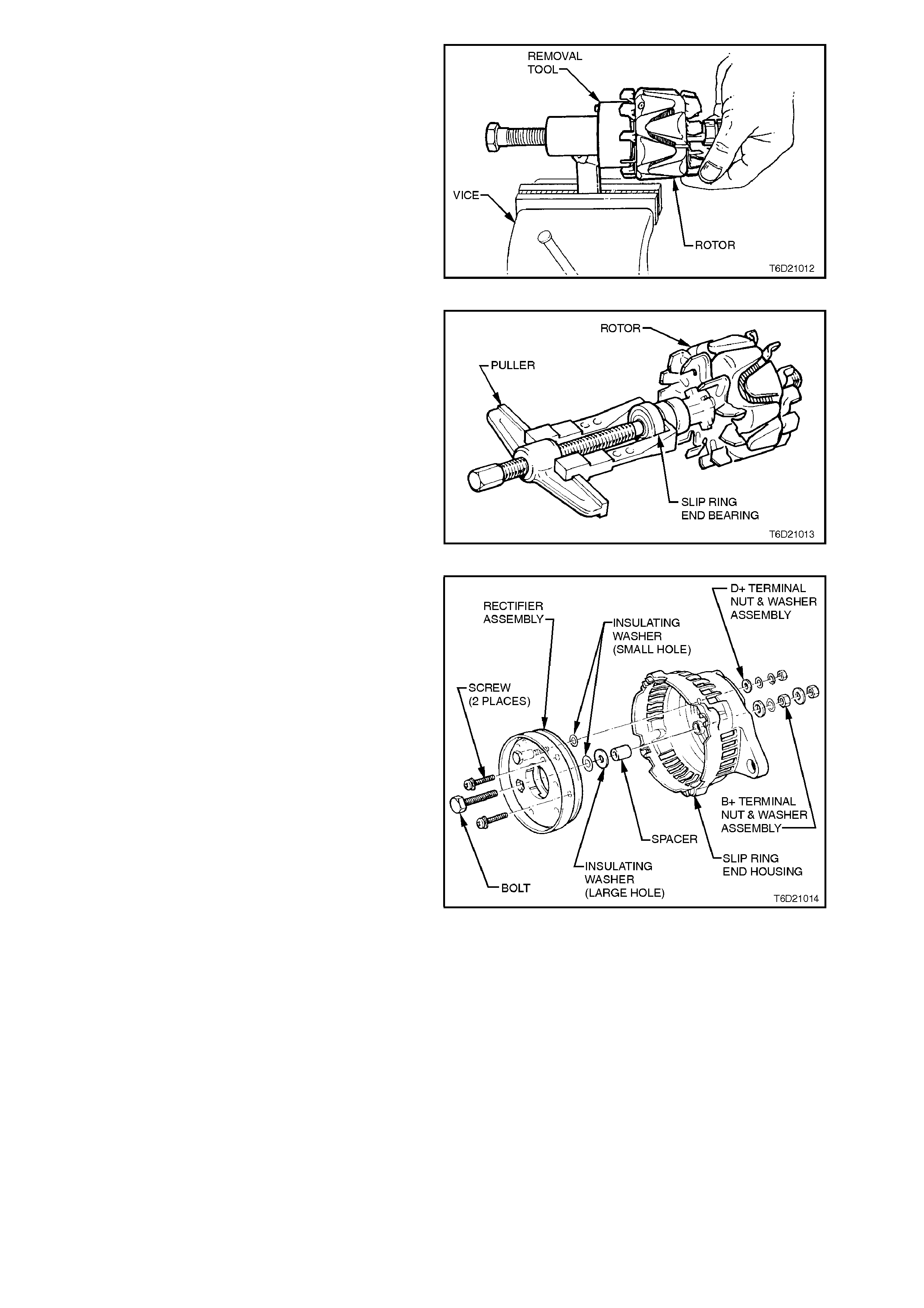
Figure 6D2-1-14
11. Remove nut, wave washer, flat washer and
insulating washer from the B+ terminal stud.
12. Remove suppressor lead connection from
rectifier + terminal.
13. Remove three screws and washers attaching
rectifier assembly to slip ring end plate.
Remove the stator and rectifier as an
assem bly. Remove spacer and m ica ins ulating
washer from B+ terminal stud.
NOTE:
Discard the mica insulating washers as new
washers and heat sink com pound mus t be used on
reassembly.
Figure 6D2-1-15
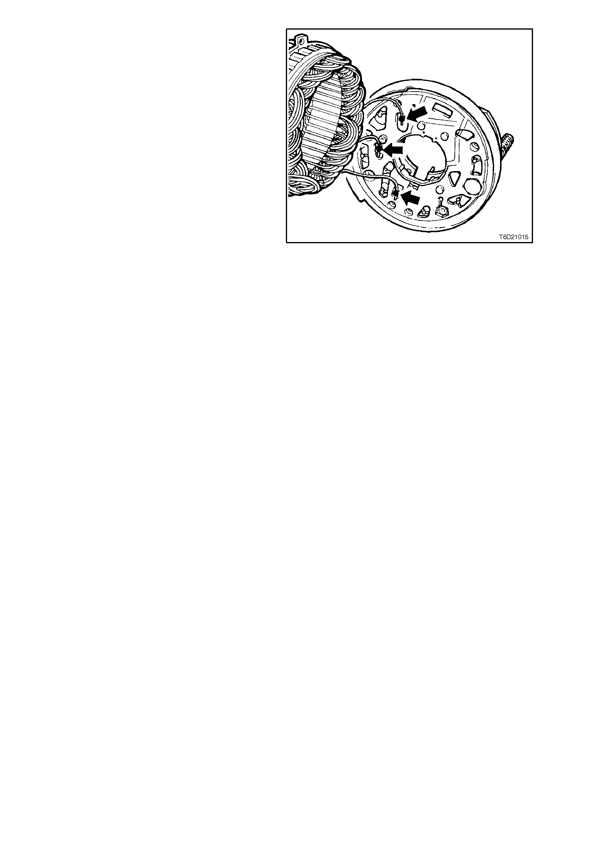
14. To separate the s tator from rectifier assembly,
grasp the stator wires close to the wire loop
with a pair of long nosed pliers, heat the joint
with a soldering iron, when the point becomes
plastic apply a slight twisting motion to the
wires, then pull up to release the wires.
Remove the s tator. This proc edure opens the
wire loop to release the stator connections
easily.
CAUTION:
Use only as much heat as required to melt the
solder. Excessive heat may damage the diodes.
Figure 6D2-1-16
CLEANING AND INSPECTION
With generator completely disassembled,
components should be cleaned and inspected.
Wash all components except stator, rotor, rectifier
and regulator in a suitable cleaning solvent.
CAUTION:
Do not clean stator or rotor windings with
cleaning solvent or damage to the insulation
could result.
WARNING:
CLEAN ALL PARTS OTHER THAN THOSE
PREVIOUSLY NOMINATED USING A NON
VOLATILE OR LOW INFLAMMABLE AGENT IN
A WELL VENTILATED AREA.
IT IS IMPORTANT THAT ALL PARTS ARE
THOROUGHLY DRIED BEFORE ASSEMBLY,
TAKING CARE NOT TO BREATH IN ANY
VAPOURS.
OBSERVE THE SAFETY REGULATIONS AND
PRECAUTIONS ISSUED BY THE
MANUFACTURER OF THE CLEANING AGENT
IN USE.
CAREFULLY CLEAN ROTOR AND STATOR
WITH COMPRESSED AIR.
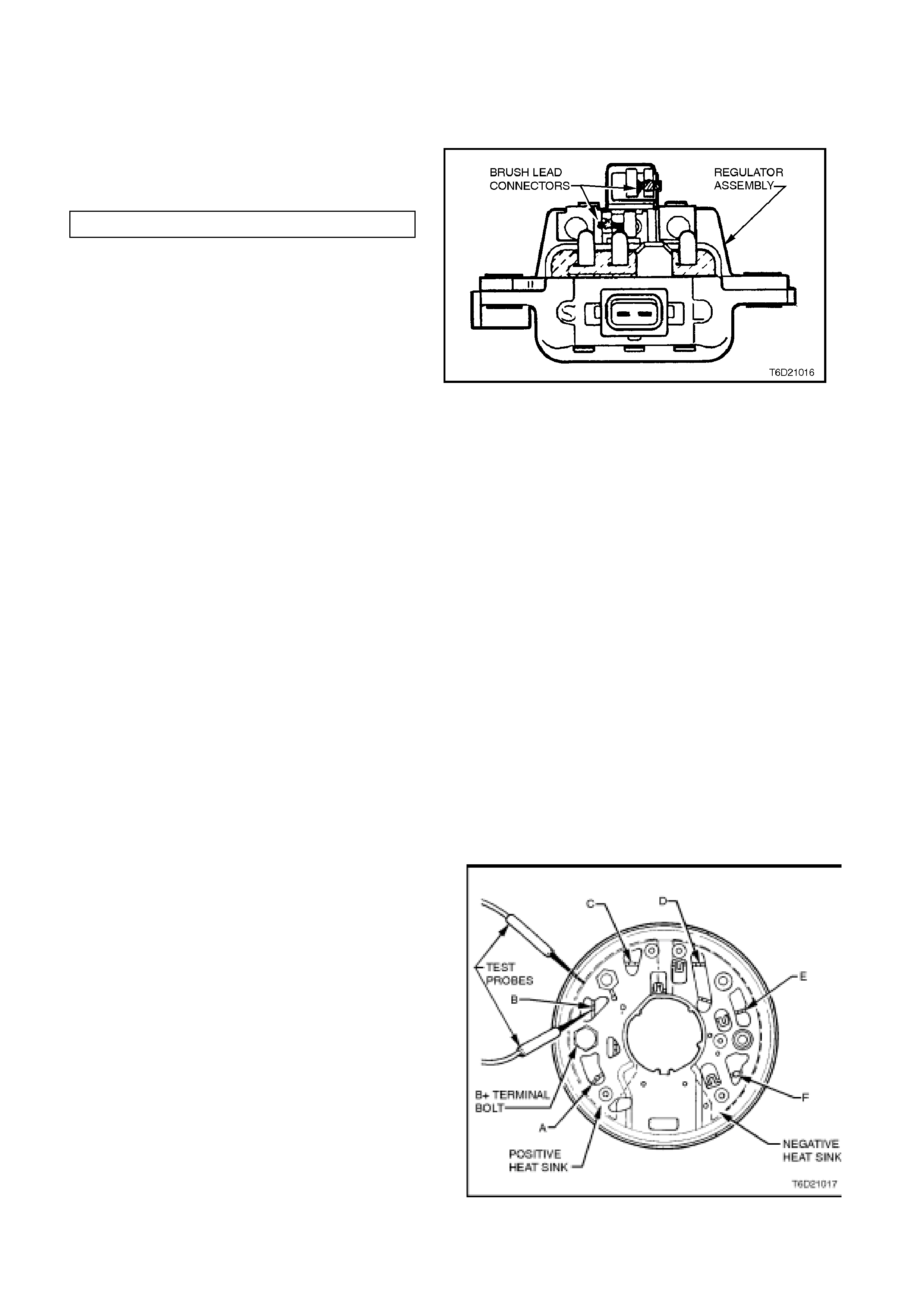
COMPONENT CHECKING
BRUSH GEAR
1. Unsolder brush leads from regulator
connections and bend back the retaining lugs.
Remove brushes and springs.
2. Measure length of brushes, replace if less
than specified minimum length.
MINIMUM BRUSH LENGTH 3.8 mm
3. Inspect brushes for damage.
4. Inspect brush springs for discolouration or
breakage. If either condition exists, replace
springs.
5. Install brush springs over brush leads, install
brushes into regulator and solder leads to
connections. Figure 6D2-1-17
6. Check that brushes m ove smoothly in and out
of holder by pushing on end of brushes, and
then releasing.
DIODES
NOTE:
The rectifier assembly is not repairable and should be
replaced if diodes prove to be faulty.
The following commercially available test equipment is
essential for correctly testing the diodes within the
rectifier assembly.
A. A diode tester or multimeter with a diode test
feature where the DC output at the test probes
does not exceed 14 volts, or in the case of AC
testers, 12 volts RMS.
This is necessary so as to ensure that when testing
the diodes, the for ward and rever se voltage c hec ks
are completed and are not masked by the diode
turning on due to zener breakdown voltage.
B. A zener diode tester with a DC output in excess of
30 volts. The tester should also incorporate internal
current limiting set to five mA to prevent high
currents during testing.
1. Attach negative test probe of diode tester or
multimeter with diode test function to the positive
heat sink of the rectifier assembly and the positive
probe alternatively to positive diode c onnections A,
B and C shown in Fig. 6D2-1-18.
A low resistance reading, or the forward voltage
drop across the diode should be obtained.
Reverse probe connections and repeat test to
check that current is passed in one direction only
(high resistance reading or higher reverse voltage
should be obtained).
Figure 6D2-1-18
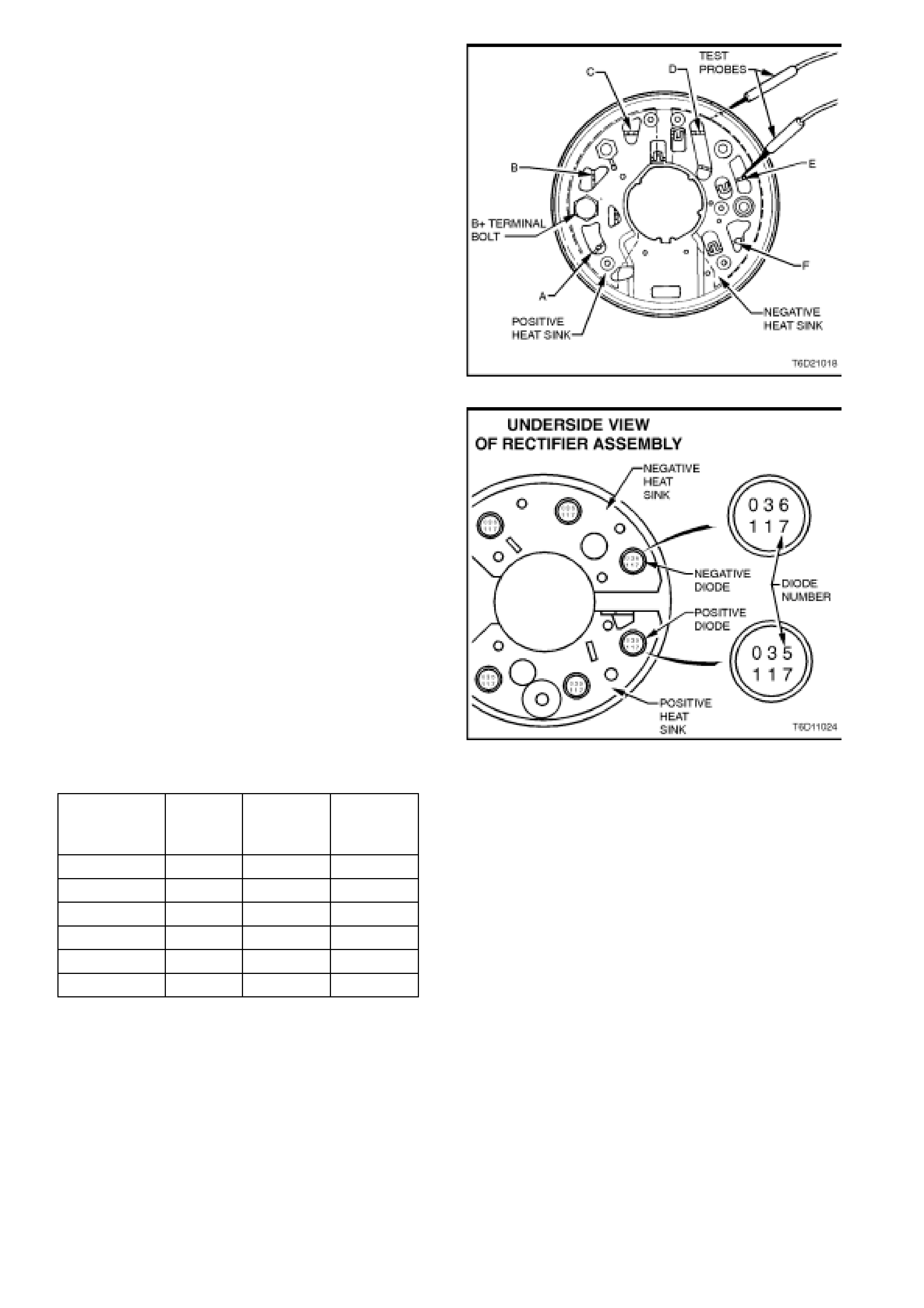
2. Repeat procedure on negative heat sink by
attaching positive test probe to the negative heat
sink and the negative probe alternatively to
negative diode connections D, E and F shown in
Fig. 6D2-1-19.
A low resistance reading, or the forward voltage
drop across the diode should be obtained.
Reverse probe connections and repeat test to
check that current is passed in one direction only
(high resistance reading or higher reverse voltage
should be obtained).
NOTE:
In steps 1 and 2, ensure that the reverse voltage
applied is less than 14 volts DC, or 12 volts RMS when
using an AC tester.
Figure 6D2-1-19
3. Ensure that steps 1 and 2 are carried out before
the diodes zener voltage is tested. The diodes are
grouped together according to their zener voltage,
ie. all diodes within a rectifier must have the same
zener voltage.
To identif y the zener voltage of the diodes, ref er to
the numbers stamped into the base of each diode
and to the following chart.
Figure 6D2-1-20
Diode Zener
Voltage
at 5mA
Positive
Diode
Number
Negative
Diode
Number
Forward
Current
Rating
17.8 - 19.2 031 032 35A
18.8 - 20.2 033 034 35A
19.8 - 21.2 035 036 35A
20.8 - 22.2 037 038 35A
21.8 - 23.2 038 040 35A
22.8 - 24.2 041 042 35A

ROTOR
INSULATION TEST
Using an ohmmeter, or powered test lamp (up to
110V), check insulation between slip rings and
rotor core or shaft. Test light should not glow or
ohmmeter should indicate an open circuit (or
resistance of greater than 1 megohm). If an open
circuit does not exist replace rotor.
Figure 6D2-1-21
OPEN CIRCUIT TEST
Connect ohmmeter probes across slip rings and
measure resistance of rotor windings.
Rotor winding resistance values are given in the
following chart.
NOTE:
If the resistance of the rotor winding is not to
specification, replace the rotor.
ROTOR WINDING 2.3 ±
RESISTANCE @ 20°C 0.115 W
Figure 6D2-1-22
SLIP RINGS
If the slip rings are worn or out of round they must
be re-m achined to a m inimum diam eter of 26.7m m
and should have a runout not exceeding 0.45mm.
If the slipring is below these limits it must be
replaced with a new one.
WARNING:
EXTREME CARE MUST BE TAKEN WHEN
MACHINING THE SLIPRING AS IT IS POSSIBLE
FOR THE TURNING TOOL TO FOUL THE FAN.
BEARINGS
The bearings in this alternator are a special low
noise, high speed type and must only be replaced
by Bosch original equipment bearings. Bosch part
No’s 9 900 069 006 for drive end bearing, 1 900
905 275 for slip ring end bearing.
CAUTION:
Failure to use these bearings will result in
noisy operation and reduced s ervice life.
Check bearing bores in drive end and slip ring end
housings for wear. If bearing outer race is allowed
to rotate in its bore, it will cause ovality of the bore
and a lip will form in the bore.
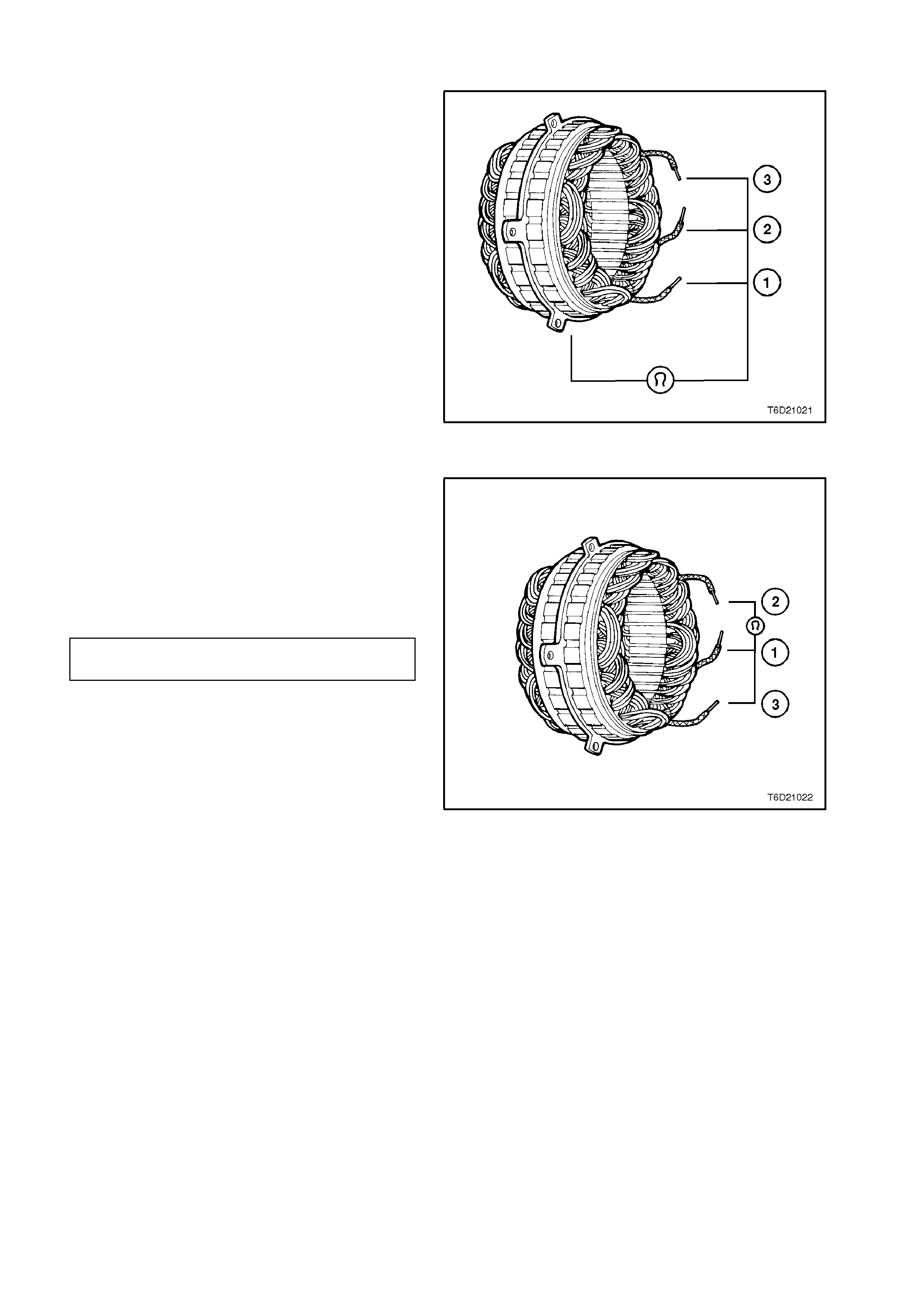
STATOR
INSULATION TEST
Connect a powered test lamp (up to 110 V) or an
ohmmeter between any stator lead and stator
frame. The insulation resistance must be greater
than 1 megohm. If test lamp glows or ohmmeter
reading is low indicating that an open circuit does
not exist, replace stator.
Figure 6D2-1-23
OPEN CIRCUIT TEST
1. Connect ohmmeter to any two stator leads.
Ohmmeter should not register any significant
resistance.
2. Repeat test on remaining stator leads. If
resistances are high, replace the stator.
The stator winding resistance is given in the
following chart.
STATOR WINDING 0.015 ±
RESISTANCE @ 20°C 0.00015 W
Figure 6D2-1-24
REASSEMBLE
Refer to Fig. 6D2-1-1 for identification of
components.
NOTE:
Special assembly tool (Bosch tool 9122 067 037)
fits both ball races at one operation which reduces
noise and provides extended lifetime.
1. Attach new Drive End Bearing into Drive End
Housing with bearing plate. Tighten retaining
screws to the correct torque specification.
DRIVE END HOUSING BEARING
PLATE RETAINING SCREW 2.1 - 3.0 Nm
TORQUE SPECIFICATION
2. Insert new Slip Ring Bearing into recess in
Bearing Assembly Fixture. (Bosch tool 9122
067 037)
3. Insert Rotor into Bearing Assembly Fixture so
that rotor shaft at Slip Ring end is seated in
Slip Ring Bearing.
4. Place Drive End Housing onto Bearing
Assembly Fixture.
5. Insert mandrel into Drive End Housing and
press bearings into position.
6. Assem ble drive pulley, washer and nut to rotor
shaft.
7. Mount an 8 mm Allen key in a vice with the
long end pointing out from the side of the vice.
Place socket used for pulley nut removal
(24mm) onto nut. Position drive end housing
with the internal hexagon of the rotor shaft
onto the Allen key.
Tighten drive pulley attaching nut. to the
correct torque specification.
DRIVE PULLEY ATTACHING NUT 54 - 68
TORQUE SPECIFICATION Nm
NOTE:
Under no circums tances is the rotor to be m ounted
in the vice as the rotor and or cooling fans will be
damaged.
Figure 6D2-1-27
Techline
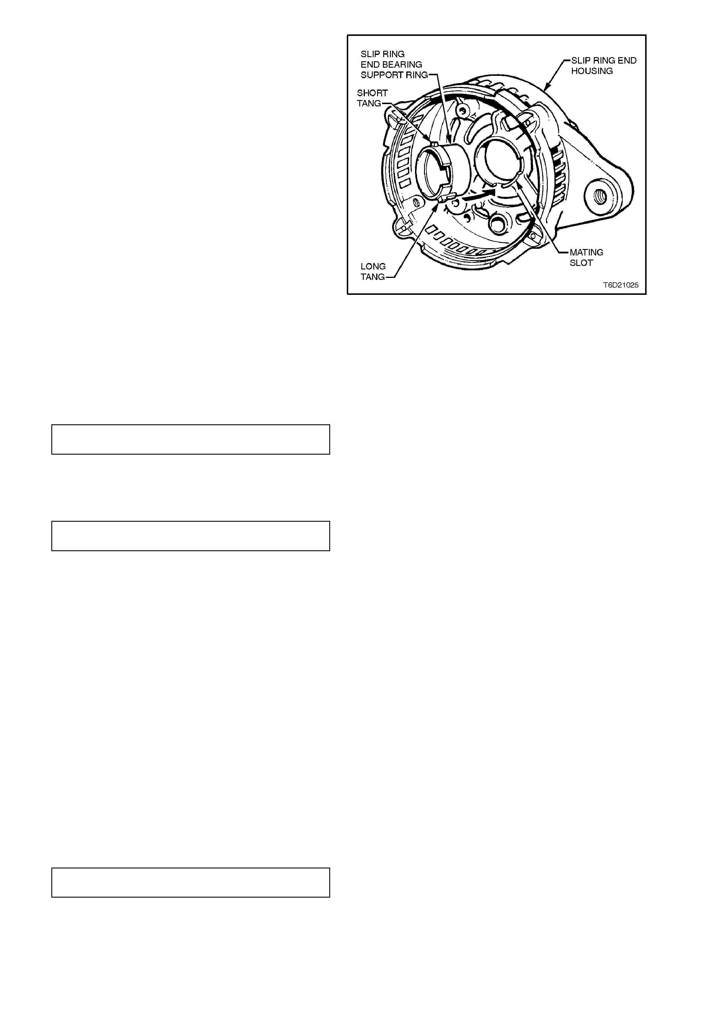
8. Inspect the slip ring end bearing support ring
for signs of damage, especially cracks. If in
any doubt replace the ring by pressing it into
the slip ring end housing by hand. DO NOT
USE EXCESSIVE FORCE.
IMPORTANT:
The slip ring end bearing support ring will only
locate correc tly into the slip ring end housing in one
location, i.e. with the long tang on its outer diam eter
locating into the mating slot in the slip ring end
housing.
9. Apply heat sink compound to both sides of
new rectifier positive heat sink mica washers.
Assemble mica washers to positive heat sink
with washer having largest hole fitted over the
B+ terminal bolt. The other mica washer is
fitted on the positive heat sink , ar ound the hole
for the retaining screw.
10. Install spacer over B+ terminal bolt and
assemble rectifier into slip ring end housing.
Assemble ins ulating washer, f lat washer , wave
washer and nut to B+ terminal, leaving nut
finger tight.
Figure 6D2-1-28
11. Install and tighten rectifier retaining screws to
the correct torque specification.
RECTIFIER RETAINING SCREW
TORQUE SPECIFICATION 2.2 - 3.2 Nm
Tighten B+ terminal nut to the correct torque
specification.
B+ TERMINAL NUT
TORQUE SPECIFICATION 7.5 - 8.5 Nm
12. To refit the stator, ensure that the mating
surfaces of the stator frame, drive end and slip
ring end housings are clean and free from
damage.
Fit the stator into the slip ring end housing,
noting the correct lead positioning. Fit the
stator leads into the wire loops in the rectifier.
Using a pair of pointed nose pliers, squeeze
the loops to retain the stator leads prior to
soldering. Solder the leads into position using
60/60 resin cored solder.
Once completed, ensure the leads will clear
the internal fan when the rotor is assembled
into the stator.
13. Assem ble rotor and dr ive end housing into the
stator and slip ring end plate assembly,
aligning marks made during disassembly.
14. Reinstall through bolts and tighten evenly, and
to the correct torque specification.
THROUGH BOLT
TORQUE SPECIFICATION 3.8 - 5.5 Nm

NOTE:
Ensure that the slip ring housing and drive end
housing are seated squarely on the stator frame.
This ensur es that the air gap between the rotor and
stator windings is equal at all points.
15. Reinstall the regulator and brush assembly to
the slip ring end housing, ensuring that the
regulator engages with the spring connectors
on the rectifier. Ensure the brushes are
located correctly onto the slip rings.
Install the regulator and brush assembly
securing screws and tighten to the correct
torque specification.
REGULATOR AND BRUSH
ASSEMBLY SECURING SCREW
TORQUE SPECIFICATION 1.6 - 3.2 Nm
16. Reconnect suppressor lead to rectifier +
terminal.

REINSTALL
1. Place generator into mounting bracket,
aligning drive end plate and mounting bracket
bolt holes. Install mounting bracket bolt and
nut, leave finger tight.
2. Install generator positive lead (red wire),
washer and nut on B+ term inal. Tighten nut to
the correct torque specification, then refit cap
over B+ terminal.
B+ TERMINAL NUT
TORQUE SPECIFICATION 7.5 - 8.5 Nm
3. Connect wiring harness at the generator
terminal block.
4. Install the generator brace and brace bolt to
generator drive end plate, leave bolt finger
tight.
5. Install drive belt onto generator drive pulley,
ensuring that drive belt is correctly fitted to
crankshaft balancer and water pump pulley
and that all drive pulleys are aligned.
6. Use generator to achieve specified
generator/water pump belt tension. For
details, refer to Section 6A2 ENGINE
MECHANICAL - V8 ENGINE. Tighten the
generator mounting bolts to the correct torque
specification.
GENERATOR TO MOUNTING
BRACKET NUT
TORQUE SPECIFICATION 20 - 45 Nm
GENERATOR TO BRACE BOLT
TORQUE SPECIFICATION 15 - 35 Nm
BRACE TO FRONT COVER BOLT
TORQUE SPECIFICATION 23 - 30 Nm
GENERATOR/WATER PUMP
DRIVE BELT
TENSION SPECIFICATION
57 kg NEW
34 kg USED
7. Reconnect battery earth cable at battery.
8. Start engine and check generator warning
lamp operation, drive belt alignment,
generator output and regulated voltage.

4. DIAGNOSIS
1. UNDERCHARGED BATTERY
a. Defective battery
b. Loose connection in charging system
c. Corroded connections in charging circuit
d. Defective wiring
e. Faulty generator
f. Faulty voltage regulator
2. OVERCHARGED BATTERY
a. Shorted battery cell
b. Faulty voltage regulator
c. Short circuit in rotor winding
d. Voltage drop in sense wire
3. FAULTY INDICATOR LIGHT OPERATION
(LIGHT DOES NOT GLOW)
a. Burnt out bulb
b. Defective bulb socket
c. Defective wiring
d. Defective rectifier
e. Defective regulator
4. FAULTY INDICATOR LIGHT OPERATION
(LIGHT REMAINS ON)
a. Negative diode failure
b. Defective voltage regulator
c. Faulty generator
d. B+ cable off or broken
e. S cable off or broken
f. Battery overcharged
g. Open circuit in rotor winding
5. NOISY GENERATOR OPERATION
a. Normal magnetic hum
b. Badly discharged battery
c. Generator mounting brackets loose or bolts loose
d. Worn or frayed drive belt
e. Worn bearings
f. Loose drive pulley attaching nut
g. Open or shorted diodes
h. Open or shorted stator winding

5. SPECIFICATIONS
Earth Polarity Negative
Nominal Voltage 12V
Nominal Output 120 Amps
Stator Phases 3
Stator Winding Connections Star
Number Of Poles 12
Resistance of Rotor Winding ohms @ 20°C 2.3 ±0.115 W
Resistance of Stator Winding ohms @ 20°C 0.015 ± 0.00015 W
Voltage Regulator Setting 14.25-14.55V
Brush Length 9.3 mm (new) 3.8 mm (min)
Generator Belt Tension 64 kg (new) 43 kg (used)

6. TORQUE WRENCH SPECIFI CATIONS
Nm
Through Bolts 3.8 - 5.5
Front Bearing Retainer Plate Screws 2.1 - 3.0
Drive Pulley Retaining Nut 54 - 68
Regulator and Brush Assembly Securing
Screws 1.6 - 3.2
'B+' Terminal Stud Nut 7.5 - 8.5
Battery Harness Terminal to 'B+' Terminal
Stud Nut 5 - 12
Rectifier Plate Retaining Screw 2.2 - 3.2
Capacitor Fixing Screw 2.7 - 3.8
Generator to Mounting Bracket Nut 20 - 45
Brace to Generator Bolt 15 - 35
Brace to Front Cover Bolt 23 - 30
Generator Mounting Bracket to Cylinder
Head Bolts 46 - 60
Idler Pulley Clamp Nut 35 - 65

7. SPECIAL TOOLS
TOOL NO. REF IN TEXT TOOL DESCRIPTION COMMENTS
9981 066 601 ROTOR BEARING REMOVAL TOOL
9122 067 037 BEARING ASSEMBLY FIXTURE
BT3373-F BELT TENSION GAUGE