SECTION 6D2-2 STARTING SYSTEM - V8 ENGINE
CAUTION:
This vehicle will be equipped with a Supplemental Restraint System (SRS). A SRS will
consist of either seat belt pre-tensio ners and a driver’s side air bag , or seat belt pre-
tensioners and a driver’s and front passenger’s side air bags. Refer to CAUTIONS,
Section 12M, before performing any service operation on or around SRS
components, the steering mechanism or wiring. Failure to follow the CAUTIONS
could result in SRS deplo yment, resulting in possible p ersonal injury or unnecessary
SRS system repairs.
CAUTION:
This vehicle may be equipped with LPG (Liquefied Petroleum Gas). As this fuel in the
gaseous form is heavier than air, and in the interests of safety, the LPG fuel system
should be isolated by turning 'OFF' the manual service valve and then draining the
LPG service lin es, before any service wo rk is carried out on the vehicle. Refer to the
LPG leaflet included with the Owner's Handbook for details or LPG Section 2 for
more specific servicing information.
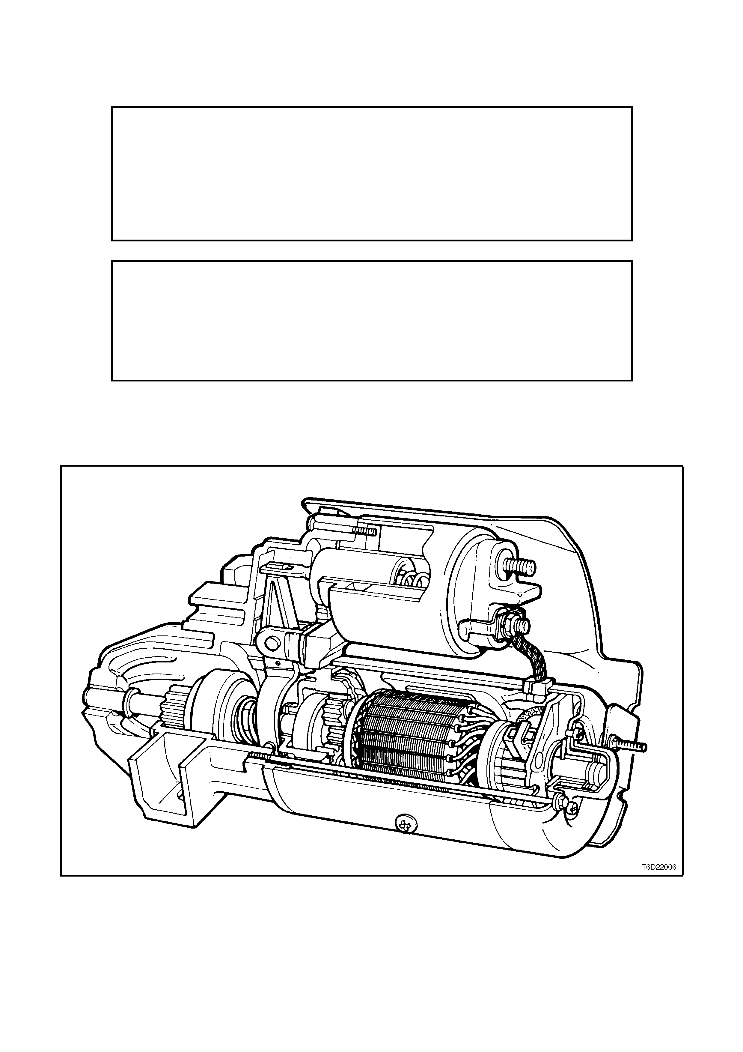
1. GENERAL DESCRIPTI ON
Figure 6D2-2-1
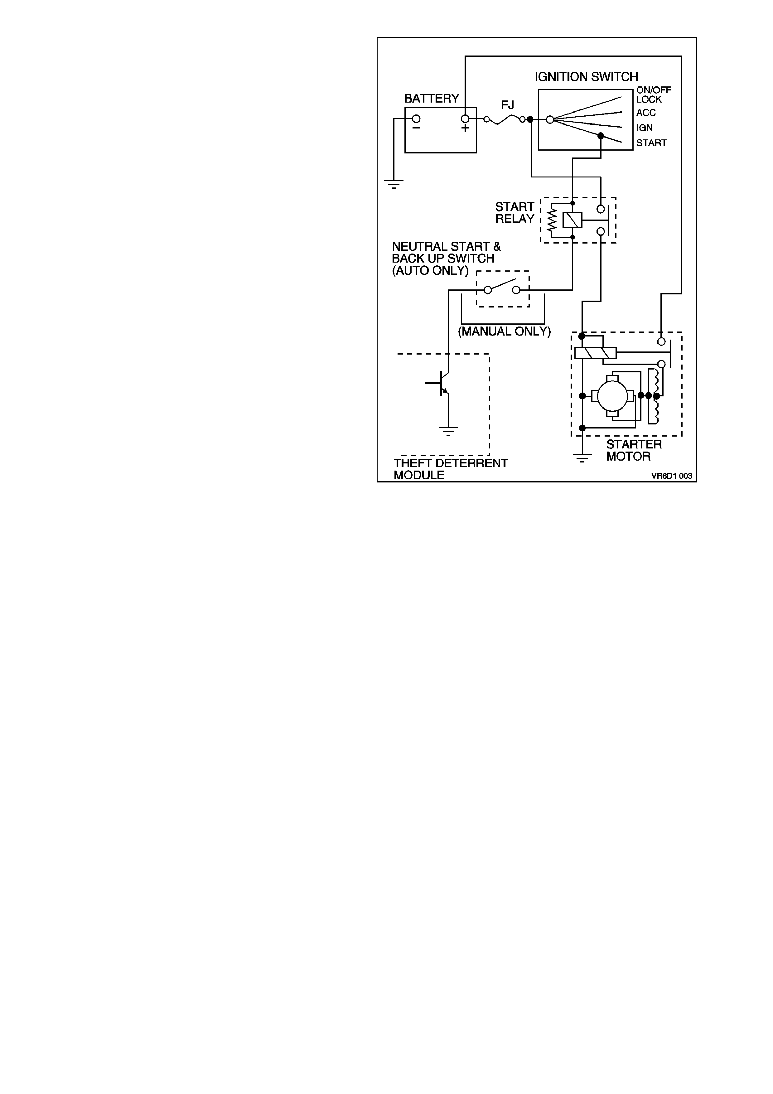
The starting system comprises the battery, starter
motor, ignition switch, neutral/back-up switch
(vehicles with automatic transmission), theft
deterrent engine crank inhibitor and related electrical
wiring.
The starter motor is a series parallel wound, four
pole, four brush type. The armature shaft is
supported at each end by oil absorbent sintered
metal bushes pressed into the commutator end
frame and drive end housing. These bearings
require lubrication only at time of overhaul.
The four brushes are supported by the brush holder
which is retained to the commutator end frame by
screws. Two brushes are grounded to the frame,
and two are insulated from the f r ame and c onnected
to the field coils. The field coils are held in place by
the pole shoes which are attached to the starter
frame by large diameter screws. The field coils are
connected to an insulated terminal on the starter
frame through which current is supplied to the
starter motor from the solenoid switch.
The pinion assembly transmits cranking torque to
the flexplate/ring gear. T o pr event the armature from
being driven at excessive speed by the engine, an
internal clutch allows the pinion to rotate freely in
relation to the armature shaft when the engine
begins to operate.
Figure 6D2-2-2
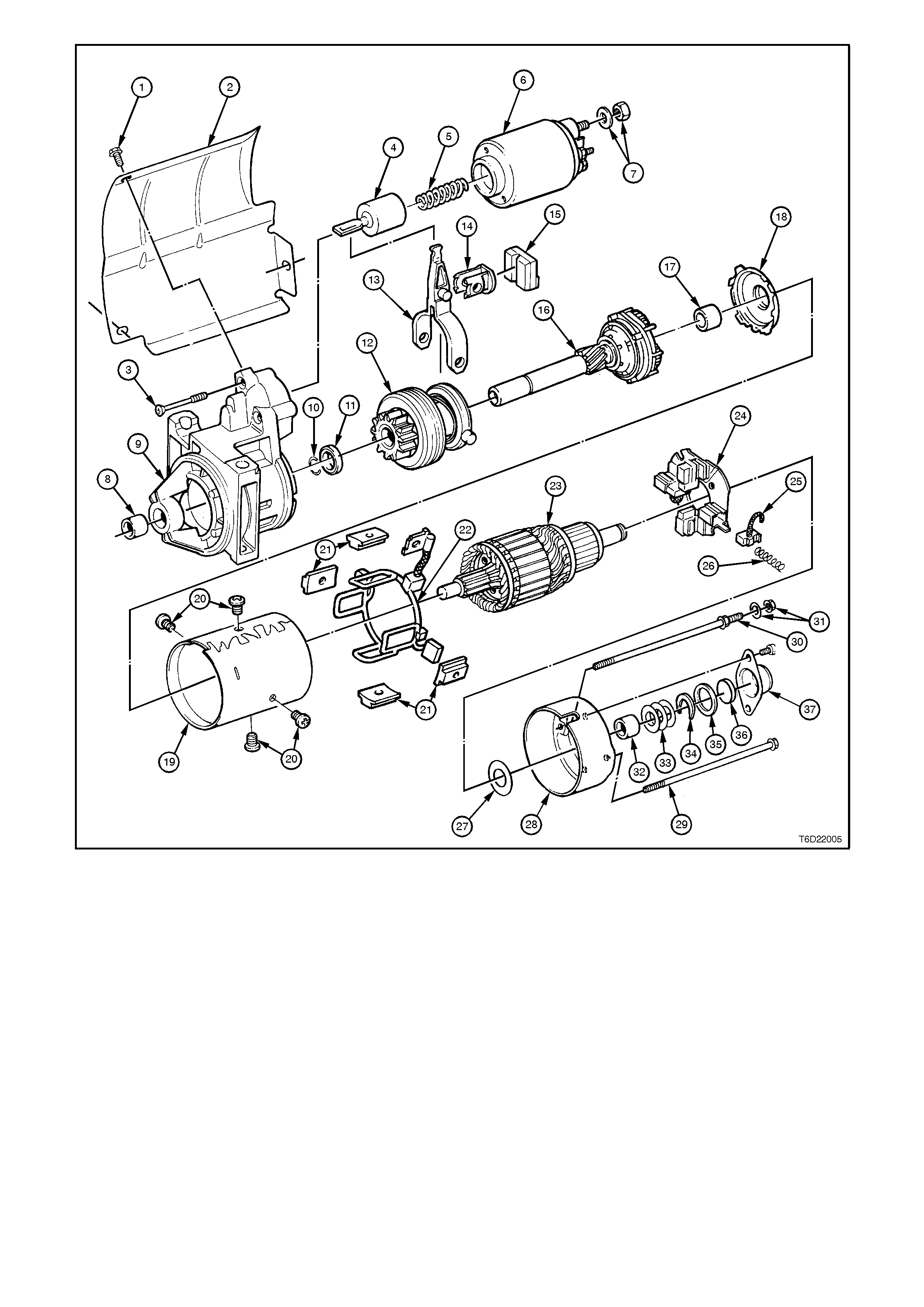
Figure 6D2-2-3
1 Heat Shield Retaining Screw 13 Fork lever 26 Brush holder spring
2 Heat Shield 14 Drive lever bearing 27 Thrust washer
3 Solenoid switch to drive end 15 Sealing rubber 28 Commutator end cover
housing mounting screws 16 Planetary drive shaft 29 Through bolt (standard)
4 Plunger 17 Commutator front cover bush 30 Through bolt (extended
thread)
5 Return spring 18 Cover plate 31 Through bolt nut and washer
6 Solenoid switch 19 Field coil housing 32 Commutator end cover bush
7 ‘M’ terminal nut and washer 20 Field coil pole side screws 33 Adjustment washers
8 Drive end housing bush 21 Pole shoe 34 Horse shoe clip
9 Drive end housing 22 Field coil and positive
brushes 35 Dust cover sea l
10 Stud ring 23 Armature 36 Felt pad
11 Stop ring retainer 24 Brush holder & negative
brushes 37 Dust cover
12 Drive assembly 25 Brush
2. SERVICE OPERATIONS
2.1 PERFORMANCE TESTING
The following tests involve the starter motor being
removed from the vehicle, refer to 2.3 STARTER
MOTOR - REMOVE in this Section, and then
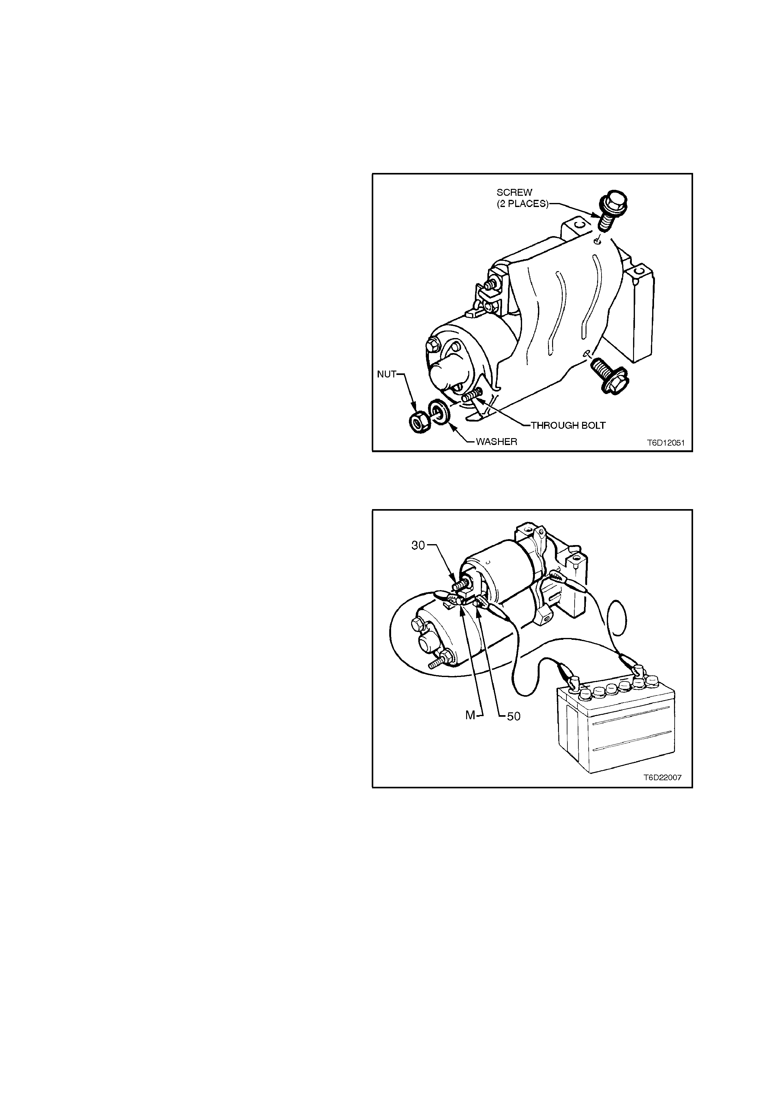
remove the heat shield as follows:
Remove the nut from the end of the extended
through bolt and then remove the two heat shield
retaining screws and washers.
Figure 6D1-2-4
SOLENOID SWITCH TESTS
Pull-In Test
1. Remove nut and washer from solenoid switch
short threaded terminal ('M' terminal). Remove
field coil braided cable and terminal from
threaded terminal.
2. Using suitable test leads and 12 volt battery,
connect as shown in Fig. 6D1-2-5. Check that
drive assembly moves outward.
If drive assembly does not move, replace
solenoid switch as described in this Section.
Figure 6D1-2-5
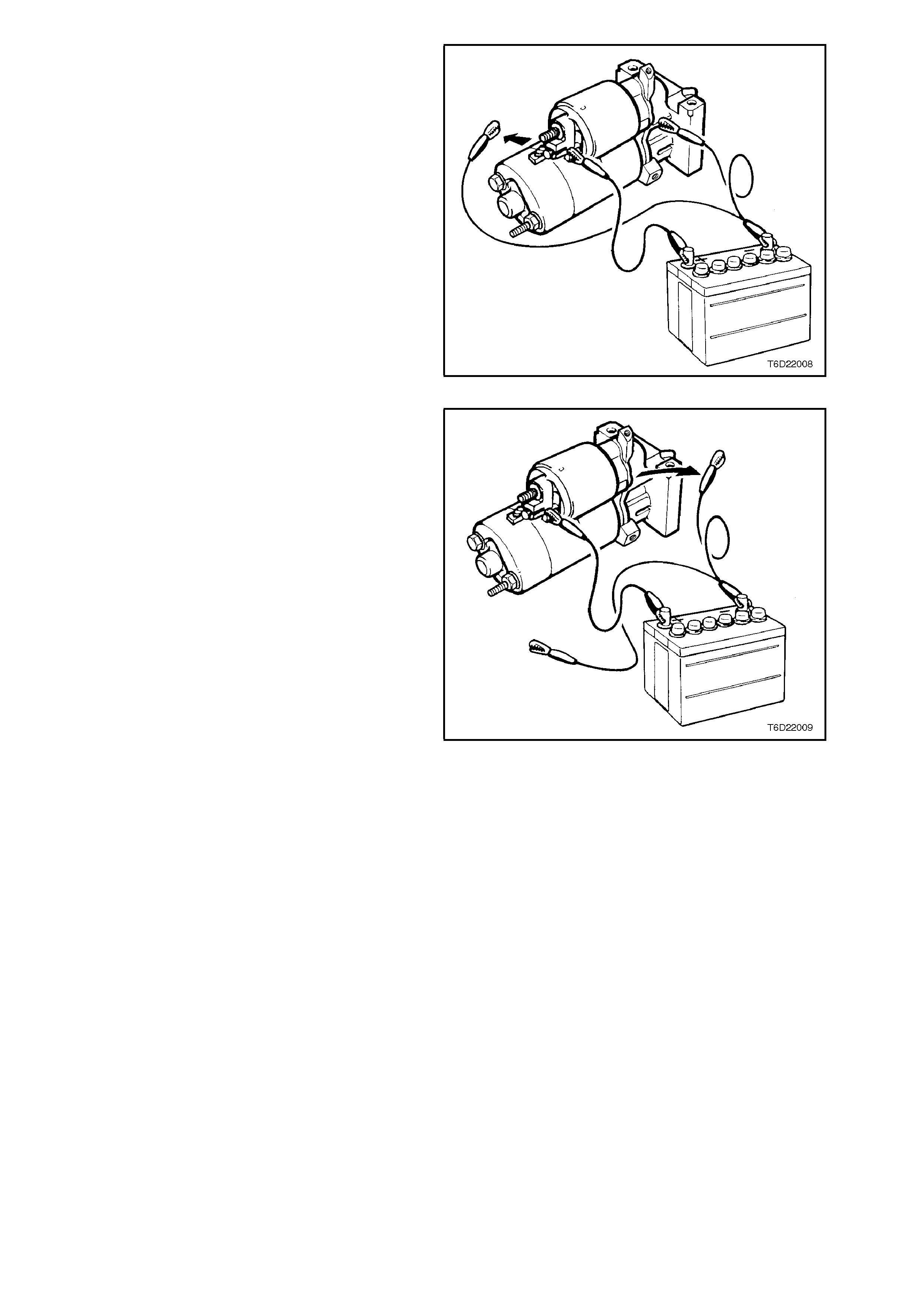
Hold-In Test
1. With battery connections to starter motor and
solenoid switch as shown for Pull-In Test,
disconnect negative lead from solenoid switch
short threaded terminal ('M' terminal).
2. Check that drive assembly remains outward.
If drive assembly returns inward, replace
solenoid switch as described in this Section.
Figure 6D1-2-6
Drive Assembly Return
1. With battery and connections to starter motor
and solenoid switch as at end of Hold-In Test,
disconnect negative lead from drive end
housing.
2. Check that drive assembly returns inward.
If drive assembly does not return, replace
solenoid switch as described in this Section.
Figure 6D1-2-7
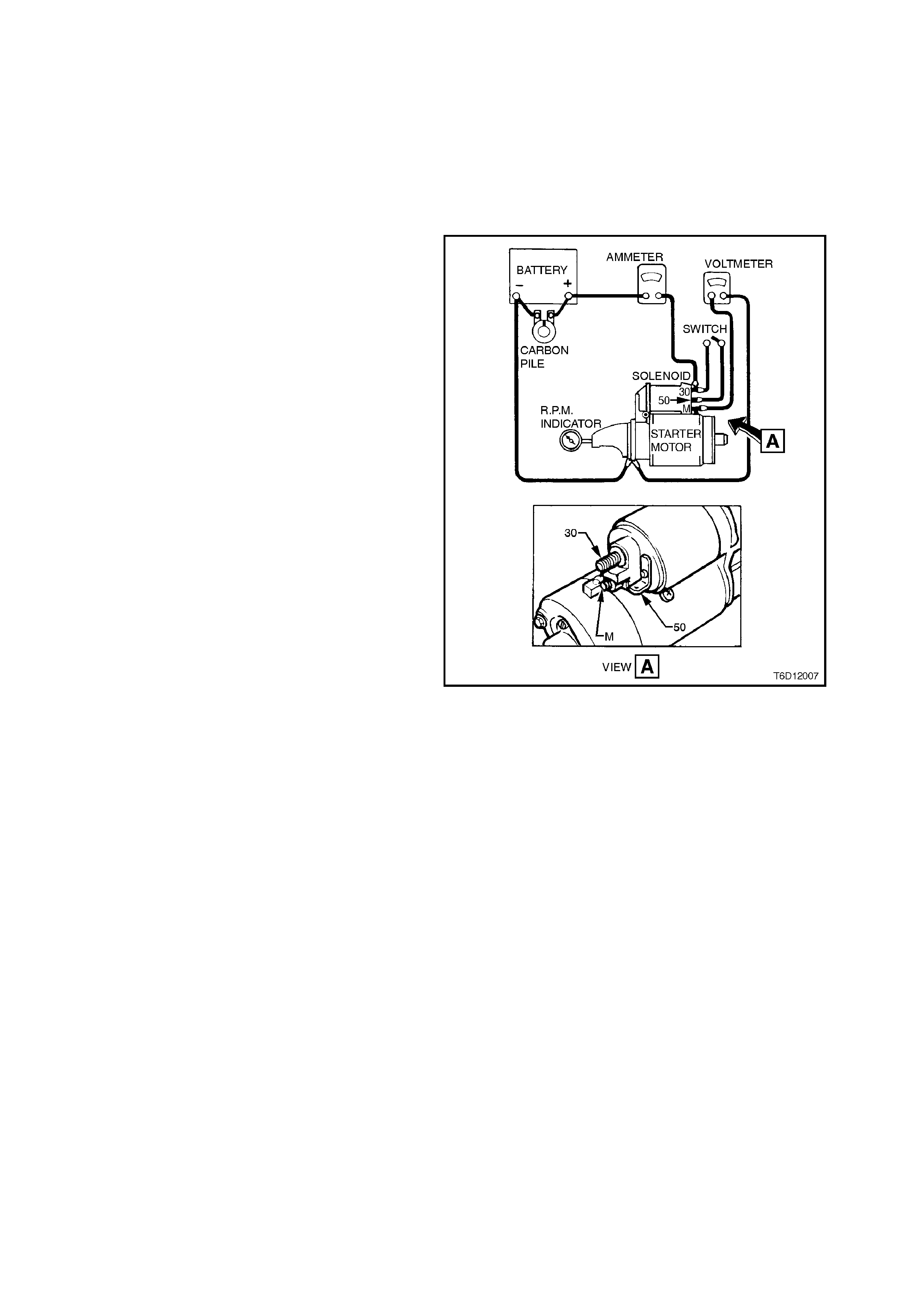
2.2 NO LOAD TEST
With the starter motor removed from the engine,
the pinion should be checked for freedom of
operation by turning it on the armature shaft. The
armature should be checked for freedom of
rotation by prying the pinion with a screwdriver. If
the armature does not tur n freely, the motor should
be disassembled immediately. However, if the
armature does rotate freely, the motor should be
given a NO LOAD test before disassembly.
Clamp starter motor securely to test bench and
mak e connections as shown in Fig. 6D2-2- 8. Close
the switch and compare the rpm, current, and
voltage readings with the following specifications.
STARTER MOTOR SPEED 6500 rpm
STARTER MOTOR CURRENT 70 amp s (max)
TERMINAL VOLTAGE 12 volts
If the NO LOAD test indicates that the starter
motor is defective, refer to 3. DIAGNOSIS in this
Section for probable cause of starter motor fault.
Figure 6D2-2-8
2.3 STARTER MOTOR
REMOVE
1. Disconnect battery earth lead.
2. Jack up front of vehicle and support on safety
stands. For location of jacking locations, refer
to Section 0A GENERAL INFORMATION.
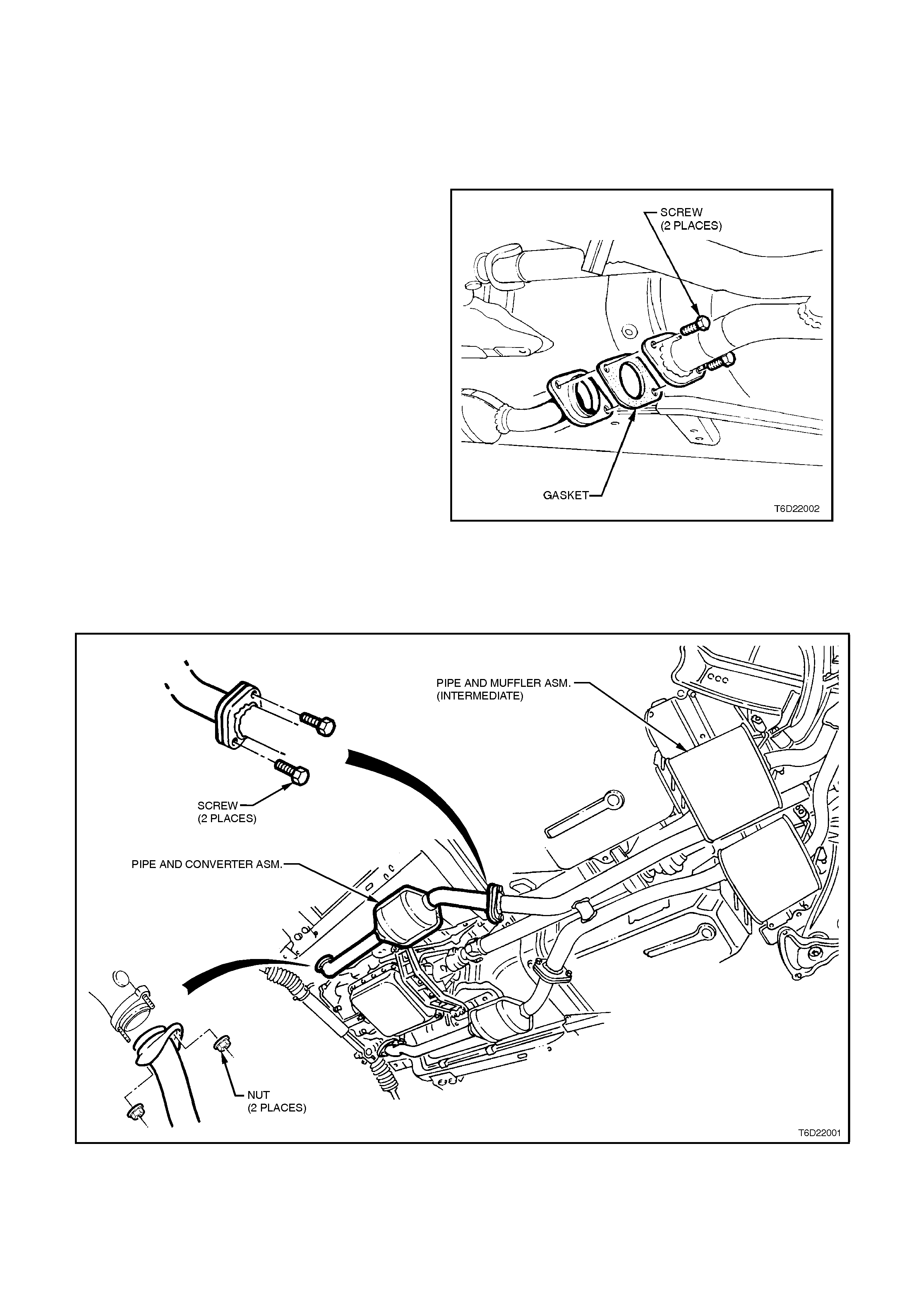
3. Remove left hand side engine pipe to exhaust
manifold attaching bolts.
Figure 6D2-2-9
4. Remove bolts attaching engine pipe assembly
to front of catalytic converter, remove engine
pipe assembly and discard gasket.
Figure 6D2-2-10
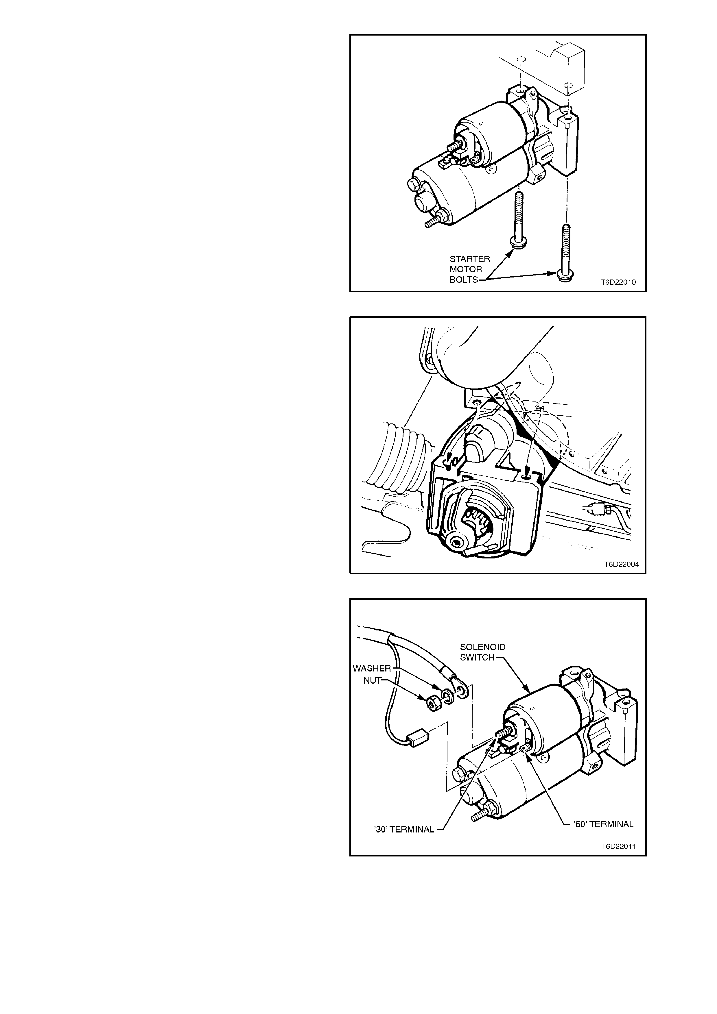
5. Remove starter motor to cylinder block brace
bolts.
Remove starter motor to cylinder block
mounting bolts.
Figure 6D2-2-11
6. Withdraw starter motor out rearward.
Figure 6D2-2-12
7. Remove heat shield, refer to
2.1 PERFORMANCE TESTING in this Section.
Remove nut and washer from starter motor
solenoid 'B' terminal and remove battery lead.
Pull wiring harness connec tor f r om solenoid '50'
terminal.
Figure 6D2-2-13
REINSTALL
Reinstallation of the starter motor is the reverse of
removal procedures, noting the following points:
1. Ensure that all fasteners are tightened to the
correct torque specifications.
STARTER MOTOR TO CYLINDER
BLOCK MOUNTING BOLT
TORQUE SPECIFICATION 40 - 60 Nm
STARTER MOTOR TO CYLINDER
BLOCK BRACE BOLT
TORQUE SPECIFICATION 12 - 16 Nm
ENGINE PIPE TO EXHAUST
MANIFOLD ATTACHING BOLT
TORQUE SPECIFICATION 15 - 35 Nm
ENGINE PIPE ASSEMBLY TO
CATALYTIC CONVERTER
ATTACHING BOLT
TORQUE SPECIFICATION
30 - 50
Nm
STEERING GEAR TO FRONT
CROSSMEMBER MOUNTING NUT
TORQUE SPECIFICATION 50 - 85 Nm
2. Check starter motor operation.
3. Check exhaust system for leaks, repair if
necessary.
DISASSEMBLE
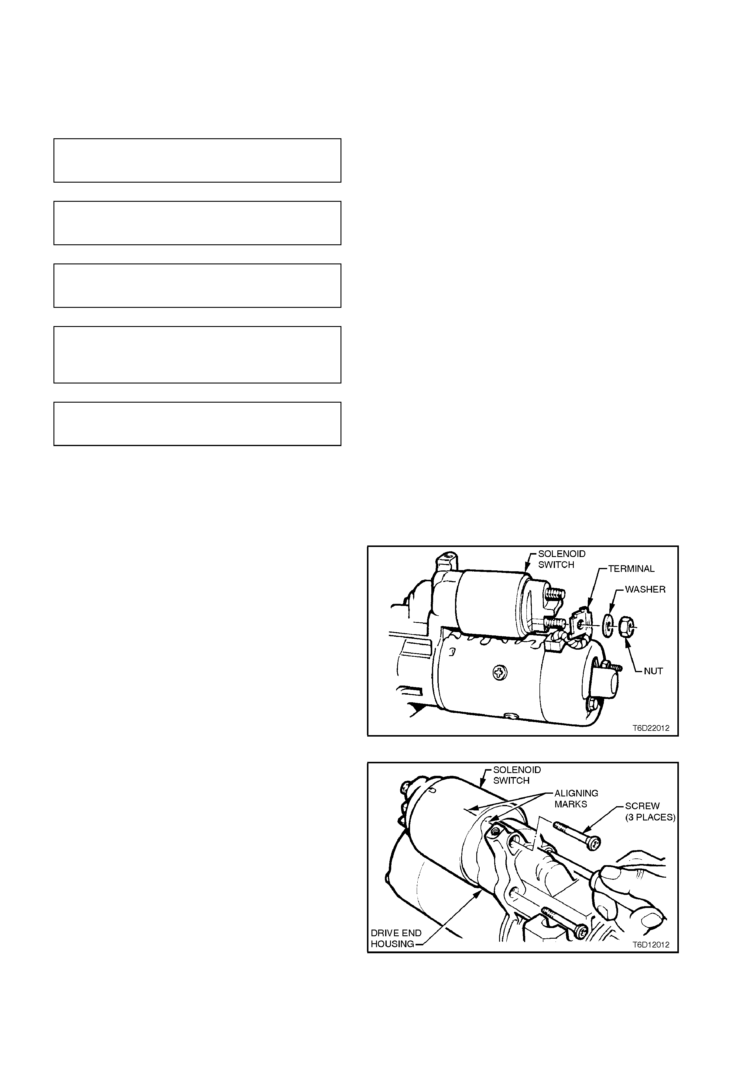
1. Remove the nut and washer from the solenoid
field coil terminal, then separate the lead from
terminal.
Figure 6D2-2-14
2. Remove the two solenoid mounting screws.
3. Remove solenoid by lifting and unhooking
solenoid plunger fr om drive ass embly engaging
lever.
Figure 6D2-2-15
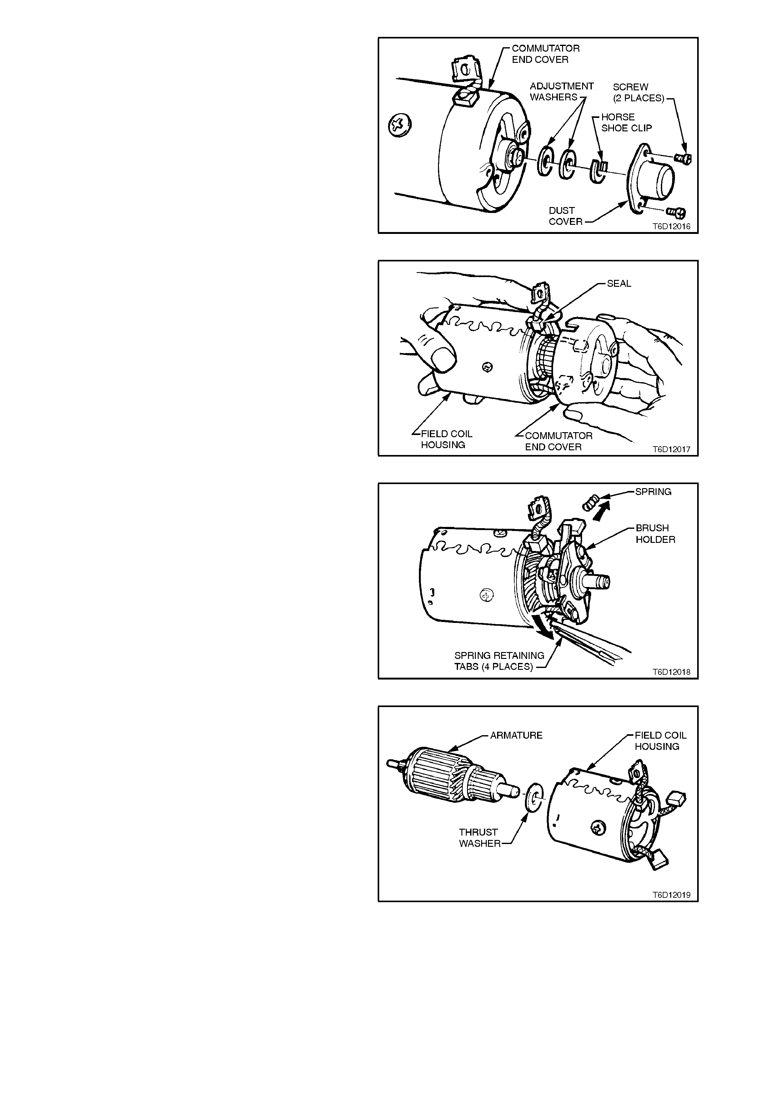
4. Remove the screws securing the commutator
end cover bearing cap.
5. Separate the bearing cap, then using a pair of
Circlip pliers, remove the circlip and any shim/s.
Remove seal from commutator end cover.
Figure 6D2-2-16
6. Remove two through bolts securing
commutator end cover and field coil housing to
drive end housing.
7. Remove commutator end cover and brace.
Figure 6D2-2-17
8. Carefully bend back the brush spring retaining
lugs on the positive brush holders and remove
springs and brushes. Rem ove the brush holder
from commutator.
Figure 6D2-2-18
9. Loosen the pivot bolt nut until level with the end
of the pivot bolt. Tap the pivot bolt free using a
brass drift and hammer.
10. Remove the nut and withdraw the pivot bolt.
11. Separate the field coil housing from the drive
end housing.
12. Withdraw the armature, engaging lever and
drive assembly from the drive end housing.
Figure 6D2-2-19
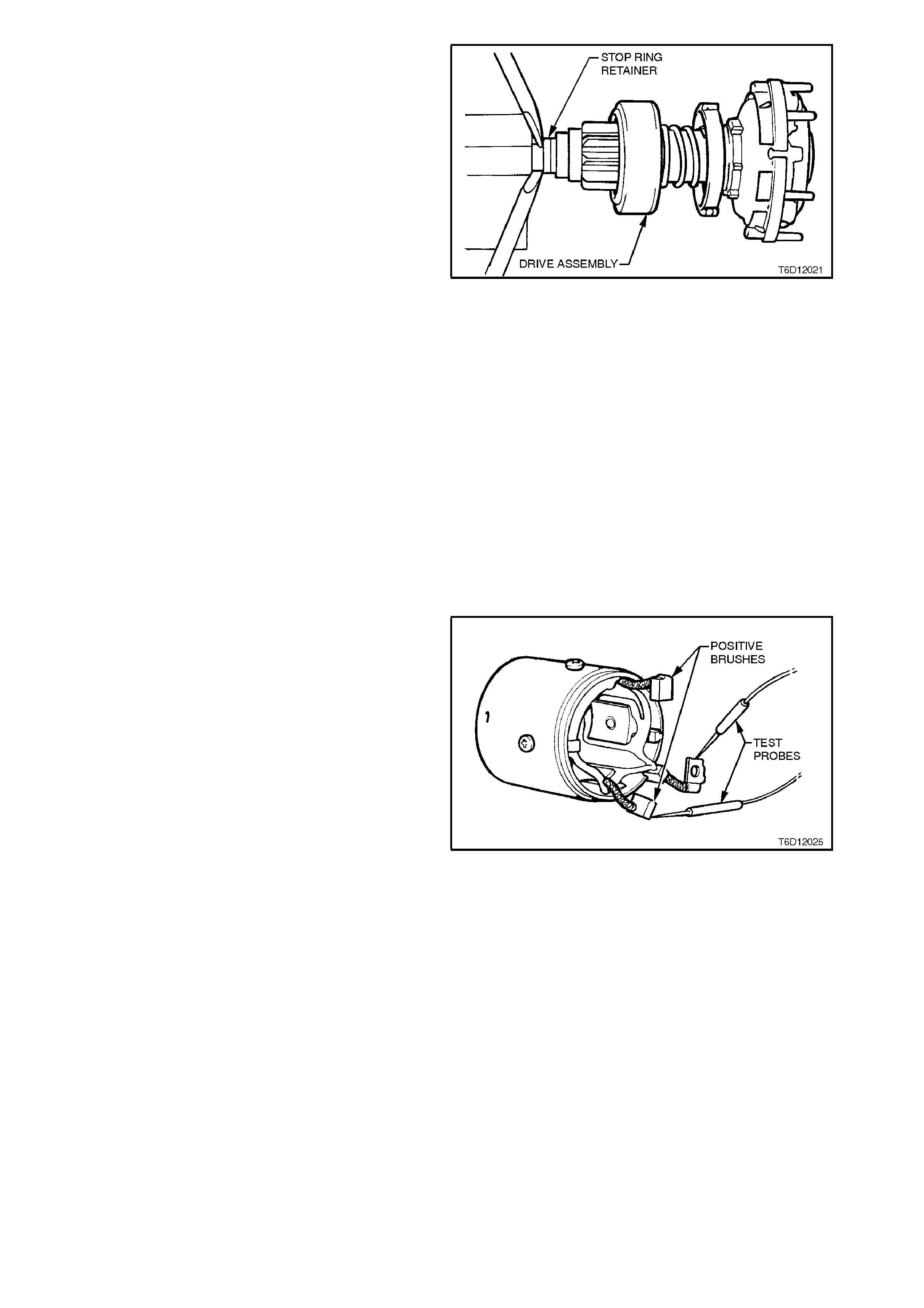
13. Knock the stop ring toward the armature using
a steel tube with a 15 mm I.D.
As an alternative, clamp drive end of armature
shaft in a vice with soft jaws. Prise stop ring
toward armature using two screwdrivers
pivoting on vice jaws and levering against stop
ring.
14. Expand and remove spring clip using a pair of
Circlip pliers. Take care not to scratch or
damage the armature shaft.
15. Remove any burrs from spring clip groove on
armature shaft using a fine file.
16. Remove stop ring and pinion assembly from
armature shaft. Figure 6D2-2-20
CLEANING AND INSPECTION
With the starter motor completely disass embled, all
components should be cleaned and inspected.
W ash the components excluding the armature and
field coils in a suitable cleaning agent.
CAUTION:
Do not clean armature or field coils with
cleaning solvent as damage to the insulation
could occur.
Carefully clean armature and field coils using
compressed air.
COMPONENT CHECKING
FIELD COILS
1. Connect a 12 volt powered DC test lamp
between field coil winding connection and a
positive brush. If the field coil circuit is
serviceable, the lamp will illuminate to indicate
continuity.
Repeat the procedure on the rem aining positive
brush.
2. Ensure brushes are not touching the field coil
housing, then connect a 240 volt powered test
lamp between field coil winding connection and
field coil housing. The lamp will not illuminate if
winding insulation is satisfactory.
Figure 6D2-2-21
3. Visually inspect field coil windings for signs of
insulation breakdown and/or burns.
4. Remove and replace defective field coils with
an approved pole shoe screwdriver.
ARMATURE INSULATION TEST
Connect a 240 volt powered test lamp between the
armature core and a commutator segment. If lamp
illuminates, armature is grounded and should be
replaced.
Repeat the procedure on the r emaining com mutator
segments.
Figure 6D2-2-22
ARMATURE CONTINUITY TEST
Using an ohmmeter (or 12 volt powered DC test
lamp) touch one probe onto a com m utator segm ent,
then touch the remaining probe to an adjacent
segment. Repeat this procedure on each adjacent
set of segments.
If any adjacent set of segments does not indicate
continuity (i.e. test lamp does not illuminate), the
armature windings are open circuit, and the
armature must be replaced.
Figure 6D2-2-23
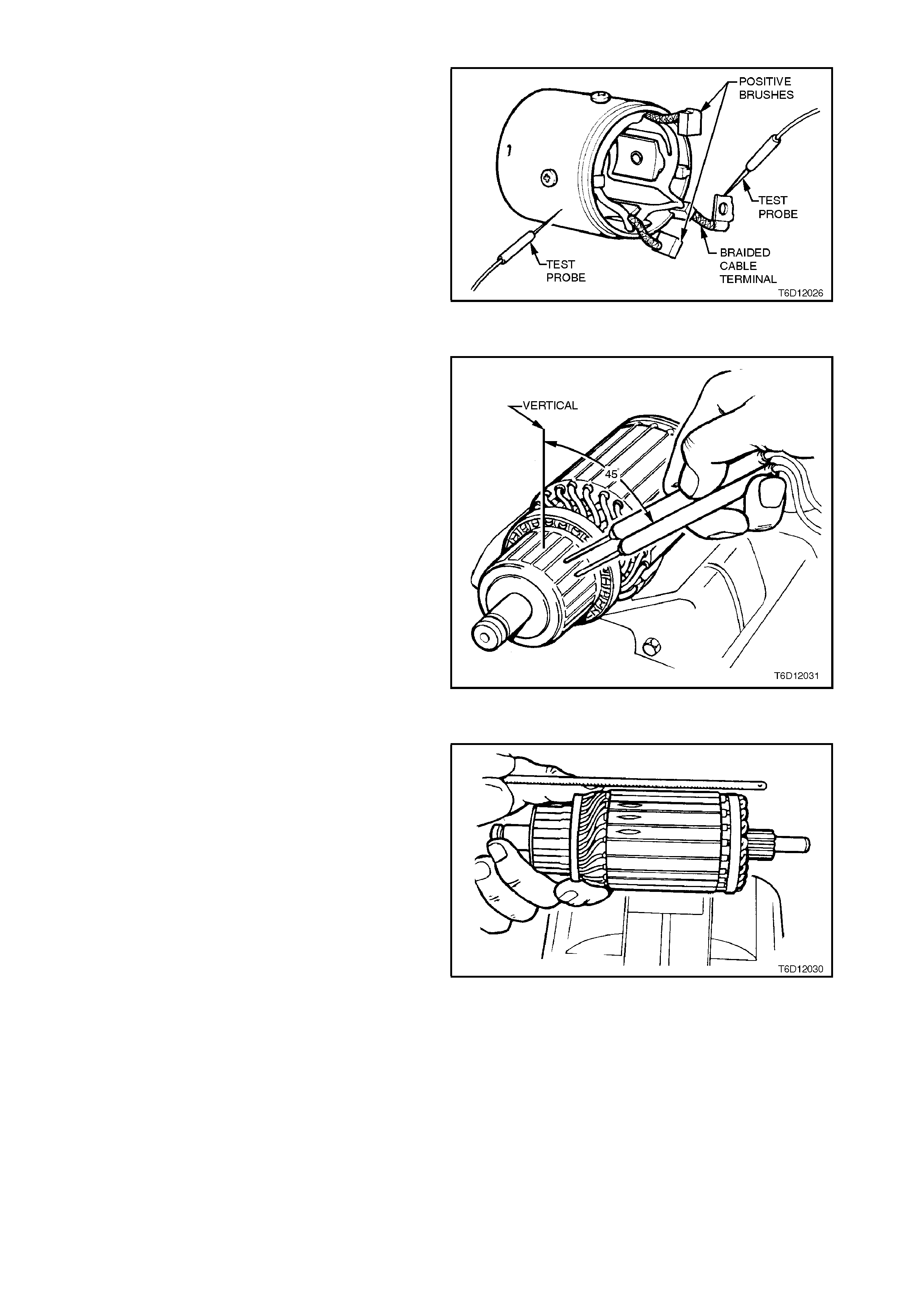
ARMATURE SHORT CIRCUIT TEST
Test armature for short circuits on a growler.
1. Place armature on growler and switch on
growler. Hold a hack saw blade appr oxim ately 6
mm above armature core and rotate armature.
2. If the hacksaw blade vibrates, undercut
between the commutator segments (to a depth
of approximately 0.7 mm) using a suitable small
file, then re-check armature.
3. If hacksaw blade still vibrates, the armature is
short circuited and must be replaced.
Figure 6D2-2-24
ARMATURE TO COMMUTATOR LEADS
Check to ensure that armature to commutator
leads are correctly soldered to commutator. Re-
solder if necessary.
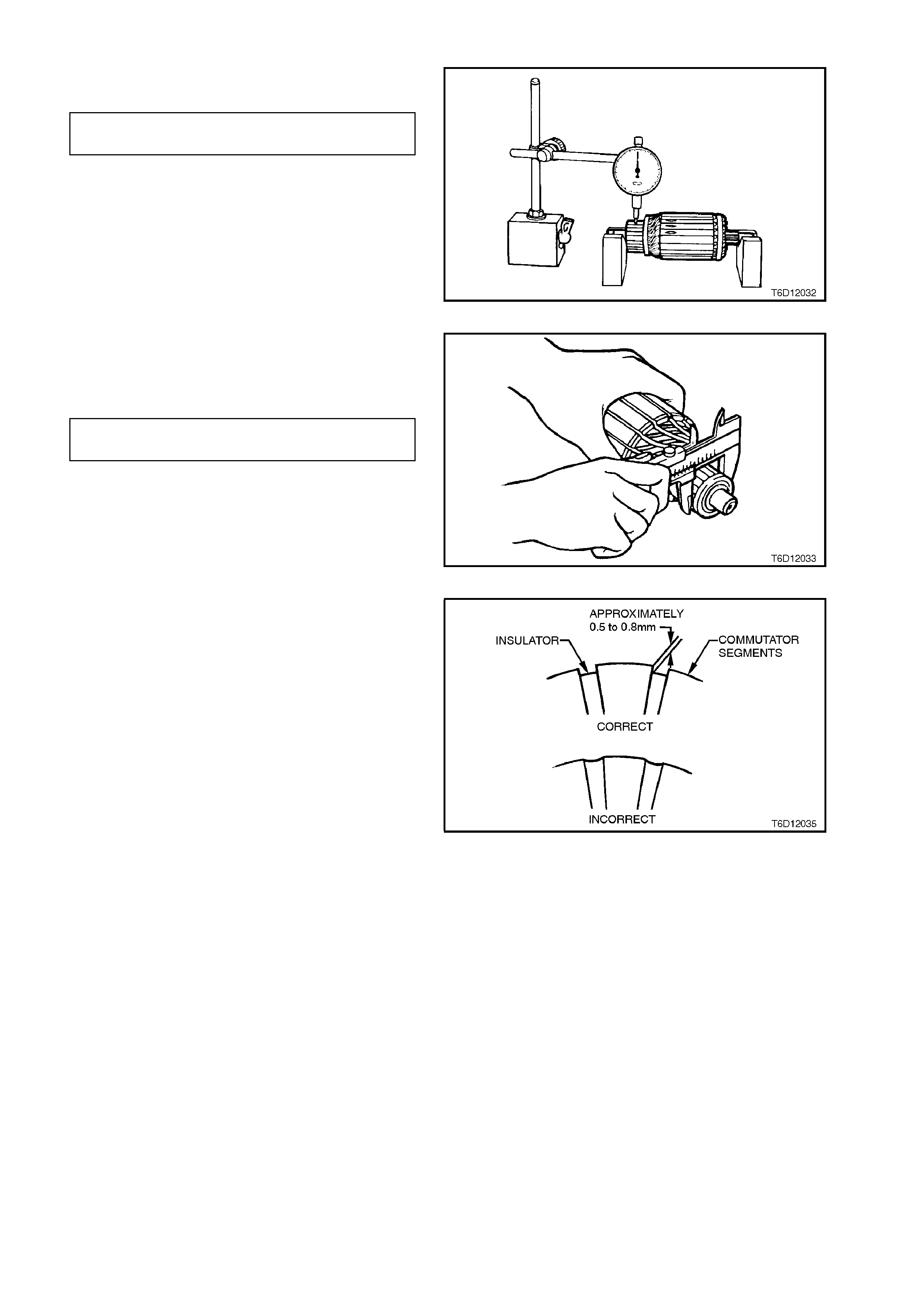
COMMUTATOR SURFACE
Check commutator for out-of-round.
COMMUT ATOR MAXIMUM 0.05
PERMISSIBLE OUT-OF-ROUND mm
If the armature is otherwise satisfactory but
commutator is worn, burnt, out-of-round, or has
high insulation between the segments, the
commutator should be machined.
Figure 6D2-2-25
NOTE:
Replace the armature if the commutator diameter is
below the dimension given in the following chart.
COMMUT ATOR MINIMUM 33.5
DIAMETER mm
Figure 6D2-2-26
After machining the commutator, undercut the
insulation between the commutator segments to a
depth of approximately 0.7 mm using a suitable
small file.
After under cutting, car efully clean all dirt and debris
from the segment slots, and lightly polish
commutator with fine emery cloth to remove any
burrs left by the undercutting operation. Clean
commutator and armature thoroughly using
compressed air.
Figure 6D2-2-27
BRUSHES
Ensure that brushes slide sm oothly in their holders,
brush connec tions are good and brushes are clean
and not chipped.
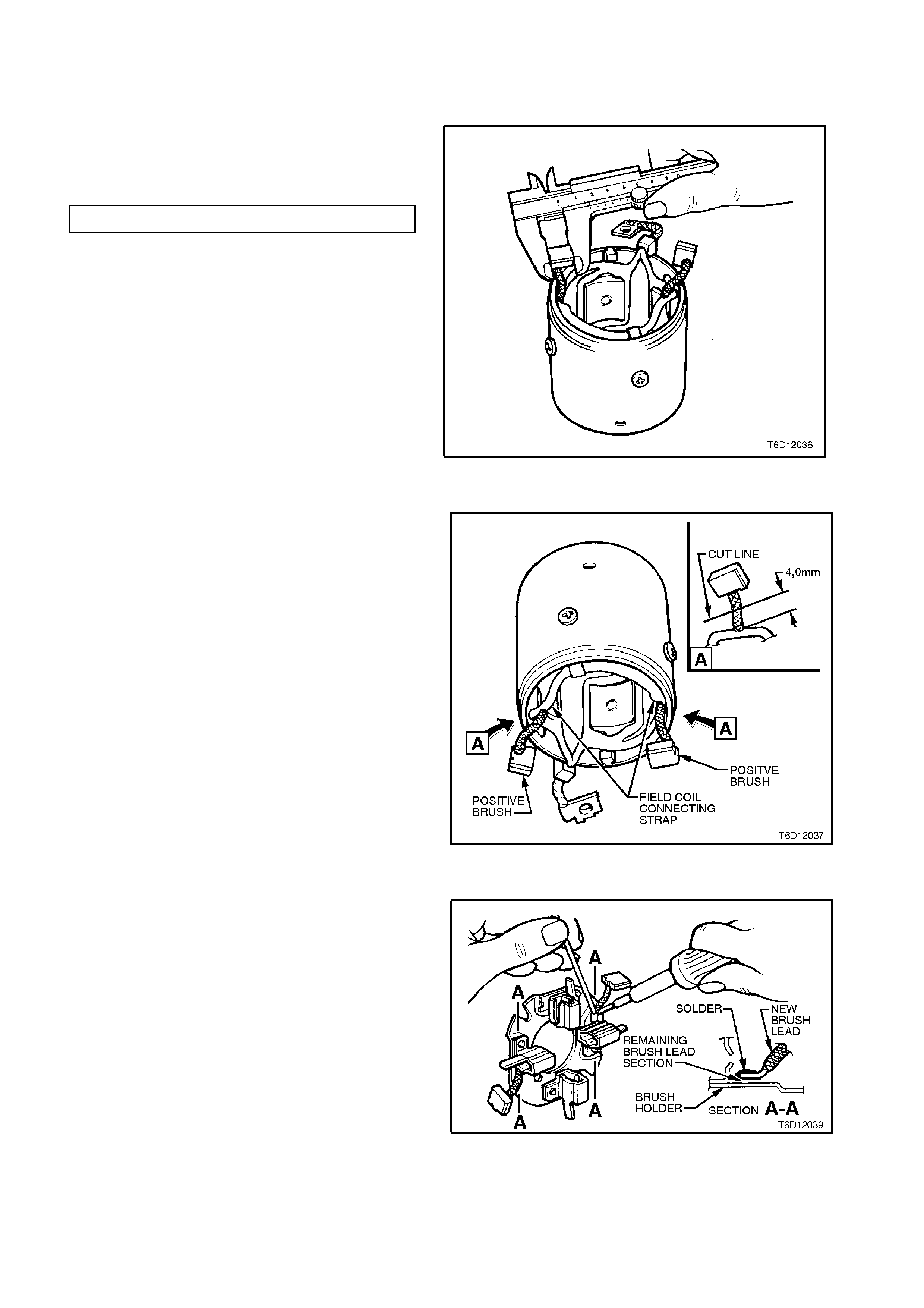
Check brush length. If any brush is below
specification, replace the complete brush set and
machine commutator if necessary.
MINIMUM BRUSH LENGTH 13 mm
If necessary, replace brushes as follows:
Figure 6D1-2-28
POSITIVE BRUSHES
1. Cut the brush lead at the field coil. Discard the
brush and spring.
2. Clean the field coil terminal and any remaining
section of the brush lead.
3. 'Tin' the field coil terminal.
NOTE:
Replacement brushes have ends of leads 'tinned'.
4. Hold the new brush lead in position (refer to
Figure 6D2-2-29 for correct orientation) on the
field coil terminal, using a pair of pliers. Solder
brush lead to field coil end.
NOTE:
When soldering the new brush lead into place, do
not allow the solder to run too far up the lead.
Figure 6D2-2-29
NEGATIVE BRUSHES
5. Hold the new brush lead in position on the pre-
tinned cut-off lead using a pair of pointed nose
pliers, noting brush lead direc tion as per step 1.
Solder new brush lead to cut-off lead.
NOTE:
When soldering the new brush lead into place,
ensure that the solder does not run up the lead by
capillary action. Should this happen, it will make the
lead too inflexible and not allow correct brush
movement and/or cause fouling during reassembly.
Figure 6D1-2-30
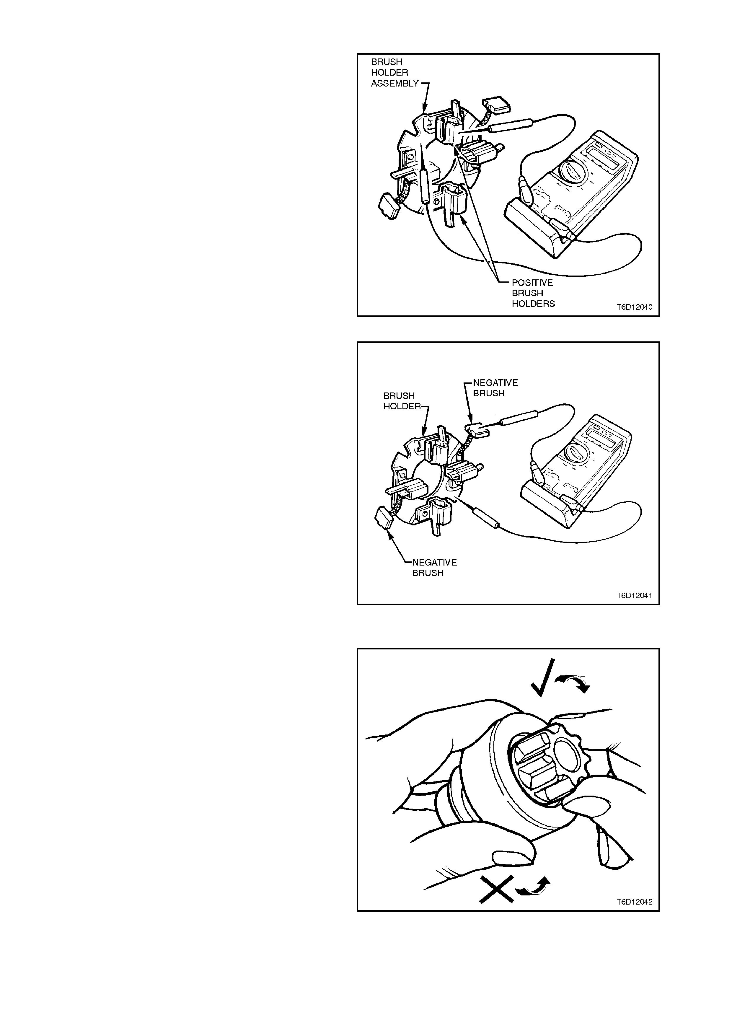
BRUSH HOLDER ASSEMBLY
Using an ohmmeter, check insulation between the
positive brush holders and earth. If continuity exists,
replace holder assembly.
Figure 6D2-2-31
Check continuity between negative brushes and
holder assembly base. If continuity does not exist,
replace the brush holder.
Check condition of the brush holder spring retaining
tags. If any tags are weak, broken or there is any
sign of fatigue from being bent back, replace the
brush holder assembly.
Figure 6D2-2-32
DRIVE ASSEMBLY CHECK
Inspect pinion gear for burrs and worn or chipped
teeth.
Check the operation of the pinion. The pinion gear
should rotate free and smooth in relation to the
pinion housing when turned in a clockwise direction,
but not rotate when turned in a counter-clockwise
direction.
Replace the pinion if out of specification, or if pinion
gear is damaged. If the pinion teeth are damaged or
broken, inspect ring gear teeth and replace as
necessary. For ring gear replacement, refer to
Section 6A2 ENGINE MECHANICAL - V8 ENGINE.
Inspect engaging lever contact surfaces, and inspect
pivot bolt and engaging lever hole. Replace
components if worn.
Figure 6D2-2-33
BUSHES
Check the fit of armature shaft in commutator end
cover and drive end housing.
If bushes are exc essively worn, the star ter m otor is
likely to operate inefficiently and/or the armature
may foul on field coil poles.
To remove bushes, support the commutator end
cover or drive end housing (as appropriate), and
carefully tap bush out using a suitable mandrel.
NOTE:
If new bushes are to be installed, they must be
soaked in clean engine oil for one hour prior to
installation.
To install new bushes, press or tap into position
with a suitable shouldered mandrel.
Do not ream bushes after they have been installed
as self-lubricating qualities of the bush will be
diminished.
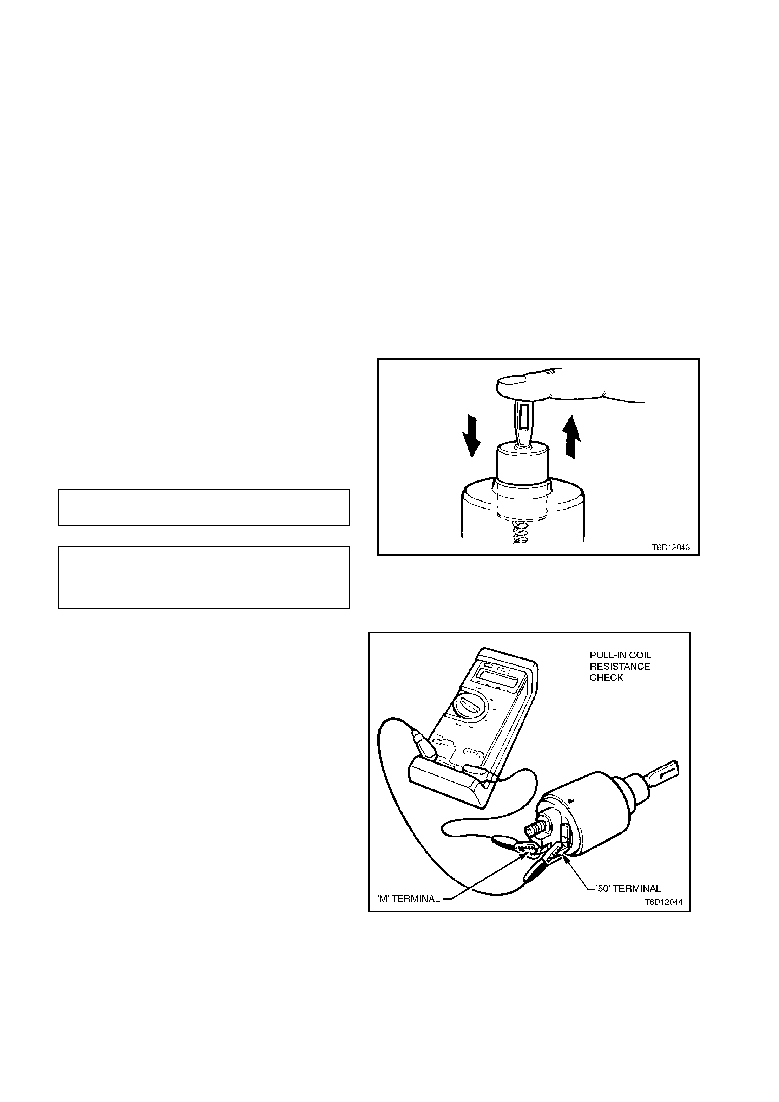
SOLENOID
Inspect the solenoid switch for any external
damage.
Install return spring and plunger to solenoid switch.
Depress plunger and releas e it. The plunger s hould
return quickly to its original position. If the plunger
sticks in the switch bore, replace solenoid switch
assembly.
PULL-IN WINDING TERMINALS 50
RESISTANCE AND M
TERMINAL 50
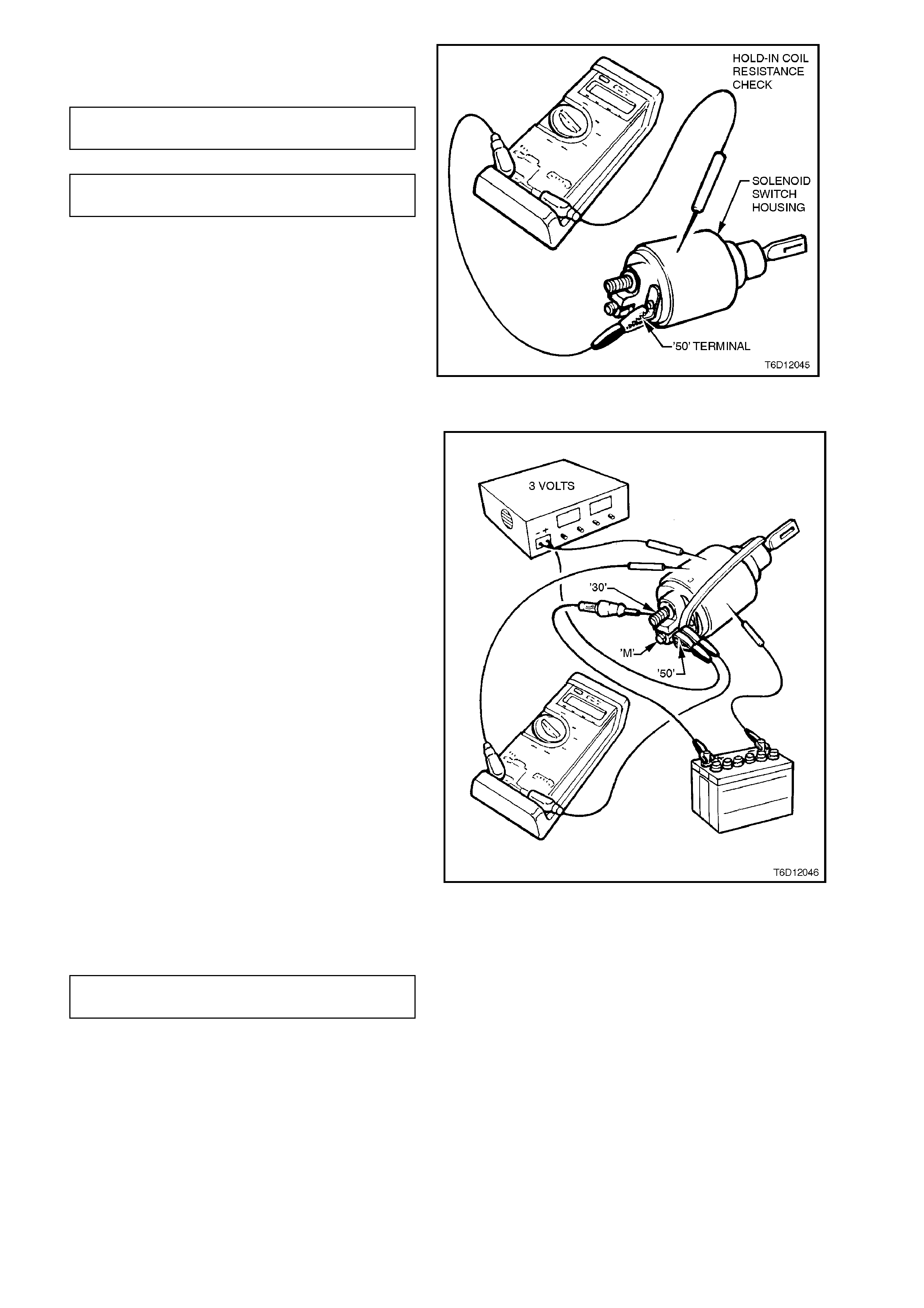
HOLD-IN WINDING AND SOLENOID
RESISTANCE SWITCH
HOUSING
Figure 6D2-2-34
Check the solenoid switch windings dc resistances
using an ohmmeter acr os s the ter minals nominated
in the following chart.
Figure 6D2-2-35
Replace solenoid switch if resistance readings are
not to specification
PULL-IN WINDING 0.248 - 0.281 Ohms
RESISTANCE @ 20° C
HOLD-IN WINDING 1.16 - 1.30 Ohms
RESISTANCE @ 20° C
Figure 6D2-2-36
TESTING 'PULL-IN' AND 'HOLD-IN' VOLTAGES
During the following solenoid switch 'pull-in' and
'hold-in' checks, the solenoid switch must be held
vertically, i.e. with the plunger uppermost. It is
recommended that a rubber band be fitted around
the plunger and solenoid switch housing to prevent
the plunger from flinging out during testing.
Using a power supply capable of supplying 30
amps, set the voltage to 3.0 volts. A battery and a
variable resistor may also be used.
Connect the solenoid to the power supply as shown
in Fig. 6D1-2-37.
Connect a 12 volt test lamp between solenoid
switch terminal '30' and +12 volt supply. Also,
connect a voltmeter between solenoid switch
terminal 50 and earth.
Fully press in solenoid plunger until test lamp
illuminates. Allow the plunger to spring out by
approximately 8 - 10 mm and hold in this position.
NOTE:
The test duration for the following 'pull-in' voltage
check should be no more than two seconds.
Slowly increase the voltage on terminal '50' until the
plunger pulls in, noting the voltmeter r eading. At the
same time, the test lamp must be fully illuminated
(check of solenoid switch main contact continuity)
Voltage reading should be as specified in the
following chart.
PULL-IN VOLTAGE TEST 3.0 - 6.5
SPECIFICATION VOLTS
Figure 6D2-2-37
Set the power supply to 12 volts and connect the
positive lead to solenoid switch terminal '50'.
Connect the negative lead to the solenoid switch
housing. Press the plunger in f ully. It should r em ain
held in by the solenoid's hold-in winding.
Decrease the voltage until the winding will no
longer hold the plunger, noting the voltmeter
reading.
Voltage reading should be as specified in the
following chart.
HOLD-IN VOLTAGE TEST 0.2 - 2.0
SPECIFICATION VOLTS
Press the plunger until the solenoid switch contac ts
close (indicated by test lamp illuminating).
It should be possible to depress the plunger into the
solenoid switch housing a further 1 mm or more. If
less than 1 mm is achieved, the solenoid switch
must be replaced.
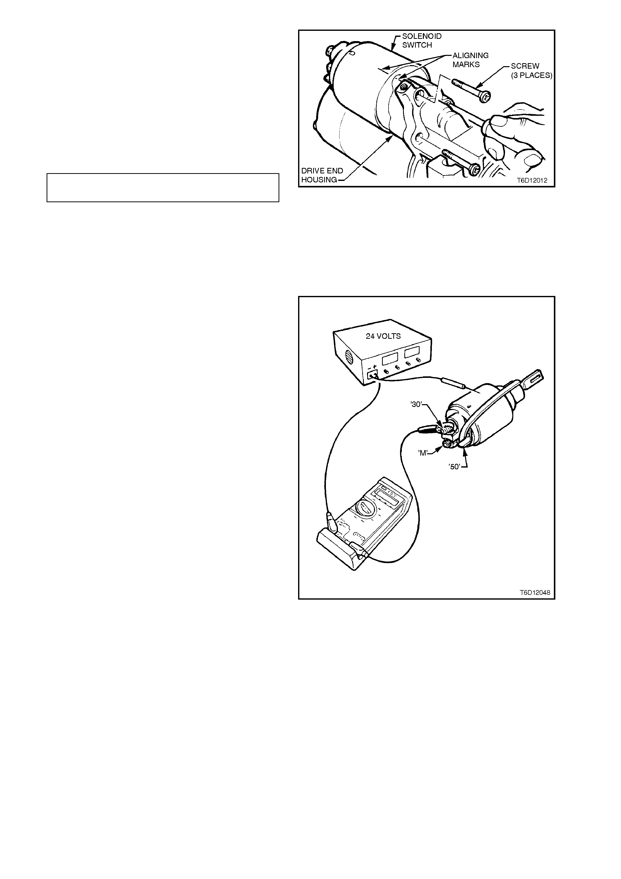
Figure 6D2-2-38
A 24 volt supply is required for this test.
Attach positive supply lead to solenoid switch
terminal '30' (main battery supply input) and
negative lead to solenoid switch housing.
Press the plunger in fully and then release. The
plunger should return to its rest position by the
action of the return spring. If it does not, the
windings have inter-winding short circuits.
W hen the solenoid s witch is connected in this way,
the windings are differentially compounded, that is
their fields are in opposition to each other.
At end of solenoid switch testing, remove rubber
band retaining the plunger and return spring in the
solenoid switch housing.
Figure 6D2-2-39

REASSEMBLE
Reassembly is the reverse of the disassembly
procedure, note the following points:
1. Lubricate drive end, pinion and commutator
end bushes with clean engine oil.
2. Lightly coat armature shaft bearing surfaces
and helical splines, drive assembly internal
helical splines and engaging fork contact
surfaces with Molybdenum Disulphide grease
(Holden Specification HN 1271 or equivalent).
3. Install the pinion and stop ring onto the
armature shaft, then secure the spring clip in
the groove, using a pair of Circlip pliers.
4. Secure armature in a soft jaw vice, turn drive
assembly up to stop ring. Using multi-grips
and a suitable insulator on the pinion gear
teeth, continue to turn drive assembly until
stop ring locks over spring clip.
5. Adjust armature end play to specification
using shim/s between commutator end cover
and Circlip on armature shaft.
ARMATURE END PLAY
SPECIFICATION 0.05 - 0.30
mm
6. If necessary, tighten field coil pole screws to
the correct torque specification.
POLE SHOE SCREWS
TORQUE SPECIFICATION 30 - 60
Nm
7. With the starter motor reassembled, a NO
LOAD test should be conducted, refer to
2.2 NO LOAD TEST in this Section.
Failure of the starter motor to perform
according to the NO LOAD specification may
be due to tight or dirty bushes or high
resistance connections. Rectify any faults
found.
8. After starter motor has been r eassem bled and
tested, all external joints, i.e. solenoid to drive
end housing and commutator end cover to
field coil housing, s hould be painted. This is to
ensure correct sealing of the starter motor
assembly.

3. DIAGNOSIS
Many starting problems can be categorised within the following classifications:
1. The starter motor will not crank the engine.
2. The engine will crank at normal speed, but will not start.
3. The starter cranks the engine very slowly.
If the engine is cranked over by the starter motor at the normal speed, but will not start, the problem is in the ignition
system, fuel system or engine, rather than a fault in the starting system.
Before removing the starter motor, when investigating a starting problem, follow the procedures outlined in the
accompanying diagnostic charts.
SYMPTOM PROBABLE FAULT
A. Speed, torque and current low. A. High resistance in motor. Check field to
terminal connection, condition of
brushes and their connections and
check for dirty brushes or burnt
commutator.
B. Speed and torque low, current high. B. Tight or worn bearings, bent armature
shaft, insufficient end play, armature
fouling pole shoe, short-circuited
armature, earthed armature or field coil.
C. Speed and current high, torque low. C. Short circuited windings in field coil.
D. Armature does not rotate. No current. D. Open circuited armature, field coils or
solenoid. If commutator is badly burned,
there may be poor contact between
brushes and commutator, owing to
excessively worn or sticking brushes.
E. Armature does not rotate. High current. E. Earthed field winding or open-circuited
solenoid. Armature physically prevented
from rotating.
F. Excessive brush movement causing
arcing at commutator. F. Low brush spring tension, worn or out-
of-round commutator, 'thrown' or high
segment on commutator, or insulation
protruding between segments.
G. Excessive arcing at commutator. G. Defective armature windings, sticking
brushes or dirty commutator.
H. Armature rotates but pinion does not
mesh with ring gear. H. Pinion bearing fouled, burred, damaged
ring gear or broken pinion teeth.

NO CRANKING, NO SOUND FROM SOLENOID:
STEP ACTION RESULT YES NO
1. • Turn Headlamps and
Dome lamps On, Turn
Ignition to Start
Position.
Lamps
Dim Go to Step 2 Go to Step 3
2. • Check battery
• Charge battery
• Check generator
• Check cranking
voltage at battery posts
• Check current draw
Is 9.6
volts
present
Go to Step 7 Test battery.
If OK repair
Starter
3. • Turn on radio Operate
OK Go to Step 4 Go to Step 6
4. • Check voltage at
Solenoid Switch
terminal ‘50’.
Is 7.0
volts
present
Repair Starter Go to Step 5
5. • With Key in Start
Position, Check at
Ignition terminal ‘50’.
Is 7.0
volts
present
Repair wiring
Ignition Switch
Starter Motor
Replace Ignition
Switch
6. • Check engine main
wiring harness fusible
link and ignition
connections
7. • Check voltage from
engine block to Neg.
post. Key in start
position. (Pos. lead on
block)
Is 0.5
volts or
more
present
Clean and tighten
negative cable
conn. And/or
replace cable
Go to Step 8
8. • Check cranking
voltage at starter “B”
terminal
Is 9.0
volts
present
Check fuse and
engine to M.W.H.
connectors
Clean and tighten
positive cable
conn. And/or
replace cable

SLOW CRANKING, SOLENOID CLICKS OR CHATTERS:
Check : Battery state of charge. Refer to Section 12A BATTERY A ND CABLES.
Visual condition of battery cables and connections.
If battery needs charging, carry out generator and battery drain check, charge battery and recheck cranking. If
trouble has not been found proceed.
Remove engine fuse link from engine compartment fuse housing. This prevents fuel injection and ignition during
engine cranking. Make all voltmeter readings with ignition key in start position.
STEP ACTION RESULT YES NO
1. • Measure cranking
voltage at battery
terminal posts
Is 9.6
volts or
more
present
Go to Step 2 Go to Step 3
2. • Measure voltage from
battery negative
terminal to engine
block. (positive lead on
block)
Is 0.5
volts or
more
present
Repair negative
cable and
connections
Go to Step 4
3. • Charge and load test
battery Is battery
OK Repair Starter Replace battery
4. • Measure voltage at
solenoid switch ‘30’
(B+) terminal, clean
and tighten
connections at starter
Is 9.0
volts or
more
present.
Repair starter Go to Step 5
5. • Clean and tighten
positive cable
connections.
• If OK replace cable
This procedure is designed for use on engines and batteries at room temperature or normal operating
temperatures. It also assumes there are no engine defects which could cause cranking problems. To use it under
other conditions might result in misdiagnosis.

4. SPECIFICATIONS
Type Bosch. Four pole, four brush
Rotation (drive end view) Clockwise
Number of pinion teeth 9
No load test: Maximum current 70 amps or less at 12 Volts
6500 rpm or greater
Lock test: Maximum current
(including solenoid) 525 amps
Volts 7 volts
Torque 23 Nm or greater
Solenoid Test Solenoid detached
from starter motor: Pull in voltage 8 volts or less @ 20°C
Spring out voltage 0.4 - 0.5 volts
Armature end play 0.05 - 0.30 mm
Commutator: Maximum
permissible out-of-
round
0.05 mm
Minimum diameter 33.5 mm
Depth of undercut 0.7 mm
Brushes: Minimum length 13 mm
Spring tension 15 - 17 N
Lubricant Molybdenum Disulphide
Holden Specification HN 1416

5. TORQUE WRENCH SPECIFI CATIONS
Nm
Through bolts 6.6 - 9.6
Pole screws 30 - 60
Solenoid attaching bolts 4.5 - 6.0
'B+' terminal nut 5 - 12
'50' terminal nut 6.0 - 8.0
Starter motor to cylinder block mounting bolts 40 - 60
Starter motor to cylinder block brace bolt 12 - 16
Engine pipe to exhaust manifold attaching bolts 15 - 35
Steering gear to front cross member mounting
nuts 50 - 85
Engine pipe assembly to catalytic converter
attaching nuts 30 - 50