
SECTION 6D2-3 IGNITION SYSTEM - V8 ENGINE
CAUTION:
This vehicle is equipped with a Supplemental Restraint System (SRS). A SRS will
consist of either seat belt pre-tensio ners and a driver’s side air bag, o r seat belt pre-
tensioners and a driver’s and front passenger’s side air bags. Refer to CAUTIONS,
Section 12M, before performing any service operation on or around SRS
components, the steering mechanism or wiring. Failure to follow the CAUTIONS
could result in SRS deployment, resu lting in possible perso nal in jury or u nnecessary
SRS system repairs.
1. GENERAL DESCRIPTI ON
Ignition timing is controlled by the PCM (Powertrain Control Module) for vehicles fitted with either automatic
transmission or manual transmission as described in Section 6C2 POWERTRAIN MANAGEMENT - V8 ENGINE.
In addition to the PCM, the major components of the ignition system are:
Distributor Assembly
Ignition Trigger Module
Ignition Coil and Bracket
Spark Plugs and Leads
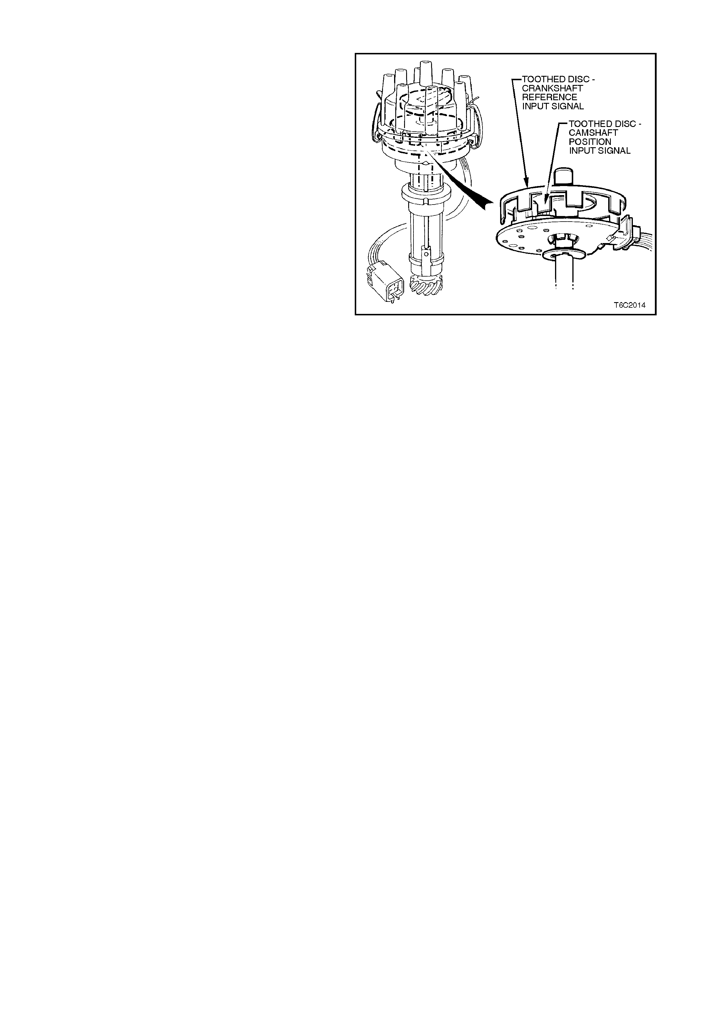
DISTRIBUTOR ASSEMBLY
The distributor performs the normal distributor function of directing ignition voltage to the appropriate cylinder by
means of a rotor, distributor cap, spark plug leads, etc. The distributor incorporates two Hall effect sensors (stator)
and rotor. One sensor is used to provide a crankshaft reference input signal, while the other sensor provides a
camshaft position input signal. The Hall effect sensor is connected by three leads to the ignition trigger module,
which in turn provides a distributor reference input to the PCM. In addition a single lead connected to the PCM
provides a camshaft position input signal, (refer to Section 6C2 POWERTRAIN MANAGEMENT - V8 ENGINE).
IGNITION TRIGGER MODULE
The ignition trigger module provides for an interface between the Hall effect crank angle sensor, the PCM and the
ignition coil.
The ignition trigger module performs three functions. It takes the signal from the distributor Hall effect crank angle
sensor and processes it into a form that is suitable for the PCM. The PCM uses these reference pulses to calculate
engine position and engine rpm.
Under normal running conditions, the PCM supplies an EST signal to the ignition trigger module that allows it to turn
the primary winding of the ignition coil on and off. This gives the PCM control of the spark timing when the by-pass
line from the PCM is high. For details, refer to Section 6C2 POWERTRAIN MANAGEMENT -V8 ENGINE.
During engine cranking, and if there is a PCM failure, the ignition trigger module directly controls the switching of the
coil primary in response to the distributor Hall effect crank angle sensor pulses. This gives a fixed 10 degrees
B.T.D.C. ignition timing.
IGNITION COIL
The ignition coil is specifically designed to suit the electronic control module and medium energy ignition sy stem.
Therefore the coil must not be replaced with any other type of coil.
SPARK PLUGS AND LEADS
The spark plug wiring used with the ignition system is a carbon impregnated core conductor encased in an 8 mm
diameter silicone rubber jacket. As a safeguard against subjecting the catalytic converter to unburned fuel due to
misfiring, the spark plug leads incorporate shielding where necessary to prevent contact with other components and
heat shielding on specific cylinders. It is therefore important that lead routing is correct.
Techline
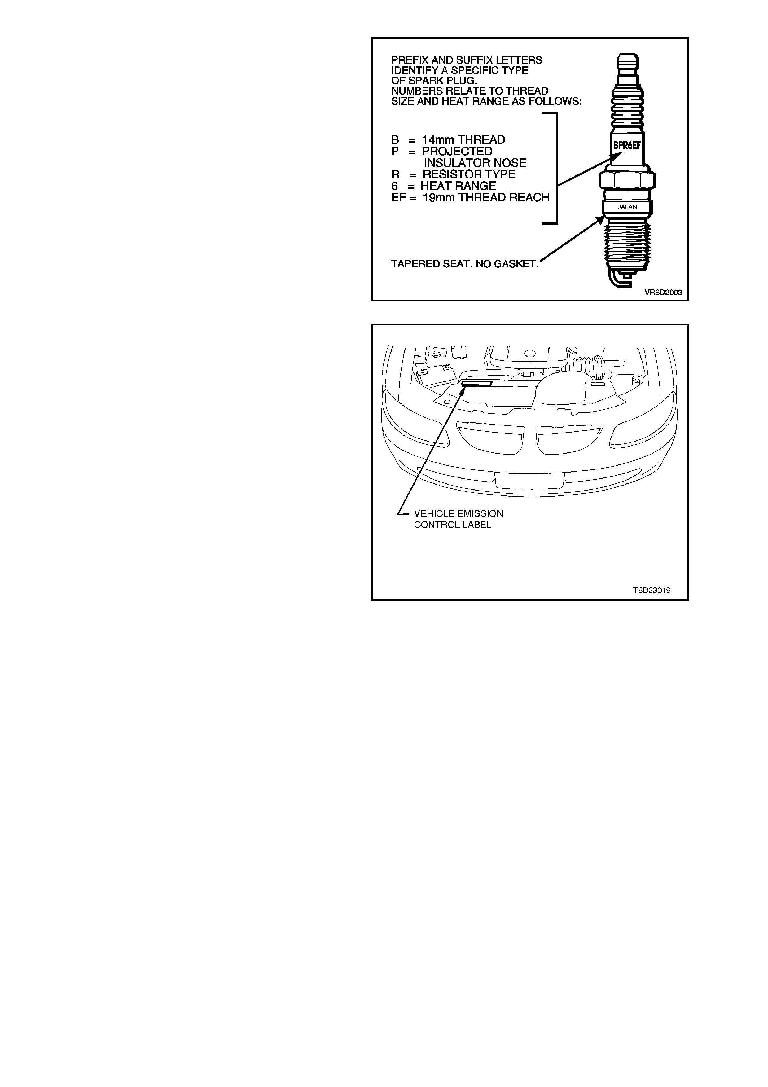
Resistor type, copper cored, tapered seat spark
plugs are used in the V8 engine. No gasket is used
on these tapered seat plugs.
Figure 6D2-3-1 illustrates and explains the spark
plug letter coding.
Always replace the spark plugs with the correct
plug listed on the Vehicle Emission Control
Information Label. The label also lists the correct
spark plug gap.
Centre electrode resistance is 3 - 7.5 kW @ 20°C.
Figure 6D2-3-1
Vehicle Emission Control Information Label is
located on the left hand side of the radiator shroud.
Figure 6D2-3-2
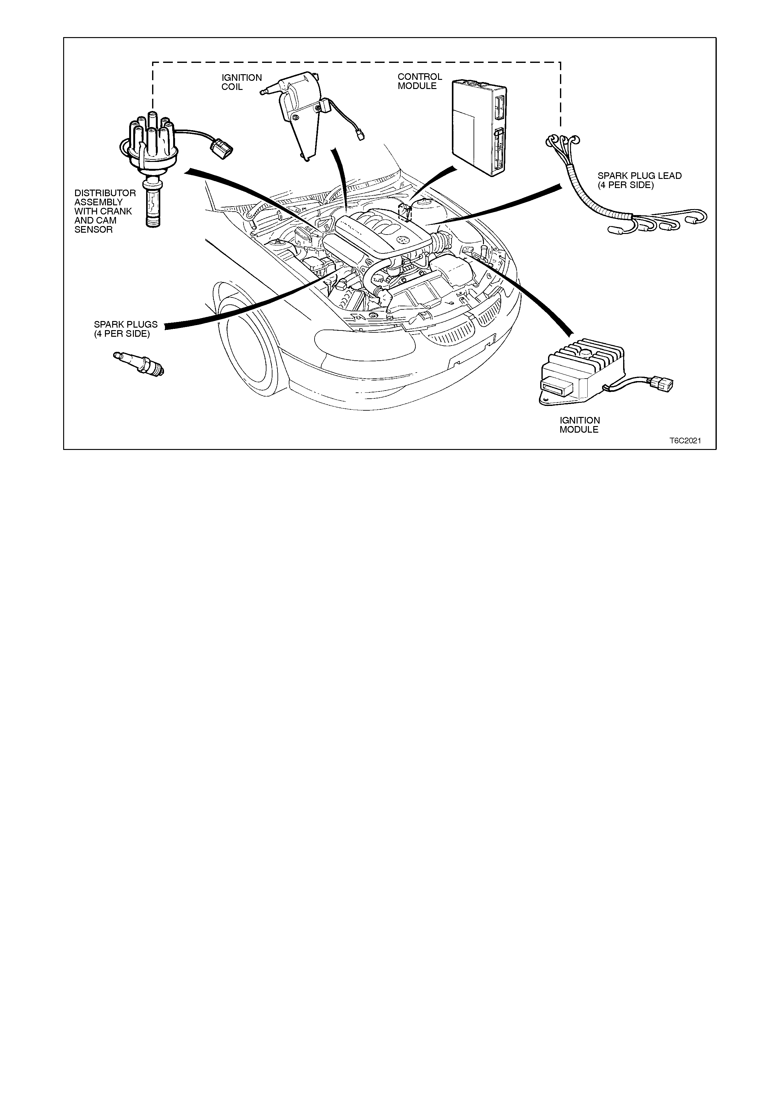
Figure 6D2-3-3
1.1 GENERAL INFORMATION
Under normal operating conditions only the spark plugs require regular maintenance or replacement (refer to
2.6 SPARK PLUGS in this Section), the PCM and ignition trigger module cannot be adjusted or repaired for service
(refer to Section 6C2 POWERTRAIN MANAGEMENT - V8 ENGINE).
The ignition timing cannot be altered by mechanical influences other than, distributor removal or inadequate clamp
torque, and therefore it is not necessary to perform any periodical adjustment.
The Hall effect sensors have no contact or wear parts, and no adjustment can be performed on the internal
distributor components.
Before commencing work on the ignition system, to avoid the possibility of personal injury occurring due to electrical
shock, refer to 1.2 GENERAL PRECAUTIONS in this Section.
1.2 GENERAL PRECAUTIONS
The ignition system can produce high voltages in
the primary and secondary circuit which may be
dangerous. Ensure that all work is carried out with
care.
Do not disconnect the spark plug leads from the
spark plugs while the engine is operating, as
damage to the ignition trigger module and
associated circuits may result. To avoid possible
personal injury, do not touch any ignition system
components while the ignition is switched ON or
the engine is operating.
Do not touch the transistor on top of the ignition
module while the engine is operating, as an
electrical shock will result.
Before removing or refitting any parts or electrical
connections, ensure that ignition system is
switched OFF.
Never separate the battery from the on board
electrical system while the engine is operating.
Ensure that all cable harness plugs are properly
connected and that battery terminals are clean.
Never connect or disconnect cable harness plugs
at the PCM when the ignition is switched ON.
When arc (or any other electric fusion) welding on
the vehicle, first disconnect both battery cables and
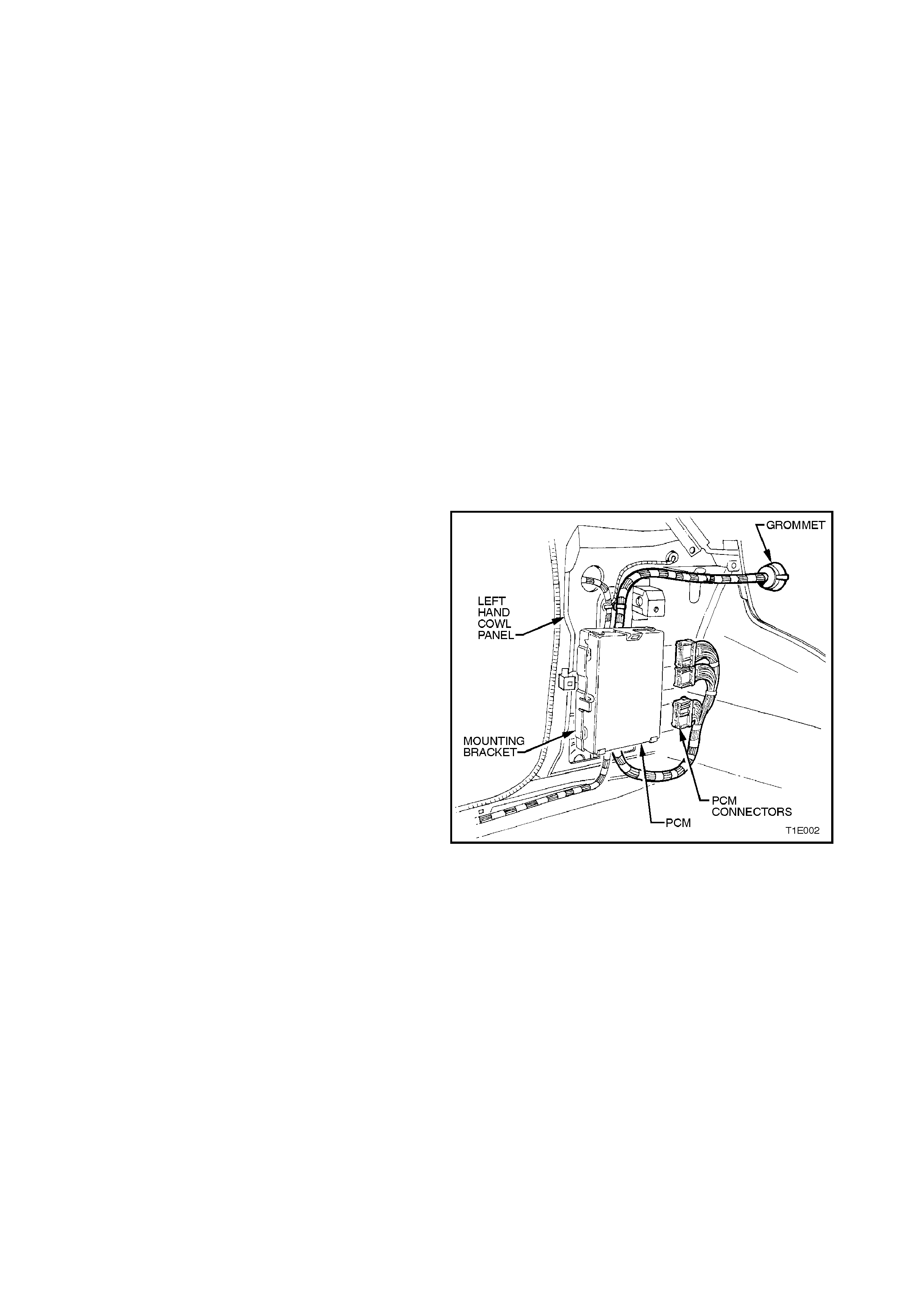
the PCM harness at the PCM connector. Locate
powertrain control module in the passenger footwell.
Remove passenger side shroud lower trim
assembly, refer to Section 1A2 BODY
DIMENSIONS.
When steam cleaning the engine, do not direct the
nozzle at any ignition system component.
Use only test equipment suitable for use with
electronic ignition systems, since other test
equipment may give incorrect results, or damage
components.
When using test equipment tachometers which
connect to the primary ignition circuit, first
disconnect the brown tachometer lead (on vehicles
fitted with tachometer) from the engine harness.
Connect the test equipment, using an appropriate
terminal connector with suitable insulation. This is to
protect the operator from possible contact with the
high voltage produced in the primary ignition circuit,
and to avoid the accidental grounding of the positive
ignition coil terminal, which may result in damage
occurring to the ignition trigger module.
Disconnect both cables from the battery when
recharging, as some battery charging equipment
produces TRANSIENT VOLTAGE that may damage
the PCM.
Figure 6D2-3-4
2. SERVICE OPERATIONS
2.1 IGNITION TRIGGER MODULE
REMOVE
1. Ensure the ignition switch is in the OFF
position.
2. Disconnect the battery earth cable at battery .
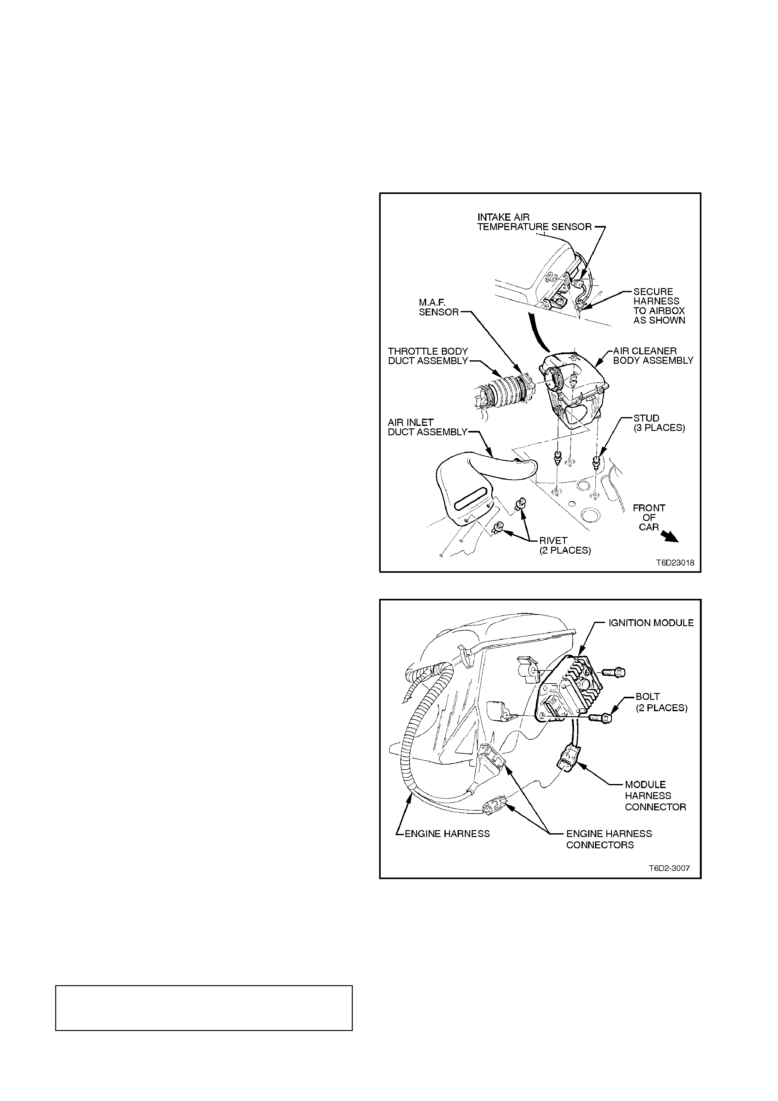
3. Remove harness to air temperature sensor
mounted on air cleaner cover.
4. Undo retaining clips and remove M.A.F. sensor
from air cleaner.
CAUTION:
The M.A.F. sensor is fragile and should be
treated with extreme care.
5. Unfasten two scrivets and remove air inlet duct
assembly.
6. Firm ly grip air cleaner base and pull upwards to
release base from mounting studs.
Figure 6D2-3-5
8. Compress locking tang on engine harness to
module harness connector, separate
connectors.
On engine harness connector to module
assem bly housing connector, use a fine bladed
screwdriver, lever out wire retainer from engine
harness connector and pull connector from
module.
9. Remove two bolts and nuts securing m odule to
fender inner panel, remove module.
Figure 6D2-3-6
REINSTALL
Reinstallation of the module is the reverse of
rem oval procedures . Tighten m odule retaining nuts
to the correct torque specification.
IGNITION MODULE
RETAINING NUT
TORQUE SPECIFICATION 3.0 - 8.0 Nm
2.2 IGNITION COIL ASSEMBLY
REMOVE
1. Ensure the ignition switch is in the OFF
position.
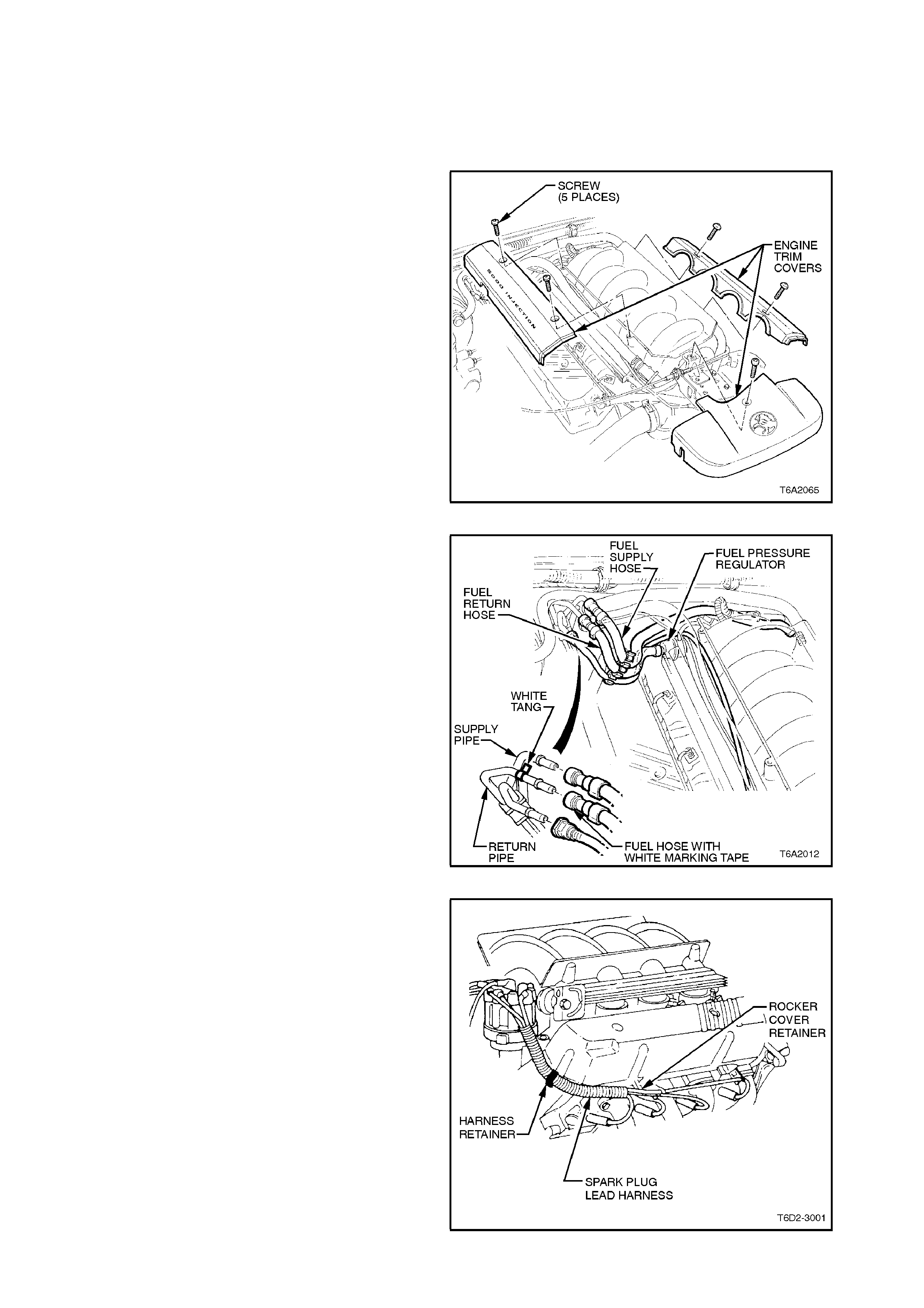
2. Disconnect battery earth cable at battery.
3. Remove bolts securing engine trim covers to
inlet manifold, remove covers.
Figure 6D2-3-7
4. Depressurise fuel system, refer to
Section 6C2 POWERTRAIN M ANAGEMENT -
V8 ENGINE.
Remove fuel pressure (supply) line from fuel
damper connection.
Figure 6D2-3-8
5. Disconnect spark plug leads from spark plugs
and rocker cover retainers.
Open spark plug lead harness retainers at
end of each cylinder head.
Figure 6D2-3-9
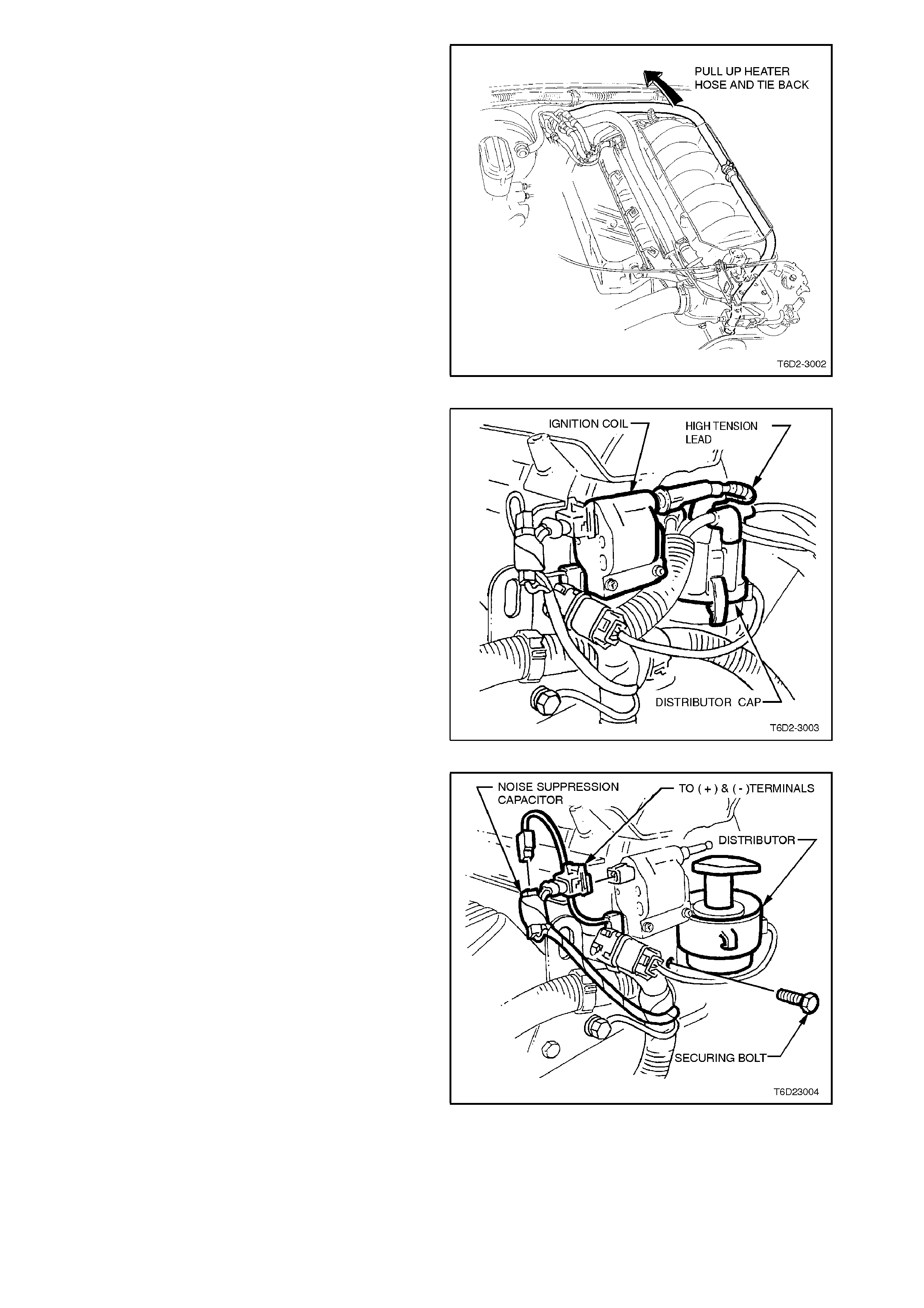
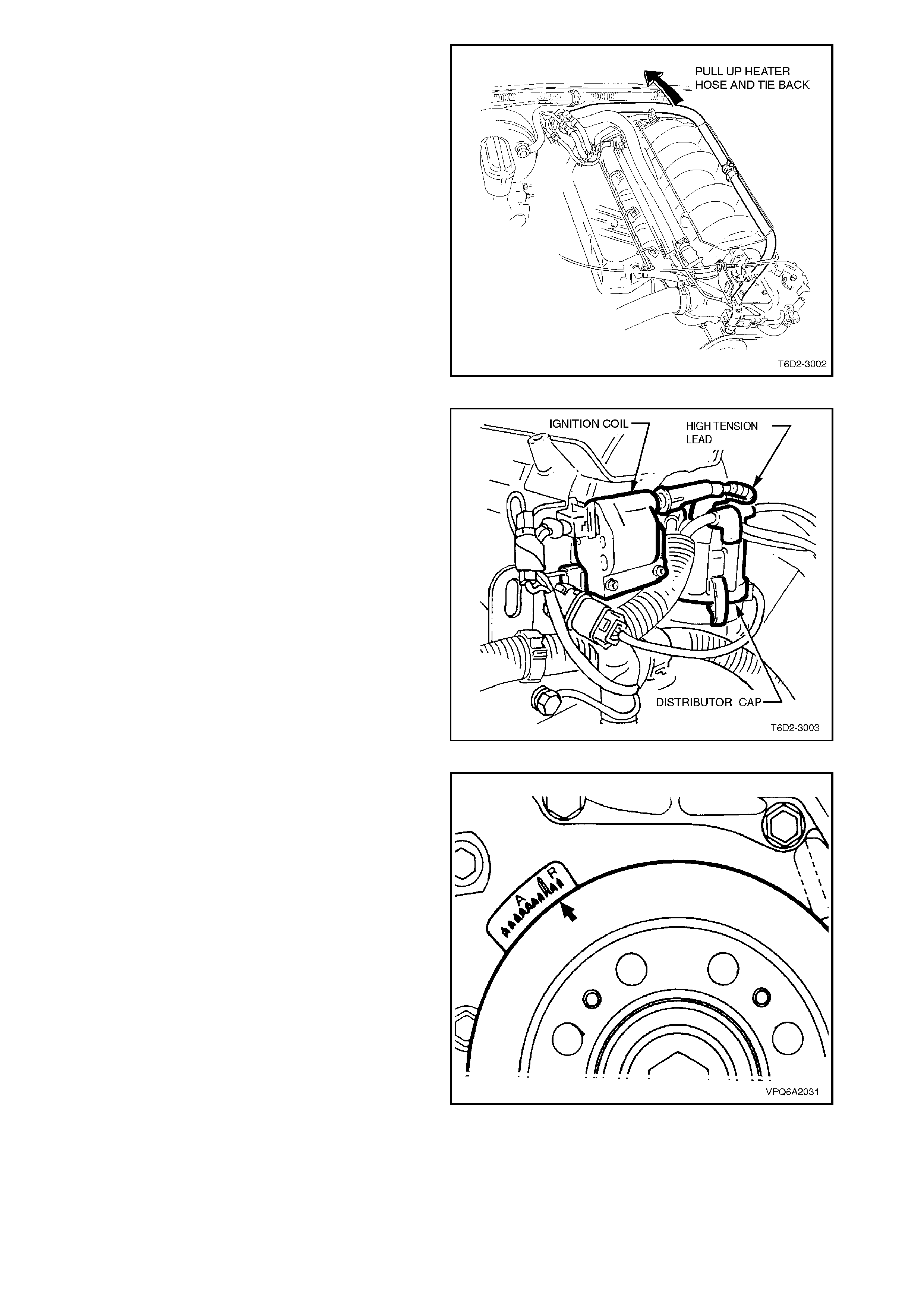
6. To improve accessibility, pull up left hand
heater hose over inlet manifold, and tie back.
Figure 6D2-3-10
7. Remove high tension lead from coil terminal.
8. Push back distributor cap retaining clips,
remove distributor cap and leads.
Figure 6D2-3-11
9. Disconnect the engine harness leads from the
ignition coil.
10. Remove bolt securing ignition coil to manifold,
and remove ignition coil from engine.
Figure 6D2-3-12

REINSTALL
Reinstallation of the coil assem bly is the rever se of
the removal procedures, noting the following
points:
1. Tighten coil retaining bolt to specification.
IGNITION COIL TO CYLINDER
BLOCK RETAINING BOLT
TORQUE SPECIFICATION 17 - 23 Nm
Ensure that spark plug leads are correctly routed
refer to 2.6 SPARK PLUG LEADS.
Pressurise fuel system, refer to Section 6C2
POWERTRAIN MANAGEMENT - V8 ENGINE.
Check for leaks, repair as necessary.
INSPECT AND TEST
NOTE:
Due to installed location, it is advised that coil
assembly be removed for testing purposes as
previously described.
1. Inspect the coil for any signs of external
damage. If damaged, replace coil assembly.
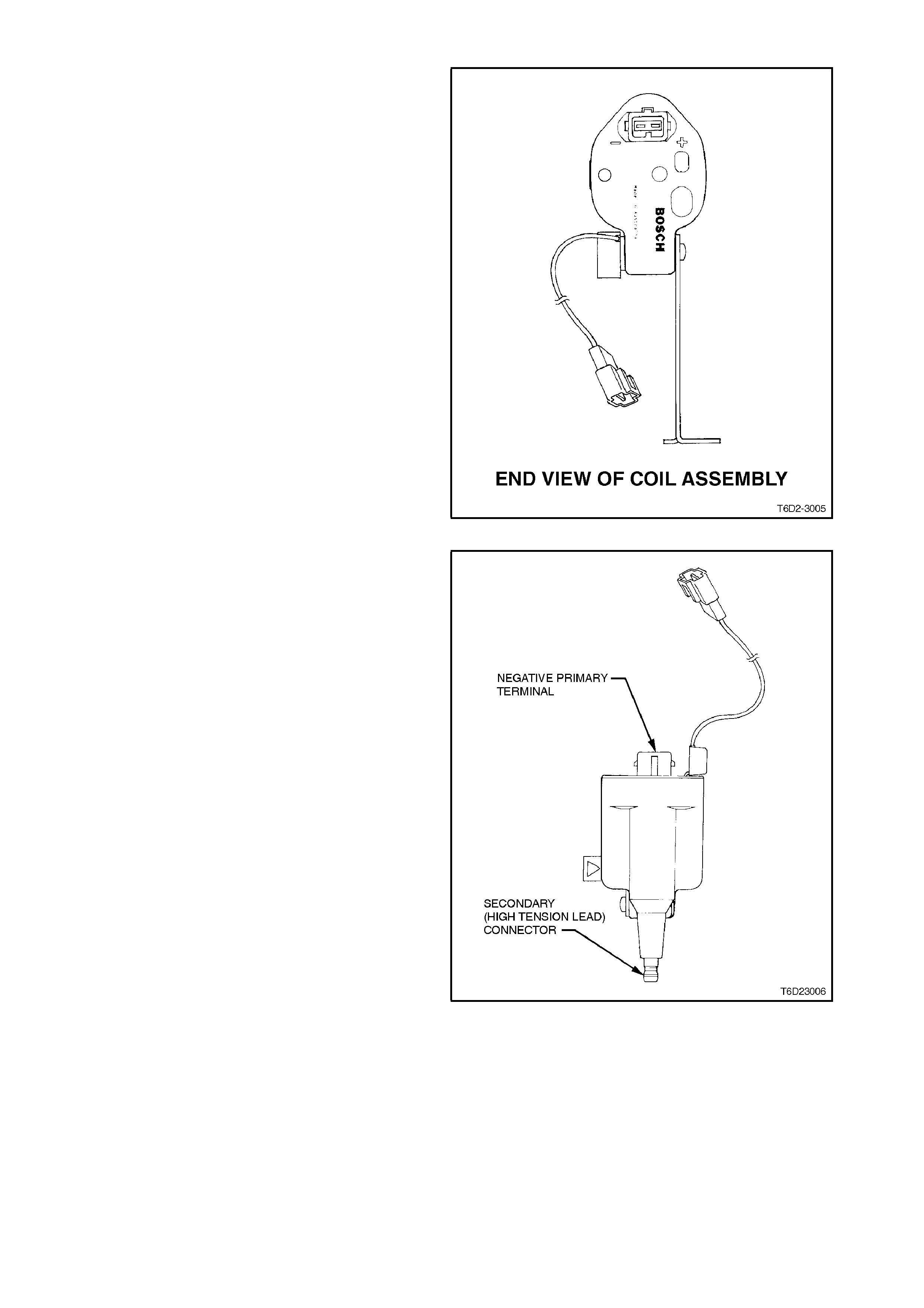
2. Connect an ohmmeter across the positive (+)
and negative (-) terminals of the coil. The
resistance across the primary windings should
be 0.42 - 0.47 ohms @ 20 - 30°C.
Figure 6D2-3-13
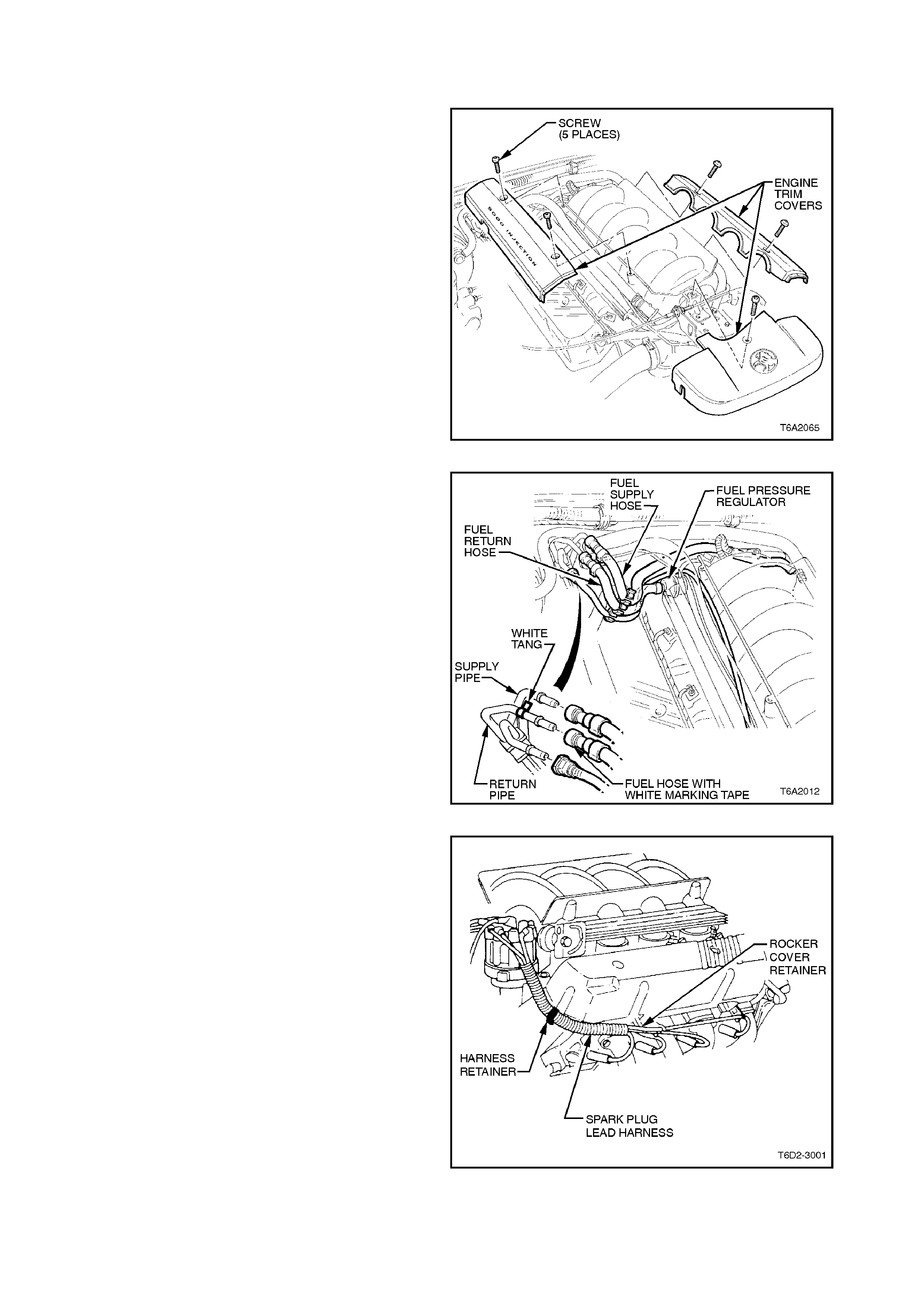
4. Connect the ohmmeter across the negative (-)
primary terminal and the secondary (high
tension lead) connector. The resistance across
the secondary windings should be 5940 - 7260
ohms @ 20 - 30°C.
5. Discard coil if out of specification.
Figure 6D2-3-14
2.3 DISTRIBUTOR
REMOVE
1. Depressurise fuel system, refer to
Section 6C2 POWERTRAIN M ANAGEMENT -
V8 ENGINE.
2. Disconnect battery earth lead.
3. Remove bolts securing engine trim covers to
inlet manifold, remove covers.
Figure 6D2-3-15
4. Remove fuel pressure (supply) line from fuel
rail connection.
Figure 6D2-3-16
5. Disconnect spark plug leads from spark plugs
and rocker cover retainers.
Open spark plug lead harness retainers at end
of each cylinder head.
Figure 6D2-3-17
6. To improve accessibility, pull up left hand
heater hose over inlet manifold, and tie back.
Figure 6D2-3-18
7. Remove high tension lead from coil terminal.
8. Disconnect wiring harness connector from
distributor.
9. Push back distributor cap retaining clips,
remove distributor cap and leads.
Figure 6D2-3-19
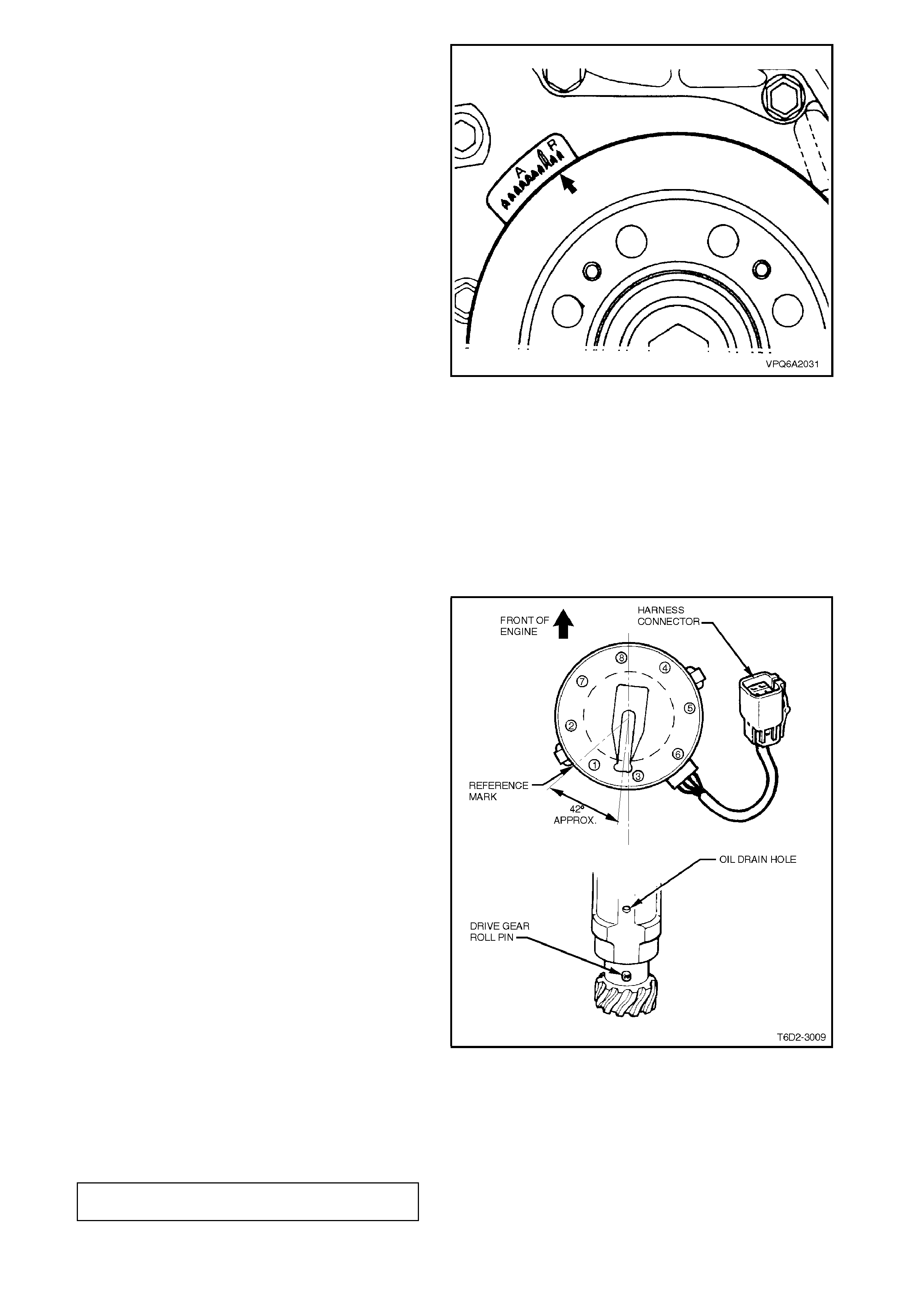
10. Using a suitable size socket and bar on
crankshaft torsional damper retaining bolt,
rotate crankshaft until distributor rotor is in
number one cylinder position and timing mark
on torsional damper is aligned at T.D.C.
position.
Figure 6D2-3-20
11. Remove distributor rotor button.
12. Using a suitable size 'crows foot' socket and
bar, remove distributor clamp securing bolt,
remove retainer and clamp.
13. Remove distributor and discard sealing gasket.
NOTE:
Do not rotate the crank shaft af ter the distributor has
been removed.
Figure 6D2-3-21
REINSTALL
Reinstallation of the distributor, cap and leads is
the reverse of removal procedures, noting the
following points:
1. The timing mark on torsional damper should
be at T.D.C. position, and both valves on
number one cylinder should be closed. If
necessary, rotate crankshaft to achieve
correct timing.
2. Install rotor button and align with number one
cylinder reference mark. Rotate rotor button
counter clockwise approximately 42 degrees
until drive gear roll pin is aligned with oil drain
hole in distributor body, refer Fig 6D2-3-22.
3. Remove rotor button, maintaining alignment
described in step 2.
4. Install distributor into cylinder block.
NOTE:
The distributor shaft will rotate during installation as
the helical gears mesh.
5. Install distributor clamp, retainer and securing
bolt. Leave bolt finger tight.
6. Check to ensure that rotor button is pointing to
number one reference mark and tighten clamp
securing bolt.
7. Ensure that engine harness connector is
correctly installed into distributor connector.
8. Ensure that spark plugs leads are correctly
routed, refer to 2.6 SPARK PLUG LEADS in
this Section.
9. Pressurise fuel system, refer to Section 6C2
POWERTRAIN MANAGEMENT - V8 ENGINE.
Check for leaks. Repair as necessary. Figure 6D2-3-22
10. Check and set ignition timing as necessary,
refer to 2.4 IGNITION TIMING in this Section.
11. Tighten distributor clamp bolt to the correct
torque specification.
DISTRIBUTOR CLAMP BOLT
TORQUE SPECIFICATION 20 - 27
Nm
TEST
NOTE:
Perform the distributor hall effect sensor tests with
the distributor assembled.
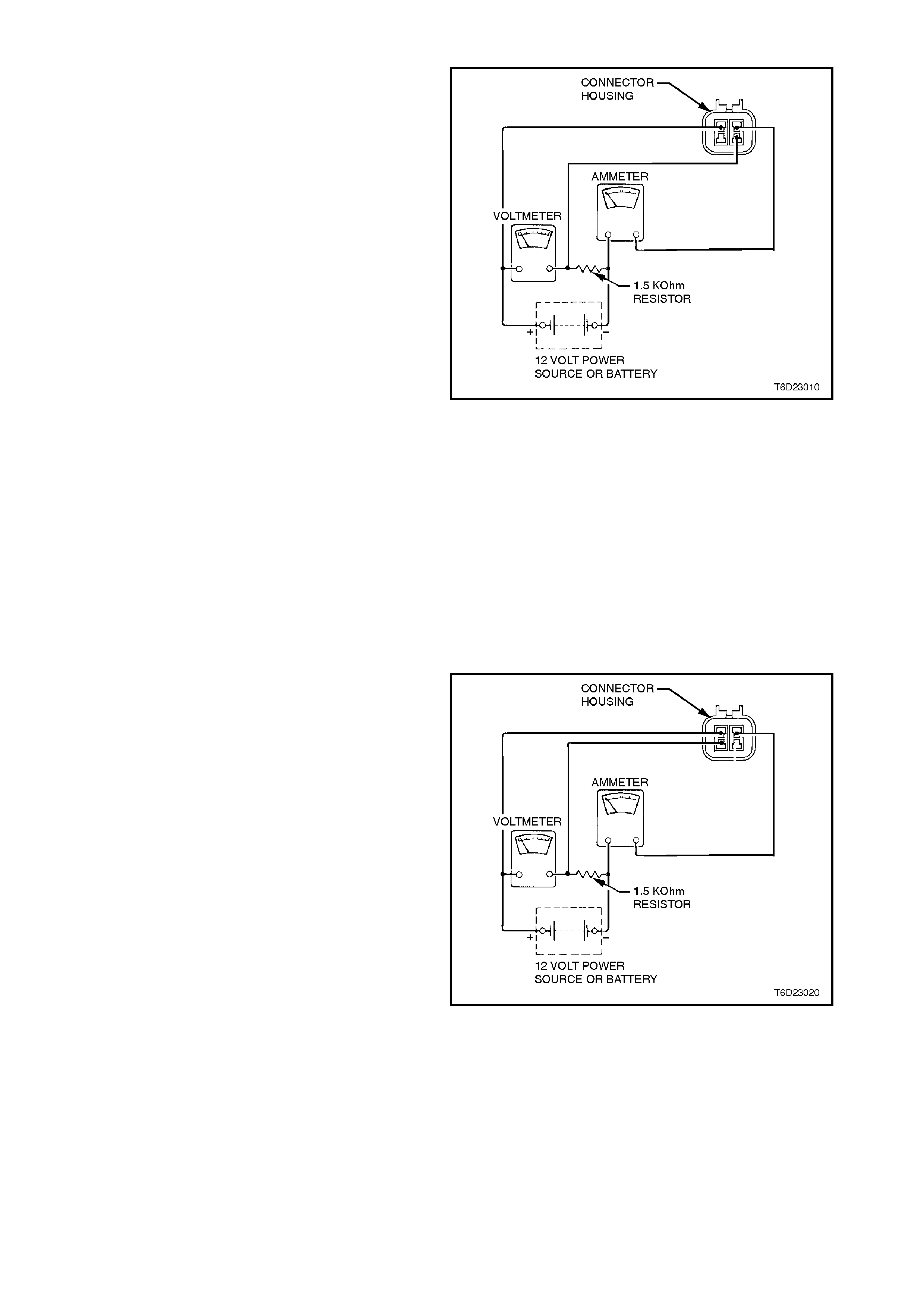
Crankshaft reference input sensor
1. Rotate the distributor shaft until a trigger vane
of toothed disc is outside the Hall effect sensor
air gap.
2. Connect the positive side of a regulated 12 volt
power source to an am meter, then connect the
ammeter to the upper right terminal on the
distributor connector.
3. Connect the negative side of the power source
to a voltmeter, then c onnect the positive side of
the voltmeter to the lower right terminal on the
distributor connector.
4. Connect a 1.5 K ohm resistor between the
positive side of the voltmeter and the ammeter
(refer to Figure 6D2-3-23).
5. Connect the upper left distributor terminal to the
negative side of the power source.
6. The voltmeter should indicate 0.4 volts (400
mV) , or less , and the ammeter s hould r ead les s
than 20 mA (at 24°C.).
7. Rotate the distributor shaft until any trigger
vane is within the Hall effect sensor air gap.
8. With the trigger vane within the air gap the
voltmeter should indicate 11.0 volts and the
ammeter should read less than 20 mA (at
24°C).
9. Replace any Hall effect sensor assemblies
damaged or out of specification.
Figure 6D2-3-23
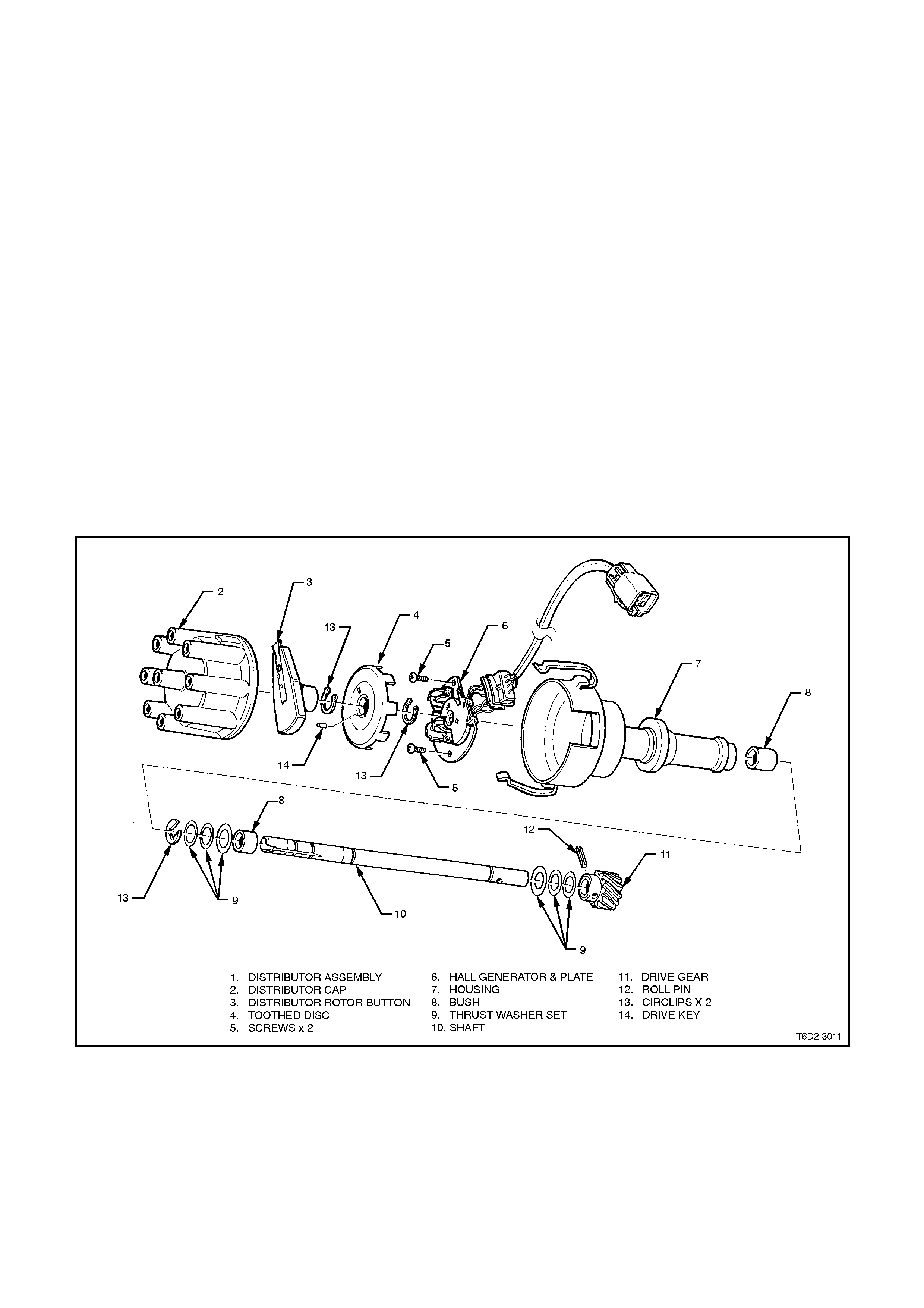
Camshaft position input sensor
1. Rotate the distributor shaft until the trigger vane
of the disc is outside the Hall effect sensor air
gap.
2. Connect the positive side of a regulated 12 volt
power source to an am meter, then connect the
ammeter to the upper right terminal on the
distributor connector.
3. Connect the negative side of the power source
to a voltmeter, then c onnect the positive side of
the voltmeter to the lower left terminal on the
distributor connector.
4. Connect a 1.5 K ohm resistor between the
positive side of the voltmeter and the ammeter
(refer to Figure 6D2-3-23).
5. Connect the upper left distributor terminal to the
negative side of the power source.
6. The voltmeter should indicate 0.4 volts (400
mV) , or less , and the ammeter s hould r ead les s
than 20 mA (at 24°C.). Figure 6D2-3-24
7. Rotate the distributor shaft until the trigger
vane is within the Hall effect sensor air gap.
8. With the trigger vane within the air gap the
voltmeter should indicate 11.0 volts and the
ammeter should read less than 20 mA (at
24°C).
9. Replace any Hall effect sensor assemblies
damaged or out of specification.
DISASSEMBLE
1. Remove distributor cap.
2. Remove the distributor rotor button.
3. Separate distributor harness connector.
4. Remove two screws securing the Hall effect
sensor plate.
5. Slide harness block from distributor body.
6. Support the drive gear in a wooden 'V' block,
then drive out the roll pin, using a suitable pin
punch and hammer. Remove the drive gear
and thrust washer set.
7. Push shaft from housing by applying a light
force at drive shaft end.
8. Remove Circlips from shaft, using Circlip
pliers.
9. Remove the plastic bush and Hall effect
sensor plate from shaft.
10. Drive the toothed disc from the shaft, using a
suitable sleeve and a hammer.
NOTE:
Do not misplace the drive key when removing the
disc (refer to Figure 6D2-3-25).
11. Press the bushes from the housing using a
suitable press, if replacement is required.
Figure 6D2-3-25
REASSEMBLE
Reassembly is the reverse of DISASSEMBLE
procedure, note the following points;
1. Align the toothed disc drive slot and shaft
keyway, and install drive key.
2. Support the distributor in a soft jaw vice, and
lightly tap the toothed disc into position using a
suitable sleeve and hammer.
NOTE:
Check to ensure that there is no foreign debris
trapped within the Hall effect sensor air gap.
Figure 6D2-3-26
2.4 IGNITION TIMING
ADJUST
NOTE:
The PCM uses the timing set in diagnostic mode
as a base for reference. Therefore, if the initial
base timing is set incorrectly , the entire spark curve
will be incorrect.
1. Operate engine at idle speed, and allow it to
reach normal operating temperature.
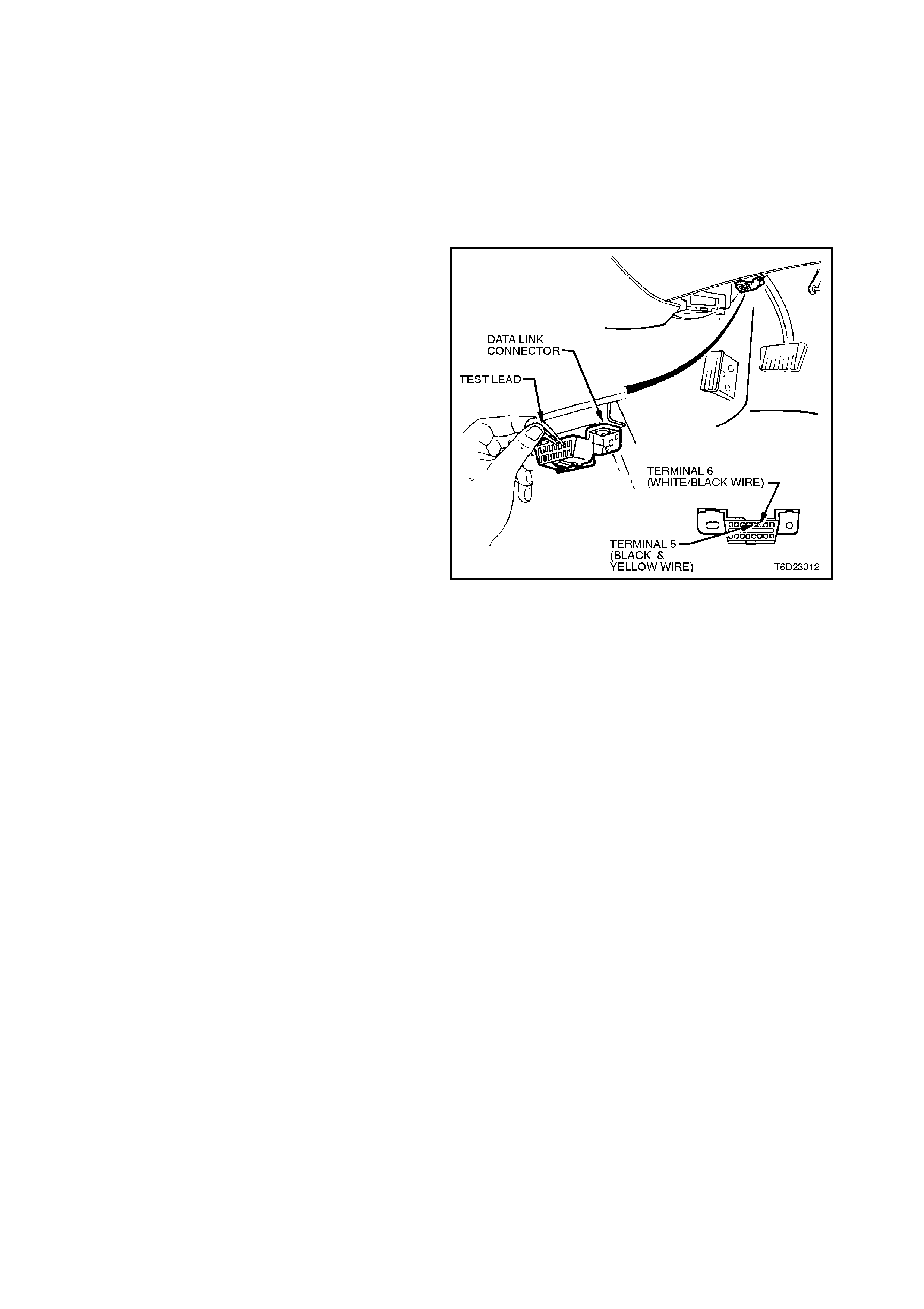
2. Ground DLC diagnostic mode request terminal
with a jumper wire and suitable terminals.
CAUTION:
The timing light must be suitable for use with
semi-conductor type ignition systems, otherwise
TRANSIENT VOLTAGE that may be produced in
an unsuitable timing light could destroy the
ignition trigger module.
3. Use a suitable tim ing light to check that ignition
timing is 10 degrees BTDC.
4. If adjustment is required, loosen distributor
clamp bolt and rotate distributor to achieve
correct timing.
5. Tighten distributor clamp bolt to specified
torque and re-check ignition timing.
6. Stop the engine and remove the jumper wire
from the DLC connector.
Figure 6D2-3-27
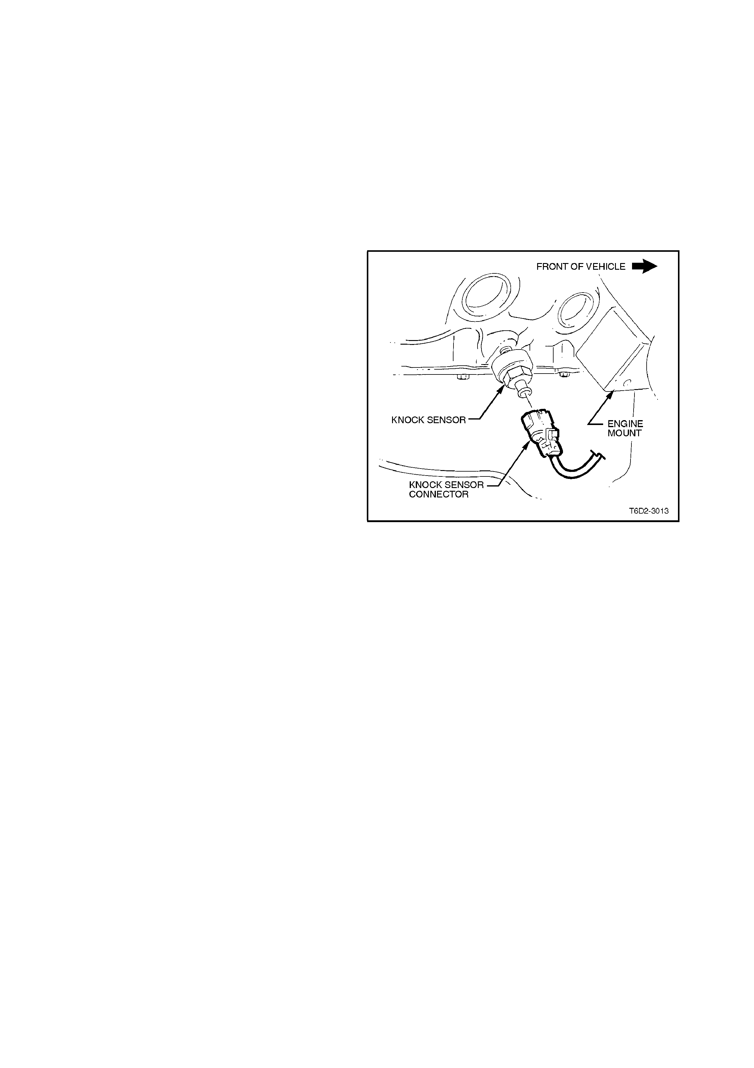
2.5 KNOCK SE NS OR
IMPORTANT:
IT MUST BE NOTED THAT THE KNOCK
SENSORS SCREW INTO THE CYLINDER BLOCK
COOLANT JACKETS.
IF REMOVING THE KNOCK SENSORS WITH THE
ENGINE COOLANT STILL HOT, ENSURE
EXTREME CAUTION IS TAKEN SO AS TO
PREVENT ANY SERIOUS PERSONAL INJURY
DUE TO HOT COOLANT DRAINING FROM THE
CYLINDER BLOCK.
REMOVE
NOTE:
Extreme care should be exercised when handling
the knock sensor so as not to drop it on a hard
surface. If this should happen, the sensor internal
components can be damaged.
1. Allow engine to cool to ambient temperature
(less than 50°C), then remove radiator cap.
2. Disconnect battery earth lead.
3. Raise front of vehicle and support on safety
stands. Refer to Section 0A GENERAL
INFORMATION for location of jack points.
4. Squeeze together 'wide ends' of k nock s ensor
wiring harness connector (connector is oval
shaped) and pull connector from sensor.
5. Place a suitable drain tray beneath the knock
sensor location.
6. Using a 22 mm socket, universal joint and
suitable length soc ket bars , loosen and rem ove
sensor f rom c ylinder bloc k, tak ing extr em e care
to avoid any draining coolant if it is hot.
Figure 6D2-3-28

REINSTALL
1. Ensure that the threads in the sensor
mounting hole in cylinder block are clean.
2. If reinstalling original sensor, inspect sealant
on sensor threads. If worn away, apply a light
coating of Loctite 242 (Holden's Specification
HN1256 Class 2, Type 2) to sensor threads.
NOTE:
On a new sensor, do not apply sealant to threads
as threads are coated with a sealant during
production. Applying additional sealant will affect
the sensor's ability to detect engine knock.
3. Install sensor and tighten to the corr ect torque
specification.
NOTE:
Ensure that knock sensor is never over tightened
as damage to the sensor can occur.
KNOCK SENSOR TIGHTENING
TORQUE SPECIFICATION 16 - 22
Nm
4. Reconnect wiring harness connector to
sensor. Ensure that connector is securely
fitted onto sensor.
5. Refill cooling system and pressure test for
leaks, refer Section 6B2 ENGINE CO OLING
- V8 ENGINE.
6. Reconnect battery earth lead.
2.6 SPARK PLUG LEADS
REMOVE AND REINSTALL
Use care when removing spark plug lead boots
from spark plugs.
NOTE:
Pull the boot only, DO NOT pull on the lead.
When reinstalling plug leads, route leads correctly
and through the proper retainers. Failure to route
the leads correctly can result in the lead/s chaf fing,
burning, or cause cross firing.
NOTE:
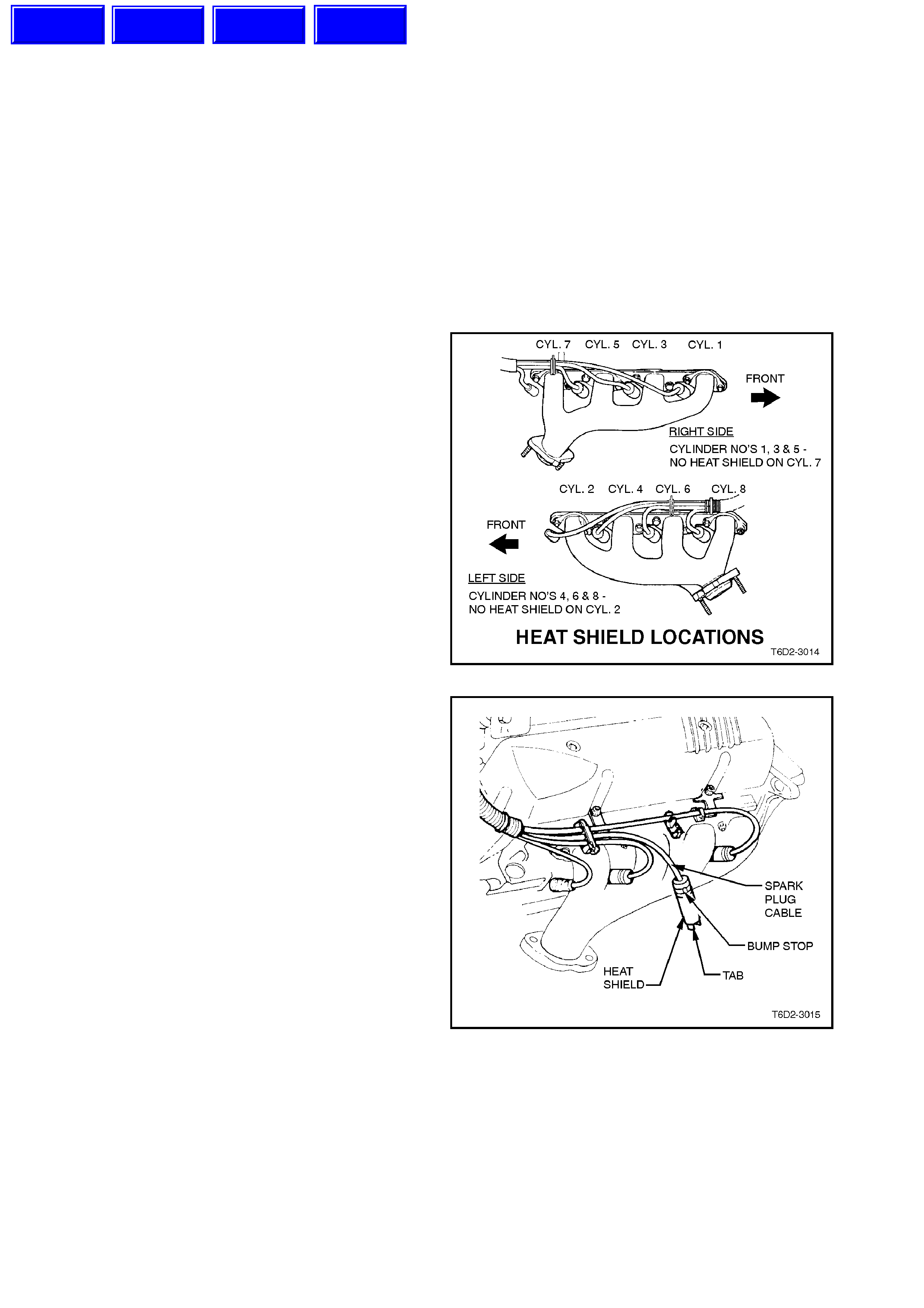
All spark plug leads ar e numbered to c orr es pond to
the cylinder location.
Leads for cylinder numbers 1, 3, 4, 5, 6 and 8 have
heat shields fitted to their spark plug boots. These
cylinders mus t have heat shielded leads fitted to the
spark plugs.
Figure 6D2-3-29
Special care should be exercised when reinstalling
spark plug lead boots to ensure that the metal
terminal within the boot is fully seated on the spark
plug terminal and that the boot has not moved on
the lead.
If boot movement has occurred, the boot will give a
false visual impression of being fully seated.
Also ensure that the metal tabs at the base of the
boot heat shields are completely seated over the
spark plug hex, als o that heat shields rem ain seated
against bump stops at end of cable boot.
Figure 6D2-3-30
Figure 6D2-3-31 illustrates the spark plug lead
routing.
Techline
Techline
Techline
Techline
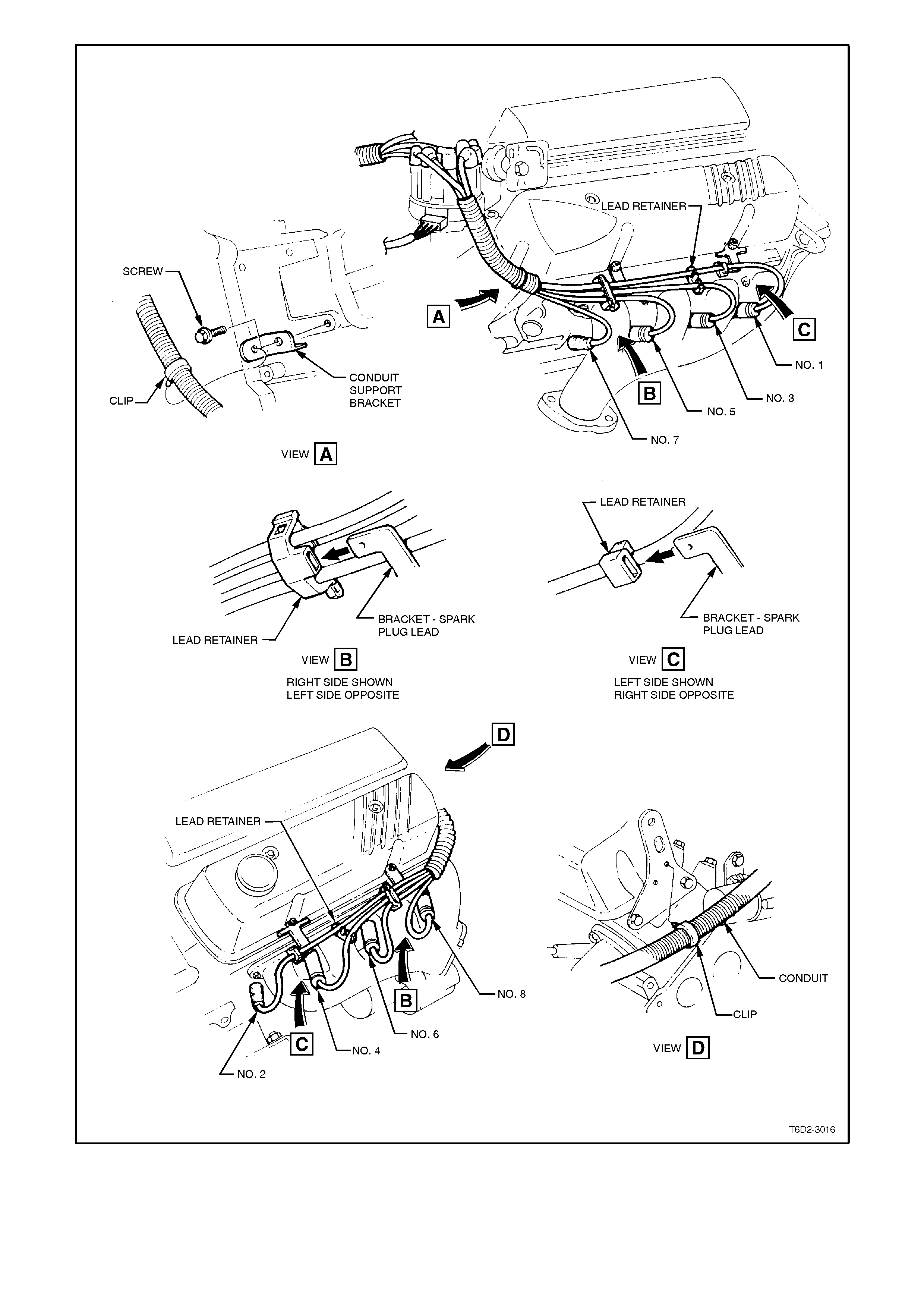
Figure 6D2-3-31
TEST
Remove leads, taking note of precautions as
previously outlined.
Connect an ohm meter capable of r eading to 50,000
ohms across each spark plug lead. The ohmmeter
should indicate the correct resistance specification.
SPARK PLUG LEAD
RESISTANCE Less than 25,000 W
SPECIFICATION
COIL LEAD
RESISTANCE Less than 6,000 W
SPECIFICATION
Inspect the leads for burnt, cracked or chaffed
areas.
Replace any damaged or out of specification leads.
Figure 6D2-3-32
2.7 SPARK PLUGS
REMOVE
1. Disconnect spar k plug leads f rom spar k plugs,
refer to 2.6 SPARK PLUG LEADS in this
Section.
NOTE:
When removing spark plugs, place them in or der of
removal. This will enable a check of individual
cylinders to be made. Engine condition can be
assessed by viewing the colour of the plug insulator
and electrode wear.
2. Unscrew and remove spark plugs using a 16
mm spark plug socket.
3. Seal the spark plug holes, to prevent foreign
material entering the combustion chambers.
CLEAN AND ADJUST
1. Carefully inspect spark plug insulators and
electrodes. Replace any plug with cracked or
broken insulation or loose electrodes.
NOTE:
Refer to 3. DIAGNOSIS in this Section for
identification of spark plug condition.
2. If spark plugs are oily, clean and dry with
compressed air.
NOTE:
Should one or two spark plug insulators appear
different to the other spark plugs, check engine
compression (refer to Section 6A2 ENGINE
MECHANICAL - V8 ENGINE).
3. Clean spark plugs using sand blast type
cleaning equipment, following the
manufacturer's recommendations.
4. Inspect spark plugs again for defects which
may not have been apparent before cleaning.
5. Ensure that spark plug threads are clean and
in good order.
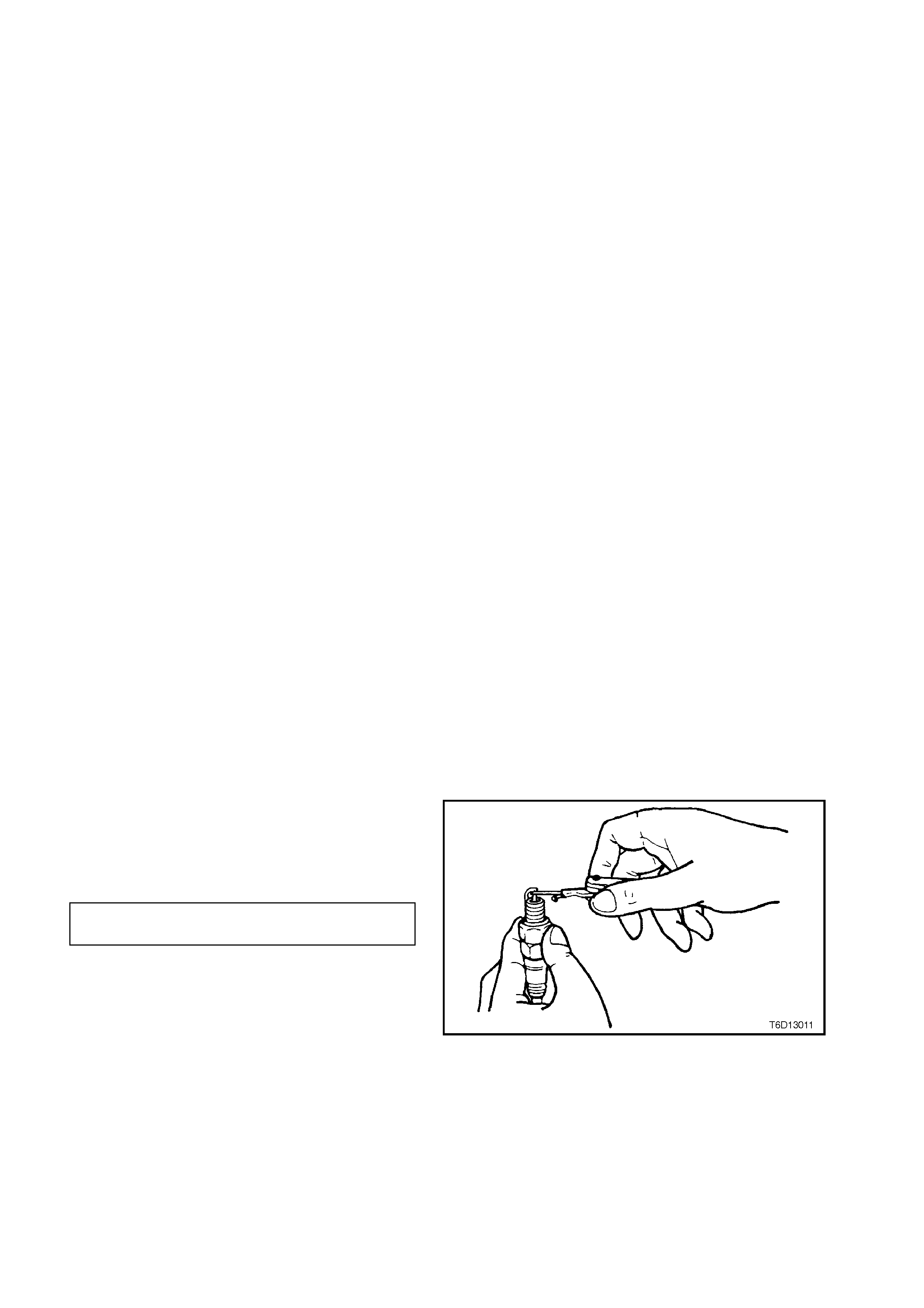
6. Use round wire feeler gauges to check gap
between spark plug electrodes.
7. Adjust gap to correct specification by bending
outer electrode.
SPARK PLUG GAP 1.0 ± 0.05
SPECIFICATION mm
Figure 6D2-3-33

REINSTALL
1. Remove the seal from spark plug holes.
2. Reinstall spark plugs and tighten to the cor r ect
torque specif ication using a 16 m m spark plug
socket.
SPARK PLUG TORQUE
SPECIFICATION 15 - 25
Nm
3. Reinstall spark plug leads.

3. DIAGNOSIS
For diagnosis of the ignition system, refer to Section 6C2 POWERTRAIN MANAGEMENT - V8 ENGINE.
3.1 SPARK PLUG DIAGNOSIS
Worn or dirty plugs may give satisfactory operation while the vehicle is idling, but under load they may break down.
Faulty plugs can cause; poor fuel economy, power loss, loss of speed, hard starting and general poor engine
performance.
Spark plugs may also fail due to carbon fouling, excessive gap or a broken insulator.
Fouled plugs are indicated by black carbon deposits. The black deposits are usually the result of slow-speed driving
and Broken insulators are usually the result of improper installation or careless re-gapping. Broken upper insulators
usually result from a poor fitting spark plug socket or an outside blow. The cracked insulator may not show up
initially, but will, as soon as oil or moisture penetrates the crack. The crack is often just below the crimped part of
the shell and may not be visible.
Broken lower insulators usually result from careless re-gapping and generally are visible. This type of break may
result from the plug operating too 'HOT', which may happen in periods of high speed operation or under heavy
loads. When re-gapping a spark plug, always make the gap adjustment by bending the earth (side) electrode. Do
not use spark plugs with broken insulators.
When replacing spark plugs, use only genuine spark plugs of the correct heat range.
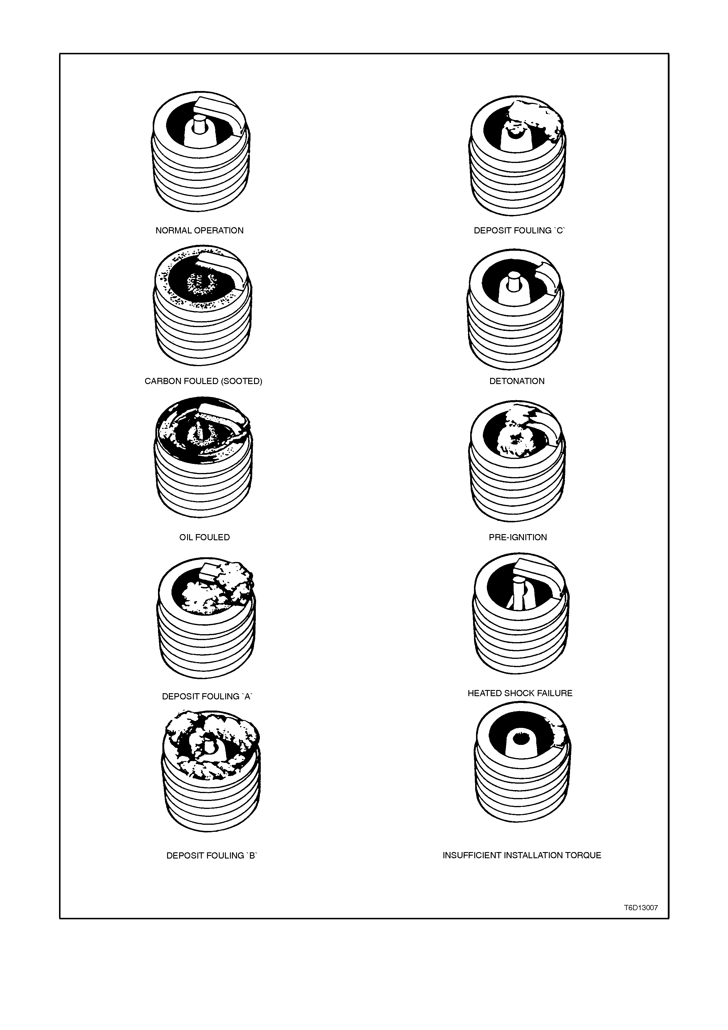
ANALYSIS OF SPARK PLUG CONDITION
Figure 6D2-3-34

NORMAL OPERATION
Refer to Fig. 6D2-3-34
Brown or greyish-tan deposits and slight electrode wear indicate correct spark plug heat range and mixed periods of
high and low speed driving.
CARBON FOULED (SOOTED)
Refer to Fig. 6D2-3-34
Dry, fluffy black carbon (soot) deposits due to poor ignition output, weak coil or faulty spark plug leads.
Excessive idling, slow speeds under light load also can keep spark plug temperatures so low that normal
combustion deposits are not burned off.
OIL FOULED
Refer to Fig. 6D2-3-34
Wet, oily deposits with minor electrode wear may be caused by oil leaking past worn piston rings. 'Break in' of a new
or recently overhauled engine before rings are fully seated may also result in this condition.
DEPOSIT FOULING "A"
Refer to Fig. 6D2-3-34
Red brown, yellow and white coloured coatings on the insulator tip. These coatings are by-products of combustion
and come from the fuel and lubricating oil, both of which today generally contain additives. Most powdery deposits
have no adverse effect on spark plug operation; however, they may cause intermittent missing under severe
operating conditions, especially at high speeds and heavy load.
DEPOSIT FOULING "B"
Refer to Fig. 6D2-3-34
Deposits are similar to those identified as DEPOSIT FOULING "A". These deposits are by-products of combustion
and come from the fuel and lubricating oil. Excessive valve stem clearances and/or defective intake valve seals will
allow excessive oil to enter the combustion chamber. The deposits will accumulate on the portion of the spark plug
projecting into the chamber and will be heaviest on the side facing the intake valve. Defective seals should be
suspected when the condition is found in only one or two cylinders
DEPOSIT FOULING "C"
Refer to Fig. 6D2-3-34
Most powdery deposits identified in DEPOSIT FOULING "A", have no adverse effect on the operation of the spark
plug as long as they remain in the powdery state. However, under certain conditions of operation, these deposits
melt and form a shiny glaze coating on the insulator which, when hot, acts as a good electrical conductor. This
allows the current to follow the deposits instead of jumping the gap, thus shorting out the spark plug.
DETONATION
Refer to Fig. 6D2-3-34
Commonly referred to as engine knock or 'ping', detonation causes severe shock inside the combustion chamber to
the adjacent parts which include spark plugs.
PRE-IGNITION
Refer to Fig. 6D2-3-34
Causes burned or blistered insulator tip and badly eroded electrodes. Excessive overheating is indicated. Cooling
system blockage or sticking valves are common causes of pre-ignition. Spark plugs which are the wrong (too hot)
heat range, or not properly installed are also a possible cause. Sustained high speed, heavy load service can
produce high temperatures which will cause pre-ignition.
HEAT SHOCK FAILURE
Refer to Fig. 6D2-3-34
A common cause of broken and cracked insulator tips. Rapid increase in tip temperature under severe operating
conditions causes the heat shock and a fracture results. Another common cause of chipped or broken insulator tips
is carelessness in re-gapping, by either bending the centre electrode to adjust the gap, or allowing the gapping tool
to exert force against the tip of the centre electrode or insulator when bending the outer electrode to adjust the gap.
INSUFFICIENT INSTALLATION TORQUE
Refer to Fig. 6D2-3-34
Poor contact between the spark plug and the engine seat. The lack of proper heat transfer, resulting from poor seat
contact, causes overheating of the spark plug and, in many cases, severe damage as shown. Dirty threads in the
cylinder head can also result in the plug seizing before it is seated.
THREAD SEIZURE
Refer to Fig. 6D2-3-34
Recommended installation torque may be obtained without taper seat engagement in cylinder head. Operation of an
engine with this type of installation may result in spark plug overheating, causing possible damage to the spark plug
or engine. Always ensure cylinder head and spark plug threads are free of deposits, burrs and scale.

4. SPECIFICATIONS
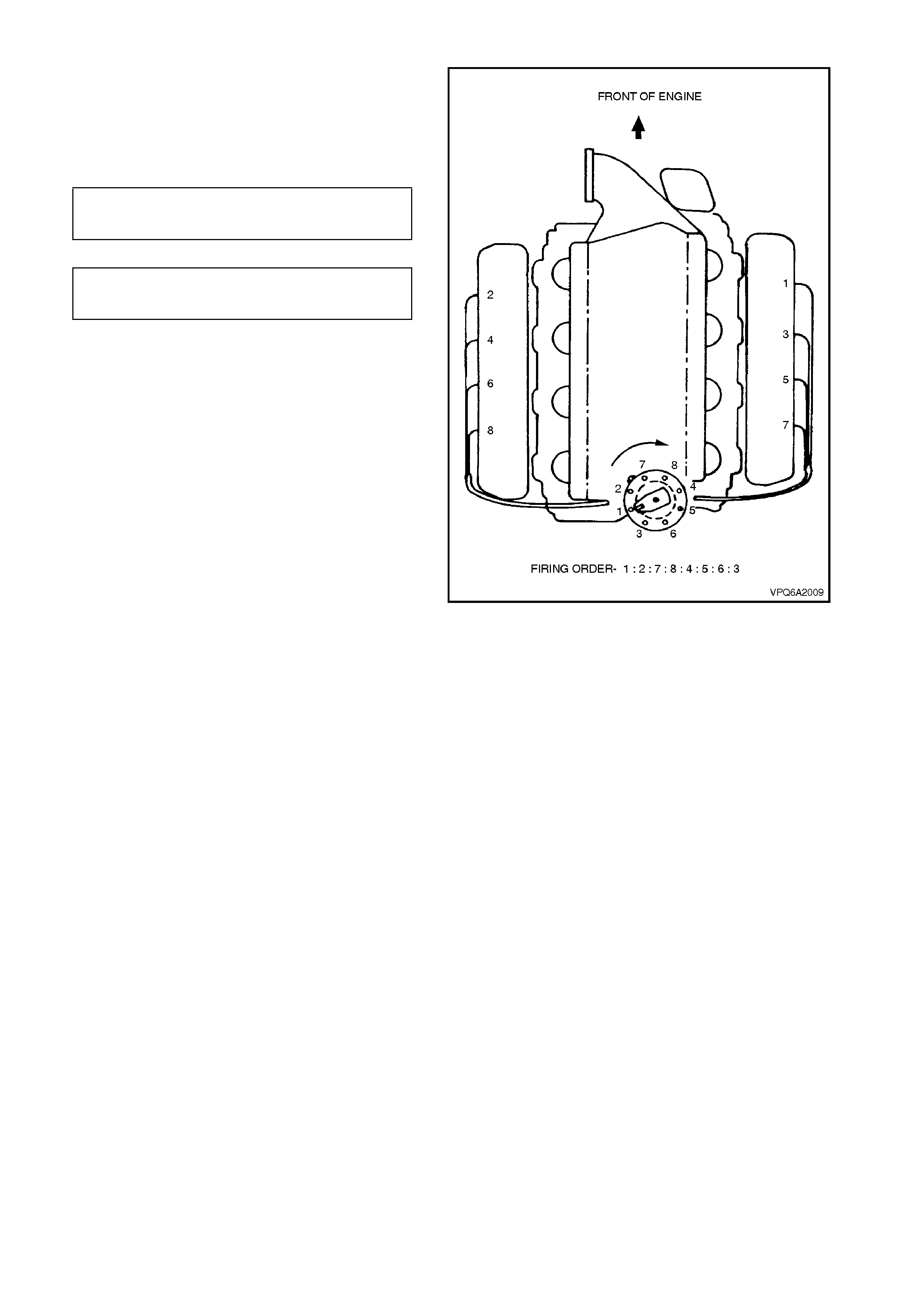
Distributor Type Bosch Hall Effect
Firing Order 1-2-7-8-4-5-6-3
Ignition Coil Primary Winding
Resistance 0.42 - 0.47 W @ 20 - 30°C
Ignition Coil Secondary Winding
Resistance 5940 - 7260 W @ 20 - 30°C
Spark Plug
Original Equipment NGK BPR6EF
Service Replacement AC R42LTS
Spark Plug Gap 1.0 ± 0.05 mm
Spark Plug Lead Resistance Less than 25,000 W
Coil Lead Resistance Less than 6,000 W

5. TORQUE WRENCH SPECIFI CATIONS
Nm
Ignition Coil to Cylinder Block Bolt 17 - 23
Ignition Module Retaining Nuts 3.0 - 8.0
Distributor Clamp Bolt 20 - 27
Spark Plugs 15 - 25
Knock sensor 16 - 22