
SECTION 7B1 - MANUAL TRANSMISSION -
V6 ENGINE
CAUTION:
This vehicle will be equipped with a Supplemental Restraint System (SRS). An SRS
will consist of either seat belt pre-tensioners and a driver's side air bag, or seat belt
pre-tensioners and a driver's and front passenger's side air bags. Refer to
CAUTIONS, Section 12M, before performing any service operation on or around any
SRS components, the steering mechanism or wiring. Failure to follow the CAUTIONS
could result in SRS deplo yment, resulting in possible p ersonal injury or unnecessary
SRS system repairs.
CAUTION:
This vehicle may be equipped with LPG (Liquefied Petroleum Gas. In the interests of
safety, the LPG fuel system should be isolated by turning ‘OFF’ the manual service
valve and then draining the LPG serv ice lines, before any service w ork is carried out
on the vehicle. Refer to the LPG leaflet included with the Owner's Handbook for
details or LPG Section 2 for more specific servicing information.
CAUTION:
Whenever any component that forms part of the ABS or ABS/ETC (if fitted), is
disturbed during Service Operations, it is vital that the complete ABS or ABS/ETC
system is checked, using the procedure as detailed in 4. DIAGNOSIS, ABS or
ABS/ETC FUNCTION CHECK, in Section 12L ABS & A BS/ETC.
1. GENERAL INFORMATION
With the introduction of VT Series vehicles, the manual transmission fitted with the V6 engine, is the five speed,
Getrag, Type 260 (production option M35).
This manual transmission is standard equipment on V6 powered Executive models and is optional on Berlina.
The ‘260’ manual transmission is a fully synchronised unit, including reverse gear, with baulk ring type
synchronisers. The transmission primarily consists of a two piece transmission case, with the clutch housing
integrated with the front case section. During disassembly, the gear train and shift mechanism remain in the
transmission case rear section.
1.1 GENERAL DESCRIPTION
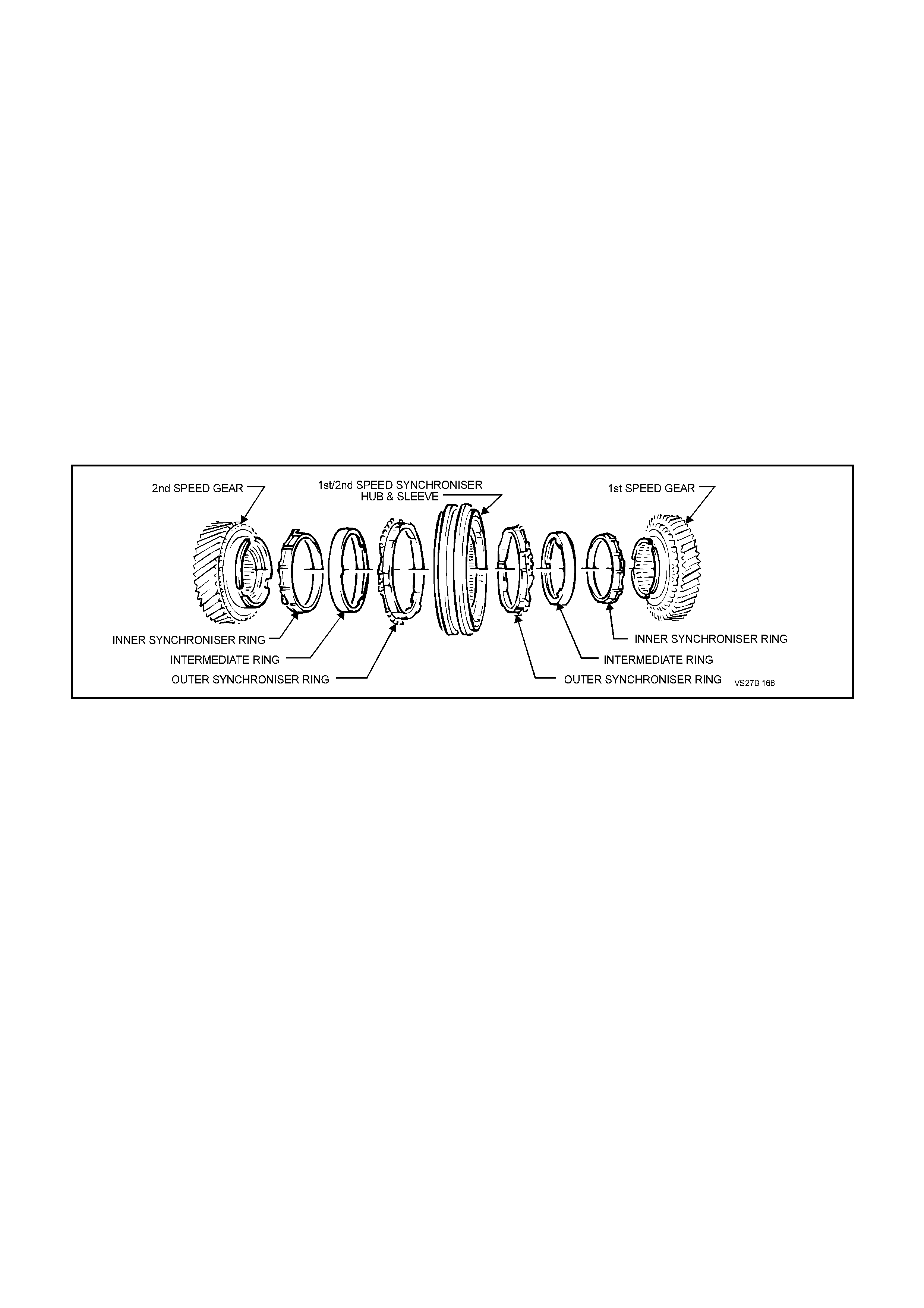
SYNCHRONISER ASSEMBLIES
Each of the three synchroniser hubs are an interference fit, splined to the mainshaft and fixed by selective snap
rings to accommodate manufacturing tolerances. Sintered, double cone blocking rings are fitted to 1st and 2nd
gears, while those for 3rd, 4th, 5th and reverse gears are brass, with a molybdenum coating on their inner surface.
The purpose of the synchroniser assemblies is to permit clutching to the required gear, that is in constant mesh with
the cluster gear.
Synchroniser Action
During synchroniser operation, the synchroniser sleeve is moved into engagement by the appropriate fork, carrying
with it three sy nchroniser inserts and spring loaded balls, located in slots in the synchroniser hub.
The synchroniser sleeve, together with the inserts, is moved along the hub, placing a load on the three lugs of the
blocking ring.
This initial force is sufficient to seat the blocking ring and start pre-synchronisation because of the friction between
the cone on the constant mesh gear and the blocking ring/s.
At this stage, gear engagement is prevented as long as there is a difference in speed between the mating surfaces
of the blocking ring and cone of the constant mesh gear. As the speeds between the blocking ring and the gear
cone become synchronised, the teeth on the blocking ring and gear cone line up with the internal splines of the
sleeve, allowing the sleeve to engage the teeth on the mainshaft gear, completing gear selection.
Figure 7B1-1 shows an exploded view of the three piece synchromesh unit, used for 1st and 2nd gears.
Figure 7B1-1
REVERSE GEAR
The reverse idler gear is in constant mesh with the cluster gear and the reverse gear that is mounted on the
mainshaft. When reverse gear is engaged, the 5th/reverse synchromesh sleeve engages the reverse constant
mesh gear, completing the selection.
BEARING SUPPORT
The maindrive gear runs on a single row ball race in the front of the transmission case and supports the front end of
the mainshaft via a caged needle roller bearing. The mainshaft runs on a single row ball race, mounted in the rear
transmission case .
The maindrive gear and mainshaft bearings are located in their respective housings by an interference fit and the
use of snap rings or a bolted plate. Shims are used to accommodate manufacturing tolerances in each bearing
bore.
The cluster gear runs on two parallel roller bearings, one at each end, with end float being controlled by a shim
located between the cluster gear front bearing cup and the front circlip.
Each of the mainshaft constant mesh gears run on caged needle roller bearings, while the reverse idler gear is
supported by two caged needle roller bearings running on the idler gear shaft.
LUBRICATION
Lubrication of all internal components is by splash feed, provided by the rotating cluster gear assembly.
SELECTOR MECHANISM
The floor mounted, gearshift control lever operates a single rail mechanism which extends into the rear
transmission case. The first/second, third/fourth and fifth/reverse shift forks are all supported at each end, in the two
transmission case s.
A shift interlock system, prevents engagement of more than one gear at a time. The system consists of an interlock
pin located in the third/fourth selector shaft and two interlock balls, that locate in a neutral position groove in each of
the remaining two rails. These components, together with the shift detent balls and springs are all located in the end
of rear transmission housing.
When either the first/second or fifth/reverse selector shaft is moved to engage a gear, one of the interlock balls is
moved across, displacing the interlock pin, effectively locking the remaining two shafts. Moving the third/fourth
selector shaft, moves each of the two balls firmly into their respective shafts, allowing a third/fourth shift to take
place, with the interlock pin being carried with the shaft.
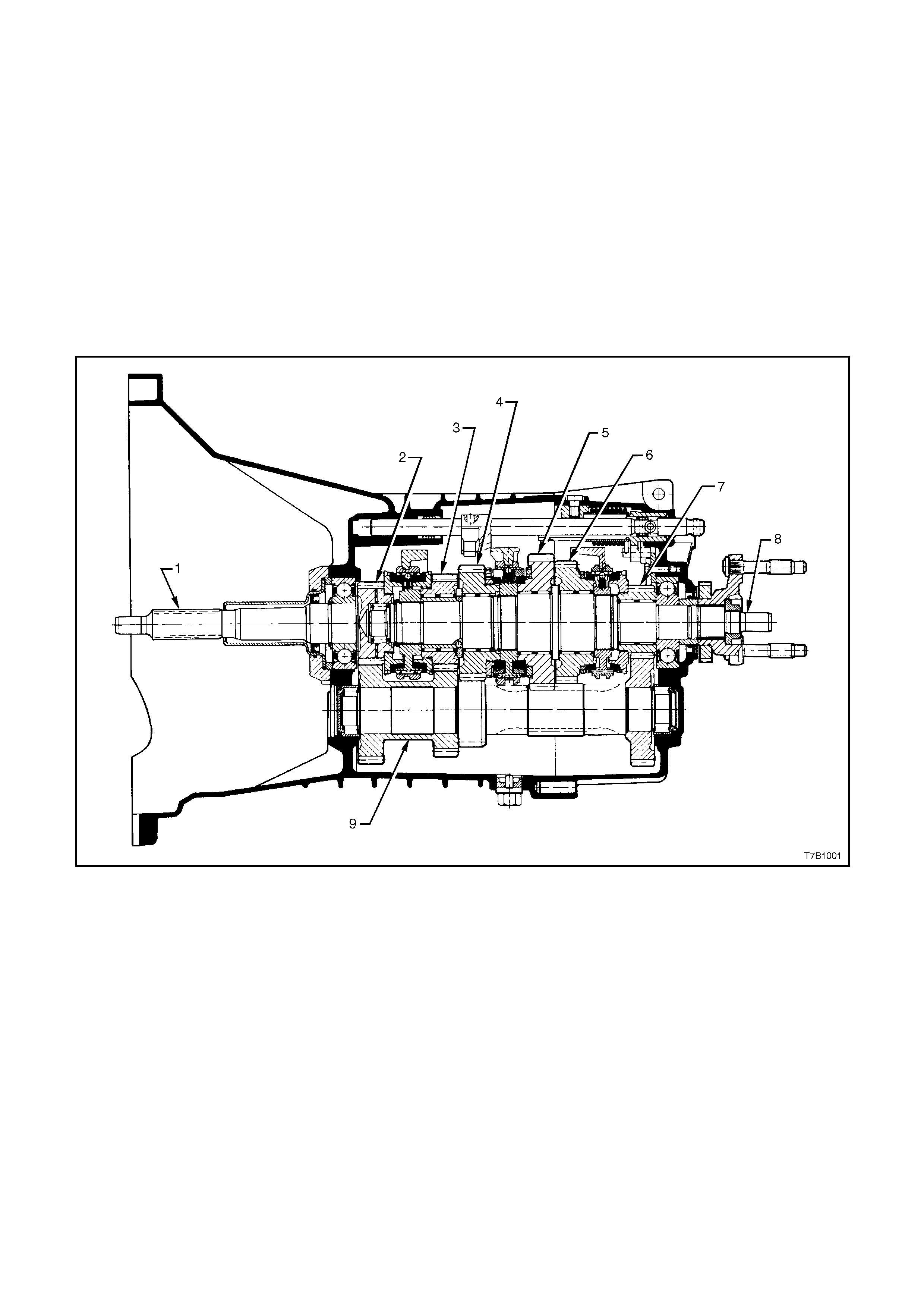
See Figure 7B1-2 for a sectioned view of the type ‘260’ transmission (production option M35). Figure 7B1-3 shows
an exploded view of the two case halves and selector components, while figure 7B1-4 shows an exploded view of
the gear train components.
1. Input Shaft
2. Maindrive Gear
3. Third Speed Gear
4. Second Speed Gear
5. First Speed Gear
6. Reverse Gear
7. Fifth Speed Gear
8. Mainshaft
9. Cluster Gear
Figure 7B1-2 - Type ‘260’ Transmission, Sectioned View
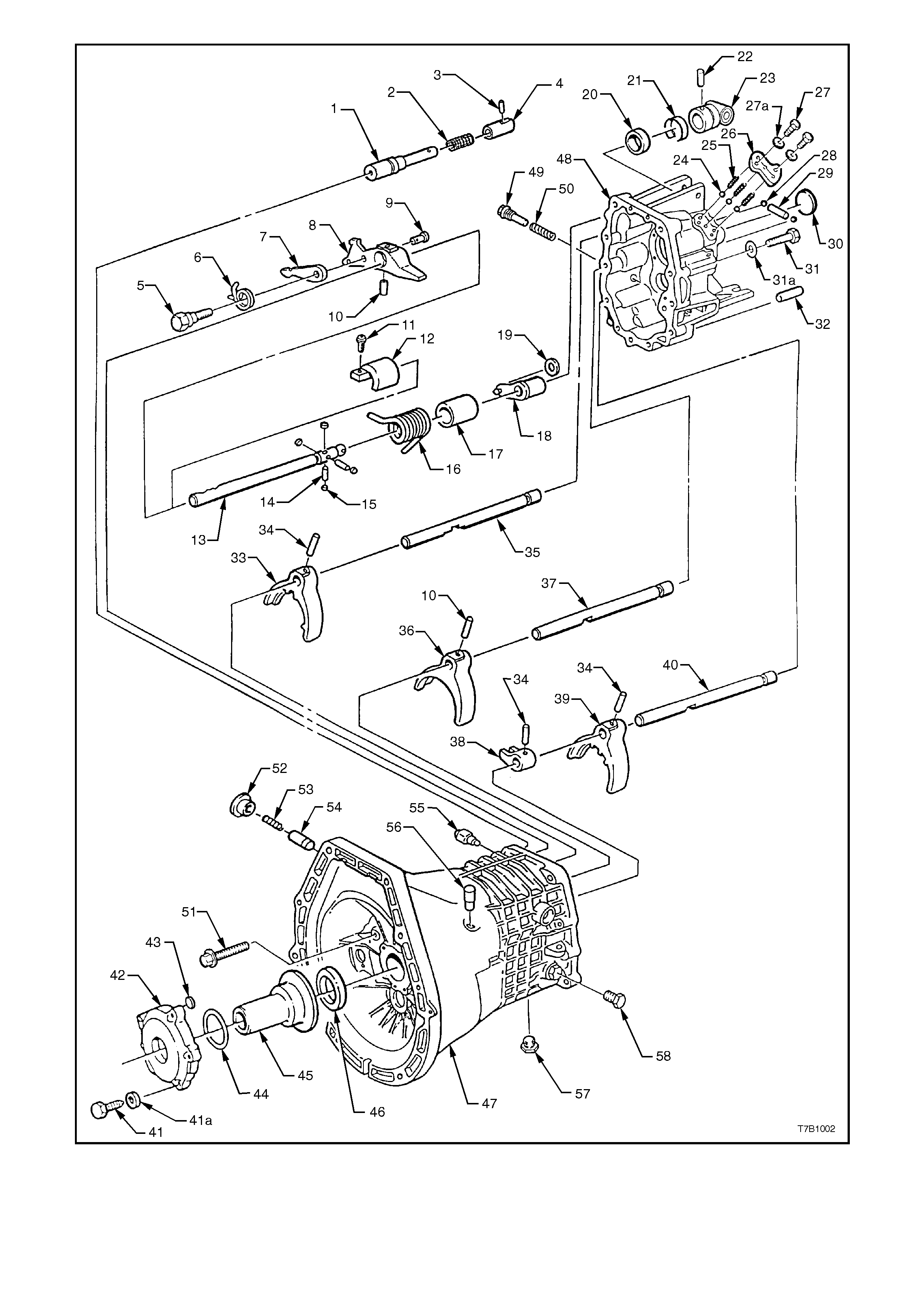
Figure 7B1-3 - Transmission Shift Mechanism and Case Components
REF No. PART NAME REF No. PART NAME
1.
2.
3.
4.
5.
6.
7.
8.
9.
10.
11.
12.
13.
14.
15.
16.
17.
18.
19.
20.
21.
22.
23.
24
25.
26.
27.
27a.
28.
29.
Reverse blocker pin
Helical compression spring
Reverse blocker bushing,
retainer pin
Reverse blocker bushing
Cap bolt
Cylindrical torsion spring
Reverse lock plate
Shift finger
Pin
Roll pin
Allen key head cap screw
Shift shaft support
Selector rod shift shaft
Dowel pin
Roller
Cylindrical torsion spring
Bushing
Select lever
Roller
Oil seal - shift shaft
Spring retaining clip
Selector rod trunnion pin
Selector rod trunnion
Detent ball - 3 places
Helical compression spring -
3 places
Cover plate
Bolt
Wave washer
Interlock ball - 2 places
Interlock pin
30.
31.
31a.
32.
33.
34.
35.
36.
37.
38.
39.
40.
41.
41a.
42.
43.
44.
45.
46.
47.
48.
49.
50.
51.
52.
53.
54.
55.
56.
57.
58.
Welsh plug
Bolt
Wave washer
Dowel pin
Shift fork, 5th/Reverse
Roll pin
Selector shaft, 5th/Reverse
Shift fork, 3rd/4th
Selector shaft, 3rd/4th
Shift yoke, 1st/2nd
Shift fork, 1st/2nd
Selector shaft, 1st/2nd
Bolt
Wave washer
Front housing cover
Disc
O-ring
Clutch throwout bearing guide
Oil seal
Front transmission housing
Rear transmission housing
Plug
Spring
Reverse blocker pin bolt
Plug
Spring
Detent plunger assembly
Back-up lamp switch
Breather plug
Drain plug with magnet
Filler plug
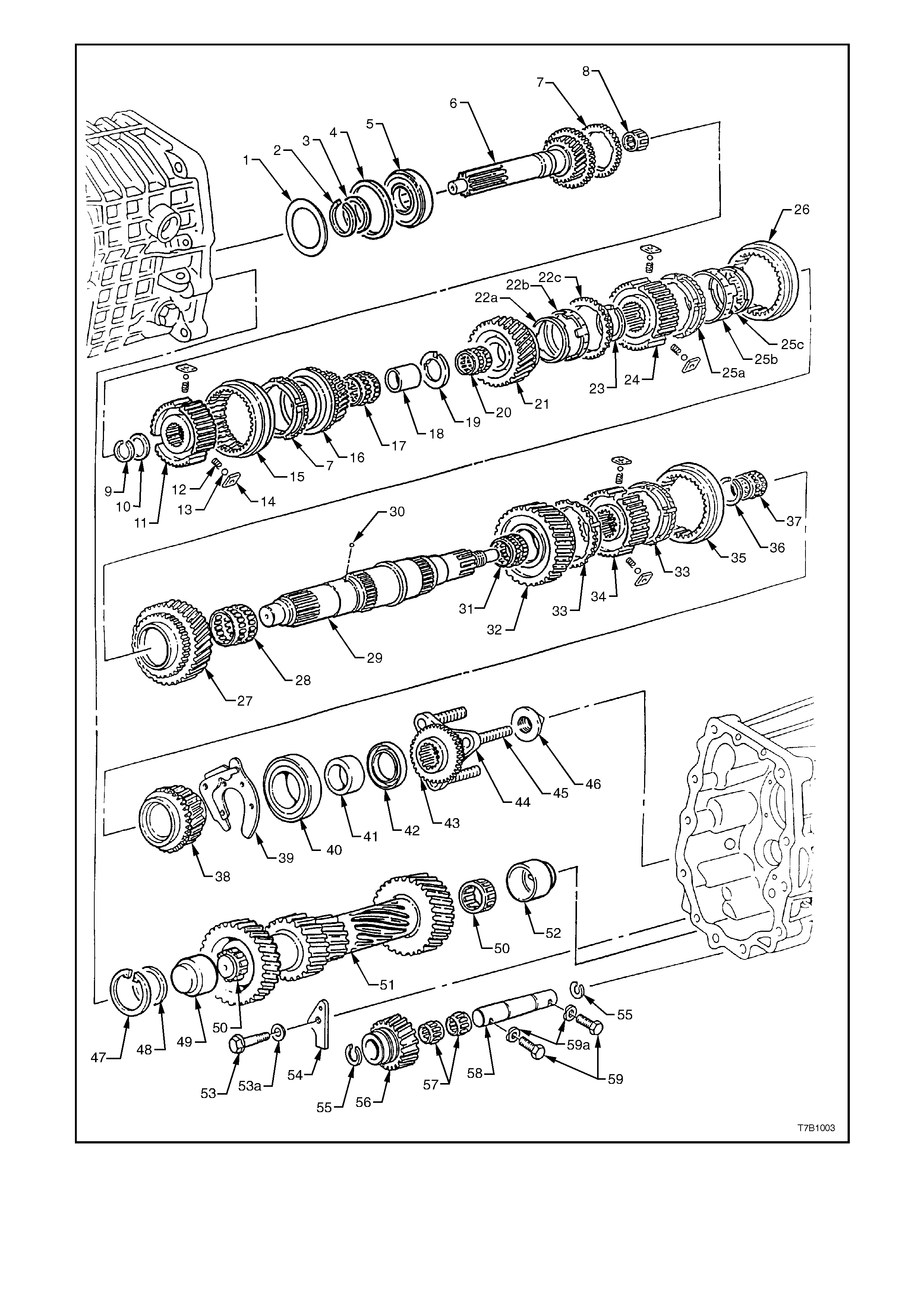
Figure 7B1-4 - Transmission Gear Components

REF No. PART NAME REF No. PART NAME
1.
2.
3.
4.
5.
6.
7.
8.
9.
10.
11.
12.
13.
14.
15.
16.
17.
18.
19.
20.
21
22a
22b
22c.
23.
24.
25a.
25b.
25c.
26.
27.
28.
29.
30.
31.
Selective spacer washer
Snap ring
Selective spacer washer
Front bearing spacer ring
Front bearing
Input shaft and maindrive gear
Synchromesh ring
Caged, spigot needle roller
bearing
Snap ring
Selective spacer washer
Synchromesh hub
Spring
Ball
Sliding key
Synchromesh outer sleeve
3rd speed gear
Caged, needle roller bearing
Needle roller inner sleeve
Thrust washer
2nd gear, needle roller bearing
2nd speed gear
Cone ring
Friction ring
Synchromesh ring
Snap ring
1st/2nd speed synchromesh
hub
Synchromesh ring
Friction ring
Cone ring
Synchromesh outer sleeve
1st speed gear
1st speed, needle roller bearing
Mainshaft
Locating ball
Reverse gear, needle roller
bearing
32.
33.
34.
35.
36.
37.
38.
39.
40.
41.
42.
43.
44.
45.
46.
47.
48.
49.
50.
51.
52.
53.
53a.
54.
55.
56.
57.
58.
59.
59a.
Reverse gear
Synchromesh ring
5th/Reverse speed synchromesh
hub
Synchromesh outer sleeve
Selective snap ring
5th speed, needle roller bearing
5th speed gear
Rear mainshaft bearing retainer
plate
Rear mainshaft bearing
Spacer
Oil seal
Speed sensor toothed ring
Output flange
Knurled stud
Flanged retaining nut
Circlip
Support washer
Front cluster gear needle roller
bearing cup
Cluster gear needle roller bearing
Cluster gear
Rear cluster gear needle roller
bearing cup
Bolt
Wave washer
Thrust plate
Snap ring
Reverse idler gear
Caged needle roller bearings
Reverse idler gear shaft
Bolt
Wave washer

1.2 POWER FLOWS
The maindrive gear, fifth, third, second, first speed and reverse gears are in constant mesh with the cluster gear.
Therefore, when the engine is running with the clutch engaged, torque is imparted to the maindrive gear and
through the cluster gear to the fifth, third, second, first speed and reverse gears at all times.
Refer to Figure 7B1-6 for illustrations relating to the following descriptions:
NEUTRAL
In neutral, with the clutch engaged, the maindrive gear turns the cluster gear. The cluster gear turns the constant
mesh gears because no synchroniser assemblies are engaged. As all constant mesh gears are supported on roller
bearings, they will also rotate with the cluster gear.
FIRST GEAR
In first gear, the first/second speed synchroniser sleeve is moved rearward to engage the first speed gear, which is
being turned by the cluster gear. Because the first/second speed synchroniser hub is splined to the mainshaft,
torque is imparted to the mainshaft from the first speed gear through the sy nchroniser sleeve and hub.
SECOND GEAR
In second gear, the first/second speed synchroniser sleeve is moved forward to engage the second speed gear,
which is being turned by the cluster gear. Because the first/second speed synchroniser hub is splined to the
mainshaft, torque is imparted to the mainshaft from the second speed gear through the synchroniser sleeve and
hub.
THIRD GEAR
In third gear, the first/second speed synchroniser sleeve assumes a neutral position. The third/fourth speed
synchroniser sleeve is moved rearward to engage the third speed gear, which is being turned by the cluster gear.
The engagement of the sleeve with the third speed gear, imparts torque to the mainshaft because the third/fourth
speed synchroniser hub is splined to the mainshaft.
FOURTH GEAR
In fourth gear, the third/fourth speed synchroniser sleeve is moved forward to engage the maindrive gear. This
engagement of the maindrive gear with the third/fourth synchroniser sleeve and hub assembly, imparts torque
directly to the mainshaft. While the cluster gear is still rotating, it does not impart torque to any component but
continues to lubricate the internal transmission components by the ‘splash’ method.
FIFTH GEAR
In fifth or overdrive gear, the first/second and third/fourth speed synchroniser sleeves assume neutral positions. The
fifth speed/reverse synchroniser sleeve is moved rearward to engage the fifth speed constant mesh gear, supported
on the mainshaft by a caged needle roller bearing. This engagement of the sleeve with the fifth speed constant
mesh gear, imparts torque from the cluster gear to the mainshaft, via the splined synchromesh hub.
REVERSE GEAR
In reverse gear, the fifth speed/reverse synchroniser sleeve is moved forward to engage the mainshaft reverse gear
and the cluster reverse gear, via the reverse idler gear. This imparts torque from the cluster reverse gear through
the idler gear (reversing direction of rotation) to the mainshaft reverse gear. Because the fifth speed/reverse
synchromesh hub is splined to the mainshaft, this causes the mainshaft to rotate in the opposite direction to the
maindrive gear.
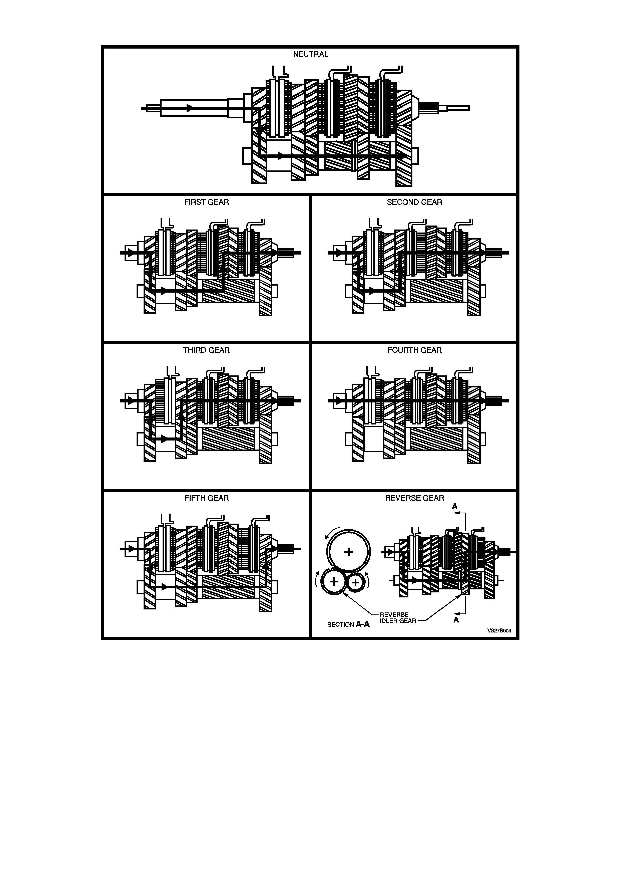
MANUAL TRANSMISSION POWER FLOWS
Figure 7B1-6

1.3 TRANSMISSION SERIAL NUMBER
The transmission serial number is located on a self-adhes ive decal attached to the lef t s ide of the trans miss ion f r ont
housing.
This number pr ovides coded infor mation which c ould be significant to parts interpretation and should be ref erred to
when ordering replacement parts.
Figure 7B1-5

2. SERVICI NG I NFORMATION
2.1 RECOMMENDED LUBRICANT
The recommended lubricant for the ‘260’ manual transmission is an 80W gear oil to Holden’s Specification HN1855,
such as Castrol VMX80W or equivalent.
The transmission lubricant capacity is approximately 1.2 litres.
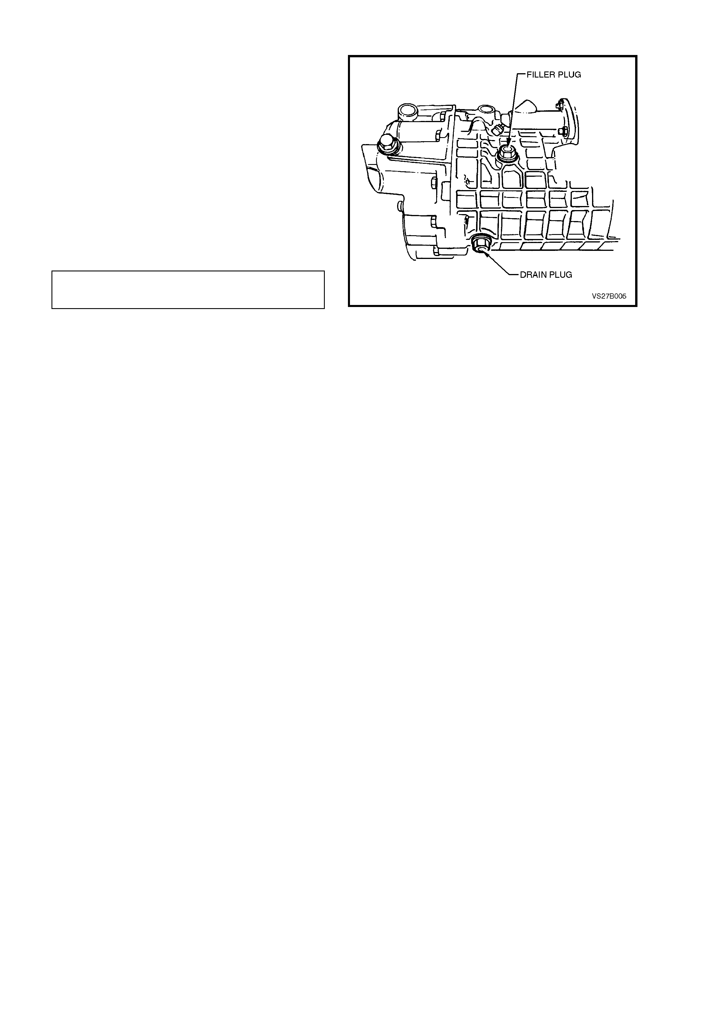
2.2 CHECKING TRANSMISSION LUBRICANT LEVEL
To check transmission lubricant level, remove
transmission filler plug, using a 17 mm ring
spanner, from right hand side of transmission case.
The level is correct when lubricant is level with the
filler plug threads.
NOTE:
Ensure that the vehicle is on level ground and
transmission is cold.
If necessary, add lubricant to bring to the correct
level.
Reinstall filler plug and tighten to the correc t torque
specif ic ation. Do not apply thread sealant or tape to
the plug threads.
TRANSMISSION FILLER PLUG 40 - 60
TORQUE SPECIFICATION Nm
Lubricant level is to be checked at the time or
distance intervals detailed in the VT Ser ies Owner's
Handbook.
Figure 7B1-7

2.3 DRAINING AND REFILLING TRANSMISSION
While the initial fill of transmission lubricant is
specif ied as a ‘fill for lif e’, s hould a lubr icant c hange
be required, then the following procedure should be
adopted.
1. To drain transmission, jack up vehicle front
and rear and support on safety stands.
Refer to Section 0A GENERAL
INFORMATION for the location of jacking
points.
2. Place a drain tray beneath transmission and
remove filler plug and then drain plug using a
17 mm ring spanner.
3. When transmission has fully drained, insert
drain plug and tighten to the correct torque
specification. Do not apply thread sealant or
tape to the plug threads.
TRANSMISSION DRAIN PLUG 40 - 60
TORQUE SPECIFICATION Nm
4. Refill transmission to correct level, refer
2.2 CHECKING TRANSMISSION
LUBRICANT LEVEL in this Section.
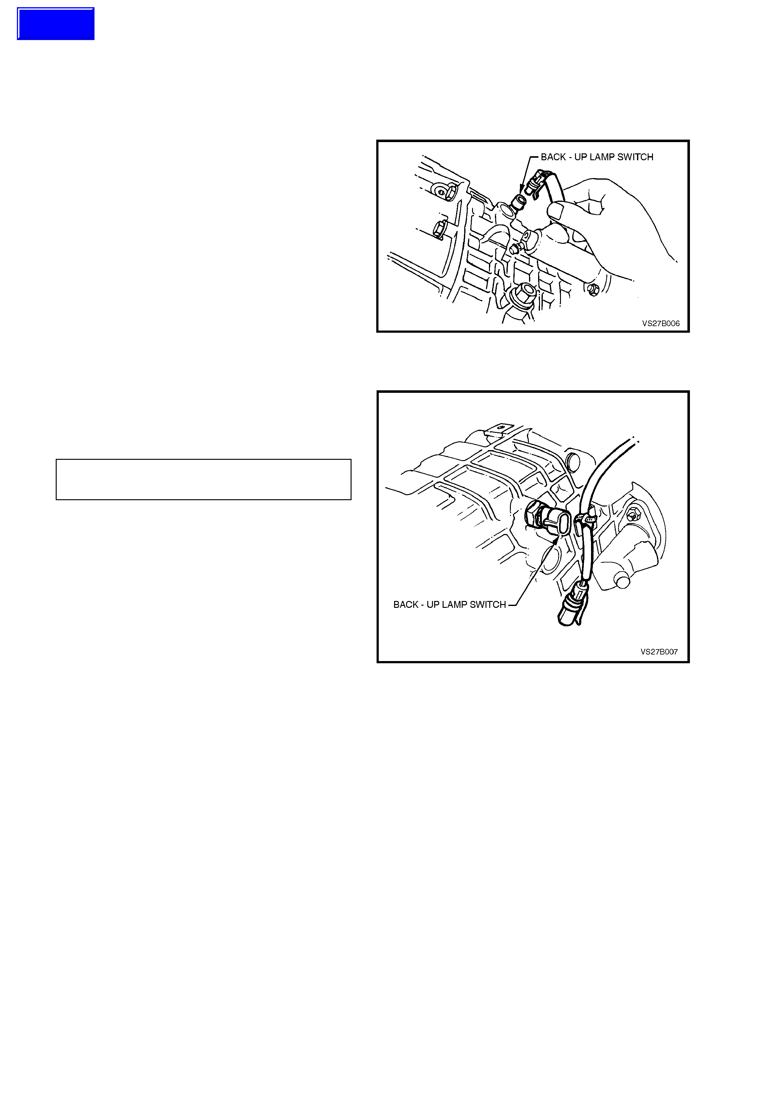
3. MI NOR SERVICE OPERATIONS
3.1 BACK-UP LAMP SW ITCH
REMOVE
1. Raise front of vehicle and support on safety
stands.
Refer to Section 0A GENERAL
INFORMATION for the location of jacking
points.
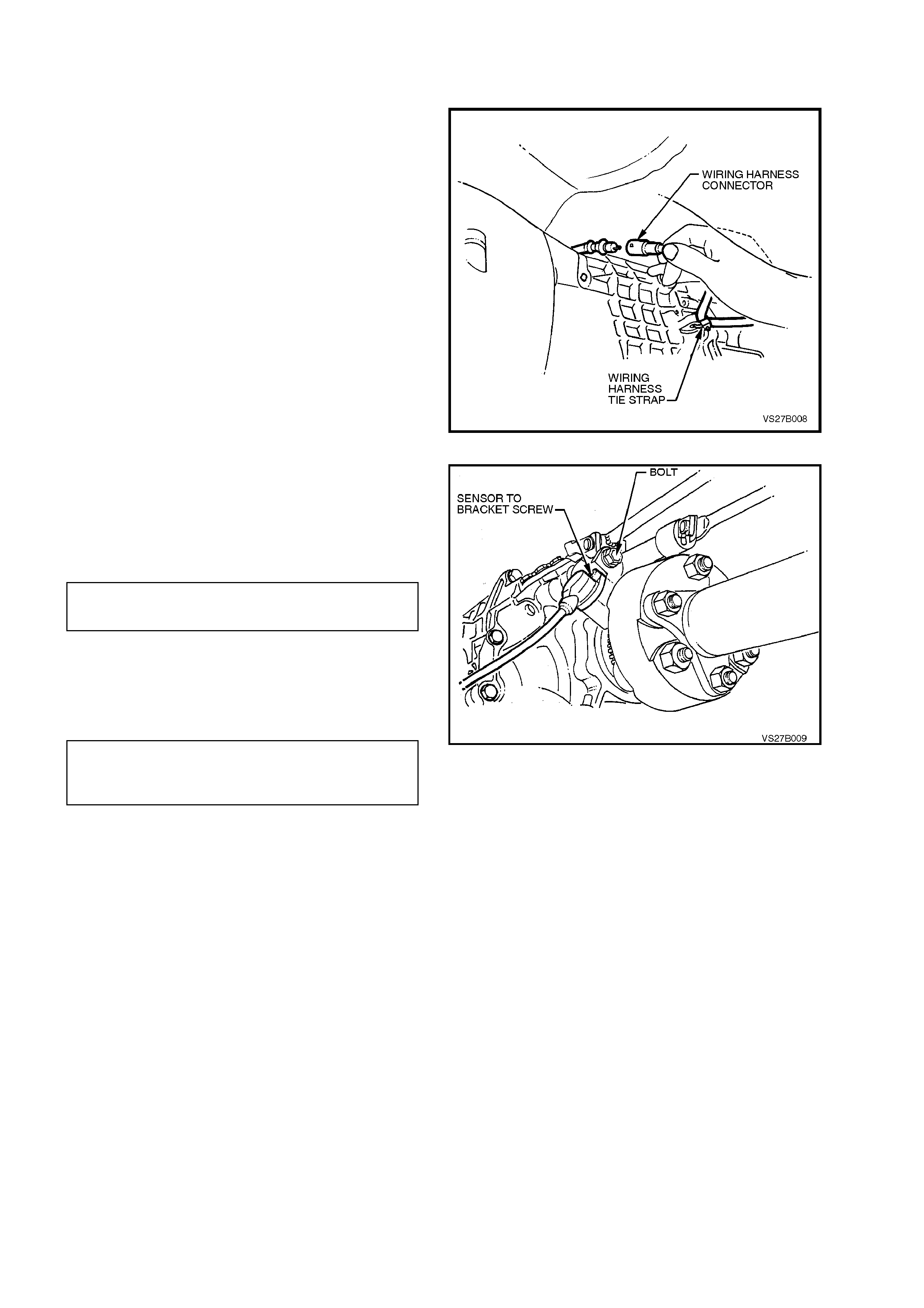
2. Remove wiring harness connector from
switch, located on the right hand side of the
transmission case.
3. Loosen, then remove switch from the
transmission case.
Figure 7B1-8
REINSTALL
1. Ensure that the switch threads are clean.
2. Install switch to transmission case and tighten
to the correct torque specification.
BACK-UP LAMP SWITCH 20
TORQUE SPECIFICATION Nm
3. Install wiring harness connector to switch.
4. Remove safety stands and lower vehicle to
ground.
5. Check back-up lamp operation.
Figure 7B1-9
Techline
3.2 SPEED SENSOR AND/OR BRACKET
REPLACE
1. Jack up vehicle front and rear and support on
safety stands. Refer to
Section 0A GENERAL INFORMATION for
the location of jacking points.
2. Disconnect speed sensor wiring harness
connector.
3. Cut the speed sensor wiring harness strap
from the lug on the transmission case.
4. Remove speed sensor mounting bracket bolt
from the rear of the transmission housing.
5. Remove the bracket and sensor assembly
from the rear transmission housing.
6. Remove the sensor to bracket mounting
screw, then disconnect the sensor by a
twisting and pulling motion to free the O-ring
seal from the bracket.
Figure 7B1-10
7. Installation is the reverse of removal except for
the following points;
a. Tighten the speed sensor to mounting
bracket retaining screw to the correct
torque specification.
SPEED SENSOR TO BRACKET 6 - 14
SCREW TORQUE SPECIFICATION Nm
b. Tighten the sensor bracket to
transm iss ion housing m ounting bolt to the
correct torque specification.
SPEED SENSOR BRACKET TO
TRANSMISSION HOUSING BOLT 15 - 20 Nm
TORQUE SPECIFICATION
c. Connect the speed sensor lead to the
wiring harness connector, ensuring that
the connection is positive and secure.
d. Secure the speed sensor wiring harness
to the lug on the transmission using a
new tie strap.
Figure 7B1-11
3.3 GEARSHIFT LEVER KNOB AND BOOT ASSEMBLY
NOTE:
The gearshift lever knob and console boot are
manufactured as a single component. Do not
attempt to remove the gearshift lever knob
separately to the boot.
REMOVE
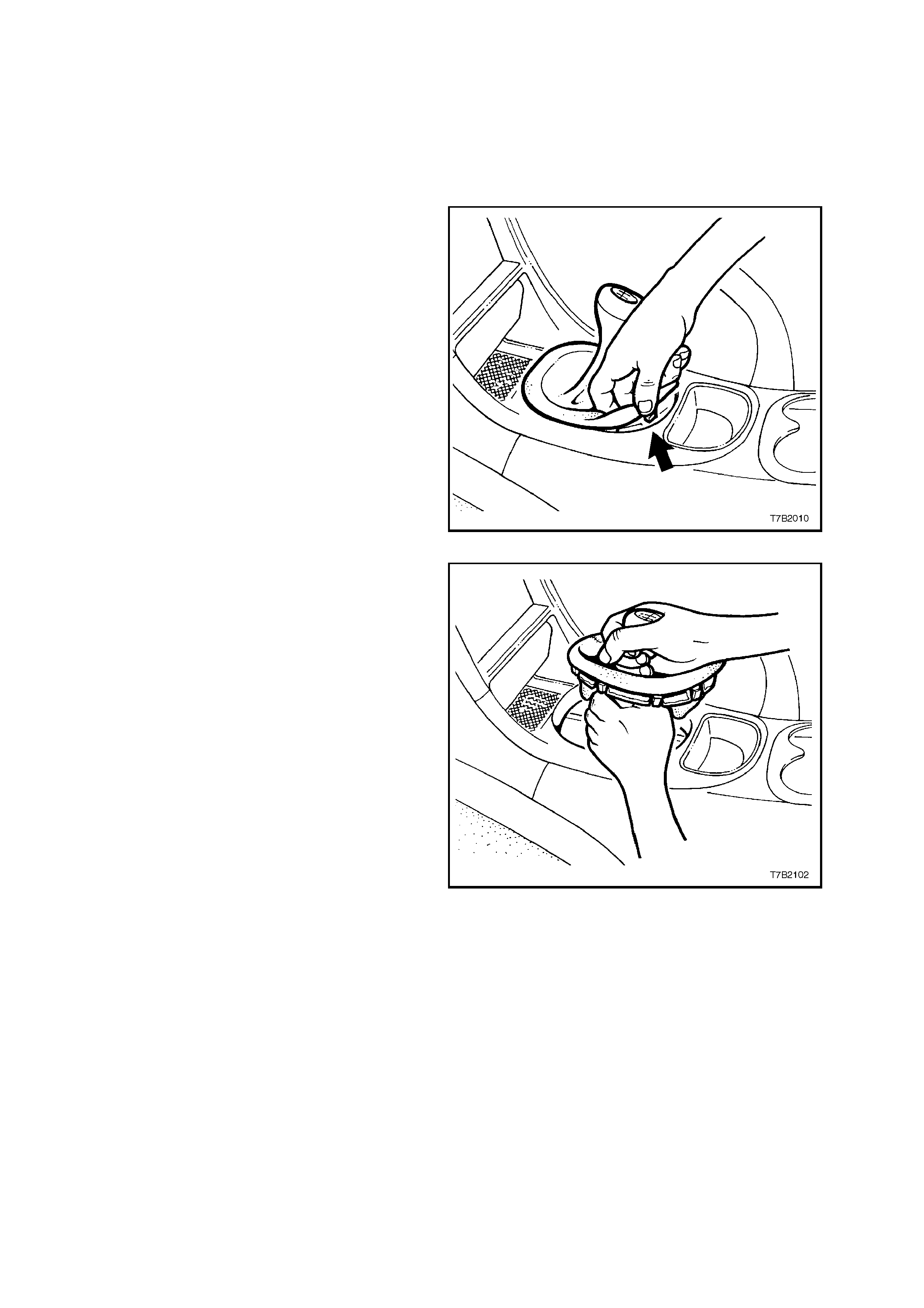
1. With the fingers of one hand hooked under the
edge of the gearshift lever boot as shown,
caref ully release each of the 8 plas tic retainer s
and free the gearshift lever boot from the
console cap.
Figure 7B1-12
2. Lift the gears hif t lever boot enough to enable a
firm grasp to be made on the gearshift lever
with the left hand, then grasp the gearshift
knob with the right.
3. W hile rocking the knob sideways, and with an
upward force applied, dislodge the knob
retaining claws from the lever.
4. Remove the gearshift lever knob and boot
assembly, from the gearshift lever.
Figure 7B12-13
REINSTALL
1. Reinstall the knob and boot as sem bly over the
gearshift lever, align the knob in the correct
attitude and then bump the knob onto the
gearshif t lever until the retaining claws engage
with the groove in the lever.
2. Align the boot retaining clips with the hole in
the console cap, then carefully seat the boot
retainers into the console cap until each clip
engages correctly.
3.4 GEARSHIFT LEVER
REMOVE
1. Remove the gearshift lever knob and boot
assembly, from the gearshift lever. Refer
3.3 GEARSHIFT LEVER KNOB AND BOOT
ASSEMBLY, for the necessary procedure.
2. Raise vehicle front and rear and support
on safety stands. Refer to
Section 0A GENERAL INFORMATION for
the location of jacking points.
3. Scribe around each of the rear engine
mounting c r oss member mounting points to the
vehicle underbody, to provide an alignment
reference for reassembly.
IMPORTANT:
This step is critical to the correct powertrain
alignment on reassembly. If not carried out, then
vehicle vibration and/or handling problems will
result!
NOTE:
For clarity, the exhaust system is shown as being
removed.
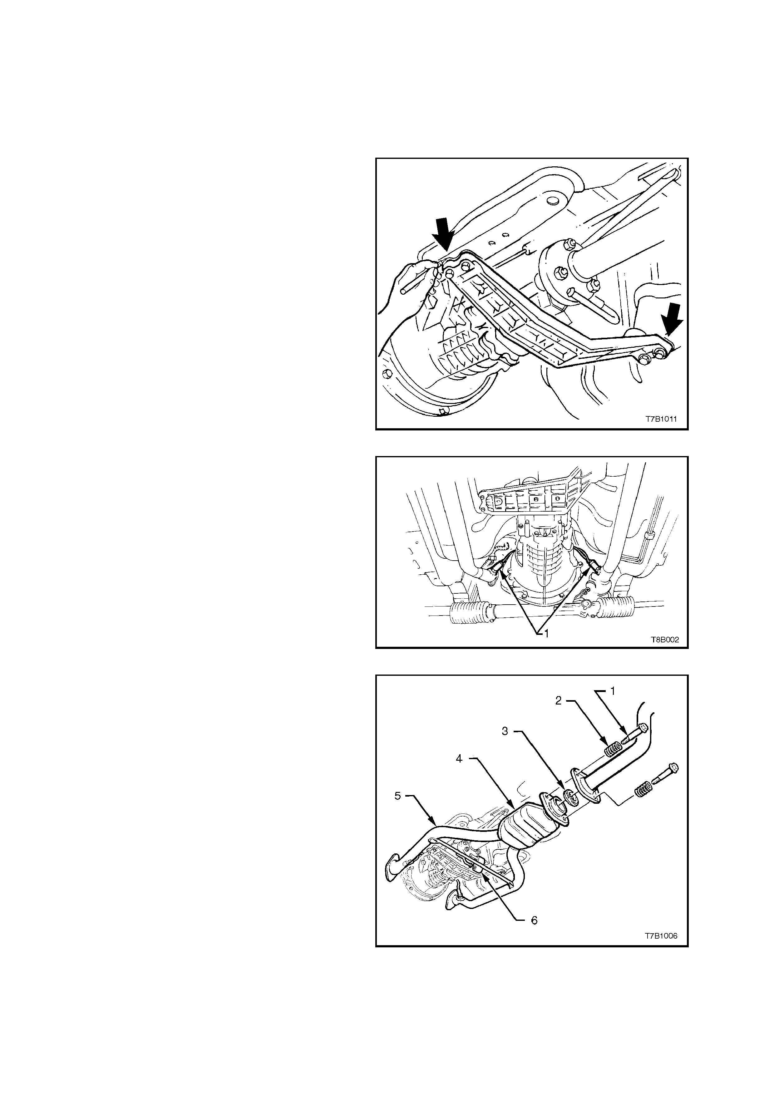
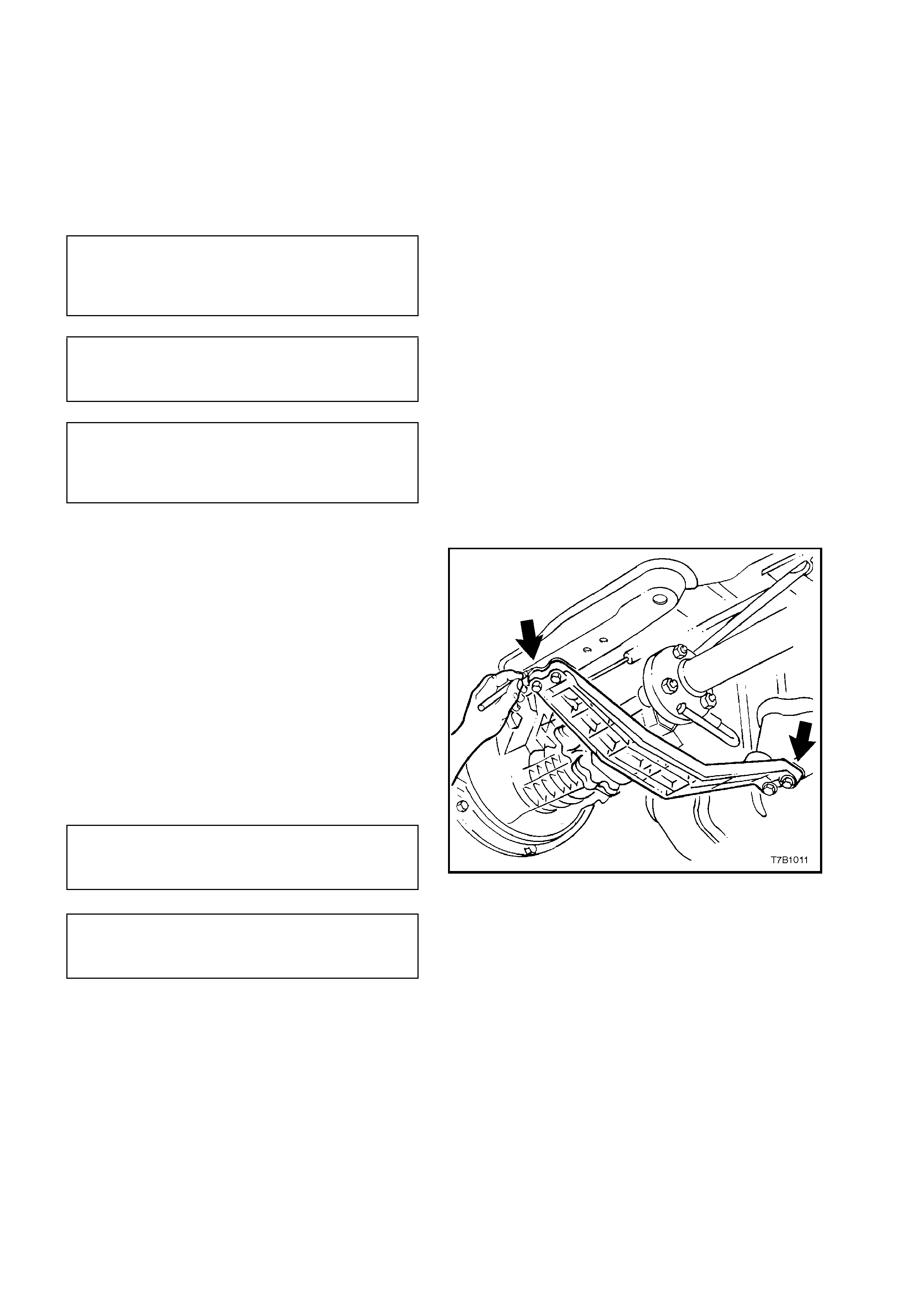
4. Support the rear of the transmission with a
floor jack, then remove the four rear engine
mounting crossmember bolts.
Figure 7B1-14
5. Lower the rear of the transmission, sufficient
to gain access to the front end of the shift
linkage brace.
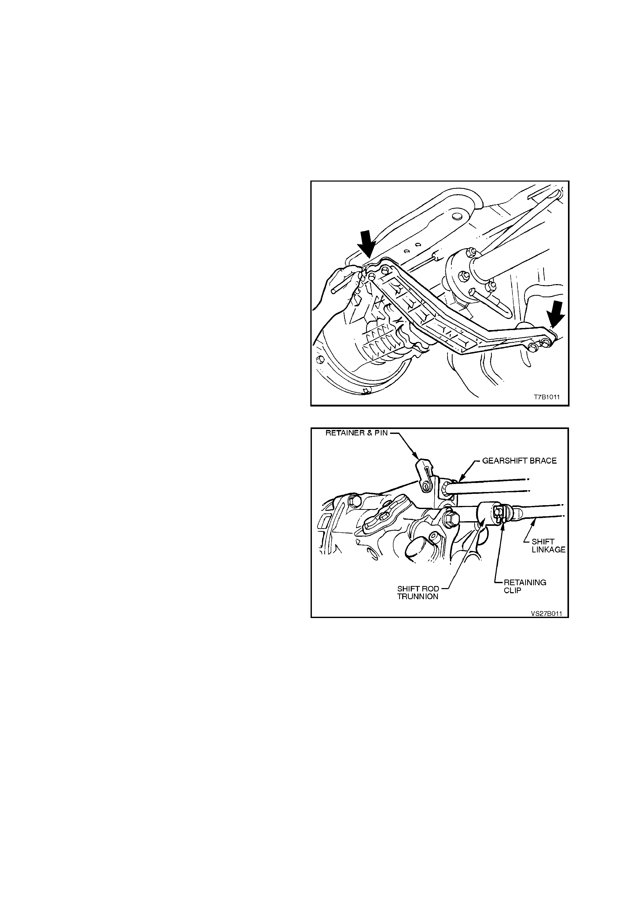
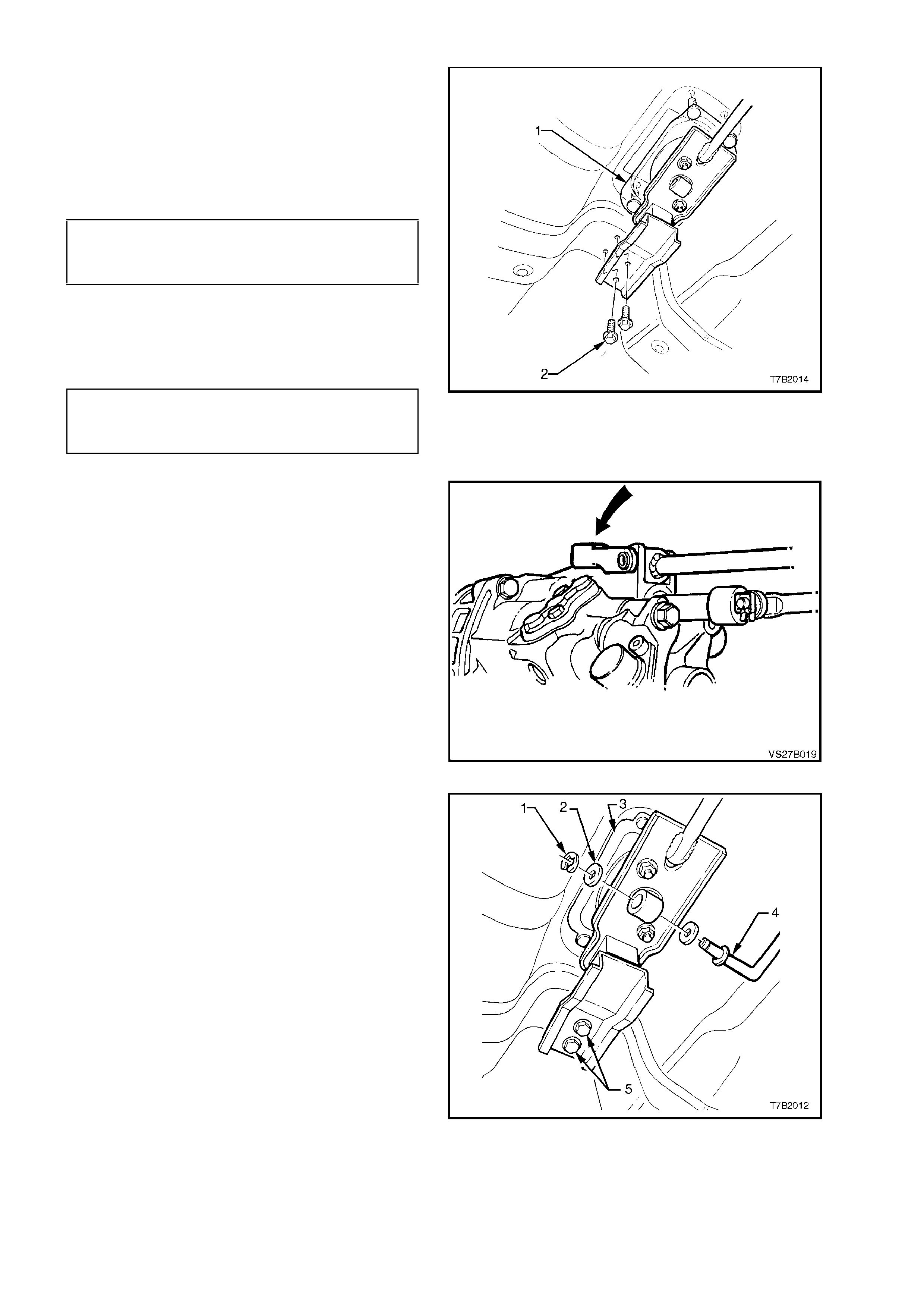
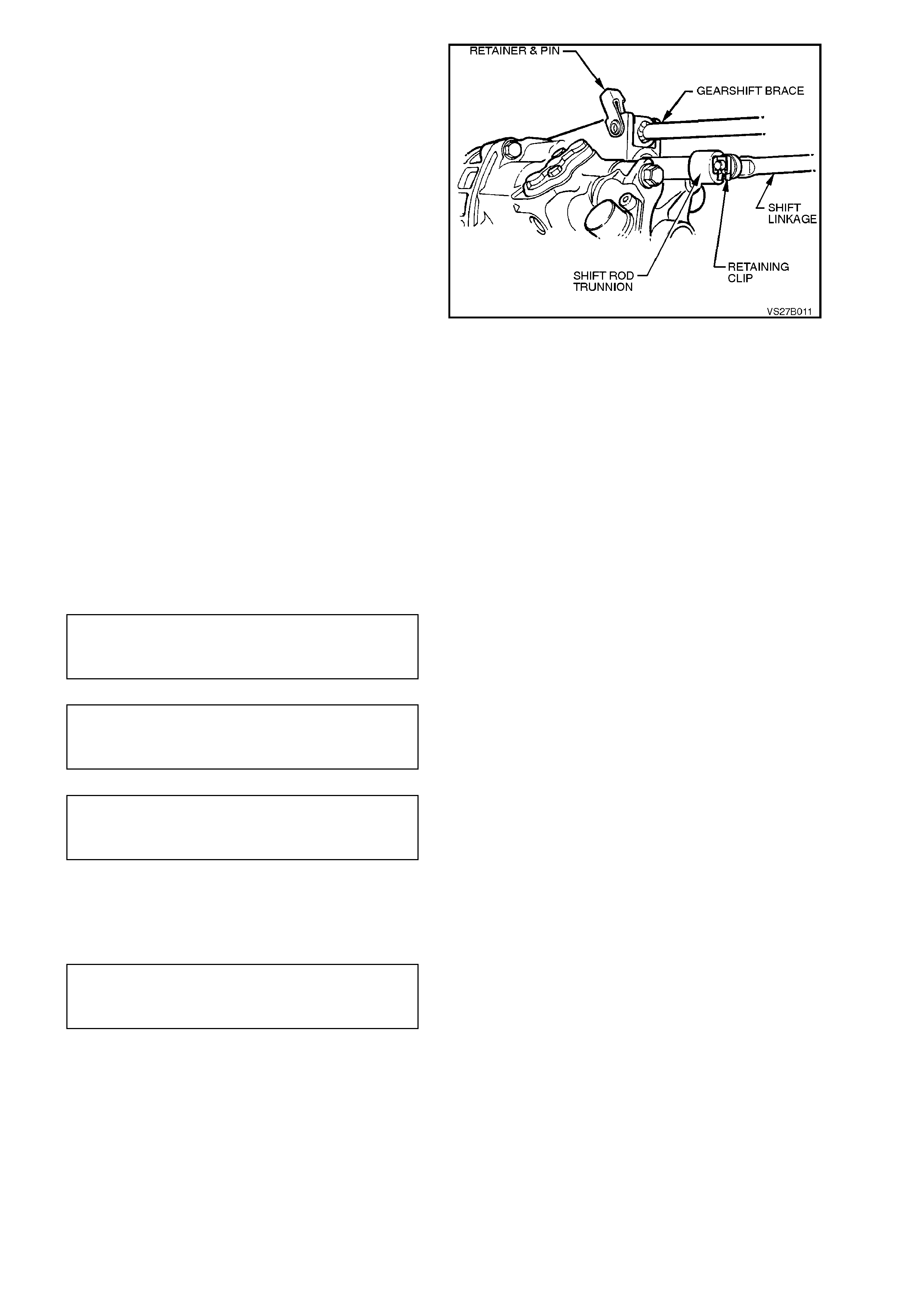
6. From under vehicle, prise the shift linkage
brace retainer loose, at the transmission end,
using a screwdriver or suitable lever.
7. Remove the retainer and pin from the
transmission case lugs.
Figure 7B1-15
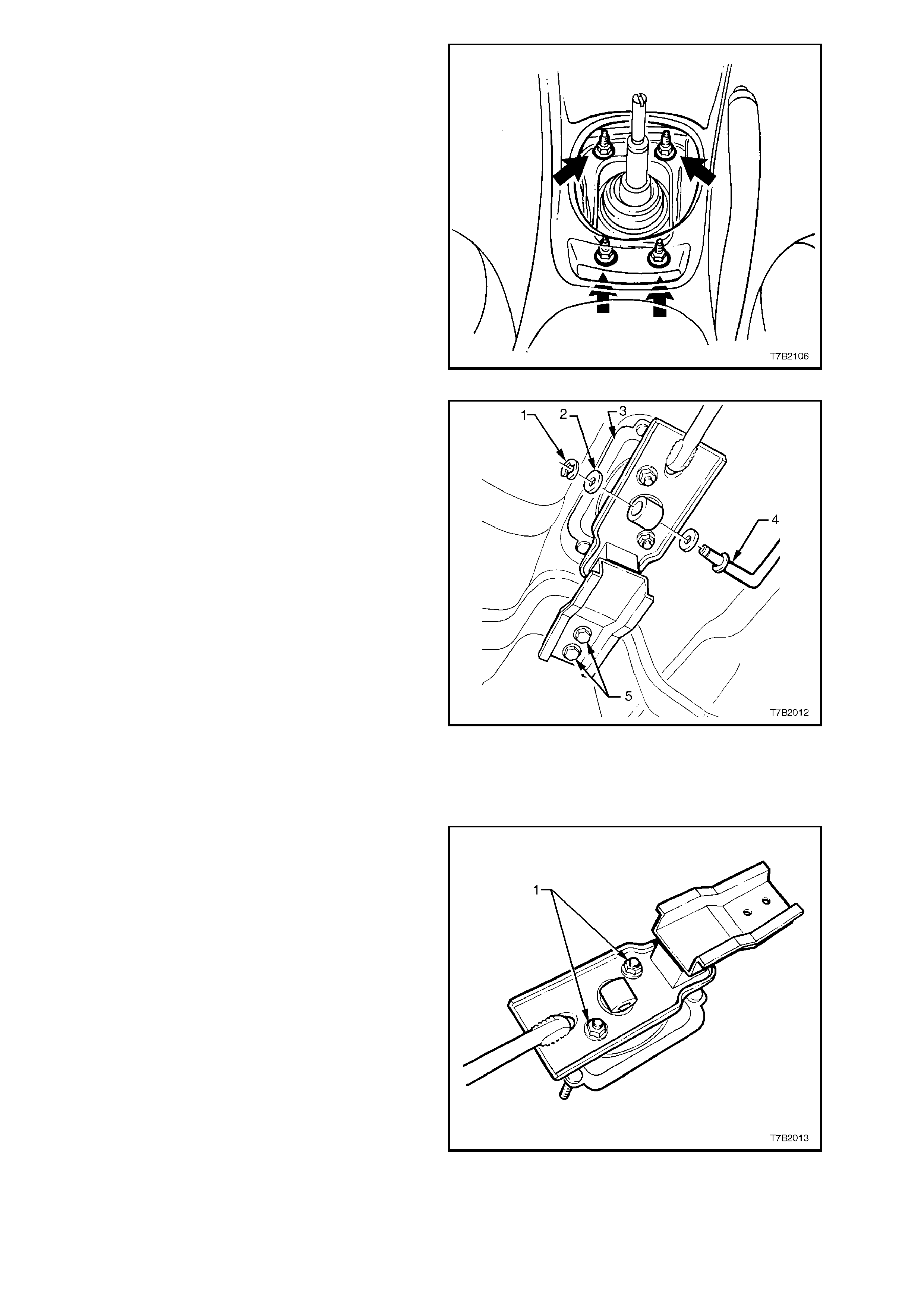
8. Remove the four gearshift lever bracket,
mounting nuts (arrows) from inside the
vehicle.
Figure 7B1-16
9. Remove the retaining C-clip (1) and washer
(2) from the transmission shift rod coupling
(4), at the gearshift lever end.
10. Remove two gearshift lever support mounting
bolts (5) from underfloor bracket.
11. Remove gearshift lever bracket (3), with
rubber boot and the complete br ace as s embly,
from below the vehicle.
NOTE 1:
If the shift rod is disconnected from the
transmission end and removed from the vehicle
with the brace assem bly, take particular note of the
rod’s orientation f or correc t installation. Do not lose
the washer fitted at the inner end of the shift rod
coupling (4).
NOTE 2:
W hile the illustration shows the propeller shaft and
exhaust removed for clarity, removal of the brace
assembly from the vehicle, is possible without first
removing these items.
Figure 7B1-17
DISASSEMBLE
1. Remove both nuts (1) securing the gearshift
lever ball socket retainer, to the mounting
brace.
2. Remove retainer and gearshift lever assem bly
from the brace.
Figure 7B1-18
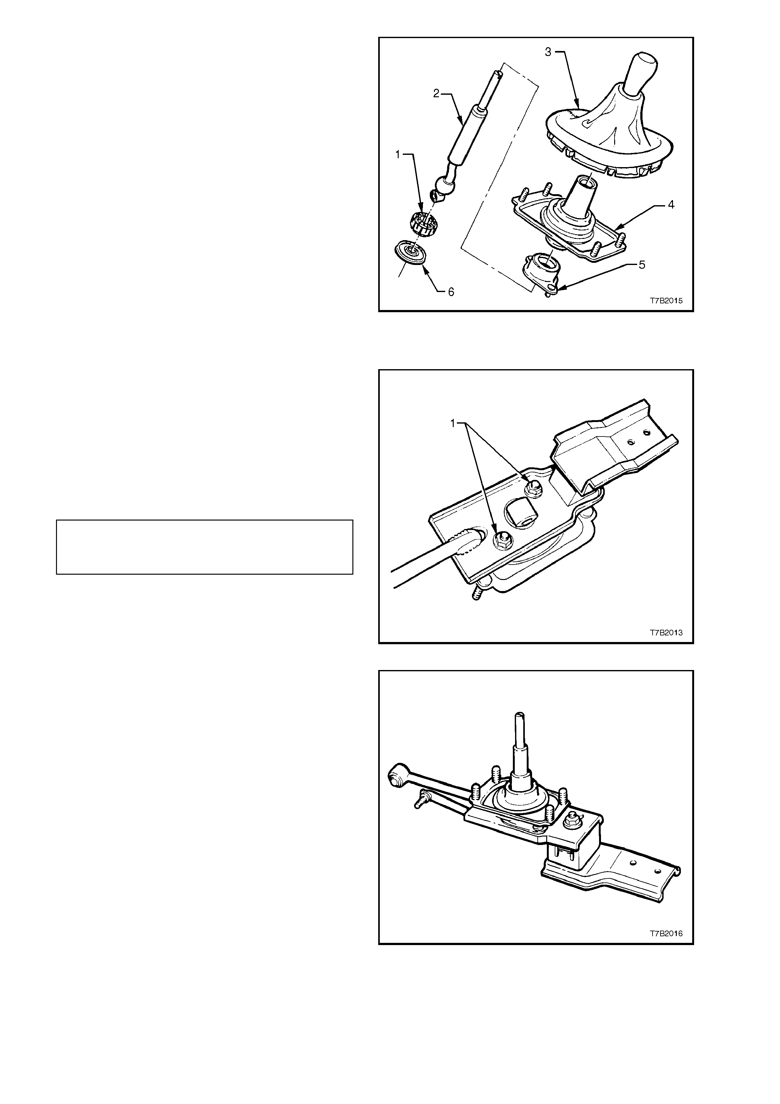
3. Remove the boot and mounting bracket
assembly (4), from the gearshift lever (2).
4. Separate the assem bly by holding the bearing
cover (5) and gently bump the end of the
gearshif t lever (2), to displace the end plate ( 6)
and bearing (1) from the ball of the gearshift
lever.
5. Inspect all components for wear and/or
damage, replacing parts as required.
Figure 7B1-19
REASSEMBLE
Reassembly operations are the reverse of
disassembly, except for the following items.
1. Lubricate the gearshift lever ball and socket
with Lithium grease NLGI No. 4 EP.
2. Install the gearshift lever ball and socket
retainer to the brace, fit the two retaining nuts
(1) and tighten to the correct torque
specification.
GEARSHIFT BALL SOCKET
RETAINER PLATE NUTS 6 - 14 Nm
TORQUE SPECIFICATION
Figure 7B1-20
3. Install the rubber gearshift boot over the
gearshift lever as shown.
Figure 7B1-21
REINSTALL
1. Install gearshift lever assembly into position,
aligning studs with the holes in the floor pan
and the bolt holes in the rubber m ounting, with
the captive nuts on the underbody.
2. Install gearshift lever brace rubber mounting
bolts (2) and tighten to the correct torque
specification.
SHIFT LEVER BRACE, RUBBER
MOUNTING BRACKET BOLT 6 - 14 Nm
TORQUE SPECIFICATION
3. From inside the vehicle, install and tighten the
four, brace (1) to underfloor retaining nuts,
tightening to the correct torque specification.
SHIFT LEVER BRACE TO
UNDERFLOOR RETAINING NUT 6 - 14 Nm
TORQUE SPECIFICATION
Figure 7B1-22
4. Install gearshift brace pin and retainer to the
transmission end, ensuring that the security
lug is firmly in place.
Figure 7B1-23
5. Install gearshif t linkage to the lower end of the
gearshift lever, then install the washer (2) and
C-clip (1).
NOTE:
Ensure that the linkage is only assembled in the
attitude shown. If fitted in the reverse direction, the
linkage may foul, resulting in diff iculty with 2nd gear
selection that can cause damage to the
transmission.
6. Remove safety stands and lower vehicle to
ground.
7. Disconnect battery ground cable.
8. Reinstall gearshift lever knob/boot assembly.
Refer to 3.3 GEARSHIFT LEVER KNOB AND
BOOT ASSEMBLY in this Section, f or spec ific
details.
9. Road test vehicle to check gearshift operation. Figure 7B1-24
ADJUST
No adjustment of the gearshift linkage is required.
3.5 SHIFT LINKAGE BRACE RUBBER MOUNTING AND/OR BUSH
REPLACE
1. Remove the gearshift lever and brace
assembly from the vehicle, as detailed in
3.4 GEARSHIFT LEVER in this Section.
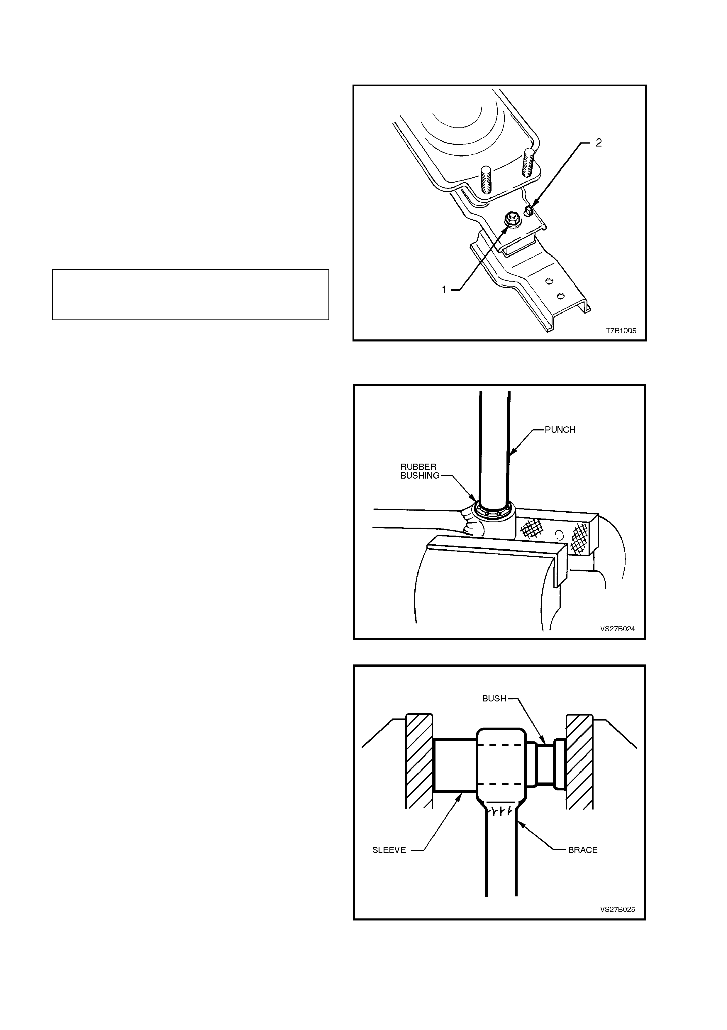
Brace Mounting
2. Remove the rubber mounting from the rear of
the gearshift lever support after removing the
retaining nut (1).
3. Fit the rear mounting to the brace, inserting
the locating tang (2) in the hole provided.
Install the retaining nut (1) and tighten to the
correct torque specification.
REAR GEARSHIFT LINKAGE
RUBBER MOUNTING NUT 22 Nm
TORQUE SPECIFICATION
Figure 7B1-25
Brace Bush
4. Using a suitable sized pin punch and ham m er,
remove the rubber bushing from the
transmission end of the brace assembly,
clamping the eye of the brace between
protected vice jaws.
Figure 7B1-26
5. Using a suitable sized piece of tubing (or
sock et) , over the end of the brac e eye, use the
clamping effect of a bench vice to install the
replacement rubber bush.
NOTE:
Dip the replacement bushing in a soap solution to
assist in the installation process.
6. Reinstall the brace and gearshift assembly into
the vehicle, as detailed in
3.4 GEARSHIFT LEVER in this Section.
Figure 7B1-27
4. MAJOR SERVICE OPERATIONS
4.1 SPEED SENSOR TOOTHED RING OR TRANSMISSION CASE REAR SEAL
REMOVE
1. Disconnect battery earth lead.
2. Raise front and rear of vehicle, supporting
on safety stands. Refer to
Section 0A GENERAL INFORMATION for
the location of jacking points.
3. Scribe around each of the rear engine
mounting c r oss member mounting points to the
vehicle underbody, to provide an alignment
reference for reassembly.
IMPORTANT:
This step is critical to the correct powertrain
alignment on reassembly. If not carried out, then
vehicle vibration and/or handling problems will
result!
4. Support the rear of the transmission with a
floor jack, then remove the four rear engine
mounting crossmember bolts.
Figure 7B1-28
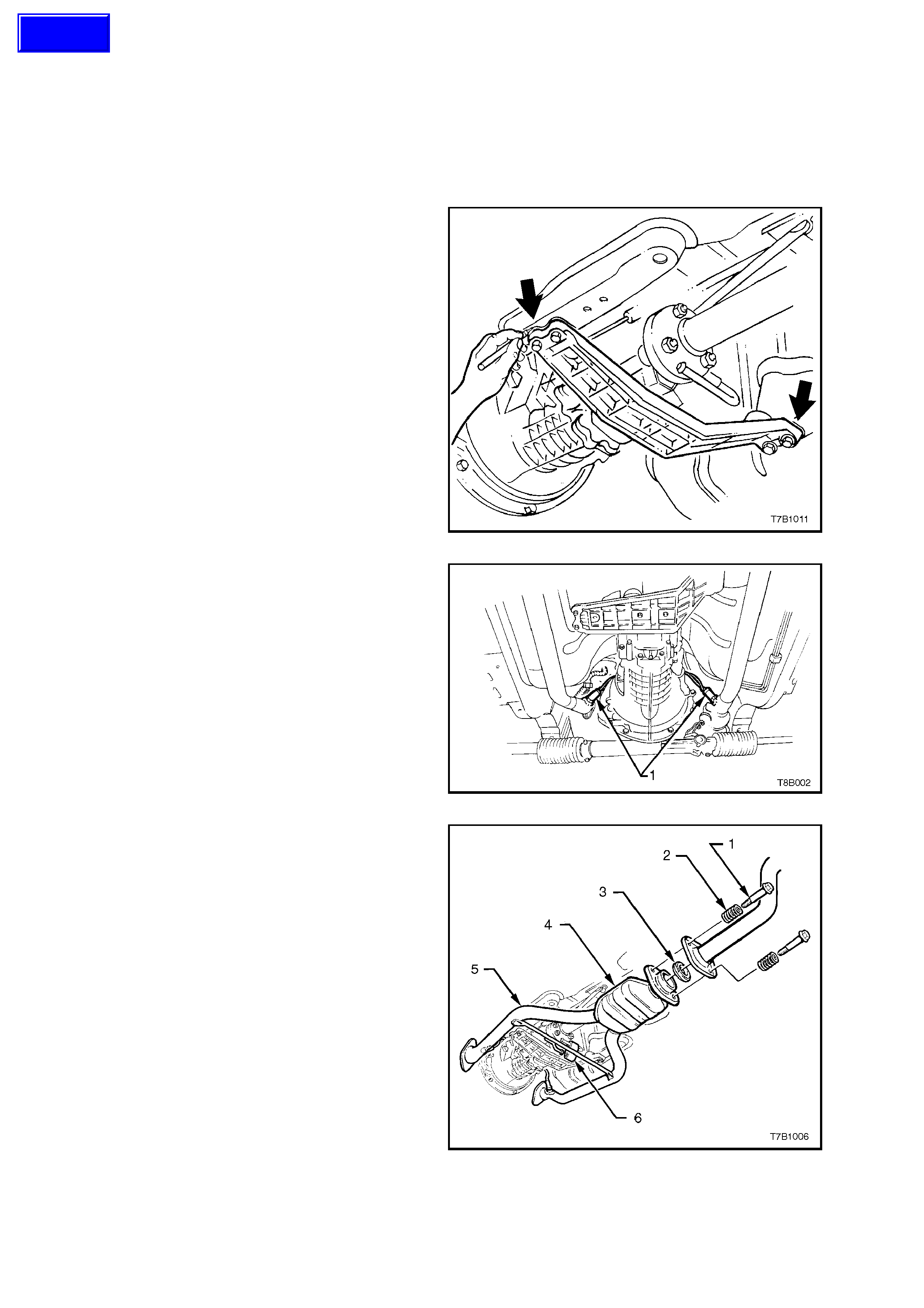
4. Disconnect wiring harness connectors from
each of the two oxygen sensors (1).
Figure 7B1-29
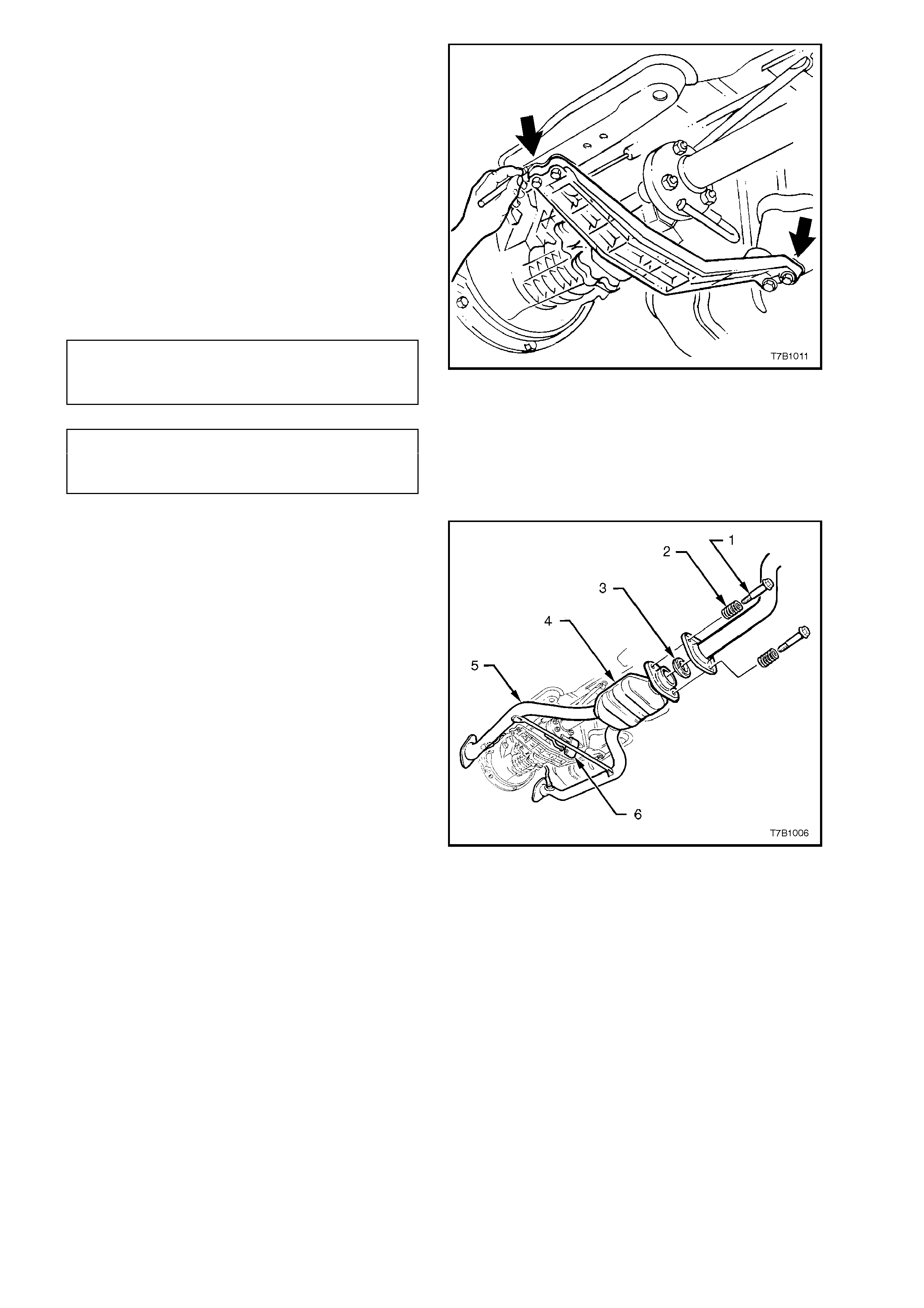
5. Then remove the twin exhaust pipe (5) and
catalytic converter (4) from the exhaust
manif olds, the s upport rubber (6) at the rear of
the transm ission and the interm ediate exhaust
pipe, after removing the two bolts (1), springs
(2) and seal ring (3).
Figure 7B1-30
6. Support weight of transm ission as sembly on a
transmission jack.
7. Remove engine rear crossmember to side
frame attaching bolts (2).
8. Remove crossmember to rear mounting
attaching nuts (3) from the reaar engine
mounting (4), then remove crossmember (1)
from the vehicle.
NOTE:
Illustration does not show transmission jack in
position, for clarity of the crossmember orientation.
Figure 7B1-31
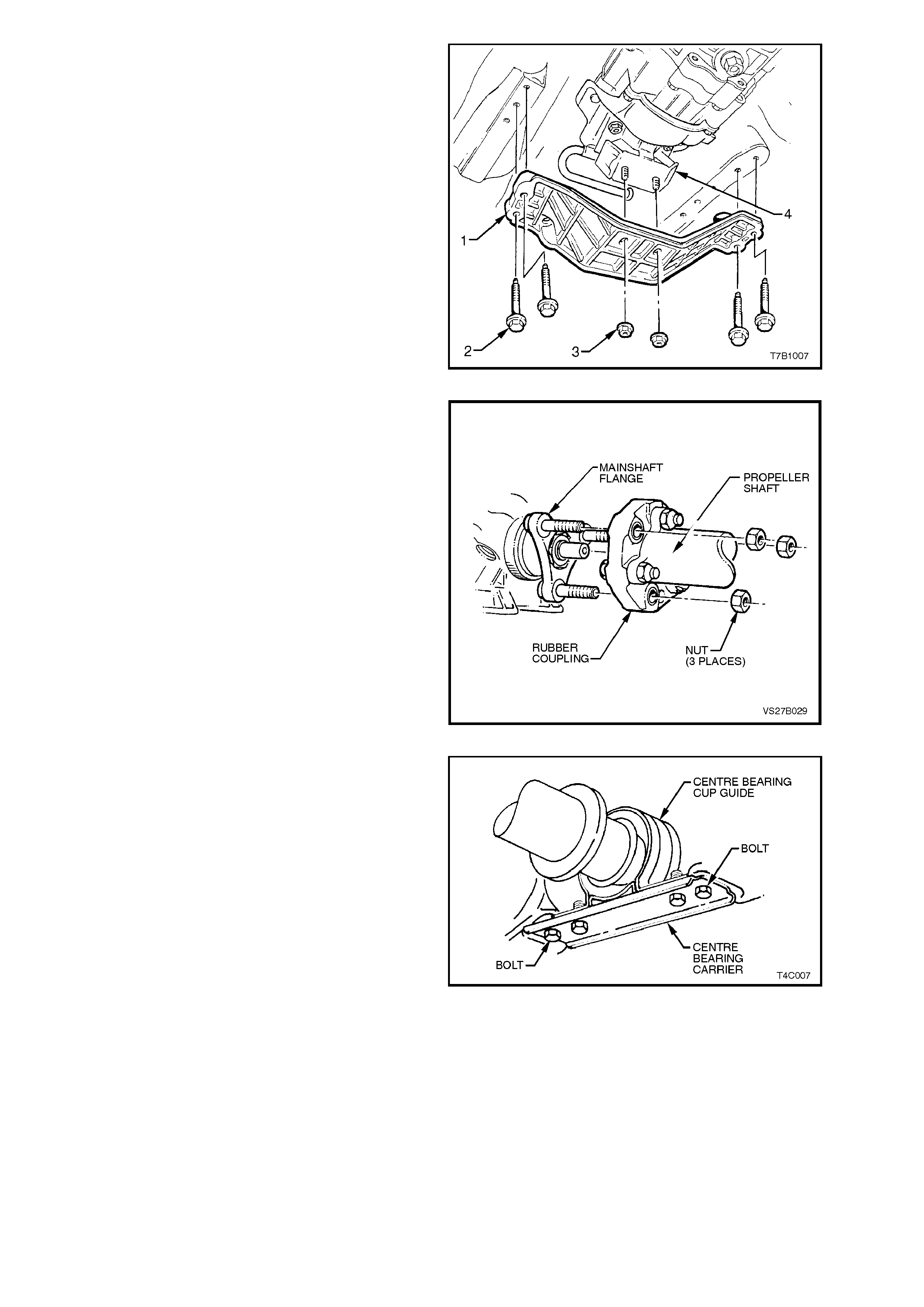
8. Remove propeller shaft flexible rubber
coupling to mainshaft flange attaching nuts.
Figure 7B1-32
9. Remove centre bearing carrier to underbody
reinforcement bolts and spacers.
NOTE:
For correct reassembly, take particular note of any
spacer arrangement that may be fitted, observing
any side to side variations and the orientation of the
bracket offset.
Figure 7B1-33
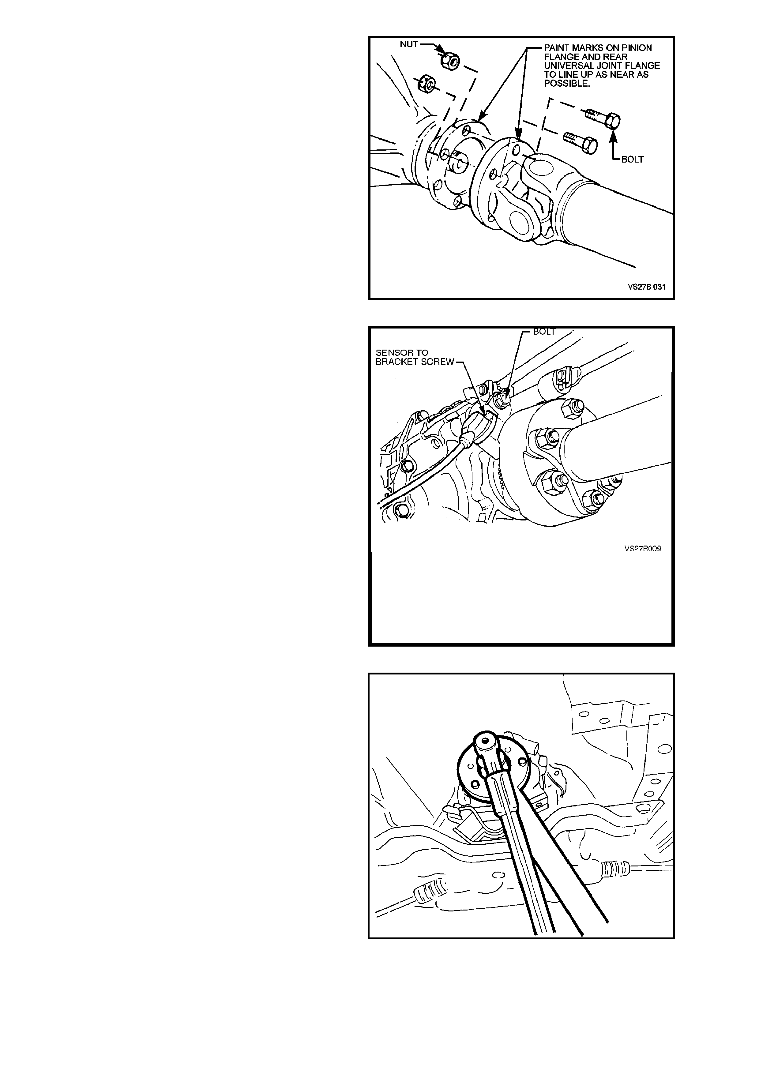
10. Remove bolts and nuts holding propeller shaft
rear universal joint flange to pinion flange.
Disengage rear universal joint flange from
pinion flange.
NOTE:
The two flanges have paint alignment marks that
are assem bled as c lose together as pos sible. If the
marks are not visible, scribe a mark on both
flanges so that they may be reinstalled in their
correct position.
11. Remove propeller shaft by pulling it toward
rear of vehicle to disengage rubber coupling
from mainshaft flange.
Figure 7B1-34
12. Remove the speed sensor bracket retaining
bolt from the rear of the transmission, remove
the sensor and bracket and secure to the
underbody with a piece of tie wire.
Figure 7B1-35
13. To use the previously released, Tool No. KM-
620-1-A to hold the flange, it must first be
modified by redrilling the three holes stamped
‘B’ (on the Tool) to 13 mm.
Fasten the modified tool to the flange using
the three discarded nuts. Then, using a
suitable length of pipe on the tool, loosen and
remove flange nut, using a commercially
available, 30 mm deep socket.
Figure 7B1-36
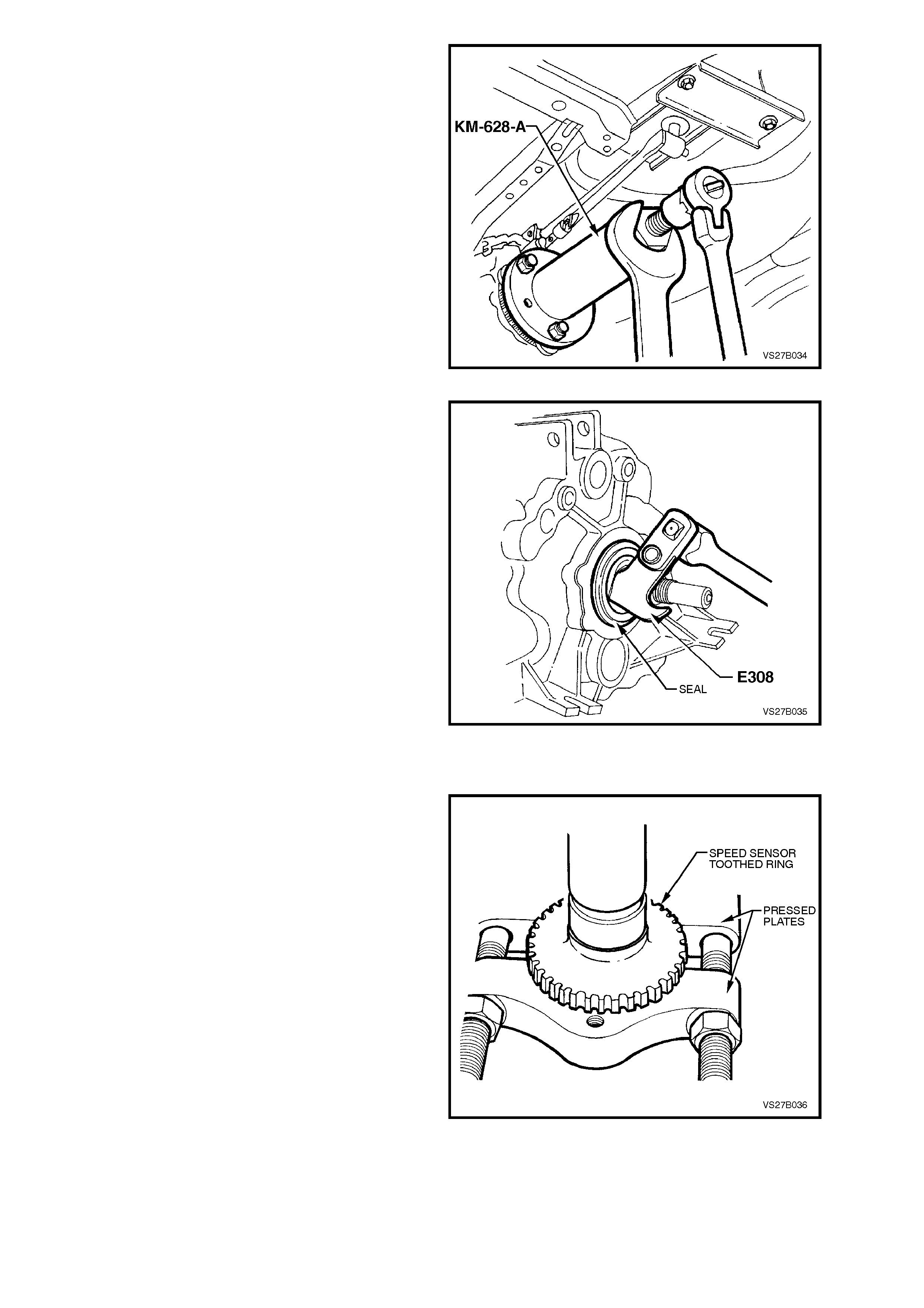
14. Place a drain tray beneath transmission.
15. Install extractor, Tool No. AKM-628-A to output
shaft flange.
16. Tighten extractor forcing bolt and remove
flange and speed sensor toothed ring, from
output shaft.
17. Inspect the sealing surface of the flange for
damage. Replace as necessary.
NOTE:
Tak e care that no tooth dam age takes place to the
speed sensor toothed ring while the flange is
removed.
Figure 7B1-37
18. Using a seal remover such as Tool No. E308
or a suitable lever, remove the seal from the
transmission case .
Figure 7B1-38
SPEED SENSOR TOOTHED RING - REPLACE
NOTE:
Only perform this operation if the speed sensor
toothed ring is damaged or the flange is being
replaced.
1. Use press plates such as J22912-01
(previously released as E6673) or commercial
equivalent, fitted under the speed sensor
toothed ring, with the flat side against the
toothed ring, then press from the mainshaft
flange.
NOTE:
A new toothed ring must be fitted after removal,
because of the risk of tooth dam age. To achieve an
accurate speed sens or reading, it is abs olutely vital
that no tooth damage is evident.
2. Using a suitable diameter and length of pipe,
carefully press the replacement toothed ring
onto the mainshaft output flange.
NOTE:
Ensure that the mainshaft output flange is
supported on the machined inner boss and not on
the three studs, during the installation process.
Figure 7B1-39
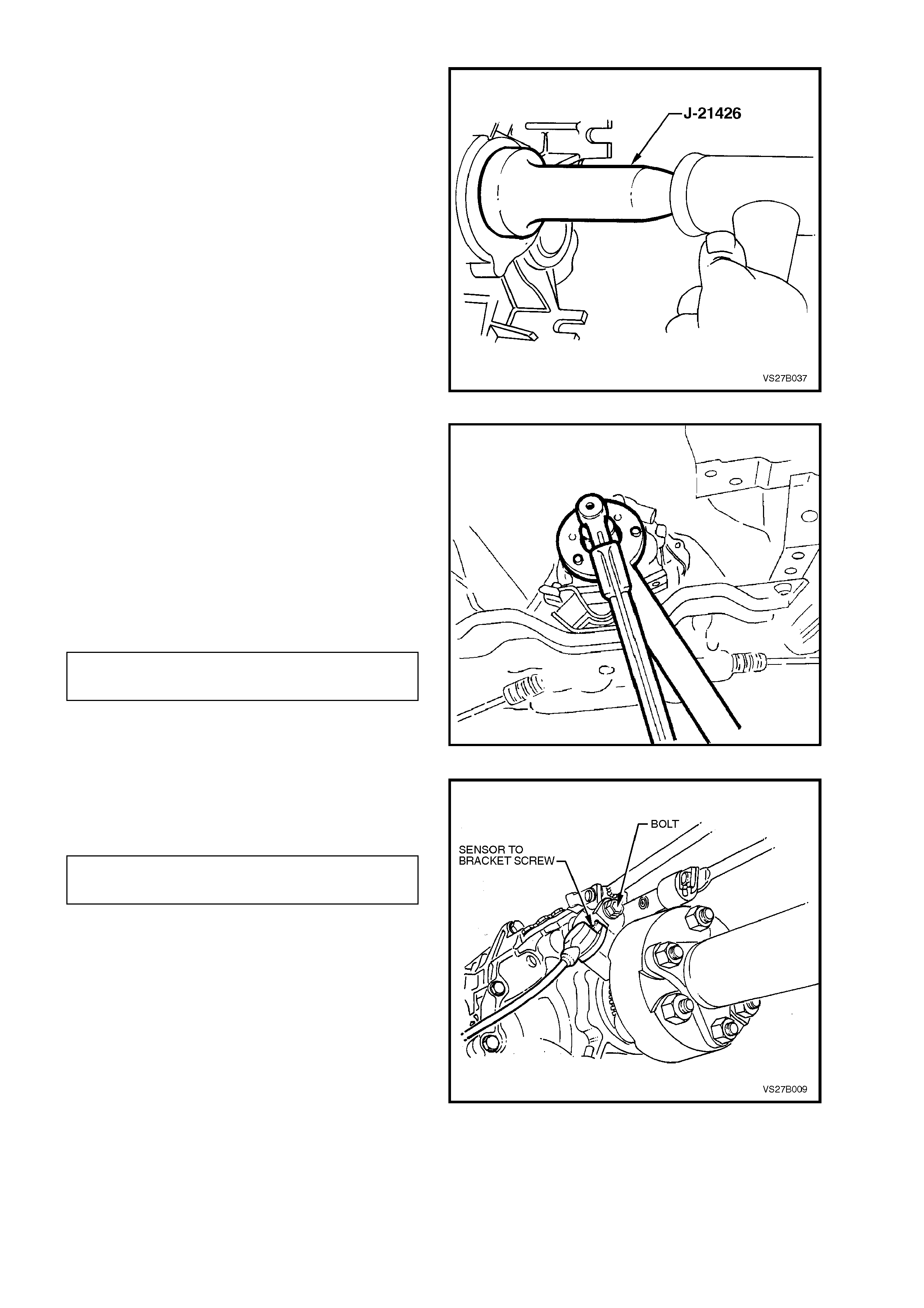
REINSTALL
1. Lubricate seal surface of spacer with
transmission lubricant and install over the
mainshaft.
2. After lubricating the seal lip with transmission
lubricant, use previously released Tool No. J-
21426 (or similar ) and ins tall the new seal over
the sleeve and into the transmiss ion rear case
housing.
Figure 7B1-40
3. Install flange and toothed ring onto mainshaft,
using the original flange nut to pull the
assembly fully into place. Use Tool No. KM-
620-1-A to hold the flange during this process.
4. Remove the original nut and replace with a
new nut that has had thread sealant such as
Loctite 242 or 243 (or equivalent to Holden’s
Specification HN1256) applied to the threads.
5. Again using modified Tool No. KM-620-1-A to
hold flange, tighten the new flange nut to the
correct torque specification.
MAINSHAFT FLANGE NUT 100
TORQUE SPECIFICATION Nm
Figure 7B1-41
6. Reinstall speed sensor and bracket assembly,
tightening the retaining bolt to the correct
torque specification.
SPEED SENSOR RETAINING 6 - 14
SCREW TORQUE SPECIFICATION6 Nm
Figure 7B1-42
7. Install propeller shaft rubber coupling to
transmission mainshaft flange and loosely
install NEW attaching nuts.
8. Lift propeller shaft upward and install centre
bearing carrier to underbody reinforcement,
ensuring that any spacers are placed in the
same positions, noted on removal. Install
retaining bolts.
9. Assemble propeller shaft rear universal joint
flange to pinion flange and install attaching
bolts and nuts.
10. Tighten all propeller shaft attaching bolts to
the correct torque specification.
PROPELLER SHAFT RUBBER
COUPLING TO TRANSMISSION
OUTPUT FLANGE NUT, 74 - 80 Nm
TORQUE SPECIFICATION
CENTRE BEARING CARRIER
TO UNDERBODY REINFORCEMENT 20 - 25 Nm
BOLT, TORQUE SPECIFICATION
PROPELLER SHAFT REAR
UNIVERSAL JOINT FLANGE TO
PINION FLANGE BOLT 55 - 60 Nm
TORQUE SPECIFICATION
11. Install rear crossmember to rear mounting,
install washers and attaching nuts.
12. Loosely install rear crossmember to side
frame member bolts.
13. Carefully align the scribed marks made prior to
rem oval, then tighten the four cross mem ber to
side frame bolts.
IMPORTANT:
This step is critical to the correct powertrain
alignment. If not carried out, then vehicle vibration
and/or handling problems will result!
14. Remove transmission jack.
15. After checking to see that the crossmember
position has not changed, tighten the four
crossmember to side frame bolts and the rear
mounting nuts to the correct torque.
REAR CROSSMEMBER TO REAR
MOUNTING ATTACHING NUT 20 - 30 Nm
TORQUE SPECIFICATION
REAR CROSSMEMBER TO SIDE
FRAME MEMBER BOLT 50 - 65 Nm
TORQUE SPECIFICATION
Figure 7B1-43
16. Reinstall exhaust system, tightening fasteners
as detailed in Sections 8B EXHAUST
SYSTEM.
17. Check transmission lubricant level and top up
as necessary, refer 2.2 CHECKING
TRANSMISSION LUBRICANT LEVEL in this
Section.
18. Remove jack stands and lower vehicle to the
ground.
19. Reconnect battery ground lead.
4.2 TRANSMISSION ASSEMBLY
REMOVE
1. Disconnect battery ground lead.
2. Raise vehicle front and rear and support on
safety stands. Refer to Section 0A
GENERAL INFORMATION for the location of
jacking points.
3. Use a sharp s criber to m ark the exac t location
of the crossm ember to the side fram e, before
loosening any of the four cr ossm em ber to side
frame attaching bolts.
IMPORTANT:
This step is critical to the correct powertrain
alignment on reassembly. If not carried out, then
vehicle vibration and/or handling problems will
result!
Figure 7B1-44
3. Disconnect wiring harness connectors from
each of the two oxygen sensors (1).
Figure 7B1-45
4. Then remove the twin exhaust pipe (5) and
catalytic converter (4) from the exhaust
manif olds, the s upport rubber (6) at the rear of
the transm ission and the interm ediate exhaust
pipe, after removing the two bolts (1), springs
(2) and seal ring (3).
5. Depending on the reason for removal, it might
be opportune to drain the transmission
lubricant into a clean container. Refer to the
procedure detailed in 2.3 DRAINING AND
REFILLING TRANSMISSION in this Section.
NOTE:
Regardless of the reasons for the transmission
being removed, if the lubricant is drained prior to
rem oval, then it is good pr actice to car efully inspect
the magnet in the drain plug and the fluid for
foreign matter such as metal particles, etc.
Figure 7B1-46
Techline

6. Support weight of transm ission as sembly on a
transmission jack.
7. Remove engine rear crossmember to side
frame attaching bolts (2).
8. Remove crossmember to rear mounting
attaching nuts (3) from the rear engine
mounting (4), then remove the crossmember
(1) from the vehicle.
NOTE:
Illustration does not show transmission jack in
position, for clarity of the crossmember orientation.
Figure 7B1-47
9. Remove propeller shaft flexible rubber
coupling to mainshaft flange, crimped
attaching nuts. Discard the nuts.
Figure 7B1-48
10. Remove centre bearing carrier to underbody
reinforcement bolts and spacers.
NOTE:
For correct reassembly, take particular note of any
spacer arrangement that may be fitted, observing
any side to side variations and the orientation of the
bracket offset.
Figure 7B1-49
11. Remove bolts and nuts holding propeller shaft
rear universal joint flange to pinion flange.
Discard the crimped nuts.
Disengage rear universal joint flange from
pinion flange.
NOTE:
The two flanges have paint alignment marks that
are assembled as close together as possible.
If the marks are not visible, scribe a mark on both
flanges so that they may be reinstalled in their
correct position.
12. Remove propeller shaft by first disengaging
the shaft assembly from the pinion flange,
then pull toward rear of vehicle to disengage
rubber coupling from mainshaft flange.
Remove the complete assembly from the
vehicle. Figure 7B1-50
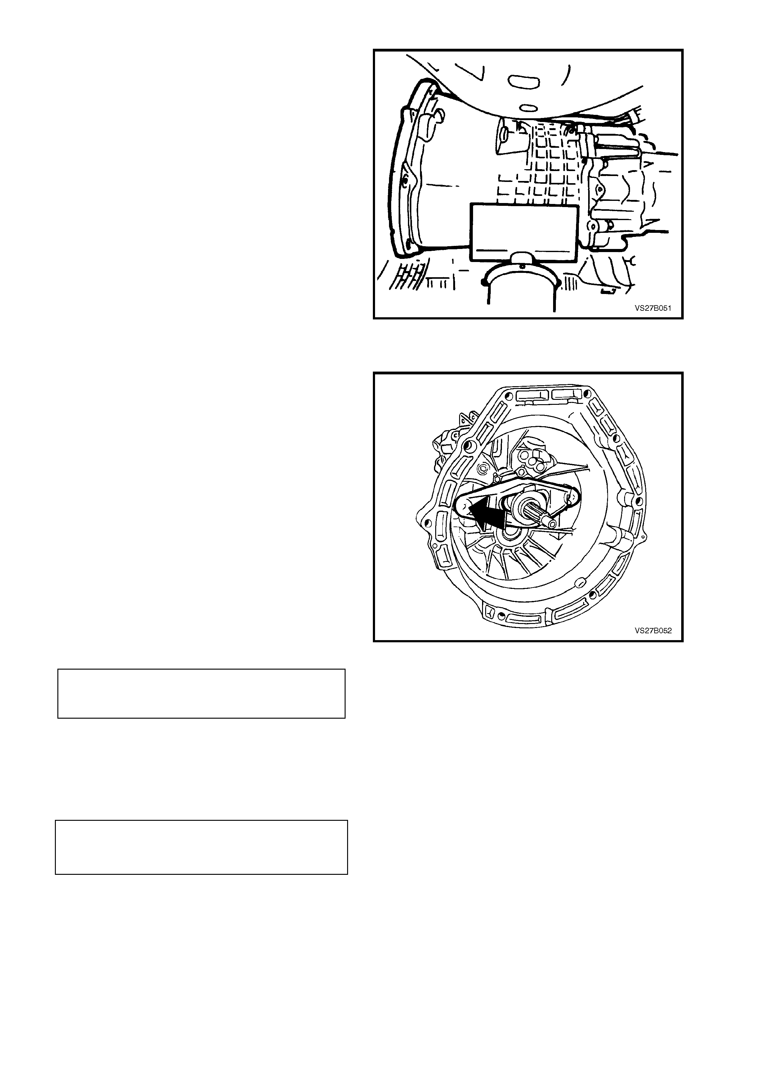
13. Disconnect the speed sensor wiring harness
connector on the left hand side of the
transmission.
Figure 7B1-51
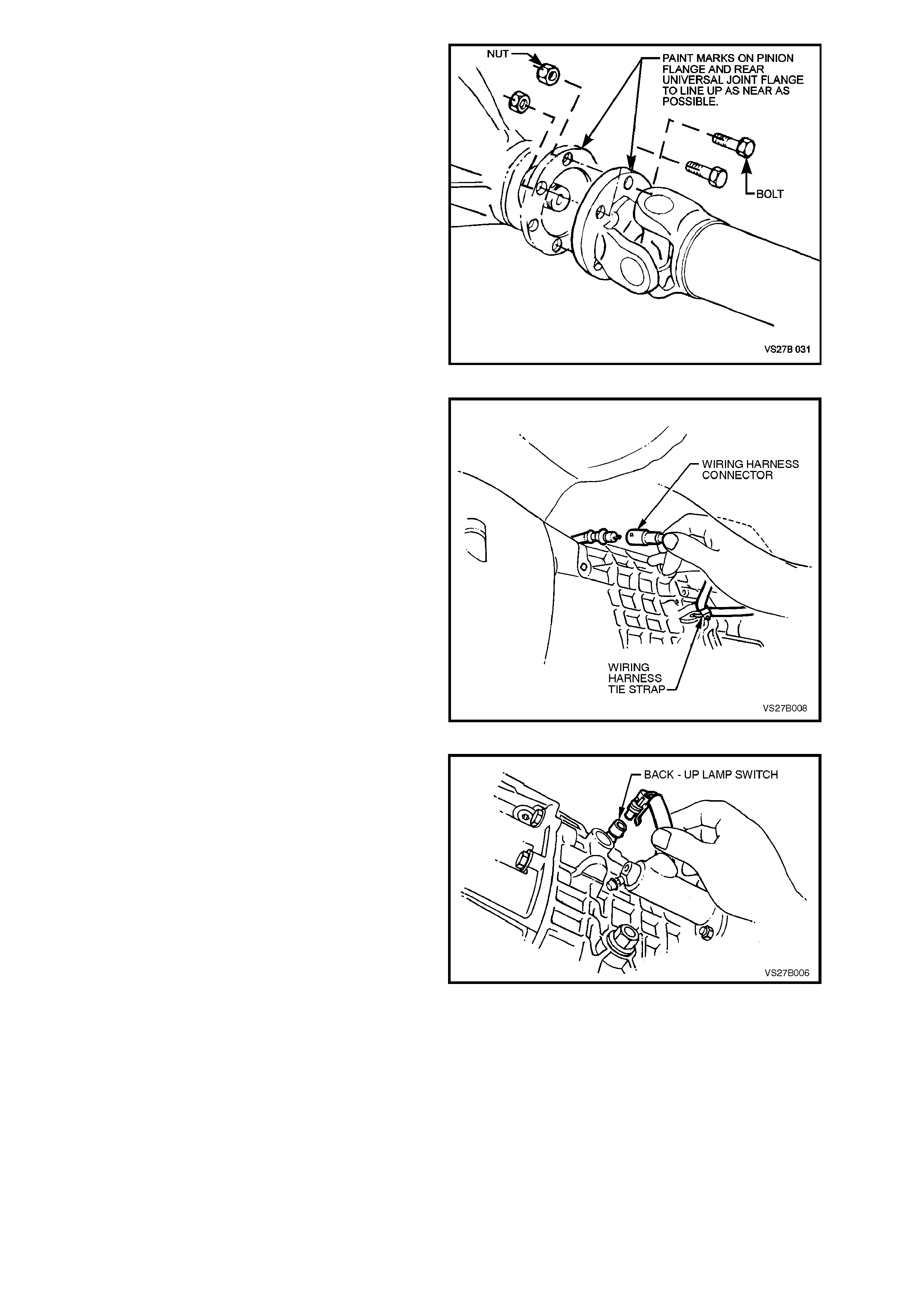
14. Disconnect wiring harness connector from
back up lamp switch.
Figure 7B1-52
15. Remove clutch actuating cylinder retaining
nuts, remove the cylinder (1) from the
transm ission case and s ecure to one side with
tie wire or similar.
Figure 7B1-53
16. Remove transmission to engine brace
attaching bolts (2) from the clutch housing (1).
Braces (3) can remain bolted to the engine oil
pan but the front lower cover cannot be
removed until the transmission is removed.
17. Remove two screws securing the lower
flywheel cover plate to the transmission clutch
housing.
NOTE:
The right hand side screw also has a wiring
harness clip.
18. Lower transmission slowly on jack, still
supporting weight of transmission.
Figure 7B1-54
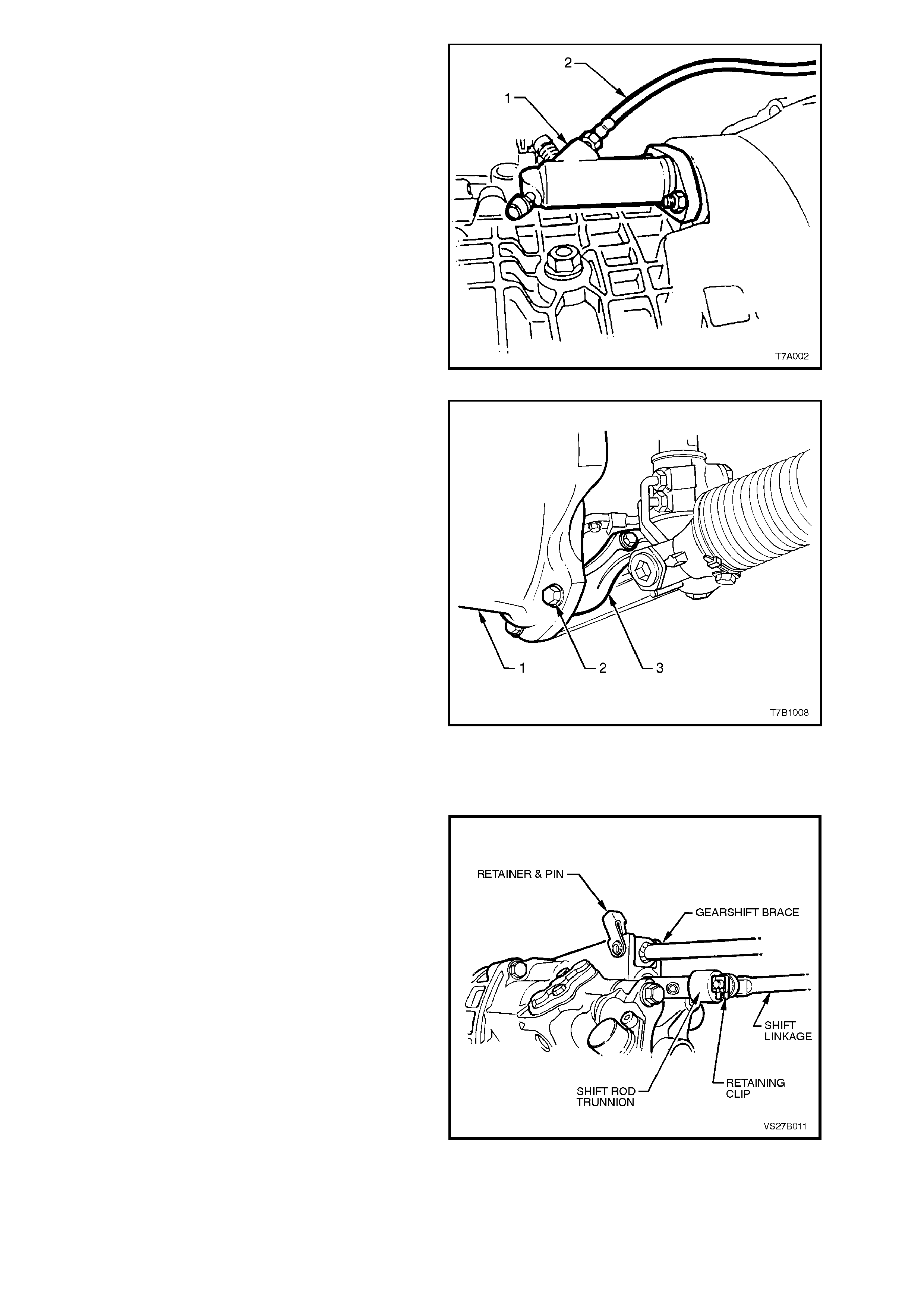
19. Disconnect wiring harness from two retaining
clips; one on top of the transm ission case, the
other on the right hand side.
20. Using a screwdriver, remove retainer from
shift rod at the transmission end.
21. Using a suitable lever, prise the shift linkage
brace retaining bracket from the transmission
lug, then remove retainer and pin assembly
from brace and transmission.
Figure 7B1-55
22. Remove transmission case to engine block
attaching bolts.
23. Withdraw transmission from the engine block
and clutch driven plate.
NOTE:
Keep the transmission assembly supported so that
it does not tilt in relation to the engine, until the
maindrive gear splines are clear of the clutch
driven plate. If the transmission is allowed to hang
on the splines, the clutch driven plate will be
damaged.
Figure 7B1-56
REINSTALL
1. Put transmission into 4th gear.
2. Apply a thin coating of Special High
Tem per ature grease ( to Holden's Spec ification
HN1227) to maindrive gear splines. Push the
clutch throwout bearing into the fully released
position (toward the transmission), ensuring
that placement with the throwout fork, is
correct. Lubricate the spigot end of the
transmission input shaft with a smear of SAE
90 Gear Oil
3. Raise transmission on jack and install
maindrive gear into splines of clutch driven
plate and push transmission toward engine
block . It may be necessary to rotate the output
flange to assist in spline alignment.
4. Install flywheel lower cover plate before
pushing the transmission fully home on to the
guide pins, then install the two retaining
screws and tighten to the correct torque.
FLYWHEEL LOWER
COVER PLATE SCREW 5 - 10 Nm
TORQUE SPECIFICATION
5. Install and tighten clutch housing to engine
block attaching bolts and nut. Also install the
two clutch housing to beaming brace bolts,
tightening all to the correct torque
specification.
CLUTCH HOUSING TO ENGINE
BLOCK AND BEAMING BRACE 50 - 85 Nm
BOLT TORQUE SPECIFICATION
6. Using transmission jack, support transmission
in a lower than installed position.
7. Install wiring harness into retaining clips.
Figure 7B1-57
8. Align the shift linkage brace/bush and the
transm ission lug holes. Install the pin from the
left hand side, then rotate, to engage the
retaining clip with the transmission lug. Tap to
fully engage the clip with the lug.
9. Raise the transmission assembly into the
installed position.
10. Fit a washer to the inner end of the shift
linkage pin, apply a small amount of
Molybdenum Disulphide grease (Holden’s
Specification HN1461) to the pin, then install
into the transmission shift rod trunnion. Install
a second washer to the shift linkage pin, then
secure with the retaining clip.
11. Install wiring harness connector to back up
lamp switch and to the speed sensor.
12. Assemble propeller shaft flexible rubber
coupling to transmission mainshaft flange and
loosely install NEW attaching nuts.
13. Lift propeller shaft upward and install centre
bearing carrier to underbody reinforcement,
ensuring that all spacers are replaced in the
same positions, noted on removal. Install
retaining bolts.
Figure 7B1-58
14. Assemble propeller shaft rear universal joint
flange to pinion flange and install attaching
bolts and nuts.
15. Tighten all propeller shaft attaching bolts to
the correct torque specification.
PROPELLER SHAFT RUBBER
COUPLING TO OUTPUT FLANGE 74 - 80 Nm
NUT TORQUE SPECIFICATION
CENTRE BEARING CARRIER TO
UNDERBODY REINFORCEMENT 20 - 25 Nm
BOLT TORQUE SPECIFICATION
PROPELLER SHAFT REAR
UNIVERSAL JOINT FLANGE BOLT 55 - 60 Nm
TORQUE SPECIFICATION
16. Install clutch actuating cylinder to transm iss ion
case, install the nuts and tighten to the correc t
torque specification.
CLUTCH ACTUATING CYLINDER
RETAINING NUT 22 Nm
TORQUE SPECIFICATION
NOTE:
When the actuating cylinder is engaged with the
mounting studs, the internal spring will hold the
flange out from the fully installed position, by
approximately 25 mm. Hold the cylinder in against
this spring force, to start the retaining nuts.
17. Install rear crossmember to rear mounting,
install washers and attaching nuts.
18. Loosely install rear crossmember to side
frame member bolts.
19. Carefully align the scribed marks (arrows)
made prior to removal, then tighten the four
crossmember to side frame bolts.
IMPORTANT:
This step is critical to the correct powertrain
alignment. If not carried out, then vehicle vibration
and/or handling problems will result!
20. Remove transmission jack.
21. After checking to see that the crossmember
position has not changed, tighten the four
crossmember to side frame bolts and the rear
mounting nuts to the correct torque.
REAR CROSSMEMBER TO REAR
MOUNTING ATTACHING NUT 20 - 30 Nm
TORQUE SPECIFICATION
REAR CROSSMEMBER TO SIDE
FRAME MEMBER BOLT 50 - 65 Nm
TORQUE SPECIFICATION
Figure 7B1-59
22. Inspect catalytic converter to intermediate
exhaust pipe seal ring (3) for deterioration or
damage, replacing if required.
23. Reinstall exhaust system components. Refer
to Section 8B EXHAUST SYSTEM, for the
necessary procedures and clearances.
Tighten all fasteners to the correct torque
specifications, as detailed in that Section.
24. If transmission fluid was drained during the
removal operation, then refill, as described in
2.3 DRAINING AND REFILLING
TRANSMISSION in this Section.
25. Remove safety stands and lower vehicle.
26. Reconnect battery earth lead.
27. Road test vehicle and check transmission,
clutch and gearshift operations.
Figure 7B1-60
4.3 TRANSMISSION DISASSEMBLE
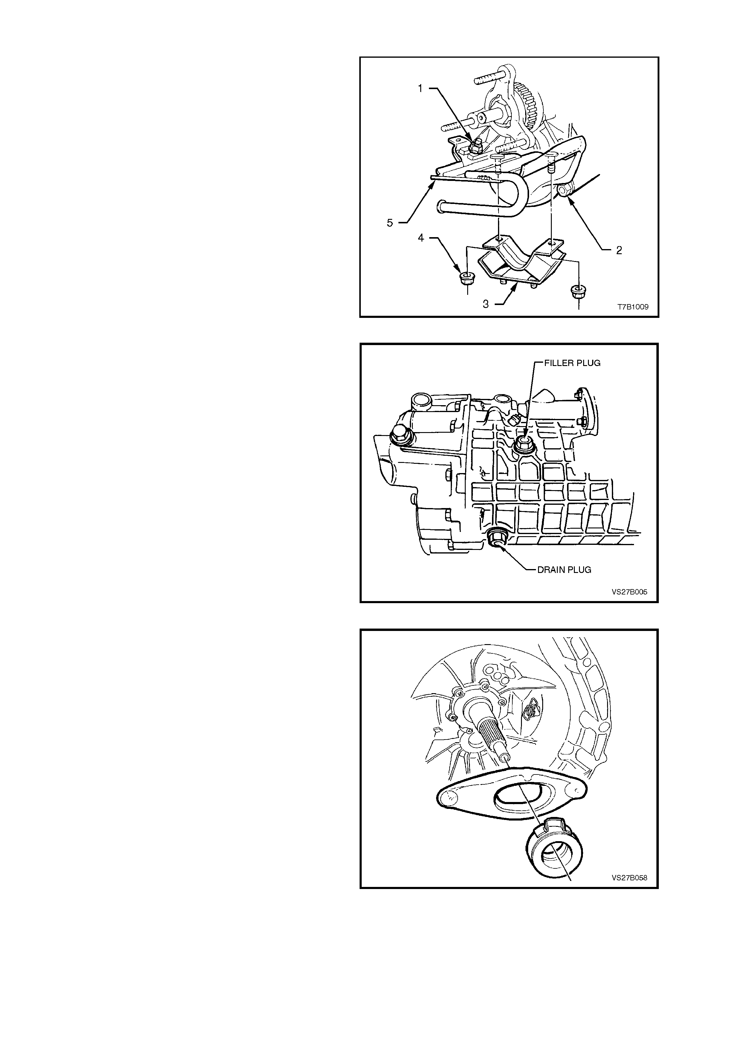
1. Remove rear engine mounting nuts (4) from
the transmission adaptor bracket (5).
2. Remove both nuts (1) and the two Allen key
headed bolts (2) securing the rear engine
mounting adaptor bracket (5) to the rear
transmission housing. Set to one side.
Figure 7B1-61
3. If not carried out during the transmission
rem oval procedure, us e a 17 m m ring spanner
and remove transmission filler plug from right
hand side of transmission case.
4. Remove trans miss ion drain plug with a 17 ring
spanner and allow transmission lubricant to
drain into a suitable clean, drain tray.
NOTE:
At this time, car efully inspect the drain plug m agnet
and the drained fluid for foreign matter such as
metal particles, etc.
Figure 7B1-62
5. Release clutch releas e lever from the wire clip
and remove lever from transmission case,
together with the thrust bearing.
Figure 7B1-63
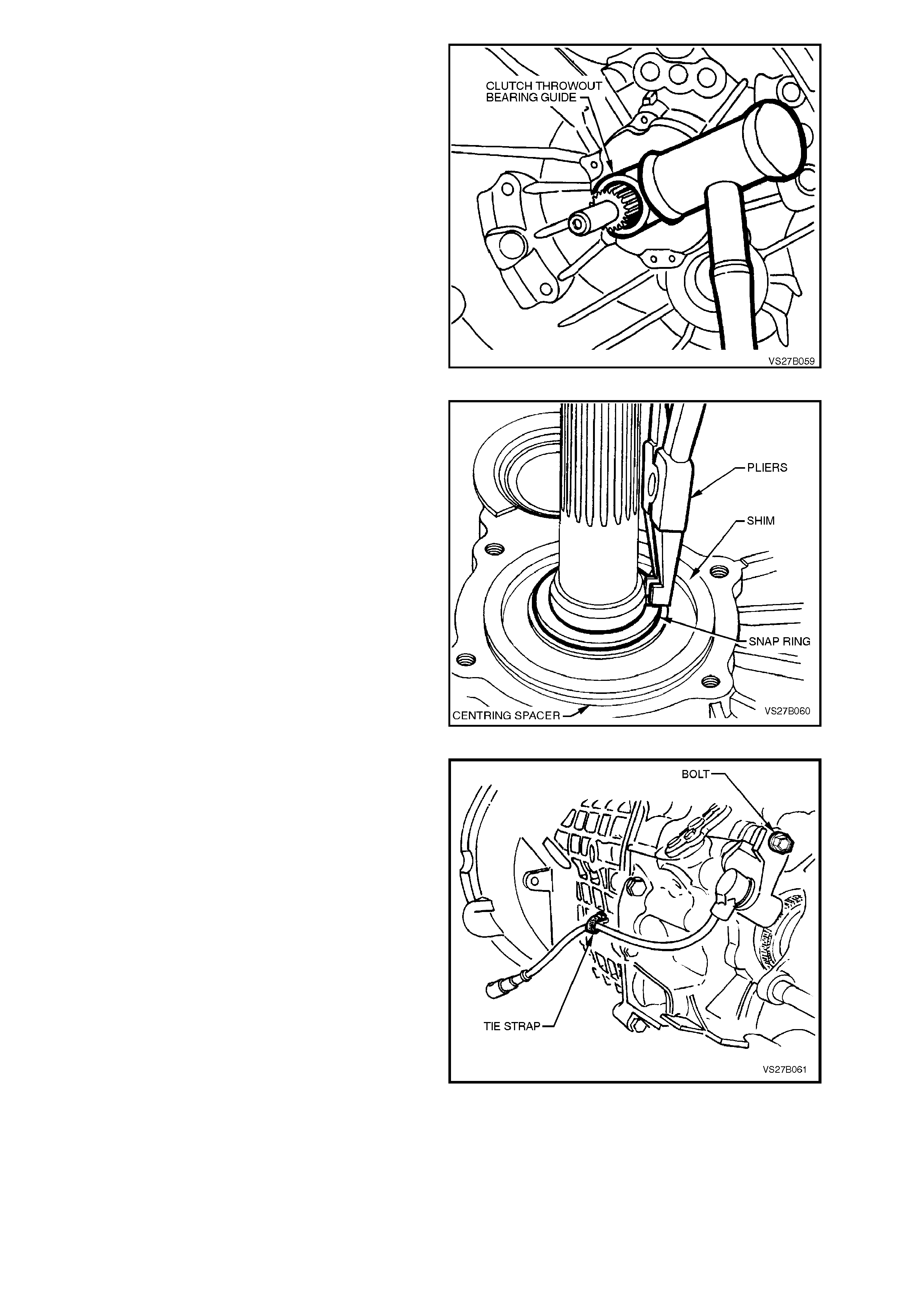
6. Remove bolts attaching throwout bearing
guide assembly. Gently tap sideways with a
soft faced hammer to break the seal, then
remove the assembly from the transmission
maindrive gear shaft.
Figure 7B1-64
7. Remove shim washer and distance spacer
ring from the front bearing. Using suitable
snap ring pliers, remove the snap ring and
spacer washer from maindrive gear.
Figure 7B1-65
8. Remove the speed sensor bracket retaining
bolt from the rear transmission case. Cut the
wiring harness retaining strap from the
transmission case lug and remove the sensor
and bracket assembly.
Figure 7B1-66
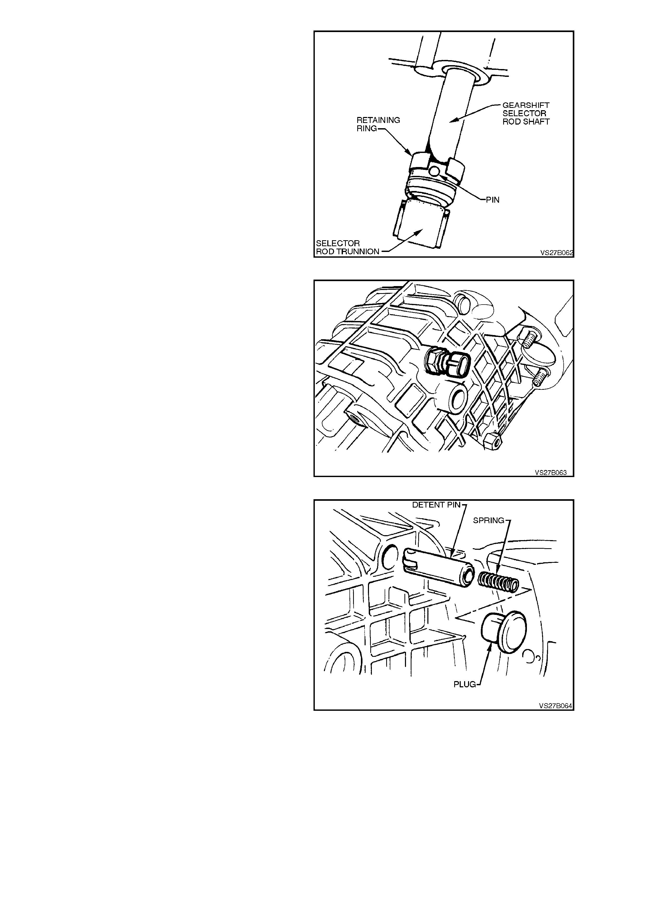
9. Lever the spring steel retaining ring forward
from selector rod trunnion, to expose the
connecting pin.
While pushing the trunnion in to the
transmission, use a suitable punch and push
the pin from the trunnion. Remove trunnion
and retaining ring from the selector rod.
Figure 7B1-67
10. Remove back-up lamp switch and spacer
washer.
Figure 7B1-68
11. Using suitable lever, remove detent plug from
front section of transmission case.
12. Remove detent pin, pressure spring and plug.
Figure 7B1-69
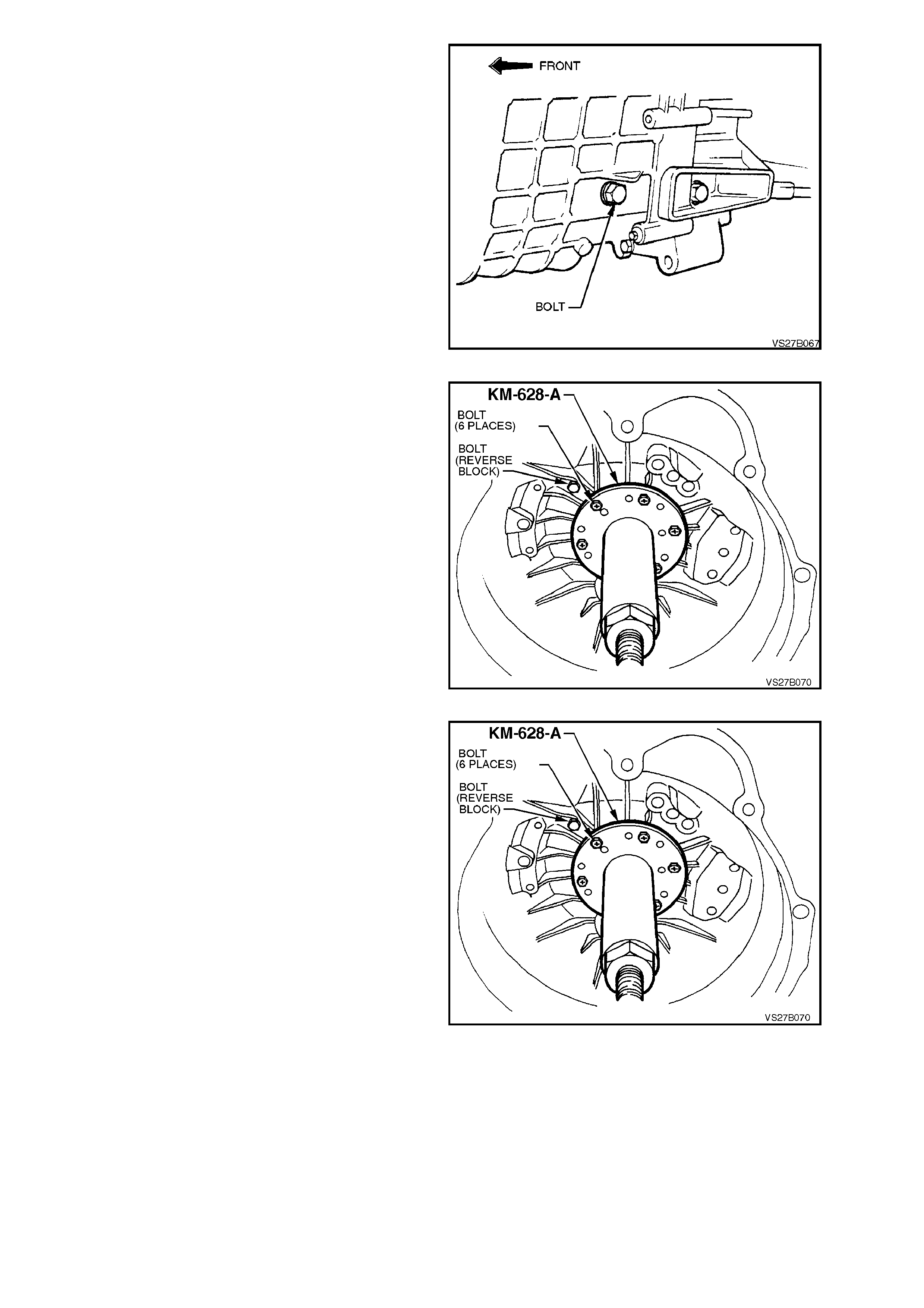
13. Remove front bolt fastening the reverse idler
gear shaft to the left side of transmission case.
Figure 7B1-70
14. Remove transmission case attaching bolts
from case rear section. Take note of the
longer bolt (60 mm) position (arrow) for
reassembly.
15. Drive the upper locating dowel pin into the
front transmission case.
NOTE:
The output flange is shown as being removed, to
enable the bolts to be more clearly shown.
Figure 7B1-71
16. Install extractor, Tool No. AKM-628-A, to front
of transm ission case using all six of the clutch
throwout bearing guide bolts.
17. Tighten extractor forcing bolt to separate
transmission case sections.
NOTE:
While the forcing bolt of Tool AKM-628-A has
torque applied, it may be necessary to use a
suitable block of wood and hammer at the two lug
locations provided on the rear transmission case, to
assist in the separation process.
18. Carefully remove the front transmission case
section and place to one side.
NOTE 1:
The maindrive gear bearing and cluster gear front
bearing cup remain in the transmission case front
section. Take care that the cluster gear roller
bearing does not fall out of the front case
immediately after splitting the cases. The
remainder of the transmission assembly is
removed with the transmission case rear section.
NOTE 2:
When the transmission cases have been
separated, do not manipulate the position of the
transmission rear section by using the maindrive
gear as a lever or handle. If this is done, then the
mainshaft spigot bearing will suffer brinelling and
be permanently damaged.
Figure 7B1-72
19. Before using the previously released, Tool No.
KM-620-1-A to hold the flange, it must first be
modified by redrilling the three holes stamped
‘B’ (on the Tool) to 13 mm.
Fasten the modified tool to the flange using
the three discarded nuts. Then, using a
suitable length of pipe on the tool handle,
loosen and remove flange nut, using a
commercially available, 30 mm deep socket.
Figure 7B1-73
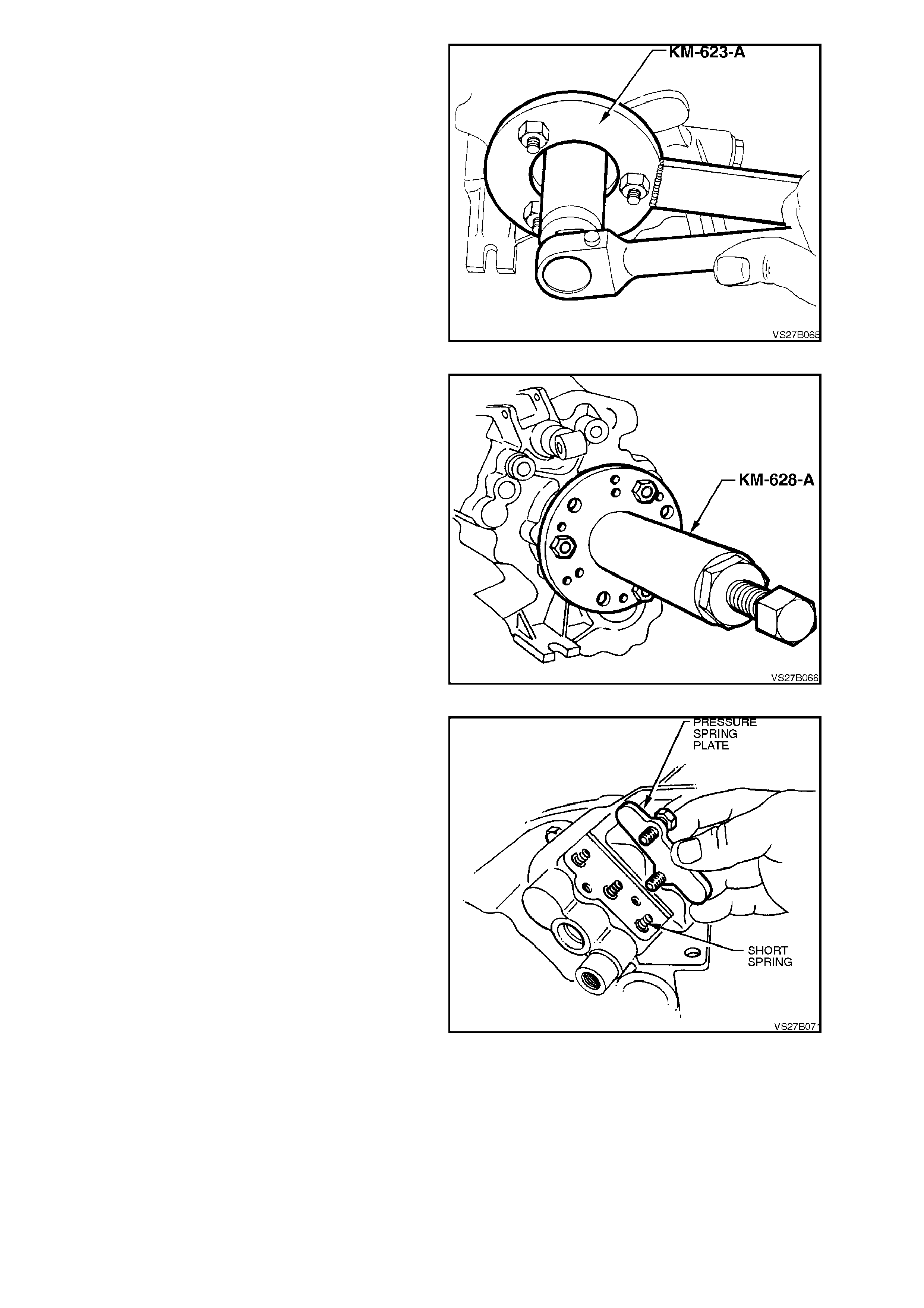
20. Install extractor, Tool No. AKM-628-A to
mainshaft output flange studs. Use the
removed nuts to secure the extractor tool to
the flange.
21. Tighten ex tractor forc ing bolt to remove flange
from mainshaft.
Figure 7B1-74
22. Remove bolts attaching pressure spring cover
plate to transmission case rear section.
23. Remove three detent ball springs.
24. Using a pencil magnet, remove three detent
balls from under the springs.
Figure 7B1-75
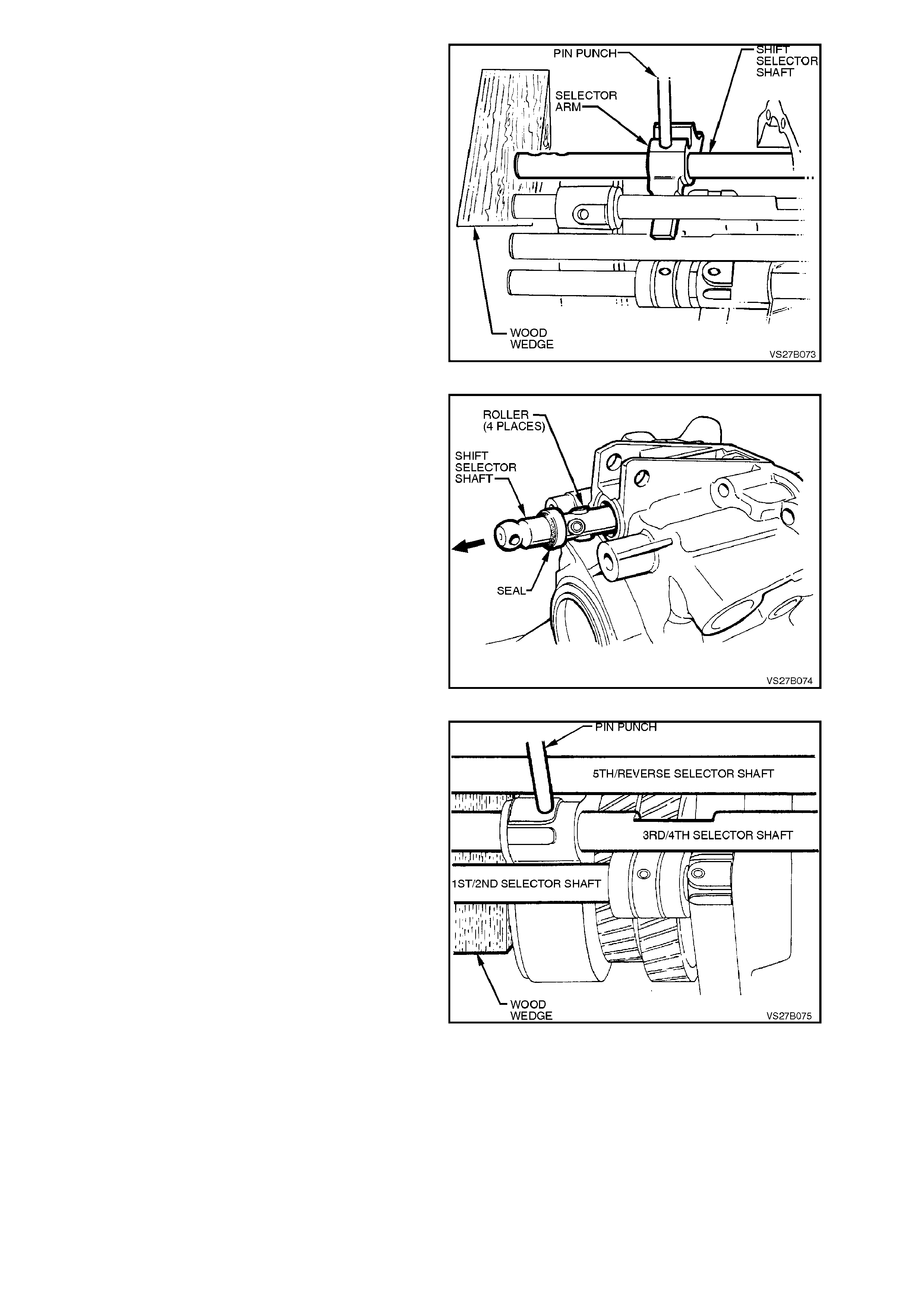
25. Select 4th gear, s upport the s hif t s elec tor s haf t
with a wooden wedge, then remove the roll pin
from the gearshift selector arm, using a
suitable sized pin punch. When in 4th gear,
the roll pin will not foul on gear teeth during the
removal process.
Figure 7B1-76
26. Using a soft faced hammer, tap the shift shaft
rearwards through the bearing support,
removing the seal in the same operation.
NOTE:
As the shift shaft is removed, there are four rollers
that can be dislodged from the pins in the shaft.
Take care not to lose them.
Figure 7B1-77
27. While supporting the selector shaft with a
suitable wedge of wood, drive the selec tor f ork
roll pin out, just s uf ficient to enable the shaf t to
be removed.
Figure 7B1-78
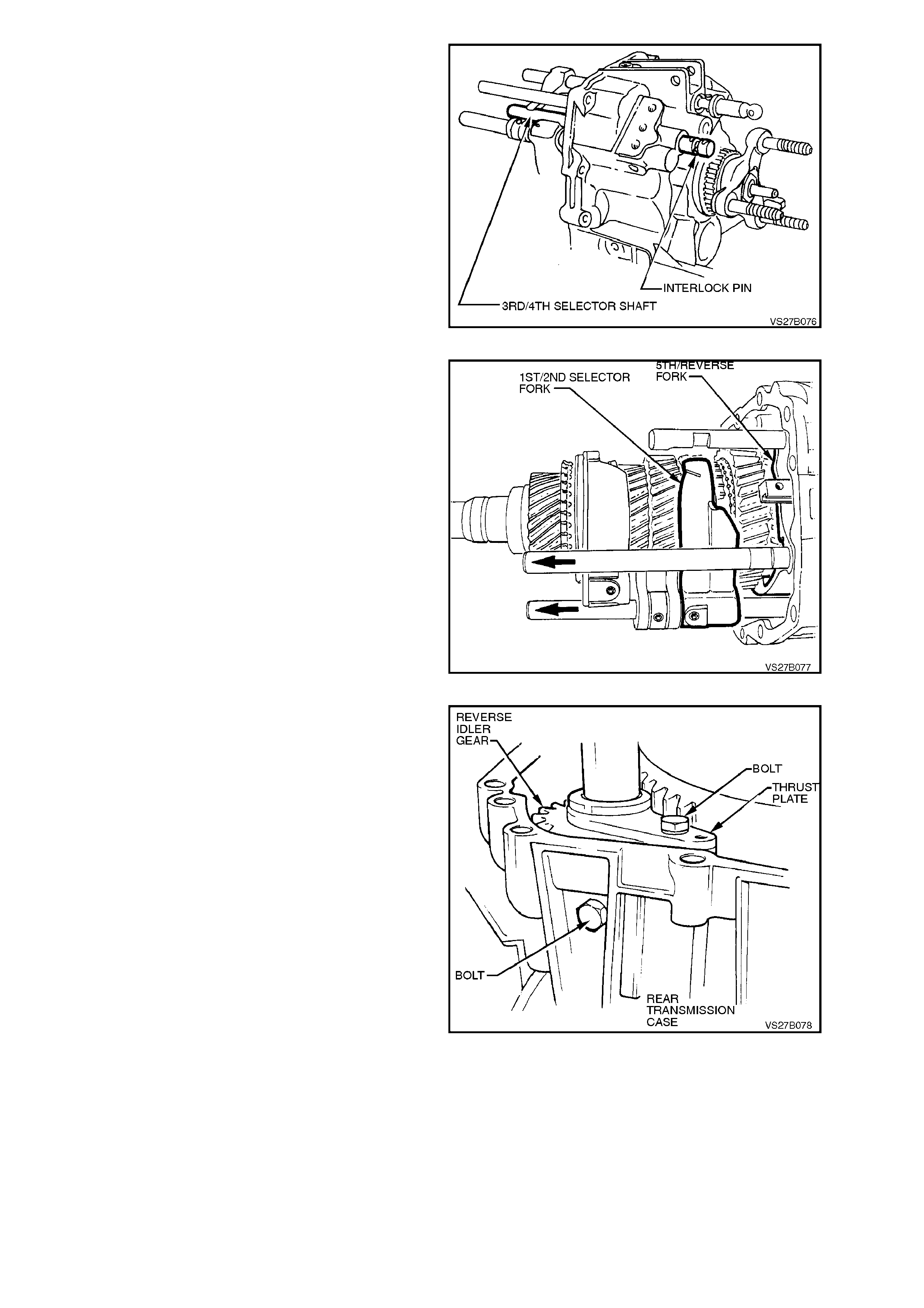
28. While supporting the 3rd/4th shift fork, use a
soft faced hammer to gently tap the shaft
rearward, displacing the expansion plug in the
rear transmission housing. This will allow
rem oval of the inter lock pin and the shaf t from
the rear, which overcomes the risk of the
interlock pin becoming dis lodged and jamm ing
the shaft.
Figure 7B1-79
29. Move the 1st/2nd synchromesh ring forward
into the 2nd gear position and the 5th/Revers e
synchromesh ring forward, into the Reverse
position.
Figure 7B1-80
30. Remove the rear bolt securing the reverse
idler gear to the transmission case and the
bolt securing the thrust plate. Remove the
reverse idler gear shaft and r oller bearing f rom
the rear case section. Remove the idler gear.
Figure 7B1-81
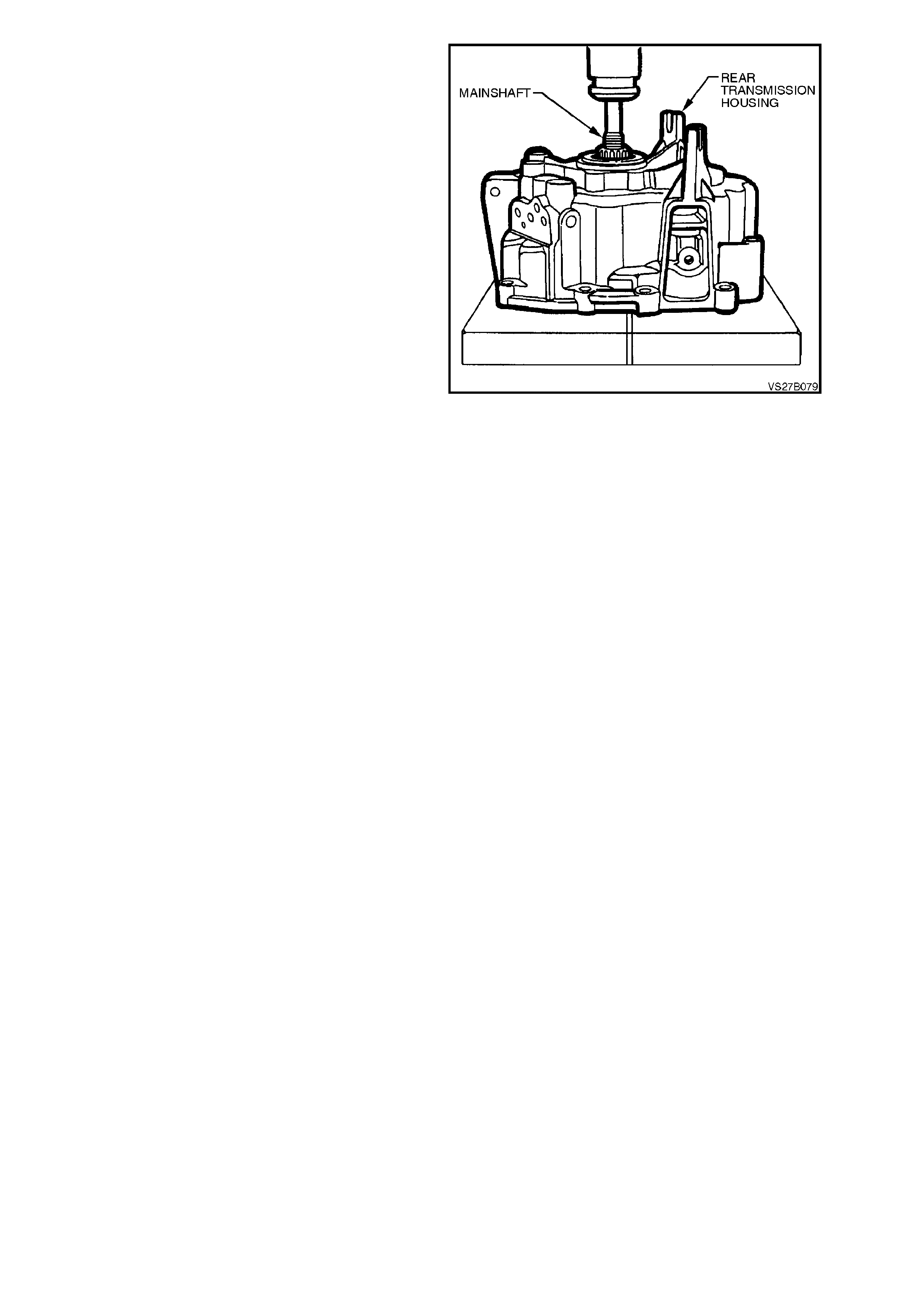
31. To remove mainshaft and cluster gear
assemblies, together with the selector shafts
and forks from rear transmission case,
support the case on suitable press plates , then
press the mainshaft from the rear mainshaft,
sealed ball race.
IMPORTANT:
Take care when the gear assemblies come free
from the ball race, as they are heavy. Do not allow
them to drop to the floor when gear tooth damage
could occur.
NOTE:
Do not lose any of the selector interlock balls that
will come away when the shafts are removed.
There are two of them, both of equal size.
Once free, the cluster gear assembly and
selector shafts and forks can be easily
separated from the mainshaft assembly.
Figure 7B1-82
4.4 TRANSMISSION SUB-ASSEMBLIES
DISASSEMBLE
Mainshaft
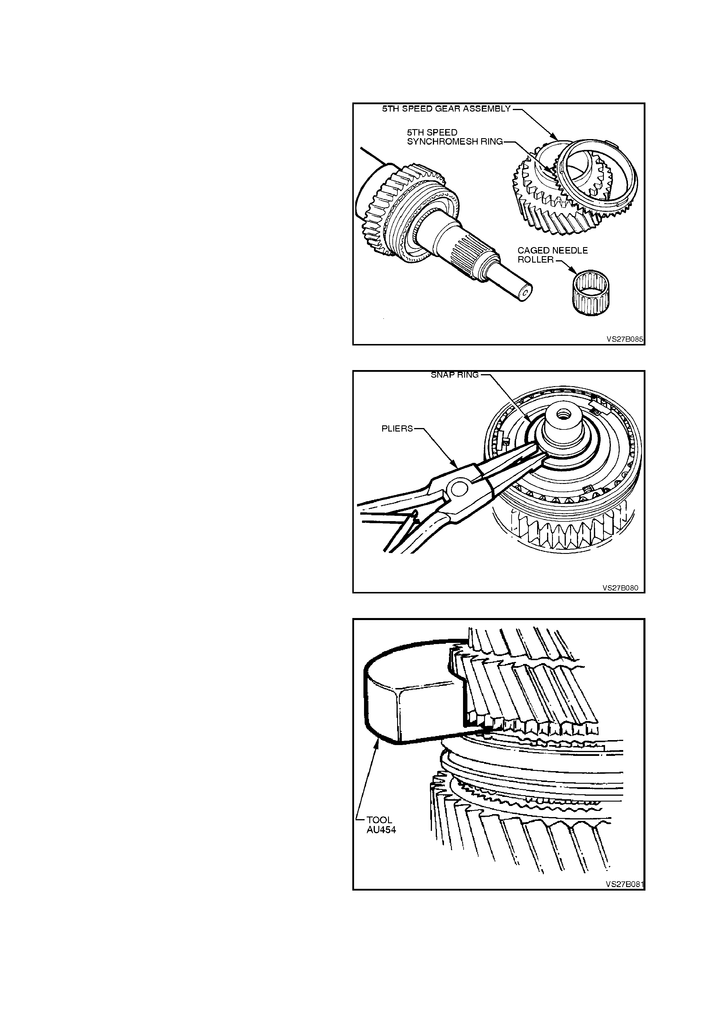
1. Remove the 5th speed constant mesh gear,
synchromesh ring and caged needle roller
bearing from the rear of the mainshaft.
Figure 7B1-83
2. Remove maindrive gear and fourth speed gear
synchromesh ring from mainshaft.
3. Remove snap ring and washer from front end
of mainshaft.
Figure 7B1-84
4. Insert each half of Tool No. AU454 under the
dog clutch teeth of 2nd speed gear, ensuring
that both halves are fully installed.
Figure 7B1-85
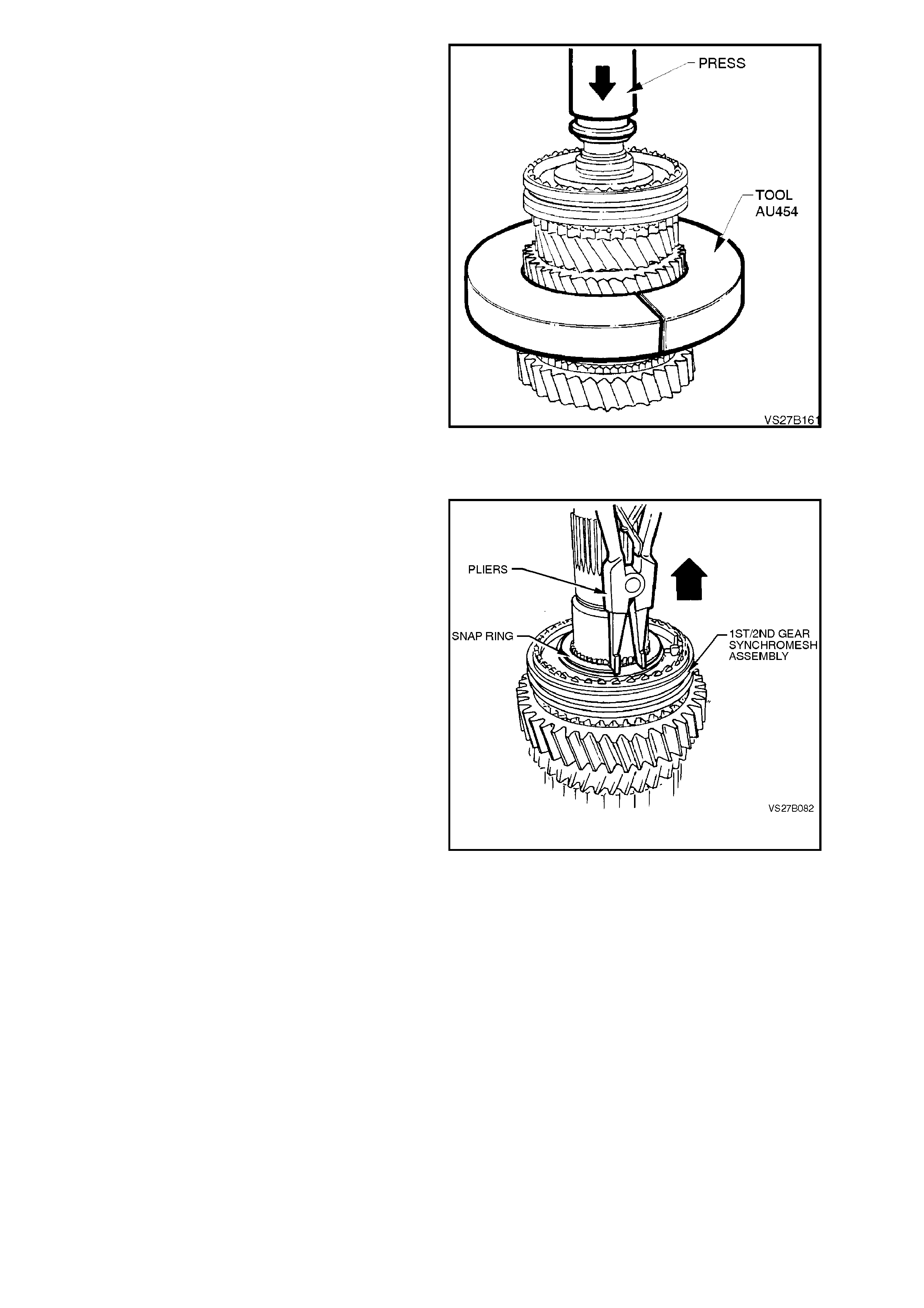
5. Support both halves of Tool No. AU454 under
suitable press plates and press the mainshaft
from the following components;
•3rd/4th gear synchromesh assembly.
•3rd speed gear and synchromesh ring.
•3rd speed gear, caged needle roller
bearing.
•3rd speed gear, roller bearing sleeve.
•2nd speed gear thrust washer.
•Thrust washer locating ball.
•2nd speed gear.
•2nd speed gear, caged needle roller
bearing.
NOTE:
As the synchromesh hub and roller bearing sleeve
are both interference fits on the mainshaft, some
forc e will be required to rem ove thes e com ponents.
Also, take care not to lose the thrust washer
locating ball, as it may fall out during the pressing
operation.
6. Remove the three part synchromesh rings
from the 1st/2nd synchromesh assembly.
Figure 7B1-86
7. Remove snap ring from the 1st/2nd gear
synchromesh hub.
Figure 7B1-87
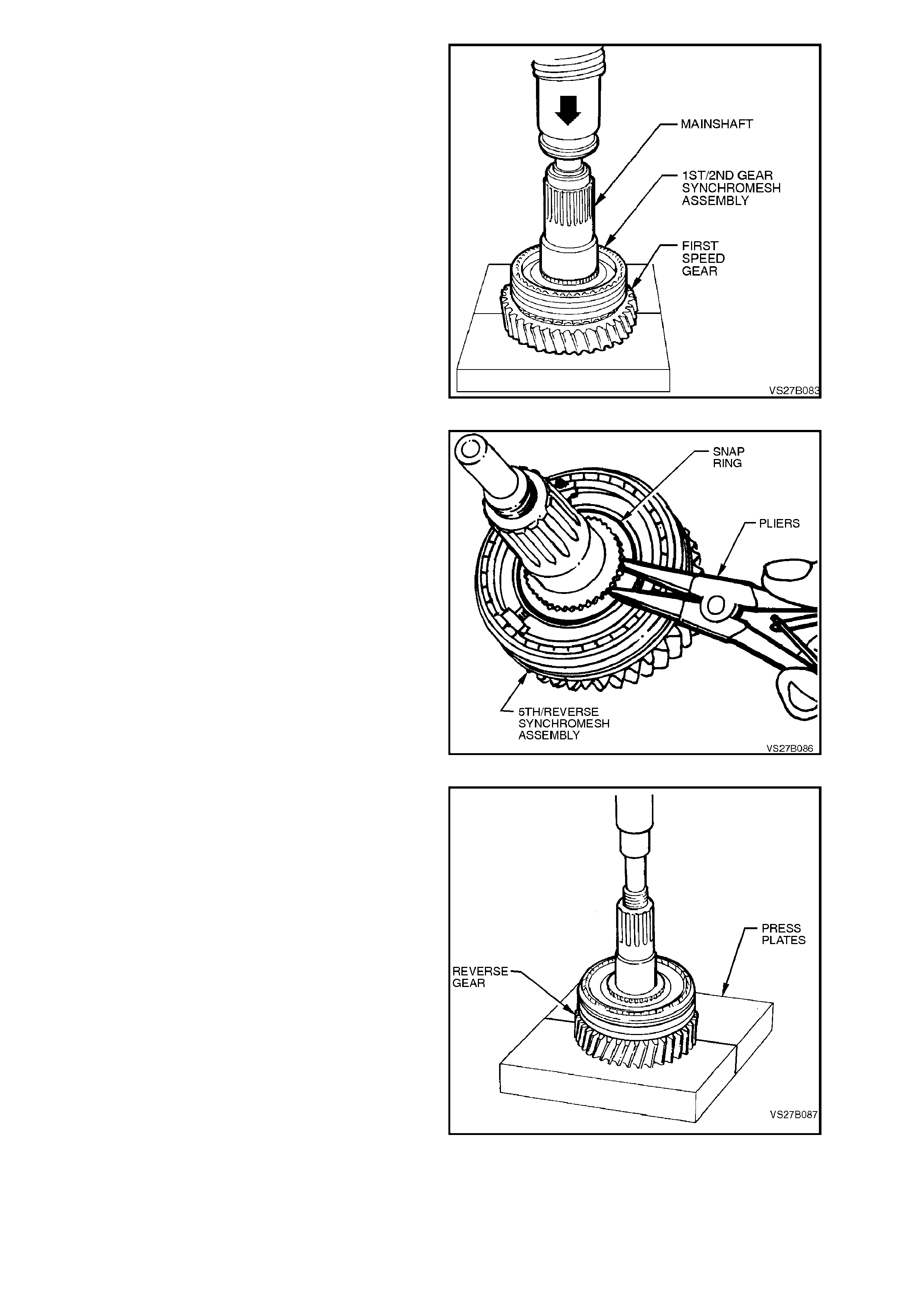
8. Using suitable press plates, positioned with
the flat side under first speed gear, press
mainshaft from 1st/2nd speed synchromesh
assembly, 1st speed synchromesh ring, cone
ring, friction ring, first speed gear and needle
roller bearing.
Figure 7B1-88
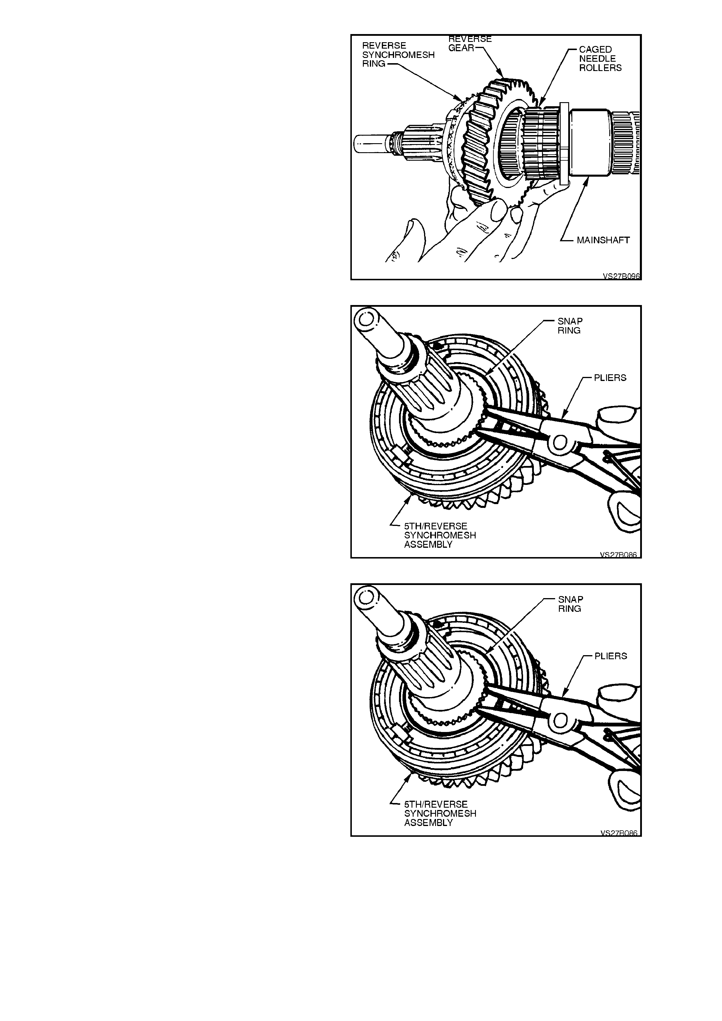
9. Remove 5th/Rever se speed synchrom esh hub
snap ring from mainshaft.
Figure 7B1-89
10. Press mainshaft from 5th/Reverse speed
synchromes h assembly, reverse synchrom esh
ring and reverse constant mesh gear, using
suitable press plates, with the flat side
positioned under Reverse speed gear.
11. Remove reverse speed gear and selective,
caged needle roller bearing from mainshaft.
Figure 7B1-90
MAINDRIVE GEAR
1. Remove the caged needle roller bearing from
the maindrive gear.
Figure 7B1-91
CLUSTER GEA R
While the cluster gear is made up from three
separate components, it is only serviced as a
complete assembly. It should therefore, not be
dismantled. The assembly of the components is
precise and cannot be duplicated.
REVERSE IDLER GEAR SHAFT
When removing the two snap rings securing the
two caged needle roller bearings to the idler shaft,
take par ticular note of the orientation of each to the
bearings.
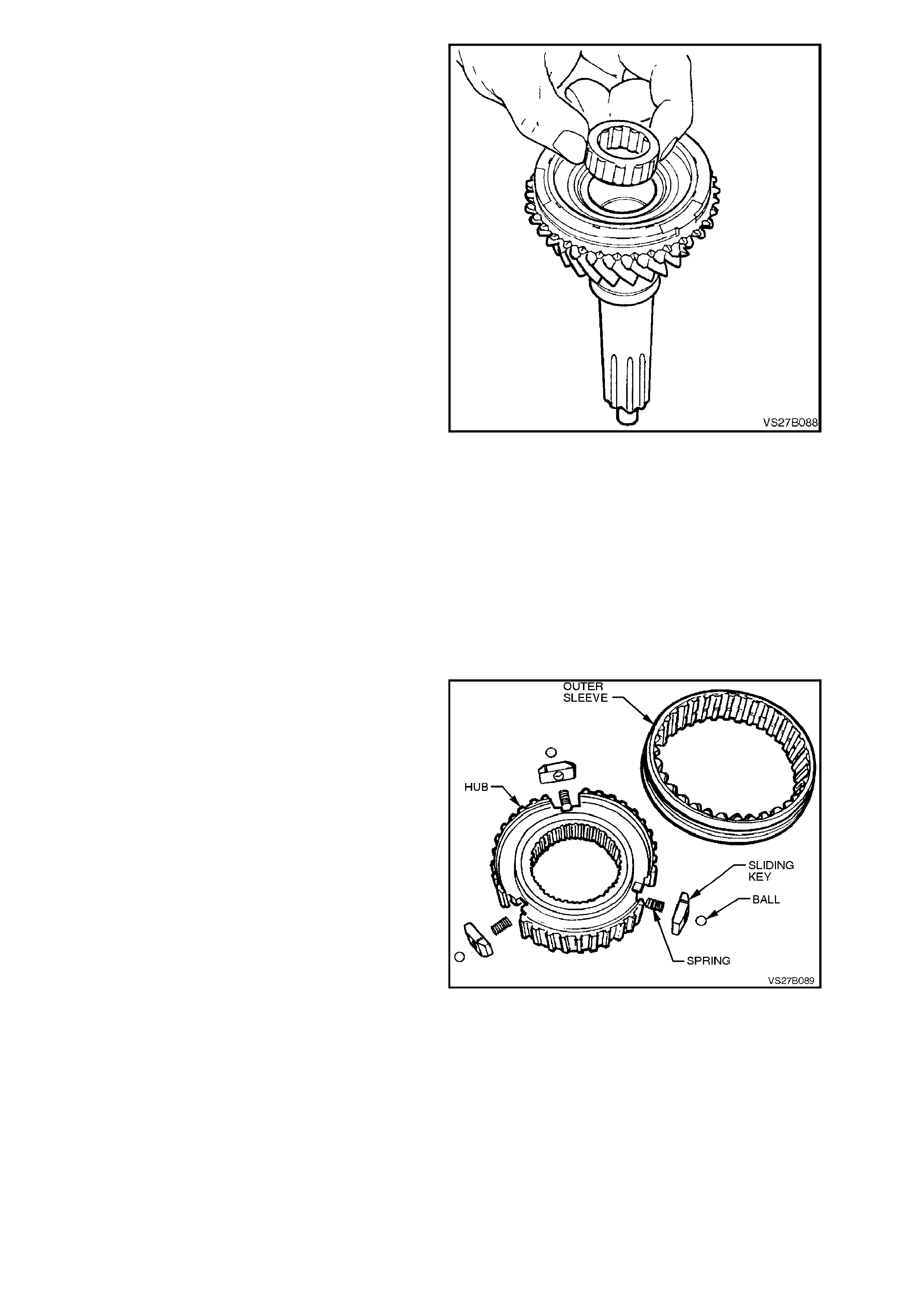
SYNCHROMESH ASSEMBLIES
With the index finger and thumb of the left hand
circling the synchromesh hub, slide the outer
sleeve from the assem bly, using the r ight hand. Be
careful that the pressure springs do not cause any
of the three balls to be ejected and lost. Note the
relationship of the outer sleeve to the synchrom esh
hub.
NOTE:
While the synchromesh assembly shown is for the
1st/2nd speed ranges, the disassembly process is
the same for each of the remaining two
assemblies.
Figure 7B1-92
INSPECT COMPONENTS
1. Check synchromesh rings for cracks and for
deformation. Inspect rings for excessive wear
in the areas shown.
2. Check synchromesh hubs, outer sleeves,
sliding blocks and synchromesh springs for
damage.
Figure 7B1-93
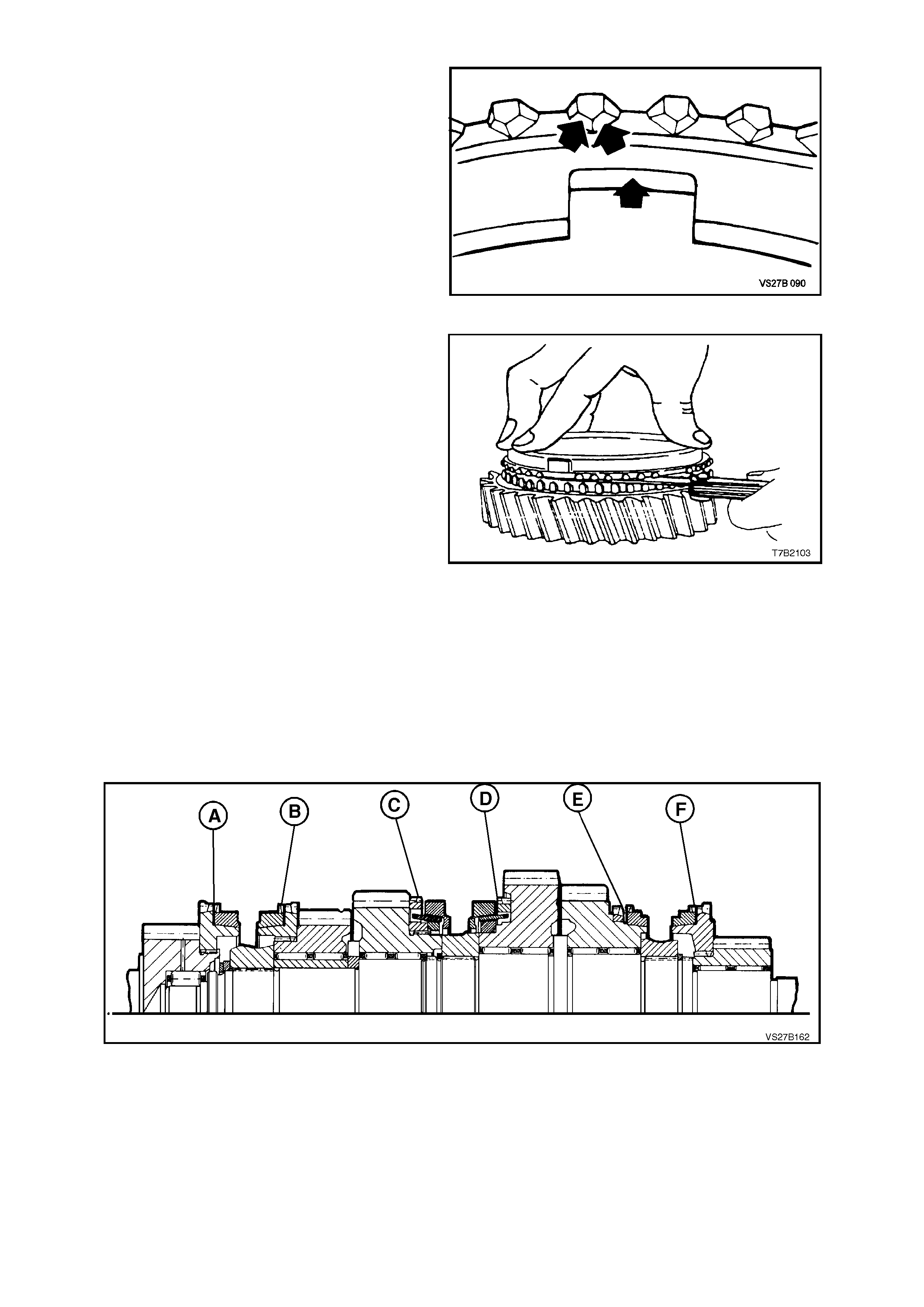
3. Check each synchromesh ring for wear by
mounting the ring on the respective gear and
measuring the gap, as indicated.
NOTE:
To obtain an accurate measurement, the
synchromesh ring must be held squarely and fully
installed on its gear, as shown. Then, using feeler
gauges, measure the gap in at least three places
around the circumference. Average the readings
and use this f igure to asse ss the synchr omesh ring
wear.
Specifications for each synchromesh ring are as
follows and correspond to the synchromesh
assemblies indicated in the sectioned view.
Position Gear Serviceable Wear Limit
(A) 4th 0.82 - 1.35 mm
(B) 3rd 0.82 - 1.35 mm
(C) 2nd 0.85 - 2.25 mm
(D) 1st 0.95 - 2.35 mm
(E) Reverse 0.5 - 0.98 mm
(F) 5th 0.82 - 1.35 mm
Figure 7B1-94
Figure 7B1-95
4. Inspect all gears, sleeves, hubs, rings and
shafts for wear, scoring, pitting, c hips, nick s or
burrs. Slight s cores or bur rs m ay be honed off
with a fine stone, however if a gear is chipped
or unduly worn it must be replaced.
5. Inspect all needle roller bearings for wear or
damage.
NOTE:
As needle roller wear can be difficult to see, it is
good practice to r eplace all roller bear ings where a
substantial distance has been covered by the
transmission.
6. Inspect the mainshaft surfaces, roller bearing
inner sleeves and internal surfaces of the
gears where the needle bearings come into
contact.
NOTE:
The needle roller bearing assembly used with the
mainshaft Reverse gear, is a selective fit. Should
any component associated with this gear and/or
the mainshaft need to be replaced, then the
following procedure must be adopted, to ensure
that the correct replacement part/s are fitted.
SYNCHROMESH ASSEMBLIES
Identification
Identification or particular installation position of
each of the synchromesh assembly components is
described as follows:
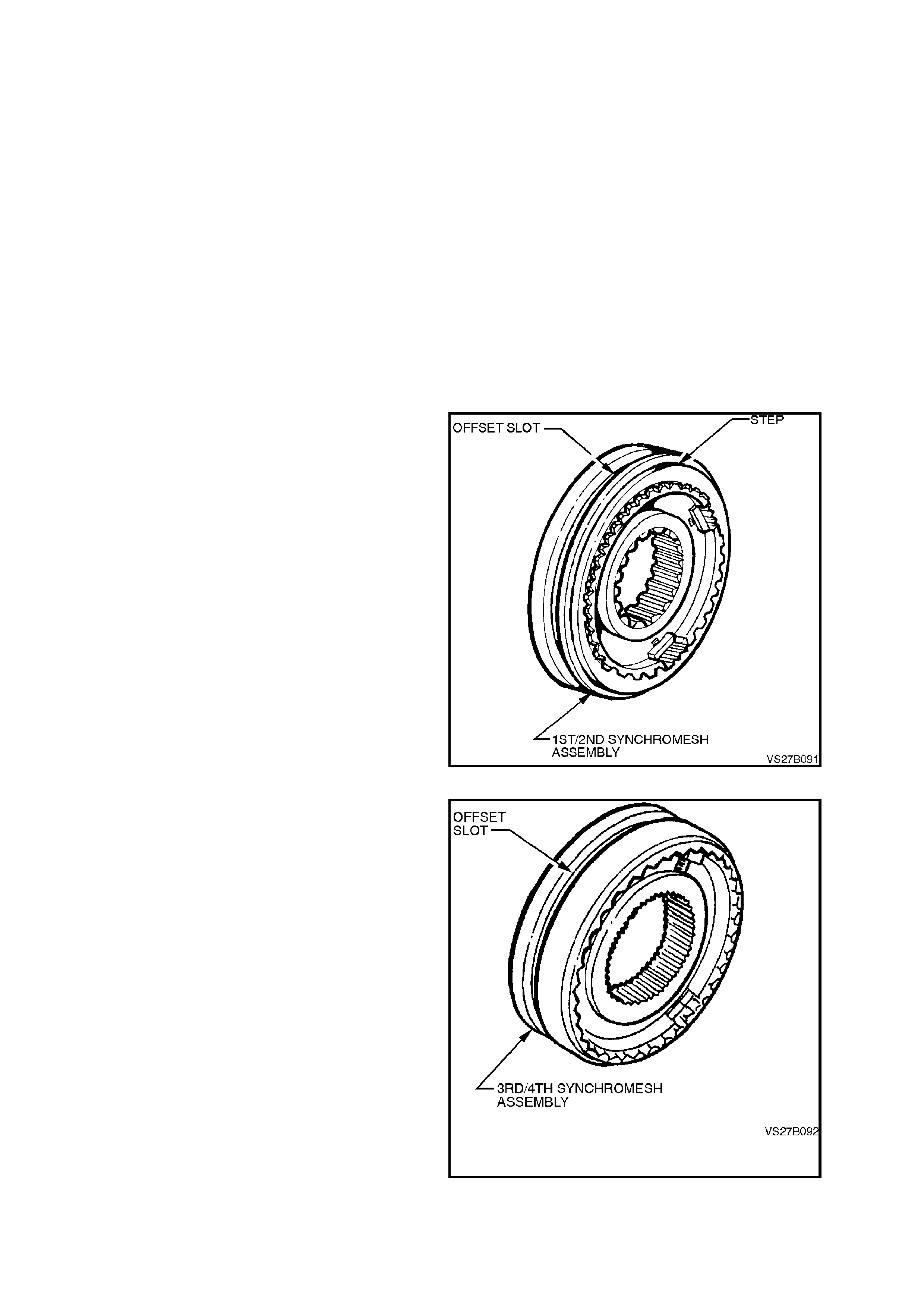
1. The 1st/2nd speed synchromesh assembly
can be recognised by the larger diameter
splined hole in the hub, when com pared to the
3rd/4th synchromesh assembly.
The stepped edge on the outer sleeve is
another identification feature.
Figure 7B1-96
2. Identification of 3rd/4th speed synchromesh
assembly is by the offset selector slot in the
outer sleeve and smaller diameter s plined hole
in the hub.
Figure 7B1-97
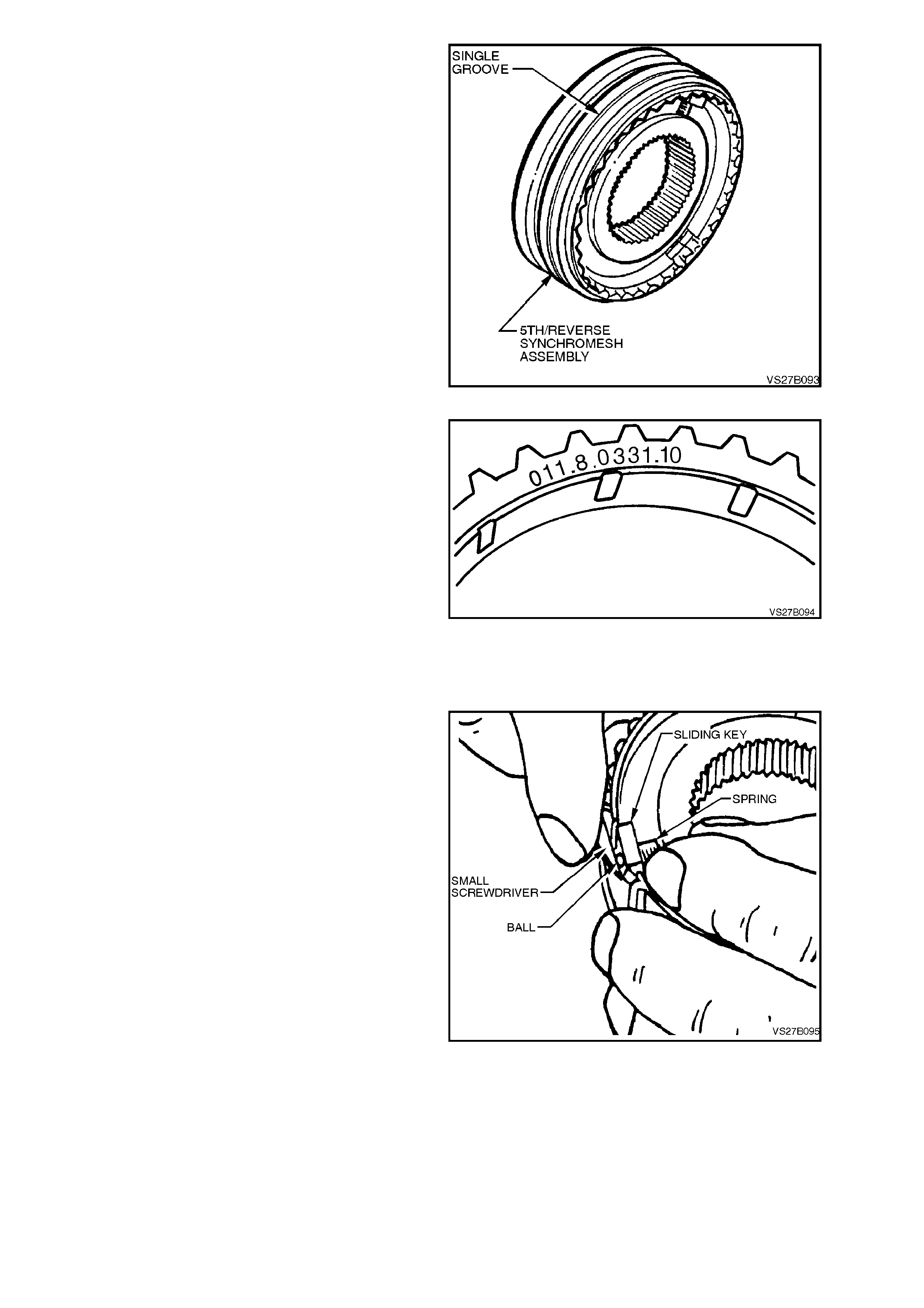
3. Identification of the 5th/Reverse synchromesh
assembly is by a single groove on the outer
sleeve and the larger diameter splined hole in
the hub, when compared to the 3rd/4th speed
synchromesh assembly.
Figure 7B1-98
The synchromesh rings can be identified by the
number stamped on the flat face of each one.
Applications are as follows;
1st/2nd 040.8.0001.00
3rd/4th 002.8.0301.00
5th/Reverse 011.8.0331.10
(optional) 011.8.0331.11
Figure 7B1-99
REASSEMBLE
Synchromesh Assemblies
The respective synchromesh assemblies are to be
assembled before pressing onto the mainshaft.
Only one synchromesh assembly is described in
the following operations, since reassembly is
similar for all units.
1. Support the synchromesh hub over a suitable
disc to raise it from the bench surface and
install the outer sleeve over the synchromesh
hub.
2. Insert sliding keys (with the chamfered ends
facing outwards) and the pressure springs,
into each of the locations in the synchromesh
hub. Use petroleum jelly to hold parts in place.
3. Using a small screwdriver, prise each key
upwards, just sufficient to enable a ball to be
inserted. While holding the ball inwards, push
the key down to capture the ball. Repeat for
the remaining two key/spring combinations.
Figure 7B1-100
Assembly Notes:
a. The thicker boss of the 3rd/4th
synchromesh hub faces 3rd gear. The
offset of the 3rd/4th selector fork groove
faces 4th gear.
b. The offset groove and the step in the
outer sleeve of the 1st/2nd gear
synchromesh assembly, faces 1st gear.

c. The single groove on the outer sleeve of
the 5th/Reverse synchromesh outer
sleeve, faces 5th gear.
MAINSHAFT
Reverse Gear Needle Roller Bearing
NOTE:
The mainshaft reverse gear, caged needle roller
bearing is a selective fit, with the various sizes
identified by different colour needle roller bearing
cages.
Both the mains haft and r everse gear are accurately
measured after manufacture and the size recorded
by using different colour paint daubs on each
component.
Depending on the combination of the two different
colours (and therefore, sizes), the correct needle
roller bearing can then be selected, also by a colour
coding of the cage.
Examples of the selection process, using the
opposite table, are;
1. With a white paint daub on the mainshaft and
a green daub on the reverse gear, the correct
needle roller selec tion would be one that had a
red cage.
2. A yellow daub on the mainshaft with a yellow
daub on the reverse gear , indicates the correc t
needle roller selection as being one with a
white cage.
3. Those combinations marked ‘*‘ are non-
preferred combinations. If possible, an
alternative mainshaft or reverse gear colour
would be preferred. However, is this is not
possible, then the choices as listed, can be
used.
TABLE 1
Relationship of the Mainshaft, Reverse Gear and Reverse
Gear Needle Roller Bearing
Mainshaft Reverse
Gear Needle Roller Bearing
Paint Daub
Colour Paint Daub
Colour Cage
Colour Undersize Dimension
White Yellow Green -0.5 to -0.7 mm
White White White -0.3 to -0.5 mm
White Green Red 0 to -0.2 mm
Yellow Orange Green -0.6 to -0.7 mm
Yellow Yellow White -0.3 to -0.5 mm
Yellow White Blue -0.1 to -0.3 mm
*Yellow Green Red 0 to -0.2 mm
Orange Blue Green -0.5 to -0.7 mm
Orange Orange White -0.3 to -0.5 mm
Orange Yellow Blue -0.1 to -0.3 mm
* Orange White Red 0 to -0.2 mm
1. Coat mainshaft, all gear bores and needle
bearings with transmission lubricant.
2. Assem ble the colour c oded, selec tive Reverse
gear needle bearing, gear and synchromesh
ring to mainshaft.
3. Preheat assembled 5th/Reverse speed
synchromesh hub to approximately 100 °C.
NOTE:
Use Faber Castell Thermochrom 2815/100 °C to
indicate temperature.
Apply therm ochrom around the inner s urface of the
synchromesh hub.
Figure 7B1-101
4. Using a heat proof glove, position
synchromesh assembly onto mainshaft, with
the groove in the outer sleeve facing 5th gear
and aligning mainshaft and hub splines.
5. Using suitable sleeve and press plates, press
mainshaft into synchromesh hub, ensuring
that synchromesh ring slots align with sliding
keys in the synchromesh assembly.
6. Remove mainshaft from press, and if
necessar y, lever up the Reverse s ynchrom esh
ring with a screwdriver so that it is not jam m ed
on the gear cone.
Figure 7B1-102
7. Install synchromesh assembly selective snap
ring onto mainshaft, ensuring that no gap
exists between the synchromesh hub and the
installed snap r ing. Mak e sure the snap ring is
seated correctly in groove.
Snap rings are available in thicknesses of 1.8, 1.85,
1.9, 1.95 and 2 mm.
Figure 7B1-103
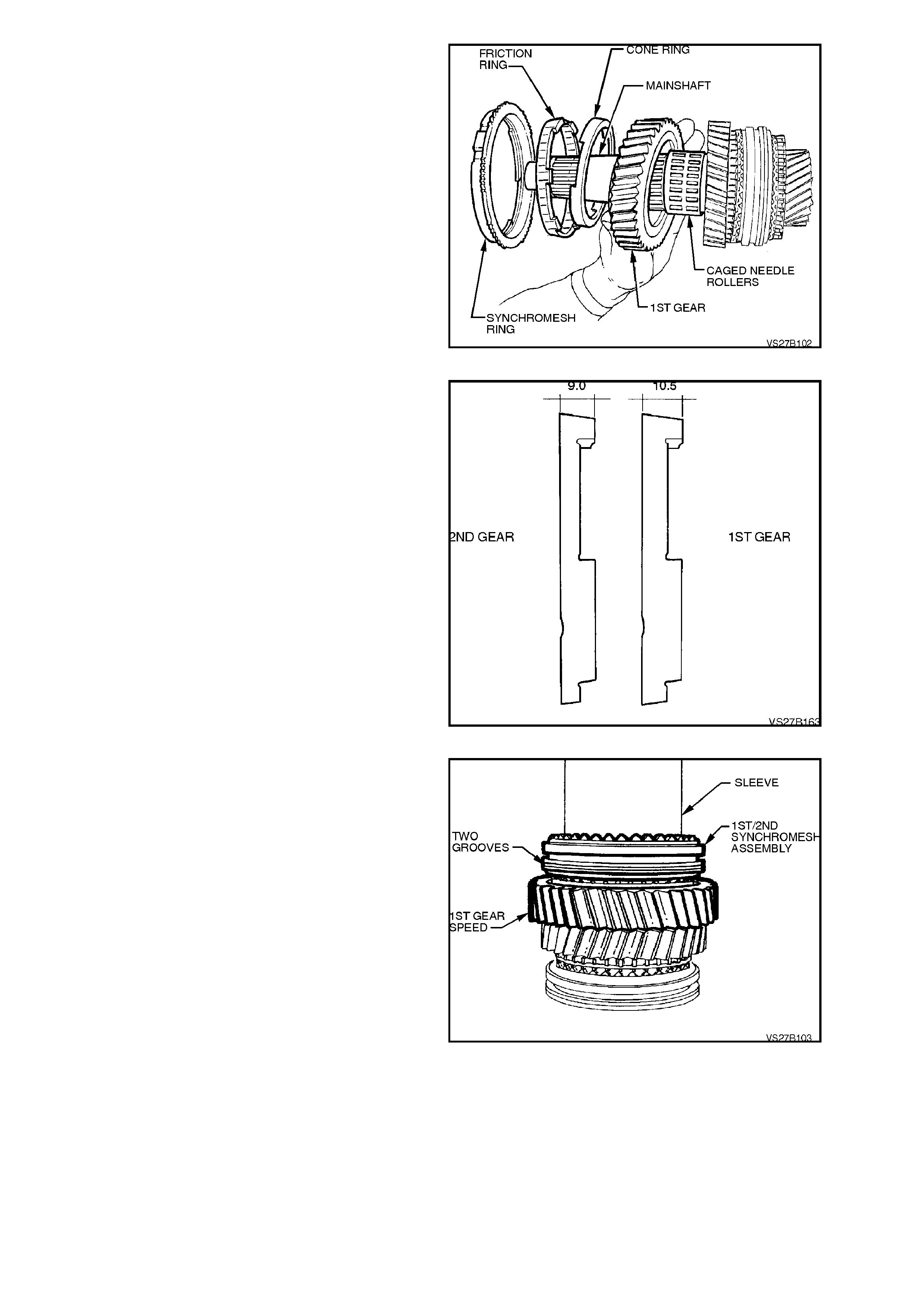
8. Install 1st speed gear, caged needle roller
bearing, 1st speed gear , f r iction r ing, cone r ing
and synchromesh ring onto mainshaft.
NOTE:
The 1st and 2nd gear synchromesh cone rings
have different dimensions. See the next illustration.
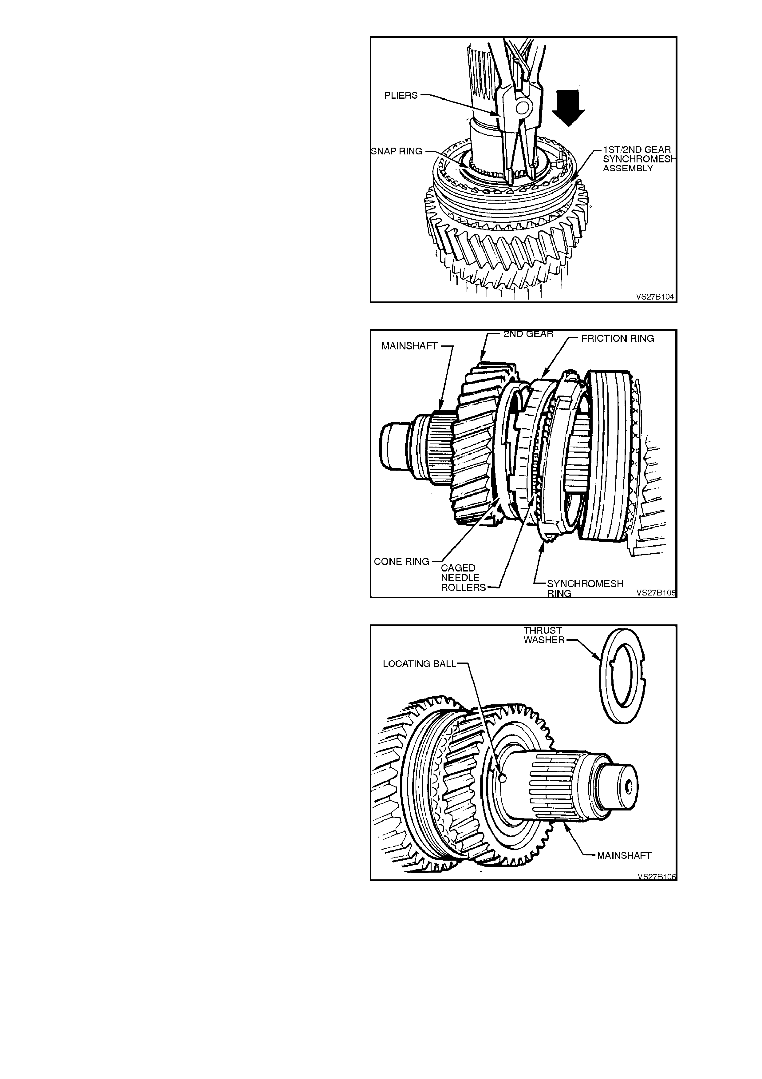
Figure 7B1-104
IMPORTANT:
Ensure that the correct cone ring is f itted. The c one
rings for 1st and 2nd gears have different
dimens ions, as shown. T he m anufac turer’s num ber
on each ring is as follows;
1st gear cone ring 040.8.0069.00
2nd gear cone ring 040.8.0059.00
Figure 7B1-105
9. Preheat assembled 1st/2nd speed
synchromesh hub on a hot plate to
approximately 100° C.
NOTE:
Use Faber Castell Thermochrom 2815/100° C to
indicate temperature. Apply thermochrom around
synchromesh hub.
10. Using a heat proof glove, position
synchromesh assembly onto mainshaft,
aligning mainshaft and hub splines.
NOTE:
The side with the smaller outer surface and the
step, faces 1st gear.
11. Using suitable sleeve, pres s synchrom esh hub
onto mainshaft, ensuring that synchromesh
ring slots align with sliding keys.
12. Remove mainshaft from press, and if
necessary, lever up 1st speed synchromesh
ring with a screwdriver so that it is not jam m ed
on the gear cone.
Figure 7B1-106
13. Mount rear end of mainshaft in vice with soft
metal jaws.
14. Install synchromesh assembly, selective snap
ring onto mainshaft, ensuring that snap ring is
correctly seated in groove, without any end
clearance.
NOTE:
Snap rings are available in thicknesses of 1.8, 1.85,
1.9, 1.95 and 2 mm.
Figure 7B1-107
15. Install 2nd speed gear with caged needle roller
bearing, friction cone, cone ring and
synchromesh ring onto mainshaft, ensuring
that the friction ring, cone ring and
synchromesh ring are correctly located in the
synchromesh assembly.
NOTE:
Ensure that the correct synchromesh cone ring is
fitted. Refer to Figure 7B-105 for correct
identification details.
Figure 7B1-108
16. Install small, locating ball in mainshaft,
securing with petroleum jelly.
Figure 7B1-109
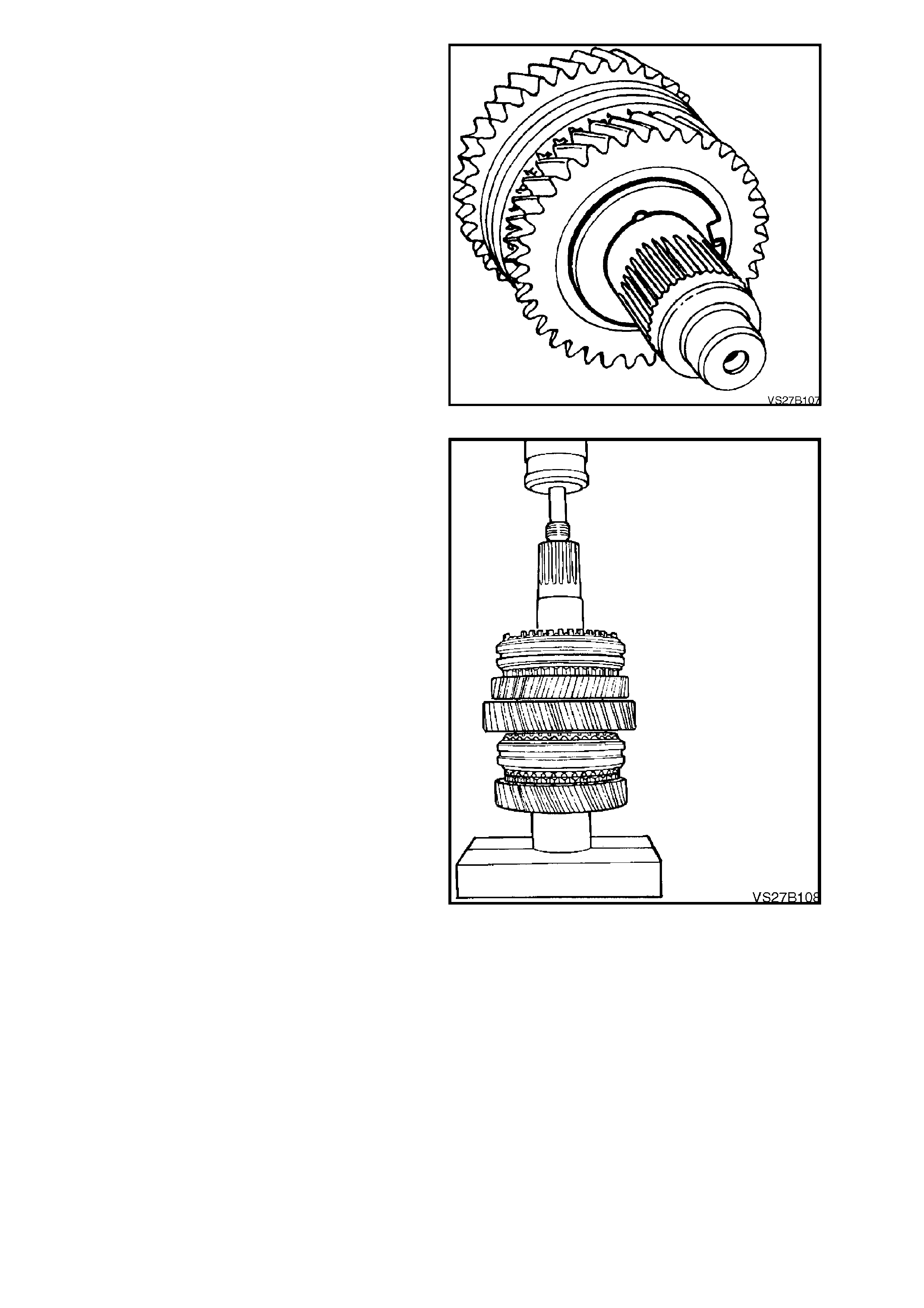
17. Install thrust washer over locating ball.
Figure 7B1-110
18. Preheat 3rd speed gear roller bearing
sleeve on a hot plate to approximately 80° C.
NOTE:
Use Faber Castell Thermochrom 2815/80° C to
indicate temperature.
19. Using a heat proof glove, position bearing
sleeve onto mainshaft and press home using
suitable press plates. When pressing
mainshaft into the sleeve, ensure that the
thrust washer remains in place over the
retaining ball.
Figure 7B1-111
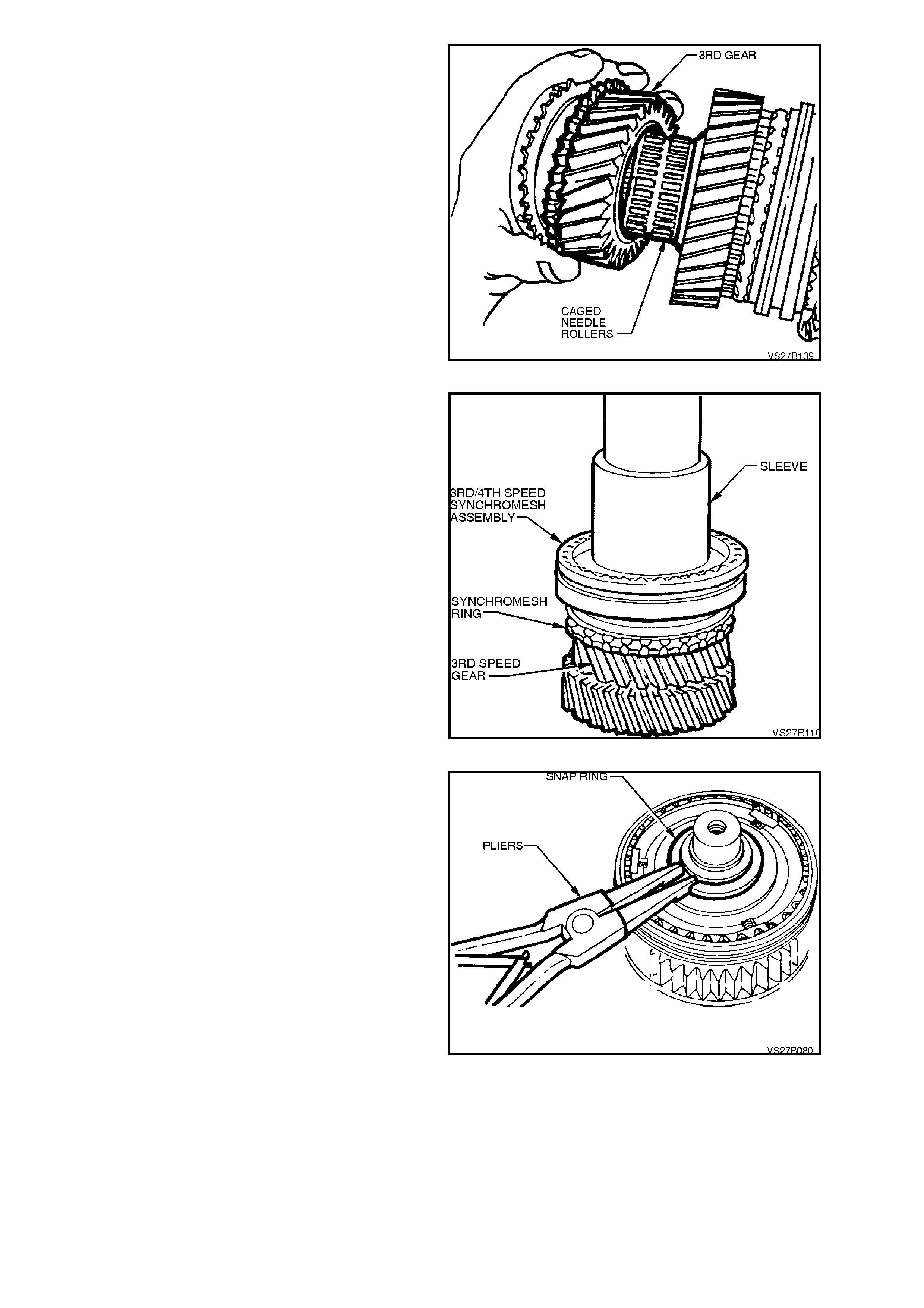
20. Install caged needle roller bearing, 3rd speed
constant mesh gear and synchromesh ring,
onto mainshaft.
21. Preheat assembled 3rd/4th speed
synchromesh assembly on a hot plate to
approximately 100° C.
NOTE:
Use Faber Castell Thermochrom 2815/100° C
around synchromesh hub, to indicate temperature.
22. Using a heat proof glove, position
synchromesh assembly onto mainshaft,
aligning mainshaft and hub splines.
NOTE:
The 3rd/4th selector fork offset in the outer sleeve
faces away from 3rd gear.
Figure 7B1-112
23. Using suitable sleeve, pres s synchrom esh hub
assembly onto mainshaft, ensuring that
synchromesh ring slots align with sliding keys.
24. Remove mainshaft from press, and if
necessary, lever up 3rd speed synchromesh
ring with a screwdriver so that it is not jam m ed
on the gear cone.
Figure 7B1-113
25. Install washer and snap ring to mainshaft,
ensuring that snap ring is correctly seated in
groove with no clearance between the snap
ring and the washer.
Snap rings are available in thicknesses of 2.0, 2.1,
2.2, 2.3, 2.4 and 2.5 mm.
Figure 7B1-114
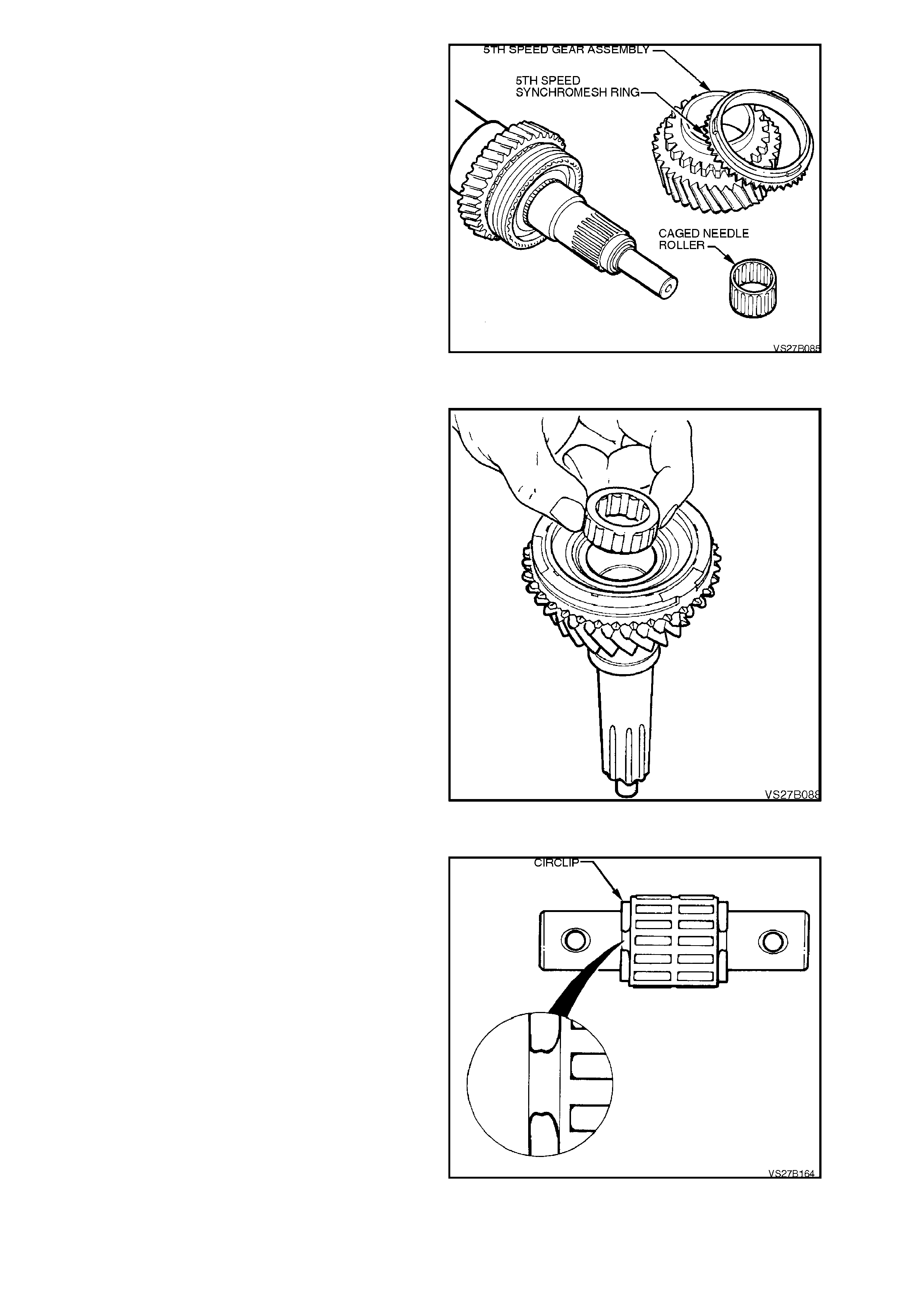
26. Install 5th speed caged needle roller bearing
onto mainshaft. Then install the synchromesh
ring, engaging ring slots with sliding blocks of
the synchrom esh assem bly and f inally, the 5th
speed gear.
Figure 7B1-115
Maindrive Gear
1. Coat maindrive gear needle bearing with
petroleum jelly.
2. Insert bearing assembly into the maindrive
gear.
Figure 7B1-118
Reverse Idler Gear Shaft
1. Lubricate the reverse idler gear shaft with
clean transmission fluid, then install the two
caged needle roller bearings.
2. Locate the roller bearings by installing new
snap rings to eac h groove on the reverse idler
gear shaft.
IMPORTANT:
Snap rings must be installed with the curved out
portion of each snap ring end, AWAY from the
roller bearing as shown.
As the reverse idler gear is in constant mesh with
the cluster gear, if the snap rings are not installed
as shown, then a transmission noise will be
created.
Figure 7B1-119
TRANSMISSION CASE, REAR SECTION
Disassemble
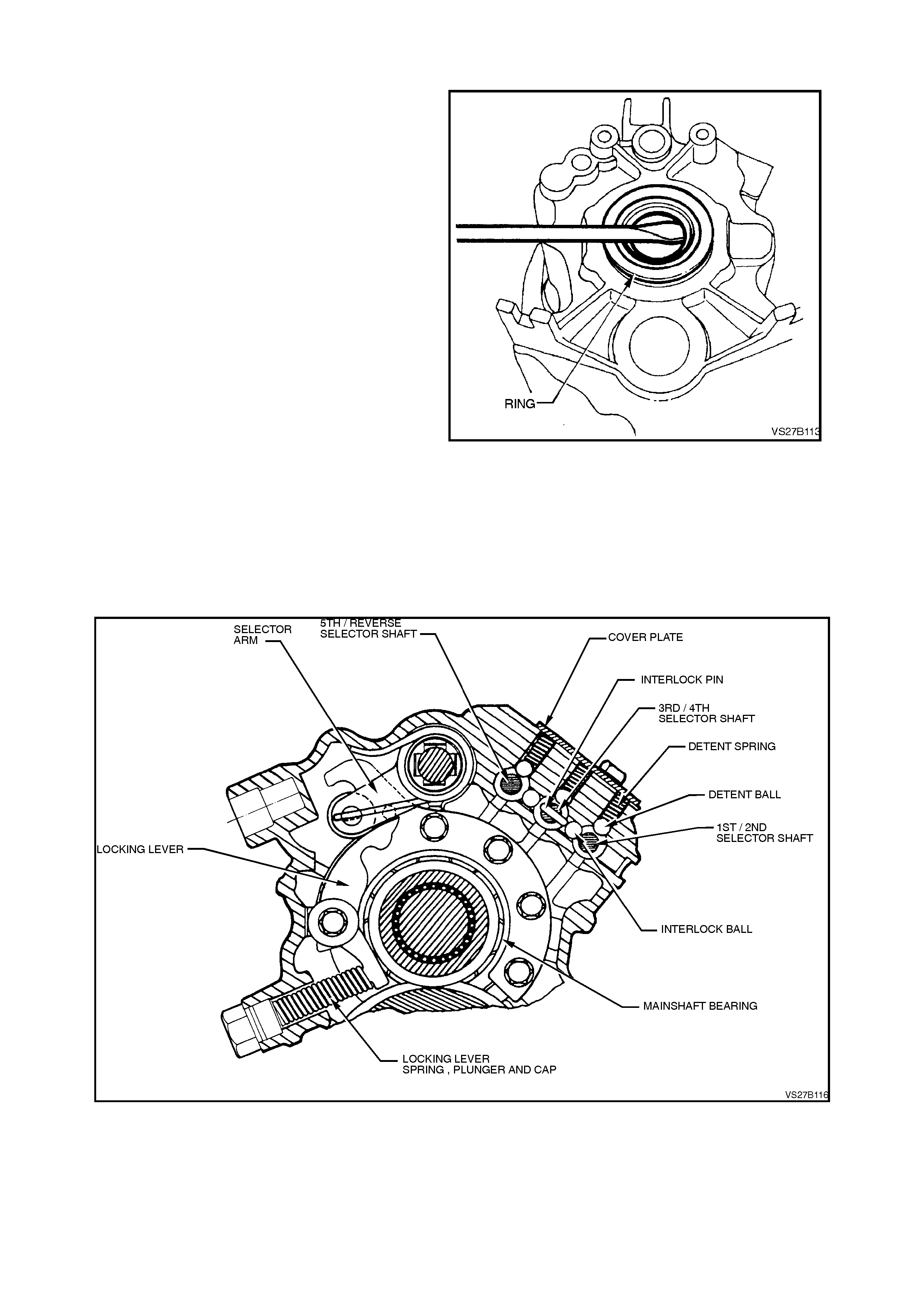
1. To remove the rear oil seal, use the distance
spacer ring f rom the fr ont m ainshaf t bearing to
protect the transmission rear housing, then
use a screwdriver to lever out the seal from
the rear transmission case.
NOTE:
Take extreme care not to scratch the seal surface
in the rear transmission case. If damaged, a
subsequent fluid leak may occur.
Figure 7B1-120
2. Remo ve the locking lever sc rew plug from the
rear housing, using a 19 mm ring spanner,
noting that sealant is applied to the threads.
CAUTION:
Take care that the plug does not fly out under
spring force, when the plug is unscrewed.
3. Remove the spring from the rear housing.
Figure 7B1-121
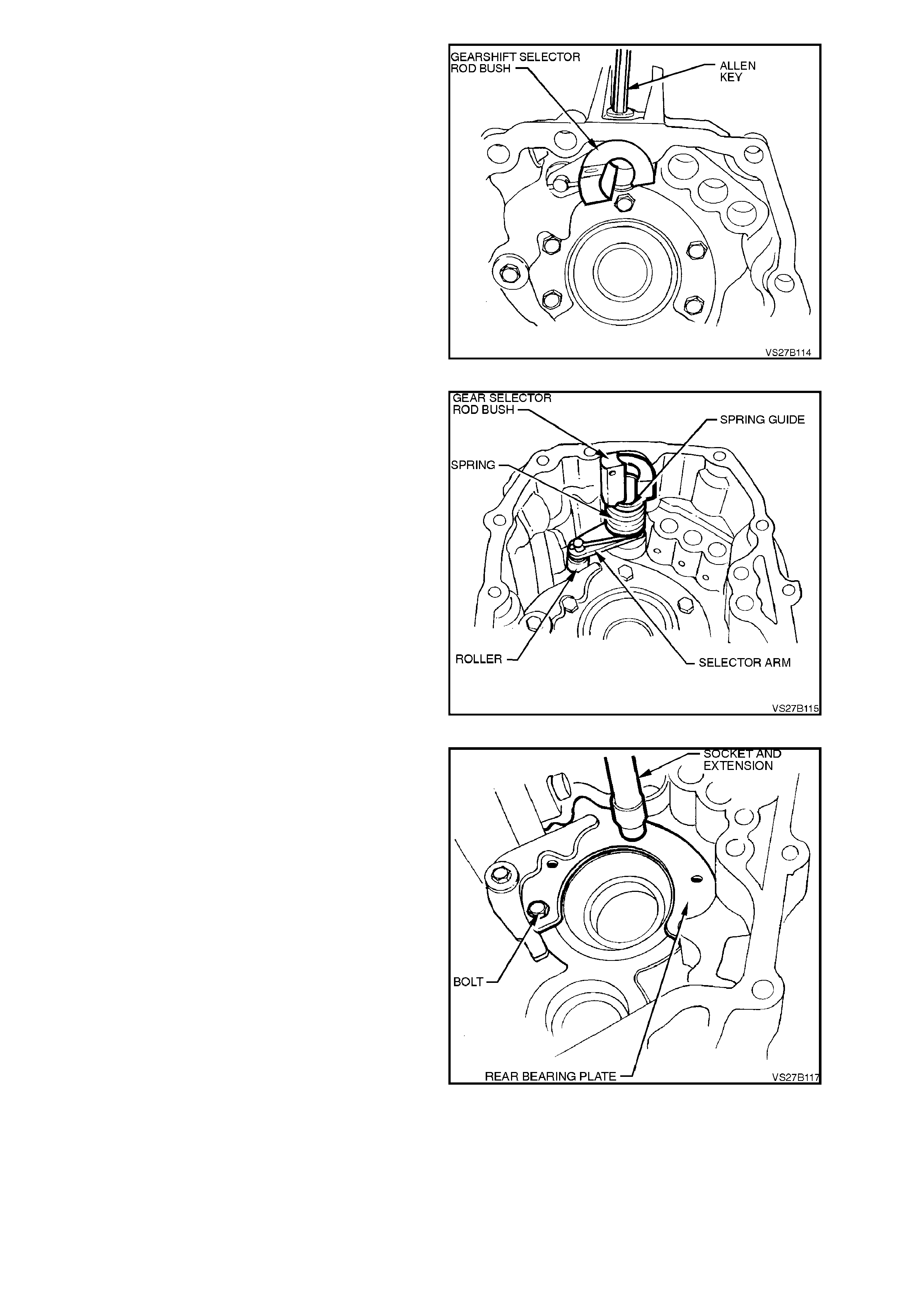
4. Using a 6 mm, Allen key socket, remove the
gearshift selector rod bush lock bolt from the
rear case section.
NOTE 1:
The loc k bolt has sealant applied to the thread and
will be difficult to remove, if a hot air gun is not
used to soften the sealant prior to bolt removal.
NOTE 2:
As the Allen key screw is removed, support the
gearshif t selector rod bush against rotational s pring
force.
Figure 7B1-122
5. From inside case, remove the spring, spring
guide and selector arm with roller. Be careful
as spring force can easily eject these parts,
uncontrolled.
Figure 7B1-123
6. Remove the f ive bolts holding the rear bear ing
plate and locking lever support, then remove
the plate and locking lever as an assembly.
7. If required, remove the locking lever pivot bolt
and nut from the rear bearing retaining plate.
Figure 7B1-124
NOTE:
Unless the rear mainshaft bearing is to be
replaced, there is no need for this next operation.
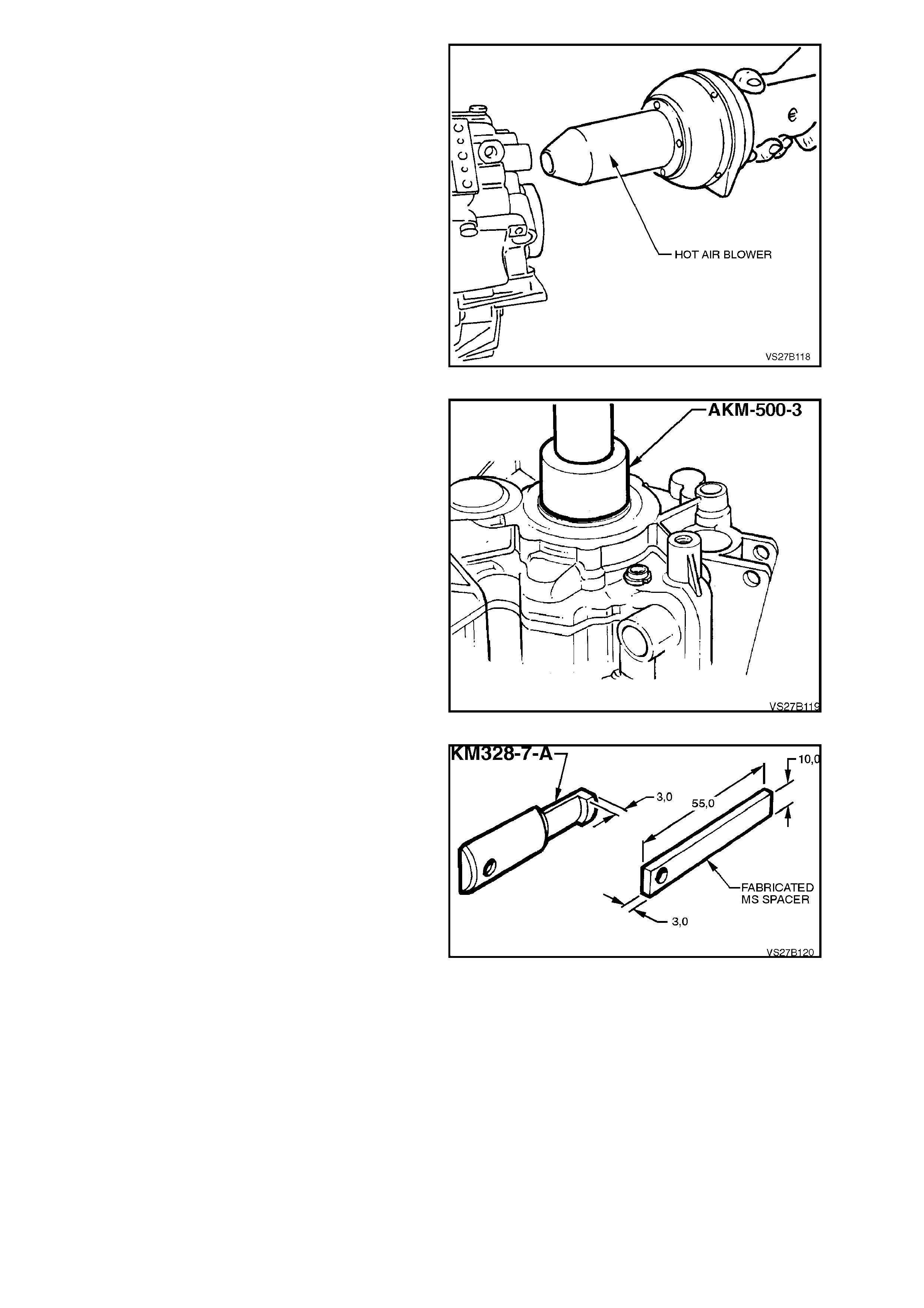
8. Preheat the transmission housing in the rear
bearing area, to approximately 80° C using a
commercially available hot air blower.
NOTE:
Use Faber Castell Thermocrom 2815/80° C, to
ensure that an excessive temperature is not
reached.
Figure 7B1-125
9. Use a suitable sleeve such as AKM- 500-3 and
press the mainshaft rear bearing from the
transmission housing.
IMPORTANT:
Because of ball brinelling, the bearing MUST be
replaced, after removal.
Figure 7B1-126
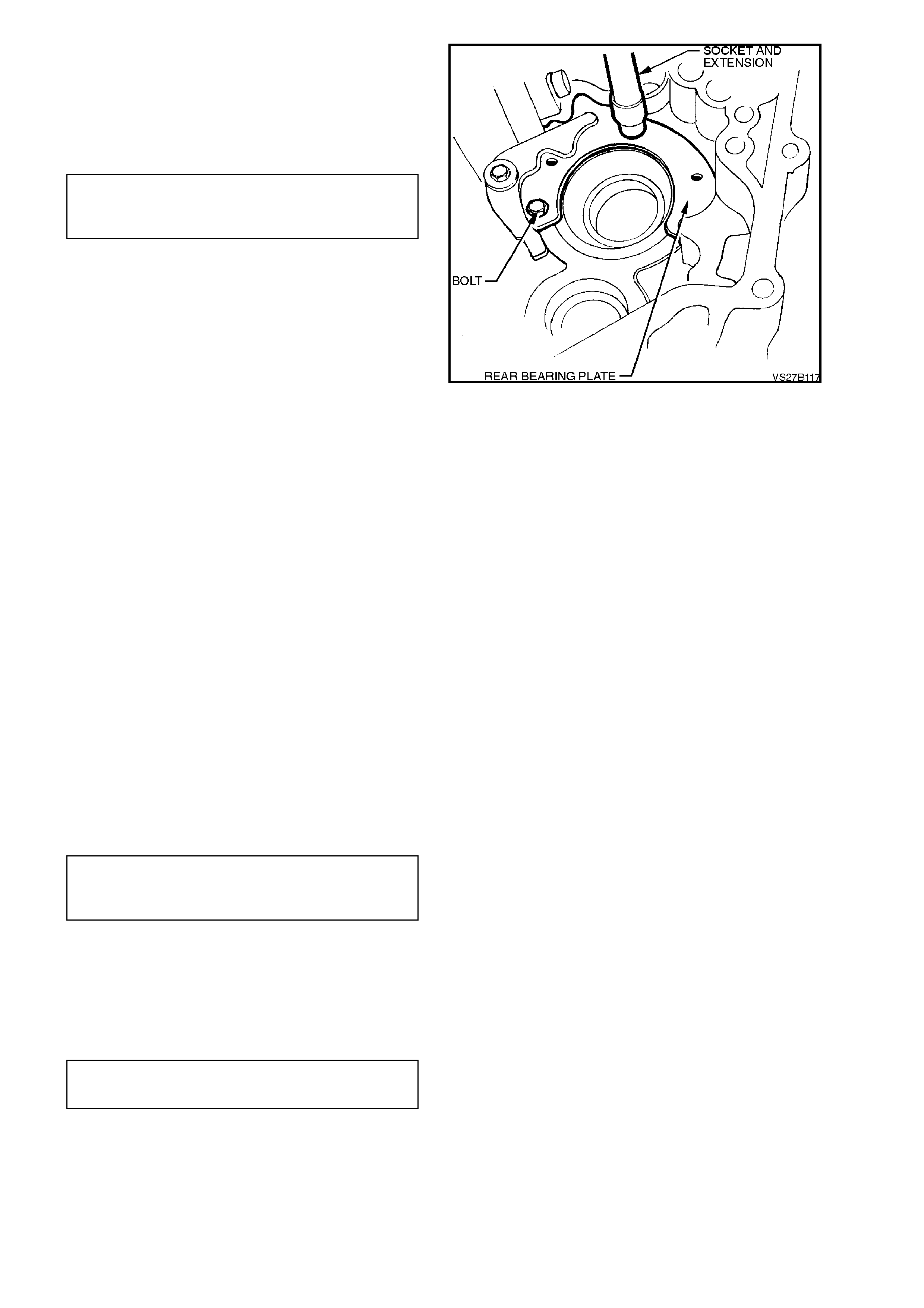
10. To remove the rear cluster gear bearing cup,
use the following method;
a. Grind the legs of Tool KM-328-7-A down
to approximately 3 mm , s uf ficient to inser t
under the bearing cup.
b. Fabricate a spacer as shown, to insert
between the two legs, using 3 mm
thickness, mild steel stock.
Figure 7B1-127
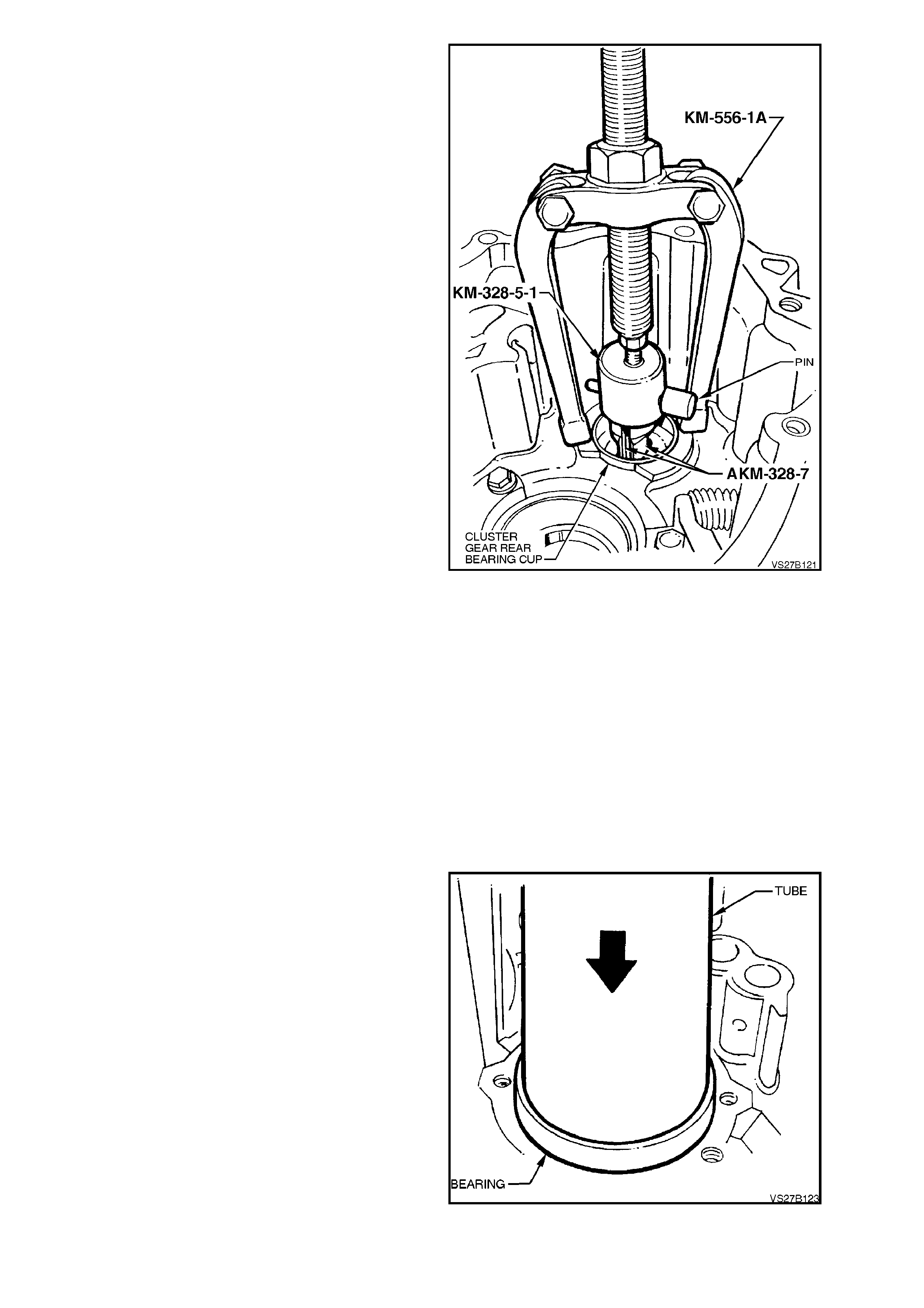
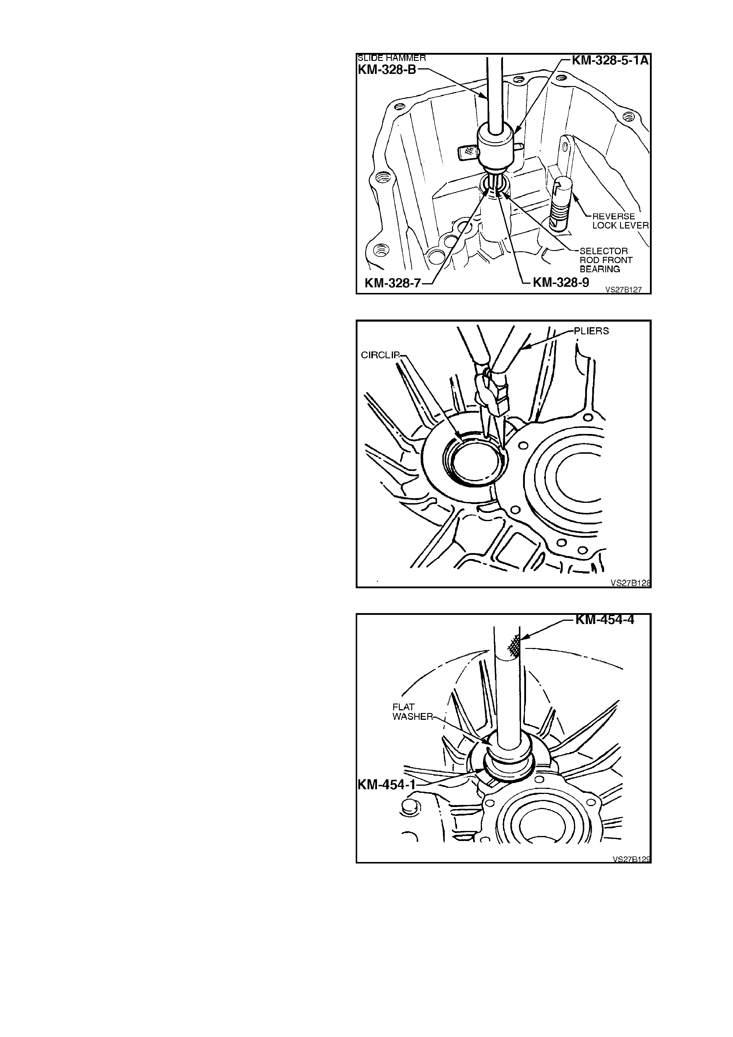
c. Install each of the modified legs of Tool
KM-328-7-A under the bearing cup, then
insert the fabricated spacer in between
them.
d. Use the cup, Tool KM-328-5-A and pin
from slide hammer, Tool KM-328-B to
secure the legs and spacer assembly.
e. Screw threaded adaptor into cup and
install puller KM-556-1A.
f. Use the puller to extract the bearing cup
from the rear transmission case.
NOTE:
To aid in rem oval of bearing, it will be necessar y to
preheat case area of bearing to 80° C, using a
commercially available, hot air blower.
Use Faber Castell Thermocrom 2815/80° C, to
ensure that an excessive temperature is not
reached.
Figure 7B1-128
INSPECT
1. Inspect rear transm ission cas e for any defects
or cracks that may cause oil leaks.
2. Check all machined surfaces for burrs, and if
present, dress them off with a fine cut file.
3. Check bearing bores for damage or scoring.
4. Inspect all shift control component contact
surfaces and sliding surfaces for wear,
scratches, projections or other damage.
5. Check all springs for damage or distortion.
6. Check the selector inter-lock pin and balls for
damage.
REASSEMBLE
1. Using a suitable length and diameter pipe,
press a new, sealed ball race into the rear
transmission case, ensuring that force is only
applied to the outer bearing ring.
NOTE 1:
To assist in the installation of the bearing, heat the
rear transmission housing with a commercially
available hot air gun to approximately 80° C.
Use Faber Castell Thermocrom 2815/80° C, to
ensure that an excessive temperature is not
reached.
NOTE 2:
The of fset on the inner bear ing cone faces the rear
of the transmission.
Figure 7B1-129
2. Apply thread sealant such as Loctite 242 or
243 (or equivalent, to Holden’s Specification
HN1256) to the cleaned threads of the rear
bearing plate retaining bolts. Install the rear
bearing plate and tighten the bolts to the
correct torque specification.
REAR BEARING PLATE AND
LOCKING LEVER BOLT 10 Nm
TORQUE SPECIFICATION
Figure 7B1-130
3. Preassemble the selector arm, spring, bush
and sleeve, by first inserting the shaft of Tool
AU462 into the rear of the selector arm,
engaging the lugs with those in the arm (2).
Then, install the straight end of the spring (5)
into the selector arm pin hole and insert the
sleeve and bush (4) over the shaft. Insert the
sleeve of Tool AU462 over the protruding s haf t
and engage the leg with the free end of the
spring.
While holding the selector lever (2) in one
hand, rotate the sleeve of the holding Tool
AU462 counter-clockwise, loading the spring.
Tighten the locking screw (3) to retain the
assembly in the loaded state.
4. Use petroleum jelly to sec ure the selector arm
roller (1), to the pin, then install the assembly
to the rear transmission case. Install the bush
locating screw, after applying sealant such as
Loctite 242 or 243 (or equivalent to Holden’s
Specification HN1256) to cleaned screw
threads and tighten with an Allen key headed
socket to the correct torque specification.
GEARSHIFT SELECTOR
ROD BUSH SCREW 20 Nm
TORQUE SPECIFICATION
5. Apply thread sealant such as Loctite 242 or
243 (or equivalent, to Holden’s Specification
HN1256) to the cleaned threads of the locking
lever screw plug. Install the spring and plug,
tightening to the correct torque specification.
LOCKING LEVER SCREW PLUG 48
TORQUE SPECIFICATION Nm
TRANSMISSION CASE, FRONT SECTION
DISASSEMBLE
1. Insert the legs of Tool KM328-7-A into the
bearing and hold in position with spacer. Tool
KM-328-9. Slip the cup of Tool KM-328-5-1A
over the legs and secure with the pin.
2. Screw the thread of slide hammer, Tool No.
KM-328-B into the cup and remove the
gearshift selector rod front bearing from case.
NOTE:
When carrying out this operation, the bearing will
be damaged and must be replaced.
3. From inside the transmission bell housing,
remove the bolt securing the reverse block
assembly. To remove the reverse block shaft,
temporarily reinstall the bolt for a few threads
and gently tap the shaft free from the
transmission front case. Figure 7B1-131
NOTE:
Normally this next operation would only be
considered necessary if replacement of the front
cluster gear, bearing and/or transmission front case
was required.
4. Remove cluster gear front bearing snap ring
from front transmission case and remove any
end float adjusting shims.
NOTE:
If necessary, press bearing inward slightly so that
snap ring can be removed. Use the adaptor, Tool
KM-454-1 and mandrel Tool KM-454-4, with a flat
washer.
Figure 7B1-132
5. Use the adaptor, Tool KM 454-1 and mandrel
Tool KM-454-4, with a flat washer (or a sleeve
of 43 mm diameter), press the bearing cup
into the transmission case.
Figure 7B1-133
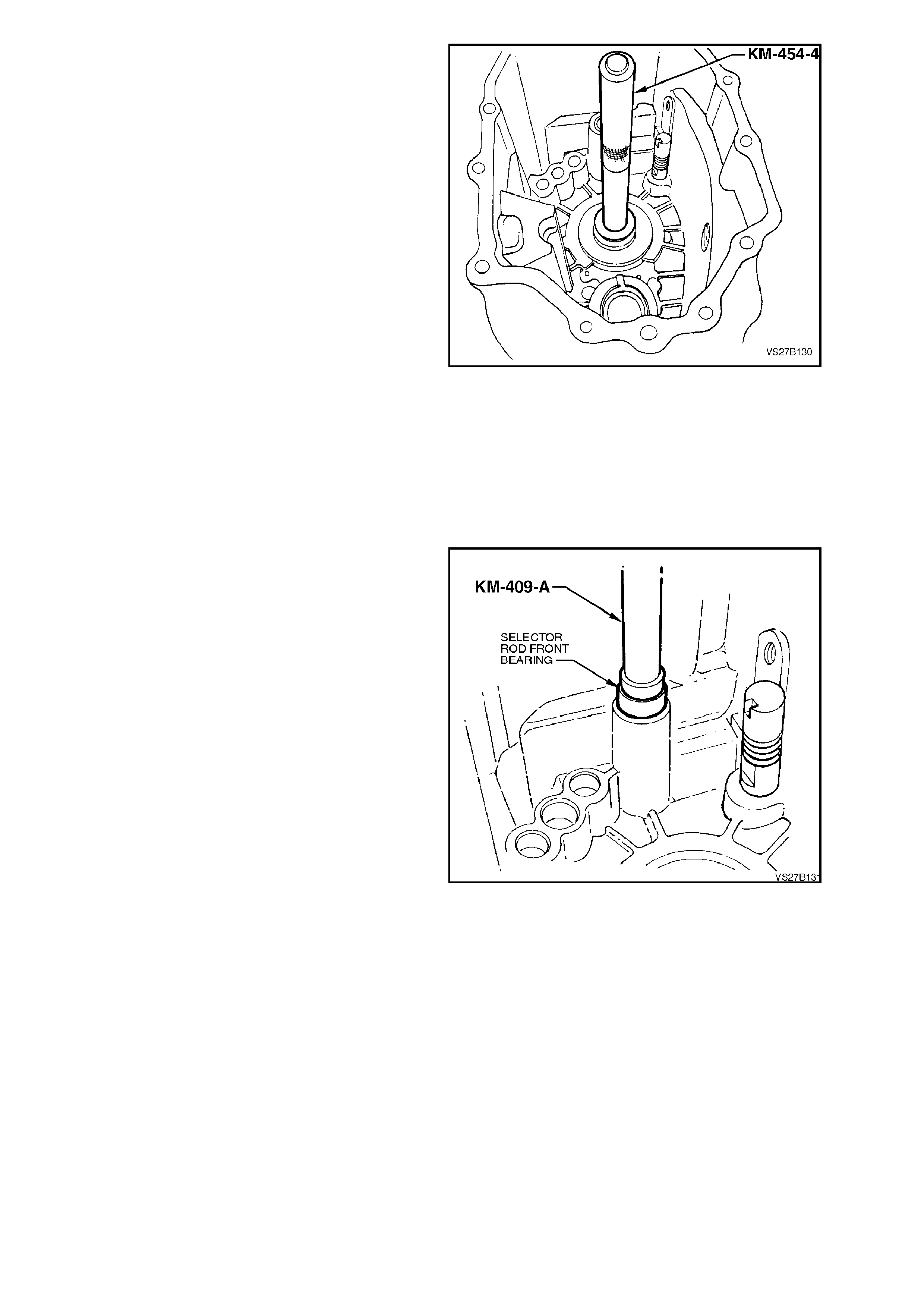
6. Using a suitable adaptor (or sleeve), press on
the outer ring of the maindrive gear bearing
from inside the transmission case, to remove
it.
Figure 7B1-134
INSPECT
1. Inspect transmission case for any defects or
cracks that may cause oil leaks.
2. Check all machined surfaces for burrs, and if
present, dress them off with a fine cut file.
3. Check bearing bores for damage or scoring.
REASSEMBLE
1. Lubricate a new gearshift lever shaft guide
bearing with transmission fluid. Install, using
Tool No. KM-409-A or equivalent.
Figure 7B1-135
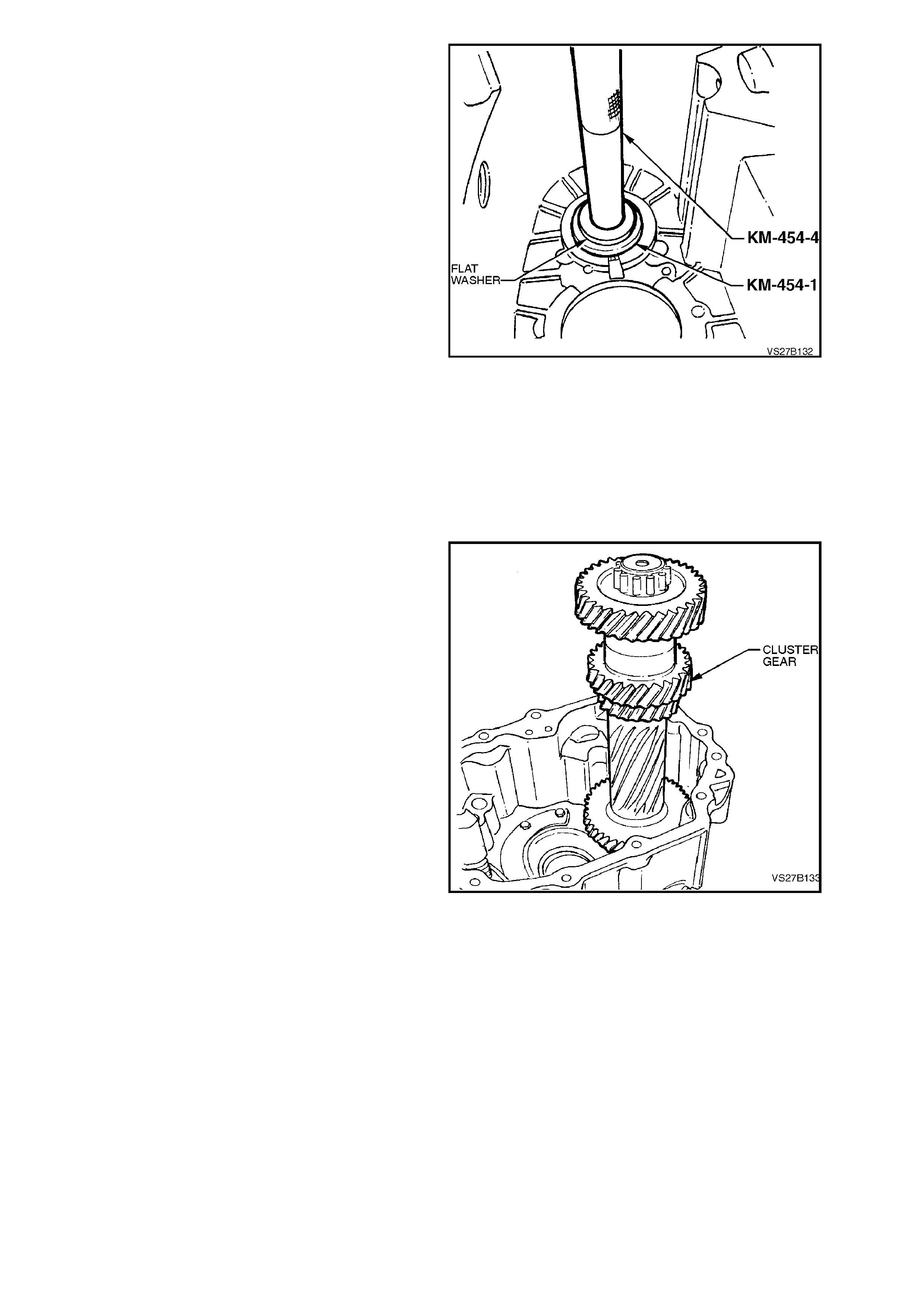
2. Install compensating shim/s and a new snap
ring to the bore of the front cluster gear
bearing.
3. Install cluster gear front bearing, using
adaptor, Tool KM-454-1, flat washer and
mandrel KM-454-4 (or a suitable sized tube),
pressing from the inside of the front
transmission housing, outward.
NOTE 1:
If a new transmiss ion cas e f ront s ec tion and/or new
cluster gear is to be installed, the end play m ust be
measured.
Refer to the Sub-Asse m bly heading ‘Cluster Gear
End Play Adjustment', next in this Section.
NOTE 2:
If the maindrive bearing was removed and a
replacement is to be installed, then compensating
shim thickness will need to be calculated, after
installation. As bear ing replacem ent would nor m ally
be carried out during tr ansmiss ion reassembly, this
operation will be detailed at that time. In any case,
if cluster gear end play adjustment is to be carried
out, then the bearing would need to be rem oved for
this operation.
Figure 7B1-136
CLUSTER GEAR END PLAY ADJUSTMENT
This operation is only necessary when replacing
the front transmission case and/or the cluster gear.
1. Install cluster gear into transmission case rear
section.
Figure 7B1-137
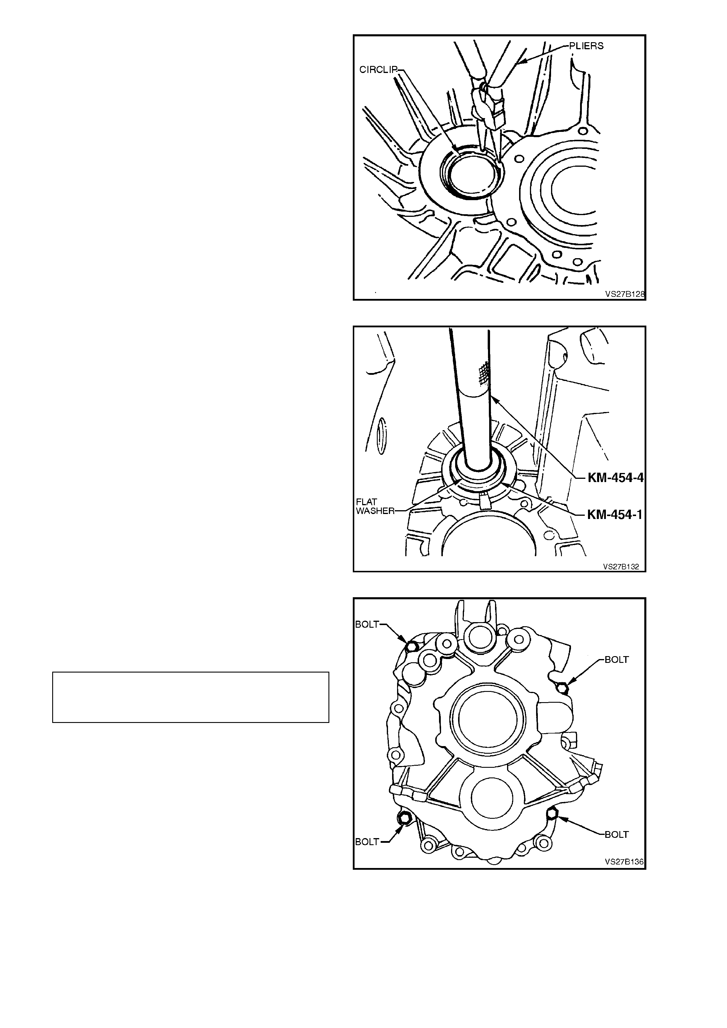
2. Remove front cluster bearing circlip from
transmission case front section, then remove
compensating shim/s.
NOTE:
If necessary, press bearing cup inward slightly to
enable removal of snap ring.
Figure 7B1-138
3. Install cluster gear f ront bear ing c irclip, without
shim/s.
4. Using adaptor, Tool KM-454-1 and mandrel
KM-454-4, together with a flat washer (or a
suitable tube), press bearing into case bore
until it contacts snap ring.
Figure 7B1-139
5. Place transmission case front section onto
rear section and install four case attaching
bolts. Tighten bolts to the correct torque
specification
TRANSMISSION REAR CASE
ATTACHING BOLT 25 Nm
TORQUE SPECIFICATION
Figure 7B1-140
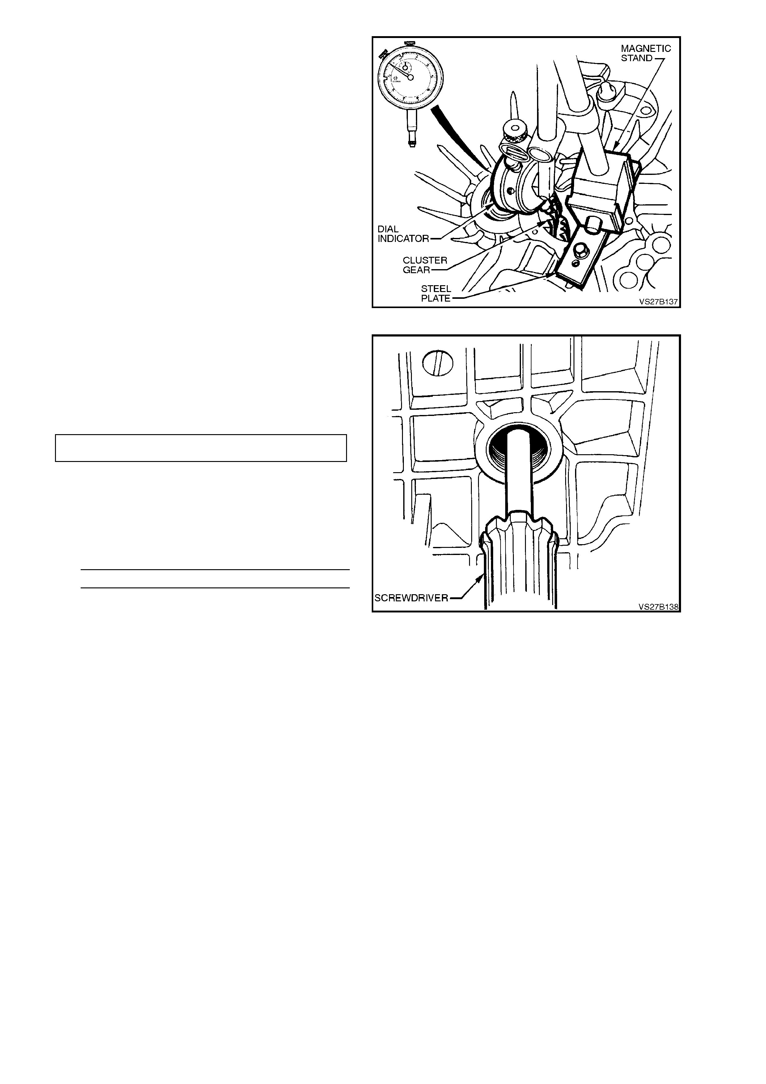
6. Secure a piece of flat steel (approximately 20
x 5 mm) with two bolts, to the front machined
surface of the clutch throwout bearing guide
flange.
7. Mount a dial indicator and stand to the flat
steel, ensuring that the stylus of dial indicator
rests on front of cluster gear, as shown. Zero
the dial indicator.
Figure 7B1-141
8. Using a screwdriver through filler plug
opening, raise and lower clus ter gear to obtain
the total end float dimension. Record this
reading.
Axial play should be to the following specification:
CLUSTER GEAR AXIAL PLAY 0.13 - 0.23 mm
9. Subtract this axial play figure from the
measurement taken to determine the required
shim stack.
e.g. Total Axial Play Recorded = 3.96 mm
Subtract Axial Play Specification = 0.18 mm
Required Shim Thickness = 3.78 mm
Shims are available in 1.0, 1.7 mm, 1.8 mm,
2.0 mm, 2.1 mm, 2.2 mm and 2.3 mm
thicknesses. In the above example, a shim
combination of 1.8 and 2.0 mm would be
required.
10. Install selected shim/s, refer to
Transmission Case Front Section-
Disassemble and Reassemble in this
Section.
11. Recheck axial play as described previously.
12. Once axial play has been adjusted, separate
the two transmission cases and remove the
cluster gear.
Figure 7B1-142
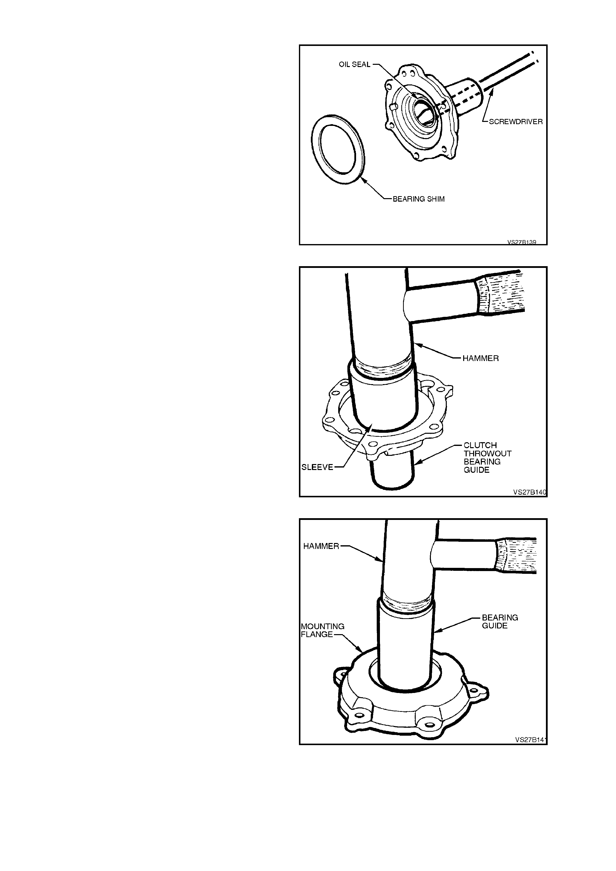
CLUTCH THROWOUT BEARING GUIDE
INPUT SHAFT SEAL, REPLACE
1. Remove the maindrive bearing compensation
shim/s if fitted, from the throwout bearing
guide and set to one side. If the maindrive
bearing is not replaced, then this same shim
stack will need to be reinstalled, on
reassembly.
2. Using a scr ewdriver, lever s eal ring f r om thrus t
bearing guide sleeve, as shown. Take c are not
to scratch the seal surface of the throwout
bearing guide during seal removal.
Figure 7B1-143
3. Using a suitable size sleeve, install new seal
into guide sleeve.
Figure 7B1-144
‘O’ RING, REPLACE‘
1. W hile holding the flange against a f lat surfac e,
use a plastic faced hammer and tap the
throwout bearing guide from the mounting
flange.
NOTE:
Do not lose the small locating disc.
Figure 7B1-145

2. Remove the O-ring seal from the mounting
flange, using a small screwdriver.
3. Clean all components and inspect for wear
and damage. Replace as required.
4. Install new O-ring into the flange, lubricating
with petroleum jelly.
5. Align the locating disc, semi-circular cut-outs
of the flange and guide and assemble, taking
care to keep both parts square to each other.
6. Install the locating disc, securing with a small
amount of petroleum jelly.
Figure 7B1-146
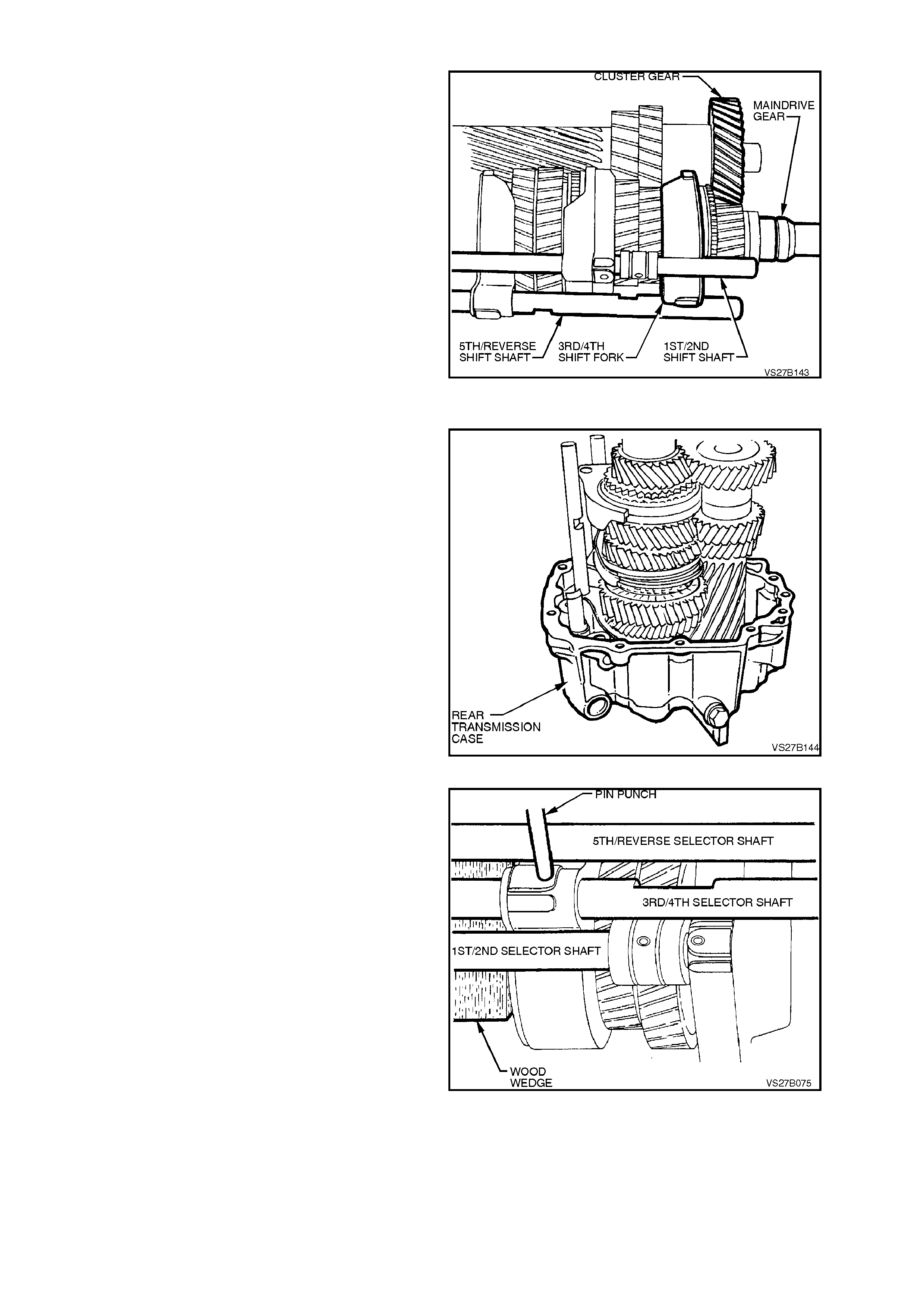
4.5 TRANSMISSION REASSEMBLE
1. Carefully move the respective synchromesh
rings into Reverse and 2nd gear positions.
2. Install all shift forks to their respective
synchromesh rings - the 5th/Reverse and
1st/2nd, with their shafts, both with new roll
pins fitted.
NOTE:
The 3rd/4th shift shaft will be fitted later in the
assembly process.
3. Assem ble the maindr ive gear and cluster gear
to the mainshaft assembly, holding everything
together as a single assembly.
4. Pre-heat the inner race of the sealed rear ball
race to 80° C, using a commercially available
hot air blower.
NOTE:
Use Faber Castell Thermocrom 2815/80° C to
indicate the temperature of the inner race. Figure 7B1-147
5. With the transmission case rear section
supported in an upright position, carefully
install the gear and shift fork/rail assemblies
into the case, aligning the two shift rails with
their respective bores.
Figure 7B1-148
6. Carefully move the 5th/Reverse and 1st/2nd
gear synchromesh rings into the Neutral
position.
7. Install both interlock balls to the interloc k bore,
securing in place with petroleum jelly.
8. With the transmission rear case in an upright,
horizontal position, install the lower interlock
ball.
9. Insert the 3rd/4th selector shaft through the
3rd/4th shift fork and install partially into the
bore in the rear case. Then, using a small
screwdriver, insert the second interlock ball
into position from the rear, fully installing with
the 3rd/4th selector shaft.
10. Push the 3rd/4th selector shaft through and
out the rear of the case, insert the interlock
pin, then move the selector shaft forward,
lining up the roll pin hole with the selector fork.
NOTE:
Ensure that the detent ball grooves in the selector
shaft face uppermost.
11. While supporting the shaft with a suitable
wooden wedge, install a new roll pin to the fork
and shaft.
Figure 7B1-149
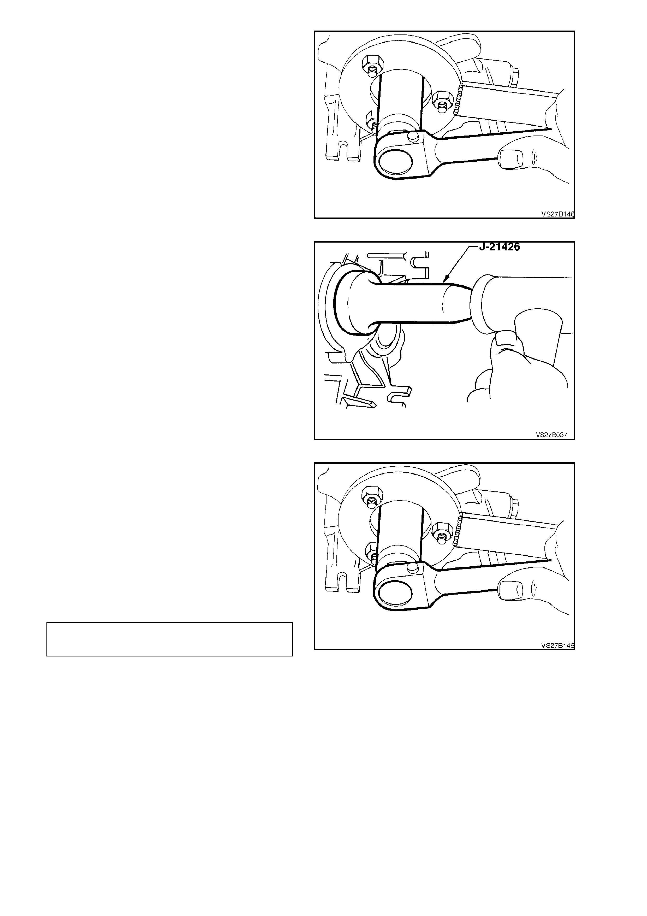
12. Fully install the mainshaft to the sealed rear
bearing, using the following method:
a. Temporarily install the mainshaft sleeve
and the output flange and toothed ring
assembly to the mainshaft.
b. While holding the flange with Tool No.
KM-620-1-A and a suitable length of pipe,
tighten the flange nut using a
commercially available, 30 mm socket,
pulling the inner bearing fully into place.
c. Remove the f lange nut, flange and s leeve
from the mainshaft.
Figure 7B1-150
13. With the transmission in a horizontal position,
install a new seal into transmission case rear
section using Tool No. J-21426 or similar, after
coating the seal lip with transmission lubricant.
14. Also lubricate the seal surface of mainshaft
sleeve with transmission lubricant and install
over the mainshaft.
Figure 7B1-151
15. Reinstall mainshaft flange and toothed ring
assembly to the mainshaft.
16. Apply Loctite 242 or 243 (or equivalent to
Holden’s Specification HN1256) to the splines
of the mainshaft flange and the cleaned
threads of the flange nut. Install the flange to
the mainshaft.
17. While holding the flange with Tool No. KM-
620-1-A, tighten the nut to fully install the
output flange and then tighten the flange nut to
the correct torque specification.
MAINSHAFT FLANGE NUT 100
TORQUE SPECIFICATION Nm
Figure 7B1-152
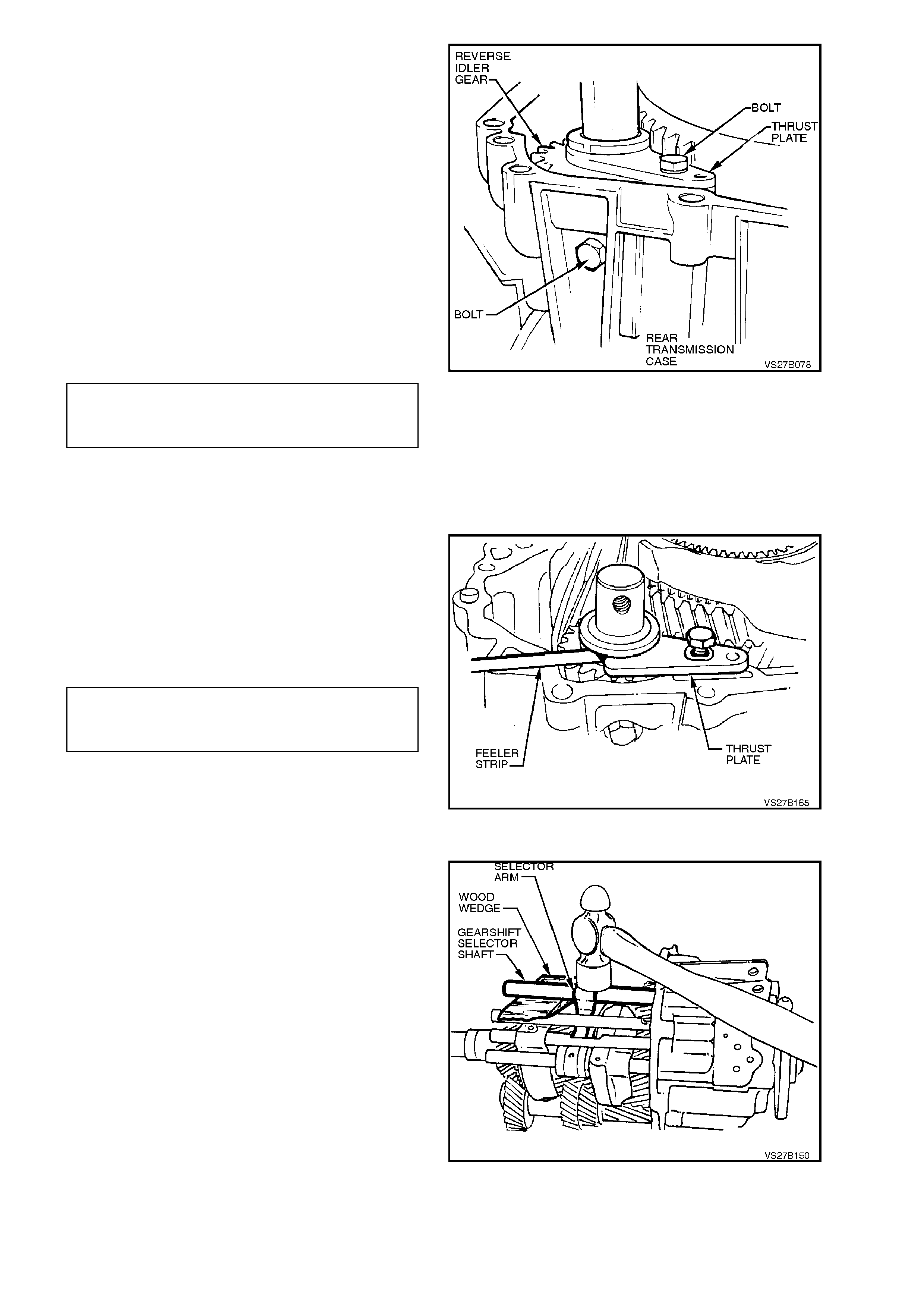
18. Apply a smear of sealant such as Loctite 574
(or equivalent to Holden’s Specification
HN2216) to the section of the rear case that
supports the reverse idler shaft.
19. Install reverse idler gear into position, with the
groove facing forward.
20. Lubricate the reverse idler gear shaft needle
roller bearings with transmission lubricant,
then insert the shaf t through the gear and into
the rear case, aligning the threaded hole with
the locating bolt hole in the rear transmission
case.
21. Apply sealant such as Loctite 242 or 243 (or
equivalent, to Holden’s Specification HN1256)
to the underhead portion of the reverse idler
gear shaft fastening bolt, install and tighten to
the correct torque specification.
REVERSE IDLER GEAR SHAFT
REAR LOCATING BOLT 25 Nm
TORQUE SPECIFICATION
NOTE:
Do not tighten the thrust plate retaining bolt at this
time!
Figure 7B1-153
22. Reduce the width of a piece of feeler gauge
0.040 mm thick, sufficient to fit between the
reverse idler gear and the retainer.
23. Insert the feeler gauge and, while holding the
retainer against the feeler gauge, tighten the
retaining bolt to the correct torque
specification.
REVERSE IDLER GEAR THRUST
PLATE RETAINING BOLT 25 Nm
TORQUE SPECIFICATION
NOTE:
This operation is necessary to centre the retaining
plate with the reverse idler gear. Failure to c ar ry out
this operation will result in transmission noise. Figure 7B1-154
24. Apply a thin coating of petroleum jelly to
gearshift operating shaft rollers, then install
shaft into the r ear of the tr ansm iss ion housing,
aligning the rollers with the internal selector
arm and the shaft with the selector arm.
25. Align the selector arm roll pin hole with the
operating shaft hole, support the shaft with a
suitable size wooden wedge, then install a new
roll pin to the arm and shaft.
Figure 7B1-155
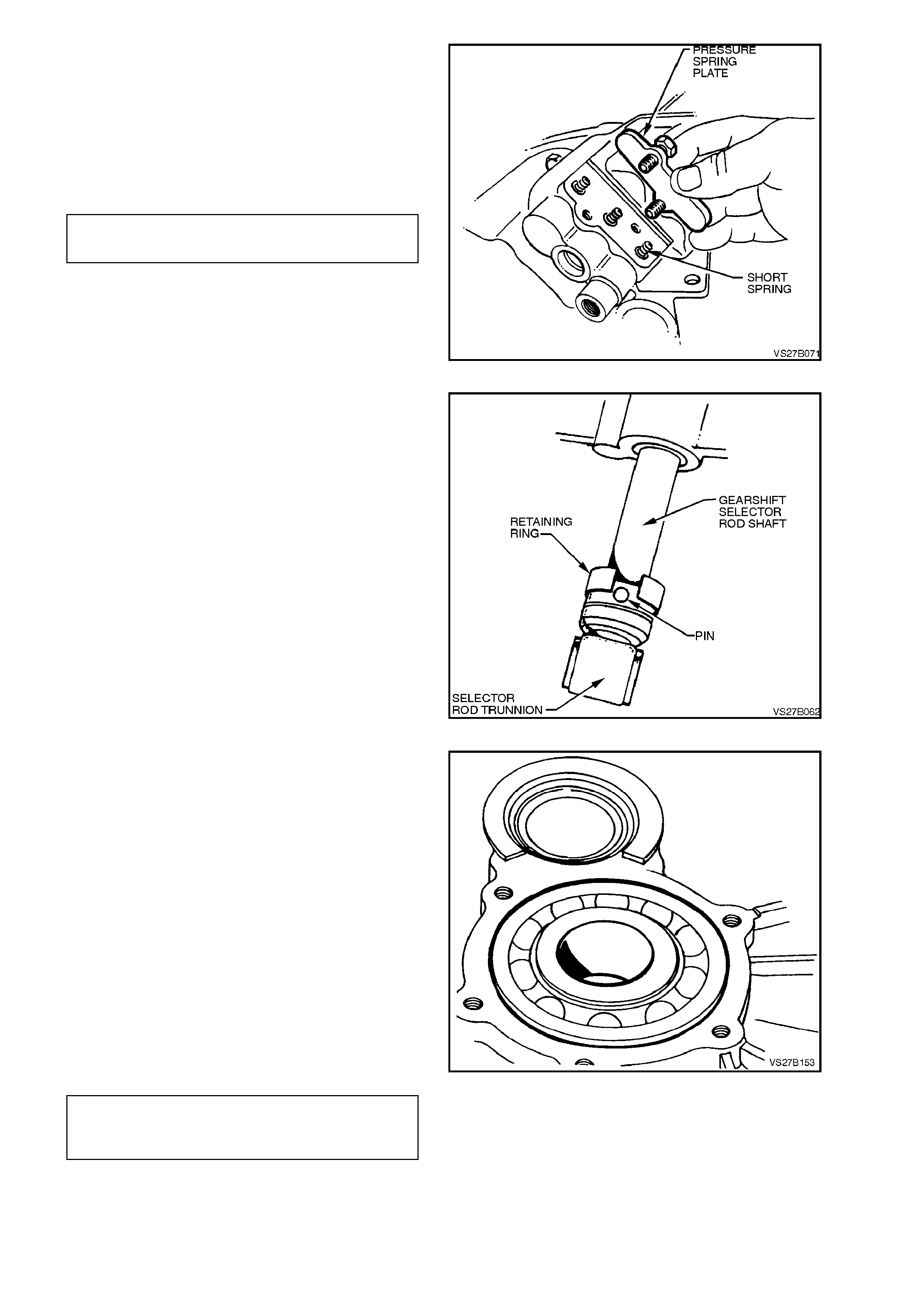
26. Insert the three detent balls and pressure
springs into transmission case.
27. Apply thread sealant such as Loctite 242 or
243 (or equivalent, to Holden’s Specification
HN1256) to the cleaned threads of the
attaching bolts, then install pressure spring
cover and tighten bolts to the correct torque
specification.
SHIFT DETENT SPRING COVER 10
BOLT TORQUE SPECIFICATION Nm
Figure 7B1-156
28. Lubricate gearshift shaft seal lips with
transm ission fluid, then install the s eal into the
rear transmission housing, using a suitable
length and size of tubing, until the seal is flush
against the rear transmission housing.
29. Install gearshift trunnion to the gearshift
selector rod shaft and secure with the retaining
pin.
30. Lever the spring steel retaining ring over the
pin, then rotate to completely cover the pin.
31. Select 4th gear and check that all remaining
synchronisers are loosely seated against their
respective gear cones. If necessary, loosen
firmly seated ring/s from gear cone/s.
Figure 7B1-157
32. Preheat transmission case front section in
area of m aindrive bearing to approxim ately 80
°C using a commercially available hot air
blower.
NOTE:
Use Faber Castell Thermochrom 2815/80 °C to
indicate temperature. Apply thermochrom around
bearing area of transmission case.
33. Using a suitable sleeve acting on the outer
bearing ring, press bearing fully home to the
flange in transmission case front section.
34. Install reverse block assembly to the
transmission case, by using a plastic faced
hammer. Apply Loctite 574 (or equivalent to
Holden’s Specification HN2216) to the sealing
surface of the retaining bolt. Tighten to the
correct torque specification.
REVERSE BLOCK BOLT TO
TRANSMISSION FRONT CASE 10 Nm
TORQUE SPECIFICATION
Figure 7B1-158
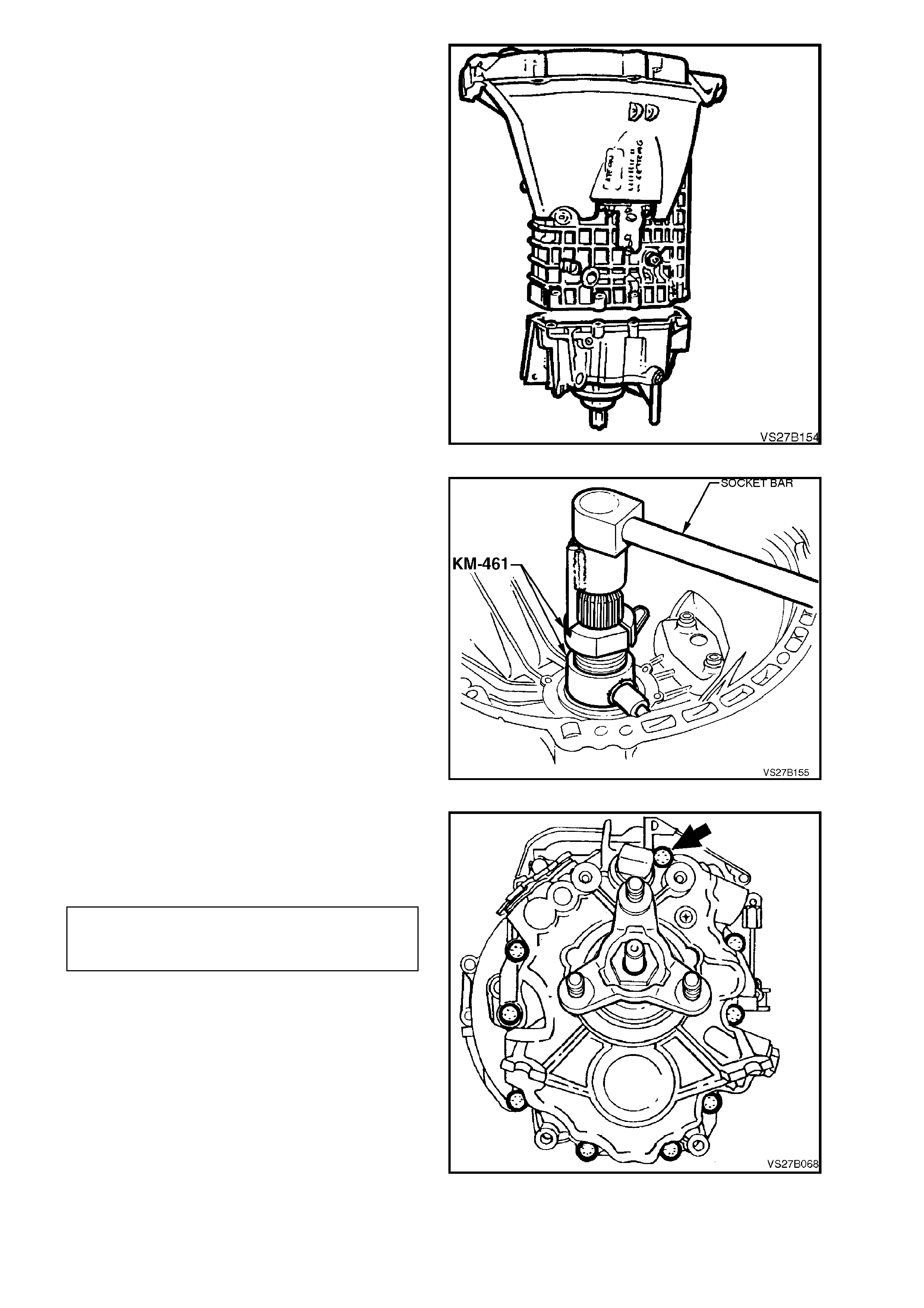
35. Apply a bead of Loctite 574 sealant or
equivalent (to Holden's Spec ification HN2216),
to sealing surface of transmission case and
the front bolt hole of the reverse idler shaft.
36. Position front section of transmission case
onto rear section, aligning shift rods with front
section bore holes.
Figure 7B1-159
37. Install Tool No. KM-461 as shown and draw
the input shaft into the front bearing, using a
socket bar.
38. Rem ove Tool No. KM-461 and ins tall selec tive
washer and retaining ring to maindrive gear.
Selective washers are available in thick nesses
of 2.1 mm, 2.2 mm, 2.3 mm, 2.4 mm and 2.5
mm.
NOTE:
The specified clearance between the selective
washer and the front bearing hub is from 0.00 -
0.09 mm.
39. Place transmission into neutral position and
rotate maindrive gear to check that no
synchroniser rings have become jammed on
gear cones. Figure 7B1-160
40. Install new dowel pins to align the front and
rear transmission cases, prior to installing and
tightening the attaching bolts to the correct
torque specification.
TRANSMISSION REAR CASE
TO FRONT CASE BOLT 25 Nm
TORQUE SPECIFICATION
Note the location of the longest bolt (arrow).
Figure 7B1-161
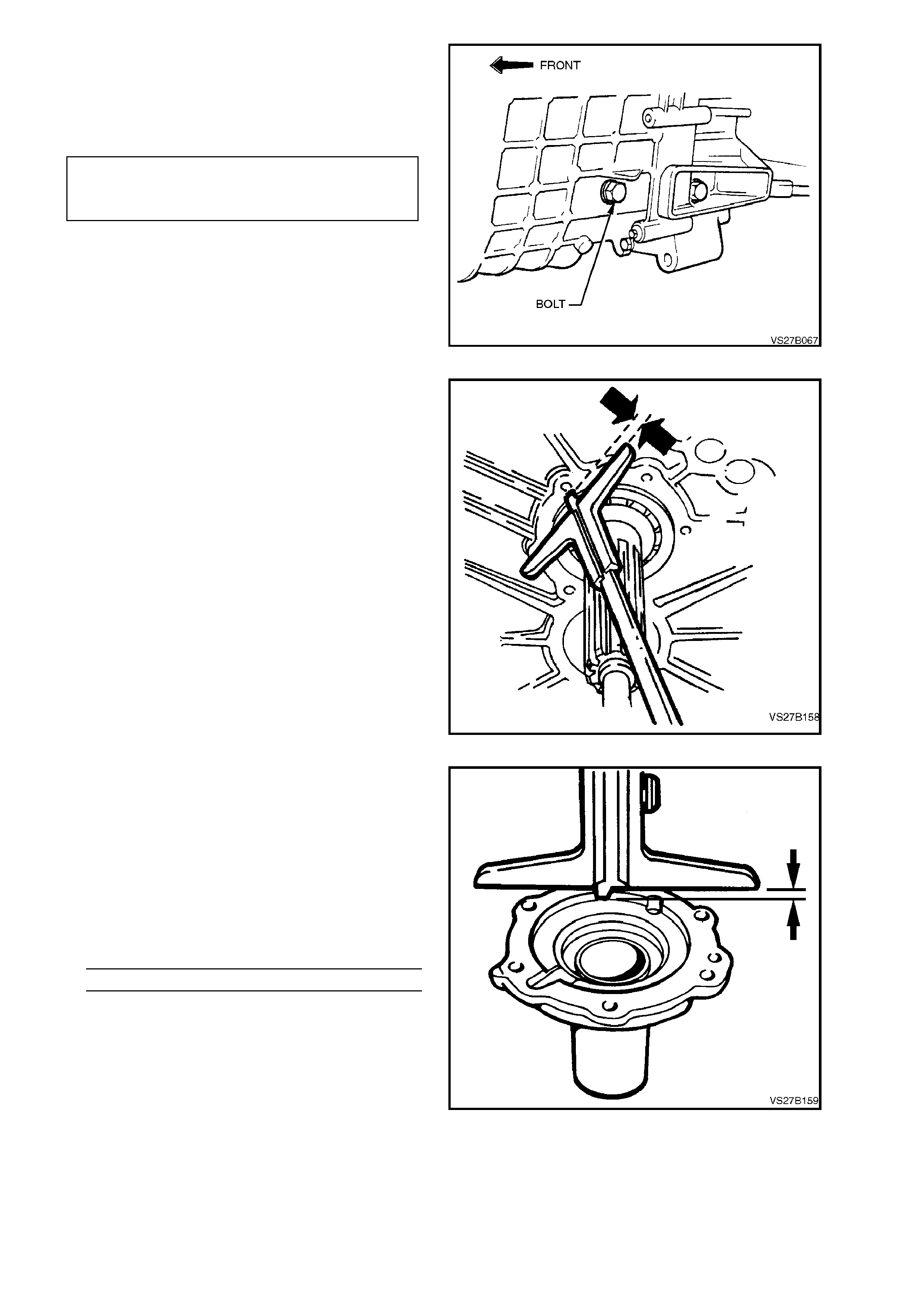
41. Apply sealant such as Loctite 242 or 243 (or
equivalent, to Holden’s Specification HN1256)
to the underhead portion of the reverse idler
gear shaft fastening bolt, install and tighten to
the correct torque specification.
REVERSE IDLER GEAR SHAFT
FRONT LOCATING BOLT 25 Nm
TORQUE SPECIFICATION
Figure 7B1-162
42. Prior to installing the clutch throwout bearing
guide, the compensating shim thickness must
be determined, as follows:
a. With the front bearing distance ring
installed, use a depth gauge to measure
the distance between the front edge of
the bearing distance ring and the
transmission case, noting the
measurement.
Figure 7B1-163
b. After removing any shims, measure the
depth of the counterbore in the clutch
throwout bearing guide, noting the
measurement.
c. Subtract measurement ‘a’ from ‘b’ to
determine the compensating shim stack
required.
e.g. Front Bearing Ring Protrusion = 5.5 mm
Throwout Counterbore Depth = 6.0 mm
Shim thickness = 0.5 mm
Selective shim s are available in thic knes ses of
0.3 mm, 0.4 mm and 0.5 mm.
Figure 7B1-164
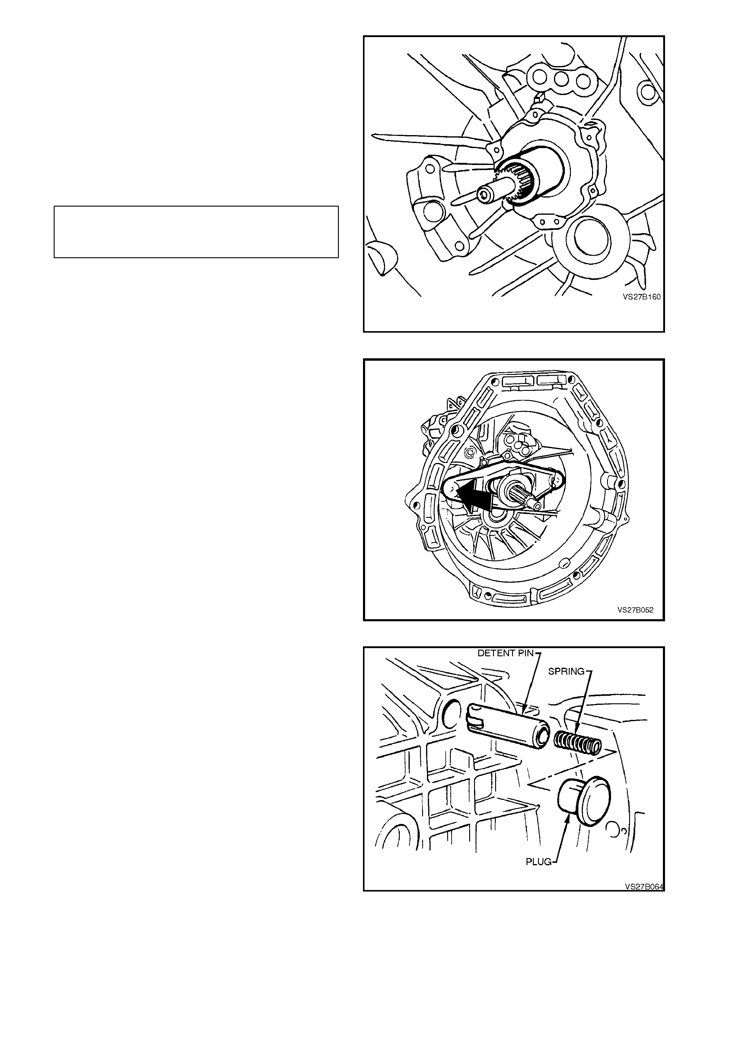
43. Apply a thin coating of Loctite 574 (or
equivalent to Holden’s Specification HN2216),
to the mounting face of the clutch throwout
bearing retaining plate.
44. Lubricate seal with transmission fluid, then
install throwout bearing guide assembly.
45. Apply sealant such as Loctite 574 (or
equivalent to Holden’s Specification HN2216),
to the cleaned threads of the fas tening bolts to
the correct torque specification.
THROWOUT BEARING GUIDE
ASSEMBLY BOLT 10 Nm
TORQUE SPECIFICATION
NOTE:
The bearing guide assembly can only be installed
in the one correct position.
Figure 7B1-165
46. Lubricate throwout bearing guide sleeve,
maindrive gear teeth, release lever, throwout
bearing and ball headed pin with high
temperature grease. Refer to
Section 7A CLUTCH.
47. Install clutch throwout bearing to the clutch
release lever, then install the bearing/lever
assembly, securing to the pivot ball with the
spring clip.
48. Push the bearing fully in, to maintain position
on the lever, until the transmission is installed
and the slave cylinder is reinstalled.
Figure 7B1-166
49. Insert detent pin and pressure spring into
transmission case.
NOTE:
Ensure that detent pin is installed with roller in a
horizontal position, as shown.
50. Install detent spring closure plug, after coating
with sealant such as Loctite 574 (or
equivalent, to Holden’s Specification HN2216).
Figure 7B1-167
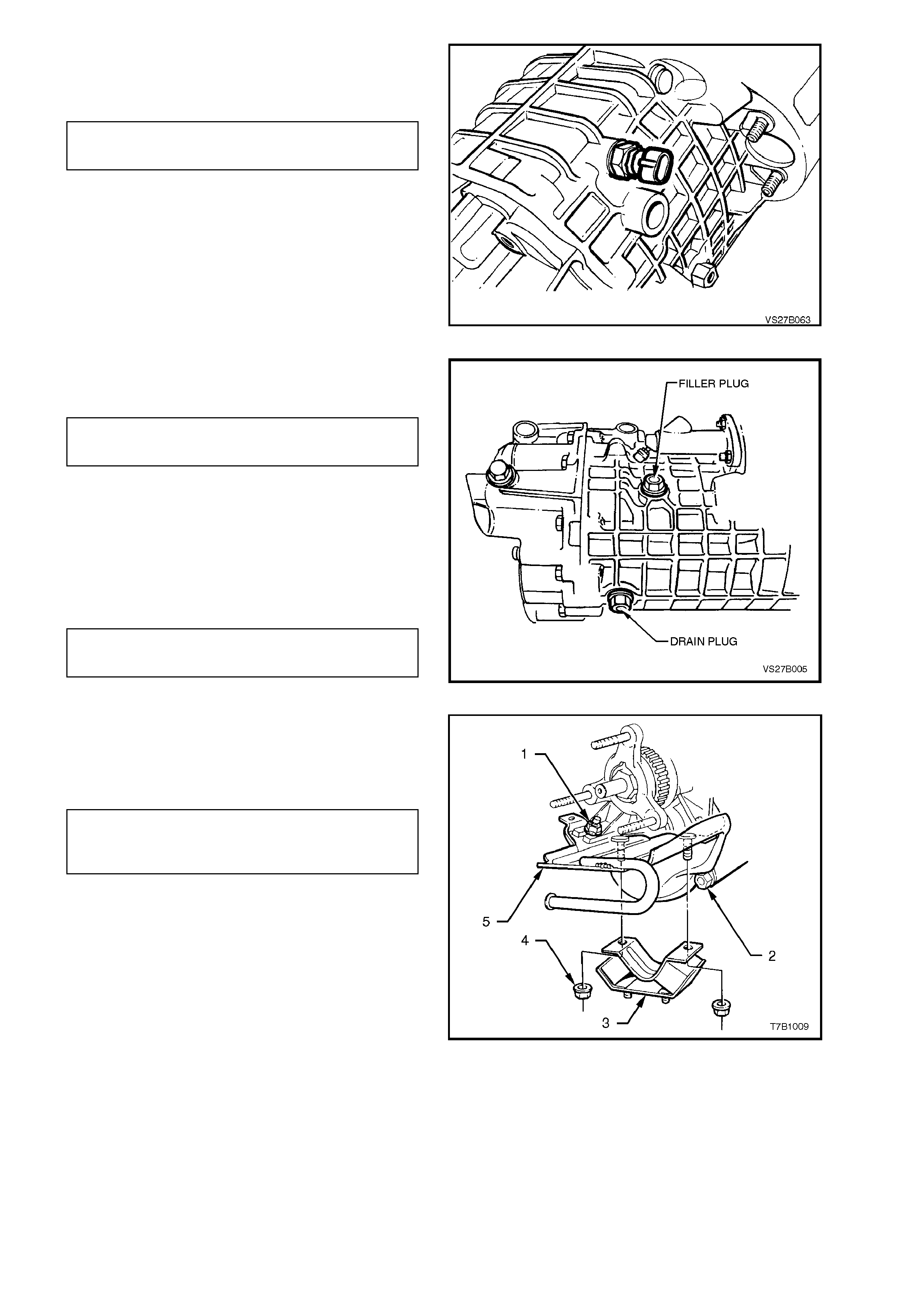
51. Install back-up lamp switch to transmission
case and tighten to the correct torque
specification.
BACK-UP LAMP SWITCH 25
TORQUE SPECIFICATION Nm
Figure 7B1-168
52. Install drain plug and tighten to the correct
torque specification.
TRANSMISSION DRAIN PLUG 45
TORQUE SPECIFICATION Nm
53. Fill transmission with approximately 1.2 litres
of 80W gear oil to Holden's Specification
HN1855, such as Castrol VMX80W or
equivalent.
54. Install filler plug and tighten to the correct
torque specification.
TRANSMISSION FILLER PLUG 45
TORQUE SPECIFICATION Nm
Figure 7B1-169
55. Install rear mount (3) to transmission case
rear section adaptor plate (3). Tighten
attaching nuts (1 and 4) and bolts (2) to the
correct torque specification.
REAR TRANSMISSION CASE
ADAPTOR PLATE BOLTS AND 20 - 30 Nm
NUTS TORQUE SPECIFICATION
56. Reinstall transmission into vehicle. Refer to
4.2 TRANSMISSION ASSEMBLY in this
Section.
Figure 7B1-170

5. DIAGNOSIS
CONDITION PROBABLE CAUSE CORRECTION
TRANSMISSION SHIFT
HARD/HEAVY Clutch pedal high effort.
Shifter shaft binding.
Internal bind in
transmission caused by
shift forks, selector shafts
or synchromesh
assemblies.
Incorrect lubricant.
Lubricate or replace as required.
Check for mispositioned shift fork roll pin/s,
loose bolts, worn shifter shaft or shaft bores or
distorted oil seal.
Repair as necessary.
Remove, disassemble and inspect
transmission. Replace worn or damaged
components as necessary.
Drain and refill transmission.
GEAR CLASH WHEN
SHIFTING FROM ONE
GEAR TO ANOTHER
Lubricant level low or
incorrect lubricant.
Gearshift components or
synchromesh assemblies
worn or damaged.
Drain and refill transmission and check for
lubricant leaks if level was low. Repair as
necessary.
Remove, disassemble and inspect
transmission. Replace worn or damaged
components as necessary.
TRANSMISSION NOISY Lubricant level low or
incorrect lubricant has
been used.
Transmission housing to
engine attaching.
Gearshift mechanism,
transmission gears or
bearing components worn
or damaged.
Drain and refill transmission. If lubricant was
low, check for leaks and repair as necessary.
Check and correct bolt torque settings as
necessary.
Remove, disassemble and inspect
transmission. Replace worn or damaged
components as necessary.
JUMPS OUT OF GEAR Gearshift mechanism, shift
forks, selector shafts,
interlock pin, detent
balls/springs, worn or
damaged.
Gear teeth worn or
tapered, synchromesh
assemblies worn or
damaged.
Remove, disassemble and inspect
transmission assembly. Replace worn or
damaged components as necessary.
Remove, disassemble and inspect
transmission. Replace all worn or damaged
components as necessary.
Techline

CONDITION PROBABLE CAUSE CORRECTION
WILL NOT SHIFT INTO
ONE GEAR Gearshift selector shaft/s,
interlock pin or selector
arm, worn, damaged or
inco rrectly assembled.
Synchromesh sleeves or
hubs, worn or damaged.
Remove, disassemble and inspect
transmission selector assemblies. Repair or
replace components as necessary.
Remove, disassemble and inspect
transmission. Replace worn or damaged
components.
LOCKED IN ONE GEAR -
CANNOT BE SHIFTED
OUT
Shift shaft/s worn or
damaged, selector fork
bent or broken.
Gearshift mechanism worn,
damaged or broken. Worn
or damaged gear train
components.
Inspect and replace worn or damaged
components.
Disassemble transmission. Replace damaged
parts or assemble correctly.
TRANSMISSION WILL
NO T SHIFT INTO
REVERSE (ALL OTHERS
OK)
Worn or damaged internal
components.
Reverse block mechanism
jammed
Remove transmission. Check for damaged
reverse gear train components.
Dismantle transmission, inspect and replace
components as necessary.

6. SPECIFICATIONS
TRANSMISSION:
V6 Powered Vehicles Getrag, Type 260 - 5 Speed Manual Transmission,
Overdrive 5th Speed, Production Option M35
TRANSMISSION RATIOS:
1st 3.829:1
2nd 2.199:1
3rd 1.401:1
4th 1.000:1
5th 0.809:1
Reverse 3.456:1
NUMBER OF TEETH:
Maindrive Input Gear 26
Mainshaft Gear
1st 41
2nd 37
3rd 30
5th 26
Reverse 37
Reverse Idler Gear 21
Cluster Gear Input 34
Cluster Gear
1st/Reverse 14
2nd 22
3rd 28
5th 42
SYNCHROMESH ASSEMBLIES:
Synchromesh Ring Wear
New Clearance 1.0 - 1.3 mm
Replacement Clearance less than 1.0 mm
Synchromesh Ring identification
1st, 2nd 040.8.0001.00
3rd, 4th 002.8.0301.00
5th/Reverse 011.8.0331.10
011.8.0331.11 (optional)
END FLOAT CLEARANCES:
Maindrive Gear 0.00 - 0.09 mm
Cluster Gear 0.13 - 0.23 mm
SELECTIVE SNAP RING THICKNESSES:
3rd/4th Synchromesh Assembly 2.0, 2.1, 2.2, 2.3, 2.4, 2.5 mm
1st/2nd Synchromesh Assembly 1.8, 1.85, 1.9, 1.95, 2.0 mm
5th/Reverse Synchromesh Assembly 1.8, 1.85, 1.9, 1.95, 2.0 mm
SELECTIVE SHIM/WASHER THICKNESSES:
Throwout Bearing Guide to Input Shaft Bearing 0.3, 0.4, 0.5 mm
Input Shaft Bearing 2.1, 2.2, 2.3, 2.4, 2.5 mm
Cluster Gear End Float Adjusting 1.0, 1.7, 1.8, 2.0, 2.1, 2.2, 2.3 mm

LUBRICANT:
Type 80W Gear Oil to Holden’s Specification HN 1855,
such as Castrol VMX80W or equivalent.
Capacity (Nominal) 1.2 litres
SEALANTS:
Thread Sealant in nominated locations Loctite 242 or 243 or equivalent to Holden’s
Specification HN1256
Transmission Case Mating Surfaces, Clutch Loctite 574 or equivalent, to Holden’s
Throwout Guide Sleeve to Front Case and Specification HN2216
other nominated locations

7. TORQUE WRENCH SPECIFI CATIONS
Nm
Transmission Filler Plug 40 - 60
Transmission Drain Plug 40 - 60
Back-up Lamp Switch 20
Speed Sensor to Bracket Screw 6 - 14
Speed Sensor Bracket to Transmission Housing
Bolt 15 - 20
Gearshift Ball Socket Retainer Plate Nuts 6 - 14
Gearshift Lever Bracket to Underfloor 6 - 14
Rear Gearshift Brace Rubber Mount to Underfloor
Bolt 6 - 14
Rear Gearshift Linkage Rubber Mounting Nut 22
Mainshaft Flange Nut 100
Propeller Shaft Rubber Coupling to Transmission
Output Flange Nut 74 - 80
Centre Bearing Carrier to Underbody
Reinforcement Bolt 20 - 25
Propeller Shaft Rear Universal Joint Flange to
Pinion Flange Bolt 55 - 60
Rear Crossmember to Rear Mounting Attaching
Nut 20 - 30
Rear Crossmember to Side Frame Member Bolt 50 - 65
Clutch Housing to Engine Block and Beaming
Brace Bolt 50 - 85
Flywheel Lower Cover Attaching Screws 5 - 10
Clutch Actuating Cylinder Retaining Nut 22
Rear Bearing Plate and Locking Lever Bolt 10
Locking Lever Screw Plug 48
Gearshift Selector Rod Bush Securing Screw 20
Transmission Rear Case to Front Case Attaching
Bolt 25
Reverse Idler Gear Shaft Locating Bolt 25
Reverse Idler Gear Thrust Plate Retaining Bolt 25
Shift Detent Spring Cover Bolt 10
Throwout Bearing Guide Assembly Bolt 10
Reverse Block, Retaining Bolt 10
Rear Transmission Case Adaptor Plate Bolts and
Nuts 20 - 30
Rear Engine Mounting to Adaptor Plate Nuts 50 - 65
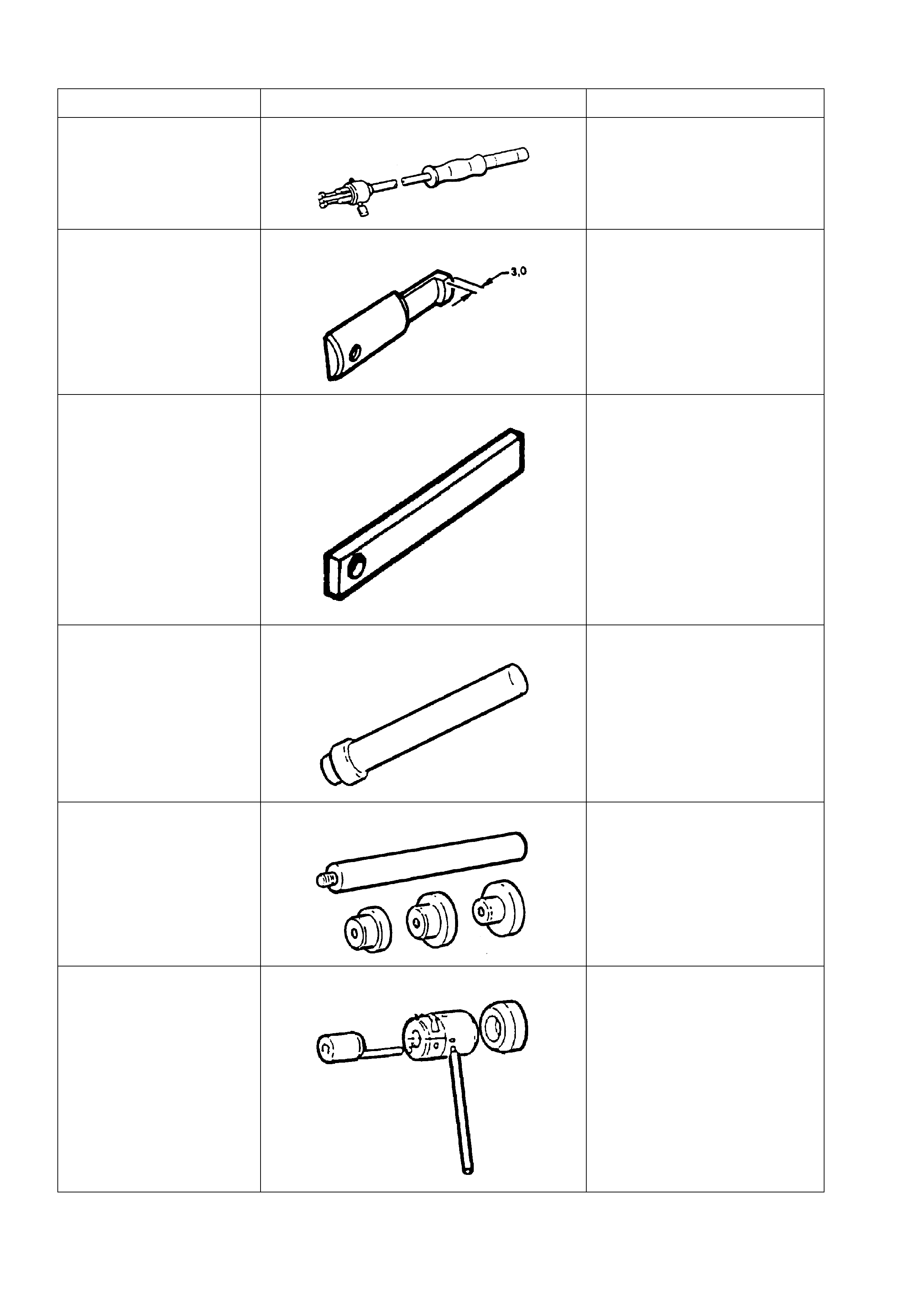
8. SPECIAL TOOLS
TOOL NO. REF IN TEXT TOOL DESCRIPTION COMMENTS
KM-328-B SLIDE HAMMER PREVIOUSLY RELEASED
FOR SB BARINA AND
CALIBRA VEHICLES.
INCLUDES CUP KM-328-5-A
AND PIN.
KM-328-7-A PULLER LEGS MODIFY AS DETAILED.
KM-328-9 SPACER USED WITH LEGS KM-328-7-A
KM-409-A INSTALLER USED TO INSTALL THE SHIFT
ROD BEARING INTO THE
FRONT TRANSMISSION
HOUSING.
KM-454-A REMOVER/INSTALLER USED TO REMOVE AND
INSTALL CLUSTER GEAR
BEARING CUPS.
KM-461 INSTALLER USED TO ASSEMBLE THE
TWO TRANSMISSION
HOUSINGS ON
REASSEMBLY.
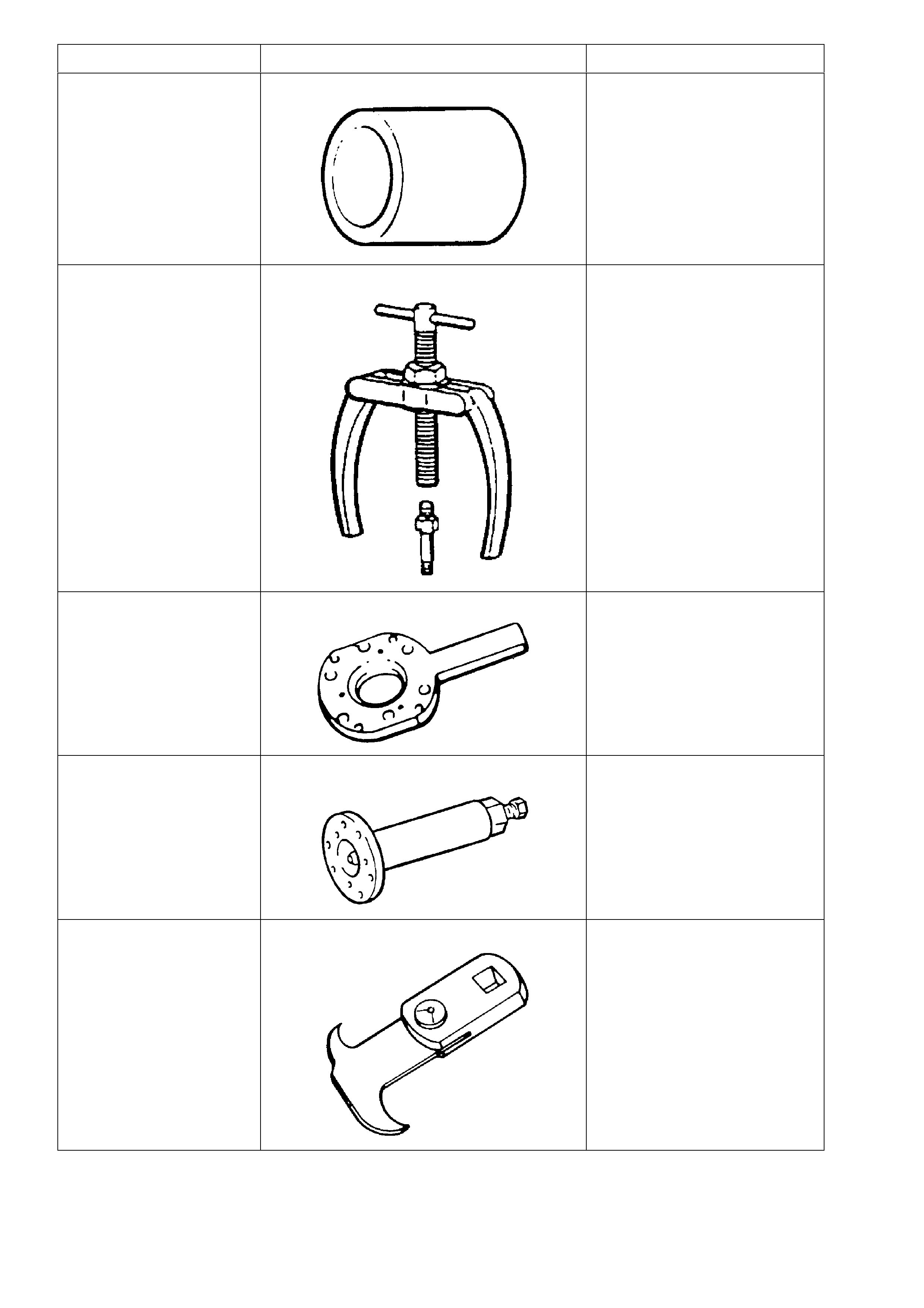
TOOL NO. REF IN TEXT TOOL DESCRIPTION COMMENTS
AKM-500-3 SLEEVE PREVIOUSLY RELEASED.
KM-556-1A PULLER PART OF PULLER KIT KM-
556-A, PREVIOUSLY
RELEASED FOR SB BARINA
AND CALIBRA
KM-620-1-A FLANGE HOLDING TOOL MODIFIED FROM THE
PREVIOUSLY RELEASED
TOOL AS DETAILED IN THE
TEXT.
AKM-628-A EXTRACTOR TOOL USED TO REMOVE THE
MAINSHAFT FLANGE AND TO
SEPARATE THE TWO
TRANSMISSION HOUSINGS
ON DISASSEMBLY.
E308 SEAL REMOVER PREVIOUSLY RELEASED.
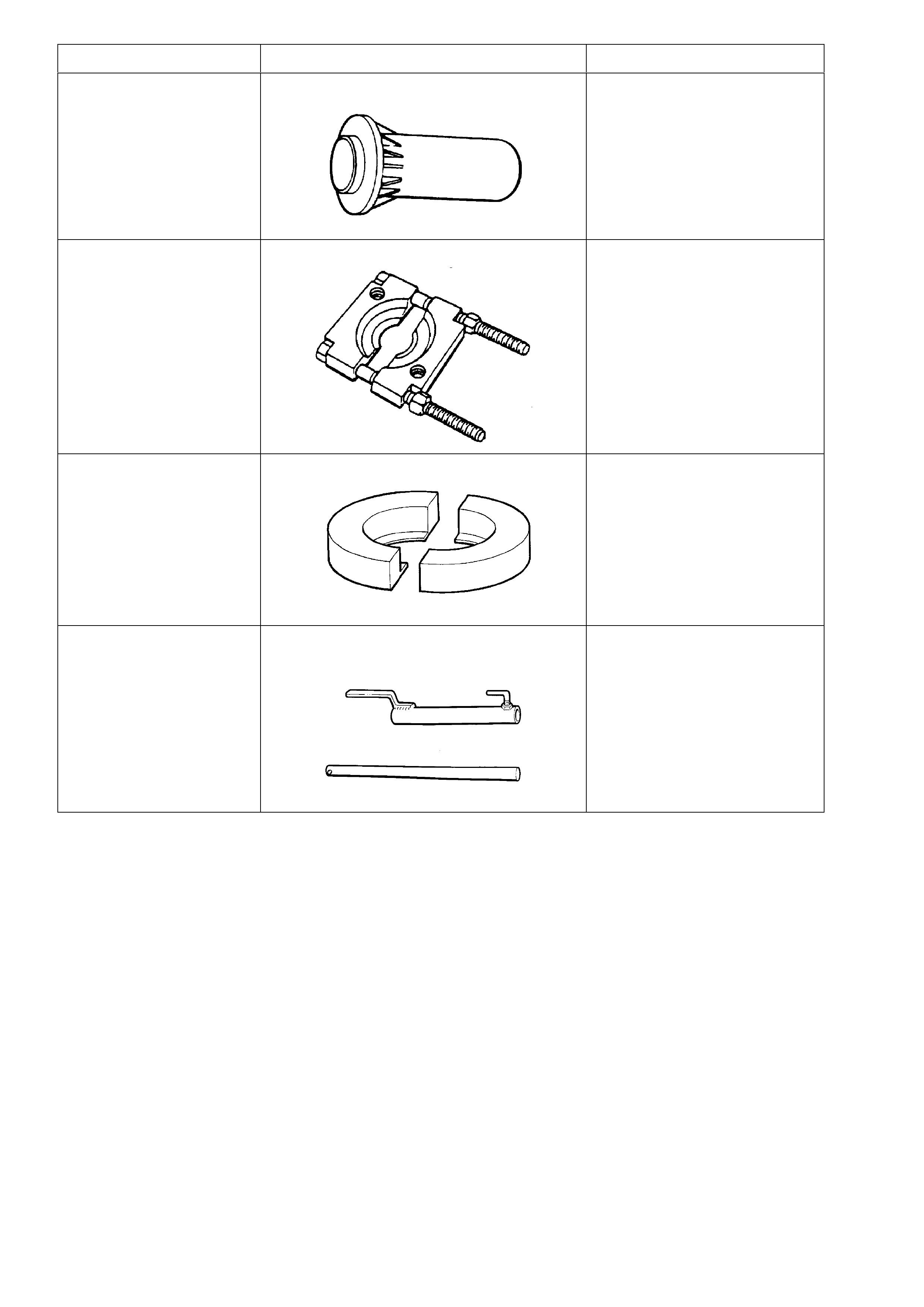
TOOL NO. REF IN TEXT TOOL DESCRIPTION COMMENTS
J-21426 SEAL INSTALLER PREVIOUSLY RELEASED
FOR 4L60-E AUTOMATIC
TRANSMISSION.
J-22912-01 PRESS PLATES PREVIOUSLY RELEASED
UNDER THIS NUMBER AND
E6673.
AU454 GEAR REMOVER PLATES USED TO REMOVE 3RD/4TH
SYNCHROMESH ASSEMBLY,
3RD SPEED GEAR, 2ND
SPEED GEAR AND RELATED
COMPONENTS FROM THE
MAINSHAFT.
AU462 SELECT LEVER SPRING AND BUSH
INSTALLER NEW RELEASE