
SECTION 7C3 - HYDRA-MATIC 4L60-E AUTOMATIC
TRANSMISSION - HYDRAULIC/MECHANICAL
DIAGNOSIS
CAUTION:
This vehicle will be equipped with a Supplemental Restraint System (SRS). An SRS
will consist of either seat belt pre-tensioners and a driver's side air bag, or seat belt
pre-tensioners and a driver's and front passenger's side air bags. Refer to
CAUTIONS, Section 12M, before performing any service operation on or around any
SRS components, the steering mechanism or wiring. Failure to follow the CAUTIONS
could result in SRS deployment, resu lting in possible perso nal in jury or u nnecessary
SRS system repairs.
CAUTION:
This vehicle may be equipped with LPG (Liquefied Petroleum Gas. In the interests of
safety, the LPG fuel system should be isolated by turning ‘OFF’ the manual service
valve and then draining the L PG service lines, before any service w ork is carried out
on the vehicle. Refer to the LPG leaflet included with the Owner's Handbook for
details or LPG Section 2 for more specific servicing information.
CAUTION:
Whenever any component that forms part of the ABS or ABS/ETC (if fitted), is
disturbed during Service Operations, it is vital that the complete ABS or ABS/ETC
system is checked, using the procedure as detailed in 4. DIAGNOSIS, ABS or
ABS/ETC FUNCTION CHECK, in Section 12L ABS & ABS/ETC.
1. GENERAL INFORMATION
1.1 HOW TO USE THIS SECTION
This section contains a description of the HYDRA-MATIC 4L60-E operation and the procedures for diagnosing the
hydraulic/mechanical aspects of this transmission. When diagnosing any condition on the 4L60-E HY DRA-MATIC
transmission, begin with the "HYDRA-MATIC 4L60-E Functional Test Procedure" detailed in this Section.
After the cause of a condition is determined, refer to Section 7C4 ON-VEHICLE SERVICING or
Section 7C5 UNIT REPAIR, for the necessary procedures. Alternatively, if the condition is considered to be
electrical/electronic in nature, then refer to either Section 6C1, POWERTRAIN MANAGEMENT - V6 ENGINE or
Section 6C2, POWERTRAIN MANAGEMENT - V8 ENGINE.
1.2 TRANSMISSION GENERAL DESCRIPTION
The Hydra-matic 4L60-E is a fully automatic, four speed, rear wheel drive transmission. It consists primarily of a four
element torque converter, two planetary gear sets , various clutches, an oil pump and a control valve body.
The four element torque converter contains a pump, a turbine, a pressure plate splined to the turbine and a stator
assembly. The torque converter acts as a fluid coupling to transmit power smoothly from the engine to the
transmission. It also provides additional hydraulic torque multiplication when required. The pressure plate, when
applied, provides a mechanical 'direct drive' coupling of the engine to the transmission.
The two planetary gear sets provide the four forward gear ratios and reverse. Changing of the gear ratios is fully
automatic and is accomplished through the use of various electronic sensors that provide input signals to the
Powertrain Control Module (PCM). The PCM interprets these signals to send current to the various solenoids inside
the transmission.
By using electronics, the PCM controls shift points, shift feel and torque converter clutch apply and release, to
provide proper gear ranges for maximum fuel economy and vehicle performance.
Five multiple-disc clutches, one roller clutch, a sprag clutch and a brake band provide the friction elements required
to obtain the various ratios with the planetary gear sets.
An hydraulic system (the control valve body), pressurised by a vane type pump, provides the working pressure
needed to operate the friction elements and automatic controls.
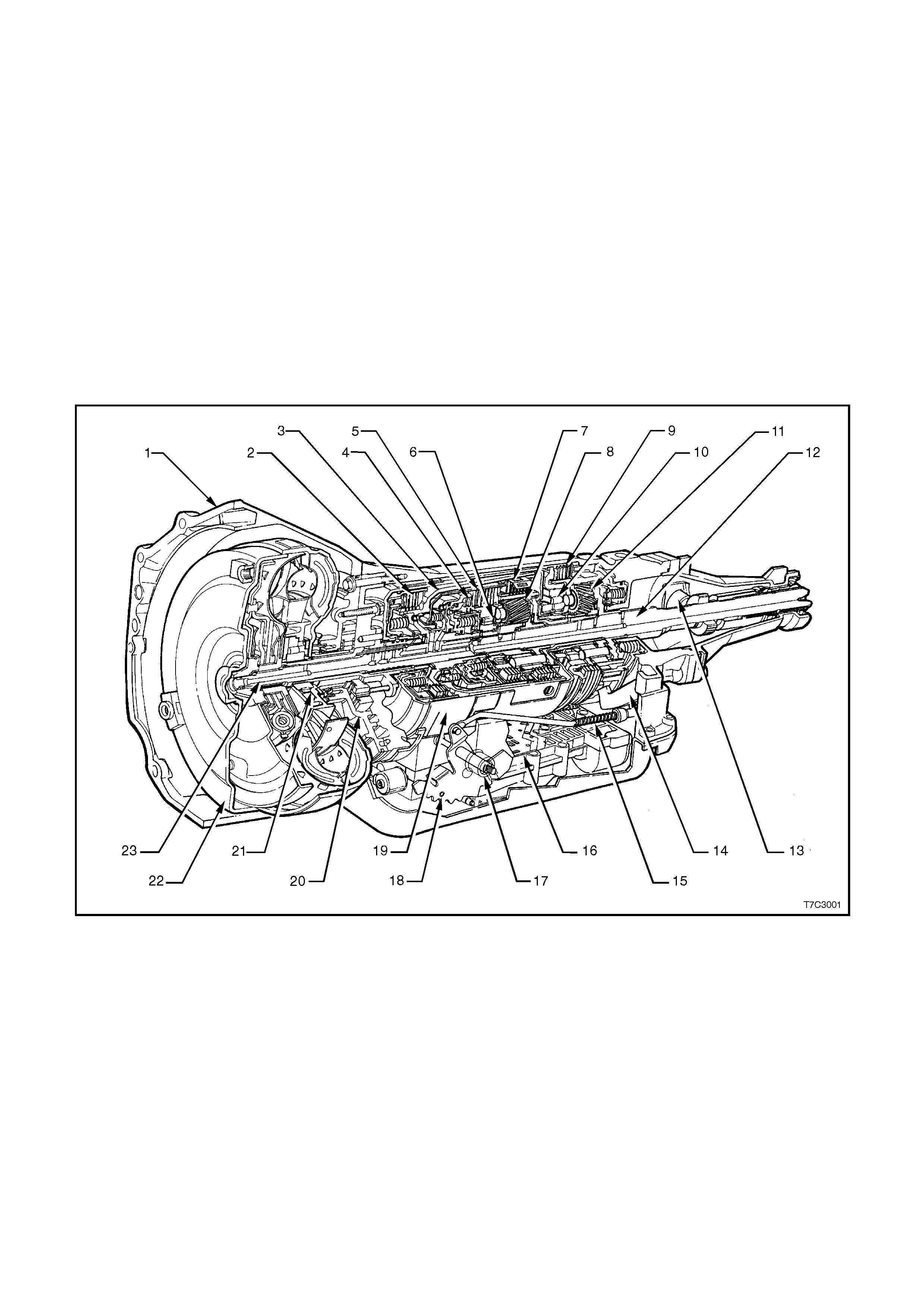
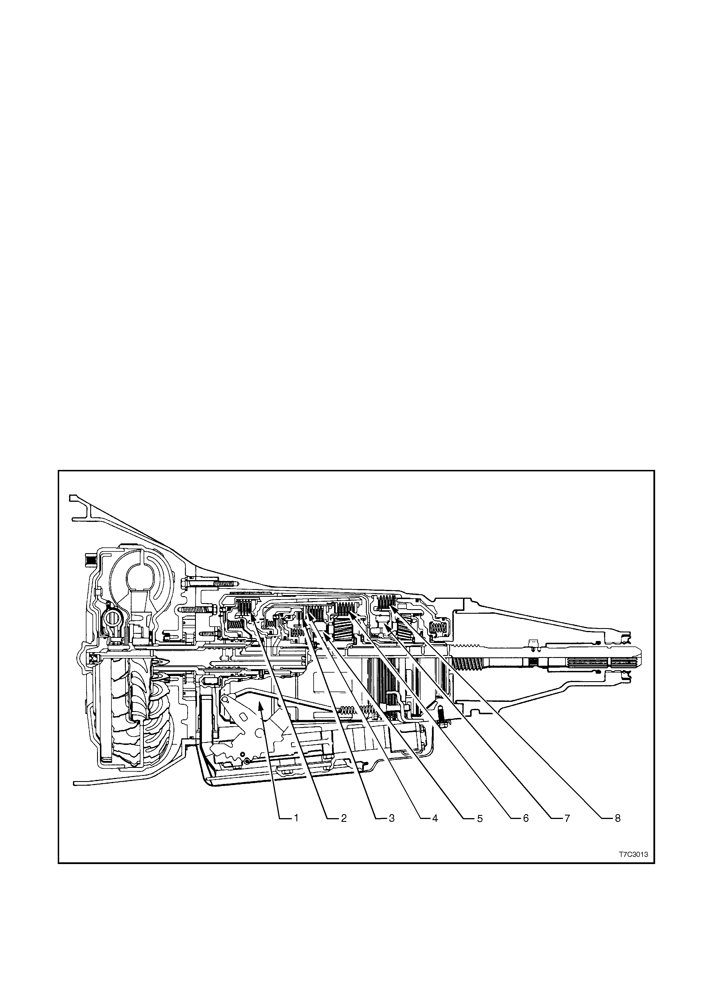
The general arrangement of both the majority of mechanical and hydraulic components is as shown.
1. Case Assembly 9. Low and Reverse Clutch 17. Manual Shaft
2. Reverse Input Clutch 10. Low Roller Clutch Assembly 18. Inside Detent Lever
3. Input Clutch Housing 11. Reaction Planetary Gear Set 19. 2 - 4 Band Assembly
4. Overrun Clutch 12. Output Shaft 20. Pump Assembly
5. Forward Clutch 13. Speed Sensor 21. Stator Roller Clutch
6. Forward Clutch Sprag Assembly 14. Parking Pawl 22. Torque Converter Assembly
7. 3 - 4 Clutch 15. Parking Lock Actuator Assembly 23. Turbine Shaft
8. Input Planetary Gear Set 16. Control Valve Assembly
Figure 7C3-1

1.3 TRANSMISSION DEFINITIONS AND ABBREVIATIONS
The following Definitions and Abbreviations are provided to establish a common language for describing
transmission related conditions.
Taking the few minutes required to read this information may easily overcome unnecessary waste of time by being
familiar with the terminology used within this Diagnosis Section.
THROTTLE POSITIONS
Minimum Throttle - the least amount of throttle opening required for an upshift.
Light Throttle - approximately 1/4 of accelerator pedal travel (25% Throttle Position).
Medium Throttle - approximately 1/2 of accelerator pedal travel (50% Throttle Position).
Heavy Throttle - approximately 3/4 of accelerator pedal travel (75% Throttle Position).
Wide Open Throttle (WOT) - full travel of the accelerator pedal ( 100% Throttle Position).
Full Throttle Detent Downshift - a quick apply of the accelerator pedal to its full travel, forcing a downshift.
Zero Throttle Coastdown - a full release of the accelerator pedal while the car is in motion and in drive range.
Engine Braking - a condition where the engine is used to slow the car by manually downshifting during a zero
throttle coastdown.
SHIFT CONDITIONS
Bump - a sudden and forceful apply of a clutch or band.
Chuggle - a bucking or jerking may be most noticeable when the converter clutch is engaged; similar to the feel of
towing a trailer.
Delayed - a condition where a shift is expected but does not occur for a period of time. Examples of this could be
described as clutch or band engagement that does not occur as quickly as expected during a part throttle or
wide open throttle apply of the accelerator or, when manually downshifting to a lower range. Also defined as
"LATE" or "EXTENDED".
Double Bump (Double Feel) - two sudden and forceful applications of a clutch or band.
Early - a condition where the shift occurs before the car has reached proper speed. Tends to labour the engine
after the upshift.
End Bump - a firmer feel at the end of a shift, compared to the feel at the start of the shift. Also defined as "END
FEEL" or "SLIP BUMP".
Firm - a noticeably quick apply of a clutch or band that is considered normal with a medium to heavy throttle.
Should not be confused with "HARSH" or "ROUGH".
Flare - a quick increase in engine rpm along with a momentary loss of torque. This most generally occurs during a
shift. Also defined as 'SLIPPING''.
Harsh (Rough) - a more noticeable apply of a clutch or band as compared with "FIRM". This condition is
considered undesirable at any throttle position.
Hunting - a repeating quick series of upshifts and downshifts that causes a noticeable change in engine rpm. An
example could be described as a 4-3-4 shift pattern. Also defined as "BUSYNESS".
Initial Feel - a distinct firmer feel at the start of a shift as compared to the finish of the shift.
Late - a shift that occurs when the engine is at a higher than normal rpm for a given amount of throttle.
Shudder - a repeating jerking condition similar to "CHUGGLE" but more severe and rapid. This condition may be
most noticeable during certain ranges of car speed.
Slipping - a noticeable increase in engine rpm without a car speed increase. A slip usually occurs during or after
initial clutch or band apply.
Soft - a slow, almost unnoticeable clutch or band apply with very little shift feel.
Surge - a repeating engine related condition of acceleration and deceleration that is less intense than "CHUGGLE".
Tie-Up - a condition where two opposing clutches and/or bands are attempting to apply at the same time causing
the engine to labour with a noticeable loss of engine rpm.
NOISE CONDITIONS
Planetary Gear Noise - a whine related to car speed most noticeable in first gear or reverse. Becomes less
noticeable after an upshift.
Pump Noise - a high pitch whine that increases with engine rpm.

ABBREVIATIONS
PCM -Powertrain Control Module.
TCC - Torque Converter Clutch.
TP Sensor - Throttle Position Sensor.
ECT Sensor - Engine Coolant Temperature
VS Sensor - Vehicle Speed Sensor.
TFP VAL. POSITION SW. - Transmission Fluid Pressure Manual Valve Position Switch
PSA - Transmission Range (TR) Pressure Switch Assembly.
TTS - Transmission Fluid Temperature Sensor.

2. DIAGNOSIS
2.1 BASIC KNOWLEDGE REQUIRED
You must be familiar with some basic electronics to use this section. They will help y ou to follow diagnostic
procedures.
NOTE:
A lack of basic knowledge of this powertrain when performing diagnostic procedures, could result in incorrect
diagnostic performance or damage to powertrain components. Do not, under any circumstances, attempt to
diagnose a powertrain problem without this basic knowledge.
SPECIAL TOOLS
You should be able to use a break out box, a Digital Volt Meter (DVM), a circuit tester, jumper wires or leads and a
line pressure gauge set. Having access to and the ability to use the TECH 2 scan tool would also be a distinct
advantage, as many aspects of transmission diagnosis requires the use of this instrument.
The Functional Test Procedure detailed in Section 2.2, is designed to verify the correct operation of components in
the transmission and to identify whether a condition is electrical in nature, or not. This will eliminate the unnecessary
removal of transmission components and time loss in rectification.
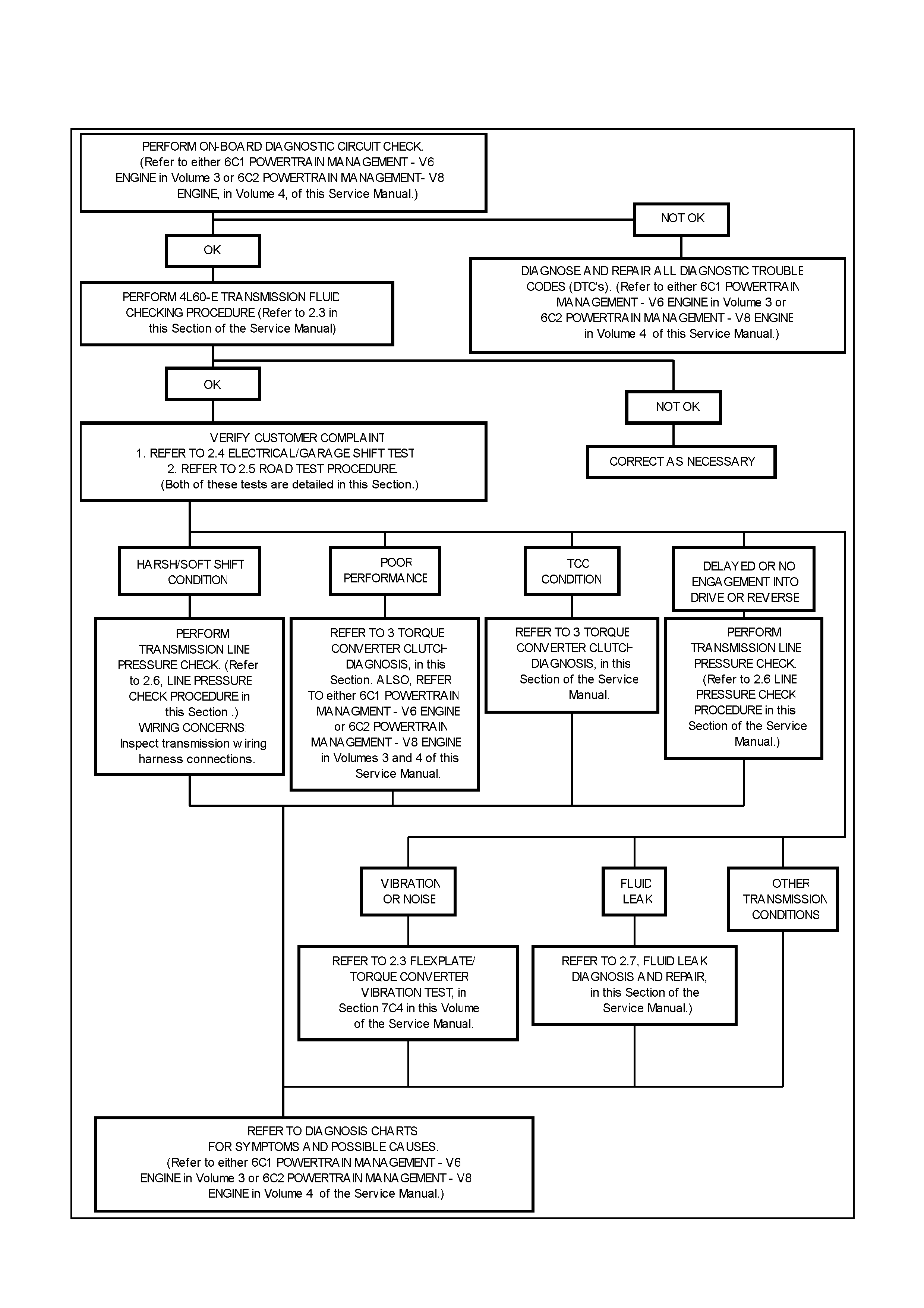
2.2 FUNCTIONAL TEST PROCEDURE
When diagnosing any HYDRA-MATIC - 4L60-E related condition, always begin with the Functional Test Procedure
detailed in Figure 7C3-2. This procedure will indicate the proper path of diagnosing the transmission, by describing
the basic checks and then referencing the locations of specific checks.
Figure 7C3-2

2.3 TRANSMISSION FLUID CHECKING PROCEDURE
1. Start engine and drive vehicle for a distance of 24 km, or until transmission normal operating temperature (82 -
94° C) is reached.
NOTE:
As temperature affects transmission fluid levels, this operation must only be carried out with the transmission at
normal operating temperature. If the vehicle is not at normal operating temperature, and the proper checking
procedures are not followed, the result could be a false reading of the fluid level on the dipstick.
2. Park vehicle on level ground.
3. Move gear selector to 'PARK' position.
4. Apply park brake.
5. Let engine idle for 3 minutes with accessories turned off.
6. Lift the coloured dipstick locking lever, remove dipstick and check fluid colour, condition and level.
7. If the fluid level is low, add only enough Dexron® III to bring the level into the “HOT” area.
*Inaccurate fluid level readings will result if checked immediately after the vehicle has been operated under any
or all of the following conditions:
a. In high ambient temperatures above 32° C.
b. At sustained high speeds.
c. In heavy city traffic during hot weather.
d. Towing.
e. In commercial use (e.g. taxi).
*If the vehicle has been operated under these conditions, switch the engine off and allow the vehicle to 'cool' for
approximately thirty minutes. After the cool-down period, re-start the vehicle and continue from step 2, above.
STEP ACTION YES NO
1. Check the fluid colour.
Is the fluid colour red? Go to Step 2 Go to Step 11
2. Is the fluid level satisfactory? Go to Step 20 Go to Step 3
3. Check the fluid.
Is the fluid foamy? Go to Step 8 Go to Step 4
4. Check the fluid level. The correct fluid level
should be in the middle of the cross-hatch on the
dipstick.
Is the level high?
Go to Step 9 Go to Step 5
5. Fluid will be low.
Add fluid to the correct fluid level.
Is the fluid level satisfactory?
Go to Step 6 Go to Step 1
6. Check for external leaks.
Were any leaks present?
Go to Step 7 Go to Step 20
7. Correct the fluid leak condition.
Is action complete?
Go to Step 20
8. Is the fluid level too high? Go to Step 9 Go to Step 10
9. Remove excess fluid to adjust to the correct fluid
level.
Is action complete?
Go to Step 20
10.
1. Check for contaminants in the fluid.
2. Drain the fluid to determine the source of
contamination.
3. Is action complete?
Go to Step 15

STEP ACTION YES NO
11. Is the fluid colour a non-transparent pink? Go to Step 12 Go to Step 13
12. Replace the leaking cooler.
Is the action complete?
Go to Step 15
13. The fluid colour should be light brown.
Transmission fluid may turn dark with normal use.
This does not always indicate oxidation or
contamination.
Is the fluid colour light brown?
Go to Step 14 Go to Step 1
14. Drain the fluid to determine if the fluid is
contaminated. A very small amount of material in
the bottom of the oil pan is a normal condition, but
larger pieces of metal or other material in the
bottom of the oil pan are not and the transmission
requires an overhaul.
Was the fluid contaminated?
Go to Step 15 Go to Step 18
15. Overhaul the transmission or fit a SRTA unit.
Refer to Section 7C5 Unit Repair.
Is action complete?
Go to Step 16
16. Flush the coolers.
Is action complete?
Go to Step 17
17. Add new fluid.
Is action complete?
Go to Step 19
18. Change the fluid and filter.
Is action complete?
Go to Step 19
19. Is the fluid level satisfactory? If not, correct as
necessary.
Is action complete?
Go to Step 20
20. Refer to 2.2 Functional Test Procedure, in this
Section.
Is action complete?
Fluid Checking
Procedure
Completed

2.4 ELECTRICAL/GARAGE SHIFT TEST
This preliminary test should be performed before a hoist or road test to make sure electronic control inputs are
connected and operating. If the inputs are not checked before operating the transmission, a simple electrical
condition could be misdiagnosed as a major transmission condition.
The TECH 2 scan tool provides valuable information and must be used on the HYDRA-MATIC 4L60-E transmission
for accurate diagnosis.
1 Move gear selector to "Park" (P) and set the park brake.
2. Connect scan tool to DLC terminal.
3. Start engine.
4. Connect power to scan tool.
5. Verify that the following signals are present:
•ENGINE SPEED
•TRANS OUTPUT SPEED
•VEHICLE SPEED
•A/B/C RNG
•PRNDL SELECT
•DESIRED PCS
•ACTUAL PCS
•PCS DUTY CYCLE
•ENG COOLANT TEMP
•TRANS FLUID TEMP
•THROTTLE ANGLE
•SYSTEM VOLTS
6. Monitor the PRNDL SELECT signal and move the gear selector through all the ranges.
•Verify that the PRNDL SELECT value matches the gear range indicated on the instrument panel or
console.
•Gear selections should be immediate and not harsh.
7. Move gear selector to neutral and monitor the THROTTLE ANGLE signal while increasing and decreasing
engine RPM with the accelerator pedal.
•THROTTLE ANGLE should increase with engine RPM.
UPSHIFT CONTROL AND TORQUE CONVERTER CLUTCH (TCC) APPLY
The PCM calculates upshift points based primarily on two inputs: THROTTLE ANGLE and VEHICLE SPEED. When
the PCM says a shift should occur, an electrical signal is sent to the shift solenoids which in tum moves the valves
to perform the upshift.
The shift speed charts reference THROTTLE ANGLE instead of "min throttle" or "wot" to make shift speed
measurement more uniform and accurate. The TECH 2 scan tool should be used to monitor THROTTLE ANGLE.
The TECH 2 scan tool also has the advantage of being able to record shift point information. Check the instruction
manual for the required procedures.
With gear selector in D4:
1. Look at the shift speed chart (See in this section) and choose a throttle angle of 50%.
2. Set up the scan tool to monitor THROTTLE ANGLE and VEHICLE SPEED
3. Accelerate to the chosen throttle angle and hold the throttle steady.
4. As the transmission upshifts, note the shift speed and commanded gear changes for:
•2nd gear.
•3rd gear.
•4th gear
IMPORTANT:
Shift speeds may vary due to slight hydraulic delays responding to electronic controls. A change from the original
equipment tyre size also affects shift speeds.
Note when TCC applies. This should occur in third or fourth gear. If the apply is not noticed by a drop in engine
speed, refer to the "Functional Check Procedure", in 3 TORQUE CONVERTER CLUTCH DIAGNOSIS, in this
Section.

The TCC should not apply unless the transmission has reached a minimum operating temperature of 18°C TRAN
TEMP and engine coolant temp of 60°C.
5. Repeat steps 1-4 using several different throttle angles.
PART THROTTLE DETENT DOWNSHIFT
1. At vehicle speeds of 64 to 88 km/h in fourth gear, quickly increase throttle angle and verify that:
•TCC releases.
•Transmission downshifts to 3rd gear immediately.
•1-2 Shift Solenoid turns off.
FULL THROTTLE DETENT DOWNSHIFT
1. At vehicle speeds of 64 to 88 km/h in fourth gear, quickly increase throttle angle to its maximum position and
verify that::
•TCC releases.
•Transmission downshifts to 2nd gear immediately.
•1-2 Shift Solenoid is off, 2-3 Shift Solenoid is on.
MANUAL DOWNSHIFTS
The shift solenoids do not control the initial downshift during 4-3 and 3-2 manual downshifts. All manual downshifts
are hydraulic except the 2-1. The solenoid states will change during, or shortly after a manual downshift is selected.
1. At vehicle speeds of 64 to 88 km/h in fourth gear, release the accelerator pedal while moving the gear selector
to ‘3’. Observe that:
•TCC releases.
•Transmission downshifts to 3rd gear immediately.
•Engine slows vehicle down.
2. Move gear selector back to D4 and accelerate to 64 to 72 km/h. Release the accelerator while moving the gear
selector to ‘2’ and observe that:
3. Move gear selector back to D4 and accelerate to 48 km/h. Release the accelerator pedal while moving the
gear selector to ‘1’ and observe that:
•TCC releases.
•Transmission downshifts to 1st gear immediately.
•Engine slows vehicle down.
COASTING DOWNSHIFTS
1. With the gear selector in D4, accelerate to 4th gear with TCC applied.
2. Release the accelerator pedal and lightly apply the brakes, and observe that:
•TCC releases.
•Downshifts occur at speeds shown on the Shift Speed Chart, in this Section.
MANUAL GEAR RANGE SELECTION
Upshifts in the manual gear ranges are controlled by the shift solenoids. Perform the following tests by accelerating
at 10-15° TP Sensor:
Manual Third (3)
1. With vehicle stopped, move the gear selector to D3 and accelerate to observe:
•1-2 shift.
•2-3 shift.
Manual Second (2)
1. With vehicle stopped, move gear selector to D2 and accelerate to observe:
Transmission starts and remains in second gear.
2. Accelerate to 40 km/h and observe:
•2-3 shift does not occur.
•TCC does not apply.
Manual First (1)
1. With vehicle stopped, move gear selector to D1. Accelerate to 32 km/h (20 mph) and observe:
•No upshifts occur.
•TCC does not apply.

Reverse (R)
1. With vehicle stopped, move gear selector to R and slowly accelerate to observe:
•1-2 and 2-3 Shift Solenoids are on.
Use the TECH 2 scan tool to see if any transmission trouble codes have been set. Refer to
Section 6C1 POWERTRAIN MANAGEMENT - V6 ENGINE or Section 6C2, POWERTRAIN MANAGEMENT -
V8 ENGINE for the required procedures and suggested action required After repairing the vehicle, verify that the
code does not set again.
If the transmission is not performing well and no trouble codes have been set, there may be an intermittent
condition. Check all electrical connections for damage or a loose fit. TECH 2 has a snapshot mode that can help
catch an intermittent condition that does not occur long enough to set a code. Refer to Section 0C, TECH 2 for the
necessary procedure.
If no trouble codes have been set and the condition is suspected to be hydraulic, take the vehicle on a road test.

2.5 ROAD TEST PROCEDURE
IMPORTANT NOTES:
1. Shift points will vary with actual throttle position and driver habits.
2. Compare the results of the test with speed shift chart information. Use these results with the diagnosis
information contained in this Section to evaluate the transmission.
3. This test should only be performed when traffic and road conditions permit.
4. Observe all traffic safety regulations.
5. Perform the road test using a scan tool.
Drive and Reverse Engagement Shift Check
1. Start engine.
2. Depress brake pedal.
3. Move gear selector:
•'P' (Park) to 'R' (Reverse).
•'R' (Reverse) to 'N' (Neutral) to 'D' (Drive).
Gear selections should be immediate and not harsh.
Upshifts and Torque Converter Clutch (TCC) Application
With gear selector in 'D' (Economy Mode):-
1. Accelerate using a steady increasing throttle application.
2. Note the shift speed point gear engagements for:
•1st to 2nd gear.
•2nd - 3rd gear.
•3rd - Overdrive 4th.
3. Note the speed shift point for Torque Converter Clutch (TCC) application. This should occur while in third gear
(Power Mode) or overdrive (Economy Mode).
IMPORTANT:
The TCC will not engage if engine coolant temperature is below 45° C or road speed is less than;
88 km/h in 4th Economy Mode
65 km/h in 3rd Power Mode.
Part Throttle Downshift
At a speed of 70 - 90 km/h, quickly depress the accelerator to half open throttle position and observe:
•TCC releases.
•Transmission immediately causes a 4-3 downshift.
Full Throttle (Detent) Downshift
Operate the vehicle at 70 - 90 km/h in 'D', then quickly depress the accelerator to wide open throttle position and
observe:
TCC releases.
Transmission immediately causes a 4-2 downshift.
Manual Downshift
1. Operate the vehicle at 70 - 90 km/h in 'D', then release the accelerator pedal (closed throttle position) and
move the gear selector to '3' (Third) gear position at the same time and observe:
•TCC release occurs at zero throttle.
•Transmission immediately downshifts to 3rd gear.
•Engine should moderately slow vehicle.
2. Operate the vehicle at 70 - 80 km/h in 'D'. Release the accelerator pedal and simultaneously move the gear
selector to '2' (Second) gear position, and observe:
•TCC release occurs at zero throttle.
•Transmission immediately downshifts to 2nd gear.
•Engine should slow vehicle.

3. Move gear selector to 'D' and accelerate from zero to 40 km/h, with 1-2 and 2-3 upshifts at light throttle.
Release the accelerator pedal (closed throttle position) and simultaneously move the gear selector to '1' (First)
gear position and observe:
•Transmission immediately downshifts to 1st gear.
•Engine should significantly slow vehicle.
Coastdown Downshift
1. With the gear selector in 'D', accelerate to engage 4th gear with TCC applied (approximately 75 km/h).
2. Release the accelerator pedal (closed throttle position) and lightly apply the brakes to observe:
•TCC release occurs at zero throttle.
•The point at which downshift occurs. This will only be noticeable with the assistance of a TECH 2 scan
tool display.
MANUAL GEAR RANGE SELECTION.
Manual Third '3'
With vehicle stopped, place gear selector in '3' and accelerate to observe:
•The first to second gear shift point.
•The second to third gear shift point.
•TCC apply/release (in Economy/Power modes).
Manual Second '2'
1. With vehicle stopped, place gear selector in '2' (Second) and accelerate to observe:
•The first to second gear shift point.
2. Accelerate to 60 km/h and observe:
•That no second to third gear shift occurs.
•That TCC does not engage.
Manual First '1'
1. With vehicle stopped, place gear selector in '1' (First), accelerate to 40 km/h and observe:
•That no upshift occurs. (PCM protection will cause a 1-2 upshift near maximum engine speed.)
•That TCC does not engage.
Reverse.
1. With vehicle stopped, selecte 'R' (Reverse), slowly accelerate and observe reverse gear operation.

1998 MY HYDRA-MATIC 4L60-E SHIFT SPEED CHART
UPSHIFTS
SHIFT CLOSED THROTTLE -
6.25% - (km/ h ) PART THROTTL E -
50% - (km/h ) WID E OPEN THRO TTLE -
100% - (km/h )
MODE 1 - 22 - 33 - 41 - 22 - 33 - 41 - 22 - 33 - 4
ECONOMY 19 32 73 43 72 205 64 118 205
HFD
(V6 ENGINE ) POWER 21 35 89 52 92 205 64 119 205
CRUISE N/A 35 81 N/A 84 205 N/A 119 205
HND ECONOMY 19 33 71 45 81 200 65 122 200
(V6
SUPERCHARGED POWER 21 35 93 55 97 200 84 121 200
ENGINE CRUISE N/A 34 93 N/A 97 200 N/A 119 200
ECONOMY 19 29 71 39 72 185 61 116 185
HBD
(V8 ENGINE ) POWER 21 34 89 50 81 186 61 116 185
CRUISE N/A 35 81 N/A 87 185 N/A 113 185
DOWNSHIFTS
SHIFT CLOSED THROTTLE -
6.25% - (km/ h ) PART THROTTL E -
50% - (km/h ) WID E OPEN THRO TTLE -
100% - (km/h )
MODE 4 - 33 - 22 - 14 - 33 - 22 - 14 - 33 - 22 - 1
ECONOMY68291684481620410946
HFD
(V6 ENGINE ) POWER79321897611820410946
CRUISE 72 32 N/A 93 67 N/A 204 109 N/A
HND ECONOMY64311677561618811351
(V6
SUPERCHARGED POWER 85 34 18 101 64 18 188 113 51
ENGINE) CRUISE 65 32 N/A 101 64 N/A 188 105 N/A
ECONOMY66191680531617710546
HBD
(V8 ENGINE ) POWER79191884612417710646
CRUISE 72 32 N/A 113 57 N/A 177 105 N/A
MISCELLANEOUS SHIFTS
MANUAL LOW WOT MIN TCC APPLY Coastdown Information
2-1 Downshift 3-1 Downshift 3rd Gear 3-1 3-2
HFD (V6 ENGI NE) 58 46 53 N/A 32
HND (V6 SUPE RCHARGED ENGINE) 56 46 55 N/A 33
HBD (V8 ENGINE) 58 46 53 17 N/A
NOTE 1.
This publication does not include all possible
throttle positions and the corresponding shift point
information.
NOTE 2.
All speeds are indicated in kilometres per hour
(km/h).
NOTE 3.
Actual shift points may vary in accordance with
transmission build variations.
2.6 LINE P RE SSURE CHECK PROCEDURE
Line pressures are calibrated for two sets of gear
ranges - Drive/Park/Neutral and Reverse. This
allows the transmission line pressure to be
appropriate for two different pressure needs in
different gear ranges:
Gear Range Line Pressure Range
Drive, Park or Neutral 379 - 1,303 kPa
Reverse 441 - 2,234 kPa
Before perf orm ing a line pressur e check , ver ify that
the pressure control solenoid is receiving the
correct electrical signal from the PCM, as follows:
1. Install the TECH 2 scan tool. Refer to
Section 0C TECH 2 for the necessary
procedure.
2. Start the engine and firmly apply the park
brake.
3. Check for a stored pressure control solenoid
Diagnostic T rouble Code (DT C) and any other
stored codes.
4. Rectify as necessary.
NOTE:
The transmission may experience harsh, soft or
mushy shifts for up to two days afterwards.
PROCEDURE
1. Check engine and transmission fluid levels.
2. Check manual linkage for correct adjustment
and wear.
3. If not previously carried out, install a TECH 2
scan tool to the vehicle. Refer to
Section 0C, TECH 2 for the necessary
procedure.
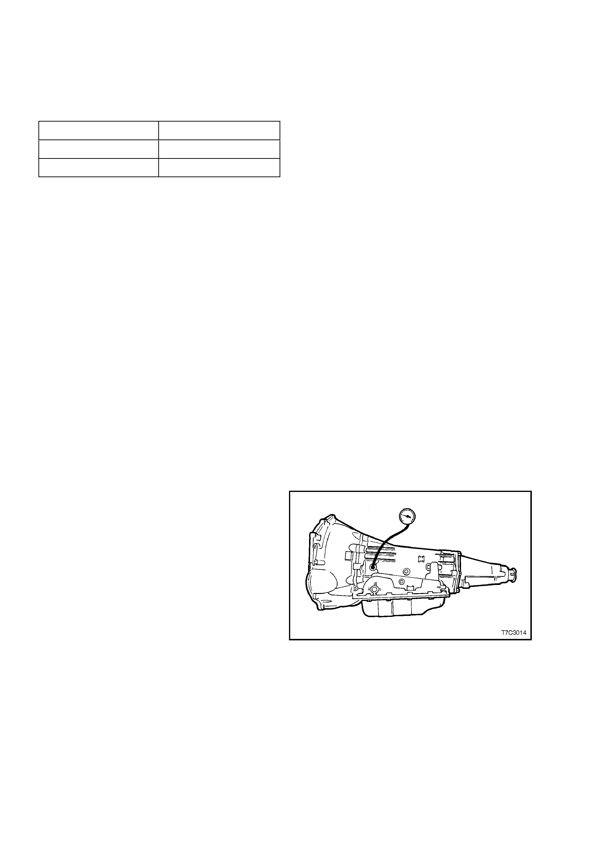
4. Install an oil pressure gauge such as Tool
J21867 or commercial equivalent, to the line
pressure tapping point on the transmission, as
shown.
5. Select ‘P’ (Park) range and firmly apply the
park brake.
6. Start the engine and allow to warm up, at idle.
7. Access the “PCS CONTROL” test on the
TECH 2 scan tool.
8. Increase “DESIRED PCS” in 0.1 Amp
increm ents on the TECH 2 scan tool and read
the corres ponding line press ure reading on the
fluid pressure gauge. (Allow the pressure to
stabilise for 5 seconds after each current
change.
9. Compare the pressure readings against the
chart shown next.
IMPORTANT:
Total test running time should not exceed 2 minutes
or transmission damage could occur.
Figure 7C3-3

NOTE 1:
Pressures are to be taken at an engine speed of 1,500 rpm and a temperature of 66° C. Line pressure drops as
temperature increases.
NOTE 2:
If pressure readings differ greatly from the line pressure chart, refer to the Diagnostic Section in 6C1
POWERTRAIN MANAGEMENT - V6 ENGINE or 6C2 POWERTRAIN MANAGEMENT - V8 ENGINE.
NOTE 3:
The TECH 2 scan tool is only able to control the pressure control solenoid in Park, and Neutral, with the vehicle
stopped. This protects the clutch packs from extremely high or low pressures in Drive or Reverse ranges
Pressure Control Solenoid
Current (Amp) Line Pressure
(kPa)
0.02 1,172 - 1,310
0.10 1,138 - 1,275
0.20 1,103 - 1,241
0.30 1,069 - 1,206
0.40 1,020 - 1,158
0.50 965 - 1,103
0.60 896 - 1,000
0.70 758 - 896
0.80 620 - 793
0.90 448 - 620
0.98 379 - 448
Figure 7C3-4

2.7 FLUID LEAK DIAGNOSIS AND REPAIR
The cause of most external leaks can usually be located and repaired with the transmission installed in the vehicle.
METHODS FOR LOCATING LEAKS
General Method
1. Verify that the leak is in fact, transmission fluid.
2. Thoroughly clean the suspected leak area.
3. Operate the vehicle for about 24 km or until normal operating temperatures are reached.
4. Park the vehicle over clean paper or cardboard.
5. Switch the engine off and look for fluid spots on the paper.
6. Make necessary repairs.
Powder Method
1. Thoroughly clean the suspected leak area with a suitable cleaning agent.
2. Apply an aerosol type powder (eg foot powder) to the suspected leak area.
3. Operate the vehicle for about 24 km or until normal operating temperatures are reached.
4. Switch the engine off.
5. Inspect the suspected leak area and trace the leak path through the powder to find the source.
6. Make necessary repairs.
Dye and Black Light Method
While the following can be used as a guide, always follow the manufacturer’s recommendations for use of this
equipment.
1. Pour the manufacturer's recommended amount of dye (such as J28431-B) into the transmission.
2. Road test the vehicle under normal operating conditions.
3. Direct the black light (Tool No. J42220) to the suspect area. Any fluid leak will appear as a brightly coloured
path, leading to the source.
NOTE:
The colour of the dyed fluid can be checked on the transmission dipstick.
4. Make the necessary repairs, then re-check that the leak has been rectified.
REPAIRING THE LEA K
NOTE 1:
Once the leak has been located and traced back to its source, the CAUSE of the leak must be determined, for the
repair to be satisfactory .
NOTE 2:
If a gasket is replaced, but the sealing flange is distorted or bent (eg oil pan flange), the new gasket will not stop the
leak. Obvious damage such as this must be rectified before fitting new gaskets, if a satisfactory repair is to be
expected.
NOTE 3:
Before attempting to repair a leaking seal and/or gasket, check to make sure that the following conditions do not
apply:
Gaskets:
Fluid level or pressure is too high.
Blocked or partially blocked vent or drain back holes.
Incorrectly torqued fasteners or dirty/damaged threads.
Warped/bent flanges or sealing surface.
Scratches, burrs or other damage to the sealing surface.
Damaged or worn gasket.
Cracking or porosity of the component or adjacent part.
Improper sealant used (where applicable).
Techline

Seals:
Fluid level or pressure is too high.
Blocked or partially blocked vent or drain back holes.
Damaged seal bore (Scratched burred or nicked).
Damaged or worn seal.
Incorrect previous installation.
Cracks in the component.
Manual or output shaft is scratched, nicked or worn.
Loose or worn bearing, causing excess seal wear.
POSSIBLE POINTS OF FLUID LEAKS
1. Transmission and Oil Pan:
Attaching bolts not torqued correctly.
Improperly installed or damaged gasket.
2. Case Leak:
Filler tube multi-lip seal damaged or missing.
Filler tube bracket misaligned.
Speed sensor seal damaged.
Manual shaft seal worn or damaged.
Oil cooler connector fittings loose or damaged.
Propeller shaft oil seal worn or damaged.
Line pressure plug loose or thread damage has occurred.
Porous casting.
3. Leak at End of Converter:
Converter seal damaged.
•Seal lip cut (Check converter hub for damage).
•Bushing has moved forward and/or is damaged.
•Garter spring is missing from seal.
Converter leak in the weld area.
Porous casting (case or pump).
4. Fluid Comes from Vent or Fill Tube:
Overfilled.
Water or coolant in fluid (milky/pink fluid colour).
Case porous.
Incorrect fluid level indicator.
Blocked or partially blocked vent.
Drain back holes blocked.
The alignment of the oil pump to case gasket is incorrect.
CASE POROSITY REPAIR
1. Clean the area with epoxy manufacturer's recommended solvent and air dry .
CAUTION:
Epoxy adhesives may cause skin irritations and eye damage. Read and follow all information on the
product label, as provided by the manufacturer.
2. Mix sufficient amount of epoxy adhesive ('Araldite' or an equivalent product), following the manufacturer's
recommendations.
3. While the transmission case is hot, apply epoxy adhesive with a clean, dry stiff brush.
4. Allow the adhesive to dry for the recommended time before starting the engine and checking the results of the
repair.
5. Repeat the fluid leak diagnosis procedure previously detailed.
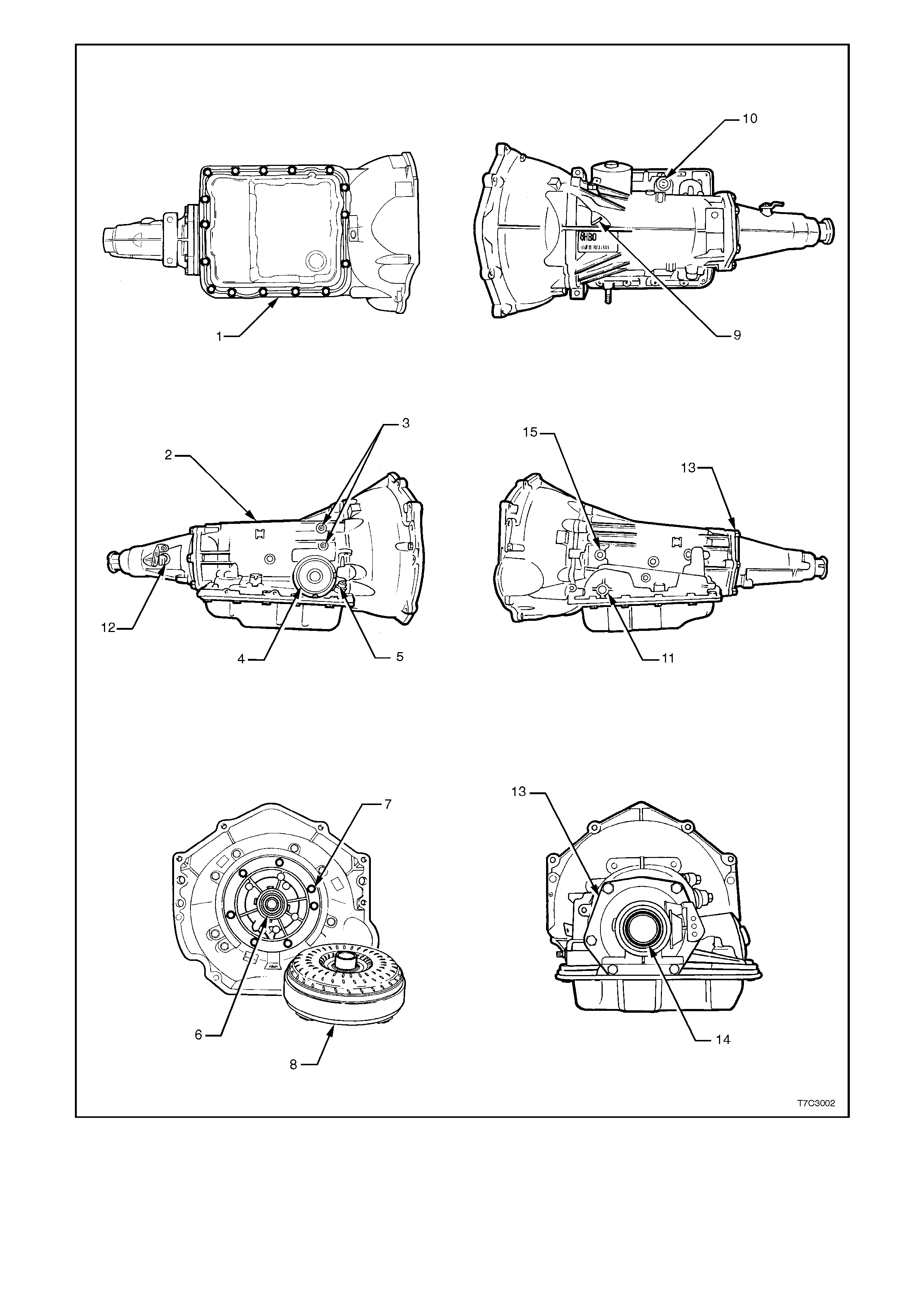
1. Oil Pan Gasket
2. Transmission Main Case
3. Cooler Connections
4. 2-4 Servo Cover Seal
5. Oil Filler Tube Seal
6. Oil Pump Seal Assembly
7. Oil Pump to Case Seal
8. Torque Converter
9. Transmission Vent
10. Pass-through Connector O-ring
11. Manual Shaft Oil Seal
12. Vehicle Speed Sensor O-ring
13. Extension Housing to Case Seal
14. Extension Housing Oil Seal
Assembly
15. Line Pressure Plug
Figure 7C3-5 Possible Points of External Leaks

3. TORQUE CONVERTER CLUTCH (TCC) DIAGNOSIS
To properly diagnose the Torque Converter Clutch (TCC) system, perform all electrical testing first and then the
hydraulic testing.
The TCC is applied by fluid pressure, that is controlled by solenoids located inside the automatic transmission
assembly. For a detailed description of this control function, refer to Section 7C1 GENERAL INFORMATION.
3.1 FUNCTIONAL CHECK PROCEDURE
INSPECT
1. Install a tachometer or TECH 2 scan tool.
2. Operate the vehicle until proper operating temperature is reached.
3. Drive the vehicle at 80 to 88 km/h with a light throttle (road load).
4. Maintaining throttle, lightly touch the brake pedal and check for release of the TCC and a slight increase in
engine speed (RPM).
5. Release the brake, slowly accelerate and check for a re-apply of the converter clutch and a slight decrease in
engine speed (RPM).

3.2 TORQUE CONVERTE R EVALUATION
TORQUE CONVERTER STATOR
The torque converter stator roller clutch can have one of two different type malfunctions:
A. Stator assembly freewheels in both directions.
B. Stator assembly remains locked up at all times.
Condition A - Poor Acceleration Low Speed
The car tends to have poor acceleration from a standstill. At speeds above 50 to 55 km/h, the car may act normally.
If poor acceleration is noted it should first be determined that the exhaust system is not blocked, and the
transmission is in first (1st) gear when starting out.
If the engine freely accelerates to high RPM in "NEUTRAL" (N), it can be assumed that the engine and exhaust
system are normal. Checking for poor performance in "Drive" and "Reverse" will help determine if the stator is
freewheeling at all times.
Condition B - Poor Acceleration High Speed
Engine RPM and car speed limited or restricted at high speeds. Performance when accelerating from a standstill is
normal. Engine may over-heat. Visual examination of the converter may reveal a blue colour from over-heating.
If the converter has been removed, the stator roller clutch can be checked by inserting two fingers into the splined
inner race of the roller clutch and trying to tum the race in both directions. The inner race should turn freely
clockwise, but not turn or be very difficult to turn anti-clockwise.
Noise
Torque converter whine is usually noticed w hen the vehicle is stopped and the transmission is in "Drive" or
"Reverse". The noise will increase when engine RPM is increased. The noise will stop when the vehicle is moving or
when the torque converter clutch is applied because both halves of the converter are turning at the same speed.
Perform a stall test, as detailed next, to make sure the noise is actually coming from the converter:
1. Place foot on brake.
2. Put gear selector in "Drive".
3. Depress accelerator to approximately 1200 RPM for no more than six seconds.
NOTE:
If the accelerator is depressed for more than six seconds, damage to the transmission may occur.
A torque converter noise will increase under this load.
IMPORTANT:
This noise should not be confused with pump whine noise which is usually noticeable in "Park", "Neutral" and all
other gear ranges. Pump whine will vary with pressure ranges.
The torque converter should be replaced under any of the following conditions:
•External leaks in the hub weld area.
•Converter hub is scored or damaged.
•Converter pilot is broken, damaged or fits poorly into crankshaft.
•Steel particles are found after flushing the cooler and cooler lines.
•Pump is damaged or steel particles are found in the converter.
•Vehicle has TCC shudder and/or no TCC apply. Replace only after all hydraulic and electrical diagnoses have
been made. (Converter clutch material may be glazed.)
•Converter has an imbalance which cannot be corrected. (Refer to Converter Vibration Test Procedure.)
•Converter is contaminated with engine coolant containing antifreeze.
•Internal failure of stator roller clutch.
•Excess end play.
•Heavy clutch debris due to overheating (blue converter).
•Steel particles or clutch lining material found in fluid filter or on magnet when no internal parts in unit are worn
or damaged - indicates that lining material came from converter.
The Torque Converter Should Not Be Replaced If:
•The oil has an odour, is discoloured, and there is no evidence of metal or clutch facing particles.
•The threads in one or more of the converter bolt holes are damaged. Correct with thread insert.
•Transmission failure did not display evidence of damage or worn internal parts, steel particles or clutch plate
lining material in unit and inside the fluid filter. Vehicle has been exposed to high mileage (only). The
exception may be where the torque converter clutch damper plate lining has seen excess wear by vehicles
operated in heavy and/or constant traffic, such as taxi, delivery or police use.

3.3 TCC SHUDDER
The key to diagnosing Torque Converter Clutch (TCC) shudder is to note when it happens and under what
conditions.
TCC Shudder should only occur during the APPLY and/or RELEASE of the converter clutch; SELDOM after the
TCC plate is fully applied.
While TCC Is Applying Or Releasing:
If the shudder occurs while TCC is applying, the problem can be within the transmission or torque converter.
Something is not allowing the clutch to become fully engaged, not allowing clutch to release, or is trying to release
and apply the clutch at the same time. This could be caused by leaking turbine shaft seals, a restricted release
orifice, a distorted clutch or housing surface due to long converter bolts, or defective friction material on the TCC
plate.
Shudder Occ urs After TCC Has Applied:
In this case, most of the time there is nothing wrong with the transmission! As mentioned above, once the TCC has
been applied, it is very unlikely that it will slip. Engine problems may go unnoticed under light throttle and load, but
become noticeable after TCC apply when going up a hill or accelerating, due to the mechanical coupling between
engine and transmission.
NOTE:
Once TCC is applied there is no torque converter (fluid coupling) assistance. Engine or driveline vibrations could be
unnoticeable before TCC engagement.
Inspect the following components to avoid misdiagnosis of TCC Shudder and possibly disassembling a
transmission and/or replacing a torque converter unnecessarily:
•Spark plugs - Inspect for cracks, high resistance or broken insulator.
•Plug wires - Look in each end. If there is red dust (ozone) or black substance (carbon) present, then the wires
are bad. Also look for a white discolouration of the wire indicating arcing during hard acceleration.
•Distributor cap and rotor (V8 engine) - Look for broken, cracked parts and carbon tracking.
•Ignition coil (V8 engine) - Look for carbon tracking on tower, indicating arcing while engine is misfiring.
•Fuel injector - Filter may be plugged.
•Vacuum leak - Engine won't get correct amount of fuel. May run rich or lean depending on where the leak is.
•MAP sensor - Like a vacuum leak, engine won't get correct amount of fuel for proper engine operation.
•Carbon on intake valves - Restricts proper flow or air/fuel mixture into cylinders.
•Flat cam - Valves don't open enough to let proper fuel/air mixture into cylinders.
•Oxygen sensor - May command engine too rich or too lean for too long.
•Fuel pressure - May be too low.
•Engine mounts - Vibration of mounts can be multiplied by TCC engagement.
•Propeller shaft universal joints - Check for vibration.
•TPS - TCC apply and release depends on TPS in many engines. If TPS is out of specification, TCC may
remain applied during initial engine acceleration.
•Cylinder balance - Bad piston rings or poorly sealing valves can cause low power in a cylinder.
•Fuel contamination - Causes poor engine performance.
3.4 RANGE REFERENCE CHART
RANGE GEAR SHIFT
SOLENOID 2-4 BAND RE V ERS
E INPUT OVERRU
N
CLUTCH
FORWAR
D
CLUTCH
FORWARD
SPRAG
CL.
3-4
CLUTCH LOW/
ROLLER LOW/
REVERSE
1 - 22 - 3 (#1) CLUTCH
(#2) (#3) (#4) ASSEMBL
Y
(#5)
(#6) CLUTCH(
#7) CLUTCH
(#8)
PARK On * On * APPLIED
REVERSE On * On * APPLIED APPLIED
NEUTRAL On * O n *
1ST On On APPLIED HOLDING HOLDING
D2ND OFF On APPLIED APPLIED HOLDING
3RD OFF OFF APPLIED HOLDING APPLIED
4TH On OFF APPLIED APPLIED APPLIED
1ST On On APPLIED HOLDING HOLDING
32ND OFF On APPLIED APPLIED HOLDING
3RD OFF OFF APPLIED APPLIED HOLDING APPLIED
21ST On On APPLIED APPLIED HOLDING HOLDING
2ND OFF On APPLIED APPLIED APPLIED HOLDING
11ST On On APPLIED APPLIED HOLDING HOLDING APPLIED
2ND ** OFF On APPLIED APPLIED APPLIED HOLDING
*SHIFT SOLENOID STATE IS A FUNCTION OF VEHICLE SPEED AND MAY CHANGE IF A VEHICLE SPEED INCREASES
SUFFICIENTLY IN PARK, REVERSE OR NEUTRAL.. HOWEVER, tHIS DOES NOT AFFECT TRANSMISSION OPERATION.
** IN MANUAL FIRST, SECOND GEAR IS ONLY AVAILABLE ABOVE APPROXIMATELY 70 KM/H TO PREVENT ENGINE
OVERSPEEDING.
Figure 7C3-6

4. FLUID FLOW AND CIRCUIT DESCRIPTI ONS
PARK (ENGINE RUNNING)
Figure 7C3-7 Park Engine Running

With the gear selector lever in the PARK (P) position and the engine running, the line pressure from the oil pump
assembly is directed to various components in the valve body and the oil pump.
PRESSURE REGULATOR
Pressure Regulator Valve
The pressure regulator valve regulates the oil pump output (line pressure) in response to the signal fluid pressure,
the spring force and the line pressure acting on the end of the valve. The line pressure is routed through the valve
and into both the converter feed and the decrease fluid circuits. Regulated line pressure is also directed to the
manual valve, the converter clutch signal valve and the actuator feed limit valve.
Pressure Relief Valve
Controlled by spring force, this checkball limits the maximum value of the line pressure. When the line pressure
reaches this limiting value, fluid is exhausted past the ball and returns to the sump.
Line Pressure Tap
The line pressure tap provides a location to measure the line pressure with a fluid pressure gauge.
Actuator Feed Limit Valve
Biased by spring force and orificed AFL fluid, it limits the maximum value of line pressure entering the AFL fluid
circuit. Below this limiting value, the AFL fluid pressure equals the line pressure. The AFL fluid is routed to the
pressure control solenoid, the 3-2 control solenoid, the 1-2 and 2-3 shift solenoids, and the 2-3 shift valve train.
Pressure Control Solenoid
Controlled by the Powertrain Control Module (PCM) the pressure control solenoid regulates the filtered AFL fluid
into the torque signal fluid pressure. The PCM controls this regulation by varying the current value to the solenoid in
relation to the throttle position and other vehicle operating conditions.
TORQUE CONVERTER CLUTCH (TCC)
Torque Converter Clutch Signal Valve
The valve may be in a position to allow the line pressure to enter the converter clutch (CC) signal fluid circuit. If this
occurs with the 2nd clutch fluid circuit empty, the CC signal fluid pressure orificed to the end of the CC signal valve
will close the valve and block line pressure. Any fluid in the CC signal fluid circuit will exhaust through the normally
open TCC solenoid.
Converter Clutch Apply Valve
Held in the release position by spring force, it directs converter feed fluid into the release fluid circuit. Also, fluid
returning from the converter in the apply fluid circuit is routed through the valve and into the cooler fluid circuit.
Torque Converter
Release fluid pressure unseats the TCC apply checkball (#9), keeps the pressure plate released from the converter
cover and fills the converter with fluid. Fluid exits the converter between the converter hub and the stator shaft in the
apply fluid circuit.
Cooler and Lubrication System
Cooler fluid from the converter clutch apply valve is routed through the transmission fluid cooler and into the
lubrication fluid circuits.
MANUAL VALVE
Controlled by the selector lever and the manual shaft, the manual valve is in the Park (P) position and directs the
line pressure into the PR (Park/Reverse) fluid circuit. Line pressure is blocked from entering any other fluid circuit at
the manual valve.
LOW AND REVERSE CLUTCH APPLIES
Lo and Reverse Clutch Piston
The PR fluid seats the low and reverse clutch checkball (#10) and is orificed to the outer area of the piston. Orificing
the PR fluid around the #10 checkball helps control the low and reverse clutch apply. Also, Lo/Reverse fluid
pressure from the low overrun valve acts on the inner area of the low and reverse clutch piston in order to increase
the clutch holding capacity.
Low Overrun Valve
The PR fluid pressure moves the valve against the spring force and fills the low/reverse fluid circuit. Lo/Reverse
fluid is orificed (323) back to the low overrun valve in order to assist the PR fluid in moving the valve against the
spring force. The spring force provides a time delay for the PR fluid filling the Lo/Reverse fluid circuit. The
Lo/Reverse fluid is routed to the inner area of the low and reverse clutch piston in order to increase the holding
capacity of the clutch.

TRANSMISSION FLUID PRESSURE MANUAL VALVE POSITION SWITCH (TFP VAL. POSITION SW.)
ASSEMBLY
The TFP Val. Position Sw. consists of five fluid pressure switches: D2 and D3 are normally closed and D4, Low and
Rev are normally open. All fluid circuits routed to the assembly are empty and the TFP Val. Position Sw. signals the
PCM that the transmission is in either Park or Neutral.
Shift Solenoids (1 -2 and 2-3)
Both shift solenoids, which are normally open, are energised by the PCM and block fluid from exhausting. This
maintains the signal A fluid pressure at the 1-2 shift solenoid and signal B fluid pressure at the 2-3 shift solenoid.
Shift Valves (1-2, 2-3 and 3-4)
Signal A fluid pressure holds the 1-2 shift valve in the downshift position and the 3-4 valve in the upshift (first and
fourth gear) position. The signal B fluid pressure from the 2-3 shift solenoid holds the 2-3 shift train in the downshift
position.
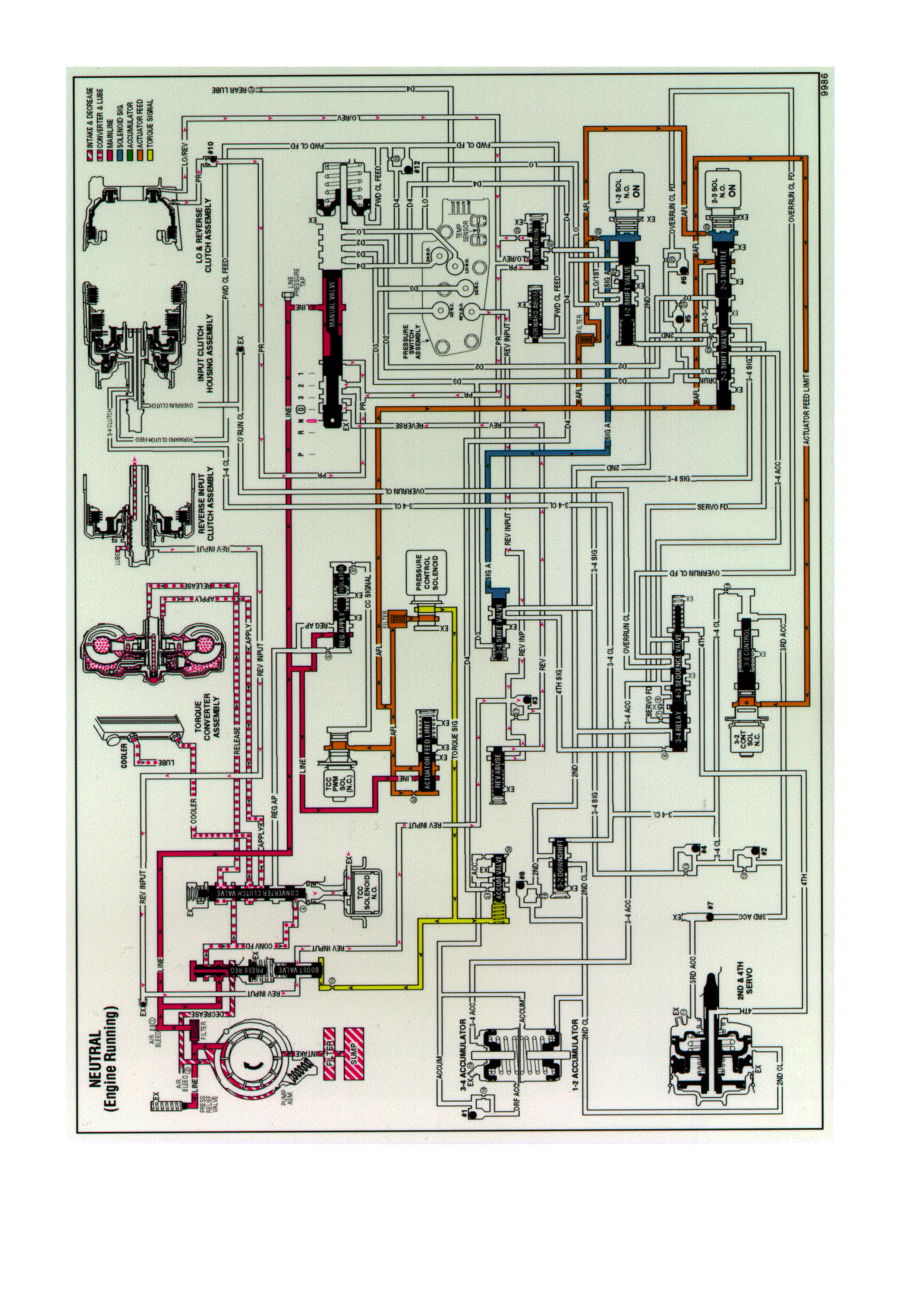
NEUTRAL - ENGINE RUNNING
Figure 7C3-8 Neutral Engine Running

When the gear selector lever is moved to the Neutral (N) position from the Reverse position, the following changes
occur to the transmission hydraulic and electrical systems.
MANUAL VALVE
In the Neutral position, the manual valve blocks the line pressure from entering any other fluid circuits. Reverse and
PR fluids exhaust past the manual valve.
LO AND REVERSE CLUTCH RELEASES
Lo and Reverse Clutch Piston
PR and Lo/reverse fluids exhaust from the piston, thereby releasing the lo and reverse clutch plates. Exhausting PR
fluid unseats the lo and reverse clutch checkball (#10) for a quick exhaust.
LO OVERRUN VALVE
Spring force closes the valve when the PR fluid pressure exhausts. Lo/reverse fluid exhausts through the valve, into
the Lo/1st fluid circuit, past the 1-2 shift valve, into the Lo fluid circuit and through an exhaust port at the manual
valve.
REVERSE INPUT CLUTCH RELEASES
Reverse Input Clutch Piston
Reverse input fluid pressure exhausts from the piston, through the boost valve, past the #3 checkball and to the
manual valve. With the reverse input fluid exhausted, the reverse input clutch plates are released and the
transmission is in Neutral.
REVERSE ABUSE VALVE
Reverse fluid pressure exhausts and spring force closes the valve.
BOOST VALVE
Reverse input fluid pressure exhausts and line pressure returns to the normal operating range as in the Park and
Overdrive positions.
REVERSE INPUT CHECKBALL (#3)
Exhausting reverse input fluid unseats the ball for a quick exhaust through the reverse fluid circuit and past the
manual valve.
TRANSMISSION FLUID PRESSURE MANUAL VALVE POSITION SWITCH (TFP VAL. POSITION SW.)
ASSEMBLY
IMPORTANT:
In Park, Reverse and Neutral the shift solenoids are shown energised. This is the normal operating state when the
vehicle is stationary or at low vehicle speeds. However, the PCM will change the shift solenoid states depending on
the vehicle speed.
For example, if Neutral is selected when the transmission is operating in Second Gear, the shift solenoids will
remain in a Second Gear state. However, with the manual valve blocking line pressure, the shift solenoid states do
not affect transmission operation in Park, Reverse and Neutral.
Reverse input fluid exhausts from the TFP Val Position Sw. With no other fluid routed to it, the TFP Val Position Sw.
signals the PCM that the transmission is operating in either Park or Neutral.
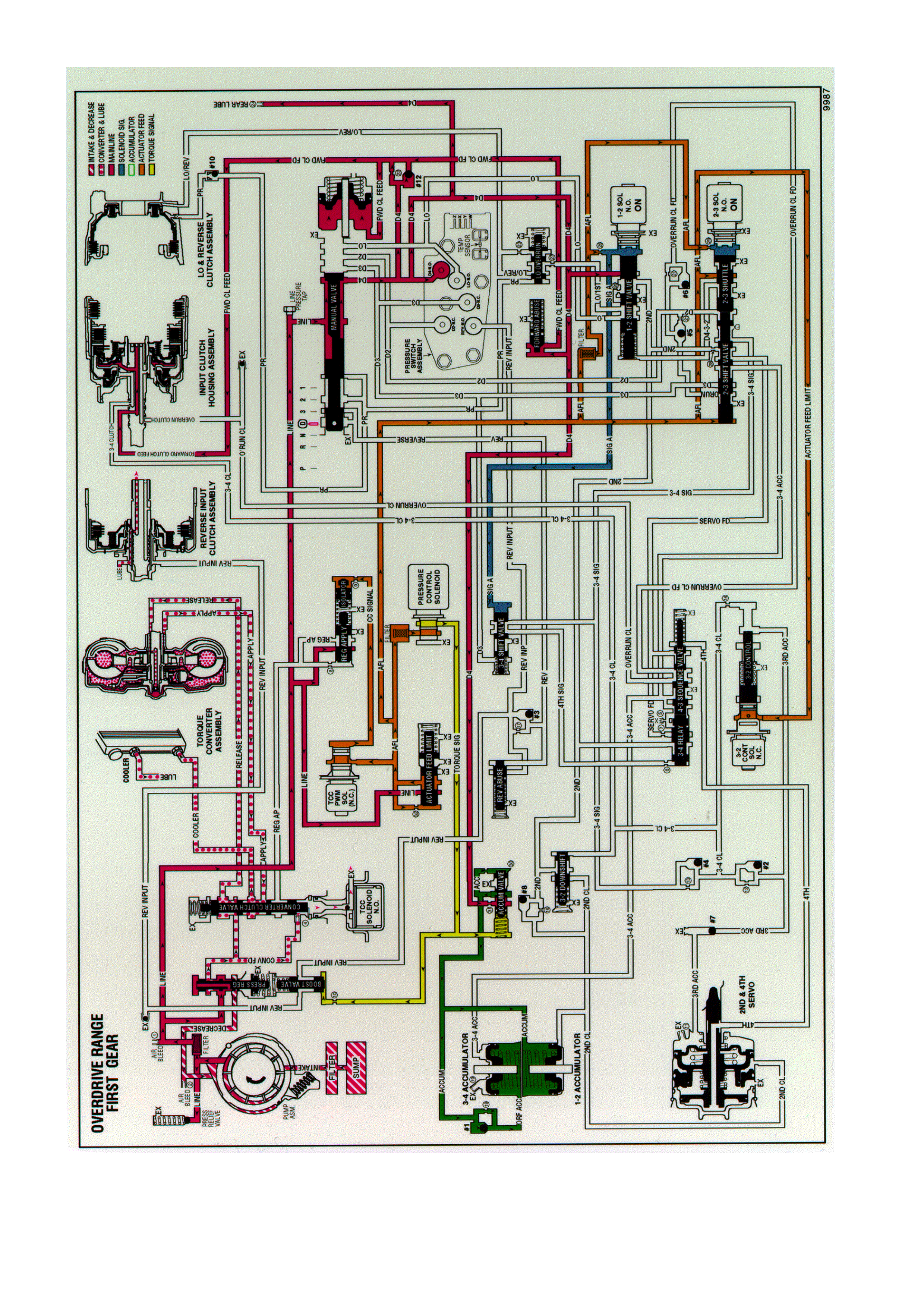
DRIVE (OVERDRIVE) RANGE, FIRST GEAR
Figure 7C3-9 Drive Range, First Gear

When the gear selector lever is moved to the Overdrive position, from the neutral position, the following changes
occur to the transmission’s hydraulic and electrical sy stems:
MANUAL VALVE
Line pressure flows through the manual valve and fills the D4 fluid circuit. All other fluid circuits remain empty w ith
the manual valve in the Overdrive position.
FORWARD CLUTCH APPLIES
Forward Clutch Accumulator Checkball (#12)
D4 fluid pressure seats the checkball and is orificed (#22) into the forward clutch feed fluid circuit. This orifice helps
control the forward clutch apply rate.
Forward Clutch Accumulator Piston
Forward clutch feed fluid pressure moves the piston against spring force. This action absorbs some of the initial
increase of forward clutch feed fluid pressure to cushion the forward clutch apply.
Forward Clutch Abuse Valve
D4 fluid pressure acts on the valve opposite of spring force. At engine speeds greater than idle, D4 fluid pressure
increases and moves the valve against spring force (as shown). D4 fluid can then quickly fill the forward clutch feed
fluid circuit, thereby bypassing the control of orifice #22 and providing a faster apply of the forward clutch.
Otherwise, with increased throttle opening and engine torque, the clutch may slip during apply .
TRANSMISSION FLUID PRESSURE MANUAL VALVE POSITION SWITCH (TFP VAL. POSITION SW.)
ASSEMBLY
D4 fluid pressure is routed to the TFP Val. Position Sw. and closes the normally open D4 fluid pressure switch. This
signals the PCM that the transmission is operating in Overdrive range.
1-2 SHIFT SOLENOID
Energised (ON) as in Neutral, the normally open solenoid is closed and blocks signal A fluid from exhausting
through the solenoid. This maintains pressure in the signal A fluid circuit.
2-3 SHIFT SOLENOID
Energised (ON) as in Neutral, the normally open solenoid is closed and blocks signal B fluid from exhausting
through the solenoid. This maintains signal B fluid pressure at the solenoid end of the 2-3 shift valve.
2-3 Shift Valve Train
Signal B fluid pressure at the solenoid end of the 2-3 shift valve holds the valve train in the downshifted position
against AFL fluid pressure acting on the 2-3 shift valve. In this position, the 2-3 shuttle valve blocks AFL fluid from
entering the D432 fluid circuit. The D432 fluid circuit is open to an exhaust port past the valve.
1-2 SHIFT VALVE
Signal A fluid pressure holds the valve in the downshifted position against spring force. In the First gear position, the
valve blocks D4 fluid from entering the 2nd fluid circuit.
ACCUMULATOR VALVE
Biased by torque signal fluid pressure, spring force and orificed accumulator fluid pressure at the end of the valve,
the accumulator valve regulates D4 fluid into accumulator fluid pressure. Accumulator fluid is routed to both the 1-2
and 3-4 accumulator assemblies in preparation for the 1-2 and 3-4 upshifts respectively.
REAR LUBE
D4 fluid is routed through an orifice cup plug (#24) in the rear of the transmission case to feed the rear lube fluid
circuit.
PRESSURE CONTROL SOLENOID
Remember that the pressure control solenoid continually varies torque signal fluid pressure in relation to throttle
position and vehicle operating conditions. This provides a precise control of line pressure.
3-2 CONTROL SOLENOID
The PCM keeps the solenoid OFF in First gear and the normally closed solenoid blocks filtered AFL fluid from
entering the 3-2 signal fluid circuit.
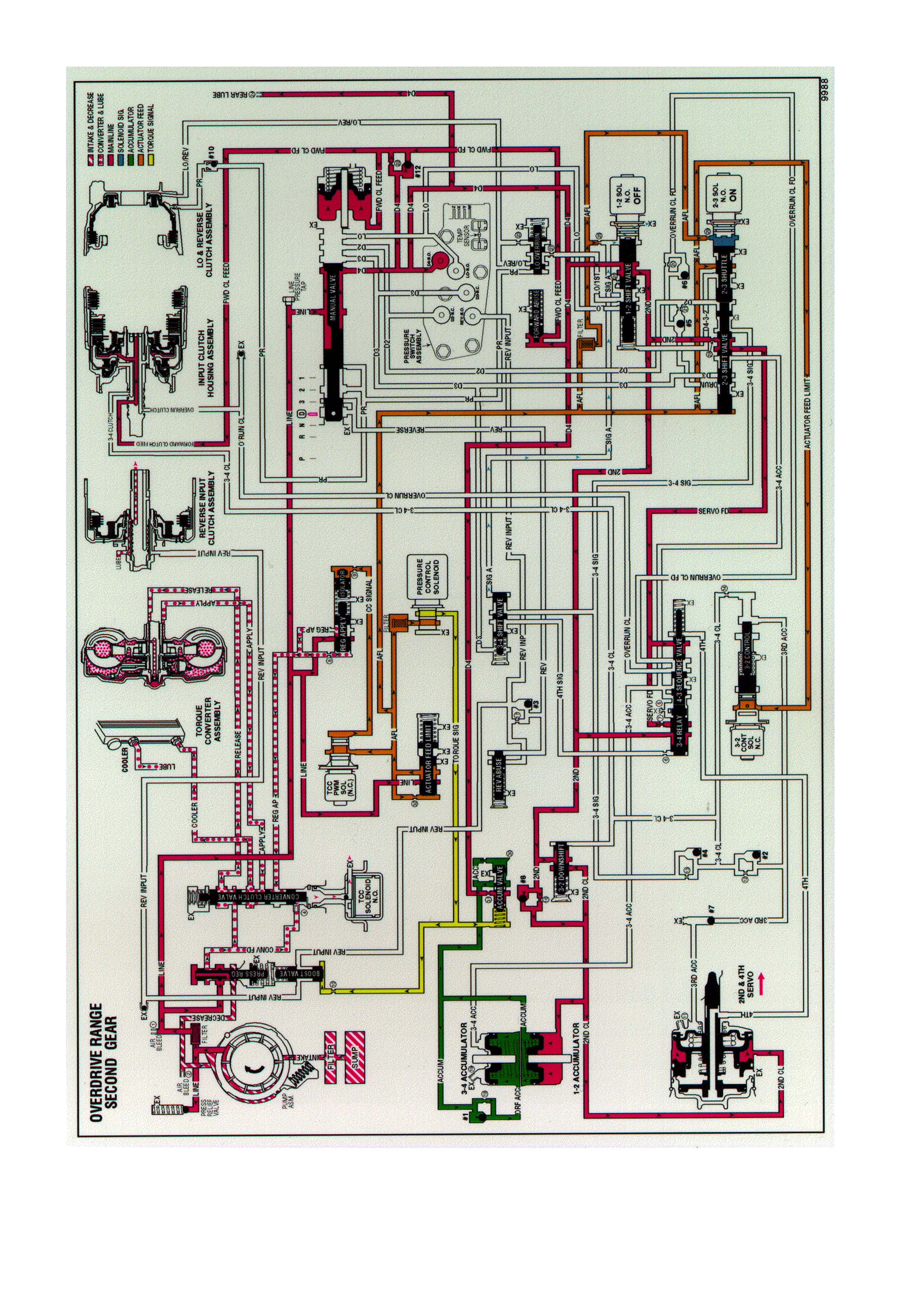
DRIVE (OVERDRIVE) RANGE, SECOND GEAR
Figure 7C3-10 Drive Range, Second Gear

As vehicle speed increases and other operating conditions are appropriate, the PCM de-energises the 1-2 shift
solenoid in order to shift the transmission to second gear.
1-2 SHIFT SOLENOID
De-energised (turned OFF) by the PCM, the normally open solenoid opens and signal A fluid exhausts through the
solenoid.
2-3 SHIFT SOLENOID
IMPORTANT:
The actuator feed limit (AFL) fluid continues to feed the signal A fluid circuit through orifice #25. However, the
exhaust port through the solenoid is larger than orifice #25 in order to prevent a pressure build-up in the signal A
fluid circuit. Exhausting signal A fluid is represented by the blue arrows.
Energised (ON) as in first gear, the 2-3 shift solenoid blocks signal B fluid from exhausting through the solenoid.
This maintains signal B fluid pressure at the solenoid end of the 2-3 shift valve.
1-2 SHIFT VALVE
Without signal A fluid pressure, spring force moves the valve into the upshift position. D4 fluid is routed through the
valve and fills the 2nd fluid circuit.
1-2 SHIFT CHECKBALL (#8)
The 2nd fluid pressure seats the #8 checkball, flows through orifice #16, and fills the 2nd clutch fluid circuit. This
orifice helps control the 2-4 band apply rate.
2-4 SERVO ASSEMBLY
The 2nd clutch fluid pressure moves the #8 checkball, flows through orifice #16 and fills the 2nd clutch fluid circuit.
This orifice helps to control the 2-4 band apply rate.
1-2 ACCUMULATOR
The 2nd clutch fluid pressure also moves the 1-2 accumulator piston against the spring force and the accumulator
fluid pressure. This action absorbs the initial 2nd clutch fluid pressure in order to cushion the 2-4 band apply rate.
Also, the movement of the 1-2 accumulator piston forces some accumulator fluid out of the accumulator assembly.
This accumulator fluid is routed back to the accumulator valve.
ACCUMULATOR VALVE
The accumulator fluid forced out of the 1-2 accumulator is orificed (#30) to the end of the accumulator valve. This
pressure moves the valve against the spring force and the torque signal fluid pressure in order to regulate the
exhaust of excess accumulator fluid. This regulation provides additional control for the 2-4 band apply rate. The fluid
circuit shows the exhaust of the accumulator fluid during the shift by the arrow directions in the accumulator fluid
circuit.
2-3 SHIFT VALVE TRAIN
The signal B fluid pressure from the 2-3 shift solenoid holds the valve train in the downshift position. The 2nd fluid is
routed through the 2-3 shuttle valve and fills the servo feed fluid circuit.
3-4 RELAY VALVE AND 4-3 SEQUENCE VALVE
Spring force holds these valves in the downshift position (first, second and third gear positions). The 2nd fluid is
blocked by the 3-4 relay valve and the servo feed fluid is blocked by both valves in preparation for a 3-4 upshift.
3-2 DOWNSHIFT VALVE
Spring force holds the valve closed, blocking the 2nd fluid and the 2nd clutch fluid. This valve is used in order to
help control the 3-2 downshift.
3-4 SHIFT VALVE
Signal A fluid pressure exhausts and spring force moves the valve into the downshift position (second and third
gear positions).
CONVERTER CLUTCH SIGNAL VALVE
The 2nd clutch fluid pressure opens the valve and the line pressure feeds the converter clutch (CC) signal fluid
circuit. The TCC signal fluid is orificed (#8) to the end of the CC signal valve and opposes the 2nd clutch fluid
pressure. The TCC signal fluid is routed through a filter and orificed (#4) to the TCC solenoid.
TCC SOLENOID
IMPORTANT:
The orifice cup plug (#4) in the CC signal fluid circuit is smaller than the exhaust through the TCC solenoid.
Therefore, fluid pressure does not build up at the end of the converter clutch apply valve.
Under normal operating conditions in second gear, the PCM keeps the normally open TCC solenoid de-energised
(OFF). CC signal fluid exhausts through the open solenoid and spring force keeps the converter clutch apply valve
in the release position.

DRIVE (OVERDRIVE) RANGE, THIRD GEAR - TCC APPLIED
Figure 7C3-11 Drive Range, Third Gear

As vehicle speed increases further and other vehicle operating conditions are appropriate, the PCM de-energises
the normally open 2-3 shift solenoid in order to shift the transmission into Third gear.
2-3 SHIFT SOLENOID
De-energised (turned OFF) by the PCM, the solenoid opens and actuator feed limit signal B fluid exhausts through
the solenoid.
NOTE:
AFL fluid continues to feed signal B fluid to the solenoid through orifice #29. However, the exhaust port through the
solenoid is larger than orifice #29 to prevent a build-up of pressure in the signal B fluid circuit at the solenoid end of
the 2-3 shift valve. Exhausting signal B fluid is represented by the arrows through the solenoid.
2-3 SHIFT VALVE TRAIN
AFL fluid pressure at the 2-3 shift valve moves the valve train toward the solenoid. In the upshifted position, the
following changes occur:
AFL fluid is routed through the 2-3 shift valve and fills the D432 fluid circuit.
2nd fluid is blocked from entering the servo feed fluid circuit and is orificed (#28) into the 3-4 signal fluid circuit. This
orifice helps control the 3-4 clutch apply rate.
Servo feed fluid exhausts past the valve into the 3-4 accumulator fluid circuit and through an exhaust port at the 3-4
relay valve.
3-4 CLUTCH EXHAUST CHECKBALL (#4)
3-4 signal fluid unseats the ball and enters the 3-4 clutch fluid circuit.
3-4 CLUTCH PISTON
3-4 clutch fluid pressure moves the piston to apply the 3-4 clutch plates and obtain 3rd gear. However, the 2-4 band
must release as the 3-4 clutch applies.
3RD ACCUMULATOR CHECKBALL (#2)
3-4 clutch fluid pressure unseats the ball and fills the 3rd accumulator fluid circuit.
3RD ACCUMULATOR EXHAUST CHECKBALL (#7)
3rd accumulator fluid seats the ball against the orificed exhaust and is routed to the released side of the 2nd apply
piston. Before the #7 checkball seats air in the 3rd accumulator fluid circuit is exhausted through the orifice.
2-4 SERVO ASSEMBLY
3rd accumulator fluid pressure acts on the release side of the 2nd apply piston and assists servo return spring
force. The surface area on the release side of the piston is greater than the surface area on the apply side.
Therefore, 3rd accumulator fluid pressure and servo return spring force move the 2nd apply piston against 2nd
clutch fluid pressure. This action serves two functions:
1. Move the apply pin to release the 2-4 band.
2. Act as an accumulator by absorbing initial 3-4 clutch fluid to cushion the 3-4 clutch apply rate. Remember that
the 3rd accumulator fluid circuit is fed by 3-4 clutch fluid.
3-2 DOWNSHIFT VALVE
3-4 clutch fluid pressure moves the valve against spring force. This opens the valve and allows 2nd fluid to feed the
2nd clutch fluid circuit through the valve.
1-2 SHIFT SOLENOID AND 1-2 SHIFT VALVE
The 1-2 shift solenoid remains de-energised and signal A fluid is exhausted through the solenoid. Also, D432 fluid
pressure from the 2-3 shift valve assists spring force to hold the 1-2 shift valve in the upshifted position.
3-4 SHIFT VALVE
Spring force holds the valve in the downshifted position, blocking 3-4 clutch fluid in preparation for a 3-4 upshift.
TORQUE CONVERTER CLUTCH
TCC Solenoid
Under normal operating conditions in Overdrive Range-Third Gear, the PCM keeps the normally open TCC solenoid
de-energised. CC signal fluid exhausts through the open solenoid and spring force keeps the converter clutch apply
valve in the release position. However, at speeds above approximately 121 km/h, the PCM will command TCC
apply in Third gear.
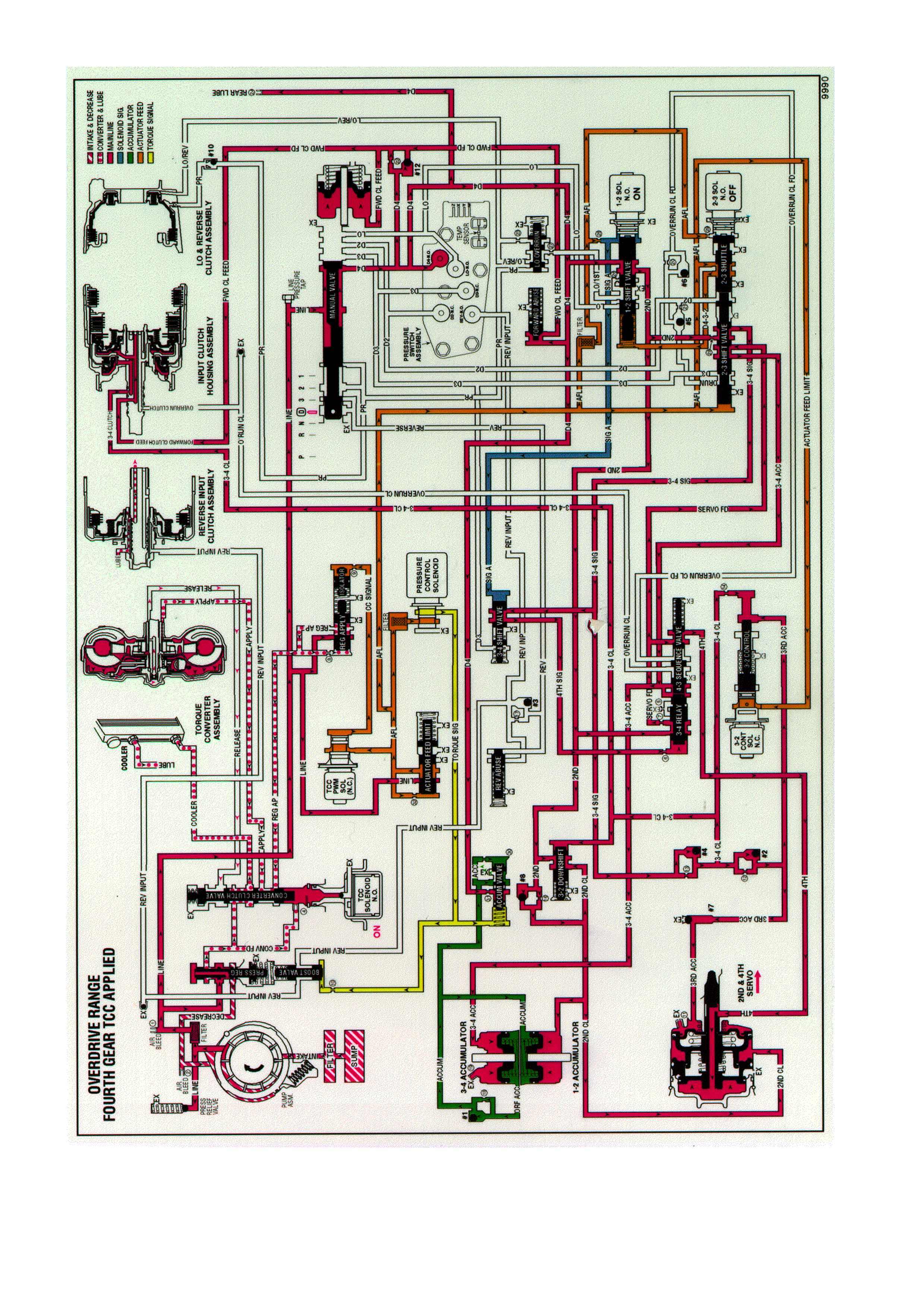
DRIVE (OVERDRIVE) RANGE, FOURTH GEAR - TCC APPLIED
Figure 7C3-12 Drive Range, Fourth Gear

At higher vehicle speeds, the Hydra-matic 4L60-E transmission uses an overdrive gear ratio (fourth gear) in order
to increase fuel economy and in order to maximise engine performance. When vehicle operating conditions are
appropriate, the PCM energises the 1-2 shift solenoid to shift the transmission into fourth gear.
1-2 SHIFT SOLENOID
Energised (turned ON) by the PCM, the normally open solenoid closes and blocks signal A fluid from exhausting
through the solenoid. This creates pressure in the signal A fluid circuit.
2-3 SHIFT SOLENOID
De-energised (OFF) as in third gear, the 2-3 shift solenoid exhausts signal B fluid through the solenoid.
1-2 SHIFT VALVE
D432 fluid pressure from the 2-3 shift valve and spring force hold the valve in the upshift position against signal A
fluid pressure.
3-4 SHIFT VALVE
Signal A fluid pressure moves the valve into the upshift position against the spring force. In this position, the valve
routes 3-4 signal fluid into the 4th signal fluid circuit.
3-4 RELAY VALVE AND 4-3 SEQUENCE VALVE
4th signal fluid pressure moves both valves into the upshift (fourth gear) position against the spring force acting on
the 4-3 sequence valve. This causes the following changes:
Orificed (#7) 2nd fluid is routed through the 3-4 relay valve and into the servo feed fluid circuit.
Servo feed fluid is routed through the 4-3 sequence valve and into the 4th fluid circuit.
3-4 accumulator fluid routed from the 2-3 shuttle valve is blocked by both valves.
2-4 SERVO ASSEMBLY
4th fluid is routed through the center of the servo apply pin and acts on the apply side of the 4th apply piston. 4th
fluid pressure moves the 4th apply piston against the apply pin spring force acting on the release side of the 4th
apply piston. This action moves the apply pin and applies the 2-4 band in order to obtain fourth gear.
2-4 BAND APPLY ACCUMULATION
2-3 Shift Valve Train
The valve train remains in the upshift position with the AFL fluid pressure acting on the 2-3 shift valve. In addition to
its operation third gear, the 2-3 shift valve directs servo feed fluid into the 3-4 accumulator fluid circuit.
3-4 ACCUMULATOR ASSEMBLY
3-4 accumulator fluid pressure moves the 3-4 accumulator piston against spring force and orificed accumulator fluid
pressure, This action absorbs initial 4th clutch apply fluid pressure in order to cushion the 2-4 band apply.
Remember that both of the 3-4 accumulator and 4th fluid circuits are fed by servo feed fluid.
As 3-4 accumulator fluid fills the accumulator, any air in the system will exhaust through orifice #19. This piston
movement forces some orificed accumulator fluid out of the 3-4 accumulator assembly.
3-4 ACCUMULATOR CHECKBALL (#1)
The accumulator fluid forced from the accumulator unseats the #1 checkball and enters the accumulator fluid
circuit. This fluid is routed to the accumulator valve. This is shown by the arrow directions in the fluid circuit.
ACCUMULATOR VALVE
Accumulator fluid forced from the 3-4 accumulator is orificed to the end of the accumulator valve. This fluid
pressure, in addition to spring force and torque signal fluid pressure, regulates the exhaust of excess accumulator
fluid pressure through the middle of the valve. This regulation helps control the 2-4 band apply feel.
TORQUE CONVERTER CLUTCH APPLIES
TCC Solenoid
When operating conditions are appropriate, the PCM energises the normally open TCC solenoid. This closes the
solenoid, blocks the converter clutch signal fluid from exhausting and creates pressure in the converter clutch signal
fluid circuit.
CONVERTER CLUTCH APPLY VALVE
Converter clutch signal fluid pressure moves the valve against spring force and into the apply position. In this
position, release fluid is open to an exhaust port and converter feed fluid fills the apply fluid circuit. Converter feed
fluid also feeds the cooler fluid circuit through orifice #3.

TORQUE CONVERTER
Release fluid from behind the pressure plate exhausts through the end of the turbine shaft. Apply fluid pressure is
routed between the converter hub and stator shaft where it enters the torque converter. This fluid applies the
converter clutch against the converter cover and keeps the converter filled with fluid.
TCC Apply Checkball (#9)
Release fluid, exhausting from the converter, seats the #9 checkball located in the end of the turbine shaft, and is
orificed around the ball. Orificing the exhausting release fluid controls the converter clutch apply rate.
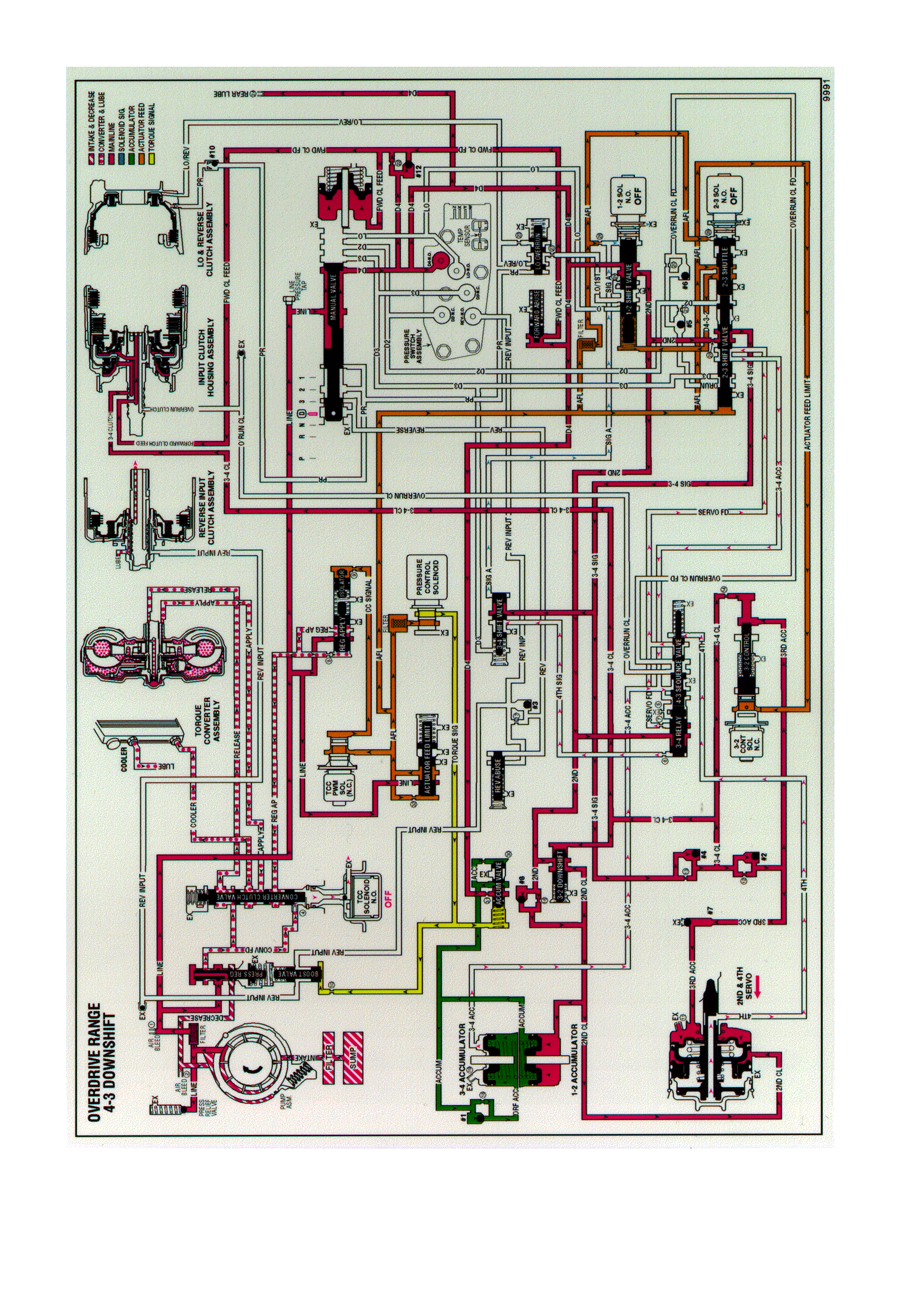
DRIVE (OVERDRIVE) RANGE, 4-3 DOWNSHIFT
Figure 7C3-13 Drive Range, 4-3 Downshift

When the transmission is operating in fourth gear, a forced 4-3 downshift occurs if there is a significant increase in
throttle position. At minimum throttle, the vehicle speed decreases gradually (coastdown) and the PCM commands
a 4-3 downshift.
The PCM also initiates a forced 4-3 downshift when the throttle position remains constant but engine load is
increased, such as driving up a steep incline. To achieve a 4-3 downshift, the PCM de-energises the 1-2 shift
solenoid and the following changes occur to the transmission's electrical and hydraulic systems:
1-2 SHIFT SOLENOID
De-energised by the PCM, the normally open solenoid opens and signal A fluid exhausts through the solenoid.
1-2 SHIFT VALVE
As in Fourth gear, D432 fluid pressure and spring force hold the valve in the upshift position.
2-4 BAND RELEASES
3-4 Shift Valve
With the signal A fluid pressure exhausted, the spring force moves the valve into the downshift position. In this
position, the valve blocks the 3-4 signal fluid and the 4th signal fluid exhausts past the valve.
3-4 RELAY VALVE AND 4-3 SEQUENCE VALVE
These valves control the timing of the 2-4 band release. With the 4th signal fluid pressure exhausted, the 3-4
accumulator fluid pressure moves the 3-4 relay valve into the third gear position. This opens the 3-4 accumulator
fluid to an orificed exhaust (#5) past the 3-4 relay valve (shown by red arrows). Because the exhaust is orificed, the
3-4 accumulator fluid pressure momentarily holds the 4-3 sequence valve against spring force before completely
exhausting.
When the exhausting 3-4 accumulator fluid pressure decreases sufficiently, the spring force moves the 4-3
sequence valve into the third gear position as shown. This opens both the 3-4 accumulator and the 4th fluid circuits
to a quick exhaust past the 4-3 sequence valve. In this position the valve blocks the 2nd fluid from entering the
servo feed fluid circuit.
2-4 SERVO ASSEMBLY
The 4th fluid exhausts from the 4th apply piston in the servo assembly. The apply pin spring moves the 4th apply
piston and the apply pin in order to release the band from the reverse input drum and shift the transmission into
third gear.
3-4 ACCUMULATOR ASSEMBLY
The 3-4 accumulator fluid exhausts from the 3-4 accumulator piston. The orificed accumulator fluid pressure and
the spring force move the piston into a third gear position.
3-4 ACCUMULATOR CHECKBALL (#1)
As the accumulator fluid fills the 3-4 accumulator, it seats the #1 checkball and is forced through orifice #18. This
orifice controls the rate at which accumulator fluid pressure fills the 3-4 accumulator and the 3-4 accumulator fluid
exhausts from the accumulator assembly.
ACCUMULATOR VALVE
Biased by torque signal fluid pressure and spring force, the accumulator valve regulates the drive fluid into the
accumulator fluid circuit.
2-3 SHIFT SOLENOID
This solenoid remains de-energised as in fourth gear and the signal B fluid exhausts through the solenoid.
2-3 SHIFT VALVE TRAIN
The AFL fluid pressure at the 2-3 shift valve holds the valves in the upshift position. This allows the servo feed fluid
to exhaust through the valve, into the 3-4 accumulator fluid circuit and past the 4-3 sequence valve.
TORQUE CONVERTER CLUTCH
The PCM releases the converter clutch prior to initiating the 4-3 downshift. However, if the vehicle speed is above
approximately 121 km/h, the PCM commands the TCC to apply in third gear.
Pressure Control Solenoid
Remember that the pressure control solenoid continually adjusts the torque signal fluid pressure in relation to the
various PCM input signals (mainly the throttle position).
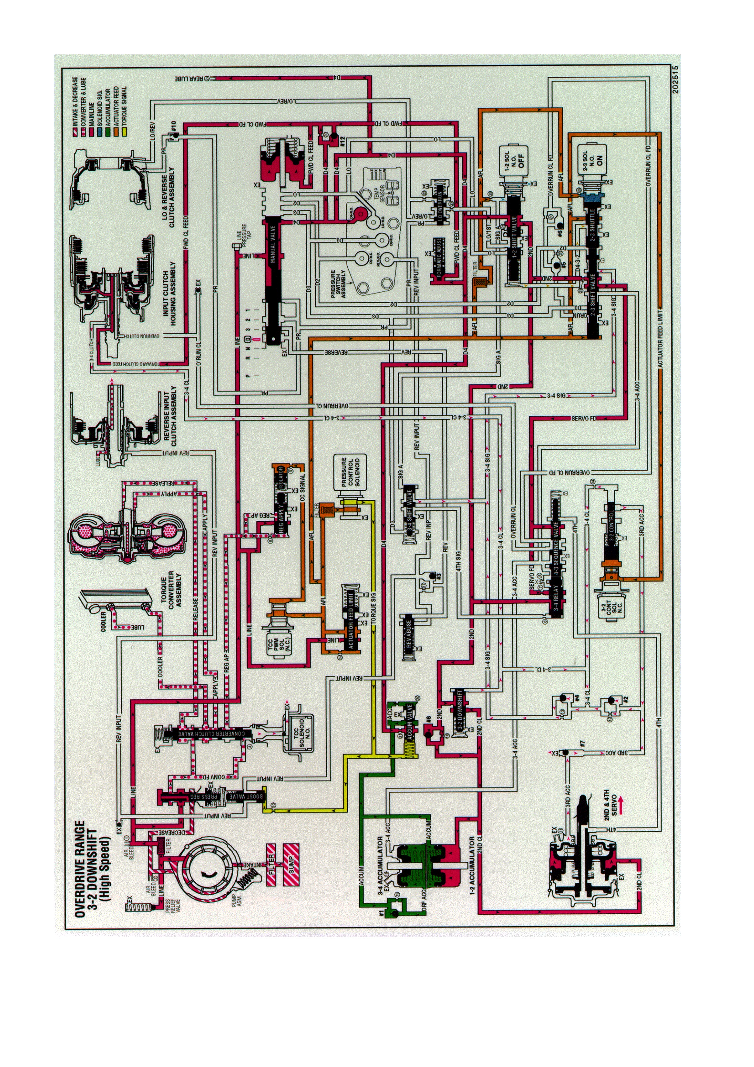
DRIVE (OVERDRIVE) RANGE, 3-2 DOWNSHIFT
Figure 7C3-14 Drive Range, 4-3 Downshift

Similar to a forced 4-3 downshift, a forced 3-2 downshift can occur because of minimum throttle (coastdown
conditions), heavy throttle or increased engine load. In order to achieve a forced 3-2 downshift, the PCM energises
the 2-3 shift solenoid and the following changes occur:
Energised by the PCM, the normally open solenoid closes and blocks the signal B fluid from exhausting through the
solenoid. This creates pressure in the signal B fluid circuit at the solenoid end of the 2-3 shift valve.
2-3 SHIFT VALVE TRAIN
The signal B fluid pressure from the shift solenoid moves both valves to the downshift position against AFL fluid
pressure acting on the 2-3 shift valve. This causes the following changes:
The AFL fluid is blocked from the D432 fluid circuit and the D432 fluid exhausts past the 2-3 shuttle valve.
The 2nd fluid is blocked from feeding the 3-4 signal fluid circuit and the 2nd fluid is routed into the servo feed fluid
circuit.
The 3-4 signal fluid is exhausted past the valve. The 3-4 clutch fluid and the 3rd accumulator fluid, which were fed
by the 3-4 signal fluid, also exhaust.
3-4 CLUTCH RELEASES AND 2-4 BAND APPLIES
3-4 Clutch Piston
The 3-4 clutch fluid exhausts from the piston and the 3-4 clutch plates are released.
3-4 Clutch Exhaust Checkball (#4)
Exhausting the 3-4 clutch fluid seats the #4 checkball and is forced through orifice #13. This orifice controls the 3-4
clutch fluid exhaust and the 3-4 clutch release rate.
2-4 SERVO ASSEMBLY
The 3rd accumulator fluid exhausts from the servo assembly. The 2nd clutch fluid pressure moves the 2nd apply
piston against the servo return spring force in order to move the apply pin and apply the 2-4 band.
3-2 DOWNSHIFT VALVE AND 1-2 UPSHIFT CHECKBALL (#8)
The 3-2 clutch fluid exhausts from the valve and the spring force moves the valve into the second gear position.
However, before the spring force overcomes exhausting the 3-4 clutch fluid pressure, the 2nd fluid feeds the 2nd
clutch fluid circuit through the valve. This bypasses the control of orifice #16 at the #8 checkball and provides a
faster 2-4 band apply. Remember that the #8 checkball and orifice #16 are used to help control the 2-4 band apply
during a 1-2 upshift.
DOWNSHIFT TIMING AND CONTROL
At higher vehicle speeds, the 2-4 band apply must be delayed to allow the engine speed RPM to increase
sufficiently for a smooth transfer of engine load to the 2-4 band. Therefore, exhaust of the 3rd accumulator fluid
must be delayed. However, at lower speeds the band must be applied quickly. In order to provide for the varying
requirements for the 2-4 band apply rate, the exhausting 3rd accumulator fluid is routed to both the 3rd accumulator
checkball (#2) and the 3-2 control valve.
3RD ACCUMULATOR CHECKBALL (#2)
The exhausting 3rd accumulator fluid seats the #2 checkball and is forced through orifice #12. This fluid exhausts
through the 3-4 clutch and the 3-4 signal fluid circuits and past the 2-3 shift valve. Orifice #12 slows the exhaust of
the 3rd accumulator fluid and delays the 2-4 band apply rate.
3-2 CONTROL SOLENOID AND 3-2 CONTROL VALVE
These components are used to increase the exhaust rate of 3rd accumulator fluid, as needed, depending on the
vehicle speed.
The 3-2 control solenoid is a normally closed On/Off solenoid controlled by the PCM. The PCM controls the
solenoid state during a 3-2 downshift according to vehicle speed.
Low Speed
At lower vehicle speeds, the PCM operates the 3-2 control solenoid in the Off position.
In the Off position the solenoid blocks actuator feed limit fluid pressure from the 3-2 control valve.
With no actuator feed limit fluid pressure, the 3-2 control valve spring force keeps the valve open to allow a faster
exhaust of 3rd accumulator fluid through orifice #14 into the 3-4 clutch fluid circuit.
A faster exhaust of the 3rd accumulator exhaust fluid provides a faster apply of the 2-4 band, as needed at lower
vehicle speeds.
High Speed
At high vehicle speed, the PCM operates the 3-2 control solenoid in the On position allowing actuator feed limit fluid
to pass through the solenoid. This pushes the 3-2 control valve Into the closed position.
This action permits a slow apply of the 2-4 band by blocking off 3rd accumulator exhaust fluid from entering the 3-4
clutch fluid circuit through orifice #14.
This allows the engine speed to easily come up to the necessary RPM before the 2-4 band is applied.

3RD ACCUMULATOR EXHAUST CHECKBALL (#7)
After the downshift is completed, the #7 checkball unseats and allows the residual fluid in the 3rd accumulator fluid
circuit to exhaust.
PRESSURE CONTROL SOLENOID
Remember that the pressure control solenoid continually adjusts torque signal fluid in relation to the various PCM
input signals (mainly the throttle position).
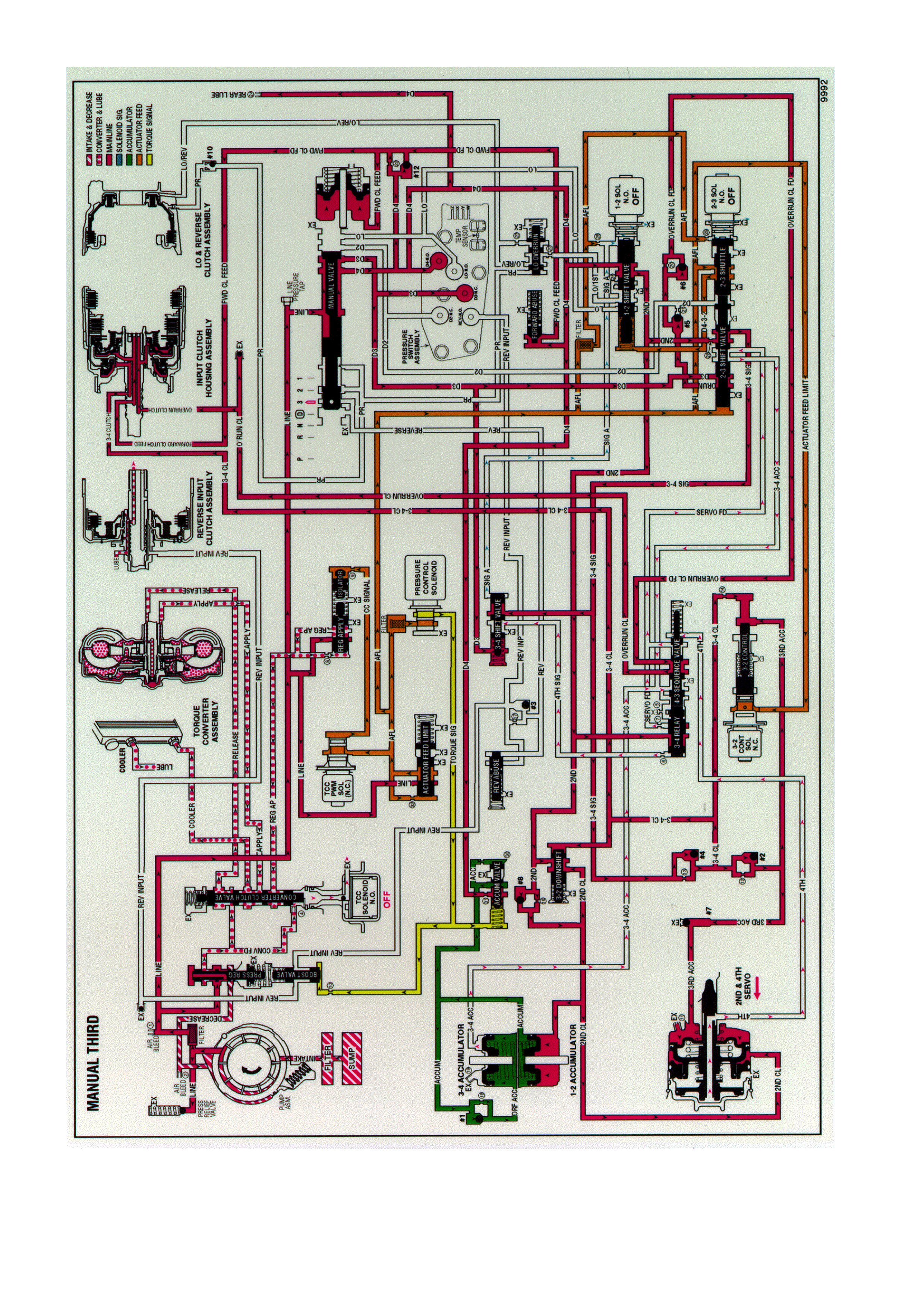
MANUAL THIRD GEAR - TCC APPLIED
Figure 7C3-15 Manual Third Gear, TCC Applied

A manual 4-3 downshift is available to increase vehicle performance when the use of only three gear ratios is
desired. Manual Third gear range also provides engine braking in Third gear when the throttle is released. A manual
4-3 downshift is accomplished by moving the selector lever into the Manual Third (D) position. This moves the
manual valve and immediately downshifts the transmission into Third gear. Refer to Overdrive Range, 4-3
Downshift for a complete description of a 4-3 downshift. In Manual Third, the transmission is prevented, both
hydraulically and electronically, from shifting into Fourth gear. The following information explains the additional
changes during a manual 4-3 downshift as compared to a forced 4-3 downshift.
MANUAL VALVE
The selector lever moves the manual shaft and manual valve into the Manual Third position (D). This allows line
pressure to enter the D3 fluid circuit.
TRANSMISSION FLUID PRESSURE MANUAL VALVE POSITION SWITCH (TFP VAL. POSITION SW.)
ASSEMBLY
D3 fluid is routed to the TFP Val. Position Sw. and opens the normally closed D3 fluid pressure switch. The
combination of the opened D3 switch and the closed D4 switch signals the PCM that the transmission is operating
in Manual Third.
1-2 SHIFT SOLENOID
When Manual Third is selected, the PCM de-energises the 1-2 shift solenoid to immediately downshift the
transmission into Third gear. This electronically prevents Fourth gear.
3-4 SHIFT VALVE
D3 fluid pressure assists spring force to keep the valve in the downshifted position against the signal A fluid circuit.
In this position, the valve blocks 3-4 signal fluid and the 4th signal fluid circuit is open to an exhaust port past the
valve. Therefore, with D3 fluid pressure assisting spring force, Fourth gear is hydraulically prevented.
2-3 SHIFT VALVE TRAIN
With the 2-3 shift solenoid de-energised and open, actuator feed limit (AFL) fluid acting on the 2-3 shift valve holds
both valves in the upshifted position. This allows D3 fluid to feed the overrun fluid circuit through the 2-3 shift valve.
OVERRUN CLUTCH FEED CHECKBALL (#5)
Overrun fluid pressure seats the ball against the empty D2 fluid circuit.
OVERRUN CLUTCH CONTROL CHECKBALL (#6)
Overrun fluid pressure seats the #6 checkball and is orificed (#20) to fill the overrun clutch feed fluid circuit. This
orifice controls the overrun clutch apply rate.
3-4 RELAY VALVE AND 4-3 SEQUENCE VALVE
4th signal fluid pressure is exhausted from the end of the 3-4 relay valve. Overrun clutch feed fluid pressure assists
spring force and closes both valves. This allows overrun clutch feed fluid to flow through the 4-3 sequence valve
and fill the overrun clutch fluid circuit.
OVERRUN CLUTCH PISTON
Overrun clutch fluid pressure moves the piston to apply the overrun clutch plates. The overrun clutch plates provide
engine compression braking in Manual Third - Third Gear.
OVERRUN CLUTCH AIR BLEED CHECKBALL
This ball and capsule is located in the overrun clutch fluid circuit in the oil pump. It allows air to exhaust from the
circuit as fluid pressure increases and also allows air into the circuit to displace the fluid when the clutch releases.
TORQUE CONVERTER CLUTCH
The PCM de-energises the TCC solenoid to release the converter clutch prior to downshifting (assuming the
converter clutch is applied in Overdrive Range-Fourth Gear when Manual Third is selected). The PCM will re-apply
the converter clutch in Manual Third-Third Gear only when vehicle speed is above approximately 121 km/h.
PRESSURE CONTROL SOLENOID
The pressure control solenoid operates in the same manner as Overdrive Range, regulating in response to throttle
position and other vehicle operating conditions.
MANUAL THIRD-FIRST AND SECOND GEARS
Overrun Clutch Released
In Manual Third, the transmission upshifts and downshifts normally between First, Second and Third gears.
However, in First and Second gears, the 2-3 shift solenoid is energised and the 2-3 shift valve train is in the
downshifted position. The 2-3 shift valve blocks D3 fluid from entering the overrun fluid circuit and opens the
overrun fluid circuit to an exhaust port at the valve. This prevents overrun clutch apply and engine compression
braking in Manual Third-First and Second Gears.
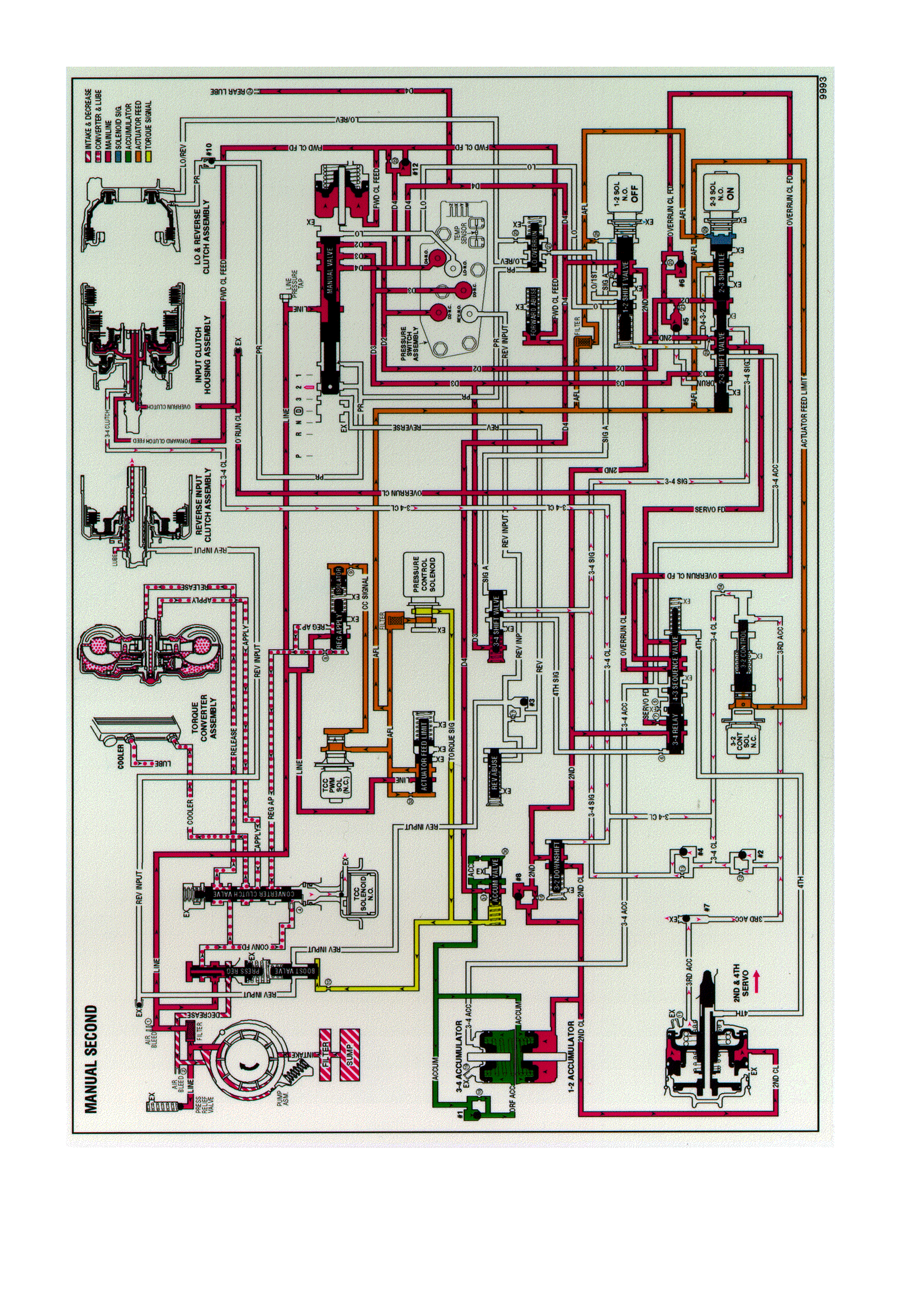
MANUAL SECOND GEAR
Figure 7C3-16 Manual Second Gear

A manual 3-2 downshift can be accomplished by moving the gear selector lever into the Manual.
Second (2) position when the transmission is operating in third gear. This causes the transmission to shift
immediately into second gear regardless of vehicle operating conditions. Also, the transmission is prevented from
operating in any other gear, first, third or fourth. The following information explains the additional changes during a
manual 3-2 downshift, as compared to a forced 3-2 downshift.
MANUAL VALVE
The selector lever moves the manual shaft and the manual valve into the manual second (2) position. This allows
the line pressure to enter the D2 fluid circuit.
TRANSMISSION FLUID PRESSURE MANUAL VALVE POSITION SWITCH (TFP VAL. POSITION SW.)
ASSEMBLY
The D2 fluid is routed to the TFP Val. Position Sw. where it opens the normally closed D2 fluid pressure switch.
With the D2 and the D3 pressure switches closed and the D4 pressure switch open, the TFP Val. Position Sw.
signals the PCM that the transmission is operating in manual second.
THIRD AND FOURTH GEARS PREVENTED
2-3 Shift Solenoid
The PCM energises the 2-3 shift solenoid and the AFL fluid pressure holds the 2-3 shift valve in the downshift
position. This electronically prevents operation of the third and fourth gears.
2-3 Shift Valve Train
The D2 fluid is routed between the 2-3 shuttle and the 2-3 shift valves and causes the following:
Regardless of the operating conditions, the D2 fluid pressure holds the 2-3 shift valve in the downshift position
against the AFL fluid pressure.
The 2nd fluid is blocked from entering the 3-4 signal fluid circuit and the 3-4 signal fluid circuit is open to an exhaust
port at the valve.
The 3-4 clutch cannot apply with the 3-4 signal fluid exhausted. Therefore, third and fourth gears are hydraulically
prevented.
The 2nd fluid feeds the servo feed fluid circuit, but the 2nd fluid circuit has no function in manual second.
The AFL fluid is blocked by the 2-3 shift valve and the D432 fluid circuit is exhausted through the valve.
The overrun fluid is exhausted through the 2-3 shuttle valve.
1-2 SHIFT VALVE
The 1-2 solenoid is OFF, the signal A fluid exhausts through the solenoid and the spring force holds the valve in the
upshifted position.
FIRST GEAR PREVENTED
The prevention of first gear is controlled electronically by the PCM through the 1-2 shift solenoid. The PCM keeps
the 1-2 shift solenoid de-energised, regardless of the vehicle operating conditions when the TFP Val. Position Sw.
signals manual second gear range. This keeps signal A fluid exhausted and the spring force holds the 1-2 shift
valve in the upshift position.
OVERRUN CLUTCH REMAINS APPLIED
Overrun Clutch Feed Checkball (#5)
Orificed D2 fluid pressure seats the #5 checkball against the empty overrun clutch fluid circuit. This is done
simultaneously with the overrun clutch fluid exhausting so that there is a continuous fluid supply to the overrun
clutch feed fluid circuit.
Overrun Clutch Piston
A continuous supply of fluid pressure is routed to the piston in order to keep the overrun clutch plates applied.
TORQUE CONVERTER CLUTCH
The converter clutch is released prior to downshifting into manual second-second gear. Under normal operating
conditions, the TCC will not apply in second gear.
PRESSURE CONTROL SOLENOID
The PCM output signal to the pressure control solenoid increases the operating range of torque signal fluid
pressure in manual second. This provides the increased line pressure for the additional torque requirements during
the engine compression braking and increased engine loads.

MANUAL FIRST GEAR
Figure 7C3-17 Manual First Gear

A manual 2-1 downshift can be accomplished by moving the gear selector lever into the manual first (1) position
when the transmission is operating in second gear. The downshift to first gear is controlled electronically by the
PCM. The PCM will not energise the 1-2 shift solenoid to initiate the downshift until the vehicle speed is below
approximately 48 to 56 km/h. Above this speed, the transmission operates in a manual first-second gear state. The
following text explains the manual 2-1 downshift.
MANUAL VALVE
The selector lever moves the manual shaft and the manual valve into the manual first (1) position. This allows the
line pressure to enter the Lo fluid circuit.
TRANSMISSION FLUID PRESSURE MANUAL VALVE POSITION SWITCH (TFP VAL. POSITION SW.)
ASSEMBLY
Lo fluid is routed to the TFP Val. Position Sw. where it closes the normally open Lo pressure switch. The addition of
the lo pressure switch being closed signals to the PCM that manual first is selected.
2-3 SHIFT SOLENOID
In both first and second gears, this solenoid is energised and maintains the signal B fluid pressure at the solenoid
end of the 2-3 shift valve train.
2-3 SHIFT VALVE TRAIN
Held in the downshift position by the signal B fluid pressure from the solenoid, the valve train blocks the AFL fluid
from entering the D432 fluid circuit. The D432 fluid circuit is open to exhaust past the valve.
1-2 SHIFT SOLENOID
Below approximately 48 to 56 km/h (30 to 35 mph) the PCM energises the normally open solenoid. This blocks the
signal A fluid pressure from exhausting through the solenoid and creates the pressure in the signal A fluid circuit.
Above this speed, the PCM keeps the solenoid de-energised and the transmission operates in manual first-second
gear.
1-2 SHIFT VALVE
Signal A fluid pressure moves the valve against the spring force and into the downshift position. In this position, Lo
fluid from the manual valve is routed into the Lo/1st fluid circuit and D4 fluid is blocked from entering the 2nd fluid
circuit. The 2nd fluid exhausts through an orifice and an annulus exhaust port past the valve. This orifice (#26) helps
control the 2-4 band release during a 2-1 downshift.
2-4 BAND RELEASES
2-4 Servo Assembly
The 2nd clutch fluid, which was fed by the 2nd fluid, exhausts from the servo. This allows the spring force from the
servo cushion and the servo return springs to move the 2nd apply piston and apply the pin to release the 2-4 band.
These spring forces help control the 2-4 band release.
1-2 ACCUMULATOR ASSEMBLY
The 2nd clutch fluid also exhausts from the 1-2 accumulator assembly. The spring force and the accumulator fluid
pressure move the accumulator piston to assist the 2nd clutch fluid exhaust.
ACCUMULATOR VALVE
As the accumulator fluid is filling the 1-2 accumulator assembly, the accumulator valve regulates the D4 fluid into
the accumulator fluid circuit. This regulation biased by torque signal fluid pressure and spring force, helps control
the movement of the 1-2 accumulator piston. The 2nd clutch fluid exhaust, and the 2-4 band release.
1-2 UPSHIFT CHECKBALL (#8)
Exhausting the 2nd clutch fluid pressure unseats the ball and is routed through the 2nd fluid circuit.
CONVERTER CLUTCH SIGNAL VALVE
The 2nd fluid exhausts from the converter clutch signal valve. Refer to Park- Engine Running range for a
description of the TCC signal valve operation in first gear.
LO AND REVERSE CLUTCH APPLIES
Lo Overrun Valve
The Lo/1st fluid is regulated through the lo overrun valve and into the Lo/reverse fluid circuit in order to control the
Lo and reverse clutch apply.
LO AND REVERSE PISTON
The Lo/reverse fluid pressure acts on the inner area of the piston in order to move the piston and in order to apply
the lo and reverse clutch plates.

OVERRUN CLUTCH APPLIED
The overrun clutch remains applied in manual first in order to provide engine compression braking.
PRESSURE CONTROL SOLENOID
Similar to manual second, the PCM output signal to the pressure control solenoid increases the operating range of
the torque signal fluid pressure. This provides the increased line pressure for the additional torque requirements
during the engine compression braking and the increased engine loads.
3-2 DOWNSHIFT CONTROL SOLENOID A ND THE 3-2 CONTROL VALVE
In first gear the solenoid is OFF, the AFL fluid is blocked by the solenoid, and the 3-2 signal fluid exhausts through
the solenoid and the spring force opens the 3-2 control valve.
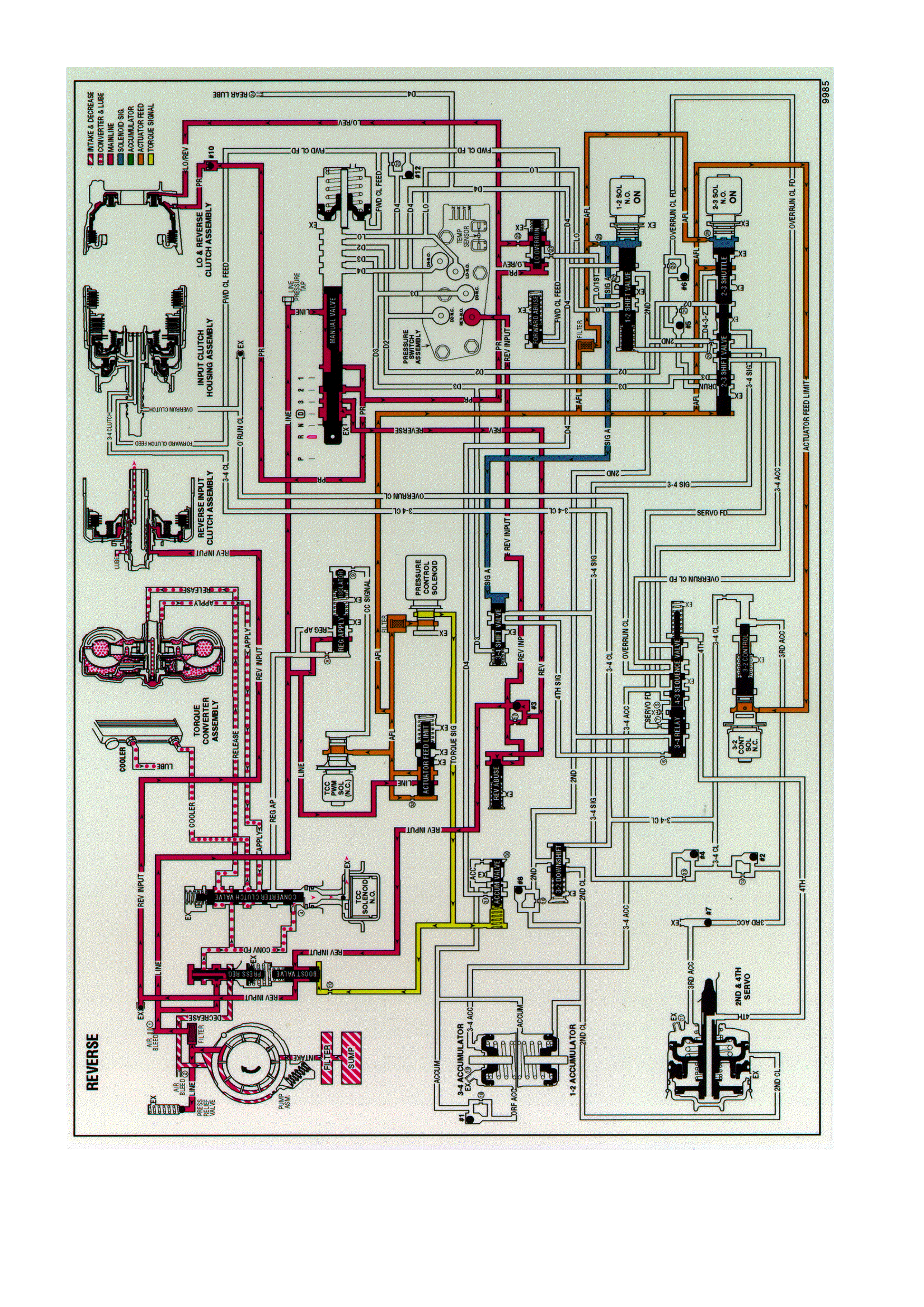
REVERSE
Figure 7C3-18 Reverse

When the gear selector lever is moved to the Reverse (R) position (from the Park position), the following changes
occur to the transmissions hydraulic and electrical systems:
MANUAL VALVE
The manual valve moves to the Reverse position and line pressure enters the reverse fluid circuit. As in Park, line
pressure also fills the PR (Park/Reverse) fluid circuit. All other fluid circuits are blocked by the manual valve.
LO AND REVERSE CLUTCH
As in Park, PR fluid pressure acts on the outer area of the lo and reverse clutch piston to apply the lo and reverse
clutch. Also, Lo/reverse fluid from the lo overrun valve acts on the inner area of the piston to increase the holding
capacity of the clutch (see Note below).
REVERSE INPUT CHECKBALL (#3)
Reverse fluid pressure seats the #3 checkball, flows through orifice #17 and fills the reverse input fluid circuit. This
orifice helps control the reverse input clutch apply rate when engine speed is at idle.
REVERSE ABUSE VALVE
Reverse fluid pressure acts on the end of the valve opposite of spring force. At engine speeds above idle, reverse
fluid pressure, which is fed by line pressure, increases and moves the valve against spring force (as shown).
Reverse fluid can then fill the reverse input fluid circuit through the reverse abuse valve. This bypasses the control
of orifice #17 and provides a faster clutch apply.
BOOST VALVE
Reverse input fluid pressure moves the boost valve against the pressure regulator valve spring. The spring acts on
the pressure regulator valve to increase the operating range of line pressure in Reverse. Reverse input fluid also
flows through the valve and to the reverse input clutch piston. Remember that torque signal fluid pressure
continually acts on the boost valve to control line pressure in response to vehicle operating conditions.
REVERSE INPUT CLUTCH PISTON
Reverse input fluid pressure moves the piston to apply the reverse input clutch plates and obtain Reverse.
REVERSE INPUT AIR BLEED CHECKBALL
This ball and capsule is located in the reverse input fluid circuit in the oil pump to provide an air escape when the
fluid pressure increases. It also allows air into the circuit to displace the fluid when the clutch releases.
TRANSMISSION FLUID PRESSURE MANUAL VALVE POSITION SWITCH (TFP VAL. POSITION SW.)
ASSEMBLY
Reverse input fluid pressure closes the normally open reverse switch in the TFP Val. Position Sw. This signals the
PCM that the manual valve is in the Reverse (R) position.
SHIFT SOLENOIDS (1-2 AND 2-3)
Both solenoids are energised as in the Park range. Signal A and signal B fluids are blocked from exhausting
through the shift solenoids to maintain fluid pressure in these circuits at the end of the shift valves.
SHIFT VALVES (1-2, 2-3 AND 3-4)
Signal A fluid pressure holds the 1-2 shift valve in the downshifted position and the 3-4 shift valve in the upshifted
(First and Fourth gear) position. Signal B fluid pressure from the 2-3 solenoid shift holds the 2-3 shift valve train in
the downshifted position.
PRESSURE CONTROL SOLENOID
The pressure control solenoid continues to regulate AFL fluid into torque signal fluid pressure. The PCM varies the
current at the solenoid to regulate torque signal fluid pressure in response to throttle position and other PCM input
signals. Torque signal fluid pressure is used to control line pressure at the boost and pressure regulator valves.
NOTE:
The explanation in each gear range is, for the most part, limited.
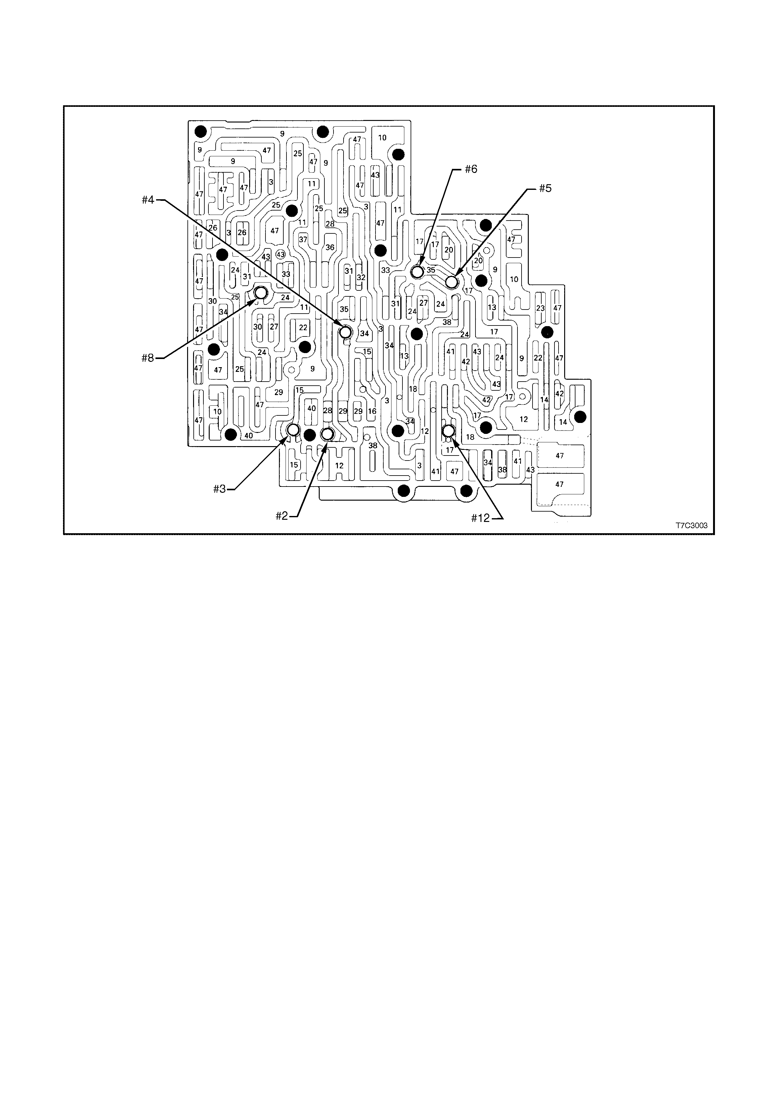
5. HYDRAULIC PATHS IN TRANSMISSION COMPONENTS
CONTROL VALVE BODY PASSAGES AND CHECKBALL LOCATIONS
#2 Checkball (61) 15. Reverse 31. Servo Feed
#3 Checkball (61) 16. Reverse Input (Rev. Cl.) 32. 4th
#4 Checkball (61) 17. D4 33. 3- 4 Accumulator
#5 Checkball (61) 18. Forward Clutch Feed 34. D3
#6 Checkball (61) 20. Accumulator 35. Overrun
#8 Checkball (61) 22. Signal A 36. Overrun Clutch Feed
#12 Checkball (61) 23. Signal B 37. Overrun Clutch
3. Line 24. 2nd 38. D2
9. Actuator Feed Limit 25. 2nd Clutch 40. 3 - 2 Signal
10. Filtered Actuator Feed 26. CC Signal 41. Low
11. Torque Signal 27. 3 - 4 Signal 42. Low/1st
12. PR 28. 3rd Accumulator 43. Exhaust
13. D4 - 3 - 2 29. 3 - 4 Clutch 47. Void
14. Low/Reverse 30. 4th Signal
Figure 7C3-19 Control Valve Body Passages and Checkball Locations
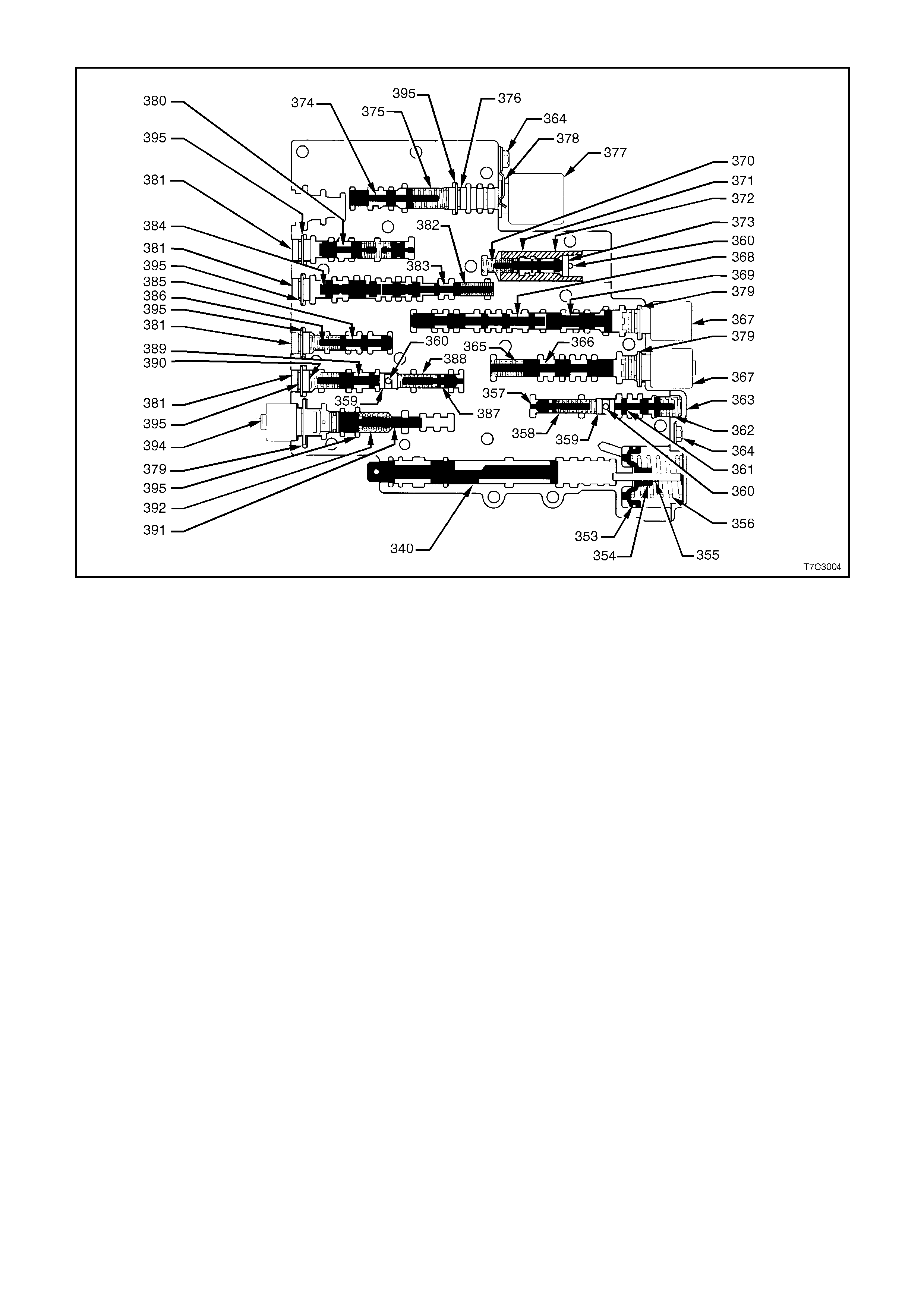
CONTROL VALVE BODY VALVE TRAINS
340. Valve, Manual 367. 2-3 Shift Solenoid 383. Valve, 4-3 Sequence
353. Seal, Forward Accumulator Oil 368. Valve, 2-3 Shift 384. Valve, 3-4 Relay
354. Piston, Forward Accumulator 369. Valve, 2-3 Shuttle 385. Valve, 3-4 Shift
355. Pin, Forward Accumulator 370. Spring, 1-2 Accumulator Valve 386. Spring, 3-4 Shift Valve
356. Spring, Forward Accumulator 371. Valve, 1-2 Accumulator 387. Valve, Reverse Abuse
357. Valve, Forward Abuse 372. Sleeve, 1-2 Accumulator Valve 388. Spring, Reverse Abuse
Valve
358. Spring, Forward Abuse Valve 374. Valve, Actuator Feed Limit 389. Valve, 3-2 Downshift
359. Plug, Bore 375. Spring, Actuator Feed
Limit Valve 390. Spring, 3-2 Downshift
Valve
360. Pin, Coiled Spring 376. Plug, Bore 391. Valve, 3-2 Control
361. Valve, Low Overrun 377. Pressure Control Solenoid 392. Spring, 3-2 Control Valve
362. Spring, Low Overrun Valve 378. Retainer, Pressure Control
Solenoid 394. 3-2 Control Solenoid
363. Cover, Forward Accumulator 379. Retainer, Solenoid 395. Retainer, Bore Plug
364. Bolt, Forward Accumulator Cover 380. Valve, Converter Clutch Signal 397. Spring
365. Spring, 1-2 Shift Valve 381. Plug, Bore 398. Valve
366. Valve, 1-2 Shift 382. Spring, 4-3 Sequence Valve
Figure 7C3-20 Control Valve Body Valve Trains
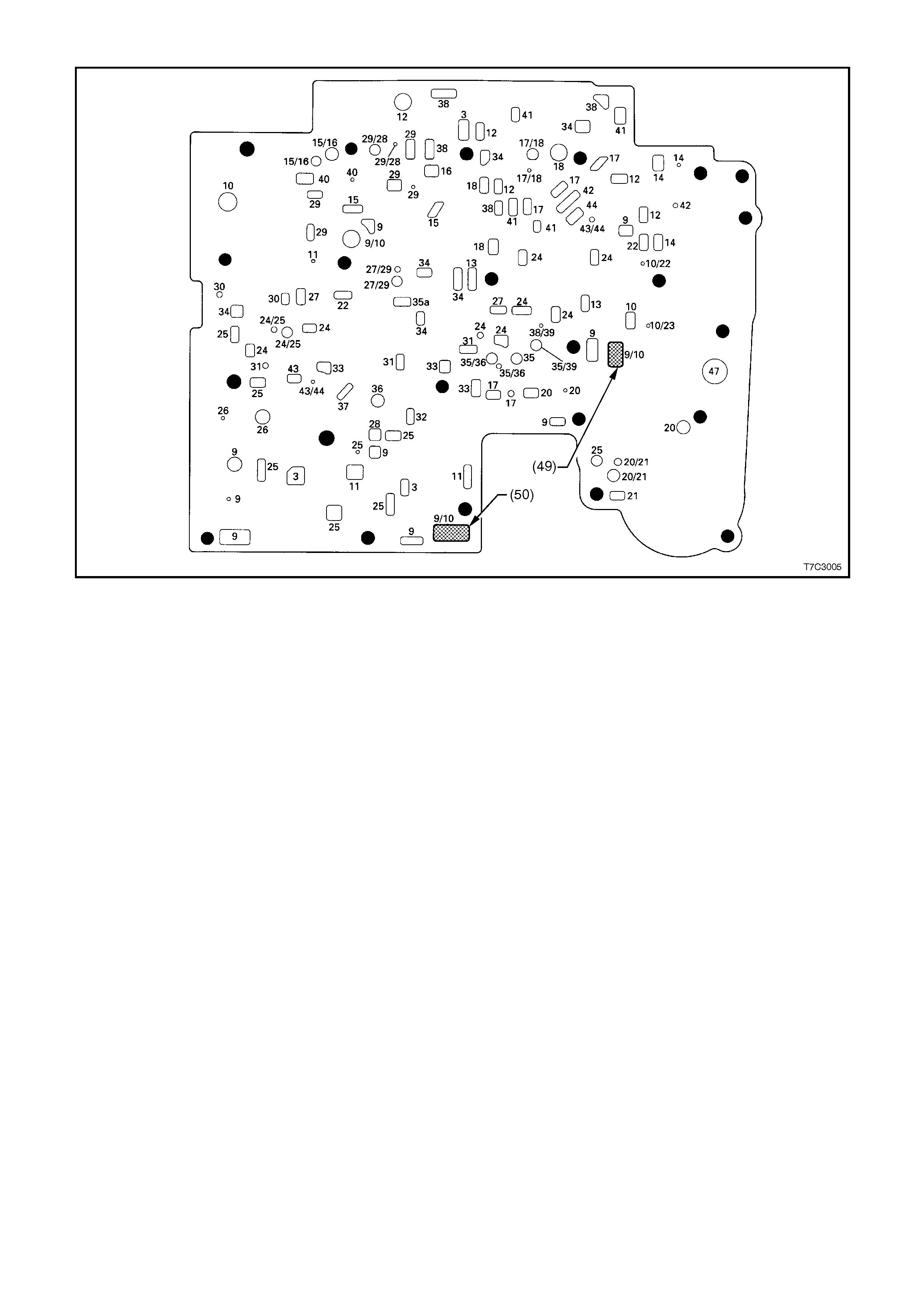
SPACER PLATE PASSAGES
49. Screen, Shift Solenoids 18. Forward Clutch Feed 33. 3 - 4 Accumulator
50. Screen, Pressure Control Solenoid 20. Accumulator 34. D3
3. Line 20/21. Accumulator/Orificed
Accumulator 35a. Overrun
9. Actuator Feed Limit 21. Orificed Accumulator 35. Overrun
9/10. Actuator Feed Limit/ Filtered
Actuator Feed 22. Signal A 35/36. Overrun/Overrun Clutch
Feed
10. Filtered Actuator Feed 24. 2nd 35/39. Overrun/Orificed D2
10/22.Filtered Actuator Feed/Signal A 24/25. 2nd/2nd Clutch 36. Overrun Clutch Feed
10/23.Filtered Actuator Feed/Signal B 25. 2nd Clutch 37. Overrun Clutch
11. Torque Signal 26. CC Signal 38. D2
12. PR 27. 3 - 4 Signal 38/39. D2/Orificed D2
13. D4 - 3 - 2 27/29. 3 - 4 Signal 40. 3 - 2 Signal
14. Low/Reverse 28. 3rd Accumulator 41. Low
15. Reverse 29/28. 3 - 4 Clutch/3rd
Accumulator 42. Low/1st
15/16. Reverse/Reverse Input (Rev. Cl.) 29. 3 - 4 Clutch 43. Exhaust
16. Reverse Input (Rev. Cl.) 30. 4th Signal 43/44. Exhaust/Orificed Exhaust
17. D4 31. Servo Feed 44. Orificed Exhaust
17/18. D4 32. 4th 47. Void
Figure 7C3-21 Spacer Plate Passages
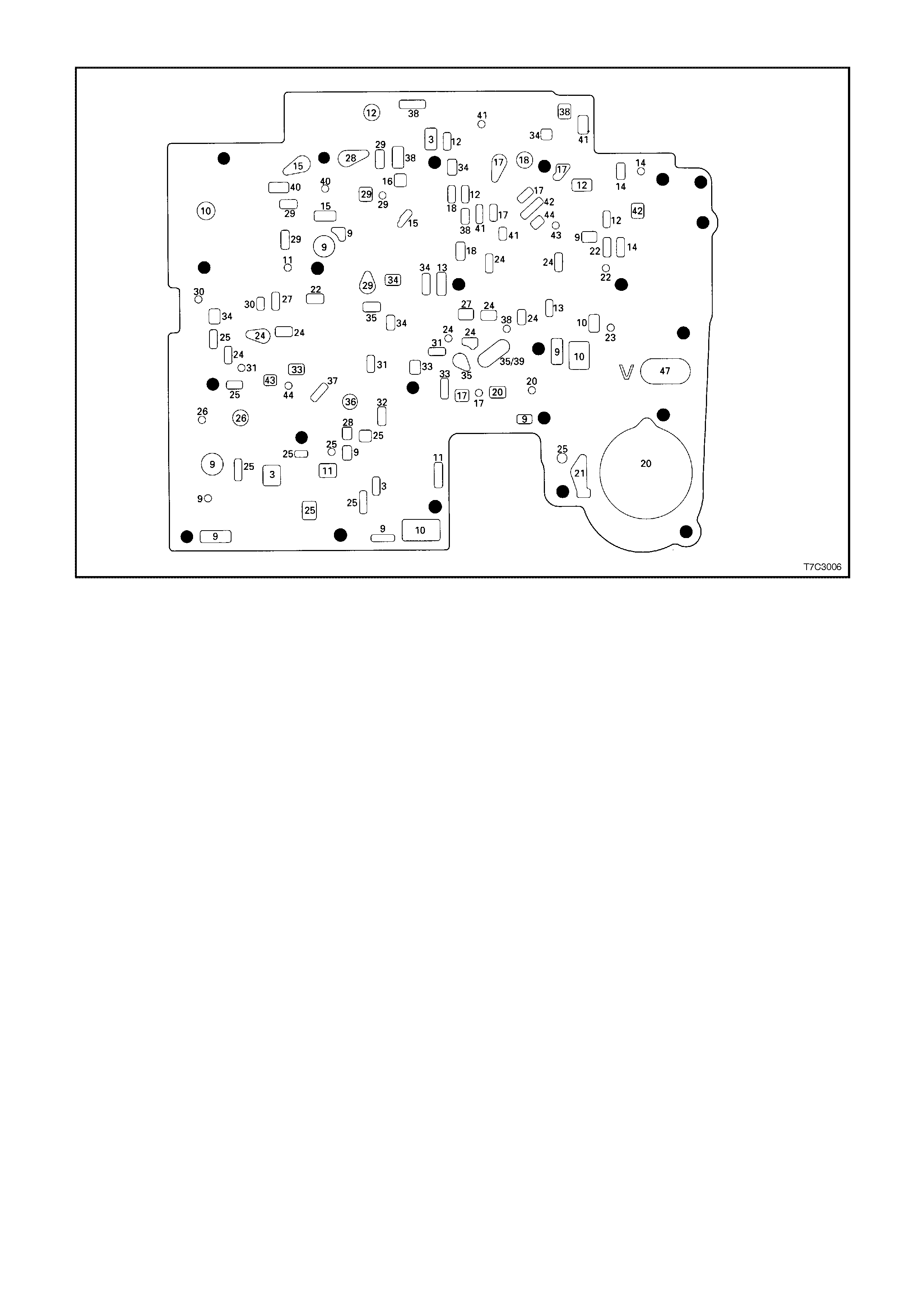
SPACER PLATE TO CONTROL VALVE BODY GASKET
3. Line 22. Signal A 35. Overrun
9. Actuator Feed Limit 23. Signal B 35/39. Overrun/Orificed D2
10. Filtered Actuator Feed 24. 2nd 36. Overrun Clutch Feed
11. Torque Signal 25. 2nd Clutch 37. Overrun Clutch
12. PR 26. CC Signal 38. D2
13. D4 - 3 - 2 27. 3 - 4 Signal 40. 3 - 2 Signal
14. Low/Reverse 28. 3rd Accumulator 41. Low
15. Reverse 29. 3 - 4 Clutch 42. Low/1st
16. Reverse Input (Rev. Cl.) 30. 4th Signal 43. Exhaust
17. D4 31. Servo Feed 44. Orificed Exhaust
18. Forward Clutch Feed 32. 4th 47. Void
20. Accumulator 33. 3 - 4 Accumulator
21. Orificed Accumulator 34. D3
Figure 7C3-22 Spacer Plate to Control Valve Body Gasket
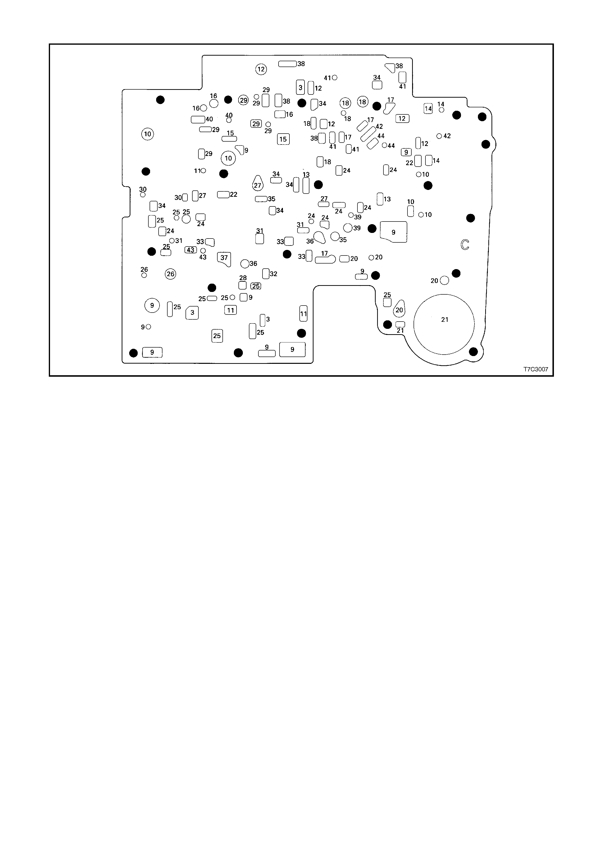
SPACER PLATE TO TRANSMISSION CASE GASKET
3. Line 21. Orificed Accumulator 34. D3
9. Actuator Feed Limit 22. Signal A 35. Overrun
10. Filtered Actuator Feed 24. 2nd 36. Overrun Clutch Feed
11. Torque Signal 25. 2nd Clutch 37. Overrun Clutch
12. PR 26. CC Signal 38. D2
13. D4 - 3 - 2 27. 3 - 4 Signal 39. Orificed D2
14. Low/Reverse 28. 3rd Accumulator 40. 3 - 2 Signal
15. Reverse 29. 3 - 4 Clutch 41. Low
16. Reverse Input (Rev. Cl.) 30. 4th Signal 42. Low/1st
17. D4 31. Servo Feed 43. Exhaust
18. Forward Clutch Feed 32. 4th 44. Orificed Exhaust
20. Accumulator 33. 3 - 4 Accumulator
Figure 7C3-23 Spacer Plate to Transmission Case Gasket
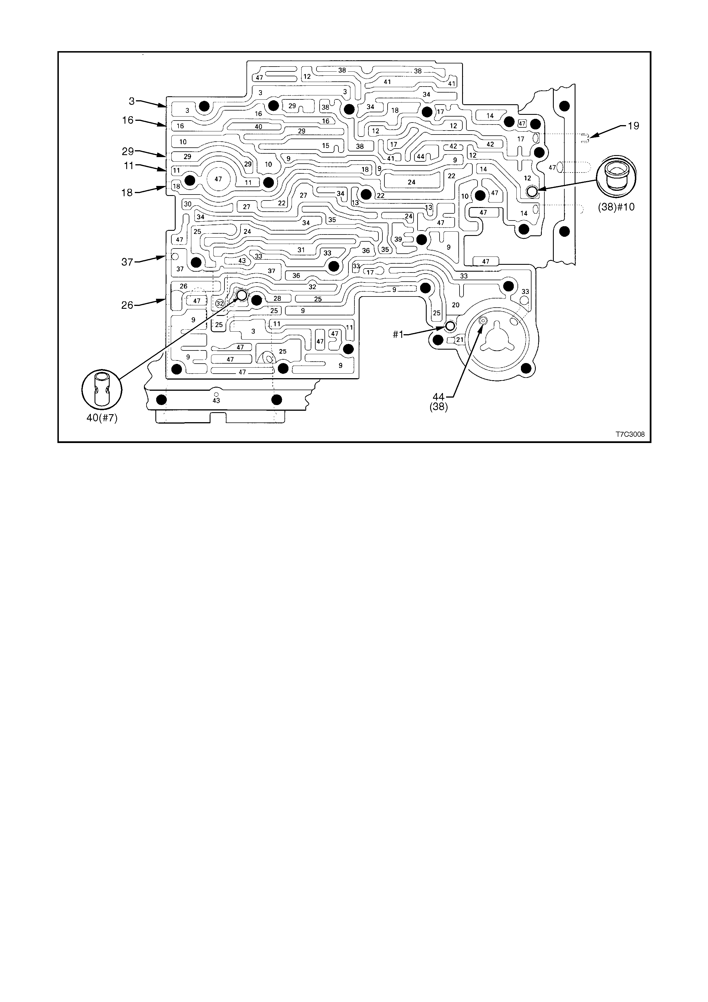
TRANSMISSION CASE FLUID PASSA GES AND CHECKBALL LOCATIONS
#1(61) Checkball 18. Forward Clutch Feed 33. 3 - 4 Accumulator
#7(40) 3rd Accum. Retainer and Ball
Assembly 19. Rear Lube 34. D3
#10(42) Checkball 20. Accumulator 35. Overrun
44(38) Accumulator Bleed Plug 21. Orificed Accumulator 36. Overrun Clutch Feed
3. Line 22. Signal A 37. Overrun Clutch
9. Actuator Feed Limit 24. 2nd 38. D2
10. Filtered Actuator Feed 25. 2nd Clutch 39. Orificed D2
11. Torque Signal 26. CC Signal 40. 3 - 2 Signal
12. PR 27. 3 - 4 Signal 41. Low
13. D4 - 3 - 2 28. 3rd Accumulator 42. Low/1st
14. Low/Reverse 29. 3 - 4 Clutch 43. Exhaust
15. Reverse 30. 4th Signal 44. Orificed Exhaust
16. Reverse Input (Rev. Cl.) 31. Servo Feed 47. Void
17. D4 32. 4th
Figure 7C3-24 Transmission Case Fluid Passages and Checkball Locations
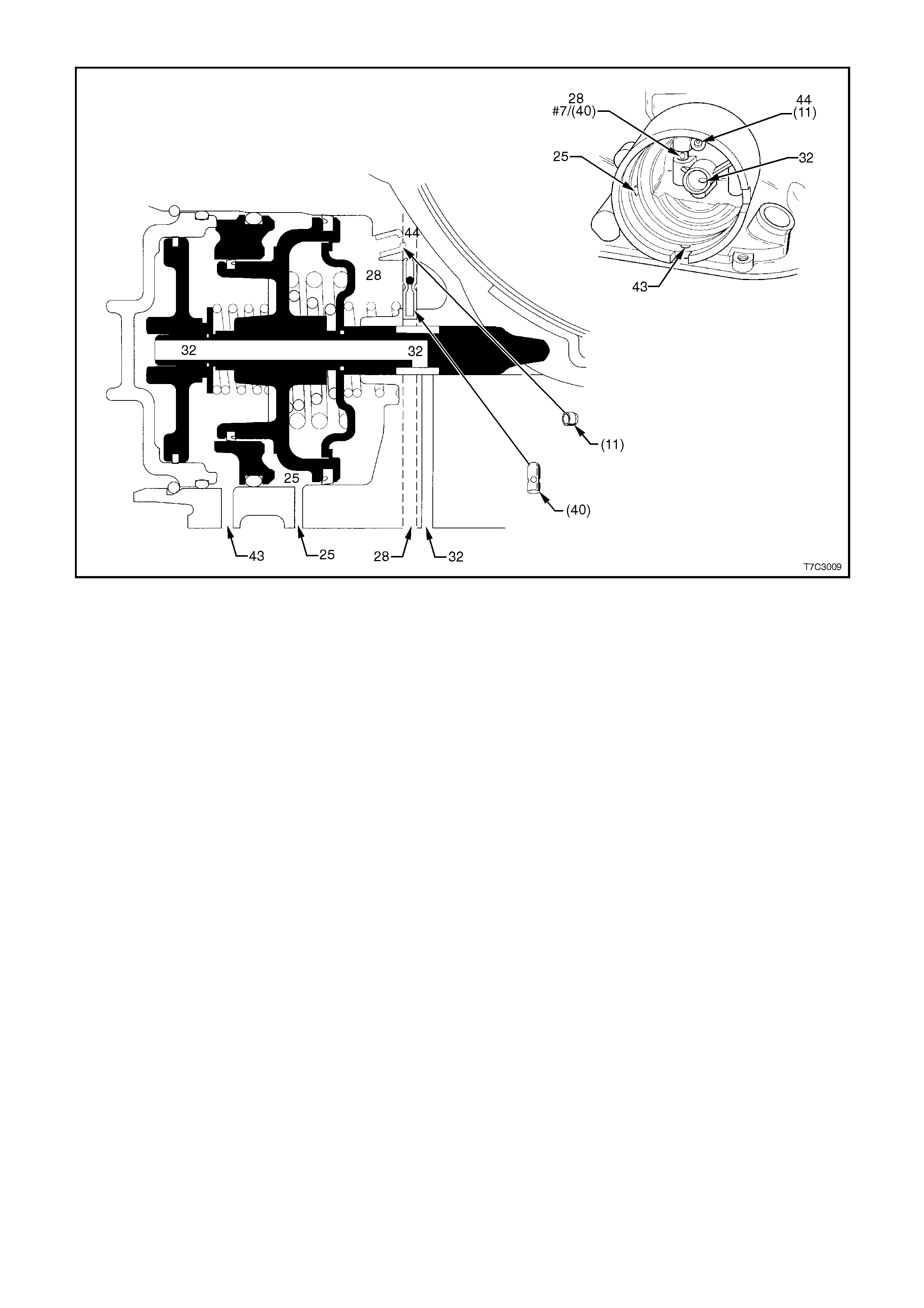
2-4 SERVO PASSAGES
11. Case Servo Orificed Plug 25. 2nd Clutch 43. Exhaust
40. 3rd Accum. Retainer and Ball Assembly (#7) 28. 3rd Accumulator 44. Orificed Exhaust
37(40) 3rd. Accum. Retainer and Ball Assembly 32. 4th
Figure 7C3-25 2-4 Servo Passages
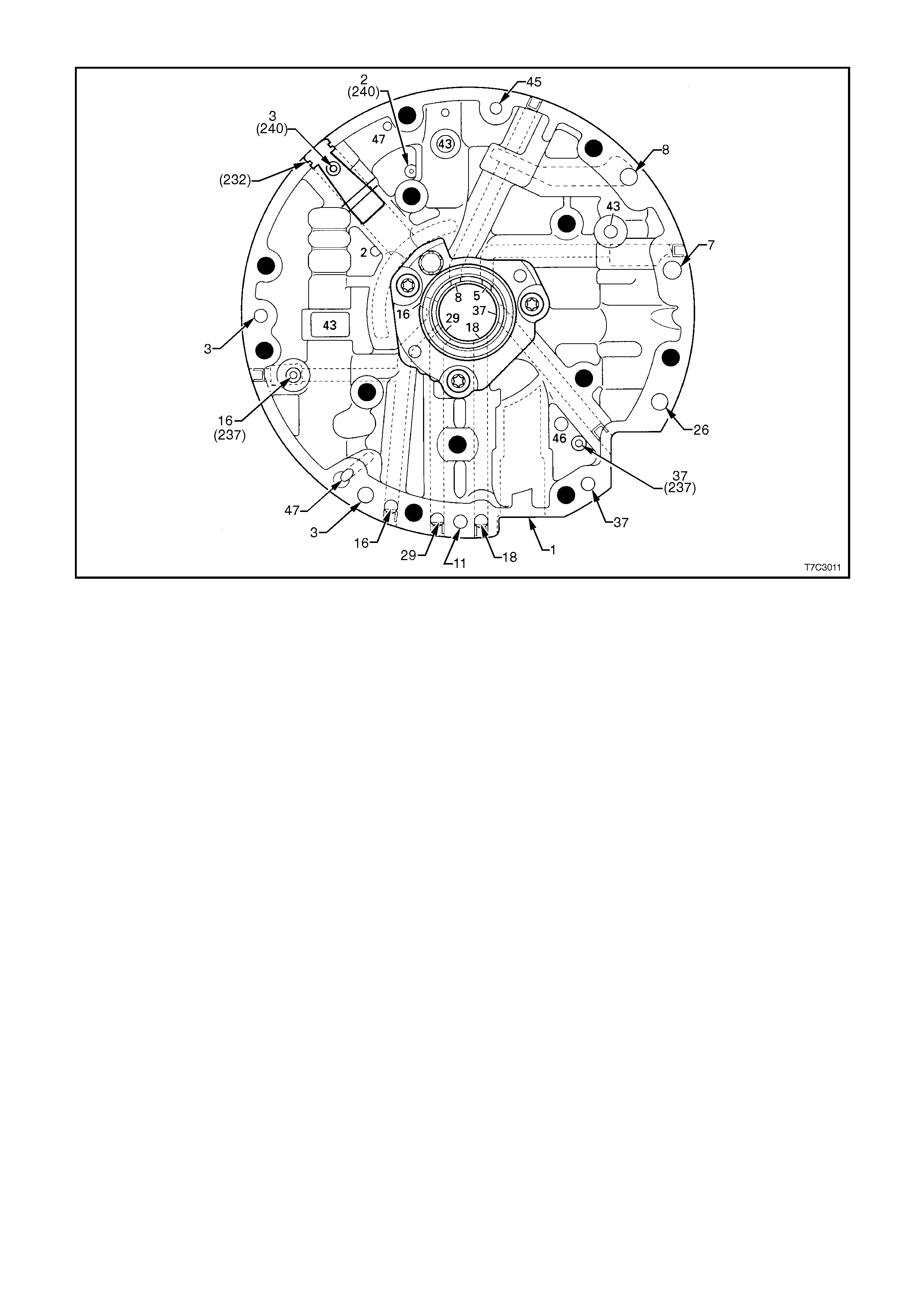
OIL PUMP COVER FLUID PASSA GES (TRANSMISSION CASE SIDE)
232. Oil Pump Cover Screen 7. To Cooler 37. Overrun Clutch
237. Check Valve Retainer and Ball Assembly 8. Lube from Cooler 43. Exhaust
240. Orificed Cup Plug 11. Torque Signal 45. Vent
1. Suction (Intake) 16. Reverse Input (Rev. Cl.) 46. Seal Drain
2. Decrease 18. Forward Clutch Feed 47. Void
3. Line 26. CC Clutch
5. Release 29. 3 - 4 Clutch
Figure 7C3-26 Oil Pump Cover Fluid Passages (Transmission Case Side)
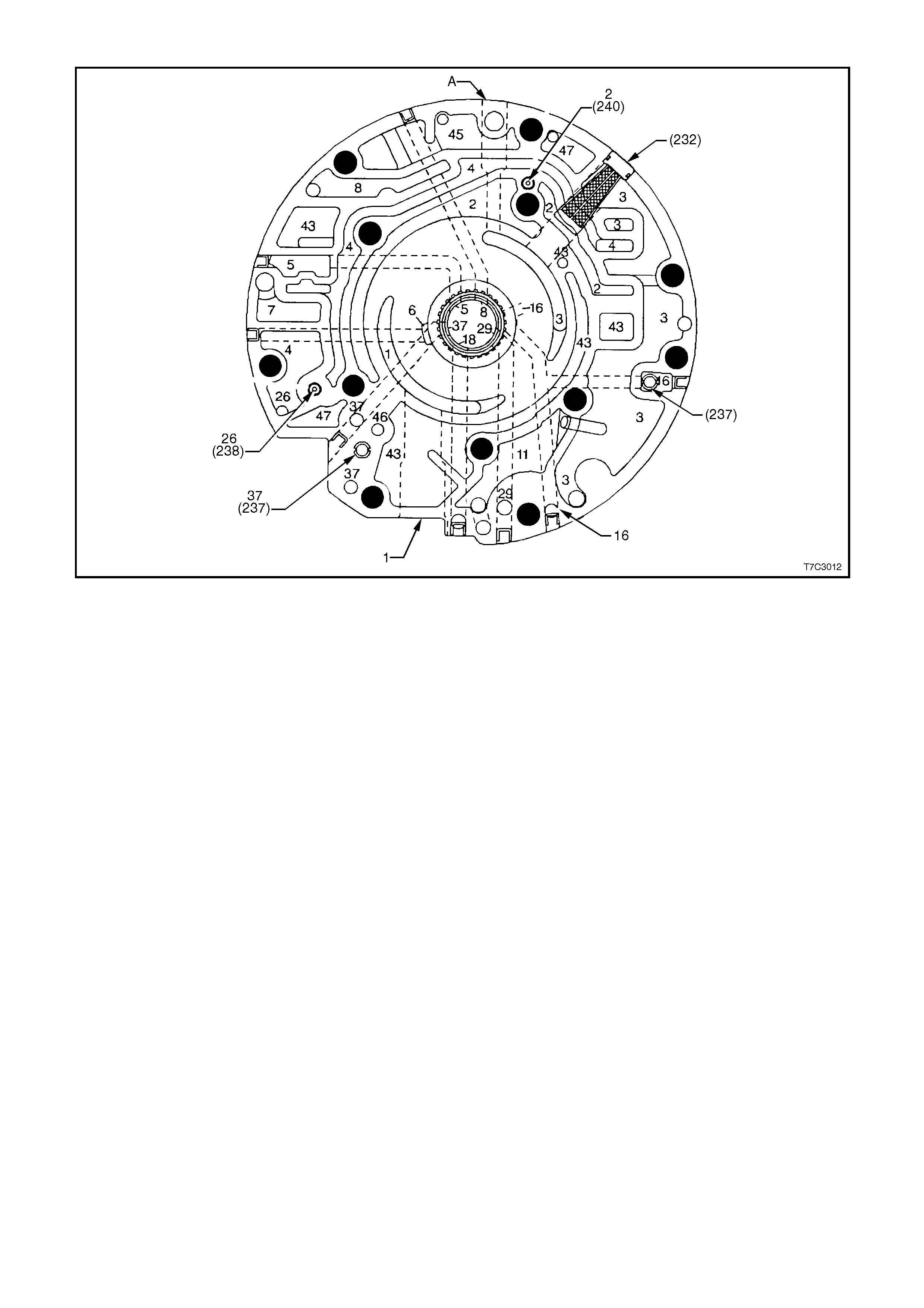
OIL PUMP COVER FLUID PASSAGES
1. Suction (Intake) 8. Lube from Cooler 37. Overrun Clutch
2. Decrease 11. Torque Signal 43. Exhaust
3. Line 16. Reverse Input 45. Vent
4. Converter Feed 18. Forward Clutch Feed 46. Seal Drain
5. Release 26. CC Clutch 47. Void
7. To Cooler 29. 3 - 4 Clutch
Figure 7C3-27 Oil Pump Cover Fluid Passages

OIL PUMP BODY FLUID PA SSAGES
1. Suction (Intake) 8. Lube from Cooler 37. Overrun Clutch
2. Decrease 11. Torque Signal 43. Exhaust
3. Line 16. Reverse Input 45. Vent
4. Converter Feed 26. CC Clutch 46. Seal Drain
5. Release 29. 3 - 4 Clutch 47. Void
7. To Cooler
Figure 7C3-28 Oil Pump Body Fluid Passages
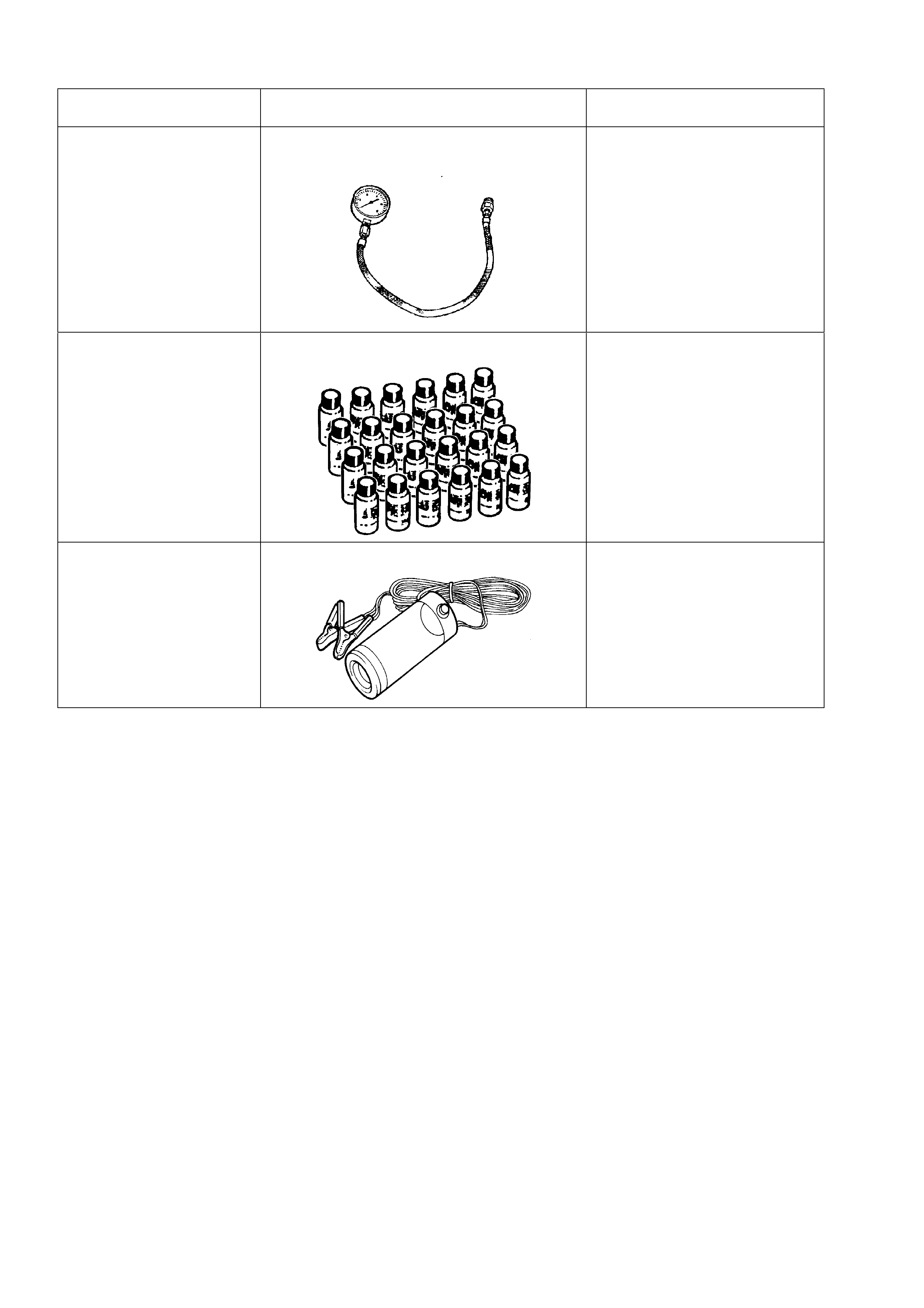
6. SPECIAL TOOLS
TOOL NO. REF IN TEXT TOOL DESCRIPTION COMMENTS
J21867 PRESSURE GAUGE AND HOSE
ASSEMBLY PREVIOUSLY RELEASED.
J28431-B FLUORESCENT OIL DYE PREVIOUSLY RELEASED.
SUPPLIED IN PACKS OF 24, 1
OZ BOTTLES. SUITABLE FOR
BLACK LIGHT TRACING OF
ENGINE, TRANSMISSION
AND POWER STEERING
FLUID LEAKS.
J42220 12 VOLT BLACK LIGHT PREVIOUSLY RELEASED.
USED WITH SPECIAL,
FLUORESCENT DYES FOR
TRACING A VARIETY OF
FLUID LEAKS.