
SECTION 7C5 - HYDRA-MATIC 4L60-E AUTOMATIC
TRANSMISSION: UNIT REPAIR
CAUTION:
This vehicle will be equipped with a Supplemental Restraint System (SRS). An SRS
will consist of either seat belt pre-tensioners and a driver's side air bag, or seat belt
pre-tensioners and a driver's and front passenger's side air bags. Refer to
CAUTIONS, Section 12M, before performing any service operation on or around any
SRS components, the steering mechanism or wiring. Failure to follow the CAUTIONS
could result in SRS deplo yment, resulting in possible p ersonal injury or unnecessary
SRS system repairs.
CAUTION:
This vehicle may be equipped with LPG (Liquefied Petroleum Gas. In the interests of
safety, the LPG fuel system should be isolated by turning ‘OFF’ the manual service
valve and then draining the LPG serv ice lines, before any service w ork is carried out
on the vehicle. Refer to the LPG leaflet included with the Owner's Handbook for
details or LPG Section 2 for more specific servicing information.
1. TRANSMISSION DISASSEMBLE
1.1 GENERAL SERVICE INFORMATION
The use of air powered tools to disassemble or reassemble this transmission is not recommended. Apart from the
fact that thread stripping is more likely when incorrect torque values are applied to fasteners, component parts can
be distorted to the point where malfunctions will occur.
Teflon Sealing Rings
If any sealing rings are found to be damaged, cut or do not rotate freely in their groove, check that the ring groove
has no trapped debris, is not burred or damaged in such a way that early failure of a replacement ring will occur.
Thrust Washer Surfaces
On inspection, thrust washer and thrust bearing surfaces may appear to be polished at points of contact. This is a
normal condition and should not be considered as damage, requiring replacement.
Techline
1.2 TRANSMISSION PREPARATION
1. Thoroughly clean exterior of transmission.
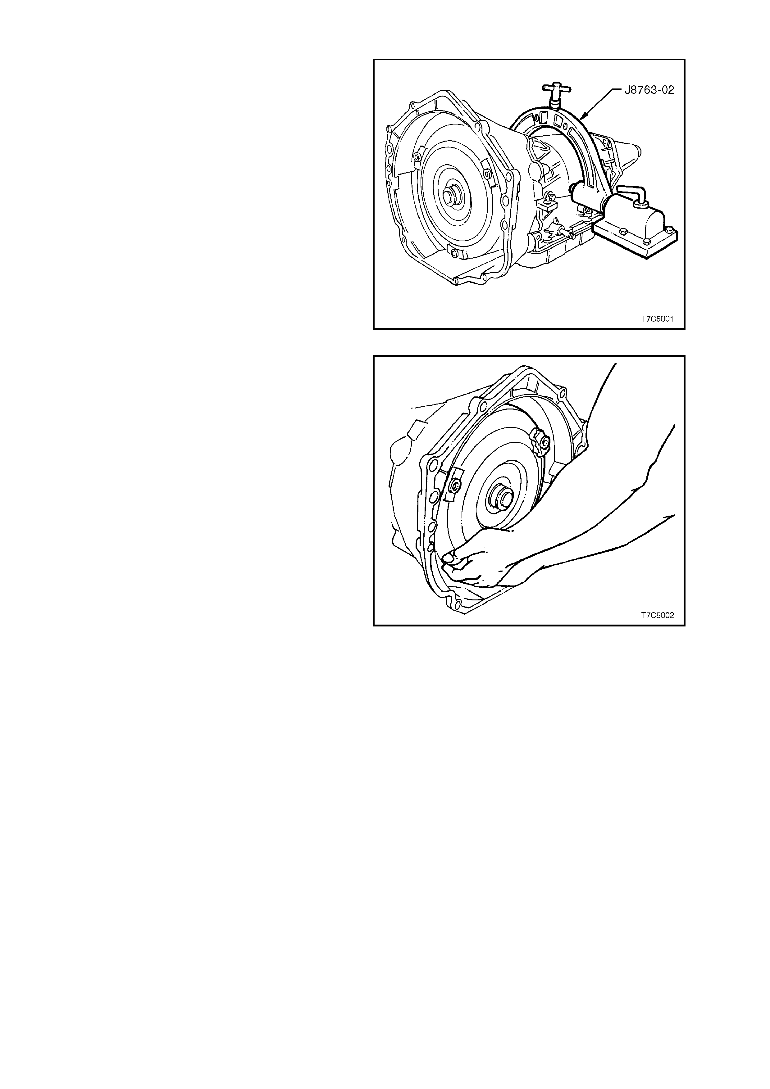
2. Install transmission holding fixture, E1363 (or
J8763-02) as shown. Note that the 2-4 Servo
should be facing away from the workbench.
NOTE:
If removal of the wiring harness is anticipated as
being necessary, the wiring harness connector
should be pushed into the case before fitting the
transmission holding fixture. This removal
operation can be achieved by pushing down
squarely on the wiring harness connec tor, us ing a 1
5/16" socket (¾" drive) to compress the connector
retaining lugs.
3. Rotate the transmission so that the converter
housing faces upward and drain the fluid from
the case extension.
Ensure that the container has the capacity to
hold at least 8 litres. Figure 7C5-1
4. Remove torque converter by sliding clear of
input shaft. Drain fluid into a suitable
container.
Figure 7C5-2

1.3 2-4 SERVO ASSEMBLY
REMOVE
1. Depress 2-4 servo cover (1) with a hammer
handle and hold.
2. Remove cover retainer ring.
Figure 7C5-3
3. To remove cover (28), either cut the O-ring
seal (not shown) and remove with thin nosed
pliers first, or stretch the O-ring by pulling it
through one of the two openings, while
removing the cover.
NOTE:
The four th apply piston (25) m ay com e out with the
cover (28) . If so, and the piston acc identally falls to
the floor, check that the teflon ring grooves have
not been damaged to the point where ring binding
and/or damage could occur.
4. Remove fourth apply piston (25) from second
apply piston assembly.
5. Remove second apply piston (17).
6. Remove servo return spring (12).
Figure 7C5-4
DISASSEMBLE
1. Remove servo pin retainer clip (24) from
second apply piston pin assembly.
2. Remove washer (23) and apply pin spring
(22).
3. Remove second apply piston pin (13).
Legend - 2nd Apply Piston Assembly
12 Spring, servo re turn
13 Pin, 2nd apply piston
14 Ring, retainer (2nd apply piston)
15 Retainer, servo cushion spring
16 Spring, servo cushion (outer)
105 Spring, servo cushion (inner) -
V6 engine only
17 Piston, 2nd apply
18 Ring, oil seal (2nd apply piston -
outer)
19 Ring, oil seal (2nd apply piston -
inner)
20 Housing, servo piston (inner)
21 Seal, O-ring
22 Spring, servo apply pin
23 Washer, servo apply pin
24 C-clip retainer, servo apply pin
Figure 7C5-5
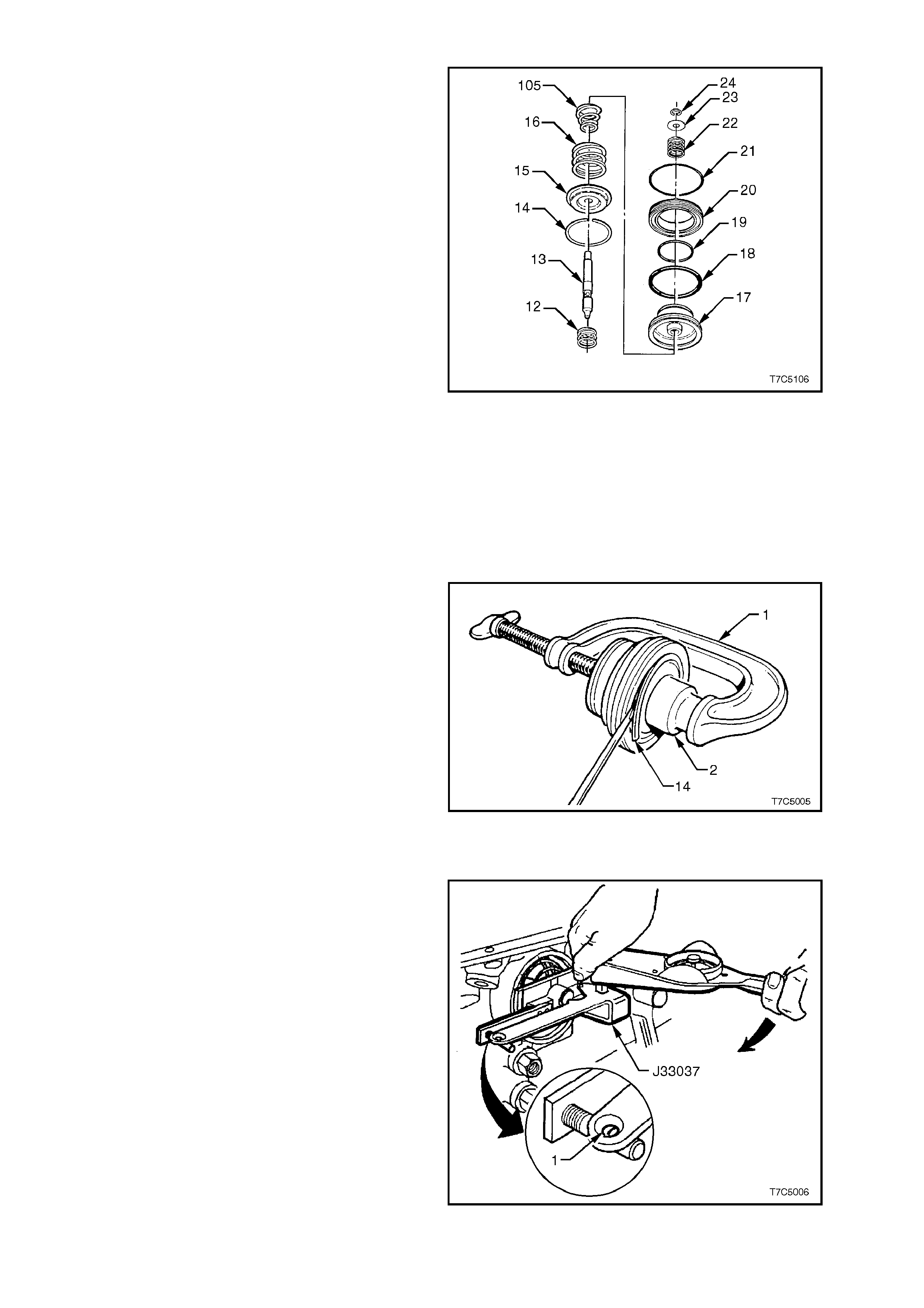
4. Fit a suitable G-clamp (1) and socket (2), to
the second apply piston assembly as shown.
5. Use this arrangement to compress piston
assembly.
6. Remove second apply piston retainer ring
(14).
7. Remove G-clamp and socket.
8. Remove cushion spring (16) and tapered
cushion spring (105) (V6 only) and retainer
(15).
Figure 7C5-6
SERVO PIN LENGTH
NOTE:
At this point, it is advisable to measure the servo
pin, installed length as described in the next four
steps. Should the pin prove to be too short or too
long, look closely at the 2-4 band and reverse input
drum for wear and/or damage, once the
transmission has been disassembled.
1. Install the pin, tapered end first.
2. Install Tool No. J33037 as s hown, and refit the
servo cover retaining ring, to hold the tool.
3. Apply 11 Nm torque. If white line appears in
gauge slot (1), pin length is correct.
4. Remove Tool No. J33037.
Figure 7C5-7
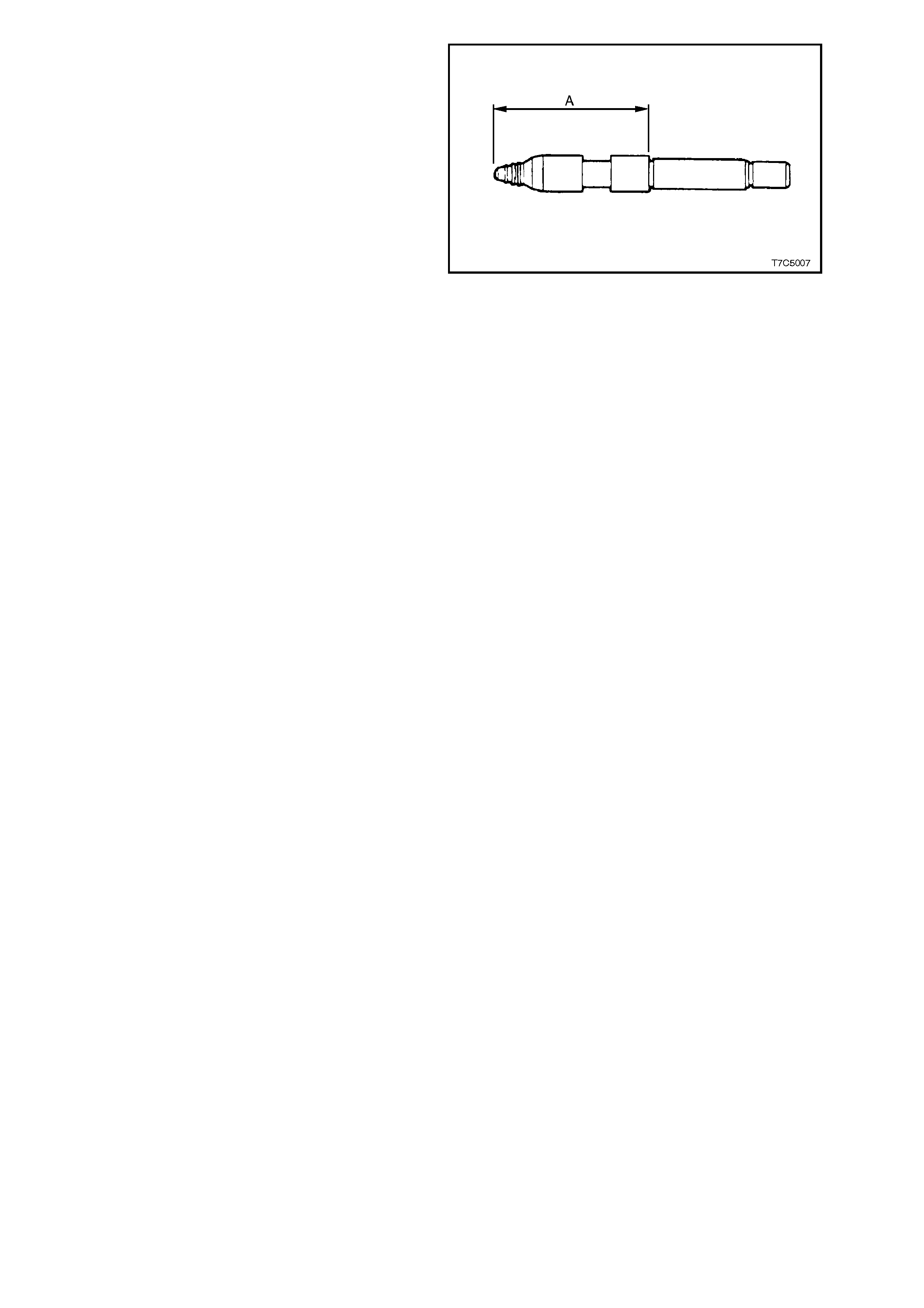
5. Measure the pin length ‘A’ and record.
6. If pin length is incorrect and requires
replacement, use selection chart to determine
correct pin length.
2 - 4 SERVO PIN SELECTION
PIN LENGTH (mm) IDENTIFICATION
65.82 - 66.12 2 RINGS
67.23 - 67.53 3 RINGS
68.64 - 68.94 WIDE BAND
Figure 7C5-8
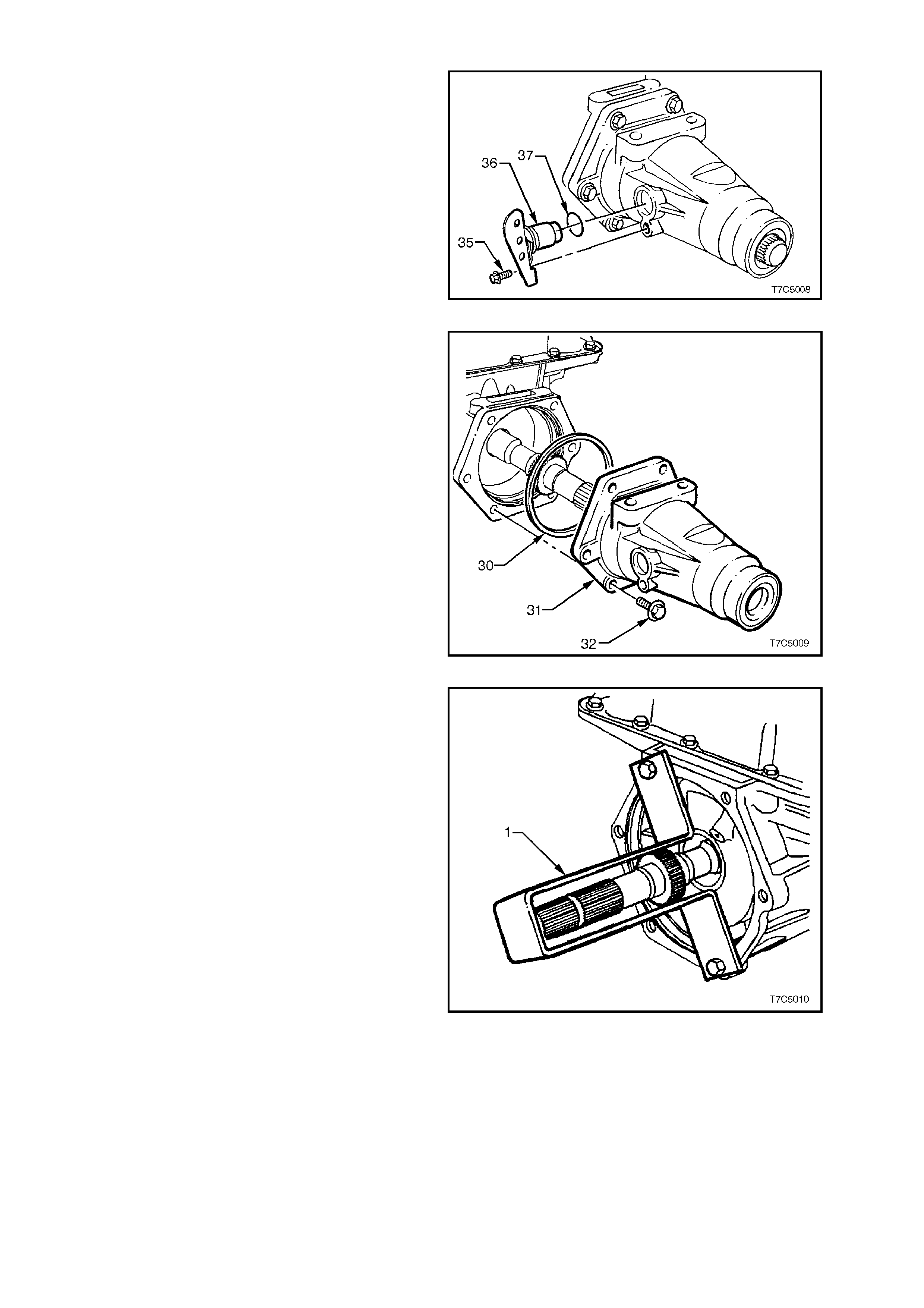
1.4 SPEED SENSOR AND CASE EXTENSION
1. Remove the speed sensor retaining bolt (35)
from the extension housing, then remove the
sensor (36) and O-ring (37).
NOTE:
No special tool is required for this operation.
Figure 7C5-9
2. If required, remove the case extension seal,
using a suitable seal removing tool, such as
E308 or similar.
3. Remove six case extension bolts (32).
4. W ithdraw case extension (31) and O-ring seal
(30).
Figure 7C5-10
5. To support and stop the output shaft from
falling from the transm ission at a later point in
the disassembly process, fabricate a support
brack et (1) fr om a s trip of suitable sheet m etal
(as shown). Install bracket using two case
extension bolts.
Figure 7C5-11

1.5 OIL PAN AND FILTER ASSEMBLY
1. Clean all dirt from around the oil pan, screws
and transmission case.
2. Remove all oil pan screws (76), the oil pan
(75), gasket (73) and magnet (not shown),
from the transmission case.
Figure 7C5-12
3. Lift the oil filter and twist to remove f r om the oil
pump body.
Open filter by prying the metal crimping away
from the top of the filter and pull apart. Ins pect
the filter material for particles that might
indicate the reason f or the tr ansmis sion failur e
(Not necessarily the cause!). Examples of the
type of material are;
- Clutch friction material.
- Bronze slivers, indicating bush wear.
- Steel particles.
Figure 7C5-13
4. Using suitable circlip pliers or a two-legged
puller and slide hammer, such as Litchfield
E6668 or other commercial equivalent,
remove the filter seal, taking care not to
damage the oil pump bore during the process.
NOTE:
If scratched, fluid leakage could occur from this
point, once the vehicle has been put back into
service.
Figure 7C5-14
1.6 CONTROL VALVE BODY AND WIRING HARNESS
NOTE:
If removal of the wiring harness is necessary, the
wiring harness connector should have been pus hed
into the case before fitting the transm ission holding
fixture.
After removing the holding fixture from the
transmission case, use a 1 5/16" socket (¾" drive)
and push down squarely on the wiring harness
connector, to compress the connector retaining
lugs.
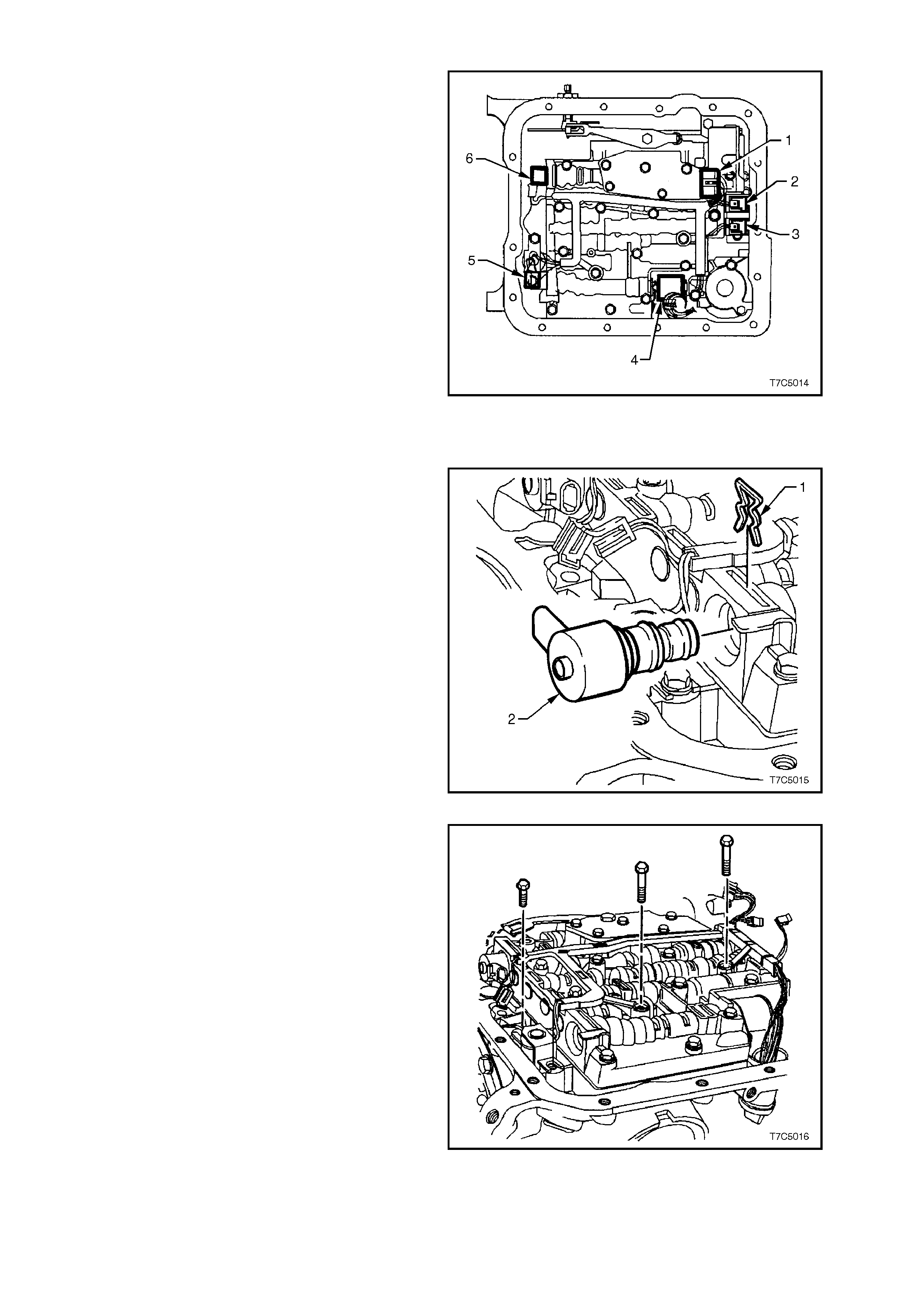
1. Disconnect wiring harness connectors from all
electrical components, except the Torque
Converter Clutch (TCC) Solenoid:
1. Pressure Switch Assembly (PSA).
2. 1-2 Shift Valve Solenoid
3. 2-3 Shift Valve Solenoid
4. Pressure Control Solenoid (PCS)
5. TCC Pulse Width Modulated (TCC PWM)
Solenoid
6. 3-2 Control Solenoid
Figure 7C5-15
2. Remove the TCC Pulse Width Modulated
(PWM) solenoid retainer clip (1), then the
solenoid (2).
Figure 7C5-16
3. Remove wiring harness retaining bolts from
the control valve body.
4. Remove two bolts holding the TCC solenoid
assembly.
Figure 7C5-17
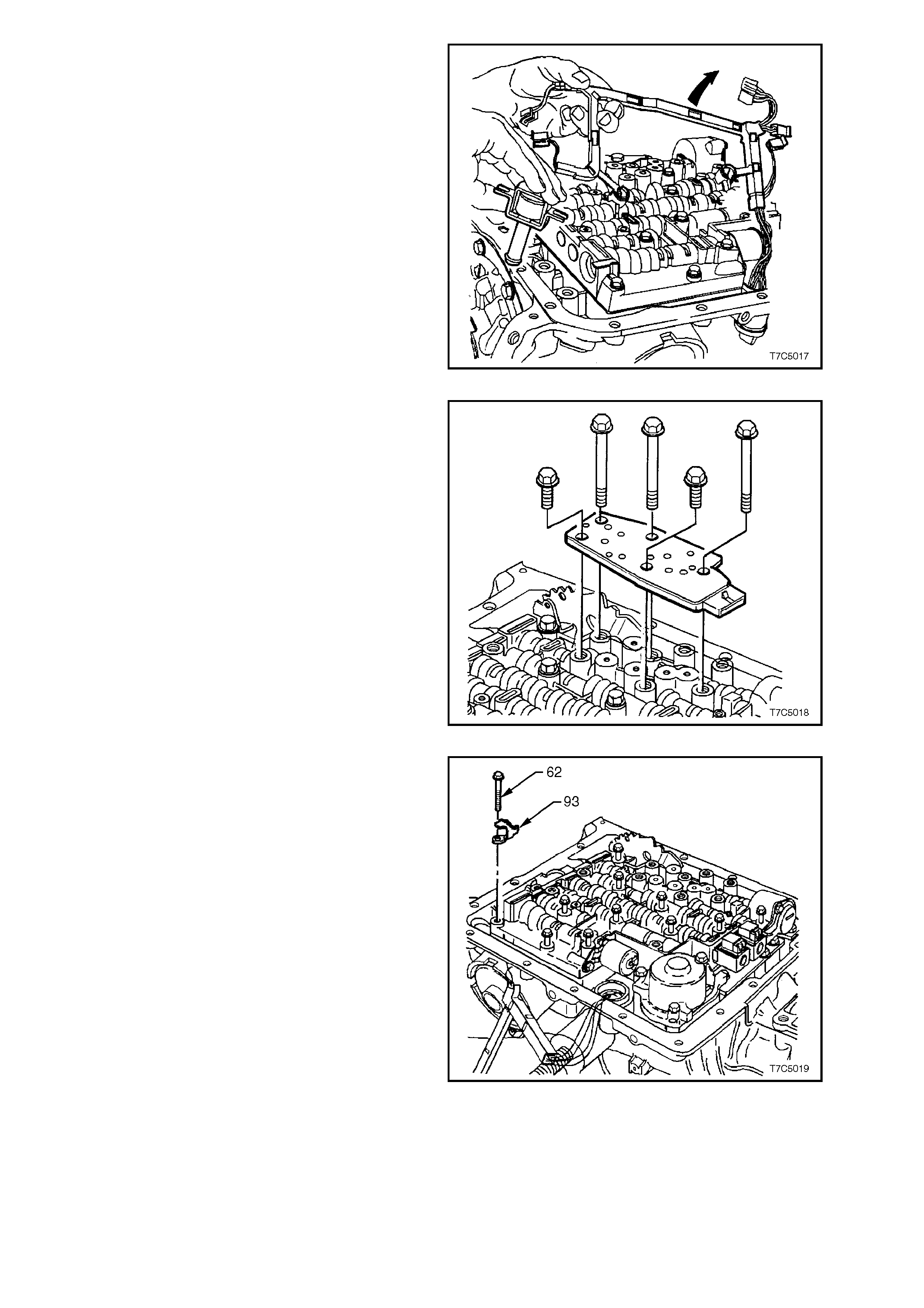
5. Lift the TCC solenoid assembly from oil pump.
6. Carefully drape the wiring harness over the
side of the transmiss ion cas e, af ter wrapping a
piece of lint free cloth around the wiring
harness to pr event chafing of the insulation on
the transmission oil pan rail.
NOTE:
If rem oval of the wiring harness /TCC Solenoid f rom
the transmission case is required, it will not be
possible until the control valve body has been
removed.
Figure 7C5-18
7. Remove the Transmission Range Fluid
Pressure Switch Assembly (PSA) retaining
bolts, then remove the PSA from the valve
body.
Figure 7C5-19
8. Remove the bolt securing the manual detent
spring.
9. Progressively loosen, then remove remaining
control valve bolts (62) and the fluid level
indicator stop bracket (93).
Figure 7C5-20
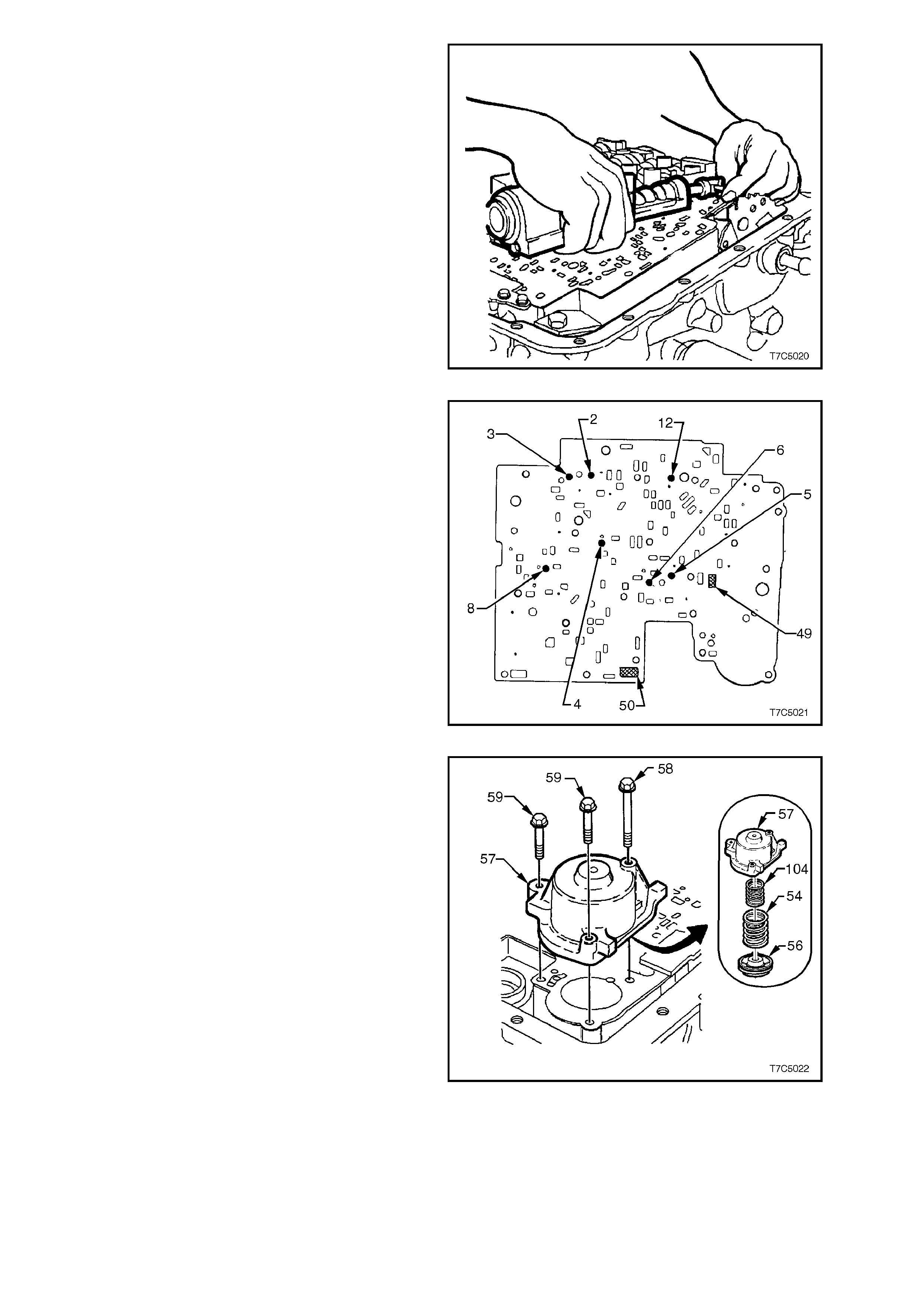
10. Rem ove control valve body assem bly by lifting
from the rear, s upporting the valve body in one
hand, while holding the manual valve link with
the other. As the valve body is being lifted,
rotate it slightly to release the manual valve
link from the manual valve.
11. Remove manual valve link from the inner
detent lever.
Figure 7C5-21
NOTE:
Take care not to lose the seven check balls that
are located under the control valve body. Shown
are the ball locations on the spacer plate after the
control valve body has been removed.
Figure 7C5-22
12. W hile holding the cover (57) down against 1-2
accumulator spring force (54/104),
progress ively loosen, then rem ove the three 1-
2 accumulator cover bolts ('58'x 1 and '59' x
2). Remove the cover (57), 1-2 accumulator
piston (56), two springs (54/105) and the pin
(not shown).
13. Remove the 1-2 accumulator piston (56) from
the cover, by applying low air pressure to the
oil drilling in the cover.
CAUTION:
To avoid the possibility of personal injury
and/or damage to the 1-2 accumulator piston,
do not use air pressure in excess of 70 kPa for
this operation.
14. Remove and discard the seal from the 1-2
accumulator piston.
15. Tag the outer 1-2 accumulator spring/s
(54/104) for correct reassembly. Figure 7C5-23
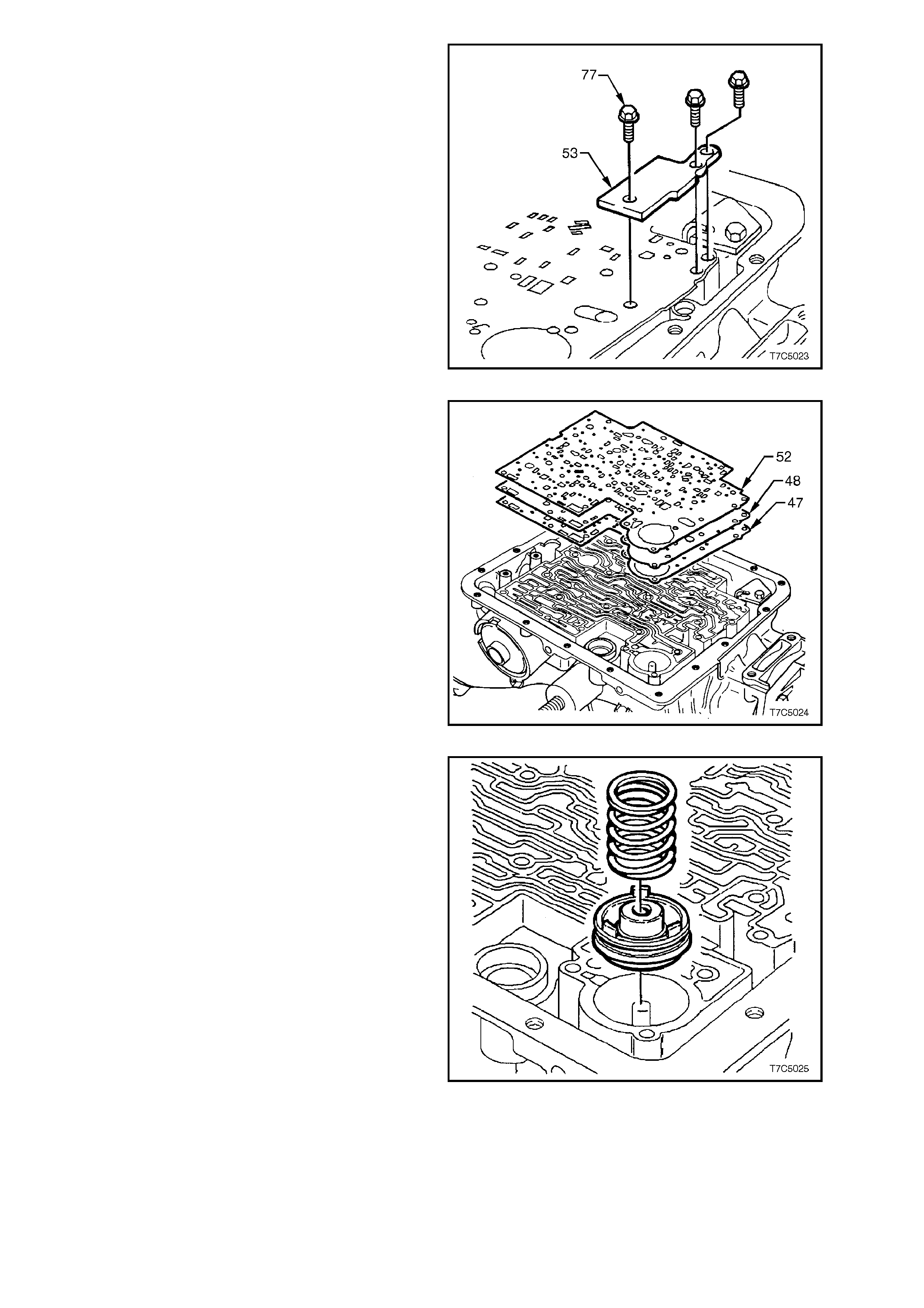
16. Remove the three spacer plate retaining bolts
(77) and plate (53).
Figure 7C5-24
17. Remove the spacer plate (48) and two spacer
plate gaskets (47/52) from the transmission
case.
Figure 7C5-25
18. Remove the 3-4 accumulator spring and tag
for correct reassembly.
19. Using flat blade snap ring pliers, remove the 3-
4 accumulator piston (44) from the
transm ission case, by rotating the piston while
pulling it from the case.
20. Remove and discard the seal from the 3-4
accumulator piston.
Figure 7C5-26
1.7 CONVERTER HOUSING
1. Rotate the transmission assembly until the
converter housing is facing upward as shown,
then lock the assembly in that position.
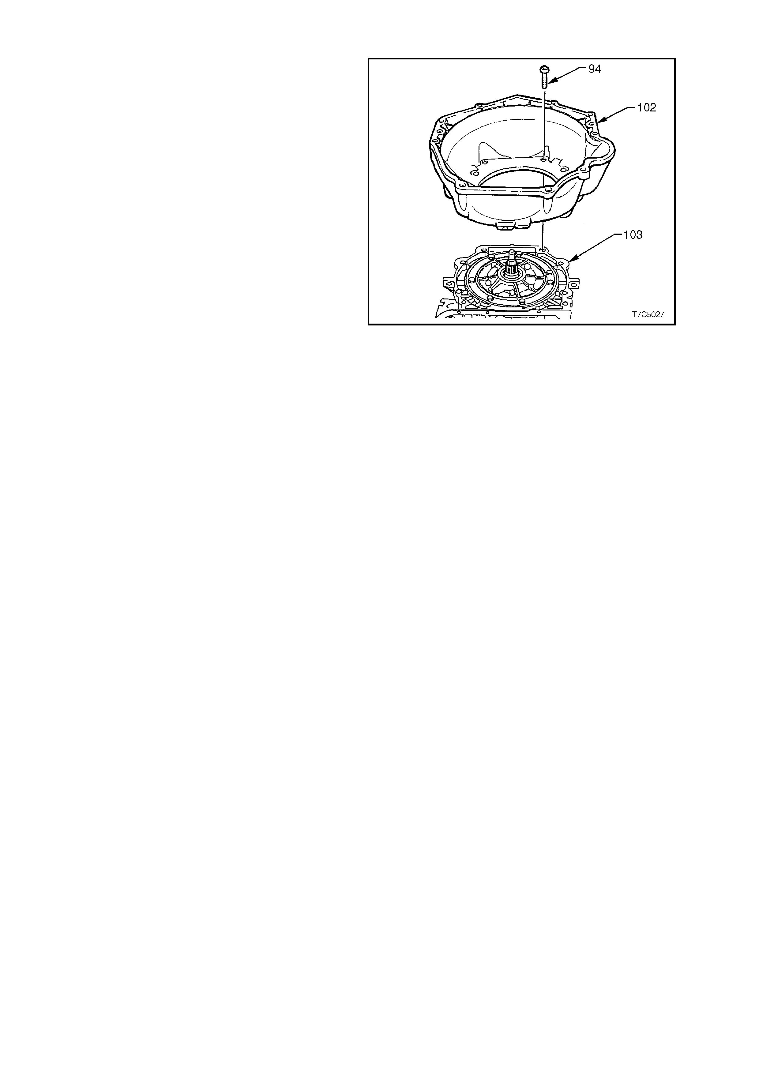
2. Using Torx Plus bit, Tool No. J41510 or
commercial equivalent, progressively loosen,
then remove the converter housing bolts (94).
NOTE:
Do not use a standard, # 50 Torx bit, as the bolt
design is such that only the Torx Plus bit is capable
of applying sufficient loosening torque without bolt
damage.
3. Remove the converter housing (102) from the
transmission case (103).
Figure 7C5-28
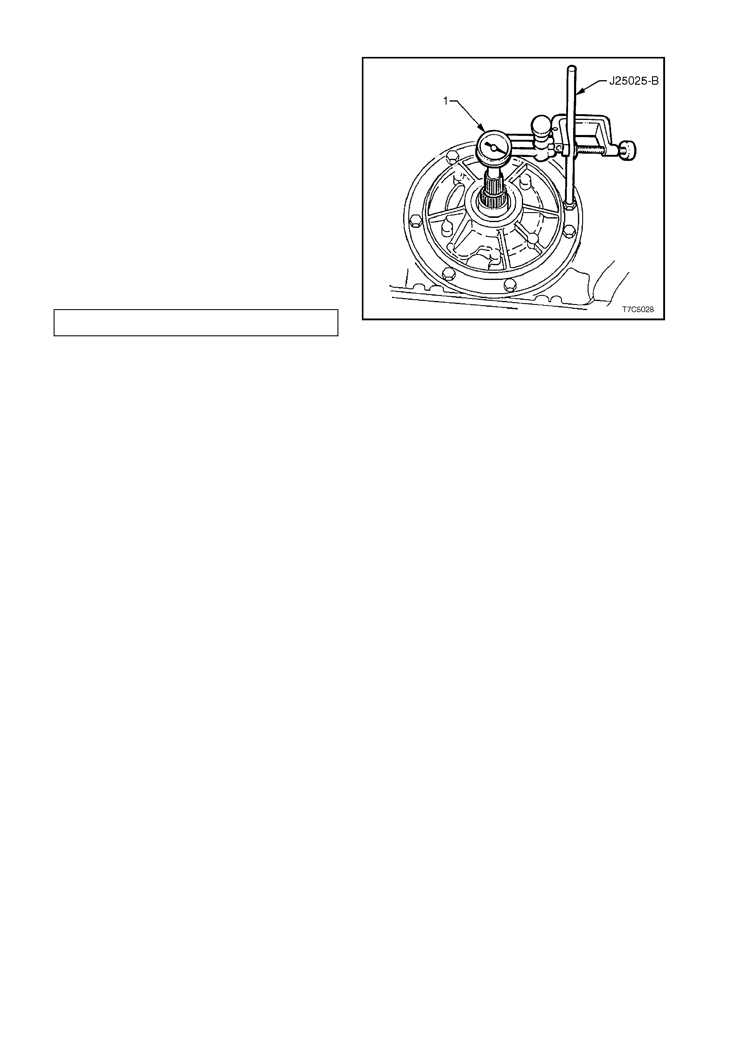
1.8 TRANSMISSION E ND P LAY CHECK
To assist in the diagnostic process, transmission
end play should be checked prior to removing
internal components. If the measured end play is
outside specifications, then a careful inspection for
worn or misassembled parts can then be made
during the disassembly process.
1. Leave the transmission with the input shaft in
a vertical position.
2. Remove an oil pump bolt and install Tool No.
J25025-B and locknut.
3. Install dial indicator (1) on Tool No. J25025-B
and set to zero in contact with end of input
shaft.
4. Pull up on input shaft by hand to m easure end
play.
TRANSMISSION END PLAY 0.13 - 0.92 mm
5. Remove Tool No. J25025-B and dial indicator. Figure 7C5-29
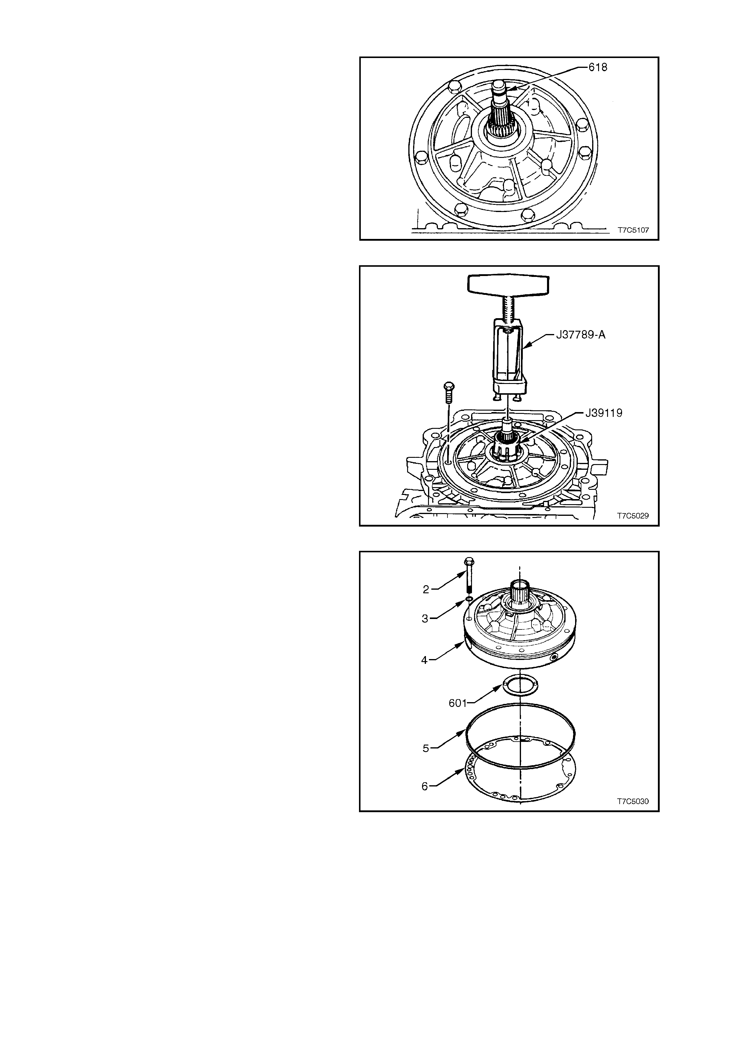
1.9 OIL PUMP ASSEMBLY
1. Remove input shaft O-ring (618) from the
turbine shaft (V8 input shaft is shown).
2. Prise the front helix seal retainer from the oil
pump housing.
3. Using a suitable seal removing tool, such as
E308 or similar, extract the seal and discard.
Figure 7C5-30
4. Remove remaining oil pump bolts and seals.
5. Slide Tool No. J39119 over the stator shaft
until it locks under the splines. Install Tool No.
J37789-A over J39119 and tighten the clamp
bolt. Unseat oil pump assem bly by turning the
forcing screw against the input shaft. Remove
the oil pump assembly from the transmission
case.
6. Remove special tools from the oil pump.
Figure 7C5-31
7. Remove oil pump to case seal (5) and gasket
(6).
8. Rem ove rever s e input clutc h to oil pump thrus t
washer (601).
Figure 7C5-32
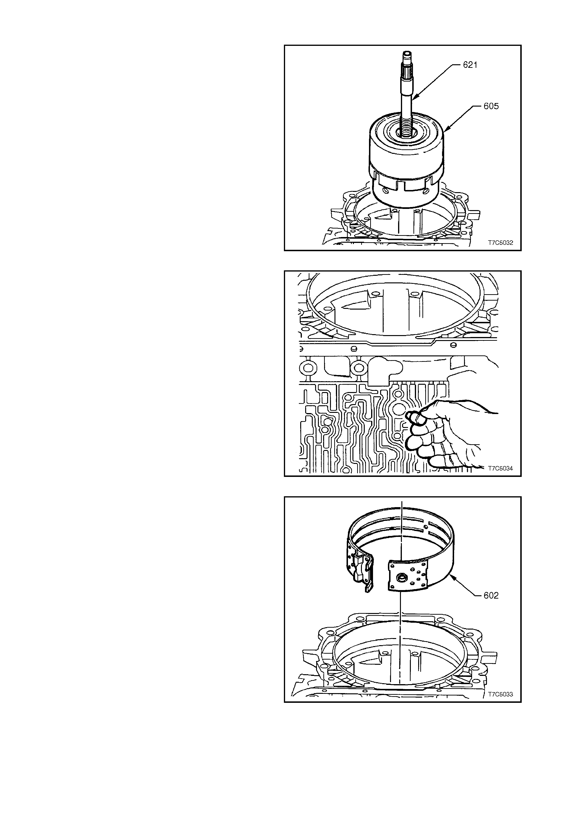
1.10 REVERSE INPUT CLUTCH, INPUT CLUTCH, 2-4 BAND AND INPUT GEAR SET
For a complete parts identification listing, refer to
Figure 7C5-37 and legend.
1. Remove reverse input clutch (605) and input
clutch assembly by grasping input shaft (621)
and withdrawing the assembly from
transmission case .
NOTE:
Take care, as this assembly is heavy.
Figure 7C5-33
2. Remove 2-4 band anchor pin from the
transmission case .
Figure 7C5-34
3. Remove 2-4 band assembly (602).
Figure 7C5-35
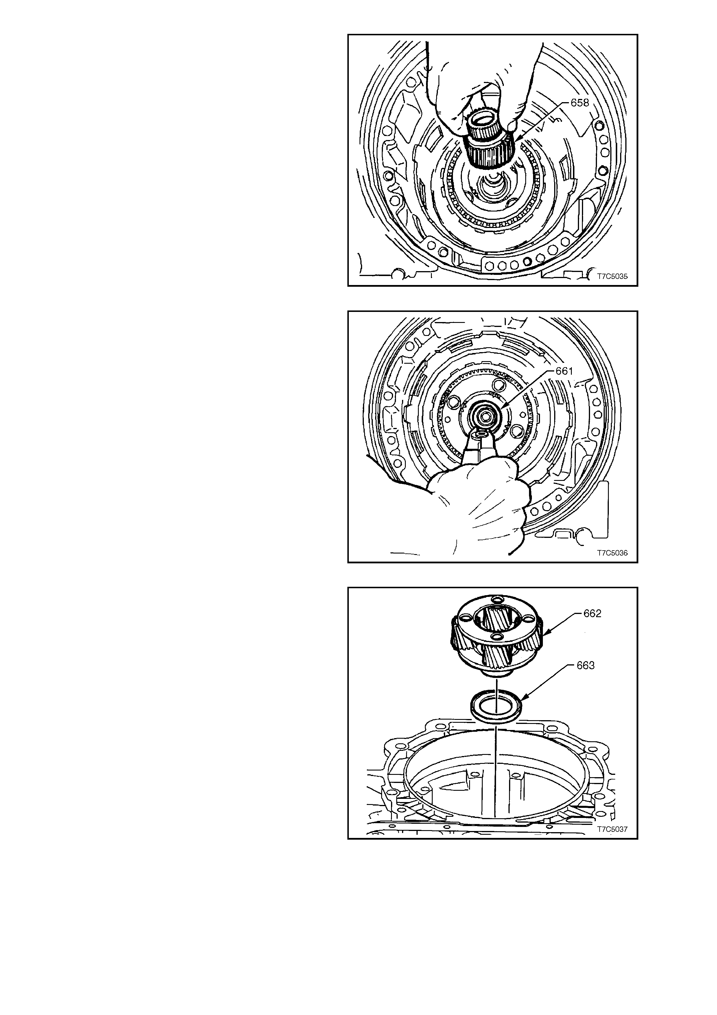
4. Remove input sun gear (658).
Figure 7C5-36
5. Remove input carrier to output shaft retaining
ring (661) using suitable snap ring pliers.
NOTE 1.
Do not over expand ring.
NOTE 2.
Using the snap ring pliers that ar e available as T ool
No. J34627, will not only make the task of circlip
removal easier but there will be less chance of the
snap ring being over expanded.
NOTE 3.
The output shaft will tend to fall out of the
transmission when the retaining ring is removed,
unless the fabricated bracket was fitted to the
output shaft (Refer to 1.4 SPEED SENSOR AND
CASE EXTENSION).
Figure 7C5-38
6. Remove input carrier assembly (662).
7. Remove thrust bearing (663).
8. Remove fabricated bracket and withdraw
output shaft ('687' in Figure 7C5-37).
Figure 7C5-39
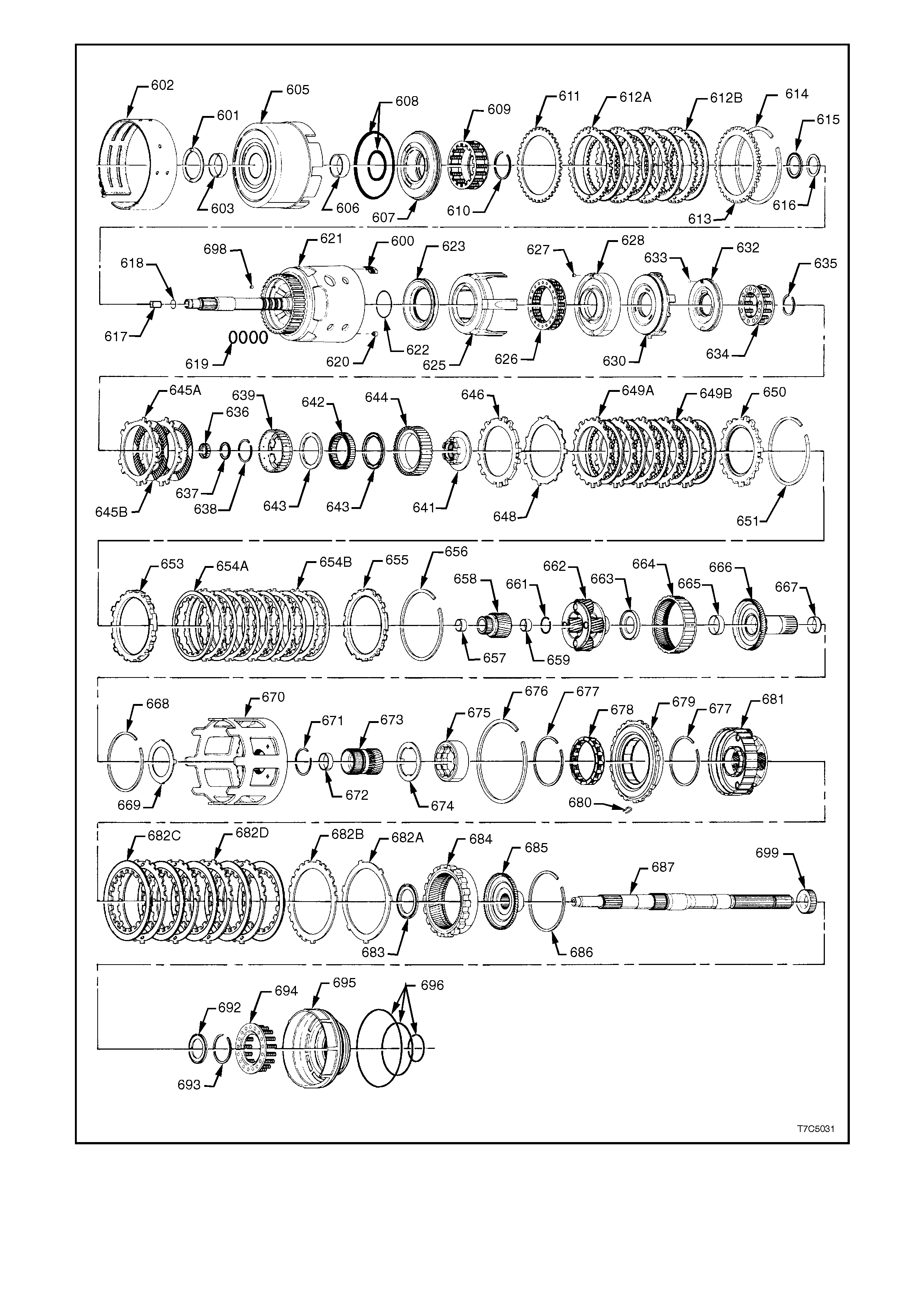
Figure 7C5-37 - Internal Parts
REF
No. PART NAME REF
No. PART NAME
7
600.
601.
602.
603.
605.
606.
607.
608.
609.
610.
611.
612A.
612B.
613.
614.
615.
616.
617.
618.
619.
620.
621.
622.
623.
625.
626.
627.
628.
630.
632.
633.
634.
635.
636.
637.
638.
639.
641.
642.
643.
644.
645a.
645b.
646.
648.
649a.
649b.
Bush, case
Spring assembly, 3-4 clutch boost - 5 places
Washer, thrust
Band assembly
Bush, reverse input clutch (front)
Housing & drum assembly, reverse input clutch
Bush, reverse input clutch (rear)
Piston assembly, reverse input clutch
Seals, reverse input clutch, inner and outer
Spring assembly, reverse input clutch
Ring, reverse input clutch, spring retainer
Plate, reverse input clutch, Belleville
Plate, reverse input clutch, turbulator, steel
Plate, reverse input clutch, composition
Plate, reverse input clutch, selective
Ring, reverse input clutch, retaining
Bearing assembly, stator shaft
Washer, thrust selective
Retainer and check ball assembly,
Seal, O-ring, turbine shaft
Ring, oil seal (solid)
Retainer and check ball assembly
Housing and shaft assembly, input
Seal, O-ring, input to forward clutch housing
Piston, 3rd and 4th clutch
Ring, 3rd and 4th clutch (apply)
Spring assembly, 3rd and 4th clutch
Retainer and ball assy, forward clutch housing
Housing, forward clutch
Piston, forward clutch
Piston, overrun clutch
Ball, overrun clutch
Spring assembly, overrun clutch
Snap ring, overrun clutch spring retainer
Seal, input housing to output shaft
Bearing assembly, input sun gear
Snap ring, overrun clutch hub retaining
Hub, overrun clutch
Retainer and race assembly, sprag
Forward sprag assembly
Retainer rings, sprag assembly
Race, forward clutch (outer)
Plate assembly, overrun clutch (steel)
Plate assembly, overrun clutch (composition)
Plate, forward clutch (apply)
Plate, forward clutch (waved)
Plate assembly, forward clutch (steel)
Plate assembly, forward clutch (composition)
650.
651.
653.
654a.
654b.
655.
656.
657.
658.
659.
661.
662.
663.
664.
665.
666.
667.
668.
669.
670.
671.
672.
673.
674.
675.
676.
677.
678.
679.
680.
681.
682A.
682B.
682C.
682D.
683.
684.
685.
686.
687.
692.
693.
694.
695.
696.
698.
699.
Plate, forward clutch backing (selective)
Ring, forward clutch backing plate retainer
Plate, 3rd and 4th clutch apply (stepped)
Plate assy, 3rd and 4th clutch (composition)
Plate assy, 3rd and 4th clutch (steel)
Plate, 3rd and 4th clutch backing (selective)
Ring, 3rd and 4th clutch backing plate retainer
Plug, orifice cup
Gear, input sun
Bush, input sun gear (rear)
Retainer, output shaft to input carrier
Carrier assembly, input
Bearing assembly, thrust
Gear, input internal
Bush, reaction carrier shaft (front)
Shaft, reaction carrier
Bush, reaction carrier shaft (rear)
Retainer ring, reaction shaft/internal gear
Washer, thrust
Shell, reaction sun
Retainer ring, reaction sun gear
Bush, reaction sun
Gear, reaction sun
Washer, thrust
Race, low and reverse roller clutch
Retainer ring, low and reverse support to case
Retainer ring, low and reverse roller assembly
Clutch assembly, low and reverse roller
Support assembly, low and reverse clutch
Spring, low and reverse clutch support retainer
Carrier assembly, reaction
Plate, low and reverse clutch (waved)
Plate, low and reverse clutch (selective)
Plate, low and reverse clutch (composition)
Plate, low and reverse clutch, turbulator (steel)
Bearing assembly, thrust
Gear, internal reaction
Support, internal reaction gear
Retainer ring, reaction gear/support
Shaft, output
Bearing, reaction gear support to case
Retainer ring, low and reverse clutch
Spring assembly, low and reverse clutch
Piston, low and reverse clutch
Seal, low and reverse clutch (outer/centre/inner)
Orifice cup
Rotor, internal transmission speed sensor
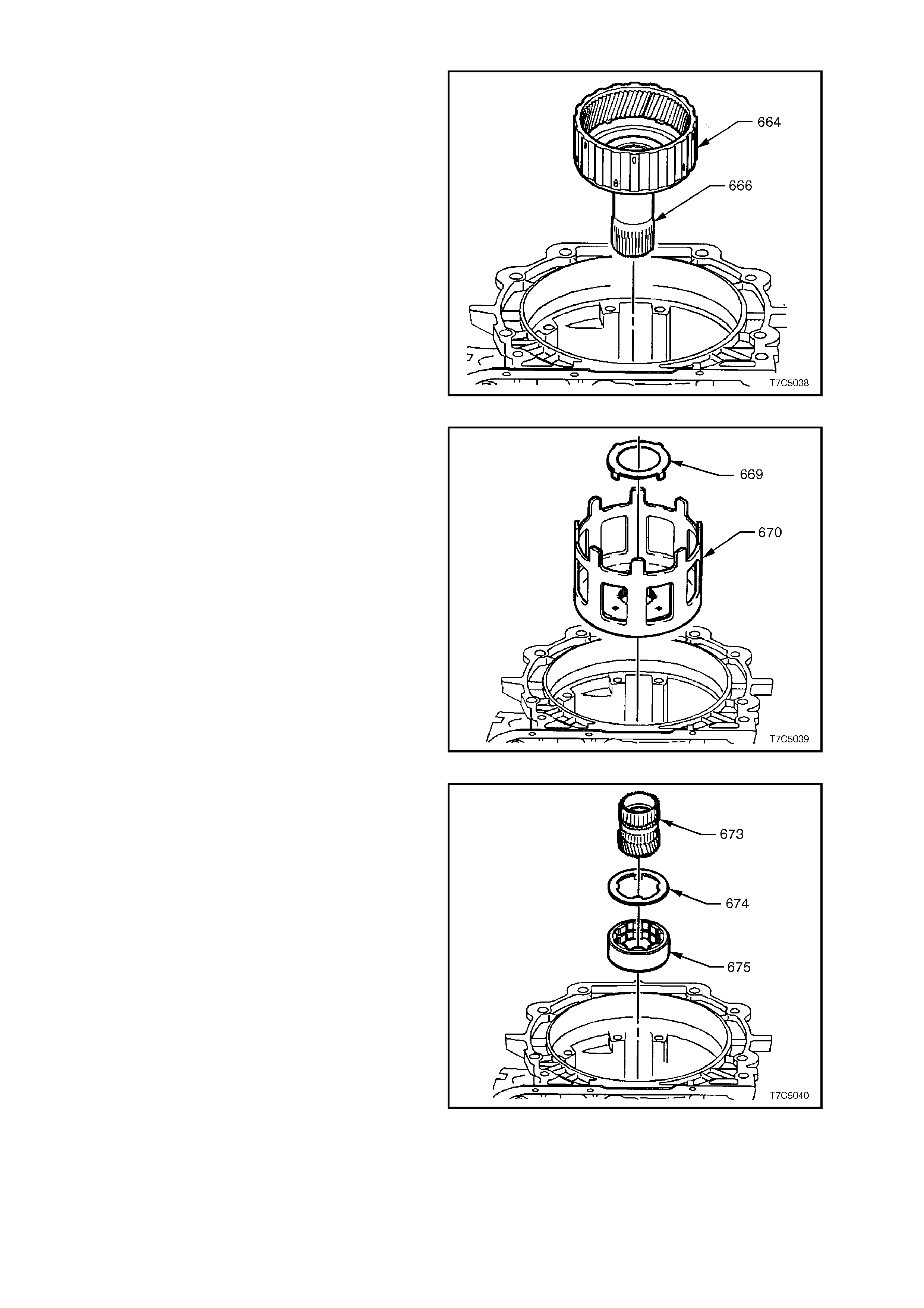
1.11 REACTION GEAR SET
1. Remove input internal gear (664) and reaction
carrier shaft (666).
Figure 7C5-40
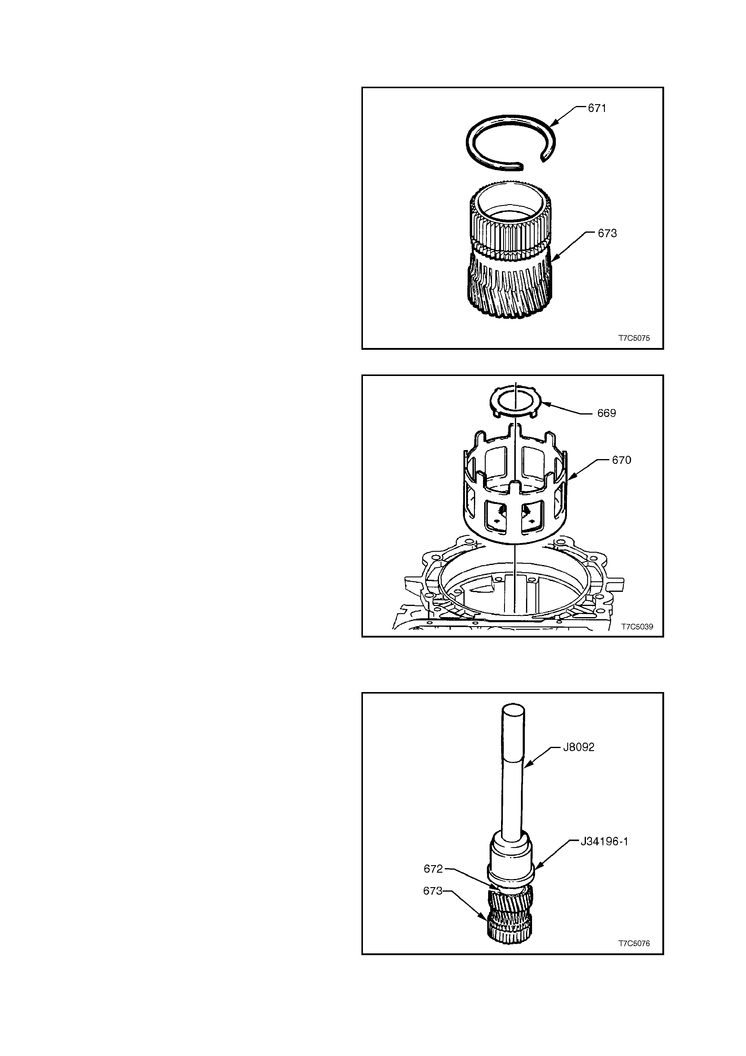
2. Remove reaction shaft/shell thrust washer
(669) and reaction sun shell (670).
Figure 7C5-41
3. Remove reaction sun gear (673).
4. Remove race/reaction shell thrust washer
(674).
5. Remove low and reverse roller clutch race
(675), by holding the inner surf ace and turning
the race in the 'free' direction.
Figure 7C5-42
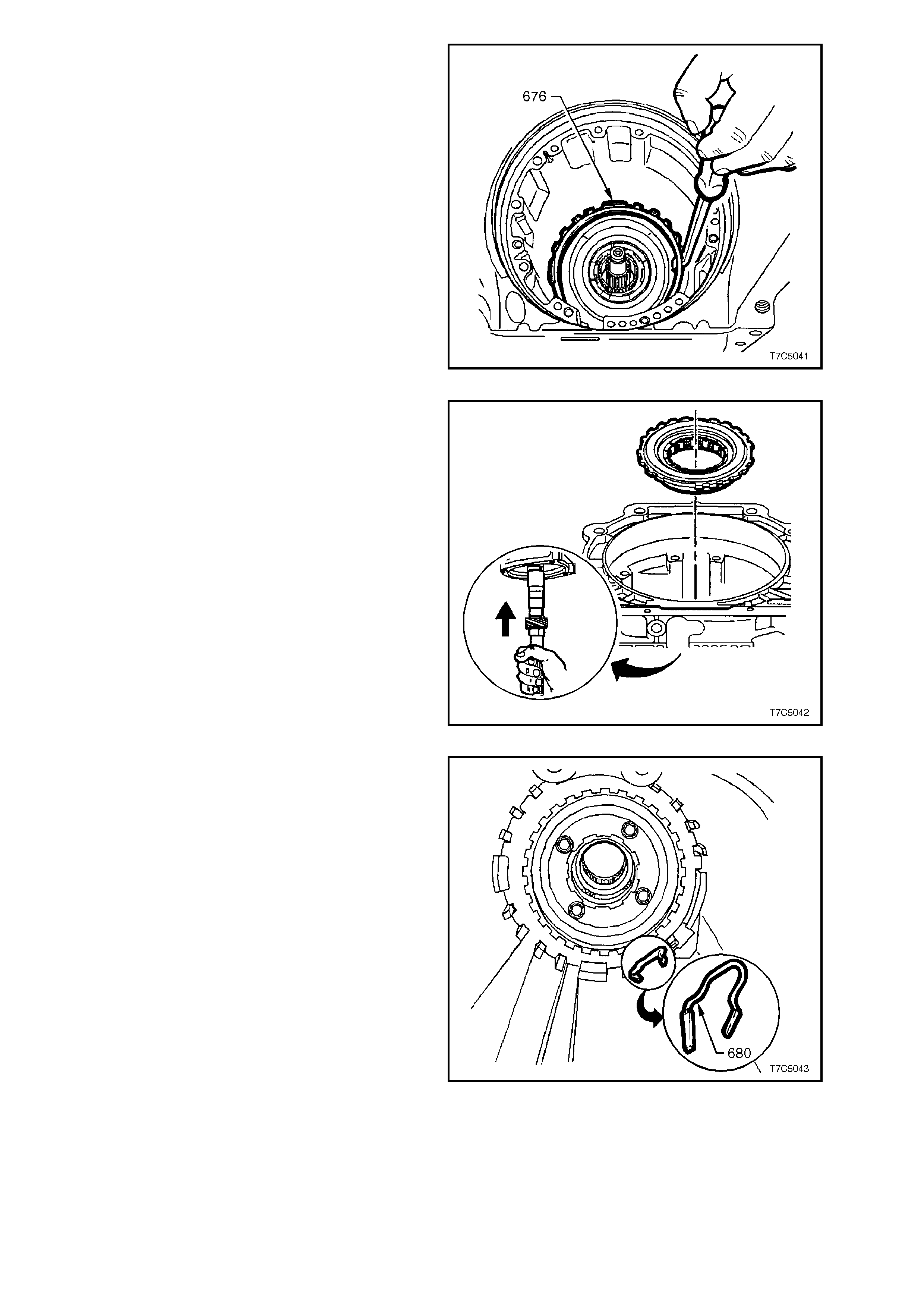
6. Remove low and reverse support to case
retaining ring (676).
Figure 7C5-43
7. Reinsert mainshaft and push up to dislodge
the low and reverse clutch support assembly.
8. Remove the low and reverse clutch support
from the transmission case.
Figure 7C5-44
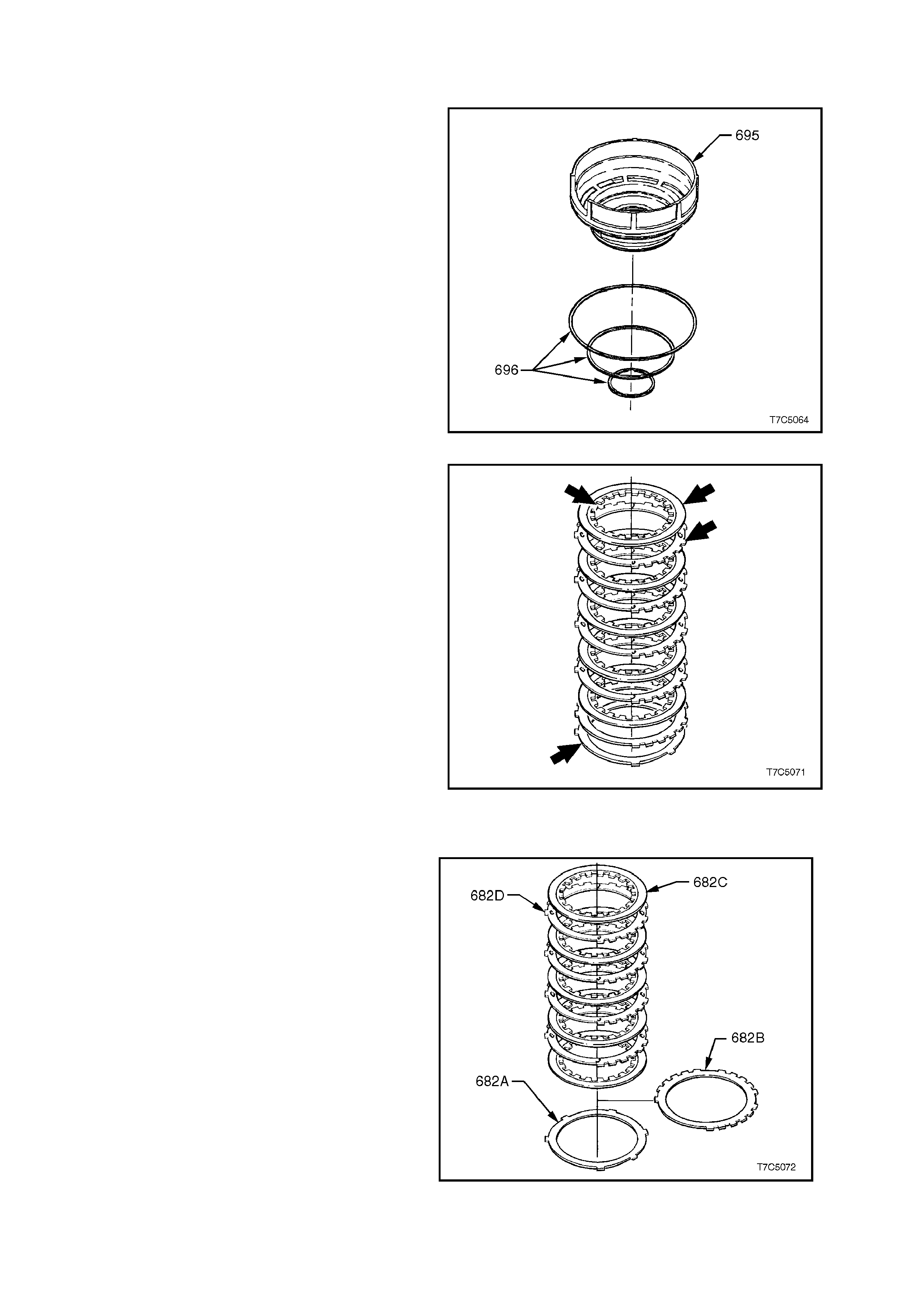
9. Remove low and reverse clutch support
retainer spring (680).
Figure 7C5-45

10. Remove the reaction carrier (681).
Figure 7C5-46
11. Remove low and reverse clutch plate
assembly;
682C Composition plates.
682D Steel plates.
682B Selective spacer plate.
682A Wave plate.
Figure 7C5-47
12. Remove reaction carrier support thrust bearing
(683), reaction internal gear (684) and support
assembly (685).
13. Remove r eaction gear s upport to cas e bearing
assembly (692).
Figure 7C5-48
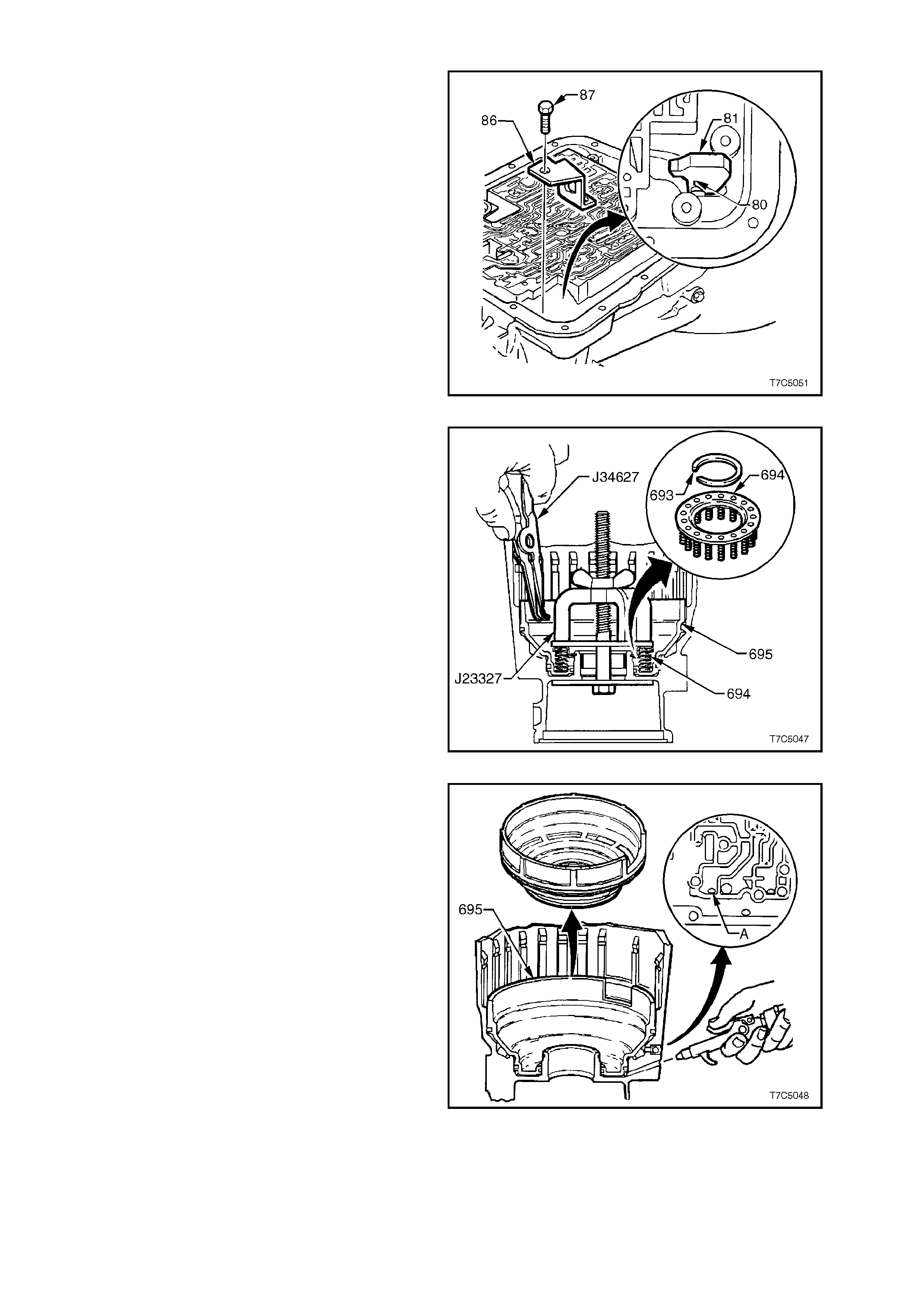
1.12 LOW AND REVERSE CLUTCH ASSEMBLY
1. Remove bolt (87) securing the parking pawl
bracket (86). This will allow the spring (80) to
retract the parking pawl (81), providing
clearance to remove the low and reverse
clutch.
NOTE:
If the parking pawl needs to be removed completely
because of interference, follow the next three
steps.
Otherwise, continue the disassembly from step 5.
2. Remove pawl shaft plug with a suitable easy
out extractor (not shown).
3. Use a magnet to remove pawl pivot shaft.
4. Remove parking pawl bracket, pawl and
spring.
Figure 7C5-49
5. Install Tool No. J23327 as shown and
compress spring assembly (694).
6. Remove low and reverse clutch retaining ring
(693), using snap ring pliers J34627 or
equivalent.
7. Remove J23327 and low and reverse clutch
spring assembly (694).
Figure 7C5-50
8. Apply air pressure to low and reverse apply
passage in transmiss ion cas e as s hown (A), to
assist in the removal of the low and reverse
clutch piston. Remove piston (695).
CAUTION:
To reduce the possibility of injury, do not use
air pressure in excess of 70 kPa for this
operation.
Figure 7C5-51
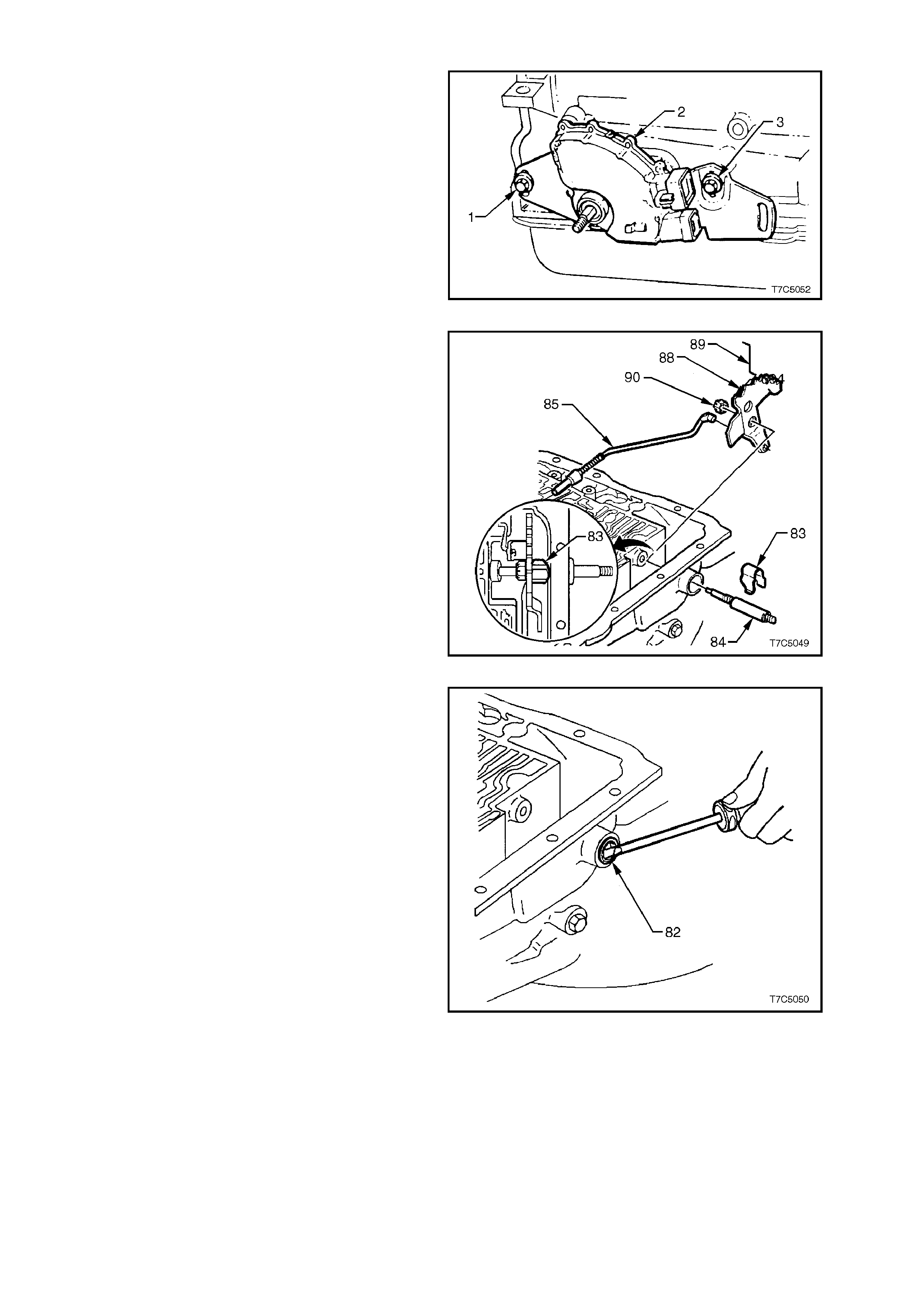
1.13 INNE R MANUAL SHAFT, LINKAGE AND SEAL
1. Remove the two sc rews ( 1 and 3) s ec uring the
neutral start and bac k-up lam p switch ( 2), then
remove the switch (2) from the transmission
case.
Figure 7C5-52
2. Remove the nut (90) s ecuring the inner detent
lever (88) to the manual shaft (84).
3. Remove the inner detent lever (88) and
parking pawl actuator rod (85).
4. Remove the retaining clip (83) from the
manual shaft (84).
5. Withdraw the manual shaft (84) from the
transmission case .
Figure 7C5-53
6. Pry out the manual shaft seal (82) from the
transmission case with a suitable screwdriver.
Figure 7C5-54
2. COMPONENT DISASSEMBLE, INSPECTION, REASSEMBLE
2.1 TRANSMISSION CASE
INSPECT
1. Wash case thoroughly with solvent, dry with
air and blow out all oil passages.
NOTE:
Do not use cloth to dry.
2. Inspect case for cracks or porosity.
3. Check case to valve body face for damage,
distortion and inter-connected oil passages.
NOTE:
Face flatness can be checked by inspecting the
case, spacer plate gasket for complete witness
marks. If the marks are incomplete, an uneven
case surface, or cross channel leaks are indicated.
4. Check vent assembly for damage.
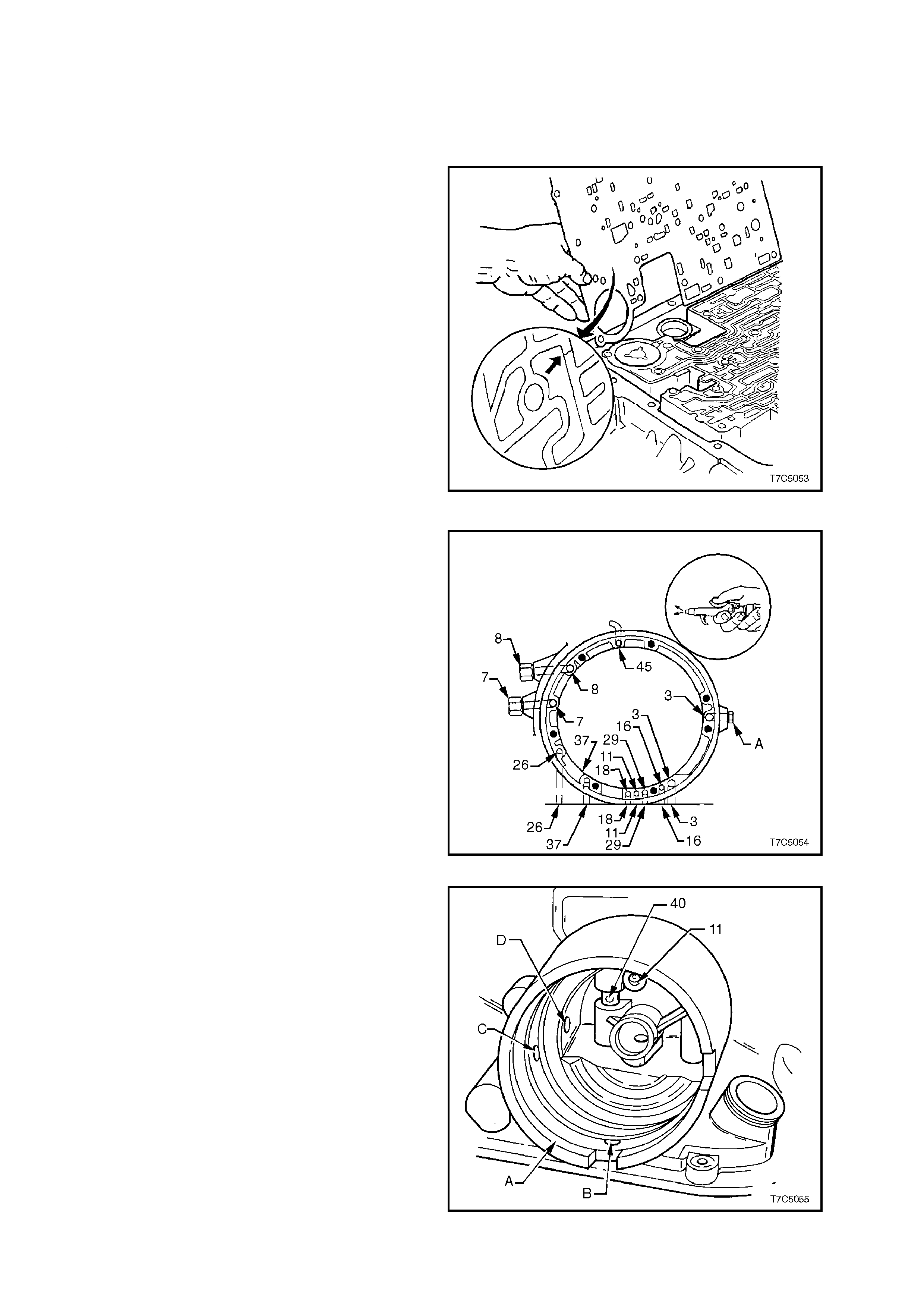
5. Using compressed air, check all oil passages.
For case channel identification, refer to
7C3-5 HYDRAULIC PATHS IN
TRANSMISSION COMPONENTS for
identification of these fluid passages. Figure 7C5-55
6. Check oil pump fluid passages by blowing
LOW pressure compressed air into the
numbered passages, as shown.
Legend - Case, Oil Pump Fluid Passages
3 Line pressure
7 To External Cooler
8 From External Cooler
11 Torque Signal
16 Reverse Input Clutch
18 Forward Clutch Feed
26 Torque Converter Clutch Signal
29 3-4 Clutch
37 Overrun Clutch
A Line Pressure Plug
Figure 7C5-56
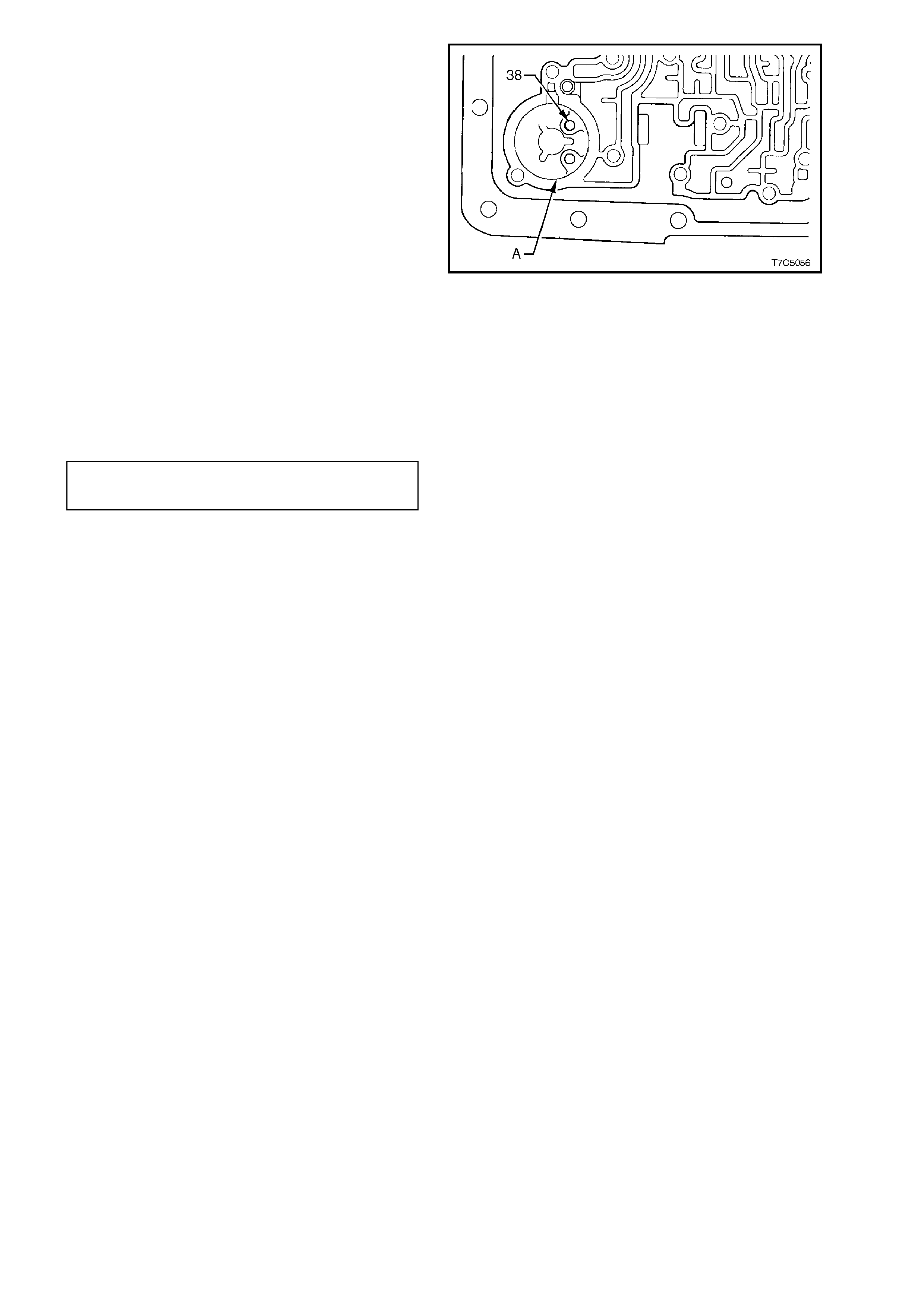
7. Inspect 2-4 servo bore (1) for damage or
porosity. Ensure all slots and passages are
clear. Check for sharp edges. Check orifice
cup plug in the servo bore (11) for debris or
damage.
Legend - 2-4 Servo Bore and Components
A 2-4 Servo Bore
B Servo Exhaust Hole
C 2nd and 4th Band Apply Passage
D 3rd Accumulator Pressure Tap
Passage
11 Orifice Cup Plug
40 3rd Accumulator Retainer and Ball
Assembly
Figure 7C5-57
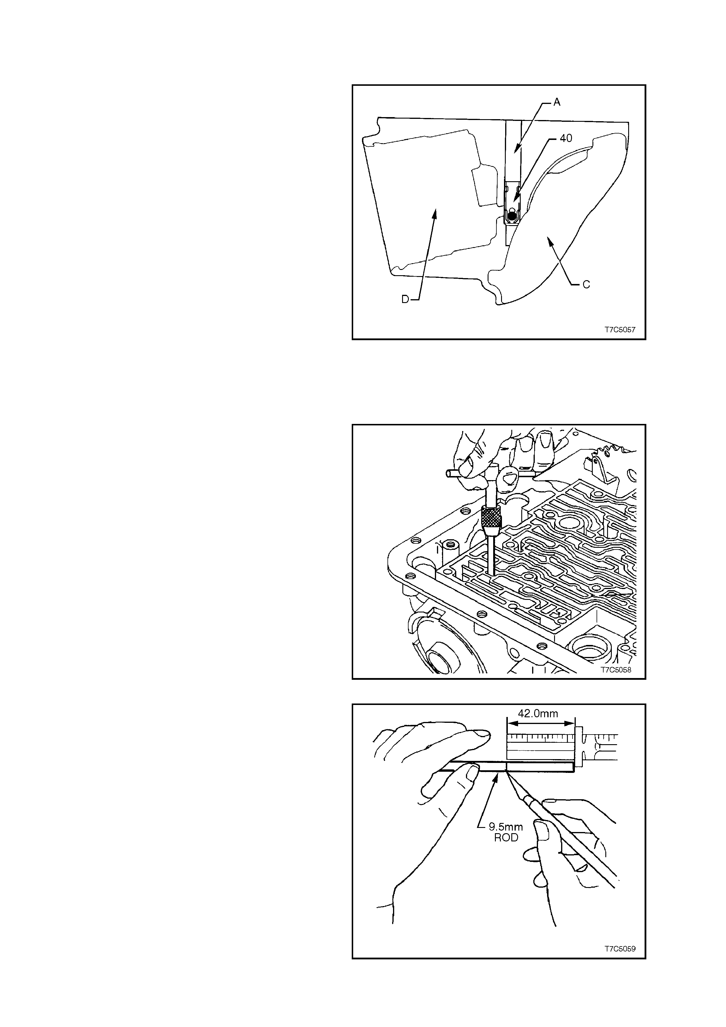
8. Inspect 3-4 accumulator bore (A) and orifice
cup plug (38) for damage or porosity. Ensure
all slots and passages are clear. Check for
sharp edges. Check for pin damage.
Figure 7C5-58
9. Inspect vehicle speed sender unit bore for
damage or porosity.
10. Inspect all bolt holes and oil cooler pipe
connections for thread damage. Repair with
thread inserts or equivalent, as necessary.
11. If rem oved, tighten oil cooler pipe connections
to the correct torque specification.
OIL COOLER PIPE CONNECTIONS 35 - 41
TORQUE SPECIFICATION Nm
12. Inspect case interior for:
a. Damaged ring grooves or casting flash.
b. Clutch plate lugs worn or damaged.
c. Worn or damaged bushes.
2.2 THIRD ACCUMULATOR RETAINER AND BALL ASSEMBLY
INSPECT
1. Inspect third accumulator ball and retainer
(refer Figures 7C5-57 and 7C5-59) for:
a. Ball missing, damaged or sticking.
b. Retainer loose or not seated correctly.
c. Feed slots restricted.
2. Check third acc umulator ball as sembly (40) f or
leaking as follows:
a. Reinstall the assembled 2-4 servo
components, including cover and
retaining ring, into 2-4 servo bore (D).
b. Pour suitable solvent into third
accumulator bore (A).
c. Watch for leakage into case interior (C).
NOTE:
Because fluid will flow from the orifice in the case
servo plug (11 in Figure 7C5-57), careful
observation of the source of the fluid leakage will
be required.
d. Remove 2-4 servo components.
Figure 7C5-59
REPLACE
If leakage is observed to come from the third
accumulator ball assembly, replace as follows:
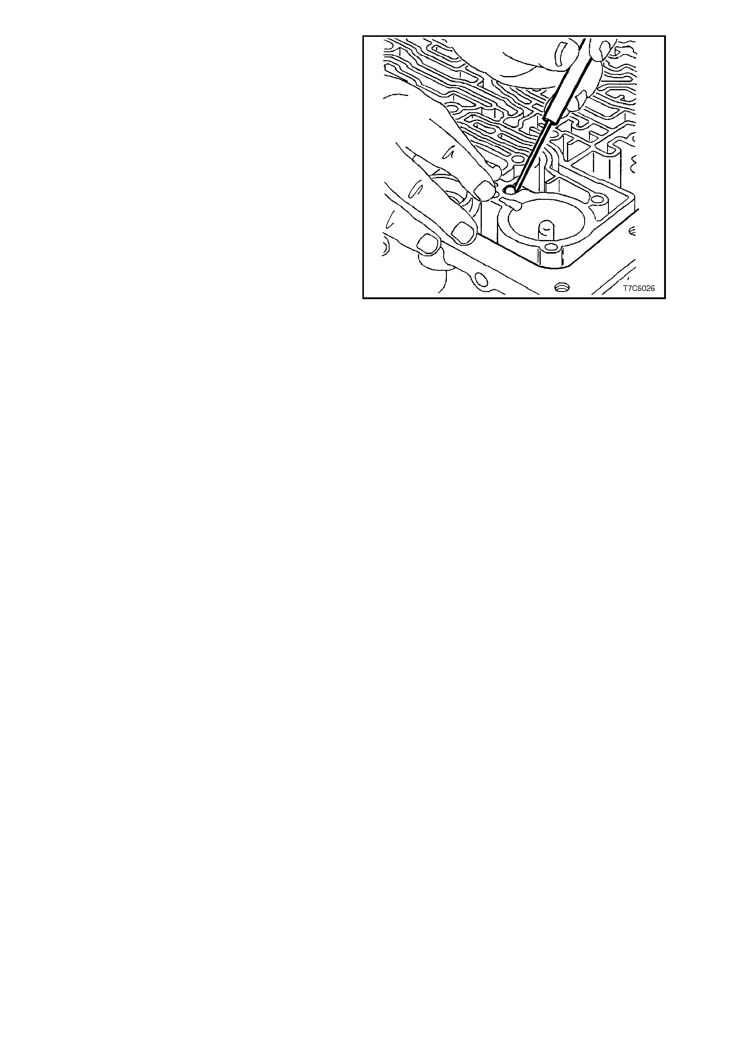
1. Remove old assembly with a suitable screw
extractor (6.3 mm or #4).
Figure 7C5-60
2. Select a suitable length of 9.5 mm rod and
scribe a mark, 42 mm from a squared end, to
indicate the correct depth of installation.
Figure 7C5-61

3. Using the 9.5 mm rod, install a new 3r
d
accumulator retainer and ball check assembly
(40), aligning the oil feed slots with the servo
bore (see Figure 7C5-57 for reference).
4. Install the third accumulator ball and retainer
assem bly (40) until the scribe mark (A) on the
rod, is level with the case face.
Figure 7C5-62
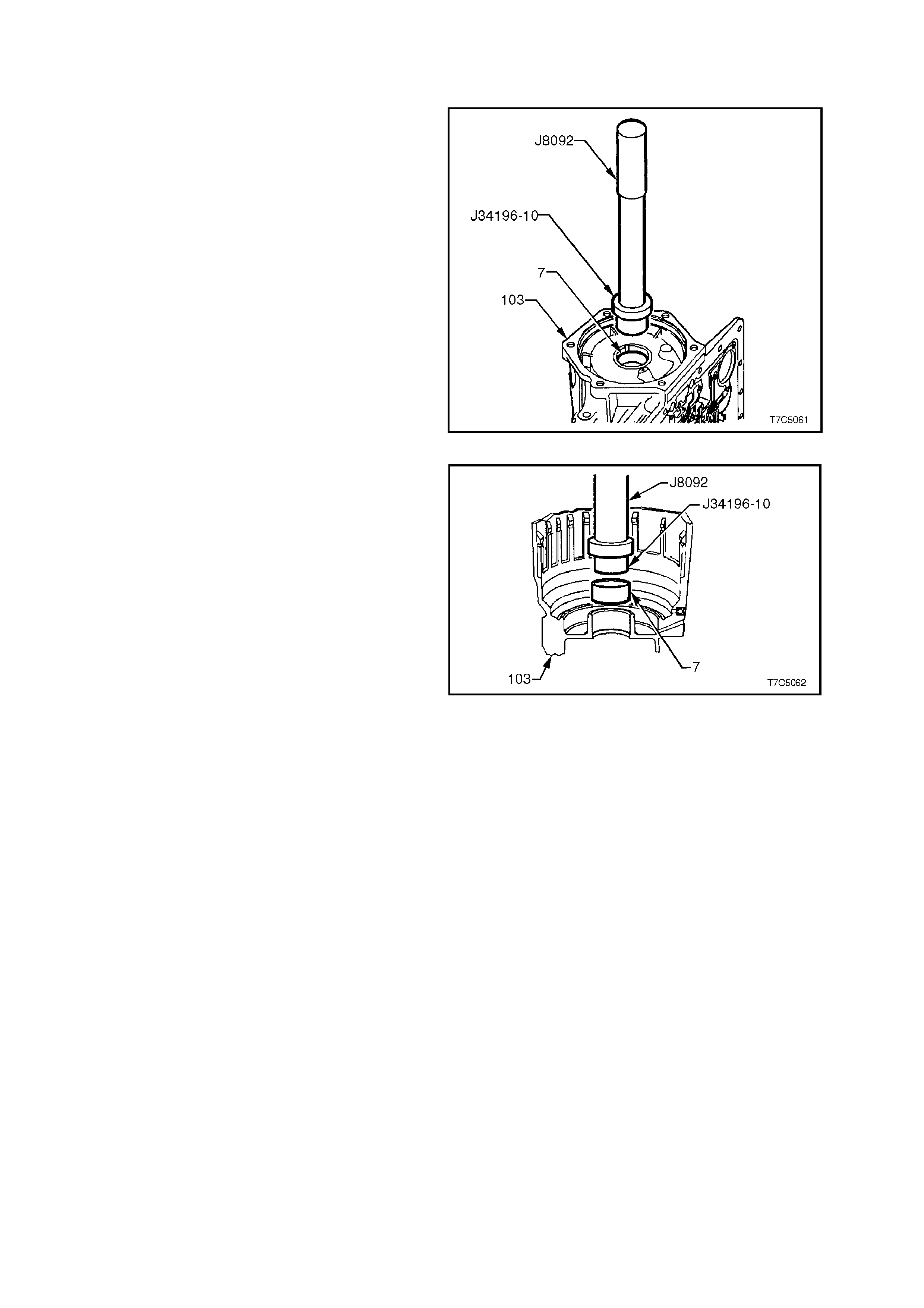
2.3 CASE BUSHING
REPLACE
1. Using bush remover Tool J34196-10 and
driver handle Tool J8092, press the rear
bushing from the transmission case.
Figure 7C5-63
2. Install a new bush, using the sam e tools as for
removal.
Figure 7C5-64

2.4 2-4 SERVO ASSEMBLY
INSPECT
1. Inspect components for wear or damage.
Check springs for broken coils and/or
distortion.
2. Inspect bore in transmission case for any
sharpness that may damage servo seals.
2.5 LOW AND REVERSE CLUTCH ASSEMBLY
INSPECT
1. Inspect piston (695) for porosity or damage.
2. Inspect spring assembly (694) for damage.
3. Inspect retaining ring (693) for distortion.
4. Remove piston seals (696) and discard.
Lubricate new seals with transmission fluid
and install on piston.
Figure 7C5-65
5. Inspect low and reverse clutch plates
(682C/D). Check composition plates for wear,
heat damage or delamination and check steel
plates for heat damage or surface finish
damage.
Figure 7C5-66
SPACER PLATE SELECTION
Select the correct spacer plate (682-B) as
described in the following steps.
1. Stack the low and reverse clutch plates on a
flat surface in the following order:
a. 1 waved plate (682-A).
b. 5 fibre (682-C) and 4 steel (682-D) plates,
starting with a fibre (composition) plate
and alternating with a steel plate, etc.
c. Low and reverse clutch s upport (679) (not
shown).
2. Apply a light (approx. 2 kg), evenly distributed
load to the low and reverse support assembly.
IMPORTANT:
Excessive pressure will start to flatten the wave
plate, resulting in an incorrect measurement.
Figure 7C5-67
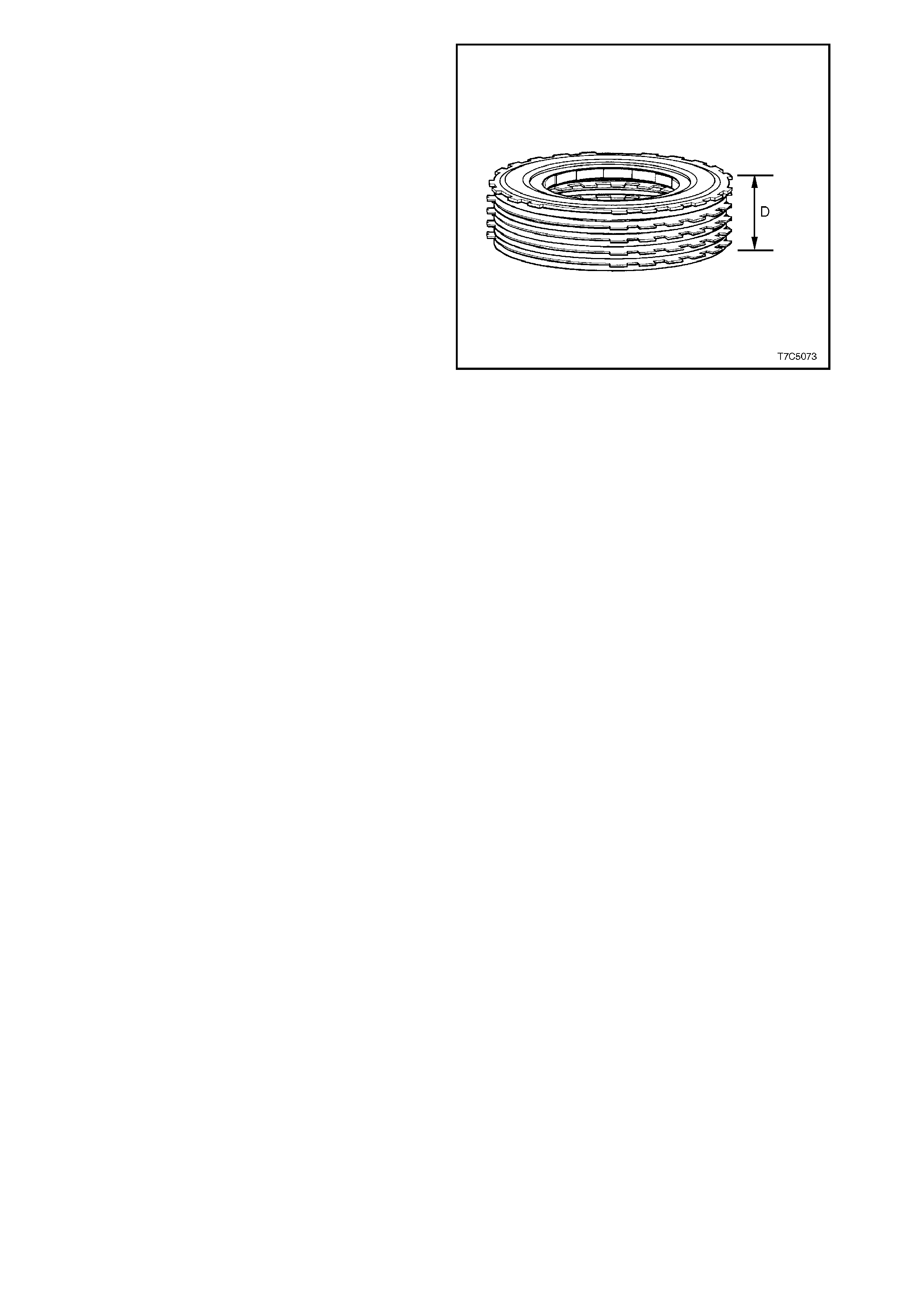
3. Using a vernier caliper, measure height of
clutch pack from work surface to top of low
and reverse clutch support, noting the
dimension (D) as shown, with load applied.
4. Use the following Selection Chart to select
the correct spacer plate, relative to the
measured height.
LOW AND REV E RSE CLUTCH SPACER
PLATE SELECTION
IF PACK HEIGHT IS USE THIS SELECTIVE PLATE
FROM TO IDENTITY PLATE THICKNESS
(mm) (mm) (mm)
27.545 28.065 NONE 1.684 1.829
28.066 28.586 0 1.168 1.314
27.026 27.544 1 2.198 2.344
OVERALL CLUTCH P ACK HEI GHT 29.22 - 29.90 mm
(Includi ng S pacer Plat e)
NOTE 1:
The s elective plate shown as 'NONE' in the above
chart, refer s to a fifth, steel reac tion plate, which is
to be used as the spacer plate.
NOTE 2:
Should a measurement fall in an overlap in the
Selection Chart, either the selective plate that is
thinner or thicker, can be fitted.
NOTE 3:
Regardless of the combinations used, the critical
specification that must be achieved, is the overall
clutch pack height (including the spacer plate),
which is to be between 29.22 mm and 29.90 mm.
5. Install correct spacer plate between wave
plate and first fibre clutch plate with
identification side facing upwards.
Figure 7C5-68
2.6 LOW AND REVERSE CLUTCH SUPPORT ASSEMBLY
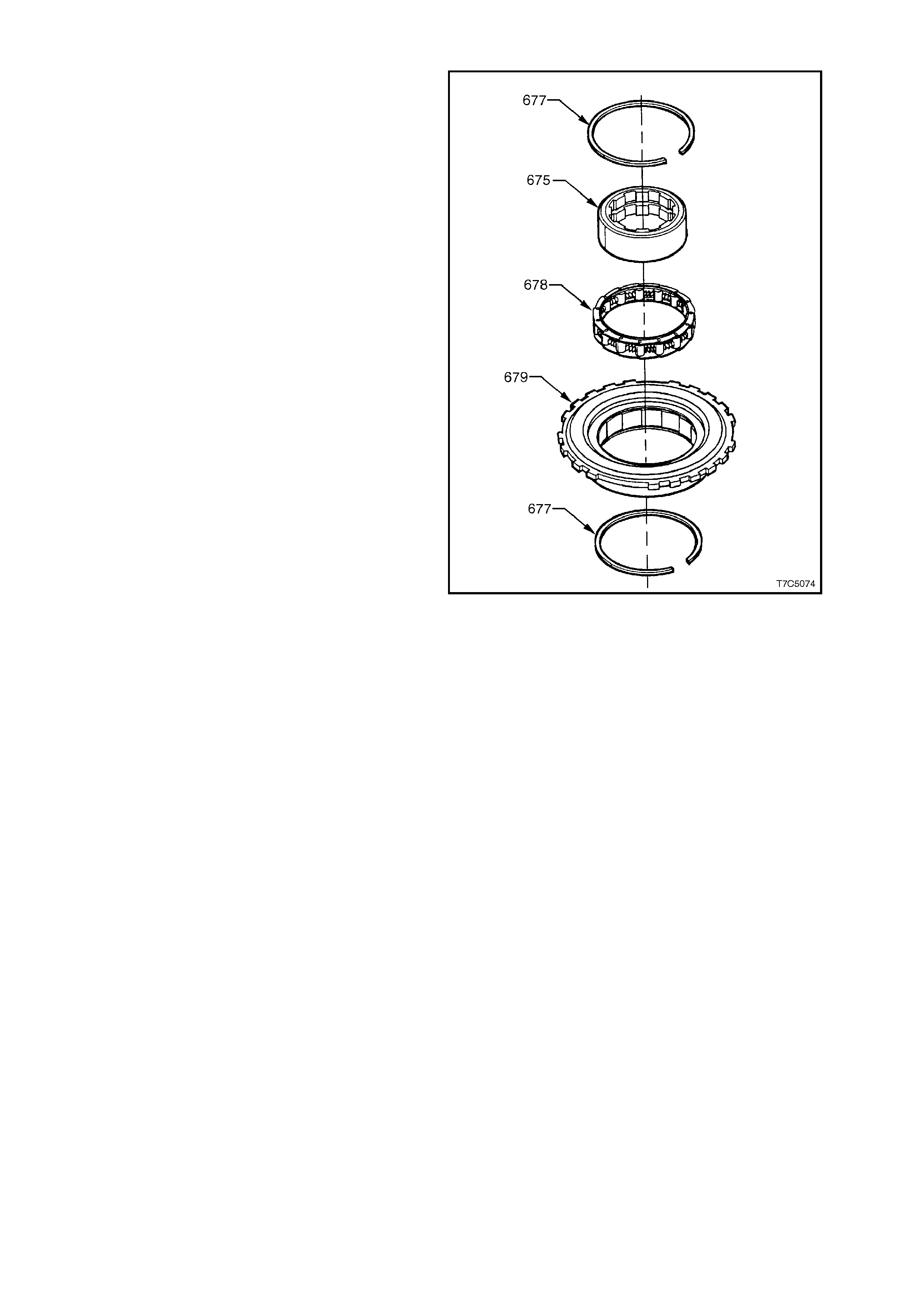
1. Disassemble low and reverse support
assembly as follows:
a. Remove inner race (675).
b. Remove one retaining ring (677).
c. Remove roller clutch assembly (678).
2. Inspect inner race for damage.
3. Inspect roller clutch assembly for damaged
rollers or broken springs.
4. Inspect support assembly for loose cams,
cracks or damage.
NOTE:
The low and reverse support assembly is
reassembled during transmission reassembly.
Figure 7C5-69

2.7 REACTION INTERNAL GEAR AND CARRIER ASSEMBLY
INSPECT
1. Inspect reaction gear support case bearing
surface and thrust bearing assembly (692) for
damage.
Figure 7C5-70
2. Inspect reaction internal gear (684) and
support (685) for incorrec t assembly, stripped
splines, cracks, teeth or lug damage.
Figure 7C5-71
3. Inspect reaction carrier bearing surface and
thrust bearing assembly (683) for damage.
Figure 7C5-72
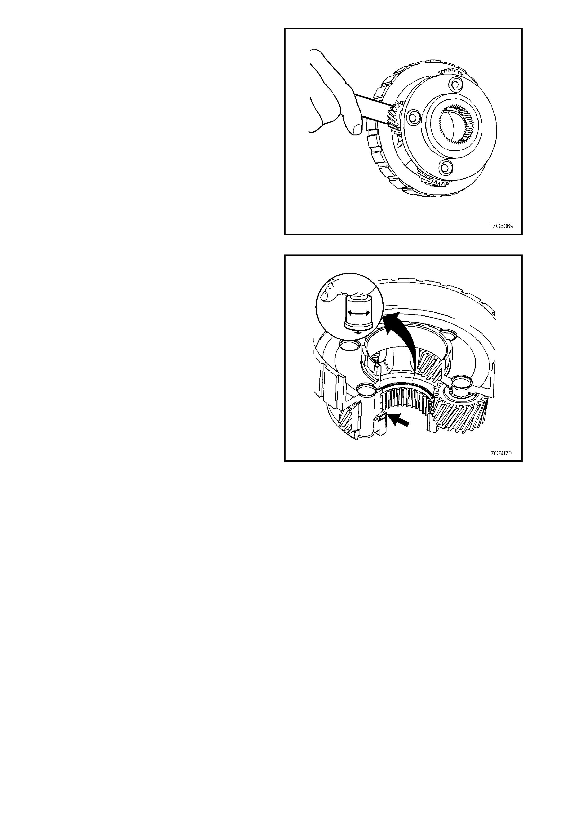
4. Inspect reaction carrier assembly (681) for
pinion gear wear, proper pinion staking and
free turning of pinions.
5. Check for excessive pinion washer wear by
meas ur ing pinion end play. End play should be
0.20 to 0.60 mm. The reaction carrier
assembly is serviced as a complete assembly
and should be replaced if worn or defective.
Figure 7C5-73
5. Check carrier assembly captive thrust bearing
as follows:
a. Place a suitable bush (or socket) on
bearing race ( do not contac t pinion gear s )
and turn bush with palm of your hand.
b. Any imperfections will be felt through
bush.
Figure 7C5-74
2.8 REACTION SUN GEAR AND SHELL
INSPECT
1. Inspect reaction sun gear (673) for dam age to
bush, damage to spline or teeth, loose or
weak retaining ring. Do not remove ring ex cept
for replacement.
Figure 7C5-75
2. Inspect reac tion sun shell (670) for damage or
wear to tangs.
3. Inspect thrust washers (669, 674 - not shown)
for wear or damage.
Figure 7C5-76
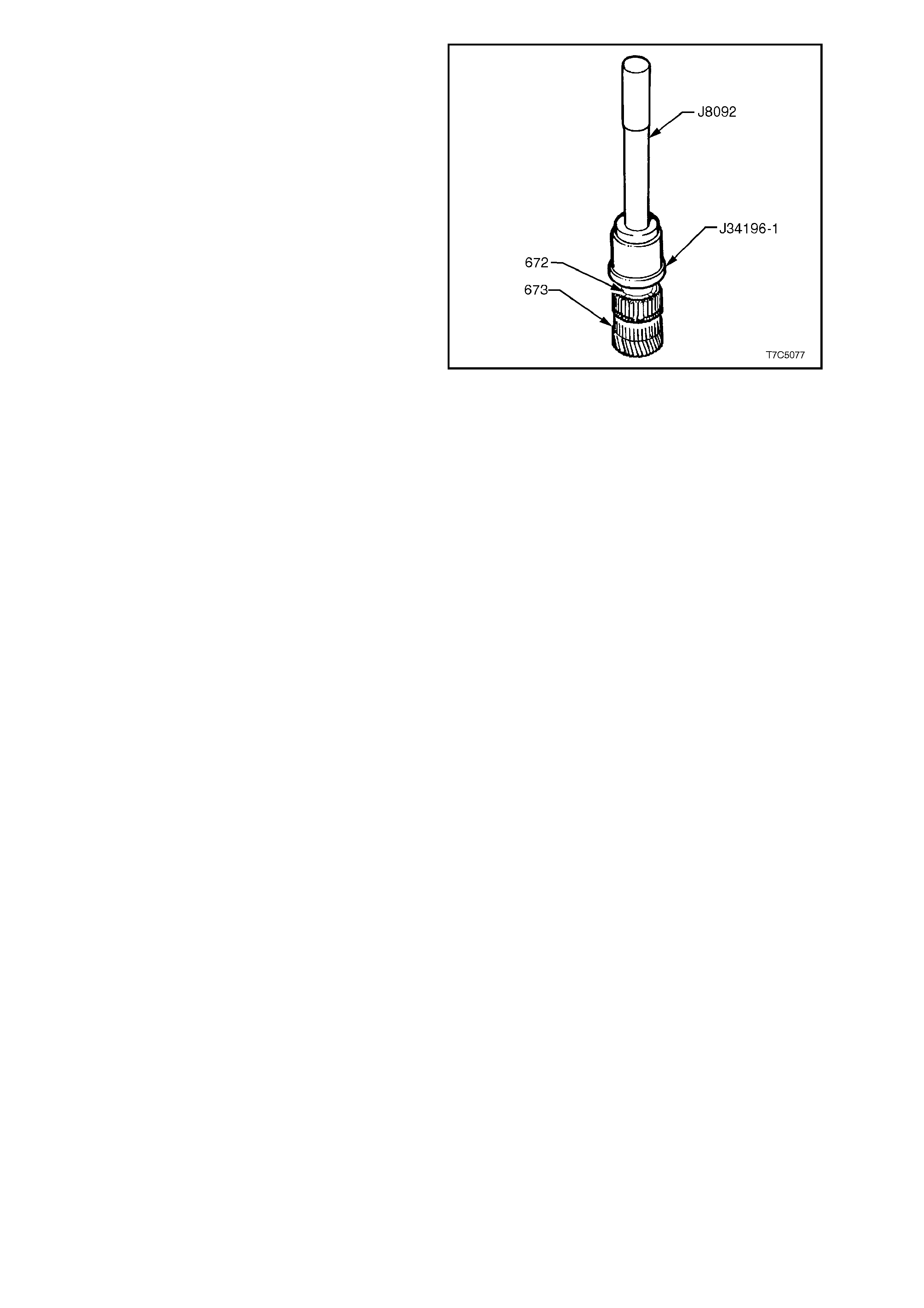
SUN GEAR BUSH - REPLACE
1. Should the sun gear bushing (672) require
replacement, use bush remover Tool J34196-
1 and driver handle J8092 to press the bush
from the gear.
Figure 7C5-77
2.9 INPUT INTERNAL GEAR AND OUTPUT SHAFT
INSPECT
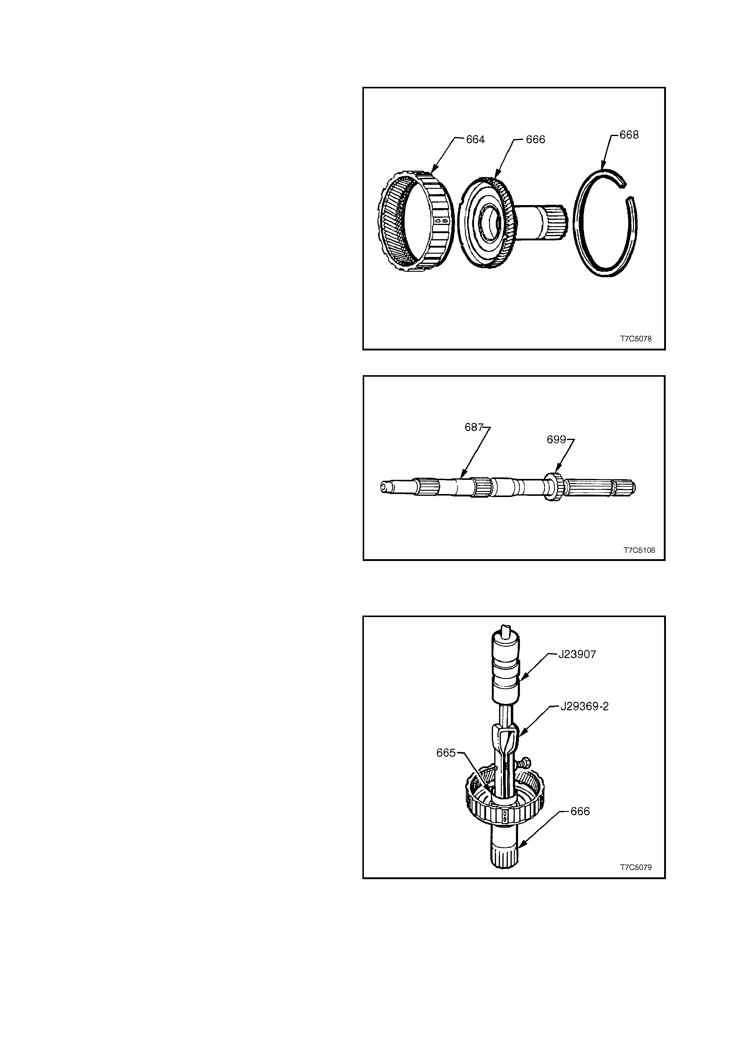
1. Remove retaining ring (668) from input internal
gear (664).
2. Remove reac tion carrier shaf t (666) f rom input
internal gear and inspect shaft for:
a. Damaged or worn bushes.
b. Cracks.
c. Damaged spline or gear teeth.
d. Undercutting around shaft from
interference with sun gear.
3. Inspect input internal gear (664) f or cr ack ed or
damaged splines or gear teeth.
4. Inspect carrier to reaction shaft thrust bearing
for wear or damage (663).
5. If all parts are serviceable, reassemble the
reaction carrier shaft (666) into the input
internal gear (664) and inst all the retaining r ing
(668). Figure 7C5-79
6. Inspect transmission output shaft (687) for:
a. Blocked or restricted lube passages.
b. Damage to splines or ring groove.
c. Burrs or damage to bearing journals.
d. Burrs or damage to case extension seal
surface. Polish with crocus cloth if
necessary.
e. Tooth damage to transmission output
shaft sensor rotor.
Figure 7C5-80
REACTION CARRIER SHAFT BUSHES - REPLACE
1. Using universal bushing remover J29369-2
and slide hammer J23907 or equivalent,
remove front bushing (665) from the reaction
carrier gear shaft (666).
Figure 7C5-81
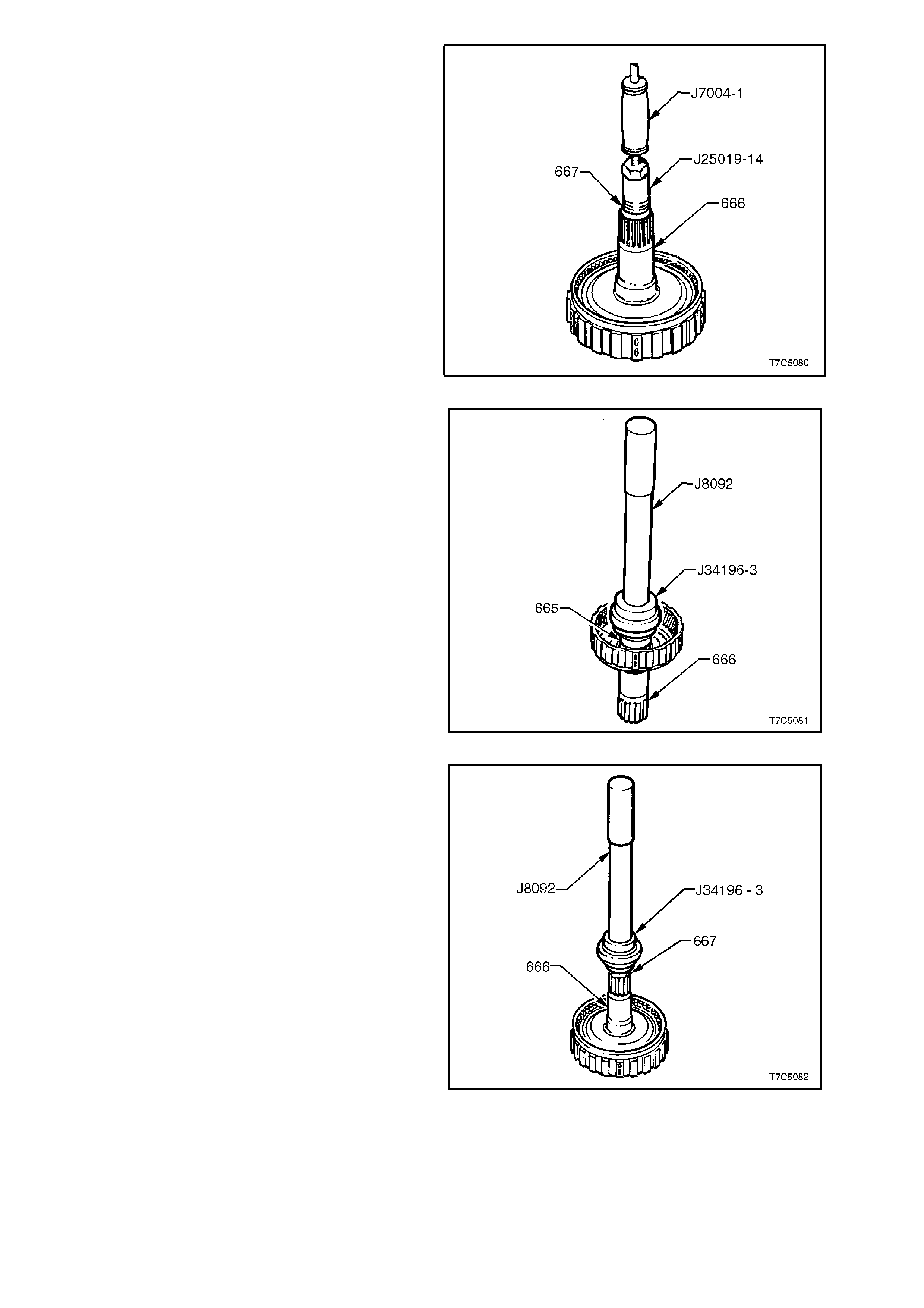
2. Remove the rear bushing (667) from the
reaction car rier gear shaf t (666) by using bush
puller Tool J25019-14 and slide hammer
J7004-1 or equivalent.
Figure 7C5-82
3. Install front bushing (665), using bush installer
Tool J34196-3 and driver handle J8092.
Figure 7C5-83
4. Install rear bushing (667), using the same
tools as for the front bushing.
Figure 7C5-84
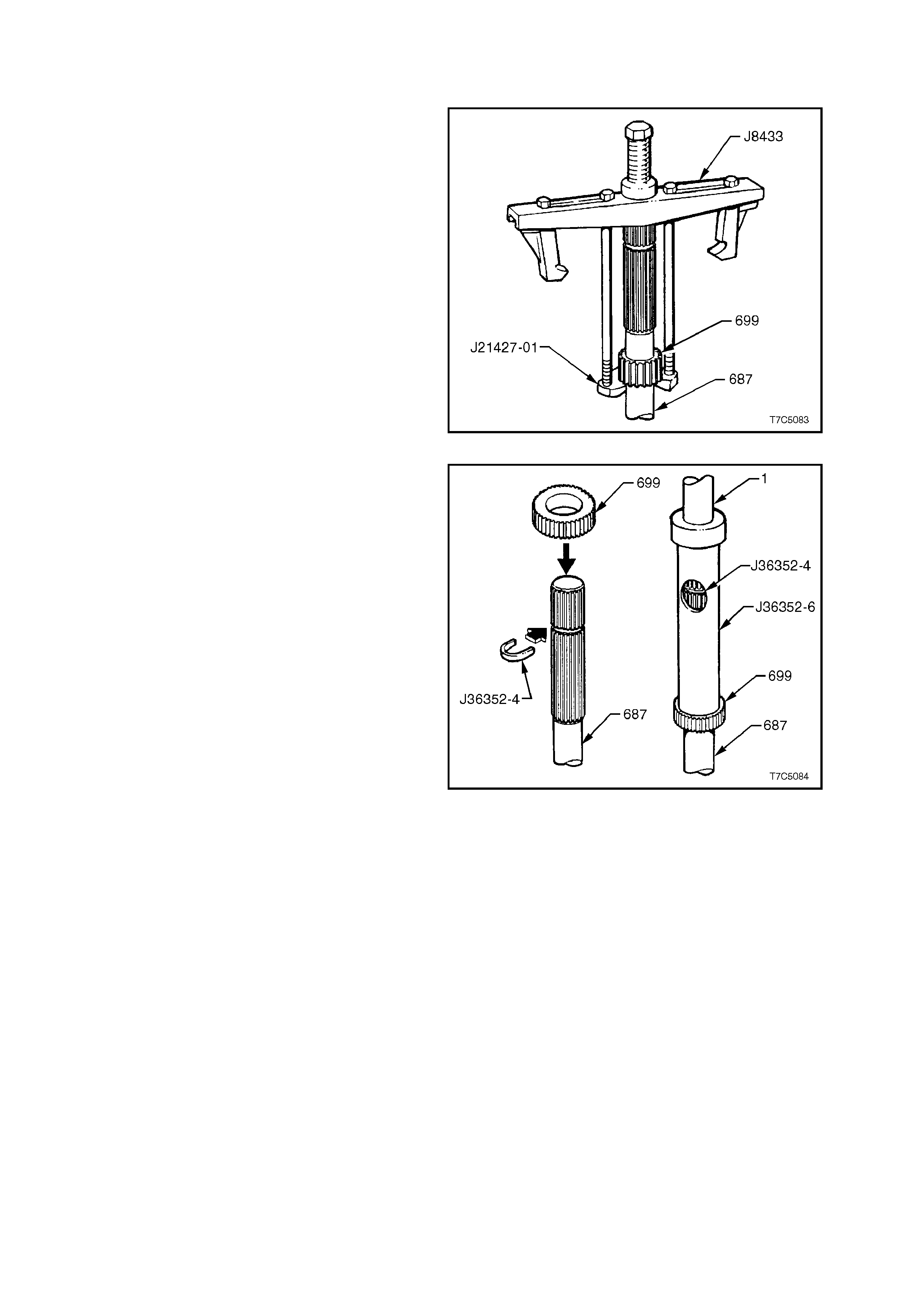
2.10 TRANSMISSION OUTPUT SPEED SENSOR RING
REPLACE
NOTE:
Normally this operation is not necessary and should
only be carried out, if inspection of the Speed
Sensor Ring shows that tooth damage has
occurred. Once removed, the ring must be
replaced and not re-used.
1. Using Tool Nos. J8433 and J21427-01,
remove the ring (699) from the output shaft
(687).
Figure 7C5-85
2. Place a new rotor over the trans miss ion output
shaft.
3. Insert Tool No. J36352-4 into the groove on
the transmission output shaft.
4. Place Tool No. J36352- 6 over the output shaft
and press sensor ring onto the output shaft
until the tube contacts the C-washer, in the
window.
Figure 7C5-86
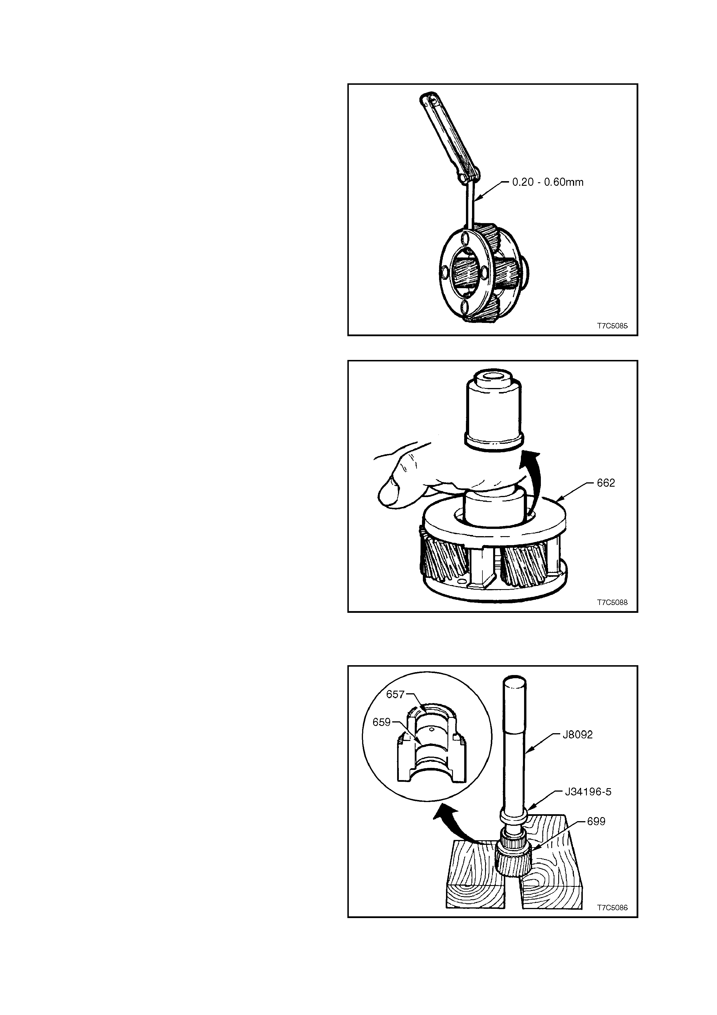
2.11 INPUT CARRIER AND S UN GEAR
INSPECT
1. Inspect sun gear (658) for damage to bush,
cracks and damage to spline or gear teeth.
2. Inspect carrier assembly (662) for pinion gear
wear, proper pinion stak ing and free turning of
pinions.
3. Check for excessive pinion washer wear by
meas ur ing pinion end play. End play should be
0.20 to 0.60 mm. The input ca rr ier as s embly is
serviced as a complete assembly and should
be replaced if components are worn or
defective.
Figure 7C5-87
4. Check carrier assembly captive thrust bearing
as follows:
a. Place a suitable bush (or socket) on
bearing race ( do not contac t pinion gear s )
and turn bush with palm of your hand.
b. Any imperfections will be felt through
bush.
Figure 7C5-88
INPUT SUN GEAR BUSHES - REPLACE
1. Using bush rem oving tool J34196-5 and driver
handle J8092, press both sun gear bushes
(657/ 659) from the gear.
Figure 7C5-89

2. Press the front sun gear bush (657) in to the
gear, using Tool J34196-4 and driver handle
J8092.
3. Press the rear sun gear bush (659) in to the
gear, using Tool J34196-6 and driver handle
J8092.
Figure 7C5-90
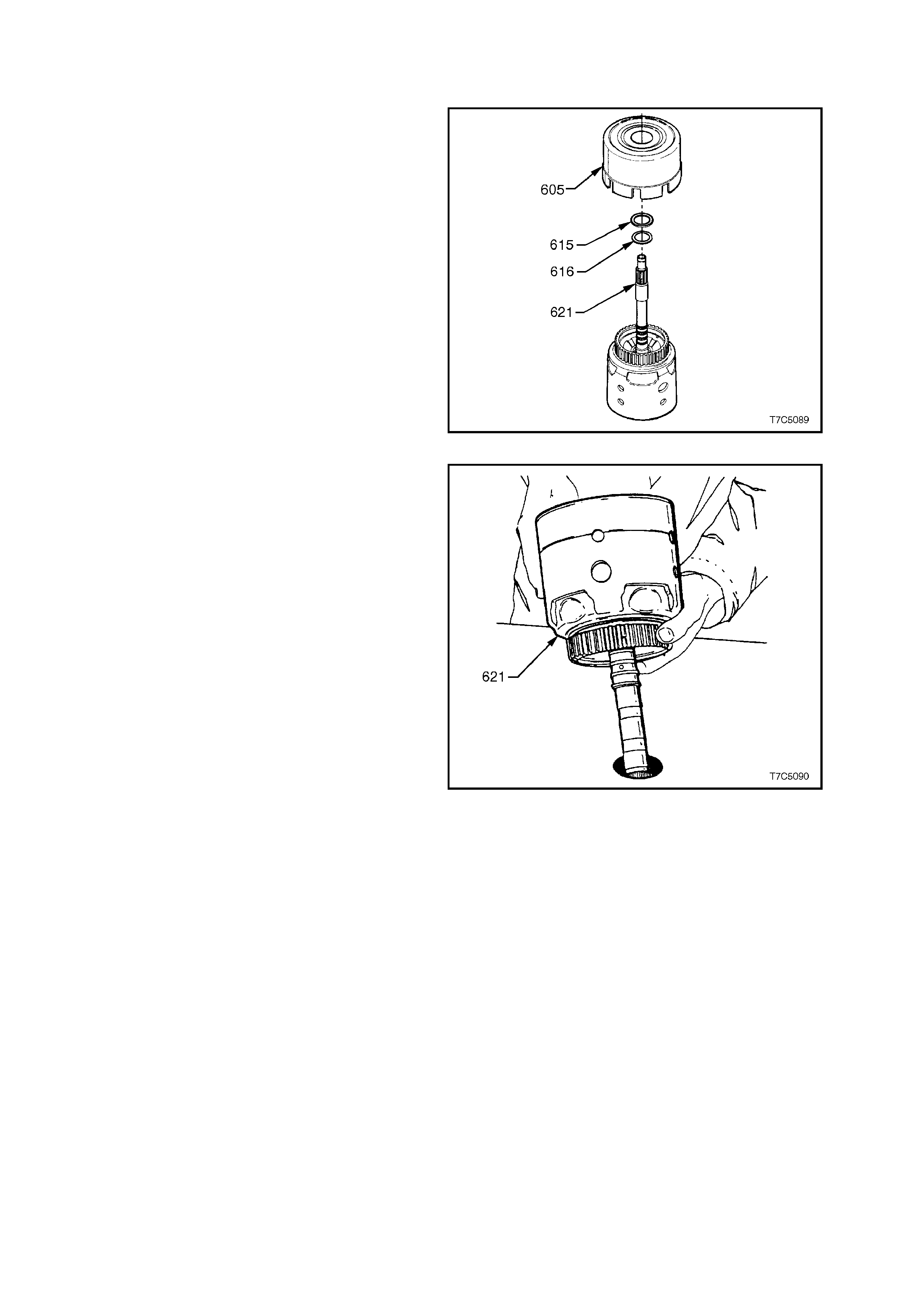
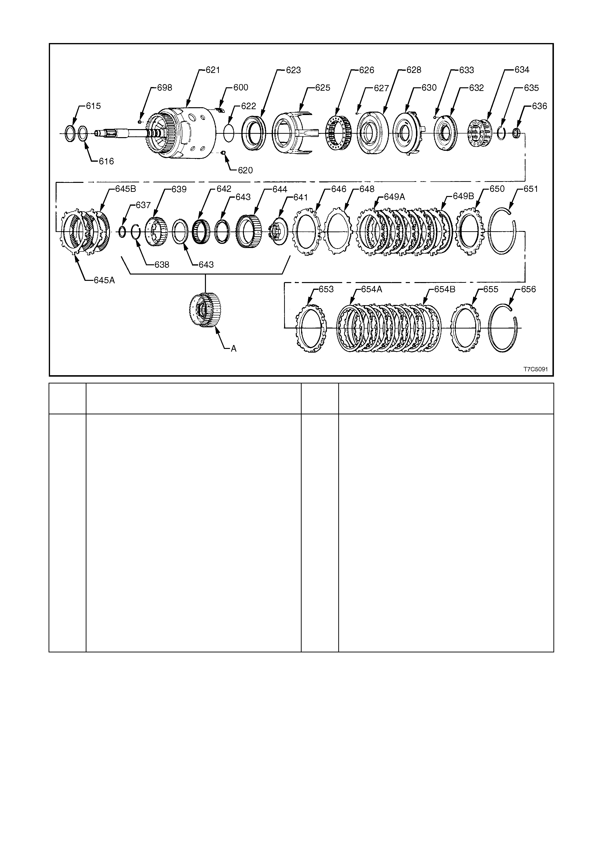
2.12 INPUT CLUTCH HOUSING ASSEMBLY
DISASSEMBLE
1. Remove reverse input clutch housing and
drum assembly (605) from input housing and
shaft assembly (621).
2. Remove thrust bearing (615) and selective
thrust washer (616).
Figure 7C5-91
3. Place input clutch hous ing and dr um ass embly
(621) on work bench with input shaft
protruding through hole in workbench.
Figure 7C5-92
NOTE:
For identification of parts, refer to Figure 7C5-94.
4. Remove 3-4 clutch plate retaining ring (656)
and backing plate (655).
5. Remove 3-4 clutch plates (654).
6. Remove five, 3-4 clutch boost spring
assemblies (600).
7. Remove stepped, 3-4 clutch apply plate (653).
8. Remo ve forward c lutch back ing plate retaining
ring (651) and backing plate (650).
9. Remove forward clutch sprag assembly ‘A’
(parts 637 - 644).
10. Remove input sun gear bearing assembly
(637).
11. Remove input housing to output shaft lip seal
(636).
12. Remove forward clutch plates (649 A/B).
13. Remove forward clutch wave plate (648).
14. Remove forward clutch apply plate (646).
15. Remove overrun clutch plates (645 A/B).
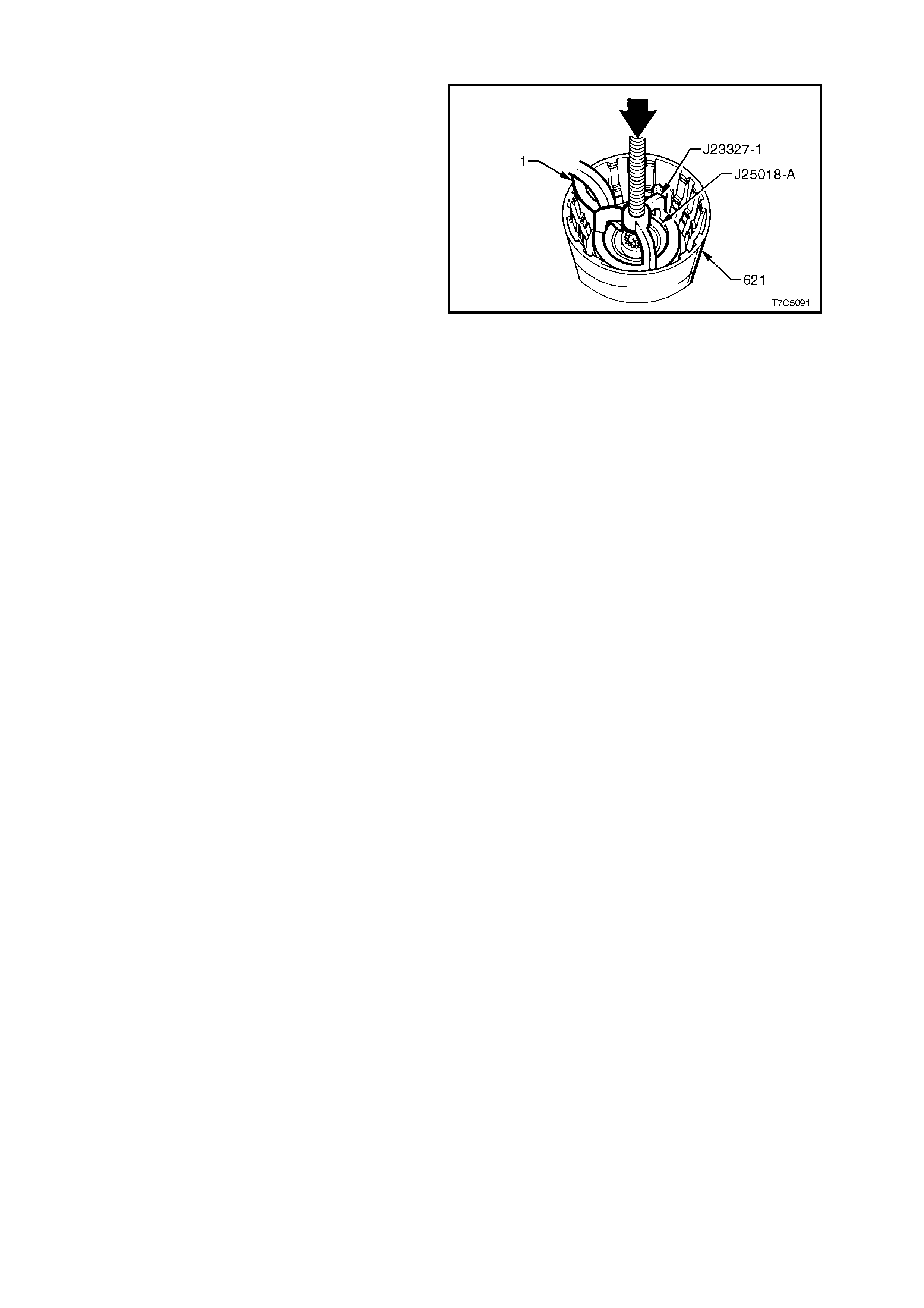
16. Place input housing and shaft assembly in a
suitable press.
17. Install part of Tool Nos . J23327-1 and J 25018-
A underneath, as shown.
18. Compress overrun clutch spring assembly
(634) in press and remove overrun clutch
retaining ring (635).
19. Return input housing and shaft assembly to
workbench.
20. Remove overrun clutch spring assembly (634).
21. Remove forward clutch piston assembly (630,
together with the overrun clutch piston (632.
22. Separate the two pistons and remove all seals.
NOTE:
Separate assembly by impacting the input housing
assembly on a wooden block.
23. Remove forward clutch housing (628).
24. Remove 3-4 clutch spring assembly (626).
25. Remove 3-4 clutch apply ring (625) and piston
(623) with seals.
26. Discard all seals.
Figure 7C5-93
REF
No. PART NAME REF
No. PART NAME
600.
615.
616.
620.
621.
622.
623.
625.
626.
627.
628.
630.
632.
633.
634.
635.
636.
645a.
645b.
‘A’
Spring assembly, 3-4 clutch boost - 5 places
Bearing assembly, stator shaft
Washer, thrust selective
Retainer and check ball assembly
Housing and shaft assembly, input
Seal, O-ring, input to forward clutch housing
Piston, 3rd and 4th clutch
Ring, 3rd and 4th clutch (apply)
Spring assembly, 3rd and 4th clutch
Retainer and ball assy, forward clutch housing
Housing, forward clutch
Piston, forward clutch
Piston, overrun clutch
Ball, overrun clutch
Spring assembly, overrun clutch
Snap ring, overrun clutch spring retainer
Seal, input housing to output shaft
Plate assembly, overrun clutch (steel)
Plate assembly, overrun clutch (composition)
Forward clutch sprag assembly, consisting of;
637
638
639
641
642
643
644
646
648
649a
649b
650
651
653
654a
654b
655
656
698
Bearing assembly, input sun gear
Snap ring, overrun clutch hub retaining
Hub, overrun clutch
Retainer and race assembly, sprag
Forward sprag assembly
Retainer rings, sprag assembly
Race, forward clutch (outer)
Plate, forward clutch (apply)
Plate, forward clutch (waved)
Plate assembly, forward clutch (steel)
Plate assembly, forward clutch (composition)
Plate, forward clutch backing (selective)
Ring, forward clutch backing plate retainer
Plate, 3rd and 4th clutch apply (stepped)
Plate assy, 3rd and 4th clutch (composition)
Plate assy, 3rd and 4th clutch (steel)
Plate, 3rd and 4th clutch backing (selective)
Ring, 3rd and 4th clutch backing plate retainer
Plug, orifice cup
Figure 7C5-94 Input Clutch Housing - Exploded View
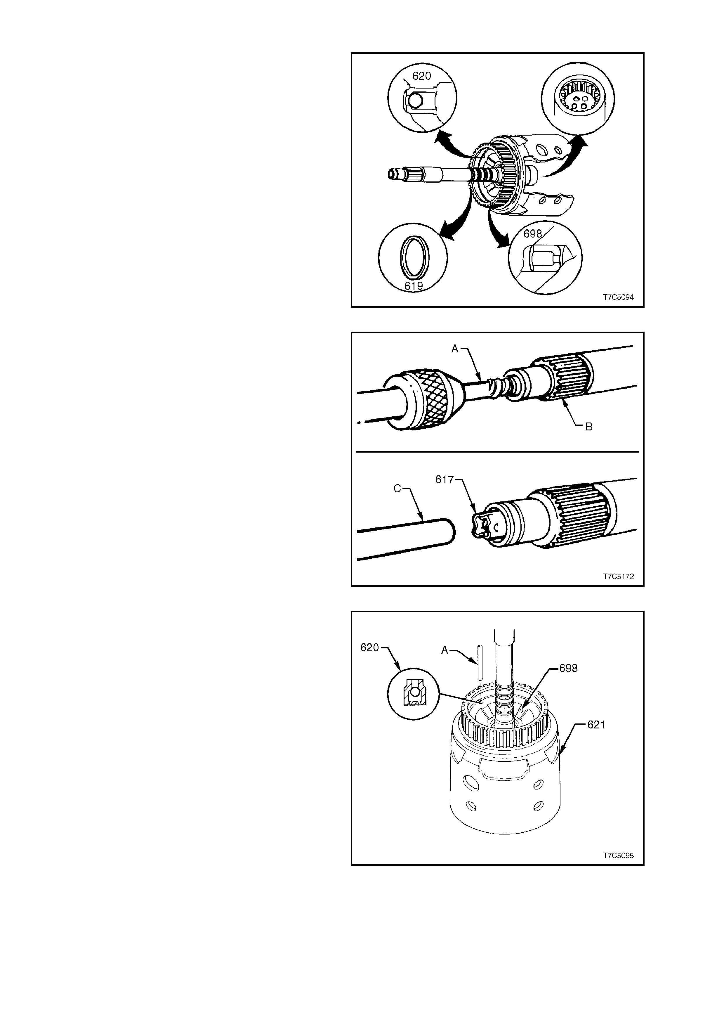
INSPECT
1. Inspect input housing and shaft assembly for
porosity, wear or damage.
2. Blow through all input shaft passages with
compressed air. The three turbine shaft
sealing balls must not be loose or leaking (the
open hole (A) is a lube oil passage to the
output shaft).
3. Check orifice cup plug (698) is not missing.
4. Check for cracks at all lube holes.
5. Check that the four turbine shaft sealing rings
rotate freely in their grooves and that they are
undamaged and free from burrs.
6. Inspect check ball and retainer (620). Check
that the ball moves freely and that the retainer
is not loose in the housing. Leak test the
check ball, with solvent.
Figure 7C5-95
7. If required, replace the turbine shaft check ball
assembly (617), as follows;
a. Straighten the retainer tangs and remove
the ball.
b. Use a suitable easy out extractor (A) to
remove retainer from the turbine shaft
(B).
c. Install new check ball and retainer
assembly (617), using 9.5 mm (3/8”) rod
(C), until the retainer is 3.0 mm below the
end of the input shaft.
d. Check that the check ball moves freely.
Figure 7C5-96
8. Replace input shaft housing check ball
assembly, if necessary, as follows:
a. Tap out retainer and ball assembly (620),
using 5.7 mm (1/4 inch) rod.
Figure 7C5-97
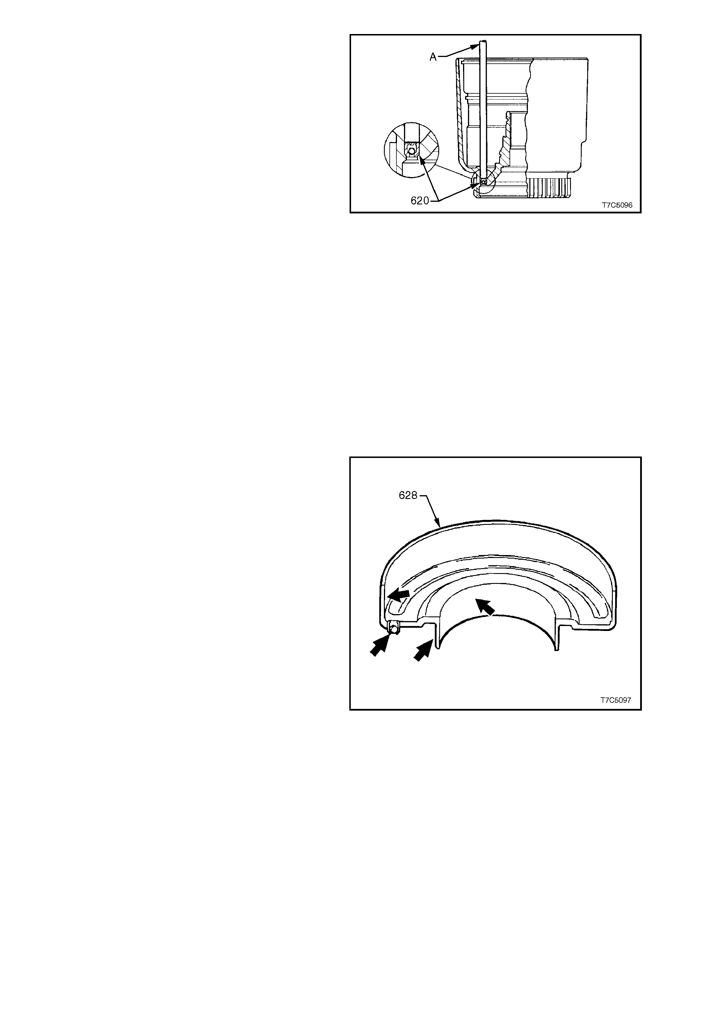
b. Install new assembly with 5.7 mm rod
until shoulder is seated in housing from
input shaft side, as shown.
Figure 7C5-98
8. Inspect 3-4 clutch piston (623) for porosity or
damage.
9. Inspect 3-4 clutch apply ring (625) for bent
tangs.
10. Inspect 3-4 clutch spring assembly (626) for
distortion or damage.
11. Inspect each of the five 3-4 clutch spring
assemblies (600) for damage or distortion.
12. Inspect the 3-4 clutch plates for damaged
tangs, delamination and/or excessive wear.
NOTE:
The green/black appearance of the 3-4 clutch
plates is normal. Therefore, do not assume that
these plates are burned because of colour.
13. Inspect forward clutch housing (628) for:
a. Correct check ball (627) operation.
b. Damage, distortion or cracks.
c. Burrs in seal areas.
Figure 7C5-99
14. Inspect forward clutch piston (630) for:
a. Porosity or damage.
b. Ring groove damage.
c. Apply leg damage.
NOTE:
As the inner and outer piston seals are bonded to
the forward clutch piston, if any seal damage is
found, then the piston assembly must be replaced.
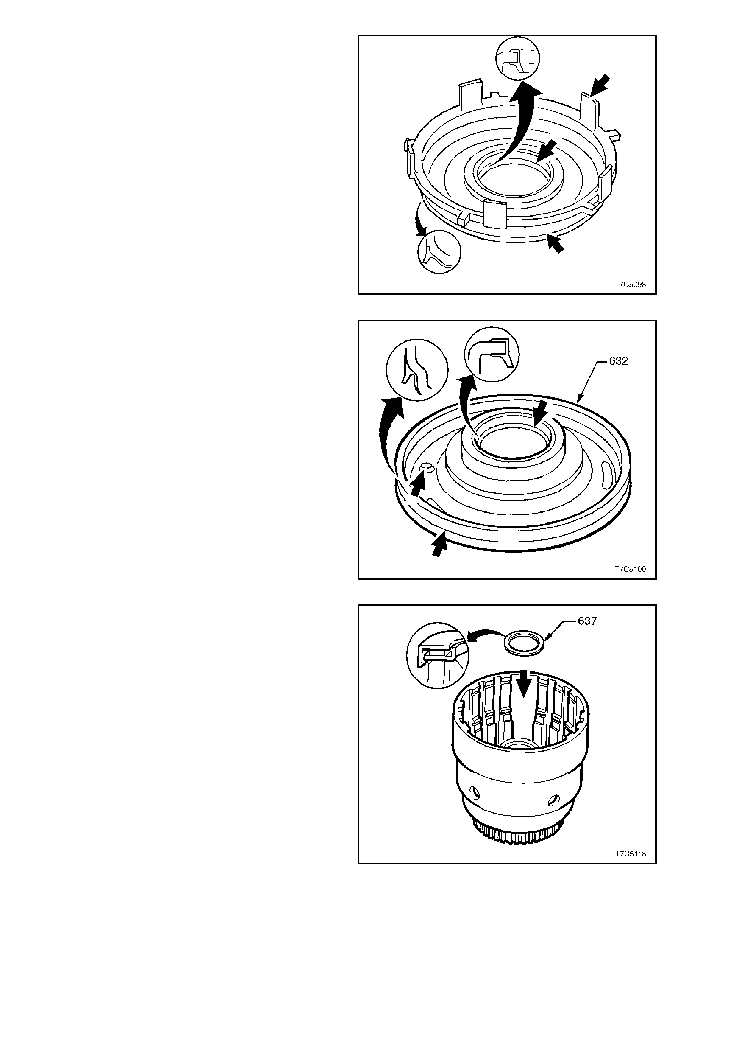
Figure 7C5-100
15. Inspect overrun clutch piston (632) for:
a. Porosity or damage.
b. Ring groove damage.
c. Seal damage.
d. Check ball operation (overrun) (633).
NOTE:
As the inner and outer piston s eals ar e now bonded
to the overrun clutch piston, if any seal damage is
found, then the piston assembly must be replaced.
16. Inspect overrun spring assembly (634) for
damage or distortion.
17. Inspect overrun clutch plates (645), forward
clutch plates (649) and 3- 4 clutch plates ( 654).
Check composition plates for damaged tangs,
delamination or excessive wear. Check steel
plates for damaged tangs, wear or heat
damage. Figure 7C5-101
18. Inspect input sun gear bearing as sem bly (637)
and input housing to output shaft seal (636) for
wear, damage or distortion.
Figure 7C5-102
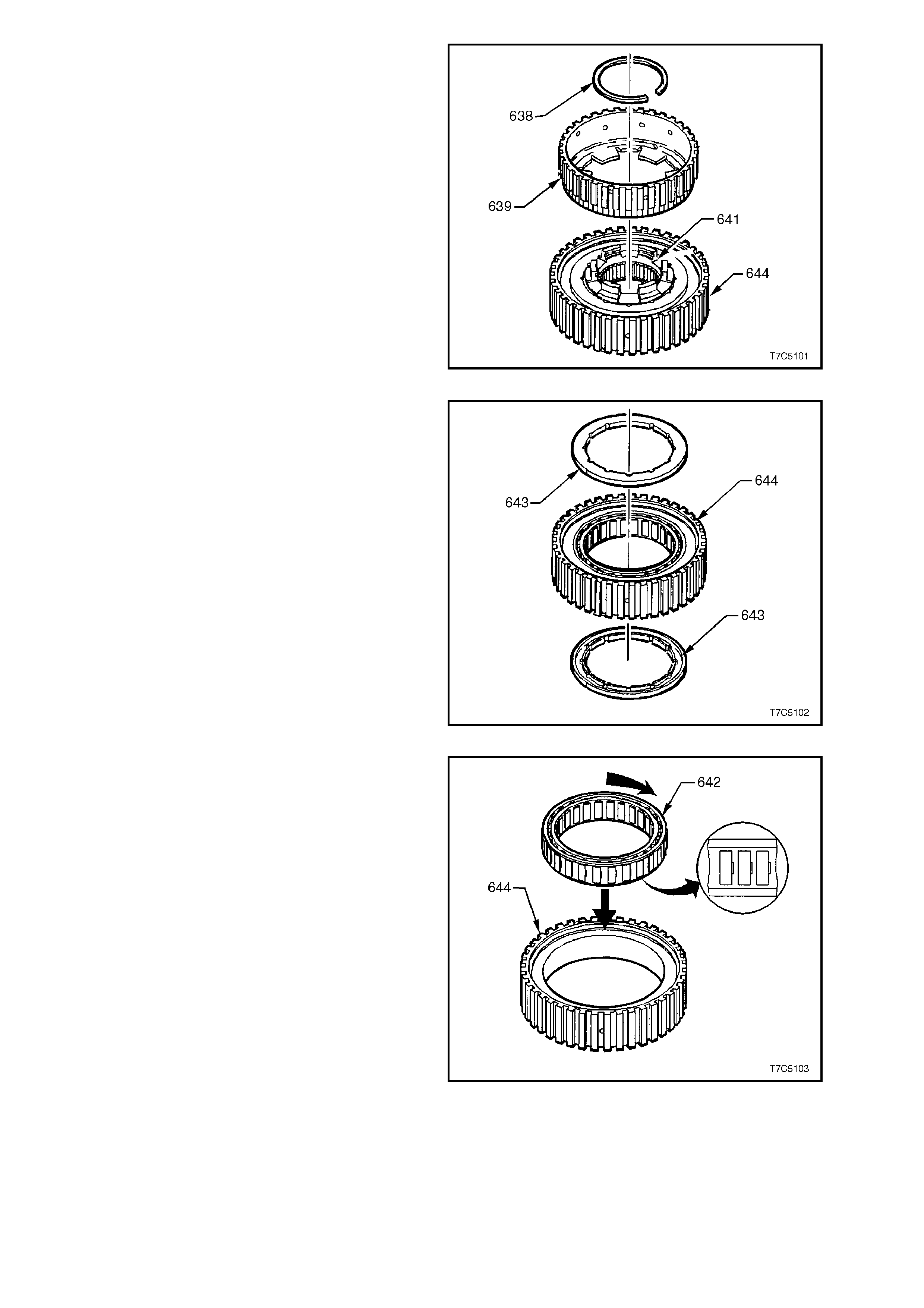
19. Disassemble forward sprag clutch assembly
as follows:
a. Remove overrun clutch hub retaining
snap ring (638) and clutch hub (639).
b. Remove forward clutch outer race (644).
c. Remove sprag retainer and race
assembly (641).
Figure 7C5-103
d. Remove sprag assembly retainer rings
(643).
e. Remove the forward sprag assembly
from the forward clutch outer race (644).
Figure 7C5-104
20. Inspect forward clutch sprag assembly (642)
for:
a. Wear or damage.
b. Weak or broken springs.
c. Damaged or missing retaining caps.
Figure 7C5-105
21. Inspect overrun clutch hub (639) for:
a. Spline damage.
b. Plugged lubrication holes.
c. Damaged tangs.
d. Cracks.
22. Inspect sprag retainer and race assembly
(641) for:
a. Spline damage.
b. Ring groove damage.
c. Surface finish damage.
d. Loose retainer.
23. Inspect forward clutch outer race (644) for:
a. Spline damage.
b. Surface finish damage.
c. Plugged lubrication holes.
24. Inspect forward (650) and 3-4 clutch backing
plates (655) for:
a. Flatness.
b. Surface finish damage.
c. Burrs and nicks.
25. Inspect forward clutch apply plate (646) and
spacer plate for:
a. Flatness.
b. Surface finish damage.
c. Burrs and nicks.
26. Inspect 3-4 clutch apply plate (653) for flatness
and surface finish damage.
27. Inspect 3-4 clutch r ing retaining plate (652) for
bent tangs and flatness.
Figure 7C5-106
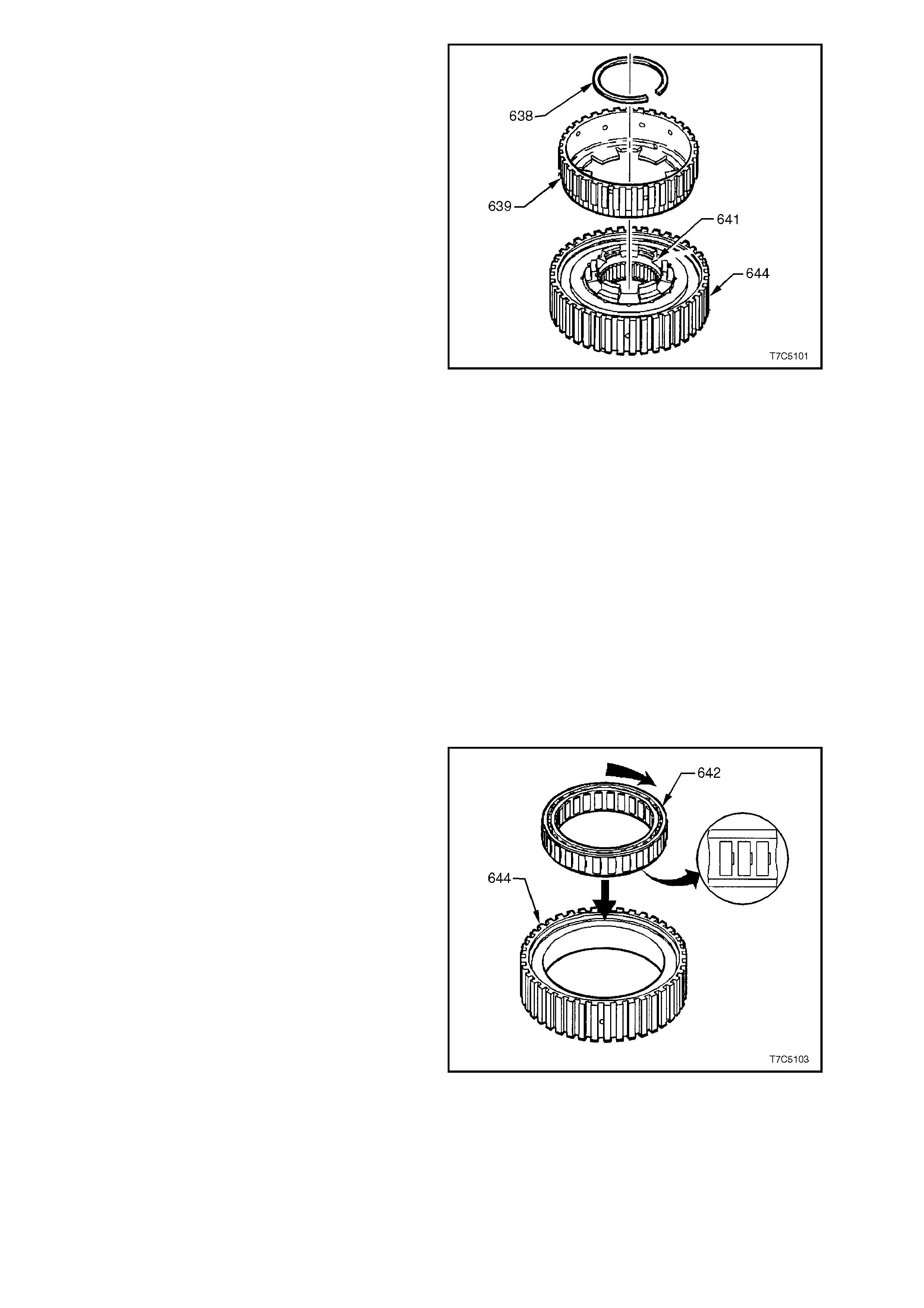
REASSEMBLE
FORWARD CLUTCH SPRAG ASSEMBLY
1. Reinstall forward sprag assembly (642) into
forward clutch outer race (644). Notches in
sprag cage point in the direction shown.
Figure 7C5-107
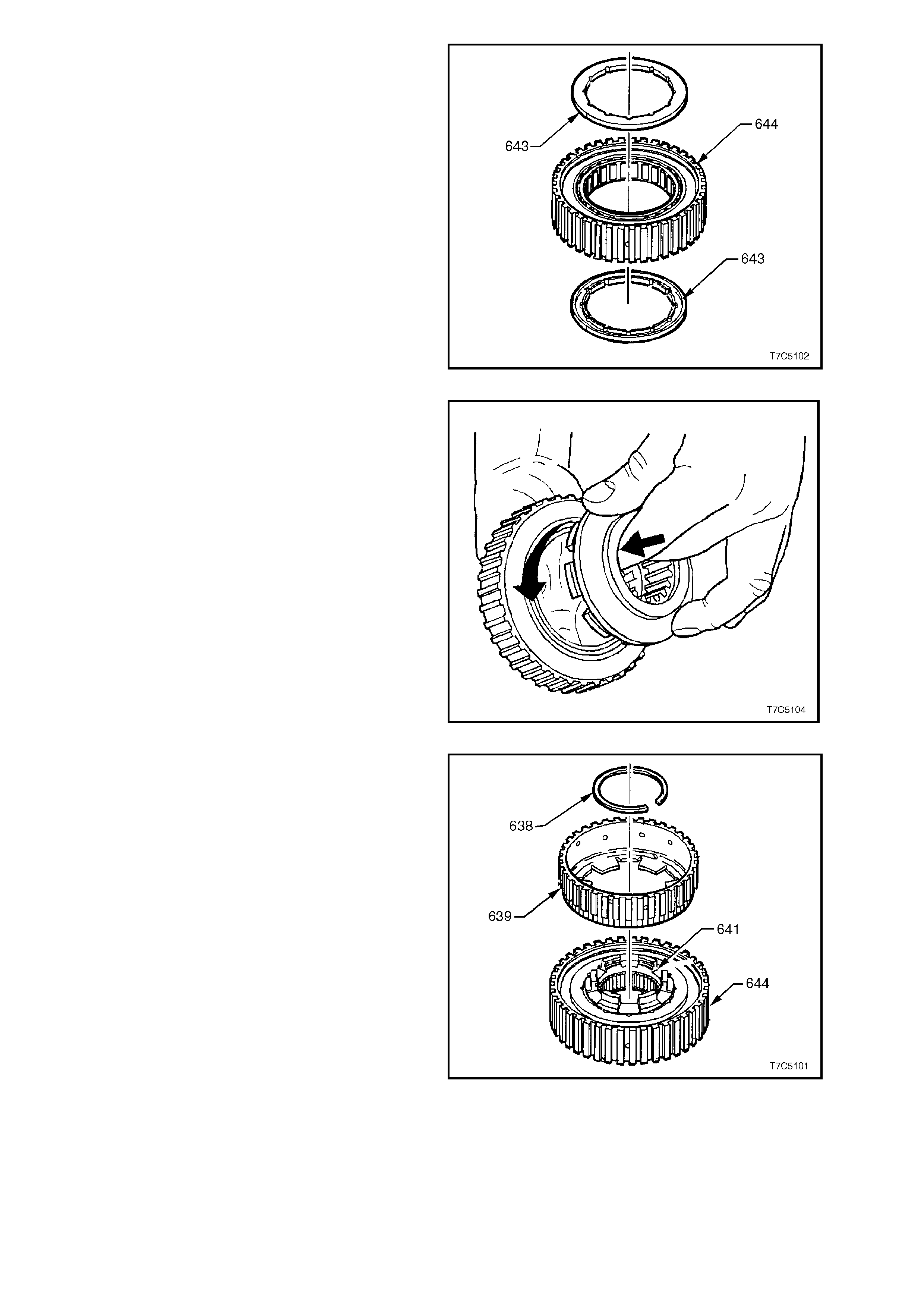
2. Reinstall one sprag retaining ring (643) onto
sprag retainer and race hub assembly (641)
with retaining ring recess facing outward.
Figure 7C5-108
3. Locate sprag r etaining ring (643) and r ace hub
assembly (641) into the sprag outer race
assembly as follows:
a. Hold outer race (644) in right hand
supporting sprag assembly (642) with
fingers at recessed side of outer race.
b. Insert retaining ring and race hub
assembly from opposite side of outer
race by pushing in and turning anti-
clockwise.
4. Reinstall remaining sprag assembly outer
retaining ring (643), with the recess facing
inward toward the sprag (642).
Figure 7C5-109
5. Reinstall overrun clutch hub (639).
6. Reinstall overrun clutch hub retaining snap
ring (638) into groove in sprag retainer and
race assembly (641).
7. Test assembly for correct operation as follows;
a. Hold the forward clutch outer race (644)
in the left hand and grasp the overrun
clutch hub (639) with the r ight. Attempt to
rotate the hub in both directions.
b. Provided the overrun clutch hub rotates
when turned clockwise and locks up
when attempting to turn it counter-
clockwise, then the sprag has been
assembled correctly. If however, the
assembly operates backwards, the sprag
is assembled incorrectly. Dismantle and
re-assemble correctly.
Figure 7C5-110
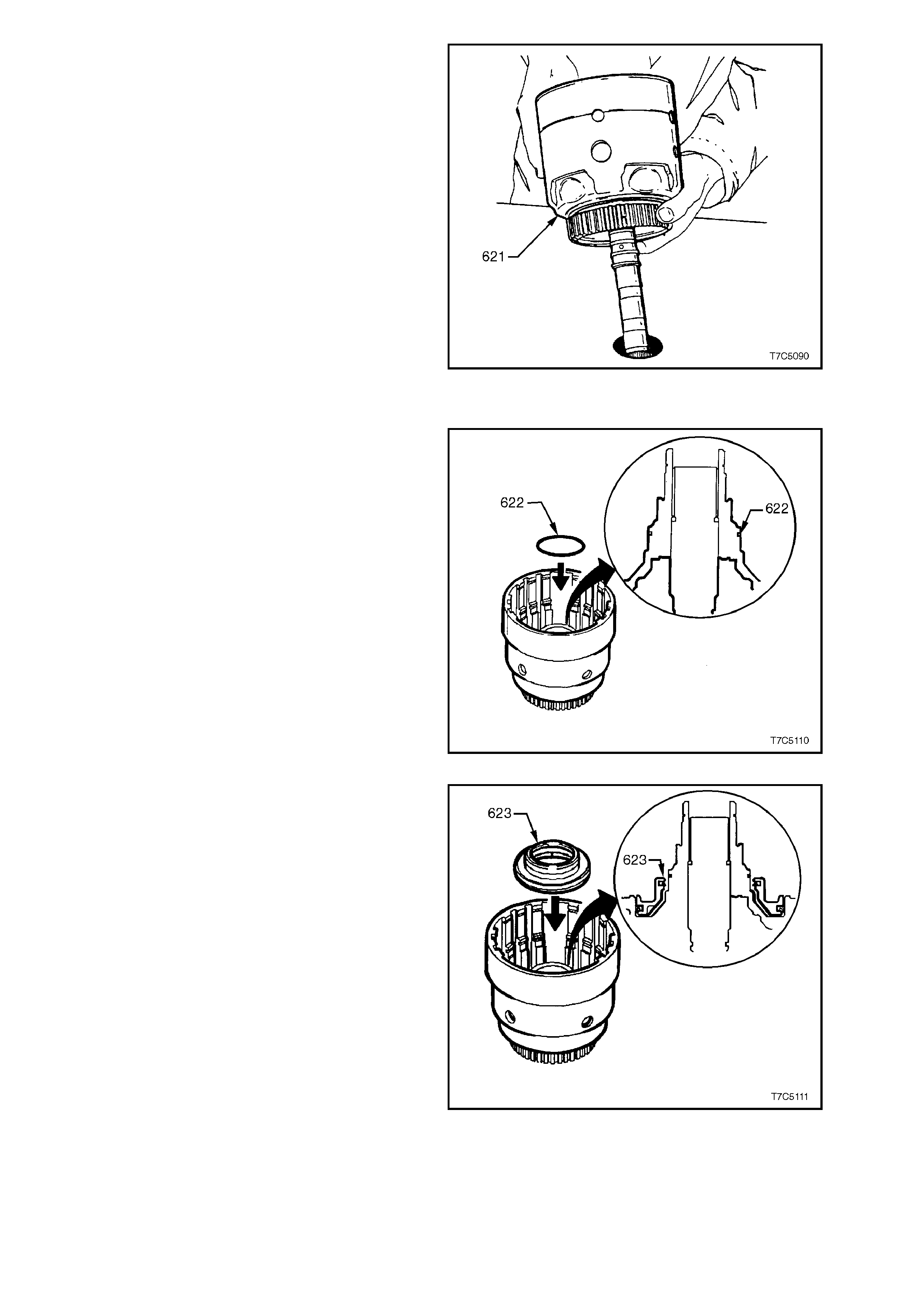
8. Place input housing and shaft assembly (621)
on workbench with input shaft protruding
through hole in workbench.
Figure 7C5-111
3-4 CLUTCH ASSEMBLY
9. Lubricate a new O-ring (622) with petroleum
jelly and install on input housing.
Figure 7C5-112
10. Coat new 3-4 clutch piston inner and outer lip
seals with petroleum jelly.
11. Reinstall 3-4 clutch piston in input housing as
shown, taking care not to damage seals.
Figure 7C5-113
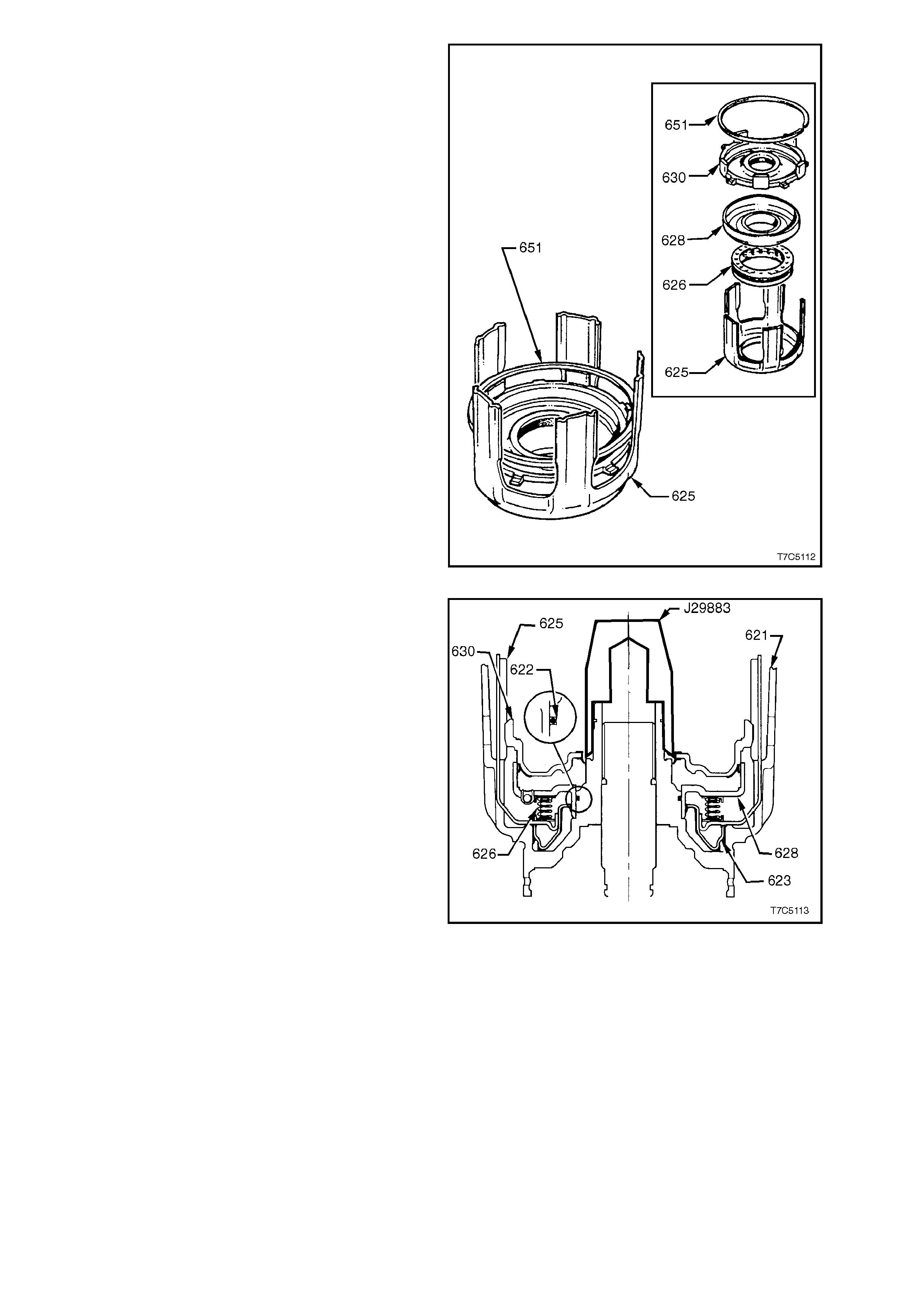
12. Locate 3-4 clutch spring assembly (626) onto
the five legged 3-4 clutch apply ring (625).
13. Coat forward clutch piston inner and outer
bonded seals with petroleum jelly and install
the forward clutch piston (630) into forward
clutch housing (628) taking care not to
damage the outer seal.
14. Reinstall forward clutch assembly onto 3-4
clutch spring ass em bly, locating forward clutch
piston smaller apply legs between 3-4 clutch
apply ring legs, as shown.
15. Use the forward clutch backing plate retaining
ring (651) to hold these parts in place during
installation.
Figure 7C5-114
16. Fit Tool J29883 on input housing as shown
and coat with petroleum jelly.
17. Reinstall 3-4 clutch apply ring/forward clutch
assembly into input housing as follows:
a. Hold assembly by apply ring legs and
carefully lower into the input housing and
shaft assembly.
b. Do not let forward clutch piston separate
from forward clutch housing.
c. Seat assembly by pushing down firmly
onto the forward clutch piston. It may be
necessary to slightly 'rock' assembly to
overcome cocking. Ensure the forward
clutch housing is seated over the O-ring
(622).
18. Remove Tool No. J29883 and the temporarily
installed retaining ring (651).
Figure 7C5-115
OVERRUN CLUTCH ASSEMBLY
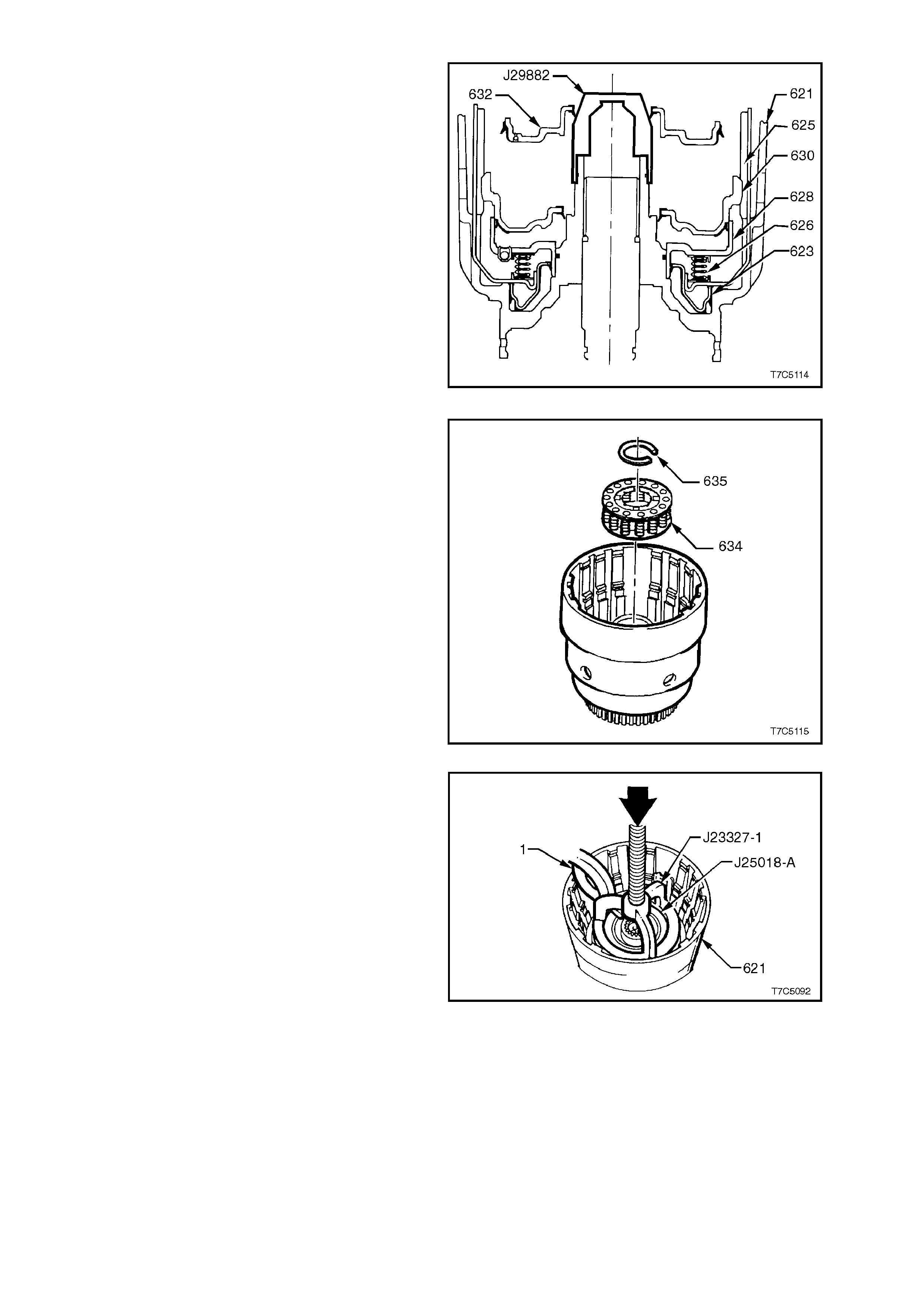
19. Fit Tool J29882 on input housing, as shown
and coat with petroleum jelly.
20. Lubricate overrun clutch pis ton inner and outer
bonded seals with petroleum jelly and install
piston (632) with hub facing upwards, as
shown.
NOTE:
If all components are correctly seated, overrun
clutch piston hub locates approximately 3 mm
below snap ring groove in input housing hub.
21. Remove tool J29882.
Figure 7C5-116
22. Reinstall overrun clutc h spring assem bly (634)
onto overrun clutch piston.
Figure 7C5-117
23. Install part of J23327 and J25018-A as shown.
24. Place input housing and shaft assembly in a
suitable press.
25. Compr ess over run clutc h spring ass em bly and
install clutch retaining ring (635). Do not over-
compress springs. Remove specia l tools.
Figure 7C5-118
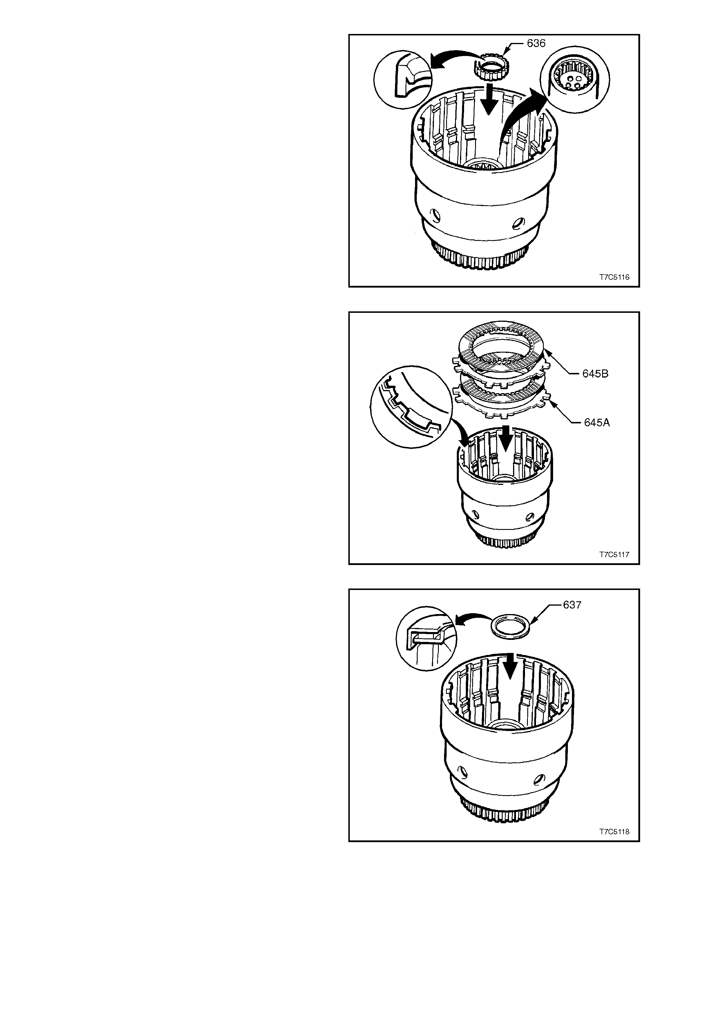
26. Install new output shaft seal (636) into input
housing, noting seal lip orientation.
Figure 7C5-119
27. Pre-lubricate overrun clutch plates (645B) in
automatic transmission fluid and reinstall into
input housing; steel (645A) first, then
composition (645B), steel and the second
composition plate. Align the steel plates with
the wide notch, as shown.
NOTE:
This clutch pack is the smallest set in the
transmission.
Figure 7C5-120
28. Reinstall input sun gear thrust bearing
assembly (637) onto input clutch hub with
inside race facing input housing hub, as
shown. Retain thrust bearing in place with
petroleum jelly.
Figure 7C5-121
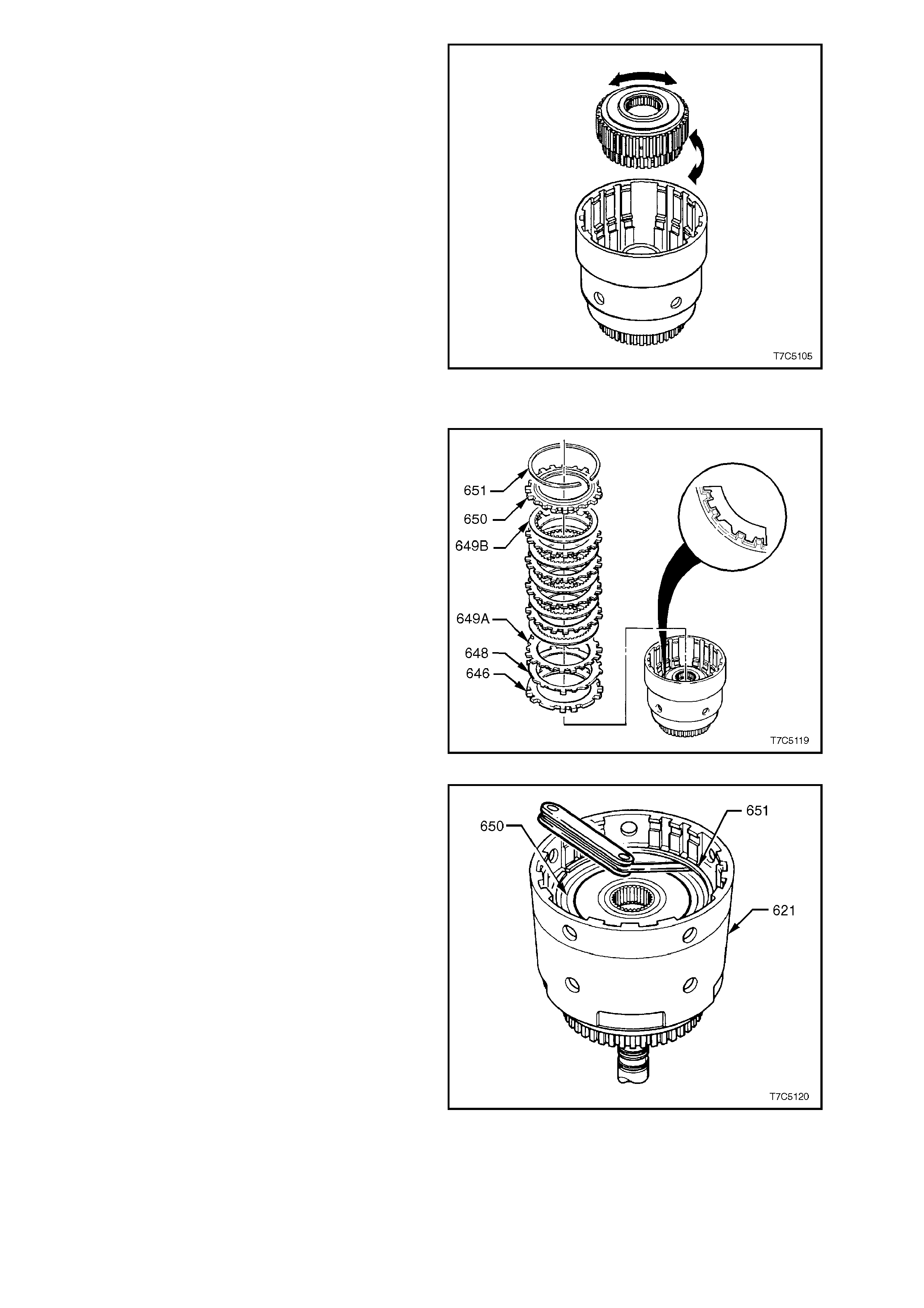
29. Align the two composition over run clutch plate,
inner tangs.
30. Reinstall forward clutch sprag assembly into
input clutch housing, locating overrun clutch
hub (639) into overrun clutch plates.
Figure 7C5-122
FORWARD CLUTCH ASSEMBLY
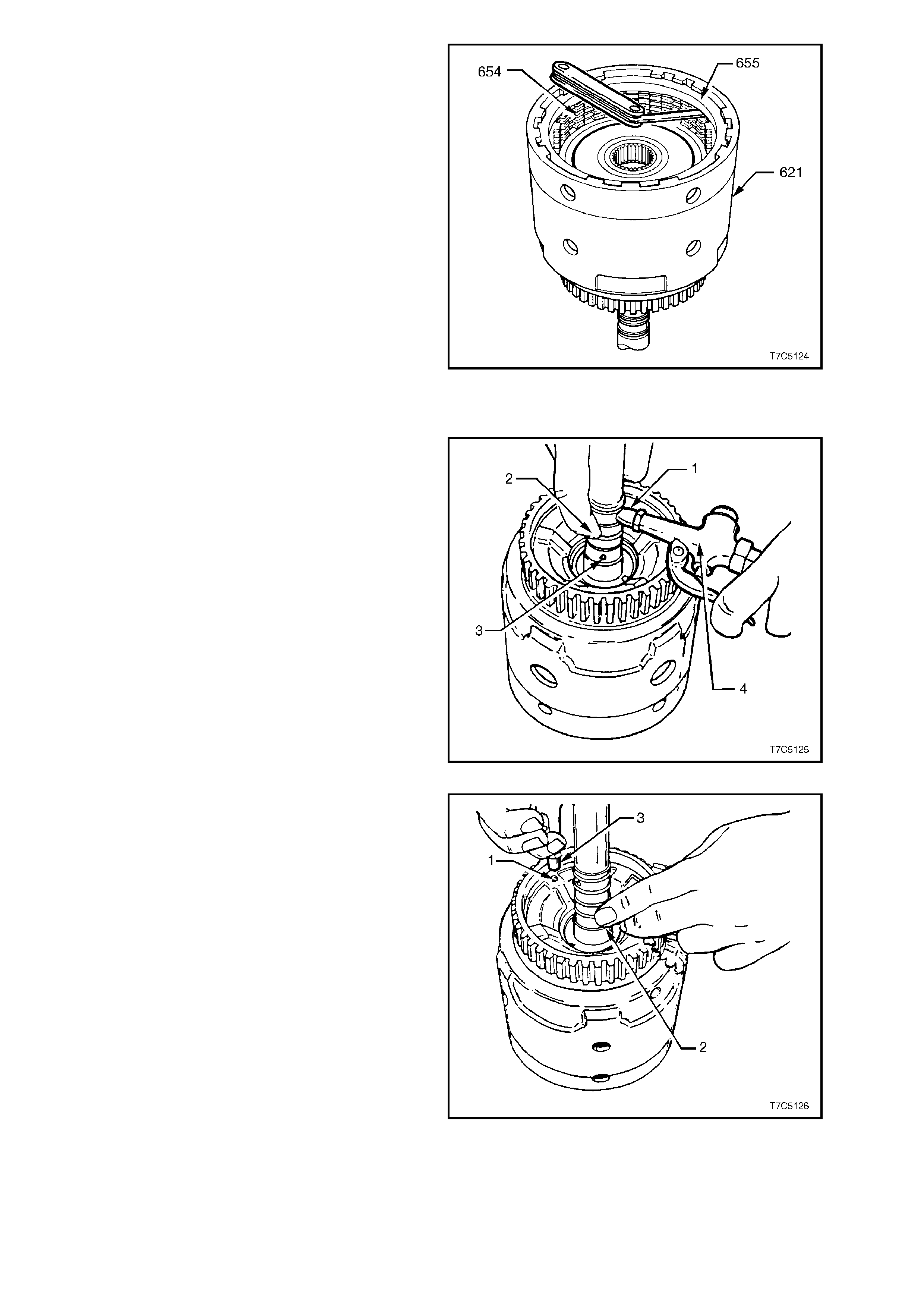
31. Reinstall forward clutch apply plate (646) into
input clutch housing (621), indexing as shown.
32. Reinstall waved steel forward clutch plate
(648) into input clutch housing, again indexing
as before.
33. Reinstall rem aining forward clutch plates (649)
into input housing; starting with a steel plate
(649A), then composition (649B, etc.
34. Reinstall for ward c lutch s elec tive bac king plate
(650) and then reinstall retaining ring (651).
Figure 7C5-123
35. Measure end clearanc e between backing plate
(650) and retaining ring (651) with two feeler
gauges. Clearance should be 0.75 to 1.60
mm. If clearanc e is incorrect, s elect a s uitable
selective backing plate (650) from chart below
and install instead of the original backing plate.
FORWARD CLUTCH SELECTIVE PLATE
PLATE THICKNESS (mm) IDENTIFICATION
6.97 - 7.07 A
6.38 - 6.48 B
5.79 - 5.89 C
5.20 - 5.30 D
4.61 - 4.71 E
Figure 7C5-124
3-4 CLUTCH
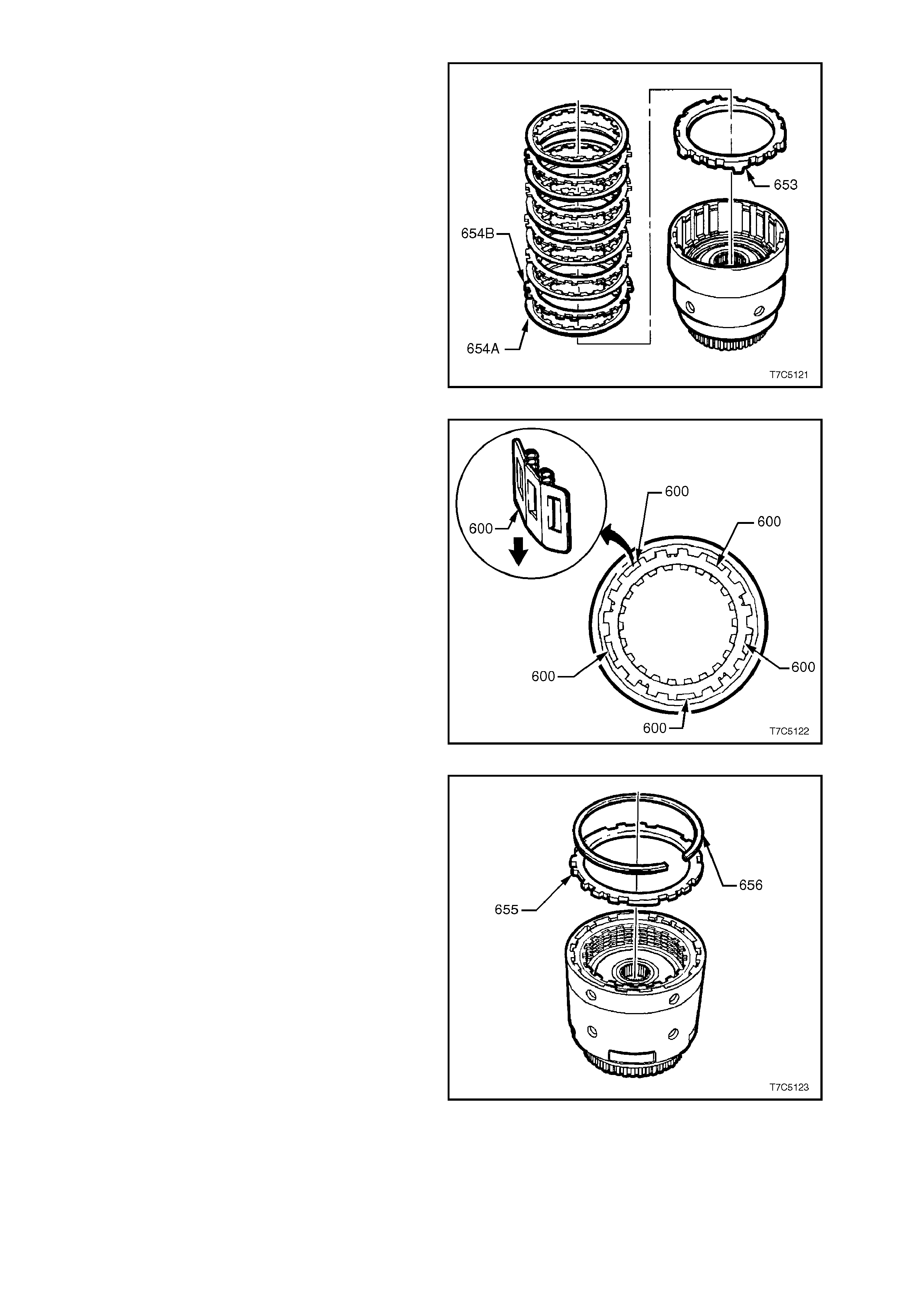
36. Reinstall 3-4 clutch apply plate (653), with the
protruding lugs facing inward, as shown.
37. Reinstall 3-4 clutch plates (654), starting with a
composition (654A), then steel (654B), etc.
Figure 7C5-125
NOTE:
Install the steel plates with the wider lug openings
in the wide gap of the input housing (621), to allow
space for the five spring boost assemblies.
38. Reinstall five spring boost assemblies (600),
exposed spring ends uppermost and equally
spaced in the locations shown.
Figure 7C5-126
39. Reinstall 3-4 clutch backing plate (655),
chamfered side up and wide tangs over the
spring boost assemblies (600). Reinstall
retaining ring (656).
Figure 7C5-127
40. Measure clearance between backing plate
(655) and adjacent composition plate with a
feeler gauge. Clearance should be 0.90 -
2.10 mm. If clearance is incorrect, select a
suitable selective backing plate from the chart
below and install in the place of the original
backing plate.
3-4 CLUTCH SELECTIVE PLATE
PLATE THICKNESS (mm) IDENTIFICATION
5.88 - 5.68 A
4.99 - 4.76 B
4.10 - 3.90 C
Figure 7C5-128
INPUT CLUTCH HOUSING AIR CHECKS
1. Check overrun clutch by using a rubber tipped
air nozzle (4) to apply air pressure to the
overrun clutch passage (1) while blocking
forward clutch apply hole (2). Overrun clutch
should apply. Lube passage (3) is shown to
assist with correct orifice identification.
NOTE:
Unless the forward clutch apply hole is blocked
during this test, air will leak past the forward clutch
piston lip seals and exit via the forward clutch feed
hole in the input shaft.
2. Check the forward clutch by applying air
pressure to the forward clutch apply hole.
Forward clutch should apply.
Figure 7C5-129
3. Check 3-4 clutch by applying air pressure (3)
to the 3-4 clutch ball and retainer assembly
(1), while blocking the 3-4 feed hole (2) in the
turbine shaft. The 3-4 clutch should apply.
Figure 7C5-130
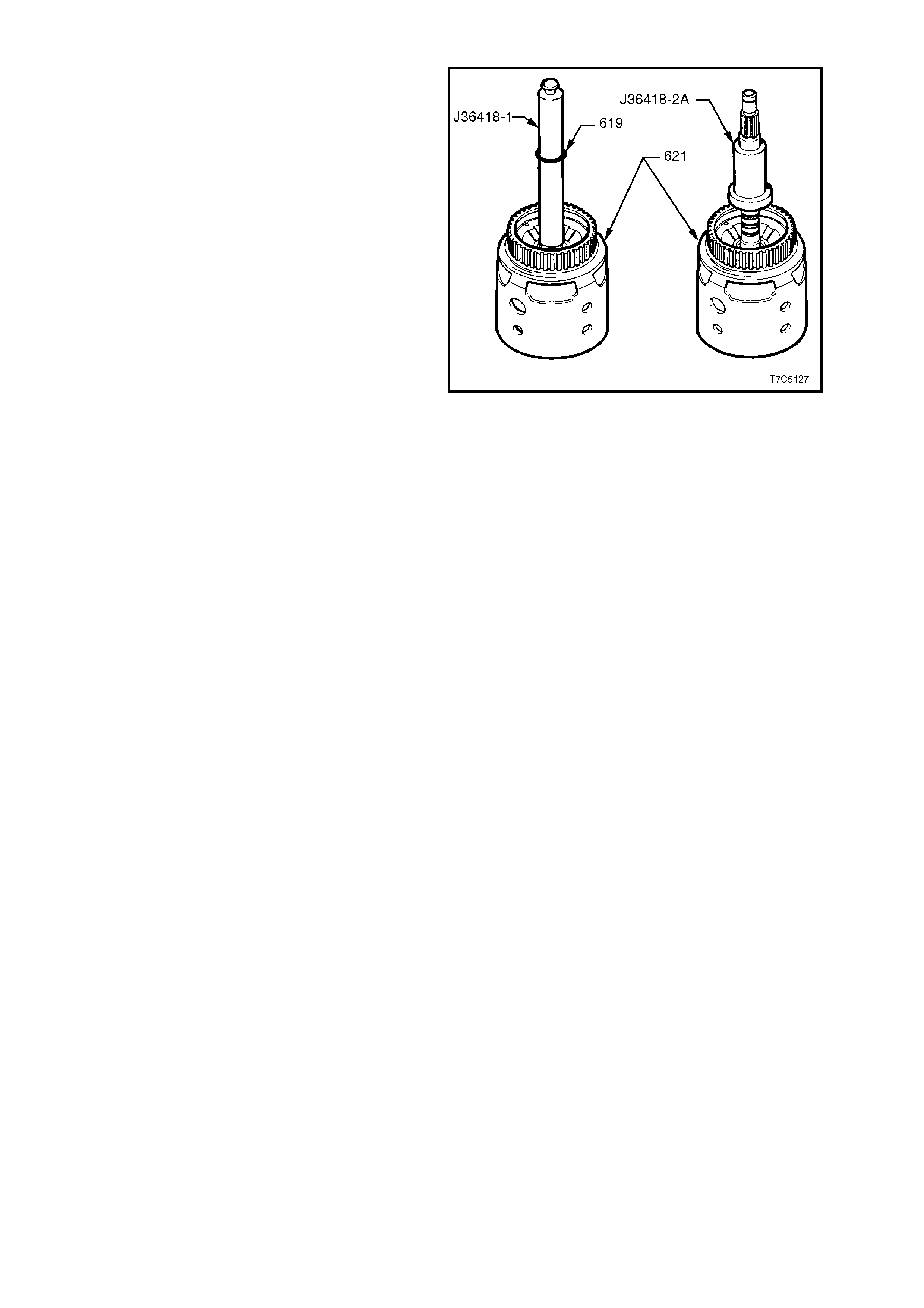
REINSTALL TURBINE SHAFT SEALING RINGS
1. Fit Tool No. J36418-1 over input shaft.
2. Install four new input shaft oil seal rings (619).
3. Remove J36418-1 and install J36418-2A over
seals to re-size them. Leave J36418-2A in
place until transmission is reassembled.
Figure 7C5-131
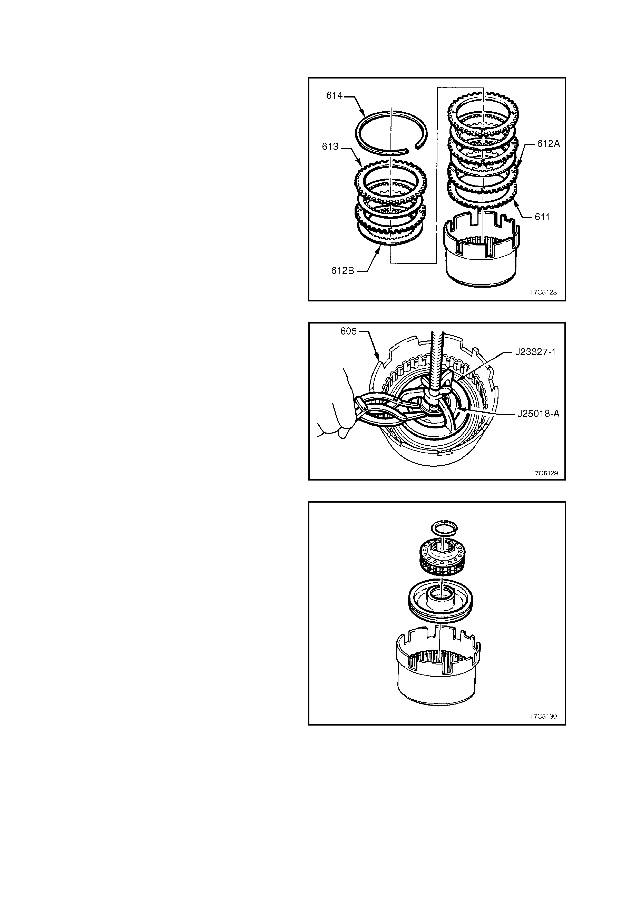
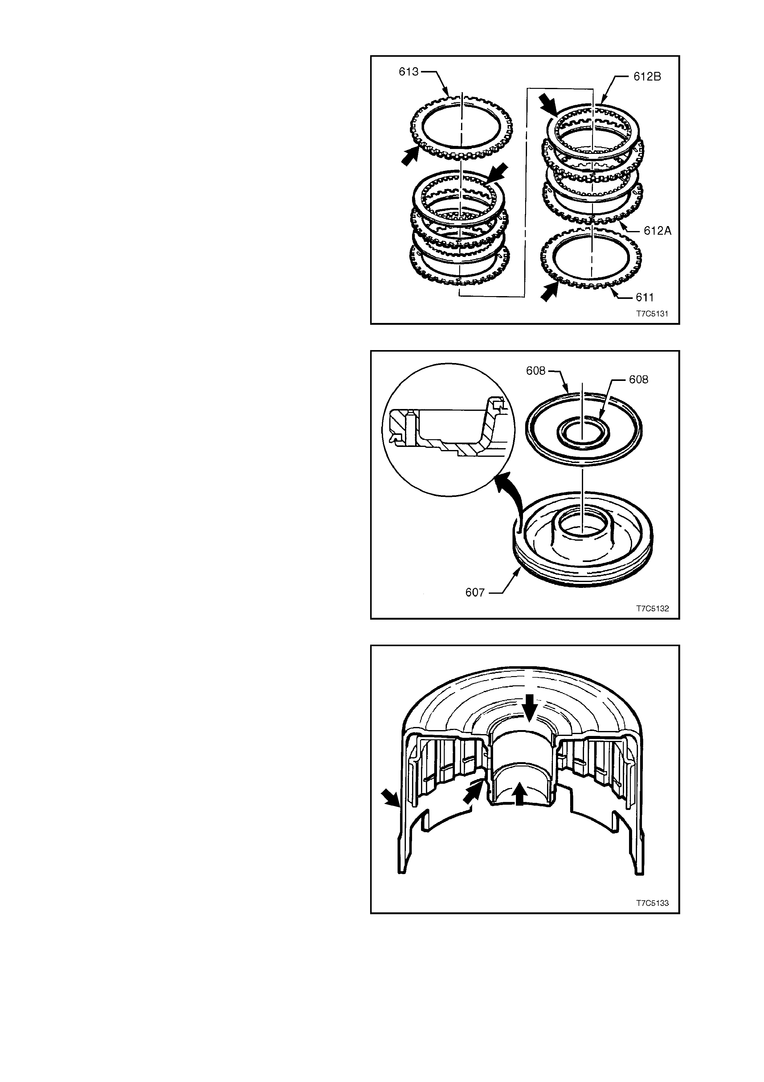
2.13 REVERSE INPUT CLUTCH ASSEMBLY
DISASSEMBLE
1. Remove backing plate retaining ring (614)
from housing and drum assembly.
2. Remove backing plate (613) and clutch plates
(612A/B) including Belleville plate (611).
Figure 7C5-132
3. Install Tools J23327 with J25018-A
underneath and com pres s rever se input c lutch
sprin g assembly.
Figure 7C5-133
4. Remove spring assembly retaining ring.
5. Remove J23327 and J25018-A and remove
sprin g assembly.
6. Remove piston and discard piston seals.
Figure 7C5-134
INSPECT
1. Inspect selective backing plate (613) for
damage, burrs or distortion.
2. Inspect clutch plates. Check composition
plates (612B) for tang damage, delamination
or wear. Check steel plates (612A) for tang
damage, wear or heat damage.
3. Check the waved plate (611) for heat dam age
or tang wear.
4. Inspect spring assembly for distortion or
damage.
Figure 7C5-135
5. Inspect the reverse input clutch piston (607)
for:
a. Damage or porosity.
b. Ring groove damage.
6. Remove both piston seals (608) and discard.
Figure 7C5-136
7. Inspect housing and drum assembly (605) for:
a. Damaged or worn bushes.
b. Surface damage to hub or outer housing.
c. Leaking weld.
Figure 7C5-137
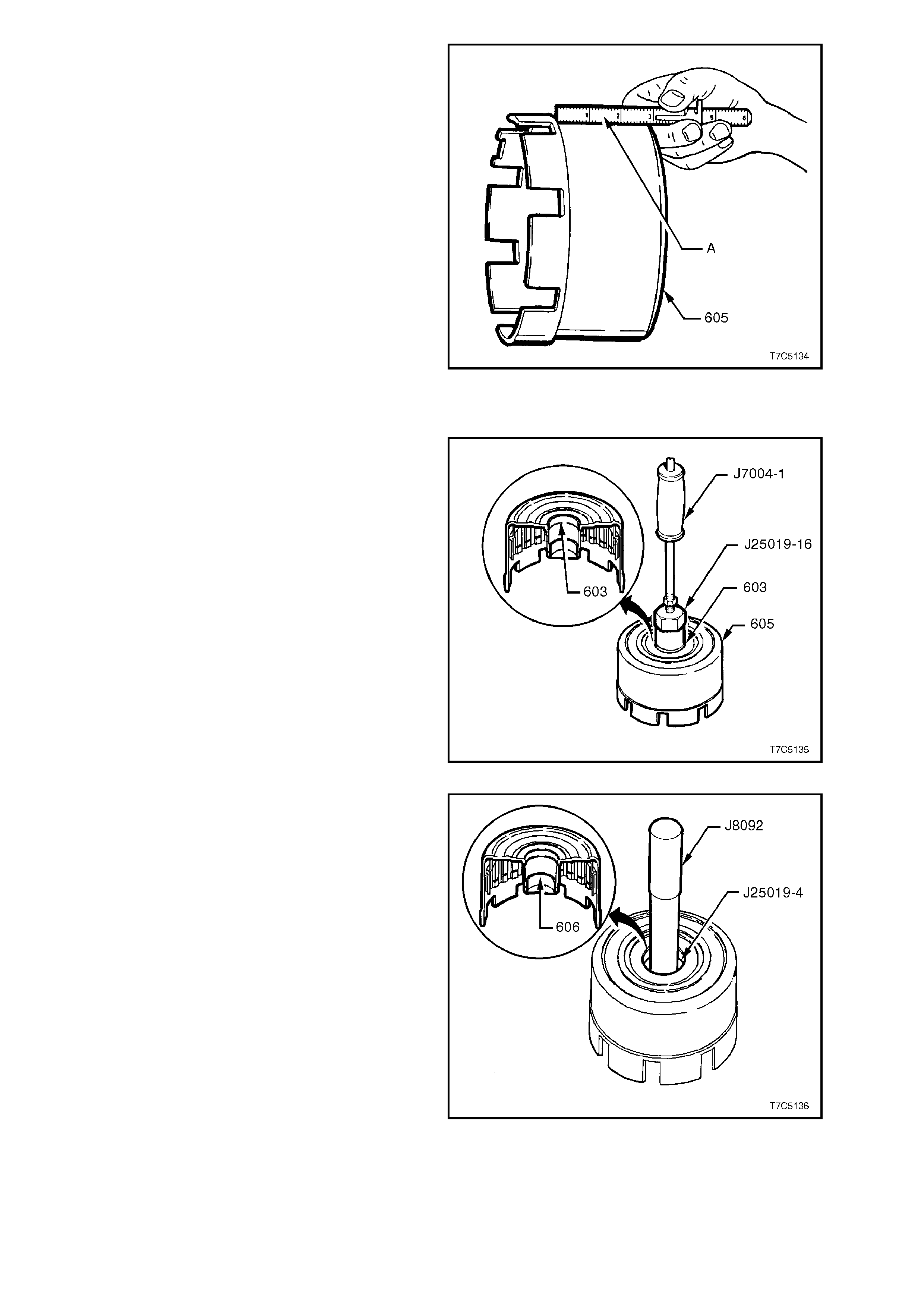
d. Outer housing 'dishing' at point ‘A’.
Should the bushes require replacement, refer to the
following procedure.
Figure 7C5-138
REVERSE INPUT CLUTCH HOUSING BUSHES - REPLACE
1. Using bush remover J25019-16 and slide
hammer J7004-1, remove the front bushing
from the reverse input clutch housing.
Figure 7C5-139
2. Use bush remover J 25019-4 and dr iver handle
J8092 to press the rear bush from the reverse
input clutch housing.
Figure 7C5-140
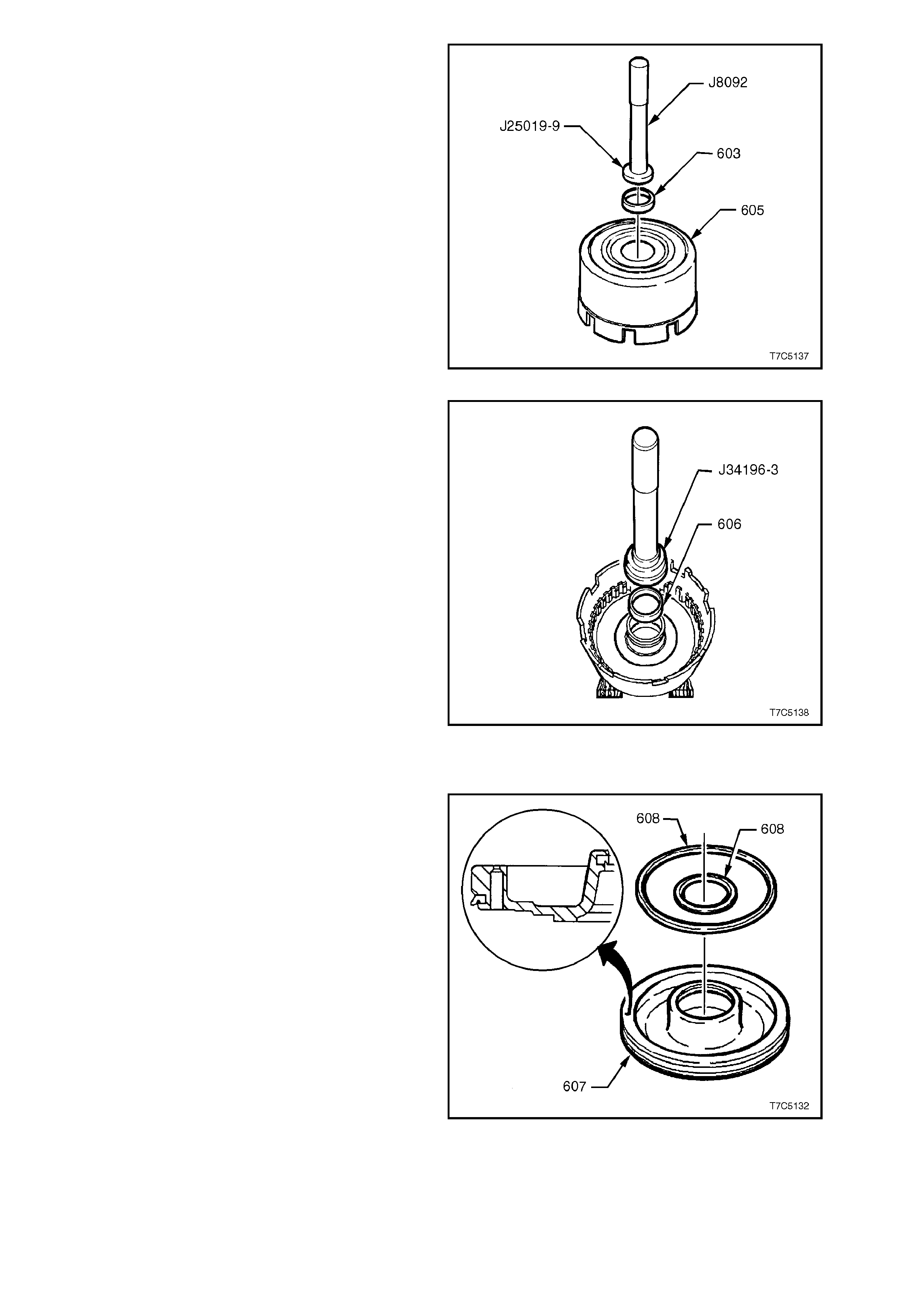
3. Press a new front bush (603) into the reverse
input clutch housing, using installer J25019-9
and driver handle J8092.
Figure 7C5-141
4. Support the reverse input clutch housing on
suitable pieces of wood and install a new rear
bush (606), using installer J 34196-3 and driver
handle J8092
Figure 7C5-142
REASSEMBLE
1. Lubricate new piston seals with transmission
fluid and install s eals on piston with lips facing
in the direction shown.
Figure 7C5-143
2. Position a strip of thin plastic material
(approximately 0.01 mm thick) (1) around one
half of the hub and coat with petroleum jelly.
3. Coat piston seals with petroleum j elly and, with
seal lips facing down, reinstall piston (607) by
tilting down on the side opposite the plastic
strip.
4. Gently work the piston down against the
plastic strip and into the hub. Remove the
plastic strip.
5. Reinstall spring assembly with larger opening
facing piston.
6. Install Tools J25018A and J23327 to
com press spring ass embly and reinstall s pring
assembly retaining ring. Remove tools.
Figure 7C5-144
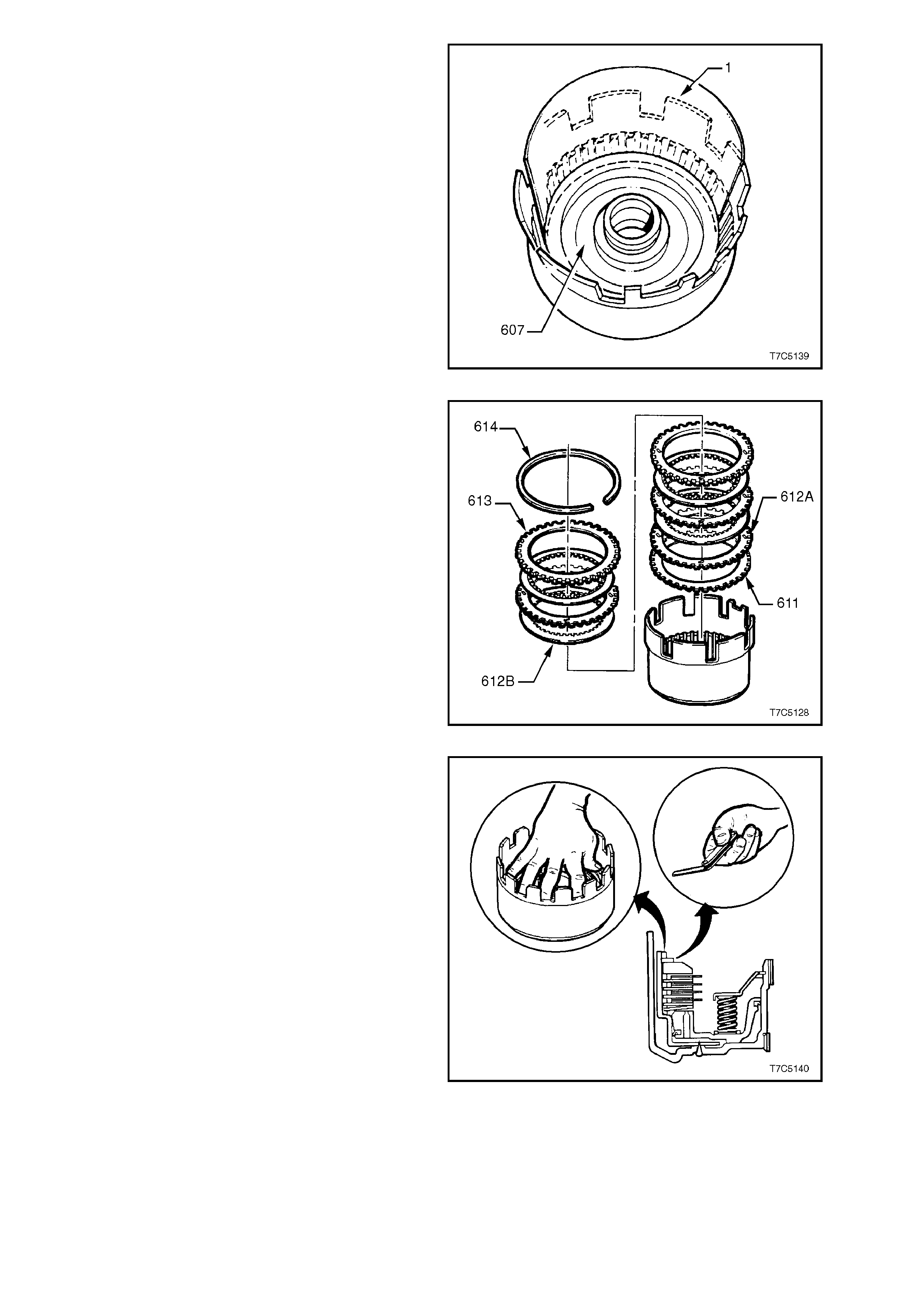
6. Reinstall Belleville clutch plate (611), concave
side down.
7. Reinstall remaining clutch plates, starting with
a steel plate (612A), then composition (612B),
etc.
8. Reinstall selective backing plate (613),
chamfered side up and reinstall retaining ring
(614).
Figure 7C5-145
9. Apply an evenly distributed, medium load
(approx. 10 kg) to the backing plate (613) as
shown in the inset.
NOTE:
Excessive pressure will distort the Belleville plate.
10. Use a feeler gauge to measure the gap
between the backing plate (613) and retaining
ring (614). The gap should be between 1.02
and 1.95 mm.
11. If gap is not to specification, select another
backing plate from the table below to replace
the original. Thes e specif ications apply to both
the V6 and V8 applications.
REVERSE INPUT CLUTCH BACKING
PLATE SELECTION
PLATE THICKNESS (mm) IDENTIFICATION
7.249 - 7.409 2
6.519 - 6.678 3
5.787 - 5.947 4 Figure 7C5-146
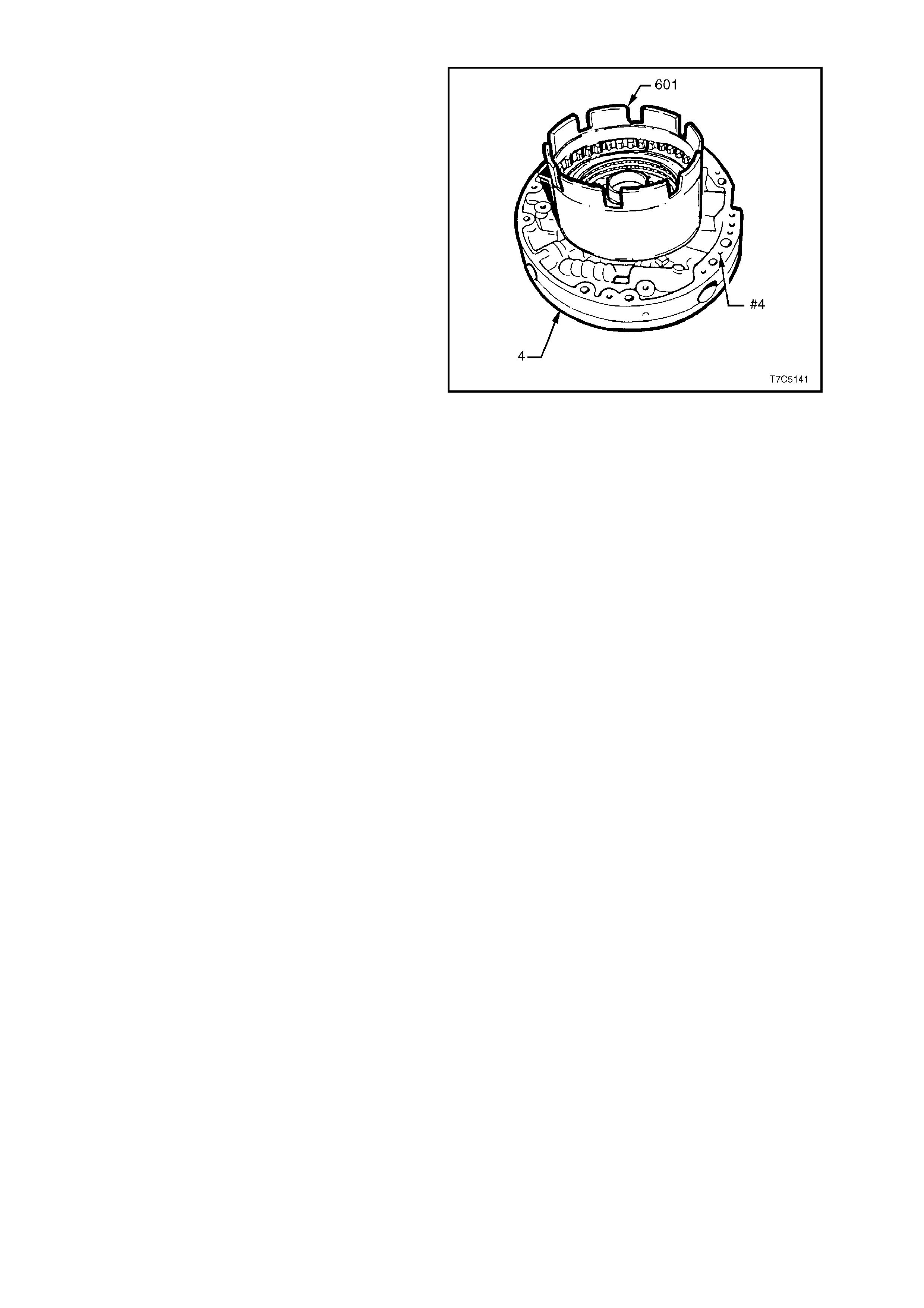
REVERSE INPUT CLUTCH AIR CHECK
NOTE:
Even though air pressure will be lost through the
bleed hole in the piston during this process, it is
recommended that the reverse input clutch be
completely assembled, prior to conducting this test.
If air tested with only the piston and return spring
assembly secured with a retaining ring, the piston
may 'over-stroke' and dis lodge the snap ring and/or
cause the piston seals to become dislodged from
the piston and damaged. In either case, there is a
safety risk that is to be avoided.
1. Mount the reverse input drum assembly (605)
and thrust washer (601), onto the inverted
pump assembly (4), as shown.
2. Apply air pressure in bursts to the oil pump
housing passage (# 4) and observe the
movement of the clutch piston and the clutch
pack.
If the clutch does not apply, there is a
possibility that the air pressure is too low.
Therefore, increase the pressure before
condemning the clutch piston assembly.
Figure 7C5-147

2.14 2-4 BAND
INSPECT
1. Inspect 2-4 band assembly for damage,
delamination or excessive wear.
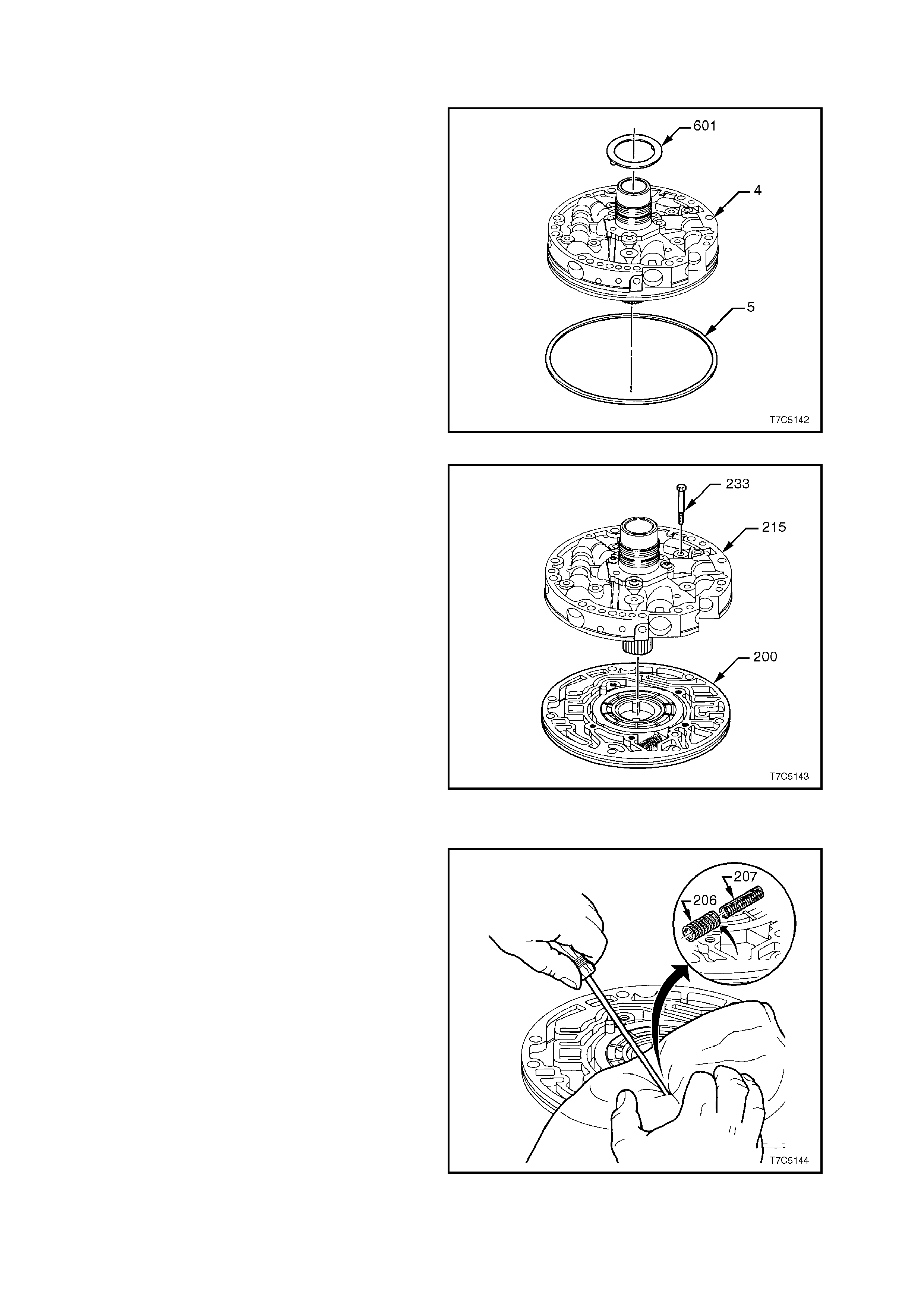
2.15 OIL PUMP
DISASSEMBLE
1. Position the oil pump assembly so that the
stator shaft (214) protrudes through a hole in
the workbench.
2. Remove the thrust washer (601), from the
reverse input drum support and the O-ring
seal (5) from the pump body.
Figure 7C5-148
3. Remove five bolts (233) securing the pump
cover to the pump body.
4. Separate the pump c over as s embly (215) from
pump body (200).
Figure 7C5-149
OIL PUMP BODY
1. Compress pump slide springs (206 and 207)
with a suitable lever or long nose pliers and
remove spri ngs.
CAUTION:
Springs are under a high load. Place a covering
over springs (as shown) before removal to
prevent possible injury.
Figure 7C5-150
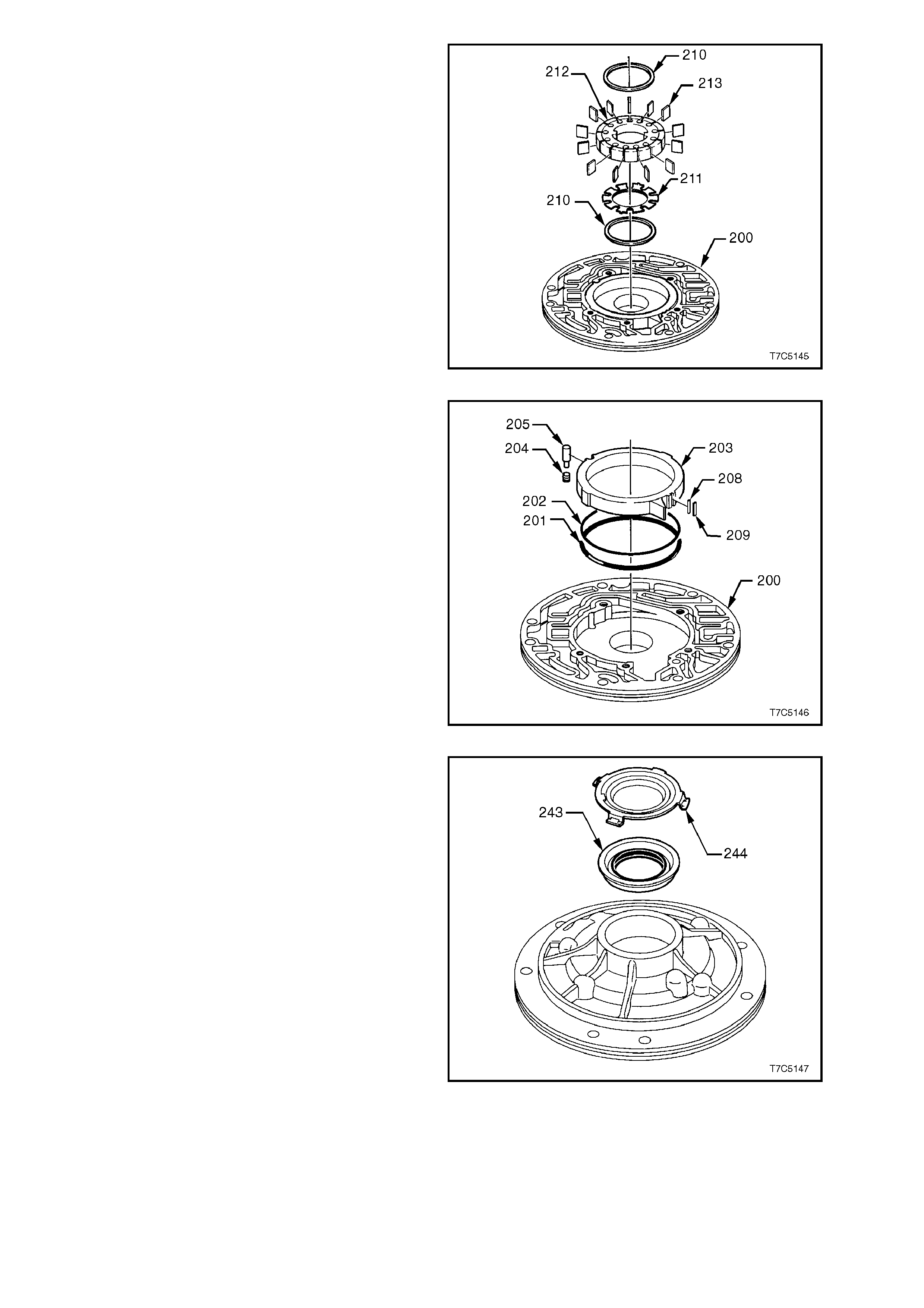
2. Remove following components from pump
cavity in body (200):
a. Pump guide ring (210).
b. Thirteen pump vanes (213). Note wear
mark patterns for reassembly.
c. Pump rotor (212).
d. Rotor guide (211).
e. Pump vane guide ring (210).
Figure 7C5-151
f. Slide (203).
g. Slide seal (209).
h. Seal support (208).
i. Pivot slide pin (205) and spring (204).
j. Slide seal ring (201) and back up seal
(202).
Figure 7C5-152
3. Use a screwdriver to prise out the front helix
seal retainer ( 244) and oil seal as sem bly (243)
from the pump body.
Figure 7C5-153

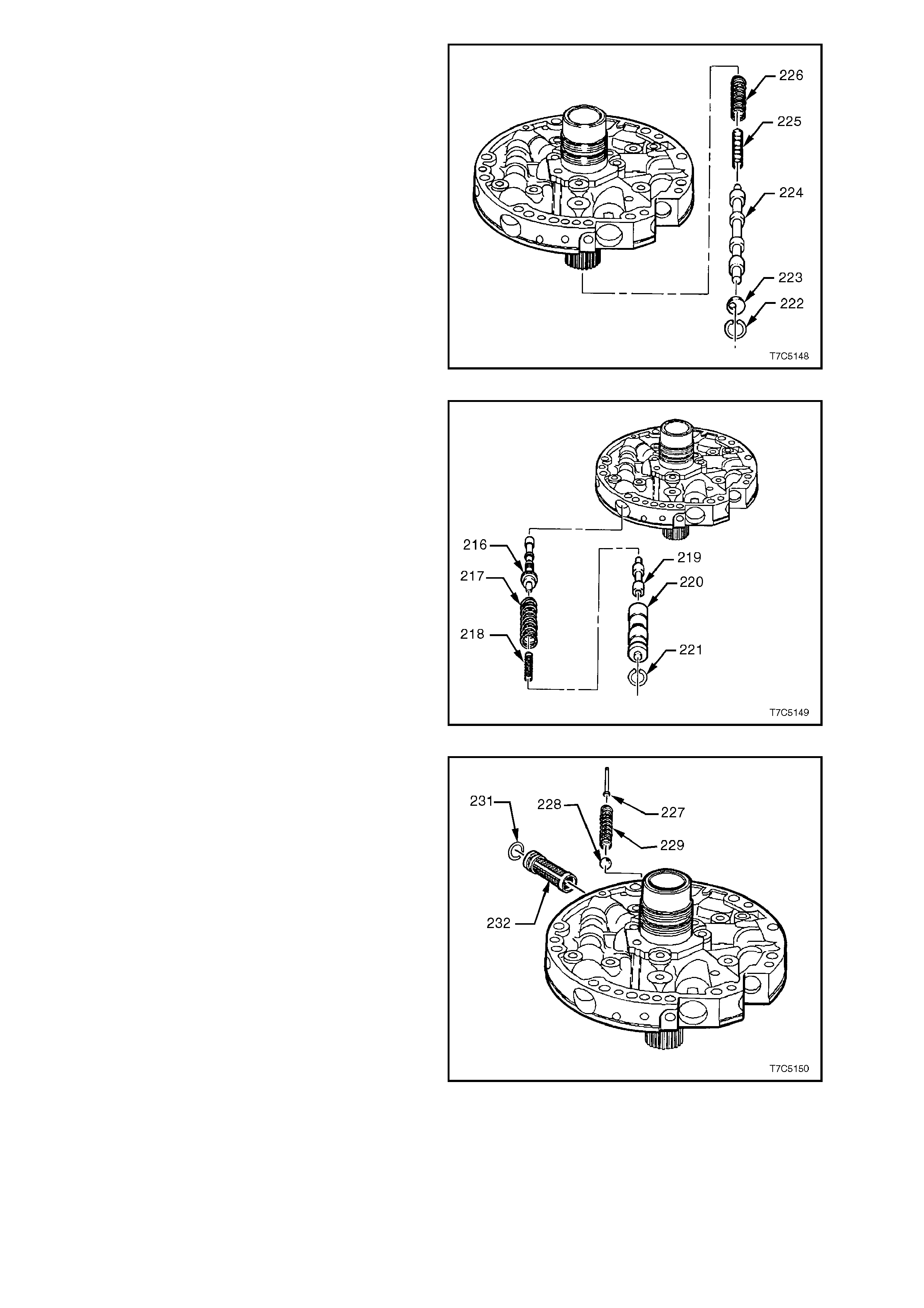
OIL PUMP COVER
1. Compress converter clutch apply stop valve
(223) with a screwdriver and use circlip pliers
to remove the circlip (222). Slowly release
spring force and remove the stop valve (223),
the converter clutch apply valve (224) and the
two converter clutch valve springs (225 and
226). Lay components out in order for
inspection.
Figure 7C5-154
9. Repeat this process for the pressure regulator
valve assembly (216 to 221).
Figure 7C5-155
10. Prise pressure release pin (227) from pump
cover then remove spring (229) and ball (228).
CAUTION:
Spring is under very high load. Cover assembly
with cloth when removing pin.
11. Using long nose pliers , pull cover s creen ( 232)
and O-ring seal (231) from the pump cover.
Figure 7C5-156
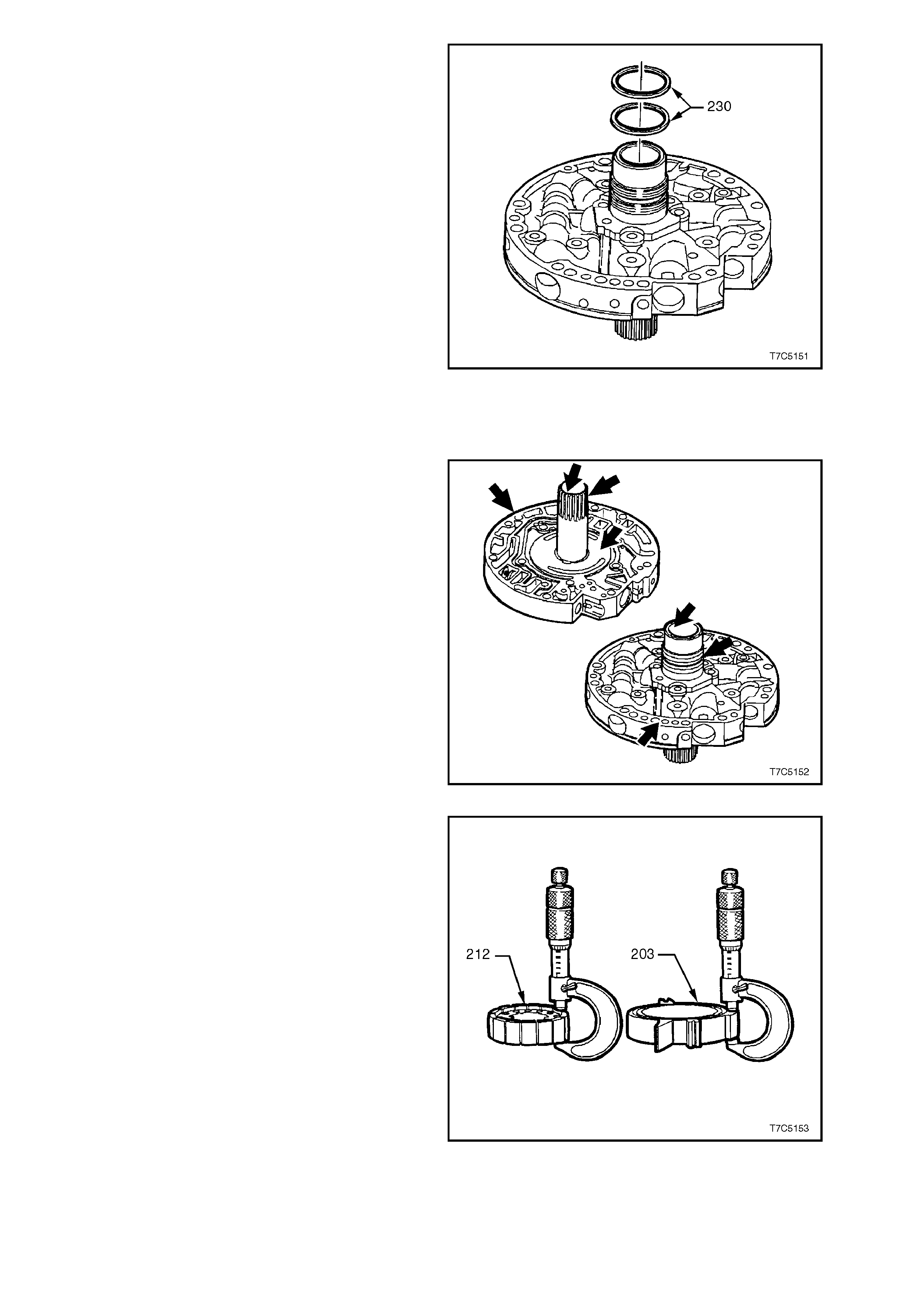
12. Carefully cut the two stator shaft seals (230)
and discard.
13. W ash all c omponents with solvent and air dry.
Do not dry with a cloth.
Figure 7C5-157
INSPECT
1. Inspect pump cover (215) and body (200) for:
a. Worn or damaged bushes.
b. Porosity.
c. Scored or irregular mating faces.
d. Foreign material.
e. Cross channel leaks.
f. Ring groove damage.
2. Inspect valve trains for chips, burrs, distortion,
blocked passages and free movement of
components in bores. Remove burrs with
lapping compound.
3. Inspect pressure relief components for
damage or distortion.
Figure 7C5-158
4. Inspect pump rotor and slide for cracks.
5. If inspection indicates that the pump rotor
(212) or slide (203) require replacement,
measure components over undamaged
surfaces and ensure that the rotor and slide
selected, are from the same size groups.
Lightly hone both sides of r eplac ement rotor or
slide to remove any nicks or burrs.
OIL PUMP ROTOR AND OIL PUMP SLIDE
SELECTION CHART
THICKNESS (mm) IDENTIFICATION
17.948 - 17.961 1
17.961 - 17.974 2
17.974 - 17987 3
17.987 - 18.00 4
18.000 - 18.013 5
Figure 7C5-159

OIL PUMP BUSHINGS - REPLACE
OIL PUMP COVER
1. Remove the pum p, cavity body bushing (242),
using a bench press and Tool J41778-1.
Figure 7C5-160
2. To install a new bushing, first place the stop
plate, Tool J 41778-2 under the oil pum p cavity
body (200), as shown.
Figure 7C5-161
3. Position both components under a bench
press.
4. Install a new bush (242) into the oil pump
cavity body, using Tool J41778-1.
NOTE:
Having stop plate J41778-2 under the pump cavity
body, eff e ctively limits how far the new bus h c an be
installed.
Figure 7C5-162
PUMP COVER
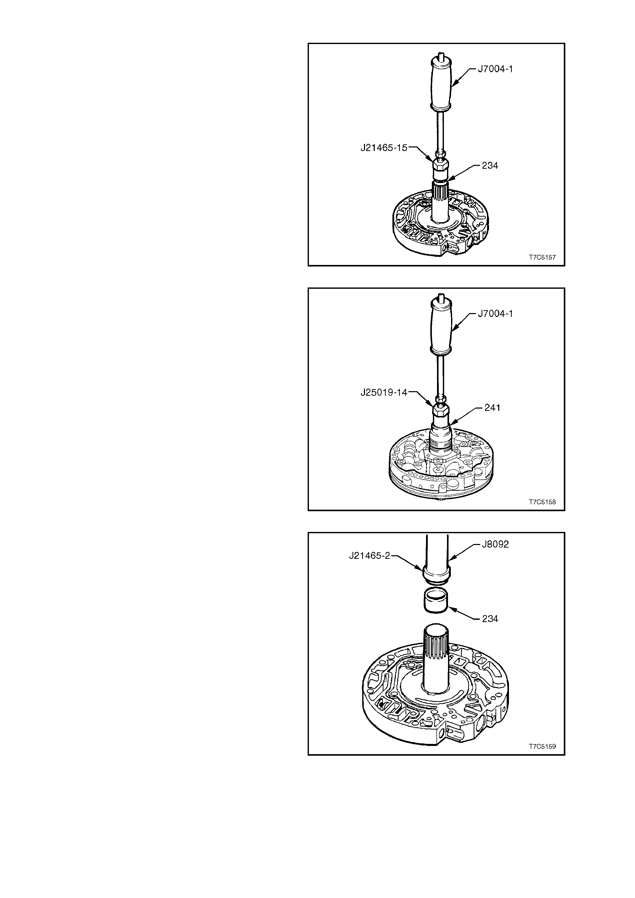
1. Using bush remover J21465-15 and slide
hammer J7004-1, remove the stator shaft,
front bushing.
Figure 7C5-163
2. Using bush remover J25019-14 and slide
hamm er J 7004-1, rem ove the stator s haft rear
bushing, from the pump cover.
Figure 7C5-164
3. Install a new front stator shaft bush (234),
using installer J21465-2 and driver handle
J8092.
Figure 7C5-165
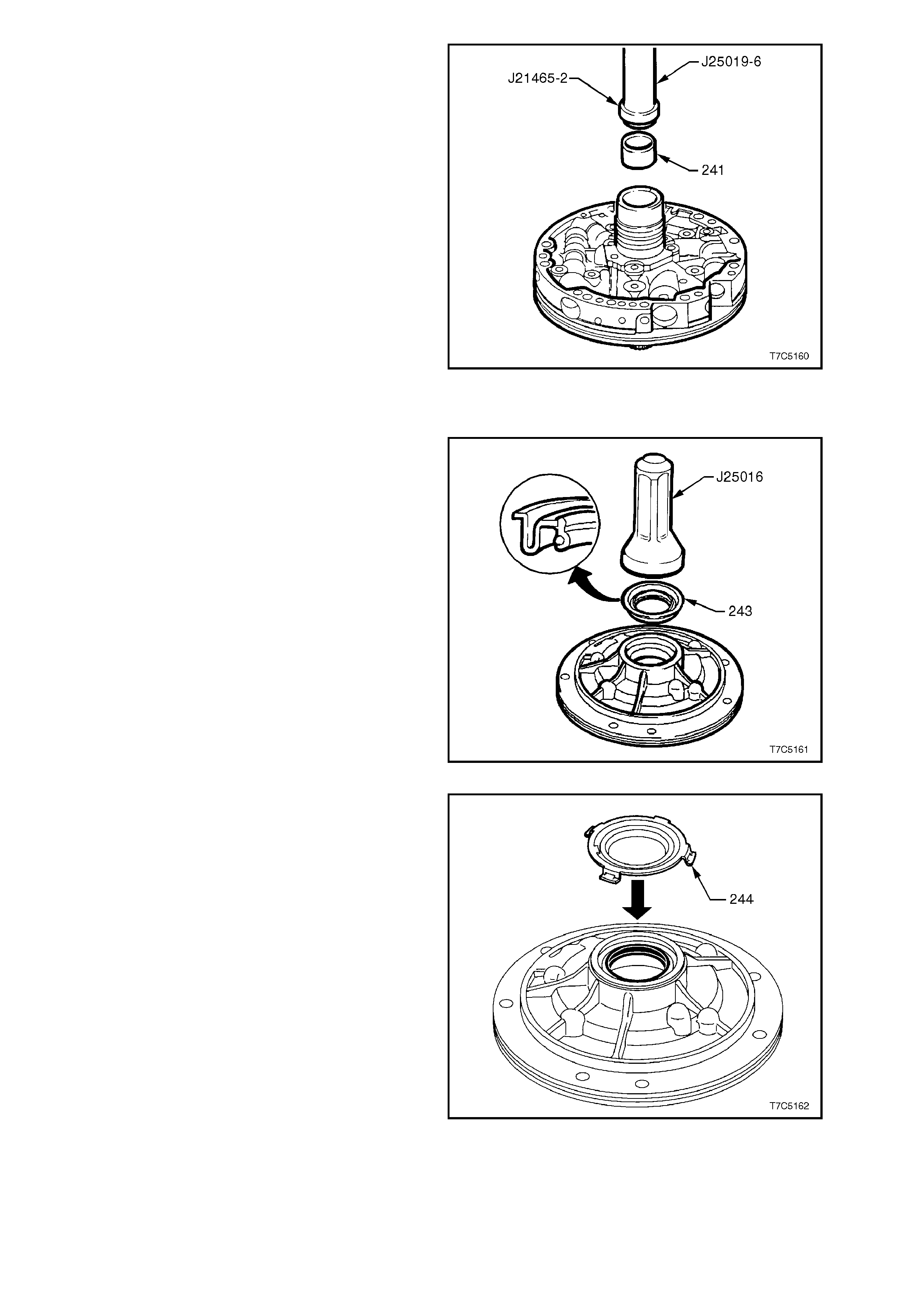
4. Install a new stator shaft rear bush (241),
using installer J21465-2 and driver handle
J25019-6.
Figure 7C5-166
REASSEMBLE
1. Install new oil seal (243), using seal installer,
Tool J25016.
Figure 7C5-167
2. Install front helix retainer (244).
Figure 7C5-168
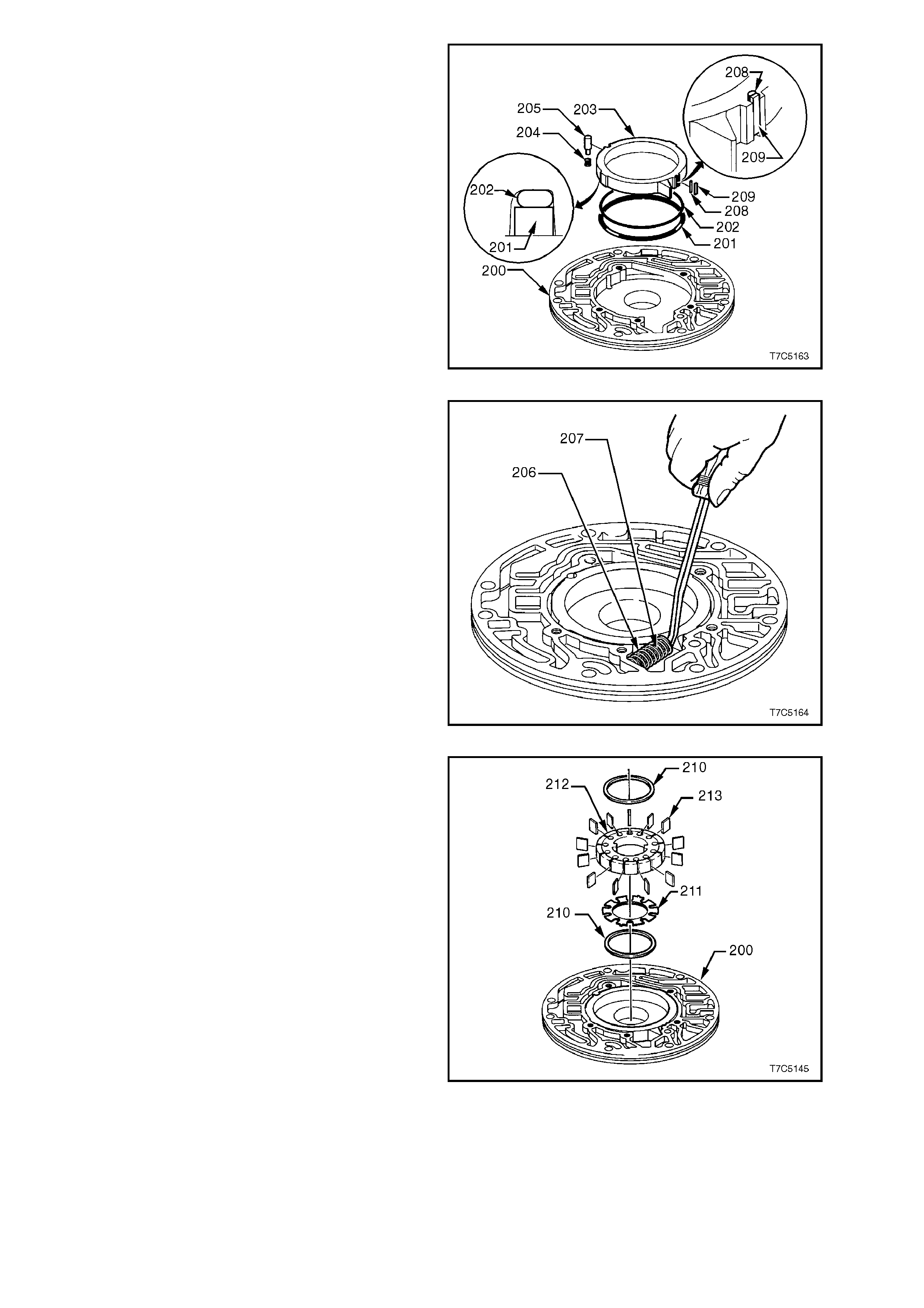
3. Install new slide seal bac k-up O-r ing (202) and
support ring (201) into groove on rear side of
slide, retaining both with petroleum jelly.
4. Reinstall pump slide into body, aligning notch
with pivot pin hole.
5. Reinstall slide s eal support ( 208) together with
slide seal (209) into notch in pump slide.
6. Install pivot pin spring (204) and pin (205).
Figure 7C5-169
7. Carefully compress slide springs (206/207)
with long nose pliers, then use a piece of
hacksaw blade against the slide flange to
assist (or a wide bladed screwdriver as shown)
and reinstall springs in pump body.
CAUTION:
Spring tension is very high when both are
compressed. Protect eyes from possible
damage.
Figure 7C5-170
8. Reinstall one of the vane guide rings ( 210) into
pump body (200).
9. Locate rotor guide (211) onto rotor and retain
with petroleum jelly.
10. Reinstall rotor, with rotor guide facing pump
body.
11. Reinstall pump vanes (213), assembling with
the wear marks in the same position as
originally found on disassembly.
12. Reinstall remaining vane guide ring (210).
Figure 7C5-171
Place pump body assembly to one side and
reassemble pump cover as follows:
13. Reinstall inner (225) and outer (226) converter
clutch apply valve springs onto the stem of the
converter clutch apply valve (224) and, as an
assembly, reinstall into valve bore of the
cover.
14. Reinstall valve stop (223) and while
compressing the springs, install the retaining
circlip (222) in converter clutch valve bore,
ensuring that the circlip is correctly seated in
groove.
Figure 7C5-172
15. Reinstall pressure regulator valve (216) and
springs ( 217/218) into pr es sur e r egulator valve
bore of oil pump cover.
16. Insert the rever se boost valve (219) in rever se
boost valve sleeve (220), and reinstall
assembly into pressure regulator valve bore,
orientated as shown.
17. While compressing the valve train against the
pressure regulator spring forces, install the
retaining circlip (221), ensuring the circlip is
correctly seated in groove.
Figure 7C5-173
18. Reinstall pressure relief ball (228), spring
(229) and pin (227) in pump cover.
19. Reinstall cover filter screen (232) with new
seal (231).
Figure 7C5-174
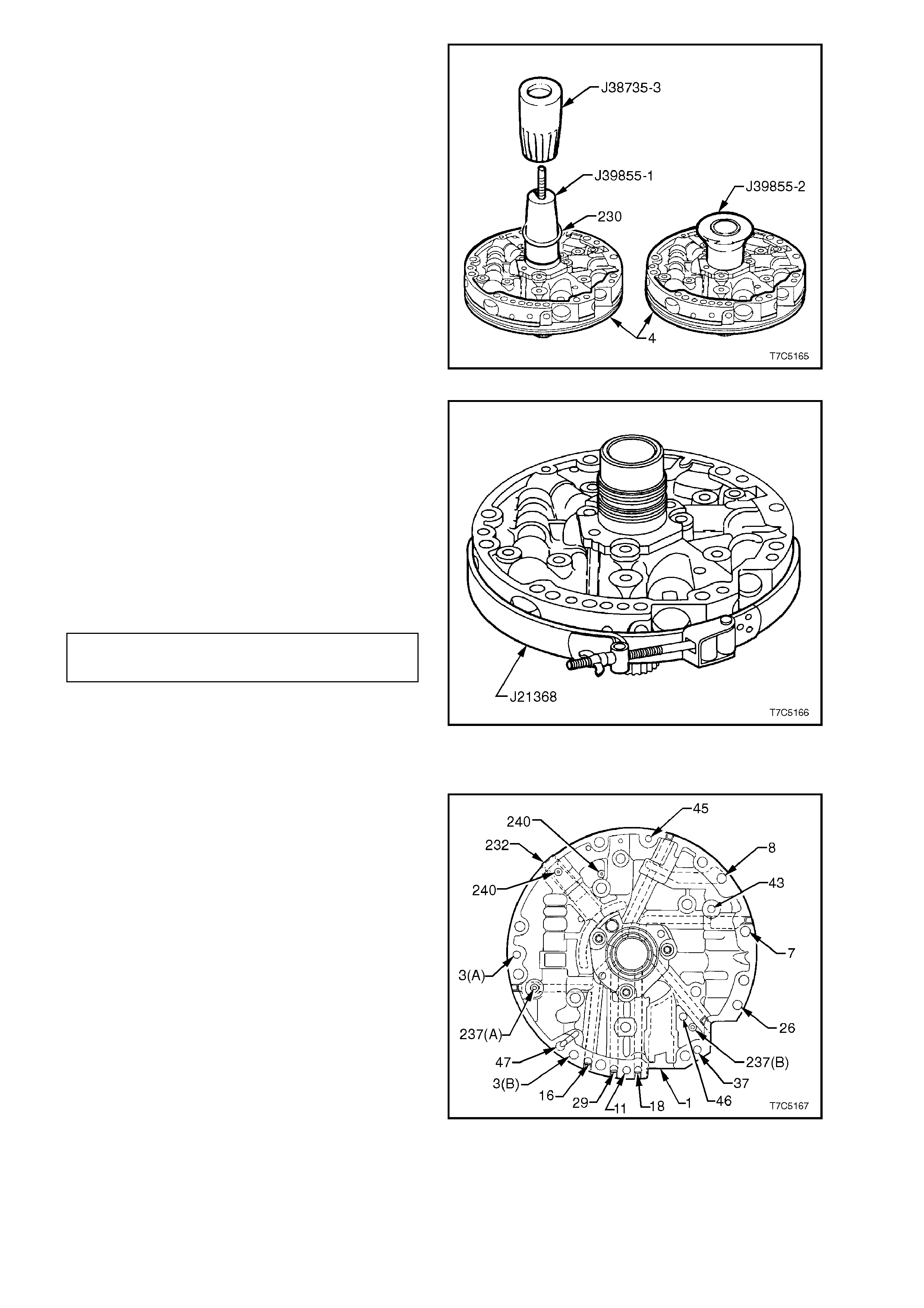
20. Expand new solid stator shaft oil seals (230)
over Tool No. J 39855-1 and install, using T ool
No. J38735-3.
21. Once both seals are installed, compress to
size by fitting sizing tool, J39855-2, using
petroleum jelly to assist, as required. Leave
sizing tool installed until the pump ass embly is
reinstalled into the transmission.
Figure 7C5-175
22. Place the stator shaft through a hole in the
workbench.
23. Install pump cover assembly (215) on pump
body assem bly (200) and reinstall f ive cover to
body bolts (233), finger tight.
24. To align pump cover to body, fit alignment
band tool J21368 as shown, and secure finger
tight.
25. Tighten cover to pump body bolts to specified
torque. Remove pump assembly alignment
band tool.
PUMP COVER TO PUMP BODY 20 - 27
TORQUE SPECIFICATION Nm
Figure 7C5-176
OIL PUMP AIR CHECKS
NOTE 1.
It is advisable to wear safety glasses when
performing any of the following air check
procedures.
NOTE 2.
To check for a restriction (rather than a blocked
passage), perform tests with a piston type oil can
filled with transmission fluid, rather than use
compressed air.
Air check oil pump as indicated in Figures 7C5-
177 and 7C5-178 to ensure that all passages are
open and all cup plugs are correctly installed.
Figure 7C5-177
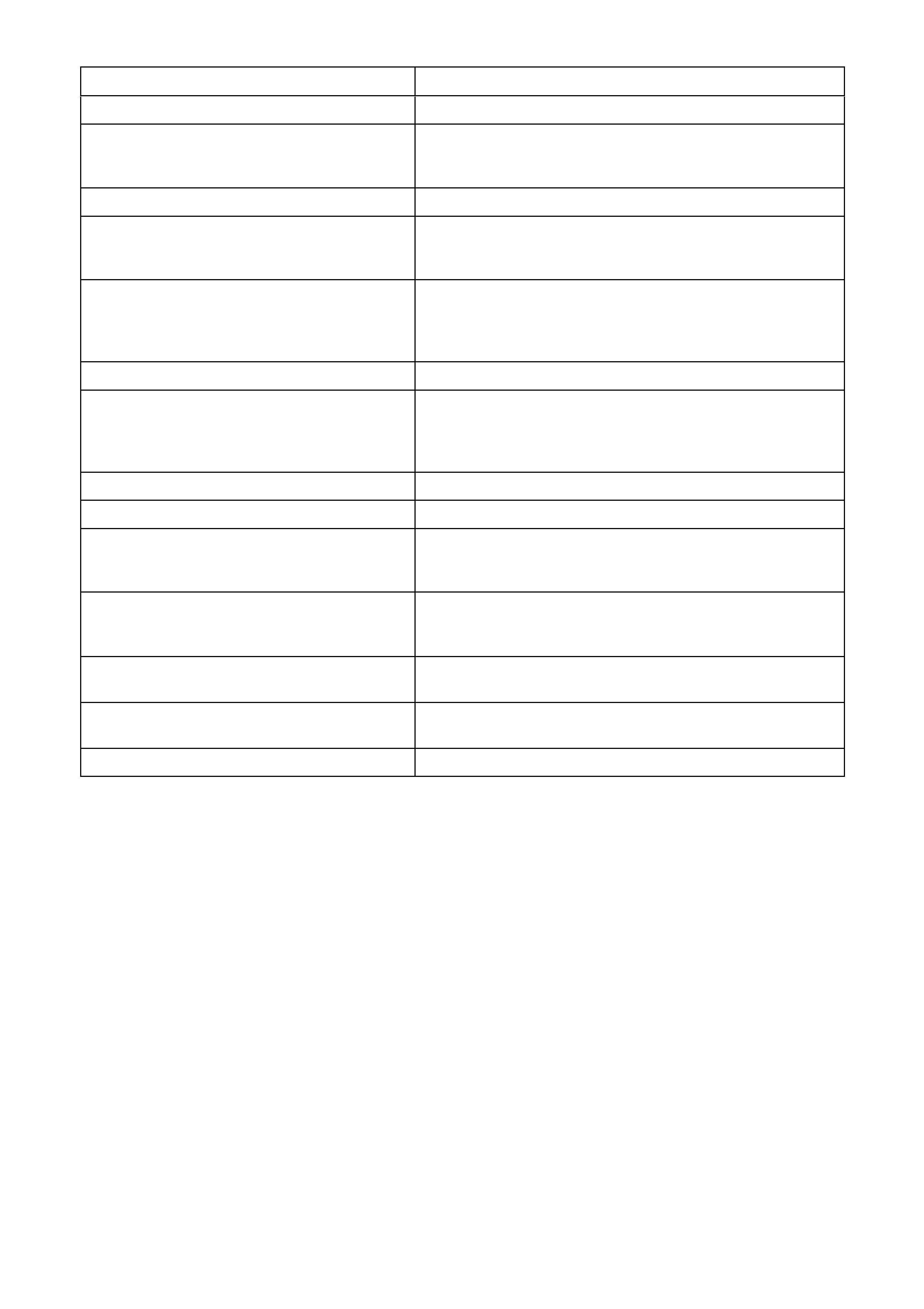
BLOW AIR IN: CHECK FOR AIR OUT:
#18 Forward Clutch Feed The second hole down inside the stator shaft bore.
#11 Torque Signal Block hole #47 with a finger. Inject short blasts of
compressed air into hole #11. The Boost valve will click with
each blast of air.
#29 3 - 4 Clutch The first hole down inside the stator shaft bore.
#16 Reverse Input Clutch The reverse input feed hole between the two oil seals on
the outside of the pump hub. The air seats the reverse
check ball, shown as #237 (A).
#3 (B) Line Pressure (To Valve Body) Line Pressure hole #3 (A) and through the filter screen
(232).
CAUTION: Take care that the air pressure does not blow
the filter screen out, as personal injury could result.
#47 Void This drilling terminates in a cavity in the pump body.
#3 (A) Line Pressure (To Pressure Tap Point) Line pressure hole #3 (B) and through the filter screen
(232).
CAUTION: Take care that the air pressure does not blow
the filter screen out, as personal injury could result.
#45 Vent The vent cavity.
#8 From Oil Cooler From the lube cavity in the top of the stator support shaft.
#43 Torque Converter Clutch Release Insert an Allen key through the hole in the converter clutch
valve and push on the valve against spring force. Air will
then come out of the lower hole inside the stator support.
#7 To Oil Cooler Through the filter screen.
CAUTION: Take care that the air pressure does not blow
the filter screen out, as personal injury could result.
#26 Torque Converter Clutch Signal Through the hole normally filled by the converter clutch
solenoid.
#37 Overrun Clutch The third hole down inside the stator support shaft. Air
pressure will also seat the Check Valve, shown as #237 (B).
#46 Seal Drain Back Between the stator shaft and the oil pump body seal.

2.16 CONTROL VALVE BODY
DISASSEMBLE
NOTE 1:
Some valve trains are under pressure from spring force. Cover the bores while removing roll pins and retainer clips.
NOTE 2:
Valves, springs and bushings must be laid out in the exact order of removal, to ensure correct orientation when
reassembling.
NOTE 3:
While the following sequence of disassembly is suggested, it is not mandatory. Refer to exploded view for
identification of the various components and their locations for this control valve body.
1. Remove the pressure control solenoid retaining bolt (364), the retainer (378) and the solenoid (377).
2. W hile supporting the bore plug (376), remove the retaining clip (395), the bore plug, actuator feed limit valve
spring (375) and valve (374).
3. Rem ove the 2-3 shift solenoid retaining c lip (379), the solenoid (367B); then r emove the valve train c onsisting
of the 2-3 shuttle valve (369) and 2-3 shift valve (368).
4. Remove the 1-2 shift solenoid retaining clip (379), then the solenoid (367A), 1-2 shift valve (366) and spring
(365).
5. Remove the 1-2 accum ulator roll pin (360), bore plug (373) and then the 1-2 accumulator sleeve (372), valve
(371) and spring (370).
6. Remove the three forward accumulator cover retaining bolts (364), then the cover (363).
7. Remove the f orward accum ulator spring (356), pist on (354) and pin (355). Disc ard the sealing ring (353) after
removing it from the piston.
8. Remove the low overrun valve spring (362) and valve (361).
9. While supporting the bore plug (359) with a suitable probe, remove the r oll pin (360) , the bore plug, the forward
abuse valve spring (358) and valve (357).

REF
No. PART NAME REF
No. PART NAME
350
353.
354
355
356
357
358
359
360
361
362
363
364
365
Valve Assembly, Control Body
Seal, Forward Accumulator
Piston, Forward Accumulator
Pin, Forward Accumulator
Spring, Forward Accumulator
Valve, Forward Abuse
Spring, Forward Abuse Valve
Plug, Bore
Pin, Coiled Spring
Valve, Low Overrun
Spring, Low Overrun Valve
Cover, Forward Accumulator
Bolt, Forward Accumulator Cover
Spring, 1 - 2 Shift Valve
366
367A
367B
368
369
370
371
372
374
375
376
377
378
Valve, 1 - 2 Shift
1 - 2 Shift Solenoid (A)
2 - 3 Shift Solenoid (B)
Valve, 2 - 3 Shift
Valve, 2 - 3 Shuttle
Spring, 1 - 2 Accumulator Valve
Valve, 1 - 2 Accumulator
Sleeve, 1 - 2 Accumulator
Valve, Actuator Feed Limit
Spring, Actuator Feed Limit Valve
Plug, Bore
Pressure Control Solenoid
Retainer, Pressure Control Solenoid
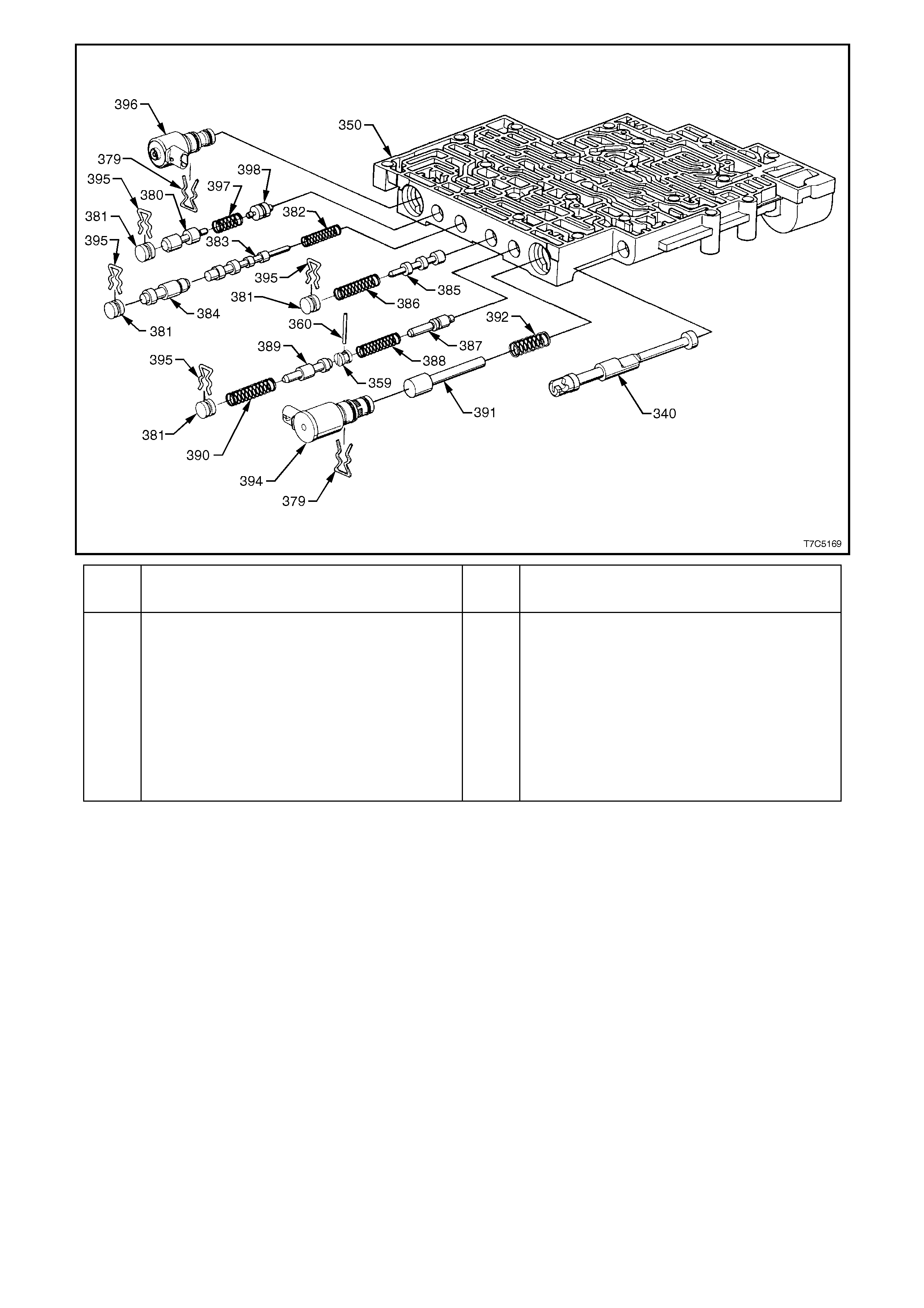
Figure 7C5-178 Control Valve Body ‘A’ - Exploded View
10. Turn the control valve body around and remove the manual valve (340).
11. While supporting the 3-2 control solenoid (394), remove the retaining clip (379) and the solenoid.
12. Remove the 3-2 control valve (391) and spring (392).
13. Hold 3-2 downshift bore plug (381) in, then remove the retaining clip (395). Follow this with the 3-2 downshift
valve spring (390) and valve (389).
14. W hile supporting the reverse abuse bore plug (359) with a suitable probe, rem ove the roll pin (360) and plug.
Then remove the reverse abuse valve spring (388) and valve (387).
15. Support the 3-4 shift valve bore plug (381), while removing the clip (395). Then remove the 3-4 shift valve
spring (386) and valve (385).
16. Support the 3-4 relay valve bore plug (381), while removing the clip (395). Then remove the 3-4 relay valve
(384), 4-3 sequence valve (383) and spring (382).
17. Support the bore plug (381) while removing the retaining clip (395), then remove the regulator apply valve
(380), spring (397) and isolator valve (398), behind it.
18. Clean all valves, springs, bushings and control valve body in clean solvent, then dry with compressed air.
NOTE:
The Torque Converter Clutch PWM Solenoid (396) is removed prior to the TCC Solenoid, during the process of
removing the control valve body from the transmission.
REF
No. PART NAME REF
No. PART NAME
340
379
380
381
382
383
384
385
386
387
Valve, Manual
Retainer, Solenoid
Valve, Regulator Apply
Plug, Bore
Spring, 4 - 3 Sequence Valve
Valve, 4 - 3 Sequence
Valve, 3 - 4 Relay
Valve, 3 - 4 Shift
Spring, 3 - 4 Shift Valve
Valve, Reverse Abuse
388
389
390
391
392
394
395
387
398
Spring, Reverse Abuse Valve
Valve, 3 - 2 Downshift
Spring, 3 - 2 Downshift Valve
Valve, 3 -2 Control
Spring, 3 -2 Control Valve
3 - 2 Control Solenoid
Retainer, Bore Plug
Spring, Regulator Supply
Valve, Isolator
Figure 7C5-179 Control Valve Body ‘B’ - Exploded View
INSPECT
NOTE 1:
The use of a honing stone, fine sandpaper or
crocus cloth is not recommended for servicing
stuck valves. All valve lands have sharply
ma chined cor ners that are nec ess ary for "cleaning"
the bore. If these corners are rounded, foreign
material could wedge between the valve and its
bore, causing valve sticking.
NOTE 2:
If it is found to be necessary to clean a valve,
"micro fine" lapping compound with a 900 grit or
finer may be used.
NOTE 3:
Too m uc h "lapping" of a valve will c reate exc ess ive
clearances, increasing the chance of valve
malfunction.
1. Inspect all valves and bushings for scoring,
scratches or nicks.
2. Inspect all springs for damaged or distorted
coils.
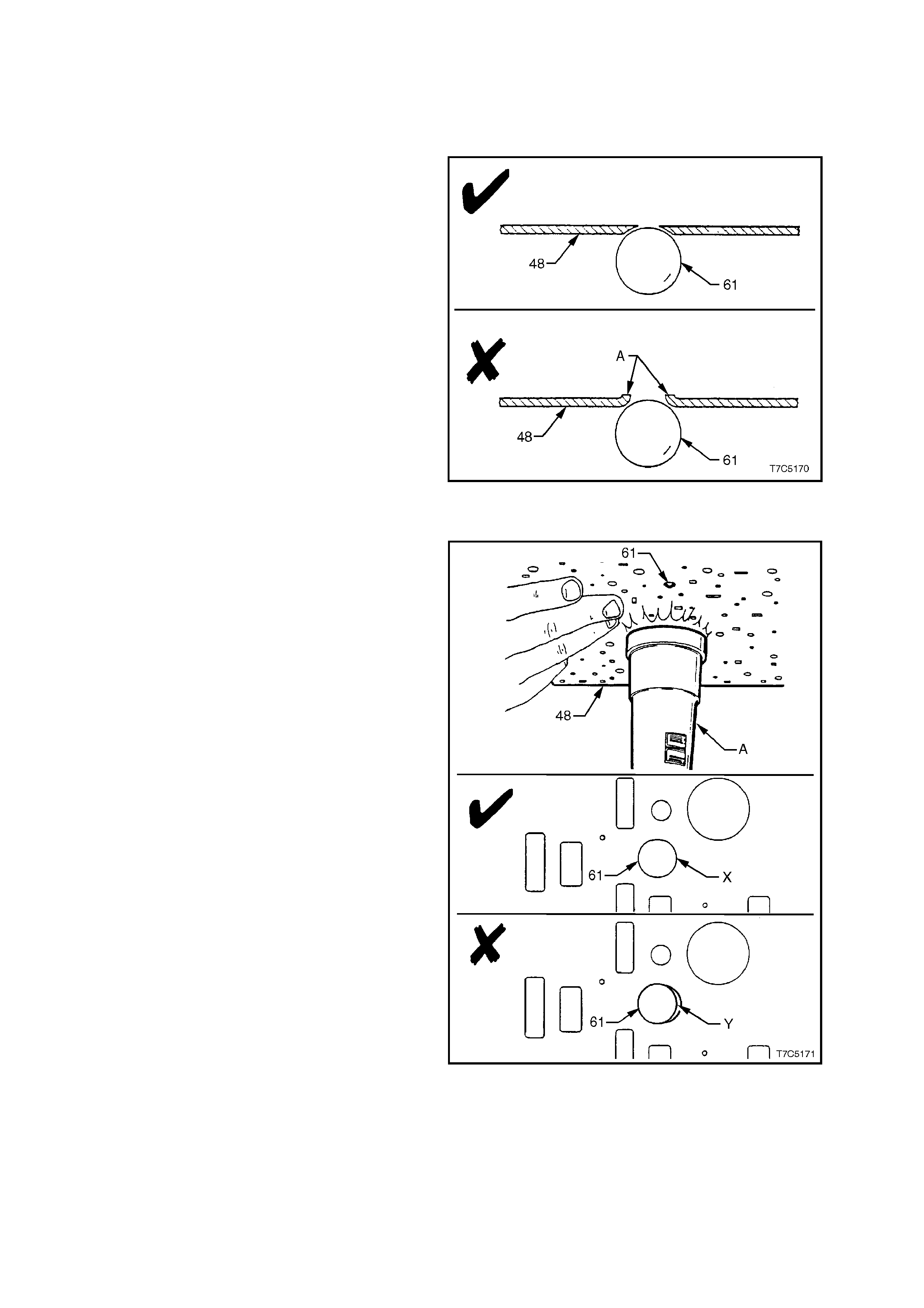
3. Inspect valve body casting for porosity,
crack s, damaged m achined surfaces, blocked
or partially blocked passages and scored or
damaged valve train bores.
SPACER PLATE EVALUATION
During inspection of the spacer plate, it is
acceptable for some check ball peening to be
evident but the following is recommended when
establishing the serviceability of this component.
Procedure 1:
The spacer plate (48) must be inspected thoroughly
for r aised m aterial on the opposite side of all c heck
ball (61) locations. If the material on the opposite
side is raised (A), the peening is considered to be
too severe and the spacer plate must be replaced.
Figure 7C5-180
Procedure 2:
To verify that a check ball location has peened
evenly and the ball is seating correctly, seat the
check ball (61) on the spacer plate. Us e a torch (A)
to shine a beam of light on the opposite side and
check for light between the spacer plate and the
check ball.
No light should be visible, as indic ated at ‘X’. If it is ,
as indicated by ‘Y’, the spacer plate must be
replaced. Perform this check for all check ball
locations on the spacer plate.
Figure 7C5-181

REASSEMBLE
1. Reassemble all components in the reverse
order to disassembly. Use Figures 7C5-
178/179 as a ref erence. Note orientation of all
valves, sleeves and solenoids.
IMPORTANT:
When reinstalling each of the bore plug retainer
clips (395), ensure that they are installed from the
transmission case side of the valve body (i.e. the
ma chined side). If this is not done, then r einstalling
the wiring harness will not be possible without
damage. Also, correct installation of the fluid filter
will not be possible, preventing fitment of the oil
pan.
NOTE:
The TCC PWM Solenoid (396) is not to be installed
until the TCC Solenoid has been installed and
the retaining bolts torqued to specification.
This operation occurs during the installation of
the control valve body to the transmission
case.
2. Tighten all retaining bolts to the corr ect torque
specification.
PRESSURE CONTROL SOLENOID
BRACKET TO VALVE BODY 8 - 14 Nm
TORQUE SPECIFICATION
FORWARD ACCUMULATOR COVER
TO VALVE BODY BOLT 8 - 14 Nm
TORQUE SPECIFICATION
3. To prevent dust contamination, store
assembled control valve body in a clean
plastic bag, until transmission is reassembled

3. TRANSMISSION REASSEMBLE
3.1 MANUAL SHAFT AND PARKING LINKAGE
If previously removed, reinstall manual shaft and
parking linkage components, as detailed in the
following steps:
1. Using a suitable sized socket, install a new
manual shaft seal (82) into the transmission
case. Lubricate the seal lips with a small
amount of clean, automatic transmission fluid.
Figure 7C5-182
2. Install the parking pawl actuator (85) to the
inner detent lever (88).
3. Remove any burrs from the manual shaft (84)
and, after lubricating with transmission fluid,
carefully install into the transmission case,
locating the inner detent lever (88), over the
flats on the manual shaft (84).
4. Install the inner manual shaft nut (80) and
tighten to the correct torque specification.
MANUAL SHAFT TO INNER
DETENT LEVER NUT 27 - 34 Nm
TORQUE SPECIFICATION
5. Install the manual shaft retainer clip (83) over
the manual shaft (84).
Figure 7C5-183
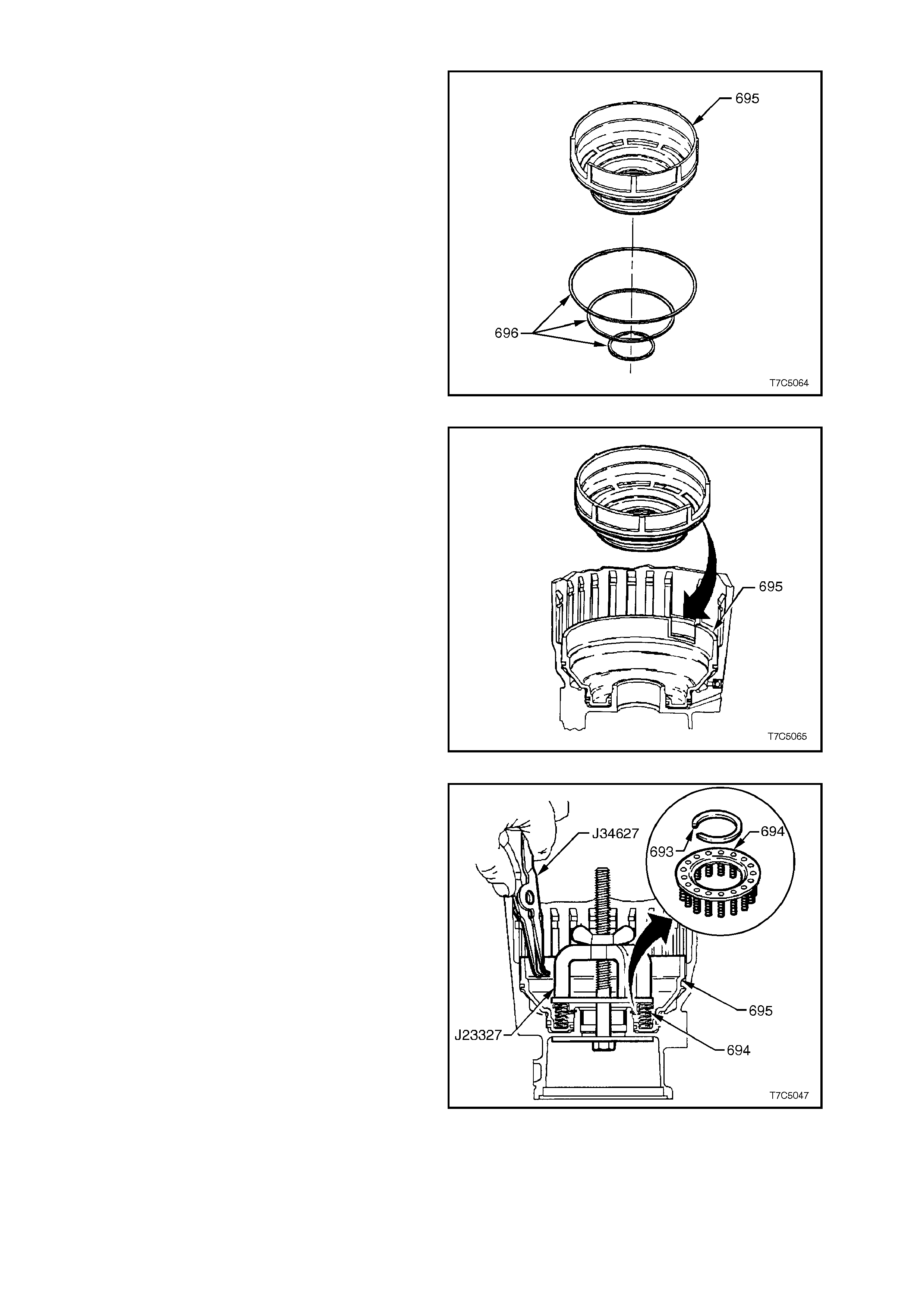
3.2 LOW AND REVERSE CLUTCH PISTON
1. Lubricate new low and reverse clutch piston,
square section seals (696), with transmission
fluid (or petroleum jelly) and install on piston
(695).
Figure 7C5-184
2. Reinstall piston (695) in transmission case,
aligning piston with notch in bottom of c as e, as
indicated. Use Tool J23327 (shown next), to
ensure the piston is installed square to its
bore.
Figure 7C5-185
3. Locate spring assembly on piston as shown,
with flat side uppermost.
4. Install Tool J23327 and compress spring
assembly below groove in case.
NOTE:
Make sure the lower plate of Tool J23327 indexes
correctly in the recess in the end of the
transmission case .
5. Reinstall retaining ring and remove J23327.
Figure 7C5-186
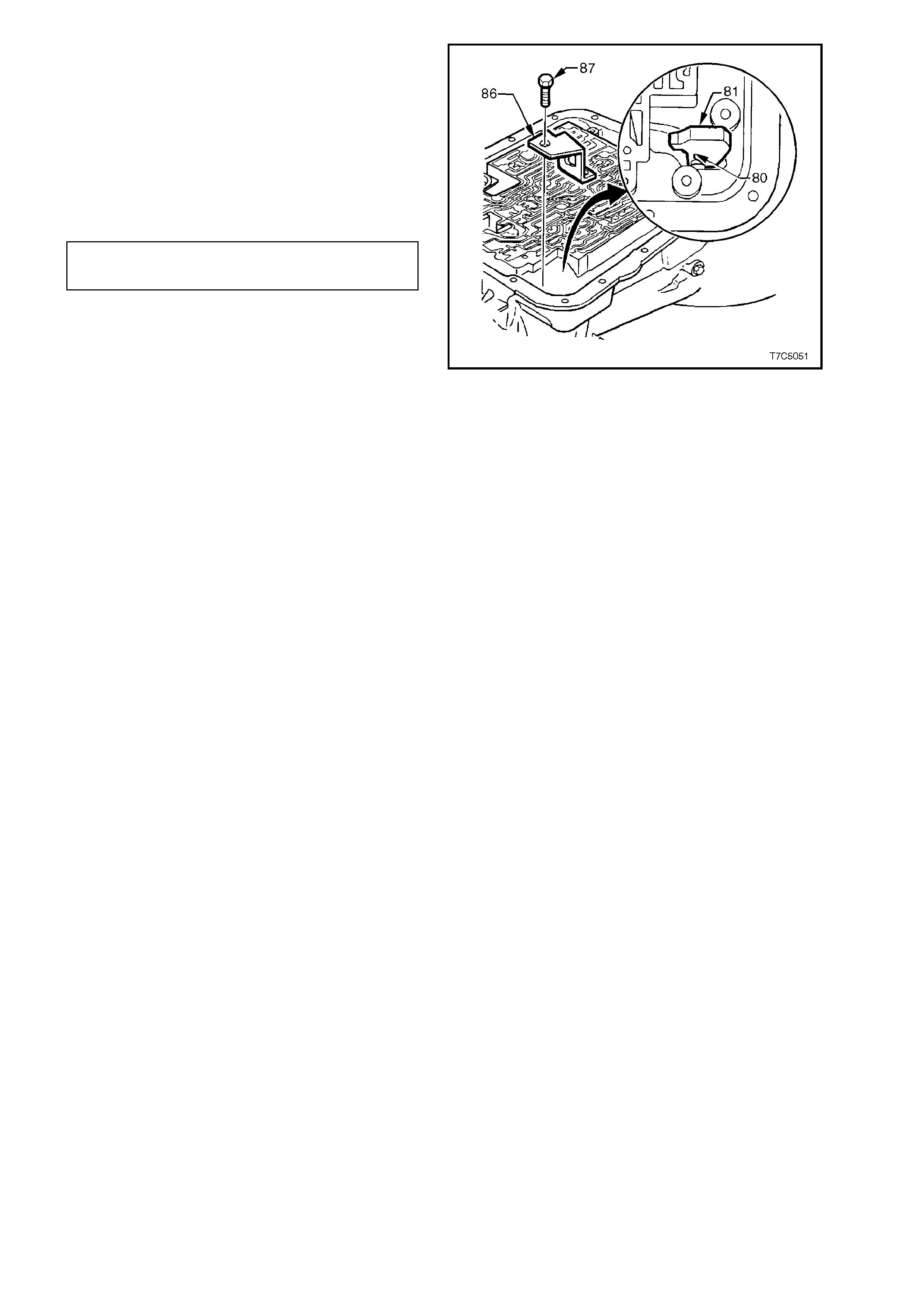
6. If previous ly removed, loc ate par king pawl (81)
and return spring (80) in case.
7. Reinstall parking pawl pivot shaft (79). Check
for free movement of components.
8. Coat retaining plug (78) with Loctite 242
sealant or equivalent, to Holden's Spec if ic ation
HN1256 and install with hammer and punch.
9. Reinstall park pawl brack et (86) and bolts (87)
and tighten to the specified torque.
PARK PAWL BRACKET BOLT 27 - 34
TORQUE SPECIFICATION Nm
Figure 7C5-187
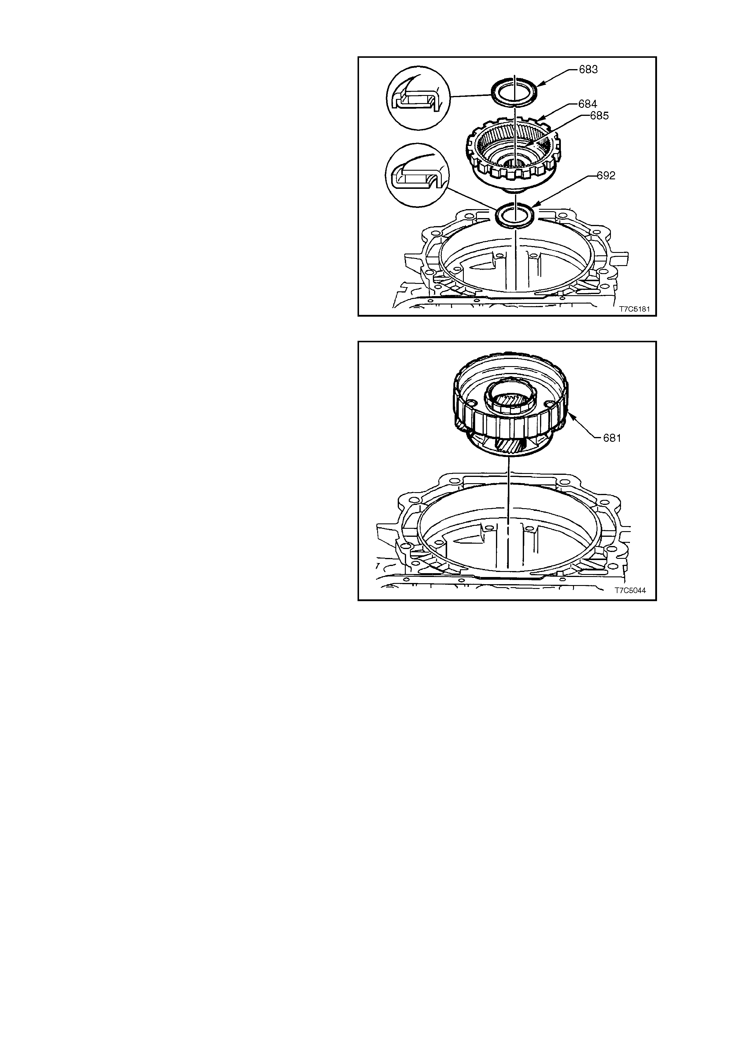
3.3 REACTION PLANE TARY GEAR SET
1. Reinstall gear support to case bearing (692)
onto transmission case hub (685) as shown;
i.e. with outside bearing race towards case
hub. Retain with petroleum jelly.
2. Reinstall reaction internal gear (684) and
support (685) assem bly into bearing (692) and
transmission case hub.
3. Reinstall reaction carrier to support thrust
bearing (683) on support (685) with outer
bearing race facing support.
Figure 7C5-188
4. Reinstall reaction carrier assembly (681) onto
thrust bearing.
Figure 7C5-189
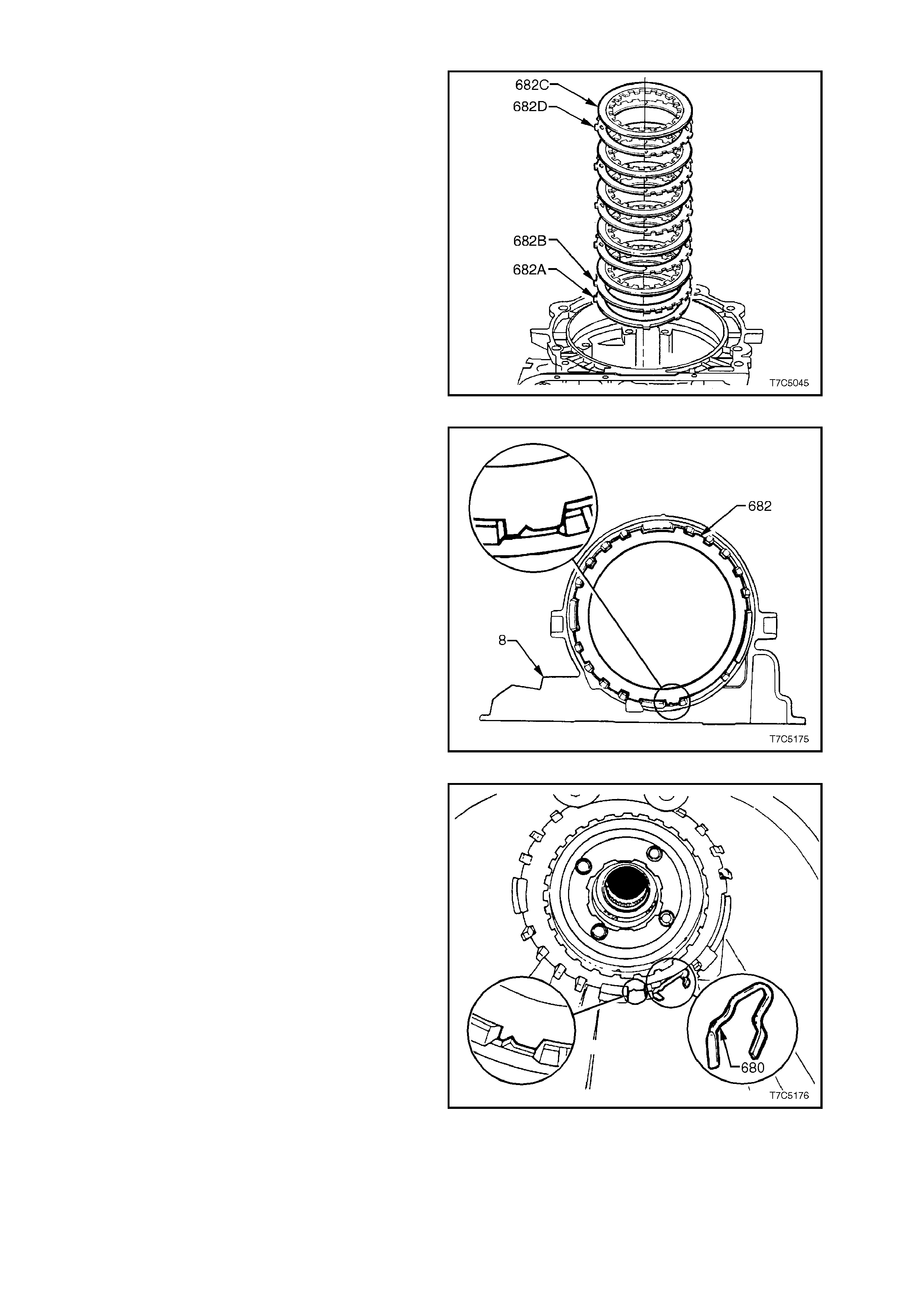
3.4 LOW AND REVERSE CLUTCH PLATES AND SUPPORT ASSEMBLY
1. Soak composition plates in new transmission
fluid.
2. Reinstall low and reverse clutch assembly by
starting with the waved plate (682A), then
selective plate (682B), (as correctly selected
during component inspection procedures).
3. Then install a c omposition c lutch plate (682C),
then a turbulator steel (682D), etc.
Figure 7C5-190
4. Index the waved, selective and steel plates, as
shown.
Figure 7C5-191
5. Apply petroleum jelly to the flat portion of the
spring and insert the spring into the curved
area in the transmission case as shown.
Figure 7C5-192
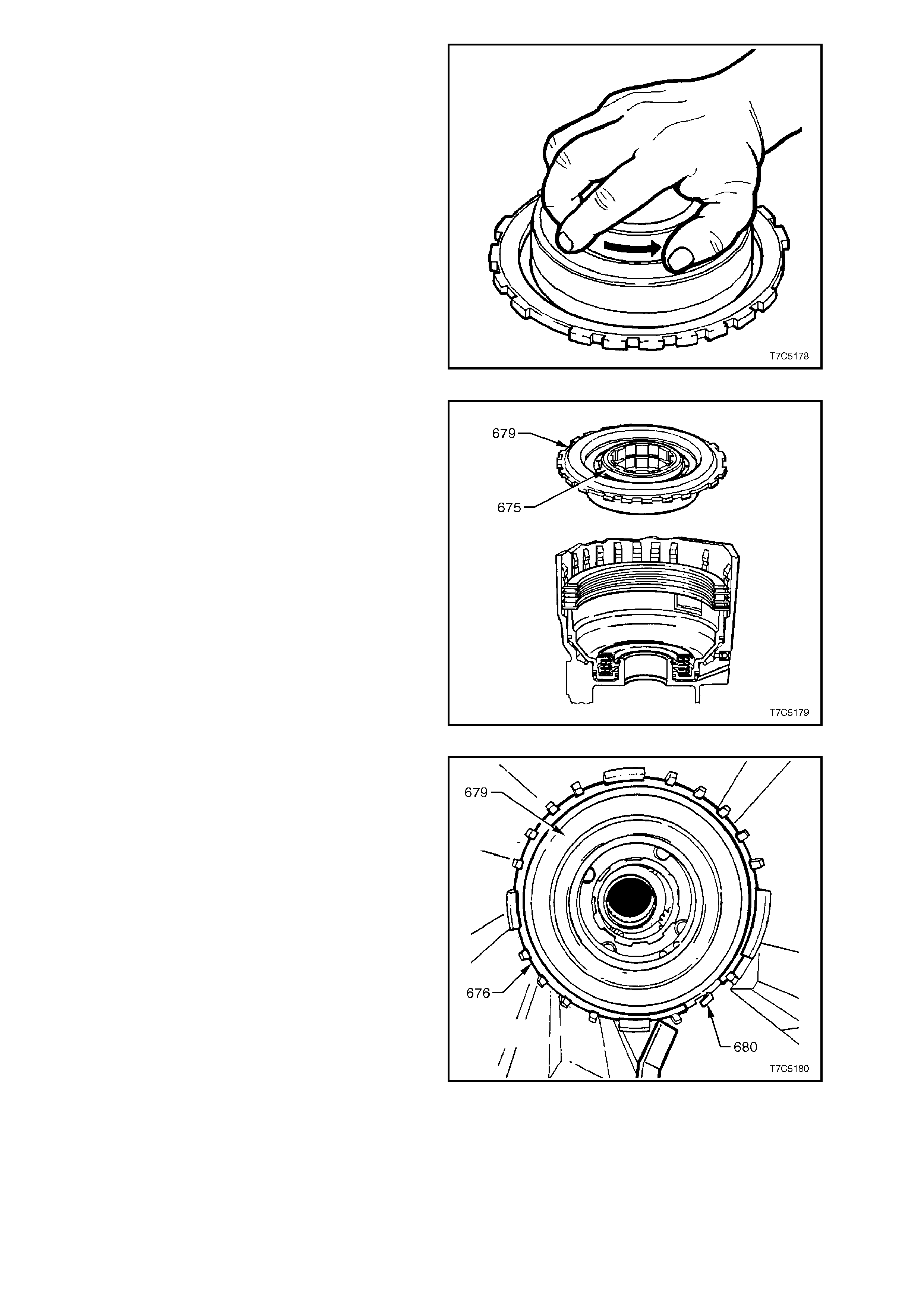
6. Reinstall low and reverse roller clutch
assembly (678) into cam and support
assembly (679).
7. Reinstall both retaining rings (677) that were
removed during roller clutch disassembly.
8. Reinstall inner low and reverse clutch race
(675) by pushing and turning in the direction
shown.
NOTE:
Test for correct operation as shown. The race
should ‘free-wheel’ in the direction indicated by the
arrow.
Figure 7C5-193
9. Pull the low and reverse roller clutch inner
race (675) up fr om its norm ally seated position
(as shown), to enable a grip on the support
assembly (679) to be made. Slightly tilt the
support assembly while aligning the wide
notch on the support with a matching wide lug
on the case.
10. Push the assembly into the case until it is
squarely seated and then, while turning the
roller clutch inner race in a clockwise direction
(free), push it down until the internal splines
line up with those on the reaction carrier.
Figure 7C5-194
11. Reinstall support retaining ring (676) by
aligning one end against the low and reverse
clutch suppor t retainer spring (680), then work
the remainder into the groove with the aid of a
screwdriver. Make sure the snap ring is fully
seated in the groove.
12. To c heck the operation of the low and reverse
piston, apply low pressure air to 'A', as shown
in Figure 7C5-51. As air is supplied, the low
and reverse piston should be seen to move
when viewed in the parking pawl area of the
case. Air leaks should also be listened for,
during this check.
Figure 7C5-195
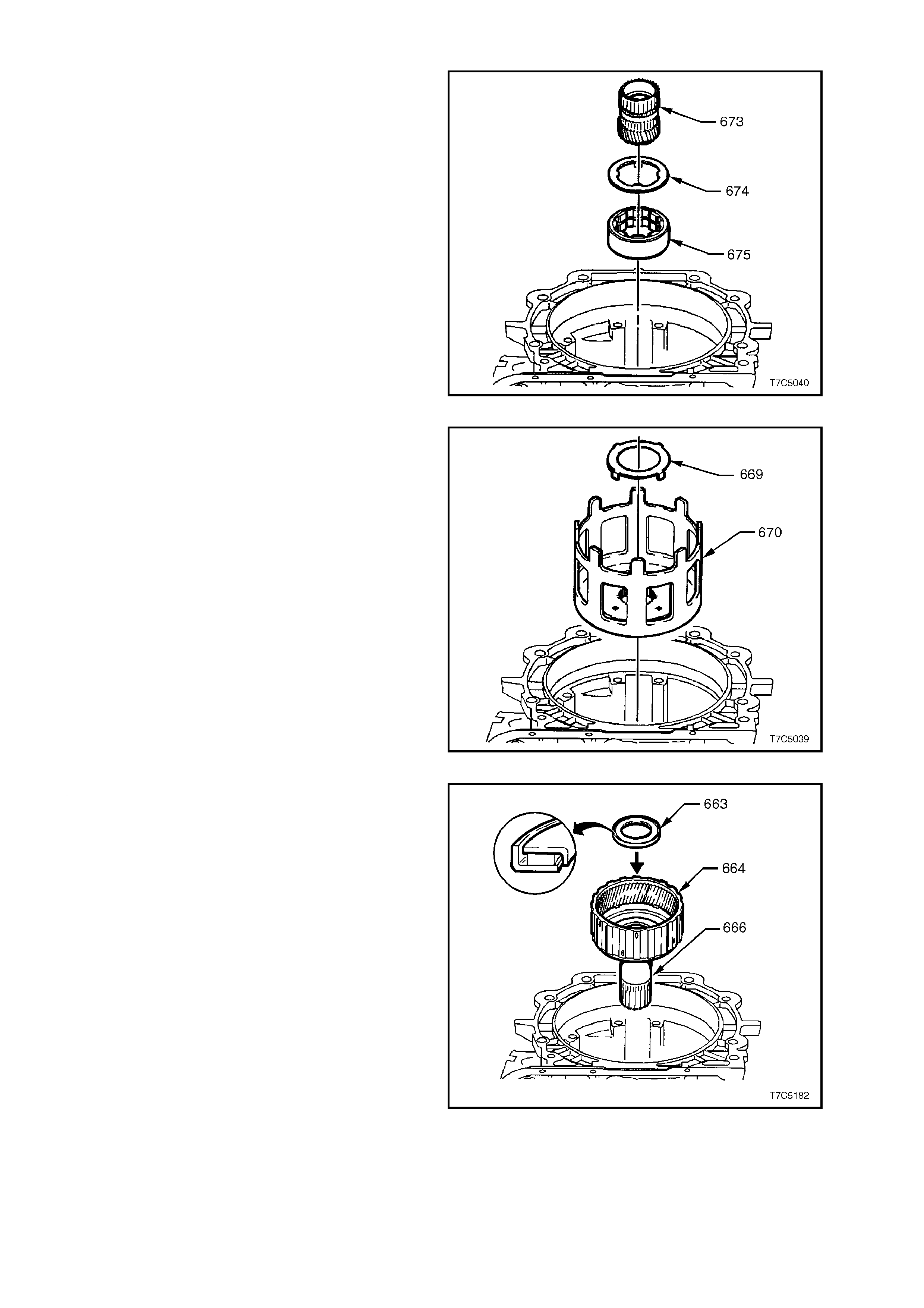
3.5 REACTION GEAR, INPUT GEAR AND OUTPUT SHAFT
1. If removed, install a new reaction sun gear
retaining ring (671) onto reaction sun gear.
2. Reinstall reaction sun gear (673), helical gear
side down, into reaction carr ier in tr ansm iss ion
case meshing teeth with pinion gears.
3. Reinstall thrust washer (674) into the
transmission case, ensuring that the lugs on
the thrust washer face downward and locate in
the inner race of the low and reverse roller
clutch (675).
Figure 7C5-196
4. Reinstall bronze thrust washer (669) onto
reaction sun shell and secure with petroleum
jelly. Tangs on washer locate in four holes in
reaction sun shell.
5. Reinstall reaction sun shell (670) onto thrust
washer (674), locating shell over reaction sun
gear.
Figure 7C5-197
6. Reinstall thrust bearing (663) onto reaction
carrier shaft assembly with outer race against
reaction carrier shaft, as shown. Turn and
press until the splines on the reaction carrier
shaft (666) are aligned with the splines on the
reaction car rier as sem bly (681, in Figure 7C5-
189).
Figure 7C5-198
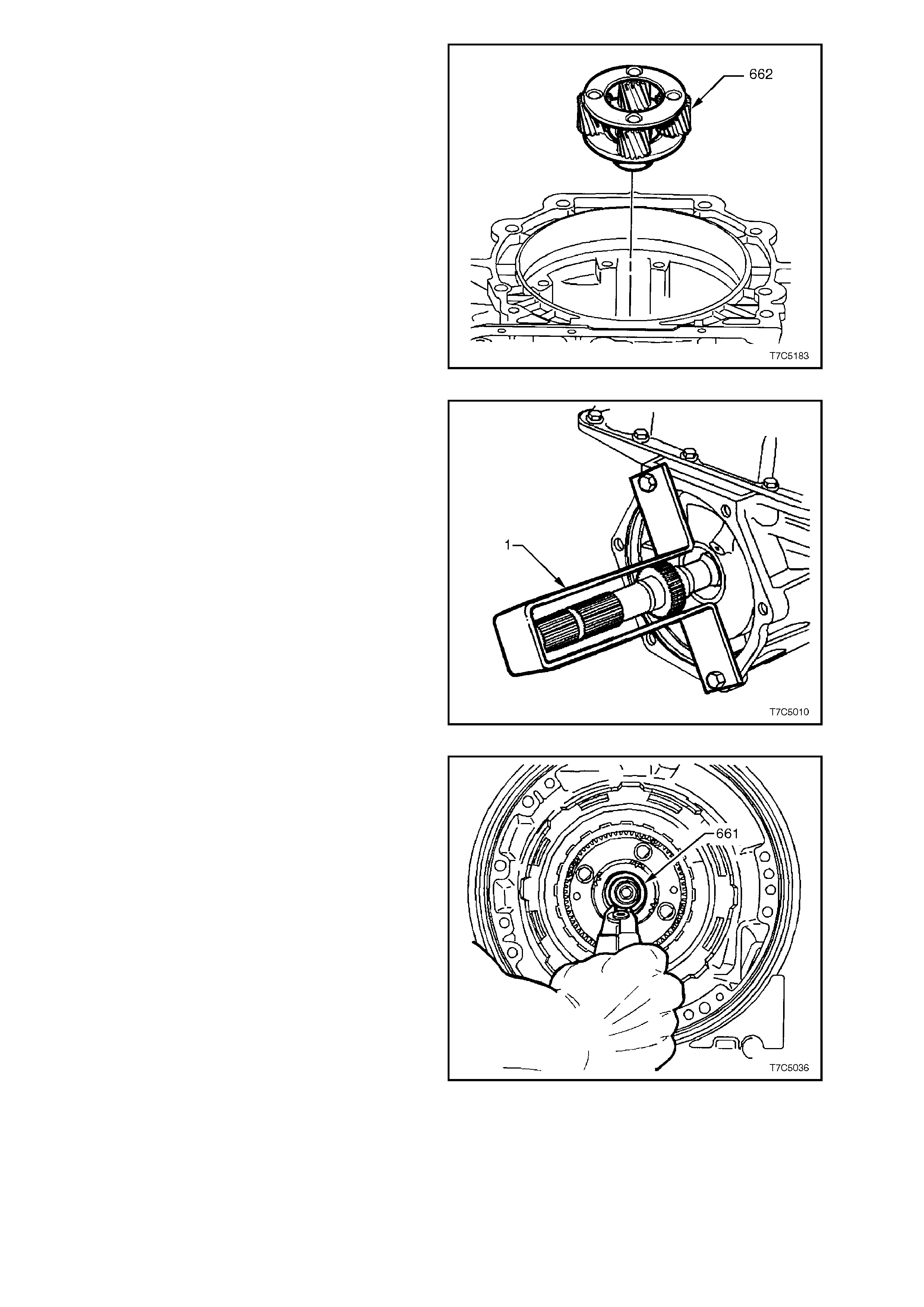
7. Reinstall input carrier assembly (662), rotating
back and forth, to index with the teeth of the
input internal gear.
Figure 7C5-199
8. While supporting the input carrier assembly
(662), reinstall output shaft into the input
carrier and attach the support bracket (1) that
was used during disassembly.
Figure 7C5-200
9. Reinstall retaining ring (661) into output shaft
ring groove. If ring was previously over-
expanded, use a new ring. Do not over-
expand ring during installation.
NOTE:
Using snap ring pliers, Tool No. J34627, will assist
in preventing retaining ring over-expans ion, as they
have been specifically designed for this particular
task.
Figure 7C5-201
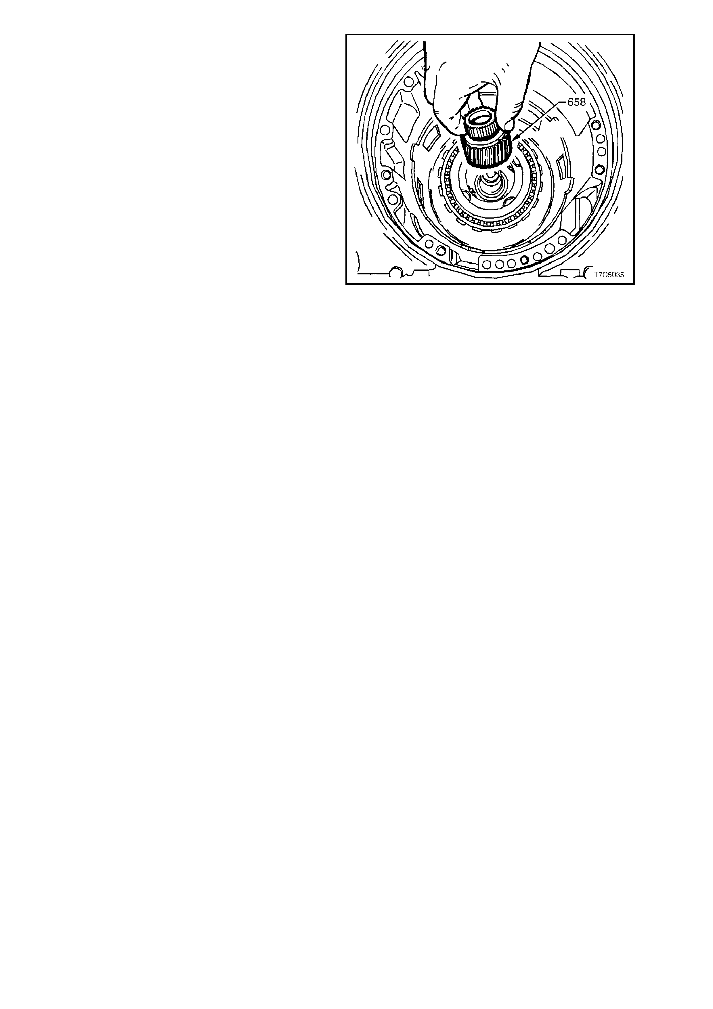
10. Reinstall input sun gear (658) into the input
carrier, meshing helical sun gear teeth with
carrier pinion gear teeth.
Figure 7C5-202
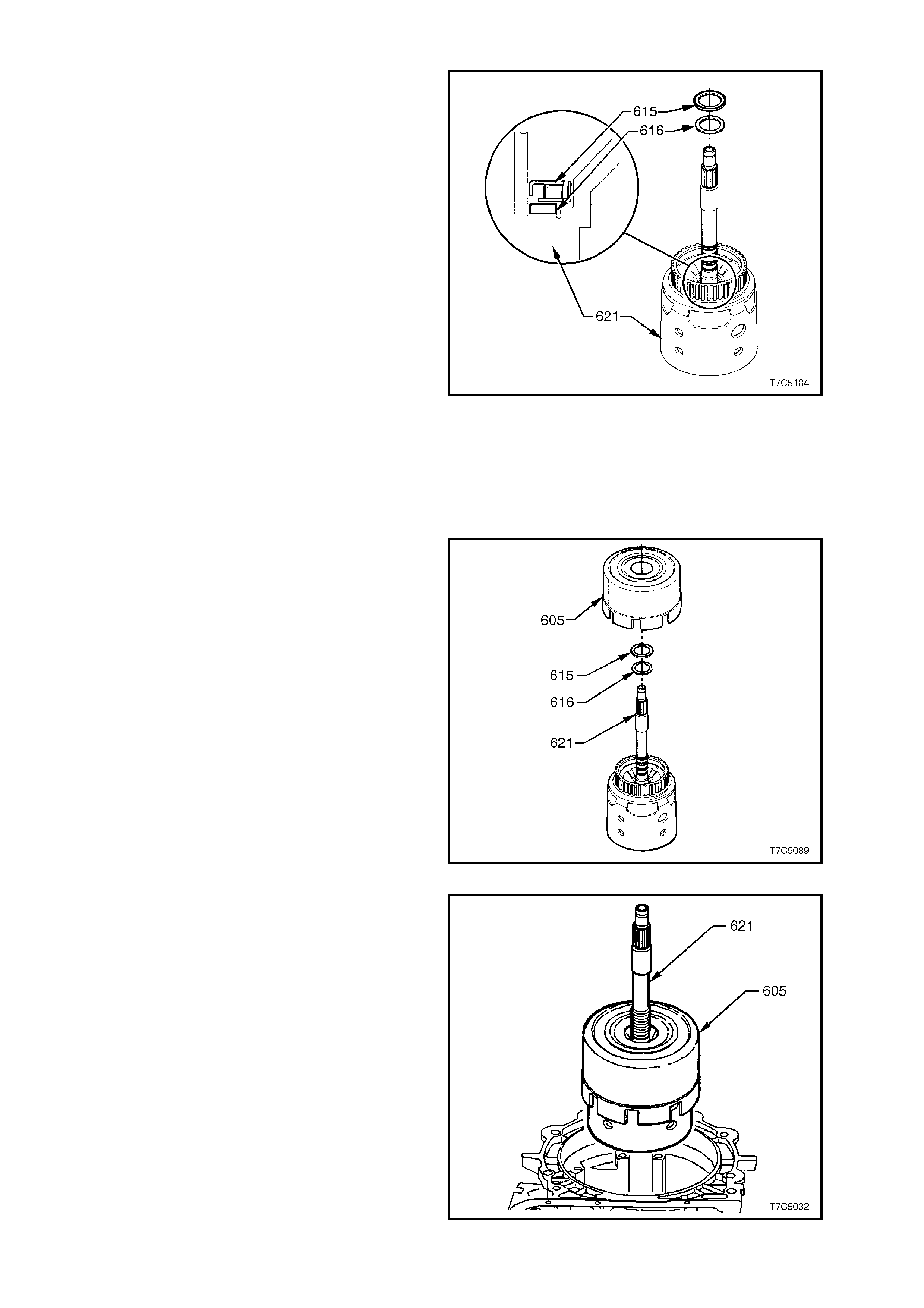
3.6 REVERSE INPUT CLUTCH, INPUT CLUTCH AND INPUT GEAR SET
1. Remove Tool J36418-2A (Refer
Figure 7C5-131) from input shaft and reinstall
selective thrust washer (616) on input housing
and shaft assembly.
NOTE 1:
This selective washer controls the end play of the
transmission, measured in 1.8 Transmission End
Play Check.
NOTE 2:
If end play was not to specif ication, replace original
selective washer with a new one, selec ted fr om the
table below.
TRANSMISSION END PLAY WASHER SELECTION
WASHER THICKNESS (mm) IDENTIFICATION
1.87 - 1.97 67
2.04 - 2.14 68
2.21 - 2.31 69
2.38 - 2.48 70
2.55 - 2.65 71
2.72 - 2.82 7
2.89 - 2.99 73
3.06 - 3.16 74
2. Reinstall bearing assembly (615) on selective
thrust washer with inside race (black)
uppermost, as shown.
Figure 7C5-203
3. Reinstall reverse input clutch assembly (605)
onto input housing and shaft assembly (621),
aligning reverse input clutch plate tangs with
input housing hub. Ensure all c lutch plates are
engaged.
Figure 7C5-204
4. Reinstall reverse input (605) and input clutch
(621) assemblies into transmission case.
Locate 3-4 clutch plate tangs over input
internal gear. Ensure all clutch plates are fully
engaged. When correctly installed, reverse
input clutch housing (605) is loc ated j ust below
case oil pump, machined land in the
transmission case.
Figure 7C5-205
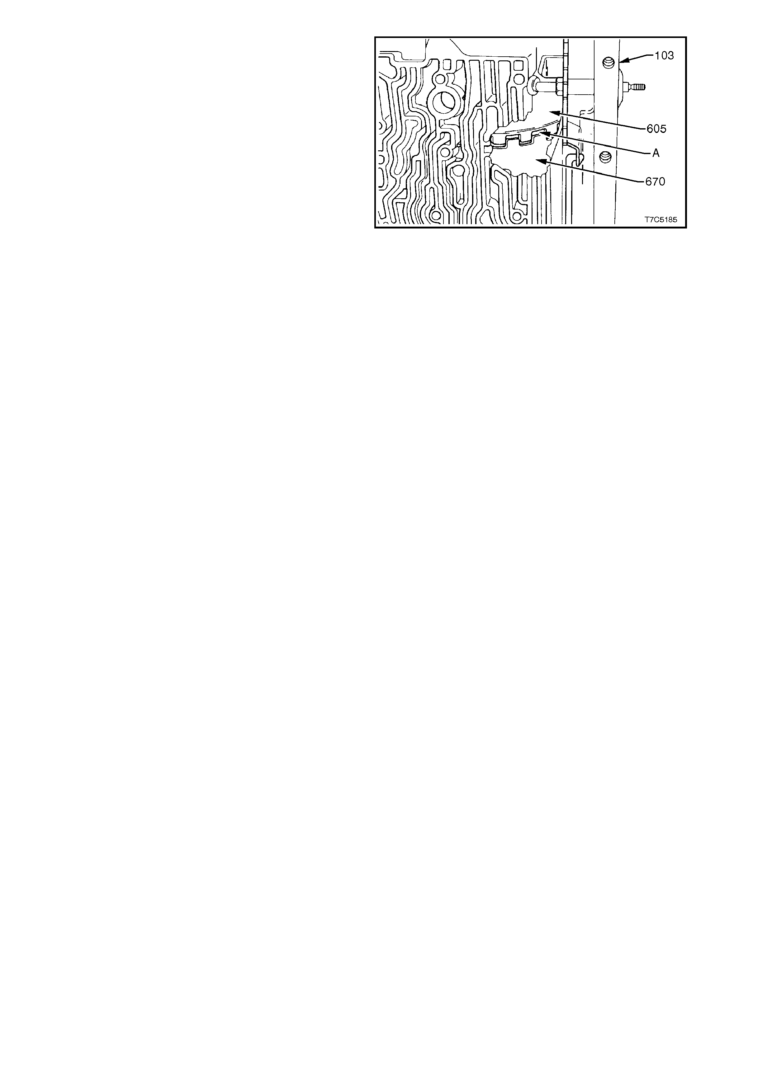
NOTE:
There should be approximately 3.8 mm clearance
(A) between reverse input clutch ( 605) and reac tion
sun gear shell (670), as shown. This is normal.
Figure 7C5-206
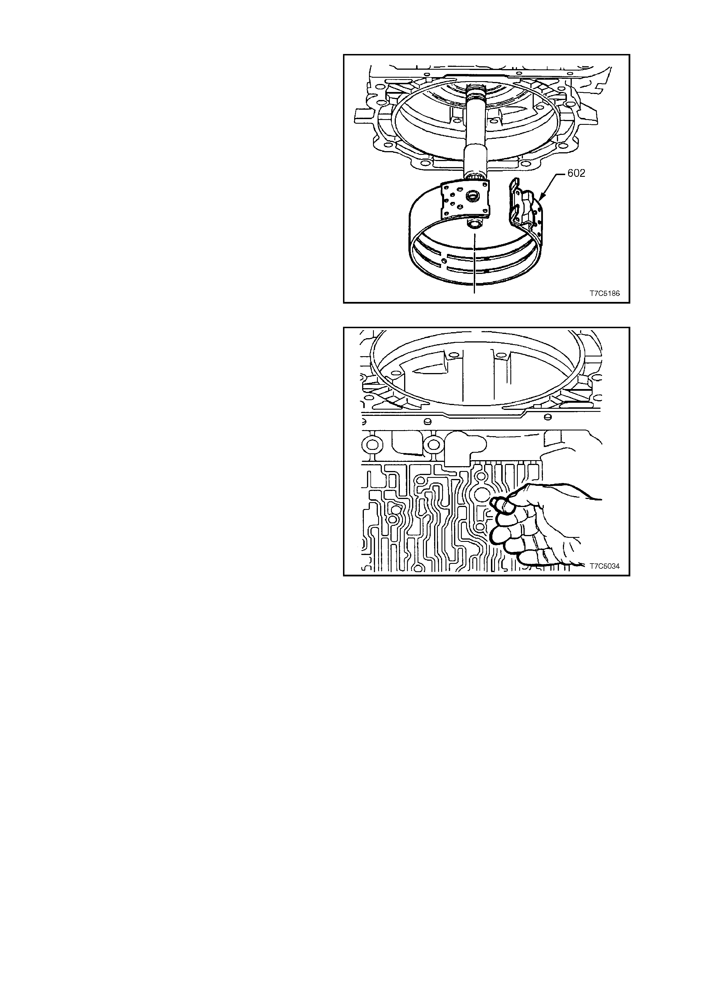
3.7 2-4 BAND ASSEMBLY
1. Inspect 2-4 band assembly for damage or
wear, noting that the band material is now
grey/black in colour. Only replace the band if
the material is scored, flaking or heavily worn.
2. Rotate transm ission through 90° as shown, s o
that the case channels are uppermost.
3. Using both hands, squeeze the 2-4 band into a
circle and work the band into place around the
reverse input drum housing (605). With the
transmission in the position shown, the weight
of the reverse input and input clutch assem bly
will be such that adequate clearance will be
provided for reinstallation of the band.
Figure 7C5-207
4. After reinstalling 2-4 band assembly (602) into
transmission, align the anchor pin end of the
band, with the hole in case.
5. Reinstall 2-4 band anchor pin into
transmission case, as indicated. Ensure pin
engages 2-4 band assembly.
Figure 7C5-208
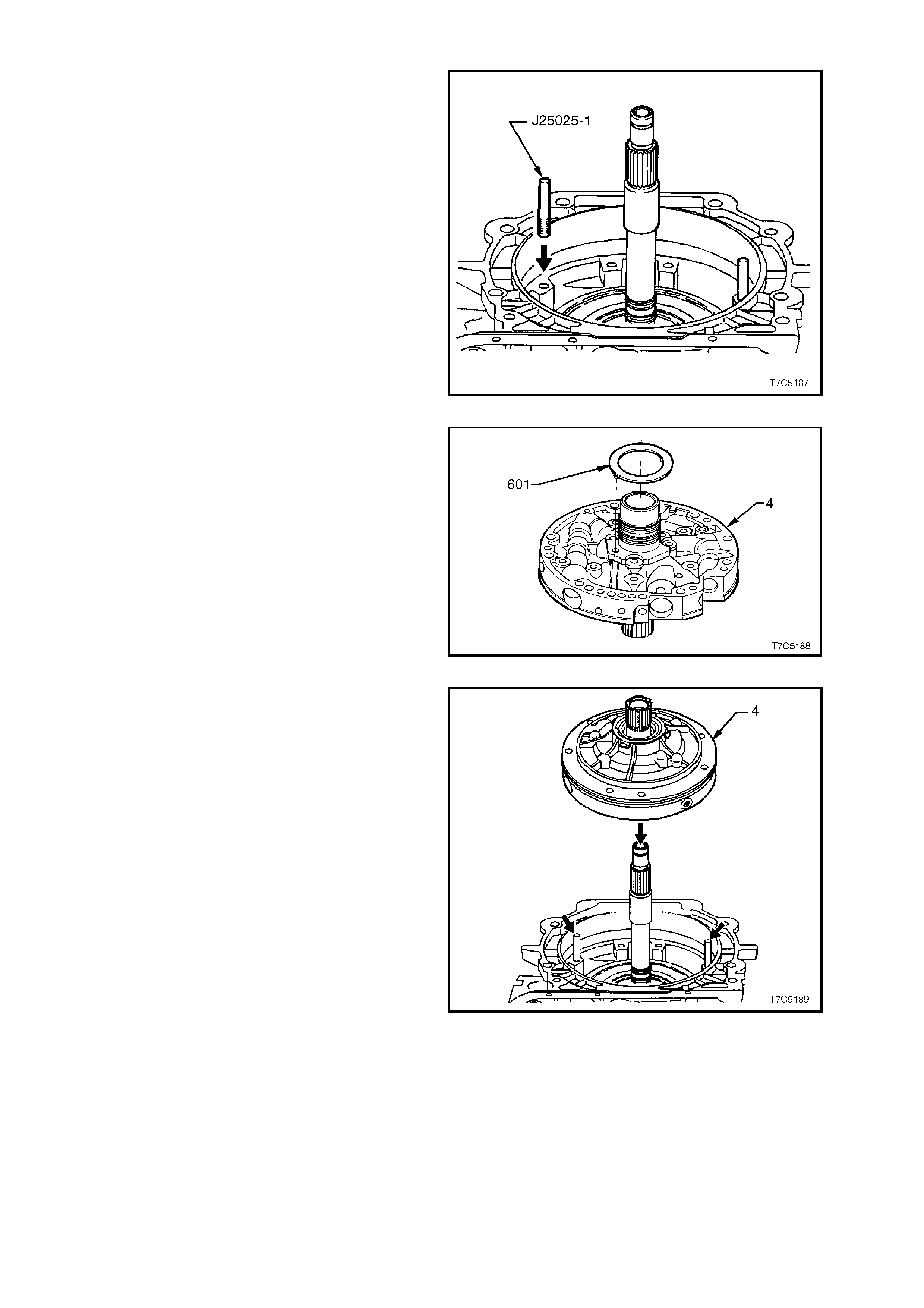
3.8 OIL PUMP
1. Install T ool J25025-1 alignm ent pins , into c ase
as shown. (Part of Tool J25025-B).
Figure 7C5-209
2. Reinstall thrust washer (601) on oil pump (4)
as shown. Retain with petroleum jelly.
Figure 7C5-210
3. Fit new oil pump gasket (6) to transmission
case, align bolt holes and locate over the
alignment pins ( arrows). Retain with petroleum
jelly.
4. Remove oil pump hub sealing ring sizing tool
J39855-2 (see Figure 7C5-175).
5. Lubricate new oil pum p s quare s ec tion s eal (5 )
with petroleum jelly and install in the pump
body groove. W hen correctly installed and not
twisted, the seal colour strip should be visible
around the pump body (4).
Figure 7C5-211
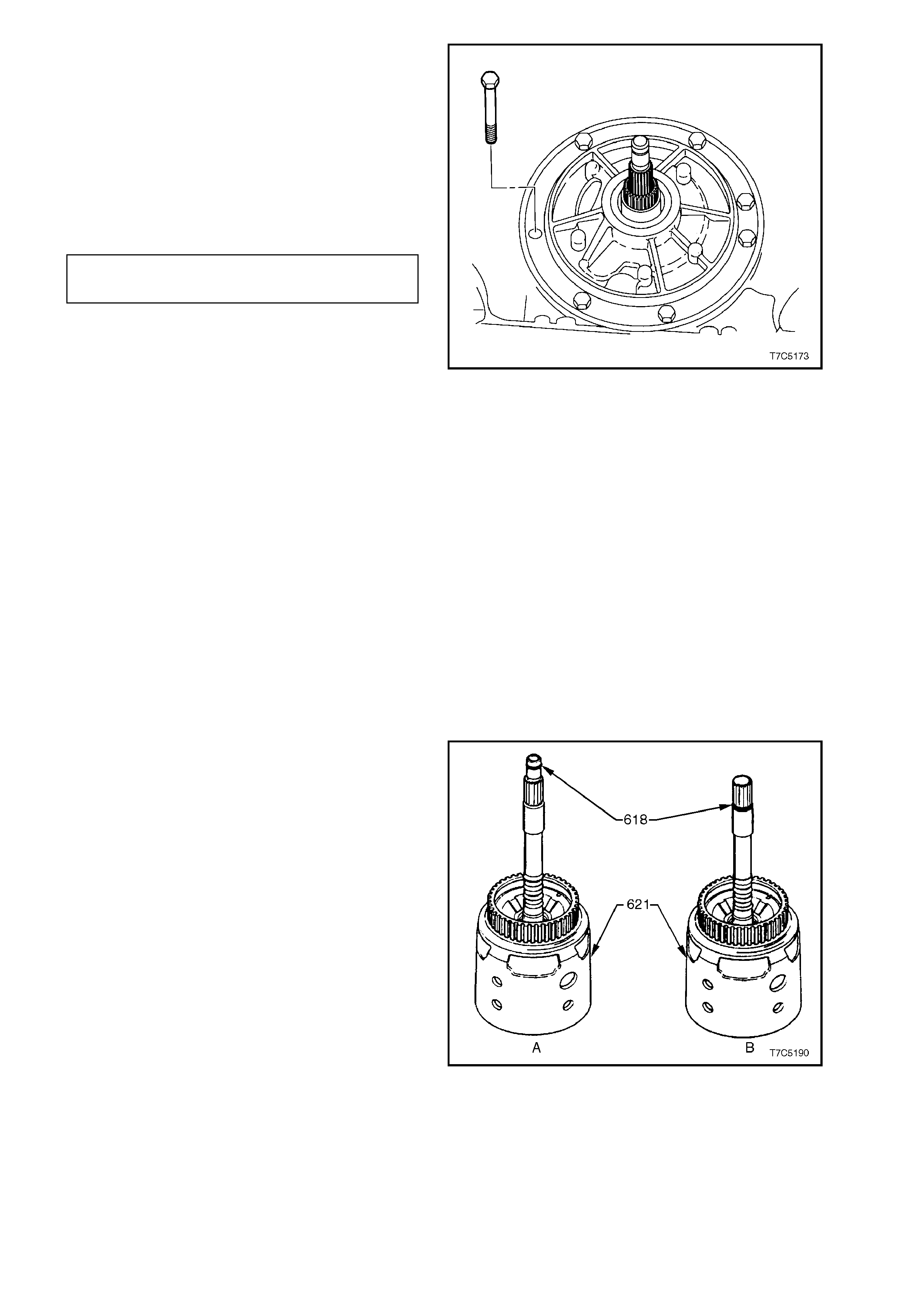
6. Prime oil pump with new transmission fluid
and reinstall assembly into case, over
alignment pins.
7. Reinstall bolts, complete with new sealing
washers, then remove alignment pins,
J25025-1.
8. Progressively tighten bolts in an alternating
pattern to draw the pump body fully into the
transmission case. Tighten bolts to specified
torque.
OIL PUMP TO CASE BOLT 20 - 27
TORQUE SPECIFICATION Nm
Figure 7C5-212
8. After removing the output shaft support
bracket, turn input shaft by hand. If unable to
do so, transmission is incorrectly assembled
(possible thrust washer dislodgment).
Dismantle and rectify problem.
9. Measure transmission end play as described
in 1.8 T ransmission En d Play Check. If end
play is not to specification, replace selective
thrust washer ( 616) between the input hous ing
(621) and the stator shaft bearing assembly
(615). Refer to Step 1 of 3.6 Reverse Input
Clutch, Input Clutch and Input Gear Set
NOTE:
If end play is to specification, the output shaft can
be turned in both forward and reverse directions.
The effort required to turn the output shaft in the
reverse direction however, will be greater than in
the forward direction.
10. Install new O-ring seal (618) into groove at
end of input shaf t ( ‘A’ is the V8, ‘B’, the V6 and
V6 supercharged engines).
Figure 7C5-213

3.9 CONVERTE R HOUS ING
1. Install the converter housing to the
transmission case .
2. Apply Loctite 242, 243 or equivalent (to
Holden’s Specific ation HN1256) to the threads
of the bolt located at the 7 o’clock position
(when looking into the converter housing).
3. Install all converter housing bolts and tighten
to the specified torque, using Torx Plus bit,
Tool No. J41510 or commercial equivalent.
CONVERTER HOUSING BOLT 72 - 78
TORQUE SPECIFICATION Nm
NOTE:
Do not use a standard, # 50 Torx bit, as the bolt
design is such that only the Torx Plus bit is capable
of applying the correct torque without bolt damage. Figure 7C5-214
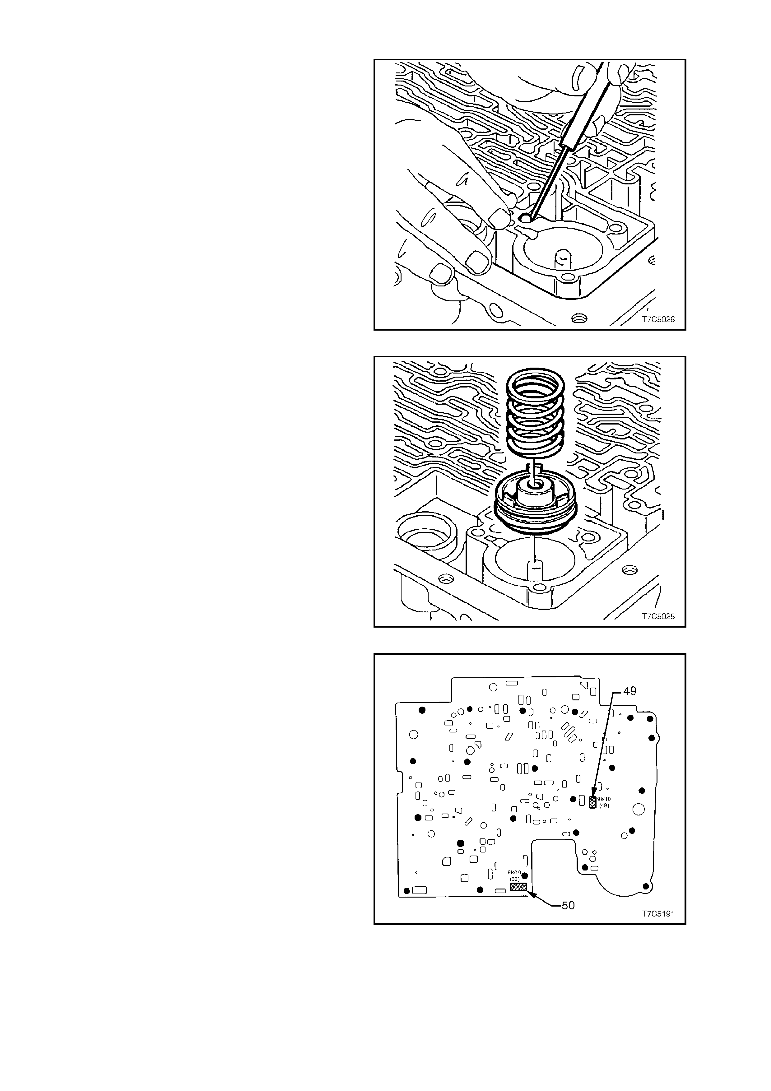
3.10 CONTROL V ALVE BODY AND ASSOCIATED COMPONENTS
1. Reinstall check ball into case. Secure with a
smear of petroleum jelly.
2. If previously removed, install a new O-ring
onto the wiring harness through connector,
smear with petroleum jelly and install into the
case. Ensure that each of the four lugs on the
connector body has 'clicked' into place, on the
outside of the case.
Figure 7C5-215
3. Reinstall 3-4 accumulator pin into case.
NOTE:
The 3-4 and 1-2 accumulator piston pins are
different diameters. Ensure that the 3-4
accumulator pin is not a loose fit in the case. The
correct pin should be a snug fit.
4. Coat new 3-4 accumulator piston seal with
petroleum jelly and install on piston. Rotate
piston seal in the piston groove to ensure that
no binding occurs.
5. Reinstall 3-4 accumulator piston over pin with
three lugs facing out of bore.
6. Reinstall 3-4 accumulator piston spring.
Figure 7C5-216
7. if a new spacer plate is to be fitted, it will be
necessary to install two filter screens (49 and
50) to the spacer plate before fitment. Location
of these two screens is as shown.
Figure 7C5-217
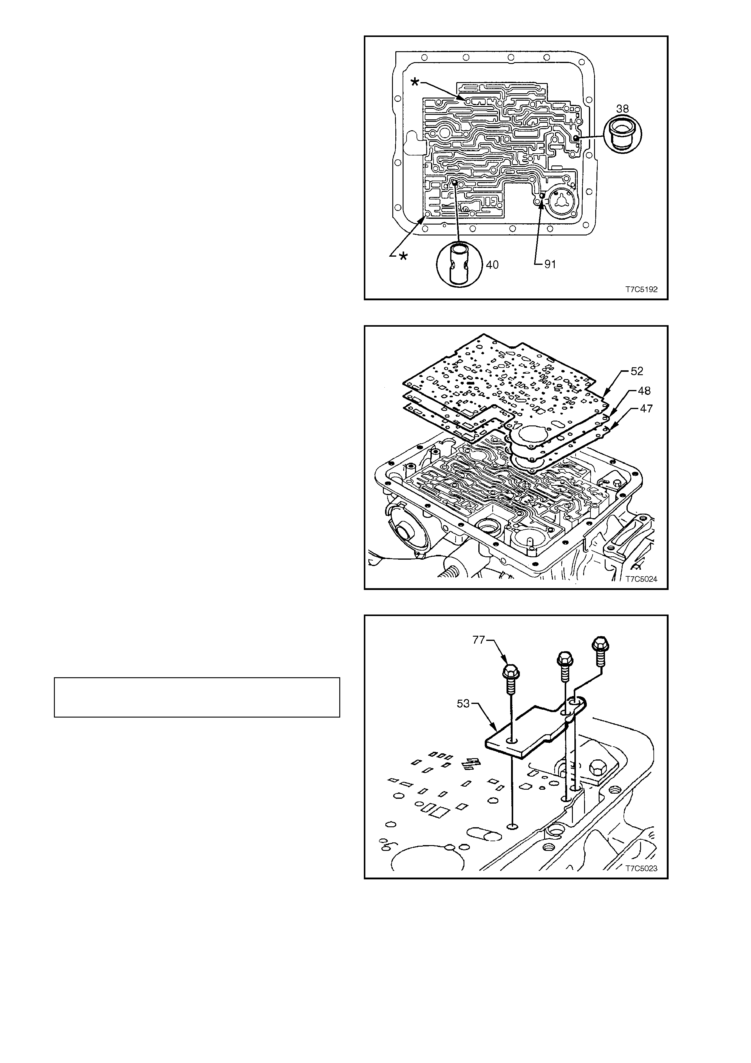
8. Install two suitable guide pins (part of T ool No.
J25025-B), into cas e at the locations indicated
by an asterisk (V). These locations are
impor tant, as the matching holes in the spacer
plate have a closer clearance tolerance than
the other holes.
The view shown, also confirms the location of
the check ball #1 (91) , the orifice plug #10 ( 38)
and the 3rd accumulator, check ball assembly
#7 (40).
IMPORTANT:
Ensure that the guide pins are f ully installed s o that
no thread is visible. Otherwise, the spacer plate
gasket could become caught in a thread during
installation, resulting in incorrect alignment.
Figure 7C5-218
9. Sm ear petroleum j elly over a new spacer plate
to case gas k et ( 47) and install on tr ans miss ion
case, over the guide pins. Gasket is identified
with a 'C' (Case).
10. Reinstall spacer plate (48) over the guide pins.
11. Smear petroleum jelly over a new valve body
to spacer plate gasket (52) and install on
transmission case, over the guide pins.
Gasket is identified with a 'V' (Valve body).
IMPORTANT:
Incorrect placement of the spacer plate gaskets
may cause transmission shift problems.
Figure 7C5-219
12. Install three spacer plate support plate (53)
retaining bolts (77), tightening to specified
torque.
SPACER PLATE SUPPORT PLATE 8 - 14
BOLT TORQUE SPECIFICATION Nm
Figure 7C5-220
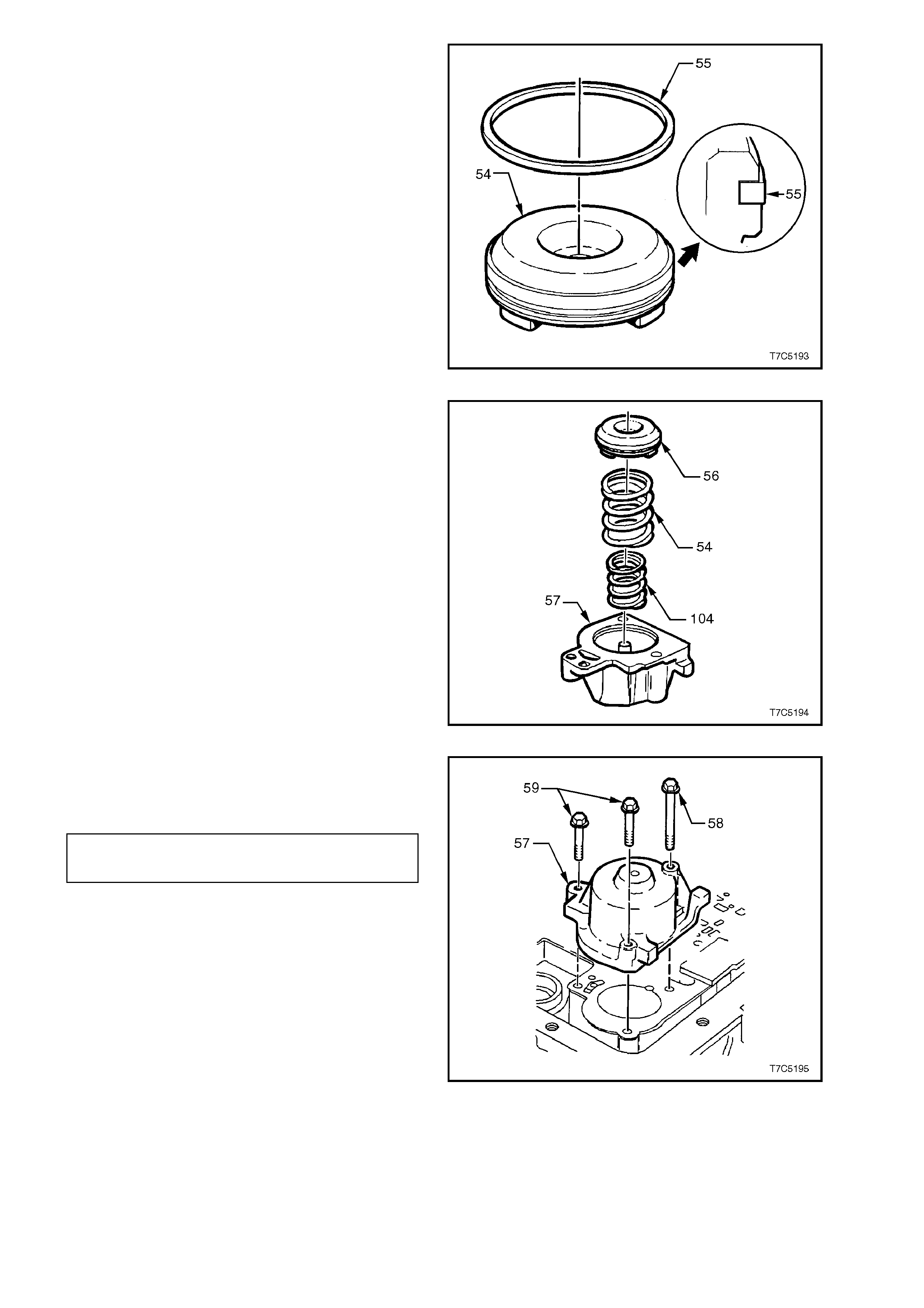
13. Coat new 1-2 accumulator piston seal (55)
with petroleum jelly and install on piston (54).
Rotate piston seal in the piston groove to
ensure that no binding occurs.
Figure 7C5-221
14. Reinstall piston pin and the previously tagged,
two 1-2 accumulator springs (54) into the
accumulator cover.
15. Reinstall piston into cover and pin assembly.
The three lugs on the piston point into the
cover.
Figure 7C5-222
16. Reinstall 1-2 accumulator assembly onto
transmission, while holding piston in place.
Tighten bolts to specified torque.
1 -2 ACCUMULATOR COVER BOLT 8 - 14
TORQUE SPECIFICATION Nm
Figure 7C5-223
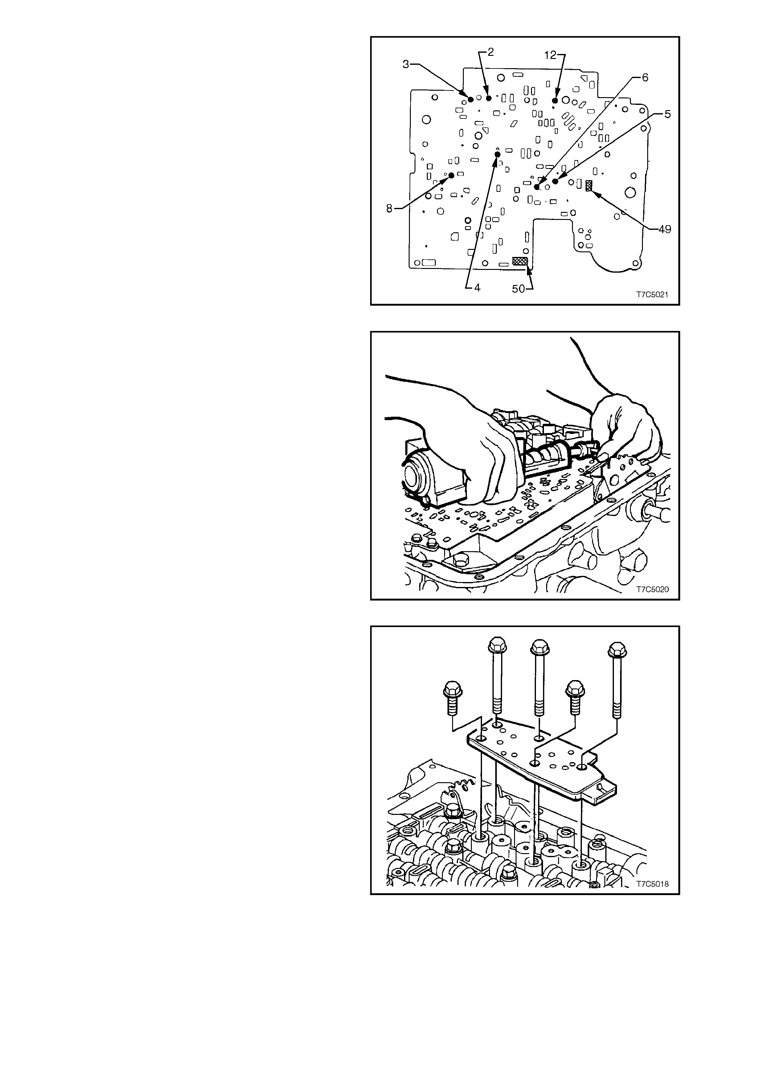
17. Remove spacer plate guide pins from case.
18. Reinstall seven check balls onto the control
valve body spacer plate in the locations as
shown and secure with a small amount of
petroleum jelly.
Figure 7C5-224
19. Insert the m anual valve link (89) into the inner
detent lever (88).
20. Turn the valve body over and, while supporting
the manual valve link in one hand and the
valve body in the other, rotate the valve body
slightly and connect the link with the manual
valve. Move the manual valve forward, to
retain the link connection and carefully lower
the valve body into position.
Figure 7C5-225
21. Reinstall bolts to the transmission range
pressure switch assembly (PSA), but do not
tighten.
Figure 7C5-226
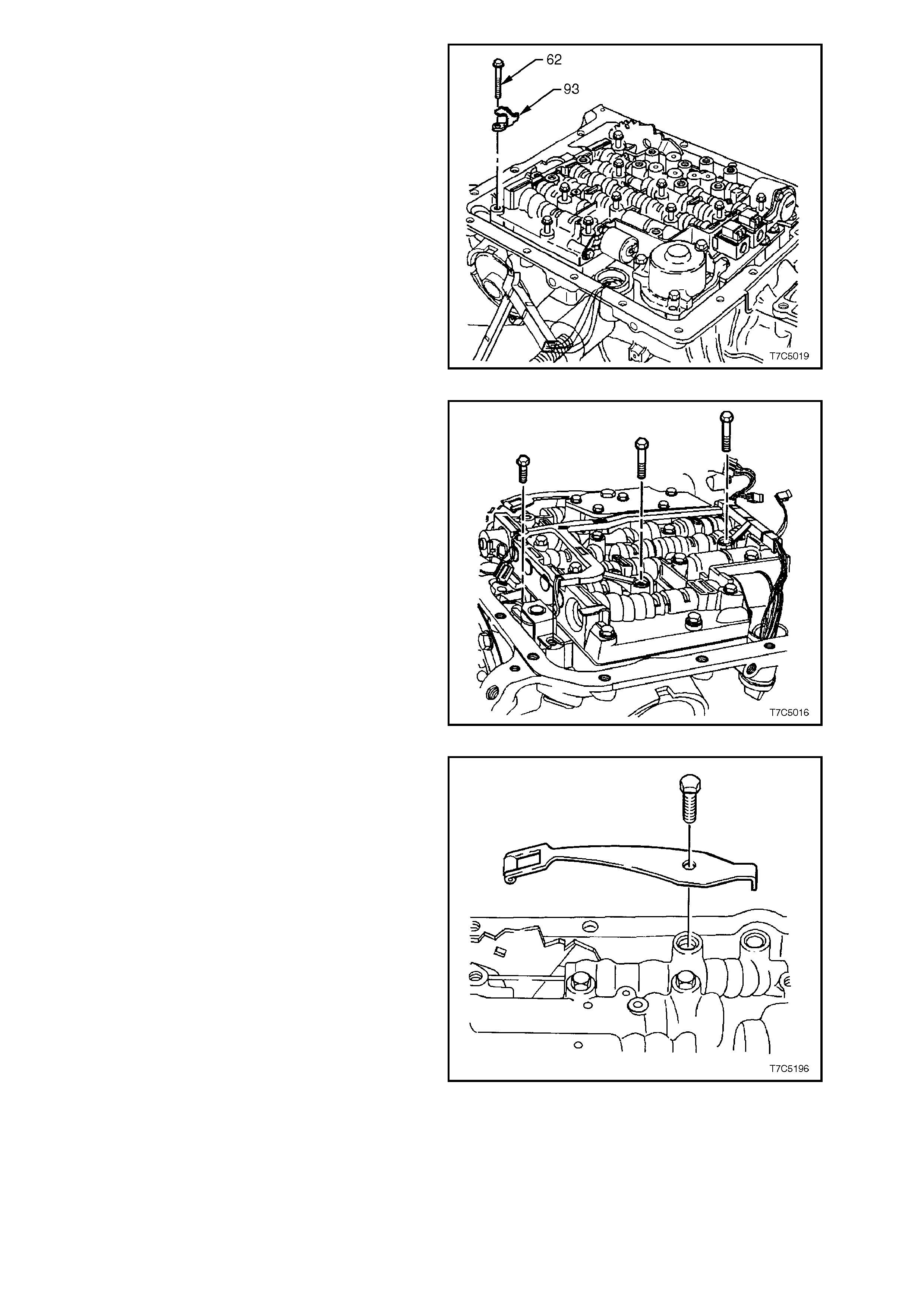
22. Install the dipstick stop bracket (93) and
retaining bolt (62). Do not tighten at this time.
Figure 7C5-227
23. Loosely install harness bracket bolts.
24. Loosely install the remainder of the control
valve body bolts.
Figure 7C5-228
25. Reinstall the manual detent spring assembly
retaining bolt.
Figure 7C5-229
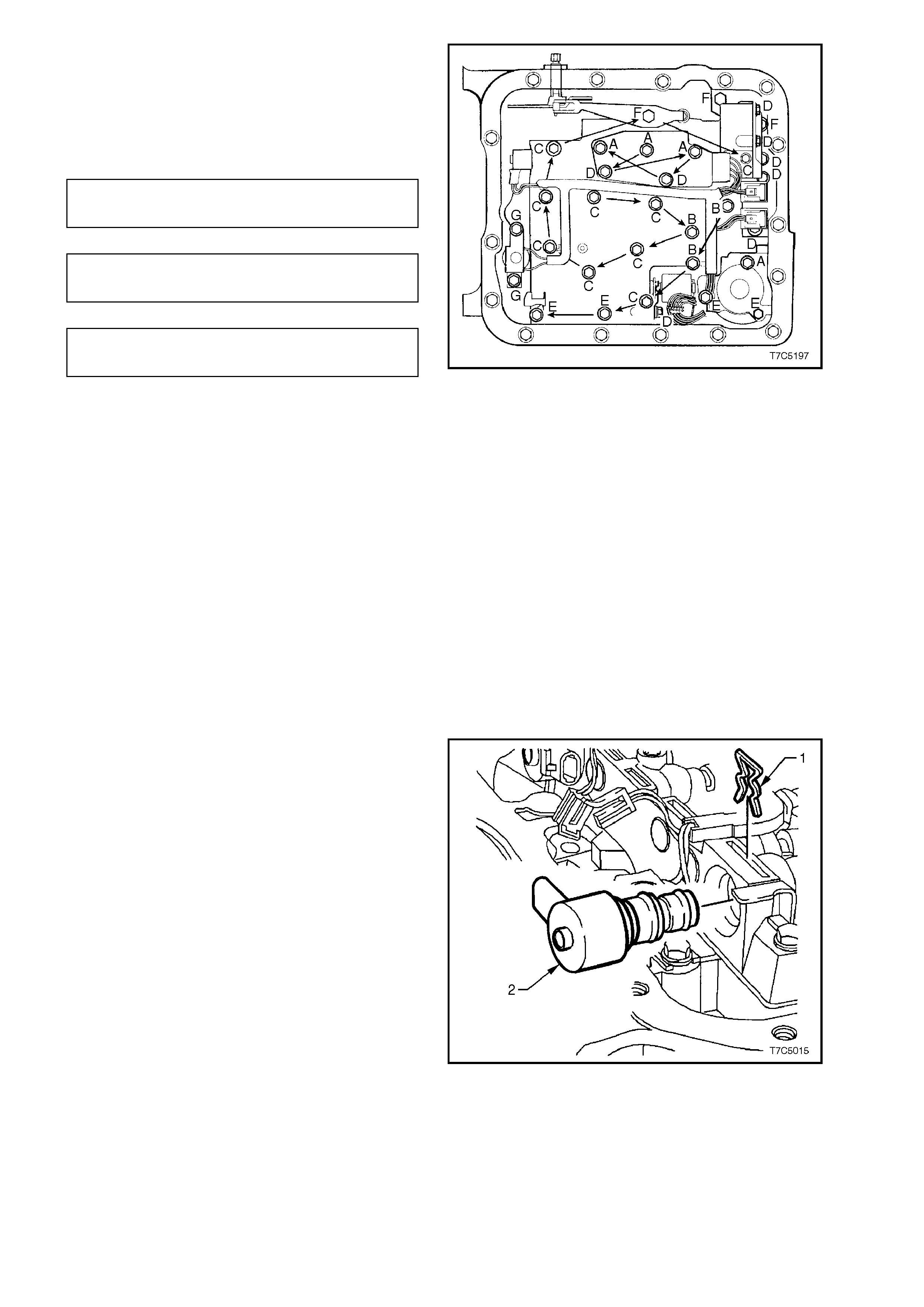
26. Coat a new TCC solenoid O-ring with
petroleum jelly and install on solenoid, then
reinstall TCC solenoid assembly into the oil
pump body
27. Tighten all bolts to the specified torque
specification, in the order shown.
CONTROL VALVE BODY and PSA 8 - 14
TORQUE SPECIFICATION Nm
MANUAL DETENT SPRING 20 - 27
BOLT TORQUE SPECIFICATION Nm
TCC SOLENOID BOLT 8 - 14
TORQUE SPECIFICATION Nm
IMPORTANT:
The control valve body bolts must be tightened in
an outward spiral from the centre, as shown.
Failure to follow this pattern may distort the valve
body, causing valves to jam in their bores.
NOTE:
There are 7 different bolt sizes used. The letters
shown, relate to the following bolt sizes.
Control Valve Body Fastener Specifications
A — M6 x 1.00 x 65.0
B — M6 x 1.00 x 54.4
C — M6 x 1.00 x 47.5
D — M6 x 1.00 x 18.0
E — M6 x 1.00 x 35.0
F — M8 x 1.25 x 20.0
G — M6 x 1.00 x 12.0
Figure 7C5-230
28. Coat a new TCC PWM solenoid O-ring with
petroleum jelly, install on the solenoid (2).
Then reinstall the solenoid into the control
valve body, securing with retaining clip (1).
Figure 7C5-231
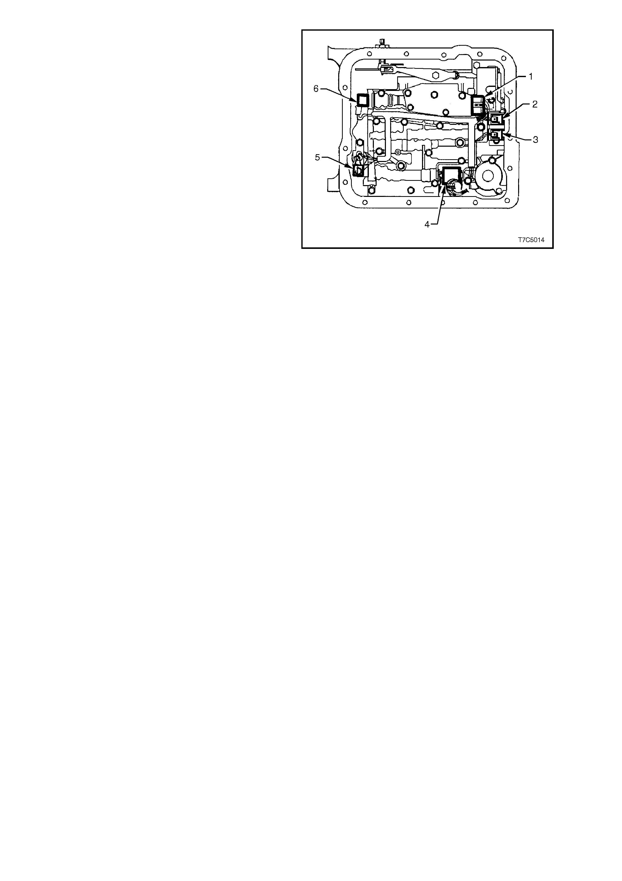
29. Reinstall electrical wiring harness connectors
to the respective components as shown, and
indicated below.
Electrical Connector Identification
1. Pressure Switch Assembly (PSA).
2. 1-2 Shift Valve Solenoid
3. 2-3 Shift Valve Solenoid
4. Pressure Control Solenoid (PCS)
5. TCC Pulse Width Modulated (TCC PWM)
Solenoid
6. 3-2 Control Solenoid
Figure 7C5-232
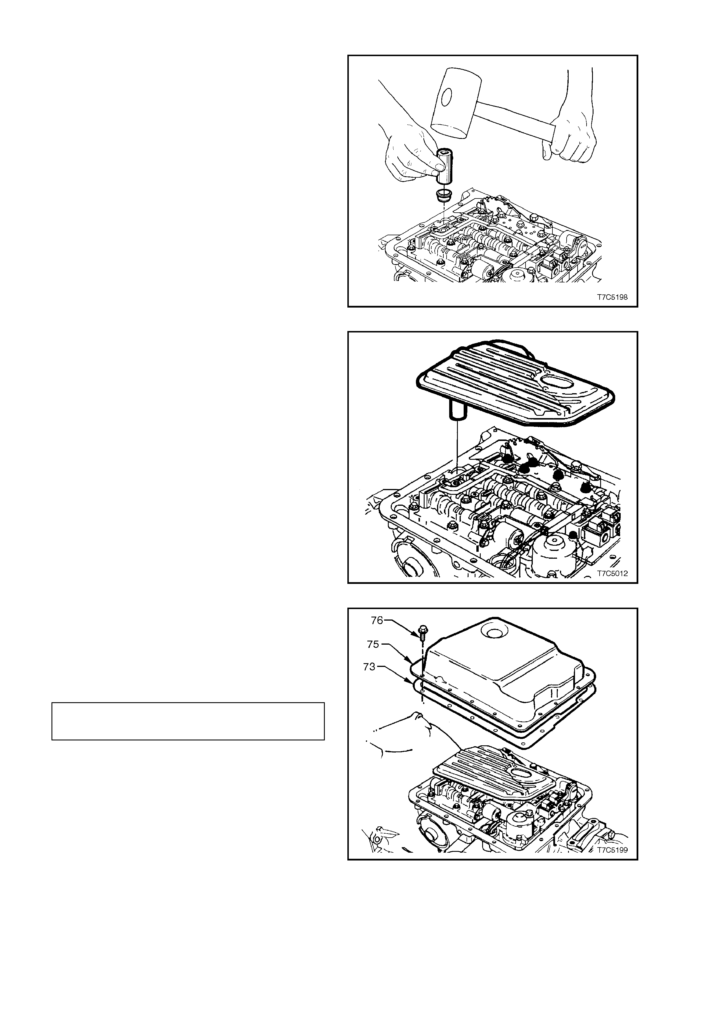
3.11 OIL FILTER AND OIL PAN
1. Lubricate new oil filter seal with petroleum jelly
and install into the oil pump bore, using a
suitable size socket or piece of tubing.
Figure 7C5-233
2. Install a new oil filter into the oil filter seal.
Figure 7C5-234
3. Check that the magnet is in the designated
position in the oil pan.
4. Install a new oil pan gasket.
5. Reinstall oil pan and tighten bolts to specified
torque.
OIL PAN BOLT 9.5 - 13.8
TORQUE SPECIFICATION Nm
Figure 7C5-235
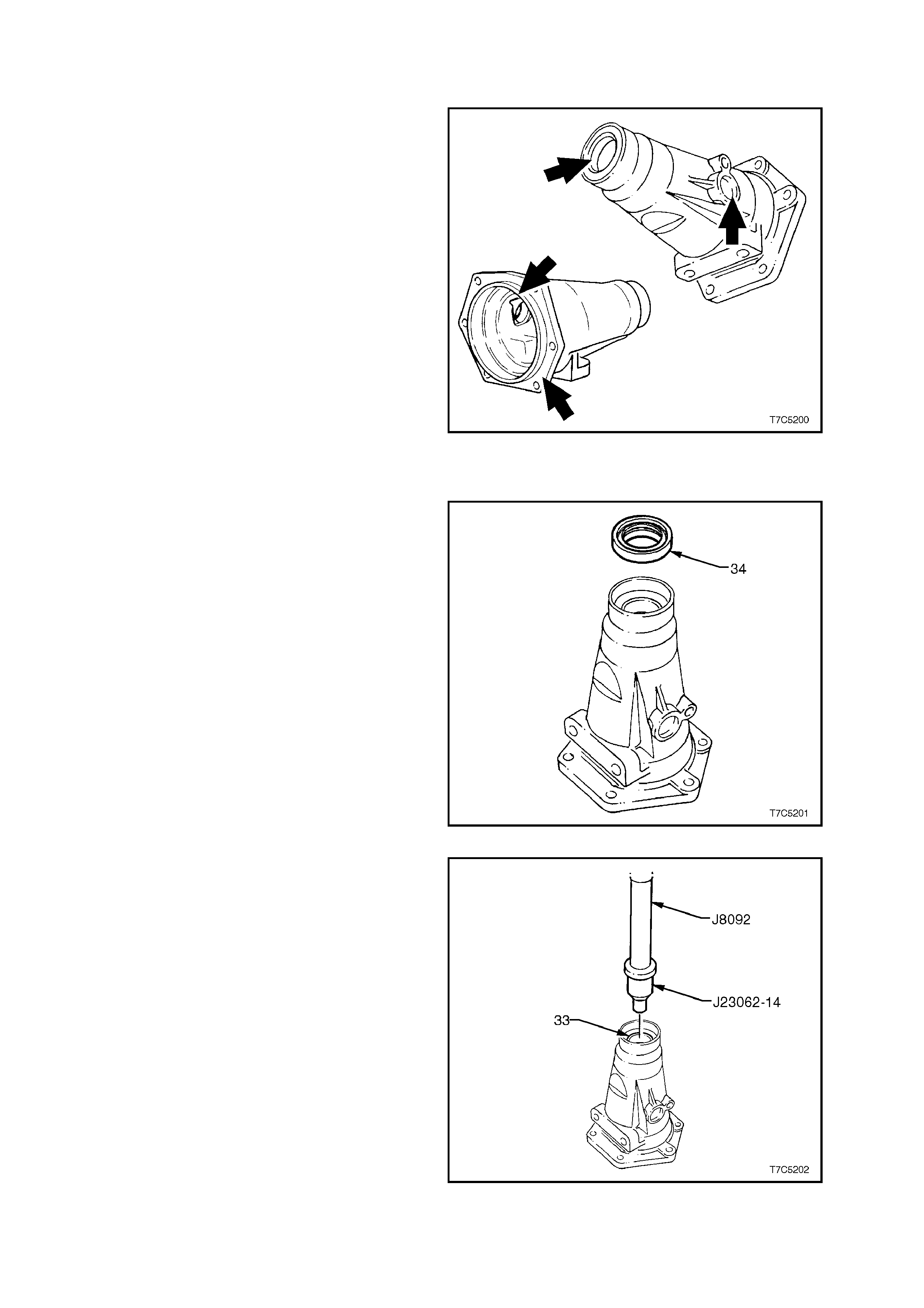
3.12 CASE EXTENSION HOUSING AND SPEED SENSOR
INSPECT
1. Inspect the for nicks or burrs to machined
surfaces, removing as required with a fine cut
file.
2. Check the propeller s haft sliding yoke bus h f or
wear.
Figure 7C5-236
CASE EXTENSION HOUSING BUSH - REPLACE
1. If not previously carried out, remove the case
extension oil seal, using a removing tool such
as Tool E308 or commercial equivalent.
Figure 7C5-237
2. Using bush remover, Tool J23062-14 and
driver handle J8092, press the bush (33) f rom
the extension housing.
Figure 7C5-238
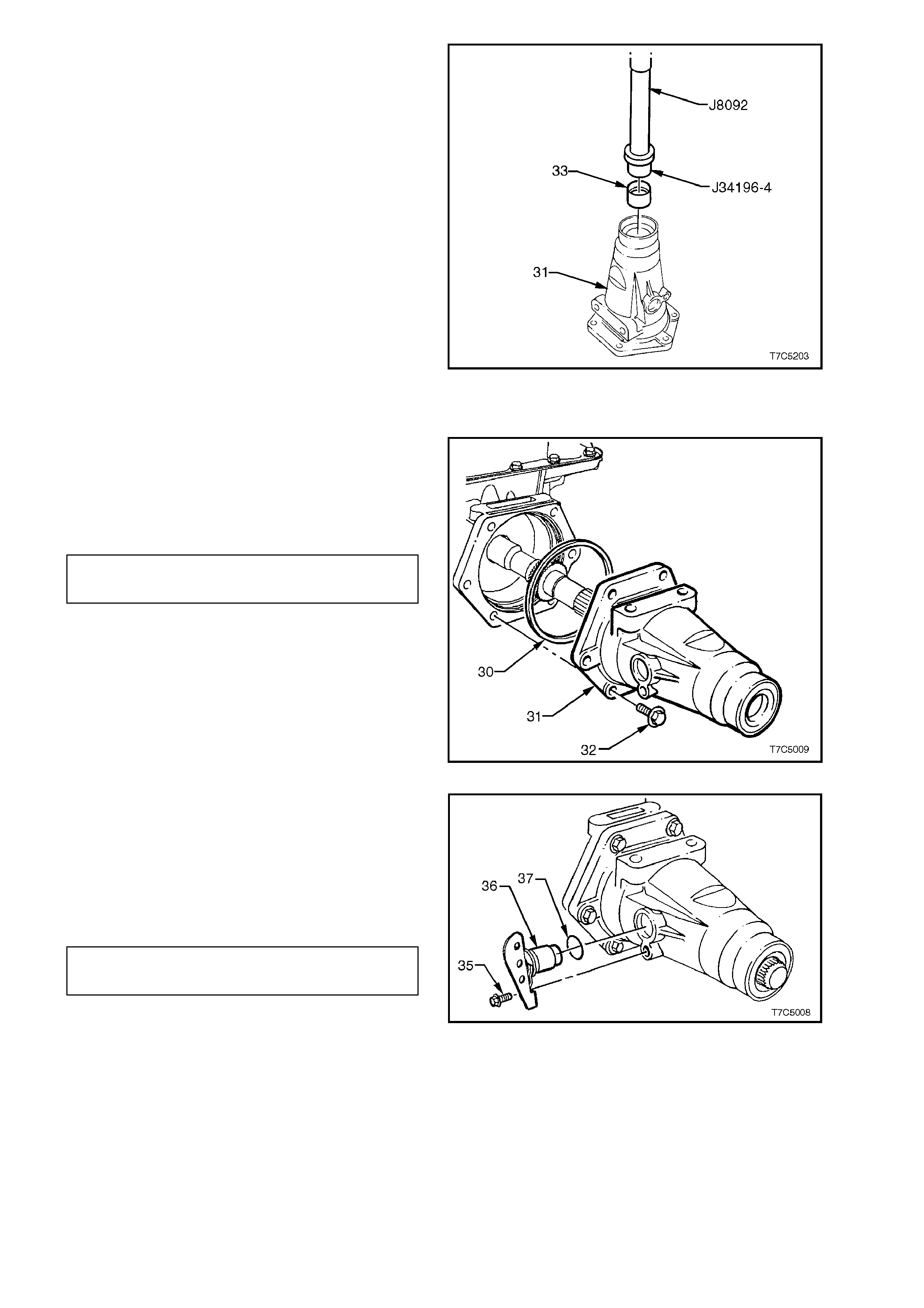
3. Install a new bush (33) into the extension
housing (31), using installer J34196-4 and
driver handle J8092.
Figure 7C5-239
REINSTALL
1. Install a new seal (30) to the case extension
(31), then install to the rear of the tr ans miss ion
case.
2. Reinstall the six attaching bolts (32) and
tighten to the correct torque specification.
CASE EXTENSION HOUSING BOLT 42 - 48
TORQUE SPECIFICATION Nm
Figure 7C5-240
3. Inspect the speed sensor for damage and, if
serviceable, lubricate new O-ring (37) with
petroleum jelly and install on speed sensor
(36).
4. Reinstall the sensor to the case extension,
install the retaining bolt and tighten to the
correct torque specification.
SPEED SENSOR RETAINING BOLT 10.5 - 13.5
TORQUE SPECIFICATION Nm
Figure 7C5-241
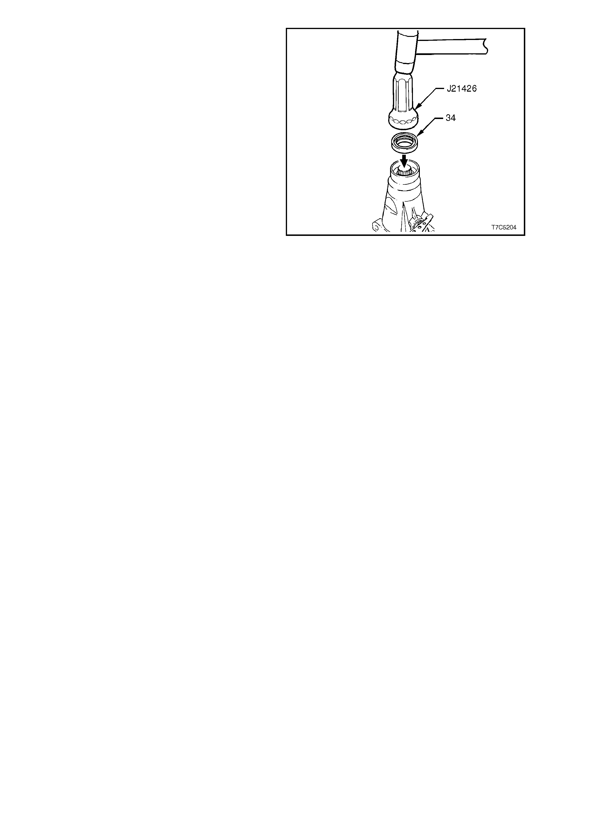
5. Install new extension housing seal (34), using
Tool J21426.
Figure 7C5-242
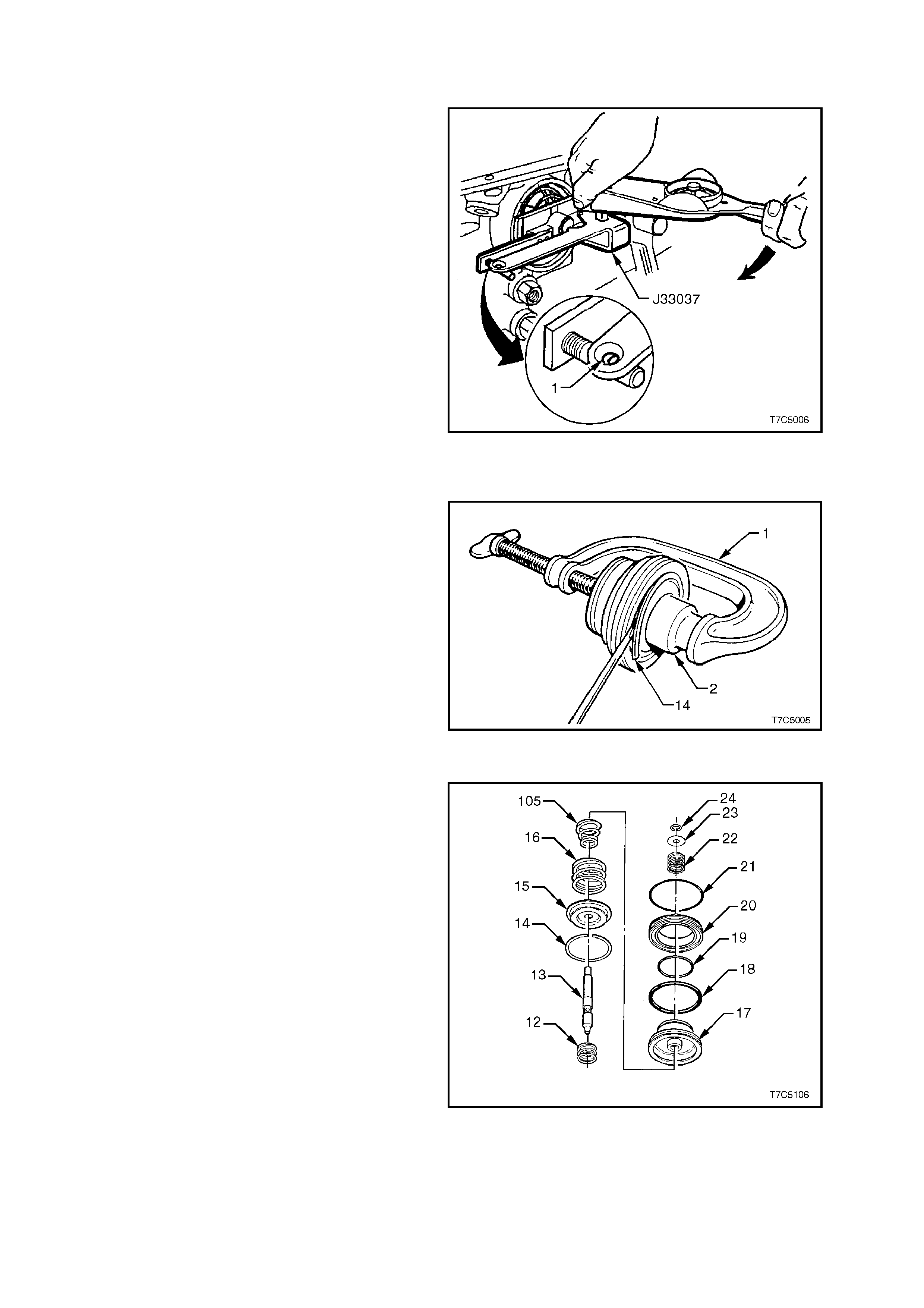
3.13 2-4 SERVO ASSEMBLY
SERVO PIN LENGTH - CHECK
1. Install the pin, tapered end first, into the
transmission case .
2. Install Tool J33037 as shown, then install the
servo cover retaining ring to secure the tool.
3. Apply 11 Nm of torque to the tool arm. If the
white line appears in the gauge eyelet (1), then
the pin length is correct.
4. Remove Tool J330307 and the 2nd apply
piston pin, from the transmission case.
5. Should the white line not appear in the gauge
eyelet, then a replacement pin must be
selected from the following:
2 - 4 SERVO PIN SELECTION
PIN LENGTH (mm) IDENTIFICATION
65.82 - 66.12 2 RINGS
67.23 - 67.53 3 RINGS
68.64 - 68.94 WIDE BAND
Figure 7C5-243
REINSTALL
1. Reinstall cus hion springs (16 and 105) into the
well of the second apply piston (17) , as shown
next.
NOTE:
The V8 application has only one cushion spring.
2. Reinstall cus hion spring retainer (15) on top of
spring (16).
3. Fit a G-clam p (1) and suitable sized socket ( 2)
to the second apply piston assembly as
shown.
4. Use this arrangement to compress piston
assembly sufficient to allow the retaining ring
(14), to be reinstalled.
5. Remove tools to release spring tension. Figure 7C5-244
6. Reinstall the apply pin ring retainer (24) and
test that the 2-4 servo pin does not bind.
7. Reinstall servo apply pin spring (22) and
washer (23), securing with C-clip (24).
8. After applying petroleum jelly to the inner and
outer 2nd apply piston sealing rings (18 and
19), install to piston (17).
9. Apply petroleum jelly to a new servo piston,
inner housing O-ring seal (21) and install on
inner housing (20), ensuring that the seal is
correctly seated in the groove.
10. Reinstall the inner housing (20) over the 2nd
apply piston's inner sealing ring (19).
Figure 7C5-245
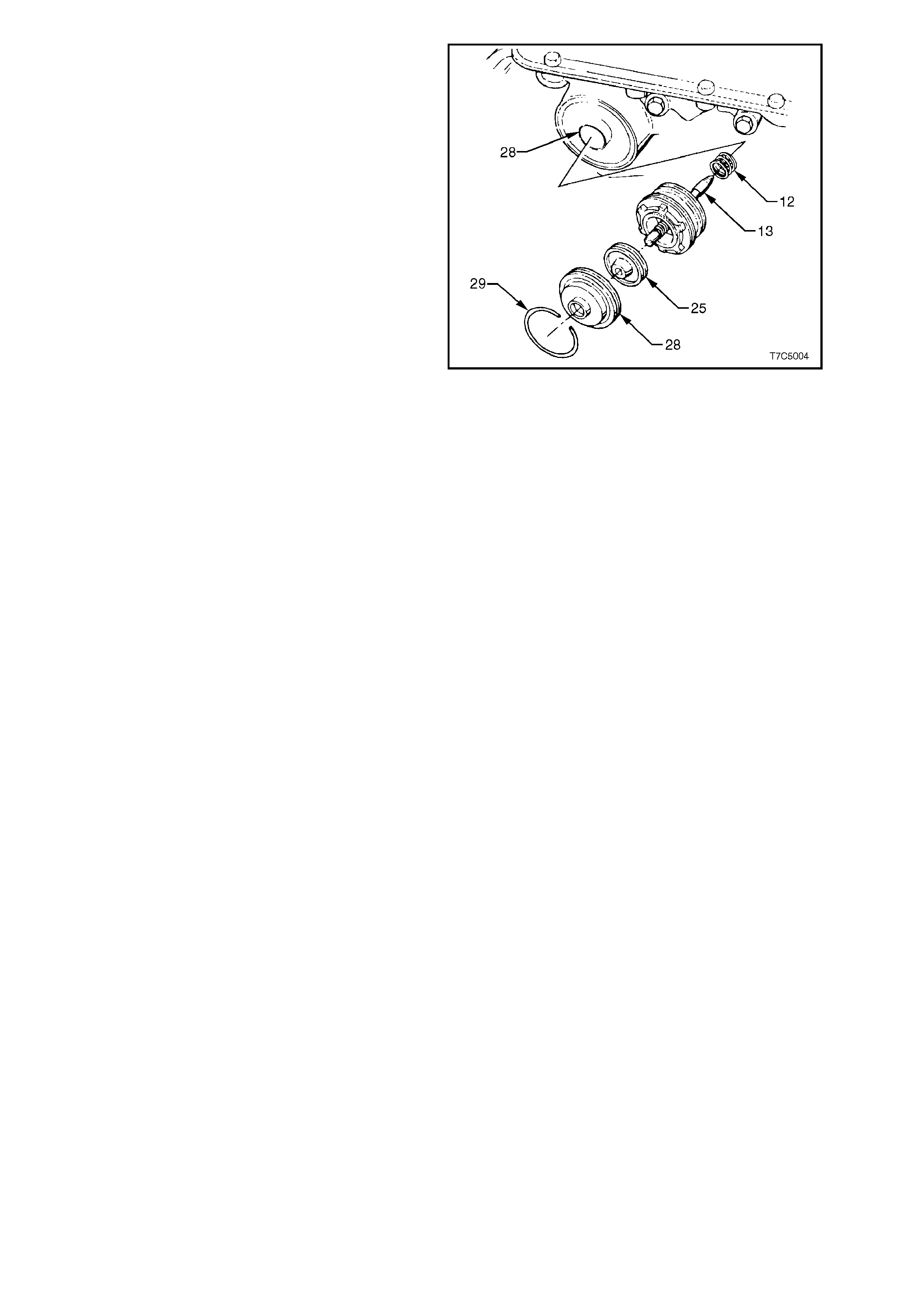
11. Lubricate a new 4th apply piston oil seal ring
(26) (not shown) with petroleum jelly and
reinstall on the 4th apply piston (25).
12. Reinstall 4th apply piston assembly (25) into
the servo cover (28), with the piston boss
facing the cover, as shown.
13. Lubricate a new servo cover O-ring (27) (not
shown), with petroleum jelly and fit to the
groove in the servo cover (28).
14. Reinstall servo return spring (12), servo apply
pin and 2nd apply piston assembly into servo
bore in the transmission case.
15. Reinstall the 4th apply piston and outer cover
over the servo pin and press in until the
retaining ring groove in the case is visible.
16. Reinstall retaining ring (29).
Figure 7C5-246
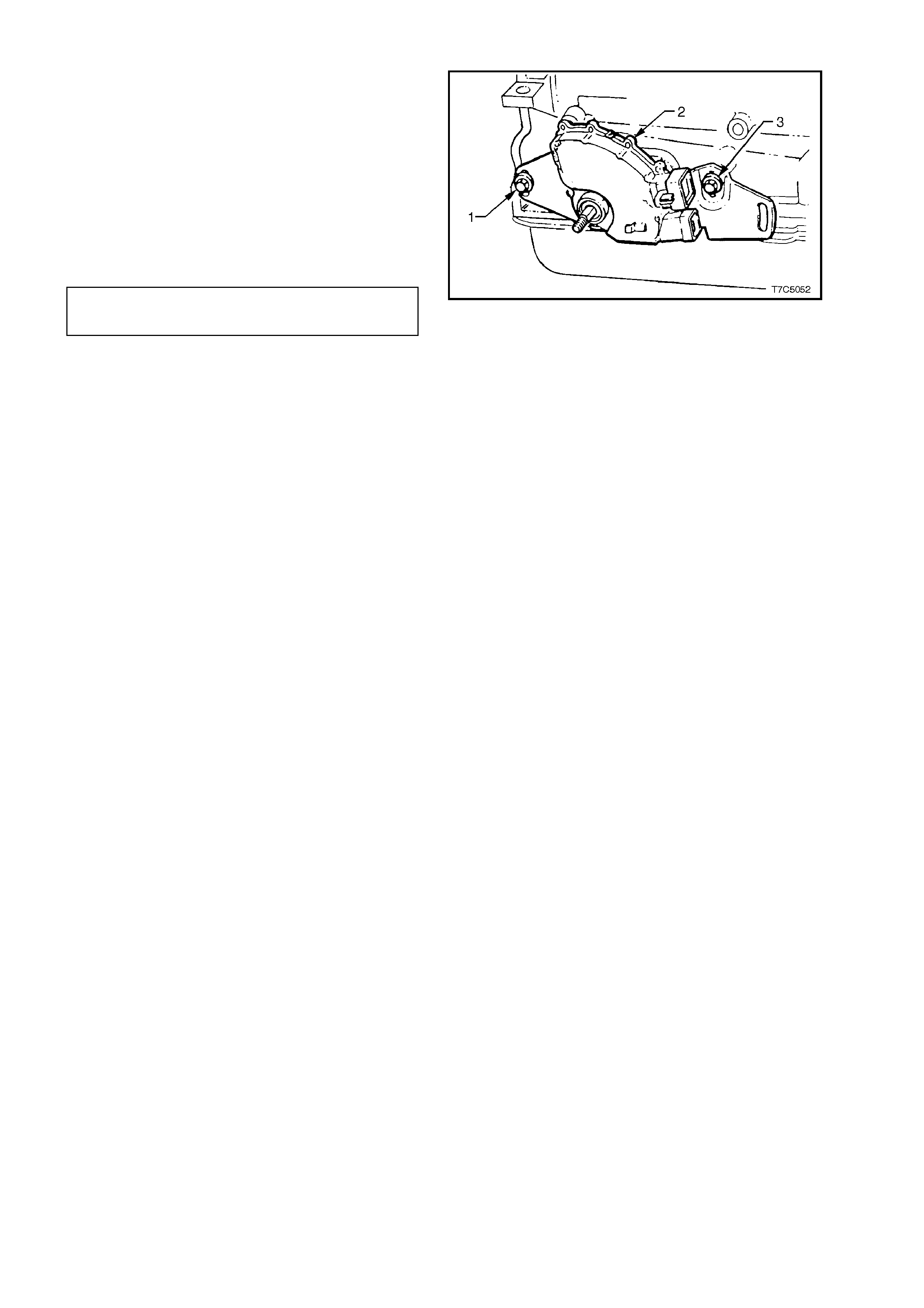
3.14 NEUTRAL START & BACK-UP LAMP SWITCH ASSEMBLY
1. Reinstall the neutral start and back-up lamp
switch (2) but do not fully tighten the attaching
screws (1 and 3).
NOTE:
Final adjustment of the neutral start and back-up
lamp switch is carried out after the transmission is
reinstalled into the vehicle and the shift linkage
installed.
2. Reinstall the selector lever and the retaining
nut. Tighten to the correct torque specification.
SELECTOR LEVER RETAINING 15 - 35
NUT TORQUE SPECIFICATION Nm
NOTE:
The lever must be held securely while the nut is
tightened.
Figure 7C5-247
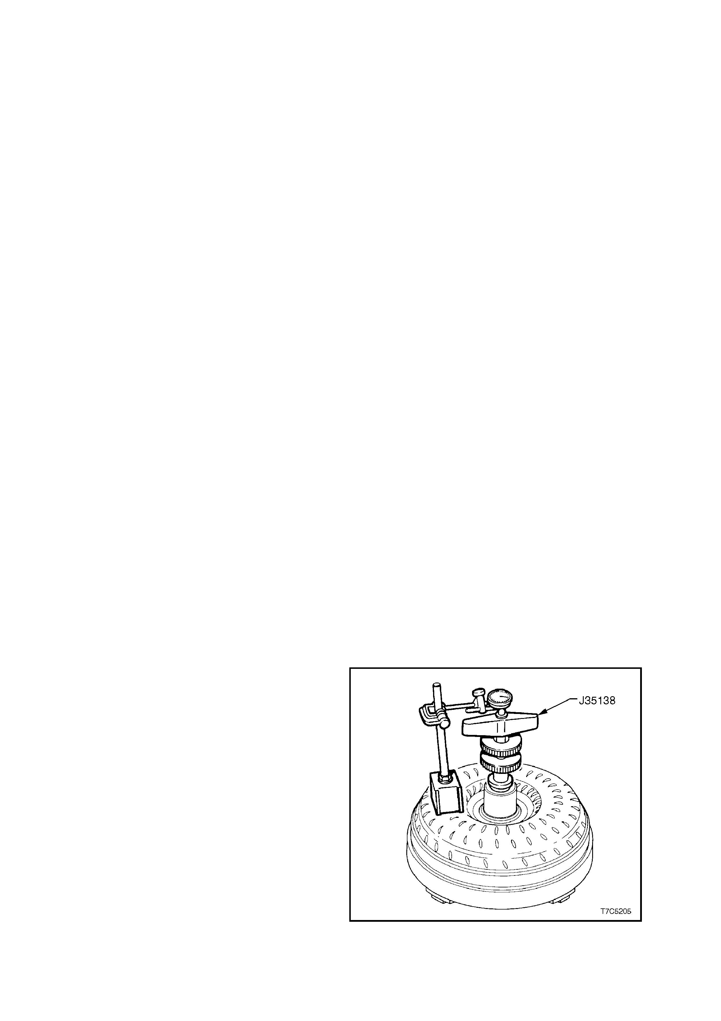
3.15 TORQUE CONV E RTER
INSPECT
The torque converter is serviced as an assembly
and should be replaced if any of the following
conditions exist:
a. Metal particles found when flushing
cooler or converter pipes - converter
flushing is not recommended. Refer to
Section 7C4 ON-VEHICLE SERVICING
for more detailed information regarding
cooler flushing procedures.
b. Oil pump damaged.
c. Leaking converter welds.
d. Converter pilot broken, damaged or poor
fit in crankshaft.
e. Converter hub scored or damaged.
f. Internal damage to stator.
g. Transmission fluid contaminated with
coolant.
h. Excess end play.
The Torque Converter Should NOT be Replaced
If: a. The transmission fluid has an odour,
discolouration or no evidence of metallic
or clutch plate material has been found.
If any of these conditions apply:
– Drain as much fluid as possible from the
torque converter.
– Replace the oil filter and pan gasket.
– Fill transmission with the correct fluid, to
the recommended level. See
Section 7C4 ON-VEHICLE SERVICING
for more specific information.
b. Any converter bolt hole threads are
damaged or stripped.
If either of these instances are found to
exist, install thread inserts.
TORQUE CONVERTER END PLAY - CHECK
The only satisfactory method of accurately
determ ining torque c onverter end play, is to use the
optional Tool No. J35138, in conjunction with an
accurate dial indicator and a magnetic stand, set up
as shown.
After zeroing the dial indicator, move the handle up
and down and take the end play reading from the
dial indicator needle fluctuation.
TORQUE CONVERTER END PLAY
Engine - Converter Diameter End Play (mm)
V6 - 245 mm 0 - 0.5
V8 - 298 mm 0 - 0.6
Figure 7C5-248
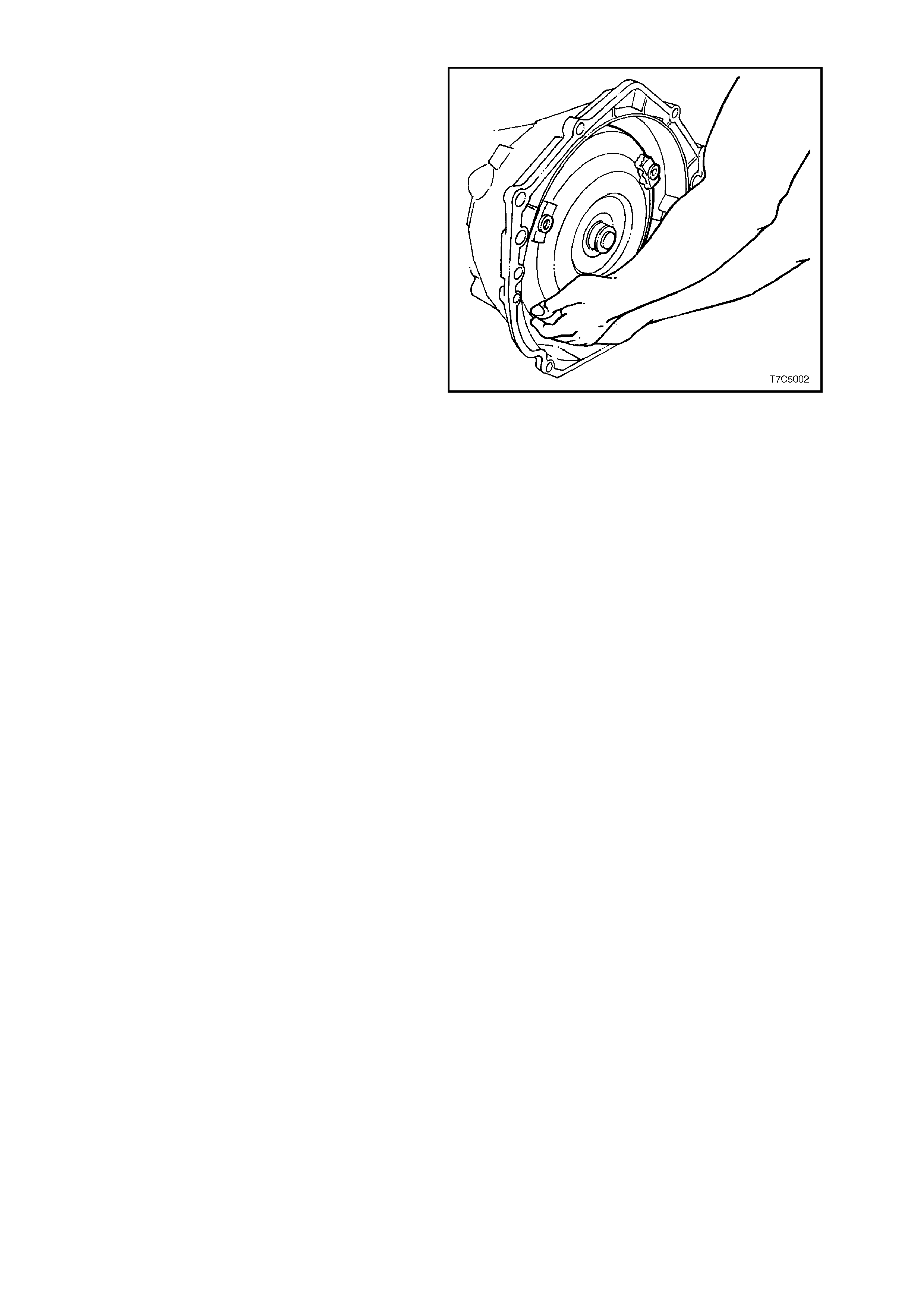
REINSTALL
1. Reinstall torque converter to tur bine shaf t, with
the transmission in a horizontal position, as
shown.
2. Install a restraining plate across the
transmission converter housing to prevent the
converter from accidentally being dislodged.,
prior to transmission installation.
Figure 7C5-249
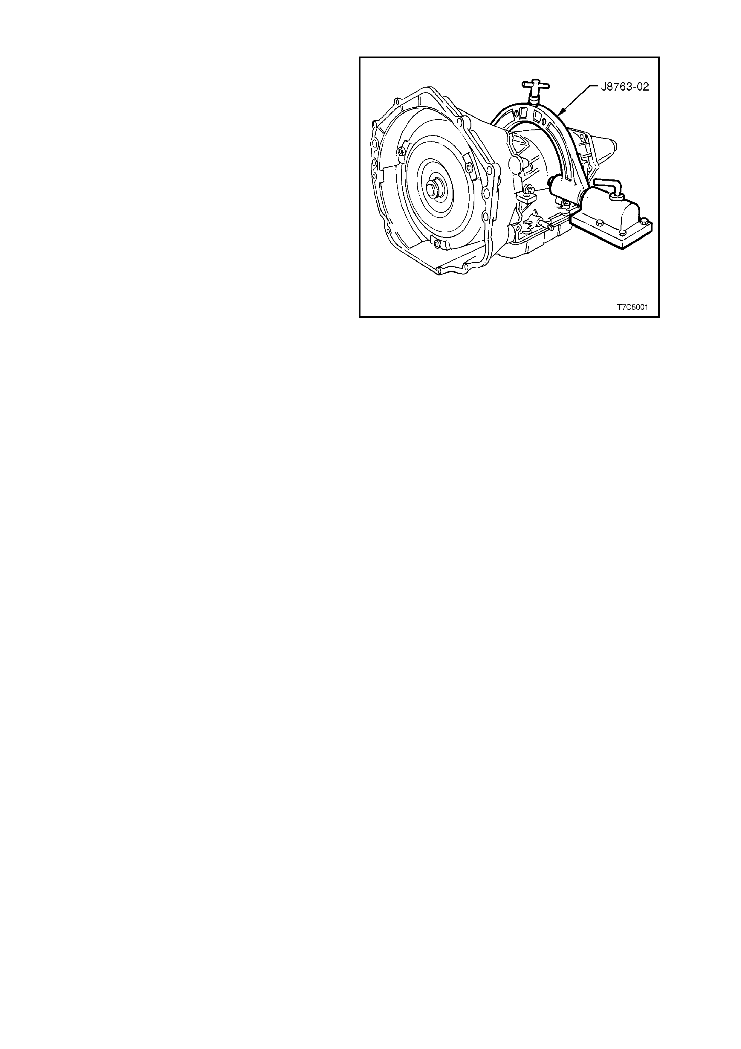
3.16 TRANSMISSION FIXTURE REMOVAL
1. Remove the transmission and holding fixture
(J8763-02) from the bench bracket.
2. Loosen the clamp screws and remove the
bracket from the transmission.
3. Plug all openings suc h as the oil cooler fittings
and output shaft to prevent the ingress of
foreign material, prior to installation in the
vehicle.
Figure 7C5-250
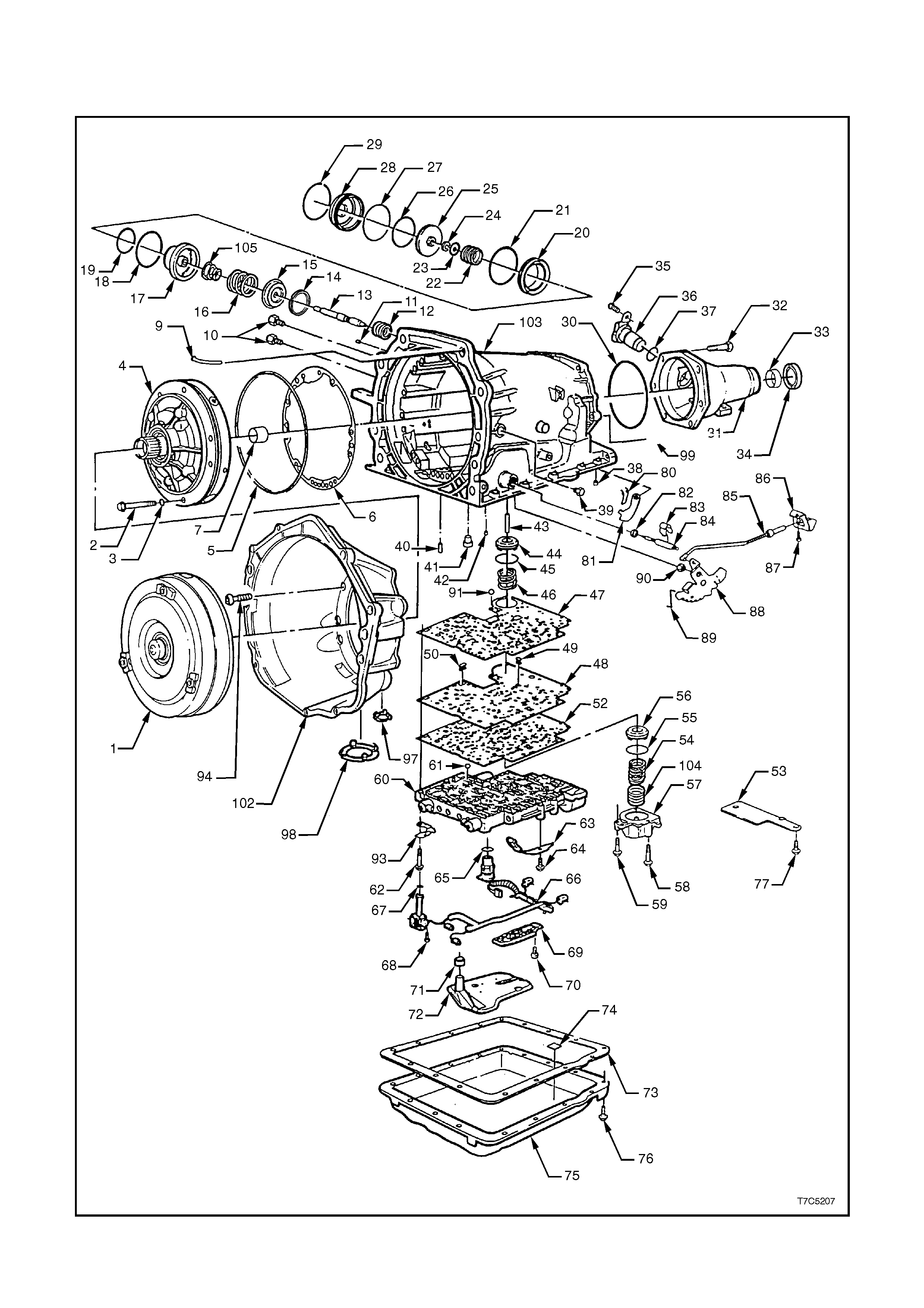
4. TRANSM I SSION REFERENCE DIAGRAMS
TRANSMISSION CASE AND EXTERNAL PARTS
Figure 7C5-251 - Transmission Case and External Parts
REF
No. PART NAME REF
No. PART NAME
1.
2.
3.
4.
5.
6.
7.
9.
10.
11.
12.
13.
14.
15.
16.
17.
18.
19.
20.
21.
22.
23.
24.
25.
26.
27.
28.
29.
30.
31.
32.
33.
34.
35.
36.
37.
38.
39.
40.
41.
42.
43.
Torque Converter Assembly
Bolt, Oil Pump to Case
O-ring, Oil Pump to Case Bolt
Pump Assembly, Oil
Seal, Oil (Oil Pump to Case)
Gasket, Oil Pump Cover to Case
Bush, Case
Vent Assembly, Transmission
Connector, Oil Cooler Pipe
Plug, Case Servo
Spring, Servo Retu rn
Pin, 2nd Apply Piston
Ring, Retainer (2nd Apply Piston)
Retainer, Servo Cushion Spring (Outer)
Spring, Servo Cushion (Outer)
Piston, 2nd Apply
Ring, Oil Seal (2nd Apply Piston - Outer)
Ring, Oil Seal (2nd Apply Piston - Inner)
Housing, Servo Piston (Inner)
Seal O-ring
Spring, Servo Apply Pin
Washer, Servo Apply Pin
Ring, Retainer (Apply Pin)
Piston 4th Apply
Ring, Oil Seal (4th Apply Piston - Outer)
Seal, O-ring (2-4 Servo Cover)
Cover, 2-4 Servo
Ring, Servo Cover Retain ing
Seal, Case Extension to Case
Extension, Case
Bolt, Case Extension to Case
Bush, Case Extensi on
Seal Assembly, Case Extension Oil
Bolt, Speed Sensor Retaining
Sensor, Vehicle Speed
Seal, O-ring (Vehicle Speed Sensor)
Plug, Transmission Case (Accumulator
Bleed)
Plug, Line Pressure
Retainer and Ball Assembly, 3rd Accumulator
Pin, Band Anchor
Retainer and Ball Assembly, (Double Orifice)
Pin, Accumulator Piston
44.
45.
46.
47.
48.
49.
50.
52.
53.
54.
55.
56.
57.
58.
59.
60.
61.
62.
63.
64.
65.
66.
67.
68.
69.
70.
71.
72.
73.
74.
75.
76.
77.
91.
93.
94.
97.
98.
102.
103.
104.
105.
Piston, 3-4 Accumulator
Ring, Oil Seal (3-4 Accumulator Piston)
Spring, 3-4 Accumulator
Gasket, Spacer Plate to Case
Plate, Valve Body Spacer
Screen, Shift Solenoids
Screen, Pressure Control Solenoid
Gasket, Spacer Plate to Valve Body
Plate, Spacer Plate Support
Spring, 1-2 Accumulator (Outer)
Ring, Oil Seal (1-2 Accumulator)
Piston, 1-2 Accumulator
Cover and Pin Assembly, 1-2 Accumulator
Bolt, Accumulator Cover
Bolt, Accumulator Cover
Valve Assembly, Control Body
Checkball
Bolt, Valve Body
Spring Assembly, Manual Detent
Bolt, Manual Detent Spring
O-ring Seal, Wiring Harness Pass-through
Connector,
Solenoid Assembly Harness, Wiring
Seal, O-ring, (Solenoid)
Bolt, Hex Washer Head (Solenoid)
Switch A ssembly, Transmission Pressure
Bolt, Pressure Switch Assembly
Seal, Filter
Filter Assembly, Transmission Oil
Gasket, Transmission Oil Pan
Magnet, Chip Collector
Pan, Transmission Oil
Screw, Transmission Oil Pan
Bolt, Spacer Plate Support
Number 10 Checkball
Bracket, Dipstick Stop
Bolt, Converter Housing to Case
Plug, Converter Housing Access Hole
Plate, Converter Bolt Inspection
Housing, Torque Converter
Case, Transmission Main
Spring, 1-2 Accumulator (Inner)
Spring, Servo Cushion (Inner)
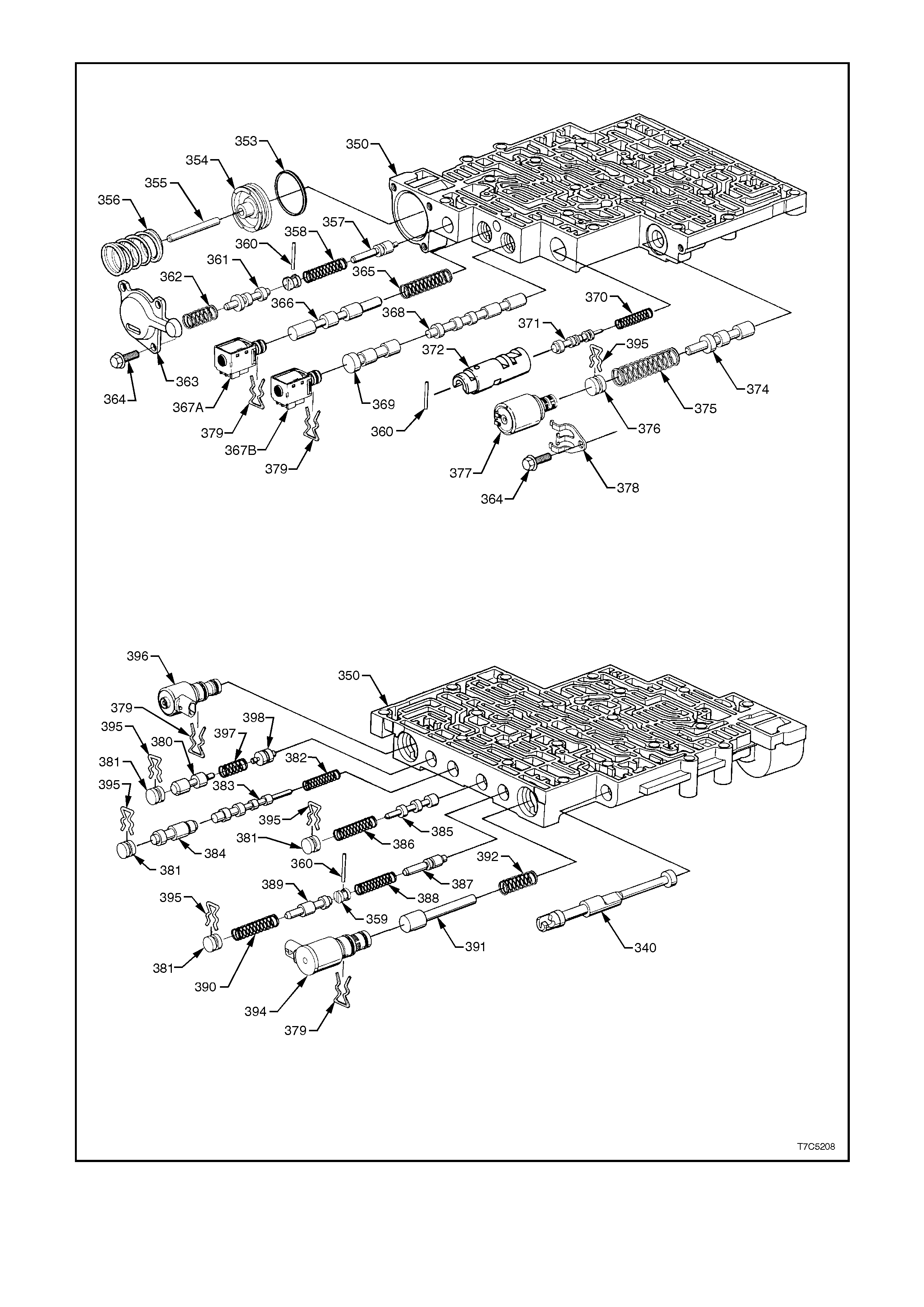
CONTROL VALVE BODY ASSEMBLY
Figure 7C5-252 - Control Valve Body Assembly

REF
No. PART NAME REF
No. PART NAME
340.
350.
353.
354.
355.
356.
357.
358.
359.
360.
361.
362.
363.
364.
365.
366.
367A.
367B.
368.
369.
370.
371.
372.
Valve, Manual
Valve Assembly, Control Body
Seal, Forward Accumulator
Piston, Forward Accumulator
Pin, Forward Accumulator
Spring, Forward Accumulator
Valve, Forward Abuse
Spring, Forward Abuse Valve
Plug, Bore
Pin, Coiled Spring
Valve, Low Overrun
Spring, Low Overrun Valve
Cover, Forward Accumulator
Bolt, Forward Accumulator Cover
Spring, 1 - 2 Shift Valve
Valve, 1 - 2 Shift
1 - 2 Shift Solenoid (A)
2 - 3 Shift Solenoid (B)
Valve, 2 - 3 Shift
Valve, 2 - 3 Shuttle
Spring, 1 - 2 Accumulator Valve
Valve, 1 - 2 Accumulator
Sleeve, 1 - 2 Accumulator
374.
375.
376.
377.
378.
379.
380.
381.
382.
383.
384.
385.
386.
387.
388.
389.
390.
391.
392.
394.
395.
387.
398.
Valve, Actuator Feed Limit
Spring, Actuator Feed Limit Valve
Plug, Bore
Pressure Control Solenoid
Retainer, Pressure Control Solenoid
Retainer, Solenoid
Valve, Regulator Apply
Plug, Bore
Spring, 4 - 3 Sequence Valve
Valve, 4 - 3 Sequence
Valve, 3 - 4 Relay
Valve, 3 - 4 Shift
Spring, 3 - 4 Shift Valve
Valve, Reverse Abuse
Spring, Reverse Abuse Valve
Valve, 3 - 2 Downshift
Spring, 3 - 2 Downshift Valve
Valve, 3 -2 Control
Spring, 3 -2 Control Valve
3 - 2 Control Solenoid
Retainer, Bore Plug
Spring, Regulator Supply
Valve, Isolator
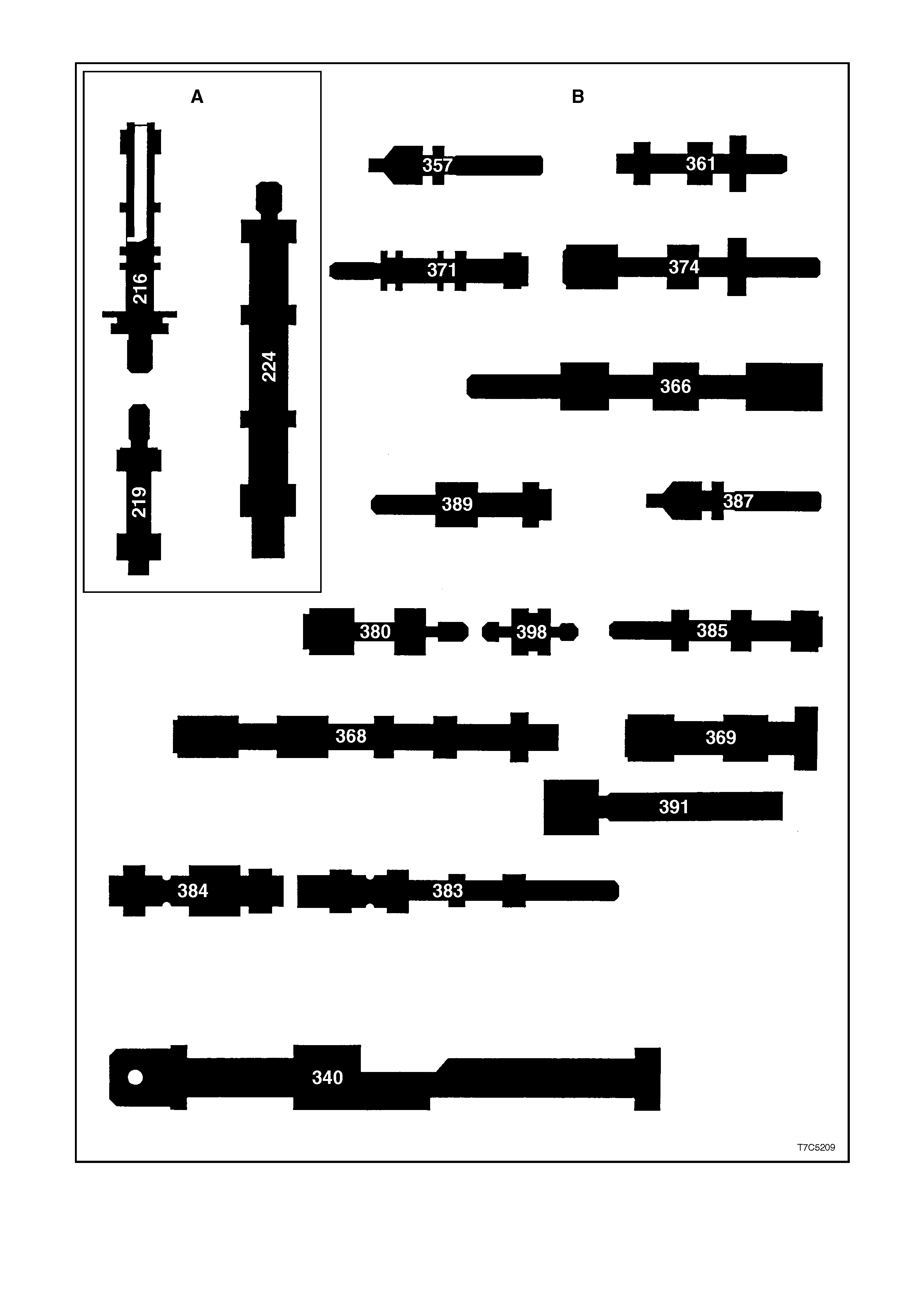
CONTROL VALVE IDENTIFICATION
Figure 7C5-253 - Control Valve Identification

Ref. No. PART NAME
A Located in the Oil Pump
216.
219.
224.
Valve, Pressure Regulator
Valve, Reverse Boost
Valve, Converter Clutch
B Located in the Control Valve Body
340.
357.
361.
366.
368.
369.
371.
374.
380.
383.
384.
385.
387.
389.
391.
398.
Valve, Manual
Valve, Forward Abuse
Valve, Low Overrun
Valve, 1 - 2 Shift
Valve, 2 - 3 Shift
Valve, 2 - 3 Shuttle
Valve, 1 - 2 Accumulator
Valve, Actuator Feed Limit
Valve, Regulator Apply
Valve, 4 - 3 Sequence
Valve, 3 - 4 Relay
Valve, 3 - 4 Shift
Valve, Reverse Abuse
Valve, 3 -2 Downshift
Valve, 3 -2 Control
Valve, Isolator
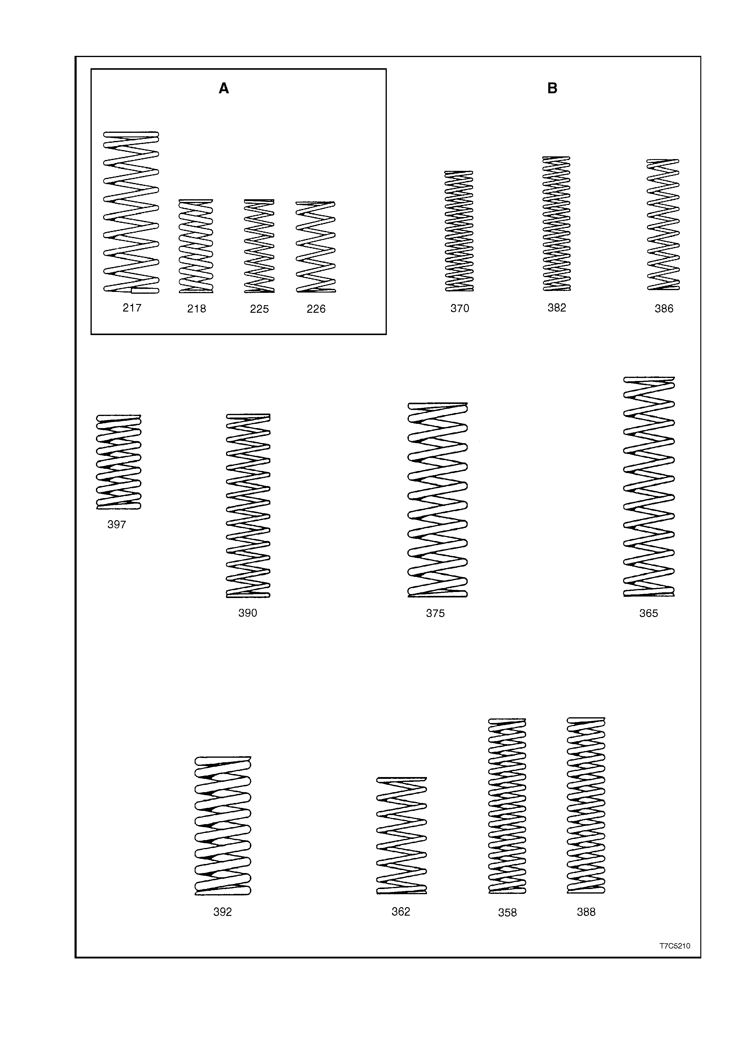
CONTROL VALVE SPRING IDENTIFICATION
Figure 7C5-254 - Control Valve Spring Identification

Ref. No. PART NAME
A Located in the Oil Pump
217.
218.
225.
226.
Spring, Pressure Regulator Valve
Spring, Pressure Regulator Isolator
Spring, Converter Clutch Valve (Inner)
Spring, Converter Clutch Valve (Outer)
B Located in the Control Valve Body
358.
362.
365.
370.
375.
382.
386.
388.
390.
392.
387.
Spring, Forward Abuse Valve
Spring, Low Overrun Valve
Spring, 1 - 2 Shift Valve
Spring, 1 - 2 Accumulator Valve
Spring, Actuator Feed Limit Valve
Spring, 4 - 3 Sequence Valve
Spring, 3 - 4 Shift Valve
Spring, Reverse Abuse Valve
Spring, 3 - 2 Downshift Valve
Spring, 3 -2 Control Valve
Spring, Regulator Supply
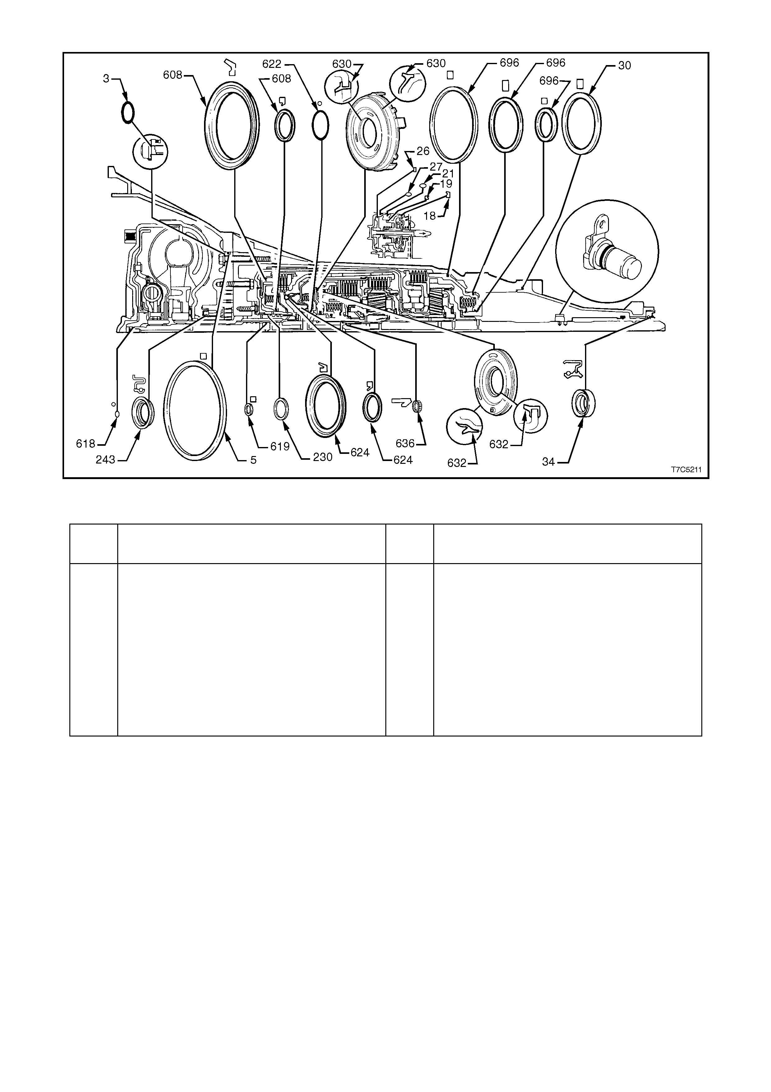
SEAL LOCATIONS AND ORIENTATION
Figure 7C5-255 Seal Locations and Orientation
Ref.
No. PART NAME Ref.
No. PART NAME
3.
5.
18.
19.
21.
26.
27.
30.
34.
37.
230.
O-ring, Pump to Case Bolt
Seal, Oil (Pump to Case)
Ring, Oil Seal (2nd Apply Piston - Outer)
Ring, Oil Seal (2nd Apply Piston - Inner)
Seal, O-ring.
Ring, Oil Seal (4th Apply Piston - Outer)
Seal, O-ring (2-4 Servo Cover)
Seal, Case Extension to Case
Seal, Case Extension
Seal, O-ring (Vehicle Speed Sensor)
Ring, Oil Seal (Stator Shaft)
243.
608.
618.
619.
622.
624.
630.
632.
636.
696.
Seal Assembly, Oil
Seals, Reverse Input Clutch
Seal, O-ring (Turbine Shaft)
Ring, Oil Seal (Solid)
Seal, O-ring (Input to Forward Housing)
Seals, 3rd and 4th Clutch (Service
Replacement)
Piston, Forward Clutch
Piston, Overrun Clutch
Seal, Input Housing to Output Shaft
Seals, (Low and Reverse Clutch Piston)
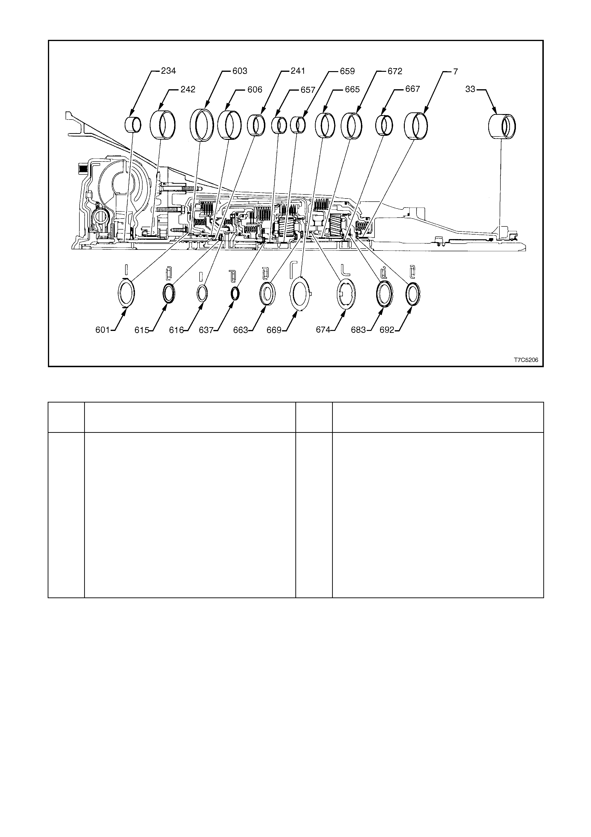
BUSH/BEARING LOCATIONS AND ORIENTATION
Figure 7C5-256 Bush/Bearing Locations and Orientation
Ref.
No. PART NAME Ref.
No. PART NAME
7.
33.
234.
241.
242.
601.
603.
606.
615.
616.
637.
657.
659.
Bushing, Case
Bushing, Case Extension
Bushing, Stator Shaft (Front)
Bushing, Stator Shaft (Rear)
Bushing, Oil pump Body
Washer, Thrust (Pump to Drum)
Bushing, Reverse Input Clutch (Front)
Bushing, Reverse Input Clutch (Rear)
Bearing Assembly, Stator Shaft Selective
Washer
Washer, Thrust (Selective)
Bearing Assembly, Input Sun Gear
Bushing, Input Sun Gear (Front)
Bushing, Input Sun Gear (Rear)
663.
665.
667.
669.
672.
674.
683.
692.
Bearing Assembly, Thrust (Input carrier to
Reaction Shaft
Bushing, Reaction Carrier Shaft (Front)
Bushing, Reaction Carrier Shaft (Rear)
Washer, Thrust (Reaction Shaft/Shell)
Bushing, Reaction Gear
Washer, Thrust (Race/Reaction Shell)
Bearing Assembly, (Reaction
Carrier/Support)
Bearing, Reaction Gear Support to Case

5. SPECIFICATIONS
GENERAL
Type Hydra-matic 4L60-E.
Code V6 Engine - HFD.
V6 Supercharged Engine - HND.
V8 Engine - HBD.
Special Features Electronically controlled shift pattern,
feel and torque converter clutch operation.
Overdrive 4th speed range.
Selector Location Floor mounted console.
GEAR RATIOS:
Park (P)
Reverse (R) 2.294:1
Neutral (N)
Overdrive (OD - 4) 0.696:1
Drive (D - 3) 1.000:1
Second (2) 1.625:1
First (1) 3.059:1
SHIFT SPEEDS Refer to Section 7C3 DIAGNOSIS.
OIL PRESSURE Refer to Section 7C3 DIAGNOSIS.
TORQUE CONVERTER:
Number of Elements 3 plus torque converter clutch.
Maximum torque ratio at stall V6 Engine - 1.63:1 (k=122).
V6 Supercharged Engine - 1.63:1 (k=133).
V8 Engine - 2.15:1 (k=115).
Nominal Diameter V6 Engine - 245 mm.
V6 Supercharged Engine - 258 mm.
V8 Engine - 298 mm.
LUBRICANT:
Type recommended Dexron® III (To Holden's Specification HN2126)
Capacity Nominal only. Check when transmission
is at operating temperature.
Refill V6 Engine - 4.8 litres.
V8 Engine - 5.0 litres.
Total (Dry) V6 Engine - 7.9 litres.
V8 Engine - 10.6 litres.
Fluid Cooling Engine coolant to fluid in both radiator tanks and
externally, air to fluid cooler (where fitted).
CLUTCHES AND BAND
2 - 4 BAND:
Type Composition lined, steel band.
Operation Servo.
Adjustment Selective Apply Pin.
65.82 - 66.12 mm 2 Rings.
67.23 - 67.53 mm 3 Rings.
68.64 - 68.94 mm Wide Band.

REVERSE INPUT CLUTCH:
Type Multiple wet disc.
Clutch plate, number and thickness:
Steel 4 1.892 - 2.045 mm.
Composition 4 1.730 - 1.880 mm.
Belleville 1 2.210 - 2.311 mm.
Backing plate 1 Selective.
Backing plate, identification
and thickness: '2' 7.249 - 7.409 mm.
'3' 6.519 - 6.678 mm.
'4' 5.787 - 5.947 mm.
Backing plate travel 1.02 - 1.94 mm
FORWARD CLUTCH:
Type Multiple wet disc
Clutch plate, number
and thickness:
Flat steel plates 5 2.29 mm
Composition plates 5 1.78 mm
Apply plate 1 4.30 mm
Waved steel plate 1 1.79 mm
Backing plate 1 Selective
Backing plate, identification
and thickness: 'A' 6.97 - 7.07 mm
'B' 6.38 - 6.48 mm
'C' 5.79 - 5.89 mm
'D' 5.20 - 5.30 mm
'E' 4.61 - 4.71 mm
Backing plate travel 0.75 - 1.60 mm
OVERRUN CLUTCH:
Type Multiple wet disc
Clutch plates, number and thickness:
Flat steel 2 2.248 - 2.400 mm
Composition 2 2.03 mm
3 - 4 CLUTCH:
Type Multiple wet disc
Clutch plates, number and thickness:
Flat steel 5 2.71 mm
Composition 6 2.03 mm
Flat steel apply plate 1 5.60 mm
Flat steel (same spline
configuration as flat steel) 1 1.78 mm
Backing plate 1 Selective
Backing plate, identification
and thickness: 'A' 5.88 - 5.68 mm
'B' 4.99 - 4.76 mm
'C' 4.10 - 3.90 mm
Backing plate travel 0.90 - 2.10 mm

LOW AND REVERSE CLUTCH:
Type Multiple wet disc
Clutch plates, number and thickness:
Flat steel 5 1.75 mm
Composition 5 2.25 mm
Flat steel - waved 1 2.42 mm
Selective flat steel plate 1 Selective
Selective plate, identification
and thickness: NONE 1.684 - 1.829 mm
'0' 1.168 - 1.314 mm
'1' 2.198 - 2.344 mm
Overall clutch pack height
(Including spacer plate) 29.22 - 29.90 mm
Clutch plate support thickness 6.655 - 6.909 mm
CLEARANCES:
Transmission end play 0.13 - 0.92 mm
Pinion gears end play (all) 0.20 - 0.60 mm
Torque converter end play V6 engine: 0 - 0.5 mm
V8 Engine: 0 - 0.6 mm

6. TORQUE WRENCH SPECIFI CATIONS
NOTE:
For a listing of torque wrench specifications relating to the removal and reinstallation procedures associated with the
automatic transmission, refer to Section 7C4 HYDRA-MATIC 4L60-E AUTOMATIC TRANSMISSION: ON-
VEHICLE SERVICING.
Nm
Manual shaft to inner detent lever nut 27 - 34
Manual shaft selector lever nut 15 - 35
Neutral start and back-up lamp switch bolts 15 - 35
Oil cooler pipe connections 35 - 41
Oil pump cover to pump body bolt 20 - 27
Pressure control solenoid bracket to valve body bolt 8 - 14
Forward accumulator cover to valve body bolt 8 - 14
Park pawl bracket bolt 27 - 34
Oil pump to case bolt 20 - 27
Spacer plate support plate bolt 8 - 14
1 - 2 accumulator cover bolt 8 - 14
Control valve body bolt 8 - 14
Manual detent spring retaining bolt 20 - 27
Torque converter clutch solenoid bolt 8 - 14
Oil pan bolt 9.5 - 13.8
Converter housing to case bolt 72 - 78
Case extension housing bolt 42 - 48
Speed sensor retaining bolt 10.5 - 13.5
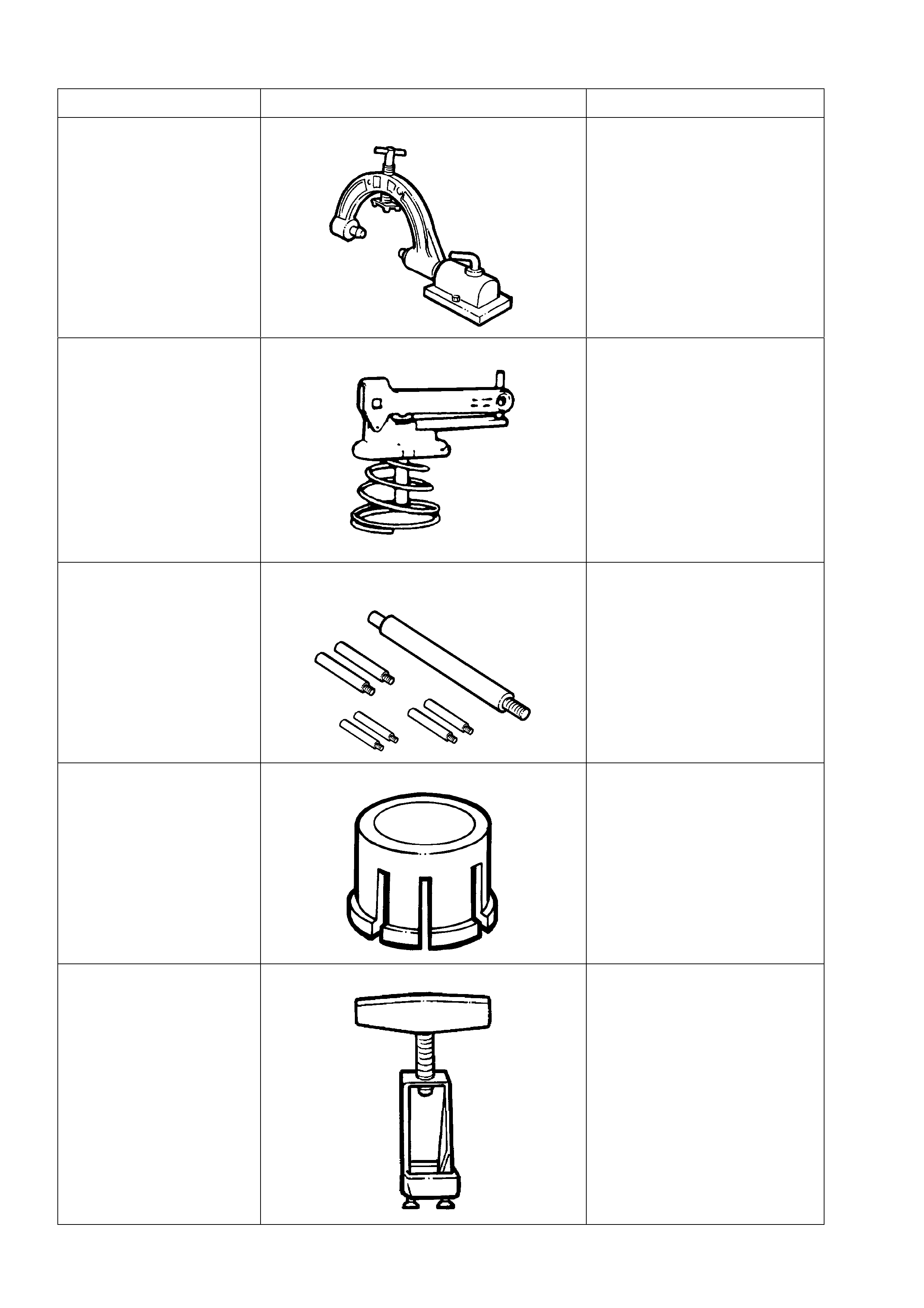
7. SPECIAL TOOLS
TOOL NO. REF IN TEXT TOOL DESCRIPTION COMMENTS
J8763-02 HOLDING FIXTURE PREVIOUSLY RELEASED AS
E1363 FOR TRIMATIC AND
THM 400 TRANSMISSIONS.
ALSO REQUIRED IS THE
BENCH FIXTURE, J3289-20.
J33037 2 - 4 BAND APPLY PIN TOOL PREVIOUSLY RELEASED.
J25025-B DIAL INDICATOR STAND AND GUIDE PIN
SET PREVIOUSLY RELEASED
FOR THM 125 TRANSAXLE.
J39119 OIL PUMP REMOVER ADAPTOR PREVIOUSLY RELEASED.
J37789-A OIL PUMP REMOVER PREVIOUSLY RELEASED
FOR 4L60.
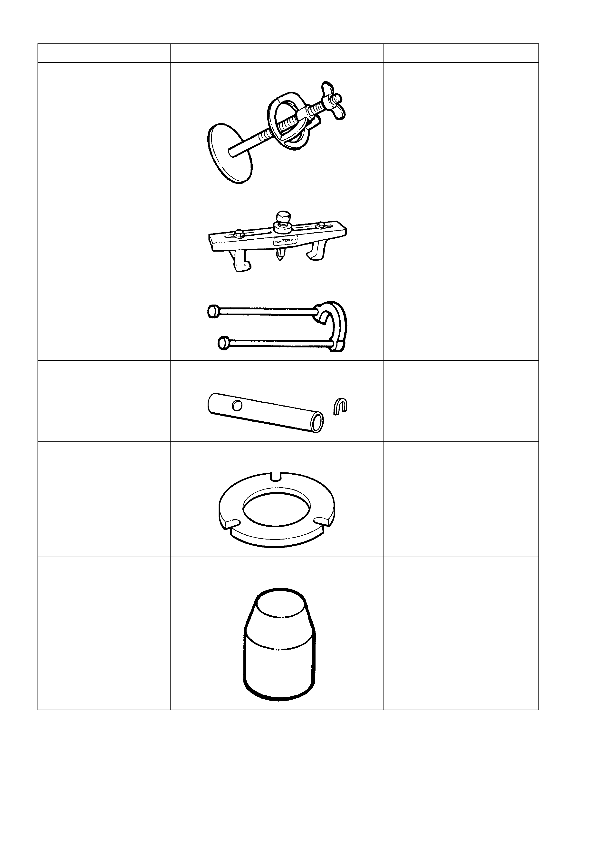
TOOL NO. REF IN TEXT TOOL DESCRIPTION COMMENTS
J23327 CLUTCH SPRING COMPRESSOR PREVIOUSLY RELEASED
FOR THM 400.
J8433 PULLER PREVIOUSLY RELEASED
FOR THM 400.
J21427-01 PULLER ADAPTOR PREVIOUSLY RELEASED
FOR THM 400.
J36352 SPEED SENSOR INSTALLER &
GAUGING TOOL PREVIOUSLY RELEASED.
COMPRISES SLEEVE, J36352-
6 AND 'C' STOP, J36352-4.
J25018-A CLUTCH SPRING COMPRESSOR
ADAPTOR PREVIOUSLY RELEASED
FOR TRIMATIC AND THM 400.
J29882 INNER OVERRUN CLUTCH SEAL
PROTECTOR PREVIOUSLY RELEASED.
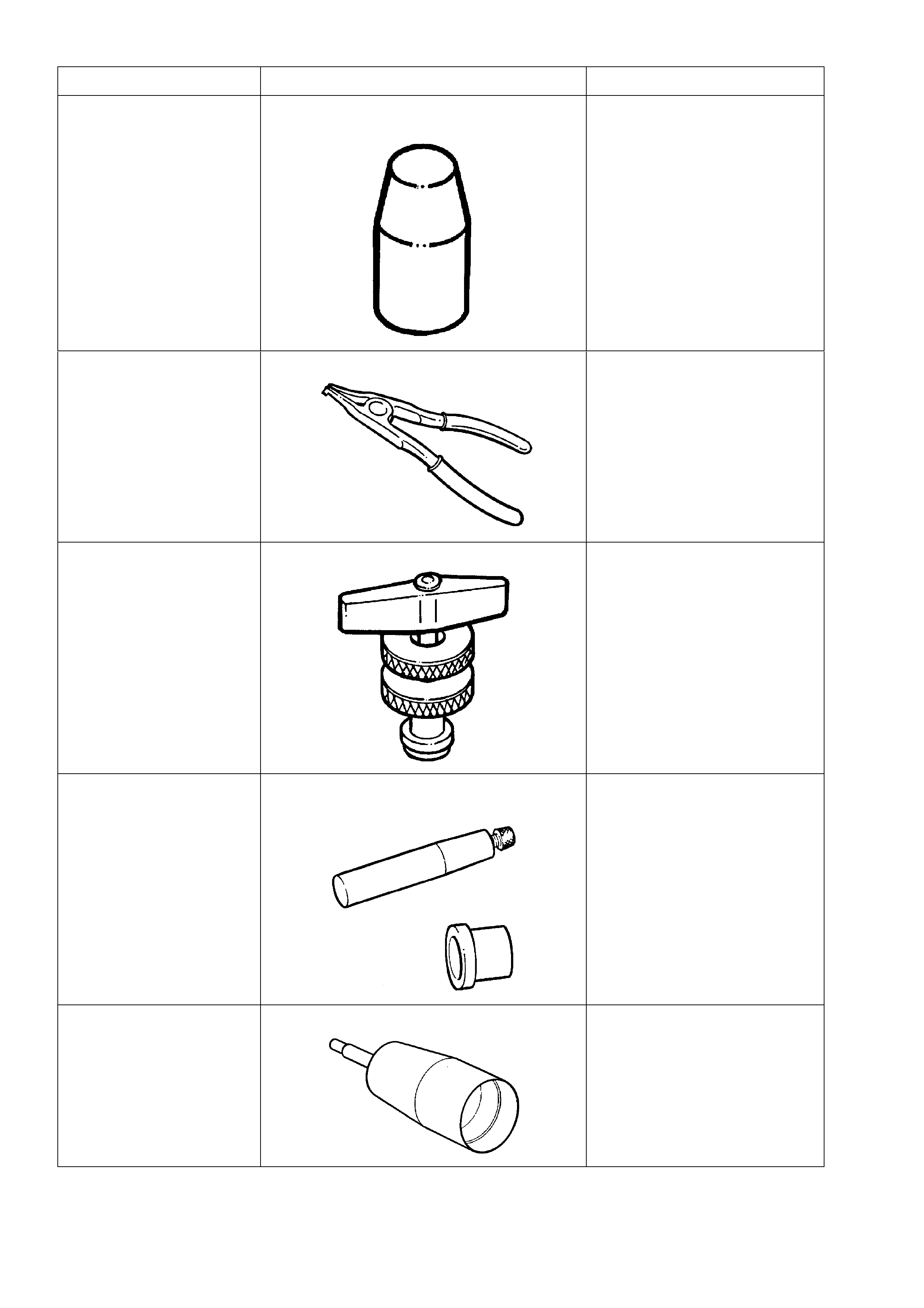
TOOL NO. REF IN TEXT TOOL DESCRIPTION COMMENTS
J29883 INNER FORWARD CLUTCH SEAL
PROTECTOR PREVIOUSLY RELEASED.
J34627 SNAP RING PLIERS PREVIOUSLY RELEASED AS
AN OPTIONAL TOOL.
SPECIFIC PURPOSE IS TO
ASSIST IN THE
REMOVAL/REPLACEMENT
OF THE OUTPUT SHAFT
SNAP RING.
J35138 TORQUE CONVERTER END PLAY PREVIOUSLY RELEASED AS
AN OPTIONAL TOOL.
TO BE USED IN
CONJUNCTION WITH
COMMERCIALLY AVAILABLE
MAGNETIC STAND AND DIAL
INDICATOR.
J36418-B TURBINE SHAFT SEAL INSTALLER &
RESIZER PREVIOUSLY RELEASED.
J39855-1 STATOR SHAFT SEAL EXPANDER PREVIOUSLY RELEASED.
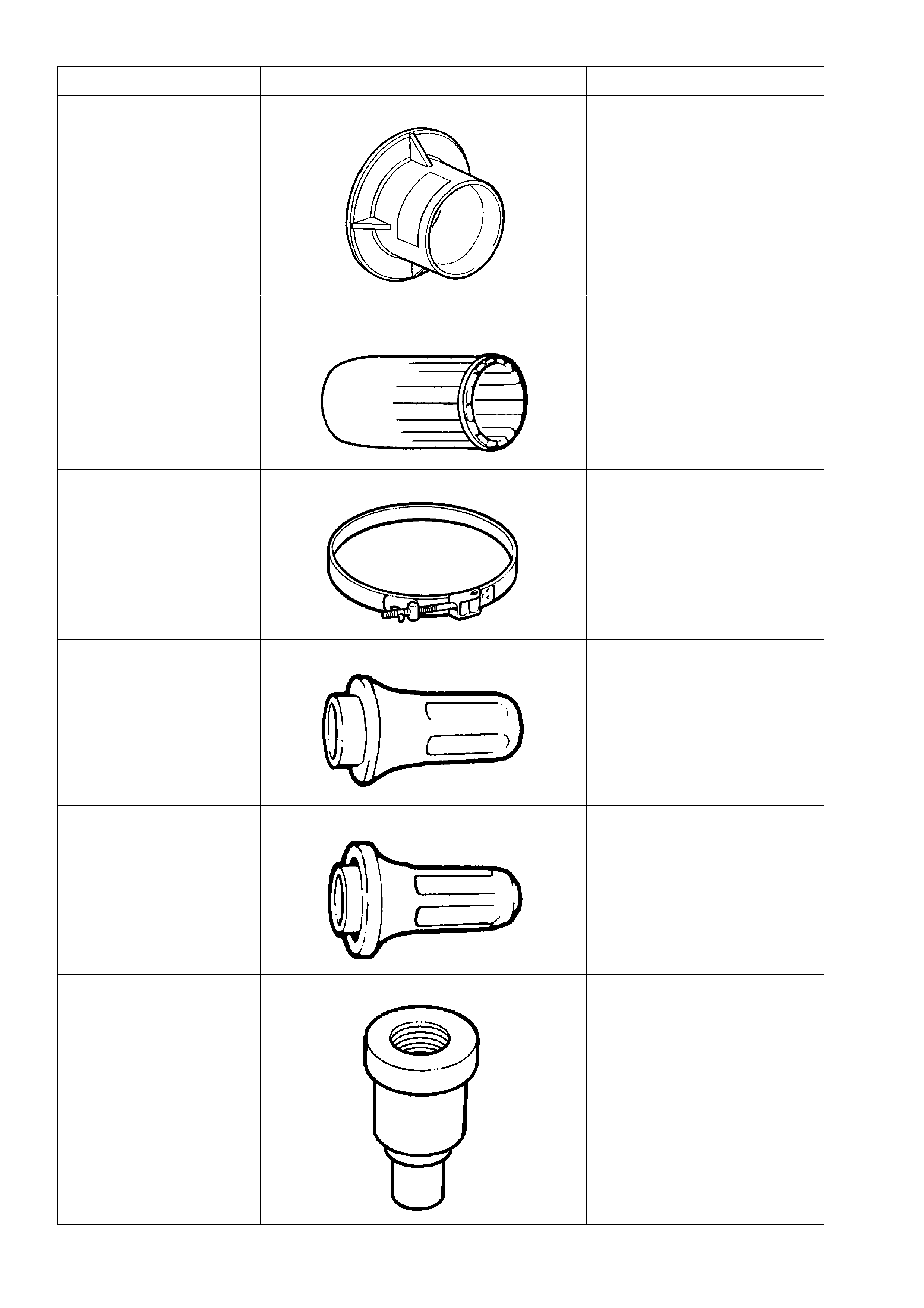
TOOL NO. REF IN TEXT TOOL DESCRIPTION COMMENTS
J39855-2 STATOR SHAFT SEAL RESIZER PREVIOUSLY RELEASED.
J38735-3 STATOR SHAFT SEALING RING
INSTALLER PREVIOUSLY RELEASED.
J21368 OIL PUMP ALIGNMENT BAND PREVIOUSLY RELEASED
FOR 4L60.
J21426 REAR SEAL INSTALLER PREVIOUSLY RELEASED
FOR TRIMATIC, AS 7AT-6.
J25016 OIL PUMP SEAL INSTALLER PREVIOUSLY RELEASED.
J23062-14 BUSH REMOVER NEW RELEASE. USED IN
CONJUNCTION WITH DRIVER
HANDLE J8092
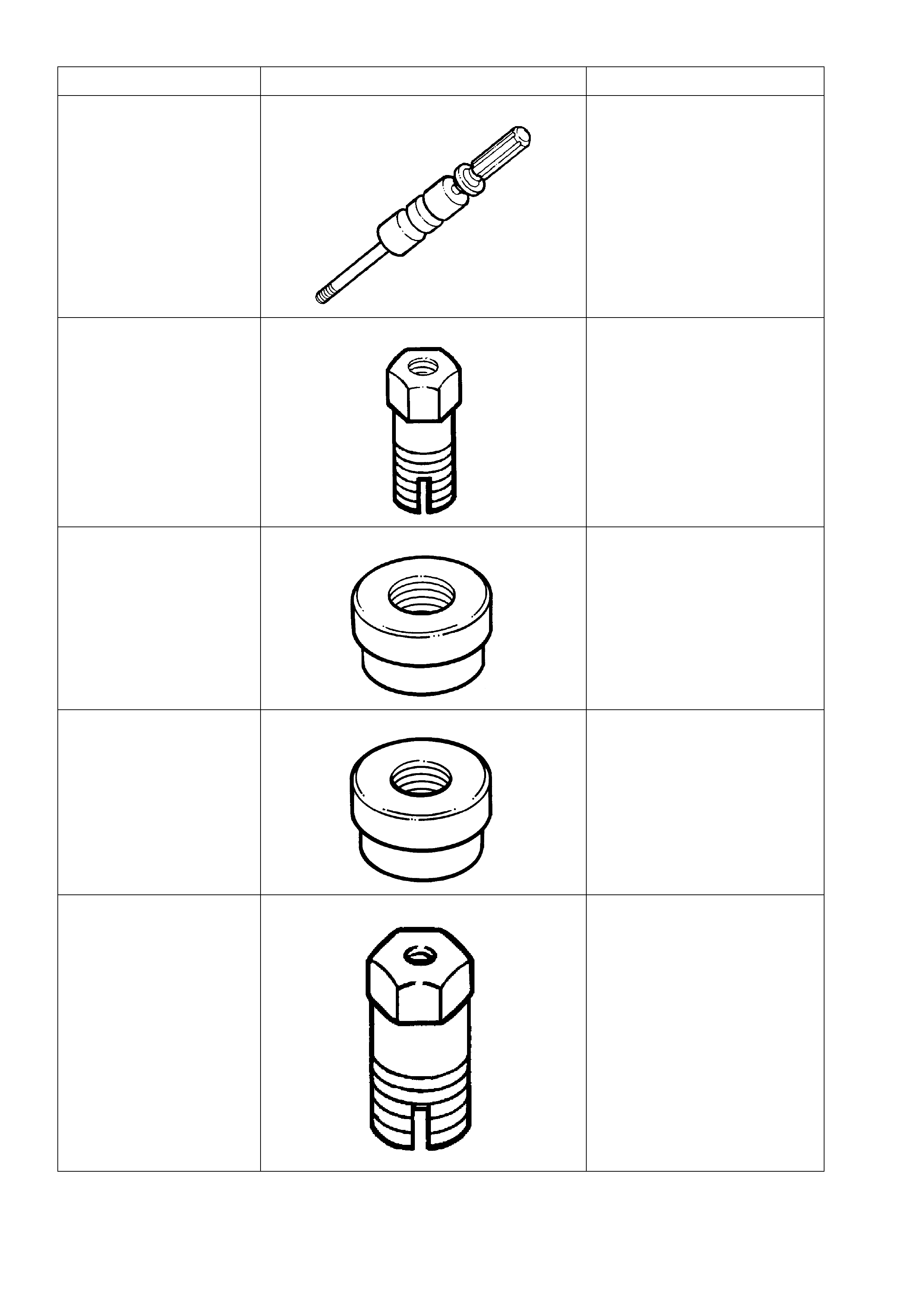
TOOL NO. REF IN TEXT TOOL DESCRIPTION COMMENTS
J23907 SLIDE HAMMER PREVIOUSLY RELEASED
J24036 BUSH REMOVER NEW RELEASE.
J25019-9 BUSH INSTALLER NEW RELEASE. USED IN
CONJUNCTION WITH DRIVER
HANDLE J8092
J25019-12 BUSH INSTALLER NEW RELEASE. USED IN
CONJUNCTION WITH DRIVER
HANDLE J8092
J25019-14 BUSH REMOVER NEW RELEASE
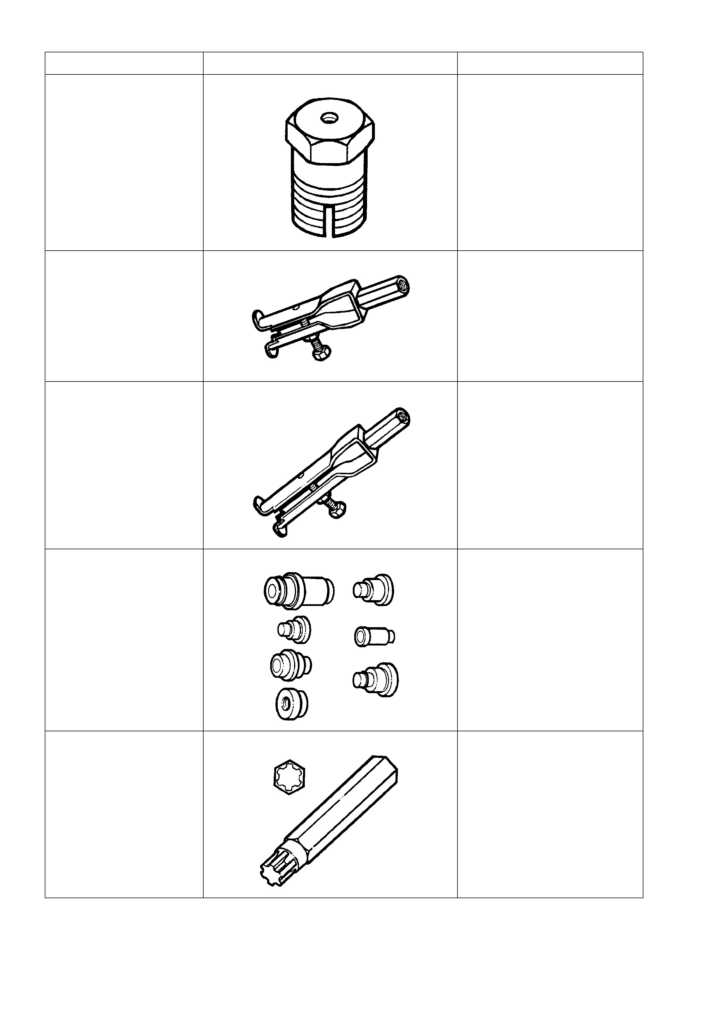
TOOL NO. REF IN TEXT TOOL DESCRIPTION COMMENTS
J25019-16 BUSH REMOVER NEW RELEASE
J29369-1 UNIVERSAL BUSH REMOVER PREVIOUSLY RELEASED
J29369-2 UNIVERSAL BUSH REMOVER PREVIOUSLY RELEASED
J34196-B BUSH REMOVER/INSTALLER SET NEW RELEASE
J41510 #50 TORX PLUS BIT NEW RELEASE
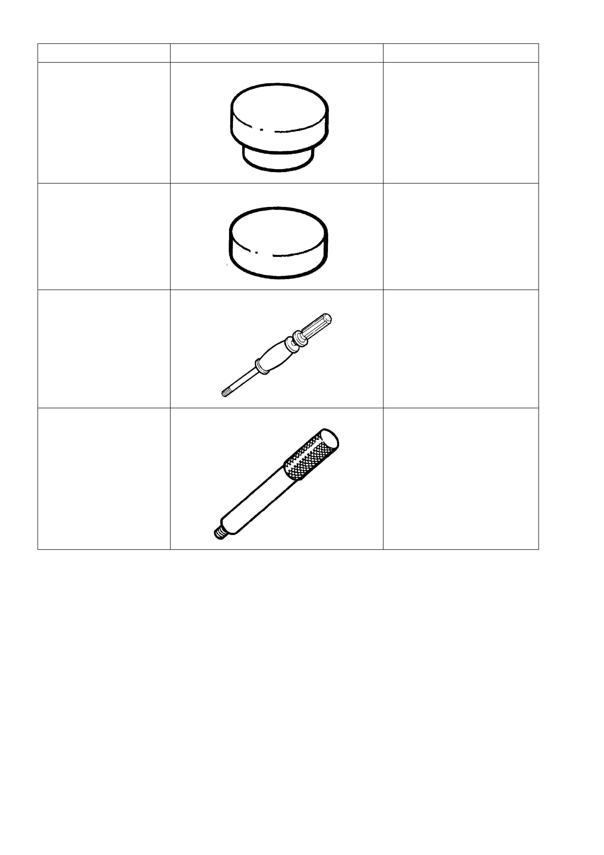
TOOL NO. REF IN TEXT TOOL DESCRIPTION COMMENTS
J41778-1 OIL PUMP BUSH INSTALLER PREVIOUSLY RELEASED
FOR VS
J41778-2 SUPPORT PLATE PREVIOUSLY RELEASED
FOR VS
J6125-1B SLIDE HAMMER PREVIOUSLY RELEASED
J8092 DRIVER HANDLE PREVIOUSLY RELEASED.