SECTION 9A - STEERING
CAUTION:
This vehicle will be equipped with a Supplemental Restraint System (SRS). An SRS
will consist of either seat belt pre-tensioners and a driver's side air bag, or seat belt
pre-tensioners and a driver's and front passenger's side air bags. Refer to
CAUTIONS, Section 12M, before performing any service operation on or around any
SRS components, the steering mechanism or wiring. Failure to follow the CAUTIONS
could result in SRS deployment, resu lting in possible perso nal in jury or u nnecessary
SRS system repairs.
CAUTION:
This vehicle may be equipped with LPG (Liquefied Petroleum Gas). In the interests of
safety, the LPG fuel system should be isolated by turning ‘OFF’ the manual service
valve and then draining the L PG service lines, before any service w ork is carried out
on the vehicle. Refer to the LPG leaflet included with the Owner's Handbook for
details or LPG Section 2 for more specific servicing information.
CAUTION:
Whenever any component that forms part of the ABS or ABS/ETC (if fitted), is
disturbed during Service Operations, it is vital that the complete ABS or ABS/ETC
system is checked, using the procedure as detailed in 4. DIAGNOSIS, ABS or
ABS/ETC FUNCTION CHECK, in Section 12L ABS & ABS/ETC.
1. GENERAL INFORMATION
A driver’s side Supplemental Restraint System (SRS) and an energy absorbing steering column incorporating a
Tilt/Reach feature, is fitted as standard equipment on all VT models.
The variable ratio, power steering gear, is fitted as standard equipment to all VT models except Calais.
For servicing information on the speed sensitive power steering fitted to this model, refer to Section 9B SPEED
SENSITIVE POWER STEERING.
1.1 GENERAL DESCRIPTION - POWER STEERING
POWER STEERING RACK AND PINION
The power steer ing gear features a variable ratio rack and pinion that is m ade possible by the unique design of the
rack teeth. This means that the effective pitch radius of the pinion is less in the straight ahead position than on
turns.
This results in less tur ns being r equired from lock to loc k . F or ex ample, 3.5 tur ns would be requir ed if the 'on c entre'
ratio was used from lock to lock, whereas only 2.7 turns are required with this rack design.
Referring to Figure 9A-1, the helical toothed pinion (8) is supported in the steering gear housing (3) by a needle
roller bearing (11) at the upper end, a ball race (12) at the lower and a roller bearing (15) at the upper end of the
pinion teeth.
The rack operates within the housing and is supported at one end by a rack bearing and at the other end by the
pinion (8) and a spring loaded pad (13), which maintains slack free adjustment of the rack (14) with the pinion (8).
The tie rods are connected to eac h end of the rack by pre-as sem bled ball joints and to the steering ar ms by tie rod
end ball joints.
Techline
Techline
Techline
Techline
Techline
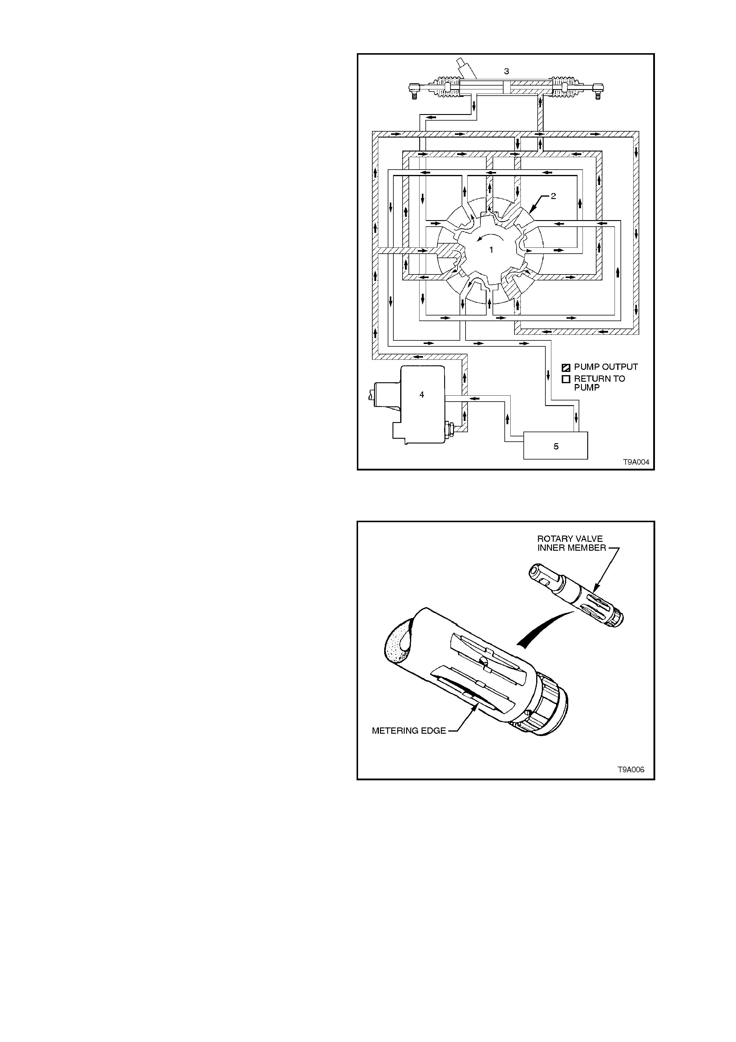
PRINCIPLES OF OPERATION
With the engine running and the steering wheel in
the neutral position (straight ahead), fluid flows
continuously from the power steering pump to the
steering gear and back to the pump, via the fluid
reservoir. In this steering mode, very little pressure
is required to maintain the high fluid flow rate that
occurs at this time. As a result, little engine power
is required to operate the system.
When turning the steering wheel to either s ide, f luid
flow from the pump is directed by a rotary control
valve fitted to the steering gear, to whichever side
of the rack piston is appropriate, as indicated by the
steering wheel position. The fluid pressure then
increases as necessary, to provide the required
steering assistance.
This rotary control valve assembly, is located
between the input shaft (1) and the pinion (8), in the
steering gear.
As shown, the rotary valve assem bly consists of an
inner member (1) which forms part of the input
shaft and a surrounding sleeve member (2). The
whole valve, rotates in the steering gear housing
(3) as the steering wheel is turned, but it is the
slight relative movement of the inner and the sleeve
members that controls and directs the power
steering fluid flow.
Fluid is fed to the valve ( ) and from there, to the
left (4) and right (5) sides of the power piston via
circum f erential grooves in the outer sleeve, that are
sealed by PTFE seals (6). Excess fluid is returned
to the reservoir.
The outer sleeve is coupled by a stepped pin (7) to
the rack pinion (8), while the input shaft (1) is
coupled to the rack pinion by a pinned (9), flexible,
torsion bar (10) that provides a mechanical but
flexible link between the two members.
In the straight ahead position, the valve remains
centred. As steering effort requirements increase,
the torsion bar flexes, causing slight relative
rotation between the input shaft and sleeve,
directing fluid and providing power assistance as
needed.
Figure 9A-1
Power Steering Gear - Figure 9A-2
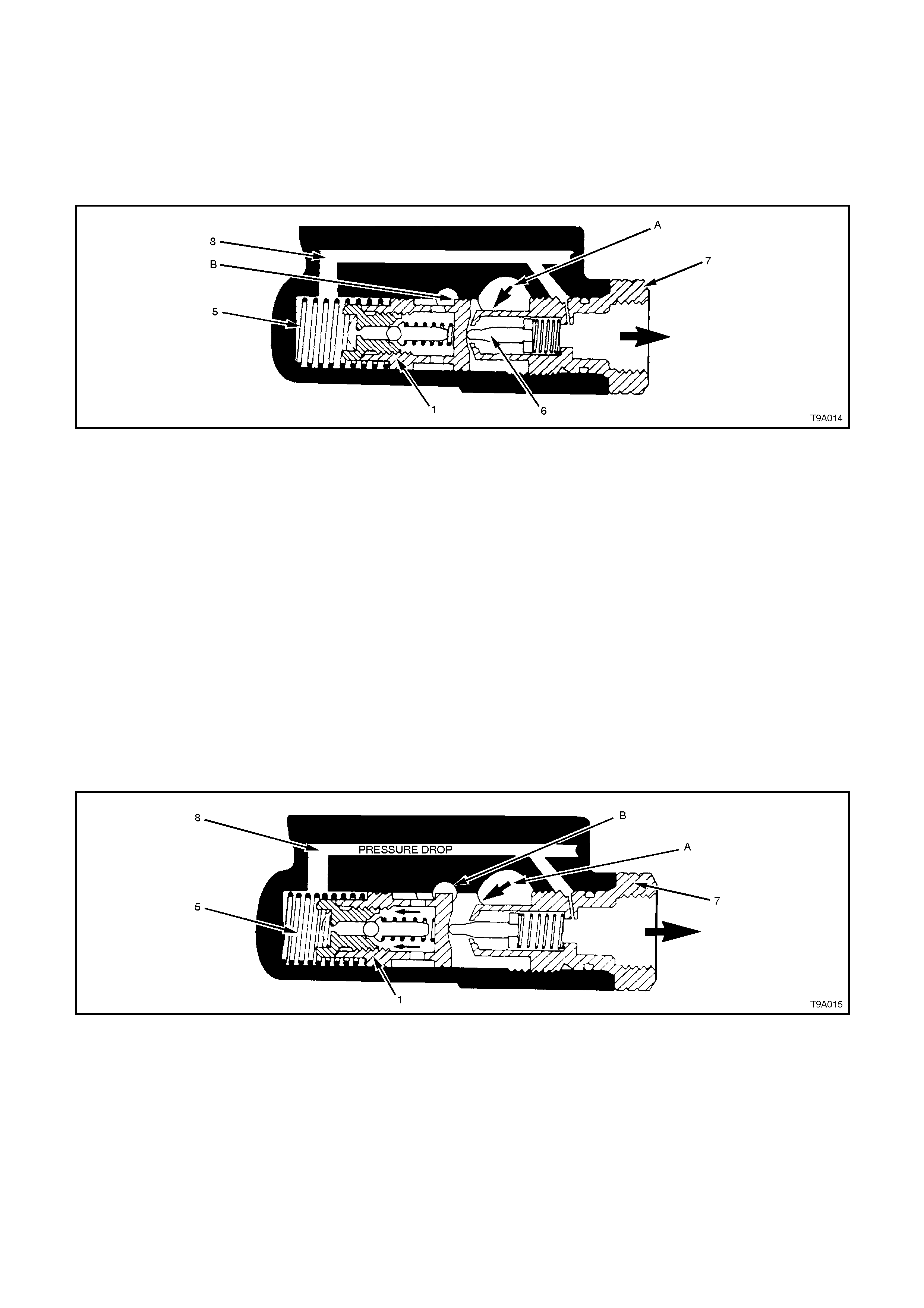
NEUTRAL POSITION (STRA IGHT AHEAD)
From the stylised cros s-s ec tioned view of the rotary
valve shown in Figure 9A-3, it can be seen that in
this attitude, fluid f low from the pum p ( 4) is dir ected
into the cavities (Shown as ‘A’). of the inner valve
assembly (1) and out through a number of drilled
holes in the outer sleeve (2) (Shown as ‘B’). In this
steering position, the inner valve (1) allows fluid to
pass equally to both sides of the rack (3) piston
(shown as 'Static' because no fluid actually flows to
and from the steering gear). The bypassed fluid
returns to the fluid reservoir (5) through holes
drilled in the longitudinal grooves of the inner valve.
W ith an equal pr essure applied to both sides of the
rack piston, no power assistance is provided.
Figure 9A-3
TURNING RIGHT
When turning to the right, as soon as relative
motion between the inner rotating valve (1) and
outer sleeve (2) occurs, fluid is restricted in its f ree
return to the pump and is routed to the right hand
side of the rack piston. At the same time, fluid on
the opposite side of the piston is directed to the
return circ uit, leading to the reservoir (5) and pump
(4). This action is slight at first, providing only a
small amount of driver assistance, but becomes
progressively greater with a higher steering load
that causes the torsion bar in the rotary valve
assembly, to twist.
Figure 9A-4
TURNING LEFT
When turning left, the opposite situation occurs.
That is, once the relative m otion between the inner
valve (1) and the outer sleeve (2) causes a return
restric tion, fluid is r outed to the left hand s ide of the
rack piston (3), providing the required assistance.
Also, fluid on the opposite side of the piston is free
to flow back to the reservoir (5) and the pump (4),
through the return circuit. As before, the amount of
assistance provided by the fluid, is determined by
the restric tion caused by the interaction of the inner
valve and outer rotary sleeve. This is controlled by
the twisting of the torsion bar connected between
these two valve members.
Figure 9A-5
INNER VALVE MEMBER
W hen parking, more than 90% of the work is done
by the fluid. In order to achieve a balance between
this graduated increase of assistance and maintain
a realistic 'feel' with good response as the road
speed increases, the grooves of the inner rotating
valve are precisely shaped to meter the flow of oil.
Note that under extreme load conditions or when
for any reason, the hydraulic system is inoperative,
the torsion bar is able to deflec t suffic iently to allow
the input shaft to drive the steering pinion directly.
This is achieved by having a loose fitting spline
between the lower end of the input shaft and the
surrounding upper end of the pinion. Under these
operating conditions, steering loads will be high and
a noticeable amount of slack will develop because
of the flexing of the torsion bar. W hile the steering
gear remains entirely operable, in the interest of
safety, the vehicle should be operated in this
manner only for the minimum distance needed to
reach a point where the system can be serviced. Figure 9A-6
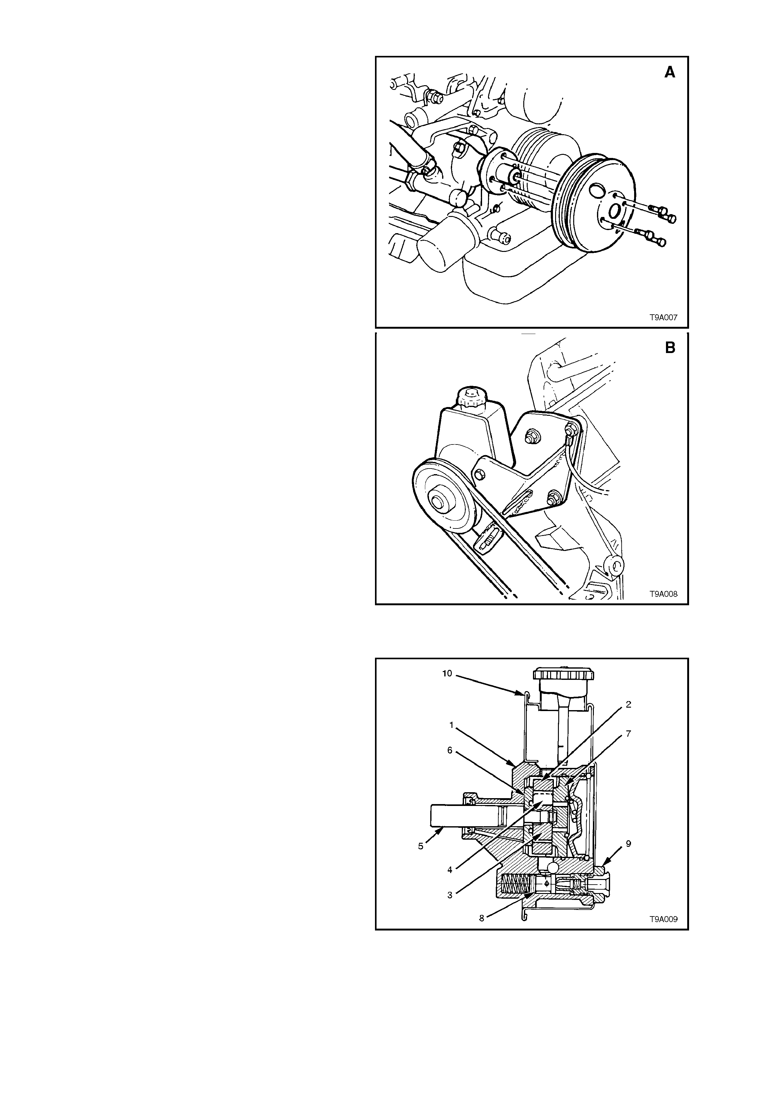
POWER STEERING PUMPS
Hydraulic pressure for the V6 engined, power
steering system is provided by a SAGINAW 'N'
Series, droop flow, vane type pump [A]. The pump
is mounted to a retaining bracket, attached to the
right hand side of the cylinder block. The remote
fluid reservoir is mounted to a bracket attached to
the radiator.
Construction of the 'P' series V8 engine power
steering pump [B], is slightly different in that the
housing and internal parts are mounted inside the
reservoir so the pump parts always operate,
submerged in oil. The pump is mounted to a
bracket attached to the front of the right hand
cylinder head.
Figure 9A-7
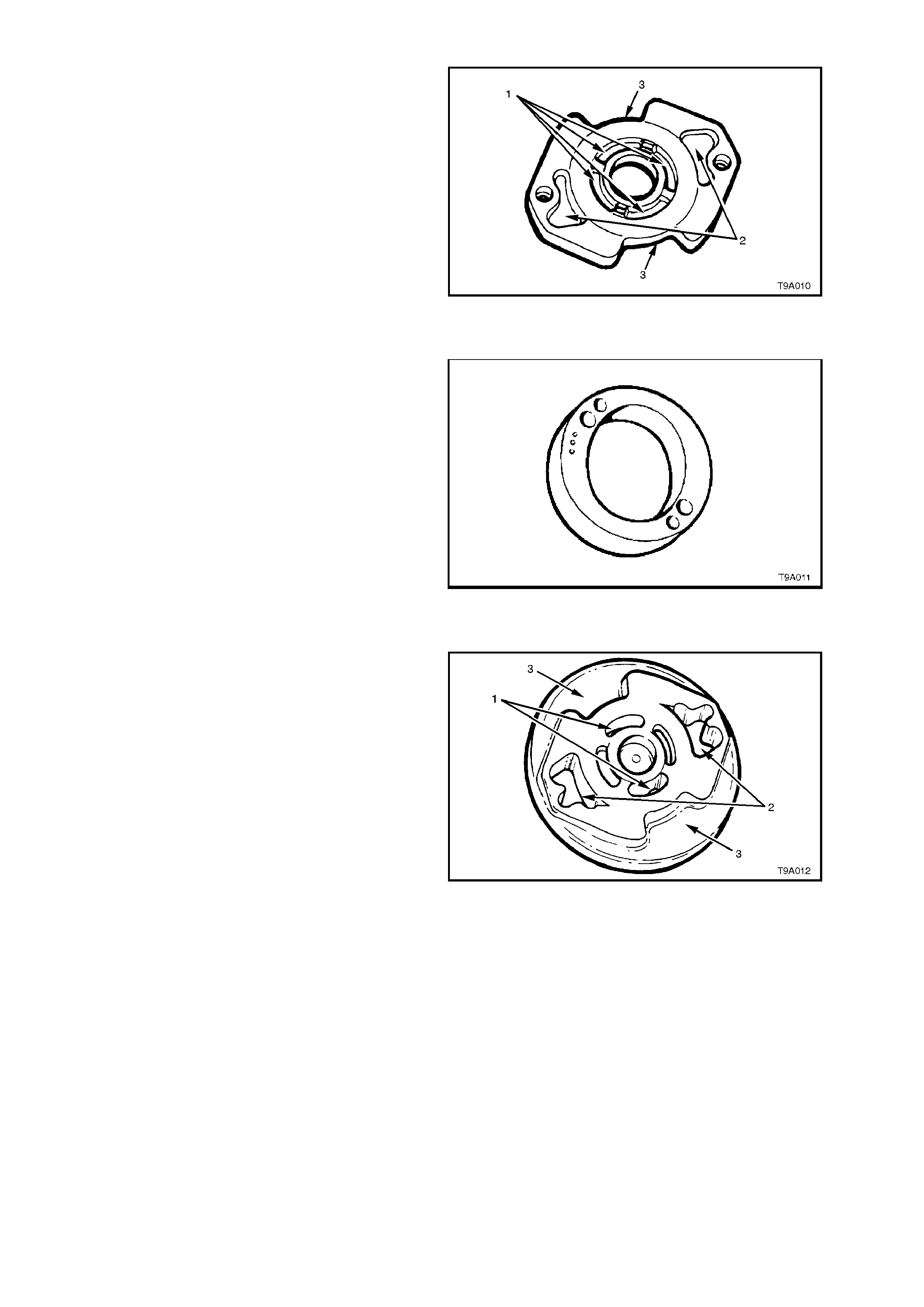
PUMP CONSTRUCTION
Shown is a sectioned view of a 'P' series pump
assembly. As both the 'N' and 'P' Series power
steering pum ps are sim ilar in c onstruc tion, the view
shown will suffice for both pumps. Essentially the
only difference between them being the manner in
which the fluid reservoir (10) is arranged, and the
drive pulley designs.
In each pump assembly there is a large cavity in
the rear of the pump housing (1) that contains the
following parts: pump ring (2), pump rotor (3) and
vanes (4), splined to the drive shaft (5) and thrust
(6) and pressure plates (7).
A smaller cavity, below the larger one , contains the
flow control assembly (8), which consists of a
control valve assembly and pump outlet fitting (9)
with control needle and spring.
Figure 9A-8
THRUST PLATE
The thrust plate is located on the inner face of the
housing by two dowel pins. This plate has six
cavities; the four central cavities (1) supply under-
vane fluid pressure, and the two outer cavities (2)
direct discharge pressure through the cross-over
holes in the pump ring, through to the pressure
plate and then on to the steering gear. The outside
slots (3) are for fluid intak e from the suction part of
the pump to the rotor.
Figure 9A-9
PUMP RING
The end faces of the pum p ring are ground f lat and
parallel. The centre hole is a two lobed cam in
which the rotor and vanes operate, providing two
cycles per revolution. T he ring is placed next to the
thrust plate and located with the same two dowel
pins.
Figure 9A-10
PRESSURE PLATE
The pressure plate is fitted against the pump ring
and located with the same two dowel pins. This
plate has two central ports (1) for under-vane fluid
pressure. The two outer ports (2) pass fluid under
discharge pr es sur e thr ough the contr ol valve, to the
steering gear.
The two outer slots (3) in the press ure plate ar e for
intake of the fluid from the suction part of the pump.
Figure 9A-11
DRIVE SHAFT AND ROTOR
The drive shaft is fitted with a belt driven pulley
from the engine crankshaft. The pump rotor is
splined to the drive shaft and is located within the
pump ring between the thrust and pressure plates.
Ten vanes are mounted in radial slots around the
rotor. The shaft is supported by a bush, pressed
into the front of the pump housing.
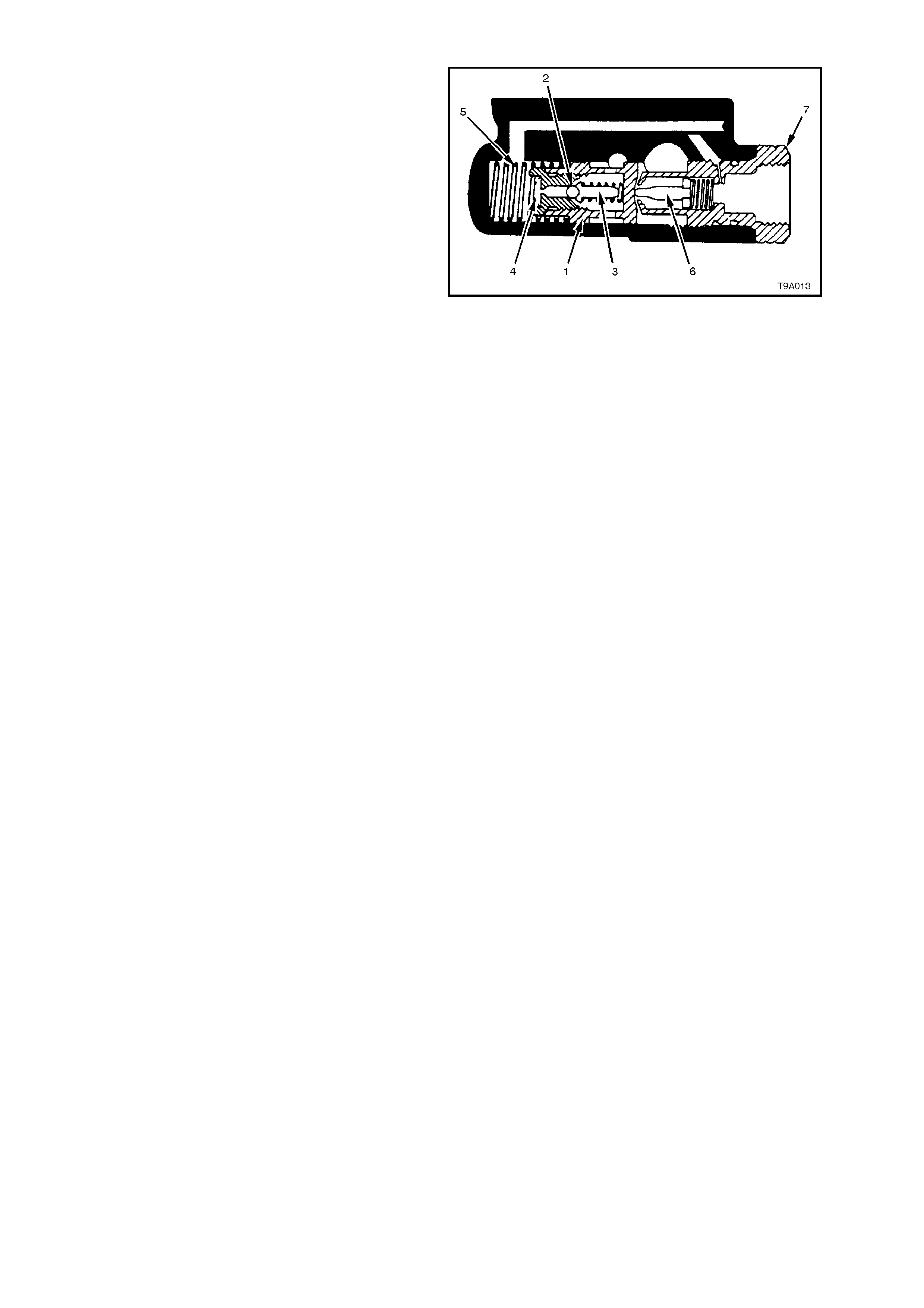
CONTROL VALVE ASSEMBLY
The purpose of the control valve assem bly fitted to
droop flow design pum ps, is to vary power steering
system pressure and fluid flow to the steering gear
as required, under various operating conditions.
The control valve assembly consists of the control
valve plunger (1), an internal pressure relief ball
check (2), ball check guide and ball check guide
spring (3) . A scr een (4) in the end of the plunger, is
designed to keep dirt and foreign material out of the
ball check area.
Movem ent of the c ontrol valve as s embly under fluid
pressure and spring (5) force, acts upon a fluid
control needle and spring (6), in the pump outlet
fitting (7). The needle is tapered and movement
within the outlet fitting orifice hole, changes the
amount of fluid flow to the steering gear.
Figure 9A-12
FILLING THE PUMP
When the pump and power steering gear are
completely empty of fluid, adding fluid to the
reservoir will fill the pump housing assembly.
Suction and gravity draw fluid into the intake
section of the pump, causing it to flow through a
drilled passage in the housing, leading to the large
cavity around the rotor ring. The fluid fills this area
and also the two intake openings on the pressure
and thrust plates, f illing the space between the ring
and rotor assembly. Any air that might enter the
system is automatically removed by the circulating
fluid, from the pump, through the fluid circuit to the
steering gear and then to the reservoir, where it
vents to atmosphere, via the reservoir cap.
PRINCIPLES OF OPERATION
The m ode of oper ation of the power steering pum p
is based upon the demand of the power steering
gear.
The various major modes of operation are:
1. Slow cornering.
2. Moderate to high speed straight ahead driving.
3. Cornering against the wheel stop.
The pump is designed to recognise these
conditions and compensate for them internally .
As the pump drive shaft turns the rotor, the vane
tips follow the inner cam surface of the pump ring,
moving outward and inward twice during each
revolution. This results in a complete pumping
cycle every 180° of rotation. Fluid is moved in the
spaces between the vanes. As the vane tips move
outward, fluid enters the inter -vane spaces through
four suction ports in the pressure and thrust plates .
As the vane tips m ove inwards, the pres sure of the
fluid is raised and the fluid is discharged from the
pump ring. High pressure discharges into a cavity,
behind the pressure plate. A portion of this fluid is
circulated through the central port system in the
pressure plate, forcing the vanes to follow the cam
surface of the ring.
Fluid is discharged from the high pressure cavity,
through the outlet fitting to the steering gear. As the
fluid passes through the outlet fitting, the fluid
pressure drops. This reduced pressure is
transmitted to the spring end of the control valve.
SLOW CORNERING
Pump speeds during slow cornering or parking are normally low, as are demands for fluid flow due to slower
steering manoeuvres.
The fluid is pressurised to approximately 3,400 kPa to 4,800 kPa and directed to the high pressure cavity behind the
pressure plate (arrow ‘A’). Discharge ports direct this fluid to the outlet fitting (7) and then to the steering gear.
The discharge fluid pressure from the outlet fitting (7), is slightly lower in pressure than the internal high pressure
coming from the pump ring. This drop in pressure occurs as the fluid flow passes the needle (6) and orifice in the
outlet fitting.
Figure 9A-13
This lower pressure is transmitted to the spring (5) end of the control valve (1) by a fluid passage (8), connecting the
control valve to the outlet fitting (7).
This results in a pressure unbalance on the valve itself.
The control valve (1) moves away from the outlet fitting (7), but due to the force of the control valve spring (5), the
valve remains closed to the fluid by-pass hole (B). The movement of the control valve (1), controls the needle valve
(6) in the outlet fitting (7) and this controls the fluid flow to the steering gear.
Because fluid pressure is not high enough to cause the pressure relief ball check to actuate, the external circuit
through the steering gear, allows fluid to recirculate through the entire system.
MODERATE TO HIGH SPEED OPERATION
System pressures in this mode are normally low (approximately 260 kPa) due to the lack of steering manoeuvres.
Fluid is discharged from the high pressure cavity through the outlet fitting (7) to the steering gear. As fluid passes
through the fitting, a pressure drop occurs across the needle valve (6) and orifice. This reduced pressure is
transmitted to the spring (5) end of the control valve (1), via the fluid passage (8).
This pressure differential, causes the control valve (1) to move and open up the fluid by-pass passage (B) to the
pump inlet. The movement of the control valve (1) also controls the movement of the flow control needle (6) in the
outlet fitting (7). The needle closes in the orifice and fluid flow to the steering gear is reduced.
Figure 9A-14
CORNERING AGAINST WHEEL STOPS
When the steering wheel is turned to full lock and held in that position, the steering rack power piston chamber
becomes fully pressurised and fluid flow stops. The resulting high pressure is then transmitted to the spring (5) end
of the control valve (1) by connecting fluid passage (8) from the outlet fitting.
When the pressure relief ball check (2) within the control valve opens, a small amount of fluid passes through the
pressure relief orifice, creating a pressure drop, acting on the spring end of the control valve.
The control valve then moves back against spring force (5), opening the fluid by-pass passage (B). Fluid then
returns to the pump inlet. Pre-determined relief pressure is thus maintained while the steering gear is turned and
held on full lock.
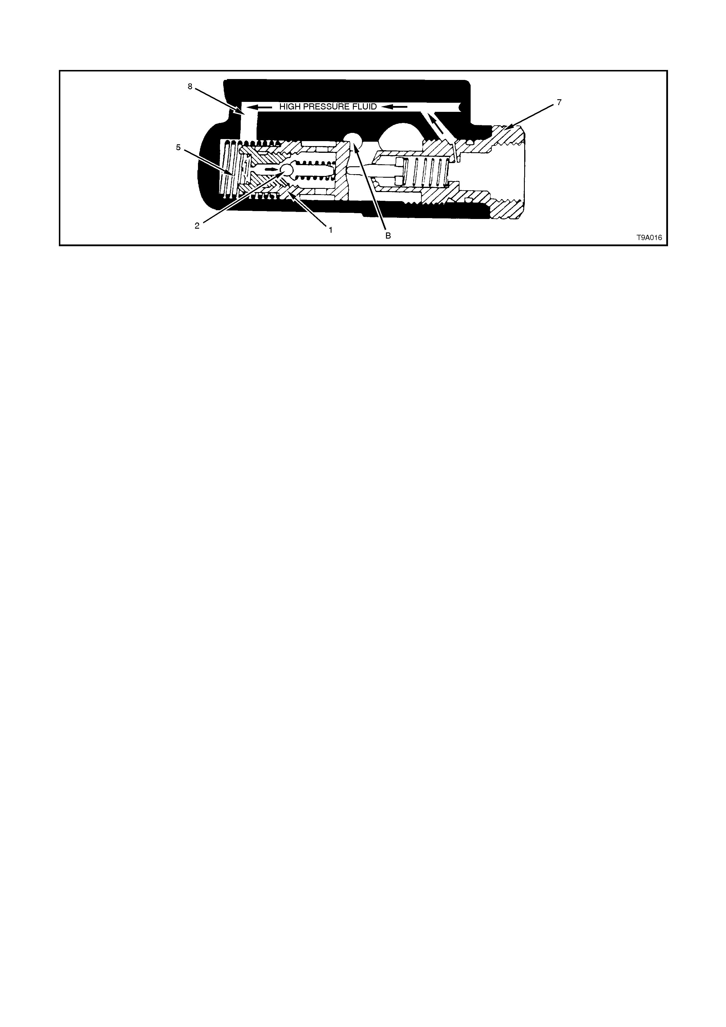
NOTE:
This condition should not be maintained for long periods of time due to excessive fluid temperature rise.
Figure 9A-15

1.2 GENERAL DESCRIPTION - STEERING COLUMN
All steering columns include a combination ignition/steering lock, are of an energy absorbing design and will
progressively compress under impact from either direction.
In addition, all steering columns are equipped with a Tilt/Reach feature, as an integral part of their design.
The ignition/steering lock is located to the right of the column assembly. The body of the lock assembly forms an
integral part of the column outer tube and cannot be removed/replaced as a separate component.
The steering lock is activated when the 'lock' position is s elected and the lock m echanism is released and engages
into a slot in the steering shaft (when the slot is facing the lock mechanism).
The ignition switch is attached to the left hand end of the ignition/steering lock housing.
The end of the ignition barrel ass embly shaft is s tepped and engages with the ignition switch. T he ignition s witch is
activated as the lock cylinder is rotated.
Connecting the steering shaft to the steering gear, is an integral steering coupling, which features two universal
joints and a vibration damper.
The following features determine the steering column assembly collapse behaviour in the event of a collision.
A. Upper End of the Steering Column
The upper end of the steering column is fastened to the instrument panel by a bracket with two inserts at the
mounting point, and held in pos ition by two bolts. Under c ollision conditions , should the vehic le operator not be
wearing a seat belt, and suf ficient f orce be exerted by the person against the steer ing wheel and the deployed
air bag, the bracket is able to m ove away from the inserts, the am ount being controlled by a coiled spring on
each side. This enables the upper end of the steering colum n to move down, within a specified load range, in
this extreme and illegal situation.
Collapse load control is achieved prim arily by the break ing away of the mounting bracket f rom the two inserts
and the tension applied by the two control springs.
B. Telescoping Shaft Assembly
The shaf t assembly consists of an upper tube that s lides over a lower shaft, thus allowing the shaft to transm it
torque but still collapse during impact.
C. Supplemental Restraint System (SRS)
This s ystem is des igned to supplement the lap/sash seat belt, dr iver rest raint system als o fitted to the vehicle.
Under no circumstances is the SRS system expected to replace the need for the driver to wear a seat
belt.
CAUTION:
Before any servicing operations are considered, that could in any way impinge on the operation of the SRS
and/or the personal safety of the individual working on the vehicle, the cautionary notes detailed under
2.1 STEERING COLUMN ASSEMBLY SERVICE NOTES AND PRECAUTIONS, in this Section, must be read
and complied with, in all respects!
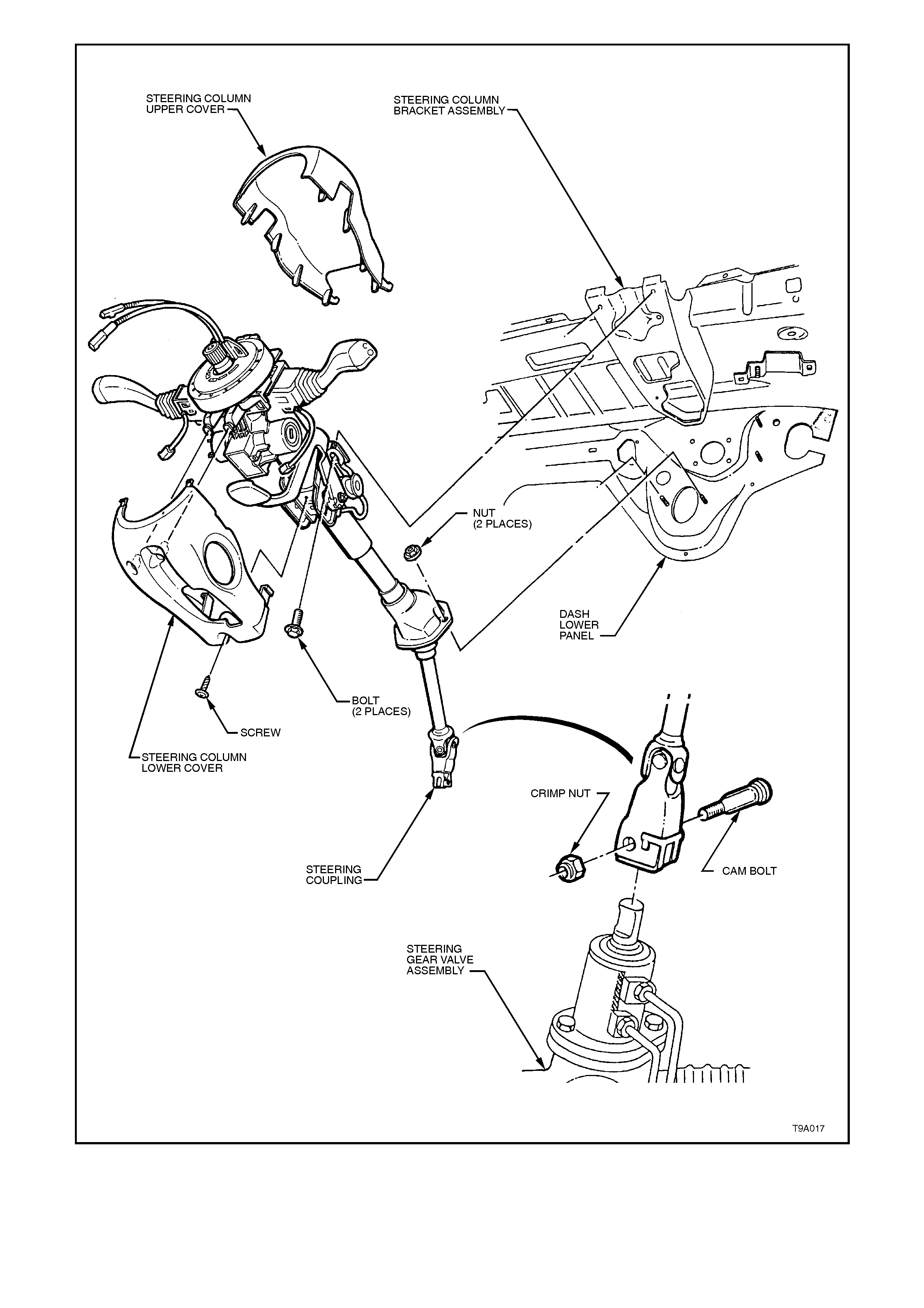
Figure 9A-16

2. STEERING COLUMN ASSEM BLY SERVICE OPERATIONS
2.1 STEERING COLUMN ASSEMBLY SERVICE NOTES AND PRECAUTIONS
CAUTION:
Disable the SRS (Air Bag). Refer to 'DISABLING THE SRS’, in this Section.
CAUTIONARY NOTES:
1. The outer jacket, steering shaft and instrument panel mounting bracket are designed as energy absorbing
units. Because of the design of these components, it is absolutely vital that the steering column assembly is
handled with care when performing any of the required service operations. Avoid hammering, jarring, dropping
or leaning on any portion of the column.
2. All steering wheel and column fasteners are important parts in that they could affect the performance of other
vital parts and systems.
3. Fasteners must be replaced with those of the same part number or with an equivalent part, if replacement is
required. Do not use a replacement part of lesser quality or substitute design.
4. Torque values must be used where specified during reassembly to assure proper retention of the part.
Techline

2.2 SRS DISABLING AND ENABLING PROCEDURE
DISABLING THE AIR BAG
IMPORTANT:
While simply disconnecting the battery earth
lead from the battery terminal is sufficient to
disable the air bag/s fitted to VT Series
vehicles, this wo uld also mean losing radio PIN
setting (if the battery were to remain
disconnected for more than approximately 8
hours) and BCM programming. The procedure
detailed here then, describes an approach that
disables the driver’s air bag, rendering it safe
to work on steering components but allowing
all pre-sets to remain intact.
1. Disconnect the battery earth lead from the
battery terminal.
2. Turn the steering wheel so that the vehicle’s
front wheel are pointing straight ahead.
3. Rotate the ignition switch to the ‘LOCK’
position and remove key from the ignition
switch.
4. Lower the instrument panel right hand cover
assembly by grasping the top edge on each
side of the s teering column with the finger tips
and pulling the top edge out, to free the
retaining lugs from the clips.
5. Release steering column tilt/reach clamp
lever, lower the column and lock the clamp
lever in this position to retain column in the
lowered position.
Figure 9A-17
6. Remove mini fuse F26 (arrow) from fuse
panel, using the removal tool provided.
Figure 9A-18

7. Insert finger between the steering wheel and
the lower cover as shown and apply a small
amount of force, pus hing the cover toward the
instrument cluster.
8. Remove the upper cover by lifting upwards,
then rearwards.
Figure 9A-19
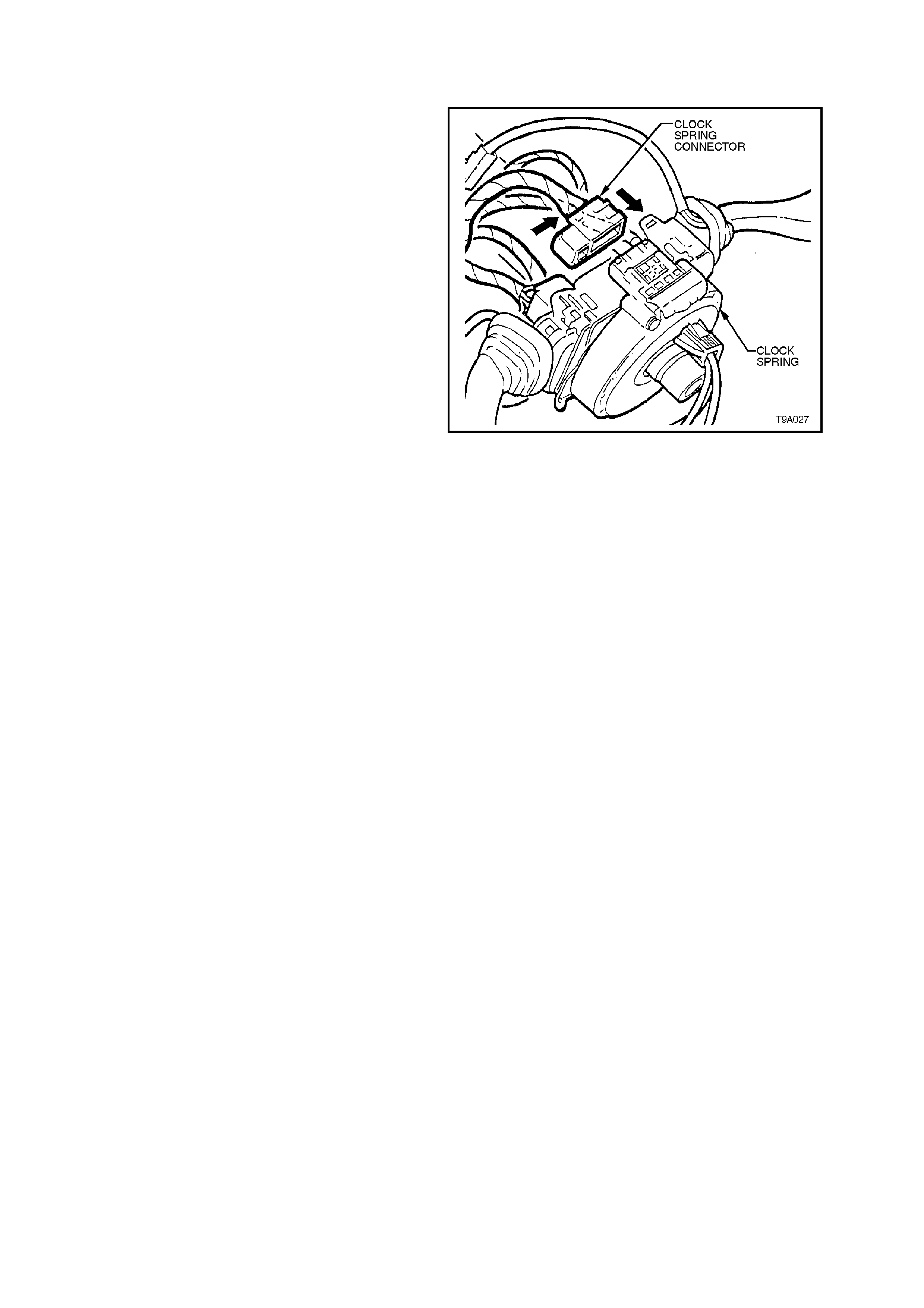
9. Disconnect the wiring harness connector from
the clock spring assembly, by first pulling the
yellow connector lock to the left hand side as
shown, then pull the connector from the clock
sprin g assembly.
NOTE:
The steering wheel is shown removed to more
clearly illustrate the connector.
IMPORTANT:
This procedure is only suitable for disabling the
driver’s side air b ag. For the passenger side air
bag (where fitted), disconnecting the battery
earth lead from the battery terminal is the most
practical method.
THIS PROCEDURE IS ONLY SUITABLE FOR
THE SRS (AIR BAG/S) FITTED TO VT SERIES
VEHICLES. DO NOT USE THIS PROCEDURE ON
ANY OTHER VEHICLE APART FROM THESE
MODELS! Figure 9A-20
ENABLING THE DRIVER’S SIDE AIR BAG
1. Ensure the ignition is switched to the ‘LOCK’
position.
2. Install the wiring harness connector to the
clock spring assembly, then push the yellow
connector lock in the direction shown. When
fully engaged a ‘click’ will be heard.
NOTE 1: The steering wheel is shown removed to
more clearly illustrate the connector.
3. To enable the remainder of the driver’s side
SRS:
Raise the instrument panel right-hand lower
cover and locate each tang in its respective
clip before firmly pushing home to secure.
Install the retaining screw.
Reinstall the upper steering column cover in
the reverse way to removal, ensuring the two
locating lugs at the front end of the upper
cover, engage with the retaining lugs on the
lower.
Reinstall fuse F26 to fuse panel.
Close the instrument panel lower cover by
locating each tang in its respective clip, then
pushing firmly to secure.
4. Connect battery earth lead to battery earth
terminal.
5. Switch ignition ON and observe the SRS
warning lamp in the instrument cluster. The
warning lamp should be illuminated for
approxim ately 5 seconds. During this period of
time the SDM performs a wiring and self-
check.
If no system faults are detected, the SRS
warning lamp will be switched OFF. If the
warning lamp remains illuminated and an
audible alarm chimes, or the warning lamp
illuminates 2 seconds after it was originally
switched off, an SRS fault is present. Ref er to
3, DIAGNOSTICS, in Section 12M, SRS, to
rectify fault.
Figure 9A-21
2.3 HORN BAR & AIRBAG ASSEMBLY
If conducting this operation on an air bag that has
been deployed, ensure that safety glasses and
gloves are worn to protect eyes and hands from
possible irritation when handling the deployed horn
bar and air bag inflator module assembly.
After deployment of the horn bar and air bag
inflator m odule as sembly, the surfac e of the air bag
may contain a powdery residue that consists
primarily of corn starch (used to lubricate the bag
as it inflates) and by the products of the chemical
reaction. Sodium hydroxide dust is produced as a
by-product of air bag deployment reaction, which
then quickly reacts with atmospheric moisture and
is converted to sodium carbonate and sodium
bicarbonate (baking soda). Therefore, it is unlikely
that sodium hydroxide will be present after
deployment.
REMOVE
1. Disable the SRS (Air Bag). Refer to 2.2 SRS
DISABLING AND ENABLING PROCEDURE
in this Section.
2. Using a number T30H Torx bit (commercially
available), or Tool No. ETX30H and a suitable
holder such as Tool No. J25359-8 (1), loosen
then remove the horn bar and air bag inflator
module assembly retaining screws (2) from
four places on the rear of the steering wheel.
Figure 9A-22
2. Lift up the horn bar and air bag inflator module
assembly (1) from the steering wheel, remove
the yellow clock spring to inflator assembly
connection (2) and disconnect wiring harness
connectors (3 and 4) from rear of assembly.
NOTE:
If removing a horn bar and air bag inflator module
assembly from a steering wheel fitted with stereo
controls (as shown), take extreme care when
disconnecting the left hand horn pad connector (3)
from the stereo control wiring connector.
Otherwise, damage to the stereo control wiring
could result.
Remove the horn bar and air bag inflator
module assembly (1) from the steering wheel.
CAUTION:
When carrying a live (undeployed) horn bar and
air bag inflator module assembly, make sure
the bag opening is facing away from the body.
Never carry the horn bar and air bag inflator
module assembly by the horn bar wires or
connectors on the underside of the assembly.
In case of accidental deployment, the bag will
then deploy with a minimal chance of injury.
When placing a live horn bar and air bag
inflator module assembly on a bench or other
surface, always face the bag and horn bar
facing up, away from the surface. Never rest the
horn bar and air bag inflator module assembly
with the horn bar face down. This is necessary
so that a free space is provided to allow the air
bag to expand, in the unlikely event of
accidental deployment. Otherwise, personal
injury may result.
Figure 9A-23
REINSTALL
1. Lift horn bar and air bag inflator module
assembly up to steering wheel and reconnect
all wiring harness connec tors to the r ear of the
assembly.
2. Seat the horn bar and air bag inflator module
assembly on steering wheel, ensuring wiring
and connectors are not caught between the air
bag inflator module and the steering wheel
hub.
3. Using a number T30H Torx bit, Tool No.
ETX30H and a suitable holder such as Tool
No. J25359-8, install then tighten the four
screws into the rear of the steering wheel to
secure the horn bar and air bag inflator
module assembly to the steering wheel.
Tighten screws to the correct torque
specifications. DO NOT OVER-TIGHTEN.
HORN BAR AND AIRBAG MODULE
ASSEMBLY TO STEERING WHEEL 10 - 14 Nm
SCREW TORQUE SPECIFICATION
4. Enable the SRS (Air Bag). Refer 2.2 SRS
DISABLING AND ENABLING PROCEDURE,
in this Section.

5. Switch ignition ON and observe the SRS
warning lamp in the instrument cluster. The
warning lamp should be illuminated for
approximately 5 seconds. During this period of
time the SDM performs a wiring and self-
check.
If no system faults are detected, the SRS
warning lamp will be switched OFF. If the
warning lamp remains illuminated and an
audible alarm chimes, or the warning lamp
illuminates 2 seconds after it was originally
switched off, an SRS fault is present. Refer to
3, DIAGNOSTICS, in Section 12M, SRS, to
rectify fault.

2.4 STEERING WHEEL
REMOVE
CAUTION:
Disable the SRS (Air Bag). Refer to in 2.2 SRS
DISABLING AND ENABLING PROCEDURE, in
this Section.
1. Remove the horn bar and air bag inflator
assembly, as described in 2.3 HORN BAR
AND AIRBAG MODULE ASSEMBLY,
Remove, in this Section.
2. Ensure that the front wheels and the steering
wheel are in the straight ahead position.
NOTE:
This is im por tant to ens ure that the c loc k s pr ing coil
is locked, when the steering wheel is removed.
3. To aid installation of the steering wheel to its
original position, scribe an aligning mark on
the steering wheel centre section and steering
shaft. A felt tipped pen could also be used.
NOTE:
Do not use a centre punch for this operation. See
'CAUTIONARY NOTES’, in 2.1, in this Section.
4. Using a commercially available, Torx E20
socket, remove the steering wheel retaining
bolt.
NOTE:
Do not use a conventional, 12 pointed socket for
this operation.
7. Remove the steering wheel from the steering
shaft splines and feed the clock spring wiring
and connectors through the steering wheel
aperture.
NOTE:
When the steering wheel is removed, check that
the green coloured tang has engaged the inner
clock spring member to lock it in the centralised
position.
Figure 9A-24
NOTE:
With the increased diameter of the steering shaft
and the angle of the locating bevel, it is not usually
necessary to require a puller to remove the steering
wheel. However, if one is required, use puller, Tool
No. J1859-A (1) and legs (2), Tool No. E1408.
9. Install legs (2) to the steering wheel.
10. After turning the lugged feet on each of the
legs in an outward direction, tighten the
puller forcing screw to pull the steering wheel
from the mating splines on the steering shaft.
Remove the puller (1) from the steering wheel.
Figure 9A-25
REINSTALL
1. Install steering wheel to steering shaft,
aligning marks made prior to removal and
ensuring the drive tang of the clock spring is
aligned with the steering wheel aperture.
NOTE:
This action automatically releases the clock spring
centralising lock.
2. After cleaning the threadlock residue from the
bolt threads, apply Loctite '242' (or equivalent
to Holden’s Specification HN1256 Class 2,
Type2) to bolt threads. Install and tighten
steering wheel retaining bolt to the correct
torque specification, using a commercially
available, Torx E20 socket.
STEERING WHEEL RETAINING 40 - 50
BOLT TORQUE SPECIFICATION Nm
3. Reinstall the horn bar and air bag inflator
assembly, as described in 2.3 HORN BAR
AND AIRBAG MODULE ASSEMBLY in this
Section. Tighten the four scr ews to the correct
torque specification. DO NOT OVER-
TIGHTEN.
HORN BAR AND AIRBAG MODULE
ASSEMBLY TO STEERING WHEEL 10 - 14 Nm
SCREW TORQUE SPECIFICATION
6. Enable the SRS (Air Bag). Refer to 2.2 SRS
DISABLING AND ENABLING PROCEDURE,
in this Section.
7. Check horn and turn indicator operation.
2.5 IGNITION BARREL LOCK CYLINDER
REMOVE
CAUTION:
Disable the SRS (Air Bag). Refer to 2.2 SRS
DISABLING AND ENABLING PROCEDURE, in
this Section.
1. Disconnect battery earth lead.
2. Remove ignition keys from ignition switch.
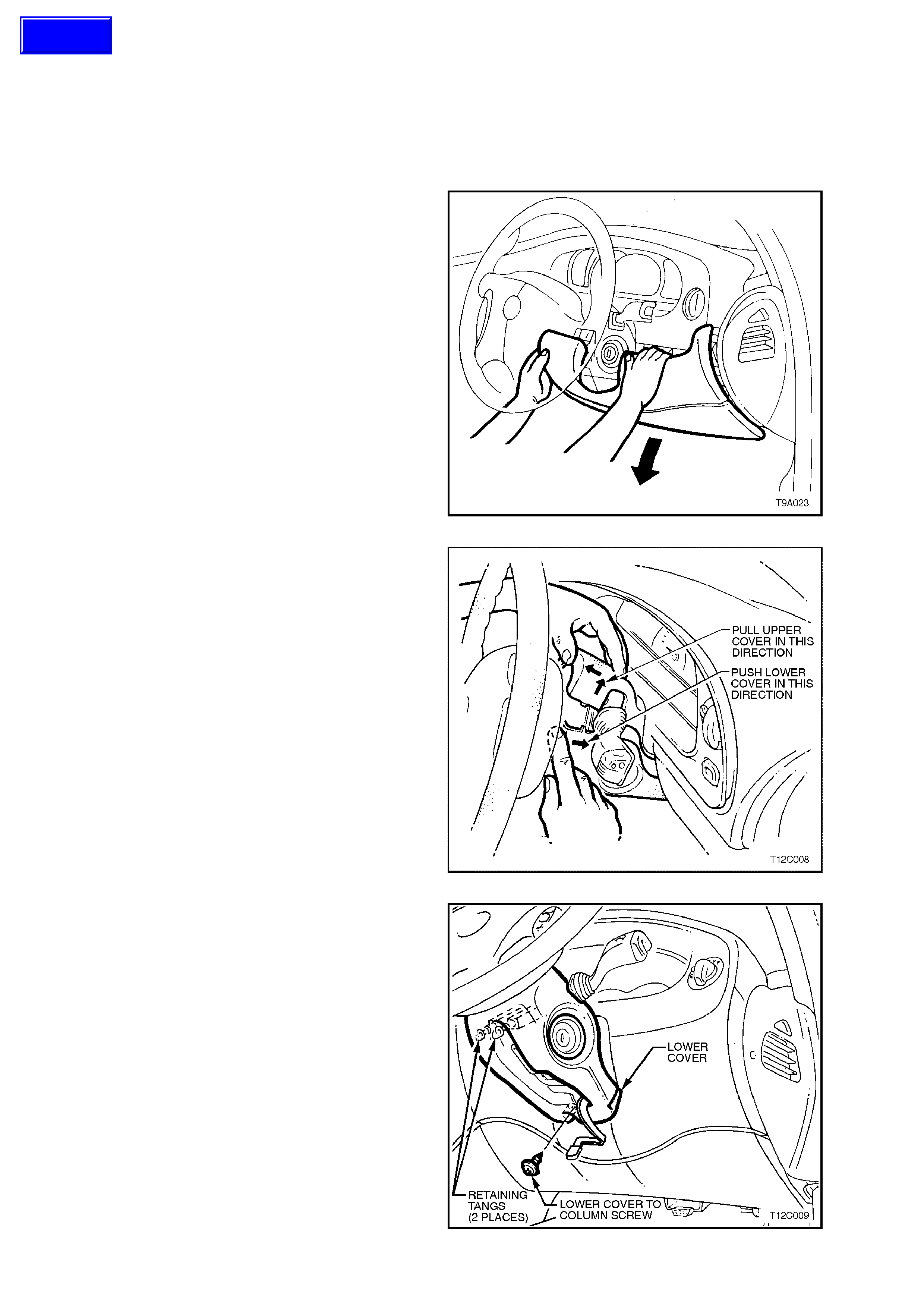
3. Lower the instrument panel right hand cover
assembly by grasping the top edge on each
side of the s teering column with the finger tips
and pulling the top edge out, to free the
retaining lugs from the clips.
4. Release the steering column tilt/reach clamp
lever, lower the column and lock the clamp
lever in this position.
Figure 9A-26
5. Insert finger between the steering wheel and
the lower cover as shown and apply a small
amount of force, pushing the c over toward the
instrument cluster.
6. Remove the upper cover by lifting upwards,
then rearwards.
Figure 9A-27
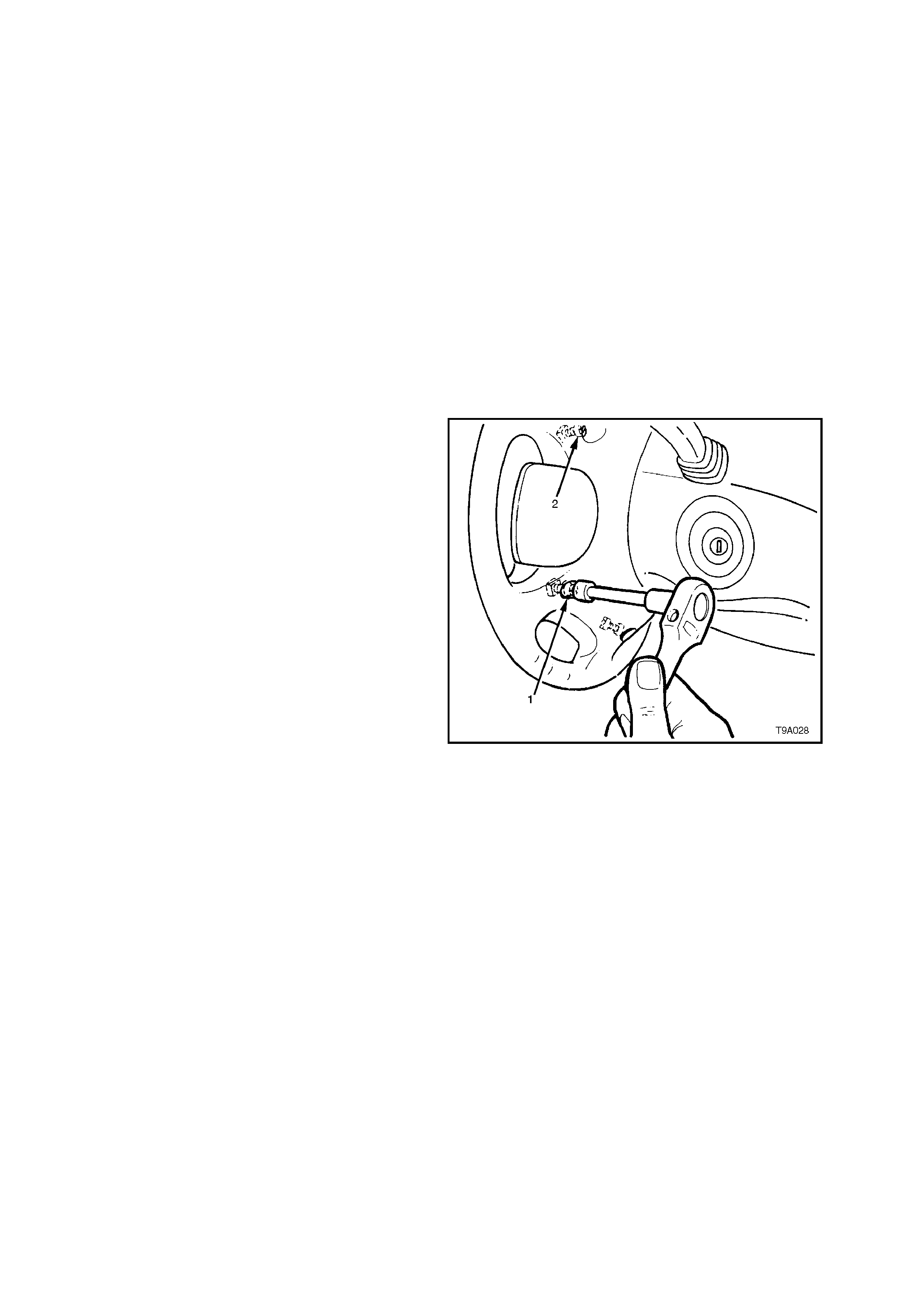
7. Remove the screw securing the lower cover to
the steering column.
8. Push the lower cover up towards the steering
wheel to release the cover from the two
retaining tangs on the steering column.
9. While feeding the key reader outer surround
from the lower cover, remove the lower cov er.
Figure 9A-28
Techline
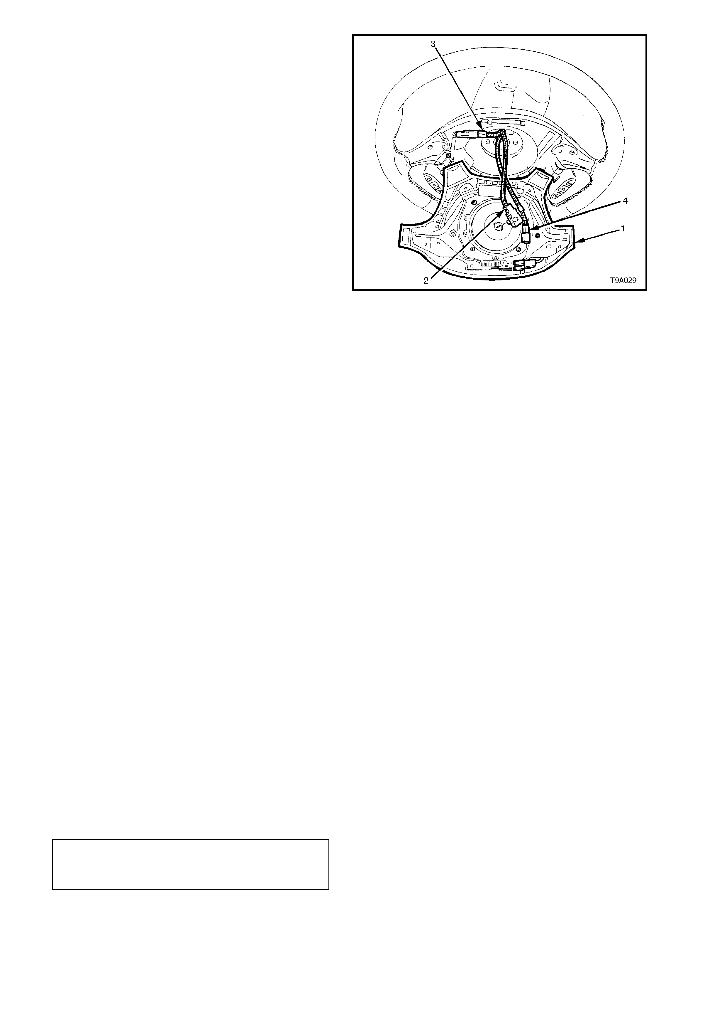
10. Disconnect the wiring harness connector and
ignition lock illumination socket and bulb from
the key reader assembly.
11. Carefully pull the key reader from the ignition
lock assembly housing.
Figure 9A-29
12. Insert ignition key into barrel and turn to the
'ON' position.
13. Insert a 2.5 mm diameter pin (an Allen key is
suitable) (1), into locking pin hole, depress
spring loaded barrel locking latch to release
lock cylinder.
14. Remove pin and pull barrel (2) from lock
housing.
Figure 9A-30
REINSTALL
1. Install key into ignition barrel, and turn key to
the ignition 'ON' position.
2. Insert barrel into lock housing until latch locks
into the housing.
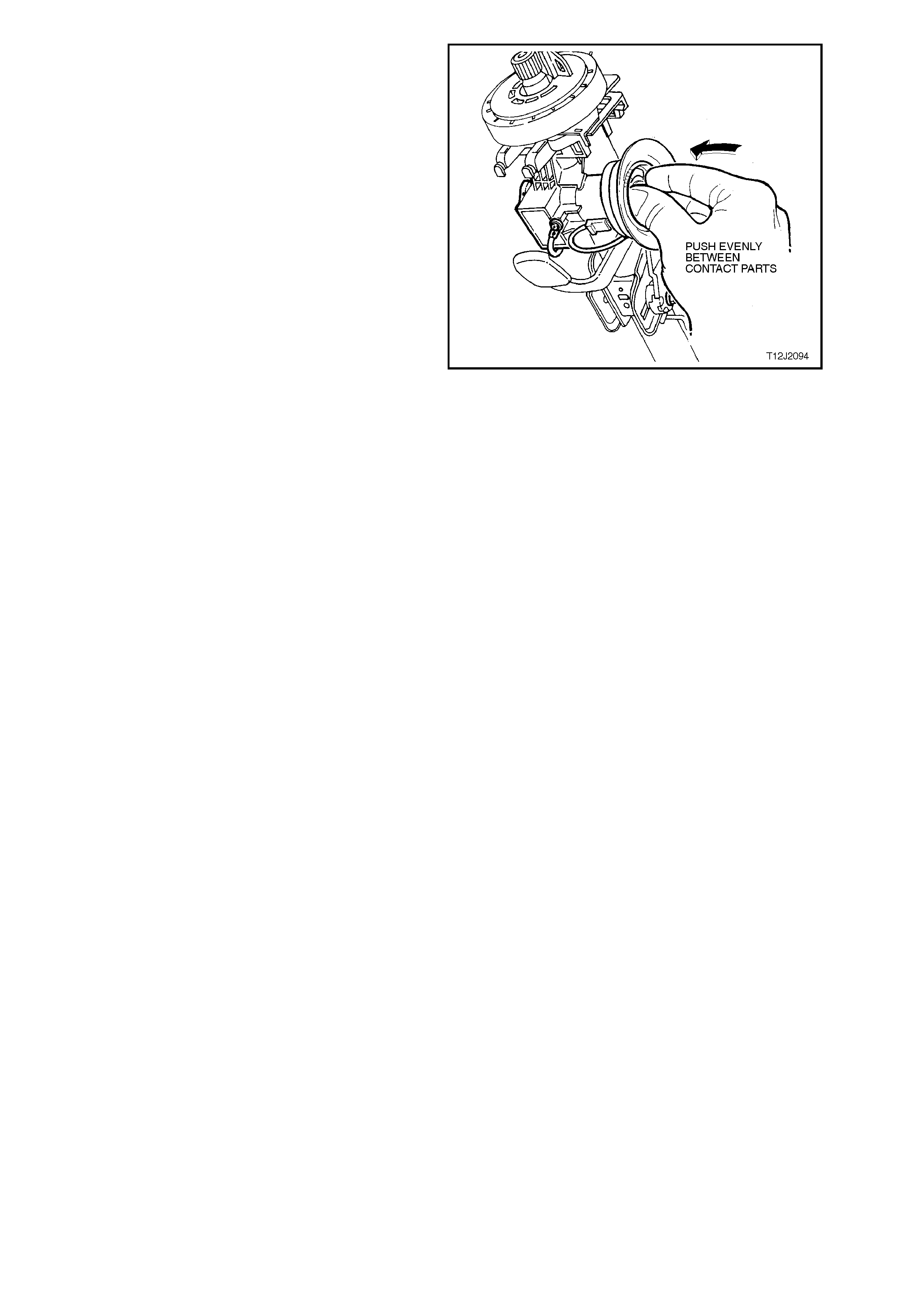
3. To reinstall the ignition key reader, align the
flat section of the remote key reader
assembly, with the ignition lock assembly.
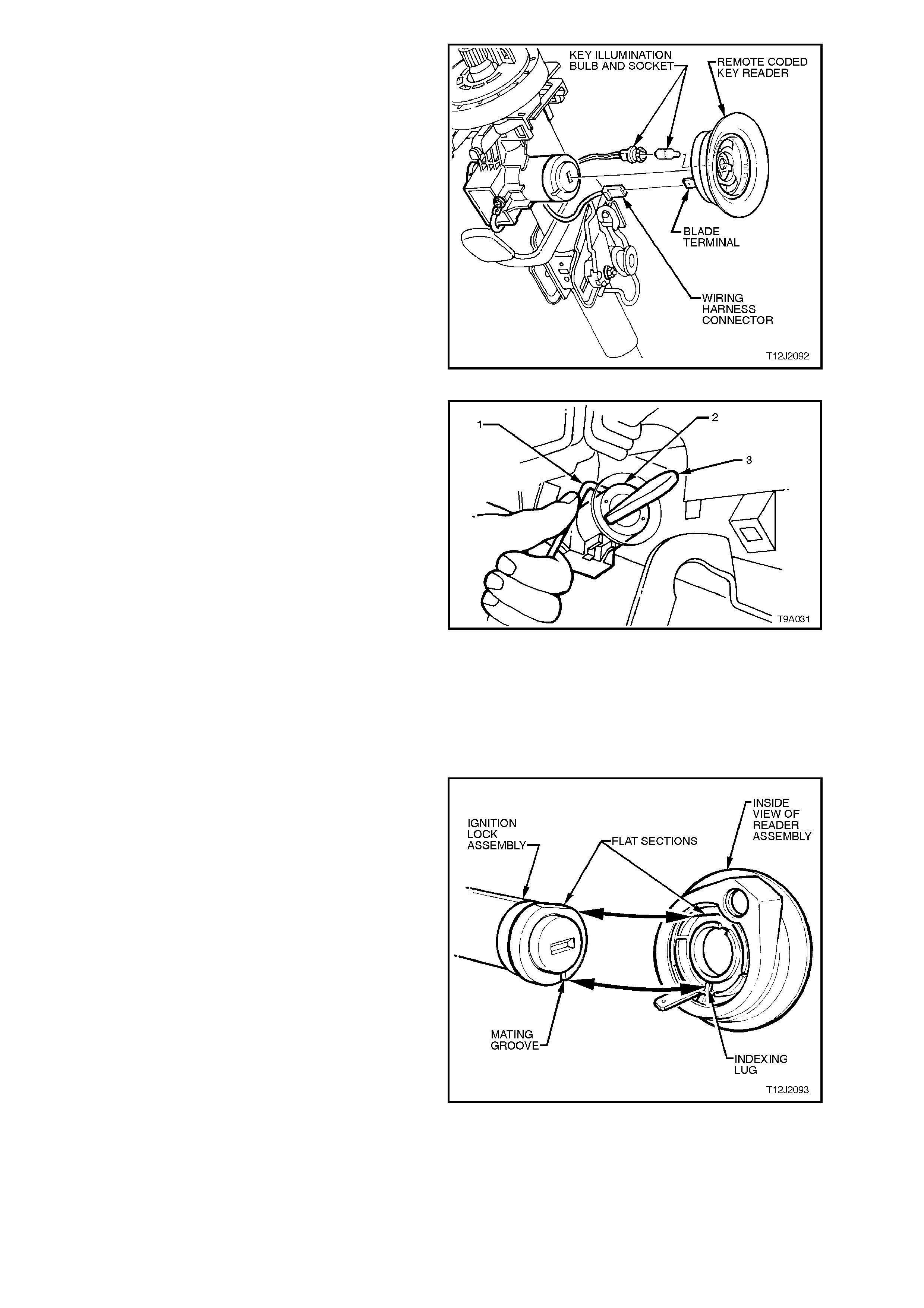
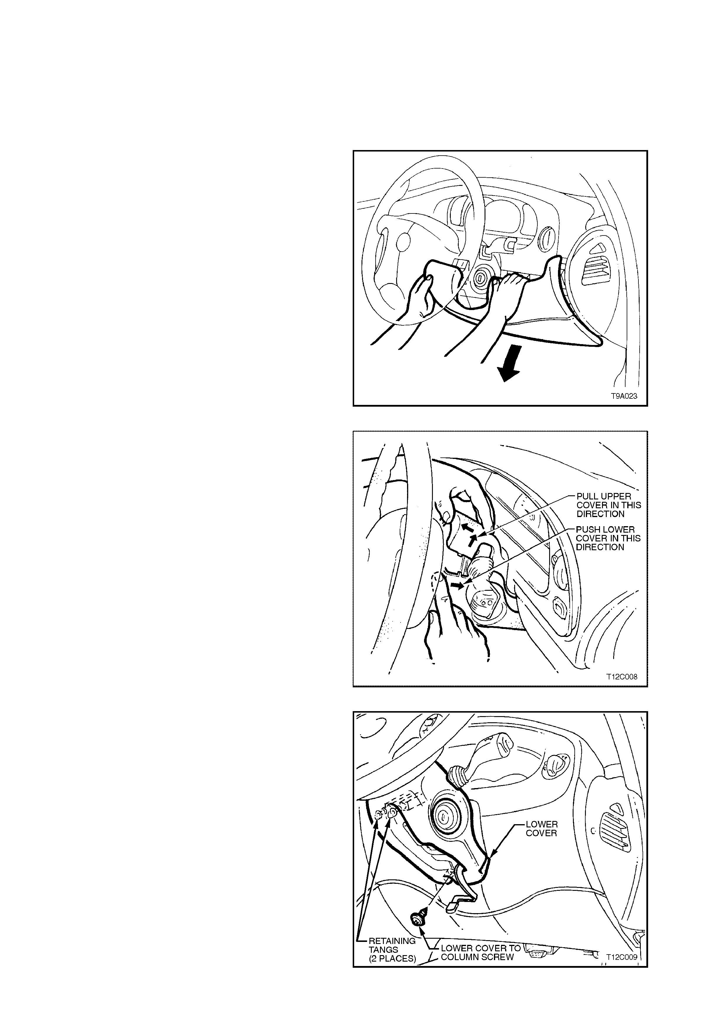
Figure 9A-31
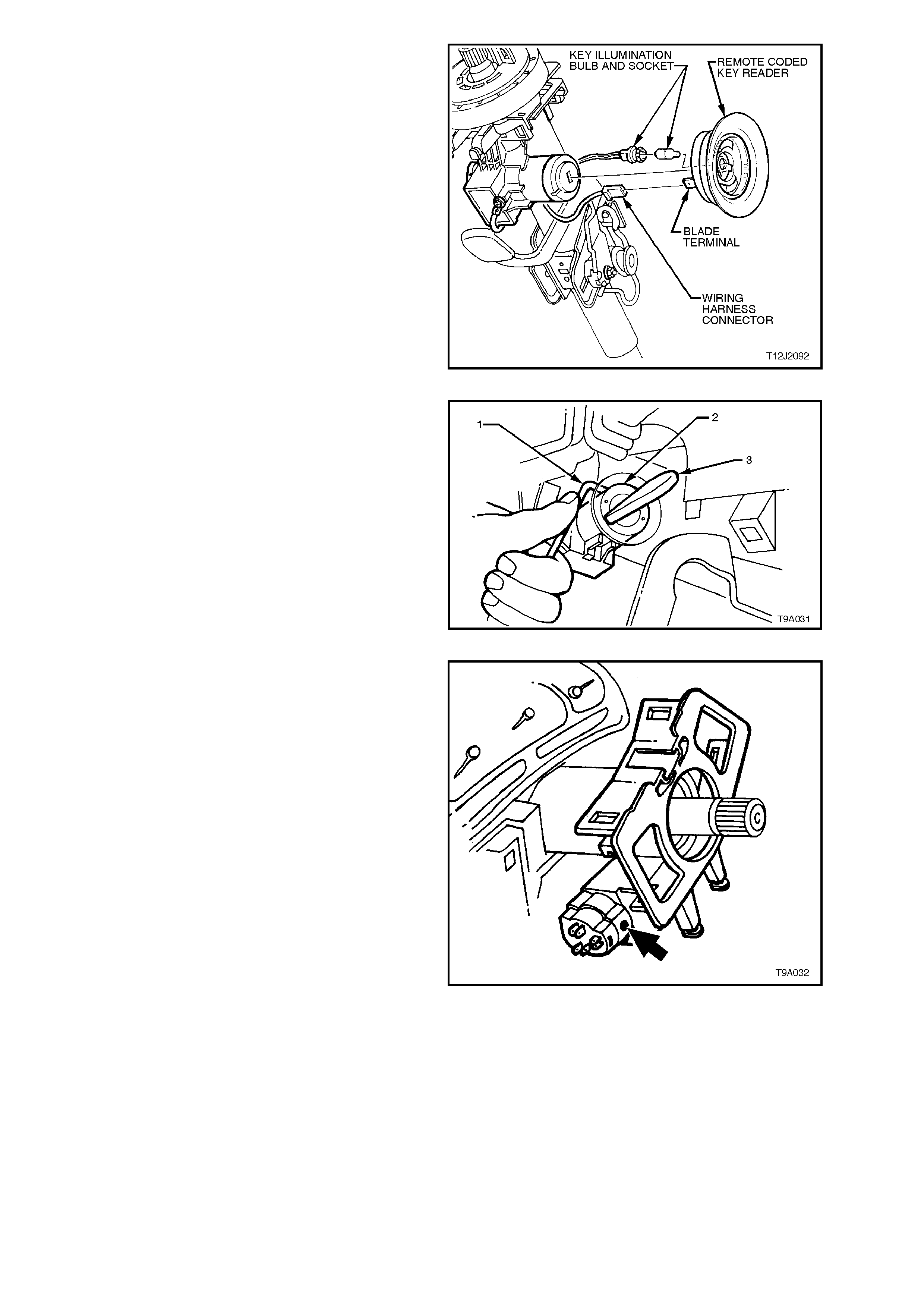
4. Gently press the key reader assembly onto the
ignition lock by pushing evenly between the
two key reader seats, until the reader
assembly seats onto the ignition lock.
5. Ensure that the wiring harness connector and
ignition lock illumination bulb and socket are
securely fitted to the key reader assembly.
6. Reinstall steering column lower cover, by
engaging the two retaining tangs before
pushing the cover towards the instrument
cluster to engage. When the holes are aligned,
install the lower cover attaching screw.
7. Install the upper cover in the reverse manner
to removal.
8. Raise the instrument panel right hand cover
assembly and locate each tang in its
respective clip before firmly pushing home to
secure.
9. Reconnect battery earth lead.
10. Insert the ignition key and check ignition
switch lock and barrel operations.
IMPORTANT:
Enable the SRS (Air Bag). Refer to 2.2 SRS
DISABLING AND ENABLING PROCEDURE, in
this Section.
Figure 9A-32
2.6 IGNITION SWITCH
REMOVE
CAUTION:
Disable the SRS (Air Bag). Refer to 2.2 SRS
DISABLING AND ENABLING PROCEDURE in
this Section.
1. Disconnect battery earth lead.
2. Remove ignition keys from ignition switch.
3. Lower the instrument panel right hand cover
assembly by grasping the top edge on each
side of the s teering column with the finger tips
and pulling the top edge out, to free the
retaining lugs from the clips.
4. Release the steering column tilt/reach clamp
lever, lower the column and lock the clamp
lever in this position.
Figure 9A-33
5. Insert finger between the steering wheel and
the lower cover as shown and apply a small
amount of force, pushing the c over toward the
instrument cluster.
6. Remove the upper cover by lifting upwards,
then rearwards.
Figure 9A-34
7. Remove the screw securing the lower cover to
the steering column.
8. Push the lower cover up towards the steering
wheel to release the cover from the two
retaining tangs on the steering column.
9. While feeding the key reader outer surround
from the lower cover, remove the lower cov er.
Figure 9A-35
10. Disconnect the wiring harness connector and
ignition lock illumination socket and bulb from
the key reader assembly..
11. Carefully pull the key reader from the ignition
lock assembly housing.
Figure 9A-36
12. Insert ignition key into barrel and turn to the
'ON' position.
13. Insert a 2.5 mm diameter pin (an Allen key is
suitable) (1), into locking pin hole, depress
spring loaded barrel locking latch to release
lock cylinder.
14. Remove pin and pull barrel (2) from lock
housing.
Figure 9A-37
15. Disconnect wiring harness connector from the
ignition switch.
16. Using a fine bladed screwdriver, remove
ignition switch to steering lock housing
retaining grub screw (arrow).
17. Pull switch from steering lock housing,
disengaging the roll pin f rom the side oppos ite
the grub screw.
Figure 9A-38

REINSTALL
Installation of the ignition switch is the reverse of
removal procedure, noting the following points:
1. When installing ignition switch into housing,
ensure that the switch body engages the
locating roll pin in the housing and that the s lot
in end of switch aligns with stepped end of
ignition barrel shaft and
2. Once fitted, retain the switch by tightening the
grub screw.
3. After installing the wiring harness connector to
the ignition switch, reconnect battery earth
lead and check ignition switch operation.
IMPORTANT:
Enable the SRS (Air Bag). Refer to 2.2 SRS
DISABLING AND ENABLING PROCEDURE, in
this Section.

2.7 STEERING LOCK
As the steering lock is an integral part of the steering column assembly, the steering lock is not a separately
serviceable component. If found to be faulty, the entire steering column assembly must be replaced.

2.9 STEERING COLUMN ASSEMBLY
REMOVE
CAUTION:
Disable the SRS (Air Bag). Refer to 2.2 SRS
DISABLING AND ENABLING PROCEDURE in
this Section.
1. Disconnect battery earth lead.
2. Lower the instrument panel right hand cover
assembly by grasping the top edge on each
side of the s teering column with the finger tips
and pulling the top edge out, to free the
retaining lugs from the clips.
3. Using a screwdriver or similar, lever out the
left hand hinge pin, lower the cover at the left
hand end, then remove cover from the
instrument panel.
4. Remove steering wheel, refer to
2.4 STEERING WHEEL in this Section.
Figure 9A-39
5. Remove the instrument panel lower trim by
removing the two fasteners and retainer.
Lower the trim, then twist the footwell
illumination lamp holder to remove.
Figure 9A-40
6. Remove the screws attaching the fuse and
body control module panel to the dash panel.
Leaving the Data Link Connector (DLC)
attached to the panel, swing the panel to one
side and secure with tie wire or similar.
Figure 9A-41
7. After removing the upper steering column
cover, remove the screw (1) securing the
lower cover to the steering column.
8. Push the lower cover up towards the top of the
steering column (arrow) to release the two
retaining tangs (2) on the steering column.
9. While feeding the key reader outer surround
from the lower cover, remove the lower cover.
Figure 9A-42
10. To remove the clock spring assembly,
disengage the two top locking tangs by lifting
first in direction (1) then pulling the clock
spring assembly in direction (2) to disengage
each tang. Repeat for the lower two tangs,
then remove the assembly from the steering
column.
Figure 9A-43
11. Disconnect the wiring harness connector and
ignition lock illumination socket and bulb from
the key reader assembly.
12. Carefully pull the key reader from the ignition
lock assembly housing.
13. Remove the screw holding the earth lead to
the ignition lock housing and remove the
wiring harness connector from the ignition
switch assembl y.
Figure 9A-44
14. Remove both the turn s ignal and wiper/washer
switch assemblies by depressing the switch
retaining tangs (2), then pull each switch from
the upper bearing suppor t as sem bly (3). While
removal of the turn signal switch assembly is
shown (1), the retention method for both
switches is the same.
15. Using a screwdriver or similar, depress the
tangs of the wiring harness retaining clip and
remove.
16. Carefully lift the wiring harness to one side and
secure.
Figure 9A-45
17. Loosen but do not remove steering column to
instrument panel mounting bolts.
18. Raise front of vehicle and place on safety
stands. Refer to Section 0A, GENERAL
INFORMATION for location of jacking points.
19. Remove steering coupling to steering rack
pinion shaft cam bolt nut. Remove the cam
bolt, then disengage the retaining clip and
slide the coupling away from the steering rack
pinion shaft.
Figure 9A-46
20. From inside the vehicle, remove the two nuts
(2) securing the lower housing ass embly (1) to
the floorpan.
21. W hile supporting the steering colum n, remove
the previously loosened upper column
retaining bolts.
22. Remove the steering column assembly from
the vehicle.
Figure 9A-47
REINSTALL
Installation of the steering column assembly is the
reverse of r emoval pr ocedur es , noting the f ollowing
points:
1. Inspect the foam seal stuck to the lower
housing to ensure it is intact. If the sealing
ability of the flattened seal is suspect, apply a
continuous bead of silicone sealant such as
RTV 732 or equivalent to Holden’s
Specification HN 1373 to the seal material.
2. After installing the steering column coupling
through the floor pan, install the two lower
housing retaining nuts but do not tighten at
this stage.
3. Lift the column assembly and loosely install
the two upper support bracket retaining bolts.
NOTE:
Only use bolts that were originally used, or replace
with genuine parts, as these parts are an inherent
part of this vital safety feature of the vehicle.
4. Engage the lower coupling with the steering
rack input shaft, install cam bolt and a new
'crimp' nut to the lower coupling and tighten
the nut to the specified torque.
LOWER STEERING COUPLING
TO RACK PINION, CAM BOLT 23 - 30 Nm
NUT TORQUE SPECIFICATION
Figure 9A-48
5. Tighten the lower housing retaining nuts from
inside the vehicle, to the specified torque.
STEERING COLUMN LOWER
HOUSING RETAINING NUTS 15 - 30 Nm
TORQUE SPECIFICATION
6. Tighten the two upper bracket to instrument
panel mounting nuts to the correct torque
specification.
UPPER STEERING COLUMN
MOUNT ATTACHING NUTS 15 - 30 Nm
TORQUE SPECIFICATION
7. The remainder of the installation process is
the reverse of the removal steps, with the
exception of the following important points:
8. Reinstall the clock spring assembly as follows:
a. To avoid irreparable dam age to the clock
spring coil ribbon wire, ensure that the
steering gear is in the centralised
position. Refer to 3.6 POWER
STEERING GEAR in this Section for the
required details.
b. W ith the clock spring assembly locked in
the centralised position, install over the
steering shaf t, indexing the lower loc ating
pins on the clock spring, with matching
holes in the switch housing.
c. Push the clock spring assembly onto the
switch housing until the four locking tangs
fully engage.
NOTE:
If the clock spring assembly was removed without
being centred, refer to the following procedure.
9. Reinstall steering wheel, refer to 2.4
STEERING WHEEL in this Section.
10. Connect battery earth lead and check the
operation of all affected electrical items.
CENTRING THE CLOCK SPRING COIL
1. The steering gear MUST be in the centralised
position before the installation of the coil
spring assembly, otherwise irreparable
damage to the clock spring coil may result.
Refer to 3.6 POWER STEERING GEAR in
this Section for details regarding centralising
the steering gear.
2. To centralise the clock spring prior to
installation:
a. Hold the clock spring coil outer housing
with the left hand.
b. Then, while holding each of the two
locking lugs inward as shown, rotate the
inner member in a clockwise direction
until a mechanical stop is felt.
c. While still holding the locking lugs as
before, rotate the inner member of the
clock spring assembly in the opposite
direction, approximately 2.5 turns, until
the green indexing tab (1) is seen full
width in the upper window.
NOTE:
It is possible to have a partial view of the green tab
without the clock spring coil being in the correct,
centred position.
d. Release the locking lugs and the inner
rotor should now be locked to the outer
member with the clock spring in the
centralised position.
Figure 9A-49

2.10 CHECKING S TEERING COLUMN FOR ACCIDENT DAMAGE
IMPORTANT:
Vehicles involved in accidents resulting in major body
or sheet metal damage or where the steering column
has been impacted, column damage or misalignment
may also have occurred.
INSPECT:
1. Check visually to see that either or both of the
two mounting lugs have been dislodged from the
column bracket and that the control springs are
undamaged.
2. Visually check for any damage to the column
and/or shaft that causes binding or jamming.
Should any component of the steering column
assembly show signs that distortion has occurred,
then the column must be replaced as an assembly.
For steering column assembly replacement
procedures, refer to 2.9 STEERING COLUMN
ASSEMBLY in this Section.
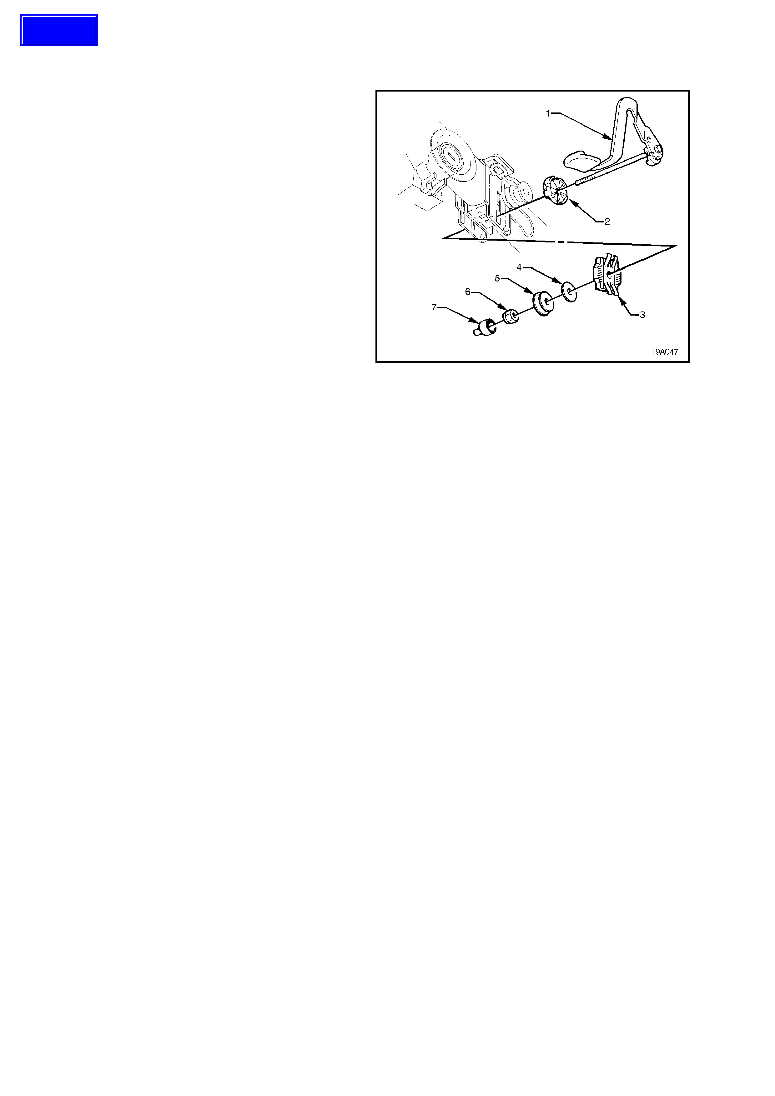
2.11 TILT/RE ACH HANDLE
REPLACE
NOTE:
While replacement of this component is not
recommended, the handle is serviced separately.
1. Release the tilt/reach handle (1) and, while
supporting it with one hand, remove the
through bolt, nut cover (7) and retaining nut
(6).
2. Withdraw the through bolt and handle (1),
inner cam (2), outer rack (3), washer (4) and
bearing (5).
3. Reinstall through bolt and replacement handle
(1), through the inner cam (2).
4. Apply Loctite 242 (or equivalent to Holden’s
Specification HN1256 Class 2, Type 2) to the
bolt thread.
5. Reinstall the remaining components in the
reverse order to removal and install a NEW
retaining nut (6).
Important:
The final tension on the through bolt determines the
security of the upper steering column assembly and
the final nut tension must be determined by
adopting the following procedure.
6. Tighten the nut until a f orc e of 80 N is r equired
to push the lever closed.
7. With the lever releas ed, check that the c olum n
is free to slide up and down. If the rack (3)
grates, loosen the nut just sufficient to allow
free movement of the column.
8. Install the nut cover (7).
Figure 9A-50
Techline


2.13 STEE RING COUPLING
Because the steering coupling forms an integral part of the steering shaft assembly, should the coupling be found to
require replacement, the complete column assembly must be replaced. For steering column assembly replacement
procedures, refer to 2.9 STEERING COLUMN ASSEMBLY in this Section.
3. POWER STEERING SERVICE OPERATIONS
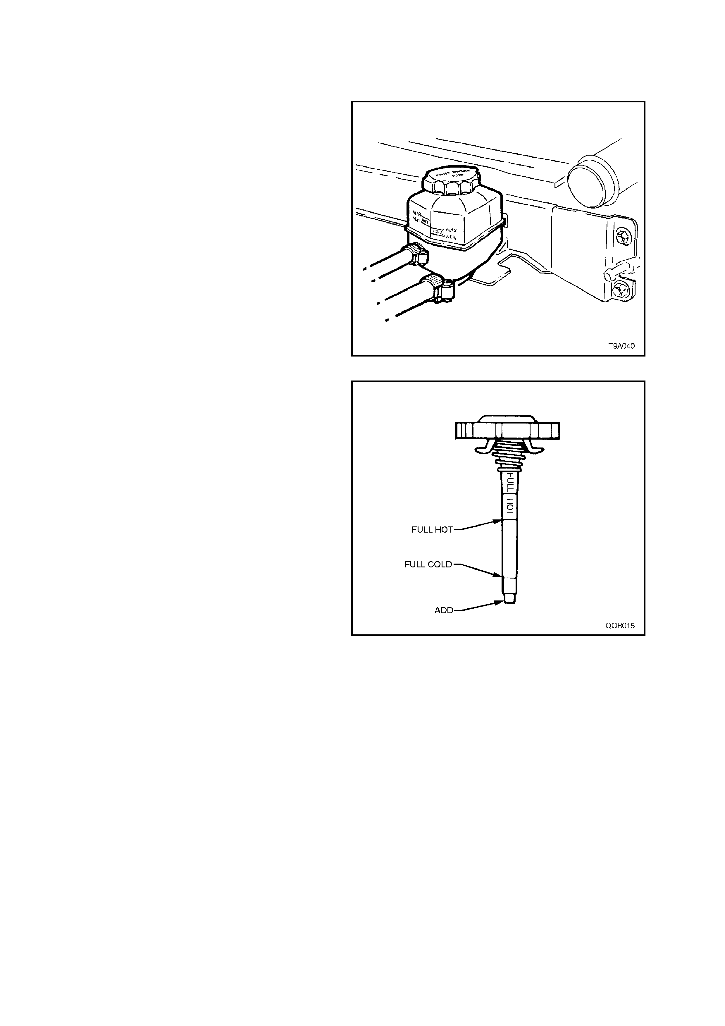
3.1 FLUID LEVEL CHECK
NOTE:
The recommended fluid for use in all VT series
vehicles, is Dex r on® III autom atic trans m ission f luid
to Holden’s Specification HN2126.
V6 Engine
The power steering fluid level can be checked by
viewing the level through the translucent plastic
side of the reservoir.
If the fluid is cold, the level should be in the ‘COLD’
range. Sim ilar ly, if it is hot, the fluid s hould be in the
‘HOT’ range. If the fluid level is at the low side of
either range, new fluid should be added to br ing the
level into the correct range and the system checked
for the cause of the leakage and corrected as
necessary.
Figure 9A-51
V8 Engine
The power steering fluid level is checked by using
the dipstick attached to the reservoir filler cap.
The fluid level should be in the range between the
‘ADD’ and ‘FULL HOT’ indicator marks on the
dipstick , depending on the temperature of the fluid.
If the power steering fluid is at or below the ‘ADD’
mark, new fluid should be added to bring the level
into the correct range and the system checked for
the cause of the leakage and corrected as
necessary.
Figure 9A-52
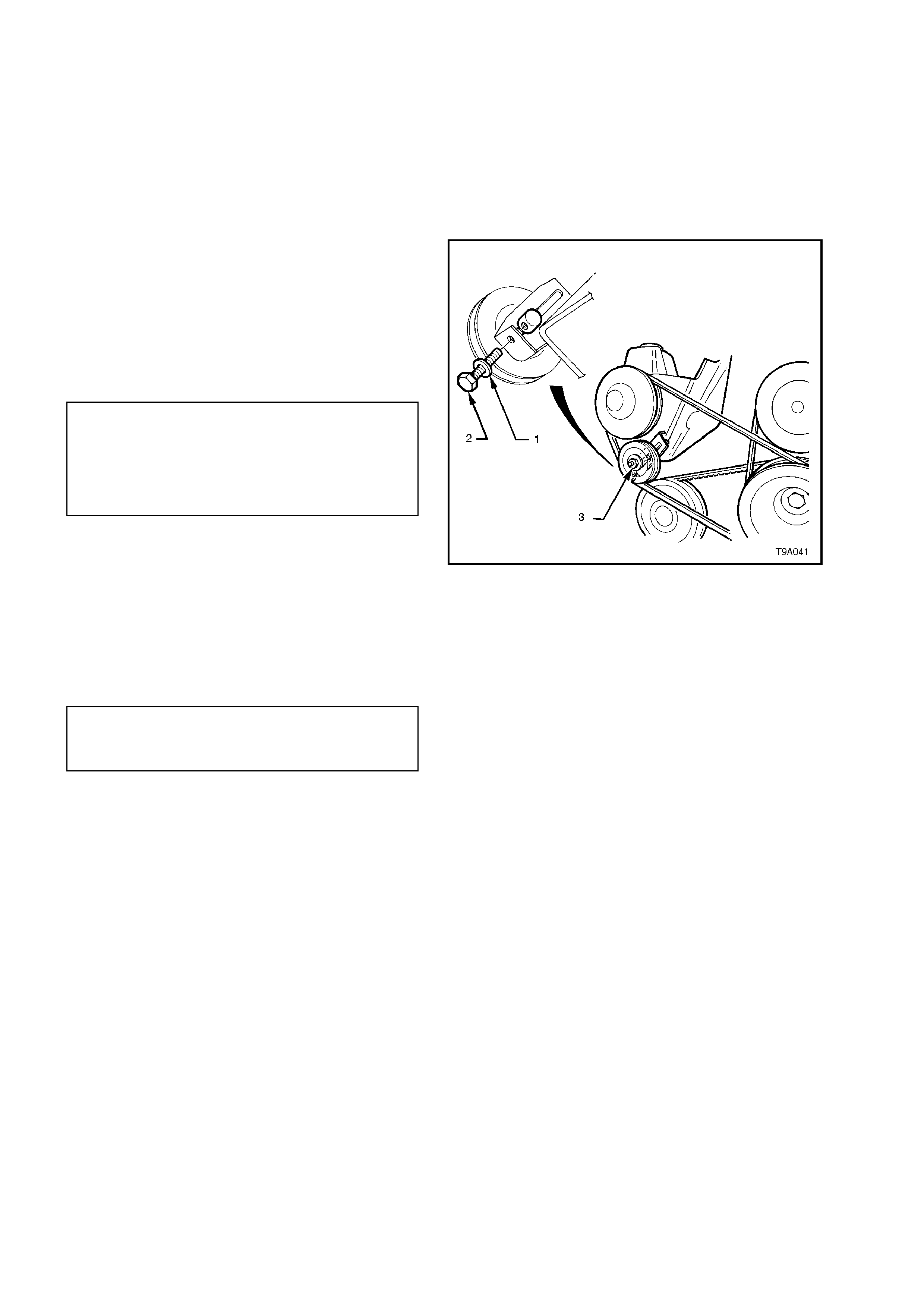
3.2 DRIVE BELT ADJUSTMENT
V6 ENGINE
For vehicles with V6 engine, the power steering
pump is driven by the engine serpentine drive belt.
The belt is self adjusting within tensioner operating
limits. For details, refer to Section 6A1, ENGINE
MECHANICAL.
V8 ENGINE
For this engine, check drive belt tension as follows:
1. Inspect drive belt condition.
2. Check belt for correct tension using belt
tension gauge, Tool No. BT3373-F (or
J23600-B).
Refer to the following chart for the correct belt
tension specifications.
POWER STEERING PUMP DRIVE 57 kg
New
BELT TENSION SPECIFICATION 34 kg
Used *
* A drive belt is considered used after
10 minutes of running.
To Adjust the Drive Belt Tension:
1. Loosen power steering pump idler pulley nut
(3).
2. Adjust the bolt (2) to move the idler pulley
position, to achieve the specified belt tension.
3. Tighten power steering pump idler pulley nut
(3) to the correct torque specification.
POWER STEERING PUMP
IDLER PULLEY NUT 35 - 65 Nm
TORQUE SPECIFICATION
Figure 9A-53

3.3 HYDRAULIC SYSTEM, BLEEDING/REFILLING PROCEDURE
CAUTIONARY NOTES:
1. If the fluid level is low in the fluid reser voir, air will be drawn in and m ixed with the fluid in small bubbles . If the
pump is allowed to continue operation, an increasing am ount of air will be drawn into the system , causing the
fluid volume to increase to a point where the r es ervoir will overf low. Sudden releases in pres s ure that will occur
when the steering is suddenly taken off a 'full lock' condition, will cause dramatic eruptions of fluid from the
reservoir. The separation of air entrapped under these conditions will be extr emely difficult to r emove and m ay
take several days.
2. If the steering rack assembly requires replacement, a large volum e of air will be required to be purged, which
means that the reservoir fluid level will fall rapidly when the engine is started.
3. During bleeding, it is important that the front wheels are clear of the ground and that the steering is not held
forcibly against the steering stops.
BLEEDING/REFILLING PROCEDURE
1. Raise front of vehicle and place on safety stands. Refer to Section 0A, GENERAL INFORMATION.
2. With engine not running, add fluid to reservoir to the maximum mark (or greater, if it is known that the steering
gear is empty).
3. Start engine and allow to run for only 2-3 seconds. Do not turn the steering wheel at this point.
4. Continue with Steps 2 and 3 until the fluid level remains constant.
5. Start and run the engine at idle speed, turning the steering wheel from lock to lock, without holding at the full
lock positions (this will build up high pressures, atomising any entrapped air). Repeat this procedure from six to
eight times. Stop the engine, check the fluid level and top up to the maximum level, as required.
6. Start and run the engine at idle speed. Again turn the steering wheel from lock to lock but now slowly build up
the pressure levels by holding against the full lock position from 1-2 seconds. Repeat this procedure from four
to six times. Stop the engine and top up the fluid level to the maximum mark, as required.
NOTE:
While the majority of entrapped air will be removed by the above process, a small amount may remain, which can
only be removed by alternate circulation and settling of the fluid for a prolonged period. This is usually achieved
automatically after two to three days, with daily driving and settling overnight.
7. Turn the steering wheel to the straight ahead position, lower vehicle to the ground and turn ignition 'OFF'.
3.4 HYDRAULIC SYSTEM, CHECK
The following procedures outline methods to
identify and isolate power steering hydraulic circuit
difficulties. This test is divided into two parts. Test
number one provides a means of determining
whether the power steering system hydraulic parts
are faulty. If test number one results in readings
indicating faulty hydraulic operation, test number
two will identify the faulty part.
Before performing the hydraulic circuit test,
carefully check the fluid level, drive belt condition
and tension, idler and driving pulleys for smooth
operation.
The engine must be at normal operating
temperature and the front tyres inflated to the
correct pressure. All tests are made with engine
idling.
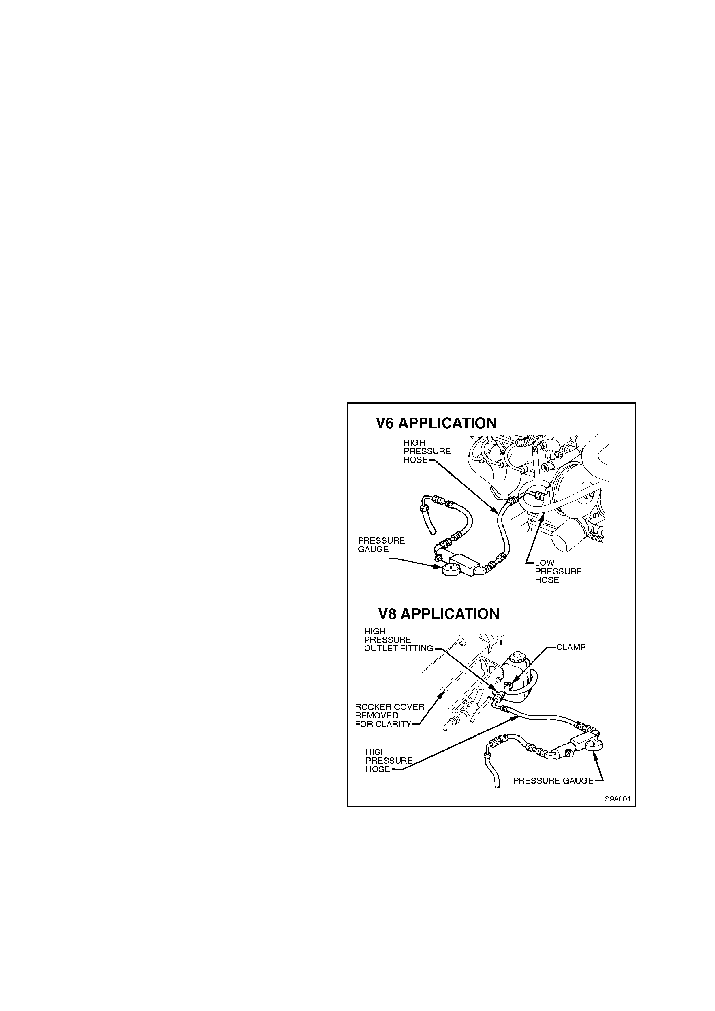
To perform the two pressure checks, it is
necessary to connect a pressure gauge assembly
into the hydraulic line between the pump and
steering gear.
PROCEDURE
1. Place a drain tray beneath the power steering
pump assembly.
2. Loosen and remove the high pressure
hydraulic line fitting and O-r ing from the power
steering pump.
3. Install pressure gauge assembly (Hose set
AU392 and Gauge assembly E1461-1 (or 9A7-
1) into the outlet fitting of the pump and the
disconnected high pressure hose fitting.
4. Refill system with fluid to the correct level,
refer to 3.1 FLUID LEVEL CHECK in this
Section. Ensure that there are no leaks at
either the hose or gauge connections.
5. Bleed air from the system, as described in the
Bleeding/Refilling Procedure, just detailed.
Figure 9A-54

TEST 1 - HYDRAULIC CIRCUIT OPEN
1. With valve open, start engine, allow to idle and with steering LIGHTLY on full lock, check connections for
leakage.
2. Insert thermometer into reservoir filler opening and move steering from lock to lock until fluid reaches 75°
Celsius.
3. Turn steering to full lock momentarily, if pressure is below 7,580 kPa (V6 application) or 8,270 kPa (V8
application), a faulty hydraulic circuit is indicated.
TEST 2 - HYDRAULIC CIRCUIT CLOSED
1. Slowly turn valve on Tool E1461-1 (or 9A7-1) to the closed position, note pressure, and quickly re-open valve
to avoid pump damage.
2. If pressure was less than 7,580 kPa (V6 application) or 8,270 kPa (V8 application), the pump may be
considered to be faulty.
3. If pressure was between 7,580 - 8,270 kPa (V6 application) or 8,270 - 8,960 kPa (V8 application), steering
gear, external hoses or connections may be considered faulty.
NOTE:
If pump proves faulty, retest after overhaul to check repairs and condition of steering gear.
4. At the completion of tests, remove pressure gauge, hoses and connectors.
5. While LIGHTLY holding the steering wheel on full lock, have an observer check for fluid leaks from the hose
connections.
The following flow chart, details an alternative procedure for checking the power steering hydraulic system.
POWER STEERING HYDRAULIC SYSTEM CHECK
STEP ACTION YES NO
1Start engine and allow to idle.
Is fluid level correct? Go to Step 2. Top up as required
and check for leaks.
Go to Step 2.
2Check fluid condition. Is fluid condition OK? Go to Step 3. Drain, flush system
and refill with fluid.
Go to Step 3.
3With valve on test gauge fully open, check pressure reading.
Is the pressure reading for standard power steering
approximately 350 kPa or:
With speed sensitive power steering, is the pressure reading
approximately 700 kPa?
Go to Step 4. Check hoses/pipes
for restriction. Repair
or replace as
necessary.
Go to Step 4.
4Is system pressure now to specification? Go to Step 5. Replace steering rack
valve assembly.
Go to Step 3.
5Close then open valve fully three times, noting the highest
pressure reading each time.
NOTE:
Do not leave valve closed for more than 5 seconds, as pump
damage could result.
Are all readings between 7,580 - 8,270 kPa (V6) or 8,270 -
8,960 kPa (V8) and within 340 kPa of each other?
Hydraulic system
is operating to
specification.
Go to Step 6.
6Are pressures within specified range but not within 340 kPa of
each other? Go to Step 7. Go to Step 9.
7Remove flow control valve and remove any burrs with crocus
cloth or fine hone.
Repeat Step 4. Are pressure readings now OK?
Hydraulic system
is now operating
to specification.
Go to Step 8.
8Remove pump, disassemble clean, reassemble and reinstall.
Repeat Step 4. Are pressure readings now within 340 kPa of
each other?
Hydraulic system
is now operating
to specification.
Go to Step 10.
9Are pressures within 340 kPa of each other but below
specified maximum range? Go to Step 10. Go to Step 5.
10 Replace flow control valve, then repeat
Step 4.
Are pressure readings now OK?
Hydraulic system
is now operating
to specification.
Overhaul or replace
power steering pump.
Go to Step 5.
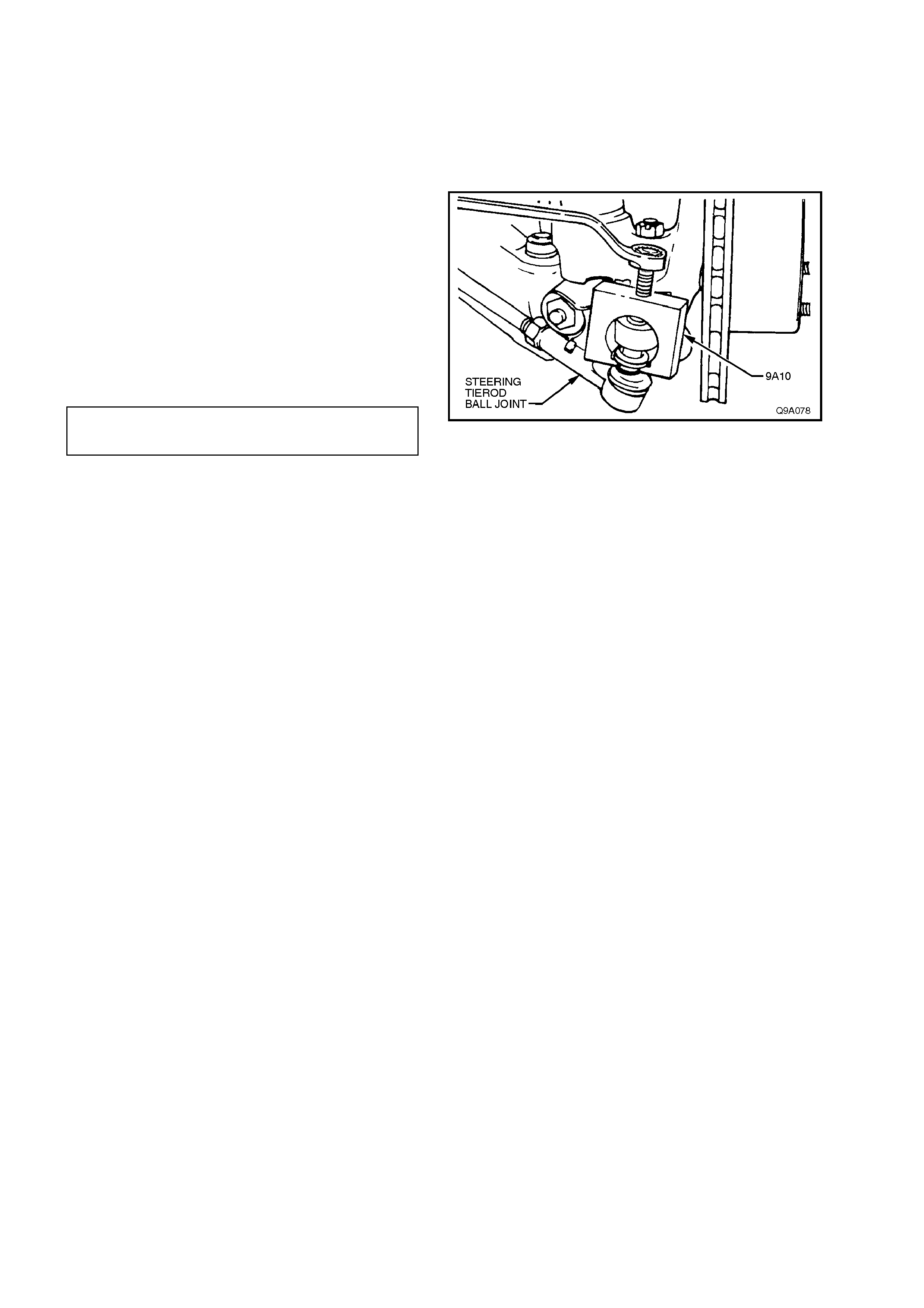
3.5 TIE ROD BALL JOINT
REPLACE
Tie rod ball j oints are ser viced as an ass embly and
must be replaced when excessive up or down
movement is evident, or if any lost motion or end
play exists at the ball end of the stud.
1. Remove split pin and nut from tie rod ball stud.
2. Using Tool No. 9A10 or similar, tighten centre
screw to force stud from taper in steering arm.
3. Loosen tie rod lock nut. Unscrew ball joint
from tie rod, counting the number of turns to
wind ball joint from tie rod.
4. Install new ball joint onto tie rod and wind on
the same number of turns as in Step 3.
5. Install ball joint to steering arm. Install
castellated nut and tighten to the correct
torque specification.
TIE ROD BALL JOINT STUD 50 - 85
TORQUE SPECIFICATION Nm
NOTE:
Ensure that the nylon spacer is positioned on the
tie rod ball joint stud before installing into steering
arm.
6. Install new split pin.
7. Check front wheel toe-in. Refer to
Section 3 FRONT SUSPENSION.
Figure 9A-55
3.6 POWER STEERING GEAR
IMPORTANT:
Remove the ignition key from the ignition lock
and ensure that the steering column is locked.
If this operation is not carried out and the
steering wheel is spun while the steering gear
is removed from the vehicle, the clock spring
coil in the upper end of the steering column will
be destroyed!
REMOVE
1. Disconnect battery earth lead.
2. Raise front of vehicle and place on safety
stands. Refer to Section 0A GENERAL
INFORMATION.
3. Remove front wheel cover (steel wheels) or
centre caps (alloy wheels)
4. Mark relationship of each wheel to hub/brake
disc. Remove road wheel attaching nuts and
remove wheels.
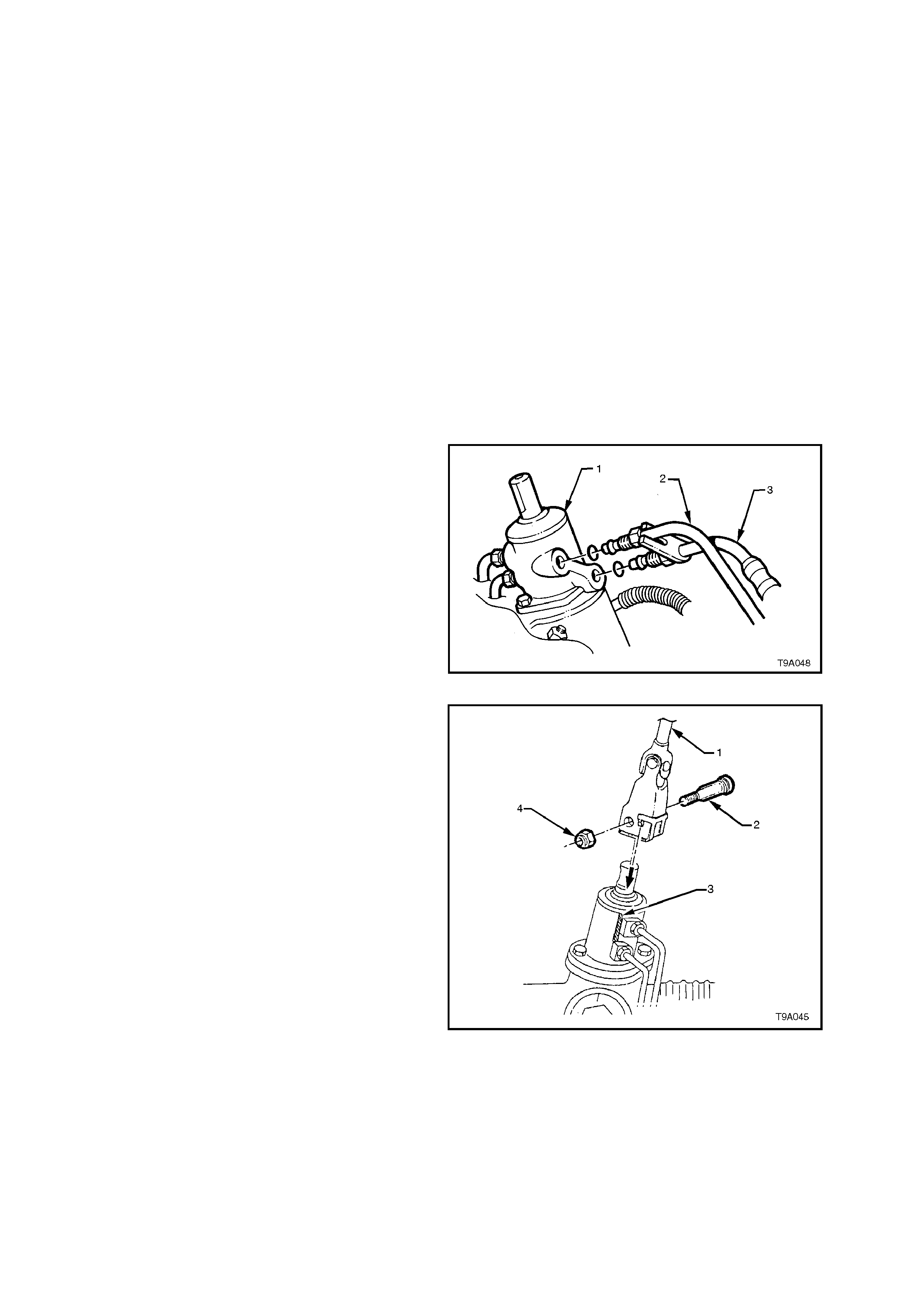
5. Place a drain tray beneath steering gear.
6. Loosen and remove hydraulic lines (2 and 3)
from steering gear valve housing ( 1) and allow
fluid to drain into a suitable container. While
the V6 engine application is shown, the V8
engined arrangement is similar.
Figure 9A-56
7. Remove steering coupling lower cam bolt (2)
nut (4), and slide coupling (1) away from
steering gear (3).
Figure 9A-57
8. Remove tie rod end split pins and castellated
nuts (’3’ in Figure 9A-59).
9. Separate tie rod end ball studs from steering
arm tapers using a suitable remover, such as
Tool No. 9A10.
Figure 9A-58
10. Remove steering gear housing to front
suspension crossmember mounting bolts (1)
and nuts (2).
11. Remove steering gear by pulling it out from
front suspension crossmember mounting (4)
and slide pinion (input) shaft (5) from steering
coupling lower clamp.
Figure 9A-59
REINSTALL
1. Ensure steering gear is centralised.
NOTE 1:
This is achieved by rotating the pinion to the
halfway position of its total lock to lock rotation.
W hen the r ack is in the stra ight ahead position, the
pinion (input) shaft will be aligned as shown.
NOTE 2:
Alternatively, remove both inner boot clamps, slide
the boots back and measure the exposed portion of
each end of the rack from the housing. W hen both
measurements are equal, the rack is centralised.
2. Ensure steering wheel is in straight ahead
position.
3. Slide steering gear pinion (input) shaft into
steering coupling lower flange.
4. Position steering gear housing into
crossmember mounting points. Install
mounting bolts, washers and nuts and tighten
nuts to the correct torque specification.
STEERING GEAR HOUSING TO
CROSSMEMBER MOUNTING 70 - 85 Nm
TORQUE SPECIFICATION
5. Inspect condition of steering gear hydraulic
line O-rings. Replace as necessary.
6. Refit hydraulic lines to steering gear valve
housing. Tighten flare nuts to the correct
torque specification.
HYDRAULIC LINE TO VALVE
HOUSING FLARE NUT 25 - 35 Nm
TORQUE SPECIFICATION
Figure 9A-60
7. Install lower cam bolt (2) and a new nut (4).
Tighten to the correct torque specification.
STEERING COUPLING CAM BOLT 23 - 30
NUT TORQUE SPECIFICATION Nm
8. Reinstall tie rod end ball studs into steering
arms. Reinstall castellated nuts and tighten to
the correct torque specification.
TIE ROD BALL JOINT STUD
CASTELLATED NUT 50 - 85 Nm
TORQUE SPECIFICATION
9. Install new split pins into tie rod ball studs.
NOTE:
Ensure plastic spacers are positioned on tie rod
end ball studs and that they are in good condition
before fitting studs into steering arms. Replace
spacers if damaged.
10. Install wheels, aligning marks made on
removal. Tighten wheel attaching nuts to the
correct torque specification.
ROAD WHEEL ATTACHING NUT 110 - 140
TORQUE SPECIFICATION Nm
11. Lower vehicle to ground and reconnec t battery
earth lead.
12. Refill and bleed hydraulic system, refer
3.3, HYDRAULIC SYSTEM,
BLEEDING/REFILLING in this Section.
13. Check front wheel toe-in setting, refer to
Section 3, FRONT SUSPENSION for details.
Figure 9A-61
1. Screw - Valve Housing Attaching
(2 places)
2. Cover - Dust
3. Housing - Valve
4. O-ring
5. Seal
6. Bearing - Roller
7. Circlip
8. Valve Assembly - Rotary
9. Seal
10. Bearing - Roller
11. Bearing - Ball
12. Nut - Pinion
13. Plug - Sealing
14. Insert - Rack Pad
15. Pad - Rack
16. Washer
17. Spring
18. Plug - Rack Pad
19. Nut - Lock
20. Housing - Steering Gear
21. Pipe - Rack Piston Fluid - Short
22. Pipe - Rack Piston Fluid - Long
23. Rack and Piston Assembly
24. Spacer - Inner Rack Seal
25. Seal - Inner Rack
26. Seal - Rack Piston
27. O-ring - Rack Piston
28. Seal - Outer Rack
29. Bushing - Rack Outer
30. Wire - Retaining
31. Rod - Tie
32. End - Tie Rod
33. Nut - Lock
34. Bellows
35. Clip - Bellows Outer
36. Strap - Bellows Inner Tie
37. Bracket - Mounting
38. Insulator - Mounting Bracket
Figure 9A-62 - Rack and Pinion Power Steering Gear
DISASSEMBLE
For identification of components, refer to Figure
9A-62.
1. Clean all dirt and foreign matter from exterior
of steering gear assembly.
2. Mount steering gear housing (1) by gripping
right hand mounting boss (2) in a vice fitted
with soft jaws.
3. Place a drain tray beneath steering gear.
Figure 9A-63
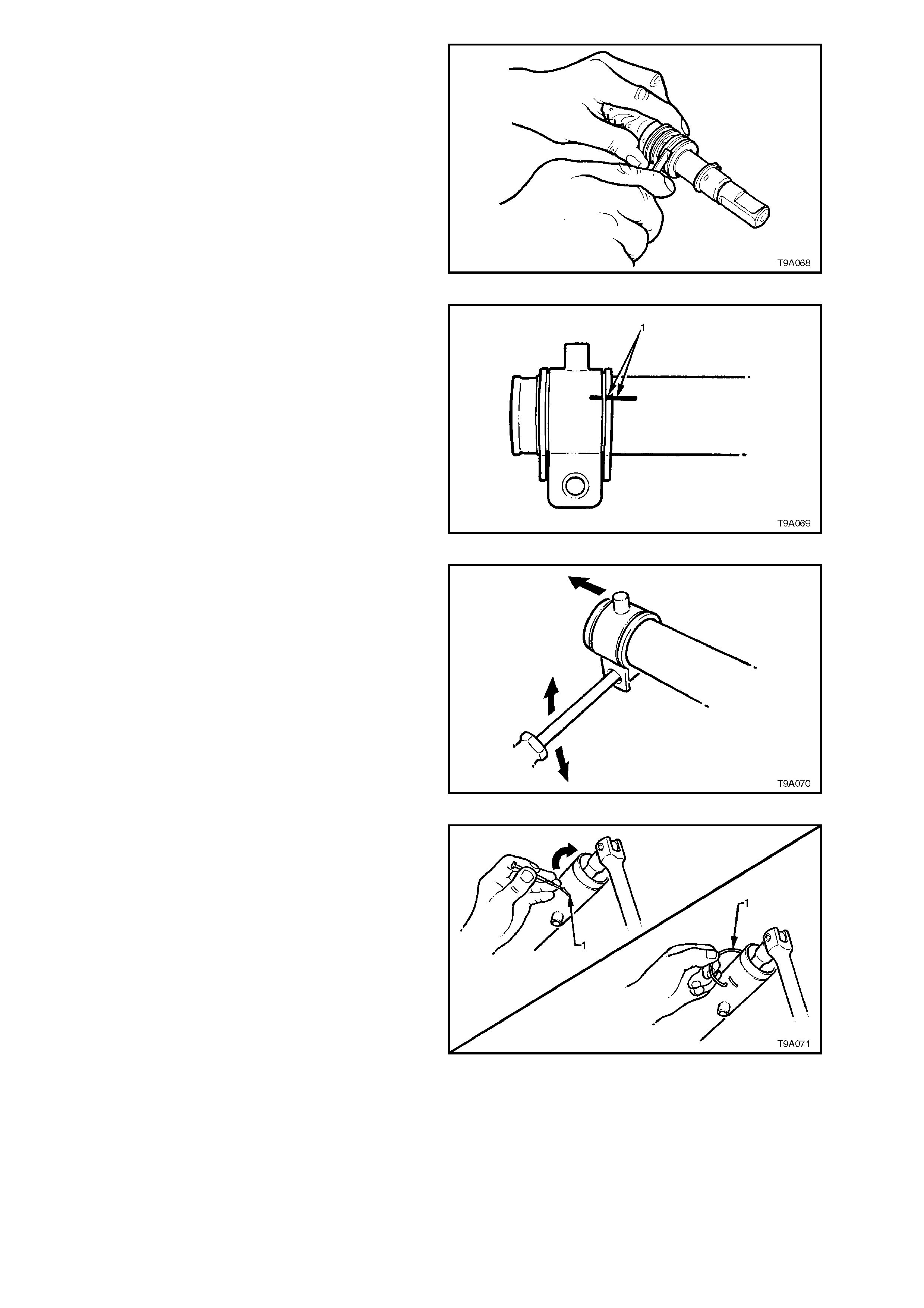
4. Unclip and remove all bellows clips.
a. To r emove outer c lips : Move ends of c lips
sideways until they disengage.
Figure 9A-64
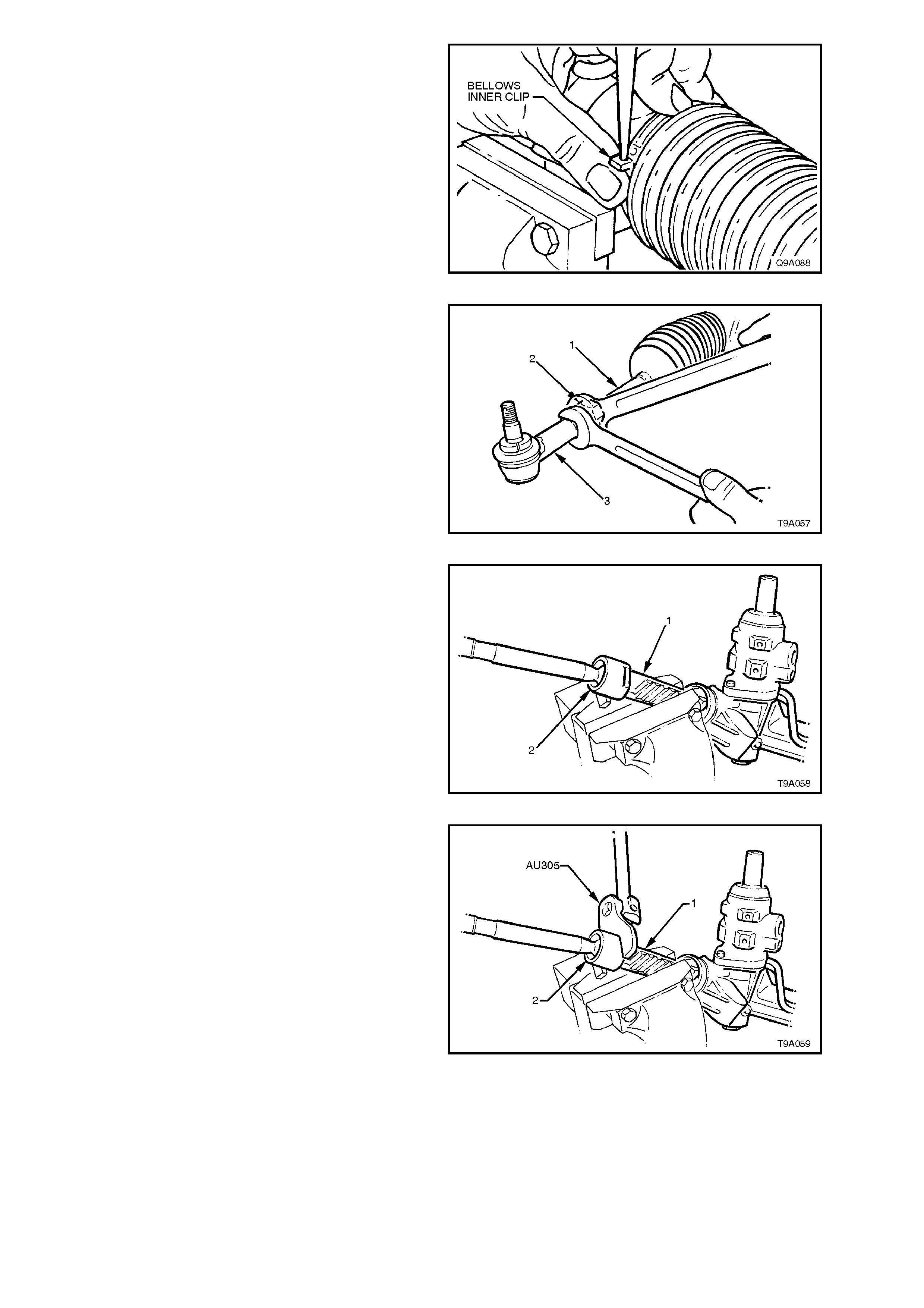
b. To remove inner clips: Push out the pin
retaining the clip ends together using a
fine pin punch.
Figure 9A-65
5. Loosen tie rod lock nuts (2). Remove tie rod
ball joints (3) and lock nuts (2) from tie rods
(1).
6. Slide bellows from steering gear housing and
tie rods.
7. Rotate pinion (input) shaft fully counter-
clockwise (full left lock).
Figure 9A-66
8. Remove steering gear housing from vice and
grip exposed tooth end of rack (1) in vice with
soft jaws.
Figure 9A-67
9. Using Tool No. AU305, loosen then tighten tie
rod ball joint housing to break the staking, then
unscrew housing from end of rack
Figure 9A-68
10. Remove housing assembly from vice and
ensure that there is no foreign matter on rack
teeth. Rotate pinion (input) shaft clockwise,
just enough to expose left hand tab washer
and tie rod.
11. Remount steering gear in vice, gripping
around exposed teeth of rack.
12. Remove left-hand tie rod assembly as in
step 9.
13. Remount steering gear housing (3) in vice
fitted with protective jaws, gripping right-hand
mounting boss.
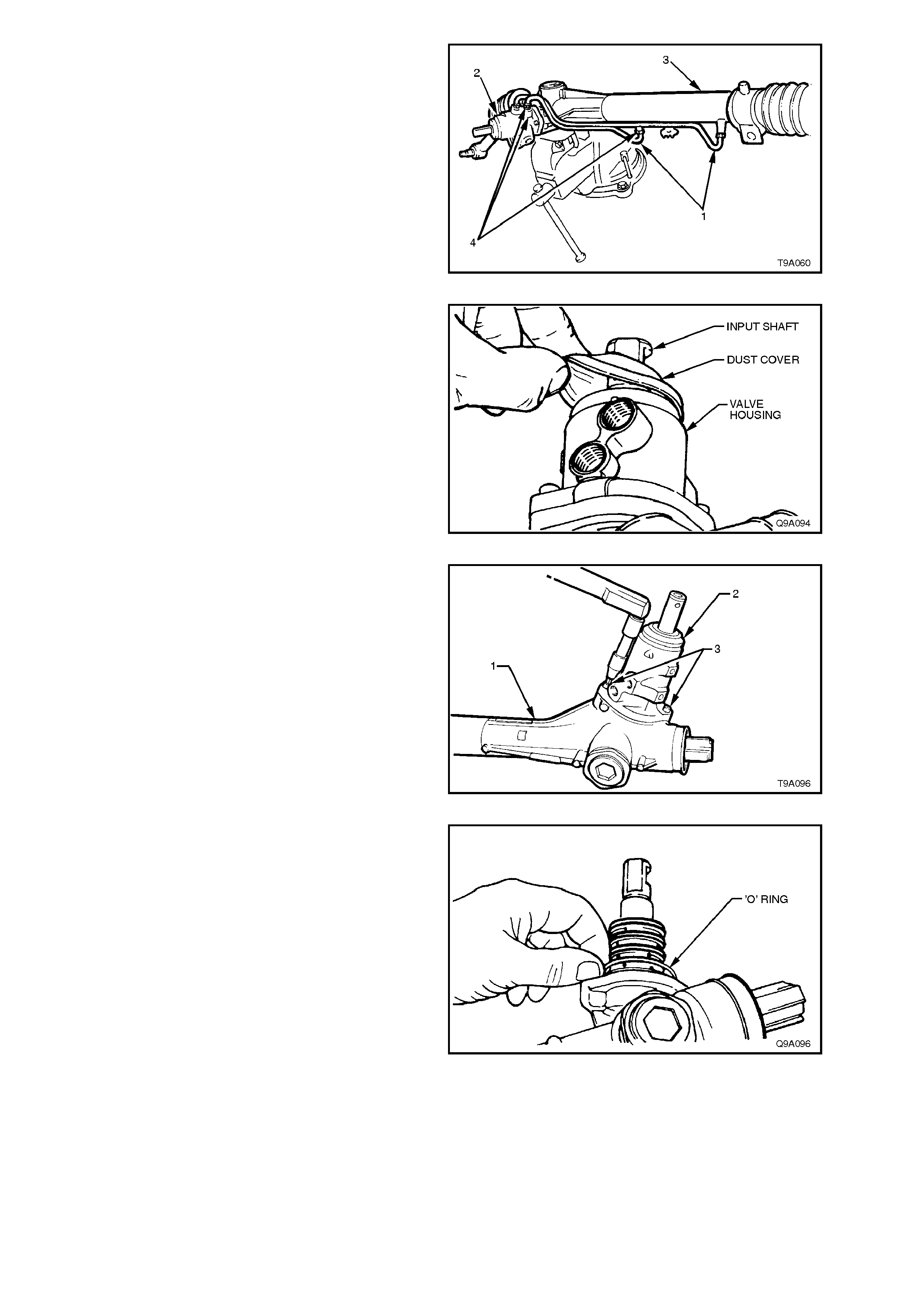
14. Disconnect feed pipes (1 and 4) from valve
housing (2) and steering gear tubing (3).
Figure 9A-69
15. Remove dust cover from valve housing and
input shaft.
Figure 9A-70
16. Using a 5 mm Allen key, remove valve
housing attaching screws (3). Withdraw valve
housing (2) from input shaft.
Figure 9A-71
17. Rem ove and discard valve hous ing to steering
gear housing O-ring.
Figure 9A-72
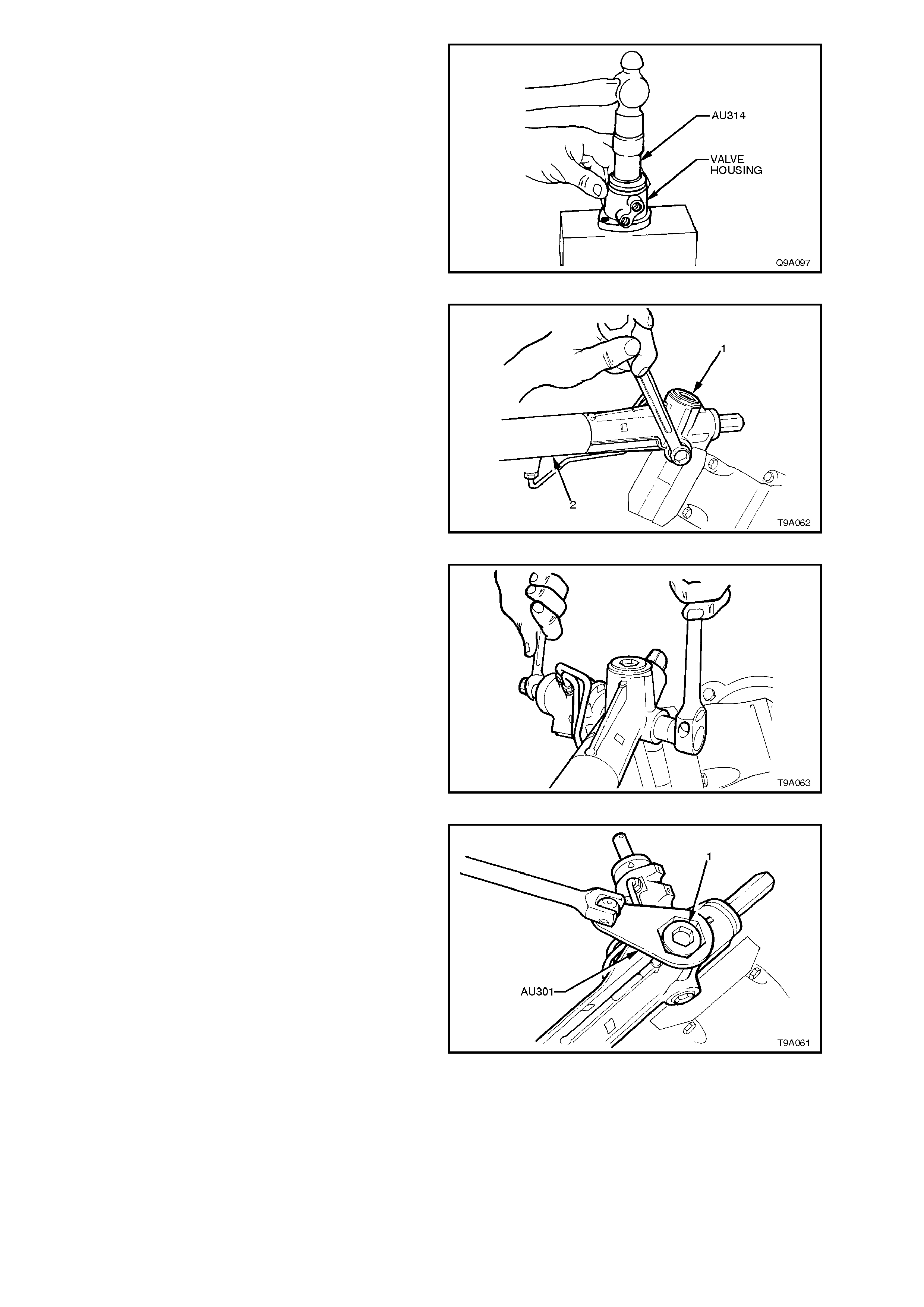
18. Place flange face of valve housing onto a
wooden block and, using Tool No. AU314,
drive valve seal and bearing from valve
housing.
NOTE:
As there is no inner race, to support them, the
needle rollers may fall out during this operation.
Figure 9A-73
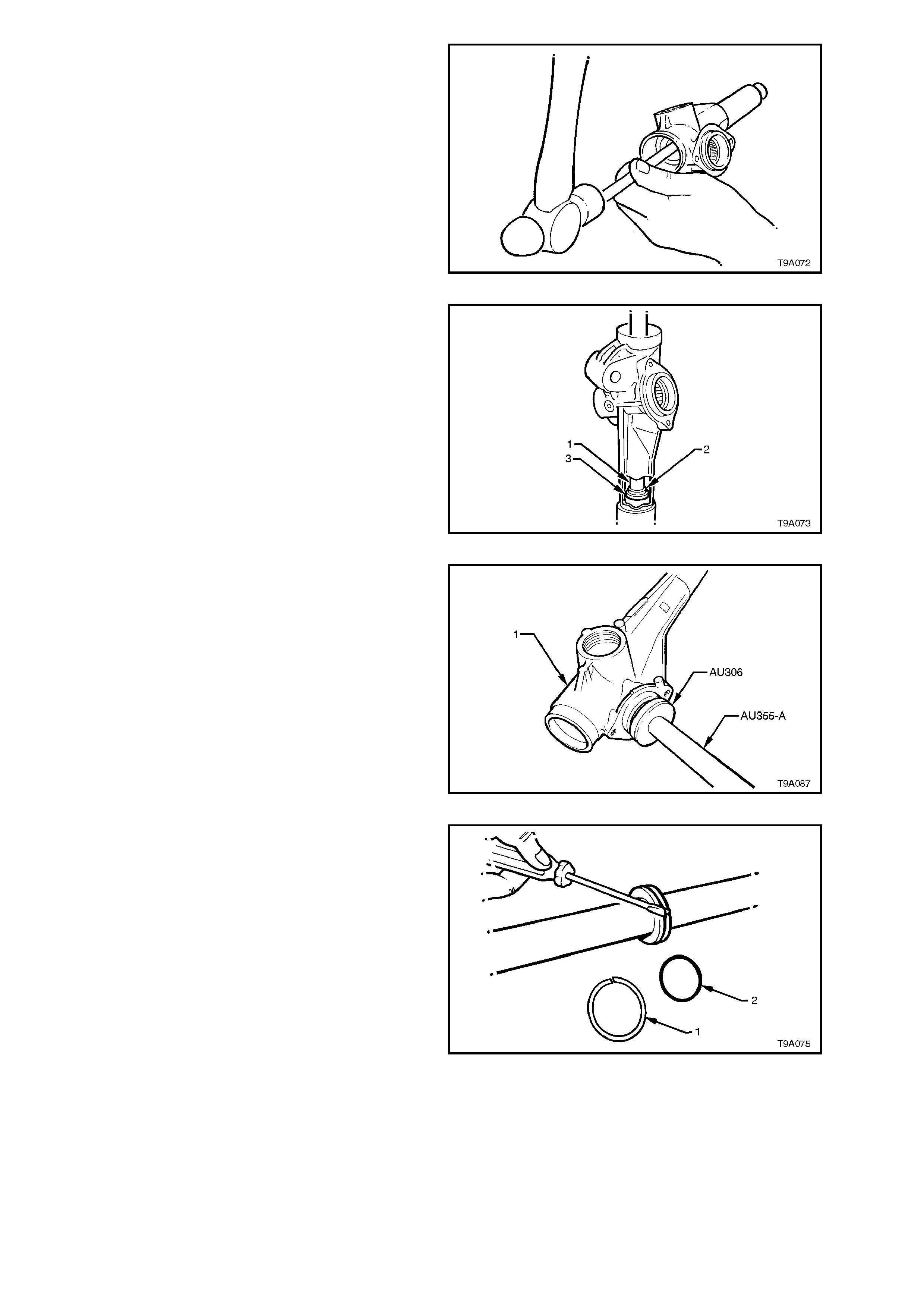
19. Remove pinion lower bearing screw plug (1)
from housing.
Figure 9A-74
20. While holding the input pinion with a set
spanner across the flats, remove pinion lower
bearing retaining nut from pinion.
Figure 9A-75
21. Remove rack pad adjuster lock nut (1) using
Tool No. AU301.
22. Rotate input shaft fully clockwise (full right
lock).
Figure 9A-76
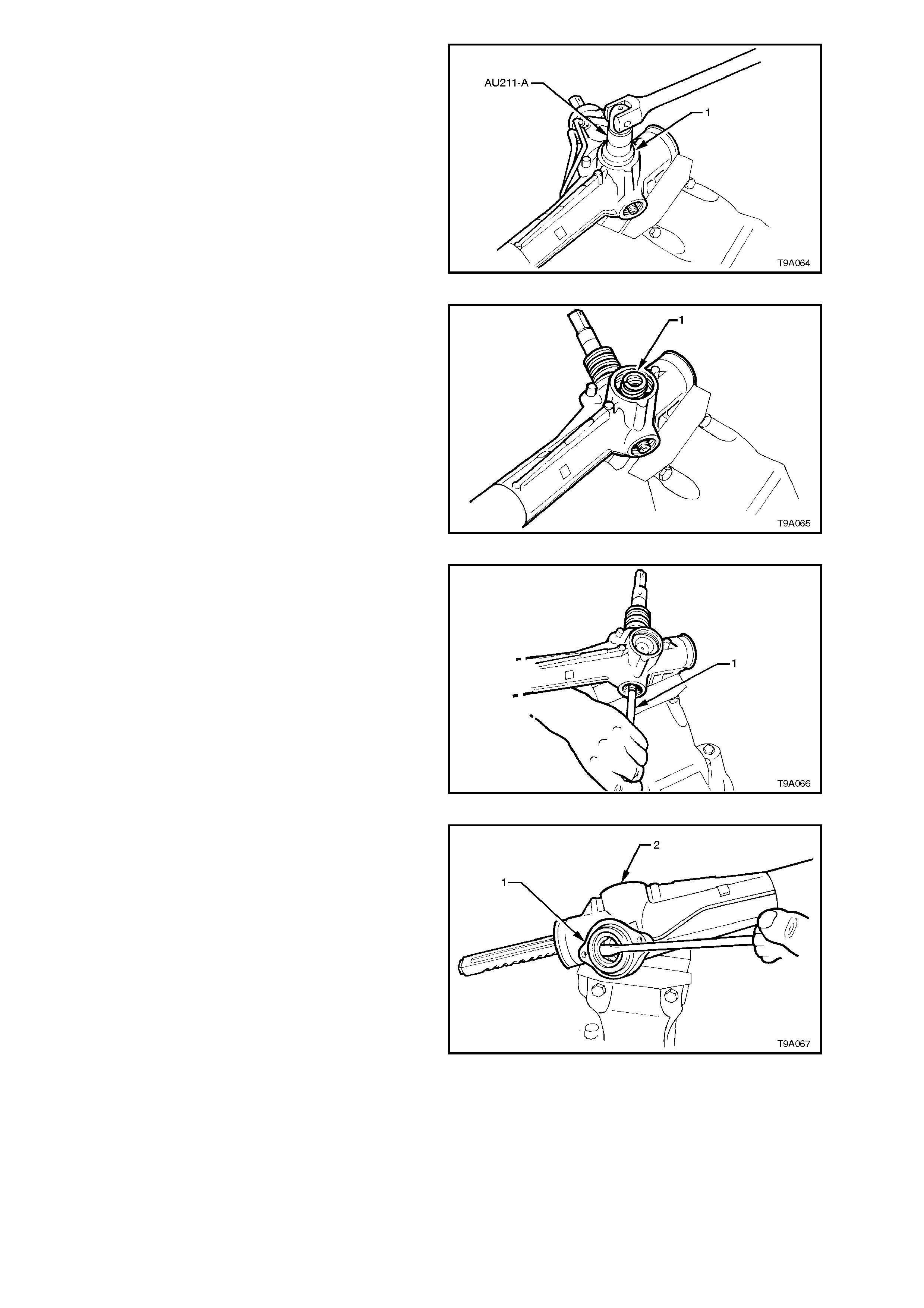
23. Loosen and remove rack pad adjuster screw
(1), using Tool No. AU211-A.
Figure 9A-77
24. Remove rack pad spring (1) and rack pad
assembly from steering gear housing.
NOTE:
It may be necessary to remove the housing from
the vice and tap gently on a wooden block to
dislodge the rack pad assembly .
Figure 9A-78
25. Using a brass drift (1) and a soft faced
hammer, gently knock on lower end of pinion
to remove pinion assembly from housing.
Figure 9A-79
26. Using a screwdriver, lever out pinion seal (1)
from housing (2). Discard seal.
NOTE:
Take care not to damage housing lip.
Figure 9A-80
27. Remove and discard PTFE rings from rotary
valve outer sleeve.
The seals are best removed by cutting
diagonally with a sharp knif e, but car e m ust be
taken to avoid scratching the sides of the
grooves otherwise subsequent leakage will
result.
NOTE:
Because of component matching that is critical to
the safe operation of the sleeve and valve
assembly, THE PINION ASSEMBLY MUST NOT
BE FURTHER DISMANTLED.
Figure 9A-81
28. Using a white marker pen or sim ilar, mark the
relative position of the left hand mounting
bracket and the steering rack tube (1).
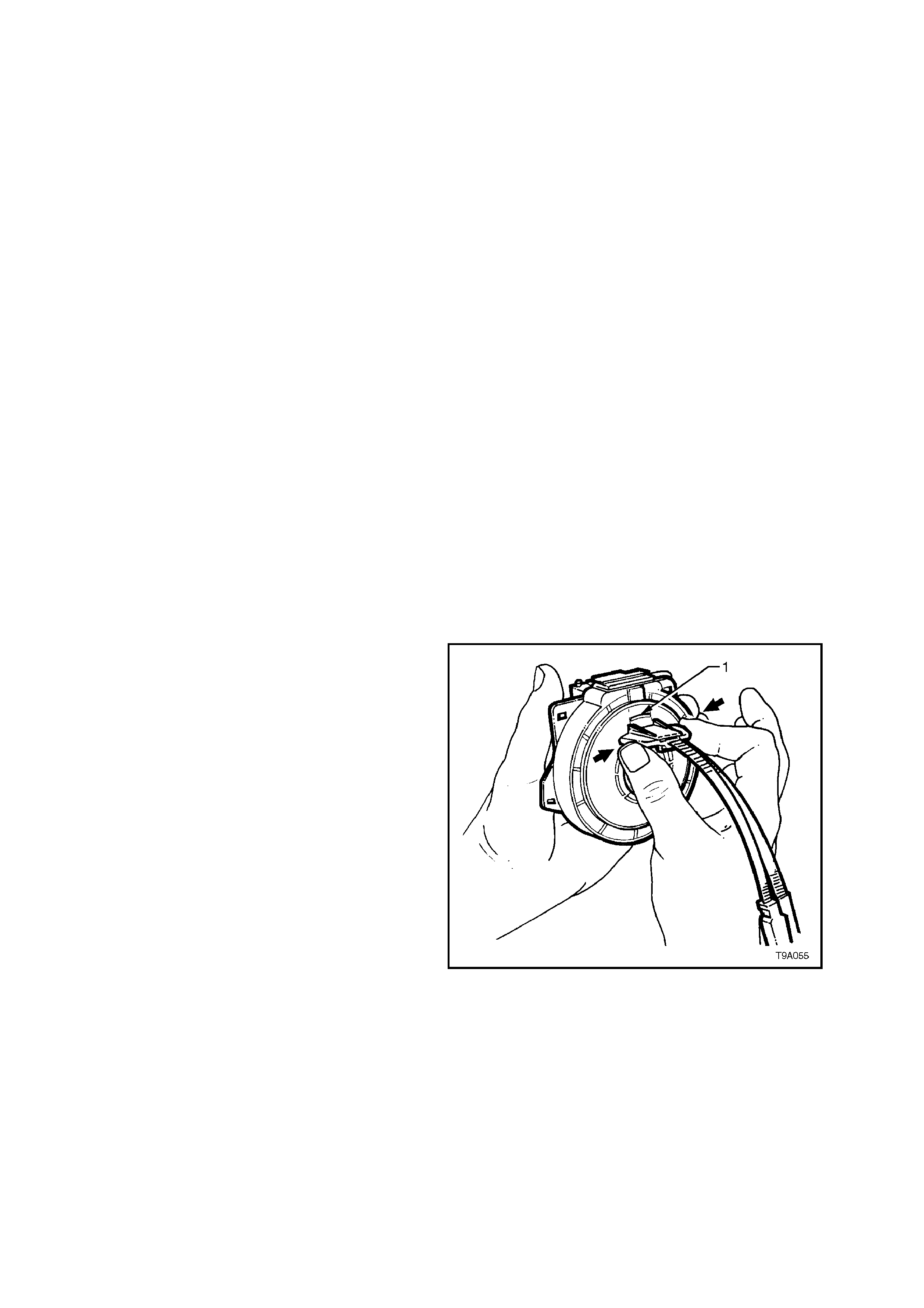
Figure 9A-82
29. Remove the left hand mounting bracket, by
using a round bar inserted through the
mounting holes and rotating the bushing and
bracket, back and forth while pulling at the
same time.
Figure 9A-83
30. Remove the rack end bushing retaining wire,
as follows:
a. Using Tool No. E8803-7 with a socket
extension and bar, rotate the rack end
bush anti-clockwise, until the end of the
retainer (1) appears in the slot.
b. Carefully prise the end of the retainer wire
free of the rack tube as shown, then
rotate the end bushing with Tool No,
E8803-7, in a clock wise direction (arrow),
winding the retainer out of the tube.
c. Continue unwinding the retainer until the
end of the retainer (1) appears, then lift it
from the slot in the rack tube. Figure 9A-84
31. Remove the rack from the housing by inserting
a brass drift into the right threaded end of the
rack and driving the rack from the tube end of
the rack housing.
NOTE:
As this action will remove the rack end bush and
the outer piston rod seal from the steering tube,
some resistance will be encountered.
Figure 9A-85
32. Insert a suitable length of tubing or mild steel
stock (1), 30 mm in diameter into the housing
from the pinion end, then use a hammer to
drive the spacer (2) and inner piston rod seal
(3) and from the rack housing.
Figure 9A-86
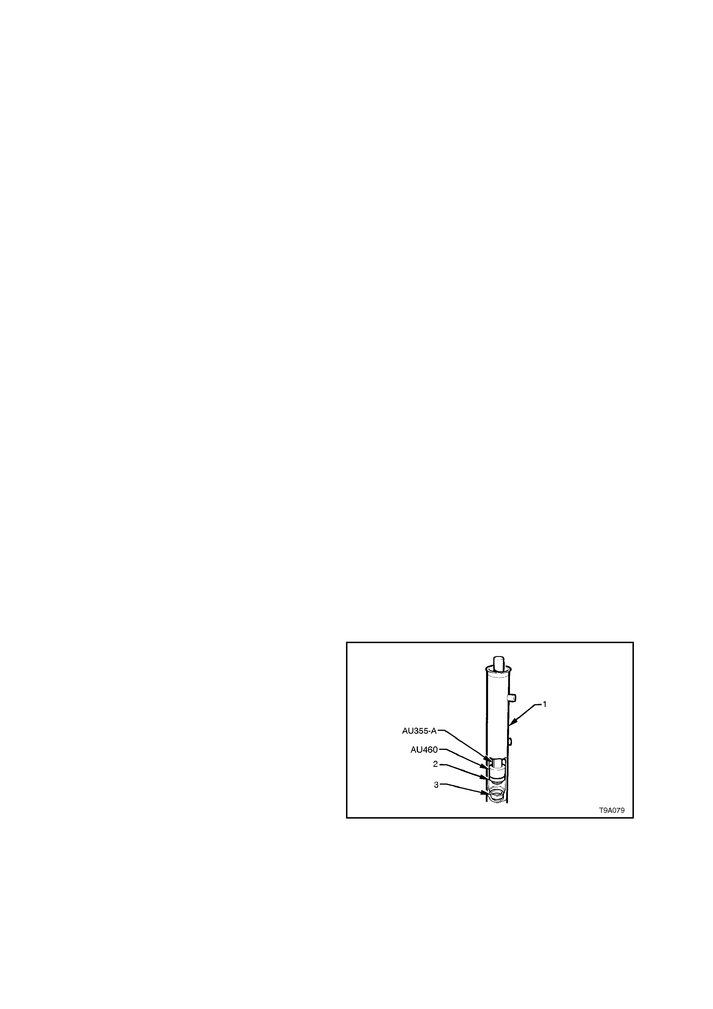
33. Remove pinion lower bearing using Tool No.
AU306 and driver handle AU355-A.
NOTE:
The pinion upper bearing cannot be removed from
the steering gear housing. If the upper bearing is
found to be damaged or has failed, then the
housing and bearing assembly must be replaced.
Figure 9A-87
34. Remove rack piston seal (1) and O-ring (2)
from the rack piston.
NOTE:
The s eal (1) c an be more eas ily rem o ved by cutting
diagonally with a sharp knife, but take care not to
scratch the sides of the seal groove, during this
process.
Figure 9A-88
CLEAN AND INSPECT
Thor oughly wash all m etal parts in cleaning solvent
and blow dry with compressed air.
1. Inspect rubber bellows for damage or
deterioration, replace if necessary.
2. Inspect pinion bearings for signs of brinelling,
damage or wear.
NOTE:
The pinion upper bearing cannot be removed from
the steering gear housing. If the upper bearing is
found to be damaged, replace the housing and
pinion upper bearing assembly.
3. Inspect pinion for signs of tooth wear or
damage.
4. Inspect rack for signs of wear or damage to
teeth, rack pad faces and rack bearing journal.
NOTE:
A light polish on teeth and rack rear face is norm al
and should not be confused with wear.
5. Inspect housing for wear or damage in pinion
bearing bores, seal bores, rack piston and
lock stop faces.
6. Inspect rack pad for damage or excessive
wear.
7. Inspect m ajor components of pinion assem bly
(pinion, valve, sleeve and torsion bar) for
damage or wear.
NOTE:
Thes e parts cannot be serviced individually as they
are hydraulically balanced at the pinning stage of
assembly to equalise the steering efforts in right
and left directions.
REASSEMBLE
1. Check that each of the rack seals have a
circular, plastic insert ring fitted to each, on the
opposite side to the spring loaded seal lip, with
the tapered edge of the ins ert facing in toward
the seal. Ensure the taper ed ends of the rings
seat correctly.
2. Screw Tool No. AU460 onto driver handle Tool
No. AU355-A with the O-ring end facing out.
Install the inner seal spacer (3) onto Tool No.
AU355-A, using the O-ring to hold the spacer
in place. Insert the tools and spacer into the
rack tube.
3. Using tool combination AU460/AU355-A,
press the seal s pacer (3) into the rack hous ing
(1), until the end of Tool No. AU355-A
protrudes f rom the rac k tube by approxim ately
53 mm . This m easurement will ensur e that the
spacer has been fully installed.
4. Reverse the fitment of Tool No. AU460 to the
driver handle Tool No. AU355-A.
5. Lubricate a new rack inner seal (2) with
Dexron® III autom atic trans miss ion f luid. Install
the seal (2) over the spigot of T ool No. AU460,
ensuring that the spring loaded sealing lip is
facing Tool No. AU460.
6. Press seal into the rack housing (1) on top of
the spacer (3). The seal will be fully installed
when the end of Tool No. AU355-A protrudes
from the rack tube by approximately 60 mm.
Figure 9A-89

7. Install a new O-ring to groove in rack piston.
8. After dipping a new Teflon seal ring in clean
power steering fluid, install the seal ring over
expander Tool No. E8803-9.
Figure 9A-90
9. With the seal ring still installed on Tool No.
E8803-9, slide the ass em bly over the rack and
up to the piston. Slide the seal ring (1) off the
expansion tool and into the piston groove (2),
over the O-ring.
Figure 9A-91
10. Ensure that the seal is seated correctly in the
groove, by wrapping fingers around the seal,
as shown.
Figure 9A-92
11. Install protector sleeve, Tool No. AU456 over
the toothed end of the rack and liberally apply
clean power steering fluid to the protector’s
outer surface.
12. Liberally apply clean power steering fluid to the
inner surface of the rack tube and over the
rack piston seal.
13. Carefully install the rack and protector into the
rack housing and through the inner seal,
aligning the rack teeth with the pinion bore.
Continue installation until the rack piston has
entered the smaller, inner tube diameter.
Remove the seal protector, Tool No. AU456
from the toothed end of the rack. Figure 9A-93
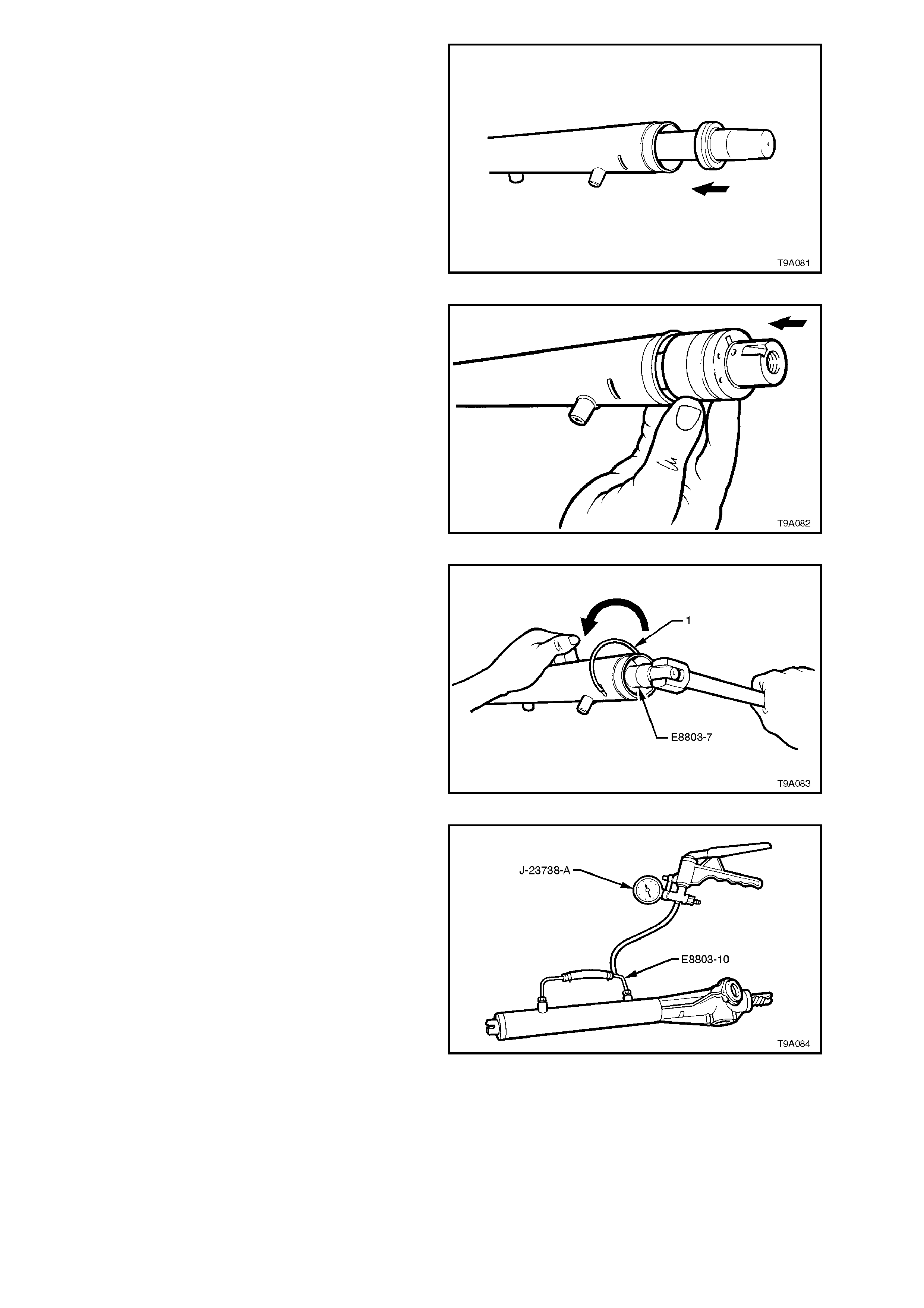
14. Again install seal protector E8803-6 over the
end of the rack at the plain end.
Liberally apply clean power steering fluid to the
lip surface of the outer rack seal, then install
over the protector and onto the rack, with the
seal lips facing in towards the rack piston.
Figure 9A-94
15. Lubricate the left hand end bearing, inner
surface, with clean power steering fluid, then
install into the rack tube, pushing in against
the outer rack seal.
NOTE:
To assist in installation of the bearing retaining
wire, align the hole in the bearing with the opening
in the steering housing tube.
16. Using installer Tool No. E8803-11, install the
outer seal and bearing until the retaining wire
groove is aligned with the slot in the rack
housing tubing.
Figure 9A-95
17. If necessary, rotate the end bearing with Tool
No. E8803-7, until the hole in the wire groove
appears in the tube slot.
Install the bent end of the bearing retaining
wire, into the hole then, continuing to use Tool
No. E8803-7, rotate the bearing in an anti-
clockwise direction until the end of the wire
disappears into the rack tubing.
Figure 9A-96
18. Install Tool No. E8803-10, to the two cylinder
pipe fittings. Tighten the unions just sufficient
to effect an air tight seal.
19. Using a hand vacuum pum p, s uch as T ool No.
J-23738-A, apply a vacuum of 53.3 k Pa (or 40
cm, 15.75 in. Hg), for approximately 30
seconds.
20. Check that no change in the vacuum occurs
during this period. If a change does occur,
then the reason must be found and corrected
before proceeding further.
Figure 9A-97

21. Check the mounting bracket insulator for
serviceability. Apply petroleum jelly (Vaseline
or equivalent) to the inner surface, then install
bracket and insulator to the steering tube, in
the reverse manner to removal. Align the
marks mark prior to removal.
Figure 9A-98
22. Centralise the rac k as sembly by m easuring 82
± 1 mm from the lock stop (flange inside rack
housing) to the end of the toothed rack (1), as
shown.
Figure 9A-99
23. Lubricate a new pinion upper seal with
Dexronâ III automatic transmission fluid, then
fit to Tool No. AU315, that has driver handle
AU355-A attached. Press s eal into plac e in the
valve housing (1).
24. Lubricate the upper pinion bearing with EP
Semi Fluid Lithium Base O Grease and fit to
Tool No. AU315, that has driver handle
AU355-A attached. Press bearing into valve
housing until fully seated.
Figure 9A-100
25. To fit new PTFE seal rings into sleeve
grooves, f irst warm in hot water then install on
expander, Tool No. 9A23.
Slide expanding tool with ring installed, over
the sleeve, then push the seal off and into the
sleeve groove. Repeat for remaining three
seals.
Figure 9A-101
26. After all seals have been fitted to the sleeve
grooves, push T ool No. AU440 over rings and
valve assembly (1), then leave for 5-10
minutes to contract rings back to normal size.
Figure 9A-102
27. Insert 50 grams of EP Semi Fluid Lithium
Base O Gr eas e into the st eering gear hous ing,
through the pinion bore.
28. Using Tool No. AU313, install a new seal into
the steering gear housing (1), fully seating the
seal in its bore.
Figure 9A-103
29. W hile maintaining rack in centralised position,
insert pinion so that the clamp bolt flat of input
shaft is positioned as shown, when pinion is
fully located in housing.
Figure 9A-104
30. Pack pinion lower bearing with EP Semi Fluid
Lithium Base O Grease. Reinstall pinion lower
bearing using Tool No. AU307.
NOTE:
Tool No. AU307 screws onto end of pinion and
pinion lower bearing is f ully installed when T ool No.
AU307 cannot be screwed onto pinion any further.
Remove AU307 when bearing is installed.
Figure 9A-105
31. Reinstall rack pad insert to rack pad. Reinstall
rack pad assembly into the steering gear
housing.
32. Reinstall rack pad spring (1) and plastic
washer.
Figure 9A-106
33. Screw lock nut onto adjusting screw. Install
adjusting screw into steering gear housing.
Leave lock nut loose.
34. Install pinion lower bearing retaining nut and
tighten to the correct torque specification.
PINION LOWER BEARING
RETAINING NUT 35 - 45 Nm
TORQUE SPECIFICATION
NOTE:
This is a deformed thread lock nut and may be
reused once only. However, it is recommended that
a new nut is fitted at each overhaul. Figure 9A-107
35. Apply Loctite 242 thread sealant (or equivalent
to Holden's Specification HN1256) to the
cleaned threads of the pinion lower s crew plug
(1) and tighten to the correct torque
specification.
PINION LOWER RETAINING
SCREW PLUG 55 - 60 Nm
TORQUE SPECIFICATION
Figure 9A-108
36. Install new O-ring (2) onto lip of steering gear
housing (1).
Figure 9A-109
37. Slide valve housing (2) over input shaft and
locate onto lip of steering gear housing (1).
NOTE:
Care must be taken to ensure PTFE sleeve seals
and valve seal are not cut or deformed during this
process.
38. Reinstall and tighten valve housing retaining
screws (3) to the correct torque specification.
VALVE HOUSING RETAINING 5 - 6
SCREW TORQUE SPECIFICATION Nm
Figure 9A-110
39. Reconnect feed pipes (1 and 4) to valve
housing (2) and steering gear tubing (3) and
tighten pipe flare nuts to the correct torque
specification.
FEED PIPE FLARE NUT 15 - 25
TORQUE SPECIFICATION Nm
NOTE:
The longer of the two pipes (LH lock) is installed
into the upper location on the valve body housing,
while the shorter (RH lock) is installed into the
lower. Figure 9A-111
40. With steering rack in centralised position,
tighten rack pad adjusting screw (1) using Tool
No. AU211-A to specified torque.
RACK PAD ADJUSTING SCREW 10 - 12
INITIAL TORQUE SPECIFICATION Nm
Figure 9A-112
41. Using angle wrench, Tool No. E7115, turn
rack pad adjusting screw back ( anti-clockwise)
20 - 28°.
Figure 9A-113
42. Install Tool No. AU316 to input shaft and
meas ure rotating torque of input shaf t, using a
dial type torque wrench, by cycling the steering
gear back and forth. Torque requirements are
from 0.8 to 2.5 Nm.
Figure 9A-114
43. Apply Loctite 242 thread sealant (or equivalent
to Holden's Specification HN1256) to the
cleaned threads of the rack pad plug lock nut.
44. While holding adjusting screw in above
position with Tool No. AU211-A and a socket
bar, tighten lock nut to the correct torque
specification using Tool No. AU301 and a
torque wrench.
RACK PAD ADJUSTING SCREW
LOCK NUT 55 - 65 Nm
TORQUE SPECIFICATION
NOTE:
Once the rack pad adjustment has been set and
the lock nut torqued to specification, the steering
gear must be racked from lock-to-lock to ensure
localised wear has not appreciably affected the
setting. The gear should not bind or appear tight
over any part of the total travel. Should gear bind or
appear tight, rechec k rack pad adjus tm ent. If this is
not the cause, strip gear assembly and examine
rack and pinion for wear. Replace as necessary.
Figure 9A-115
45. Rotate pinion shaft fully anti-clockwise (left
lock).
46. Remove steering gear housing from vice, and
grip exposed toothed end of rack in vice with
soft jaws.

47. Using Tool No. AU305, tighten right-hand tie
rod to the correct torque specification.
TIE ROD END HOUSING 90 - 100
TORQUE SPECIFICATION Nm
48. Using centre punch and hammer, stake rack
to tie rod ball joint housing.
49. Remove steering gear housing from vice and
rotate pinion shaft slightly clockwise, just
enough to expose the left hand end of rack.
50. Tighten left hand tie rod as in steps 47 and 48.
51. Relocate steering gear housing in vice by
gripping right hand mounting boss.
52. Rotate input shaft to straight ahead position.
Install dust cover onto input shaft.
53. Refit bellows to tie rods and steering gear
housing. Reinstall retaining clips.
54. Refit tie rod ball joint lock nuts and tie rod ball
joints to tie rods.
NOTE:
Do not tighten lock nuts, as toe-in adj ustment m ust
be performed when steering gear is reinstalled.
Figure 9A-116
55. Reinstall steering gear assembly into the
vehicle, as detailed In 3.6 POWER
STEERING GEAR in this Section.
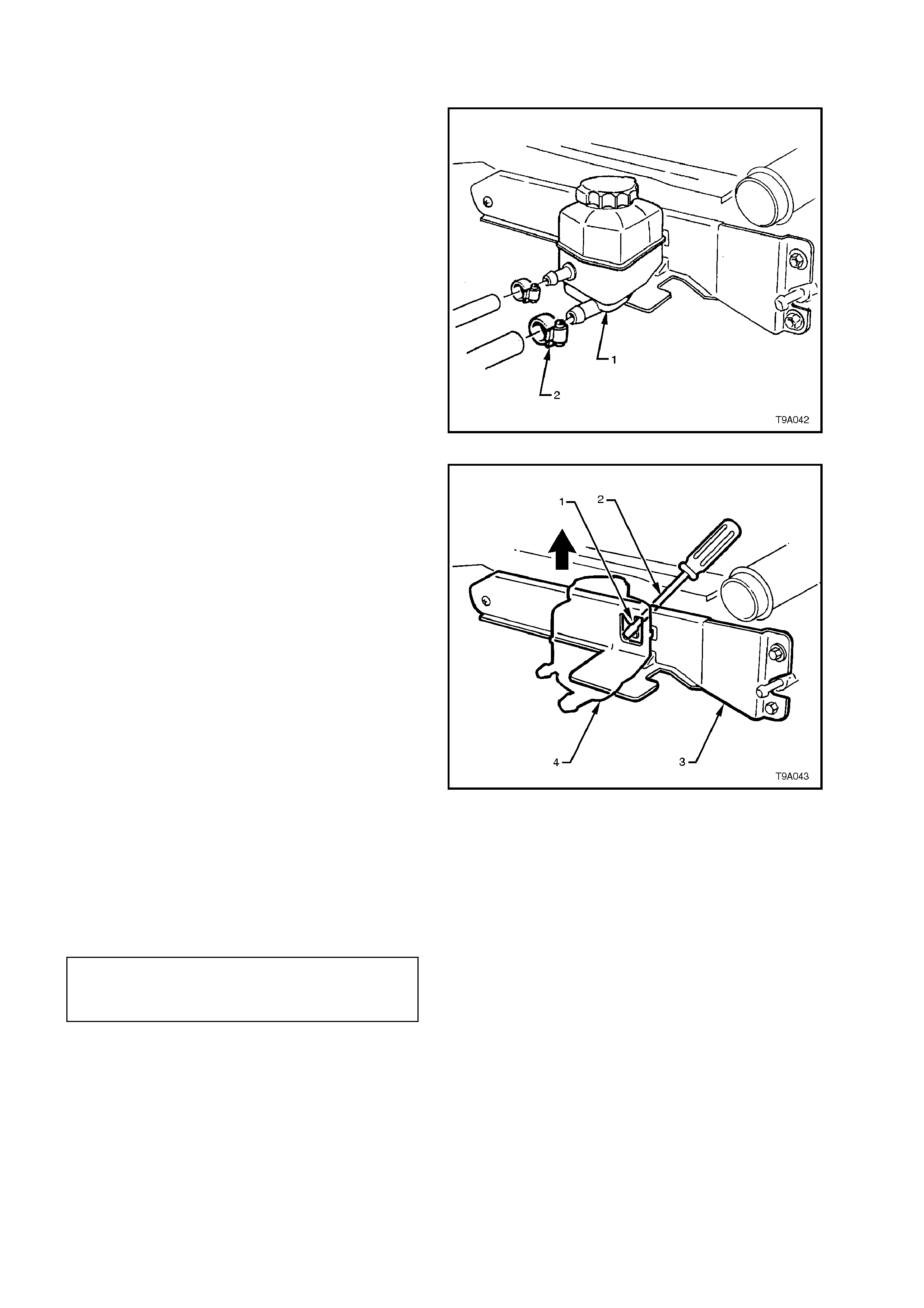
3.7 FLUID RESERVOIR-V6 ENGINE
REMOVE
1. Place a drain tray beneath reservoir assembly.
2. Loosen hose clamps and remove the two
hoses from the reservoir.
NOTE:
Cover or tape the hose ends to prevent
contamination ingress.
Figure 9A-117
3. Using a suitable lever such as a screwdriver,
gently lever locking tang back towards the
radiator and lift the reservoir up and out of the
retaining bracket.
4. If required, remove the two hexagon headed
screws and one self tapping screw securing
the bracket to the radiator, then remove the
bracket.
Figure 9A-118
REINSTALL
Reinstallation is the reverse to rem oval operations,
noting the following points:
1. Tighten the reservoir retaining bracket screws
to the correct torque specification.
RESERVOIR RETAINING BRACKET
ATTACHING SCREW 3 - 7 Nm
TORQUE SPECIFICATION
2. Refill and bleed the hydraulic system. Refer to
3.3 HYDRAULIC SYSTEM -
BLEEDING/REFILLING in this Section.
3. Start the engine and check f or fluid leak s f rom
the reservoir area.
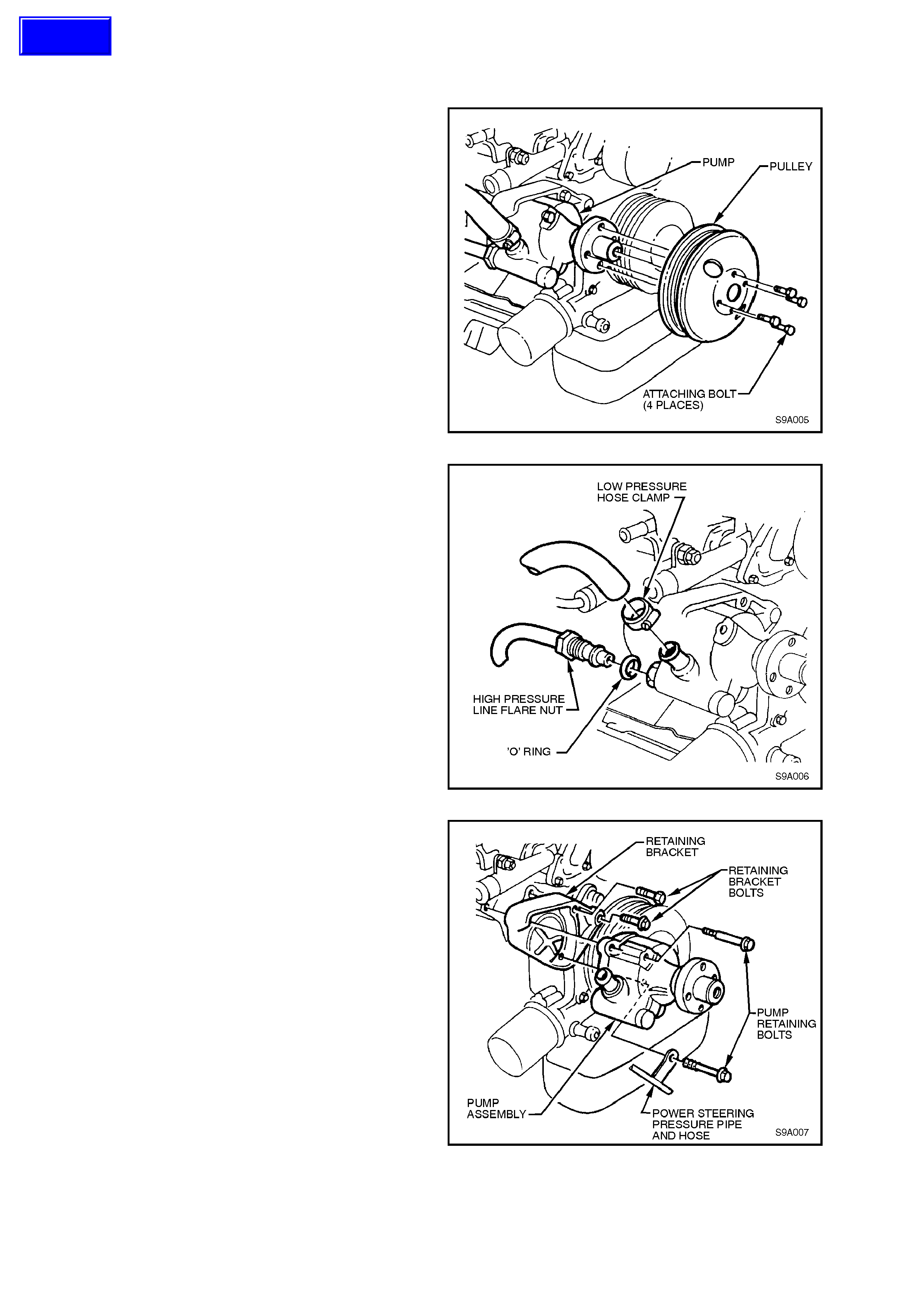
3.8 POWER STEERING PUMP-V6 ENGINE
REMOVE
1. Disconnect battery earth lead.
2. Loosen the four power steering pump pulley
attaching bolts (Do not remove at this stage).
3. Using an 15 mm ring spanner on drive belt
tensioner pulley pivot bolt, rotate tensioner
pulley anti-clockwise and remove drive belt
from pump pulley. Release tensioner pulley.
4. Remove pump pulley attaching bolts and
pulley.
Figure 9A-119
5. Place a drain tray beneath power steering
pump assembly.
6. Loosen and remove high pressure line flare
nut and O-ring from pump outlet fitting.
7. Loosen low pressure hose clamp and remove
hose from reservoir.
NOTE:
Cover or tape the pump and hose f ittings to prevent
contamination ingress.
Figure 9A-120
8. Remove the two power steering pump
retaining bolts and remove the pump from the
retaining bracket.
9. If required, remove the two bolts securing the
retaining bracket to the cylinder block, then
remove the bracket.
Figure 9A-121
Techline
REINSTALL
Installation of the power steering pump is the
reverse of r emoval pr ocedur es , noting the f ollowing
points:
1. Tighten retaining bracket to cylinder block
retaining bolts to the correct torque
specification.
PUMP RETAINING BRACKET 30 - 40
BOLT TORQUE SPECIFICATION Nm
2. Tighten the two pump to retaining bracket
attaching bolts to the correct torque
specification.
PUMP TO RETAINING BRACKET 30 - 40
BOLT TORQUE SPECIFICATION Nm
3. Tighten the four pum p pulley attaching bolts to
the correct torque specification.
PUMP PULLEY BOLT 20 - 30
TORQUE SPECIFICATION Nm
4. Install new sealing O-r ing to high pressu re line
connection. Lubricate sealing ring with
Dexron® III automatic transmission fluid prior
to installation.
5. Refill and bleed hydraulic system, refer to
3.3 HYDRAULIC SYSTEM -
BLEEDING/REFILLING in this Section.
6. Start engine and check for fluid leaks around
pump and reservoir area.
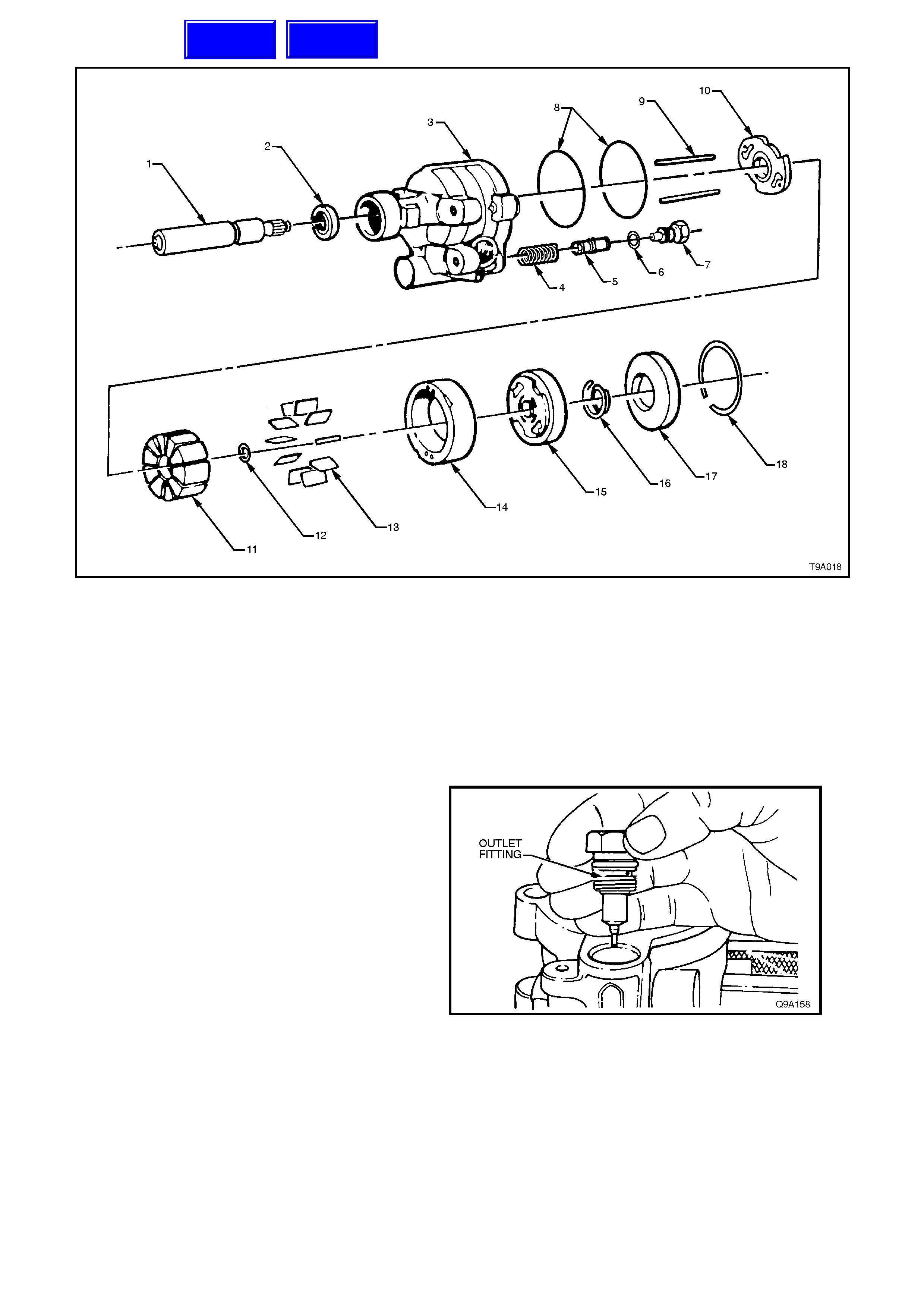
DISASSEMBLE
1. Shaft - Pump Drive
2. Seal - Pump Drive Shaft
3. Housing Assembly - Pump
4. Spring - Flow Control Valve
5. Valve - Flow Control
6. O-Ring, Outlet Fitting
7. Fitting, Outlet
8. O-Rings - Pressure and End Plates
9. Dowel Pins, Pump Ring
10. Plate - Thrust
11. Rotor
12. Ring - Shaft Retaining
13. Vanes - Pump
14. Ring - Pump
15. Plate - Pressure
16. Spring - Pressure Plate
17. Plate - End
18. Ring - End Plate Retaining
Figure 9A-122 ‘N’ Series Pump Assembly (V6 Engine)
1. Tilt pump assembly up and allow fluid to drain
from pump.
2. Remove drive belt pulley hub refer to
3.10, POWER STEERING PUMP PULLEY
HUB - V6 ENGINE in this Section.
3. Clamp pump, with rear surface uppermost, in
vice fitted with sof t jaws. Do not use ex cessive
force or pump body will be distorted.
4. Remove outlet fitting and associated O-ring.
Take care as spring loaded flow control valve
will thrust outlet fitting from pump housing.
Figure 9A-123
Techline
Techline
5. Remove end plate retaining ring. Compress
retaining ring by pushing with a small punch
through hole in pump housing, then remove
ring with screwdriver. Hold hand over ring as
end plate is spring loaded and may spring out.
NOTE:
It may be necessary to slide the retaining ring
around with a screwdriver, until one end is close to
the access hole.
Figure 9A-124
6. Remove end plate. A slight rocking motion or
light tapping with a soft faced hammer will
force plate if it should stick.
7. Remove end plate spring.
8. Remove end plate O-ring from pump housing
and discard.
9. Remove pump from vice and invert to remove
flow control valve and spring.
10. Clean exposed end of drive shaft to remove
any dirt or rust. This will prevent damage to
shaft bush that m ight requir e the housing to be
replaced.
Figure 9A-125
11. Tap shaft very lightly until shaft, pressure
plate, pump ring, rotor assembly and thrust
plate can be removed as a unit.
12. Disassemble parts just removed. Refer Figure
9A-122 for relationship details. Remove vanes
from rotor. Remove rotor from shaft after
removing retaining ring from shaft. Discard
ring.
Figure 9A-126
13. Remove pressure plate O-ring from pump
housing and discard.
14. Remove dowel pins.
Figure 9A-127
15. Pry shaft seal from pump housing with a
screwdriver . Take c are not to damage hous ing
bore. Discard seal.
Figure 9A-128
CLEAN AND INSPECT
Clean all metal parts in solvent, air dry and inspect
as follows:
1. Flow control valve m ust slide f reely in housing
bore. If s tick ing is obs erved, c heck f or dirt and
burrs.
2. Check cap screw in end of flow control valve
for looseness: if loose, tighten being careful
not to damage machined surfaces.
3. Be sure that pressure plate and thrust plate
surfaces are flat and parallel with pump ring.
Check for cracks and scoring.
NOTE:
A high polish is always present on rotor, pressure
plate and thrust plate as a result of normal wear.
Do not confuse this with scoring.
4. Ensure vanes move freely in rotor slots.
5. If the flow control plunger is suspected of
being faulty, install a new component. This
part is serviced as a unit only and is factory
calibrated.
6. Check drive shaft for worn splines, breaks,
bush material pick-up, etc.
7. Using a piece of wire, probe through shaft seal
relief hole to check for blockage.
8. Always replace all seals and O-rings when
pump is disassembled.
REASSEMBLE
1. Install a new shaft s eal in pum p hous ing using
Tool No. E1460-1 (or 9A6-1). Lubricate seal
lips with Dexron® III automatic transmission
fluid.
Figure 9A-129
2. Reinstall thrust plate on shaft with ported face
towards splined end of shaft.
Figure 9A-130
3. Reinstall rotor, which must be free on shaft
splines, with countersunk side towards thrust
plate.
4. Install a new shaft r etaining ring. Plac e r ing on
end of shaft and use a 10 mm socket to tap
ring into place. Ensure ring is correctly seated
in groove.
Important:
Do not use a C-ring to replace the full
circumference clip ring.
5. Reinstall dowel pins in pump housing.
6. Lubricate new pressure plate O-ring with and
install in pump housing.
7. Clamp pump housing, cavity uppermost, in a
vice with soft jaws. Do not clamp with
excessive force.
8. Reinstall shaf t, thrust plate and rotor ass em bly
into housing, aligning thrust plate holes with
dowel pins.
Figure 9A-131
9. Reinstall pump ring onto dowel pins with
identifying three dots (arrow) facing
uppermost. There are four holes in the pump
ring, the smaller holes are the dowel pin holes.
10. Reinstall vanes into rotor slots.
11. Lubricate outer circumference and chamfer of
pressure plate with Dexron® III automatic
transmission fluid to prevent damage to O-
ring. Reinstall pressure plate on dowel pins
with ported face toward pump ring such that
narrow slots engage dowel pins.
12. Seat pressure plate by placing a large socket
on top of plate and pressing down by hand.
Plate will travel approximately 2 mm to seat.
13. Reinstall pressure plate spring on pressure
plate.
14. Lubricate new end plate O-ring with Dexron®
III automatic transmission fluid and install in
housing groove.
Figure 9A-132
15. Lubricate outside circumference and chamfer
of end plate with transmission fluid to avoid
damaging the O-ring and reinstall end plate.
16. Reinstall end plate retaining ring. Locate end
of ring near hole in housing.
17. Reinstall flow control spring and plunger (hex
head end first) into pump housing.
18. Lubricate outlet f itting O-ring with transm ission
fluid, install on outlet fitting. Install outlet fitting
and tighten to the correct torque specification.
POWER STEERING PUMP OUTLET 50 - 102
FITTING TORQUE SPECIFICATION Nm
19. Reinstall pump pulley hub, refer to
3.10 POWER STEERING PUMP PULLEY
HUB - V6 ENGINE in this Section.
Figure 9A-133
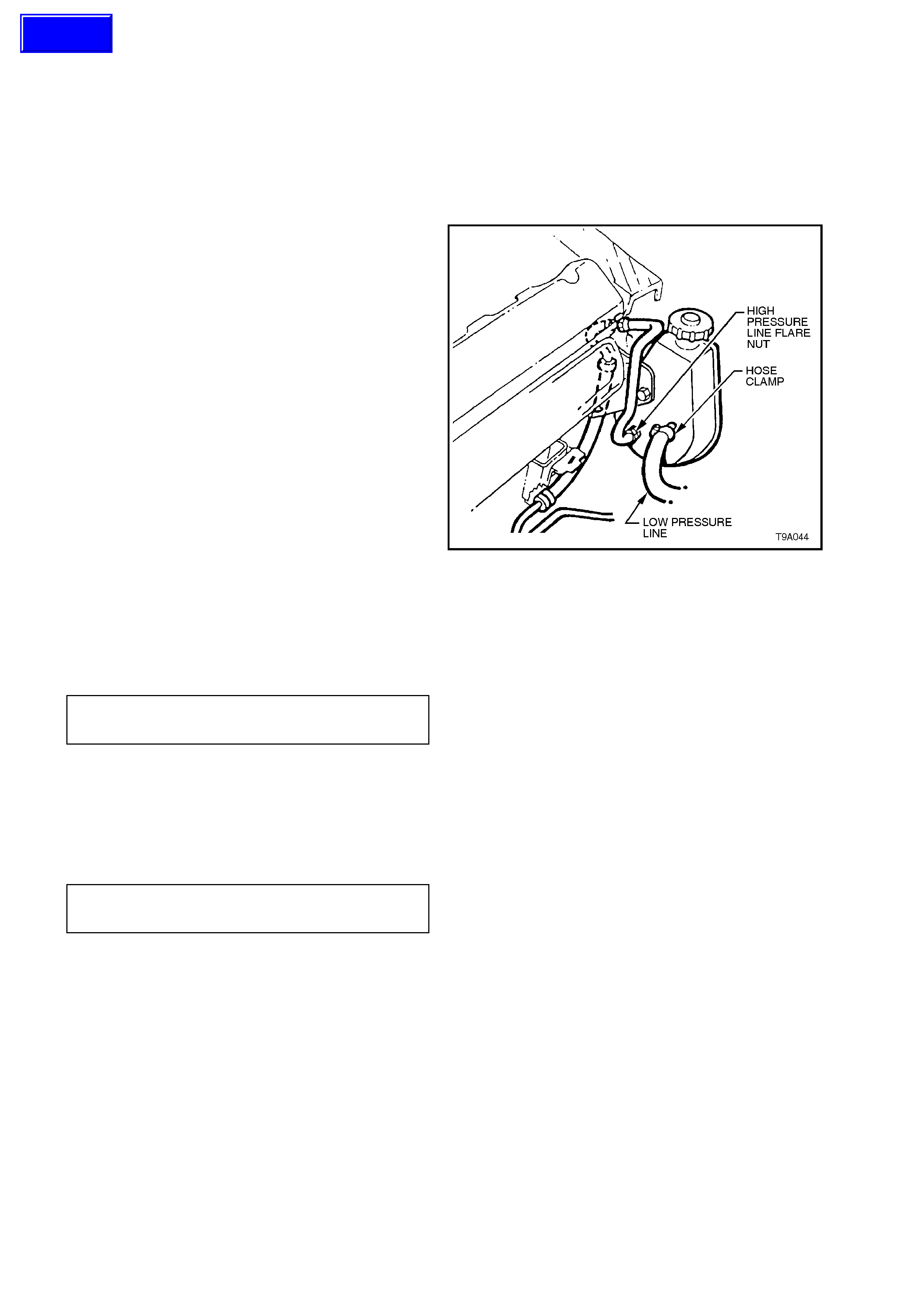
3.9 POWER STEERING PUMP - V8 ENGINE
REMOVE
1. Loosen power steering pump idler pulley lock
nut, loosen off drive belt adjustment, then
rem ove belt fr om pulleys. Refer to 3.2 DRIVE
BELT ADJUSTMENT - V8 ENGINE in this
Section.
2. Place a drain tray under the pump assembly.
3. Disconnect hoses at pump. Note view shown
is the arrangement for the V8 engine, without
ABS. Secure hose ends in a raised position to
prevent oil loss. Cap or tape hose ends and
pump fittings to prevent foreign matter entry.
4. Remove bolts securing pump to mounting
bracket and remove pump.
Figure 9A-134
REINSTALL
1. Reinstall pump on mounting bracket and
tighten pump mounting bolts to the correct
torque specification.
PUMP MOUNTING BOLT 35 - 65
TORQUE SPECIFICATION Nm
2. Reconnect hoses to pump and tighten. Use a
new O-ring on the high pressure pipe and
lubricate with Dexron® III automatic
transmission fluid. Tighten high pressure
fitting to the correct torque specification.
HIGH PRESSURE FITTING 25 - 35
TORQUE SPECIFICATION Nm
3. Fill reservoir with fluid and turn pulley anti-
clock wise (as view from f ront) until air bubbles
cease to appear. Top up fluid level as
necessary.
4. Reinstall drive belt and adjust, refer to
3.2 DRIVE BELT ADJUSTMENT - V8
ENGINE in this Section.
5. Bleed hydraulic system, refer to
3.3 HYDRAULIC SYSTEM,
BLEEDING/REFILLING PROCEDURE in this
Section.
Techline
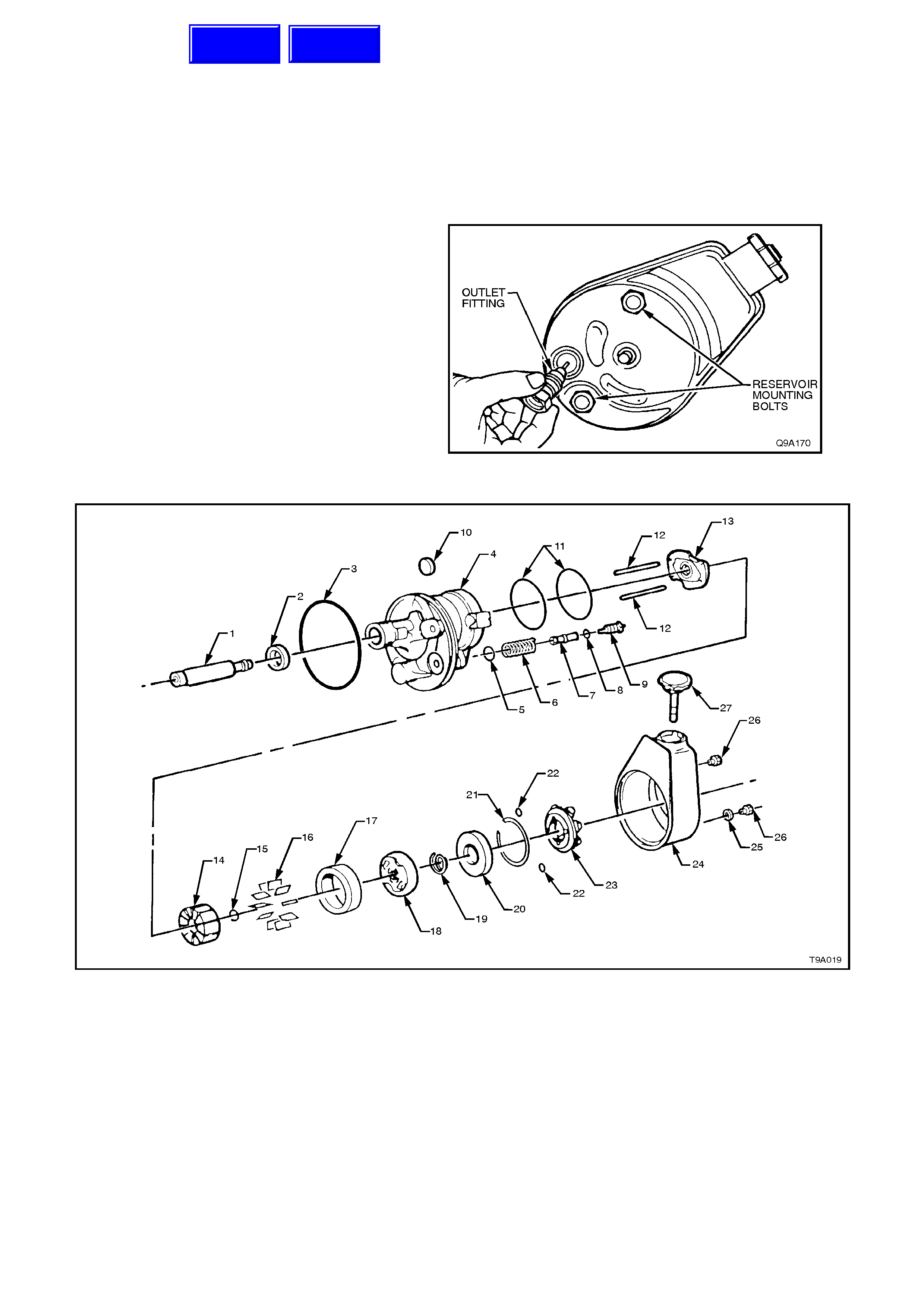
DISASSEMBLE
1. Remove reservoir cap and drain fluid from
reservoir.
2. Remove drive belt pulley, refer to
3.11, POWER STEERING PUMP PULLEY -
V8 ENGINE in this Section.
3. Clamp pum p, res ervoir upper most, in vic e with
soft jaws. Do not use ex cess ive forc e or pum p
will be distorted.
4. Remove outlet fitting and associated O-ring.
Take care as spring loaded flow control valve
will thrust outlet fitting from pump housing.
5. Remove reservoir mounting bolts.
6. Remove reservoir from pump housing by
tapping on outer edge of reservoir with soft
faced hammer.
Figure 9A-135
1. Shaft - Pump Drive
2. Seal - Pump Drive Shaft
3. O-Ring - Reservoir Body
4. Housing Assembly - Pump
5. O-Ring - Flow Control Valve
6. Spring - Flow Control Valve
7. Valve - Flow Control
8. O-Ring - Outlet Fitting
9. Fitting - Outlet
10. Magnet
11. O-Rings - End and Pressure Plates
12. Dowel Pins, Pump Ring
13. Plate, Thrust
14. Rotor
15. Ring - Shaft Retaining
16. Vanes - Pump
17. Ring - Pump
18. Plate - Pressure
19. Spring - Pressure Plate
20. Plate - End
21. Ring - End Plate Retaining
22. O-Ring Seal - Reservoir Bolt
23. Filter Assembly
24. Reservoir Assembly
25. Spacer Washer - Rese rvoir
26. Bolt - Reservoir
27. Cap and Indicator Assembly - Reservoir
Figure 9A-136 ‘P’ Series Pump Assembly (V8 Engine)
Techline
Techline
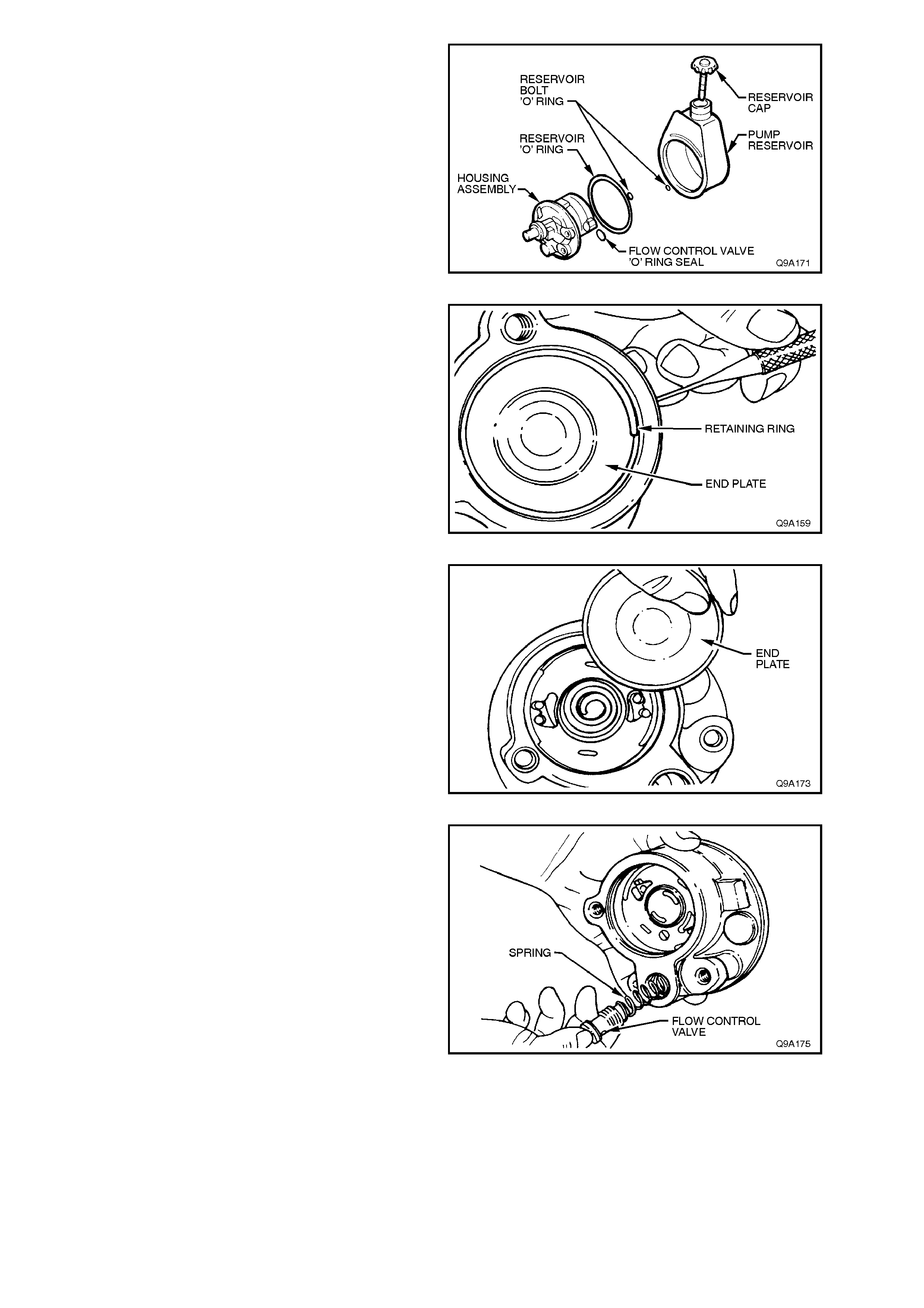
7. Remove reservoir O-ring from pump housing
and discard. Remove mounting bolt seals and
flow control valve seal and discard.
8. Note location of magnet on pump housing
flange. Remove magnet from housing.
Figure 9A-137
9. Remove end plate retaining ring. Compress
retaining ring by pushing with a small punch
through hole in pump housing, then remove
ring with screwdriver. Hold hand over ring as
end plate is spring loaded and may spring out.
Figure 9A-138
10. Remove end plate. A slight rocking motion or
light tapping with a soft f aced ham m er will free
plate if it should stick.
11. Remove end plate O-ring from housing and
discard.
12. Remove end plate spring.
Figure 9A-139
13. Remove pump f rom vice and invert to rem ove
flow control valve and spring.
Figure 9A-140
14. Clean exposed end of drive shaft to remove
any dirt or rust. This will prevent damage to
shaft bush that may require replacement of
housing assembly.
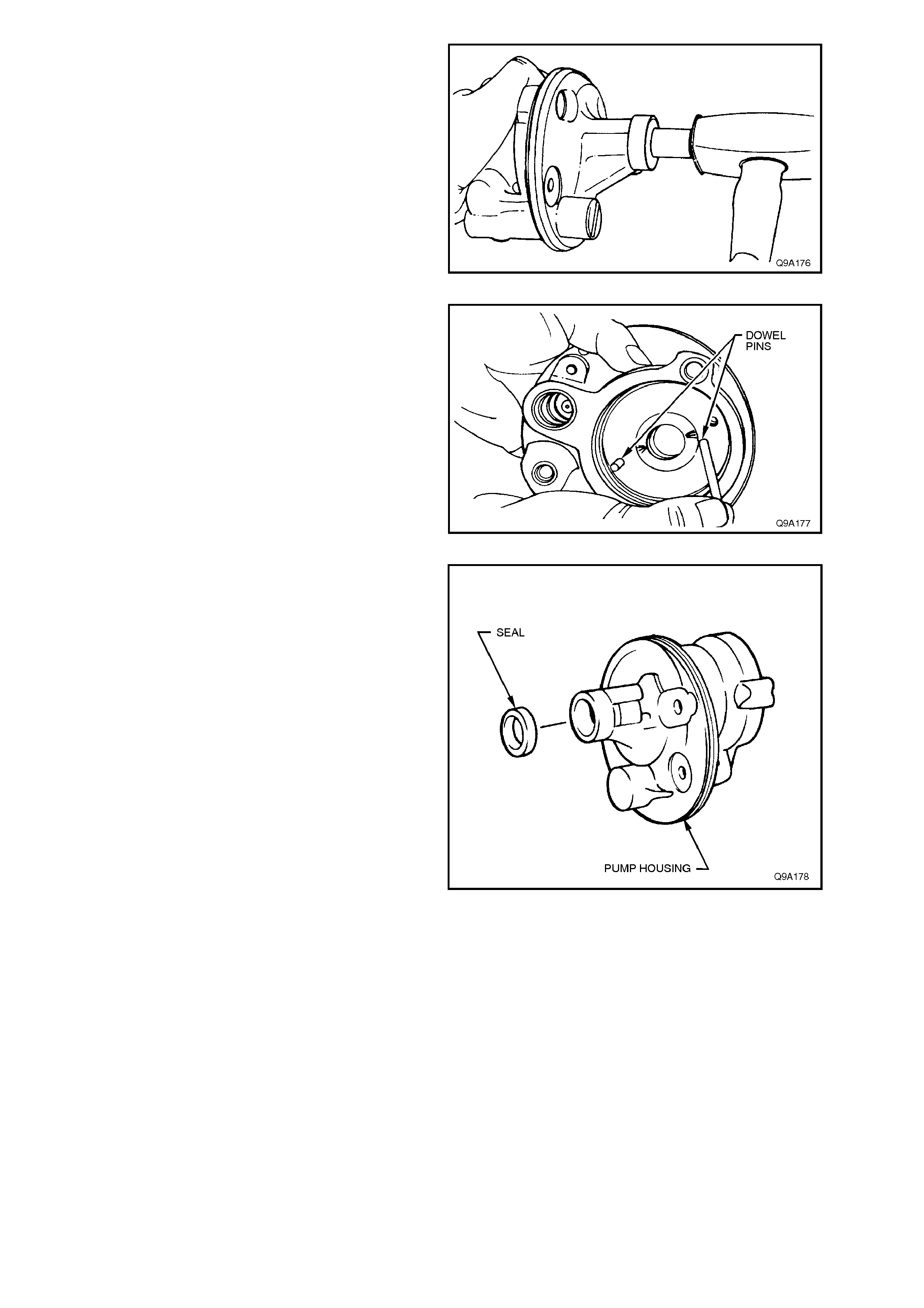
15. Tap shaft very lightly until shaft, pressure
plate, pump ring, rotor assembly and thrust
plate can be removed as a unit.
16. Disassem ble parts just removed. Refer Figure
9A-136 for relationship details. Remove vanes
from rotor. Remove rotor from shaft by
removing retaining ring from shaft. Discard
ring.
Figure 9A-141
17. Remove pressure plate O-ring from pump
housing and discard.
18. Remove dowel pins.
Figure 9A-142
19. Pry shaft seal from pump housing with a
screwdriver . Tak e care not to dam age housing
bore. Discard seal.
Figure 9A-143
CLEAN AND INSPECT
Clean all metal parts in solvent, air dry and inspect
as follows:
1. Flow control valve m ust slide f reely in housing
bore. If s tick ing is obs erved, c heck f or dirt and
burrs.
2. Check cap screw in end of flow control valve
for looseness: if loose, tighten being careful
not to damage machined surfaces.
3. Be sure that pressure plate and thrust plate
surfaces are flat and parallel with pump ring.
Check for cracks and scoring.
NOTE:
A high polish is always present on rotor, pressure
plate and thrust plate as a result of normal wear.
Do not confuse this with scoring.
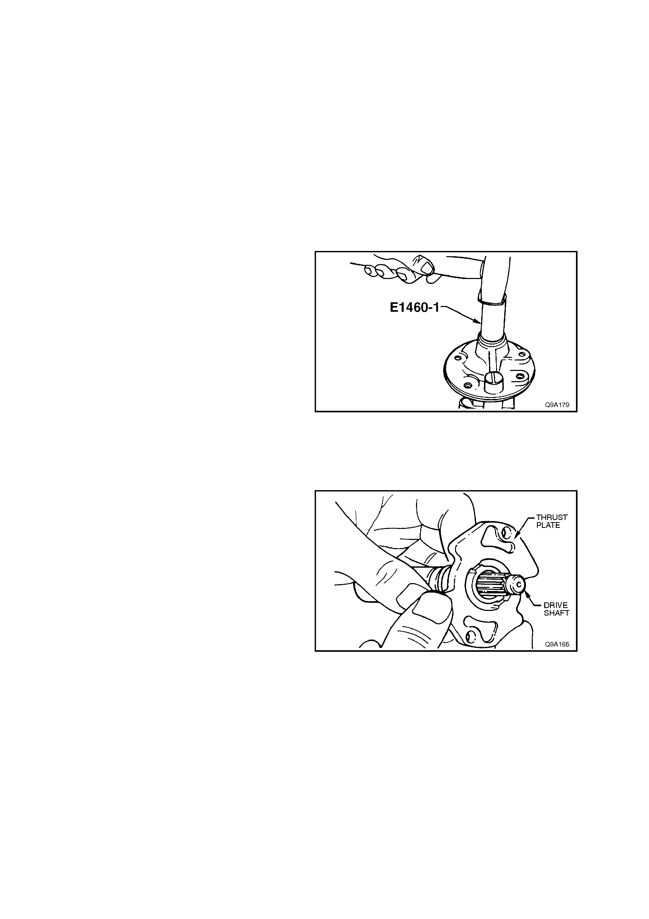
4. Ensure vanes move freely in rotor slots.
5. If the flow control plunger is suspected of
being faulty, install a new component. This
part is serviced as a unit only and is factory
calibrated.
6. Check drive shaft for worn splines, breaks,
bush material pick-up, etc.
7. Using a piece of wire, probe through shaft seal
relief hole to check for blockage.
8. Always replace all seals and O-rings when
pump is disassembled.
9. Check reservoir, bolts, casting, etc, for burrs
and other faults which would impair proper
operation.
REASSEMBLE
1. Install a new shaft s eal in pum p hous ing using
Tool No. E1460-1 (or 9A6-1).
Figure 9A-144
2. Reinstall dowel pins in pump housing.
3. Lubricate new pressure plate O-ring with
Dexron® III automatic transmission fluid and
install in pump housing.
4. Reinstall thrust plate on shaft with ported face
towards splined end of shaft.
Figure 9A-145
5. Reinstall rotor, which must be free on shaft
splines, with countersunk side towards thrust
plate.
6. Install a new shaft r etaining ring. Plac e r ing on
end of shaft and use a drift then a 10 mm
socket to tap ring into place. Ensure ring is
correctly seated in groove.
Important:
Do not use a C-ring to replace a full circle clip ring.
7. Clamp pump housing, cavity uppermost, in a
vice with soft jaws. Do not clamp with
excessive force.
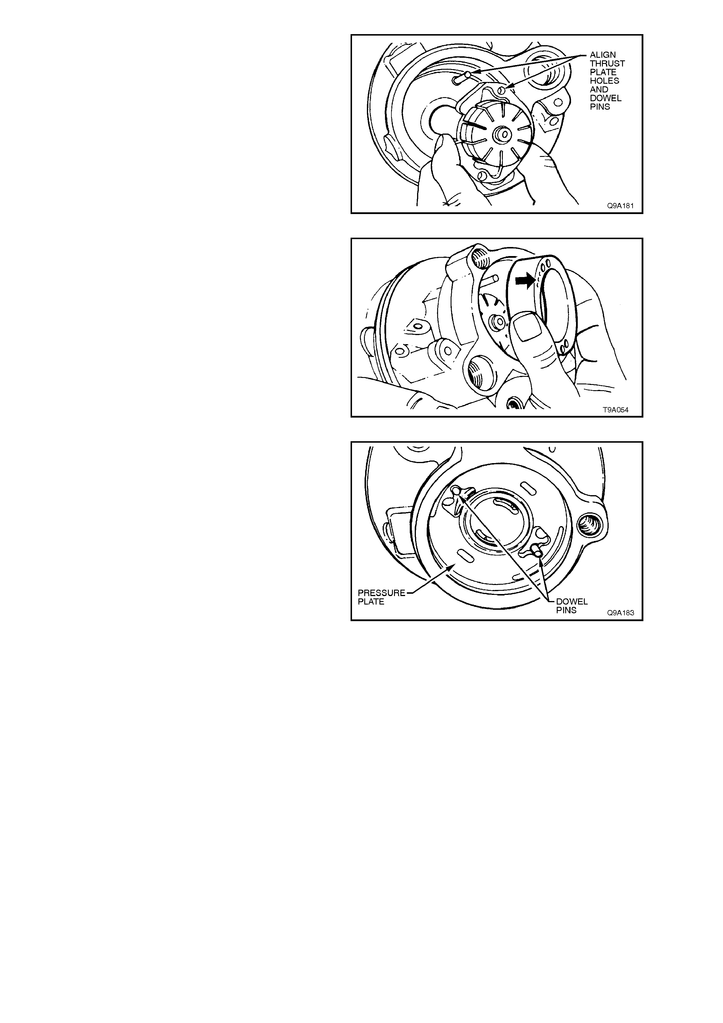
8. Reinstall shaf t, thrust plate and rotor ass em bly
into housing, aligning thrust plate holes with
dowel pins.
Figure 9A-146
9. Reinstall pump ring onto dowel pins with the
identifying three dots (arrow) facing
uppermost. There are four holes in the pump
ring, the smaller holes are the dowel pin holes.
10. Reinstall vanes into rotor slots.
Figure 9A-147
11. Lubricate outer circumference and chamfer of
pressure plate with Dexron® III automatic
transmission fluid to prevent damage to O-
ring. Reinstall pressure plate on dowel pins
with ported face toward pump ring such that
narrow slots engage dowel pins.
Figure 9A-148
12. Seat pressure plate by placing a large socket
on top of plate and pressing down by hand.
Plate will travel approximately 2 mm to seat.
13. Reinstall pressure plate spring on pressure
plate.
14. Lubricate new end plate O-ring with Dexron®
III automatic transmission fluid and install in
housing groove.
15. Lubricate outside circumference and chamfer
of end plate with transmission fluid to avoid
damaging the O-ring and reinstall end plate.
16. Reinstall end plate retaining ring. Locate end
of ring near hole in housing.

17. Reinstall flow control spring and plunger (hex
head screw end first) into pump housing.
Figure 9A-149
18. Lubricate reservoir O-ring with transmission
fluid and install on pump housing.
19. Lubricate reservoir bolt seals and flow control
valve seal with transmiss ion f luid and install on
pump assembly.
Figure 9A-150
20. Clean magnet and reinstall on housing in
original position as noted during disassembly.
21. Lubricate reservoir sealing edge with
transm ission fluid and reinstall r eservoir. Push
down on reservoir until it seats on housing.
Check location of bolt and control valve O-
rings.
22. Reinstall reservoir mounting bolts and tighten
to the correct torque specification.
RESERVOIR MOUNTING BOLTS 35 - 80
TORQUE SPECIFICATION Nm
23. Lubricate outlet f itting O-ring with transm ission
fluid, install on outlet fitting. Install outlet fitting
and tighten to the correct torque specification.
POWER STEERING PUMP OUTLET 50 - 102
FITTING TORQUE SPECIFICATION Nm
24. Reinstall pump pulley, refer to 3.11 POWER
STEERING PUMP PULLEY - V8 ENGINE in
this Section.
Figure 9A-151
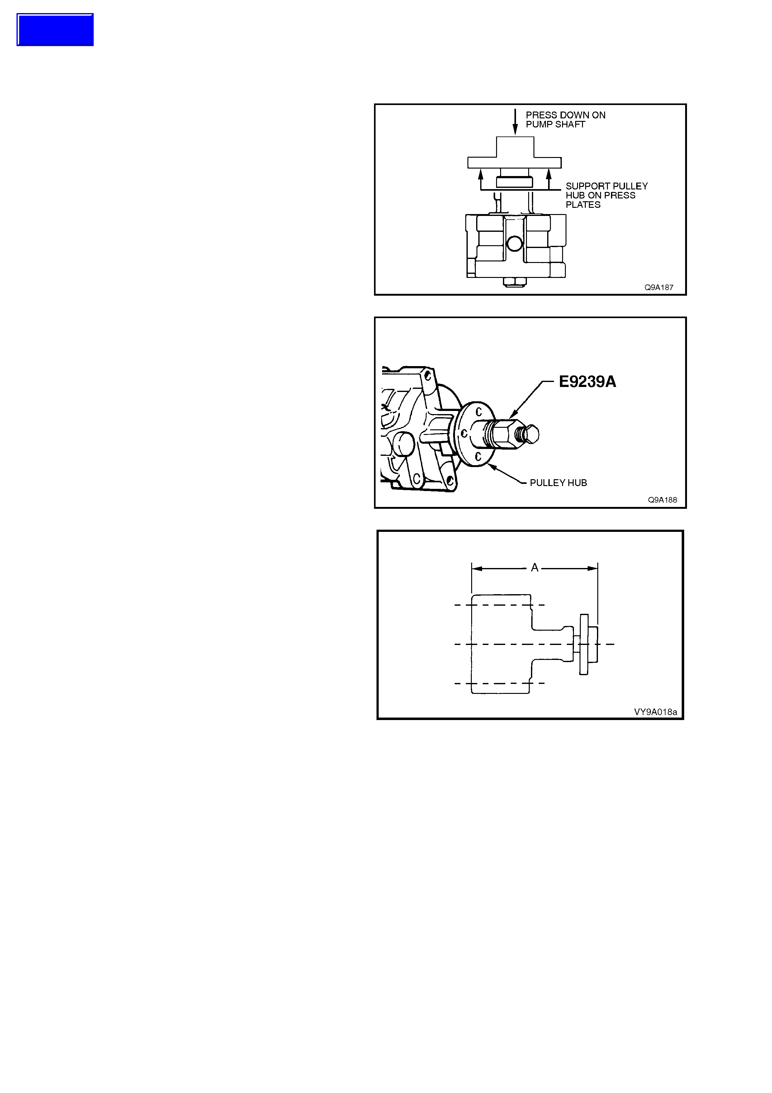
3.10 POWER STEERING PUMP PULLEY HUB - V6 ENGINE
REPLACE
1. Remove power steering pump, refer to
3.8 POWER STEERING PUMP in this
Section.
2. Using suitable press plates, such as Tool No.
E6673 (or J22912-01), support pulley hub and
press pump assembly from pulley hub.
Figure 9A-152
3. Make sure pulley hub bore and pump shaft
are free from burrs, place pulley hub on end of
pump shaft and install replacer, Tool No.
E9239A (or J25033-B), by screwing bolt fully
into pump shaft.
Figure 9A-153
4. Install the pulley hub by holding the bolt and
turning the large bearing nut clockwise.
Assemble the hub to the pump shaft until
dimension A equals 128.0 ± 0.3 mm.
5. Remove Tool No. E9239A (or J25033).
Figure 9A-154
Techline
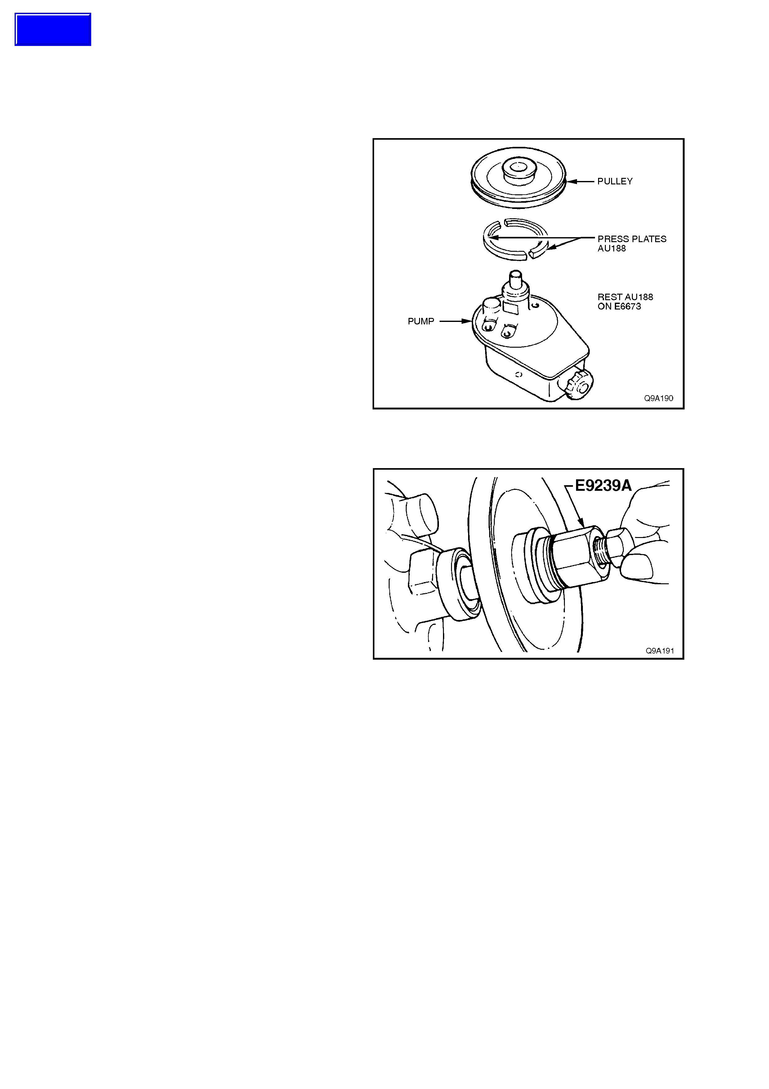
3.11 POWER STEERING PUMP PULLEY - V8 ENGINE
REPLACE
1. Remove power steering pump, refer to
3.9 POWER STEERING PUMP-V8 ENGINE
in this Section.
2. Using suitable pres s plates, s uc h as E6673 (or
J22912-01), with press plates, Tool No.
AU188, support pulley and press pump
assembly from pulley.
NOTE:
Do not position press plates on the edge of the
pulley, as damage to the pulley will occur.
Figure 9A-155
3. Ensure pulley bore and pump shaf t are fr ee of
burrs, place pulley on end of pump shaft.
4. Install Tool No. E9239A (or J25033-B) by
screwing bolt fully into pump shaft.
5. Reinstall pulley by holding large nut bearing
and turning bolt clockwise until pulley is flush
with shaft end.
6. Remove Tool No. E9239A (or J25033-B).
Figure 9A-156
Techline

3.12 OIL COOLER
REMOVE
Refer to Figure 9A-157 and Figure 9A-1 for the
general layout of the oil cooler, hoses and fittings
used for the power steering fitted to V6 and V8
powered, VT vehicles.
REINSTALL
Again, refer to the above mentioned figures for
hose and pipe routing, as well as the various
torque specifications for fasteners and hose
clamps.
Techline
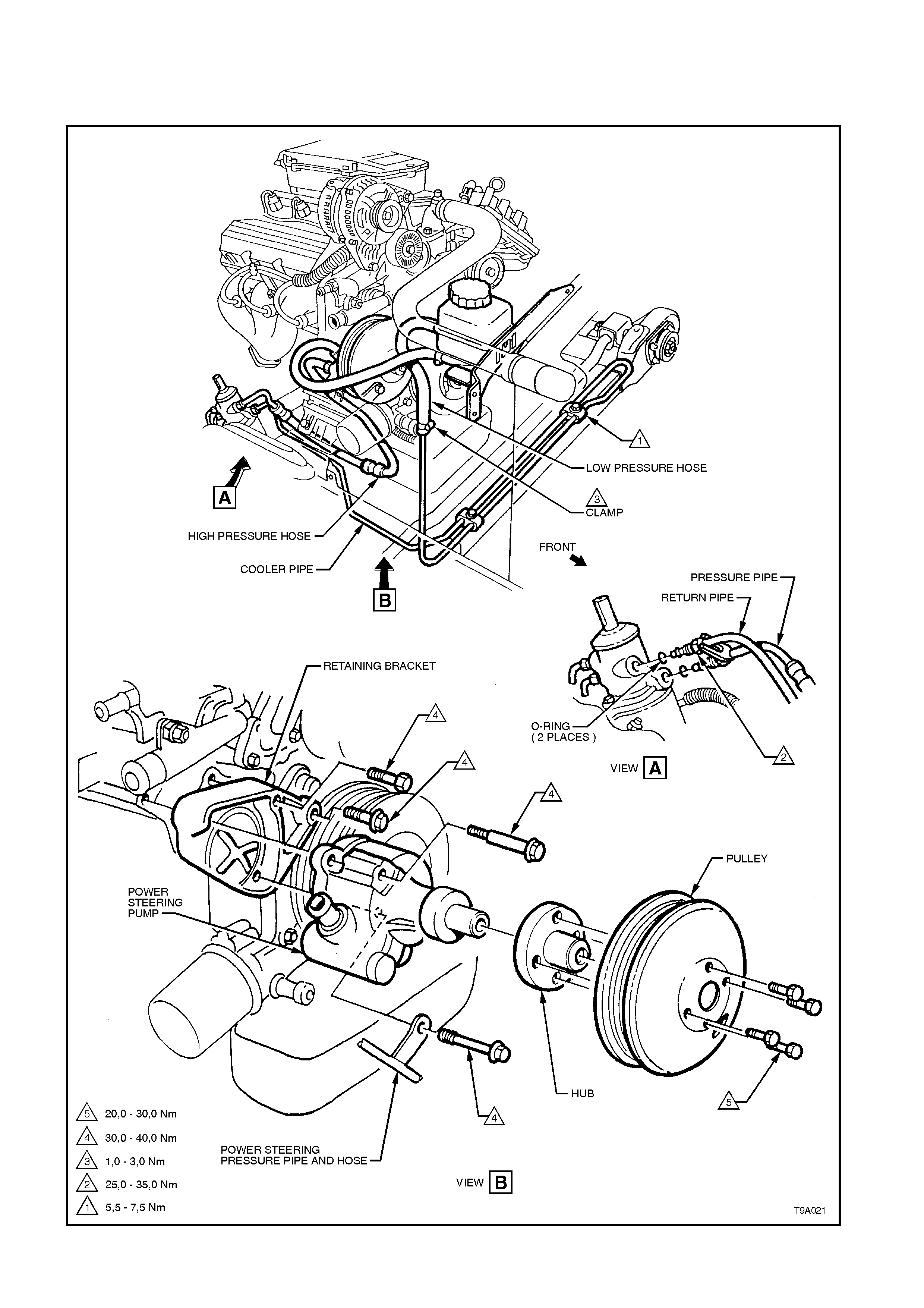
3.13 HOSE ROUTING
V6 ENGINE POWER STEERING PUMP AND HOSE INSTALLATION
Figure 9A-157 V6 Engine Power Steering Pump and Hose Installation
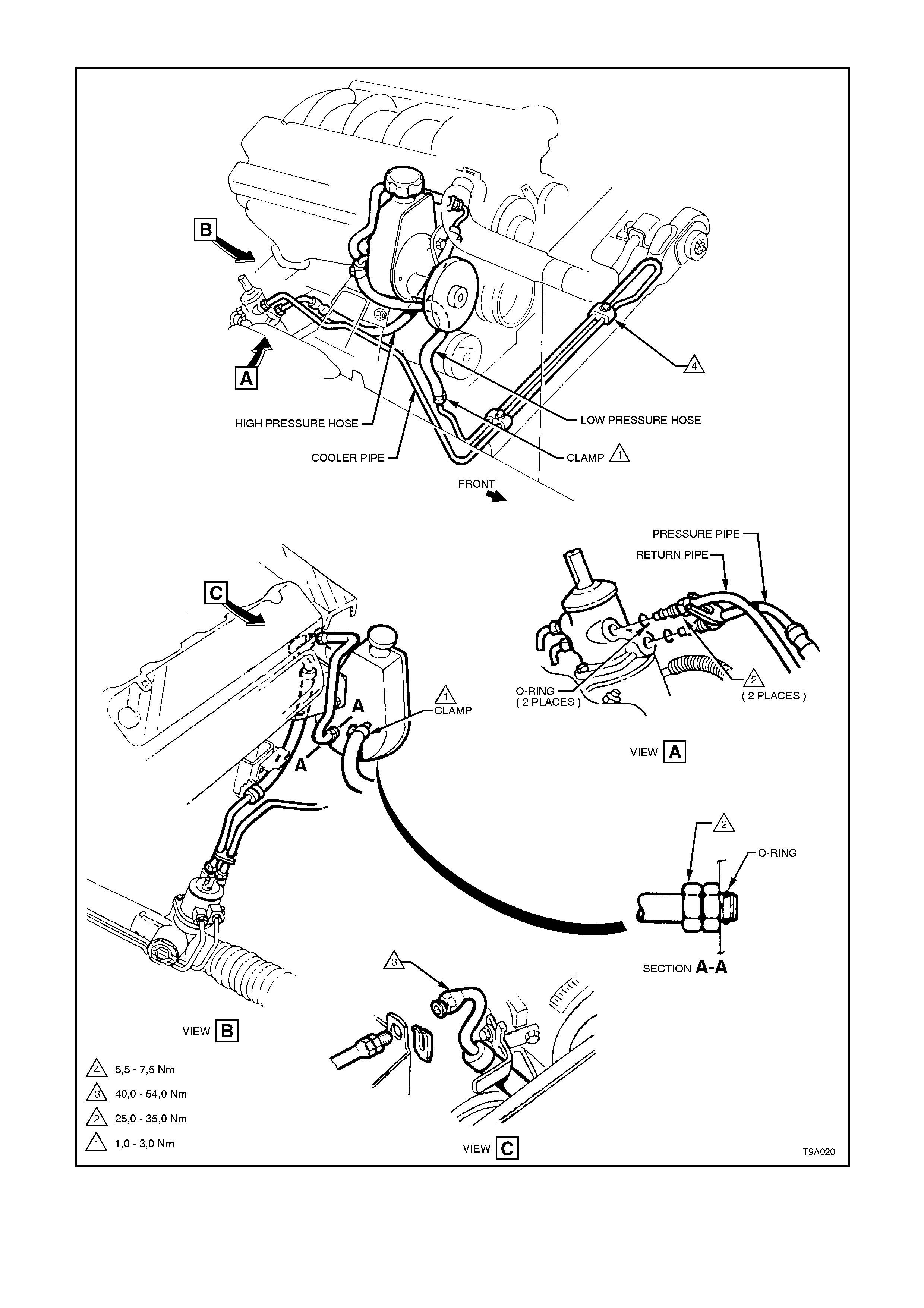
V8 ENGINE POWER STEERING AND HOSE INSTALLATION (WITHOUT ABS)
Figure 9A-158 V8 Engine Power Steering and Hose Installation (Without ABS)

4. DIAGNOSIS
4.1 GENERAL DIAGNOSTIC INFORMATION
Faulty steering can be caused by problems in areas other than the pump or steering gear. Areas of the steering
system that can be easily checked and quickly corrected without disassembly and overhaul of any major
components, should be attempted first.
Problems such as hard or loose steering, road shock or vibrations are not always due to the steering gear or pump,
but are often related instead to such factors as low tyre pressure or front end alignment. These items should be
checked and corrected before any adjustment or disassembly of the steering gear or pump is attempted.
Other factors that may affect correct operation of the steering system, are:
1. Loose component mountings.
2. Drive belt tension.
3. Fluid level and condition.
These factors must be checked and corrected before making any further diagnosis of the steering system.
After the source of the problem has been located, the cause of the problem can be diagnosed and corrected.
For example, if the fluid level in the reservoir is found to be low, refill and check the entire hydraulic system for fluid
leaks. Refilling the reservoir will not necessarily correct the problem.
Techline
Techline
TechlineTechline
Techline

4.2 POWER STEERING PUMP
DIAGNOSTIC ITEMS
Chirp Noise In Steering Pump.
1. Incorrectly tensioned drive belt.
Drive Belt Squeal (Particularly noticeable at full wheel travel and standstill parking).
1. Incorrectly tensioned drive belt.
Growl Noise In Steering Pump.
1. Excessive back-pressure in hoses or steering gear caused by restriction of flow.
Growl Noise In Steering Pump (Particularly noticeable at standstill parking).
1. Scored pressure plate, thrust plate or rotor.
2. Extreme wear of pump ring and vanes.
Groan Noise In Steering Pump.
1. Low fluid level.
2. Air in the fluid. Poor pressure hose connection.
Rattle Noise In Steering Pump.
1. Vanes not installed correctly.
Momentary Increase In Effort When Turning Wheel Fast To Right Or Left.
1. Low fluid level.
2. Drive belt slipping.
3. High internal leakage.
Steering Wheel Surges Or Jerks When Turning With Engine Running, Especially During Parking.
1. Low fluid level.
2. Incorrectly tensioned drive belt.
3. Insufficient pump pressure.
4. Sticky flow control valve.
Hard Steering Or Lack Of Assist, Especially In Parking.
1. Incorrectly tensioned drive belt.
2. Low fluid level.
3. Steering gear to column misalignment.
4. Tyres not properly inflated.
NOTE:
If rectification of checks 1 through 4 does not correct hard steering, follow the Power Steering Test Procedure as
outlined in 3.4 HYDRAULIC SYSTEM CHECK in this Section.
Further possible causes could be:
5. Sticky flow control valve.
6. Insufficient pump pressure output.
7. Excessive internal pump leakage.
8. Excessive internal system leakage.
Foaming or Milky Power Steering Fluid, Low Fluid Level And Possible Low Pressure.
1. Air in the fluid, and loss of fluid due to internal pump leakage, causing overflow.
Low Pressure From Steering Pump.
1. Flow control valve stuck or inoperative.
2. Pressure plate not flat against pump ring.
3. Extreme wear of pump ring and vanes.
4. Scored pressure plate, thrust plate or rotor.
5. Vanes not installed correctly.
6. Vanes sticking in rotor slots.
7. Cracked or broken thrust or pressure plate.
8. High internal leakage.

LEAK DIAGNOSIS
General Procedure
1. Wipe suspected area dry.
2. Check for overfilled reservoir.
3. Check for aeration and overflow of foaming fluid.
4. Check hose connections - tighten if necessary to the specified torque.
5. Verify exact point of leakage.
Example:
The location the fluid drips from is not necessarily the leakage point - fluid could be overflowing from the reservoir
(V8) for example.
6. When service is required:
a. Clean leakage area upon disassembly.
b. Replace leaking seal.
c. Check component sealing surfaces for damage and replace component if necessary.
d. Tighten fastener/s to the specified torque where required.
External Leakage Check
The purpose of this procedure is to pinpoint the location of the leak. In some cases, the leak can easily be located.
Seepage type leaks may be more difficult to isolate. To locate seepage leaks, use the following method.
1. With the engine stopped, wipe the complete power steering system dry (steering gear, pump, hoses and
connections).
2. Check the fluid level in the pump's reservoir. Add fluid if necessary.
3. Start the engine then turn the steering wheel from stop to stop several times. Do not hold it at a stop for any
length of time, as this can damage the power steering pump. It is easier if someone else operates the steering
wheel while you search for the seepage.
4. Find the exact area of the leak. If the leak is in the steering gear assembly, remove and repair as necessary.
Seal Replacement Recommendations
Lip seals, which seal rotating shafts, require special treatment. This type of seal is used on the steering gear pinion
shaft and on the drive shaft of the pump. When there is a leak in one of these areas, always replace the seal/s after
inspecting and thoroughly cleaning the sealing surfaces. Replace the shaft only if very severe pitting is found. If the
corrosion in the lip seal contact area is slight, clean the surface of the shaft with crocus cloth. Replace the shaft only
if the leakage cannot be stopped by first smoothing with crocus cloth.
Techline
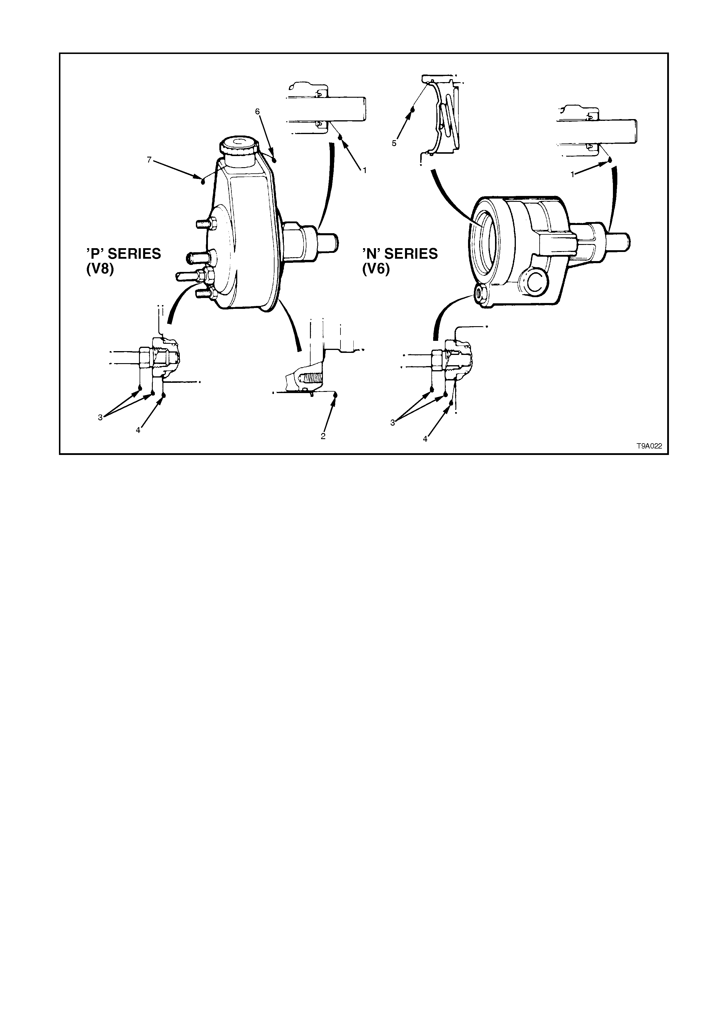
PUMP LEAK DIAGNOSIS
Figure 9A-159
NOTE:
The following explanations relate to the numbers shown in Figure 9A-159.
1. Replace drive shaft seal. Make certain that drive shaft is clean and free of pitting in seal area.
2. Replace reservoir O-ring seal.
3. Torque hose fitting nut to 25 - 35 Nm. If leakage persists, replace O-ring seal.
4. Torque outlet fitting to 50 - 102 Nm. If leakage persists, replace O-ring seal.
5. Replace end plate O-ring seal.
6. Check oil level; if leakage persists with the level correct and cap tight, replace the cap.
7. If a cracked or bent reservoir is detected, replace reservoir.

5. SPECIFICATIONS
STEERING GEAR
Steering Gear Type
Power Steering Rack and pinion with integral power cylinder and
rotary valve mechanism - variable ratio
Steering Gear Ratio
On-centre 17.2:1
Toward Lock 11.8:1
No. of Steering Wheel turns Lock to Lock 3.0
Nominal Rack Travel Total 164 mm
POWER STEERING
Make Saginaw
TypeV6 'N' Series droop flow vane type
V8 'P' Series droop flow vane type
Pressure at 1,000 engine rpm
V6 7,580 - 8,270 kPa
V8 8,270 - 8,960 kPa
Drive Pulley
Lubrication (Power Steering)
Hydraulic Dexron® III Automatic Transmission Fluid
Fluid Capacity Approx. 650 ml
Note: Use fluid level indicator as a final check
to ensure correct refill quantity
Drive Belt Tension
V6 Belt Self Adjusting
V8 - New Belt 57 kg
Used Belt 34 kg (A belt is considered ‘used’
after 10 minutes of operation)
FRONT WHEEL TOE
Front Toe-in (Total) 0° 10’ ± 0° 10’
Front Toe-in (Per Wheel) 0° 5’ ± 0° 5’
LUBRICANTS
Specified Grease EP Semi Fluid Lithium Base O Grease
SEALANTS
Specified Locking Products Loctite 242 or equivalent, to Holden's
Specification HN1256 Class 2, Type 2

6. TORQUE WRENCH SPECIFICATIONS
Nm
STEERING COLUMN ASSEMBLY
Steering wheel retaining bolt 40 - 50
Horn bar and air bag inflator assembly to steering
wheel securing screw 10 - 14
Upper steering column mount attaching bolt 15 - 30
Lower steering coupling to steering rack pinion
clamp nut 23 - 30
Steering shaft lower bearing support retaining nuts 15 - 30
POWER STEERING GEAR
Steering gear housing to crossmember mounting nut 70 - 85
Hydraulic line to valve housing flare nut 25 - 35
Road wheel attaching nut 110 - 140
Pinion lower bearing retaining nut 35 - 45
Pinion lower bearing screw plug 55 - 60
Valve housing retaining screw 5 - 6
Feed pipe flare nut 15 - 25
Rack pad adjusting screw 10 - 12,
then back
off 20 - 28°
Rack pad adjusting screw lock nut 55 - 65
Tie rod ball joint stud castellated nut 50 - 85
Tie rod ball joint adjustment lock nut 50 - 85
Tie rod to rack 90 - 100
V6 POWER STEERING PUMP
Reservoir attaching screw 3.0 - 7.0
Pump pulley attaching bolt 20 - 30
Pump to retaining bracket bolt 30 - 40
Power steering pump outlet fitting 50 - 102
V8 POWER STEERING PUMP
Pump mounting bracket nuts 35 - 65
Pump to mounting bracket bolts 35 - 65
Power steering pump idler pulley nut 35 - 65
High pressure hose flare nut 25 - 35
Reservoir mounting bolts 35 - 80
Power steering pump outlet fitting 50 - 102
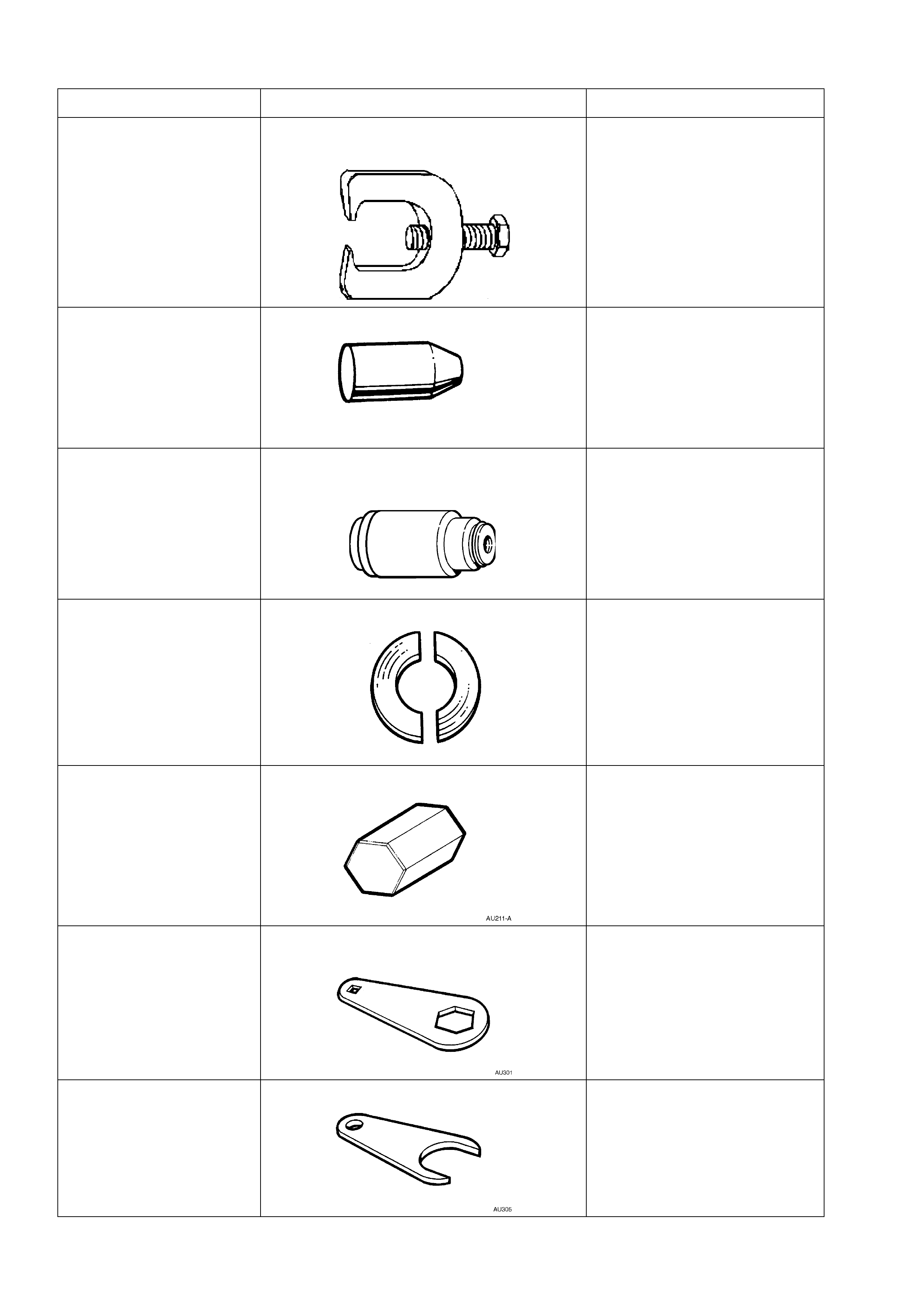
7. SPECIAL TOOLS
TOOL NO. REF IN TEXT TOOL DESCRIPTION COMMENTS
9A-10 STEERING LINKAGE BALL STUD
REMOVER PREVIOUSLY RELEASED
FOR ‘V’ CAR
9A-23 EXPANDER - SLEEVE SEALS PREVIOUSLY RELEASED
FOR HQ/WB SERIES
VEHICLES.
AU460 INSTALLER - INNER RACK SEAL AND
SPACER NEW RELEASE.
USED IN CONJUNCTION
WITH DRIVER HANDLE
AU355-A.
AU188 PRESS PLATES PREVIOUSLY RELEASED
FOR ‘J’ CAR.
AU211-A RACK PAD ADJUSTING SCREW WRENCH PREVIOUSLY RELEASED
FOR ‘J’ CAR, MANUAL
STEERING.
AU301 RACK PAD ADJUSTING SCREW LOCK
NUT WRENCH PREVIOUSLY RELEASED
FOR ‘V’ CAR.
AU305 TIE ROD WRENCH PREVIOUSLY RELEASED
FOR ‘V’ CAR.
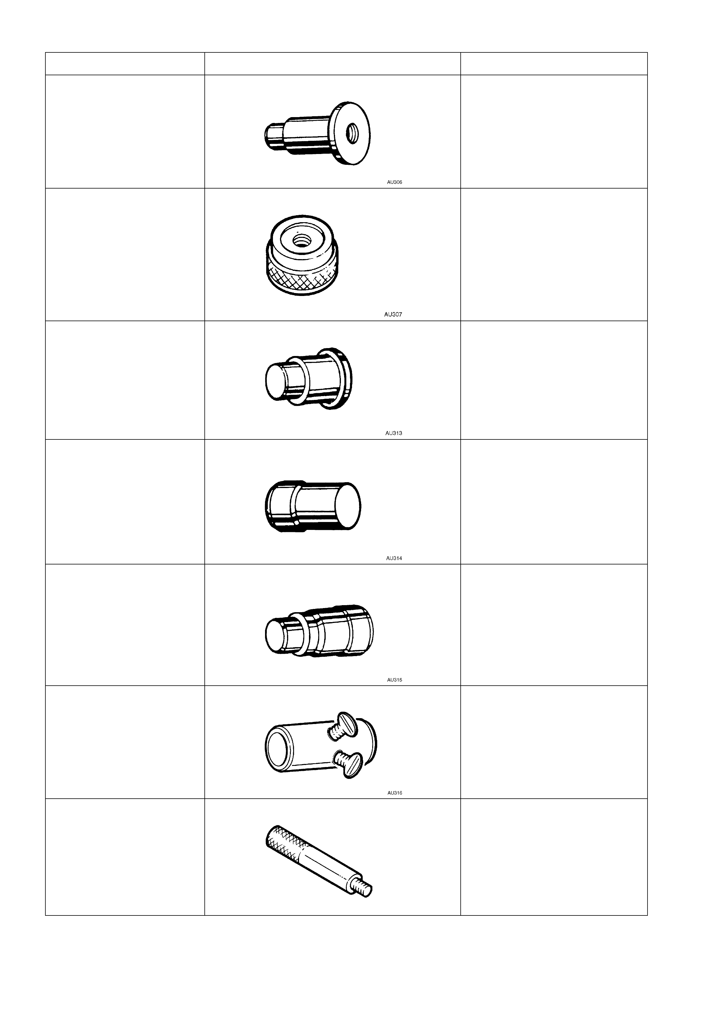
TOOL NO. REF IN TEXT TOOL DESCRIPTION COMMENTS
AU306 LOWER PINION BEARING REMOVER PREVIOUSLY RELEASED
FOR ‘VP’ SERIES.
AU307 LOWER PINION BEARING INSTALLER PREVIOUSLY RELEASED
FOR ‘VP’ SERIES.
AU313 UPPER PINION OIL SEAL INSTALLER PREVIOUSLY RELEASED TO
INSTALL VALVE HOUSING
BEARING ON ‘VP’ SERIES.
AU314 VALVE HOUSING SEAL AND BEARING
REMOVER PREVIOUSLY RELEASED
FOR ‘VP’ SERIES.
AU315 VALVE HOUSING SEAL & BEARING
INSTALLER PREVIOUSLY RELEASED
FOR ‘VP’ SERIES.
AU316 PRE-LOAD ADAPTOR PREVIOUSLY RELEASED
FOR ‘VP’ SERIES.
AU355-A DRIVER HANDLE PREVIOUSLY RELEASED AS
KM523-1 FOR ‘J’ SERIES
TRANSAXLE.
USED IN CONJUNCTION
WITH AU306 AND AU315.
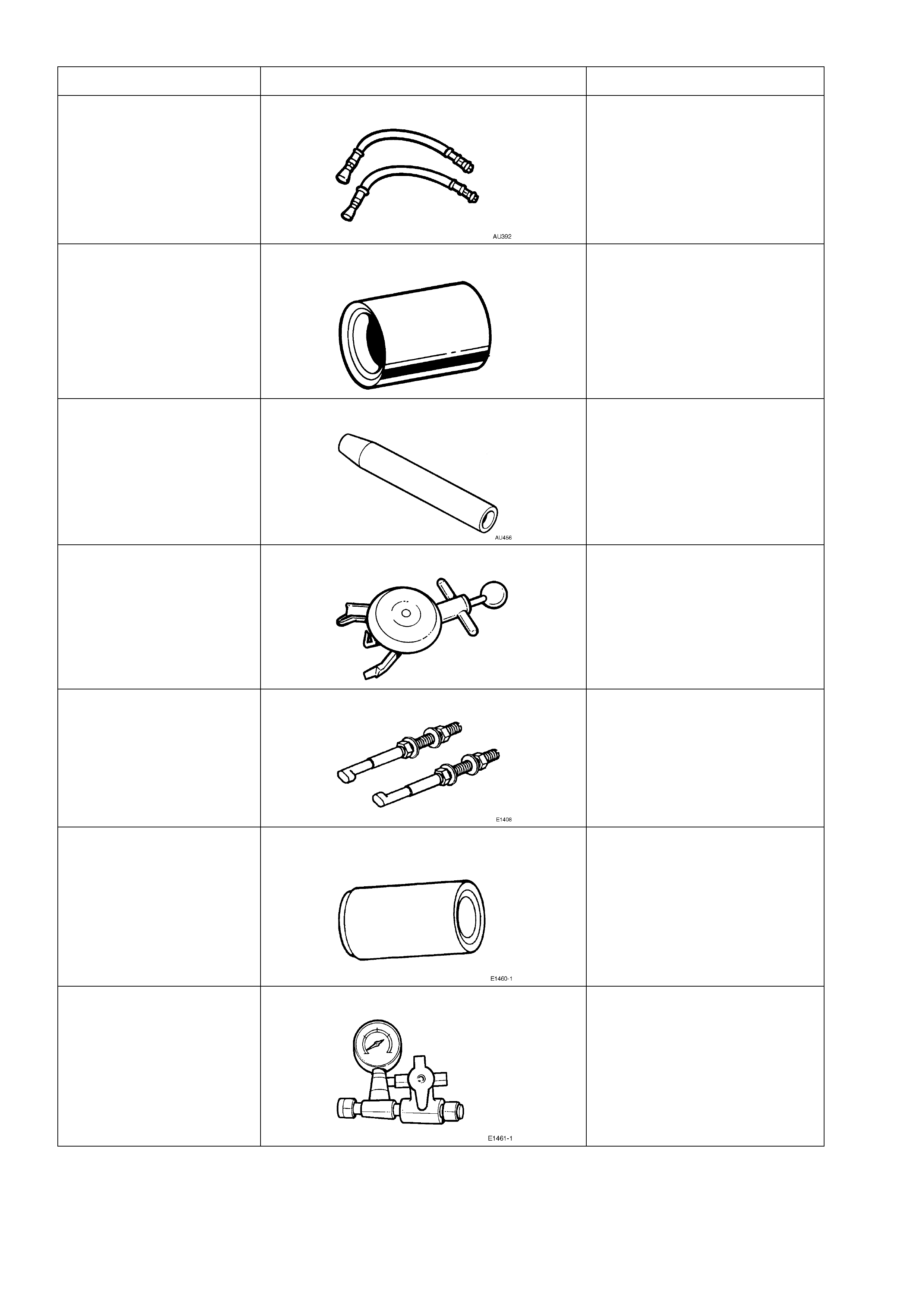
TOOL NO. REF IN TEXT TOOL DESCRIPTION COMMENTS
AU392 PRESSURE HOSE SET PREVIOUSLY RELEASED.
COMPRISES:
AU392-1, HOSE WITH MALE
END FITTING.
AU392-2, HOSE WITH
FEMALE END FITTING.
AU440 CONTRACTOR - SLEEVE SEALS PREVIOUSLY RELEASED
FOR ‘VR’ SERIES, SPEED
SENSITIVE STEERING.
AU456 RACK SEAL PROTECTOR - LONG NEW RELEASE.
BT3373-F BELT TENSION GAUGE PREVIOUSLY RELEASED.
E1408 STEERING WHEEL PULLER LEGS PREVIOUSLY RELEASED
FOR ‘VR’ SERIES.
E1460-1 POWER STEERING PUMP SHAFT SEAL
INSTALLER PREVIOUSLY RELEASED AS
9A6-1 FOR ‘V’ CAR.
E1461-1 PRESSURE GAUGE ASSEMBLY PREVIOUSLY RELEASED AS
J22912-01
TOOL NO. REF IN TEXT TOOL DESCRIPTION COMMENTS
E6673 PRESS PLATES PREVIOUSLY RELEASED AS
J22912-01.
E7115 ANGLE WRENCH PREVIOUSLY RELEASED AS
KM470 FOR ‘V’ AND ‘J’ CARS.
E8803-6 RACK SEAL PROTECTOR - SHORT NEW RELEASE.
E8803-7 RACK PISTON TOOL NEW RELEASE.
USED TO ROTATE THE END
BUSHING TO
REMOVE/INSTALL
RETAINING WIRE CLIP.
E8803-9 RACK PISTON SEAL EXPANDER NEW RELEASE.
USED TO EXPAND THE RACK
PISTON SEAL PRIOR TO
INSTALLATION.
E8803-10 RACK SEAL TEST ADAPTOR NEW RELEASE.
USED IN CONJUNCTION
WITH HAND VACUUM PUMP
TO ASSESS RACK SEAL
SERVICEABILITY.
E8803-11 RACK END SEAL/BUSH INSTALLER NEW RELEASE.
USED TO INSTALL RACK END
SEAL AND BUSH.
TOOL NO. REF IN TEXT TOOL DESCRIPTION COMMENTS
ETX30H TORX BIT PREVIOUSLY RELEASED.
ALSO COMMERCIALLY
AVAILABLE AS A T30H TORX
BIT
J1859-A STEERING WHEEL PULLER PREVIOUSLY RELEASED
FOR ‘LB’ ASTRA.
J23738-A HAND VACUUM PUMP PREVIOUSLY RELEASED OR
USE COMMERCIALLY
AVAILABLE EQUIVALENT.
J25359-8 TORX BIT HOLDER PREVIOUSLY RELEASED OR
COMMERCIALLY AVAILABLE.
USED WITH ETX30H TORX
BIT.
J25765-A DIAL TYPE TORQUE WRENCH PREVIOUSLY RELEASED
FOR ‘LB’ ASTRA
(TRANSAXLE), OR USE
COMMERCIALLY AVAILABLE
EQUIVALENT, CAPABLE OF
MEASURING FROM 0.4 - 6.0
NM.
R9239A POWER STEERING PUMP PULLEY
INSTALLER PREVIOUSLY RELEASED AS
J25033-B FOR ‘J’ AND ‘V’
CARS.