SECTION 2A - HEATING AND AIR CONDITIONING
DESCRIPTION AND OPERATION
CAUTION:
This vehicle will be equipped with a Supplemental Restraint System (SRS). A SRS will consist of either
seat belt pre-tensioners and a driver's air bag, seat belt pre-tensioners and a driver's and front
passenger's air bag s or seat belt pre- tensio ners, d riv er’s and fron t p asseng er’s air bag and lef t and rig ht
hand side air bags. Refer to SAFETY PRECAUTIONS, Section 12M Supplemental Restraint System of
this Service Information CD before performing any service operation on, or around any SRS
components, the steering mechanism or wiring. Failure to follow the SAFETY PRECAUTIONS could
result in SRS deployment, resulting in possible personal injury or unnecessary SRS system repairs.
CAUTION:
This vehicle may be equipped with LPG (Liquefied Petroleum Gas). In the interests of safety, the LPG
fuel system should be isolated by turning 'OFF' the manual service valve and then draining the LPG
service lines, before any service work is carried out on the vehicle. Refer to the LPG leaflet included with
the Owner's Handbook for details or the appropriate Section of this Service Information CD for more
specific servicing information.
1. GENERAL INFORMATION
With the introduction of VT Series II Models, and in particular, the GEN III V8 engine comes numerous changes to
the heating and ventilation system.
The following list provides a summary of the changes to the heating and air conditioning system for both V6 and V8
powered vehicles:
• Revised liquid line routing for all VT Series II Models.
• Vehicles with the 5.7 litre GEN III V8 engine are fitted with a Delphi (Harrison) V7 air conditioning compressor.
• As a running change, (from vehicle identification number L314227) the evaporator core was modified where the
outlet tube pipe joint was deleted and replaced with a one piece tube.
• From start of VT Series II production, vehicles with a naturally aspirated V6 engine will be equipped with new
engine cooling fans.
For information regarding the description and operation of the heating and air conditioning system that is not
included in this Section, refer to Section 2A AIR CONDITIONING - DESCRIPTION AND OPERATION of this
Service Information CD.
NOTE: Reference to Section 2D AIR CONDITIONING - ECC - DESCRIPTION AND OPERATION of this Service
Information CD should be made for information regarding the ECC system.
Techline
Techline
Techline
Techline
2. GENERAL DESCRIPTI ON
2.1 AIR CONDITIONING COMPONENTS
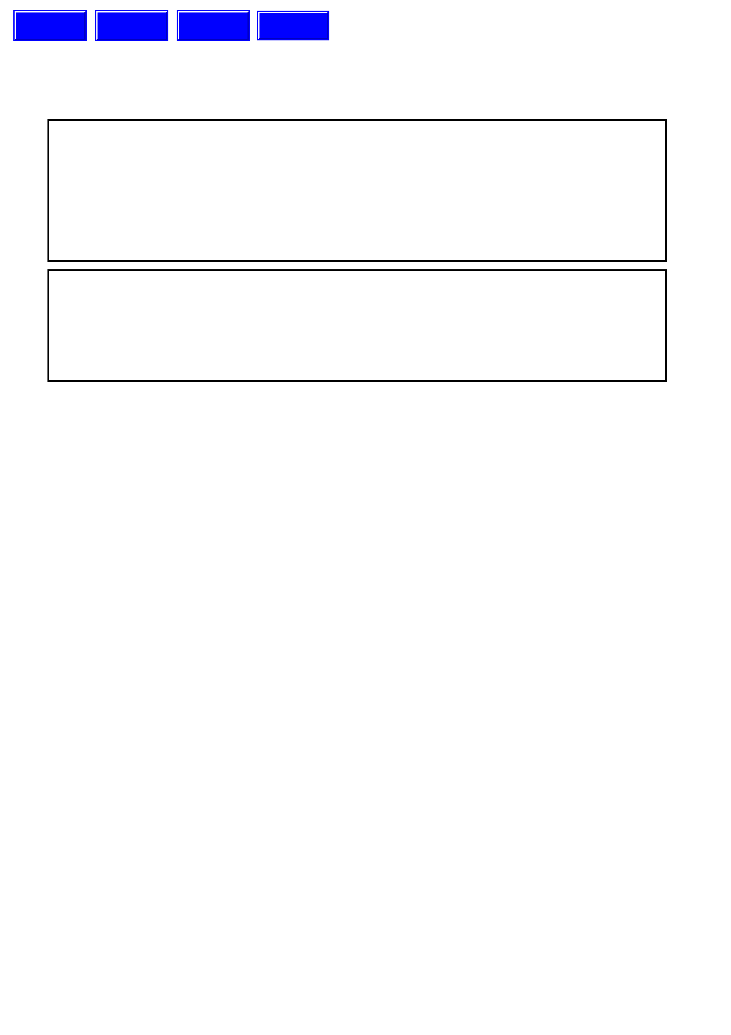
Figure 2A-1 GEN III V8 engine compartment components
1. Thermal expansion valve (or block valve) 10. Condenser 19. Pressure transducer
2. Discharge/Suction hose/tube assembly 11. RH air chute 20. 0-Ring
3. Liquid line 12. Upper mounting grommet 21. Oil pan gaurd
4. LH air chute 13. Drive belt 22. Lower air chute extension
5. Lower mounting grommet 14. Drive belt idler pulley 23. Bolt
6. Air chute lower baffle 15. Drive belt tensioner
7. Filter Drier Receiver (FDR) 16. Compressor mounting bracket
8. Fastener 17. Compressor
9. Ambient air temperature sensor 18. Schraeder valve and cap
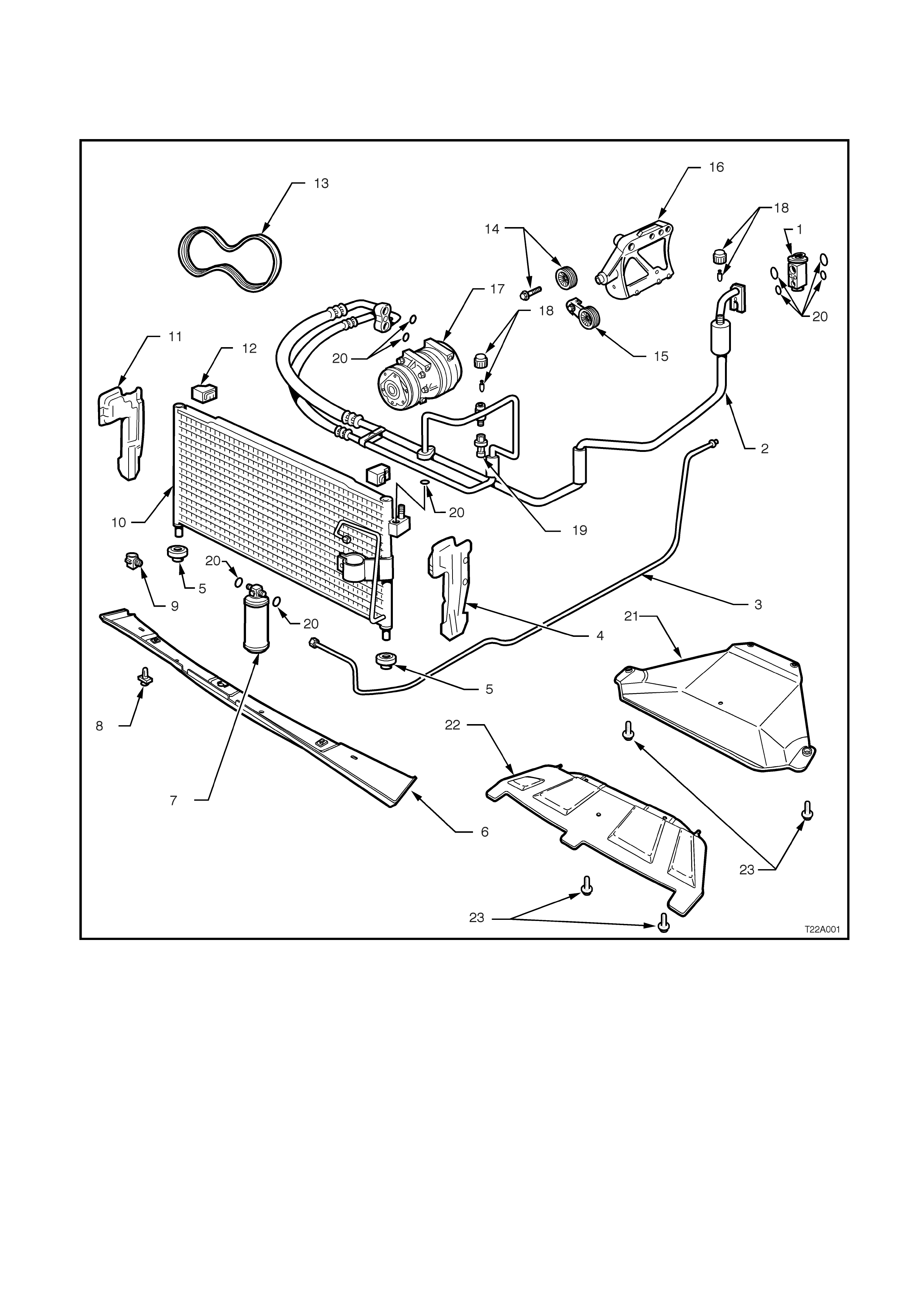
PRESSURE TRANSDUCER
The pressure transducer is a sealed gauge
referenc e capacitive pressure s ensor with on board
signal conditioning. It provides a 0 to 5 volt output
and requires a 5 volt regulated power supply.
In operation the transducer senses applied
pressure via the deflection of a two piece ceramic
diaphragm with one half being a parallel plate
capacitor. Changes in capacitance influenced by
the refrigerant pressure under the ceramic
diaphragm are converted to an analogue output by
the transducers integral signal electronics.
The pressure transducer’s electronics are on a
flexible circuit board contained in the upper section
of the transducer. T hey provide linear calibration of
the capacitance signal from the ceramic sensing
diaphragm.
Benefits of using the pressure transducer over a
normal type pressure switch is that the transducer
is constantly monitoring pressures and sending
signals to the powertrain control module (PCM).
The normal type pressure s witch only has an upper
and lower cut out point. The PCM will disengage
the A/C compressor at low or high refrigerant
pressures and electronic diagnostic equipment can
be used to extract system pressure information
making it easier when diagnosing problems.
NOTE: Fig. 2A-2 shows the V6 application. The
pressure transducer on VT Series II Models with
GEN III V8 engines is identical and in the same
location, however, removal of the upper radiator
shroud is necessary to gain access.
NOTE: Pressure transducer diagnostics can be
found in Section 6C1 POWERTRAIN
MANAGEMENT - V6 ENGINE of this Service
Information CD, or 6C3 POWERTRAIN
MANAGEMENT - GEN III V8 ENGINE of this
Service Information CD.
T22A002
3
4
5
2
1
Figure 2A-2
1. Pressure transducer
2. High pressure charge port
3. Signal electronics
4. Pressure port
5. Ceramic diaphragm
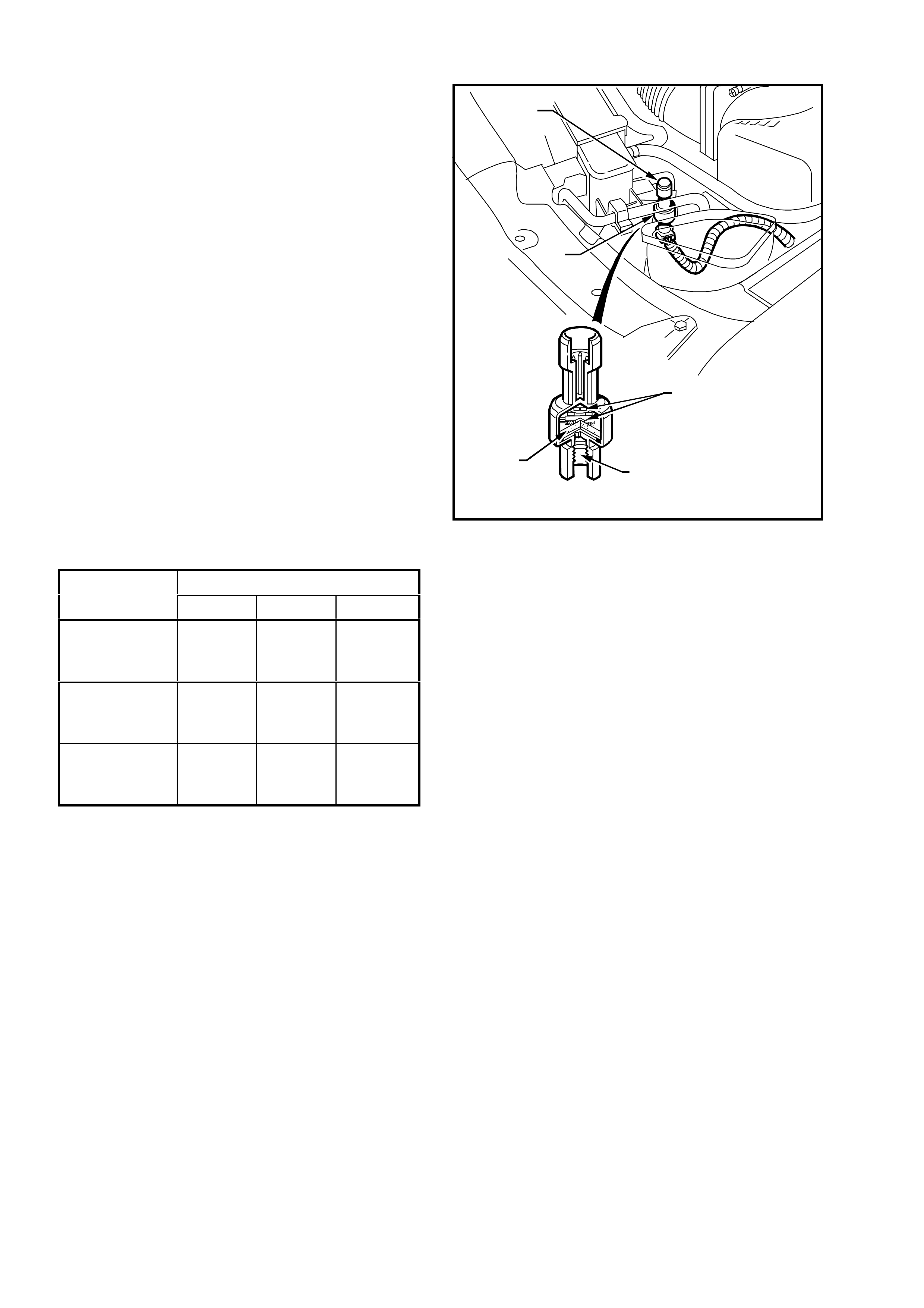
ENGINE
V6 V6 S/C GEN III V8
Low Pressure
Cut Out @
Cut In @ 180 kPa
240 kPa 180 kPa
240 kPa 180 kPa
240 kPa
High Pressure
Cut Out @
Cut In @ 2900 kPa
2000 kPa 2900 kPa
2400 kPa 2900 kPa
2000 kPa
High Speed Fan
ON @
Off @ 2000 kPa
1500 kPa 2600 kPa
2300 kPa 2400 kPa
1900 kPa
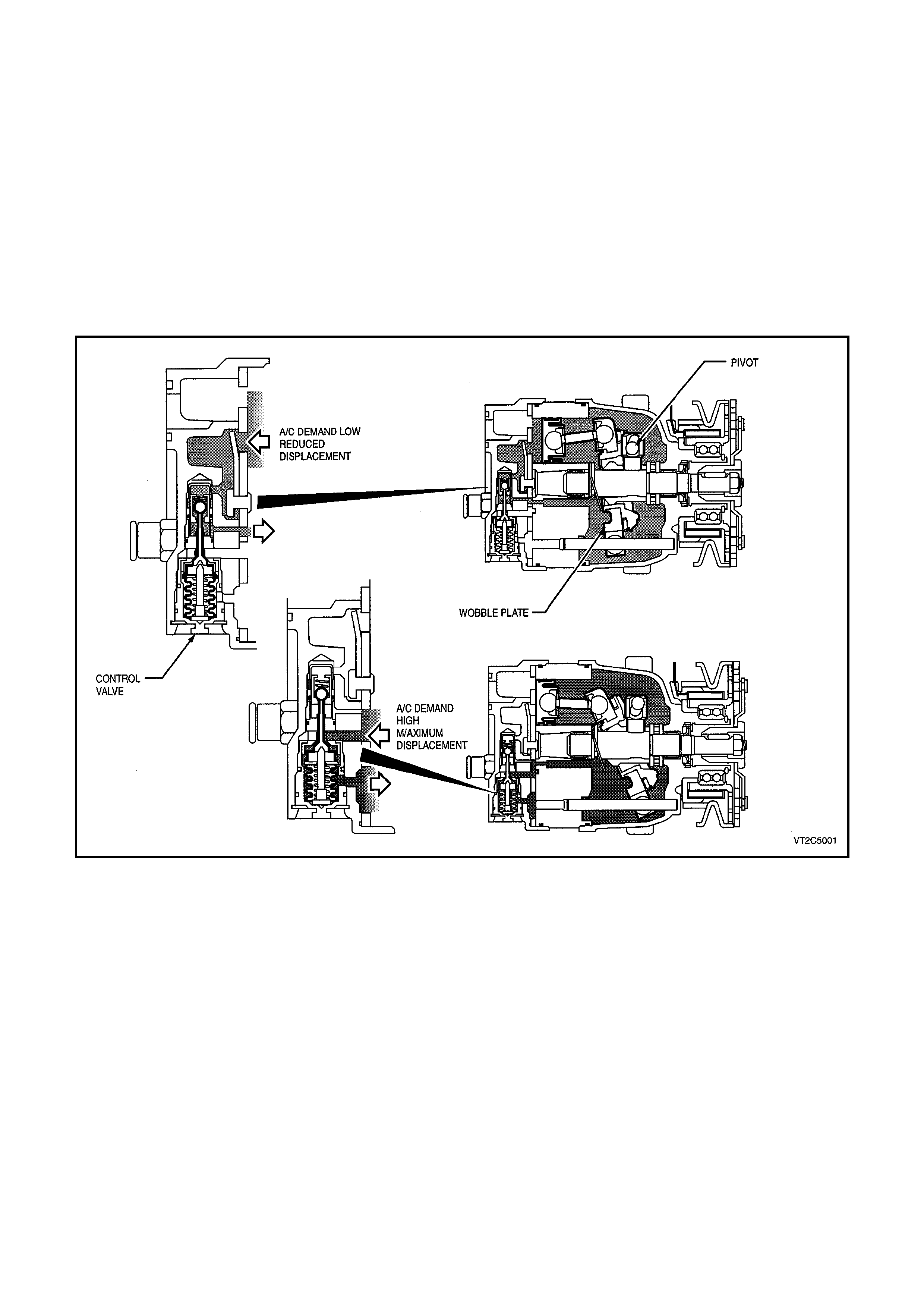
HARRISON V5 AND V7 COMPRESSOR
The Harrison V5 and V7 compressor can match the air conditioning demand under all conditions without cycling.
The basic compressor mechanism is a variable angle wobble-plate with five (V5) or seven (V7) axially oriented
cylinders. The control mechanism of the compressor displacement is a bellows actuated control valve located in the
rear head of the compressor which senses compressor suction pressure. The wobble-plate angle and compressor
displacement are controlled by the compressor crankcase-suction pressure differential.
When the A/C capacity demand is high, the suction pressure will be above the control point. The valve will maintain
a bleed from the compressor crankcase to suction, no crankcase-suction pressure differential and the compressor
will have maximum displacement.
When the A/C capacity demand is lower and the suction pressure reaches the control point, the valve will bleed
discharge gas into the crankcase and close off a passage from the compressor crankcase to the suction plenum.
The pressure differential creates a total force on the pistons resulting in a movement about the wobble-plate pivot
pin that reduces the plate angle.
The V5 compressor has a pumping capacity of 156cc while the V7 has a pumping capacity of 179cc.
Figure 2A-3
ENGINE COOLI NG FAN APPLICATION
T22A003
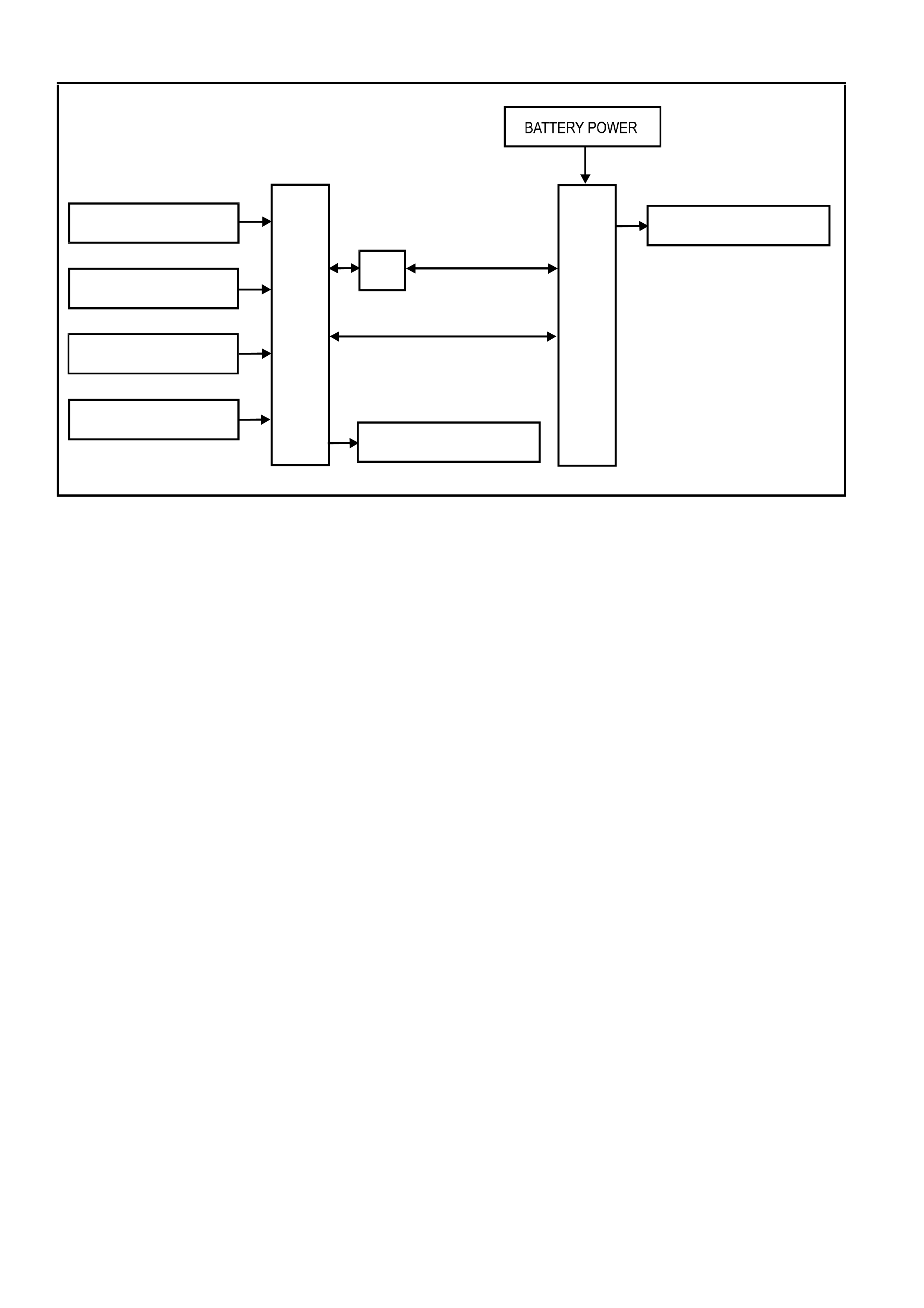
PCM
HIGH SPEED COOLING
FAN RELAY
PIM BCM
LOW SPEED COOLING
FAN RE LAY
IGNITION SWITCH ON
VEHICLE SPEED
SENSOR
ENGINE COOLANT
TEMP. SENSOR
AIR CONDITIONING
REQUEST
V6 & V6 S/C ENGINE
GEN III V8 ENGINE
Figure 2A-4 System Overview
VT Series II Models with V6 engines have two single speed electric engine cooling fans; a low speed fan and a high
speed fan (only the low speed fan operates for low speed operation, however, both the high and low fans operate
for high speed). All other VT Series Models, regardless of the engine configuration (including GEN III V8), are
equipped with two, two speed electric cooling fans.
The engine cooling fan assemblies provide the primary means of moving air through the engine radiator. These
fans are placed between the radiator and the engine and have their own shroud. These fans configurations are
used on all vehicles even if not equipped with air conditioning. There is no fan in front of the A/C condenser.
The electric engine cooling fans are used to cool engine coolant flowing through the radiator, and if fitted, refrigerant
flowing through the A/C condenser.
On vehicles with V6 engines, the engine cooling fan motors have two terminals; one positive and one negative. The
positive terminals are permanently connected to battery voltage. When the negative terminal is connected to
earthed through the low speed cooling fan relay, the low speed cooling fan will operate. When the negative terminal
is connected to earth via the high speed cooling fan relay, both cooling fans will operate.
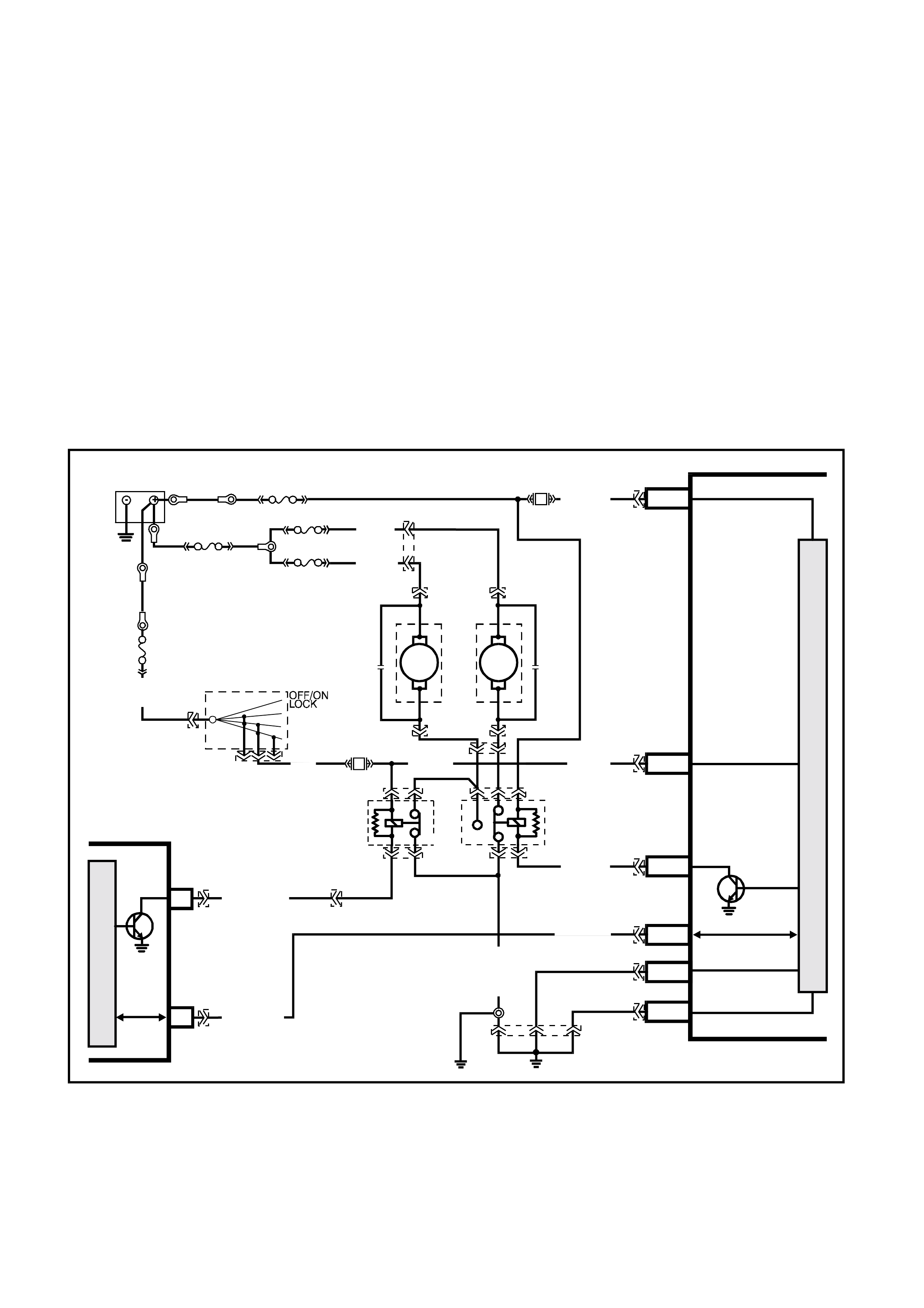
On vehicles with either V6 supercharged or GEN III V8 engines, the engine cooling fan motors have four terminals,
two negative and two positive terminals. The two positive terminals are permanently connected to battery voltage.
When one of the negative terminals is earthed, both cooling fan motors will operate at low speed. When both
negative terminals are earthed, both cooling fans will operate at high speed.
Regardless of the engine configuration, the low speed cooling fan operation is enabled when the low speed engine
cooling fan micro relay (located in the engine compartment relay housing, labelled Lo Fan) is energised by the Body
Control Module (BCM) via a request from the Powertrain Control Module (PCM). The PCM will request low speed
fan enable and disable via serial data communication to the BCM on circuit 1221 (Red/Black wire). After the PCM
requests a change in the state of the low speed relay (i.e. OFF to ON or ON to OFF), the BCM will send a serial
data response message back to the PCM confirming it received the message.
NOTE: On vehicles with GEN III V8 engines, serial data communication between the PCM and BCM is via the
Powertrain Interface Module (PIM).
The PCM determines when to enable the low speed fan relay based on inputs from the A/C request signal, Cooling
Temperature Sensor (CTS) and the Vehicle Speed Sensor (VSS).
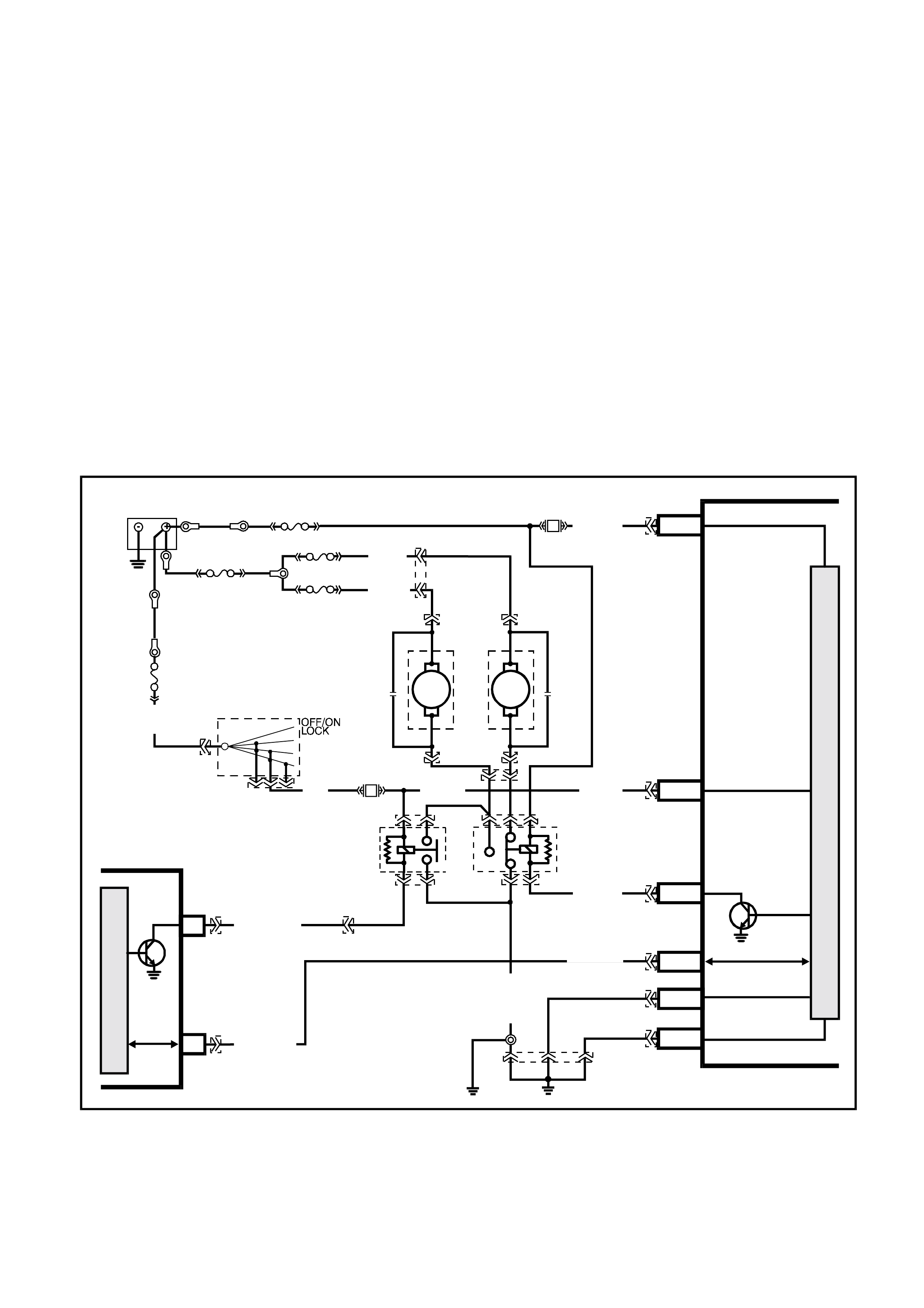
LOW SPEED FAN OPERATION
The low speed cooling fan relay will be turned ON when:
•Air conditioning request indicated (YES) and the vehicle speed is less than 30 km/h or
•Air conditioning pressure is greater than 1500 kPa or
•Coolant temperature is greater than 104°C (V6 and V6 supercharged) / 98°C (GEN III V8) or
•Vehicles with V6 and V6 supercharged engines; an engine coolant temperature sensor failure is detected by the
PCM, refer to Section 6C1 POWERTRAIN MANAGEMENT - V6 ENGINE for additional information.
Vehicles with GEN III V8 engines; when a coolant temperature sensor failure in conjunction with an Intake Air
Temperature (IAT) sensor failure is detected by the PCM, refer to Section 6C3 POWERTRAIN
MANAGEMENT - GEN III V8 ENGINE for additional information.
•When the ignition switch is turned fr om ON to O FF and the engine c oolant temperature is above 117°C ( V6 and
V6 supercharged) / 113°C (GEN III V8). The BCM will continue to energise the low speed engine cooling fan
micro relay for four minutes.
The PCM will request the BCM to switch off the low speed cooling fan relay when the following conditions have
been met:
•Air conditioning request not indicated (NO) and the coolant temperature is less than 99°C (V6 and V6
supercharged) / 95°C (GEN III V8) or
•Air conditioning reques t indicated (YES) with pressure les s than 1170 kPa, vehicle speed greater than 50 k m/h
and coolant temperature less than 99°C (V6 and V6 supercharged) / 98°C (GEN III V8).
NOTE: On vehicles with GEN III V8 engines, the low speed cooling fan has a minimum run on time of 30 seconds.
Figure 2A-5 V6 Engine - Low speed cooling fan activation
A3
F6
M
I
C
R
O
SERIAL DATA
HIGH
CURRENT EARTH
SERIAL
DATA
PCM
IGNITION
LOW
SPEED FAN
M
I
C
R
O
P
R
O
C
E
S
S
O
R
BATTE RY MAIN POWER
YB194
YB188
F31
O/B (740)
BCM
T22A004
ELECTRONIC EARTH
HIGH
SPEED
FAN
ENGINE
COOLING
FANS
BLU/W (304)
R/B (1221)
Y (208)
O ( 204)
O/B (473)
ENGINE
COOLING
FAN RELAY
(LOW SPEED)
ENGINE
COOLING
FAN RELAY
(HIGH SPEED)
YE43
YE43
30
87
85
86
YE103
YE103
87A
30
87
85
86
15a 15 50
30 ACC
IGN
START
IGNITION SWITCH
F14
P (3) P/B (39) P/B (39)
BLUE
FUSIBLE
LINK
BATTERY
FS
FT FAN 1
FU FAN 2
YE10
YE31
YE24YE9
R
(203)
R
(001)
R
(001)
FJ
YE9
YE24
R
(001)
R (2)
R/B (1221)
YE114
B/Y
(155)
B/G
(151)
LOC. E2 LOC. E3
B/P (157)
A5/A6
E20/D6
B7/B7
E2/D2
A1/A5
B10/B11
YB175
YB164
YB174
YB163
YB175
YB164
YB176
YB165
YB174
YB163
YB176
YB165
YB44
YB44 YE140
YE140
YE139
YE139
YE104
YE110

Figure 2A-6 V6 Supercharged & GEN III V8 Engine - Low speed cooling fan activation
R/B (1221) E2/D2 SERIAL DATA
HIGH
CURRENT EARTH
IGNITION
LOW
SPEED FAN
M
I
C
R
O
P
R
O
C
E
S
S
O
R
BATTE RY MAIN POWE R
YE114
BCM
15a 15 50
30 ACC
IGN
START
T22A006
B/Y
(155) A1/A5 ELECTRONIC EARTH
E20/D6
B7/B7
P/B (39)
P (3)
B/G
(151)
LOC.
E2 LOC.
E3
B10/B11
IGNITION SWITCH
O/B (473)
87A
30
87
85
86 87
30 85
86
ENGINE
COOLING
FAN 1
ENGINE
COOLING
FAN RELAY
(LOW SPEED)
GEN III
GEN III
ENGINE
COOLING
FAN RELAY
(HIGH SPEED)
P/B (39)
F14
BLU/W (304)
R/B (1221)
R/B (1049)
B/P (157)
A3
F6
M
I
C
R
O
SERIAL
DATA
V6 S/C PCM
HIGH
SPEED
FAN
J1-58
J2-33
M
I
C
R
O
SERIAL
DATA
GEN III PCM
PIM
HIGH
SPEED
FAN
BLUE
FUSIBLE
LINK
YE103
YE119
YB44
YB44
YE119
YE43 YB174
YB163
YB176
YB165
YB175
YB164
YB175
YB164
YB174
YB163
YB176
YB165
YB194 YE110
YE123
YB188
YE112 YB215
YB215
YE103
F31
A5/A6
O/B (740)
ENGINE
COOLING
FAN 2
BATTERY
FS
FT FAN 1
FU FAN 2
YE10
YE31
YE24YE9
(1040)
R
(203)
R
(001)
R
(001)
Y
(208)
O
(204)
YE118
FJ
YE9YE24
R
(001)
R (2 )
6
7
M
I
C
R
O
UART
CLASS 2 SE RIAL DA TA
SERIAL DATA
BLU/W (304)
HIGH SPEED FAN OPERATION
The high speed cooling fan relay will be turned ON if the low speed cooling fan relay has been energised for one
second and the following conditions have been met:
•Vehicles with V6 or V6 supercharged engines; if there is a BCM message response fault, setting a DTC 92 or
•Vehicles with V6 and V6 supercharged engines; an engine coolant temperature sensor failure is detected by the
PCM, refer to Section 6C1 POWERTRAIN MANAGEMENT - V6 ENGINE for additional information or
•Engine coolant temperature is above 107°C (V6 and V6 supercharged) / 108°C (GEN III V8) or
•Air conditioning pressure is greater than 2000 kPa (V6), 2600 kPa (V6 supercharged), 2400 (GEN III V8).
NOTE: If the low speed cooling fan is off when the criteria for turning the high speed cooling fan on are first met, the
high speed cooling fan will turn on 5 seconds (V6 and V6 supercharged) / 1 second (GEN III V8) after the low speed
cooling fan is switched on.
If both the high and low speed cooling fans are enabled, the PCM will turn the high speed cooling fan off when:
•The engine coolant temperature is less than 108°C (V6 and V6 supercharged) / 102°C (GEN III V8) and
•Air conditioning request is not indicated (NO) or
•Air conditioning request is indicated (YES) and the pressure is less than 1500 kPa (V6), 2300 kPa (V6
supercharged), 1900kPa (GEN III V8).
NOTE: On vehicles with GEN III V8 engines, the high speed cooling fan has a minimum run on time of 30 seconds.
Figure 2A-7 V6 Engine - High speed cooling fan activation
A3
F6
M
I
C
R
O
SERIAL DATA
HIGH
CURRENT EARTH
SERIAL
DATA
PCM
IGNITION
LOW
SPEED FAN
M
I
C
R
O
P
R
O
C
E
S
S
O
R
BATTE RY MAIN POWER
YB194
YB188
F31
O/B (740)
BCM
T22A005
ELECTRONIC EARTH
HIGH
SPEED
FAN
ENGINE
COOLING
FANS
BLU/W (304)
R/B (1221)
Y (208)
O ( 204)
O/B (473)
ENGINE
COOLING
FAN RELAY
(LOW SPEED)
ENGINE
COOLING
FAN RELAY
(HIGH SPEED)
YE43
YE43
30
87
85
86
YE103
YE103
87A
30
87
85
86
15a 15 50
30 ACC
IGN
START
IGNITION SWITCH
F14
P (3) P/ B (39) P /B (39)
BLUE
FUSIBLE
LINK
BATTERY
FS
FT FAN 1
FU FAN 2
YE10
YE31
YE24YE9
R
(203)
R
(001)
R
(001)
FJ
YE9
YE24
R
(001)
R (2)
R/B (1221)
YE114
B/Y
(155)
B/G
(151)
LOC. E2 LOC. E3
B/P (157)
YB175
YB164
YB174
YB163
YB175
YB164
YB176
YB165
YB174
YB163
YB176
YB165
YB44
YB44 YE140
YE140
YE139
YE139
YE104
YE110
A5/A6
E20/D6
B7/B7
E2/D2
A1/A5
B10/B11
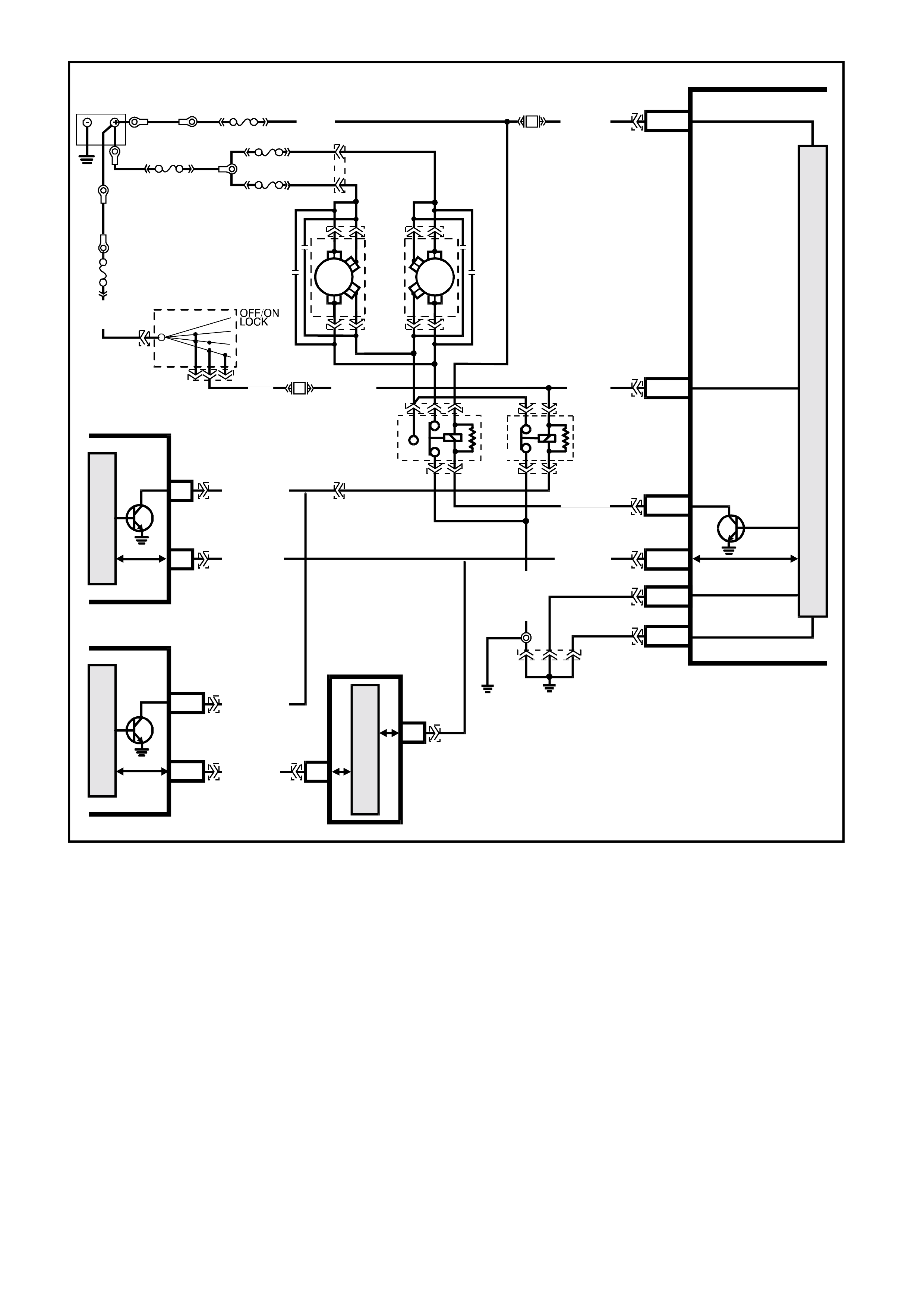
Figure 2A-8 V6 Supercharged & GEN III V8 Engine - High speed cooling fan activation
R/B (1221) SERIAL DATA
HIGH
CURRENT EARTH
IGNITION
LOW
SPEED FAN
M
I
C
R
O
P
R
O
C
E
S
S
O
R
BATTE RY MAIN POWE R
YE114
BCM
15a 15 50
30 ACC
IGN
START
T22A007
B/Y
(155) ELECT RONIC EARTH
P/B (39)
P (3)
B/G
(151)
LOC.
E2 LOC.
E3
IGNITION SWITCH
O/B (473)
87A
30
87
85
86 87
30 85
86
ENGINE
COOLING
FAN 1
ENGINE
COOLING
FAN RELAY
(LOW SPEED)
GEN III
GEN III
ENGINE
COOLING
FAN RELAY
(HIGH SPEED)
P/B (39)
F14
BLU/W (304)
R/B (1221)
R/B (1049)
B/P (157)
A3
F6
M
I
C
R
O
SERIAL
DATA
V6 S/C PCM
HIGH
SPEED
FAN
J1-58
J2-33
M
I
C
R
O
SERIAL
DATA
GEN III PCM
PIM
HIGH
SPEED
FAN
BLUE
FUSIBLE
LINK
YE103
YE119
YB44
YB44
YE119
YE43
YB194 YE110
YE123
YB188
YE112 YB215
YB215
YE103
F31
O/B (740)
ENGINE
COOLING
FAN 2
BATTERY
FS
FT FAN 1
FU FAN 2
YE10
YE31
YE24YE9
(1040)
R
(203)
R
(001)
R
(001)
Y
(208)
O
(204)
YE118
FJ
YE9YE24
R
(001)
R (2 )
6
7
M
I
C
R
O
UART
CLASS 2 SE RIAL DA TA
SERIAL DATA
BLU/W (304)
E2/D2
A1/A5
E20/D6
B7/B7
B10/B11
YB174
YB163
YB176
YB165
YB175
YB164
YB175
YB164
YB174
YB163
YB176
YB165
A5/A6