
SECTION 2B - HEATING & AIR CONDITIONING
- REMOVAL AND INSTALLATION
CAUTION:
This vehicle will be equipped with a Supplemental Restraint System (SRS). A SRS will consist of either
seat belt pre-tensioners and a driver's air bag, seat belt pre-tensioners and a driver's and front
passenger's air bag s or seat belt pre- tensio ners, d riv er’s and fron t p asseng er’s air bag and lef t and rig ht
hand side air bags. Refer to SAFETY PRECAUTIONS, Section 12M Supplemental Restraint System of
this Service Information CD before performing any service operation on, or around any SRS
components, the steering mechanism or wiring. Failure to follow the SAFETY PRECAUTIONS could
result in SRS deployment, resulting in possible personal injury or unnecessary SRS system repairs.
CAUTION:
This vehicle may be equipped with LPG (Liquefied Petroleum Gas). In the interests of safety, the LPG
fuel system should be isolated by turning 'OFF' the manual service valve and then draining the LPG
service lines, before any service work is carried out on the vehicle. Refer to the LPG leaflet included with
the Owner's Handbook for details or the appropriate Section of this Service Information CD for more
specific servicing information.
1. GENERAL INFORMATION
This Section details only the Service Operations (rem oval and installation operations) that have changed since the
publication of this Service Information CD. Therefore, for Service Operations not covered in this Section, refer to
Section 2B AIR CONDITIONING - REMOVAL & INSTALLAT ION of this Service Inf ormation CD. If the removal of
any ECC components is warranted, reference to Section 2E AIR CONDITIONING - ECC - REMOVAL &
INSTALLATION of this Service Information CD should be made.
Figure 2B-1 details the air conditioning hose and line layout for VT Series Models with GEN III V8 engine
Techline
Techline
Techline
Techline
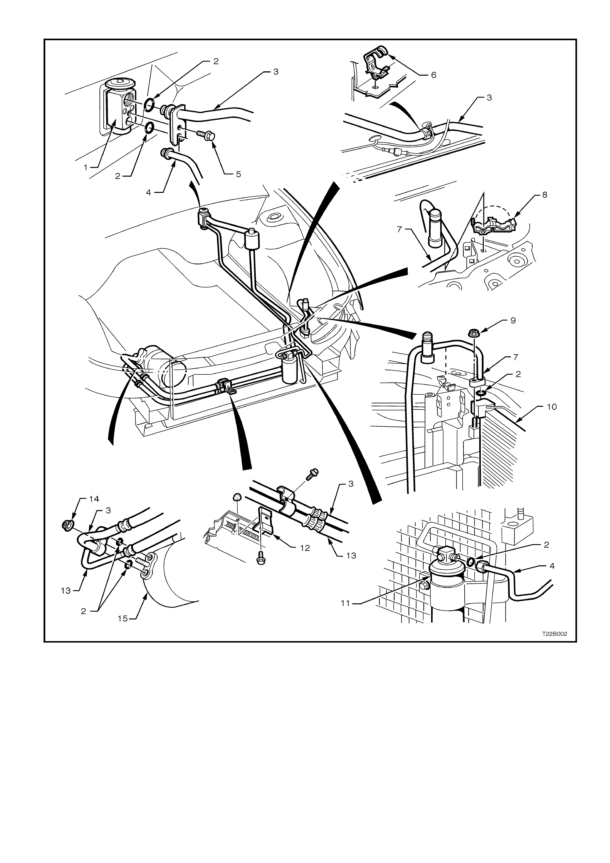
Figure 2B-1 GEN III V8 engine air conditioning hose and line layout
1. Thermal Expansion Valve (or block valve) 7. Discharge tube 13. Discharge hose/tube
2. 0-Ring 8. Discharge tube retaining clip 14. Retaining nut
3. Suction hose 9. Discharge tube retaining nut 15. Compressor
4. Liquid tube 10. Condenser
5. Retaining screw 11. Filter Drier Receiver (FDR)
6. Suction tube retaining clip 12. Retaining clamp
2. SERVICE OPERATIONS
2.1 HEATING, VENTILATION AND AIR CONDITIONING (HVAC) UNIT
REMOVE & REINSTALL
Removal and reinstallation of the HVAC unit on a
vehicle with a GEN III V8 engine is as detailed in
Section 2B AIR CONDITIONING - REMOVAL &
INSTALLATION of this Service Information CD,
noting the following:
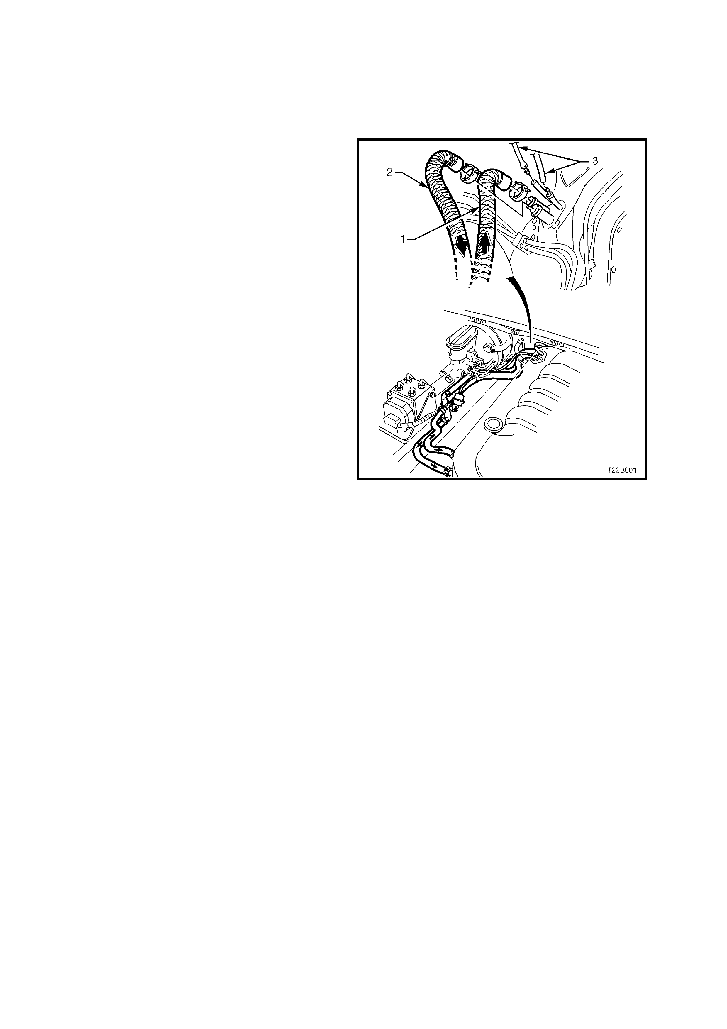
Figure 2B-2 shows the location of the heater
hoses and HVAC vacuum hoses in the engine
compartment. Before these hoses are removed,
they should be marked to ensure the correct
replacement position.
Figure 2B-2

2.2 CONDENSER - GEN III V8 ENGINE
REMOVE
1. Recover refrigerant from the air conditioning
system, refer to Section 2C AIR
CONDITIONING - SERVICING AND
DIAGNOSIS of this Service Information CD.
2. Remove the r adiator assem bly, refer to Section
6B3 ENGINE COOLING - GEN III V8 ENGINE
in the VT Series II Service Information.
3. Remove the two screws securing the left hand
side grille insert to the front bumper assembly
and lift grille out and up.
Figure 2B-3
4. Through the opening in the front bumper facia,
(where the left hand grille insert was removed)
unscrew the liquid tube fitting (1) from the Filter
Drier Receiver (FDR) (2) outlet.
T22B004
2
1
Figure 2B-4
5. Gently prise open the discharge tube retaining
clip (1).
6. Remove the nut ( 2) retaining the discharge tube
pad fitting (3) to the condenser (4).
7. Cap all open tubes/hoses to avoid moisture
from entering the system.
8. Discard O - ring (5).
T22B005
123
5
4
Figure 2B-5
9. ECC vehicles only: disconnect the ambient
temperature sensor electrical connector from
the front right hand side of the condenser.
10.Tilt the condenser towards engine and lift
upwards.
T22B006
Figure 2B-6
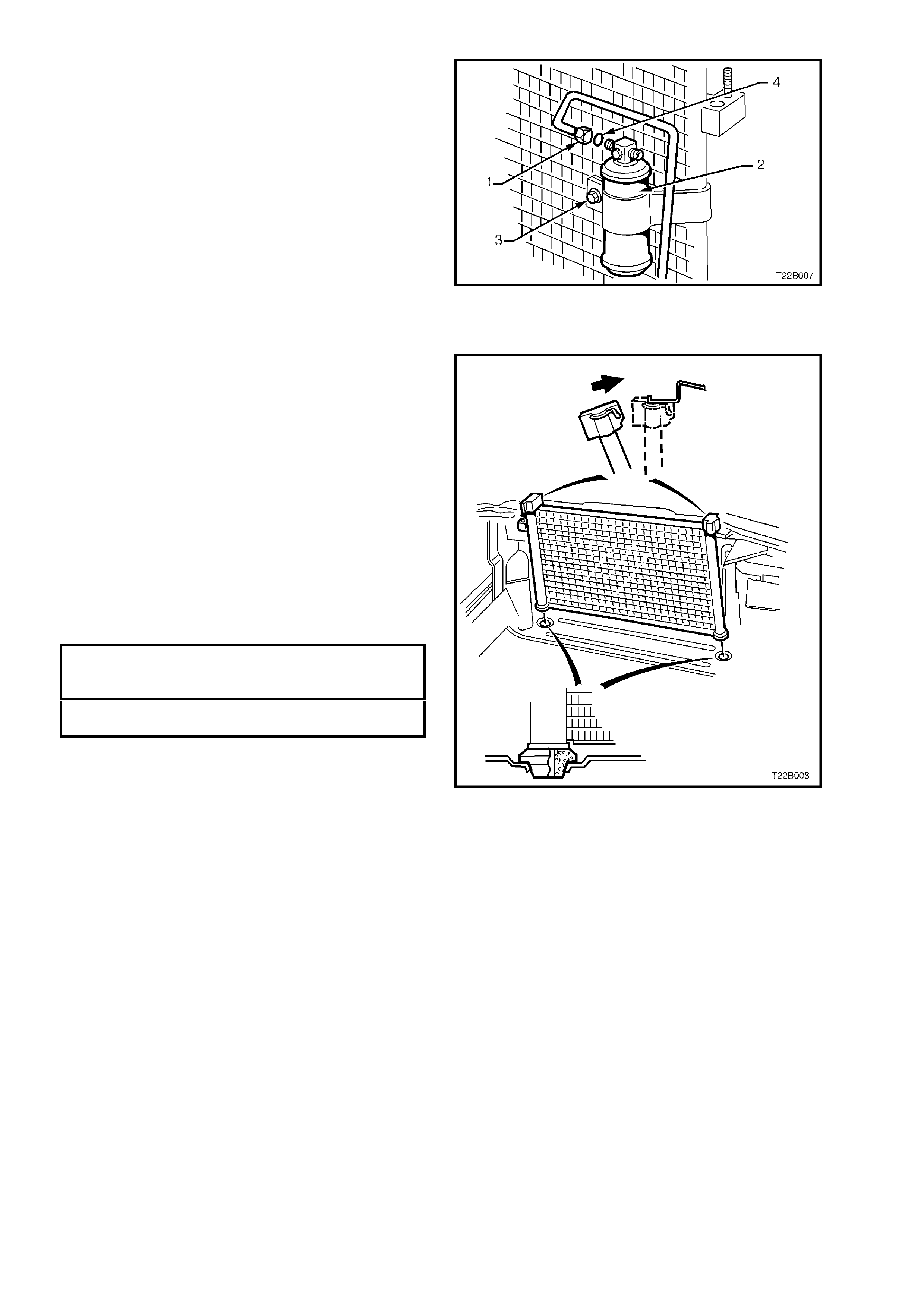
11.Mark mounting position of FDR for correct
reinstallation.
12.Unscrew the FDR inlet fitting (1), loosen the
FDR mounting bracket bolt (3) and remove the
FDR (2).
13.Discard O-ring (4).
Figure 2B-7
REINSTALL
Reinstallation of the c ondens er is the r evers e of the
removal procedure, noting the following:
1. Always use new O-r ings and lubricate with PAG
refrigerant oil (part number 12345923) before
fitting.
CAUTION: Do not allow PAG refrigerant oil to
contact bare skin or vehicle paint work. If contact
occurs to either, wash PAG refrigerant oil off
immediately.
2. When reinstalling the FDR, ensure the FDR inlet
tube is connected to the fitting on the FDR with
the word ‘IN’ on it (refer to markings on FDR
before removal).
3. Tighten all air conditioning fittings to the correct
torque specifications.
DISCHARGE TUBE PAD
RETAINING NUT 7.5 - 12.5 Nm
TORQUE SPECIF ICATION
AIR CONDITIONING TUBE FITTING 7.5 - 12.5
TO FDR TORQUE SPECIFICATION Nm
4. Recharge air conditioner system, refer to
Section 2C AIR CONDITIONING - SERVICING
& DIAGNOSIS of this Service Information CD. Figure 2B-8
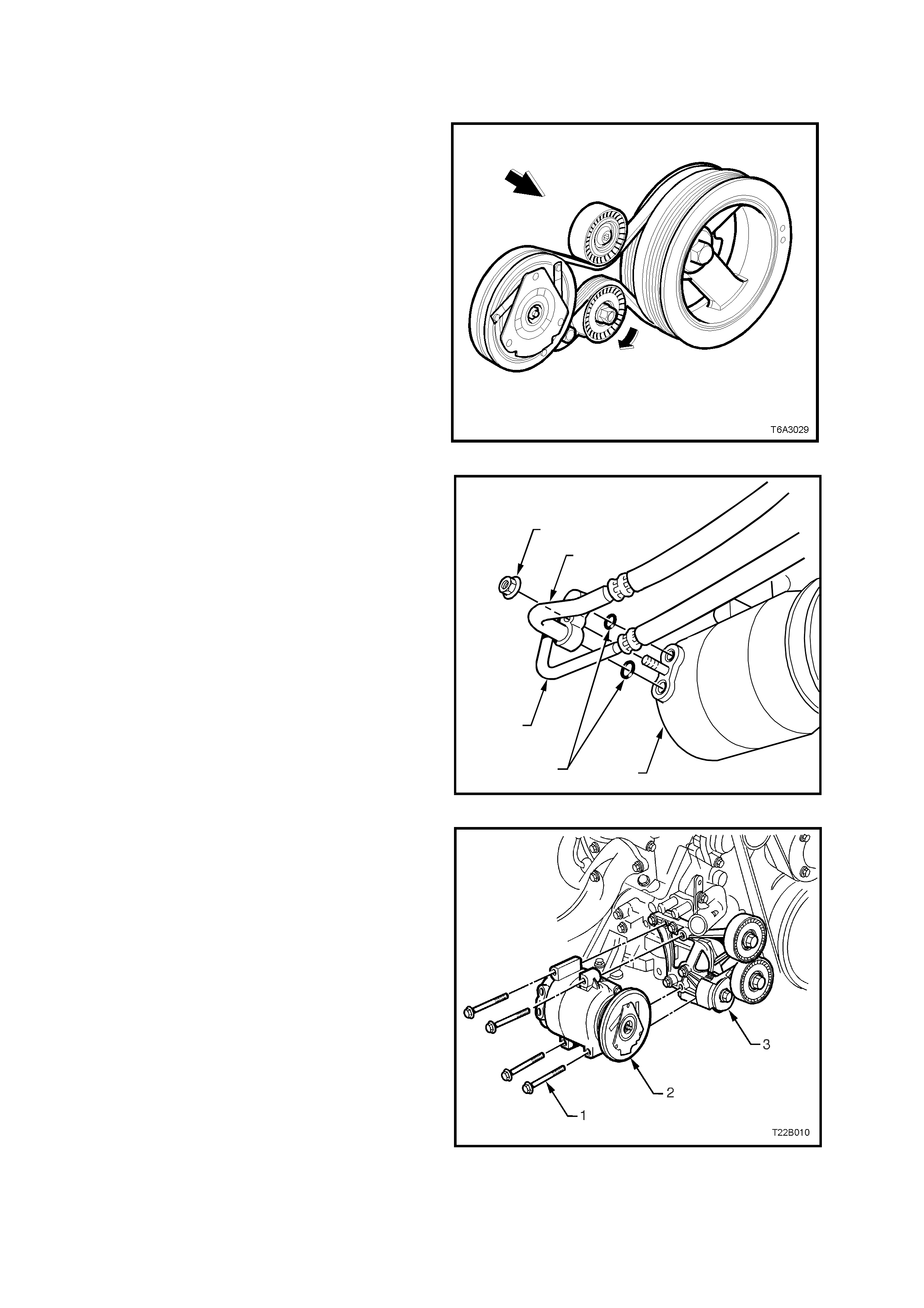
2.3 AIR CONDITIONING DRIVE BELT- GEN III V8 ENGINE
REMOVE
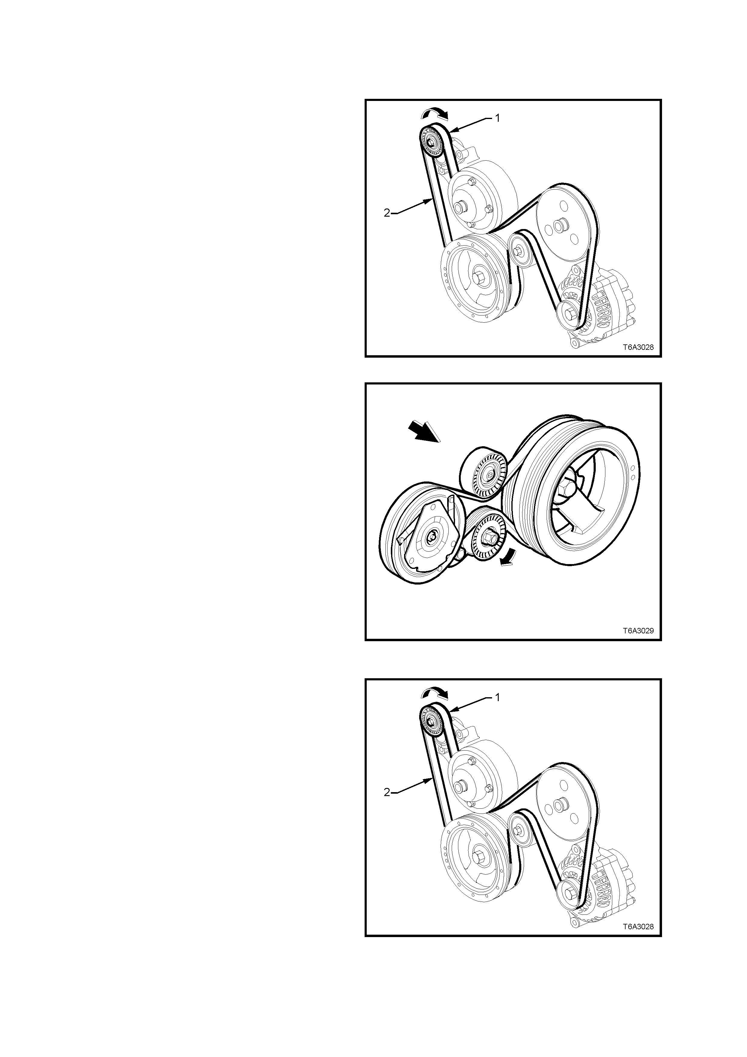
1. Using a 15mm socket attached to the centre
bolt of the tensioner, rotate the engine
accessory drive belt tensioner (1), in the
direction indicated, to reduce belt tension.
2. Remove the engine dr ive belt (2), taking note of
the belt routing.
Figure 2B-9
3. Using a 15mm socket attached to the centre
bolt of the tensioner, rotate the air conditioning
drive belt tensioner in the direction shown, to
relieve belt tension.
4. Remove the air conditioning drive belt from the
pulleys.
5. Inspect belts for damage and replace if
necessary.
REINSTALL
1. Clean the engine acces sory and air conditioning
drive belt running surfaces
2. Using a 15mm socket attached to the centre
bolt of the tensioner, rotate the air conditioning
drive belt tensioner in the direction shown, install
the drive belt over the pulleys, routing the belt
correctly , as shown.
3. Inspect the installation to ensure that the belt is
correctly aligned on all pulleys. Figure 2B-10
4. Using a 15mm socket attached to the centre
bolt of the tensioner, rotate the engine
accessory drive belt tensioner (1), in the
direction indicated, install the engine accessory
drive belt (2) over the pulleys, routing the belt
correctly , as shown.
5. Inspect the installation to ensure that the belt is
correctly aligned on all pulleys.
6. Start the engine to ensure correct operation.
Figure 2B-11
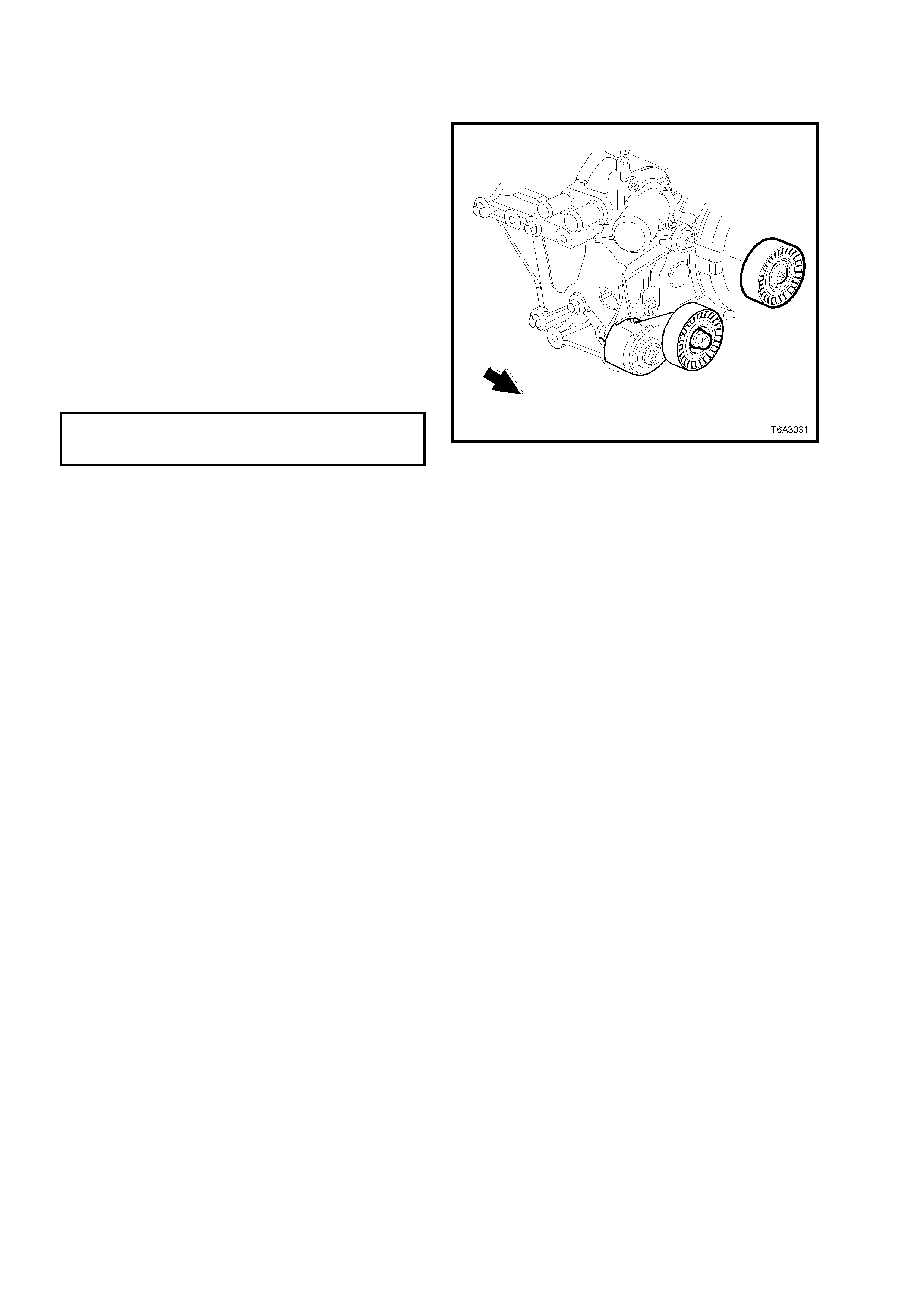
2.4 AIR CONDITIONING DRIVE BELT IDLER PULLEY - GEN III V8 ENGINE
REPLACE
1. Using a 15mm socket attached to the centre
bolt of the tensioner, rotate the air conditioning
drive belt tensioner in the direction shown in
Figure2B-10, to relieve belt tension.
2. Remove the air conditioning drive belt from the
pulleys but leave hanging on the crankshaft
pulley.
3. Using a commercially available, Torx bit T50,
remove the bolt securing the air conditioning
com pr es s or drive belt idler pulley to its mounting
boss on the water pump housing, then remove
the pulley assembly.
4. Install the idler pulley to its mounting boss.
5. Install the idler pulley retaining bolt and tighten
to the correct torque specification.
AIR CONDITIONING COMPRESSOR
DRIVE BELT IDLER PULLEY BOLT 40.0 - 60.0 Nm
TORQUE SPECIFICATION
6. Reinstall the air conditioning compressor drive
belt. Refer 2.3 AIR CONDITIONING DRIVE
BELT _ GEN III ENGINE – REINSTALL in this
Section for the necessary procedure.
Figure 2B-12
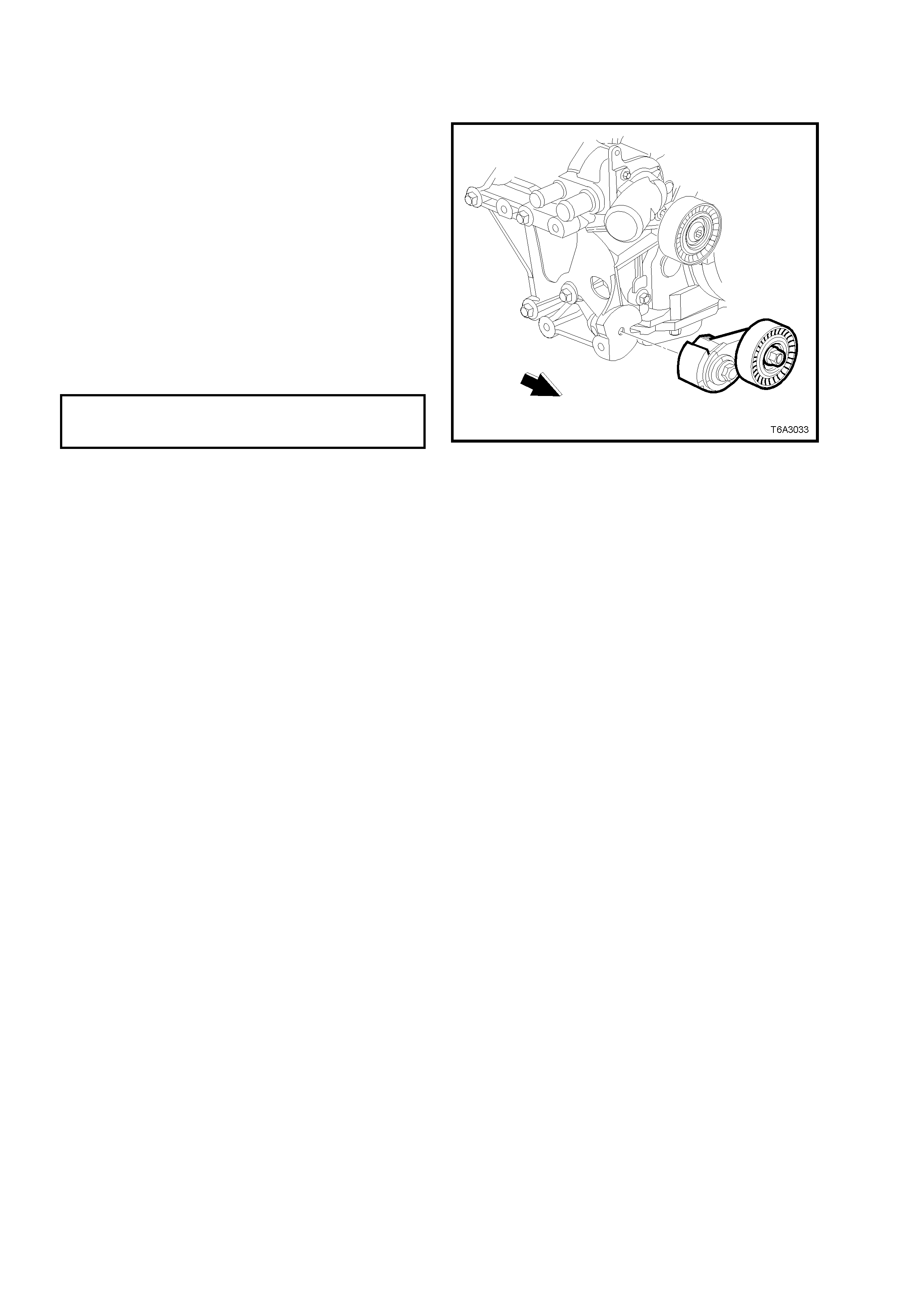
2.5 AIR CONDITIONING DRIVE BELT TENSIONER - GEN III V8 ENGINE
REPLACE
1. Using a 15mm socket attached to the centre
bolt of the tensioner, rotate the air conditioning
drive belt tensioner in the direction shown in
Figure 2B-10, to relieve belt tension.
2. Remove the air conditioning drive belt from the
pulleys but leave hanging on the crankshaft
pulley.
3. Remove the bolt securing the air conditioning
compressor drive belt tensioner, then remove
the assembly.
4. Install the tensioner as sembly and the mounting
bolt.
5. Tighten the tensioner mounting bolt to the
correct torque specification.
AIR CONDITIONING DRIVE BELT
TENSIONER BOLT 21.0 - 29.0 Nm
TORQUE SPECIFICATION
6. Reinstall the air conditioning compressor drive
belt. Refer 2.3 AIR CONDITIONING DRIVE
BELT - REINSTALL in this Section for the
necessary procedure.
Figure 2B-13
2.6 COMPRESSOR - GEN III V8 ENGINE
REMOVE
1. Disconnect the battery ground cable.
2. Drain coolant and rem ove the heater hoses and
lower radiator coolant hose from the cylinder
block , refer to Section 6B3 ENGINE COOLING
- GEN III V8 ENGINE in the VT Series II Servic e
Information.
3. Recover refrigerant charge, refer to
Section 2C AIR CONDIT IONING - SERVICING
AND DIAGNOSIS of this Service Information
CD.
4. Using a 15mm socket attached to the centre
bolt of the air conditioning drive belt tensioner,
rotate the tensioner in the direction shown in
Figure 2B-10, to relieve belt tension.
5. Remove the air conditioning drive belt from the
pulleys but leave hanging on the crankshaft
pulley. Figure 2B-14
6. Loosen and remove the nut (1) retaining the
suction (2) and discharge (3) hoses to the
com press or (4). Rem ove the hoses (2 & 3) f rom
the compressor.
7. Discard O-rings (5).
8. Cap or plug the ports immediately to prevent
entry of moisture from the atmosphere.
9. Disconnect the compressor clutch electrical
connector.
T22B009
1
2
3
54
Figure 2B-15
10.Remove the four bolts (1) retaining the
compressor (2) to the mounting bracket (3).
NOTE: Figure 2B-16 shows several components
removed for clarity only (i.e. heater and coolant
hoses). To remove the compressor, it is not
necessary to remove these components.
11.Remove compressor.
12. If necess ary, remove the f our bolts retaining the
compressor mounting bracket to the cylinder
block and remove the mounting bracket.
Figure 2B-16

REINSTALL
1. If removed, reinstall the compressor mounting
bracket and tighten the four retaining bolts to
the correct torque specification.
COMPRESSOR MOUNTING BRACKET
RETAINING BOLT 40.0 - 60.0 Nm
TORQUE SPECIFICATION
NOTE: If replacing with a new compressor refer to
Section 2C AIR CONDITIONING - SERVICING
AND DIAGNOSIS of this Service Information CD
for lubrication requirements/specifications.
2. Fit the compressor to the com pressor mounting
bracket, install the four retaining bolts and
tighten to the correct torque specification.
COMPRESSOR RETAINING BOLT 40.0 - 60.0
TORQUE SPECIFICATION Nm
3. Reinstall the air conditioning compressor drive
belt. Refer 2.3 AIR CONDITIONING DRIVE
BELT – GEN III V8 ENGINE - REINSTALL in
this Section for the necessary procedure.
4. Remove c aps f r om compres sor ports and ins tall
new sealing washers.
5. Using new O-rings lubricated with PAG
refrigerant oil (part number 12345923) install
the air conditioning suction and discharge hose
pad fitting onto the compressor.
CAUTION: Do not allow PAG refrigerant oil to
contact bare skin or vehicle paint work. If contact
occurs to either, wash PAG refrigerant oil off
immediately.
6. Install the suction and discharge hose pad
retaining nut and tighten to the correct torque
specification.
SUCTION AND DISCHARGE HOSE
PAD RETAINING NUT 28.0 - 42.0 Nm
TORQUE SPECIFICATION
7. Connect the compressor clutch electrical
connector.
8. Connect heater and lower radiator coolant
hoses, refill coolant system with correct coolant
and pressure test coolant system, refer to
Section 6B3 ENGINE COOLING - GEN III V8
ENGINE in VT Series II Service Information.
9. Recharge air conditioner system, refer to
Section 2C AIR CONDITIONING - SERVICING
& DIAGNOSIS of this Service Information CD.

3. TORQUE WRENCH SPECIFI CATIONS
For torque wrench specifications not listed below, refer to Section 2B HEATING AND AIR CONDITIONING -
REMOVAL AND INSTALLATION, of this Service Information CD.
GEN III V8 ENGINE Nm
Air conditioning compressor drive belt idler pulley bolt......... 40.0 - 60.0
Air conditioning compressor drive belt tensioner bolt ........... 21.0 - 29.0
Air conditioning tube fittings to FDR...................................... 7.5 - 12.5
Compressor mounting bracket retaining bolt........................ 40.0 - 60.0
Compressor retaining bolt..................................................... 40.0 - 60.0
Compressor suction and discharge hose pad retaining nut.. 28.0 - 42.0
Condenser discharge tube pad retaining nut........................ 7.5 - 12.5
V6 ENGINE Nm
Compressor retaining bolt..................................................... 20.0 - 30.0
Compressor retaining nut...................................................... 40.0 - 55.0
Compressor suction and discharge hose pad retaining nut.. 28.0 - 42.0
NOTE: The V6 compressor torque wrench specifications listed above were
either omitted or incorrectly quoted in Section 2B HEATING AND AIR
CONDITIONING - REMOVAL AND INSTALLATION, of this Service
Information CD.