
SECTION 5A - STANDARD BRAKES
CAUTION:
This vehicle will be equipped with a Supplemental Restraint System (SRS). A SRS will consist of either
seat belt pre-tensioners and a driver's air bag, seat belt pre-tensioners and a driver's and front
passenger's air b ags o r seat b elt p re-t ension ers, driv er’s an d f ron t p asseng er’s air bag and left and righ t
hand side air bags. Refer to SAFETY PRECAUTIONS, Section 12M Supplemental Restraint System of
this Service Information CD before performing any service operation on, or around any SRS
components, the steering mechanism or wiring. Failure to follow the SAFETY PRECAUTIONS could
result in SRS deployment, resulting in possible personal injury or unnecessary SRS system repairs.
CAUTION:
This vehicle may be equipped with LPG (Liquefied Petroleum Gas). In the interests of safety, the LPG
fuel system should be isolated by turning 'OFF' the manual service valve and then draining the LPG
service lines, before any service work is carried out on the vehicle. Refer to the LPG leaflet included with
the Owner's Handbook for details or the appropriate Section of this Service Information CD for more
specific servicing information.
1. GENERAL INFORMATION
Standard brake components on VT Series II Models carry over from earlier VT Series Models, with some minor
revisions to accommodate the GEN III V8 engine.
Thes e revisions c onsist of a m inor modif ication to the routing of the brak e pipes and on vehicles with a GEN III V8
engine, a new brake booster vacuum hose.
Also included in this Section is a revised brake disc Service Operation, which includes a detailed procedure for
checking brake disc runout and indexing the brake disc to the hub to prevent brake shudder.
NOTE: Disc and hub indexing involves aligning the point of maximum runout on the hub with the point of least
runout on the brake disc.
Techline
Techline
Techline
Techline
Techline
Techline
2. SERVICE OPERATIONS
Excluding the brake disc Service Operation, all standard brake Service Operations for VT Series and VT Series II
Models carry over from those detailed in Section 5A STANDARD BRAKES of this Service Inform ation CD, noting
the following:
The torque s pecification quoted f or the park brak e lever bolt, listed in Section 5A STANDARD BRAKES in the VT
Series I Service Information are incorrect. The correct torque specification for these bolts is 35 - 65Nm.
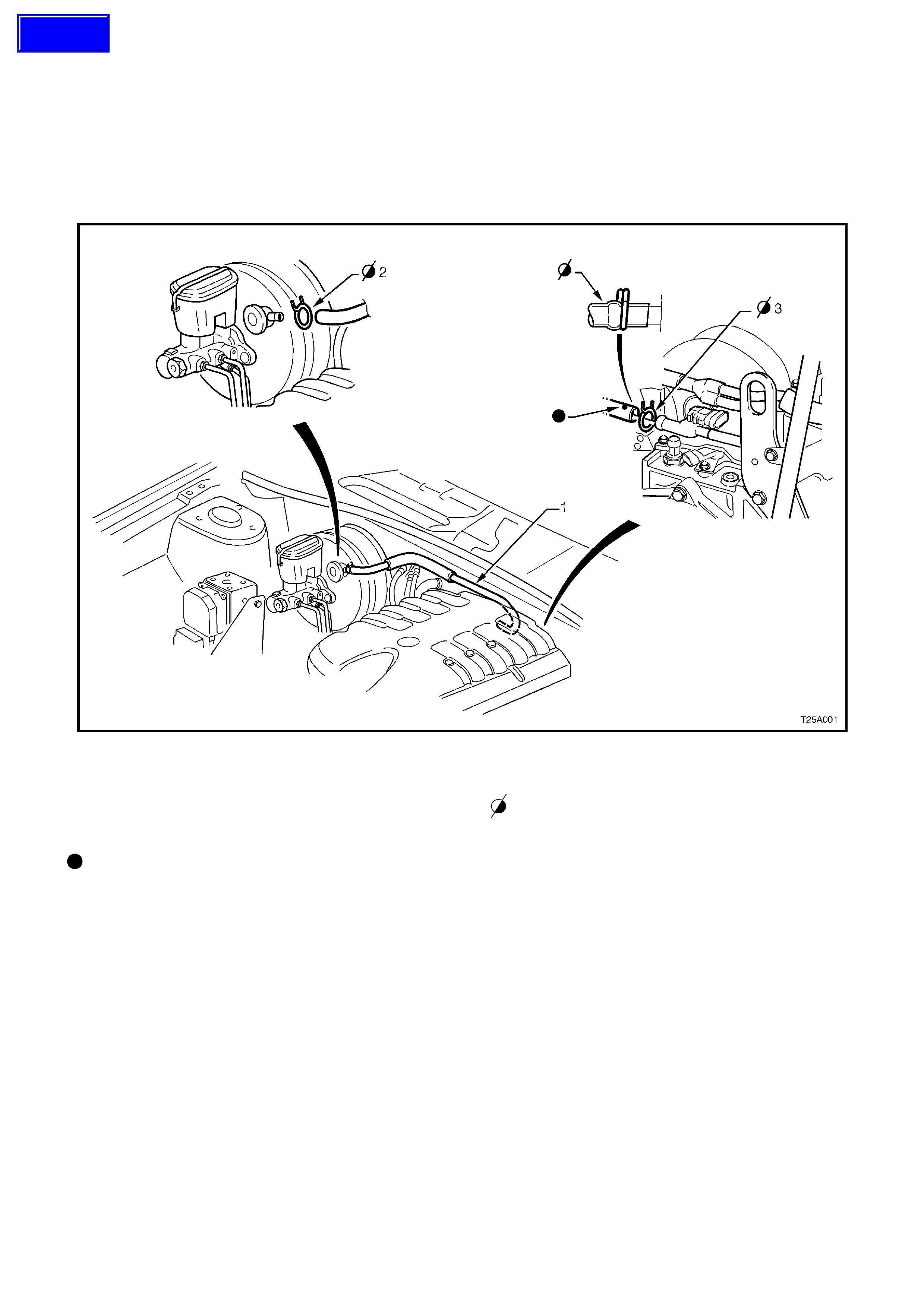
If removal of the brake booster vacuum hose on VT Series Models with GEN III V8 engines becomes necessary,
reference to Figure 5A-1 should be made for the correct routing and retainment of this hose.
Figure 5A-1
1. GEN III brake booster vacuum hose.
2. Retaining clip, brake booster end.
3. Retaining clip, engine manifold end.
Blue spot to be on top.
Ensure hose ends are clamped behind the ridge
on the nipple to prevent hoses from
disengaging.
Techline
2.1 FRONT BRAKE DISC
CAUTION: Whenever any component that
forms part of the ABS (if fitted) is disturbed
during Service Operations, it is vital that the
complete ABS system be checked, using the
procedure as detailed in DIAGNOSIS, ABS
FUNCTION CHECK, in Section 12L ABS &
ABS/ETC (V6 engine) or Section 12L ABS &
ABS/ETC (GEN III V8 engine) of this Service
Information.
REMOVE
IMPORTANT: T he brake dis c to hub relationship is
carefully matched during production (indexed), to
minimise the effect of a tolerance stack-up, that
could result in disc runout and subsequent brake
shudder.
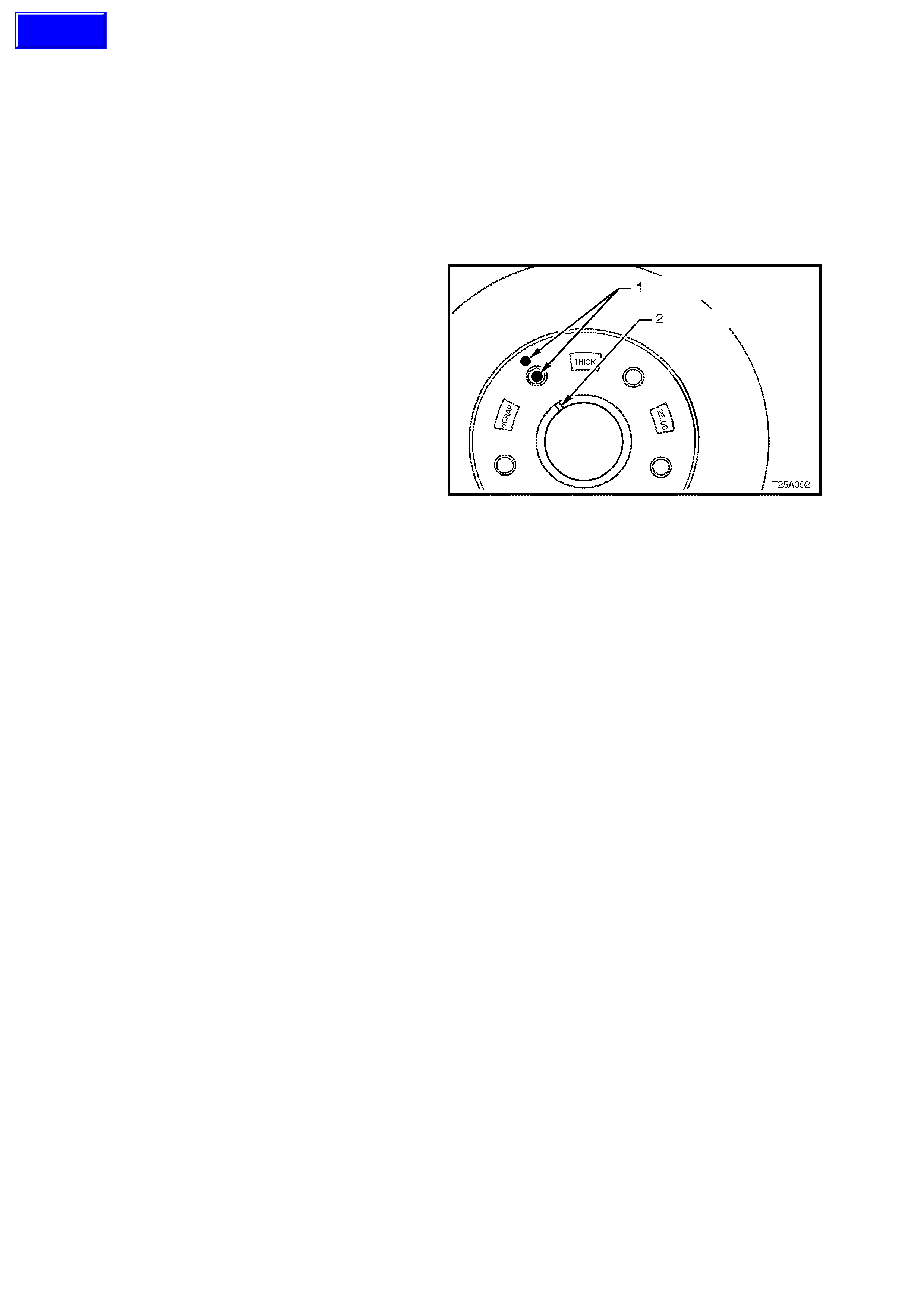
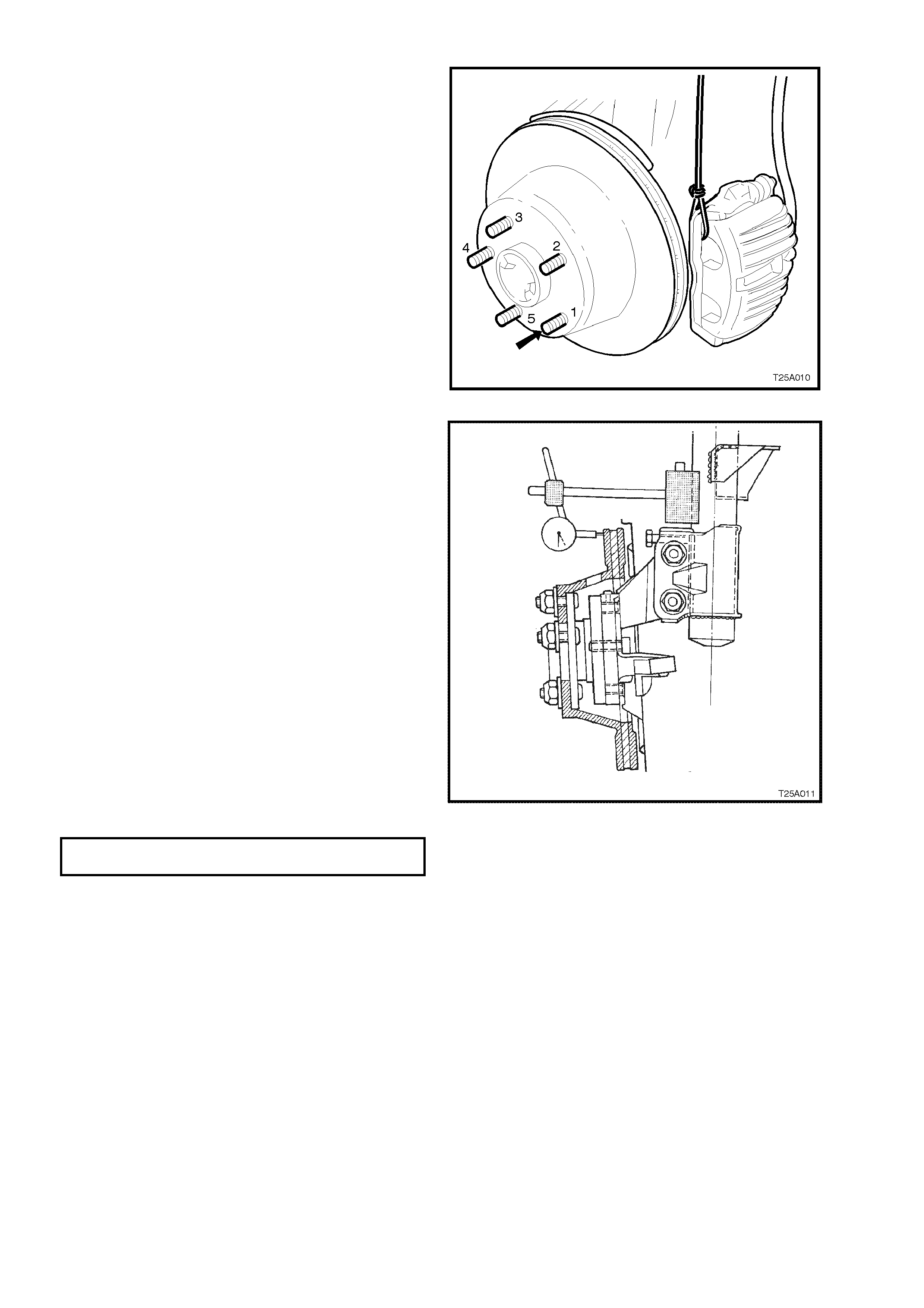
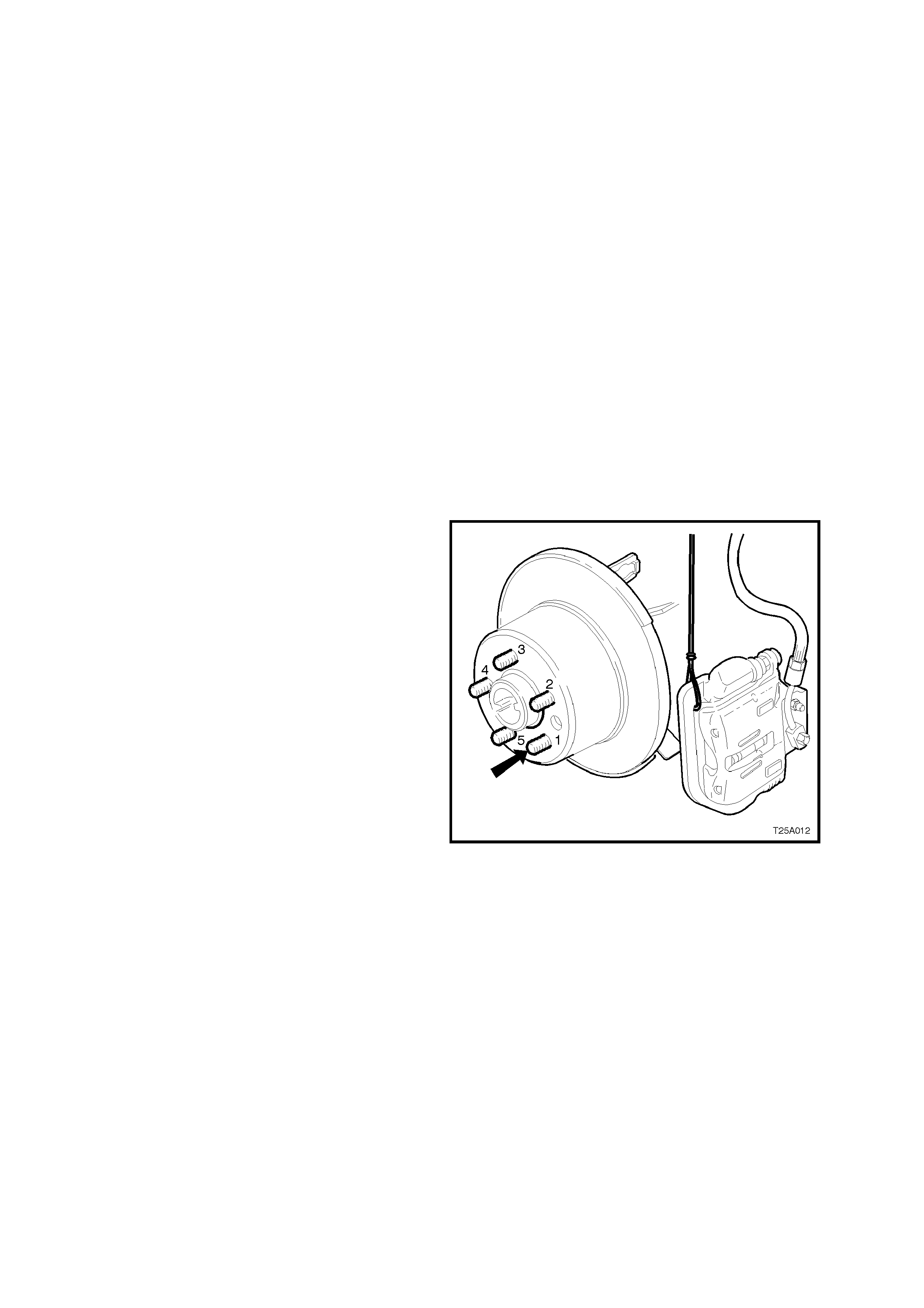
Therefore, prior to removal of the front brake disc/s,
check to see whether a paint daub mark (1) is still
visible on the brake disc hub surface, adjacent to
one of the wheel studs and in alignment with the
two marks (2) on the end of the hub, as shown.
If the paint marks are no longer visible, then
carefully mark the relationship of the brake disc to
the hub for installation. If this precaution is not
taken, then a disc runout condition could be
induced that will cause brake shudder.
NOTE: If the br ake disc is being removed to rec tify
brake shudder, if the brake disc is to be machined
or replaced, or if brake disc to hub m atching is not
evident, the brake disc to the hub must be indexed.
Figure 5A-2
1. Remove brake calliper assembly, refer to 3.3
BRAKE CALLIPER (FRONT AND REAR), in
Section 5A STANDARD BRAKES of the VT
Series I Service Information.
NOTE: It is not necessary to disconnect the brake
hose from calliper. Support the calliper with a wire
hook to avoid strain on the brake hose.
2. If necessary, jar the brake disc loose by
carefully tapping the disc in the centre
between the wheel studs, with a soft faced
hamm er, tak ing care not to dam age the wheel
stud threads.
INSPECT
If the brak e disc surface is rusted or lightly scored,
resurface disc. Scores less than 0.4 mm deep will
not affect brake performance.
If scoring is deep or if brake disc parameters are
out of specification, the disc must be machined.
NOTE 1: Machine or resurface BOTH sides of
disc. Do not machine or resurface one side only.
Techline
NOTE 2: After machining, the brak e disc s hould be
ground to achieve a non-circumferential finish of
0.4 to 2.0 microns.
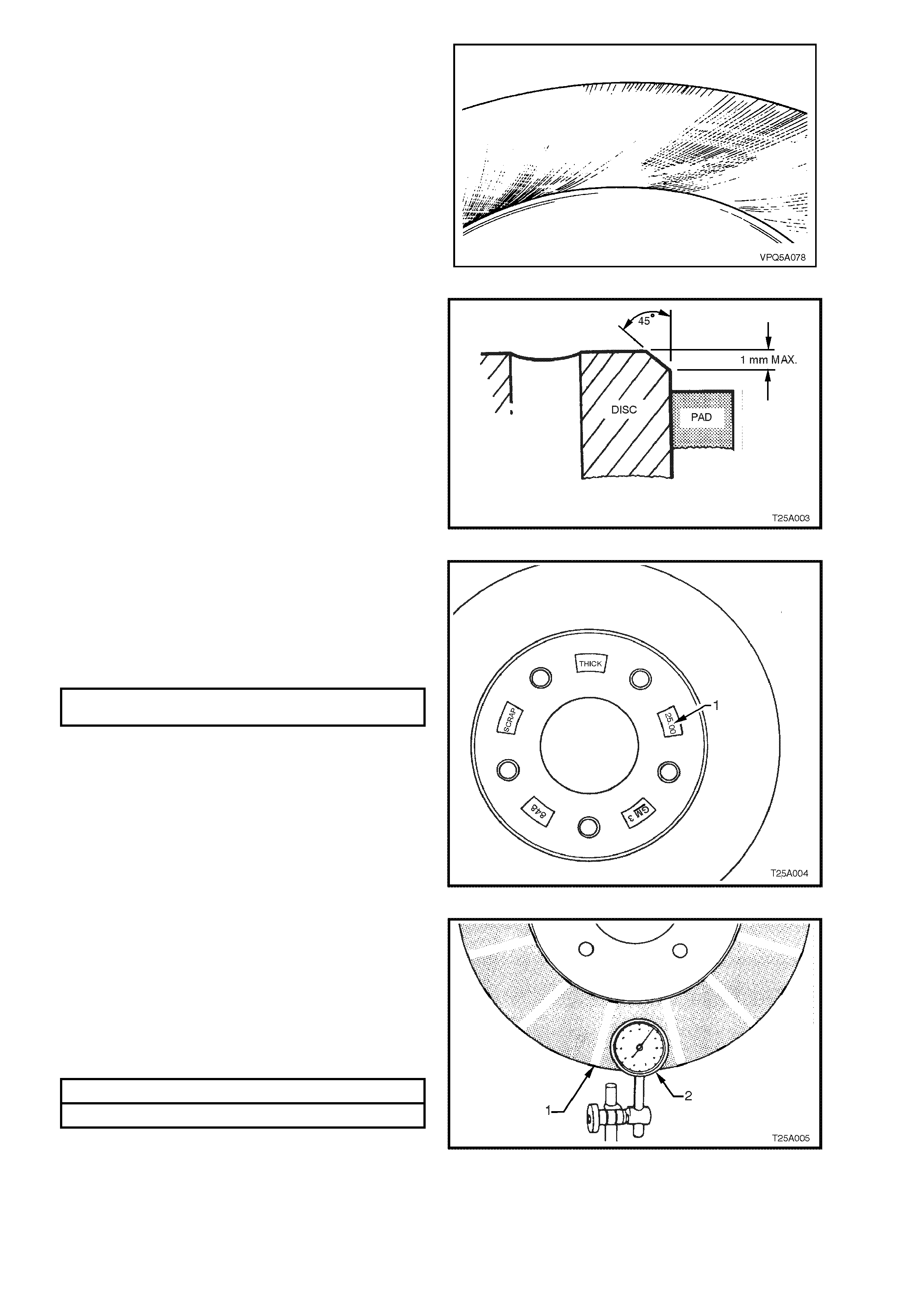
Figure 5A-3
NOTE 3: After machining, the chamfer on the
brake disc outer diam eter must be 45 deg x 1 mm
maximum with a pad to chamfer clearance of 1.3
mm minimum to 2.5 mm maximum. This is to
prevent thermal stress cracking at the top of the
disc.
Figure 5A-2
NOTE 4: Replace disc if specifications cannot be
achieved above the minimum disc thickness.
WARNING:
THE NUMBER CAST INTO THE HUB (1) IS THE
MINIMUM SAFE THICKNESS. AT THIS
THICKNESS THE DISC MUST BE REPLACED
MINIM U M BRAKE DISC T HICKNESS 25.0
(REPLACEMENT REQUIRED) mm
Figure 5A-3
Inspect disc as follows:
1. Using a piece of chalk, mark the brake disc
every 30 deg (1).
2. Using a dial indicator (2), check that lateral
run-out of each braking surface does not
exceed 0.04 m m Total Indicated Runout (T IR)
and that the rate of change does not exceed
0.03 mm in 30 deg.
MAX IM UM LATERAL RUNOUT (TIR) 0.04mm
MAX IM UM LATERAL RUNOUT IN 30 DEG 0.03mm
NOTE: This specification is the lateral run-out of a
front brake disc that has been removed from the
vehicle (do not confuse this with brake disc to hub
assembled lateral run-out.
Figure 5A-4
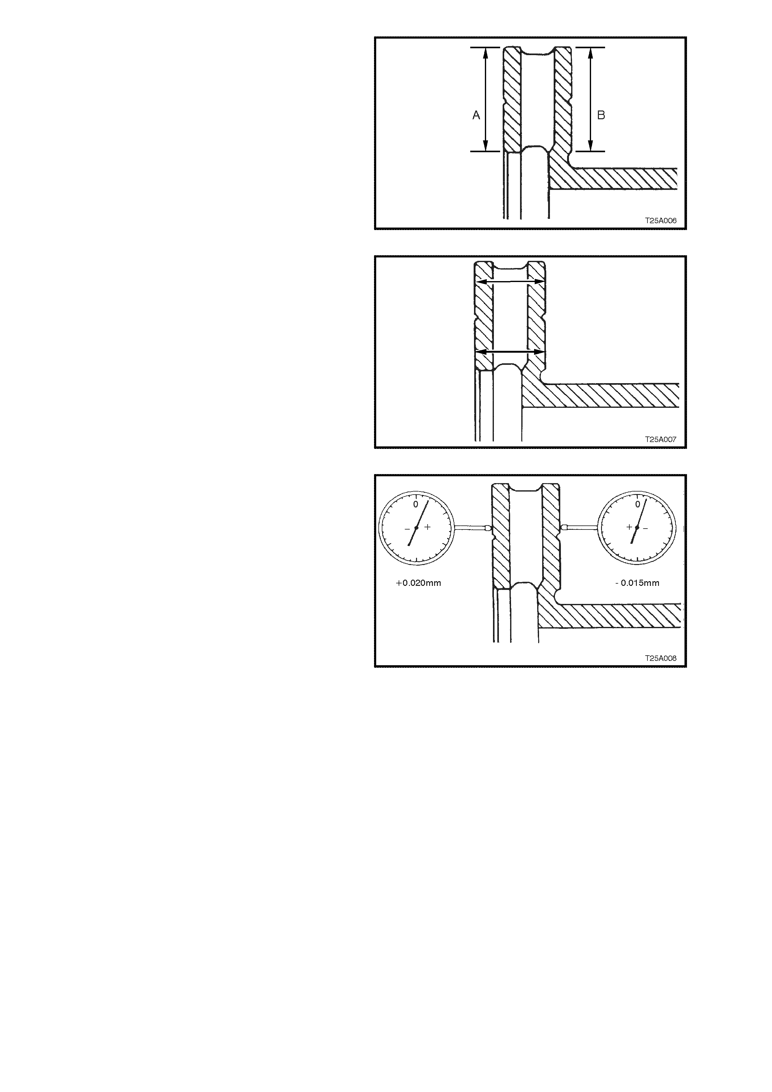
3. Check that both surfaces of the brak e disc (A &
B) are flat within 0.05 mm TIR.
Figure 5A-5
4. Check that disc s ur f aces ar e parallel with each
other to within 0.08 mm, when checked
radially.
NOTE: Taper variation must not exceed 0.08mm
Figure 5A-6
5. Check that total circumferential thickness
variation, (also referred to as Disc Thickness
Variation) at any radius, does not exceed
0.005 mm in 360 deg as the brake disc is
rotated.
NOTE: To measure the thickness variation,
measure both sides of the brake disc for runout
and add the two measurements together.
i.e. In the sample opposite:
Total runout on one side = +0.020mm
Total runout on other side = - 0.015mm
Therefore +0.020 +-0.015 = +0.005mm Figure 5A-7

BRAKE DISC AND HUB INDEXING PROCEDURE
NOTE 1: Brake disc and hub indexing is required in
order to obtain the minimum installed brake disc
runout. Brake disc and hub indexing involves
aligning the point of maximum runout on the hub
with the point of least runout on the brake disc
NOTE 2: This procedure is to be used whenever
reinstalling brake discs that have been rem oved for
machining off car. It must also be used when
installing new brake discs or brake discs that have
been removed for any reason and where the brake
disc to hub matching is not evident.
The procedure consists of three parts as follows:
Part 1. Clean mating surfaces
Part 2. Measure and Match brake disc high point
to hub low point. If these measurements are not
OK, go to Part 3
Part 3. Checking hub mounting face runout
Part 1. Clean mating surfaces
Ensure that brake disc and hub mating surfaces
are free from dirt, corrosion, etc. If required, use
fine emery paper to clean surfaces.
Part 2. Indexing brake disc to hub
1. Fasten the brak e disc onto the hub with wheel
nuts reversed to avoid damage to the tapers,
and nip up with a spanner.
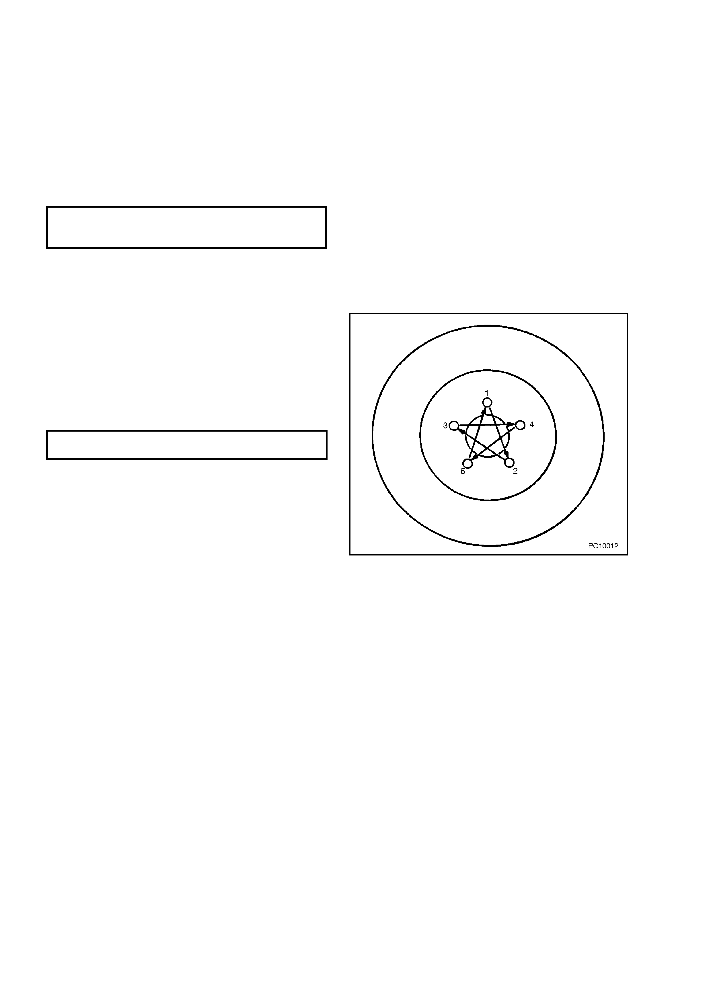
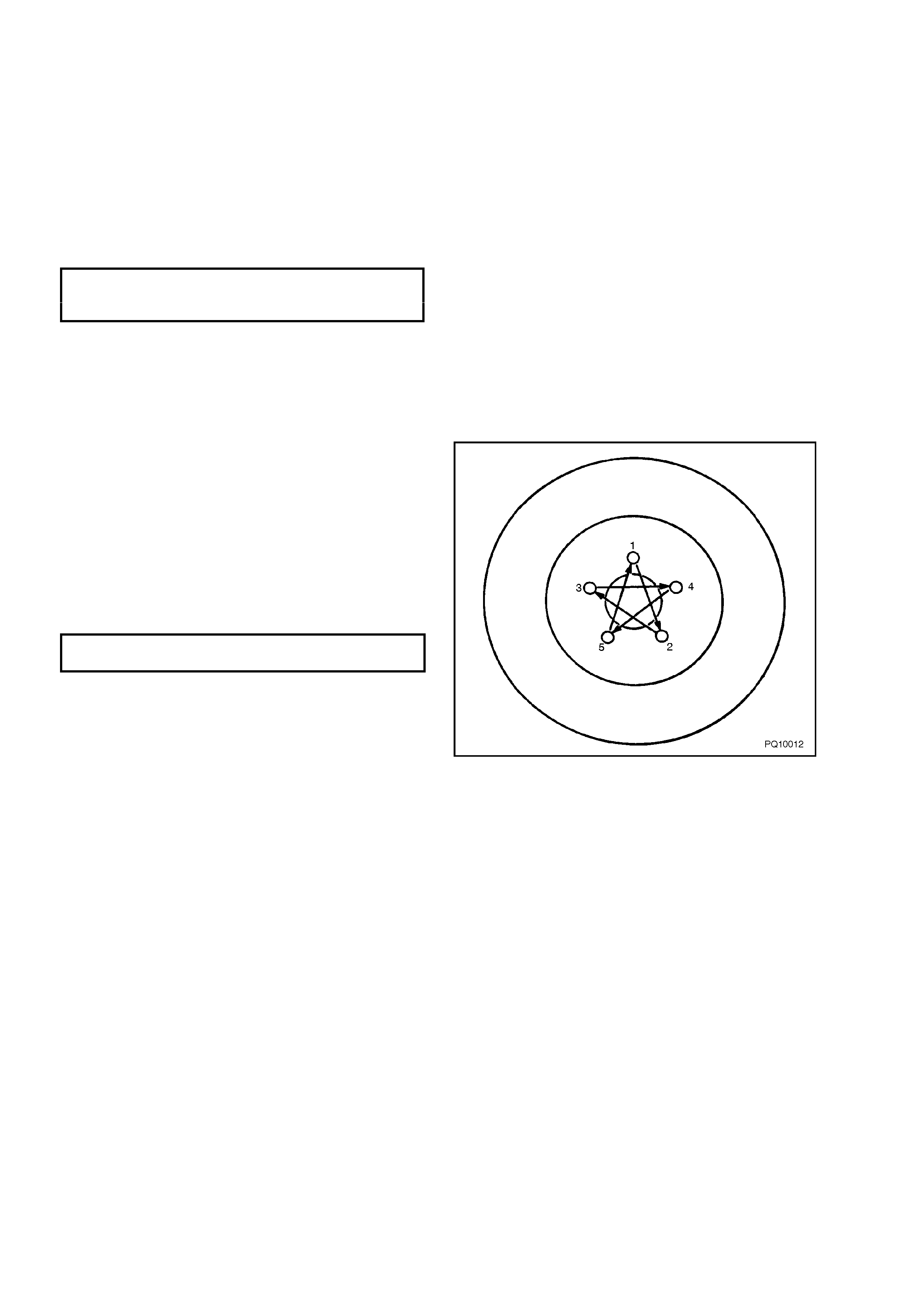
2. Number each of the wheel stud holes on the
front surface of the brake disc from 1 to 5.
Place a chalk mark on the end of the wheel
stud adjacent to the number “1” hole.
Figure 5A-8
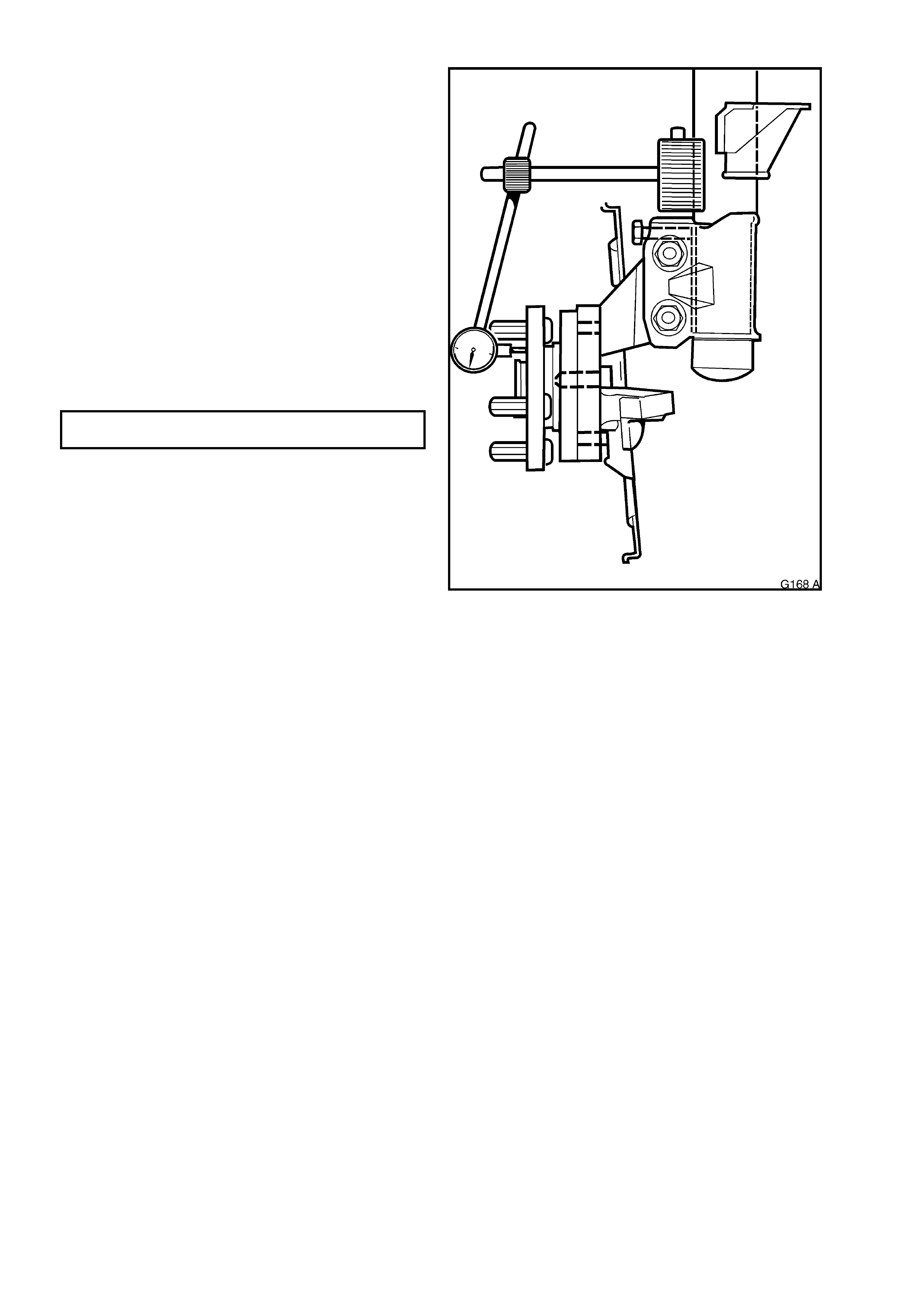
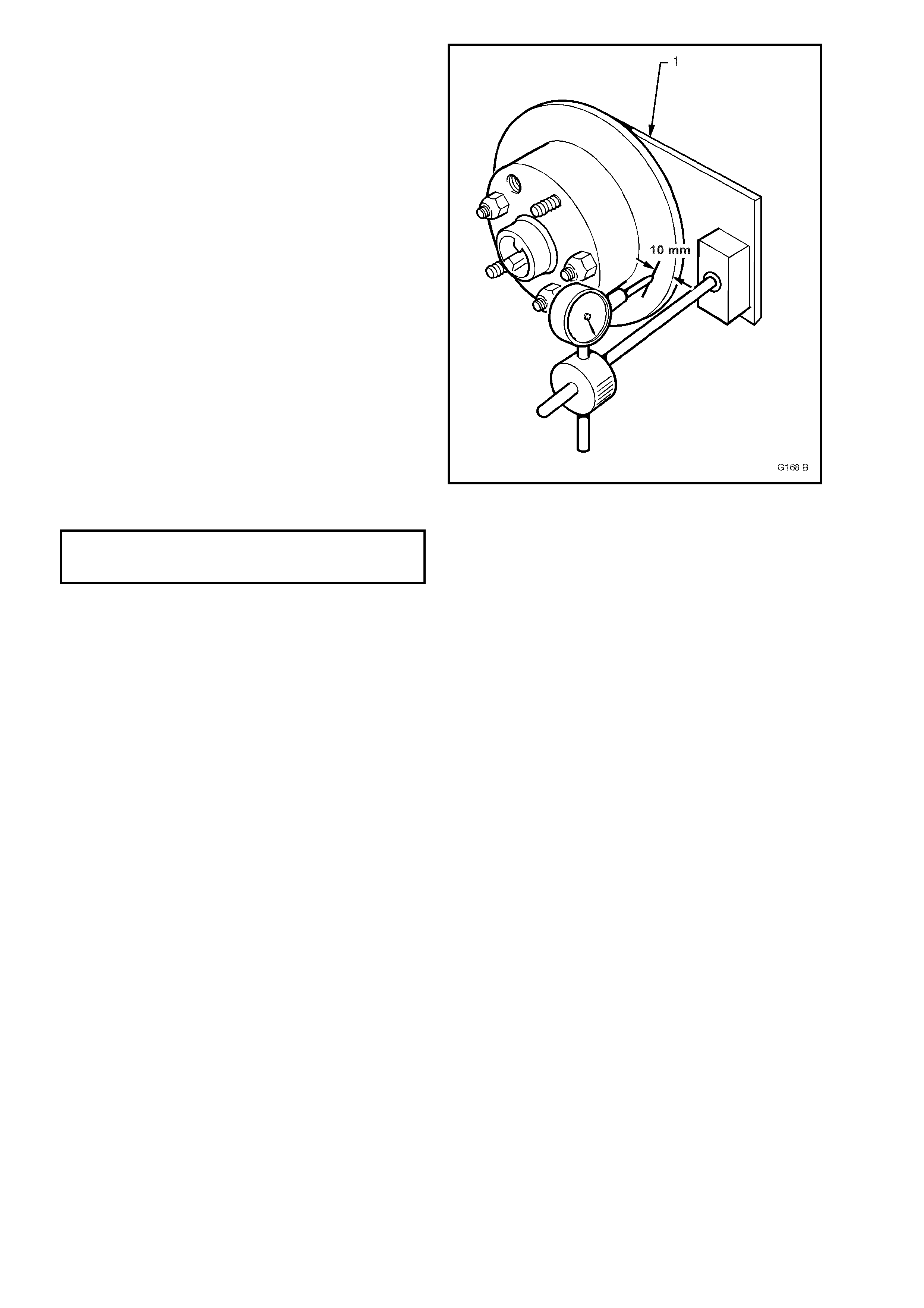
3. Set up a dial indicator on a m agnetic bas e and
attach to the strut tube above the brake disc.
Position the pointer about 10 to 15mm inboar d
from the outer diameter of the brake disc.
4. Carefully rotate the brake disc and note the
points of minimum and maximum runout on
the dial indicator. The number of divisions
between these two points is the total indicated
runout. Record this figure together with the
number on the brake disc aligned with the
chalk-marked stud.
5. Remove and reinstall the brake disc with hole
number “2” over the marked stud. Repeat Step
4. This procedure is to be repeated for all 5
hole positions.
6. Mount the brake disc to the hub in the stud
position which recorded the least amount of
runout.
NOTE: If the lowest assembled disc runout
achieved is more than 0.050 mm (50 micron)
then the hub runout should be checked as
detailed in Part 3.
MAX IM U M ASSEMBLED DISC & HUB 0.05
RUNOUT AT DISC OUT ER DIAM ET ER mm
Figure 5A-9
Part 3. Hub runout check
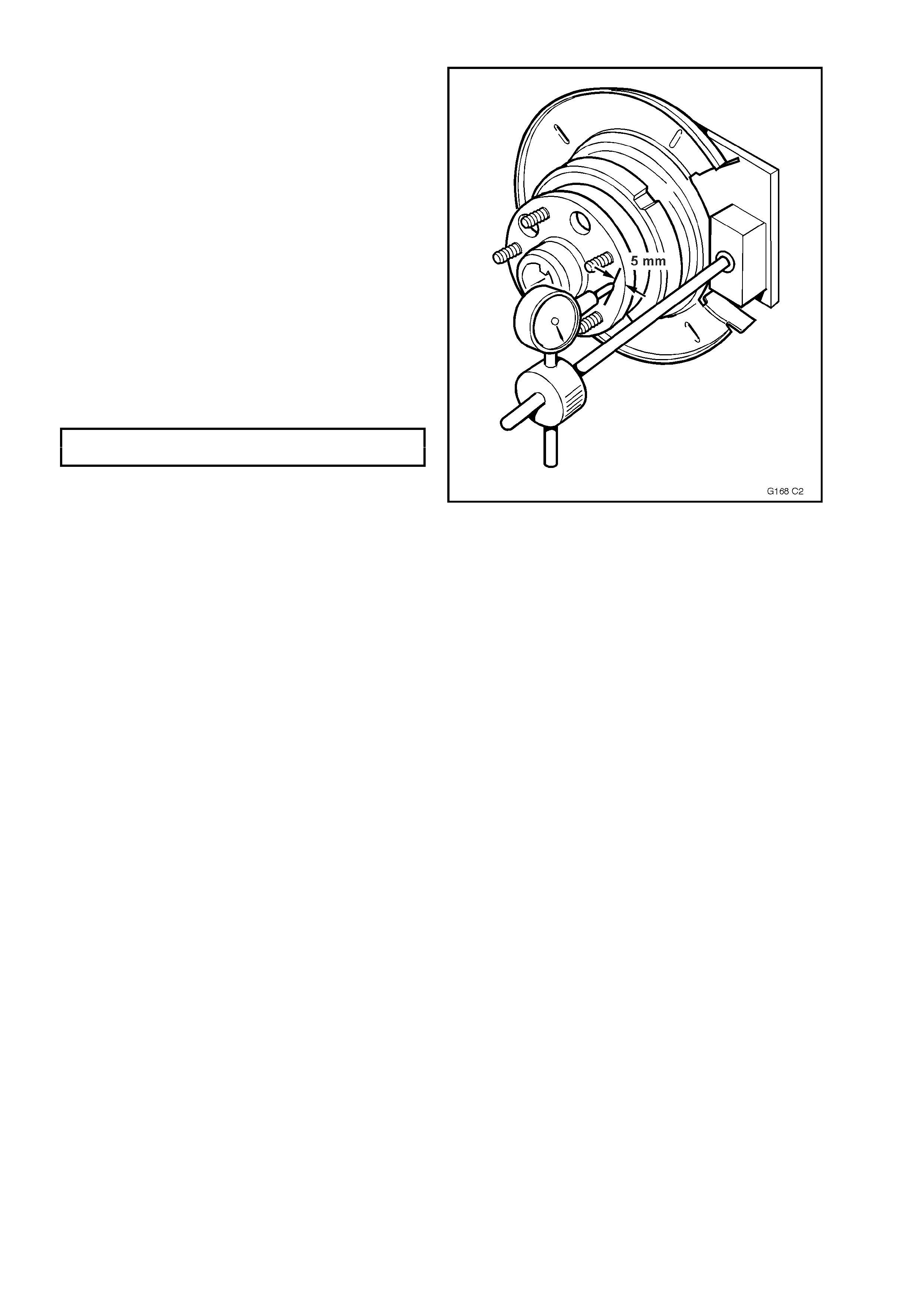
1. Clean the front hub f ace by rubbing lightly with
fine emery paper.
2. Locate the dial indicator on the strut tube and
position the pointer on the hub face about
midway between the spigot and the studs.
NOTE: For this check to be performed to 100 %
accurac y, a flat paralleled surfac e plate attached to
the hub should be used, however, measuring
runout between each of the wheel studs should
suffice.
3. Carefully rotate the hub by the hub spigot (to
avoid loading the bearing) and note the points
of minimum and maximum runout on the dial
indicator. The number of divisions between
these two points is the total indicated runout.
4. If the runout measured in Step 3 exceeds
0.025 mm (25 micron) then the hub unit
should be replaced.
MAX IM UM RUNOUT AT HUB FACE 0.025
– FRONT HUB mm
Figure 5A-10
REINSTALL
1. Reinstall the brake disc over the wheel studs
in either the pre-marked/indexed position or
the newly indexed position.
2. Ensure anchor plate mounting surfaces are
clean.
3. Position calliper assembly over brake disc,
insert anchor plate retaining bolts and
washers.
4. Ensure brake hose is not kinked or twisted.
5. Tighten anchor plate bolts to specified torque.
FRONT BRAKE CALLIPER 80- 90 Nm, plus
ANCHOR PLATE BOLT 40° - 50°
TORQUE SPECIFICATION turn angle
6. Depress the brake pedal several times to
bring pads into position against disc.
7. Reinstall road wheels aligning marks made
prior to removal then lower vehicle.
8. Tighten road wheel attaching nuts to the
specified torque and in the order shown.
NOTE: Do not use an impact gun to tighten wheel
nuts unless it is fitted with a torque limiter bar
(commercially available). Failure to correctly tighten
wheel nuts to the correct torque specification may
result in a warped brake disc, which may lead to
development of brake shudder.
ROAD WHEEL ATTACHING NUT 110 - 140
TORQUE SPECIFICATION Nm
Figure 5A-11

2.2 REAR BRAKE DISC
CAUTION : Whenever any component that forms part of the ABS (if fitted) is disturbed during Service
Operations, it is vital that the complete ABS system be checked, using the procedure as detailed in
DIAGNOSIS, ABS FUNCTION CHECK, in Section 12L ABS & ABS/ETC, (V6 engine) or Section 12L ABS &
ABS/ETC (GEN III V8 engine) of this Service Information.
REMOVE
IMPORTANT: The brake disc to hub relationship is carefully matched during production (indexed), to minimise the
effect of a tolerance stack-up, that could result in disc runout and subsequent brake shudder.
Carefully mark the relationship of the brake disc to the hub for installation. If this precaution is not taken, then a disc
runout condition could be induced that will cause brake shudder.
NOTE: If the brake disc is being removed to rectify brake shudder, if the brake disc is to be machined or replaced,
or if brake disc to hub matching is not evident, the brake disc to the hub must be indexed.
Ensure park brake is fully released.
1. Remove brake calliper assembly, refer to 3.3 BRAKE CALLIPER (FRONT AND REAR), in Section 5A
STANDARD BRAKES of this Service Information CD.
NOTE: It is not necessary to disconnect the brake hose from the calliper. Support the calliper with a wire hook to
avoid strain on brake hose.
2. If necessary, jar the brake disc loose by carefully tapping the disc in the centre between the wheel studs, with a
soft faced hammer, taking care not to damage the wheel stud threads.
NOTE: It may be necessary to loosen the park brake shoe adjustment, to allow the disc to be removed over the
park brake shoes. Refer to Operation 3.5 PARK BRAKE SHOE, ADJUST, in Section 5A STANDARD BRAKES of
this Service Information CD for details.
INSPECT
If the brake disc surface is rusted or lightly scored,
resurface disc. Scores less than 0.4 mm deep will
not affect brake performance.
If scoring is deep or if disc parameters are out of
specification, the disc must be machined.
NOTE 1: Machine or res ur f ace BO TH s ides of dis c .
Do not machine or resurface one side only.
NOTE 2: After machining, disc finish should be 0.6
to 1.25 microns and should not be circumferential
i.e. disc finish should be non-directional. Park brake
surface finish should be 20 microns.
NOTE 3: Replace the brake disc if specifications
cannot be achieved above the minimum disc
thickness.
MINIM U M BRAKE DISC T HICKNESS 13.9
(REPLACEMENT REQUIRED) mm
WARNING: THE DISC MUST BE REPLACED AT
THIS THICKNESS!
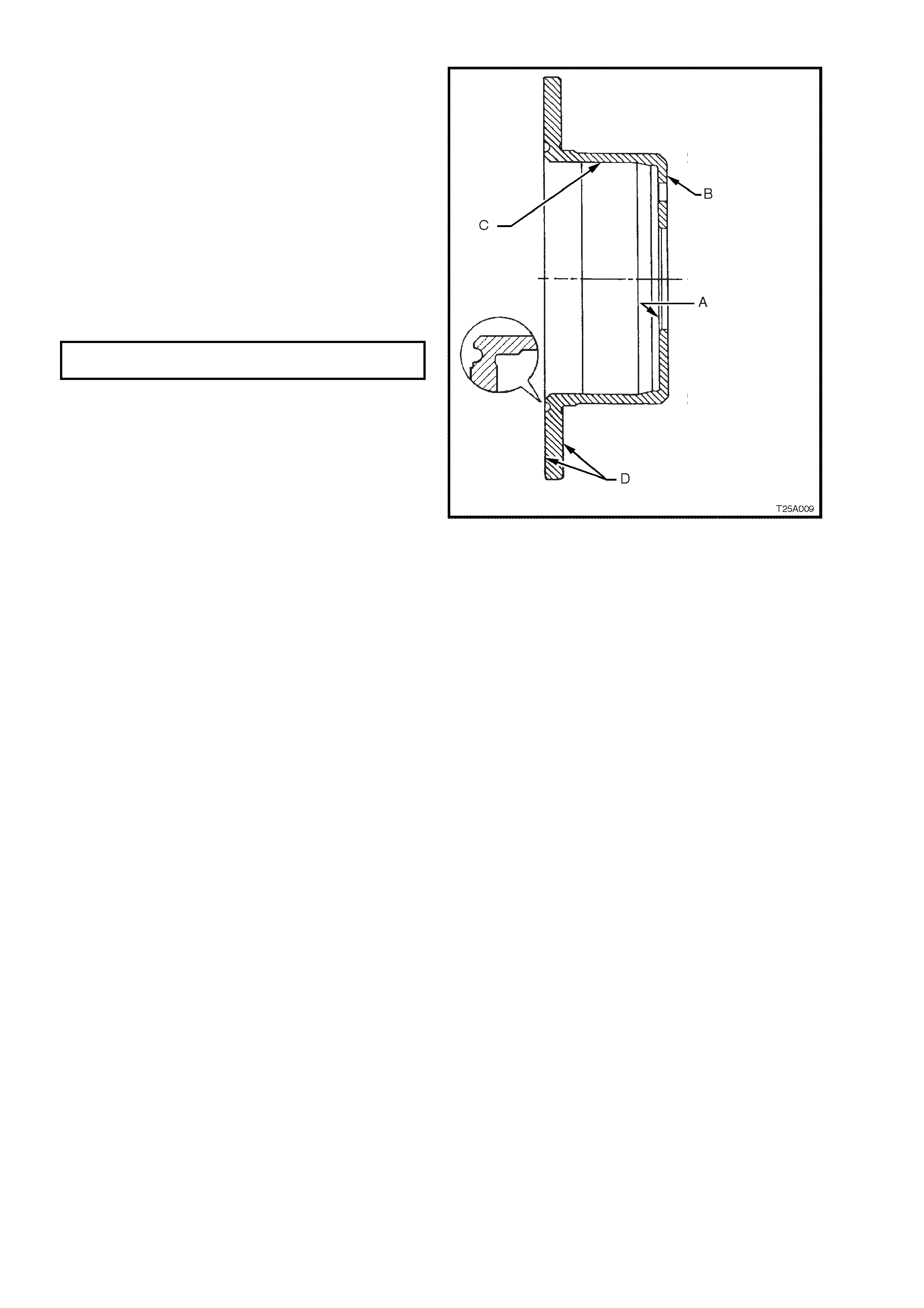
Inspect brake disc as follows:
1. Check that surface ‘B' is flat within 0.08 mm
and is parallel with surface ‘A' within 0.08 mm
Total Indicated Runout (TIR).
2. Check that surface ‘C' circular run-out is less
than 0.08 mm and that surface is square to
surface ‘A' within 0.05 mm TIR
3. Check that each brake disc surface is flat
within 0.05 mm and is parallel to surface ‘A'
within 0.085 mm TIR
4. Check that lateral run-out of each braking
surface ‘D’ is less than 0.05 mm when
measured from surface ‘A' as shown or when
bolted to the axle and that rate of change does
not exceed 0.03 mm in 30°.
5. Check that maximum circumferential
thickness (also referred to as Disc Thickness
Variation (DTV)) does not vary by more than
0.013 mm at any radius when disc is rotated.
Figure 5A-12
BRAKE DISC AND HUB INDEXING PROCEDURE
NOTE 1: The brake disc and hub indexing is
required in order to obtain the minimum installed
disc runout. Brake disc and hub indexing involves
aligning the point of maximum runout on the hub
with the point of least runout on the disc
NOTE 2: This procedure is to be used whenever
reinstalling brake discs that have been rem oved for
machining off car. It must also be used when
installing new brake discs or brake discs that have
been removed for any reason and where the brake
disc to hub matching is not evident.
The procedure consists of three parts as follows:
Part 1. Clean mating surfaces
Part 2. Measure and Match brake disc high
point to hub low point. If measurements are
not OK, go to Part 3
Part 3. Checking hub mounting face runout
Part 1. Clean mating surfaces
Ensure that brake disc and hub mating surfaces
are free from dirt, corrosion, etc. If required, use
fine emery paper to clean surfaces.
Part 2. Indexing brake disc to hub
1. Fasten the brak e disc onto the hub with wheel
nuts reversed to avoid damage to the tapers,
and nip up with a spanner.
2. Number each of the wheel stud holes on the
front surface of the brake disc from 1 to 5.
Place a chalk mark on the end of the wheel
stud adjacent to the number “1” hole.
Figure 5A-13
3. Set up a dial indicator on a m agnetic bas e and
attach to a pre-fabricated mounting plate (1)
(refer 5. SPECIAL TOOLS in this Section for
pre-f abricated m ounting plate details) bolted to
the calliper attaching points. Position the
pointer of the dial indicator about 10 to 15mm
inboard from the outer diameter of the brake
disc.
4. Carefully rotate the brake disc and note the
points of minimum and maximum runout on
the dial indicator. The number of divisions
between these two points is the total indicated
runout. Record this figure together with the
number on the brake disc aligned with the
chalk-marked stud.
5. Remove and reinstall brake disc with hole
number “2” over the marked stud and repeat
Step 4. This proc edur e is to be r epeated f or all
5 hole positions.
6. Mount the disc to the trunnion hub in the stud
position which recorded the least amount of
runout.
NOTE: If the lowest assembled disc runout
achieved is more than 0.080 mm (80 micron) then
the trunnion hub runout should be checked as
shown in Part 3.
MAX IMUM ASSEMBLED BRAKE DISC &
TRUNION HUB RUNOUT AT BRAKE DISC 0.08 mm
OUTER DIAM ET ER – REAR BRAKE DISC
Figure 5A-14
Part 3 Trunion hub runout check
1. Clean the front hub f ace by rubbing lightly with
fine emery paper.
2. Locate the dial indicator on the pre-fabricated
mounting plate bolted to the calliper mounting
points and position the pointer on the hub f ace
as shown, refer Fig. 5A-15.
NOTE: For this check to be performed to 100 %
accurac y, a flat paralleled surfac e plate attached to
the hub should be used, however, measuring
runout between each of the wheel studs should
suffice.
3. Carefully rotate the hub by the wheel studs
and note the points of minimum and maximum
runout on the dial indicator. The number of
divisions between these two points is the total
indicated runout.
4. If the runout measured in Step 3 exceeds
0.060 mm (60 micron) then the trunnion
assembly must be replaced.
MAXIMUM TRUNNION HUB TOTAL
INDICATED RUNOUT 0.06 mm
Figure 5A-15
REINSTALL
1. Reinstall the brake disc over the wheel studs
in either the pre-marked/indexed position or
the newly indexed position.
2. Ensure anchor plate mounting surfaces are
clean.
3. Position calliper assembly over brake disc,
insert anchor plate retaining bolts and
washers.
4. Ensure brake hose is not kinked or twisted.
5. Tighten anchor plate bolts to specified torque.
REAR BRAKE CALLIPER
ANCHOR PLATE BOLT 70 - 100 Nm
TORQUE SPECIFICATION
6. Depress the brake pedal several times to
bring pads into position against disc.
7. Adjust park brake shoe clearance as detailed
in 3.5 PARK BRAKE SHOE, ADJUST, in
Section 5A STANDARD BRAKES of this
Service Information CD.
8. Reinstall road wheels aligning marks made
prior to removal then lower vehicle.
9. Tighten road wheel attaching nuts to the
specified torque and in the order shown.
NOTE: Do not use an impact gun to tighten wheel
nuts unless it is fitted with a torque limiter bar
(commercially available). Failure to correctly tighten
wheel nuts to the correct torque specification may
result in a warped brake disc, which may lead to
development of brake shudder.
ROAD WHEEL ATTACHING NUT
TORQUE SPECIFICATION 110 - 140 Nm
Figure 5A-16

3.SPECIFICATIONS
FRONT BRAKE DISC
Type............................................................................ Ventilated
Diameter (nominal)..................................................... 296 + 0.0 – 0.2mm
Thickness................................................................ 28.0 ± 0.15mm
Minimum thickness (replacement required)............ 25.0mm
Maximum circumferential thickness variation (also
referred to as Disc Thickness Variation DTV)) ....... 0.005mm
Maximum taper variation......................................... 0.08mm
Maximum lateral runout (disc removed).................. 0.04mm
Maximum lateral runout in 30 deg (disc removed) 0.03mm
Maximum assembled disc and hub runout at disc
outer diameter......................................................... 0.05mm
Maximum runout at hub face................................... 0.025mm
REAR BRAKE DISC
Type............................................................................ Solid
Diameter (nominal)..................................................... 286 + 0.0 – 0.2mm
Thickness................................................................ 15.9 ± 0.2mm
Minimum thickness (replacement required)............ 13.9mm
Maximum circumferential thickness variation (also
referred to as Disc Thickness Variation DTV)) ....... 0.013mm
Maximum lateral runout........................................... 0.05mm
Maximum lateral runout in 30 deg...................... 0.03mm
Maximum assembled disc and trunion hub runout
at disc outer diameter.............................................. 0.08mm
Maximum trunnion hub total indicated runout ......... 0.06mm

4.TORQUE WRENCH SPECIFICATIONS
Nm
Front Brake Calliper Anchor Plate Bolt ................................. 80 - 90 Nm,
plus 40° - 50°
Rear Brake Calliper Anchor Plate Bolt.................................. 70 - 100
Road Wheel Attaching Nut ................................................... 110 - 140
Park Brake Lever Bolt........................................................... 35 - 65
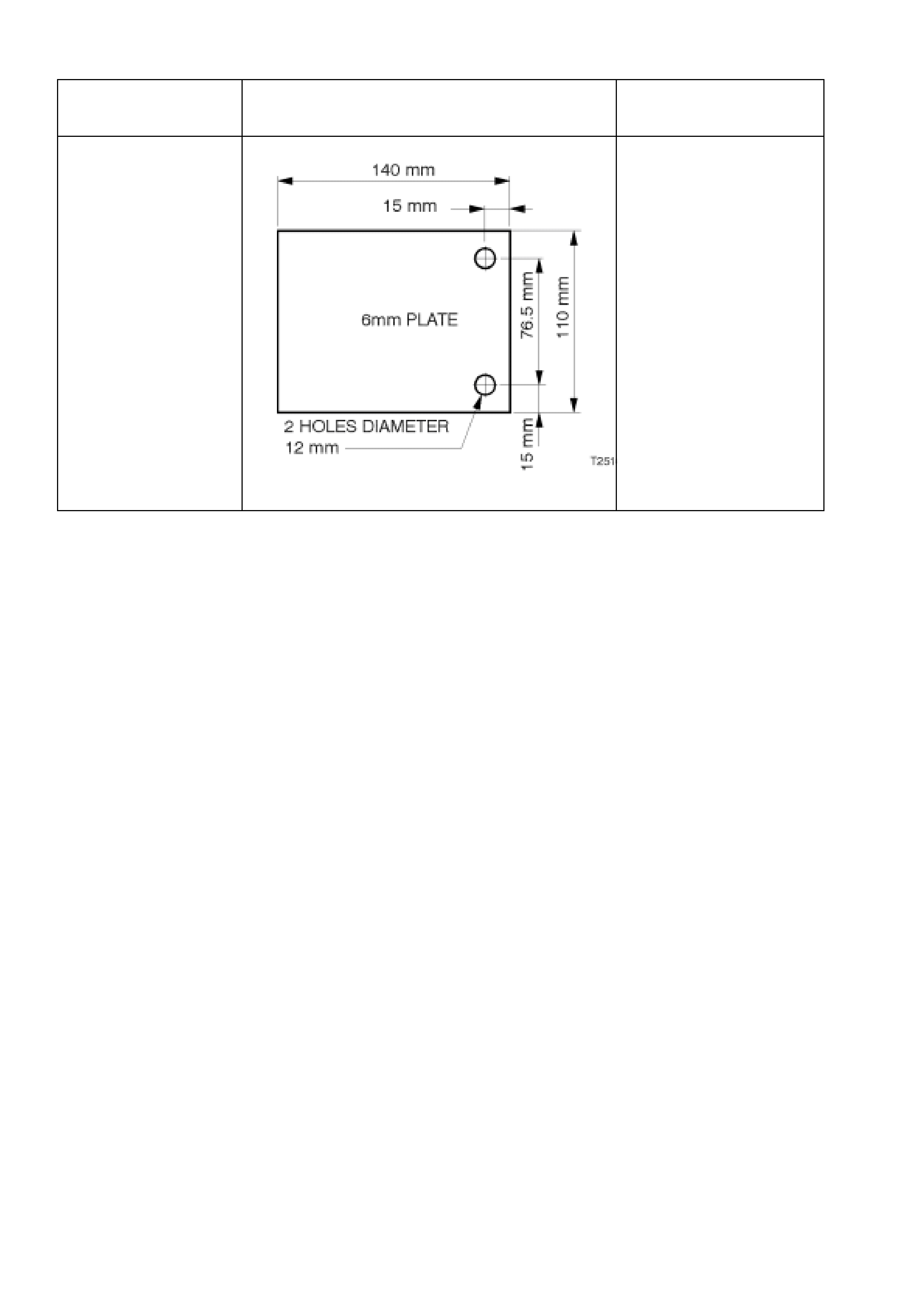
5. SPECIAL TOOLS
TOOL NO. REF
IN TEXT TOOL DESCRIPTION COMMENTS
NOT APPLICABLE PRE-FABRICATED MOUNTING PLATE The mounting plate shown
can easily be made in-
dealership using a 6mm
thick metal plate.
If using the calliper bolts to
attach the plate to the
trunion, a 17mm spacer will
be required.