
SECTION 12J-1 - LOW SERIES BODY
CONTROL MODULE
CAUTION:
This vehicle will be equipped with a Supplemental Restraint System (SRS). A SRS will consist of either
seat belt pre-tensioners and a driver's air bag, seat belt pre-tensioners and a driver's and front
passenger's air bag s or seat belt pre- tensio ners, d riv er’s and fron t p asseng er’s air bag and lef t and rig ht
hand side air bags. Refer to SAFETY PRECAUTIONS, Section 12M Supplemental Restraint System in the
VT Series I Service Information before performing any service operation on, or around any SRS
components, the steering mechanism or wiring. Failure to follow the SAFETY PRECAUTIONS could
result in SRS deployment, resulting in possible personal injury or unnecessary SRS system repairs.
CAUTION:
This vehicle may be equipped with LPG (Liquefied Petroleum Gas). In the interests of safety, the LPG
fuel system should be isolated by turning 'OFF' the manual service valve and then draining the LPG
service lines, before any service work is carried out on the vehicle. Refer to the LPG leaflet included with
the Owner's Handbook for details or the appropriate Section of this Service Information CD for more
specific servicing information.
1. GENERAL DESCRIPTI ON
A Body Control Module (BCM), both High and Low Series, com bine into one centr al m odule, the control or assist of
various vehicle electrical systems or features, rather than having individual modules for each system or feature.
Low Series BCMs are fitted as standard equipment on all VT Series Executive, Acclaim, S and SS Models.
Two levels of Low Series BCM have been r eleased; a LOW level for vehic les without power operated windows and
a MID level for vehic les with power operated windows and interm ittent sync hronised rear wiper control. If a servic e
operation or diagnostic procedure requires that a Low Ser ies BCM be r eplac ed, ensur e that the c orr ect BCM level is
reinstalled for the particular level of vehicle.
The Low Series BCM is located beneath the ins tr ument clus ter, to the r ight of the st eering c olumn, ref er to Fig. 12J -
1-2. Fig. 12J-1-1 illustrates the identification details for the Low Series BCM. External identific ation can be m ade by
referring to the last three digits of the BCM part number.
Information regarding High Series BCMs, fitted to VT Series Berlina and Calais Models, can be found in
Section 12J-2 HIGH SERIES BODY CONTROL MODULE in the VT Series II Service Information.
With the introduction of VT Series II Models, comes various upgrade features (and changes) for the BCM. The
following list provides a summary of these new features, additional and more detailed information of an individual
features can be found within this Section.
• Remote deadlocking via remote key (two lock button presses within ten seconds).
• Battery saver feature; turns off all internal lamps after one hour of the ignition being switched off.
NOTE: This f eatur e inc ludes a pr e-deliver y mode which sets the timer to a shor ter period of thr ee minutes until
the vehicle has travelled above 20km/h for a cumulative period of 30 minutes. After this period, the battery
saver timer sets to one hour.
• The standing current in the BCM has also been lowered from 18mA to 4mA.
• Key off courtesy lamp; courtesy lamp comes on for 30 seconds when the ignition is switched off.
• Disablement of the in-vehicle boot release button when security system armed.
• HSPO accessory alarm compatibility (TECH 2 selectable - can be enabled or disabled).
• Deletion of the two hour override. For the override feature to be deleted, both the BCM and PCM had to be
changed. These changes were staggered in introduction:
BCMs were changed in July 1998.
V6 PCMs were changed in October 1998.
V8 PCMs were changed in November 1998.
• Serviceability of door lock microswitch (at VT start of production, microswitches were serviced as part of the
door handle assembly only).
Techline
Techline
Techline
Techline
Techline
Techline

Also released f or VT Series II Models is the new GEN III V8 engine. T he Powertrain Control Module (PCM) f or this
engine uses what is referred to as ‘class 2’ serial communication. All other control modules, including the BCM,
communicate serial data, in what is referred to as UART (Universal Asynchronous Receive and Transmit). The
‘class 2’ communication is more sophisticated than UART, and as such, requires a Powertrain Interface Module
(PIM) to convert class 2 communication into UART.
In sim ple terms, the G EN III V8 engine PCM comm unicates in a dif ferent language than the other c ontrol modules
and therefore requires the PIM to translates the PCM information into the same language as the other control
modules communicate in. Refer to 1.2 SERIAL DATA COMMUNICATION (BUS MASTER) for more information.
The PIM is located in the same location as a V6 PCM; behind the passenger side shroud lower trim assembly.
Specific software has been developed for use with the TECH 2 diagnostic scan tool to assist with various vehicle
electrical system fault finding, including the various BCM functions and controls.
The T ECH 2 connection for the Low Series BCM s erial data com munic ation is via the Data Link Connector (DLC) ,
attached to the instrument panel lower right hand trim, to the left of the steering column, refer to Fig 12J-1-2.
This Section has been compiled to address these new features and changes only. For information that is not
covered in this Section, including General Description, Service Operations, Diagnosis and Special Service Tools,
refer to Section 12J-1 LOW SERIES BODY CONTROL MODULE in the VT Series I Service Information.
BODY CONTROL MODULE FEATURES
BCM FEATURE LEVEL 1
LOW - 315 LEVEL 2 (OPTIONAL)
MID - 313
Serial Data Interface (SDI) (Bus
master) A A
Central door locking A A
Boot release with speed interlock A A
Power window system N/A A
Dome lamp delay control A A
Heated rear window control A A
Intermittent and synchronised to
front rear wiper control with full
wipe in reverse gear (wagon only) N/A A
Fixed dwell wiper control A A
Auto lights OFF (fixed) A A
Engine disable A A
Engine cooling low speed fan
control A A
Cruise control interface A A
SRS (air bag) deployment vehicle
shutdown A A
Air conditioning interface A A
Battery saver mode A A
N/A = NOT AVAILABLE A = AVAILABLE
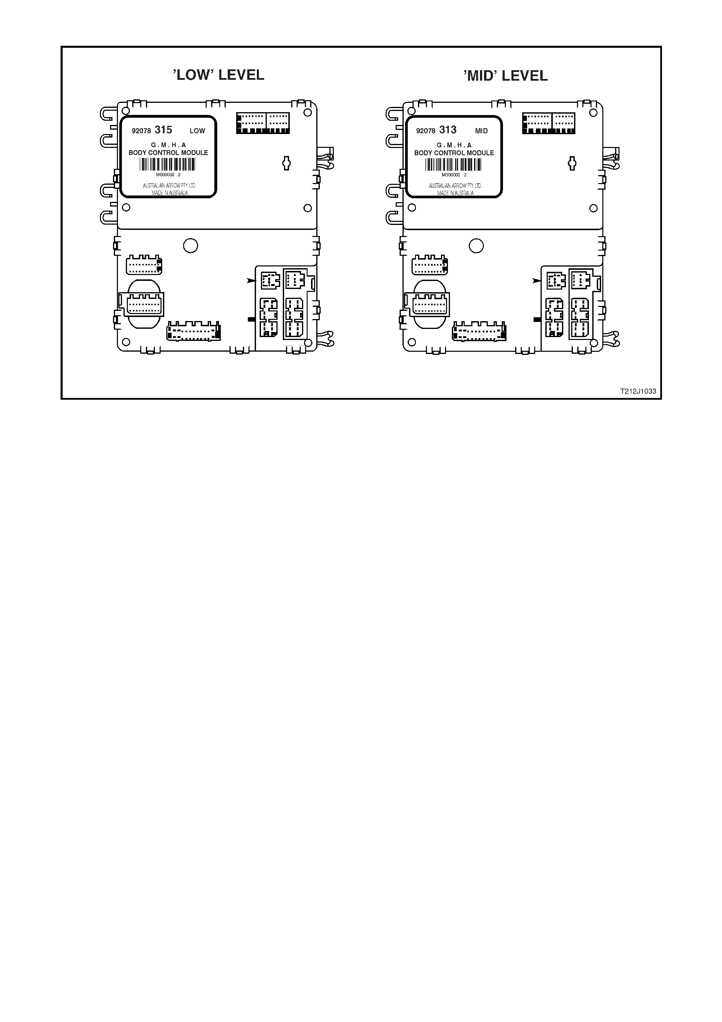
Figure 12J-1-1 Low series BCM identification
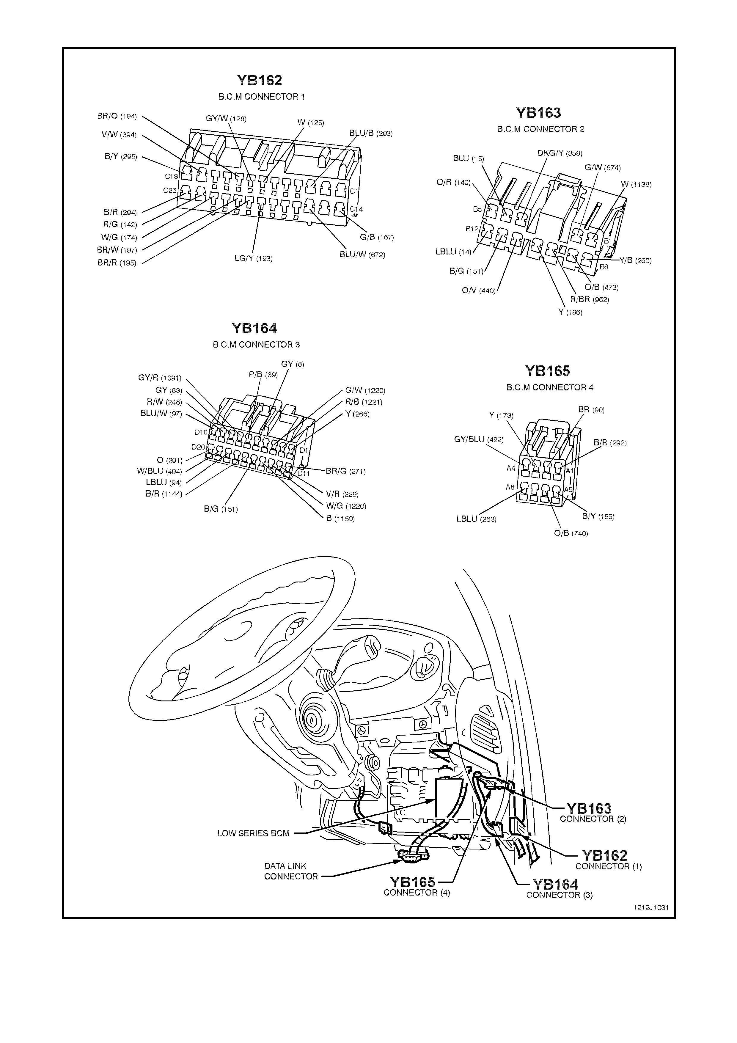
Figure 12J-1-2 BCM location and connector/terminal assignment

LOW SERIES BCM TERMINAL IDENTIFICATION
YB165 CONNECTOR 4
PIN NO. DESCRIPTION CIRCUIT WIRE COLOUR CIRCUIT TYPE
A1 DEMIST OUTPUT 292 B/R O
A2 WIPER OUTPUT 90 BR O
A3 WINDOW POWER OUTPUT 173 Y O
A4 REAR WIPER OUTPUT 492 GY/BLU O
A5 EARTH 155 B/Y E
A6 BATTERY POSITIVE 740 O/B P
A7 NC
A8 THEFT DETERRENT LED OUTPUT 263 LBLU O
YB163 CONNECTOR 2
PIN NO. DESCRIPTION CIRCUIT WIRE COLOUR CIRCUIT TYPE
B1 INTERIOR ILLUMINATION RELAY 1138 W O
B2 POWER WINDOW DOWN OUTPUT 674 G/W O
B3 A/C BLOWER INPUT 359 DKG/Y PPU
B4 RIGHT INDICATOR OUTPUT 15 BLU O
B5 INDICATOR POWER 140 O/R P
B6 ALARM STATUS OUTPUT 260 Y/B O
B7 LOW FAN SPEED OUTPUT 473 O/B O
B8 A/C LED OUTPUT 962 R/BR O
B9 WI PER PARK INPUT 196 Y PPU
B10 DOOR LOCK POWER 440 O/V P
B11 POWER EARTH 151 B/G E
B12 LEFT INDICATOR OUTPUT 14 LBLU O
YB162 CONNECTOR 1
PIN NO. DESCRIPTION CIRCUIT WIRE COLOUR CIRCUIT TYPE
C1 NC
C2 NC
C3 DRIVER’S DOOR UNLOCK OUTPUT 293 BLU/B O
C4 NC
C5 NC
C6 NC
C7 PASSENGER’S DOOR AJAR INPUT 125 W PPU
C8 DRIVER’S DOOR AJAR INPUT 126 GY/W PPU
C9 PASSENGER’S DOOR UNLOCK INPUT 194 BR/O PPU
C10 NC
C11 NC
C12 DEADLOCKS 394 V/W O
C13 ALL DOORS LOCK OUTPUT 295 B/Y O
C14 WINDOW DOWN INPUT 167 G/B PD
C15 NC
C16 WINDOW UP INPUT 672 BLU/W PD
C17 NC
C18 NC
C19 NC
C20 UNLOCK INPUT 193 LG/Y PPU
C21 LOCK INPUT 195 BR/R PPU
C22 DEADLOCK REQUEST INPUT 197 BR/W PPU
C23 NC
C24 DOME LAMP OU TPUT 174 W/G O
C25 BOOT OUTPUT 142 R/G O
C26 PASSENGER’S DOOR UNLOCK OUTPUT 294 B/R O

YB164 CONNECTOR 3
PIN NO. DESCRIPTION CIRCUIT WIRE COLOUR CIRCUIT TYPE
D1 REMOTE RECEIVER (DATA) 266 Y I
D2 SERIAL DATA MAIN BUS 1221 R/B I/O
D3 SERIAL DATA AUXILIARY BUS 1220 G/W I/O
D4 NC
D5 ILLUMINATION LINK 8 G/Y LINK
D6 IGNITION INPUT 39 P/B PD, P
D7 REAR WI PE INPUT 1391 GY/R PD
D8 CRUISE ON INPUT 83 GY PD
D9 A/C SWITCH INPUT 248 R/W PD
D10 INTERMITTENT WIPER INPUT 97 BLU/W PD
D11 REMOTE RECEIVER (EARTH) 271 BR/G E
D12 SLIP RING 229 V/R I/O
D13 SDM SERIAL DATA BUS 1220 W/G I/O
D14 LIGHTS OFF EARTH OUTPUT 1150 B PD, O
D15 ILLUMINATION LINK 151 B/G LINK
D16 BOOT RELEASE INPUT 1144 B/R PPU
D17 NC
D18 FRONT SCREEN WIPE / WASH INPUT 94 LBLU PD
D19 REAR SCREEN WASH INPUT 494 W/BLU PD
D20 DEMIST INPUT 291 O PD
GLOSSARY
E - Earth O - Output P - Power PU - Pull up
PPU - Pulsed pull up PD - Pull down I - Input I/O - Input / Output
NC - No circuit
B - Black G - Green O - Orange V - Violet
BLU - Blue GY - Grey P - Pink W - White
BR - Brown LBLU - Light blue R - Red Y - Yellow
DKBLU - Dark blue LG - Light green T - Tan

1.1 BATTERY SAVER MODE
The BCM battery saver mode provides vehicle battery protection (through reduced current consumption).
After a programmed delay period (shut down timer) the BCM -:
1. De-activates the interior illumination relay which supplies battery voltage to all interior dome, ignition loc k, glove
and boot lamps, protecting the battery in the event of-:
A lamp mistakenly left on (ie. door open)
A faulty illumination circuit or component causing excess current consumption.
2. De-activates the power window relay (separate from the normal power window off delay function).
3. Disables BCM inputs normally not required with the ignition in the ‘OFF’ or ‘ACC’ positions, to reduce its own
current consumption.
The battery Saver delay period has a default value of one (1) hour, however can be set from 2 – 255 minutes via
TECH 2.
The delay period (shut down timer) is initiated when the ignition is switched to the ‘ACC’ or ‘OFF’ positions.
Whilst in battery saver mode, the BCM is ‘woken’ up when:
1. Any door is opened.
2. The BCM receives a valid RF key ‘UNLOCK’ or ‘BOOT’ signal.
3. The ignition is switched to ‘ON’.
4. The doors unlocked via the driver’s door microswitch.
5. The deadlock switch is activated.
6. TECH 2 is plugged in and communicating with the BCM.
7. The headlamp switch is cycled from ‘OFF’ – ‘ON’ or ‘ON’ – ‘OFF’.
8. The rear compartment lock switch, located in the glove box, is activated.
PRE-DELIVERY MODE.
To pr ovide additional battery protection the vehicle is delivered with the BCM in pre-deliver y mode. In this m ode the
battery saver period is set to 3 minutes.
Pre-delivery mode is disabled once the vehicle has travelled for a total of thirty (30) minutes at speeds above 20
km/h. This value is estimated to be the equivalent period prior to customer delivery.
Pre-delivery mode can also be enabled and disabled via TECH 2.
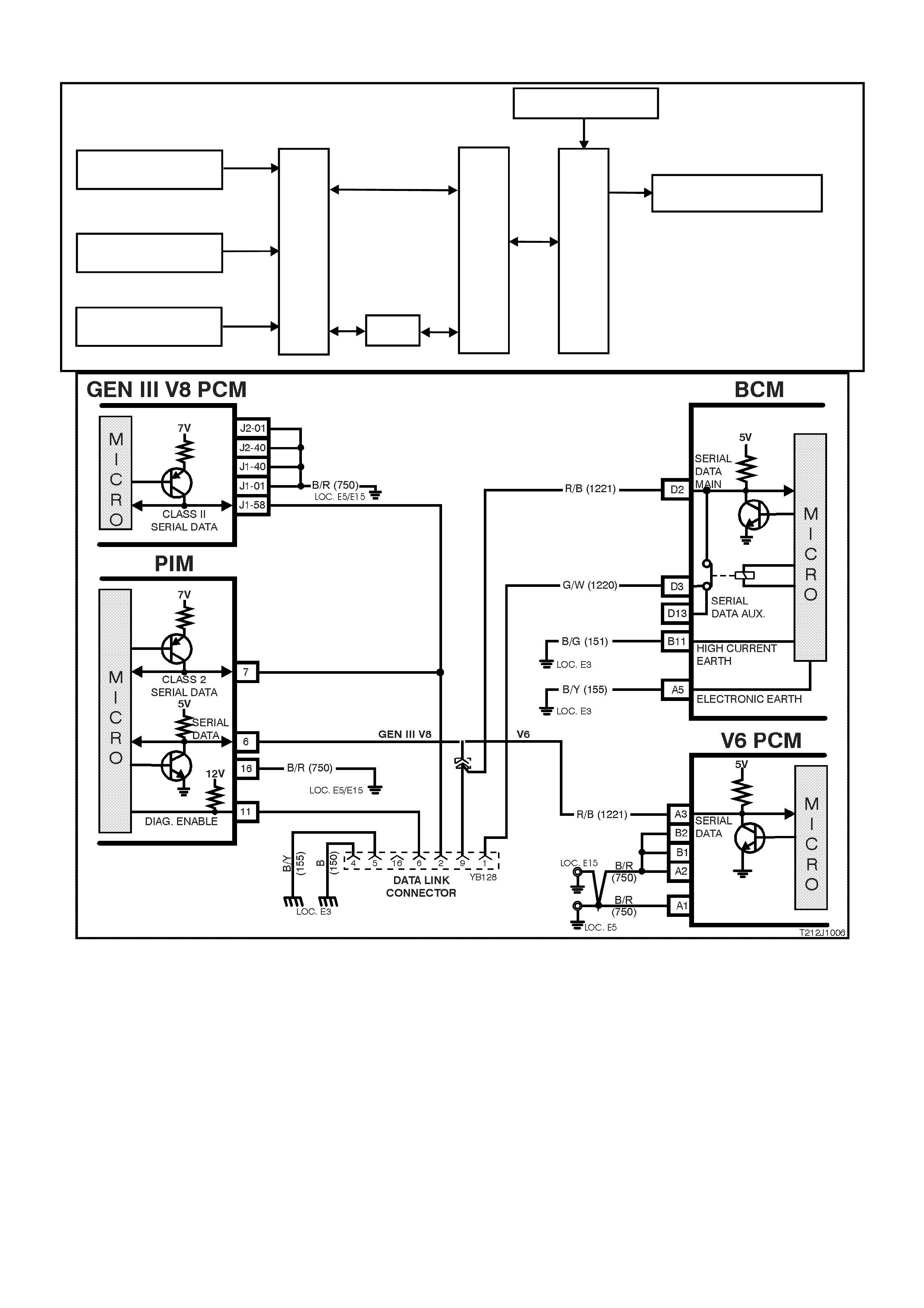
1.2 SE RIAL DATA COMMUNICATION (BUS MASTER)
GENERAL INFORMATION
Various devices; system control modules of the vehicle, as well as TECH 2 communicate with each other. The
communication between control modules and com munication with the TECH 2 diagnostic scan tool is achieved on
the serial com munic ation lines using serial data. Serial data tr ansfers inf ormation in a linear f ashion - over a single
line, one bit at a time. The serial data line is referred to as the ‘data bus’.
Excluding the GEN III V8 PCM, all control modules communicating on the data bus communicate using UART
communication.
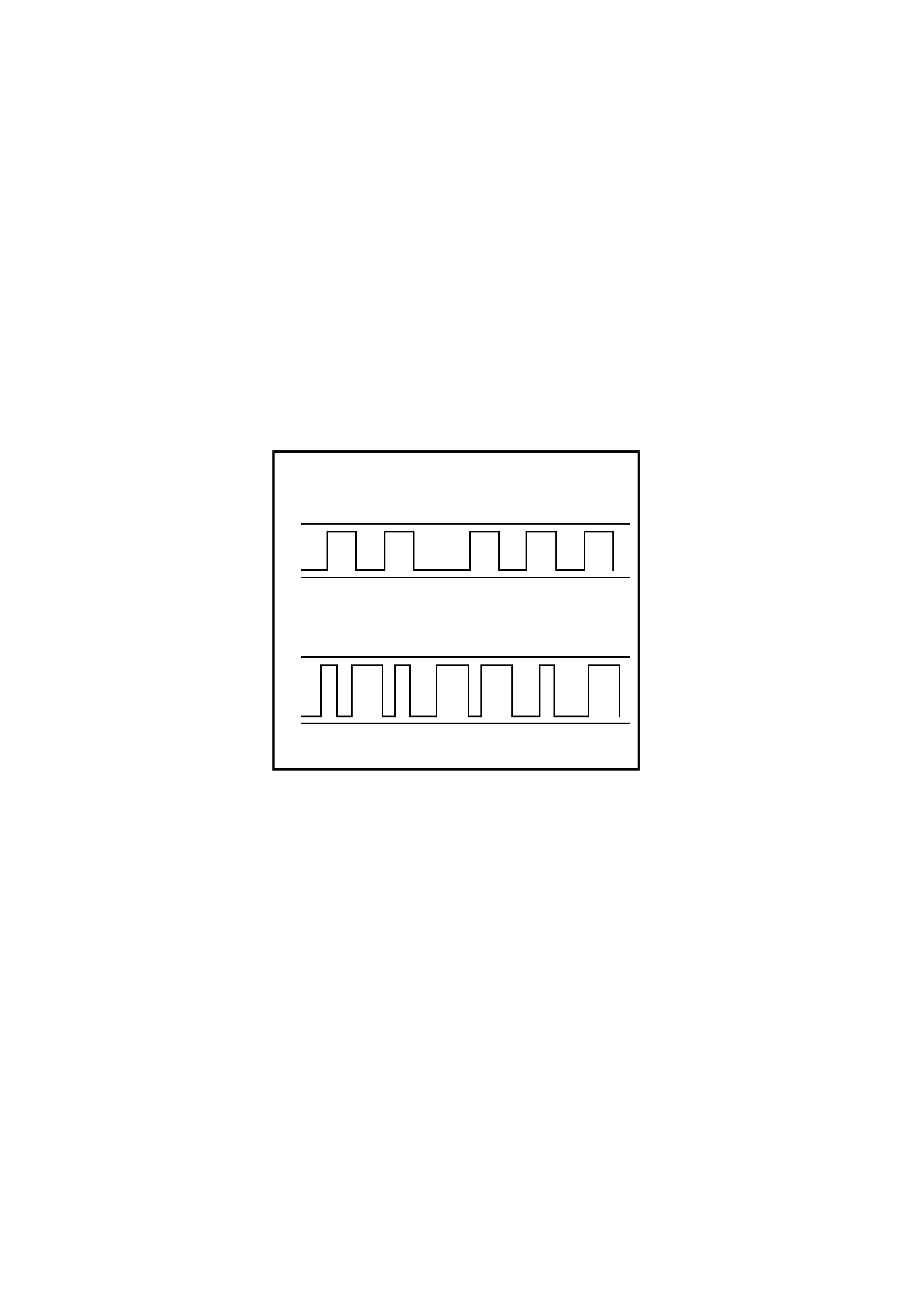
UART is a 5 volt data line that toggles the voltage to earth (0 volts ) at a fixed bit puls e width dur ing c om m unication.
UART trans m its data at the rate of 8.2 k ilobits per s econd ( 8192 bits /sec). In UART com m unications , when ther e is
no communication on the data line, the system voltage will be 5 volts.
The GEN III V8 PCM us es Class 2 com m unication. T his type of com m unication toggles the data line from 0 volts to
7 volts at a either a short or long pulse width at rate of 10.4 kilobits per second (average). In class 2
communications, when there is no communication on the data line, the system voltage will be 0 volts.
As the ‘Class 2’ c omm unication is diff erent to UART (dif ferent languages), c omm unication between the modules is
incompatible, and as such, requires a Powertrain Interface Module (PIM) to convert Class 2 communication into
UART, and UART into Class 2 (a trans lator). Ref er to ‘POWERTRAIN INTERFACE MO DULE (PIM)’ in this Sec tion
for additional information on this module.
TECH 2 is able to communicate with both UART and Class 2 control modules.
T212J1012
11
0
1
00
1
0
1
0
5V
0V
UART
CLASS 2
11 1
111
000 0
000
7V
0V
Figure 12J-1-3 Serial Data Digital Wave Form
On all VT Series Models, the BCM is the Bus Master of the serial data communication system. The BCM
periodically polls (surveys) each device on the data bus and requests status data.
The devices (control modules) the BCM polls are:
• Body Control Module (BCM).
• V6 and V6 supercharged engine Powertrain Control Module (PCM).
• Powertrain Interface Module (PIM), GEN III V8 engines only.
• Instrument cluster (INS).
• Antilock Brake/Electronic Traction Control System (ABS/ETC) module.
• Supplemental Restraint System (SRS) Sensing and Diagnostic Module (SDM).
• TECH 2 diagnostic scan tool.
The data provided by each device may be utilised by any device connected to the bus.
Each device has a unique response Message Identifier Word (MIW) for ease of identification.
The bus m aster (BCM) polls eac h device with a serial data mes sage which includes that devices MIW. T he device
responds by putting a serial data m essage onto the bus which inc ludes its MIW and data, of which is retr ieved and
utilised by any device requiring it.
The BCM polls each device for a status update, once ever y 300 m illisec onds. T he exception to this being the PCM
(V6) and PIM (GEN III V8) which are polled twice every 300 milliseconds.
When the ignition switch is turned from the OFF position to the ON position, the BCM will communicate with the
PCM (via the PIM on vehicles with GEN III V8 engines) f or thef t deter rent pur poses . If the BCM does not r ec eive an
OK TO START message from the PCM within 0.5 seconds of ignition on, the auxiliary data bus is isolated via
switching from the BCM.
The isolation of the auxiliary data bus during this period eliminates the possibility of a device failure other than the
BCM, PCM or PIM (GEN III V8 only), causing a problem on the bus and inhibiting theft deterrent communications.
This period (short loop time) continues until the PCM responds with an acknowledgment or a maximum of five
seconds after which the BCM will switch to the standard polling sequence.
Following successful antitheft communications, the BCM begins sequential polling of devices on the bus and normal
system operation is established.
When the ignition switch is in the OFF position, the BCM continues to poll, allowing for TECH 2 communications
and external control of the bus prior to the ignition being switched on.
Powertrain Interface Module (PIM)
The PIM is a hardware and serial communications interface between the GEN III V8 PCM and the vehicles
electrical s ys tem. The pr imary purpose of this m odule is to allow the GEN III PCM to interfac e (talk ) to the ex isting
communications bus (UART) operating in the vehicle. The PIM acts as a transparent bi-directional translation
device which allows data to flow between the modules with varying communication protocols; Class 2 and UART.
W hen the ignition switch is turned from the OFF position to the ON position, and the PIM receives a poll from the
BCM, the PIM requests data from the GEN III PCM via its Class 2 interface and transfers this information to the
other control modules via the UART bus ( Serial c ommunications bus ). The PIM also monitor s r es pons es from other
control m odules on the UART bus and, using its Clas s 2 connection, trans fers any inf orm ation relevant to the GEN
III PCM as requested.
T212J2031
Figure 12J-1-4 PIM location
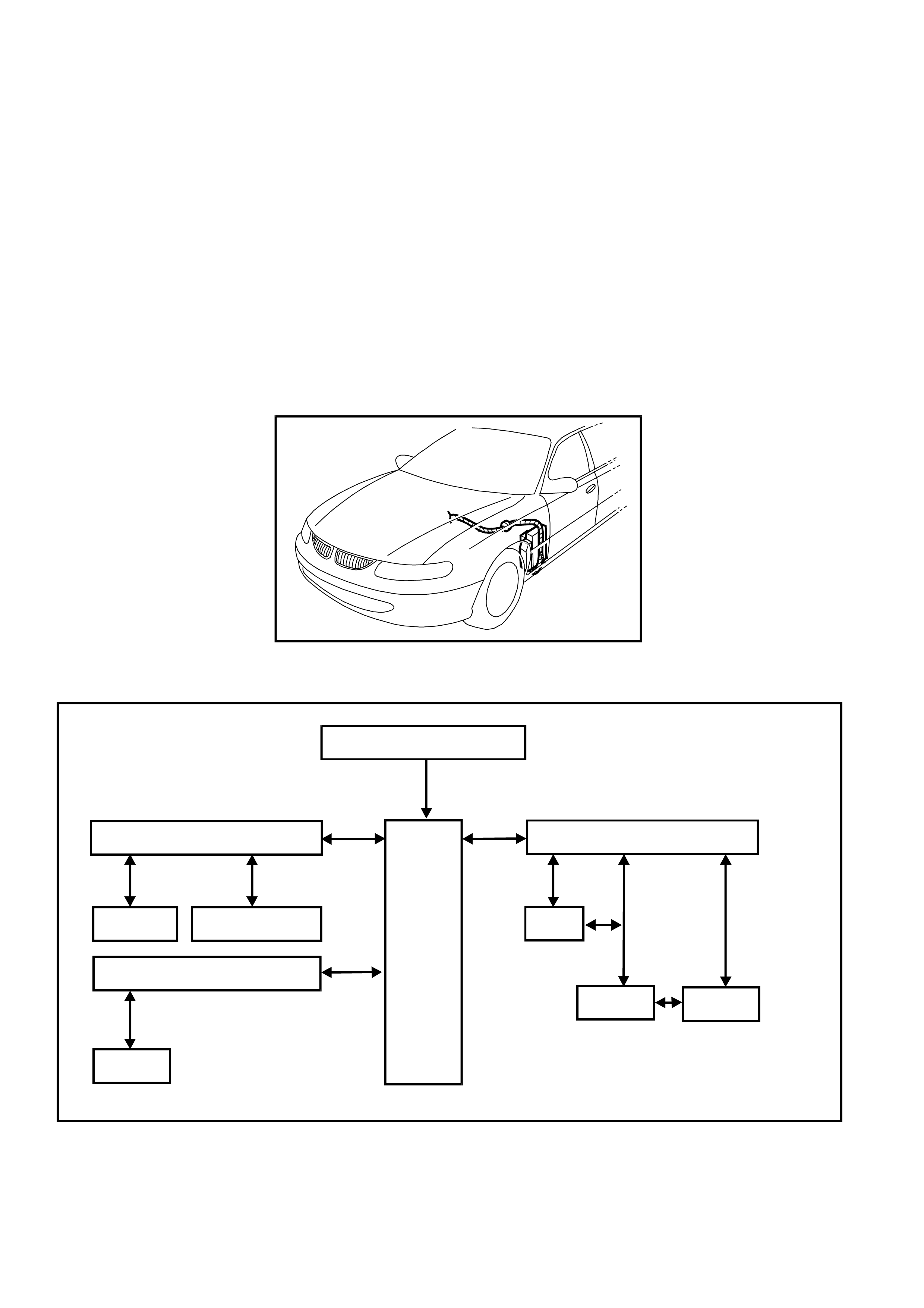
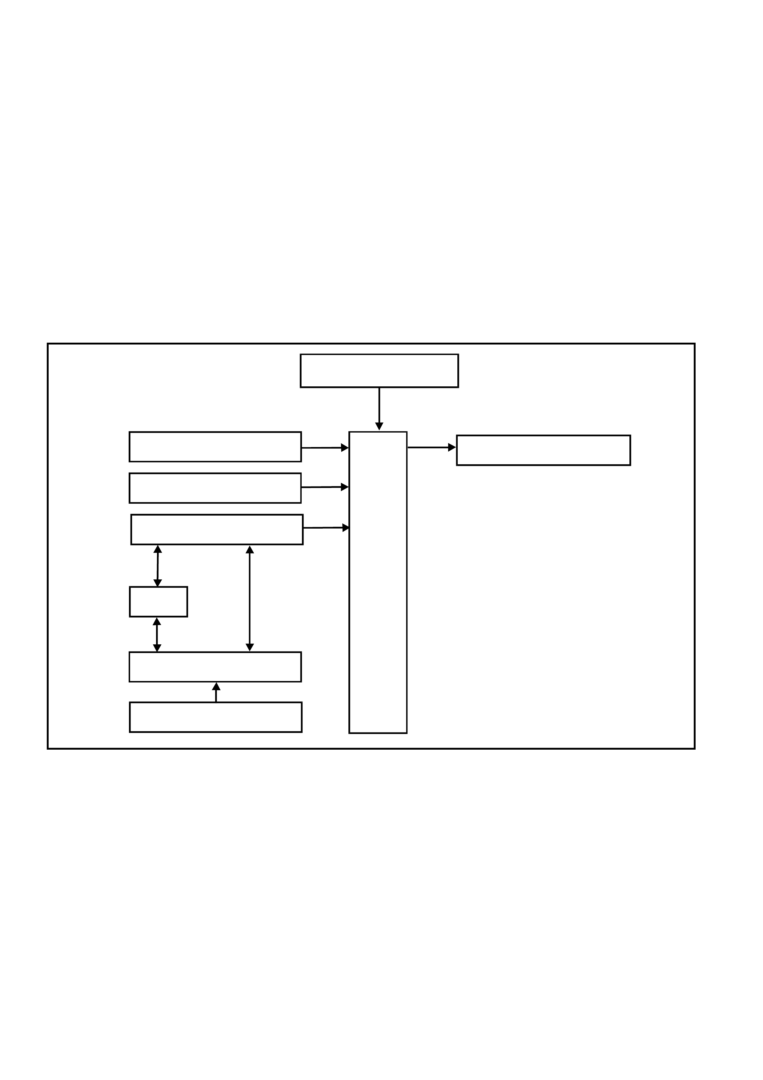
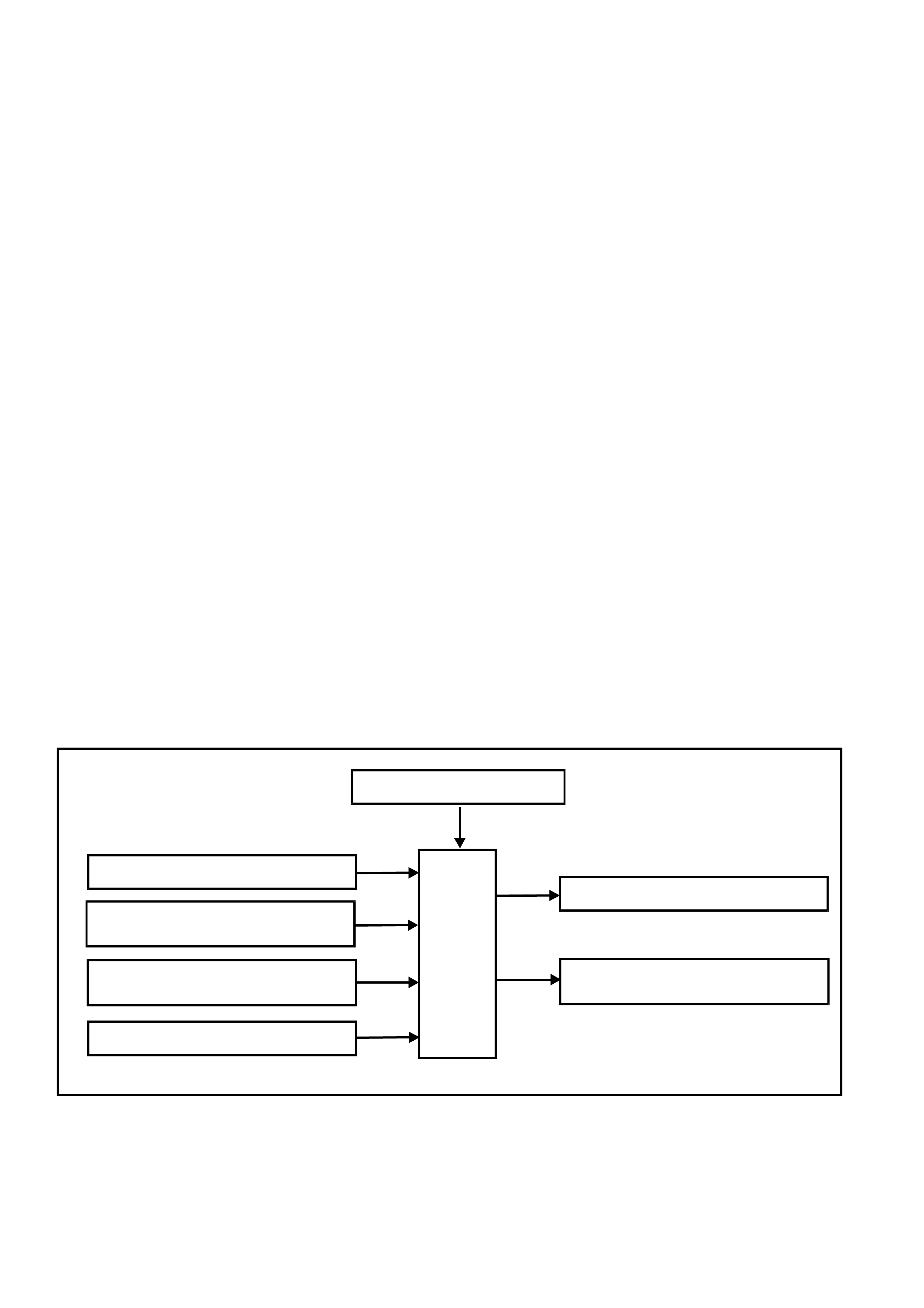
SYSTEM OVERVIEW - SERIAL COMMUNICATION
BATTERY POWER
BCM
SERIAL DATA MAIN
DLC
SERIAL DATA AUX
ABS/ETC INSTRUMENTS
SRS SERIAL DATA AUX
SRS
PCM
PIM
GEN III V8
ENGINE V6 & V6 S/C
ENGINE
T212J1001

INPUTS / OUTPUTS
Serial Data Signal - Main
BCM term inal D2, serial data s ignal - m ain, refer to Fig. 12J-1- 6, is connec ted to the PCM (via PIM on vehicles with
GEN III V8 engines) and DLC via circuit 1221 (Red/Black wire). It is via this line that the BCM communicates with
the PCM and external devices connected to the DLC, at all times.
Serial Data Signal - Auxiliary
BCM terminals D3 and D13, serial data signal - auxiliary, refer to Fig. 12J-1-6, is connected to the instrument
cluster, ABS/ETC and SRS modules via circuit 1220 (Green/White wire). It is via this line that the BCM
com munic ates with these devic es, af ter s ucc es s f ul thef t deterr ent c omm unic ations between the PCM and BCM ( via
the serial data - main line when the ignition switch is turned from the OFF to ON position).
If the BCM does not receive an OK TO START message from the PCM within 0.5 seconds of ignition on, during
theft deterrent communications, the serial data - auxiliary line is isolated from the serial data - main line via
switching within the BCM. (This will continue for a five second period if there is still no acknowledgment from the
PCM, before it starts polling)
INPUTS
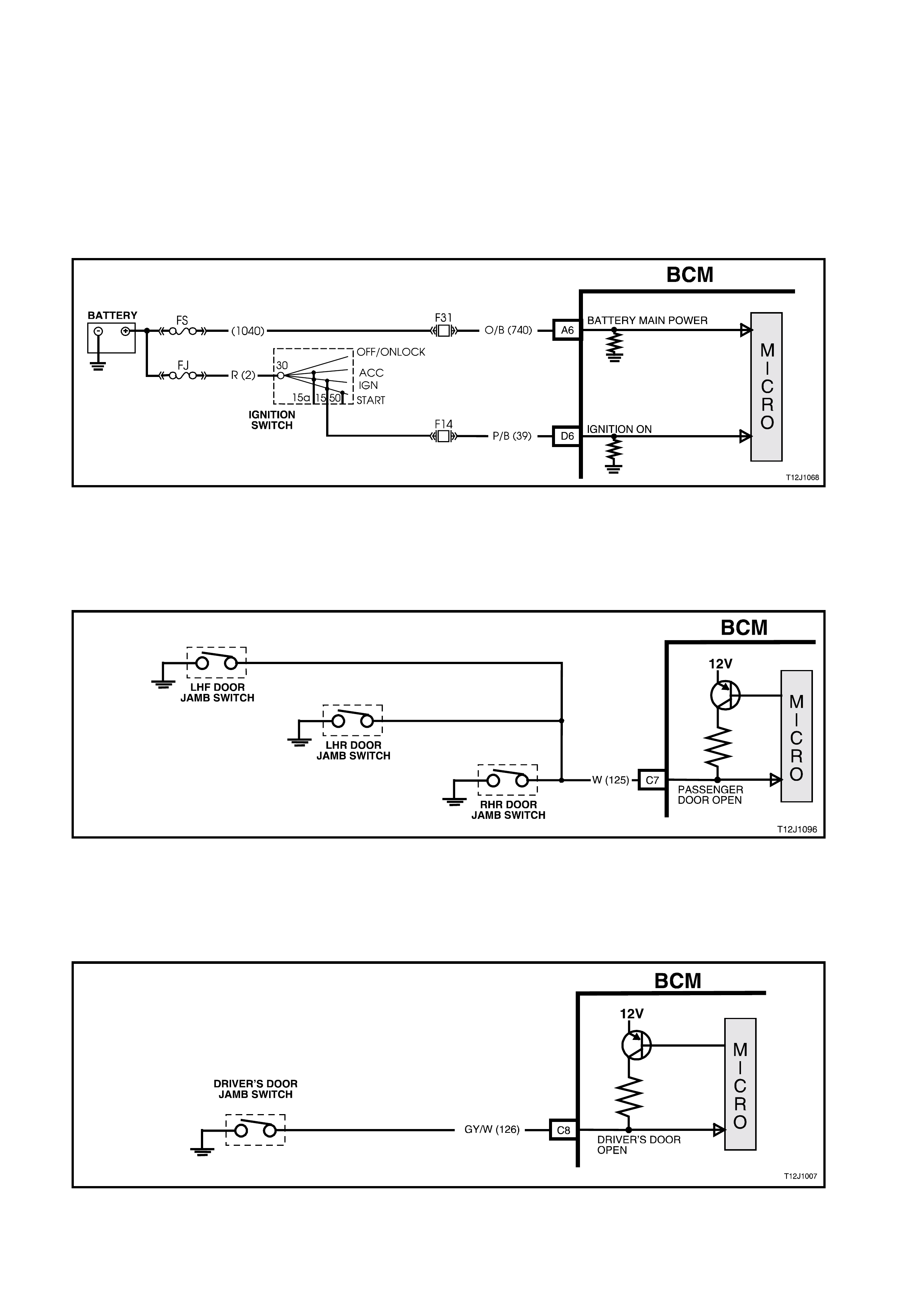
Ignition Switch ON Input Signal
The BCM uses this input signal to determine when the ignition switch is in the IGN or START position. W hen the
ignition switch is in the IGN or START position, battery voltage is applied to the BCM term inal D6 from the ignition
switch and fuse F14 via circuit 39 (Pink/Black wire), refer to Fig. 12J-1-5.
NOTE: The circ uit diagram s shown in this General Des cription Sec tion are to aid in interpr eting the operation of the
circuit and theref ore, only the m ain connectors and wiring colours ar e shown. For com plete circuits details , refer to
either the relevant diagnostic procedure in this Section or Section 12P WIRING DIAGRAMS in the VT Series II
Service Information.
Figure 12J-1-5 Ignition switch on input signal
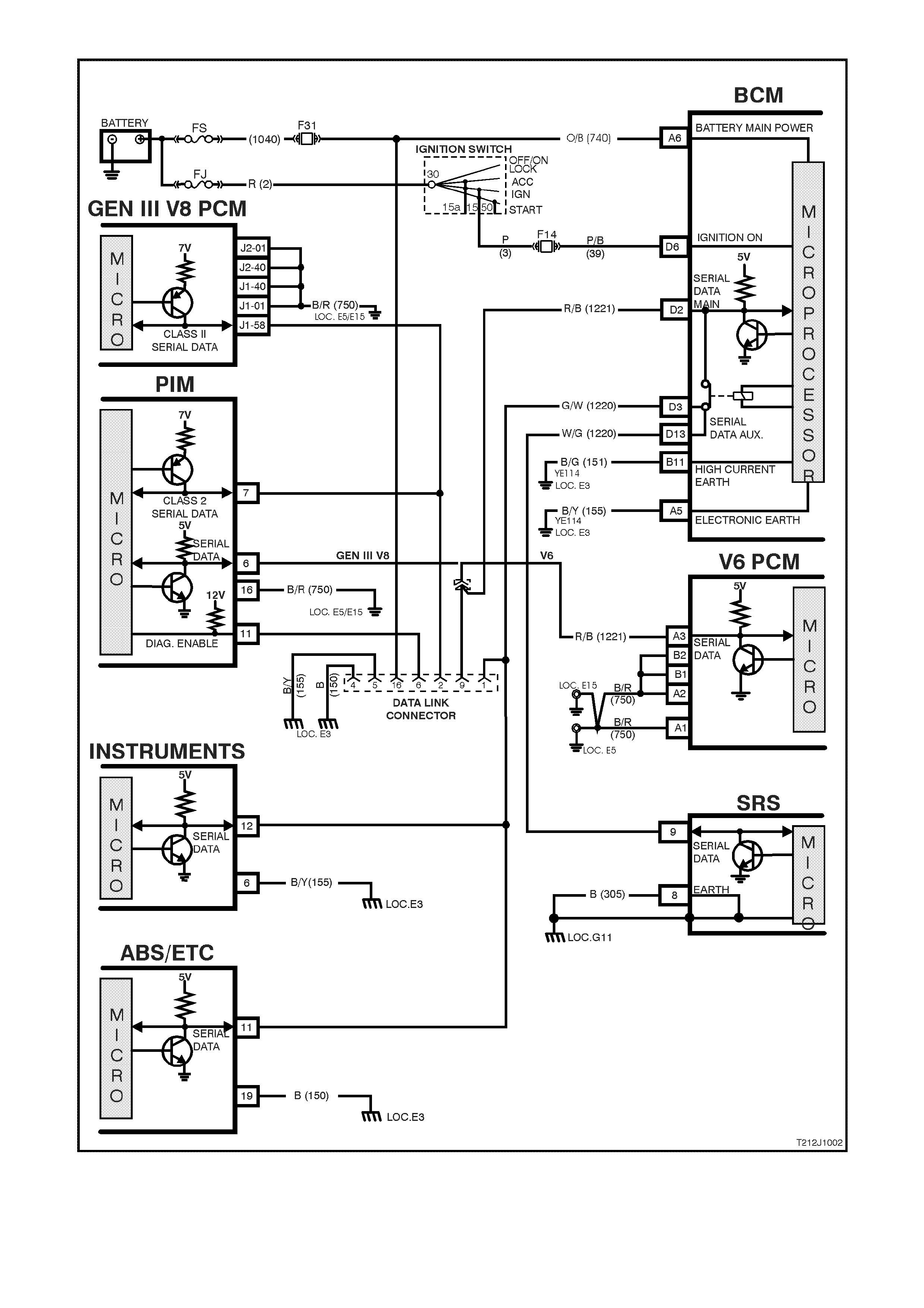
Figure 12J-1-6 Serial data communication circuit
1.3 CENTRAL DOOR LOCKING SYSTEM
GENERAL INFORMATION
On VT Series II Models, the centr al door lock ing system ess entially car ries over from VT Series Models, noting the
following:
On VT Series II Models, it is possible to deadlock the doors via the remote coded key.
NOTE: Although the VT Series II central door locking system essentially carries over, if diagnosing a central door
locking circuit fault, reference to the wiring diagrams in Section 12P WIRING DIAGRAMS in the VT Series II
Service Information should be made.
For additional, including General Description, Service Operations and Diagnosis of the centr al door lock ing s ystems
that is not covered in this Section, refer to Section 12J-1 LOW SERIES BODY CONTROL MODULE in the VT
Series I Service Information.
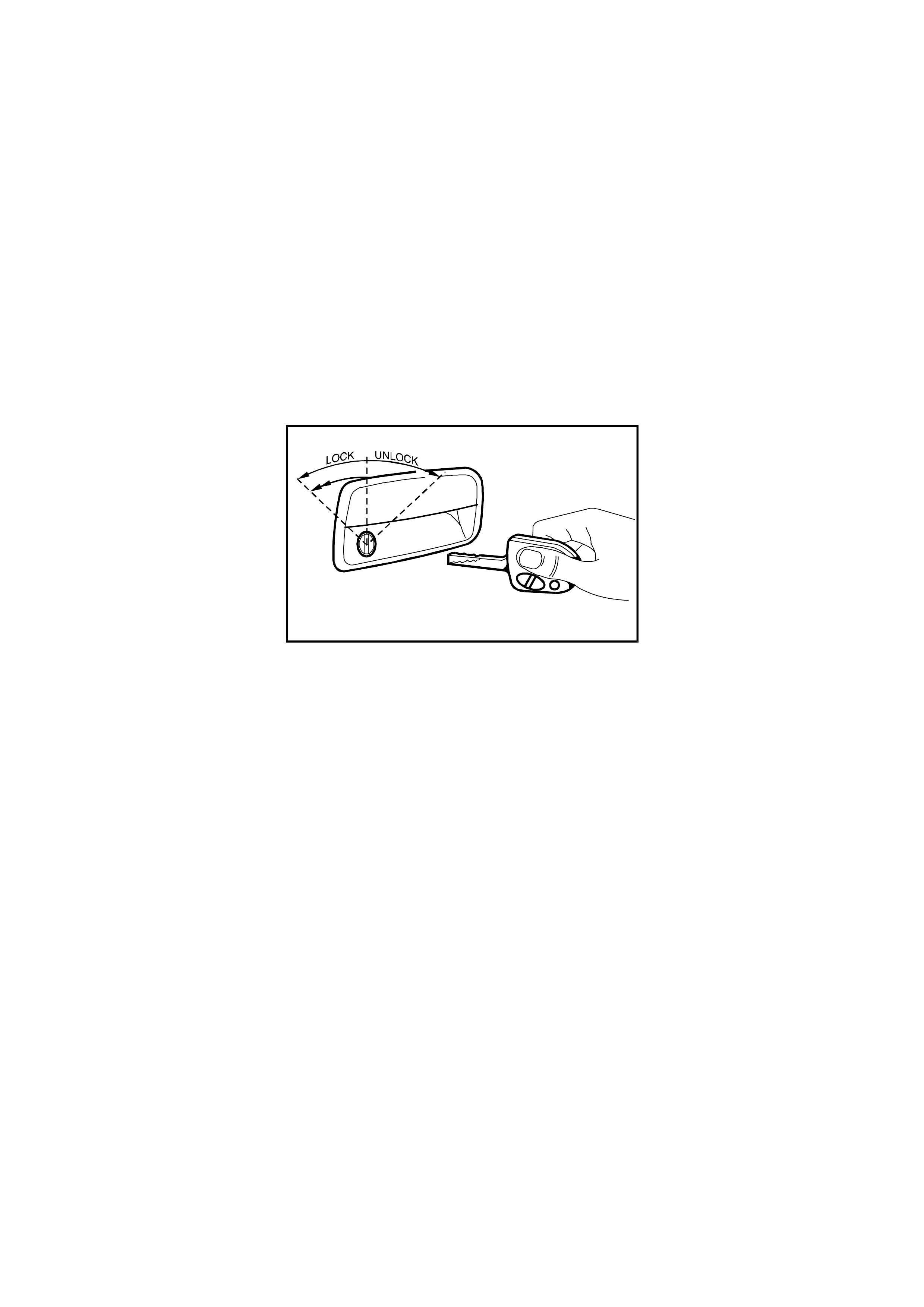
SYSTEM CHECK
The operation of the central door locking system is independent of the ignition being switched ON or OFF.
The figure below shows the key positions on the driver’s door for the various key locking functions.
Deadlock refers to the electrical means that can be activated to ensure vehicle security by inhibiting door lock
operation.
T212J1034
Figure 12J-1-7 Deadlocking with two sequential lock activation’s
Deadlock
The deadlocking feature applies to all four doors, but not to the luggage compartment lid or tailgate.
The deadlocking feature is engaged as follows:
• Two sequential lock activation’s of the door lock microswitch or
• Operating the ‘lock’ button on the remote coded key twice within 10 seconds.
Successful deadlocking via the remote coded key is indicated by the turn signal lamps turning on for three seconds.
If the vehicle is already deadlocked, pressing the lock button on the remote coded key will cause the turn signal
lamps to turn on for three seconds, indicating that the vehicle is already deadlocked.
If the vehicle is locked (not deadlocked) pressing the lock button on the remote coded key 10 seconds after the
previous press, the doors will not deadlock and the turn signal lamps will flash briefly, indicating that the doors are
only lock ed. Pressing the lock button again, within in a 10 second period will cause the doors to deadlock and turn
the signal lamps will turn on for three seconds.
After the deadlocking feature device has been engaged, unlocking is possible at the driver’s door from outside, by:
• Inserting the key into the driver’s door lock cylinder and turning the key to the unlock position or
• Activating the un-lock button on the remote key unlocks the deadlocks on all doors, but only unlocks the
driver’s door (providing two stage unlocking is enabled).
To ensure access to the vehicle if the electrical system should f ail (discharged battery), after the system has been
engaged, the driver’s door lock cylinder can be moved independently of the actuator and therefore allowing
unlocking of the driver’s door latch.
The rear com partment lid or tailgate can be lock ed/unlocked when the m echanical deadloc king featur e is ac tuated,
while leaving the doors secured.
NOTE: Deadlocking is not possible with the ignition in the ON position.
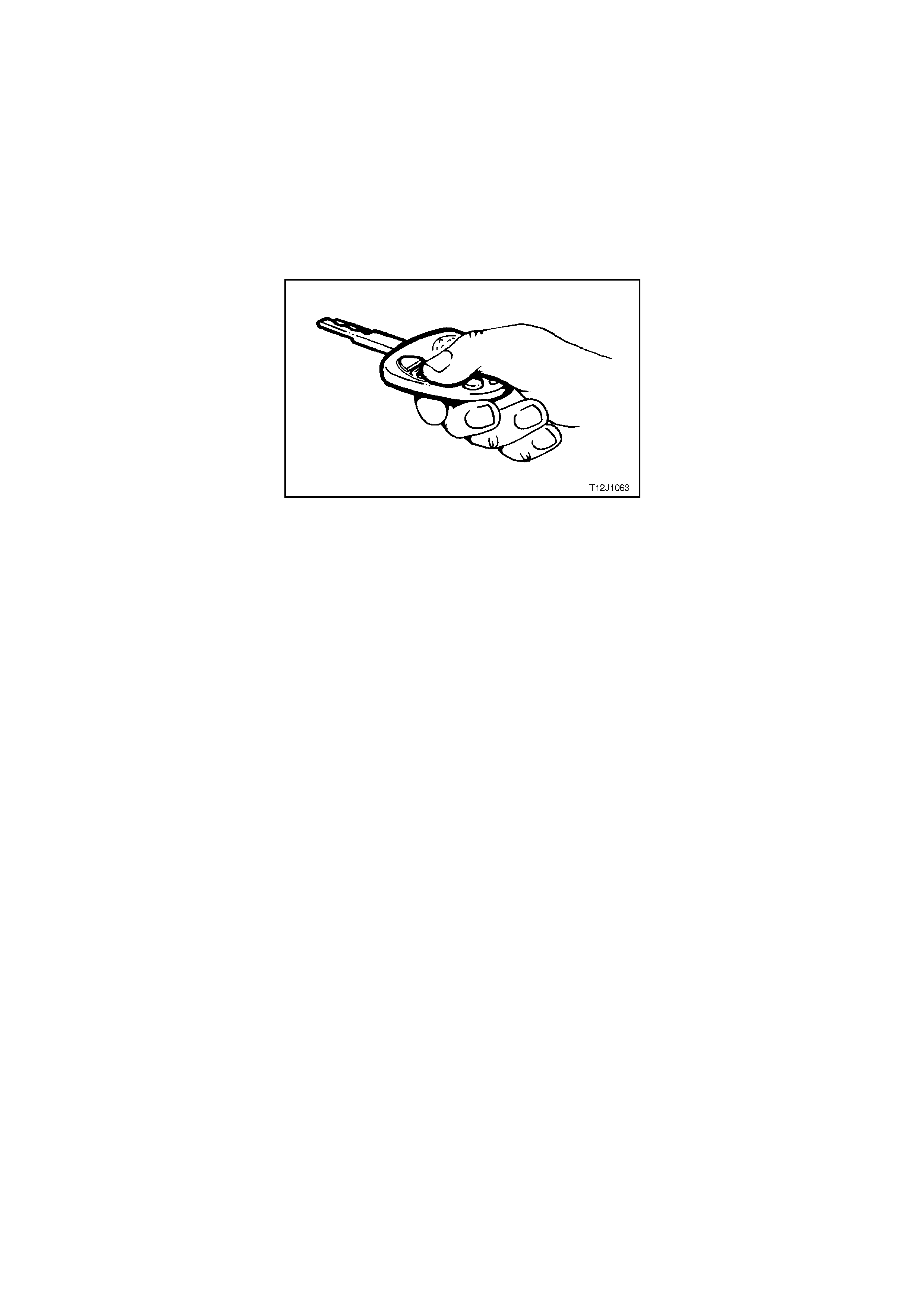
Remote Coded Key Check
Check that the remote coded key locks all doors when the remote coded key lock button is pressed, at a distance
within 4 metres from the driver’s side B pillar.
When the remote c oded key unlock button is press ed the driver's side should unlock ( vehicles program m ed for two
stage unlock). Pressing the unlock button again and all passenger doors (and tailgate on station wagon models)
should unlock.
On vehicles programmed for single stage unlock, the single press of the unlock button will unlock all doors and
tailgate on station wagon models.
If this test does not prove satisfactory, refer to 2.3 REMOTE CODED KEY in Section 12J-1 LOW SERIES BODY
CONTROL MODULE in the VT Series I Service Information for a more detailed diagnosis before continuing with the
central locking system check.
Figure 12J-1-8 Remote coded key
Checking the Deadlock Feature
Open all windows.
Close all doors.
Actuate the deadlock feature from the driver’s door with the key.
Check that all door lock buttons cannot be pulled up. They are electrically blocked.
NOTE: The door lock (snib) buttons can be pulled up slightly, but they will be under tension.
Overheating Prevention
In the event of m ultiple activation’s within a defined tim e period, the central door loc king system will be deactivated
and remain inoperative for a defined tim e period to prevent the door actuators from overheating. After a fixed time
delay, the system will re-activate and operate as normal.
1.4 BOOT RELEASE
GENERAL INFORMATION
The rear compartment lock actuator (boot release) is controlled by pressing the rear compartment lock switch which
is located in the glove compartment, or pressing the boot release button on the remote coded key which in turn
transmits an RF output signal. The RF signal is received by the BCM’s remote receiver and activates the
microprocessor within the BCM.
The rear compartment lock switch is disabled when the theft deterrent system is armed via the remote code key,
driver’s door microswitch or deadlocked.
The rear compartment lock switch is only enabled when the theft deterrent system is disarmed via the remote
coded key or remote key reader (valid security code).
The BCM will monitor the rear compartment lock switch and remote boot signal and inhibit boot release if the
vehicle speed is above 15 km/h.
NOTE: The circ uit diagram s shown in this General Des cription Sec tion are to aid in interpr eting the operation of the
circuit and therefore, only the main connectors and wiring colours are shown. For complete circuit details, refer to
either the relevant diagnostic section or Section 12P WIRING DIAGRAMS in the VT Series II Service Information.
SYSTEM OVERVIEW - BOOT RELEASE
BATTERY POWER
BOOT SO LENOID D RIVE
BCM
BOOT REL EASE
REMOTE RECEIVER
T212J1025
SERIAL DATA
VEHICLE SPEED
PCM
PIM
GEN III V8
ENGINE V6 & V6 S/C
ENGINE
CIRCUIT OPERATION
Battery Power
Battery voltage is applied to the BCM micr oprocessor term inal A6 at all tim es from f usible link FS and fus e F31 via
circuit 740 (Orange/Black wire).
Inputs
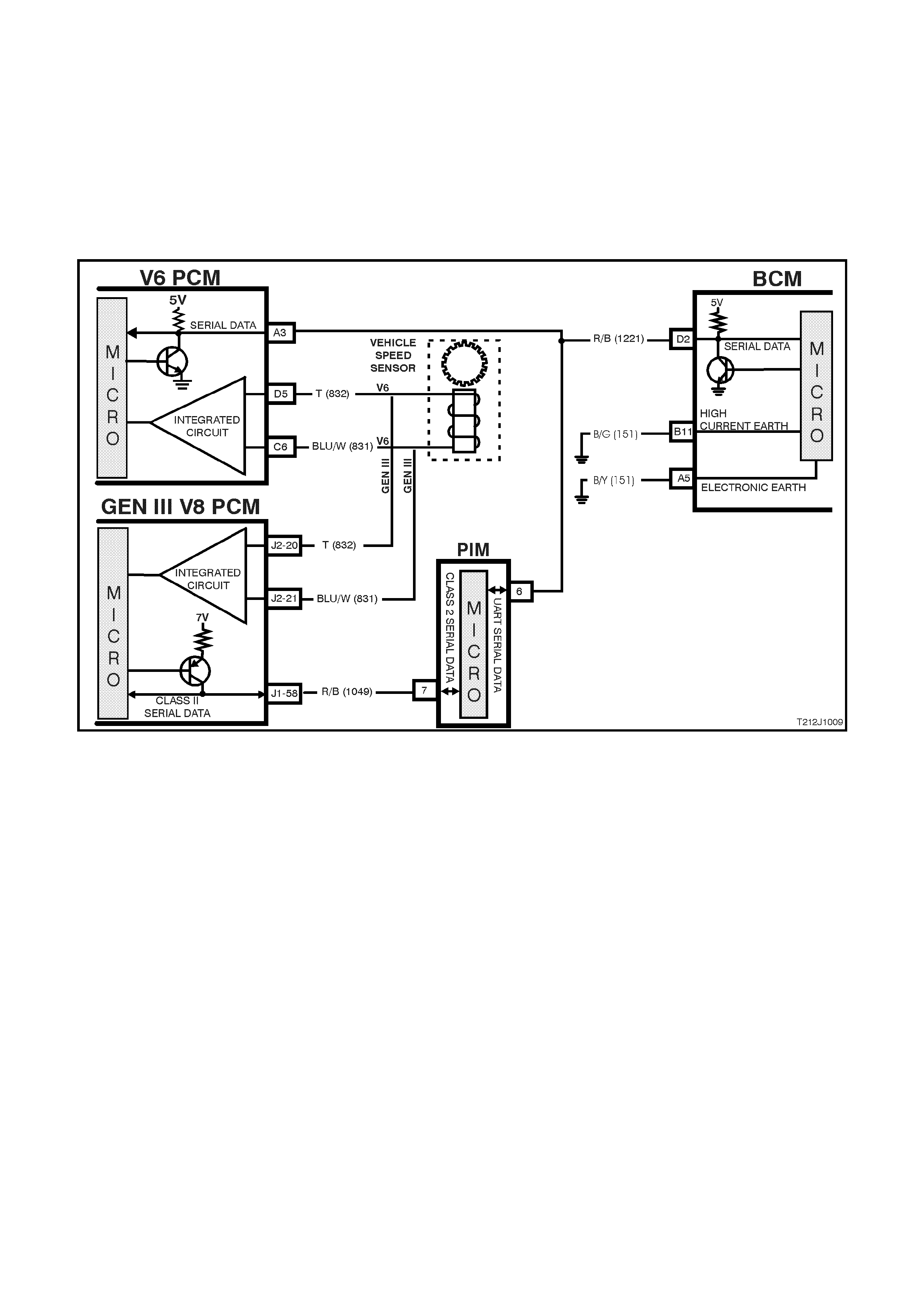
Serial Data Signal (Refer to Fig. 12J-1-9)
BCM terminal D2, serial data bus, is connected to the PCM terminal A3, via circuit 1221 (Black/Red wire). It is via
the serial data bus line that the BCM receives serial data relating to the speed of the vehicle.
Figure 12J-1-9 Vehicle speed input
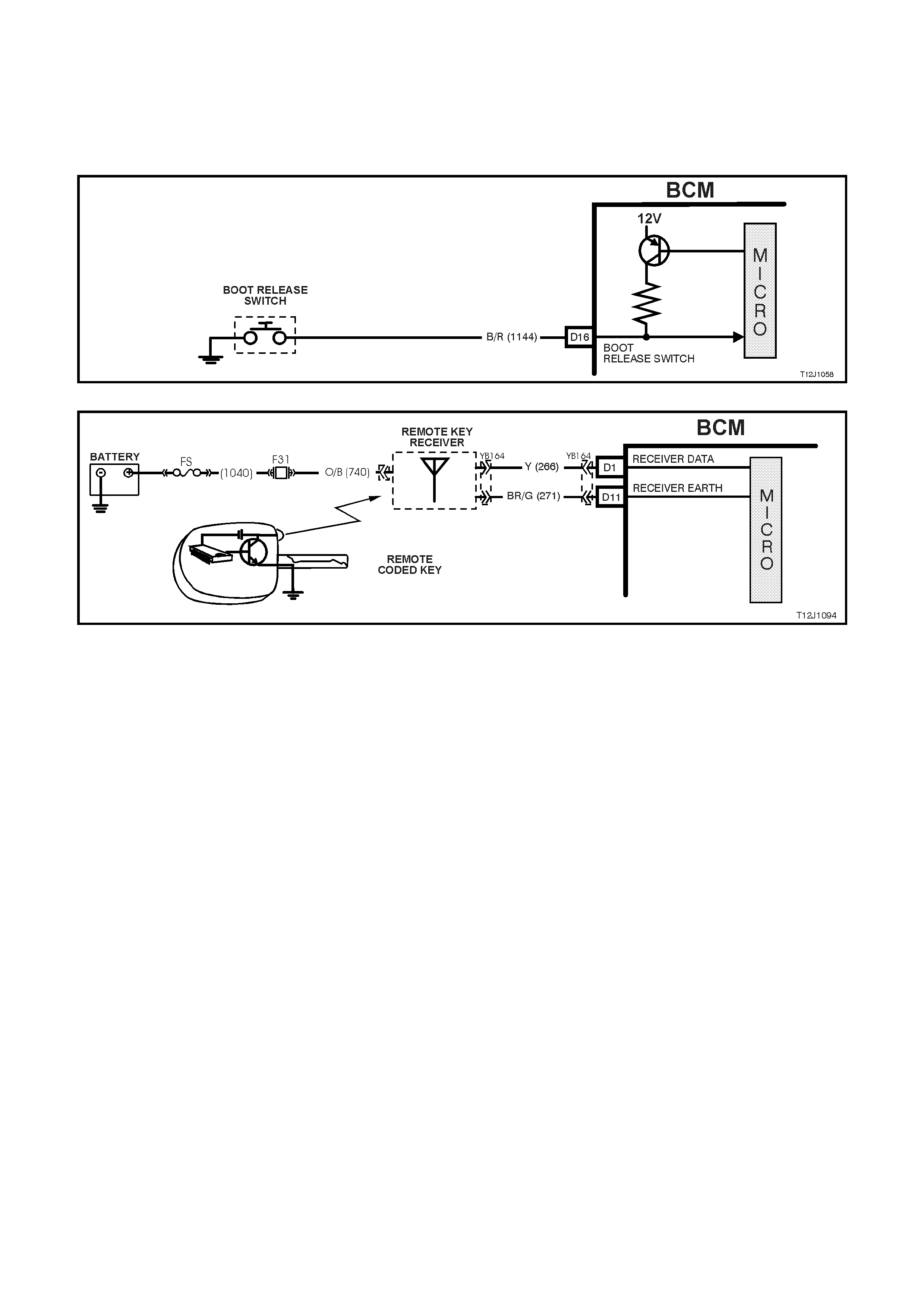
Boot Release input (Refer to Fig. 12J-1-10 and to Fig. 12J-1-11)
Pressing the r ear com partm ent loc k switch caus es the contac ts to clos e, connecting BCM ter m inal D16 to earth via
circuit 1144 (Black/Red wire). This action causes the voltage at terminal D16 to be pulled low, less than 0.2 volts.
This low voltage at terminal D16 is seen by the BCM as a boot release switch input signal. The BCM will not activate
the rear compar tment lock actuator if the vehic le s peed is gr eater than 15 km/h, the system is armed via the remote
coded key , or driver’s door lock microswitch is deadlocked.
Figure 12J-1-10 Boot release input
Figure 12J-1-11 Remote coded key circuit
Outputs (Refer to Fig. 12J-1-12)
The BCM can activate the rear compartment lock actuator by energising its internal boot release relay. This will
apply battery voltage from terminal B5, through the boot release relay contacts and terminal C25 to the rear
com partment releas e actuator, circuit 142 (Red/G reen wire). The earth circuit for the rear compartm ent solenoid is
via the body and main wiring harness.
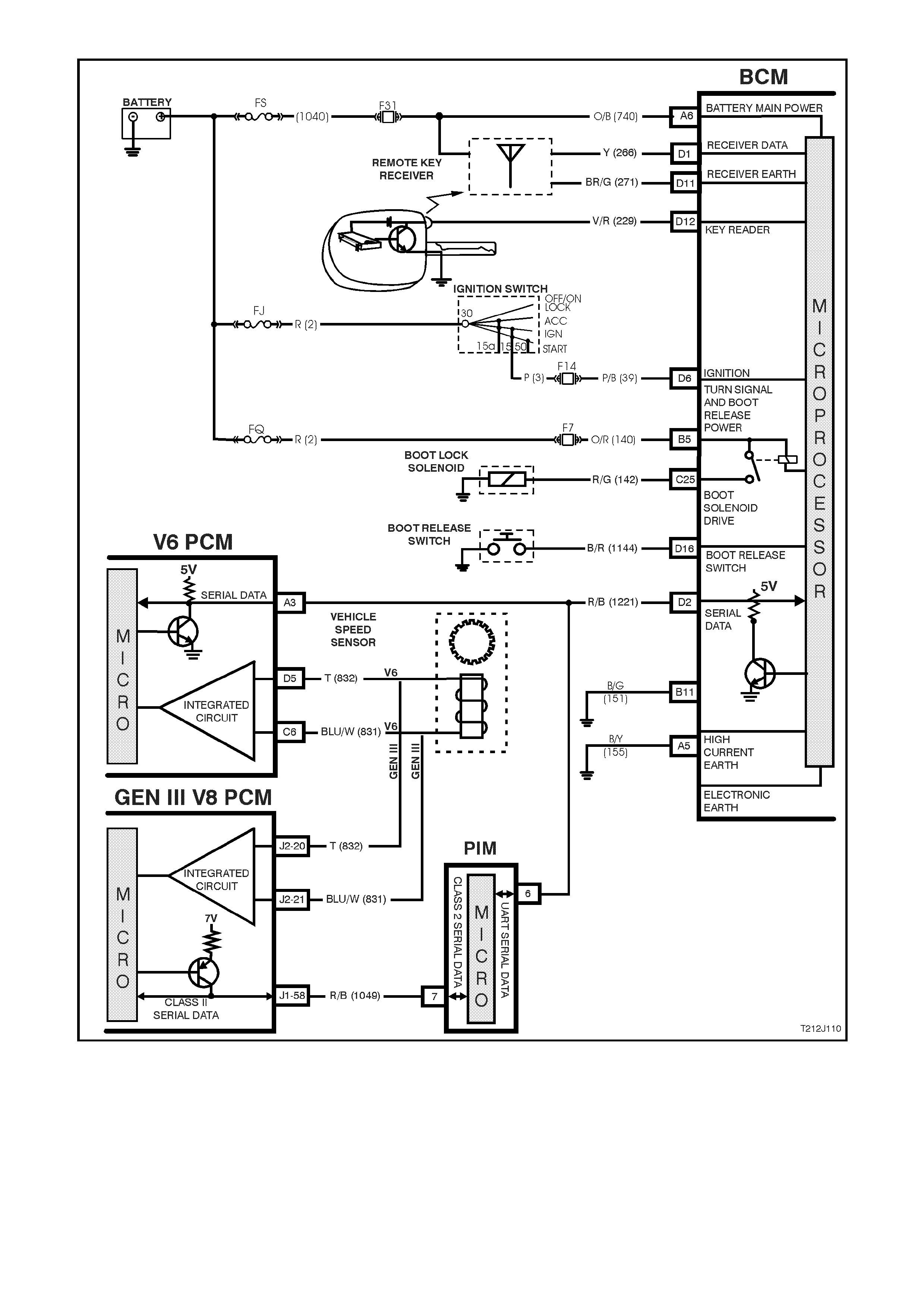
Figure 12J-1-12 Boot release circuit
1.5 THEFT DETERRENT SYSTEM
GENERAL INFORMATION
The theft deterrent system on VT Series Models uses a remote c oded k ey to arm and disar m the system , as well as
electrically lock or unlock all doors and tailgate (station wagon), or operate the boot unlock mechanism (sedan).
NOTE: The circ uit diagram s shown in this General Des cription Sec tion are to aid in interpr eting the operation of the
circuit and therefore, only the main connectors and wiring colours are shown. For complete circuit details, refer to
either the relevant diagnostic procedure in this Section or Section 12P WIRING DIAGRAMS in the VT Series II
Service Information.
SYSTEM OPERATION
There are two modes of theft deterrent operation, armed and disarmed.
Armed
Once the theft deterrent system is enabled, it can be manually armed in one of two ways:
Actively, by pressing the lock button on the remote coded key or,
Passively, as the BCM will automatically arm 30 seconds after the ignition is turned off.
When the system is armed, the start relay (located in the engine compartment relay housing) and the powertrain
management system (Powertrain Control Module (PCM) and on vehicles with GEN III V8 engines, Powertrain
Interface Module (PIM)) are disabled, preventing the engine from being started.
Disarmed
With the system disarmed and the PCM/PIM enabled, the engine will be allowed to be started when the ignition
switch is turned to the run position.
The theft deterrent system can be disarmed in two ways:
1. Pressing the unlock button on the remote coded key. This unlocks the doors, turns the interior dom e lamp on
and disarms the system for 30 seconds.
2. By inserting the remote coded key into the ignition switch cylinder and turning the ignition to the ON or run
position. This causes the BCM to read a security code serial data output from the remote coded key contact
pin via the remote coded key reader assembly.
NOTE: Should the engine crank briefly when the ignition switch is turned to the START position (ie. due to mis-
aligned or a faulty remote coded key reader) then pressing the unlock button on the remote coded key will also
disarm the theft deterrent system.
Remote Coded Key (Refer to Fig. 12J-1-13)
The theft deterrent system uses a remote coded key to arm and disarm the system, and electrically lock or unlock
all doors and tailgate (station wagon), or operate the boot unlock mechanism (sedan models).
The rem ote coded key is powered by its own internal battery. If its internal battery fails, the remote coded k ey can
be powered by the rem ote coded key reader once the k ey is ins erted into the ignition switch cylinder and tur ned to
the IGN or START position.
When the theft deterrent system is armed by pressing the remote coded key lock button, the indicators will flash
once and the theft deterrent alert indicator LED will begin to flash. Disarming the system by pressing the unlock
button will cause the indicators to flash twice and the theft deterrent alert indicator LED will stop flashing.
The Radio Frequency (RF) transmitted by the remote coded key is received by the BCM’s remote receiver located
in the dash panel.
NOTE: Passive arming of the system does not automatically operate the door locks or flash the indicators.
Figure 12J-1-13 Remote coded key input
The theft deterrent alert indicator LED is used to indicate the state of the system. A flashing LED indicates that the
system is arm ed and consequently the vehicle cannot be started. When the LED is turned off , the BCM is disar m ed
and the engine can be started.
The theft deterrent LED is incorporated into the trip computer switch assembly in the instrument panel facia.
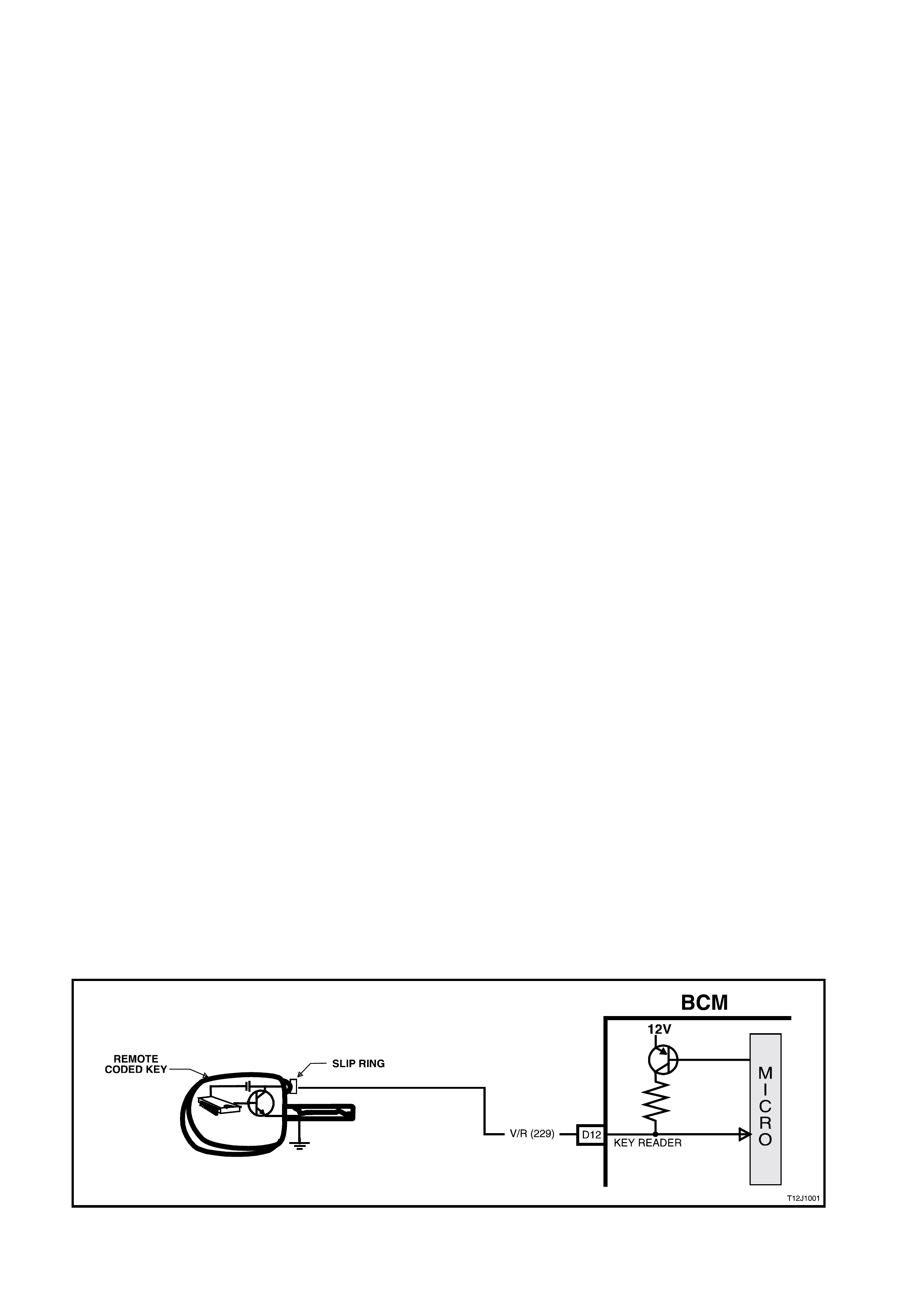
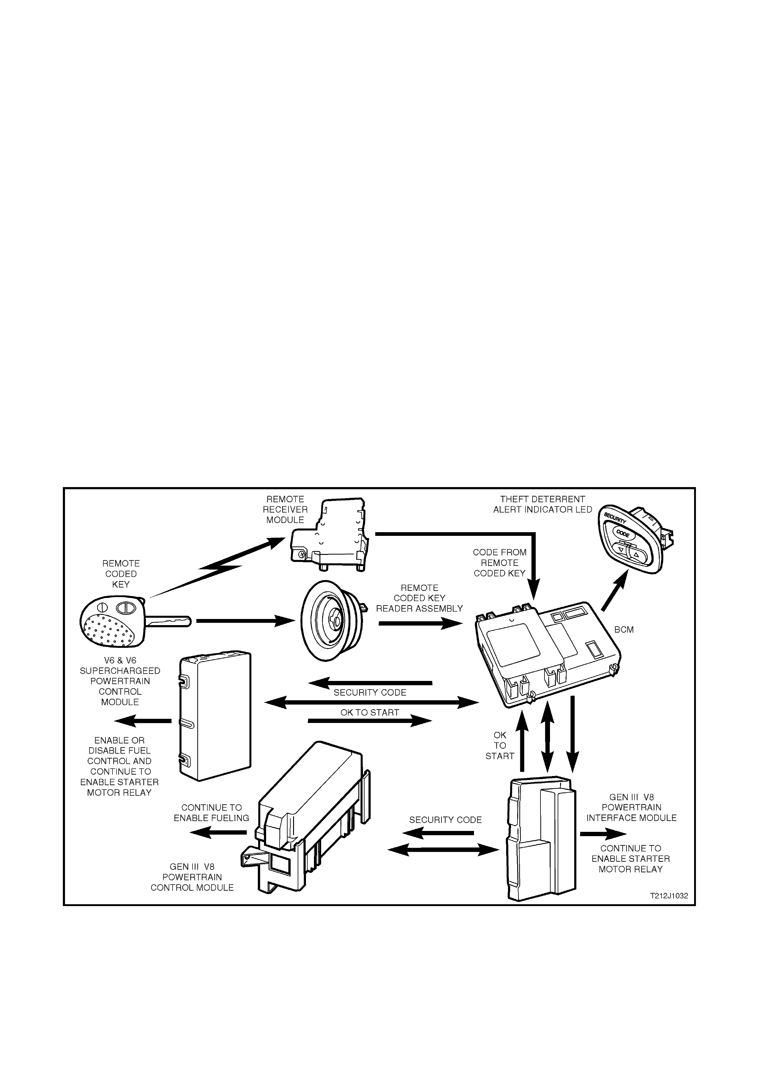
Operation (Refer to Fig. 12J-1-14)
V6 and V6 Supercharged Engine
When the ignition switch is turned to the ON position, the BCM polls the PCM and sends an encrypted BCM/Key
security code (The security code is received via the BCM slip ring or remote receiver in the event of no slip ring
communication). The PCM compares the received security code with it’s stored security code and if the codes
match, the PCM will enable injector fuelling and continue engine cranking. The PCM will return an OK TO START
message, which tells the BCM to jump from SHORT LOOP mode to the LONG LOOP mode.
GEN III V8 Engine
When the ignition switch is turned to the ON position, the BCM polls the PIM and sends an encrypted BCM/Key
security code (The security code is received via the BCM slip ring or remote receiver in the event of no slip ring
communication). The PIM compares the received security code with it’s stored security code and if the codes
match, the PIM will continue enabling engine cranking and send a separate encrypted security code to the PCM.
The PCM compares this code with its stored security code and if the codes match, the PCM will enable injector
fuelling to continue. The PIM will return an OK TO START message, which tells the BCM to jump from SHORT
LOOP mode to the LONG LOOP mode. (Refer to 1.2 SERIAL DATA COMMUNICATION in this Section for
additional information about sort and long loop).
NOTE: Regardless of the engine configuration, it is very important that the remote coded key reader is aligned
correc tly with the ignition lock ass embly, or mis alignment with the remote c oded key contact may occur res ulting in
intermittent or no engine cranking or starting.
Figure 12J-1-14 Theft deterrent system
Theft Deterrent Alert Indicator LED

SYSTEM OVERVIEW - THEFT DETERRENT
BATTERY POWER
LH TU RN SI GNAL
RH TURN SIGNAL
THEFT DETERRENT LED
BCM
TURN SIGNAL POWER
DRIVER’S DOOR OPEN
REMOTE RECEIVER
KEY RE AD ER
IGNITION SWITCH ON
T212J1024
SERIAL DATA
PCM
PIM
GEN III V8
ENGINE V6 & V6 S/C
ENGINE
CIRCUIT OPERATION (REFER TO FIG. 12J-1-19)
Battery Power(Refer to Fig. 12J-1-15)
Battery voltage is applied to the BCM microprocessor from terminal A6 at all times from fusible link FS and fuse F31
via circuit 740 (Orange/Black wire).
Indicators Power (Refer to Fig. 12J-1-15)
Battery voltage is applied to BCM terminal B5 at all times from fusible link FJ and fuse F7 via circuit 140
(Orange/Red wire).
Inputs
Ignition Switch ON Input Signal (Refer to Fig. 12J-1-15)
The BCM uses this input signal to determine when the ignition switch is in the IGN or START position. W hen the
ignition switch is in the IGN or START position, battery voltage is applied to the BCM term inal D6 from the ignition
switch and fuse F14 via circuit 39 (Pink/Black wire).
Figure 12J-1-15 Battery power, turn signal indicator power and ignition switch on input signals
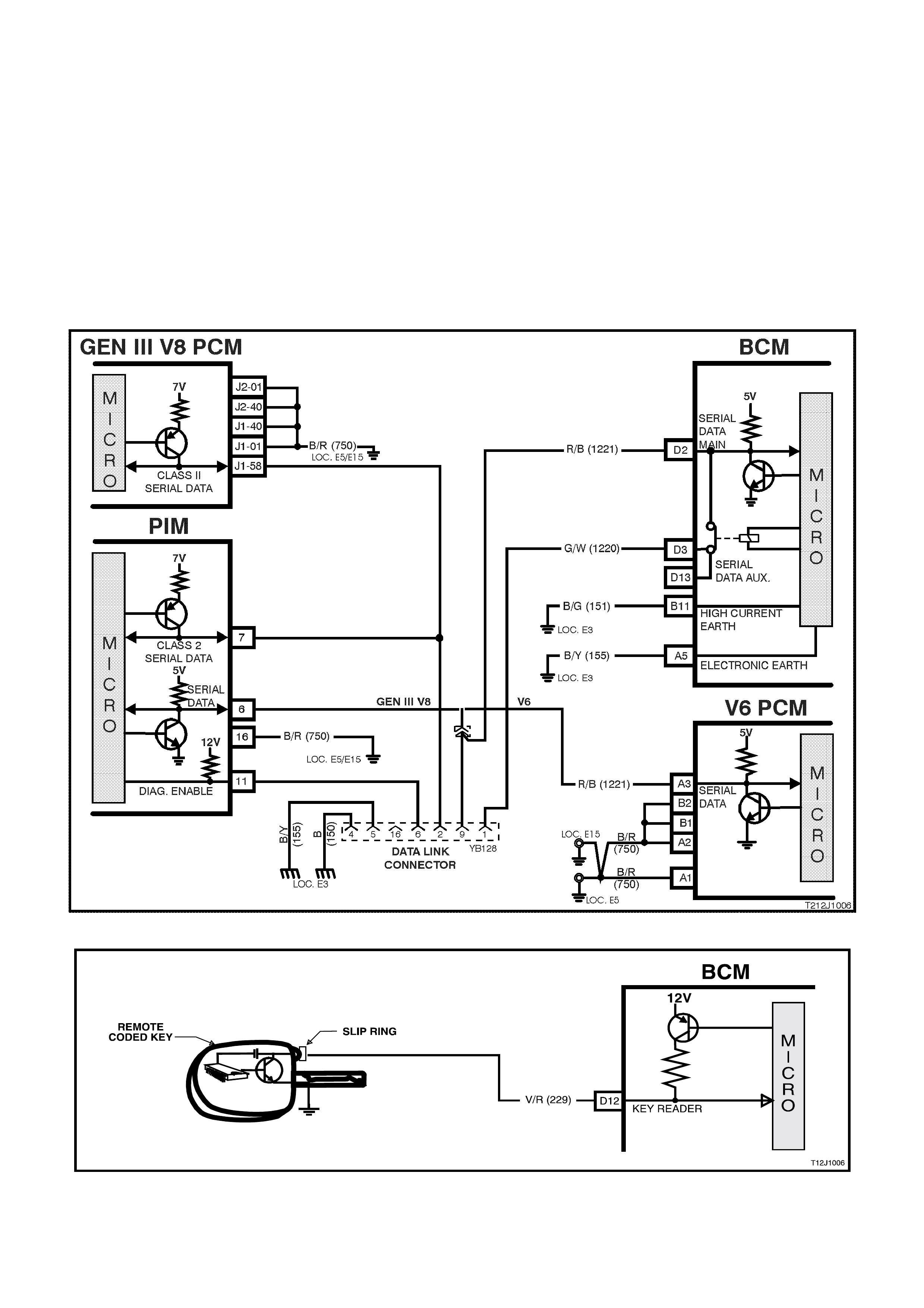
BCM and Powertrain Control Module Communication (Serial Data) (Refer to Figs. 12J-1-16 and 12J-1-17)
V6 and V6 Supercharge d Engine
When the ignition switch is turned to the ON pos ition, the BCM polls the PCM and sends a secur ity code. The PCM
compares this code with it’s stored code and if they match, the PCM will enable fuel system control and continue
engine cranking.
The serial data from the remote coded key is applied to BCM terminal D12, circuit 229 (Violet/Red wire).
GEN III V8 Engine
W hen the ignition switch is turned to the ON position, the BCM polls the PIM and sends a security code. The PIM
com pares this code with it’s stored c ode and if they matc h, the PIM continues enabling engine crank ing and sends
the GEN III V8 PCM a security code. The GEN III V8 PCM compares this code with its stored code and, if they
match, the PCM will continue engine fuelling.
The serial data from the remote coded key is applied to BCM terminal D12, circuit 229 (Violet/Red wire).
Figure 12J-1-16 Serial data circuit
Figure 12J-1-17 Remote coded key input signal
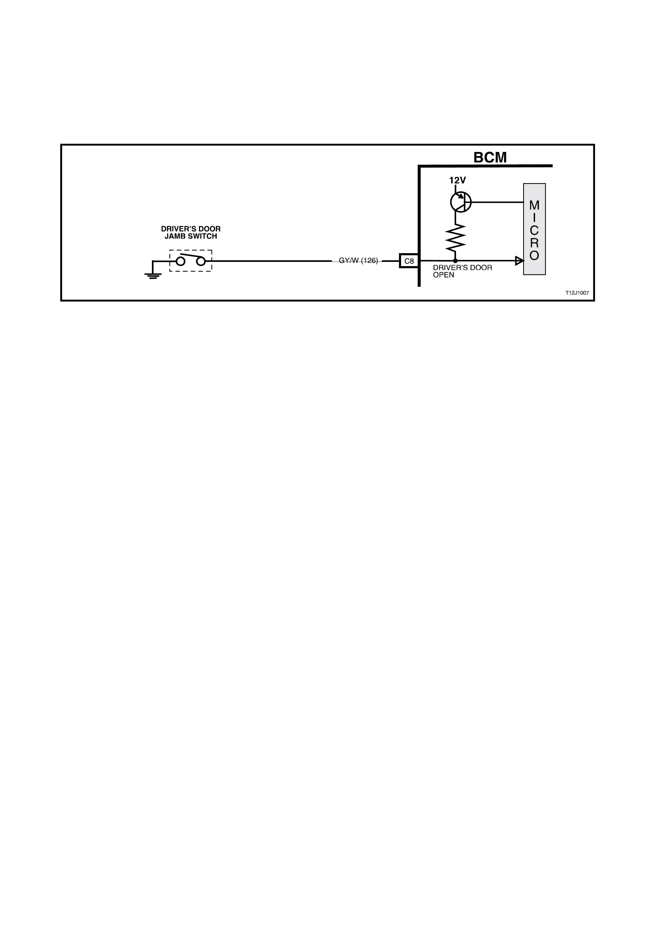
Driver's Door Jamb Switch (Refer to Fig. 12J-1-18)
The BCM uses this input signal to determine if the driver's front door is opened or closed. The BCM must sense that
the driver's door is closed before the theft deterrent system can be actively armed.
When the door is opened, the jamb switch earth’s terminal C8 via circuit 126 (Grey/White wire). This causes the
voltage at terminal C8 to be pulled low, less than 0.2 volts (driver's door open). This low voltage at terminal C8 is
seen by the BCM as the driver's door open input signal.
Figure 12J-1-18 Driver’s door jamb switch circuit
Outputs
Left Hand Indicators
The BCM controls the operation of the left hand indicators by pulsing its internal indicator relay. This causes the
indicator relay contacts to close and open a number of times. This allows battery voltage from terminal B5 to be
applied internally to terminal B12, to the left hand indicator lamps via circuit 14 (Light Blue wire).
Right Hand Indicators
The BCM c ontrols the operation of the right hand indic ators in the s am e m anner as the lef t hand indicator s. Pulsing
of its internal indicator relay causes the indicator relay contacts to close and open a number of times. This allows
battery voltage from terminal B5 to be applied internally to terminal B4, to the right hand indicator lam ps via circuit
15 (Blue wire).
Theft Deterrent Alert Indicator LED
The theft deterrent alert indicator LED will continuously flash on and off whenever the system is armed. The BCM
controls the oper ation of the thef t deter rent aler t indic ator LED by pulsing an internal switch on and of f , which in tur n
switches the voltage applied to the theft deterrent alert indicator LED via terminal A8, circuit 263 (Light Blue wire).
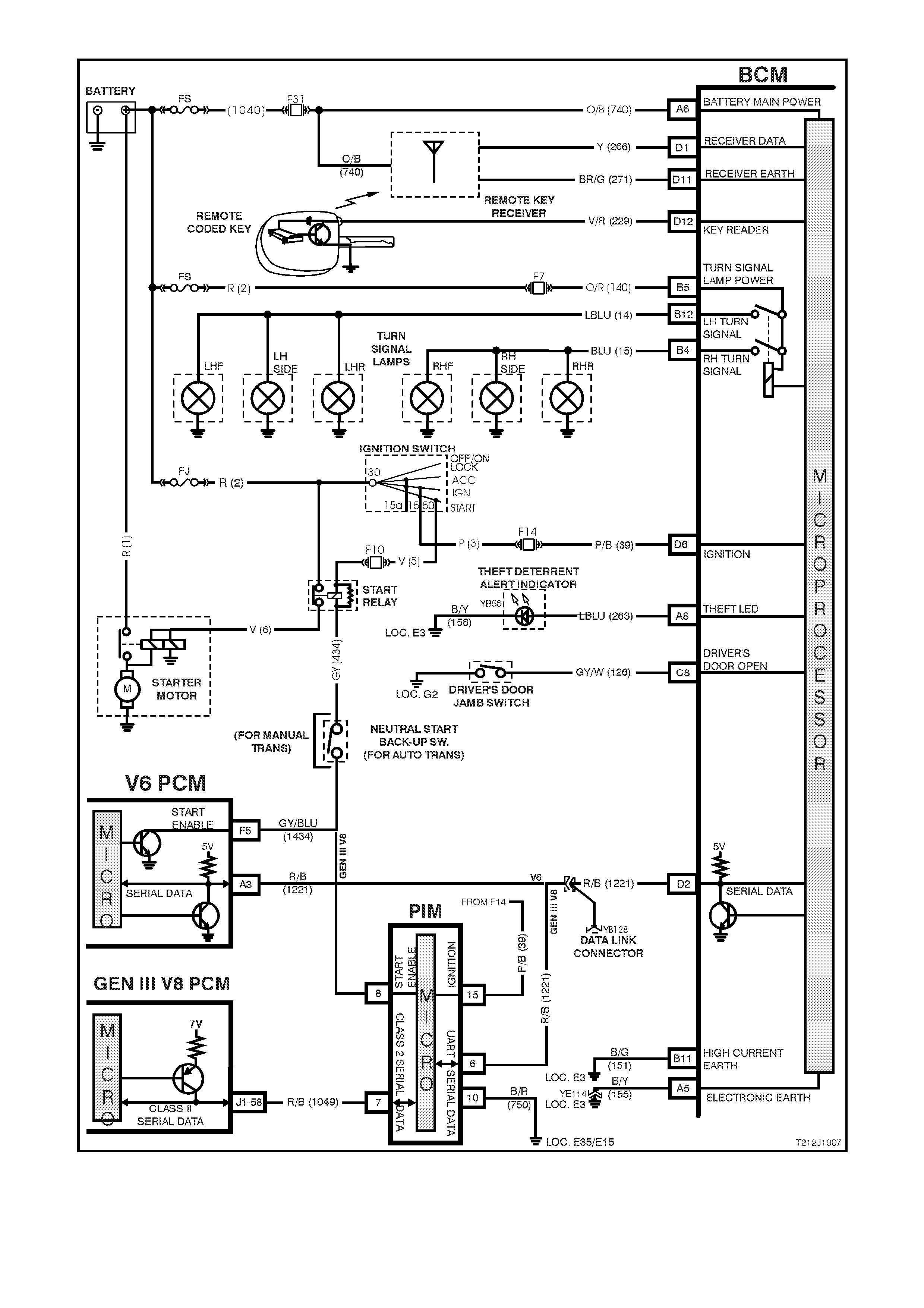
Figure 12J-1-19 Theft deterrent system circuit
1.6 POWER WINDOW SYSTEM
GENERAL INFORMATION
The BCM controls the following functions of the power window system:
1. Control of positive supply to all door window motors.
2. Automatic down of driver's door window (activated when the driver's power window switch DOWN button is
depressed for more than 0.4 seconds).
Once activated, the automatic down feature is cancelled within 100 ms (0.01 second) after:
a. The driver's power window switch UP button is depressed following which the window will move upward (if up
button is held) or:
b. The driver's power window switch DOW N button is depressed (the window will stop when the down button is
released).
3. With ignition on, power is supplied continuously to the window system.
4. When the ignition is switched off and no door has been opened, power is supplied to the window system for a
maximum of 60 minutes, provided the BCM has not entered battery saver mode. If battery saver mode is
active, power will be removed from the window system when the ignition is switched off.
5. In the event of any door being opened, power is supplied to the system for 45 seconds maximum, timed from
when any door was opened. If during this period the power window switch is activated again, the 45 second
period will recommence from 0 seconds.
When the doors are remotely unlocked (by using the remote coded key), provided the vehicle is not in battery
saver mode, power is supplied to the system for up to 60 minute (If the vehicle is in battery saver mode, power
is removed from the system). The delay is cancelled when the doors are locked by the remote coded key.
NOTE: The circ uit diagram s shown in this General Des cription Sec tion are to aid in interpr eting the operation of the
circuit and therefore, only the main connectors and wiring colours are shown. For complete circuit details, refer to
either the relevant diagnostic section or Section 12P WIRING DIAGRAMS in the VT Series II Service Information.
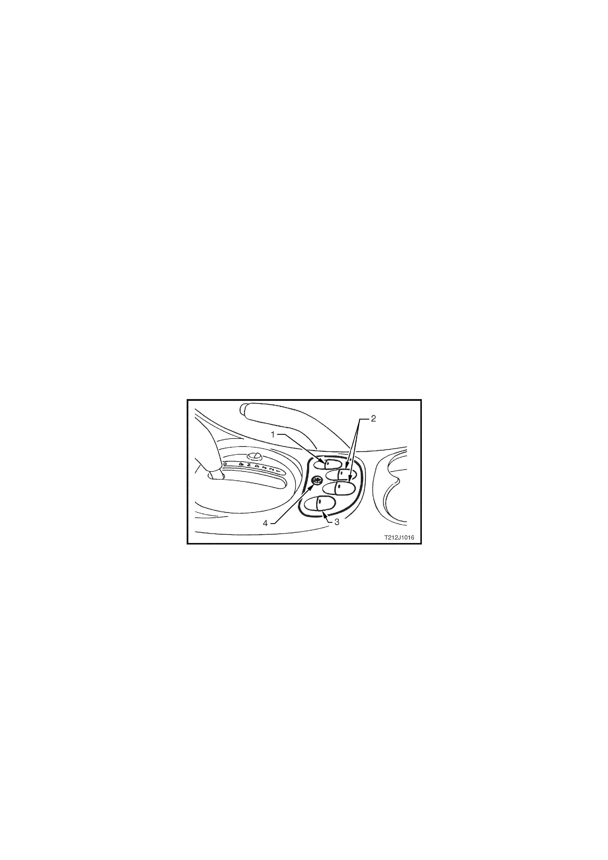
SYSTEM CHECK
Figure 12J-1-20 Power w indow switch assembly
1. Drivers window switch.
2. Rear passenger window switches (left and right hand).
3. Front passenger window switch.
4. Child safety switch.
Prerequisite Condition
The child safety switch must be switched OFF. This will be indicated by the green light emitting diodes (LED) in
each of the rear door rocker switches being illuminated.
System Active
System active is indicated by the illumination of the lights in each of the rocker switches.
When the ignition switch is turned ON, all switches are active.
With the ignition switch turned OFF, all switches will remain active for 45 seconds after any door is opened.
With the ignition switch turned OFF, all switches will remain active for approximately 60 minutes, PROVIDED
THERE ARE NO OPEN DOORS.
System Inactive
Lights are not illuminated.
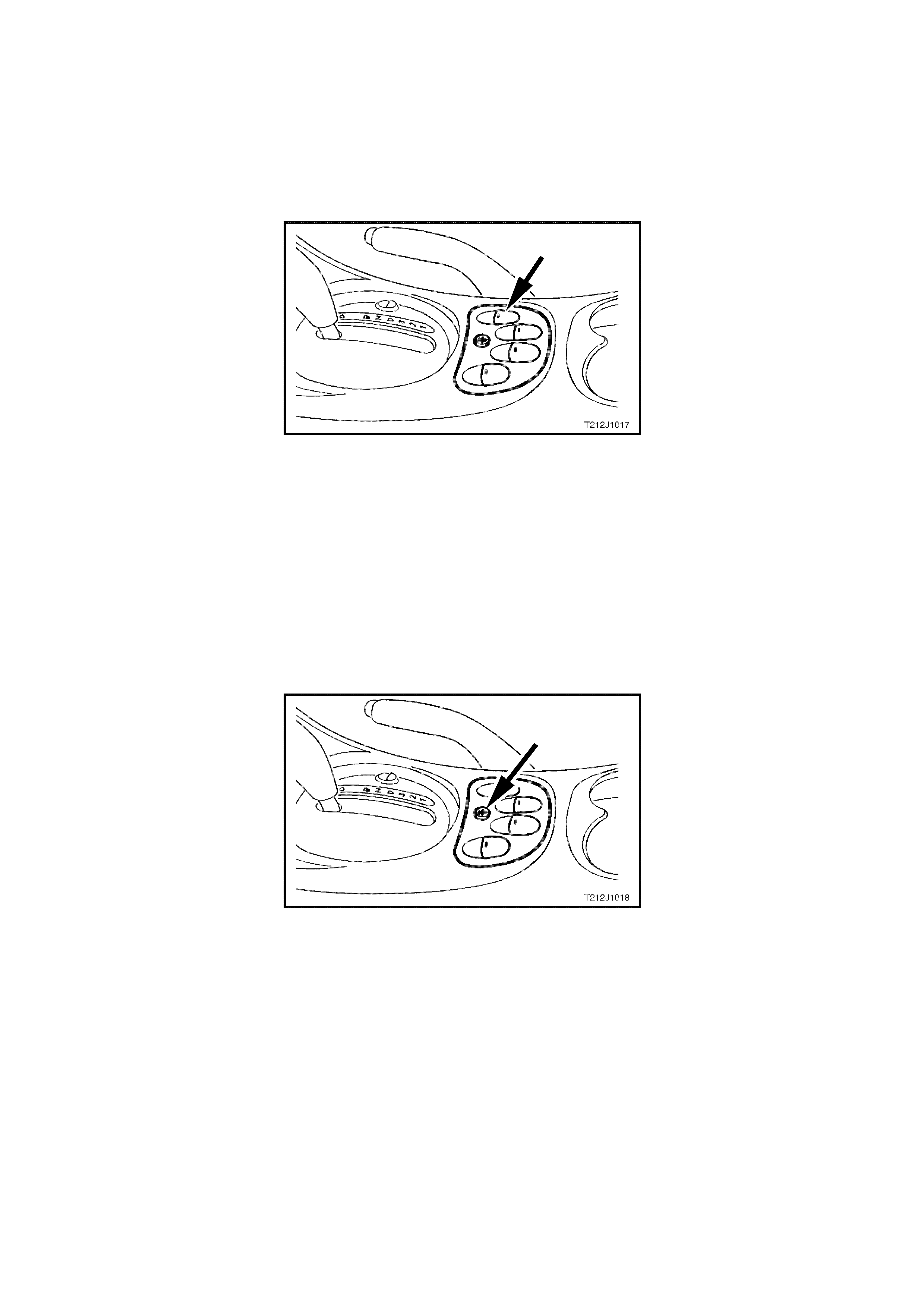
Automatic DOWN Operation of Driver’s Window
With the driver’s window in the fully UP position and the ignition switch turned to ON, press the dr iver window switch
to the window DOWN position for more than 0.5 seconds and release.
The window will continue to lower automatically until the fully DOWN position is reached.
To interrupt this function, press the UP button momentarily.
Figure 12J-1-21 Driver’s power window switch
Child Safety Switch
W hen the child safety switch (override switch) is OFF, the rear windows can be opened or closed from the centre
console switch assembly or the rocker switches in each of the rear doors.
Check the operation of this feature, as per the following:
1. Switch ignition ON.
2. Check that the green LED in each of the rear door rocker switches is illuminated.
3. Open and close the rear door windows using the rocker switches in the rear doors.
4. Press the child saf ety switch button in the centre of the switch ass em bly in the console as shown in Fig. 12J-1-
35.
5. Check that the green LED in each of the r ear door roc k er switches ex tinguishes and that the r ear windows can
only be raised or lowered from the switch in the centre console.
Figure 12J-1-22 Child safety switch
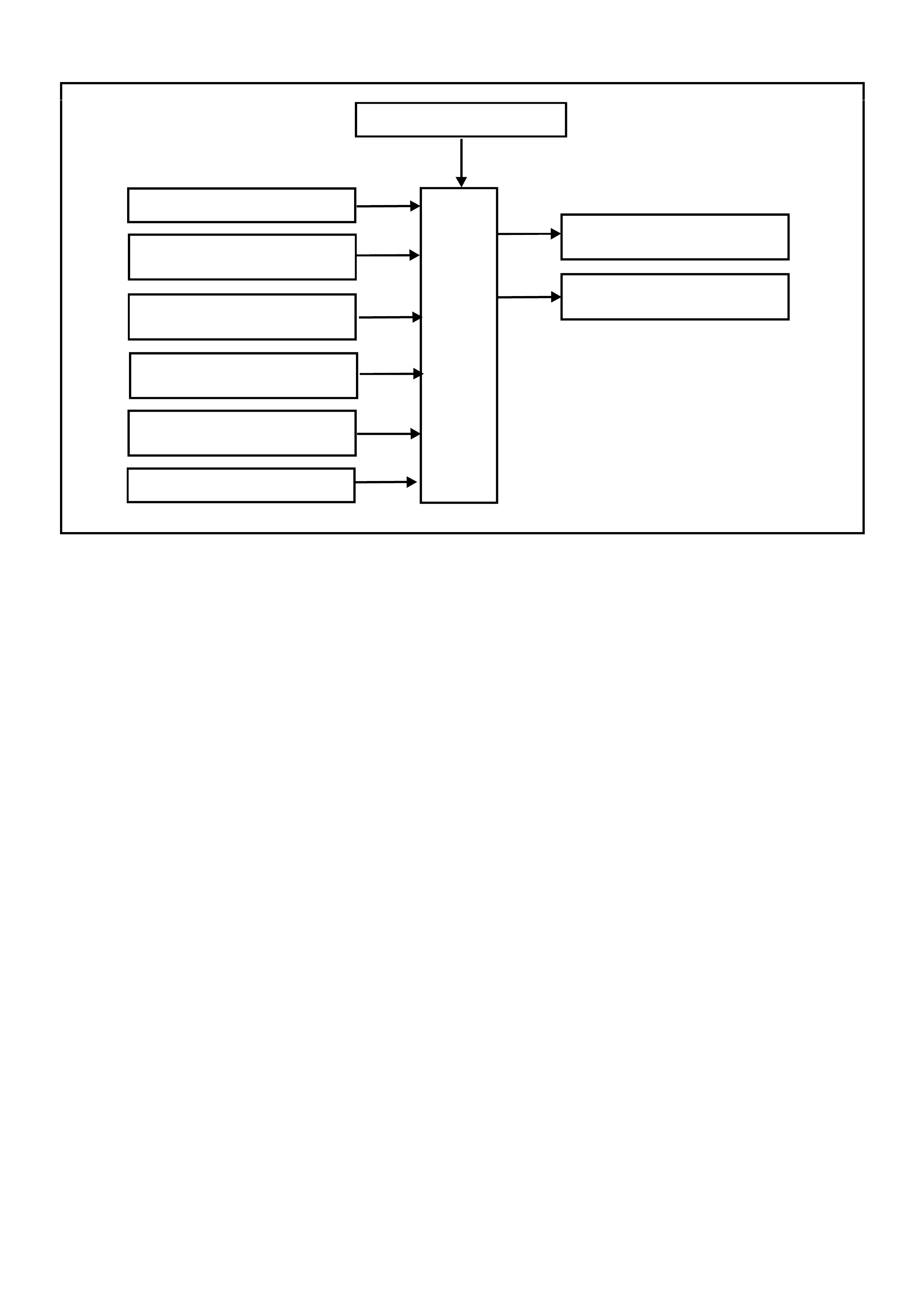
SYSTEM OVERVIEW - POWER WINDOWS
BATTERY POWER
BCM
IGNITION SWITCH ON
DRIVER’S WINDOW
DOWN SWITCH DRIVER’S WINDOW
RELAY
T212J1020
POWER WINDOW
RELAY
DRIVER’S WINDOW
UP SWITCH
DRIVER’S DOOR
JAMB SWITCHES
PASSENGER DOO R
JAMB SWITCHES
REMOTE RECEIVER
CIRCUIT OPERATION
A permanent magnet motor operates each of the power window mechanisms to raise or lower the window glass.
The direction in which the motor turns depends on the polarity of a voltage supplied to its terminals. The power
window switches, located in the centre console, or in the rear doors, control the polarity of the supply voltages.
The BCM has two main control functions in the power window system.
1. To control the operation of the power window relay and hence, power supply to the whole system.
2. To control the operation of the driver's side front window motor.
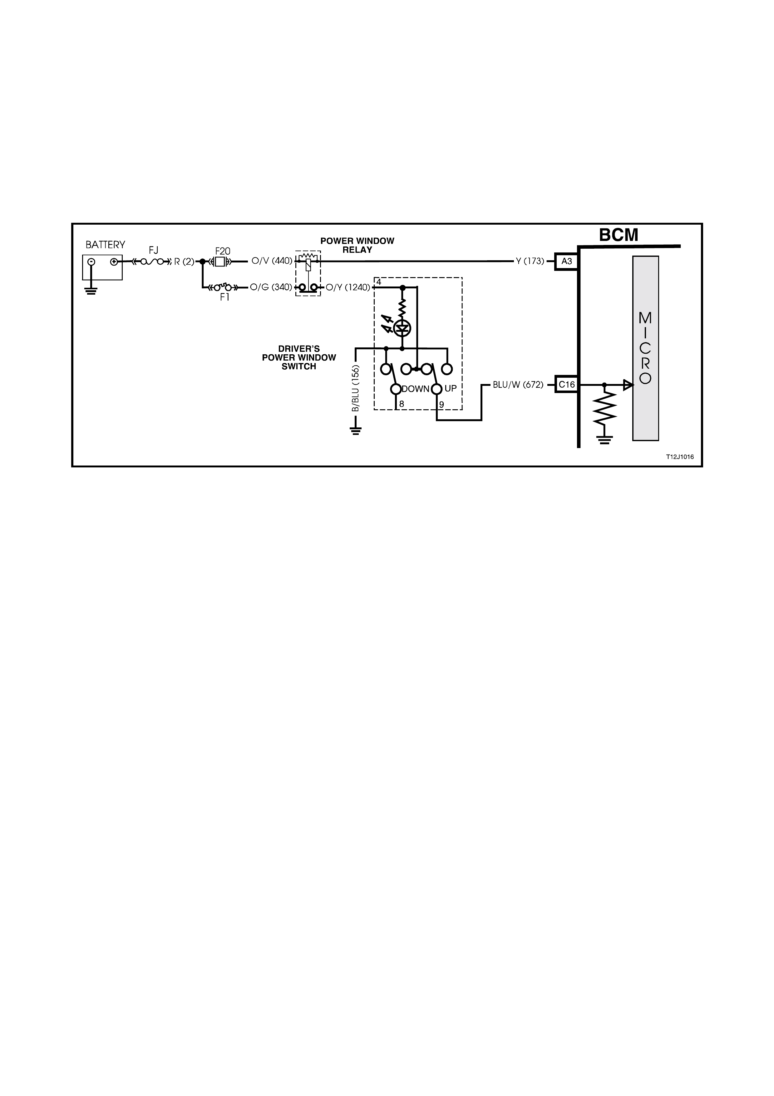
Opening Window - Driver's Door (Refer to Fig. 12J-1-25)
Ignition On Input Signal (Refer to Fig. 12J-1-23)
The BCM uses this input signal to determine when the ignition switch is in the IGN or START position. W hen the
ignition switch is in the IGN or START position, battery voltage is applied to the BCM term inal D6 from the ignition
switch and fuse F14 via circuit 39 (Pink/Black wire).
When the BCM receives an ignition on input it energises the power windows relay (voltage supplied by fuse F20
circuit 440 (Orange/Violet wire) by earthing the relay’s pull-in coil via circuit 173 (Yellow wire) and BCM terminal A3.
With the relay coil energis ed, the relay contacts close and power via f usible link FJ and circ uit break er F1 is applied
to the power window switches and each of the lights of the window switches (for rear door window switches, the
power window override switch in the RHF power window switch must be OFF). The opposite side of each light is
connected to earth, therefore the lights are illuminated (system active).
By depressing and releasing the driver's front window switch down button within 0.4 of a second (so as not to
engage the automatic down feature), this allows battery voltage from the power windows relay, circuit 1240
(Orange/Yellow wire), and the power window switch terminal 4, through to terminal 8 and then BCM terminal C14
(window down signal input).
The opposite side of the motor is connected to earth on circuit 672 (Blue/White wire) via power window switch
terminals 9 and 5 to circuit 156 (Black/Blue wire). This causes the motor armature to rotate, operating the window
regulator to lower the window.
As described under power windows general inf orm ation, the driver's window will automatic ally travel f ully downward
provided the power window switch down button is depressed for more than 0.4 seconds. The BCM m icroproces sor
senses the tim e the down button is depressed via ter minal C14 and energises the external relay so as to allow the
window to lower fully. The BCM senses this down signal and activates BCM terminal B2 to energise the drivers
window relay. Power is then fed through the relay (via circuit 673) and terminals 9 and 5 on the power window
switch.
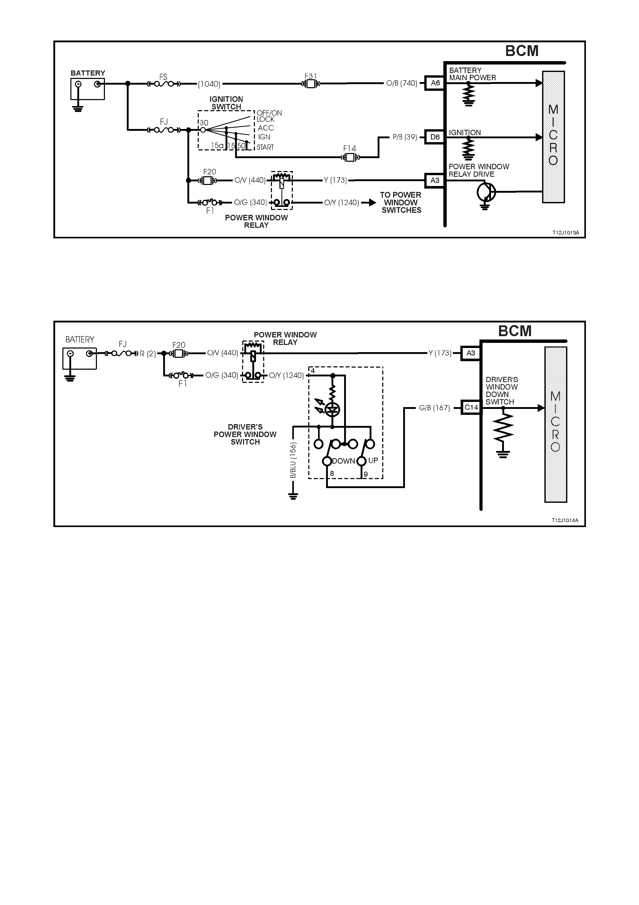
Figure 12J-1-23 Ignition switch on input signal
Driver's Front Window Down Switch Input Signal (Refer to Fig. 12J-1-24)
W ith the driver's front window switch down button depressed, battery voltage from the power windows relay, circ uit
1240 (Orange/Yellow wire), and the power window switch terminal 4, through to terminal 8 is applied to BCM
terminal C14 (window down signal input).
Figure 12J-1-24 Driver’s front window down switch input circuit
When the BCM receives a driver 's front window down switch input signal it energise s an ex ter nal relay. T his caus es
the relay contacts to changeover, allowing battery voltage from the power windows relay contacts, to one side of the
driver's side power window motor on circuit 673 Green/Orange wire.
If the window is travelling downward and the down button is again depressed, the BCM m icroproces sor sens es this
(voltage again sensed at BCM terminal C14) and de- energises the external relay, the contacts open and the m otor
stops when the button is released.
Should the up button be momentarily depressed whilst the window is travelling downward, positive battery supply
connection is on both sides of the motor armature and the motor stops. If the up button is depressed whilst the
window is travelling downward, the window down function is cancelled. The window will then move upward as
described in the following text.
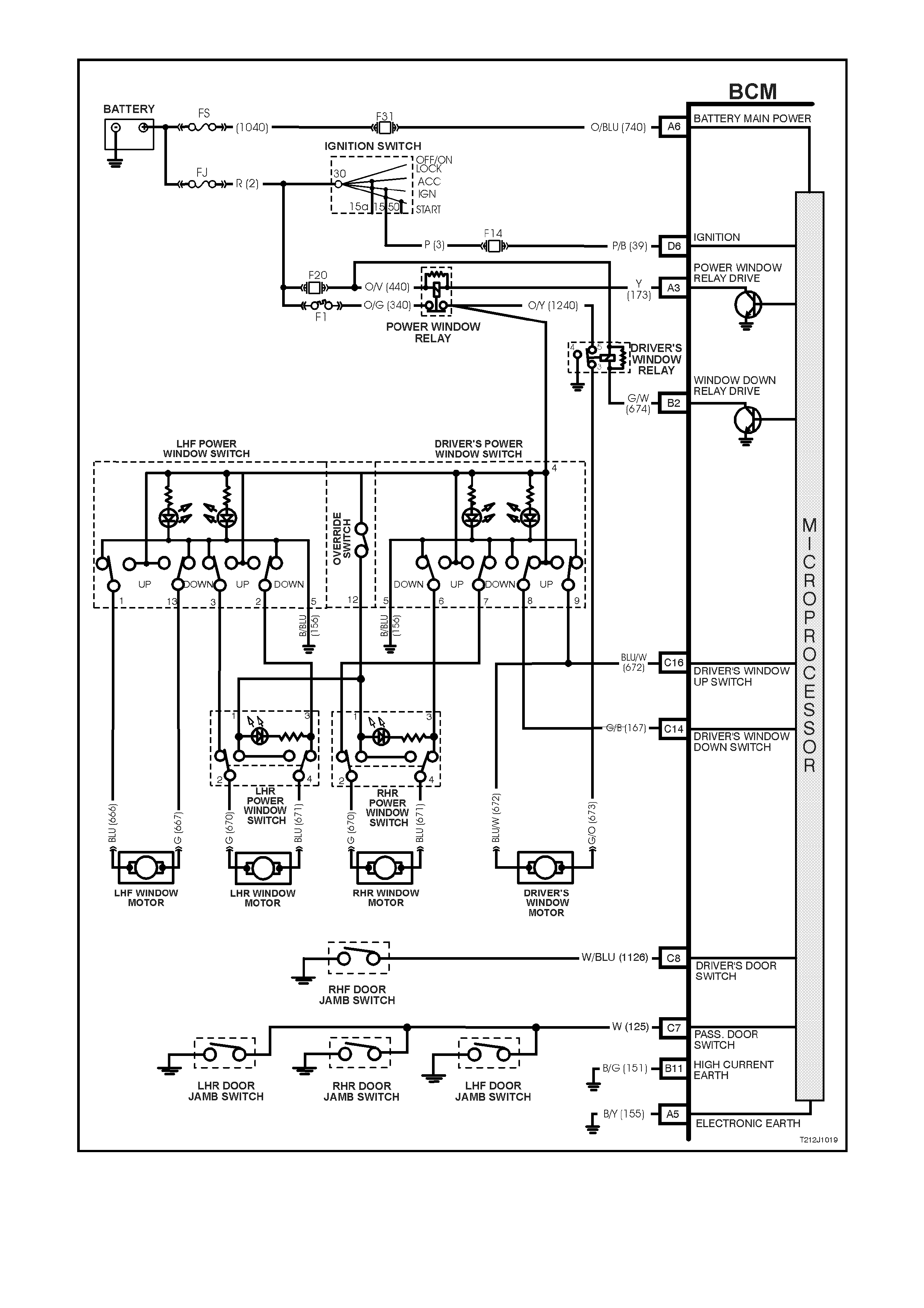
Figure 12J-1-25 Driver’s window down operation circuit
Closing Window (Refer to Fig. 12J-1-27)
Driver's Front Window Up Switch Input Signal (Refer to Fig. 12J-1-26)
By depressing and holding down driver's front window up button, battery voltage from the power windows relay
(circuit 1240 Orange/Yellow wire) is applied, via power window switch terminals 4 and 9, to the driver's side power
window motor (circuit 672 Blue/White wire).
The opposite side to the motor (circuit 673 Green/Orange wire) is connected to earth via the drivers window relay,
term inals 3 and 4 to earth (circuit 150, Black wire). This causes the m otor arm ature to rotate, oper ating the window
regulator to raise the window as long as the power window switch up button is depressed.
Figure 12J-1-26 Driver’s front window up switch input circuit
Window Operation - Passenger Doors
Power is supplied to all the power window switches fr om the power window relay (to the rear door switches pr ovided
the power window override switch is off). If the power window override switch is on, (contacts between terminals 4
and 12 are open) the power supply to the rear door power window switches is interrupted.
With the switch buttons at rest, all their contacts are connected to earth, circuit 156 (Black/Blue wire). By depressing
the appropriate passenger's window switch down or up button, this allows battery voltage from the power windows
relay, through the depressed switch button contact to one side of the window motor. With the other side of the motor
connected to earth, this causes the motor armature to rotate, operating the window regulator to raise or lower the
window as long as the window switch button is depressed.
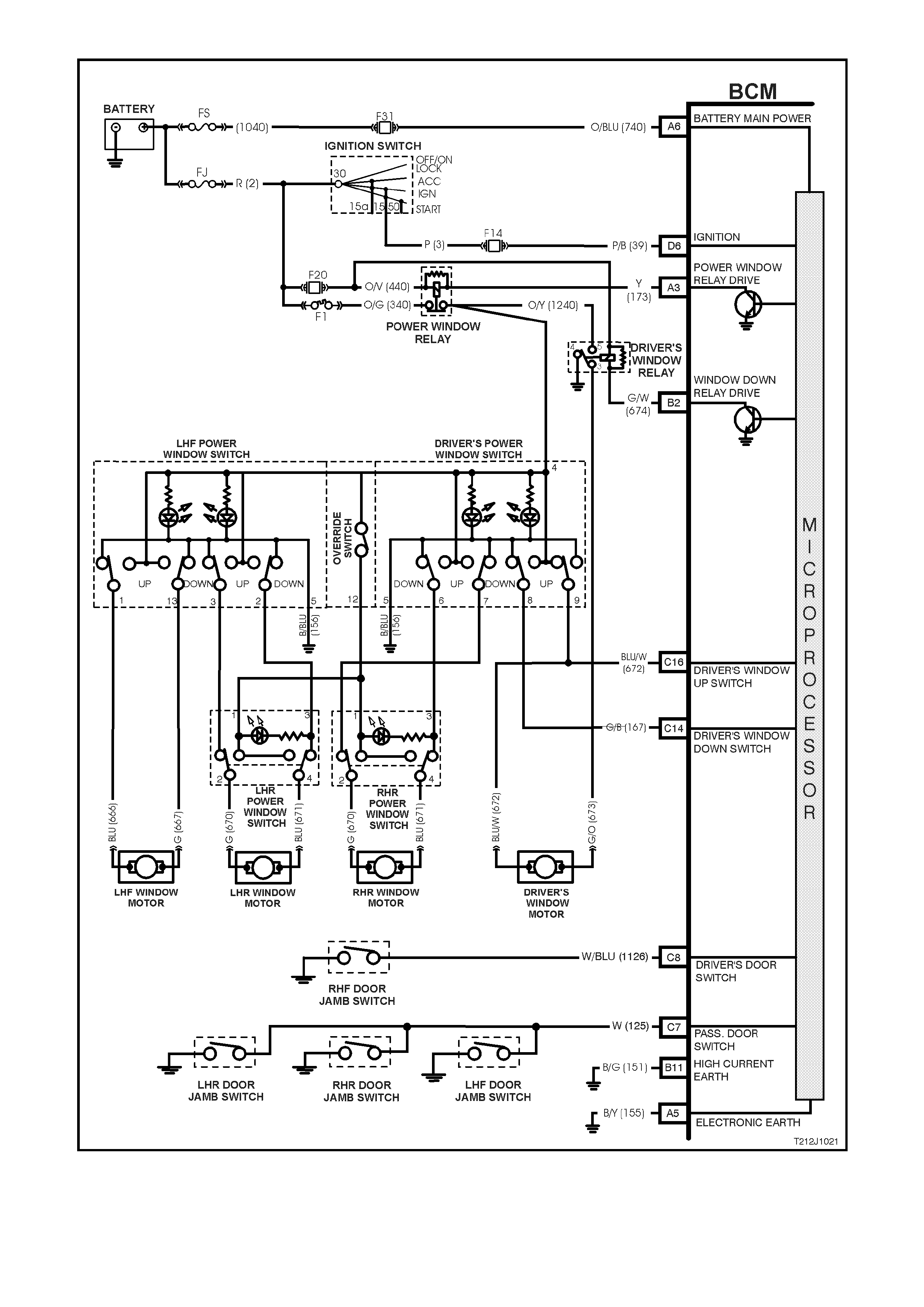
Figure 12J-1-27 Driver’s window up operation circuit

1.7 ENGINE COOLING FAN, LOW SPEED CONTROL
GENERAL INFORMATION (REFER TO FIGS. 12J-1-28 AND 12J-1-29 FOLLOWING)
VT Series II Models with V6 engines have two single speed electr ic engine cooling fans; a low speed f an and a high
speed fan. All other VT Series Models, r egardless of the engine c onfiguration (including GEN III V8), are equipped
with two, two speed electric cooling fans.
The engine cooling fan assemblies provide the primary means of moving air through the engine radiator. These
fans are placed between the radiator and the engine and have their own shroud. These fans configurations are
used on all vehicles even if not equipped with air conditioning. There is no fan in front of the A/C condenser.
The electric engine cooling fans are used to cool engine coolant flowing through the radiator, and if fitted, refrigerant
flowing through the A/C condenser.
On vehicles with V6 engines, the engine cooling fan m otors have two term inals; one pos itive and one negative. The
positive terminals are permanently connected to battery voltage. When the negative terminal is connected to
earthed through the low speed cooling fan r elay, the low speed cooling f an will operate. When the negative term inal
is connected to earth via the high speed cooling fan relay, both cooling fans will operate.
On vehicles with either V6 supercharged or G EN III V8 engines, the engine cooling fan m otors have four term inals,
two negative and two positive terminals. The two positive terminals are permanently connected to battery voltage.
When one of the negative terminals is earthed, both cooling fan motors will operate at low speed. When both
negative terminals are earthed, both cooling fans will operate at high speed.
Regardless of the engine configuration, the low speed c ooling fan operation is enabled when the low speed engine
cooling fan micr o r elay (located in the engine com par tment relay housing, labelled Lo Fan) is ener gis ed by the Body
Control Module (BCM) via a request from the Powertrain Control Module (PCM). The PCM will request low speed
fan enable and disable via serial data communication to the BCM on circuit 1221 (Red/Black wire). After the PCM
requests a change in the state of the low speed relay (i.e. OFF to ON or ON to OFF), the BCM will send a serial
data response message back to the PCM confirming it received the message.
NOTE: On vehicles with GEN III V8 engines, serial data communication between the PCM and BCM is via the
Powertrain Interface Module (PIM).
The PCM determines when to enable the low speed fan r elay based on inputs f rom the A/C request signal, Cooling
Temperature Sensor (CTS) and the Vehicle Speed Sensor (VSS).
For information regarding the engine cooling fan high speed control, refer to either
Section 2A HEATING & AIR CONDITIONING - DESCRIPTION & OPERATION, or, depending on the engine
variation, Section 6C1 POWERTRAIN MANAGEMENT - V6 ENGINE in the VT Series I Service Information or
Section 6C3 POWERTRAIN MANAGEMENT - GEN III V8 ENGINE in the VT Series II Service Information.
NOTE: T he c ircuit diagram s shown in this Gener al Description Sec tion are to aid in interpr eting the operation of the
circuit and therefore, only the main connectors and wiring colours are shown. For complete circuit details, refer to
either the relevant diagnostic section or Section 12P WIRING DIAGRAMS in the VT Series II Service Information.
SYSTEM OVERVIEW - ENGINE COOLING FAN, LOW SPEED CONTROL
BATTERY POWER
BCM
PCM
ENGINE COOLING FAN
LO W SPEED RELAY
T212J2052
VEHICLE SPEED
ENGINE COOLANT
TEMPERATURE
A/C REQUEST
PIM
GEN III V8
ENGINE
V6 & V6 S/C
ENGINE
S
E
R
I
A
L
D
A
T
A
Figure 12J-1-28 Main serial data communication circuit

CIRCUIT OPERATION
V6 ENGINE (Refer Fig. 12J-1-29)
The engine cooling low speed fan relay is energised by the BCM earthing terminal B7, circuit 473 (Orange/Black
wire). This caus es the relay contacts to s witch over f r om 30-87A to 30- 87 and cir cuit 157 (Black/red wire) is ear thed
through the relay and to the low speed fan term inal on circuit 533 (Blue/Yellow wire). Battery voltage is supplied to
the other low speed fan terminal via circuit 208 (Yellow wire).
V6 SUPERCHARGED & GEN III V8 ENGINES (Refer Fig. 12J-1-30)
The engine cooling low speed fan relay is energised by the BCM earthing terminal B7, circuit 473 (Orange/Black
wire). This causes the relay contacts to switch over from 30-87A to 30-87 and circuit 157 (Black/Red wire) is
earthed through the relay and to the low speed fan term inal on circuit 533 (Blue/Yellow wire). T he other low speed
fan terminal is connected to battery voltage via circuit 208 (Yellow wire).
LOW SPEED FAN OPERATION
The low speed cooling fan relay will be turned ON when:
•Air conditioning request indicated (YES) and the vehicle speed is less than 30 km/h or
•Air conditioning pressure is greater than 1500 kPa or
•Coolant temperature is greater than 104°C (V6 and V6 supercharged) / 98°C (GEN III V8) or
•Vehicles with V6 and V6 supercharged engines; an engine coolant temperature sensor failure is detected by
the PCM, refer to Section 6C1 POWERTRAIN MANAGEMENT - V6 ENGINE for additional information.
Vehicles with GEN III V8 engines; when a coolant temperature sensor failure in conjunction with an Intake Air
Temperature (IAT) sensor failure is detected by the PCM, refer to Section 6C3 POWERTRAIN
MANAGEMENT - GEN III V8 ENGINE for additional information.
•When the ignition switch is turned from ON to OFF and the engine coolant temperature is above 117°C (V6
and V6 superchar ged) / 113°C (GEN III V8). The BCM will continue to energise the low speed engine cooling
fan micro relay for four minutes.
The PCM will request the BCM to switch off the low speed cooling fan relay when the following conditions have
been met:
• Air conditioning request not indicated (NO) and the coolant temperature is less than 99°C (V6 and V6
supercharged) / 95°C (GEN III V8) or
• Air conditioning request indicated (YES) with press ure less than 1170 k Pa, vehicle speed gr eater than 50 k m /h
and coolant temperature less than 99°C (V6 and V6 supercharged) / 98°C (GEN III V8).
NOTE: On vehicles with GEN III V8 engines, the low speed cooling fan r un on tim e has a m inim um def ault value of
30 seconds.
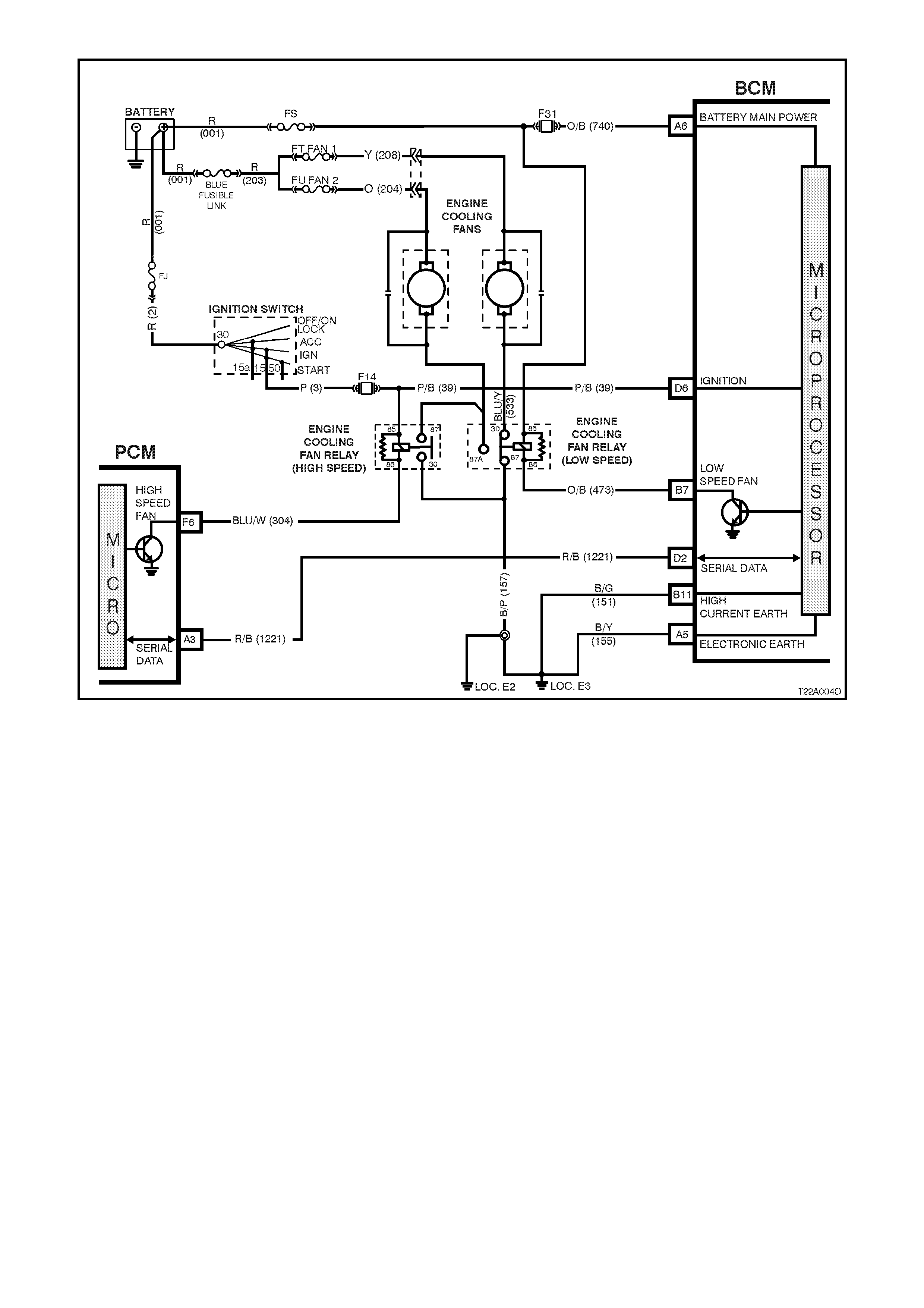
Figure 12J-1-29 V6 engine cooling fan low speed control
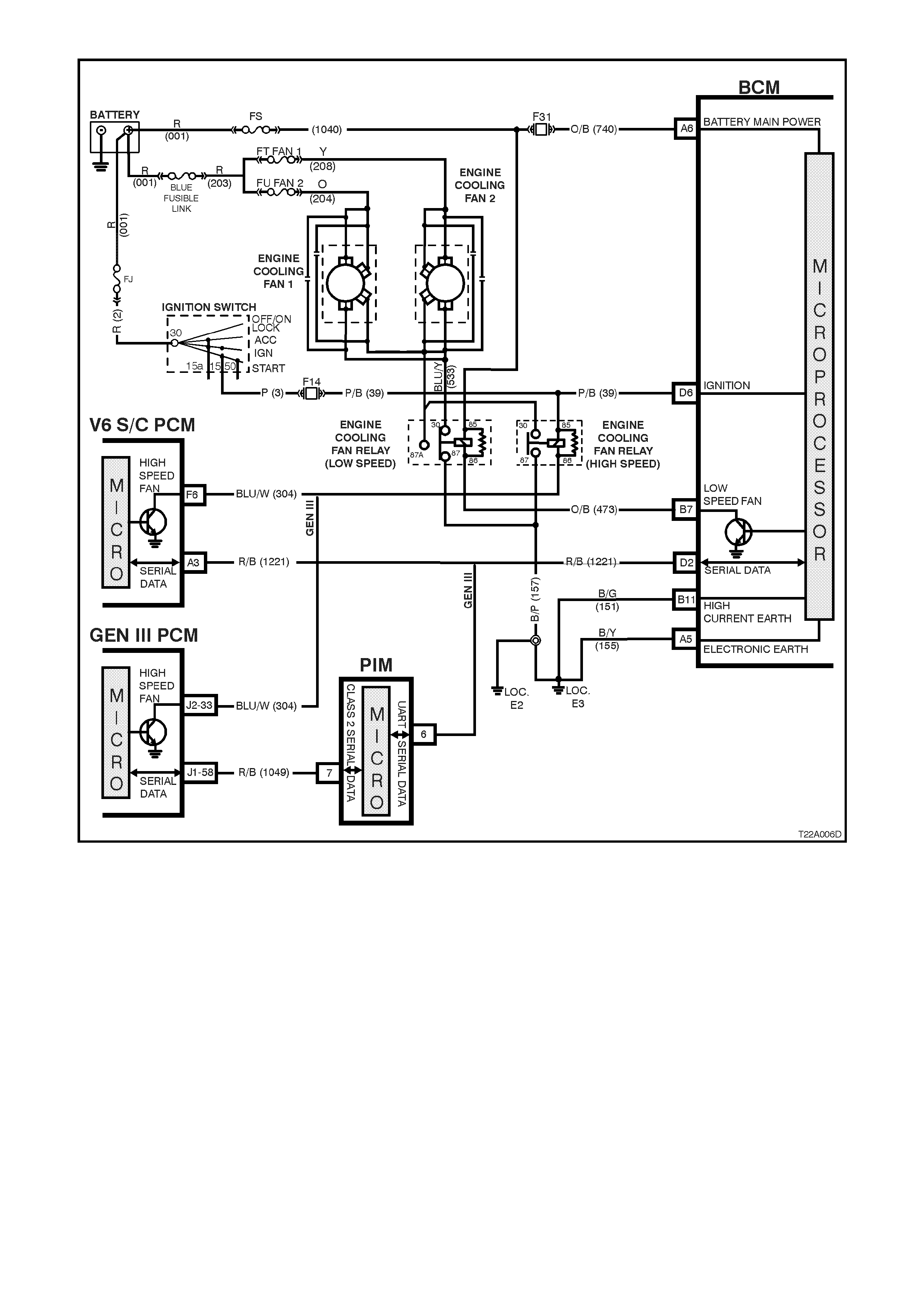
Figure 12J-1-30 V6 supercharged and GEN III V8 engine cooling fan low speed control
1.8 AUTOMATIC LIGHT CONTROL
GENERAL INFORMATION
On VT Series II Models, the automatic light control system carries over from earlier VT Series Models, noting the
following:
Comm unic ation between the PCM and the BCM on vehicles with GEN III V8 engines is via the Powertr ain Interfac e
Module (PIM).
If diagnosing a circuit fault with the automatic light control system, reference to the wiring diagrams in
Section 12P WIRING DIAGRAMS in the VT Series II Service Information should be made.
Additional details, including General Description, Service Operations and Diagnosis of the automatic light control
system that is not cover ed in this Sec tion, r ef er to Sectio n 12J-1 LO W SERIES BODY CONT ROL M ODULE in the
VT Series I Service Information.
SYSTEM OVERVIEW - AUTOMATIC LIGHTS OFF
BCM
BATTERY POW ER
IGNITION SWITCH ON
HEADLAM P SW I TCH
DRIVER’S DOOR JAMB SWITCH
T212J1026
HEADLAMP RELAY
PARKING LAMP RELAY
SERIAL DATA
VEHICLE SPEED
PCM
PIM
GEN III V8
ENGINE V6 & V6 S/C
ENGINE
1.9 WIPER SYSTEM
GENERAL INFORMATION
On VT Series II Models, the wiper system carries over from earlier VT Series Models, noting the following:
Comm unic ation between the PCM and the BCM on vehicles with GEN III V8 engines is via the Powertr ain Interfac e
Module (PIM).
If the ignition switch is turned to the ACC position and the vehicle enters battery saver mode, the interm ittent wipers
will not operate.
If diagnosing a circuit fault with the wiper system, reference to the wiring diagrams in
Section 12P WIRING DIAGRAMS in the VT Series II Service Information should be made.
SYSTEM OVERVIEW - FRONT AND REAR WIPER SYSTEM
BATTERY POW ER
BCM
REAR WIPER SWITCH
REAR WASHER SWITCH
WIPER MOTOR PARK SWITCH
WIPER INTERMITTENT SWITCH
T212J1027
WIPER MOTOR LOW SPEED
REAR WIPER MOTOR
FRONT WA SH ER SWITCH
SERIAL DATA
REVE RS E GEAR
PCM
PIM
GEN III V8
ENGINE V6 & V6 S/C
ENGINE
1.10 DOME LAMP DELAY CONTROL
GENERAL INFORMATION
NOTE: The circ uit diagram s shown in this General Des cription Sec tion are to aid in interpr eting the operation of the
circuit and theref ore, only the m ain connectors and wiring colours ar e shown. For com plete circuits details , refer to
either the relevant diagnostic section or Section 12P WIRING DIAGRAMS in the VT Series II Service Information.
The interior lighting is contr olled by the BCM or by the dome lam p switch ( incorporated in the over head lam p/s witch
assembly). The interior lighting is activated when any door is opened, unlocked with the remote coded key, when
the ignition is switched from IGN to OFF, or when the dome lamp switch is operated.
In addition, as part of the battery saver function, the BCM controls internal, dome, ignition lock surround, glove
compartment and door lamps. The BCM controls battery voltage to these circuits via the interior illumination relay.
There is a delay per iod before the battery saver function of the BCM deac tivates the interior illumination r elay. The
delay default time is set to one hour, however, can be reprogrammed with TECH 2 from between 2 and 255
minutes. The delay period (shut down timer) is initiated when the ignition is switched to the ACC or OFF positions.
Whilst in battery saver mode, the BCM will reactivate the interior illumination relay when:
1. When any door is opened.
2. The BCM receives a valid remote receiver.
3. When the ignition is switched to the ON position.
4. Doors are unlocked via the driver’s door microswitch.
5. TECH 2 is connected to the DLC and communicating with the BCM.
6. The headlamp switch is cycled from OFF to ON or ON to OFF.
7. The deadlock switch is activated.
8. The boot release switch (located in the glove compartment) is pressed.
The interior lighting is activated when any door is open. After all doors have been closed, the lamp rem ains active
for an additional 30 seconds.
If the lighting has been activated by a BCM control system or action, the dome lamp switch will turn the interior
lighting off when the dome lam p switch is switched f rom DOOR to OF F. T his m eans that the switch can c urtail any
delay time initiated as well as switch the lighting off whilst a door is open. With the dome lamp switch in the ON
position, BCM control of the interior lighting is overridden, provided the battery saver mode is inactive.
The interior lighting is s witched on upon c entral door unloc king for 30 sec onds . If the ignition is turned on dur ing this
delay, the interior lighting will be switched off immediately. Interior lighting is also switched off upon central door
locking, except if the dome lamp switch is turned on or if a passenger door is open. It will then be extinguished
when all doors are closed.
SYSTEM OVERVIEW - DOME LAMP DELAY
BATTERY POW ER
BCM
PASSENGER DOOR
JAMB SWITCH
DRIVER’S DOOR JAMB
SWITCH
DOME LAMP
INTERIOR ILLUMINATION
RELAY
T212J1022
IGNITION SWITCH ON
REMOTE RECEIVER
CIRCUIT OPERATION (REFER TO FIG. 12J-1-34)
Battery voltage is applied to all interior lamps via fuse F6, circuit 1140 (Orange wire), the interior illum ination relay,
and circuit 1145 (Orange/Black wire). The opposite side of the dome lamps are connected to earth via circuit 174
(W hite/Green wire) and BCM terminal C24. The BCM controls the operation of the dome lamps connected to this
earth by energising its internal dome lamp relay contacts to close, completing the circuit to earth.
Ignition Switch ON Input Signal (Refer to Fig. 12J-1-31)
The BCM uses this input signal to determine when the ignition switch is in the IGN or START position. W hen the
ignition switch is in either of these positions, battery voltage is applied to the BCM terminal D6 from the ignition
switch and fuse F14 via circuit 39 (Pink/Black wire).
Figure 12J-1-31 Ignition switch on input signal
Passenger Door Open Input Signal (Refer to Fig. 12J-1-32)
When any passenger door is opened, BCM terminal C7 is connected to earth via circuit 125 (W hite wire) and the
passenger door jamb switch. T his c aus es the voltage at terminal C7 to be pulled low, less than 0.2 volts ( pas senger
door open). This low voltage at terminal C7 is seen by the BCM as the passenger door open input signal.
Figure 12J-1-32 Passenger door open input signal
Driver’s Door Open Input Signal (Refer to Fig. 12J-1-33)
W hen the dr iver’s door is opened, BCM ter minal C8 is connected to earth via circuit 126 (G rey/White wire) and the
driver’s door jam b switch. This causes the voltage at ter minal C8 to be pulled low, les s than 0.2 volts ( driver’s door
open). This low voltage at terminal C8 is seen by the BCM as the driver’s door open input signal.
Figure 12J-1-33 Driver’s door open input signal
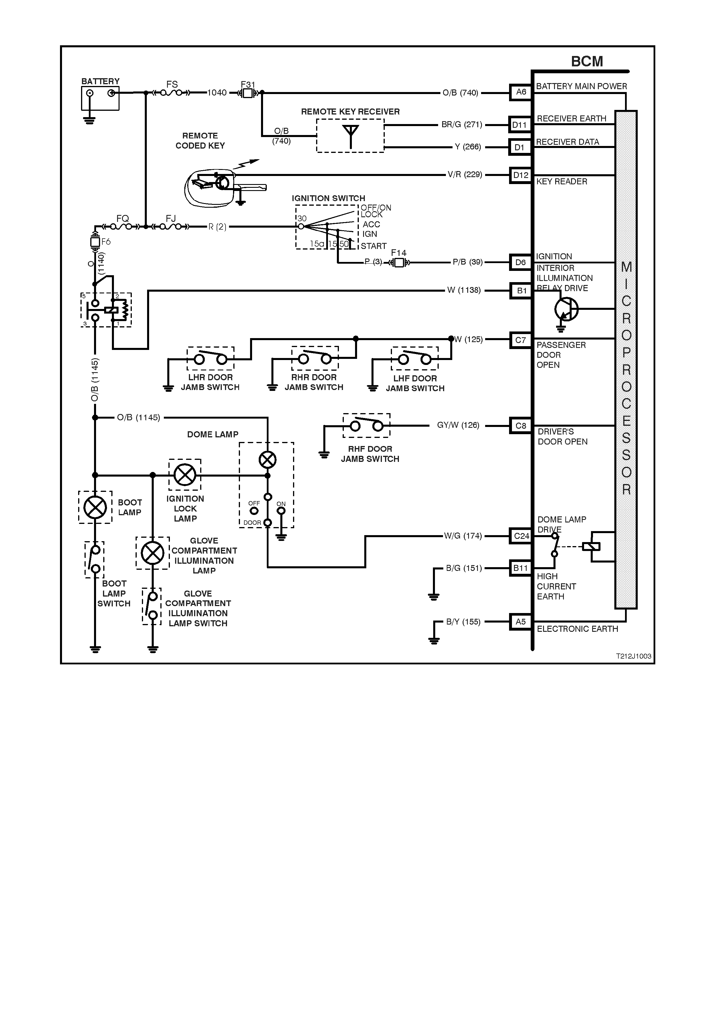
Figure 12J-1-34 Dome lamp delay control circuit
1.11 AIR CONDITIONING INTERFACE
GENERAL INFORMATION
The air- conditioning interf ace is used to turn the air c onditioning system on and of f. T he BCM r eads the m om entary
air conditioning switch signal, monitors fan speed and if the ignition is on, requests the PCM (via the PIM on
vehicles with GEN III V8 engines) to turn on the air conditioning compressor. The air conditioning status LED is
turned on by the BCM when the air conditioning s ystem is ac tive (if the ignition is turned on) and will toggle with the
air conditioning selec t switch. The s tatus will be rem ember ed when the ignition is switched from on to off , however,
if the battery is disconnected the s tatus will reset to off when the battery is reconnected. If the blower is of f and the
air conditioning selec t button is pr ess ed, then the nex t time the blower is s witched on, provided it is dur ing the same
ignition cycle, the air conditioning status will also come on.
The blower fan is controlled by the blower fan inhibit relay, which is energised when the ignition is switched to the
IGN or START positions.
NOTE: The circ uit diagram s shown in this General Des cription Sec tion are to aid in interpr eting the operation of the
circuit and therefore, only the main connectors and wiring colours are shown. For complete circuit details, refer to
either the relevant diagnostic section or Section 12P WIRING DIAGRAMS in the VT Series II Service Information.
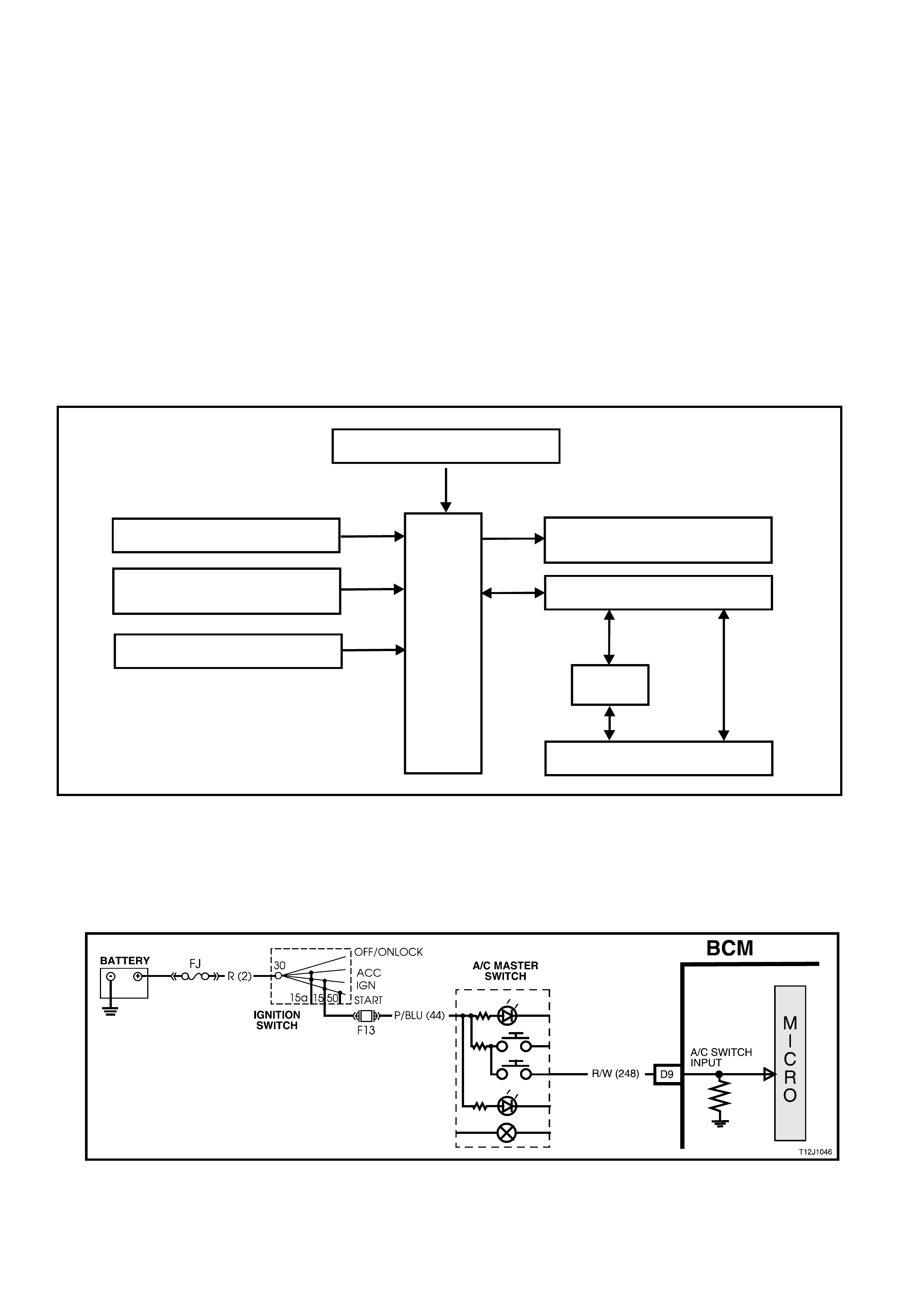
SYSTEM OVERVIEW - AIR CONDITIONING INTERFACE
BATTERY POWER
BCM
IGNITION SWITCH ON
BLOW ER FAN
AIR CONDITIONING
SWITCH SERIAL DATA MAIN
AIR CONDITIONING
STATUS LED
T212J1013
PCM
PIM
GEN III V8
ENGINE V6 & V6 S/C
ENGINE
CIRCUIT OPERATION (REFER TO FIG. 12J-1-38)
Air Conditioning Switch Input Signal (Refer to Fig. 12J-1-35)
Activating the air conditioning switch causes battery voltage, via the ignition switch contacts, fuse F13 circuit 44
(Pink/ Blue wire) and the air conditioning switch to be applied to BCM term inal D9. T his voltage is s een by the BCM
as the air conditioning switch input signal.
Figure 12J-1-35 Air conditioning switch input signal
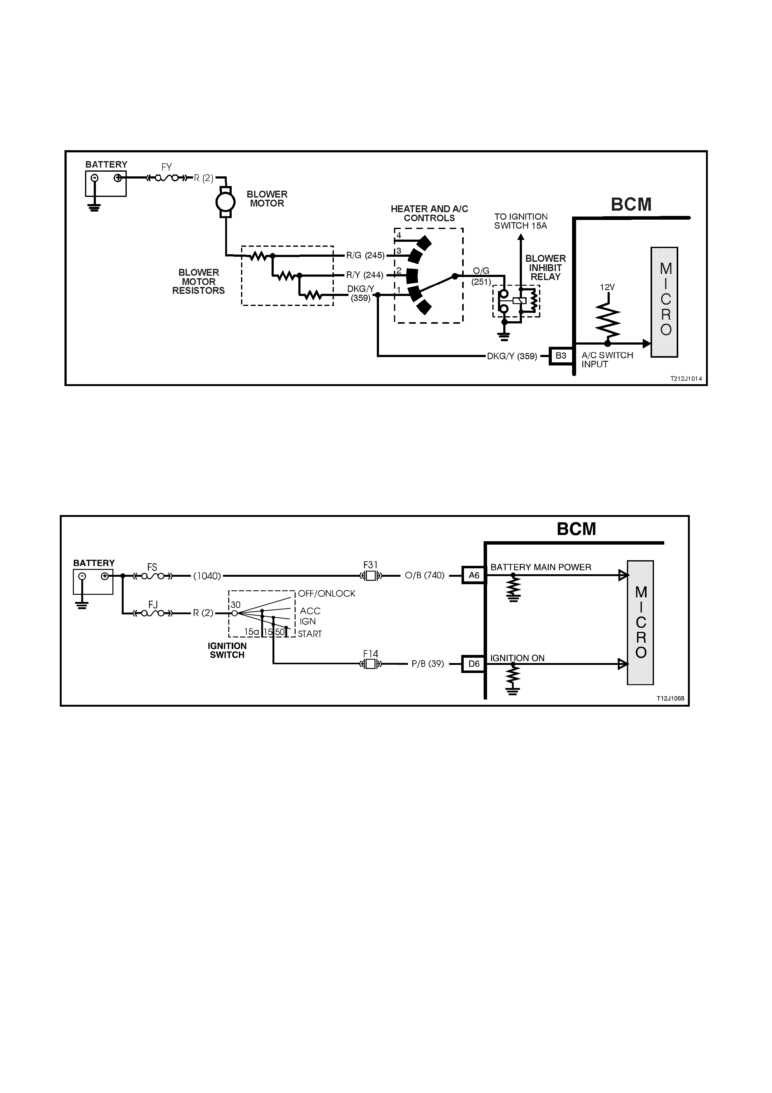
Blower Motor Input Signal (Refer to Fig. 12J-1-36)
The blower motor input signal m onitors the operating state of the blower m otor. W hen the blower motor is running
the BCM input B3 is pulled to ground via circuit 359 (Dark Green/Yellow wire), the blower switch (heater and A/C
controls) , circuit 251 (O range/Green wire) and the blower inhibit relay. This will cause the voltage at BCM ter minal
B3 to go from battery voltage to less than 0.3 volts. This low voltage is s een by the BCM as m eaning the blower is
on.
Figure 12J-1-36 Blower motor input signal
Ignition Switch On Input Signal (Refer to Fig. 12J-1-37)
The BCM uses this input signal to determine when the ignition switch is in the IGN or START position. W hen the
ignition switch is in the IGN or START position, battery voltage is applied to the BCM term inal D6 from the ignition
switch and fuse F14 via circuit 39 (Pink/Black wire).
Figure 12J-1-37 Ignition switch on input signal
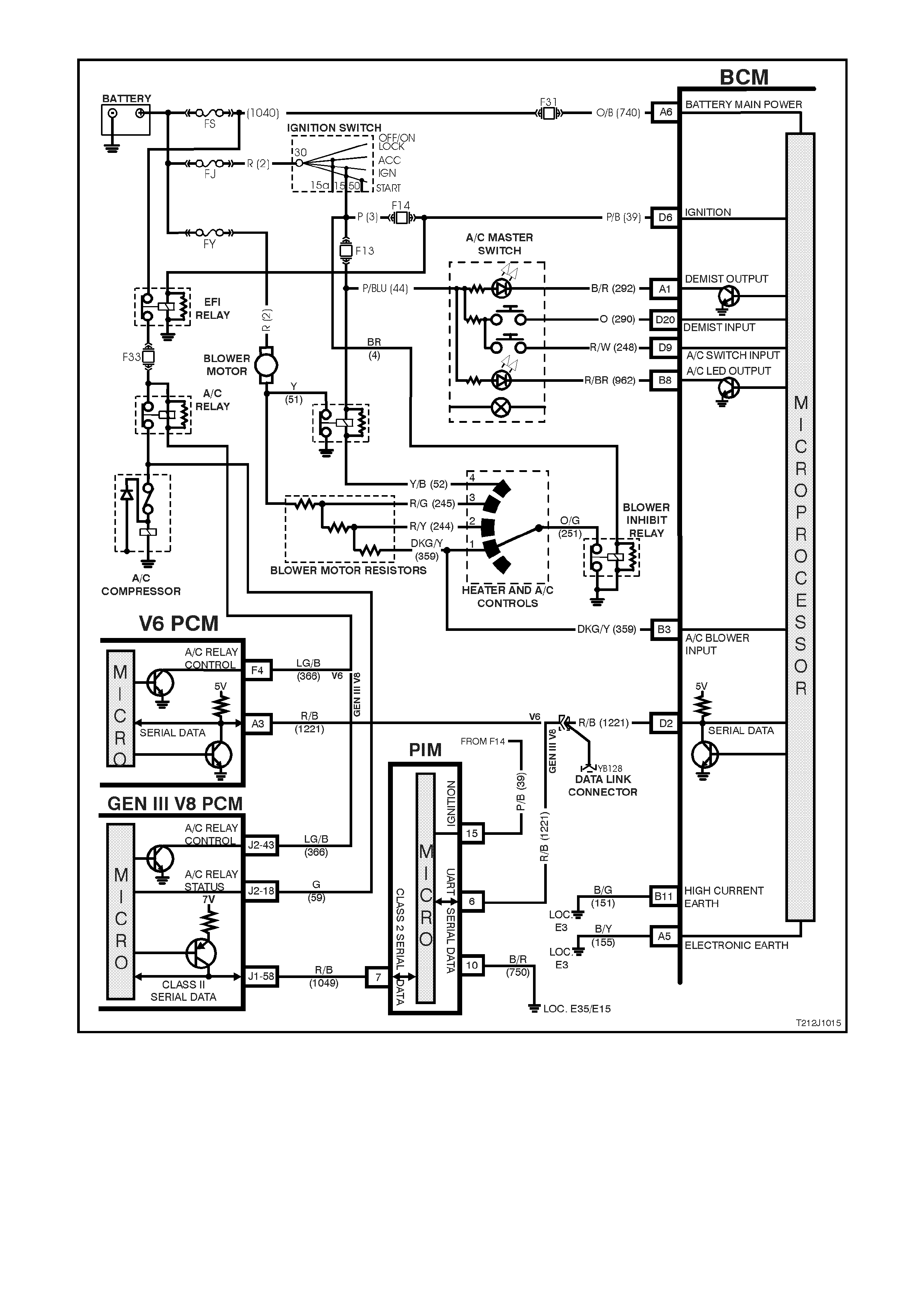
Figure 12J-1-38 Air conditioning interface circuit
1.12 SRS DEPLOYMENT VEHICLE SHUTDOWN
GENERAL INFORMATION
On VT Series II Models, SRS deployment vehicle shutdown carries over from earlier VT Series Models, noting the
following:
Comm unic ation between the PCM and the BCM on vehicles with GEN III V8 engines is via the Powertr ain Interfac e
Module (PIM).
If diagnosing a circuit fault with SRS deployment vehicle shutdown, reference to the wiring diagrams in
Section 12P WIRING DIAGRAMS in the VT Series II Service Information should be made.
For additional details, including General Description, Service Operations and Diagnosis of the SRS deployment
vehicle shutdown feature that is not covered in this Section, refer to Section 12J-1 LOW SERIES BODY
CONTROL MODULE in the VT Series I Service Information.
SYSTEM OVERVIEW - SRS VEHICLE SHUTDOWN
BATTERY POW ER
BCM
DOOR LOCK POWER
IGNITION SWITCH ON
T212J1028
SRS SERIAL DATA AUX
SDM
DOME LAMP
DOOR UNLOCK
DOOR DEADLOCK
SERIAL DATA MAIN
PCM
PIM
GEN III V8
ENGINE V6 & V6 S/C
ENGINE
DRIVER’S DOOR UNLOCK

2. SERVICE OPERATIONS
2.1 LOW SERIES BCM
REMOVE & REINSTALL
The procedure for removing and reinstalling the BCM is as detailed in Section 12J-1 LOW SERIES BODY
CONTROL MODULE in the VT Series I Service Information, noting the following.
If the BCM is r eplaced, the new BCM m ust be sec urity linked to the PCM and, on vehicles with GEN III V8 engines,
the PIM as per the following procedure. If this procedure is not performed, the vehicle will not crank.
BCM LINK TO PCM/PIM
Connect TECH 2 to DLC and select the following:
Diagnostics / (X) 1999 / VT COMMODORE / BODY / BODY CONTROL MODULE / SECURITY / BCM LINK TO
PCM/PIM / select applicable engine and follow TECH instructions.
NOTE: On vehicles with a GEN III V8 engine it will be necessary to obtain TIS approval during the linking
procedure. When instructed to obtain TIS approval by TECH 2, use the following procedure:
1. Disconnect TECH 2 from the vehicle.
2. Using the RS232 connector lead and TECH 2 power lead, connect T ECH 2 to a Personal Com puter ( PC) with
TIS installed (refer Section 0C TECH 2 in the VT Series II Service Information).
3. Turn the TECH 2 unit on so that the TECH 2 screen displays ‘TECH 2’
4. Open TIS and select NEW SESSION / TECHLINE / ENABLING PROGRAMMING and follow the instructions
given by TIS (PC screen).
5. When TIS displays ENABLING PROGRAMMING SUCCESSFUL, press OK.
6. Disconnect TECH 2 from the PC and reconnect TECH 2 to the vehicles DLC.
7. On TECH 2, select Diagnostics / (X) 1999 / VT COMMODORE / BODY / BODY CONTROL MODULE /
SECURITY / BCM LINK TO PCM/PIM / select applicable engine and follow TECH instructions again.
For additional information regarding TECH 2 and TECH 2 test modes (including this linking procedure), refer to
3 TECH 2 DIAGNOSIS FOR BCM in this Section.
Techline

2.2 DOOR LOCK MICROSW ITCHES
Door lock microswitches are now serviced separately on VT Series Models. For the removal and reinstallation
procedure, refer to Section 1A5 FRONT AND REAR DOOR ASSEMBLIES in the VT Series II Service Information.
The procedure for testing the microswitches remains unchanged from that published in
Section 12J-1 LOW SERIES BODY CONTROL MODULE in the VT Series I Service Information.

2.3 VEHICLE SPEED SENSOR
MANUAL TRANSMISSION
For vehicle speed sensor removal, testing and reinstallation instructions, refer to the relevant Powertrain
Management Section in this Service Information CD:
SECTION 6C1 POWERTRAIN MANAGEMENT - V6 ENGINE in the VT Series I Service Information.
SECTION 6C2 POWERTRAIN MANAGEMENT - V8 ENGINE in the VT Series I Service Information.
SECTION 6C3 POWERTRAIN MANAGEMENT - GEN III V8 ENGINE in the VT Series II Service Information.
AUTOMATIC TRANSMISSION
For vehicle s peed sensor rem oval, testing and r einstallation ins tructions , ref er the relevant Powertr ain Managem ent
Section in this Service Information CD:
SECTION 6C1 POWERTRAIN MANAGEMENT - V6 ENGINE in the VT Series I Service Information.
SECTION 6C2 POWERTRAIN MANAGEMENT - V8 ENGINE in the VT Series I Service Information.
SECTION 6C3 POWERTRAIN MANAGEMENT - GEN III V8 ENGINE in the VT Series II Service Information.

3. TECH 2 DIAGNOSIS FOR BCM
3.1 BASIC KNOWLEDGE REQUIRED
Before attem pting to diagnose the c ontrol or assist of the various vehicle electrical s ys tems contr olled by the BCM,
you must have a good understanding of electrical system basics and the use of circuit testing tools. Without this
basic knowledge it will be difficult to use the diagnostic procedures detailed in this Section.
Some elec trical basics, troubleshooting procedures and hints as well as the use of cir cuit testing tools are cover ed
in Section 12P, WIRING DIAGRAMS in the VT Series I Service Information.
Basic Electrical Circuits - You should understand the basic theory of electricity, series and parallel circuits, and
voltage drops across series resistors. You should know the meaning of voltage (volts), current (amps), and
resistanc e (ohms). You should understand what happens in a circuit with an open or shorted wire (s horted either to
voltage or earth). You should also be able to read and understand a wiring diagram.
Use of Circuit Testing Tools - You should know how to use a jumper lead to test circuits. You should be familiar with
the use of a high input im pedance ( 10 Meg ohm) digital type m ultimeter such as tool No. J39200 or equivalent and
be able to measure voltage, current, and resistance. You should be familiar with the proper use of the TECH 2
Diagnostic Scan Tool.
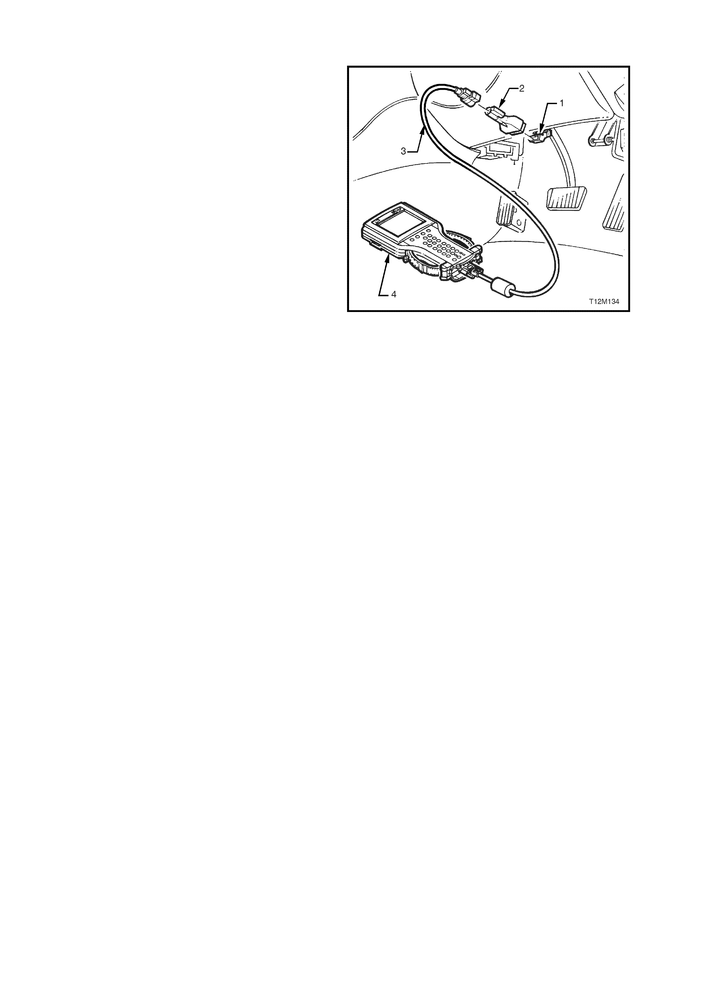
3.2 CONNECTING TE CH 2
TECH 2, with the appropriate software, cables and
adaptors, when connected to the Data Link
Connector (DLC) is capable of reading BCM serial
data. The DLC is connected to the instrument panel
lower right hand trim, to the right of the steering
column.
For additional general information on connecting
and operating TECH 2, refer to
Section 0C TECH 2 in the VT Series I Service
Information.
1. DLC
2. DLC ADAPTOR
3. DLC CABLE
4. TECH 2
Figure 12J-1-39

TECH 2 has seven test modes for diagnosing the
BCM. The seven test modes are as follows:
Mode F0: Normal Mode
In this mode, the Tech 2 monitors the
communication between control modules on the
serial data line. The information displayed on the
TECH 2 screen in this mode is what the BCM is
communicating to the other modules via the serial
data line.
Mode F1: Diagnostic Trouble Codes
In this test mode, curr ent Diagnostic Trouble Codes
(DTCs) stored in the control m odules mem ory may
be displayed or cleared.
Mode F2: Data Display
In this test mode, TECH 2 displays the status of
inputs and outputs of the BCM.
Mode F3: Snapshot
In this test mode, Tech 2 captures BCM data
before and after a forced manual trigger.
Mode F4: Miscellaneous Tests
In this test mode, Tech 2 performs various
functional tests to assist in pr oblem isolation during
trouble shooting.
Mode F5: Program
In this test mode, Tech 2 allows the programming
of various features by turning the feature OFF or
ON, or adjusting settings (ie. Two Stage Unlock,
HSPO accessory alarm).
Mode F6: Security
In this test m ode, T ech 2 pr ovides the user with the
capability of linking the BCM to the PIM (GEN III V8
only) and to the PCM, reading security information
(ie. radio pin numbers), and programming security
features (ie. keys).
Figure 12J-1-40
3.3 TECH 2 TEST MODES AND DISPLAYS FOR BCM DIAGNOSIS
A prerequisite to this diagnostic section is for the
user to be familiar with the proper use of TECH 2.
The f ollowing pages illus trate only the major TECH
2 screen displays and provide a brief explanation of
their function for diagnosing the BCM. If additional
inform ation is required on the operation of T ECH 2,
reference should be made to either
Section 0C TECH 2 in the VT Series I Service
Information and in the VT Series II Service
Information of this Service Information CD, or the
TECH 2 OPERATORS MANUAL.
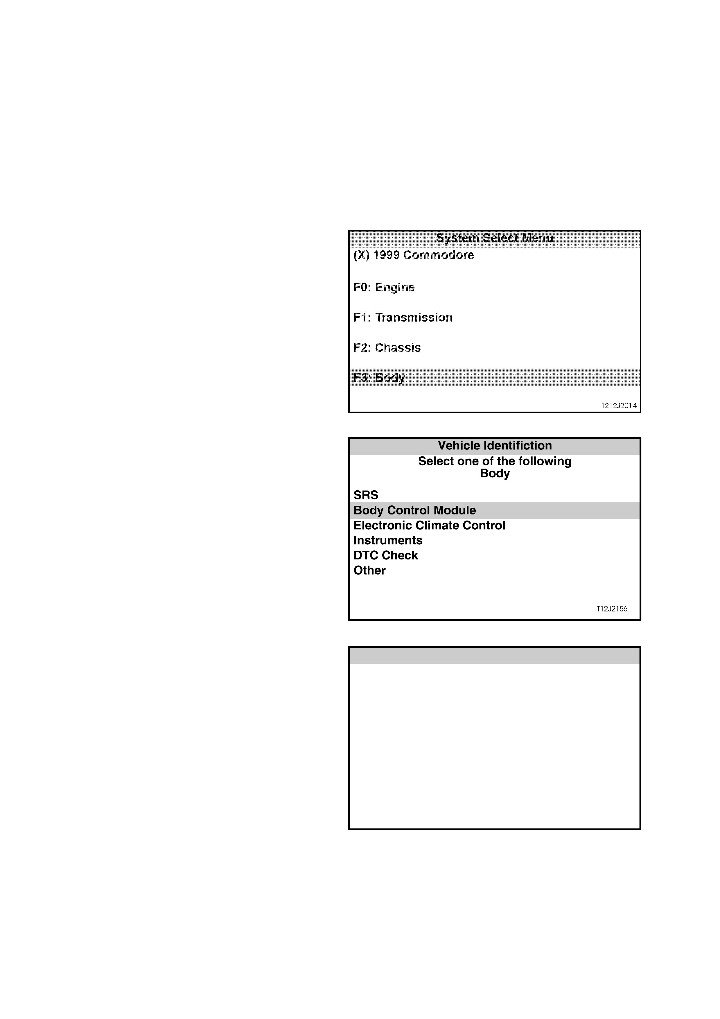
System Select Menu
W ith TECH 2 c onnected to the DLC and turned on,
F0: DIAGNOSTICS selected from the MAIN
MENU, the appropriate MODEL YEAR and
VEHICLE TYPE must be selected for access to the
SYSTEM SELECT MENU.
Select F3: BODY.
This mode contains all functions to test, diagnose,
monitor and program the vehicles body systems
including the BCM as well as providing the
opportunity to check all DTCs that may be set in the
vehicle.
Figure 12J-1-41
Body Application Menu
Once F3: BO DY has been selec ted from the s elect
menu, BCM can be selected.
Select Body Control Module and press enter to
continue.
NOTE: If information regarding DTCs set for the
vehicle is required, select DTC CHECK and press
enter to continue. To return to the BCM mode
option from the DTC CHECK mode option screen
display, simply press the EXIT key on TECH 2.
Once the BCM has been selec ted and entered, the
following two SYSTEM IDENTIFICATION screens
will appear which require action. Figure 12J-1-42
System Identification
Turn the ignition ON (as requested) and press
CONFIRM soft key to continue.
System Iden tification
(X) 1999 Commodore
El ectr o ni c Sy s tem : Bo dy Co nt ro l M o du le
Turn On Ignition!
T212j2015
Figure 12J-1-43
The SYSTEM IDENTIFICATION screen will then
display the control module level and type. Press the
CONFIRM soft key to continue to the BCM
APPLICATION MENU.
BCMs fitted to Executive, Acclaim, S and SS
Models should display:
BCM Level: Low or Mid (depending on vehicle
options)
BCM type: 1
System Iden tification
(X) 1999 Commodore
El ectr o ni c Sy s tem : Bo dy Co nt ro l Module
BCM Leve l: Low
BCM Type:1
T212J1038
Figure 12J-1-44
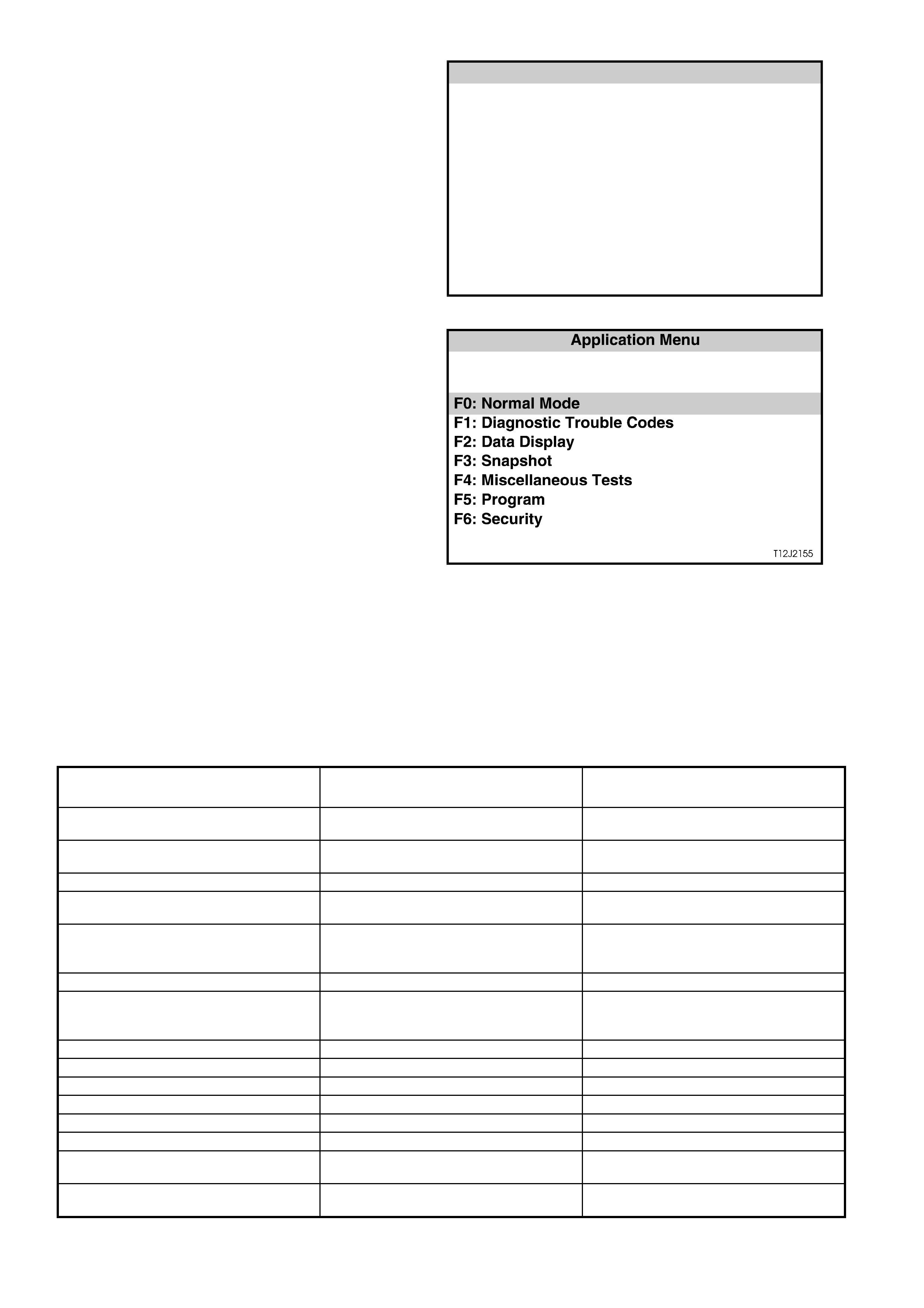
Application Menu
The following functions will now be available:
F0: Normal Mode
F1: Diagnostic Trouble Codes
F2: Data display
F3: Snapshot
F4: Miscellaneous Tests
F5: Program
F6: Security
Figure 12J-1-45
F0: NORMAL MODE
In the F0: Normal Mode, information that the BCM
is communicating to other control modules, via the
serial data line, is displayed.
The table below lists each item in the Normal
Mode, together with a brief description of its
meaning.
DATA STREAM / SCREEN
DISPLAY DESCRIPTION EXPECTED READING
Ignition Status Displays current state of ignition switch
as sensed by the BCM. On 12 Volts / Off 0 Volts
Ignition Off Time Displays the length of time since the
ignition was last switched off. XX minutes
Instrument Lamps Displays instrument illumination level. 0 % / 100 %
Lights On Displays current status of headlamp
switch. Yes / No
Ambient Light Level This feature is only available for
vehicles with high series BCM’s
(Calais).
0
Boot Status Displays boot switch status. Open / Closed
Rear Lamp Status This feature is only available for
vehicles with high series BCM’s
(Calais).
Okay
Front Wiper Status Displays front wiper drive status. On / Off
Front Auto wiper Status This feature is unavailable at present. Off
Cruise Control Input Signal Displays cruise control status. On / Off
A/C Request (Air Conditioning) Displays A/C request status. On / Off
BCM Lower Fan Drive Displays low speed fan drive status. On / Off
BCM Chime (Body Control Module) This feature is unavailable at present. Off
Key User Displays which remote coded key is in
use. 1 / 2
BCM DTC Status Display will advise if any BCM DTCs
are set. No DTCs / DTCs Set

F1: DIAGNOSTIC TROUBLE CODES
The following functions will be available in this
mode:
F0: Read Current DTC Information - a listing of all
(if any) current DTCs that have been set by the
BCM will be displayed. A short description of what
the DTC is, is also displayed in this mode.
F1/F2 Clear DTC Information - simply select F1:
CLEAR CODES, press the ENTER button on
TECH 2 and confirm the action as instructed by
TECH 2.
NOTE: If a HSPO accessory alarm system has
been installed to a VT Series II Model, and the
BCM alarm feature is enabled (via TECH 2
Program - Alarm Enable), TECH 2 will display F1
Read Alarm Code Information. Once alarm code
information is selected, a description of alarm
codes (if any) will be displayed.
The following chart sets out all the possible BCM
DTCs as indicated by TECH 2 for Low Series
BCM’s.
Refer to the relevant diagnostic chart in this Section
when attempting rectification of a system problem
or failure.
Figure 12J-1-46

BCM DIAGNOSTIC TROUBLE CODES
DTC CODE DESCRIPTION REFER
1Output overload - sets if the BCM’s output
protection circuitry detects an output driver
overload. This will cause all BCM output drives
to be set to the inactive state. The BCM will then
attempt to drive all outputs approximately every
10ms, thus causing all active BCM output drives
to repeatedly switch from an active to an
inactive state until the fault condition is
remedied.
NOTE: The BCM is unable to identify which
output is being overloaded.
This DTC can be set by any one of the BCM outputs
being shorted to battery positive, therefore, if DTC 1 is
set, refer to section relevant to driver complaint (if any).
For a listing of all BCM outputs, refer to the MID
SERIES BCM TERMINAL IDENTIFICATION chart in 1
GENERAL DESCRIPTION in this Section.
NOTE: DTC 1 can also be set by electrical transients,
therefore, if DTC 1 is set and there are no noticeable
problems with the vehicle, clear DTC and check
function of BCM outputs. If DTC does not reset and
BCM outputs are functioning correctly, disregard DTC
1.
2Slip Ring Failure - sets if the number of failed
slip ring reads exceeds a programmable
percentage of all slip ring reads (approximately
18 failed slip ring reads out of 100 good slip ring
reads).
4.4 THEFT DETERRENT, in this Section to rectify
problem.
7PCM Data Lost - sets when the BCM does not
receive responses from the PCM (via PIM on a
vehicle with a GEN III V8 engine) or receives
incorrectly formatted responses from the PCM
within three seconds of normal serial data bus
activity.
The three second time out period is reset
whenever the following conditions occur:
Ignition switched from OFF to ON.
A good PCM poll response is received from the
PCM/PIM.
A key has been programmed.
BCM has just been reset.
4.2 SERIAL DATA COMMUNICATION, in this Section
to rectify problem.
8PCM Vehicle Speed Data Unstable - sets if the
BCM receives two consecutive road speed
updates from the PCM/PIM with a magnitude
difference of 30 km/h.
(This DTC can also be set by wheel spin)
Connect TECH 2 to DLC, select Engine / Data Display,
scroll to Vehicle Speed, road test vehicle and note if
screen displays actual vehicle speed. If it does not
display actual vehicle speed, refer to 6C1
POWE RTRAIN MANAGEMENT - V6 ENGINE in the VT
Series I Service Information or 6C3 POWERTRAIN
MANAGEMENT - GEN III V8 ENGINE in the VT Series
II Service Information of this Service Information CD. If
screen does display actual vehicle speed, replace
BCM.
17 Serial Data Bus Fault - sets if the BCM cannot
detect six consecutive messages on the serial
data bus. This trouble code indicates either a
short circuit on the bus or if two or more
modules send a message at the same time.
4.2 SERIAL DATA COMMUNICATION, in this Section
to rectify problem.
BCM ENTRY DETERRENT ALARM CODES (Vehicles with HSPO accessory alarm kit only)
AC CODE DESCRIPTION REFER
1 Bonnet alarm triggered If an alarm code is triggered, it does not indicated a
2 BOOT ALARM TRIGGERED PROBLEM WITH THE ENTRY DETERRENT SYSTEM,
RATHER IT SIMPLY
3 PASSENGER’S DOOR ALARM TRIGGERED ACTS AS A GUIDE TO INDICATE WHICH ALARM
TRIGGER (I.E. BONNET
4 DRIVER’S DOOR ALARM TRIGGERED SWITCH) IS TRIGGERING THE ALARM SYSTEM.
5 IGNITION ALARM TRIGGERED

F2: DATA DISPLAY
In this test mode, TECH 2 checks if the BCM is actually receiving an input or inputs from the appropriate sensor/s or
actuator/s for the system being diagnosed.
If the sensor/s or actuator/s input/s are not being received, then c arry out the relevant system diagnos is as defined
in this Section.
If the sens or/s or actuator /s input/s ar e being rec eived, go to the appr opriate F 4: BCM T EST mode to c ommand the
BCM via TECH 2 to operate the system output.
Should the system output or actuator not function correctly, conduct relevant system diagnosis as defined in this
Section. If system wiring and output actuator are OK, replace BCM.
A description explaining the display and, where applicable, affected terminals is included in the charts below.
NOTE: W hen T ECH 2 is com municating with the BCM, it also determ ines what type of BCM is fitted to the vehicle
and therefore only the relevant data list and functional tests will be displayed.
Data List
SCREEN DISPLAY DESCRIPTION TERMINAL
AFFECTED
BCM LEVEL Displays what level of BCM is fitted to the vehicle.
The screen should display LOW or MID depending on whether vehicle is fitted
with power windows.
If fuse F31 or circuits 740 and/or 1040 are open circuited, communication with
the BCM will not be possible. If these circuits are OK, refer to 4.2 SERIAL DATA
COMMUNICATION in this Section.
-
BCM TYPE Displays what type of BCM is fitted to the vehicle.
The screen will display the type of BCM fitted to the vehicle (TYPE 1). (BCMs
fitted to Executive, Acclaim, S and SS VT Series II Models should always display
TYPE 1).
If fuse F31 or circuits 740 and/or 1040 are open circuited, communication with
the BCM will not be possible. If these circuits are OK, refer to 4.2 SERIAL DATA
COMMUNICATION in this Section.
-
VEHICLE SPEED Displays vehicle speed input to BCM via the main SDI (circuit 1221).
If vehicle speed cannot be displayed in the BCM Data Display mode, road test
vehicle and check if it can be displayed in the Engine Data Display mode. If it
can not be displayed, refer to 6C1 POW ERTRAIN MANAGEMENT - V6 ENGINE
in the VT Series I Service Information or 6C3 POW ERTRAIN MANAGEMENT -
GEN III V8 ENGINE in the VT Series I Service Information in this Service
Information. If vehicle speed can be displayed in the Engine Data Display mode,
replace BCM.
D2
SLIP RING ENABLED Screen display may flash from NO to YES briefly when BCM receives a correct
key reading. If BCM does not receive a correct key reading, screen will flash
between NO YES continuously until a correct reading is achieved.
If screen does not change as described, refer to 4.4 THEFT DETERRENT in this
Section.
D12
IGNITION SWITCH Displays current state of ignition switch as sensed by the BCM.
Will display ON with ignition switch in IGN or START positions and OFF in ACC
or OFF positions.
If screen display doesn’t change as described, check circuitry between ignition
switch and BCM, and ignition switch contacts. If circuit and switch are OK, BCM
is faulty.
D6
CENTRAL LOCKING Displays the current state of the BCM’s internal central door locking relays.
When locking the central door locking system, either remotely or by turning the
RH door key switch, the screen display changes to ALL LOCK. If the RH door
key switch is activated a second time or the remote coded key lock button is
pressed a second time, the screen will display DEADLOCKED.
When unlocking the system by turning the RHF door key switch, the screen
display changes from ALL LOCKED or DEADLOCKED to ALL UNLOCK.
Unlocking remotely, the screen display changes from ALL LOCKED or
DEADLOCKED to DRIVER UNLOCK on first press (If vehicle is programmed
with two stage unlocking) and second button press, the screen displays ALL
UNLOCK.
If screen display does not change as described, refer to 4.3 CENTRAL DOOR
LOCKING and carry out FUNCTIONAL CHECK - CENTRAL DOOR LOCKING.
-

SCREEN DISPLAY DESCRIPTION TERMINAL
AFFECTED
DRIVER’S DOOR
UNLOCK SWITCH Displays RHF door lock actuator / key switch input to BCM.
W ith doors locked, screen displays OFF, unlocking the driver’s door or all doors,
screen will change to ON.
If the circuit from BCM terminal C20 is open circuited, the passenger’s doors
cannot be unlocked by the RHF door lock key switch.
C20
PASSENGER’S DOOR
UNLOCK SWITCH Displays passenger door lock actuator switch inputs to the BCM.
W ith doors locked, screen displays OFF, unlocking the passenger doors, screen
changes to ON.
If the circuit from BCM terminal C9 is open circuited, the passenger doors cannot
be unlocked. The screen display will also remain unchanged.
C9
LOCK SWITCH
STATUS Displays the front doors lock actuator inputs to the BCM.
When doors are locked, by activating either of the front door lock actuators
(snib), screen displays ON. When doors are unlocked, screen displays OFF.
If circuit is open, doors can not be locked from the front door lock actuators
(snib), but system can be locked remotely.
If screen display does not change as described, refer to 4.3 CENTRAL DOOR
LOCKING in this Section and carry out FUNCTIONAL CHECK - CENTRAL
DOOR LOCKING.
C21
DEADLOCK SWITCH Displays RHF door lock microswitch input to BCM.
With RHF door lock cylinder in the unlocked and locked position, screen
displays OFF. Display will change to DEADLOCK when the door lock cylinder is
turned to the deadlock position.
If circuit 197 is open circuited, doors cannot be locked or deadlocked by turning
the RHF door lock cylinder and screen display will remain off. However, doors
can be locked and deadlocked remotely.
If screen display does not change as described, refer to 4.3 CENTRAL DOOR
LOCKING in this Section and carry out FUNCTIONAL CHECK - CENTRAL
DOOR LOCKING.
C22
DOME LAMP DRIVE Display changes from OFF to ON as dome lamp is turned ON or when the
remote coded key UNLOCK button is depressed. Display goes OFF when the
ignition is turned ON. This check confirms if the BCM internal circuitry is
operating(a relay within the BCM will be heard to click as the drive is turned on).
If circuit 174 between the BCM, terminal C25 and the interior lighting is open
circuited, the interior lighting will not come on.
If screen display does not change as described, refer to 4.6 DOME LAMP
DELAY CONTROL in this Section.
C24
HEADLAMP SWITCH Displays status of switch during auto off period only.
Display changes from OFF to ON as headlamps delay period is in progress. This
check confirms that the BCM internal switching is operating. Display goes to
OFF when the headlamp auto off is cancelled.
If screen does not change as described, refer to 4.13 AUTOMATIC LIGHTS OFF
CONTROL in this Section.
D14
HEADLAMP DRIVE With the ignition turned on, screen displays ON, turning the ignition off, the
screen will still display ON. Turn headlamps on, scroll ignition from on to off and
open the driver’s door, screen will change from ON to OFF and headlamps will
go out.
If screen does not change as described, refer to 4.13 AUTOMATIC LIGHTS
CONTROL OFF in this Section.
D14
DRIVER’S DOOR Displays the driver’s door jamb switch input to the BCM.
W hen the driver’s door is open, the screen display should be OPEN, and when
the door is closed, the screen should display CLOSED.
If screen does not change as described, refer to 4.4 THEFT DETERRENT in this
Section.
C8
PASSENGER DOORS Displays the passenger’s door jamb switch input to the BCM.
When the passenger’s door is open, the screen display should be OPEN, and
when the door is closed, the screen should display CLOSED.
If screen does not change as described, refer to 4.4 THEFT DETERRENT in this
Section.
C7

SCREEN DISPLAY DESCRIPTION TERMINAL
AFFECTED
FRONT WASHER
PUMP SWITCH Displays front washer pump switch input to BCM.
W ith ignition on and the washer pump switch activated, screen display changes
from OFF to ON.
If circuit 94, between the BCM and the wiper/washer switch is open circuited, the
wipe after wash function will not operate.
If screen display does not change, check circuit 94 between BCM terminal D18
and wiper/washer switch (including wiper/washer switch contacts), refer to
Section 12C INSTRUMENTS, W IPER/W ASHER AND HORN in the VT Series I
Service Information.
D18
WIPER PARK SWITCH Displays input to BCM.
With wipers in the park position, screen displays ON. With wipers operating,
display will change to OFF and momentarily go to ON as wipers operate through
the park region.
If circuit 196, between the BCM and the wiper motor is open circuited, the screen
will display ON all the time and wipers will not park when turned off.
If screen display remains ON with wipers operating, check for open circuit
between BCM terminal B9 and wiper motor, carry out checks of wiper motor,
refer to Section 12C INSTRUMENTS, WIPER/WASHER AND HORN in the VT
Series I Service Information.
B9
FRONT WIPER
INTERMITTENT
SWITCH
Displays wiper/washer switch intermittent switch contacts input to BCM.
W ith ignition on and wiper/washer switch set to the intermittent position, screen
display changes to ON.
If circuit 97, between the BCM and the wiper/washer switch is open circuited,
there will be no intermittent wiper function.
If screen display does not change, check circuit 97 between BCM terminal D10
and wiper/washer switch (including wiper/washer switch contacts), refer to
Section 12C INSTRUMENTS, W IPER/WASHER AND HORN in the VT Series I
Service Information.
D10
INTERMITTENT
WIPER DRIVE W ith wipers operating in the intermittent mode, screen displays ON. W ith wipers
in the parked position, and in 1st or 2nd speed, screen displays off.
If screen displays are not as described, refer to 4.11 WIPER CONTROL
SYSTEM in this Section.
-
FRONT WIPER
DWELL TIME Displays wiper/washer switch dwell time input to the BCM.
The wiper dwell on vehicles with a low series BCM is a fixed dwell period of
approximately 8.0 seconds and is non-adjustable.
If wipers do not operate intermittently when selected, check for open in circuit 97
between BCM terminal D10 and wiper/washer switch (including wiper/washer
dwell control adjustment contacts, refer to Section 12C INSTRUMENTS,
WIPER/WASHER AND HORN in the VT Series I Service Information.
D10
REAR WASH PUMP
SWITCH Displays rear washer pump switch input to BCM.
W ith ignition on and the washer pump switch activated, screen display changes
from OFF to ON.
If circuit 494, between the BCM and the wiper/washer switch is open circuited,
the wipe after wash function will not operate.
If screen display does not change, check circuit 494 between BCM terminal D19
and wiper/washer switch (including wiper/washer switch contacts), refer to
Section 12C INSTRUMENTS, W IPER/WASHER AND HORN in the VT Series I
Service Information.
D19
REAR WIPER SWITCH Displays rear wiper switch input to BCM.
W ith ignition on and the rear wiper switch in the on position, screen will change
from OFF to ON (this applies to wagon only, on sedan models, the screen will
always display OFF).
If screen displays are not as described, refer to 4.11 WIPER CONTROL
SYSTEM in this Section.
D7
HEATED REAR
WINDOW DRIVE With ignition on, screen display changes from OFF to ON as the heated rear
window is turned on, and then to off as switch is turned off. Also, if turned on, it
will remain on for fifteen minutes, provided the switch is not reactivated and the
screen will then display OFF. This check confirms that the BCM internal circuitry
is operating.
-
HEATED REAR
WINDOW SWITCH Displays heated rear window switch input to BCM.
Display will change from OFF to ON as switch is depressed and held on.
Release switch and display will change to OFF.
If screen does not change, check wiring between BCM terminal D20 and heated
rear window switch and heated rear window switch contacts, refer to 4.9
HEATED REAR WINDOW in this Section.
D20

SCREEN DISPLAY DESCRIPTION TERMINAL
AFFECTED
POWER WINDOW
SWITCH Displays input to BCM.
W ith power windows enabled, screen displays OFF. W ith driver’s window switch
down button activated, screen displays DOWN. W ith driver’s window switch up
button activated, screen displays UP.
If screen does not display DOWN when the down button is activated and the
window automatic down function does not work, check for open circuit between
BCM terminal C14 and the driver’s side power window switch.
C14 (Down)
C16 (Up)
WINDOW AUTO
DOWN DRIVE Screen display changes from OFF to ON when the driver’s side power window
switch automatic down button is activated and functioning. W ill also display ON
when down button is activated, but with automatic down feature not functioning.
If the driver’s side power window operates normally except for the automatic
down feature, and all system inputs are determined to be OK, then BCM is
faulty.
-
POWER WINDOW
RELAY Displays the power window relay status as determined by the BCM internal
circuitry. The relay is enabled by the BCM earthing circuit 173.
With the power window switch enabled (lights in power switch illuminated),
screen displays ENABLED. With the system OFF, screen displays DISABLED.
If the screen displays ENABLED but the lights in the power window switch do not
illuminate, check for open in wiring to BCM terminal A3.
If screen displays are not as described, refer to 4.10 POWER WINDOW
SYSTEM in this Section.
A3
CRUISE CONTROL
INPUT SIGNAL Displays the cruise control on/off switch input status to the BCM.
W ith ignition on, each activation of the cruise on/off switch will toggle the screen
display to the next state, ie. OFF to ON or ON to OFF.
If the screen display changes as described, but the cruise control CRUISE lamp
in the instrument cluster does not illum inate, refer to 4.14 CRUISE CONTROL in
this Section.
If screen display does not change, refer to Section 12E CRUISE CONTROL in
the VT Series I Service Information.
D8
A/C SWITCH Displays air conditioning switch input to BCM.
Display will change from OFF to ON as switch is depressed and held on.
Release switch and display will change to OFF.
If screen does not change, check wiring between BCM terminal D9 and air
conditioning switch and air conditioning switch contacts, refer to 4.7 AIR
CONDITIONING INTERFACE in this Section.
D9
A/C INDICATOR Displays the status of the air conditioning system.
With ignition on, and blower fan on, will display ON when the A/C switch is
switched on, and OFF when switch is switched off.
If screen does not change, refer to 4.7 AIR CONDITIONING INTERFACE in this
Section.
-
A/C BLOWER
SWITCH Displays air conditioning blower switch input to BCM.
Display will change from OFF to ON when switch is switched to from off to on.
If screen does not change, refer to 4.7 AIR CONDITIONING INTERFACE in this
Section.
B3
ILLUMINATION DRIVE
RELAY W henever the vehicle is not in battery saver mode screen will display ON. If the
screen does not reflect this status, refer to 4.6 DOME LAMP DELAY CONTROL
in this Section.
NOTE: The vehicle will exit battery saver mode whenever TECH 2
communicates on the Serial Data line (connected to the DLC and powered up),
therefore, screen should always display Illumination Drive Relay ON.
B1
BOOT/BONNET
SWITCH OPEN Only available on vehicles with HSPO accessory alarm fitted and alarm option
enabled. -
BOOT RELEASE
SWITCH Displays boot release switch input to BCM.
W ith the boot release switch (located in glove compartment) in the rest position,
screen displays OFF. With switch held in, switch displays ON.
If screen does not change as described, refer to 4.8 BOOT RELEASE in this
Section.
D16
BOOT SOLENOID
DRIVE Provided the vehicle speed is less than 15 km/h, depressing the boot release
button on the remote coded key will cause the screen display to change from
CLOSED to OPEN as the BCM internal relay is activated.
If screen does not change or boot release does not operate, refer to 4.8 BOOT
RELEASE in this Section.
-

SCREEN DISPLAY DESCRIPTION TERMINAL
AFFECTED
OVERRIDE STATUS This screen displays the status of the theft deterrent systems override function.
NOTE: The 2 hour override function was deleted from the BCM in July 1998,
therefore, the screen display should always display ‘security ON’.
-
SECURITY LED Displays current state of the BCM’s theft deterrent system LED driver condition.
If the LED is flashing, ie. system armed, the screen will pulse between ON and
OFF.
This checks that the BCM is turning on and off the voltage supply.
If TECH 2 screen display does not change, the BCM is faulty.
If TECH 2 screen display does change, but the LED does not flash, check for
open in wiring from BCM to LED
A8
INDICATORS When the BCM activates the indicators via its internal relay, the screen display
alternates between ON and OFF as the indicators flash.
This checks that the BCM is pulsing its internal relay, thereby supplying voltage
from BCM terminal B5 to terminals B4 and B12. If screen display does not
change as described, BCM is faulty.
If screen display does change as described, but the indicators do not flash,
check for open circuit in wiring from BCM output terminals B4 and B12 or input
to BCM terminal B5 (refer to 4.4 THEFT DETERRENT diagnosis in this Section).
B4, B5, B12
PASSIVE MODE W ith the theft deterrent system in passive arm state, screen displays should be
ON (theft deterrent LED flashing). -
ALARM HORN DRIVE Only available on vehicles with HSPO accessory alarm fitted and alarm option
enabled. -
REMOTE DOOR
SIGNAL Screen display changes to UNLOCK then OFF when remote coded key unlock
button is depressed. Changes to LOCK to OFF when lock button is depressed.
If the screen displays INVALID KEY continuously when the remote coded key is
depressed, and the BCM does not operate, that particular remote coded key is
not coded to the BCM (refer to 4.12 REMOTE RECEIVER/KEY in this Section).
NOTE: Due to the fact that the screen changes when the remote coded key is
depressed, is confirmation that there is an RF output from the remote coded key
and that it is recognised by the BCM either as correct or invalid.
-
REMOTE BOOT
SIGNAL Screen display changes to OPEN then OFF when the boot release button on the
remote coded key is depressed.
If the screen displays INVALID KEY continuously when the boot release button
on the remote coded key is depressed, and the BCM does not operate, that
particular remote coded key is not coded to the BCM (refer to 4.12 REMOTE
RECEIVER/KEY in this Section).
NOTE: Due to the fact that the screen changes when the remote coded key is
depressed, is confirmation that there is an RF output from the remote coded key
and that it is recognised by the BCM either as correct or invalid.
-
REMOTE KEY
NUMBER Depressing a button on the remote coded key enables the BCM to read the
key’s security code information. If the remote coded key has been programmed
to the BCM, the screen displays the remote coded key user number that has
been assigned to it during the programming process.
A BCM can have up to 31 different remote coded keys programmed into it.
-
SERIAL DATA BUS
ISOLATION Displays serial data bus isolation internal switch status.
During normal operations (ignition on, cranking or engine running) the serial data
bus isolation switch will be closed and screen displays NORMAL. If engine will
not start within 0.5 seconds of being cranked, the serial data bus isolation switch
will open (isolating auxiliary serial data bus) for a maximum period of 5 seconds,
during this time, screen display will change to DATA CUTOFF
If screen displays are not as described, refer to 4.2 SERIAL DATA
COMMUNICATION in this Section.
-
LOW FAN DRIVE This checks the BCM’s ability to turn on it’s internal driver to earth, thus enabling
the engine cooling low speed fan.
W ith the low speed fan not operating, screen displays OFF. With fan operating,
screen displays ON.
DTC STATUS Display will advise if any BCM DTCs are set.
Screen will display No DTCs if there are no DTCs or DTCs Set if there are any
BCM DTCs se t.
-

Part Number
SCREEN DISPLAY DESCRIPTION TERMINAL
AFFECTED
PART NUMBER W ith the theft deterrent system disarmed, TECH 2 displays the last two digits of
the Holden part number for the BCM fitted to the vehicle (ie. 15).
This information can be checked against the part number label attached to the
BCM case, refer Fig. 12J-1-1 in this Section.
F3: SNAPSHOT
In this mode, TECH 2 captures data before and after a forced manual trigger.
The purpose of the SNAPSHOT test mode is to help isolate an intermittent or transient problem by storing BCM
data parameters just before and just after a problem occurs.
F4: MISCELLANEOUS TESTS
In this test mode, Tech 2 performs various functional tests to assist in problem isolation during trouble shooting.
If a vehicle component is com manded by TECH 2 to operate and the TECH 2 screen display changes as per this
com mand, yet the component does not operate, check for a f aulty circ uit between the BCM and the component (ie.
If low speed cooling fan is com manded ON, T ECH 2 scr een displays LOW SPEED COO LING FAN ON yet the low
speed cooling fan is physically not ON, then check cooling fan wiring between the BCM and the low speed cooling
fan, including cooling fan, for open or short circuit).
To operate any of the m iscellaneous tes ts, sim ply select the appr opriate functional tes t from the miscellaneous test
application menu and follow the instructions as per TECH 2.
When the Miscellaneous Tests option is selected, the following options will become available.
NOTE: additional application menu screens will be displayed for Lamps, Wiper Tests, and Security Systems.
• Lamps: If lamps are selected, an additional application menu will be displayed offering additional functional
tests of the vehicles lighting system.
• Dome: In this mode, TECH 2 commands the BCM to switch on and off the interior lighting.
If the interior lighting does not operate, refer to 4.6 DOME LAMP DELAY CONTROL diagnosis in this
Section.
• Lamp Delay Drive: In this mode with the ignition OFF and the headlamps and park lamps turned ON,
TECH 2 commands the BCM to switch OFF and ON the vehicle park lamps and headlamps.
If lamps do not switch off when commanded, refer to 4.13 AUTOMATIC LIGHTS OFF CONTROL
diagnosis in this Section.
• Indicators: In this mode, TECH 2 commands the BCM to switch ON and OFF the turn signal indicator
lamps, including the warning lamps in the instrument cluster.
If the turn signal lamps do not operate when commanded by TECH 2, refer to 4.4 THEFT DETERRENT
diagnosis in this Section.
• A/C LED: In this mode, TECH 2 commands the BCM to switch the A/C on/off switch LED on and off.
If LED status does not change when commanded, refer to 4.7 AIR CONDITIONING INTERFACE in this
Section.
• Low Fan: In this mode, TECH 2 commands the BCM to switch ON and then OFF, (will switch OFF
automatic ally af ter a short per iod provided the PCM is not com manding the low fan on) the engine cooling low
speed fan relay.
If the engine cooling low speed fan does not operate in this mode, ref er to 4.5 ENGINE COOLING FAN LOW
SPEED CONTROL diagnosis in this Section.
• Data Bus Isolator: In this mode, the BCM data bus isolator switch can be opened or closed.
To check if the data bus isolator is operating, start engine, command the data bus isolator switch open with
TECH 2 and hold the right arrow key down for 10 seconds. W hen the data bus isolator switch is opened for
more than 10 seconds with the engine running, the engine check light in the instrument cluster will illuminate
(no DTCs will be set).
If the data bus isolator will not change state, refer to 4.2 SERIAL DATA COMMUNICATION diagnosis, in this
Section.
NOTE: The Data Bus Isolator will only be held open for 5 seconds unless the right arrow key is held down.
• Central Locking: In this mode, TECH 2 commands the BCM to operate all door lock actuators.
If door locks do not operate, refer to 4.3 CENTRAL DOOR LOCKING diagnosis in this Section.
• Heated Rear Window: In this mode, the rear window demister can be turned on and off.
When switched on, the heated rear window switch LED is illuminated and the relay can be heard to operate.
If the LED does not illuminate or the relay does not click when operated, refer to 4.9 HEATED REAR WINDOW
in this Section.

• Wiper T ests: If W ipers are selected, an additional application menu will be displayed offering extra f unctional
tests of the vehicles wiper system.
• Front Wipers: In this mode, the front windshield wipers can be driven ON and OFF.
• Rear Wipers: In this mode, the rear screen wipers can be driven ON and OFF.
If the wipers to not operate when commanded by TECH 2, refer to 4.11 WIPER CONTROL SYSTEM in this
Section.
• Window Down: In this mode, the driver’s window can be driven down.
NOTE: Before entering and conducting this test, ensure that driver's side power window is fully up.
If the power window auto down function does not operate when c omm anded by T ECH 2, ref er to 4.10 POWER
WINDOW SYSTEMS diagnosis in this Section.
• Power Window Relay: In this mode, TECH 2 commands the BCM to turn off the power window relay.
If the power relay is disabled, the power window will not function. If power windows still function while disabled,
refer to 4.10 POWER WINDOW SYSTEM diagnosis in this Section.
• Illumination Drive Relay: In this mode, TECH 2 commands the illumination drive relay on or off.
If the interior lamps do not turn on when this relay is commanded on, refer to 4.6 DOME LAMP DELAY
CONTROL diagnosis in this Section.
• Security System: If the security system mode is selected, an additional application menu will be displayed
offering additional functional tests of the vehicles security system.
• Security LED: In this mode, TECH 2 commands the BCM to turn the theft deterrent alert indicator LED
ON and OFF.
If the theft deterrent LED does not operate in this mode, refer to 4.4 THEFT DETERRENT diagnosis in
this Section.
• Boot Release: In this mode, TECH 2 commands the BCM to activate the sedan rear compartment lock
actuator.
If the boot release does not work in this mode, refer to 4.4 BOOT RELEASE diagnosis in this Section.
• Alarm Output: In this mode, the alarm s tatus output can be s witched on or of f (this featur e is for a HSPO
accessory alarm system).
NOTE: This test is for vehicles without the alarm option enabled.
• Alarm Horn Drive: In this m ode, the alarm horn output can be toggled ON and OFF (this feature is f or a
HSPO accessory alarm system).
NOTE: This test is for vehicles with the alarm option enabled and HSPO accessory alarm system
installed.
F5: PROGRAM
In this test mode, TECH 2 allows the programming of various features by turning the feature OFF or ON, or
adjusting settings to suit individual owner requests.
To operate any of the programming features, simply select the appropriate function to be changed from the
Program Application Menu and follow the instructions as per TECH 2.
When the Program option is selected, the following choices will become available.
• Rear Wiper Control: In this mode, the rear wiper control can be disabled. By disabling this feature, it will
change the rear wiper continuously sweeping the tailgate screen when the rear intermittent wiper is activated
and reverse gear is selected to, continuously sweeping the tailgate screen when the front wiper is activated
and reverse gear is selected.
• Two Stage Unlocking: In this mode, the two stage door unlock feature (one press of remote coded key unlock
button will unlock the driver’s door only, a second press will open all doors)” can be disabled, thus enabling
single stage unlock (one press of remote coded key unlock button will unlock all doors).
• Battery Saver Shutdown Mode: In this mode the battery saver shutdown mode time can be changed to
switch on after 2 minutes to 255 minutes. Outside pre-delivery mode, the default time is one hour.
• Ignition Off Courtesy Lamp: In this mode the ignition off courtesy lamp can be disabled.
• Pre-delivery Mode: Pre-delivery mode is a function of the battery saver feature allowing the vehicle to enter
battery saver mode after only three minutes. Pre-delivery mode can be enabled or disabled in this mode.
• Alarm Enable: In this mode, an alarm option (for HSPO accessory alarm kits) can be enabled or disabled.
NOTE: After changing alarm option, T ECH will exit the system and the technician will have to rese lect in order
for the relevant data list and tests to become available.

F6: SECURITY
In this test mode, Tech 2 provides the user with the capability of: linking the PCM and or PIM (GEN II V8) to the
BCM, reading security information (ie. radio pin numbers), and programming security features (ie. keys).
NOTE: A precondition to all security features is: the theft deter rent system must be disarmed and the ignition m ust
be switched ON with a programmed remote coded key.
When the Security option is selected, the following choices will become available.
• BCM Link to PCM/PIM: If the BCM is replaced, the new BCM must be linked to the PCM otherwise, the
vehicle will not crank. Likewise, if the PCM and or PIM (GEN III V8) is replaced, the new PCM/PIM must be
security linked to the BCM.
By selecting this mode, after the new BCM, PCM or PIM has been installed, TECH 2 will security link these
components. Refer to 2.1 LOW SERIES BCM in this Section for complete details of this procedure.
• Security Information: If this mode is selected, the following vehicle security information is displayed.
• Radio PIN
• Mechanical Key Number
• Glove Box Key
• Program
NOTE: Programming features are only available to Authorised Holden Dealers. Consult separate literature for
further details

4. DIAGNOSIS
4.1 PREREQUISITES TO DIAGNOSIS AND TROUBLESHOOTING
NOTE: The diagnostic procedures in this section are applicable to VT Series II Models only. When diagnosing a
BCM feature on an earlier VT Series Model, or for diagnostic procedures not detailed in this Section, refer to
Section 12J-1 LOW SERIES BODY CONTROL MODULE in the VT Series I Service Information.
PRELIMINARY SYSTEM REQUIREMENTS
The prerequisites before proceeding with system checks are:
• Ensure no moisture is present in the wiring harness connections in either A-pillar.
• Ensure that sound earth c onnections ar e available f or all functioning c omponents, particular ly at the body earth
connection (fender panel inner stud, adjacent to the battery).
• Ensure the battery is in good condition and adequately charged (above 11.5 volts) before carrying out any
electrical checks.
SAFETY REQUIREMENTS
Disconnect the battery when carrying out work which involves the risk of an electrical short circuit.
Do not touch mechanical components during function checks, to avoid the risk of a hand being caught in the
mechanism.
CHECKING EQUIPMENT
TECH 2 diagnostic tool.
A digital multimeter, with a minimum 20 Megohm impedance MUST be used when undertaking any electrical
checks on these systems.
Exercise care when taking readings from wiring harness connectors. It is preferred that the back probing method
with individual connectors is employed wherever possible, to avoid terminal damage and subsequent connection
failure.
When carrying out wiring check s as directed to by the diagnostic c harts , rather than probe ter minals and c onnec tors
with incorrect sized multimeter connections, use the adaptors contained in a suitable connector test adaptor kit such
as KM-609. This will prevent any possibility of spreading or damaging wiring harness terminals.
IMPORTANT:
• ENSURE THAT THE IGNITION IS TURNED OFF AND THE BATTERY EARTH LEAD IS DISCONNECTED
BEFORE ANY TEST THAT REQUIRES DISCONNECTION OR RECONNECTION OF ANY OF THE BCM
CONNECTORS.
• When checking the complete system, the exact order of the test steps should be observed.
• If the required nominal value is not achieved in any stage, then the problem must be rectified before
proceeding further.
• Unless the multimeter being used has an auto ranging function, check that the correct range, as specified, is
selected before the test is carried out.
• It will be necessary to lower the BCM down to gain access to BCM wiring harness connectors, refer to
2.1 LOW SERIES BCM in this Section.
• Testing of the various systems will involve gaining access to specific wiring harness connectors. For the
location of these connectors, refer to Section 12N FUSES AND WIRING HARNESSES in the VT Series I
Service Information.

KEY READER CIRCUIT DIAGNOSIS
INTERMITTENT OPERATION
Preliminary Checks
• Check for loose key shaft.
• Check for correct screws.
• Correct length of remote key shaft. (Check shaft against a known good key).
• Remove the key shaft, clean the earth contact, key shaft and reinstall the key shaft. If screws won’t retain or if
the screw threads are deformed, then replace the screws.
STEP ACTION YES NO
1. • Is the case cracked along the weld line, or are there
visible gaps (at the sides only)? Refer to Figure 12J-1-
89A. Replace Key. Go to step 2.
2. • Are any of the buttons collapsed , depressed or
damaged? Replace Key. Go to step 3.
3. • With the Theft Deterrent LED flashing, insert the remote
key into the ignition switch and slowly turn to the ‘ON’
position.
• Does the Theft Deterrent LED stop flashing?
Go to step 4. Go to step 6.
4. • With the Theft Deterrent LED off, turn the remote key to
the ‘START’ position.
• Does the vehicle start? Go to step 5
Refer to 4.4
Theft Deterrent
diagnosis in
this Section.
5 • Does the customer complain that occasionally the
Traction Control Light remains ‘ON’ or Theft Deterrent
LED continues to flash at a quicker rate after starting?
Go to step 7. Go to step 6.
6. • Connect a multimeter between a known good earth and
one of the reader slip rings.
• Apply a thick tape over the remote key contact pin and
insert into the ignition switch.
• Is there on the slip ring 4 - 6V AC constantly when the
remote key is turned to the ‘ON’ position?
• At end of test, remove tape from the remote key.
Go to step 7. Go to step 8.
7. • Check integrity of ignition barrel earth by-:
Visually inspecting earth strap on ignition lock
housing.
Checking tightness of earth strap.
Checking for continuity to known good earth.
• Is ignition barrel earth OK?
Vehicle built
prior to
15/8/01,
Go to Step 10.
Vehicle built
after 15/8/01
Go to Step 11.
Repair or
replace faulty
components.
Recheck circuit
to verify repair.
8. • With a multimeter check for continuity between BCM and
remote key reader.
• Is there continuity? Go to step 9.
Repair open
circuit.
Recheck circuit
to verify repair.
9. • Disconnect appropriate BCM connector (Refer to Wiring
Diagrams)
• With the ignition switch in the ‘OFF’ position check for a
short to B+/Earth on the slip ring.
• Is there a short?
Repair short
circuit.
Recheck
circuit to verify
repair.
Call Australian
Arrow on
03 9785 0792
10. • Align Key reader
- Remove key reader and align the locating rib on the
Reader with the ignition barrel.
• Does the vehicle start?
Verify repair.
Return vehicle
to customer
and monitor.
Go to step 11.

STEP ACTION YES NO
11. • Check for a slip ring contact as per following procedure -:
- Remove starter relay from the engine bay to prevent
the vehicle from cranking.
- Disconnect Remote key reader connector by access
from under steering column cover.
- Ensure the Theft Deterrent LED is flashing, and
slowly turn key and hold in crank position.
- While holding in crank position, reconnect the reader
connector.
- Does the Theft Deterrent LED switch off (has key
been read)?
- Remove ignition key, rotate it 180 degrees, insert into
the ignition switch and check contact with the
second slip ring with the same method.
• Did the or Theft Deterrent LED stop flashing in both first
and second slip ring tests?
Call Australian
Arrow on
03 9785 0792 Go to step 12.
12. • Check for worn or relaxed key reader contacts as per
following procedure -:
- With or Theft Deterrent LED flashing, turn key to
Accessories position.
- Apply outward pre-load to key, by pulling on key
gently away from reader.
- While monitoring or Theft Deterrent LED, quickly turn
key from Accessory to crank position.
- Visually inspect for the key contact pin making
contact with the slip ring.,
- Remove ignition key, rotate it 180 degrees, insert into
the ignition switch and check contact with the second
slip ring with the same method.
• Did the Theft Deterrent LED stop flashing?
Vehicle built
prior to May
98, Replace
Remote Key.
Vehicle built
post May 98,
Call Australian
Arrow on
03 9785 0792
Replace with
full circle slip
ring assembly.
REMOTE OPERATION
Diagnostic Aids:
Prior to fur ther diagnosis, technicians should be aware of the following system functions:
• There is a 2 second delay on the remote boot release
• The central locking system will time-out as a result of multiple activation of the lock or unlock remote
buttons.
• Loss of rolling code synchronisation can be rectified by cycling the key in ignition.
• Metal objects such as other keys on the key ring or key tags can effect range if folded over the remote key
head.
• If the reported problem is specific to one area, radio or TV towers can effect key range and performance.
• Damaged key casing may cause moisture ingress resulting in premature key failure.
STEP ACTION YES NO
1. • Is the case cracked along the weld line, or are there
visible gaps (at the sides only)? Refer to Figure 12J-1-
89A. Replace Key. Go to step 2.
2. • Are any of the buttons collapsed , depressed or
damaged? Replace Key. Go to step 3.
3. • With all doors closed and unlocked, insert the remote into
the driver’s door lock barrel and turn anti-clockwise.
• Do all doors lock? Go to step 5. Go to step 4.

STEP ACTION YES NO
4. • Does the Dome lamp remain on with the ignition in the
‘ON’ position and all the doors closed? Inspect door
jamb switches
or circuit for
short to earth.
Refer to 4.3
Central Door
Locking
diagnosis in this
Section.
5 • With all doors closed and unlocked, operate the
DOOR/LOCK button on the remote key within 4 metres of
the driver’s side ‘B’ pillar.
• Do all doors lock?
Go to step 6. Go to step 7.
6. • Vehicles with remote boot operation,
- Operate the BOOT button on the remote key for at
least 2 seconds within 2 metres of the rear of the
vehicle.
• Does the boot solenoid activate?
Refer diagnostic
aids above then
Go to step 10. Go to step 8
7. • Does the remote key operate intermittently while
tapping it? Replace Key. Go to step 8.
8. • Connect TECH 2 to the DLC.
• Proceed to the BCM Data List mode and select REMOTE
DOOR and REMOTE BOOT signals.
• Operate the UNLOCK/LOCK/BOOT button on the remote
key.
• Does the Screen Display change to show either
‘UNLOCK’ or ‘LOCK’ or ‘OPEN’?
For Door
unlocking
problems, call
Australian
Arrow on
03 9785 0792.
For boot release
problems refer
to 4.8 Boot
Release
diagnosis in this
Section.
Go to Step 9.
9. • Connect TECH 2 to the DLC of another fully functional
VT/WH vehicle.
• Proceed to the BCM Data List mode and select REMOTE
DOOR and REMOTE BOOT signals.
• Operate the UNLOCK/LOCK/BOOT button on the remote
key.
• Does the Screen Display change to show ‘INVALID
KEY’?
Go to Step 10. Replace Remote
Key .
10. • Test receiver/sunsensor
- Confirm normal 4 metre remote range is achievable
with passenger compartment cool.
- Use a 150 Watt lamp applied to the remote receiver
for 5 minutes maximum.
Recheck remote range – is it less than 4 metres from the
drivers side door when hot but more than 4 metres range
when cold?
Replace
receiver or
sunsensor
Call Australian
Arrow Customer
Service on
03 9785 0792
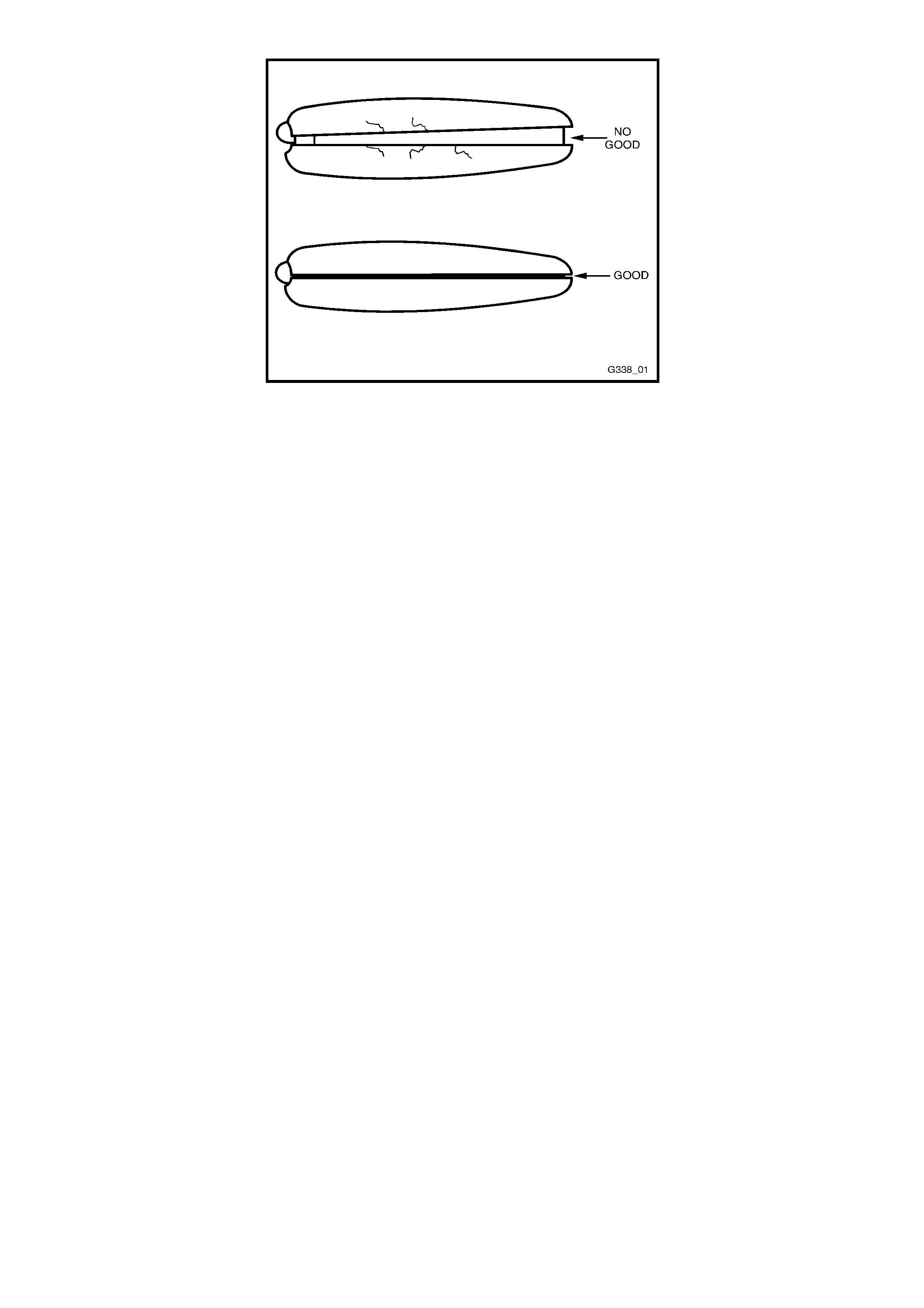
Figure 12J-1-46A
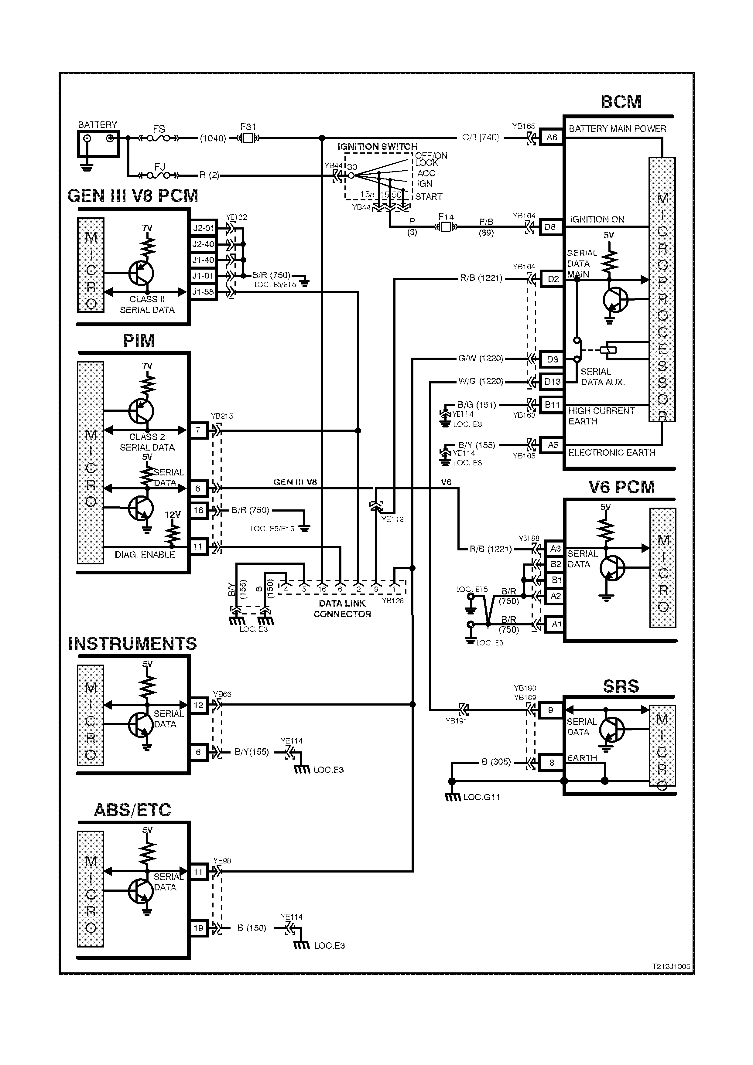
4.2 SERIAL DATA COMMUNICATION
Figure 12J-1-47

GENERAL INFORMATION
The VT Series Model uses a bus master communication system where the BCM is the Bus Master.
The BCM periodically polls (surveys) each device on the bus and requests status data.
NOTE: The GEN III PCM communicates using a Class 2 communication protocol, all other control modules
communicate using UART. Due to these two different communication protocols, a Powertrain Interface Module
(PIM) is required to convert the Class 2 data into UART. For additional information on Class 2 and UART
communication protocols and the PIM, refer to 1.2 SERIAL DATA COMMUNICATION (BUS MASTER) in this
Section.
The devices connected to the bus are:
• Body Control Module (BCM).
• V6 and V6 supercharged engine Powertrain Control Module (PCM).
• GEN III V8 Powertrain Control Module (PCM) via the Powertrain Interface Module (PIM).
• Instrument cluster (INS).
• Antilock Brake System / Electronic Traction Control (ABS/ETC) module.
• Supplemental Restraint System (SRS) Sensing and Diagnostic Module (SDM).
• External diagnostic scan tool (TECH 2).
The data provided by each device may be utilised by any device connected to the bus.
Each device has a unique response “Message Identifier Word” (MIW) for ease of identification.
The bus m aster (BCM) polls each device with a serial data m essage which includes that devic es MIW . The devic e
responds by putting a serial data m essage back onto the bus. T he devices m essage includes its MIW and data, of
which is retrieved and utilised by any device on the bus requiring it.
The BCM polls each device for a status update, once ever y 300 m illiseconds. The ex ception to this being the PCM
(V6) and PIM (GEN III V8) which are polled twice every 300 milliseconds.
When the ignition switch is turned from the OFF position to the ON position, the BCM will communicate with the
PCM (via the PIM on vehicles with GEN III V8 engines) f or thef t deter rent pur poses . If the BCM does not r eceive an
OK TO START message from the PCM within 0.5 seconds of ignition on, the auxiliary data bus is isolated via
switching from the BCM.
The isolation of the auxiliary data bus during this period eliminates the possibility of a device failure other than the
BCM, PCM or PIM (GEN III V8 only), causing a problem on the bus and inhibiting antitheft communications.
This period (short loop time) continues until the PCM responds with an acknowledgment or a maximum of five
seconds after which the BCM will switch to the standard polling sequence.
Following succes sful theft deterr ent comm unications, the BCM begins sequential polling of devices on the bus and
normal system operation is established.
When the ignition switch is in the OFF position, the BCM continues to poll, allowing for TECH 2 communications
and external control of the bus prior to the ignition being switched on.
Test Description
The numbers below refer to step numbers on the facing pages diagnostic chart.
1. Ensures TECH 2 is functioning correctly.
2. Checks if TECH 2 can communicate with the BCM.
3. Checks if TECH 2 can communicate with the V6 or V6 supercharged PCM (vehicles with V6 or V6
supercharged engines).
4. Checks if TECH 2 can communicate with the PIM (vehicles with GEN III V8 engines).
5. Checks if TECH 2 can communicate with the GEN III V8 PCM (vehicles with GEN III V8 engines).
6. Checks if TECH 2 can communicate with all the devices (SRS, ABS/ETC, INS) on the auxiliary serial data line.
7. Checks continuity of circuit 1221 between the BCM and the DLC.
8. Check s if no BCM com m unication is c aused by control m odule interf erence connec ted to the m ain or auxiliary
serial data line.
9. Checks if no BCM communication is caused by a short to battery + or earth on the main and auxiliary serial
data lines.
10. Check s continuity of circuit 1221 between the BCM and PCM, and if there is a problem with the PCM (vehicles
with V6 and V6 supercharged engines).
11. Checks continuity of circuit 1221 between the BCM and PIM (vehicles with GEN III V8 engines).
12. Continuation of Step 6; determines if TECH 2 can communicate with at least one of the devices (SRS,
ABS/ETC, INS) on the auxiliary serial data line.
13. Check s to establis h whether lost c ommunication between modules on the aux iliary serial data line and TECH 2
is due to an open in circuit 1220 or the module itself.
14. Check s to establish whether loss of com munic ation on the auxiliary serial data line is due to an open in c ircuit
1220 or the BCM.
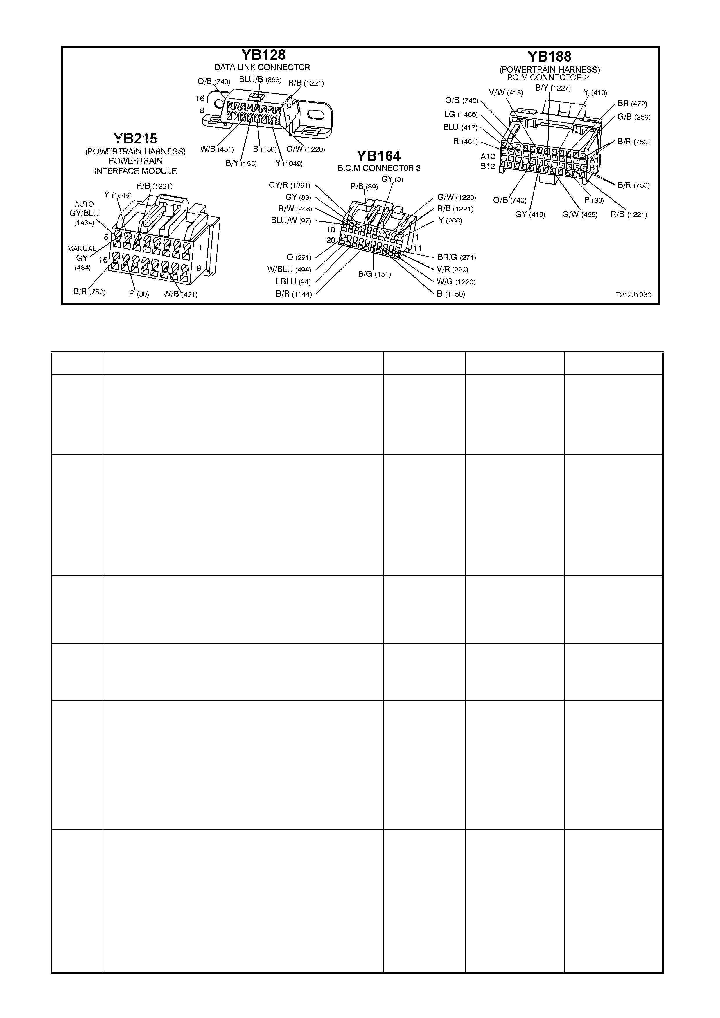
Figure 12J-1-48
SERIAL DATA COMMUNICATION
STEP ACTION VALUE YES NO
1. • Connect TECH 2 to DLC.
• Turn ignition ON.
• Push power button on TECH 2.
• Does TECH 2 power up (screen will illuminate
display TECH 2)?
Go to Step 2. Go to TECH 2
diagnosis, refer
to Section 0C
TECH 2 in the VT
Series II Service
Information.
2. • With TECH 2 still connected and ignition ON, select
Diagnostics / Body / Body Control Module.
• Does TECH 2 display BCM system identification
information (BCM level and type)?
Go to Step 3 -
vehicles with V6
or V6
supercharged
engines.
Go to Step 4 -
vehicles with
GEN III V8
engines
Go to Step 7.
3. • With TECH 2 still connected, ignition ON, exit
BODY and select Diagnostics / Engine / Engine
Type (ie V6, V6 Supercharged).
• Does TECH 2 display PCM system identification
information (ie. prom identification)?
Go to Step 6. Go to Step 10.
4. • With TECH 2 still connected, ignition ON, exit
BODY Control Module and select Powertrain
Interface Module (PIM)
• Can TECH 2 communicate with the PIM?
Go to Step 5. Go to Step 11.
5. • With TECH 2 still connected, ignition ON, exit
BODY and select Diagnostics / Engine / Engine
Type (ie V8 GEN III).
• Does TECH 2 display GEN III V8 PCM system
identification information (ie. prom identification)?
Go to Step 6 Go to PCM
diagnostics in
Section 6C3
POWERTRAIN
MANAGEMENT -
GEN III V8
ENGINE in the
VT Series II
Service
Information.
6. • With TECH 2 still connected, ignition ON, exit
Engine Diagnostics and select Body / DTC Check /
DTC Check.
• Can TECH 2 communicate with all control modules
fitted to the vehicle (if NO DATA is displayed next
to a control module, then there is no
communication between TECH 2 and that control
module)?
NOTE: If vehicle is not equipped with a particular
feature, ie. ECC, No Data will be displayed next to this
module in the TECH 2 display.
System OK. Go to Step 12.

STEP ACTION VALUE YES NO
7. • Turn ignition OFF.
• Back probe DLC connector YB128, terminal 9,
circuit 1221 (Red/Black wire) and BCM connector
YB164, terminal D2, circuit 1221 (Red/Black wire)
with an Ohmmeter.
• Is value as specified?
Below 1 ohm Go to Step 8. Check and repair
open in circuit
1221 between
DLC and BCM.
Recheck and
verify repair.
8. • Disconnect control modules on auxiliary serial data
line (ABS, ABS/ETC, SRS, INS) and the PCM (V6
& V6 Supercharged engine) or PIM (GEN III V8
engine) on the main serial data line one at a time,
checking each time if TECH 2 can communicate
with the BCM (refer to Step 2).
• Does communication between the BCM and TECH
2 resume after disconnecting any of the control
modules?
Go to suspect
control module
diagnosis in the
relevant Section
in this Service
Information CD.
Go to Step 9.
9. • Disconnect all control modules; ABS, ABS/ETC,
SRS, INS, PCM, PIM (GEN III only) and BCM.
• Check integrity (i.e. short to battery +, short to
earth) of circuits 1221 (Red/Black wire) and circuit
1220 (Green/White – White/Green wire).
• Are circuits 1221 and 1220 OK?
Replace BCM,
refer to 12J-1
LOW SERIES
BCM in the VT
Series I Service
Information.
Recheck and
verify repair.
Repair circuits
1221 or 1220 as
necessary.
Recheck and
verify repair.
10. • Turn ignition OFF.
• Back probe BCM connector YB164, terminal D2,
circuit 1221 (Red/Black wire) and PCM connector
YB188, terminal A3, circuit 1221 (Red/Black wire)
with an Ohmmeter.
• Is value as specified?
Below 1 ohm Go to PCM
diagnostics in
Section 6C1
POWERTRAIN
MANAGEMENT -
V6 ENGINE in
the VT Series I
Service
Information.
Check and repair
open in circuit
1221 between
PCM and BCM.
11. • Turn ignition OFF.
• Back probe BCM connector YB164, terminal D2,
circuit 1221 (Red/Black wire) and PIM connector
YB215, terminal 6, circuit 1221 (Red/Black wire)
with an Ohmmeter.
• Is value as specified?
Below 1 ohm Go to 4.4 THEFT
DETERRENT
diagnostics in
this Section.
Check and repair
open in circuit
1221 between
PIM and BCM.
12. • In Step 6, was TECH 2 able to communicate with at
least one of the control modules on the auxiliary
serial data line (ABS, ABS/ETC, INS, SRS)?
NOTE: TECH 2 will display No Data next to a control
module that it can not communicate with in the DTC
Check mode.
Go to Step 13. Go to Step 14.
13. • Check continuity between BCM and suspect control
module in circuit 1220 (Green/White - White/Green
wire).
• Does continuity exist?
Go to suspect
control module
diagnosis in the
relevant Section
in this Service
Information CD.
Repair open in
circuit 1220
between suspect
control module
and the BCM.
Recheck and
verify repair.
14. • Check continuity between BCM and all control
modules on the auxiliary serial data line.
• Does continuity exist?
Replace BCM,
refer to 12J-1
LOW SERIES
BCM in the VT
Series I Service
Information.
Recheck and
verify repair.
Repair open in
circuit 1220.
Recheck and
verify repair.

4.3 CENTRAL DOOR LOCKING
GENERAL INFORMATION
The diagnostic procedure for central door locking system remains unchanged from the procedure detailed in
Section 12J-1 LOW SERIES BODY CONTROL MODULE in the VT Series I Service Information, noting the
following:
On VT Series II Models, it is possible to deadlock the doors via the remote coded key.
When diagnosing a central door locking circuit fault on a VT Series II Model, reference to the wiring diagrams in
Section 12P WIRING DIAGRAMS in the VT Series II Service Information should be made.
Due to the addition of the deadlock ing feature via the r em ote coded k ey, the central door lock ing System Check , as
detailed in the VT Series I Service Information has been updated and republished to include this feature.
SYSTEM CHECK
The operation of the central door locking system is independent of the ignition being switched ON or OFF.
Deadlock refers to the electrical means that can be activated to ensure vehicle security by inhibiting door lock
operation.
Even though the electronic theft deterrent system, via the remote coded key, can activate the doors locks, it does
not engage the electrical 'blocking' of the doors (deadlocking).
Central Locking and Unlocking
Operation of this system can be effected as follows;
1. Driver’s door, outside key and inside locking (snib) button (locking and unlocking).
2. Left hand front passenger door inside locking (snib) button (locking and unlocking)
3. Rear passenger doors inside locking (snib) button (only unlocking is possible).
Deadlock
The deadlocking feature applies to all four doors, but not to the luggage compartment lid or tailgate.
The deadlocking feature is engaged as follows:
• Two sequential lock activation’s of the door lock microswitch or
• Operating the ‘lock’ button on the remote coded key twice within 10 seconds.
Successful deadlocking via the remote coded key is indicated by the turn signal lamps turning on for three seconds.
If the vehicle is already deadlocked, pressing the lock button on the remote coded key will cause the turn signal
lamps to turn on for three seconds, indicating that the vehicle is already deadlocked.
If the vehicle is locked (not deadlocked) pressing the lock button on the remote coded key 10 seconds after the
previous press, the doors will not deadlock and the turn signal lamps will flash briefly, indicating that the doors are
only lock ed. Pressing the lock button again, within in a 10 second period will cause the doors to deadlock and turn
the signal lamps will turn on for three seconds.
After the deadlocking feature device has been engaged, unlocking is possible at the driver’s door from outside, by:
• Inserting the key into the driver’s door lock cylinder and turning the key to the unlock position or
• Activating the un-lock button on the remote key unlocks the deadlocks on all doors, but only unlocks the
driver’s door (providing two stage unlocking is enabled).
To ensure access to the vehicle if the electrical system should f ail (discharged battery), after the system has been
engaged, the driver’s door lock cylinder can be moved independently of the actuator and therefore allowing
unlocking of the driver’s door latch.
The rear com partment lid or tailgate can be lock ed/unlocked when the m echanical deadloc king featur e is ac tuated,
while leaving the doors secured.
NOTE: Deadlocking is not possible with the ignition in the ON position.
Overheating Prevention
In the event of m ultiple activation’s within a defined tim e period, the central door loc king system will be deactivated
and remain inoperative for a defined tim e period to prevent the door actuators from overheating. After a fixed time
delay, the system will re-activate and operate as normal.
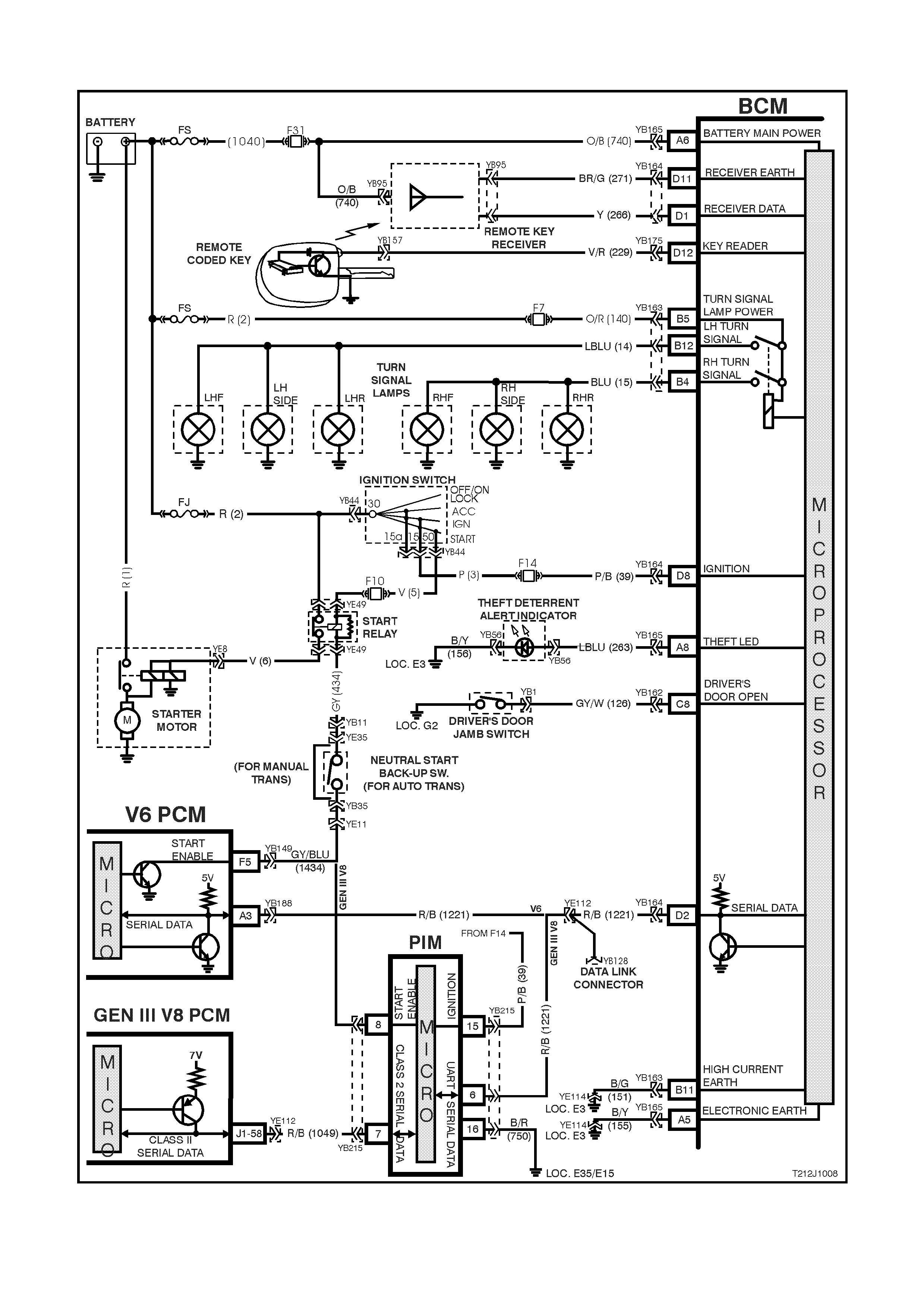
4.4 THEFT DETERRENT
Figure 12J-1-49

Circuit Description
The theft deterrent system can be armed by pressing the lock button on the remote coded key when the driver’s
door is closed or pass ively ar med autom atically by the BCM 30 s econds af ter the ignition is switched of f. When the
system is armed, the Powertrain Control Module (PCM)(V6 and V6 supercharged engine) or Powertrain Interface
Module (PIM)(GEN III V8 engine) prevents the engine from starting.
The theft deterrent system can be disarmed in two ways:-
By press ing the unlock button on the r emote c oded key. This will unlock door s, turn the interior light on and disarm
the system for 30 seconds.
By inserting the remote coded key into the ignition switch cylinder and turning the ignition to the ON position. This
causes the BCM to read a security code serial data output from the rem ote coded key contact pin, via the remote
coded key reader assembly.
Should the system not disar m (thef t deterrent LED of f) when the ignition switch is turned to the ON position ( ie. due
to a mis aligned or f aulty rem ote c oded key reader or f aulty remote coded key), then press the loc k or unlock button
on the remote key to disarm the theft deterrent system.
The remote coded key is powered by it’s own internal battery. If the battery fails, the remote coded key can be
powered by the rem ote coded key reader once the k ey is inserted into the ignition cylinder and turned to either the
ON or START positions.
When pressing the lock button on the remote coded key to arm the system, the indicators will flash once and the
theft deterrent alert indicator (LED) will begin to flash.
W hen pressing the unlock button on the rem ote coded key to disarm the s yst em, the indicators will flash twice and
the theft deterrent alert indicator (LED) will go out.
On vehicles with V6 and V6 superc harged engines, when the ignition switch is turned to the ON position, the BCM
polls the PCM and sends an enc rypted BCM/Key s ecurity code (T he sec urity code is rec eived via the BCM slip ring
or rem ote receiver in the event of no slip ring com m unication). T he PCM com pares the rec eived secur ity code with
it’s stored secur ity code and if the codes m atch, the PCM will enable injector fuelling and continue engine cr anking.
The PCM will return an OK TO START message, which tells the BCM to jump from SHORT LOOP mode to the
LONG LOOP mode.
On vehicles with GEN III V8 engines, when the ignition switch is turned to the ON position, the BCM polls the PIM
and sends an encrypted BCM/Key security code (The security code is received via the BCM slip ring or remote
receiver in the event of no slip ring comm unication). The PIM compares the received security code with it’s stored
security code and if the codes match, the PIM will continue engine c r ank ing and s end a s epar ate encr ypted secur ity
code to the PCM. T he PCM compares this code with its stored secur ity code and if the c odes m atch, the PCM will
enable injector fuelling to continue. The PIM will return an OK TO START message, which tells the BCM to jump
from SHORT LOOP mode to the LONG LOOP mode.
Test Description
The numbers below refer to step numbers in the following diagnostic chart.
1-10 Functional check of system.
11. Checks if doors are not locking due to central door locking system or remote receiver/remote key.
12. Re-synchronisation of remote key rolling code in event of rolling code misalignment.
14. Uses TECH 2 to operate indicators (establish whether problem is with the BCM or other external problem).
15. Checks turn signal input at input to BCM.
16. Checks turn signal output at output of BCM when commanded by TECH 2.
17. Uses T ECH 2 to operate the theft deterrent LED (est ablish whether problem is with the BCM or other ex ternal
problem).
18. Checks for theft deterrent LED output drive form the BCM when commanded by TECH 2.
19. Checks for short to earth in circuit 263 causing LED to be faulty.
20. Checks circuit 263.
21. Checks circuit 156 for open to establish if circuit is faulty or theft deterrent LED is faulty.
22. Checks if problem is confined to the key reader or remote serial data transfer.
23. Checks for poor remote coded key shaft earth contact.
24. Checks for poor contact of remote coded key pin with remote coded key reader.
25. Checks if problem is with remote coded key by trying a known good remote coded key.
26. Checks for BCM signal at remote key reader.
27. Checks ignition switch/cylinder earth.
28. Uses TECH 2 to check IGNITION ON signal at microprocessor of BCM.
29. Checks circuit 229 for open to establish if circuit is faulty or BCM is faulty.
30. Checks for short to earth in circuit 229.
31. Checks ignition ON signal at input to BCM.
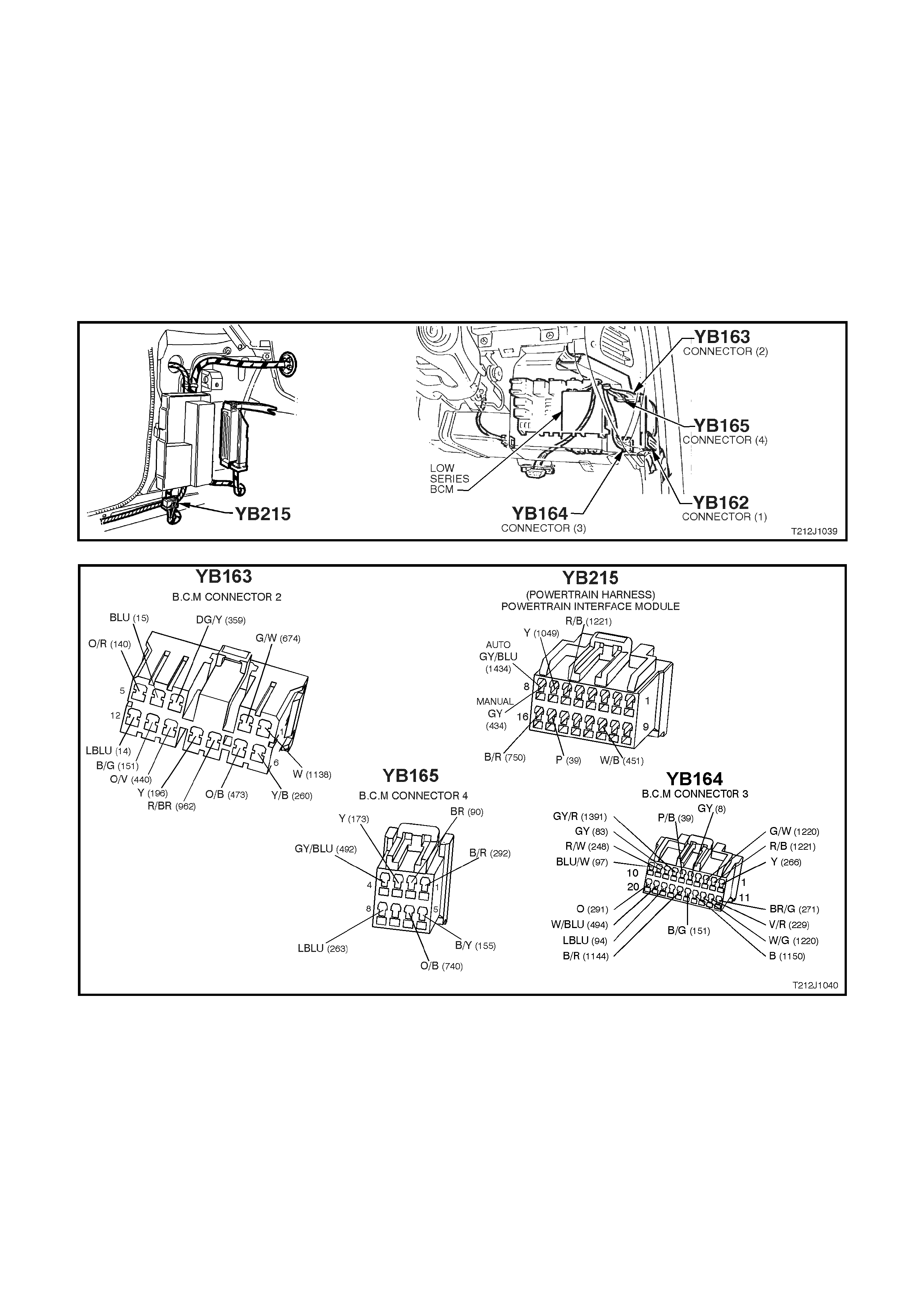
32. Uses TECH 2 to check for PASSIVE MODE OFF signal at microprocessor of BCM to establish if fault is with
the BCM or PCM.
33. Continuation of functional check for vehicles with GEN III V8 engines.
34. Uses TECH 2 to check for PASSIVE MODE OFF signal at microprocessor of BCM to establish if fault is with
the BCM or PCM.
35. Using TECH 2, checks for communication with the PIM.
36. Uses TECH 2 to check for THEFT STATUS start signal at the microprocessor of the PIM.
37. Uses TECH 2 to drive the starter relay to determine if the fault is with the PIM or starter circuits.
38. Checks for ignition on (power feed) at the input to the PIM.
39. Checks circuit 750.
40. Checks circuit 1221.
41. Uses TECH 2 to check starter relay drive of PIM.
Figure 12J-1-50
Figure 12J-1-51

THEFT DETERRENT
STEP ACTION VALUE YES NO
1. • Close and lock all doors.
• Operate remote key UNLOCK button within 4
meters of the driver’s side B pillar.
• Does the driver’s door unlock (2 stage unlocking
programmed) or all doors unlock (single stage
unlocking programmed)?
Go to Step 2. Go to Step 11.
2. • In Step 1, did all indicator lights flash twice (both
left and right hand sides)? Go to Step 3. Go to Step 13.
3. • In Step 1, did the dome lamp illuminate? Go to Step 4. Go to dome lamp
delay diagnosis,
refer 4.6 DOME
LAMP DELAY
CONTROL in this
Section.
4. • In Step 1, did the theft deterrent LED go out
immediately and begin flashing 30 seconds latter? Go to Step 5. Go to Step 17.
5. • Close all doors.
• Arm theft deterrent system by operating the LOCK
button on the remote coded key within four metres
of the driver’s side B pillar.
• Did all doors lock?
Go to Step 6. Go to central
door locking
diagnosis, refer
to 4.3 CENTRAL
DOOR LOCKING
in this Section.
6. • In Step 5, did the dome lamp go out immediately
upon activating the lock button? Go to Step 7. Go to dome lamp
delay diagnosis,
refer 4.6 DOME
LAMP DELAY
CONTROL in this
Section.
7. • In Step 5, did all indicator lights flash once (both
left and right hand sides)? Go to Step 8. Replace BCM,
refer to 12J-1
LOW SERIES
BCM in the VT
Series I Service
Information.
Recheck and
verify repair.
8. • Is the theft deterrent LED flashing? Go to Step 9. Replace BCM,
refer to 12J-1
LOW SERIES
BCM in the VT
Series I Service
Information.
Recheck and
verify repair.
9. • Unlock vehicle with remote coded key and wait for
the vehicle to passively arm (theft deterrent LED
flashing).
• With vehicle passively armed), insert the ignition
key into ignition switch and turn to the ON position.
• Does the theft deterrent LED extinguish?
Go to Step 10. Go to Step 22.
10. • Turn the ignition key to the START position.
• Does the vehicle crank and start? System OK. Go to Step 32 -
vehicles with V6
or V6
supercharged
engines.
Go to Step 33 -
vehicles with
GEN III V8
engines
11. • Insert ignition key into driver’s door lock cylinder
and operate door unlock microswitch (turn key to
unlock position).
• Do all doors unlock?
Go to Step 12. Go to central
door locking
diagnosis, refer
to 4.3 CENTRAL
DOOR LOCKING
in this Section.

STEP ACTION VALUE YES NO
12. • Insert ignition key into ignition switch and cycle
from OFF - ON - OFF.
• Remove key and lock doors with driver’s door lock
cylinder switch.
• Operate UNLOCK button on remote key within 4
metres of driver’s door B pillar.
• Does the driver’s door unlock (2 stage unlocking
programmed) or all doors unlock (single stage
unlocking programmed)?
Go to Step 2. Go to remote
receiver
diagnosis in
Section 12J-1
LOW SERIES
BCM in the VT
Series I Service
Information.
Recheck and
verify repair
13. • In Step 2, did at least one side of vehicle’s
indicators flash twice (either left or right hand
side)?
Go to Step 16. Go to Step 14.
14. • Driver’s door closed.
• Connect TECH 2 to DLC.
• Select BODY / BODY CONTROL MODULE /
MISCELLANEOUS TESTS / LAMPS /
INDICATORS.
• Conduct test as instructed by TECH 2.
• Do all indicator lights illuminate?
Go to central
door locking
diagnosis, refer
to 4.3 CENTRAL
DOOR LOCKING
in this Section.
Go to Step 15.
15. • Back probe BCM connector YB163, terminal B5,
circuit 140 (Orange/Red wire) with a Voltmeter to
earth.
• Is voltage as specified?
Approx. 12
volts Go to Step 16. Check and repair
open in circuit
140 (including
fuse F7), recheck
and verify repair.
16. • Back probe BCM connector YB163, terminals B12
and B4, circuits 14 & 15 (Light Blue wire and Blue
wire respectively) with a Voltmeter to earth.
• Repeat Tech 2 Indicator Illumination test as per
Step 14.
• Is voltage as specified?
Approx. 12
volts Check and repair
circuits 14 (LH
indicator) and/or
15 (RH
indicator).
Recheck and
verify repair
Replace BCM,
refer to 12J-1
LOW SERIES
BCM in the VT
Series I Service
Information.
Recheck and
verify repair.
17. • Connect TECH 2 to DLC.
• Select BODY / BODY CONTROL MODULE /
MISCELLANEOUS TESTS / SECURITY SYSTEM /
SECURITY LED.
• Conduct test as instructed by TECH 2.
• Does theft deterrent LED illuminate?
Replace BCM,
refer to 12J-1
LOW SERIES
BCM in the VT
Series I Service
Information.
Recheck and
verify repair.
Go to Step 18.
18. • Back probe BCM connector YB165, terminal A8,
circuit 263 (Light Blue wire) with a Voltmeter to
earth.
• Repeat Security LED test as per Step 17.
• Are voltages as specified?
Approx 5 volts
LED on
Approx 0 volts
LED off
Go to Step 20. Go to Step 19.
19. • Back probe BCM connector YB165, terminal A8,
circuit 263 (Light Blue wire) with an Ohmmeter to
earth.
• Is value as specified?
Below 1 ohm. Repair short in
circuit 263.
Recheck and
verify repair.
Replace BCM,
refer to 12J-1
LOW SERIES
BCM in the VT
Series I Service
Information.
Recheck and
verify repair.
20. • Back probe theft deterrent LED connector YB56,
circuit 263 (Light Blue wire) with a Voltmeter to
earth.
• Repeat Security LED test as per Step 17.
• Are voltages as specified?
Approx 5 volts
LED on
Approx 0 volts
LED off
Go to Step 21. Check and repair
open in circuit
263. Recheck
and verify repair.
21. • Back probe theft deterrent LED connector YB56,
circuit 156 (Black/Yellow wire) with a Ohmmeter to
earth.
• Is value as specified?
Below 1 ohm Replace theft
deterrent LED,
refer to 12C
INSTRUMENTS,
WI PERS /
WASHER &
HORN in the VT
Series I Service
Information.
Repair open in
circuit 156.
Recheck and
verify repair.

STEP ACTION VALUE YES NO
22. • With the ignition key in the ON position, operate
the unlock button on the remote coded key.
• Does the theft deterrent LED go out?
Go to Step 23. Go to remote
receiver
diagnosis in
Section 12J-1
LOW SERIES
BCM in the VT
Series I Service
Information.
Recheck and
verify repair
23. • Remove remote key, key shaft and clean earth
contact (shaft earth).
• Reinstall key shaft and tighten screws to the
correct torque specification (0.7 - 0.9 Nm).
• With system passively armed (theft deterrent LED
flashing), insert key into ignition switch and turn key
to the ON position.
• Does the theft deterrent LED go out?
Go to Step 10. Go to Step 24.
24. • Turn ignition key to the ON position.
• Visually check to see if remote coded key contact
pin is making good contact with remote key reader
(slip ring).
• Is remote coded key contact pin making good
contact?
Go to Step 25. Check and
repair: remote
key reader or
alignment of
remote key
reader (refer step
12) or length of
key shaft or
remote key
contact pin
25. • Check function of second remote key.
• Is second key OK? Replace remote
coded key, refer
to Section 12J-1
LOW SERIES
BCM in the VT
Series I Service
Information.
Recheck and
verify repair .
Go to Step 26
26. • Isolate remote coded key contact pin (use a thick
piece of paper to cover pin).
• Insert key into ignition switch and turn key to the
ON position.
• Measure voltage at the remote coded key reader
(slip ring) to a sound earth.
• Is voltage as specified?
Fluctuates
between 4 - 6
volts - AC
Go to Step 27. Go to Step 28.
27. • Check ignition switch earth using an Ohmmeter
connected between the ignition switch housing a
sound earth point.
• Is value as specified?
Below
100 ohms Replace BCM,
refer to 12J-1
LOW SERIES
BCM in the VT
Series I Service
Information.
Recheck and
verify repair.
Check and repair
open or poor
earth connection
at ignition switch.
Recheck and
verify repair.
28. • Connect TECH 2 to DLC.
• Select BODY / BODY CONTROL MODULE / DATA
DISPLAY / DATA LIST.
• Turn ignition ON as instructed by TECH 2.
• Scroll to Ignition Switch display.
• Does screen display Ignition Switch On?
Go to Step 29. Go to Step 31.
29. • Back probe BCM connector YB164, terminal D12,
circuit 229 (Violet/Red wire) with a Voltmeter to
earth.
• With remote coded key contact pin isolated
(covered with thick paper), insert ignition key into
ignition switch and turn ignition switch to the ON
position.
• Is voltage as specified?
Fluctuates
between 4 - 6
volts - AC
Check and repair
open in circuit
229 or remote
key reader,
Recheck and
verify repair.
Go to Step 30.

STEP ACTION VALUE YES NO
30. • Check circuit 229 (Violet/Red wire) for short to
earth.
• Is circuit 229 OK?
Check and repair
short in circuit
229. Recheck
and verify repair.
Replace BCM,
refer to 12J-1
LOW SERIES
BCM in the VT
Series I Service
Information.
Recheck and
verify repair.
31. • Back probe BCM connector YB164, terminal D6,
circuit 39 (Pink/Black wire) with a Voltmeter to
earth.
• Turn ignition ON.
• Is voltage as specified?
Approx. 12
volts Replace BCM,
refer to 12J-1
LOW SERIES
BCM in the VT
Series I Service
Information.
Recheck and
verify repair.
Check and repair
open in circuit 39
(including fuse
F14). Recheck
and verify repair.
32. • Connect TECH 2 to DLC.
• Select BODY / BODY CONTROL MODULE / DATA
DISPLAY / DATA LIST and scroll to PASSIVE
MODE.
• With system disarmed (theft deterrent LED off),
does the screen display Passive Mode OFF?
Go to PCM
diagnostics in
Section 6C1
POWERTRAIN
MANAGEMENT -
V6 ENGINE in
the VT Series I
Service
Information
Replace BCM,
refer to 12J-1
LOW SERIES
BCM in the VT
Series I Service
Information.
Recheck and
verify repair.
33. • Turn the ignition to the START position.
• Does the engine crank and continue to crank after
1 second?
Go to PCM
diagnostics in
Section 6C3
POWERTRAIN
MANAGEMENT -
GEN III V8 ENG
in the VT Series
II Service
Information.
Go to Step 34.
34. • Connect TECH 2 to the DLC.
• Turn ignition ON.
• Select BODY / BODY CONTROL MODULE / DATA
DISPLAY / DATA LIST and scroll to PASSIVE
MODE.
• With the theft deterrent system disarmed (theft
deterrent LED off) does the screen display Passive
Mode OFF?
Go to Step 35. Replace BCM,
refer to 12J-1
LOW SERIES
BCM in the VT
Series I Service
Information.
Recheck and
verify repair.
35. • With TECH 2 still connected and ignition ON, exit
BODY CONTROL MODULE and select BODY /
POWERTRAIN INTERFACE MODULE (PIM).
• Can TECH 2 communicate with the PIM (i.e.
software version number displayed)?
Go to Step 36. Go to Step 38.
36. • Ensure the BCM has been linked to the PIM (Refer
BCM linking procedure in the Service Operations of
this Section).
• With TECH 2 still connected and ignition ON select
BODY / BODY CONTROL MODULE /
POWERTRAIN INTERFACE MODULE / DATA
LIST. Scroll to THEFT STATUS.
• Does screen display Theft Status START?
Go to Step 37. Replace PIM,
refer Section 6C3
POWERTRAIN
MANAGEMENT -
GEN III V8 ENG
in the VT Series
II Service
Information.
37. • With TECH 2 connected and ignition ON, select
BODY / BODY CONTROL MODULE /
POWERTRAIN Interface Module /
MISCELLANEOUS TESTS / STARTER RELAY.
• Turn and hold the ignition switch in the START
position.
• Conduct starter relay test as instructed by TECH 2.
• Does the engine crank?
Replace PIM,
refer Section 6C3
POWERTRAIN
MANAGEMENT -
GEN III V8 ENG
in the VT Series
II Service
Information.
Go to Step 41.
38. • Back probe PIM connector YB215, terminal 15,
circuit 39 (Pink wire) with a voltmeter to earth.
• Turn ignition ON.
• Is voltage as specified?
12 volts Go to Step 39. Check and repair
open in circuit
39. Recheck and
verify repair.

STEP ACTION VALUE YES NO
39. • Turn ignition OFF.
• Back probe PIM connector YB215, terminal 16,
circuit 750 (Black/Red wire) wi th an ohmmeter to
earth.
• Is value as specified?
Below 1 ohm Go to Step 40. Check and repair
open in circuit
750. Recheck
and verify repair.
40. • Back probe BCM connector YB164, terminal D2,
circuit 1221 (Red/Black wire) and PIM connector
YB215, terminal 6, circuit 1221 (Red/Black wire)
with an ohmmeter.
• Is value as specified?
Below 1 ohm Replace PIM,
refer Section 6C3
POWERTRAIN
MANAGEMENT -
GEN III V8 ENG
in the VT Series
II Service
Information.
Check and repair
open in circuit
1221 between
PIM and BCM.
Recheck and
verify repair.
41. • Back probe PIM connector YB215, terminal 8,
circuit 1434 (Grey/Blue wire) with a voltmeter to
earth.
• Connect TECH 2 to the DLC and select BODY /
BODY CONTROL MODULE / POWERTRAIN
INTERFACE MODULE / MISCELLANEOUS TESTS
/ STARTER RELAY.
• Turn and hold the ignition switch in the START
position.
• Conduct starter relay test as instructed by TECH 2.
• Is value as specified?
Below 1 volt Check the starter
circuits, including
fuse F10, circuits
1434, 434, 5, 6,
1, starter relay,
neutral safety
switch and
starter motor.
Refer to the
appropriate
sections in this
Service
Information CD
Replace PIM,
refer Section 6C3
POWERTRAIN
MANAGEMENT -
GEN III V8 ENG
in the VT Series
II Service
Information.
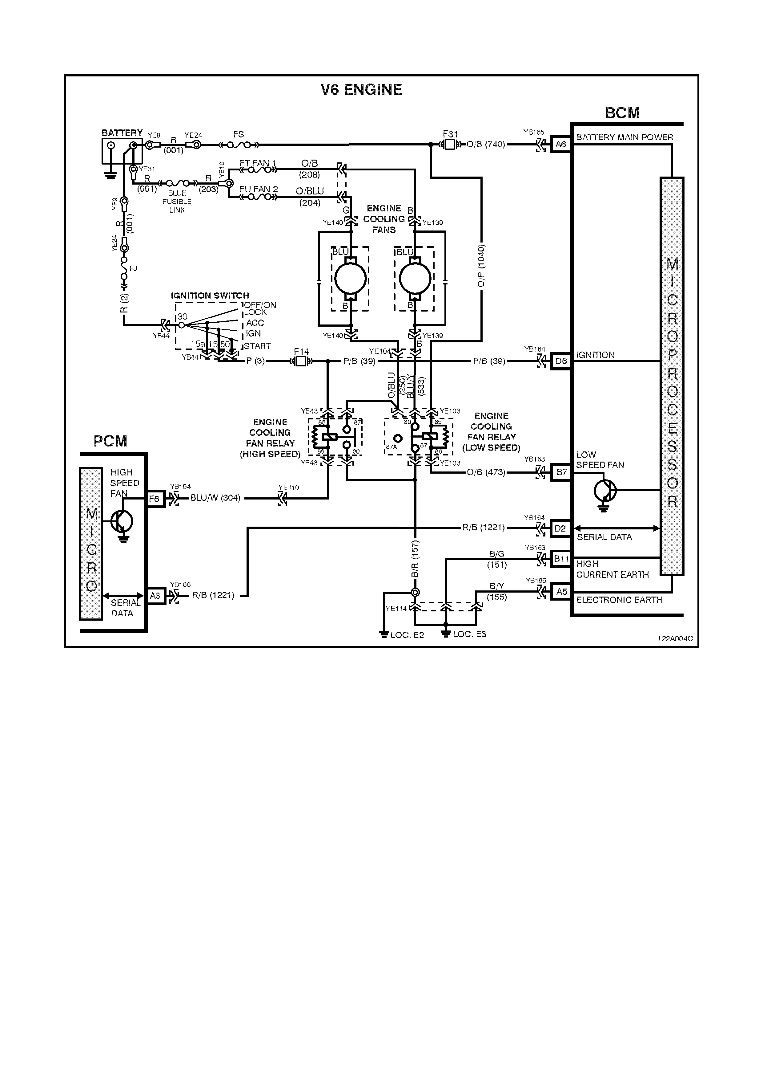
4.5 ENGINE COOLING FAN, LOW SPEED CONTROL
Figure 12J-1-52
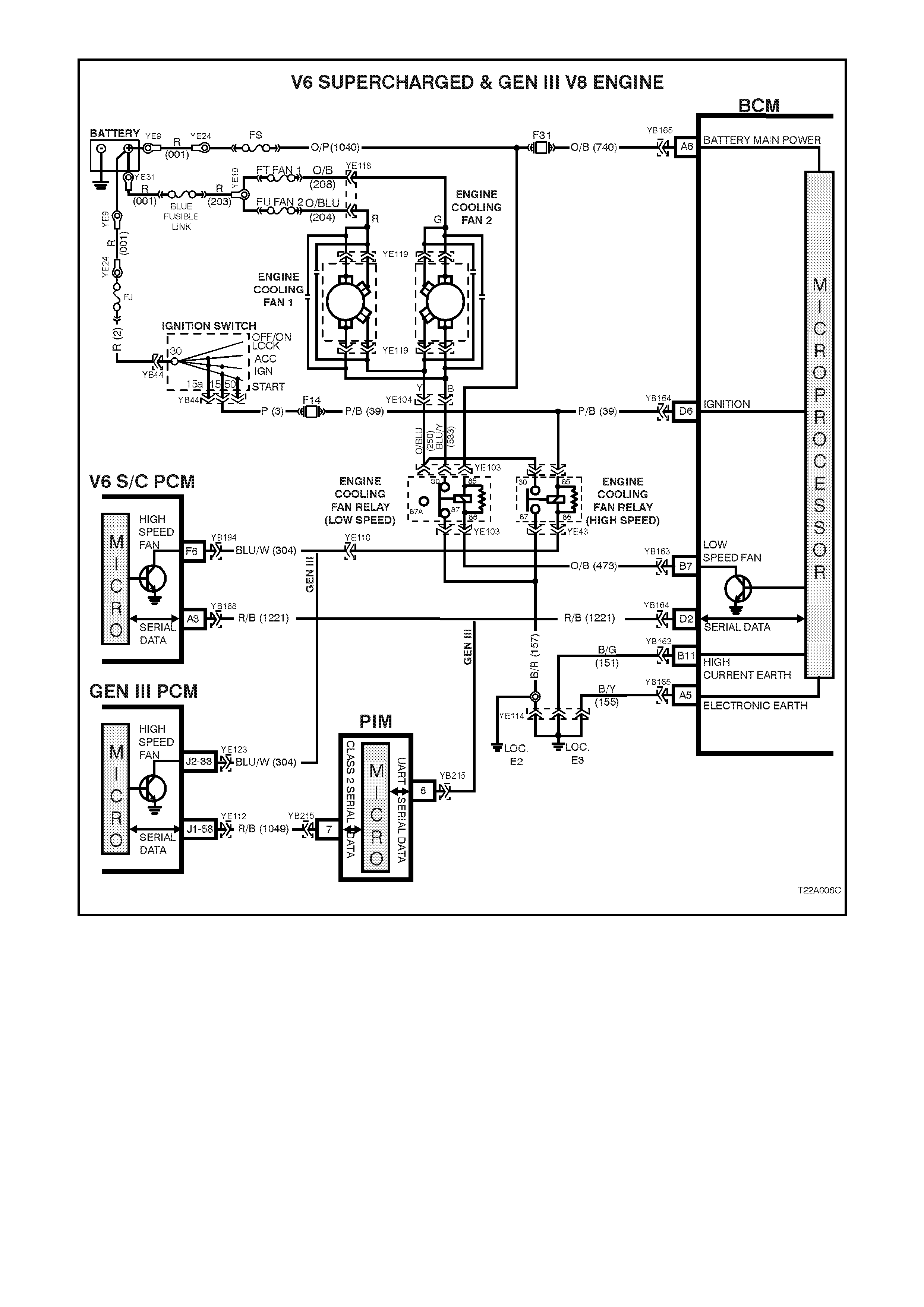
Figure 12J-1-53
CIRCUIT DESCRIPTION
Regardless of the engine configuration, the low speed cooling f an operation is enabled when the low speed engine
cooling fan micr o r elay (located in the engine com par tment relay housing, labelled Lo Fan) is ener gis ed by the Body
Control Module (BCM) via a request from the Powertrain Control Module (PCM). The PCM will request low speed
fan enable and disable via serial data communication to the BCM on circuit 1221 (Red/Black wire).
The PCM determines when to enable the low speed fan r elay based on inputs f rom the A/C request signal, Cooling
Temperature Sensor (CTS) and the Vehicle Speed Sensor (VSS).
When the ignition switch is turned f rom ON to O FF and the engine c oolant tem perature is above 117°C (V6 and V6
supercharged) / 113°C (GEN III V8). The BCM will continue to energise the low speed engine cooling fan micro
relay for four minutes.
On vehicles with GEN III V8 engines, the low speed cooling fan run on time has a minimum default value of 30
seconds.

Test Description
The numbers below refer to step numbers in the following diagnostic chart.
1. Functional check of low speed cooling fan operation.
2. Uses TECH 2 to command the BCM to turn the low speed fan on.
3. Checks for battery voltage supply to engine cooling fan motor.
4. Checks low speed fan drive signal at output of BCM when.
5. Checks circuit 473.
6. Checks circuit 1040.
7. Checks circuit 157.
8. Checks engine cooling low speed fan motor.
9. Checks circuit 533 and engine cooling low speed fan relay.
Figure 12J-1-54
Figure 12J-1-55

ENGINE COOLING FAN LOW SPEED CONTROL
STEP ACTION VALUE YES NO
1. • With the engine coolant temperature greater than
104°C (V6 or V6 Supercharged engine) or 98°C
(GEN III V8 engine) is the low speed fan enabled?
System OK. Go to Step 2.
2. • Connect TECH 2 to the DLC.
• Select BODY / BODY CONTROL MODULE /
MISCELLANEOUS TESTS / LOW FAN.
• Conduct test as instructed by TECH 2 and enable
the low speed fan.
• Is the low speed fan enabled?
Go to PCM /
Temperature
sensor diagnosis
in Section 6C1
POWERTRAIN
MANAGEMENT -
V6 ENGINE, VT
Series I Service
Information or
Section 6C3
POWERTRAIN
MANAGEMENT -
GEN III V8 ENG,
VT Series II
Service
Information.
Go to Step 3.
3. • Back probe engine cooling fan motor connector
YE139 circuit 208 (Black wire) on vehicles with V6
engines or connector YE119, circuit 208 (Green
wire) on vehicles with V6 supercharged or GEN III
V8 engines with a Voltmeter to earth.
• Is voltage as specified?
12 volts Go to Step 4. Check and repair
open in circuit
208. Recheck
and verify repair.
4. • Back probe BCM connector YB163, terminal B7,
circuit 473 (Orange/Black wire) with a jumper lead
to earth.
• Does low speed fan turn on?
0 volts Replace BCM,
refer to 12J-2
LOW SERIES
BCM, VT Series I
Service
Information.
Recheck and
verify repair.
Go to Step 5.
5. • Back probe engine cooling fan low speed relay
connector YE103, terminal 86, circuit 473
(Orange/Black wire) with a jumper lead to earth.
• Does low speed fan turn on?
0 volts Go to Step 6. Check and repair
open in circuit
473. Recheck
and verify repair.
6. • Back probe engine cooling fan low speed relay
connector YE103, terminal 85, circuit 1040
(Orange/Pink wire) wi th a Voltmeter to earth.
• Is voltage as specified?
12 volts Go to Step 7. Check and repair
open in circuit
1040. Recheck
and verify repair.
7. • Back probe engine cooling fan low speed relay
connector YE103, terminal 87, circuit 157
(Black/Red wire) with an Ohmmeter to earth.
• Is value as specified?
Below 1 ohm Go to Step 8. Check and repair
open in circuit
157. Recheck
and verify repair.
8. • Back probe engine cooling fan motor connector
YE139 (V6) or YE119 (V6 supercharged and GEN
III V8), circuit 553 (Black wire) with a test light
connected to battery +.
• Connect TECH 2 to the DLC.
• Select BODY / BODY CONTROL MODULE /
MISCELLANEOUS TESTS / LOW FAN.
• Conduct test as instructed by TECH 2 and enable
the low speed fan.
• Does test lamp illuminate?
Replace engine
cooling fan
motor, refer to
either Section
6B1 ENGINE
COOLING - V6
ENGINE, VT
Series I Service
Information or
6B3 ENGINE
COOLING - GEN
III V8 ENGINE,
VT Series I
Service
Information.
Recheck circuit
to verify repair.
Go to Step 9.
9. • With TECH 2 still connected, back probe engine
cooling fan low speed relay connector YE103,
terminal 30, circuit 533 (Blue/Yellow wire) with a
test light connected to battery +.
• Repeat TECH 2 LOW SPEED FAN test as again.
• Does test lamp illuminate?
Repair open in
circuit 533.
Recheck circuit
to verify repair .
Replace engine
cooling low
speed fan relay.
Recheck and
verify repair.
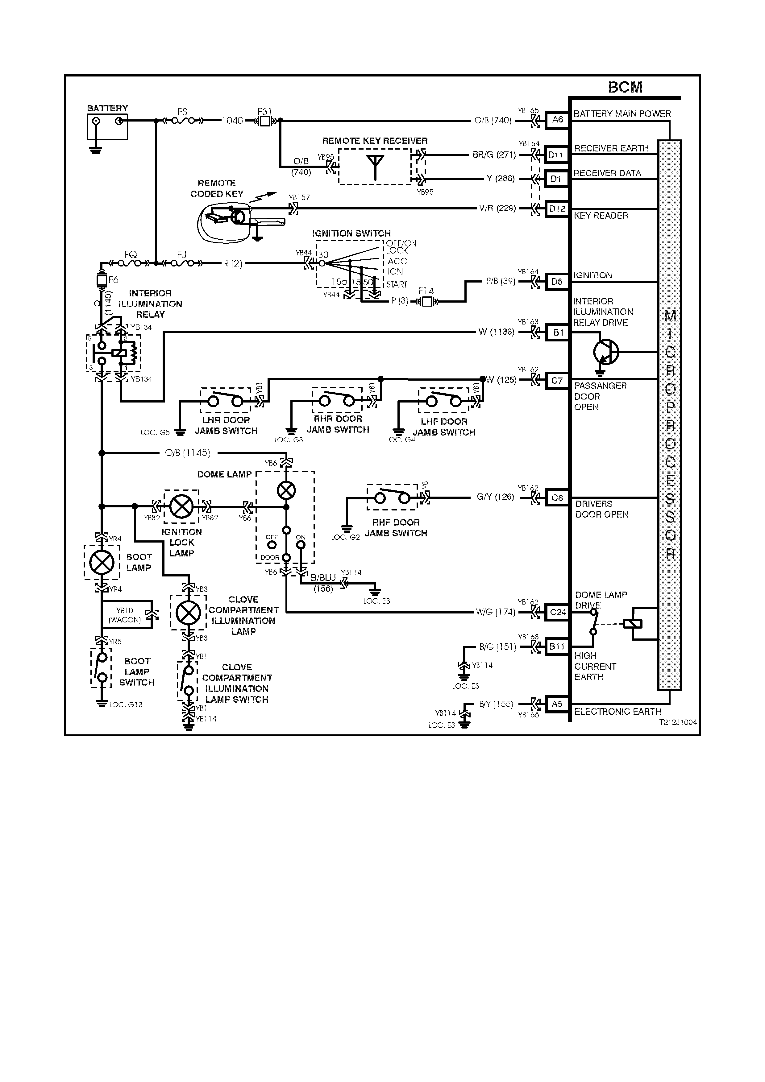
4.6 DOME LAMP DELAY CONTROL
Figure 12J-1-56

CIRCUIT DESCRIPTION
The interior lighting is controlled by the BCM or by the dom e lamp s witch (incorporated in the overhead dom e lam p
and switch assembly). The interior lighting is activated when any door is opened, unlocked with the remote coded
key, when the ignition is switched from IGN to ACC or OFF position, or when the dome lamp switch is operated.
In addition, as part of the battery saver function, the BCM controls internal, dome, ignition lock surround, glove
compartment and door lamps. The BCM controls battery voltage to these circuits via the interior illumination relay.
There is a delay per iod before the battery saver function of the BCM deac tivates the interior illumination r elay. The
delay default tim e is set to one hour, however, c an be reprogram m ed with T ECH 2 from between 2 to 255 m inutes.
The delay period is initiated when the ignition is switched to the ACC or OFF positions.
Whilst in battery saver mode, the BCM will reactivate the interior illumination relay when:
When the bonnet, boot or any door is opened.
The BCM receives a valid remote receiver.
When the ignition is switched to the ON position.
Doors are unlocked via the driver’s door microswitch.
TECH 2 is connected to the DLC and communicating with the BCM.
The headlamp switch is cycled from OFF to ON or ON to OFF.
The deadlock switch is activated.
The boot release switch is pressed.
The interior lighting is activated when any door is open. After all doors have been closed, the lamp will remain
activated for an additional 30 seconds.
The BCM monitors the DOORS and ON positions and controls the dome lamp accordingly.
If the interior lighting has been activated by a BCM control system ac tion, the dom e lam p switch will turn the interior
lighting off when it is switched from the DOO R to the O FF pos ition. T his means that the s witch can cur tail any delay
time indicated as well as switch the lighting off whilst a door is open. The exception to this is (if the vehicle is
equipped with an alarm system) if the theft deterrent system has been triggered. In this case, even with the switch in
the OFF position, the dome lamp will flash.
The interior lighting is s witched on upon c entr al door unloc king for 30 s econds . If the ignition is tur ned on during this
period, the interior lighting will be switched off immediately. Interior lighting is also switched off upon central door
locking, except if the dome lamp switch is turned on or if a door remains open.
Test Description
The numbers below refer to step numbers in the following diagnostic chart.
1-7. Functional check of dome lamp system.
8. Checks dome lamp globe.
9. Checks for battery + to the dome lamp switch assembly.
10. Checks circuit 1140 / fuse F6.
11. Checks circuit 1145.
12. Checks interior illumination relay.
13. Checks circuit 1138 / relay drive from BCM.
14. Checks circuit 156 and dome lamp and switch assembly.
15. Checks dome lamp drive output at BCM.
16. Checks circuit 174 and dome lamp and switch assembly.
17. Uses TECH 2 to check for passenger door signal at microprocessor of BCM.
18. Checks BCM for false output drive, circuit 174 and dome lamp and switch assembly.
19. Checks passenger door jamb circuit and switches.
20. Checks driver’s door jamb switch signal at input of BCM.
21. Checks circuit 126.
22 & 23. Checks passenger door jamb switch signal at input of BCM.
24. Checks ignition signal at input of BCM.
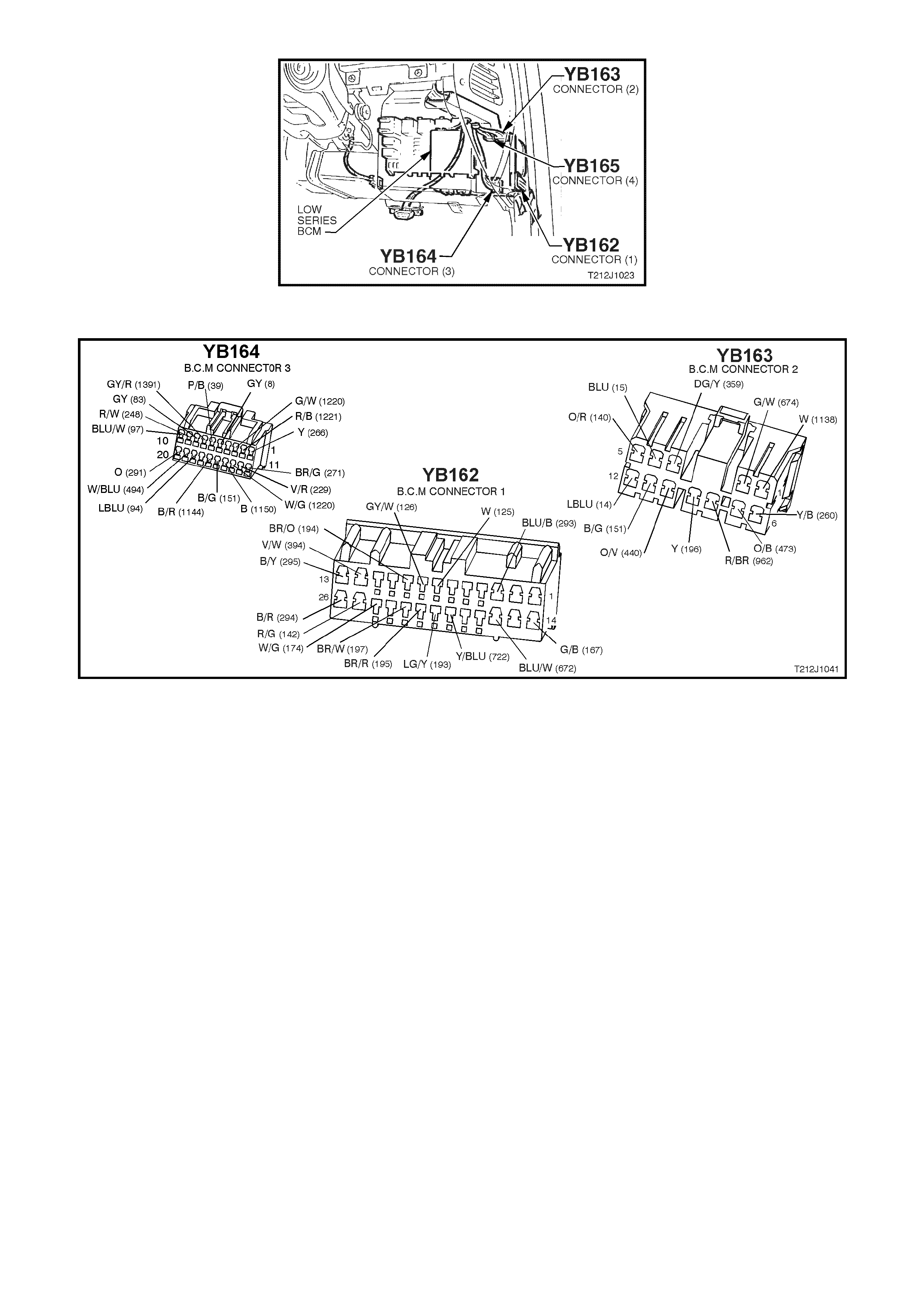
Figure 12J-1-57
Figure 12J-1-58

DOME LAMP DELAY
STEP ACTION VALUE YES NO
1. • Switch the dome lamp switch to the ON position.
• Does the dome lamp illuminate? Go to Step 2. Go to Step 8.
2. • Dome lamp switch in DOOR position.
• All doors locked.
• Unlock doors with remote key.
• Does dome lamp turn on?
Go to Step 3. Go to Step 15.
3. • Dome lamp switch in DOOR position.
• Dome lamp on (doors open).
• Close doors and lock with remote key.
• Does dome lamp turn off immediately?
Go to Step 4. Go to Step 17.
4. • Dome lamp switch in DOOR position.
• Doors closed but unlocked (dome lamp off).
• Open driver’s door.
• Does dome lamp illuminate
Go to Step 5. Go to Step 20.
5. • Dome lamp switch in DOOR position.
• Doors closed but unlocked (dome lamp off).
• Open any passenger door.
• Does dome lamp illuminate?
Go to Step 6. Go to Step 22.
6. • Dome lamp switch in DOOR position.
• With doors closed, lock then unlock doors with
remote key.
• Within 30 seconds, turn ignition to the ON position.
• Does the dome lamp turn off immediately?
Go to Step 7. Go to Step 24.
7. • With the ignition OFF, all doors closed and the
dome lamp switch in the DOOR position, turn the
ignition ON.
• Turn the ignition OFF.
• Does the dome lamp turn on?
System OK Replace BCM,
refer to 12J-1
LOW SERIES
BCM in the VT
Series I Service
Information.
Recheck and
verify repair.
8. • Check dome lamp globe.
• Is globe OK? Go to Step 9. Replace globe.
Recheck and
verify repair.
9. • Back probe dome lamp and switch assembly
connector YB6, circuit 1145 (Orange/Black wire)
with a Voltmeter to earth.
• Is voltage as specified?
12 volts Go to Step 14. Go to Step 10.
10. • Back probe the interior illumination relay connector
YB134 terminals 2 and 5, circuit 1140 (Orange
wire) with a voltmeter to earth.
• Turn ignition ON.
• Is voltage as specified?
12 volts Go to Step 11. Check and repair
fault in circuit
1140 (including
fuse F6).
Recheck and
verify repair.
11. • Back probe the interior illumination relay connector
YB134 terminals 3, circuit 1145 (Orange/Black
wire) with a voltmeter to earth.
• Turn ignition ON.
• Is voltage as specified?
12 volts Repair open in
circuit 1145.
Recheck and
verify repair
Go to Step 12.
12. • Dome lamp switch in ON position.
• Back probe interior illumination relay connector
YB134, terminal 1, circuit 1138 (White wire) with a
jumper lead connected to earth.
• Turn ignition ON.
• Does the dome lamp turn ON?
Go to Step 13 Replace interior
illumination relay.
Recheck and
verify repair.
13. • Back probe BCM connector YB163 terminal B1,
circuit 1138 (White wire) with a jumper lead
connected to earth.
• Turn ignition ON.
• Does the dome lamp turn ON?
Go to Step 24. Check and repair
open in circuit
1138. Recheck
and verify repair.

STEP ACTION VALUE YES NO
14. • Back probe dome lamp and switch assembly
connector YB6, circuit 156 (Black/Blue wire) with
an Ohmmeter to earth.
• Is reading as specified?
Below 1 ohm Replace dome
lamp and switch
assembly, refer
12B LIGHTING
SYSTEM in the
VT Series I
Service
Information.
Recheck and
verify repair.
Repair open in
circuit 156.
Recheck and
verify repair.
15. • Turn ignition OFF.
• Back probe BCM connector YB162, terminal C24,
circuit 174 (White/Green wire) with an Ohmmeter to
earth.
• With doors closed, lock and unlock doors using
remote key.
• Within 30 seconds of unlocking doors, is reading
as specified?
Below 1 ohm Go to Step 16 Replace BCM,
refer to 12J-1
LOW SERIES
BCM in the VT
Series I Service
Information.
Recheck and
verify repair
16. • Back probe BCM connector YB162, terminal C24,
circuit 174 (White/Green wire) and dome lamp and
switch assembly connector YB6, circuit 174
(White/Green wire) with an Ohmmeter.
• Is reading as specified?
Below 1 ohm Replace dome
lamp and switch
assembly, refer
12B LIGHTING
SYSTEM in the
VT Series I
Service
Information.
Recheck and
verify repair.
Repair open in
circuit 174.
Recheck and
verify repair.
17. • Passenger doors closed.
• Connect TECH 2 to DLC.
• Select Body / Body Control Module / Data Display
and scroll to Passenger Doors.
• Does the screen display Passengers Doors
Closed?
Go to Step 18. Go to Step 19.
18. • Dome lamp switch in DOOR position.
• Disconnect BCM connector YB162.
• Does dome lamp turn off?
Replace BCM,
refer to 12J-1
LOW SERIES
BCM in the VT
Series I Service
Information.
Recheck and
verify repair.
Check and repair
either short in
circuit 174 or
faulty dome lamp
and switch
assembly.
Recheck and
verify repair.
19. • TECH 2 still connected and Data Display selected,
scroll to Passenger Doors.
• Disconnect BCM connector YB162.
• Does screen display Passenger Doors Closed?
Check and repair
either short in
circuit 125 or
faulty passenger
door jamb switch
assembly.
Recheck and
verify repair.
Replace BCM,
refer to 12J-1
LOW SERIES
BCM in the VT
Series I Service
Information.
Recheck and
verify repair.
20. • Driver’s door open.
• Back probe BCM connector YB162, terminal C8,
circuit 126 (Grey/White wire) with a Voltmeter to
earth.
• Is voltage as specified?
Below
0.5 volts Replace BCM,
refer to 12J-1
LOW SERIES
BCM in the VT
Series I Service
Information.
Recheck and
verify repair.
Go to Step 21.
21. • Back probe BCM connector YB162, terminal C8,
circuit 126 (Grey/White wire) and driver’s door jamb
switch connector YB1, circuit 126 (Grey/White wire)
with an Ohmmeter.
• Is reading as specified.
Below 1 ohm Replace driver’s
door jamb switch,
refer to 12J-1
LOW SERIES
BCM in the VT
Series I Service
Information.
Recheck and
verify repair.
Repair open in
circuit 126.
Recheck and
verify repair.

STEP ACTION VALUE YES NO
22. • Back probe BCM connector YB162, terminal C7,
circuit 125 (White wire) with a Voltmeter to earth.
• Open and close each passenger door.
• Is voltage as specified when opening each of the
passenger doors?
Below
0.5 volts Replace BCM,
refer to 12J-1
LOW SERIES
BCM in the VT
Series I Service
Information.
Recheck and
verify repair.
Go to Step 23.
23. • While performing test in Step 17, was voltage as
specified at least one of the passenger doors? Check and repair
either open in
relevant
passenger door
jamb circuit or
fault door jamb
switch.
Repair open in
circuit 125.
Recheck and
verify repair.
24. • Back probe BCM connector YB164 terminal D6,
circuit 39 (Pink/Black wire) with a Voltmeter to
earth.
• Turn ignition ON.
• Is voltage as specified?
12 volts Replace BCM,
refer to 12J-1
LOW SERIES
BCM in the VT
Series I Service
Information.
Recheck and
verify repair.
Repair open in
circuit 39
(including fuse
F4 and ignition
switch). Recheck
and verify repair.
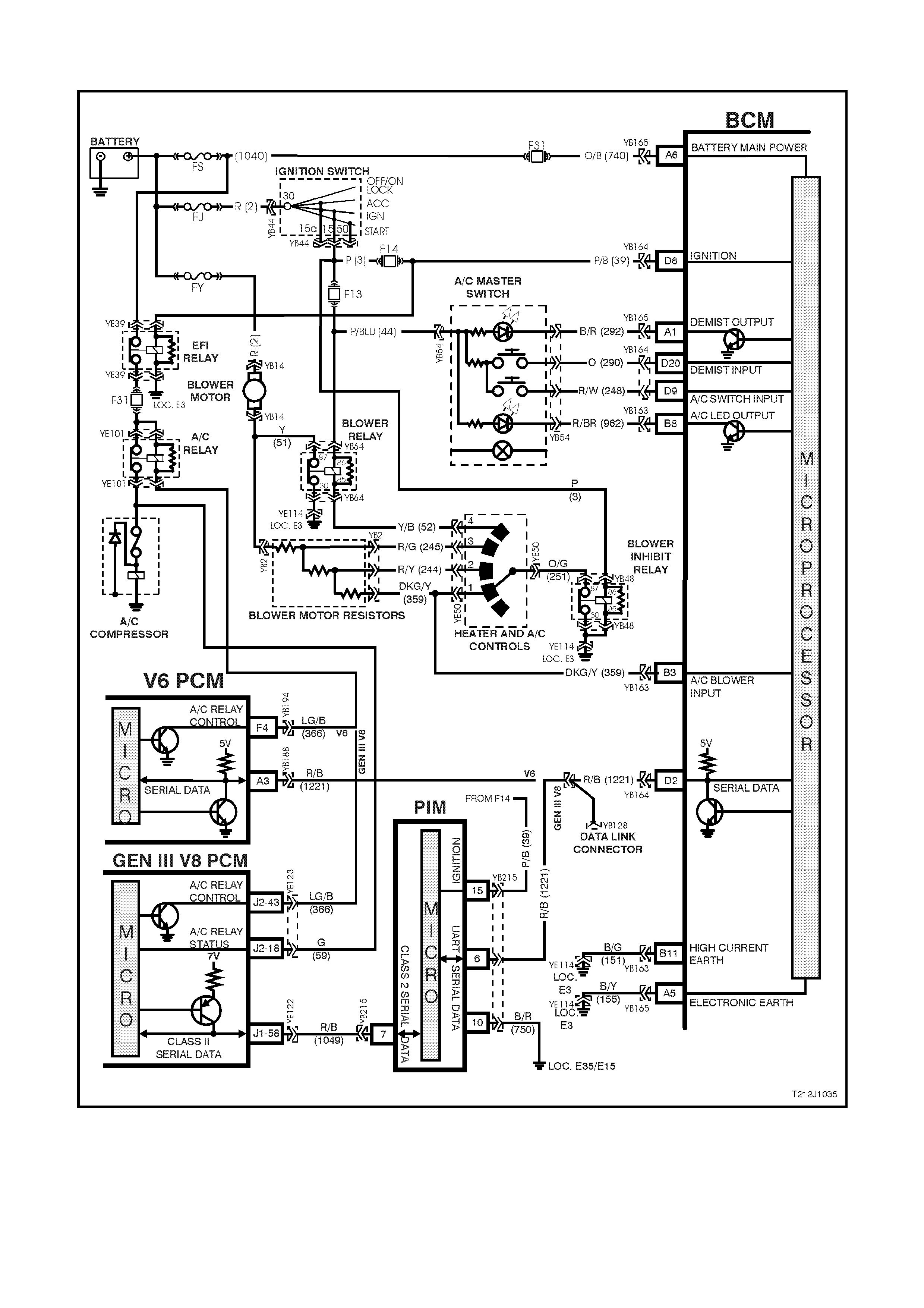
4.7 AIR CONDITIONING INTERFACE
Figure 12J-1-59
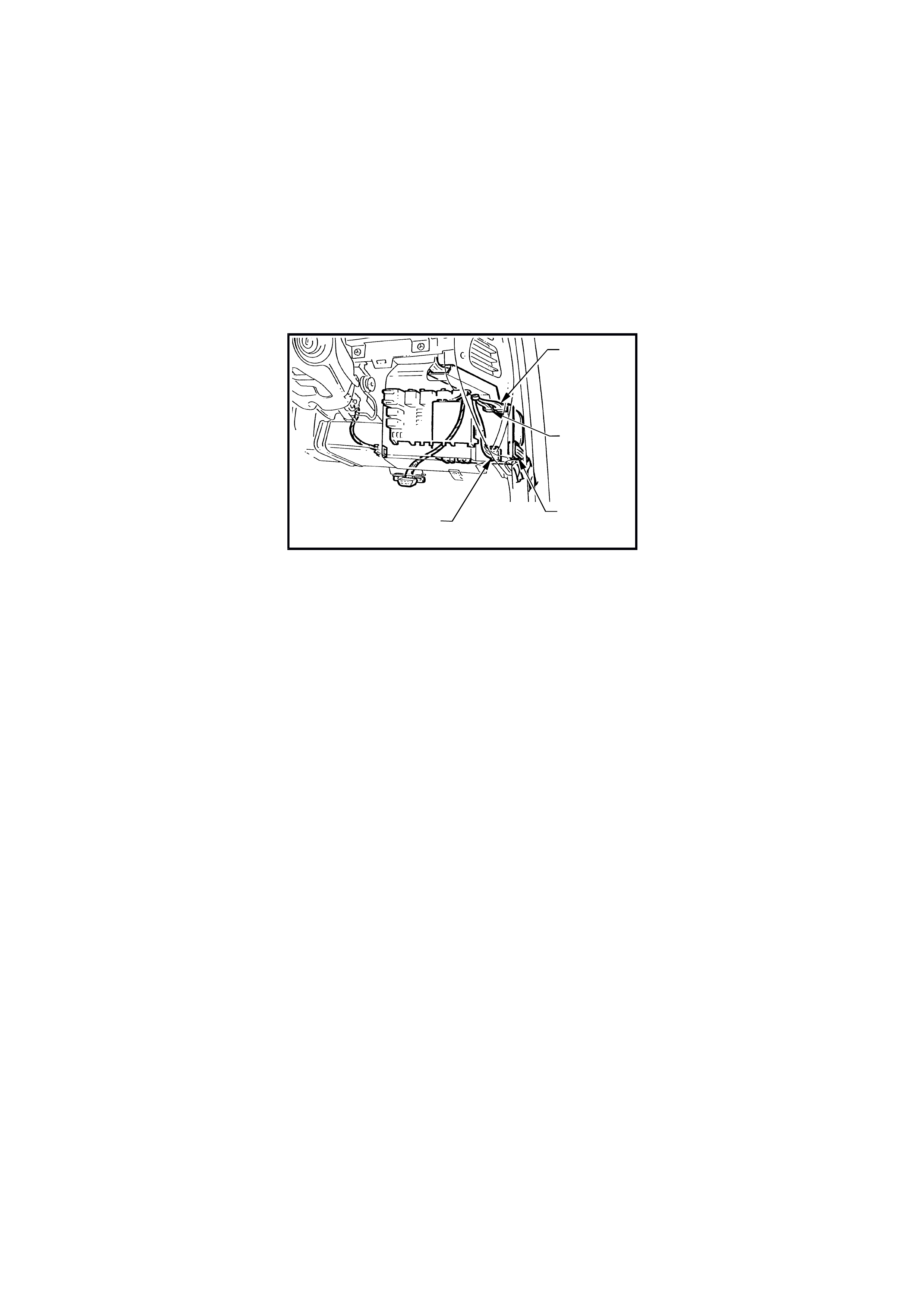
CIRCUIT DESCRIPTION
The air- conditioning interf ace is used to turn the air conditioning system on and off . T he BCM reads the m om entar y
air conditioning switch signal, monitors fan speed and if the ignition is on the BCM requests the PCM (via PIM on
vehicles with GEN III V8 engines) to turn on the air conditioning compressor. The air conditioning status LED is
turned on by the BCM when the air conditioning s ystem is ac tive (if the ignition is turned on) and will toggle with the
air conditioning select switch. The status will be remembered when the ignition is s witched f r om ON to OF F or when
the blower is off, but will reset to off when the battery is disconnected. If the blower is off and the air conditioning
select button is pressed, then the next tim e the blower is s witched on, the air conditioning status will also com e on.
Turning the ignition off will cancel this button press function.
The blower fan is controlled by the blower fan inhibit relay, which is energised with the ignition switch in the IGN
position.
NOTE: The BCM has provision for an air conditioning thermostat to prevent the evaporator from icing up. In the
absence of this thermostat, the input is connected to ignition.
YB165
CONNECTOR (4)
YB163
CONNECTOR (2)
YB162
CONNECTOR (1)
YB164
CONNECTOR (1)
T12J1077A
Figure 12J-1-60
Test Description
The numbers below refer to step numbers in the following diagnostic chart.
1-5. Functional check of air conditioning system.
6. Checks blower inhibit relay output switch.
7. Checks circuit 251.
8. Checks heater and air conditioning control switch.
9. Checks battery positive feed to blower motor.
10. By-passes the resistor assembly (blower motor) to determine problem with blower motor assembly.
11. Checks battery positive at blower inhibit relay.
12. Checks circuit 150.
13. Checks circuit 150 including blower inhibit relay.
14. Checks blower motor circuit 51.
15. Uses TECH 2 to conduct air conditioning compressor/air conditioning status LED test.
16. Uses TECH 2 to check air conditioning select ON/OFF signal at microprocessor of BCM.
17. Uses TECH 2 to check BLOWER FAN ON signal at microprocessor of BCM.
18. Test to determine if air conditioning status LED is not illuminated due to BCM or other circuits.
19. Checks for battery positive supply to air conditioning master switch assembly.
20. Checks circuit 962 and air conditioning master switch assembly.
21. Checks AIR CONDITIONING SELECT signal at input to BCM.
22. Checks circuit 248 and air conditioning master switch assembly.
23. Checks BLOWER FAN ON signal at input to BCM.
24. Checks if TECH 2 is able to communicate to BCM via the serial data bus.
25. Uses TECH 2 to command the PCM to switch the air conditioning compressor on.
26. Checks blower relay drive signal.
27. Checks battery positive feed to blower relay.
28. Checks blower relay switch output.
29. Checks circuit 52 and heater and air conditioning control switch
30. Checks circuit 150 and blower relay.

Figure 12J-1-61
AIR CONDITIONING INTERFACE
STEP ACTION VALUE YES NO
1. • Turn ignition ON.
• Heater and air conditioning control switch speed 1.
• Does blower motor operate?
Go to Step 2. Go to Step 6.
2. • Turn ignition ON.
• Heater and air conditioning control switch speed 1.
• Toggle air conditioning select switch.
• Does air conditioning status LED illuminate?
Go to Step 3. Go to Step 15.
3. • Turn ignition ON.
• Heater and air conditioning control switch speed 1.
• Toggle air conditioning select switch to ON.
• Does air conditioning compressor operate?
Go to Step 4. Go to Step 24.
4. • Turn ignition ON.
• Heater and air conditioning control switch speed 4.
• Does blower motor operate?
Go to Step 5. Go to Step 26.
5. • Turn ignition ON.
• Heater and air conditioning control switch speed 4.
• Toggle air conditioning select switch to ON.
• Does air conditioning compressor operate?
System OK. Check blower
motor resistor
assembly, refer
to 2 AIR
CONDITIONING
in the VT Series I
Service
Information.
6. • Turn ignition ON.
• Back probe blower inhibit relay connector YB48,
terminal 87, circuit 251 (Orange/Green wire) with a
Voltmeter to earth.
• Is voltage as specified?
100 mVolts Go to Step 7. Go to Step 11.
7. • Back probe heater and air conditioning control
switch connector YB50, circuit 251 (Orange/Green
wire) with a Voltmeter to earth.
• Is voltage as specified?
100 mVolts Go to Step 8. Repair open in
circuit 251.
Recheck circuit
to verify repair.
8. • Back probe heater and air conditioning control
switch connector YB50, circuit 359 (Dark
Green/Yellow wire) with an Voltmeter to earth.
• Is voltage as specified?
100 mVolts Go to Step 9. Replace heater
and air
conditioning
control switch,
refer to 2 AIR
CONDITIONING
in the VT Series I
Service
Information.
9. • Back probe blower motor connector YB14, circuit 2
(Red wire) with a Voltmeter to earth.
• Is voltage as specified?
12 volts Go to Step 10. Check and repair
fault in circuit 2
(including fusible
link FY).
Recheck and
verify repair

STEP ACTION VALUE YES NO
10. • Disconnect blower motor resister connector YB2.
• Back probe blower resistor connector YB2 (harness
end) circuit 51 (Yellow wire) with a jumper lead and
connect to earth.
• Does the blower motor operate?
Check blower
motor resistor. Go to Step 14.
11. • Turn ignition ON.
• Back probe blower inhibit relay connector YB48,
terminal 86, circuit 3 (Pink wire) with a Voltmeter to
earth.
• Is voltage as specified?
12 volts Go to Step 12. Check and repair
fault in circuit 3.
Recheck and
verify repair
12. • Back probe blower inhibit relay connector YB48,
terminal 85, circuit 150 (Black wire) with a jumper
lead connected to earth.
• Turn ignition ON.
• Does the blower motor operate?
Check and repair
fault in circuit
150. Recheck
and verify repair.
Go to Step 13.
13. • Back probe blower inhibit relay connector YB48,
terminal 30, circuit 150 (Black wire) with an
Ohmmeter to earth.
• Is value as specified?
Below 1 ohm Replace blower
inhibit relay.
Recheck and
verify repair.
Check and repair
open in circuit
150 Recheck and
verify repair.
14. • Back probe blower motor connector YB14, circuit
51 (Yellow wire) with a jumper lead and connect to
earth.
• Does blower motor operate?
Check and repair
open in circuit
51. Recheck and
verify repair.
Replace blower
motor, refer to 2
AIR
CONDITIONING
in the VT Series I
Service
Information.
15. • Connect TECH 2 to DLC.
• Select Body / Body Control Module / Miscellaneous
Tests / Lamps / A/C Test.
• Conduct test as instructed by TECH 2 and switch
the A/C compressor status LED on.
• Does Air conditioning status LED illuminate?
Go to Step 16. Go to Step 18.
16. • With TECH 2 connected, exit Miscellaneous Test
and select Data Display.
• Scroll to A/C Switch.
• Does screen display AC Switch On / Off when
toggling air conditioning select switch?
Go to Step 17. Go to Step 21.
17. • With TECH 2 connected and Data Display
selected, scroll to A/C Blower Switch.
• Switch heater and air conditioning control switch to
speed 1.
• Does screen display A/C Blower Switch On?
Replace BCM,
refer to 12J-1
LOW SERIES
BCM in the VT
Series I Service
Information.
Recheck and
verify repair.
Go to Step 23.
18. • Turn ignition ON.
• Back probe BCM connector YB163, terminal B8,
circuit 962 (Red/Brown wire) with a jumper lead
and connect to earth.
• Does air conditioning status LED illuminate?
Replace BCM,
refer to 12J-1
LOW SERIES
BCM in the VT
Series I Service
Information.
Recheck and
verify repair
Go to Step 19.
19. • Back probe air conditioning master switch
connector YB54, circuit 44 (Pink/Blue wire) with a
Voltmeter to earth.
• Turn ignition ON.
• Is voltage as specified?
12 volts Go to Step 20. Check and repair
fault in circuit 44
(including fuse
F13). Recheck
and verify repair.
20. • Turn ignition ON.
• Back probe air conditioning master switch
connector YB54, circuit 962 (Red/Brown wire) with
a jumper lead and connector to earth.
• Does air conditioning status LED illuminate?
Check and repair
open in circuit
962. Recheck
and verify repair.
Replace heater
and air
conditioning
control switch,
refer to 2 AIR
CONDITIONING
in the VT Series I
Service
Information.

STEP ACTION VALUE YES NO
21. • Turn ignition ON.
• Back probe BCM connector YB164, terminal D9,
circuit 248 (Red wire) with a Voltmeter to earth.
• Is voltage as specified when air conditioning switch
is activated?
Switch closed
(held in)
12 volts
Switch open
(rest position)
0 volts
Replace BCM,
refer to 12J-1
LOW SERIES
BCM in the VT
Series I Service
Information.
Recheck and
verify repair.
Go to Step 22.
22. • Turn ignition ON.
• Back probe air conditioning master switch
connector YB54, circuit 248 (Red/Wh ite wire) with
a Voltmeter to earth.
• Is voltage as specified when air conditioning switch
is activated?
Switch closed
(held in)
12 volts
Switch open
(rest position)
0 volts
Check and repair
open in circuit
248. Recheck
and verify repair.
Replace heater
and air
conditioning
control switch,
refer to 2 AIR
CONDITIONING
in the VT Series I
Service
Information.
23. • Turn ignition ON.
• Back probe BCM connector YB163, terminal B3,
circuit 359 (Dark Green/Yellow wire) with a
Voltmeter to earth.
• Is voltage as specified?
100 mVolts Replace BCM,
refer to 12J-1
LOW SERIES
BCM in the VT
Series I Service
Information.
Recheck and
verify repair.
Check and repair
open in circuit
359. Recheck
and verify repair.
24. • Connect TECH 2 to DLC.
• Select Body / Body Control Module.
• Does TECH 2 display system identification
information (BCM type)?
Go to Step 25 Go to serial data
communications
diagnosis, refer
to 4.2 SERIAL
DATA COM. in
this Section.
25. • With TECH 2 connected, exit Body and select
Engine / appropriate engine / Data Display /
Miscellaneous Tests and command AC
Compressor On.
• Does air conditioning compressor operate?
Replace BCM,
refer to 12J-1
LOW SERIES
BCM in the VT
Series I Service
Information.
Recheck and
verify repair.
Go to PCM
diagnosis, in
Sections 6C1
POWERTRAIN
MANAGEMENT -
V6 ENGINE in
the VT Series I
Service
Information OR
6C3
POWERTRAIN
MANAGEMENT -
GEN III V8 ENG
in the VT Series I
Service
Information.
26. • Turn ignition ON.
• Switch heater and air conditioning control switch to
speed 4.
• Back probe blower relay connector YB64, terminal
85, circuit 52 (Yellow/Black wire) with a Voltmeter
to earth.
• Is voltage as specified?
100 mVolts Go to Step 27. Go to Step 29.
27. • Turn ignition ON.
• Back probe blower relay connector YB64, terminal
86, circuit 44 (Pink/Blue wire) with a Voltmeter to
earth.
• Is value as specified?
12 volts Go to Step 28. Check and repair
open in circuit
44. Recheck and
verify repair.
28. • Turn ignition ON.
• Switch heater and air conditioning control switch to
speed 4.
• Back probe blower relay connector YB64, terminal
87, circuit 51 (Yellow wire) with a Voltmeter to earth
• Is voltage as specified?
100 mVolts Check and repair
open in circuit
51. Recheck and
verify repair
Go to Step 30.

STEP ACTION VALUE YES NO
29. • Turn ignition ON.
• Switch heater and air conditioning control switch to
speed 4.
• Back probe heater and air conditioning control
switch connector YB50, circuit 52 (Yellow/Black
wire) with a Voltmeter to earth.
• Is voltage as specified?
100 mVolts Check and repair
open in circuit
52. Recheck and
verify repair.
Replace heater
and air
conditioning
control switch,
refer to 2 AIR
CONDITIONING
in the VT Series I
Service
Information.
30. • Back probe blower relay connector YB64, terminal
30, circuit 150 (Black wire) with a Voltmeter to
earth.
• Is voltage as specified?
100 mVolts Replace blower
relay. Recheck
and verify repair.
Check and repair
open in circuit
150. Recheck
and verify repair.

4.8 BOOT RELEASE
The boot release system diagnostic procedure remains unchanged from the procedure detailed in
Section 12J-1 LOW SERIES BODY CONTROL MODULE in the VT Series I Service Information, noting the
following:
The rear compartm ent lock switch (located in the glove com partment) is disabled when the vehicle speed is above
15 km/h, theft deterrent system is armed via the remote coded key, or driver’s door microswitch or deadlock.
The rear compartment lock switch is only enabled when the theft deterrent system is disarmed via the remote
coded key or remote key reader (valid security code).
W hen diagnosing the boot releas e system circuit fault on a VT Series II Model, refer ence to the wiring diagrams in
Section 12P WIRING DIAGRAMS in the VT Series II Service Information should be made.
Techline

4.9 HEATED REAR WINDOW
The diagnostic procedure for the heated rear window remains unchanged from the procedure detailed in
Section 12J-1 LOW SERIES BODY CONTROL MODULE in the VT Series I Service Information, noting the
following:
When diagnosing a heated rear window system circuit fault on a VT Series II Model, reference to the wiring
diagrams in Section 12P WIRING DIAGRAMS in the VT Series II Service Information should be made.

4.10 POWER WINDOW SYSTEM
The diagnostic procedure for power windows remains unchanged from the procedure detailed in
Section 12J-1 LOW SERIES BODY CONTROL MODULE in the VT Series I Service Information, noting the
following:
When the ignition is switched off and no door has been opened, power is supplied to the window system for a
maximum of 60 minutes, provided the BCM has not entered battery saver mode. If battery saver mode is active,
power will be removed from the window system.
Additionally, when the doors are remotely unlocked (by using the remote coded key), provided the vehicle is not in
battery saver m ode, power is supplied to the system f or a 60 m inutes ( If the vehic le is in battery saver m ode, power
is removed from the system). The delay is cancelled when the doors are locked by the remote coded key.
When diagnosing the power window system circ uit fault on a VT Series II Model, r ef er ence to the wiring diagrams in
Section 12P WIRING DIAGRAMS in the VT Series II Service Information should be made.

4.11 WIPER CONTROL SYSTEM
The wiper control system diagnostic procedure remains unchanged from the procedure detailed in
Section 12J-1 LOW SERIES BODY CONTROL MODULE in the VT Series I Service Information, noting the
following:
If referred to Powertrain Management (PCM) diagnostics and the vehicle is equipped with a GEN III V8 engine,
reference to Section 6C3 POWERTRAIN MANAGEMENT - GEN III V8 ENGINE in the VT Series II Service
Information should be made.
If the ignition switch is in the ACC pos ition and the vehicle enter s batter y saver m ode, the inter mittent wipers will not
function.
When diagnosing a circuit fault in the wiper control system on a VT Series II vehicle, reference to the wiring
diagrams in Section 12P WIRING DIAGRAMS in the VT Series II Service Information should be made.

4.12 RE MOTE RECEIVER/KEY
The remote receiver/key diagnostic procedure remains unchanged from the procedure detailed in
Section 12J-1 LOW SERIES BODY CONTROL MODULE in the VT Series I Service Information, noting the
following:
If referred to theft deterrent diagnosis and the vehicle is a VT Series II Model, reference to
4.4 THEFT DETERRENT in this Section should be made, not to the VT Series I Service Information.
When diagnosing a faulty remote receiver/key circuit on a VT Series II Model, reference to the wiring diagrams in
Section 12P WIRING DIAGRAMS in the VT Series II Service Information should be made.
Techline

4.13 AUTOMATIC LIGHTS OFF CONTROL
The diagnostic procedure for automatic lights off control remains unchanged from the procedure detailed in
Section 12J-1 LOW SERIES BODY CONTROL MODULE in the VT Series I Service Information, noting the
following:
When diagnosing a faulty automatic lights off control circuit on a VT Series II Model, reference to the wiring
diagrams in Section 12P WIRING DIAGRAMS in the VT Series II Service Informationshould be made.

4.14 CRUIS E CONTROL INTERFACE
The diagnostic procedure for cruise control interface remains unchanged from the procedure detailed in
Section 12J-1 LOW SERIES BODY CONTROL MODULE in the VT Series I Service Information, noting the
following:
When diagnosing a circuit fault in the cruise control interface on a VT Series II Model, reference to the wiring
diagrams in Section 12P WIRING DIAGRAMS in the VT Series II Service Information should be made.

4.15 SRS DEPLOYMENT VEHICLE SHUTDOWN
The SRS deployment vehicle shutdown diagnostic procedure remains unchanged from the procedure detailed in
Section 12J-1 LOW SERIES BODY CONTROL MODULE in the VT Series I Service Information, noting the
following:
If ref er red to s erial data c ommunications diagnos tics r ef er to 4.2 SERIAL DATA COMM UNICATION in this Section,
not to in the VT Series I Service Information.
When diagnosing a circuit fault with for SRS deploym ent vehic le s hutdown on a VT Ser ies II Model, r ef erenc e to the
wiring diagrams in Section 12P WIRING DIAGRAMS in the VT Series II Service Information should be made.