
SECTION 12L - ANTI-LOCK BRAKING &
ELECTRONIC TRACTION CONTROL - GEN III V8
ENGINE
CAUTION:
This vehicle will be equipped with a Supplemental Restraint System (SRS). A SRS will consist of either
seat belt pre-tensioners and a driver's air bag, seat belt pre-tensioners and a driver's and front
passenger's air bag s or seat belt pre- tensio ners, d riv er’s and fron t p asseng er’s air bag and lef t and rig ht
hand side air bags. Refer to SAFETY PRECAUTIONS, Section 12M Supplemental Restraint System of the
VT Series I Service Information before performing any service operation on, or around any SRS
components, the steering mechanism or wiring. Failure to follow the SAFETY PRECAUTIONS could
result in SRS deployment, resulting in possible personal injury or unnecessary SRS system repairs.
CAUTION:
This vehicle may be equipped with LPG (Liquefied Petroleum Gas). In the interests of safety, the LPG
fuel system should be isolated by turning 'OFF' the manual service valve and then draining the LPG
service lines, before any service work is carried out on the vehicle. Refer to the LPG leaflet included with
the Owner's Handbook for details or the appropriate Section of this Service Information CD for more
specific servicing information.
CAUTION:
Whenever any component that forms part of the ABS or ABS/ETC (if fitted), is disturbed during Service
Operations, it is vital that the complete ABS or ABS/ETC system is checked, using the procedure as
detailed in 4 DIAGNOSIS, ABS or ABS/ETC FUNCTION CHECK, in Section 12L ABS & ABS/ETC, in either
of the VT Series I Service Information 7 (V6) or the VT Series II Service Information (GEN III V8) of this
Service Information CD.
1. GENERAL INFORMATION
NOTE: ABS is an Anti-locking Braking System only while the ABS/ETC system is an Anti-locking Braking System
(ABS) and an Electronic Traction Control system (ETC). Depending on the Model variant, both of these systems are
available as either an option or standard equipment to VT Series Models.
ABS for VT Series II Models (including vehicles f itted with GEN III V8 engines) carries over from earlier VT Series
Models, with all information detailed in Section 12L ABS & ABS/ETC of the VT Series I Service Information.
ABS/ETC for VT Series II Models carries over from earlier VT Series Models for vehicles fitted with V6 and V6
Supercharged engines only, with all information detailed in Section 12L ABS & ABS/ETC of the VT Series I
Service Information.
On VT Series II Models with GEN III V8 engines, the ABS element of the ABS/ETC system is functionally and
systematically the same as what has been published for VT Series Models with V6 engines of the VT Series I
Service Information.
Additionally with the ETC elem ent of the ABS/ET C system, VT Series II Models with GEN III V8 engines use brak e
intervention, however, this is where the similarity ends. As a result of this, this Section details only the ABS/ETC
system used on VT Series Models with GEN III V8 engines, and in certain situation, only what varies from
previously published inform ation. For General Inf ormation c overing the basic func tion and purpose of an Elec tronic
Traction Control system, refer to Section 12L ABS & ABS/ETC of the VT Series I Service Information.
The ABS/ETC system on VT Series II Models with GEN III V8 engine uses a throttle relaxer to control the throttle
position of the throttle body. The throttle relaxer is controlled by its own control module; throttle relaxer control
module, which receives inf ormation from the ABS/ETC control m odule. As with the V6 system, engine intervention
is also used and will retard the ignition timing to reduce the amount of torque.
The throttle relaxer is positioned part way along the accelerator cable in the engine c om partm ent. T he request f rom
the accelerator pedal (pedal depressed) is transmitted via the cable to the throttle relaxer. The request then
continues on to the throttle body under normal driving conditions.
In a situation where a rear wheel is about to lose traction, under heavy acceleration for the road condition, the
throttle relaxer will interrupt the request from the accelerator pedal and control the throttle position of the throttle
body. This will bring the wheels back to a controlled condition.

2. GENERAL DESCRIPTI ON
On all VT Series Models, the conventional portion (non-ABS) of the braking system comprises the conventional
heavy duty braking system, specific brake pipe harness and lines and a common master cylinder with the
conventional non-ABS braking system, but has a screw-in blanking plug installed into the lower of the two front
brak e outlets. Each front wheel hub also includes the wheel speed sens or as part of the ass embly. The rear wheel
speed sensors are toothed pulse rings attached to each of the inner axle flanges.
At road speeds above approximately 3 km /h, the ABS is designed to c ontrol brak e f luid press ure so that the wheels
are prevented fr om lock ing-up dur ing brak ing, irrespec tive of the r oad conditions and tyre grip. The s ystem s tarts to
regulate when one wheel is detected to be decelerating faster than the other wheels, tending to lock. The vehicle
remains steerable, even in the event of panic braking, for instance on bends or when swerving to avoid an obstacle.
The ABS/ETC fitted to VT Series Models with GEN III V8 engines modulates braking pressure separately at each
front and rear wheel. The ABS/ETC is referred to as a four channel system as each of the four wheels have a
separate hydraulic brake circuits which are used to achieve anti-lock braking and traction control functions. The
term modulated refer s to the ABS ability to 'Maintain', 'Reduc e' or 'Incr ease' (Build-up) the hydraulic press ure in the
various brake circuits based on various inputs.
The TECH 2 diagnostic scan tool is programmed to assist with VT electrical diagnosis and problem solving,
including ABS and ABS/ETC.
TECH 2 connects to the ABS/ETC serial data communication information via the Data Link Connector (DLC),
attached to the instrum ent panel lower r ight hand trim , to the right of the s teering colum n. F or additional infor m ation
on DLC location and system diagnosis, refer to 4. ABS DIAGNOSIS in this Section. For additional and more
comprehensive information regarding TECH 2, refer to Section 0C TECH 2 of the VT Series I Service Information.
T212L001
8
7
6
5
4
3
2
1
11
12
13
14
17
16
15
9
10
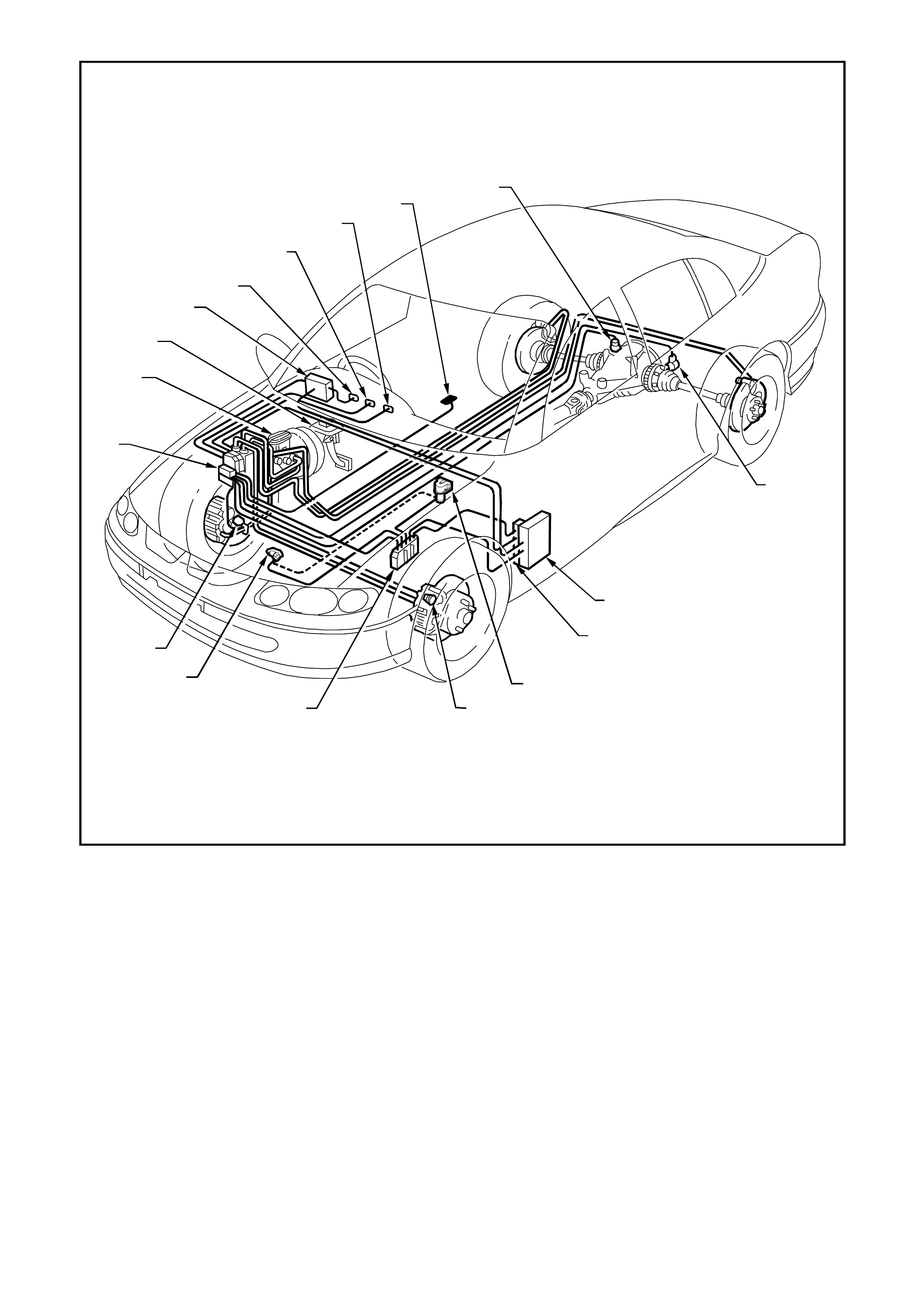
Figure 12L-1 Typical location of components for ABS/ETC on vehicles with GEN III V8 engines
1. Hydraulic modulator and control module assembly 10. Left rear wheel speed sensor
2. Master cylinder 11. Powertrain Interface Module (PIM)
3. Stop lamp switch 12. Throttle relaxer (actuator) control module
4. Body Control Module (BCM) 13. Throttle relaxer (actuator) assembly
5. TRAC OFF warning lamp 14. Left front wheel speed sensor
6. TRAC LOW warning lamp 15. Powertrain Control Module (PCM)
7. ABS OFF warning lamp 16. Throttle Position Sensor (TPS)
8. Traction control on/off switch 17. Right front wheel speed sensor
9. Right rear wheel speed sensor
2.1 ABS/ETC SYSTEM OVERVIEW
BASIC OPERA TING PRINCIPLE
The rotational speed of each wheel is measured by inductive wheel speed sensors. W hen the brak es are applied,
the change in rotational speed is used by the processor in the ABS/ETC control module to determine the
deceleration, acceleration and slip of the wheels.
On vehicles with ABS/ETC, the front and rear wheels are individually controlled (four channel system).
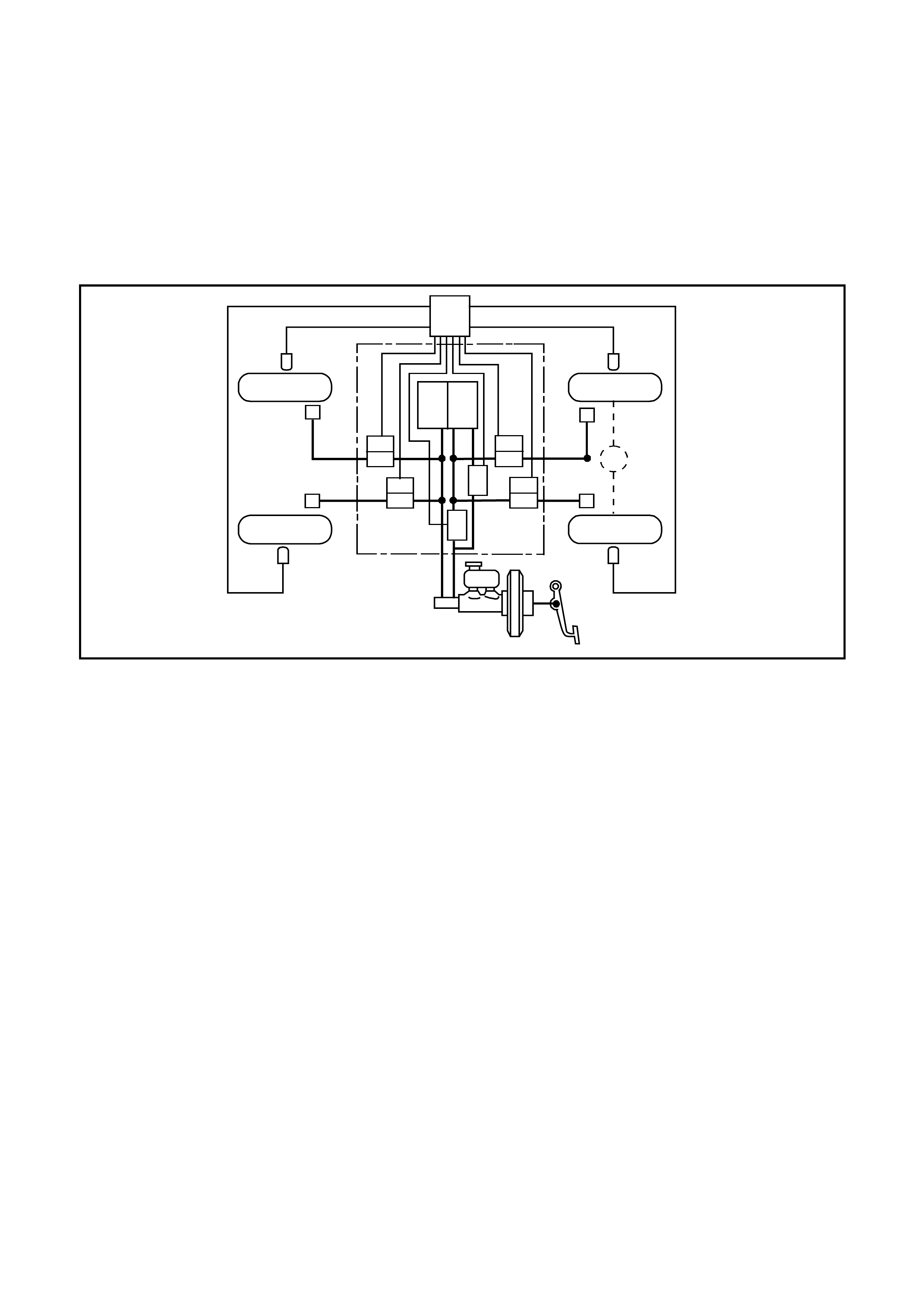
Fig 12L-2 provides an overview of a four channel ABS/ETC system. The braking force for each wheel (front and
back) is regulated using individual inlet and outlet solenoid valves within the hydraulic modulator. Four sensors
measure the individual speed of each wheel.
T212L007
5
2
2
3
7
6
4
3b 3b
3a
3a
11
2
2
1
1
3a
3a 3a
3a
3a
3a
Figure 12L-2 Four Channel ABS/ETC
1. Wheel speed sensors 3a.Solenoid valve 5. Electronic control module
2. Brake callipers 3b.Return pump 6. Switching valve
3. Hydraulic modulator 4. Brake master cylinder 7. Priming valve

2.2 NORMAL CONDITIONS DURING ABS AND ETC INTERVENTION
During anti-lock braking, a series of rapid pulsations are felt through the brake pedal. These pulsations occur as
solenoid valves within the under hood hydraulic modulator assembly change position to modulate brake hydraulic
pressure. Brake pedal pulsation continues until the vehicle is stopped or the ABS mode disengages.
The operation of the pump, also within the hydraulic modulator assembly, is characterised by rapid brake pedal
pulsations that is accom panied by some electric m otor and pump noise. Pump operation m ay be perceived during
regular vehicle oper ation or during initial ABS/ETC contr ol module self -test. W hile these f unctions som etime caus e
driver concern, they are normal functions of ABS/ETC operation.
Traction control intervention operates in three stages; engine spark retard, throttle angle reduction, and rear brake
application.
The first is less noticeable; with only a power sag from the engine being felt as the ABS/ETC control module
requests the PCM to retard the engine spark as appropriate.
If the ABS/ETC control module continues to detect the rear wheels are rotating faster than the front, it will request
the throttle relaxer control module to reduce the throttle angle.
The final step taken to control the rear wheel is for the ABS/ETC control module to apply the rear brakes, thus
reducing the torque to the rear wheels.
W hen the vehicle reaches approxim ately 6 km /h and provided the ABS/ET C control module does not sense a stop
lamp switch input, after initial engine start-up and driving away, the ABS/ETC control module tests the solenoid
valves and pump. This self test can be heard by the driver and is a normal oper ating f unc tion of the ABS/ETC. If the
ABS/ETC control module does sense a stop lamp switch input, the self test will not occur until the vehicle is
travelling at approximately 18 km/h.
Normal function of the ABS, TRAC OFF and LOW TRAC warning lamps in the instrument cluster are as follows:
ABS lamp: should illuminate when the ignition is switched on and will go out approximately two seconds later.
Should the lamp not go out, the ABS/ETC control module has detected a system fault.
TRAC O FF lamp: s hould illuminate when the ignition is switched on and will go out appr ox imately five s ec onds later
(or two seconds later with engine running). If the lamp does not go out, either the ABS/ETC control module has
detected a system fault, or the system has been manually switched off.
LOW TRAC lamp: should illuminate when the ignition is switched on and will go out approximately two seconds
later. This lamp will flash whenever the ETC system is engaged.

2.3 ABS/ETC SYSTEM COMPONENTS
WHEEL SPEED SENSORS AND PULSE RINGS
Inductive wheel speed sensors are used to detect
the rotational speed of each wheel. There are
specific wheel sensor assemblies for front and rear
wheels.
Introduced as a running change (approximately
April, 1999), the design of the front wheel
hub/bearing/sensor changed. As a consequence of
this change, the wheel speed sensor wiring
harness connector (2) changed to a ‘push-on’ type
with a locking tang, in lieu of the screw retained
connector used previously.
Front Wheel Speed Sensors
The front wheel speed sensors (1) are incorporated
as part of the front suspension front wheel hub
assembly.Figure 12L-3
There are three specific front wheel hub
assemblies available. For vehicles with ABS or
ABS/ETC, there is a right and left, which
incorporates the wheel speed sensor and a 48
tooth magnet impulse ring. For non ABS vehicles, a
common hub is used for both sides.
Identification of the front wheel hub assemblies is
by the assembly part number etched on the outer
surface (1) of the hub wheel flange or by simply
noting whether a wheel speed sensor cap is fitted
to the hub (2).
CAUTION: During any service operation that
requires the replacement of the front hub
assembly on a vehicle equipped with ABS/ETC,
ensure that the correct replacement hub
assembly is installed, otherwise malfunctioning
of the ABS or ABS/ETC will occur.
NOTE 1: Always refer to the latest Holden spare
parts information (PartFinderTM) for the correct front
wheel hub assembly part numbers.
NOTE 2: Apart f rom wheel stud replacem ent, there
are no serviceable items in the front wheel hub
assembly. With the unit being a ‘sealed for life’
assembly, there are no requirements for wheel
speed sensor and/or bearing adjustments. Should
a non-standard condition develop, then the hub
assembly must be replaced as complete unit.
T212L004
2
1
Figure 12L-4
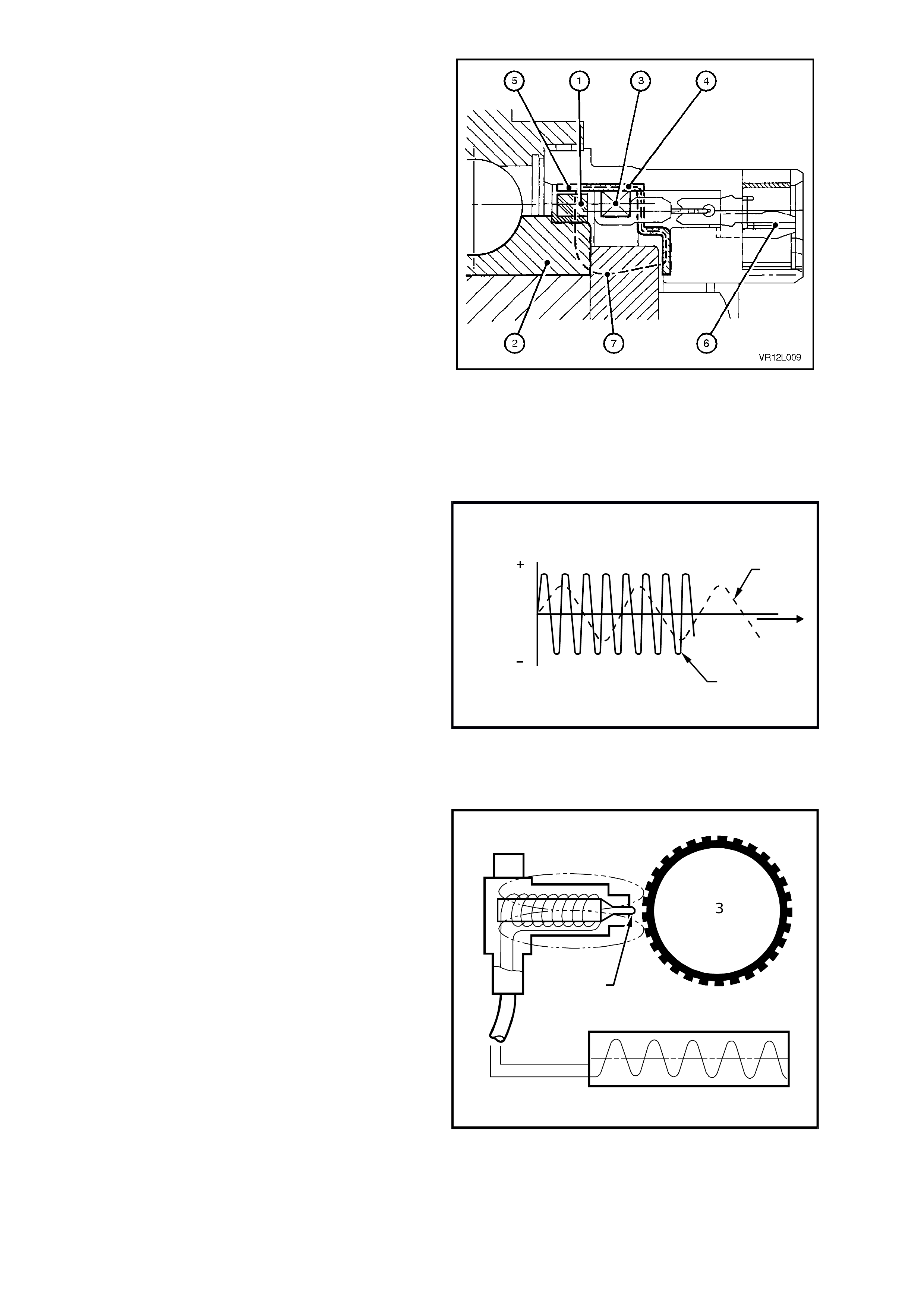
Fig. 12L-5 illustrates a sectioned view of the front
wheel sensor in the front hub assembly.
The components of the sensor are:
• magnetic impulse ring (1)
• coil (3)
• flux concentrator (4)
• coaxial connector (6)
The magnetic impuls e ring ( 1), attached to the fr ont
hub rotating member (2), is magnetised and
contains 48 individual magnets evenly spaced
around the ring.
On the flux concentrator (4) there are a
corresponding 48 evenly spaced teeth (5).
Magnetic flux (7), generated from the impulse ring
(1), is induced into the coil (3) via the flux
concentrator (4).
As the road wheel is rotated, the front hub inner
member and magnetic impulse ring rotate as one,
causing a variation of the magnetic flux generated
in the flux concentrator. This change in the
magnetic flux causes an alternating voltage to be
induced in the coil of the sensor.
Figure 12L-5
The frequency and amplitude of the induced
voltage are dependent on wheel RPM, the number
of turns of the coil, the magnetisation level of the
impulse ring and the number teeth of the flux
concentrator. Of all these factors, the only variable
is the wheel RPM, so the frequency and amplitude
of the output signal depend on the speed of wheel
rotation.
The dotted line (1) in Fig 12L-6 represents the
voltage generated by the wheel speed sensor
versus time (T) at low wheel speed.
The continues line (2) in Fig 12L-6 represents the
voltage generated by the wheel speed sensor
versus time (T) at high wheel speed.
1
2
T
V
V
T212L005
Figure 12L-6
Rear Wheel Speed Sensors
The rear wheel speed sensor (1) basically consists
of a magnetic core and a coil. The pole tip (2) is
surrounded by a m agnetic f ield. As the wheel turns,
the teeth of the pulse ring (3) cause c hanges in this
magnetic field. The magnetic flux thereby changes
and an alternating voltage is induced in the coil of
the wheel speed sensor.
The pole piece on the outer surface of the sensor is
of a plastic construction and therefore there is no
requirement to coat the outer surface with high
temperature grease when reinstalling sensor
assemblies (as on previous models).
The rear wheel speed sensors have a high voltage
output and therefore, there is no need to install
shim s between the sens or and its mating m ounting
bracket.
1. Wheel speed sensor
2. Pole tip
3. Pulse ring
4. Sensor output
T212L006
1
3
2
4
Figure 12L-7
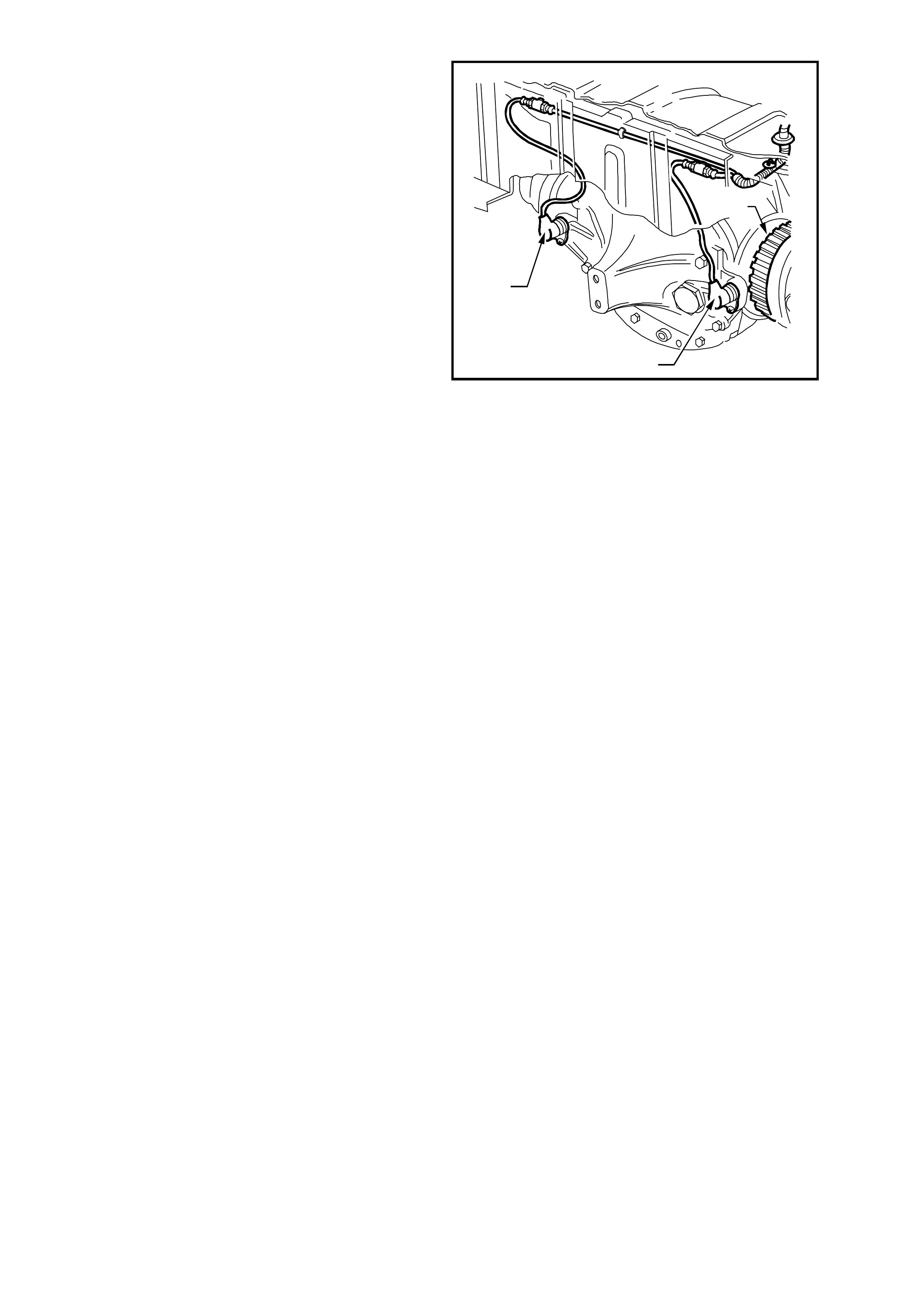
The rear wheel speed sensors (1) are located in a
bracket which is part of the final drive rear cover.
Each pulse ring (2) is a toothed ring made of a
ferrous metal that rotates to allow the wheel speed
sensor to read the rotational speed of each rear
wheel.
The rear wheel pulse rings are part of the final drive
inner axle flanges and are not serviced separately.
As the road wheels rotate, the wheel speed
sensors generate an AC electrical signal
proportional (in frequency and amplitude) to the
wheel speed. The ABS or ABS/ETC c ontrol m odule
uses wheel speed signals to determine when anti-
lock control or traction control is required.
Specifically, the module uses wheel speed sensor
signals to find out whether any of the wheels are
decelerating rapidly (lock ing) or ac celerating rapidly
(slipping).
The ABS/ET C s ystem is calibr ated to us e tyres of a
known rolling radius and pulse rings with a specif ic
number of teeth. The num ber of teeth on the pulse
rings correspond directly to tyre size. If one of the
tyres f itted to the vehicle is larger or s maller (not to
original equipment size) than the remainder of the
tyres on the vehicle, the ABS/ETC control module
will not modulate brake system hydraulic pressure
properly. Improper system operation occurs
because the wheel speed signal from the off-size
tyre makes the module think that one wheel is
accelerating or decelerating faster than the others.
T212L008
2
1
1
Figure 12L-8
NOTE: IT IS IMPORTANT THAT THE VEHICLE
ONLY BE EQUIPPED WITH THE ORIGINAL
EQUIPMENT TYRE SIZE AS NOMINATED ON
THE VEHICLES TYRE PLACARD. CHANGING
TYRE SIZE COULD AFFECT SYSTEM
FUNCTION.
ABS/ETC CONTROL MODULE
The ABS/ETC control module (1) evaluates the
signals from the wheel speed sensors and
computes the permissible wheel slip for optimum
braking and traction.
During ABS, it regulates the necessary braking
pressure in the brake callipers by means of
solenoid valves within the hydraulic modulator
assembly (2). The ABS/ETC control module tests
the system in accordance with a defined program
and monitors it during driving.
The ABS/ETC control module also monitors both
front and rear wheel speeds through the wheel
speed sensors for wheel slip. If at any time during
acceleration the ABS/ETC control module detects
drive wheel slip, it will act to bring excess engine
torque into a specific range by:
• Requesting the PCM to retard the amount of
spark advance, via the spark retard circuit,
circuit 1687 (Grey/Black wire).
• Throttle angle reduction: sending a message
to the throttle relaxer control module, via the
requested throttle position line (DKR), circuit
1426 (Orange/White wire), to reduce the
throttle angle. The throttle relaxer control
module achieves this by driving the throttle
relaxer motor, which in turn pulls back the
throttle cable, reducing the throttle body
opening.
The throttle relaxer control module sends a
signal back to the ABS/ETC control module
via the actual throttle position line ( DKI), circ uit
1427 (Black/White), reporting on the actual
throttle position.
• Brake application: the ABS/ETC control
module will activate the ABS isolator valves,
turn on the ABS pum p m otor and supply brake
pressure to the spinning wheel/s.
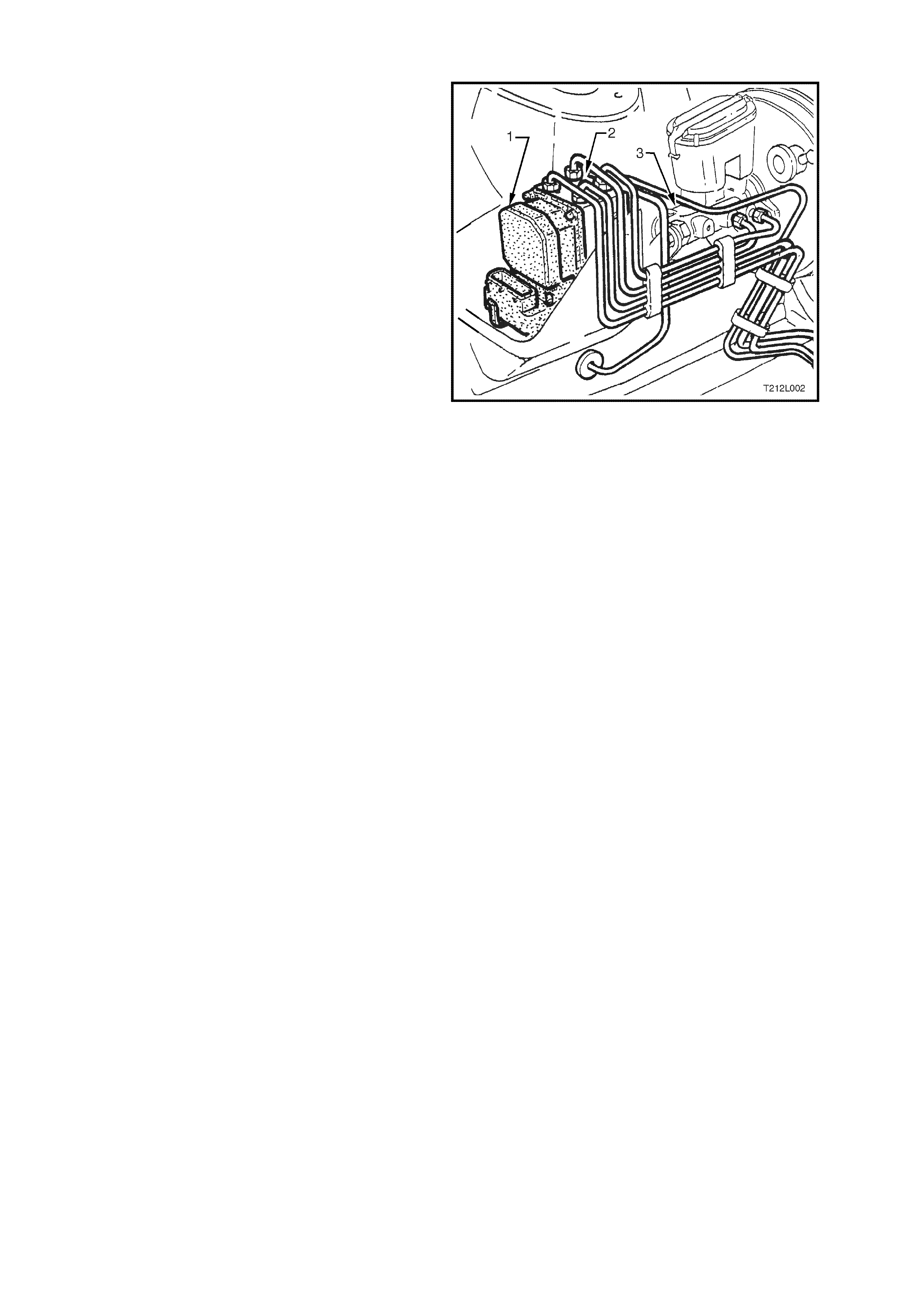
The ABS/ETC contr ol module is integrated with the
hydraulic modulator and is located in the engine
compartment, forward of the master cy linder (3).
There are different control modules used in VT
Series Model vehicles for ABS and ABS/ETC
systems. It is physically impossible to fit an ABS
control m odule to an ABS/ETC hydraulic m odulator
or an ABS/ETC control module to a ABS hydraulic
modulator. However, if replacing either an ABS or
ABS/ETC control m odule, always refer to the latest
VT Series Model Parts Information for the correct
ABS and ABS/ETC control module part numbers.
Figure 12L-9

HYDRAULIC MODULATOR
The hydraulic modulator (2) for the ABS/ETC
system consists of ten solenoid valves (four inlet,
four outlet and two ETC solenoid valves), two
accumulators, one for the front brake circuits and
the other for the rear brak e circuit and a brak e f luid
return pump.
The solenoid valves are actuated by the ABS/ETC
control module (1). Depending on the switching
stage, they connect the wheel brake calliper s either
with the brake m aster cylinder (3) or with the pump
assembly, or disconnect the wheel brake calliper
from both the circuit and pump. When pressure is
reduced, the return pump conveys the brake fluid
flowing out of the wheel brake cylinders back into
the brake master cylinder via the corresponding
accumulator. The accumulators serve to
temporarily accommodate the brake fluid 'surplus'
which suddenly occurs following a drop in pressure.
The hydraulic modulator is mounted in the engine
compartment, forward of the brake master cylinder. Figure 12L-10
THROTTLE RELAXER
Mounted to the cockpit module, in the engine
compartment, the throttle relaxer consists of: three
pulleys (2), a dust cover (1) and a motor (3).
The accelerator pedal cable is connected to the
centre (B) of the three pulleys. The throttle cable
(throttle relaxer to throttle body cable) attaches to
the bottom (A) of the three pulleys. If the vehicle is
fitted with cruise control, the cruise control cable
attaches to the top pulley (C).
Via a raised lug on pulley B, through an elongated
slot in pulley C, pulleys B and C are connected to
each other. This allows for the operation of the
cruise control, and interruption free movement of
pulley B (accelerator pedal position) when the
cruise control is not in operation.
Pulleys A and B are connected to each other via an
internal spring. Under normal operating conditions,
the load applied to pulleys B and C (accelerator
pedal and cruise control actuator load) is
transferred through the internal spring to pulley A
and onto the throttle body.
During ETC intervention, the throttle relaxer motor
controls pulley A regardless of the accelerator
pedal position. The internal spring between pulley A
and B is compres s ed and theref or e, the ac celer ator
pedal is overridden. A slight sensation on the
accelerator pedal can be felt during this stage.
If the cruise control is engaged and the ETC
intervenes, the cruise control will automatically be
disengaged.
T212L009
2
ABC1
3
Figure 12L-11
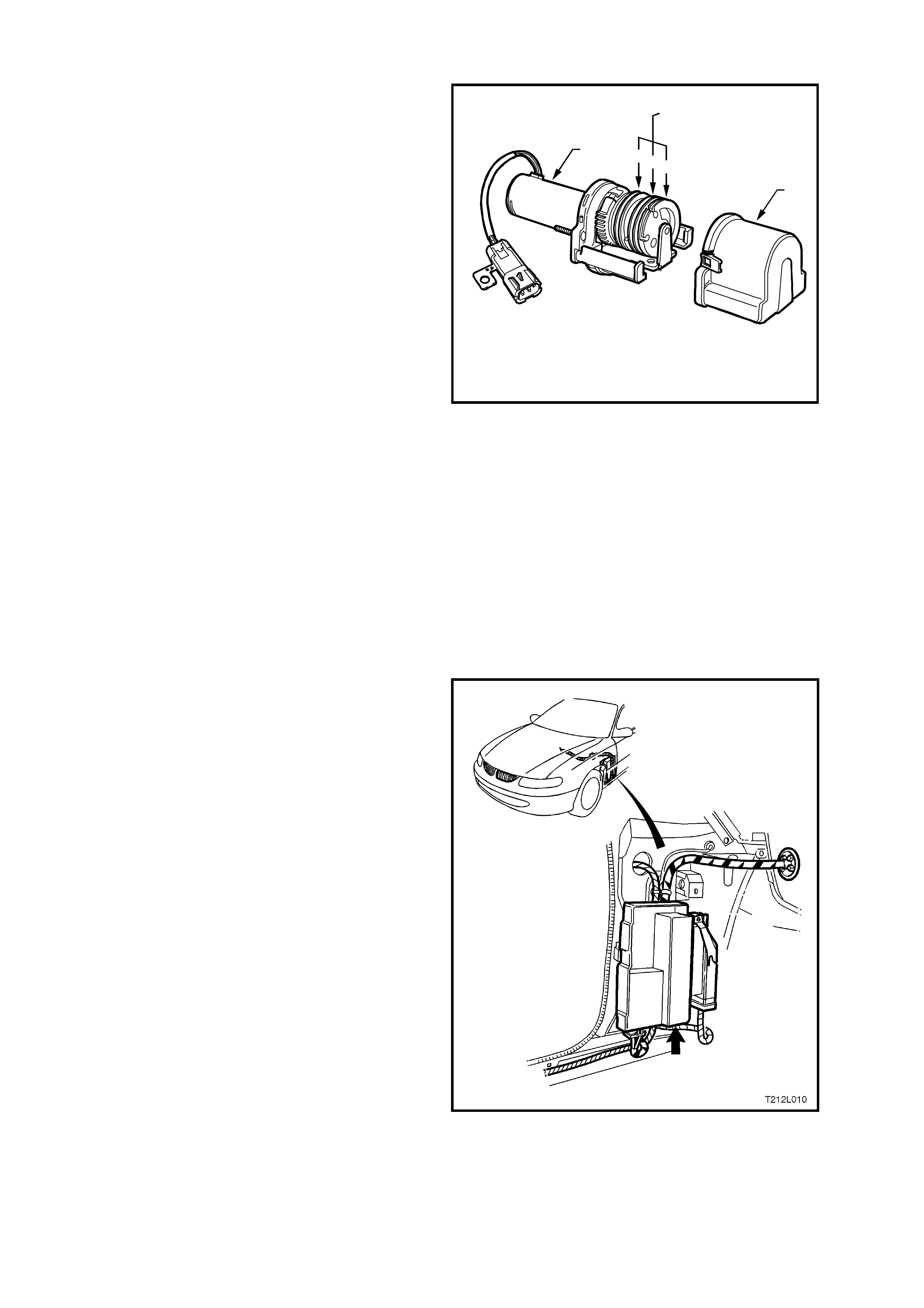
THROTTLE RELAXER CONTROL MODULE
The throttle relaxer control module is located
behind the passenger side shroud lower trim
assembly, next to the Powertrain Interface Module
(PIM).
The throttle relaxer control module operates using
information received from both the throttle position
sensor and the ABS/ETC control module.
The ABS/ETC control module communicates with
the throttle relaxer control module via Pulse Width
Modulated (PWM) signals sent and received on two
circuits; DKR circuit 1426 (Orange/W hite wire) and
DKI circuit 1427 (Blac k /White wire). DKR translates
to the requested throttle position, DKI translates to
actual throttle position.
Diagnostic Trouble Codes DTCs for the throttle
relaxer are incorporated into the ABS/ETC control
module.
Figure 12L-12
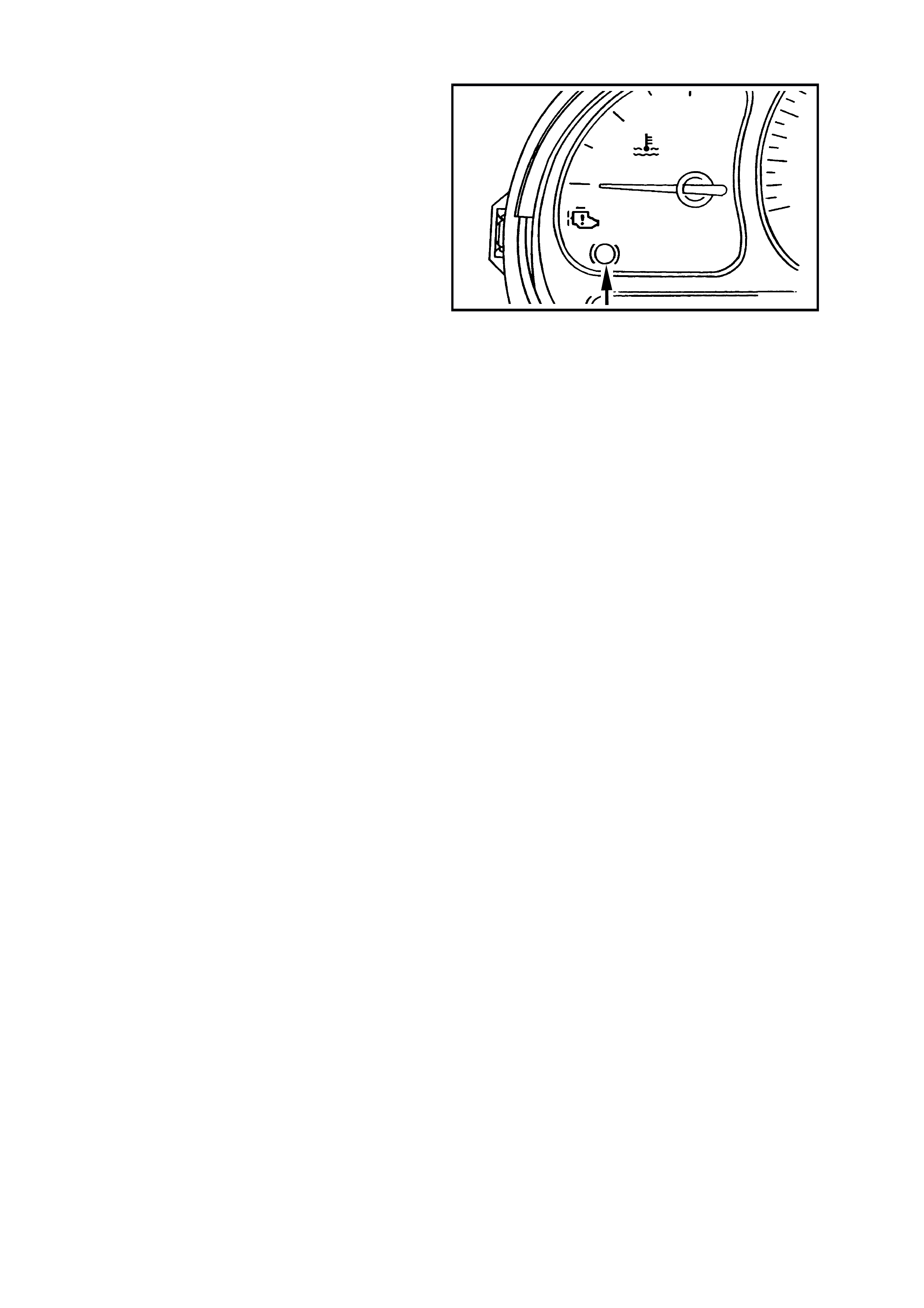
ABS WARNING LAMP
Located in the instrument cluster, the ABS warning
lamp is part of the driver warning system.
The ABS warning lamp is controlled by the
ABS/ETC control module. It is illuminated to warn
the driver that autom atic anti- lock brak ing capability
is totally inhibited. This does not affect the
operation of the vehicle's conventional braking
system.
The ABS warning lamp will illuminate when:
1. The ignition is turned on. The lamp will go out
after a stationary 'Self Check' is completed
(two to five seconds).
2. The ABS or ABS/ETC control module detects
an ABS electrical wiring or component
problem.
3. The ABS or ABS/ETC control module detects
a problem within itself.
These conditions are part of the ABS self-check.
4. When using TECH 2 in certain diagnostic
modes for ABS/ETC diagnosis, the ABS/ETC
system is disabled by the ABS/ETC control
module while it is communicating with
TECH 2.
Should the ABS warning lamp lose power (from
fuse F13 ignition fuse) or the ABS control module
lose earth (terminals 19, 20 and 21), the ABS
warning lamp will not illuminate at any time.
H
C
TRAC
OFF LOW
TRAC
ABS
T212L011
Figure 12L-13
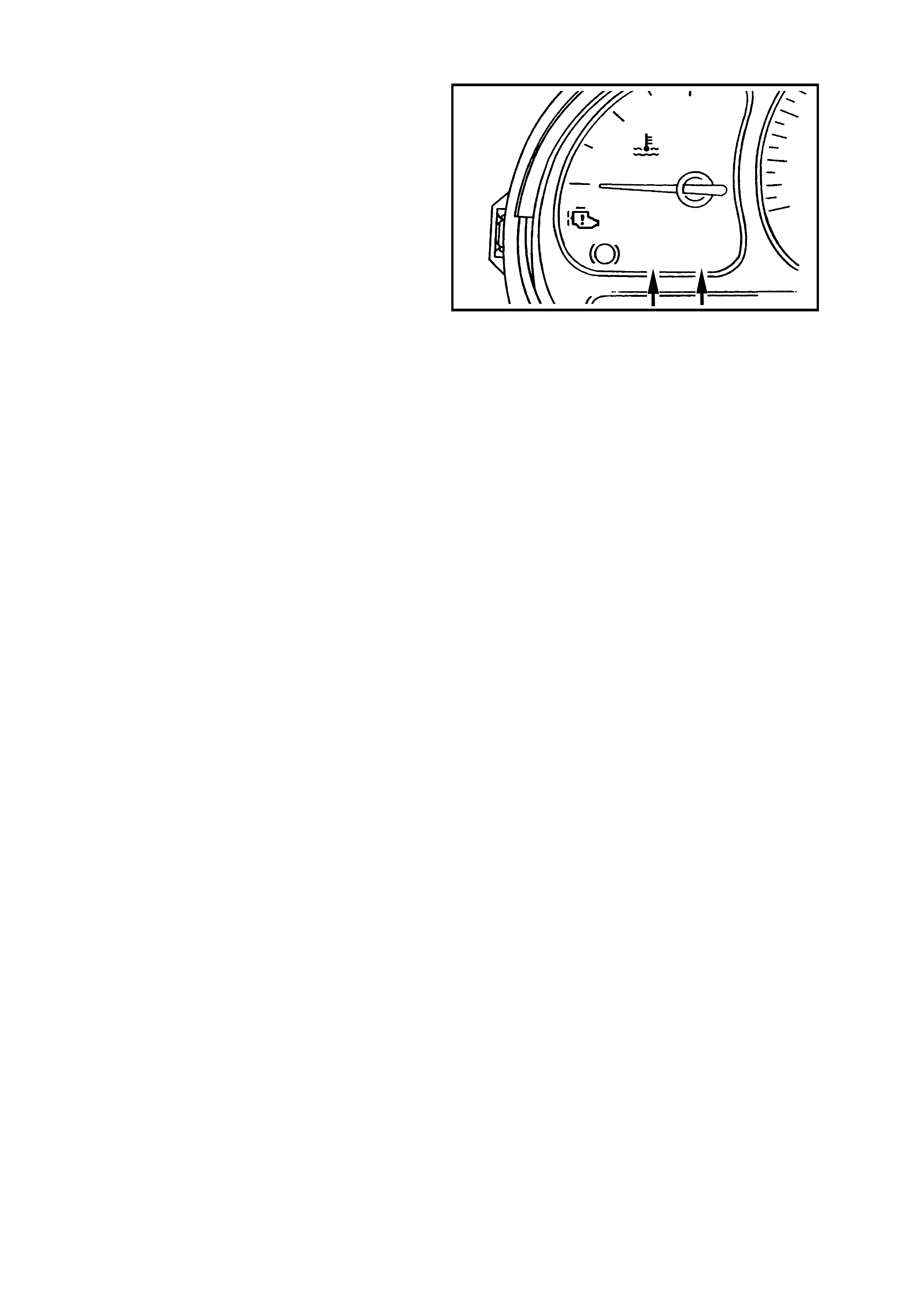
ELECTRONIC TRACTION CONTROL (ETC) WARNING LAMPS
There are two electronic traction control warning
lamps located in the instrument panel cluster;
TRAC OFF and LOW TRAC.
The TRAC OFF warning lamp is controlled by the
ABS/ETC control module, via the serial data bus
circuit, and will illuminate to warn the dr iver that the
ETC system has been disabled.
The TRAC OFF warning lamp will illuminate when:
1. The ignition is turned on. The lamp will go out
after a stationary 'Self Check' is completed
(two to five seconds).
2. When the ETC system is manually switched
off, via the TRAC CTRL button.
3. The ABS/ETC control module detects an ETC
electrical wiring or component problem.
4. The ABS/ETC control module detects a
problem within itself.
5. When using TECH 2 in certain diagnostic
modes for ABS/ETC diagnosis, the ABS/ETC
system is disabled by the ABS/ETC control
module while it is communicating with the
TECH 2.
Should the TRAC OFF or LOW TRAC warning
lamps lose power (from fuse F13 ignition fuse)
neither of these lamps will illuminate. Also, if the
ABS/ETC c ontrol module los es earth (ter minals 19,
20 and 21), the LOW TRAC warning lamp will not
illuminate.
The LOW T RAC warning lamp is also controlled by
the ABS/ETC control module and will illum inate for
two seconds when the ignition is switched on and
then go out, or when the ABS/ETC control module
is controlling wheel spin, indicating that the vehicle
is in a critical situation.
H
C
TRAC
OFF LOW
TRAC
ABS
T212L012
Figure 12L-14
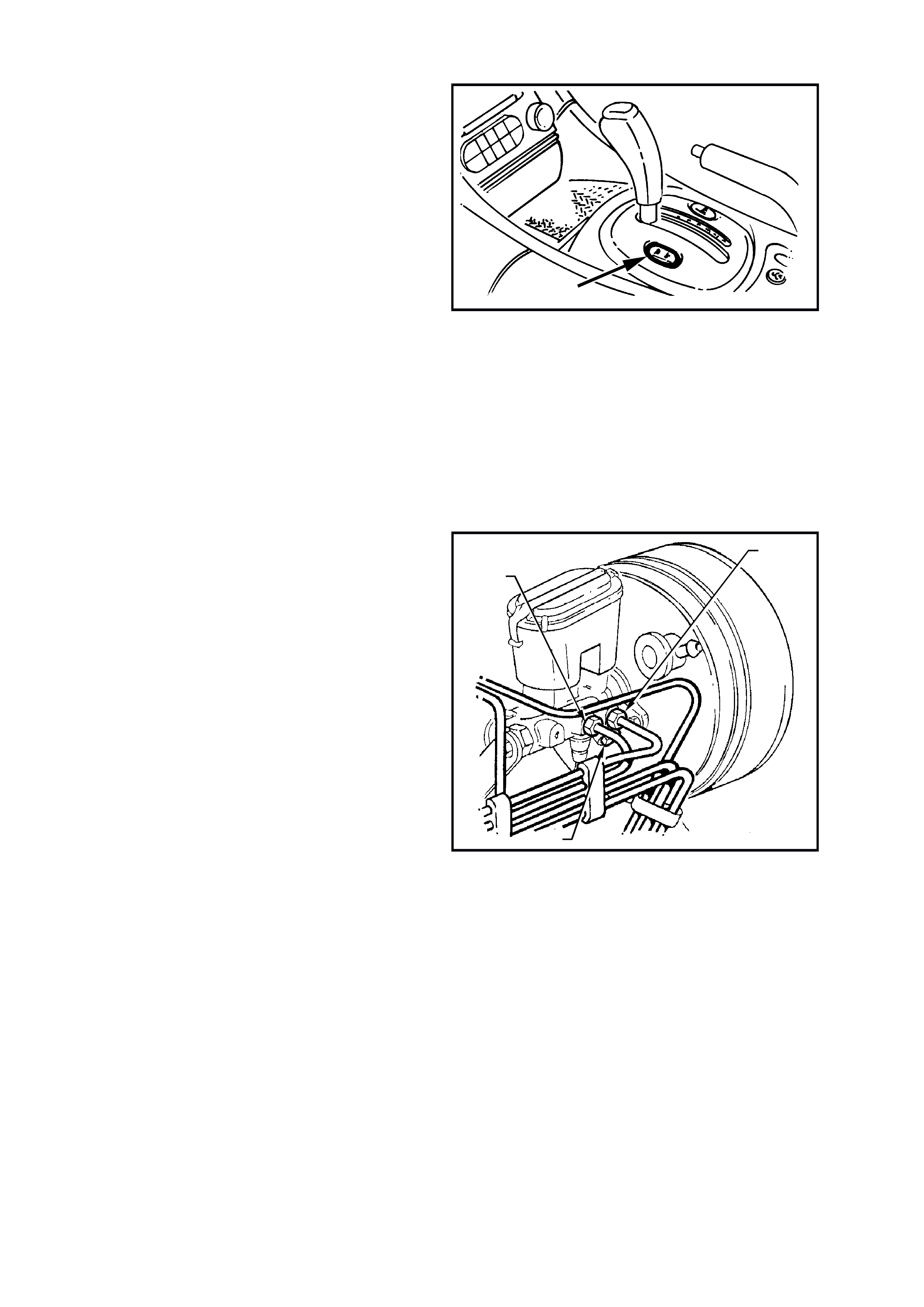
ELECTRONIC TRACTION CONTROL ( ETC) SWITCH
In certain circumstances (i.e. if the vehicle became
bogged and could be ‘rocked out’) it may be
necessary to disable the electronic traction control
system (ETC). This is achieved by pressing the
TRAC CTRL button, located near the transmission
selector, refer to
Fig. 12L-15. If the traction control system is
switched off, the TRAC OFF lamp will illuminate.
The system can be switched on again by either
pressing the TRAC CTRL button again or when the
ignition is next cycled (off to on).
NOTE 1: If the electronic traction control system is
commanded off, the ABS will still function normally.
NOTE 2: If the TRAC CTRL button is depressed
and held for 10 or more seconds, the ABS/ETC
control module will see this as a short circuit and
the ETC will be permanently enabled (for that
ignition cycle) until the ignition is switched off and
the engine restarted. Additionally, the TRAC OFF
warning lamp (if illuminated) will be turned off until
the ignition is switched off and the engine restarted.
T212L013
Figure 12L-15
BRAKE MASTER CYLINDER
On VT Series Models, regardless of the engine
configuration, a common brake master cylinder is
used on vehicles with standar d, ABS and ABS/ET C
brake systems. The only difference being that the
master cylinder used with ABS and ABS/ETC
systems has a screw-in blanking plug installed and
tightened into the lower of two front brak e outlets in
the master cylinder.
1. Rear brake outlet pipe.
2. Front brake outlet pipe.
3. Blanking plug.
T212L014
2
1
3
Figure 12L-16
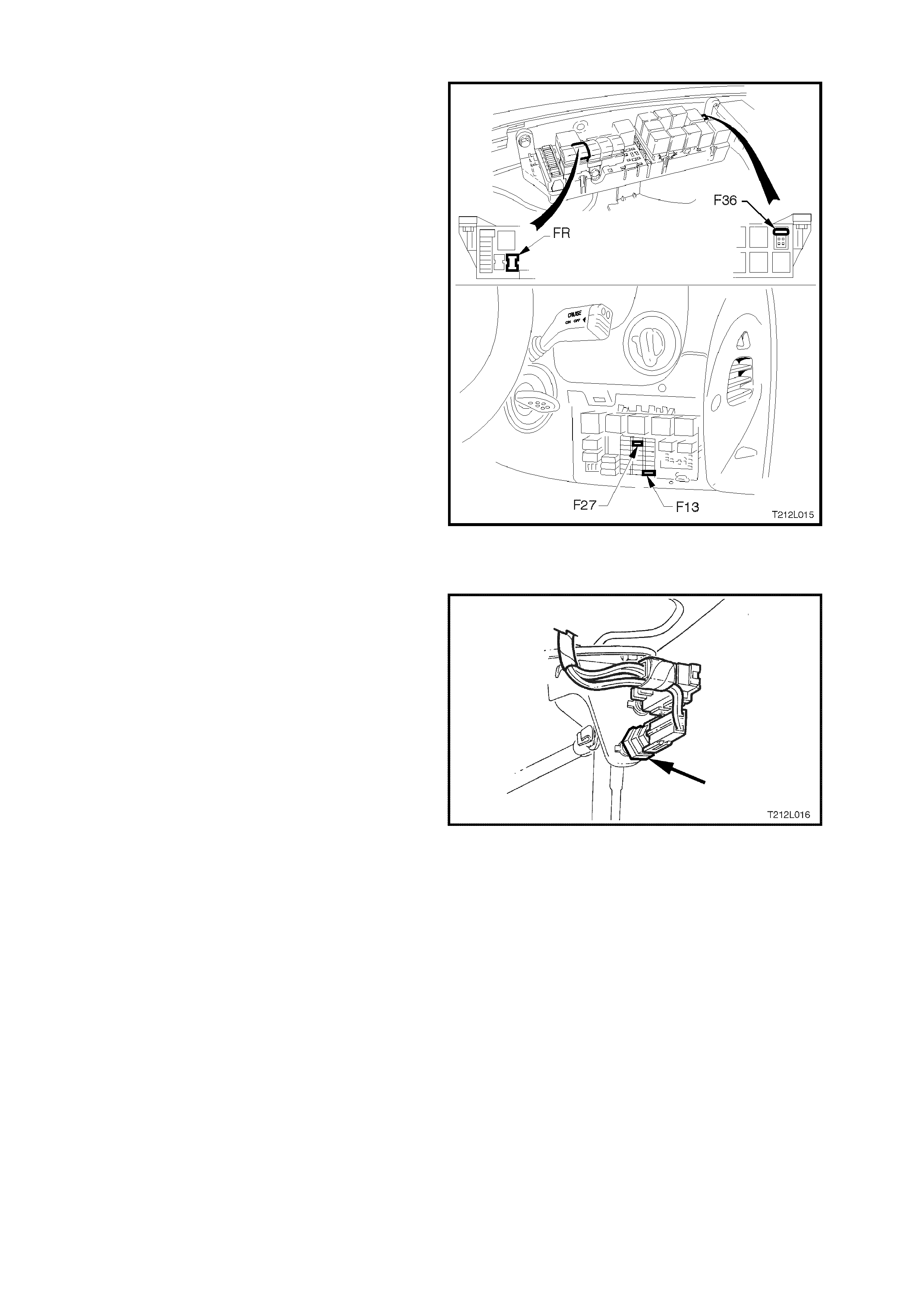
ABS & ETC FUSES
An ABS 60 amp fusible link, marked FR, is
incorporated in the engine c ompar tment f usible link
housing.
The throttle relaxer and throttle relaxer control
module are supplied voltage via fuse F36, also
located in the engine compartment fusible link
housing.
An additional 10 am p fuse, F27 is used f or the ABS
and is located in the passenger compartment fuse
panel at fuse location No. 27.
The ABS, TRAC OFF & LOW TRAC warning
lamps are supplied voltage via fuse F13 located in
the passenger compartment fuse panel.
Figure 12L-17
STOP LAMP SWITCH
The stop lamp switch, located in the brake pedal
support, provides a BRAKES APPLIED 12 volt
input signal to terminal 14 of the ABS/ETC control
module. Whenever the ABS/ETC control module
receives this signal the ABS control cycle will begin.
If the driver pum ps the brake pedal during the ABS
operation, the control cycle will be reset.
The stop lamp switch is a nor mally open switch that
supplies battery voltage to the stop lamps and
terminal 14 of the ABS/ETC control module, when
closed. When the switch is open (brakes not
applied), terminal 14 of the ABS/ETC control
module is earthed through the stop lam ps, causing
the voltage at terminal 14 to be pulled low (less
than 0.2 volts)
Also, if the ABS/ET C control module senses a stop
lamp switch input, the self test will not occur until
the vehicle is travelling at approximately 18 km/h.
For all service operations on the stop lamp switch,
refer to Section 12B LIGHTING SYSTEM of the
VT Series I Service Information.
Figure 12L-18

2.4 INSTALLATION POSITION OF ABS AND ABS/ETC COMPONENTS
The following figures illustrate the installed positions of the various ABS/ETC components for VT Series Models with
GEN III V8 engines.
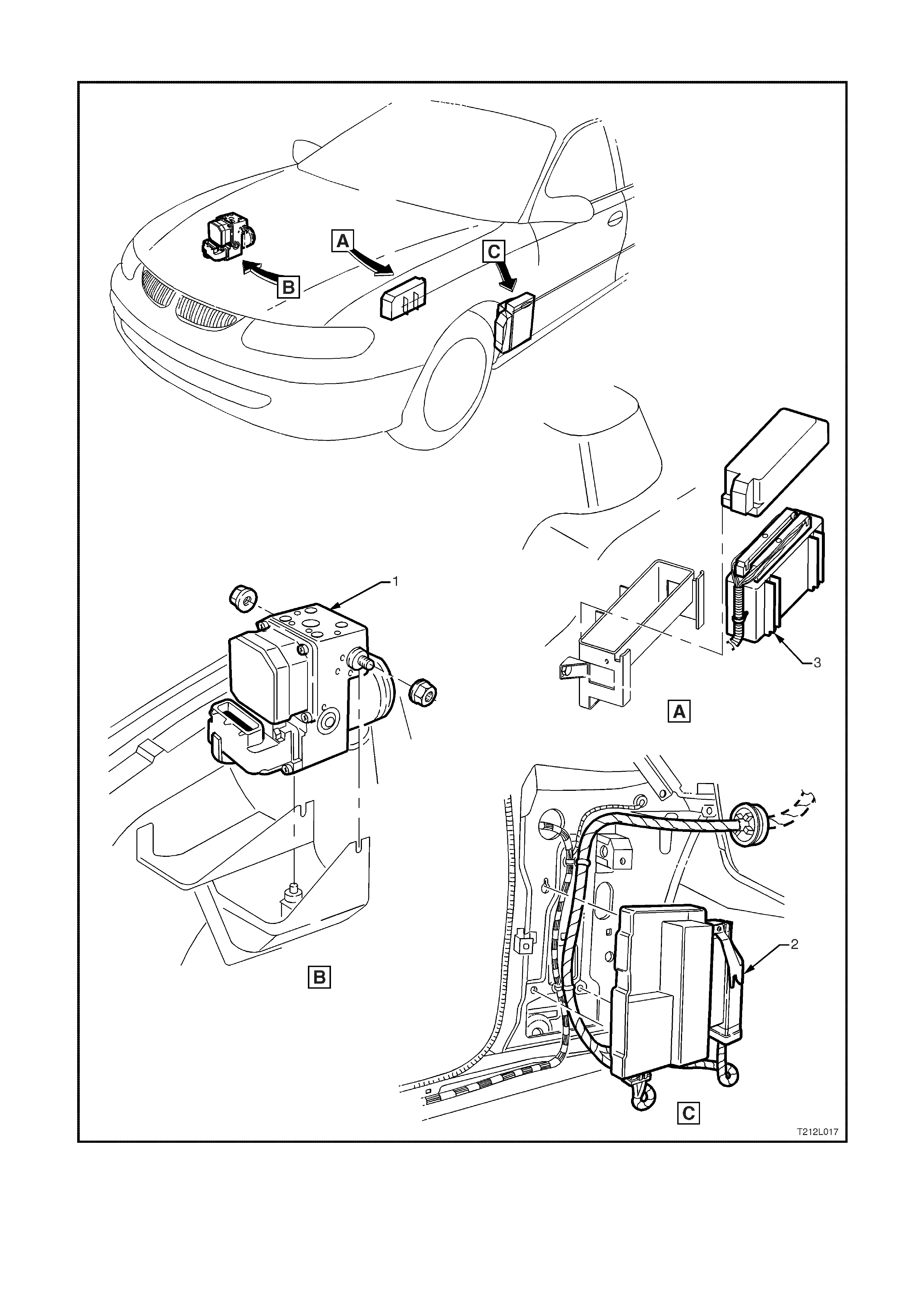
Figure 12L-19 Installation and location of Hydraulic modulator and control modules
1. ABS/ETC Hydraulic modulator and
control module assembly 2. Throttle relaxer control module 3. Powertrain Control Module (PCM)
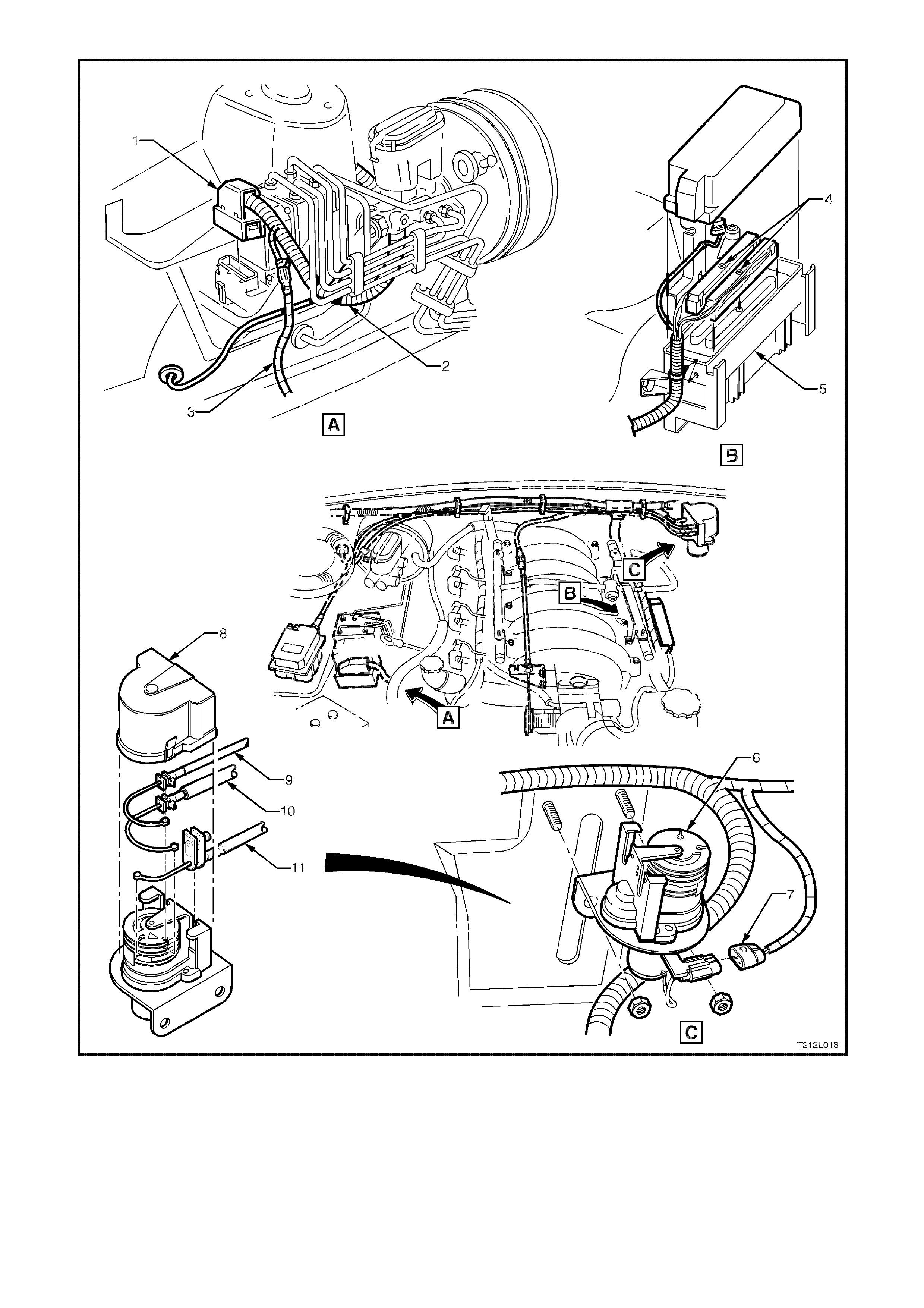
Figure 12L-20 Installation and location of throttle relaxer and cables, powertrain harness to PCM and throttle relaxer,
and main wiring harness to ABS/ETC control module
1. ABS/ETC control module connector 5. PCM 9. Cruise control cable
2. Main wiring harness 6. Throttle relaxer 10. Accelerator cable
3. Power steering harness 7. Powertrain harness to throttle relaxer 11. Throttle cable
4. Powertrain harness to PCM 8. Throttle relaxer cover
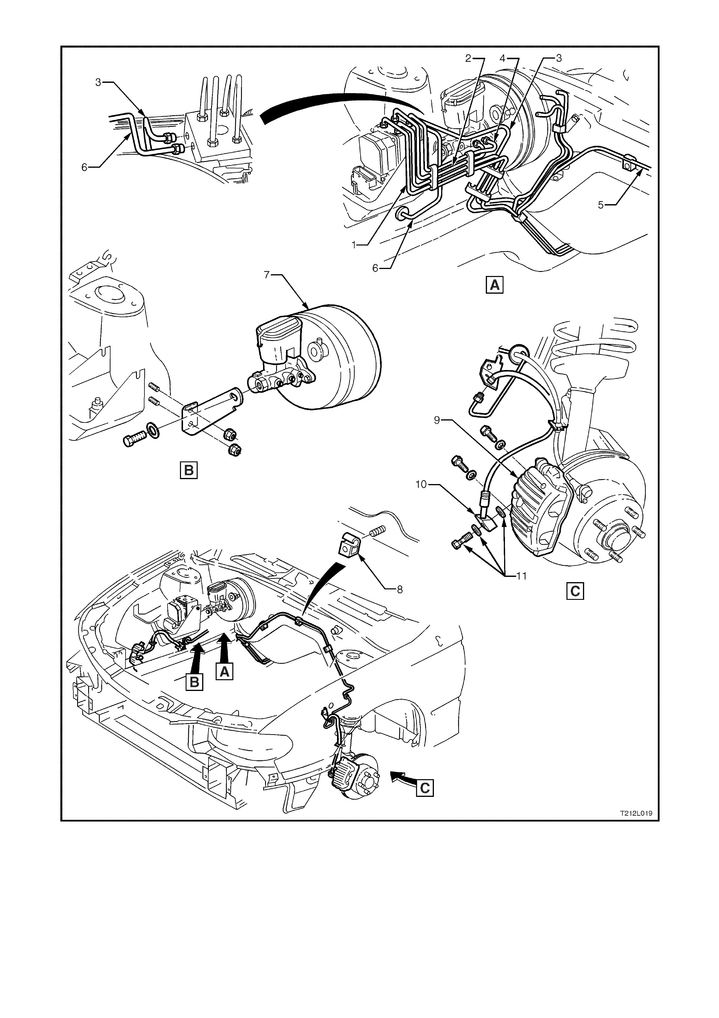
Figure 12L-21 Engine compartment and front brake line routing
1. Modulator to LH rear brake hose 5. Modulator to LH front brake hose 9. Front brake calliper
2. Master cylinder to modulator rear pipe 6. Modulator to RH front brake hose 10. Front brake hose
3. Modulator to RH rear brake hose 7. Master cylinder and brake booster 11. Front brake hose to calliper
4. Master cylinder to modulator front
pipe 8. Brake line retaining clip bolt and washer
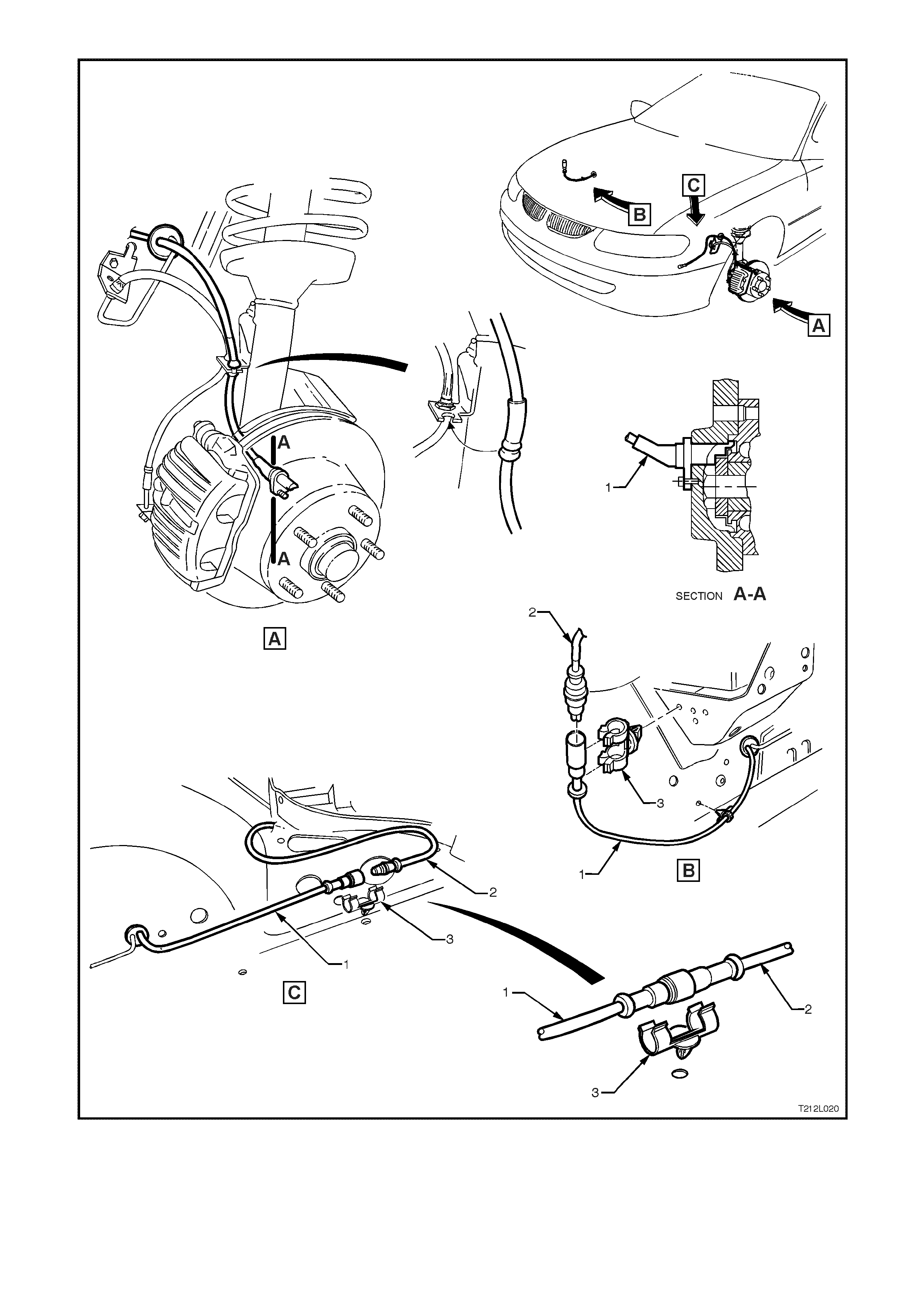
Figure 12L-22 Front wheel speed sensor lead routing
1. Front wheel s
p
eed sensor and lead
assembly 2. Main wiring harness 3. Retaining clip
NOTE: View A shows left hand side wheel speed sensor assembly, Views B and C are from inside the engine compartment.
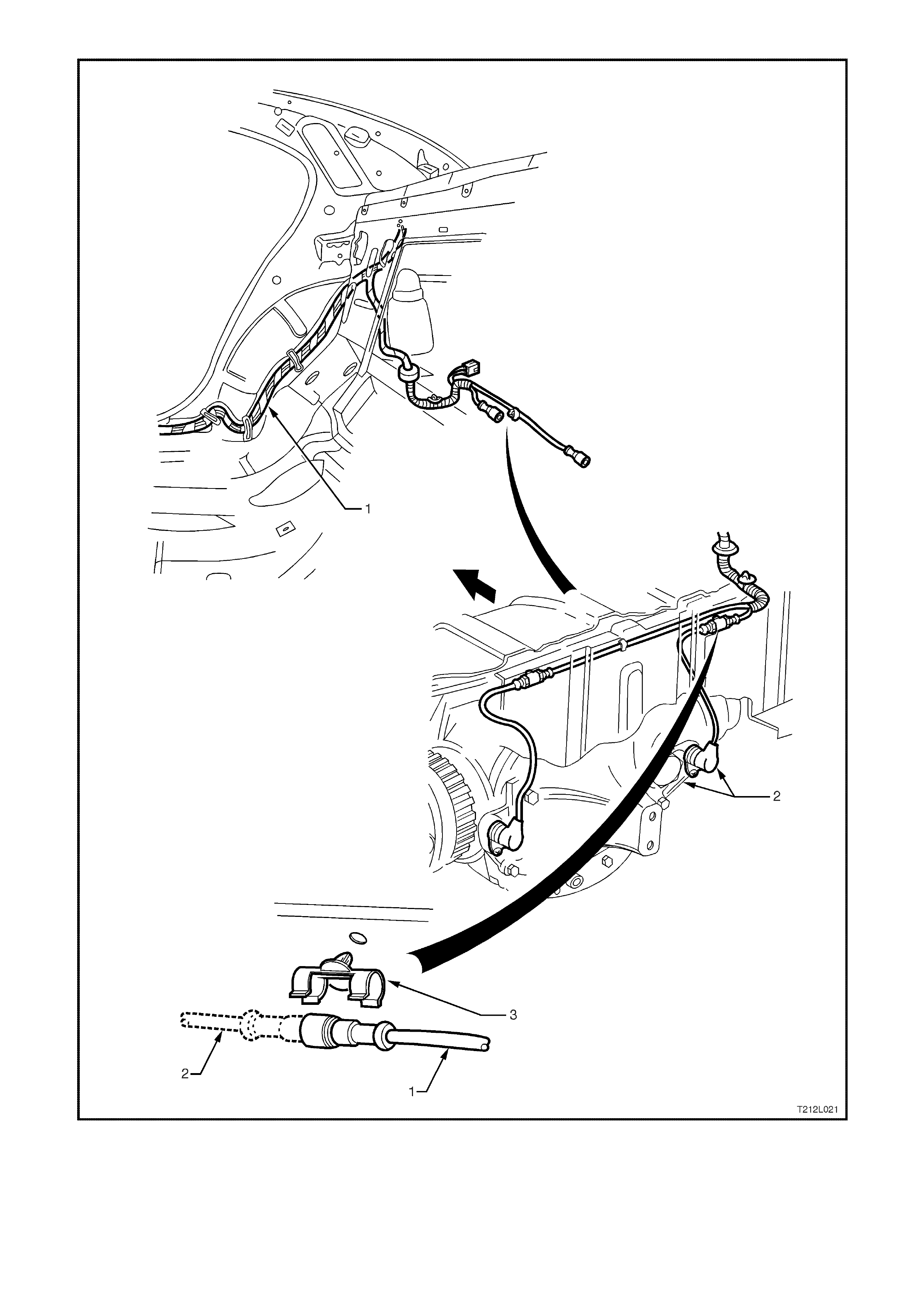
Figure 12L-23 Rear wheel speed sensor lead and body wiring harness routing
1. Body wiring harness 2. Rear wheel speed sensor and lead assembly 3. Retaining clip

2.5 GEN III V8 ENGINE ABS/ETC PRINCIPLES OF OPERATION
NON-ANTI-LOCK BRAKING / NON-TRACTION CONTROL
Under normal braking and driving conditions, the anti-lock braking system functions much like a conventional
braking system. Brake fluid pressure is provided by the brake master cylinder and the power booster.
For non-anti- lock braking, hydraulic press ur e is applied to the br ake calliper s without any intervention from the ABS.
At this time, the hydraulic modulator establishes an open two-way fluid path from the master cylinder to the brake
callipers. Non-anti-lock braking occurs when the wheel sensors do not detect wheel lock-up tendencies. However,
even though the ABS is passive during normal braking, the ABS/ETC module is constantly monitoring for rapid
acceleration (wheel slip) and deceleration (wheel lock) of any of the wheels and a signal from the brake switch
(brakes applied input).
ANTI-LOCK BRA KING
When the ABS senses any tendency for wheel lock-up, it enters the anti-lock mode. During anti-lock braking, the
ABS modulates hydraulic pressure in the brake circuits to control wheel slip to approximately 10 - 20%. For anti-lock
braking, the ABS control module controls current flow to the hydraulic modulator solenoid valves to control (by
maintaining, decreasing or increasing) hydraulic pressure in the brake circuits.
NOTE: The hydraulic modulator cannot increase brake circuit hydraulic pressure above the pressure supplied by
the brake master cylinder during anti-lock braking.
ELECTRONIC TRACTION CONTROL
W hen the ABS/ET C control module s enses spin fr om the drive wheels due to too m uch engine torque for the road
conditions, it enters the traction control mode.
The ABS/ET C module monitors both front and rear wheel speeds through the wheel speed sensors. If at any time
during acceleration the ABS/ETC module detects drive wheel slip, it will request:
• The PCM, via the spark retard circuit, to retard the amount of spark advance.
• The throttle relaxer control module to reduce the engine throttle opening by a certain percentage to bring
engine torque into a specific range.
The throttle relaxer control module accomplishes this by commanding the throttle relaxer to override the
accelerator pedal cable and physically reduce the throttle body butterfly opening by winding the throttle cable
back.
This is ac hieved via two high speed Puls e Width Modulated ( PWM) c irc uits between the ABS/ETC module and
the throttle relaxer control module. The ABS/ETC control module sends a message to the throttle relaxer
control m odule on the requested throttle pos ition (DKR) c ircuit. T he throttle r elaxer c ontrol m odule then repor ts
the modif ied throttle pos ition opening back to the ABS/ET C control m odule via the ac tual throttle position (DKI)
circuit.
Simu ltaneously with engine spark retard and throttle position intervention, the ABS/ET C control m odule will activate
the ABS isolation valves, turn on the ABS pump motor and supply brake pressure to the over spinning wheel(s).
The isolation valves isolate the front brake hydraulic circuits from the master cylinder and rear brake hydraulic
circuits. Once the rear brake hydraulic circuits are isolated, pressure can be applied to the rear wheels without
affecting any other brake hydraulic circuits. The ABS/ETC module opens the priming valve, allowing fluid to be
drawn from the m aster cylinder to the pump m otor, tur ns on the ABS pump m otor to apply pressure, begins cycling
the ABS assembly's inlet and outlet valves, and closes the switching valve, ensuring fluid is directed to the wheel
not back into the master cylinder.
The inlet and outlet valve cycling aids in obtaining m aximum road surf ace traction in the sam e manner as the Anti-
Lock Brake m ode. The diff erence between Traction Contr ol and Anti-Lock Brake mode is that brak e fluid pres sure
is increased to lesson wheel spin (Traction Control mode), rather then reduced to allow greater wheel spin (Anti-
Lock Brake mode).
If at any time dur ing Traction Contr ol mode, the brakes are manually applied, the brake s witch signals the ABS/ET C
module to inhibit brake intervention and allow for manual braking (throttle reduction and spark retard intervention
can still occur if necessary).
Figure 12L-24
ABS/ETC CONTROL MODULE OPERATION
Inputs
The following ABS/ETC components send signals to the ABS/ETC control module where they are evaluated in
order for the module to maintain and control wheel slip/spin.
• Ignition on input, (via fusible link FJ, ignition switch, fuse F27) - ABS/ETC control module terminal No. 15.
• Wheel speed sensor inputs - ABS/ETC control m odule terminal No’s. LHF 6 and 7, RHF 4 and 5, LHR 8 and 9,
and RHR 1 and 2.
• Brakes applied input (from brake lamp switch) - ABS/ETC control module terminal No. 14.
• Battery voltage - ABS/ETC control module terminals 17 and 18.
• Actual throttle position (DKI) - ABS/ETC control module terminal 27.
• Engine speed signal - ABS/ETC control module terminal 30.
• ETC disable switch (TRAC CTRL) - ABS/ETC control module terminal 31.
• Serial data (input and output) - ABS/ETC control module terminal No. 11.
T212L022
.....
.....
.....
.....
.....
.....
.....
.....
.....
.....
.....
.....
.....
.....
.....
.....
RIGHT REAR
RIGHT REAR
R IGHT FR ONT
R IGHT FR ONT
LEFT F RONT
LEFT F RONT
LEFT REAR
LEFT REAR
BRAKE LAMP SWITCH
SER IAL DATA
IG NIT ION " ON"
12 VOLT
12 VOLT
ACTUAL THROTTLE POSITION (D KI)
ETC DISABLE SWITCH
ENGIN E SPEED SIG NAL
WHEEL SPEED
SENSORS
INPUTS OUTPUTS
16 19
.....
.....
.....
.....
.....
.....
.....
.....
12
13
11
21
28
20 R EQUESTED THR OTTLE POSITION (DKR)
SER IAL DAT A
DIAGNOSTIC TER MINAL
E.T.C. WARNING LAMPS
A.B.S. WARNING LAM PS
R EQUESTED SPARK R ET AR D
PUMP RELAY/
PU MP MOT OR
INT ERNAL CONTROL
VALVE RELAY/
SOLENOI D VALVES
INT ERNAL CONTROL
1
2
4
5
6
7
8
9
11
14
15
17
18
27
30
31
ABS/ETC
CONTROL
MODULE
-
-

Outputs
To control the anti-lock braking system and traction control system, the ABS/ETC control m odule sends command
signals to the following components.
• Valve relay/solenoid valves - internal control.
• Pump relay/pump motor - internal control.
• Serial data (input and output) - ABS/ETC control module terminal No. 11.
• Self diagnostic 'Flash Code Actuation' - ABS/ETC control module terminal No. 12.
• Requested throttle position - ABS/ETC control module terminal No. 13.
• ETC warning lamp (TRAC OFF, LOW TRAC) - ABS/ETC control module terminal 20.
• ABS warning lamp - ABS/ETC control module terminal No. 21.
• Requested spark retard – ABS/ETC control module terminal No. 28.
With the ignition switch in the on position, batter y voltage is applied to the ABS/ETC control m odule ter m inal No. 15
via fuse F27. Battery voltage is also applied to the pum p motor relay and valve relay via fusible link FR. Neither of
the relays operate until they receive an earth from the ABS/ETC control module.
Also, battery voltage is supplied to the ABS and ETC warning lamps via fuse F13. The LOW TRAC and ABS
warning lamp s will not illum inate until they are earthed by ABS/ETC control m odule. If the ABS/ET C c ontrol module
wiring harness connector YE98, is not connected to the control module, terminals 19, 20 and 21 are shorted
together by a shorting bar, and the LOW TRAC and ABS warning lamps will be illuminated. The TRAC OFF warning
lamp is defaulted to the on position and is turned off via a serial data message from the ABS/ETC control module
when the ignition is turned on (provided the system is OK).
Wheel speed sensors are located at each front wheel and at each final drive inner axle flange. When the vehicle
starts m oving, all of the speed sensors create signals that are input to the ABS/ET C control module at terminals 1
and 2, 4 and 5, 6 and 7, 8 and 9. These signals are AC electrical pulses that are proportional (in frequency and
amplitude) to wheel rotational speed.
Once the vehicle has been started and dr iven over approx imately 6 km /h, the c ontro l module perf or ms an ABS/ETC
self test. The control module test cycles each solenoid valve and the return pump in the hydraulic modulator to
check component operation. The control module checks its own logic section and circuitry. If errors are detected
during this test, the control module earths terminal 20, illuminates the ABS warning lamp and also sends a
message, via the serial data circuit, commanding the TRAC OFF warning lamp to be illum inated. The ABS and/or
ETC warning lamp/s are illuminated to warn the driver of a problem with the system/s. The ABS/ETC control module
remains deactivated until the next ignition switch OFF to ON cycle when the process is repeated and the ABS
and/or TRAC OFF warning lamp/s will be illuminated.
The ABS self test occurs once each ignition cy cle as follows:
1. After receiving an ignition ON input, the control module earths and activates the valve relay.
2. As soon as the ABS/ETC control module receives a signal from any of the wheel speed sensors, it checks
wheel speed sensor output. If any of the wheel speed sensor signals are not detected, or are incorrect, the
ABS/ETC system will be disabled and the warning lamps will be illuminated.
3. When the vehicle reaches approximately 6 km/h, the control module tests the solenoid valves and the return
pump in the modulator. If the control lamp switch receives a brake lamp switch input before the vehicle has
reach 6 km/h, the self test will not occur until the vehicle reaches a road speed of approximately18 km/h.
4. If the pum p or s olenoid valves f ail to operate, the ABS/ET C s ystem will be dis abled and the warning lam ps will
be illuminated.
Once the vehicle is moving, the control module continuously monitors itself and the following components:
1. Solenoid valves.
2. Wheel speed sensors.
3. Wiring harness and relays.
4. Battery voltage.
If battery voltage drops below approximately 9 volts, the ABS/ETC will be disabled and the ABS and TRAC OFF
warning lamps will be illuminated, while the voltage remains below 9 volts.
During braking applications, if one or more wheels start to decelerate too quickly, the ABS is engaged and the
modulation process begins. Wheel speed information sent to the ABS/ETC control module is processed and the
module deter mines pr oper solenoid valve oper ation in the modulator. The modulator c ontains ten s olenoid valves ; a
priming and switching relay, plus one inlet and one outlet valve for each wheel.
When wheel spin is detected and traction control mode begins, the ABS/ETC control module also engages ABS
through the modulation process. Additionally, the ABS/ETC control module simultaneously changes the engine
output conditions by reducing the amount of spark advance and reducing the throttle opening.
HYDRAULIC MODULATOR OPERATION
The hydraulic modulator executes ABS control
module commands using 10 solenoid valves.
These solenoid valves, located in the hydraulic
modulator assembly, are in series with the brake
master cylinder and the brake circuits. The
hydraulic modulator solenoid valves are activated
separately by the ABS/ETC control module
corresponding to various ABS or ETC control
phases:
1. Non-ABS Braking (ABS and ETC phases)
2. Maintaining Pressure (ABS phase)
3. Reducing Pressure (ABS phase)
4. Increasing (Building-up) Pressure (ABS phase)
5. Normal condition (ABS and ETC phases -
brakes off)
6. Applying (ETC phase)
The hydraulic modulator assembly contains 10
solenoid valves and a brake fluid return pump;
however, for explanation of the operation, only one
accumulator and four solenoid valves will be
described ( rear brak es). T he operation is the s ame
for all four circuits.
Non-ABS Braking (ABS and ETC phases)
During this condition, the inlet and outlet valves are
not activated. The inlet valve (pressure holding
solenoid valve) is open. This allows brake fluid to
flow in either direction between the brake master
cylinder and the brake calliper, providing for
conventional non-ABS braking. The outlet valve
(pressure release outlet solenoid valve) is closed,
blocking off the passage to the accumulator and
the return pump.
The brake master cylinder hydraulic pressure is
applied to the brake circuits (calliper). If the
ABS/ETC control module (not shown) does not
detect any rapid wheel deceleration, the ABS will
remain passive at this time.
Hydraulic modulator status:
LH inlet valve... Open LH outlet valve.Closed
RH inlet valve .. Open RH outlet valve Closed
Priming valve... Closed Switching valve Open
Motor ............... OFF
Figure 12L-25
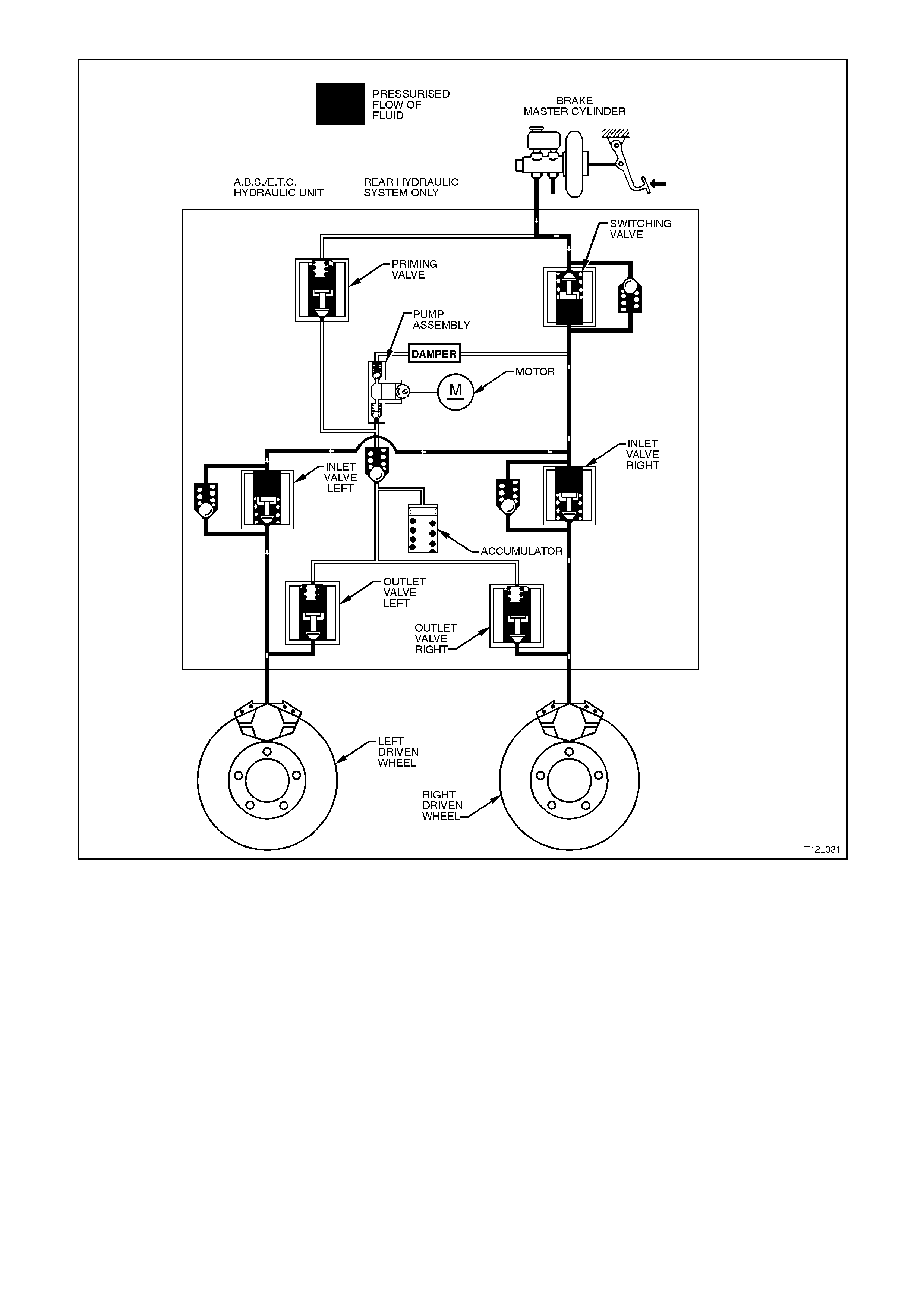
Figure 12L-26
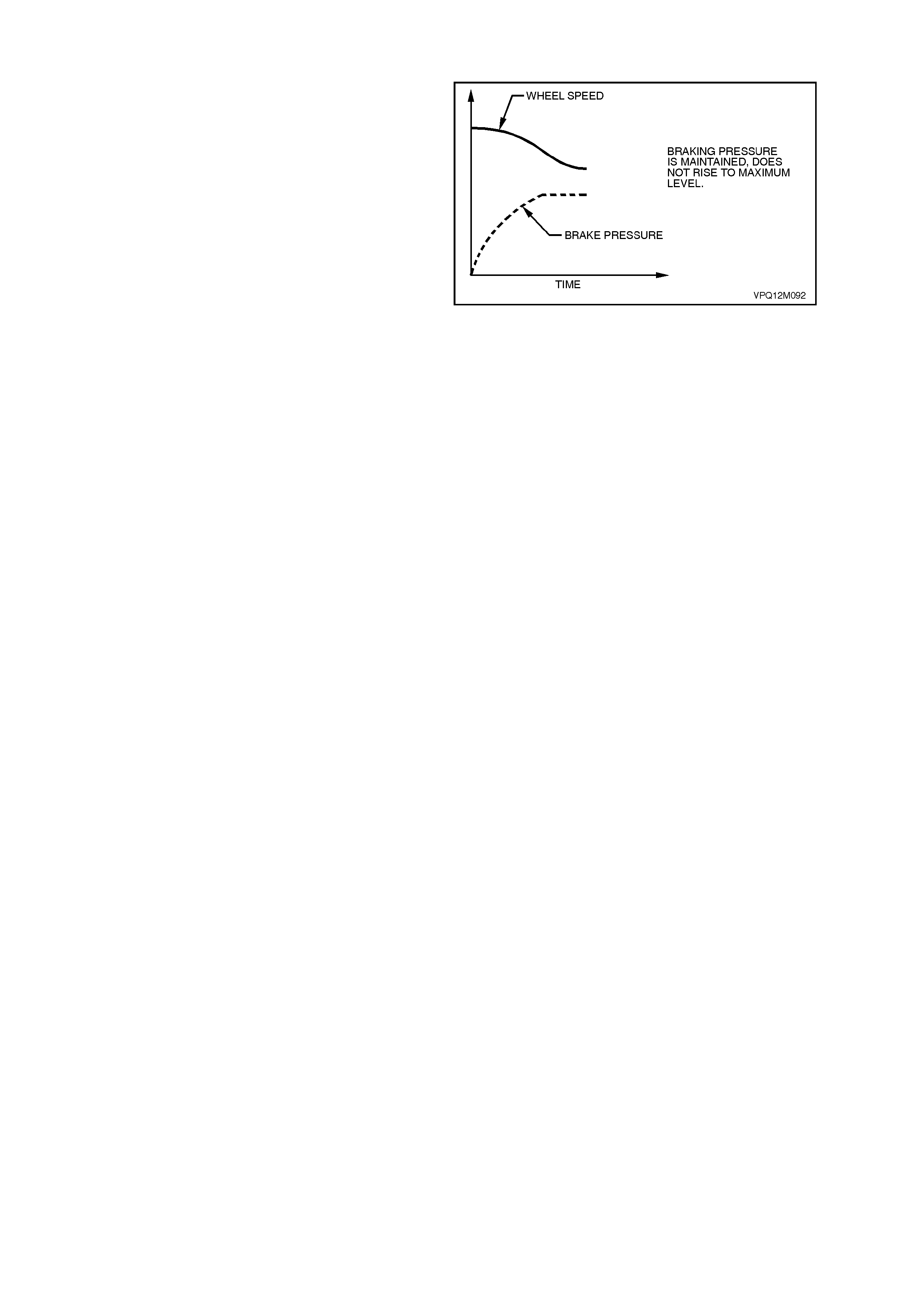
Maintaining Pressure (ABS phase)
NOTE: The following diagram and explanation
assumes the right hand rear wheel is having a
tendency to lock.
When the ABS/ETC control module detects
excessive wheel deceleration (based on the wheel
speed sensor (not shown) s ignal), it com m ands the
right hand inlet valve (pressure holding solenoid
valve) to maintain brake circuit pressure. It does
this by earthing the respective circuit (RH in this
case), ther efore allowing a current f low through the
coil of inlet valve solenoid. This causes the
armature and valve to move downward, isolating
the brake circuit (calliper) from the master cylinder.
NOTE: W ith the brak e circuit isolated, brake circuit
pressure between the modulator and the brake
calliper circuit remains constant despite increased
master cylinder hydraulic pressure.
Hydraulic modulator status:
LH inlet valve... Open LH outlet valve.Closed
RH inlet valve .. Closed RH outlet valve Closed
Priming valve... Closed Switching valve Open
Motor ............... OFF
Figure 12L-27
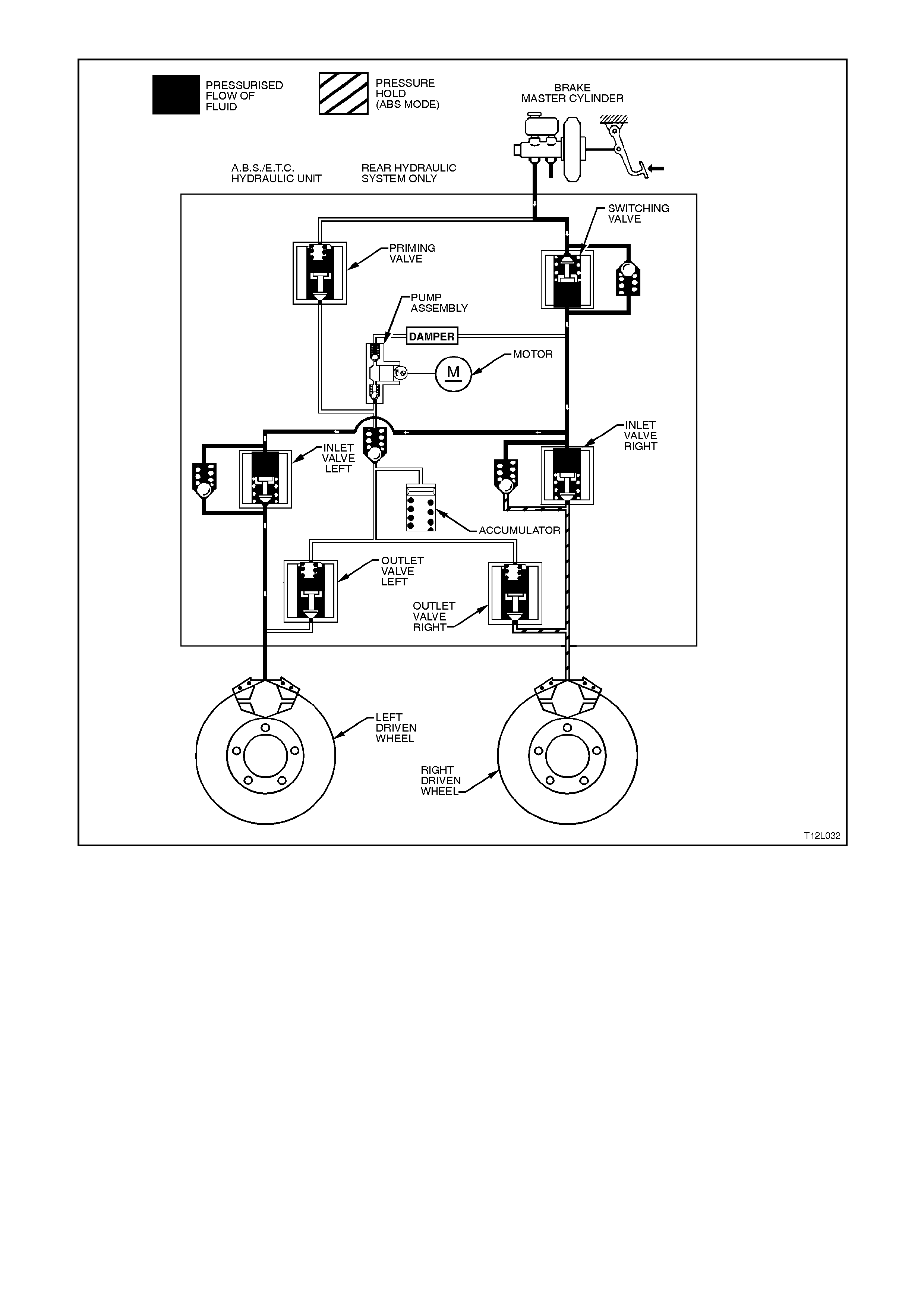
Figure 12L-28
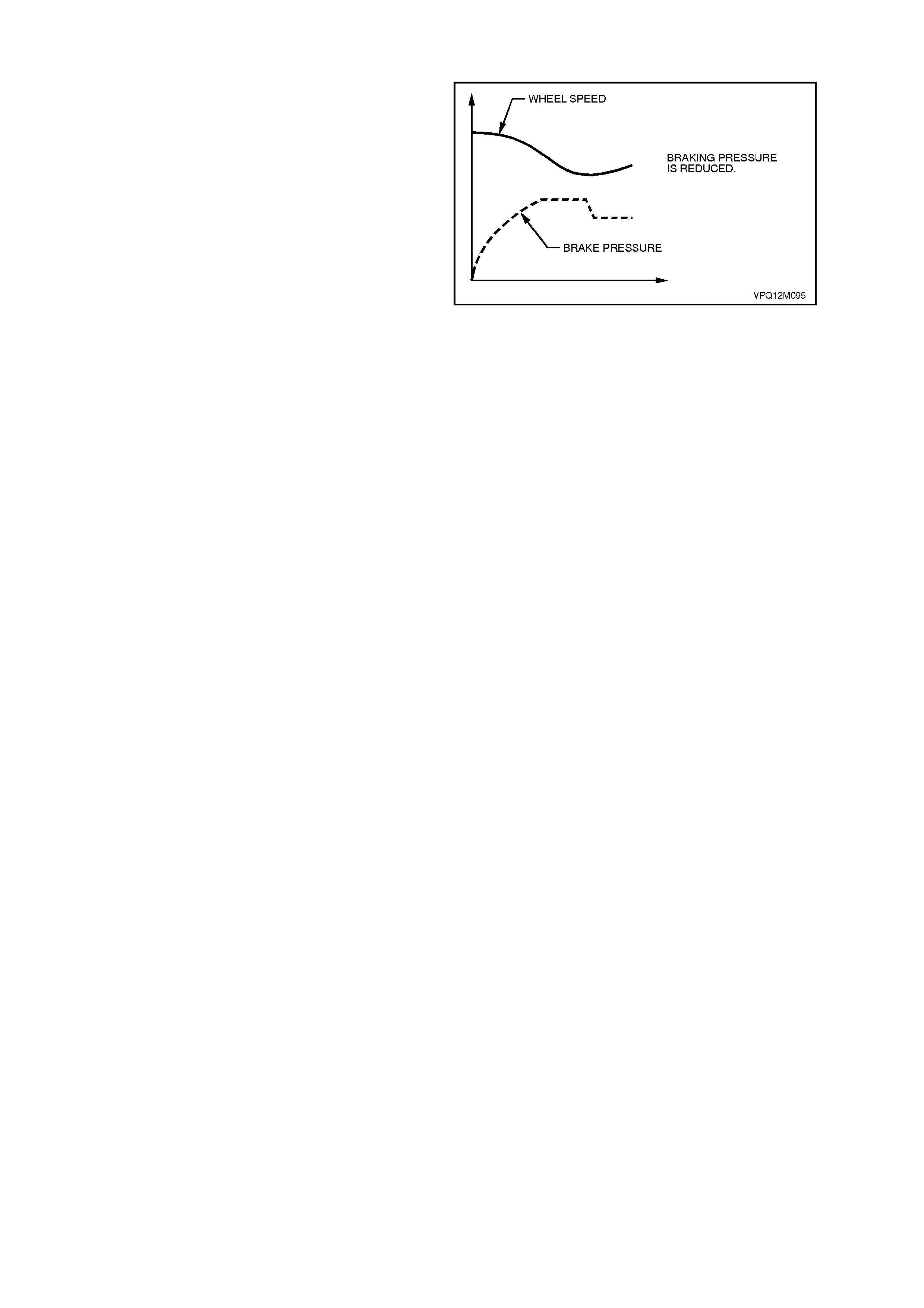
Reducing Pressure (ABS phase)
NOTE: The following diagram and explanation
assumes the right hand rear wheel is having a
tendency to lock.
If isolation of a brake circuit between the brake
master cylinder and the brake calliper does not
reduce the excessive wheel deceleration, the
ABS/ETC control module commands the outlet
valve (pressure release solenoid valve) open to
reduce hydraulic brak e press ure in the brak e circ uit
(RH outlet valve in this case). During this phase,
the ABS/ETC control module earth’s the coil of the
RH outlet valve, allowing a current flow through the
coil windings. This causes the armature and valve
to move downward, opening a passage from the
brake circuit to the accumulator and the pump
assem bly inlet. At this stage, both the RH inlet and
RH outlet valves are activated simultaneously.
NOTE: At this time, the brake circuit is isolated
from the mas ter c ylinder by the return pump valving
and the energised return pump.
This action sends brake fluid from the brake
circuits back to the master cylinder. The return
pump continues to operate during the remainder of
the anti-lock cycle. This will increase the r eturn f low
pressure from the calliper, thus allowing the fluid
released from the calliper to be returned back to
the master cylinder. The pump will continue to
operate during the rest of the anti-lock brake cy cle.
Hydraulic modulator status:
LH inlet valve... Open LH outlet valve.Closed
RH inlet valve .. Closed RH outlet valve Open
Priming valve... Closed Switching valve Open
Motor ............... ON
NOTE: Motor will remain operational until ABS
mode is exited.
Accumulators
During the 'Reducing Pressure' phase of ABS
modulation, the acc umulators ( 2c) temporar ily store
fluid from the brake circuits. Some road conditions
require the relief of a large volum e of fluid f rom the
brak e callipers . In such c onditions, the accum ulator
guarantees pressure reduction. As soon as the
solenoid valve (2b) moves to the 'Reduction
Pressur e' pos ition, brake f luid f rom the br ak e c irc uit
flows into the accum ulator. Thus, before the return
pump (2d) starts operation, the accum ulator allows
an immediate pressure reduction in the brake
circuit. The front brake circuits share a common
accumulator. The rear brake circuit uses a
separate accumulator. The accumulators are
spring-loaded and designed to operate at less than
1000 kPa.
Figure 12L-29
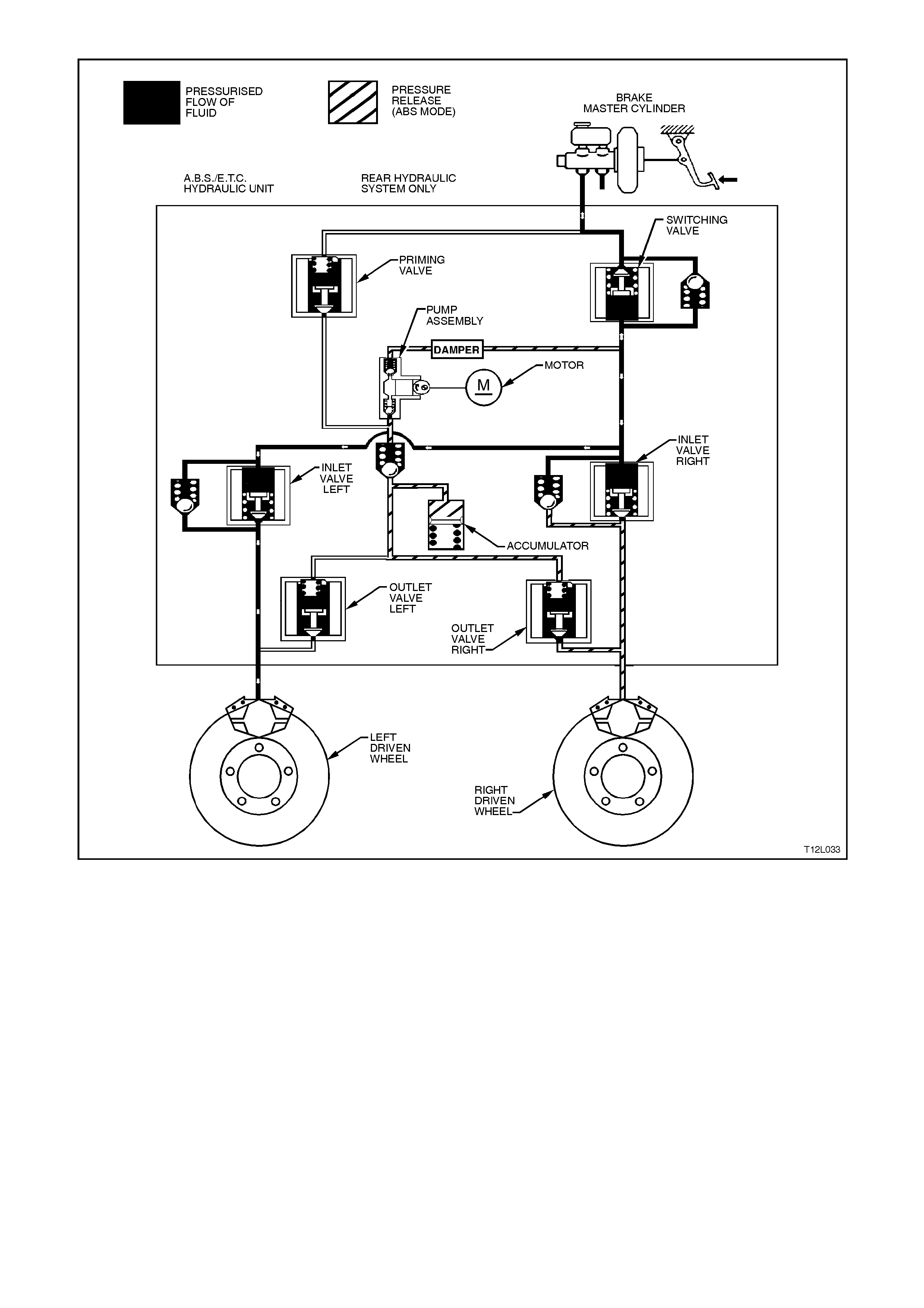
Figure 12L-30
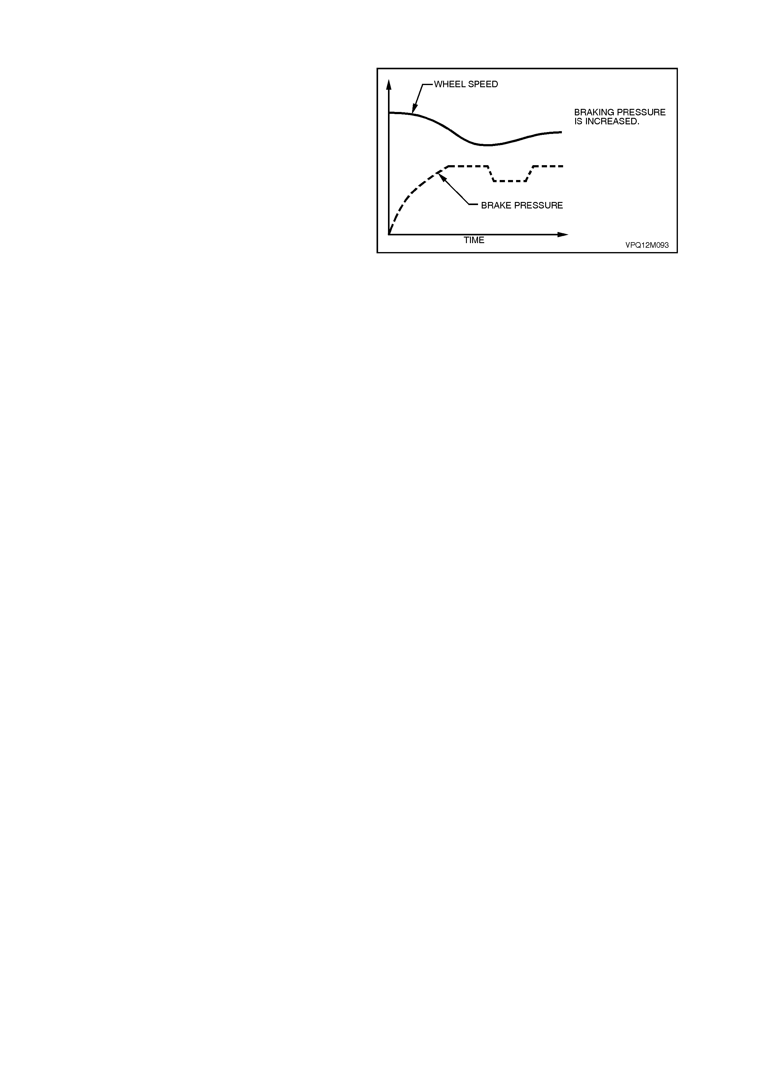
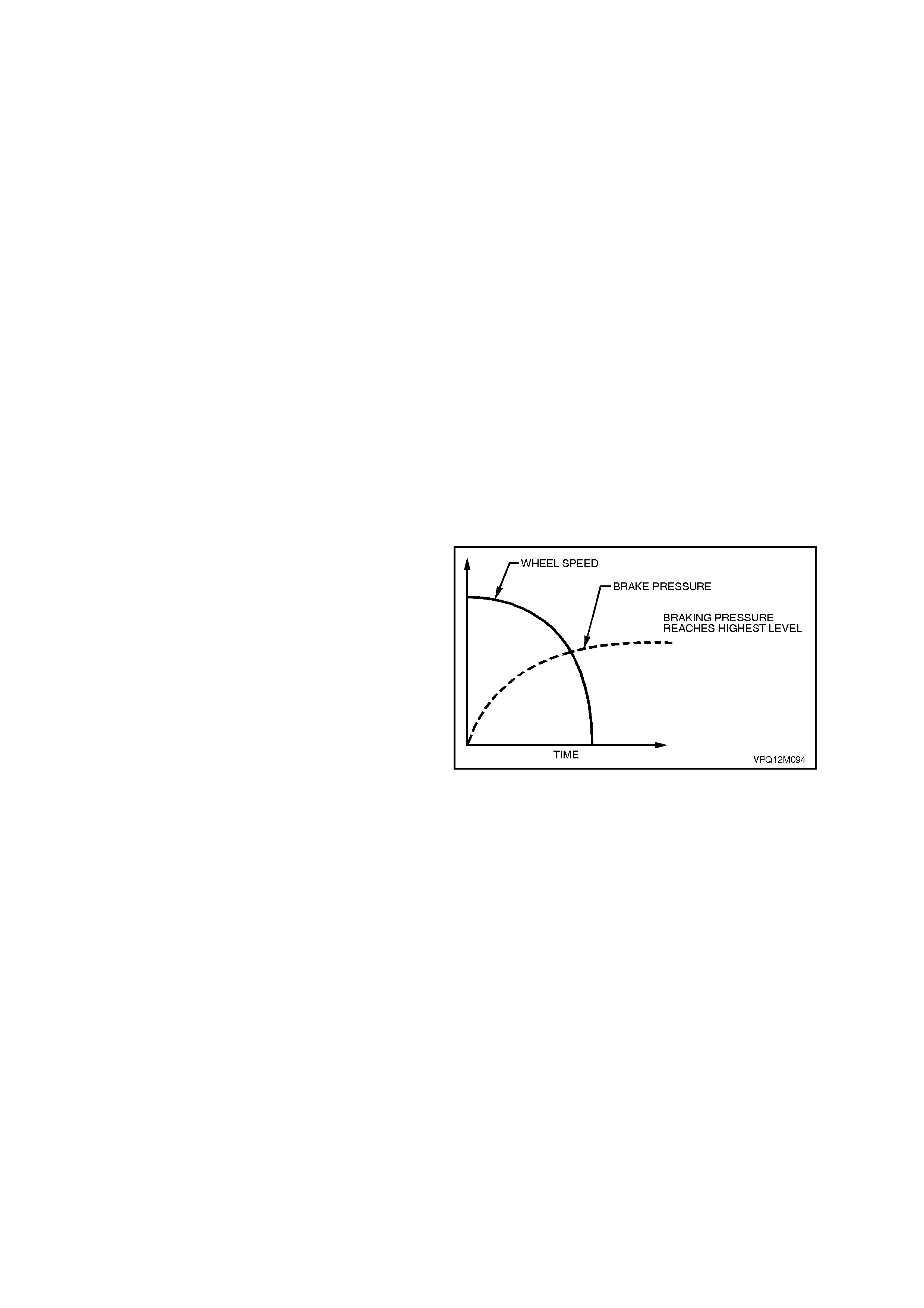
Increasing (Building-up) Pressure (ABS phase)
NOTE: The following diagram and explanation
assumes the right hand rear wheel is having a
tendency to lock.
The wheel accelerates again as a result of the
reduced braking pressure. Upon reaching a
specific limit, the ABS/ETC control module
registers the fact that the wheel is now not being
braked sufficiently.
The ABS/ETC control module then de-energises
both the RH inlet and RH outlet valves and the
formerly reduced pressure is then incr eas ed so that
the wheel is again decelerated. The ABS/ETC
control cycle begins again. There is approximately
4 - 6 control cycles per second, depending on the
state of the road surface.
Hydraulic modulator status:
LH inlet valve .....Open LH outlet valve ......Closed
RH inlet valve.....Open RH outlet valve......Closed
Priming valve .....Closed Switching valve......Open
Motor.................. ON
Figure 12L-31
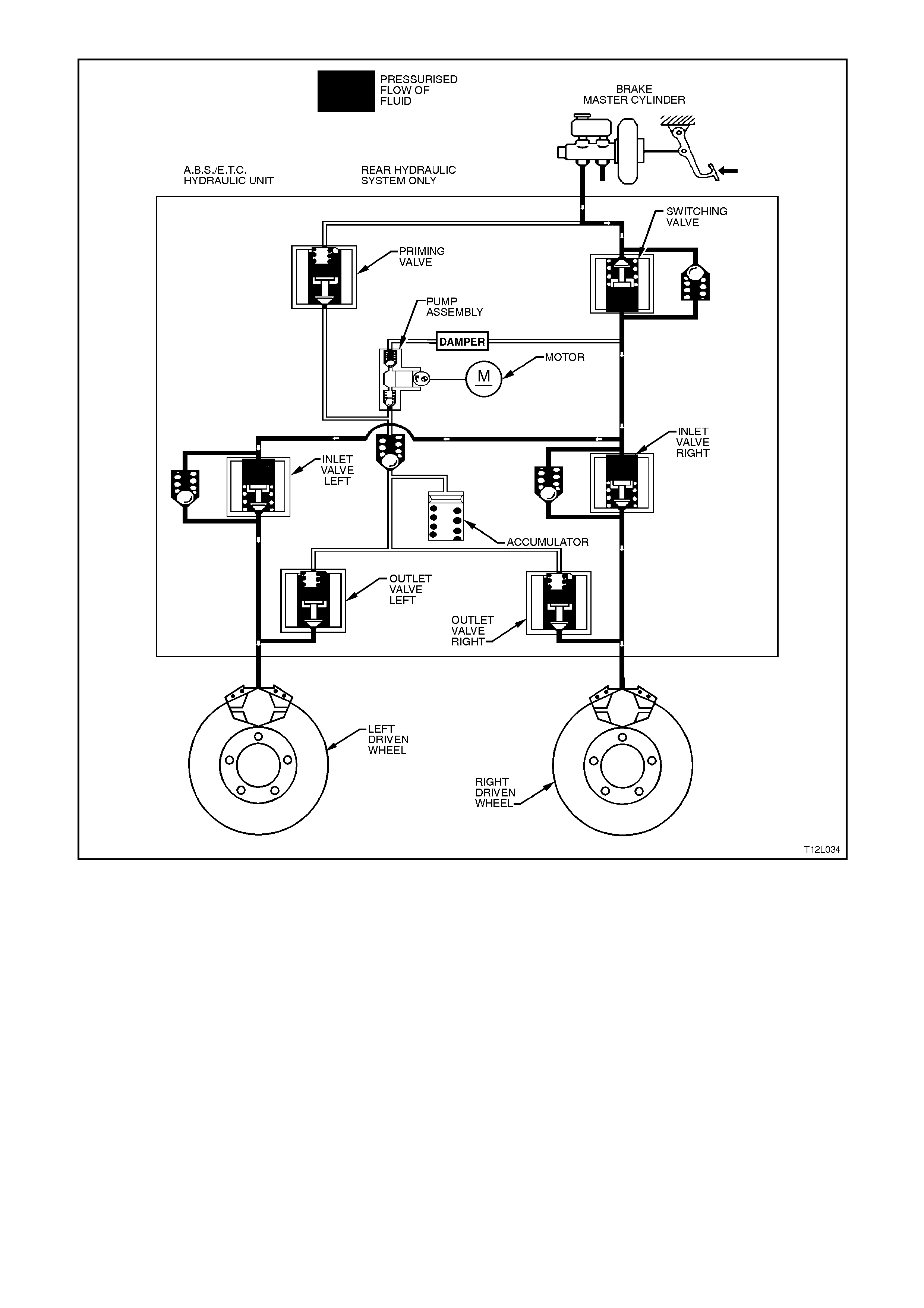
Figure 12L-32
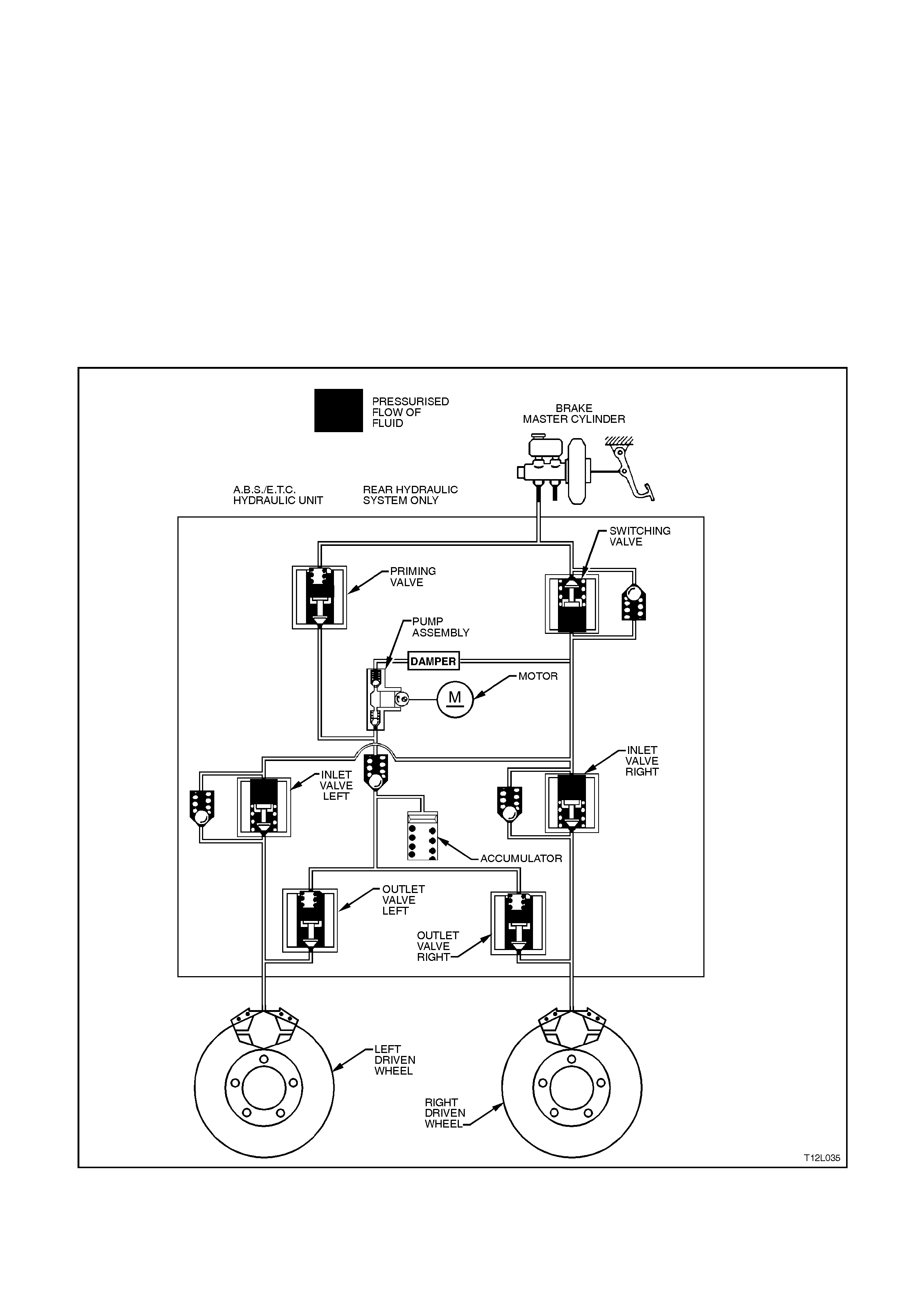
ETC Normal condition (ABS and ETC phases)
In the normal condition, there is no brake
intervention. All the valves in the hydraulic
modulator are in their normal rest positions,
allowing for uninterrupted flow for normal braking
condition. The schematic below depicts no
pressure in the system, therefore no application of
brakes.
Hydraulic modulator status:
LH inlet valve... Open LH outlet valve.Closed
RH inlet valve .. Open RH outlet valve Closed
Priming valve... Closed Switching valve Open
Motor ............... OFF
Figure 12L-33

ETC in operation (ETC phase)
NOTE: The following diagram and explanation assumes the right hand rear wheel is having a tendency to spin.
BRAKE INTERVENTION
In the following schematic, the ABS/ETC control module has detected that the wheel is about to enter into a
situation where wheel slippage is about to occur from excess engine torque for the road condition.
The ABS/ETC control module commands the priming valve open, allowing fluid to be drawn from the master
cylinder by the pum p assem bly. T he switching valve is clos ed, ensuring fluid is dir ected to the wheels and not back
to the master cylinder.
With the right wheel tending to spin, the left inlet valve closes, allowing the brakes to be applied only to the right
wheel. This will transfer the torque to the left wheel. This operation can be applied approximately 4 - 6 times a
second and can function on either of the driven wheels, or both.
Hydraulic modulator status:
LH inlet valve... Closed LH outlet v alve....Closed
RH inlet valve..Open RH outlet valve ...Closed
Priming valve... Open Switching valve...Closed
Motor ............... On
Engine spark and throttle position inter vention
Simultaneously to brake intervention, the ABS/ETC control module communicates with the Powertrain Control
Module (PCM) and the throttle relaxer control m odule requesting the PCM to retard the spark advance and for the
throttle relaxer control module to reduce the throttle opening.
W ith the engine running, the PCMs continually supplies and monitors a 12 volt pull-up voltage to the spark retard
circuit. The ABS/ETC control module requests spark retard by pulling this voltage low. The PCM then responds by
reducing the spark advance of the engine.
The ABS/ET C control m odule constantly sends a Pulse Width Modulated ( PW M) s ignal at 90% with a frequency of
100Hz to the throttle relaxer control m odule on the reques ted throttle pos ition line (DKR) T his s ignal is to indicate to
the throttle relaxer control module that the traction control system (ETC) is in a state of readiness.
With the engine running, the ABS/ETC control module constantly sends a Pulse Width Modulated (PMW) signal
with a duty cycle of 90% to the throttle relaxer control module via the requested throttle position line (DKR). The
throttle relaxer control module responds on the actual throttle position line (DKI) with a PWM signal with a duty cycle
of 9%.
When the ABS/ETC c ontr ol module determines that a r educ tion in throttle is r equired, it r educ es the PWM signal on
the requested throttle position line (DKR), from 90% (no throttle reduction) to as low as approximately 14%
(maximum throttle reduction). The throttle relaxer control module then drives the throttle relaxer motor, overriding
the accelerator pedal command (drivers foot), pulling the throttle cable back, and thus, closing the amount of throttle
opening.
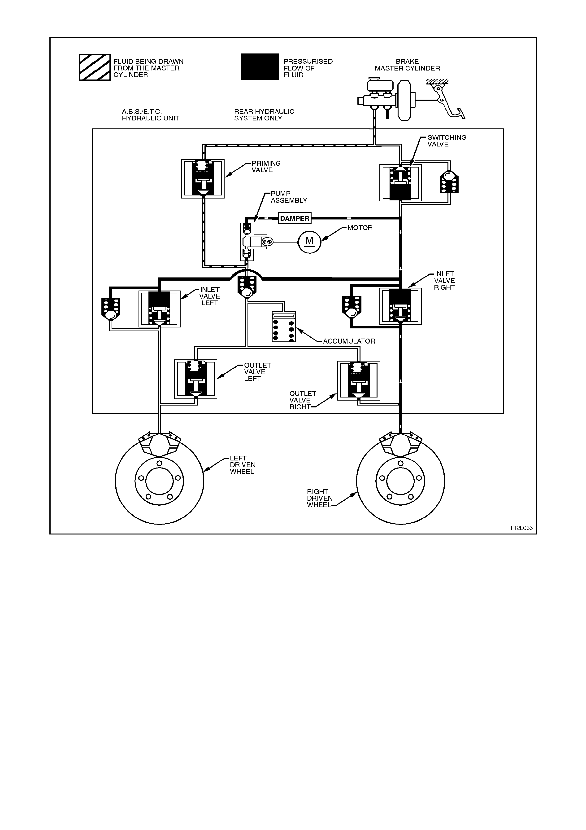
Figure 12L-34
MASTER CYLINDER OPERATION
The operation of the master cylinder assembly used on vehicles with ABS/ETC is the sam e as the assem bly used
on vehicles without ABS/ETC, r efer to Section 5A STANDARD BRAKES of the VT Series I Ser vice Inform ation for
details.
OPERATION AND TESTING OF THE ABS AND ‘TRAC OFF’ WARNING LAMPS
Should a vehicle equipped with ABS/ETC come into the workshop with one of the following customer complaints,
make sure of the circumstances before checking the complete ABS/ETC with the TECH 2 diagnostic scan tool.
1. Warning lamp(s) does not illuminate after switching the ignition on.
2. Warning lamp(s) does not go out after engine has started.
3. Warning lamp(s) illuminates again while driving or illuminates occasionally.
The following gives information about the functioning and malfunctioning of the ABS and TRAC OFF warning lamps.
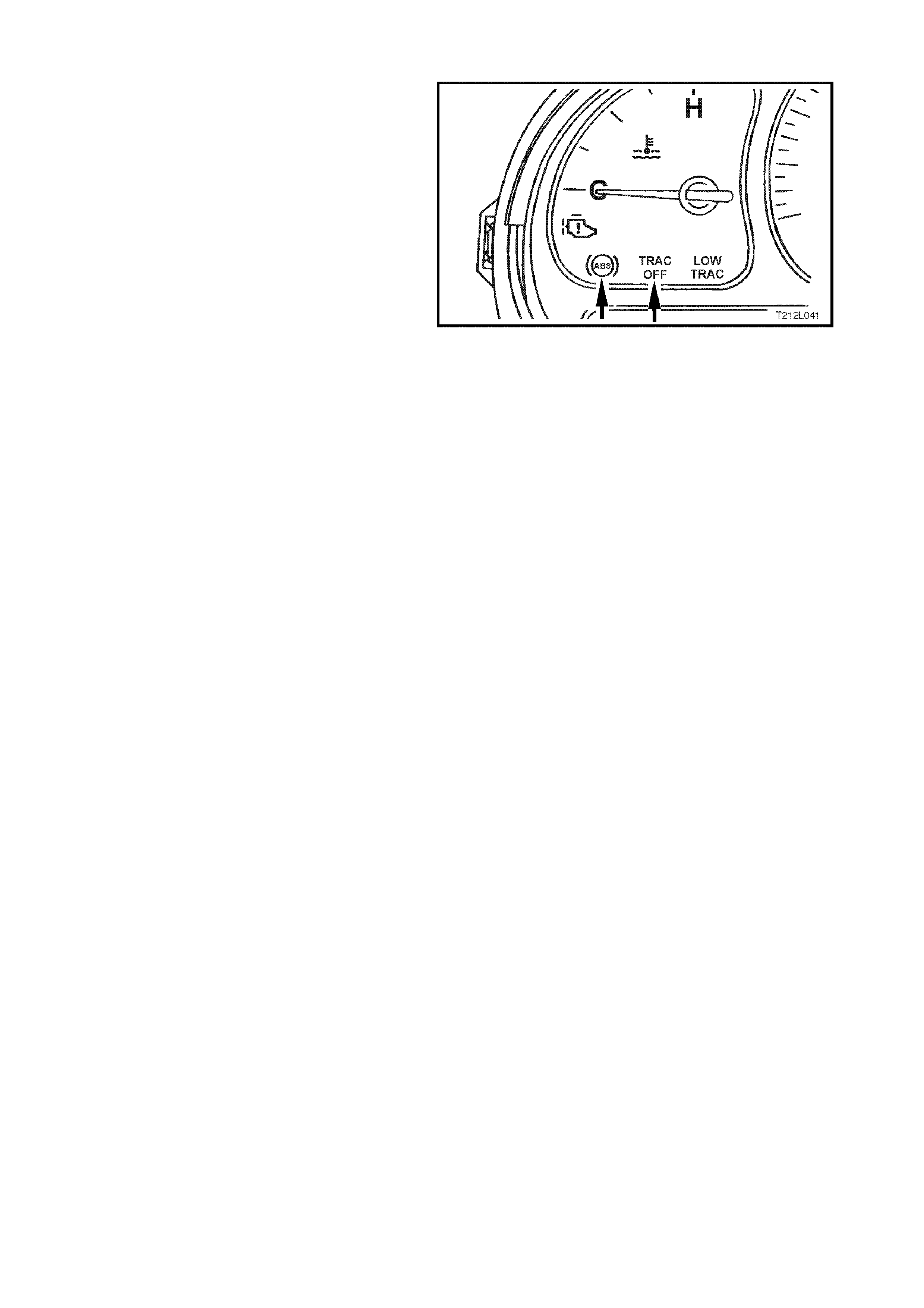
ABS and TRAC OFF Warning Lamps
W hen the ignition is switched on, the ABS warning
lamp illuminates for approximately two seconds
and the TRAC OFF warning lamp f or appr ox imately
five seconds (with engine running, TRAC OFF lamp
will illuminate for only two seconds also). During
this period of time, the ABS/ETC control module
performs a check of the ABS/ETC system wiring.
On all vehicles with ABS/ETC, as soon as all four
wheels of the vehicle exceed a speed of
approximately 6 km/h for the first time after starting,
the ABS/ETC system tests itself automatically
(ABS/ETC 'Self-Test'). The ABS/ETC control
module cycles each solenoid valve and the return
pump motor in the hydraulic modulator to check
component operation. The ABS/ETC control
module also checks its own circuitry.
This procedure is repeated every time the ignition is
switched OFF and the engine is started again. In
addition, the ABS/ETC system constantly tests
itself while the vehicle is travelling.
The warning lamp is also used for self diagnosis
purposes.
NOTE: The TRAC OFF warning lamp will also
illuminate if the TRAC CTRL button has been
pressed. The TRAC OFF light will then stay
illuminated until either the ignition is switched off or
the TRAC CTRL button is pressed again.
Figure 12L-35

Incorrect Warning Lamp Indications (ABS and TRAC OFF)
1. Warning lamp(s) does not illuminate after switching ignition ON.
2. Warning lamp(s) does not go out after approximately 2 seconds.
3. Warning lamp(s) illuminates when driving or illuminates occasionally.
NOTE: The T RAC O FF warning lam p will illum inate if the ETC system is m anually switched of f by the T RAC CT RL
switch located in the console and the LOW TRAC warning lamp will flash if the ETC system is functioning (in a
wheel spin situation). If either of these lights illuminate under these conditions, the system is functioning correctly.
Illumination of the ABS warning lamp indicates to the driver that the ABS is defective.
Illumination of the TRAC OFF warning lamp indicates to the dr iver that the ETC system is either manually disabled
or defective.
When the ABS warning lamp is activated, the vehicle reverts to normal braking as in vehicles without ABS fitted
(e.g. under emergency braking, wheel/s may lock).
When the TRAC OFF warning lamp is activated, the ABS still functions correctly.
Occasional illumination of the warning lamps may be brought about through the battery being insufficiently charged.
The lamp lights up only as long as there is a low voltage, e.g. after switching on electrical components at idle.
The causes of trouble can be determined with the assistance of the TECH 2 diagnostic scan tool.
LOW TRAC warning lamp
The LOW TRAC lam p is used to inform the driver that the vehicle is in a critical driving situation and that the ETC
system has been engaged to control wheel spin.
3. SERVICE OPERATIONS
NOTE: With exception to the following Service Operations, all Service Operations for VT Series II ABS and
ABS/ETC carry over from those described in Section 12L ABS & ABS/ETC of the VT Series I Service Information.
3.1 THROTTLE RELAXER CONTROL MODULE
REMOVE
1. Disconnect battery earth lead.
2. Remove left hand front shroud panel lower
trim assembly (kick panel trim), refer to
Section 1A2 UNDERBODY of the VT Ser ies I
Service Information.
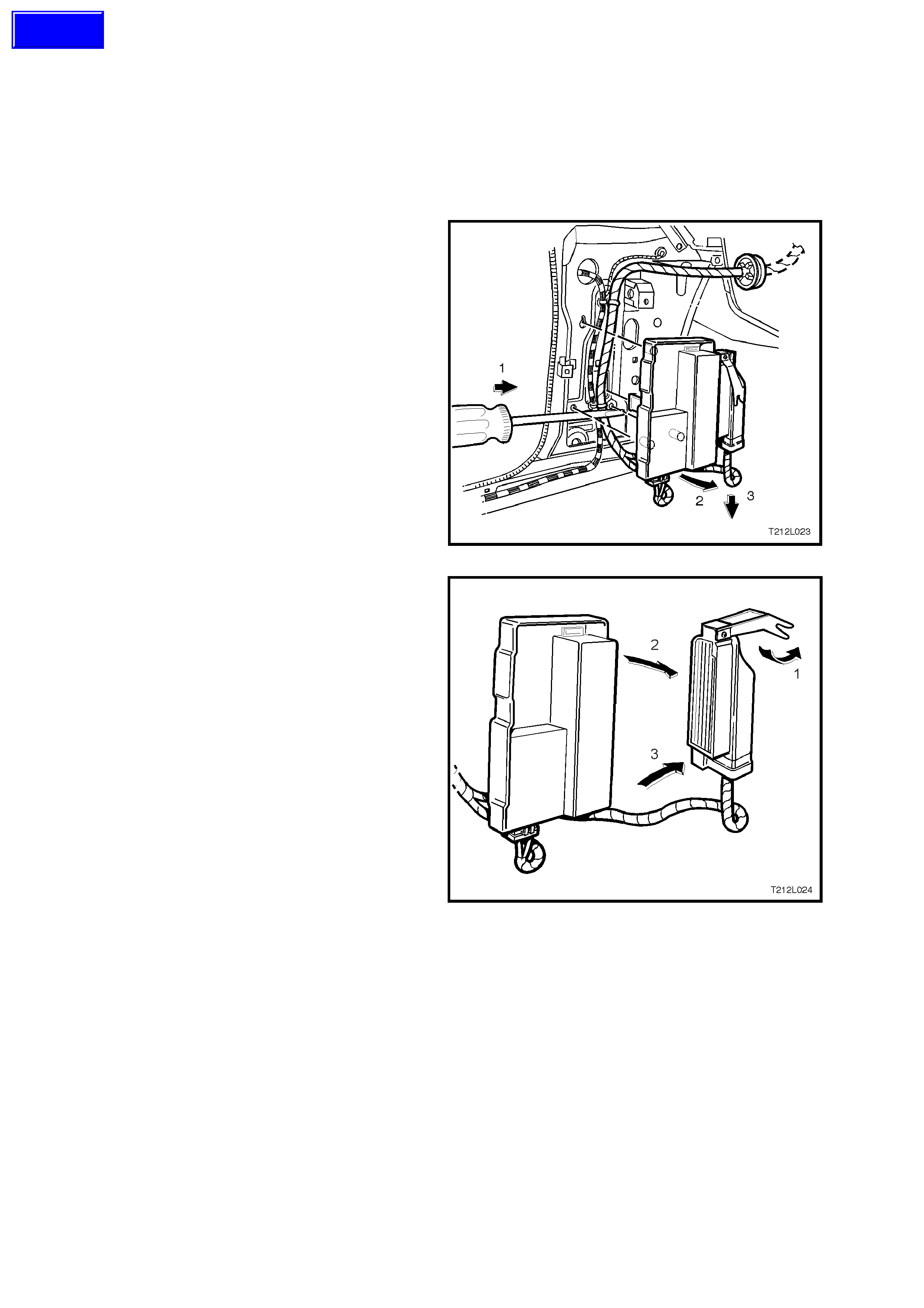
3. Using a flat bladed screw driver, push the
lower retaining tab (between the shroud lower
panel and the back of the throttle relaxer
control module mounting bracket) forward
while lifting the base of the mounting bracket
outwards, approximately two centimetres.
With the lower retaining tab disengaged, pull
the mounting bracket assembly downwards to
disengage the top retaining tab.
Figure 12L- 36
4. Disconnect the throttle relaxer control module
connector by:
1. Lift the locking lever on the control
module connector.
2. Pull the top of connector away from
control module.
3. Lift connector upwards, disengaging the
base of the connector from the control
module.
Figure 12L-37
Techline
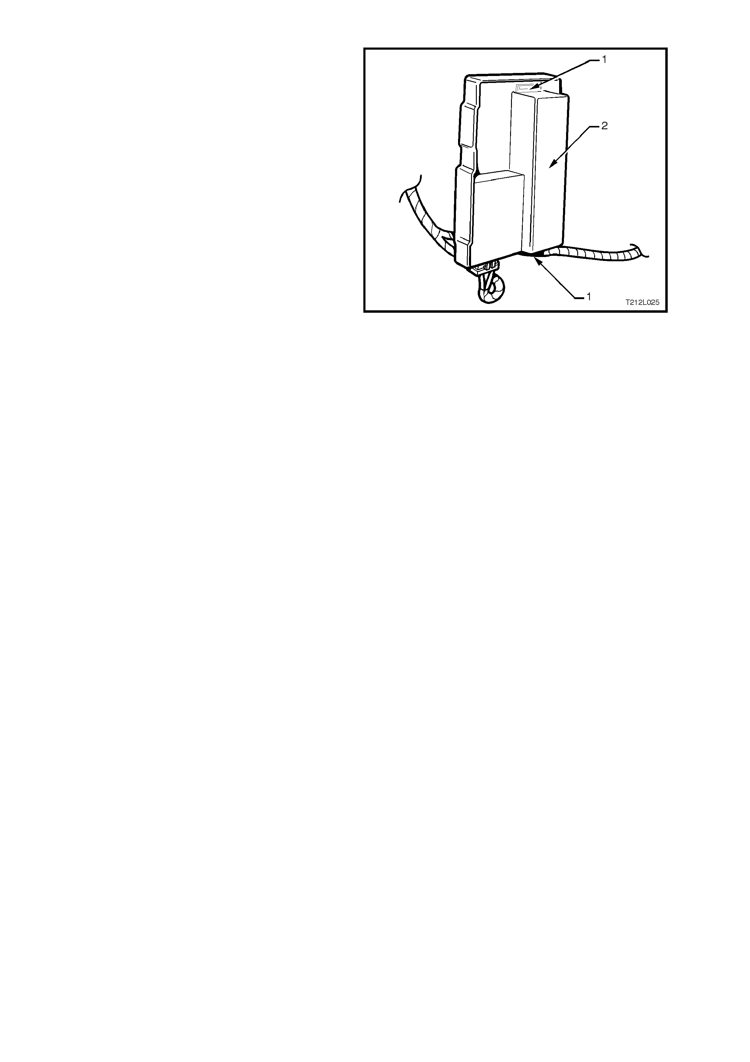
5. Lift the two retaining tabs (1) on the mounting
bracket and slide the throttle relaxer control
module (2) out of mounting bracket.
Figure 12L-38
REINSTALL
Reinstallation of the throttle relaxer control module
is the revers e of the rem oval procedur e, noting the
following:
1. To reconnect the throttle relaxer control
module wiring harness connector, use the
following procedure:
1. Hook base of connector into throttle
relaxer control module.
2. Push top edge of connector into throttle
relaxer control module using the base as
a pivot.
3. Push locking lever down and towards the
throttle relaxer control module.
4. Ensure lever seats flush with top of
connector housing.
2. Turn ignition ON and observe the ABS and
TRAC OFF warning lamps. Lamps should
illuminate for approxim ately 2 - 5 se conds and
then turn off. If warning lamps remain
illuminated, refer to 4.4 ABS OR ABS/ETC
FUNCTIONAL CHECK in this Section.


4. ABS/ETC DIAGNOSIS
CAUTION: Certain components in the Anti-lock Brake System and Electronic Traction Control system are
not intended to be serviced individually. Attempting to remove or disconnect certain system components,
such as the solenoid valves or pump motor from the hydraulic modulator, may result in personal injury
and/or improper system operation. Only those components with approved removal and reinstallation
procedures describ ed in 3. SERVICE OPERAT IONS in this Section and Section 12L ABS & ABS/ETC of the
VT Series I Service Information should be serviced.
Before attempting any diagnostic work on the ABS, refer to and read the 'SAFETY AND PRECAUTIONARY
MEASURES' as described in 3. SERVICE OPERATIONS, Section 12L ABS & ABS/ETC of the VT Series I
Service Information.
4.1 GENERAL DESCRIPTION
Diagnostic information in this Section relates only to ABS/ETC systems on vehicles with GEN III V8 engines.
Additionally, only diagnostic information that differs from the ABS/ETC system used on VT Series Models with V6
engines is detailed. For diagnostic information that is not detailed in this Section, refer to
Section 12L ABS & ABS/ETC of the VT Series I Service Information.
The following information is necessary when diagnosing any Anti-lock Braking System problem or failure,
specifically it should be used to diagnose conditions that may cause the illumination of the ABS or TRAC OFF
warning lamps in the instrument cluster.
Should conditions exist with the conventional (non ABS) portion of the braking system which cause the BRAKE
FAILURE warning lamp to illuminate (also in the instrument cluster), or there is some other obvious brake
mechanical problem, such as brake noise, brake pulsation (pedal or vehicle vibration during normal brake
application), brake pull or a parking brake problem, then these problems must be corrected before attempting to
rectify any suspected ABS/ETC problem. Refer to Section 5A STANDARD BRAKES of the VT Series I Service
Information for diagnosis and repair of the conventional braking system.

4.2 BASIC KNOWLEDGE REQUIRED
Before attem pting to diagnose the Anti-lock Brake System or Electronic Traction Control system , you m ust have a
good understanding of electrical system basics and the use of circuit testing tools. W ithout this basic knowledge it
will be difficult to use the diagnostic procedures detailed in this Section.
Some elec trical basics, troubleshooting procedures and hints as well as the use of circuit testing tools are covered
in Section 12P WIRING DIAGRAMS of the VT Series I Service Information.
Basic Electrical Circuits - You should understand the basic theory of electricity, series and parallel circuits, and
voltage drops across series resistors. You should know the meaning of voltage (volts), current (amps), and
resistanc e (ohms). You should understand what happens in a circuit with an open or shorted wire (shor ted either to
voltage or earth). You should also be able to read and understand a wiring diagram.
Use of Circuit Testing Tools - You should know how to use a jumper lead to test circuits. You should be familiar with
the use of a high input im pedance ( 10 Meg ohm) digital type multim eter such as tool No. J39200 or equivalent and
be able to measure voltage, current, and resistance. You should be familiar with the proper use of the TECH 2
Diagnostic Scan Tool.
4.3 VISUAL INSPECTION
When investigating any complaint of an ABS/ETC system problem or malfunction, start diagnosis with an ABS,
ABS/ETC visual inspection.
The ABS, ABS/ETC vis ual ins pec tion is an ex amination of eas ily access ible components that c ould caus e pr oblems
with the system. The visual inspection procedure may quickly identify the cause and eliminate the need for
additional diagnosis.
If the complaint condition cannot be resolved by a visual check of the system components, then proceed to the
ABS, ABS/ETC Functional Check following on after the Visual Inspection Chart.
ABS, ABS/ETC VISUAL INSPECTION CHART
ITEM INSPECT FOR CORRECTIVE ACTION
GENERAL
Wheel and Tyres Recommended tyre and wheel
size fitted to vehicle Fit recommended size tyres
and wheels
BRAKE SYSTEM COMPONENTS
Master Cylinder Fluid Reservoir Low fluid level Add fluid as required.
Determine cause of fluid loss
and repair
Hydraulic Modulator External leaks If leakage is excessive,
replace modulator
Brake Booster And Master
Cylinder Correct installation and
assembly Reinstall or reposition
components correctly
Park Brake Mechanism Mechanism fully releasing Operate lever to verify release.
Adjust cable or repair release
mechanism as required
FUSES
ENGINE COMPARTMENT
ABS Fusible Link FR Blown fusible link Replace fusible link. Inspect
for cause of failure
PASSENGER COMPARTMENT
ABS Fuse F27 Blown fuse Replace fuse. Inspect for
Warning Lamp Fuse F13
(Ignition Circuit) cause of fuse failure
Stop Lamp Fuse F5
WIRING CONNECTIONS
ENGINE COMPARTMENT
ABS/ETC control module Wiring
Harness Connector In all cases, inspect for:
Main W i ring Harness to Front
Wheel Speed Sensor
Connections Proper engagement.
Loose wires or terminals. Ensure proper engagement
Repair as required
Hydraulic modulator pump motor
wiring harness connector Corroded or broken
connections
PASSENGER COMPARTMENT
Main W i ring Harness to Body
Harness Connectors
UNDER VEHICLE
Front Wheel Speed Sensor Lead
to Front Wheel Hub Connections
Body Harness to Rear Wheel
Speed Sensor Connections

4.4 ABS OR ABS/ETC FUNCTIONAL CHECK
If the source of the system problem or malfunction was not isolated during the ABS, ABS/ETC visual inspection,
carry out the following ABS, ABS/ETC functional check. Also, use the check to verify normal ABS/ETC operation
during diagnosis or after making any system repairs.

ABS OR ABS/ETC FUNCTIONAL CHECK CHART
STEP ACTION YES NO
1•Has ABS, ABS/ETC Visual Inspection been
performed? Go to Step 2. Perform ABS, ABS/ETC
Visual Inspection as per
4.3 in this Section before
proceeding.
2. •While observing the Brake Failure warning lamp, turn
the ignition to the Bulb Check position (engine
cranking position).
•Does the Brake Failure warning lamp illuminate?
Go to Step 3. Check warning lamp
circuit, refer to Section
12C of the VT Series I
Service Information.
3. •Turn ignition OFF.
•Turn ignition ON whilst observing ABS or ABS and
TRAC OFF warning lamp.
•Do warning lamps illuminate for approximately three
seconds (five seconds for TRAC OFF lamp) then turn
OFF?
NOTE: If engine is started, warning lamps will illuminate
for only 2 seconds
Go to Step 7. Go to Step 4.
4. •Install TECH 2 to DL C.
•Select Chassis / ABS/ETC and press CONFIRM.
•Does TECH 2 communicate with the ABS by
displaying the System Identification Information?
Go to Step 5. Refer to DTC 72 -
SERIAL DATA FAULT
Diagnosis in this Section.
5. •With TECH 2 still connected, select Diagnostic
Trouble Codes / Read DTCs.
•Are any DTCs set?
Go to Step 6. Refer to Charts A1, A2
(WARNING LAMPS
INOP) or CHARTS C1,
C2 (WARNING LAMPS
ILLUMINATED
CONTINUOUSLY) in
Section 12L ABS &
ABS/ETC of the VT
Series I Service
Information.
6. •Select relevant DTC Function Key.
•Are the ignition cycles zero (0)? Refer to relevant
ABS/ETC DTC chart in
this Section or in
Section 12L ABS &
ABS/ETC of the VT
Series I Service
Information.
Refer to 4.5
INTERMITTENT
FAILURES in this
Section.
7. •Road test vehicle, ensuring to achieve at least a
speed of 35 km/h.
•Did the ABS warning lamp turn on during the road test
?
NOTE: Ensure TECH 2 is disconnected during road test.
Go to Step 5. Go to Step 8.
8. •During the road test, did the vehicle exhibit any
symptoms or improper operation that may be
mechanical in nature and/or did the Brake Failure
warning lamp turn ON ?
Refer to Section 5A
BRAKES of the VT
Series I Service
Information for
conventional braking
system repair details.
Go to Step 9.
9. •Install TECH 2 to DLC and turn ignition ON.
•Check for any ABS History DTCs.
•Are any History DTCs present (1 or more ignition
cycles)?
Refer to relevant
ABS/ETC DTC
diagnostic chart in this
Section or in Section
12L ABS & ABS/ETC of
the VT Series I Service
Information. Chart may
be used to identify and
isolate suspected
failures. Also, refer to
4.5, INTERMITTEN T
FAILURES in this
Section for more
information on isolating
suspected failures.
Clear all DTCs and
repeat this functional
check.
System OK, however, if
a fault is still suspected,
refer to 4.5,
INTERMITTENT
FAILURES in this
Section.
WHEN ALL DIAGNOSIS AND REPAIRS ARE COMPLETED, CLEAR ALL DTCs AND VERIFY CORRECT OPERATION

4.5 INTERMITTENT FAILURES
As with most electronic systems, intermittent failures may be difficult to accurately diagnose. The following is a
method to try to isolate an intermittent failure, especially wheel speed circuit failures.
If the control module detects an ABS fault, the ABS warning lamp will illuminate during the ignition cycle in which the
fault was detected and a Diagnostic Trouble Code (DTC) will be logged in memory of the control module.
If an ETC fault occurs, either the TRAC OFF and /or ABS warning lamp will illuminate, if the fault is specific to the
ETC system, both the TRAC OFF and the ABS warning lamps will illuminate, if the fault is common to both
systems.
If an intermittent problem occurs, the TRAC OFF and/or ABS warning lamp will go out (if the fault corrects itself)
after the ignition has been cycled off and on. Also stored in the control m odule memory, will be the history data of
the DTC at the time the fault occurred. This history data includes the number of Ignition Cycles since the DTC
occurred, if the Ignition Cycle is zero, then the DTC is Current, if the Ignition Cycles is greater than zero, then the
DTC is a history DTC. TECH 2 can be used to read ABS/ETC data;
1. If a system fault has been detected, record all current tr ouble codes and tr ouble code histor y information. Als o,
if available, record any specific driving condition during which the problem or failure occurs. This information
can help in duplicating the condition.
2. Clear any trouble codes that are stored in the control module memory, refer 'CLEARING DTCs' in this Section.
3. Using the TECH 2 in Snapshot Mode while test-driving the vehicle, try to duplicate the condition in which the
problem or fault occ urs. Refer to 4.7 TECH 2 Diagnostics in this Sect ion for additional inf ormation on the us e
of TECH 2.
NOTE: IN CERTAIN DIAGNOSTIC MODES, THE ANTI-LOCK BRAKING SYSTEM IS DISABLED WHILE TECH 2
IS COMMUNICATING WITH THE ABS OR ABS/ETC CONTROL MODULE.
If an intermittent condition is still undetected, or not related to the wheel speed circuitry, go to the appropriate
Diagnostic Tr ouble Code (DTC) or symptom c hart in this Sec tion. Follow through the Char t while m oving or wiggling
the associated ABS or ABS/ETC wiring harnesses and connectors, and at the same time looking for intermittent
type failures in the circuitry.
Most intermittent problems are caused by faulty electrical connections or wiring. When an intermittent failure is
encountered, check suspect circuits for:
a. Poor mating of connector body halves or terminals not fully seated in the connector body (backed out).
b. Improperly formed or damaged terminals. If damaged, carefully reform terminals in a suspected circuit.
c. Poor terminal to wire connection. This r equires r emoving the terminal f r om the c onnector body to inspec t ( refer
to Section 12P WIRING DIAGRAMS of the VT Series I Service Information).
Also, due to the sensitivity of ABS/ETC components to Electro-Magnetic Interference (EMI), the following checks
should be performed if an intermittent malfunction is suspected:
a. Check for proper installation of wiring harness es resulting f rom add-on options such as a C.B. radio or cellular
telephone etc.
b. Visually inspect wheel speed sensors and pulse rings for looseness, damage, foreign material accumulation
and proper mounting. Replace damaged components, remove any foreign material and/or properly attach all
components.
c. While test driving vehicle, monitor wheel speeds using TECH 2. If any wheel speed drops or displays erratic
speed, refer to the appropriate wheel speed DTC chart in this Section.
If detected, ABS failures will disable the anti-lock brake function of an entire ignition cycle, even if the condition
clears itself before the ignition is switched off. However, the clearing of low voltage failure conditions during an
ignition cycle will allow ABS operation to resume.
If an ETC only failure is detected, the traction control functions will be disabled for an entire ignition cycle, even if the
condition clears itself before the ignition is switched off. However, the clearing of low voltage failure conditions
during an ignition cycle will allow ABS and ETC operation to resume.
4.6 ABS & ABS/ETC SELF DIAGNOSTICS
DIAGNOSTIC TROUBLE CODES
The ABS/ETC control modules are equipped with a self diagnostic capability that can detect and isolate ABS/ETC
problem s or failures . When a pr oblem or failure is detected, the ABS/ETC contr ol module s ets a Diagnos tic T r ouble
Code (DTC) that represents that particular problem or failure. There are twenty nine DTCs on ABS/ETC systems for
vehicles with GEN III V8 engines that may be set by the ABS/ETC control module. Depending on the DTC set,
either the ABS, ETC or both ABS and ETC systems will be disabled. If the ABS is disabled, it will allow for
conventional non ABS brak ing only and the ABS warning lam p will be turned on. The ABS/ET C control m odule has
the capability of storing three DTCs.
NOTE: The warning lamp will illuminate whilst a fault is ac tive. If a fault has oc c urr ed and is not ac tive, the lamp will
not be illuminated and a fault code will be stored.
The control module performs an automatic test once during each ignition cycle when the vehicle reaches
approxim ately 6 km /h (or 18 k m/h if a stop lamp s ignal is received). T he automatic test cycles each solenoid valve
and the pump motor to check component operation. If any error is detected during this test, the ABS/ETC control
module will set a DTC. This test may be heard and felt while it is taking place and is a normal mode of operation.
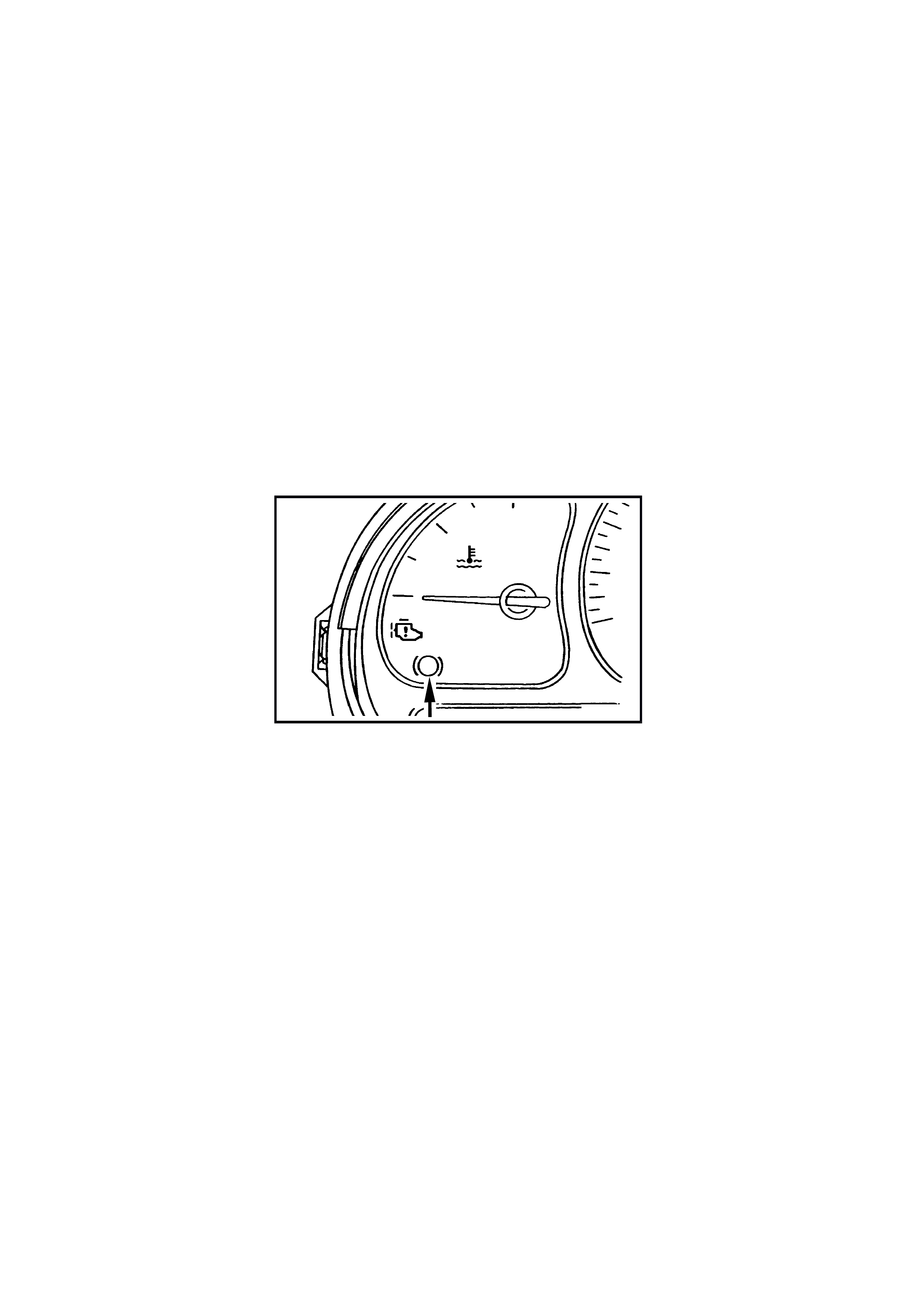
The ABS/ETC control module can display the DTCs via the ABS warning lamp only when the 'Diagnostic Service
Mode' has been entered. Entering the diagnostic service mode is accomplished by either:
Earthing terminal 12 of the Data Link Connec tor (DLC) us ing a test lead fitted with suitable term inals and monitoring
the ABS warning lamp to flash system DTCs, refer to FLASH CODE DIAGNOSTICS DISPLAY in this Section.
Or by using TECH 2, refer to 4.7 TECH 2 DIA GNOSTICS in this Section.
H
C
TRAC
OFF LOW
TRAC
ABS
T212L011
Figure 12L-39
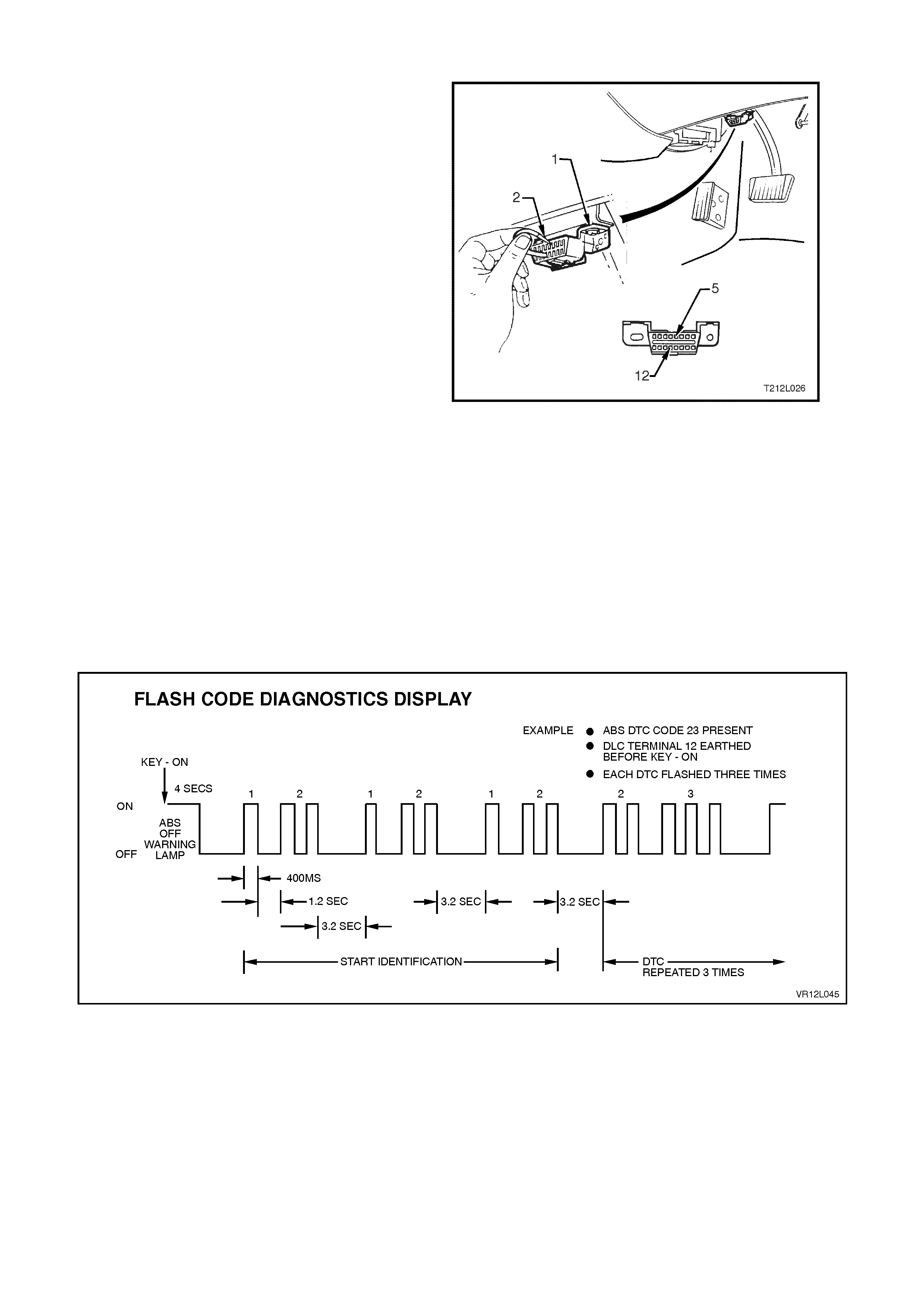
FLASH CODE DIAGNOSTICS DISPLAY
To enable the ABS warning lamp to flash system
DTCs, the vehicle must be stopped (vehicle speed
is less than 10 km/h), terminal 12, circuit 863
(Blue/Black wire) (12) of the DLC (1) earthed to
terminal 5, circuit 155 (Black/Yellow wire (5) of the
DLC using a test lead (2) fitted with suitable
terminals and then the ignition turned on. The flash
code diagnostics will remain enabled as long as
terminal 12 is earthed, serial data line
communication has not been initiated or until any
wheel speed is greater than 10 km/h.
Approximately three sec onds af ter earthing ter minal
12 (with the ignition ON) of the DLC, the ABS/ETC
control module will begin flashing the ABS warning
lamp.
The flash sequenc e will begin with DTC 12 to signal
the beginning of the f lash code display. DTC 12 will
flash three times. Each stored code will then be
displayed three times. After all codes have been
displayed, the sequence will repeat, starting with
DTC 12.
The charts on the next page set out all the possible
diagnostic trouble codes.
NOTE: Flash code diagnosis is not fully supported
on certain Diagnostic Trouble Codes involving the
solenoid valves or motor due to the valve relay
inside the control unit being disabled. Diagnostic
Trouble Codes 41, 42, 45, 46, 47, 48, 55, 56, 61
and 63 will prevent the ABS warning lamp from
turning off. These faults can only be read through
the DLC using TECH 2.
Figure 12L-40
Figure 12L-41

GEN III V8 ABS/ETC DIAGNOSTIC TROUBLE CODES
DTC CODE DESCRIPTION
12 No Fault
21 Front Right Wheel Speed Sensor Incorrect Signal
23 Front Right Wheel Speed Sensor Short Circuit or Open Circuit
25 Front Left Wheel Speed Sensor Incorrect Signal
27 Front Left Wheel Speed Sensor Short Circuit or Open Circuit
28 Wheel Speed Sensor Frequency Error
31 Rear Right Wheel Speed Sensor Incorrect Signal
33 Rear Right Wheel Speed Sensor Short Circuit or Open Circuit
35 Rear Left Wheel Speed Sensor Incorrect Signal
37 Rear Left Wheel Speed Sensor Short Circuit or Open Circuit
41 Front Right Inlet Valve Solenoid Fault
42 Front Right Outlet Valve Solenoid Fault
45 Front Left Inlet Valve Solenoid Fault
46 Front Left Outlet Valve Solenoid Fault
47 Priming Valve Solenoid Fault
48 Switching Valve Solenoid Fault
51 Rear Right Inlet Valve Solenoid Fault
52 Rear Right Outlet Valve Solenoid Fault
55 Rear Left Inlet Valve Solenoid Fault
56 Rear Left Outlet Valve Solenoid Fault
58 Throttle Relaxer PWM (Pulse Width Modulation) Interface Fault
61 Pump Motor or Relay Fault
62 RPM Signal Fault
63 Valve Solenoid Relay Fault
64 Throttle Relaxer Control Module Position Fault
65 Throttle Relaxer Motor Fault
66 Throttle Relaxer Control Fault
67 Stop Lamp Switch Circuit Fault
68 TPS (Throttle Position Switch) Monitoring Fault
71 Control Module Internal Fault
72 Serial Data Fault
73 Spark Retard Monitoring Fault
78 Incorrect Option Coding
85 System Voltage Too Low
NOTE: Diagnos tic char ts f or the DT Cs listed in bold tex t in the table above are the only DTCs that dif fer f rom those
previously published for V6 ABS/ETC s ystems. F or diagnostic charts covering DT Cs lis ted in norm al tex t, refer ence
to Section 12L ABS & ABS/ETC in the VT Series I Service Information should be made.
CLEARING DTCS
Any DTCs stored in the ABS/ETC control module's memory can be erased in one of three ways:
1. Diagnostic Request Line Procedure.
2. TECH 2 Clear Codes Selection.
3. Ignition Cycle Default.
These three methods are detailed as follows.
IMPORTANT: Whichever method is used, be sure to verify proper system operation and absence of any
DTCs when clearing procedure is completed. The ABS/ETC control module will not permit DTC clearing
until all of the codes have been displayed. Also, DTCs cannot be cleared by unplugging the ABS/ETC
control module, disconnecting the battery cables, or turning the ignition OFF (except on an ignition cycle
default).
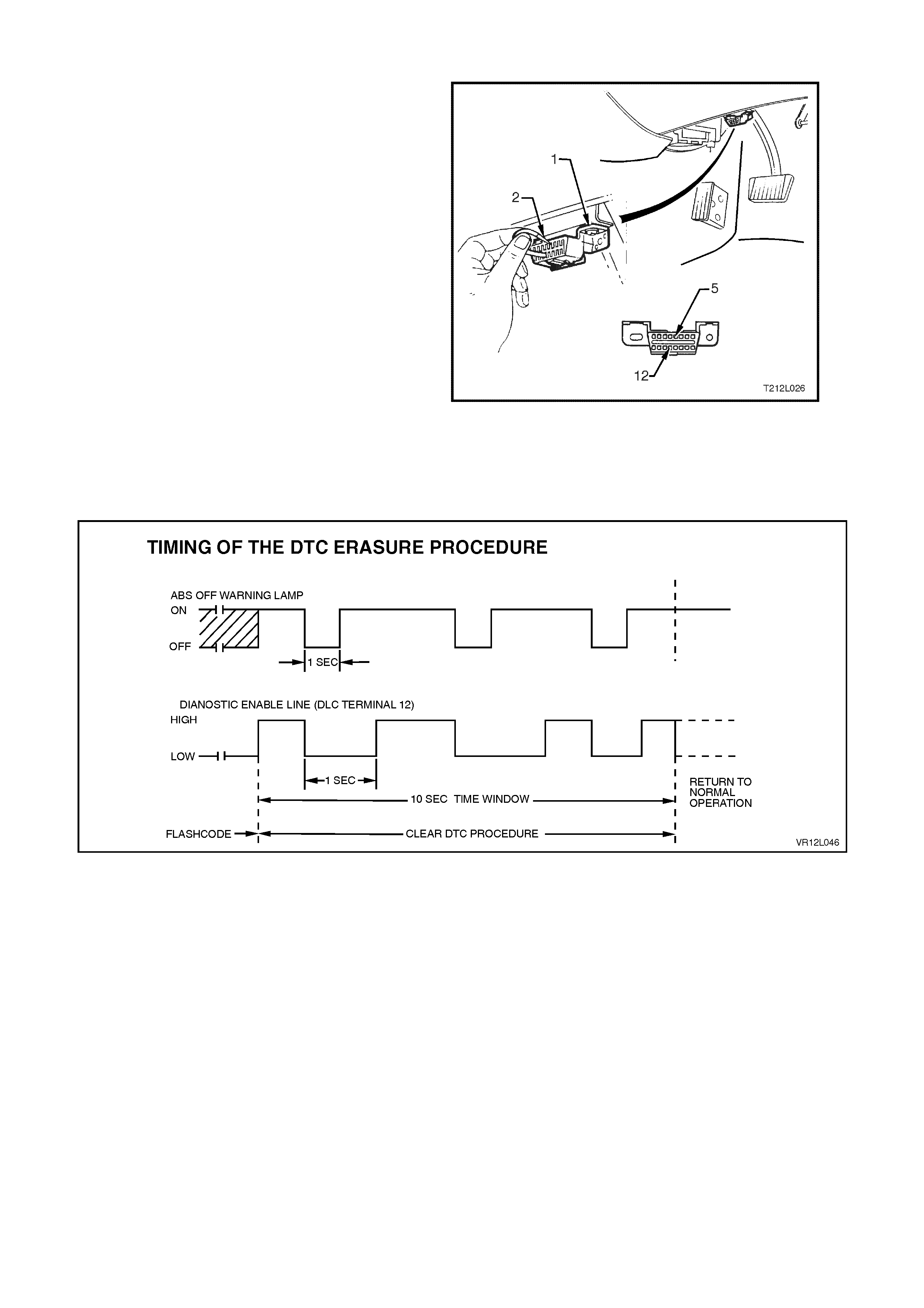
Diagnostic Reques t Line Procedure
To clear trouble codes via the DLC (1) diagnostic
request line, terminal 12 (12), go through the
following procedure.
1. Turn ignition OFF.
2. Connect a test lead (2) fitted with suitable
term inals between DLC terminal 5, c ircuit 155,
black/yellow wire (5) and terminal 12, circuit
863, blue/black wire (12).
3. Turn ignition on (this will enable Flash Code
Diagnostics Display) and allow all codes to be
displayed.
4. Disconnect one end of test lead from DLC for
approximately one second then reconnect for
no less than one second. Repeat this step at
least two more times within 10 seconds,
leaving test lead connected to DLC upon
completion of final connection.
Observe flashing ABS warning lamp. Only DTC 12
should be flashed. If not, trouble codes have not
been properly cleared. Begin clearing code
procedure again at Step 1. If DTCs are cleared,
wait at least 15 seconds before turning ignition
'OFF'.
Figure 12L-42
Figure 12L-43

TECH 2 Clear Codes Procedure
Before clearing DTCs, check and note any history code data, as this information will also be cleared.
Select the appropriate menu, and s elect the Clear Codes f unction. Ver if y that DT Cs have been c leared by using the
TECH 2 to read ABS/ET C trouble codes. If any are present, either the DT Cs were not cleared, or an ABS/ETC f ault
still exists.
Refer to 4.8 TECH 2 TEST MODES AND SCREEN DISPLAYS FOR ABS AND ETC DIAGNOSIS
Ignition Cycle Default
If the ignition is cycled 100-times without a particular fault reappearing, that fault code will be erased from the
ABS/ETC control module memory, and the ignition cycle counter inside the control module will be reset to zero.
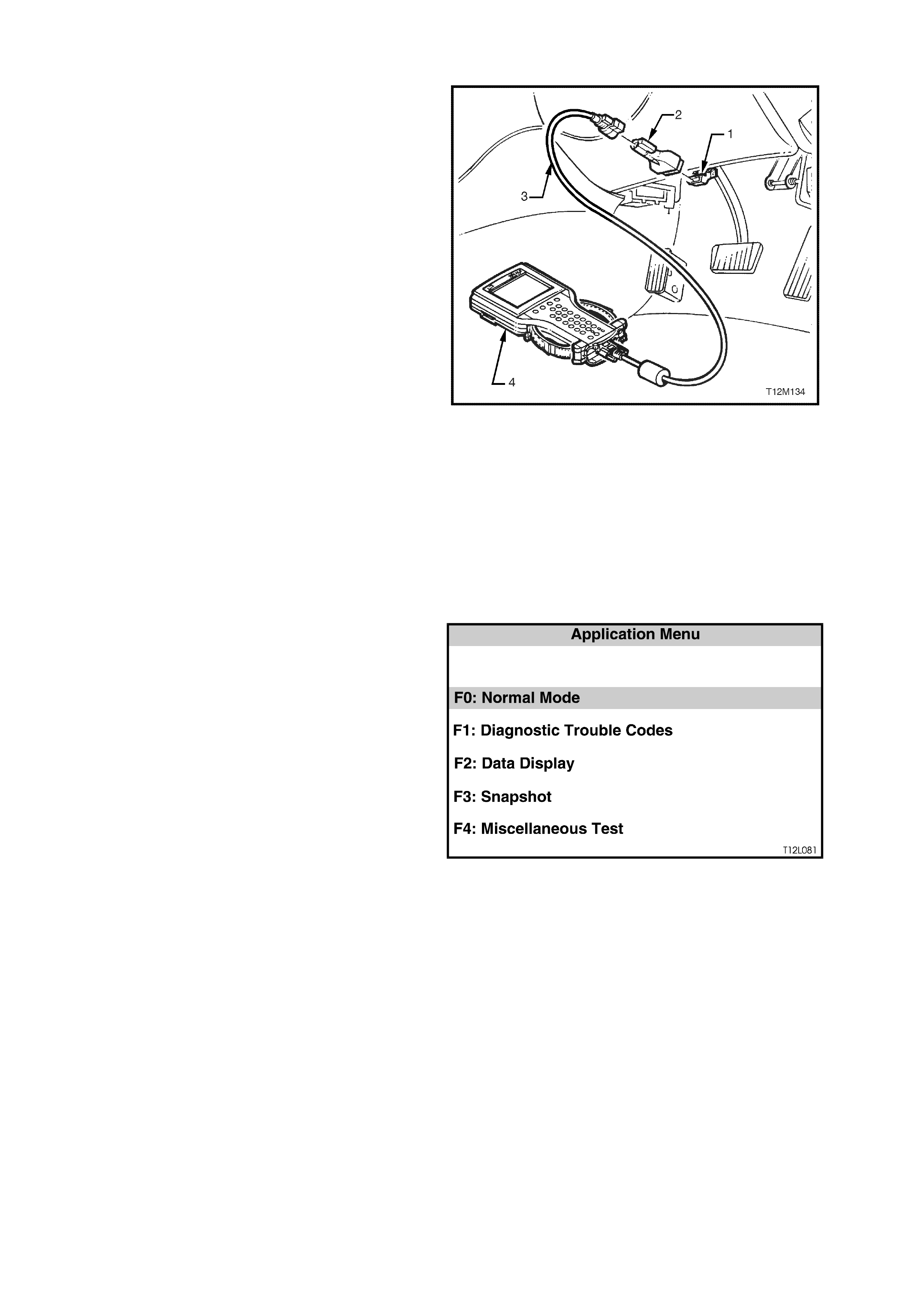
4.7 TECH 2 DIAGNOSTICS
IMPORTANT: When using TECH 2 in certain
diagnostic modes for ABS/ETC diagnosis, the
Anti-lock Brake System is disabled by the
ABS/ETC control module while it is
communicating with TECH 2. The ABS warning
lamp in the instrument cluster will be
illuminated, indicating only conventional (non
ABS) braking is possible.
TECH 2, with the appropriate software, cables and
adaptors, when connected to the Data Link
Connector (DLC) is capable of reading ABS/ETC
serial data. The DLC is connected to the instr ument
panel lower right hand trim, to the right of the
steering column.
For additional general information on connecting
and operating TECH 2, refer to
Section 0C TECH 2 of the VT Series I Service
Information.
1. DLC
2. DLC ADAPTOR
3. DLC CABLE
4. TECH 2
TECH 2 has five test modes for diagnosing the
Anti-lock Brake System and Electronic Traction
Control system. The five test modes are as follows:
Figure 12L-44
Mode F0: Normal Mode
In this mode, TECH 2 monitors the constant
communication between control modules on the
serial data line. The information displayed on the
TECH 2 screen in this mode is what the ABS/ETC
control module is communicating to the other
modules via the serial data line.
Mode F1: Diagnostic Trouble Codes
In this mode, TECH 2 will display a DTC selection
list. When the appropriate function key is selected,
TECH 2 will display a DTC Data Lis t. T he Data Lis t
contains relevant information relating to the DTC.
Mode F2: Data Display
In this test mode, the operator of TECH 2 has the
option of selecting an Active or Disabled data
stream that they can use to constantly monitor the
status of inputs and outputs of the ABS/ETC
system.
MODE F3: SNAPSHOT
In this test mode, the TECH 2 captures ABS/ETC
data before and after a forced manual trigger.
MODE F4: MISCELLANEOUS TESTS
In this test mode, TECH 2 performs system
functional tests to assist in pr oblem isolation during
troubleshooting.
Each test mode has specific diagnosis capabilities
that depend upon various function key entries on
TECH 2.
Also, included in the MISCELLANEOUS TESTS is
a procedure for ABS/ETC brake bleeding.
Figure 12L-4528
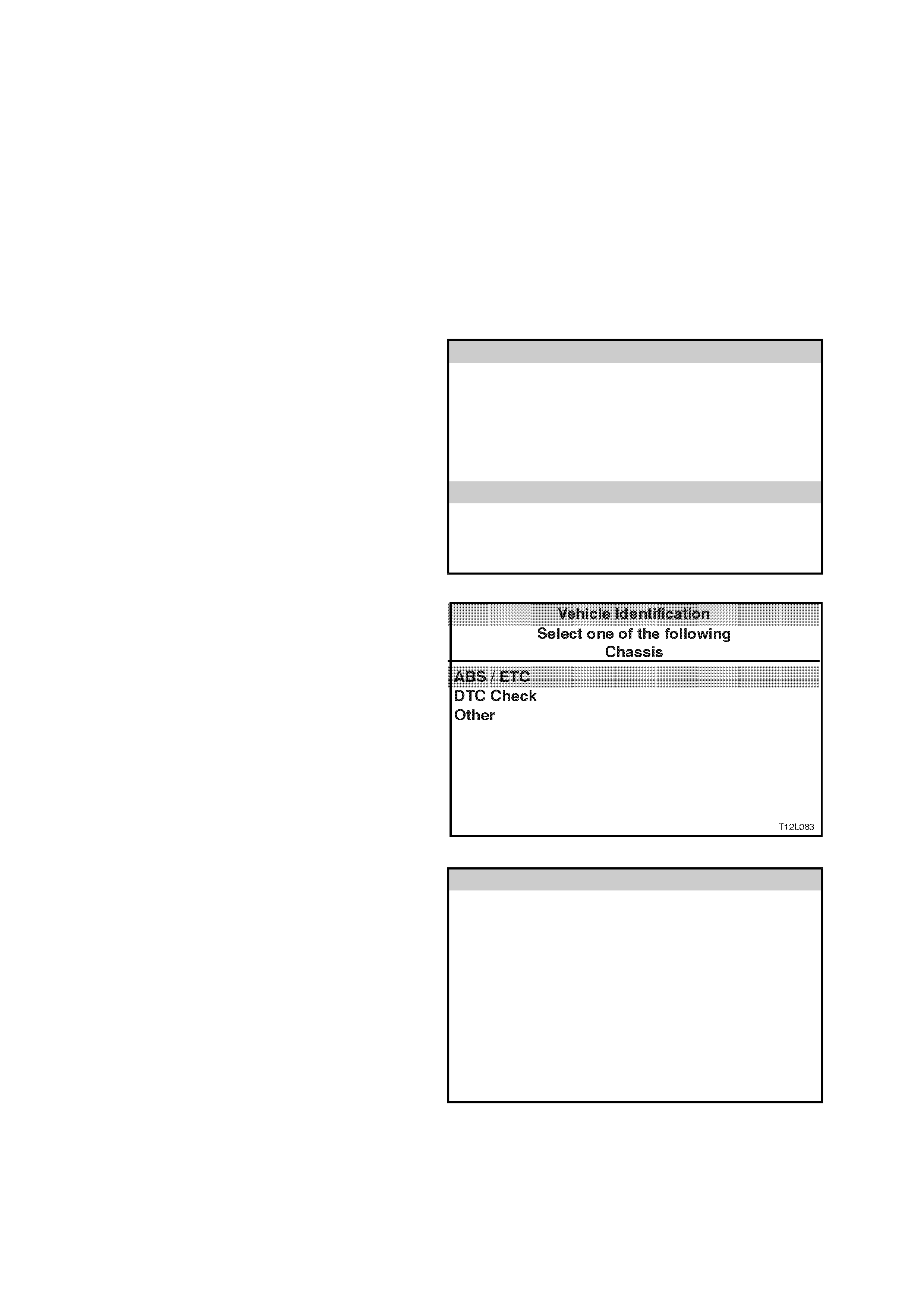
4.8 TECH 2 TEST MODES AND SCREEN DISPLAYS FOR ABS AND ETC DIAGNOSIS
WARNING: When using TECH 2 for ABS/ETC
diagnosis, in certain diagnostic modes, the
system will be disabled.
As a prerequisite to this diagnostic section is for the
user to be familiar with the proper use of TECH 2,
the following pages illustrate only the major TECH
2 screen displays and provide a brief explanation of
their function for diagnosing the ABS/ETC system s .
If additional information is required on the operation
of TECH 2, reference should be made to either
Section 0C TECH 2 of the VT Series I Service
Information or the TECH 2 OPERATORS
MANUAL.
System Select Menu
With TECH 2 connected to the DLC and F0:
DIAGNOST ICS selected f rom the MAIN MENU, the
appropriate MODEL YEAR and VEHICLE TYPE
must be selected for access to the SYSTEM
SELECT MENU.
Select F2: CHASSIS and press enter to continue.
System S elect Menu
(X) 1999 Commodore
F0: Engine
F1: Transmission
F2: Chassis
F3: Body
T212L027
Figure 12L-46
Vehicle Identification Menu
Once F2: CHASSIS has been selected from the
select menu, the ABS/ETC systems can be
selected.
Select ABS/ETC.
Once ABS/ETC is selected, the ABS/ETC
Application menu will be displayed, via the System
Identification screens which will require action.
NOTE: If DTC Check is selected, TECH 2 will
display information advising if any DTCs are set by
any control module. (If DTCs are set from another
module, ref er to the relevant Section in this Ser vice
Information CD). Figure 12L-47
System Identification
Turn the ignition ON (as requested) and press
CONFIRM soft key to continue.
System Iden tification
(X) 1999 Commodore
Electronic System : ABS / ETC
Turn On Ignition!
T212L028
Figure 12L-48
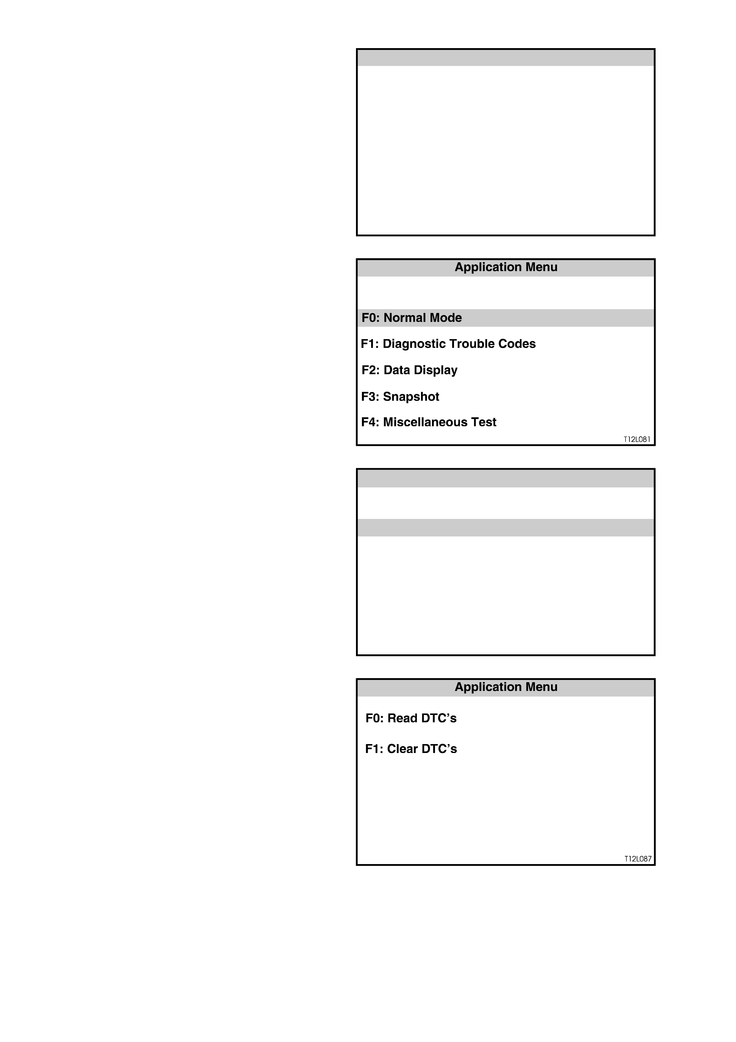
The SYSTEM IDENTIFICATION screen will then
display the control module part num ber and s ystem
identification. Press the CONFIRM soft key to
continue to the ABS/ETC APPLICATION MENU.
System Iden tification
(X) 1999 Commodore
Electronic System : ABS / ETC
Part Number XXXXXXXX
System I.D. XX
System ABS/ETC
T212L029
Figure 12L-49
ABS/ETC Application Menu
The following functions will now be available:
F0: Normal Mode
F1: Diagnostic Trouble Codes
F2: Data display
F3: Snapshot
F4: Miscellaneous Tests
Figure 12L-50
F0: NORMAL MODE
In the F0: Normal Mode, information that the
ABS/ETC control module is communicating to other
control modules, via the serial data line, is
displayed.
For example: As displayed opposite, the ETC
Warning lamp status is ON. This means the
ABS/ETC control module is communicating with the
instruments, requesting the ABS warning lamp to
be illuminated.
System S elect Menu
Stop Lamp Switch OFF
ON
NO
YES
OFF
NO DTCs
OFF
ABS Warnin g Lamp
ETC Warning Lamp
Low Traction
ETC Equipped
ABS Chi me
ABS DTC Status
T12L086
Figure 12L-51
F1: DIAGNOSTIC TROUBLE CODES
If the F0: READ DTCs is selected from this mode,
a listing of all (if any) DTCs that have been set by
the ABS/ETC control module will be displayed. To
obtain further information about a particular DTC,
press the relevant function key (i.e. F0) and a DTC
data list will be displayed. From the information
provided in this data list, you can determine when
the DTC occurred and the operating conditions of
the system at the time.
For a listing of all DTCs, refer to 4.6 ABS &
ABS/ETC SELF DIAGNOSTICS in this Section.
DTCs can be cleared by simply selecting F1 Clear
DTCs and pressing the ENTER key.
NOTE: If any DTCs are set, reference should be
made to the r elevant diagnostic char ts in either this
section or Section 12L ABS & ABS/ET C of the VT
Series I Service Information.
Figure 12L-52

F2: DATA DISPLAY
If the F2: DATA DISPLAY mode is selected, an additional application menu will appear giving the operator the
option of selecting ABS/ETC data while the system is either active or disabled.
F0: Active ABS/ETC
F1: ABS/ETC disabled
If the disabled data list is selected, the ABS warning lamp will be illuminated and the system will become disabled.
W hile the two data lists of fer sim ilar inform ation, the active data list has the advantage of m onitoring the ABS/ETC
systems while they are operational, aiding in the diagnosis of intermittent faults.
W hen monitor ing speed data, the T ECH 2 screen displays the signals being sent fr om the wheel speed sensor s to
the control module. In F0: Active ABS/ETC display mode, the vehicle can be driven while TECH 2 displays wheel
speed data. At this time, the readings may be compared with vehicle speed to check proper operation. Wheel
speed signals can also be compared with each other to determine whether they are within specification.
If one wheel speed signal differ s greatly from the other signals , impr oper operation of that partic ular sensor m ay be
indicated. Intermittent wheel speed signals can be detected in this mode by looking for signals that vary for no
apparent reason. This variation can oc c ur dur ing vehicle oper ation and can be c aptur ed during F 3: SNAPSHOT test
mode.
For additional information regarding the soft k eys while in the DATA DISPLAY mode, ref er to Section 0C TECH 2
of the VT Series I Service Information.
The table below lists each item contained in the data s tream f or both active and disabled lists, together with a brief
description of their meanings.
ACTIVE ABS/ETC
DATA STREAM / SCREEN DISPLAY DESCRIPTION
FR Wheel Speed (Front Right) Displays wheel speed sensor input (km/h) to the control module.
FL Wheel Speed (Front Left)
RR Wheel Speed (Rear Right)
RL Wheel Speed (Rear Left)
Pump Motor Displays current status of pump motor - either ON or OFF.
Pump Relay Displays current status of pump relay - either ON or OFF.
Valve Relay Displays current status of valve relay - either OPEN or CLOSED.
ETC Switch Displays current status of switch - will display OPEN when switch is in the
rest position and CLOSED when held down.
Requested Throttle N/A as of start of production, will always display 0%
(If available – will display the percentage of throttle opening the ABS/ETC
control module is requested the throttle relaxer control module to supply)
Actual Throttle Position N/A as of start of production, will always display 0%
(If available – will display the actual percentage the throttle body valve is
open)
ABS/ETC DISABLED
DATA STREAM / SCREEN DISPLAY DESCRIPTION
FR Wheel Speed (Front Right) Displays wheel speed sensor input (km/h) to the control module.
FL Wheel Speed (Front Left)
RR Wheel Speed (Rear Right)
RL Wheel Speed (Rear Left)
Stop Lamp Switch Displays current status of switch - displays OFF when switch is in the rest
position and ON when brake pedal is depressed.
Pump Monitor Will always display OFF as ABS and ETC are disabled in this mode.
Valve Relay Displays current status of valve relay - either OPEN or CLOSED.
Note: if displays OPEN in this mode, there is a fault in the valve relay circuit.
ETC Switch Displays current status of switch - displays OPEN when switch is in the rest
position and CLOSED when held down.
Engine Speed Displays the current engine speed in RPM.
Throttle Position Displays the current throttle position (percentage of throttle valve opening).
System ID Displays control module internal software identification number.
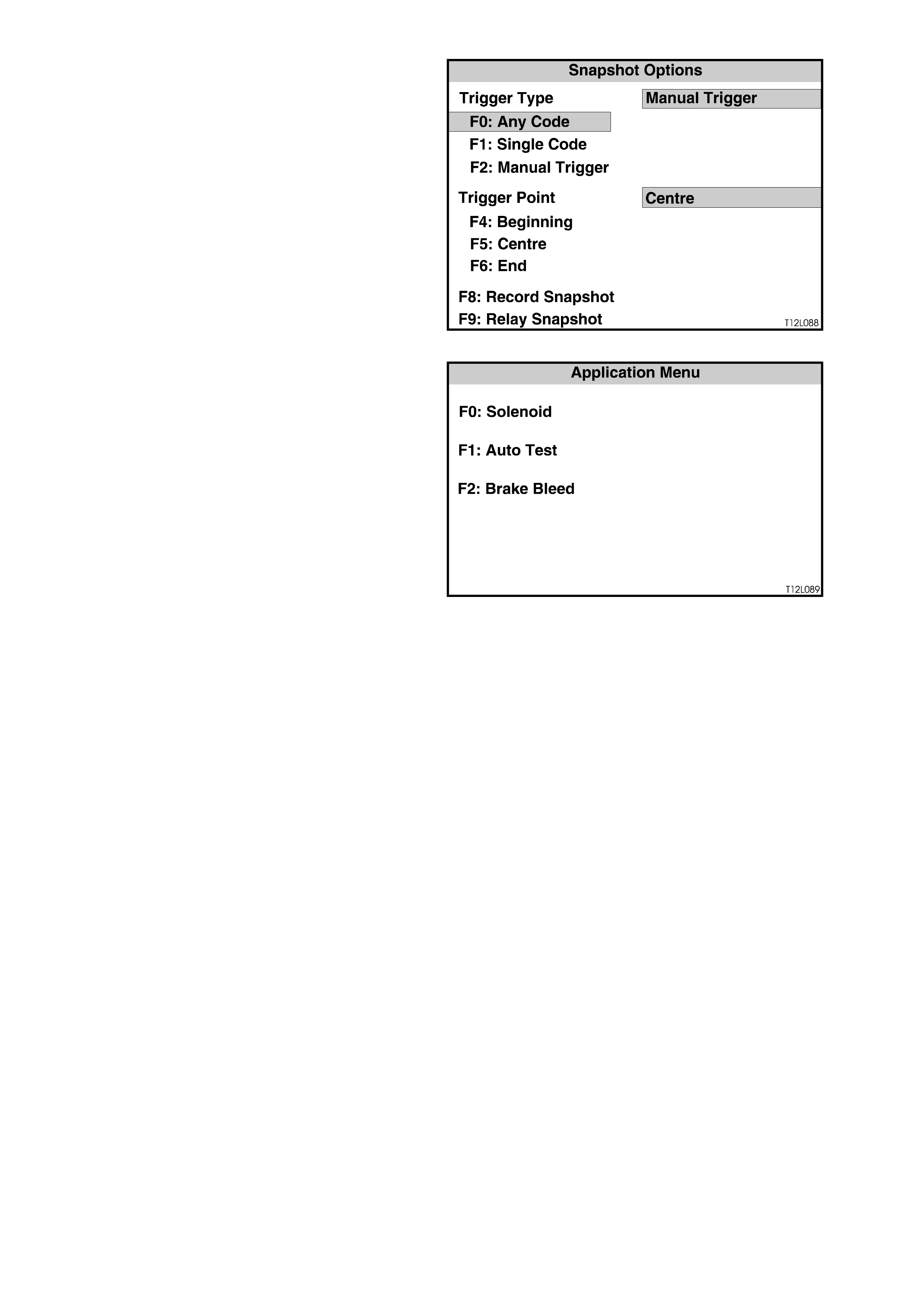
F3: SNAPSHOT
The snapshot mode will help to identify problems
caused by speed sensor signals that may cause
intermittent operation of the ABS/ETC systems.
The SNAPSHOT mode captures data before and
after a forced manual trigger condition.
Figure 12L-53
F4: MISCELLANEOUS TESTS
In the Miscellaneous Tests mode, functional tests
are available on the ABS/ETC systems that will
help identify proper operation. In this mode, error
conditions can be further identified by testing and
observing the test results.
Additionally, in this mode, the hydraulic modulator
can be bled (F2: BRAKE BLEED).
In the MISCELLANEOUS TESTS mode the
following tests can be performed:
F0: Solenoid
This test indicates whether spec ific s olenoid valves
in the hydraulic modulator release pressure to
assigned hydraulic wheel circuits and hold pr es sur e
in assigned hydraulic wheel circuits.
Figure 12L-54
NOTE: Use this procedure in conjunction with the
information displayed on the TECH 2 SCREEN
while in the F0: SOLENOID test mode.
The PRESSURE RELEASE part of the test
activates a selected hydraulic wheel circuit valve,
placing it in the pressure release position. Valve
action can then be verified by checking the
appropriate wheel for proper brake action.
The PRESSURE HOLD part of the test activates a
selected hydraulic wheel circuit valve, placing it in
the pressure hold position. Valve action can then be
verified by checking the appropriate wheel for
proper brake action.
These tests completely check each solenoid valve.
With an assistant, the pressure release and hold
tests can be verified as follows:
1. Ignition OFF.
2. Raise vehicle such that the wheels are at leas t
150 mm off the floor.
3. Install TECH 2 to the DLC.
4. Select Diagnostics / Chassis / ABS/ETC and
turn ignition on and confirm System
Identification information as instructed.
5. Select Miscellaneous Tests / Solenoids.
6. Select the relevant solenoid to be tested and
press ENTER.
7. Follow instructions on the TECH 2 display
screen while getting an assistant to try to spin
the road wheel being tested when requested
by TECH 2.

NOTE: This test verifies correct operation of the
hydraulic functioning of the solenoid valves.
Electrical function is verified by the constant
monitoring of the circuits by the ABS/ETC control
module during normal operation of the system. If
the control module detects an electrical problem,
such as an open or short to earth of a solenoid
circuit, a DTC will be set and the system will be
disabled.
F1: Auto Test
The AUTO test is performed automatically by the
control module once during each ignition cycle
when the vehicle reaches approximately 6 km/h.
The TECH 2 will perform this test automatically
during the ABS TESTS mode. The AUTO test
cycles each solenoid valve and the pump motor
briefly to check c om ponent operation. If any error is
detected during this tes t, the control m odule will set
a DTC and the ABS and or TRAC OFF warning
lamp will be illuminated. Perform the test as follows:
NOTE 1: Use this procedur e in conjunc tion with the
information displayed on the TECH 2 SCREEN
while in the F1: AUTO TEST, test mode.
NOTE 2: If there are any DTCs set, they will have
to be cleared before this test can be performed.

Procedure
1. Turn ignition OFF.
2. Install TECH 2 to the DLC.
3. Select Diagnostics / Chassis / ABS/ETC and turn ignition on and confirm System Identification information as
instructed.
4. Select Miscellaneous Tests / Auto Test and press the CONTINUE soft key on TECH 2 to start test (return
pump will be heard running for a short period).
5. Note any DTCs that are set when test is completed.
F2: Brake Bleed
This test pr ompts the tec hnic ian to bleed the brake system . T he tes t is divided into two par ts ; a primar y bleed and a
secondary bleed. A primary bleed is a manual bleed of each hydraulic circuit. During a secondary bleed, the
ABS/ETC control module activates the solenoid and pump motor so that any air in these components is expelled.
NOTE 1: The AUTO Test must be carried out prior to conducting the brake bleed procedure. If the automatic test
has not been conducted, carry out test as described under F1: AUTOMATIC Test.
The brake bleed procedure is as follows:
1. Install brake bleeding equipm ent to vehic le as rec ommended in Sect ion 5 BRAKES of the VT Series I Ser vice
Information.
2. Turn ignition OFF.
3. Install TECH 2 to DLC.
4. Select Diagnostics / Chassis / ABS/ETC and turn ignition on and confirm System Identification information as
instructed.
5. Select Miscellaneous Tests / Brake Bleed and follow instructions on the TECH 2 display screen.
NOTE 2: T he TECH 2 screen will display “RUN AUTO TEST PRIOR TO BRAKE BLEED. DONE ?” Select YES or
NO. The AUTOMATIC T EST mus t be c arr ied out prior to c onduc ting the brake bleed proc edur e. If the auto tes t has
not been conducted, select NO and carry out test as described under F1: AUTO TEST.
If the auto test has been completed, select YES and continue.
The procedure will begin with a manual bleed at the right hand rear brake calliper. Ensure a suitable size plastic
hose is installed over the bleed screw and that it leads into a container of brake fluid.
While following the bleed procedure, as per TECH 2 instructions, ensure that fluid is continuously fed into the
master cylinder, especially while the secondary circuit is being bled.

4.9 DIAGNOSTIC CHARTS
INTRODUCTION
The f ollowing diagnostic charts ar e designed to provide fas t and eff icient fault location of the ABS/ET C system s f or
vehicles with GEN III V8 engines. Each diagnostic chart consists of: a ‘diagnostic chart’, connector body terminal
assignments for connectors relevant to that particular diagnostic chart, and pertinent information including
Diagnostic Trouble Code (DTC) setting parameters and circuit diagrams.
NOTE 1: For diagnostic charts not published in this Section, refer to Section 12L ABS & ABS/ETC of the VT
Series I Service Information.
NOTE 2: Always refer to the latest GEN III V8 engine wiring diagrams of the VT Series II Service Inf ormation when
refer to the diagnostic charts in Section 12L ABS & ABS/ETC of the VT Series I Service Information.
The following figures illustrate the terminal layout of the various connectors used in the system. These figures
should be used in conj unc tion with the diagnostic c har t circ uit diagr ams when chec king circ uit f aults if the c onnec tor
diagram is not included in the chart.
When carrying out wiring checks as directed to by the diagnostic charts, rather than probe terminals and connectors
with incorrect sized multimeter connections, use the adaptors contained in connector test adaptor k it, such as KM-
609. This will prevent any possibility of spreading or damaging wiring harness terminals.
DIAGNOSTIC AID
It is very important that before any component be replaced, when recommended in a diagnostic procedure, that a
thorough inspection of the wiring and connectors be performed. Terminals should be checked for corrosion and
correct sizing. Failure to carefully and fully inspect wiring and connectors may result in misdiagnosis, causing
unnecessary part replacement with reappearance of the malfunction.
ON-VEHICLE SERVICE
When a diagnostic chart in this Section makes reference to removing/reinstalling or checking a component for
proper mounting or operation, refer to the appropriate service operation in this Section or
Section 12L ABS & ABS/ETC of the VT Series I Service Information.
After all diagnosis and repairs are completed, road-test the vehicle to ensure proper ABS/ETC operation and the
ABS and TRAC O FF warning lam ps do not com e on, ref er to 4.4 FUNCT IONAL CHECK in this Section. If TECH 2
was used for diagnosis, disconnect it from the DLC and turn the ignition OFF for at least 10 seconds before road
testing. This is necessary to reset the ABS/ETC control module as it is disabled during most TECH 2 diagnostic
procedures, and does not reset until serial data communication is stopped and ignition power is lost.
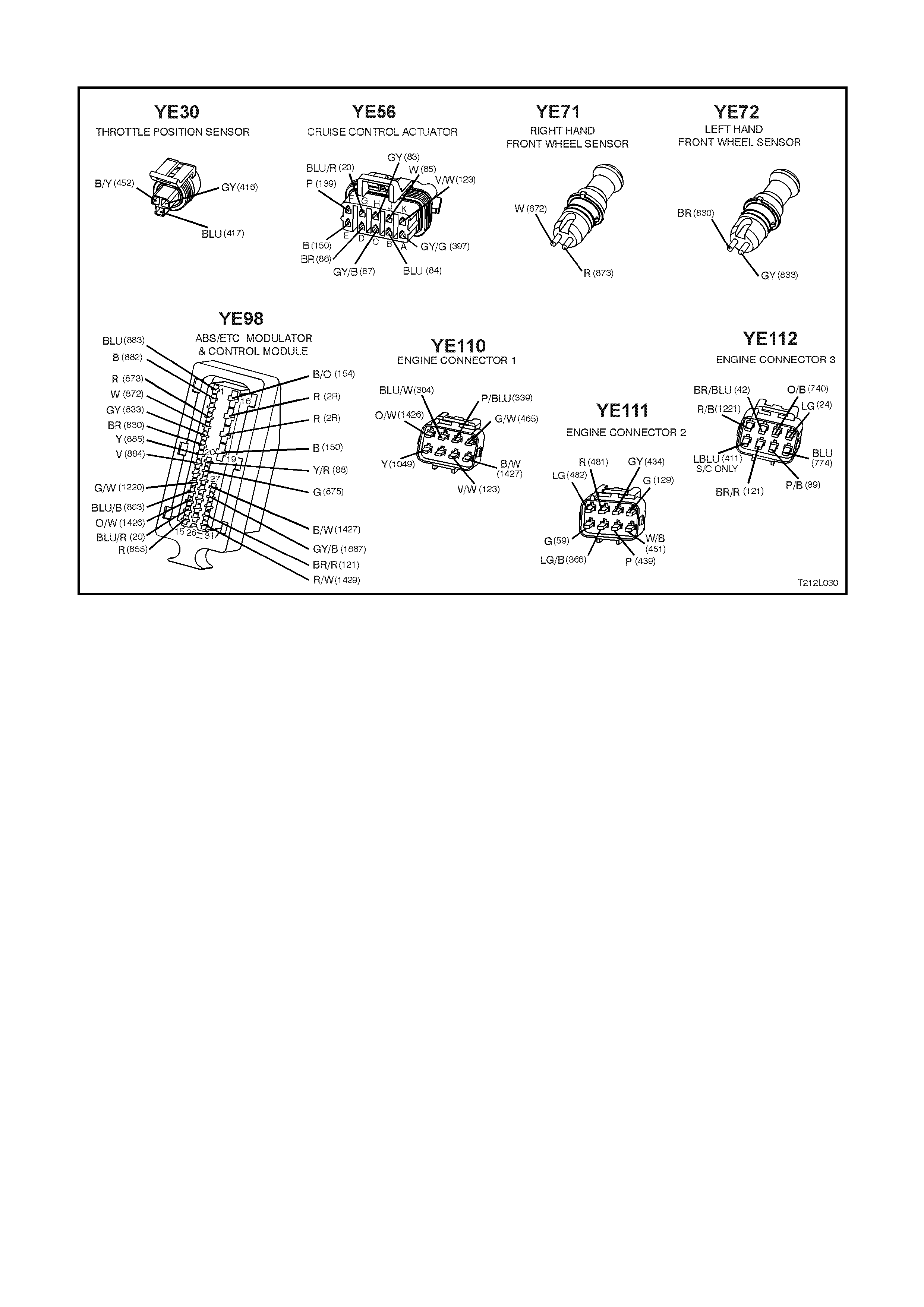
WIRING HARNESS CONNECTORS
Figure 12L-55
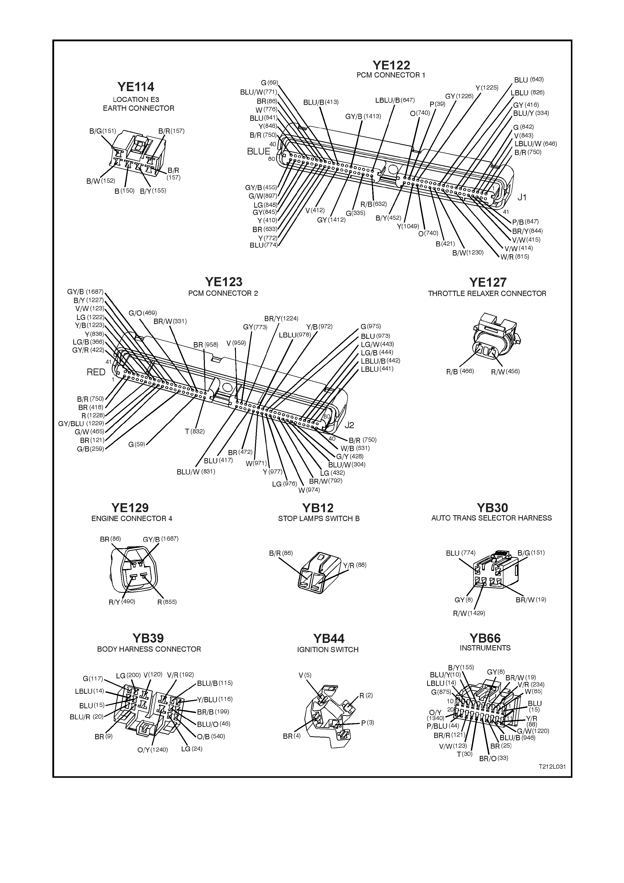
Figure 12L-56
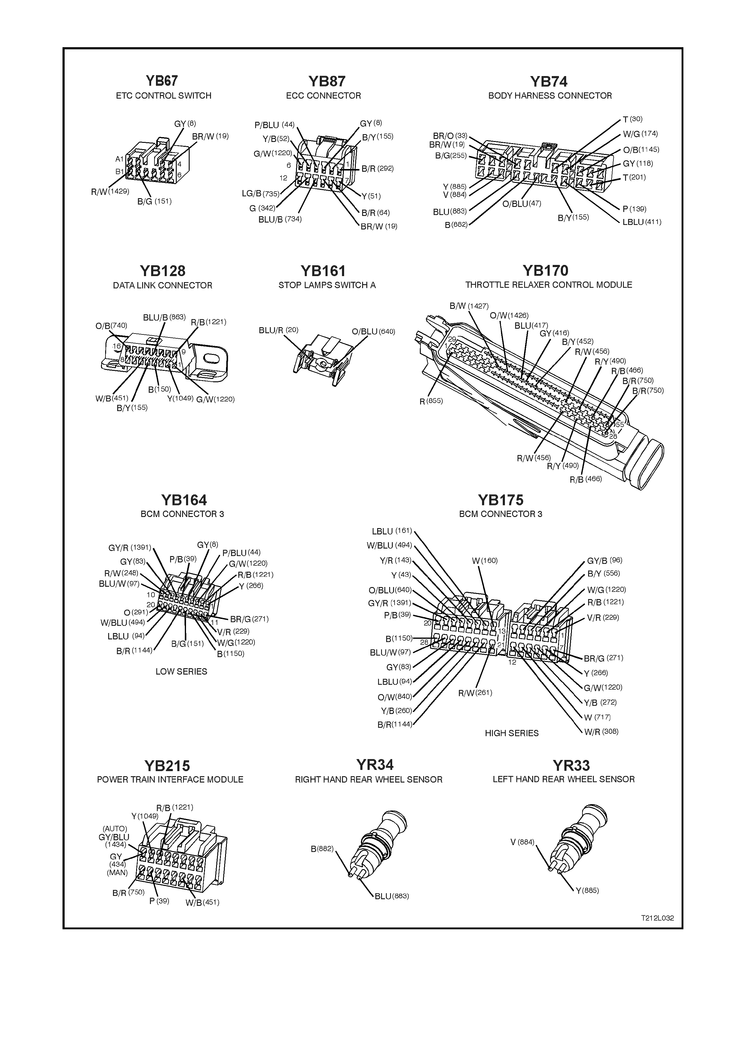
Figure 12L-57

DTC 58 - THROTTLE RELAXER PWM INTERFACE FAULT
Figure 12L-58
CIRCUIT DESCRIPTION:
W ith the ignition on, the ABS/ETC contr ol module c onstantly sends a Puls e W idth Modulated (PWM) signal at 90%
with a frequency of 100Hz to the throttle relaxer control module on the requested throttle position line (DKR), via
term inal 13, c irc uit 1426 (O r ange/White wire) . T his s ignal is to indic ate to the thr ottle relax er c ontrol module that the
traction control system (ETC) is in a state of readiness. If the ABS/ETC control module requests traction control,
throttle reduction, it signals to the throttle relaxer control module to reduce the throttle opening by varying the duty
cycle of this PWM signal.
DTC 58 will set if this frequency output signal deviates outside a frequency specification (95 – 105 Hz) or if the
signal stops for more than 50 milliseconds. The throttle relaxer control module monitors this line and, if the above
conditions are detected, the throttle relaxer control module sends a PWM signal of 93% on the actual throttle
position line (DKI), circuit 1427 (Black/White wire) back to the ABS/ETC control module. The ABS/ETC control
module interprets this signal (or if no PWM signal is returned) as a DKR of throttle relaxer control module fault.
If the ABS/ETC control module senses this fault, the ETC system will be disabled (ABS operation will operate
normally), the TRAC OFF warning lamp will be illuminated and DTC 58 will be set. The TRAC OFF warning lamp
will remain illuminated for the remainder of the ignition cycle. If the failure is intermittent, the control module will
enable the system at the next ignition cycle and the relevant history DTC will be set.
Test Description:
The numbers below refer to Step numbers in the diagnostic chart for DTC 58.
1. Checks for continuity in earth circuit 750.
2. Checks for continuity in earth circuit 750
3. Checks circuit 855 for an open or high resistance.
4. Checks circuit 1426 for an open, short to earth or short to voltage.
5. Checks circuit 1427 for an open, short to earth or short to voltage.
Notes on Diagnostic Chart:
1. For all wiring checking procedures, refer to Section 12P WIRING DIAGRAMS of the VT Series I Service
Information.
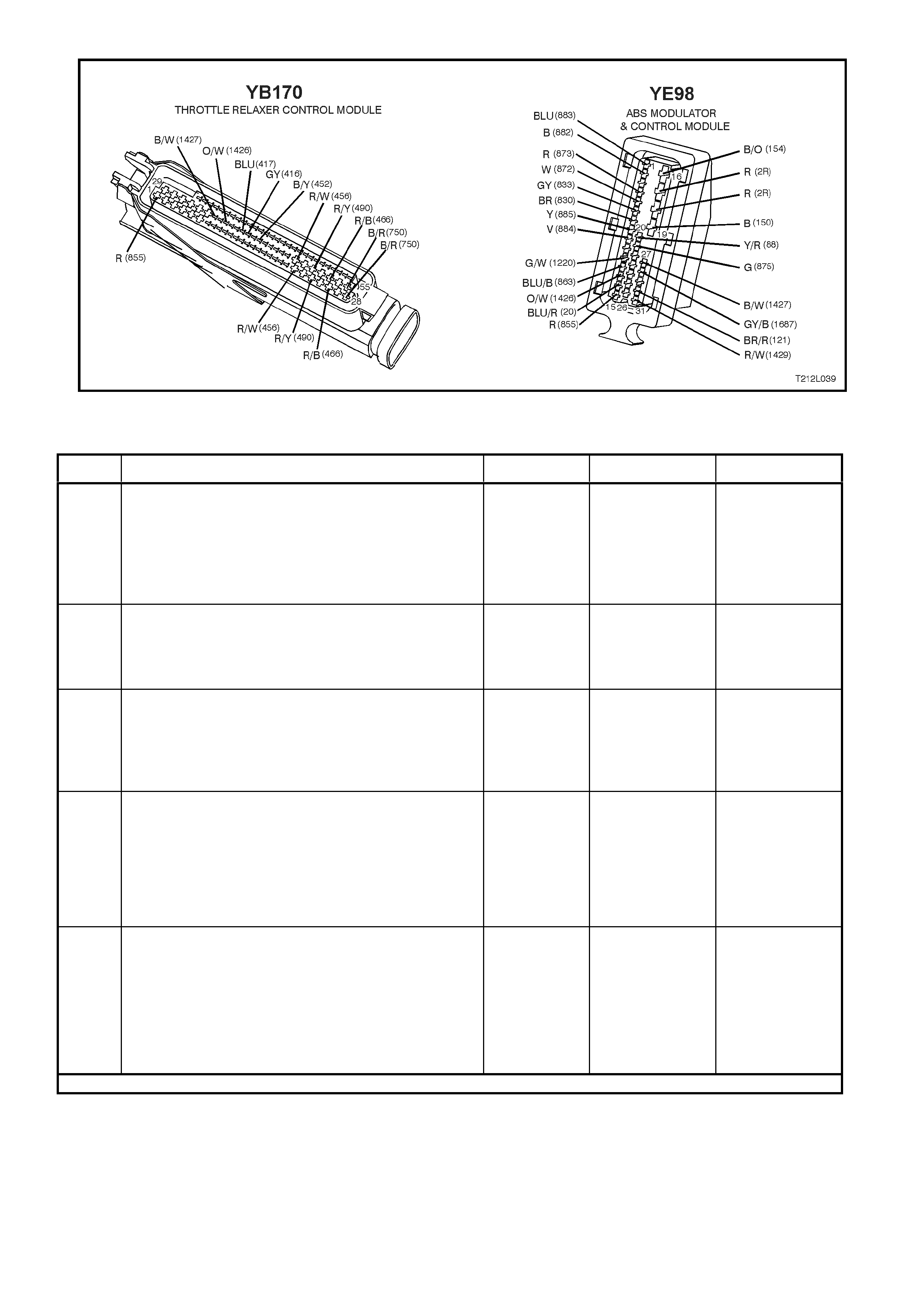
Figure 12L-59
STEP ACTION VALUE YES NO
1. •Disconnect the throttle relaxer control module
connector YE170.
•Check resistance between connector YE170,
terminal 28, circuit 750 (Black/Red wire) and earth
location E5/E15 (engine block) (refer to NOTE 1 on
previous page).
•Is value as specified?
0 – 5 ohms Go to Step 2. Repair circuit 750
as necessary,
recheck and
verify repair.
2. •With connector YE170 disconnected, check
resistance between connector YE170, terminal 55,
circuit 750 (Black/Red wire) and earth location
E5/E15 (refer to NOTE 1 on previous page).
•Is value as specified?
0 – 5 ohms Go to Step 3. Repair circuit 750
as necessary,
recheck and
verify repair.
3. •With connector YE170 disconnected, turn the
ignition switch to the ON position.
•Measure voltage between the throttle relaxer
control module connector YE170, terminals 1 and
28 (refer to NOTE 1 on previous page).
•Is voltage as specified?
Battery + Go to Step 4. Repair circuit 855
as necessary,
recheck and
verify repair.
4. •With connector YE170 disconnected, disconnect
the ABS/ETC control module connector YE98.
•Check integrity (open, short to earth and short to
voltage) of circuit 1426 (Orange/White wire)
between connector YE98 terminal 13 and
connector YE170 terminal 37 (refer to NOTE 1 on
previous page).
•Is integrity of circuit 1426 OK?
Go to Step 5. Repair circuit
1426 as
necessary,
recheck and
verify repair.
5. •With connectors YE170 and YE98 disconnected,
check integrity (open, short to earth and short to
voltage) of circuit 1427 (Black/White wire) between
connector YE98 terminal 27 and connector YE170
terminal 35 (refer to NOTE 1 on previous page).
•Is integrity of circuit 1427 OK?
Replace throttle
relaxer control
module, refer
3.1 THROTTLE
RELAXER
CONTROL
MODULE in this
Section. Recheck
and verify repair.
Repair circuit
1427 as
necessary,
recheck and
verify repair.
WHEN ALL DIAGNOSIS AND REPAIRS ARE COMPLETED, CLEAR ALL DTCs AND VERIFY CORRECT OPERATION
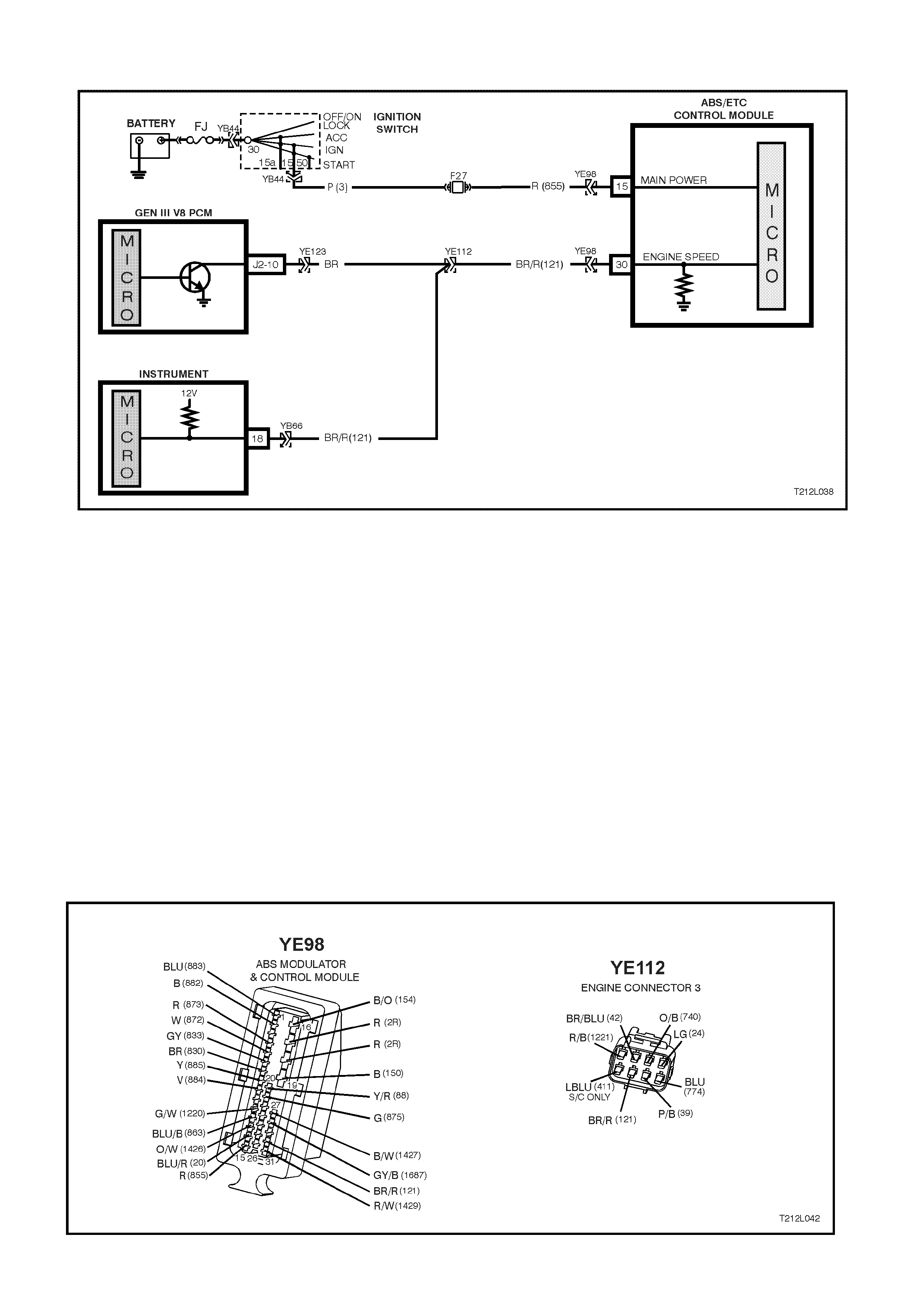
DTC 62 - RPM SIGNAL FAULT
Figure 12L-60
CIRCUIT DESCRIPTION:
The determine the requested amount of spark retard, and prevent the engine from stalling, the ABS/ETC control
module monitors the engine speed. An engine RPM signal is sent to terminal 30 of the ABS/ETC control module
from the PCM. This signal has a fixed duty cycle and a frequency that will vary with changing engine RPM.
DTC 62 will set if an RPM signal (engine speed signal) is not received by the ABS/ETC control module at terminal
30, provided the engine speed is greater than 480 RPM.
If the ABS/ETC control m odule senses this fault, only the ETC s ys tem will be disabled (ABS will operate norm ally),
the TRAC OFF warning lamp will be illum inated and the relevant DT C will be set. T he T RAC OFF warning lamp will
rem ain illuminated f or the rem ainder of the ignition cycle. If the f ailure is interm ittent, the c ontrol m odule will enable
the system at the next ignition cycle and the relevant history DTC will be set.
Test Description:
The numbers below refer to Step numbers in the diagnostic chart for DTC 62.
1. Checks for continuity in circuit 121.
Notes on Diagnostic Chart:
1. For all wiring checking procedures, refer to Section 12P WIRING DIAGRAMS of the VT Series I Service
Information.
Figure 12L-61

NOTE: The following diagnostic procedure assumes the instrument tachometer is functioning correctly. If the
instrument tachometer is not functioning correctly, or PCM DTC P0654 is set, refer to
Section 6C3 POWERTRAIN MANAGEMENT – GEN III ENGINE of the VT Series II Service Information.
STEP ACTION VALUE YES NO
1. •Disconnect ABS/ETC control module connector
YE98 and engine connector YE112.
•Check continuity of circuit 121 (Brown wire)
between ABS/ETC control module connector
YE98, terminal 30 and engine connector YE112,
(refer to NOTE 1 on previous page).
•Does continuity exist?
Replace
ABS/ETC control
module, refer to
Section 12L ABS
& ABS/ETC of
the VT Series I
Service
Information.
Recheck and
verify repair.
Check and repair
open in circuit
121. Recheck
and verify repair.
WHEN ALL DIAGNOSIS AND REPAIRS ARE COMPLETED, CLEAR ALL DTCs AND VERIFY CORRECT OPERATION
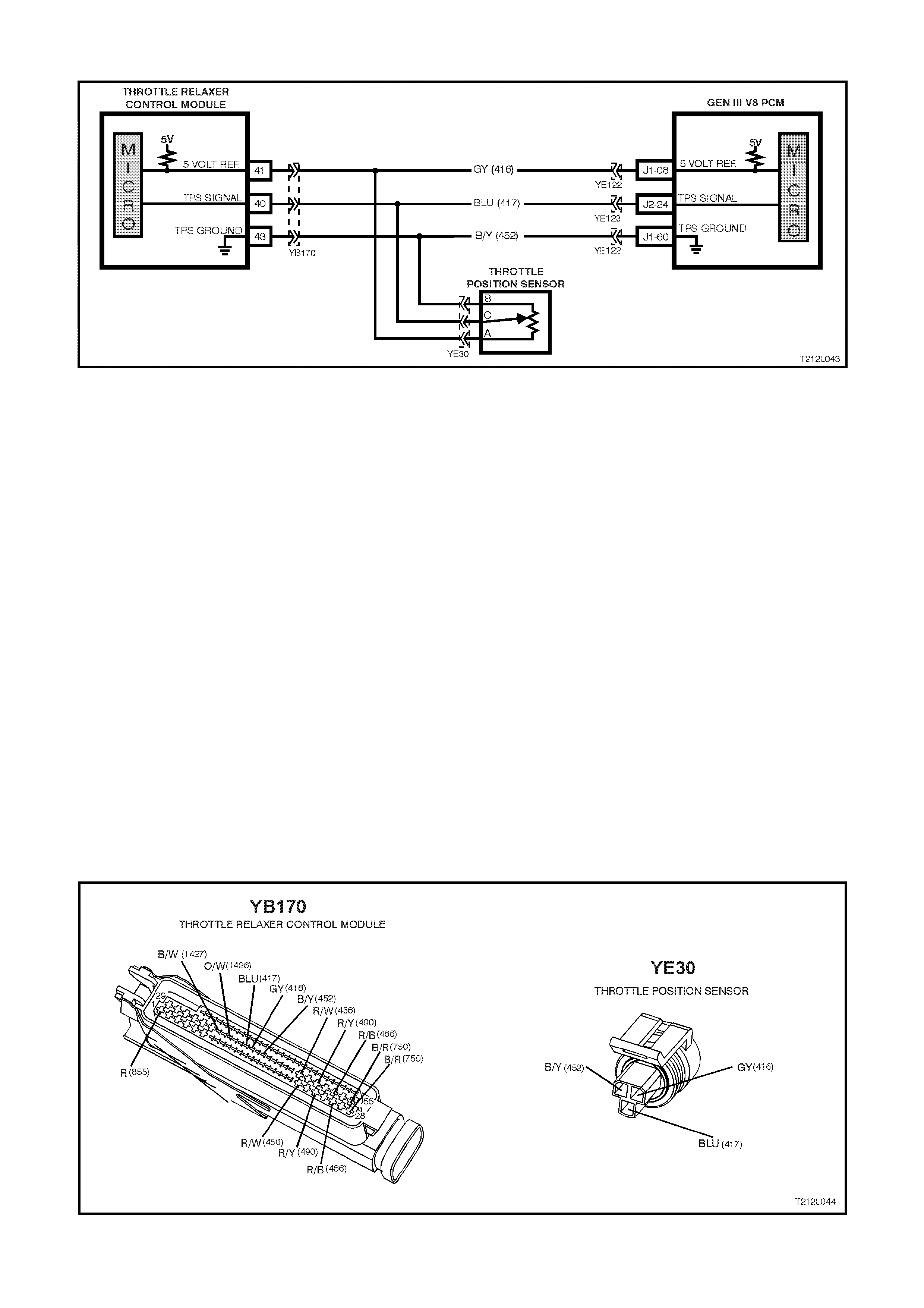
DTC 64 - THROTTLE RELAXER CONTROL MODULE POSITION FAULT
Figure 12L-62
CIRCUIT DESCRIPTION:
The ABS/ETC control module continuously receives a throttle position message every 200 milliseconds, via the
actual throttle position line (DKI), circuit 1427 (Black/White wire).
DTC 64 will set if a mes sage is not received from the throttle position s witch for m ore than six s econds. If this DTC
is set, there will probably be a PCM DTC set also. If a PCM DTC is set, remedy this fault first.
If the ABS/ETC control m odule senses this fault, only the ETC s ys tem will be disabled (ABS will operate norm ally),
the TRAC OFF warning lamp will be illuminated and the relevant DTC will be set. The ETC system will remain
disabled and TRAC OFF warning lamp will remain illuminated until the ABS/ETC control module receives five
consecutive throttle position messages. After five consecutive messages are received by the ABS/ETC control
module, the control module will enable the system, and the relevant history DTC will be set.
Test Description:
The numbers below refer to Step numbers in the diagnostic chart for DTC 64.
1. Determines if fault is related to the ABS/ETC system of the powertrain management system.
2. Checks circuit 417 for open or high resistance.
3. Checks circuit 416 for open or high resistance.
4. Checks circuit 452 for open or high resistance.
Notes on Diagnostic Chart:
1. For all wiring checking procedures, refer to Section 12P WIRING DIAGRAMS of the VT Series I Service
Information.
2. Refer to 4.7 TECH 2 DIAGNOSTICS in this Section for connecting and using TECH 2.
Figure 12L-63

STEP ACTION VALUE YES NO
1. •Install TECH 2 to the DLC (refer NOTE 2 on
previous page).
•Select Diagnosis / Engine / GEN III V8 / Diagnostic
Trouble Codes / Read DTC Info Ordered Priority.
•Are any PCM DTCs set (in particular DTCs related
to the throtle position switch)?
Rectify fault
causing PCM
DTC to set, refer
to Section 6C3
POWERTRAIN
MANAGEMENT -
GEN III V8
ENGINE of the
VT Series II
Service
Information
Go to Step 2.
2. •Disconnect throttle relaxer control module wiring
harness connector YB170, the throttle position
sensor wiring harness connector YE30 and the
PCM wiring harness connector YE122.
•Measure resistance between connector YB170,
terminal 40 and connector YE30, terminal C, circuit
417 (Blue wire)(refer to NOTE 1 on previous
page).
•Is resistance as specified?
0 – 5 ohms Go to Step 4. Check and repair
open or high
resistance in
circuit 417
between
connector YB170
and YE30.
Recheck circuit
to verify repair.
3. •With connectors YB170, YE30 and YE122
disconnected, measure resistance between
connector YB170, terminal 41 and connector YE30
terminal A, circuit 416 (Grey wire)(refer NOTE 1 on
previous page).
•Is resistance as specified?
0 – 5 ohms Go to Step 4. Check and repair
open or high
resistance in
circuit 416
between
connector YB170
and YE30.
Recheck circuit
to verify repair.
4. •With connectors YB170, YE30 and YE122
disconnected, measure resistance between
connector YB170, terminal 43 and connector YE30
terminal B, circuit 452 (Black/Yellow wire)(refer
NOTE 1 on previous page).
•Is resistance as specified?
0 – 5 ohms Replace throttle
relaxer control
module, refer 3.1
THROTTLE
RELAXER
CONTROL
MODULE in this
Section, recheck
and verify repair
Check and repair
open or high
resistance in
circuit 452
between
connector YB170
and YE30.
Recheck circuit
to verify repair.
WHEN ALL DIAGNOSIS AND REPAIRS ARE COMPLETED, CLEAR ALL DTCs AND VERIFY CORRECT OPERATION
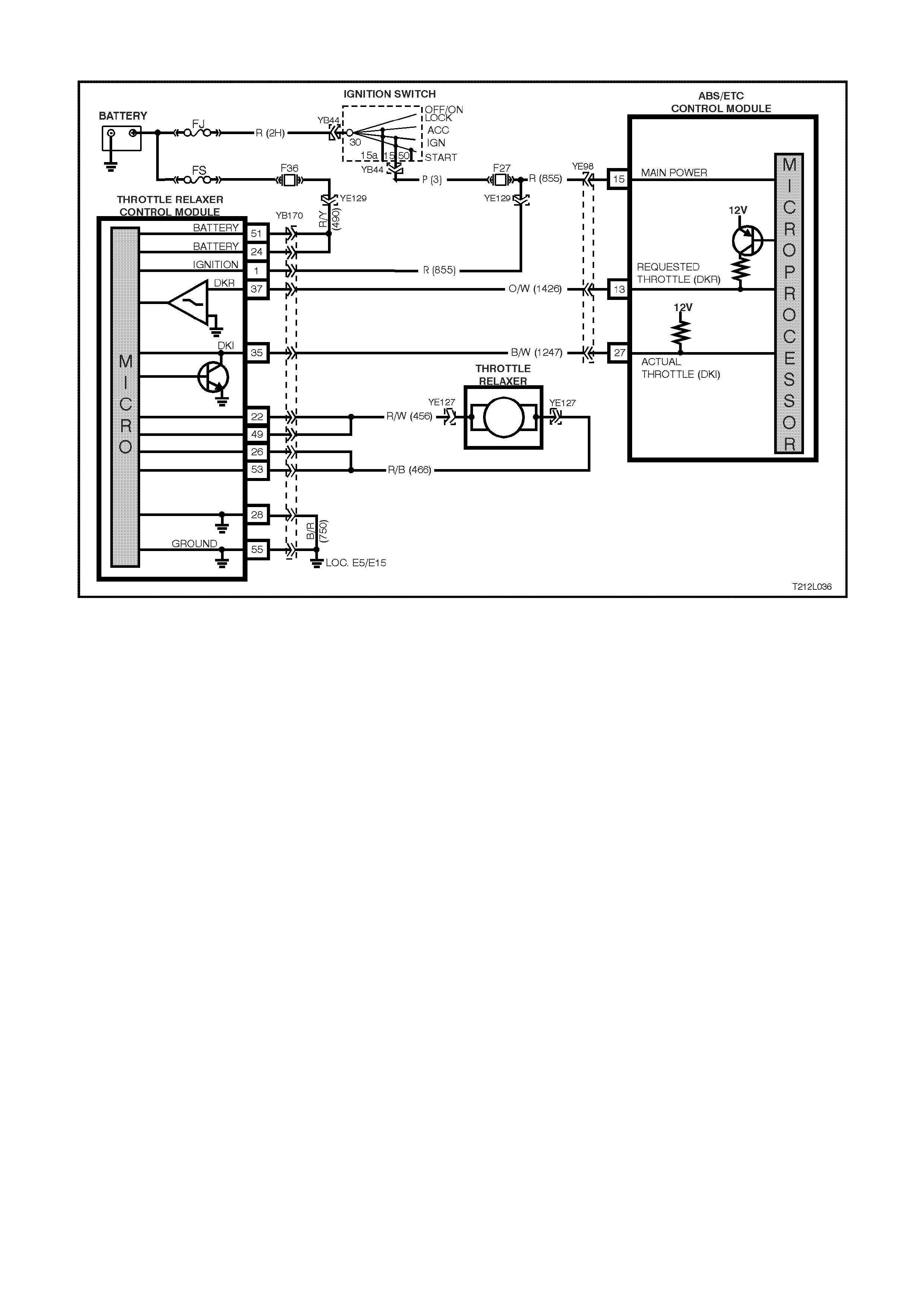
DTC 65 - THROTTLE RELAXER MOTOR FAULT
Figure 12L-64
CIRCUIT DESCRIPTION:
The throttle relaxer is controlled at a commanded current rate by the throttle relaxer control module.
DTC 65 will set if the throttle relaxer motor or circuit is open, shorted to earth or shorted to voltage.
If the ABS/ETC control m odule senses this fault, only the ETC s ys tem will be disabled (ABS will operate norm ally),
the TRAC OFF warning lamp will be illum inated and the relevant DT C will be set. T he T RAC OFF warning lamp will
rem ain illuminated f or the rem ainder of the ignition cycle. If the f ailure is interm ittent, the c ontrol m odule will enable
the system at the next ignition cycle and the relevant history DTC will be set.
Test Description:
The numbers below refer to Step numbers in the diagnostic chart for DTC 65.
1.-2.Checks continuity of circuit 750.
3.-4.Checks integrity (open or short to earth) of circuit 490 (including fuse F36).
5. Determines if the throttle relaxer motor is faulty.
6.-7.Checks for open in circuit 456.
8.-9.Checks for open in circuit 466.
10. Checks for short to earth in circuit 456.
11. Checks for short to earth in circuit 466.
12. Checks for short to voltage in circuit 456.
13. Checks for short to voltage in circuit 466.
Notes on Diagnostic Chart:
1. For all wiring checking procedures, refer to Section 12P WIRING DIAGRAMS of the VT Series I Service
Information.
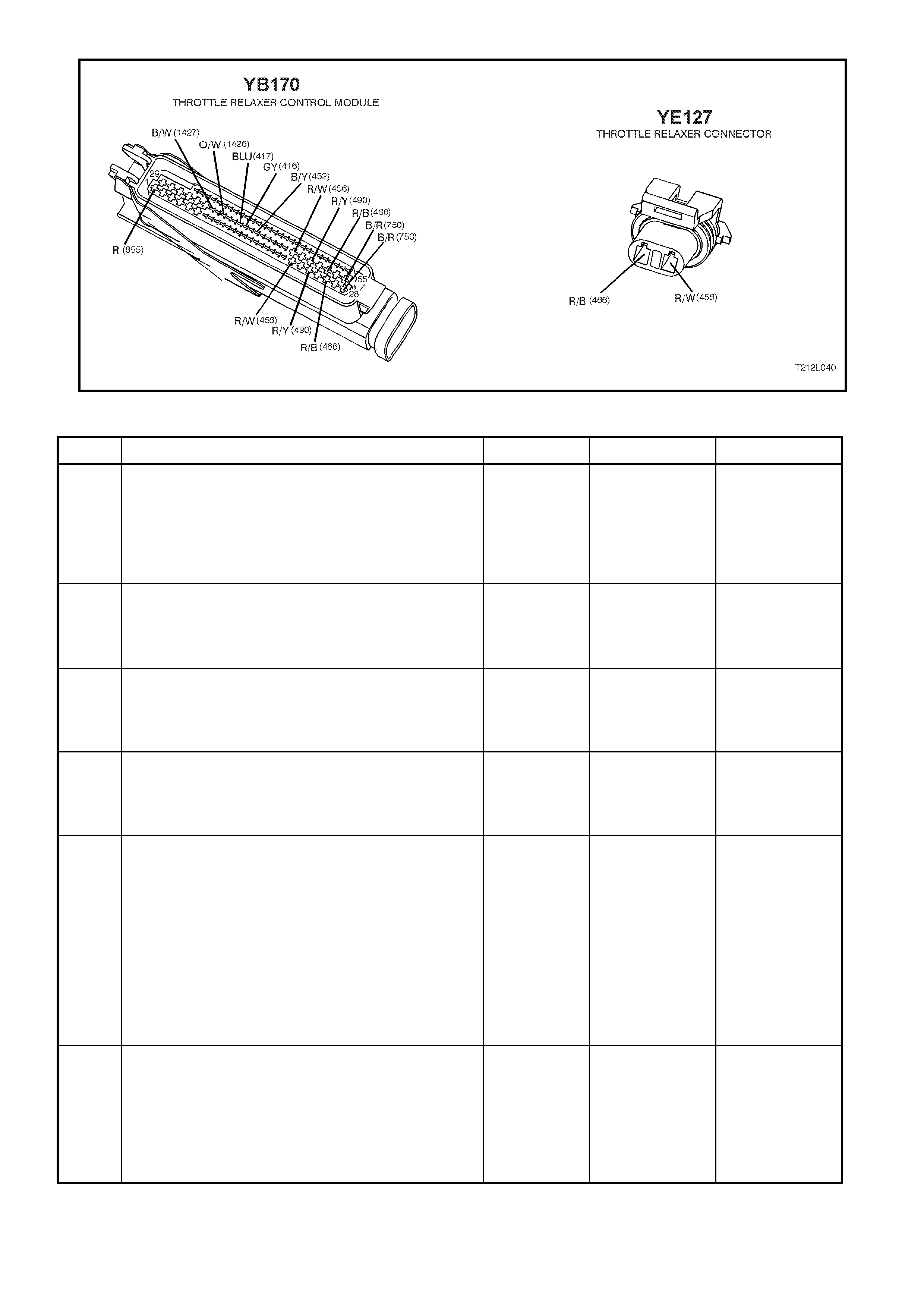
Figure 12L-65
STEP ACTION VALUE YES NO
1. •Disconnect the throttle relaxer control module
connector YE170.
•Check resistance between connector YE170,
terminal 28, circuit 750 (Black/Red wire) and earth
location E5/E15 (engine block) (refer to NOTE 1 on
this page).
•Is value as specified?
0 – 5 ohms Go to Step 2. Repair circuit 750
as necessary,
recheck and
verify repair.
2. •With connector YE170 disconnected, check
resistance between connector YE170, terminal 55,
circuit 750 (Black/Red wire) and earth location
E5/E15 (refer to NOTE 1 on this page).
•Is value as specified?
0 – 5 ohms Go to Step 3. Repair circuit 750
as necessary,
recheck and
verify repair.
3. •With connector YE170 disconnected, measure
voltage between the throttle relaxer control module
connector YE170, terminals 51 and 28 (refer to
NOTE 1 on this page).
•Is voltage as specified?
Battery + Go to Step 4. Repair circuit 490
(incl. fuse F36)
as necessary,
recheck and
verify repair.
4. •With connector YE170 disconnected, measure
voltage between the throttle relaxer control module
connector YE170, terminals 24 and 28 (refer to
NOTE I on previous page).
•Is voltage as specified?
Battery + Go to Step 5. Repair circuit 490
as necessary,
recheck and
verify repair.
5. •Turn the ignition switch to the OFF position.
•Disconnect throttle relaxer connector YE127.
•Disconnect all cables from the throttle relaxer
pulleys.
•Rotate pulleys on the throttle relaxer by hand fully
then release, allowing the pulleys to return to the
stop. Repeat this procedure three times.
•Check resistance between the throttle relaxer
terminals A and B (refer to NOTE 1 on previous
page).
•Is the resistance within the range as specified?
0.5 – 10
ohms Go to Step 6. Replace the
throttle relaxer
assembly, refer
to Section 6C3-3
POWERTRAIN
MANAGEMENT
– GEN III V8
ENGINE of the
VT Series II
Service
Information.
Recheck and
verify repair
6. •With the throttle relaxer connector YE127
disconnected, disconnect throttle relaxer control
module connector YB170.
•Check resistance of circuit 456 (Red/White wire)
between connector YB170 terminals 22 and
connector YE127 terminal A (refer to NOTE 1 on
previous page).
•Is resistance value as specified?
0 – 5 ohms Go to Step 7. Repair open in
circuit 456,
recheck and
verify repair.

STEP ACTION VALUE YES NO
7. • With the throttle relaxer connector YE127
disconnected, disconnect throttle relaxer control
module connector YB170.
• Check resistance of circuit 456 (Red/White wire)
between connector YB170 terminal 49 and
connector YE127 terminal A (refer to NOTE 1 on
previous page).
• Is resistance value as specified?
0 – 5 ohms Go to Step 8. Repair open in
circuit 456,
recheck and
verify repair.
8. • With the throttle relaxer connector YE127 and the
throttle relaxer control module connector YB170
disconnected, check resistance of circuit 466
(Red/Black wire) between connector YB170
terminal 26 and connector YE127 terminal B (refer
to NOTE 1 on previous page).
• Is resistance value as specified?
0 – 5 ohms Go to Step 9. Repair open in
circuit 466,
recheck and
verify repair.
9. • With the throttle relaxer connector YE127 and the
throttle relaxer control module connector YB170
disconnected, check resistance of circuit 466
(Red/Black wire) between connector YB170
terminal 53, and connector YE127 terminal B (refer
to NOTE 1 on previous page).
• Is resistance value as specified?
0 – 5 ohms Go to Step 10. Repair open in
circuit 466,
recheck and
verify repair.
10. • Reconnect the throttle relaxer connector YE127.
• Check resistance between terminals 22, circuit 456
(Red/White wire) and 28, circuit 750 (Black/Red
wire) on the throttle relaxer control module
connector YB170 (refer to NOTE 1 on previous
page).
• Is resistance value as specified?
Infinite ohms Go to Step 11. Repair short to
earth in circuit
456, recheck and
verify repair.
11. • Check resistance between terminals 26, circuit 466
(Red/Black wire) and 28, circuit 750 (Black/Red
wire) on the throttle relaxer control module
connector YB170 (refer to NOTE 1 on previous
page).
• Is resistance value as specified?
Infinite ohms Go to Step 12. Repair short to
earth in circuit
466, recheck and
verify repair.
12. • Reconnect the throttle relaxer control module
connector YB170.
• Disconnect the throttle relaxer connector YE127.
• Turn the ignition switch to the ON position.
• Using a voltmeter, check voltage at connector
YE127, terminal A, circuit 456 (Red/W hite wire)
(refer to NOTE 1 on previous page).
• Is voltage as specified?
Greater than
1 volt Repair short to
voltage in circuit
456, recheck and
verify repair.
Go to Step 13.
13. • With the throttle relaxer connector YE127 and the
throttle relaxer control module connector YB170
disconnected, and the ignition switch in the ON
position, check voltage at connector YE127,
terminal B, circuit 466 (Red/Black wire) (refer to
NOTE 1 on previous page).
• Is voltage as specified?
Greater than
1 volt Repair short to
voltage in circuit
466, recheck and
verify repair.
Replace throttle
relaxer control
module, refer to
3.1 THROTTLE
RELAXER
CONTROL
MODULE in this
Section. Recheck
and verify repair.
WHEN ALL DIAGNOSIS AND REPAIRS ARE COMPLETED, CLEAR ALL DTCs AND VERIFY CORRECT OPERATION

DTC 66 – THROTTLE RELAXER CONTROL FAULT
CIRCUIT DESCRIPTION:
DTC 66 is a throttle position control failure that is most likely due to a mechanical fault caused by a jammed or
binding throttle cable of throttle relaxer motor. DTC 66 can only be detected when the ABS/ETC control module is
modulating (or attempting to modulate) the throttle position.
If the throttle relaxer control module is unable to adjust the throttle position, as requested by the ABS/ETC control
module, via the requested throttle position line (DKR), the throttle relaxer control module will try to reduce the
throttle opening by increasing the current supplied to the throttle relaxer. This current will rise to a m aximum value
and if it stays there for m ore than three seconds , a mess age is sent to the ABS/ET C control m odule and a DTC 66
is set.
If the ABS/ETC control m odule senses this fault, only the ETC s ys tem will be disabled (ABS will operate norm ally),
the TRAC OFF warning lamp will be illum inated and the relevant DT C will be set. T he T RAC OFF warning lamp will
rem ain illuminated f or the rem ainder of the ignition cycle. If the f ailure is interm ittent, the c ontrol m odule will enable
the system at the next ignition cycle and the relevant history DTC will be set.
ACTION:
If DTC 66 sets, visually and physically check the following components:
• Check accelerator pedal, throttle and (if fitted) cruise control cables for binding or fouling.
• Remove the accelerator pedal, throttle and (if fitted) cruise control cables from the throttle relaxer. Check
operation of the throttle relaxer pulleys to ensure they rotate freely without binding or sticking.
Repair or replace components as necessary. Ensure all cables are routed correctly. Clear all DTCs and verify
correct operation.
NOTE 1: The throttle relaxer is a non serviceable component. If the throttle relaxer pulleys are found to be faulty,
replace the throttle relaxer assembly.
NOTE 2: To remove, reinstall and adjust the cables and throttle relaxer assembly, refer to
Section 6C3 POWERTRAIN MANAGEMENT – GEN III V8 ENGINE of the VT Series II Service Information.
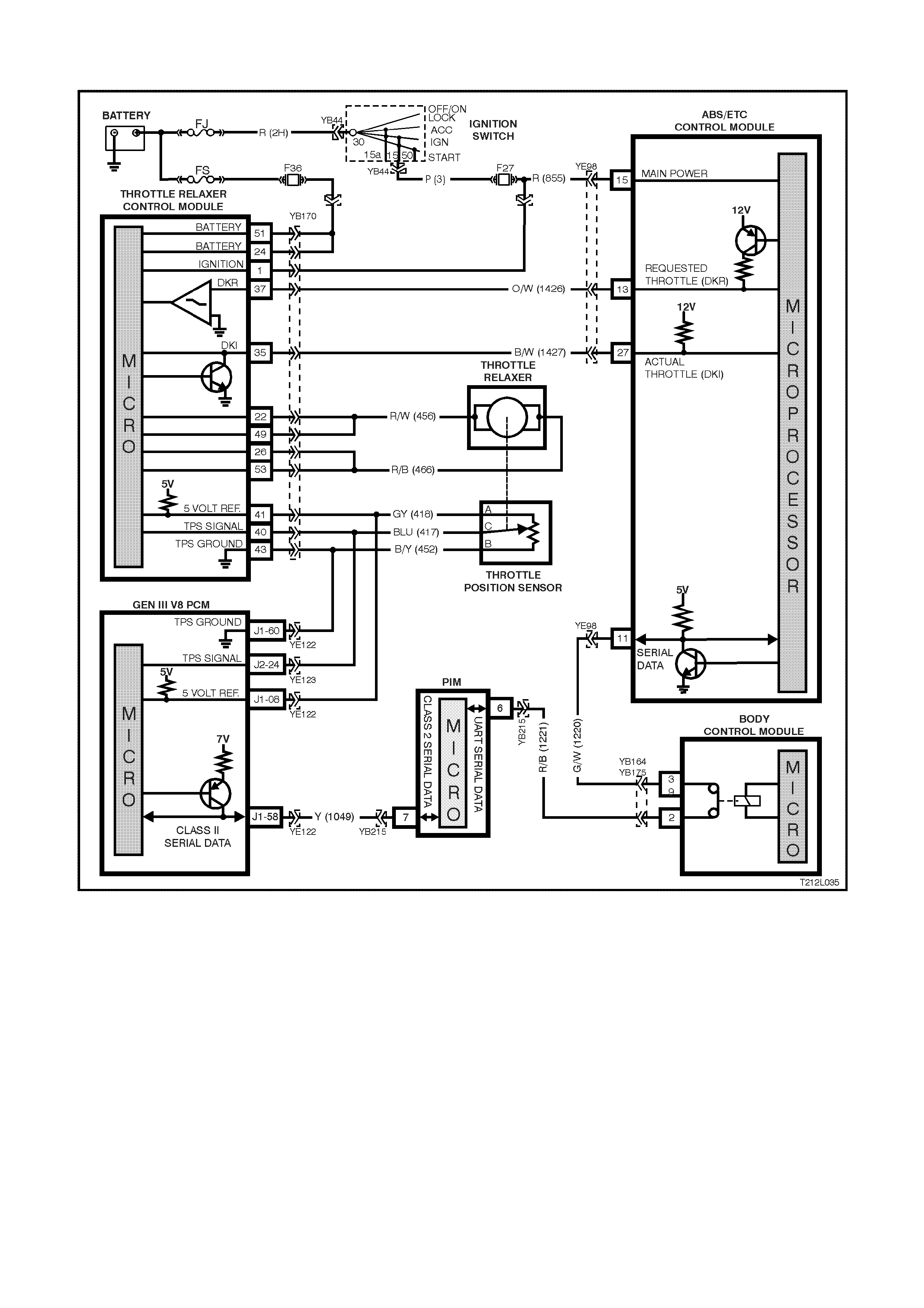
DTC 68 – TPS (THROTTLE POSITION SWITCH) MONITORING FAULT
Figure 12L-66
CIRCUIT DESCRIPTION:
The ABS/ETC contr ol m odule m onitors the throttle position, when set by the throttle relaxer contr ol module, via the
actual throttle position (DKI) input, circuit 1427 (Black /W hite wire). At the sam e time, the ABS/ETC control m odule
monitors the throttle position, as read by the Throttle Position Switch (TPS), and communicated on the serial data
line (circuit 1220, Green/W hite wire) by the PCM/PIM. If the values from the two inputs do not correlate with each
other, the ABS/ETC control module will set DTC 68.
If the ABS/ETC control m odule senses this f ault, only the ETC s ys tem will be disabled (ABS will operate norm ally),
the TRAC OFF warning lamp will be illum inated and the relevant DT C will be set. T he T RAC OFF warning lam p will
rem ain illuminated f or the rem ainder of the ignition c ycle. If the f ailure is interm ittent, the c ontrol m odule will enable
the system at the next ignition cy cle and the relevant history DTC will be set.
Test Description:
The numbers below refer to Step numbers in the diagnostic chart for DTC 68.
1. Determines if fault is related to the ABS/ETC system of the powertrain management system.
2. Checks if ABS/ETC control module is receiving the correct signal.
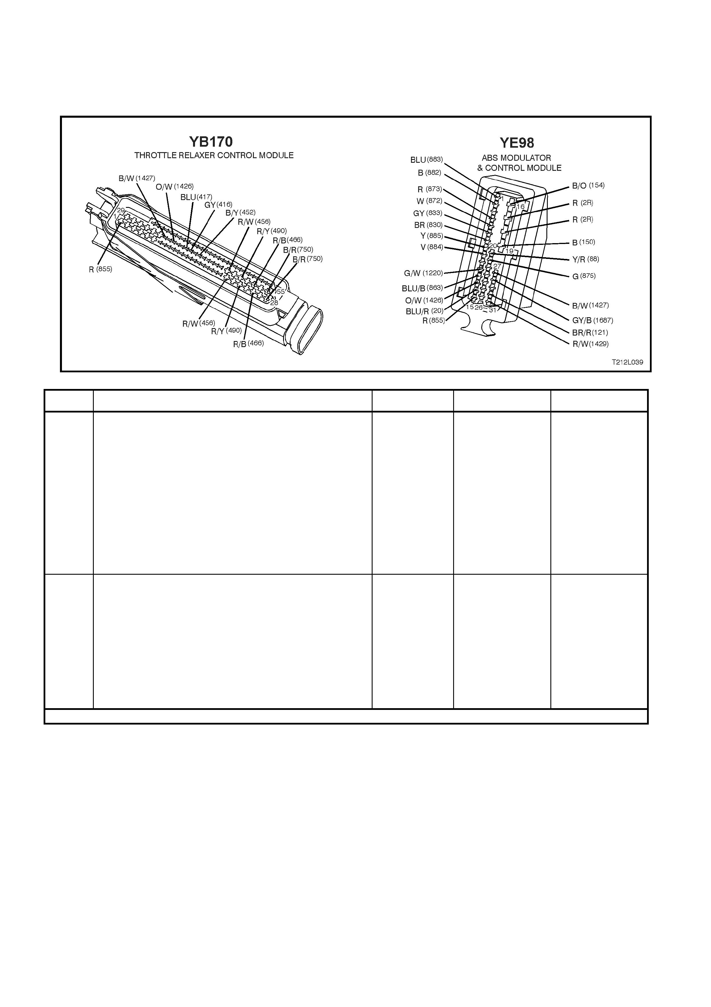
Notes on Diagnostic Chart:
1. For all wiring checking procedures, refer to Section 12P WIRING DIAGRAMS of the VT Series I Service
Information.
2. Refer to 4.7 TECH 2 DIAGNOSTICS in this Section for connecting and using TECH 2.
Figure 12L-67
STEP ACTION VALUE YES NO
1. •Install TECH 2 to the DLC (refer NOTE 2 on this
page).
•Select Diagnosis / Engine / GEN III V8 / Diagnostic
Trouble Codes / Read DTC Info Ordered Priority.
•Are any PCM DTCs set ?
Rectify fault
causing PCM
DTC to set, refer
to Section 6C3
POWERTRAIN
MANAGE MENT -
GEN III V8
ENGINE of the
VT Series II
Service
Information.
Recheck and
verify repair.
Go to Step 2.
2. •Reconnect the throttle relaxer control module
connector YB170.
•Back probe ABS/ETC control module connector
YE98, terminal 27, circuit 1427 (Black/White wire)
with a volt meter to earth (refer NOTE 1 on
previous page).
•Turn ignition on.
•Vary the position of the throttle opening, while
taking not of voltage reading.
•Is voltage as specified?
Throttle
closed -
approx. 1 volt
WOT approx.
10 volts
Replace
ABS/ETC control
module, refer to
Section 12L ABS
& ABS/ETC of
the VT Series I
Service
Information.
Recheck circuit
to verify repair.
Replace throttle
relaxer control
module, refer to
3.1 THROTTLE
RELAXER
CONTROL
MODULE in this
Section. Recheck
and verify repair.
WHEN ALL DIAGNOSIS AND REPAIRS ARE COMPLETED, CLEAR ALL DTCs AND VERIFY CORRECT OPERATION
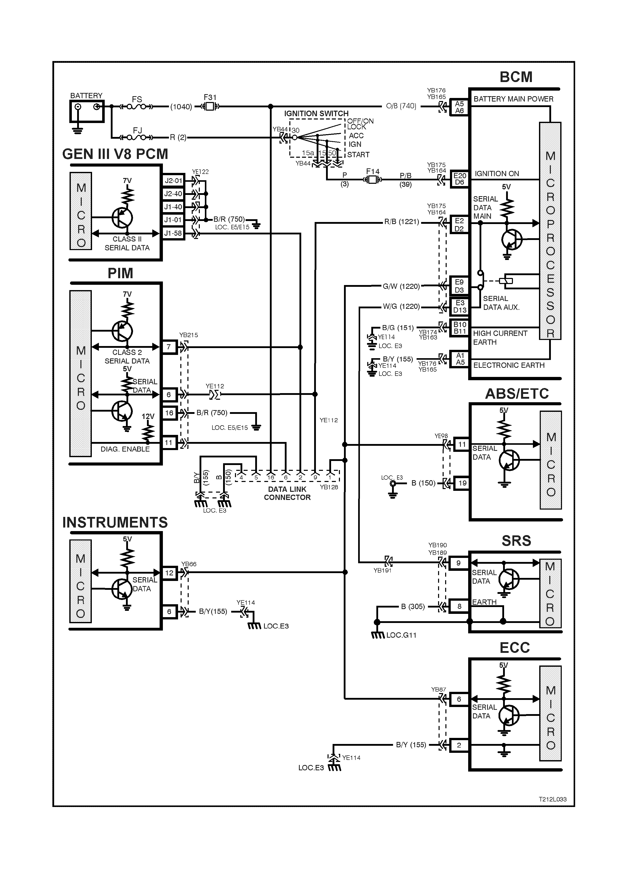
DTC 72 - SERIAL DATA FAULT
Figure 12L-68
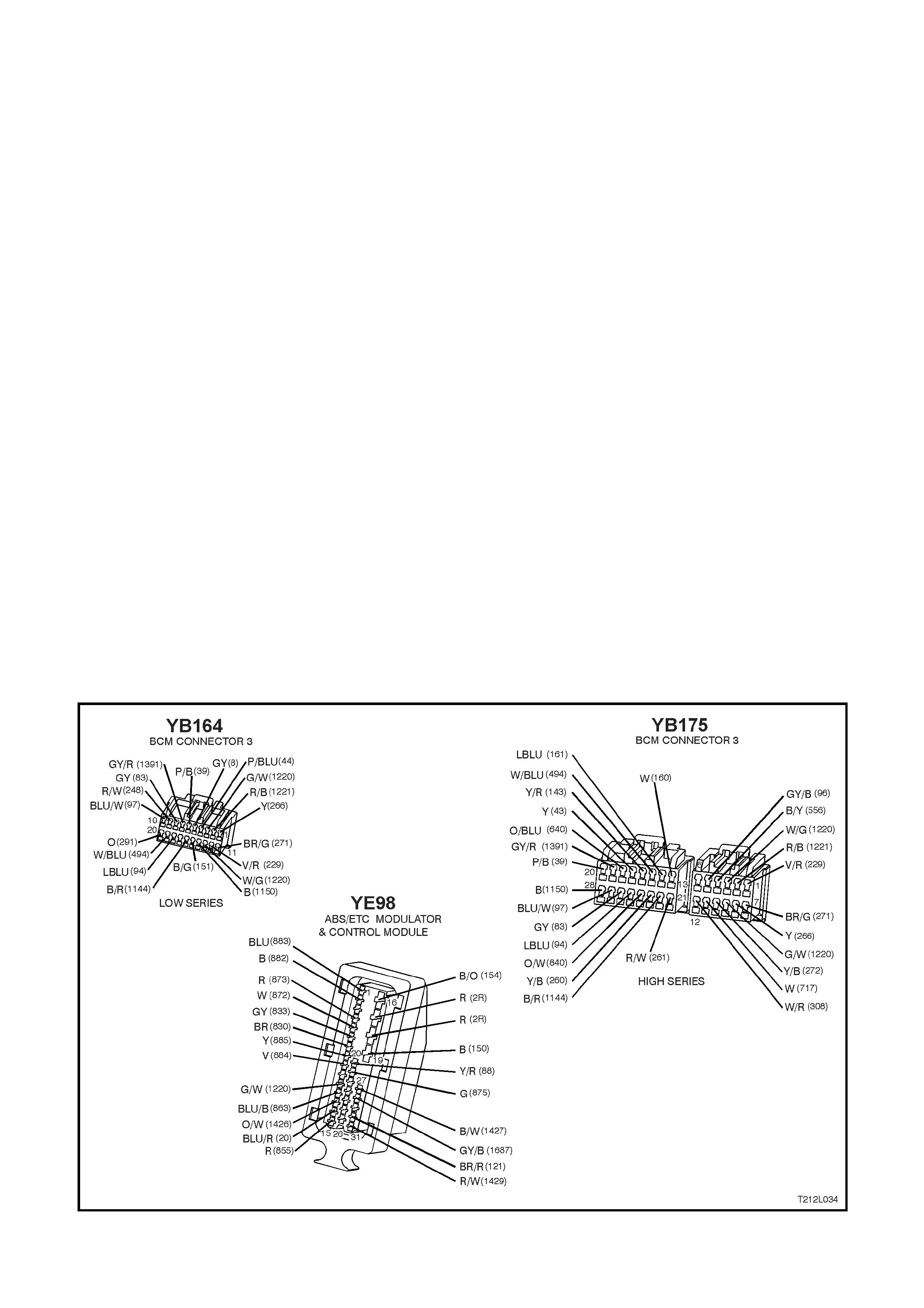
CIRCUIT DESCRIPTION:
W ith the ignition ON, the ABS/ETC control module will be able to communicate with other control modules via the
serial data line, circuit 1220 (Gr een/W hite wire). If com m unication between the modules is dis rupted due to a short
or open circuit, DTC 72 will be set.
If the ABS/ETC control m odule senses this fault, only the ETC system will be disabled (ABS operation will operate
normally), the TRAC OFF warning lamp will be illuminated and the relevant DTC will be set. The TRAC OFF
warning lamp will remain illum inated for the remainder of the ignition cycle. If the failure is intermittent, the control
module will enable the system at the next ignition cycle and the relevant history DTC will be set.
There are several other control modules that are connected to the serial data circuit (PCM/PIM, BCM, ABS/ETC,
ECC, SRS, and the instrum ent c luster) . Any of these contr ol modules c ould c ause a fault in the serial data line. This
fault could result in TECH 2 not being able to display serial data.
Test Description:
The numbers below refer to Step numbers in the diagnostic chart for DTC 72.
1. This test determines if fault is current or not.
2. This test checks for connector or wiring problems which may cause an intermittent fault.
3. Determines if fault is in wiring or ABS/ETC control module.
4. Determines if fault is with BCM serial data communication (bus master).
5. Checks if fault is caused by other control modules that are communicating on the serial data line.
6. Checks circuit 1220 and determines if fault is in wiring or control module.
7. Checks for continuity in circuit 1220.
Notes on Diagnostic Chart:
1. For all wiring checking procedures, refer to Section 12P WIRING DIAGRAMS in the VT Series I Service
Information or in the VT Series II Service Information on this Service Information CD.
2. Refer to 4.7 TECH 2 DIAGNOSTICS in this Section for connecting and using TECH 2.
Diagnostic Aids:
A fault with the serial data circ uit could be caused by one or more of the several control m odules connected to the
serial data circuit. Isolate the fault by disconnecting each controller one at a time until serial data c omm unication is
restored.
Figure 12L-69

STEP ACTION VALUE YES NO
1. • Install TECH 2 to DLC.
• Select Diagnostics / Chassis / ABS/ETC /
Diagnostic Trouble Codes / Clear DTCs and clear
all DTCs (refer to NOTE 2 on opposite page).
• Road test vehicle.
• Does DTC 72 set again ?
NOTE: Go to Step 4 if TECH 2 will not communicate
with the ABS/ETC control module.
Go to Step 3. Go to Step 2.
2. • Inspect all system wiring and connections that
could cause intermittent faults. Check all wiring is
in good condition, terminals are clean and tight
and making good contact (refer NOTE 1 on
previous page).
• Is wiring OK ?
NOTE: Other control modules (SRS, Instruments, ECC,
BCM, PCM) that are connected to the serial data circuit
could cause DTC 72 to set, therefore, check wiring and
connectors that could cause intermittent faults at these
control modules also.
Fault not present.
Check all system
wiring harness
connectors and
terminals, in
particular the
modulator and
ABS/ETC control
module
connector
terminals.
Make repairs as
necessary,
recheck and
verify repair.
3. • In step 1, was TECH 2 able to communicate with
the ABS/ETC control module (refer NOTE 2 on
previous page)?
(With the ignition on and Chassis / ABS/ETC
selected, TECH 2 should display the ABS/ETC
control module part number, system identification
and actual system.)
Go to Step 4. Replace
ABS/ETC control
module, refer to
Section 12L ABS
& ABS/ETC of
the VT Series I
Service
Information,
recheck circuit to
verify repair.
4. • With TECH 2 connected, select Diagnostics / Body
/ Body Control Module and turn ignition on as
requested (refer NOTE 2 on previous page).
• Does TECH 2 display BCM system identification
information (BCM level and type) ?
Go to Step 5. Refer to BCM
Serial Data
Communication
diagnostics in
Section 12J-1
LOW SERIES
BCM or 12J-2
HIGH SERIES
BCM of the VT
Series II Service
Information.
5. • Using TECH 2, ch eck for similar DTCs (Seri al Data
faults) that have been set by other control
modules; instruments, SRS, and ECC if applicable
to model variant (refer NOTE 2 on previous page).
• Have similar DTCs been set by other control
modules ?
Go to Step 6. Go to Step 7.
6. • Check circuit 1220 (Green/White wire or
White/Green wire) for open, short to earth or short
to voltage between BCM and individual control
modules (refer NOTE 1 on previous page).
• Is circuit 1220 OK ?
NOTE: Disconnect each controller in circuit 1220 one
at a time to isolate the fault in the circuit or to identify
control module causing fault.
Replace faulty
module, refer to
relevant Section
in this Service
Information CD,
recheck and
verify repair.
Make repairs as
necessary,
recheck and
verify repair.
7. • Disconnect BCM connector YB164 (Low Series
BCM) or YB175 (High Series BCM) and ABS/ETC
control module connector YE98.
• Check for continuity between BCM connector
YB164 terminal D3 or YB175 terminal E9 and
ABS/ETC control module connector YE98, terminal
11, circuit 1220 (Green/White wire) (refer to NOTE
1 on previous page).
• Does continuity exist ?
Replace
ABS/ETC control
module, refer to
Section 12L ABS
& ABS/ETC of
the VT Series I
Service
Information,
recheck circuit to
verify repair.
Check and repair
open in circuit
1220 between
BCM and
ABS/ETC control
module, recheck
and verify repair.
WHEN ALL DIAGNOSIS AND REPAIRS ARE COMPLETED, CLEAR ALL DTCs AND VERIFY CORRECT OPERATION
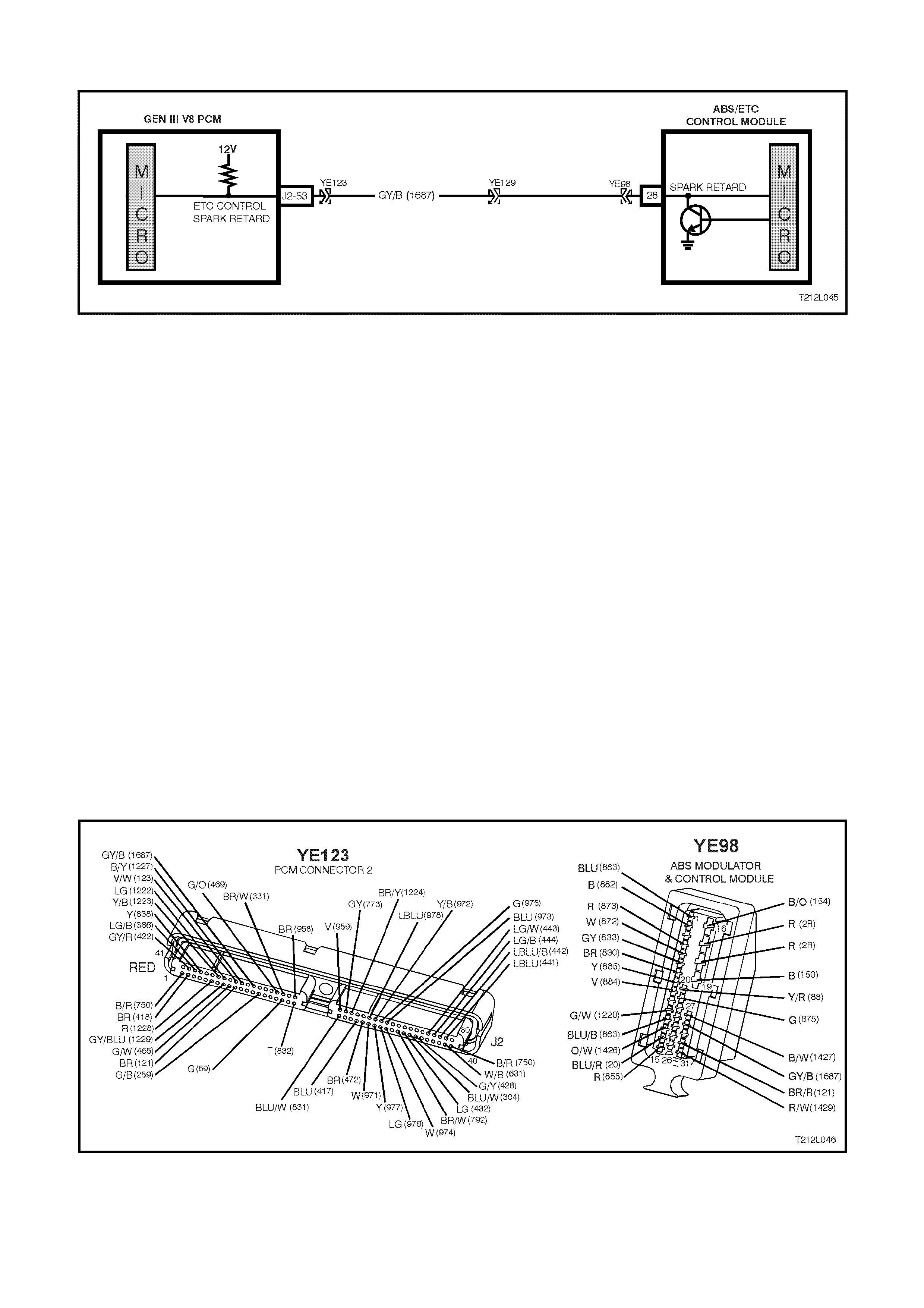
DTC 73 – SP ARK RETARD MONITORING FAULT
Figure 12L-70
CIRCUIT DESCRIPTION:
Spark retard is simultaneously controlled by the ABS/ETC control module and the PCM. The PCM supplies a 12 volt
pull up voltage. This voltage is monitor ed by the PCM, the ABS/ETC c ontrol m odule request spark retard by pulling
this voltage low.
The ABS/ETC contr ol m odule continually m onitors circuit 1687. If the ABS/ETC control m odule detects a continuity
problem in circuit 1687 it will set a DTC 73.
If the ABS/ETC control m odule senses this fault, only the ETC s ys tem will be disabled (ABS will operate norm ally),
the TRAC OFF warning lamp will be illum inated and the relevant DT C will be set. T he T RAC OFF warning lamp will
rem ain illuminated f or the rem ainder of the ignition cycle. If the f ailure is interm ittent, the c ontrol m odule will enable
the system at the next ignition cycle and the relevant history DTC will be set.
Test Description:
The numbers below refer to Step numbers in the diagnostic chart for DTC 73.
1. Checks for 12 volt pull up from PCM.
2. Checks for short to voltage in circuit 1687.
3. Checks for open and short to earth in circuit 1687.
Notes on Diagnostic Chart:
1. For all wiring checking procedures, refer to Section 12P WIRING DIAGRAMS of the VT Series I Service
Information.
2. Refer to the PCM ON-BOARD DIAGNOSTIC SYSTEM CHECK in Section 6C3 POWERTRAIN
MANAGEMENT – GEN III V8 ENGINE before replacing PCM.
Figure 12L-71

STEP ACTION VALUE YES NO
1. •Disconnect ABS/ETC control module connector
YE98.
•Start engine.
•Check voltage at ABS/ETC control module
connector YE98, terminal 28, circuit 1687
(Grey/Black wire).
•Is voltage as specified?
Battery + Go to Step 2. Go to Step 3.
2. •With connector YE98 disconnected, disconnect
the PCM connector YE123.
•Turn ignition ON.
•Check circuit 1687 for short to voltage (refer to
NOTE 1 on previous page).
•Is circuit 1687 OK?
Replace
ABS/ETC control
module, refer to
Section 12L ABS
& ABS/ETC of
the VT Series I
Service
Information,
recheck circuit to
verify repair.
Repair short to
voltage in circuit
1687, recheck
and verify repair.
3. •With connector YE98 disconnected, disconnect
the PCM connector YE123.
•Turn ignition OFF.
•Check circuit 1687 for an open of short to earth
(refer NOTE 1 on previous page).
•Is circuit 1687 OK?
Check and if
necessary,
replace PCM,
refer Section 6C3
POWERTRAIN
MANAGEMENT
– GEN III V8
ENGINE (See
NOTE 2 on
previous page
before replacing
PCM).
Repair short to
earth or open in
circuit 1687,
recheck and
verify repair.
WHEN ALL DIAGNOSIS AND REPAIRS ARE COMPLETED, CLEAR ALL DTCs AND VERIFY CORRECT OPERATION
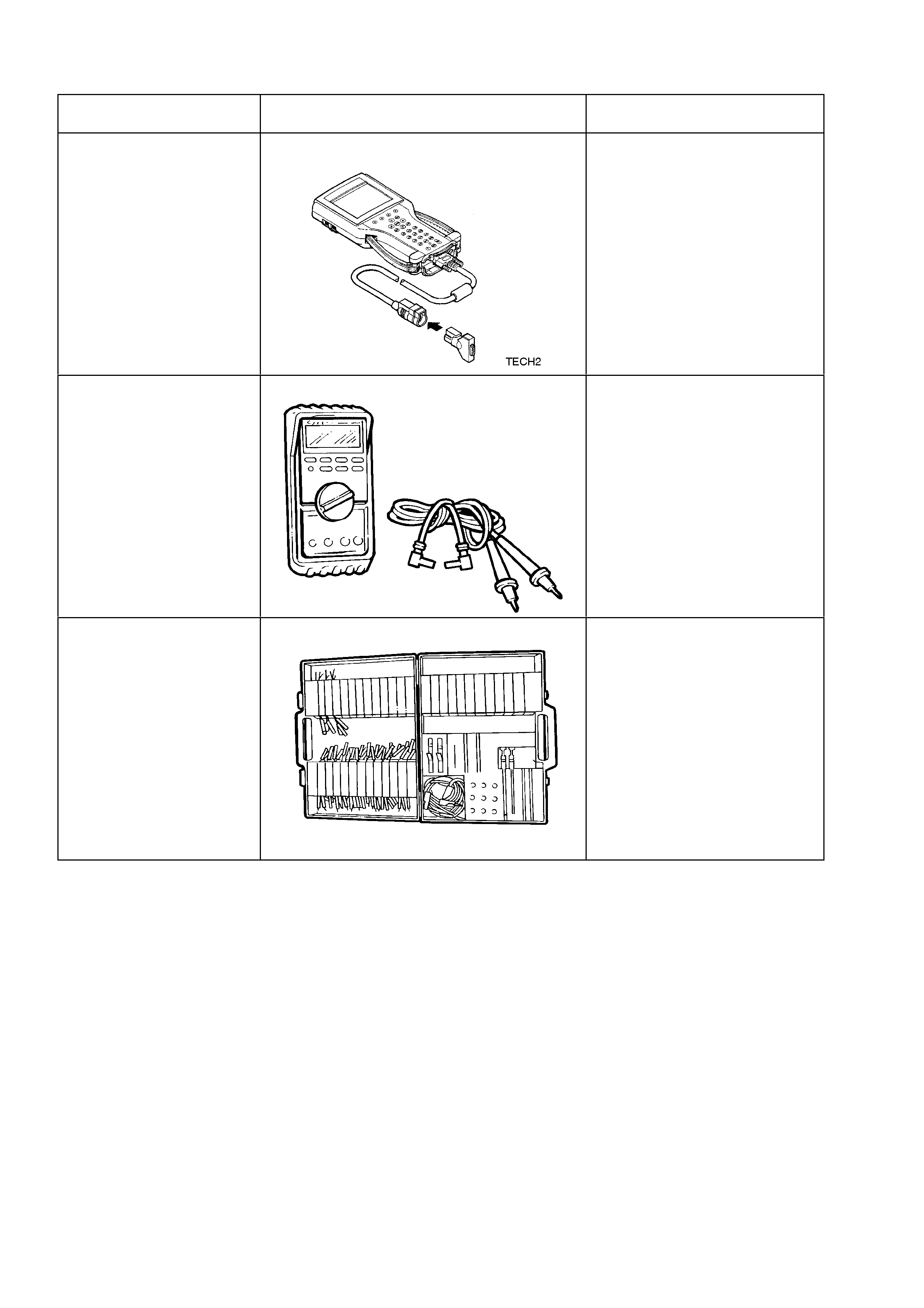
5. SPECIAL TOOLS
TOOL NO. REF IN TEXT TOOL DESCRIPTION COMMENTS
TECH 2 DIAGNOSTIC SCAN TOOL PREVIOUSLY RELEASED
J39200 DIGITAL MULTIMETER TOOL NO. J39200
PREVIOUSLY RELEASED, OR
USE COMMERCIALLY
AVAILABLE EQUIVALENT.
MUST HAVE 10 MEG OHM
INPUT IMPEDANCE AND BE
CAPABLE OF READING
FREQUENCIES
KM-609 ELECTRONIC KIT USED IN CONJUNCTION
WITH A MULTIMETER FOR
MEASURING VOLTAGES AND
RESISTANCE’S WITHOUT
DAMAGING WIRING
HARNESS CONNECTORS