SECTION 6B1-1 - ENGINE COOLING -
V6 ENGINE
CAUTION:
This vehicle will be equipped with a Supplemental Restraint System (SRS). A SRS will consist of either
seat belt pre-tensioners and a driver's air bag, seat belt pre-tensioners and a driver's and front
passenger's air bag s or seat belt pre- tensio ners, d riv er’s and fron t p asseng er’s air bag and lef t and rig ht
hand side air bags. Refer to SAFETY PRECAUTIONS, Section 12M Supplemental Restraint System of the
VT Series I Service Information before performing any service operation on, or around any SRS
components, the steering mechanism or wiring. Failure to follow the SAFETY PRECAUTIONS could
result in SRS deployment, resulting in possible personal injury or unnecessary SRS system repairs.
CAUTION:
This vehicle may be equipped with LPG (Liquefied Petroleum Gas). In the interests of safety, the LPG
fuel system should be isolated by turning 'OFF' the manual service valve and then draining the LPG
service lines, before any service work is carried out on the vehicle. Refer to the LPG leaflet included with
the Owner's Handbook for details or the appropriate Section of this Service Information CD for more
specific servicing information.
1. GENERAL INFORMATION
The engine cooling system on VT Series II Models with V6 engine carries over from VT Series Models, noting the
following:
From the s tar t of VT Series II produc tion, the ther mostat bypass hole in the lower intake manif old f or the V6 engine,
was reduced f rom 3 m m to 2 m m. T his change r esults in a quick er warm -up tim e, f urther as sisting in the reduction
of exhaust emissions.
Because this shorter warm-up period also affects the engine management system (e.g. fuel injector pulse width
calibration), calibration changes were also made to the PCM PROM at this time.
The only service implication that results from this change is that the lower intake manifold will not service back to
earlier engines.
As a running change, approximately March 1999, two single speed electric engine cooling fans were introduced to
vehicles with V6 engine; a low speed fan and a high speed fan (as compared to; two, two speed electric cooling
fans).
As infor mation about these new engine cooling f ans has not been published before, this Section has been c ompiled
to cover their introduction.
As a further running change, for all VT Series II vehicles fitted with the V6 Supercharged engine, produced from
October 18, 1999 and from a production serial num ber of L518684, the cooling system and hose/pipe arr angement
was made common with the naturally aspirated V6 engine. Operation of the two single speed electric fans fitted to
V6 Supercharged engines from this breakpoint, is the same as described in this Section.
To provide a comparison between the two systems, the arrangement of the automatic transmission fluid cooler/s
and hoses/pipes, both before and after the breakpoint are provided in this Section.
For information, including General Information, Service Operations, Specifications and Torque Wrench
Specifications, that is not covered in this Section, refer to Section 6B1-1 ENGINE COOLING - V6 ENGINE of the
VT Series I Service Information.
NOTE: The cooling system for vehicles with V6 supercharged engines does not change for VT Series II Models.
Techline
Techline

1.1 COOLING FAN OPERATION
On VT Series II Models with V6 engines, the engine cooling fan motors have two terminals; one positive and one
negative. The positive terminals are permanently connected to battery voltage. When the negative terminal is
connected to earth through the low speed cooling fan relay, the low speed cooling fan will operate. When the
negative terminal is connected to earth via the high speed cooling fan relay, both cooling fans will operate.
The low speed cooling f an operation is enabled when the low speed engine cooling fan micro relay (located in the
engine com partment relay housing, labelled Lo Fan) is energised by the Body Control Module (BCM) via a request
from the Powertrain Control Module (PCM). The PCM will request low speed fan enable and disable via ser ial data
communication to the BCM on circuit 1221 (Red/Black wire). After the PCM requests a change in the state of the
low speed relay (i.e. OFF to ON or ON to OFF), the BCM will send a serial data response message back to the
PCM confirming it received the message.
The PCM determines when to enable the low speed fan r elay based on inputs from the A/C request signal, Engine
Coolant Temperature (ECT) sensor and the Vehicle Speed Sensor (VSS).
LOW SPEED FAN OPERATION
The low speed cooling fan relay will be turned ON when:
•Air conditioning request indicated (YES) and the vehicle speed is less than 30 km/h or
•Air conditioning pressure is greater than 1500 kPa or
•Coolant temperature is greater than 104°C or
•An engine coolant temperature sensor failure is detected by the PCM, refer to Section 6C1 POWERTRAIN
MANAGEMENT - V6 ENGINE for additional information.
•When the ignition switch is turned from ON to OFF and the engine coolant temperature is above 117°C. The
BCM will continue to energise the low speed engine cooling fan micro relay for approximately four minutes.
The PCM will request the BCM to switch off the low speed cooling fan relay when the following conditions have
been met:
•Air conditioning request not indicated (NO) and the coolant temperature is less than 99°C or
•Air conditioning reques t indicated (YES) with pressure les s than 1170 kPa, vehicle speed greater than 50 k m/h
and coolant temperature less than 99°C.
HIGH SPEED FAN OPERATION
The PCM determines when to enable the high speed fan relay based on inputs from the ECT sensor. The high
speed cooling fan relay will be turned ON if the low speed cooling f an relay has been energised for one second and
the following conditions have been met:
•If there is a BCM message response fault, setting a DTC 92 or
•An engine coolant temperature sensor failure is detected by the PCM, refer to Section 6C1 POWERTRAIN
MANAGEMENT - V6 ENGINE for additional information or
• Engine coolant temperature is above 108°C or
•Air conditioning pressure is greater than 2000 kPa.
NOTE: If the low speed cooling fan is off when the criteria for turning the high speed cooling fan on are first met, the
high speed cooling fan will turn on 5 seconds after the low speed cooling fan is switched on.
If both the high and low speed cooling fans are enabled, the PCM will turn the high speed cooling fan off when:
•The engine coolant temperature is less than 103°C and
•Air conditioning request is not indicated (No) or
•Air conditioning request is indicated (Yes) and the pressure is less than 1500 kPa.
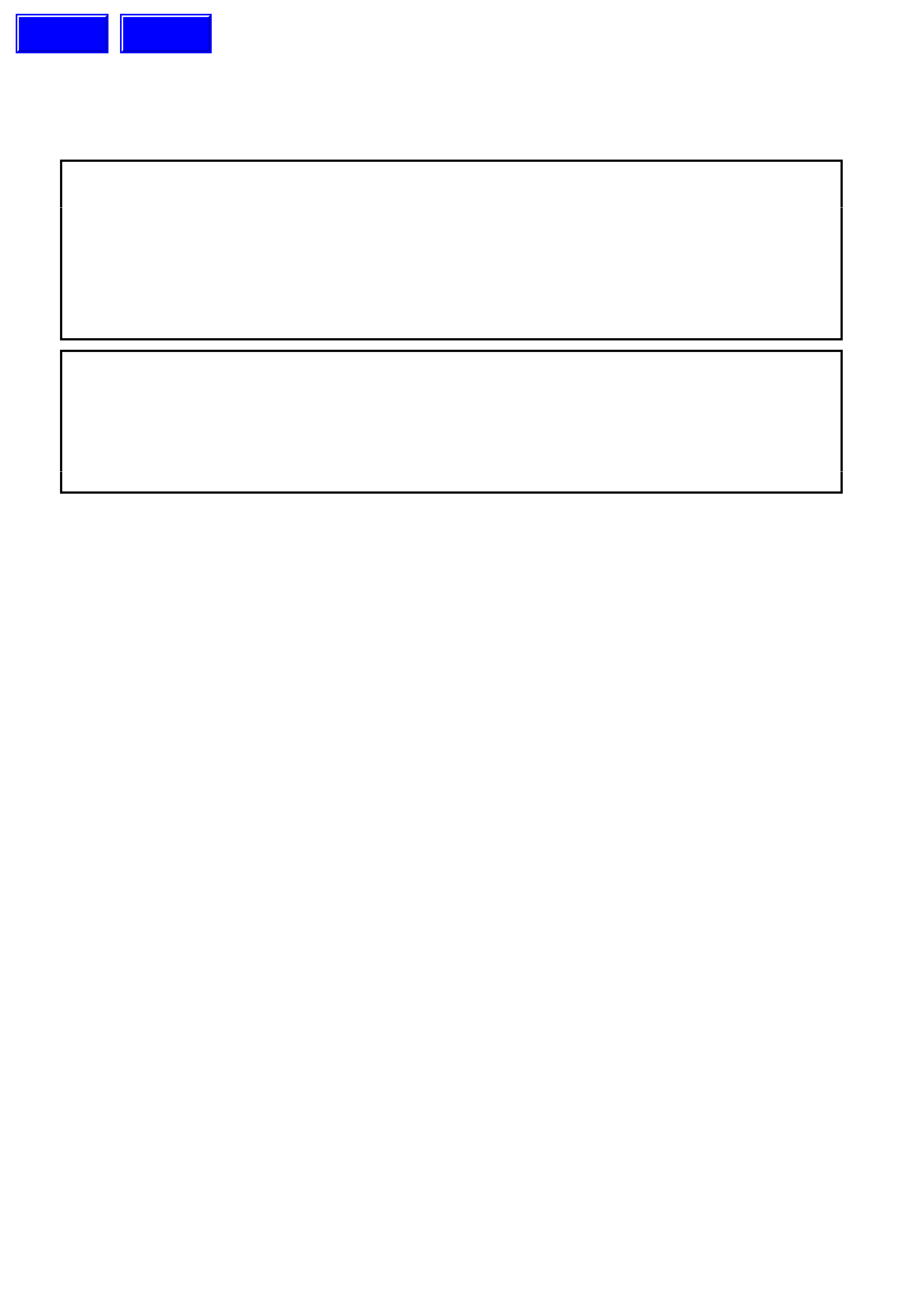
1.2 AUTOMATIC TRANSMISSION OIL COOLER PIPES/HOSES
V6 SUPERCHARGED ENGINE BEFORE
BREAKPOINT
Legend:
1. Fluid Cooler Line to External Cooler.
2. Fluid Cooler Line to Radiator Tank, Outlet
Fitting.
3. Fitting, Fluid Cooler Return Line.
4. Fitting, Fluid Cooler Inlet Line.
5. Transmission Cooler Interconnect Pipe to
Radiator Tank Fitting.
6. Fluid Cooler Line to Radiator Tank Inlet
Fitting.
7. Transmission Cooler Interconnect Pipe to
Radiator Tank Fitting.
Figure 6B1-1-1
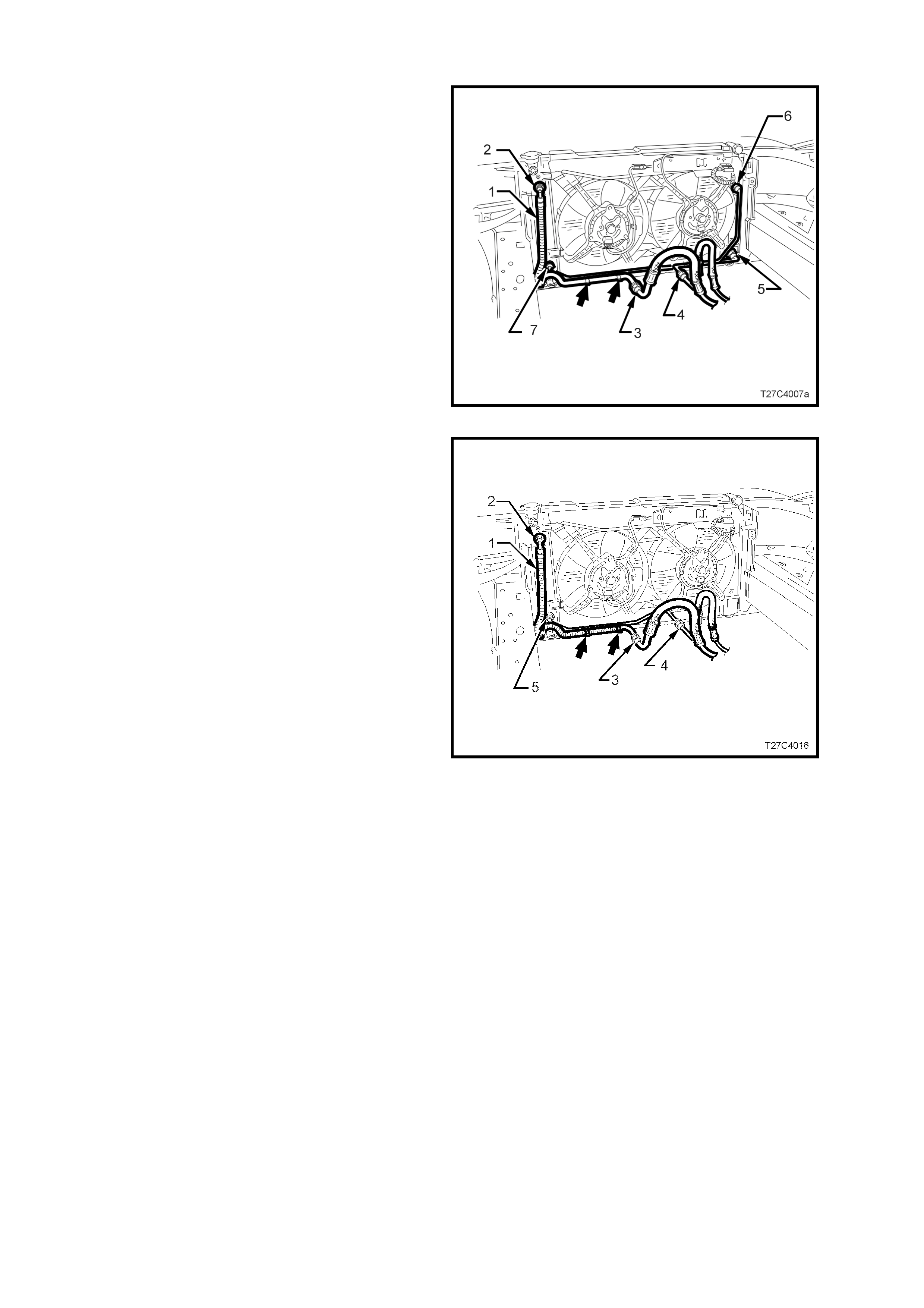
V6 SUPERCHARGED ENGINE AFTER THE
BREAKPOINT
Legend:
1. Fluid Cooler Line to External Cooler.
2. Fluid Cooler Line to Radiator Tank, Outlet
Fitting.
3. Fitting, Fluid Cooler Return Line.
4. Fitting, Fluid Cooler Inlet Line.
5. Fluid Cooler Line to Radiator Tank Inlet
Fitting.
Figure 6B1-1-2

2. SERVICE OPERATIONS
2.1 SERVICE INFORMATION
Service Operations for the cooling system on vehicles with V6 engine carry over from those detailed in Section
6B1-1 ENGINE COOLING - V6 ENGINE of the VT Series I Service Information, noting the following.
To accommodate the new engine cooling fans, a minor revision to the lower baffle air chute was made, however,
this revision does not effect the way the air chute attaches to the front of the vehicle.
If reins talling a c ooling f an, c ooling f an motor or s hroud as s embly to a VT Series II vehicle with a V6 engine, ref er to
4. TORQUE WRENCH SPECIFICATIONS in this Section for the correct torque wrench specifications.
Techline
Techline
Techline

3. SPECIFICATIONS
VT SERIES II ENGINE COOLING FAN 1 (LOW SPEED)
Number of blades.................................................... 5
Spacing ................................................................... Even
Material.................................................................... Polypropylene (20% glass filled)
Diameter.................................................................. 300 mm
Electric motor drive ................................................. 80 watts (nominal)
VT SERIES II ENGINE COOLING FAN 2
Number of blades.................................................... 4
Spacing ................................................................... Even
Material.................................................................... Polypropylene (7.5% glass filled)
Diameter.................................................................. 340 mm
Electric motor drive ................................................. 120 watts (nominal)

4. TORQUE WRENCH SPECIFI CATIONS
Nm
Cooling Fan and Shroud to Radiator Attaching Bolt ............. 3.0 - 4.5
Cooling Fan Motor Shaft Attaching Nut ................................ 4.9 - 7.4*
Cooling Fan Motor to Shroud................................................ 1.3 - 1.8
* Apply Loctite 243 or equivalent to Holden Specification HN 1256