
SECTION 6C3-2B - SYMPTOMS - GEN III V8 ENGINE
CAUTION:
This vehicle will be equipped with a Supplemental Restraint System (SRS). A SRS will consist of either
seat belt pre-tensioners and a driver's air bag, seat belt pre-tensioners and a driver's and front
passenger's air b ags o r seat b elt p re-t ension ers, driv er’s an d f ron t p asseng er’s air bag and left and right
hand side air bags. Refer to SAFETY PRECAUTIONS, Section 12M Supplemental Restraint System in the
VT Series II Service Informationbefore performing any service operation on, or around any SRS
components, the steering mechanism or wiring. Failure to follow the SAFETY PRECAUTIONS could
result in SRS deployment, resulting in possible personal injury or unnecessary SRS system repairs.
CAUTION:
When performing any Diagnostics, make certain that the drive wh eels are blocked and the parking brake
is firmly set.
GENERAL DESCRIPTION
When no diagnostic trouble codes have been set and the Tech 2 scan tool data values are within typical ranges,
you should diagnose the condition based on the symptoms of the complaint.
This Symptom Section starts with preliminary checks that must be performed in order to diagnose by symptom.
Then, intermittent conditions are discussed. These preliminary pages provide important information to assist you
with symptom diagnosis. Next, the contents of this Section presents the various symptoms and lists a series of
checks for each.
Many of the s ymptom diagnostic s st art with a very important pr ocedur e, a vis ual/physical inspection. Always look for
the obvious first. Some situations may warrant observing the driver. Is the driver using the correct shift lever position
or riding the brake pedal? Visually check the engine, transmission , PCM, and PIM connectors. Are there any
disconnected wires or incorrectly installed components?
Finally, are there obvious signs that someone may have perform ed incorrect r epairs? These c hecks tak e very little
time; they can eliminate the time spent on a broad-base systematic diagnosis by directing you to the problem. If they
do not reveal the problem, proceed to check the other suspect systems, as referred to in this Section.

PCM / PIM
Since the PCM and PIM can have a failure which may affect only one circuit, following the Diagnostic Procedures in
this Section will determine which circuit has a problem and where it is.
If a diagnostic chart indicates that the PCM, PIM and/ or connection is the cause of a problem and the PCM
or PIM has been replaced, but does not correct the problem, one of the following may be the reason:
• There is a problem with the PCM or PIM terminal connections. The diagnostic chart will say "PCM or PIM
connections or PCM/PIM." The terminals may have to be removed from the connector in order to check them
properly.
• The PCM or PIM is not correct for the application. The incorrect PCM or PIM may cause a malfunction and may
or may not set a code.
• The problem is intermittent. This means that the problem is not present at the time the system is being
checked. In this case, refer to the SYMPTOMS Charts and make a careful phy sical inspection of all
components of the system involved.
• Shorted solenoid, relay coil, or harness. Solenoids and relays are turned ON and OFF by the PCM, using
internal electronic switches called "Drivers." Each "driver" is part of a group of four (called "Quad drivers").
Failure of one driver may cause other drivers in the set to malfunction. Solenoid and relay coil resistance must
measure more than 20 ohms, in most cases. Less resistance may cause early failure of the PCM "driver."
Before replacing a PCM or PIM, be sure to check the coil resistance of all solenoids and relays controlled by the
PCM or PIM. See PCM and PIM wiring diagram for the solenoid(s) and relay(s) and the coil terminal identification.
• The replacement PCM or PIM may be faulty. After the PCM or PIM is replaced, the system should be
rechecked for proper operation. If the diagnostic chart again indicates the PCM or PIM is the problem,
substitute a known good PCM or PIM. Although this is an extremely rare condition, it could occur.
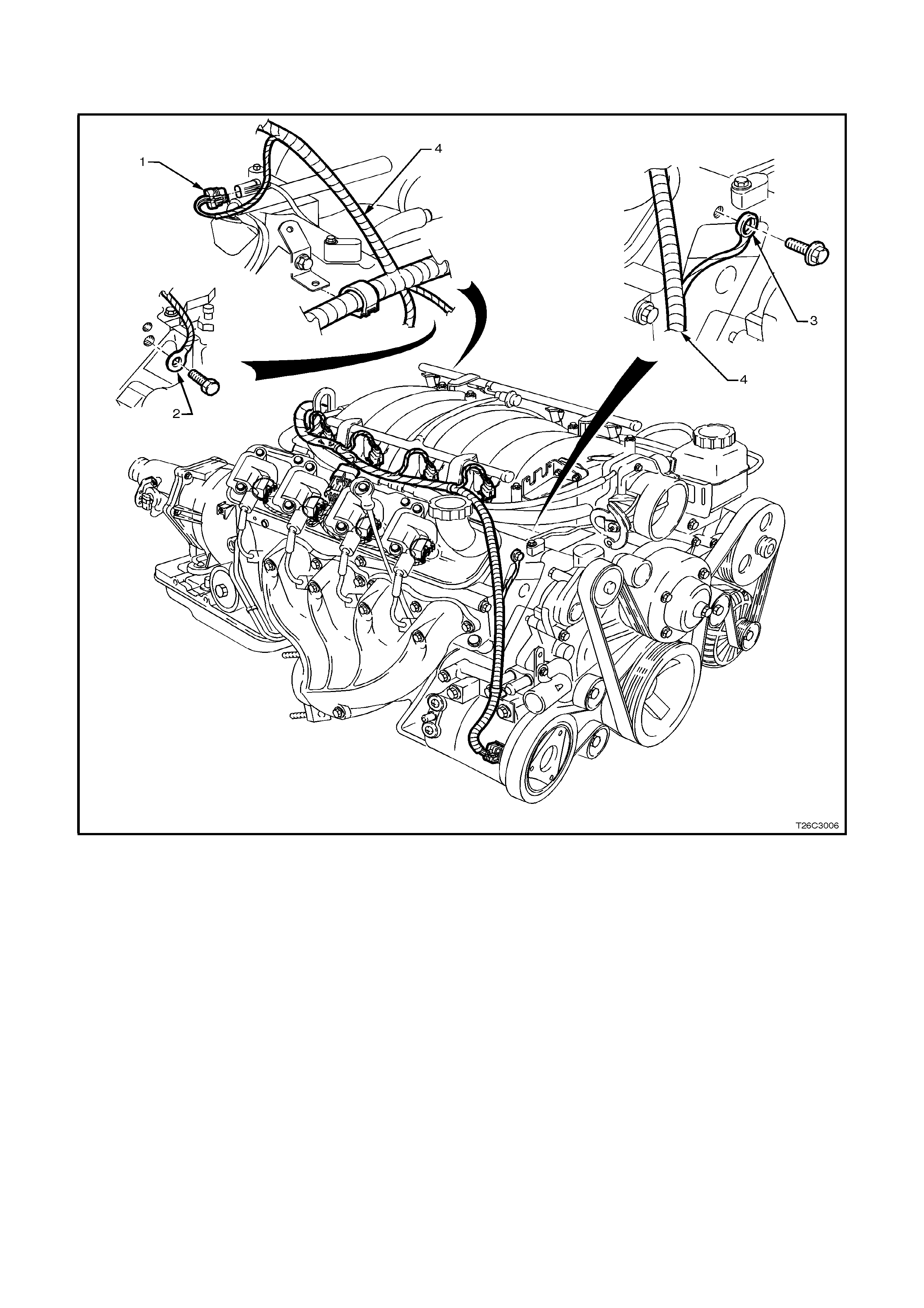
ENGINE EARTH LOCATIONS
1. Knock Sensors Jumper Harness Connector
2. PCM Earth Location Left Rear Head
3. PCM Earth Location Right Front Head
4. PCM Wiring Harness to A/C Compressor

SYMPTOMS
IMPORTANT PRELIMINARY CHECKS BEFORE STARTING
Perform the Powertrain OBD System Check before using the System Tables, and verify all of the following are true:
• The PCM/PIM and CPL (Check Powertrain Lamp) are operating correctly.
• There are no PCM or PIM DTC(s) stored.
• Ensure that the engine coolant temperature is not above 130°C (266°F). This condition causes the PCM to
operate in Engine Coolant O ver T e mperature- F uel Disabled Mode. While in Engine Coolant O ver Temperature-
Fuel Disabled Mode, the PCM turns the f uel O FF to f our c ylinders at a tim e in order to keep engine temperature
from reaching damaging levels. The system perceives Engine coolant Over Temperature as a lack of power,
mis s , or r ough idle. If the vehic le is oper ating in Engine Coolant Over Temper ature- F uel Disabled Mode, refer to
Section 6B-3 ENGINE COOLING – GEN III V8 ENGINE of the VT Series II Service Information for diagnosis.
• The T ech 2 scan tool data is within the norm al operating range, ref er to Section 6C3-2 DIAGNOSIS – GEN III
V8 ENGINE of the VT Series II Service Information.
• Verify the driver com plaint, and locate the correct symptom in the table of contents. Check the items indicated
under that symptom.

INSPECTION
Several of the symptom procedures require a careful visual and physical inspection. This step is extremely
important-it can lead to correcting a problem without further checks and can save valuable time.
This check includes:
• The PCM/PIM earths for being clean, tight, and in their proper location.
• Vacuum hos es for splits , k ink s, and pr oper connections , as s hown on the Vehicle Emis sion Control Inf orm ation
label. Check thoroughly for any type of leak or restriction.
• The Mas s Air Flow (MAF) s ensor installation. T he arrows on the plastic portion of the sensor must point toward
the engine.
• The air intake ducts for being collapsed, split or for having damaged areas.
• Air leaks at throttle body mounting area, Mass Air Flow (MAF) sensor, and the intake manifold sealing surfaces.
• The ignition wires for cracking, hardness, proper routing and carbon tracking.
• The engine harness wiring and terminals for proper connections, pinches or cuts.

INTERMITTENTS
IMPORTANT: Check for improper installation of electrical components if an intermittent condition exists. Inspect for
aftermarket theft deterrent devices, lights and cellular phones. Ensure that no aftermarket equipment is connected
to the Class II circuit. If you can not locate an intermittent condition, a cellular phone signal communication may be
the cause of the condition.
IMPORTANT: The problem may or may not turn ON the Check Powertrain Lamp (CPL) or store a DTC. DO NOT
use the Diagnostic Trouble Code (DTC) tables for intermittent problems. The fault must be present in order to
locate the problem.
Faulty electrical connections or wiring cause most intermittent problems. Perform a careful inspection for the
following conditions:
• Poor mating of the connector halves or a terminal not fully seated in the connector body (backed out).
• An improperly formed or damaged terminal.
• Reform or replace connector terminals in the problem circuit in order to insure proper contact tension.
• Poor terminal to wire connection requires removing the terminal from the connector body in order to check.
• Road test the vehic le with a Digital Multim eter ( DMM) J 39200 c onnected to the s uspected c ircuit. An abnorm al
voltage when the malfunction occurs is a good indication that there is a malfunction in the circuit being
monitored.
Use a scan tool in order to help detect intermittent conditions. The scan tool has several features that you can use
to locate an intermittent condition. Use the following features to find intermittent faults:
• You can trigger the Snaps hot f eatur e in order to captur e and s tore engine par ameters within the scan tool when
the malfunction occurs. You can then review this stored information in order to see what caused the
malfunction.
• Using the Scan Tool’s Freeze Frame/Fa ilure Records can als o aid in locating an intermittent c ondition. Review
and capture the information in the Freeze Frame/Failure Records associated with the intermittent DTC being
diagnosed. Drive the vehicle in the conditions that were present when the DTC was originally set.
IMPORTANT: If the intermittent condition exists as a start and then stall condition, check for DTC(s) relating to the
theft deterrent system. Check for improper installation of electrical options such as lights, cellular phones etc.
Any of the following may cause an intermittent Check Powertrain Lamp (CPL) with no stored DTC:
• The ignition coils shorted to a earth, arcing at the ignition wires or the spark plugs.
• The PCM/PIM earths, refer to Section 12P WIRING DIAGRAMS of the VT Series II Service Information.
• The Ignition Control ( IC) wires f or being routed too c lose to the sec ondary ignition wires, c oils, or the gener ator.
Ensure that all of the circuits from the PCM to the ignition coils have good connections.
• An open diode across the A/C compressor clutch and the other open diodes, refer to Section 12P WIRING
DIAGRAMS of the VT Series II Service Information.
Use the following tables when diagnosing a symptom complaint:
• Hard Start
• Surges/Chuggles
• Lack of Power, Sluggishness, or Sponginess
• Detonation/Spark Knock
• Hesitation, Sag, Stumble
• Cuts Out, Misses
• Poor Fuel Economy
• Rough, Unstable, or Incorrect Idle, Stalling
• Dieseling, Run-On
• Backfire

HARD START
Checks Actions
Definition: Engine cranks OK, but does not start for a long time. Does eventually run, may start but stalls
immediately.
Preliminary • Refer to SYMPTOMS, IMPORTANT PRELIMINARY CHECKS
BEFORE STARTING in this Section.
• Check the PCM/PIM earths for being clean, tight and in their proper
locations. Ref er to Section 12P WIRING DIAG RAMS of the VT Ser ies II
Service Information.
• Refer to Service Bulletins for relevant information.
Sensor/System • Check the Engine Coolant Temperature (ECT) sensor for an incorrect
value. Compare the Engine Coolant Temperature against the Intake Air
Temperature (IAT) on a cold engine. The ECT and IAT sensor values
should be within ± 3°C (5°F) of each other. If the ECT sensor is out of
range with the IAT sensor, check the resistance of the ECT sensor.
Refer to Temperature vs Resistance for resistance specifications.
Replace the ECT sensor if the resistance is not within the specification.
If the sensor is within the specification, repair ECT signal circuit for high
resistance.
• Check the Mass Air Flow sensor installation. A MAF sensor that is
incorrectly installed may cause hard starting. The embossed arrows on
the MAF sensor indicate the direction of the intake air flow. The arrow
must point toward the engine. Install the MAF in the proper direction.
Refer to MAF Sensor Replacement in Section 6C3-3 SERVICE
OPERATIONS – GEN III V8 ENGINE of the VT Series II Service
Information.
Fuel System • Check the fuel pump relay operation. The fuel pump should turn ON for
2 seconds when you turn on the ignition. Refer to Fuel Pump Relay
Circuit Diagnosis in Section 6C3-2A DIAGNOSTIC CHARTS – GEN III
V8 ENGINE of the VT Series II Service Information.
• A faulty in-take fuel pump check valve slows the fuel in the lines to drain
back to the tank after the engine stops. To check for this condition, refer
to Fuel System Diagnosis in Section 6C3-2A DIAGNOSTIC CHARTS –
GEN III V8 ENGINE of the VT Series II Service Information.
• Check both injector fuses for being open. An open injector fuse causes
four injectors and four ignition coils not to operate. Replace the fuse.
Inspect the injector circuit and the ignition coil circuits for an intermittent
short to earth.
• Check for a low fuel pressure condition. Refer to Fuel System
Diagnosis in Section 6C3-2A DIAGNOSTIC CHARTS – GEN III V8
ENGINE of the VT Series II Service Information.
• Check for a restricted fuel filter. Refer to Fuel System Diagnosis in
Section 6C3-2A DIAGNOSTIC CHARTS – GEN III V8 ENGINE of the
VT Series II Service Information.
• Check for a contaminated fuel condition.

HARD START (Continued)
Checks Actions
Ignition System • Check both injector fuses for being open. An open injector fuse causes
four injectors and four ignition coils not to operate. Replace the fuse.
Inspect the injector circuit and the ignition coil circuits for an intermittent
short to earth.
Check for proper ignition voltage output with spark tester J 26792. Refer to
Section 6D3-3 IGNITION SYSTEM – GEN III V8 ENGINE of the VT
Series II Service Information.
• Remove the spark plugs and check for the following:
- Wet plugs
- Cracks
- Wear
- Incorrect gap
- Burned electrodes
- Heavy deposits
• Determine the causes of the fouling before replacing the spark plugs, if
the spark plugs are fuel or oil fouled.
• Check for bare or shorted ignition wires.
• Check for loose ignition coil earths.
• Check the spark plugs for proper heat range.
Refer to Section 6D3-3 IGNITION SYSTEM – GEN III V8 ENGINE of the
VT Series II Service Information.
Engine Mechanical • Excessive oil in combustion chamber - leaking valve seals. Refer to
Section 6A3 ENGINE MECHANICAL– GEN III V8 ENGINE of the VT
Series II Service Information.
• Low cylinder compression. Refer to Section 6A3 ENGINE
MECHANICAL– GEN III V8 ENGINE of the VT Series II Service
Information.
• Inspect combustion chambers for excessive carbon build-up. Clean the
chambers using a de-carboning agent. Follow the instructions of the
product.
• Check for incorrect basic engine parts. Inspect the following: Cylinders,
camshaft, pistons, etc.
Refer to Section 6A3 ENGINE MECHANICAL – GEN III V8 ENGINE of the
VT Series II Service Information.

SURGES/CHUGGLES
Checks Actions
Definition: Engine power variation under steady throttle or cruise. Vehicle speeds up and slows down with no
change in the accelerator pedal position.
Preliminary • Refer to SYMPTOMS, IMPORTANT PRELIMINARY CHECKS
BEFORE STARTING in this Section.
• Refer to Service Bulletins for relevant information.
• Check the PCM/PIM earths for being clean, tight and in their proper
locations. Ref er to Section 12P WIRING DIAG RAMS of the VT Ser ies II
Service Information.
• Be sure the driver understands the operation of the tr ansm iss ion torque
converter clutch and A/C compressor operation as explained in the
Owner’s Handbook. Inform the driver on how the TCC and the A/C
clutch operates.
Sensor/System • Check the Heated Oxygen Sensor (HO2S). The Heated Oxygen
Sensors (HO2S) should r espond quick ly to diff erent throttle positions . If
they do not, check the HO2S f or silicon or other contam inates from fuel
or the use of improper RTV sealant. The sensors may have a white
powdery coating and result in a high but false signal voltage (rich
exhaust indication). The PCM will then reduce the amount of fuel
delivery to the engine causing a severe driveability problem.
• Check the MAF sensor connections.
Fuel System • Check for a low fuel pressure condition. Refer to Fuel System
Diagnosis in Section 6C3-2A DIAGNOSTIC CHARTS – GEN III V8
ENGINE of the VT Series II Service Information.
• Check for a restricted fuel filter. Refer to Fuel System Diagnosis in
Section 6C3-2A DIAGNOSTIC CHARTS – GEN III V8 ENGINE of the
VT Series II Service Information.
• Check for a contaminated fuel condition.
• Check that each injector harness is connected to the correct
injector/c ylinder according to the f iring order (1-8-7- 2-6-5- 4-3). Relocate
injector harnesses as necessary.
• Check the items that cause an engine to run rich (long term fuel trim
near 13%). For a r ich condition, ref er to DTC P0132 HO2S Cir cuit High
Voltage Bank 1 Lef t Sens or and DTC P0152 HO2S Cir c uit High Voltage
Bank 2 Right Sensor .
• Check the items that can cause an engine to run lean (long term fuel
trim near 23%). For a lean condition, ref er to DTC P0131 HO2S Circuit
High Voltage Bank 1 Left Sensor and DTC P0151 HO2S Circuit High
Voltage Bank 2 Right Sensor.

SURGES/ CHUGGLES (Continued)
Checks Actions
Ignition System • W et down the sec ondary ignition system with water from a spray bottle.
W etting down the secondary ignition system m ay help locate damaged
or deteriorated components. Look/listen for arcing or misfiring as you
apply the water.
• Check for proper ignition voltage output with spark tester J 26792.
• Remove the spark plugs and check for the following:
- Wet plugs
- Cracks
- Wear
- Incorrect gap
- Burned electrodes
- Heavy deposits
• An incorrect spark plug gap will cause a driveability problem. Set the
spark plug gaps using a wire gauge gap tool (J 41319). Refer to Section
6D3-3 IGNITION SYSTEM – GEN III V8 ENGINE of the VT Series II
Service Information.
• If spark plugs are fouled, determine the cause of the fouling before
replacing them.
• For f uel f ouling, refer to DT C P0172 F uel Trim System Ric h Bank 1 and
DTC P0175 Fuel Trim System Rich Bank 2 in Section 6C3-2A
DIAGNOSTIC CHARTS – GEN III V8 ENGINE of the VT Series II
Service Information for diagnosis of the rich condition
• For oil fouling refer to Section 6A3 ENGINE MECHANICAL – GEN III
V8 ENGINE of the VT Series II Servic e Inf ormation, f or diagnos is of the
oil fouling condition.
• Check for loose ignition coil earths.
• Check the spark plugs for proper heat range. Refer to Section 6D3-3
IGNITION SYSTEM – GEN III V8 ENGINE of the VT Series II Service
Information.
Engine Mechanical Ensure that the engine coolant temperature is not above 130°C (266°F).
This condition causes the PCM to operate in Engine Coolant Over
Temperature-Fuel Disabled Mode. While in Engine Coolant Over
Tem per ature-Fuel Dis abled Mode, the PCM turns f uel OFF to four cylinders
at a tim e to keep engine tem peratures fr om reaching dam aging levels. The
system perceives Engine Coolant Over Temperature-Fuel Disabled Mode
as a lack of power, miss, or rough idle. If the vehicle operates in Engine
Coolant Over Temperature-Fuel Disabled Mode. Refer to Section 6B3
ENGINE COOLING – GEN III V8 ENGINE of the VT Series II Service
Information for diagnosis.
Additional Checks • Inspect vacuum hoses for splits, kinks, proper connections and routing.
• Check the Torque Converter Clutch (TCC) operation. A TCC applying
too soon can cause the engine to detonate. Refer to Section 7C2
AUTOMATIC TRANSMISSION – ELECTRICAL DIAGNOSIS of the VT
Series II Service Information for diagnosis..

LACK OF POWER, SLUGGISHNESS, OR SPONGINESS
Checks Actions
Definition: Engine delivers less than normal power. Little or no increase in speed when the accelerator pedal is
partially depressed.
Preliminary • Refer to SYMPTOMS, IMPORTANT PRELIMINARY CHECKS
BEFORE STARTING in this Section.
• Refer to Service Bulletins for relevant information.
• Check the PCM/PIM earths for being clean, tight and in their proper
locations.
• Remove the air filter element and check for dirt or for being restricted.
Refer to Air Cleaner Element Replacem ent in Section 6C3-3 SERVICE
OPERATIONS – GEN III V8 ENGINE of the VT Series II Service
Information and replace as necessary.
Fuel System • Check both injector fus es for being open. An open injec tor fus e causes
four injectors and four ignition coils not to operate. Replace the fuse.
Inspect the ignition coil circuits and the injector circuits for an
intermittent short to earth.
• Check for a low fuel pressure condition. Refer to Section 6C3-2A
DIAGNOSTIC CHARTS – GEN III V8 ENGINE of the VT Series II
Service Information.
• Check for a res tricted fuel f ilter. Refer to Section 6C3-2A DIAGNOSTIC
CHARTS – GEN III V8 ENGINE of the VT Series II Service Information.
• Check for a contaminated fuel condition.
• Check the items that cause an engine to run rich (long term fuel trim
near -13%). For a ric h condition, r ef er to DT C P0132 HO 2S Circ uit High
Voltage Bank 1 Lef t Sens or and DTC P0152 HO2S Cir c uit High Voltage
Bank 2 Right Sensor
• Check the items that can cause an engine to run lean (long term fuel
trim near 23%). For a lean condition, ref er to DTC P0131 HO2S Circuit
High Voltage Bank 1 Left Sensor and DTC P0151 HO2S Circuit High
Voltage Bank 2 Right Sensor.
Sensor/System • Use the Tech 2 scan tool in order to monitor the knock sensor system
for excessive spark retard activity. Refer to Section 6C3-2A
DIAGNOSTIC TABLES of the VT Series II Service Information.

LACK OF POWER, SLUGGISHNESS, OR SPONGINESS (Continued)
Checks Actions
Ignition System • Check both injector fuses for being open. An open injector fuses
causes f our injectors and four ignition coils not to operate. Replace the
fuse. Inspect the ignition coil circuits and the injector circuits for an
intermittent short to earth.
• W et down the sec ondary ignition system with water from a spray bottle.
W etting down the secondary ignition system m ay help locate damaged
or deteriorated components. Look/listen for arcing or misfiring as you
apply the water.
• Check for correct ignition voltage output with spark tester J 26792.
Refer to Electronic Ignition System Diagnosis Section 6C3-2C
FUNCTIONAL CHECKS – GEN III V8 ENGINE of the VT Series II
Service Information.
• Remove the spark plugs and check for the following:
- Wet plugs
- Cracks
- Wear
- Incorrect gap
- Burned electrodes
- Heavy deposits
• An incorrect spark plug gap will cause a driveability problem. Set the
spark plug gaps using a wire gauge gap tool (J 41319). Refer to Section
6D3-3 IGNITION SYSTEM – GEN III V8 ENGINE of the VT Series II
Service Information.
• If spark plugs are fouled, determine the cause of the fouling before
replacing them.
• For f uel f ouling, refer to DT C P0172 F uel Trim System Ric h Bank 1 and
DTC P0175 Fuel Trim System Rich Bank 2 in Section 6C3-2A
DIAGNOSTIC CHARTS – GEN III V8 ENGINE of the VT Series II
Service Information for diagnosis of the rich condition
• For oil fouling refer to Section 6A3 ENGINE MECHANICAL – GEN III
V8 ENGINE of the VT Series II Servic e Inf ormation, f or diagnos is of the
oil fouling condition.
• Check for loose ignition coil earths.
• Check the spark plugs for proper heat range. Refer to Section 6D3-3
IGNITION SYSTEM – GEN III V8 ENGINE of the VT Series II Service
Information.
Engine Mechanical • Ensure that the engine coolant temperature is not above 130°C
(266°F). This condition causes the PCM to operate in Engine Coolant
Over Temperature-Fuel Disabled Mode. While in Engine Coolant Over
Temperature-Fuel Disabled Mode, the PCM turns fuel OFF to four
cylinders at a time to keep engine temperatures from reaching
damaging levels. The system perceives Engine Coolant Over
Temperature-Fuel Disabled Mode as a lack of power, miss, or rough
idle. If the vehicle operates in Engine Coolant Over Tem perature - Fuel
Disabled Mode, refer to Section 6B3 ENGINE COOLING – GEN III V8
ENGINE of the VT Series II Service Information for diagnosis.
• Excessive oil in combustion chamber - leaking valve seals. Refer to
Section 6A3 ENGINE MECHANICAL – GEN III V8 ENGINE of the VT
Series II Service Information for diagnosis.
• Low cylinder compression. Refer to Section 6A3 ENGINE
MECHANICAL – GEN III V8 ENGINE of the VT Series II Service
Information for diagnosis.
• For incorrect basic engine parts. Inspect the following:
- Camshaft
- Cylinder heads
- Pistons, etc.
Refer to Section 6A3 ENGINE MECHANICAL – GEN III V8 ENG INE of
the VT Series II Service Information for diagnosis.

LACK OF POWER, SLUGGISHNESS, OR SPONGINESS (Continued)
Checks Actions
Additional Checks • Check the exhaust system for possible restrictions. Check for the
following:
- Inspect the exhaust system for damaged or collapsed pipes.
- Inspect the exhaust manifold for a collapsed inner wall.
- Inspect the muffler for heat distress or possible internal failure.
- Inspect for possible restricted catalytic converters by comparing
exhaust system back pressure on each side of the engine.
• Check Torque Converter Clutch (TCC) for proper operation. Refer to
Section 7C2 AUTOMATIC TRANSMISSION – ELECTRICAL
DIAGNOSIS of the VT Series II Service Information for diagnosis.

DETONATION/SPARK KNOCK
Checks Actions
Definition: A mild to severe ping, usually worse under acceleration. The engine makes sharp metallic knocks that
change with throttle opening.
Preliminary • Refer to SYMPTOMS, IMPORTANT PRELIMINARY CHECKS
BEFORE STARTING in this Section.
• Refer to Service Bulletins for relevant information.
• Check the PCM/PIM earths for being clean, tight and in their proper
locations. Ref er to Section 12P WI RING DIAG RAMS of the VT Series II
Service Information.
• If the Tech 2 sc an tool readings are norm al (r efer to the suppor ting text
of the Powertrain On-Board Diagnostic (OBD) System Check) and there
are no engine mec hanical faults , fill the fuel tank with a prem ium petrol
that has a m inimum octane reading of 92 and re-evaluate the vehicle’s
performance.
Fuel System • Check for a low fuel pr essure condition. Ref er to Fuel System Diagnosis
in Section 6C3-2A DIAGNOST IC CHARTS – GEN III V8 ENGINE of the
VT Series II Service Information.
• Check for a restricted fuel filter. Refer to Fuel Sy stem Diagnosis.
• Check for a contaminated fuel condition.
• Check the items that cause an engine to run rich (long term fuel trim
near -13%). For a ric h condition, r ef er to DT C P0132 HO 2S Circ uit High
Voltage Bank 1 Lef t Sens or and DTC P0152 HO2S Cir c uit High Voltage
Bank 2 Right Sensor.
• Check the items that can cause an engine to run lean (long term fuel
trim near 23%). For a lean condition, ref er to DTC P0131 HO2S Cir cuit
High Voltage Bank 1 Left Sensor and DTC P0151 HO2S Circuit High
Voltage Bank 2 Right Sensor.
Ignition System Check the spark plugs for proper heat range. Refer to Section 6D3-3
IGNITION SYSTEM – GEN III V8 ENGINE of the VT Series II Service
Information.
Engine Mechanical Check for the following engine mechanical problems:
• Excessive oil in combustion chamber-leaking valve seals. Refer to
Section 6A3 ENGINE MECHANICAL – GEN III V8 ENGINE of the VT
Series II Service Information.
• Low cylinder compression. Refer to Section 6A3 ENGINE
MECHANICAL – GEN III V8 ENGINE of the VT Series II Service
Information.
• Inspect com bustion cham bers for excessive car bon build-up. Clean the
chambers using a de-carboning agent. Follow the instructions of the
product.
• For incorrect basic engine parts. Inspect the following:
- Cylinders
- Camshaft
- Pistons, etc.
• Refer to Section 6A3 ENGINE MECHANICAL – GEN III V8 ENGINE of
the VT Series II Service Information.
Additional Checks • Check the Park/Neutral Position (PNP) switch operation. Refer to
Section 7C2 AUTOMATIC TRANSMISSION – ELECTRICAL
DIAGNOSIS of the VT Series II Service Information for diagnosis.
• Check the TCC operation. The TCC applying too soon can cause the
engine to spark knock. Refer to Section 7C2 AUTOMATIC
TRANSMISSION – ELECTRICAL DIAGNOSIS of the VT Series II
Service Information.

HESITATION, SAG, STUMBLE
Checks Actions
Definition: Momentary lack of response as the accelerator is depressed. Can occur at any vehicle speed. Usually
more pronounced when first trying to make the vehicle move from a standing start. May cause the engine to stall
if severe enough.
Preliminary • Refer to Symptoms, Important Preliminary Checks Before Starting.
• Search for Service Bulletins.
• Check the PCM/PIM earths for being clean, tight and in their proper
locations. Ref er to Section 12P WI RING DIAG RAMS of the VT Series II
Service Information.
Sensor/System Check the MAP sensor operation. Refer to Section 63-2A DIAGNOSTIC
TABLES of the VT Series II Service Information.
Fuel System • Check for a low fuel pressure condition. Refer to Fuel System
Diagnosis in Section 6C3-2A DIAGNOSTIC CHARTS – GEN III V8
ENGINE of the VT Series II Service Information.
• Check for a restricted fuel filter. Refer to Fuel System Diagnosis in
Section 6C3-2A DIAGNOSTIC CHARTS – GEN III V8 ENGINE of the
VT Series II Service Information.
• Check for a contaminated fuel condition.
• Check both injector fus es for being open. An open injec tor fus e causes
four injectors and four ignition coils not to operate. Replace the fuse.
Inspect the ignition coil circuits and the injector circuits for an
intermittent short to earth.
• Perfor m the injector balanc e test. Ref er to Fuel Inj ector Balance T est in
Section 6C3-2C FUNCTIONAL CHECKS – GEN III V8 ENGINE of the
VT Series II Service Information for procedure.
• Check the items that cause an engine to run rich (long term fuel trim
near -13%). For a ric h condition, r ef er to DT C P0132 HO 2S Circ uit High
Voltage Bank 1 Lef t Sens or and DTC P0152 HO2S Cir c uit High Voltage
Bank 2 Right Sensor.
• Check the items that can cause an engine to run lean (long term fuel
trim near 23%). For a lean condition, ref er to DTC P0131 HO2S Cir cuit
High Voltage Bank 1 Left Sensor and DTC P0151 HO2S Circuit High
Voltage Bank 2 Right Sensor.

HESITATION, SAG, STUMBLE (Continued)
Checks Actions
Ignition System • W et down the sec ondary ignition system with water from a spray bottle.
W etting down the secondary ignition system m ay help locate damaged
or deteriorated components. Look/listen for arcing or misfiring as you
apply the water.
• Check both injector fus es for being open. An open injec tor fus e causes
four injectors and four ignition coils not to operate. Replace the fuse.
Inspect the ignition coil circuits and the injector circuits for an
intermittent short to earth
• Check for proper ignition voltage output with spark tester J 26792.
Refer to Electronic Ignition System Diagnosis in Section 6C3-2C
FUNCTIONAL CHECKS – GEN III V8 ENGINE of the VT Series II
Service Information for procedure.
• Remove the spark plugs and check for the following:
- Wet plugs
- Cracks
- Wear
- Incorrect gap
- Burned electrodes
- Heavy deposits
• An Incorrect spark plug gap will cause a driveablitiy problem. Set the
spark plug gap using a wire gauge gap tool (J 41319). Refer to Section
6D3-3 IGNITION SYSTEM – GEN III V8 ENGINE of the VT Series II
Service Information.
• If spark plugs are fouled, determine the cause of the fouling before
replacing them.
• For f uel f ouling, refer to DT C P0172 F uel Trim System Ric h Bank 1 and
DTC P0175 Fuel Trim System Rich Bank 2 in Section 6C3-2A
DIAGNOSTIC CHARTS – GEN III V8 ENGINE of the VT Series II
Service Information for diagnosis of the rich condition
• For oil fouling refer to Section 6A3 ENGINE MECHANICAL – GEN III
V8 ENGINE of the VT Series II Service Inf orm ation, f or diagnosis of the
oil fouling condition.
• Check for loose ignition coil earths.
• Check the spark plugs for proper heat range. Refer to Section 6D3-3
IGNITION SYSTEM – GEN III V8 ENGINE of the VT Series II Service
Information.
Engine Cooling System Check the engine thermostat for proper operation and for proper heat
range. Refer to in Sec tion 6B3 ENG INE CO OLING – GEN III V8 ENGINE of
the VT Series II Service Information.
Additional Checks Check the generator output voltage. Refer to in Section 6D3-1 CHARGING
SYSTEM – GEN III V8 ENGINE of the VT Series II Service Information.
Repair the charging system if the generator output voltage is less than 9
volts or more than 16 volts.

CUTS OUT, MISSES
Checks Actions
Definition: Steady pulsation or jerking that follows engine speed, usually more pronounced as an engine load
increases. This condition is not normally felt above 1500 RPM or 48 km/h. The exhaust has a steady spitting
sound at idle or low speed.
Preliminary • Refer to SYMPTOMS, IMPORTANT PRELIMINARY CHECKS
BEFORE STARTING in this Section.
• Refer to Service Bulletins for relevant information.
• Check the PCM/PIM earths for being clean, tight and in their proper
locations. Ref er to Section 12P WIRING DIAG RAMS of the VT Ser ies II
Service Information.
• Remove the air filter element and check for dirt or for being restricted.
Refer to Air Cleaner Element Replacem ent in Section 6C3-3 SERVICE
OPERATIONS – GEN III V8 ENGINE of the VT Series II Service
Information and replace as necessary.
Fuel System • Perform the injector balance test. Refer to Fuel Injector Balance Test
for procedure.
• Check for a low fuel pressure condition. Refer to Fuel System
Diagnosis in Section 6C3-2A DIAGNOSTIC CHARTS – GEN III V8
ENGINE of the VT Series II Service Information.
• Check for a restricted fuel filter. Refer to Fuel System Diagnosis in
Section 6C3-2A DIAGNOSTIC CHARTS – GEN III V8 ENGINE of the
VT Series II Service Information.
• Check for a contaminated fuel condition.
• Check the items that cause an engine to run rich (long term fuel trim
near -13%). For a ric h condition, r ef er to DT C P0132 HO 2S Circ uit High
Voltage Bank 1 Lef t Sens or and DTC P0152 HO2S Cir c uit High Voltage
Bank 2 Right Sensor.
• Check the items that can cause an engine to run lean (long term fuel
trim near 23%). For a lean condition, ref er to DTC P0131 HO2S Circuit
High Voltage Bank 1 Left Sensor and DTC P0151 HO2S Circuit High
Voltage Bank 2 Right Sensor.
Sensor/System • Use a Tec h 2 sc an tool in order to m onitor the k noc k s ensor s ystem for
excessive spark retard activity. Refer to Section 6C3-2A DIAGNOSTIC
TABLES of the VT Series II Service Information.

CUTS OUT, MISSES (Continued)
Checks Actions
Ignition System • W et down the sec ondary ignition system with water from a spray bottle.
W etting down the secondary ignition system m ay help locate damaged
or deteriorated components. Look/listen for arcing or misfiring as you
apply the water.
• Check for proper ignition voltage output with spark tester J 26792.
Refer to Electronic Ignition System Diagnosis in Section 6C3-2C
FUNCTIONAL CHECKS – GEN III V8 ENGINE of the VT Series II
Service Information.
• Remove the spark plugs and check for the following:
- Wet plugs
- Cracks
- Wear
- Incorrect gap
- Burned electrodes
- Heavy deposits
• An Incorrect spark plug gap will cause a driveablitiy problem. Set the
spark plug gap using a wire gauge gap tool (J 41319). Refer to Sec tion
6D3-3 IGNITION SYSTEM – GEN III V8 ENGINE of the VT Series II
Service Information.
• If spark plugs are fouled, determine the cause of the fouling before
replacing them.
• For f uel f ouling, refer to DT C P0172 F uel Trim System Ric h Bank 1 and
DTC P0175 Fuel Trim System Rich Bank 2 in Section 6C3-2A
DIAGNOSTIC CHARTS – GEN III V8 ENGINE of the VT Series II
Service Information for diagnosis of the rich condition
• For oil fouling refer to Section 6A3 ENGINE MECHANICAL – GEN III
V8 ENGINE of the VT Series II Servic e Inf ormation, f or diagnos is of the
oil fouling condition.
• Refer to Electronic Ignition System Diagnosis in Section 6C3-2C
FUNCTIONAL CHECKS – GEN III V8 ENGINE of the VT Series II
Service Information.
• Inspect the Secondary ignition for the following:
- Ignition wires for cross firing
- Ignition wires arcing to earth
- Ignition wires for proper routing
• - Ignition coils for crack or carbon tracking
Engine Mechanical • Check engine mechanical for the following:
- Check compression
- Sticking or leaking valves
- Worn camshaft lobes
- Valve timing
- Bent push rods
- Worn rocker arms
- Broken valve springs
- Excessive oil in combustion chamber - leaking valve seals
- Low cylinder compression
• For incorrect basic engine parts. Inspect the following:
- Camshaft
- Cylinder heads
- Pistons, etc.
Refer to in Section 6A3 ENGINE MECHANICAL – GEN III V8 ENGINE of
the VT Series II Service Information.

CUTS OUT, MISSES (Continued)
Checks Actions
Additional Checks • Check the exhaust system for possible restrictions. Check for the
following:
- Inspect the exhaust system for damaged or collapsed pipes.
- Inspect the exhaust manifold for a collapsed inner wall.
- Inspect the muffler for heat distress or possible internal failure.
- Inspect for possible restricted catalytic converters by comparing
exhaust system back pressure on each side of the engine. Check
back pressure by removing the Heated Oxygen Sensors.
• Electromagnetic Interference (EMI) on the reference circuit can cause
an engine miss condition. A sudden increase in engine RPM with no
change of thr ottle position indicates EMI m ay be present. Check routing
of secondary ignition wires, high voltage components (near ignition
control circuits) if a problem exists.
• Check the intake manifold and the exhaust manifold passages for
casting f lash. Ref er to in Sec tion 6A3 ENG INE MECHANICAL – GEN III
V8 ENGINE of the VT Series II Service Information.

POOR FUEL ECONOMY
Checks Actions
Definition: Fuel economy, as measured by an actual road test, is noticeably lower than normal.
Preliminary • Refer to SYMPTOMS, IMPORTANT PRELIMINARY CHECKS
BEFORE STARTING in this Section.
• Refer to Service Bulletins for relevant information.
• Check the PCM/PIM earths for being clean, tight and in their proper
locations. Ref er to Section 12P WIRING DIAG RAMS of the VT Ser ies II
Service Information.
• Check the driver’s driving habits.
• Is the A/C ON or the demister mode ON all the time?
• Are the tyres at the correct pressure?
• Are excessively heavy loads being carried?
Fuel System • Remove the air filter element and check for dirt or for being restricted.
• Perfor m the injector balanc e test. Ref er to Fuel Inj ector Balance T est in
Section 6C3-2 FUNCTIONAL CHECKS – GEN III V8 ENGINE of the VT
Series II Service Information for procedure.
• Check for a low fuel pressure condition. Refer to Fuel System
Diagnosis in Section 6C3-2A DIAGNOSTIC CHARTS – GEN III V8
ENGINE of the VT Series II Service Information.
• Check for a restricted fuel filter. Refer to Fuel System Diagnosis in
Section 6C3-2A DIAGNOSTIC CHARTS – GEN III V8 ENGINE of the
VT Series II Service Information.
• Check for a contaminated fuel condition.
• Check that each injector harness is connected to the correct
injector/c ylinder acc ording to the firing order (1-8-7- 2-6-5-4-3) . Relocate
injector harness as necessary.
• Check for injectors that are shorted internally. Compare the injector
resistanc es. Inj ec tor r es istanc e s hould be within one ohm of each other.
Refer to Fuel Injector Coil Test - ECT Between 10-35° C in Section
6C3-2 FUNCTIONAL CHECKS – G EN III V8 ENGINE of the VT Series
II Service Information for procedure.
• Check for foreign material accumulation in the throttle bore, carbon
build-up on the throttle valve, or on the throttle shaft. Also inspect for
throttle body tampering.
• Check the items that cause an engine to run rich (long term fuel trim
near -13%). For a ric h condition, r ef er to DT C P0132 HO 2S Circ uit High
Voltage Bank 1 Lef t Sens or and DTC P0152 HO2S Cir c uit High Voltage
Bank 2 Right Sensor.
• Check the items that can cause an engine to run lean (long term fuel
trim near 23%). For a lean condition, ref er to DTC P0131 HO2S Cir cuit
High Voltage Bank 1 Left Sensor and DTC P0151 HO2S Circuit High
Voltage Bank 2 Right Sensor.
Sensor/System • Check the air intake system and crankcase for air leaks.
• Check the PCV System for correct operation. Place a finger over the
inlet hole in the valve end sever al tim es. T he valve should s nap back . If
not, replace the valve.
• Check for proper calibration of speedometer. Using the Tech 2 scan
tool, command vehicle speed output. Speedometer should read same
as Tech 2 output. If not, refer to Section 12C INSTRUMENTS,
WIPERS/WASHERS & HORN of the VT Series II Service Information.
• Use the Tech 2 scan tool in order to monitor the knock sensor system
for excessive spark retard activity. Refer to Section 6C3-2A
DIAGNOSTIC TABLES of the VT Series II Service Information.

POOR FUEL EC ONOMY (Continued)
Checks Actions
Ignition System • Check for proper ignition voltage output with spark tester J 26792.
Refer to Electronic Ignition System Diagnosis in Section 6C3-2C
FUNCTIONAL CHECKS – GEN III V8 ENGINE of the VT Series II
Service Information.
• Remove the spark plugs and check for the following:
- Wet plugs
- Cracks
- Wear
- Incorrect gap
- Burned electrodes
- Heavy deposits
• An incorrect spark plug gap will cause a driveablitiy problem. Set the
spark plug gap using a wire gauge gap tool (J 41319). Refer to Section
6D3-3 IGNITION SYSTEM – GEN III V8 ENGINE of the VT Series II
Service Information.
• If spark plugs are fouled, determine the cause of the fouling before
replacing them.
• For f uel f ouling, refer to DT C P0172 F uel Trim System Ric h Bank 1 and
DTC P0175 Fuel Trim System Rich Bank 2 in Section 6C3-2A
DIAGNOSTIC CHARTS – GEN III V8 ENGINE of the VT Series II
Service Information for diagnosis of the rich condition
• For oil fouling refer to Section 6A3 ENGINE MECHANICAL – GEN III
V8 ENGINE of the VT Series II Servic e Inf ormation, f or diagnos is of the
oil fouling condition.
• Inspect the Secondary ignition for the following:
- Ignition wires arcing to earth
- Ignition wires for proper routing
• Wetting down the secondary ignition system with water from a spray
bottle m ay help loc ate damaged or deterior ated components. Look and
listen for arcing or misfiring as y ou apply w ater.
• Check for loose ignition coil earths.
Engine Cooling System • Check the engine coolant level for being low. Refer to Section 6B3
ENGINE COOLING – GEN III V8 ENGINE of the VT Series II Service
Information.
• Check the engine thermostat for proper operation and for the correct
heat range. Refer to Section 6B3 ENGINE COOLING – GEN III V8
ENGINE of the VT Series II Service Information.

POOR FUEL EC ONOMY (Continued)
Checks Actions
Engine Mechanical • Check engine mechanical for the following:
- Check compression
- Sticking or leaking valves
- Worn camshaft lobes
- Valve timing
- Bent push rods
- Worn rocker arms
- Broken valve springs
- Excessive oil in combustion chamber - leaking valve seals
- Low cylinder compression
• For incorrect basic engine parts. Inspect the following:
- Cylinders
- Camshaft
- Pistons, etc.
Refer to Section 6A3 ENGINE MECHANICAL – GEN III V8 ENGINE of the
VT Series II Service Information
Additional Checks • Check the vacuum hoses for splits, kinks, and proper connections.
• Check the TCC operation. The Tech 2 scan tool should indicate an
RPM drop, when the system c omm ands the TCC ON. Ref er to Section
7C2 AUTOMATIC TRANSMISSION – ELECTRICAL DIAGNOSIS of the
VT Series II Service Information for diagnosis.
• Check the exhaust system for possible restrictions. Check for the
following:
- Inspect the exhaust system for damaged or collapsed pipes.
- Inspect the exhaust manifold for a collapsed inner wall.
- Inspect the muffler for heat distress or possible internal failure.
- Inspect for possible restricted catalytic converters by comparing
exhaust system back pressure on each side of the engine. Check
back pressure by removing the heated oxygen sensors.
• Electromagnetic Interference (EMI) on the reference circuit can cause
an engine miss condition. A sudden increase in engine RPM with no
change of thr ottle position indicates EMI m ay be present. Check routing
of secondary ignition wires, high voltage components (near ignition
control circuits) if a problem exists.
• Check PNP switch circuit. Refer to Section 7C2 AUTOMATIC
TRANSMISSION – ELECTRICAL DIAGNOSIS of the VT Series II
Service Information for diagnosis.
• Check for faulty engine mounts. Refer to Section 6A3 ENGINE
MECHANICAL – GEN III V8 ENGINE of the VT Series II Service
Information for inspection of mounts.
• Check the intake and the exhaust m anifold passages for casting flash.
Refer to Section 6A3 ENGINE MECHANICAL – GEN III V8 ENGINE of
the VT Series II Service Information.

ROUGH, UNSTABLE, OR INCORRECT IDLE, STALLING
Checks Actions
Definition: Engine runs unevenly at idle. If severe, the engine or vehicle may shake. Engine idle speed may vary
in RPM. Either condition may be severe enough to stall the engine.
Preliminary • Refer to SYMPTOMS, IMPORTANT PRELIMINARY CHECKS
BEFORE STARTING in this Section.
• Refer to Service Bulletins for relevant information.
• Check the PCM/PIM earths for being clean, tight and in their proper
locations. Ref er to Section 12P WIRING DIAG RAMS of the VT Ser ies II
Service Information.
• Remove and check the air filter element f or dirt, or for being restricted.
Refer to Air Cleaner Element Replacem ent in Section 6C3-3 SERVICE
OPERATIONS – GEN III V8 ENGINE of the VT Series II Service
Information. Replace as necessary.
Fuel System • Perfor m the injector balanc e test. Ref er to Fuel Inj ector Balance T est in
Section 6C3-2C FUNCTIONAL CHECKS – GEN III V8 ENGINE of the
VT Series II Service Information for this procedure.
• Check for a low fuel pressure condition. Refer to Fuel System
Diagnosis in Section 6C3-2A DIAGNOSTIC CHARTS – GEN III V8
ENGINE of the VT Series II Service Information.
• Check for a restricted fuel filter. Refer to Fuel System Diagnosis in
Section 6C3-2A DIAGNOSTIC CHARTS – GEN III V8 ENGINE of the
VT Series II Service Information.
• Check for a contaminated fuel condition.
• Check that each injector harness is connected to the correct
injector/c ylinder according to the f iring order (1-8-7- 2-6-5- 4-3). Relocate
injector harness as necessary.
• Check the items that cause an engine to run rich (long term fuel trim
near -13%). For a ric h condition, r ef er to DT C P0132 HO 2S Circ uit High
Voltage Bank 1 Lef t Sens or and DTC P0152 HO2S Cir c uit High Voltage
Bank 2 Right Sensor.
• Check the items that can cause an engine to run lean (long term fuel
trim near 23%). For a lean condition, ref er to DTC P0131 HO2S Circuit
High Voltage Bank 1 Left Sensor and DTC P0151 HO2S Circuit High
Voltage Bank 2 Right Sensor.
Sensor/System • Check the PCV System for correct operation. Place a finger over inlet
hole of the valve end several times. valve should snap back. If not,
replace the valve.
• Use the Tech 2 scan tool in order to monitor knock sensor system for
excessive spark retard activity. Refer to Section 6C3-2A DIAGNOSTIC
TABLES of the VT Series II Service Information.
Techline

ROUGH, UNSTABLE, OR INCORRECT IDLE, STALLING (Continued)
Checks Actions
Ignition System • Check for proper ignition voltage output with spark tester J 26792.
Refer to Electronic Ignition System Diagnosis in Section 6C3-2C
FUNCTIONAL CHECKS – GEN III V8 ENGINE of the VT Series II
Service Information.
• Remove the spark plugs and check for the following:
- Wet plugs
- Cracks
- Wear
- Incorrect gap
- Burned electrodes
- Heavy deposits
• An Incorrect spark plug gap will cause a driveablitiy problem. Set the
spark plug gap using a wire gauge gap tool (J 41319). Refer to Sec tion
6D3-3 IGNITION SYSTEM – GEN III V8 ENGINE of the VT Series II
Service Information.
• If spark plugs are fouled, determine the cause of the fouling before
replacing them.
• For f uel f ouling, refer to DT C P0172 F uel Trim System Ric h Bank 1 and
DTC P0175 Fuel Trim System Rich Bank 2 in Section 6C3-2A
DIAGNOSTIC CHARTS – GEN III V8 ENGINE of the VT Series II
Service Information for diagnosis of the rich condition
• For oil fouling refer to Section 6A3 ENGINE MECHANICAL – GEN III
V8 ENGINE of the VT Series II Servic e Inf ormation, f or diagnos is of the
oil fouling condition.
• Inspect the Secondary ignition for the following:
- Ignition wires arcing to earth
- Ignition wires for proper routing
• Wetting down the secondary ignition system with water from a spray
bottle m ay help loc ate damaged or deterior ated components. Look and
listen for arcing or misfiring as y ou apply w ater.
• Check for loose ignition coil earths.
Engine Mechanical • Check engine mechanical for the following:
- Check compression
- Sticking or leaking valves
- Worn camshaft lobes
- Valve timing
- Bent push rods
- Worn rocker arms
- Broken valve springs
- Excessive oil in combustion chamber - leaking valve seals
- Low cylinder compression
• For incorrect basic engine parts. Inspect the following:
- Cylinder
- Camshaft
- Pistons, etc.
Refer to Section 6A3 ENGINE MECHANICAL – GEN III V8 ENGINE of the
VT Series II Service Information.

ROUGH, UNSTABLE, OR INCORRECT IDLE, STALLING (Continued)
Checks Actions
Additional Checks • Check the exhaust system for possible restrictions. Check for the
following:
- Inspect the exhaust system for damaged or collapsed pipes.
- Inspect the exhaust manifold for a collapsed inner wall.
- Inspect the muffler for heat distress or possible internal failure.
- Inspect for possible restricted catalytic converters by comparing
exhaust system back pressure on each side of the engine. Check
back pressure by removing the heated oxygen sensors.
• Electromagnetic Interference (EMI) on the reference circuit can cause
an engine miss condition. A sudden increase in engine RPM with no
change of thr ottle position indicates EMI m ay be present. Check routing
of secondary ignition wires, high voltage components (near ignition
control circuits) if a problem exists.
• Check PNP swi tch circuit.
• Check for faulty engine mounts. Refer to Section 6A3 ENGINE
MECHANICAL – GEN III V8 ENGINE of the VT Series II Service
Information for inspection of the mounts.
• Check the intake and the exhaust m anifold passages for casting flash.
Refer to Section 6A3 ENGINE MECHANICAL – GEN III V8 ENGINE of
the VT Series II Service Information.

DIESELING, RUN-ON
Checks Actions
Definition: Engine continues to run after key is turned OFF, but runs very rough. If the engine runs normally,
check the ignition switch and the ignition switch adjustment.
Preliminary • Refer to SYMPTOMS, IMPORTANT PRELIMINARY CHECKS
BEFORE STARTING in this Section.
• Refer to Service Bulletins for relevant information.
• Check the PCM/PIM earths for being clean, tight and in their proper
locations. Ref er to Section 12P WI RING DIAG RAMS of the VT Series II
Service Information.
• Pre-ignition due to build up of carbon in the combustion chamber.
Fuel System Inspect the injectors for leaking condition. Refer to Fuel System Diagnosis
in Section 6C3-2A DIAG NOST IC CHARTS – G EN III V8 ENGINE of the VT
Series II Service Information for this procedure.

BACKFIRE
Checks Actions
Definition: Fuel ignites in the intake manifold or in the exhaust system, making a loud popping noise.
Preliminary • Refer to SYMPTOMS, IMPORTANT PRELIMINARY CHECKS
BEFORE STARTING in this Section.
• Refer to Service Bulletins for relevant information.
• Check the PCM/PIM earths for being clean, tight and in their proper
locations. Ref er to Section 12P WI RING DIAG RAMS of the VT Series II
Service Information.
Fuel System • Check for a low fuel pressure condition. Refer to Fuel System
Diagnosis in Section 6C3-2A DIAGNOSTIC CHARTS – GEN III V8
ENGINE of the VT Series II Service Information.
• Check for a restricted fuel filter. Refer to Fuel System Diagnosis in
Section 6C3-2A DIAGNOSTIC CHARTS – GEN III V8 ENGINE of the
VT Series II Service Information.
• Check for a contaminated fuel condition.
• Check that each injector harness is connected to the correct
injector/c ylinder acc ording to the firing order (1-8-7- 2-6-5-4-3) . Relocate
injector harness as necessary.
Sensor/System • Check the air intake system and crankcase for air leaks.
• Check the PCV System for correct operation. Place a finger over the
inlet hole in the valve end sever al tim es. T he valve should s nap back . If
not, replace the valve.
• Check for proper calibration of speedometer. Using Tech 2 scan tool,
command vehicle speed output, speedometer should read same as
Tech 2 output. If not, refer to Section 12C INSTRUMENTS,
WIPERS/WASHERS & HORN of the VT Series II Service Information.
• Use the Tech 2 scan tool in order to monitor the knock sensor system
for excessive spark retard activity. Refer to Section 6C3-2A
DIAGNOSTIC TABLES of the VT Series II Service Information.

BACKFIRE (Continued)
Checks Actions
Ignition System • Check for proper ignition voltage output with spark tester J 26792.
Refer to Electronic Ignition System Diagnosis in Section 6C3-2C
FUNCTIONAL CHECKS – GEN III V8 ENGINE of the VT Series II
Service Information.
• Check for an intermittent ignition system malfunction in the following
circuits:
- Intermittent ignition control circuit.
- Use the scan tool’s Snapshot feature in order to help locate an
intermittent ignition failure.
• Remove the spark plugs and check for the following:
- Wet plugs
- Cracks
- Wear
- Incorrect gap
- Burned electrodes
- Heavy deposits
• An Incorrect spark plug gap will cause a driveablitiy problem. Set the
spark plug gap using a wire gauge gap tool (J 41319). Refer to Section
6D3-3 IGNITION SYSTEM – GEN III V8 ENGINE of the VT Series II
Service Information.
• If spark plugs are fouled, determine the cause of the fouling before
replacing them.
• For f uel f ouling, refer to DT C P0172 F uel Trim System Ric h Bank 1 and
DTC P0175 Fuel Trim System Rich Bank 2 in Section 6C3-2A
DIAGNOSTIC CHARTS – GEN III V8 ENGINE of the VT Series II
Service Information for diagnosis of the rich condition
• For oil fouling refer to Section 6A3 ENGINE MECHANICAL – GEN III
V8 ENGINE of the VT Series II Servic e Inf ormation, f or diagnos is of the
oil fouling condition.
• Inspect the Secondary ignition for the following:
- Ignition wires for cross firing
- Ignition wires arcing to earth
- Ignition coils arcing routing
• Wetting down the secondary ignition system with water from a spray
bottle m ay help loc ate damaged or deter iorated components . Look and
listen for arcing or misfiring as y ou apply w ater.
• Check for loose ignition coil earths.
Engine Cooling System • Check the engine coolant level for being low. Refer to Section 6B3
ENGINE COOLING – GEN III V8 ENGINE of the VT Series II Service
Information.
• Check the engine thermostat for proper operation and for the correct
heat range. Refer to Section 6B3 ENGINE COOLING – GEN III V8
ENGINE of the VT Series II Service Information.

BACKFIRE (Continued)
Checks Actions
Engine Mechanical • Check engine mechanical for the following:
- Check compression
- Sticking or leaking valves
- Worn camshaft lobes
- Valve timing
- Bent push rods
- Worn rocker arms
- Broken valve springs
- Excessive oil in combustion chamber - leaking valve seals
- Low cylinder compression
• Check for incorrect basic engine parts. Inspect the following:
- Cylinder
- Camshaft
- Pistons, etc.
• Refer to Section 6A3 ENGINE MECHANICAL – GEN III V8 ENGINE of
the VT Series II Service Information.
Additional Checks • Check the vacuum hoses for splits, kinks, proper connections and
routing.
• Check the TCC operation. The s can tool should indicate an RPM drop,
when the system commands the TCC ON. Refer to Section 7C2
AUTOMATIC TRANSMISSION – ELECTRICAL DIAGNOSIS of the VT
Series II Service Information for diagnosis.
• Check the exhaust system for possible restrictions. Check for the
following:
- Inspect the exhaust system for damaged or collapsed pipes.
- Inspect the exhaust manifold for a collapsed inner wall.
- Inspect the muffler for heat distress or possible internal failure.
- Inspect for possible restricted catalytic converters by comparing
exhaust system back pressure on each side of the engine. Check
back pressure by removing the Heated Oxygen Sensors. Refer to
Restricted Exhaust System Checks and Engine Exhaust.
• Electromagnetic Interference (EMI) on the reference circuit can cause
an engine miss condition. A sudden increase in engine RPM with no
change of thr ottle position indicates EMI m ay be present. Check routing
of secondary ignition wires, high voltage components (near ignition
control circuits) if a problem exists.
• Check PNP switch circuit. Refer to Section 7C2 AUTOMATIC
TRANSMISSION – ELECTRICAL DIAGNOSIS of the VT Series II
Service Information for diagnosis.
• Check for faulty engine mounts. Refer to Section 6A3 ENGINE
MECHANICAL – GEN III V8 ENGINE of the VT Series II Service
Information for inspection of the mounts.
• Check the intake and the exhaust m anifold passages for casting flash.
Refer to 6A3 ENGINE MECHANICAL – GEN III V8 ENGINE of the VT
Series II Service Information.

RESTRICTED EXHAUST SYSTEM CHECK
Step Action Value(s) Yes No
1 Did you perform the Powertrain On-Board
Diagnostic (OBD) System Check? Go to Step 2 Go to
Powertrain
OBD System
Check
2
1. Carefully remove the HO2S for Bank 1 Left
Sensor.
2. Install the Exhaust Back Pressure tester BT-
8515 in place of the Heated Oxygen Sensor.
3. Idle the engine at normal operating temperature.
4. Observe the exhaust system back pressure
reading on the gauge.
Does the reading exceed the specified value?
8.6 kPa
(1.25 psi)
Go to Step 5 Go to Step 3
3 1. The Exhaust Back pressure Gauge still installed.
2. Increase engine speed to 2000 RPM.
3. Observe the exhaust system back pressure
reading on the gauge.
Does the reading exceed the specified value?
20.7 kPa
(3 psi)
Go to Step 6 Go to Step 4
4 1. Ignition OFF.
2. Reinstall Bank 1 HO2S.
3. Carefully remove the HO2S for Bank 2 Right
Sensor.
4. Install the Exhaust Back Pressure tester BT-
8515 in place of the Heated Oxygen Sensor.
5. Idle the engine at normal operating temperature.
6. Observe the exhaust system back pressure
reading on the gauge.
Does the reading exceed the specified value?
8.6 kPa
(1.25 psi)
Go to Step 6 Go to Step 5
5 1. The Exhaust Back pressure Gauge still installed.
2. Increase engine speed to 2000 RPM.
3. Observe the exhaust system back pressure
reading on the gauge.
Does the reading exceed the specified value?
20.7 kPa
(3 psi)
Go to Step 6 No Exhaust
Restrictions
found. If a
driveability
symptom
exists, refer to
SYMPTOMS
6 Repair the restriction in the exhaust sy stem. Check
exhaust system for the following:
• Restricted Exhaust Manifolds
• Collapsed pipes
• Heat distress
• Internal muffler failure
• Damaged Catalytic Converter
Is the action complete?
System OK
TESTING EARTHS
Unusual displays in the instrument cluster, lamps
that are dim or flash unexpectedly, unexpected
readings - gremlins? Probably not; these are
classic symptoms of earth problems.
This section discusses the importance of good
earth circuits. It starts by explaining some basic
theories. Then, you are shown how to diagnose a
solid-state circuit earth condition and how, if there
is a problem, to correct it.
BASICS
For a circuit to operate properly, you need three
things - a good power supply to components, good
components, and good earths. Circuits are
complete systems; current must flow from
beginning to end as designed, not hindered by
unexpected resistance anywhere in the circuit.
Some technicians realise that the power supply to a
circuit must be free of unwanted resistance, but
have difficulty visualising why an earth circuit must
also be free of unwanted resistance. Current flow is
through a complete circuit; it passes through and
out of a component like water flowing through a
tub. With a properly draining tub (no clogs), the
water can flow out as freely as it flowed in. Current
must enter and leave components freely, if they are
to perform as designed.
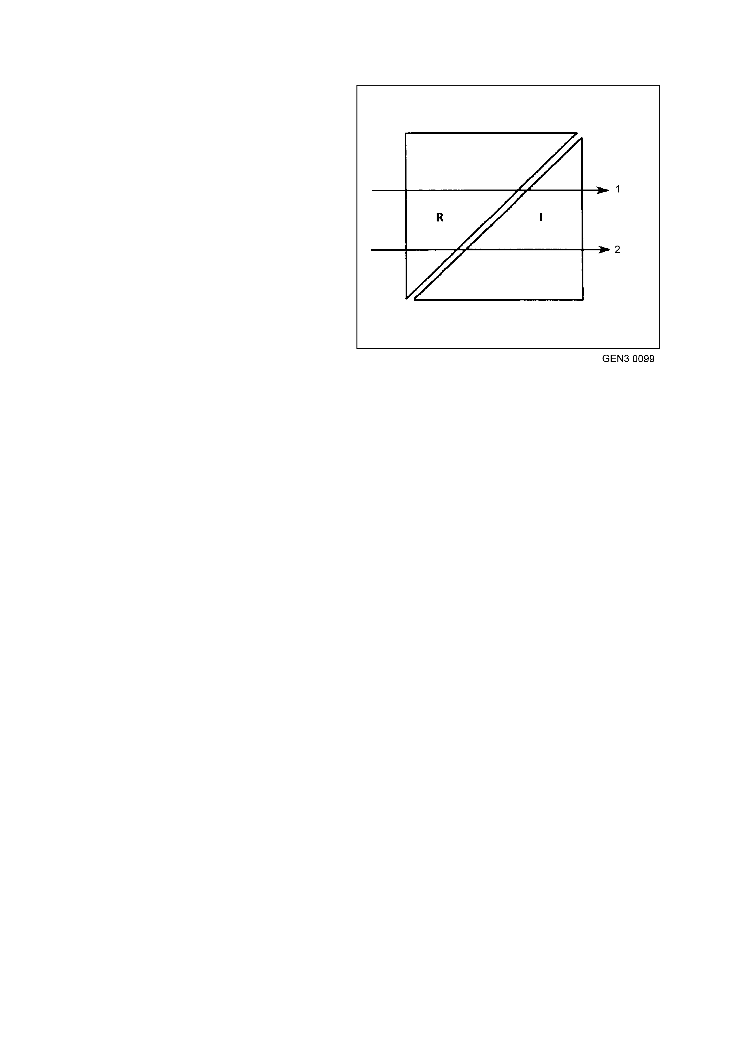
Voltage = Resistance x Current
V=R x I
1. Large Resistance Small Current
2. Small Resistance Large Current
Sensitive solid-state systems have their own earths;
high current devices (like motors) do not earth at the
same location. High current devices can cause
voltage spikes (sudden changes in voltage) when
turned ON or OFF. To prevent these spikes from
affecting sensitive solid-state circuits, the two
different types of systems use different earth
locations. The use of a dedicated wire to connect an
isolated earth junction block to the battery negative
terminal. This wire reduces the effect of spikes on
sensitive circuits at the earth junction block.
Solid-state circuits are particularly sensitive to poor
circuit continuity because in most cases they use low
current flow. This section on testing earths concerns
one solid-state device, the PCM. However, the
information included here applies to all solid-state
earth circuits.
Severe restrictions in the earth circuit can cause
resets and intermittent codes in solid-state systems.
The PCM operates devices (fuel injectors, idle air
control, etc.) and receives inputs from low voltage
sensors, manifold absolute pressure sensor,
crankshaft speed/position. These input and output
devices need good circuitry for correct operation.
Remember, that when maladjusted or imperfect
sensors cause values to shift there are usually
driveability problems. If there is excessive resistance
in the earth circuit, the result will be the same; shifted
sensor outputs with corresponding driveability
conditions. These conditions may not be severe
enough to set diagnostic trouble codes, but they will
reduce vehicle efficiency and performance and may
be noticed by the driver.
SENSOR CIRCUIT EARTH SENSITIVITY - AN EXAMPLE.
Looking at the Throttle Position (TP) sensor circuit
will provide an example of how a little resistance in
the earth circuit can cause problems. The
accompanying figure shows a TP sensor first with a
good earth circuit and then with a poor connection
in the earth circuit. Refer to this figure as you
proceed through the text that follows.
A throttle position sensor consists of a resistor and
a wiper. One terminal of the resistor is connected to
a supply voltage and the other earth. As the wiper
moves along the resistor, the voltage of the wiper
terminal progressively changes. If the wiper is near
the supply voltage end of the resistor, the wiper
output will approach the supply voltage (over 4.5
volts at wide open throttle).
As the wiper moves toward the earthed end of the
resistor, the voltage of the wiper output decreases
to near zero (about 0.5 volts for the closed throttle
in this example). (The actual closed and wide open
throttle voltage specifications may vary for different
engines.) The sensor output should never be
greater than reference supply voltage or less then
.20 volts. (The PCM would set a diagnostic trouble
code if this occurs.)
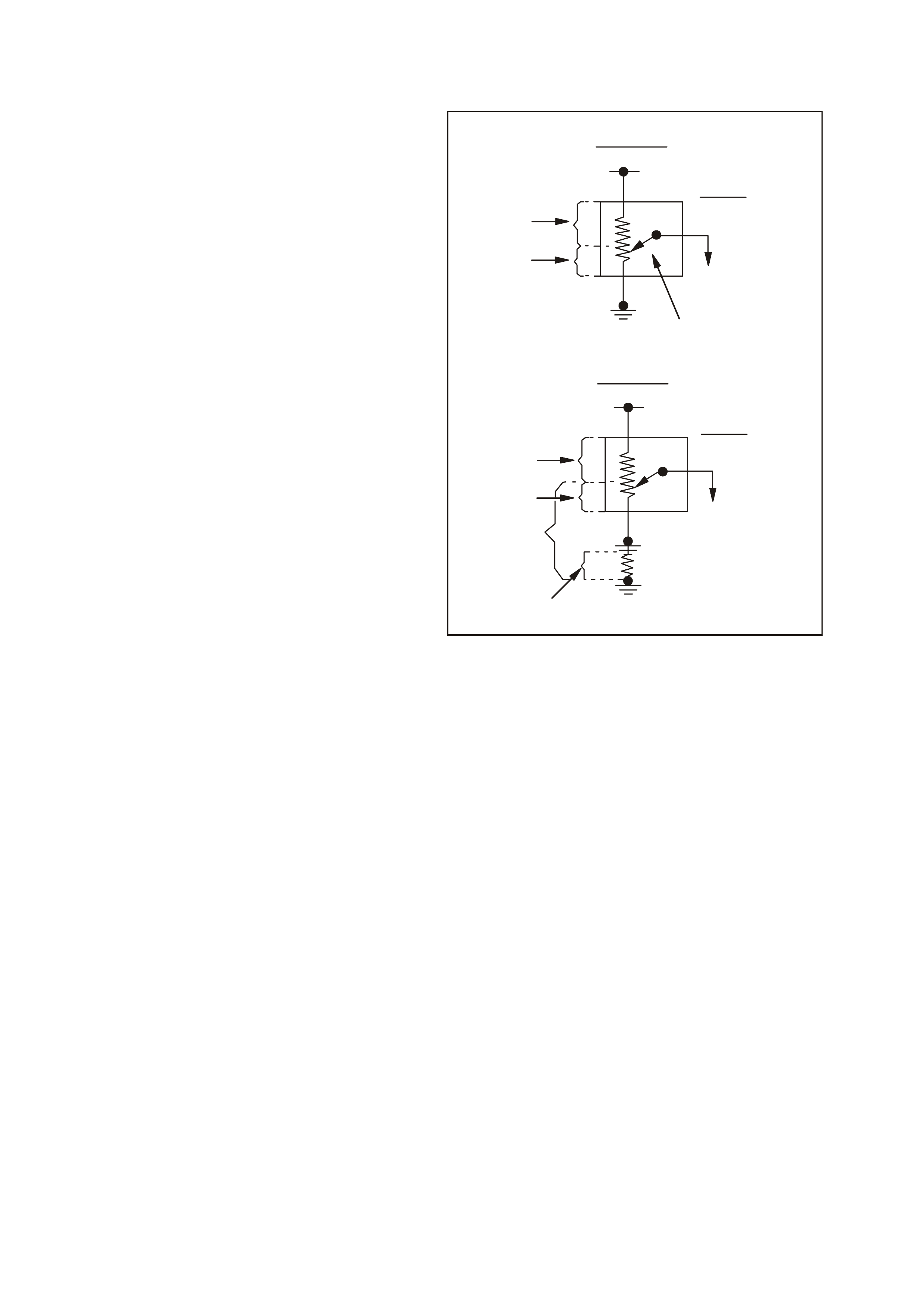
The diagram to the right shows voltage drops
across various points in the circuit. In the example
with good circuit earth, the TP sensor is shown with
the wiper in the closed throttle position. The total
voltage across the resistor in the TP sensor is 5
volts. The voltage drop from the resistor source
voltage terminal to the wiper is 4.5 volts. The
voltage drop from the wiper to the resistor earth
side is 0.5 volts. The wiper output is 0.5 volts - a
good value for this example of a closed throttle.
Now, look at the sensor with the bad signal caused
by resistance in the earth circuit. The throttle
positions stays the same but the sensor output
voltage changes. In this example the increased
resistance causes an additional voltage drop of 0.5
volts. The voltage drop from the wiper to found is
now 1.0 volt (0.5 + 0.5 = 1.0). Because the source
voltage is a constant 5 volts, the voltage drop from
the source voltage input to the wiper can now be
only 4 volts (5.0 - 1.0 = 4.0). The PCM now
receives 1.0 volt from the TP sensor. This is not a
good value (in this example) of a closed throttle
Now you can see why good earths are needed and
how sensitive some circuits can be.
GE N 3 0100
1
2
3
4
5
6
7
8
2
3
9
10
11
12
13
Voltage Drop Illustration
1. Sensor With Good Earth
2. Fixed 5 Volts
3. Throttle Position Sensor
4. 0.5 Volts Sensor Output
5. Wiper
6. Voltage Drop Of 0.5 Volts
7. Voltage Drop Of 4.5 Volts
8. Sensor With Poor Earth
9. 1.0 Volts Sensor Output
10. Voltage Drop Caused By Resistance Of Poor Earth Is
0.5 Volts
11. Total Voltage Drop Below Wiper Is 1.0 Volts
12. Voltage Drop Of 0.5 Volts
13. Voltage Drop Of 4.0 Volts

EARTH CIRCUITS
How do you know which wires are earth wires, which connectors they go through, and whether they are connected
to an earth junction or the body?
Section 12P WIRING DIAGRAMS of the VT Series II Service Information should be used whenever you are
diagnosing any electrical condition, including earths. The individual circuits show the power and earth circuits for
components in specific systems.
If you suspect several circuits are being affected by a poor or a back-feed to earth, look at the circuits to see how
the systems might interact. If they have any common earth wires, that is where you should start your
diagnosis.Back-feeding is when current, seeking earth, feeds back through inactive circuits (the reverse direction of
normal current flow) to find a path to earth. This can only happen when the active circuit (needing an earth) shares a
disconnected or poor earth with an inactive circuit and the voltage supply side of the inactive circuit feeds other
components with good earths.

PARALLEL EARTHS
Some solid-state components use redundant earth
circuits; that is, they have more than one wire
connecting to earth. The PCM has more than one
earth circuit wire. There are several reasons for
redundant earths.
The PCM has many low-current circuits, but the
current from all these circuits (when they are
active) adds up to a larger current. Higher current
loads are managed more easily with several regular
size wi res, rather than with one large diameter wire.
Basic circuit theory shows that the effective
resistance of parallel resistors is less than any of
the individual resistors. This is true for even the
small resistances in wires. Parallel wires provide
the lowest resistance. Because of them, in many
solid-state systems a problem with one of the earth
wires would not affect the circuit; the redundant
wires could handle the current load. For other solid-
state systems the loss of even one redundant earth
may affect operation, but the remaining earth
wire(s) may allow the vehicle to be driven.
Here is one example which can prove to be difficult
to diagnose:
Symptom: A vehicle has driveability symptoms.
Whenever a Tech 2 scan tool is connected and the
vehicle tested, none of the complaint symptoms are
displayed.
Cause: The PCM earths are not providing a good
earth, hence the resulting driveability condition.
When a scan tool is plugged in, a good earth path
is provided for the PCM through the Data Link
Connector (DLC). The DLC uses a different earth
than the PCM.
Always test for driveability symptoms before
hooking up a scan tool. If they disappear when the
scan tool is hooked up, check the earth circuit for
continuity.
The severity of the symptom(s) is proportional to
the severity of the problem in the earth circuit. A
complete open in the circuit has the most severe
effect. Use the severity of the symptom(s) as an
indication of the extent of the resistance in the
earth circuit.
parallel earths
1 1 1 1
------ = -------- + ------ + ------- +
R TOTAL R 1 R 2 R 3
EXAMPLE: 2 PARALLEL CIRCUITS, ONE WITH
ONE OHM RESISTANCE AND
THE OTHER WITH TWO OHMS
RESISTANCE.
1 1 1
------ = -------- + ------
R TOTAL 11 2 2
1 2 1
------ = -------- + ------
R TOTAL 2 2
1 3
------ = --------
R TOTAL 2
2
R TOTAL = -------- Ω
3

CHECKING EARTHS
Once you determine that the cause of the vehicle
symptom(s) may be caused by a bad earth, it is time to
check for poor earth with one more tool: a high-
impedance voltmeter.
The best way to check for poor earth connections in
low-current solid-state circuits is to check the voltage
drop. To do this you need a high-impedance voltmeter
rated at a minimum of 10 megaohms (10,000,000
ohms) per volt. Most quality digital multimeters meet or
exceed this specification. Voltmeters with less
impedance can affect the circuit you are testing and
also give an incorrect reading.
Start by checking the entire suspect earth circuit. With
a voltmeter set on the 2 volt DC scale, connect the
black negative lead to the battery negative terminal. (If
you are using an auto-ranging meter, set it to the DC
volts setting. Connect the red positive lead to the earth
terminal of the component to be tested. With the circuit
activated, check the voltage drop in the circuit. If the
voltage reading is within specifications, look for a
cause other than a poor earth at this component.
If the voltage reading is too high, proceed by isolating
the cause of the high voltage drop. Move the positive
lead to the next connection in the earth circuit. (Keep
the negative lead connected to the battery negative
terminal.) Be sure to check both sides of each in-line
connector and both the eyelet and the stud or screw at
earth points. Repeat this process through the earth
path until the voltmeter reading is within specifications.
The high resistance causing the earth problem is
located between where you obtained a good reading
and the last high reading.
When a circuit uses redundant earths be sure to check
all the earth circuits for excessive voltage drop.
WITH METER
NEGATIVE (BLACK)
PROBE AT THE
BATTERY NEGATIVE
TERMINAL, PLACE THE
METER POSITIVE (RED)
PROBE BETWEEN:
MAXIMUM ALLOWABLE
VOLTAGE
SENSOR AND PCM
0.060 (60 MILLIVOLTS)
PCM AND BATTERY
NEGATIVE TERMINAL
0.020 (20 MILLIVOLTS)

EARTH CREDIBILITY CHECK
CORRECTING PROBLEMS IN EARTH CIRCUITS
Once a high resistance condition in a earth circuit has been located, you must determine the actual cause.
If the problem is at a connector, check for bent, corroded, or loose connector terminals. Terminals must have a
slight drag when disassembled/assembled. If they slide apart/together without resistance, they will not provide a
good connection.
If the problem is at a stud, bolt, or sheet metal screw, check for corrosion, paint, or loose connections. Paint can
be a very good insulator; good conductors, not insulators are needed for electrical connections.
Corrosion, paint, and other causes of resistance should be removed using a wire brush and/or emery cloth.
When assembling earth wire’s eyelet on earth points, be sure an external type star washer is placed below the
wire eyelet(s). If the system is marginal, you can also place a star washer between the nut or the sheet-metal screw
and the top wire eyelet. Tighten the fastener to specification, making sure the star washer digs through any paint
into the mounting surface. Star washers also lock the fastener in place, preventing it from loosening.
All fasteners should be tightened so that the fastener head presses the earth wire eyelet or star washer to the
mounting surface and stops. Repair any stripped earth fasteners.
IMPORTANT: Do not over-tighten sheet-metal screws. Over-tightening can enlarge the hole and create a bad
earth. If the sheet-metal is enlarged, the screw will continue to turn. Drill a new correctly sized hole for the screw.
EARTH CREDIBILITY CHECK
STE
P ACTION VALUE YES NO
1. Did you perform the Powertrain On-Board
Diagnostic (OBD) System Check? Go to Step 2. Go to
Powertrain
OBD System
Check Table
2. 1. Ignition OFF.
2. Disconnect IAT sensor connector.
3. Using DMM J 39200 set to DC voltage scale,
connect negative lead to negative battery cable
at battery and connect positive lead to the IAT
earth circuit wire at the IAT sensor connector.
4. Ignition ON.
5. Using the Tech 2 scan tool, select CANISTER
PURGE.
6. Turn ON Canister Purge.
Is voltage measured less than value shown.
0.067 volts
(67
Millivolts)
No problem
found, continue
with symptom
diagnosis.
Go to Step 3
3. 1. Remove and thoroughly clean the PCM earth
terminals and connection.
2. Reassemble the PCM Earth terminals.
Is action complete?
Verify Repair