SECTION 9A - STEERING
CAUTION:
This vehicle will be equipped with a Supplemental Restraint System (SRS). A SRS will consist of either
seat belt pre-tensioners and a driver's air bag, seat belt pre-tensioners and a driver's and front
passenger's air b ags or seat belt pre- tensioners, driv er’s and front passenger’s air bag and left and right
hand side air bags. Refer to SAFETY PRECAUTIONS, Section 12M, Supplemental Restraint System in this
Service Information before performing any service operation on, or around any SRS components, the
steering mechanism or wiring. Failure to follow the SAFETY PRECAUTIONS could result in SRS
deployment, resulting in possible personal injury or unnecessary SRS system repairs.
CAUTION:
This vehicle may be equipped with LPG (Liquefied Petroleum Gas). In the interests of safety, the LPG fuel
system should be isolated by turning ‘OFF’ the manual service valve and then draining the LPG service
lines, before any service work is carried out on the vehicle. Refer to the LPG leaflet included with the
Owner's Handbook for details or the appropriate Section of this Service CD for more specific servicing
information.
CAUTION:
Whenever any component that forms part of the ABS or ABS/ETC (if fitted), is disturbed during Service
Operations, it is vital that the complete ABS or ABS/ETC system is checked, using the procedure as
detailed in 4. DIAGNOSIS, ABS or ABS/ET C FUNCT ION CHECK, in Section 12L ABS & ABS/ETC, of the VT
Series I Service Information or the VT Series II Service Information.
1. GENERAL INFORMATION
With the introduction of VT Series II vehicles, a revised design steering rack is fitted. The revised design
incorporates the pinion rotary valve housing as a single piece casting integral with the steering rack body casting.
This single piece casting steering rack is only used on those vehicles fitted with the standard power steering.
As the remainder of service operations are the same as those published in Section 9A STEERING and
Section 9B SPEED SENSITIVE POWER STEERING of the VT Series I Service Information, refer to these Sections
for all operations not described here.
Essentially, the service item s covered in this Sec tion relate to the new design steering rack and the power steering
pump and fluid cooler, as fitted to the GEN III V8 engine.
1.1 GENERAL DESCRIPTION - POWER STEERING RACK AND PINION
While the operation of the revised designpower steering gear remains unchanged, this general description is
included, to provide a more complete service operation description.
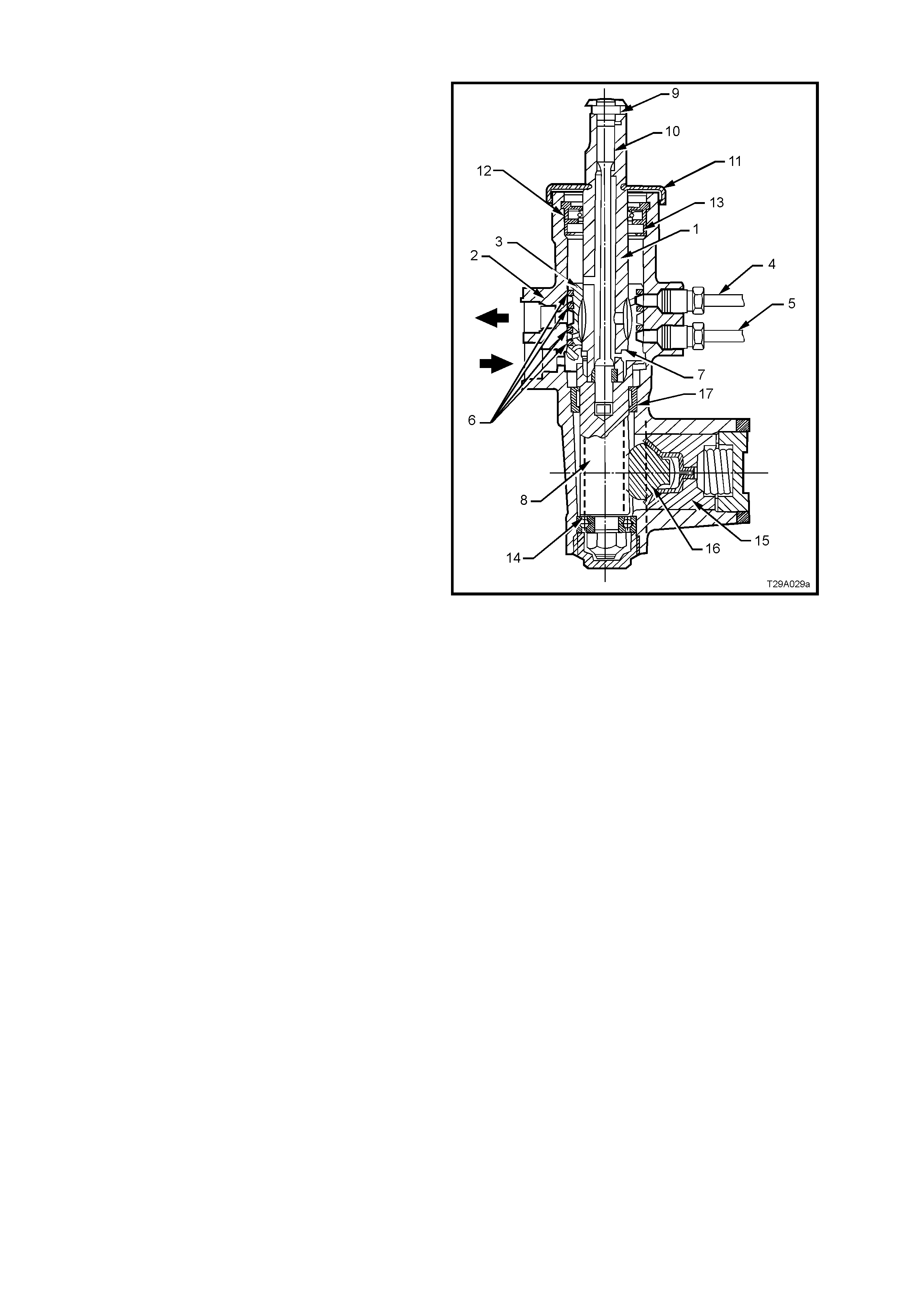
The power steering gear features a variable ratio rack and pinion that is m ade possible by the unique design of the
rack teeth. This means that the effective pitch radius of the pinion is less in the straight ahead position than on
turns. T his results in less turns being required fr om loc k to lock . For ex ample, 3.5 turns would be required if the ‘on
centre’ ratio was used from lock to lock, whereas only 2.7 turns are required with this rack design.
Referring to Figure 9A-1, the helical toothed pinion (8) is supported in the steering gear housing (2) by a needle
roller bearing (13) at the upper end, a ball race (14) at the lower and a roller bearing (17) at the upper end of the
pinion teeth.
The rack (16) operates within the housing and is supported at one end by a rack bearing and at the other end by the
pinion (8) and a spring loaded pad (15), which maintains slack free adjustment of the rack (16) with the pinion (8).
The tie rods ar e connected to each end of the rack by pre-ass embled ball j oints and to the steering arm s by tie rod
end ball joints.
Techline
Techline
Techline
Techline
Techline
Techline
Techline
Techline
PRINCIPLES OF OPERATION
With the engine running and the steering wheel in
the neutral position (straight ahead), fluid flows
continuously from the power steering pump to the
steering gear and back to the pump, via the fluid
reservoir. In this steering mode, very little pressure
is required to maintain the high fluid flow rate that
occurs at this time. As a result, little engine power
is required to operate the system.
When turning the s teer ing wheel to either side, f luid
flow from the pump is directed by a rotary control
valve fitted to the steering gear, to whichever side
of the rack piston is appropriate, as indicated by the
steering wheel position. The fluid pressure then
increases as necessary, to provide the required
steering assistance.
This rotary control valve assembly, is located
between the input shaft (1) and the pinion (8), in the
steering gear.
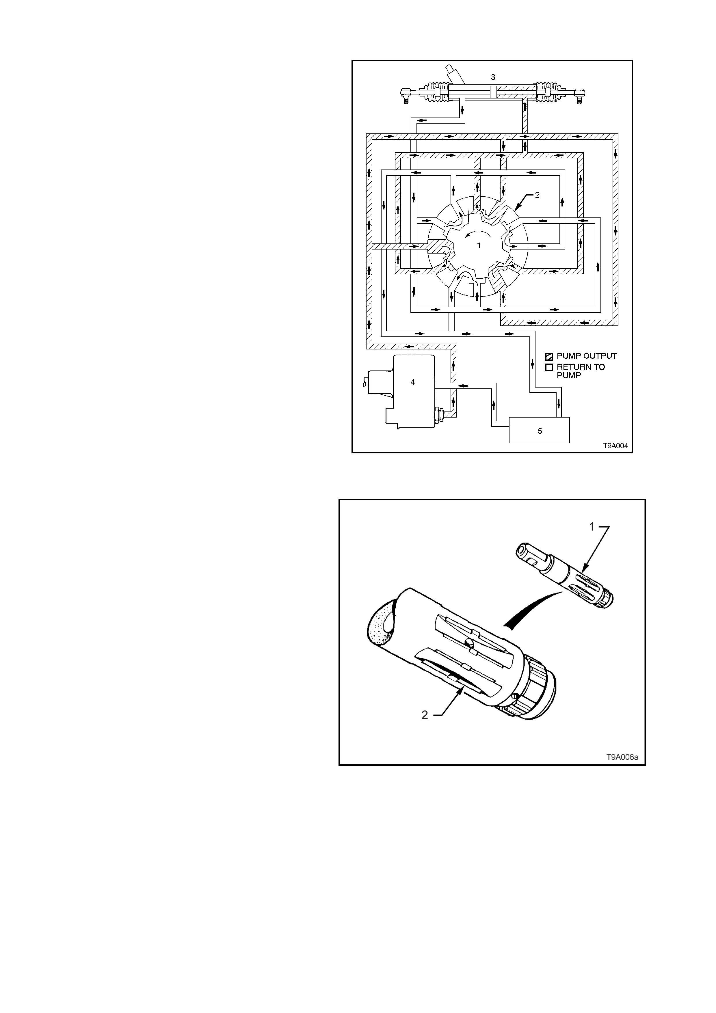
As shown, the rotary valve assem bly consists of an
inner member (1) which forms part of the input
shaft and a surrounding sleeve member (2). The
whole valve, rotates in the steering gear housing
(3) as the steering wheel is turned, but it is the
slight relative movement of the inner and the sleeve
members that controls and directs the power
steering fluid flow.
Fluid is fed to the valve (➨) and from there, to the
left (4) and right (5) sides of the power piston via
circum f erential gr ooves in the outer sleeve, that are
sealed by PTFE seals (6). Excess fluid is returned
to the reservoir.
The outer s leeve is coupled by a stepped pin (7) to
the rack pinion (8), while the input shaft (1) is
coupled to the rack pinion by a pinned (9), flexible,
torsion bar (10) that provides a mechanical but
flexible link between the two members.
In the straight ahead position, the valve remains
centred. As steering effort requirements increase,
the torsion bar flexes, causing slight relative
rotation between the input shaft and sleeve,
directing fluid and providing power assistance as
needed.
Figure 9A-1
A Rack Gain B Rack Travel 1 Clamp Bolt Flat
Figure 9A-2 - Power Steering Gear
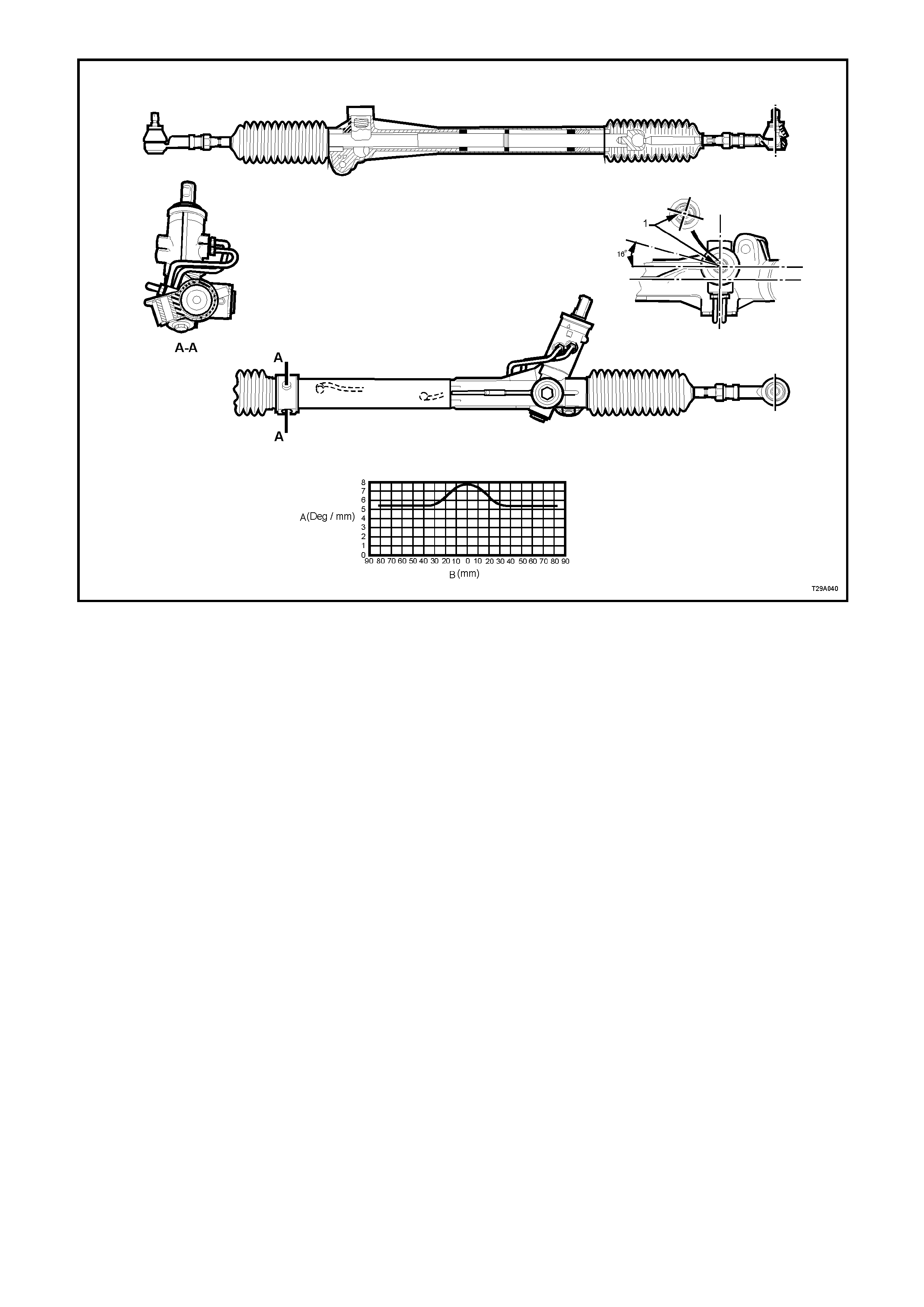
FLUID FLOW
NEUTRAL POSITION (STRAIGHT AHEAD)
From the s tylised cross - s ect ioned view of the r otary
valve shown in Figure 9A-3, it can be seen that in
this attitude, fluid f low from the pum p ( 4) is dire cted
into the cavities (Shown as ‘A’). of the inner valve
assembly (1) and out through a number of drilled
holes in the outer sleeve (2) (Shown as ‘B’). In this
steering position, the inner valve (1) allows fluid to
pass equally to both sides of the rack (3) piston
(shown as 'Static' because no f luid actually flows to
and from the steering gear). The bypassed fluid
returns to the fluid reservoir (5) through holes
drilled in the longitudinal grooves of the inner valve.
W ith an equal pr essure applied to both sides of the
rack piston, no power assistance is provided.
Figure 9A-3
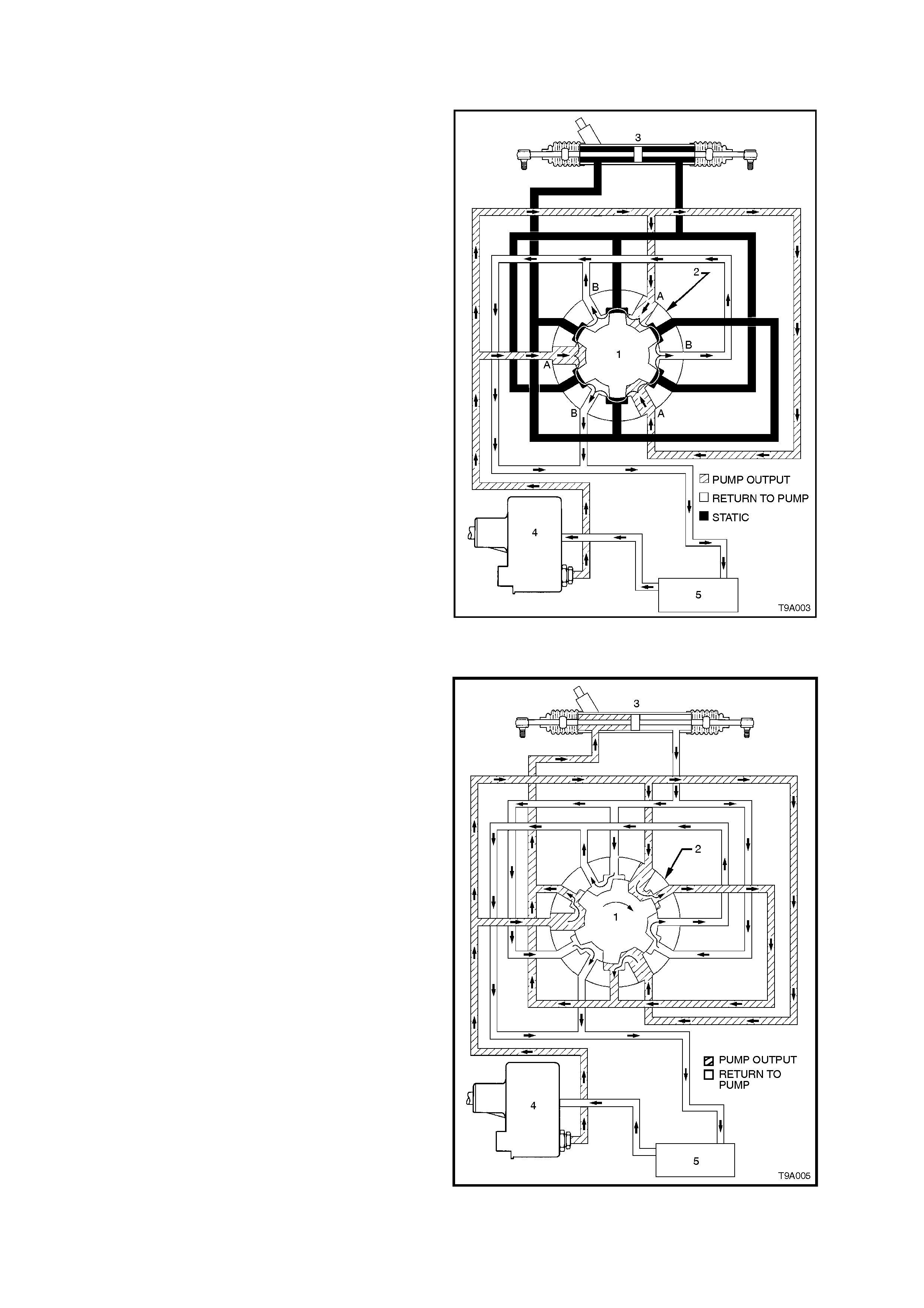
TURNING RIGHT
When turning to the right, as soon as relative
motion between the inner rotating valve (1) and
outer sleeve (2) occurs, fluid is restricted in its free
return to the pump and is routed to the right hand
side of the rack piston. At the same time, fluid on
the opposite side of the piston is directed to the
return circuit, leading to the reser voir (5) and pump
(4). This action is slight at first, providing only a
small amount of driver assistance, but becomes
progressively greater with a higher steering load
that causes the torsion bar in the rotary valve
assembly, to tw ist.
Figure 9A-4
TURNING LEFT
When turning left, the opposite situation occurs.
That is, once the relative m otion between the inner
valve (1) and the outer sleeve (2) causes a return
restric tion, f luid is routed to the lef t hand side of the
rack piston (3), providing the required assistance.
Also, fluid on the opposite side of the piston is free
to flow back to the reservoir (5) and the pump (4),
through the return circuit. As before, the am ount of
assistance provided by the fluid, is determined by
the res triction caused by the interaction of the inner
valve and outer rotary sleeve. This is controlled by
the twisting of the torsion bar connected between
these two valve members.
Figure 9A-5
INNER VALVE MEMBER
W hen parking, more than 90% of the work is done
by the fluid. In order to achieve a balance between
this graduated increase of assistance and maintain
a realistic 'feel' with good response as the road
speed increases, the grooves (2) of the inner
rotating valve (1) ar e precisely shaped to meter the
flow of oil.
Note that under extreme load conditions or when
for any reason, the hydraulic system is inoperative,
the torsion bar is able to deflect suf ficiently to allow
the input shaft to drive the steering pinion directly.
This is achieved by having a loose fitting spline
between the lower end of the input shaft and the
surrounding upper end of the pinion. Under these
operating conditions, steering loads will be high and
a noticeable amount of slack will develop because
of the torsion bar flexing. Therefore, while the
steering gear rem ains entir ely operable, the vehicle
should only be operated in this manner for the
minimum distance needed to reach a point where
the system can be serviced.
Figure 9A-6
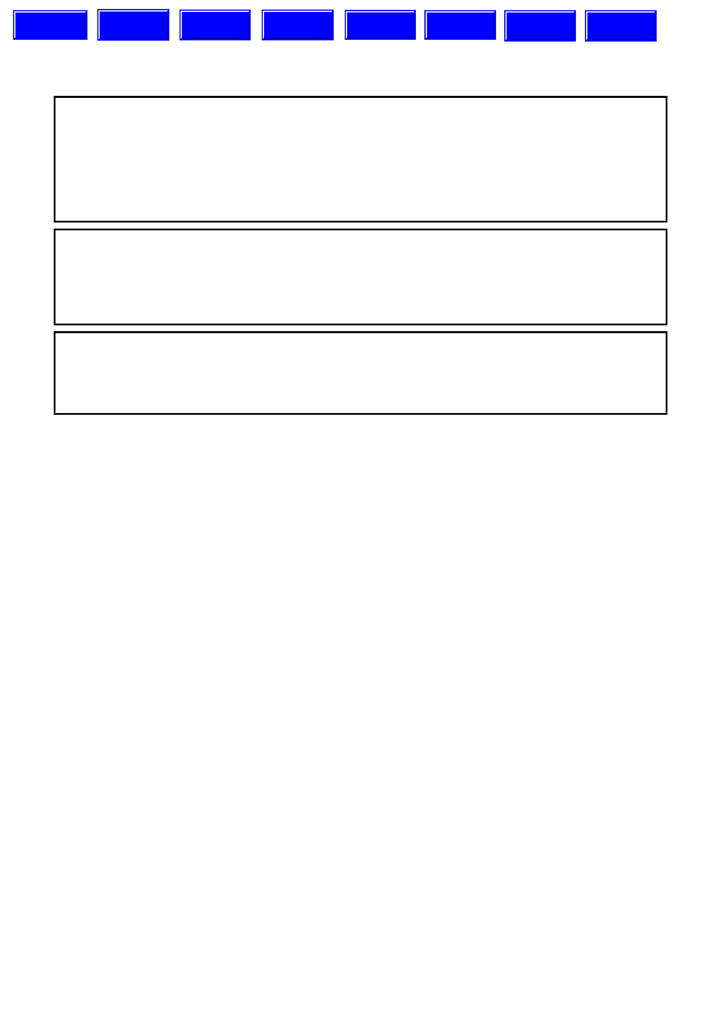
1.2 GEN III V8 ENGINE POWER STEERING PUMP
In design and operation, the power steering pump
fitted to the GEN III V8 engine is the s ame as the ‘N’
series pump fitted to V6 engined VT series vehicles.
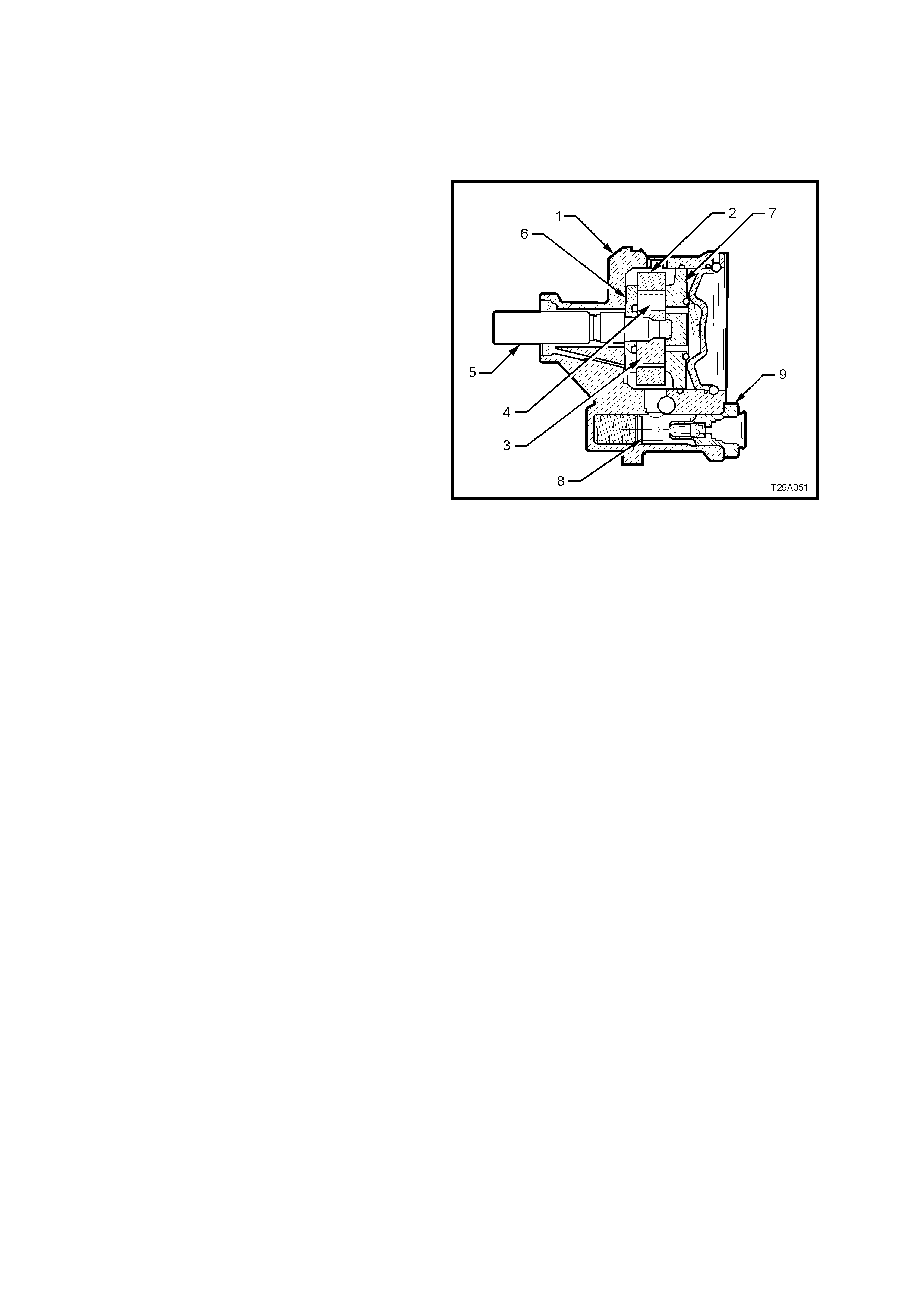
PUMP CONSTRUCTION
In the rear of the pump housing (1), a cavity
contains the following parts: pump ring (2), pump
rotor (3) and vanes (4), splined to the drive shaft (5)
and thrust (6) and pressure plates (7).
A sm aller cavity, below the larger one, contains the
flow control assembly (8), consisting of a control
valve assembly and pump outlet fitting (9) with
control needle and spring.
Figure 9A-7

2. STEERING COLUMN ASSEM BLY SERVICE OPERATIONS
2.1 STEERING COLUMN ASSEMBLY SERVICE NOTES AND PRECAUTIONS
CAUTION: Disable the SRS (Air Bag). Refer to ‘DISABLING THE SRS’, in Section 12M of this Service
Information.
CAUTIONARY NOTES:
1. The outer j ack et, steering shaf t and instrum ent panel mounting br acket are designed as energy absorbing units.
Because of the design of these components, it is absolutely vital that the steering column assembly is handled
with care when perform ing any of the required s ervice oper ations. Avoid ham m ering, j arring, dropping or leaning
on any portion of the column.
2. All steering wheel and column fasteners are important parts in that they could affect the performance of other
vital parts and systems.
3. Fasteners must be replaced with those of the same part number or with an equivalent part, if replacement is
required. Do not use a replacement part of lesser quality or substitute design.
4. Torque values must be used where specified during reassembly to assure proper retention of the part.
NOTE: For all service operations relating to the steering column and associated components, refer to
Steering 9A STEERING, of the VT Series I Service Information.
Techline
3. POWER STEERING SERVICE OPERATIONS
3.1 FLUID LEVEL CHECK
NOTE: The recommended fluid for use in all VT
series vehicles, is Dexron® III automatic
transmission fluid to Holden’s Specification HN2126.
V6 ENGINE
Refer to Steering 9A STEERING of the VT Series I
Service Information for information relating to this
service operation.
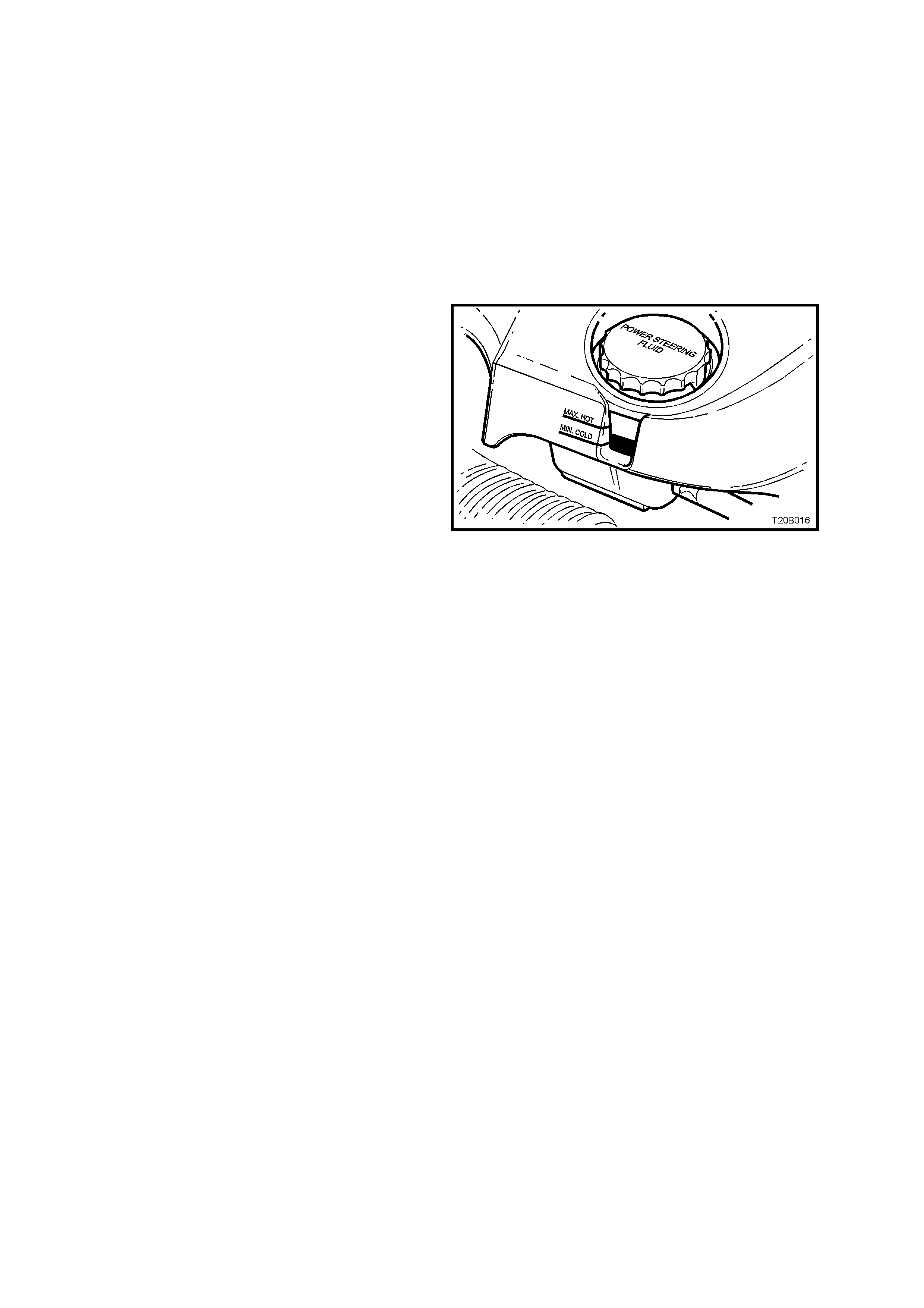
GEN III V8 ENGINE
The power steering fluid level can be checked by
viewing the level through the translucent plastic
side of the reservoir. There is no need to remove
the engine dress cover for this operation.
If the f luid is cold, the level should be in the ‘COLD’
range. Similarly, if it is hot, the f luid should be in the
‘HOT’ range. If the fluid level is at the low side of
either range, new fluid should be added to bring the
level to the correct point and the system checked
for the cause of the leakage and corrected as
necessary.
Figure 9A-8

3.2 DRIVE BELT ADJUSTMENT
V6 ENGINE
For vehicles with V6 engine, the power steering pum p is driven by the engine serpentine drive belt. T he belt is self
adjusting within tensioner operating limits. For details, refer to Section 6A1, ENGINE MECHANICAL of the VT
Series I Service Information.
GEN III V8 ENGINE
For vehic les with the GEN III V8 engine, the power steer ing pum p is driven by the engine serpentine drive belt. T he
belt is self adjusting within tensioner operating limits. For details, refer to Section 6B3, GEN III V8 ENGINE
COOLING of the VT Series II Service Information.

3.3 HYDRAULIC SYSTEM, BLEEDING/REFILLING P ROCEDURE
CAUTIONARY NOTES:
1. If the fluid level is low in the fluid reservoir, air will be drawn in and mixed with the fluid in sm all bubbles. If the
pump is allowed to continue operation, an increasing amount of air will be drawn into the system, causing the
fluid volum e to increas e to a point where the reservoir will overflow. Sudden releases in pressure that will occur
when the steering is suddenly taken off a ‘full lock’ condition, will cause dramatic eruptions of fluid from the
reservoir. The separation of air entrapped under these conditions will be extremely difficult to remove and may
take several days.
2. If the steering rack assembly requires replacement, a large volume of air will be required to be purged, which
means that the reservoir fluid level will fall rapidly when the engine is started.
3. During bleeding, it is important that the front wheels are clear of the ground and that the steering is not held
forcibly against the steering stops.
BLEEDING/REFILLING PROCEDURE
1. Raise front of vehicle and place on safety stands. Refer to Section 0A, GENERAL INFORMATION of the VT
Series I Service Information.
2. W ith engine not r unning, add fluid to reservoir to the m aximum mar k (or greater , if it is known that the steering
gear is empty).
3. Start engine and allow to run for only 2-3 seconds. Do not turn the steering wheel at this point.
4. Continue with Steps 2 and 3 until the fluid level remains constant.
5. Start and run the engine at idle speed, turning the steering wheel from lock to lock, without holding at the full
lock positions (this will build up high pressures, atomising any entrapped air). Repeat this procedure from six to
eight times. Stop the engine, check the fluid level and top up to the maximum level, as required.
6. Start and run the engine at idle speed. Again turn the steering wheel from lock to lock but now slowly build up
the pressure levels by holding against the full lock position from 1-2 seconds. Repeat this procedure f rom four
to six times. Stop the engine and top up the fluid level to the maximum mark, as required.
NOTE: While the majority of entrapped air will be removed by the above process, a small amount may remain,
which can only be removed by alternate circulation and settling of the fluid for a prolonged period. This is usually
achieved automatically after two to three day s, with daily driving and settling overnight.
7. Turn the steering wheel to the straight ahead position, lower vehicle to the ground and turn ignition ‘OFF’.
3.4 HYDRAULIC SYSTEM, CHECK
The f ollowing procedur es outline methods to identif y and isolate power steering hydraulic circ uit dif f ic ulties . T his test
is divided into two parts. Test number one provides a means of determining whether the power steering system
hydraulic parts are faulty. If test number one results in readings indicating faulty hydraulic operation, test number
two will identify the faulty part.
Before perfor ming the hydraulic circuit tes t, caref ully check the fluid level, drive belt c ondition and tension, idler and
driving pulleys for smooth operation.
The engine must be at normal operating temperature and the front tyres inflated to the correct pressure. All tests
are made with engine idling.
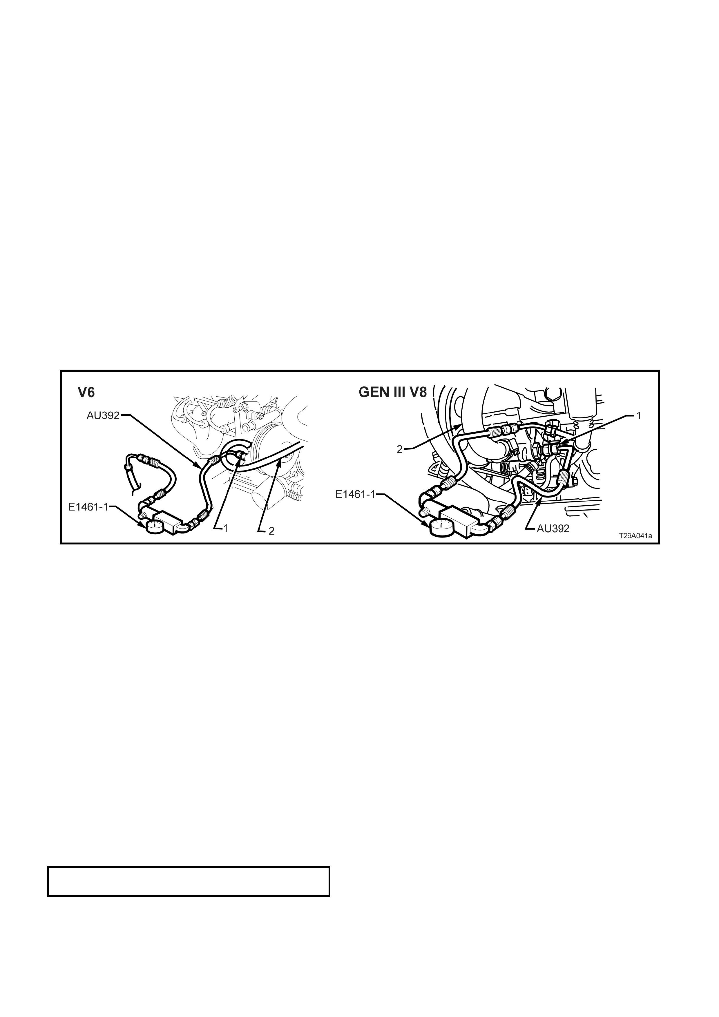
To perform the two pressure checks, it is necessary to connect a pressure gauge assembly into the hydraulic line
between the pump and steering gear.
PROCEDURE
1. Place a drain tray beneath the power steering pump assembly.
2. Loosen and remove the high pressure hydraulic line fitting and O-ring from the power steering pump.
3. Install pressure gauge assembly (Hose set AU392 and Gauge assem bly E1461-1) between the outlet fitting of
the pump and the high pressure hose fitting (1).
4. R efill system with f luid to the correct level, r efer to 3.1 FL UID LEVEL CHECK in this Section. Ensur e that there
are no leaks at either the hose or gauge connections.
5. Bleed air from the system , refer to 3.3 HYDRAULIC SYSTEM , BLEEDING/ REFILLING PROCEDURE, in this
Section.
Figure 9A-9
TEST 1 - HYDRA ULIC CIRCUIT OPEN
1. With valve open, start engine, allow to idle and with steering LIGHTLY on full lock, check connections for
leakage.
2. Insert thermometer into reservoir filler opening and move steering from lock to lock until fluid reaches 75°
Celsius.
3. Turn steering to full lock momentarily, if pressure is below 7,580 kPa (V6 engine) or 8,270 kPa (GEN III V8
engine), a faulty hydraulic circuit is indicated.
TEST 2 - HYDRAULIC CIRCUIT CLOSED
1. Slowly turn valve on Tool E1461-1 to the closed position, note pressure, and quickly re-open valve to avoid
pump damage.
2. If pressure was less than 7,580 kPa (V6 engine) or 8,270 kPa (GEN III V8 engine), the pump may be
considered to be faulty.
3. If pressure was between 7,580 - 8,270 kPa (V6 engine) or 8,270 - 8,960 kPa (GEN III V8 engine), steering gear,
external hoses or connections may be considered faulty.
NOTE: If pump proves faulty, retest after overhaul to check repairs and condition of steering gear.
4. At the completion of tests, remove pressure gauge, hoses and connectors.
5. Reinstall high pressure line and O-ring to the pump outlet fitting and tighten the flare nut to the correct torque
specification.
HIGH PRESSURE LINE FLARE NUT 25 - 35
TORQUE SPECIFICATION Nm
6. While LIGHTLY holding the steering wheel on full lock, have an observer check for fluid leaks from the hose
connections.
The following flow chart, details an alternative procedure for checking the power steering hydraulic system.
POWER STEERING HYDRAULIC SYSTEM CHECK
STEP ACTION YES NO
1 • Start engine and allow to idle.
• Is fluid level correct? Go to Step 2. Top up as required
and check for leaks.
Go to Step 2.
2 • Check fluid condition. Is fluid condition OK? Go to Step 3. Drain, flush system
and refill with fluid.
Go to Step 3.
3 • With valve on test gauge fully open, check pressure
reading.
• Is the pressure reading for standard power steering
approximately 350 kPa or:
• With speed sensitive power steering, is the pressure
reading approximately 700 kPa?
Go to Step 4. Check hoses/pipes for
restriction. Repair or
replace as necessary.
Go to Step 4.
4 • Is system pressure now to specification? Go to Step 5. Replace steering rack
valve assembly.
Go to Step 3.
5 • Close then open valve fully three times, noting the highest
pressure reading each time.
NOTE: Do not leave valve closed for more than five seconds,
as pump damage could result.
• Are all readings between 7,580 - 8,270 kPa (V6) or 8,270 -
8,960 kPa (V8) and within 340 kPa of each other?
Hydraulic system is
operating to
specification.
Go to Step 6.
6 • Are pressures within specified range but not within 340 kPa
of each other? Go to Step 7. Go to Step 9.
7 • Remove flow control valve and remove any burrs with
crocus cloth or fine hone.
• Repeat Step 4. Are pressure readings now OK?
Hydraulic system is
now operating to
specification.
Go to Step 8.
8 • Remove pump, disassemble clean, reassemble and
reinstall.
• Repeat Step 4. Are pressure readings now within 340 kPa
of each other?
Hydraulic system is
now operating to
specification.
Go to Step 10.
9 • Are pressures within 340 kPa of each other but below
specified maximum range? Go to Step 10. Go to Step 5.
10 • Replace flow control valve, then repeat Step 4.
• Are pressure readings now OK? Hydraulic system is
now operating to
specification.
Overhaul or replace
power steering pump.
Go to Step 5.
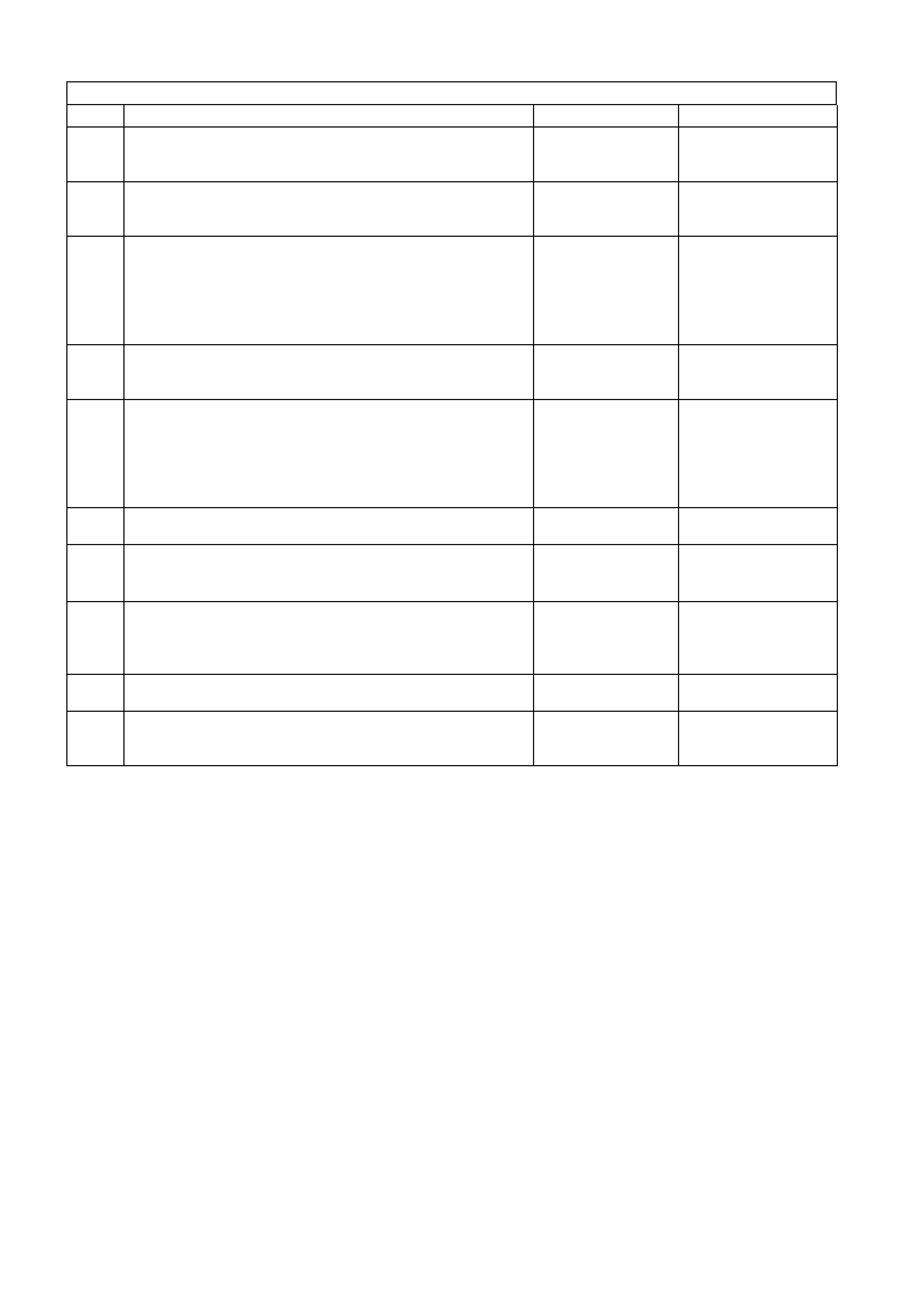
3.5 TIE ROD BALL JOINT
REPLACE
Tie rod ball joints are serviced as an assembly and
must be replaced when excessive up or down
movement is evident, or if any lost motion or end
play exists at the ball end of the stud.
1. Raise front of vehicle and place on safety
stands. Refer to Section 0A GENERAL
INFORMATION of the VT Series I Service
Information.
2. Remove front wheel cover (steel wheels) or
centre caps (alloy wheels)
3. Mark relationship of each wheel to hub/brake
disc. Remove road wheel attaching nuts and
remove wheels.
4. Remove split pin and nut from tie rod ball stud.
5. Using Tool No. 9A10 or similar, tighten centre
screw to force stud from taper in steering arm.
6. Loosen tie rod lock nut. Unscrew ball joint (1)
from tie rod, counting the number of turns to
wind ball joint from tie rod.
7. Install new ball joint (1) onto tie rod and wind on
the same number of turns as in Step 3.
8. Install ball joint to steering arm. Install
castellated nut and tighten to the correct torque
specification.
TIE ROD BALL JOINT STUD 50 - 85
TORQUE SPECIFICATION Nm
NOTE: Ensure that the nylon spacer is positioned
on the tie rod ball joint stud before installing into
steering arm.
9. Install new split pin into tie rod ball studs.
Figure 9A-10
10. Check front wheel toe. Refer to
Section 3 FRONT SUSPENSION of the VT
Series II Service Information.
NOTE: Ensure plastic spacers are positioned on tie
rod end ball studs and that they are in good condition
before fitting studs into steering arms. Replace
spacers if damaged.
11. Tighten the tie rod end lock nuts to the corrct
torque specifcation.
TIE ROD BALL JOINT LOCK NUT 50 – 85
TORQUE SPECIFICATION Nm
12. Install wheels, aligning marks made on removal.
Tighten wheel attaching nuts to the correct
torque specification. Do not over-tighten!
ROAD WHEEL ATTACHING NUT 110 - 140
TORQUE SPECIFICATION Nm
13. Lower vehicle to ground and reconnect battery
earth lead.
14. Check front wheel toe-in setting, refer to
Section 3, FRONT SUSPENSION of the VT
Series II Service Information for details
3.6 POWER STEERING GEAR
IMPORTANT: Remove the ignition key from the
ignition lock an d en sure t hat t he steering column
is locked. If this operation is not carried out and
the steering wheel is spun while the steering
gear is removed from the vehicle, the clock
spring coil in the upper end of the steering
column will be destroyed!
REMOVE
NOTE: While the illustrations for this service
operation show the single piece valve housing
steering gear, the procedure is also applicable to the
two-piece valve housing, f itted to the speed sensitive
steering rack.
1. Disconnect battery earth lead.
2. Raise front of vehicle and place on safety
stands. Refer to Section 0A GENERAL
INFORMATION of the VT Series I Service
Information.
3. Remove front wheel cover (steel wheels) or
centre caps (alloy wheels)
4. Mark relationship of each wheel to hub/brake
disc. Remove road wheel attaching nuts and
remove wheels.
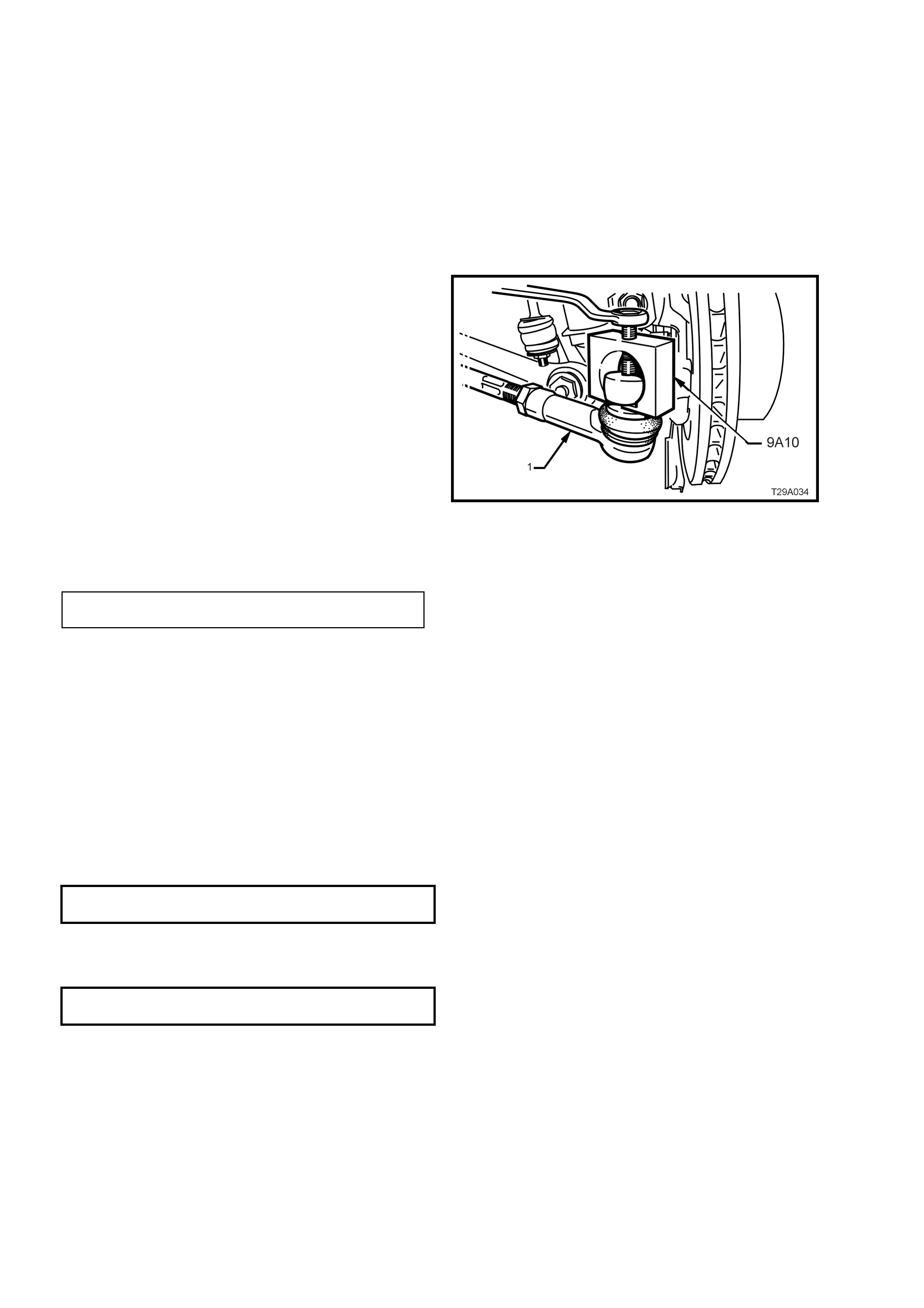
5. Place a drain tray beneath steering gear.
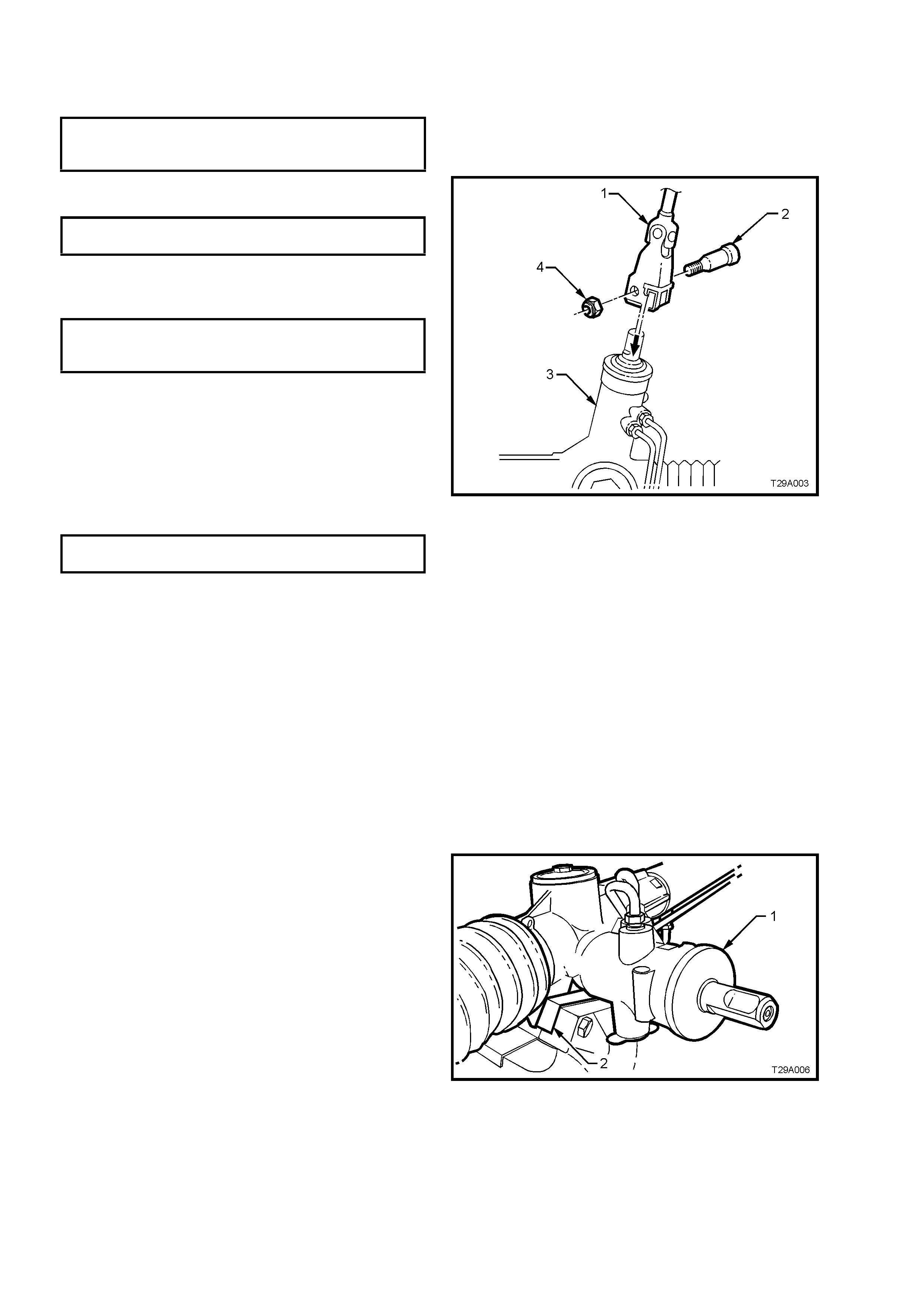
6. Loosen and remove hydraulic lines (2 and 3)
from steering gear valve housing (1) and allow
fluid to drain into a suitable container.
Figure 9A-11
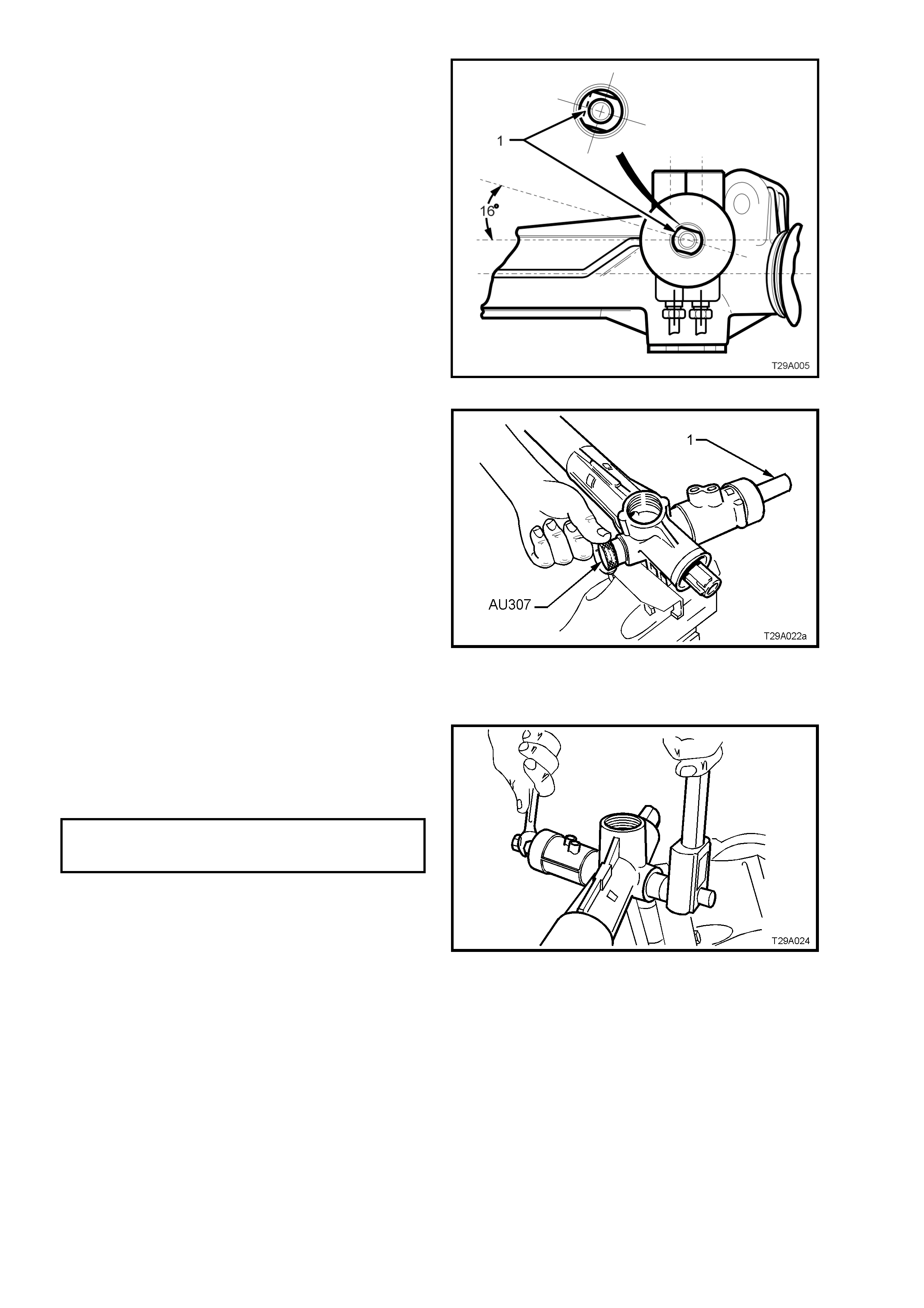
7. Remove steering coupling lower cam bolt nut
(4), then remove the cam bolt (2).
Figure 9A-12
Techline
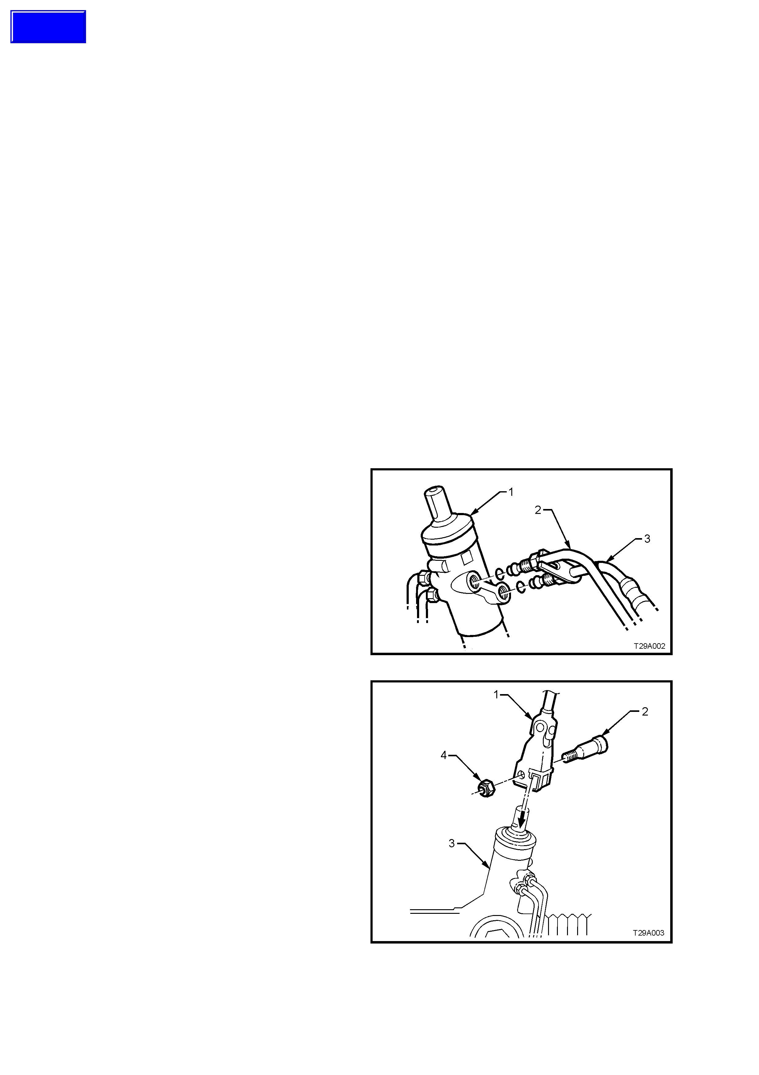
8. Remove tie rod ball joint split pins and
castellated nuts (’3’ in Figure 9A-14).
9. Separate tie rod ball joint (1) studs from
steering arm tapers using a suitable remover,
such as Tool No. 9A10.
Figure 9A-13
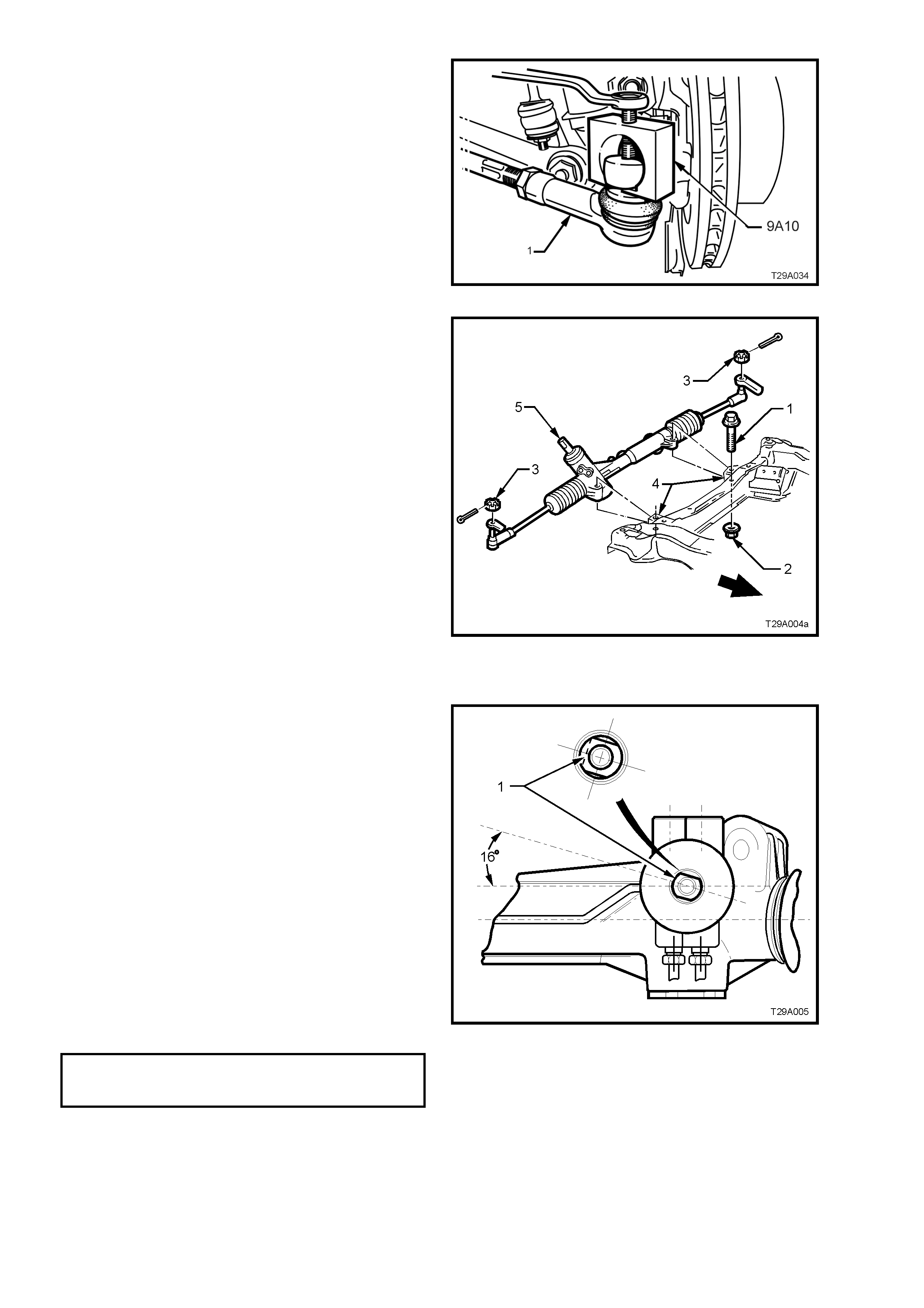
10. Remove steering gear housing to front
suspension crossmember mounting bolts (1)
and nuts (2).
11. Remove steering gear by pulling it out from
front suspension crossmember mounting (4)
and slide pinion (input) shaft (5) from steering
coupling lower clamp.
Figure 9A-14
REINSTALL
1. Ensure steering gear is centralised.
NOTE 1: This is achieved by rotating the pinion to
the half way position of its total lock to lock r otation.
W hen the rac k is in the stra ight ahead position, the
pinion (input) shaft will be aligned as shown.
NOTE 2: Alternatively, remove both inner boot
clamps, slide the boots back and measure the
exposed portion of each end of the rack from the
housing. When both measurements are equal, the
rack is centralised.
2. Ensure steering wheel is in straight ahead
position.
3. Slide steering gear pinion (input) shaft into
steering coupling lower flange.
4. Position steering gear housing into
cross member mounting points. Ins tall mounting
bolts, washers and nuts and tighten nuts to the
correct torque specification.
STEERING GEAR HOUSING TO
CROSSMEMBER MOUNTING 70 - 85 Nm
TORQUE SPECIFICATION
5. Inspec t condition of steering gear hydr aulic line
O-rings. Replace as necessary.
Figure 9A-15
6. Refit hydraulic lines to steering gear valve
housing. Tighten flare nuts to the correct torque
specification.
HYDRAULIC LINE TO VALVE
HOUSING FLARE NUT 30 - 42 Nm
TORQUE SPECIFICATION
7. Install lower cam bolt (2) and a new nut (4).
Tighten to the correct torque specification.
STEERING COUPLING CAM BOLT 23 - 30
TORQUE SPECIFICATION Nm
8. Reinstall tie rod end ball studs into steering
arms. Reinstall castellated nuts and tighten to
the correct torque specification.
TIE ROD BALL JOINT STUD
CASTELLATED NUT 50 - 85 Nm
TORQUE SPECIFICATION
9. Install new split pins
NOTE: Ensure plastic spacers are positioned on tie
rod end ball studs and that they are in good
condition before fitting studs into steering arms.
Replace spacers if damaged.
10. Install wheels, aligning marks made on
removal. Tighten wheel attaching nuts to the
correct torque specification.
ROAD WHEEL ATTACHING NUT 110 - 140
TORQUE SPECIFICATION Nm
11. Lower vehicle to ground and reconnect battery
earth lead.
Figure 9A-16
12. Refill and bleed hydraulic system, refer
3.4, HYDRAULIC SYSTEM, BLEEDING/
REFILLING in this Section.
13. Check front wheel toe-in setting, refer to
Section 3, FRONT SUSPENSION of the VT
Series II Service Information for details.
DISASSEMBLE
For identification of components, refer to
Figure 9A-23.
1. Clean all dirt and foreign matter from exterior
of steering gear assembly.
2. Mount steering gear housing (1) by gripping
right hand mounting boss in a vice fitted with
soft jaws (2 ).
3. Place a drain tray beneath steering gear.
Figure 9A-17
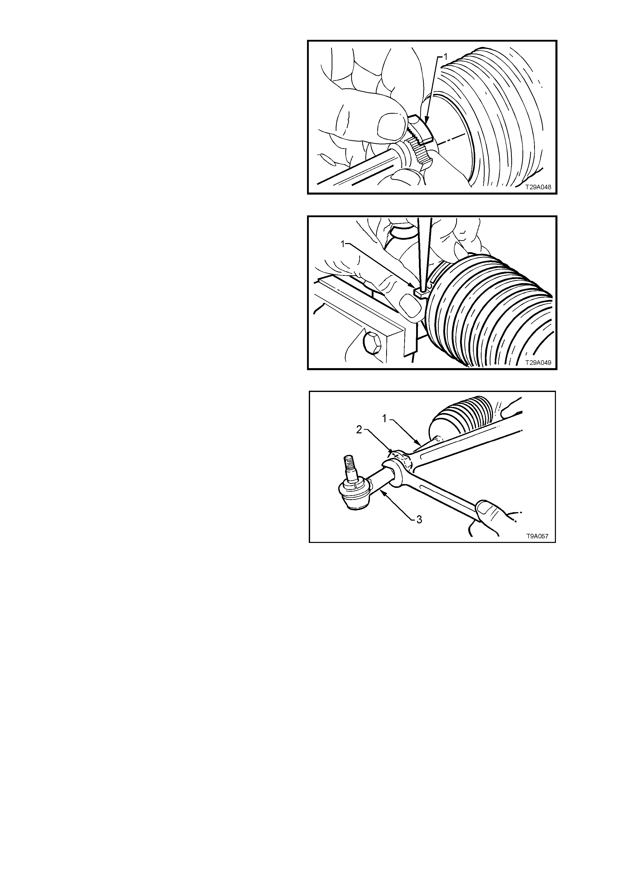
4. Unclip and remove all bellows clips.
a. To remove outer clips (1): Move ends of
clips sideways until they disengage.
Figure 9A-18
b. To remove inner c lips (1): Push out the pin
retaining the clip ends together using a fine
pin punch.
Figure 9A-19
5. Loosen tie rod lock nuts (2). Remove tie rod
ball joints (3) and lock nuts (2) from tie rods (1).
6. Slide bellows from steering gear housing and
tie rods.
7. Rotate pinion (input) shaft fully counter-
clockwise (full left lock).
Figure 9A-20
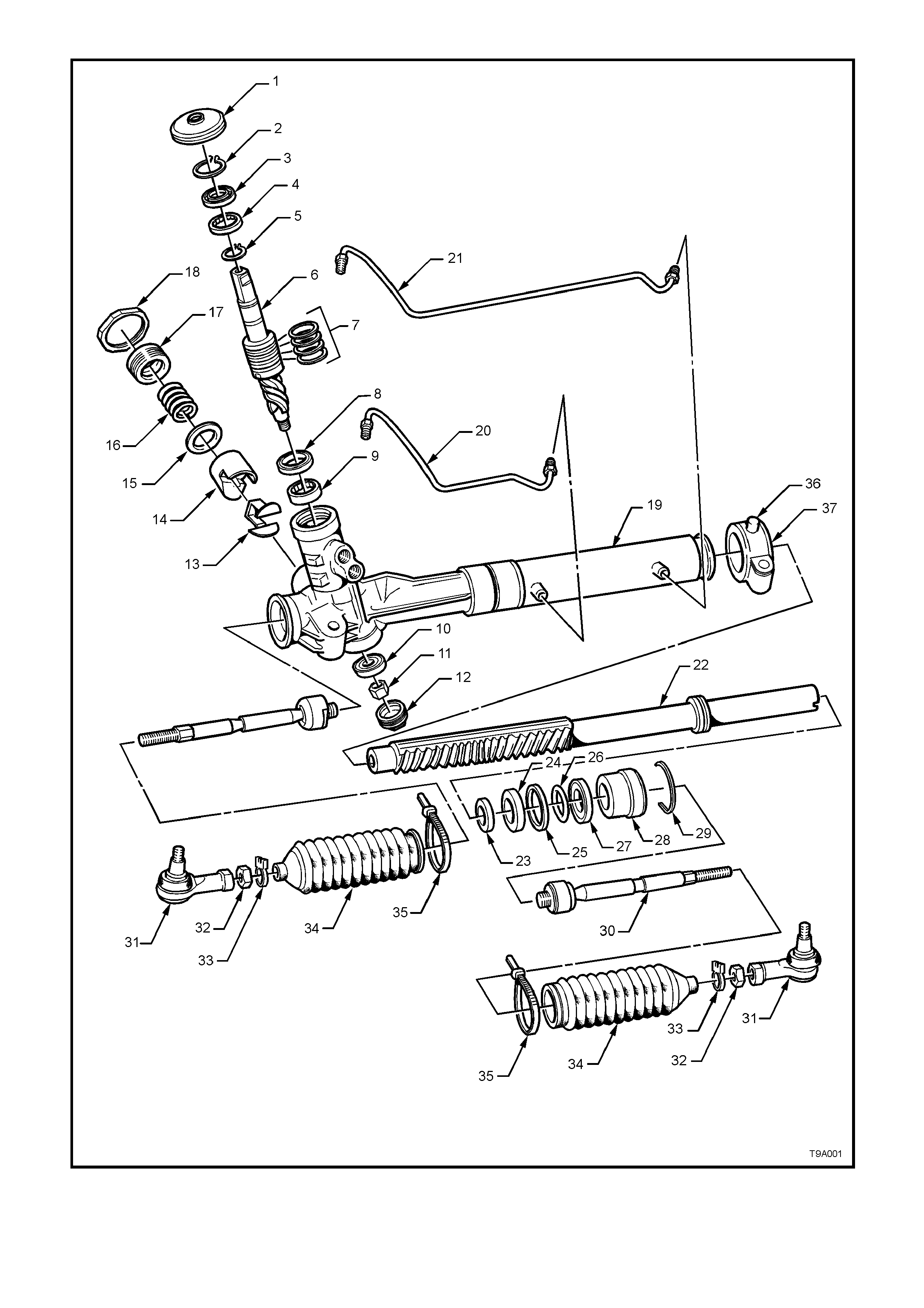
Figure 9A-21 - Rack and Pinion Power Steering Gear
LEGEND
1. Cover - Dust
2. Circlip - Pinion Seal Retaining
3. Seal - Pinion Upper
4. Bearing - Pinion Upper Roller
5. Circlip
6. Valve Assembly - Rotary
7. Sealing Rings - 4 places
8. Seal - Pinion Intermediate
9. Bearing - Pinion Intermediate Roller
10. Bearing - Ball
11. Nut - Pinion
12. Plug - Sealing Screw
13. Insert - Rack Pad
14. Pad - Rack
15. Washer - Plastic
16. Spring
17. Plug - Rack Pad
18. Nut - Lock
19. Housing - Steering Gear
20. Pipe - Rack Piston Fluid - Short
21. Pipe - Rack Piston Fluid - Long
22. Rack and Piston Assembly
23. Spacer - Inner Rack Seal
24. Seal - Inner Rack
25. Sealing Ring - Rack Piston
26. O-ring - Rack Piston
27. Seal - Outer Rack
28. Bushing - Rack Outer
29. Wire - Retaining
30. Rod - Tie
31. End - Tie Rod
32. Nut - Lock
33. Clip - Bellows Outer
34. Bellows
35. Strap - Bellows Inner Tie
36. Bracket - Mounting
37. Insulator - Mounting Bracket
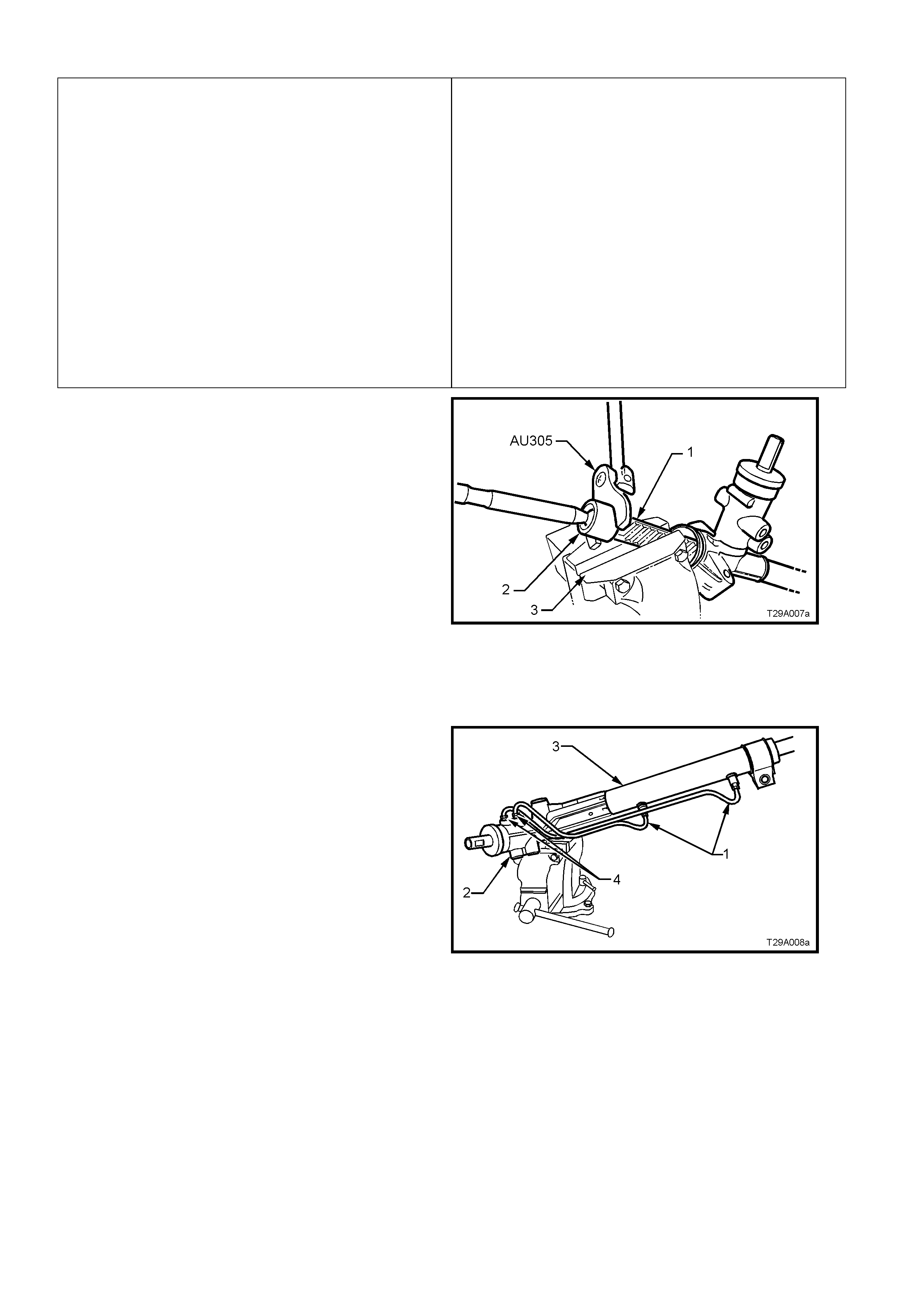
8. Remove steering gear housing from vice and
grip exposed tooth end of rack (1) in vice with
soft jaws (3 ).
9. Using Tool No. AU305, loosen then tighten tie
rod ball joint housing (2) to break the staking,
then unscrew housing from end of rack.
10. Remove housing assembly from vice and
ensure that there is no foreign matter on rack
teeth. Rotate pinion ( input) shaf t clock wise, jus t
enough to expose left hand tie rod ball joint
housing.
11. Remount steering gear in vice, again gripping
on the right hand end of the exposed teeth of
rack.
12. Remove left-hand tie rod assembly, using the
same method described in step 9.
Figure 9A-22
13. Remount s teer ing gear hous ing ( 3) in vice fitted
with protective jaws, gripping right-hand
mounting boss.
14. Disconnect feed pipes (1 and 4) from valve
housing (2) and steering gear tubing (3).
Figure 9A-23
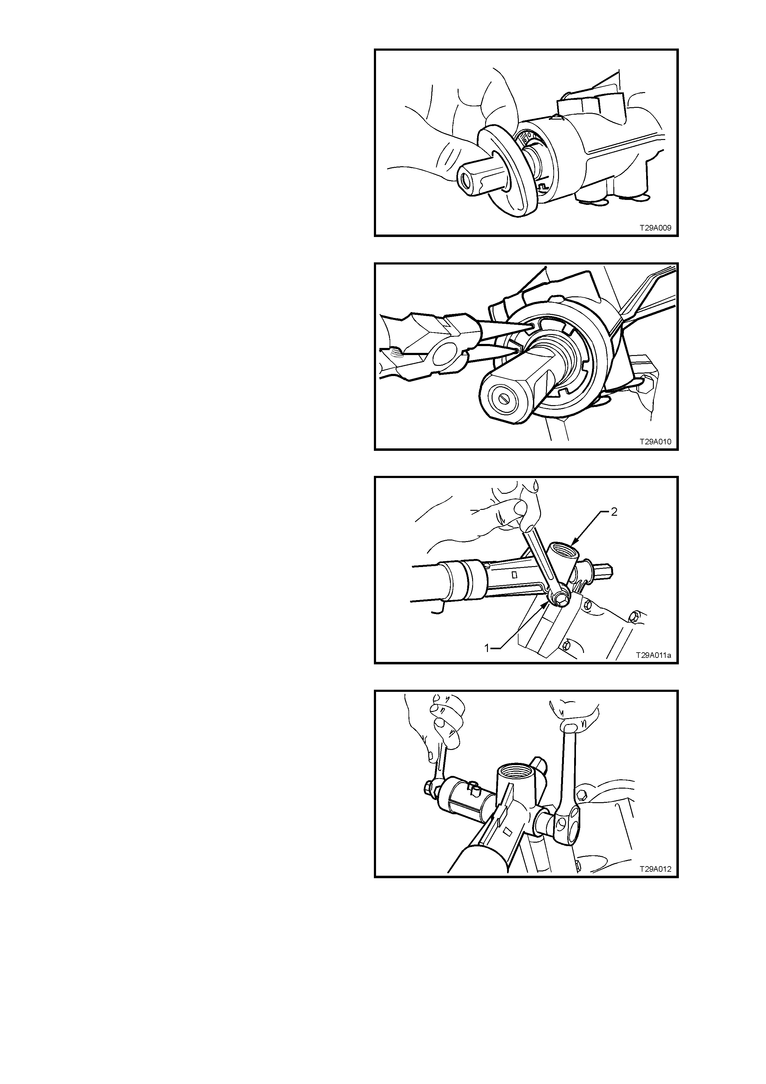
15. Remove dust cover from valve housing and
input shaft.
Figure 9A-24
16. Using suitable circlip pliers, compress and
rem ove the pinion s eal r etaining c irc lip f r om the
top of the housing.
Figure 9A-25
17. Remove pinion lower bearing screw plug (1)
from housing (2).
Figure 9A-26
18. While holding the input pinion with a 15 m m set
spanner across the flats, remove pinion lower
bearing retaining nut from pinion, using a 17
mm socket and ratchet.
Figure 9A-27
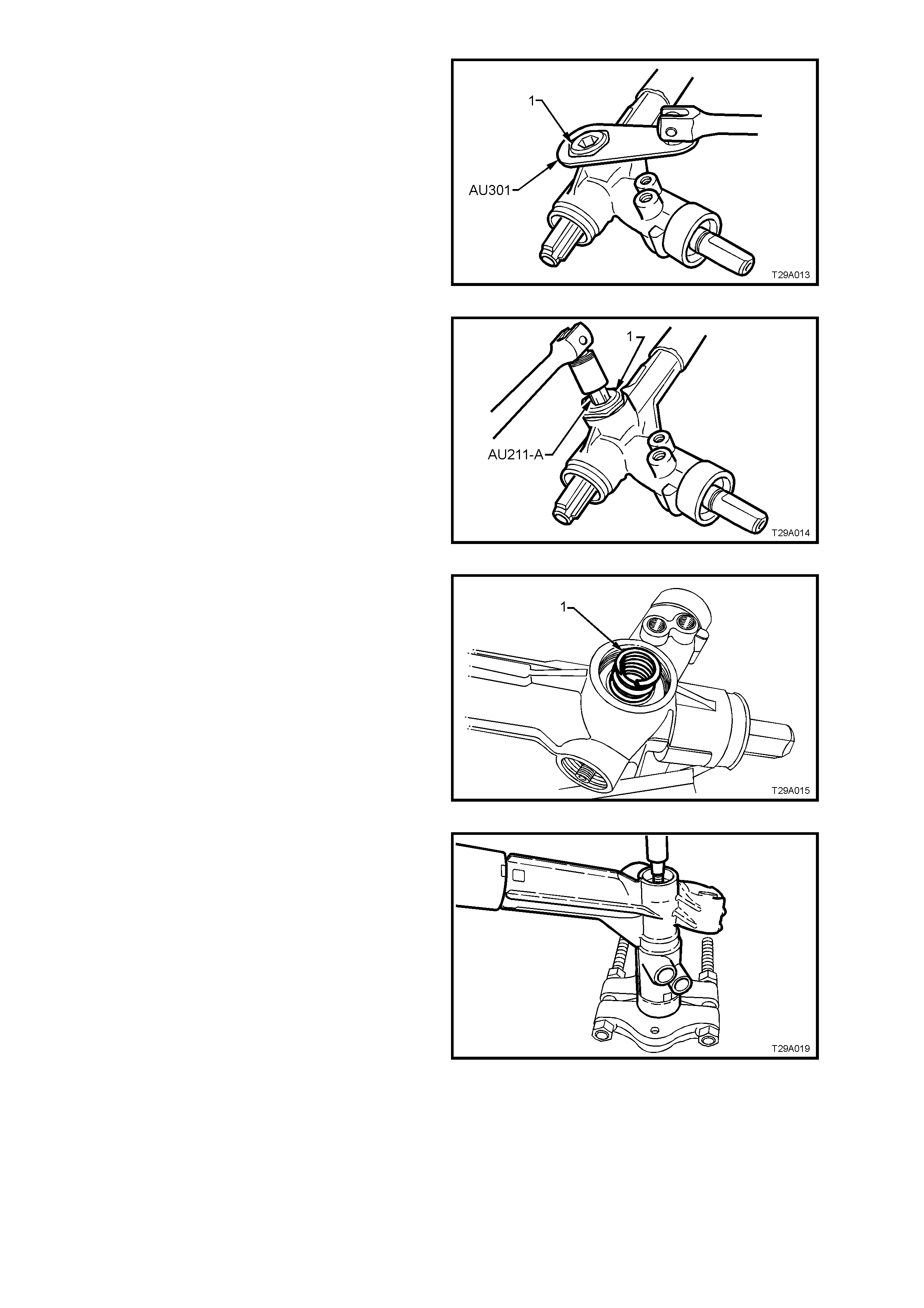
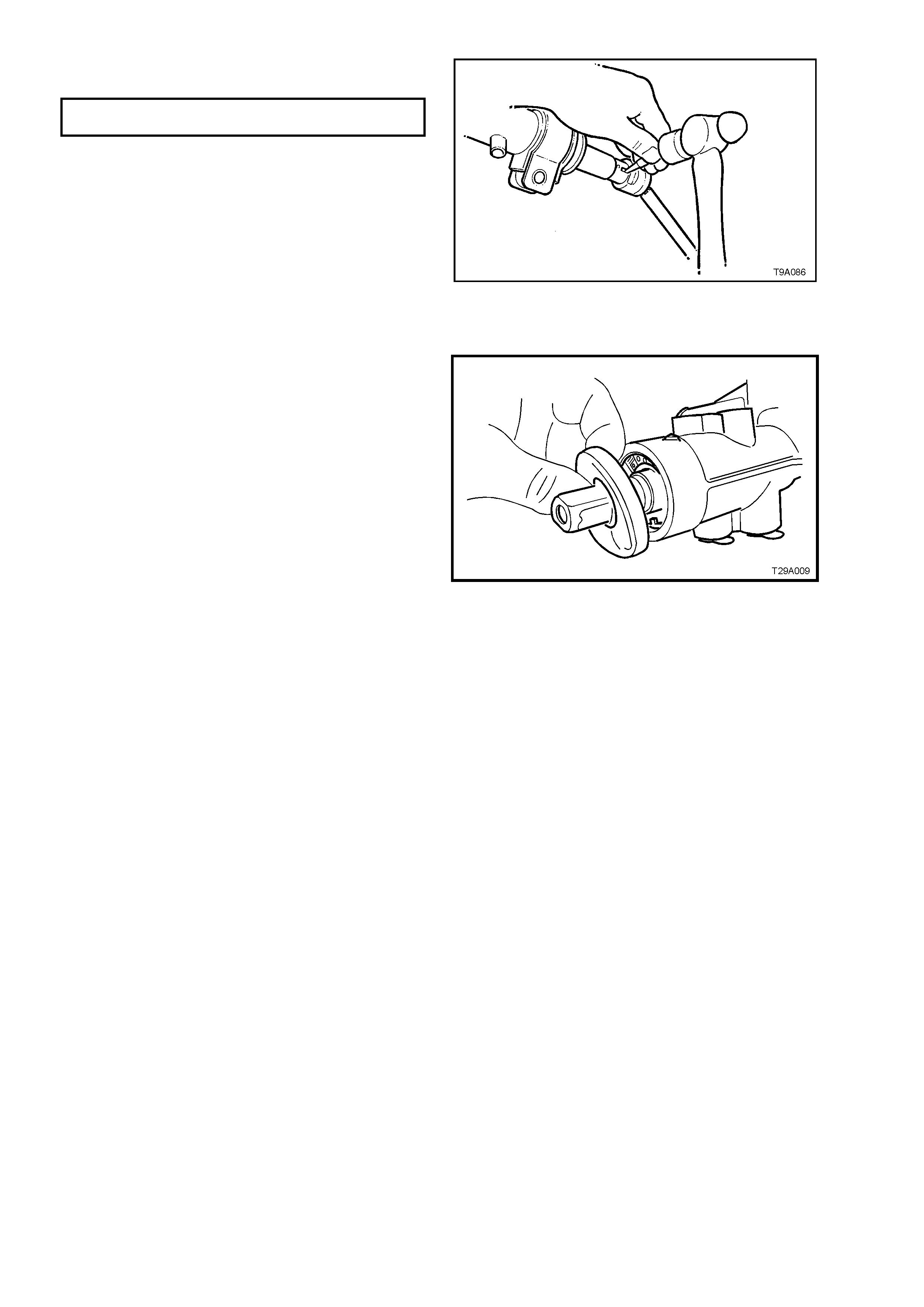
19. Remove rack pad adjuster lock nut (1) using
Tool No. AU301.
20. Rotate input shaft fully clockwise (full right
lock).
Figure 9A-28
21. Loosen and remove rack pad adjuster screw
(1), using Tool No. AU211-A.
Figure 9A-29
22. Remove rack pad spring (1), plastic washer
and rack pad assembly from steering gear
housing.
NOTE: Snap ring pliers can be used to grasp the
rack pad inside the internal flange and twisting
back and forth while pulling to remove.
Alternatively, remove the housing f rom the vic e and
tap gently on a wooden block to dislodge the rack
pad assembly.
Figure 9A-30
23. With the steering gear housing supported on
suitable press plates such as J 22912-01 as
shown, use a suitable drift and press on the
lower end of pinion to remove pinion assembly
from housing.
NOTE: While pressing is the preferred method of
removing the pinion assembly from the housing, a
brass drift and hammer could also be use for this
operation. However, considerable f orce will need to
be applied to remove the pinion assem bly from the
lower ball bearing and housing as the upper pinion
seal and roller bearing are also removed in this
operation.
Figure 9A-31
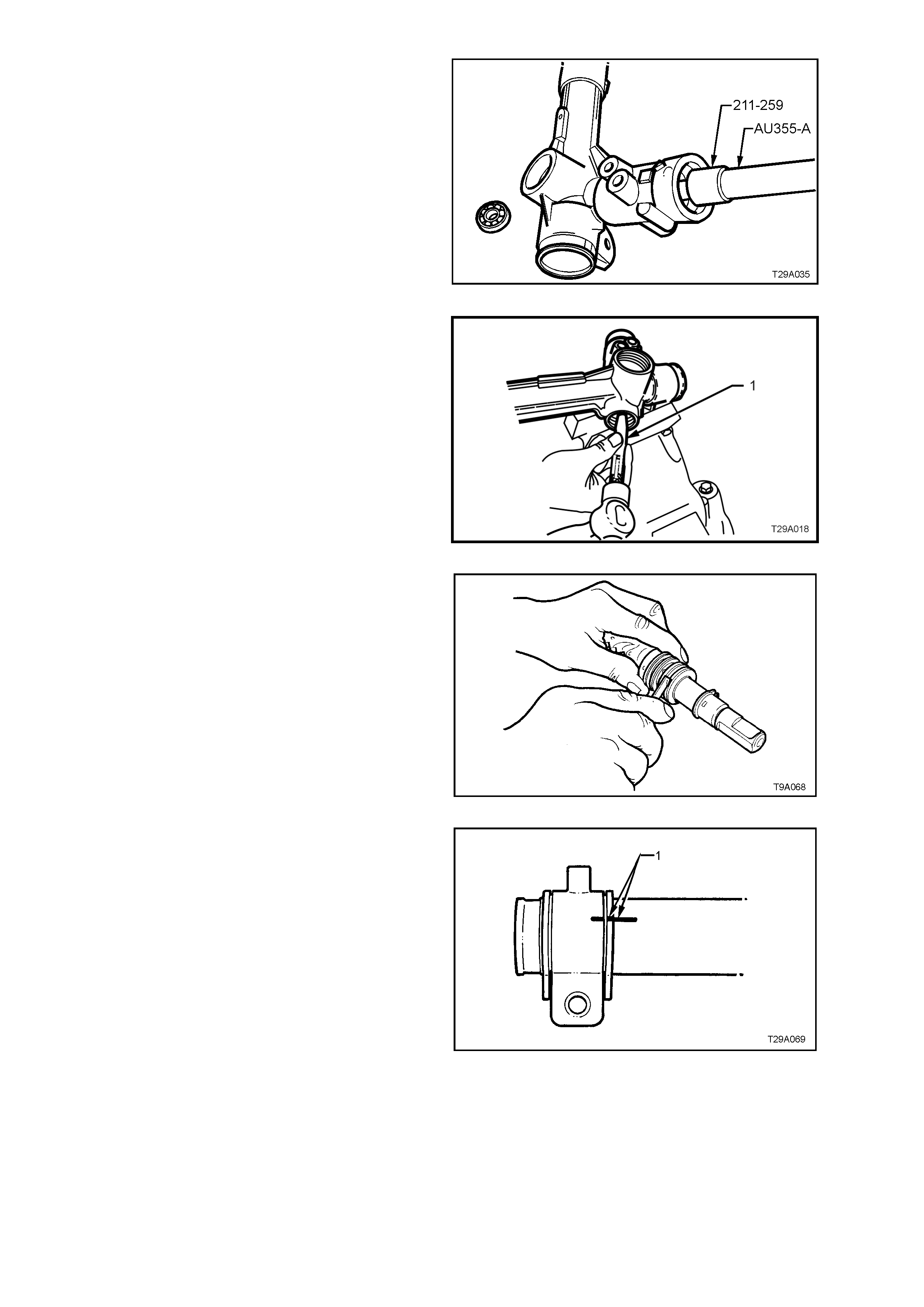
24. Screw Tool 211-259 to driver handle AU355-A,
then insert tool assembly into the rack housing
and tap the lower pinion ball bearing from the
housing.
NOTE: As this oper ation will possibly brinell the ball
race, discard after removal.
Figure 9A-32
25. If required, remove the intermediate pinion
roller bearing and s eal by using a pin punch (1)
and hammer, working from opposite sides of
the bearing case until the bearing and seal are
dislodged from the housing
NOTE: As this operation will permanently damage
the roller bearing it must be replaced after removal.
Figure 9A-33
26. Remove and discard PTFE rings from rotary
valve outer sleeve.
The seals are best removed by cutting
diagonally with a sharp knife, but care must be
taken to avoid scratching the sides of the
grooves otherwise subsequent leakage will
result.
NOTE: Because of component matching that is
critical to the s afe oper ation of the sleeve and valve
assembly, THE PINION ASSEMBLY MUST NOT
BE FURTHER DISMANTLED.
Figure 9A-34
27. Using a white marker pen or similar, mark the
relative position of the left hand mounting
bracket and the steering rack tube (1).
Figure 9A-35
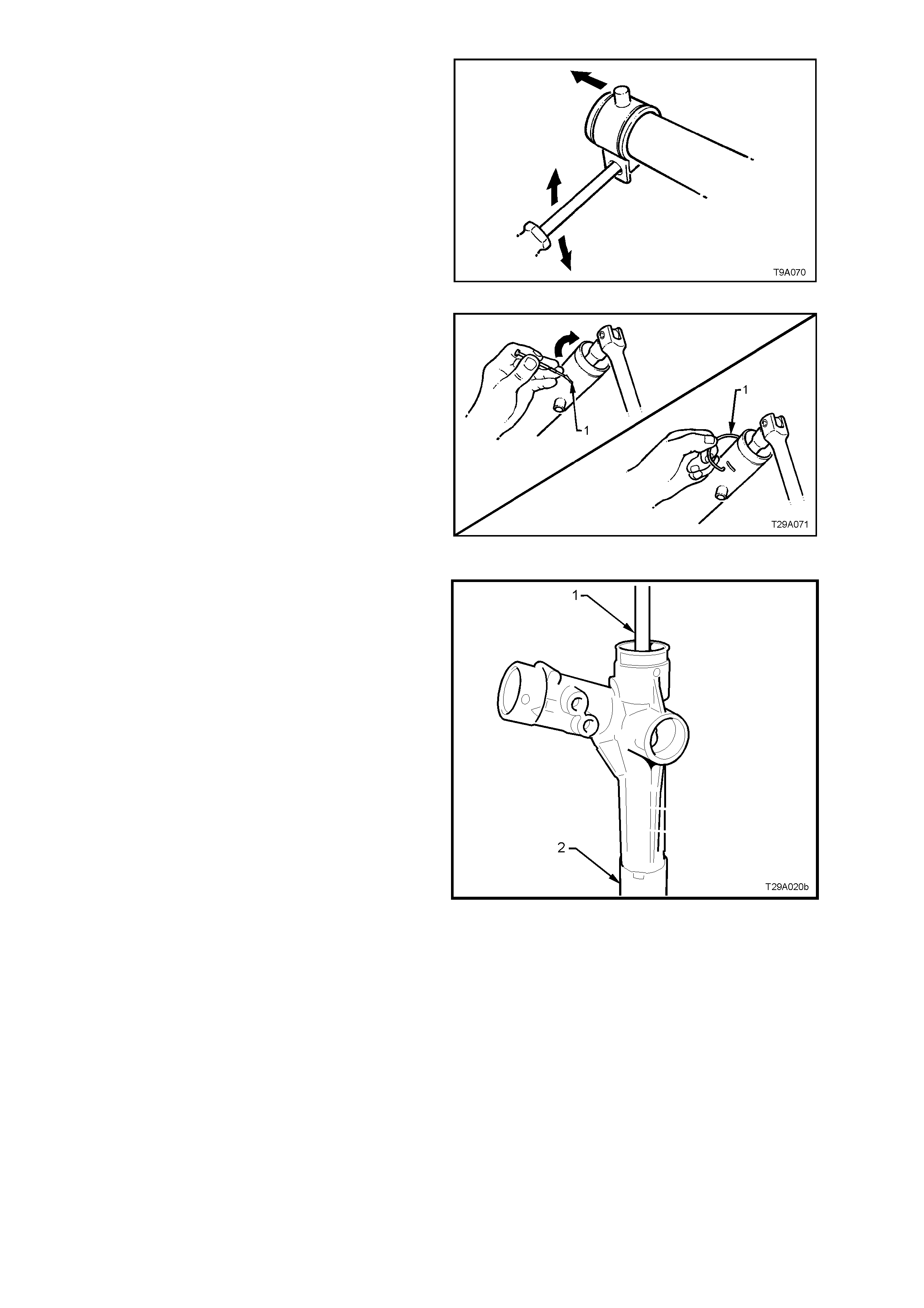
28. Remove the left hand mounting bracket, by
using a round bar inserted through the
mounting holes and rotating the bushing and
bracket, back and forth while pulling at the
same time.
Figure 9A-36
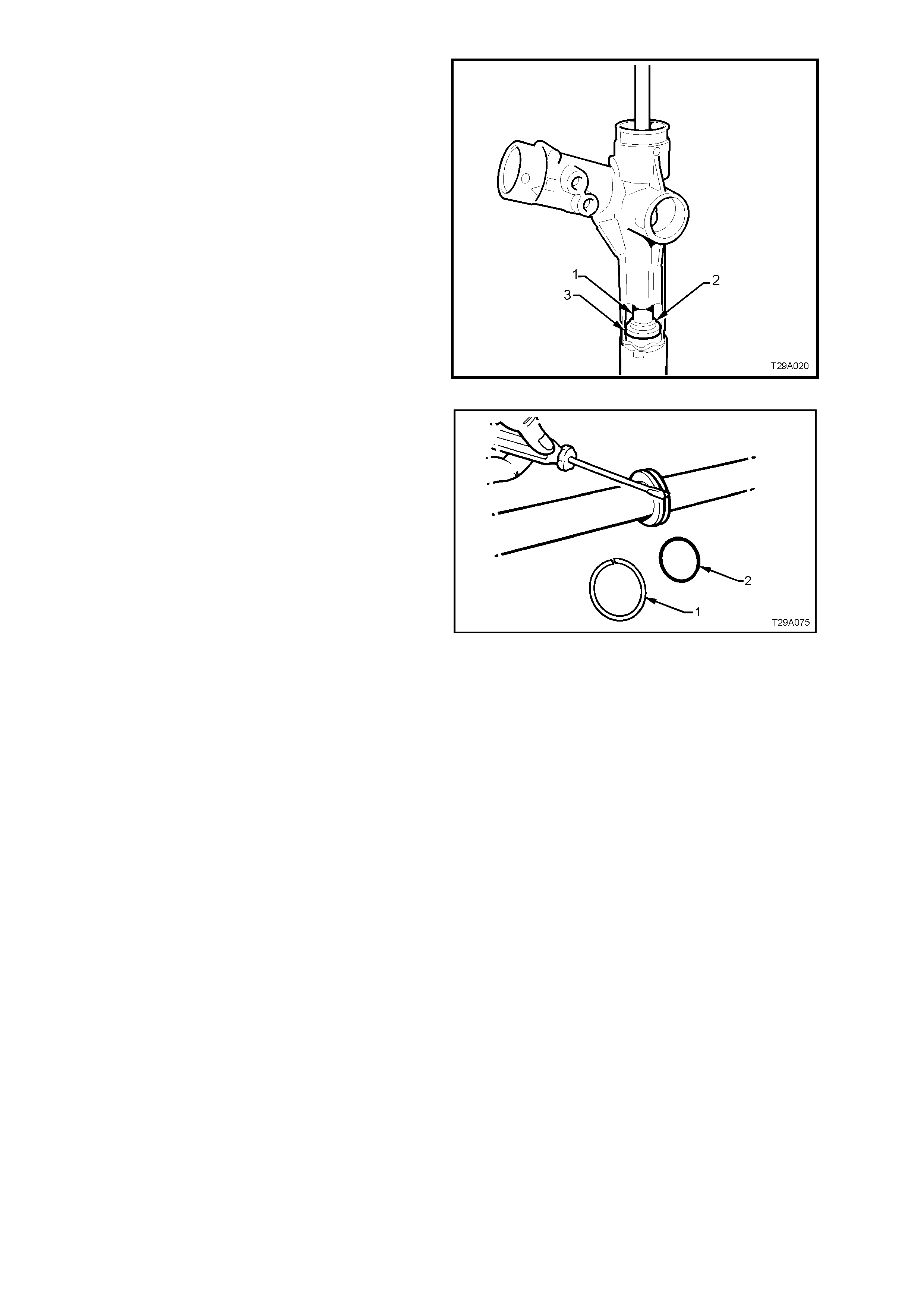
29. Remove the rack end bushing retaining wire,
as follows:
a. Using Tool No. E8803-7 with a socket
extension and bar, r otate the rack end bush
anti-clockwise, until the end of the retainer
(1) appears in the slot.
b. Carefully prise the end of the retainer wire
free of the rack tube as shown, then rotate
the end bus hing with Tool No, E8803-7, in a
clockwise direction (arrow), winding the
retainer out of the tube.
c. Continue unwinding the retainer until the
end of the retainer (1) appears, then lift it
from the slot in the rack tube.
Figure 9A-37
30. Support the tube end of the rack housing (2)
over suitable press plates such as J22919-01
or similar, the remove the rack from the
housing by inserting a brass drift (1) into the
right threaded end of the r ack and pr essing the
rack from the tube end of the rack housing.
NOTE: While a drift and hammer could also be
used, considerable resistance will be encountered,
as rack removal also removes the rack end bush
and the outer piston rod seal from the steering
tube.
Figure 9A-38
31. Insert a suitable length of tubing or mild steel
stock (1), 30 mm in diameter into the housing
from the pinion end, then use a hammer (or
press) to drive the spacer (2) and inner piston
rod seal (3) and from the rack housing.
Figure 9A-39
32. Remove rack piston seal (1) and O-ring (2)
from the rack piston.
NOTE: The seal (1) can be more easily removed
by cutting diagonally with a sharp knife, but take
care not to scratch the sides of the seal groove,
during this process.
Figure 9A-40
CLEAN AND INSPECT
Thoroughly wash all metal parts in cleaning solvent and blow dry with compressed air.
1. Inspect rubber bellows for damage or deterioration, replace if necessary.
2. Inspect pinion bearings for signs of brinelling, damage or wear.
NOTE: As the intermediate pinion bearing will have been damaged on removal and the lower ball bearing will
possibly have suffered brinelling damage, both of these bearings must be replaced on reassembly.
3. Inspect pinion for signs of tooth wear or damage.
4. Inspect rack for signs of wear or damage to teeth, rack pad faces and rack bearing journal.
NOTE: A light polish on teeth and rack rear face is normal and should not be confused with wear.
5. Inspect housing for wear or damage in pinion bearing bores, seal bores, rack piston and lock stop faces.
6. Inspect rack pad for damage or excessive wear.
7. Inspect major components of pinion assembly (pinion, valve, sleeve and torsion bar) for damage or wear.
NOTE: These parts cannot be serviced individually as they are hydraulically balanced at the pinning stage of
assembly to equalise the steering efforts in right and left directions.
REASSEMBLE
1. Check that each of the rack seals have a
circular , plastic insert ring f itted to each, on the
opposite side to the spr ing loaded seal lip, with
the tapered edge of the insert facing in toward
the seal. Ensure the tapered ends of the rings
seat correctly.
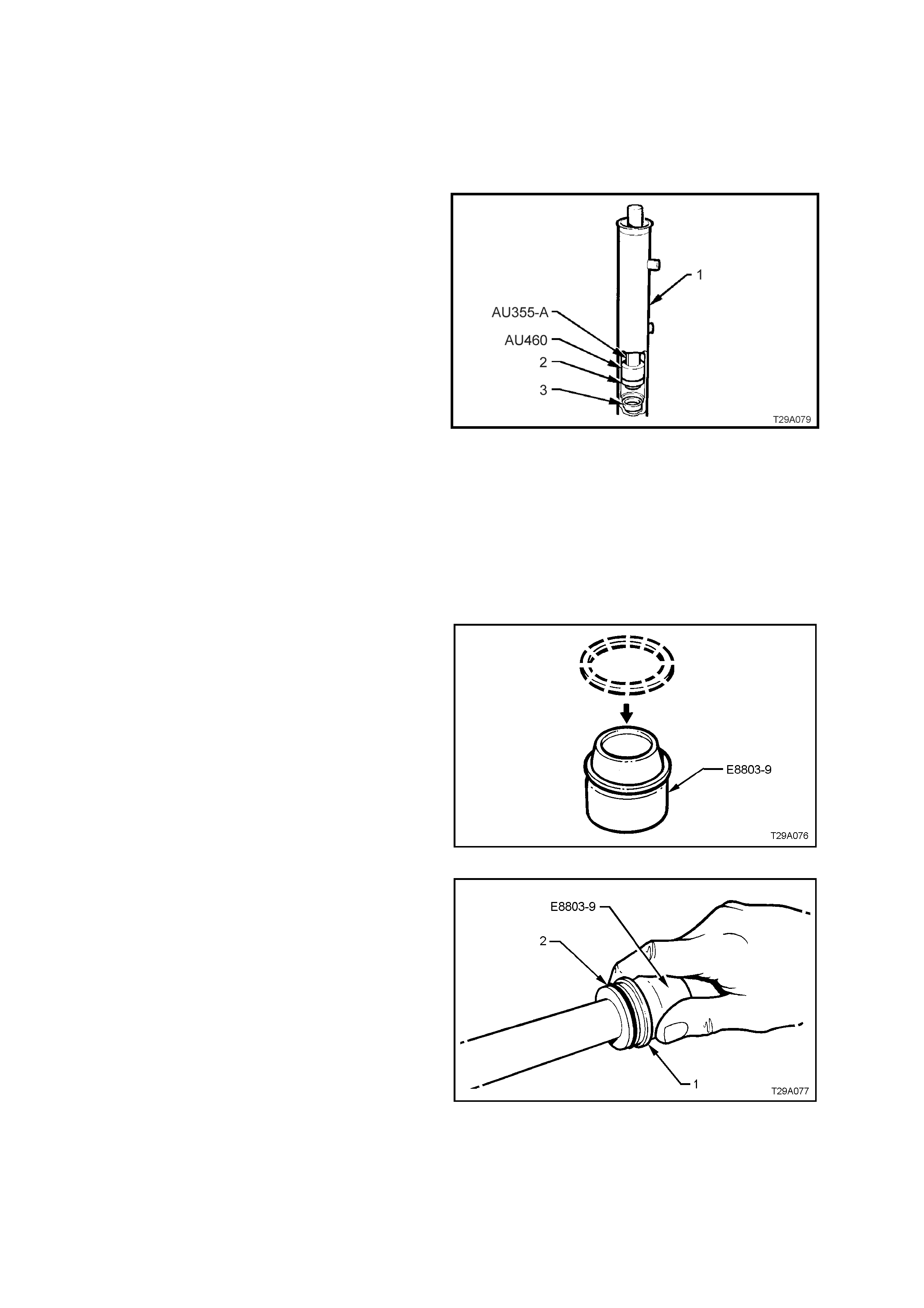
2. Screw Tool No. AU460 onto driver handle Tool
No. AU355-A with the O-ring end facing out.
Install the inner seal spacer (3) onto Tool No.
AU355-A, using the O- ring to hold the s pacer in
place. Insert the tools and spacer into the rack
tube.
3. Using tool combination AU460/AU355-A, press
the seal spacer (3) into the rack housing (1),
until the end of Tool No. AU355-A protrudes
from the rack tube by approximately 53 mm.
This measurement will ensure that the spacer
has been fully installed.
4. Reverse the fitment of Tool No. AU460 to the
driver handle Tool No. AU355-A.
5. Lubricate a new rack inner seal (2) with
Dexron® III autom atic transm ission fluid. Install
the seal (2) over the spigot of T ool No. AU460,
ensuring that the spring loaded sealing lip is
facing Tool No. AU460.
6. Press seal into the rack housing (1) on top of
the spacer (3). The seal will be fully installed
when the end of Tool No. AU355-A protrudes
from the rack tube by approximately 60 mm.
Figure 9A-41
7. Install a new O-ring to groove in rack piston.
8. After dipping a new Teflon seal ring in clean
power steering fluid, install the seal ring over
expander Tool No. E8803-9.
Figure 9A-42
9. With the seal ring still installed on Tool No.
E8803-9, slide the assembly over the rack and
up to the piston. Slide the seal ring (1) off the
expansion tool and into the piston groove (2),
over the O-ring.
Figure 9A-43
10. Ensure that the seal is seated correctly in the
groove, by wrapping f ingers around the seal, as
shown.
Figure 9A-44
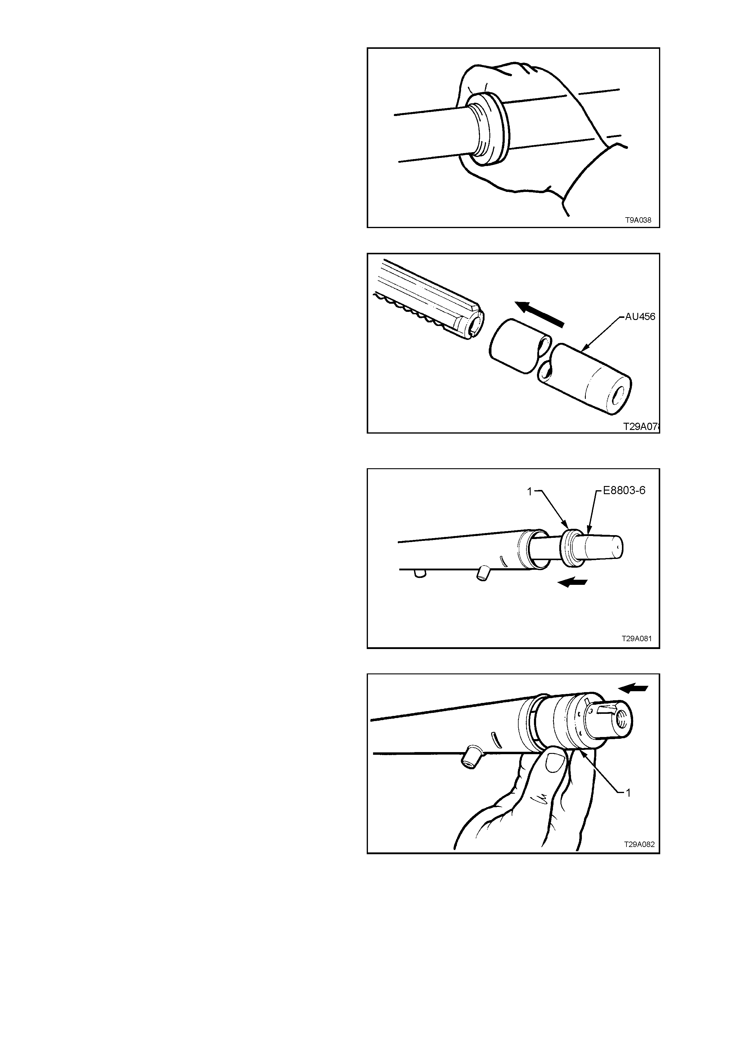
11. Install protector sleeve, Tool No. AU456 over
the toothed end of the rack and liberally apply
clean power steering fluid to the protector’s
outer surface.
12. Liberally apply clean power steering fluid to the
inner surf ac e of the r ack tube and over the rack
piston seal.
13. Carefully install the rack and protector into the
rack housing and through the inner seal,
aligning the rack teeth with the pinion bore.
Continue installation until the rack piston has
entered the smaller, inner tube diameter.
Remove the seal protector, Tool No. AU456
from the toothed end of the rack.
Figure 9A-45
14. Install the shorter seal protector E8803-6 over
the end of the rack, at the plain end.
Liberally apply clean power steering fluid to the
lip surface of the outer rack seal (1), then install
over the protector and onto the rack, with the
seal lips facing in towards the rack piston.
Figure 9A-46
15. Lubricate the left hand end bearing (1), inner
surface, with clean power steering fluid, then
install into the rack tube, pushing in against the
outer rack seal.
NOTE: To assist in installation of the bearing
retaining wire, align the hole in the bearing with the
opening in the steering housing tube.
16. Using installer Tool No. E8803-11, install the
outer seal and bearing until the retaining wire
groove is aligned with the slot in the rack
housing tubing.
Figure 9A-47
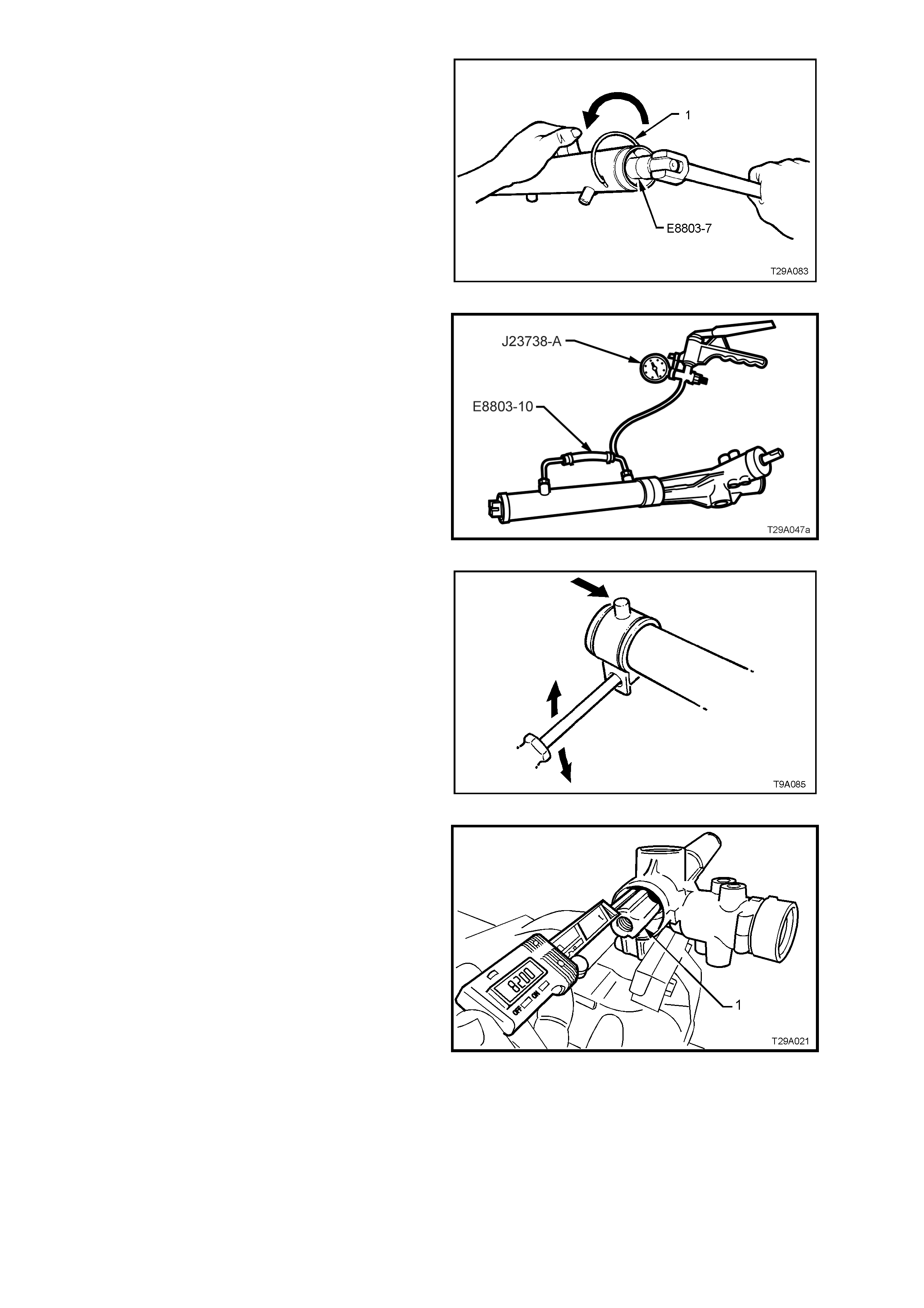
17. If necessary, rotate the end bearing with Tool
No. E8803-7, until the hole in the wire groove
appears in the tube slot.
Install the bent end of the bearing retaining
wire, into the hole then, continuing to use Tool
No. E8803-7, rotate the bearing in an anti-
clockwise direction until the end of the wire
disappears into the rack tubing.
Figure 9A-48
18. Install Tool No. E8803-10, to the two cylinder
pipe fittings. Tighten the unions just enough to
effect an air tight seal.
19. Using a hand vacuum pump, such as T ool No.
J-23738-A, apply a vacuum of 53.3 kPa (or 40
cm, 15.75 in. Hg), for approximately 30
seconds.
20. Check that no change in the vacuum occurs
during this period. If a c hange does occ ur, then
the reas on m ust be f ound and correc ted befor e
proceeding further.
Figure 9A-49
21. Check the mounting bracket insulator for
serviceability. Apply petroleum j elly (Vaseline or
equivalent) to the inner surface, then install
bracket and insulator to the steering tube, in
the reverse manner to removal. Align the
marks mark prior to re moval.
Figure 9A-50
22. Centralise the rack assembly by measuring
82 ± 1 mm from the lock stop (flange inside
rack housing) to the end of the toothed rack
(1), as shown.
Figure 9A-51
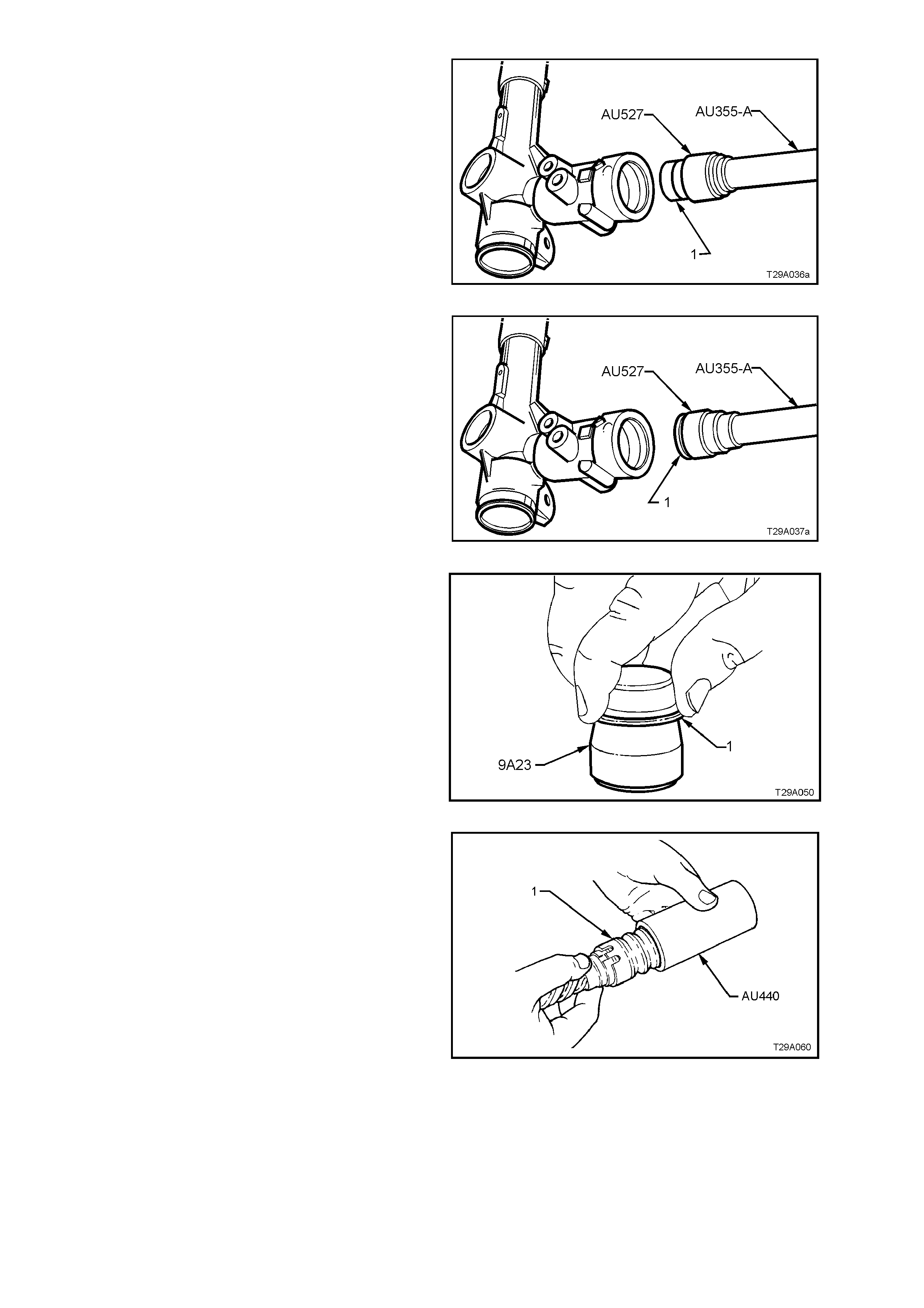
23. Lubricate a new pinion intermediate roller
bearing (1) with Dexronâ III automatic
transmission fluid, then install on the longer
pilot of Tool AU527 that has driver handle
AU355-A attached.
24. Press the bearing (1) into the steering rack
housing until fully seated. Remove the
installation tools.
Figure 9A-52
25. Reverse Tool AU527 onto driver handle
AU355-A, then install a new intermediate seal
(1) onto the shorter pilot, with the seal lips
facing the tool shoulder.
26. Press the seal (1) into the steering rack
housing until fully seated. Remove the
installation tools.
Figure 9A-53
27. To fit new PTFE seal rings (1) to sleeve
grooves, first warm in hot water then install on
expander, Tool No. 9A23.
Slide expanding tool with ring installed, over the
sleeve, then push the seal off and into the
sleeve groove. Repeat for remaining three
seals.
Figure 9A-54
28. After all seals have been fitted to the sleeve
grooves, push Tool No. AU440 over rings and
valve assembly (1), then leave for 5-10 m inutes
to contract rings back to normal size.
Figure 9A-55
29. Inser t 50 gram s of EP Sem i Fluid Lithium Base
O Grease into the steering gear housing,
through the pinion bore.
30. While maintaining rack in centralised position,
insert pinion so that the clamp bolt flat of input
shaft is positioned as shown, when pinion is
fully located in housing.
Figure 9A-56
31. Pack pinion lower bearing with EP Semi Fluid
Lithium Base O Grease.
32. Reinstall pinion lower bearing, using the
following procedure:
a. Install a new, lubricated ball bearing over
the lower end of the pinion, then thread T ool
AU307 onto the pinion end.
b. While holding the knurled section with one
hand as shown, fit an 15 m m set spanner to
the flat section of the pinion (1) and turn
back and forth, advancing the installation
tool until the bearing is fully seated.
c. The bearing will be fully installed when Tool
AU307 cannot be advanced any further.
d. Remove AU307 when bearing is installed.
Figure 9A-57
33. Install pinion lower bearing retaining nut and
tighten to the correc t torque specif ication, using
a torque wrench and socket on the nut and a
15 mm set spanner holding the pinion input
shaft.
PINION LOWER BEARING
RETAINING NUT 35 - 45 Nm
TORQUE SPECIFICATION
NOTE: This nut has a deformed thread and may be
reused once only. However, it is strongly
recommended that a new nut is fitted at each
overhaul.
Figure 9A-58
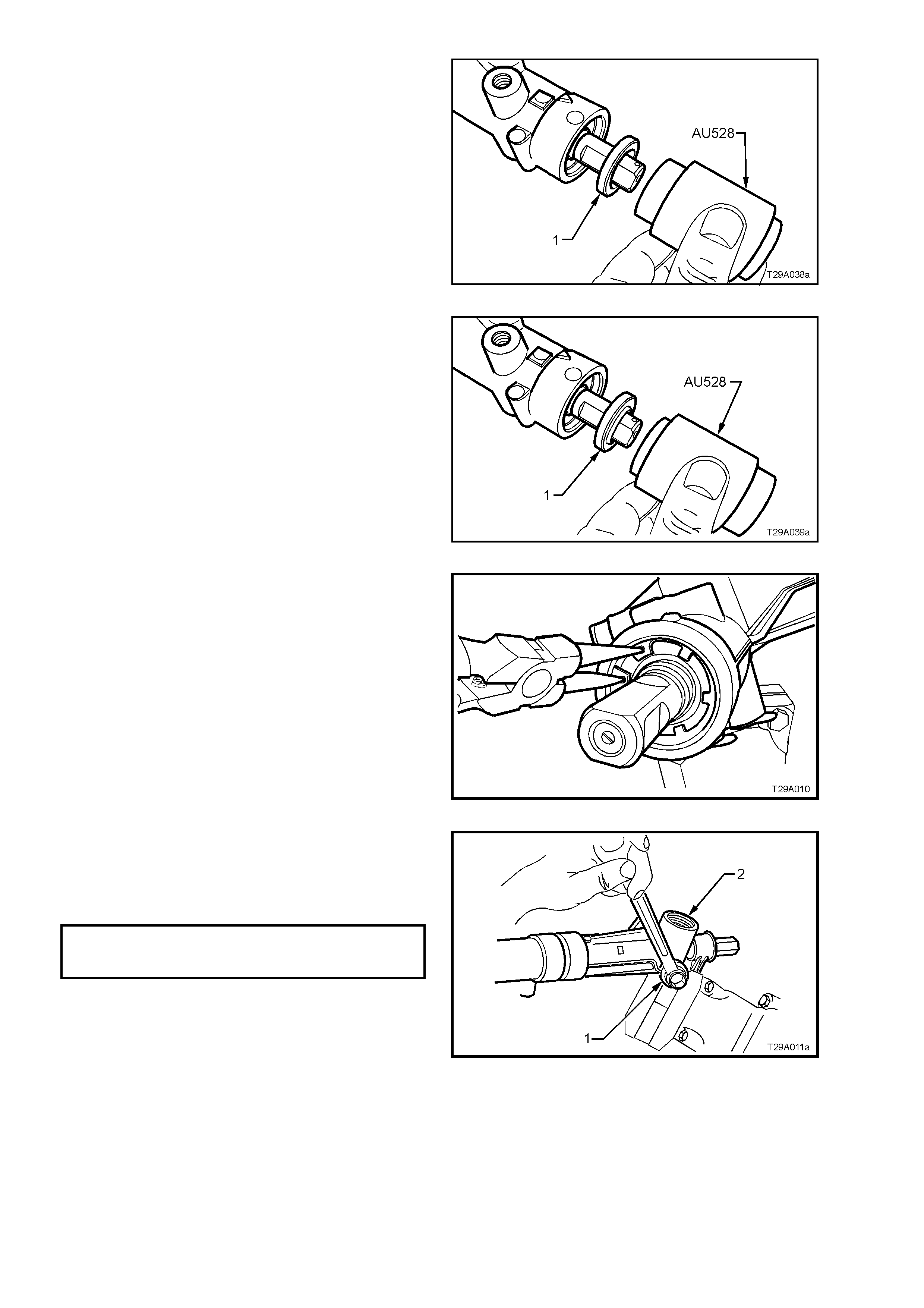
34. Lubricate the upper pinion roller bearing (1)
with Dexronâ III automatic transmission fluid,
then install over the pinion shaft.
35. Reinstall the upper bearing (1) into the steering
rack housing, using Tool AU528 and a plastic
hammer.
NOTE: Tool AU528 s hould be used with the longer
shank facing the bearing. When the shoulder
contacts the rack housing, the bearing will have
been installed to the correct depth.
Figure 9A-59
36. Lubricate a new pinion shaft upper oil seal (1)
with Dexronâ III automatic transmission fluid,
then install over the pinion shaft with the seal
lips facing down.
37. Reinstall the pinion shaft upper oil seal (1) into
the steering rack housing, using Tool AU528
and a plastic hammer.
NOTE: Tool AU528 should be used with the shorter
shank facing the oil seal. When the shoulder
contacts the rack housing, the oil seal will have
been installed to the correct depth.
Figure 9A-60
38. Using suitable circlip pliers, reinstall the circlip
over the top of the pinion upper oil seal,
ensuring that the circlip locates correctly in the
housing groove.
Figure 9A-61
39. Apply Loctite 242 thread sealant (or equivalent
to Holden’s Specification HN1256) to the
cleaned threads of the pinion lower screw plug
(1), reinstall the plug into the housing (2) and
tighten to the correct torque specification.
PINION LOWER RETAINING
SCREW PLUG 55 - 60 Nm
TORQUE SPECIFICATION
Figure 9A-62
40. Reinstall rack pad insert to rack pad (if
rem oved). Reinstall rack pad assem bly into the
steering gear housing.
41. Reinstall plastic washer ( 1) and r ac k pad spring
(2).
Figure 9A-63
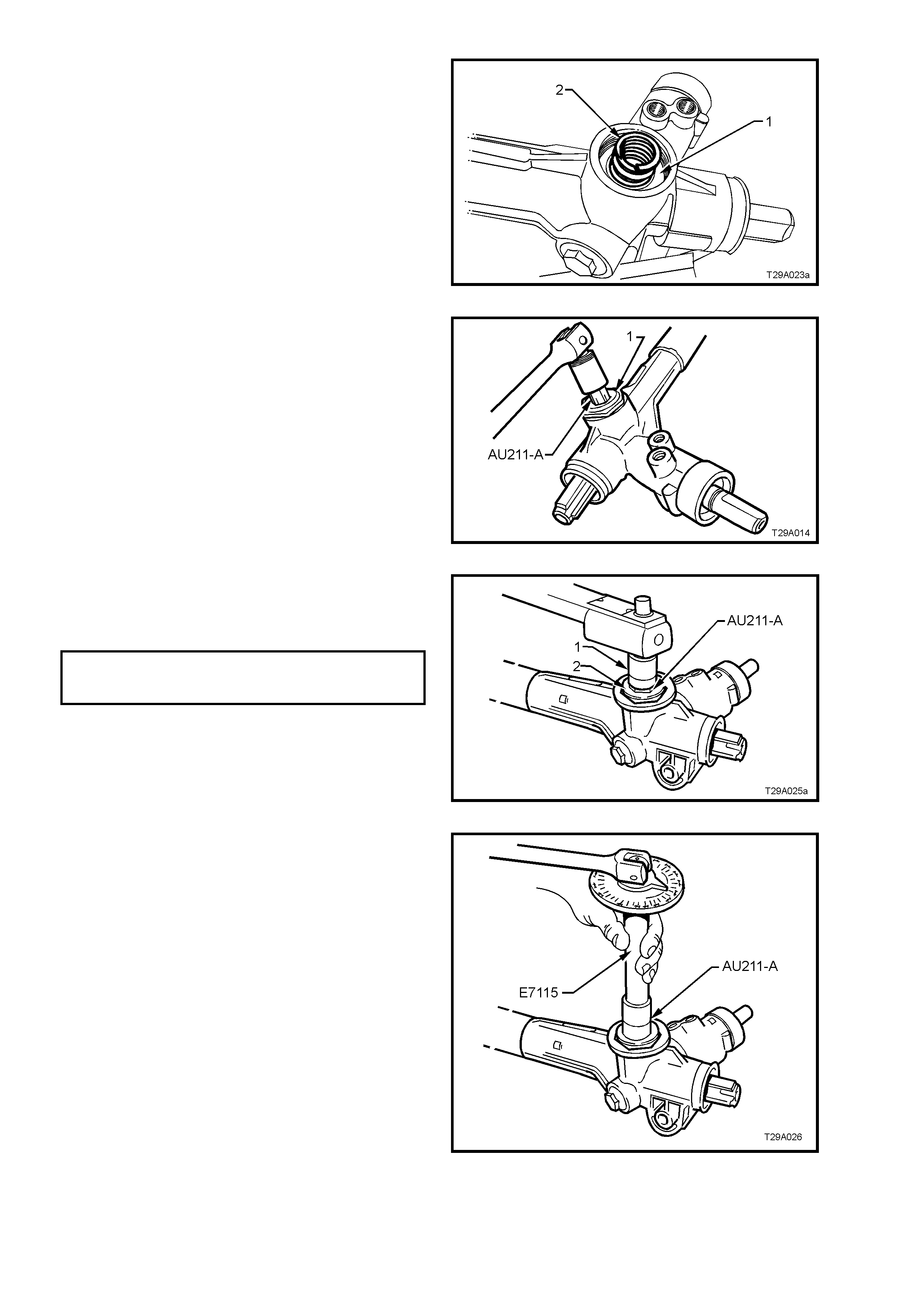
42. Screw lock nut onto adjusting screw. Install
adjusting screw (1) into steering gear housing,
using Tool AU211-A but leave the lock nut
loose.
Figure 9A-64
43. With steering rack in centralised position,
tighten rac k pad adj usting screw (2) us ing Tool
No. AU211-A, socket (1) and torque wrench to
the correct initial torque.
RACK PAD ADJUSTING
SCREW INITIAL 10 - 12 Nm
TORQUE SPECIFICATION
Figure 9A-65
44. Using angle wrench, Tools E7115 and AU211-
A, turn rack pad adjusting screw back (anti-
clockwise) 20 - 28°.
Figure 9A-66
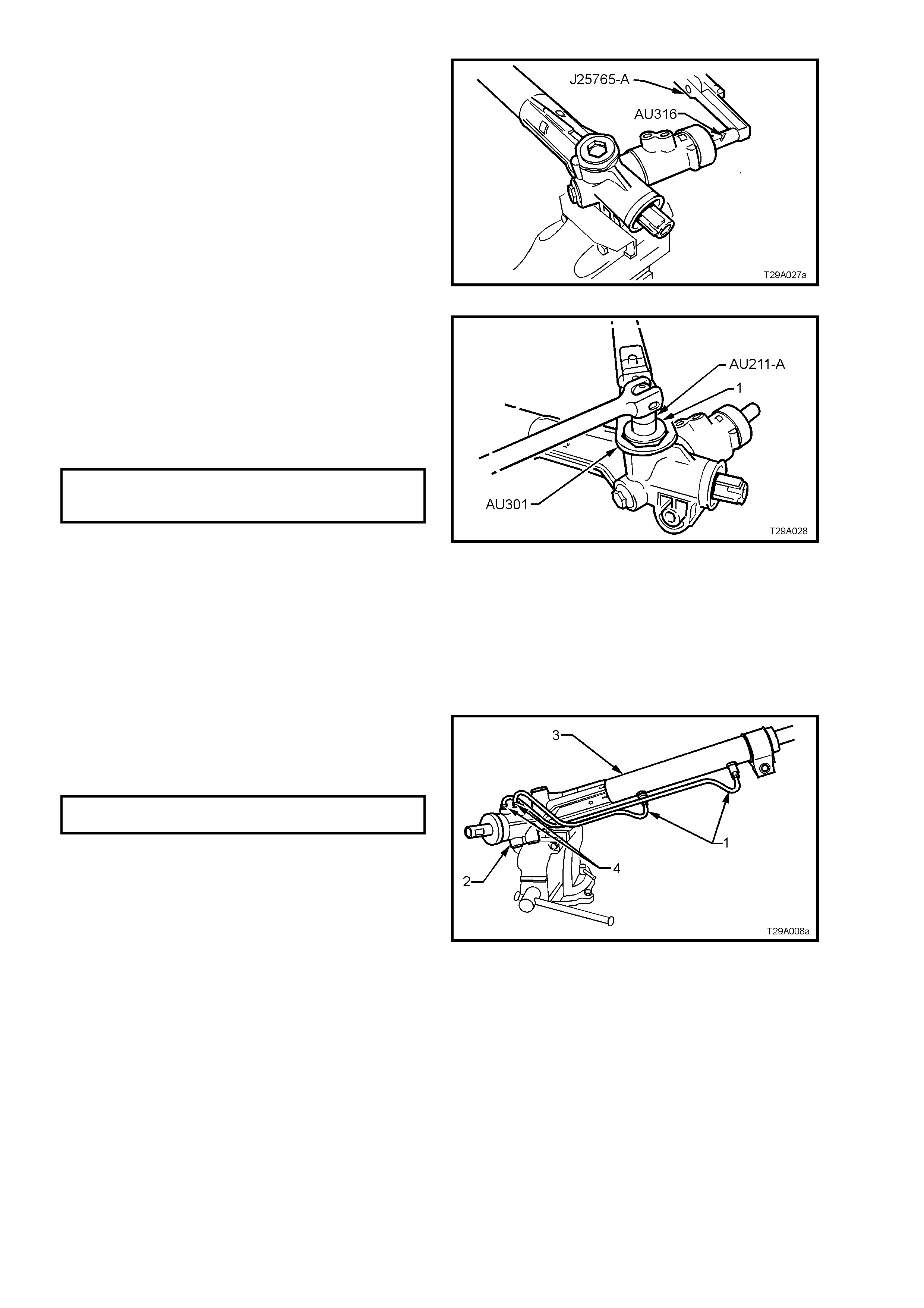
45. Install Tool AU316 to input shaft and measure
rotating torque of input shaft, using a dial type
torque wrench such as J25765-A, by cycling
the steering gear back and forth. Torque
requirements are from 0.8 to 2.5 Nm.
46. As required, minor variations in rotating torque
from specification can be corrected by
readjusting the rack pad spring tension.
NOTE: If a large variation in rotating torque from
specification or binding is experienced, the cause
must be determined and corrected before
proceeding further.
Figure 9A-67
47. Apply Loctite 242 thread sealant (or equivalent
to Holden’s Specification HN1256) to the
cleaned threads of the rack pad plug lock nut.
48. While holding adjusting screw in the correctly
adjusted position with Tool No. AU211- A and a
socket bar, tighten the lock nut (1) to the
correct torque specification using Tool No.
AU301 and a torque wrench.
RACK PAD ADJUSTING
SCREW L OCK NUT 55 - 65 Nm
TORQUE SPECIFICATION
NOTE: Once the r ack pad adjus tment has been set
and the lock nut torqued to specification, the
steering gear must be racked from lock-to-lock to
ensure localised wear has not appreciably affected
the setting. The gear should not bind or appear
tight over any part of the total travel. Should gear
bind or appear tight, recheck rack pad adjustment.
If this is not the cause, strip gear assembly and
examine rack and pinion for wear. Replace as
necessary.
Figure 9A-68
49. Reconnect feed pipes (1 and 4) to valve
housing (2) and steering gear tubing (3) and
tighten pipe flare nuts to the correct torque
specification.
FEED PIPE FLARE NUT 15 - 25
TORQUE SPECIFICATION Nm
NOTE: The longer of the two pipes (LH lock) is
installed into the upper location on the valve body
housing, while the s horter ( RH lock ) is installed into
the lower.
Figure 9A-69
50. Rotate pinion shaft fully anti-clockwise (left
lock).
51. Remove steering gear housing from vice, and
grip exposed toothed end of rack in vice with
soft jaws.
52. Using Tool No. AU305, tighten right-hand tie
rod to the correct torque specification.
TIE ROD TO RACK 90 - 100
TORQUE SPECIFICATION Nm
53. Using c entre punch and ham mer, stake rac k to
tie rod ball joint housing.
54. Remove steering gear housing from vice and
rotate pinion shaft slightly clockwise, just
enough to expose the left hand end of rack.
55. Tighten left hand tie rod as in steps 53 and 54.
56. Relocate steering gear housing in vice by
gripping right hand mounting boss.
57. Rotate input shaft to straight ahead position.
Install dust cover onto input shaft.
Figure 9A-70
58. Reinstall a new dust cover to the pinion shaft,
ensuring that the cover is engaged with the
groove in the pinion.
Figure 9A-71
59. Refit bellows to tie rods and steering gear
housing. Reinstall retaining clips.
60. Refit tie rod ball joint lock nuts and tie rod ball
joints to tie rods.
NOTE: Do not tighten lock nuts, as toe adjustment
must be performed after steering gear is
reinstalled.
61. Reinstall steering gear assembly into the
vehicle, as detailed In 3.6 POW ER STEERING
GEAR - REINSTALL in this Section.
3.7 FLUID RESERVOIR - GEN III V8 ENGINE
REMOVE
1. Disconnect battery earth lead from the battery.
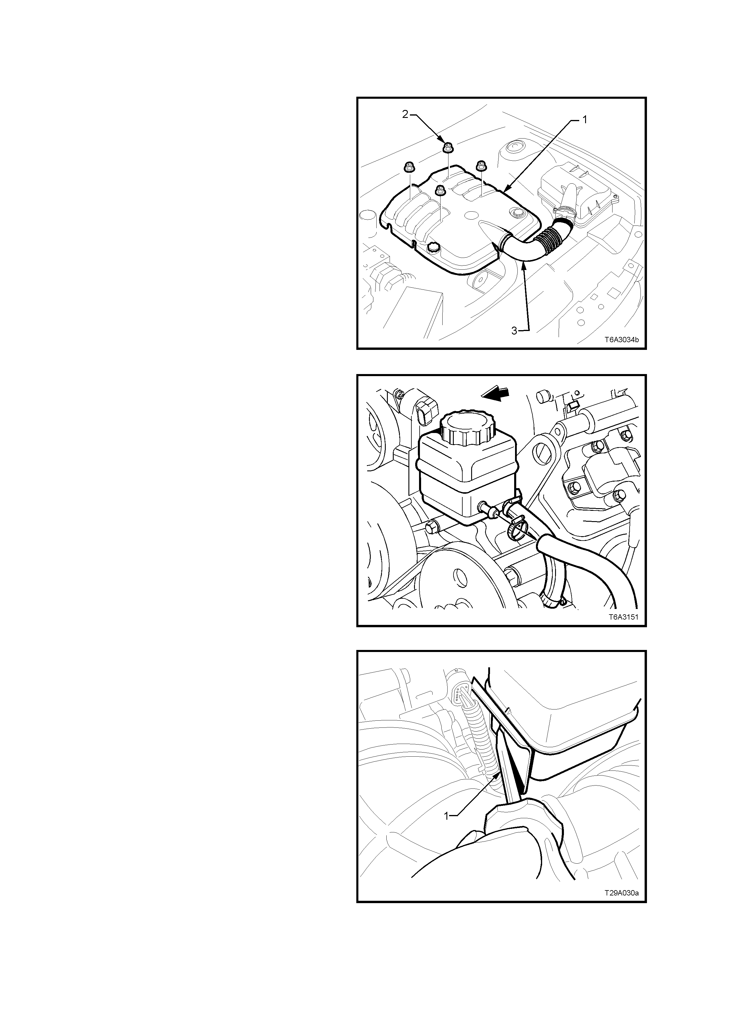
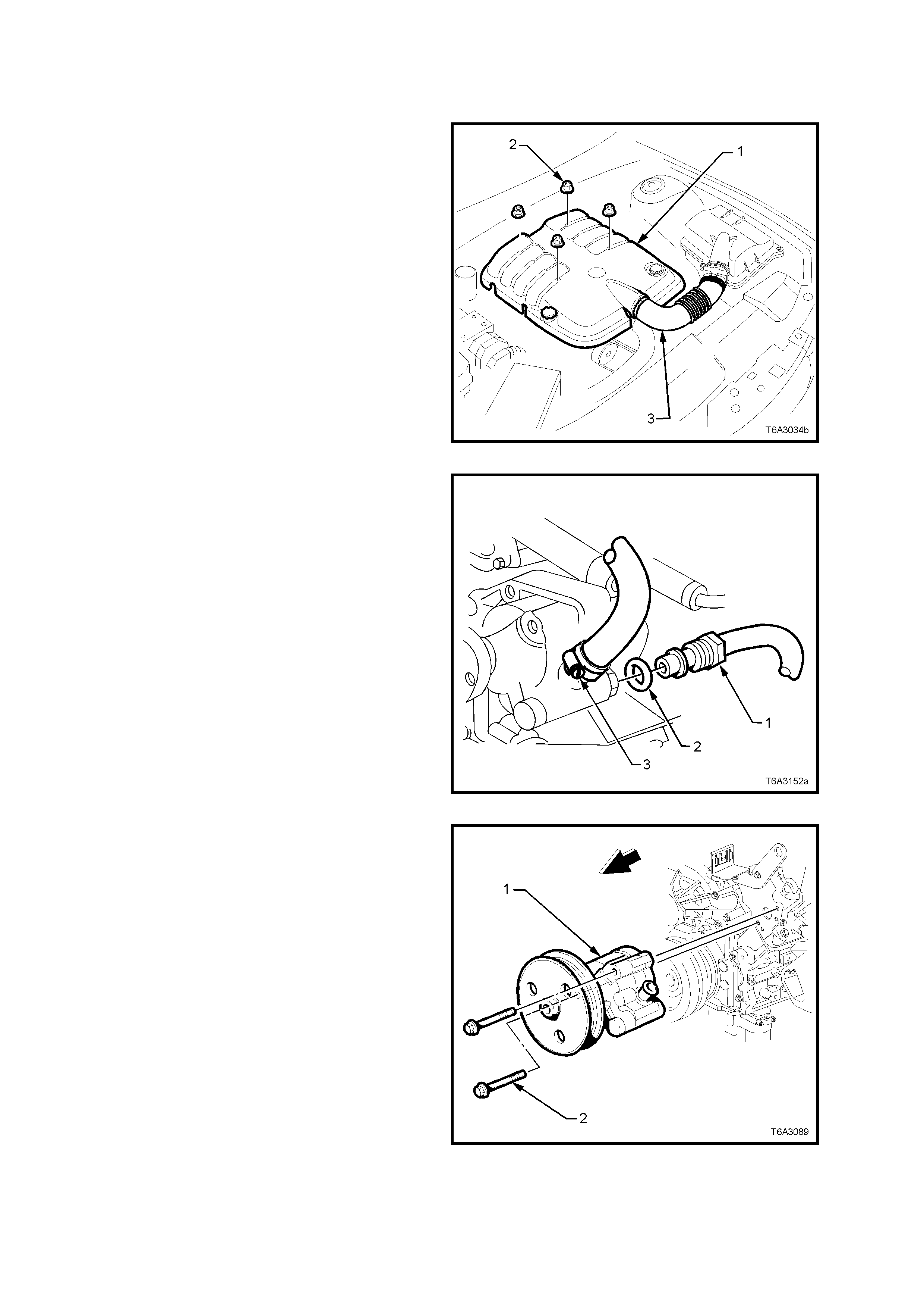
2. Remove the engine trim cover retaining nuts
(2) then remove the cover (1) from the engine.
Figure 9A-72
3. Place a drain tray beneath reservoir assembly.
4. Loosen hose clamps and remove the two
hoses from the reservoir.
NOTE: Cover or tape the hose ends to prevent
contamination ingress.
Figure 9A-73
5. Using a suitable lever such as a screwdriver
(1), gently lever locking tang back to clear the
reservoir tab, then lift the reservoir up and out
of the retaining bracket.
6. Reset the bracket locking tang back into the
original position.
7. If required, remove the two bolts securing the
com bination res ervoir and engine lif ting brack et
from the left hand cylinder head. Remove the
bracket from the engine.
Figure 9A-74

REINSTALL
Reinstallation is the reverse to removal operations, noting the following points:
1. If removed, reinstall the reservoir/engine lift bracket bolts and tighten to the correct torque specification.
RESERVOIR/ENGINE LIFT
BRACKET ATTACHING BOLT 50 Nm
TORQUE SPECIFICATION
2. Tighten reservoir hose clamps to the correct torque specification.
POWER STEERING RESERVOIR
HOSE CLAMP 2.0 - 3.0 Nm
TORQUE SPECIFICATION
3. Reinstall the engine trim cover, install the retaining nuts and tighten to the correct torque specification.
ENGINE TRIM COVER NUT 8.0 – 12.0
TORQUE SPECIFICATION Nm
4. Refill and bleed the hydraulic system. Refer to 3.4 HYDRAULIC SYSTEM - BLEEDING/REFILLING in this
Section.
5. Start the engine and check for fluid leaks from the reservoir area.
3.8 POWER STEERING PUMP - GEN III V8 ENGINE
REMOVE
6. Loosen the two hose clamps securing the air
intake duc t (3) to the throttle body and Mass Air
Flow (MAF) sensor.
7. Remove the air intake duct from the throttle
body and MAF sensor.
8. Rem ove the engine acces sory drive belt. Refer
to Section 6A3 - GEN III V8 ENGINE,
2.6 ENGINE DRIVE BELT S, of the VT Ser ies II
Service Information for the required procedure.
Figure 9A-75
9. Place a drain tray beneath power steering
pump assembly.
10. Remove the power steering fluid reservoir.
Refer 3.7 FLUID RESERVOIR - GEN III V8
ENGINE, in this Section.
11. Loos en and rem ove high pres sure line f lare nut
(1) and O-ring (2) from pump outlet fitting.
12. Loosen low pressure hose clamp (3) and
remove hose from pump inlet fitting.
NOTE: Cover or tape the pum p and hose fittings to
prevent dirt entry.
Figure 9A-76
13. Rem o ve the two power steering pum p retaining
bolts (2) securing the pump to the front of the
left hand cylinder head. Remove the pump
from the engine.
NOTE: Access to the two bolts can be made
through the pulley holes, using a suitable socket
and extension.
Figure 9A-77
REINSTALL
Reinstallation of the power steering pump is the reverse of removal procedures, noting the following points:
1. Tighten the two pump to cy linder head retaining bolts to the correct torque specification.
PUMP TO CYLINDER HEAD BOLT 20 - 35
TORQUE SPECIFICATION Nm
2. Install new sealing O-ring to high pressure line connection. Lubricate sealing ring with Dexron® III automatic
transmission fluid prior to installation.
3. Tighten the high pressure pipe flare nut to pump outlet fitting, to the correct torque specification, using a back-
up spanner on the outlet fitting.
HIGH PRESSURE LINE FLARE NUT 25 - 35
TORQUE SPECIFICATION Nm
4. Reinstall and tighten all low pressure hose clamps to the correct torque specification.
LOW PRESSURE HOSE CLAMP 2.0 - 3.0
TORQUE SPECIFICATION Nm
5. Reinstall power steering pump fluid reservoir. Refer 3.7 FLUID RESERVOIR - GEN III V8 ENGINE, in this
Section.
6. Reinstall engine accessory drive belt. Refer to Section 6A3 GEN III V8 ENGINE, 2.6 ENGINE DRIVE BELTS, of
the VT Series II Service Information for the required procedure.
7. Reinstall air intake duct to the throttle body and MAF sensor and tighten the hose c lamps to the cor rect torque
specification.
AIR INTAKE DUCT HOSE CLAMP 5.0 - 8.0
TORQUE SPECIFICATION Nm
8. Reinstall the engine trim cover, install the retaining nuts and tighten to the correct torque specification.
ENGINE TRIM COVER NUT 8.0 - 12.0
TORQUE SPECIFICATION Nm
9. Refill and bleed hydraulic system, refer to 3.4 HYDRAULIC SYSTEM - BLEEDING/REFILLING in this Section.
10. Start engine and check for fluid leaks around pump and reservoir area.
OVERHAUL PROCEDURES
Refer to 3.8 POWER STEERING PUMP - V6 ENGINE, of the VT Series I Service Information for the necessary
procedures to disassemble, clean and inspect and reassemble the power steering pump fitted to the GEN III V8
engine.
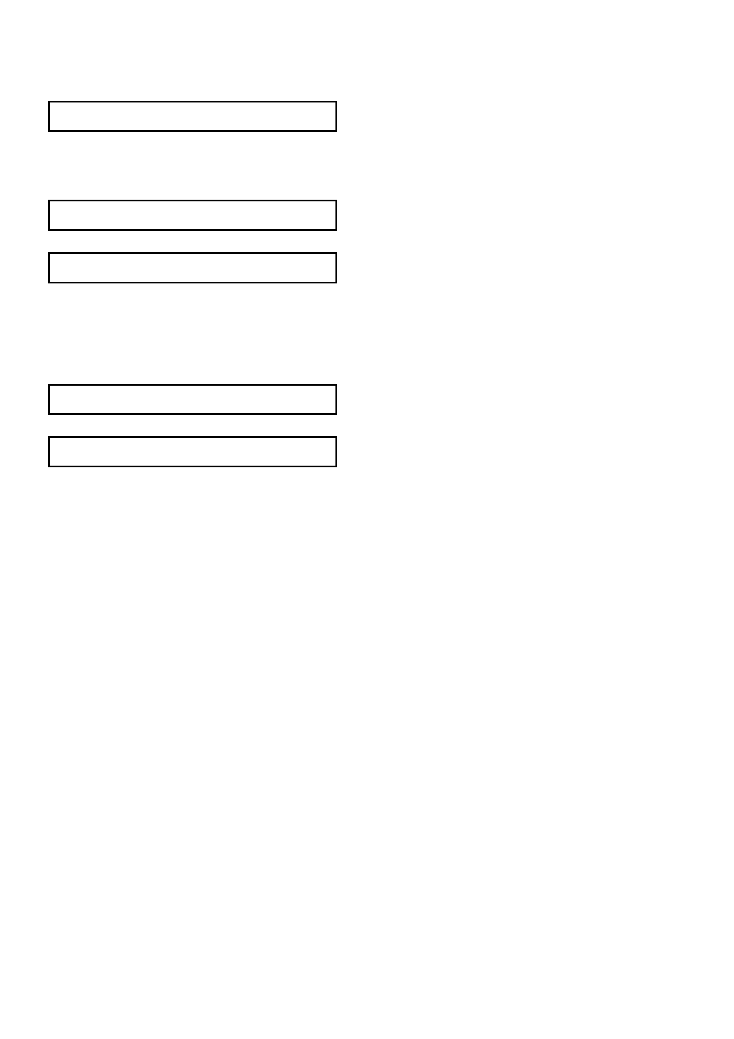
3.9 POWER STEERING PUMP PULLEY - GEN III V8 ENGINE – METHOD 1
REPLACE – USING TOOL AU188 & E9239A
1. Remove power steering pump, refer to
3.8 POWER STEERING PUMP GEN III V8
ENGINE in this Section.
2. Install s uitable pr ess plates , suc h as J22912-01
under the power steering pump pulley (1) with
pulley press plates, Tool AU188 in between the
two and press pump assembly (2) from pulley,
using a suitable sized drift on the pump pulley
shaft.
NOTE: Do not position pr ess plates on the edge of
the pulley, as damage to the pulley will occur.
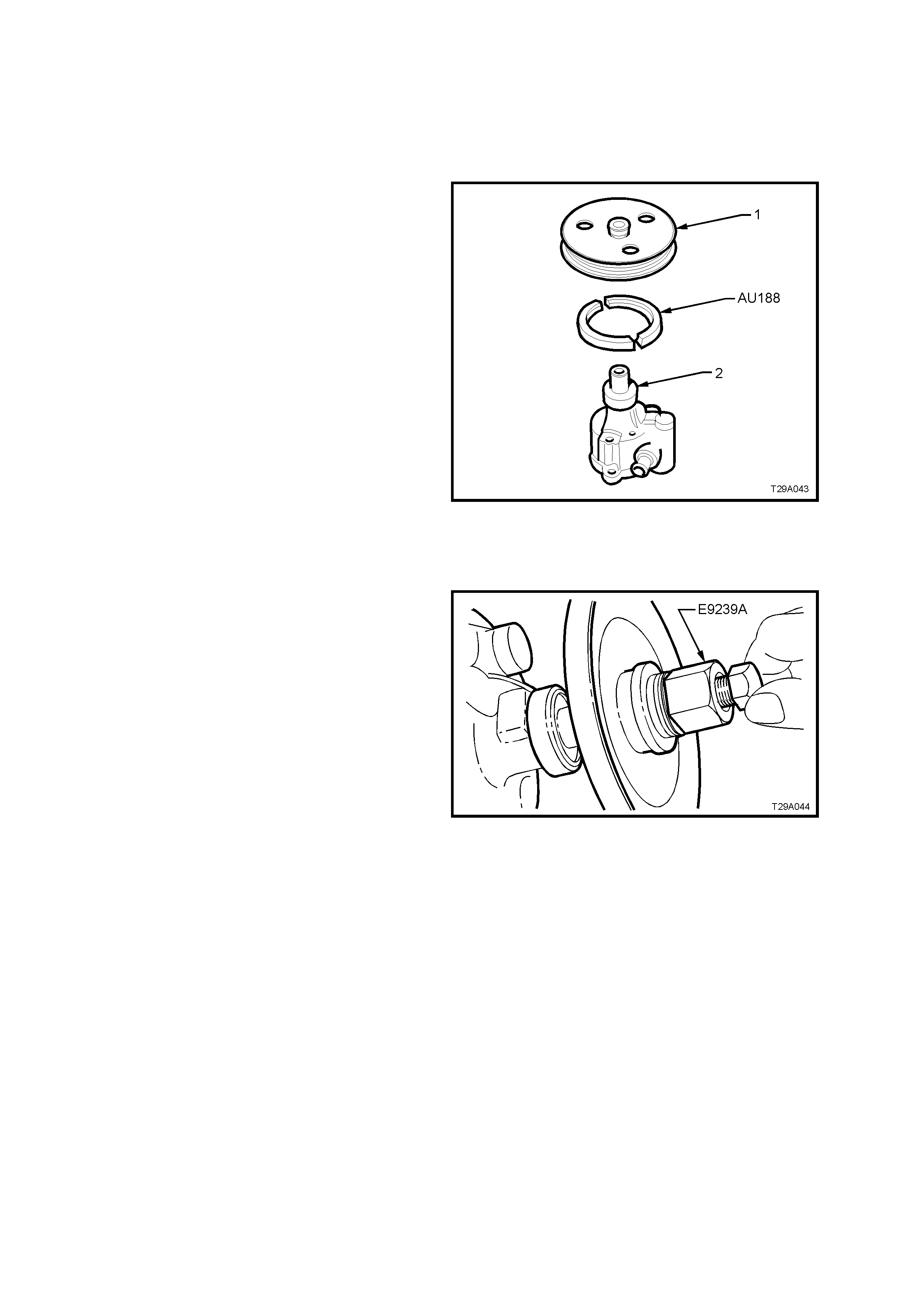
Figure 9A-78
3. Ensure pulley bore and pump pulley shaft are
free of burrs, place pulley on end of pump
shaft.
4. Install Tool No. E9239A (or J25033-B) by
screwing bolt fully into pump pulley shaft.
5. Reinstall pulley by holding the bolt head and
turning the large nut and bearing clockwise
until pulley is flush with shaft end.
6. Remove Tool No. E9239A (or J25033-B).
7. Reinstall the power steering pump, refer to
3.8 POWER STEERING PUMP – GEN III V8
ENGINE, in this Section.
Figure 9A-79
3.10 POWER STEERING PUMP PULLEY - GEN III V8 ENGINE – METHOD 2
REPLACE – USING 7185 – POWER STEERING PULLEY REMOVER & 7005 – POWER STEERING PULLY
INSTALLER
1. Remove power steering pump, refer to
3.8 POWER STEERING PUMP GEN III V8
ENGINE in this Section.
2. Lubricate the forcing screw (1) of 7185 –
POWER STEERING PULLEY REMOVER and
position the forcing screw against the pulley
shaft.
NOTE: Ensure the full diameter end of the half
jaws (2) are engaged with the pulley (4) and the
larger open end diameter (has chamfer and relief
profile) engages with the pulley flange.
3. Slide the retainer sleeve (3) over the half jaws
and hand tighten the forcing screw. Ensure
forcing screw is aligned with the pump axis.
4. Proceed to remove the pulley.
NOTE: Do not use power tools or exceed a torque
of 90Nm . If the pully cannot be removed within this
torque, replace the complete pump assembly.
Figure 9A-80
5. Assemble the drive nut (1), thread insert (2)
onto the forcing screw of 7005 – POWER
STEERING PULLEY REPLACER as shown in
fig 9.80. Ensure adequate graphite grease is
applied to the forcing screw and nut.
6. Thread the forcing screw assembly, by hand
onto the pump shaft (5) until it bottoms out
against the shoulder. DO NOT USE A
SPANNER FOR THIS OPERATION.
7. T ur n the drive nut ( 1) against the pulley (3) until
the pulley is at the correct installation depth.
DO NOT ALLOW THE FORCING SCREW TO
TURN DURING THIS OPERATION.
NOTE: Do not use power tools or exceed a torque
of 90Nm. If the pully cannot be installed within this
torque, replace the complete pump assembly.
8. Onc e the pulley is installed, rem ove the forc ing
screw from the pump shaft.
9. Reinstall the power steering pump, refer to
3.8 POWER STEERING PUMP – GEN III V8
ENGINE, in this Section.
Figure 9A-81
Techline

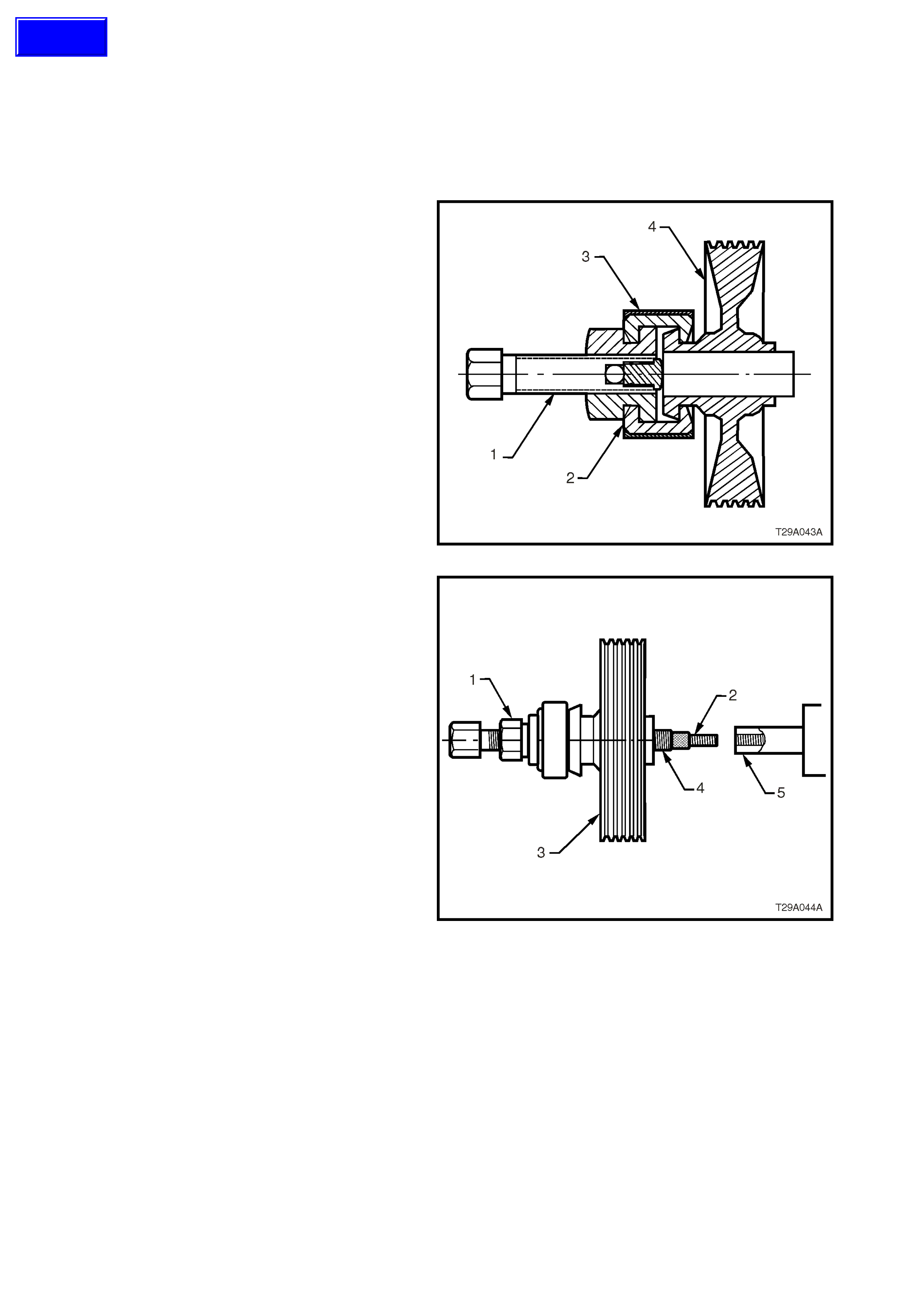
3.11 OIL COOLER AND HOSE/PIPE ROUTING - GEN III V8 ENGINE
ARRANGEMENT
Refer to Figures 9A-82 and 9A-83 for the general arrangement of the power steering oil cooler, hoses, pipes and
fittings used for the power steering system fitted to vehicles with the GEN III V8 engine. Torque specifications are
also provided.
Legend for Figure 9A-82
1. Rack - Steering
2. O-ring - Fluid Pipe to Steering Rack
3. Flare Nut - Fluid Pipe (2 places)
4. Pipe - Steering Rack to Fluid Cooler
5. Pipe - Steering Rack to Pump
6. Clamp - Low Pressure Hose
7. Hose - Low Pressure
8. O-ring - Fluid Pipe to Pump
9. Flare Nut - Fluid Pipe
10. Hose - Low pressure to Reservoir
11. Screw - Low Pressure Pipe Bracket
12. Clamp Low Pressure Hose
13. Pipe - Fluid Cooler to Reservoir
14. Screw - Low Pressure Pipe Bracket
15. Reservoir - Fluid
16. Clamp - Low Pressure Hose
17. Bolt - Pipe to Oil Pan Bracket
Figure 9A-82 - GEN III V8 Engine - Power Steering Hose/Pipe Routing
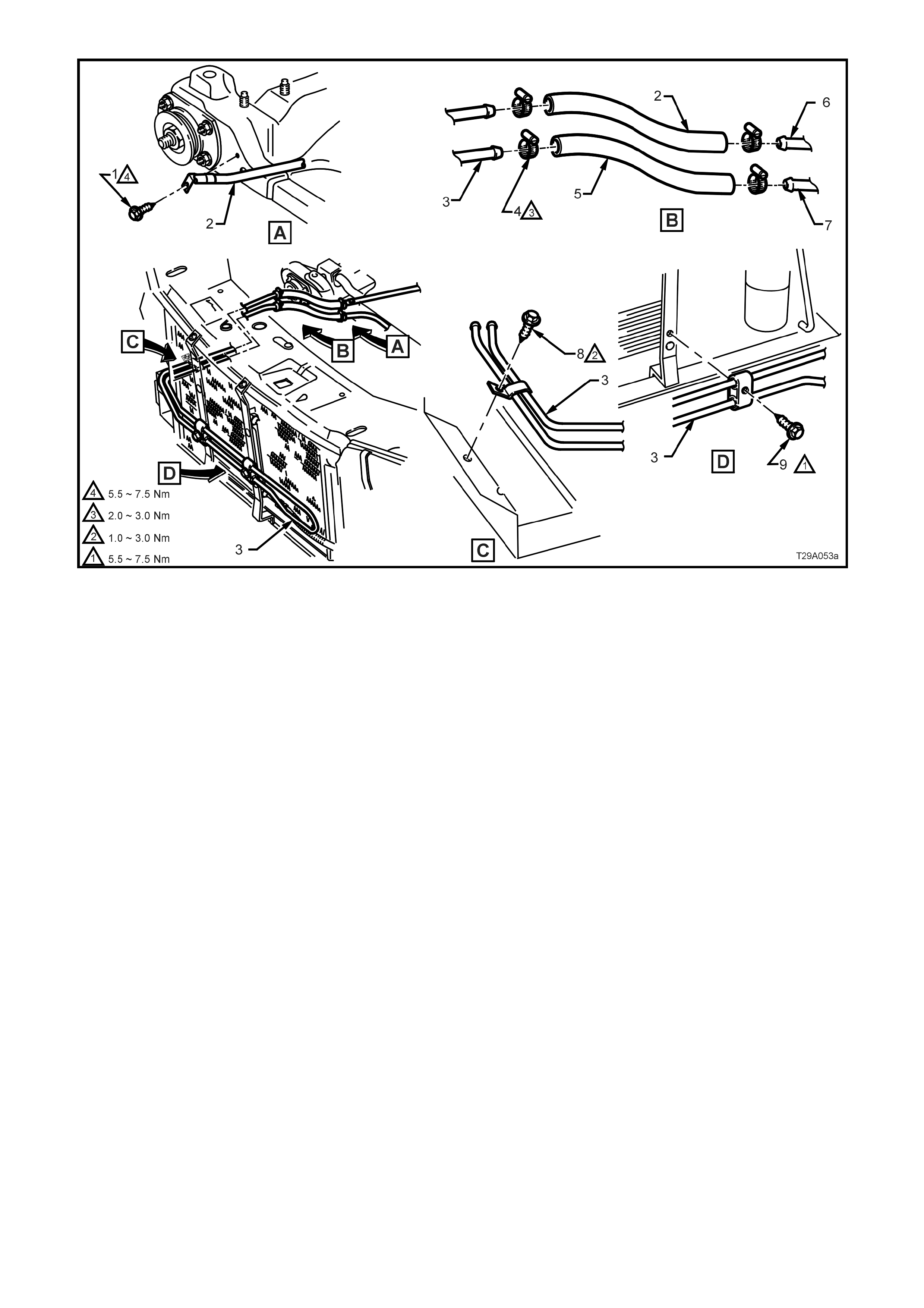
Figure 9A-83 - GEN III V8 Engine - Power Steering Fluid Cooler Hose/Pipe Routing
Legend
1. Screw - Hose Bracket
2. Hose - Fluid Cooler to Steering Rack
3. Cooler - Fluid
4. Clamp - Worm Drive Hose (4 places)
5. Hose - Fluid Cooler to Fluid Reservoir
6. Pipe - Power Steering Rack
7. Pipe - To Fluid Reservoir
8. Screw - Cooler Bracket
9. Screw - Fluid Cooler (2 places)

4. DIAGNOSIS
4.1 GENERAL DIAGNOSTIC INFORMATION
Faulty steering can be caused by problems in areas other than the pump or steering gear. Areas of the steering
system that can be easily checked and quickly corrected without disassembly and overhaul of any major
components, should be attempted first.
Problem s suc h as hard or loose st eering, road shoc k or vibrations are not always due to the steering gear or pump,
but are often related instead to such factors as low tyre pressure or front end alignment. These items should be
checked and corrected before any adjustment or disassembly of the steering gear or pump is attempted.
Other factors that may affect correct operation of the steering system, are:
1. Loose component mountings.
2. Drive belt tension.
3. Fluid level and condition.
These factors must be checked and corrected before making any further diagnosis of the steering system.
After the source of the problem has been located, the cause of the problem can be diagnosed and corrected.
For exam ple, if the fluid level in the reser voir is found to be low, ref ill and check the entire hydraulic system for fluid
leaks. Refilling the reservoir will not necessarily correct the problem.
Techline
Techline
Techline
Techline

4.2 POWER STEERING PUMP
DIAGNOSTIC ITEMS
Chirp Noise In Steering Pump.
1. Incorrectly tensioned drive belt.
Drive Belt Squeal (Particularly noticeable at full wheel travel and standstill parking).
1. Incorrectly tensioned drive belt.
Growl Noise In Steering Pump.
1. Excessive back-pressure in hoses or steering gear caused by restriction of flow.
Growl Noise In Steering Pump (Particularly noticeable at standstill parking).
1. Scored pressure plate, thrust plate or rotor.
2. Extreme wear of pump ring and vanes.
Groan Noise In Steering Pump.
1. Low fluid level.
2. Air in the fluid. Poor pressure hose connection.
Rattle Noise In Steering Pump.
1. Vanes not installed correctly.
Momentary Increase In Effort When Turning Wheel Fast To Right Or Left.
1. Low fluid level.
2. Drive belt slipping.
3. High internal leakage.
Steering Wheel Surges Or Jerks When Turning With Engine Running, Especially During Parking.
1. Low fluid level.
2. Incorrectly tensioned drive belt.
3. Insufficient pump pressure.
4. Sticky flow control valve.
Hard Steering Or Lack Of Assist, Especially In Parking.
1. Incorrectly tensioned drive belt.
2. Low fluid level.
3. Steering gear to column misalignment.
4. Tyres not properly inflated.
NOTE: If rectification of checks 1 through 4 does not correct hard steering, follow the Power Steering Test
Procedure as outlined in 3.4 HYDRAULIC SYSTEM CHECK in this Section.
Further possible causes could be:
5. Sticky flow control valve.
6. Insufficient pump pressure output.
7. Excessive internal pump leakage.
8. Excessive internal system leakage.
Foaming or Milky Power Steering Fluid, Low Fluid Level And Possible Low Pressure.
1. Air in the fluid, and loss of fluid due to internal pump leakage, causing overflow.
Low Pressure From Steering Pump.
1. Flow control valve stuck or inoperative.
2. Pressure plate not flat against pump ring.
3. Extreme wear of pump ring and vanes.
4. Scored pressure plate, thrust plate or rotor.
5. Vanes not installed correctly.
6. Vanes sticking in rotor slots.
7. Cracked or broken thrust or pressure plate.
8. High internal leakage.

LEAK DIAGNOSIS
General Procedure
1. Wipe suspected area dry.
2. Check for overfilled reservoir.
3. Check for aeration and overflow of foaming fluid.
4. Check hose connections - tighten if necessary to the specified torque.
5. Verify exact point of leakage.
Example: The location the fluid drips from is not neces sarily the leakage point - f luid could be overflowing from the
reservoir (V8) for example.
6. When service is required:
a. Clean leakage area upon disassembly.
b. Replace leaking seal.
c. Check component sealing surfaces for damage and replace component if necessary.
d. Tighten fastener/s to the specified torque where required.
External Leakage Check
The purpose of this procedure is to pinpoint the location of the leak. In som e cas es, the leak c an easily be located.
Seepage type leaks may be more difficult to isolate. To locate seepage leaks, use the following method.
1. With the engine stopped, wipe the complete power steering system dry (steering gear, pump, hoses and
connections).
2. Check the fluid level in the pump’s reservoir. Add fluid if necessary.
3. Start the engine then turn the steering wheel from stop to stop several times. Do not hold it at a stop for any
length of tim e, as this can dam age the power steering pum p. It is easier if s omeone else operates the steering
wheel while you search for the seepage.
4. Find the exact area of the leak. If the leak is in the steering gear assembly, remove and repair as necessary .
Seal Replacement Recommendations
Lip seals, which s eal rotating shafts , require special tr eatment. T his type of seal is used on the steering gear pinion
shaft and on the dr ive s haf t of the pump. When there is a leak in one of thes e areas , always replace the seal/s af ter
inspecting and thoroughly cleaning the sealing s urfaces . Replace the shaf t only if very severe pitting is f ound. If the
corros ion in the lip seal c ontac t area is s light, clean the s urf ac e of the s haf t with crocus cloth. Replace the shaft only
if the leakage cannot be stopped by first smoothing with crocus cloth.
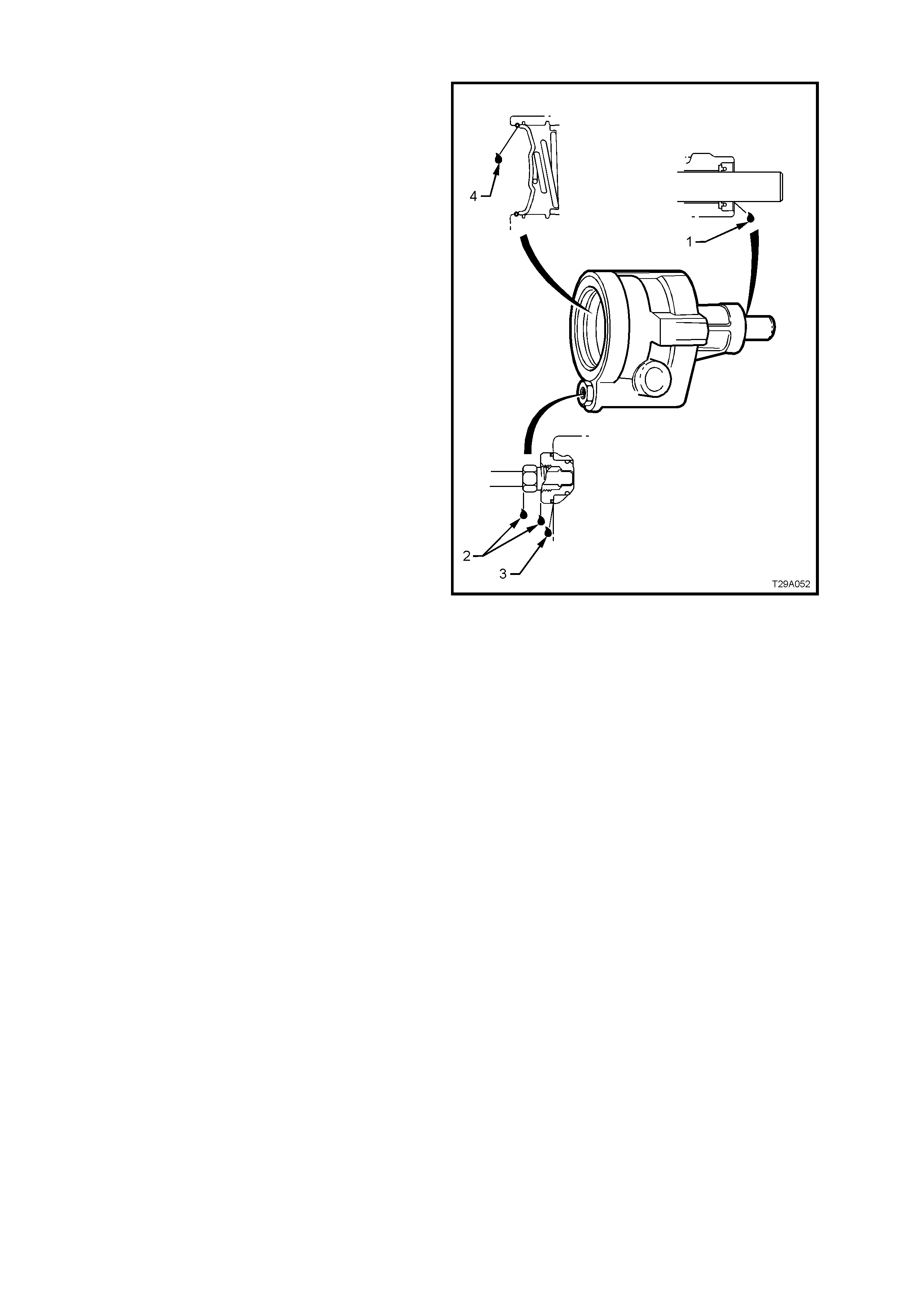
Pump Leak Diagnosis
NOTE: The following explanations relate to the
numbers shown in Figure 9A-84.
1. Replace drive shaft seal. Make certain that
drive shaft is clean and free of pitting in seal
area.
2. Torque high pressure pipe flare nut to 25 - 35
Nm. If leakage persists, replace O-ring seal.
3. Torque outlet fitting to 50 - 102 Nm. If leakage
persists, replace O-ring seal.
4. Replace end plate O-ring seal.
Figure 9A-84

5. SPECIFICATIONS
STEERING GEAR
Steering Gear Type
Power Steering................................................... Rack and pinion with integral power cylinder and
rotary valve mechanism - variable ratio
Steering Gear Ratio
On-centre........................................................... 17.2:1
Toward Lock ...................................................... 11.8:1
No. of Steering Wheel turns Lock to Lock .............. 3.0
Nominal Rack Travel Total...................................... 164 mm
POWER STEERING
Make ....................................................................... Saginaw
Type
GEN III V8 Engine............................................ ‘N’ Series droop flow vane type
Pressure at 1,000 engine rpm
GEN III V8 Engine............................................ 8,270 - 8,960 kPa
Drive........................................................................ Pulley
Lubrication (Power Steering)
Hydraulic ............................................................ Dexron® III Automatic Transmission Fluid
Fluid Capacity..................................................... Approx. 650 ml
Note: Use fluid level indicator as a final check
to ensure correct refill quantity
Drive Belt Tension
GEN III V8 Engine............................................ Belt Self Adjusting
FRONT WHEEL TOE
Front Toe-in (Degrees Total) ............................. 0° 10’ ± 0° 10’
Front Toe-in (Degrees per Wheel)..................... 0° 5’ ± 0° 5’
LUBRICANTS
Specified Grease..................................................... EP Semi Fluid Lithium Base O Grease
SEALANTS
Specified Locations................................................. Loctite 242 or equivalent, to Holden’s Specification
HN1256 Class 2, Type 2

6. TORQUE WRENCH SPECIFICATIONS
Nm
POWER STEERING GEAR
Hydraulic pipe to valve housing flare nut.............................. 30 - 42
Pinion lower bearing retaining nut ........................................ 35 - 45
Pinion lower bearing screw plug........................................... 55 - 60
Rack pad adjusting screw..................................................... 10 - 12, then back off 20 - 28°
Rack pad adjusting screw lock nut....................................... 55 - 65
Road wheel attaching nut ..................................................... 110 - 140
Steering coupling cam bolt nut ............................................. 23 - 30
Steering gear housing to crossmember mounting nut.......... 70 - 85
Steering rack feed pipe flare nut........................................... 15 - 25
Tie rod ball joint adjustment lock nut.................................... 50 - 85
Tie rod ball joint stud castellated nut .................................... 50 - 85
Tie rod to rack....................................................................... 90 - 100
GEN III V8 ENGINE POWER STEERING PUMP
Air intake duct hose clamp ................................................... 5.0 - 8.0
Engine dress cover nut......................................................... 8.0 - 12.0
High pressure hose flare nut ................................................ 25 - 35
Low pressure hose clamp - All ............................................. 2.0 - 3.0
Power steering pump outlet fitting ........................................ 50 - 102
Pump to right hand cy linder head bolt.................................. 20 - 35
Reservoir bracket mounting bolts......................................... 50
7. SPECIAL TOOLS
TOOL No. REF.
IN TEXT TOOL DESCRIPTION COMMENTS
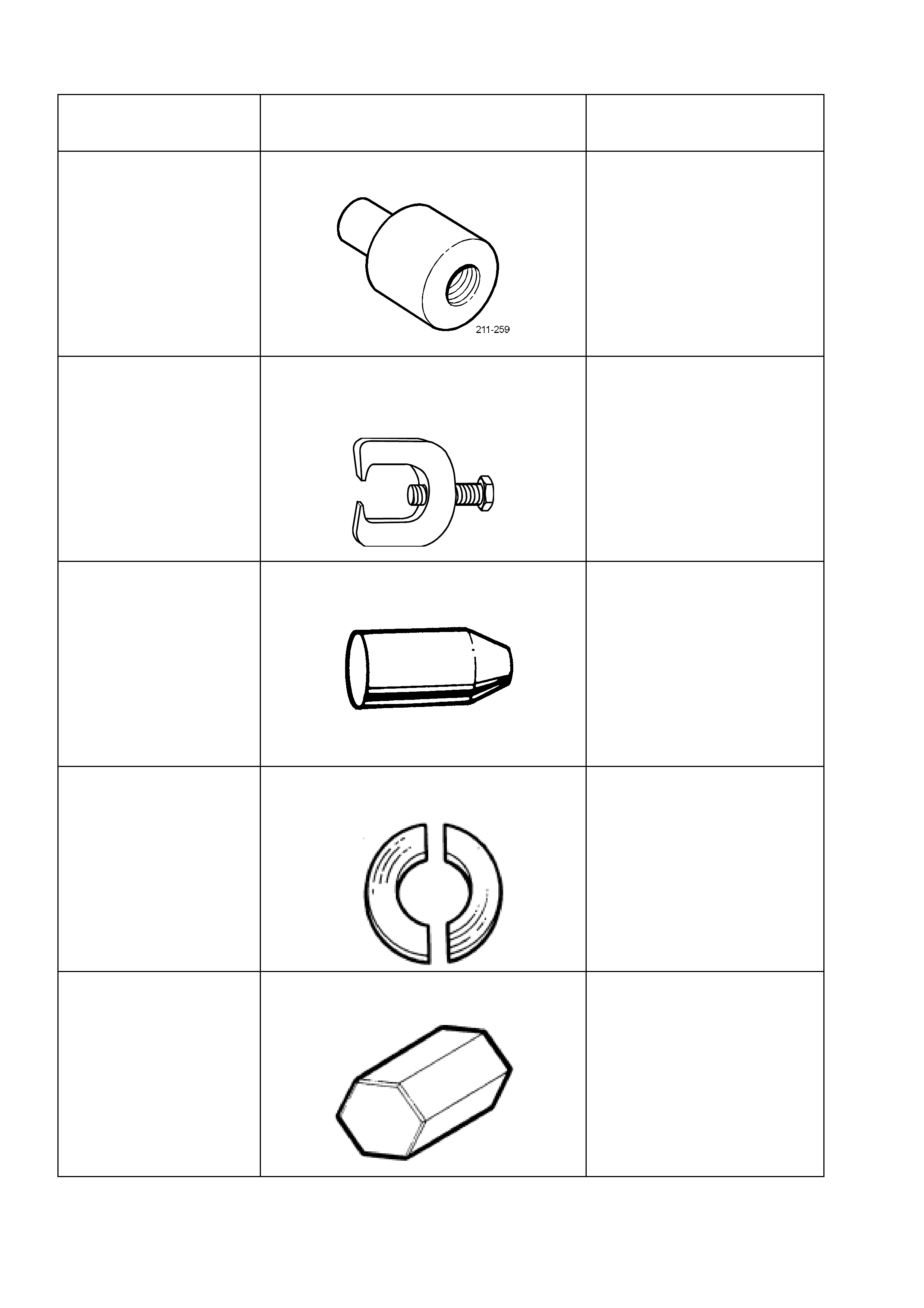
211-259 LOWER PINION BEARING REMOVER
New release.
Used in conjunction with Driver
Handle AU355-A.
9A10 STEERING LINKAGE BALL STUD
REMOVER
Previously released for ‘V’ car
9A23 EXPANDER - SLEEVE SEALS
Previously released for HQ/WB
Series vehicles.
AU188 PRESS PLATES
Previously released for ‘J’ car.
AU211-A RACK PAD ADJUSTING SCREW WRENCH Previously released for ‘J’ car,
Manual Steering.
TOOL No. REF.
IN TEXT TOOL DESCRIPTION COMMENTS
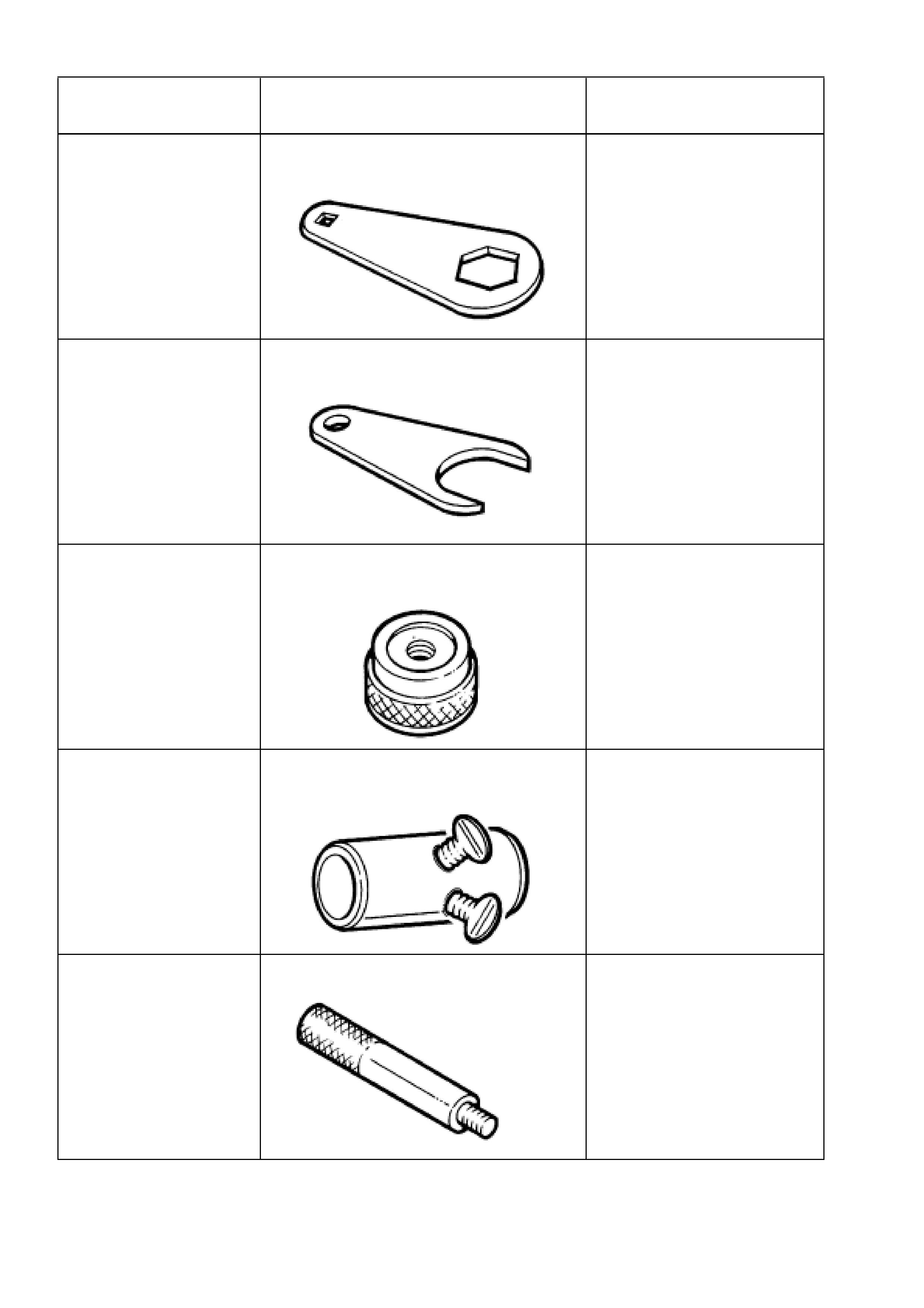
AU301 RACK PAD ADJUSTING SCREW LOCK
NUT WRENCH Previously released for ‘V’ car.
AU305 TIE ROD WRENCH
Previously released for ‘V’ car.
AU307 LOWER PINION BEARING INSTALLER
Previously released for ‘VP’
Series.
AU316 PRE-LOAD ADAPTOR
Previously released for ‘VP’
Series.
AU355-A DRIVER HANDLE
Previously released as KM523-
1 for ‘J’ series transaxle.
Used in conjunction with AU306
and AU315.
TOOL No. REF.
IN TEXT TOOL DESCRIPTION COMMENTS
AU392 PRESSURE HOSE SET Previously released.
Comprises:
AU392-1, hose with male end
fitting.
AU392-2, hose with female end
fitting.
AU440 CONTRACTOR - SLEEVE SEALS Previously released for ‘VR’
Series, speed sensitive
steering.
AU456 RACK SEAL PROTECTOR - LONG New release.
AU460 INSTALLER - INNER RACK SEAL AND
SPACER Previously released.
Used in conjunction with Driver
Handle AU355-A.
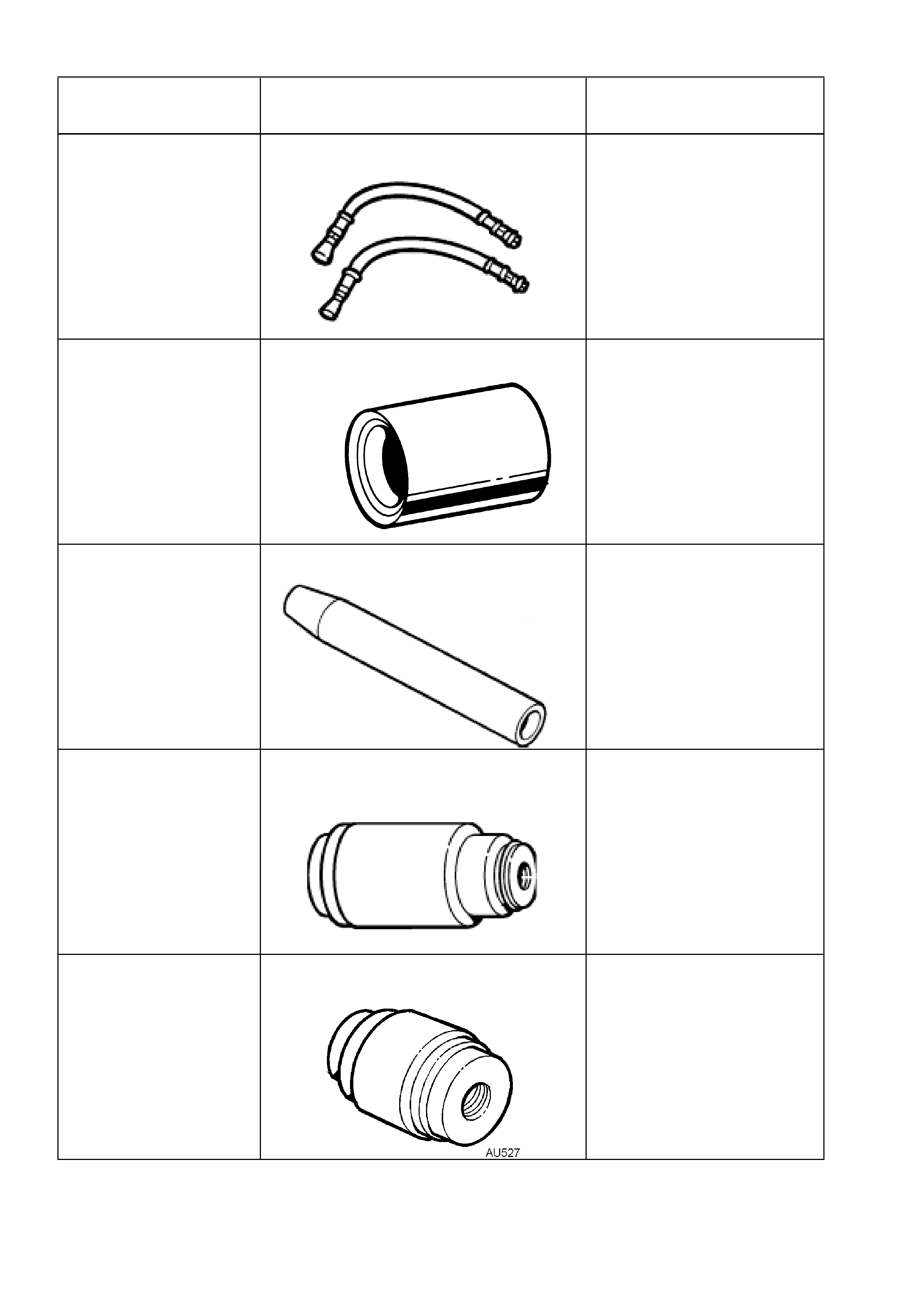
AU527 INTERMEDIATE PINION BEARING AND
OIL SEAL INSTALLER
New release.
Used in conjunction with Driver
Handle AU355-A.
TOOL NO. REF
IN TEXT TOOL DESCRIPTION COMMENTS
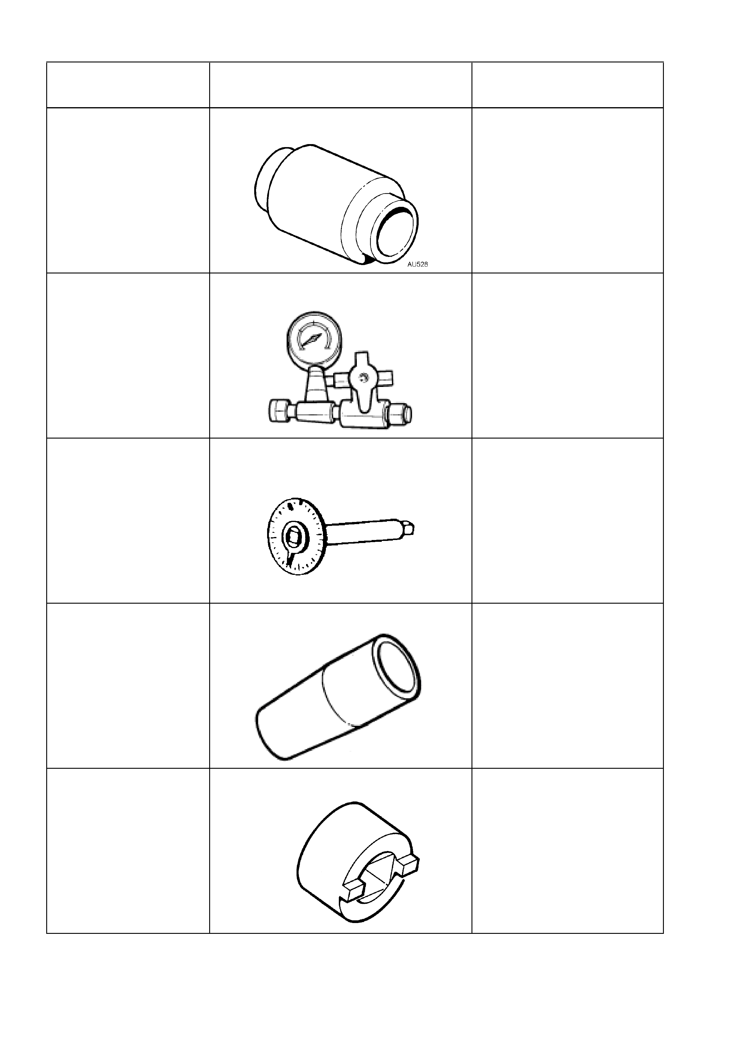
AU528 UPPER PINION BEARING AND OIL SEAL
INSTALLER
New release.
E1461-1 PRESSURE GAUGE ASSEMBLY
Previously released as J22912-
01
E7115 ANGLE WRENCH
Previously released as KM470
for ‘V’ and ‘J’ cars.
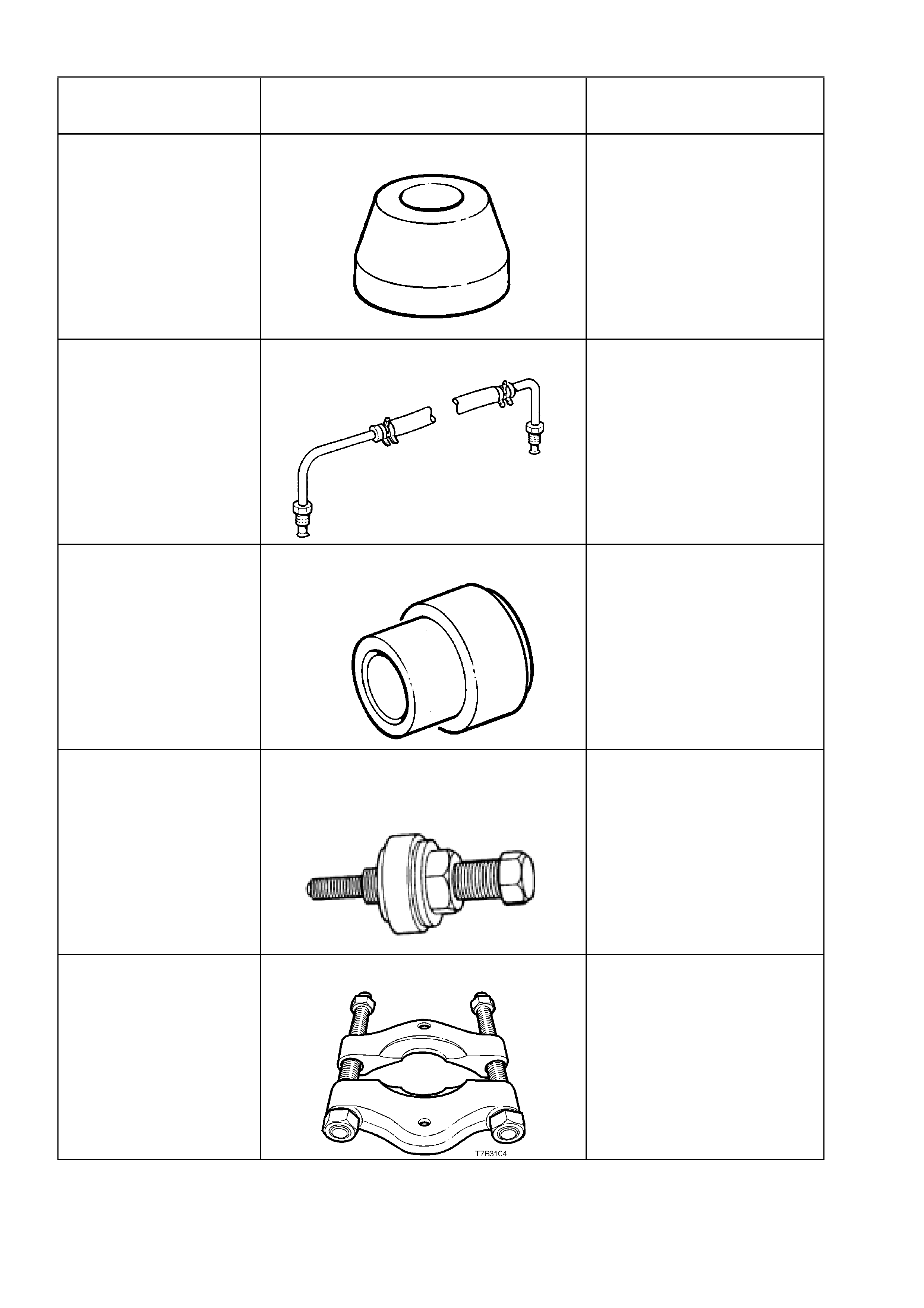
E8803-6 RACK SEAL PROTECTOR - SHORT New release.
E8803-7 RACK PISTON TOOL New release.
Used to rotate the end bushing
to remove/install retaining wire
clip.
TOOL NO. REF
IN TEXT TOOL DESCRIPTION COMMENTS
E8803-9 RACK PISTON SEAL EXPANDER New release.
Used to expand the rack piston
seal prior to installation.
E8803-10 RACK SEAL TEST ADAPTOR
New release.
Used in conjunction with hand
vacuum pump to assess rack
seal serviceability.
E8803-11 RACK END SEAL/BUSH INSTALLER New release.
Used to install rack end seal
and bush.
E9239A POWER STEERING PUMP PULLEY
INSTALLER
Previously released as J25033-
B for ‘J’ and ‘V’ cars.
J22912-01 PRESS PLATES
Previously released.
TOOL NO. REF
IN TEXT TOOL DESCRIPTION COMMENTS
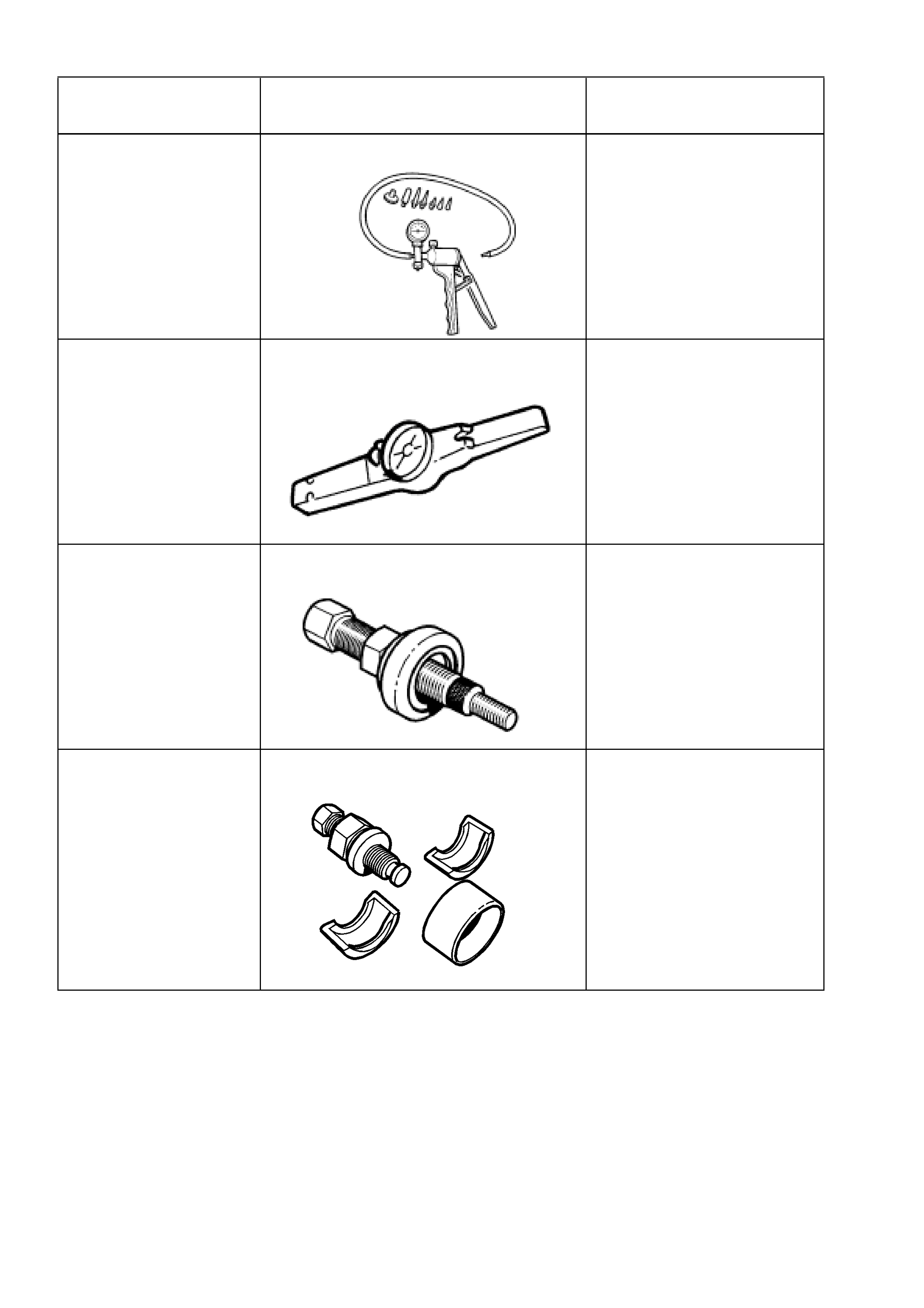
J23738-A HAND VACUUM PUMP Previously released or use
commercially available
equivalent.
J25765-A DIAL TYPE TORQUE WRENCH
Previously released for ‘LB’
Astra (transaxle), or use
commercially available
equivalent, capable of
measuring from 0.4 - 6.0 Nm.
7005 POWER STEERING PUMP PULLEY
INSTALLER
7185 POWER STEERING PUMP PULLEY
REMOVER