
SECTION 3 – FRONT SUSPENSION
CAUTION:
This vehicle will be equipped with a Supplemental Restraint System (SRS). A SRS will consist of either
seat belt pre-tensioners and a driver's air bag, seat belt pre-tensioners and a driver's and front
passenger's air b ags or seat belt pre- tensioners, driv er’s and front passenger’s air bag and left and right
hand side air bags. Refer to SAFETY PRECAUTIONS, Section 12M, Supplemental Restraint System of
this Service Information CD before performing any service operation on, or around any SRS
components, the steering mechanism or wiring. Failure to follow the SAFETY PRECAUTIONS could
result in SRS deployment, resulting in possible personal injury or unnecessary SRS system repairs.
CAUTION:
This vehicle may be equipped with LPG (Liquefied Petroleum Gas). In the interests of safety, the LPG
fuel system should be isolated by turning ‘OFF’ the manual service valve and then draining the LPG
service lin es, b efo re any serv ice work is carried o ut on th e v ehi cle. Refer t o t he L PG leaf let in clud ed with
the Owner's Handbook for details or the appropriate Section of this Service information CD for more
specific servicing information.
CAUTION:
Whenever any component that forms part of the ABS or ABS/ETC (if fitted), is disturbed during Service
Operations, it is vital that the complete ABS or ABS/ETC system is checked, using the procedure as
detailed in 4. DIAGNOSIS, ABS or ABS/ET C FUNCTION CHECK, in Section 12L ABS & ABS/ET C, in either
VT Series I Service Information (V6) or VT Series II Service Information (GEN III V8).
1. GENERAL DESCRIPTI ON
Introduced as a running change in the production of VT Series II vehicles, with a build date after August 12, 1999
and production serial number L 492505, the steering knuckle design and material was changed, which has also
resulted in a design change to the control arm ball joint. As a further result of the changed steering knuckle, the
taper angle of the steering rack outer tie rod ends has also changed.
The new/changed components will not service back to earlier build VT and VT Series II vehicles, unless the
following components are all changed as a group:
• Steering knuckle
• Control arm ball joint
• Outer tie rod end.
Planned for introduction in late January, 2000, the two front crossmember to side frame member bolts are to be
changed to incorporate a tapered boss at the head end to provide a self aligning feature for the front suspension
crossmember. This change affects the alignment procedure for the crossmember.
Only those ser vice pr ocedures af fec ted by the above changes, are descr ibed in this Section and s hould be ref erred
to for vehicles produced after the expected and stated breakpoint production serial number.
Introduced during the life of VT Series II production, minor changes to the front suspension alignment tolerance
range, results in an increased vehicle directional stability . Details are included in this Section.
Those service operations not described in this Section remain unchanged from the procedures detailed in
3. FRONT SUSPENSION, of the VT Series I Service Information and/or modified in 3. FRONT SUSPENSION of
the VT Series II Service Information.
The f ront suspension f itted to VT Series II m odels with the revised components, operates on the MacPherson strut
principle. The assembly consists of the front crossmember, control arms, tension rods, stabiliser bar and strut
assemblies (Refer to Fig. 3-1).
The c rossm ember is bolted to both longitudinal f rame s ide mem bers, while the inner pivots of the contr ol arms ar e
rubber bushed and are attached to the crossmember by bolts and nuts. The outer end of each control arm is
connected to the knuckle on the strut assembly through a ball joint tapered stud and nut.
The strut assembly incorporates a hydraulic wet sleeve type damper inside the strut tube, a rubber dust boot with
air filter and compression rubber, a coil type suspension spring mounted between the strut housing and upper
spring seat collar, a bearing assembly and an upper strut support.
The strut assembly is located at the upper end to the body structure by an upper strut support and secured by a
self-locking nut and locating disc, while the lower end of the strut tube is fastened to the steering knuckle by two
bolts and nuts.
Positioning of the control arm assemblies is controlled by tension rods connecting the control arms to the front
suspension crossmember. The tension rods are m ounted in a rubber bush at the control arm end and a fluid filled
damper at the other.
Techline
Techline

A stabiliser bar is mounted to the side members of the crossm ember by two brackets and insulating rubbers, and
attached to each strut tube by a spacer stud, insulating bushes, retainers and attaching nuts.
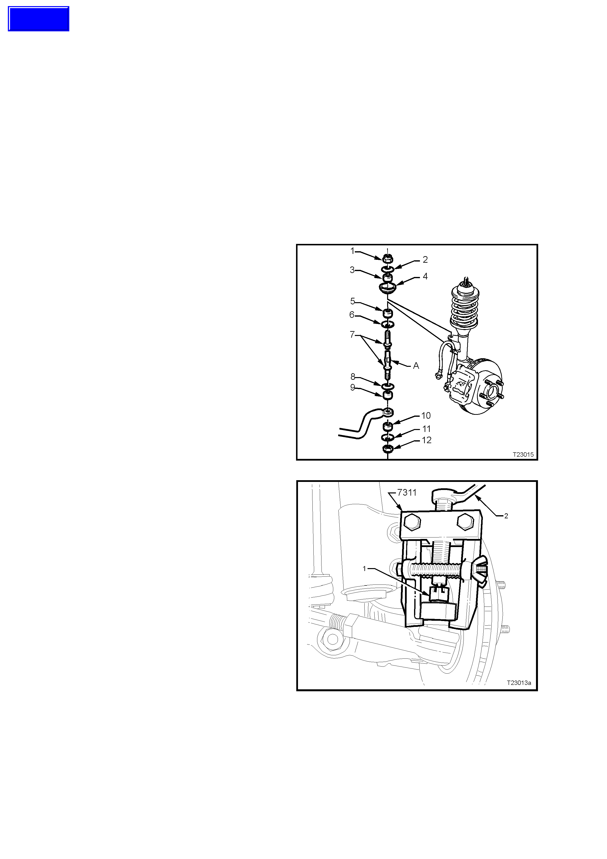
Legend for Fig. 3-1
Flattened end toward
stabiliser Stud to be held while nuts are
torqued to specification Fastener must be new and
assembled dry.
1. Nut (2 places) 12. Nut (2 places) 23. Nut (2 places)
2. Washer (2 places) 13. Nut (2 places) 24. Rod – Tension (2 places)
3. Bush (2 places) 14. Nuts (4 places) 25. Washer – Cupped (2 places)
4. Seat (2 places) 15. Insulator (2 places) 26. Control Arm – Lower (2 places)
5. Bush (2 places) 16. Bracket (2 places) 27. Washer (2 places)
6. Washer (2 places) 17. Bar – Stabiliser 28. Nut (2 places)
7. Spacer Stud (2 places) 18. Bolt (4 places) 29. Bolt (2 places)
8. Washer (2 places) 19. Nut (8 places) 30. Dust Cover (2 places)
9. Bush (2 places) 20. Nut (2 places) 31. Nut (2 places)
10. Bush (2 places) 21. Bush (2 places) 32. Locating Disc (2 places)
11. Washer (2 places) 22. Washer (1 place on driver’s
side ONLY) ‘A-A’ - Assemble washer ‘25’ as
shown
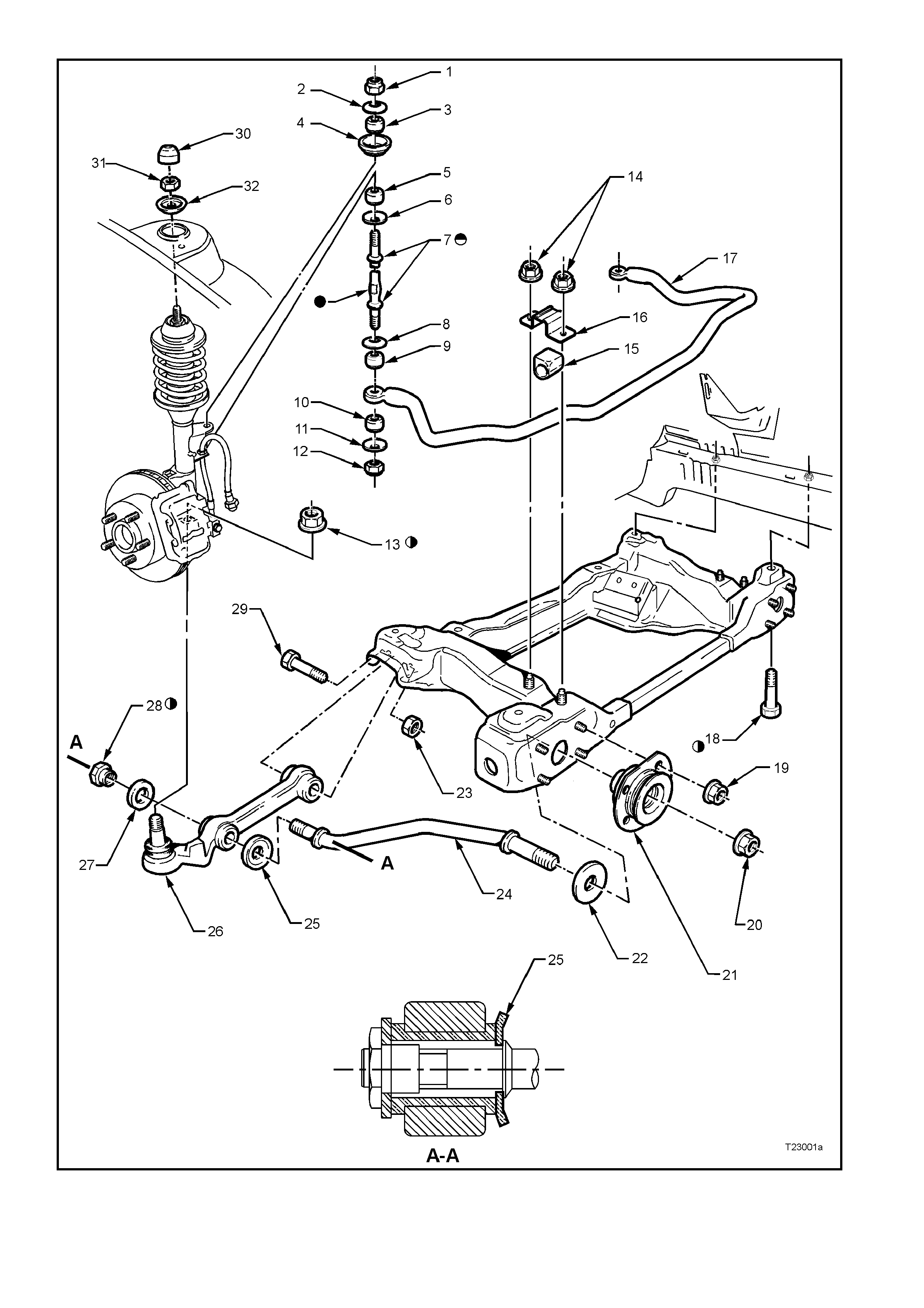
Figure 3-1
2. WHEEL ALIGNMENT
2.1 WHE EL ALIGNMENT CHECKING AND ADJUSTMENT
PRELIMINARY INSPECTION
Before any attempt is made to check camber,
caster or toe-in, these preliminary checks should
be carried out.
1. Check tyre and tyre mountings. Always check
cam ber and toe-in at the m ean r un-out position
on the tyre or rim.
2. Check and adjust tyre pressures to
recommended values.
3. Front wheel bearing end float is to be checked
to ensure it is within specification, as detailed
in 2.4 FRONT WHEEL BEARING HUB - END
FLOAT CHECKING PROCEDURE, FRONT
SUSPENSION, of the VT Series I Service
Information.
4. Control arm ball joints and inner bushes should
be checked for wear.
5. Check steering gear mounting bolts for
tightness and tie rod ball joints for wear.
6. The vehicle should be at curb weight, fuel tank
full, without driver, passengers or luggage etc.
7. Check for improperly operating front struts or
rear shock absorbers.
8. Check for loose or missing stabiliser bar or
tension rod attachments.
9. Before checking the front wheel alignment,
refer to 4A REAR SUSPENSION of the VT
Series I Service Information for rear wheel
alignment details.
CASTER ADJUSTMENT
W hile one bright f inished spaced washer (6) will be
fitted to the driver’s s ide tension rod (5), the f itment
of an additional washer is permitted to correct
minor caster adjustments
Only one spacer washer is to be fitted and is to be
added to the side with the higher caster reading.
Figure 3-2
Techline
CAMBER ADJUSTMENT
1. Raise front of vehicle and support on safety
stands under front side members. Refer to
Section 0A GENERAL INFORMATION of the
VT Series I Service Information for location of
jacking and support points.
2. Remove wheel cover (steel wheels) or centre
cap (alloy wheels) and mark relationship of
wheel to hub stud, using a felt tipped pen or
similar.
3. Remove wheel attaching nuts and remove
wheel.
4. Loosen, remove and discard the two lower
strut attaching bolts and nuts (2).
Reinstall NEW lower strut attaching bolts and
nuts (2) but do not tighten fully to
specification until after the camber has been
adjusted to the recommended specification.
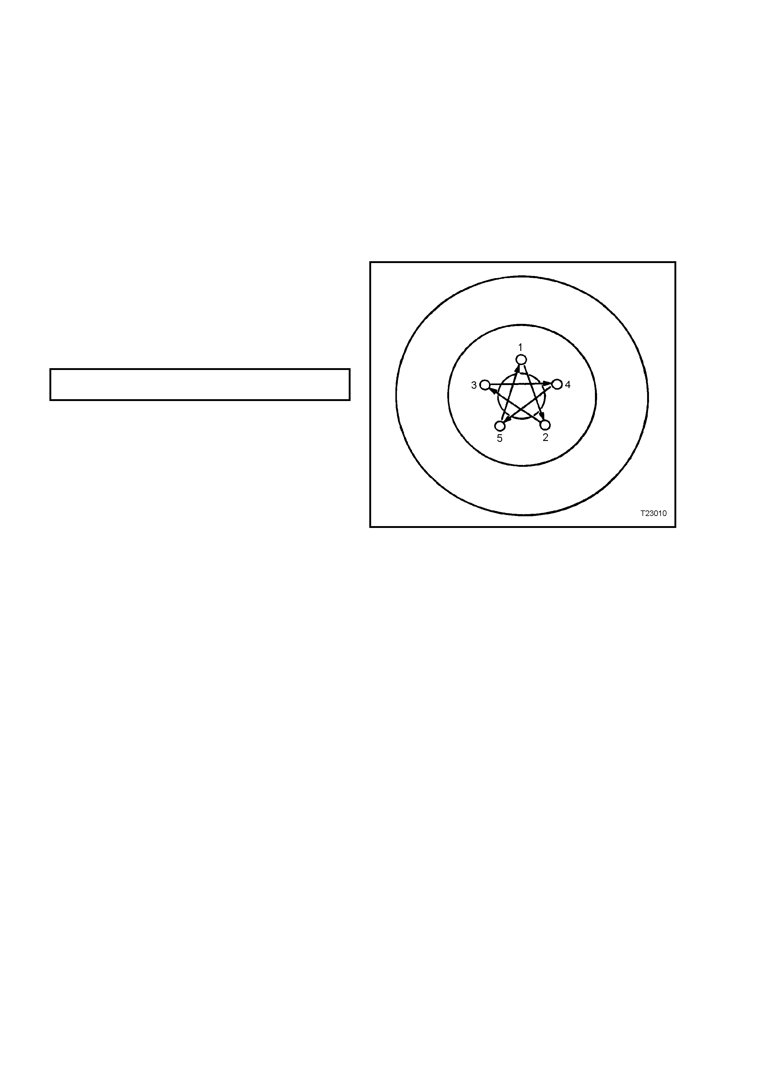
5. Reinstall road wheel, aligning previously made
marks. Install wheel nuts and tighten to the
correct torque specification, working in a ‘star’
pattern. Do not over-tighten!
ROAD WHEEL ATTACHING NUT 110 - 140
TORQUE SPECIFICATION Nm
6 Lower the vehicle to the ground and bounce
vehicle several times to settle suspension.
Figure 3-3
7. Check the camber angle.
8. If required, adjust camber by turning the
camber adjusting screw (1) in the required
direction; clockwise to reduce negative
camber, anti-clockwise to reduce positive
camber.
NOTE: The camber adjusting screw has thread
sealant applied in the form of micro-encapsulation
and does not require a lock nut.
9. Raise vehicle once again, support on safety
stands and remove the front road wheels.
10. Tighten both steering k nuckle bolts and nuts to
the correct torque specification.
NOTE: New bolts and nuts MUST be used!
STEERING KNUCKLE TO STRUT Stage 1 85 Nm
ATTACHING BOLTS & NUTS Stage 2 100 Nm
TORQUE SPECIFICATION Stage 3 Turn
through 90°
11. Reinstall road wheels, aligning the marks
made prior to removal.
12. Remove jack stands and lower vehicle.
13. Install wheel nuts and tighten to the correct
torque specification, working in a ‘star’ pattern.
Do not over-tighten!
ROAD WHEEL ATTACHING NUT
TORQUE SPECIFICATION 110 - 140 Nm
14. Refit wheel cover/centre cap.
15. Check the c amber angle again to ensure that it
is still within specification (refer to Fig. 3-6).
TOE ADJUSTMENT
Toe of both front wheels, is checked with the
wheels in the straight ahead position.
Adjustm ent is achieved by winding the tie rods in or
out of the tie rod ends, thus increasing or
decreasing their length and thereby altering the
toe-in setting.
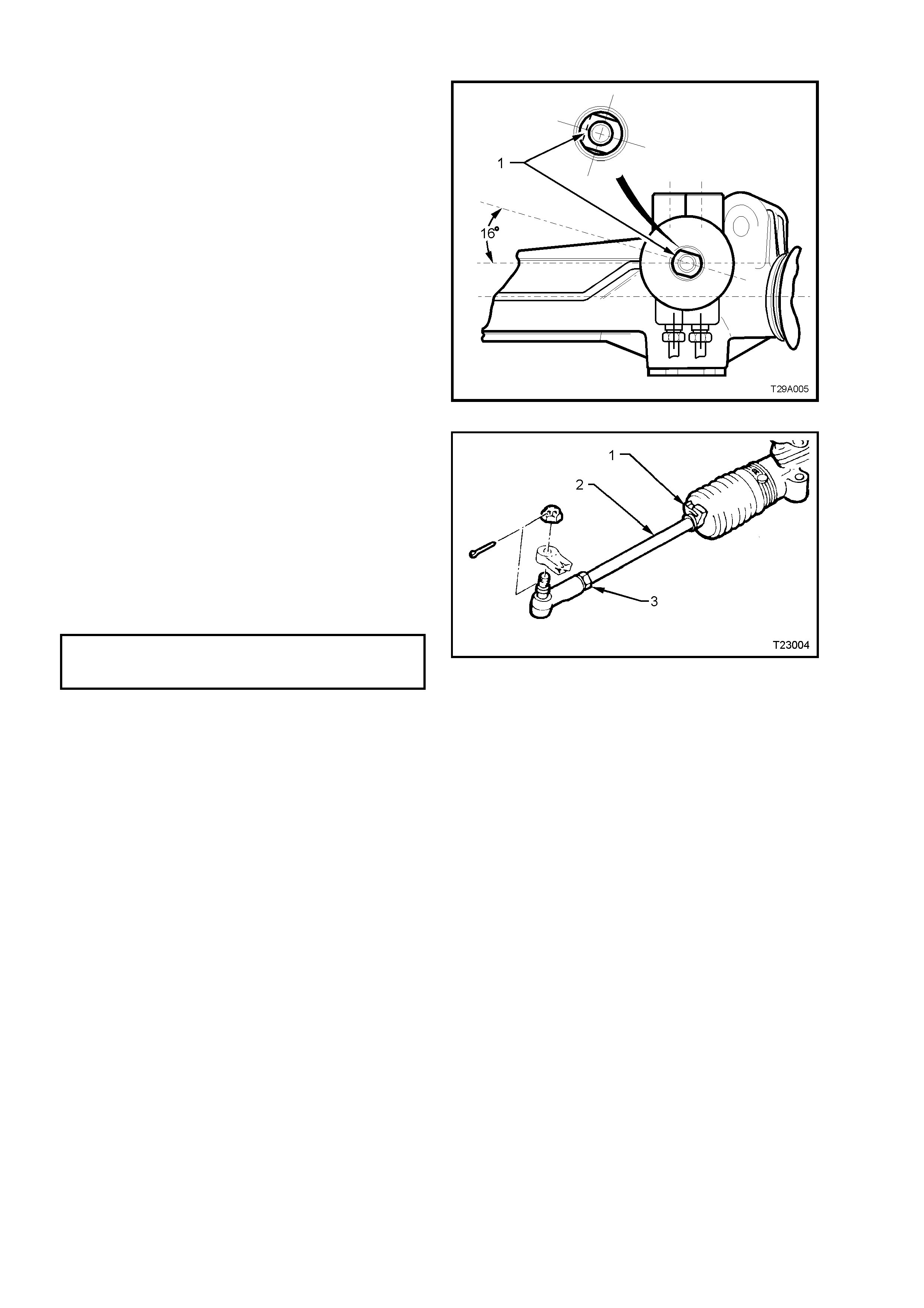
1. Set steering gear and wheels in straight ahead
position.
2. To check if steering gear is in straight ahead
position (on-centre), the pinion (input) shaft (1)
should be aligned as shown.
NOTE: While the one-piece steering rack housing
is shown, the on-centre position is the same for all
steering racks.
Figure 3-4
3. Before adjusting tie rods (2), disconnect
steering gear outer bellows clips (1).
4. Loosen lock nut (3) at end of each tie rod.
5. Turn each tie rod as required, until the correct
toe is obtained.
NOTE: During toe adj ustment, ensur e that steering
wheel is held in the straight ahead position.
6. Tighten lock nuts (3), to the correct torque
specification, ensuring that tie rod ends are in
alignment with their ball studs.
TIE ROD TO TIE ROD BALL
JOINT LOCK NUT 40 – 60 Nm
TORQUE SPECIFICATION
7. Tighten outer bellows clips securely, making
sure that convolutions of the boots are not
distorted.
Figure 3-5
8. With steering gear in straight ahead position,
ensure that st eering wheel is c entralis ed. If not,
remove steering wheel (refer to
Section 9 STEERING of the VT Series I
Service Information) and reposition.

FRONT WHEEL ALIGNMENT AT KERB WEIGHT
Wheel Alignment Angle Specification – All Sedan and Station Wagon
Camber -0° 12' ± 0° 18'
Caster 7° 45' ± 1° 15'
Toe-in Degrees Total 0° 10’ ± 0° 10'
Degrees per Wheel 0° 5’ ± 0° 5’
Toe-out on Turns 1° 42’ @ 20 ° turn angle ± 1° 30'
Steering Axis Inclination Angle 12° 52’ ± 1° 30'
Included Angle 12° 40’ ± 1° 30'
SERVICE INFORMATION
• The adjusting values for camber, caster and toe-in must remain
within the tolerances specified. The difference between left and
right must not exceed the following:
CASTER ............ 0° 36'
CAMBER ........... 0° 48'
TOE-IN............... 0° 10'
• The specifications listed are the nominal value, with acceptable
variance from this c entral point. Wher e poss ible, an attempt should
always be made to achieve the nominal settings when changing.
• Front wheel camber alters as a function of front suspension height.
• Camber adjusting bolt: After loosening both lower strut to steering
knuc kle bolts and nuts, adjust c amber by turning the adjusting bolt
clockwise to decrease negative camber and anti-clockwise to
increase negative camber. After adjustment, both bolts and nuts
MUST be replaced with new parts and tightened to the
recommended torque setting.
• The rear wheel alignment should be checked and corrected if
necessary (refer to Section 4. REAR SUSPENSION in Volume 1)
before checking front wheel alignment.
Fuel Mass with Full Tank - All Models 56 kg
Figure 3-6
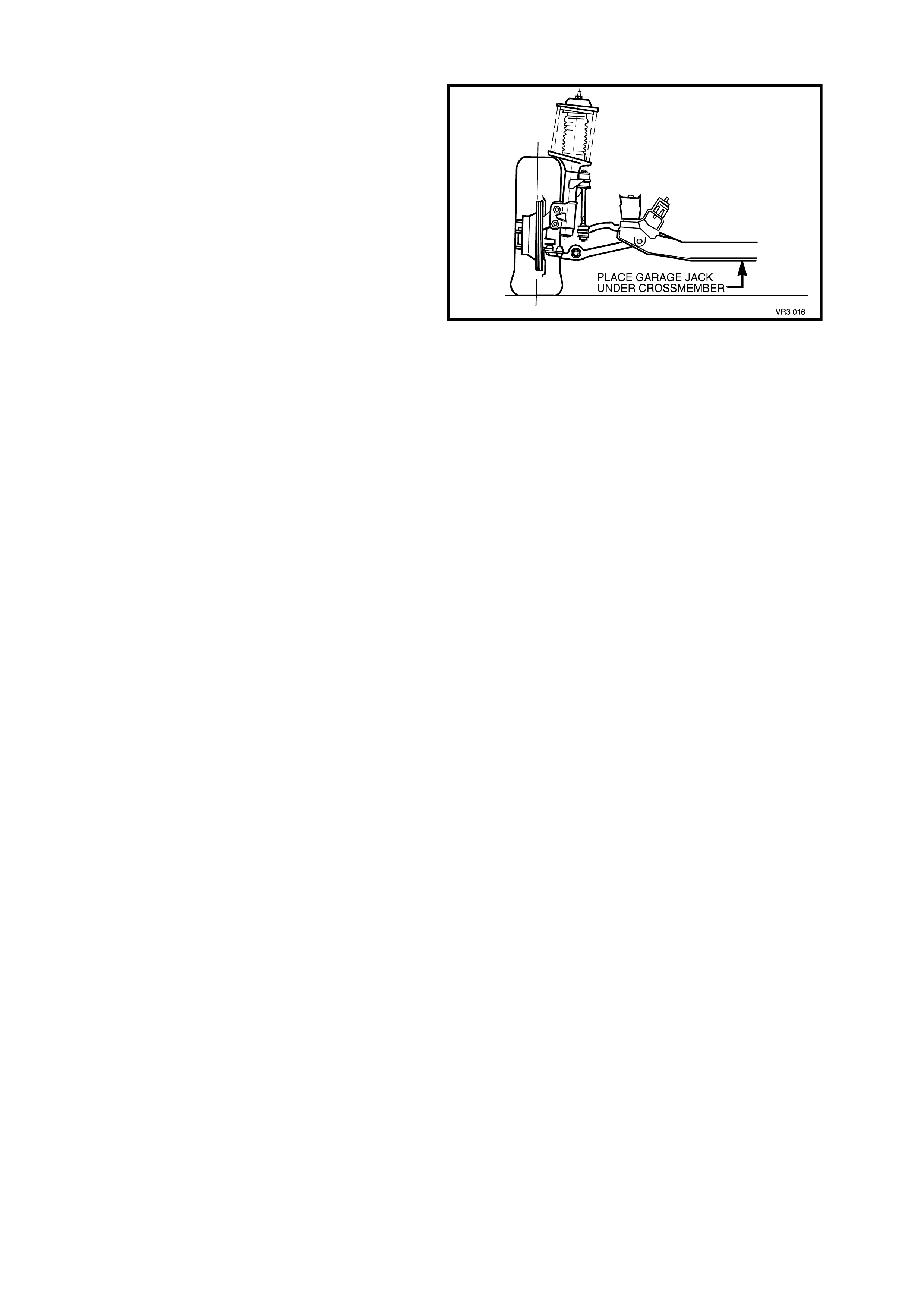
2.2 JACKING PRECAUTIONS
When raising the front of the vehicle with a jack,
the jack should be placed under the front
crossmember. THE WEIGHT OF THE VEHICLE
MUST NOT BE LIFTED UNDER THE CONTROL
ARMS.
When the vehicle is raised on the jack, it must be
firm ly supported on safety stands located under the
fram e s ide m embers before any work is attem pted.
If a vehicle is not correctly supported by safety
stands, serious injury can result if the vehicle
should slip off the jack.
Figure 3-7
3. SERVICE OPERATIONS
3.1 GENERAL
IMPORTANT SERVICE REQUIREMENTS
NOTE 1: Whenever a road wheel and/or brake
disc is removed from the vehicle, the relationship
of the road wheel to the hub and the disc to the
hub MUST be marked with a felt tipped pen or
similar, in order for those parts to be reinstalled in
their original positions. This is critical to maintain
the brake disc and road wheel runout dimension to
a minimum.
NOTE 2: When reinstalling road wheels, do not
use an impact gun to tighten wheel nuts, unless it
is fitted with a torque limiter socket (Tool AU534).
Failure to correctly tighten wheel nuts to the correct
torque specification and in the correct order, may
result in a distorted brake disc, that may lead to the
development of brake shudder.
ROAD WHEEL ATTACHING NUT
TORQUE SPECIFICATION 110 – 140 Nm
Figure 3-8

3.2 FRONT WHEEL HUB AND STEERING KNUCKLE
As stated in 1. GENERAL DESCRIPTION, the new knuckle will only service back to earlier ‘V’ series vehicles, if
the following components are all changed as a group:
• Steering knuckle
• Control arm ball joint
• Outer tie rod end.
Apart fr om wheel stud replacem ent, ther e are no ser viceable item s in the front wheel hub assem bly. As the unit is a
‘sealed for life’ assembly, neither bearing adjustment nor lubrication maintenance is required. Should a non-
standard condition develop, then the assembly must be replaced as a complete unit.
As with the earlier design hub, this design has zero axial free play or ‘end float’ but some angular movement may
be evident when a rocking force is applied to the mounted wheel and tyre assembly. Before a hub is replaced for
an excessive free play condition, refer to the checking procedure, detailed in Operation 2.4 in 3, FRONT
SUSPENSION, of the VT Series I Service Information.
Techline
3.3 SUSPENSION & TRIM HEIGHT, CHECK
The suspension and trim height dimensions for standard vehicles with base equipment only, are provided in
5. SPECIFICATIONS in this Section.
The dimensions are for a new vehicle built to standard specification and only intended as a guide when
check ing suspens ion and trim height dim ensions at norma l curb weight. Norm al curb weight is defined as a vehicle
with a full tank of fuel, all fluids at the specified levels, spare tyre included, tyre pressures as specified and no
passengers. Accumulated dirt, mileage, etc., must also be taken into consideration when checking vehicle heights.
The following procedure should be followed before checking any suspension or trim height.
1. All c hec ks must be c ar ried out on a LEVEL s ur f ac e, af ter the vehic le's tyre pressures have been c hec k ed and it
has been confirmed that the vehicle has not suffered accident damage.
2. On average, all VT Series II vehicles will sit approxim ately 4 mm lower at the right hand side front, because of
the vehicle's battery weight.
3. Push vehicle up and down several times at the front bumper bar with a decreasing force and then gently
remove hands, allowing vehicle to settle on its own. Carry out vehicle front trim and suspension height check.
4. Push vehicle up and down several times at the rear bumper bar with a decreasing force and then gently
remove hands, allowing vehicle to settle on its own. Carry out vehicle rear trim and suspension height check.
As shown in the specification listing (refer to 5. SPECIFICATIONS in this Section), there are two different
dimensions that must be checked and the location for the measurements to be taken is critical to correctly
establishing a st andard vehicle condition. When chec king a vehicle's r ide height, the following tolerances must also
be taken into account, before any spring is replaced.
RIDE HEIGHT VARIATIONS FROM SPECIFICATION
FRONT TO REAR..............................± 20 mm
SIDE TO SIDE ...................................± 10 mm
NORMAL SPRING SETTLING ..........± 5 mm
NOTE: Ride height variation may also be due to any one or a combination of the following:
a. Spring seat location on the suspension/body.
b. Incorrect springs; Check spring identification against the table shown in 5. SPECIFICATIONS in this
Section.
c. Non-standard, additional vehicle weight, such as a tow bar and/or after-market LPG fitment.
d. Any combination of the above.
CAUTION: Good judgement must be exercised before replacing a spring or springs from a vehicle whose
height is within the limits quoted. Even should a vehicle's dimensions prove to be slightly outside these
tolerances, the vehicle could well be in a serviceable condition.
Spring replacement under conditions of excessive weight due to non standard fittings, undercoating, road
dirt, etc; will assist very little in restoring the vehicle to its specified height.
3.4 FRONT WHEEL HUB, BRAKE DISC OR BRAKE SHIELD
NOTE 1: Apart f rom wheel stud r eplacem ent, there
are no serviceable items in the front wheel hub
assembly. As the unit is a 'sealed for life'
assembly, neither bearing adjustment nor
lubrication maintenance is required. Should a non-
standard condition develop, then the hub ass embly
must be replaced as a complete unit.
NOTE 2: While the front wheel hub is designed to
have zero axial free play or ‘end-float’, some
angular m ovement m ay be evident when a rock ing
force is applied to the mounted wheel and tyre
assembly. Before a hub is replaced, refer to
check ing procedur e, detailed in Operation 2.4 in 3.
FRONT SUSPENSION, of the VT Series I Service
Information.
REMOVE
1. Raise front of vehicle and support on safety
stands. Observe jacking precautions as
outlined in 2.2 JACKING PRECAUTIONS in
this Section.
2. Remove wheel cover (steel wheels) or centre
cap (alloy wheels).
3. Mark relationship of road wheel to hub or brake
disc. Loosen then remove road wheel
attaching nuts. Remove the road wheel.
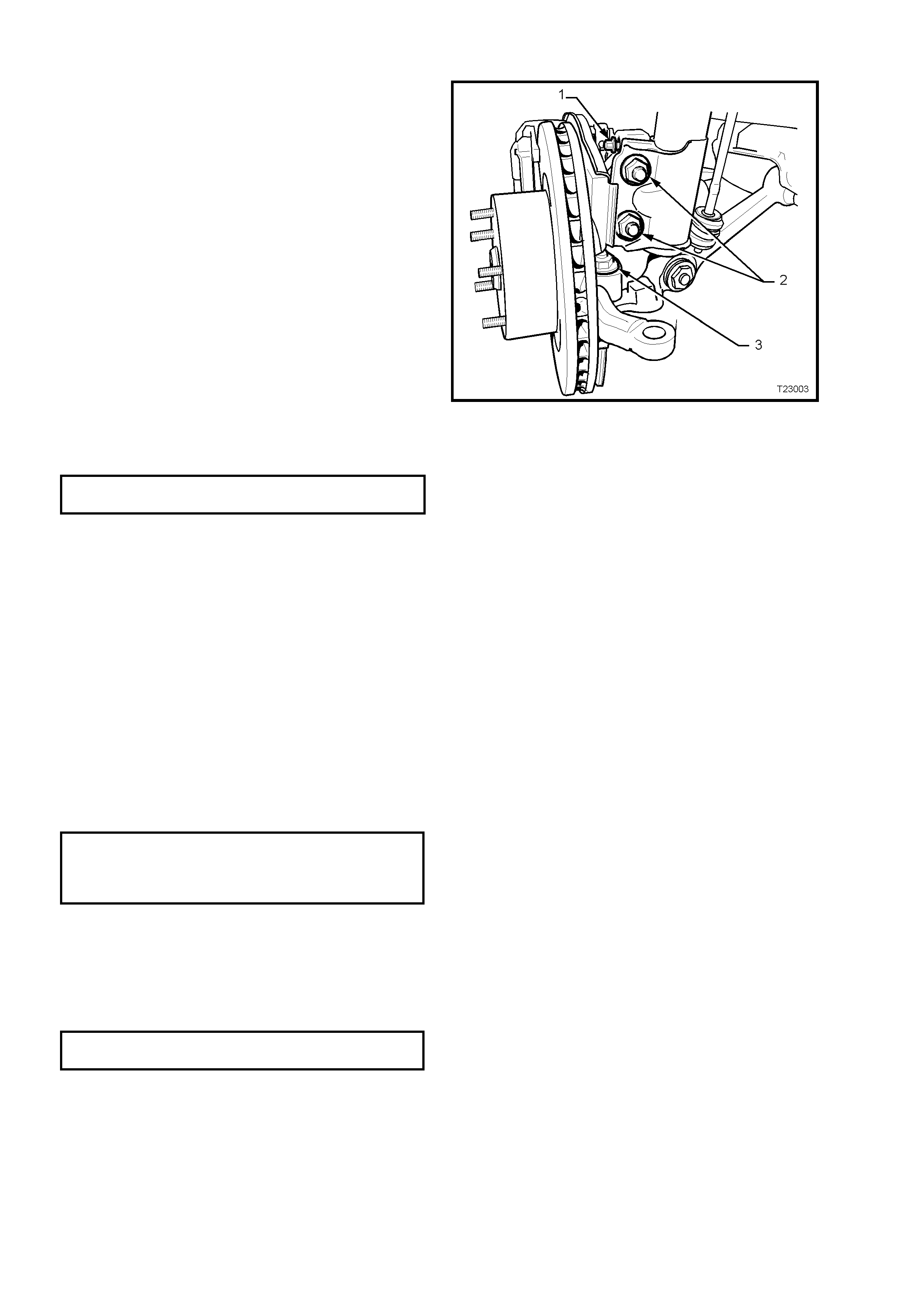
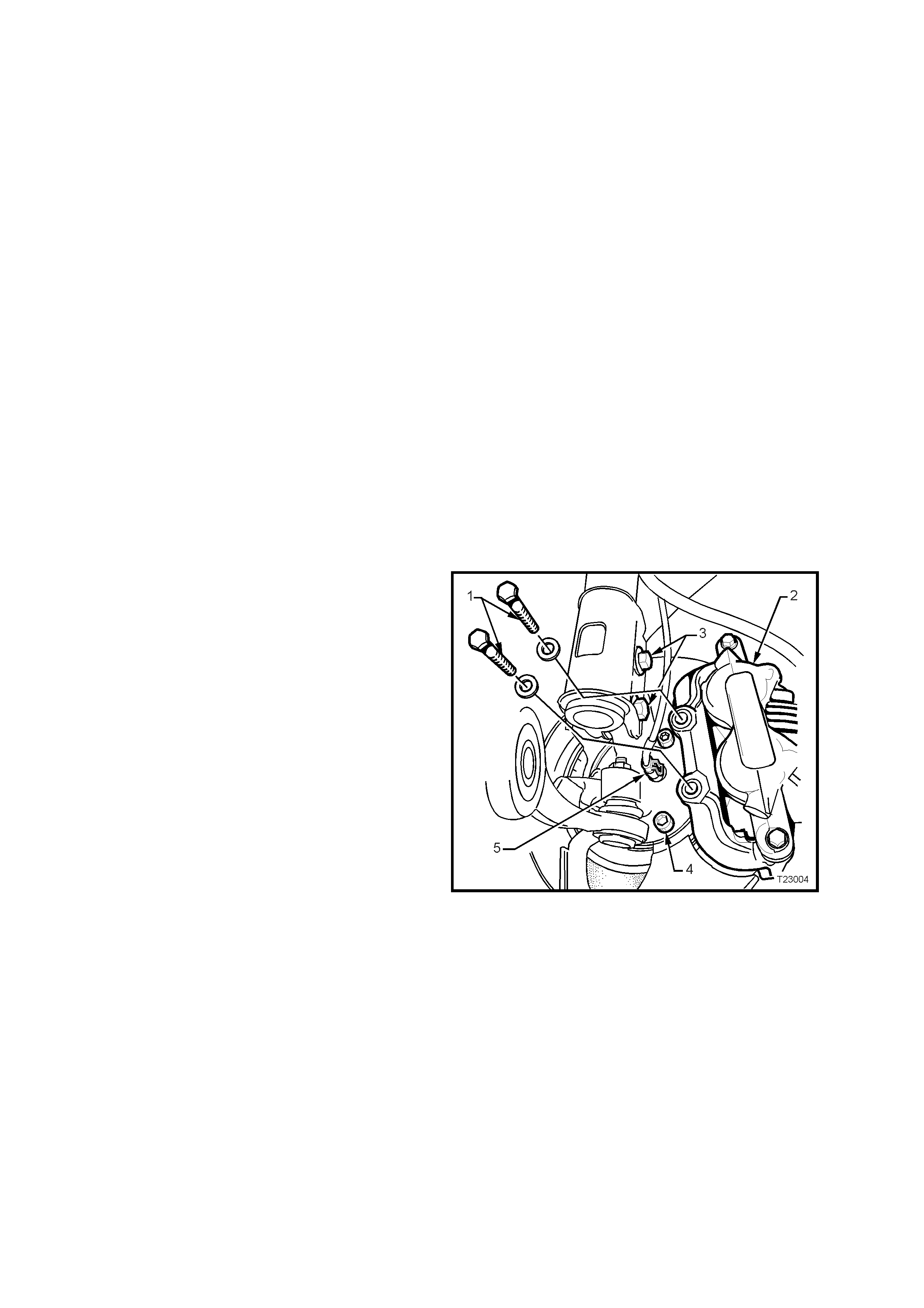
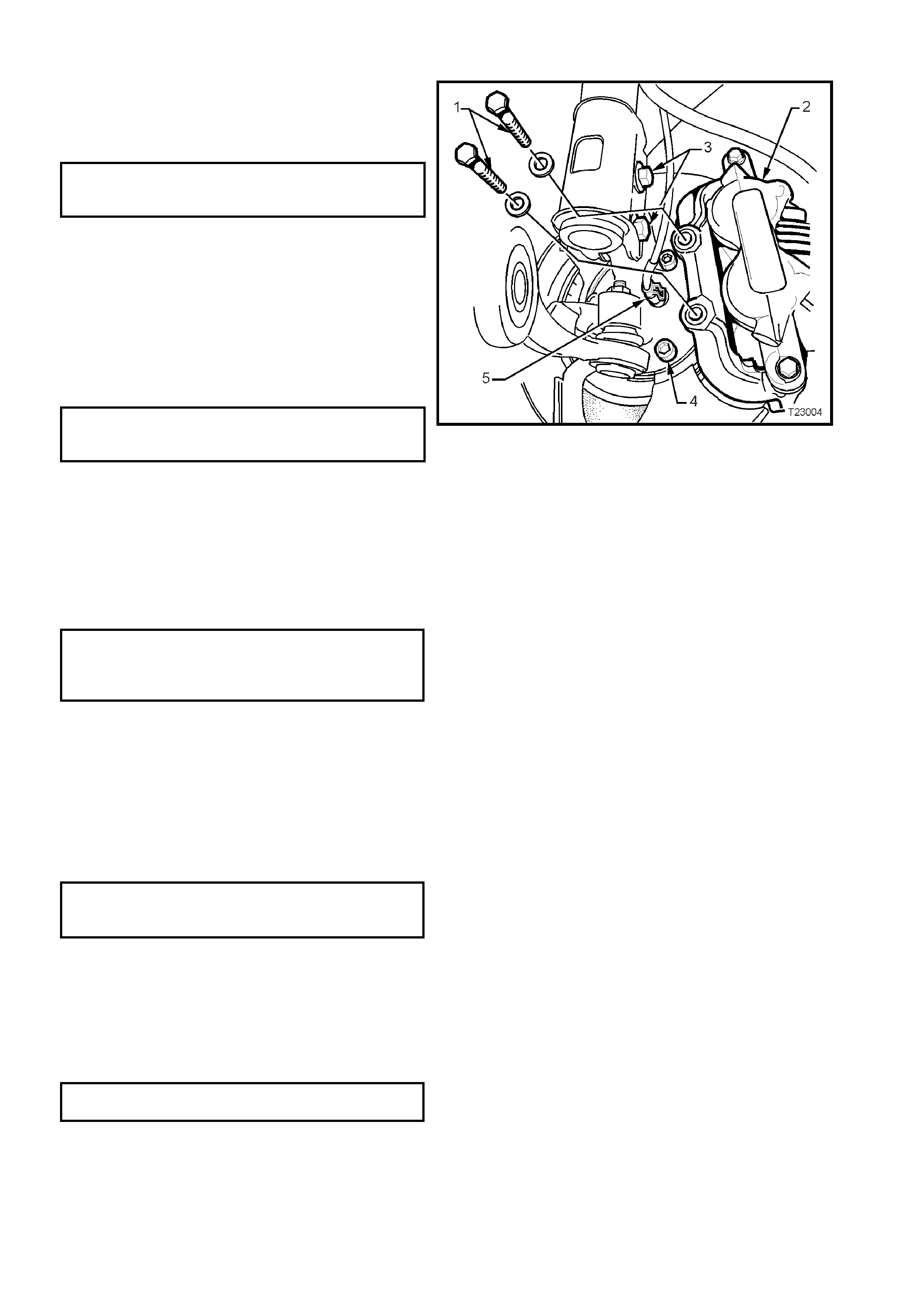
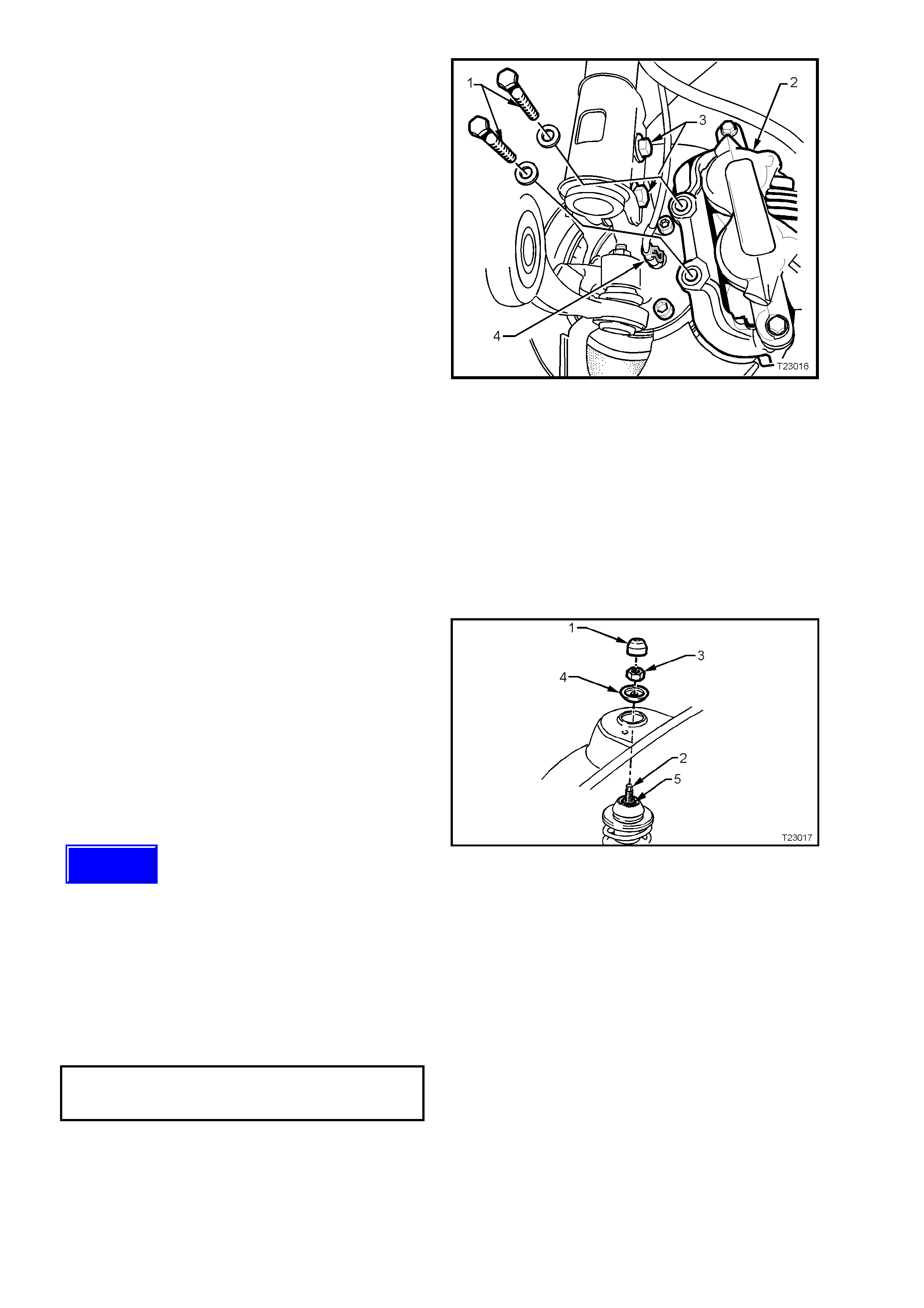
4. Remove brake caliper anchor plate retaining
bolts and washers (1), lift caliper assembly (2)
from brake disc. Position caliper (2) in such a
way that no strain is placed on the brake hose.
If necessary, tie caliper to the suspension
spring with a piece of wire. THE CALIPER IS
NOT TO HANG BY BRAKE HOSE.
5. W hile the brake disc to hub location is marked
in production, ensure that the disc to hub
position is carefully marked.
NOTE: This is necessary to overcome the
possibility of inducing a brake shudder condition
after reassembly.
6. Remove brake disc from the wheel bearing
hub.
NOTE: For vehicles equipped with ABS,
disconnect the wheel speed sensor connector (5)
from the hub sensor connector, by lifting the
connector locking tab and pulling on the connector
to disconnect.
7. Using a commercially available 10 mm Allen
key socket and a suitable socket bar, loosen
each of the three bolts (4) holding the hub to
the steering knuckle.
NOTE 1: If the Allen key socket is too long to fit
into the front, upper hub bolt, then the lower strut to
steering knuckle nut (and bolt) will need to be
loosened and removed. Discard the removed bolt
and nut, as they must be replaced on reassembly.
NOTE 2: For the front lower hub bolt, turn wheel
outwards to provide sufficient clearance.
Figure 3-9
8. If the hub is a tight fit to the knuckle, it may be
necessary to loosen the three loosened bolts
and tap on the heads. DO NOT STRIKE THE
HUB.

9. Remove the three bolts and then the hub from
steering knuckle.
10. If rem oval of the brak e s hield is neces sary, drill
the heads from the three rivets securing the
shield to the steering knuckle support.
11. After shield removal, carefully drill out the
remainder of the rivets, using a suitable sized,
sharp drill.
INSPECT
1. Check wheel studs to ensure threads are not
damaged, and that studs are pressed firmly
into the front wheel hub.
If one or more wheel studs require
replacement, refer to operation
3.3 FRONT HUB WHEEL STUD of the VT
Series I Service Information, for details.
2. Examine brake disc for scores or damage. If
either of these conditions exist, the brake disc
should be machined. Refer to
Section 5A BRAKES of the VT Series II
Service Information for details.
3. Check for damage to the shield that m ay cause
fouling of any rotating parts and if suspect, the
shield should be replaced.
REINSTALL
Reinstallation of the fr ont wheel hub and brak e dis c
is the reverse of removal procedures, except for
the following points:
All Models:
1. If the brake shield has been removed, install
three, common pop rivets (1), using a
commercially available pop rivet gun.
NOTE: Install the first rivet in the brake shield hole
with the round hole. This will ensure that the
clearance to brake caliper is correct.
2. Before installing the hub, inspect both mating
surfaces to make sure that they are clean and
free from burrs that could prevent correct
alignment of both parts, once installed.
Figure 3-10
Without ABS:
3. Install the hub assembly to the steering
knuckle.
4. Install the three attaching bolts (4) and tighten
to the correct torque specification.
FRONT HUB TO STEERING
KNUCKLE ATTACHING BOLT 100 - 115 Nm
TORQUE SPECIFICATION
NOTE: The three hub attaching bolts are micro-
encapsulated with thread sealant and are not to be
re-used more than three times. If in doubt, the bolts
should be replaced.
WITH ABS:
5. Carefully align the sensor connection on the
hub, with the hole in the steering knuckle, then
install the three hub attaching bolts (4) and
tighten to the correct torque specification.
FRONT HUB TO STEERING
KNUCKLE ATTACHING BOLT 100 - 115 Nm
TORQUE SPECIFICATION
6. Fit the wheel speed sensor connector (5),
ensuring that the locking tang is in place.
ALL MODELS:
7. If removal of the lower strut to steering knuckle
bolt and nut (3) was necessary, the bolt and
nut, must be replaced with new parts. Tighten
the bolt and nut to the correct torque
specification.
Figure 3-11
STEERING KNUCKLE TO STRUT Stage 1 85 Nm
ATTACHING BOLTS & NUTS Stage 2 100 Nm
TORQUE SPECIFICATION Stage 3 Turn
through 90°
8. Reinstall brake disc, aligning the marks made
before removal.
NOTE: If the hub was replaced, then runout
checks must be carried out on the installed brake
disc. Refer to 5A STANDARD BRAKES, of the VT
Series II Service Information for important
information regarding these checks.
9. Reinstall the brake caliper and attaching bolts,
tightening bolts to the correct specification.
BRAKE CALIPER ANCHOR 80 - 90 Nm,
PLATE RETAINING BOLTS then turn through
TORQUE SPECIFICATION 40° - 50°
10. Reinstall road wheel, aligning the marks made
prior to removal and secure with the attaching
nuts.
11. Remove jack stands and lower vehicle.
12. Tighten road wheel attaching nuts to correct
torque specification, working in a ‘star’ pattern,
as indicated in Fig. 3-8, in this Section.
ROAD WHEEL ATTACHING NUT
TORQUE SPECIFICATION 110 – 140 Nm
13. Refit wheel cover/centre cap.
CAUTION:
Whenever any component that forms part of the ABS or ABS/ETC (if fitted), is disturbed during Service
Operations, it is vital that the complete ABS or ABS/ETC system is checked, using the procedure as
detailed in 4. DIAGNOSIS, ABS or ABS/ETC FUNCT ION CHECK, in Section 12L ABS & ABS/ET C, VT Series I
Service Information (V6) or VT Series II Service Information (GEN III V8).
4. MAJOR SERVICE OPERATIONS
4.1 FRONT STRUT ASSEMBLY
REMOVE
1. Raise front of vehicle and support on safety
stands. Observe jacking precautions as
outlined in 2.2 JACKING PRECAUTIONS in
this Section.
2. Remove wheel cover (steel wheels) or centre
cap (alloy wheels).
3. Mark relationship of road wheel to hub or brake
disc. Loosen then remove road wheel
attaching nuts. Remove road wheel.
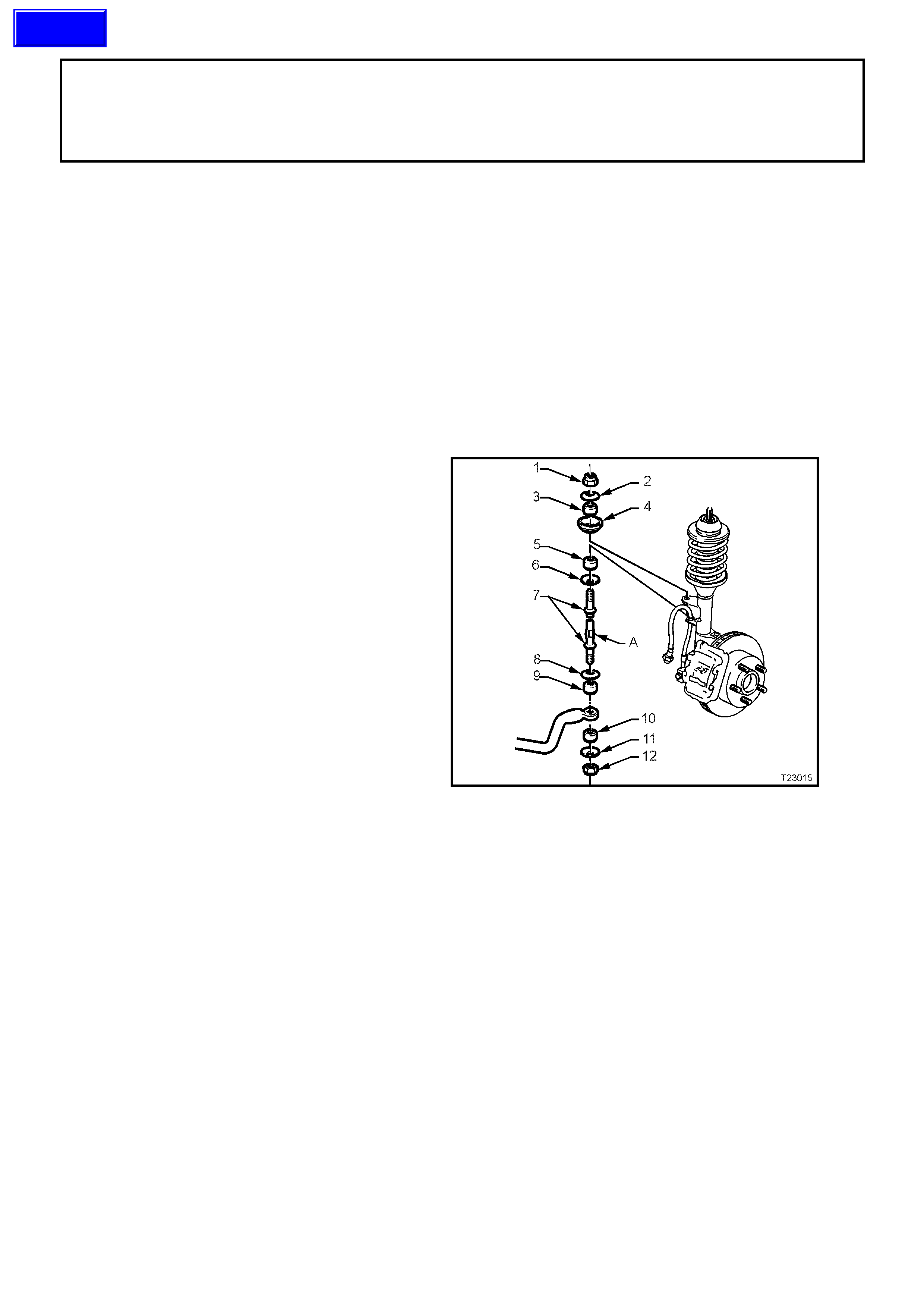
4. Position a suitable size open end spanner over
flat ‘A’ in stabiliser bar spacer stud (7), remove
upper nut (1), washer (2), bush (3) and seat
(4).
5. If the vehicle is fitted with ABS, disconnect the
wheel speed sensor cable by pulling the
insulator from the strut bracket.
Figure 3-12
Techline
6. Remove the brake caliper anchor plate
retaining bolts and washers (1), lift the caliper
assembly (2) from the brake disc and support
in such a way that no strain is placed on the
brake hose. THE BRAKE CALIPER IS NOT
TO HANG BY THE BRAKE HOSE.
NOTE: T his step is nec essary to provide access to
the lower strut mounting bolts and nuts (3).
7. If required, remove brake disc from the wheel
bearing hub. While the brake disc to hub
relationship is marked during production,
ensure that the disc to hub position is carefully
marked.
NOTE: This is necessary to overcome the
possibility of inducing a brake shudder condition
after reassembly.
8. Remove brake hose from the strut housing
bracket by turning plastic sleeve on the hose
until flats on sleeve align with bracket opening.
9. Using a suitable floor jack fitted with a block of
wood, position under the control arm, just
sufficient to support the weight.
10. Loosen, remove and DISCARD the two lower
strut to knuckle attaching bolts and nuts (3).
11. To avoid placing str ain on the ABS sensor lead
(if fitted), release the connector locking tang
and pull on the sensor lead connector (4) to
remove from the sensor.
12. Pull the steering knuckle clear of the strut.
Figure 3-13
13. Rem ove the dust cover ( 1) fr om the upper str ut
support, in the engine compartment.
14. While holding the strut rod shaft (2) with a 10
mm socket, remove the self-locking nut (3),
using a 24 mm (15/16") ring spanner, then
remove the locating disc (4). DISCARD THE
STRUT ROD NUT.
15. Carefully lower the strut from the tower,
manipulate the strut to remove the stabiliser
stud from the bracket on the strut and remove
the assembly from the vehicle.
Figure 3-14
REINSTALL
NOTE: In the interests of vehicle safety, it is
important that fasteners are replaced with new
parts where stated dur ing the reinstallation process
described here.
Important: The torque of the strut bearing
retaining n ut (‘5’ in Fig . 3-14) M UST be checked
for correct tightness BEFORE installing the
strut into the vehicle!
UPPER STRUT BEARING
RETAINING NUT 70 - 85 Nm
TORQUE SPECIFICATION
1. Manipulate the strut assembly so that the
stabiliser bar stud is located in the strut
bracket, then locate strut assembly into the
spring stru t tower.
2. After installing the locating disc, partially install
a NEW upper nut to the strut rod. Do not
tighten at this time.
Techline
3. Pivot the hub and steering knuckle assemblies,
sufficient to line up the bolt holes in the
steering knuckle and the lower end of the strut
assembly.
4. Install NEW retaining bolts and nuts, and
tighten in stages to the specified torque values.
STEERING KNUCKLE TO STRUT Stage 1 85 Nm
ATTACHING BOLTS & NUTS Stage 2 100 Nm
TORQUE SPECIFICATION Stage 3 Turn
through 90°
5. While holding the strut rod from turning, with a
10 mm socket, tighten the upper strut rod
retaining nut (‘3’ in Fig. 3-14) to the correct
torque specification, using a 24 mm (15/16")
ring spanner with a torque wrench attached.
UPPER STRUT LOCATING
PLATE RETAINING NUT 50 - 60 Nm
TORQUE SPECIFICATION
6. Install the brake hose to the strut bracket by
turning plastic sleeve on the hose until the flats
on the sleeve align with the bracket opening.
7. If removed, install the brake disc, aligning
marks made prior to removal.
8. Reinstall the brake caliper, tightening the
attaching bolts to specification.
Figure 3-15
BRAKE CALIPER ANCHOR 80 - 90 Nm,
PLATE RETAINING BOLTS then turn through
TORQUE SPECIFICATION 40° - 50°
9. If the vehicle is fitted with ABS, fit the wheel
speed sensor connector, pushing firmly onto
the sensor until the retaining tang is secure.
Then, reinstall the sensor lead into the strut
mounting bracket.
10. Reinstall stabiliser bar spacer stud nut (1) after
ensuring that all components are assembled as
shown. While holding the spacer stud (7) with a
suitable open end spanner at ‘A’, tighten the
upper retaining nut (1) until the end of the
thread on the stud.
NOTE: Do not use power tools for this tightening
operation, otherwise thread damage will result.
11. Install road wheel, aligning the marks made
prior to removal.
12. Remove safety stands and lower vehicle.
13. Tighten road wheel attaching nuts to the
correct torque specification, working in a ‘star’
pattern, as indicated in Fig. 3-8, in this Section.
ROAD WHEEL ATTACHING NUT
TORQUE SPECIFICATION 110 - 140 Nm
14. Refit wheel cover/centre cap.
15. Bounce vehicle up and down several times to
settle suspension.
16. Check wheel alignment, as detailed in
2.1 WHEEL ALIGNMENT CHECKING AND
ADJUSTMENT in this Section.
Figure 3-16
4.2 STEE RING KNUCKLE
REMOVE
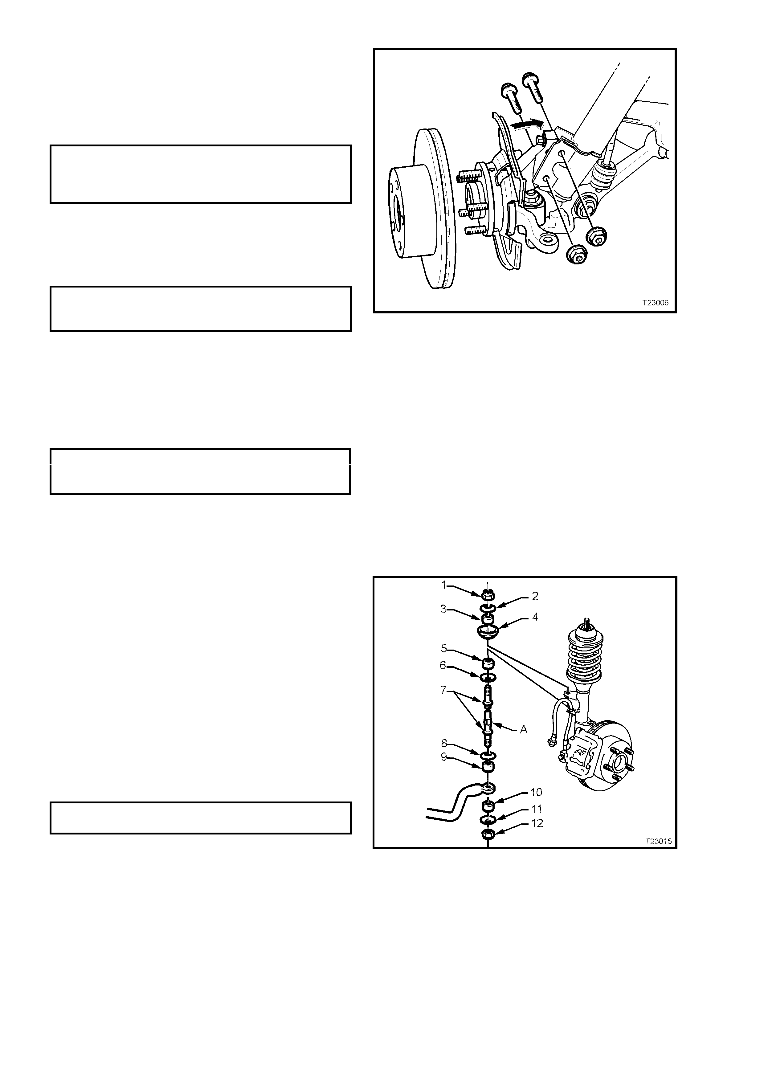
1. Remove front brake disc, wheel hub assembly
and brake shield, as detailed in
3.4 FRONT WHEEL HUB, BRAKE DISC OR
BRAKE SHIELD in this Section.
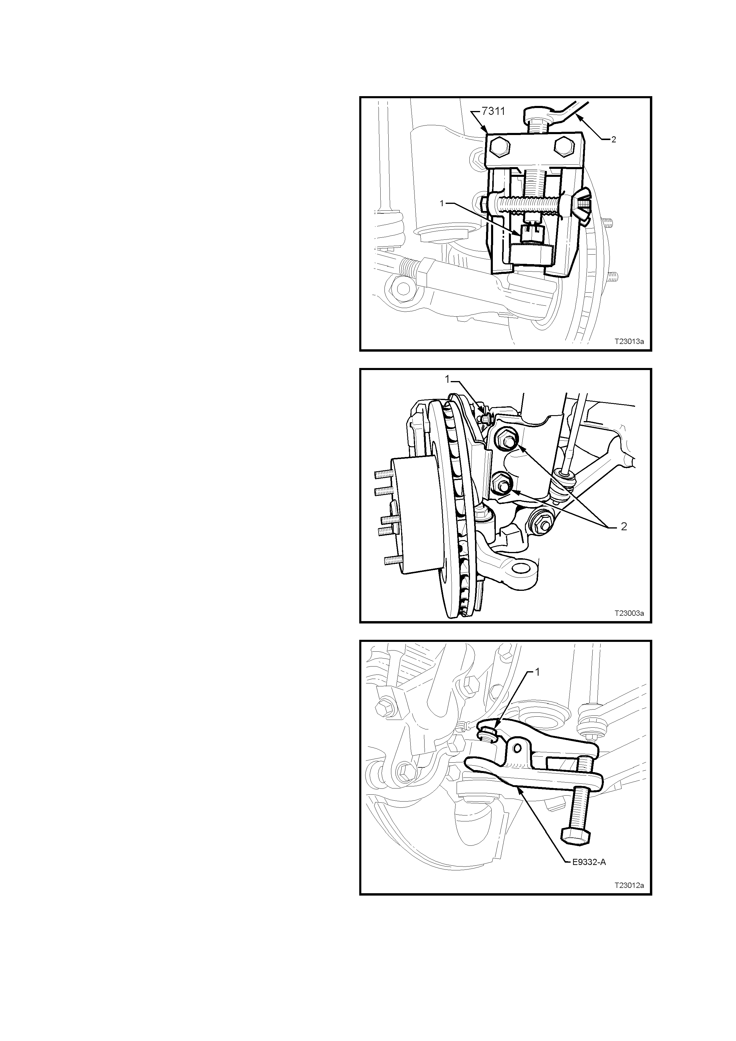
2. Remove the s plit pin and loosen the castellated
nut (1) until the nut is flush with the end of the
tie rod ball joint stud.
3. Install Tool No. 7311 as shown and, using a
ring spanner (2), press stud out from steering
knuckle.
Figure 3-17
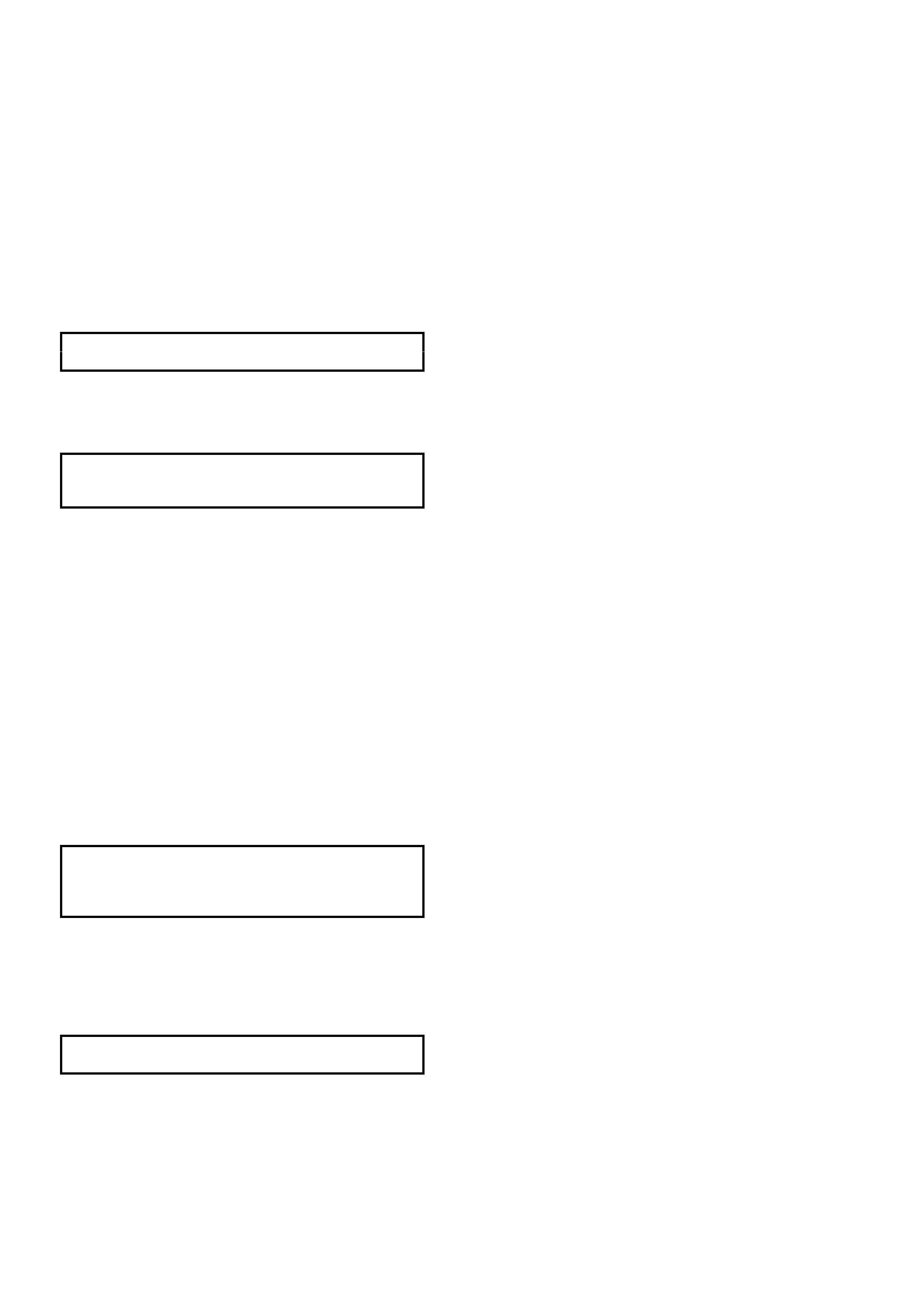
4. Loosen, remove and discard the two lower
strut attaching bolts and nuts (2).
5. If the steering knuckle is to be replaced,
remove the camber adjusting bolt (1) from the
arm.
Figure 3-18
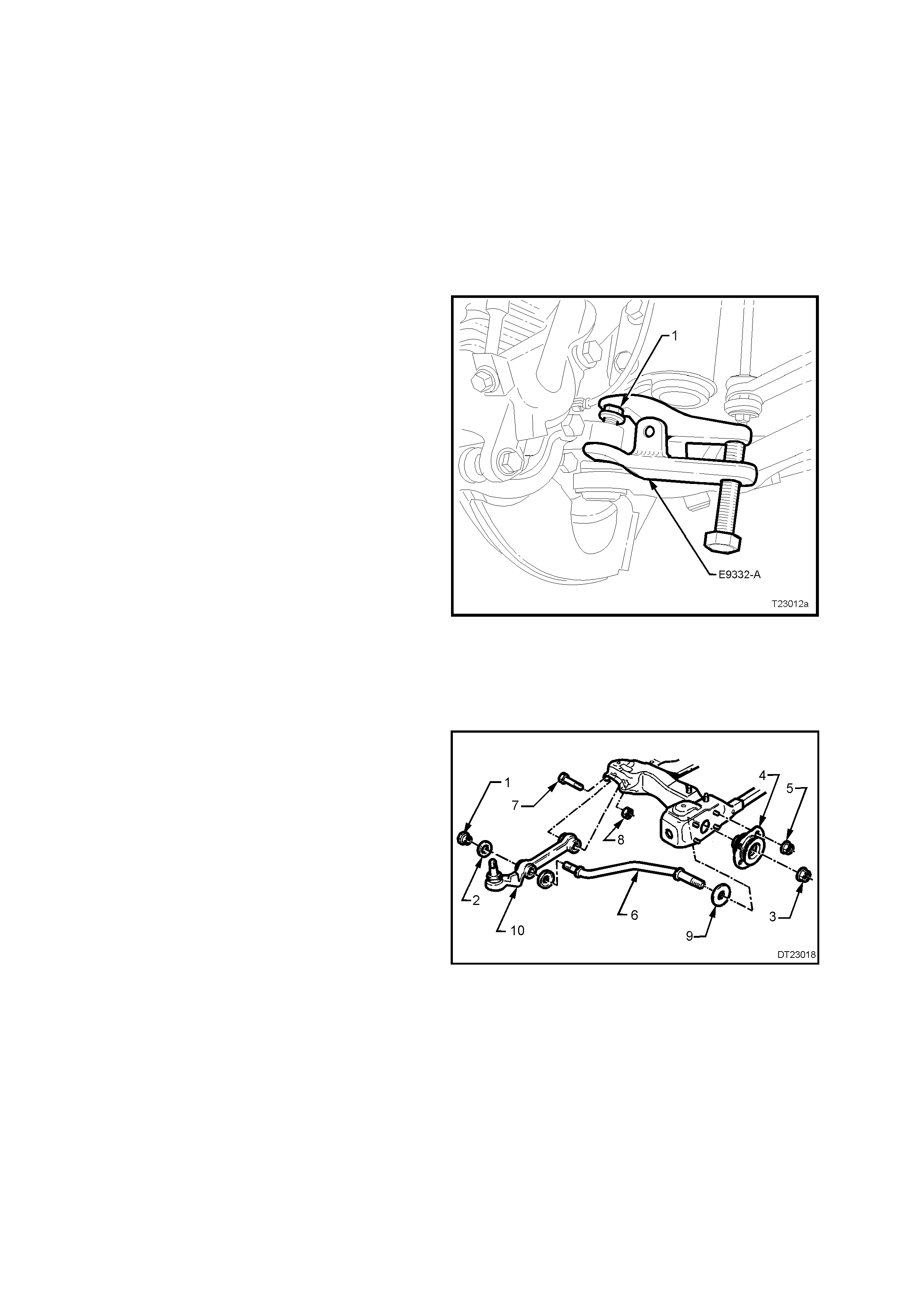
6. Loosen the ball joint retaining nut (1) until the
nut is flush with the end of the ball joint stud
thread.
NOTE: Because the nut has micro-encapsulated
sealant applied to the threads, it must be replaced
after removal.
7. Install separation Tool No. E9332-A as shown,
then apply force to the top of the ball joint stud
by tightening the forcing bolt on the tool,
separating the ball joint from the knuckle.
NOTE: Once load is applied by the release tool
loading bolt, a sharp tap on the nut end of the tool
will lessen the apply force required.
8. Temporarily jam the ball joint stud taper into
the knuckle to hold the stud, before fully
removing the retaining nut. Discard the
removed nut as it has micro-encapsulation
sealant applied and must be replaced on
reassembly.
9. Separate the knuckle from the ball joint stud
and remove from the vehicle.
Figure 3–19
REINSTALL
Reinstallation is the reverse of removal procedures
except for the following:
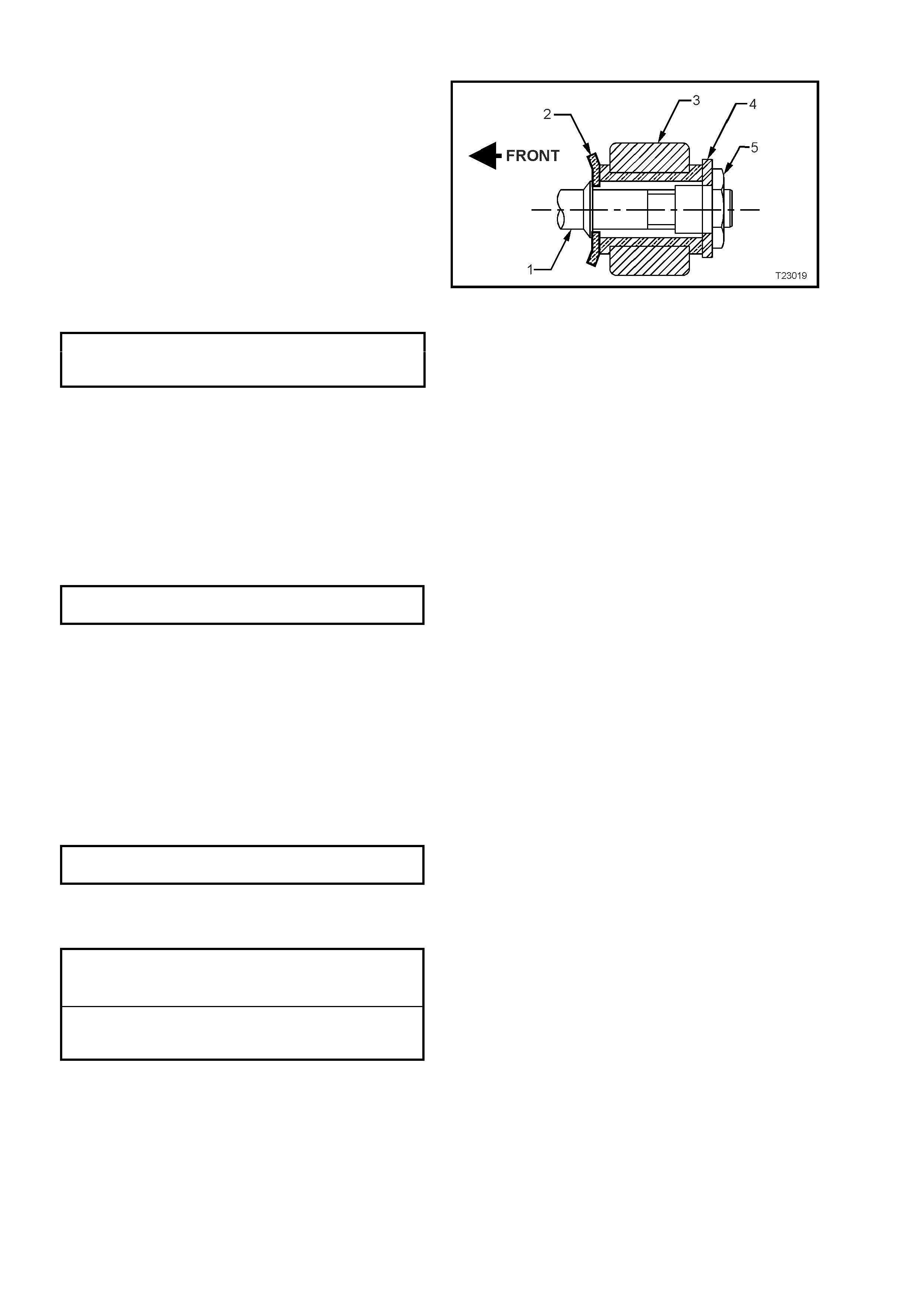
1. Reinstall the steering knuckle over the ball joint
stud, then install NEW lower strut to steering
knuckle, bolts and nuts but do not tighten fully
at this stage.
2 Using a suitable floor jack fitted with a block of
wood, position under the control arm, just
sufficient to support the weight and jam the ball
joint stud taper into the knuckle.
3. Install a NEW self-locking nut to the ball joint
stud and tighten the nut to the correct torque
specification.
BALL JOINT STUD NUT
TORQUE SPECIFICATION 50 - 70 Nm
4. Install steering tie rod end ball joint stud to the
steering knuckle and tighten the castellated
attaching nut to the correct torque
specification. Install new split pin.
TIE ROD BALL JOINT STUD
CASTELLATED NUT 50 – 80 Nm
TORQUE SPECIFICATION
5. Reinstall brake shield, wheel hub assembly
and front brake disc, as detailed in
3.4 FRONT WHEEL HUB, BRAKE DISC OR
BRAKE SHIELD in this Section.
NOTE: the brake disc must be reinstalled, aligning
the marks made prior to removal.
6. Temporarily install road wheel/s and lower
vehicle to the ground.
7. Bounce vehicle up and down several times to
settle suspension.
8. Check wheel alignment, as detailed in
2.1 WHEEL ALIGNMENT CHECKING AND
ADJUSTMENT in this Section.
9. Following wheel alignment operations, it will be
necessary to raise the vehicle and tighten the
NEW steering knuckle to strut bolts and nuts to
the correct torque specification.
STEERING KNUCKLE TO STRUT Stage 1 85 Nm
ATTACHING BOLTS & NUTS Stage 2 100 Nm
TORQUE SPECIFICATION Stage 3 Turn
through 90°
10. After reinstalling the road wheel and aligning
the marks made prior to removal, install the
nuts, lower the vehicle to the ground and
tighten road wheel attaching nuts to the correct
torque specification, working in a ‘star’ pattern,
as indicated in Fig. 3-8, in this Section.
ROAD WHEEL ATTACHING NUT
TORQUE SPECIFICATION 110 – 140 Nm
11. Refit wheel cover/centre cap.
4.3 CONTROL ARM
REMOVE
1. Raise front of vehicle and place safety stands
under side frame members. Observe jacking
precautions as outlined in
2.2 JACKING PRECAUTIONS in this Section.
2. Remove wheel cover (steel wheels) or centre
cap (alloy wheels).
3. Mark relationship of wheel to hub. Loosen,
then remove road wheel attaching nuts and
remove wheel.
4. Turn the steering out on full lock.
5. Loosen the ball joint retaining nut (1) until the
top of the nut is flush with the top of the ball
joint stud thread.
6. Install separation Tool No. E9332-A as shown,
then apply force to the top of the ball joint stud
by tightening the forcing bolt on the tool,
separating the ball joint from the knuckle.
NOTE: Once load is applied by the release tool
loading bolt, a sharp tap on the nut end of the tool
will lessen the apply force required.
7. Temporarily jam the ball joint stud taper into
the knuckle to hold the stud, before fully
removing the retaining nut. Discard the
removed nut as it has micro-encapsulation
sealant applied and must be replaced on
reassembly.
8. Separate the ball joint stud from the knuckle.
9. Hold the steering knuckle away from the
control arm by using a suitable length prop.
Figure 3-20
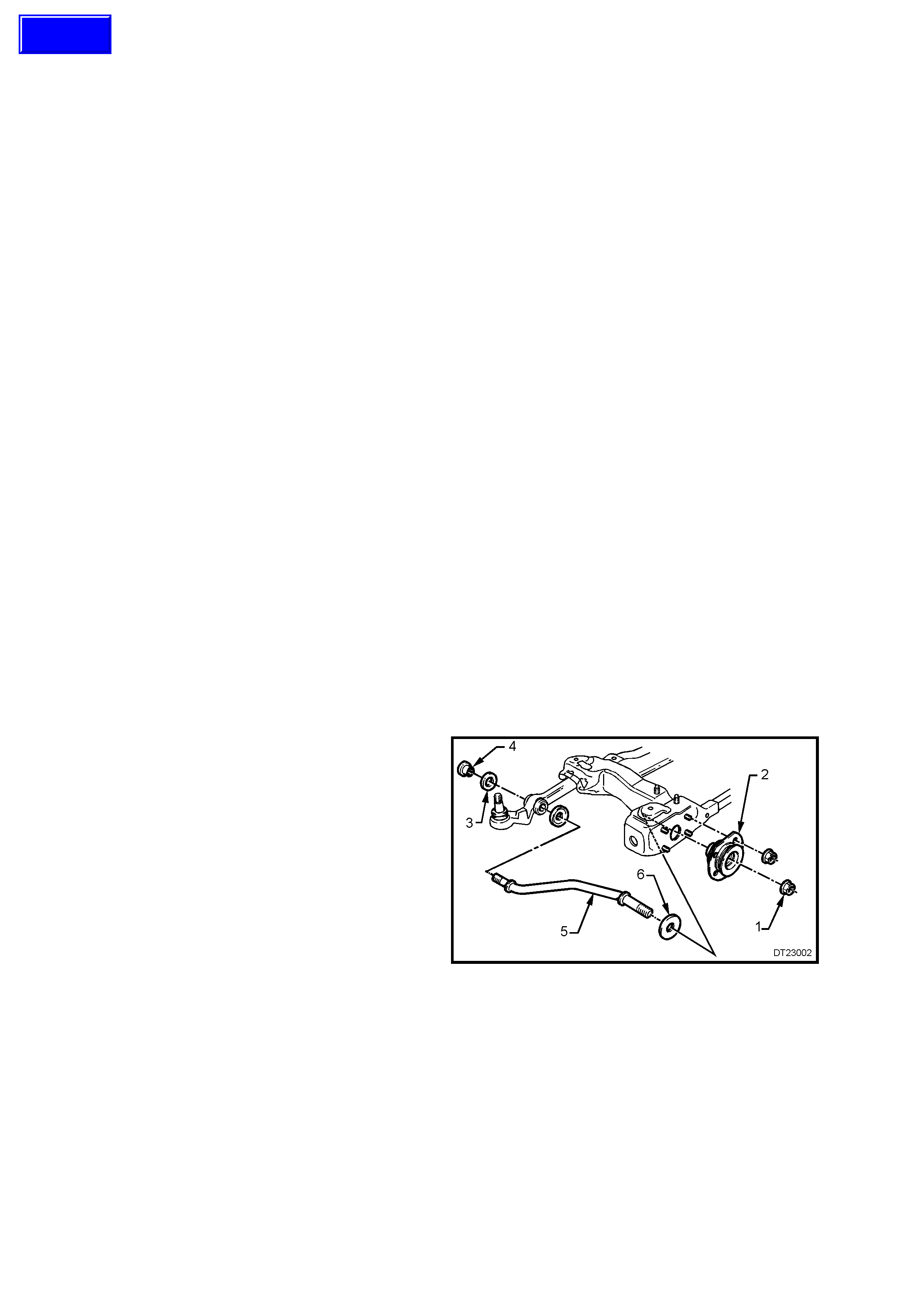
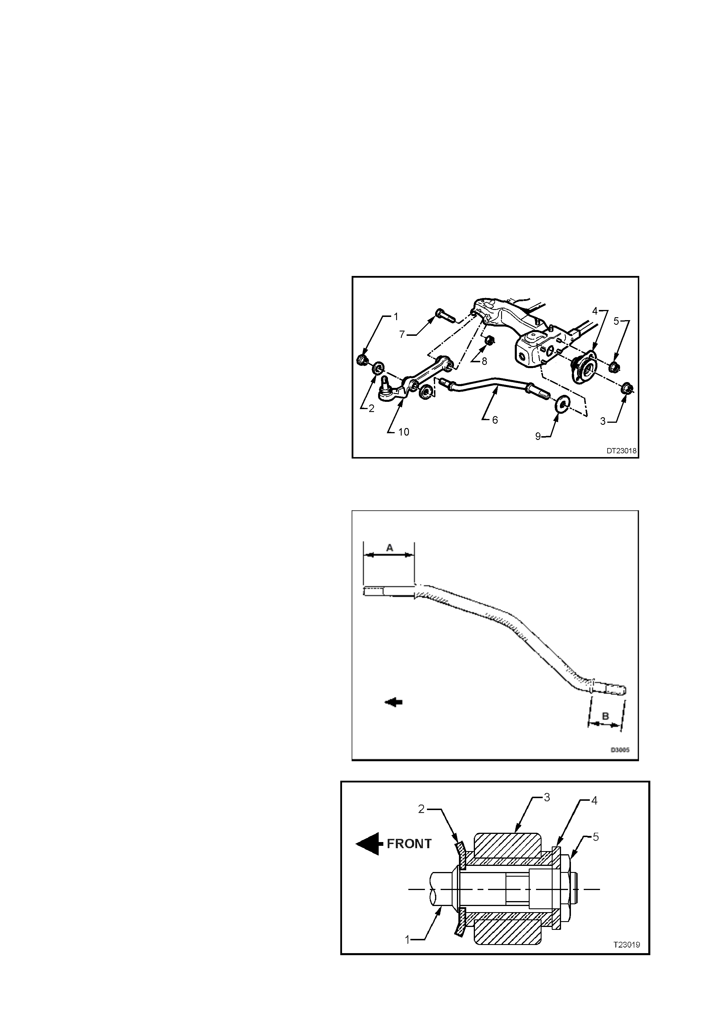
10. Loosen the tension rod front nut (3) at the
tension rod bush assembly (4).
11. Remove tension rod to control arm attaching
nut (1) and washer (2). Discard nut (1).
12. Remove the four nuts (5) securing the tension
rod, bush assembly (4) to the crossmember,
then remove the tension rod (6) from the
control arm, outer bush.
13. Rem ove contr ol arm inner pivot bolt (7) and nut
(8). Discard nut (8).
14. Remove control arm (10) and bright finished
washer (9) from the vehicle.
Figure 3-21
REINSTALL
1. Install control arm to the crossmember, install
bolt (‘7’ in Fig. 3-21), then install a NEW nut (‘8’
in Fig. 3-21), but do not fully tighten at this
stage.
2. Install tension rod (1) to control arm (3) with
convex side of cupped washer (2) toward
control arm bush, as shown.
3. Install tension rod to control arm washer (4)
with a NEW attaching nut (5) but do not fully
tighten at this stage.
4. Install tension rod, front bush assembly to the
crossmember, install the four retaining nuts
and tighten to the correct torque specification.
TENSION ROD HYDRAULIC
DAMPER ASSEMBLY ATTACHING 20 – 26 Nm
NUT TORQUE SPECIFICATION
NOTE: Ins tall a NEW tens ion rod nut to the fr ont of
the tension rod but do not tighten at this stage.
Figure 3-22
5 Using a suitable floor jack fitted with a block of
wood, positioned under the control ar m, lift jus t
sufficient to support the weight of the strut
assembly and jam the ball joint stud taper into
the knuckle.
6. Install a NEW self-locking nut to the ball joint
stud and tighten the nut to the correct torque
specification.
BALL JOINT STUD NUT
TORQUE SPECIFICATION 50 - 70 Nm
7. Install road wheel, aligning marks made prior
to removal. Tighten the wheel nuts
progressively, working in a ‘star’ pattern. Do
not overtighten.
8. Remove safety stands and lower vehicle.
9. Bounce vehicle up and down several times to
settle suspension.
10. With the weight of the vehicle on the
suspension components, tighten control arm
inner pivot bolt to the correct torque
specifications.
CONTROL ARM INNER PIVOT
BOLT TORQUE SPECIFICATION 95 – 110 Nm
11. Tighten the tension rod nuts, both at the
control arm and the tension rod hydraulic
damper, to the correct torque specifications.
TENSION ROD TO CONTROL
ARM ATTACHING NUT 95 – 110 Nm
TORQUE SPECIFICATION
TENSION ROD TO
HYDRAULIC DAMPER 140 – 155 Nm
TORQUE SPECIFICATION

Important: The weight of the vehicle must be on
all four wheels before tightening the tension rod to
specification. Otherwise the tension rod hydraulic
damper will be incorrectly preloaded, reducing the
life of the damper and affecting ride and handling.
12. Tighten road wheel attaching nuts to the
correct torque specification, working in a ‘star’
pattern, as indicated in Fig. 3-8, in this Section.
ROAD WHEEL ATTACHING NUT
TORQUE SPECIFICATION 110 – 140 Nm
13. Refit wheel cover/ centre cap.
14. Check wheel alignment, as detailed in
2.1 WHEEL ALIGNMENT CHECKING AND
ADJUSTMENT in this Section.

4.4 CONTROL ARM BALL JOINT
INSPECT
The following procedure should be used when
checking the ball joint for wear.
1. Jack up vehicle under crossmember.
2. Holding the road wheel at top and bottom,
check for play in the ball joint by rocking wheel.
3. If any up or down movem ent of s tud in ball j oint
housing is detected, the control arm and ball
joint assembly must be replaced, as the ball
joint is not serviced separately.
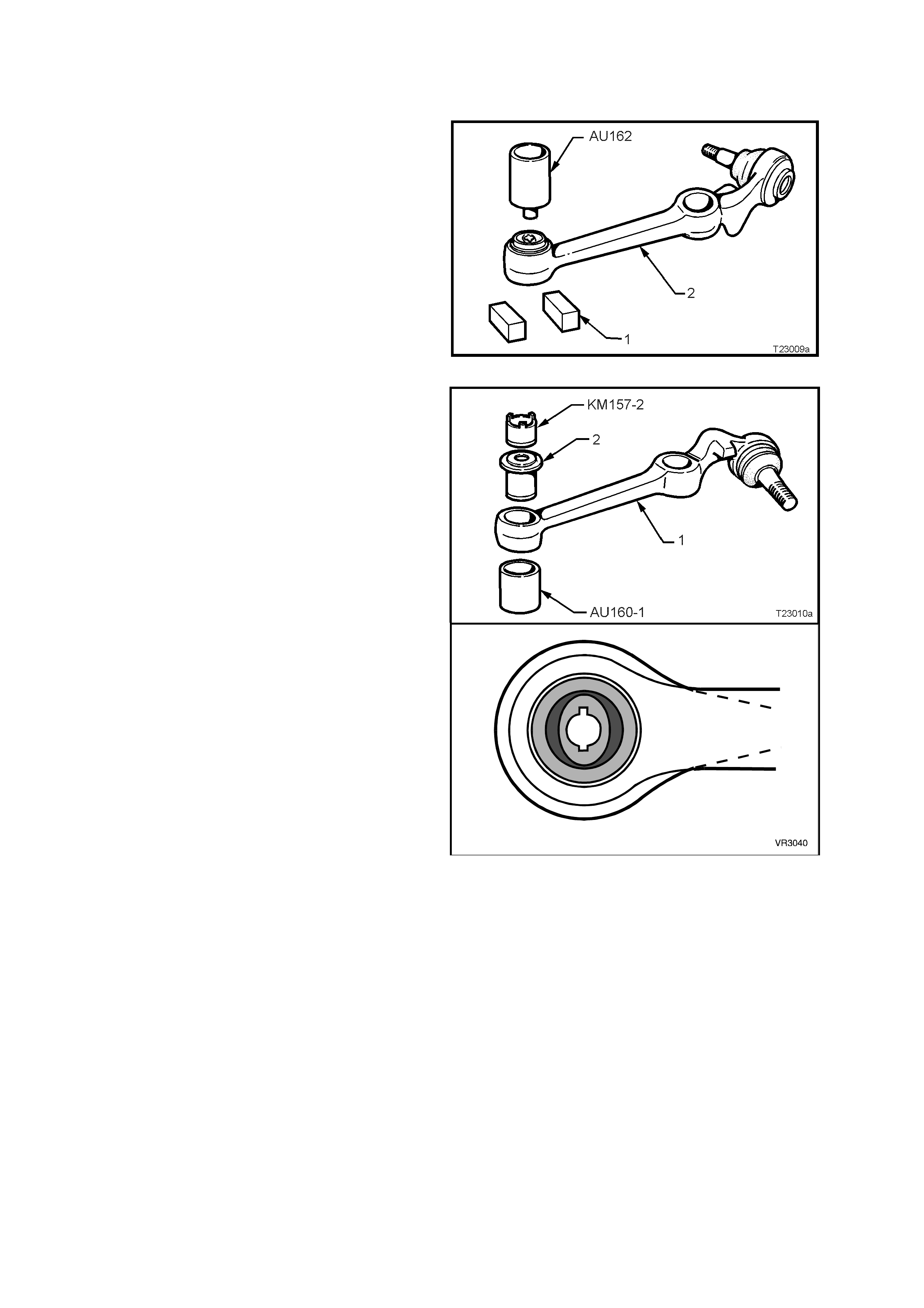
4.5 CONTROL ARM INNER PIVOT BUSH
REPLACE
1. Remove control arm (2) as detailed in
4.3 CONTROL ARM in this Section.
2. Support the control arm (2) with two pieces of
square scrap (1) and press the bush from the
arm, using Tool No. AU162.
Figure 3-23
3. Using T ool Nos. AU160-1 and KM157-2, install
new bush from front side of control arm, until
flange on outer sleeve is flush with control arm.
NOTE 1: The bush MUST be aligned, as shown.
NOTE 2: The bush may be lubricated with a soapy
water solution to ease the installation process.
NOTE 3: Tool No KM157-2 is used in the reverse
direction to some previous ‘V’ car models.
4. Reinstall control arm as detailed in
4.3 CONTROL ARM in this Section.
Figure 3-24
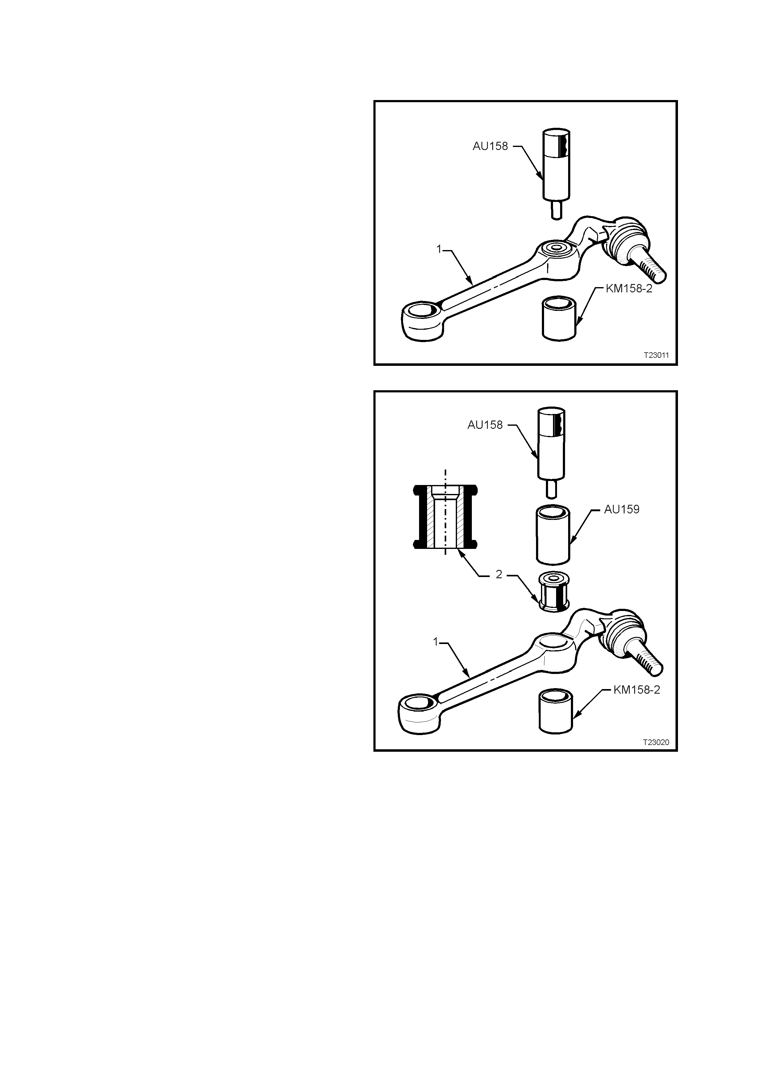
4.6 CONTROL ARM TENSION ROD BUSH
REPLACE
1. Remove control arm as detailed in
4.3 CONTROL ARM in this Section.
2. Press out tension rod bush from control arm
using Tool No AU158 and KM158-2 as shown.
Figure 3-25
3. Pr ess in a new tension r od bush (2) using T ool
No’s AU158, AU159 and KM158-2 as shown.
To as sist in installation, dip bush (2) in a soapy
water solution. Install bus h with larger diameter
of stepped tension rod mounting hole toward
rear of control arm (1).
NOTE: Press the bush (2) in until it is centrally
located in the control arm(1).
4. Reinstall control arm (1) as detailed in
4.3 CONTROL ARM in this Section.
Figure 3-26
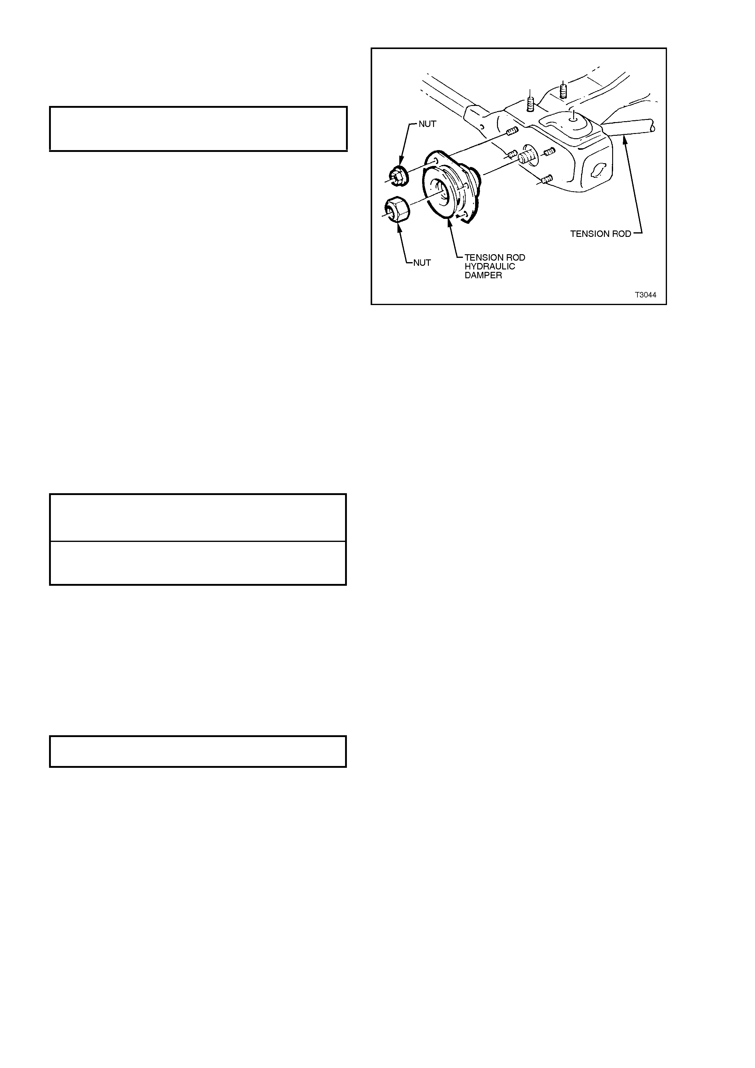
4.7 CONTROL ARM TENSION ROD
REMOVE
1. Before raising the vehicle, loosen the front
tension rod nut (‘3’ in Fig. 3-29).
2. Raise front of vehicle and place safety stands
under side frame members. Observe jacking
precautions as outlined in 2.2 JACKING
PRECAUTIONS in this Section.
3. Remove wheel cover (steel wheels) or centre
cap (alloy wheels) on the side where the tension
rod is to be removed.
4. Mark relationship of road wheel to hub. Loosen,
then rem ove road wheel attaching nuts. Rem ove
road wheel.
5. Remove tension rod to control arm attaching
nut (1) and washer (2). Discard the nut (1).
6. Rem ove four nuts (5) attaching the tension rod
hydraulic damper assembly (4) to the
crossmember outrigger.
7. Remove tension rod (6) and tension rod
damper assembly (4) from control arm and out
through the crossmember outrigger.
8. Secure the tension rod (6) in protected vice
jaws, then remove the tension rod to tension
rod dam per assem bly retaining nut (3). Discar d
the nut (3).
9. Remove bright finished washer (9), from
tension rod (6), on the driver’s side.
Figure 3-27
REINSTALL
1. Install bright finished inner washer to front end
of tension rod (A), on the driver’s side ONLY.
NOTE: T he f ront end of the tension rod is identified
by the longer length of the shouldered ends (‘A’
compared to ‘B’).
Figure 3-28
2. Install tension rod (1) into the hole in the
crossmember outrigger and then into the
control arm (3), with the cupped washer (2)
installed as shown. Reinstall tension rod to
control arm washer (4) with a NEW attaching
nut (5) but do not fully tighten at this stage.
Figure 3-29
3. Install tension rod, hydraulic damper assembly,
over the tension rod and install four retaining
nuts to the crossmember outrigger studs.
Tighten to the correct torque specification.
TENSION ROD HYDRAULIC
DAMPER ASSEMBLY ATTACHING 20 – 26 Nm
NUT TORQUE SPECIFICATION
4. Install a NEW tension rod retaining nut but do
not fully tighten at this stage.
NOTE: If fitted, ensure that the spacer washer is
installed over the tension rod and then the flat
washer, before fitting the tension rod damper.
Figure 3-30
5. Reinstall road wheel, aligning the marks made
prior to removal and secure with the attaching
nuts, tightening progressively in a ‘star’
pattern. Do not overtighten.
6. Remove safety stands and lower vehicle to the
ground.
7. Bounce vehicle up and down several times to
settle suspension.
8. With the vehicle at curb position, tighten both
the tension rod to hydraulic damper and the
tension rod to control arm attaching nuts to the
correct torque specifications.
TENSION ROD TO HYDRAULIC
DAMPER ATTACHING NUT 140 – 155 Nm
TORQUE SPECIFICATION
TENSION ROD TO CONTROL
ARM ATTACHING NUT 95 – 110 Nm
TORQUE SPECIFICATION
Important: The weight of the vehicle must be on
all four wheels before tightening each end of the
tension rod to specification. Otherwise the fluid
filled tension rod bush will be incorrectly preloaded,
reducing the life of the bush and effect ride and
handling.
9. Tighten road wheel attaching nuts to the
correct torque specification, working in a ‘star’
pattern, as indicated in Fig. 3-8, in this
Section.
ROAD WHEEL ATTACHING NUT
TORQUE SPECIFICATION 110 – 140 Nm
10. Refit wheel cover/centre cap.
11. Check wheel alignment, as detailed in
2.1 WHEEL ALIGNMENT CHECKING AND
ADJUSTMENT in this Section.
4.8 FRONT SUSPENSION CROSSMEMBER
IMPORTANT: The service procedure detailed here, is only applicable to those vehicles fitted with the
revised design front crossmember to side frame bolts. While the bolts w ill service back to earlier VT series
vehicles, unless they are used, then the procedure detailed in 3. FRONT SUSPENSION, of the VT Series I
Service Information must be followed.
REMOVE
1. Jack up front of vehicle and place safety
stands under side frame members. Observe
jacking precautions as outlined in
2.2 JACKING PRECAUTIONS in this Section.
2. Remove wheel cover (steel wheels) or centre
cap (alloy wheels).
3. Mark relationship of wheel to hub. Loosen,
then remove road wheel attaching nuts.
Remove road wheel.
4. Using a suitable size open end spanner, hold
the stabiliser bar spacer stud (7) at ‘A’ and
remove the lower nut (12), washer (11) and
bush (10) from each side.
NOTE: The illustration shows an exploded view of
the complete assembly, for convenience only.
Figure 3-31
5. Remove the split pin from the tie rod ball joint
castellated nut (1), then loosen the nut until the
top of the nut is level with the top of the tie rod
end stud.
6. Install Tool No. 7311 and use a ring spanner
(2) to separate the tie rod ball joint stud from
the steering knuckle.
Figure 3-32
Techline
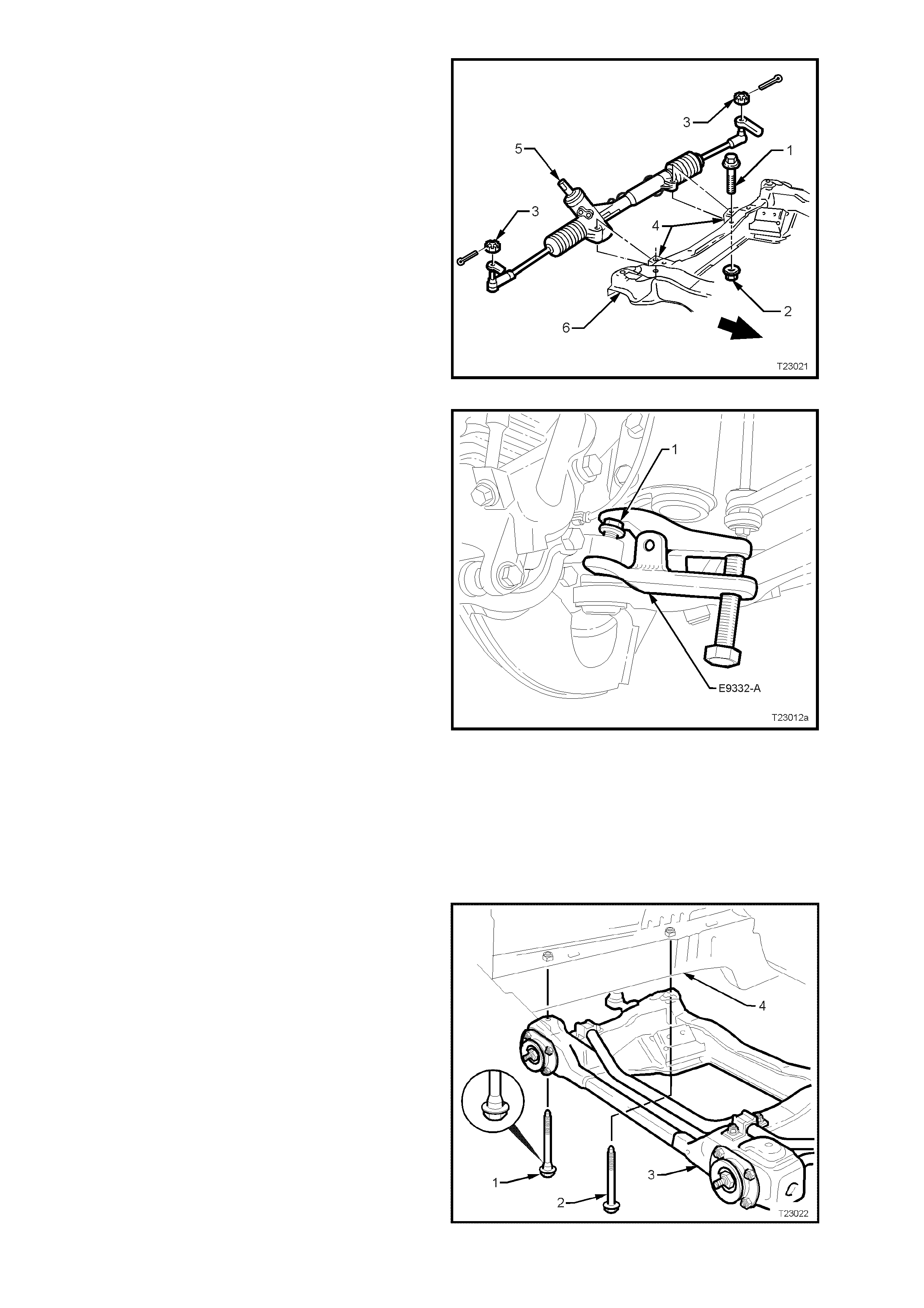
7. Remove steering gear housing (5) to
crossmember (6) mounting bolts (1) and nuts
(2). Remove steering gear housing (5) from
crossmember mountings (4).
Figure 3-33
8. Turn each wheel out in turn.
9. Loosen the ball joint retaining nut (1) until the
top of the nut is flush with the top of the ball
joint stud thread.
10. Install separation Tool No. E9332-A as shown,
then apply force to the top of the ball joint stud
by tightening the forcing bolt on the tool,
separating the ball joint from the knuckle.
NOTE: Once load is applied by the release tool
loading bolt, a sharp tap on the nut end of the tool
will lessen the apply force required.
11. Temporarily jam the ball joint stud taper into
the knuckle to hold the stud, before removing
the retaining nut. Discar d the removed nut as it
has micro-encapsulation sealant applied and
must be replaced on reassembly.
12. Separate the knuckle from the ball joint stud.
Figure 3-34
13. Mark hood hinge positions with felt tipped pen
and remove engine hood.
14. Support engine on a suitable lifting hook and
remove engine mounts to crossmember bolts
or nuts, refer to Sections 6A1 (V6) of the VT
Series I Service Information or Section 6A3
(GEN III V8) of the VT Series II Service
Information, for details.
15. Support crossmember (3) on a jack and
remove four bolts (1 and 2) securing the
crossmember to side frame members (4).
16. Lower, then remove crossmember assembly
(3) from vehicle.
17. As required, remove the control arms, tension
rod hydraulic dampers, tension rods and
stabiliser bar from the crossmember.
Figure 3-35
REINSTALL
While the majority of the reinstallation process is
the reverse of removal procedures, note the
following points:
1. Install the stabiliser bar insulating rubbers and
brackets to the crossmember, tightening
retaining nuts to the correct torque
specification.
STABILISER BAR SUPPORT
BRACKET RETAINING NUT 24 - 30 Nm
TORQUE SPECIFICATION
2. W hen reinstalling the crossmember, install the
two front, black coloured and stepped bolts (‘1’
in Fig. 3-37) and tighten to the correct torque
specification. This will correctly align the
crossmember to the side frames.
3. Reinstall the two rear, silver coloured, plain
shanked bolts (‘2’ in Fig. 3-37) to the two rear
positions and tighten them to the cor rec t torque
specification.
CROSSMEMBER TO SIDE
MEMBER BOLT (ALL) 120 – 125 Nm
TORQUE SPECIFICATION
4. Reinstall the two control arms to the
cross member, inst alling the pivot bolts fr om the
rear to the front. Install NEW nuts but do not
fully tighten at this stage.
5. If the control arms were removed with the
crossmember, install the ball joint stud into
each steering knuckle, install a NEW nut and
tighten to the correct torque specification.
BALL JOINT STUD NUT
TORQUE SPECIFICATION 50 – 70 Nm
6. If Rem oved, reinstall both tension rods, loos ely
installing washers and NEW retaining nuts, as
detailed in 4.7 CONTROL ARM TENSION
ROD in this Sec tion. Do not tighten at this time.
However, the tension rod hydraulic damper
mounting nuts can be tightened to the correct
torque specification.
TENSION ROD HYDRAULIC
DAMPER ASSEMBLY ATTACHING 20 - 26 Nm
NUT TORQUE SPECIFICATION
7. Refit steering gear housing to crossmember,
tighten mounting nuts to the correct torque
specification.
STEERING GEAR HOUSING TO
CROSSMEMBER MOUNTING 70 - 85 Nm
NUT TORQUE SPECIFICATION
8. Reconnect engine mounts to crossmember,
refer to Sections 6A1 (V6) of the VT Series I
Service Information or Section 6A3 (GEN III
V8) of the VT Series II Service Inform ation, for
details.
9. Reinstall road wheels, aligning marks made
prior to removal .
10. Refit engine hood.
11. Remove safety stands and lower vehicle.
12. Bounce vehicle up and down several times to
settle suspension.

13. Tighten control arm , inner pivot bolt nuts to the
correct torque specification.
CONTROL ARM INNER PIVOT
BOLT TORQUE SPECIFICATION 95 - 100 Nm
14. With the vehicle at curb position, tighten the
tension rod attaching nuts at the control arm
and the hydraulic dam per, to the corr ect torque
specifications.
TENSION ROD TO CONTROL
ARM ATTACHING NUT 95 - 110 Nm
TORQUE SPECIFICATION
TENSION ROD TO HYDRAULIC
DAMPER ATTACHING NUT 140 - 155 Nm
TORQUE SPECIFICATION
Important: The weight of the vehicle must be on
all four wheels before tightening the tension rod to
specification. If not, the f luid filled tension rod bush
will be ruptured, once the vehicle is put back into
service.
15. Check wheel alignment, as detailed in
2.1 WHEEL ALIGNMENT CHECKING AND
ADJUSTMENT in this Section.
5. SPECIFICATIONS
SUSPENSION
Type MacPherson Wet Strut
Application All VT Models
Travel
Compression
(2/3compression of bumper)
Rebound
Standard and V5W
90 mm
110 mm
FE2
80 mm
120 mm
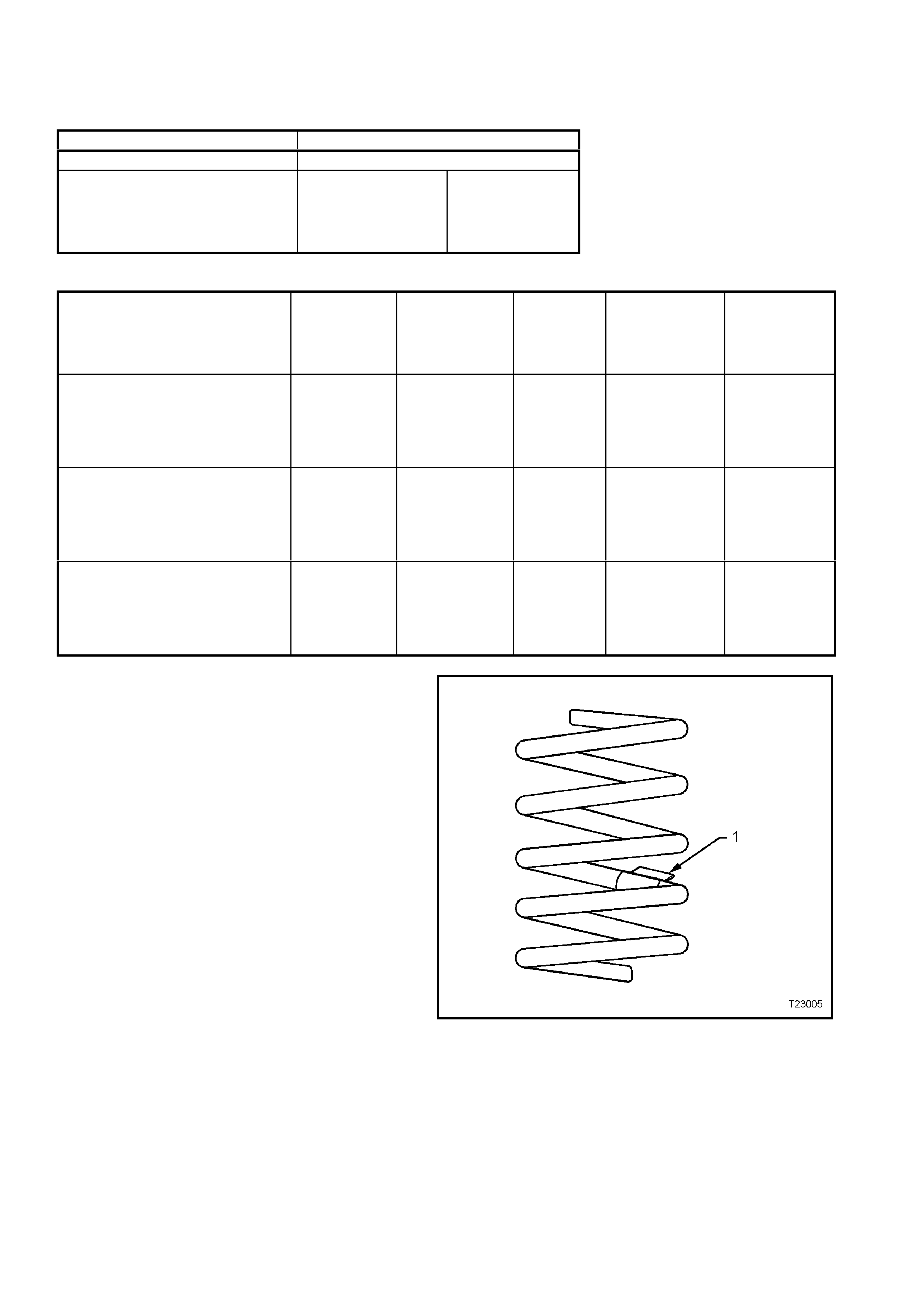
FRONT SPRING SPECIFICATIONS
SEDAN & STATION WAGON
MODELS
Approximat
e
Number
COILS
Approximate
FREE
LENGTH
(mm)
INSIDE
DIAMETE
R
(mm)
PROD. I.D.
CODE
(Tag on
spring)
SPRING
TYPE &
RATE
STANDARD SUSPENSION –
ALL ENGINES 6.05 444 136 ± 1.5 HN VARIABLE
19 - 23
N/mm
(3700 ± 110 N
@ 210 mm)
FE2 SPORTS SUSPENSION –
ALL ENGINES 5.25 341 136 ± 1.5 HJ VARIABLE
24 - 31
N/mm
(3660 ± 110 N
@ 200 mm)
V5W COUNTRY P ACK SUS PENS ION
– V6 ENGINE 6.12 376 136 ± 1.5 HS VARIABLE
24 - 31
N/mm
(3660 ± 110 N
@ 230 mm)
Figure 3-36
Legend
1. Production Identification Code Tag

STABILISER BAR (FRONT)
Type ......................................................................... Decoupled
STABILISER BAR IDENTIFICATION
Diameter I.D.
MODELS mm CODE
(2) (1)
All VT Series II Models and
Suspensions, except for
Sedan with FE2 26.0 GE
Sedan Models and
FE2 Suspension 27.0 GH
Figure 3-37
Legend
1. PRODUCTION IDENTIFICATION CODE TAG
2. Stabiliser Bar Diameter
FRONT STRUT
Type ........................................................................ Wet strut – non-serviceable
Piston Diameter....................................................... 30 mm
Fluid Type................................................................ Hydraulic fluid to Holden Specification HN 1588
Capacity............................................................. 350 ml
FRONT STRUT ID ENTIFICATION
Suspension and Application Right Hand Side Left Hand Side
STANDARD SUSPENSION –
SEDAN AND STATION WAGON RS LS
SPORTS SUSPENSION (FE2) –
SEDAN AND STATION WAGON RT LT
COUNTRY PACK SUSPENSION –
SEDAN AND STATION WAGON RU LU
CONTROL ARM
Type ........................................................................ Forged with rubber bushes for attachment to front
crossmember and tension rod. Ball joint is a press fit
into the control arm.
FRONT WHEEL BEARINGS
Type ........................................................................ Double row ball bearing
Lubricant.................................................................. Sealed for life: non-adjustable
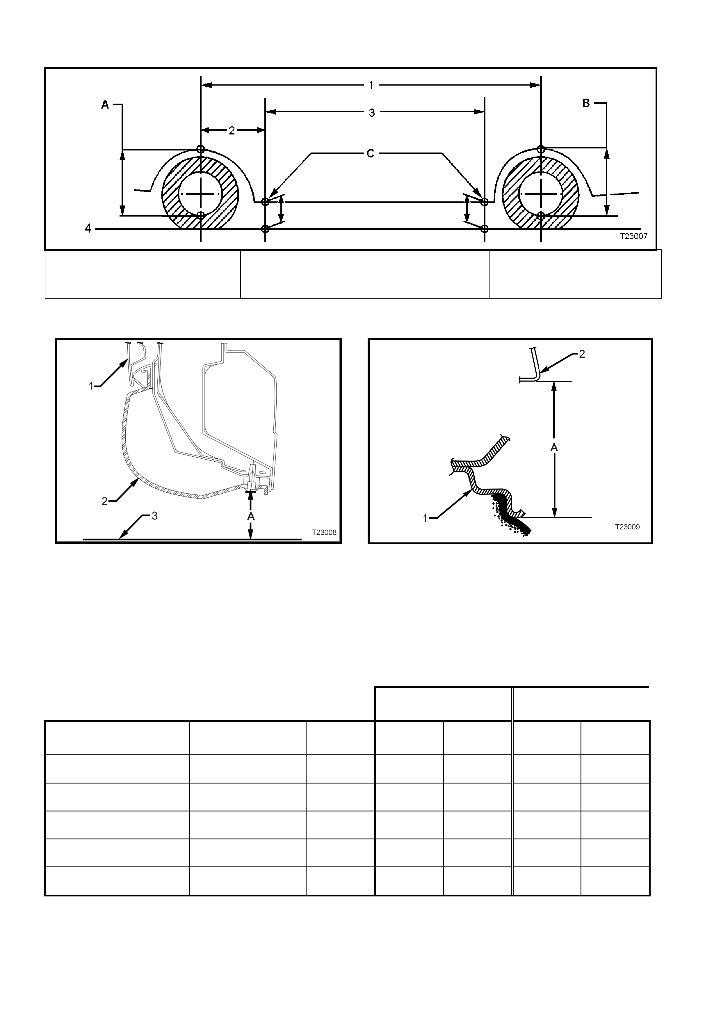
SUSPENSION and TRIM HEIGHT SPECIFICATIONS
A Front Suspension Height
B Rear Suspens i on Hei ght
C Trim Hei ght Checking Locations
1. Wheelbase: All VT S edan – 2798 mm
All Station Wagon – 2935 mm
2. Reference Point: All Models – 584.5 mm
3. Trim Height Spacing:
All Sedan – 1615 mm
All Station Wagon – 1765 mm
4. Ground Line
Figure 3-38
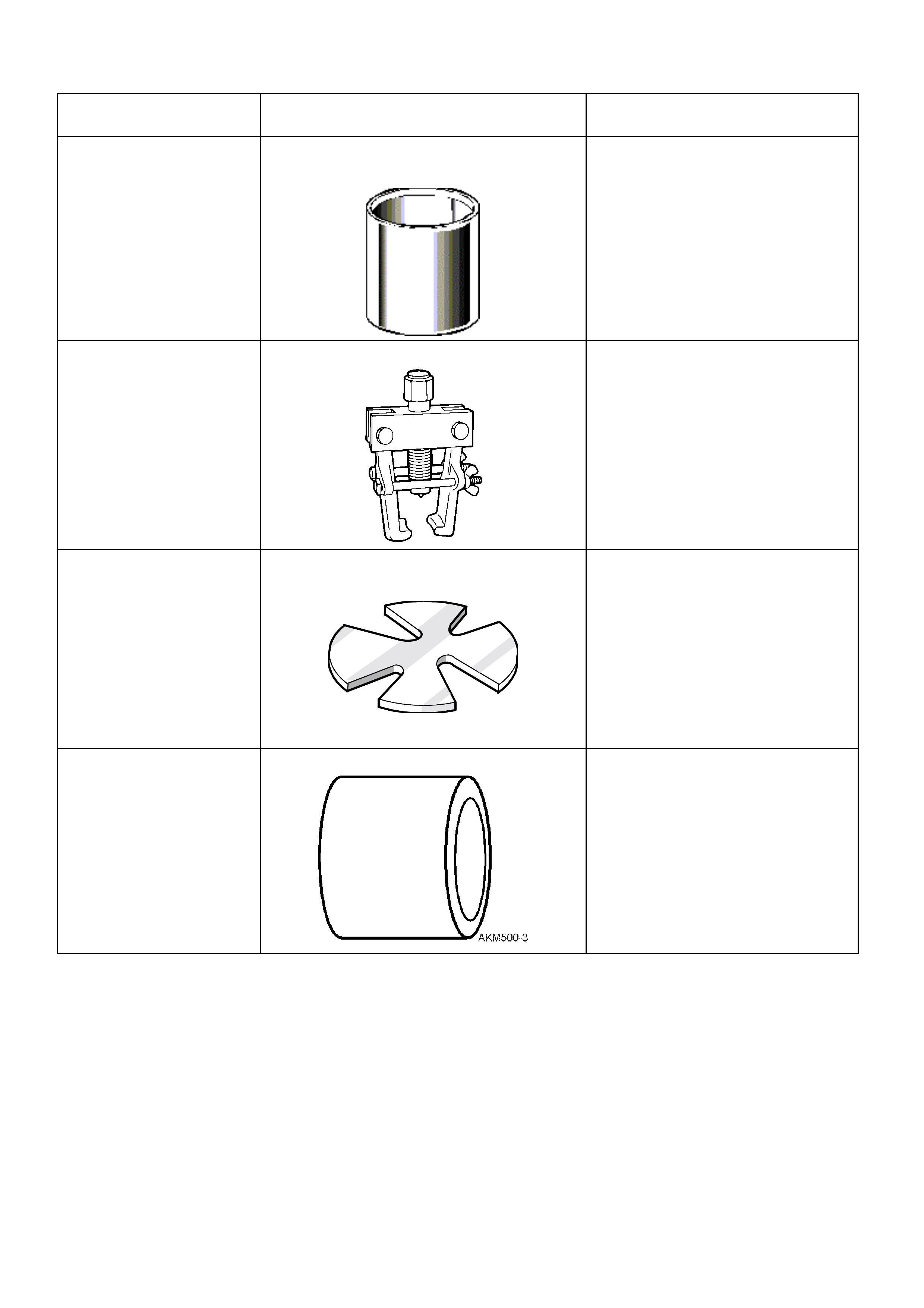
1. Door 2. Trim 3 Ground Li ne ‘ A’ Trim Hei ght 1. Wheel Rim 2. Fender Opening ‘A’ Sus pension Height
Figure 3-39 – Rear Trim Height Checking Location (Front
Similar) Figure 3-40 – Front and Rear Suspension Height
Checking Location
NOTE: The following suspensi on/trim height dimensions ar e intended for refe rence and ar e intended to be
a guide only (Refer to 3.3 SUSPENSION AND TRIM HEIGHT CHECK, in this Section).
VT SERIES II MODELS WITH V6 ENGINE AND STANDARD SUSPENSION
SUSPENSION HEIGHT
(mm) TRIM HEIGHT
(mm)
VEHICLE
DESCRIPTION TRANSMISSION MODEL FRONT REAR FRONT REAR
Executive Sedan Manual Base 593 583 192 201
Berlina Sedan Automatic Base 593 583 192 201
Calais Sedan Automatic Base 593 583 192 201
Executive Station Wagon Manual Base 603 573 192 210
Berlina Station Wagon Automatic Base 598 582 192 210

6. TORQUE SPECIFICATIONS
NOTE: For Those Torque Specifications Not Listed Here, Refer To: Section 3 FRONT SUSPENSION or
Section 9A STEERING of the VT Series I Service Information and Section 9A STEERING of the VT Series II
Service Information.
Nm
Ball Joint Stud Nut........................................................................ 50 - 70
Brake Caliper Anchor Plate Retaining Bolts.............Stage 1....... 80 - 90
Stage 2....... Turn through 40° - 50°
Control Arm Inner Pivot Bolt......................................................... 95 – 110
Crossmember to Side Member Bolt Torque................................. 120 – 125
Front Hub to Steering Knuckle Attaching Bolt .............................. 100 - 115
Road Wheel Attaching Nut........................................................... 110 - 140
Stabiliser Bar Support Bracket Retaining Nut............................... 24 - 30
Steering Gear Housing to Crossmember Mounting Nut............... 70 - 85
Steering Knuckle to Strut Attaching Bolts and Nuts Stage 1....... 85
Stage 2....... 100
Stage 3....... Turn through 90°
Tension Rod Hydraulic Damper Assembly Attaching Nut............ 20 – 26
Tension Rod to Control Arm Attaching Nut .................................. 95 – 110
Tension Rod to Hydraulic Damper Attaching Nut......................... 140 – 155
Upper Strut Bearing Retaining Nut............................................... 70 - 85
Upper Strut Locating Plate Retaining Nut..................................... 50 - 60
Tie Rod Ball Joint Stud Castellated Nut ....................................... 50 – 80
Tie Rod to Tie Rod Ball Joint Lock Nut ........................................ 40 – 60
7. SPECIAL TOOLS
TOOL No. REFERENCE
IN TEXT TOOL DESCRIPTION COMMENTS
3A8-6 SUPPORT
Previously released.
Used to support control arm during
ball joint replacement operations.
7311 TIE ROD BALL JOINT REMOVER
Previously released.
Can also be used on earlier ‘V’ cars
for the same purpose.
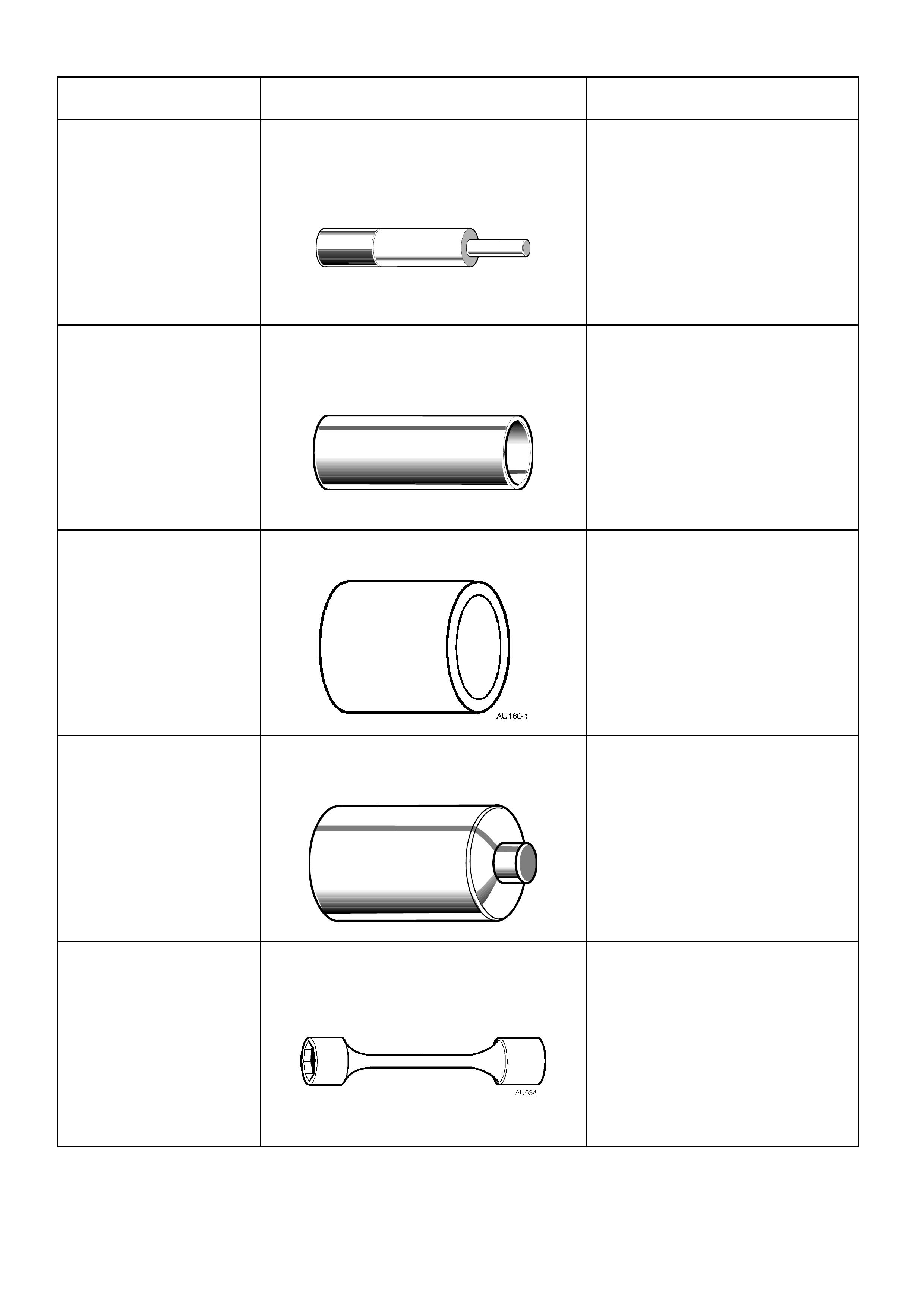
7A42 PRESS PLATES
Previously released.
AKM500-3 PRESS TUBE
Previously released.
Used to install a new ball joint into
the control arm.
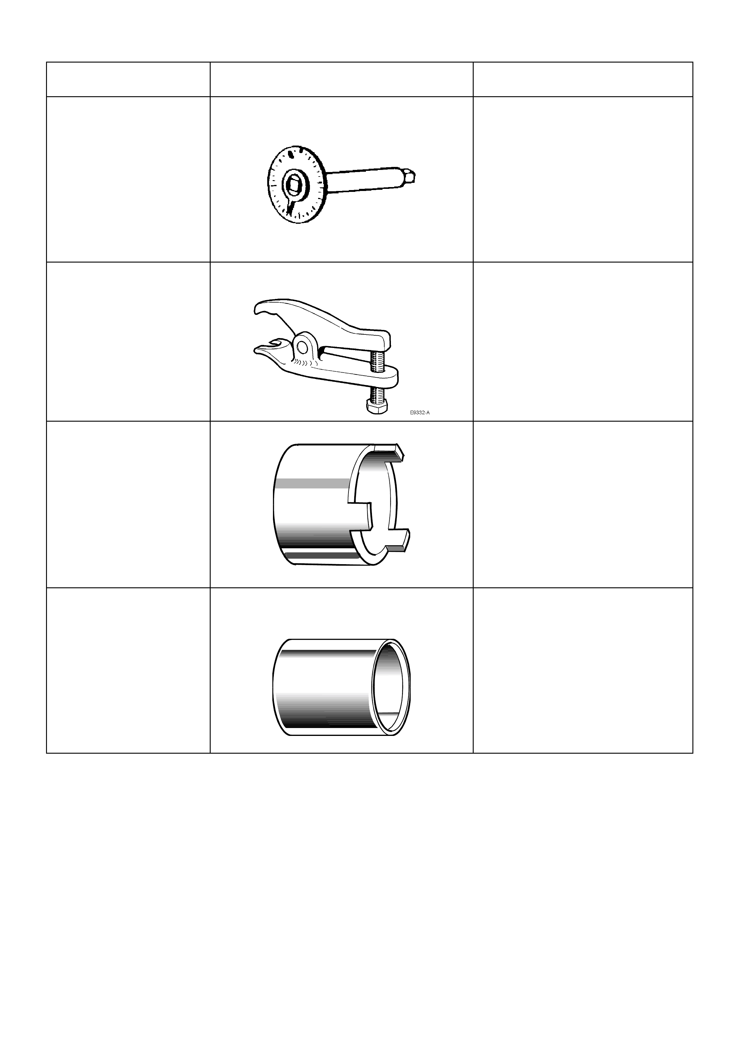
TOOL NO. REF
IN TEXT TOOL DESCRIPTION COMMENTS
AU158 CONTROL ARM TENSION ROD BUSH
REMOVER AND INSTALLER MANDREL
Previously released for "V" car.
Used with KM158-2 for removing
bush and AU159 and KM157-2 for
installing.
AU159 CONTROL ARM TENSION ROD BUSH
REPLACER SLEEVE
Previously released for "V" car.
AU160-1 SUPPORT
Previously released.
Used to support control arm when
installing a new inner bush.
AU162 CONTROL ARM INNER PIVOT BUSH
REMOVAL MANDREL
Used with AU160-1 and KM157-2.
Previously released for "V" car..
AU534 TORQUE LIMITING SOCKET
Previously released.
Used in conjunction with an impact
gun to tighten wheel nuts.
This is a mandatory tool.
TOOL NO. REF
IN TEXT TOOL DESCRIPTION COMMENTS
E7115 ANGLE WRENCH
Previously released for 'J' and 'V'
cars.
Used to tighten component fasteners
when angle torque is required.
E9332-A BALL JOINT RELEASE TOOL
Previously release.
Used to release the control arm ball
joint from the steering knuckle.
KM157-2 CONTROL ARM BUSH INSTALLER
Previously released for "V" car.
Used with AU158 and AU159.
KM158-2 CONTROL ARM TENSION ROD BUSH
INSTALLING SUPPORT SLEEVE
Previously released for "V" car.
Used with AU158 and AU159.