SECTION 3 - FRONT SUSPENSION
CAUTION:
This vehicle will be equipped with a Supplemental Restraint System (SRS). A SRS will consist of either
seat belt pre-tensioners and a driver's air bag, seat belt pre-tensioners and a driver's and front
passenger's air b ags or seat belt pre- tensioners, driv er’s and front passenger’s air bag and left and right
hand side air bags. Refer to SAFETY PRECAUTIONS, Section 12M, Supplemental Restraint System of
this Service Information CD before performing any service operation on, or around any SRS
components, the steering mechanism or wiring. Failure to follow the SAFETY PRECAUTIONS could
result in SRS deployment, resulting in possible personal injury or unnecessary SRS system repairs.
CAUTION:
This vehicle may be equipped with LPG (Liquefied Petroleum Gas). In the interests of safety, the LPG
fuel system should be isolated by turning ‘OFF’ the manual service valve and then draining the LPG
service lin es, b efo re any serv ice work is carried o ut on th e v ehi cle. Refer t o t he L PG leaf let in clud ed with
the Owner's Handbook for details or the appropriate Section of this Service Information CD for more
specific servicing information.
CAUTION:
Whenever any component that forms part of the ABS or ABS/ETC (if fitted), is disturbed during Service
Operations, it is vital that the complete ABS or ABS/ETC system is checked, using the procedure as
detailed in 4. DIAGNOSIS, ABS or ABS/ETC FUNCTION CHECK, in Section 12L ABS & ABS/ETC (V6
Engine) or (GEN III V8 Engine) of this Service Information CD.
1. GENERAL DESCRIPTI ON
Changes to the front suspension for VT Series II
vehicles are minor and are as follows:
a. Re-introduction of V5W Country Pack
suspension to VT series Sedan and Station
Wagon vehicles.
b. Revisions to some wheel alignment angles
and changes to suspension specifications to
reflect the introduction of the GEN III V8
engine and optimise vehicle ride
characteristics.
c. Apart f rom the notes contained in this Section,
all service operations remain unchanged from
those published Section 3 FRONT
SUSPENSION of the VT Series I Information.
For identification information and specification
details for the different suspension components
available for VT Series II vehicles, refer to
4. SPECIFICATIONS in this Section.
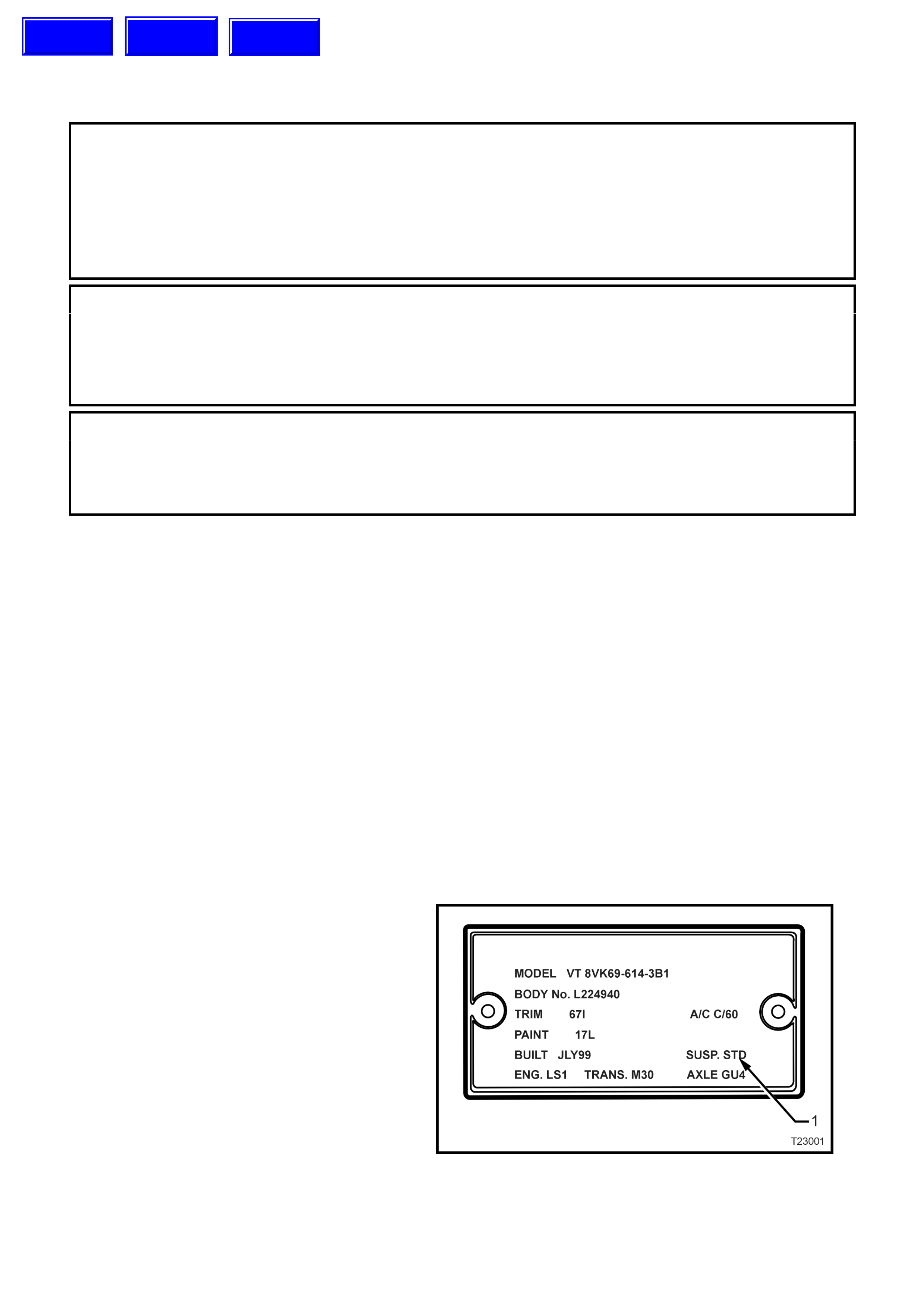
To identify the suspension fitted to an individual
vehicle, refer to “SUSP” (1) on the Body, Option
and Identification Plate.
For the location of this plate, refer to Section 0A
GENERAL INFORMATION, of this Service
Information CD.
Figure 3-1
Techline
Techline
Techline
2. WHEEL ALIGNMENT
2.1 WHE EL ALIGNMENT CHECKING AND ADJUSTMENT
PRELIMINARY INSPECTION
Before any attempt is made to check camber,
caster or toe-in, these preliminary checks should
be carried out.
1. Check tyre and tyre mountings. Always check
camber and toe-in at the mean run-out
position on the tyre or rim.
2. Check and adjust tyre pressures to
recommended values.
3. Front wheel bearing end float is to be chec k ed
to ensure it is within specification, as detailed
in 2.4 FRONT WHEEL BEARING HUB - END
FLOAT CHECKING PROCEDURE, FRONT
SUSPENSION, of this Service Information
CD.
4. Lower control arm ball joints and inner bushes
should be checked for wear.
5. Check steering gear mounting bolts for
tightness and tie rod ball joints for wear.
6. The vehicle should be at curb weight, fuel
tank full, without driver, passengers or
luggage etc.
7. Check for improperly operating front struts or
rear shock absorbers.
8. Check for loose or missing stabiliser bar or
tension rod attachments.
9. Before checking the front wheel alignment,
refer to 4A REAR SUSPENSION of this
Service Information CD for rear wheel
alignment details.
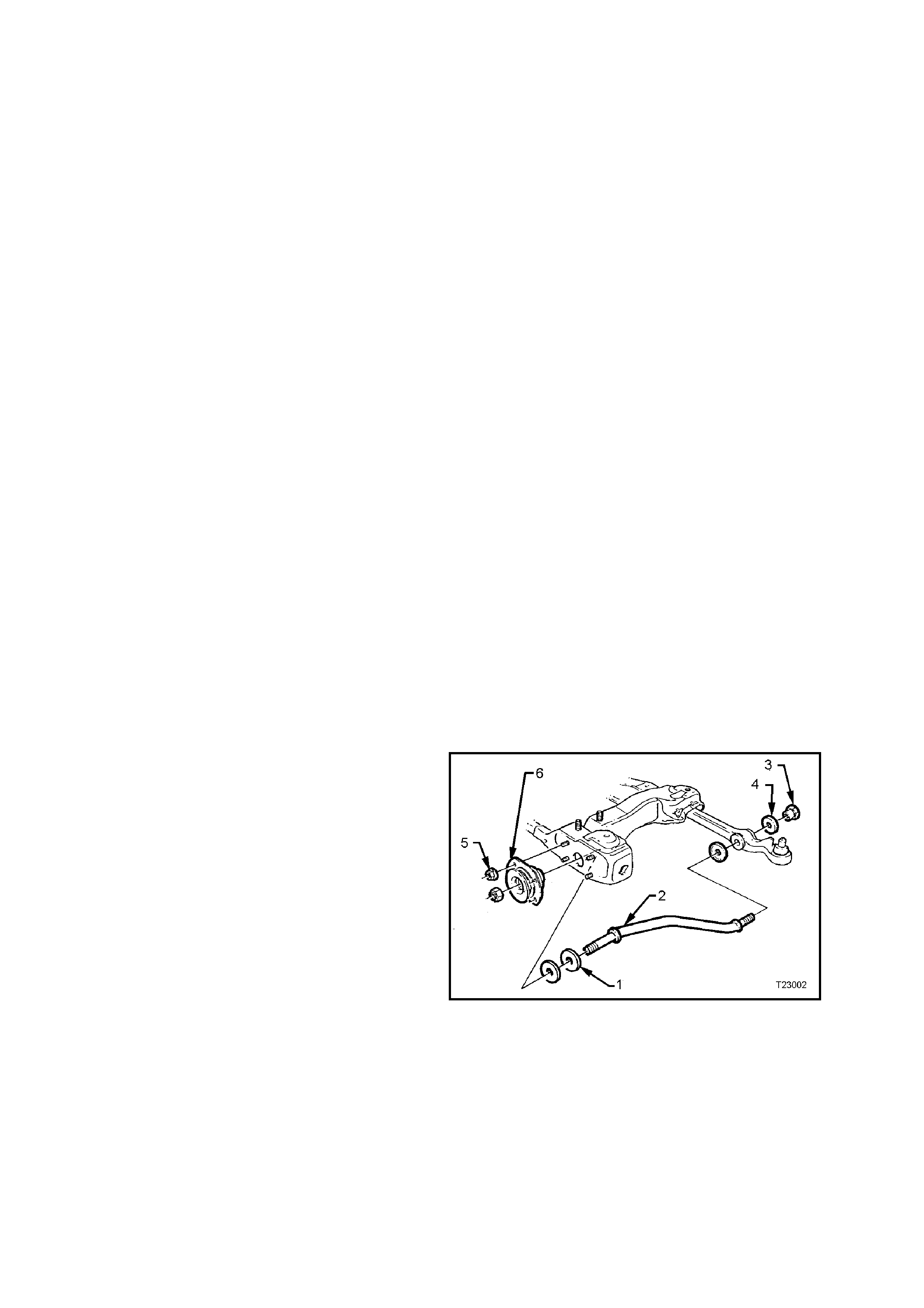
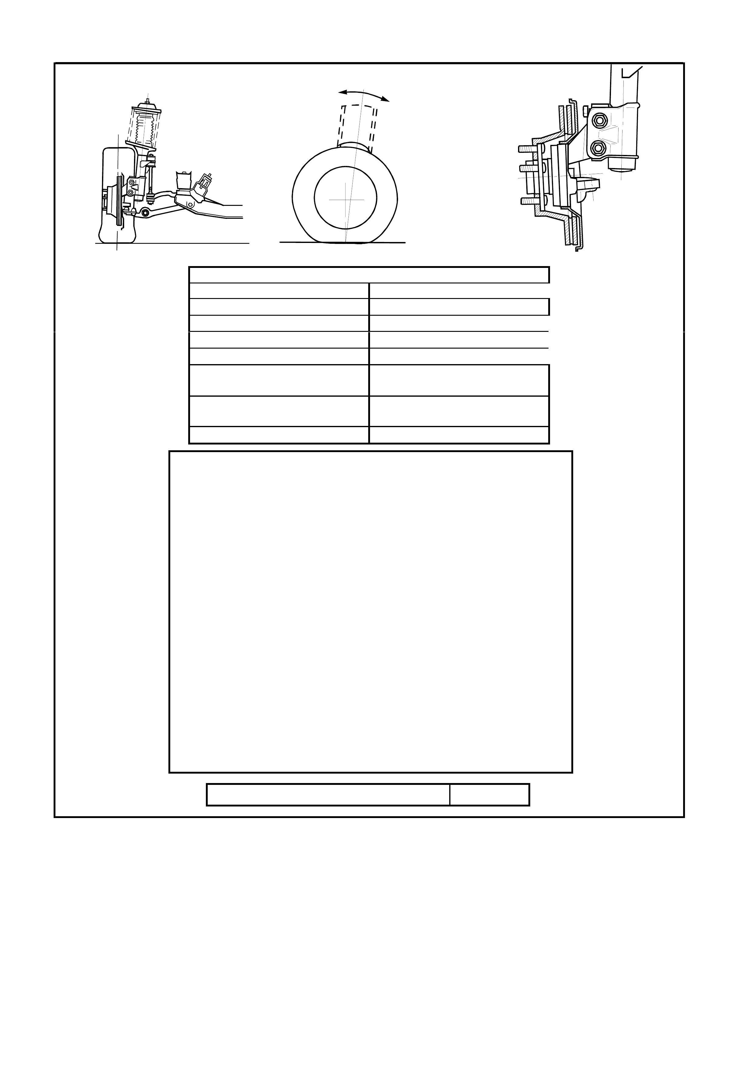
CASTER ADJUSTMENT
Only a nominal change in caster angle is
achievable and is limited to the addition (or
deletion) of a spacer washer (1) to one of the
tension rods (2). The sole purpose of fitting this
spacer is to equalis e c ast er angle f r om side to s ide,
to within 0° 30'. Only one spacer washer is to be
fitted and is to be added to the s ide with the higher
caster reading.
Figure 3-2
CAMBER ADJUSTMENT
1. Raise front of vehicle and support on safety
stands under f ront side members. Refer to 0A
GENERAL INFORMATION of this Service
Information CD for location of jacking and
support points.
2. Remove wheel cover (steel wheels) or centre
cap (alloy wheels) and mark relationship of
wheel to hub stud, using a felt tipped pen or
similar.
3. Remove wheel attaching nuts and remove
wheel.
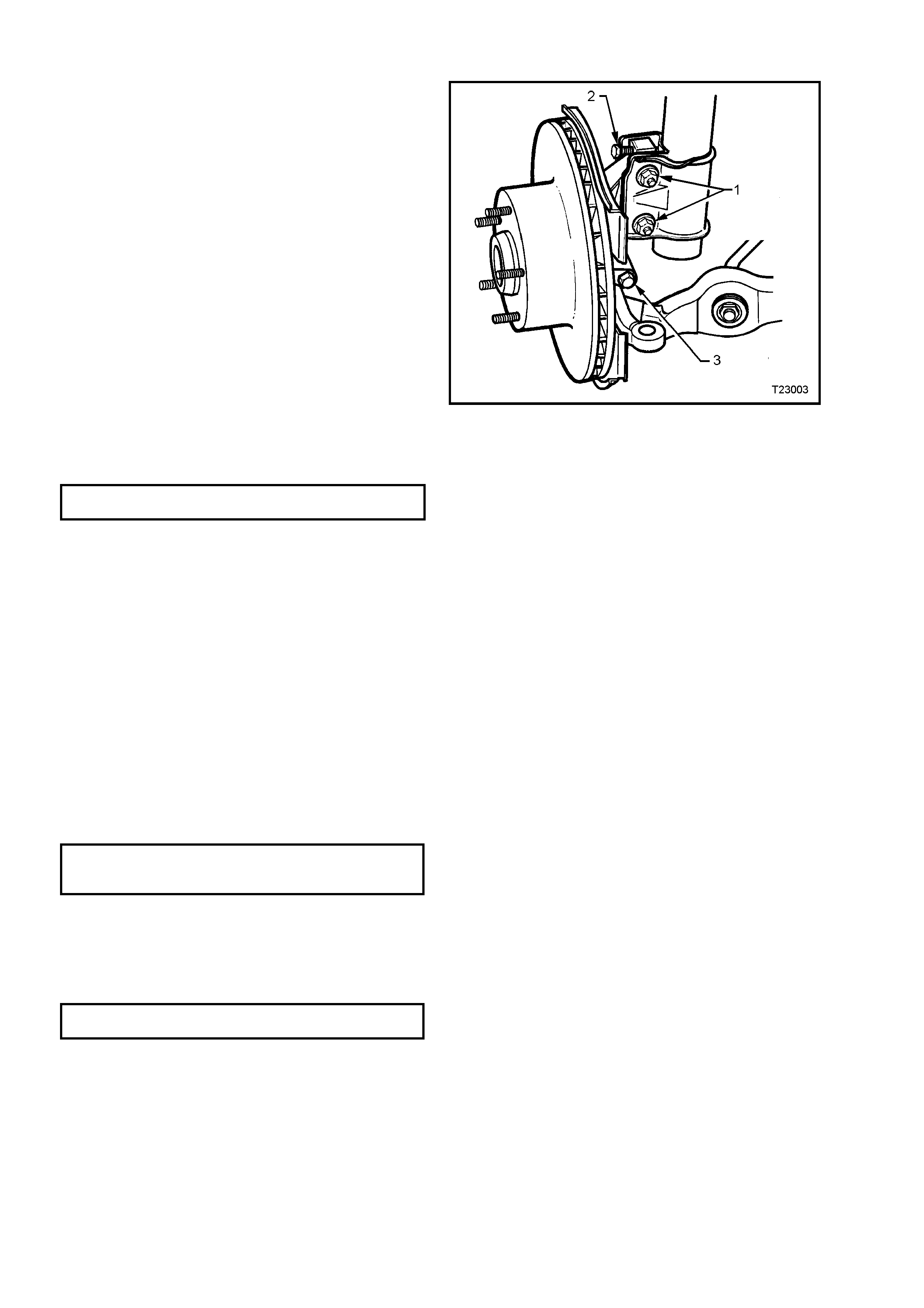
4. Loosen, remove and discard the two lower
strut attaching bolts and nuts (1).
Reinstall NEW lower strut attaching bolts and
nuts (1) but do not tighten fully to
specification until after the camber has been
adjusted to the recommended specification.
5. Reinstall road wheel, aligning previously made
marks. Install wheel nuts and tighten to the
correct torque specification. Do not over-
tighten!
ROAD WHEEL A T T A CHING NUT
TORQUE SPECIFICATION 110 - 140 Nm
6 Bounce vehicle several times to settle
supsension, then check the camber angle.
7. If required, adjust camber by turning the
camber adjusting screw (2) in the required
direction. Clockwise to reduce negative
camber, anti-clockwise to reduce positive
camber.
NOTE: The camber adjusting screw has thread
sealant applied in the form of micro-encapsulation
and does not require a lock nut.
Figure 3-3
8. Raise vehicle once again, support on safety
stands and remove the front road wheels.
9. Tighten both steering knuckle bolts and nuts
to the correct torque specification.
NOTE: New bolts and nuts MUST be used!
STEERING KNUCKLE TO STRUT Stage 1 85 Nm
ATTACHING BOLTS & NUTS Stage 2 100 Nm
TORQUE SPE CI F ICATION Stage 3 Turn through 90 °
10. Reinstall road wheels, aligning the marks
made prior to removal.
11. Remove jack stands and lower vehicle.
12. Tighten road wheel attaching nuts to correct
torque specifications. Do not over-tighten!
ROAD WHEEL ATTACHING NUT
TORQUE SPECIFICATION 110 - 140 Nm
13. Refit wheel cover/centre cap.
14. Check the camber angle again to ensure that
it is still within specification (refer to
Figure 3-6).
TOE ADJUSTMENT
Toe of both front wheels, is checked with the
wheels in the straight ahead position.
Adjustm ent is achieved by winding the tie rods in or
out of the tie rod ends, thus increasing or
decreasing their length and thereby altering the
toe-in setting.
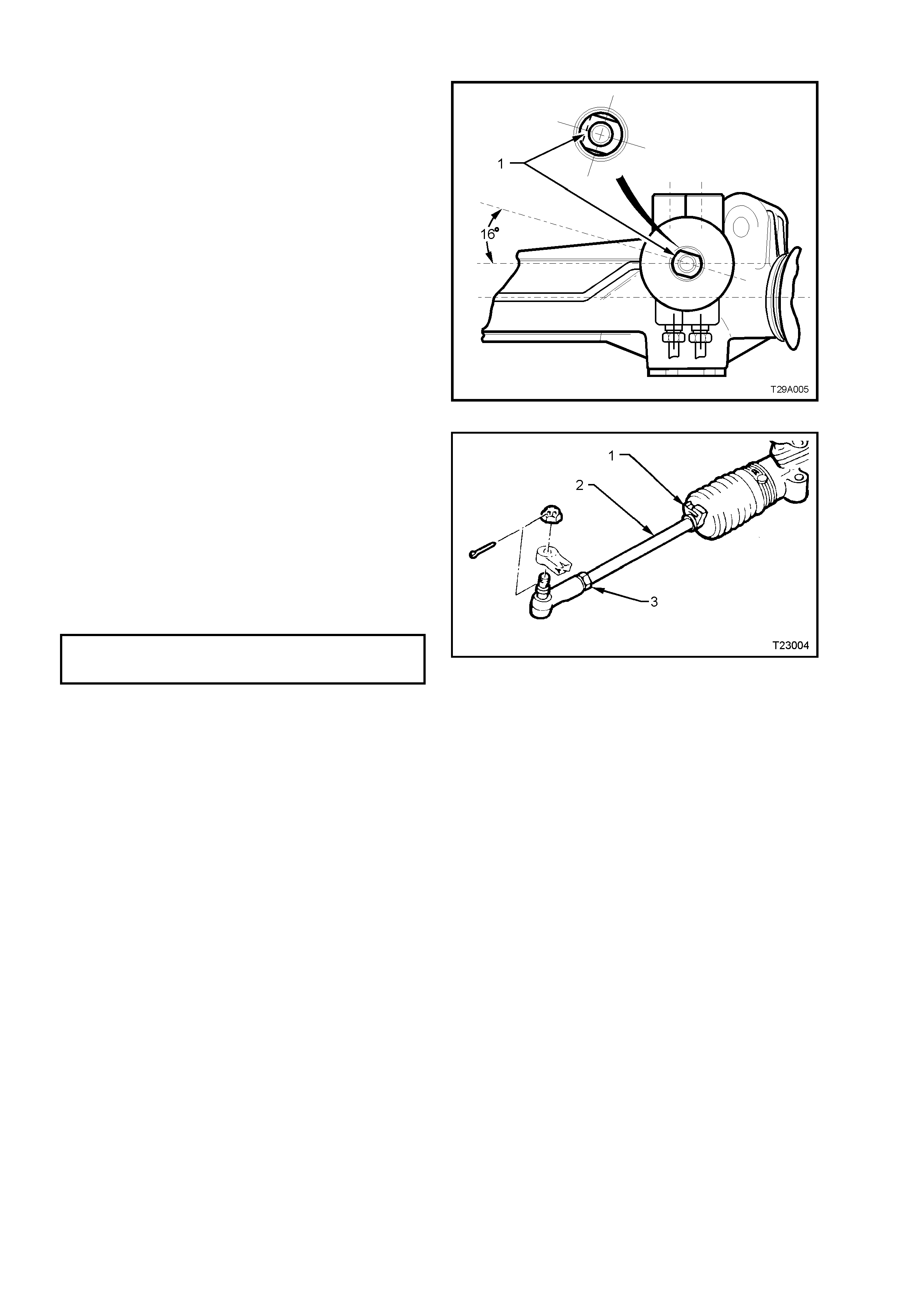
1. Set steer ing gear and wheels in straight ahead
position.
2. To check if steering gear is in straight ahead
position ( on-centre) , the pinion (input) s haft (1)
should be aligned as shown.
NOTE: While the one-piece steering rack housing
is shown, the on-centre position is the same for all
steering racks.
Figure 3-4
3. Before adjusting tie rods (2), disconnect
steering gear outer bellows clips (1).
4. Loosen lock nut (3) at end of each tie rod.
5. Turn each tie rod as required, until the correct
toe is obtained.
NOTE: During toe adj ustment, ensur e that steering
wheel is held in the straight ahead position.
6. Tighten lock nuts (3), to the correct torque
specification, ensuring that tie rod ends are in
alignment with their ball studs.
TIE ROD TO TIE ROD BALL
JOINT LOCK NUT 40 – 60 Nm
TORQUE SPECIFICATION
7. Tighten outer bellows clips securely, making
sure that convolutions of the boots are not
distorted.
8. With steering gear in straight ahead position,
ensure that steering wheel is centralised. If
not, rem ove steering wheel (refer to Section 9
STEERING of this Service Information CD)
and reposition.
Figure 3-5
FRONT WHEEL ALIGNMENT AT KERB WEIGHT
Wheel Alignment Angle Specification - All
Camber -0° 12' ± 0° 18'
Caster 7° 45' ± 1° 15'
Toe-in Degrees Total 0° 10’ ± 0° 10'
Degrees per Wheel 0° 5’ ± 0° 5’
Toe-out on Turns 1° 42’ @ 20 ° turn angle ± 1°
30'
Steering Axis Inclination
Angle 12° 52’ ± 1° 30'
Included Angle 12° 40’ ± 1° 30'
SERVICE INFORMATION
• The adjusting values for camber, caster and toe-in must remain
within the tolerances specified. The difference between left and
right must not exceed the following:
CASTER............. 0° 36'
CAMBER............ 0° 48'
TOE-IN ............... 0° 10'
• The specifications listed are the nominal value, with acceptable
variance from this central point. Where possible, an attempt
should always be made to achieve the nominal settings when
changing.
• Front wheel camber alters as a function of front suspension height.
• Camber adjusting bolt: After loosening both lower strut to steering
knuc kle bolts and nuts, adjus t camber by turning the adjusting bolt
clockwise to decrease negative camber and anti-clockwise to
increase negative camber. After adjustment, both bolts and nuts
MUST be replaced with new parts and tightened to the
recommended torque setting.
• The rear wheel alignment should be checked and corrected if
necess ary (refer to Sec tion 4. REAR SUSPENSION of this Service
Information CD) before checking front wheel alignment.
Fuel Mass with Full Tank - All Models 56 kg
Figure 3-6
3. SERVICE OPERATIONS
3.1 GENERAL
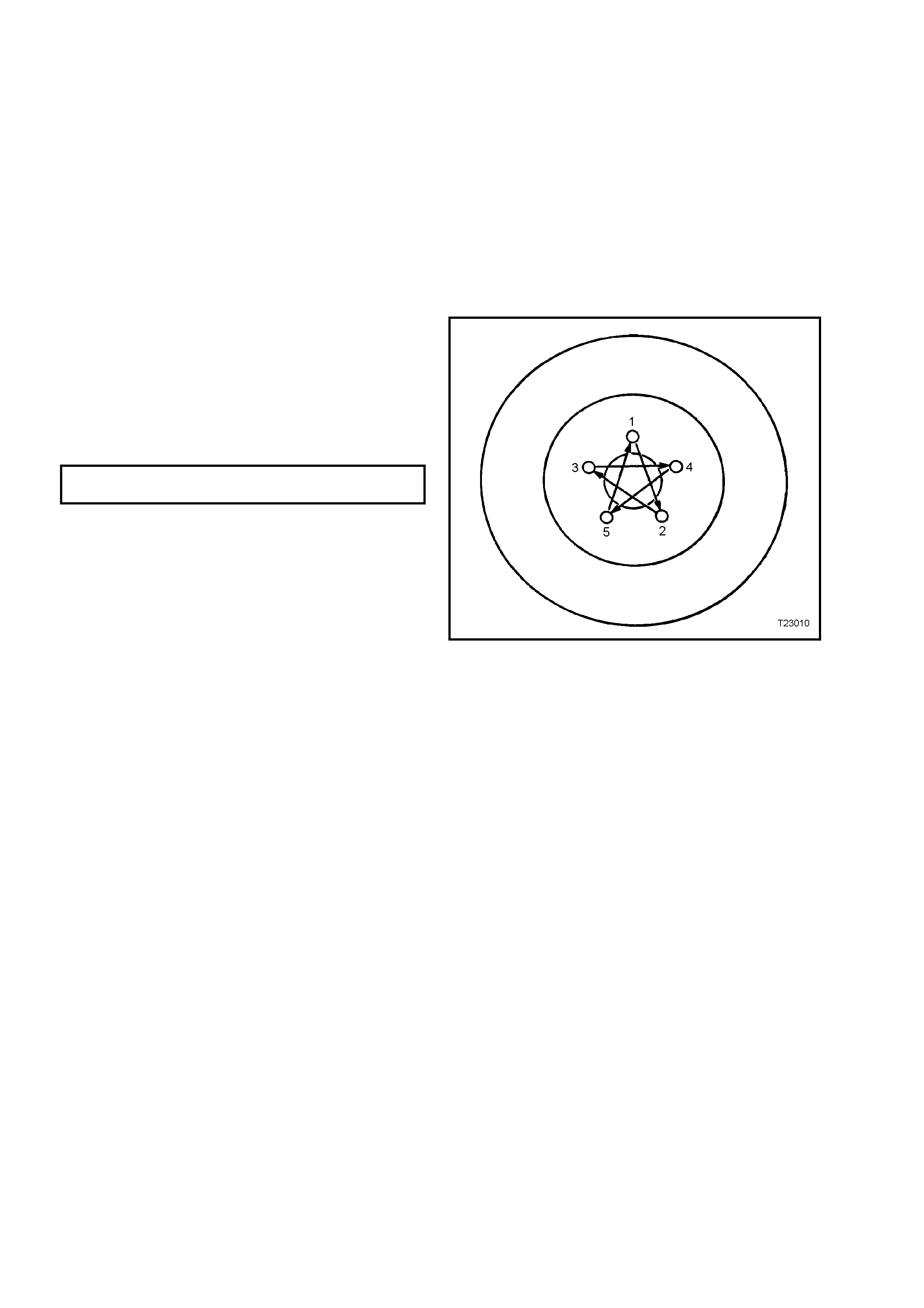
IMPORTANT SERVICE REQUIREMENTS
NOTE 1: Whenever a road wheel and/or brake
disc is removed from the vehicle, the
relationship of the road wheel to the hub and
the disc to the hub MUST be marked with a felt
tipped pen or similar, in order for those parts to
be reinstalled in their original positions. This is
critical to maintain the brake disc and road
wheel runout dimension to a minimum.
NOTE 2: When reinstalling road wheels, do not
use an impact gun to tighten wheel nuts,
unless it is fitted with a torque limiter bar
(commercially available). Failure to correctly
tighten wheel nuts to the correct torque
specification and in the correct order, may
result in a distorted brake disc, that may lead to
the development of brake shudder.
ROAD WHEEL ATTACHING NUT 110 – 140
TORQUE SPECIFICATION Nm
Figure 3-7

3.2 FRONT WHEEL HUB AND STEERING KNUCKLE
The m anufacturer of the front wheel hub has changed. Coinc ident with this change is a revision to the ABS sensor
lead retension, which has also resulted in a change to the front steering knuckle.
Note that a non-ABS hub will service back to earlier ‘V’ series vehicles but the ABS version will not, unless the
revised design steering knuckle is also changed.
Apart fr om wheel stud replacem ent, ther e are no ser viceable item s in the front wheel hub assem bly. As the unit is a
‘sealed for life’ assembly, neither bearing adjustment nor lubrication maintenance is required. Should a non-
standard condition develop, then the assembly must be replaced as a complete unit.
As with the earlier design hub, this design has zero axial free play or ‘end float’ but some angular movement may
be evident when a rocking force is applied to the mounted wheel and tyre assembly. Before a hub is replaced for
an excessive free play condition, refer to the checking procedure, detailed in Operation 2.4 in 3-FRONT
SUSPENSION, of this VT Series I Service Information.
A further revision to the design of the steering knuckle has meant that the wheel hub to knuckle sealing O-ring, is
no longer required.
Techline
3.3 SUSPENSION AND TRIM HEIGHT, CHECK
The suspension and trim height dimensions for standard vehicles with base equipment only, are provided in
4. SPECIFICATIONS in this Section.
The dimensions are for a new vehicle built to standard specification and only intended as a guide when
check ing suspens ion and trim height dim ensions at norma l curb weight. Norm al curb weight is defined as a vehicle
with a full tank of fuel, all fluids at the specified levels, spare tyre included, tyre pressures as specified and no
passengers. Accumulated dirt, mileage, etc., must also be taken into consideration when checking vehicle heights.
The following procedure should be followed before checking any suspension or trim height.
1. All checks must be c arried out on a LEVEL surfac e, after the vehicle's tyre press ures have been check ed and
it has been confirmed that the vehicle has not suffered accident damage.
2. On aver age, all VT Ser ies II vehicles will sit approxim ately 4 mm lower at the right hand side fr ont, because of
the vehicle's battery weight.
3. Push vehicle up and down several times at the front bumper bar with a decreasing force and then gently
remove hands, allowing vehicle to settle on its own. Carry out vehicle front trim and suspension height check.
4. Push vehicle up and down several times at the rear bumper bar with a decreasing force and then gently
remove hands, allowing vehicle to settle on its own. Carry out vehicle rear trim and suspension height check.
As shown in the specification listing (refer to 4. SPECIFICATIONS in this Section), there are two different
dimensions that must be checked and the location for the measurements to be taken is critical to correctly
establishing a st andard vehicle condition. When check ing a vehicle's ride height, the following tolerances m ust also
be taken into account, before any spring is replaced.
RIDE HEIGHT VARIATIONS FROM SPECIFICATION
FRONT TO REAR................................ ± 20 mm
SIDE TO SIDE..................................... ± 10 mm
NORMAL SPRING SETTLING............ ± 5 mm
NOTE: Ride height variation may also be due to any one or a combination of the following:
a. Spring seat location on the suspension/body.
b. Incorrect springs; Check spring identification against the table shown in 4. SPECIFICATIONS in this Section.
c. Non-standard, additional vehicle weight, such as a tow bar and/or after-market LPG fitment.
d. Any combination of the above.
CAUTION: Good judgement must be exercised before replacing a spring or springs from a vehicle whose
height is within the limits quoted. Even should a vehicle's dimensions prove to be slightly outside these
tolerances, the vehicle could well be in a serviceable condition.
Spring replacement under conditions of excessive weight due to non standard fittings, undercoating, road
dirt, etc; will assist very little in restoring the vehicle to its specified height.
4. SPECIFICATIONS
SUSPENSION
Type MacPherson Wet Strut
Application All VT Models
Travel
Compression
(2/3compression of bumper)
Rebound
Standard and V5W
90 mm
110 mm
FE2
80 mm
120 mm
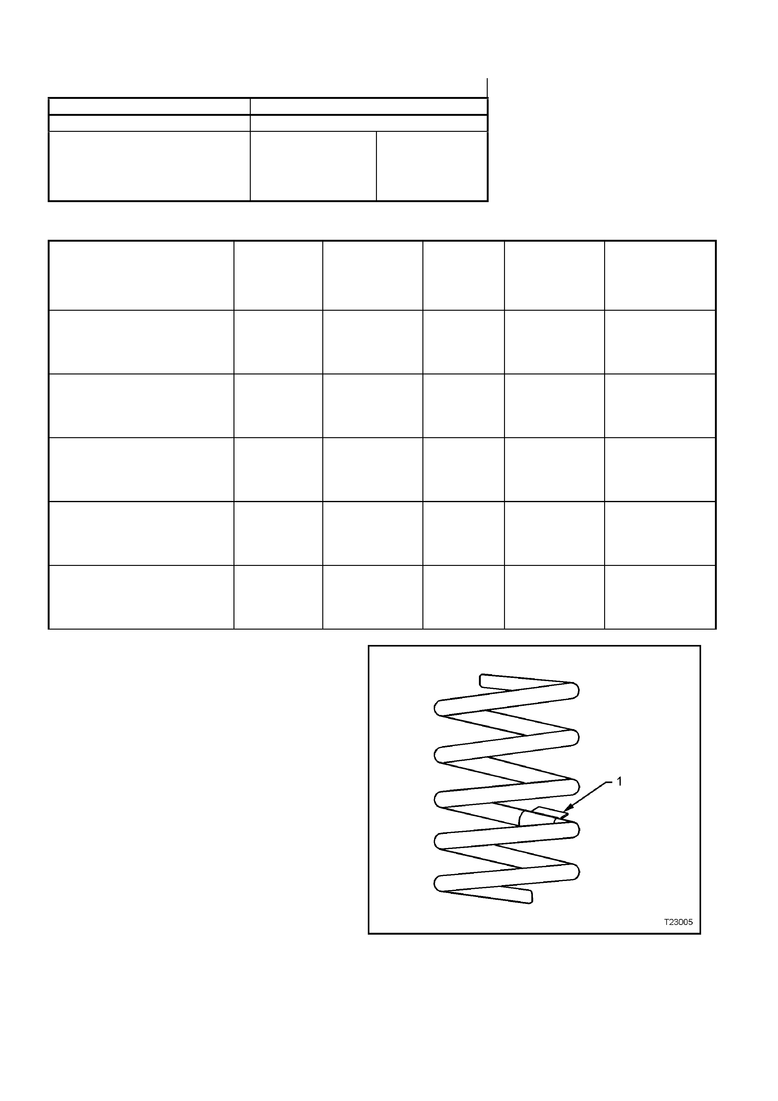
FRONT SPRING SPECIFICATIONS
MODELS Approximat
e
Number
COILS
Approximate
FREE
LENGTH
(mm)
INSIDE
DIAMETE
R
(mm)
PROD. I.D.
CODE
(Tag on
spring)
SPRING TYPE
& RATE
V6 ENGINE -SEDAN & STATION
WAGON MODELS – S T ANDARD
SUSPENSION. 6.05 444 136 ± 1.5 HN VARIABLE
19 - 23 N/mm
(3700 ± 110 N @
210 mm)
V6 ENGINE -SEDAN & STATION
WAGON MODELS - FE 2 S P O RTS
SUSPENSION. 5.25 341 136 ± 1.5 HJ VARIABLE
24 - 31 N/mm
(3660 ± 110 N @
200 mm)
V6 ENGINE - SEDAN & STATION
WAGON MODELS - V5W
COUNTRY PACK SUSPENSION 6.12 376 136 ± 1.5 HS VARIABLE
24 - 31 N/mm
(3660 ± 110 N @
230 mm)
V6 SUPERCHARGED & GEN III V8
ENGINES -SEDAN & STATION
WAGON MODELS - STANDARD
SUSPENSION.
6.05 444 136 ± 1.5 HN VARIABLE
19 - 23 N/mm
(3700 ± 110 N @
210 mm)
V6 SUPERCHARGED & GEN III V8
ENGINES -SEDAN & STATION
WAGON MODELS – FE2 S PORTS
SUSPENSION.
5.70 348 136 ± 1.5 HT VARIABLE
25 – 35 N/mm
(3825 ± 110 N @
194 mm)
Figure 3-8
LEGEND
1. Production Identification Code Tag
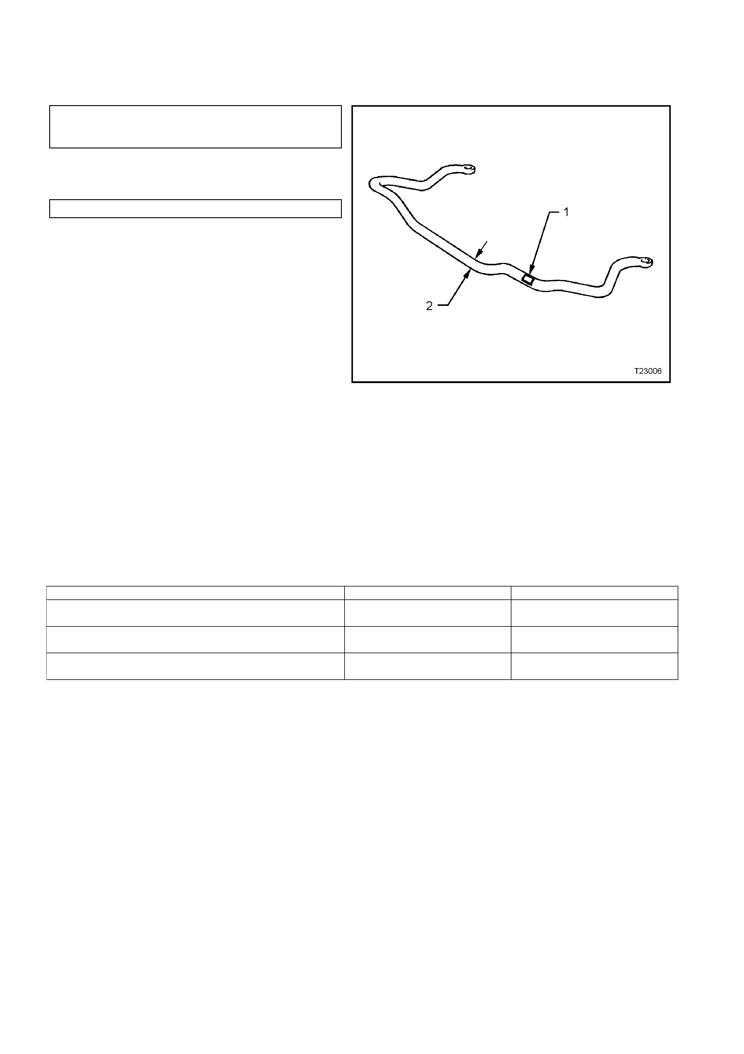
STABILISER BAR (FRONT)
Type ......................................................................... Decoupled
STABILISER BAR IDENTIFICATION
Diameter I.D.
MODELS mm CODE
(2) (1)
All VT Series II Models and
Suspensions, except for
Sedan with FE2 26.0 GE
Sedan Models and FE2 Suspension 27.0 GH
Figure 3-9
LEGEND
1. Production Identification Code Tag
2. Stabiliser Bar Diameter
FRONT STRUT
Type........................................................................ Wet strut – non-serviceable
Piston Diameter ...................................................... 30 mm
Fluid Type............................................................... Hydraulic fluid to Holden Specification HN 1588
Capacity............................................................. 350 ml
FRONT STRUT ID ENTIFICATION
Suspension and Application Right Hand Side Left Hand Side
STANDARD SUSPENSION –
SEDAN AND STATION WAGON RS LS
SPORTS SUSPENSION (FE2) –
SEDAN AND STATION WAGON RT LT
COUNTRY PACK SUSPENSION –
SEDAN AND STATION WAGON RU LU
CONTROL ARM
Type........................................................................ Forged with rubber bushes for attachment to front
crossmember and tension rod. Ball joint is a press fit
into the control arm.
FRONT WHEEL BEARINGS
Type........................................................................ Double row ball bearing
Lubricant................................................................. Sealed for life: non-adjustable
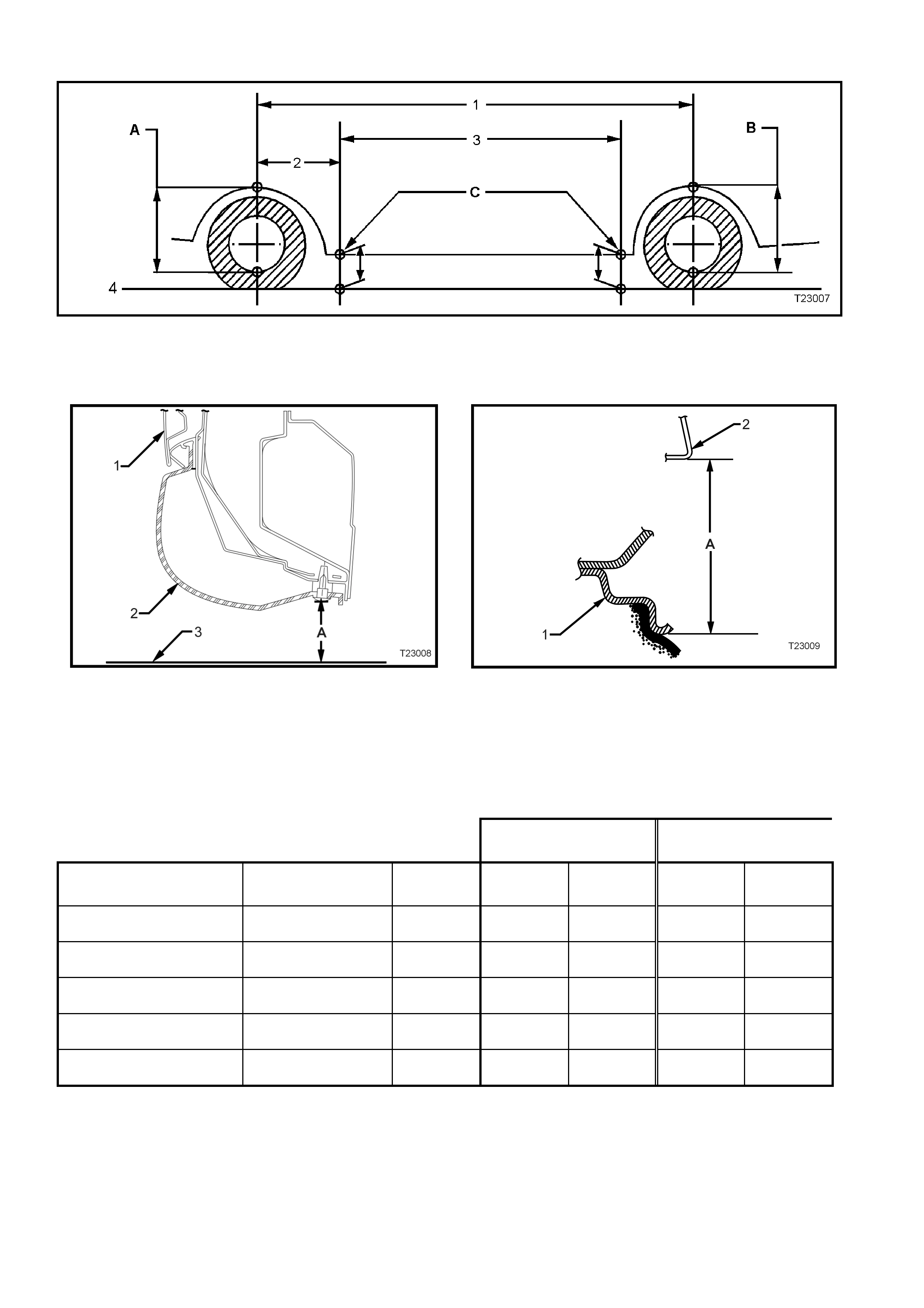
SUSPENSION A ND TRIM HEIGHT SPECIFICATIONS
A Front Suspension Height
B Rear Suspension Height
C Trim Height Checking Locations
1. Wheelbas e: All VT Sedan – 2798 mm
All Station Wagon – 2935 mm
2. Referenc e P oi nt
: All Models – 584.5 mm
3. Trim Hei ght Spacing:
All Sedan – 1615 mm
All Station Wagon – 1765 mm
4. Ground Line
Figure 3-10
1. Door 2. Trim 3 Ground Line ‘A’ Trim Height 1. Wheel Rim 2. Fender Opening ‘A’ Sus pension Height
Figure 3-11 – Rear Trim Height Checking Location (Front
Similar) Figure 3-12 – Front and Rear Suspension Height
Checking Location
NOTE: The following suspension/trim height dimensions are intended for reference and are intended to be a guide
only (Refer to 3.3 SUSPENSION AND TRIM HEIGHT CHECK, in this Section).
VT SERIES II MODELS WITH V6 ENGINE AND STANDARD SUSPENSION
SUSPENSION HEIGHT
(mm) TRIM HEIGHT
(mm)
VEHICLE
DESCRIPTION TRANSMISSION MODEL FRONT REAR FRONT REAR
Executive Sedan Manual Base 593 583 192 201
Berlina Sedan Automatic Base 593 583 192 201
Calais Sedan Automatic Base 593 583 192 201
Executive Station Wagon Manual Base 603 573 192 210
Berlina Station Wagon Automatic Base 598 582 192 210

5. TORQUE SPECIFICATIONS
NOTE: Only those torque specifications that relate to service operations described in this Section, are included
here. For all other torque specification relating to the steering system, refer to either Section 9A STEERING of the
VT Series I Information or Section 9A STEERING of the VT Series II Information. Nm
Steering Knuckle to Strut Attaching Bolts and Nuts Stage 1............ 85
Stage 2............ 100
Stage 3............ Turn through 90°
Road Wheel Attaching Nut................................................................ 110 - 140
Tie Rod to Tie Rod Ball Joint Lock Nut............................................. 40 – 60