SECTION 4A – REAR SUSPENSION
CAUTION:
This vehicle will be equipped with a Supplemental Restraint System (SRS). A SRS will consist of either
seat belt pre-tensioners and a driver's air bag, seat belt pre-tensioners and a driver's and front
passenger's air bag s or seat belt pre-t ensioners, driver’s an d front passenger’s air bag and left and right
hand side air bags. Refer to SAFETY PRECAUTIONS, Section 12M, Supplemental Restraint System of
this Service Information CD before performing any service operation on, or around any SRS
components, the steering mechanism or wiring. Failure to follow the SAFETY PRECAUTIONS could
result in SRS deployment, resulting in possible personal injury or unnecessary SRS system repairs.
CAUTION:
Whenever any component that forms part of the ABS or ABS/ETC (if fitted), is disturbed during Service
Operations, it is vital that the complete ABS or ABS/ETC system is checked, using the procedure as
detailed in 4. DIAGNOSIS, ABS or ABS/ETC FUNCTION CHECK, in Section 12L ABS & ABS/ETC, VT
Series I Service Information (V6) or VT Series II Service Information (GEN III V8).
CAUTION:
This vehicle may be equipped with LPG (Liquefied Petroleum Gas). In the interests of safety, the LPG
fuel system should be isolated by turning ‘OFF’ the manual service valve and then draining the LPG
service lin es, bef ore an y serv ice work is carried o ut on t he v eh icle. Ref er to the L PG leaf let in clud ed with
the Owner's Handbook for details or the appropriate section of this Service Information CD for more
specific servicing information.
1. GENERAL INFORMATION
A local sourc e of rear suspens ion trailing arm s is to be f itted to VT Ser ies II vehicles f rom an antic ipated break point
in late January, 2000.
As the new trailing arm requires new special tools to service the trunnion and/or bearing, should work be required
on these components, then correct identification of the trailing arm will be required. Refer to
2.2 TRAILING ARM IDENTIFICATION, in this Section for details.
The remaining service operations detailed in this Section, update previously published procedures, reflect revised
torque specifications or updated illustrations.
Apart from this change and revisions to the suspension specifications to reflect the introduction of the GEN III V8
engine and to optimise vehicle handling characteristics, all other service operations remain as detailed in
4A REAR SUSPENSION of the VT Series I Service Information.
2. SERVICE OPERATIONS
2.1 SERVICE NOTES
IMPORTANT SERVICE REQUIREMENTS
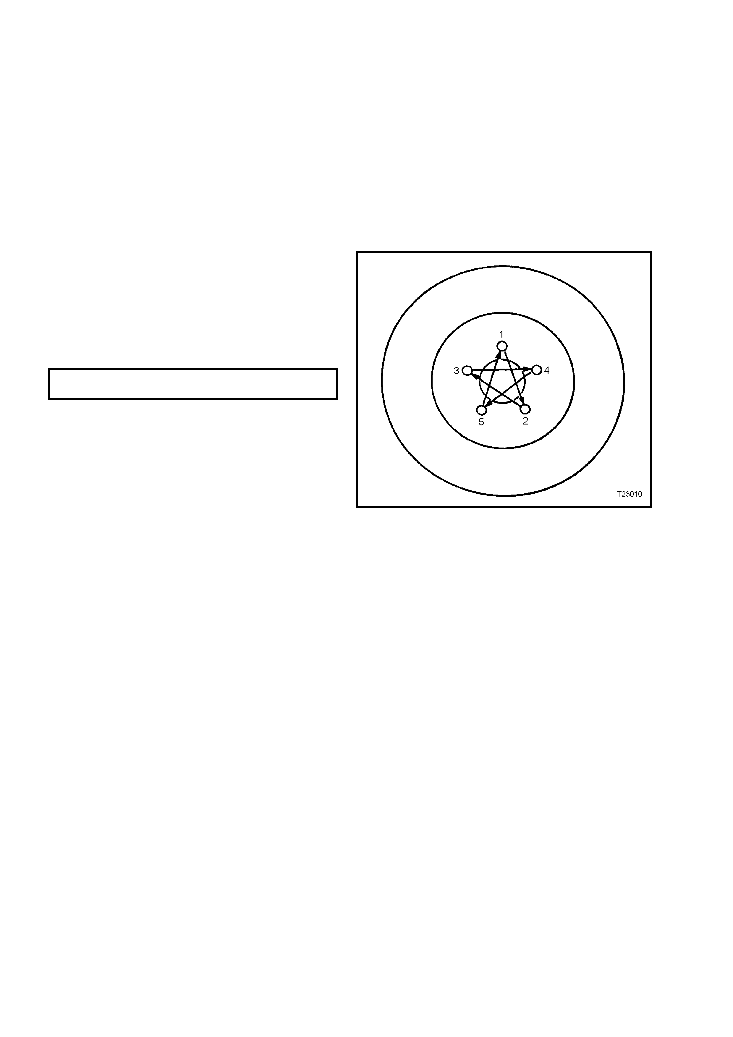
1. Whenever a road wheel and/or brake disc is
removed from the vehicle, the relationship of
the road wheel to the hub and the disc to the
hub MUST be marked with a felt tipped pen or
similar, in order for those parts to be reinstalled
in their original positions. This is critical to
maintain the brake disc and road wheel runout
dimension to a minimum.
2. When reinstalling road wheels, do not use an
impact gun to tighten wheel nuts, unless it is
fitted with a torque limiter socket (Tool No
AU534). Failure to correctly tighten wheel nuts
to the correct torque specification and in the
correct order, may result in a distorted brake
disc, that may lead to the development of
brake shudder.
ROAD WHEEL ATTACHING NUT
TORQUE SPECIFICATION 110 – 140 Nm
Figure 4A-1
3. All rear suspension fasteners are important
attaching parts because they affect the
performance of vital components and/or could
result in major repair expense. Where
specified in this Section, fasteners MUST be
replaced with ones of the s ame par t number or
with an equivalent part. Do not use a
replacem ent part of inf erior quality or substitute
design.
4. Torque values must be used as specified
during reassembly to ensure proper retention
of all rear suspension components.
2.2 TRAI LING ARM IDENTIFICATION
CAUTION: Whenever any component that
forms part of the ABS (if fitted) is disturbed
during Service Operations, it is vital that the
complete ABS system be checked, using the
procedure as detailed in DIAGNOSIS, ABS
FUNCTION CHECK, in Section 12L ABS &
ABS/ETC, VT Series I Service Information
(V6 engine) or Section 12L ABS & ABS/ETC VT
Series II Service Information (GEN III V8
engine).
As the introduction of the changed source of
trailing arm manufacturer has been on a ‘staged’
basis over a per iod of tim e, identification of the two
types is necessary if service work is to be carried
out on the trunnion and/or bearing.
The most effective way of identifying the locally
sourced trailing arm is a visual inspection, that can
be achieved by the following procedure.
1. Using a floor jack under centre of differential
carrier, j ack up r ear of vehicle and plac e safety
stands under body rear jack ing points. Ref er to
Section 0A GENERAL INFORMATION of the
VT Series I Service Information for location of
jacking points.
2. Remove wheel cover (steel wheels) or centre
cap ( alloy wheels) f rom the requir ed side of the
vehicle.
3. Mark relationship of road wheel to hub (e.g.
end of wheel stud), with a felt tipped pen or
similar. Loosen then remove road wheel
attaching nuts. Remove the road wheel.
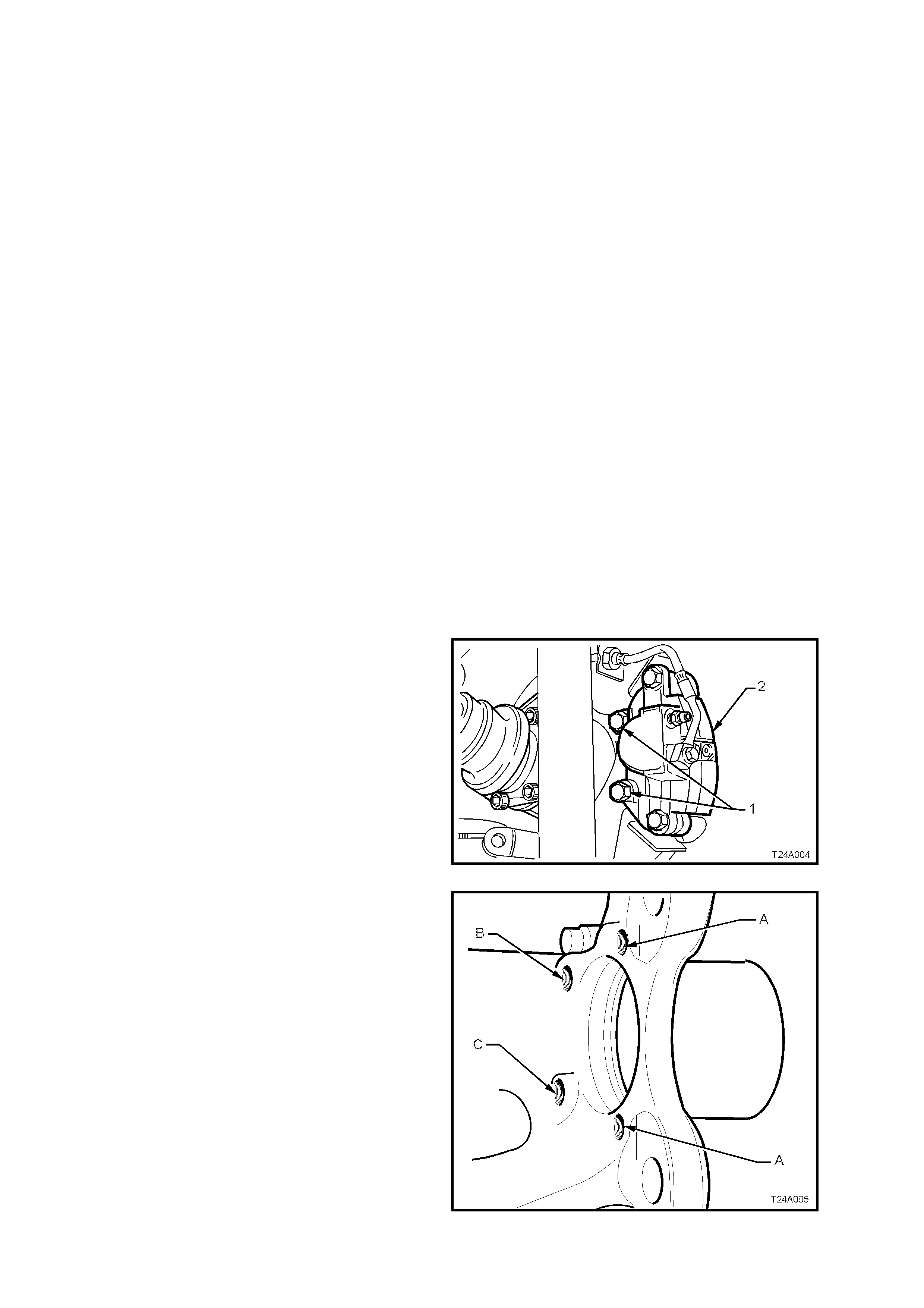
4. Remove brake caliper anchor plate to trailing
arm attaching bolts (1) and remove caliper (2)
from disc. Support the brake caliper with tie
wire secured to the vehicle underbody. THE
CALIPER IS NOT TO HANG BY THE BRAKE
HOSE.
Figure 4A-2
5. Visually observe the protrusions from the rear
of the trunnion housing. If the two inner
protrusions (‘B’ and ‘C’) are higher than the
outer two (‘A’) and each are of diff ering heights
to each other (as shown in Fig. 4A-3), then the
trailing arm is of local manufacture.
The service operations relating to the trunnion
and/or bearing are included in this Section.
Should the protrusions all be of the same
height, then the trailing arm is of the earlier
design.
For s ervice operations on this trunnion/bearing,
refer to 2.5 TRAILING ARM, in Section 4A
REAR SUSPENSION, of the VT Series I
Service Information.
NOTE: T he view shown does not include the brak e
backing plate, trunnion or inner trunnion flange, to
more clearly show the protrusion differences.
Figure 4A-3

6. Referring to Figure 4A-2, reinstall the brake
caliper (2) to the trailing arm, reinstall brake
caliper anchor plate to trailing arm attaching
bolts (1) and tighten to the correct torque
specification.
BRAKE CALIPER ANCHOR PLATE
TO TRAILING ARM ATTACHING 70 – 100 Nm
BOLT TORQUE SPECIFICATION
7. Reinstall road wheel, aligning marks made
before removal and reinstall attaching nuts.
8. Lower vehicle to the ground and tighten road
wheel attaching nuts to the correct torque
specification, working in a ‘star’ pattern. Refer
2.1 SERVICE NOTES in this Section for more
details.
ROAD WHEEL ATTACHING NUT
TORQUE SPECIFICATION 110 – 140 Nm
9. Refit wheel cover/centre cap.
2.3 TRAILING ARM
CAUTION: Whenever any component that
forms part of the ABS (if fitted) is disturbed
during Service Operations, it is vital that the
complete ABS system be checked, using the
procedure as detailed in DIAGNOSIS, ABS
FUNCTION CHECK, in Section 12L ABS &
ABS/ETC, VT Series I Service Information (V6
engine) or Section 12L ABS & ABS/ETC VT
Series II Service Information (GEN III V8
engine).
NOTE: For this service operation, new trailing arm
to crossmember lock nuts, and if necessary,
trunnion flange to trunnion assembly collar nut and
lock plate, must be used on reassembly.
REMOVE
1. Using a floor jack under centre of differential
carrier, jack up rear of vehicle and place safety
stands under body rear jack ing points. Ref er to
Section 0A GENERAL INFORMATION of the
VT Series I Service Information
2. On the side of the vehicle where the trailing
arm is to be removed, mark relationship of
road wheel to hub (e.g. end of wheel stud),
with a felt tipped pen or similar. Loosen then
remove road wheel attaching nuts. Remove
the road wheel.
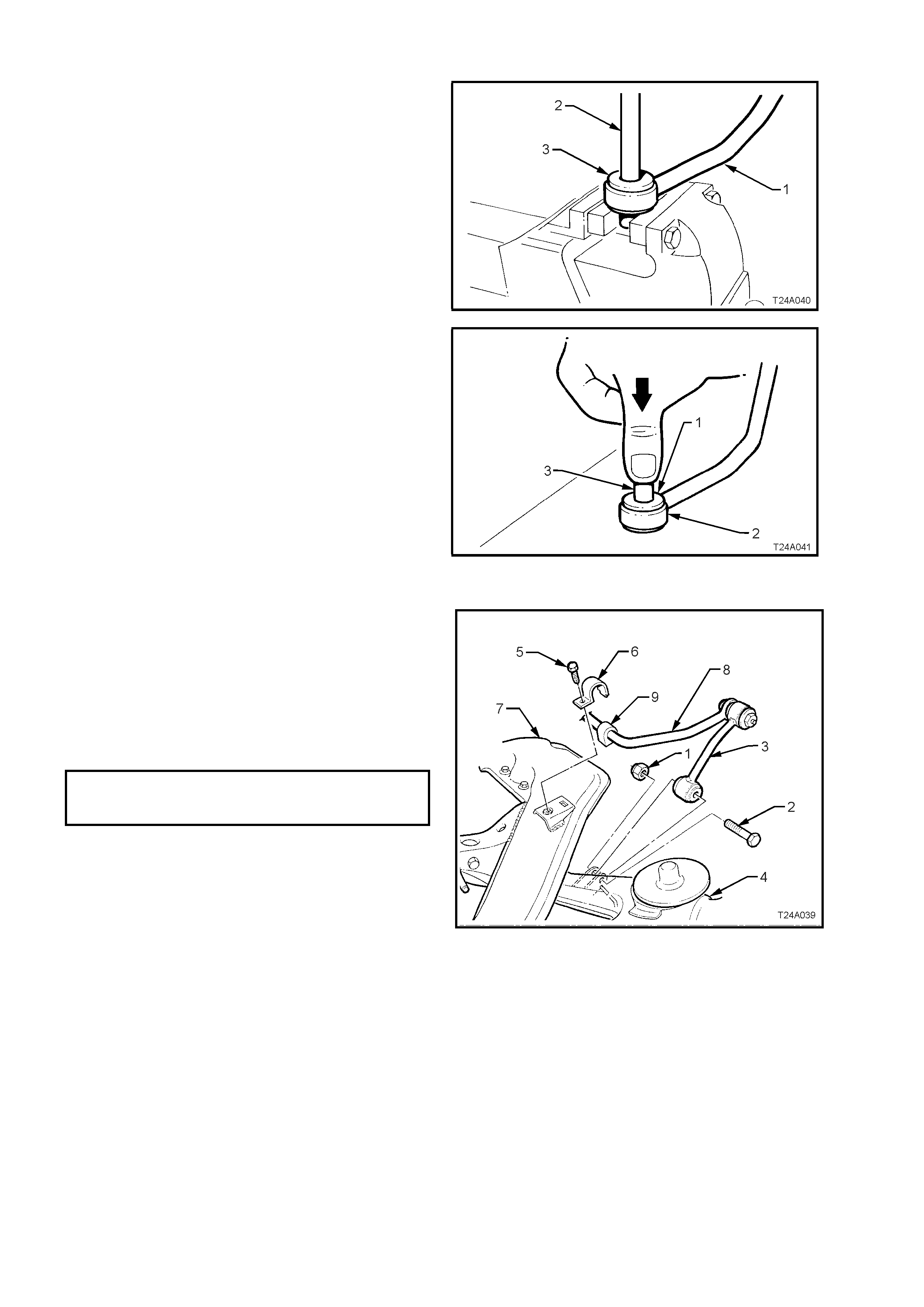
3. Loosen both stabiliser bar link (1), attaching
bolts (2) and nuts, to reduce stress on the
insulator bushes.
4. Remove the stabiliser link to trailing arm
attaching bolt and nut from side of vehicle
where the trailing arm is to be removed.
Figure 4A-4
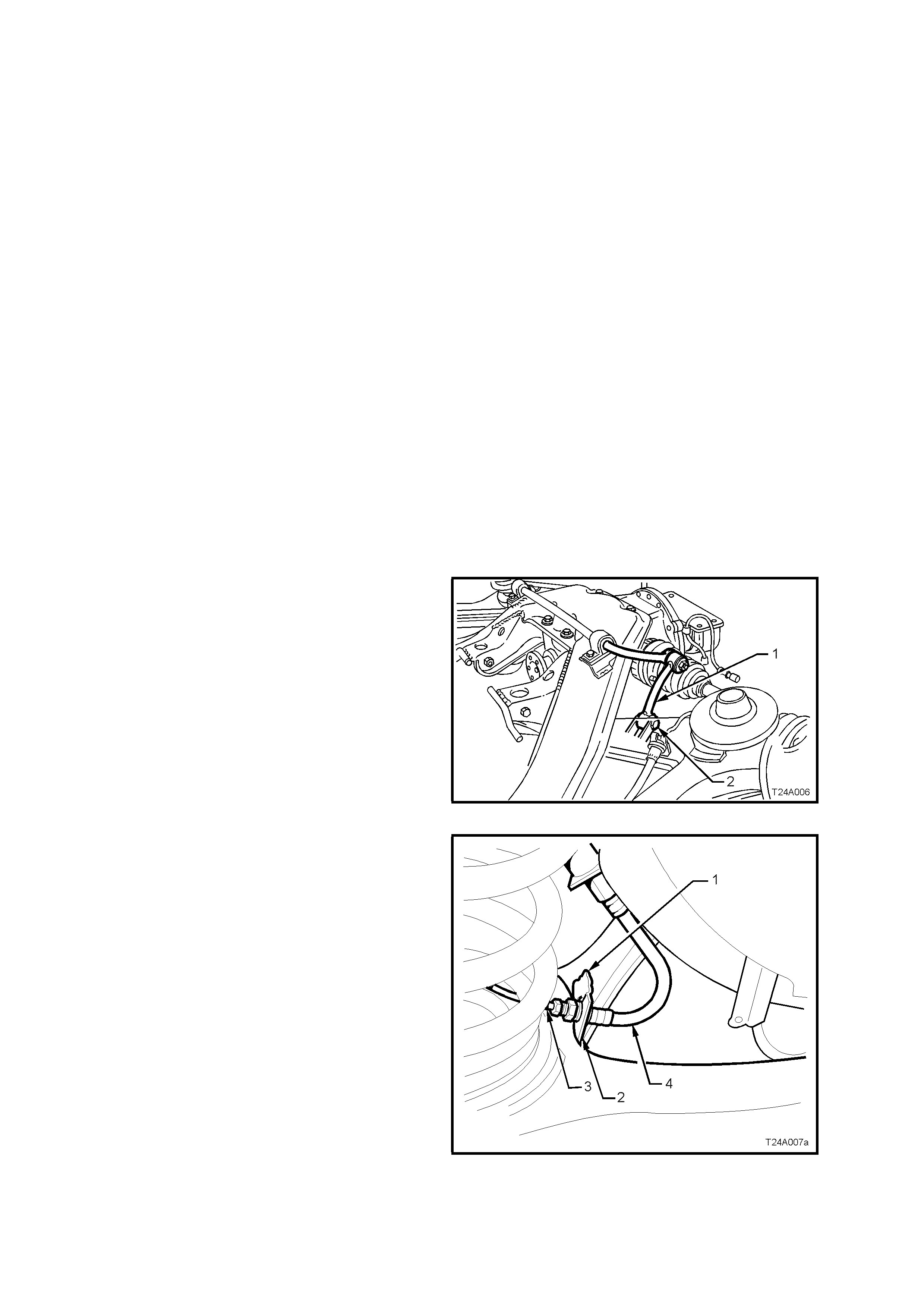
5. Remove r ear brake hos e retaining clip (1) fr om
trailing arm bracket (2) on the side to be
removed. Pull brake pipe (3) and hose (3)
forward from bracket, then disconnect from
trailing arm by lifting brak e pipe up through slot
in bracket.
Figure 4A-5
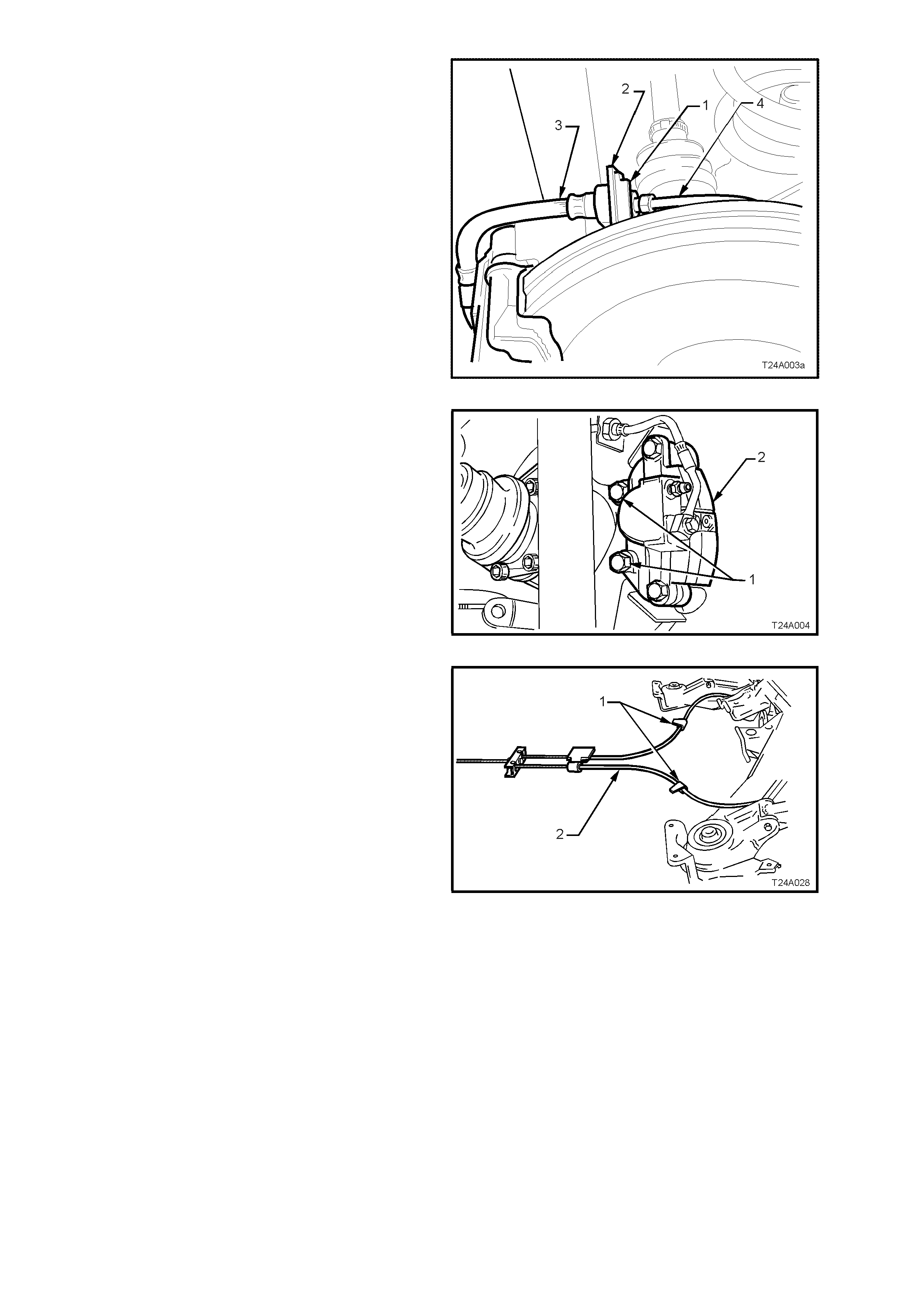
6. Remove brake hose retaining clip (1) from
brake backing plate bracket (2). Disconnect
rear caliper brake pipe (4) from brake hose (3)
and disconnect pipe f rom bac k ing plate bracket
(2).
Plug open ends of brake pipe (4) and hose (3)
to prevent fluid loss and foreign matter entry.
Figure 4A-6
7. Remove brake caliper anchor plate to trailing
arm attaching bolts (1) and remove caliper (2)
from disc. Set the brake caliper to one side.
Important: If the brake pipe to hose is not
disconnected, the brake caliper must be supported
with tie wire secured to the vehicle underbody.
THE CALIPER IS NO T T O HANG BY THE BRAKE
HOSE.
Figure 4A-7
8. Set park brake in fully released position, then
release each of the underbody to park brake
cable (1) retaining clips (2) and free cables (1).
Figure 4A-8
9. Remove park brake outer cable retaining
bracket bolt (underbody bracket and bolt are
not shown) from the vehicle underbody.
10. Pull each park brake inner cable forward and
up, (1) out of the c able retainer to release each
cable.
11. Pull the outer cable rearward (2) to remove
from the underbody retainer.
12. Remove brake disc from the wheel bearing
hub.
NOTE 1: While the brake disc to hub location is
marked in production, ensure that the disc to hub
position is carefully marked (e.g. disc to end of
wheel stud), with a felt tipped pen or s im ilar. T his is
necessar y to overcome the pos sibility of inducing a
brake shudder condition after reassembly.
NOTE 2: Should it be necessary to adjust the park
brake shoe to allow the brake disc to be removed,
refer to 5A STANDARD BRAKES, of the VT
Series I Service Information, for the necessary
procedure.
Figure 4A-9
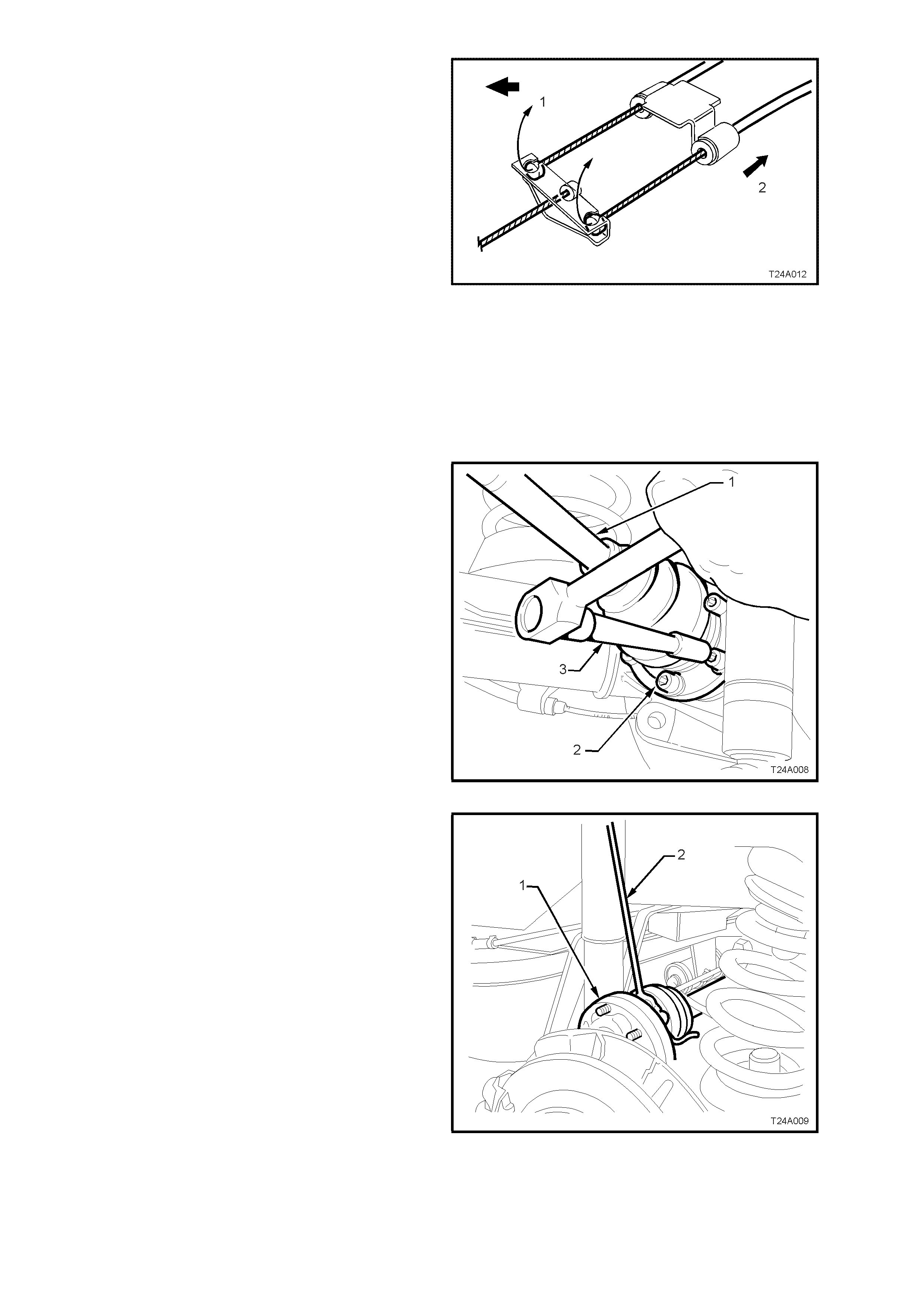
13. Using T ool No. KM468 over the wheel studs to
hold trunnion assembly hub from rotating,
loosen the six drive shaft (1) outer constant
velocity joint to trunnion flange attaching bolts
(2), using an 8 mm Allen key socket and bar
(3).
Figure 4A-10
14. Disconnect drive shaft (1) from flange and lift
upward. While keeping the outer constant
velocity joint in the same plane as the
driveshaft, use a piece of wire (2), tie up drive
shaft (1) to lower end of shock absorber upper
mounting.
NOTE: Bruising to the inside of the drive shaft
constant velocity joint boots will occur if the trailing
arm is lowered. This will lead to premature failure
of the boot and eventual failure of the joint if left
unchecked.
This is why it is im portant that the constant velocity
joint be disconnected from the trunnion flange
before removing the shock absorber lower
mounting bolt.
Figure 4A-11
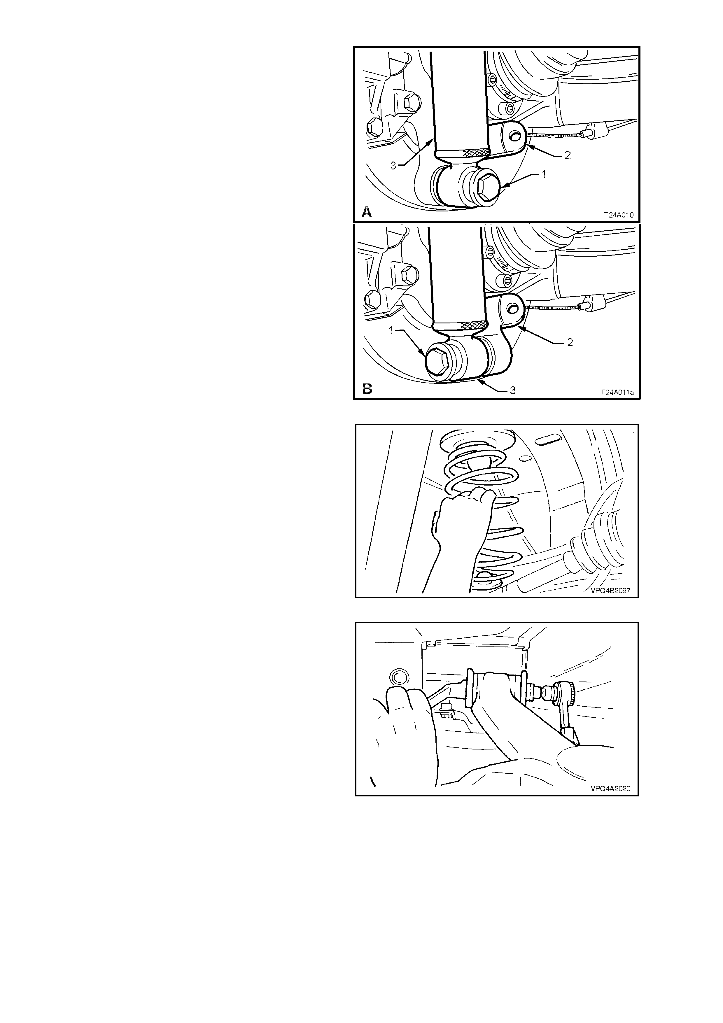
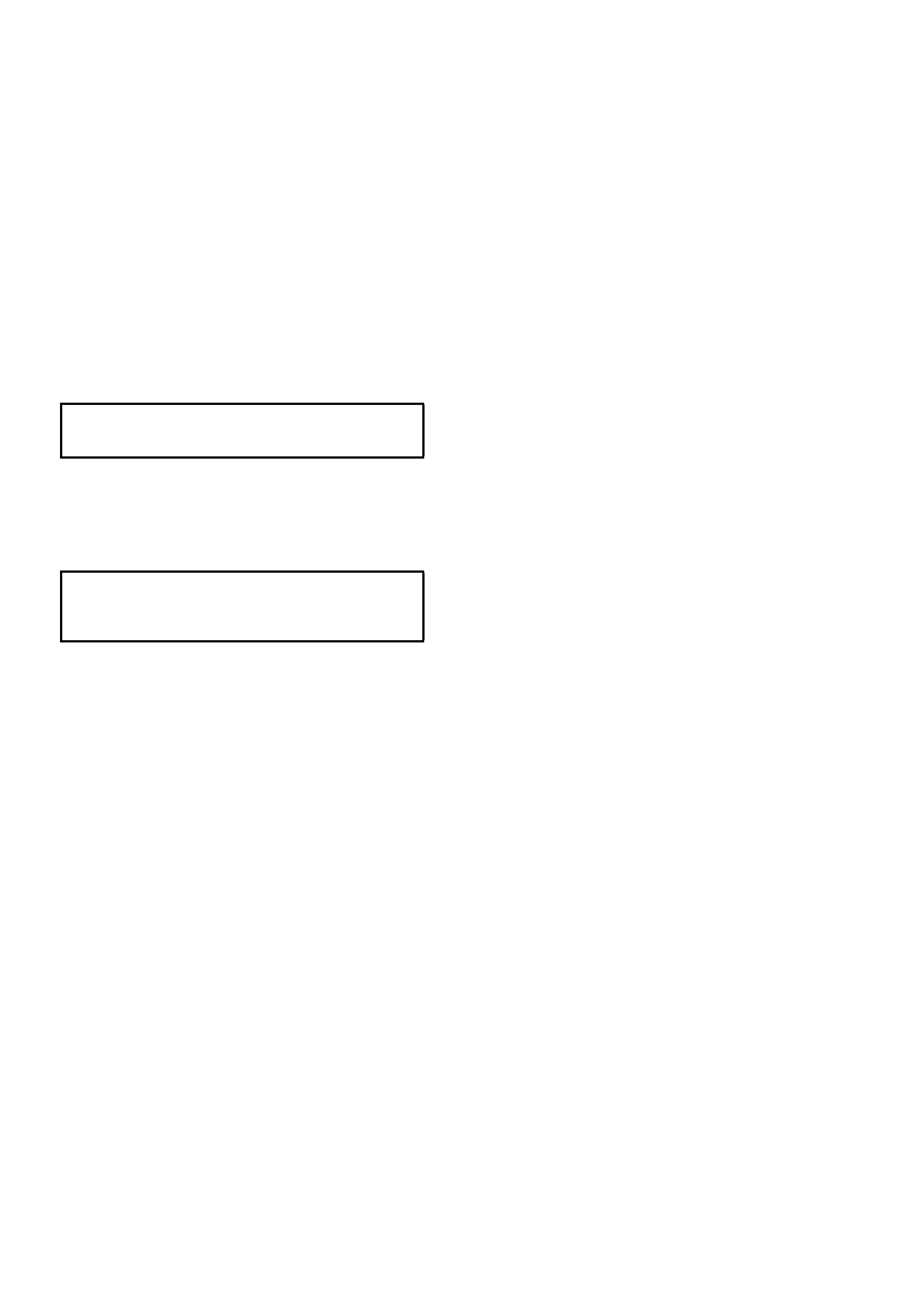
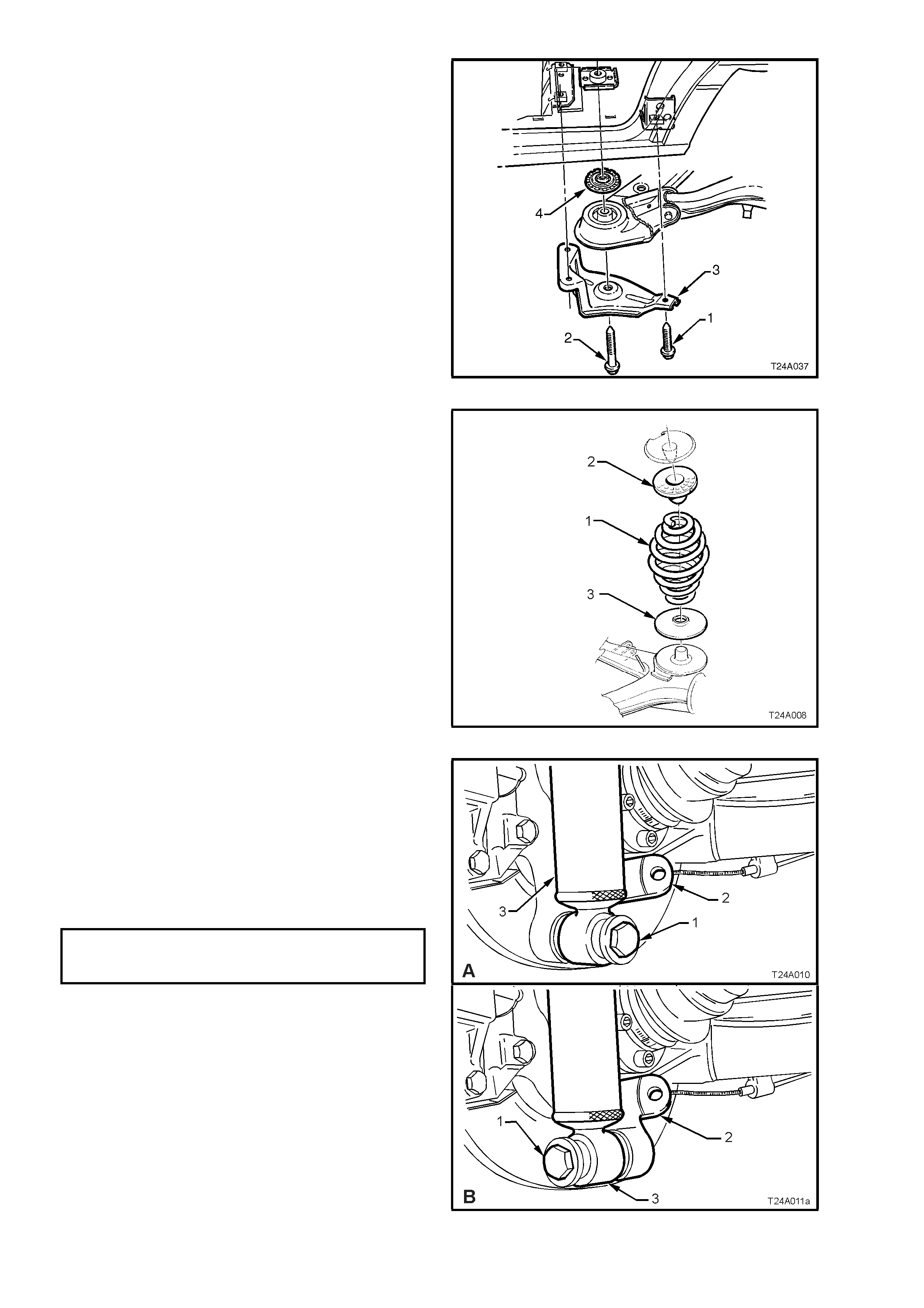
15. Position floor jack with a block of wood under
trailing arm. Raise jack slightly to take spring
load off trailing arm. Disconnect rear shock
absorber lower mounting bolt (1) from trailing
arm (2), then pull the lower end of shock
absorber (3) from trailing arm (2).
‘A’ – Sedan
‘B’ – Station Wagon
Figure 4A-12
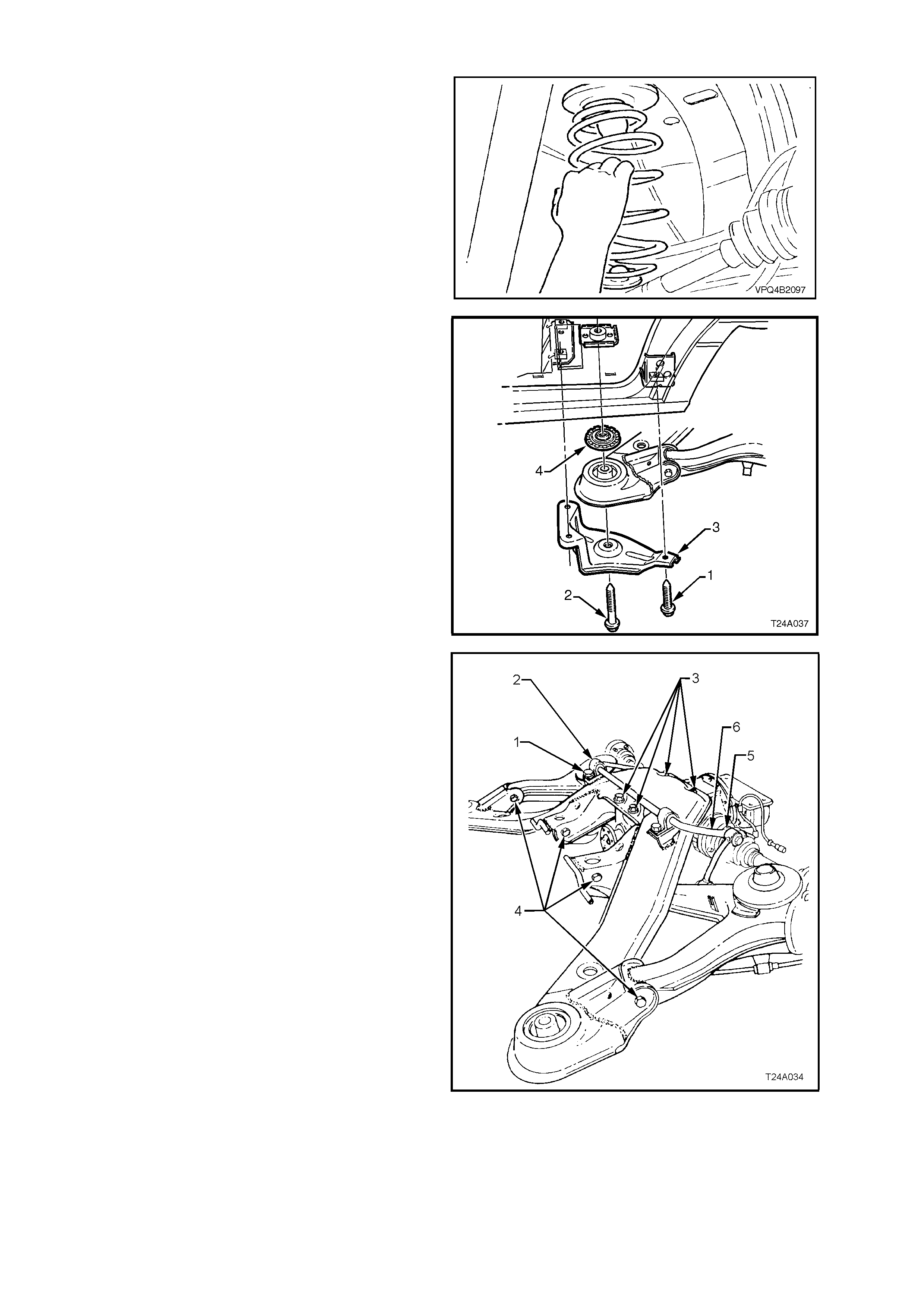
16. Loosen both trailing arm to crossmember nuts
(refer Fig. 4A-14).
17. Lower floor jack and if necessary, push down
on trailing arm and remove rear spring and
insulators from vehicle underbody and trailing
arm.
Figure 4A-13
18. Remove trailing arm to rear crossmember
attaching bolts and nuts, remove trailing arm
and discard nuts.
Figure 4A-14
REINSTALL
The reinstallation of the trailing arm is the reverse
of the rem oval procedur e, with the exception of the
following steps:
1. Reinstall trailing arm to rear crossmember,
using bolts and NEW nuts but do not fully
tighten at this stage.
NOTE: Always use new self-locking nuts.
2. Reinstall brake disc, aligning the marks made
before removal.
NOTE: If the trunnion was replaced, then runout
checks must be carried out on the installed brake
disc. Refer to 5A STANDARD BRAKES, of the VT
Series II Service Information for important
information regarding these checks.
3. Reinstall brake caliper anchor plate to the
trailing arm, reinstall the attaching bolts and
tighten to the correct torque specification.
BRAKE CALIPER ANCHOR PLATE
TO TRAILING ARM ATTACHING 70 – 100 Nm
BOLT TORQUE SPECIFICATION
4. Support trailing arm with a floor jack and
wooden block and raise enough to enable the
shock absorber to be reinstalled.
5. Reinstall shock absorber and stabiliser bar link
attaching bolts and nuts but do not fully tighten
at this stage.
6. Reinstall drive shaft outer constant velocity
joint to trunnion flange attaching bolts and
plates, then tighten to the correct torque
specification.
DRIVE SHAFT CONSTANT 50 Nm, then
VELOCITY JOINT TO TRUNNION 60° - 75°
BOLT TORQUE SPECIFICATION turn angle
7. After reconnecting all brake line connections,
bleed rear brakes and check for leaks. For the
recommended procedure, refer to
Section 5A BRAKES, of the VT Series I
Service Information.
8. Reinstall road wheel/s, aligning the marks
made prior to removal and secure with the
attaching nuts.
9. Lower vehicle to the ground and bounce the
rear of the vehicle several times to settle the
suspension components.
10. With the weight of the vehicle on the four
wheels and at curb weight, tighten the
following bolts and nuts to the respective,
correct torque specifications.
SHOCK ABSORBER LOWER
MOUNTING BOLT 105 – 125 Nm
TORQUE SPECIFICATION
STABILISER BAR LINK TO
TRAILING ARM ATTACHING 18 – 26 Nm
BOLT TORQUE SPECIFICATION
TRAILING ARM TO REAR
CROSSMEMBER ATTACHING 95 – 105 Nm
NUT TORQUE SPECIFICATION
11. Tighten road wheel attaching nuts to correct
torque specification, working in a ‘star’ pattern,
as indicated in Fig. 4A-1, in this Section.
ROAD WHEEL ATTACHING NUT
TORQUE SPECIFICATION 110 – 140 Nm
12. Refit wheel cover/centre cap.
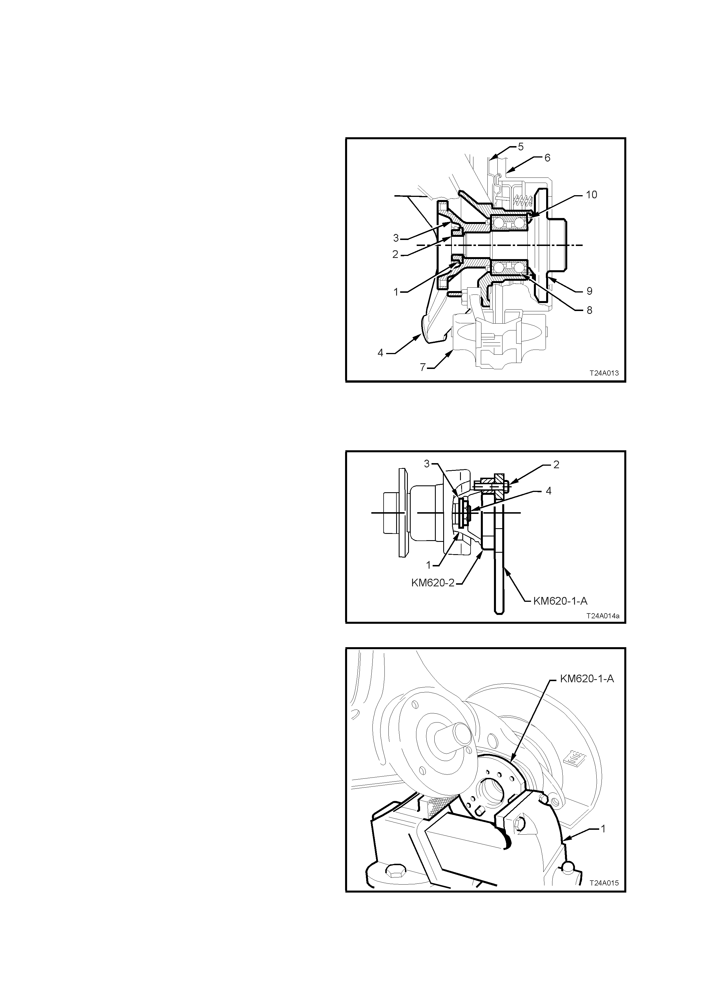
2.4 TRUNNION ASSEMBLY, FLANGE OR BEARING
REPLACE
Important: The rear wheel bearing should only be
removed if it is faulty, or the trunnion assembly is
to be removed.
Trunnion Assembly – Sectioned View
Legend:
1. Collar Nut Lock Plate
2. Collar Nut
3. Trunnion Flange
4. Trailing Arm
5. Brake Backing Plate
6. Brake Disc
7. Brake Caliper
8. Rear Wheel Bearing
9. Trunnion Assembly
10. Rear Wheel Bearing Retaining Ring
Figure 4A-15
1. Remove trailing arm. Refer
2.3 TRAILING ARM, Remove in this Section
for details.
2. Secure flange holding tool, KM620-1-A and
trunnion flange ring tool KM620-2 to trunnion
flange (1) with three of the removed drive s haft
constant velocity joint to trunnion flange
attaching bolts (2).
NOTE: Align holes marked ‘B’ on the flange
holding tool KM620-1-A and KM620-2 with holes in
the trunnion flange before installing and tightening
bolts.
Figure 4A-16
3. Distort the trunnion flange collar nut lock plate,
using a suitable size pin punch and hammer,
then remove the lock plate and discard.
4. Mount assembly in a vice (1), gripping flats of
the flange holding tool KM620-1-A. Loosen,
then remove trunnion flange to trunnion
assembly collar nut and lock plate.
NOTE: Discard the collar nut when removed as
both it and the lock plate must be replaced on
reassembly.
5. Leave the holding tool KM620-1-A and the
trunnion flange ring tool KM620-2 assembled
to the trunnion flange.
Figure 4A-17

6. Lubricate the threads of forcing screw KM620-
3, then install to adaptor KM620-4-A. Apply
grease to ball end of plunger, T ool No. KM620-
5-B, then install that, into the end of forcing
screw KM620-3.
7. Install the whole sub-assembly through the
central opening of flange holding tool KM620-
1-A. Secure the adaptor KM620-4-A to the
flange holding tool KM620-1-A, using three
suitable bolts (1).
NOTE: Adjust the position of the forcing screw
KM620-3 in the adaptor KM620-4-A, to allow
adaptor to be in full contact with the flange holding
tool KM620-1-A.
Figure 4A-18
8. With flange holding tool KM620-1-A held in a
vice (1) and, with an assistant holding and
supporting weight of the trailing arm assembly,
turn forcing screw KM620-3 using suitable
socket equipment (2), free the flange from
trunnion assembly.
Separate special tool components from the
trunnion flange, once it has been removed.
Figure 4A-19
9. Using Tor x bit s ocket, T ool No. AU416, remove
brake backing plate to trailing arm, two upper
attaching bolts. Then, using suitable socket
equipment, remove the two longer, hexagonal
headed, lower bolts.
Figure 4A-20
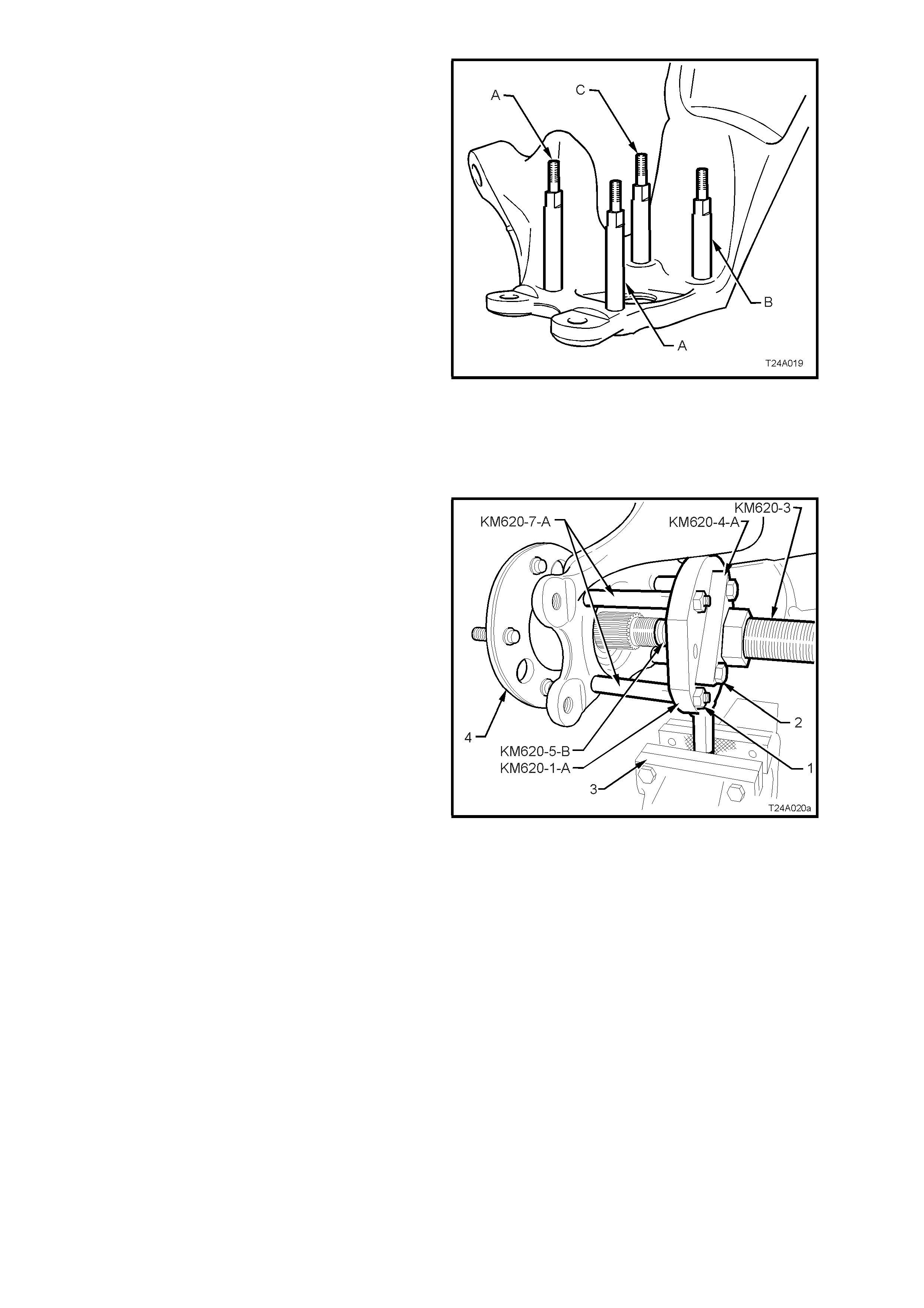
10. Preparatory to removing the trunnion assembly
and rear wheel bearing from the trailing arm,
use a commercially available M10 x 1.25
bottoming tap and clean the four backing plate
to trailing arm bolt threads, using a suitable
lubricant and working from the trunnion
assembly side.
NOTE: This step is necessary to clear any dried
mud, dirt etc, from the exposed portion of the
threads on the inboard side of the trailing arm.
Also, the deepest thread (position ‘C’) may not be
completely formed through to the inboard side.
11. Install two supports KM620-7-A in positions ‘A’
and two KM620-7-AUS to ‘B’ and ‘C’ in the
trailing arm, as indicated.
As a guide, the two longest supports (KM620-
7-A) are to be installed at the brake caliper
mounting side (position ‘A’). The longer of
KM620-7-AUS supports is installed at position
‘B’ and the shorter is installed at position ‘C’.
12. After installing all four supports in the correct
positions, tighten with a set spanner.
Figure 4A-21
13. Install flange holding tool KM620-1-A over the
four supports, KM620-7-A (2 places) and
KM620-7-AUS (2 places), install four suitable
nuts (1) and tighten to secure.
14. Pre-assemble lubricated forcing screw KM620-
3 to adaptor KM620-4-A. Apply grease to ball
end of plunger KM620-5-B, then install that,
into the end of forcing screw KM620-3.
15. Install this sub-assembly through the central
opening of holding tool KM620-1-A. Secure the
adaptor KM620-4-A to the flange holding tool
KM620-1-A, using three suitable bolts (2).
NOTE: Adjust the position of the forcing screw
KM620-3 into the adaptor KM620-4-A, to allow full
contact of the adaptor to the flange holding tool
KM620-1-A.
16. Tighten the three bolts securing adaptor
KM620-4-A to the flange holding Tool KM620-
1-A.
17. Mount assembly in vice (3) by the handle of
flange holding tool KM620-1-A as shown, then
turn the forcing screw KM620-3 and press the
trunnion assembly (4) from rear wheel bearing.
18. When trunnion has been removed, unscrew
the forc ing screw, as this sam e arrangem ent is
used to press the rear wheel bearing from the
trailing arm.
NOTE: The inner rear wheel bearing cone will
separate from the bearing assembly and be
retained on the trunnion assembly.
19. Remove the brake backing plate and park
brak e assem bly from the trailing ar m and set to
one side.
Figure 4A-22
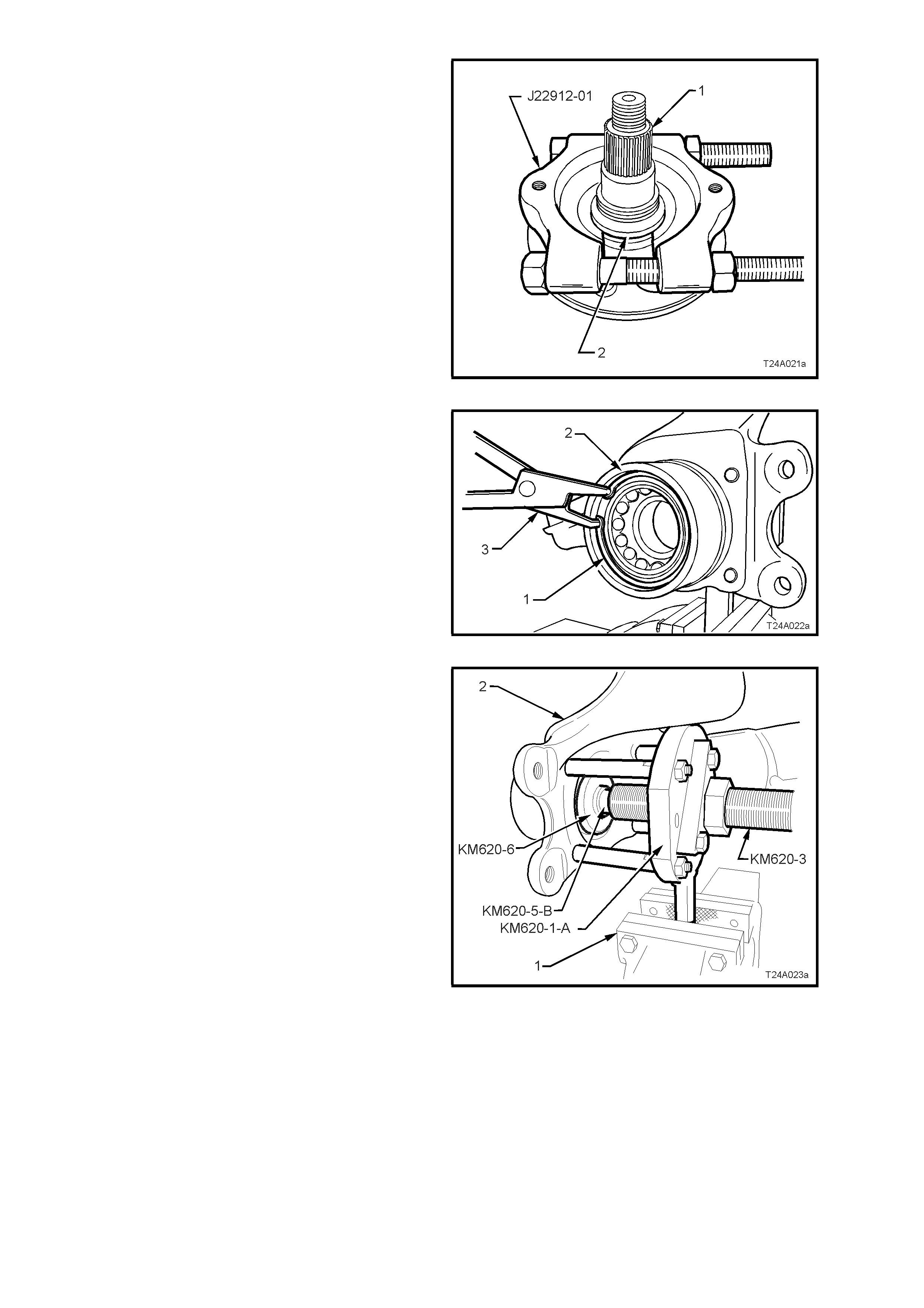
20. If the trunnion assem bly ( 1) is to be reinstalled,
then the outer half of the inner rear wheel
bearing cone (2) will need to be removed from
the trunnion assembly (1).
a. Install press plates J22912-01 over the
bearing cone (2) and tighten the press
plate bolts to grip the bearing cone.
b. Press the trunnion assembly (1) from the
bearing cone (2) and discard bearing cone.
NOTE: If the trunnion is to be replaced, then step
20, is not required. A new trunnion assembly is
supplied with wheel studs already installed.
Figure 4A-23
21. Remove wheel bearing retaining ring (1) from
trailing arm (2), using suitable circlip pliers (3).
Figure 4A-24
22. With the tool components set up as shown in
Fig. 4A-26, install rear axle bearing removing
plate KM620-6 to rear of the axle bearing.
Reposition the forcing screw KM620-3 and
adaptor KM620-5-B to retain the removing
plate KM620-6 in place.
23. With KM620-1- A mounted in vice j aws (1) , turn
the forcing screw KM620-3 clockwise to press
wheel bearing from trailing arm (2).
24. If installing a replacement trailing arm without
bushes, install new bushes. Refer to
2.6, TRAILING ARM BUSHES in 4A REAR
SUSPENSION of the VT Series I Service
Information
Figure 4A-25
25. Ensure that bearing bore of trailing arm is
clean and free of any foreign matter.
26. Coat outside diameter of a new wheel bearing
and bore of trailing arm with lubricant such as
Molybond HB50, or equivalent (to Holden’s
Specification HN1326).
27. Remove bolts securing adaptor KM620-4-A to
the holding tool KM620-1-A, then remove the
adaptor and forcing screw KM620-3.
28. Lubricate the thrust ball bearing race (1) (part
of KM620-A) with lubricant such as Molybond
HB50, or equivalent (to Holden’s Specification
HN1326), then assemble the bearing onto the
flanged end of adaptor KM620-4-A.
29. Reinstall the f orcing sc rew and adaptor/bearing
assembly to the flange holding tool KM620-1-
A. Do not reinstall the adaptor (KM620-4-A) to
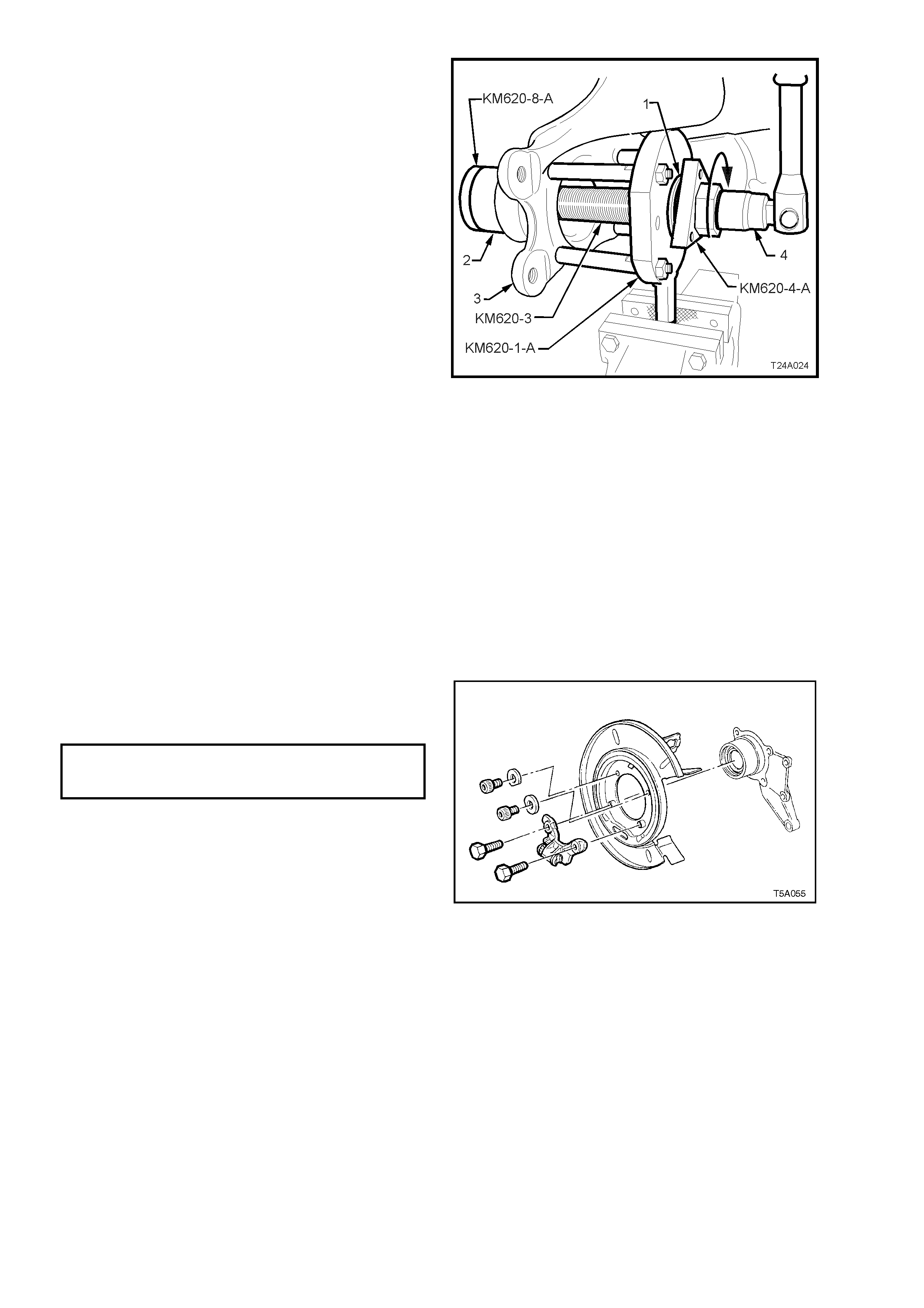
holding tool (KM620-1-A) attaching bolts.
30. Install bearing installer KM620-8-A into a new
bearing (2) and install both into the trailing arm
(3).
31. Join the forcing screw (KM620-3), and bearing
installer (KM620-8-A) by engaging the screw
thread of the forcing screw (KM620-3) with
installer (KM620-8-B) and tightening the f orc ing
screw to engage at least 8 full threads.
32. While holding the forcing screw (KM620-3)
from turning by using suitable socket
equipment (4), rotate the adaptor KM620-4-A
in the direction shown, with a suitable 40 mm
wrench to draw the new bearing (2) fully into
position.
33. Remove installer KM620-8-A once bearing is
fully installed, then install retaining ring into
trailing arm using suitable circlip pliers,
ensuring that the ring is seated correctly.
34. Separate all special tool components from the
trunnion flange, af ter the bearing has been fully
installed.
Figure 4A-26
35. Reinstall rear disc brake shield to trailing arm
bolts and tighten to the correct torque
specification.
REAR DISC BRAKE SHIELD TO Upper: 70–80 Nm
TRAILING ARM ATTACHING BOLT
TORQUE SPECIFICATION Lower: 85–90 Nm
NOTE 1: The two upper bolts have washers that
are installed with the cut-out edge facing around
the trailing arm hub outer surface.
NOTE 2: Apply Loctite 242 or equivalent (to
Holden’s Specif ication HN1256, Class 2, T ype 1) to
the threads of the two longer, lower hexagon
headed bolts, before installation.
Figure 4A-27
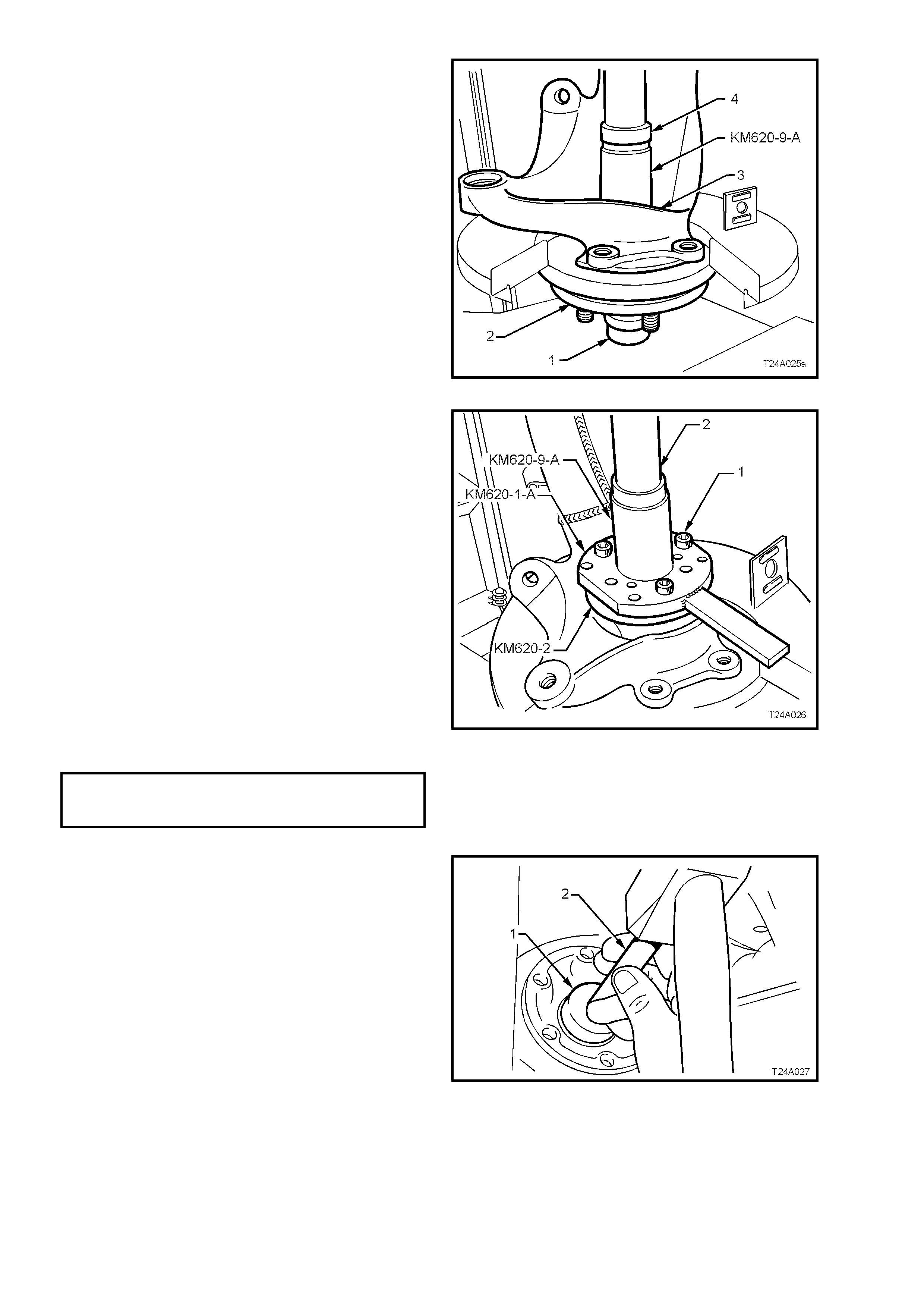
36. Position the trunnion assembly (2) with centre
hub section resting on a suitable support (1)
and press plates, checking to make sure that
the trunnion assembly wheel studs do not
contact press plates.
37. Position trailing arm (3) with wheel bearing
onto trunnion assembly. With an assistant
supporting the trailing arm assembly in this
position, use installer KM620-9-A and a
suitable length and diameter tube (4), press
wheel bearing onto trunnion assembly.
Figure 4A-28
38. Remove installer KM620-9-A and tube.
Assemble flange holding tool KM620-1-A and
trunnion flange ring KM620- 2 to trunnion flange
using three drive shaft attaching bolts (1).
39. Lubricate trunnion flange splines and trunnion
assembly threads with suitable lubricant such
as Molybond HB50, or equivalent (to Holden’s
Specification HN1326), then reinstall trunnion
flange onto trunnion assembly, aligning the
splines on each.
40. With trunnion assembly supported on press
plates, as in step 36, press trunnion flange
onto trunnion assembly using installer KM620-
9-A and a suitable tube (2).
41. Remove trailing arm assembly from press and
support assembly in a vice by the flats on
flange holding tool KM620-1-A.
42. Install a new collar nut to trunnion assembly
and tighten to the correct torque specification.
COLLAR NUT TO
TRUNNION ASSEMBLY 295 – 305 Nm
TORQUE SPECIFICATION
Figure 4A-29
43. Remove trailing arm assembly from vice and
remove all special tools from the trunnion
flange. Using a 1 ¼ inch socket (1), 150 mm
socket bar (2) and hammer, install new lock
plate over collar nut.
Figure 4A-30

2.5 REAR CROSSMEMBER
CAUTION: Whenever any component that
forms part of the ABS (if fitted) is disturbed
during Service Operations, it is vital that the
complete ABS system be checked, using the
procedure as detailed in DIAGNOSIS, ABS
FUNCTION CHECK, in Section 12L ABS &
ABS/ETC, VT Series I Service Information
(V6 engine) or Section 12L ABS & ABS/ETC VT
Series II Service Information (GEN III V8
engine).
Important: Before disturbing the rear suspension
crossmember mounting bolts, an alignment
procedure is required on reinstallation and a
special tool is required for this purpose. If this tool
is not available, then the crossmember cannot be
correctly aligned and steering and/or handling
abnormalities will result.
NOTE: Fo r this s ervice oper ation, new trailing arm -
to-crossmember lock nuts, rear crossmember rear
mount-to-vehicle underbody attaching bolts,
differential carrier-to-rear crossmember attaching
bolts and intermediate muffler support retainers
must be used on reassembly.
REMOVE
1. Using a floor jack under centre of differential
carrier, jack up rear of vehicle and place safety
stands under body rear jack ing points. Ref er to
Section 0A GENERAL INFORMATION of the
VT Series I Service Information for location of
jacking points.
2. Remove wheel covers (steel wheels) or centre
caps (alloy wheels).
3. Mark relationship of road wheels to hubs (e.g.
end of wheel stud), with a felt tipped pen or
similar. Loosen then remove road wheel
attaching nuts. Remove the road wheel.
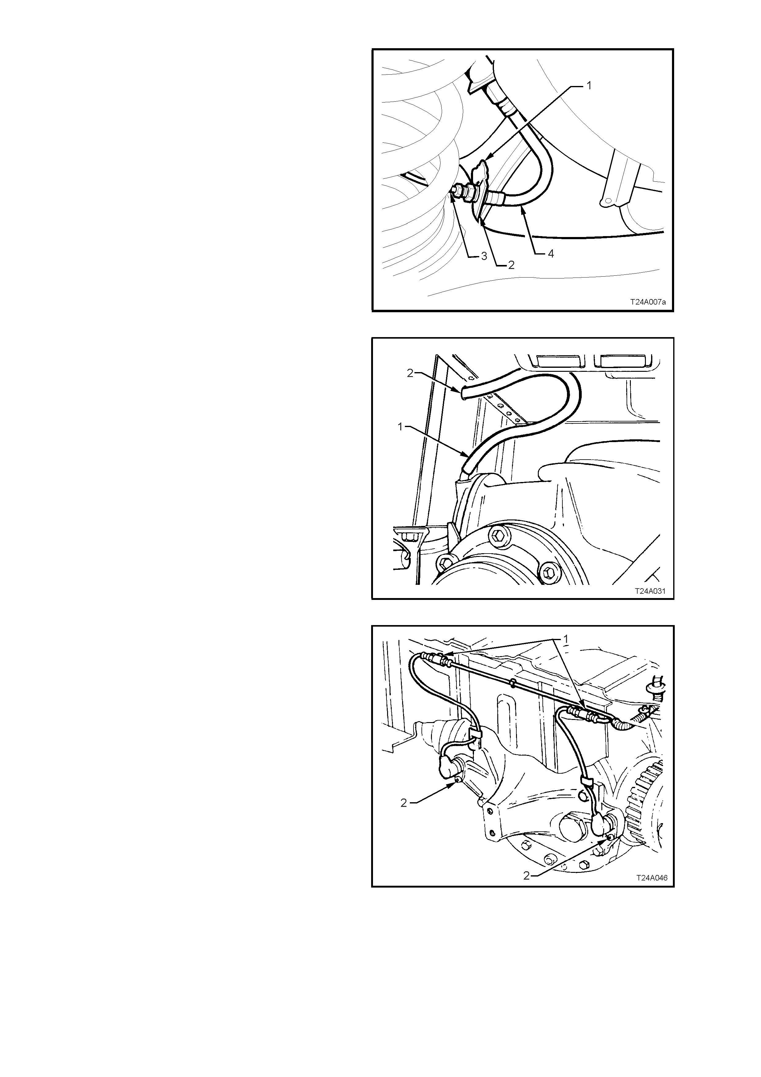
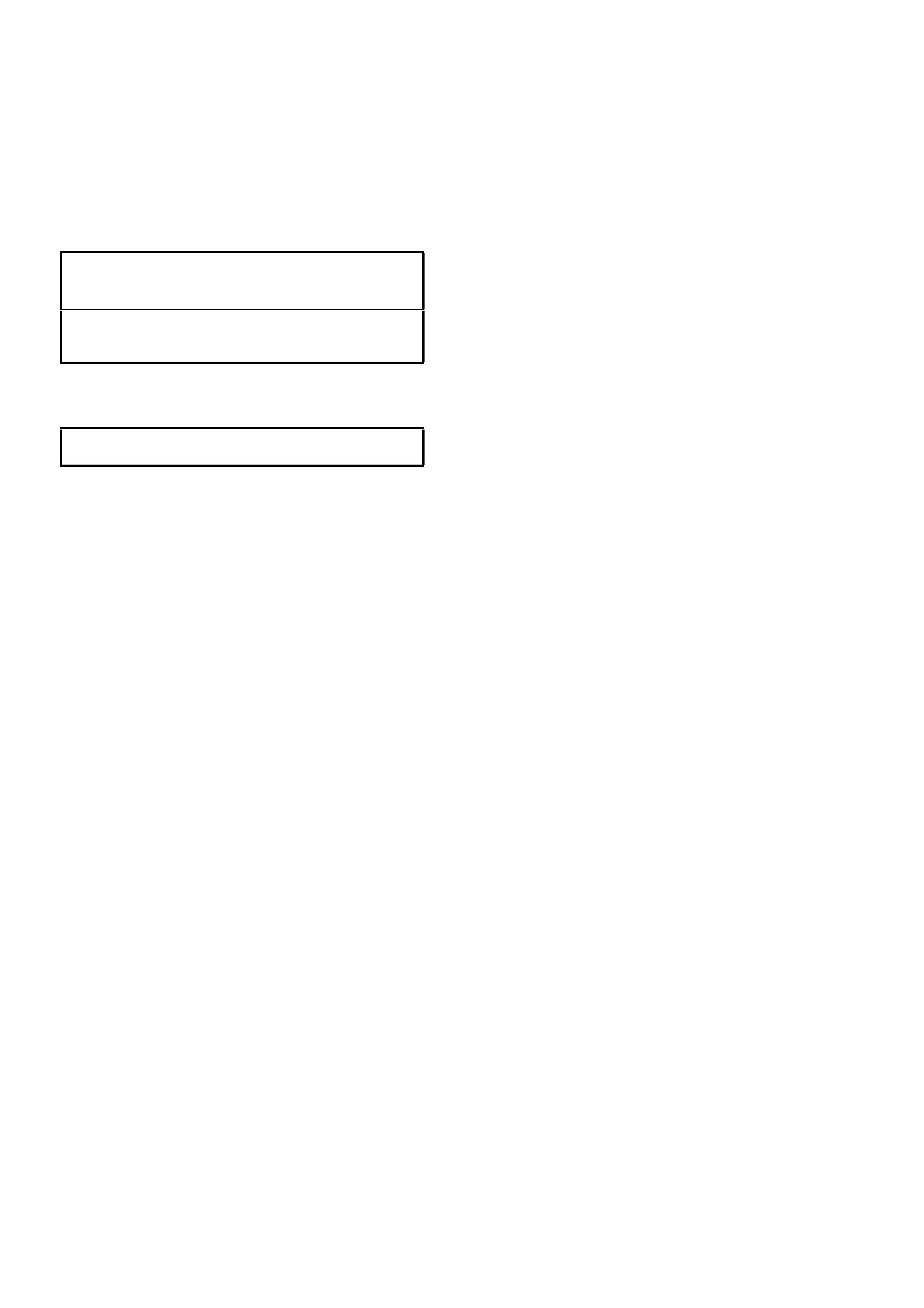
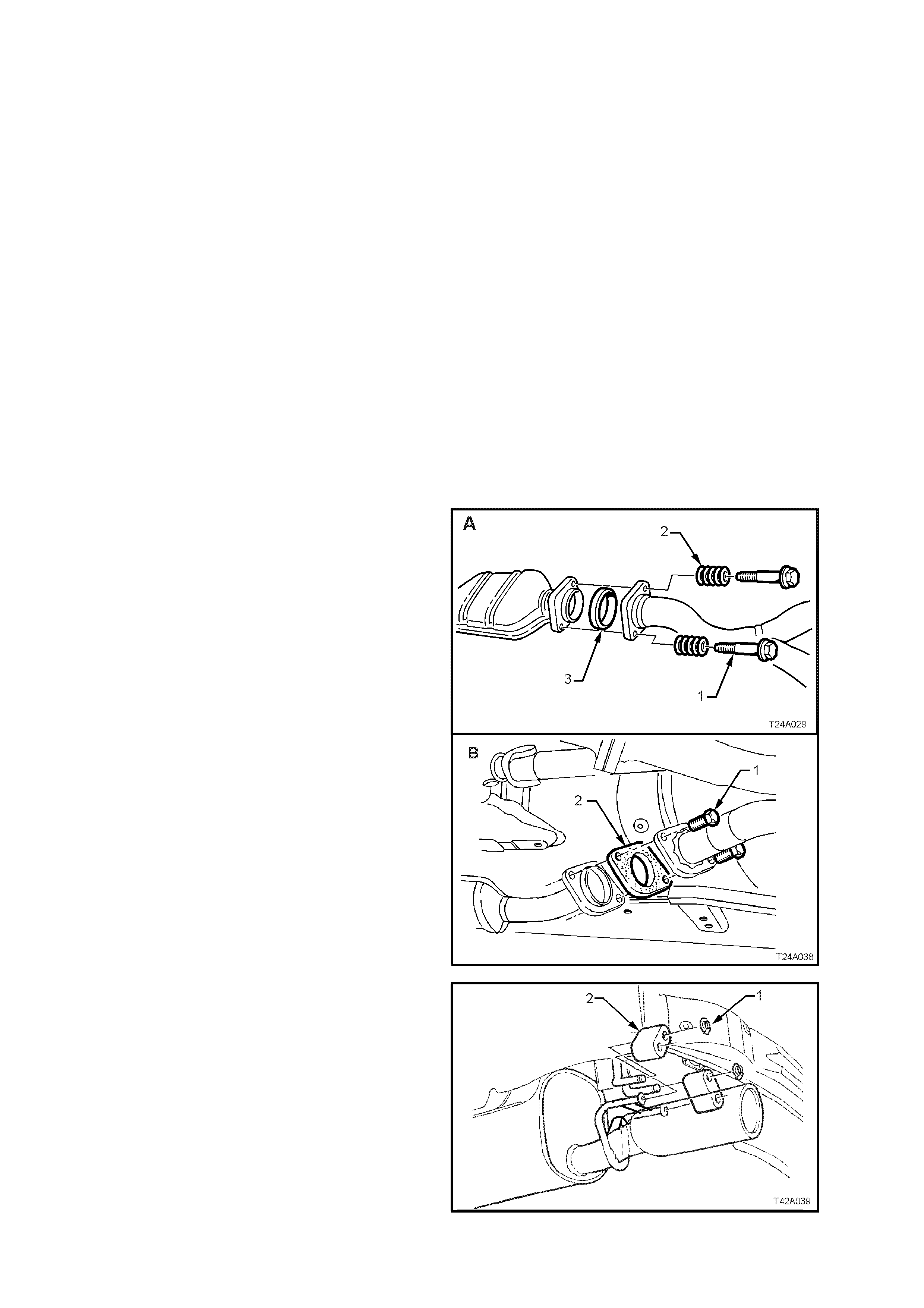
4. Disconnect exhaust system from rear of
catalytic converter/s:
V6 Engined Vehicles (A):
a. Remove both flange bolts (1) and springs
(2). After separation remove the retaining
ring (3).
V6 Supercharged and GEN III V8 Engined
Vehicles (B):
b. Remove both flange bolts (1), then the
sealing gasket (2).
NOTE: Only one side of the V6
Supercharged/GEN III V8 engine arrangement is
shown.
Figure 4A-31
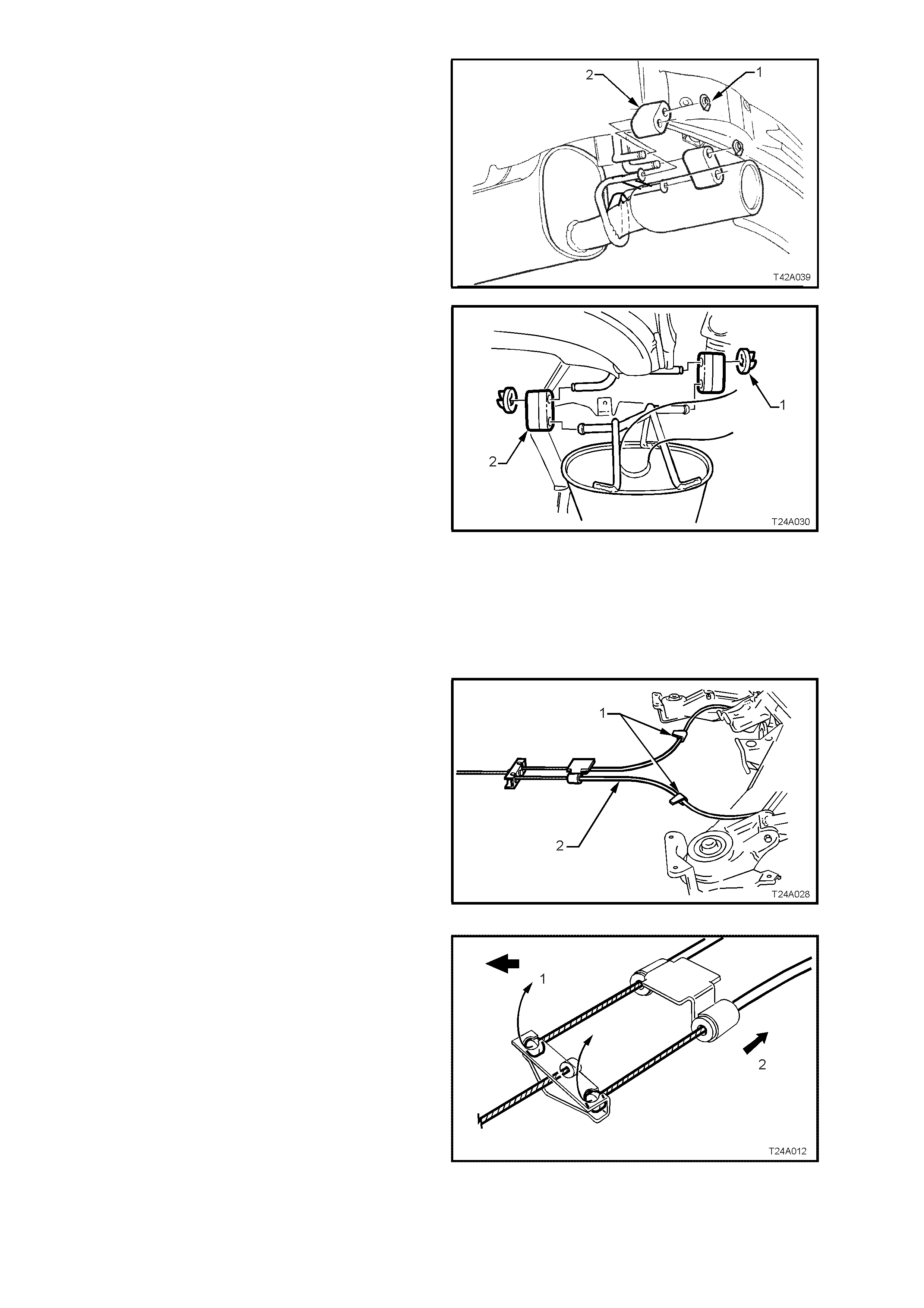
5. Remove the two retainers (1) from the top
posts and discard. Disconnect exhaust system
support rings (2) from rear hanger of rear
muffler assembly. Both V6 and GEN III V8
engine arrangements are similar.
Figure 4A-32
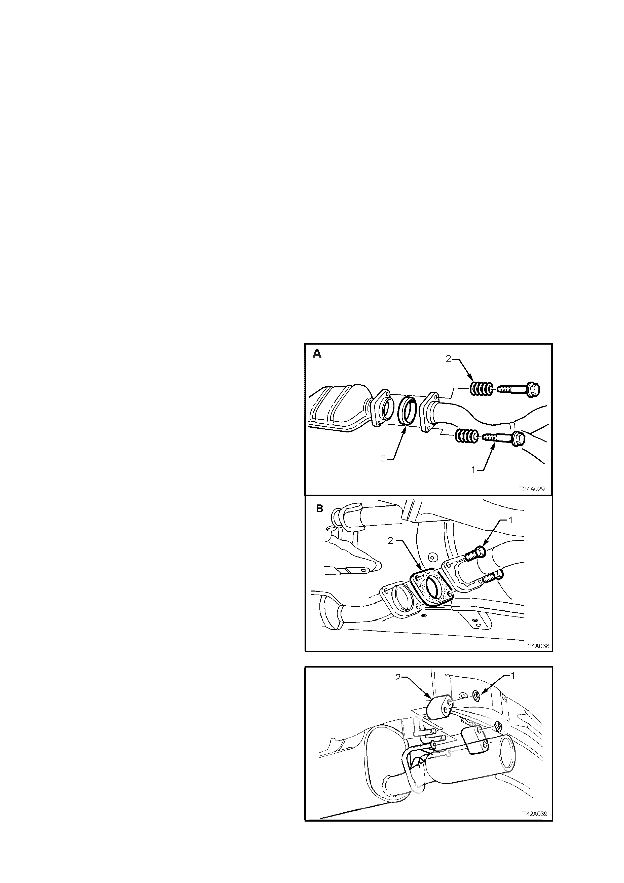
6. Remove muffler support to rear crossmember
hanger retainers (1).
NOTE: There are two retainers for V6 engined
vehicles (as shown) and four retainers for V6
Supercharged and GEN III V8 engined vehicles.
7. Support intermediate section of exhaust
system and remove support rings (2) from
muffler and crossmember hangers.
8. Remove intermediate and rear sections of
exhaust system from vehicle.
Figure 4A-33
9. Remove propeller shaft, refer to
Section 4C PROPELLER SHAFT AND
UNIVERSAL JOINTS, VT Series I Service
Information (V6 engines) or
Section 4C PROPELLER SHAFT AND
UNIVERSAL JOINTS, VT Series II Service
Information (GEN III V8 engine).
10. Set park brake in fully released position, then
release each of the underbody to park brake
cable (1) retaining clips (2) and free cables (1).
Figure 4A-34
11. Remove park brake outer cable retaining
bracket bolt (underbody bracket and bolt are
not shown) from the vehicle underbody.
12. Pull each park brake inner cable forward and
up, (1) out of the c able retainer to release each
cable.
13. Pull the outer cable rearward (2) to remove
from the underbody retainer.
Figure 4A-35
14. Disconnect brake pipe (3) from brake hose (4)
at trailing arm bracket (2) and remove the
brake hose retaining clip (1).
Plug the open ends of both pipes and hoses to
prevent unnecessary fluid loss and/or dirt
entry.
15. Repeat for the other side.
Figure 4A-36
16. Pull out differential carrier breather hose (1)
from vehicle underbody crossmember hole (2).
Figure 4A-37
17. If vehicle is fitted with ABS, pull both sensor
lead connectors from the underbody retaining
clips (1). Separate the sensor connectors from
the body harness connectors by levering with a
screwdriver.
Figure 4A-38
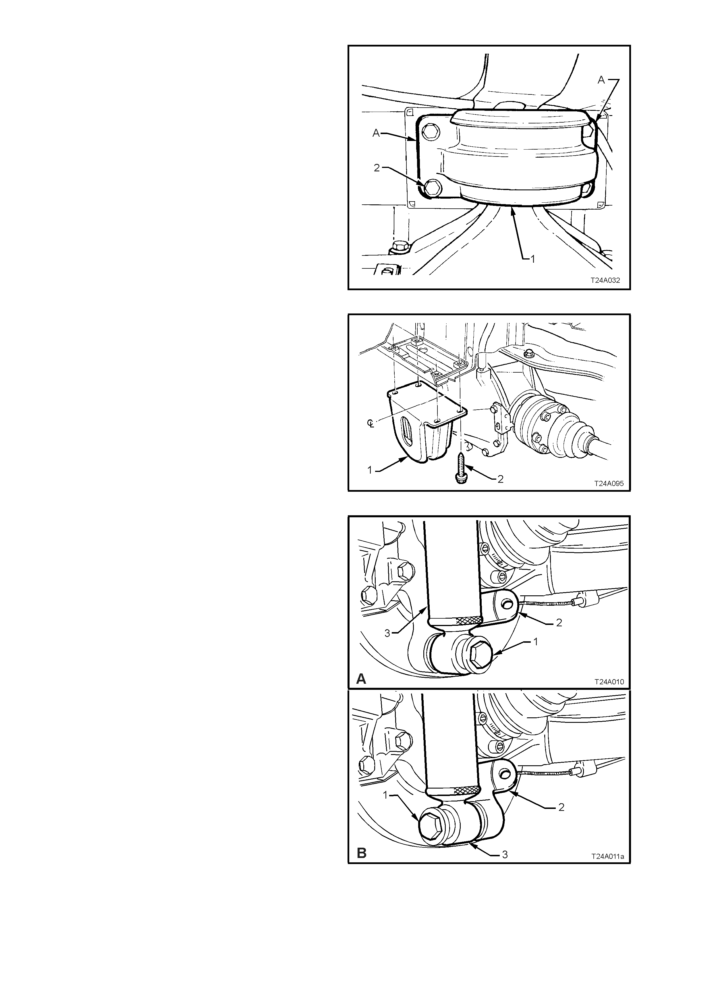
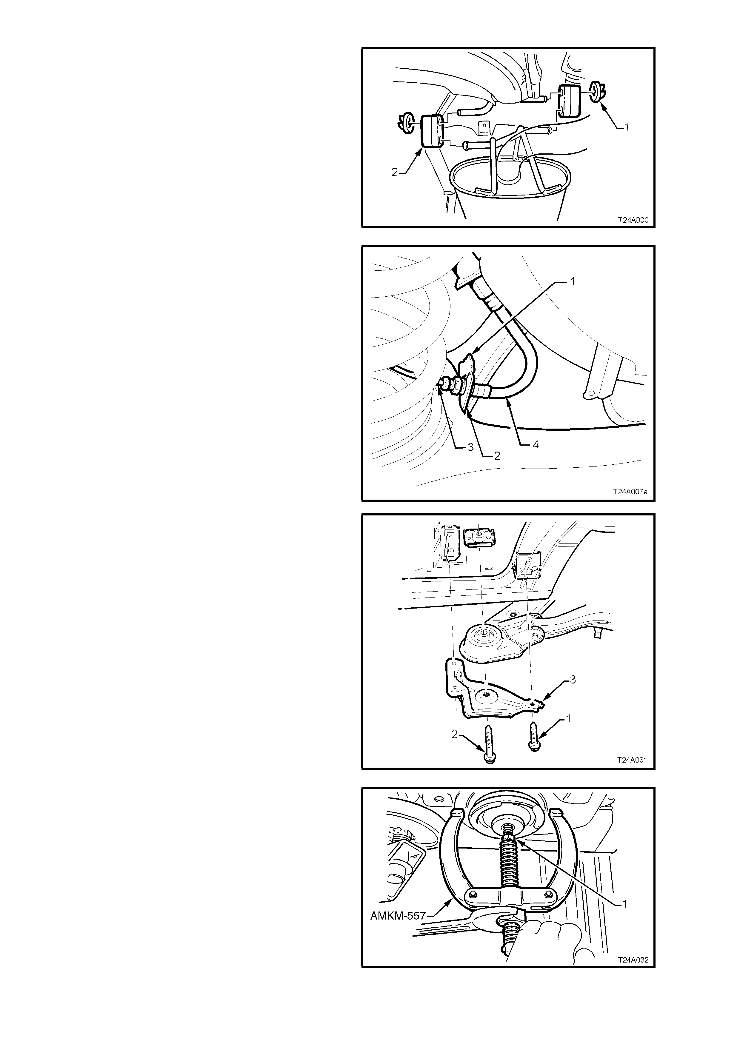
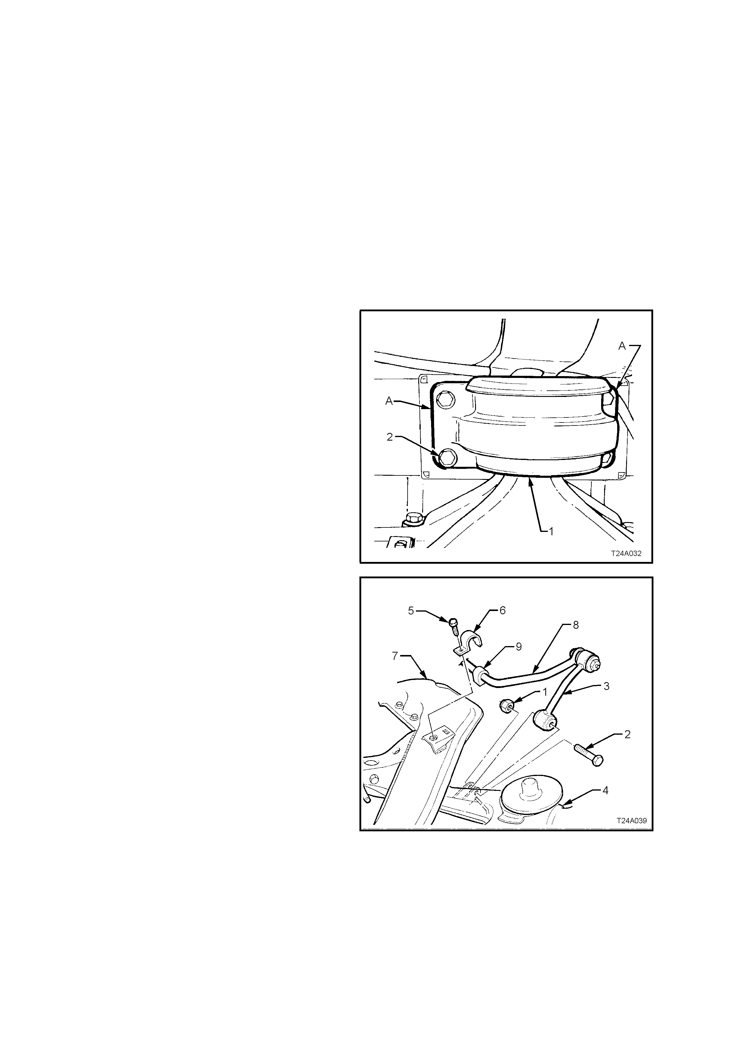
18. Using a scriber, m ark rear m ount (1) to vehicle
under body location (A). This will assist in rear
crossmember alignment on reinstallation.
19. Support weight of differential carrier with floor
jack.
Figure 4A-39
20. Remove rear mount (1) to vehicle underbody
attaching bolts (2) and discard removed bolts.
Lower differential carrier and rear
crossmember assembly by at least 60 mm.
Figure 4A-40
21. Position floor jack with a block of wood under
trailing arm. Raise jack slightly to take spring
load off trailing arm. Disconnect rear shock
absorber lower mounting bolt (1) from trailing
arm (2), then pull the lower end of shock
absorber (3) from trailing arm (2).
‘A’ – Sedan
‘B’ – Station Wagon
NOTE: Bruising to the inside of the drive shaft
constant velocity joint boots will occur if the shock
absorber is disconnected from the trailing arm
before the rear of the differential carrier and
crossmember assembly has been lowered by at
least 60 mm. Bruising of the boot will lead to
prem ature f ailure of the boot and eventual failure of
the joint if left unchecked.
Figure 4A-41
22. Remove rear springs and insulators from
vehicle underbody and trailing arms.
23. Raise dif fe rential carr ier and rear cross m em ber
on floor jack until rear mount contacts
underbody.
Figure 4A-42
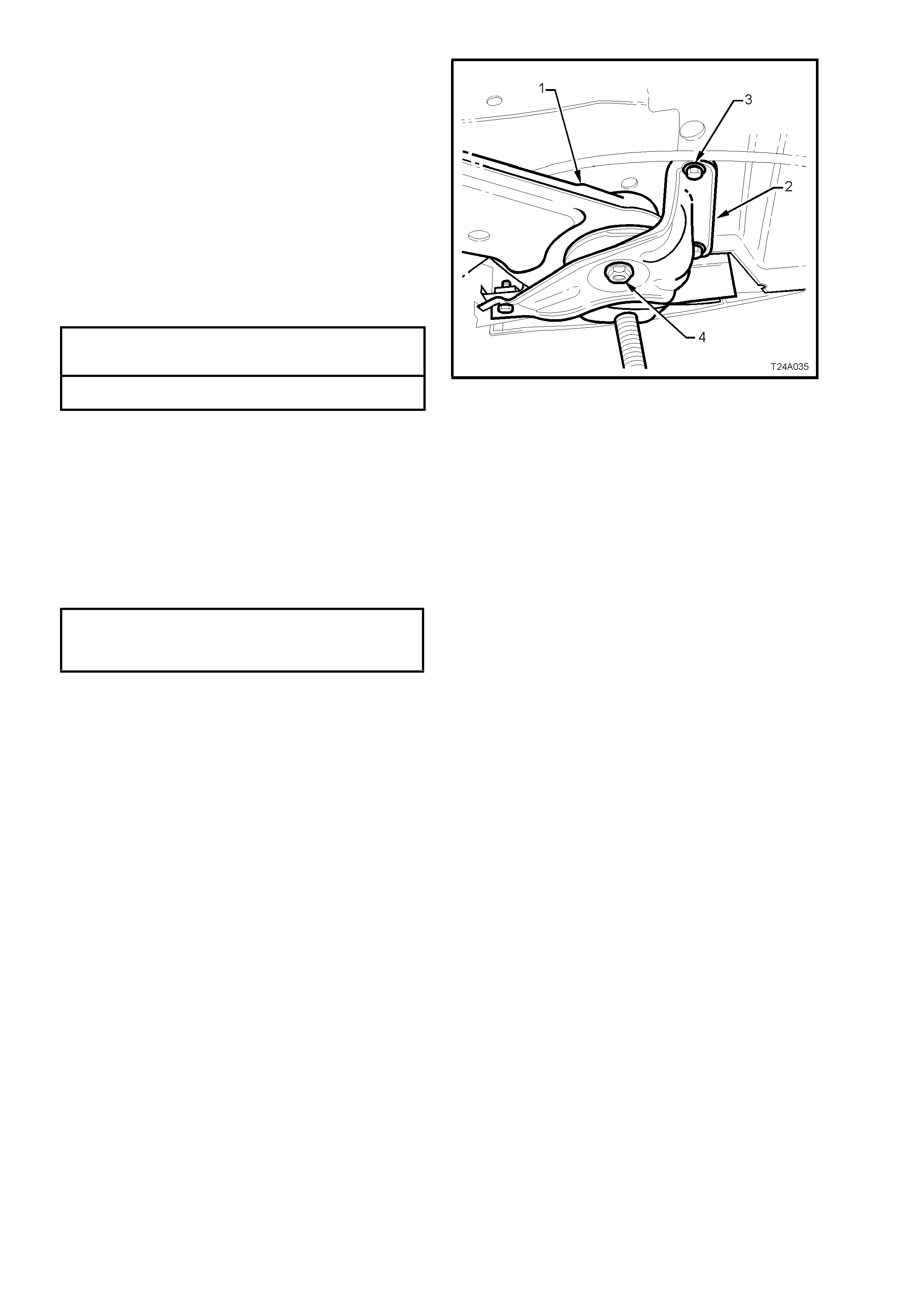
24. Use a floor jack and block of wood to support
differential carrier and crossmember assembly.
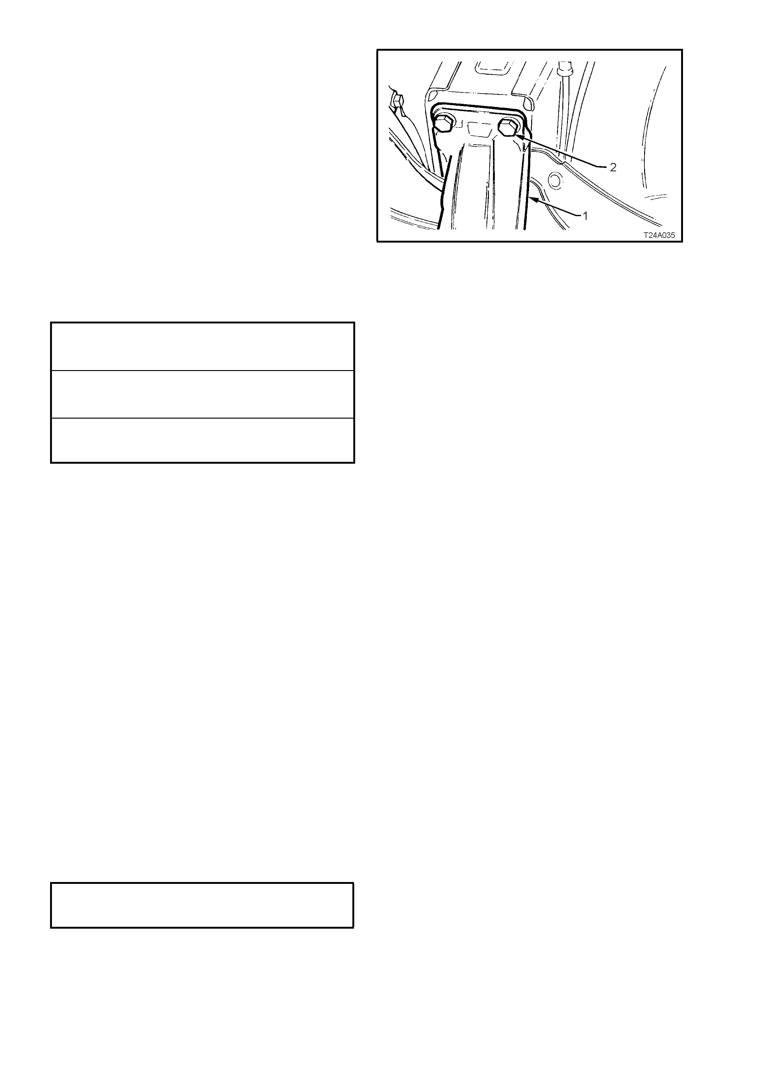
25. Remove brace to underbody bolts (1) (3
places) and crossmember to vehicle
underbody attaching bolt (2) from each side.
26. Remove the braces (3) from the vehicle.
27. With an assistant supporting front end of rear
crossmember, lower assembly on jack and
remove from beneath vehicle.
NOTE: If the vehicle is fitted with the GEN III V8
engine and manual transmission, take care not to
lose the is olating r ubbers (4 ) loc ated on top of eac h
front crossmember bush.
Figure 4A-43
28. Remove differential carrier and crossmember
assembly from jack and support trailing arms,
drive shafts and differential carrier on wooden
blocks.
29. Remove stabiliser bar mounting bracket
attaching bolts (1). Use a screwdriver to lever
up brackets (2) from mounting points and
remove brackets.
30. Remove differential carrier to crossmember
attaching bolts (3), discard bolts.
31. Rem ove trailing ar m to cros smem ber attaching
bolts and nuts (4). Discard nuts, as new ones
must be used on reassembly. Disengage
trailing arms from crossmember.
32. After loosening the s tabiliser link attaching nuts
(5) at each end and on each side to avoid
stress on the bushes, swing stabiliser bar (6)
back from crossmember.
33. Lift up and remove the crossmember.
Figure 4A- 44
REINSTALL
Reinstallation of rear crossmember is the reverse
of removal procedures, except for the following
steps:
1. If r eplacing a cros smem ber that does not have
front bushes, install new bushes. Refer
2.6 REAR CROSSMEMBER FRONT BUSH,
Replace, in this Section, for the required
procedure.
2. Install crossmember over differential carrier
and trailing arms.
3. Assemble trailing arms into crossmember
brackets and install attaching bolts and new
self-locking nuts.
Do not fully tighten nuts at this stage.
4. Align crossmember and differential carrier
mounting holes and install and tighten new
attaching bolts to the correct torque
specification.
DIFFERENTIAL CARRIER TO REAR 90 Nm, plu s
CROSSMEMBER ATTACHIN G 30° - 45°
TORQUE SPECIFICATION turn angle
5. Position stabiliser bar onto crossmember, with
insulators loc ated over crossm ember m ounting
points.
6. Engage br ackets to m ounting points and install
over insulators. Install and tighten attaching
bolts to the correct torque specification.
STABILISER BAR MOUNTING
BRACKET TO CROSSMEMBER
ATTACHING BOLT 18 - 26 Nm
TORQUE SPECIFICATION
7. With the aid of two assistants, place the
differential carrier and rear crossmember
assembly onto a floor jack.
8. Position ass embly under vehicle, raise with the
jack and, with the aid of the assistants, guide
the crossmember front mounting points into
position.
NOTE: During this operation, ensure that trailing
arms are also supported on safety stands, to keep
the drive shafts as near to horizontal as possible.
Otherwise, bruising to the insides of the constant
velocity joint boots will result, leading to boots
splitting and eventually joint failure, if left
unchecked.
9. If the vehicle is fitted with the GEN III V8
engine and manual transmission, an isolating
rubber (4) must be fitted at the top of each
crossmember front bush as shown, before
raising the assembly into place.
10. Install crossm ember front m ounting braces (3),
attaching bolts (‘1’ - three places) and rear
crossmember, front mounting bolt (4) but do
not fully tighten any of these bolts at this
stage.
Figure 4A-45
11. Lower differential carrier and rear
crossmember assembly on floor jack and
safety stands. Install rear springs (1) and the
two insulators, (2 and 3).
Figure 4A-46
12. After installing springs and insulators, use a
second floor jack to raise each trailing arm (2)
up far enough to allow shock absorber (3)
lower mounting to be installed to the trailing
arm (2).
13. Install washers and bolts (1) to the shock
absorber lower mount and tighten bolts to the
correct torque specification. Repeat for the
other side.
SHOCK ABSORBER LOWER
MOUNTING BOLT 105 - 125 Nm
TORQUE SPECIFICATION
NOTE 1: The torque specification for Sedan (A)
and Station Wagon (B) are the same.
NOTE 2: vehicle m ust be at curb weight and on all
four wheels before this torque is applied.
Figure 4A-47
14. Raise assembly until rear mount contacts
vehicle underbody.
15. Align rear mount (1) with marks on underbody,
made on disassembly, then loosely install new
attaching bolts (2) but do not fully tighten at
this stage.
16. The rear crossmember MUST now be aligned
to the vehicle centreline, using the special tool
and procedure as detailed in
Section 1A2 BODY DIMENSIONS of the VT
Series I Service Information.
CAUTION: Failure to correctly align the rear
crossmember to the centreline of the vehicle
will result in steering abnormalities and uneven
tyre wear!
17. T ighten all cros sm em ber m ounting f astener s to
the correct torque specification.
REAR MOUNT TO VEHICLE 30 – 40 Nm, plus
UNDERBODY ATTACHING BOLT 55° – 65°
TORQUE SPECIFICATION turn angle
REAR CROSSMEMBER FRONT 125 Nm, plus
MOUNTING BOLT 30° – 40°
TORQUE SPECIFICATION turn angle
REAR CROSSMEMBER FRONT
MOUNTING BRACE BOLT 60 – 85 Nm
TORQUE SPECIFICATION
18. Install differential carrier breather hose into
vehicle underbody crossmember hole. Ensure
that end of hose is pushed into hole
approximately 25 mm.
Figure 4A-48
19. If equipped with ABS, reconnect wheel sensor
wiring harness connectors. Reinstall into the
retaining clips.
20. Check park brake adjustment and bleed brake
hydraulic system, refer to
Section 5A STANDARD BRAKES of the VT
Series I Service Information.
21. Reinstall exhaust system, by first installing the
front of the intermediate pipe to the catalytic
converter (V6 engine) or converters (V6
Supercharged and GEN III V8 engines). Use
new gaskets at the flanges on V6
Supercharged and GEN III V8 converters.
22. While supporting the exhaust system, install
the exhaust hanger rubbers to the rear of the
intermediate muffler/s and secure with new
retainers.
23. Install rear muffler support rings to the rear of
the rear muffler and secure with new retainers.
24. Tighten intermediate exhaust pipe to catalytic
converter bolts to the correct torque
specification.
INTERMEDIATE EXHAUST PIPE TO All Engines
CATALYTIC CONVERTER BOL T 40 - 50 Nm
TORQUE SPECIFICATION
25. Check exhaust clearances as detailed in
Section 8B EXHAUST SYSTEM of the VT
Series I Service Information (V6 engines) or
Section 8B EXHAUST SYSTEM of the VT
Series II Service Information (GEN III V8
engine).
26. Reinstall road wheel/s, aligning the marks
made prior to removal and secure with the
attaching nuts.
27. Remove safety stands and lower vehicle.
28. Bounce the rear of the vehicle several times to
settle suspension then, with vehicle in kerb
height position, tighten trailing arm to
crossmember attaching nuts and the stabiliser
bar link nuts, to the correct torque
specifications.
TRAILING ARM TO REAR
CROSSMEMBER ATTACHING NUT 95 – 105 Nm
TORQUE SPECIFICATION
STABILISER BAR LINK, UPPER AND
LOWER MOUNTING NUT 18 – 26 Nm
TORQUE SPECIFICATION
29. Tighten road wheel attaching nuts to correct
torque specification, working in a ‘star’ pattern,
as indicated in Fig. 4A-1, in this Section.
ROAD WHEEL ATTACHING NUT
TORQUE SPECIFICATION 110 – 140 Nm
30. Refit wheel cover/centre cap.
31. Start vehicle and check for exhaust leaks.
Repair as necessary.
2.6 REAR CROSSMEMBER FRONT BUSH
CAUTION: Whenever any component that
forms part of the ABS (if fitted) is disturbed
during Service Operations, it is vital that the
complete ABS system be checked, using the
procedure as detailed in DIAGNOSIS, ABS
FUNCTION CHECK, in Section 12L ABS &
ABS/ETC, VT Series I Service Information
(V6 engine) or Section 12L ABS & ABS/ETC VT
Series II Service Information (GEN III V8
engine).
Important: Before disturbing the rear suspension
crossmember, front mounting bolts, an alignment
procedure is required on installation and a special
tool is required for this purpose. If this tool is not
available, then the crossmember cannot be
correctly aligned and steering and/or handling
abnormalities will result.
REPLACE
1. Using a floor jack under centre of differential
carrier, jack up rear of vehicle then place
safety stands under body rear jacking points.
Refer to Section 0A GENERAL
INFORMATION of the VT Series I Service
Information for location of jacking points.
2. Disconnect exhaust system from rear of
catalytic converter/s:
V6 Engined Vehicles (A):
c. Remove both flange bolts (1) and springs
(2). After separation remove the retaining
ring (3).
V6 Supercharged and GEN III V8 Engined
Vehicles (B):
d. Remove both flange bolts (1), then the
sealing gasket (2).
NOTE: Only one side of the V6
Supercharged/GEN III V8 engine arrangement is
shown.
Figure 4A-49
3. Remove the two retainers (1) from the top
posts and discard. Disconnect exhaust system
support rings (2) from rear hanger of rear
muffler assembly. Both V6 and GEN III V8
engine arrangements are similar.
Figure 4A-50
4. Remove muffler support to rear crossmember
hanger retainers (1).
NOTE: There are two retainers for V6 engined
vehicles (as shown) and four retainers for V6
Supercharged and GEN III V8 engined vehicles.
5. Support intermediate section of exhaust
system and remove support rings (2) from
muffler and crossmember hangers.
6. Remove intermediate and rear sections of
exhaust system from vehicle.
Figure 4A-51
7. Remove brake hose retaining clip (1) from
trailing arm brack et (2) and rem ove brake hose
(4) from bracket (2). Pull brake pipe (3) and
hose (4) forward from bracket and disconnect
by lifting up brake pipe (3) through slots in
bracket.
Figure 4A –52
8. Use a floor jack and block of wood to support
differential carrier and crossmember assembly.
9. Remove brace to underbody bolts (1) (3
places) and crossmember to vehicle
underbody attaching bolt (2) from side on
which bush is to be replaced.
10. Remove the brace (3) from the vehicle.
Figure 4A-53
11. Lower jack slightly and allow crossmember to
rest on a safety stand, rear of front mounting.
Install bolt (1) (part of Tool No. AMKM-557)
from above, through the bush and into the
threaded end of the forcing screw of puller
AMKM-557.
12. While holding the forcing screw, use a set
spanner to tighten the puller nut of AMKM- 557,
removing the crossmember bush.
13. Remove AMKM-557 assembly and discard the
removed bush.
Figure 4A-54

14. Align a new bush with the voided section fac ing
the rear of the vehicle, as shown in Fig. 4A-38.
Figure 4A-55
15. Draw in new bush (1) into crossmember using
Tool No. KM618-1 and KM618-2.
Figure 4A-56
16. If the vehicle is fitted with the GEN III V8
engine and manual transmission, an isolating
rubber (4) must be fitted at the top of the
crossmember front bush as shown, before
raising the assembly into place.
Figure 4A-57
17. Raise up fr ont end of the cros smem ber (1) and
install front mounting brace (2), attaching bolts
(3) and rear crossmember, front mounting bolt
(4) but do not tighten bolts at this stage.
18. The rear crossmember MUST now be aligned
to the vehicle centreline, using the special tool
and procedure, as detailed in
Section 1A2 BODY DIMENSIONS, of the VT
Series I Service Information.
CAUTION: Failure to correctly align the rear
crossmember to the centreline of the vehicle
will result in steering abnormalities and uneven
wear!
19. Tighten bolts to the correct torque
specification.
REAR CROSSMEMBER FRONT 125 Nm, pl us
MOUNTING BOLT 30° - 45°
TORQUE SPECIFICATION turn angle
BRACE TO UNDERBODY BOLT
TORQUE SPECIFICATION 60 – 85 Nm
20. Insert brake hose into trailing arm bracket and
install retaining clip.
Figure 4A-58
21. Reinstall exhaust system, by first installing the
front of the intermediate pipe to the catalytic
converter (V6 engine) or converters (V6
Supercharged and GEN III V8 engines). Use
new gaskets at the flanges on V6
Supercharged and GEN III V8 converters.
22. Reinstall and tighten flange to converter bolts
to the correct torque specification.
INTERMEDIATE EXHAUST PIPE
FLANGE TO CATALYTIC All Engines :
CONVERTER BOLT 40 – 50 Nm
TORQUE SPECIFICATION
23. While supporting the exhaust system, install
the exhaust hanger rubbers to the rear of the
intermediate muffler and secure with new
retainers.
24. Install rear muffler support rings to the rear of
the muffler and secure with new retainers at
the top posts.
25. Check exhaust clearances as detailed in
Section 8B EXHAUST SYSTEM of the VT
Series I Service Information (V6 engines) or
Section 8B EXHAUST SYSTEM of the VT
Series II Service Information (GEN III V8
engine).
26. Remove safety stands and lower vehicle.
27. Start vehicle and check for exhaust leaks,
repair as necessary.
2.7 REAR CROSSMEMBER REAR MOUNT
CAUTION: Whenever any component that
forms part of the ABS (if fitted) is disturbed
during Service Operations, it is vital that the
complete ABS system be checked, using the
procedure as detailed in DIAGNOSIS, ABS
FUNCTION CHECK, in Section 12L ABS &
ABS/ETC, VT Series I Service Information
(V6 engine) or Section 12L ABS & ABS/ETC VT
Series II Service Information (GEN III V8
engine).
Important: Before disturbing the crossmember
rear mounting bolts, an alignment procedure is
required on installation and a special tool is
required for this purpose. If this tool is not
available, then the crossmember cannot be
correctly aligned and steering and/or handling
abnormalities will result.
NOTE: For this operation, new rear crossmember
rear mount to vehicle underbody attaching bolts
and rear mount to differential carrier rear cover
attaching bolts MUST be used on reassembly.
REMOVE
28. Disconnect exhaust system from rear of
catalytic converter/s:
V6 Engined Vehicles (A):
a. Remove both flange bolts (1) and springs
(2). After separation remove the retaining
ring (3).
V6 Supercharged and GEN III V8 Engined
Vehicles (B):
b. Remove both flange bolts (1), then the
sealing gasket (2).
NOTE: Only one side of the V6
Supercharged/GEN III V8 engine arrangement is
shown.
Figure 4A-59
29. Remove the two retainers (1) from the top
posts and discard. Disconnect exhaust system
support rings (2) from rear hanger of rear
muffler assembly. Both V6 and GEN III V8
engine arrangements are similar.
Figure 4A-60

30. Remove muffler support to rear crossmember
hanger retainers (1).
NOTE: There are two retainers for V6 engined
vehicles (as shown) and four retainers for V6
Supercharged and GEN III V8 engined vehicles.
31. Support intermediate section of exhaust
system and remove support rings (2) from
muffler and crossmember hangers.
32. Remove intermediate and rear sections of
exhaust system from vehicle.
Figure 4A-61
33. Using a scriber, m ark rear m ount (1) to vehicle
under body location (A). This will aid in rear
crossmember alignment on installation.
34. Support weight of differential carrier with floor
jack.
Figure 4A-62
35. Pull out differential carrier breather hose (1)
from vehicle underbody crossmember hole (2).
Figure 4A-63
36. Remove rear mount (1) to vehicle underbody
attaching bolts (2) and discard the removed
bolts. Lower differential carrier and rear
crossmember assembly by at least 60 mm.
Figure 4A-64
37. Loosen and remove rear m ount attaching bolts
(1), remove rear mount (2) and discard
attaching bolts (1).
Figure 4A-65
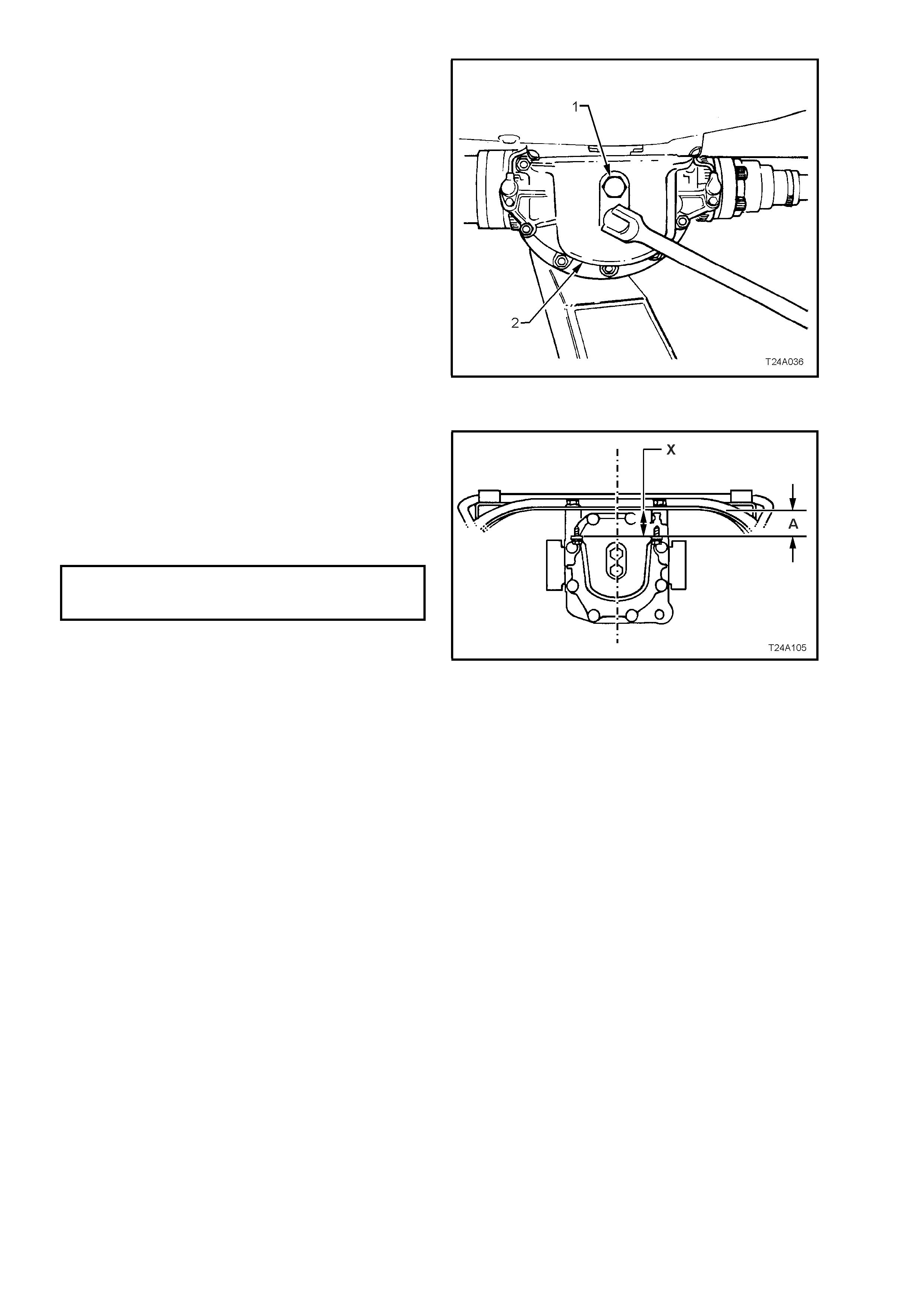
REINSTALL
1. Install rear mount and new attaching bolts to
differential carrier rear cover.
2. Tighten attaching bolts to the correct torque
specification, and at same time ensure that
mount does not twist, as the mount to vehicle
underbody mating surface s hould be parallel to
the rear crossmember, to within 1 mm (‘X’).
REAR MOUNT TO REAR COVER
ATTACHING BOLT 85 - 105 Nm
TORQUE SPECIFICATION
NOTE: Use a spirit level on rear mount to
underbody surface and top surface of
crossmember to ensure that both surfaces are
parallel. Dimension ‘A’ is to be 56.7 mm.
Figure 4A-66
3. Raise differential carrier and rear
crossmember assembly until rear mount
contacts vehicle underbody.
4. Align mount with marks on underbody, made
on disassembly and install new attaching bolts
but do not tighten at this stage.
5. The rear crossmember MUST now be aligned
to the vehicle centreline, using the special tool
and procedure as detailed in
Section 1A2 BODY DIMENSIONS, of the VT
Series I Service Information.
CAUTION: Failure to correctly align the rear
crossmember to the centreline of the vehicle
will result in steering abnormalities and uneven
tyre wear!6. Tighten rear crossmember, rear
mount to underbody bolts to the correct torque
specification.
REAR MOUNT TO VEHICLE 30 – 40 Nm, then
UNDERBODY ATTACHING BOLT 55 – 65
TORQUE SPECIFICATION turn angle
7. Install differential carrier breather hose into
vehicle underbody crossmember hole. Ensure
that end of hose is pushed into hole
approximately 25 mm.
8. Reinstall exhaust system, by first installing the
front of the intermediate pipe to the catalytic
converter (V6 engine) or converters (V6
Supercharged and GEN III V8 engines). Use
new gaskets at the flanges on V6
Supercharged and GEN III V8 converters.
9. While supporting the exhaust system, install
the exhaust hanger rubbers to the rear of the
intermediate muffler/s and secure with new
retainers.
10. Install rear muffler support rings to the rear of
the muffler, securing with new retainers.
11. Tighten intermediate exhaust pipe to catalytic
converter bolts to the correct torque
specification.
INTERMEDIATE EXHAUST PIPE TO All Engines
CATALYTIC CONVERTER BOL T 40 - 50 Nm
TORQUE SPECIFICATION
12. Check exhaust clearances as detailed in
Section 8B EXHAUST SYSTEM of the VT
Series I Service Information (V6 engines) or
Section 8B EXHAUST SYSTEM of the VT
Series II Service Information (GEN III V8
engine).
13. Remove safety stands and lower vehicle.
14. Start vehicle and check for exhaust leaks,
repair as necessary.
2.8 STABILISER BAR AND/OR MOUNTINGS
CAUTION: Before disturbing the crossmember
rear mount to underbody bolts, an alignment
procedure is required on installation and a
special tool is required for this purpose. If this
tool is not available, then the crossmember
cannot be correctly aligned and steering and/or
handling abnormalities will result.
Important: For this operation, new rear
crossmember rear mount to vehicle underbody
attaching bolts must be used on reassembly.
REMOVE
1. Using a floor jack under centre of differential
carrier, jack up rear of vehicle then place
safety stands under body rear jacking points.
Refer to Section 0A GENERAL
INFORMATION of the VT Series I Service
Information for location of jacking points.
2. Using a scriber, m ark rear mount (1) to vehicle
under body location (A). This will assist in rear
crossmember alignment on installation.
3. Support weight of differential carrier with floor
jack.
4. Remove rear mount to vehicle underbody
attaching bolts (2). Discard the removed bolts.
5. Lower differential carrier and rear
crossmember assembly sufficient to gain
access to stabiliser bar to crossmember
brackets.
NOTE: Do not allow propeller shaft or left hand
side drive shaft to rest on exhaust system.
Figure 4A-67
6. Remove both stabiliser bar link to trailing arm
attaching nuts (1) and bolts (2).
7. Swing links (3) clear of trailing arms (4).
8. Remove stabiliser bar to crossm ember bracket
attaching bolts (5).
9. Using a sc rewdriver, lever up brac kets ( 6) from
crossmember (7) and remove.
10. Remove stabiliser bar (8) from vehicle.
11. Remove insulators (9) from stabiliser bar (8).
12. Remove stabiliser bar to link mounting bolts
and nuts, to separate the links (3) from the
stabiliser bar (8).
Figure 4A-68
STABILISER BAR LINK BUSHES, REPLACE
NOTE: The same procedure is used to replace
both the upper and lower bushes.
1. While supporting link (1) on open vice jaws,
use a suitable drift (2) and hammer to remove
the steel sleeve from the centre of the bush (3).
2. Distort the flanged edge of the bush and
remove from the link.
Repeat procedure for remaining bush, as
required.
Figure 4A-69
3. To ease installation, apply petroleum jelly such
as Vaseline or equivalent, to bush/bushes (1),
then install into the eye of the link (2).
4. Apply a smear of petroleum jelly to the steel
inner sleeve (3), then insert into the bush (1)
until the sleeve (3) is centralised.
Figure 4A-70
REINSTALL
1. Loosely install the stabiliser bar link to
stabiliser bar bolts and nuts but do not fully
tighten at this stage.
2. Reinstall insulators (9) and brackets (6) to
stabiliser bar (8). Position stabiliser bar onto
crossmember (4), engaging tangs of brackets
(6) with slots in crossmember mounting points.
3. Reinstall and tighten brack et attaching bolts (5)
to the correct torque specification.
STABILISER BAR MOUNTING
BRACKET TO CROSSMEMBER 18 - 26 Nm
TORQUE SPECIFICATION
4. Reinstall links into position between trailing
arm brackets and loosely install attaching bolts
(2) and nuts (1), but do not fully tighten at
this stage.
Figure 4A-71
5. Raise differential carrier and rear
crossmember assembly until rear mount
contacts vehicle underbody.
6. Align mount with marks on underbody, made
on disassem bly and install new attaching bolts
but do not tighten at this stage.
7. The rear crossmember MUST now be aligned
to the vehicle centreline, using the special tool
and procedure as detailed in
Section 1A2 BODY DIMENSIONS, of the VT
Series I Service Information.

CAUTION: Failure to correctly align the rear
crossmember to the centreline of the vehicle
will result in steering abnormalities and uneven
tyre wear!
8. Tighten rear crossmember, rear mount to
underbody bolts to the correct torque
specification.
REAR MOUNT TO UNDERBODY 30 – 40 Nm, plus
ATTACHING BOLT 55° - 65°
TORQUE SPECIFICATION turn angle
9. Lower vehicle, then bounce rear of vehicle
several times to settle suspension.
10. Tighten stabiliser bar link mounting bolts and
nuts to the correct torque specification.
STABILISER BAR LINK
ATTACHING BOLTS AND NUTS 18 – 26 Nm
TORQUE SPECIFICATION
3. SPECIFICATIONS
SUSPENSION
Type ................................................................................ Independent semi-trailing arms
Travel
Compression (2/3 compression of bumper) .............. Sedan, 85 mm. Station Wagon 98 mm
Rebound.................................................................... Sedan, 123 mm. Station Wagon, 111 mm.
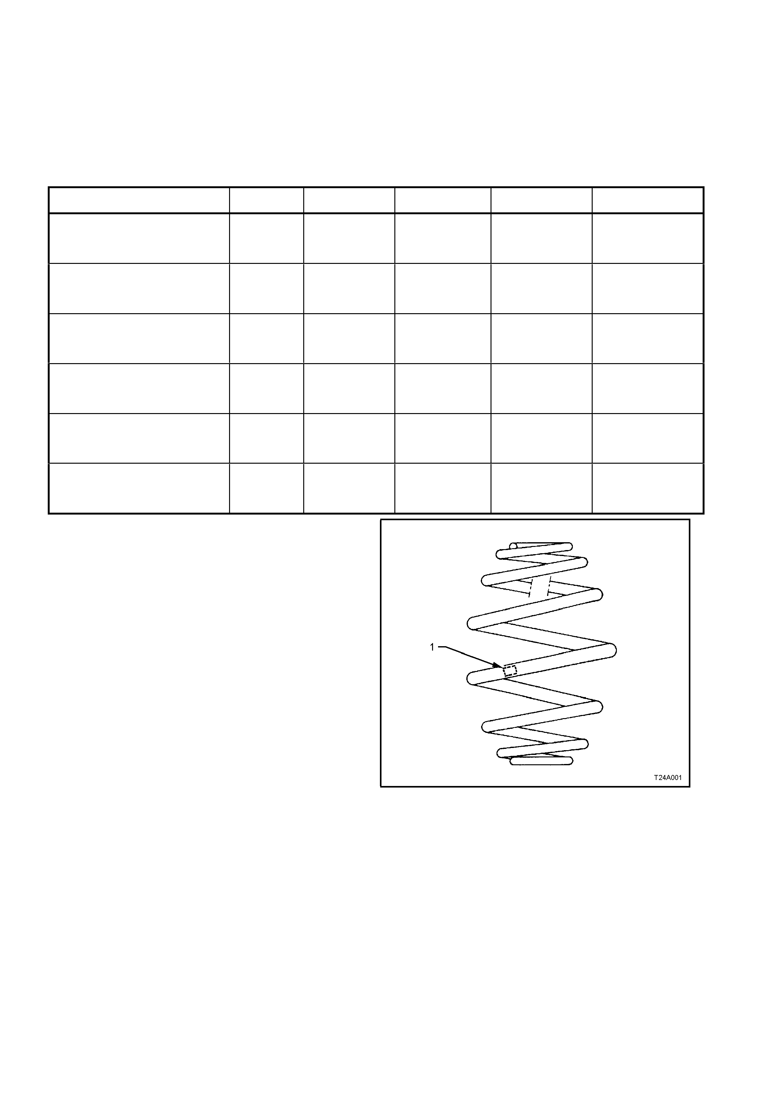
Springs............................................................................ ‘Minibloc’
REAR SPRING DETAILS
MODEL TOTAL No.
COILS FREE LENGTH
mm OUTSIDE DIAM.
Mm PROD. I.D. CODE
(Tag on spring) SPRING TYPE &
RATE
V6 & V8 ENGINE –
SEDAN MODE LS –
STANDARD SUSPENSION
7.8 275 158 EJ VARIABLE
45.0/82.0 N/mm
(4400 ± 150 N @
177 mm)
V6 & V8 ENGINE –
SEDAN MODE LS –
FE2 ‘SPORTS’ SUSPENSION
7.5 250 158 EM VARIABLE
51.0/90.0 N/mm
(4400 ± 150 N @
168 mm)
V6 & V8 ENGINE – STATION
WAGON MODELS –
STANDARD SUSPENSION
7.8 279 158 EK VARIABLE
51.0/90.0 N/mm
(5200 ± 150 N @
180 mm)
V6 ENGINE – STATION WAGON
MODELS –
FE2 ‘SPORTS’ SUSPENSION
7.8 272 158 EL VARIABLE
51.0/90.0 N/mm
(4420 ± 150 N @
188 mm)
V6 ENGINE –
SEDAN MODE LS –
V5W ‘COUNTRY PACK
SUSPENSION’
7.8 275 158 EJ VARIABLE
47.0/84.0 N/mm
(4400 ± 150 N @
177 mm)
V6 ENGINE –
STATION WAGON MODELS –
V5W ‘COUNTRY PACK
SUSPENSION’
7.8 279 158 EK VARIABLE
51.0/90.0 N/mm
(5200 ± 150 N @
180 mm)
Figure 4A-72
LEGEND
1. Production Identification Code Tag
REAR SHOCK ABSORBER DETAILS
Type
VT Sedan and Station Wagon Models ...................... Twin tube hydraulic
VT Vehicles with FE2 or V5W suspension................ Twin tube hydraulic, gas pressurised
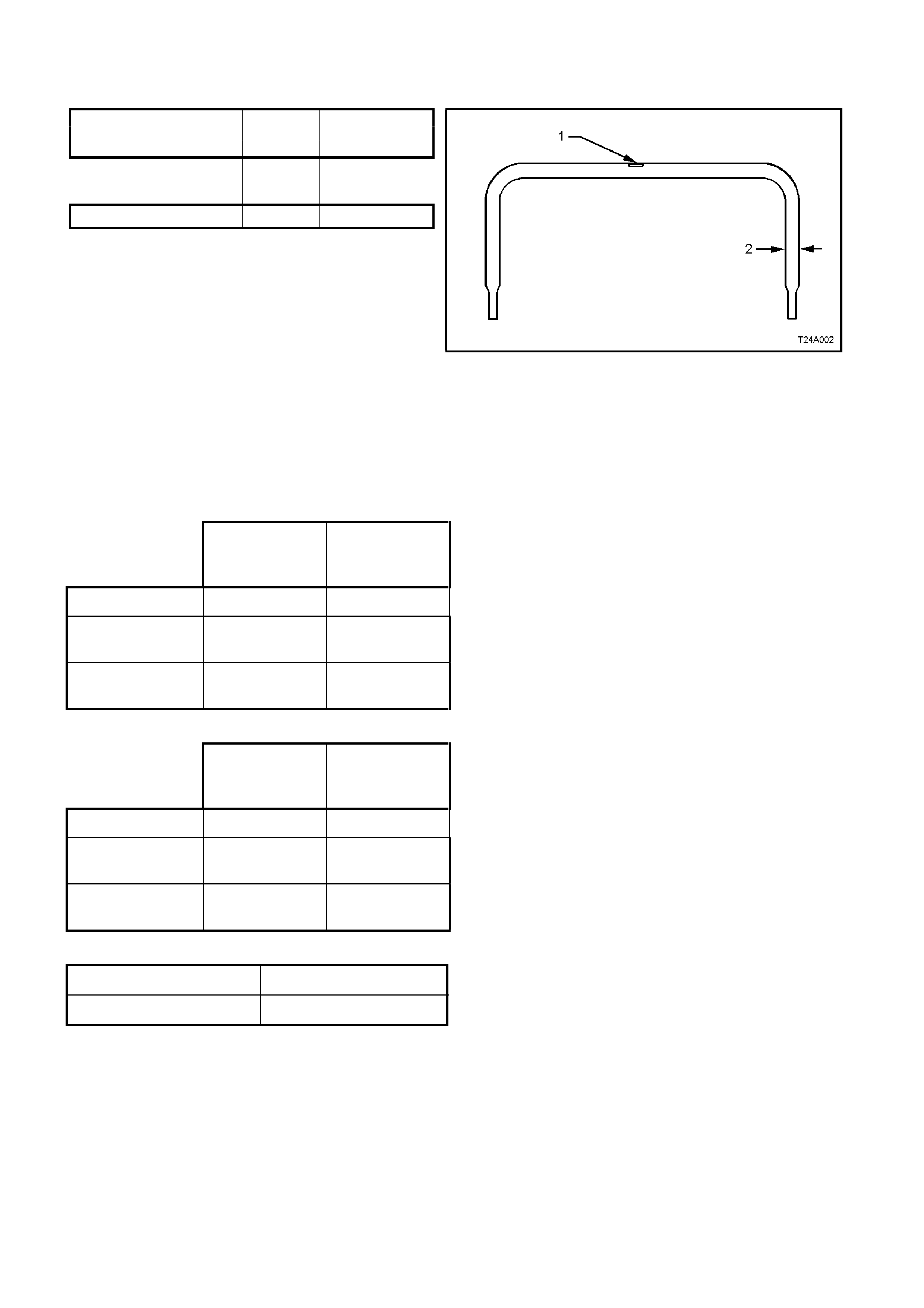
STABILISER BAR DETAILS
Type........................................................................ Linkless
Dimension Production
MODEL ‘2’ Identification
(Fig 4A-33) Code (‘1’)
All VT Series II Vehicles,
except for Sedan with FE215.0 mm FJ
Sedan Models with F E2 16.0 mm FK
Figure 4A-73
LEGEND
1. Production Identification Code Tag
2. Bar Diameter
REAR SUSPENSION: SERVICE ALIGNMENT DA TA
SEDAN MODELS
STANDARD
and V5W
SUSPENSION
FE2
SUSPENSION
REAR TRACK 1586 mm 1592 mm
CAMBER -1° 9’ to –2° 6’ -1° 27’ to –2°
29’
TOTAL TOE -0 ° 27’ to +0°
19’ -0° 19’ to +0°
32’
STATION WAGON MODELS
STANDARD
and V5W
SUSPENSION
FE2
SUSPENSION
REAR TRACK 1579 mm 1589 mm
CAMBER -1° 7’ to –1° 44’ -1° 17’ to –2°
14’
TOTAL TOE -0 ° 27’ to +0°
19’ -0° 19’ to +0°
32’
VARIATION SIDE TO SIDE (ALL MODELS)
Camber 0° 35’ Max.
Wheel Toe 0° 20’ Max
Dimensions shown are for a vehicle at curb height, i.e. vehicle ready to drive with all fluids at the recommended
levels, the fuel tank full and without driver, passenger/s or luggage.
Refer to Section 2.2 REAR WHEEL ALIGNMENT in 4A REAR SUSPENSION of the VT Series I Service
Information for specific details.

4. TORQUE WRENCH SPECIFICATIONS
NOTE: Only those torque wrench specifications relative to the service procedures contained in this section are
detailed here. for all remaining torque specifications, refer to 4A REAR SUSPENSION of the VT Series I Service
Information.
Nm
Brake Caliper Anchor Plate to Trailing Arm Attaching Bolt ............. 70 – 100
Collar Nut to Trunnion Assembly..................................................... 295 – 305
Driveshaft Constant Velocity Joint to trunnion Bolt.......................... 50, then 60° - 75° turn angle
Front Trailing Arm Mounting Brace Bolt to Underbody.................... 60 – 85
Intermediate Exhaust Pipe Flange to Catalytic Converter Bolt........ 40 – 50
Rear Crossmember Front Mounting Bolt ........................................ 125, then 30° - 45° turn angle
Rear Disc Brake Shield to Trailing Arm Attaching Bolt – Upper .... 70 – 80
Road Wheel Attaching Nut.............................................................. 110 – 140
Shock Absorber Lower Mounting Bolt............................................. 105 – 125
Stabiliser Bar Link to Trailing Arm Attaching Bolt............................ 18 – 26
Trailing Arm to Rear Crossmember Attaching Nut – All.................. 95 – 105

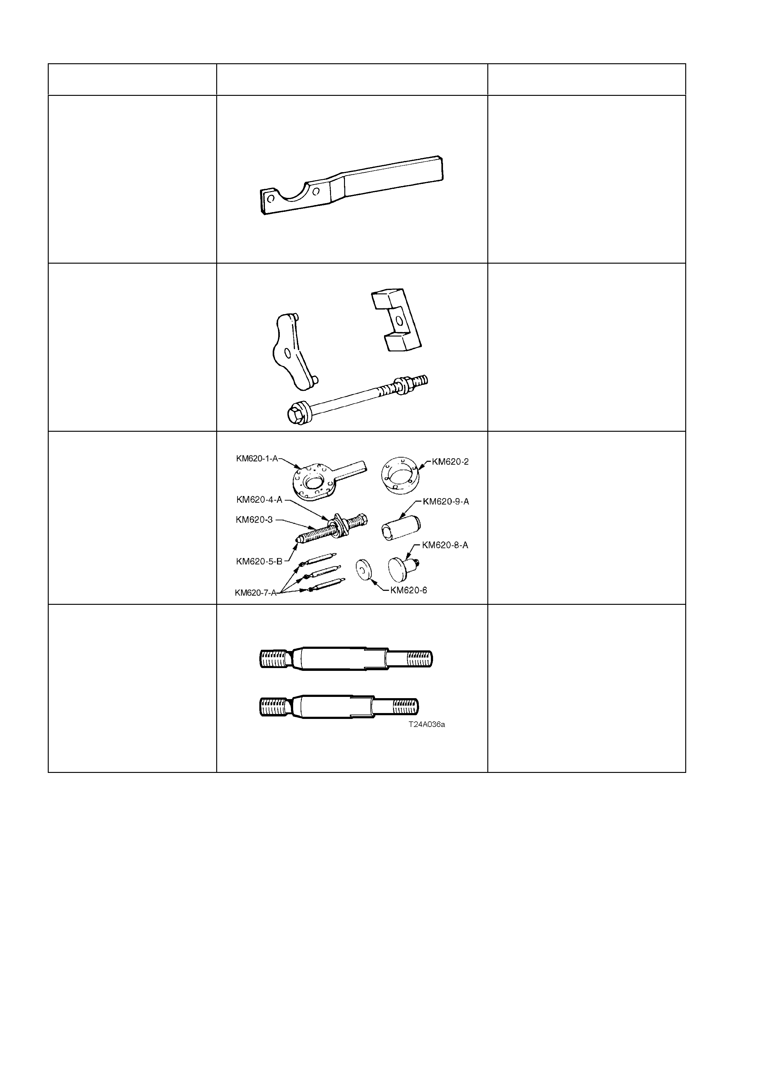
5. SPECIAL TOOLS
NOTE: Only those special tools r elative to the service pr ocedures contained in this section ar e detailed here. for all
remaining special tools, refer to 4A REAR SUSPENSION of the VT Series I Service Information.
TOOL No. REF. IN TEXT TOOL DESCRIPTION COMMENTS
AMKM–557 PULLER
Previously released.
Used to remove the mounting
bush from the front of the rear
crossmember
AU416 TORX BIT
Previously released.
Used to loosen/tighten the two
upper rear brake disc shield
bolts to the trailing arm.
AU534 TORQUE LIMITING SOCKET
New release.
Used in conjunction with an
impact gun to tighten wheel
nuts.
This is a mandatory tool.
E7115 ANGLE WRENCH
Previously released.
Used to tighten any fastener
where a torque angle is
specified in addition to and
initial torque specification.
KM468 PRESS PLATES
Previously released.
Used for various press support
operations..
TOOL No. REF. IN TEXT TOOL DESCRIPTION COMMENTS
KM468 HOLDING BAR
Previously released.
Used for hold trunnion
assembly hub from rotating.
KM618-2 INSTALLER
Previously released.
Used to install a new mounting
bush to the front of the rear
crossmember.
KM620-A REMOVER/INSTALLER
Previously released.
Used to remove and install
trunnion flange, rear wheel
bearing and trunnion assembly.
KM620-7-AUS SUPPORTS
New release.
The two revised length supports
are required when undertaking
any of the following service
operations on the locally
sourced trailing arm assembly:
• Rear trunnion flange
• Rear wheel bearing
• Rear trunnion assembly
• Rear brake disc shield.