
SECTION 7C1 – HYDRA-MATIC 4L60-E AUTOMATIC
TRANSMISSION: GENE RAL INFORMATI ON
CAUTION:
This vehicle will be equipped with a Supplemental Restraint System (SRS). A SRS will consist of either
seat belt pre-tensioners and a driver's air bag, seat belt pre-tensioners and a driver's and front
passenge r's air bags or seat b elt pre-t ensio ners, d river’s and f ront p asseng er’s a ir bag and lef t and right
hand side air bags. Refer to SAFETY PRECAUTIONS, Section 12M, Supplemental Restraint System
before performing any service operation on, or around any SRS components, the steering mechanism o r
wiring. Failure to follow the SAFETY PRECAUTIONS could result in SRS deployment, resulting in
possible personal injury or unnecessary SRS system repairs.
CAUTION:
Whenever any component that forms part of the ABS or ABS/ETC (if fitted), is disturbed during Service
Operations, it is vital that the complete ABS or ABS/ETC system is checked, using the procedure as
detailed in 4. DIAGNOSIS, ABS or ABS/ETC FUNCTION CHECK, in Section 12L ABS & ABS/ETC, (V6
Engine) or (GEN III V8 Engine) of this Service Information CD.
CAUTION:
This vehicle may be equipped with LPG (Liquefied Petroleum Gas). In the interests of safety, the LPG
fuel system should be isolated by turning ‘OFF’ the manual service valve and then draining the LPG
service lines , before an y serv ic e work is car ried o ut on t he v eh icl e. R ef er t o t he L PG le aflet inclu ded wit h
the Owner's Handbook for details or the appropriate Section of this Service Information CD for more
specific servicing information.
1. GENERAL INFORMA T ION
1.1 SECTION DE SCRIPTIONS
The Multi-Section approach to th e Hydra-matic 4L60-E Autom atic Transm ission has been continued f or VT Series
II vehicles.
SECTION 7C1: HYDRA-MATIC AUTOMATIC TRANSMISSION: GE NERAL INFORMATION
The purpose of this Section is to provide an overview of this automatic transmission, by briefly describing what
each of the various sub-sections contains.
In addition, an overview of the changed features for the 1999 model year transmission is provided.
SECTION 7C2 HYDRA-MATIC AUTOMATIC TRANSMISSION:- ELECTRICAL DIAGNOSIS
As the electrical systems and diagnosis for this transmission are controlled by the Powertrain Control Module
(PCM), this material has now been included in the appropriate sections relating to the PCM; namely
Section 6C1 POWERTRAIN MANAGEMENT - V6 ENGINE of the VT Series I Service Information and
Section 6C3 POW ERT RAIN MANAGEM ENT – GEN III V8 ENGINE of the VT Series II Service Information.
SECTION 7C3 HYDRA-MATIC AUTOMATIC TRANSMISSION:- GENERAL DIAGNOSIS
As distinct from the previous Section, 7C3 contains information that will assist in the diagnosis of the mechanical
and hydraulic components in the 4L60-E automatic transmission, with the unit installed in the vehicle.
Only those diagnostic procedures that have modified information will be published here. Therefore, this Section
should be read in conjunction with Section 7C3 - HYDRA-MATIC AUTOMATIC TRANSMISSION - GENERAL
DIAGNOSIS, of the VT Series I Service Inf or mation.
Techline
Techline
Techline

SECTION 7C4 HYDRA-MATIC AUTOMATIC TRANSMISSION:-ON-VEHICLE SERVICING
Again, this Section only covers on-vehicle servicing items that differ to those detailed in
Section 7C4 - HYDRA-MATIC AUTOMATIC TRANSMISSION -ON-VEHICLE SERVICING of the VT Series I
Service Information. As a result, this information should also be read in conjunction with that information.
SECTION 7C5 HYDRA-MATIC AUTOMATIC TRANSMISSION:-UNIT REPAIR
This sec tion c ont ai ns the proced ures nec ess ary for the d isas s embly, inspecti on, over hau l a nd assembly op erati ons
of the mechanical components, once the transmission is removed from the vehicle. As the unit repair procedures
remain essentially unchanged, refer to Section 7C5 - HYDRA-MATIC AUTOMATIC TRANSMISSION -UNIT
REPAIR of the VT Series I Service Information.
1.2 TRANSMISSION CHANGES FOR 1999 MY
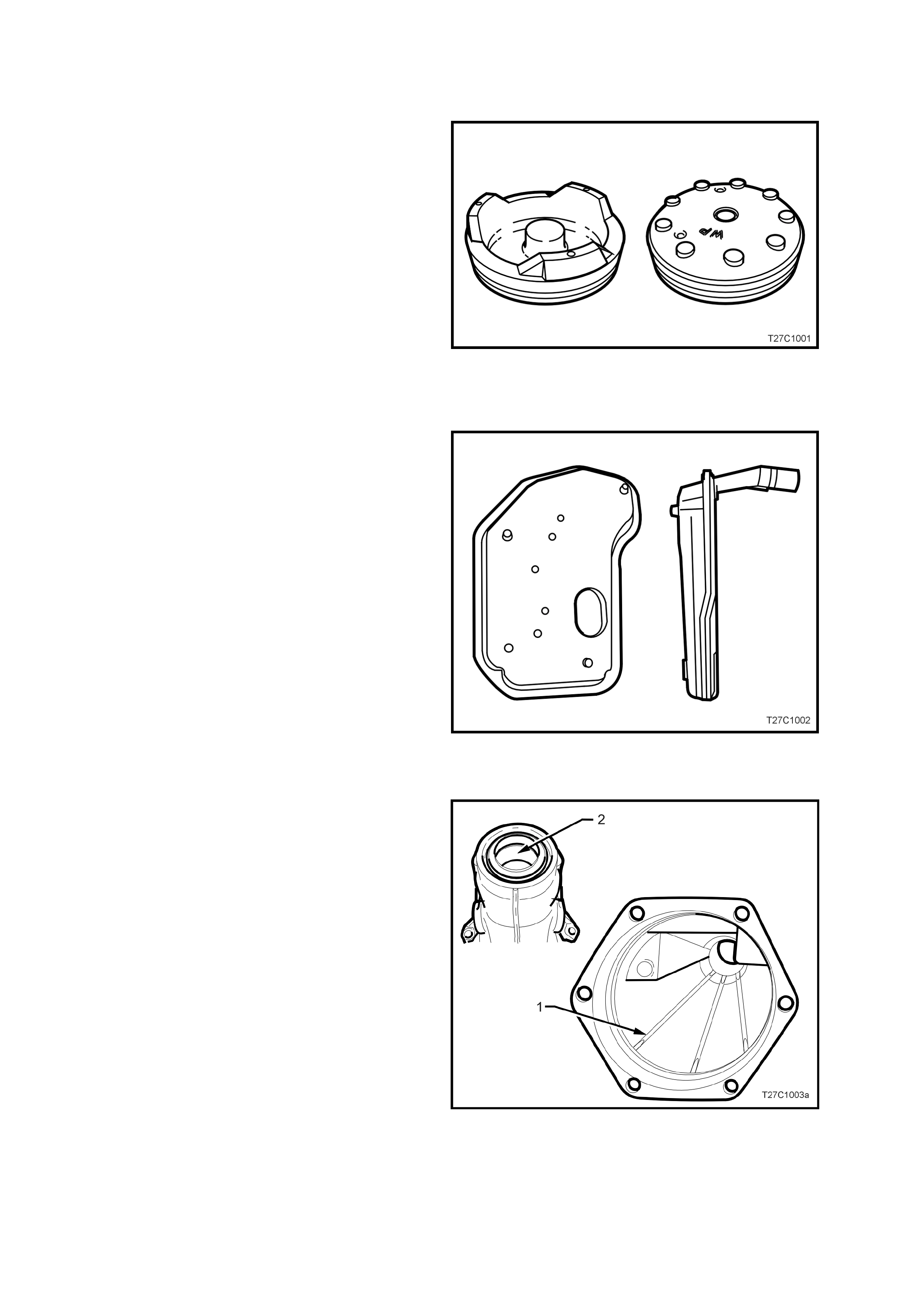
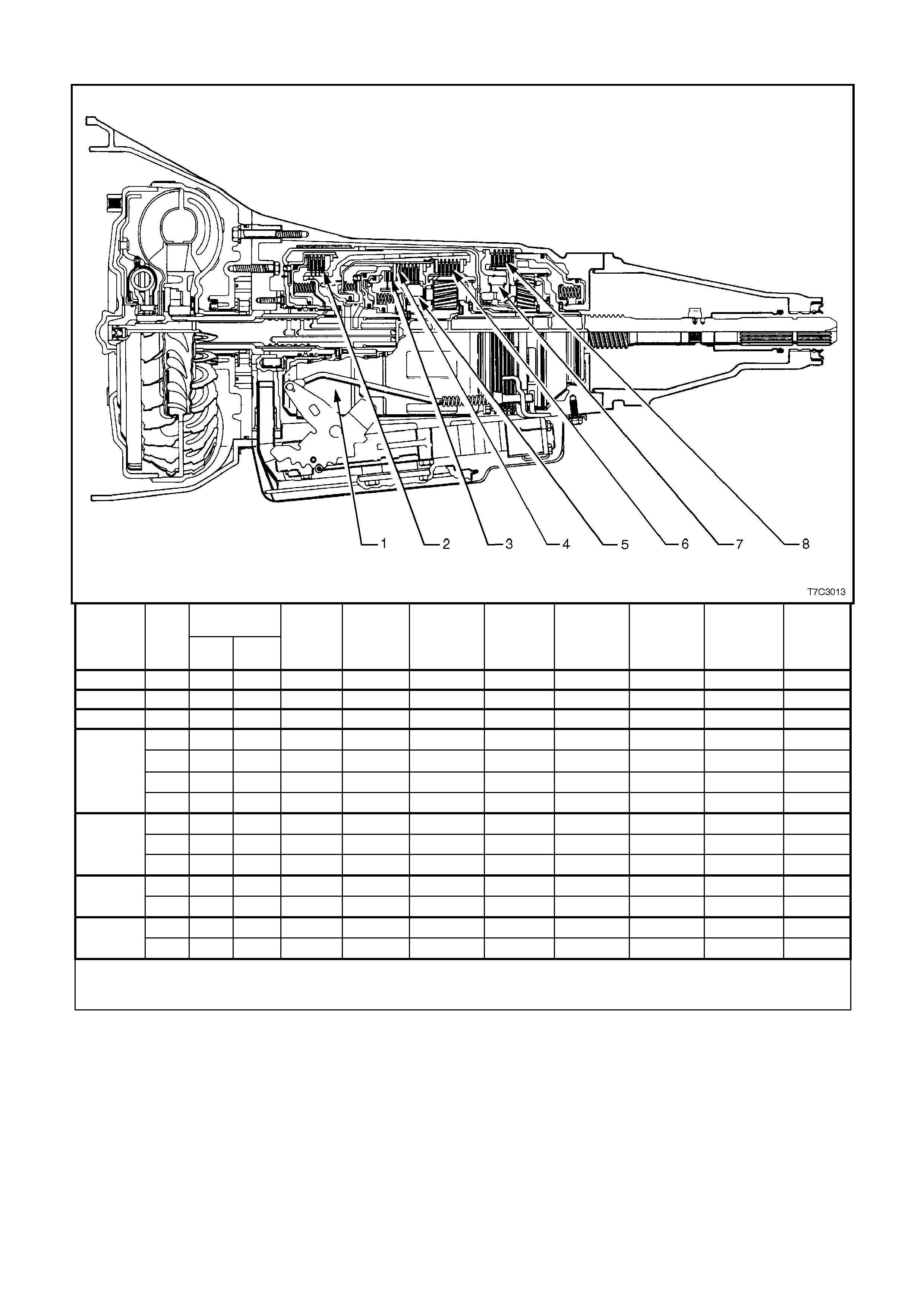
1-2 ACCUMULATOR PISTON AND SP RING
Introduced into production on May 11, 1998,
(Julian date 131), the 1-2 accumulator piston
changed from an aluminium piston to a composite
material.
At this time the accumulator outer spring also
changed f r om a round wire spr in g to a s prin g made
from oval shaped wire.
The 1-2 accumulator pistons and outer springs are
not inter-cha nge ab le.
As this change was introduced during the 1998
model year build, the composite piston and oval
wire outer spring is the on l y on e to be f itt ed t o 1 999
model year transmissions. Figure 7C1-1
DEEP PAN OIL FILTER
The oil filter used with the deep oil pan, is now a
black, all-plastic component and must be fitted to
all 1999 model year transmissions.
Important: Do not use a shallow pan filter in a
4L60-E automatic transmission that is fitted with a
deep oil pan.
Figure 7C1-2
EXTENSION HOUSING AND BUSH
The extension housing for 1999 model year
transm issions has three inter nal ribs (1) added and
the propeller shaft slip yoke bush material has
changed from a bronze bushing to one made with
a Teflon ® (2) coating.
The new bushing can be identified as a smooth
bushing with no lubricant holes previously used
with the bronze bus h and is grey/green in colo ur .
While the new extension housing and Teflon®
bush will service back to earlier, two-piece case
transmissions, the bush and extension are not
inter-changeable.
Figure 7C1-3
CONTROL VALVE BODY
To improve durability, the check ball hole as
indicated, has been changed from an oval to a
round shape.
This revised contr ol valve bod y must be us ed in all
1999 model year transmissions.
Figure 7C1-4
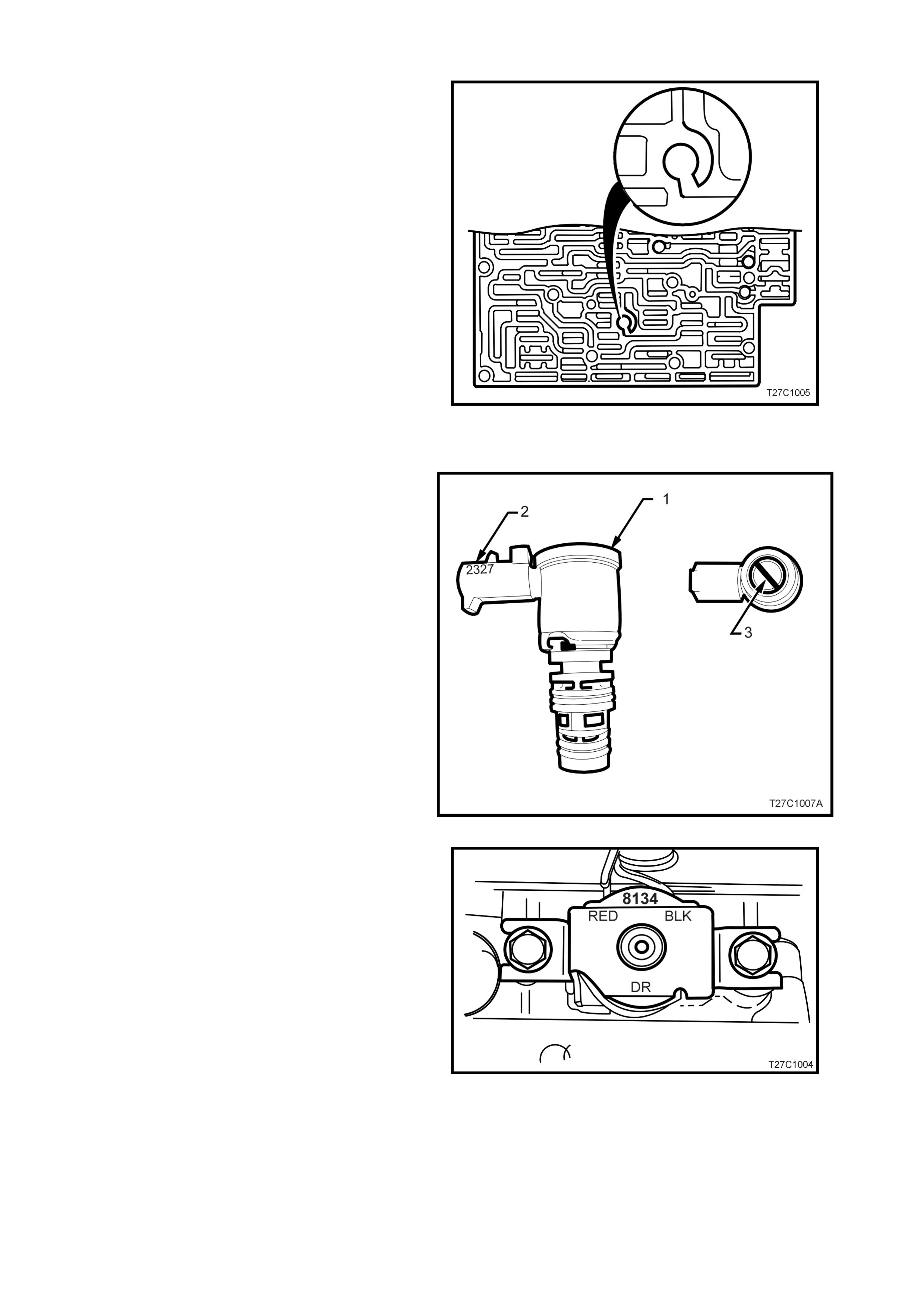
3-2 CONTROL SOLENOID
A revised 3-2 control solenoid (1) is fitted and can
be identified by the number ‘2327’ (2) (previously
‘9127’) and the inclusion of a black plastic support
(3) on the bottom of the filter screen.
This revised part m ust be fitted to 199 9 m odel year
transmissions.
Figure 7C1-5
TCC SOLENOID
The torque converter clutch solenoid has been
revised for the 1999 model year transmission, to
reduce the converter drain back.
As sho wn, the rev is ed s o len o id ca n be id ent if ied by
the silver coloured bracket (previously gold) and
with the number ‘8134’ on the wiring bobbin
(previously ‘8128’).
The revised solenoid must be used on all 1999
model year transmissions.
Figure 7C1-6
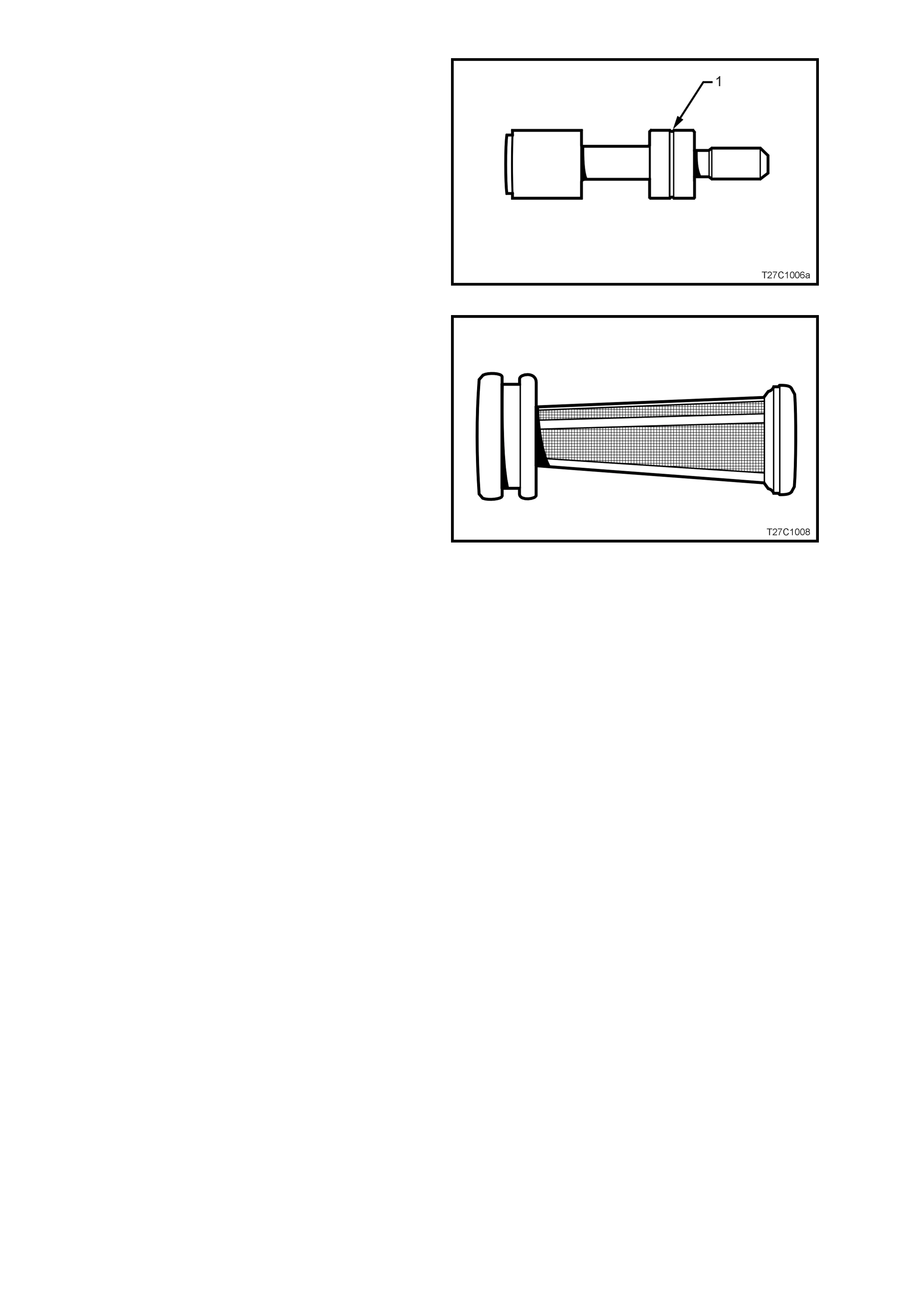
REGUL ATOR APPLY VALVE
A revised design regulator apply valve is now used,
that im proves durabilit y by lessening the possibility
of the valve wearing the control valve body bore.
The revised design can be recognised by the
groove (1) and must be used on all 1999 model
year transmissions.
Figure 7C1-7
PUMP FILTER SCREEN
The mesh on the pump filter screen is now more
coarse than the previous screen, to improve
transmission fluid flow under cold operating
conditions.
This screen must be used in all 1999 model year
transmissions.
Figure 7C1-8
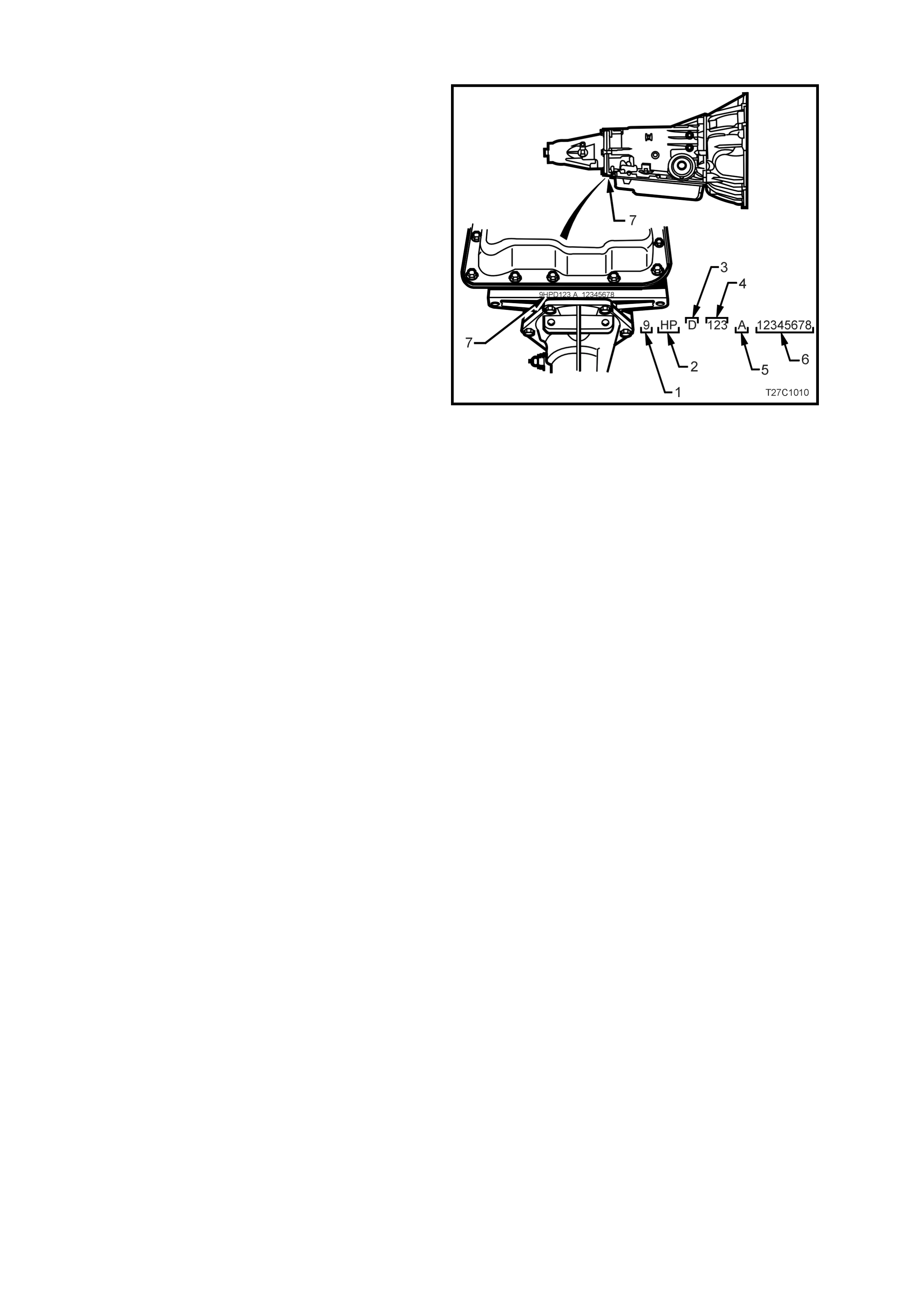
1.3 TRANSMISSION IDENTIFICATION
The 4L60-E automatic tr ansmiss ion app lication an d
identification can be determined from the stamping
in the rear of the transmission case at the rear, in
the location shown (7).
The coded number can be interpreted from the
follo wing breakdown;
1. Model Year (‘9’ = 1999)
2. Model: 3.8 litre V6 (LN3) HF
3.8 litre V6 S/C (L67) HN
5.7 litre GEN III V8 (LS1) HP
3. Transmission Model Identifier (‘D’ = 4L60-E)
4. Julian Date (Day of the Year)
5. Shift Build ‘A’, ‘B’, ‘J’ = First Shift;
‘C’, ‘H’, ‘W’ = Second Shift
6. Individual Transmission Serial Number
Figure 7C1-9

1.4 TORQUE CONVERTE R CHANGE
The size of the torque converter fitted to the V6 engine (production option LN3) automatic transm ission has been
increased from 245 mm to 258 mm, which now becomes common with the V6 supercharged engine (production
option L67). The reasons for the change are to reduce operating temperatures and improve fuel consumption
This running change, introduced with the 9HFD transmission, became effective from a vehicle build date of
Februar y 26, 1999.
1.5 RANGE RE FERENCE CH ART
RANGE GEAR SHIFT
SOLENOID 2-4 BAND REVERSE
INPUT OVERRUN
CLUTCH FORWARD
CLUTCH FORWARD
SPRAG CL. 3-4 CLUTCH LOW/
ROLLER LOW/
REVERSE
1 - 2 2 - 3 (#1) CL UTCH
(#2) (#3) (#4) ASSEMBLY
(#5) (#6) CLUTCH
(#7) CLUTCH
(#8)
PARK On * On * APPLIED
REVERSE On * On * APPLIED APPLIED
NEUTRAL On * On *
1ST On On APPLIED HOLDING HOLDING
D2ND OFF On APPLIED APPLIED HOLDING
3RD OFF OFF APPLIED HOLDING APPLIED
4TH On OFF APPLIED APPLIED APPLIED
1ST On On APPLIED HOLDING HOLDING
32ND OFF On APPLIED APPLIED HOLDING
3RD OFF OFF APPLIED APPLIED HOLDING APPLIED
21ST On On APPLIED APPLIED HOLDING HOLDING
2ND OFF On APPLIED APPLIED APPLIED HOLDING
11ST On On APPLIED APPLIED HOLDING HOLDING APPLIED
2ND ** OFF On APPLIED APPLIED APPLIED HOLDING
* SHIFT SOLENOID STATE IS A FUNCTION OF VEHICLE SPEED A ND MAY C HANGE IF A VEHI CLE SPEED INCREASES SUFFICIENTLY IN PARK, REVERSE
OR NEUTRAL. HOWEVER, tHIS DOES NOT AFFECT TRANSMISSION OPERATION.
** IN MANUAL FIRST, SECOND G EAR IS ONLY AVAILABLE ABOVE APPROXIMATELY 48 – 56 KM/H TO PREVENT ENGINE OVERSPEEDING.
Figure 7C1-10

1.6 ENGINE TORQUE MANAGEMENT
W ith the GEN III V8 engine, Tor que Man agement is a f unc tion of the PCM that r educes engin e p ower under c ert ain
conditions, included in which, is the transmission upshifts and downshifts.
Torque Management is performed for the following reasons:
1. To prevent overstress of the powertrain components.
2. To prevent damage to the vehicle during certain abusive manoeuvres.
3. To reduce engine speed when the IAC is out of the normal operating range.
The PCM monitors the following sensors and engine parameters to calculate engine output torque;
• Air/Fuel ratio
• Mass Air Flow
• Manif old Absolute Pressure
• Intake Air Temperature
• Spark Advance
• Engine Speed
• Engine Coolant Temperature
• A/C Clutch Status
The PCM monitors the torque converter status, the transmission gear ratio, and the engine speed in order to
determine if torque reduction is required. The PCM retards the spark as appropriate to reduce engine torque
output if torque reduction is required. The PCM. also shuts off the fuel to certain injectors to reduce the engine
power In the case of an abusive manoeuvres.
Instances when eng in e power red uc tio n is likely to be experienc ed, ar e:
a. During transmission upshifts and downshifts.
b. Heavy acceleration from a standing start.
c. The IAC is out of the normal operating range.
d. W hen the dri ver is perfo rming str ess-inducing (ab usive) m anoeuvres suc h as shiftin g into gear at high thr ottle
angles or shifting the transmission from reverse to drive to create, a rocking motion.
The driver is unlikely to notice the torque managem ent actions in the first two instances. The engine power output
will be moderate at full throttle in the other two cases.
The PCM calcul ates the am ount of spark retard nec essar y to re duce t he eng ine powe r b y the des ired am ount. For
example the PCM disables the fuel injectors for cy linders 1, 4, 6, and 7 in the case of an abusive manoeuvres.

2. SE RVICE NOTE S
In the inter ests of s af et y to per son ne l, e qu ipment and to t he vehic l e an d i ts com ponents , th e f oll o wing notes s ho ul d
be read and a dhered to whene ver servici ng operations are to be car ried out on the H ydra-m atic 4L60-E aut omatic
transmission.
In addit ion, s ome of this information a lso refers to the adherenc e to sound work shop practices a nd, to achieve the
design life of affected components, it is also recommended that these points are taken into account.
2.1 FASTENERS
• Always reinstall fasteners at the same locations as they were removed.
• If a fastener requires repl acement, always use a part of th e correct part number or of equal size and strengt h
or stronger.
• Tighten fasteners to correct torque value when required. Torque values are specified for dry, unlubricated
fastener threads.

2.2 GENERAL WORKSHOP PRACTICE
• Keep work area and tools clean.
• To avoid unnecessary contamination, always clean the exterior of the transmission before removing any parts.
• Do not use wiping cloths or rags because of the risk of lint being trapped in the transmission.
• Do not use solvents on:
− neoprene seals.
− composition faced clutch plates.
− thrust washers.
• Always use protective eye wear when using compressed air on components.
• Blow out all passages with compressed air. Only probe small passages with soft, thin wire.
• Handle parts with care to avoid nicks and scratches.
• Do not remove Teflon oil seal rings unless damaged or performing a complete overhaul.
• Expand internal snap rings and compress external snap rings to maximise retention and security.
• Lubricate all internal parts with transmission fluid (Only use Dexron® III), as they are being installed.
• When installing cap screws into aluminium castings:
− always use a torque wrench.
− always dip screw threads in transmission fluid (Only use Dexron® III).
− Stripped or damaged threads in aluminium castings may be reconditioned by using commercially
available thread inserts.
• Once removed, replace all gaskets, seals and O-rings with new parts and:
− always use seal protect ors where indicated and do not use gask et cement or sealant on any joined face
unless specified to do so.