
SECTION 5A - BRAKES
IMPORTANT:
Before performing any Service Operation or other procedure described in this Section, refer to Section 00
CAUTIONS AND NOTES for correct workshop practices with regard to safety and/or property damage.
1. GENERAL INFORMAT ION
The VU Series Models braking system carries over from VX Series Models with the addition of a load sensing
proportioning valve which is coupled to the rear suspension. Because VU Series Models are equipped with a load
sensing proportioning valve, the brake master cylinder does not have the standard proportioning valve installed.
The normal master cylinder proportioning valve is replaced by a pressure differential spool valve. The spool valve
provides warning in the event of a loss of front or rear system pressures and allows equal system pressure to the
load sensing proportioning valve.
The load sensing proportioning valve fitted to VU Series Models is not a serviceable item and if found to be faulty,
must be replaced as an assembly.
For inf orm ation not co ver ed in this Sect ion, ref er to S ection 5A BR AKE S in th e VT Serie s I and VT Series II Ser vice
Information.
1.1 MASTER CYLINDER - PRINCIPLES OF OPERATION
DESCRIPTION
A master cylinder with a 25.4 mm (1 inch) diameter main bore is used on all VU Series Models, regardless of the
braking system fitted. The only difference being the master cylinder used with ABS has a screw in blanking plug
installed into the lower of the two front brake outlets in the master cylinder.
The m aster cylinder is a tandem , c entre valve des ign, incor porati ng a 3 1.75 m m fast fill bore and va lve that prov ides
a reduce d p eda l travel. T he m as ter cylinder is mounted to the vac u um brak e boos t er , whic h i n t ur n is mounte d to th e
engine side of the dash panel.
CONSTRUCTION
This tandem m aster cylinder configuration provides separate hydraulic circuits for the application of the br akes, in a
front to rear split arrangement.
Both of these circuits are fed by separate fluid feed and compensating ports, through a common fluid reservoir,
sealed by a diaphragm fitted inside the reservoir cover. This diaphragm provides an effective seal against any
atmos pheric m oisture com ing into co ntact with t he hygros copic brak e fluid. T his prov ision m aintains the brak e fluid's
boiling point for a maximum period of time.
The interna l parts of the m aster cylinder comprises of a stepped di ameter prim ary pist on with an L type s eal and an
‘O’ ring, a secondary piston (which incorporates a centre valve, a caged spring and two L type seals), a return spring,
a secondary piston stop pin and a fast fill valve.
In all v ehicles , a load s ensi ng pr oport ioning valv e is loc ated at t he r ear of t he veh icle. T he prop orti oning v alv e that is
usually located in the second bor e of the master cylinder, is replaced with a pressure differentia l spool valve, which
can move within the m aster cylinder body to operate t he brake fail warning light switch. The s witch then illuminates
the brake fail warning light in the instrument cluster, should a pressure loss occur in either the front or rear brake
systems.
Techline
Techline
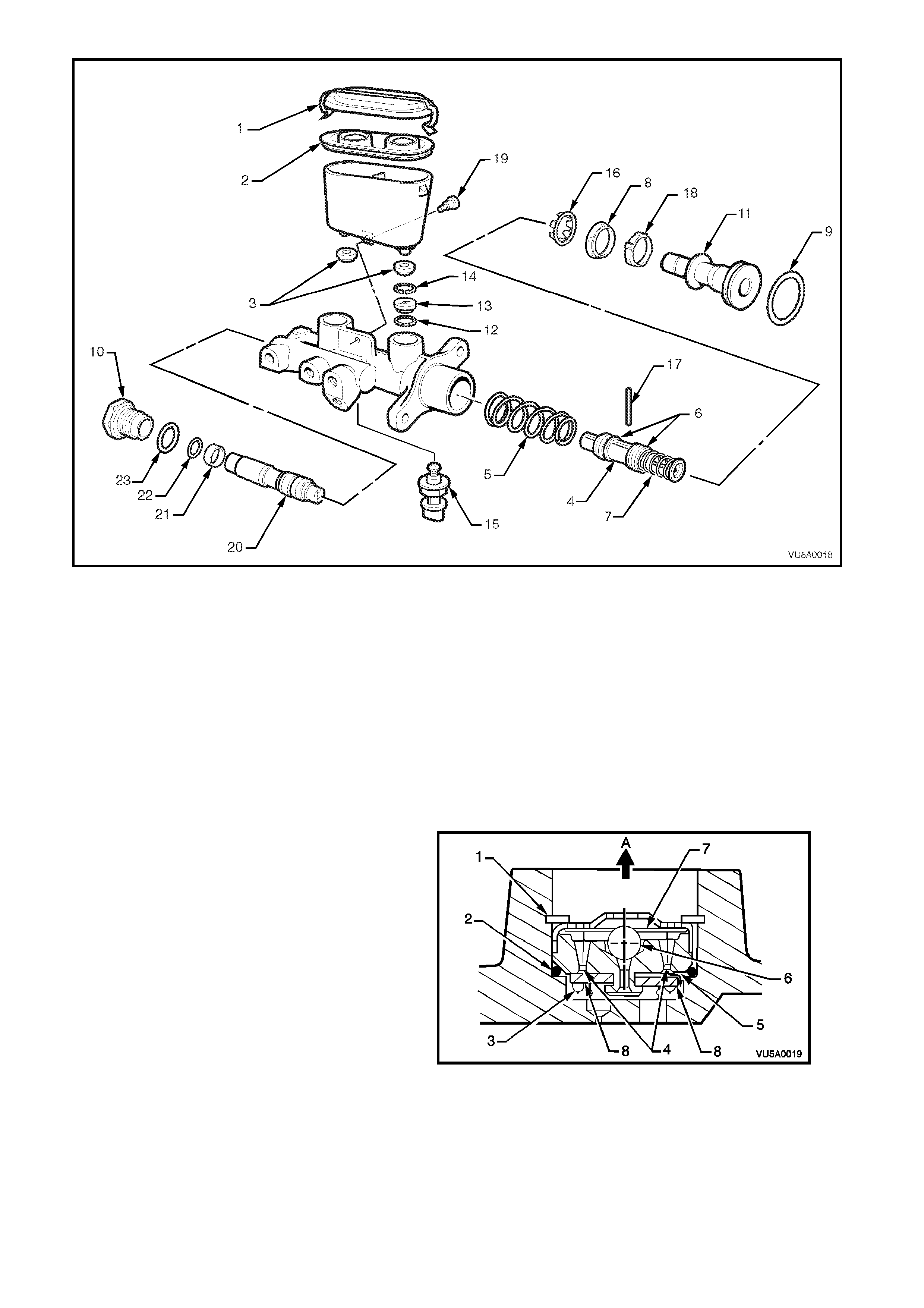
Figure 5A-1
Legend
1. Reservoir cap
2. Reservoir cap se al
3. Reservoir sealing grommets
4. Secondary piston
5. Return spring
6. Secondary seals (L type)
7. Caged spring
8. Primary seal (L type)
9. Primary piston 'O' ring
10. End plug
11. Primary piston
12. Fast fill valve 'O' ring
13. Fast fill valve
14. Fast fill valve circlip
15. Brake fail warning li ght switch
16. Primary seal retainer
17. Secondary piston stop pin
18. Recuperating guide
19. Reservoir retaining sc rew
20. Differential spool valve
21. Spool valve sleeve
22. Spool valve sleeve 'O' ring
23. End plug 'O' ring
OPERATION
The fast fill (fast pressure build up) valve
incorporated into the master cylinder provides
reduced pedal travel by rapidly overcoming the
large low pressure displacements, such as the
advancement of brake pads against the disc with
minimal primary piston travel.
Legend
1. Retaining circlip for fast fill valve
2. Fast fill valve 'O' ring
3. One way rubber flapper valve
4. Replenishing holes
5. Compensating passage
6. Ball valve and seat
7. Ball valve pre lo ad disc spr i ng
8. Rubber flaps
A. To reservoir
Figure 5A-2 FAST FILL VALVE
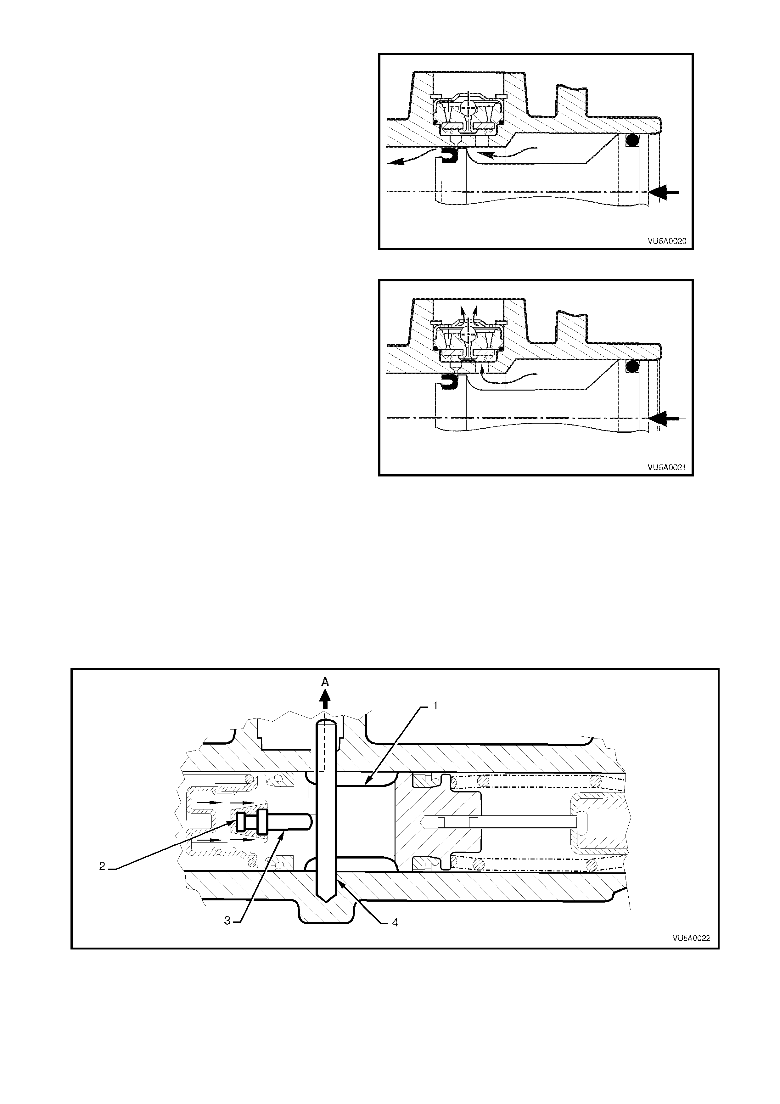
Initial primary piston movement produces pressure
in the larger bore of the master cylinder which
forces closed the flap on the fast fill valve and
prevents fluid from entering the reservoir port.
This high volume low pressure fluid flows over the
primary piston primar y L type seal, into the sm aller
bore and out to the brake calipers, catering for
most of the low pressure brake system
displacement with minimal primary piston travel.
Figure 5A-3 INITIAL PISTON MOVEMENT
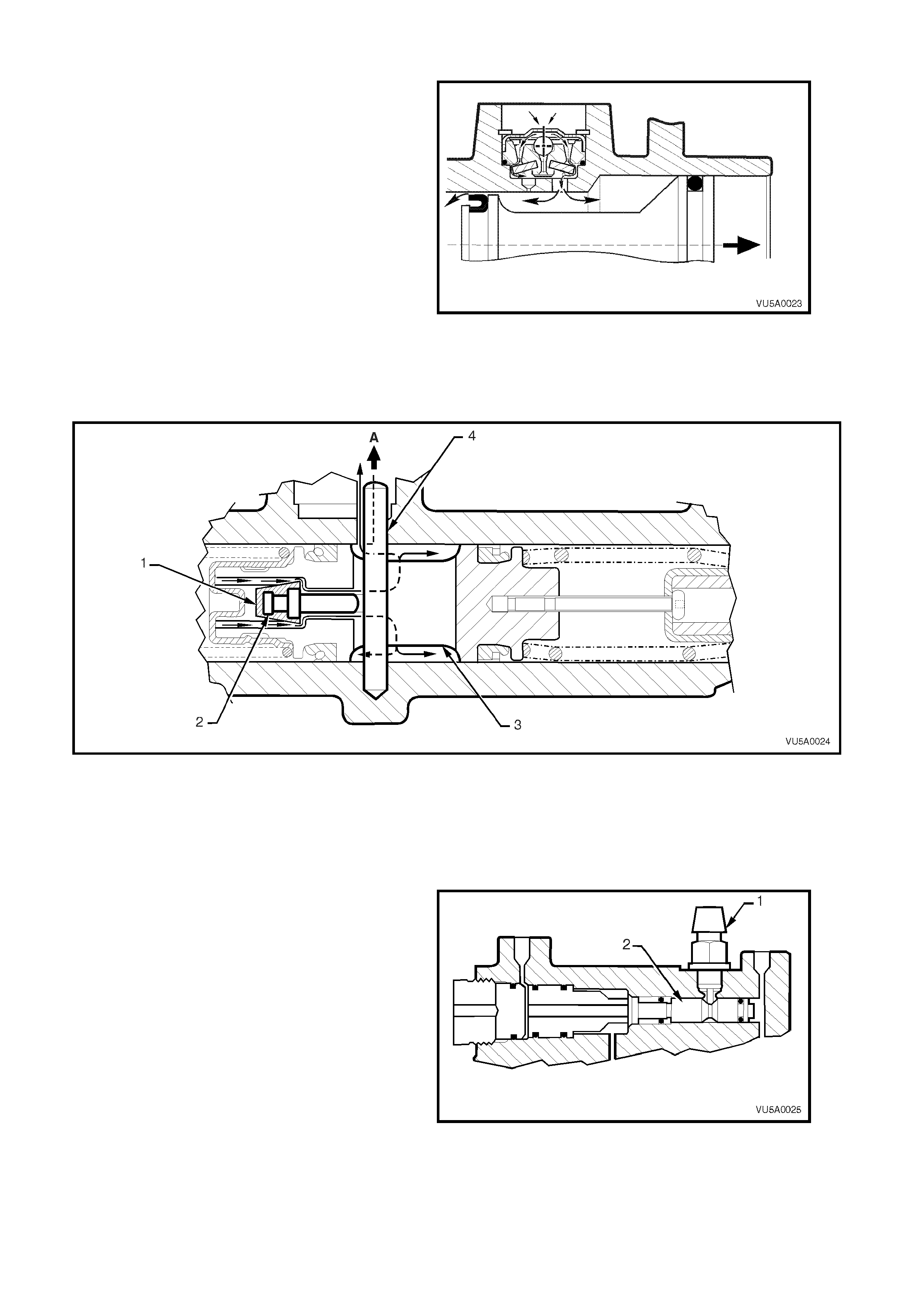
Further primary piston movement increases the
pressure in the larger bore, and at a pre-
determined pressure, the ball and seat feature
incorporated in the fast fill valve unloads,
preventing additional pressure rise and allowing
fluid to flow from the larger bore into the reservoir
port.
At this point, the small bore section of the master
cylinder functions as a conventional master
cylinder, producing high operating line pressures
with minimal primary piston travel.
Figure 5A-4 FAST FILL VALVE UNLOADING
The combination of hydraulic pressure and the force of the primary piston acting on the secondary piston spring
causes the secondary piston to move forward.
This action on the secondary piston moving forward releases the centre valve pin from contact with the secondary
piston stop pin. With the force of the centre valve spring and the release of the centre valve pin, the rubber centre
valve seal is pushed against the front of the secondary piston inner bore, effectively blocking off the fluid from the
rear brake system compensating port.
At the sam e tim e, the prim ary pist on L t ype seal pass es the f ront br ake s ystem compensating p ort, c losing it off fr om
the reservoir and thus the high operating fluid pressure is produced.
The high operating fluid pressure influence is then registered on either side of the pressure differential spool valve,
then to the front and rear brake calipers (via the load sensing proportioning valve) where the brakes are applied.
Figure 5A-5 CENTRE VALVE CLOSED
Legend
1. Secondary piston
2. Centre valve seal 3. Centre valve pin
4. Secondary stop pin A. To reservoir
FRONT BRAKE SYSTEM: When the brake pedal
is released and the primary piston returns, fluid
recuperation will occur from the reservoir through
the reple nishing ho les in the f ast fill val ve, over the
rubber flap and into the larger and smaller piston
bores.
When the primary piston has fully returned, the
compensating hole in the master cylinder will be
uncovered. This allows fluid returning from the
brake calipers to f low into t he reservoir via the f ast
fill valve compensating passage, thus relieving all
pressur e in the brak e s ystem.
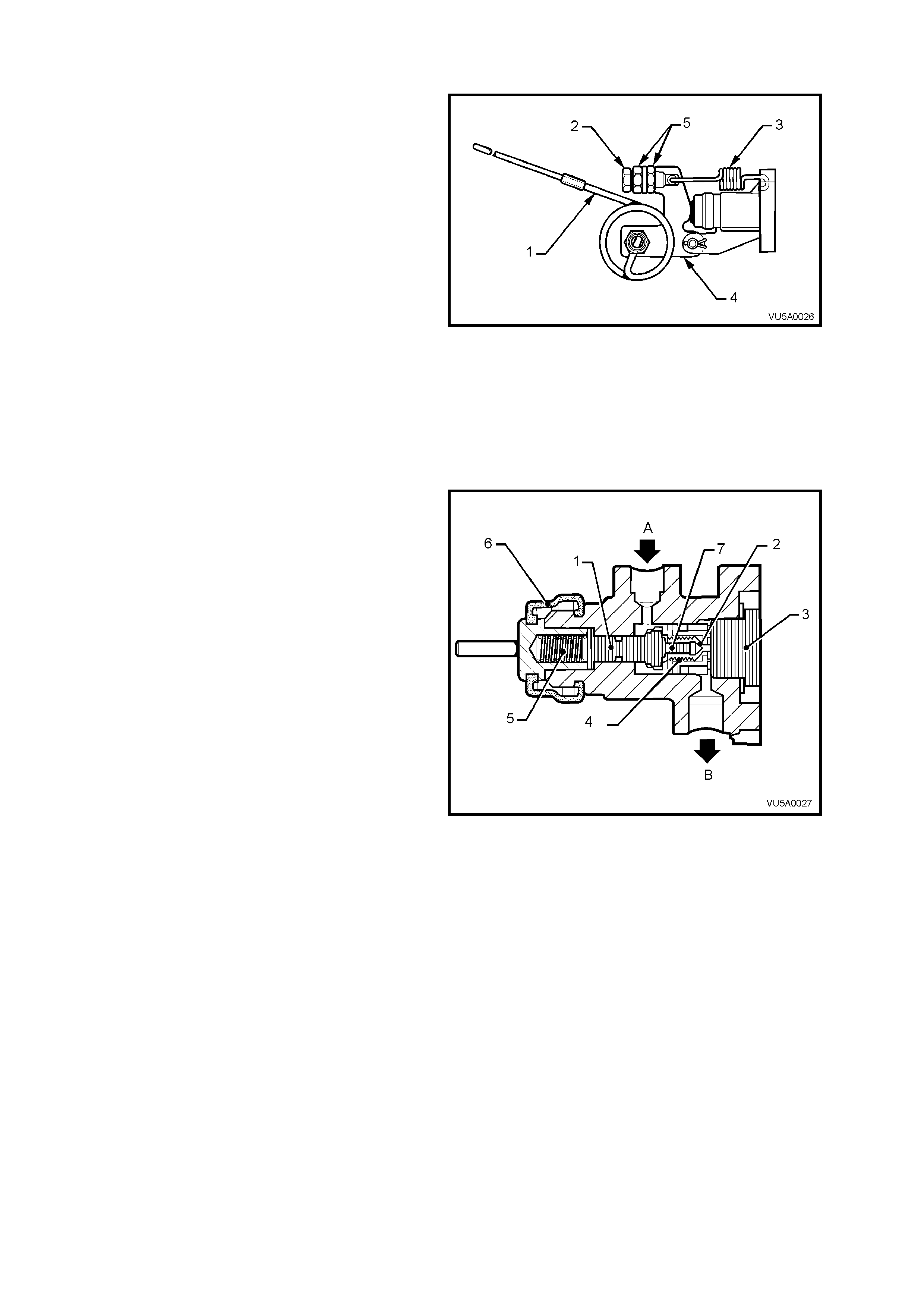
Figure 5A-6 FLUID REPLENISHMENT THROUGH FAST
FILL VALVE
REAR BR AKE SYSTE M: W hen the brake peda l is releas ed and the seco ndary pist on returns, f luid recuperatio n will
occur f r om the r eser vo ir a n d thr o ugh th e c en tre va lv e when the c entre val ve rub ber seal bec omes uns ea ted f r om the
secondary piston bore.
Figure 5A-7 FLUID REPLENISHMENT THROUGH CENTRE VALVE
Legend
1. Centre valve seal.
2. Centre valve pin. 3. Secondary piston.
4. Secondary piston stop pin. A. Compensating port to
reservoir.
PRESSURE DIFFERENT IAL SPOOL V ALVE OPERATION
The brake fail warning light switch (1) is mounted in
the spool valve body with the spring loaded plunger
fitting into a tapered groove in the centre of the
spool valve (2). With the spool in a centralised
position, the switch contacts remain open.
Should there be a loss of pressure in either the
front or rear brak e s ystem, when t he br ak e pedal is
applied, the spool valve will move off centre,
closing the switch contacts and turning on the
warning light on the instrument panel.
After repairs have been made and the brake
system has been bled, the pressure in the front
and rear brake systems will equalise (when the
brakes are applied), centralising the spool and
opening the switch contacts, thus switching off the
brak e fail warni ng li ght.
Figure 5A-8
1.2 LOAD SENSING PROPORTIONING VALVE - PRINCIPLES OF OPERATION
CONSTRUCTION
The loa d sens ing propor tio ning va lve is att ached to
the right hand frame, above the final drive
assembly. The valve torsion spring lever is
attached to the right hand trailing arm rod with a
bracket, cable and hook.
The load sensing proportioning valve senses load
by monitoring the rear suspension ride height, to
regulate the pressure applied to the rear brake
calipers. Maximum line pressure is supplied to the
rear brakes when the vehicle is fully laden, while
lightly loaded conditions provide minimum line
pressure; i.e. line pressure varies in relation to the
weight of the load.
Legend
1. Sensing torsion spring
2. Adjusting screw
3. Static spring
4. Torsion spring lever
5. Adjusting screw lock nuts
Figure 5A-9
OPERATION
The static spring exerts a force on the end of the
spool by means of a lever, while a torsion type
sensing spring attached to the right-hand trailing
arm rod modifies this applied force, depending on
the axle load.
When the vehicle is unladen or lightly loaded, the
torsion spring has the maximum effect and,
together with the static spring force, the total apply
force on the plunger and piston is lowest. This
apply force is able to position the load sensing
piston to restrict the flow of fluid through the outlet
port to the rear brakes.
However, when the vehicle is loaded, the spool is
positioned so that fluid can flow unrestricted
through the inlet port, through the spool sub-
assem bly, around th e poppet valve and out via th e
spool sub assembly sealing seat and outlet port to
the rear wheel calipers.
When the brake pedal is released, inlet pressure
drops, allowing the higher pressure on the rear
wheel side of the sensing valve to force upon the
poppet valve, such that the brake fluid can flow
almost unrestricted, back to the master cylinder.
Eventually, the spool is forced into its released
position by the external spring set up, to fully open
the passage between the front and rear circuit.
NOTE: The static spring tension is pre-set and
should not be adjusted.
Figure 5A-10
Legend
1. Load sensing valve spool
2. Load sensing valve spool sealing seat
3. Load sensing valve end plug
4. Secondary spring
5. Primary spring
6. Load sensing valve boot
7. Load sensing valve poppet and valve
A. Brake fluid inlet
B. Brake fluid outlet
2. SERVICE OPERATIONS
2.1 MASTER CYLINDER
REMOVE
1. Remove master cylinder reservoir cap
temporarily and syphon brake fluid from the
reservoir. Reinstall reservoir cap.
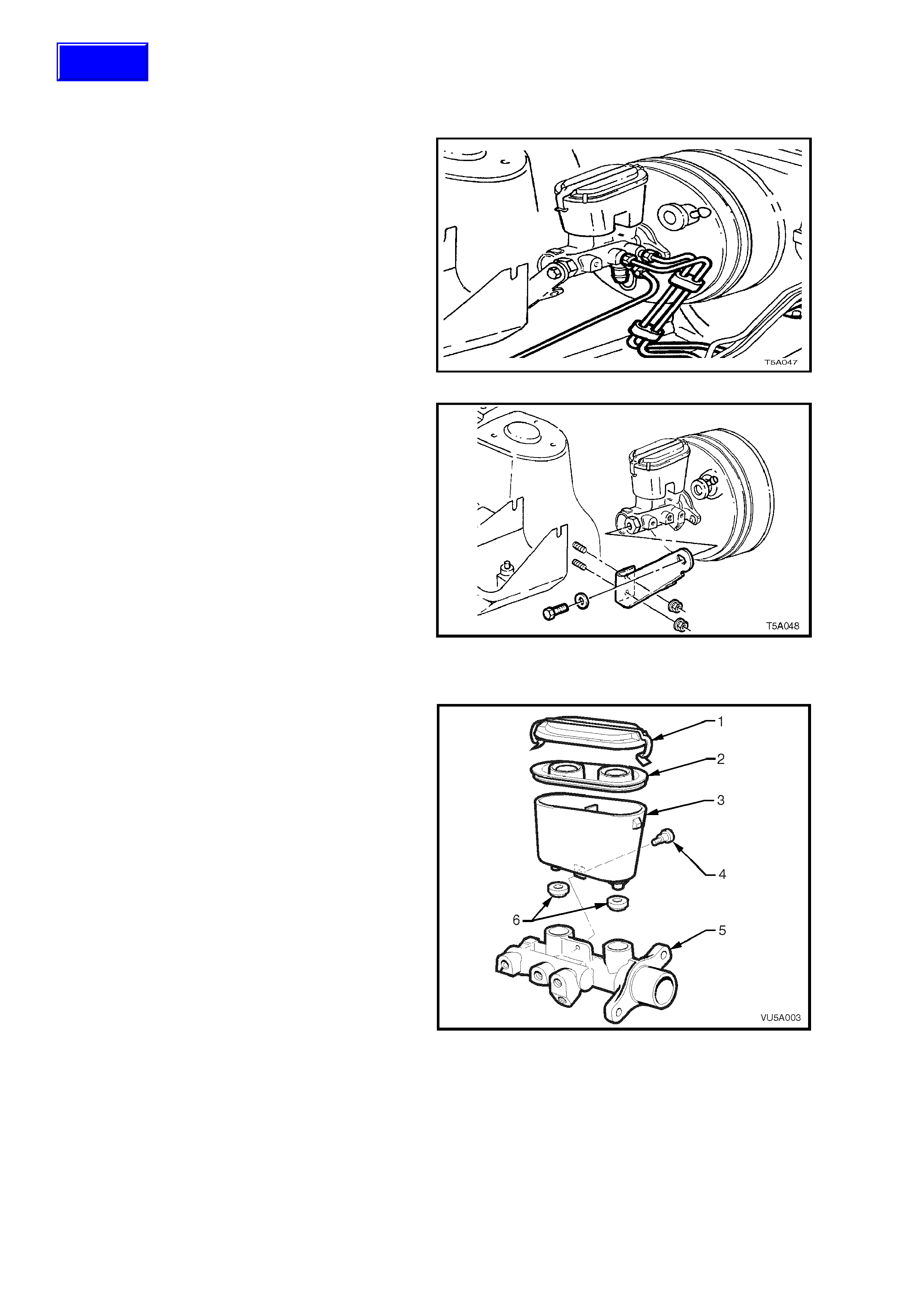
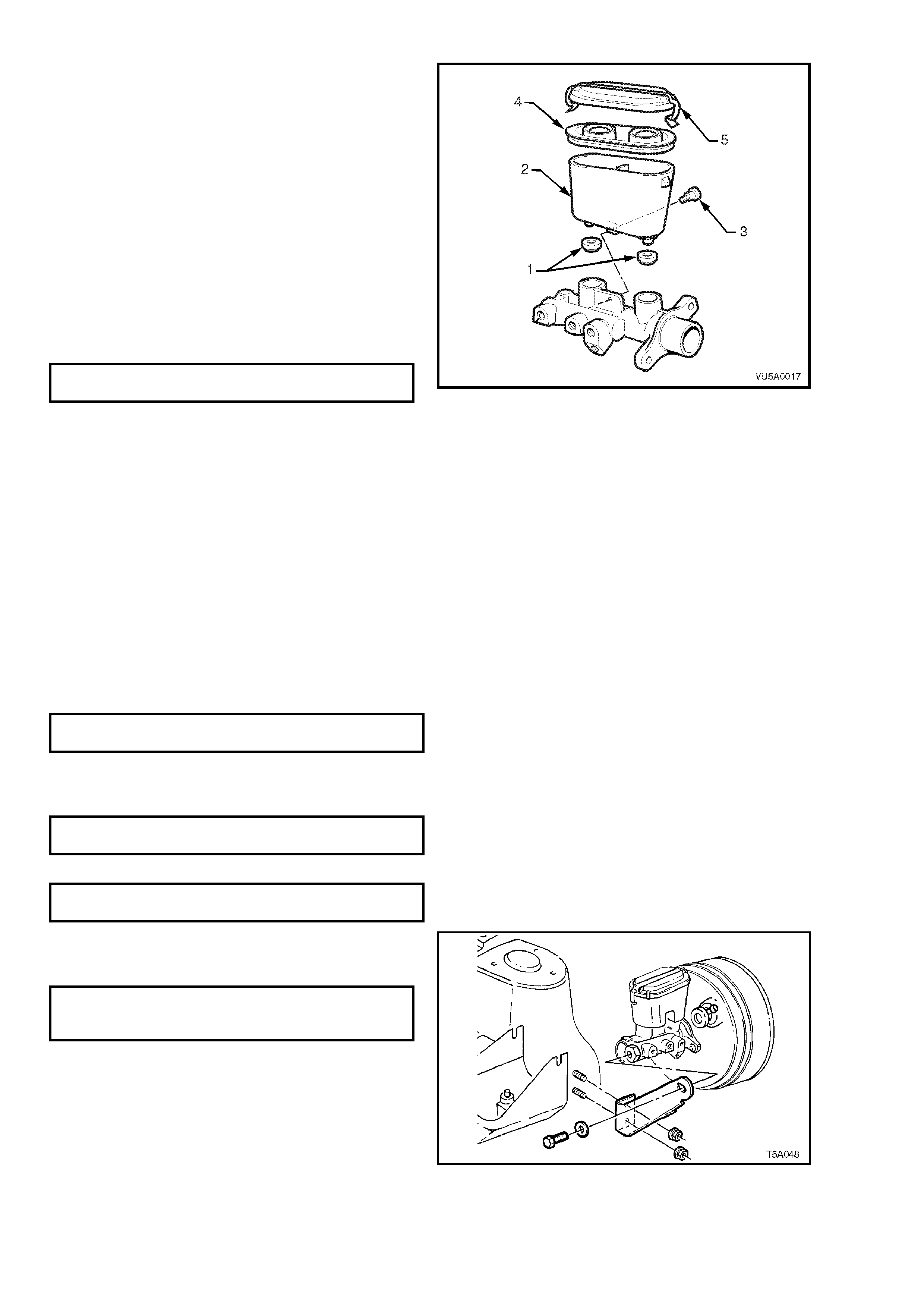
2. Disconnect electrical connector from brake
warning differential switch.
3. Disconnect brake lines from master cylinder
and plug the lines and master cylinder
apertures, to prevent foreign matter entry.
Figure 5A-11
4. Remove bolt and nuts securing the bracket to
master cylinder and front suspension strut
tower, remove bracket.
5. Remove nuts s ecuring master c ylin der t o br ake
booster and remove master cylinder.
NOTE: DO NOT disturb brake booster push rod
and DO NOT depress brake pedal with master
cylinder r em oved or the int ernal r eact ion disc in the
booster may become dislodged.
Figure 5A-12
DISASSEMBLE
1. Clean the outside of the master cylinder.
2. Remove reservoir cap (1) and seal (2). Discard
any fluid left in reservoir (3).
3. Unscrew the reservoir to body retaining screw
(4), located at the base of the reservoir.
4. Separate the plastic reservoir, by hand, from
the body (5).
5. Remove the two reservoir sealing grommets
(6) from the body.
Figure 5A-13
Techline
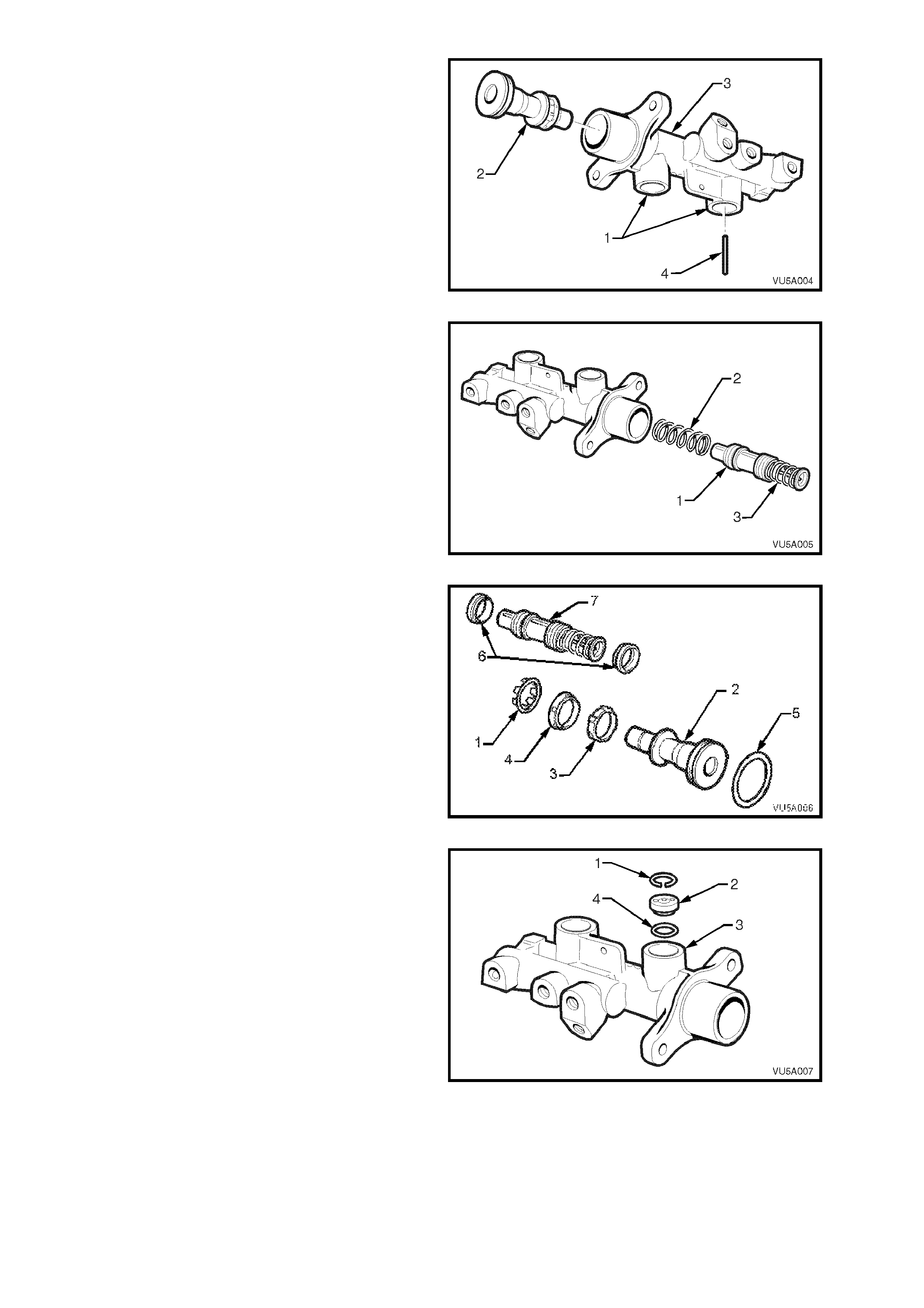
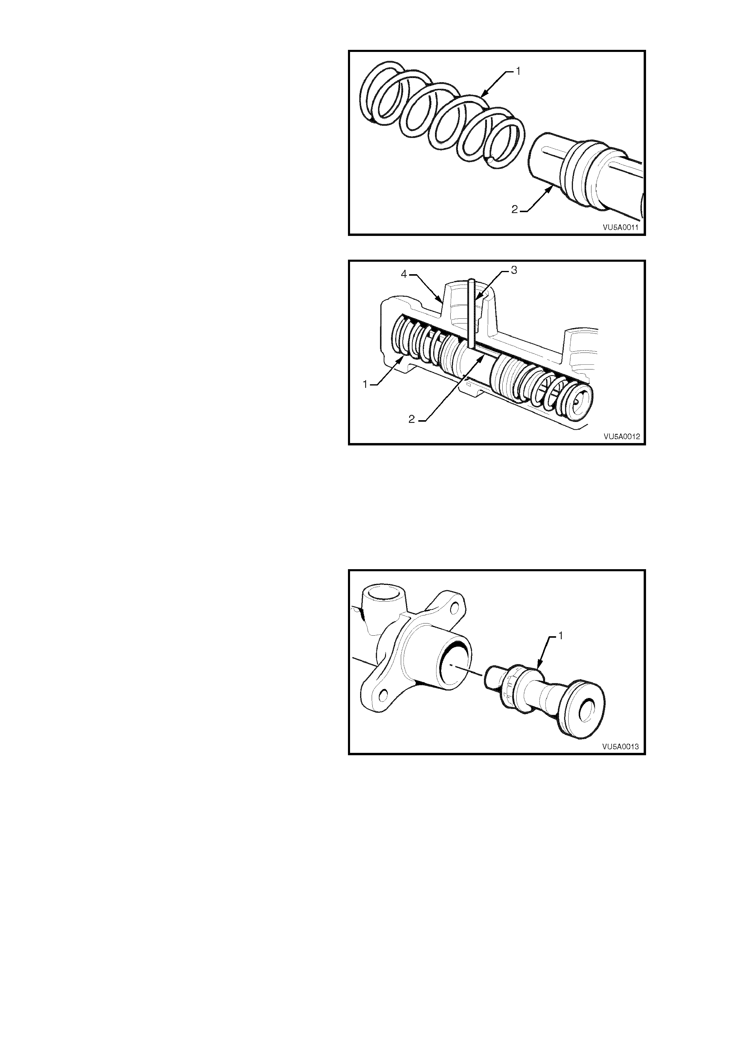
6. Invert master cylinder body so that the
reservoir ports (1) face downwards. Depress
the primary piston (2) with a wood dowel or
brass r od u nti l t he pis t on b ottoms in the bor e of
the master cylinder body (3). The secondary
piston stop pin (4) should fall out freely.
7. Carefully remove primary piston from the main
bore of the master cylinder.
Figure 5A-14
8. Remove s ec ond ar y pis to n (1) and retur n s prin g
(2) by lightly tapping the open end of the
master cylinder b ore squar ely onto a sof t piece
of wood.
NOTE 1: The caged spring (3) of the secondary
piston has been set to a predetermined length. Do
not attempt to adjust or remove the caged spring.
NOTE 2: The centre valve is part of the secondary
piston assembly and is not serviced as a separate
part.
Figure 5A-15
9. Remove the seal retainer (1) from the primary
piston (2) by using a small screwdriver to
caref ull y pry apart the seal retain er legs.
10. Remove the recuperating guide (3) and seal
(4) from the primary piston (2).
11. Remove the rubber 'O' ring (5) from the
primary piston, taking EXTREME CARE not to
damage the piston
12. Remove both rubber seals (6) from the
secondary piston (7), taking EXTREME CARE
not to damage the piston.
Figure 5A-16
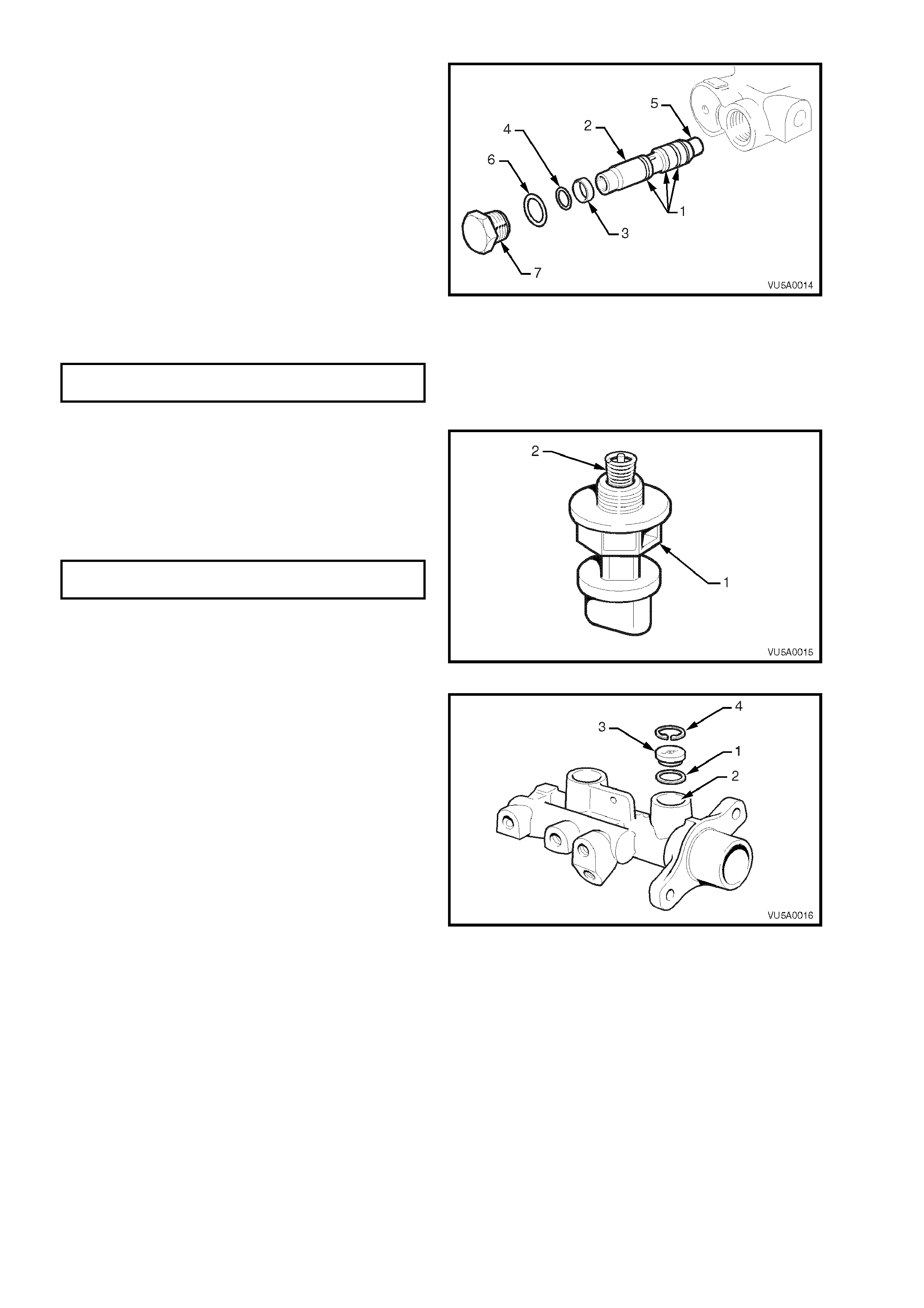
13. Using suitable circlip pliers, remove the circlip
(1) retaining the fast fill valve (2) located in the
primary reservoir port of the master cylinder
body (3).
14. Face the master cylinder reservoir ports
downwards to allow the fast fill valve to fall out.
If the valve is stuck, lightly tap the master
cylinder on a piece of wood to assist removal.
15. Remove the valve sealing 'O'-ring (4) from the
bottom of the reservoir port.
Figure 5A-17
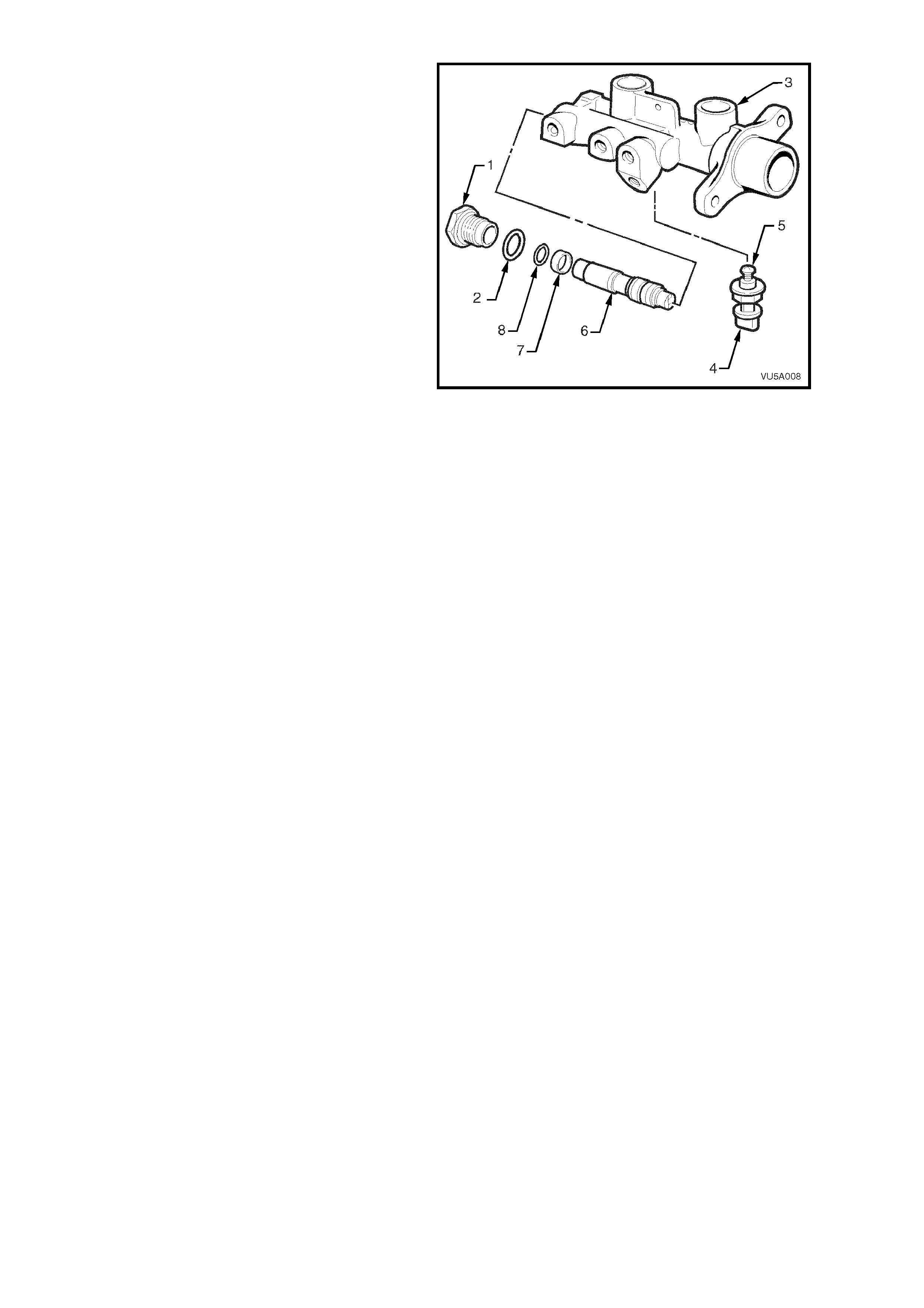
16. Unscrew and remove the end plug (1) and 'O'
ring (2) from the master cylinder body (3).
17. Remove the brake fail warning light switch (4)
from the master cylinder, ensuring that the
electrical earthing spring (5) remains on the
switch plunger.
18. Remove the pressure differential spool valve
assembly (6), spool valve sleeve (7) and 'O'
ring (8) by lightly tapping the 'end plug' end of
the cylinder bore squarely onto a soft piece of
wood to dislodge the spool valve assembly.
Important: Do not damage the pressure
differential spool valve assembly by attempting to
pull it out of the bore with pliers.
Figure 5A-18
CLEAN AND INSPECT
NOTE: Ensure work area is clean and f r ee of dus t or other c ontaminants. These can af f ec t the per f ormance of all the
seals in the master cylinder.
1. Wash master cylinder body, reservoir and cap in clean methylated spirits.
2. Wash all internal parts in brake fluid.
3. Check all recesses, openings and passages to ensure they are open and free of foreign matter.
4. Place all parts on a clean surface.
5. Inspect the master cylinder bores for signs of etching, pitting, scoring or rust. If in poor condition, replace the
cylinder.
IMPORTANT:
Do not hone the master cylinder bore.
6. Discard all rubber parts together with the secondary piston assembly (the secondary piston assembly
incorporates the secondary piston, the centre valve and the caged spring). Only new parts from the genuine
service kit should be used to reassemble the master cylinder.
REASSEMBLE
NOTE 1: Before assembly, lubricate internal parts and master cylinder bores with clean, recommended brake fluid
from a sealed container.
NOTE 2: Prior to assembly, ensure that the primary piston, without seals fitted to it, is free to move the full piston
stroke in the large bore.
NOTE 3: The three 'L' type seals must be assembled in the directions and positions shown in Fig. 5A-19.
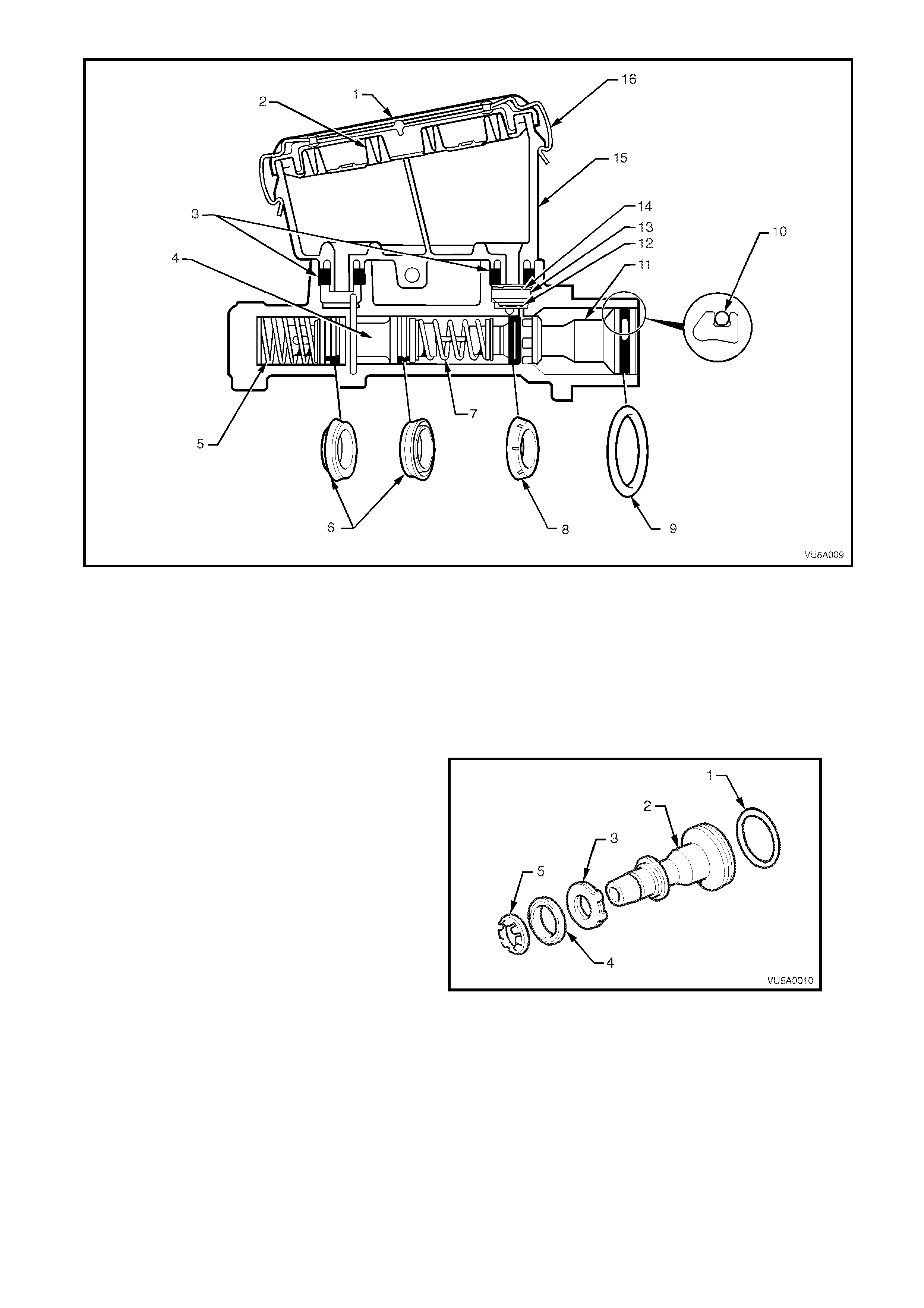
Figure 5A-19
Legend
1. Reservoir cap
2. Reservoir cap seal
3. Reservoir sealing grommets
4. Secondary piston
5. Return spring
6. Secondary seals (L type)
7. Caged spring
8. Primary seal (L type)
9. Primary piston 'O' ring
10. Primary piston (Sectional
view)
11. Primary piston
12. Fast fill valve 'O' ring
13. Fast fill valve
14. Fast fill valve circlip
15. Reservoir
16. Reservoir cap re taining clip
1. Install ‘O’ ring seal (1) into the groove at the
end of the primary piston (2).
2. Install the recuperating guide (3) followed by
the primary L type seal (4) onto the end of the
primary piston. The sealing face of the L type
seal must face away from the recuperating
guide.
NOTE: The primary L type seal for the primary
piston can be identified by the six shallow grooves
around the seal’s outer surface.
3. Ass em ble the seal re tain er (5) onto the prim ar y
piston. Using a small screwdriver, clip the
retainin g legs of the retai ner into the groov e on
the primary piston. Care should be taken to
avoid damage to the piston or seal.
Figure 5A-20
4. Ass em ble the sm all en d of the ret urn spr ing (1)
over the end of the secondary piston (2). This
should be a slight interference fit.
Figure 5A-21
5. Carefully insert the secondary piston, caged
spring end las t, throug h the large bor e and into
the sm aller bor e of the mas ter c ylinder un til th e
return spring (1) 'bottoms'. Ensure the return
spring does not dislodge from the secondary
piston assembly during this operation.
NOTE: To assemble the secondary piston
assembly into the body, align the slot in the
secondary piston (2) with the hole in the reservoir
ports. This must be done so that the secondary
piston stop pin can be inserted into secondary
reservoir port in the master cylinder.
6. Fully stroke the secondary piston using a soft
dowel and while h eld at the bottom of the bor e,
install the sec on dary pisto n s top pi n (3) in to th e
secondary reservoir port (4). The piston stop
pin should easily fit through the larger hole of
the two holes located in the secondary
reservoir port. The top of the secondar y piston
stop pin should not protrude more than 6 mm
above the bottom of the reservoir port.
Figure 5A-22
7. Inser t the pr im ary pist on (1) into the m ain bore,
against t he secondar y piston a nd caged spr ing
assembly. Carefully push both pistons down
the bore until the primary piston is flush with
the bore opening.
8. Stroke pistons and check that the primary
piston re turns to the end of the bore after eac h
stroke. Ensure movement is not sticky.
Figure 5A-23
9. Fit new O-rings (1) onto the pressure
differential spool valve (2).
10. Ensure spac er (3) and O-ring ( 4) are f itted over
the spool valve and that they are installed the
right way (spacer first followed by the O-ring).
11. Inser t spool val ve into the b or e, c app ed e nd (5)
first. Extreme care should be taken when
inserting the spool valve to ensure that the O-
rings are not damaged. If O-rings are
damaged, the master cylinder will not function
correctly and will leak brake fluid. The spool
valve assembly must be bottomed in the bore
of the master cylinder.
12. Assemble a new O-ring (6) onto the end plug
(7), and screw the end plug into the master
cylinder body.
END PLUG 25 - 30
TORQUE SPECIFICATION Nm
Figure 5A-24
13. Reinstall differential switch (1) and spring (2).
Do not over tighten.
NOTE: Ensure the earthing spring on the
differential switch is installed on the plunger as
shown. If necessary, the small end of the spring
may need to be closed down slightly to give the
required attachment.
DIFFERENTIAL SWITCH 2
TORQUE SPECIFICATION Nm
Figure 5A-25
14. Carefully install the fast fill valve O-ring (1) in
the bottom shoulder of the primary reservoir
port (2).
15. Fit the fast fill valve (3) into the primary
reservoir port, ensuring the rubber base with
six dimples is faced downwards. Secure valve
with circlip (4).
Figure 5A-26
16. Lightly smear the bores of the reservoir ports
and sealing grom mets with clean brake fluid.
17. Carefully assemble sealing grommets (1) into
the bores of the reservoir ports to locate them
against the shoulder in each bore.
18. Reins tall res ervoir (2 ) by pus hing reser voir into
the sealing grommets until the hole for the
retaining screw in the reservoir aligns with the
m aster cylinder bo d y. Ins ta l l re ta in in g s cr ew ( 3)
and tighten to the specified torque. The
retaining screw should just protrude from the
hole in the master cylinder body when
tightened.
NOTE: Both reservoir and master cylinder holes
must be aligned when installing the reservoir
retaining screw to avoid cross threading.
RESERVOIR SCREW 4.0 - 5.0
TORQUE SPECIFICATION Nm
19. Fill the master cylinder with fresh,
recommended brake fluid and bleed on the
bench prior to installation to the vehicle. After
bleeding, block master cylinder outlet ports to
prevent fluid escaping.
20. Assemble new reservoir seal (4) into reservoir
cap (5). Lubricate inside of the reservoir lips
with clean brake fluid to accept the reservoir
cap seal.
21. Install cap seal and cap.
Figure 5A-27
REINSTALL
1. Install master cylinder assembly on brake
booster, tak ing care not to disturb brak e booster
push rod. Tighten master cylinder nuts to
specified torque.
MASTER CYLINDER ATTACHING 15 - 20
NUT TORQUE SPECIFICATION Nm
2. Install bracket securing master cylinder to
adjacent spring tower. Tighten nuts and bolt to
specified torque.
MASTER CYLINDER TO BRACKET 6 - 11
BOLT TORQUE SPECIFICATION Nm
MASTER CYLINDER BRACKET 6 - 11
NUT TORQUE SPECIFICATION Nm
3. Unplug brake lines and master cylinder outlet
ports, install pipes to master cylinder and
tighten to specified torque.
BRAKE PIPE TO MASTER
CYLINDER FLARED NUT 8 - 11 Nm
TORQUE SPECIFICATION
4. Reconnect electrical connector to differential
switch.
5. Bleed brake system, refer to
Section 5 A BR AK ES of the VT Series Service
Information.
Figure 5A-28
2.2 LOAD SENSING PROPORTIONING VALVE
REMOVE
1. Raise the rear wheels and place the vehicle on suitable safety stands.
2. Disconnect the brake lines from the load sensing proportioning valve. Seal the openings and lines with suitable
plugs.
3. Unhook the load sensing proportioning valve connector cable from the load-sensing arm by moving the arm
downward to relieve the tension. Slowly release the arm.
NOTE: T he arm ma y sprin g up slight ly when the hook is
released.
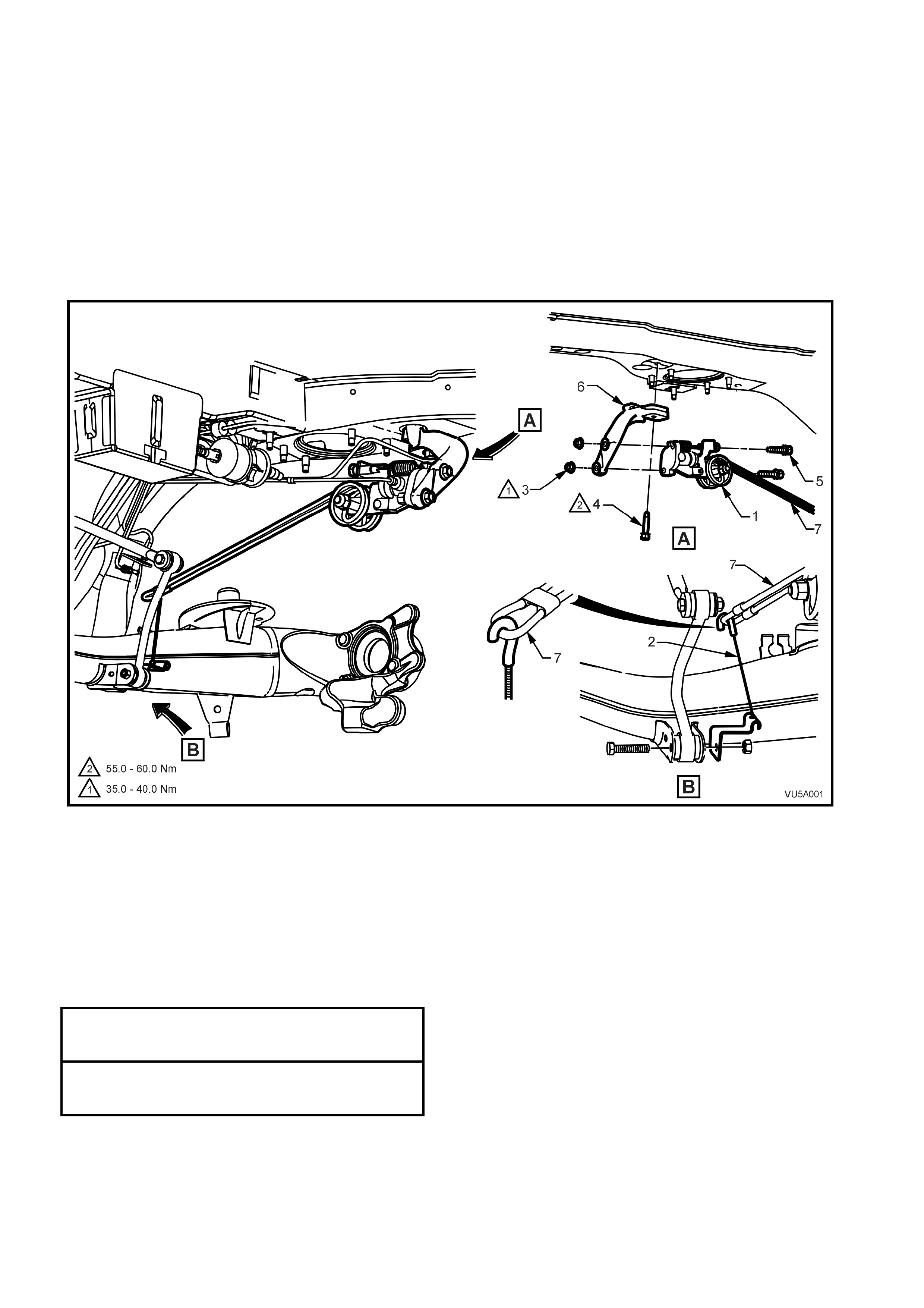
4. Support the loa d sensing proporti oning valve, then r emove the nuts f rom the two retaining b olts and rem ove the
bolts removing the valve assembly.
Figure 5A-29
Legend
1. Load sensing proportioning
valve
2. Connector cable assembly
3. Nut (2 places)
4. Mounting bracket bolt
5. Bolt (2 places)
6. Mounting bracket
7. Load sensing arm
REINSTALL
The installation procedure is the reverse of the removal procedure, noting the following:
1. Position valve on bracket, then install and secure the two bolts. Tighten the bolts or nuts to the correct torque
specification.
LOAD SENSING VALVE
MOUNTING NUT 35 - 40 Nm
TORQUE SPECIFICATION
LOAD SENSING VALVE
MOUNTING BRACKET BOLT 55 - 60 Nm
TORQUE SPECIFICATION
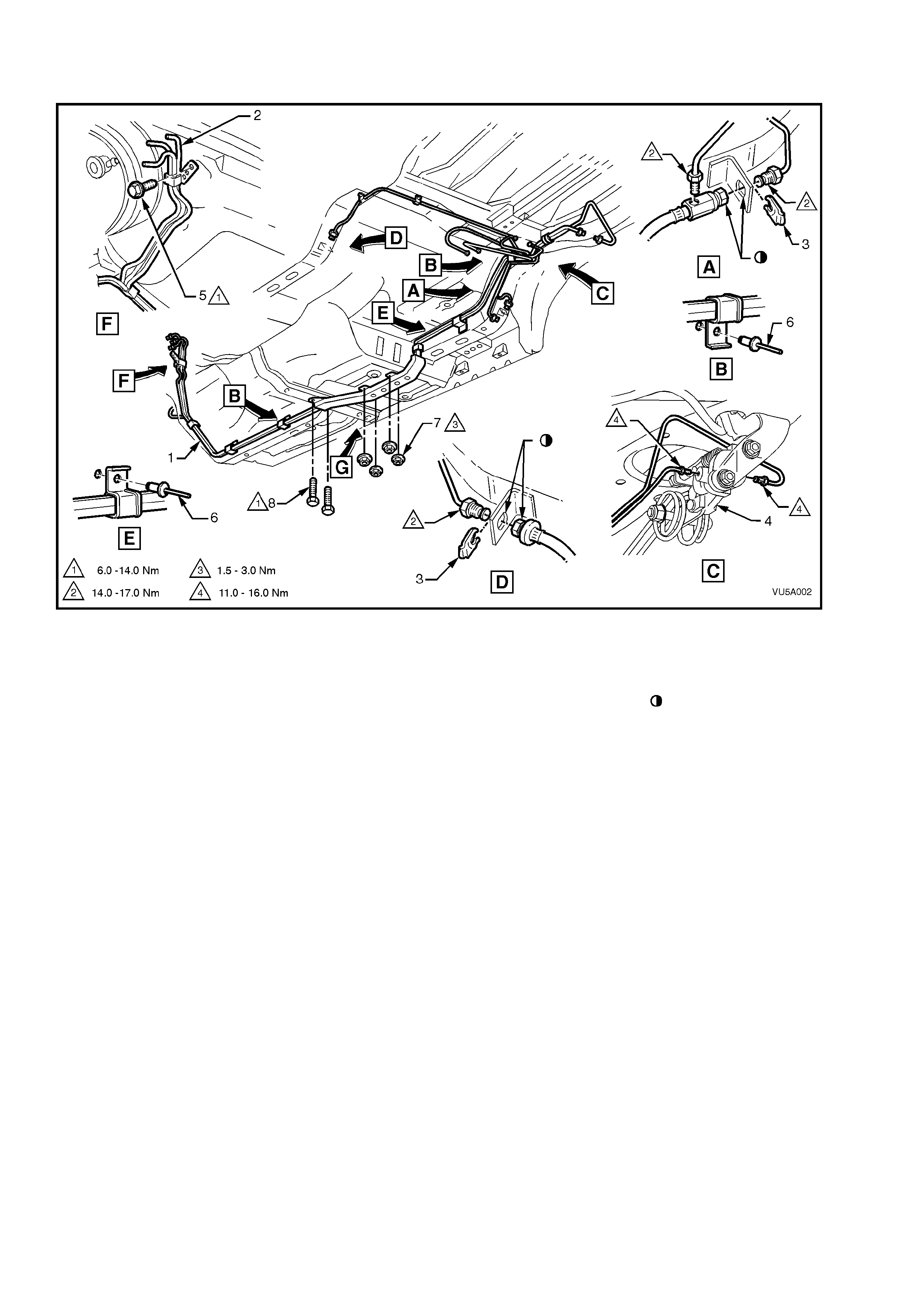
2. Ensure all pipes are secured and routed correctly, refer to Fig. 5A-30.
3. Bleed the brake system refer Section 5A STANDARD BRAKES of the VT Series Service Information.
NOTE 1: T he load se nsing propor tioning valve se tting is
preset and should not be adjusted.
NOTE 2: The c able hook mus t be connec ted to the t or sion s pring l ever in th e corr ect orien tat ion, ref er Vie w B in F ig.
5A-29.
Figure 5A-30
Legend
1. Brake and fuel line harne ss
2. Fuel feed and return line
3. Brake hose clip
4. Load sensing proportioning valve
5. Brake pipe clamp to dash panel
bolt
6. Rivet (5 places)
7. Nut (4 places)
8. Screw (2 places)
Flats aligned on hose
and bracket

3. TORQUE WRENCH SPECIFICATIONS
Nm
Master Cylinder End Plug..................................................... 25 - 30
Master cylinder attaching nuts................................................. 15 - 20
Differential Switch.................................................................... 2
Master Cylinder Reservoir Retaining Screw............................ 4 - 5
Master Cylinder Bracket Retaining Nut ................................... 6 - 11
Master Cylinder Bracket To Master Cylinder Bolt ................... 6 - 11
Brake Pipe To Master Cylinder Flared Nut.............................. 8 - 11
Load Sensing Proportioning Valve Mounting Nut.................... 35 - 40
Load Sensing Proportioning Valve Mounting Bracket Bolt...... 3 5 - 60
Brake Pipe To Load Sensing Proportioning Valve.................. 11 - 16
Rear Brake Pipes To Flexible Hose ........................................ 14 - 17
Front Brake Pipe Clamp To Dash Panel Bolt.......................... 6 - 14
Lower Brake Pipe Shield To Floor Bolt ................................... 6 - 14
Lower Brake Pipe Shield To Floor Nut.................................... 1.5 - 3