
SECTION 12C - INSTRUMENTS, WIPERS/WASHERS
& HORN
IMPORTANT:
Before performing any Service Operation or other procedure described in this Section, refer to Section
00 CAUTIONS AND NOTES for correct workshop practices with regard to safety and/or property damage.
1. GENERAL I NFORMATI O N
The ins trum ents, wipers/ washers and horn f itted to VU Series Models carr y over from VX Series Models, noting the
following:
• VU Series Models with V6 engine and m anual tr ansm iss ion have a final drive r atio of 3.46:1, requir ing a unique
speedometer calibration.
• VU Series Models are fitted with a new fuel tank and sender configuration, requiring a unique fuel level gauge
calibration.
For information relating to the Instruments, Wipers/Washers and Horn fitted to VU Series Models not covered in this
Section, refer to Section 12C INST RUMENT S, W IPERS/W ASHERS & HORN in the VX Series Service Information
in conjunction with Section 12C INSTRUMENT S, WIPERS/WASHERS & HO RN in the VT Series I and VT Series II
Service information.
Techline
Techline

2. SERVICE OPERATIONS
The s ervice operations for ins truments , wipers /was hers and horn as fitted to VU Ser ies Models carry over from VT
Series I and VT Series II Models, noting the following:
• Removal and reinstallation procedures for the instrum ent cluster as fitted to VU Series Models carry over from
the VT Series I, refer to Section 12C – INSTRUMENTS, WIPERS/WASHERS & HORN in the VT Series I
Service Information. However, the instrument configuration and fuel level gauge calibration procedures during
the programming of the new instrument cluster is unique.
• If the instrument cluster is found to be faulty, the replacement cluster must be programmed following
installation.
For information relating to the instrument configuration procedure for VU Series Models, refer to
3.1 INSTRUMENT CONFIGURATION in this Section.
For information relating to the fuel level guage calibration procedure for VU Series Models, refer to
3.2 FUEL LEVEL GUAGE CALIBRATION in this Section.
Techline
3. INSTRUMENT DIAGNOSTICS
3.1 INSTRUMENT CONFIGURATION
VU Series Models with V6 engine and manual transmission are fitted with a 3.46:1 final drive ratio. Consequently,
the correct PPK (pulses per km) values must be entered during the instrument configuration procedure.
If an instrument cluster is replaced in VU Series Models, the following procedure must be performed.
MAIN MENU
Turn ignition off.
Connect TECH 2 to the vehicle, refer to 3.1
CONNECTING THE TECH 2 TO THE VEHICLE
in Section 0C - TECH 2 of the VX Series Service
Information.
Turn the ignition on and press the power button
(PWR) on the TECH 2.
The TECH 2 will perform a series of self-
diagnosing power on self-tests (POST). Once this
has been completed successfully, the TECH 2
start up screen will be displayed. Press the Enter
key to continue.
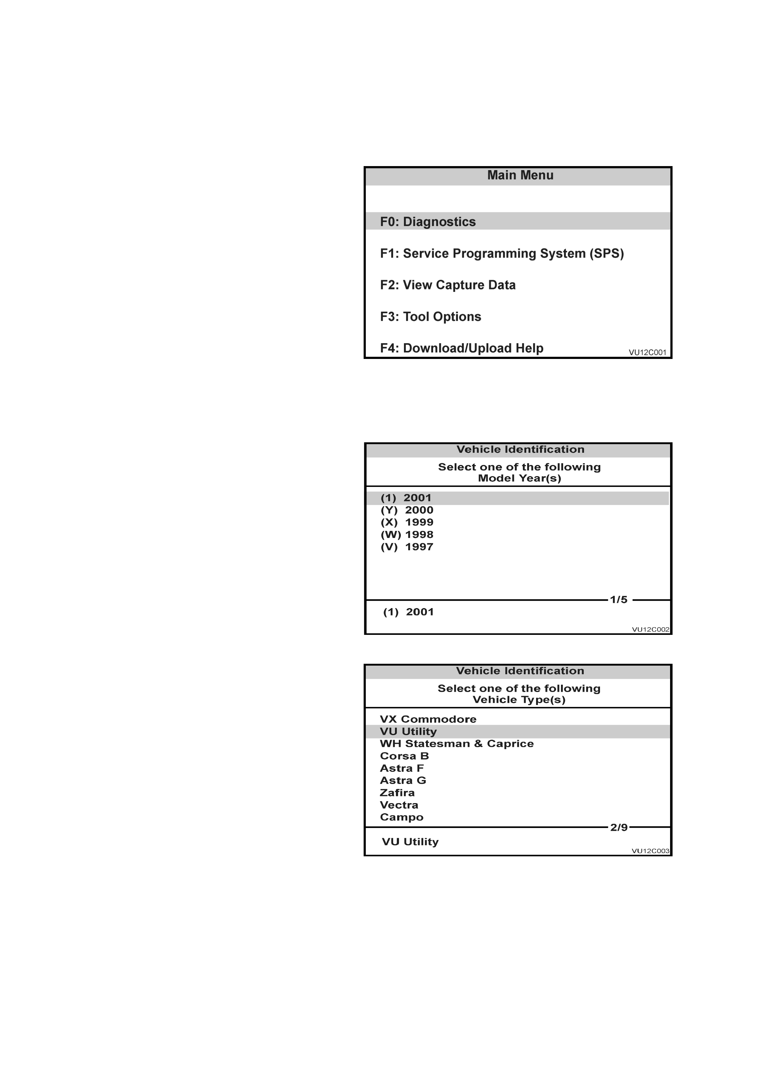
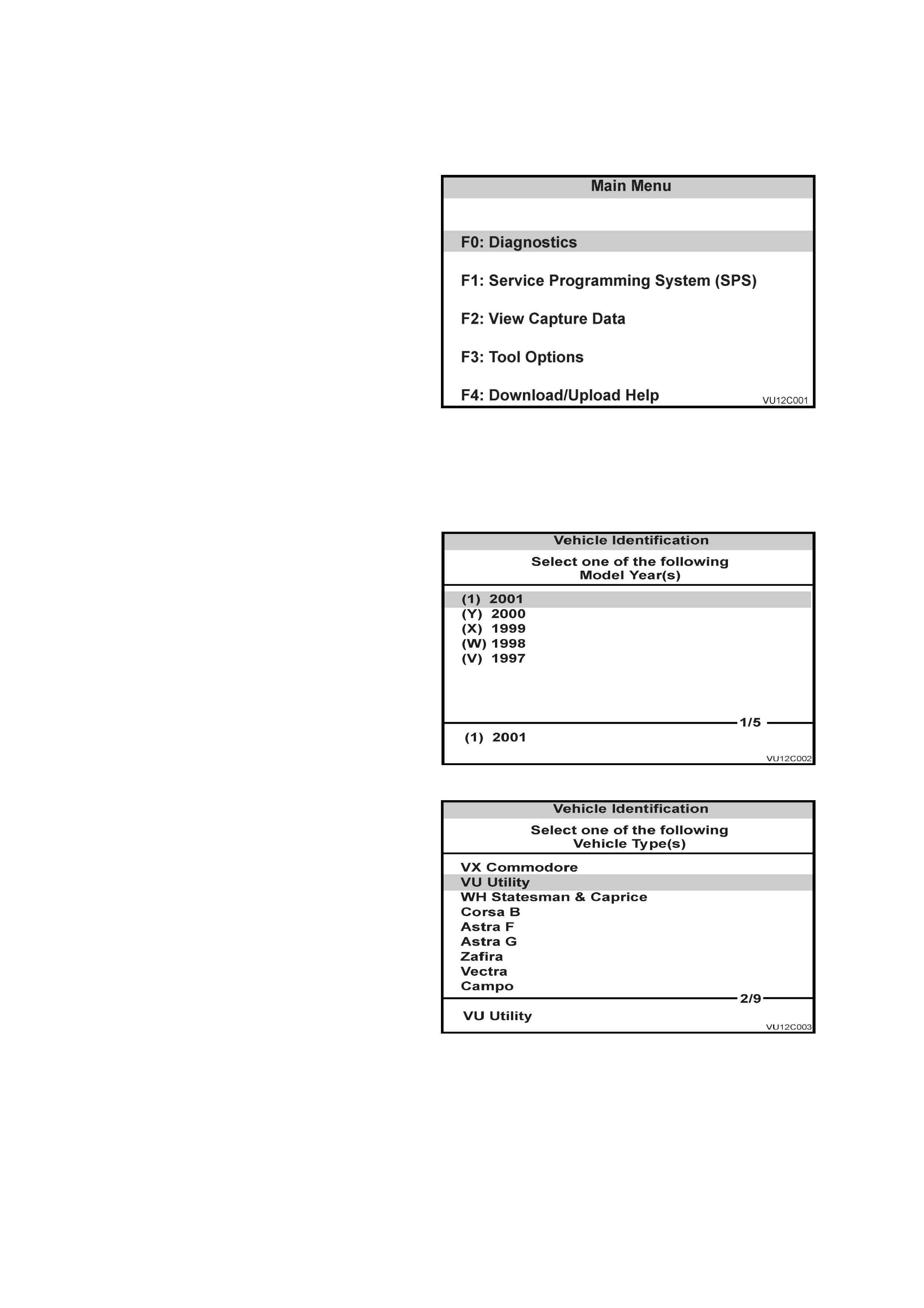
When the Main Menu screen is displayed, press
the F0 f unc tion button or Selec t F 0: Diagnostic s by
using the arrow keys until F0: Diagnostics is
highlighted and press the Enter key.
Figure 12C-1
VEHICLE IDENTIFICATION
Model Year
Select the appropriate Model Year and press
Enter.
Figure 12C-2
Vehicle Type
Select the VU Utility vehicle type and press Enter.
Figure 12C-3

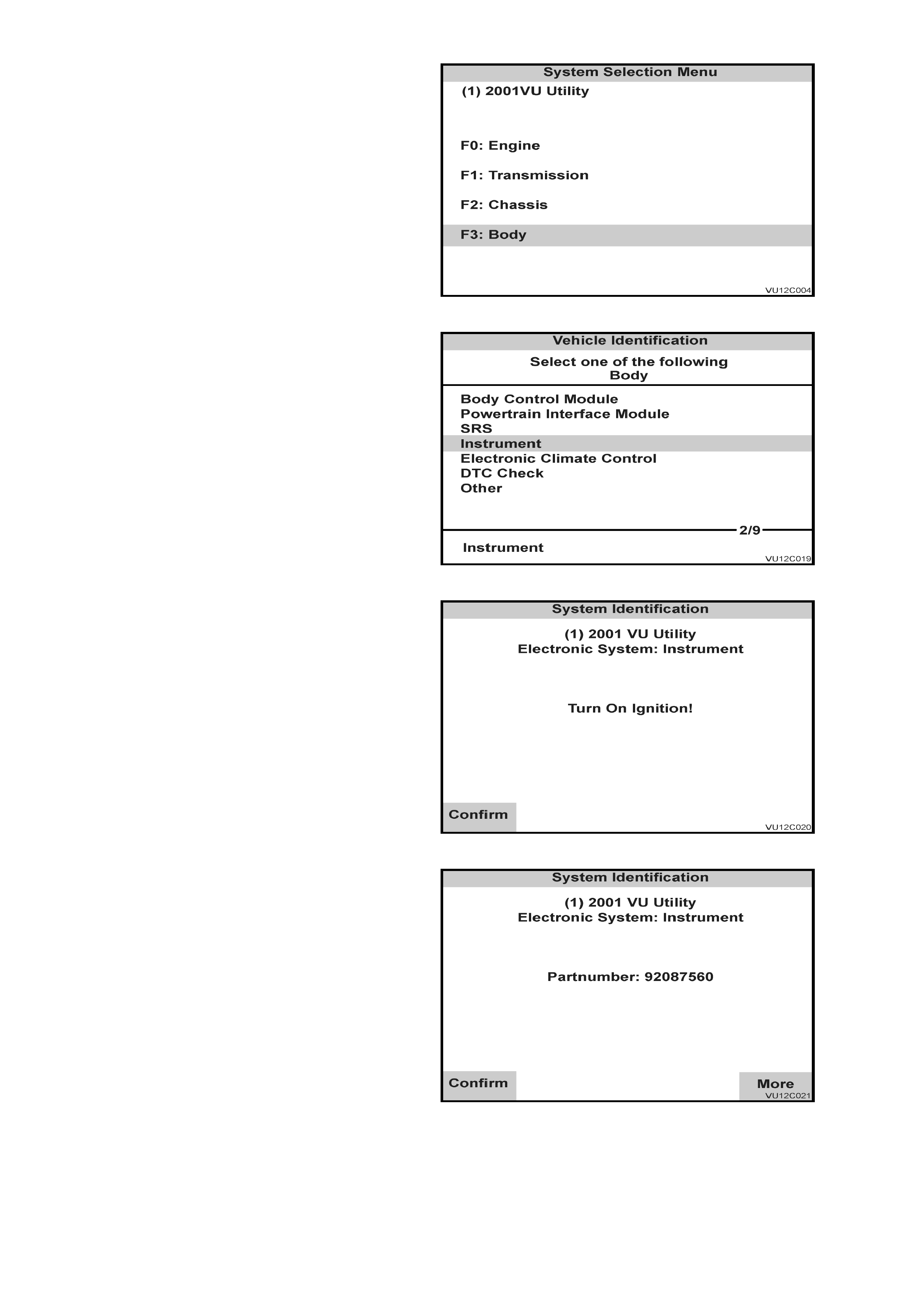
SYSTEM SELECTION MENU
Select F3: Body from the System Selection Menu
and press Enter.
Figure 12C-4
BODY MENU
Select Instrument and press Enter.
Figure 12C-5
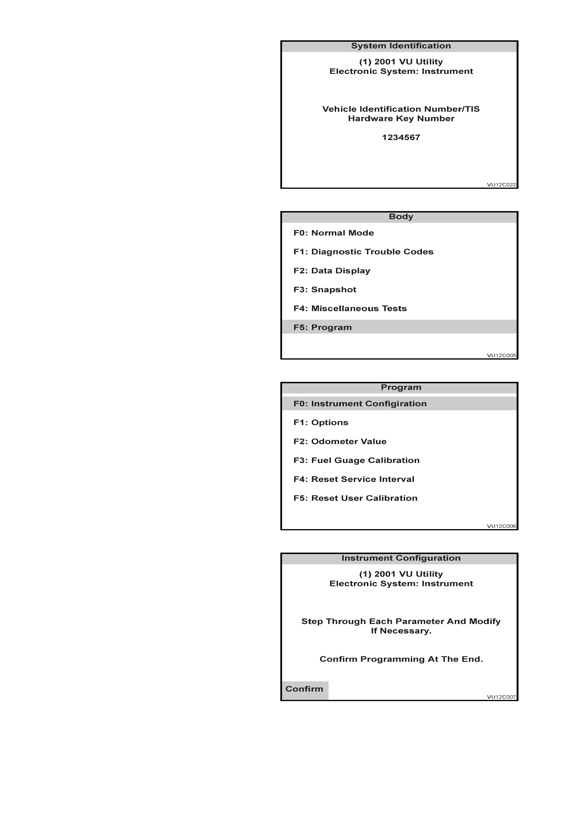
SYSTEM IDENTIFICATION
When the screen in Fig. 12C-6 is displayed,
ensure the ignition is on and press the Confirm
soft key.
Figure 12C-6
The screen in Fig. 12C-7 will now be displayed.
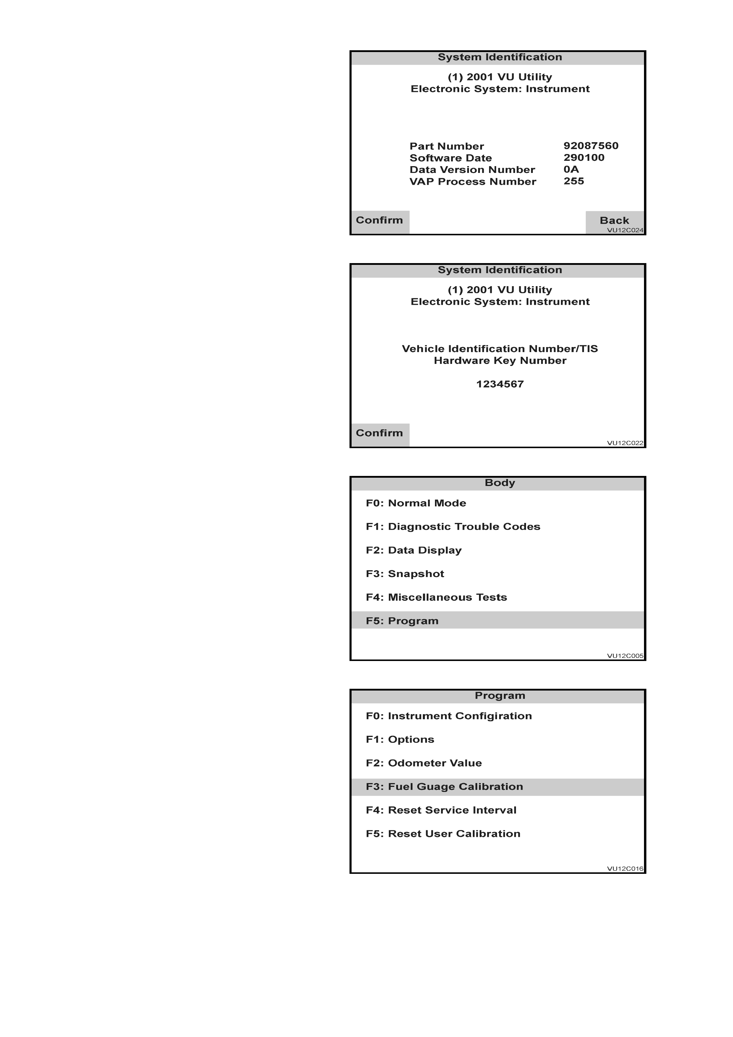
NOTE: The More soft key provides more detailed
information regarding the Instrument assembly.
Press the Confirm soft key to confirm that the
details displayed are correct.
Figure 12C-7
When the screen in Fig. 12C-8 is displayed,
confir m the Vehicle Identif ic ation Number provided
is correct and press the Confirm soft key.
Figure 12C-8
BODY MENU
Select F5: Program.
Figure 12C-9
PROGRAM MENU
Select F0: Instrument Configuration.
Figure 12C-10
Using the Next soft key, step through each
parameter and modify as necessary.
Press the Confirm soft key to continue.
Figure 12C-11
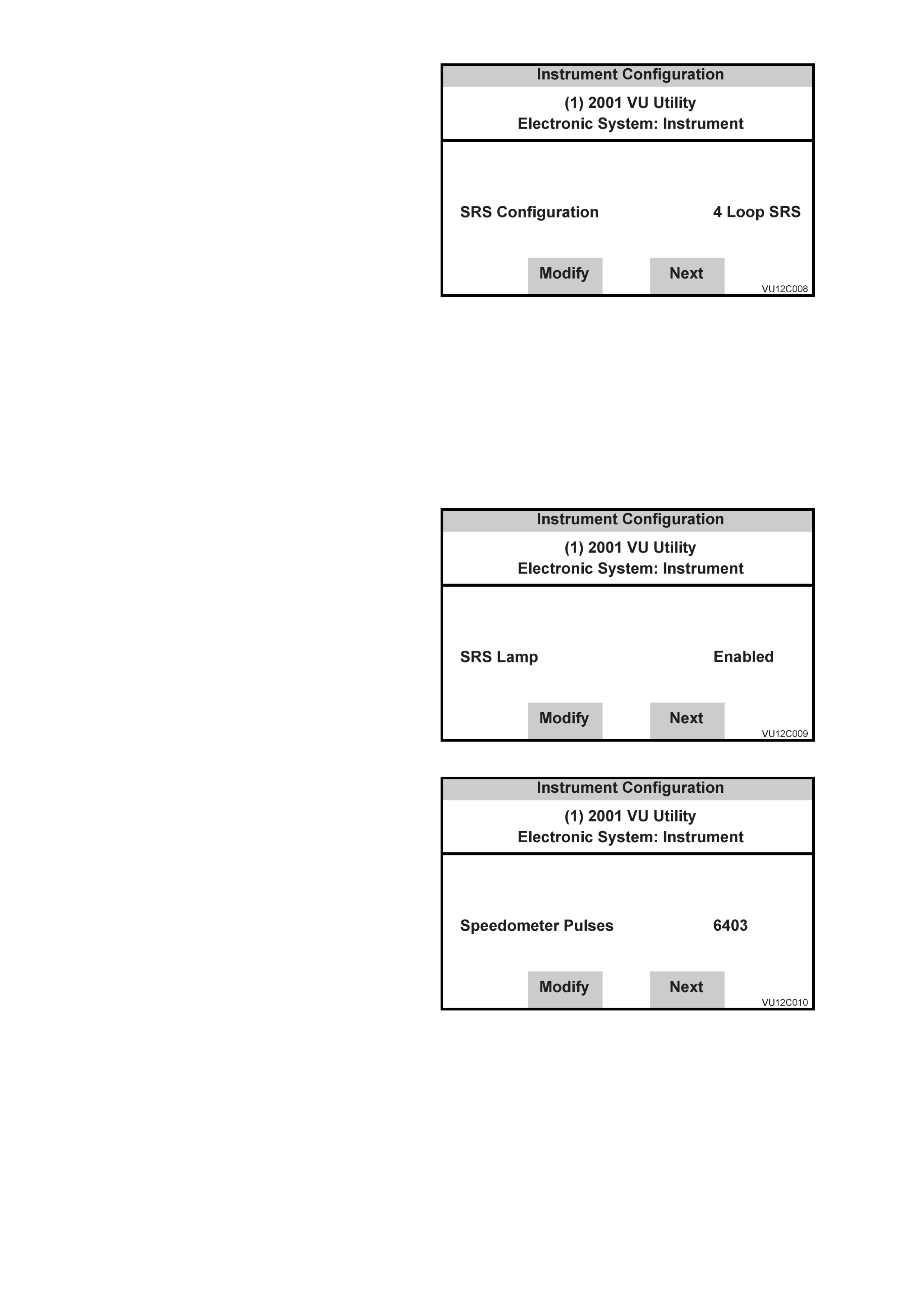
1. SRS Configuration
Press Modify soft key to set to one of the
following options:
• No SRS
• 2 Loop SRS
• 3 Loop SRS
• 4 Loop SRS
• 6 Loop SRS
NOTE: Configuration of the various SRS
systems is as follows:
• a 2-loop system is for left-hand drive
vehicles with pre-tensioners only.
• a 3-loop system is for vehicles with pre-
tensioners and driver’s air bag only.
• a 4-loop system is for vehicles with pre-
tensioners, driver’s air bag and front
passenger’s air bag only.
• a 6-loop system is for vehicles with pre-
tensioners, driver’s air bag, front
passenger’s air bag and side air bags.
Figure 12C-12
2. SRS Lamp
Press Modify soft key to set to -
Enabled/Disabled.
• For all models, set to Enabled.
Figure 12C-13
3. Speedometer Pulses
Press Modify soft key to set the speedometer
pulses per kilometre for the correct tyre size
as per the chart below. Nominal value is 6250
pulses per km.
Figure 12C-14
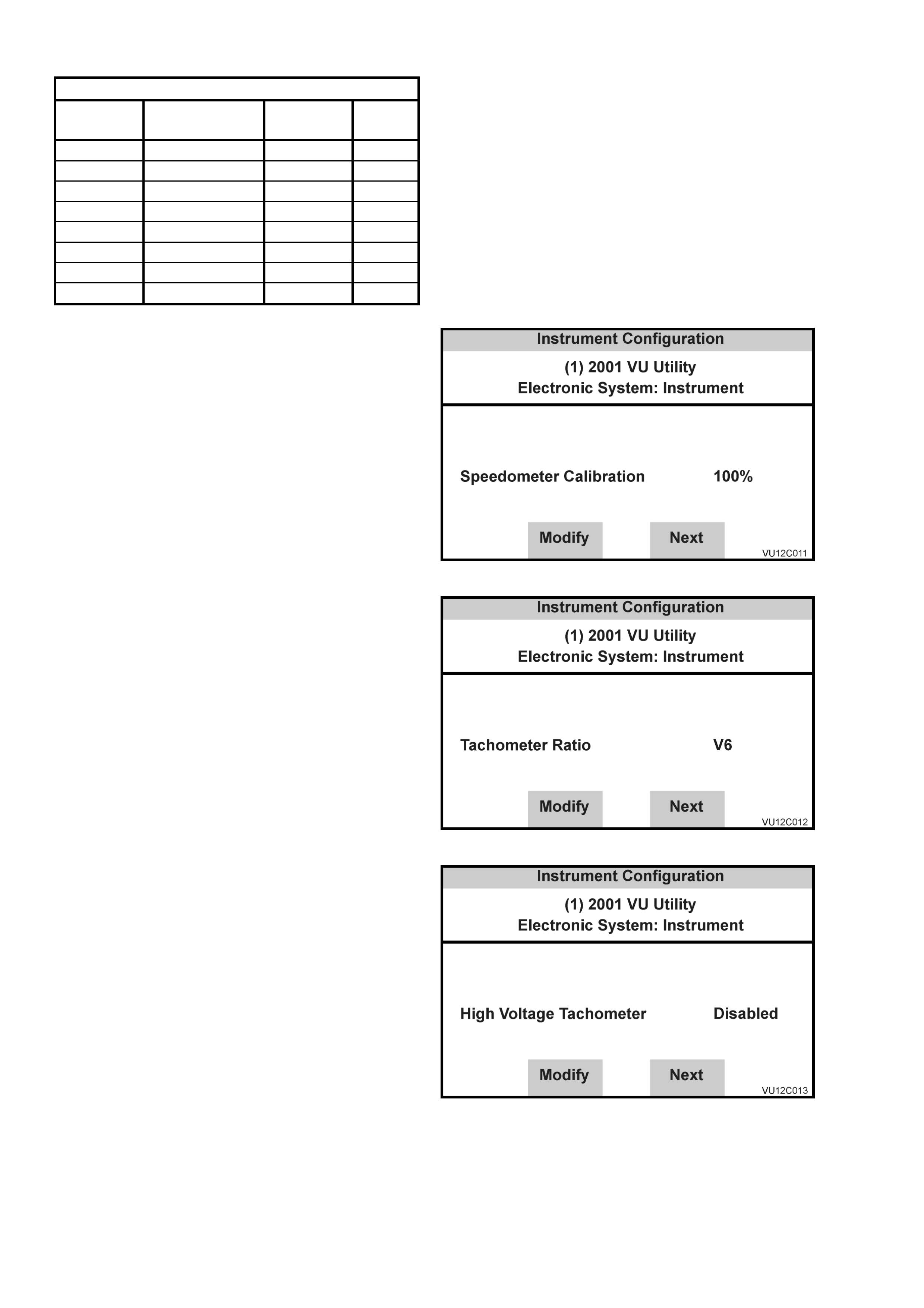
Pulses Per km (PPK)
Engine Transmission Tyre Size PPK
Value
V6 Auto 205/65 R15 6272
V6 Auto 225/55 R16 6087
V6 Manual 205/65 R15 6403
V6 Manual 225/55 R16 6214
Gen III V8 Auto/Manual 205/65 R15 6272
Gen III V8 Auto/Manual 225/60 R15 6238
Gen III V8 Auto/Manual 225/55 R16 6087
Gen III V8 Auto/Manual 235/45 R17 6301
4. Speedometer Calibration
If the Police Mode has been enabled at
F5: Program / F1: Options, the speedometer
calibration screen appears next. This allows
the speedometer to be calibrated.
Press the Modify soft key to adjust the
speedometer calibration, or the Next soft key
to continue.
Figure 12C-15
5. Tachometer Ratio
Press Modif y s oft k ey to set to - V6 or V8 Gen
III.
• Only V6 and V8 Gen III are applicable to
VU Series Models.
Figure 12C-16
6. High Voltage Tachometer
Press Modify soft key to set to - Disabled.
• For V6 engine, set to Disabled.
• For GEN III V8 engine, set to Disabled.
Figure 12C-17
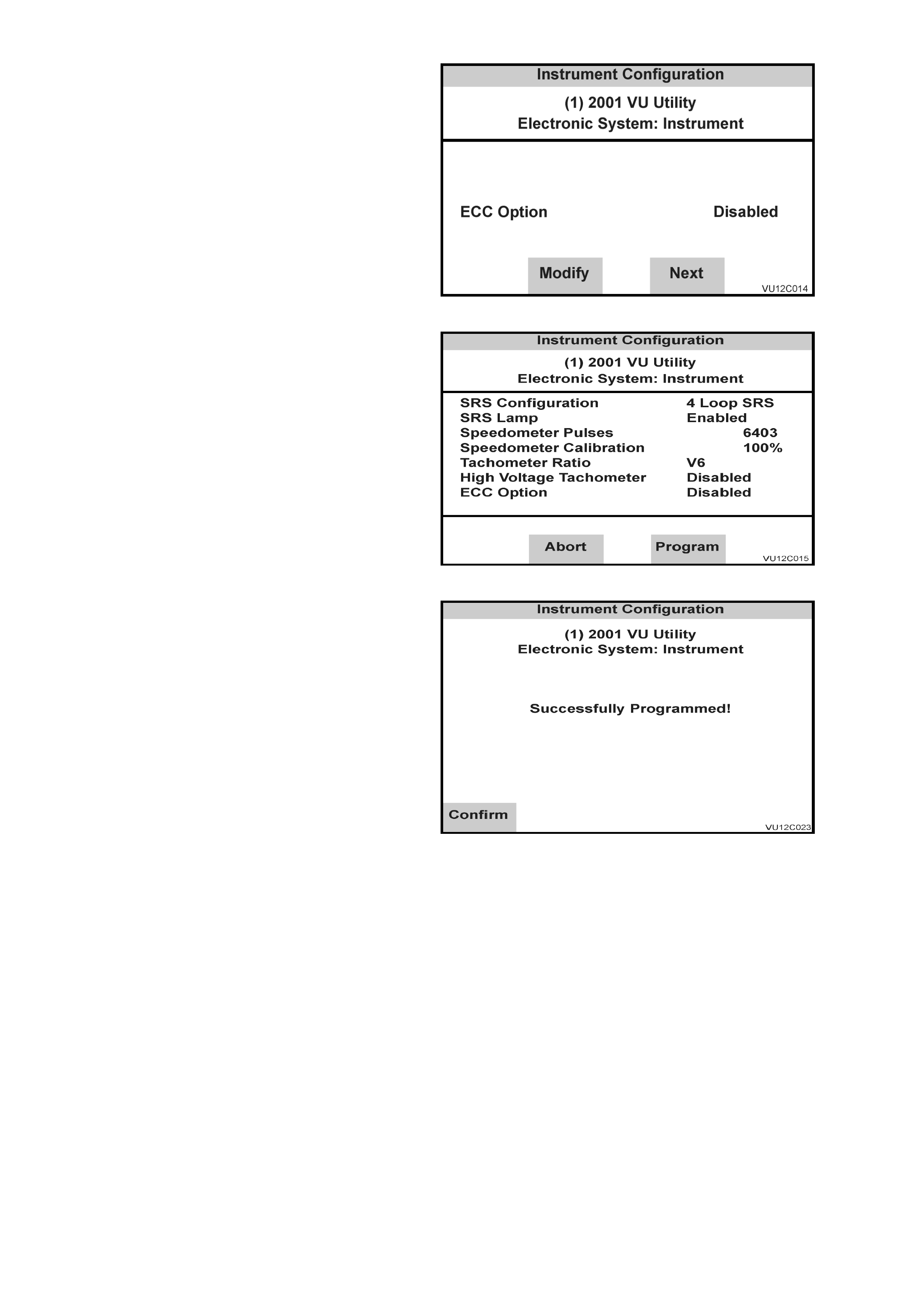
7. ECC Equipped
Press Modify soft key to set to –
Enabled/Disabled.
• For vehicles equipped with a triple window
display set to – Enabled.
• For vehicles equipped with single window
instruments set to – Disabled.
Figure 12C-18
8. Program Instrument Confirm
Press Abort soft key to abandon process, or
press Program soft key to confirm parameters.
Figure 12C-19
Press Confirm soft key when programming is
completed.
Figure 12C-20
3.2 FUEL GAUGE CALIBRATION
As VU Series Models contain new fuel tank and sender assemblies, the fuel gauge calibration for VU Series Models
is unique.
If an instrument cluster is replaced in VU Series Models, the following procedure must be performed.
MAIN MENU
Turn ignition off.
Connect TECH 2 to the vehicle; refer to
3.1 CONNECTING THE TECH 2 TO THE
VEHICLE in Section 0C - TECH 2 in the VX
Series Service Information.
Turn the ignition on and press the power button
(PWR) on the TECH 2.
The TECH 2 will perform a series of self-
diagnosing power on self-tests (POST). Once
this has been completed successfully, the TECH
2 start up screen will be displayed. Press the
Enter key to continue.
The Main Menu screen should look as follows.
Press the F0 function button or Select F0:
Diagnostics by using the arrow keys until F0:
Diagnostics is highlighted and press the Enter
key.
Figure 12C-21
VEHICLE IDENTIFICATION
Model Year
Select the appropriate Model Year and press
Enter.
Figure 12C-22
Vehicle Type
Select the VU Utility vehicle type and press
Enter.
Figure 12C-23
SYSTEM SELECTION MENU
Select F3: Body from the System Selection
Menu and press Enter.
Figure 12C-24
VEHICLE IDENTIFICATION
Body Menu
Select Instrument and press Enter.
Figure 12C-25
SYSTEM IDENTIFICATION
When the Screen in Fig. 12C-26 is displayed,
ensure the ignition is on and press the Confirm
soft key.
Figure 12C-26
The screen in Fig. 12C-27 will now be displayed.
NOTE: The More soft key provides more
detailed information regarding the Instrument
assembly.
Press the Confirm soft key to confirm that the
details displayed are correct.
Figure 12C-27
NOTE: The Back soft key returns the display to
the screen in Fig. 12C-27.
Press the Confirm soft key to confirm that the
details displayed are correct.
Figure 12C-28
When the screen in Fig. 12C-29 is displayed,
confirm the Vehicle Identification Number
provided is correct and press the Confirm soft
key.
Figure 12C-29
BODY MENU
Select F5: Program.
Figure 12C-30
PROGRAM MENU
Select F3: Fuel Gauge Calibration.
Figure 12C-31
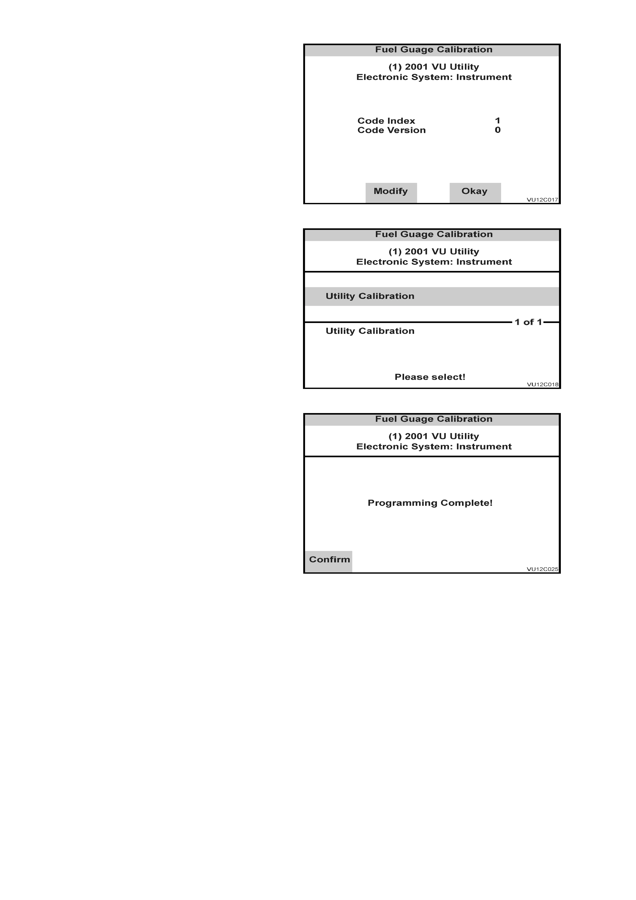
The next screen displays the instrument Code
Index and Code Version. If these need to be
updated, press the Modify soft key; otherwise
press the Okay soft key.
Figure 12C-32
Select the correct vehicle type , press Enter and
wait for the programming to be completed.
NOTE: For VU Series Models, Utility will be the
only vehicle type available.
Figure 12C-33
Press the Confirm sof t key when programming is
completed.
Figure 12C-34