
SECTION 8A2 - LPG SYSTEM
IMPORTANT:
Before performing any Service Operation or other procedure described in this Section, refer to Section
00 CAUTIONS AND NOTES for correct workshop practices with regard to safety and/or property
damage.
1. GENERAL INFORMATION
Liquefied Petroleum Gas (LPG) Production Option KL7 is available for Utility and 'S' VU Series Models with V6
engine and automatic transmission.
The system used on VU Series Models is essentially the same as detailed in the VX Series Service Information,
noting the following:
• Changes to suit the LPG cylinder assembly positioning in the load compartment.
• LPG fuel line rou ting has been rev ised to su it the pl acem ent of the LPG c ylinder in the f orward ar ea of th e
load compartment.
For Information relating to the LPG system fitted to VU Series Models not covered in this Section, refer to
Section 8A2 LPG SYSTEM in the VX Series Service Information.
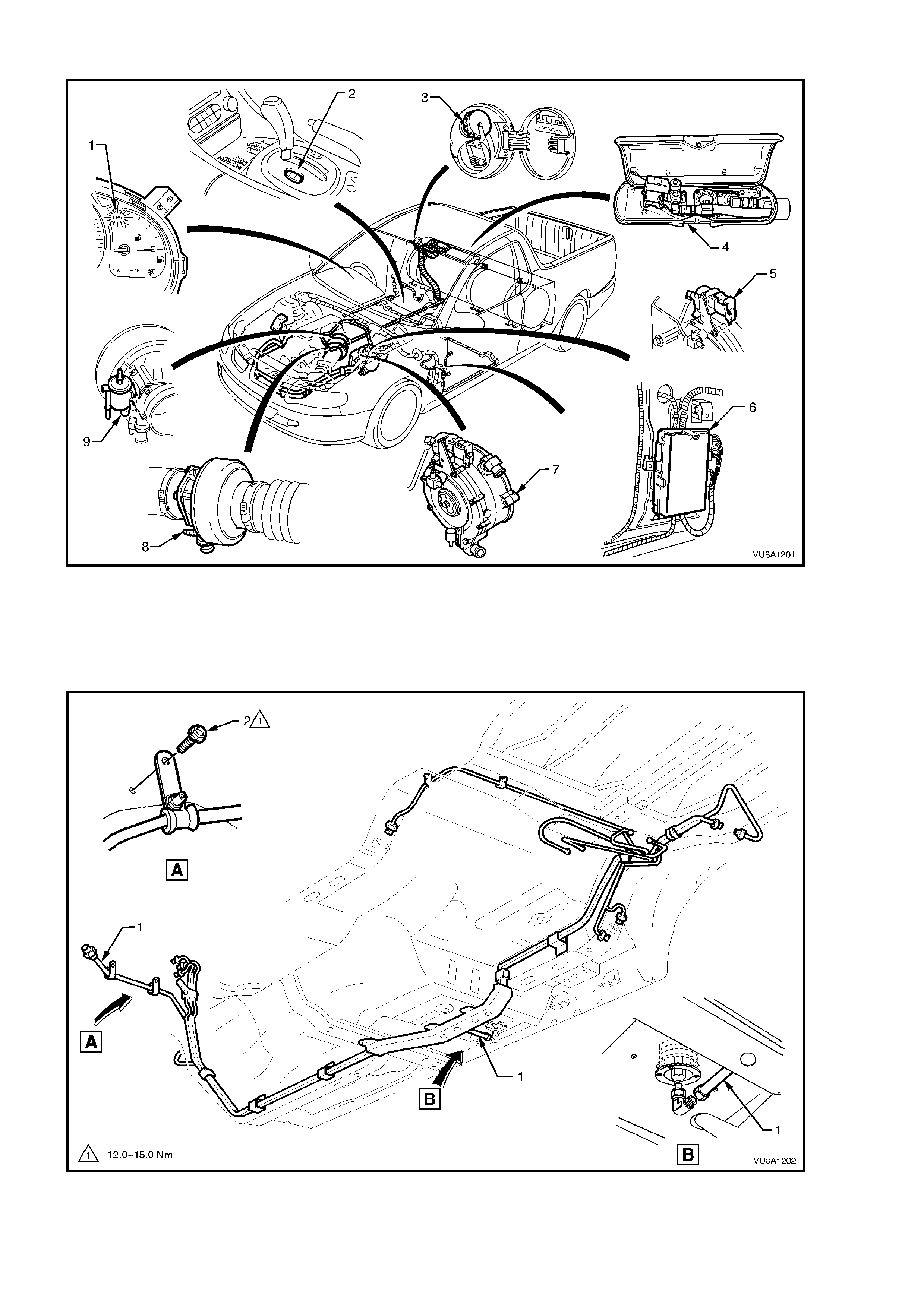
LPG SYSTEM COMPONENT LOCATIONS
Fi
g
ure 8A2-1
Legend
1. LPG lamp
2. Fuel mode switch
3. LPG filler valve
4. Solenoid and manual service valve assembly
5. LPG lock off
6. Powertrain Control Module (PCM)
7. Converter
8. Mixer
9. Fuel control valve
Figure 8A2-2
Legend
1. LPG fuel harness assembly 2. Screw

2. PRINCIPLES OF OPERATION
The Principles of Operation for Liquified Petroleum Gas (LPG) Production Option KL7 as fitted to the VU Series
Models carries over from the VX Series Models. For information regarding Principles of Operation refer to
Section 8A2 in the VX Series Models Service Information.

3. SERVICE OPERATIONS
3.1 LEAK TEST
Warning: The vehicle CANNOT be operated on LPG in the workshop, unless the workshop is a “Specialist Gas
Workshop” (in accordance with the current Australian standards AS2746 – 1985) and LPG is specifically required
for testing.
LEAK TEST PROCEDURE
With at least three litres of LPG in the LPG tank, leak test the complete LPG system following the instructions
below.
1. Park the vehicle in a dry, well ventilated area.
DO NOT SMOKE OR ALLOW NAKED FLAMES OR ANY IGNITION SOURCE NEAR THE VEHICLE DURING
THE TESTING OPERATIONS.
2. Ensure the vehicle is operating on LPG and run the engine for at least 30 seconds to fully pressurise the
system, then stop the engine.
3. The recommended sequence of testing is as follows:
A. Referring to Fig. 8A2-3, View A, remove the LPG cylinder cover in the load compartment to access the
valve box , ref er 3. 4 LPG CY LINDER in th is S ectio n. Remove the valv e box cov er (25) and leak tes t at and
around the:
Pressure relief valve (28).
AFL (7) to LPG tank (26).
AFL inlet elbow (8) to AFL (7).
Rear service line (6) to manual service valve outlet elbow (5) connection.
Solenoid and manual service valve assembly (3).
Solenoid and manual service valve assembly (3) to LPG tank (26).
Tank fuel gauge assembly (27).
Filler line (9) to AFL elbow (8).
B. Remove the load compartment side panel inner front cover to gain access to the inner side of the filler
valve assembly, refer to Section 8A1 FUEL TANK. Referring to Fig. 8A2-3, View B, leak test at and
around the filler valve connecting pipe (12) to filler line hose (11).
Open filler box door and leak test at and around the filler valve check ball (10) and filler line connecting
pipe (12) to the filler valve (29).
C. Referring to Fig. 8A2-3, View C, raise rear of vehicle and support on safety stands, refer to
Section 0A GENERAL INFORM ATION for the location of jacking points. Leak test at and around the:
Rear service line (13) to intermediate service line elbow (14) .
Intermediate service line (15) to rear service line elbow (14).
D. Referring to Fig. 8A2-3, View D, leak test in the engine compartment at and around the:
Intermediate service line (16) to front service line joiner connection (17).
E. Referring to Fig. 8A2-3, View E, leak test in the engine compartment at and around the:
Front service line (18) to lock off inlet elbow (19).
Lock off inlet elbow (19) to lock off (20).
Lock off (20) to lock off outlet elbow (24).
Lock off outlet elbow (24) to converter (23).
Lock off valve (20) to solenoid connector (21)
Lock off solenoid (22).
Converter mounting faces (23).
At the com pletion of the le ak test, close the m anual service valve, start the e ngine and run the engine until all the
LPG in the service line is exhausted. W ith the engine stopped, switch to ‘petrol’ and start the engine. The vehicle
can now be driven into the workshop.
NOTE: The vehicle cannot be operated on LPG in the workshop unless the workshop is a “Specialist Gas
Workshop”, refer to Australian Standard AS 2746 - 1985.

Legend for Fig. 8A2-3
1. Smart unit
2. Manual service valve
3. Manual service valve and rear lock off solenoid
assembly
4. Rear lock off solenoid
5. Rear service line to manual service valve elbow
6. Rear service line
7. Automatic fill limiter (AFL)
8. AFL inlet elbow
9. Filler line
10. Filler valve check ball
11. Filler line
12. Filler valve to filler line connecting pipe
13. Rear service line
14. Rear service line to intermediate service line
elbow
15. Intermediate service line
16. Intermediate service line
17. Front service line
18. Front service line
19. Lock off valve inlet elbow
20. Lock off valve
21. Front lock off solenoid to lock off valve
connector
22. Front lock off solenoid
23. Converter assembly
24. Lock off valve to converter inlet connector
25. Valve box cover
26. LPG tank
27. LPG tank level gauge
28. Pressure relief valve
29. Filler valve

Figure 8A2-3
3.2 FILLER LINE
REMOVE
CAUTION: Ensure that there are no naked flames or
other sources of ignition in the vicinity.
1. Park the vehicle in a well ventilated area, away
from any ignition source.
2. Remove the LPG cylinder cover refer to
3.4 LPG CYLINDER in this Section.
3. Drain the s ervice lines of LPG, refer to VT Series I
Service Information, LPG SYSTEM, VT SEDAN
WITH PRODUCTION LPG, Section 2 SERVICE
OPERATIONS.
4. Ensure the manual service valve is turned 'OFF'
and the battery earth lead is disconnected.
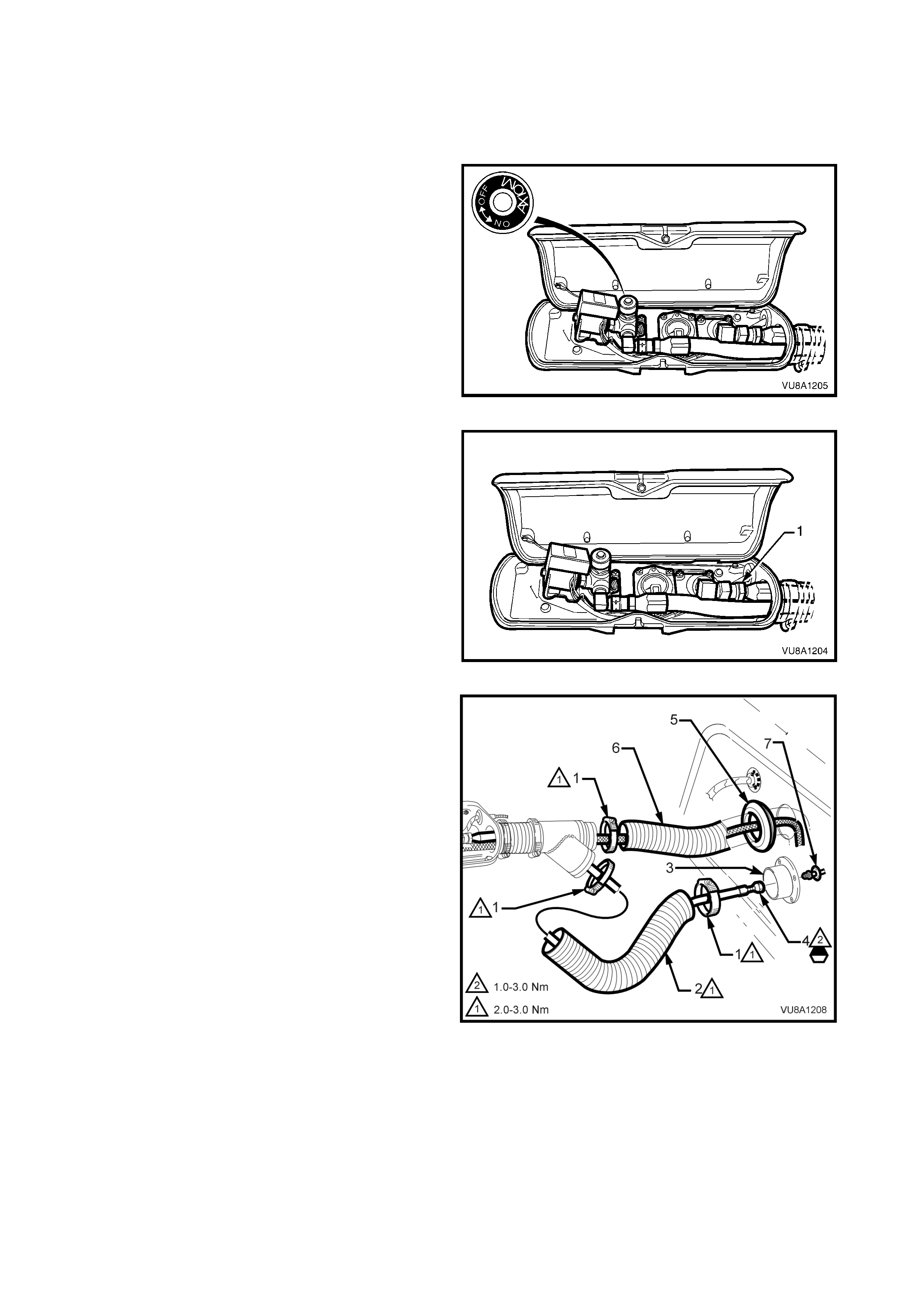
Figure 8A2-4
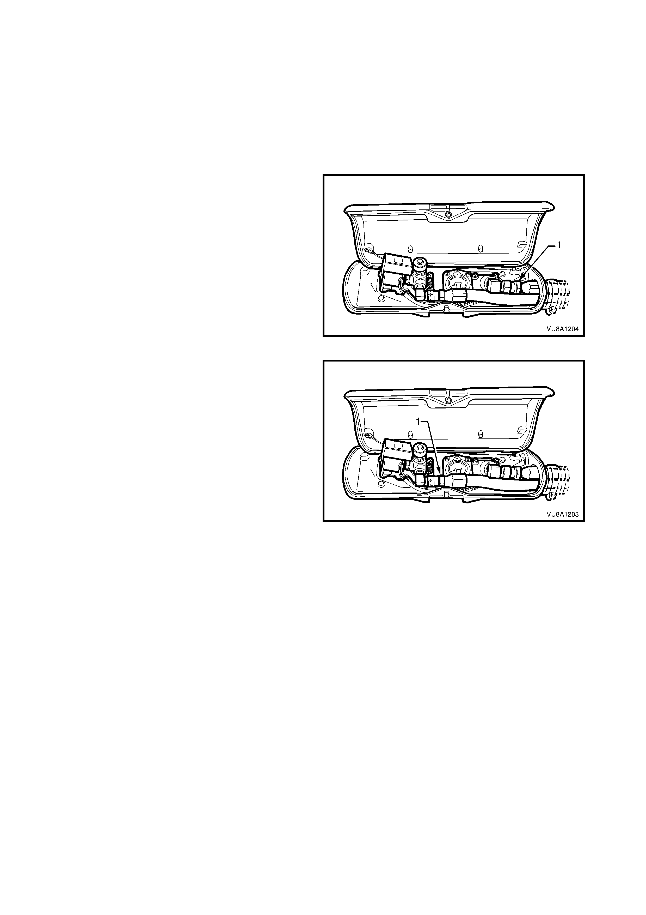
5. Remove th e cylinder va lve box cov er. From ins ide
the LPG val ve box, whi le h old ing AF L elbo w, crack
open filler line to AFL elbow connector (1) and
allow residual LPG to escape.
CAUTION: The filler line will contain LPG under
pressure. Once all the LPG in the line has dispersed,
unscrew filler line connector completely from AFL
elbow.
Figure 8A2-5
6. Remove the hose clamp (1) securing the filler line
convoluted tube (2) to the side panel inner front
cover fitting (3), disconnect filler line (4) from
rem ote filler p ipe ( 7) and r e move the LPG f ill er line
from within convoluted tube.
Figure 8A2-6

REINST ALL
Reinstallation if the filler line is the reverse of the removal procedure, noting the following:
1. Clean filler line mating threads on LPG cylinder AFL elbow.
2. Apply Loctite 577 sealant to LPG cylinder AFL elbow threads and remote filler pipe connection ensuring that
flared surfaces are free of sealant and contaminants. Refer to area marked in Fig. 8A2-6. Install filler line
connector to L PG cylinder fil ler el bo w, refer to VT Ser i es Serv ic e Inf ormation, LP G S YSTEM, VT SEDAN WITH
PRODUCTION LPG, Section 2.13 SERVICE LINES.
3. Tighten filler line connector to the specified torque specification.
FILLER LINE CONNECTORS 12 - 18
TORQUE SPECIFICATION Nm
4. Leak test LPG system, refer to 3.1 LEAK TEST.
5. Apply silicon sealer to convoluted tube mating surfaces, refer to area marked in Fig 8A2-15. Tighten
convoluted tube hose clamps to specified torque.
CONVOLUTED TUBE HOSE CLAMP 2 - 3
TORQUE SPECIFICATION Nm
6. Reinstall LPG cylinder cover.
3.3 SERVICE LINES
FRONT SERVICE LINE
The removal and reinstallation of the front service line carries over from VT Series Models. For additional
information refer to VT Series I Service Information, LPG SYSTEM.
INTERMEDIATE SERVICE LINE
The removal and installation of the intermediate service line is incorporated into the fuel and brake pipe harness
assembly and, therefore, not serviced separately. For additional information, refer to Section 8A1 FUEL TANK.
REAR SERVICE LI NE
REMOVE
CAUTION: Ensure that there are no naked flames or
other sources of ignition in the vicinity.
1. Park the vehicle in a well ventilated area, away
from any ignition source.
2. Remove the LPG cylinder cover refer to
3.4 LPG CYLINDER in this Section.
3. Remove the cylinder valve box cover and from
inside the LPG valve box ensure the manual
service valve is t urned 'OF F' and the batt ery earth
lead is disconnected.
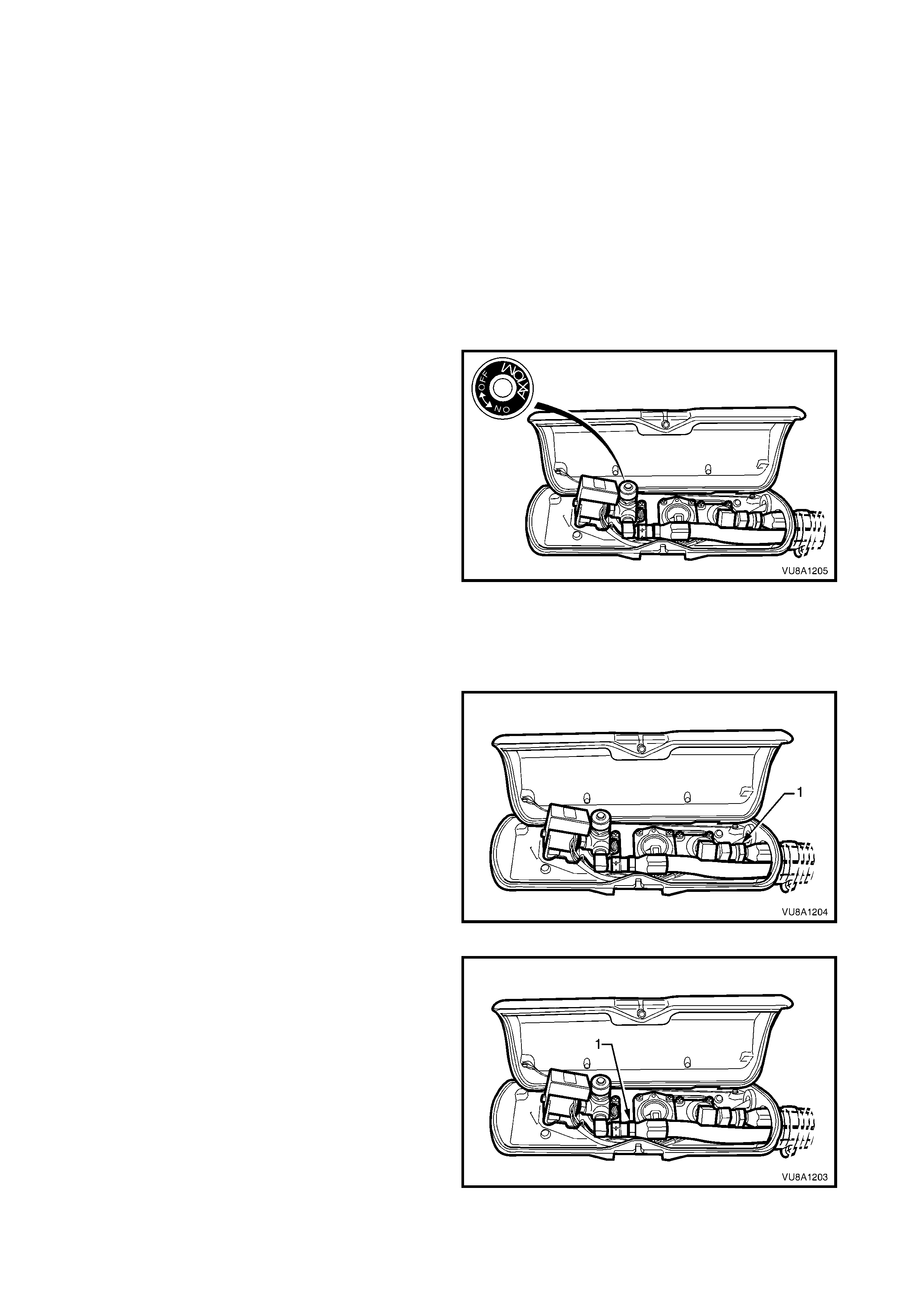
Figure 8A2-7
4. Dr ain the s erv ic e l in es of LPG, refer to VT Seri es I
Service Information, LPG SYSTEM, VT SEDAN
WITH PRODUCTION LPG, Section 2 SERVICE
OPERATIONS.
5. F rom inside the LPG valve box, while hold ing AFL
elbow, crack open filler line to AFL elbow
connector (1) and allow residual LPG to escape.
CAUTION: The filler line will contain LPG under
pressure. Once all the LPG in the line has dispersed,
unscrew filler line connector completely from AFL
elbow.
Figure 8A2-8
6. From inside the LPG valve box, loosen and
unscrew the service line connector (1) from
solenoid and manual service valve elbow.
Figure 8A2-9
7. Drill out the rivets (1) securing the service line
connection protector plate (2) and remove the
plate.
8. While holding the intermediate to service line
elbow (8) from turning, loosen and unscrew the
rear service line connector (7) from the service line
elbow.
9. Disconnect convoluted tube (3) at cylinder valve
box and r em ove r ear ser vic e line b y pulling line up
through convoluted tube
Figure 8A2-10
REINST ALL
Reinstallation if the service line is the reverse of the
removal procedure, noting the following:
1. Clean s er vice l ine m ating t hreads on so lenoi d and
manual service valve assembly, intermediate to
rear service line joiner, both rear service line
connectors, AFL valve mating threads and filler
line connector.
2. Apply Loctite 577 sealant to intermediate to rear
service line joiner threads, solenoid and manual
service valve elbow threads and AFL elbow
threads. ensuring that flared surfaces are free of
sealant and contaminants. Refer to area marked
in Fig. 8A2-10.
3. Tighten service line connector to the specified
torque specification.
SERVICE LINE CONNECTORS 12 - 18
TORQUE SPECIFICATION Nm
4. Leak tes t LPG system, r efer to 3.1 LEAK T EST in
this Section.
5. Tighten convoluted tube hose clamps to specified
torque.
CONVOLUTED TUBE HOSE CLAMP 2 - 3
TORQUE SPECIFICATION Nm
3.4 LPG CYLINDER
CAUTION: After any valve or c om ponent has be en rem oved and reinstall ed to the LPG c ylinder, t he LPG c yl inder
must be pressure and leak tested in accordance with current Australian standard AS2030.1 before the LPG
cylinder is refitted to the vehicle.
NOTE: T he LPG cylinder must be pres sure and l eak tested ac cording to t he laws of the state in which the v ehicle
is registered. This testing must only be done by a licensed installer or testing station.
REMOVE
CAUTION: Ensure that there are no naked flames or other sources of ignition in the vicinity.
1. Par k the vehicle in a well v entilat ed ar ea, a wa y from any ignition sourc e.
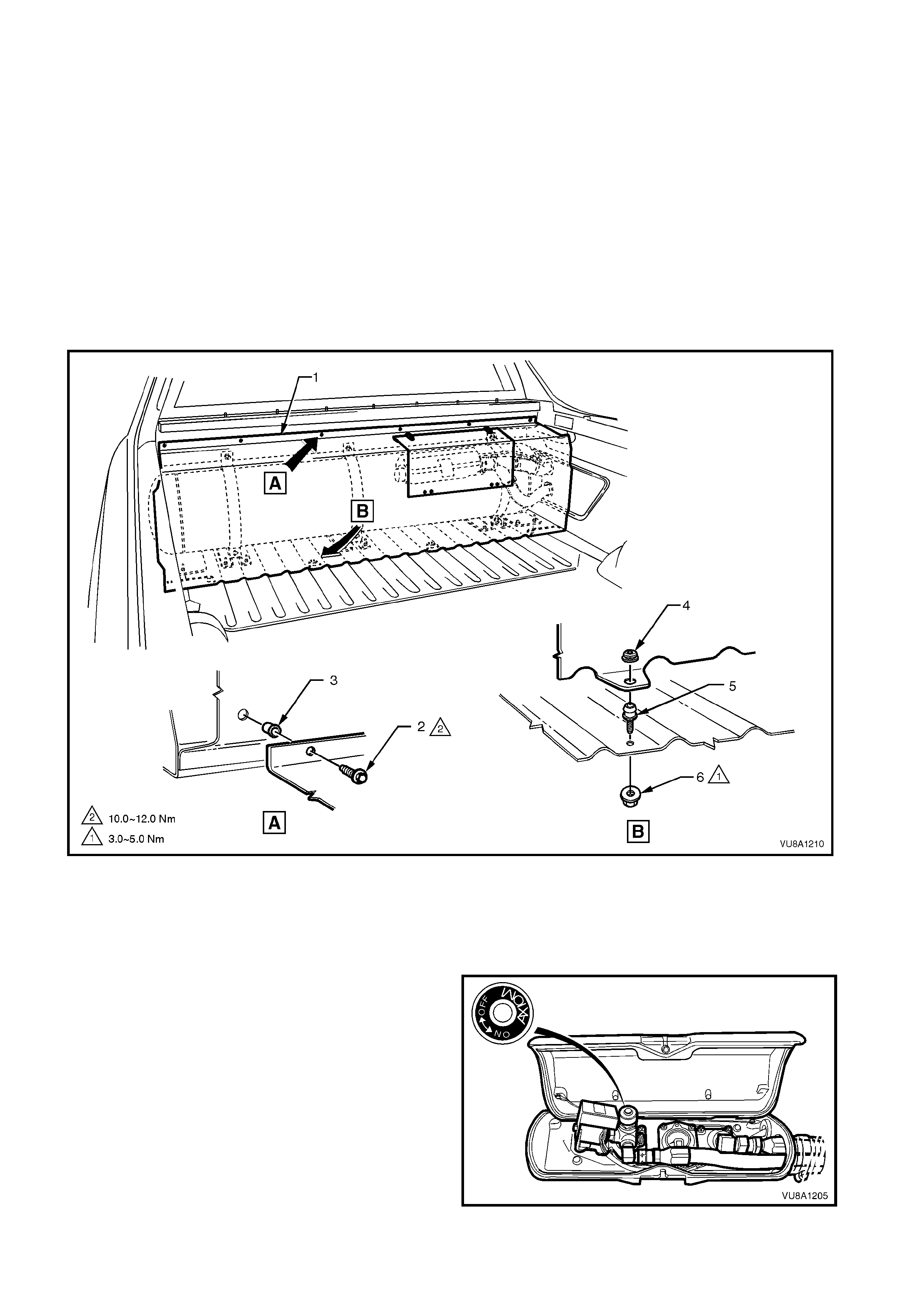
2. Remove the LPG cylinder cover upper retainer screws (2) and pull back the upper edge of the cylinder cover
(1) f or acces s. Pull c ylinder cover upwards until lower i nner retain er gromm ets ( 4) disengag e from ball stud ( 5)
and remove cover.
Figure 8A2-11
Legend
1. Cylinder cover
2. Screw (6 places) 3. Nutsert (6 places)
4. Grommet (4 places) 5. Ball stud (4 places)
6. Nut (4 places)
3. Remove the cylinder valve box cover and from
inside the LPG valve box ensure the manual
service valve is t urned 'OF F' and the batt ery earth
lead is disconnected.
Figure 8A2-12
4. Dr ain the s erv ic e l in es of LPG, refer to VT Seri es I
Service Information, LPG SYSTEM, VT SEDAN
WITH PRODUCTION LPG, Section 2 SERVICE
OPERATIONS.
5. Unload the LPG cylinder of LPG, refer to VT
Series I Service Information, LPG SYSTEM, VT
SEDAN WITH PRODUCTION LPG, Section 2.2,
LPG CYLINDER UNLOADING PROCEDURE
steps 4 to 10 (or 11 d ependin g on whether tank is
to be replaced or not).
6. F rom inside the LPG valve box, while hold ing AFL
elbow, crack open filler line to AFL elbow
connector (1) and allow residual LPG to escape.
CAUTION: The filler line will contain LPG under
pressure. Once all the LPG in the line has dispersed,
unscrew the filler line connector completely from the
AFL elbow.
Figure 8A2-13
7. From inside the LPG valve box, loosen and
unscrew the service line connector (1) from the
solenoid and manual service valve elbow.
Figure 8A2-14
8. Remove the hose clamp securing the convoluted
hose to the cylinder valve box and remove the
LPG service and filler hoses from the valve box.
9. Disconnect LPG body wiring harness connector
from LPG cylinder harness connector (9), refer to
Fig. 8A2-15.

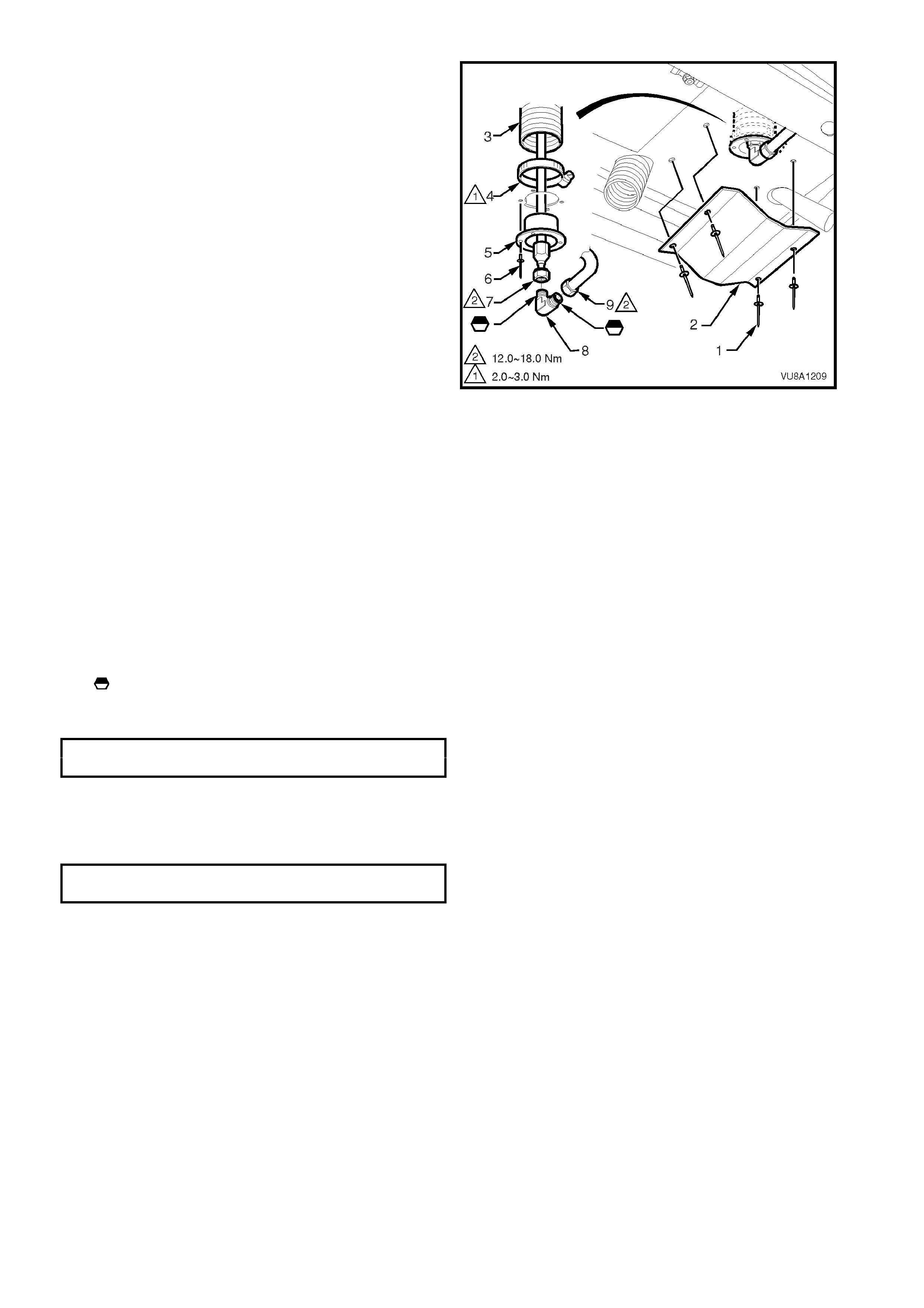
Figure 8A2-15
Legend
1. Service line connector
2. Filler line connector
3. Convoluted tube
4. Hose clamp
5. Convoluted tube
6. Convoluted tube elbow
7. Convoluted tube
8. Filler line to pipe connector
9. LPG cylinder harness
connector
Silicon sealer applied to
convoluted tube mating
surface.
Loctite 577 sealer applied on
indicated threads. On
reassembl y, ensure that the
flared surfaces are free of
sealant or contaminants.
10. Remove the three LPG cylinder strap (8) to
support bracket (7) retaining bolts (2) and
nuts (5) and remove LPG cylinder (1) from
the support brackets, refer to Fig. 8A2-16.
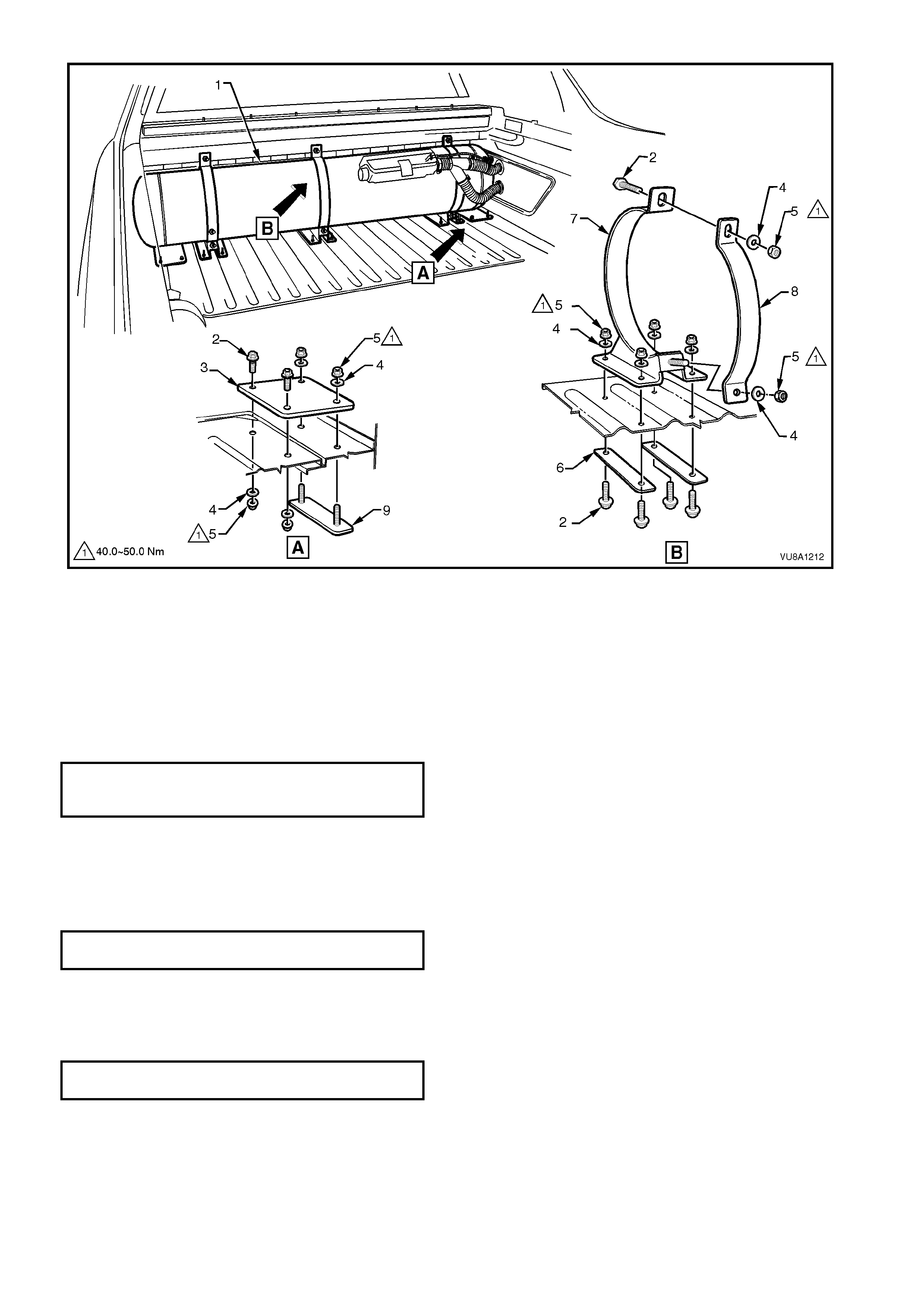
Figure 8A2-16
Legend
1. LPG Cylinder
2. Bolt (2 places per plate)
3. Upper connecting plate
4. Washer (4 places per bracket)
5. Nut (4 places per bracket)
6. Backing bar
7. Support bracket
8. Strap
9. Lower connecting plate
REINST ALL
1. Ins tall LPG c ylinder int o support brack ets. Install the t hree LPG c ylinder r etaining str aps, upper retain ing bolts,
washers and nuts. Install the three lower nuts and washers. Tighten to the specified torque specification.
CYLINDER STRAP TO SUPPORT
BRACKET RETAINING NUT 40.0 - 50.0 Nm
TORQUE SPECIFICATION
2. Clean rear service line mating threads on solenoid and manual service valve elbows.
3. Apply Loctite 577 sealant to solenoid and manual service valve elbow threads, ensuring that flared surfaces are
free of sealant and contaminants.
4. Install rear service line connector to solenoid and manual service valve elbow, refer to 3.3 SERVIC E LIN ES.
5. Tighten rear service line connector to the specified torque specification.
REAR SERVICE L INE CONNECTORS 12 - 18
TORQUE SPECIFICATION Nm
6. Clean filler line mating threads on LPG cylinder AFL elbow.
7. App ly Loctite 577 sealant t o LPG cylinder AFL elbo w threads , ensuring t hat flared s urfaces are f ree of sealant
and contaminants. Install filler line connector to AFL inlet elbow, refer to 3.2 FILLER LINE.
8. Tighten filler line connector to the specified torque specification.
FILLER LINE CONNECTORS 12 - 18
TORQUE SPECIFICATION Nm

9. Reconnect LPG body wiring harness connector to LPG cylinder connector.
10. Leak test LPG system, refer to 3.1 LEAK TEST in this Section.
11. Tighten convoluted tube hose clamps to specified torque.
NOTE: Ensure convoluted hose is sealed at joints, refer to Fig. 8A2-15.
CONVOLUTED TUBE HOSE CLAMP 2 - 3
TORQUE SPECIFICATION Nm
12. Reinstall LPG cylinder cover on locating studs, install grommets to studs, refer to Fig. 8A2-11.
13. Install LPG cylinder cover upper retaining screws (8 places) and tighten to specified torque, refer to
Fig. 8A2-11
LPG CYLINDER COVER UPP E R
RETAINING SCREWS 10.0 - 12.0 Nm
TORQUE SPECIFICATION


6. TORQUE WRENCH SPECIFIC ATIONS
Nm
LPG Service Line Connectors .............................................. 12-18
LPG Service Line Retaining Clamp Bolt............................... 12-15
LPG Filler Line Connectors................................................... 12-18
Convoluted Tube Hose Clamps............................................ 2-3
Cylinder Support Bracket Strap Retaining Nuts ................... 40-50
Cylinder Cover Upper Retaining Screws.............................. 10-12
Cylinder Cover To Load Floor Screws.................................. 3-5
Cylinder Connecting Plate Nuts............................................ 40-50
Cylinder Connecting Plate Bolts........................................... 40-50
