
SECTION 12C - INSTRUMENTS, WIPERS/
WASHERS & HORN
IMPORTANT
Before performing any Service Operation or other procedure described in this Section, refer to Section
00 CAUTIONS AND NOTES for correct workshop practices with regard to safety and/or property damage.
1. GENERAL I NFORMATI O N
Instrumentation for VX Series Models carries over from VT Series II Models noting the following:
• The instrument cluster now features a coloured instrumentation background (coloured keyed to the interior trim) on
SS models.
• Electronic T raction Control (ET C) is available on VX Series models with manual tr ansm iss ion. In this situation, the
traction control switch (TRAC CTRL) is mounted in the instrument panel on the lower right-hand side.
For all service information relating to the instrument panel mounted traction control switch, refer to
Section 12L ANTI-LOCK BRAKING & ELECTRONIC TRACTION CONTROL in this service information. The
traction control switch continues to be fitted on the console adj acent to the trans m ission s elector f or vehicles fitted
with an automatic transmission.
For inform ation relating to the ser vice pr ocedures and specif ications for the ins trum ents as f itted to VX Series Models ,
refer to Section 12C INSTRUMENTS, WIPERS/WASHERS AND HORN in the VT Series II Service Information, in
conjunction with Section 12C INSTRUMENTS, WIPERS/WASHERS AND HORN in the VT Series I Service
Information.
The wipers/washers as fitted to VX Series Models carry over from VT Series I Models, noting the following:
• A new front wiper motor and linkage assembly w as introduced as a running change to all VX Series Models.
• A new rear wiper motor and rear wiper arm were introduced as a running change to all VX Series Wagon Models.
For information relating to the wipers/washers as fitted to VX Series Models not covered in this Section, refer to
Section 12C INSTRUMENTS, WIPERS/WASHERS AND HORN in the VT Series I Service Information.
NOTE: Information has been provided in this Section to assist the technician in identifying which type of front or rear
wiper components have been used on a particular vehicle. For details regarding the actual timing for the above
changes, refer to the appropriate area in the Holden spare parts information.
The horn c omponents as f itted to VX Ser ies Models c arr y over from VT Ser ies I Models . For infor mation relating to the
horn components as fitted to VX Series Models, refer to Section 12C INSTRUMENTS, WIPERS/WASHERS AND
HORN in the VT Series I Service Information.
Techline
Techline
Techline
Techline
1.1 WIPERS AND WASHERS
FRONT WIPER MOTOR AND LINKAGE
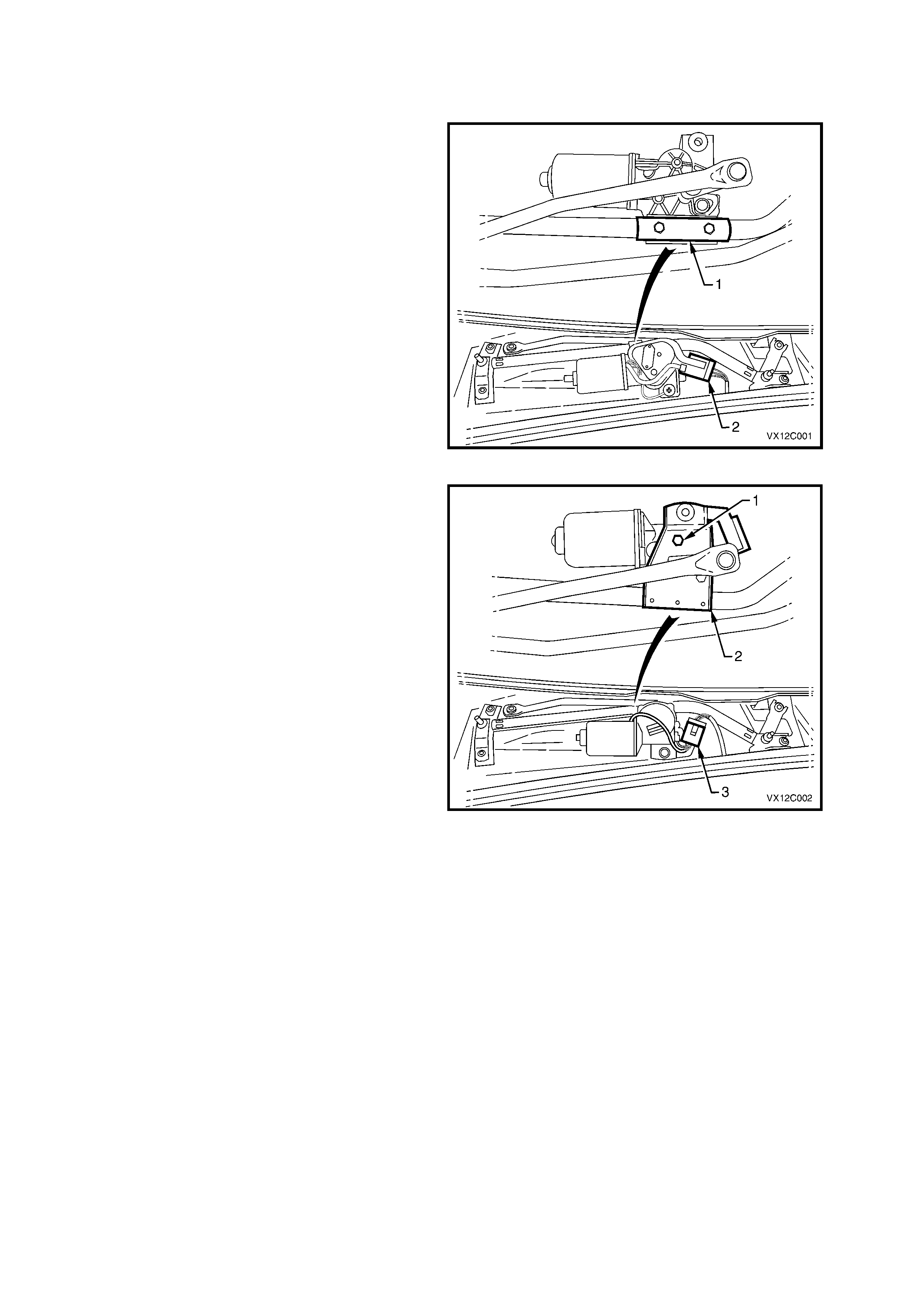
Two fr ont wiper motor and linkage ass emblies have
been used in VX Series Models. One was
manufactured by Preslite (early type) while the
other was manufactured by Trico (late type).
The early type f ront wiper motor and linkage can be
identified by the clamp type attachment of the
motor to the linkage (1) and the position of the
wiper motor harness connector (2).
For all information relating to the early type front
wiper motor and linkage, refer to
Section 12C INSTRUMENTS, WIPERS/
WASHERS AND HORN in the VT Series I Service
Information.
Figure 12C-1
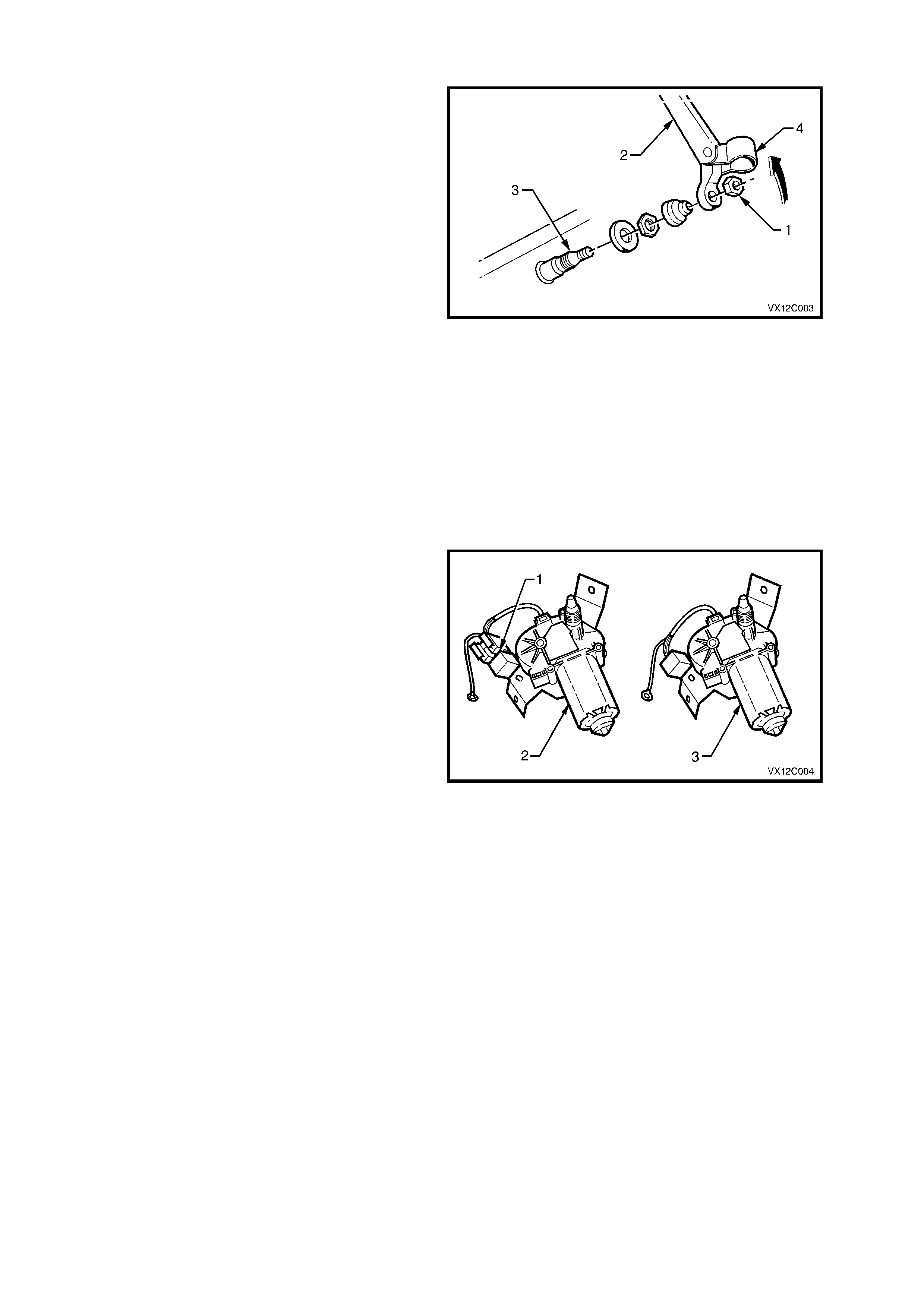
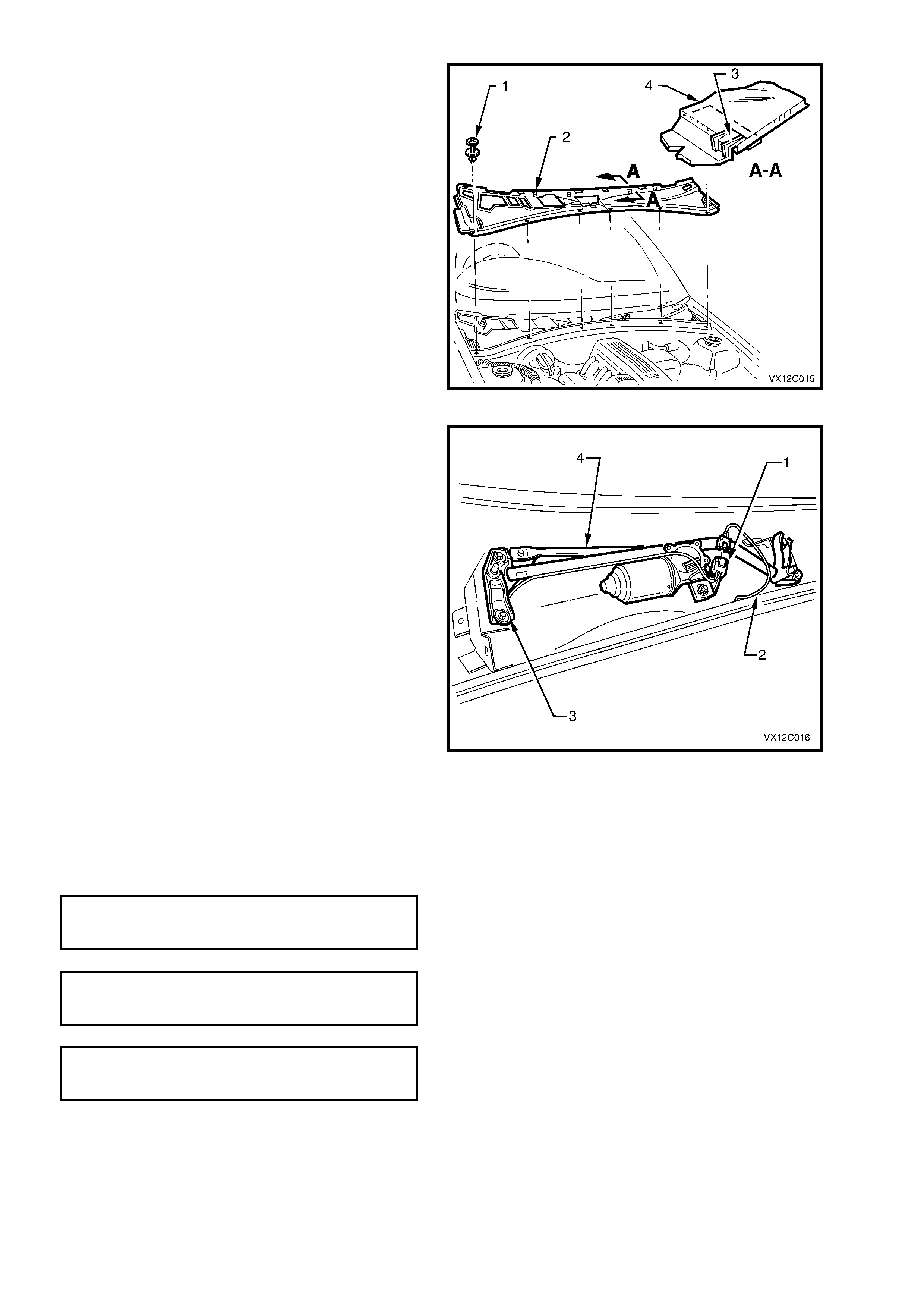
The later type front wiper m otor and linkage c an be
identified by the three bolts (1) attaching the wiper
motor to a bracket (2) spot welded to the wiper
linkage and the pos ition of the wiper m otor harness
connector (3).
This Section provides all the relevent information
relating to the later type front wiper motor and
linkage.
Figure 12C-2
REAR WIPER MOTOR
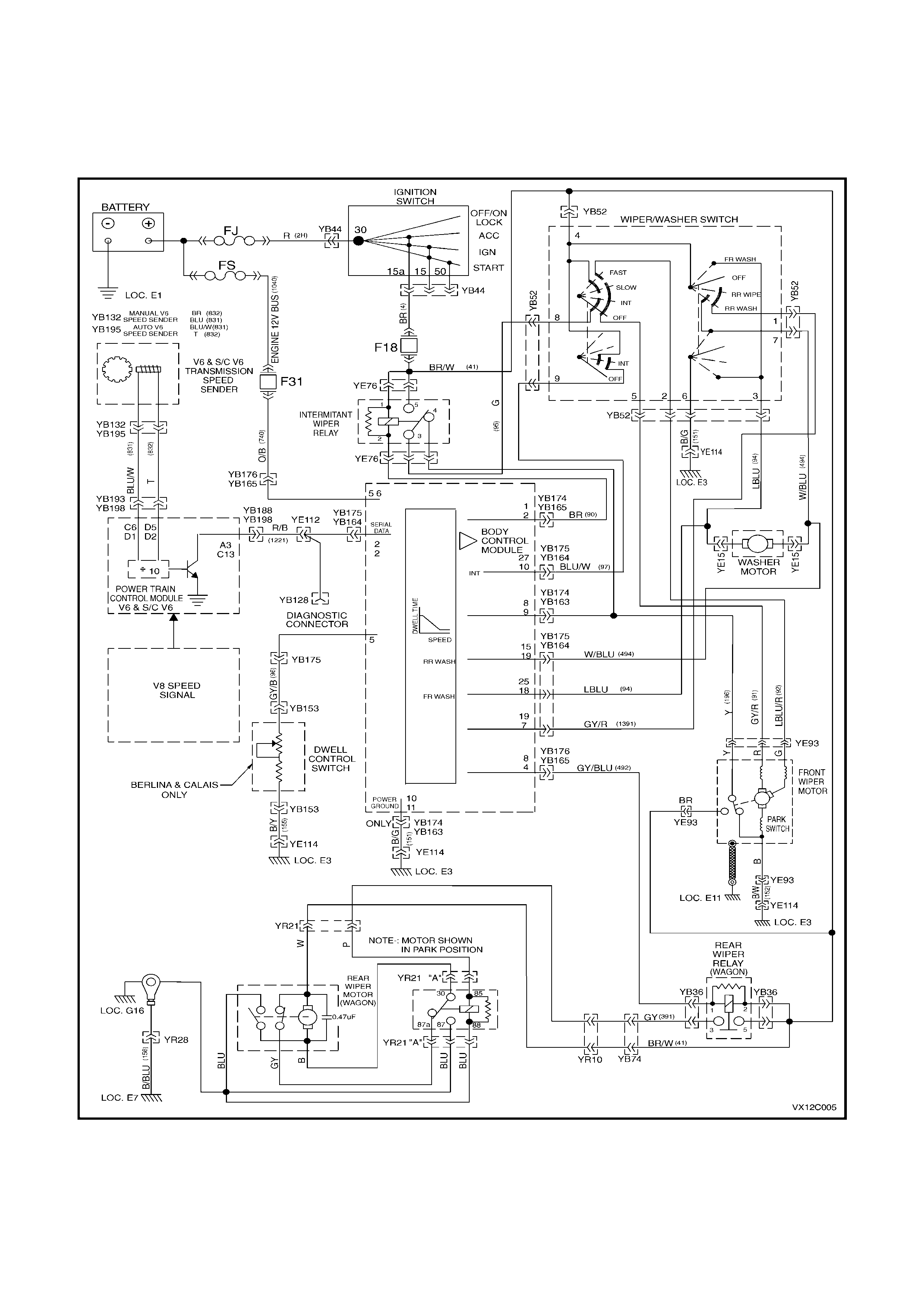
There has been three rear wiper m otor assemblies
used in VX Series Wagon Models. One was
manufactured by Preslite (early type) while the
other two were manufactured by Trico (interim and
late type).
The early type rear wiper motor can be identified by
the size of the nut (1) attaching the rear wiper arm
(2) to the r ear wiper motor shaf t (3). The early type
uses an 11 m m nut, while the interim and late type
use a 13 mm nut for the rear wiper arm to motor
attachment. To inspect the nut, lift the rear wiper
arm pivot trim cap (4).
NOTE: T he early type rear wiper motor can also be
identified by the location of the hole in the tailgate
for the wiper motor shaft. For the early type motor,
the hole in the tailgate is aligned with the centreline
of the vehicle. For the interim and late type rear
wiper motor, the hole in the tailgate is offset
approximately 50 mm towards the passenger side
from the vehicle centre line.
For all information relating to the early
type rear wiper motor, refer to
Section 12C INSTRUMENTS, WIPERS/
WASHERS AND HORN in the VT Series I Service
Information.
Figure 12C-3
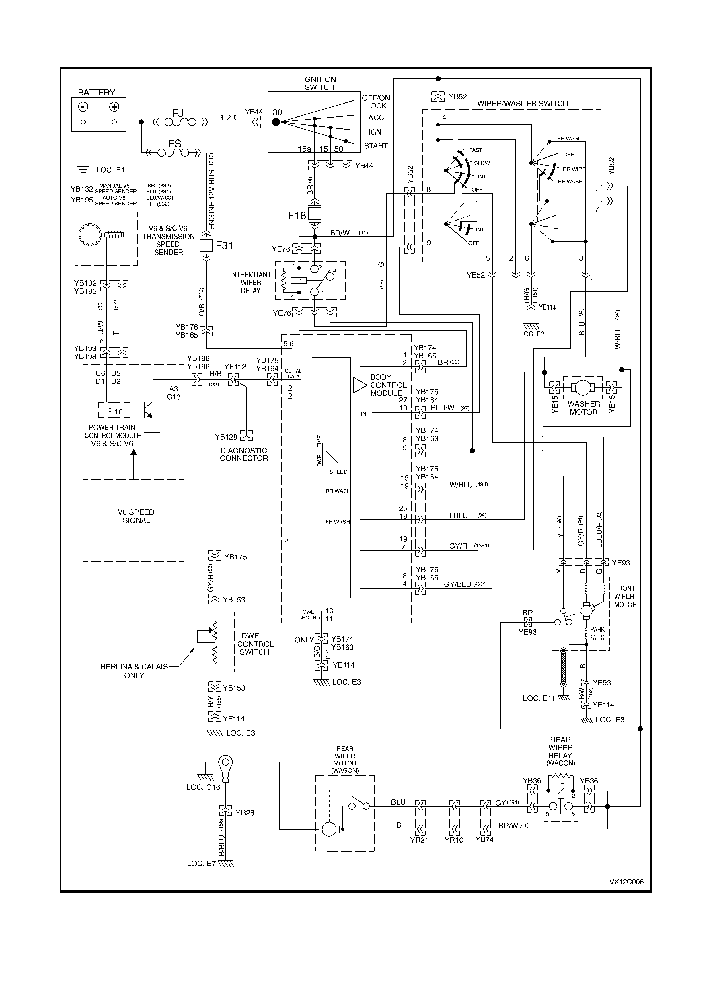
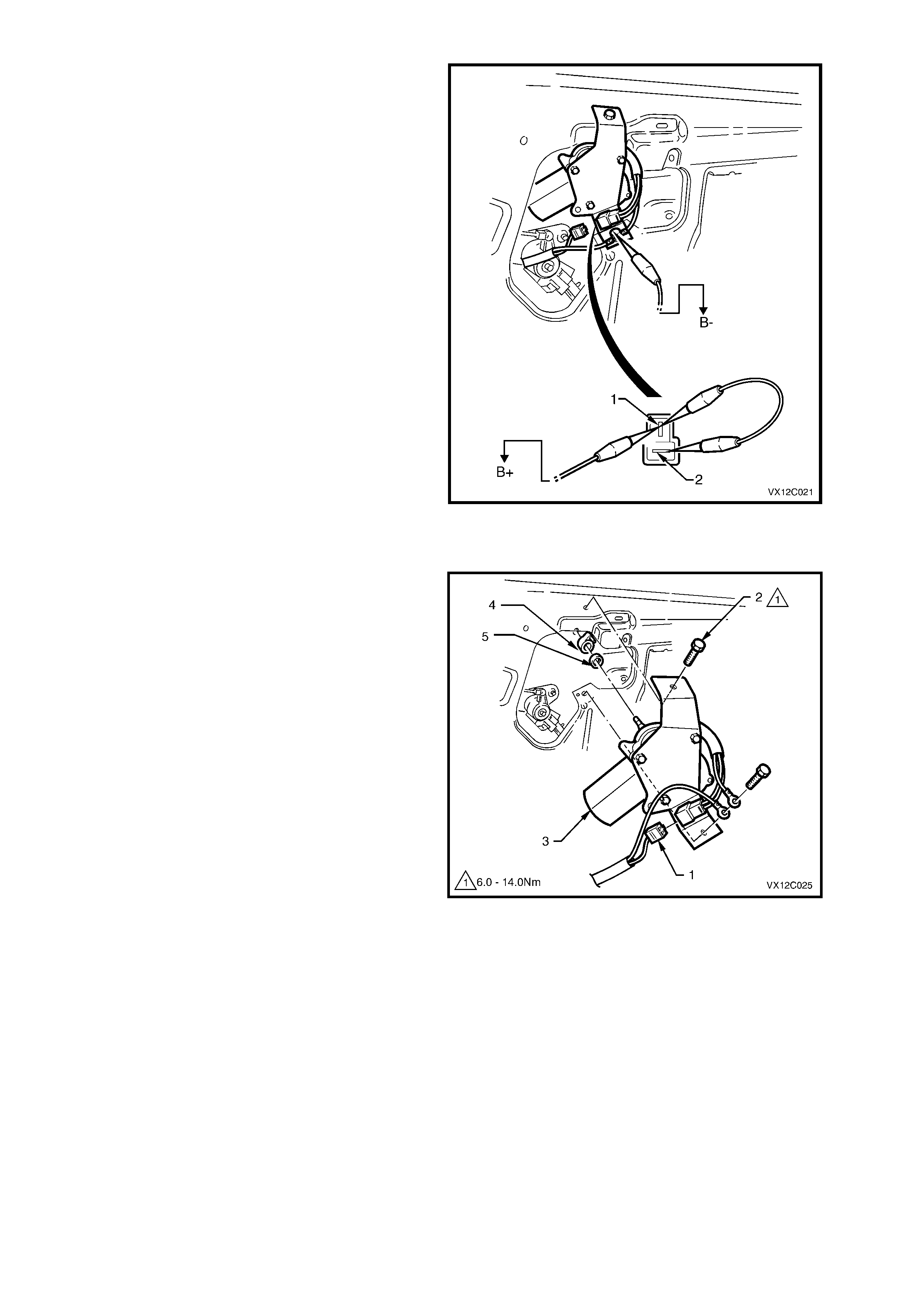
If the vehicle uses a 13mm nut for the rear wiper
arm to motor attachment, to identify whether the
vehicle is fitted with the interim or late type rear
wiper, first remove the tailgate interior trim panel,
refer to Section 1A4 REAR COMPARTMENT LID
& TAILGATE in the VT Series I Service
Information.
If the rear wiper motor has an external relay (1)
rivetted to the mounting bracket, it is an interim
type (2). If the rear wiper motor is not fitted with an
external relay, it is the late type (3).
This Section provides all the relevent information
relating to the interim and late type rear wiper motor
and linkage.
Figure 12C-4
CIRCUIT DIAGRAMS
Figure 12C-5 shows the circuit for the wiper/washer system f or vehicles with the late type (Trico) front wiper motor
and linkage assembly and interim type rear wiper motor. Figure 12C-6 shows the circuit for the wiper/washer
system for vehicles with the late type (Trico) front wiper motor and linkage assembly and late type rear wiper motor.
INTERIM TYPE REAR WIPER MOTOR
Figure 12C-5
LATE TYPE REAR WIPER MOTOR
Figure 12C-6

2. WIPERS AND WASHERS SERVICE OPERATIONS
2.1 FRONT WIPER ARM
The front wiper arm s as fitted to VX Series Models carry over from VT Series I Models. For inform ation relating to
the f ront wiper arm as fitted to VX Series Models, r ef er to Sectio n 12C INSTRUM ENTS, WIPERS/W ASHERS AND
HORN in the VT Series I Service Information.
Techline
2.2 REAR WIPER ARM
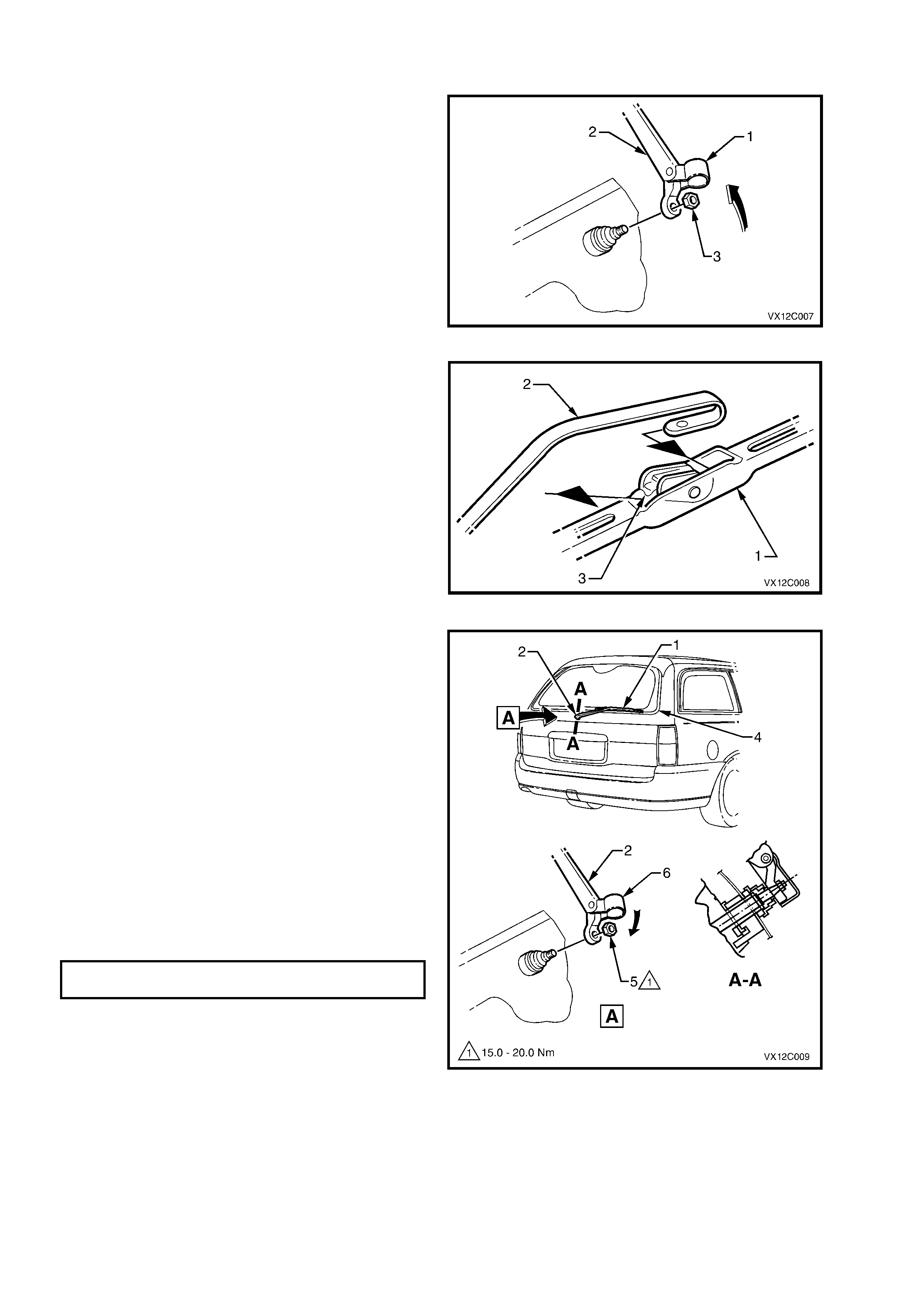
REMOVE
1. Lift up trim cap (1) from wiper motor drive
spindle end of wiper arm (2).
2. Remove wiper arm to drive spindle securing
nut (3) and remove wiper arm.
Figure 12C-7
3. If required, remove wiper blade (1) from the
arm (2) by lifting up the retainer (3) on the
wiper blade and pulling blade from arm.
Figure 12C-8
REINSTALL
1. If rem oved, slide wiper blade (1) into wiper arm
(2) until the wiper blade retainer locks into
position.
2. Ensure the wiper motor is in the PARKED
position.
3. Reinstall wiper arm assembly onto drive
spindle (3) so that the wiper blade rests on the
glass moulding (4).
NOTE: To ensure arm will not wipe over moulding
in the park position, push arm onto wiper spindle
with the arm in the vertical position and then rotate
wiper arm clockwise until blade rests on glass
moulding.
4. Reinstall the nut (5) securing the wiper arm to
the drive spindle and tighten to the correct
torque specification.
REAR WIPER ARM NUT
TORQUE SPECIFICATION 15 – 20 Nm
5. Push trim cap (6) onto wiper arm.
Figure 12C-9

2.3 FRONT AND REAR WIPER BLADES/INSERTS
The fr ont and rear wiper blades and ins erts c arry over from VT Series I Models. For information r elating to the front
and rear wiper blades as fitted to VX Series Models, refer to Section 12C INSTRUMENTS, WIPERS/WASHERS
AND HORN in the VT Series I Service Information.
2.4 FRONT WIPER MOTOR AND LINKAGE
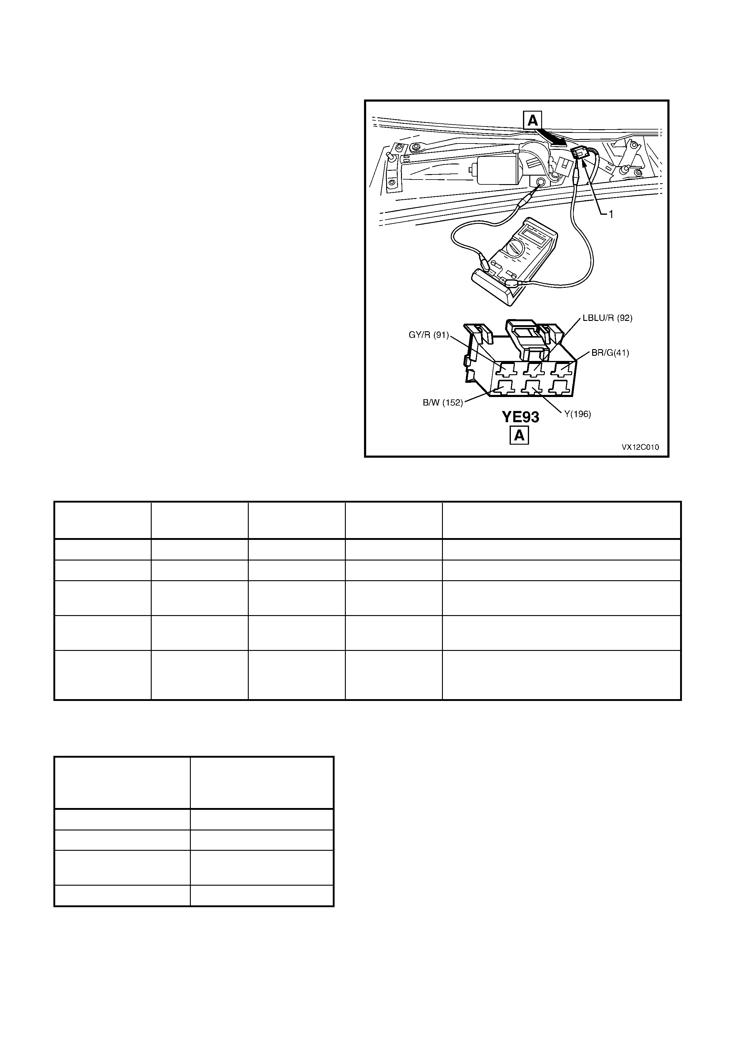
CHECKING WIPER MOTOR WIRING
The following operation checks the wiper motor
wiring at the wiper motor connec tor YE93 (1) as an
aid to diagnosing a fault in the wiper motor system.
NOTE: On vehicles with a High Series BCM,
operation of the intermediate dwell control can be
checked with TECH 2, refer Section 12J-2 HIGH
SERIES BCM in the VT Series I Service
Information.
1. Remove wiper arms, plenum covers, water
deflector and disconnect wiring harness
connector YE93, refer to Steps 1 - 6 in the
following wiper motor removal procedure.
2. Us ing a multimeter connec ted with the negative
lead to the black wire terminal of the wiring
harness connector and the positive lead to the
main wiring harness connector wire terminal
nominated in the following chart, check wiper
motor wiring as follows:
Figure 12C-10
WIRE
COLOUR CIRCUIT No. CIRCUIT MULTIMETER
SETTING RESULT IF WIPER MOTOR WIRING
IS OK
Black/White 152 Earth Resistance 0 ohms (approximately).
Brown/Green 41 Power source Voltage B+ with ignition in ACC or ON position.
Grey/Red 91 Low speed Voltage B+ with ignition in ACC or ON position
and wiper switch in low speed position.
LBlue/Red 92 High speed Voltage B+ with ignition in ACC or ON position
and wiper switch in high speed position.
Grey/Red 91 INT Position Voltage B+ cycling with ignition in ACC or ON
position and wiper switch in INT
position.
3. With wiring harness connector YE93 disconnected, check for continuity between the Yellow wire, circuit 196 and
the Grey/Red wire, circuit 91, as per the following table:
SWITCH POSITION RESULT IF WIPER
MOTOR WIRING IS
OK
OFF Continuity
INTERMITTENT Continuity
LOW Continuity (low
resistance)
HIGH Open circuit
NOTE: If any of the readings are not as specified, check and repair faulty circuit as necessary.
CHECKING WIPER MOTOR OPERATION
The following operation checks the various
functions of the wiper motor. If there is a fault
in the wiper system, and the following operation
proves that the wiper motor is OK, check
|the wiper/washer switch or wiring as described
in this Section, or check the BCM control,
depending on model variant, refer to
either Section 12J-1 LOW SERIES BCM or
Section 12J-2 HIGH SERIES BCM in the VT
Series I Service Information.
If the following operation proves that the wiper
motor is faulty, replace the wiper motor assembly.
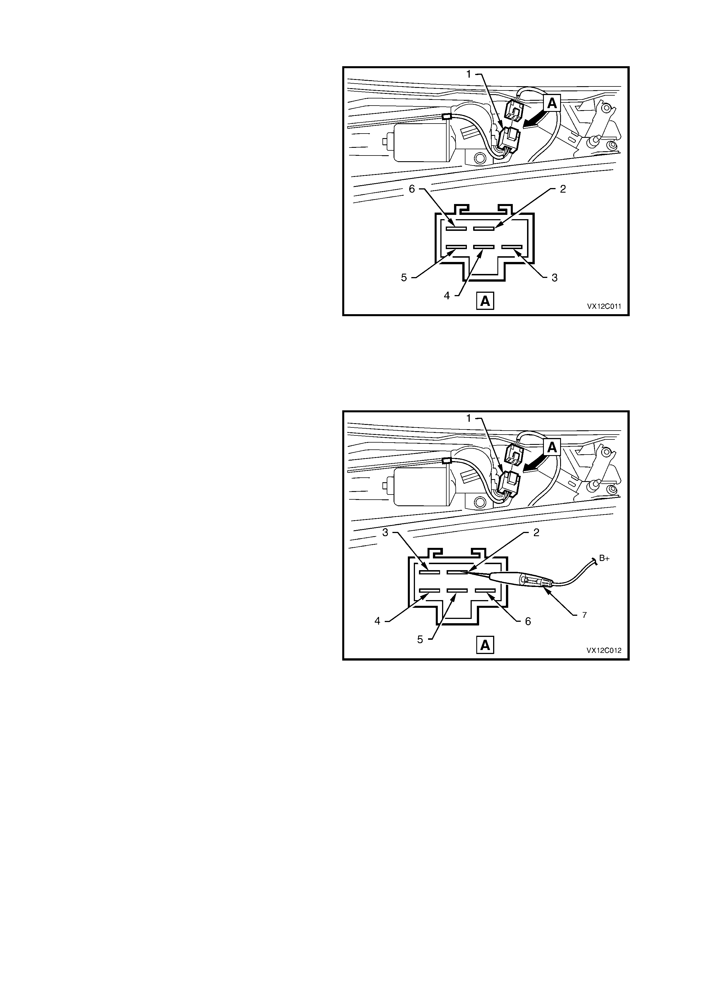
1. Remove wiper arms, plenum covers, water
deflector and disconnect wiring harness
connector (1), refer to Steps 1 - 6 in the
following wiper motor removal procedure.
2. Connect a lead from vehicle battery positive
terminal to the Red wire of the wiper motor
connector. The wiper motor should operate on
low speed.
3. Connect a lead from vehicle battery positive
terminal to the Green wire of the wiper motor
connector. The wiper motor should operate on
high speed.
Figure 12C-11
4. To check wiper motor PARK operation,
connect a jumper lead from vehicle positive to
Red wire of motor connector (1) and allow
motor to turn linkages approximately 1/4 of a
turn past the PARK position.
To check if the wiper motor is off the parked
position, connect a test lamp between battery
positive and the Yellow wire of the wiper motor
connector. The lamp should NOT illuminate. If
the lamp does illuminate, contacts within the
wiper motor are faulty or check for Yellow wire
shorted to earth.
Figure 12C-12
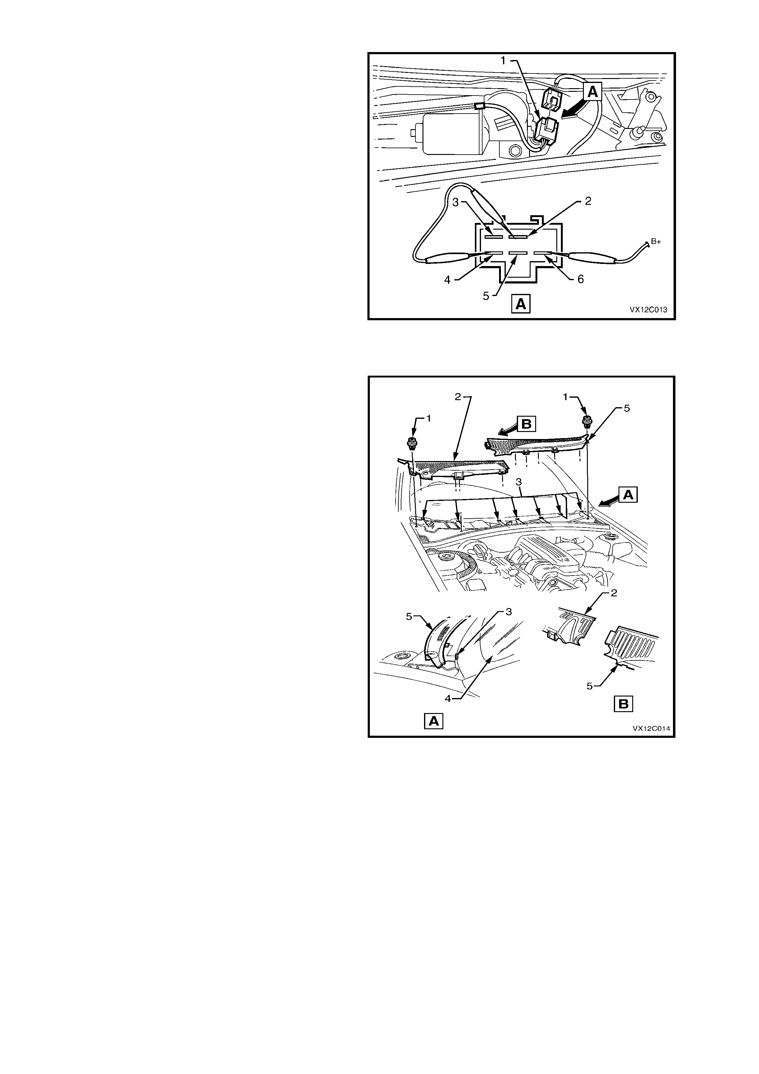
Using a second jumper wire, connect the Red
and Yellow wires of the wiper motor connector
together.
Using jumper leads from battery positive,
connect to Brown wire of wiper motor
connector and the wiper motor should turn the
wiper linkages to the PARK position and stop. If
the wiper motor does not turn the linkages or
the linkages do not stop at the PARK position,
the contacts within the wiper motor are faulty
and therefore, the wiper motor must be
replaced.
5. Reconnect wiring harness connector (1) to
wiper motor.
6. Reinstall water deflector, plenum chamber
covers and wiper arm assemblies, refer to the
following removal and reinstallation procedure
of the wiper motor in this Section.
Figure 12C-13
REMOVE
1. Remove wiper arms, refer to
Section 12C INSTRUMENTS, WIPERS/
WASHERS AND HORN in the VT Series I
Service Information.
2. Remove the six fasteners (1) securing the
plenum chamber covers to the plenum
chamber.
3. Pull the right-hand plenum chamber cover (2)
forward to release the three retaining tabs (3)
securing it to the winds creen (4), then lift c over
upwards while manoeuvring the cover away
from the engine hood hinge.
4. Pull the left-hand plenum chamber cover (4)
forward to release the four retaining tabs
securing it to the windscreen, then lift cover
upwards while manoeuvring the cover away
from the engine hood hinge.
NOTE: The right-hand plenum chamber cover
must be removed first.
Figure 12C-14
4. Rem ove the 6 fasteners (1) securing the water
deflector (2) to the plenum chamber.
5. Pull the water deflector forward to release the
four retaining tabs (3) securing it to the
windscreen (4).
6. Remove the water deflector.
Figure 12C-15
7. Squeeze the tang at the m ain wiring harness to
wiper motor harness connector and disconnect
wiring harness.
8. Remove the five screws securing the wiper
motor and linkage assembly to the plenum
chamber and remove wiper motor and linkage
assembly.
NOTE: The bolt sec uring the wiper m otor and earth
strap (5) is secured to the strap by a spacer and
cannot be seperated.
9. If necess ary, rem ove the nut sec uring the wiper
linkages to the wiper motor pivot and the three
bolts securing the wiper motor to the bracket
on the wiper linkages and separate the wiper
motor from the wiper linkages.
Figure 12C-16
REINSTALL
Installation of the wiper motor is the reverse of the
removal procedure, noting the following:
1. Ensure all fasteners are tightened to the
correct torque specification.
WIPER MOTOR TO LINKAGE
SECURING SCREWS
TORQUE SPECIFICATION 7 – 9 Nm
WIPER MOTOR CRANK ARM TO
WIPER MOTOR ATTACHING NUT
TORQUE SPECIFICATION 16 – 20 Nm
WIPER MOTOR AND LINKAGE
ASSEMBLY SECURING SCREW S
TORQUE SPECIFICATION 4 – 6 Nm

NOTE 1: If the wiper motor has been removed from
the linkages. The wiper motor pivot must be installed in
the park position, by aligning the wiper motor pivot
within the lines on the mounting bracket marked R (1)
for right-hand drive, or L (2) for left-hand drive models.
NOTE 2: Ensure that the wires from the connector do
not get caught or foul the wiper motor linkages.
2. Operate wiper motor before installing the wiper
arms to ensure it is in the correct PARK position.
3. When installing the water deflector and plenum
covers, ensure that the retaining tabs engage
under the windscreen.
Figure 12C-17
2.5 REAR WIPER MOTOR ASSEMBLY
CHECKING WIPER MOTOR WIRING
1. Remove tailgate interior trim panel, refer
Section 1A4 REAR COMPARTMENT LID &
TAILGATE in the VT Series I Service
Information.
2. Depress retaining tang on rear compartment
harness connector (1) and disconnect from
rear wiper motor connector (2).
3. Using a multimeter (3) connected between the
lower wiper motor bracket securing screw (4)
and the rear compartment harness connector,
check wiper motor wiring as per the following
chart.
Figure 12C-18
WIRE
COLOUR CIRCUIT No. CIRCUIT MULTIMETE
R SETTING RESULT IF WIPER MOTOR IS OK
Brown/White 141 Power source Voltage B+ with ignition in ACC or ON position
and wiper/washer switch OFF
Grey 391 Motor drive Voltage 0 volt with ignition in ACC or ON
position and wiper/washer switch OFF
Brown/White 141 Power source Voltage B+ with ignition in ACC or ON position
and wiper/washer switch ON
Grey 391 Motor drive Voltage B+ with ignition in ACC or ON position
and wiper/washer switch ON
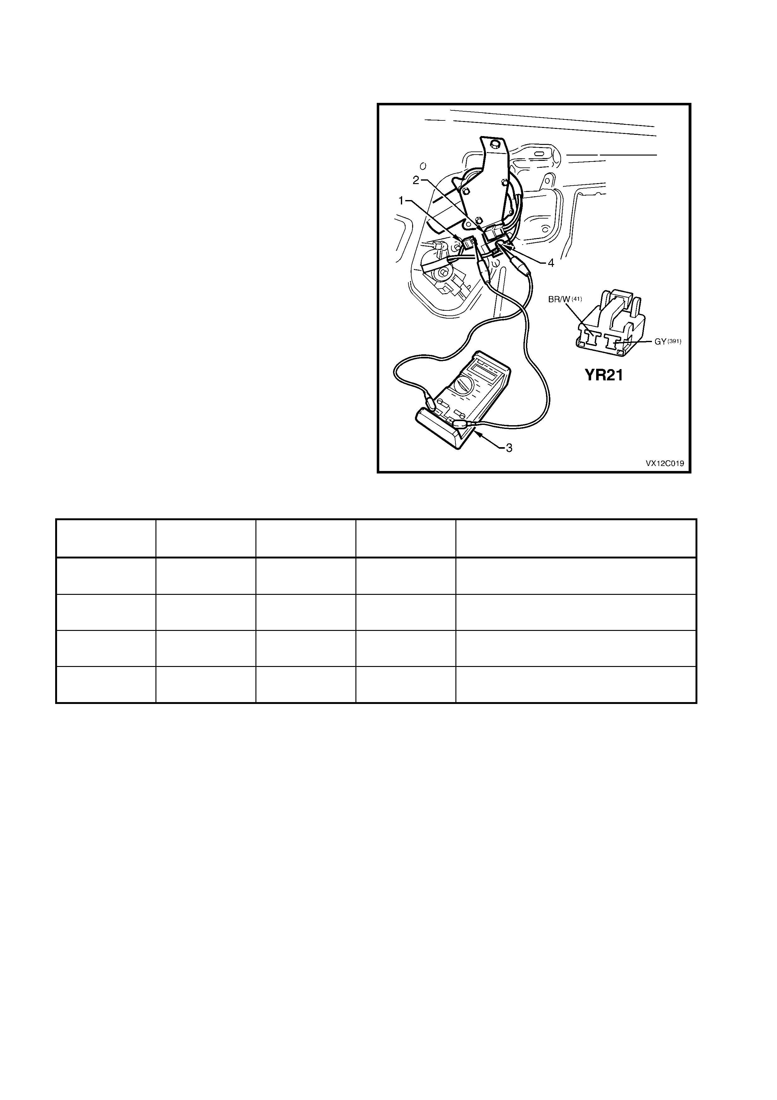
CHECKING WIPER MOTOR OPERATION – INTERIM TYPE MOTOR
1. Remove rear wiper arm, refer to
2.2 REAR WIPER ARM in this Section.
2. Remove tailgate interior trim panel, refer
Section 1A4 REAR COMPARTMENT LID &
TAILGATE in the VT Series I Service
Information.
3. Use a jumper lead connected between battery
earth and the wiper mounting br ac k et and earth
lead (Brown wire).
4. Using a second jumper lead connected to
battery positive, touch jumper lead terminal to
Blue wire terminal of wiper motor connector.
Drive spindle of motor should rotate. If drive
spindle does not rotate, motor is faulty and
must be replaced.
Figure 12C-19
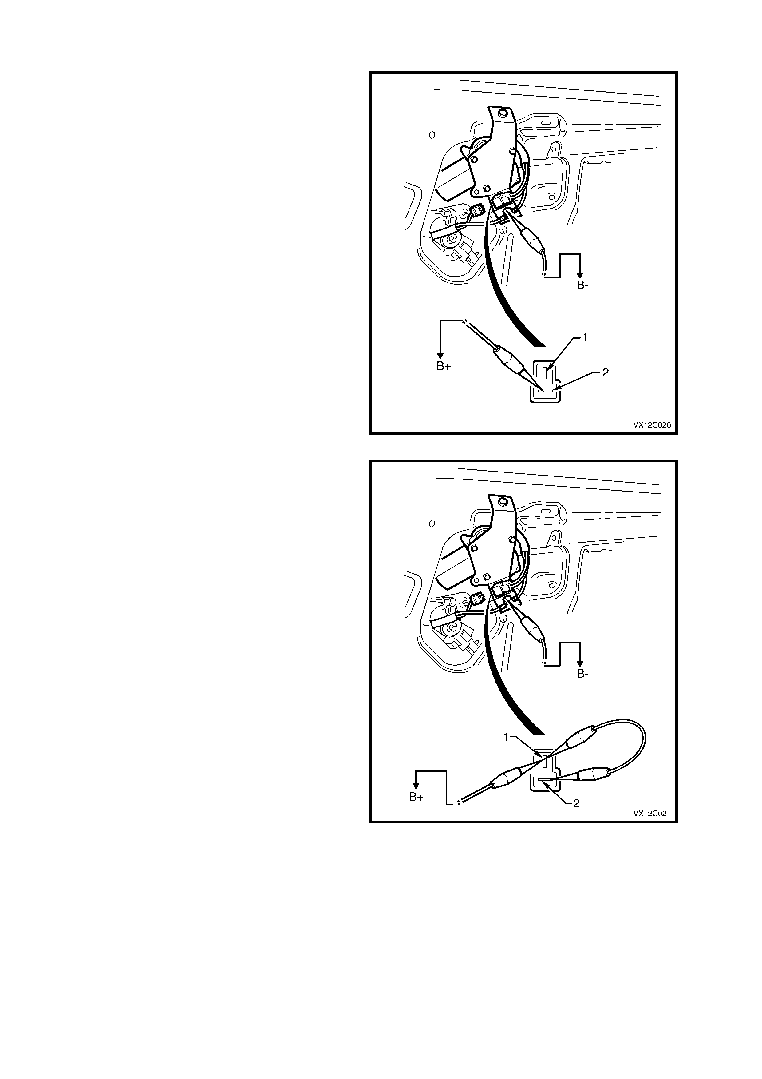
5. To check wiper motor PARKED operation,
connect a bridging wire between the Black and
Blue wires of the wiper motor connector.
Connect a jumper wire from battery positive to
Black wire to wiper motor connec tor, and wiper
motor spindle should rotate.
Disconnect bridging wire from Blue wire and
wiper motor should continue to rotate until it
reaches the PARK position.
Figure 12C-20
7. If the motor does not park, remove all jumper
wires and reconnect the rear wiper motor
harness connector.
8. Replace the rear wiper park relay with a known
good relay. If the wiper arm returns to the park
position and stops, the rear wiper park relay is
faulty and must be replaced. If the wiper arm
does not return to the park position and stop,
the rear wiper m otor inter nal contacts are f aulty
and the motor must be replaced.
NOTE: If a known good relay is not available,
continue with steps 9 through to 13.
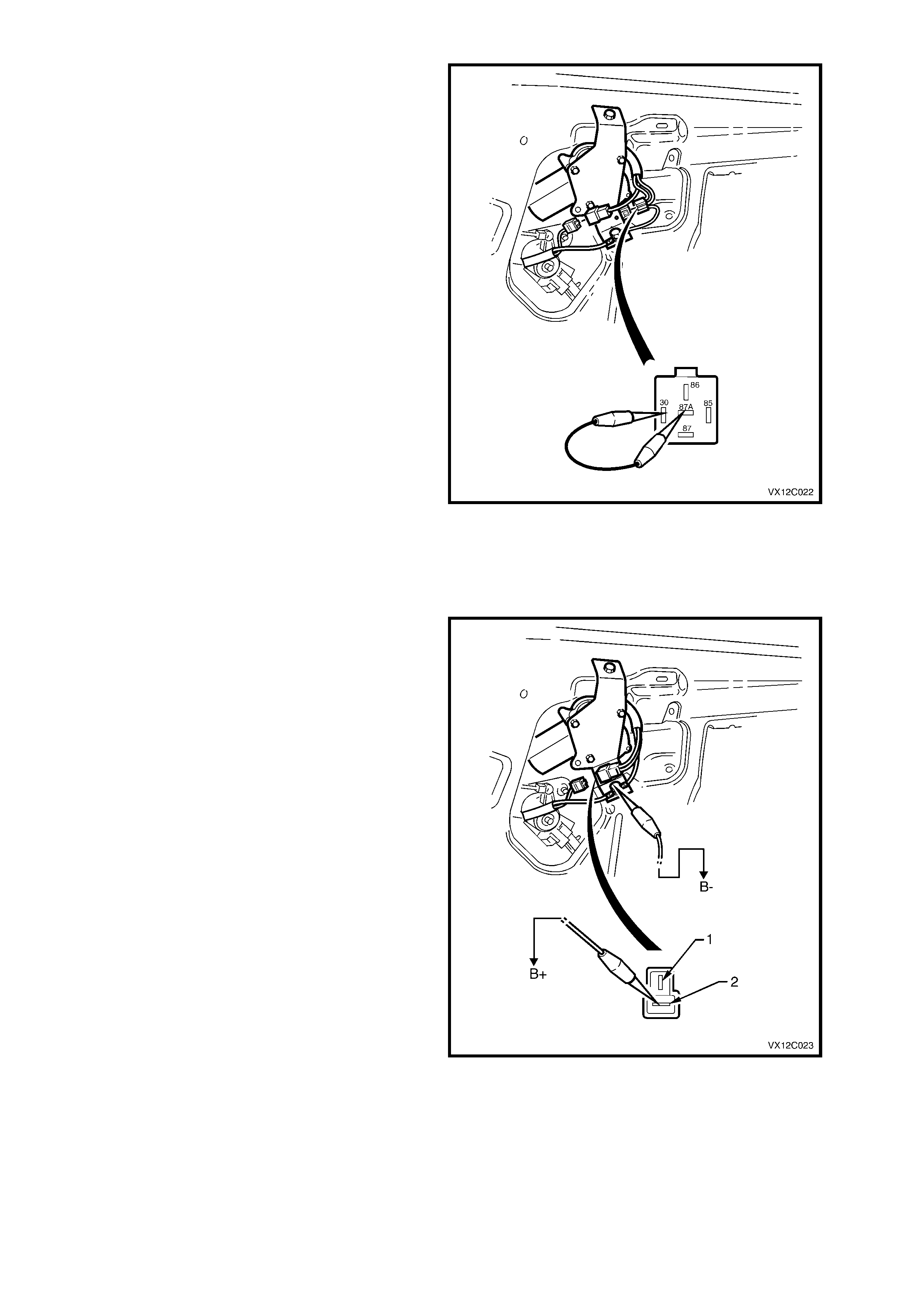
9. Turn the ignition switch to the OFF position with
the rear wiper arm in the centre of its stroke.
10. Remove the connector block from the rear
wiper park relay on the rear wiper motor
mounting bracket.
11. Connect a jumper wire between terminal 30
and terminal 87a.
12. Turn the ignition to the on position.
13. If the wiper arm returns to the par k position and
stops, the rear wiper park relay is faulty and
must be replaced. If the wiper arm does not
return to the park position and stop, the rear
wiper motor inter nal contacts are faulty and the
motor must be replaced.
Figure 12C-21
CHECKING WIPER MOTOR OPERATION – LATE TYPE MOTOR
1. Remove rear wiper arm, refer to
2.2 REAR WIPER ARM in this Section.
2. Remove tailgate interior trim panel, refer
Section 1A4 REAR COMPARTMENT LID &
TAILGATE in the VT Series I Service
Information.
3. Use a jumper lead connected between battery
earth and the wiper mounting br ac k et and earth
lead (Brown wire).
4. Using a second jumper lead connected to
battery positive, touch jumper lead terminal to
Blue wire terminal of wiper motor connector.
Drive spindle of motor should rotate. If drive
spindle does not rotate, motor is faulty and
must be replaced.
Figure 12C-22
5. To check wiper motor PARKED operation,
connect a bridging wire between the Black and
Blue wires of the wiper motor connector.
Connect a jumper wire from battery positive to
Black wire to wiper motor connec tor, and wiper
motor spindle should rotate.
Disconnect bridging wire from Blue wire and
wiper motor should continue to rotate until it
reaches the PARK position.
If motor does not park, the contacts within the
motor are faulty and therefore, the motor must
be replaced.
Figure 12C-23
REMOVE
1. Remove rear wiper arm, refer
2.2 REAR WIPER ARM in this Section.
2. Remove the rubber seal, nut, cap and spacer
from the wiper motor shaft.
3. Remove tailgate interior trim panel, refer
Section 1A4 REAR COMPARTMENT LID &
TAILGATE in the VT Series I Service
Information.
4. Depress retaining tang on rear compartment
harness connector (1) and disconnect from
rear wiper motor connector.
5. Remove the two screws (2) securing the rear
wiper motor to the tailgate, r em ove wiper m otor
and bracket assembly (3).
6. Remove inner spacer (4) and cap (5) from
wiper motor shaft.
Figure 12C-24
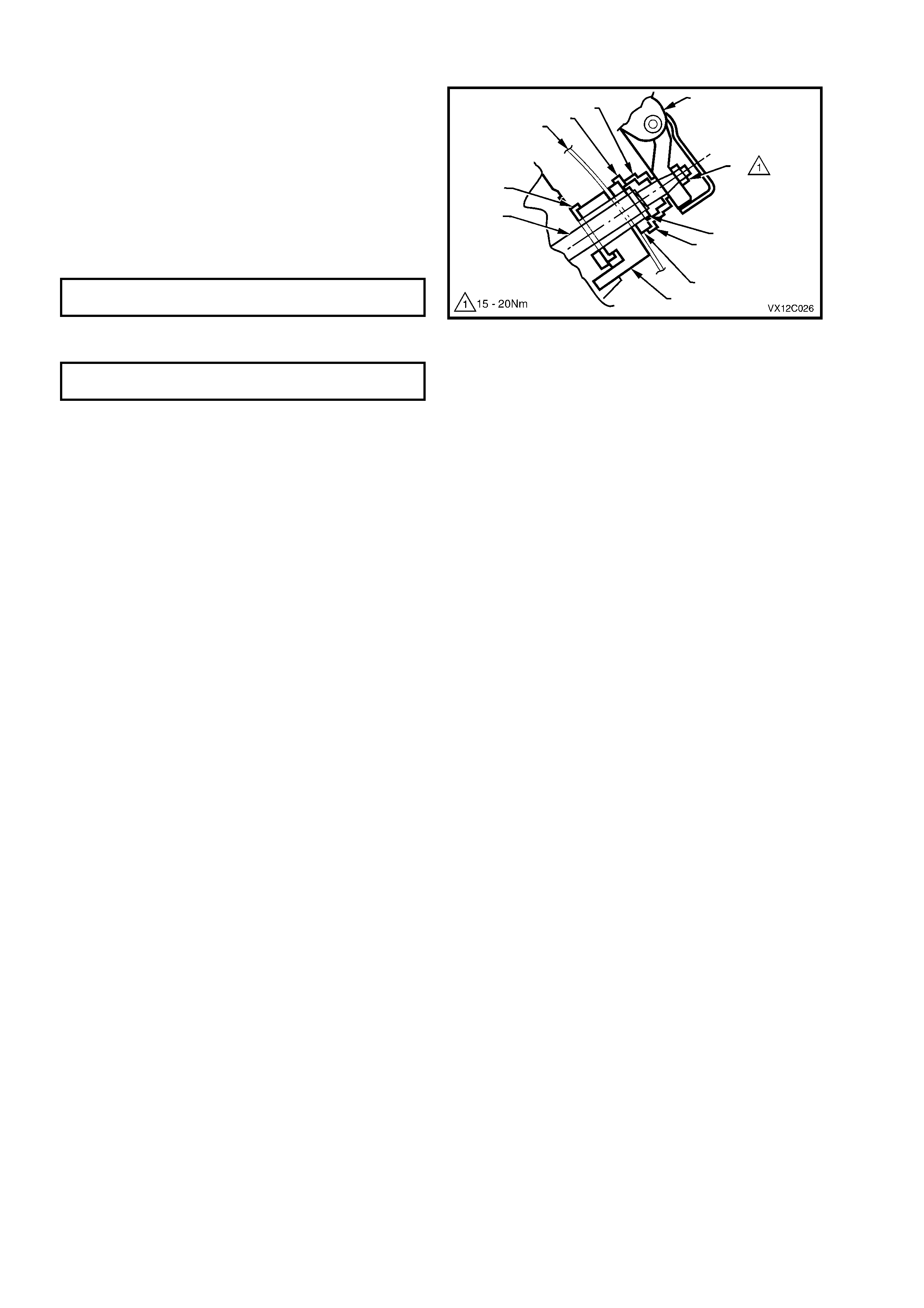
REINSTALL
Installation of the rear wiper motor is the r everse of
the removal procedure, noting the following points
1. Ensure that the inner spacer (1), outer spacer
(2), washers (3), shaft seal (4) and nut (5) are
fitted onto the wiper shaft (6) correctly.
2. To ensure the earth connection, the wiper
motor earth lead must be installed before the
tailgate harness earth lead.
3. Tighten wiper motor securing screws to the
correct torque specification.
WIPER MOTOR SECURING SCREW
TORQUE SPECIFICATION 6 – 14 Nm
4. Tighten rear wiper arm attaching nut (7) to the
correct torque specification.
REAR WIPER ARM ATTACHING NUT
TORQUE SPECIFICATION 15 – 20 Nm
Figure 12C-25

3. TORQUE WRENCH SPECIFICATIONS
Nm
Front Wiper Arm Attaching nut .............................................20 - 25
Rear Wiper Arm Attaching nut..............................................15 - 20
Rear Wiper Motor Attaching Screw ......................................6 - 14
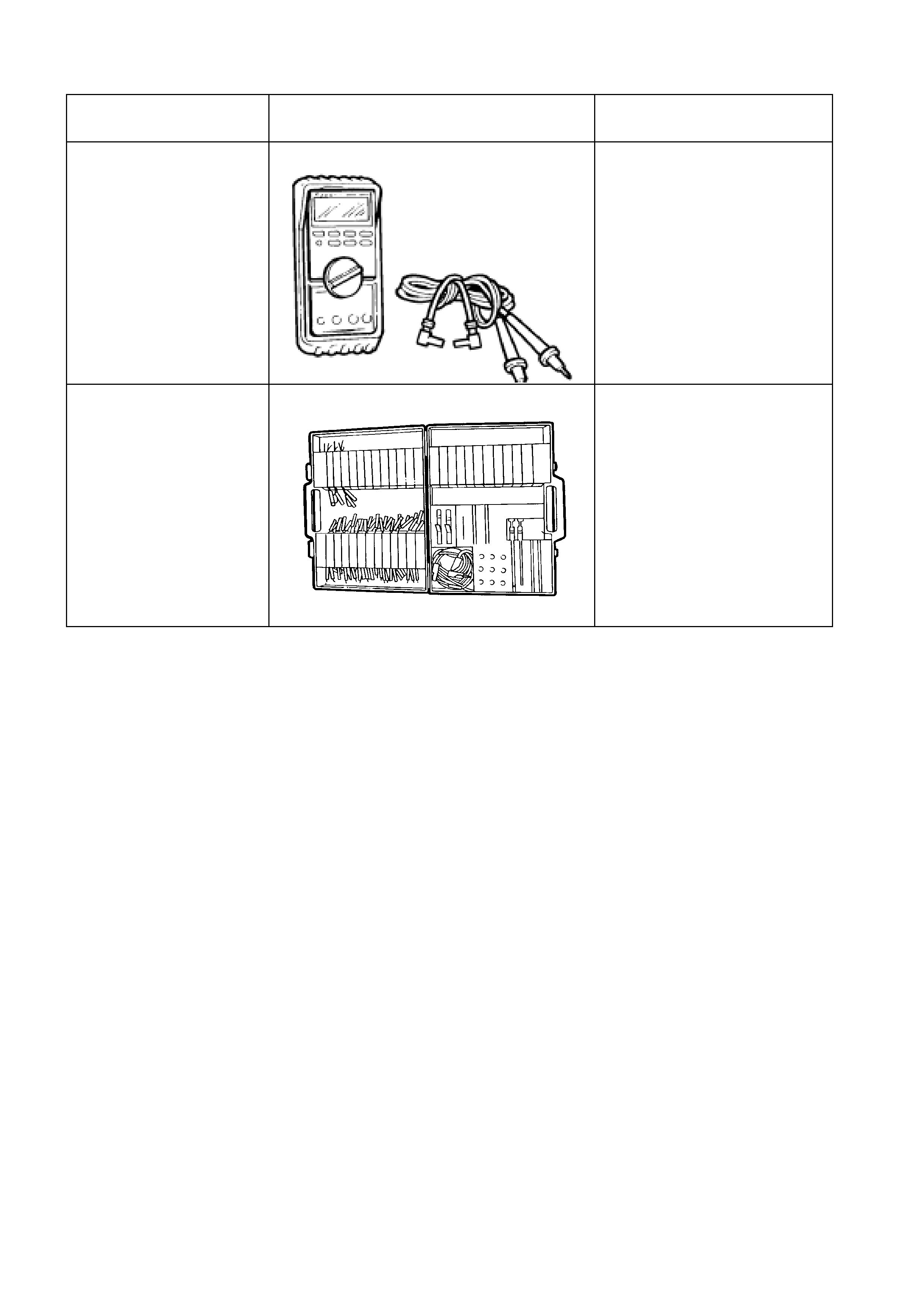
4. SPECIAL TOOLS
TOOL NO. REF
IN TEXT TOOL DESCRIPTION COMMENTS
J39200
DIGITAL MULTIMETER TOOL NO. J39200
PREVIOUSLY RELEASED, OR
USE COMMERCIALLY
AVAILABLE EQUIVALENT.
MUST HAVE 10 MEG OHM
INPUT IMPEDANCE
KM-609 CONNECTOR TEST ADAPTOR KIT
PREVIOUSLY RELEASED
FOR V CAR. USED IN
CONJUNCTION WITH A
MULTIMETER FOR
MEASURING VOLTAGES AND
RESISTANCES WITHOUT
DAMAGING WIRING
HARNESS CONNECTORS