
SECTION 12M - SUPPLEMENTAL RESTRAINT
SYSTEM (VERSIONS 8.0 AND 8.1)
IMPORTANT
Before performing any Service Operation or other procedure described in this Section, refer to Section
00 CAUTIONS AND NOTES for correct workshop practices with regard to safety and/or property damage.
1. GENERAL I NFORMATI O N
The Supplemental Restraint System (SRS) used on VX Series Models carries over from the systems that were
introduced for VT Series Models in August 1998; versions 8.0 and 8.1, noting the following:
Since the introduction of SRS versions 8.0 and 8.1, there have been numerous changes and corrections:
• Introduction of the GEN III V8 engine, resulting in a new PCM (from VT Series II).
• Introduction of a new PCM for vehicles with a V6 engine on VX Series Models.
• Minor changes to the side air bag wiring circuits – terminal assignment of connector YB205 being swapped
around (from VT Series II).
• Incorrect identification of the wire colour for circuit 1220 (from introduction of VT Series).
• Emittance of recognition of a shorting link busbar in connector YB189 (from VT Series II).
These changes and corrections do not effect the SRS Operation or Service Operations, however, to avoid any
confusion, the Diagnostic Charts for SRS versions 8.0 and 8.1 have been updated and republished in full in this
Section.
The following table summarises the version usage on VX Series Models.
SDM Pre-tensioner Driver’s Air bag Pass.Air bag Side Air bags
8.0 ✷
8.0 ✷ ✷
8.0 ✷ ✷ ✷
8.1 ✷ ✷ ✷ ✷
(SDM – Sensing and Diagnostic Module)
NOTE: Refer to the latest sales information for Model Option availability.
For all information relating to the SRS used on VX Series Models that is not covered in this Section, refer to:
Section 12M SUPPLEMENTAL RESTRAINT SYSTEM (Version 6.2) or
Section 12M SUPPLEMENTAL RESTRAINT SYSTEM (Version 8.0 & 8.1) of the VT Series I Service Information.
NOTE: Information in these two Sections should be read in conjunction with each other.
Techline


2.2 PRELIMINARY SYSTEM DIAGNOSIS
When investigating any complaint of an SRS problem or malfunction, always begin diagnosis with a circuit check,
refer to 2.5 DIAGNOSTICS CHARTS, CHART A - DIAGNOSTIC CIRCUIT CHECK in this Section.
The diagnostic circuit check is a preliminary procedure that checks to ensure the SDM is communicating on the
serial data line as well as helping to identify the problem and directing the technician to the appropriate diagnostic
chart in this Section.


2.4 TECH 2 DIAGNOSTICS, TEST MODES AND DISPLAYS FOR SRS DIAGNOSIS
All information relating to TECH 2, in regards to the SRS for VX Series Models, is as detailed in
Section 12M SUPPLEMENTAL RESTRAINT SYSTEM (Version 8.0 & 8.1) of the VT Series I Service Inform ation,
noting the following:
When using TECH 2 on a VX Series Model, ensure the correct Model Year and Vehicle Type is selected:
(Y) 2000
(1) 2001 VX Commodore
(2) 2002
2.5 DIAGNOSTIC CHARTS
The following diagnos tic charts are designed to provide f ast and ef ficient f ault location of the SRS for vehicles f itted
with an 8.0 or 8.1 SDM only. The diagnostic charts contain: a ‘diagnostic chart’, pertinent information, circuit
diagrams, and where necessary, the steps are explained by the corresponding numbered paragraphs.
Figure 12M-2 illustrates the correct use and installation of the various SRS diagnostic service tools (SD28280B &
AU485) and test lead set (KM-609-20) which are called up in the various diagnostic charts.
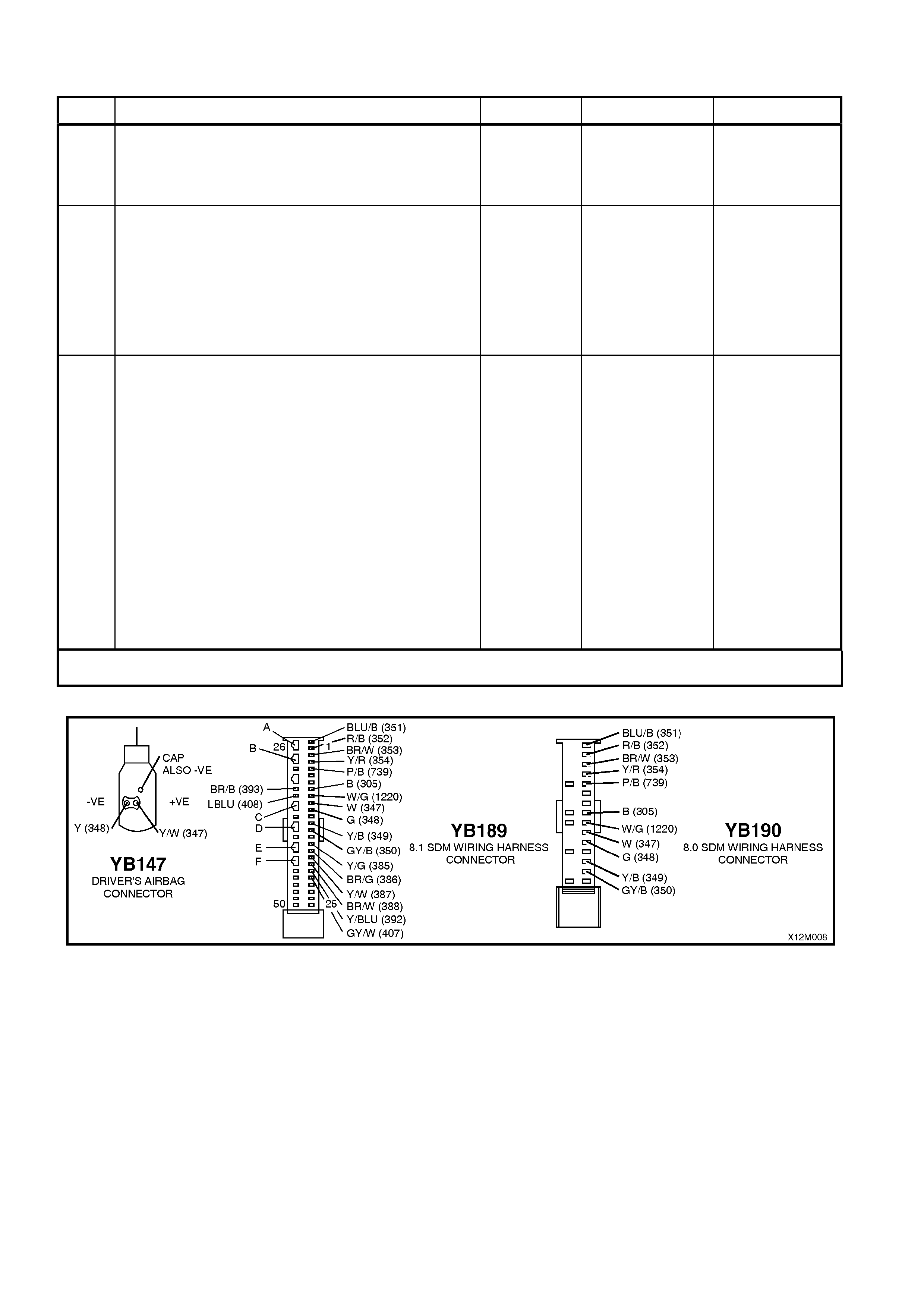
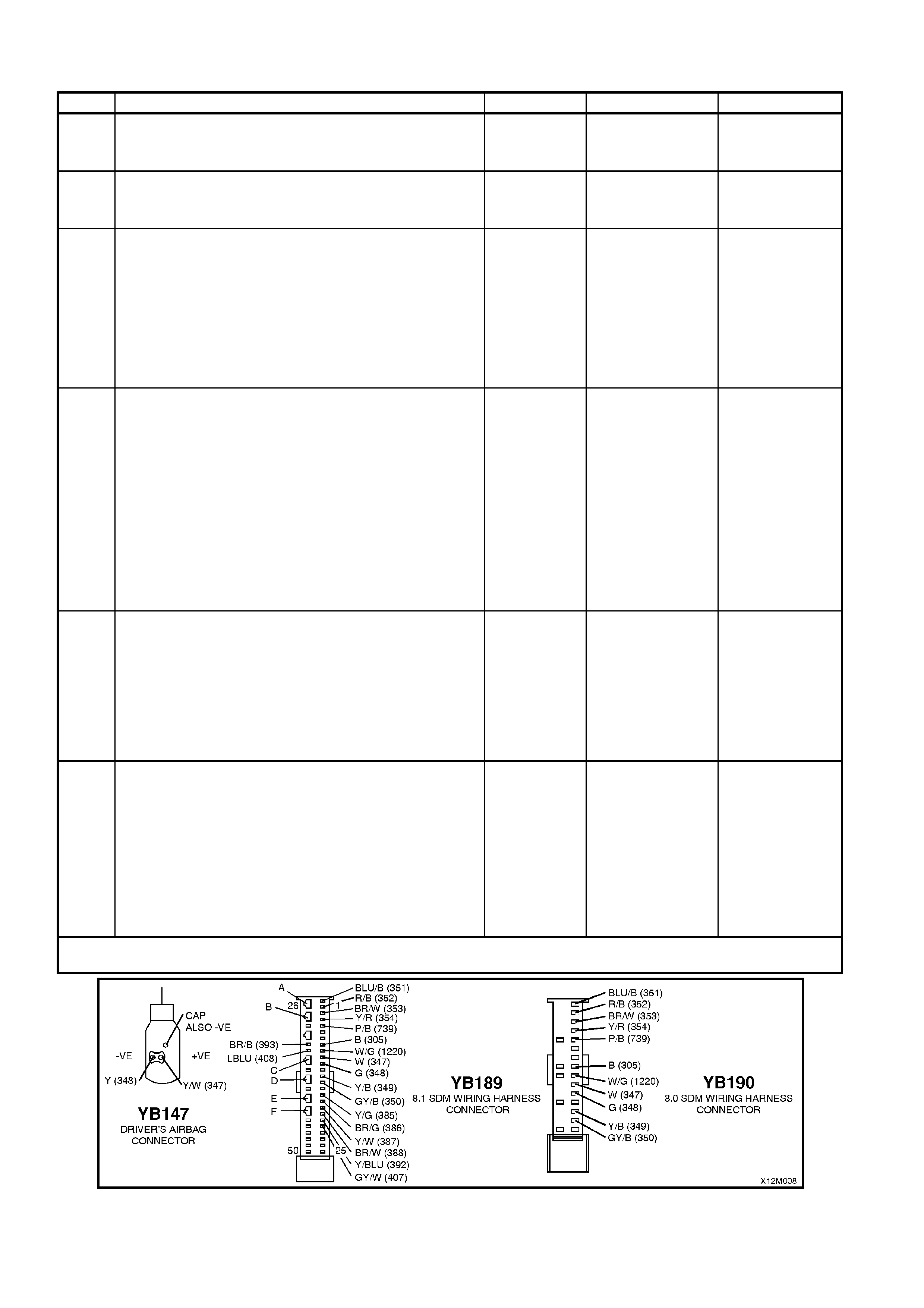
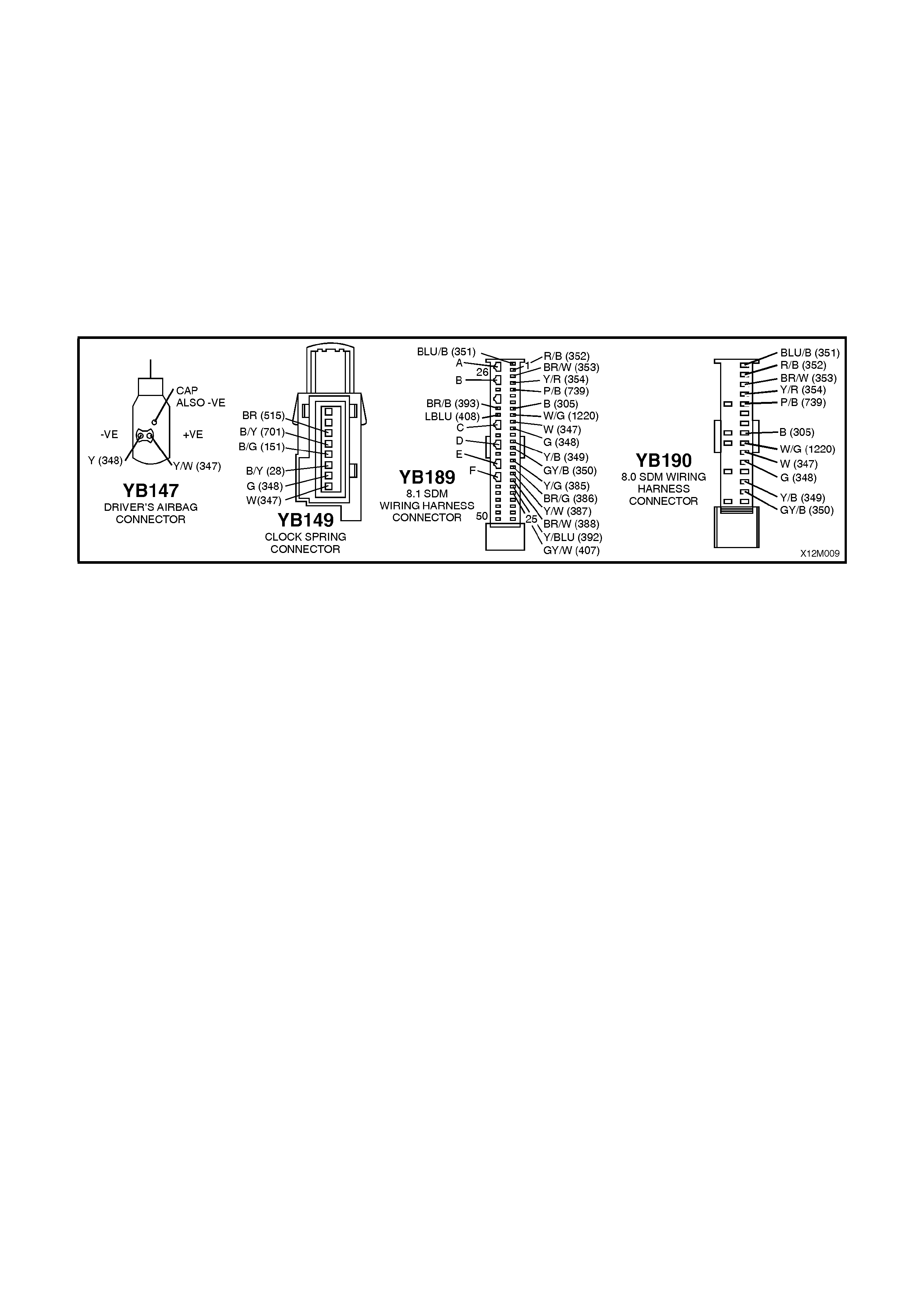
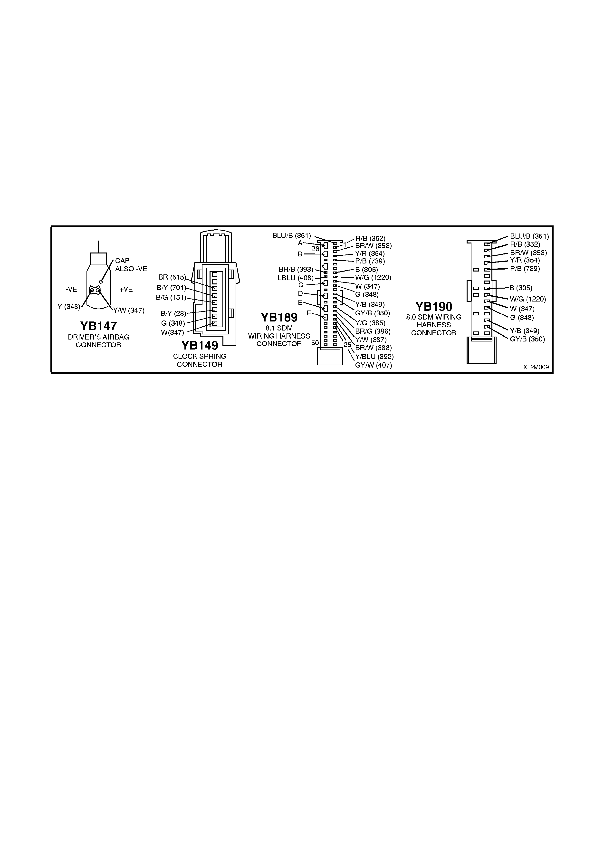
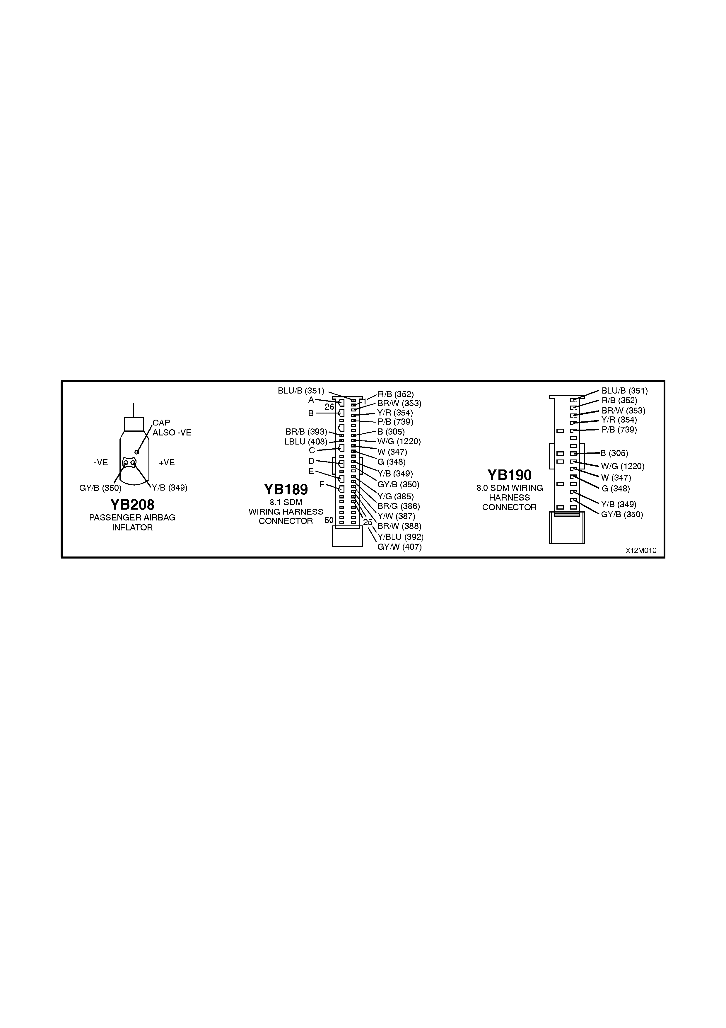
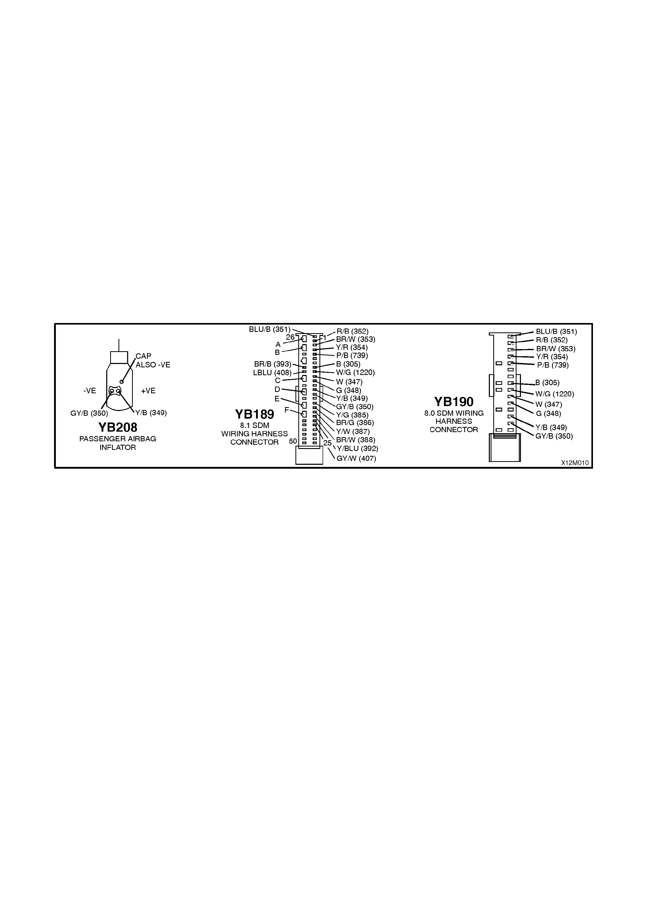
Figure 12M-3 illustrates the terminal layout of the various connectors used in the 8.0 and 8.1 systems. This
illustration should be used in conjunction with the diagnostic chart circuit diagram s when checking circuit faults if a
connector diagram is not included in the chart.
IMPORTANT: UNDER NO CIRCUMSTANCES IS 12 VOLTS TO BE APPLIED TO THE DUMMY LOAD;
SD28280B OR AU485, AS THIS WILL DAMAGE THE INTERNAL RESISTOR IN THE LOAD, RENDERING THE
DUMMY LOAD USELESS FOR ANY FURTHER DIAGNOSTIC WORK.
ENSURE THAT AT THE COMPLETION OF ANY DIAGNOSTIC PROCEDURE, ALL DIAGNOSTIC TOOLS ARE
REMOVED AND ALL SRS COMPONENTS ARE CORRECTLY RECONNECTED.
When carrying out wiring checks as dir ec ted to by the diagnostic charts, rather than probe ter minals and connectors
with incorrect sized multimeter connections, use the adaptors contained in connector test adaptor kit KM-609 and
test lead set KM-609-20. This will prevent any possibility of spreading or damaging wiring harness terminals and
later on causing a system intermittent failure.
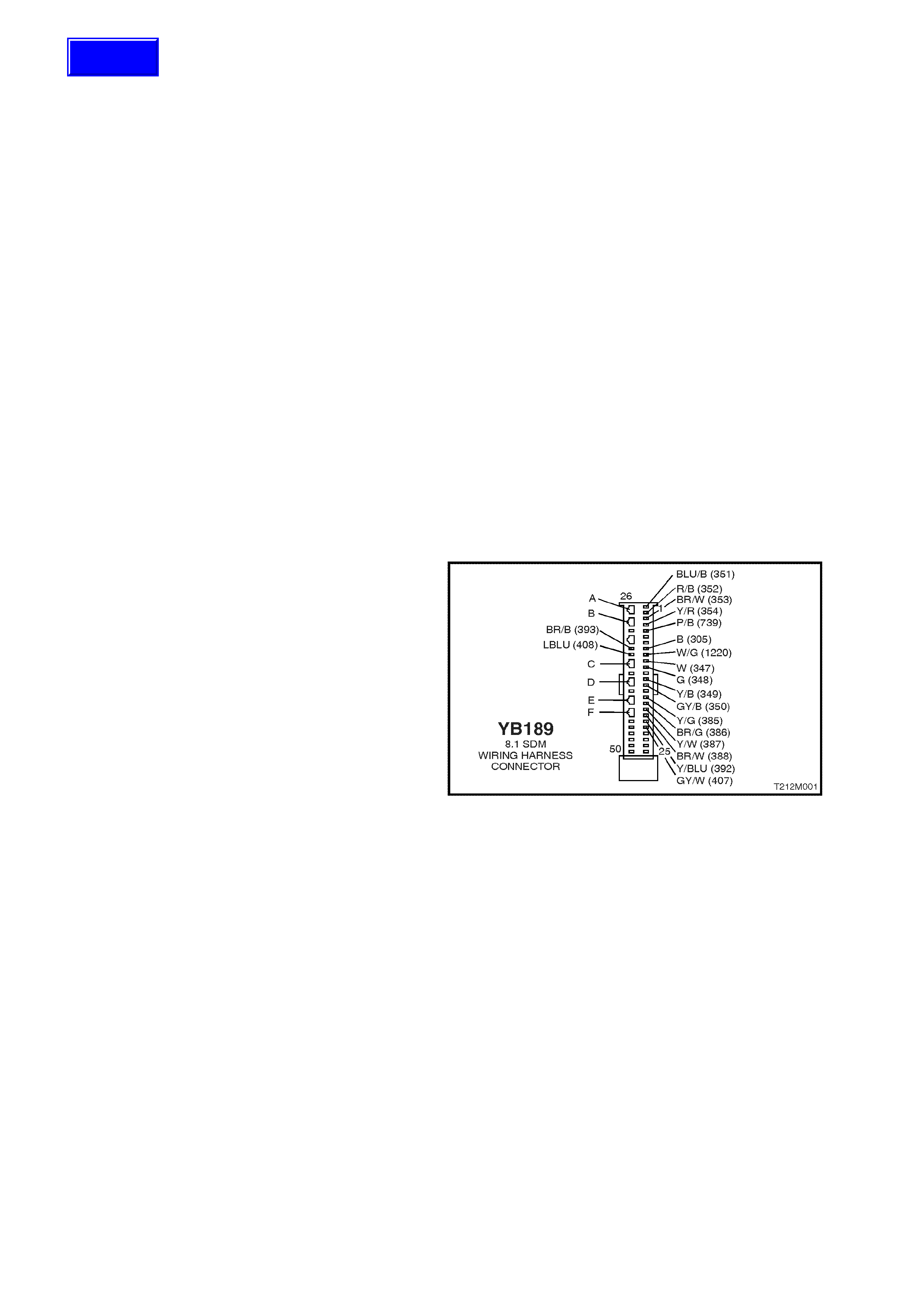
SDM connector YB189 is equipped with shorting link busbar. Whenever a diagnostic procedur e ask s a technician to
check a circuit for an open or short while SDM connector YB189 is disconnected, the technician will need to open
the shorting link busbar for that particular circuit.
To open the shorting link busbar for a particular circuit, insert a spade type terminal, approximately 3 mm in
diameter (or alternatively, use tool KM-609-9 fr om the KM- 609 kit) into the openings (nominated as A, B, C, D, E or
F in the following diagram) opposite the circuits terminal, refer Fig. 12M-1.
SHORTING LINK BUSBAR
A Terminals 1 and 2 – left hand pre-tensioner circuit
B Terminals 3 and 4 – right hand pre-tensioner circuit
C Terminals 10 and 11 – drivers air bag circuit
D Terminals 13 and 14 – passenger’s air bag circuit
E Terminals 16 and 17 left hand side air bag circuit
F Terminals 18 and 19 right hand side air bag circuit
Figure 12M-1
Techline
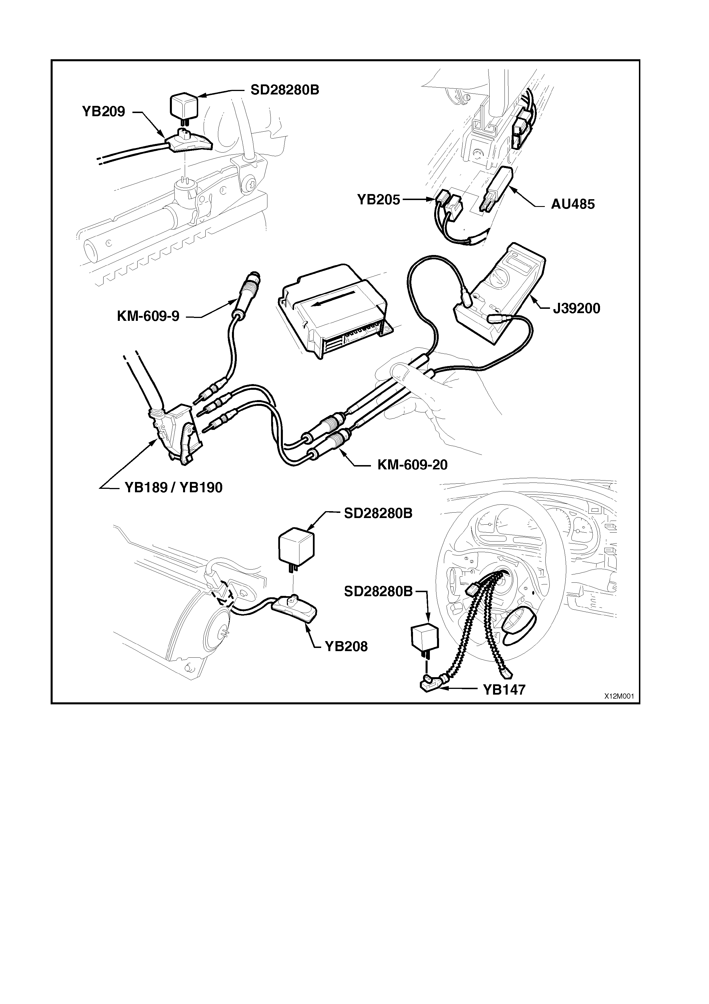
Figure 12M-2
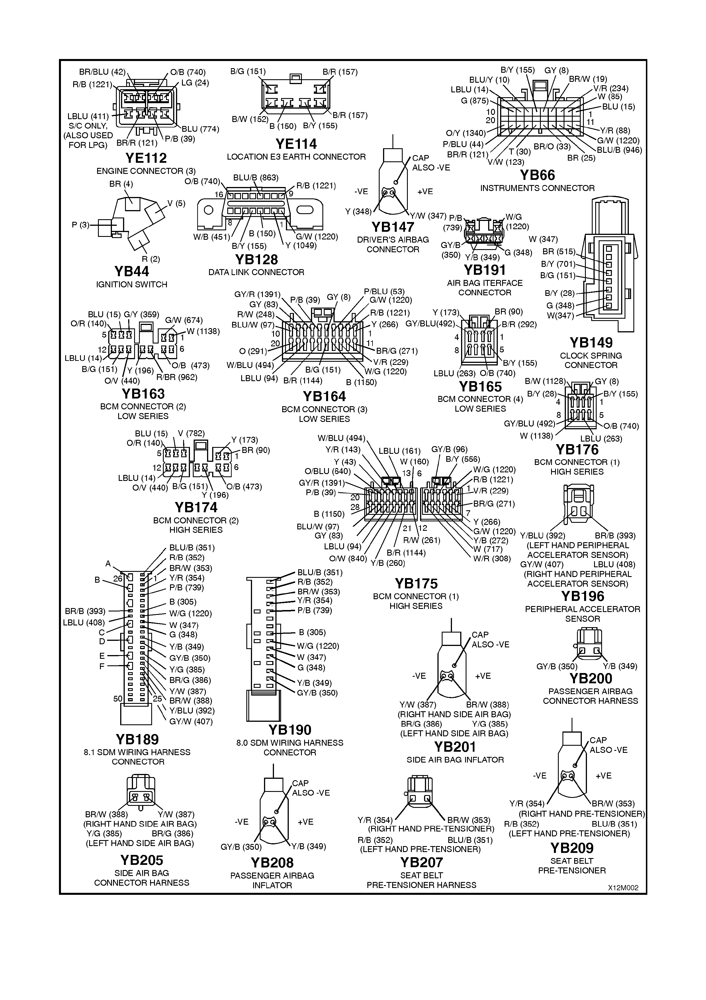
Figure 12M-3
CHART A - DIAGNOSTIC CIRCUIT CHECK
Figure 12M-4

CIRCUIT DESCRIPTION
When investigating any complaint of an SRS problem or malfunction, always begin diagnosis with the following
diagnostic circ uit check . T his c heck is a pr elim inary procedure that check s to ensure the SDM is com m unic ating on
the serial data line as well as helping to identify a problem or malfunction and directing the technician to the
appropriate diagnostic chart in this Section.
With TECH 2 connected to the DLC and the ignition switched on, TECH 2 should display serial data
communication. If TECH 2 does not display serial data, the serial data circuit maybe open or shorted.
There are several other control modules that are connected to the serial data line (PCM, BCM, ABS/ETC, ECC,
instruments and SDM). ANY one of these control modules could cause a fault on the serial data line. This fault
could result in TECH 2 not being able to display serial data.
Notes on Diagnostic Chart:
1. Refer to TECH 2 DIAGNOSTICS in Sec tion 12M SUPPLEMENTAL REST RAINT SYSTEM (Version 8.0 & 8.1)
of the VT Series I Service Information for connecting and using TECH 2.
2. Refer to Section 12P WIRING DIAGRAMS of the VT Series I Service Informationfor procedures on checking
wiring faults.
To ensure none of the other control modules on the serial data circuit are causing this voltage problem, unplug each
control module, one at a time, to isolate the short to voltage.
SDM connector YB189 is equipped with a shorting link busbar which needs to be opened before checking the
circuit. Refer to 2.5 DIAGNOSTIC CHARTS in this Section for additional information.
Test Description:
The following numbers refer to step numbers in diagnostic chart ‘A’
1-2. This test is a functional check of the SRS warning lamp during a system self check.
3. Checks to see if TECH 2 can communicate with the SDM.
4. Uses TECH 2 to check for DTCs.
5. If TECH 2 is unable to communicate with the BCM and PCM, there is a fault (short to earth) in the serial data
communication circuit (circuits 1220 or 1221).
6. Checks fuse F26 and circuit 739 for short to earth.
7. Checks for power to SDM.
8. Checks continuity of earth circuit 305.
9. Checks earth connection at SDM.
10. Checks for continuity in circuit 1220 between SDM and BCM to determine if SDM is faulty.
11. Checks if fault is with BCM or open in circuit 1220 between BCM and SDM.

CHART A - DIAGNOSTIC CIRCUIT CHECK
STEP ACTION VALUE YES NO
1. • Turn ignition on while monitoring the SRS warning
lamp in the instrument cluster.
• Does the SRS warning lamp illuminate? Go to Step 2. Go to CHART B -
‘SRS’ WARNING
LAMP
INOPERATIVE,
in this Section.
2. • After five seconds of the ignition being switched on,
does the SRS warning lamp turn off and remain off? Fault not present. Go to Step 3
3. • Connect TECH 2 to DLC (refer to NOTE 1 on this
page) and turn ignition on.
• Select Body / SRS and confirm.
• Does TECH 2 display System Identification (ie.
SDM part number)?
Go to Step 4. Go to Step 5.
4. • With TECH 2 connected, select Body / SRS /
Diagnostic Trouble Codes / Read DTC Information.
• Are there any DTCs set? Check and repair
fault causing DTC
to set, refer to
relevant diagnostic
chart in this
Section.
Go to CHART C
‘SRS’ WARNING
LAMP
ILLUMINATED
(NO DTC’S
STORED), in this
Section.
5. • With TECH 2 connected and ignition on, select
Body / DTC Check / F0: DTC Check and press the
‘Confirm’ soft key as instructed.
• Can TECH 2 communicate with the BCM and PCM
(or PIM – GEN III V8) of the vehicle (if NO DATA is
displayed next to a control module, then there is no
communication between TECH 2 and that particular
control module)?
Go to Step 6. Go to BCM
diagnostics in
Section 12J-1
LOW SERIES
BCM or 12J-2
HIGH SERIES
BCM in this
Service Manual.
6. • Check SDM fuse F26 in instrument panel
compartment.
• Is fuse OK? Go to Step 7. Check and repair
short to earth in
circuit 739,
replace fuse F26.
Recheck and
verify repair.
7. • Turn Ignition off.
• Disconnect SDM connector YB189/YB190.
• Turn the ignition on and , using SRS test lead set
KM-609-20, measure voltage between the SDM
connector YB189/YB190, terminal 5, circuit 739
(Pink/Black wire) and earth (refer to NOTE 2 & 4 on
previous page).
• Is voltage as specified?
Battery + Go to Step 8. Check and repair
open in circuit
739. Recheck
and verify repair.
8. • Turn ignition off.
• With SDM connector YB189/YB190 disconnected,
and using SRS test lead set KM-609-20, check for
continuity between SDM connector YB189/YB190,
terminal 8, circuit 305 (Black wire) and earth at
location G11 (refer to NOTE 2 & 4 on previous
page).
• Does continuity exist?
Go to Step 9. Repair open in
earth circuit 305
as necessary.
Recheck and
verify repair.
9. • Turn ignition OFF.
• Check for continuity between SDM earth (location
G11) and a known good earth (refer to NOTE 2 & 4
on previous page).
• Does continuity exist?
Go to Step 10. Repair earth as
necessary.
Recheck and
verify repair.
10. • Disconnect SDM connector YB189/YB190.
• Check for continuity in circuit 1220 (White/Green –
Green/W hite wire) between BCM and SDM by back
probing BCM connector YB164, terminal 3 (Low
Series BCM) or YB175, terminal 9 (High Series
BCM) and, using SRS test lead set KM-609-20,
probe SDM connector YB189/YB190, terminal 9
(refer to NOTE 2 & 4 on previous page).
NOTE: Use SRS test lead set KM-609-20 to probe
terminals on connector YB189/YB190.
• Does continuity exist?
Replace SDM, refer
Section 12M
SUPPLEMENTAL
RESTRAINT
SYSTEM (Version
8.0 & 8.1) of the VT
Series I Service
Information.
Recheck circuit to
verify repair.
Go to Step 11.
11. • Disconnect BCM connector YB164 (Low Series
BCM) or YB175 (High Series BCM).
• With SDM connector YB189/YB190 disconnected,
check for continuity between BCM connector
YB164, terminal 13 or YB175, terminal 3 and SDM
connector YB189/YB190, terminal 9 (refer to NOTE
2 and 4 on previous page).
NOTE: Use SRS test lead set KM-609-20 to probe
terminals on connector YB189/YB190.
• Does continuity exist?
Replace BCM, refer
to 12J-1 LOW
SERIES BCM or
12J-2 HIGH
SERIES BCM of
the VT Series II
Service
Information.
Repair open in
circuit 1220
between SDM
and BCM.
Recheck and
verify repair.
WHEN ALL DIAGNOSIS AND REPAIRS ARE COM PLETED, ENSURE ALL SRS COMPONENTS ARE
RECONNECTED, CLEAR ALL DTC’S, ENABLE THE SRS AND VERIFY CORRECT OPERATION
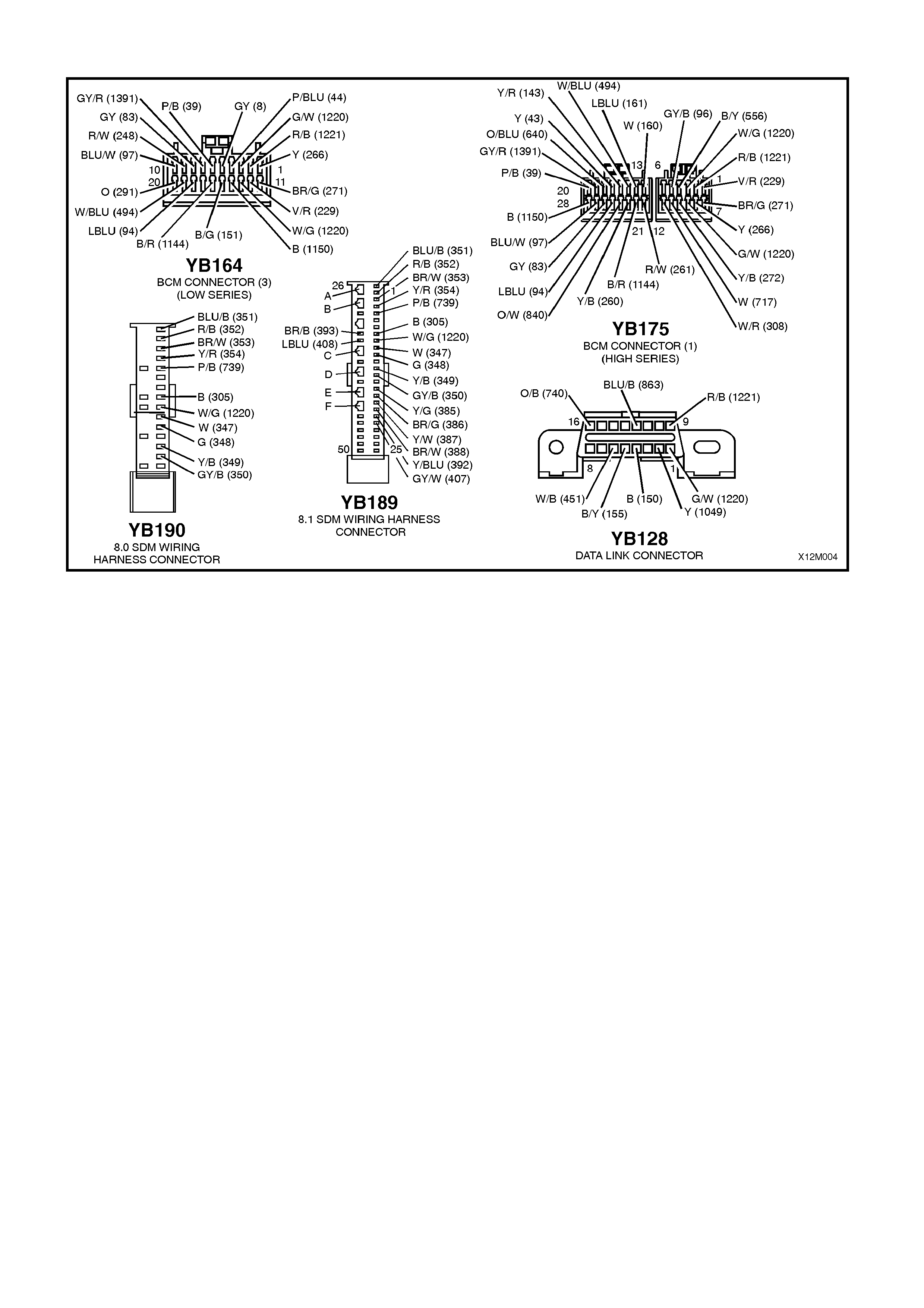
Figure 12M-5
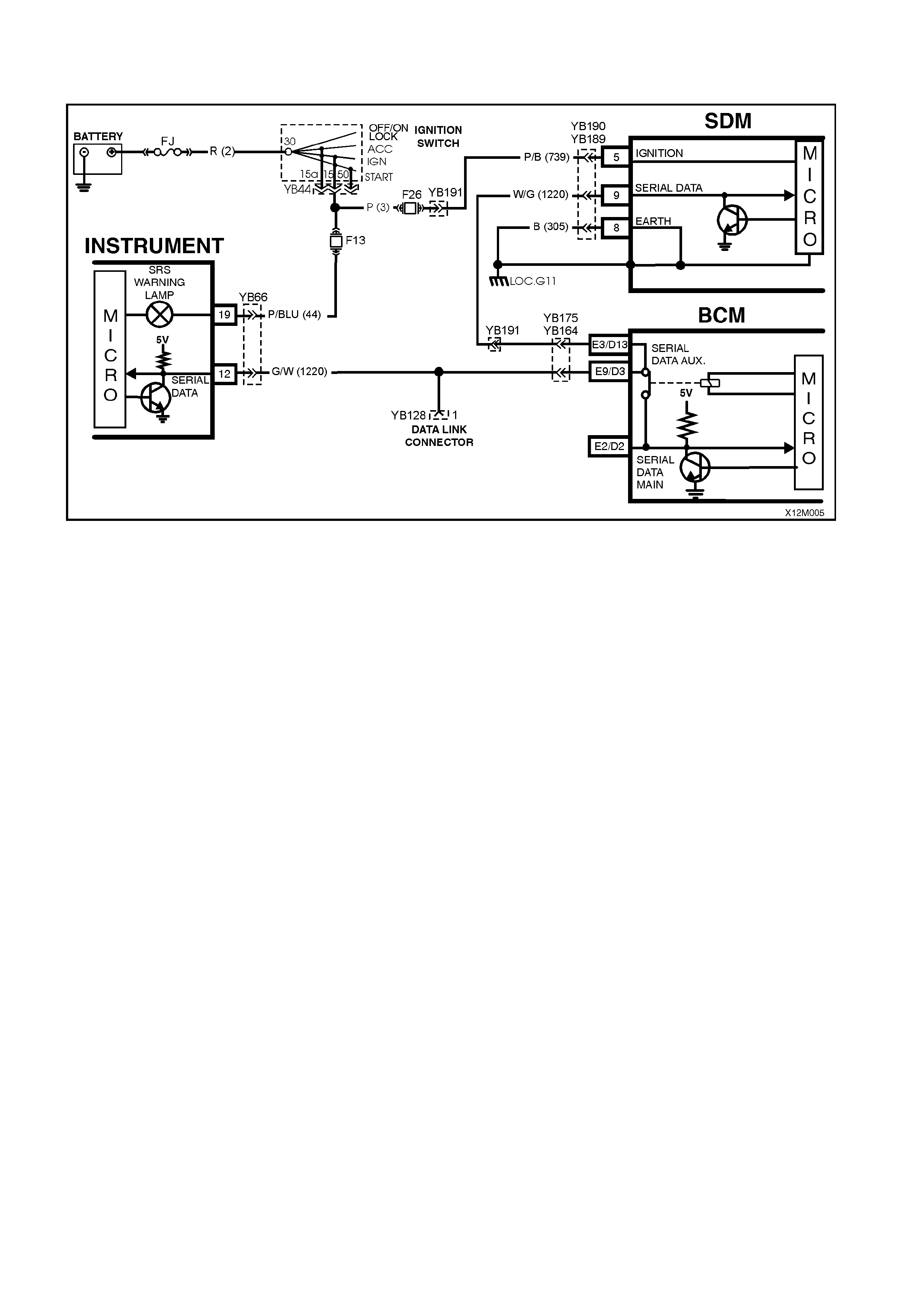
CHART B - SRS WARNING LAMP INOPERATIVE
Figure 12M-6
CIRCUIT DESCRIPTION
Battery voltage is supplied to the SRS warning lamp with the ignition switch in the IGN or START positions through
fuse F13 (located in the passenger compartment fuse panel). To illuminate the lamp, the SDM sends a serial data
message to the instrument cluster, requesting the SRS lamp to illuminate.
The SRS warning lamp will be illuminated when:
• The ignition is switched on ( system wiring and self chec k) and if no f aults are detected, the SRS warning lam p
will be turned off.
• If communication is lost between the SDM and the instrument cluster.
• If the instrument cluster has not been programmed for the vehicle configuration; 2, 3, 4 or 6 loop system
(configuration problem).
• If battery voltage is below eight volts or above 21.2 volts.
• If the SRS is deployed.
• If one or more current or history Diagnostic Trouble Codes (DTCs) are detected when the ignition is switched
on.
• During an ignition cycle, if the SDM detects a current DTC, the SRS warning lamp will be illuminated.
• If the energy reserve in the SDM is switched on (battery voltage less than 7.5 volts).
• If commanded by TECH 2.
Test Description:
The following numbers refer to step numbers in diagnostic chart ‘B’.
1. This test checks for any DTCs that may cause the SRS warning lamp to be inoperative.
2. This test determines if the SDM is faulty by using TECH 2 to drive the warning lamp on.
3. This is a simple test to determ ine if power is being supplied to the instrument cluster warning lamps (the SRS
and ABS warning lamps share a common power source).
4. This step determines if the warning lamp bulb or socket is defective.
5. This test checks for a faulty voltage supply to the warning lamp.
Notes on Diagnostic Chart:
1. Refer to TECH 2 DIAGNOSTICS in Sec tion 12M SUPPLEMENTAL REST RAINT SYSTEM (Version 8.0 & 8.1)
of the VT Series I Service Information for connecting and using TECH 2.
2. Refer to Section 12P WIRING DIAGRAM S of the VT Series I Service Information f or procedures on checking
wiring faults.
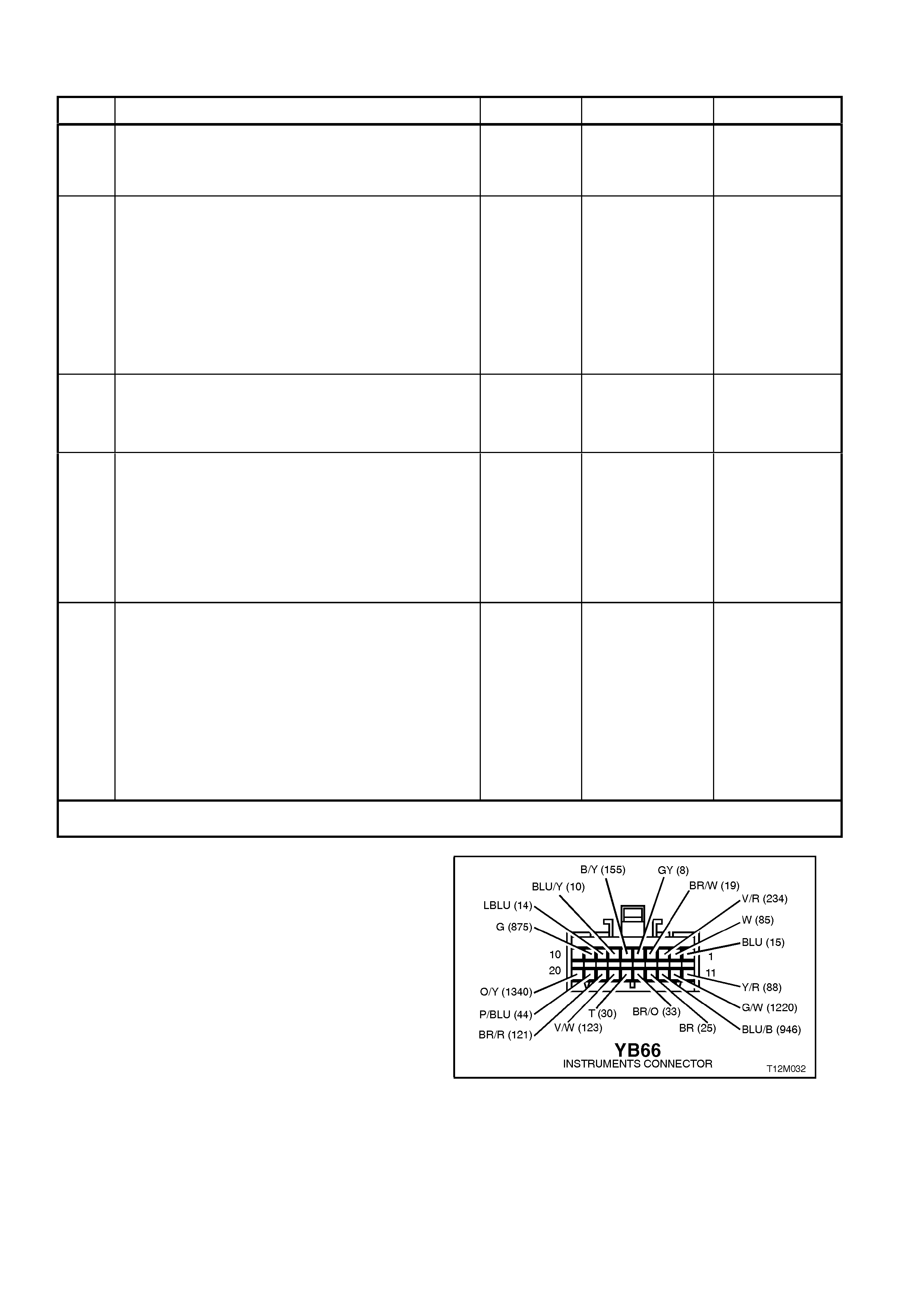
CHART B - SRS WARNING LAMP INOPERATIVE
STEP ACTION VALUE YES NO
1. • Install TECH 2 to DLC and select Body / SRS /
Diagnostic Trouble Codes / Read DTC Information
(refer to NOTE 1 on previous page).
• Are any DTCs set?
Repair conditions
which set DTCs.
Recheck and
verify repair.
Go to Step 2.
2. • With TECH 2 still connected, select Body /
Instruments / Miscellaneous Tests / Lamps and
command the SRS warning lamp on.
• Does SRS warning lamp illuminate?
Replace SDM,
refer Section 12M
SUPPLEMENTAL
RESTRAINT
SYSTEM (Version
8.0 & 8.1) of the
VT Series I
Service
Information.
Recheck circuit to
verify repair.
Go to Step 3.
3. • Disconnect TECH 2 from DLC.
• Turn ignition on whilst observing ABS warning
lamp.
• Does ABS warning lamp illuminate for
approximately five seconds then turn off?
Go to Step 4. Go to Step 5.
4. • Remove instrument cluster, refer to Section 12C
INSTRUMENTS, W IPERS/W ASHERS AND HORN
of the VT Series I Service Information.
• Remove SRS warning lamp bulb and socket from
instrument cluster and check warning lamp bulb
condition.
• Is bulb and socket OK?
Replace
instrument cluster,
refer to 12C
INSTRUMENTS,
WIPERS /
WASHERS AND
HORNS of the VT
Series I Service
Information.
Replace SRS
warning lamp
bulb and/or
socket. Recheck
and verify repair.
5. • Remove instrument cluster, refer to Section 12C
INSTRUMENTS, W IPERS/W ASHERS AND HORN
of the VT Series I Service Information.
• Switch ignition on and measure voltage between
instrument cluster connector YB66, terminal 19,
circuit 44 (Pink/Blue wire) and earth (refer to NOTE
2 on previous page).
• Is voltage as specified?
Battery + Fault not present.
Check all system
wiring harness
connectors and
terminals. Repair
as necessary and
recheck system to
verify repair.
Check fusible link
FJ and fuse F13.
Check wiring
between ignition
switch and
instrument
cluster connector
YB66. Check
ignition switch
contacts.
Recheck circuit
to verify repair.
WHEN ALL DIAGNOSIS AND REPAIRS ARE COM PLETED, ENSURE ALL SRS COMPONENTS ARE
RECONNECTED, CLEAR ALL DTC’S, ENABLE THE SRS AND VERIFY CORRECT OPERATION
Figure 12M-7
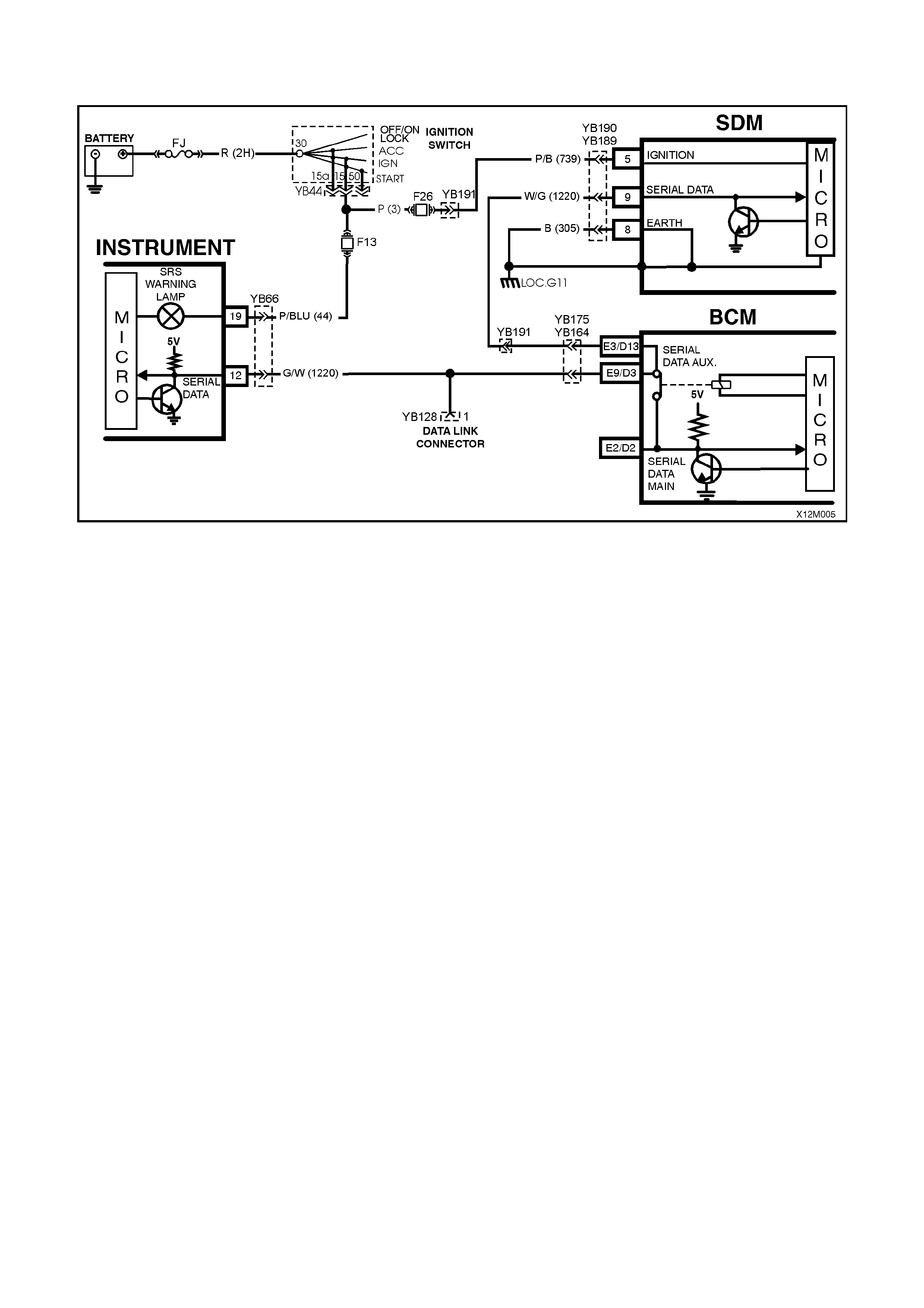
CHART C - SRS WARNING LAMP ILLUMINATED (NO DTC’S STORED)
Figure 12M-8
CIRCUIT DESCRIPTION
Battery voltage is s upplied to the SRS warning lamp with the ignition switch in the IG N or START positions through
fuse F13 (located in the passenger compartment fuse panel). To illum inate the lamp, the SDM sends a serial data
message to the instrument cluster (circuit 1220), requesting the SRS lamp to illuminate.
When the ignition is switched on, the SRS warning lamp should illuminate f or appr ox imately f ive seconds to indicate
the system start up sequence / system wiring and self check. If no system faults are detected, the SRS warning
lamp will be switched off.
If a fault is detected (either during this system check or during the ignition cycle), the SRS warning lamp will either
remain on until the fault is remedied or if a DTC is set, until it is cleared. If a fault is remedied during an ignition
cycle, unless the fault caused a DTC to set, the SRS warning lamp will turn off immediately.
The SRS SDM will send a serial data message to the instrument cluster requesting the lamp to be illuminated if it
detects any of the following: If battery voltage is below eight volts or above 21.2 volts. If the energy reserve in the
SDM is switched on (batter y voltage less than 7.5 volts). If the SRS is deployed. If the SDM does not receive a poll
from the BCM. If one or more current or history DTCs are detected when the ignition is switched ON. During an
ignition cycle, if the SDM detects a current DTC, the SRS warning lamp will be illuminated.
The SRS warning lamp will also be illuminated if com munication is lost (no serial data) between the SDM and the
instrument cluster.

Notes On Diagnostic Chart:
1. Refer to TECH 2 DIAGNOSTICS in Section 12M SUPPLEMENTAL RESTRAINT SYSTEM (Version 8.0 & 8.1)
of the VT Series I Service Information for connecting and using TECH 2.
2. Refer to Section 12P WIRING DIAGRAMS of the VT Series I Service Information for procedures on checking
wiring faults.
3. Refer to Section 6D1-1 CHARGING SYSTEM - V6 ENGINE of the VT Series I Service Information or
Section 6D3-1 CHARGING SYSTEM – GEN III V8 ENGINE of the VT Series II Service Information for
generator testing details.
4. SDM connector YB189 is equipped with a shorting link busbar which needs to be opened before checking the
circuit, re fer to 2.5 DIAGNOSTIC CHA RTS in this Section for additional information.
5. Fault Interm ittent; c onnect T ECH 2 to DLC, select F 3 Body / SRS / DATA DISPLAY and monitor the following to
see if TECH 2 display changes state while wiggling circuit wires and/or road testing vehicle:
BATTERY VOLTAGE (AFTER 3 SEC)
MODULE DEPLOYED
ENERGY RESERVE
CONFIGURATION FROM INSTRUMENTS
BCM POLL
Repair fault as necessary, recheck circuit to verify repair.
Test Description:
The following numbers refer to step numbers in diagnostic chart ‘C’
1. Ensures the Diagnostic Circuit Check was perform ed which determines if there is a serial data com munication
fault and checks if any DTCs are set.
2. Checks if fault is current or intermittent.
3. Using TECH 2, this step checks the voltage supply to the SDM. If battery voltage to the SDM falls below
eight volts or above 21.2 volts for more than three seconds, the SRS warning lamp is switched on.
4. Checks generator output.
5. Determines if the ignition input voltage at the SDM is approximately the same as what the generator output
voltage was during Step 5.
6. Checks continuity of earth circuit 305.
7. Checks earth connection at SDM, location G11.
8. Using TECH 2, this step checks if the energy reserve has been switched on. If the voltage supply to the SDM
falls below 7.5 volts, the energy reserve in the SDM is switched on.
9. Using TECH 2, this step checks if the SDM has deployed the SRS.
10. If TECH 2 is unable to drive the SRS warning lamp on and off, it indicates fault is within the instrument cluster.

CHART C - SRS WARNING LAMP ILLUMINATED (NO DTC’S SET)
STEP ACTION VALUE YES NO
1. • Was the Diagnostic Circuit Check preformed?
Go to Step 2. Go to CHART A -
DIAGNOSTIC
CIRCUIT CHECK in
this Section.
2. • Turn ignition on.
• Does SRS warning lamp remain illuminated after
five seconds? Go to Step 3. Fault intermittent,
refer to NOTE 5 on
previous page.
3. • Install TECH 2 to DLC and select Body / SRS / Data
Display and scroll to BATTERY VOLTAGE (AFTER
3 SEC)(refer to NOTE 1).
• Does TECH 2 display battery voltage (after three
sec) is OKAY?
Go to Step 8. Go to Step 4.
4. • Carry out checks of generator output (refer to NOTE
3 on previous page).
• Is generator output OK?
Go to Step 5. Repair generator as
necessary.
Recheck and verify
repair.
5. • Disconnect SDM connector YB189/YB190.
• Start engine, turn headlamps on and raise engine
idle speed to approximately 2500 RPM.
• Using Tool KM-609-20, check voltage between SDM
wiring harness connector YB189/YB190, terminal 5,
circuit 739 and a known good earth (refer to NOTE 2
& 4 on previous page).
• Is the voltage measured approximately the same as
measured during Step 4 (generator output tests)?
Go to Step 6. Check and repair
circuit 739 as
necessary.
Recheck and verify
repair.
6. • Turn ignition off.
• With SDM connector YB189/YB190 disconnected,
and using SRS test lead set KM-609-20, check for
continuity between SDM connector YB189/YB190,
terminal 8, circuit 305 (Black wire) and earth at
location G11 (refer to NOTE 2 & 4 on previous
page).
• Does continuity exist?
Go to Step 7. Repair open in
earth circuit 305 as
necessary.
Recheck and verify
repair.
7. • Check for continuity between SDM earth location
G11 and a known good earth (refer to NOTE 2 & 4
on previous page).
• Does continuity exist?
Replace SDM,
refer Section 12M
SUPPLEMENTAL
RESTRAINT
SYSTEM (Version
8.0 & 8.1) of the VT
Series I Service
Information.
Recheck circuit to
verify repair.
Repair earth as
necessary.
Recheck and verify
repair.
8. • With TECH 2 connected, and Body / SRS / Data
Display selected, scroll to ENERGY RESERVE.
• Does TECH 2 display energy reserve off?
Go to Step 9. Go to Step 4.
9. • With TECH 2 connected, and Body / SRS / Data
Display selected, scroll to MODULE HAS
DEPLOYED.
• Does TECH 2 display MODULE HAS DEPLOYED
YES?
Replace SDM,
refer Section 12M
SUPPLEMENTAL
RESTRAINT
SYSTEM (Version
8.0 & 8.1) of the VT
Series I Service
Information.
Recheck circuit to
verify repair.
Go to Step 10.
10. • Wi th TECH 2 connected, select Body / Instruments /
Miscellaneous Tests / Lamps / SRS Lamp.
• Using the soft keys on TECH 2, drive the SRS
warning lamp on and off.
• Is TECH 2 able to drive the SRS warning lamp on
and off?
Replace SDM, refer
Section 12M
SUPPLEMENTAL
RESTRAINT
SYSTEM (Version
8.0 & 8.1) of the VT
Series I Service
Information.
Recheck circuit to
verify repair.
Replace instrument
cluster assembly,
refer Section 12C
INSTRUMENTS,
WIPERS /
WASHERS &
HORN of the VT
Series I Service
Information.
WHEN ALL DIAGNOSIS AND REPAIRS ARE COM PLETED, ENSURE ALL SRS COMPONENTS ARE
RECONNECTED, CLEAR ALL DTC’S, ENABLE THE SRS AND VERIFY CORRECT OPERATION
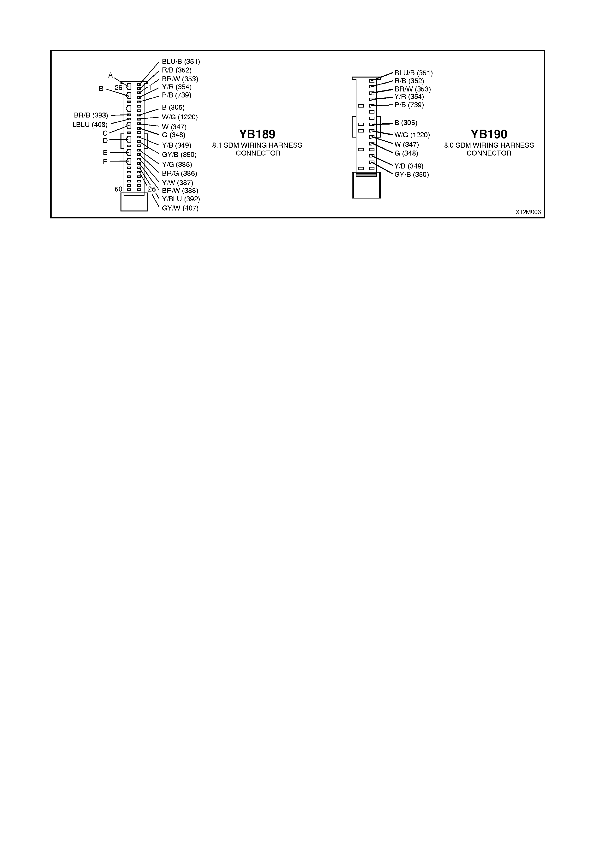
Figure 12M-9

DTC 17 - DRIVER AIR BAG CIRCUIT SHORT TO BATTERY
Figure 12M-10
CIRCUIT DESCRIPTION
At ignition on, and on a constant monitoring cycle of every 500 milliseconds during the ignition cycle, the SDM
perfor ms a s ystem s elf c hec k. If the SDM detec ts a r esis tanc e to battery supply is less than f ive kohm s in either the
positive and/or negative circuit for more than 3 - 5 seconds, a current DTC 17 will set (refer to
SRS SELF DIAGNOSTICS in Sect ion 12M SUPPLEMENTAL RESTRAINT SYST EM (Version 8.0 & 8.1) of the VT
Series I Service Information for more details).
DTC 17 will set if circuits 347 (driver’s air bag positive side) and/or 348 (driver’s air bag negative side) are shorted to
battery +.
When DTC 17 sets, the SDM illuminates the SRS warning lamp and sets a current DTC 17. Should the fault
conditions detected by the SDM clear during the same ignition cycle, the current code will clear and become a
history DTC 17. The SRS warning lamp will remain on for the remainder of the ignition cy cle.
If a DTC 17 is set, the SRS warning lamp is illuminated on each ignition cycle, even if the DTC is set as a history
DTC, until the f ault conditions for s etting DTC 17 are rectif ied and the DTC (curr ent or history) can then be cleared
from the SDM via TECH 2.
If DTC 17 is set, the SRS, including the driver’s air bag, will still be operational.
Test Description
The following numbers refer to step numbers in the following diagnostic chart.
1. Uses TECH 2 to check if DTC 17 is current or history.
2. Checks for intermittent fault by monitoring TECH 2 screen display. If screen display changes during a ‘wiggle’
test, a fault with the wiring is at that location.
3. Checks circuits 347 and 348 for a short to battery +.
Notes on Diagnostic Chart
1. For all wiring harness checking procedures, refer to Section 12P WIRING DIAGRAMS of the VT Series I
Service Information.
2. Refer to 2.8 SRS WIRING REPAIR in Section 12M SUPPLEMENTAL RESTRAINT SYSTEM (Version 6.2), of
the VT Series I Service Information before conducting any SRS wiring harness repairs.
3. Resistance cannot be m easured between the two term inals in connector YB147 as the in-built capacitor block s
measurement. Therefore, a ‘service hole’ is incorporated into the connector for fault tracing. Refer to
1.1 SYSTEM COMPONENTS, WIRING HARNESS in Section 12M SUPPLEMENTAL RESTRAINT SYSTEM
(Version 6.2) of the VT Series I Service Information for more details on this type of connector.
4. Wiring should be checked at the point where TECH 2 screen display changed status. If necessary, split open
harness.
5. If the fault can not be identified, the harness should be replaced.
6. SDM connector YB189 is equipped with a shorting link busbar which needs to be opened before checking the
circuit, re fer to 2.5 DIAGNOSTIC CHA RTS in this Section for additional information.
7. Refer to TECH 2 DIAGNOSTICS in Sec tion 12M SUPPLEMENTAL REST RAINT SYSTEM (Version 8.0 & 8.1)
of the VT Series I Service Information for connecting and using TECH 2.
DTC 17 - DRIVER AIR BAG CIRCUIT SHORT TO BATTERY
STEP ACTION VALUE YES NO
1. • Connect TECH 2 to DLC.
• Select Body / SRS / Diagnostic Trouble Codes /
Read DTC Information (refer to NOTE 7 on
previous page).
• Is DTC 17 current ?
Go to Step 3. Go to Step 2.
2. • Remove steering column upper and lower cover.
• With TECH 2 still connected, select Diagnostic
Trouble Codes / Clear DTC Information and clear
all (if any) DTCs.
• Select Diagnostic Trouble Codes / Read DTC
Information, 'wiggle' SRS wiring harness at all
locations between the SDM and the clock spring
coil and monitor TECH 2 screen display.
• Does TECH 2 screen display change status from
No Diagnostic Trouble Codes?
Make repairs as
necessary (refer
NOTE 2 & 4 on
previous page).
Clear DTC and
recheck system to
verify repair.
Fault not present.
Check all system
wiring harness
connectors and
terminals, refer to
NOTE 5 on
previous page.
Clear DTC and
recheck system.
3. • Dis able the SRS, refer to 2.2 SYSTEM DISABLING
AND ENABLING PROCEDURE in Section 12M
SUPPLEMENTAL RESTRAINT SYSTEM of the VT
Series I Service Information.
• Remove horn bar and driver's air bag inflator
module, refer to 2.3 HORN BAR AND AIR BAG
MODULE ASSEMBLY in Section 12M
SUPPLEMENTAL RESTRAINT SYSTEM, of the VT
Series I Service Information.
• Disconnect SDM wiring harness connector
YB189/YB190 from the SDM.
• Reconnect battery.
• Using Tool KM-609-20, check wiring between SDM
wiring harness connector YB189/YB190, terminals
10 and 11 and driver's air bag connector YB147,
circuits 347 (White wire) and 348 (Green wire) for
short to battery + (refer to NOTES 1, 3 and 6 on the
previous page).
• Is all OK?
Replace SDM,
refer Section 12M
SUPPLEMENTAL
RESTRAINT
SYSTEM (Version
8.0 & 8.1) of the
VT Series I
Service
Information.
Recheck circuit to
verify repair.
Make repairs as
necessary (refer
to NOTE 2 on
previous page).
Clear DTC and
recheck system
to verify repair.
WHEN ALL DIAGNOSIS AND REPAIRS ARE COM PLETED, ENSURE ALL SRS COMPONENTS ARE
RECONNECTED, CLEAR ALL DTC’S, ENABLE THE SRS AND VERIFY CORRECT OPERATION
Figure 12M-11

DTC 18 - DRIVER AIR BAG CIRCUIT SHORT TO EARTH
Figure 12M-12
CIRCUIT DESCRIPTION
At ignition on, and on a constant monitoring cycle of every 500 milliseconds during the ignition cycle, the SDM
performs a system self check. If the SDM detects a resistance to earth of less than three kohms in either the
positive or negative inflator circuit for more than 3 - 5 seconds, a current DTC 18 will set (refer to
SRS SELF DIAGNOSTICS in Section 12M SUPPLEMENT AL RESTRAINT SYST EM (Version 8.0 & 8.1) of the VT
Series I Service Information for more details).
DTC 18 will set if circuits 347 (driver’s air bag positive side) and/or 348 (driver’s air bag negative side) are shorted to
earth.
When DTC 18 sets, the SDM illuminates the SRS warning lamp and sets a ‘current’ DTC 18. Should the fault
conditions detected by the SDM clear during the same ignition cycle, the current code will clear and become a
history DTC 18. The SRS warning lamp will remain on for the remainder of the ignition cy cle.
If a DTC 18 is set, the SRS warning lamp is illuminated on each ignition cycle, even if the DTC is set as a history
DTC, until the f ault conditions for s etting DTC 18 are rectif ied and the DTC (curr ent or history) can then be cleared
from the SDM via TECH 2.
If DTC 18 is set, the SRS, including the driver’s air bag, will still be operational.
Test Description
The following numbers refer to Step numbers in the following diagnostic chart.
1. Uses TECH 2 to check if DTC 18 is current or history.
2. TECH 2 in this mode should display approximately 2.0 - 6.4 ohms if the driver's air bag loop circuit is OK.
3. If screen display changes during a wiring 'wiggle' test, a fault with the wiring is at that location.
4. Tool SD28280B is a dum m y load taking the place of the horn bar and driver's air bag inflator m odule. If T ECH 2
displays the cor rect resis tance of the dum m y load, the system f ault is in the horn bar and driver's air bag inflator
module assembly.
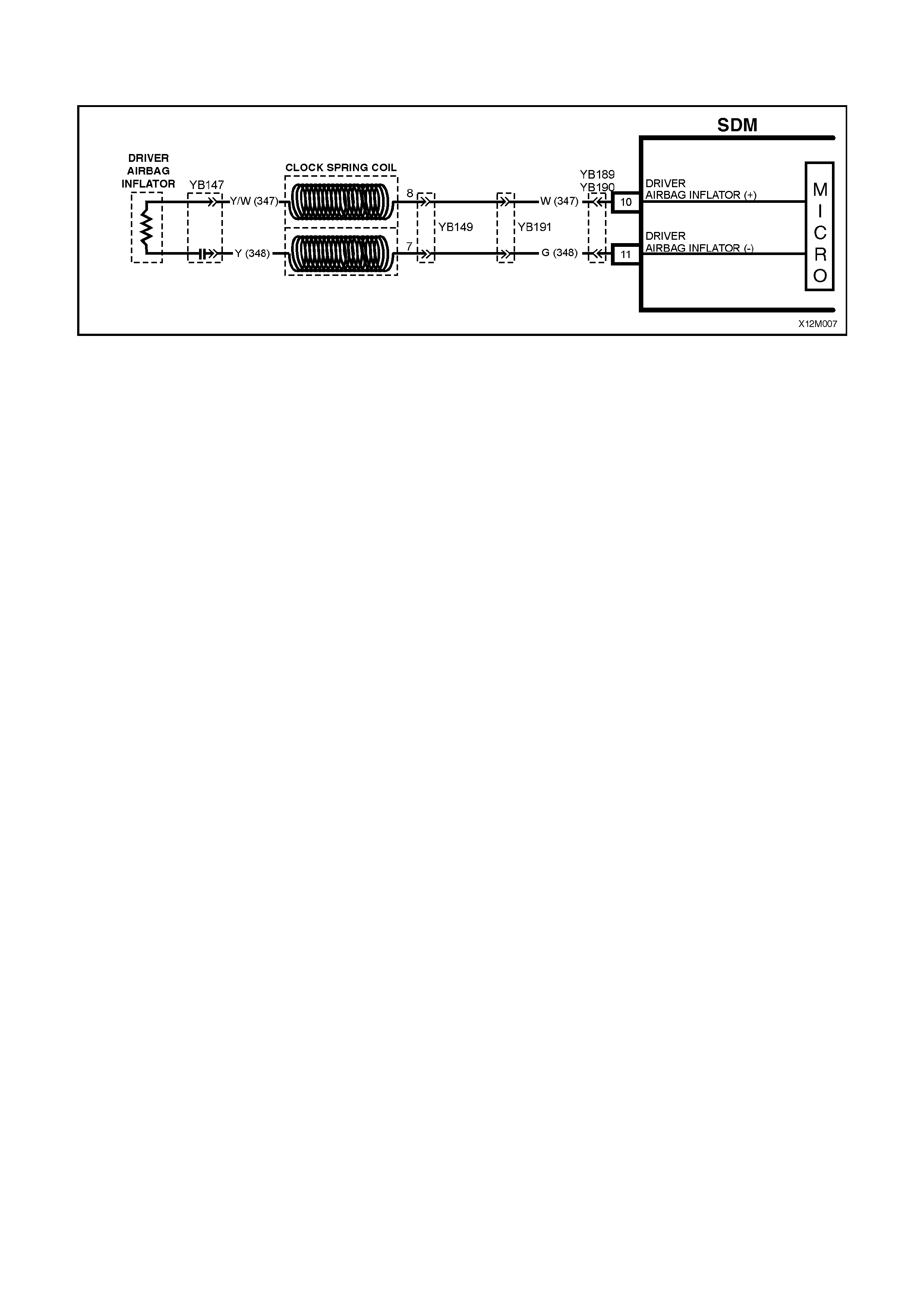
5. T his test check s the wiring between the SDM wiring harnes s connector YB189 (8.1 SDM) or YB190 (8.0 SDM) ,
terminal 10 and the horn bar and driver's air bag inflator module connector YB147 for faults.
6. T his test check s the wiring between the SDM wiring harnes s connector YB189 (8.1 SDM) or YB190 (8.0 SDM) ,
terminal 11 and the horn bar and driver's air bag inflator module connector YB147 for faults.

Notes on Diagnostic Chart
1. For all wiring harness checking procedures, refer to Section 12P WIRING DIAGRAMS of the VT Series I
Service Information.
2. Refer to 2.8 SRS W IRING REPAIR in Sect ion 12M SUPPLEMENTAL REST RAINT SYSTEM of the VT Ser ies I
Service Information before conducting any SRS wiring harness repairs.
3. Resistance cannot be measured between the two terminals in connector YB147 as the in-built capacitor blocks
measurement. Therefore, a ‘service hole’ is incorporated into the connector for fault tracing. Refer to
1.1 SYSTEM COMPONENTS, WIRING HARNESS in Section 12M SUPPLEMENTAL RESTRAINT SYSTEM
(Version 8.0 & 8.1) of the VT Series I Service Information for more details on this type of connector.
4. Wiring should be checked at point where TECH 2 screen display changed. If necessary, split open wiring
harness.
5. If the fault cannot be identified, the wiring harness should be replaced.
6. SDM connector YB189 is equipped with a shorting link busbar which needs to be opened before checking the
circuit, re fer to 2.5 DIAGNOSTIC CHA RTS in this Section for additional information.
7. Refer to TECH 2 DIAGNOSTICS in Section 12M SUPPLEMENTAL RESTRAINT SYSTEM (Version 8.0 & 8.1)
of the VT Series I Service Information for connecting and using TECH 2.
8. To enable or disable the SRS system, refer to 2.2 SYSTEM DISABLING AND ENABLING PROCEDURE in
Section 12M SUPPLEMENTAL RESTRAINT SYSTEM (Version 8.0 & 8.1) of the VT Series I Service
Information.
DTC 18 - DRIVER AIR BAG CIRCUIT SHORT TO EARTH
STEP ACTION VALUE YES NO
1. • Connect TECH 2 to DLC and select Body / SRS /
Diagnostic Trouble Codes / Read DTC Information
(refer to NOTE 7 on previous page).
• Does TECH 2 display DTC 18 as a Current DTC?
Go to Step 2. Go to Step 3.
2. • With TECH 2 still connected, select Body / SRS /
Data Display and scroll to DRIVER AIR BAG LOOP
RESISTANCE.
• Is value displayed on TECH 2 as specified?
Approx.
2.0 - 6.4
Ohms
Go to Step 3. Go to Step 4.
3. • Remove steering column upper and lower cover.
• With TECH 2 still connected, select Diagnostic
Trouble Codes / Clear DTC Information and clear all
(if any) DTCs.
• Select Diagnostic Trouble Codes / Read DTC
Information, 'wiggle' SRS wiring harness at all
locations between the SDM and the clock spring coil
and monitor TECH 2 screen display.
• Does TECH 2 screen display change status from
No Diagnostic Trouble Codes?
Make repairs as
necessary (refer
to NOTES 2 & 4
on previous
page).
Clear DTC and
recheck system to
verify repair.
Fault not
present. Check
all system wiring
harness
connectors, and
terminals, refer
to NOTE 5 on
previous page.
Clear DTC and
recheck system.
4. • Disable the SRS (refer NOTE 8 on previous page).
• Remove horn bar and driver's air bag inflator
module, refer to 2.3 HORN BAR AND AIR BAG
MODULE ASSEMBLY in Section 12M
SUPPLEMENT RESTRAINT SYSTEM, of the VT
Series I Service Information.
• Connect Tool No. SD28280B to SRS wiring harness
connector YB147.
• Enable the SRS (refer NOTE 8 on previous page).
• With TECH 2 still connected, select Body / SRS /
Data Display and scroll to DRIVER AIR BAG LOOP
RESISTANCE.
• Is value displayed on TECH 2 as specified?
Approx.
3.0 Ohms Replace horn bar
and driver air bag
inflator module
assembly, refer to
2.3 HORN BAR
AND AIR BAG
MODULE
ASSEMBLY in
Section 12M, Vol.
7 of the VT Series
Service Manual.
Clear DTC and
recheck system to
verify repair.
Go to Step 5.
5. • Disable the SRS (refer NOTE 8 on previous page).
• Disconnect SDM wiring harness connector
YB189/YB190 from the SDM.
• Remove Tool SD28280B from YB147.
• Using Tool KM-609-20, check wiring between SDM
wiring harness connector YB189/YB190, terminals
10 and driver's air bag inflator module connector
YB147, circuit 347 for short to earth (refer to NOTE
1 & 6 on previous page).
• Is all OK?
Go to Step 6. Make repairs as
necessary (refer
to NOTE 2 on
previous page).
Clear DTC and
recheck system
to verify repair.
6. • With system disabled, SDM wiring harness
connector YB189/YB190 disconnected and using
Tool KM-609-20, check wiring between SDM wiring
harness connector YB189/YB190, terminal 11 and
driver's air bag inflator module connector YB147,
circuit 348 for a short to earth (refer to NOTES 1, 3
and 6 on previous page).
• Is all OK?
Replace SDM,
refer Section 12M
SUPPLEMENTAL
RESTRAINT
SYSTEM (Version
8.0 & 8.1) of the
VT Series I
Service
Information.
Recheck circuit to
verify repair.
Make repairs as
necessary (refer
to NOTE 2 on
previous page).
Clear DTC and
recheck system
to verify repair.
WHEN ALL DIAGNOSIS AND REPAIRS ARE COM PLETED, ENSURE ALL SRS COMPONENTS ARE
RECONNECTED, CLEAR ALL DTC’S, ENABLE THE SRS AND VERIFY CORRECT OPERATION
Figure 12M-13

DTC 19 - DRIVER AIR BAG CIRCUIT CAPACITANCE TOO HIGH
Figure 12M-14
CIRCUIT DESCRIPTION
At ignition on, and on a constant monitoring cycle of every 500 milliseconds during the ignition cycle, the SDM
performs a system self check.
If the SDM detects the capacitanc e in the driver’s air bag circ uit is too high (gr eater than 550 nF) f or longer than 3 -
5 seconds, a current DTC 19 will set (refer to SRS SELF DIAGNOSTICS in Section 12M SUPPLEMENTAL
RESTRAINT SYSTEM (Version 8.0 & 8.1) of the VT Series I Service Information for more details).
DTC 19 will set if the in-built capacitor in the SRS wiring harness connector YB147 is faulty.
When DTC 19 sets, the SDM illuminates the SRS warning lamp and sets a current DTC 19. Should the fault
conditions detected by the SDM clear during the same ignition cycle, the current code will clear and become a
history DTC 19. The SRS warning lamp will remain on for the remainder of the ignition cy cle.
If a DTC 19 is set, the SRS warning lamp is illuminated on each ignition cycle, even if the DTC is set as a history
DTC, until the f ault conditions for s etting DTC 19 are rectif ied and the DTC (curr ent or history) can then be cleared
from the SDM via TECH 2.
ACTION REQUIRED
If DTC 19 is set, the driver’s air bag may not operate and therefore, the clock spring coil assembly must be replaced
(connector YB147 with the in-built capacitor is part of the clockspring coil assembly). Refer to
2.6 CLOCK SPRING COIL in Section 12M SUPPLEMENTAL RESTRAINT SYSTEM (Version 6.2), of the VT Series
I Service Information for the correct procedure on replacing the clock spring coil assembly .
After the clock spring coil ass embly has been replaced, ensure all SRS c omponents are r econnected, clear DTCs ,
enable the SRS and verify the correct operation of the system (i.e. warning lamp not illuminated after five seconds
of ignition being switched ON).
DTC 20 - DRIVER AIR BAG CIRCUIT CAPACITANCE TOO LOW
Figure 12M-15
CIRCUIT DESCRIPTION
At ignition on, and on a constant monitoring cycle of every 500 milliseconds during the ignition cycle, the SDM
performs a system self check.
If the SDM detects the capacitance in the driver’s air bag circuit is too low (less than 390 nF) for longer than 3 - 5
seconds, a current DTC 20 will set (refer to SRS SELF DIAGNOSTICS in Section 12M SUPPLEMENTAL
RESTRAINT SYSTEM (Version 8.0 & 8.1) of the VT Series I Service Information for more details).
DTC 20 will set if the in-built capacitor in the SRS wiring harness connector YB147 is faulty.
When DTC 20 sets, the SDM illuminates the SRS warning lamp and sets a current DTC 20. Should the fault
conditions detected by the SDM clear during the same ignition cycle, the current code will clear and become a
history DTC 20. The SRS warning lamp will remain on for the remainder of the ignition cy cle.
If a DTC 20 is set, the SRS warning lamp is illuminated on each ignition cycle, even if the DTC is set as a history
DTC, until the f ault conditions for s etting DTC 20 are rectif ied and the DTC (curr ent or history) can then be cleared
from the SDM via TECH 2.
ACTION REQUIRED
If DTC 20 is set, the driver’s air bag may not operate and therefore, the clock spring coil assembly must be replaced
(connector YB147 with the in-built capacitor is part of the clockspring coil assembly). Refer to
2.6 CLOCK SPRING COIL in Section 12M SUPPLEMENTAL RESTRAINT SYSTEM (Version 6.2), of the VT Series
I Service Information for the correct procedure on replacing the clock spring coil assembly .
After the clock spring coil assembly has been replaced, ensure that all SRS components are reconnected, clear
DTCs, enable the SRS and verify the correct operation of the system (i.e. warning lamp not illuminated after five
seconds of ignition being switched ON).

DTC 21 - DRIVER AIR BAG CIRCUIT RESISTANCE TOO HIGH
Figure 12M-16
CIRCUIT DESCRIPTION
At ignition on, and on a constant monitoring cycle of every 500 milliseconds during the ignition cycle, the SDM
performs a system self check.
If the SDM detects a resistance in the driver’s air bag circuit that is too high (greater than 10 ohms) for longer than 3
- 5 seconds, a current DTC 21 will set (refer to SRS SELF DIAGNOSTICS in Section 12M SUPPLEMENTAL
RESTRAINT SYSTEM (Version 8.0 & 8.1) of the VT Series I Service Information for more details).
DTC 21 will set if circuits 347 or 348, (including the horn bar and air bag assembly and the clock spring coil) are
open circuited.
When DTC 21 sets, the SDM illuminates the SRS warning lamp and sets a current DTC 21. Should the fault
conditions detected by the SDM clear during the same ignition cycle, the current code will clear and become a
history DTC 21. The SRS warning lamp will remain on for the remainder of the ignition cy cle.
If a DTC 21 is set, the SRS warning lamp is illuminated on each ignition cycle, even if the DTC is set as a history
DTC, until the f ault conditions for s etting DTC 21 are rectif ied and the DTC (curr ent or history) can then be cleared
from the SDM via TECH 2.
If DTC 21 is set, dependent on where the fault is, the driver’s air bag may not operate.
Notes on Diagnostic Chart
1. For all wiring harness checking procedures, refer to Section 12P WIRING DIAGRAMS of the VT Series I
Service Information.
2. Refer to 2.8 SRS WIRING REPAIR in Section 12M SUPPLEMENTAL RESTRAINT SYSTEM (Version 6.2) of
the VT Series I Service Information before conducting any SRS wiring harness repairs.
3. SDM connector YB189 is equipped with a shorting link busbar which needs to be opened before checking the
circuit, re fer to 2.5 DIAGNOSTIC CHA RTS in this Section for additional information.
4. Refer to TECH 2 DIAGNOSTICS in Section 12M SUPPLEMENTAL RESTRAINT SYSTEM (Version 8.0 & 8.1)
of the VT Series I Service Information for connecting and using TECH 2.
5. To enable or disable the SRS system, refer to 2.2 SYSTEM DISABLING AND ENABLING PROCEDURE in
Section 12M SUPPLEMENTAL RESTRAINT SYSTEM (Version 8.0 & 8.1) of the VT Series I Service
Information.
Test Description
The following numbers refer to Step numbers in the following diagnostic chart.
1. Uses TECH 2 to check if DTC 21 is current or history.
2. Checks for intermittent fault by monitoring TECH 2 screen. If screen display changes during a wiring 'wiggle'
test, a fault with the wiring is at that location.
3. Tool SD28280B is a dummy load taking the place of the driver’s horn bar and air bag assembly. If DTC 21
becomes a history DTC with dummy load connected, the system fault is in the driver’s horn bar and air bag
assembly.
4. Checks if open circuit is in the clock spring coil. If the clock spring coil is disconnected from the system, and
term inals 7 & 8 in connector YB149 bridged together, DT C 21 will becom e a histor y DT C if the clock spr ing coil
is faulty.
5. Checks circuit 347 for open circuit.
6. Checks circuit 348 for open circuit.
Figure 12M-17

DTC 21 - DRIVER AIR BAG CIRCUIT RESISTANCE TOO HIGH
STEP ACTION VALUE YES NO
1. • Install TECH 2 to DLC.
• Select Body / SRS / Diagnostic Trouble Codes /
Read DTC Information (refer NOTE 4 on previous
page.
• Is DTC 21 current?
Go to Step 3. Go to Step 2.
2. • Remove steering column upper and lower cover.
• With TECH 2 still connected, select Diagnostic
Trouble Codes / Clear DTC Information and clear all
(if any) DTCs.
• Select Diagnostic Trouble Codes / Read DTC
Information, 'wiggle' SRS wiring harness at all
locations between the SDM and the clock spring coil
while monitoring the TECH 2 screen display.
• Does TECH 2 screen display change status from
No Diagnostic Trouble Codes?
Make repairs as
necessary (refer
to NOTE 2 on
previous page).
Clear DTC and
recheck system to
verify repair.
Fault not present.
Check all system
wiring harness
connectors, and
terminals.
Clear DTC and
recheck system.
3. • Disable the SRS (refer NOTE 5 on previous page).
• Remove horn bar and driver's air bag inflator
module, refer to 2.3 HORN BAR AND AIR BAG
MODULE ASSEMBLY in Section 12M
SUPPLEMENT RESTRAINT SYSTEM, of the VT
Series I Service Information.
• Connect Tool No. SD28280B to SRS wiring harness
connector YB147.
• Enable the SRS (reconnect battery).
• Connect TECH 2 to DLC and select Body / SRS /
Diagnostic Trouble Codes / Read DTC Information.
• Is DTC 21 still current?
Go to Step 4. Replace horn bar
and driver's air
bag inflator
module
assembly, refer
to 2.3 HORN
BAR AND AIR
BAG MODULE
ASSEMBLY in
Section 12M, Vol
7 of the VT
Series Service
Manual. Clear
DTC and recheck
system to verify
repair.
4. • Disable the SRS (refer NOTE 5 on previous page).
• Disconnect SRS wiring harness connector YB149
from clock spring coil assembly.
• Enable the SRS (reconnect battery).
• Using a suitable jumper wire from KM-609, bridge
connector YB149, terminals 7 and 8 together.
(NOTE: This step may set a current DTC 22).
• With TECH 2 still connected, select Body / SRS /
Diagnostic Trouble Codes / Read DTC Information.
• Does DTC 21 become history?
Replace clock
spring coil
assembly, refer to
2.6 CLOCK
SPRING COIL in
Section 12M, of
the VT Series I
Service
Information. Clear
all DTCs and
recheck system to
verify repair.
Go to Step 5
5. • Disable the SRS, (refer NOTE 5 on previous page).
• Disconnect SDM wiring harness connector
YB189/YB190 from the SDM.
• Using Tool KM-609-20, check wiring between SDM
wiring harness connector YB189/YB190, terminal
10 and clock spring coil connector YB149, terminal
8, circuit 347 (White wire) for open circuit (refer to
NOTES 1 & 3 on previous page).
• Is all OK?
Go to Step 6. Make repairs as
necessary (refer
to NOTE 2 on
previous page).
Clear DTC and
recheck system
to verify repair.
6. • With system disabled, SDM wiring harness
connector YB189/YB190 disconnected and using
Tool KM-609-20, check wiring between SDM wiring
harness connector YB189/YB190, terminal 11 and
clock spring coil connector YB149, terminal 7,
circuit 348 (Green wire) for open circuit (refer to
NOTES 1 & 3 on previous page).
• Is all OK?
Replace SDM,
refer Section 12M
SUPPLEMENTAL
RESTRAINT
SYSTEM (Version
8.0 & 8.1) of the
VT Series I
Service
Information.
Recheck circuit to
verify repair.
Make repairs as
necessary (refer
to NOTE 2 on
previous page).
Clear DTC and
recheck system
to verify repair.
WHEN ALL DIAGNOSIS AND REPAIRS ARE COM PLETED, ENSURE ALL SRS COMPONENTS ARE
RECONNECTED, CLEAR ALL DTC’S, ENABLE THE SRS AND VERIFY CORRECT OPERATION

DTC 22 - DRIVER AIR BAG CIRCUIT RESISTANCE TOO LOW
Figure 12M-18
CIRCUIT DESCRIPTION
At ignition on, and on a constant monitoring cycle of every 500 milliseconds during the ignition cycle, the SDM
performs a system self check.
If the SDM detects a r es istanc e in the dr iver’s air bag cir cuit that is too low (less than one ohm) f or longer than 3 - 5
seconds, a current DTC 22 will set (refer to SRS SELF DIAGNOSTICS in Section 12M SUPPLEMENTAL
RESTRAINT SYSTEM (Version 8.0 & 8.1) of the VT Series I Service Information for more details).
DTC 22 will set if circuits 347 or 348, (including the horn bar and air bar assembly and the clock spring coil) are
shorted together.
When DTC 22 sets, the SDM illuminates the SRS warning lamp and sets a current DTC 22. Should the fault
conditions detected by the SDM clear during the same ignition cycle, the current code will clear and become a
history DTC 22. The SRS warning lamp will remain on for the remainder of the ignition cy cle.
If a DTC 22 is set, the SRS warning lamp is illuminated on each ignition cycle, even if the DTC is set as a history
DTC, until the f ault conditions for s etting DTC 22 are rectif ied and the DTC (curr ent or history) can then be cleared
from the SDM via TECH 2.
If DTC 22 is set, dependent on where the fault is, the driver’s air bag may not operate.
Test Description
The following numbers refer to step numbers in the following diagnostic chart.
1. Uses TECH 2 to check if DTC 22 is current or history.
2. Checks for intermittent fault by monitoring TECH 2 screen. If screen display changes during a wiring 'wiggle'
test, a fault with the wiring is at that location.
3. Tool SD28280B is a dummy load taking the place of the driver’s horn bar and air bag assembly. If DTC 22
becomes a history DTC with dummy load connected, the system fault is in the driver’s horn bar and air bag
assembly.
4. Check s if shor t circuit is in the clock spring coil. If the clock spr ing coil is disconnected fr om the system , a DT C
21 (open circuit) will set and DT C 22 will become histor y. If DTC 21 s ets and DT C 22 bec omes his tory, the c lock
spring coil is faulty.
5. This test checks the wiring between the SDM harness connector YB189 (8.1 SDM) or YB190 (8.0 SDM) and
SRS connector YB149 for a short circuit.
Notes on Diagnostic Chart
1. For all wiring harness checking procedures, refer to Section 12P WIRING DIAGRAMS of the VT Series I
Service Information.
2. Refer to 2.8 SRS WIRING REPAIR in Section 12M SUPPLEMENTAL RESTRAINT SYSTEM (Version 8.0 &
8.1) of the VT Series I Service Information before conducting any SRS wiring harness repairs.
3. SDM connector YB189 is equipped with a shorting link busbar which needs to be opened before checking the
circuit, re fer to 2.5 DIAGNOSTIC CHA RTS in this Section for additional information.
4. Refer to TECH 2 DIAGNOSTICS in Section 12M SUPPLEMENTAL RESTRAINT SYSTEM (Version 8.0 & 8.1)
of the VT Series I Service Information for connecting and using TECH 2.
5. To enable or disable the SRS system, refer to 2.2 SYSTEM DISABLING AND ENABLING PROCEDURE in
Section 12M SUPPLEMENTAL RESTRAINT SYSTEM (Version 8.0 & 8.1) of the VT Series I Service
Information.
Figure 12M-19

DTC 22 - DRIVER AIR BAG CIRCUIT RESISTANCE TOO LOW
STEP ACTION VALUE YES NO
1. • Install TECH 2 to DLC.
• Select Body / SRS / Diagnostic Trouble Codes /
Read DTC Information (refer to NOTE 4 on previous
page).
• Is DTC 22 current?
Go to Step 3. Go to Step 2.
2. • Remove steering column upper and lower cover.
• With TECH 2 still connected, select Diagnostic
Trouble Codes / Clear DTC Information and clear all
(if any) DTCs.
• Select Diagnostic Trouble Codes / Read DTC
Information, 'wiggle' SRS wiring harness at all
locations between the SDM and the clock spring coil
while monitoring the TECH 2 screen display.
• Does TECH 2 screen display change status from
No Diagnostic Trouble Codes?
Make repairs as
necessary (refer
to NOTE 2 on
previous page).
Clear DTC and
recheck system
to verify repair.
Fault not present.
Check all system
wiring harness
connectors, and
terminals.
Clear DTC and
recheck system.
3. • Disable the SRS (refer NOTE 5 on previous page).
• Remove horn bar and driver's air bag inflator
module, refer to 2.3 HORN BAR AND AIR BAG
MODULE ASSEMBLY in Section 12M
SUPPLEMENTAL RESTRAINT SYSTEM of the VT
Series I Service Information.
• Connect Tool No. SD28280B to SRS wiring harness
connector YB147.
• Enable the SRS (reconnect battery).
• Connect TECH 2 to DLC and select Body / SRS /
Diagnostic Trouble Codes / Read DTC Information.
• Is DTC 22 still current?
Go to Step 4. Replace horn bar
and driver's air
bag inflator
module assembly,
refer to 2.3 HORN
BAR AND AIR
BAG MODULE
ASSEMBLY in
Section 12M, Vol.
7 of the VT Series
Service Manual.
Clear DTC and
recheck system to
verify repair.
4. • Disable the SRS (refer NOTE 5 on previous page).
• Disconnect SRS wiring harness connector YB149
from clock spring coil assembly.
• Enable the SRS (reconnect battery).
• With TECH 2 still connected, select Body / SRS /
Diagnostic Trouble Codes / Read DTC Information.
• Is DTC 21 current and DTC 22 history?
Replace clock
spring coil
assembly, refer
to 2.6 CLOCK
SPRING COIL in
Section 12M, of
the VT Series I
Service
Information.
Clear all DTCs
and recheck
system to verify
repair.
Go to Step 5
5. • Disable the SRS (refer NOTE 5 on previous page).
• Disconnect SDM wiring harness connector
YB189/YB190 from the SDM.
• With SRS wiring harness connector YB149
disconnected, and using Tool KM-609-20, check for
continuity between SDM wiring harness connector
YB189/YB190, terminal 10, circuit 347 (White wire)
and terminal 11, circuit 348 (Green wire)(refer to
NOTES 1 & 3 on previous page).
• Does continuity exist?
Repair short in
circuits 347 and
348, between
SDM wiring
harness
connector
YB189/YB190
and YB149 as
necessary (refer
to NOTE 2 on
previous page).
Clear DTC and
recheck system
to verify repair.
Replace SDM,
refer Section 12M
SUPPLEMENTAL
RESTRAINT
SYSTEM (Version
8.0 & 8.1) of the
VT Series I
Service
Information.
Recheck circuit to
verify repair.
WHEN ALL DIAGNOSIS AND REPAIRS ARE COM PLETED, ENSURE ALL SRS COMPONENTS ARE
RECONNECTED, CLEAR ALL DTC’S, ENABLE THE SRS AND VERIFY CORRECT OPERATION
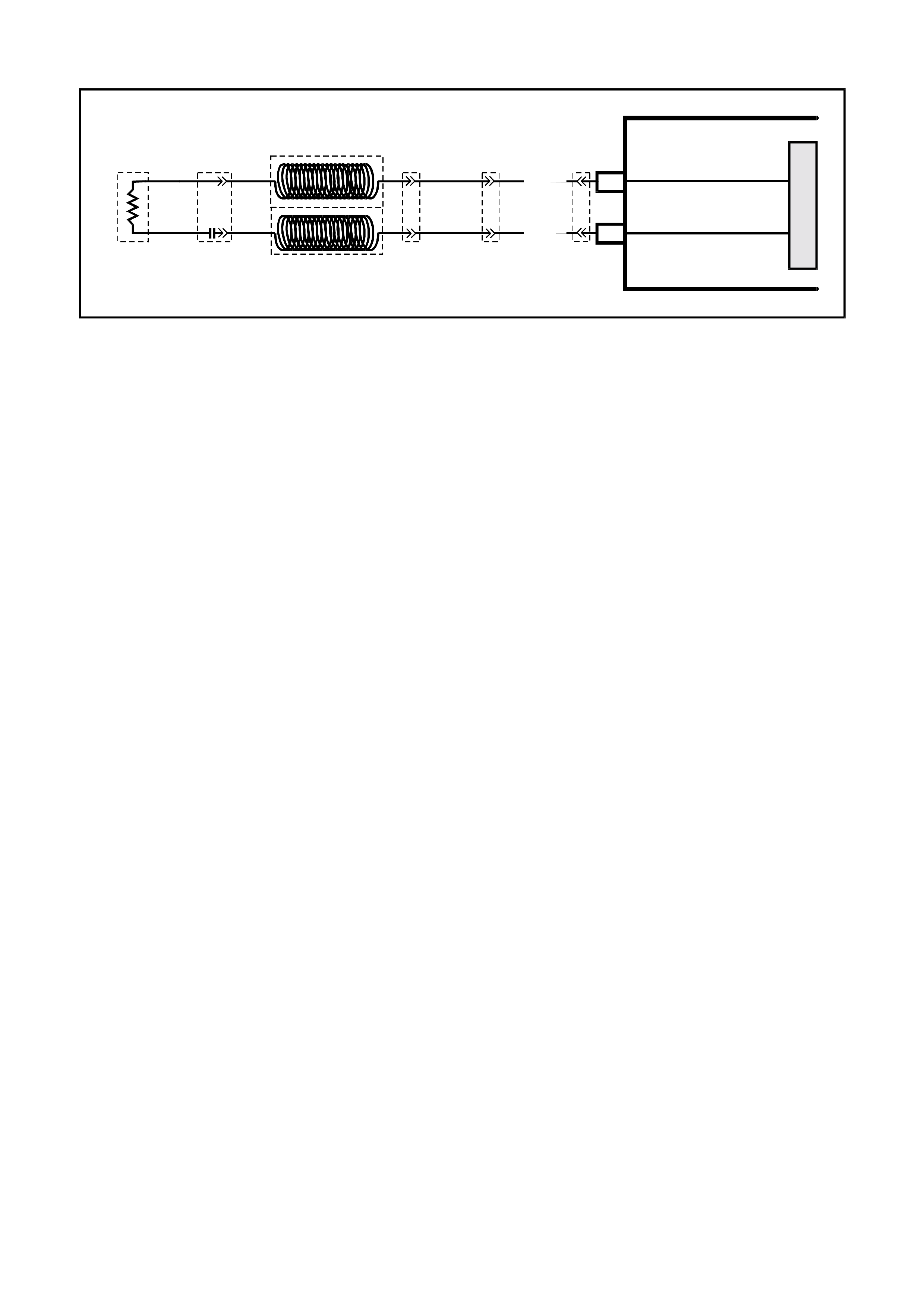
DTC 247 - DRIVER’S AIR BAG CIRCUIT POWER STAGE ERROR
T12M126
M
I
C
R
O
YB147
YB149
7
8
YB191
YB189
YB190
DRIVER
AIRBAG
INFLATOR
DRIVER
A
IRBAG INFLATOR (+)
DRIVER
A
IRBAG INFLATOR (-)
10
11
CL OCK SPR ING CO IL
W (347)
G (348)
SDM
Figure 12M-20
CIRCUIT DESCRIPTION
At ignition on, the SDM perfor ms an initial system self check of the SDM power s tages. If during this initial self test
the SDM detects a fault with the driver’s air bag power stage a current DTC 247 Driver’s Air Bag Circuit Power
Stage Error will set. On completion of the initial system self test the SDM then performs a test of the Driver’s Air Bag
Circuit. If the SDM detects a pr oblem with this circuit the as sociated Driver ’s Air Bag Cir cuit DT C will be set and the
DTC 247 Driver’s Air Bag Circuit Power Stage Error will become a history DTC.
DTC 247 Driver’s Air Bag Circuit Power Stage Error will set if a fault occurs in the driver’s air bag circuit, clock
spring coil assembly with the in-built capacitor connector YB147, connector YB149, connector YB191, the SRS
wiring harness, connector YB189/YB190 or SDM.
When a history DTC 247 Driver’s Air Bag Circuit Power Stage Error sets, the SDM illuminates the SRS warning
lamp. Should the fault conditions detected by the SDM clear during the same ignition cycle the code will remain a
history DTC 247 Driver’s Air Bag Circuit Power Stage Error for all ignition cycles until cleared. The SRS warning
lamp will remain on for the remainder of the ignition cycle.
W hen a DTC 247 Driver’s Air Bag Circuit Power Stage Error sets, the SDM illum inates the SRS warning lamp for
the rem ainder of the ignition cycle. Should the fault conditions detected by the SDM clear during the sam e ignition
cycle the code will remain a history DTC 247 Driver’s Air Bag Circuit Power Stage Error for all ignition cycles until
cleared. T he SRS warning lam p will also rem ain illum inated until the history DTC 247 Driver ’s Air Bag Circuit Power
Stage Error is cleared.
If a DTC 247 Driver’s Air Bag Circuit Power Stage is set, dependent on where the fault is, the driver’s air bag may
not operate.
ACTION REQUIRED
If DTC 247 Driver’s Air Bag Circuit Power Stage Error and any other DTC is set then the diagnostics for the other
DTC s hould be car r ied out f ir st. F or ex ample if a DT C 247 Dr iver’s Air Bag Circ uit Power Stage Err or and a DTC 21
Driver’s Air Bag Circuit Resistance High are set, the diagnostics for a DTC 21 Driver’s Air Bag Circuit Resistance
High should be carried out first.
If only a DTC 247 Driver’s Air Bag Circuit Power Stage Error is set then the SDM should be replaced.
NOTE: An intermittent in the driver’s air bag circuit may cause a DTC 247 Driver’s Air Bag Circuit Power Stage
Error to set.
After the fault has been rectified, ensure that all SRS components are reconnected, clear DTCs, enable the SRS
and verify the correct operation of the system (i.e. warning lamp not illum inated after five seconds of ignition being
switched ON).
Test Description
The following numbers refer to Step numbers in the following diagnostic chart.
1. Us es T ECH 2 to chec k if a DT C 247 Driver’s Air Bag Circ uit Power Stage Error is history code, and if any other
driver’s air bag circuit current or history DTCs are set. If any other DTCs are set refer to these DTCs first.
2. Checks for intermittent fault by monitoring TECH 2 screen during ignition on cycle. If screen display changes
during a wiring 'wiggle' test, a fault with the wiring is at that location.
3. If no other DTCs are set and there are no intermittents in the driver’s air bag circuit then the SDM should be
replaced.
Notes On Diagnostic Chart
1. For all wiring harness checking procedures, refer to VT Series 1 Service Information, WIRING DIAGRAMS,
SECTION 12P.
2. Refer to VT Series 1 Service Information Section 12M, SRS VERSION 6.2, 2.8 SRS WIRING REPAIR before
conducting any SRS wiring harness repairs.
T12M170
YB189
8.1 SDM
WIRING HARNESS
CONNECTOR
BR/B (393)
26
50 25
1
BL U/ B (351) R/B (3 52)
BR/W ( 353)
Y/R (354)
P/B (739)
B (305)
B (3 05)
G/W (1220)
W (3 4 7 )
G (3 48 )
Y/B (349)
GY / B (350 )
Y/G (385)
BR/G (386)
Y/W (387)
BR/W ( 388)
Y/BLU (392)
GY / W ( 407 )
LBLU (408)
BLU/B ( 351)
R/B (352)
BR/W (353)
Y/R (354)
P/B (739)
G/W (1220)
W (3 4 7)
G (348)
Y/B (349)
GY/ B (350)
YB190
8.0 SDM WIRING
HARNESS
CONNECTOR
+VE-VE
G (348) W (3 47 )
CAP
ALSO -VE
YB147
DRIVER'S AIRBAG
CONNECTOR
B/Y (701)
B/Y (28)
G (348)
W(347)
BR (515)
B/G (151 )
YB149
CLOCK SP RING
CONNECTOR
Figure 12M-21
DTC 247 - DRIVER’S AIR BAG CIRCUIT POWER STAGE ERROR
STEP ACTION VALUE YES NO
1. • Install TECH 2 to DLC.
• Select Body / SRS / Diagnostic Trouble Codes /
Read DTC Information.
• Is a DTC 247 Driver’s Air Bag Circuit Power Stage
Error a history DTC, and are any other driver’s air
bag circuit DTCs set?
Go to other
driver’s air bag
circui t DTC
diagnostic chart
in this Section.
Go to Step 2.
2. • Remove steering column upper and lower cover.
• With TECH 2 still connected, select Diagnostic
Trouble Codes / Clear DTC Information and clear all
DTCs.
• Select Diagnostic Trouble Codes / Read DTC
Information, 'wiggle' SRS wiring harness at all
locations between the SDM and the clock spring coil
while monitoring the TECH 2 screen display.
• Jack up the front of the vehicle and turn the steering
wheel from lock to lock while monitoring the TECH 2
screen display.
• Does TECH 2 screen display change status from
No Diagnostic Trouble Codes?
Go to applicable
DTC chart in this
Section.
Go to step 3.
3 • Replace SDM, refer to VT Series 1 Service
Information Section 12M, SRS VERSION 8.0 & 8.1,
2.4 SENSING AND DIAGNOSTIC MODULE (SDM).
Recheck circuit to verify repair.
WHEN ALL DIAGNOSIS AND REPAIRS ARE COM PLETED, ENSURE ALL SRS COMPONENTS ARE
RECONNECTED, CLEAR ALL DTC’S, ENABLE THE SRS AND VERIFY CORRECT OPERATION

DTC 33 - PASSENGER AIR BAG CIRCUIT SHORT TO BATTERY
T12M127
SDM
M
I
C
R
O
YB191
YB189
YB190
YB200
YB208
PASSENGER
AIRBAG
INFLATOR
PASSENGER
AIRBAG INFLATOR (+)
PASSENGER
AIRBAG INFLATOR (-)
13
14
Y/B (3 49)
GY/B (350)
Figure 12M-22
CIRCUIT DESCRIPTION
At ignition on, and on a constant monitoring cycle of every 500 milliseconds during the ignition cycle, the SDM
performs a system self check.
If the SDM detects a r esis tanc e to battery supply is les s than f ive kohms in either the pos itive and/or negative c irc uit
for more than 3 - 5 seconds, a current DTC 33 will set (refer to SRS SELF DIAGNOSTICS in Section 12M
SUPPLEMENTAL RESTRAINT SYSTEM (Version 8.0 & 8.1) of the VT Series I Service Information for more
details).
DTC 33 will set if circ uits 349 (pas senger’s air bag positive s ide) and/or 350 (pass enger’s air bag negative side) are
shorted to battery +.
When DTC 33 sets, the SDM illuminates the SRS warning lamp and sets a current DTC 33. Should the fault
conditions detected by the SDM clear during the same ignition cycle, the current code will clear and become a
history DTC 33. The SRS warning lamp will remain on for the remainder of the ignition cy cle.
If a DTC 33 is set, the SRS warning lamp is illuminated on each ignition cycle, even if the DTC is set as a history
DTC, until the f ault conditions for s etting DTC 33 are rectif ied and the DTC (curr ent or history) can then be cleared
from the SDM via TECH 2.
If DTC 33 is set, the SRS, including the passenger’s air bag, will still be operational.
Test Description
The following numbers refer to step numbers in the following diagnostic chart:
1. Uses TECH 2 to check if DTC 33 is current or history.
2. Checks for intermittent fault by monitoring TECH 2 screen display. If screen display changes during a ‘wiggle’
test, a fault with the wiring is at that location.
3. Checks circuit 349 and 350 for a short to battery +.
Notes on Diagnostic Chart
1. For all wiring harness checking procedures, refer to Section 12P WIRING DIAGRAMS of the VT Series I
Service Information.
2. Refer to 2.8 SRS WIRING REPAIR in Section 12M SUPPLEMENTAL RESTRAINT SYSTEM (Version 6.2), of
the VT Series I Service Information before conducting any SRS wiring harness repairs.
3. Resistance c annot be m easured between the two term inals in connector YB208, as the in-built capacitor block s
measurement. Therefore, a ‘service hole’ is incorporated into the connector for fault tracing. Refer to
1.1 SYSTEM COMPONENTS, WIRING HARNESS in Section 12M SUPPLEMENTAL RESTRAINT SYSTEM
(Version 8.0 & 8.1) of the VT Series I Service Information for more details on this type of connector.
4. Wiring should be checked at point where TECH 2 screen display changed status. If necessary, split open the
harness.
5. If the fault can not be identified, the harness should be replaced.
6. Refer to TECH 2 DIAGNOSTICS in Section 12M SUPPLEMENTAL RESTRAINT SYSTEM (Version 8.0 & 8.1)
of the VT Series I Service Information for connecting and using TECH 2.
7. To enable or disable the SRS system, refer to 2.2 SYSTEM DISABLING AND ENABLING PROCEDURE in
Section 12M SUPPLEMENTAL RESTRAINT SYSTEM (Version 8.0 & 8.1) of the VT Series I Service
Information.
8. SDM connector YB189 is equipped with a shorting link busbar which needs to be opened before checking the
circuit, re fer to 2.5 DIAGNOSTIC CHA RTS in this Section for additional information.
Figure 12M-23

DTC 33 – PASSENGER AIR BAG CIRCUIT SHORT TO BATTERY
STEP ACTION VALUE YES NO
1. • Connect TECH 2 to DLC.
• Select Body / SRS / Diagnostic Trouble Codes /
Read DTC Information (refer NOTE 6 on previous
page).
• Is DTC 33 current ?
Go to Step 3. Go to Step 2.
2. • Remove instrument panel compartment to gain
access to passenger’s air bag, refer to Section 1A3
INSTRUMENT PANEL AND CONSOLE of the VT
Series I Service Information.
• With TECH 2 still connected, select Diagnostic
Trouble Codes / Clear DTC Information and clear all
(if any) DTCs.
• Select Diagnostic Trouble Codes / Read DTC
Information, ‘wiggle’ SRS wiring harness at all
locations between the SDM and the passenger’s air
bag wiring harness connector YB208, while
monitoring TECH 2 screen display.
• Does TECH 2 screen display change status from
No Diagnostic Trouble Codes?
Make repairs as
necessary (refer
to NOTES 2 & 4
on previous
page).
Clear DTC and
recheck system to
verify repair.
Fault not present.
Check all system
wiring harness
connectors, and
terminals (refer to
NOTE 5 on
previous page).
Clear DTC and
recheck system.
3. • Disable the SRS (refer NOTE 7 on previous page).
• Disconnect passenger’s air bag inflator module
wiring harness connector YB208.
• Disconnect SDM wiring harness connector
YB189/YB190 from the SDM.
• Reconnect battery.
• Using Tool KM-609-20, check wiring between SDM
wiring harness connector YB189/YB190, terminals
13 and 14 and passenger’s air bag connector
YB208, circuits 349 (Yellow/Black wire) and 350
(Grey/Black wire) for short to battery + (refer to
NOTES 1, 3 and 8 on previous page).
• Is all OK?
Replace SDM,
refer Section 12M
SUPPLEMENTAL
RESTRAINT
SYSTEM (Version
8.0 & 8.1) of the
VT Series I
Service
Information.
Recheck circuit to
verify repair.
Make repairs as
necessary (refer
to NOTE 2 on
previous page).
Clear DTC and
recheck system
to verify repair.
WHEN ALL DIAGNOSIS AND REPAIRS ARE COM PLETED, ENSURE ALL SRS COMPONENTS ARE
RECONNECTED, CLEAR ALL DTC’S, ENABLE THE SRS AND VERIFY CORRECT OPERATION

DTC 34 - PASSENGER AIR BAG CIRCUIT SHORT TO EARTH
T12M127
SDM
M
I
C
R
O
YB191
YB189
YB190
YB200
YB208
PASSENGER
AIRBAG
INFLATOR
PASSENGER
AIRBAG INFLATOR (+)
PASSENGER
AIRBAG INFLATOR (-)
13
14
Y/B (3 49)
GY/B (350)
Figure 12M-24 - CIRCUIT DESCRIPTION
At ignition on, and on a constant monitoring cycle of every 500 milliseconds during the ignition cycle, the SDM
performs a system self check. If the SDM detects a resistance to earth of less than three kohms in either the
positive or negative inflator circuit for more than 3 - 5 seconds, a current DTC 34 will set (refer to
SRS SELF DIAGNOSTICS in Section 12M SUPPLEMENT AL RESTRAINT SYST EM (Version 8.0 & 8.1) of the VT
Series I Service Information for more details).
DTC 34 will set if circ uits 349 (pas senger’s air bag positive s ide) and/or 350 (pass enger’s air bag negative side) are
shorted to earth.
When DTC 34 sets, the SDM illuminates the SRS warning lamp and sets a current DTC 34. Should the fault
conditions detected by the SDM clear during the same ignition cycle, the current code will clear and become a
history DTC 34. The SRS warning lamp will remain on for the remainder of the ignition cy cle.
If a DTC 34 is set, the SRS warning lamp is illuminated on each ignition cycle, even if the DTC is set as a history
DTC, until the f ault conditions for s etting DTC 34 are rectif ied and the DTC (curr ent or history) can then be cleared
from the SDM via TECH 2.
If DTC 34 is set, the SRS, including the passenger’s air bag, will still be operational.
Test Description
The following numbers refer to step numbers in the following diagnostic chart:
1. Uses TECH 2 to check if DTC 34 is current or history.
2. TECH 2 in this mode should display approximately 1.6 - 6.4 ohms if the passenger’s air bag loop circuit is OK.
3. If screen display changes during a wiring 'wiggle' test, a fault with the wiring is at that location.
4. Tool SD28280B is a dummy load taking the place of the passenger ’s air bag inflator module. If TECH 2 displays
the correct resistance of the dummy load, the system fault is in the passenger's air bag inflator module
assembly.
5. T his test c heck s the wiring between the SDM wiring harnes s connec tor YB189 (8.1 SDM) or YB190 (8.0 SDM),
terminal 13 and the passenger's air bag inflator module connector YB208 for faults.
6. T his test c heck s the wiring between the SDM wiring harnes s connec tor YB189 (8.1 SDM) or YB190 (8.0 SDM),
terminal 14 and the passenger's air bag inflator module connector YB208 for faults.
Notes on Diagnostic Chart
1. For all wiring harness checking procedures, refer to Section 12P WIRING DIAGRAMS of the VT Series I
Service Information.
2. Refer to 2.8 SRS WIRING REPAIR in Section 12M SUPPLEMENTAL RESTRAINT SYSTEM (Version 6.2) of
the VT Series I Service Information before conducting any SRS wiring harness repairs.
3. Refer to TECH 2 DIAGNOSTICS in Section 12M SUPPLEMENTAL RESTRAINT SYSTEM (Version 8.0 & 8.1)
of the VT Series I Service Information for connecting and using TECH 2.
4. Resistance cannot be measured between the two terminals in connector YB208 as the in-built capacitor blocks
measurement. Therefore, a ‘service hole’ is incorporated into the connector for fault tracing. Refer to
1.1 SYSTEM COMPONENTS, WIRING HARNESS in Section 12M SUPPLEMENTAL RESTRAINT SYSTEM
(Version 8.0 & 8.1) of the VT Series I Service Information for more details on this type of connector.
5. Wiring should be checked at point where TECH 2 screen display changed. If necessary, split open wiring
harness.
6. If fault cannot be identified, the wiring harness should be replaced.
7. To enable or disable the SRS system, refer to 2.2 SYSTEM DISABLING AND ENABLING PROCEDURE in
Section 12M SUPPLEMENTAL RESTRAINT SYSTEM (Version 8.0 & 8.1) of the VT Series I Service
Information.
8. SDM connector YB189 is equipped with a shorting link busbar which needs to be opened before checking the
circuit, re fer to 2.5 DIAGNOSTIC CHA RTS in this Section for additional information.
Figure 12M-25

DTC 34 - PASSENGER AIR BAG CIRCUIT SHORT TO EARTH
STEP ACTION VALUE YES NO
1. • Connect TECH 2 to DLC.
• Select Body / SRS / Diagnostic Trouble Codes /
Read DTC Information (refer NOTE 3 on previous
page).
• Does TECH 2 display DTC 34 as a Current DTC?
Go to Step 2. Go to Step 3.
2. • W ith TECH 2 still connected to DLC, select Body /
SRS / Data Display and scroll to PASSENGER’S
AIR BAG LOOP RESISTANCE'.
• Is value displayed on TECH 2 as specified?
Approx.
1.6 - 6.4
ohms
Go to Step 3. Go to Step 4.
3. • Remove instrument panel compartment to gain
access to passenger’s air bag, refer to Section 1A3
INSTRUMENT PANEL AND CONSOLE of the VT
Series I Service Information.
• With TECH 2 still connected, select Diagnostic
Trouble Codes / Clear DTC Information and clear
all (if any) DTCs.
• Select Diagnostic Trouble Codes / Read DTC
Information, 'wiggle' SRS wiring harness at all
locations between the SDM and the passenger’s air
bag wiring harness connector YB208, while
monitoring TECH 2 screen display.
• Does TECH 2 screen display change status from
No Diagnostic Trouble Codes?
Make repairs as
necessary (refer
to NOTE to 2 & 5
on previous
page).
Clear DTC and
recheck system to
verify repair.
Fault not present.
Check all system
wiring harness
connectors, and
terminals (refer to
NOTE 6 on
previous page).
Clear DTC and
recheck system.
4. • Disable the SRS (refer NOTE 7 on previous page).
• Disconnect passenger’s air bag inflator module
wiring harness connector YB208.
• Connect Tool No. SD28280B to SRS wiring
harness connector YB208.
• Re-connect battery.
• With TECH 2 still connected, select Body / SRS /
Data Display and scroll to PASSENGER’S AIR
BAG LOOP RESISTANCE'.
• Is value displayed on TECH 2 as specified?
Approx.
3.0 ohms Replace
passenger air bag
inflator module
assembly, refer to
2.4 FRONT
PASSENGER’S
AIR BAG
MODULE
ASSEMBLY in
Section 12M, Vol
7 of the VT Series
Service Manual.
Clear DTC and
recheck system to
verify repair.
Go to Step 5.
5. • Disconnect SDM wiring harness connector
YB189/YB190 from the SDM.
• Remove Tool SD28280B from YB208.
• Using Tool KM-609-20, check wiring between SDM
wiring harness connector YB189/YB190, terminals
13 and passenger’s air bag inflator module
connector YB208, circuit 349 (Yellow/Black wire)
for short to earth (refer to NOTES 1 & 8 on
previous page).
• Is all OK?
Go to Step 6. Make repairs as
necessary (refer
to NOTE 2 on
previous page).
Clear DTC and
recheck system
to verify repair.
6. • W ith SDM wiring harness connector YB189/YB190
disconnected from the SDM and using Tool KM-
609-20, check wiring between SDM wiring harness
connector YB189/YB190, terminal 14 and
passenger’s air bag inflator module connector
YB208, circuit 350 (Grey/Black wire) for a short to
earth (refer to NOTES 1 , 4 & 8 on previous page).
• Is all OK?
Replace SDM,
refer Section 12M
SUPPLEMENTAL
RESTRAINT
SYSTEM in Vol 12
of the VT Series
Service Manual.
Recheck circuit to
verify repair.
Make repairs as
necessary (refer
to NOTE 2 on
previous page).
Clear DTC and
recheck system
to verify repair.
WHEN ALL DIAGNOSIS AND REPAIRS ARE COM PLETED, ENSURE ALL SRS COMPONENTS ARE
RECONNECTED, CLEAR ALL DTC’S, ENABLE THE SRS AND VERIFY CORRECT OPERATION

DTC 35 - PASSENGER AIR BAG CIRCUIT CAPACITANCE TOO HIGH
T12M127
SDM
M
I
C
R
O
YB191
YB189
YB190
YB200
YB208
PASSENGER
AIRBAG
INFLATOR
PASSENGER
AIRBAG INFLATOR (+)
PASSENGER
AIRBAG INFLATOR (-)
13
14
Y/B (3 49)
GY/B (350)
Figure 12M-26
CIRCUIT DESCRIPTION
At ignition on, and on a constant monitoring cycle of every 500 milliseconds during the ignition cycle, the SDM
performs a system self check.
If the SDM detects the capacitance in the passenger’s air bag circuit is too high (greater than 550 nF) for longer
than 3 - 5 seconds, a current DTC 35 will set (refer to SRS SELF DIAGNOSTICS in Section 12M SUPPLEMENTAL
RESTRAINT SYSTEM (Version 8.0 & 8.1) of the VT Series I Service Information for more details).
DTC 35 will set if the in-built capacitor in the SRS wiring harness connector YB208 is faulty.
When DTC 35 sets, the SDM illuminates the SRS warning lamp and sets a current DTC 35. Should the fault
conditions detected by the SDM clear during the same ignition cycle, the current code will clear and become a
history DTC 35. The SRS warning lamp will remain on for the remainder of the ignition cy cle.
If a DTC 35 is set, the SRS warning lamp is illuminated on each ignition cycle, even if the DTC is set as a history
DTC, until the fault conditions for setting DTC 35 are rectified and the DTC (current or history) can then be cleared
from the SDM via TECH 2.
ACTION REQUIRED
If DTC 35 is set, the passenger’s air bag may not operate and therefore, the SRS ‘pigtail’ wiring harness with
connector YB208 (between passenger air bag and SRS wiring harness) must be replaced.
NOTE: To gain access to the passenger air bag ‘pigtail’ wiring harness, refer to the removal operations of the front
passenger’s air bag module assembly in Section 12M SUPPLEMENTAL RESTRAINT SYSTEM (Version 6.2) of
the VT Series I Service Information.
After the SRS ‘pigtail’ wiring harness between the passenger air bag and the SRS wiring harness has been
replaced, ensure that all SRS components are reconnected, clear DTCs, enable the SRS and verify the correct
operation of the system (i.e. warning lamp not illuminated after five seconds of ignition being switched ON).
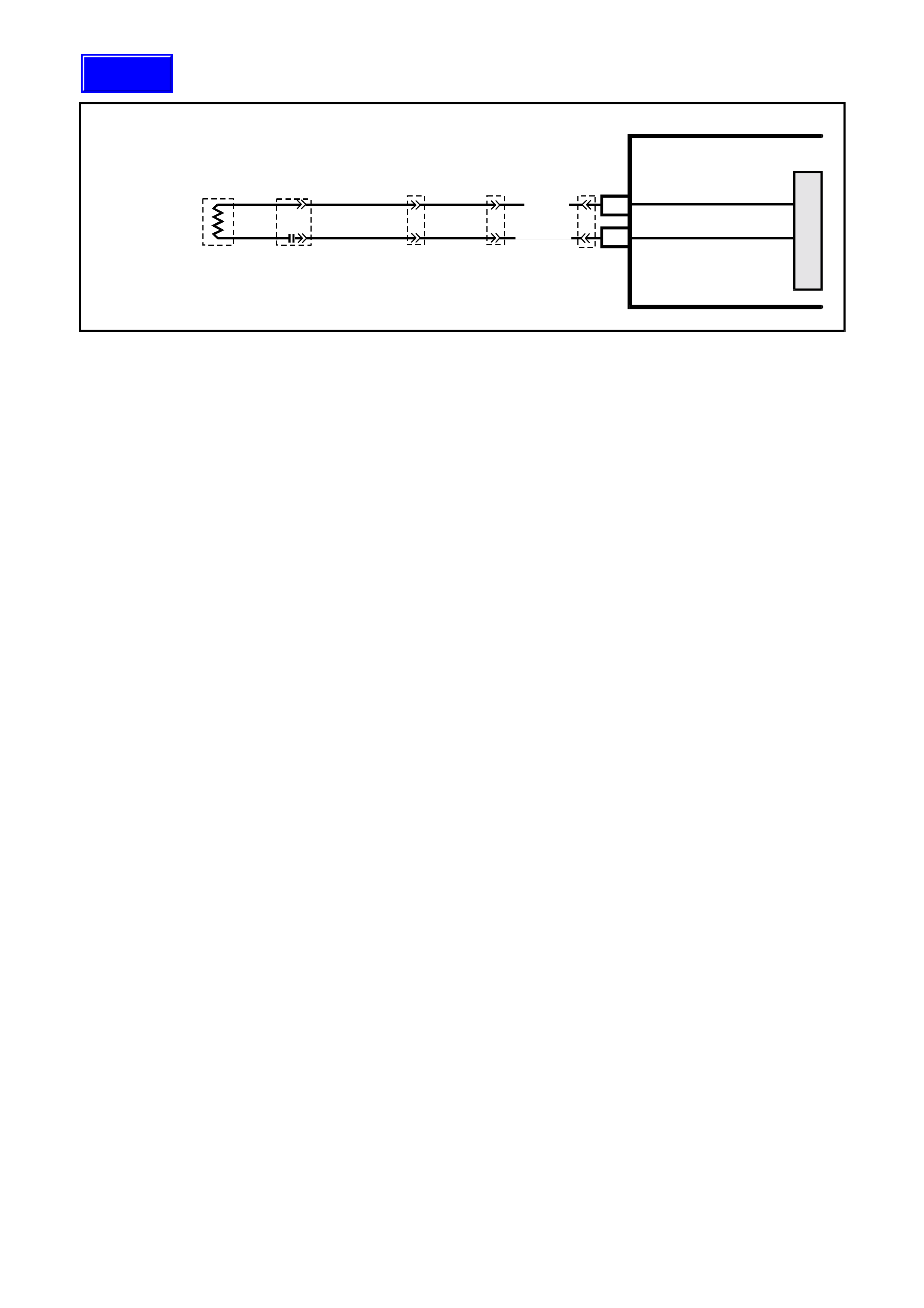
DTC 36 - PASSENGER AIR BAG CIRCUIT CAPACITANCE TOO LOW
T12M127
SDM
M
I
C
R
O
YB191
YB189
YB190
YB200
YB208
PASSENGER
AIRBAG
INFLATOR
PASSENGER
AIRBAG INFLATOR (+)
PASSENGER
AIRBAG INFLATOR (-)
13
14
Y/B (3 49)
GY/B (350)
Figure 12M-27
CIRCUIT DESCRIPTION
At ignition on, and on a constant monitoring cycle of every 500 milliseconds during the ignition cycle, the SDM
performs a system self check.
If the SDM detects the capacitance in the passenger’s air bag circuit is too low (less than 390 nF) for longer than 3 -
5 seconds, a current DTC 36 will set (refer to SRS SELF DIAGNOSTICS in Section 12M SUPPLEMENTAL
RESTRAINT SYSTEM (Version 8.0 & 8.1) of the VT Series I Service Information for more details).
DTC 36 will set if the in-built capacitor in the SRS wiring harness connector YB208 is faulty.
When DTC 36 sets, the SDM illuminates the SRS warning lamp and sets a current DTC 36. Should the fault
conditions detected by the SDM clear during the same ignition cycle, the current code will clear and become a
history DTC 36. The SRS warning lamp will remain on for the remainder of the ignition cy cle.
If a DTC 36 is set, the SRS warning lamp is illuminated on each ignition cycle, even if the DTC is set as a history
DTC, until the fault conditions for setting DTC 36 are rectified and the DTC (current or history) can then be cleared
from the SDM via TECH 2.
ACTION REQUIRED
If DTC 36 is set, the passenger’s air bag may not operate and therefore, the SRS ‘pigtail’ wiring harness with
connector YB208 (between passenger air bag and SRS wiring harness) must be replaced.
NOTE: To gain access to the passenger air bag ‘pigtail’ wiring harness, refer to the removal operations of the front
passenger’s air bag module assembly in Section 12M SUPPLEMENTAL RESTRAINT SYSTEM (Version 6.2) of
the VT Series I Service Information.
After the SRS ‘pigtail’ wiring harness between the passenger air bag and the SRS wiring harness has been
replaced, ensure that all SRS components are reconnected, clear DTCs, enable the SRS and verify the correct
operation of the system (i.e. warning lamp not illuminated after five seconds of ignition being switched ON).
Techline
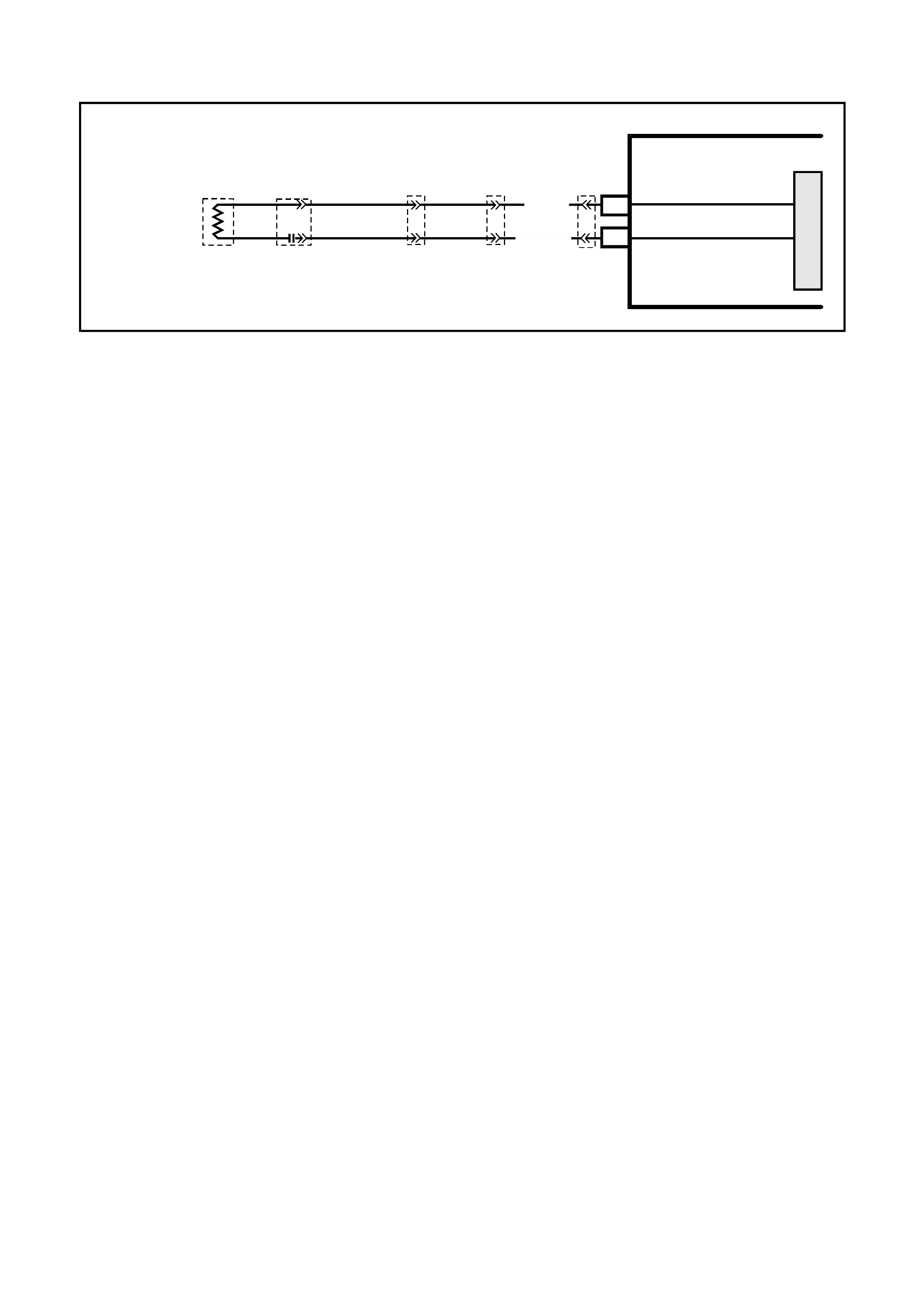
DTC 37 - PASSENGER AIR BAG CIRCUIT RESISTANCE TOO HIGH
T12M127
SDM
M
I
C
R
O
YB191
YB189
YB190
YB200
YB208
PASSENGER
AIRBAG
INFLATOR
PASSENGER
AIRBAG INFLATOR (+)
PASSENGER
AIRBAG INFLATOR (-)
13
14
Y/B (3 49)
GY/B (350)
Figure 12M-28
CIRCUIT DESCRIPTION
At ignition on, and on a constant monitoring cycle of every 500 milliseconds during the ignition cycle, the SDM
performs a system self check.
If the SDM detects a resistance in the passenger’s air bag circuit that is too high (greater than 10 ohms) for longer
than 3 - 5 seconds, a current DTC 37 will set (refer to SRS SELF DIAGNOSTICS in Section 12M SUPPLEMENTAL
RESTRAINT SYSTEM (Version 8.0 & 8.1) of the VT Series I Service Information for more details).
DTC 37 will set if circuits 349 or 350 (including the passenger’s air bag inflator module) are open circuit.
When DTC 37 sets, the SDM illuminates the SRS warning lamp and sets a current DTC 37. Should the fault
conditions detected by the SDM clear during the same ignition cycle, the current code will clear and become a
history DTC 37. The SRS warning lamp will remain on for the remainder of the ignition cy cle.
If a DTC 37 is set, the SRS warning lamp is illuminated on each ignition cycle, even if the DTC is set as a history
DTC, until the fault conditions for setting DTC 37 are rectified and the DTC (current or history) can then be cleared
from the SDM via TECH 2.
If DTC 37 is set, dependent on where the fault is, the passenger’s air bag may not operate.
Test Description
The following numbers refer to step numbers in the following diagnostic chart:
1. Uses TECH 2 to check if DTC 37 is current or history.
2. Checks for intermittent fault by monitoring TECH 2 screen. If screen display changes during a wiring 'wiggle' test,
a fault with the wiring is at that location.
3. Tool SD28280B is a dummy load taking the place of the passenger’s air bag inflator module. If DTC 37 becomes
a history DTC with dummy load connected, the system fault is in the passenger’s air bag inflator module.
4. Checks circuit 349 for open circuit.
5. Checks circuit 350 for open circuit.
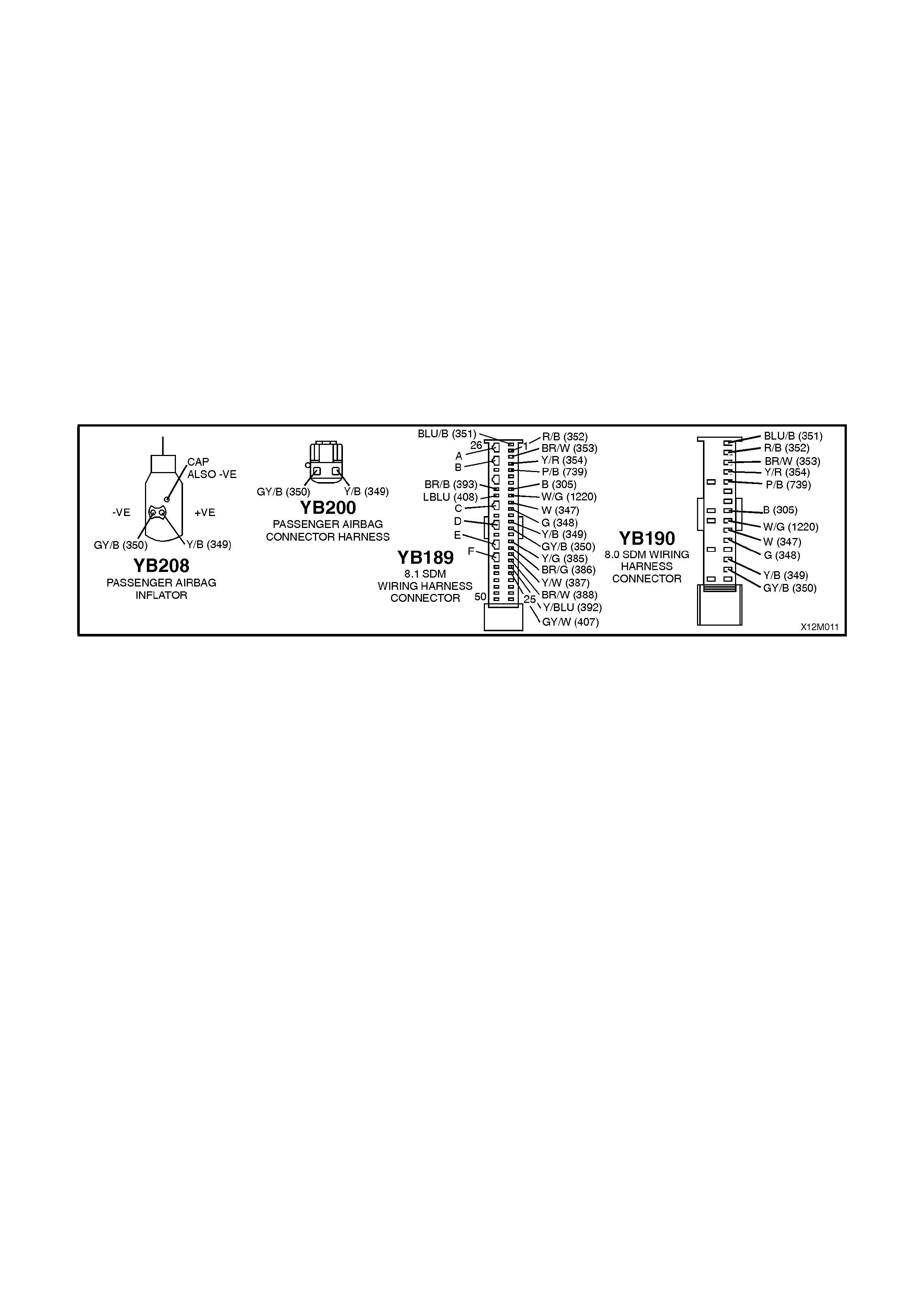
Notes on Diagnostic Chart
1. For all wiring harness checking procedures, refer to Section 12P WIRING DIAGRAMS of the VT Series I
Service Information.
2. Refer to 2.8 SRS WIRING REPAIR in this Section 12M SUPPLEMENTAL RESTRAINT SYSTEM (Version 6.2)
of the VT Series I Service Information before conducting any SRS wiring harness repairs.
3. Res istance cannot be m easured between the two terminals in c onnector YB208, as the in-built capacitor block s
measurement. Therefore, a ‘service hole’ is incorporated into the connector for fault tracing. Refer to
1.1 SYSTEM COMPONENTS, WIRING HARNESS in Section 12M SUPPLEMENTAL RESTRAINT SYSTEM
(Version 8.0 & 8.1) of the VT Series I Service Information for more details on this type of connector.
4. Refer to TECH 2 DIAGNOSTICS in Section 12M SUPPLEMENTAL RESTRAINT SYSTEM (Version 8.0 & 8.1) of
the VT Series I Service Information for connecting and using TECH 2.
5. To enable or disable the SRS system, refer to 2.2 SYSTEM DISABLING AND ENABLING PROCEDURE in
Section 12M SUPPLEMENTAL RESTRAINT SYSTEM (Version 8.0 & 8.1) of the VT Series I Service
Information.
6. SDM connector YB189 is equipped with a shorting link busbar which needs to be opened before checking the
circuit, re fer to 2.5 DIAGNOSTIC CHA RTS in this Section for additional information.
Figure 12M-29

DTC 37 - PASSENGER AIR BAG CIRCUIT RESISTANCE TOO HIGH
STEP ACTION VALUE YES NO
1. • Install TECH 2 to DLC.
• Select Body / SRS / Diagnostic Trouble Codes /
Read DTC Information (refer NOTE 4 on previous
page).
• Is DTC 37 current?
Go to Step 3. Go to Step 2.
2. • Remove instrument panel compartment to gain
access to passenger’s air bag, refer to Section 1A3
INSTRUMENT PANEL AND CONSOLE of the VT
Series I Service Information.
• With TECH 2 still connected, select Diagnostic
Trouble Codes / Clear DTC Information and clear
all (if any) DTCs.
• Select Diagnostic Trouble Codes / Read DTC
Information, 'wiggle' SRS wiring harness at all
locations between the SDM and the passenger’s air
bag wiring harness connector YB208, while
monitoring TECH 2 screen display.
• Does TECH 2 screen display change status from
No Diagnostic Trouble Codes?
Make repairs as
necessary (refer
to NOTE 2 on
previous page).
Clear DTC and
recheck system to
verify repair.
Fault not present.
Check all system
wiring harness
connectors, and
terminals.
Clear DTC and
recheck system.
3. • Disable the SRS (refer NOTE 5 on previous page).
• Disconnect the passenger’s air bag inflator module
wiring harness connector YB208.
• Connect Tool No. SD28280B to SRS wiring
harness connector YB208.
• Enable the SRS (reconnect battery).
• Connect TECH 2 to DLC.
• Select Body / SRS / Diagnostic Trouble Codes /
Read DTC Information.
• Is DTC 37 still current?
Go to Step 4. Replace
passenger’s air
bag inflator
module assembly,
refer to 2.4
FRONT
PASSENGER’S
AIR BAG
MODULE
ASSEMBLY in
Section 12M, Vol
7 of the VT Series
Service Manual.
Clear DTC and
recheck system to
verify repair.
4. • Disable the SRS, (refer NOTE 5 on previous page).
• Disconnect SDM wiring harness connector
YB189/YB190 from the SDM.
• Remove Tool No. SD28280B from SRS wiring
harness connector YB208.
• With SRS wiring harness connector YB208
disconnected, and using Tool KM-609-20, check
wiring between SDM wiring harness connector
YB189/YB190, terminal 13 and SRS wiring harness
connector YB208, circuit 349 (Yellow/Black wire)
for open circuit (refer to NOTES 1, 3 & 6 on
previous page).
• Is all OK?
Go to Step 5. Make repairs as
necessary (refer
to NOTE 2 on
previous page).
Clear DTC and
recheck system to
verify repair.
5. • W ith SDM wiring harness connector YB189/YB190
and SRS wiring harness connector YB208
disconnected and using Tool KM-609-20, check
wiring between SDM wiring harness connector
YB189/YB190, terminal 14 and SRS wiring harness
connector YB208, circuit 350 (Grey / Black wire) for
open circuit (refer to NOTES 1, 3 & 6 on previous
page).
• Is all OK?
Replace SDM,
refer Section 12M
SUPPLEMENTAL
RESTRAINT
SYSTEM (Version
8.0 & 8.1) of the
VT Series I
Service
Information.
Recheck circuit to
verify repair.
Make repairs as
necessary (refer
to NOTE 2 on
previous page).
Clear DTC and
recheck system to
verify repair.
WHEN ALL DIAGNOSIS AND REPAIRS ARE COM PLETED, ENSURE ALL SRS COMPONENTS ARE
RECONNECTED, CLEAR ALL DTC’S, ENABLE THE SRS AND VERIFY CORRECT OPERATION

DTC 38 - PASSENGER AIR BAG CIRCUIT RESISTANCE TOO LOW
T12M127
SDM
M
I
C
R
O
YB191
YB189
YB190
YB200
YB208
PASSENGER
AIRBAG
INFLATOR
PASSENGER
AIRBAG INFLATOR (+)
PASSENGER
AIRBAG INFLATOR (-)
13
14
Y/B (3 49)
GY/B (350)
Figure 12M-30
CIRCUIT DESCRIPTION
At ignition on, and on a constant monitoring cycle of every 500 milliseconds during the ignition cycle, the SDM
performs a system self check.
If the SDM detects a resistance in the passenger’s air bag circuit that is too low (less than 0.6 ohm) for longer than
3 - 5 seconds, a current DTC 38 will set (refer to SRS SELF DIAGNOSTICS in Section 12M SUPPLEMENTAL
RESTRAINT SYSTEM (Version 8.0 & 8.1) of the VT Series I Service Information for more details).
DTC 38 will set if circuits 349 or 350, (including the passenger’s air bag inflator module assembly) are shorted
together.
When DTC 38 sets, the SDM illuminates the SRS warning lamp and sets a current DTC 38. Should the fault
conditions detected by the SDM clear during the same ignition cycle, the current code will clear and become a
history DTC 38. The SRS warning lamp will remain on for the remainder of the ignition cy cle.
If a DTC 38 is set, the SRS warning lamp is illuminated on each ignition cycle, even if the DTC is set as a history
DTC, until the fault conditions for setting DTC 38 are rectified and the DTC (current or history) can then be cleared
from the SDM via TECH 2.
If DTC 38 is set, dependent on where the fault is, the passenger’s air bag may not operate.
Test Description
The following numbers refer to step numbers in the following diagnostic chart:
1. Uses TECH 2 to check if DTC 38 is current or history.
2. Checks for intermittent fault by monitoring TECH 2 screen. If screen display changes during a wiring 'wiggle' test,
a fault with the wiring is at that location.
3. Tool SD28280B is a dummy load taking the place of the passenger’s air bag inflator module. If DTC 38 becomes
a history DTC with dummy load connected, the system fault is in the passenger’s air bag inflator module.
4. This test checks the wiring between the SDM wiring harness connector YB189 (8.1 SDM) or YB190 (8.0 SDM)
and SRS wiring harness connector YB208 for a short circuit.
Notes on Diagnostic Chart
1. For all wiring harness checking procedures, refer to Section 12P WIRING DIAGRAMS of the VT Series I
Service Information.
2. Refer to 2.8 SRS WIRING REPAIR in this Section 12M SUPPLEMENTAL RESTRAINT SYSTEM (Version 6.2)
of the VT Series I Service Information before conducting any SRS wiring harness repairs.
3. Res istance cannot be m easured between the two terminals in c onnector YB208, as the in-built capacitor block s
measurement. Therefore, a ‘service hole’ is incorporated into the connector for fault tracing. Refer to
1.1 SYSTEM COMPONENTS, WIRING HARNESS in Section 12M SUPPLEMENTAL RESTRAINT SYSTEM
(Version 8.0 & 8.1) of the VT Series I Service Information for more details on this type of connector.
4. Refer to TECH 2 DIAGNOSTICS in Section 12M SUPPLEMENTAL RESTRAINT SYSTEM (Version 8.0 & 8.1) of
the VT Series I Service Information for connecting and using TECH 2.
5. To enable or disable the SRS system, refer to 2.2 SYSTEM DISABLING AND ENABLING PROCEDURE in
Section 12M SUPPLEMENTAL RESTRAINT SYSTEM (Version 8.0 & 8.1) of the VT Series I Service
Information.
6. SDM connector YB189 is equipped with a shorting link busbar which needs to be opened before checking the
circuit, re fer to 2.5 DIAGNOSTIC CHA RTS in this Section for additional information.
Techline
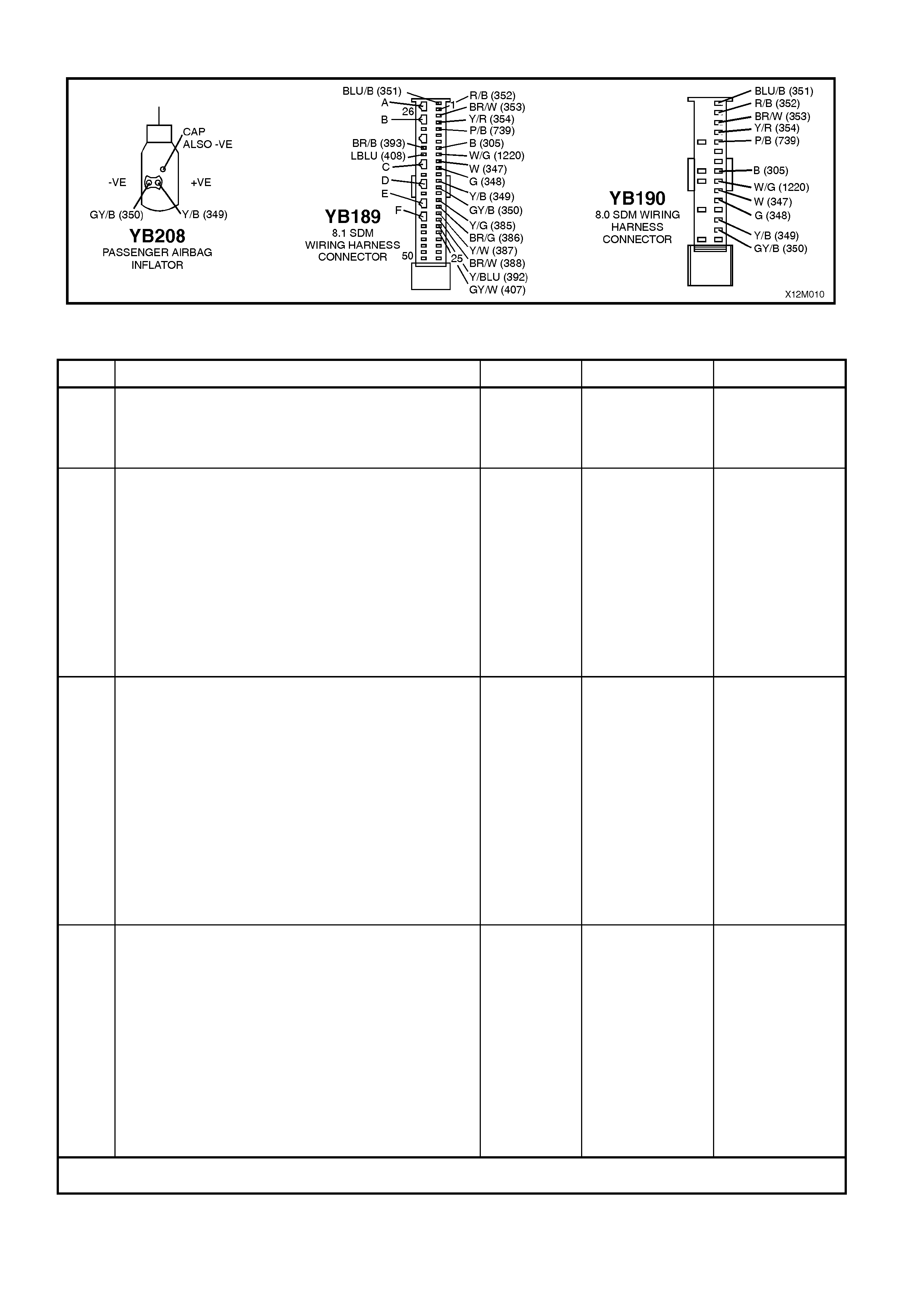
Figure 12M-31
DTC 38 - PASSENGER AIR BAG CIRCUIT RESISTANCE TOO LOW
STEP ACTION VALUE YES NO
1. • Install TECH 2 to DLC.
• Select Body / SRS / Diagnostic Trouble Codes /
Read DTC Information (refer NOTE 4 on previous
page).
• Is DTC 38 current?
Go to Step 3. Go to Step 2.
2. • Remove instrument panel compartment to gain
access to passenger’s air bag, refer to Section 1A3
INSTRUMENT PANEL AND CONSOLE of the VT
Series I Service Information.
• With TECH 2 still connected, select Diagnostic
Trouble Codes / Clear DTC Information and clear
all (if any) DTCs.
• Select Diagnostic Trouble Codes / Read DTC
Information, 'wiggle' SRS wiring harness at all
locations between the SDM and the passenger’s air
bag wiring harness connector YB208, while
monitoring TECH 2 screen display.
• Does TECH 2 screen display change status from
No Diagnostic Trouble Codes?
Make repairs as
necessary (refer
to NOTE 2 on
previous page).
Clear DTC and
recheck system to
verify repair.
Fault not present.
Check all system
wiring harness
connectors, and
terminals.
Clear DTC and
recheck system.
3. • Disable the SRS (refer NOTE 5 on previous page).
• Disconnect the passenger’s air bag inflator module
wiring harness connector YB208.
• Connect Tool No. SD28280B to SRS wiring
harness connector YB208.
• Enable the SRS (reconnect battery).
• Connect TECH 2 to DLC.
• Select Body / SRS / Diagnostic Trouble Codes /
Read DTC Information.
• Is DTC 38 still current?
Go to Step 4. Replace
passenger air bag
inflator module
assembly, refer to
2.4 FRONT
PASSENGER’S
AIR BAG
MODULE
ASSEMBLY in
Section 12M, Vol
7 of the VT Series
Service Manual.
Clear DTC and
recheck system to
verify repair.
4. • Disable the SRS (refer NOTE 5 on previous page).
• Disconnect SDM wiring harness connector
YB189/YB190 from the SDM.
• Disconnect Tool No. SD28280B from SRS wiring
harness connector YB208.
• With SRS wiring harness connector YB208
disconnected, and using Tool KM-609-20, check
for continuity between SDM wiring harness
connector YB189/YB190, terminal 13, circuit 349
(Yellow/Black wire) and terminal 14, circuit 350
(Grey/Black wire)(refer to NOTES 1, 3 & 6 on
previous page).
• Does continuity exist?
Repair short in
circuits 349 and
350, between
SDM wiring
harness
connector
YB189/YB190 and
YB208 as
necessary (refer
to NOTE 2 on
previous page).
Clear DTC and
recheck system to
verify repair.
Replace SDM,
refer Section 12M
SUPPLEMENTAL
RESTRAINT
SYSTEM (Version
8.0 & 8.1) of the
VT Series I
Service
Information.
Recheck circuit to
verify repair.
WHEN ALL DIAGNOSIS AND REPAIRS ARE COM PLETED, ENSURE ALL SRS COMPONENTS ARE
RECONNECTED, CLEAR ALL DTC’S, ENABLE THE SRS AND VERIFY CORRECT OPERATION
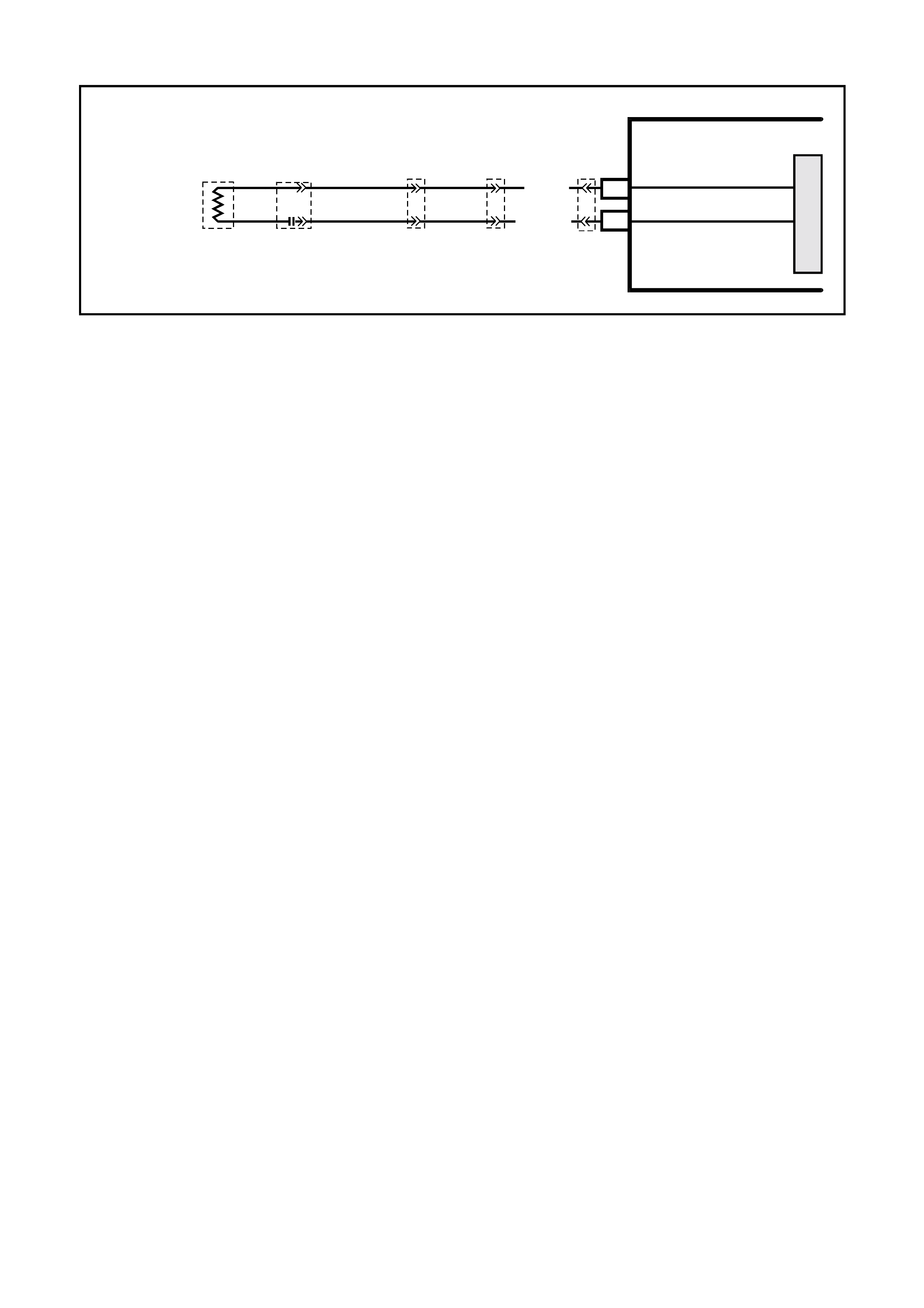
DTC 247 - PASSENGER AIR BAG CIRCUIT POWER STAGE ERROR
T12M127
SDM
M
I
C
R
O
YB191
YB189
YB190
YB200
YB208
PASSENGER
AIRBAG
INFLATOR
PASSENGER
A
IRBAG INFLAT OR (+)
PASSENGER
A
IRBAG INFLAT OR (-)
13
14
Y/B (3 4 9)
GY/B (3 50)
Figure 12M-32
CIRCUIT DESCRIPTION
At ignition on, the SDM perfor ms an initial system self check of the SDM power s tages. If during this initial self test
the SDM detects a fault with the passenger air bag power stage a current DTC 247 Passenger Air Bag Circuit
Power Stage Error will set. On completion of the initial system self test the SDM then performs a test of the
Passenger Air Bag Circuit. If the SDM detects a problem with this circuit the associated Passenger Air Bag Circuit
DTC will be set and the DTC 247 Passenger Air Bag Circuit Power Stage Error will become a history DTC.
DTC 247 Passenger Air Bag Circuit Power Stage Error will set if a fault occurs in the passenger air bag circuit,
connector YB208 with the in-built capacitor, connector YB200, connector YB191, the SRS wiring harness, connector
YB189/YB190 or SDM.
W hen a histor y DTC 247 Pass enger Air Bag Circuit Power Stage Error sets, the SDM illum inates the SRS warning
lamp. Should the fault conditions detected by the SDM clear during the same ignition cycle the code will remain a
history DTC 247 Passenger Air Bag Circuit Power Stage Err or for all ignition c ycles until cleared. T he SRS warning
lamp will remain on for the remainder of the ignition cycle.
When a DTC 247 Passenger Air Bag Circuit Power Stage Error sets, the SDM illuminates the SRS warning lamp for
the rem ainder of the ignition cycle. Should the fault conditions detected by the SDM clear during the sam e ignition
cycle the code will remain a history DTC 247 Passenger Air Bag Circuit Power Stage Error for all ignition cycles until
cleared. The SRS warning lamp will also remain illuminated until the history DTC 247 Passenger Air Bag Circuit
Power Stage Error is cleared.
If a DT C 247 Passenger Air Bag Circ uit Power Stage is set, dependent on where the f ault is, the pass enger air bag
may not operate.
ACTION REQUIRED
If DTC 247 Passenger Air Bag Circuit Power Stage Error and any other DTC is set then the diagnostics for the other
DTC s hould be car r ied out f ir st. F or ex ample if a DT C 247 Pas s enger Air Bag Circ uit Power Stage Err or and a DTC
37 Passenger Air Bag Circuit Resistance High are set, the diagnostics for a DTC 37 Passenger Air Bag Circuit
Resistance High should be carried out first.
If only a DTC 247 Passenger Air Bag Circuit Power Stage Error is set then the SDM should be replaced.
NOTE: An intermittent in the passenger air bag circuit may cause a DTC 247 Passenger Air Bag Circuit Power
Stage Error to set.
After the fault has been rectified, ensure that all SRS components are reconnected, clear DTCs, enable the SRS
and verify the correct operation of the system (i.e. warning lamp not illum inated after five seconds of ignition being
switched ON).
Test Description
The following numbers refer to Step numbers in the following diagnostic chart.
1. Uses TECH 2 to check if a DTC 247 Passenger Air Bag Circuit Power Stage Error is history code, and if any
other passenger air bag circuit current or history DTCs are set. If any other DT Cs are set refer to these DTCs
first.
2. Checks for intermittent fault by monitoring TECH 2 screen during ignition on cycle. If screen display changes
during a wiring 'wiggle' test, a fault with the wiring is at that location.
IF NO OTHER DTCS ARE SET AND THERE ARE NO INTERMITTENTS IN THE PASSENGER AIR BAG
CIRCUIT THEN THE SDM SHOULD BE REPLACED.
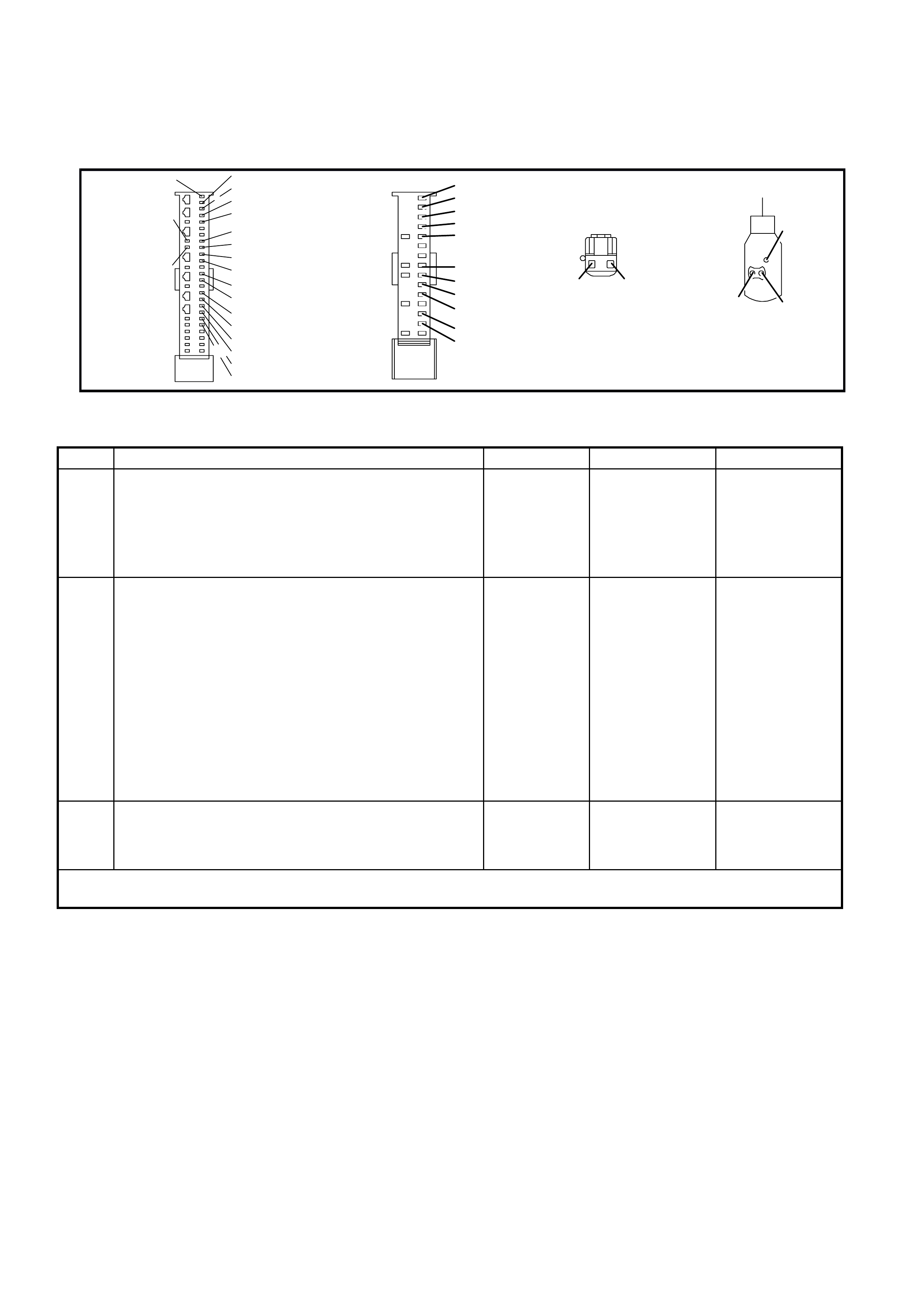
Notes on Diagnostic Chart
1. For all wiring harness checking procedures, refer to VT Series 1 Service Information, WIRING DIAGRAMS,
SECTION 12P.
2. Refer to VT Series 1 Service Information Section 12M, SRS VERSION 6.2, 2.8 SRS WIRING REPAIR before
conducting any SRS wiring harness repairs.
T12M172
YB189
8.1 SDM
WIRING
HARNESS
CONNECTOR
BR/B (393)
26
50 25
1
BLU/B (351) R/B (352)
BR/W (353)
Y/R (354)
P/B (739)
B (3 05)
B (3 05)
G/W (1220)
W (3 4 7)
G (348)
Y/B (349)
GY/B ( 3 50)
Y/G (385 )
BR/G (386)
Y/W (387 )
BR/W (388)
Y/BLU ( 392)
GY/W (407)
LBLU (408) +VE-VE
GY/B (350) Y/B (349)
CAP
ALSO -VE
YB208
PASSENGER
AIRBA G INFLATOR
BLU/B ( 351)
R/B (352)
BR/W (353)
Y/R (354)
P/B (739)
G/W (1220)
W (3 4 7)
G (348)
Y/B (349)
GY/B (350)
YB190
8.0 SDM WIRING
HARNESS
CONNECTOR
Y/B (349)
GY/B (350)
YB200
PASSENG ER AIRBAG
CONNECTOR HARNESS
Figure 12M-33
DTC 247 - PASSENGER AIR BAG CIRCUIT POWER STAGE ERROR
STEP ACTION VALUE YES NO
1. • Install TECH 2 to DLC.
• Select Body / SRS / Diagnostic Trouble Codes /
Read DTC Information.
• Is a DTC 247 Passenger Air Bag Circuit Power
Stage Error a history DTC, and are any other
passenger air bag circuit DTCs set?
Go to other
passenger air
bag circuit DTC
diagnostic chart
in this Section.
Go to Step 2.
2. • Remove instrument panel compartment to gain
access to passenger air bag, refer to Section 1A3
INSTRUMENT PANEL AND CONSOLE.
• With TECH 2 still connected, select Diagnostic
Trouble Codes / Clear DTC Information and clear all
(if any) DTCs.
• Select Diagnostic Trouble Codes / Read DTC
Information, 'wiggle' SRS wiring harness at all
locations between the SDM and the passenger air
bag wiring harness connector YB208, while
monitoring TECH 2 screen display.
• Does TECH 2 screen display change status from
No Diagnostic Trouble Codes?
Go to applicable
DTC chart in this
Section.
Go to step 3.
3 • Replace SDM, refer to VT Series 1 Service
Information Section 12M, SRS VERSION 8.0 & 8.1,
2.4 SENSING AND DIAGNOSTIC MODULE (SDM).
Recheck circuit to verify repair.
WHEN ALL DIAGNOSIS AND REPAIRS ARE COM PLETED, ENSURE ALL SRS COMPONENTS ARE
RECONNECTED, CLEAR ALL DTC’S, ENABLE THE SRS AND VERIFY CORRECT OPERATION
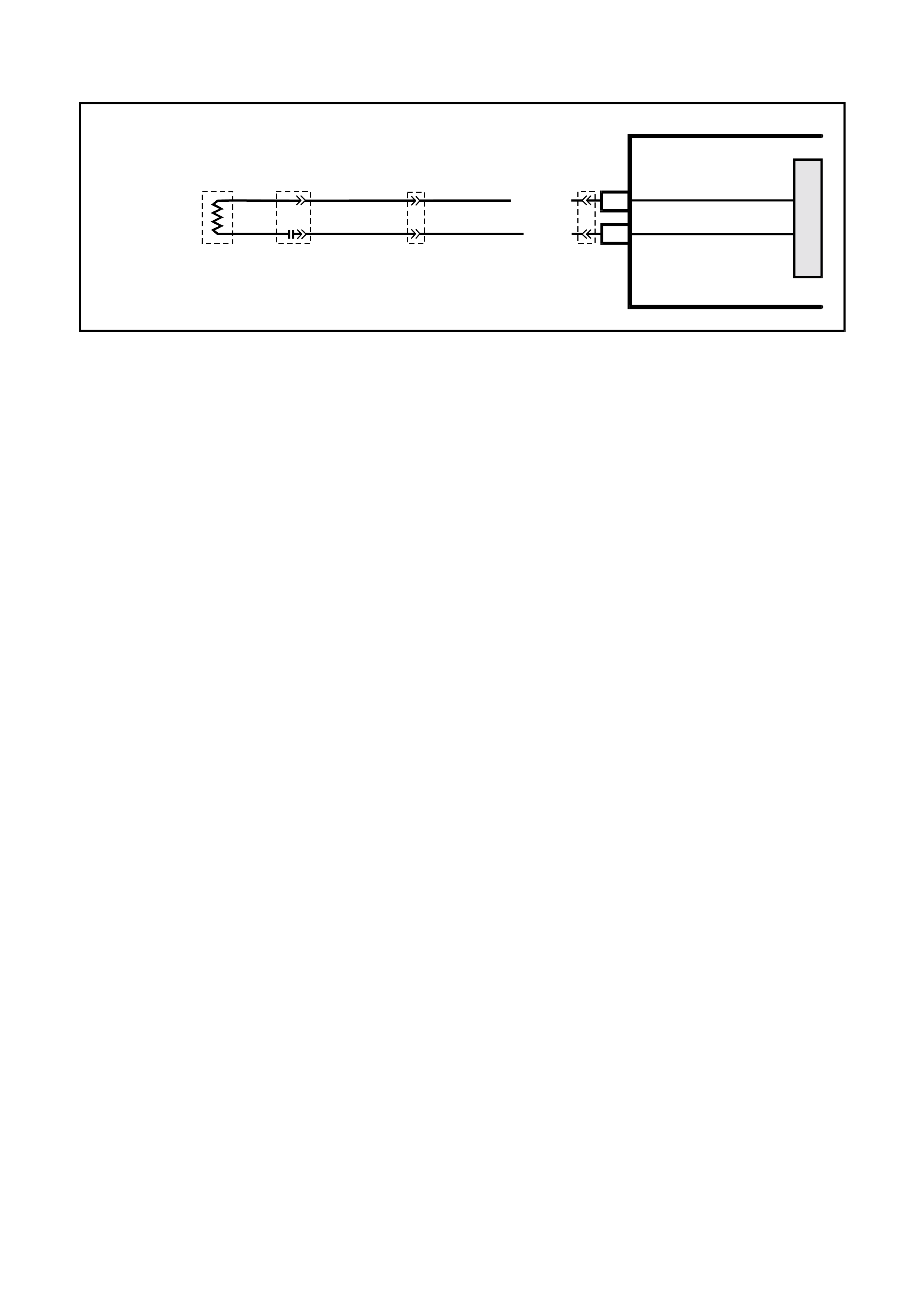
DTC 49 - LEFT HAND PRE-TENSIONER CIRCUIT SHORT TO BATTERY
T12M128
SDM
M
I
C
R
O
YB209
LEFT
HAND
PRE-TENSIONER
LEFT HAND
PRE-TENSIONER (+)
LEFT HAND
PRE-TENSIONER (- )
1
2
YB207
BLU/B (351)
R/B (352)
YB189
YB190
Figure 12M-34
CIRCUIT DESCRIPTION
At ignition on, and on a constant monitoring cycle of every 500 milliseconds during the ignition cycle, the SDM
performs a system self check.
If the SDM detects a resistance to battery supply is less than five kohms in either the positive and/or negative circuit
for more than 3 - 5 seconds, a current DTC 49 will set (refer to SRS SELF DIAGNOSTICS in Section 12M
SUPPLEMENTAL RESTRAINT SYSTEM (Version 8.0 & 8.1) of the VT Series I Service Information for more
details).
DTC 49 will set if circuits 351 (left hand pre-tensioner positive side) and/or 352 (left hand pre-tensioner negative
side) are shorted to battery +.
When DTC 49 sets, the SDM illuminates the SRS warning lamp and sets a current DTC 49. Should the fault
conditions detected by the SDM clear during the same ignition cycle, the current code will clear and become a
history DTC 49. The SRS warning lamp will remain on for the remainder of the ignition cy cle.
If a DTC 49 is set, the SRS warning lamp is illuminated on each ignition cycle, even if the DTC is set as a history
DTC, until the fault conditions for setting DTC 49 are rectified and the DTC (current or history) can then be cleared
from the SDM via TECH 2.
If DTC 49 is set, the SRS, including the left hand pre-tensioner, will still be operational.
Test Description
The following numbers refer to step numbers in the following diagnostic chart:
1. Uses TECH 2 to check if DTC 49 is current or history.
2. Checks for intermittent fault by monitoring TECH 2 screen. If screen display changes during a wiring 'wiggle' test,
a fault with the wiring is at that location.
3. Checks circuits 351 and 352 for a short to battery +.
Notes on Diagnostic Chart
1. For all wiring harness checking procedures, refer to Section 12P WIRING DIAGRAMS of the VT Series I
Service Information.
2. Refer to 2.8 SRS WIRING REPAIR in Section 12M SUPPLEMENTAL RESTRAINT SYSTEM (Version 6.2) of
the VT Series I Service Information before conducting any SRS wiring harness repairs.
3. Resist ance cannot be m eas ured between the two terminals in connector YB209, as the in-built capacitor block s
measurement. Therefore, a ‘service hole’ is incorporated into the connector for fault tracing. Refer to
1.1 SYSTEM COMPONENTS, WIRING HARNESS in Section 12M SUPPLEMENTAL RESTRAINT SYSTEM
(Version 8.0 & 8.1) of the VT Series I Service Information for more details on this type of connector.
4. W iring should be checked at point where TECH 2 screen display changed status. If necessary, split open the
harness.
5. If the fault can not be identified, the harness should be replaced.
6. Refer to TECH 2 DIAGNOSTICS in Sec tion 12M SUPPLEMENTAL REST RAINT SYSTEM (Vers ion 8.0 & 8.1)
of the VT Series I Service Information for connecting and using TECH 2.
7. To enable or disable the SRS system, refer to 2.2 SYSTEM DISABLING AND ENABLING PROCEDURE in
Section 12M SUPPLEMENTAL RESTRAINT SYSTEM (Version 8.0 & 8.1) of the VT Series I Service
Information.
8. SDM connector YB189 is equipped with a shorting link busbar which needs to be opened before checking the
circuit, re fer to 2.5 DIAGNOSTIC CHARTS in this Section for additional information.
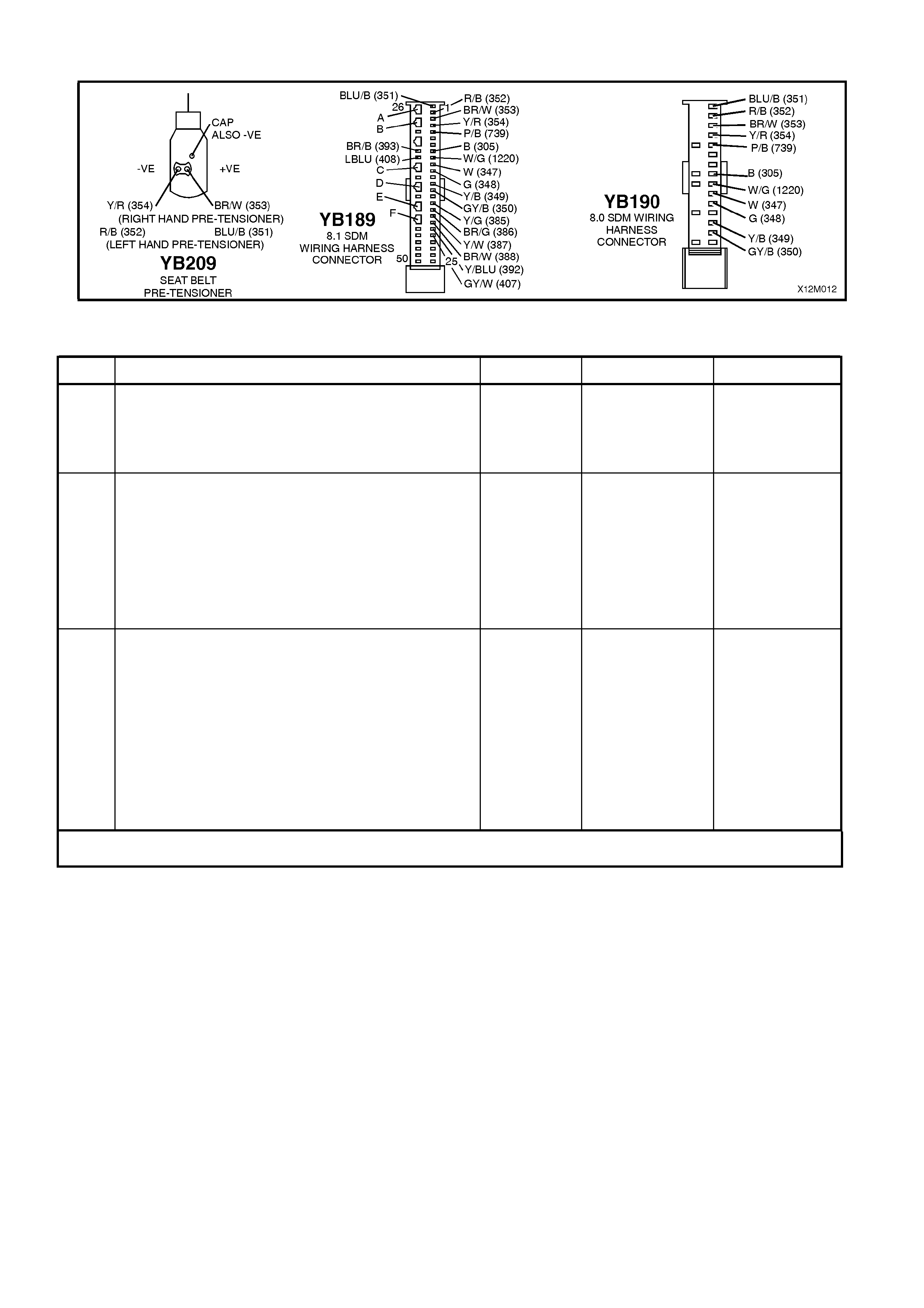
Figure 12M-35
DTC 49 - LEFT HAND PRE-TENSIONER CIRCUIT SHORT TO BATTERY
STEP ACTION VALUE YES NO
1. • Connect TECH 2 to DLC.
• Select Body / SRS / Diagnostic Trouble Codes /
Read DTC Information (refer NOTE 6 on previous
page).
• Is DTC 49 current ?
Go to Step 3. Go to Step 2.
2. • With TECH 2 still connected, select Diagnostic
Trouble Codes / Clear DTC Information and clear
all (if any) DTCs.
• Select Diagnostic Trouble Codes / Read DTC
Information, 'wiggle' SRS wiring harness at all
locations between the SDM and the left hand pre-
tensioner wiring harness connector YB209, while
monitoring TECH 2 screen display.
• Does TECH 2 screen display change status from
No Diagnostic Trouble Codes?
Make repairs as
necessary (refer
to NOTE 2 & 4 on
previous page).
Clear DTC and
recheck system to
verify repair.
Fault not present.
Check all system
wiring harness
connectors, and
terminals, refer to
NOTE 5 on
previous page.
Clear DTC and
recheck system.
3. • Disable the SRS (refer NOTE 7 on previous page).
• Disconnect the SRS wiring harness connector
YB209 from the left hand pre-tensioner assembly.
• Disconnect SDM wiring harness connector
YB189/YB190 from the SDM.
• Reconnect battery.
• Using Tool KM-609-20, check wiring between SDM
wiring harness connector YB189/YB190, terminals
1 and 2 and left hand pre-tensioner connector
YB209, circuits 351 (Blue/Black wire) and 352
(Red/Black wire) for short to battery + (refer to
NOTES 1, 3 & 8 on previous page).
• Is all OK?
Replace SDM,
refer Section 12M
SUPPLEMENTAL
RESTRAINT
SYSTEM (Version
8.0 & 8.1) of the
VT Series I
Service
Information.
Recheck circuit to
verify repair.
Make repairs as
necessary (refer
to NOTE 2 on
previous page).
Clear DTC and
recheck system
to verify repair.
WHEN ALL DIAGNOSIS AND REPAIRS ARE COM PLETED, ENSURE ALL SRS COMPONENTS ARE
RECONNECTED, CLEAR ALL DTC’S, ENABLE THE SRS AND VERIFY CORRECT OPERATION

DTC 50 - LEFT HAND PRE-TENSIONER CIRCUIT SHORT TO EARTH
T12M128
SDM
M
I
C
R
O
YB209
LEFT
HAND
PRE-TENSIONER
LEFT HAND
PRE-TENSIONER (+)
LEFT HAND
PRE-TENSIONER (- )
1
2
YB207
BLU/B (351)
R/B (352)
YB189
YB190
Figure 12M-36
CIRCUIT DESCRIPTION
At ignition on, and on a constant monitoring cycle of every 500 milliseconds during the ignition cycle, the SDM
performs a system self check. If the SDM detects a resistance to earth of less than three kohms in either the
positive or negative circuit for more than 3 - 5 seconds, a current DTC 50 will set (refer to
SRS SELF DIAGNOSTICS in Section 12M SUPPLEMENTAL RESTRAINT SYSTEM (Version 8.0 & 8.1) of the VT
Series I Service Information for more details).
DTC 50 will set if circuits 351 (left hand pre-tensioner positive side) and/or 352 (left hand pre-tensioner negative
side) are shorted to earth.
When DTC 50 sets, the SDM illuminates the SRS warning lamp and sets a current DTC 50. Should the fault
conditions detected by the SDM clear during the same ignition cycle, the current code will clear and become a
history DTC 50. The SRS warning lamp will remain on for the remainder of the ignition cy cle.
If a DTC 50 is set, the SRS warning lamp is illuminated on each ignition cycle, even if the DTC is set as a history
DTC, until the fault conditions for setting DTC 50 are rectified and the DTC (current or history) can then be cleared
from the SDM via TECH 2.
If DTC 50 is set, the SRS, including the left hand pre-tensioner, will still be operational.
Test Description
The following numbers refer to step numbers in the following diagnostic chart:
1. Uses TECH 2 to determine if DTC 50 is current or history.
2. TECH 2 in this mode should display approximately 1.6 - 6.4 ohms if the left hand pre-tensioner loop circuit is
OK.
3. If screen display changes during a wiring 'wiggle' test, a fault with the wiring is at that location.
4. Tool SD28280B is a dummy load tak ing the place of the pr e- tensioner as sembly. If TECH 2 dis plays the correct
resistance of the dummy load, the system fault is in the pre-tensioner assembly.
5. T his test c heck s the wiring between the SDM wiring harnes s connec tor YB189 (8.1 SDM) or YB190 (8.0 SDM),
terminal 1 and the left hand pre-tensioner connector YB209 for faults.
6. T his test c heck s the wiring between the SDM wiring harnes s connec tor YB189 (8.1 SDM) or YB190 (8.0 SDM),
terminal 2 and the left hand pre-tensioner connector YB209 for faults.
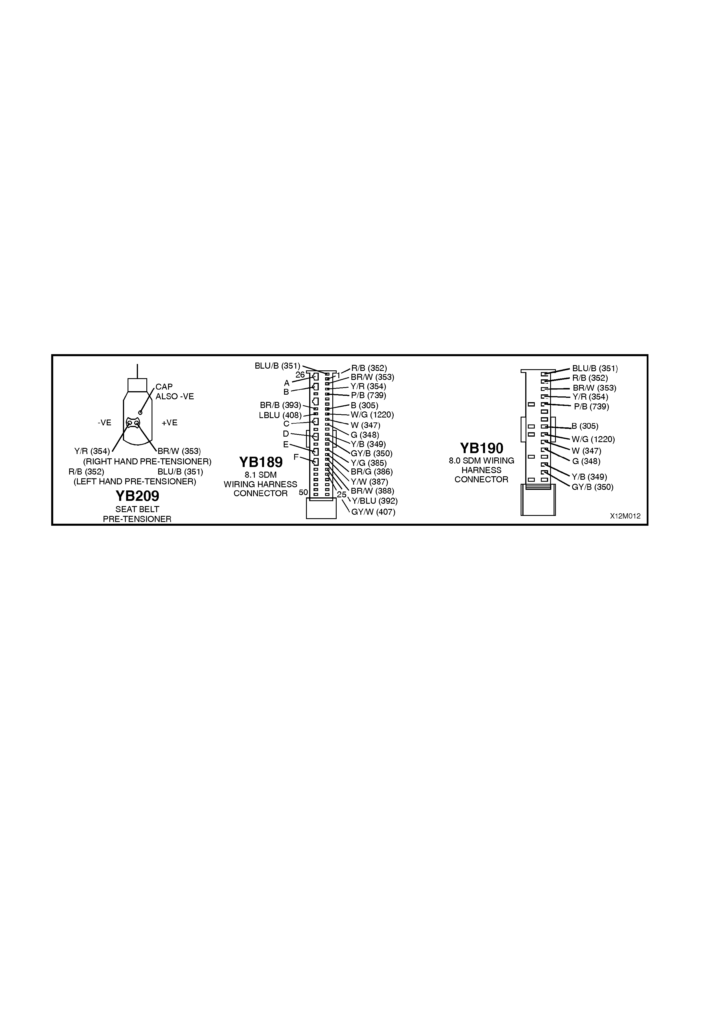
Notes on Diagnostic Chart
1. For all wiring harness checking procedures, refer to Section 12P WIRING DIAGRAMS of the VT Series I
Service Information.
2. Refer to SRS 2.8 WIRING REPAIR in this Section 12M SUPPLEMENTAL REST RAINT SYST EM (Version 6.2)
of the VT Series I Service Information before conducting any SRS wiring harness repairs.
3. Resistance cannot be m easured between the two term inals in connector YB209 as the in-built capacitor block s
measurement. Therefore, a ‘service hole’ is incorporated into the connector for fault tracing. Refer to
1.1 SYSTEM COMPONENTS, WIRING HARNESS in Section 12M SUPPLEMENTAL RESTRAINT SYSTEM
(Version 8.0 & 8.1) of the VT Series I Service Information for more details on this type of connector.
4. Wiring should be checked at point where TECH 2 screen display changed. If necessary, split open wiring
harness.
5. If fault cannot be identified, the wiring harness should be replaced.
6. Refer to T ECH 2 DIAGNOST ICS in Section 12M SUPPLEMENT AL RESTRAINT SYST EM (Version 8.0 & 8.1)
of the VT Series I Service Information for connecting and using TECH 2.
7. To enable or disable the SRS system, refer to 2.2 SYSTEM DISABLING AND ENABLING PROCEDURE in
Section 12M SUPPLEMENTAL RESTRAINT SYSTEM (Version 8.0 & 8.1) of the VT Series I Service
Information.
8. SDM connector YB189 is equipped with a shorting link busbar which needs to be opened before checking the
circuit, re fer to 2.5 DIAGNOSTIC CHARTS in this Section for additional information.
Figure 12M-37

DTC 50 - LEFT HAND PRE-TENSIONER CIRCUIT SHORT TO EARTH
STEP ACTION VALUE YES NO
1. • Connect TECH 2 to DLC.
• Select Body / SRS / Diagnostic Trouble Codes /
Read DTC Information (refer NOTE 6 on previous
page).
• Does TECH 2 display DTC 50 as a current DTC?
Go to Step 2. Go to Step 3.
2. • With TECH 2 still connected, select Body / SRS /
Data Display and scroll to LEFT HAND PRE-
TENSIONER LOOP RESISTANCE'.
• Is the resistance value displayed on TECH 2 as
specified?
Approx.
1.5 - 6.4
ohms
Go to Step 3. Go to Step 4.
3. • With TECH 2 still connected, select Diagnostic
Trouble Codes / Clear DTC Information and clear
all (if any) DTCs.
• Select Diagnostic Trouble Codes / Read DTC
Information, 'wiggle' SRS wiring harness at all
locations between the SDM and the left hand pre-
tensioner wiring harness connector YB209, while
monitoring TECH 2 screen display.
• Does TECH 2 screen display change status from
No Diagnostic Trouble Codes?
Make repairs as
necessary (refer
to NOTE 2 & 4 on
previous page).
Clear DTC and
recheck system to
verify repair.
Fault not present.
Check all system
wiring harness
connectors, and
terminals, refer to
NOTE 5 on
previous page.
Clear DTC and
recheck system.
4. • Disable the SRS (refer NOTE 7 on previous page).
• Disconnect left hand pre-tensioner wiring harness
connector YB209 from pre-tensioner.
• Connect Tool No. SD28280B to SRS wiring
harness connector YB209.
• Re-connect battery.
• With TECH 2 still connected, select Body / SRS /
Data Display and scroll to LEFT HAND PRE-
TENSIONER LOOP RESISTANCE'.
• Is the resistance value displayed on TECH 2 as
specified?
Approx.
3.0 ohms
Replace left hand
pre-tensioner
assembly, refer to
Section 1A7
SEAT AND SEAT
BELT
ASSEMBLIES of
the VT Series I
Service
Information.
Clear DTC and
recheck system to
verify repair.
Go to Step 5.
5. • Disable the SRS (refer NOTE 7 on previous page).
• Disconnect SDM wiring harness connector
YB189/YB190 from the SDM.
• Remove Tool SD28280B from YB209.
• Using Tool KM-609-20, check wiring between SDM
wiring harness connector YB189/YB190, terminal 1
and left hand pre-tensioner connector YB209,
circuit 351 (Blue/Brown wire) for short to earth
(refer to NOTES 1 & 8 on previous page).
• Is all OK?
Go to Step 6. Make repairs as
necessary (refer
to NOTE 2 on
previous page).
Clear DTC and
recheck system
to verify repair.
6. • W ith SDM wiring harness connector YB189/YB190
disconnected from the SDM and using Tool KM-
609-20, check wiring between SDM wiring harness
connector YB189/YB190, terminal 2 and left hand
pre-tensioner connector YB209, circuit 352
(Red/Black wire) for a short to earth (refer to
NOTES 1, 3 & 8 on previous page).
• Is all OK?
Replace SDM,
refer Section 12M
SUPPLEMENTAL
RESTRAINT
SYSTEM (Version
8.0 & 8.1) of the
VT Series I
Service
Information.
Recheck circuit to
verify repair.
Make repairs as
necessary (refer
to NOTE 2 on
previous page).
Clear DTC and
recheck system
to verify repair.
WHEN ALL DIAGNOSIS AND REPAIRS ARE COM PLETED, ENSURE ALL SRS COMPONENTS ARE
RECONNECTED, CLEAR ALL DTC’S, ENABLE THE SRS AND VERIFY CORRECT OPERATION

DTC 51 - LEFT HAND PRE-TENSIONER CIRCUIT CAPACITANCE TOO HIGH
T12M128
SDM
M
I
C
R
O
YB209
LEFT
HAND
PRE-TENSIONER
LEFT HAND
PRE-TENSIONER (+)
LEFT HAND
PRE-TENSIONER (- )
1
2
YB207
BLU/B (351)
R/B (352)
YB189
YB190
Figure 12M-38
CIRCUIT DESCRIPTION
At ignition on, and on a constant monitoring cycle of every 500 milliseconds during the ignition cycle, the SDM
performs a system self check.
If the SDM detects the capacitance in the left hand pre-tensioner circuit is too high (greater than 550 nF) for longer
than 3 - 5 seconds, a current DTC 51 will set (refer to SRS SELF DIAGNOSTICS in Section 12M SUPPLEMENTAL
RESTRAINT SYSTEM (Version 8.0 & 8.1) of the VT Series I Service Information for more details).
DTC 51 will set if the in-built capacitor in the SRS wiring harness connector YB209 is faulty.
When DTC 51 sets, the SDM illuminates the SRS warning lamp and sets a current DTC 51. Should the fault
conditions detected by the SDM clear during the same ignition cycle, the current code will clear and become a
history DTC 51. The SRS warning lamp will remain on for the remainder of the ignition cy cle.
If a DTC 51 is set, the SRS warning lamp is illuminated on each ignition cycle, even if the DTC is set as a history
DTC, until the fault conditions for setting DTC 51 are rectified and the DTC (current or history) can then be cleared
from the SDM via TECH 2.
ACTION REQUIRED
If DTC 51 is set, the left hand pre-tensioner may not operate and therefore, the SRS pre-tensioner wiring harness,
with connector YB209 (between left hand pre-tensioner and SRS connector YB207) must be replaced.
NOTE: Before removing the SRS pre-tensioner wiring harness, take note of wiring harness routing and how it is
retained to the front seat.
After the SRS pre-tensioner wiring harness, between the pre-tensioner and SRS wiring harness connector YB207
has been replaced, ensure all SRS components are reconnected, clear DTCs, enable the SRS and verify the
correct operation of the system (i.e. warning lamp not illuminated after five seconds of ignition being switched ON).
NOTE: After the wiring harness has been replaced, the front seat should be put through its full adjustment
(forward/backwards, full recline and up and down) to ensure that the wiring harness does not foul with any of the
seat components.

DTC 52 - LEFT HAND PRE-TENSIONER CIRCUIT CAPACITANCE TOO LOW
Figure 12M-39
CIRCUIT DESCRIPTION
At ignition on, and on a constant monitoring cycle of every 500 milliseconds during the ignition cycle, the SDM
performs a system self check.
If the SDM detects the capacitance in the left hand pre-tensioner circuit is too low (less than 390 nF) for longer than
3 - 5 seconds, a current DTC 52 will set (refer to SRS SELF DIAGNOSTICS in Section 12M SUPPLEMENTAL
RESTRAINT SYSTEM (Version 8.0 & 8.1) of the VT Series I Service Information for more details).
DTC 52 will set if the in-built capacitor in the SRS wiring harness connector YB209 is faulty.
When DTC 52 sets, the SDM illuminates the SRS warning lamp and sets a current DTC 52. Should the fault
conditions detected by the SDM clear during the same ignition cycle, the current code will clear and become a
history DTC 52. The SRS warning lamp will remain on for the remainder of the ignition cy cle.
If a DTC 52 is set, the SRS warning lamp is illuminated on each ignition cycle, even if the DTC is set as a history
DTC, until the fault conditions for setting DTC 52 are rectified and the DTC (current or history) can then be cleared
from the SDM via TECH 2.
ACTION REQUIRED
If DTC 52 is set, the left hand pre-tensioner may not operate and therefore, the SRS pre-tensioner wiring harness,
with connector YB209 (between left hand pre-tensioner and SRS connector YB207) must be replaced.
NOTE: Before removing the SRS pre-tensioner wiring harness, take note of wiring harness routing and how it is
retained to the front seat.
After the SRS pre-tensioner wiring harness, between the pre-tensioner and SRS wiring harness connector YB207
has been replaced, ensure that all SRS components are reconnected, clear DTCs, enable the SRS and verify the
correct operation of the system (i.e. warning lamp not illuminated after five seconds of ignition being switched ON).
NOTE: After the wiring harness has been replaced, the front seat should be put through its full adjustment
(forward/backwards, full recline and up and down) to ensure that the wiring harness does not foul with any of the
seat components.

DTC 53 - LEFT HAND PRE-TENSIONER CIRCUIT RESISTANCE TOO HIGH
Figure 12M-40
CIRCUIT DESCRIPTION
At ignition on, and on a constant monitoring cycle of every 500 milliseconds during the ignition cycle, the SDM
performs a system self check.
If the SDM detects a resistance in the left hand pre-tensioner circuit that is too high (greater than 10 ohms) for
longer than 3 - 5 seconds, a current DTC 53 will set (refer to SRS SELF DIAGNOSTICS in Section 12M
SUPPLEMENTAL RESTRAINT SYSTEM (Version 8.0 & 8.1) of the VT Series I Service Information for more
details).
DTC 53 will set if circuits 351 or 352 (including the left hand pre-tensioner assembly) are open circuit.
When DTC 53 sets, the SDM illuminates the SRS warning lamp and sets a current DTC 53. Should the fault
conditions detected by the SDM clear during the same ignition cycle, the current code will clear and become a
history DTC 53. The SRS warning lamp will remain on for the remainder of the ignition cy cle.
If a DTC 53 is set, the SRS warning lamp is illuminated on each ignition cycle, even if the DTC is set as a history
DTC, until the fault conditions for setting DTC 53 are rectified and the DTC (current or history) can then be cleared
from the SDM via TECH 2.
If DTC 53 is set, dependent on where the fault is, the left hand pre-tensioner may not operate.
Test Description
The following numbers refer to step numbers in the following diagnostic chart:
1. Uses TECH 2 to check if DTC 53 is current or history.
2. Checks for intermittent fault by monitoring TECH 2 screen. If screen display changes during a wiring 'wiggle' test,
a fault with the wiring is at that location.
3. Tool SD28280B is a dummy load tak ing the place of the left hand pr e-tens ioner ass embly. If DTC 53 becomes a
history DTC with dummy load connected, the system fault is in the left hand pre-tensioner assembly.
4. Checks if open circuit is in the SRS connector harness. If connector YB207 is disconnected and it’s terminal’s
are bridged together, DTC 53 will become a history DTC if this connector harness is faulty.
5. Checks circuit 351 for open circuit.
6. Checks circuit 352 for open circuit.
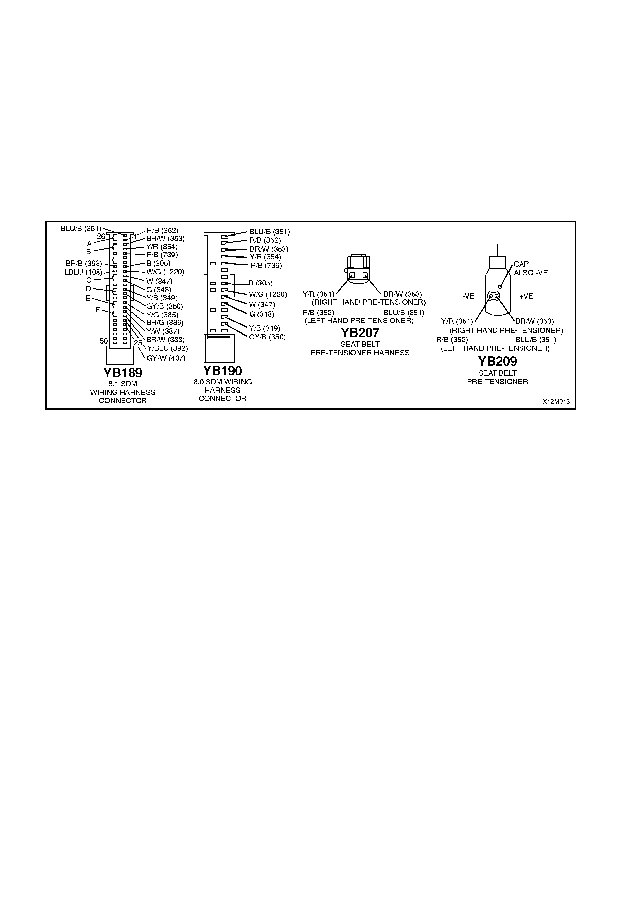
Notes on Diagnostic Chart
1. For all wiring harness checking procedures, refer to Section 12P WIRING DIAGRAMS of the VT Series I
Service Information.
2. Refer to 2.8 SRS WIRING REPAIR in Section 12M SUPPLEMENTAL RESTRAINT SYSTEM of the VT
Series I Service Information before conducting any SRS wiring harness repairs.
3. Refer to TECH 2 DIAGNOSTICS in Section 12M SUPPLEMENTAL RESTRAINT SYSTEM (Version 8.0 &
8.1) of the VT Series I Service Information for connecting and using TECH 2.
4. To enable or disable the SRS system, refer to 2.2 SYSTEM DISABLING AND ENABLING PROCEDURE
in Section 12M SUPPLEMENTAL RESTRAINT SYSTEM (Version 8.0 & 8.1) of the VT Series I Service
Information.
5. SDM connector YB189 is equipped with a shorting link busbar which needs to be opened before check ing
the circuit, refer to 2.5 DIAGNOSTIC CHARTS in this Section for additional information.
Figure 12M-41

DTC 53 - LEFT HAND PRE-TENSIONER CIRCUIT RESISTANCE TOO HIGH
STEP ACTION VALUE YES NO
1. • Connect TECH 2 to DLC.
• Select Body / SRS / Diagnostic Trouble Codes /
Read DTC Information (refer NOTE 3 on previous
page).
• Is DTC 53 current?
Go to Step 3. Go to Step 2.
2. • With TECH 2 still connected, select Diagnostic
Trouble Codes / Clear DTC Information and clear
all (if any) DTCs.
• Select Diagnostic Trouble Codes / Read DTC
Information, 'wiggle' SRS wiring harness at all
locations between the SDM and the left hand pre-
tensioner wiring harness connector YB209, while
monitoring TECH 2 screen display.
• Does TECH 2 screen display change status from
No Diagnostic Trouble Codes?
Make repairs as
necessary (refer
to NOTE 2 on
previous page).
Clear DTC and
recheck system to
verify repair.
Fault not present.
Check all system
wiring harness
connectors, and
terminals.
Clear DTC and
recheck system.
3. • Disable the SRS (refer NOTE 4 on previous page).
• Disconnect the left hand pre-tensioner wiring
harness connector YB209.
• Connect Tool No. SD28280B to SRS wiring
harness connector YB209.
• Enable the SRS (reconnect battery).
• Connect TECH 2 to DLC.
• Select Body / SRS / Diagnostic Trouble Codes /
Read DTC Information.
• Is DTC 53 still current?
Go to Step 4. Replace left hand
pre-tensioner
assembly, refer
to Section 1A7
SEAT AND SEAT
BELT
ASSEMBLIES of
the VT Series I
Service
Information.
Clear DTC and
recheck system
to verify repair.
4. • Disable the SRS (refer NOTE 4 on previous page).
• Disconnect SRS wiring harness connector YB207
(located next to left hand front seat) from left hand
pre-tensioner connector harness.
• Enable the SRS (reconnect battery).
• Using a suitable jumper wire from KM-609, bridge
terminals in connector YB207 together
(NOTE: This step may set a current DTC 54).
• With TECH 2 still connected, select Body / SRS /
Diagnostic Trouble Codes / Read DTC Information.
• Does DTC 53 become history?
Replace SRS
connector
harness (harness
between left hand
pre-tensioner and
connector
YB207). Clear all
DTCs and
recheck system to
verify repair.
Go to Step 5.
5. • Disable the SRS (refer NOTE 4 on previous page).
• Disconnect SDM wiring harness connector
YB189/YB190 from the SDM.
• Using Tool KM-609-20, check wiring between SDM
wiring harness connector YB189/YB190, terminal 1
and SRS wiring harness connector YB207, circuit
351 (Blue/Black wire) for open circuit (refer to
NOTES 1 & 5 on previous page).
• Is all OK?
Go to Step 6. Make repairs as
necessary (refer
to NOTE 2 on
previous page).
Clear DTC and
recheck system
to verify repair.
6. • W ith SDM wiring harness connector YB189/YB190
disconnected from the SDM and using Tool KM-
609-20, check wiring between SDM wiring harness
connector YB189/YB190, terminal 2 and SRS
wiring harness connector YB207, circuit 352
(Red/Black wire) for open (refer to NOTES 1 & 5 on
previous page).
• Is all OK?
Replace SDM,
refer Section 12M
SUPPLEMENTAL
RESTRAINT
SYSTEM (Version
8.0 & 8.1) of the
VT Series I
Service
Information.
Recheck circuit to
verify repair.
Make repairs as
necessary (refer
to NOTE 2 on
previous page).
Clear DTC and
recheck system
to verify repair.
WHEN ALL DIAGNOSIS AND REPAIRS ARE COM PLETED, ENSURE ALL SRS COMPONENTS ARE
RECONNECTED, CLEAR ALL DTC’S, ENABLE THE SRS AND VERIFY CORRECT OPERATION

DTC 54 - LEFT HAND PRE-TENSIONER CIRCUIT RESISTANCE TOO LOW
Figure 12M-42
CIRCUIT DESCRIPTION
At ignition on, and on a constant monitoring cycle of every 500 milliseconds during the ignition cycle, the SDM
performs a system self check.
If the SDM detects a resistance in the left hand pre-tensioner circuit that is too low (less than 0.6 ohm) for longer
than 3 - 5 seconds, a current DTC 54 will set (refer to SRS SELF DIAGNOSTICS in Section 12M SUPPLEMENTAL
RESTRAINT SYSTEM (Version 8.0 & 8.1) of the VT Series I Service Information for more details).
DTC 54 will set if circuits 351 or 352, (including the pre-tensioner assembly) are shorted together.
When DTC 54 sets, the SDM illuminates the SRS warning lamp and sets a current DTC 54. Should the fault
conditions detected by the SDM clear during the same ignition cycle, the current code will clear and become a
history DTC 54. The SRS warning lamp will remain on for the remainder of the ignition cy cle.
If a DTC 54 is set, the SRS warning lamp is illuminated on each ignition cycle, even if the DTC is set as a history
DTC, until the fault conditions for setting DTC 54 are rectified and the DTC (current or history) can then be cleared
from the SDM via TECH 2.
If DTC 54 is set, dependent on where the fault is, the passenger’s belt pre-tensioner may not operate.
Test Description
The following numbers refer to step numbers in the following diagnostic chart:
1. Uses TECH 2 to check if DTC 54 is current or history.
2. Checks for intermittent fault by monitoring TECH 2 screen. If screen display changes during a wiring 'wiggle' test,
a fault with the wiring is at that location.
3. Tool SD28280B is a dummy load tak ing the place of the left hand pr e-tens ioner ass embly. If DTC 54 becomes a
history DTC with dummy load connected, the system fault is in the left hand pre-tensioner assembly.
4. This test checks the wiring between the SDM wiring harness connector YB189 (8.1 SDM) or YB190 (8.0 SDM)
and SRS wiring harness connector YB209 for a short circuit.
Notes on Diagnostic Chart
1. For all wiring harness checking procedures, refer to Section 12P WIRING DIAGRAMS of the VT Series I
Service Information.
2. Refer to 2.8 SRS WIRING REPAIR in Section 12M SUPPLEMENTAL RESTRAINT SYSTEM of the VT Series I
Service Information before conducting any SRS wiring harness repairs.
3. Resistance cannot be m eas ured between the two terminals in connector YB209, as the in-built capacitor block s
measurement. Therefore, a ‘service hole’ is incorporated into the connector for fault tracing. Refer to
1.1 SYSTEM COMPONENTS, WIRING HARNESS in Section 12M SUPPLEMENTAL RESTRAINT SYSTEM
(Version 8.0 & 8.1) of the VT Series I Service Information for more details on this type of connector.
4. Refer to T ECH 2 DIAGNOST ICS in Section 12M SUPPLEMENT AL RESTRAINT SYST EM (Version 8.0 & 8.1)
of the VT Series I Service Information for connecting and using TECH 2.
5. To enable or disable the SRS system, refer to 2.2 SYSTEM DISABLING AND ENABLING PROCEDURE in
Section 12M SUPPLEMENTAL RESTRAINT SYSTEM (Version 8.0 & 8.1) of the VT Series I Service
Information.
6. SDM connector YB189 is equipped with a shorting link busbar which needs to be opened before checking the
circuit, re fer to 2.5 DIAGNOSTIC CHARTS in this Section for additional information.
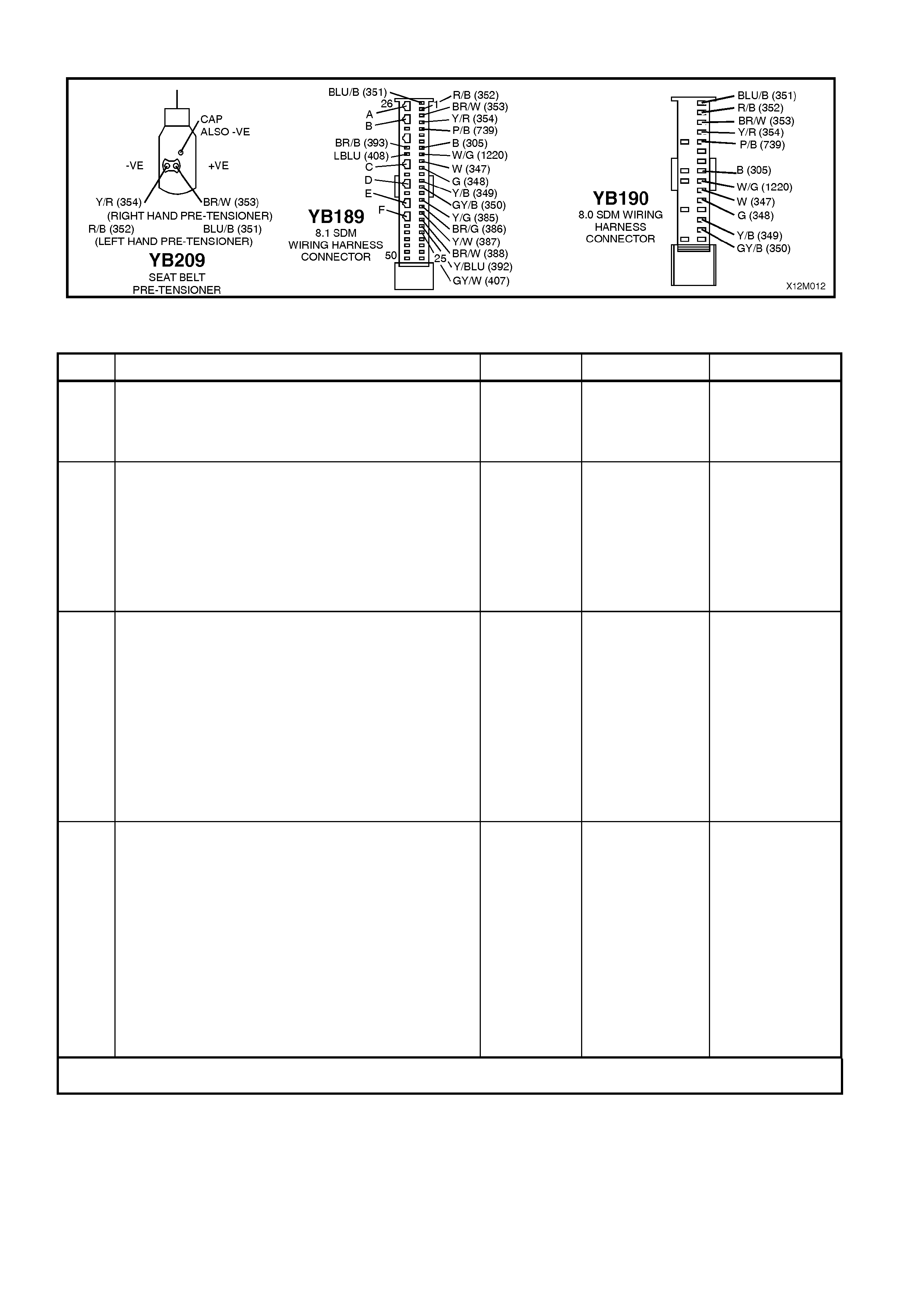
Figure 12M-43
DTC 54 - LEFT HAND PRE-TENSIONER CIRCUIT RESISTANCE TOO LOW
STEP ACTION VALUE YES NO
1. • Connect TECH 2 to DLC.
• Select Body / SRS / Diagnostic Trouble Codes /
Read DTC Information (refer NOTE 4 on previous
page).
• Is DTC 54 current?
Go to Step 3. Go to Step 2.
2. • With TECH 2 still connected, select Diagnostic
Trouble Codes / Clear DTC Information and clear
all (if any) DTCs.
• Select Diagnostic Trouble Codes / Read DTC
Information, 'wiggle' SRS wiring harness at all
locations between the SDM and the left hand pre-
tensioner wiring harness connector YB209, while
monitoring TECH 2 screen display.
• Does TECH 2 screen display change status from
No Diagnostic Trouble Codes?
Make repairs as
necessary (refer
to NOTE 2 on
previous page).
Clear DTC and
recheck system
to verify repair.
Fault not present.
Check all system
wiring harness
connectors, and
terminals.
Clear DTC and
recheck system.
3. • Disable the SRS (refer NOTE 5 on previous page).
• Disconnect the left hand pre-tensioner wiring
harness connector YB209.
• Connect Tool No. SD28280B to SRS wiring
harness connector YB209.
• Enable the SRS (reconnect battery).
• Connect TECH 2 to DLC.
• Select Body / SRS / Diagnostic Trouble Codes /
Read DTC Information.
• Is DTC 54 still current?
Go to Step 4. Replace left hand
pre-tensioner
assembly, refer to
Section 1A7
SEAT AND SEAT
BELT
ASSEMBLIES of
the VT Series I
Service
Information.
Clear DTC and
recheck system to
verify repair.
4. • Disable the SRS (refer NOTE 5 on previous page).
• Disconnect SDM wiring harness connector
YB189/YB190 from the SDM.
• Disconnect Tool No. SD28280B from SRS wiring
harness connector YB209.
• With SRS wiring harness connector YB209
disconnected, and using Tool KM-609-20, check
for continuity between SDM wiring harness
connector YB189/YB190, terminal 1, circuit 351
(Blue/Black wire) and terminal 2, circuit 352
(Red/Black wire)(refer to NOTES 1, 3 & 6 on
previous page).
• Does continuity exist?
Repair short in
circuits 351 and
352, between
SDM wiring
harness
connector
YB189/YB190
and YB209 as
necessary (refer
to NOTE 2 on
previous page).
Clear DTC and
recheck system
to verify repair.
Replace SDM,
refer Section 12M
SUPPLEMENTAL
RESTRAINT
SYSTEM (Version
8.0 & 8.1) of the
VT Series I
Service
Information.
Recheck circuit to
verify repair.
WHEN ALL DIAGNOSIS AND REPAIRS ARE COM PLETED, ENSURE ALL SRS COMPONENTS ARE
RECONNECTED, CLEAR ALL DTC’S, ENABLE THE SRS AND VERIFY CORRECT OPERATION
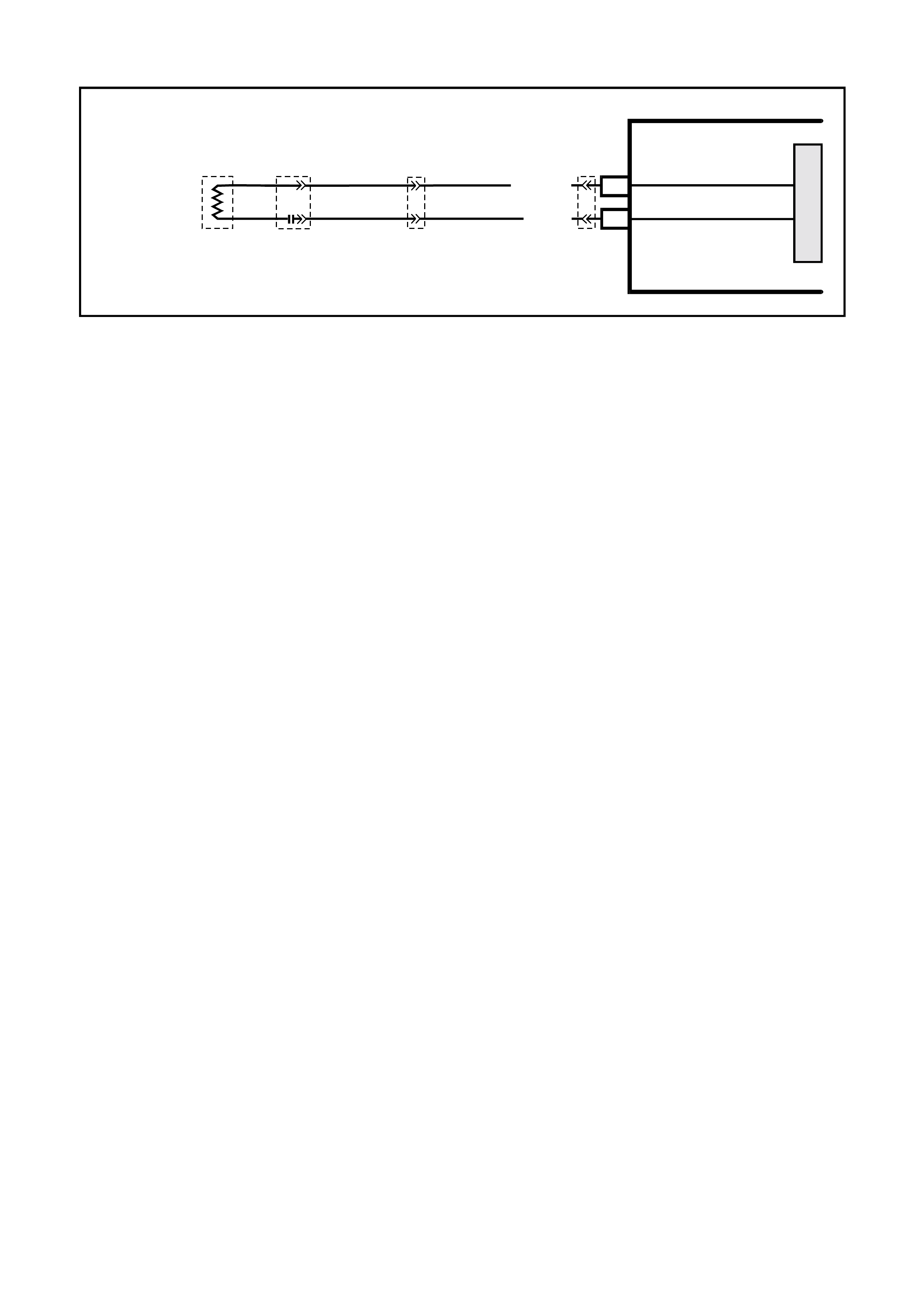
DTC 247 - LEFT HAND PRE-TENSIONER CIRCUIT POWER STAGE ERROR
T12M128
SDM
M
I
C
R
O
YB209
LEFT
HAND
PRE-TENSIONER
LEFT HAND
PRE-TENSIONER (+)
LEFT HAND
PRE-TENSIONER (-)
1
2
YB207
BLU/B (351)
R/B (352)
YB189
YB190
Figure 12M-44
CIRCUIT DESCRIPTION
At ignition on, the SDM perfor ms an initial system self check of the SDM power s tages. If during this initial self test
the SDM detects a fault with the Left Hand Pre-Tensioner Circuit power stage a current DTC 247 Left Hand Pre-
Tens ioner Circuit Power Stage Error will set. On c ompletion of the initial s ystem self test the SDM then per forms a
test of the Lef t Hand Pre-Tensioner Circuit. If the SDM detects a problem with this circuit the associated Left Hand
Pre-Tensioner Circuit DTC will be set and the DTC 247 Left Hand Pre-Tensioner Circuit Air Bag Circuit Power
Stage Error will become a history DTC.
DTC 247 Left Hand Pre-Tensioner Circuit Power Stage Error will set if a fault occurs in the Left Hand Pre-
Tensioner, connector YB209 with the in-built capacitor, connector YB207, the SRS wiring harness, connector
YB189/YB190 or SDM.
When a history DTC 247 Left Hand Pre-Tensioner Circuit Power Stage Error sets, the SDM illuminates the SRS
warning lamp. Should the fault conditions detected by the SDM clear during the same ignition cycle the code will
remain a history DTC 247 Left Hand Pre-Tensioner Circuit Power Stage Error for all ignition cycles until cleared.
The SRS warning lamp will remain on for the remainder of the ignition cycle.
W hen a DTC 247 Left Hand Pre-Tensioner Circuit Power Stage Error sets, the SDM illuminates the SRS warning
lamp f or the rem ainder of the ignition c ycle. Should the f ault conditions detected by the SDM clear during the sam e
ignition cycle the code will remain a history DTC 247 Left Hand Pre-Tensioner Circuit Power Stage Error for all
ignition cycles until cleared. T he SRS warning lamp will also rem ain illum inated until the histor y DTC 247 Left Hand
Pre-Tensioner Circuit Power Stage Error is cleared.
If a DTC 247 Left Hand Pre-Tensioner Circuit Power Stage is set, dependent on where the fault is, the Left Hand
Pre-Tensioner may not operate.
ACTION REQUIRED
If DTC 247 Left Hand Pre-Tensioner Circuit Power Stage Error and any other DTC is set then the diagnostics for
the other DTC should be carried out first. For example if a DTC 247 Left Hand Pre-Tensioner Circuit Power Stage
Error and a DTC 53 Left Hand Pre-Tensioner Circuit Resistance High are set, the diagnostics for a DTC 53 Left
Hand Pre-Tensioner Circuit Resistance High should be carried out first.
If only a DTC 247 Left Hand Pre-Tensioner Circuit Power Stage Error is set then the SDM should be replaced.
NOTE: An intermittent in the Left Hand Pre-Tensioner Circuit may cause a DTC 247 Left Hand Pre-Tensioner
Power Stage Error to set.
After the fault has been rectified, ensure that all SRS components are reconnected, clear DTCs, enable the SRS
and verify the correct operation of the system (i.e. warning lamp not illum inated after five seconds of ignition being
switched ON).
NOTE: After the wiring harness has been replaced, the front seat should be put through its full adjustment
(forward/backwards, full recline and up and down) to ensure that the wiring harness does not foul with any of the
seat components.
Test Description
The following numbers refer to Step numbers in the following diagnostic chart.
1. Uses T ECH 2 to check if a DTC 247 Left Hand Pre- Tensioner Circ uit Power Stage Error is histor y code, and if
any other Left Hand Pre-Tensioner Circuit current or history DTCs are set. If any other DTCs are set refer to
these DTCs first.
2. Checks for intermittent fault by monitoring TECH 2 screen during ignition on cycle. If screen display changes
during a wiring 'wiggle' test, a fault with the wiring is at that location.
3. If no other DTCs are set and there are no intermittents in the Left Hand Pre-Tensioner Circuit then the SDM
should be replaced.
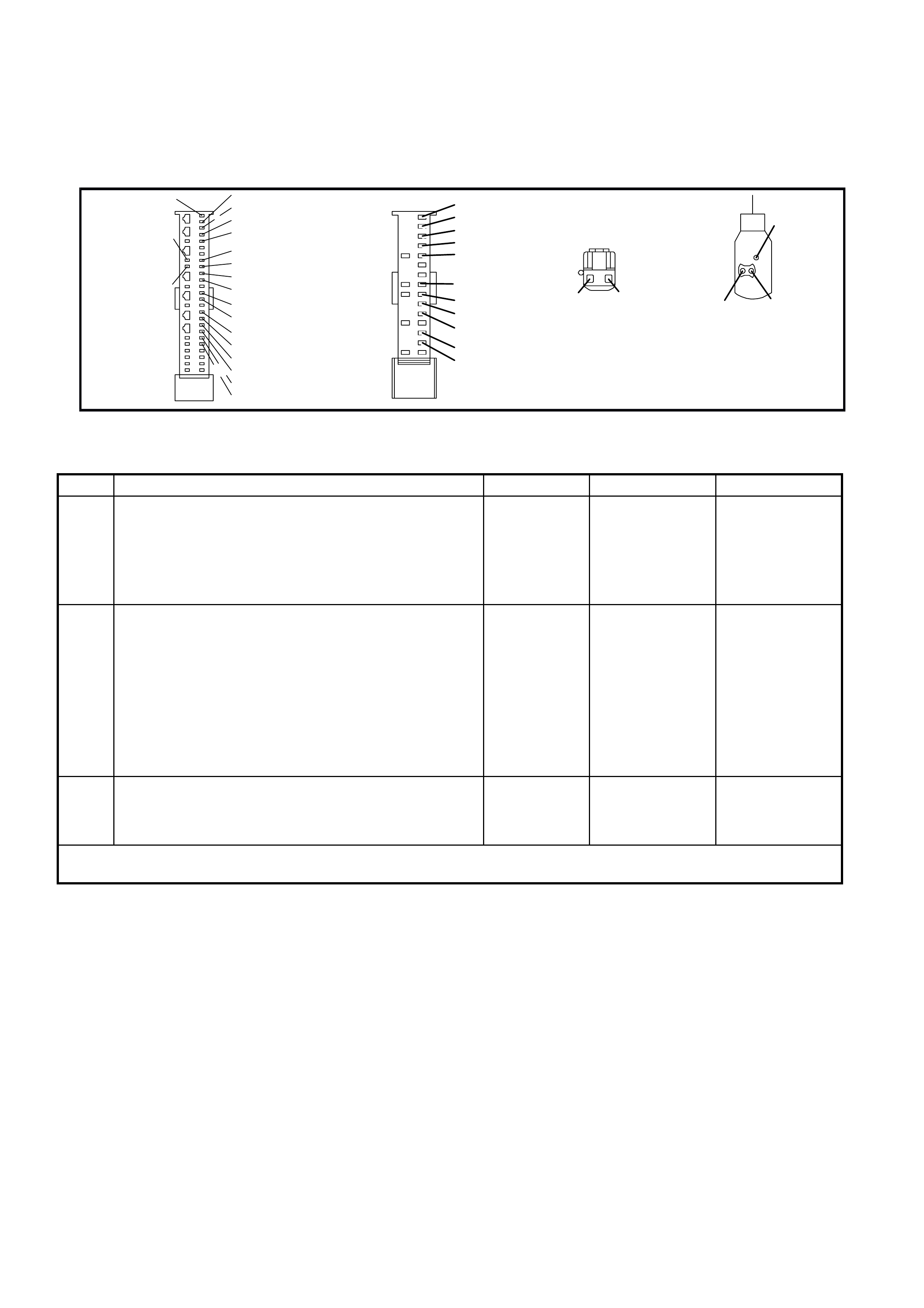
Notes on Diagnostic Chart
1. For all wiring harness checking procedures, refer to VT Series 1 Service Information, WIRING DIAGRAMS,
SECTION 12P.
2. Refer to VT Series 1 Service Information Section 12M, SRS VERSION 6.2, 2.8 SRS WIRING REPAIR before
conducting any SRS wiring harness repairs.
T12M173
YB189
8.1 SDM
WIRING
HARNESS
CONNECTOR
BR/B (393)
26
50 25
1
BLU/B (351) R/B (352)
BR/W (353)
Y/R (354)
P/B (739)
B (3 05)
G/W (1220)
W (3 4 7)
G (348)
Y/B (349)
GY/ B (350)
Y/G (385 )
BR/G (386)
Y/W (38 7 )
BR/W (388)
Y/BLU ( 392)
GY/ W (4 07)
LBLU (408)
BLU/B ( 351)
R/B (352)
BR/W (353)
Y/R (354)
P/B (739)
G/W (1220)
W (3 4 7)
G (348)
Y/B (349)
GY/ B (350)
YB190
8.0 SDM WIRING
HARNESS
CONNECTOR
YB207
SEAT B ELT
PRE-TENSIONER HARNESS
+VE-VE
(RIGHT HAND PRE -TENSIONER)
(LE FT HAND PRE-TENSI ONER)
BR/W (353)Y/R (354) Y/R (354) BR/W (353 )
BLU/B ( 351)R/B (352) R/B (352) BLU/B (351)
CAP
ALSO -V E
YB209
SEAT BELT
PRE-TENSIONER
B (3 05)
Figure 12M-45
DTC 247 - LEFT HAND PRE-TENSIONER CIRCUIT AIR BAG CIRCUIT POWER STAGE ERROR
STEP ACTION VALUE YES NO
1. • Install TECH 2 to DLC.
• Select Body / SRS / Diagnostic Trouble Codes /
Read DTC Information.
• Is a DTC 247 Left Hand Pre-Tensioner Circuit
Power Stage Error a history DTC, and are any other
Left Hand Pre-Tensioner Circuit DTCs set?
Go to other Left
Hand Pre-
Tensioner Circuit
DTC diagnostic
chart in this
Section.
Go to Step 2.
2. • With TECH 2 still connected, select Diagnostic
Trouble Codes / Clear DTC Information and clear all
(if any) DTCs.
• Select Diagnostic Trouble Codes / Read DTC
Information, 'wiggle' SRS wiring harness at all
locations between the SDM and the left hand pre-
tensioner wiring harness connector YB209, while
monitoring TECH 2 screen display.
• Does TECH 2 screen display change status from
No Diagnostic Trouble Codes?
Go to applicable
DTC chart in this
Section.
Go to step 3.
3 • Replace SDM, refer to VT Series 1 Service
Information Section 12M, SRS VERSION 8.0 & 8.1,
2.4 SENSING AND DIAGNOSTIC MODULE (SDM).
Recheck circuit to verify repair.
WHEN ALL DIAGNOSIS AND REPAIRS ARE COM PLETED, ENSURE ALL SRS COMPONENTS ARE
RECONNECTED, CLEAR ALL DTC’S, ENABLE THE SRS AND VERIFY CORRECT OPERATION

DTC 65 - RIGHT HAND PRE-TENSIONER CIRCUIT SHORT TO BATTERY
Figure 12M-46
CIRCUIT DESCRIPTION
At ignition on, and on a constant monitoring cycle of every 500 milliseconds during the ignition cycle, the SDM
performs a system self check. If the SDM detects a resistance to battery supply is less than five kohms in either the
positive and/or negative circuit for more than 3 - 5 seconds, a current DTC 65 will set (refer to
SRS SELF DIAGNOSTICS in Section 12M SUPPLEMENTAL RESTRAINT SYSTEM (Version 8.0 & 8.1) of the VT
Series I Service Information for more details).
DTC 65 will set if circuits 353 (right hand pre-tensioner positive side) and/or 354 (right hand pre-tensioner negative
side) are shorted to battery +.
When DTC 65 sets, the SDM illuminates the SRS warning lamp and sets a current DTC 65. Should the fault
conditions detected by the SDM clear during the same ignition cycle, the current code will clear and become a
history DTC 65. The SRS warning lamp will remain on for the remainder of the ignition cy cle.
If a DTC 65 is set, the SRS warning lamp is illuminated on each ignition cycle, even if the DTC is set as a history
DTC, until the fault conditions for setting DTC 65 are rectified and the DTC (current or history) can then be cleared
from the SDM via TECH 2.
If DTC 65 is set, the SRS, including the right hand pre-tensioner, will still be operational.
Test Description
The following numbers refer to step numbers in the following diagnostic chart:
1. Uses TECH 2 to check if DTC 65 is current or history.
2. Checks for intermittent fault by monitoring TECH 2 screen. If screen display changes during a wiring 'wiggle' test,
a fault with the wiring is at that location.
3. Checks circuits 353 and 354 for a short to battery +.
Notes on Diagnostic Chart
1. For all wiring harness checking procedures, refer to Section 12P WIRING DIAGRAMS of the VT Series I
Service Information.
2. Refer to 2.8 SRS WIRING REPAIR in Section 12M SUPPLEMENTAL RESTRAINT SYSTEM of the VT Series I
Service Information before conducting any SRS wiring harness repairs.
3. Resist ance cannot be m eas ured between the two terminals in connector YB209, as the in-built capacitor block s
measurement. Therefore, a ‘service hole’ is incorporated into the connector for fault tracing. Refer to
1.1 SYSTEM COMPONENTS, WIRING HARNESS in Section 12M SUPPLEMENTAL RESTRAINT SYSTEM
(Version 8.0 & 8.1) of the VT Series I Service Information for more details on this type of connector.
4. W iring should be checked at point where TECH 2 screen display changed status. If necessary, split open the
harness.
5. If the fault can not be identified, the harness should be replaced.
6. Refer to T ECH 2 DIAGNOST ICS in Section 12M SUPPLEMENT AL RESTRAINT SYST EM (Version 8.0 & 8.1)
of the VT Series I Service Information for connecting and using TECH 2.
7. To enable or disable the SRS system, refer to 2.2 SYSTEM DISABLING AND ENABLING PROCEDURE in
Section 12M SUPPLEMENTAL RESTRAINT SYSTEM (Version 8.0 & 8.1) of the VT Series I Service
Information.
8. SDM connector YB189 is equipped with a shorting link busbar which needs to be opened before checking the
circuit, re fer to 2.5 DIAGNOSTIC CHARTS in this Section for additional information.
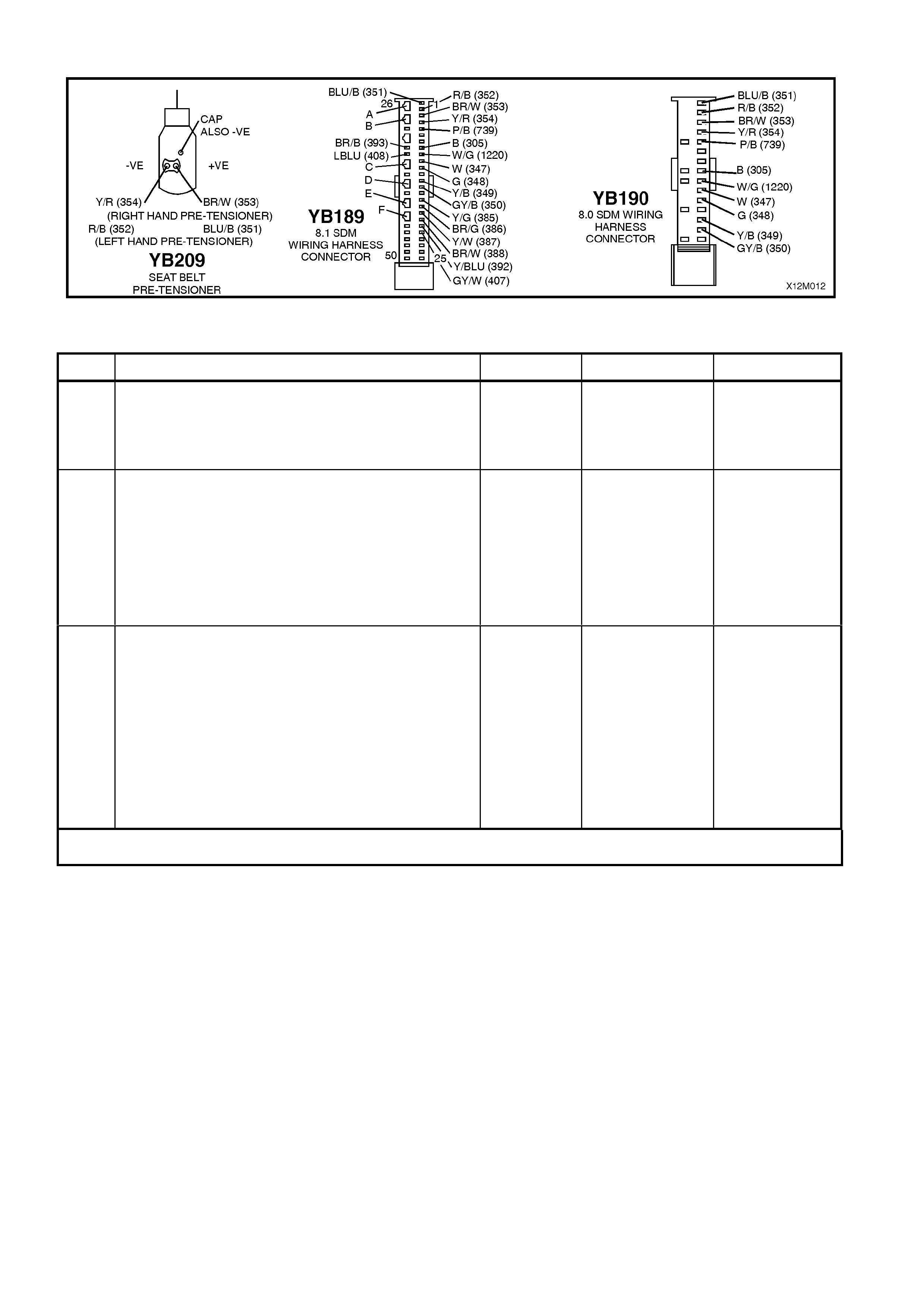
Figure 12M-47
DTC 65 - RIGHT HAND PRE-TENSIONER CIRCUIT SHORT TO BATTERY
STEP ACTION VALUE YES NO
1. • Connect TECH 2 to DLC.
• Select Body / SRS / Diagnostic Trouble Codes /
Read DTC Information (refer NOTE 6 on previous
page).
• Is DTC 65 current ?
Go to Step 3. Go to Step 2.
2. • With TECH 2 still connected, select Diagnostic
Trouble Codes / Clear DTC Information and clear
all (if any) DTCs.
• Select Diagnostic Trouble Codes / Read DTC
Information, 'wiggle' SRS wiring harness at all
locations between the SDM and the right hand pre-
tensioner wiring harness connector YB209, while
monitoring TECH 2 screen display.
• Does TECH 2 screen display change status from
No Diagnostic Trouble Codes?
Make repairs as
necessary (refer
to NOTES 2 & 4
on previous
page).
Clear DTC and
recheck system to
verify repair.
Fault not present.
Check all system
wiring harness
connectors, and
terminals, refer to
NOTE 5 on
previous page.
Clear DTC and
recheck system.
3. • Disable the SRS (refer NOTE 7 on previous page)
• Disconnect right hand pre-tensioner wiring harness
connector YB209 from pre-tensioner.
• Disconnect SDM wiring harness connector
YB189/YB190 from the SDM.
• Reconnect battery.
• Using Tool KM-609-20, check wiring between SDM
wiring harness connector YB189/YB190, terminals
3 and 4 and right hand pre-tensioner connector
YB209, circuits 353 (Brown/White wire) and 354
(Yellow/Red wire) for short to battery + (refer to
NOTES 1, 3 & 8 on previous page).
• Is all OK?
Replace SDM,
refer Section 12M
SUPPLEMENTAL
RESTRAINT
SYSTEM (Version
8.0 & 8.1) of the
VT Series I
Service
Information.
Recheck circuit to
verify repair.
Make repairs as
necessary (refer
to NOTE 2 on
previous page).
Clear DTC and
recheck system
to verify repair.
WHEN ALL DIAGNOSIS AND REPAIRS ARE COM PLETED, ENSURE ALL SRS COMPONENTS ARE
RECONNECTED, CLEAR ALL DTC’S, ENABLE THE SRS AND VERIFY CORRECT OPERATION

DTC 66 - RIGHT HAND PRE-TENSIONER CIRCUIT SHORT TO EARTH
Figure 12M-48
CIRCUIT DESCRIPTION
At ignition on, and on a constant monitoring cycle of every 500 milliseconds during the ignition cycle, the SDM
performs a system self check. If the SDM detects a resistance to earth of less than three kohms in either the
positive or negative circuit for more than 3 - 5 seconds, a current DTC 66 will set (refer to
SRS SELF DIAGNOSTICS in Section 12M SUPPLEMENTAL RESTRAINT SYSTEM (Version 8.0 & 8.1) of the VT
Series I Service Information for more details).
DTC 66 will set if circuits 353 (right hand pre-tensioner positive side) and/or 354 (right hand pre-tensioner negative
side) are shorted to earth.
When DTC 66 sets, the SDM illuminates the SRS warning lamp and sets a current DTC 66. Should the fault
conditions detected by the SDM clear during the same ignition cycle, the current code will clear and become a
history DTC 66. The SRS warning lamp will remain on for the remainder of the ignition cy cle.
If a DTC 66 is set, the SRS warning lamp is illuminated on each ignition cycle, even if the DTC is set as a history
DTC, until the fault conditions for setting DTC 66 are rectified and the DTC (current or history) can then be cleared
from the SDM via TECH 2.
If DTC 66 is set, the SRS, including the right hand pre-tensioner, will still be operational.
Test Description
The following numbers refer to step numbers in the following diagnostic chart:
1. Uses TECH 2 to determine if DTC 66 is current or history.
2. TECH 2 in this mode should display approximately 1.6 - 6.4 ohm s if the right hand pre-tensioner loop circuit is
OK.
3. If screen display changes during a wiring 'wiggle' test, a fault with the wiring is at that location.
4. Tool SD28280B is a dummy load tak ing the place of the pr e- tensioner as sembly. If TECH 2 dis plays the correct
resistance of the dummy load, the system fault is in the pre-tensioner assembly.
5. T his test c heck s the wiring between the SDM wiring harnes s connec tor YB189 (8.1 SDM) or YB190 (8.0 SDM),
terminal 3 and the right hand pre-tensioner connector YB209 for faults.
6. T his test c heck s the wiring between the SDM wiring harnes s connec tor YB189 (8.1 SDM) or YB190 (8.0 SDM),
terminal 4 and the right hand pre-tensioner connector YB209 for faults.

Notes on Diagnostic Chart
1. For all wiring harness checking procedures, refer to Section 12P WIRING DIAGRAMS of the VT Series I
Service Information.
2. Refer to SRS 2.8 WIRING REPAIR in Section 12M SUPPLEMENTAL RESTRAINT SYSTEM of the VT Series I
Service Information before conducting any SRS wiring harness repairs.
3. Resistance cannot be m easured between the two term inals in connector YB209 as the in-built capacitor block s
measurement. Therefore, a ‘service hole’ is incorporated into the connector for fault tracing. Refer to
1.1 SYSTEM COMPONENTS, WIRING HARNESS in Section 12M SUPPLEMENTAL RESTRAINT SYSTEM
(Version 8.0 & 8.1) of the VT Series I Service Information for more details on this type of connector.
4. Wiring should be checked at point where TECH 2 screen display changed. If necessary, split open wiring
harness.
5. If fault cannot be identified, the wiring harness should be replaced.
6. Refer to T ECH 2 DIAGNOST ICS in Section 12M SUPPLEMENT AL RESTRAINT SYST EM (Version 8.0 & 8.1)
of the VT Series I Service Information for connecting and using TECH 2.
7. To enable or disable the SRS system, refer to 2.2 SYSTEM DISABLING AND ENABLING PROCEDURE in
Section 12M SUPPLEMENTAL RESTRAINT SYSTEM (Version 8.0 & 8.1) of the VT Series I Service
Information.
8. SDM connector YB189 is equipped with a shorting link busbar which needs to be opened before checking the
circuit, re fer to 2.5 DIAGNOSTIC CHARTS in this Section for additional information.
Figure 12M-49

DTC 66 - RIGHT HAND PRE-TENSIONER CIRCUIT SHORT TO EARTH
STEP ACTION VALUE YES NO
1. • Connect TECH 2 to DLC.
• Select Body / SRS / Diagnostic Trouble Codes /
Read DTC Information (refer NOTE 6 on previous
page).
• Does TECH 2 display DTC 66 as a Current DTC?
Go to Step 2. Go to Step 3.
2. • W ith TECH 2 still connected to DLC, select Body /
SRS / Data Display and scroll to RIGHT HAND
PRE-TENSIONER LOOP RESISTANCE.
• Is the resistance value displayed on TECH 2 as
specified?
Approx.
1.5 - 6.4
ohms
Go to Step 3. Go to Step 4.
3. • With TECH 2 still connected, select Diagnostic
Trouble Codes / Clear DTC Information and clear
all (if any) DTCs.
• Select Diagnostic Trouble Codes / Read DTC
Information, 'wiggle' SRS wiring harness at all
locations between the SDM and the pre-tensioner
while monitoring TECH 2 screen display.
• Does TECH 2 screen display change status from
No Diagnostic Trouble Codes?
Make repairs as
necessary (refer
to NOTES 2 & 4
on previous
page).
Clear DTC and
recheck system to
verify repair.
Fault not present.
Check all system
wiring harness
connectors, and
terminals (refer to
NOTE 5 on
previous page).
Clear DTC and
recheck system.
4. • Disable the SRS (refer NOTE 7 on previous page).
• Disconnect right hand pre-tensioner wiring harness
connector YB209 from pre-tensioner.
• Connect Tool No. SD28280B to SRS wiring
harness connector YB209.
• Enable the SRS (reconnect battery).
• With TECH 2 still connected, select Body / SRS /
Data Display and scroll to RIGHT HAND PRE-
TENSIONER LOOP RESISTANCE.
• Is the resistance value displayed on TECH 2 as
specified?
Approx.
3.0 ohms
Replace right
hand pre-
tensioner
assembly, refer to
Section 1A7
SEAT AND SEAT
BELT
ASSEMBLIES of
the VT Series I
Service
Information. Clear
DTC and recheck
system to verify
repair.
Go to Step 5.
5. • Disable the SRS (refer NOTE 7 on previous page).
• Disconnect SDM wiring harness connector
YB189/YB190 from the SDM.
• Remove Tool SD28280B from YB209.
• Using Tool KM-609-20, check wiring between SDM
wiring harness connector YB189/YB190, terminal 3
and right hand pre-tensioner connector YB209,
circuit 353 (Brown/White wire) for short to earth
(refer to NOTES 1 & 8 on previous page).
• Is all OK?
Go to Step 6. Make repairs as
necessary (refer
to NOTE 2 on
previous page).
Clear DTC and
recheck system
to verify repair.
6. • W ith SDM wiring harness connector YB189/YB190
disconnected from the SDM and using Tool KM-
609-20, check wiring between SDM wiring harness
connector YB189/YB190, terminal 4 and right hand
pre-tensioner connector YB209, circuit 354
(Yellow/Red wire) for a short to earth (refer to
NOTES 1, 3 & 8 on previous page).
• Is all OK?
Replace SDM,
refer Section 12M
SUPPLEMENTAL
RESTRAINT
SYSTEM (Version
8.0 & 8.1) of the
VT Series I
Service
Information.
Recheck circuit to
verify repair.
Make repairs as
necessary (refer
to NOTE 2 on
previous page).
Clear DTC and
recheck system
to verify repair.
WHEN ALL DIAGNOSIS AND REPAIRS ARE COM PLETED, ENSURE ALL SRS COMPONENTS ARE
RECONNECTED, CLEAR ALL DTC’S, ENABLE THE SRS AND VERIFY CORRECT OPERATION

DTC 67 - RIGHT HAND PRE-TENSIONER CIRCUIT CAPACITANCE TOO HIGH
Figure 12M-50
CIRCUIT DESCRIPTION
At ignition on, and on a constant monitoring cycle of every 500 milliseconds during the ignition cycle, the SDM
performs a system self check.
If the SDM detects the capacitance in the right hand pre-tensioner circuit is too high (greater than 550 nF) for longer
than 3 - 5 seconds, a current DTC 67 will set (refer to SRS SELF DIAGNOSTICS in Section 12M SUPPLEMENTAL
RESTRAINT SYSTEM (Version 8.0 & 8.1) of the VT Series I Service Information for more details).
DTC 67 will set if the in-built capacitor in the SRS wiring harness connector YB209 is faulty.
When DTC 67 sets, the SDM illuminates the SRS warning lamp and sets a current DTC 67. Should the fault
conditions detected by the SDM clear during the same ignition cycle, the current code will clear and become a
history DTC 67. The SRS warning lamp will remain on for the remainder of the ignition cy cle.
If a DTC 67 is set, the SRS warning lamp is illuminated on each ignition cycle, even if the DTC is set as a history
DTC, until the fault conditions for setting DTC 67 are rectified and the DTC (current or history) can then be cleared
from the SDM via TECH 2.
ACTION REQUIRED
If DTC 67 is set, the right hand pre-tensioner may not operate and therefore, the SRS pre-tensioner wiring harness,
with connector YB209 (between right hand pre-tensioner and SRS connector YB207) must be replaced.
NOTE: Before removing the SRS pre-tensioner wiring harness, take note of wiring harness routing and how it is
retained to the front seat.
After the SRS pre-tensioner wiring harness, between the pre-tensioner and SRS wiring harness connector YB207
has been replaced, ensure that all SRS components are reconnected, clear DTCs, enable the SRS and verify the
correct operation of the system (i.e. warning lamp not illuminated after five seconds of ignition being switched ON).
NOTE: After the wiring harness has been replaced, the front seat should be put through its full adjustment
(forward/backwards, full recline and up and down) to ensure that the wiring harness does not foul with any of the
seat components.
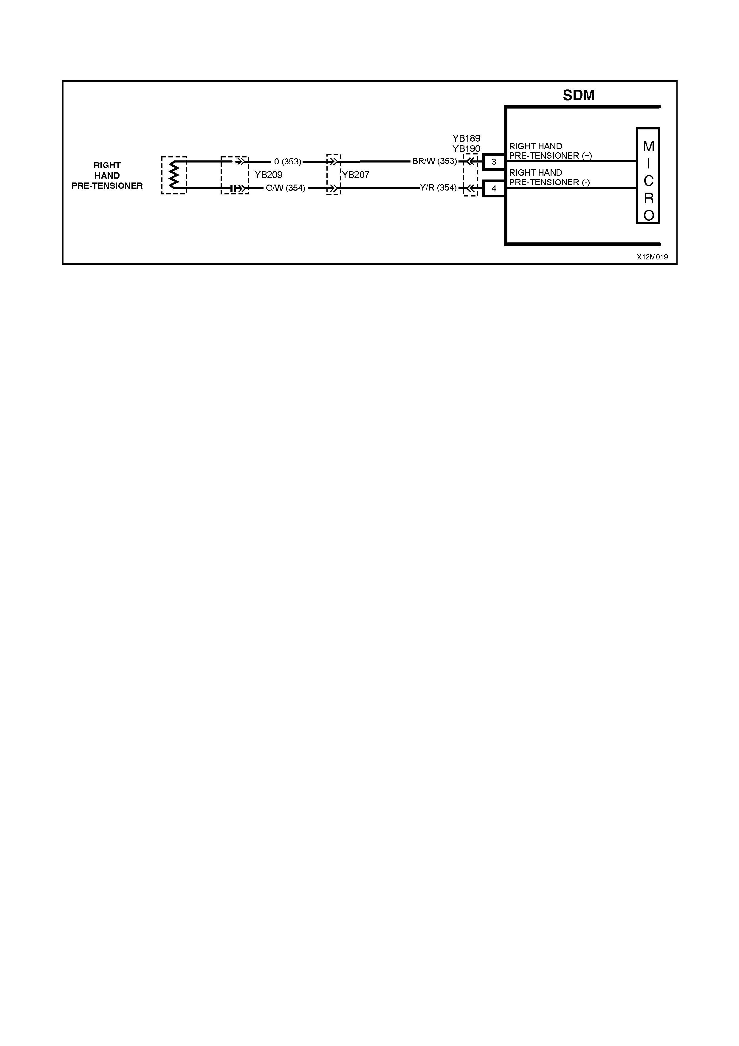
DTC 68 - RIGHT HAND PRE-TENSIONER CIRCUIT CAPACITANCE TOO LOW
Figure 12M-51
CIRCUIT DESCRIPTION
At ignition on, and on a constant monitoring cycle of every 500 milliseconds during the ignition cycle, the SDM
performs a system self check.
If the SDM detects the capacitance in the right hand pre-tensioner circuit is too low (less than 390 nF) for longer
than 3 - 5 seconds, a current DTC 68 will set (refer to SRS SELF DIAGNOSTICS in Section 12M SUPPLEMENTAL
RESTRAINT SYSTEM (Version 8.0 & 8.1) of the VT Series I Service Information for more details).
DTC 68 will set if the in-built capacitor in the SRS wiring harness connector YB209 is faulty.
When DTC 68 sets, the SDM illuminates the SRS warning lamp and sets a current DTC 68. Should the fault
conditions detected by the SDM clear during the same ignition cycle, the current code will clear and become a
history DTC 68. The SRS warning lamp will remain on for the remainder of the ignition cy cle.
If a DTC 68 is set, the SRS warning lamp is illuminated on each ignition cycle, even if the DTC is set as a history
DTC, until the fault conditions for setting DTC 68 are rectified and the DTC (current or history) can then be cleared
from the SDM via TECH 2.
ACTION REQUIRED
If DTC 68 is set, the right hand pre-tensioner may not operate and therefore, the SRS pre-tensioner wiring harness,
with connector YB209 (between right hand pre-tensioner and SRS connector YB207) must be replaced.
NOTE: Before removing the SRS pre-tensioner wiring harness, take note of wiring harness routing and how it is
retained to the front seat.
After the SRS pre-tensioner wiring harness, between the pre-tensioner and SRS wiring harness connector YB207
has been replaced, ensure that all SRS components are reconnected, clear DTCs, enable the SRS and verify the
correct operation of the system (i.e. warning lamp not illuminated after five seconds of ignition being switched ON).
NOTE: After the wiring harness has been replaced, the front seat should be put through its full adjustment
(forward/backwards, full recline and up and down) to ensure that the wiring harness does not foul with any of the
seat components.

DTC 69 - RIGHT HAND PRE-TENSIONER CIRCUIT RESISTANCE TOO HIGH
Figure 12M-52
CIRCUIT DESCRIPTION
At ignition on, and on a constant monitoring cycle of every 500 milliseconds during the ignition cycle, the SDM
performs a system self check.
If the SDM detects a resistance in the right hand pre-tensioner circuit that is too high (greater than 10 ohms) for
longer than 3 - 5 seconds, a current DTC 69 will set (refer to SRS SELF DIAGNOSTICS in Section 12M
SUPPLEMENTAL RESTRAINT SYSTEM (Version 8.0 & 8.1) of the VT Series I Service Information for more
details).
DTC 69 will set if circuits 353 or 354 (including the right hand pre-tensioner assembly) are open circuit.
When DTC 69 sets, the SDM illuminates the SRS warning lamp and sets a current DTC. Should the fault conditions
detected by the SDM clear during the same ignition cycle, the current code will clear and become a history DTC 69.
The SRS warning lamp will remain on for the remainder of the ignition cycle.
If a DTC is set, the SRS warning lamp is illuminated on each ignition cycle, even if the DTC is set as a history DTC,
until the fault conditions for setting DTC 69 are rectified and the DTC (current or history) can then be cleared from
the SDM via TECH 2.
If DTC 69 is set, dependent on where the fault is, the right hand pre-tensioner may not operate.
Test Description
The following numbers refer to step numbers in the following diagnostic chart:
1. Uses TECH 2 to check if DTC 69 is current or history.
2. Checks for intermittent fault by monitoring TECH 2 screen. If screen display changes during a wiring 'wiggle' test,
a fault with the wiring is at that location.
3. T ool SD28280B is a dum m y load tak ing the place of the right hand pre-tensioner assem bly. If DTC 69 becomes
a history DTC with dummy load connected, the system fault is in the right hand pre-tensioner assembly.
4. Checks if open circuit is in the SRS connector harness. If connector YB207 is disconnected and it’s terminals are
bridged together, DTC 69 will become a history DTC if this connector harness is faulty.
5. Checks circuit 353 for open circuit.
6. Checks circuit 354 for open circuit.
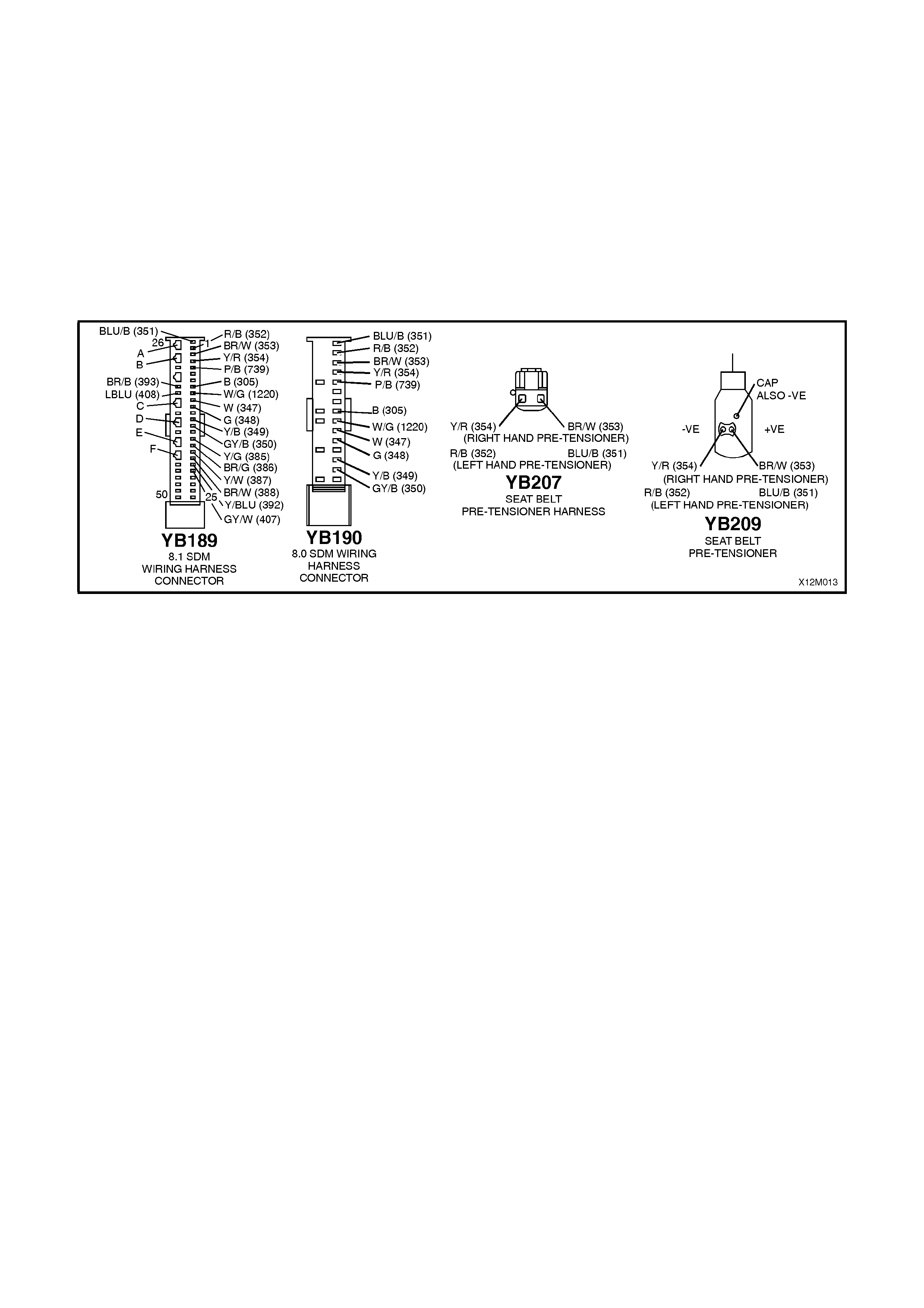
Notes on Diagnostic Chart
1. For all wiring harness checking procedures, refer to Section 12P WIRING DIAGRAMS of the VT Series I
Service Information.
2. Refer to 2.8 SRS WIRING REPAIR in Section 12M SUPPLEMENTAL RESTRAINT SYSTEM of the VT Series I
Service Information before conducting any SRS wiring harness repairs.
3. Refer to T ECH 2 DIAGNOST ICS in Section 12M SUPPLEMENT AL RESTRAINT SYST EM (Version 8.0 & 8.1)
of the VT Series I Service Information for connecting and using TECH 2.
4. To enable or disable the SRS system, refer to 2.2 SYSTEM DISABLING AND ENABLING PROCEDURE in
Section 12M SUPPLEMENTAL RESTRAINT SYSTEM (Version 8.0 & 8.1) of the VT Series I Service
Information.
5. SDM connector YB189 is equipped with a shorting link busbar which needs to be opened before checking the
circuit, re fer to 2.5 DIAGNOSTIC CHARTS in this Section for additional information.
Figure 12M-53

DTC 69 - RIGHT HAND PRE-TENSIONER CIRCUIT RESISTANCE TOO HIGH
STEP ACTION VALUE YES NO
1. • Connect TECH 2 to DLC.
• Select Body / SRS / Diagnostic Trouble Codes /
Read DTC Information (refer NOTE 3 on previous
page).
• Is DTC 69 current?
Go to Step 3. Go to Step 2.
2. • With TECH 2 still connected, select Diagnostic
Trouble Codes / Clear DTC Information and clear
all (if any) DTCs.
• Select Diagnostic Trouble Codes / Read DTC
Information, 'wiggle' SRS wiring harness at all
locations between the SDM and the right hand pre-
tensioner wiring harness connector YB209, while
monitoring TECH 2 screen display.
• Does TECH 2 screen display change status from
No Diagnostic Trouble Codes?
Make repairs as
necessary (refer
to NOTE 2 on
previous page).
Clear DTC and
recheck system to
verify repair.
Fault not present.
Check all system
wiring harness
connectors, and
terminals.
Clear DTC and
recheck system.
3. • Disable the SRS (refer NOTE 4 on previous page).
• Disconnect the right hand pre-tensioner wiring
harness connector YB209.
• Connect Tool No. SD28280B to SRS wiring
harness connector YB209.
• Enable the SRS (reconnect battery).
• Connect TECH 2 to DLC.
• Select Body / SRS / Diagnostic Trouble Codes /
Read DTC Information.
• Is DTC 69 still current?
Go to Step 4. Replace right
hand pre-
tensioner
assembly, refer
to Section 1A7
SEAT AND SEAT
BELT
ASSEMBLIES of
the VT Series I
Service
Information.
Clear DTC and
recheck system
to verify repair.
4. • Disable the SRS (refer NOTE 4 on previous page).
• Disconnect SRS wiring harness connector YB207
(located next to right hand front seat) from right
hand pre-tensioner connector harness.
• Enable the SRS (reconnect battery).
• Using a suitable jumper wire from KM-609, bridge
terminals in connector YB207 together
(NOTE: This step may set a current DTC 70).
• With TECH 2 still connected, select Body / SRS /
Diagnostic Trouble Codes / Read DTC Information.
• Does DTC 69 become history?
Replace SRS
connector
harness (harness
between right
hand pre-
tensioner and
connector
YB207). Clear all
DTCs and
recheck system to
verify repair.
Go to Step 5.
5. • Disable the SRS (refer NOTE 4 on previous page).
• Disconnect SDM wiring harness connector
YB189/YB190 from the SDM.
• Using Tool KM-609-20, check wiring between SDM
wiring harness connector YB189/YB190, terminal 3
and SRS wiring harness connector YB207, circuit
353 (Brown/White wire) for open circuit (refer to
NOTES 1 & 5 on previous page).
• Is all OK?
Go to Step 6. Make repairs as
necessary (refer
to NOTE 2 on
previous page).
Clear DTC and
recheck system
to verify repair.
6. • W ith SDM wiring harness connector YB189/YB190
disconnected from the SDM and using Tool KM-
609-20, check wiring between SDM wiring harness
connector YB189/YB190, terminal 4 and SRS
wiring harness connector YB207, circuit 354
(Yellow / Red wire) for open (refer to NOTES 1 & 5
on previous page).
• Is all OK?
Replace SDM,
refer Section 12M
SUPPLEMENTAL
RESTRAINT
SYSTEM (Version
8.0 & 8.1) of the
VT Series I
Service
Information.
Recheck circuit to
verify repair.
Make repairs as
necessary (refer
to NOTE 2 on
previous page).
Clear DTC and
recheck system
to verify repair.
WHEN ALL DIAGNOSIS AND REPAIRS ARE COM PLETED, ENSURE ALL SRS COMPONENTS ARE
RECONNECTED, CLEAR ALL DTC’S, ENABLE THE SRS AND VERIFY CORRECT OPERATION

DTC 70 - RIGHT HAND PRE-TENSIONER CIRCUIT RESISTANCE TOO LOW
Figure 12M-54
CIRCUIT DESCRIPTION
At ignition on, and on a constant monitoring cycle of every 500 milliseconds during the ignition cycle, the SDM
performs a system self check.
If the SDM detects a resistance in the right hand pre-tensioner circuit that is too low (less than 0.6 ohm) for longer
than 3 - 5 seconds, a current DTC 70 will set (refer to SRS SELF DIAGNOSTICS in Section 12M SUPPLEMENTAL
RESTRAINT SYSTEM (Version 8.0 & 8.1) of the VT Series I Service Information for more details).
DTC 70 will set if circuit 353 or 354, (including the pre-tensioner assembly) is shorted together.
When DTC 70 sets, the SDM illuminates the SRS warning lamp and sets a current DTC 70. Should the fault
conditions detected by the SDM clear during the same ignition cycle, the current code will clear and become a
history DTC 70. The SRS warning lamp will remain on for the remainder of the ignition cy cle.
If a DTC 70 is set, the SRS warning lamp is illuminated on each ignition cycle, even if the DTC is set as a history
DTC, until the fault conditions for setting DTC 70 are rectified and the DTC (current or history) can then be cleared
from the SDM via TECH 2.
If DTC 70 is set, dependent on where the fault is, the right hand belt pre-tensioner may not operate.
Test Description
The following numbers refer to step numbers in the following diagnostic chart:
1. Uses TECH 2 to check if DTC 70 is current or history.
2. Checks for intermittent fault by monitoring TECH 2 screen. If screen display changes during a wiring ‘wiggle’
test, a fault with the wiring is at that location.
3. T ool SD28280B is a dum m y load tak ing the place of the right hand pre-tensioner assem bly. If DTC 70 becomes
a history DTC with dummy load connected, the system fault is in the right hand pre-tensioner assembly.
4. This test checks the wiring between the SDM wiring harness connector YB189 (8.1 SDM) or YB190 (8.0 SDM)
and SRS wiring harness connector YB209 for a short circuit.
Notes on Diagnostic Chart
2. For all wiring harness checking procedures, refer to Section 12P WIRING DIAGRAMS of the VT Series I Service
Information.
3. Refer to 2.8 SRS WIRING REPAIR in Section 12M SUPPLEMENTAL RESTRAINT SYSTEM of the VT Series I
Service Information before conducting any SRS wiring harness repairs.
4. Resistance cannot be m eas ured between the two terminals in connector YB209, as the in-built capacitor block s
measurement. Therefore, a ‘service hole’ is incorporated into the connector for fault tracing. Refer to
1.1 SYSTEM COMPONENTS, WIRING HARNESS in Section 12M SUPPLEMENTAL RESTRAINT SYSTEM
(Version 8.0 & 8.1) of the VT Series I Service Information for more details on this type of connector.
5. Ref er to TECH 2 DIAGNOSTICS in Section 12M SUPPLEMENTAL RESTRAINT SYSTEM (Version 8.0 & 8.1) of
the VT Series I Service Information for connecting and using TECH 2.
6. To enable or disable the SRS system, refer to 2.2 SYSTEM DISABLING AND ENABLING PROCEDURE in
Section 12M SUPPLEMENTAL RESTRAINT SYSTEM (Version 8.0 & 8.1) of the VT Series I Service
Information.
6. SDM connector YB189 is equipped with a shorting link busbar which needs to be opened before checking the
circuit, re fer to 2.5 DIAGNOSTIC CHARTS in this Section for additional information.
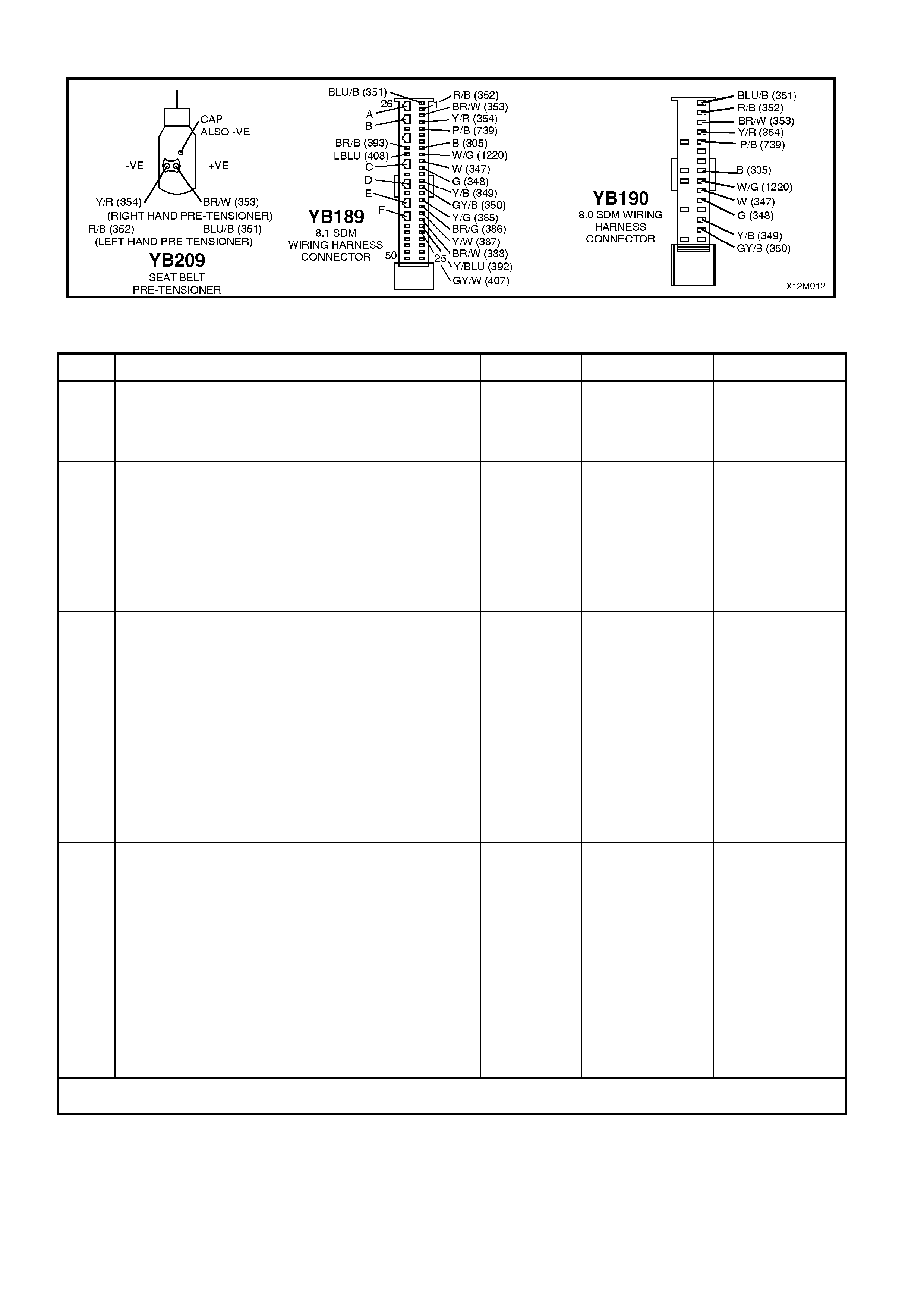
Figure 12M-55
DTC 70 – RIGHT HAND PRE-TENSIONER CIRCUIT RESISTANCE TOO LOW
STEP ACTION VALUE YES NO
1. • Connect TECH 2 to DLC.
• Select Body / SRS / Diagnostic Trouble Codes /
Read DTC Information (refer NOTE 4 on previous
page).
• Is DTC 70 current?
Go to Step 3. Go to Step 2.
2. • With TECH 2 still connected, select Diagnostic
Trouble Codes / Clear DTC Information and clear
all (if any) DTCs.
• Select Diagnostic Trouble Codes / Read DTC
Information, ‘wiggle’ SRS wiring harness at all
locations between the SDM and the right hand pre-
tensioner wiring harness connector YB209, while
monitoring TECH 2 screen display.
• Does TECH 2 screen display change status from
No Diagnostic Trouble Codes?
Make repairs as
necessary (refer
to NOTE 2 on
previous page).
Clear DTC and
recheck system to
verify repair.
Fault not present.
Check all system
wiring harness
connectors, and
terminals.
Clear DTC and
recheck system.
3. • Disable the SRS (refer NOTE 5 on previous page).
• Disconnect the right hand pre-tensioner wiring
harness connector YB209.
• Connect Tool No. SD28280B to SRS wiring
harness connector YB209.
• Enable the SRS (reconnect battery).
• Connect TECH 2 to DLC.
• Select Body / SRS / Diagnostic Trouble Codes /
Read DTC Information.
• Is DTC 70 still current?
Go to Step 4. Replace right
hand pre-
tensioner
assembly, refer to
Section 1A7
SEAT AND SEAT
BELT
ASSEMBLIES of
the VT Series I
Service
Information.
Clear DTC and
recheck system to
verify repair.
4. • Disable the SRS (refer NOTE 5 on previous page).
• Disconnect SDM wiring harness connector
YB189/YB190 from the SDM.
• Disconnect Tool No. SD28280B from SRS wiring
harness connector YB209.
• With SRS wiring harness connector YB209
disconnected, and using Tool KM-609-20, check
for continuity between SDM wiring harness
connector YB189/YB190, terminal 3, circuit 353
(Brown/White wire) and terminal 4, circuit 354
(Yellow/Red wire)(refer to NOTES 1, 3 & 6 on
previous page).
• Does continuity exist?
Repair short in
circuits 353 and
354, between
SDM wiring
harness
connector
YB189/YB190 and
YB209 as
necessary (refer
to NOTE 2 on
previous page).
Clear DTC and
recheck system to
verify repair.
Replace SDM,
refer Section 12M
SUPPLEMENTAL
RESTRAINT
SYSTEM (Version
8.0 & 8.1) of the
VT Series I
Service
Information.
Recheck circuit to
verify repair.
WHEN ALL DIAGNOSIS AND REPAIRS ARE COM PLETED, ENSURE ALL SRS COMPONENTS ARE
RECONNECTED, CLEAR ALL DTC’S, ENABLE THE SRS AND VERIFY CORRECT OPERATION

DTC 247 - RIGHT HAND PRE-TENSIONER CIRCUIT POWER STAGE ERROR
T12M129
SDM
M
I
C
R
O
YB189
YB190
YB209
RIGHT
HAND
PRE-TENSIONER
RIGHT HAND
PRE-TENSIONER (+)
RIGHT HAND
PRE-TENSIONER (-)
3
4
YB207
BR/W (353)
Y/R (354)
Figure 12M-56
CIRCUIT DESCRIPTION
At ignition on, the SDM perfor ms an initial system self check of the SDM power s tages. If during this initial self test
the SDM detec ts a f ault with the Right Hand Pre-Tens ioner Circ uit power stage a curr ent DTC 247 Right Hand Pr e-
Tens ioner Circuit Power Stage Error will set. On c ompletion of the initial s ystem self test the SDM then per forms a
test of the Right Hand Pre-Tensioner Circuit. If the SDM detects a problem with this circuit the associated Right
Hand Pre-Tensioner Circuit DTC will be set and the DTC 247 Right Hand Pre-Tensioner Circuit Air Bag Circuit
Power Stage Error will become a history DTC.
DTC 247 Right Hand Pre-Tensioner Circuit Power Stage Error will set if a fault occurs in the Right Hand Pre-
Tensioner, connector YB209 with the in-built capacitor, connector YB207, the SRS wiring harness, connector
YB189/190 or SDM.
W hen a history DTC 247 Right Hand Pre-Tensioner Circuit Power Stage Error sets, the SDM illuminates the SRS
warning lamp. Should the fault conditions detected by the SDM clear during the same ignition cycle the code will
remain a history DTC 247 Right Hand Pre-Tensioner Circuit Power Stage Error for all ignition cycles until cleared.
The SRS warning lamp will remain on for the remainder of the ignition cycle.
W hen a DT C 247 Right Hand Pre- Tensioner Circuit Power Stage Error s ets, the SDM illum inates the SRS warning
lamp f or the rem ainder of the ignition c ycle. Should the f ault conditions detected by the SDM clear during the sam e
ignition cycle the code will remain a history DTC 247 Right Hand Pre-Tensioner Circuit Power Stage Error for all
ignition cycles until cleared. The SRS warning lamp will also remain illuminated until the history DTC 247 Right
Hand Pre-Tensioner Circuit Power Stage Error is cleared.
If a DT C 247 Right Hand Pr e-Tensioner Cir c uit Power Stage is s et, dependent on where the f ault is, the Right Hand
Pre-Tensioner may not operate.
ACTION REQUIRED
If DTC 247 Right Hand Pre-Tensioner Circuit Power Stage Error and any other DTC is set then the diagnos tics for
the other DTC s hould be carr ied out firs t. For exam ple if a DT C 247 Right Hand Pre-T ensioner Circuit Power Stage
Error and a DT C 69 Right Hand Pre-T ensioner Circuit Res istance High are set, the diagnos tics for a DTC 69 Right
Hand Pre-Tensioner Circuit Resistance High should be carried out first.
If only a DTC 247 Right Hand Pre-Tensioner Circuit Power Stage Error is set then the SDM should be replaced.
NOTE: An intermittent in the Right Hand Pre-Tensioner Circuit may cause a DTC 247 Right Hand Pre-Tensioner
Circuit Power Stage Error to set.
After the fault has been rectified, ensure that all SRS components are reconnected, clear DTCs, enable the SRS
and verify the correct operation of the system (i.e. warning lamp not illum inated after five seconds of ignition being
switched ON).
NOTE: After the wiring harness has been replaced, the front seat should be put through its full adjustment
(forward/backwards, full recline and up and down) to ensure that the wiring harness does not foul with any of the
seat components.
Test Description
The following numbers refer to Step numbers in the following diagnostic chart.
1. Uses T ECH 2 to c heck if a DT C 247 Right Hand Pr e-Tensioner Circ uit Power Stage Err or is his tory code, and if
any other Right Hand Pre-T ensioner Circuit current or history DTCs are set. If any other DTCs are set refer to
these DTCs first.
2. Checks for intermittent fault by monitoring TECH 2 screen during ignition on cycle. If screen display changes
during a wiring 'wiggle' test, a fault with the wiring is at that location.
3. If no other DTCs are set and there are no intermittents in the Right Hand Pre-Tensioner Circuit then the SDM
should be replaced.
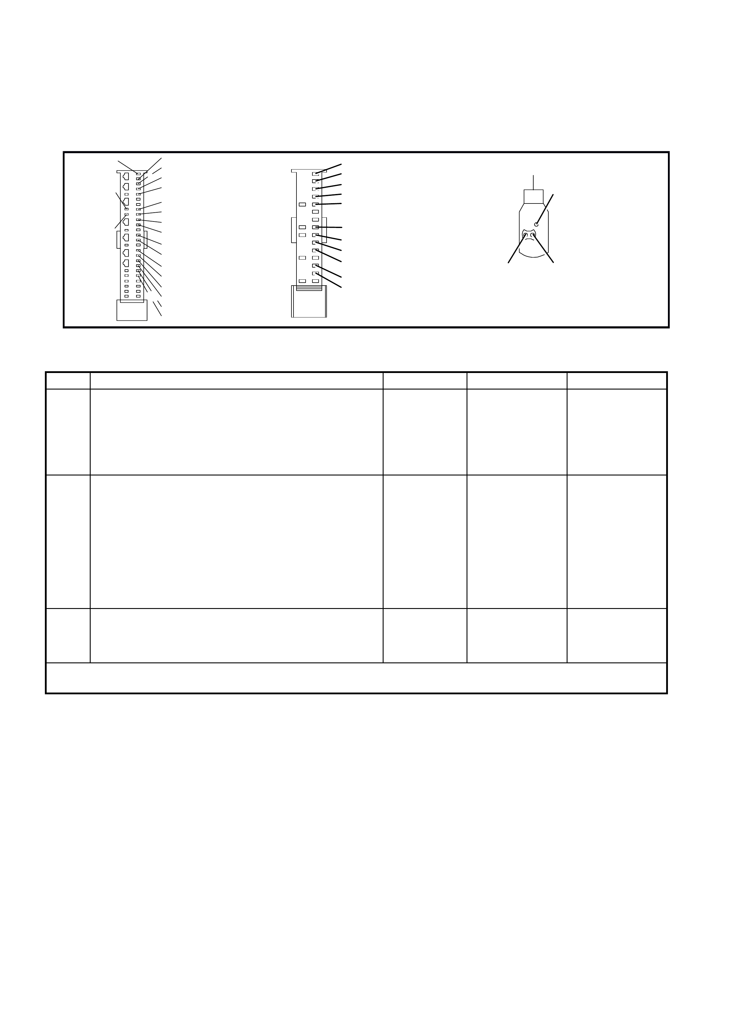
Notes on Diagnostic Chart
1. For all wiring harness checking procedures, refer to VT Series 1 Service Information, WIRING DIAGRAMS,
SECTION 12P.
2. Refer to VT Series 1 Service Information Section 12M, SRS VERSION 6.2, 2.8 SRS WIRING REPAIR before
conducting any SRS wiring harness repairs.
T12M168
YB190
8.0 SDM WI RING
HARNESS
CONNECTOR
+VE-VE
Y/R (354)
R/B (352)
(RIGHT HAND PRE-TENSIONER)
(SERVICE
HOLE)
(LE FT HAND PRE-TENSI ONER)
BR/W (353)
BLU/B ( 351)
CAP ALSO -V E
YB209
SEAT BELT
PRE-TENSIONER
HARNESS
CONNECTOR
YB189
8.1 SDM WIRING
HARNESS
CONNECTOR
BR/B (393)
26
50 25
1
BLU/B (351) R/B (352)
BR/W (353)
Y/R (354)
P/B (739)
B (3 05)
B (3 05)
G/W (1220)
W (3 47 )
G (348)
Y/B (349)
GY/B (350)
Y/G (385)
BR/G (386)
Y/W (387 )
BR/W (388)
Y/BLU ( 392)
GY/W (407)
LBLU (408)
BLU/B ( 351)
R/B (352)
BR/W (353)
Y/R (354)
P/B (739)
G/W (1220)
W (3 47 )
G (348)
Y/B (349)
GY/B (350)
Figure 12M-57
DTC 247 - RIGHT HAND PRE-TENSIONER CIRCUIT AIR BAG CIRCUIT POWER STAGE ERROR
STEP ACTION VALUE YES NO
1. • Install TECH 2 to DLC.
• Select Body / SRS / Diagnostic Trouble Codes /
Read DTC Information.
• Is a DTC 247 Right Hand Pre-Tensioner Circuit
Power Stage Error a history DTC, and are any other
Right Hand Pre-Tensioner Circuit DTCs set?
Go to other Right
Hand Pre-
Tensioner Circuit
DTC diagnostic
chart in this
Section.
Go to Step 2.
2. • With TECH 2 still connected, select Diagnostic
Trouble Codes / Clear DTC Information and clear all
(if any) DTCs.
• Select Diagnostic Trouble Codes / Read DTC
Information, 'wiggle' SRS wiring harness at all
locations between the SDM and the right hand pre-
tensioner wiring harness connector YB209, while
monitoring TECH 2 screen display.
• Does TECH 2 screen display change status from
No Diagnostic Trouble Codes?
Go to applicable
DTC chart in this
Section.
Go to step 3.
3 • Replace SDM, refer to VT Series 1 Service
Information Section 12M, SRS VERSION 8.0 & 8.1,
2.4 SENSING AND DIAGNOSTIC MODULE (SDM).
Recheck circuit to verify repair.
WHEN ALL DIAGNOSIS AND REPAIRS ARE COM PLETED, ENSURE ALL SRS COMPONENTS ARE
RECONNECTED, CLEAR ALL DTC’S, ENABLE THE SRS AND VERIFY CORRECT OPERATION

DTC 81 - LEFT HAND SIDE A IR BAG CIRCUIT SHORT TO BATTERY
Figure 12M-58
CIRCUIT DESCRIPTION
At ignition on, and on a constant monitoring cycle of every 500 milliseconds during the ignition cycle, the SDM
performs a system self check.
If the SDM detects a resistance to battery supply is less than five kohms in either the positive and/or negative circuit
for more than 3 - 5 seconds, a current DTC 81 will set (refer to SRS SELF DIAGNOSTICS in Section 12M
SUPPLEMENTAL RESTRAINT SYSTEM (Version 8.0 & 8.1) of the VT Series I Service Information for more
details).
DTC 81 will set if circuits 385 (side air bag positive side) and/or 386 (side air bag negative side) are shorted to
battery +.
When DTC 81 sets, the SDM illuminates the SRS warning lamp and sets a current DTC 81. Should the fault
conditions detected by the SDM clear during the same ignition cycle, the current code will clear and become a
history DTC 81. The SRS warning lamp will remain on for the remainder of the ignition cy cle.
If a DTC 81 is set, the SRS warning lamp is illuminated on each ignition cycle, even if the DTC is set as a history
DTC, until the fault conditions for setting DTC 81 are rectified and the DTC (current or history) can then be cleared
from the SDM via TECH 2.
If DTC 81 is set, the SRS, including the left hand side air bag, may still be operational.
Test Description
The following numbers refer to step numbers in the following diagnostic chart:
1. Uses TECH 2 to check if DTC 81 is current or history.
2. Checks for intermittent fault by monitoring TECH 2 screen. If screen display changes during a wiring 'wiggle' test,
a fault with the wiring is at that location.
3. T ool AU485 is a dumm y load taking the place of the left hand side air bag inflator module assembly. If DTC 81
becomes a history DTC with dummy load connected, the system fault is in the side air bag inflator module
assembly (or the ‘pigtail’ wiring harness that connects to the side air bag module).
4. Checks circuit 385 and 386 for short to battery +.
Notes on Diagnostic Chart
1. For all wiring harness checking procedures, refer to Section 12P WIRING DIAGRAMS of the VT Series I
Service Information.
2. Refer to 2.8 SRS WIRING REPAIR in Section 12M SUPPLEMENTAL RESTRAINT SYSTEM (Version 8.0 &
8.1) of the VT Series I Service Information before conducting any SRS wiring harness repairs.
3. Due to the design of the anti-back-out connector on the side air bag module assembly, connector YB201 can
not be dis c onnec ted f rom the s ide air bag module ass embly without damaging the assembly. Therefor e, repair s
to the SRS ‘pigtail’ wiring harness that run thr ough the front s eat are not to be attem pted. If this ‘pigtail’ harness
is damaged in any way, the harness and side air bag module assembly must be replaced as an assembly.
4. Refer to T ECH 2 DIAGNOST ICS in Section 12M SUPPLEMENT AL RESTRAINT SYST EM (Version 8.0 & 8.1)
of the VT Series I Service Information for connecting and using TECH 2.
5. To enable or disable the SRS system, refer to 2.2 SYSTEM DISABLING AND ENABLING PROCEDURE in
Section 12M SUPPLEMENTAL RESTRAINT SYSTEM (Version 8.0 & 8.1) of the VT Series I Service
Information.
6. SDM connector YB189 is equipped with a shorting link busbar which needs to be opened before checking the
circuit, re fer to 2.5 DIAGNOSTIC CHARTS in this Section for additional information.

Figure 12M-59
DTC 81 - LEFT HAND SIDE A IR BAG CIRCUIT SHORT TO BATTERY
STEP ACTION VALUE YES NO
1. • Connect TECH 2 to DLC.
• Select Body / SRS / Diagnostic Trouble Codes /
Read DTC Information (refer NOTE 4 on previous
page).
• Is DTC 81 current?
Go to Step 3. Go to Step 2.
2. • With TECH 2 still connected, select Diagnostic
Trouble Codes / Clear DTC Information and clear
all (if any) DTCs.
• Select Diagnostic Trouble Codes / Read DTC
Information and monitor the TECH 2 screen display
to see if it changes status while performing the
following:
Put left hand front seat through it’s full adjustment
(forward / backward, up / down and full recline).
'Wiggle' SRS wiring harness at all accessible
locations between the SDM and the side air bag
wiring harness connector YB205.
• Does TECH 2 screen display change status from
No Diagnostic Trouble Codes?
Make repairs as
necessary (refer
to NOTES 2 & 3
on previous
page).
Clear DTC and
recheck system to
verify repair.
Fault not present.
Check all system
wiring harness
connectors, and
terminals.
Clear DTC and
recheck system.
3. • Disable the SRS (refer NOTE 5 on previous page).
• Disconnect SRS wiring harness connector YB205
(located next to the left hand front seat) from the
left hand side air bag inflator module ‘pigtail’
harness.
• Connect Tool No. AU485 to SRS wiring harness
connector YB205.
• Reconnect battery.
• Connect TECH 2 to DLC and select: Body / SRS /
Diagnostic Trouble Codes / Read DTC Information.
• Is DTC 81 still current?
Go to Step 4. Replace left hand
side air bag and
‘‘pigtail’’ wiring
harness
assembly, refer
Section 12M
SUPPLEMENTAL
RESTRAINT
SYSTEM (Version
8.0 & 8.1) of the
VT Series I
Service
Information (refer
NOTE 3 on
previous page).
Clear DTC and
recheck system to
verify repair
4. • Disable the SRS (refer NOTE 5 on previous page).
• Disconnect SDM wiring harness connector YB189
from the SDM.
• Enable the SRS (reconnect battery).
• Using Tool KM-609-20, check wiring between SDM
wiring harness connector YB189, terminals 16 and
17 and SRS connector YB205, circuits 385
(Yellow/Green wire) and 386 (Brown/Green wire)
for short to battery + (refer to NOTES 1 & 6 on
previous page).
• Is all OK?
Replace SDM,
refer Section 12M
SUPPLEMENTAL
RESTRAINT
SYSTEM (Version
8.0 & 8.1) of the
VT Series I
Service
Information.
Recheck circuit to
verify repair.
Make repairs as
necessary (refer
to NOTE 2 on
previous page).
Clear DTC and
recheck system to
verify repair.
WHEN ALL DIAGNOSIS AND REPAIRS ARE COM PLETED, ENSURE ALL SRS COMPONENTS ARE
RECONNECTED, CLEAR ALL DTC’S, ENABLE THE SRS AND VERIFY CORRECT OPERATION

DTC 82 - LEFT HAND SIDE AI R BAG CIRCUIT SHORT TO EARTH
Figure 12M-60
CIRCUIT DESCRIPTION
At ignition on, and on a constant monitoring cycle of every 500 milliseconds during the ignition cycle, the SDM
performs a system self check. If the SDM detects a resistance to earth of less than three kohms in either the
positive or negative inflator circuit for more than 3 - 5 seconds, a current DTC 82 will set (refer to
SRS SELF DIAGNOSTICS in Section 12M SUPPLEMENTAL RESTRAINT SYSTEM (Version 8.0 & 8.1) of the VT
Series I Service Information for more details).
DTC 82 will set if circuits 385 (side air bag positive side) and/or 386 (side air bag negative side) are shorted to
earth.
When DTC 82 sets, the SDM illuminates the SRS warning lamp and sets a current DTC 82. Should the fault
conditions detected by the SDM clear during the same ignition cycle, the current code will clear and become a
history DTC 82. The SRS warning lamp will remain on for the remainder of the ignition cy cle.
If a DTC 82 is set, the SRS warning lamp is illuminated on each ignition cycle, even if the DTC is set as a history
DTC, until the fault conditions for setting DTC 82 are rectified and the DTC (current or history) can then be cleared
from the SDM via TECH 2.
If DTC 82 is set, the SRS, including the left hand side air bag, may still be operational.
Test Description
The following numbers refer to step numbers in the following diagnostic chart:
1. Uses TECH 2 to check if DTC 82 is current or history.
2. TECH 2 in this mode should display approximately 1.6 - 6.4 ohms if the passenger’s air bag loop circuit is OK.
3. If screen display changes during a wiring 'wiggle' test, a fault with the wiring is at that location.
4. T ool AU485 is a dum m y load taking the place of the side air bag inf lator m odule. If T ECH 2 displays the correct
resistance of the dummy load, the system fault is in the side air bag inflator module assembly (or the ‘pigtail’
wiring harness that connects to the side air bag module).
5. This test checks the wiring between the SDM wiring harness connector YB189, terminal 16 and the left hand
side air bag inflator module connector YB205 for faults.
6. This test checks the wiring between the SDM wiring harness connector YB189, terminal 17 and the left hand
side air bag inflator module connector YB205 for faults.
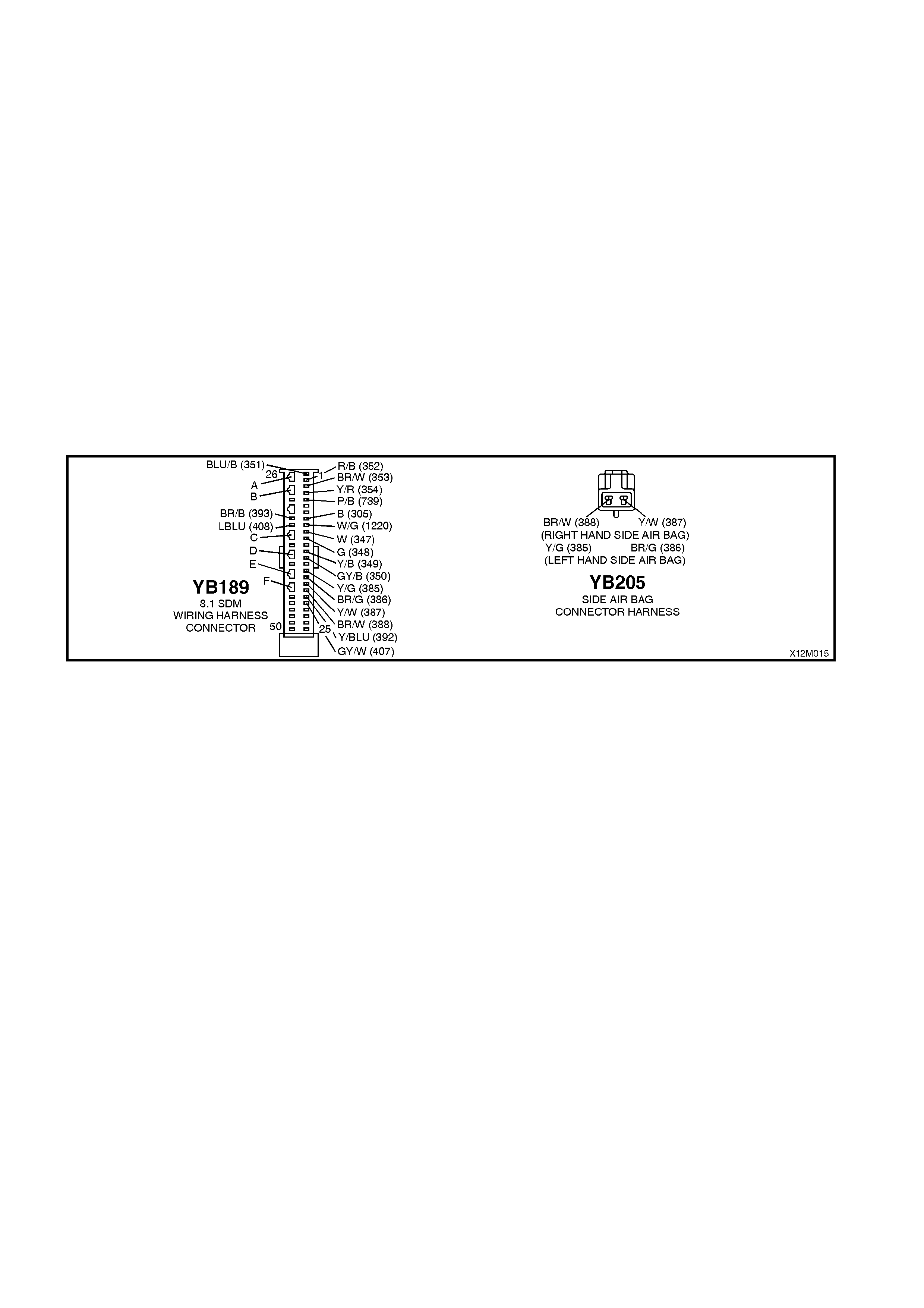
Notes on Diagnostic Chart
1. For all wiring harness checking procedures, refer to Section 12P WIRING DIAGRAMS of the VT Series I
Service Information.
2. Refer to 2.8 SRS WIRING REPAIR in Section 12M SUPPLEMENTAL RESTRAINT SYSTEM (Version 8.0 &
8.1) of the VT Series I Service Information before conducting any SRS wiring harness repairs.
3. Due to the design of the anti-back-out connector on the side air bag module assembly, connector YB201 can
not be dis c onnec ted f rom the s ide air bag module ass embly without damaging the assembly. Therefor e, repair s
to the SRS ‘pigtail’ wiring harness that runs through the front seat are not to be attempted. If this ‘pigtail’
harness is damaged in any way, the harness and side air bag module assembly must be replaced as an
assembly.
4. Wir ing s hould be c hec k ed at point where TECH 2 scr een display changed status. If nec es sar y, split open wiring
harness.
5. Refer to T ECH 2 DIAGNOST ICS in Section 12M SUPPLEMENT AL RESTRAINT SYST EM (Version 8.0 & 8.1)
of the VT Series I Service Information for connecting and using TECH 2.
6. To enable or disable the SRS system, refer to 2.2 SYSTEM DISABLING AND ENABLING PROCEDURE in
Section 12M SUPPLEMENTAL RESTRAINT SYSTEM (Version 8.0 & 8.1) of the VT Series I Service
Information.
7. SDM connector YB189 is equipped with a shorting link busbar which needs to be opened before checking the
circuit, re fer to 2.5 DIAGNOSTIC CHARTS in this Section for additional information.
Figure 12M-61

DTC 82 - LEFT HAND SIDE AI R BAG CIRCUIT SHORT TO EARTH
STEP ACTION VALUE YES NO
1. • Connect TECH 2 to DLC.
• Select Body / SRS / Diagnostic Trouble Codes /
Read DTC Information (refer NOTE 5 on previous
page).
• Does TECH 2 display DTC 82 as a Current DTC?
Go to Step 2. Go to Step 3.
2. • With TECH 2 still connected to DLC, select Body /
SRS / Data Display and scroll to LEFT HAND SIDE
AIR BAG LOOP RESISTANCE.
• Is the resistance value displayed on TECH 2 as
specified?
Approx.
1.6 - 6.4
ohms
Go to Step 3. Go to Step 4.
3. • With TECH 2 still connected, select Diagnostic
Trouble Codes / Clear DTC Information and clear all
(if any) DTCs.
• Select Diagnostic Trouble Codes / Read DTC
Information and monitor the TECH 2 screen display
to see if it changes status while performing the
following:
Put left hand front seat through it’s full adjustment
(forward / backward, up / down and full recline).
'Wiggle' SRS wiring harness at all accessible
locations between the SDM and the side air bag
wiring harness connector YB205.
• Does TECH 2 screen display change status from
No Diagnostic Trouble Codes?
Make repairs as
necessary (refer
NOTES 2, 3 & 4
on previous
page).
Clear DTC and
recheck system to
verify repair.
Fault not present.
Check all system
wiring harness
connectors, and
terminals.
Clear DTC and
recheck system.
4. • Disable the SRS (refer NOTE 6 on previous page).
• Disconnect SRS wiring harness connector YB205
(located next to the left hand front seat) from the left
hand side air bag inflator module ‘pigtail’ harness.
• Connect Tool No. AU485 to SRS wiring harness
connector YB205.
• Enable the SRS (reconnect battery).
• Connect TECH 2 to DLC and select Body / SRS /
Data Display and scroll to LEFT HAND SIDE AIR
BAG LOOP RESISTANCE'.
• Is the resistance value displayed on TECH 2 as
specified?
Approx.
2.0 ohms
Replace left hand
side air bag
inflator module
and ‘pigtail’ wiring
harness
assembly, refer
Section 12M
SUPPLEMENTAL
RESTRAINT
SYSTEM of the
VT Series I
Service
Information (refer
NOTE 3 on
previous page).
Clear DTC and
recheck system to
verify repair.
Go to Step 5.
5. • Disable the SRS (refer NOTE 6 on previous page).
• Disconnect SDM wiring harness connector YB189
from the SDM.
• Remove Tool AU485 from YB205.
• Using Tool KM-609-20, check wiring between SDM
wiring harness connector YB189, terminal 16 and
SRS connector YB205, circuit 385 (Yellow/Green
wire) for short to earth (refer NOTES 1 & 7 on
previous page).
• Is all OK?
Go to Step 7. Make repairs as
necessary (refer
to NOTE 2 on
previous page).
Clear DTC and
recheck system
to verify repair.
6. • With SDM wiring harness connector YB189
disconnected from the SDM and using Tool KM-
609-20, check wiring between SDM wiring harness
connector YB189, terminal 17 and SRS connector
YB205, circuit 386 (Brown/Green wire) for a short to
earth (refer to NOTES 1 & 7 on previous page).
• Is all OK?
Replace SDM,
refer Section 12M
SUPPLEMENTAL
RESTRAINT
SYSTEM (Version
8.0 & 8.1) of the
VT Series I
Service
Information.
Recheck circuit to
verify repair.
Make repairs as
necessary (refer
to NOTE 2 on
previous page).
Clear DTC and
recheck system
to verify repair.
WHEN ALL DIAGNOSIS AND REPAIRS ARE COM PLETED, ENSURE ALL SRS COMPONENTS ARE
RECONNECTED, CLEAR ALL DTC’S, ENABLE THE SRS AND VERIFY CORRECT OPERATION

DTC 83 - LEFT HAND SIDE A IR BAG CIRCUIT CAPACITANCE TOO HIGH
Figure 12M-62
CIRCUIT DESCRIPTION
At ignition on, and on a constant monitoring cycle of every 500 milliseconds during the ignition cycle, the SDM
performs a system self check.
If the SDM detects the capacitance in the left hand side air bag circuit is too high (greater than 550 nF) for longer
than 3 - 5 seconds, a current DTC 83 will set (refer to SRS SELF DIAGNOSTICS in Section 12M SUPPLEMENTAL
RESTRAINT SYSTEM (Version 8.0 & 8.1) of the VT Series I Service Information for more details).
DTC 83 will set if the in-built capacitor in the SRS wiring harness connector YB201 is faulty.
When DTC 83 sets, the SDM illuminates the SRS warning lamp and sets a current DTC 83. Should the fault
conditions detected by the SDM clear during the same ignition cycle, the current code will clear and become a
history DTC 83. The SRS warning lamp will remain on for the remainder of the ignition cy cle.
If a DTC 83 is set, the SRS warning lamp is illuminated on each ignition cycle, even if the DTC is set as a history
DTC, until the fault conditions for setting DTC 83 are rectified and the DTC (current or history) can then be cleared
from the SDM via TECH 2.
ACTION REQUIRED
If DTC 83 is set, the left hand side air bag may not operate and therefore, the SRS side air bag and ‘pigtail’ wiring
harness assembly must be replaced. Refer to Section 12M SUPPLEMENTAL RESTRAINT SYSTEM (Version 8.0
& 8.1) of the VT Series I Service Information for the correct procedure on replacing the side air bag and ‘pigtail’
wiring harness connector.
NOTE: Due to the design of the anti-back-out connector on the side air bag module assembly, connector YB201
can not be disconnected from the side air bag module assembly without damaging the assembly. Therefore, repairs
to the SRS ‘pigtail’ wiring harness that run through the front seat are not to be attempted (this includes the capacitor
in connector YB201). If this ‘pigtail’ harness is damaged in any way, the harness and side air bag module assembly
must be replaced as an assembly.
After the SRS side air bag and ‘pigtail’ wiring harness assembly have been replaced, ensure all SRS components
are reconnected, clear DTCs, enable the SRS and verify the correct operation of the system (i.e. warning lamp not
illuminated after five seconds of ignition being switched ON).
NOTE: After replacement, the front seat should be put through its full adjustment (forward/backwards, full recline
and up and down) to ensure that the wiring harness does not foul with any of the seat components.

DTC 84 - LEFT HAND SIDE A IR BAG CIRCUIT CAPACITANCE TOO LOW
Figure 12M-63
CIRCUIT DESCRIPTION
At ignition on, and on a constant monitoring cycle of every 500 milliseconds during the ignition cycle, the SDM
performs a system self check.
If the SDM detects the capacitance in the left hand side air bag circuit is too low (less than 390 nF) for longer than 3
- 5 seconds, a current DTC 84 will set (refer to SRS SELF DIAGNOSTICS in Section 12M SUPPLEMENTAL
RESTRAINT SYSTEM (Version 8.0 & 8.1) of the VT Series I Service Information for more details).
DTC 84 will set if the in-built capacitor in the SRS wiring harness connector YB201 is faulty.
When DTC 84 sets, the SDM illuminates the SRS warning lamp and sets a current DTC 84. Should the fault
conditions detected by the SDM clear during the same ignition cycle, the current code will clear and become a
history DTC 84. The SRS warning lamp will remain on for the remainder of the ignition cy cle.
If a DTC 84 is set, the SRS warning lamp is illuminated on each ignition cycle, even if the DTC is set as a history
DTC, until the fault conditions for setting DTC 84 are rectified and the DTC (current or history) can then be cleared
from the SDM via TECH 2.
ACTION REQUIRED
If DTC 84 is set, the left hand side air bag may not operate and therefore, the SRS side air bag and ‘pigtail’ wiring
harness assembly must be replaced. Refer to Section 12M SUPPLEMENTAL RESTRAINT SYSTEM (Version 8.0
& 8.1) of the VT Series I Service Information for the correct procedure on replacing the side air bag and ‘pigtail’
wiring harness connector.
NOTE: Due to the design of the anti-back-out connector on the side air bag module assembly, connector YB201
can not be disconnected from the side air bag module assembly without damaging the assembly. Therefore, repairs
to the SRS ‘pigtail’ wiring harness that run through the front seat are not to be attempted (this includes the capacitor
in connector YB201). If this ‘pigtail’ harness is damaged in any way, the harness and side air bag module assembly
must be replaced as an assembly.
After the SRS side air bag and ‘pigtail’ wiring harness assemblies have been replaced, ensure all SRS components
are reconnected, clear DTCs, enable the SRS and verify the correct operation of the system (i.e. warning lamp not
illuminated after five seconds of ignition being switched ON).
NOTE: After replacement, the front seat should be put through its full adjustment (forward/backwards, full recline
and up and down) to ensure the wiring harness does not foul with any of the seat components.

DTC 85 - LEFT HAND SIDE AI R BAG CIRCUIT RESISTANCE TOO HIGH
Figure 12M-64
CIRCUIT DESCRIPTION
At ignition on, and on a constant monitoring cycle of every 500 milliseconds during the ignition cycle, the SDM
performs a system self check.
If the SDM detects a resistance in the left hand side air bag circuit that is too high (greater than 10 ohms for longer
than 3 - 5 seconds, a current DTC 85 will set (refer to SRS SELF DIAGNOSTICS in Section 12M SUPPLEMENTAL
RESTRAINT SYSTEM (Version 8.0 & 8.1) of the VT Series I Service Information for more details).
DTC 85 will set if circuits 385 or 386 (including the side air bag inflator module) are open circuit.
When DTC 85 sets, the SDM illuminates the SRS warning lamp and sets a current DTC 85. Should the fault
conditions detected by the SDM clear during the same ignition cycle, the current code will clear and become a
history DTC 85. The SRS warning lamp will remain on for the remainder of the ignition cy cle.
If a DTC 85 is set, the SRS warning lamp is illuminated on each ignition cycle, even if the DTC is set as a history
DTC, until the fault conditions for setting DTC 85 are rectified and the DTC (current or history) can then be cleared
from the SDM via TECH 2.
If DTC 85 is set, dependent on where the fault is, the left hand side air bag may not operate.
Test Description
The followings numbers refer to step numbers in the following diagnostic chart:
1. Uses TECH 2 to check if DTC 85 is current or history.
2. Checks for intermittent fault by monitoring TECH 2 screen. If screen display changes during a wiring 'wiggle'
test, a fault with the wiring is at that location.
3. T ool AU485 is a dumm y load taking the place of the side air bag inflator m odule. If DTC 85 bec omes a his tory
DTC with dum my load connected, the system f ault is in the s ide air bag inf lator module as sembly (or the ‘pigtail’
wiring harness that connects to the side air bag module).
4. Checks circuit 385 for open circuit.
5. Checks circuit 386 for open circuit.
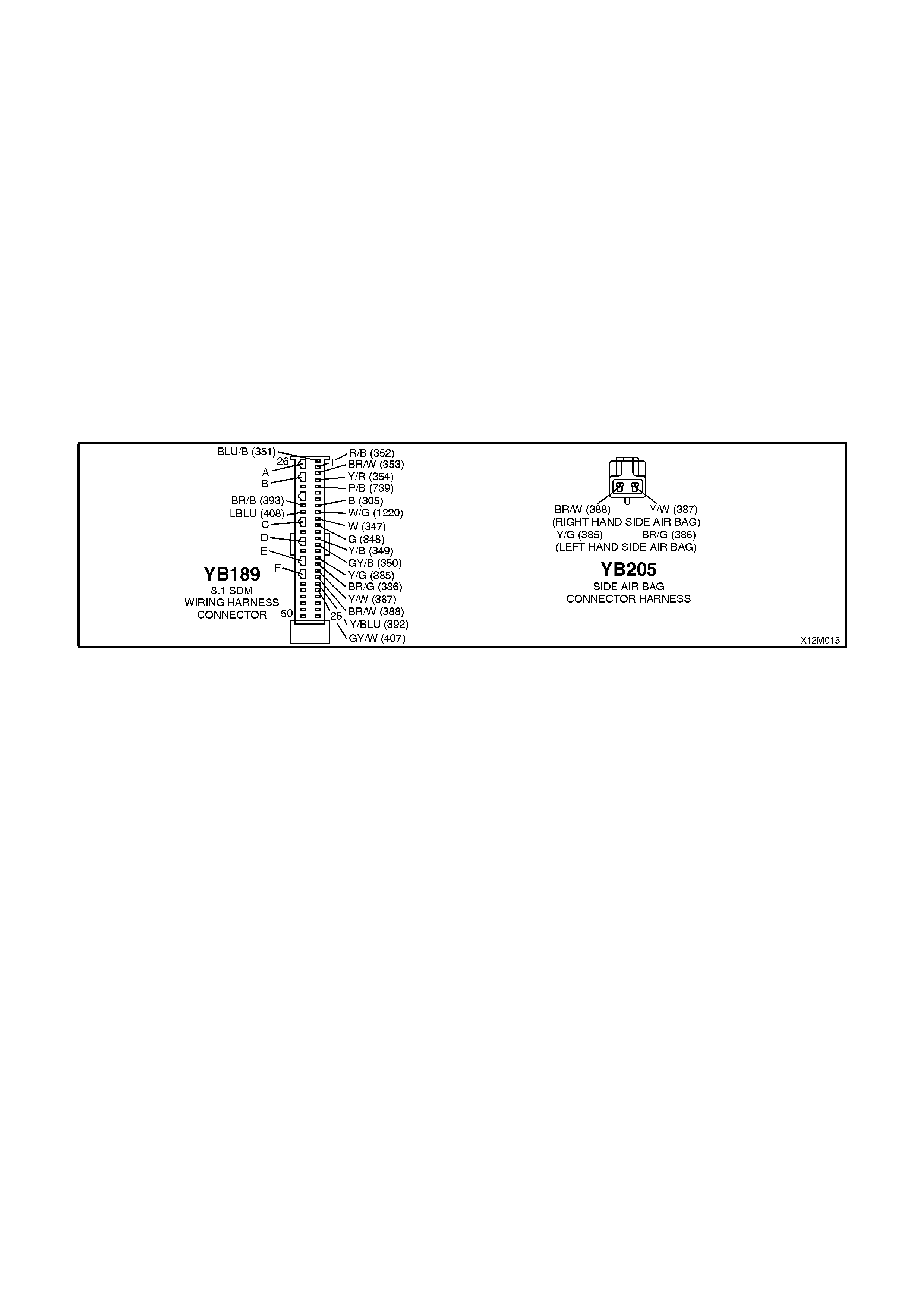
Notes on Diagnostic Chart
1. For all wiring harness checking procedures, refer to Section 12P WIRING DIAGRAMS of the VT Series I
Service Information.
2. Refer to 2.8 SRS WIRING REPAIR in Section 12M SUPPLEMENTAL RESTRAINT SYSTEM (Version 8.0 &
8.1) of the VT Series I Service Information before conducting any SRS wiring harness repairs.
3. Due to the design of the anti-back-out connector on the side air bag module assembly, connector YB201 can
not be dis c onnec ted f rom the s ide air bag module ass embly without damaging the assembly. Therefor e, repair s
to the SRS ‘pigtail’ wiring harness that run thr ough the front s eat are not to be attem pted. If this ‘pigtail’ harness
is damaged in any way, the harness and side air bag module assembly must be replaced as an assembly.
4. Wir ing s hould be c hec k ed at point where TECH 2 scr een display changed status. If nec es sar y, split open wiring
harness.
5. Refer to T ECH 2 DIAGNOST ICS in Section 12M SUPPLEMENT AL RESTRAINT SYST EM (Version 8.0 & 8.1)
of the VT Series I Service Information for connecting and using TECH 2.
6. To enable or disable the SRS system, refer to 2.2 SYSTEM DISABLING AND ENABLING PROCEDURE in
Section 12M SUPPLEMENTAL RESTRAINT SYSTEM (Version 8.0 & 8.1) of the VT Series I Service
Information.
7. SDM connector YB189 is equipped with a shorting link busbar which needs to be opened before checking the
circuit, re fer to 2.5 DIAGNOSTIC CHARTS in this Section for additional information.
Figure 12M-65

DTC 85 - LEFT HAND SIDE AI R BAG CIRCUIT RESISTANCE TOO HIGH
STEP ACTION VALUE YES NO
1. • Inst al l T ECH 2 to DLC.
• Select Body / SRS / Diagnostic Trouble Codes / Read
DTC Information (refer NOTE 5 on previous page).
• Is DTC 85 current?
Go to Step 3. Go to Step 2.
2. • With TECH 2 still connected, select Diagnostic Trouble
Codes / Clear DTC Information and clear all (if any)
DTCs.
• Selec t Diagnostic Trouble Codes / Read DTC Inform ation
and monitor the TECH 2 screen display to see if it
changes s tatus while performing the following:
Put left hand front seat through it’s full adjustment
(forward / backward, up / down and full recline).
'Wiggle' SRS wiring harness at all accessible locations
between the SDM and the side air bag wiring harness
connect or Y B205.
• Does TECH 2 screen display change status from No
Diagnosti c Trouble Codes?
Make repairs as
necess ary (refer to
NOTES 2, 3 & 4 on
previous page).
Clear DTC and
recheck system to
verify repair.
Fault not pres ent.
Check all system
wiring harness
connect ors, and
terminals.
Clear DTC and
recheck system.
3. • Disable the SRS (refer NOTE 6 on previous page).
• Disconnect SRS wiring harness connector YB205
(located next t o the left hand front seat ) from t he lef t hand
side air bag inflat or module ‘pigtail’ harness.
• Connect Tool No. AU485 to SRS wiring harness
connect or Y B205.
• Enable the SRS (reconnec t battery).
• Connect TECH 2 to DLC and select Body / SRS /
Diagnosti c Trouble Codes / Read DTC Inform at i on
• Is DTC 85 still current?
Go to Step 4. Replace lef t hand
side air bag inflator
module and ‘pigtail’
wiring harness
assembly, refer
Secti on 12M
SUPPLEMENTAL
RESTRAINT
SYSTEM (Version
8.0 & 8.1) of the
VT Series I
Service
Information (refer
NOTE 3 on previous
page).
Clear DTC and
recheck system to
verify repair.
4. • Disable the SRS (refer NOTE 6 on previous page).
• Disconnect SDM wiring harness connector YB189 from
the SDM.
• Using Tool KM-609-20, check wiring bet ween SDM wiring
harness connector YB189, terminal 16 and SRS wiring
harness c onnect or YB 205, c ircui t 385 (Y ellow/Green wire)
for open circuit (refer to NOTES 1 & 7 on previ ous page).
• Is all OK?
Go to Step 5. Make repairs as
necess a ry (ref er to
NOTE 2 on previous
page).
Clear DTC and
recheck system to
verify repair.
5. • W ith SDM wiring harness connector Y B189 dis connected
from the SDM and using Tool KM-609-20, check wiring
between SDM wiring harness connector YB189, terminal
17 and SRS wiring harness connector YB205, circuit 386
(Brown/Green wire) for open circui t (ref er to NOTE S 1 & 7
on previous page).
• Is all OK?
Replace SDM, refer
Secti on 12M
SUPPLEMENTAL
RESTRAINT
SYSTEM (Version
8.0 & 8.1) of the
VT Series I
Service
Information.
Recheck circuit to
verify repair.
Make repairs as
necess a ry (ref er to
NOTE 2 on previous
page).
Clear DTC and
recheck system to
verify repair.
WHEN ALL DIAGNOSIS AND REPAIRS ARE COMPLETED, ENSURE ALL SRS COMPONENTS ARE
RECONNECTED, CLEAR ALL DTC’S, ENABLE THE SRS AND VERIFY CORRECT OPERATION
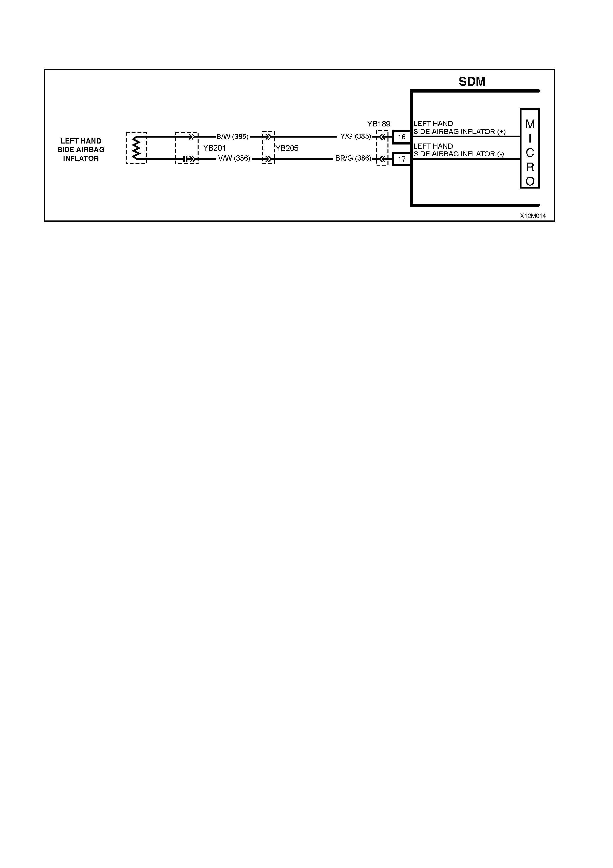
DTC 86 - LEFT HAND SIDE AIR BAG CIRCUIT RESISTANCE TOO LOW
Figure 12M-66
CIRCUIT DESCRIPTION
At ignition on, and on a constant monitoring cycle of every 500 milliseconds during the ignition cycle, the SDM
performs a system self check.
If the SDM detects a res is tance in the left hand side air bag c irc uit that is too low (les s than 0.6 ohm) for longer than
3 - 5 seconds, a current DTC 86 will set (refer to SRS SELF DIAGNOSTICS in Section 12M SUPPLEMENTAL
RESTRAINT SYSTEM (Version 8.0 & 8.1) of the VT Series I Service Information for more details).
DTC 86 will set if circuits 385 or 386, (including the side air bag inflator module assembly) are shorted together.
When DTC 86 sets, the SDM illuminates the SRS warning lamp and sets a current DTC 86. Should the fault
conditions detected by the SDM clear during the same ignition cycle, the current code will clear and become a
history DTC 86. The SRS warning lamp will remain on for the remainder of the ignition cy cle.
If a DTC 86 is set, the SRS warning lamp is illuminated on each ignition cycle, even if the DTC is set as a history
DTC, until the f ault conditions for s etting DTC 86 are rectif ied and the DTC (curr ent or history) can then be cleared
from the SDM via TECH 2.
If DTC 86 is set, dependent on where the fault is, the left hand side air bag may not operate.
Test Description
The following numbers refer to step numbers in the following diagnostic chart:
1. Uses TECH 2 to check if DTC 86 is current or history.
2. Checks for intermittent fault by monitoring TECH 2 screen. If screen display changes during a wiring 'wiggle'
test, a fault with the wiring is at that location.
3. T ool AU485 is a dumm y load taking the place of the side air bag inflator m odule. If DTC 85 bec omes a his tory
DTC with dum my load connected, the system f ault is in the s ide air bag inf lator module as sembly (or the ‘pigtail’
wiring harness that connects to the side air bag module).
4. This test checks the wiring between the SDM wiring harness connector YB189 and SRS wiring harness
connector YB205 for a short circuit.
Notes on Diagnostic Chart
1. For all wiring harness checking procedures, refer to Section 12P WIRING DIAGRAMS of the VT Series I
Service Information.
2. Refer to 2.7 SRS WIRING REPAIR in Section 12M SUPPLEMENTAL RESTRAINT SYSTEM (Version 8.0 &
8.1) of the VT Series I Service Information before conducting any SRS wiring harness repairs.
3. Due to the design of the anti-back-out connector on the side air bag module assembly, connector YB201 can
not be dis c onnec ted f rom the s ide air bag module ass embly without damaging the assembly. Therefor e, repair s
to the SRS ‘pigtail’ wiring harness that run thr ough the front s eat are not to be attem pted. If this ‘pigtail’ harness
is damaged in any way, the harness and side air bag module assembly must be replaced as an assembly.
4. Wir ing s hould be c hec k ed at point where TECH 2 scr een display changed status. If nec es sar y, split open wiring
harness.
5. Refer to T ECH 2 DIAGNOST ICS in Section 12M SUPPLEMENT AL RESTRAINT SYST EM (Version 8.0 & 8.1)
of the VT Series I Service Information for connecting and using TECH 2.
6. To enable or disable the SRS system, refer to 2.2 SYSTEM DISABLING AND ENABLING PROCEDURE in
Section 12M SUPPLEMENTAL RESTRAINT SYSTEM (Version 8.0 & 8.1) of the VT Series I Service
Information.
7. SDM connector YB189 is equipped with a shorting link busbar which needs to be opened before checking the
circuit, re fer to 2.5 DIAGNOSTIC CHARTS in this Section for additional information.

Figure 12M-67
DTC 86 - LEFT HAND SIDE AIR BAG CIRCUIT RESISTANCE TOO LOW
STEP ACTION VALUE YES NO
1. • Install TECH 2 to DLC.
• Select Body / SRS / Diagnostic Trouble Codes /
Read DTC Information (refer NOTE 5 on previous
page).
• Is DTC 86 current?
Go to Step 3. Go to Step 2.
2. • With TECH 2 still connected, select Diagnostic
Trouble Codes / Clear DTC Information and clear
all (if any) DTCs.
• Select Diagnostic Trouble Codes / Read DTC
Information and monitor the TECH 2 screen display
to see if it changes status while performing the
following:
Put left hand front seat through it’s full adjustment
(forward / backward, up / down and full recline).
'Wiggle' SRS wiring harness at all accessible
locations between the SDM and the side air bag
wiring harness connector YB205.
• Does TECH 2 screen display change status from
No Diagnostic Trouble Codes?
Make repairs as
necessary (refer
to NOTES 2, 3 &
4 on previous
page).
Clear DTC and
recheck system
to verify repair.
Fault not present.
Check all system
wiring harness
connectors, and
terminals.
Clear DTC and
recheck system.
3. • Disable the SRS (refer NOTE 6 on previous page).
• Disconnect SRS wiring harness connector YB205
(located next to the left hand front seat) from the
left hand side air bag inflator module ‘pigtail’
harness.
• Connect Tool No. AU485 to SRS wiring harness
connector YB205.
• Enable the SRS (reconnect battery).
• Connect TECH 2 to DLC and select Body / SRS /
Diagnostic Trouble Codes / Read DTC Information
• Is DTC 86 still current?
Go to Step 4. Replace left hand
side air bag
inflator module
and ‘pigtail’ wiring
harness
assembly, refer
Section 12M
SUPPLEMENTAL
RESTRAINT
SYSTEM (Version
8.0 & 8.1) of the
VT Series I
Service
Information (refer
NOTE 3 on
previous page).
Clear DTC and
recheck system to
verify repair.
4. • Disable the SRS (refer NOTE 6 on previous page).
• Disconnect SDM wiring harness connector YB189
from the SDM.
• Disconnect Tool No. AU485 from SRS wiring
harness connector YB205.
• With SRS wiring harness connector YB205
disconnected, and using Tool KM-609-20, check
for continuity between SDM wiring harness
connector YB189, terminal 17, circuit 386
(Brown/Green wire) and terminal 16, circuit 385
(Yellow/Green wire)(refer to NOTES 1, 3 & 7 on
previous page).
• Does continuity exist?
Repair short in
circuits 386 and
385, between
SDM wiring
harness
connector YB189
and YB205 as
necessary (refer
to NOTE 2 on
previous page).
Clear DTC and
recheck system
to verify repair.
Replace SDM,
refer Section 12M
SUPPLEMENTAL
RESTRAINT
SYSTEM (Version
8.0 & 8.1) of the
VT Series I
Service
Information.
Recheck circuit to
verify repair.
WHEN ALL DIAGNOSIS AND REPAIRS ARE COM PLETED, ENSURE ALL SRS COMPONENTS ARE
RECONNECTED, CLEAR ALL DTC’S, ENABLE THE SRS AND VERIFY CORRECT OPERATION
DTC 247 - LEFT HAND SIDE IMPACT AIR BAG CIRCUIT POWER STAGE ERROR
T12M130
SDM
M
I
C
R
O
YB189
YB201
LE FT HAND
SIDE AIRBAG
INFLATOR
LEFT HAND
SIDE AIRBAG INFLATOR (+)
LEFT HAND
SIDE AIRBAG INFLATOR (-)
16
17
YB205
Y/G (3 85)
BR/G (386)
Figure 12M-68
CIRCUIT DESCRIPTION
At ignition on, the SDM perfor ms an initial system self check of the SDM power s tages. If during this initial self test
the SDM detects a fault with the Left Hand Side Impact Air Bag Circuit power stage a current DTC 247 Left Hand
Side Impact Air Bag Circuit Power Stage Error will set. On completion of the initial system self test the SDM then
performs a test of the Left Hand Side Impact Air Bag Circuit. If the SDM detects a problem with this circuit the
associated Lef t Hand Side Impact Air Bag Cir cuit DTC will be set and the DTC 247 Lef t Hand Side Impact Air Bag
Circuit Air Bag Circuit Power Stage Error will become a history DTC.
DTC 247 Left Hand Side Impact Air Bag Circuit Power Stage Error will set if a fault occurs in the Left Hand Side
Impact Air Bag, connector YB201 with the in-built capacitor, connector YB205, the SRS wiring harness, connector
YB189/190 or SDM.
When a history DTC 247 Left Hand Side Impact Air Bag Circuit Power Stage Error sets, the SDM illuminates the
SRS warning lam p. Should the f ault conditions detected by the SDM clear during the same ignition cycle the code
will remain a history DTC 247 Left Hand Side Impact Air Bag Circuit Power Stage Error for all ignition cycles until
cleared. The SRS warning lamp will remain on for the remainder of the ignition cycle.
When a DTC 247 Left Hand Side Impact Air Bag Circuit Power Stage Error sets, the SDM illuminates the SRS
warning lamp for the remainder of the ignition cycle. Should the fault conditions detected by the SDM clear during
the sam e ignition cycle the c ode will rem ain a history DTC 247 Left Hand Side Im pact Air Bag Circuit Power Stage
Error for all ignition cycles until cleared. The SRS warning lamp will also remain illuminated until the history DTC
247 Left Hand Side Impact Air Bag Circuit Power Stage Error is cleared.
If a DTC 247 Left Hand Side Impac t Air Bag Circuit Power Stage is set, dependent on where the fault is , the Right
Hand Pre-Tensioner may not operate.
ACTION REQUIRED
If DT C 247 Lef t Hand Side Im pac t Air Bag Circuit Power Stage Error and any other DTC is set then the diagnos tics
for the other DTC should be carried out first. For example if a DTC 247 Left Hand Side Impact Air Bag Circuit Power
Stage Error and a DTC 85 Left Hand Side Impact Air Bag Circuit Resistance High are set, the diagnostics for a DTC
85 Left Hand Side Impact Air Bag Circuit Resistance High should be carried out first.
If only a DTC 247 Left Hand Side Impact Air Bag Circuit Power Stage Error is set then the SDM should be replaced.
NOTE: An intermittent in the Left Hand Side Impact Air Bag Circuit may cause a DTC 247 Left Hand Side Impact
Air Bag Circuit Power Stage Error to set.
After the fault has been rectified, ensure that all SRS components are reconnected, clear DTCs, enable the SRS
and verify the correct operation of the system (i.e. warning lamp not illum inated after five seconds of ignition being
switched ON).
NOTE: After replacement, the front seat should be put through its full adjustment (forward/backwards, full recline
and up and down) to ensure the wiring harness does not foul with any of the seat components.
Test Description
The following numbers refer to Step numbers in the following diagnostic chart.
1. Uses TECH 2 to check if a DT C 247 Lef t Hand Side Impac t Air Bag Circuit Power Stage Error is his tory code,
and if any other Left Hand Side Impact Air Bag Circuit current or history DTCs are set. If any other DTCs are set
refer to these DTCs first.
2. Checks for intermittent fault by monitoring TECH 2 screen during ignition on cycle. If screen display changes
during a wiring 'wiggle' test, a fault with the wiring is at that location.
3. If no other DTCs are set and there are no intermittents in the Left Hand Side Impact Air Bag Circuit then the
SDM should be replaced.

Notes on Diagnostic Chart
1. For all wiring harness checking procedures, refer to VT Series 1 Service Information, WIRING DIAGRAMS,
SECTION 12P.
2. Refer to VT Series 1 Service Information Section 12M, SRS VERSION 6.2, 2.8 SRS WIRING REPAIR before
conducting any SRS wiring harness repairs.
T12M176
YB189
8.1 SDM WIRING HARNESS
CONNECTOR
BR/B (393)
26
50 25
1
BLU/B (351) R/B (352)
BR/W (353)
Y/R (354)
P/B (739)
B (305)
G/W (1220)
W (347)
G (348)
Y/B (349)
GY/B (350)
Y/G (385)
BR/G (386)
Y/W (387)
BR/W (388)
Y/BLU (392)
GY/W (407)
LBLU (408) Y/W (387) BR/W (388)
(RIGHT HAND SIDE AIR BAG)
BR/G (386) Y/G (385)
(LEFT HAND SIDE AIR BAG)
YB205
SIDE AIR BAG
CONNECTOR HARNESS
Figure 12M-69
DTC 247 - LEFT HAND SIDE IMPACT AIR BAG CIRCUIT AIR BAG CIRCUIT POWER STAGE ERROR
STEP ACTION VALUE YES NO
1. • Install TECH 2 to DLC.
• Select Body / SRS / Diagnostic Trouble Codes /
Read DTC Information.
• Is a DTC 247 Left Hand Side Impact Air Bag Circuit
Power Stage Error a history DTC, and are any other
Left Hand Side Impact Air Bag Circuit DTCs set?
Go to other Left
Hand Side
Impact Air Bag
Circuit DTC
diagnostic chart
in this Section.
Go to Step 2.
2. • With TECH 2 still connected, select Diagnostic
Trouble Codes / Clear DTC Information and clear all
(if any) DTCs.
• Select Diagnostic Trouble Codes / Read DTC
Information and monitor the TECH 2 screen display
to see if it changes status while performing the
following:
Put left hand front seat through it’s full adjustment
(forward / backward, up / down and full recline).
'Wiggle' SRS wiring harness, at all accessible
locations between the SDM and the side impact air
bag wiring harness connector YB205.
• Does TECH 2 screen display change status from
No Diagnostic Trouble Codes?
Go to applicable
DTC chart in this
Section.
Go to step 3.
3 • Replace SDM, refer to VT Series 1 Service
Information Section 12M, SRS VERSION 8.0 & 8.1,
2.4 SENSING AND DIAGNOSTIC MODULE (SDM).
Recheck circuit to verify repair.
WHEN ALL DIAGNOSIS AND REPAIRS ARE COM PLETED, ENSURE ALL SRS COMPONENTS ARE
RECONNECTED, CLEAR ALL DTC’S, ENABLE THE SRS AND VERIFY CORRECT OPERATION

DTC 97 - RIGHT HAND SIDE A IR BAG CIRCUIT SHORT TO BATTERY
Figure 12M-70
CIRCUIT DESCRIPTION
At ignition on, and on a constant monitoring cycle of every 500 milliseconds during the ignition cycle, the SDM
performs a system self check.
If the SDM detects a resistance to battery supply is less than five kohms in either the positive and/or negative circuit
for more than 3 - 5 seconds, a current DTC 97 will set (refer to SRS SELF DIAGNOSTICS in Section 12M
SUPPLEMENTAL RESTRAINT SYSTEM (Version 8.0 & 8.1) of the VT Series I Service Information for more
details).
DTC 97 will set if circuits 388 (side air bag positive side) and/or 387 (side air bag negative side) are shorted to
battery +.
When DTC 97 sets, the SDM illuminates the SRS warning lamp and sets a current DTC 97. Should the fault
conditions detected by the SDM clear during the same ignition cycle, the current code will clear and become a
history DTC 97. The SRS warning lamp will remain on for the remainder of the ignition cy cle.
If a DTC 97 is set, the SRS warning lamp is illuminated on each ignition cycle, even if the DTC is set as a history
DTC, until the fault conditions for setting DTC 97 are rectified and the DTC (current or history) can then be cleared
from the SDM via TECH 2.
If DTC 97 is set, the SRS, including the right hand side air bag, may still be operational.
Test Description
The following numbers refer to step numbers in the following diagnostic chart:
1. Uses TECH 2 to check if DTC 97 is current or history.
2. Checks for intermittent fault by monitoring TECH 2 screen. If screen display changes during a wiring 'wiggle' test,
a fault with the wiring is at that location.
3. T ool AU485 is a dum m y load taking the place of the right hand side air bag inf lator m odule ass em bly. If DTC 97
becomes a history DTC with dummy load connected, the system fault is in the side air bag inflator module
assembly (or the ‘pigtail’ wiring harness that connects to the side air bag module).
4. Checks circuit 388 and 387 for short to battery +.
Notes on Diagnostic Chart
1. For all wiring harness checking procedures, refer to Section 12P WIRING DIAGRAMS of the VT Series I
Service Information.
2. Refer to 2.8 SRS WIRING REPAIR in Section 12M SUPPLEMENTAL RESTRAINT SYSTEM (Version 8.0 &
8.1) of the VT Series I Service Information before conducting any SRS wiring harness repairs.
3. Due to the design of the anti-back-out connector on the side air bag module assembly, connector YB201 can
not be dis c onnec ted f rom the s ide air bag module ass embly without damaging the assembly. Therefor e, repair s
to the SRS ‘pigtail’ wiring harness that run thr ough the front s eat are not to be attem pted. If this ‘pigtail’ harness
is damaged in any way, the harness and side air bag module assembly must be replaced as an assembly.
4. Refer to T ECH 2 DIAGNOST ICS in Section 12M SUPPLEMENT AL RESTRAINT SYST EM (Version 8.0 & 8.1)
of the VT Series I Service Information for connecting and using TECH 2.
5. To enable or disable the SRS system, refer to 2.2 SYSTEM DISABLING AND ENABLING PROCEDURE in
Section 12M SUPPLEMENTAL RESTRAINT SYSTEM (Version 8.0 & 8.1) of the VT Series I Service
Information.
6. SDM connector YB189 is equipped with a shorting link busbar which needs to be opened before checking the
circuit, re fer to 2.5 DIAGNOSTIC CHARTS in this Section for additional information.

Figure 12M-71
DTC 97 - RIGHT HAND SIDE A IR BAG CIRCUIT SHORT TO BATTERY
STEP ACTION VALUE YES NO
1. • Connect TECH 2 to DLC.
• Select Body / SRS / Diagnostic Trouble Codes /
Read DTC Information (refer NOTE 4 on previous
page).
• Is DTC 97 current?
Go to Step 3. Go to Step 2.
2. • With TECH 2 still connected, select Diagnostic
Trouble Codes / Clear DTC Information and clear
all (if any) DTCs.
• Select Diagnostic Trouble Codes / Read DTC
Information and monitor the TECH 2 screen display
to see if it changes status while performing the
following:
Put right hand front seat through it’s full adjustment
(forward / backward, up / down and full recline).
'Wiggle' SRS wiring harness at all accessible
locations between the SDM and the side air bag
wiring harness connector YB205.
• Does TECH 2 screen display change status from
No Diagnostic Trouble Codes?
Make repairs as
necessary (refer
to NOTE 2 & 3 on
previous page).
Clear DTC and
recheck system to
verify repair.
Fault not present.
Check all system
wiring harness
connectors, and
terminals.
Clear DTC and
recheck system.
3. • Disable the SRS (refer NOTE 5 on previous page).
• Disconnect SRS wiring harness connector YB205
(located next to the right hand front seat) from the
left hand side air bag inflator module ‘pigtail’
harness.
• Connect Tool No. AU485 to SRS wiring harness
connector YB205.
• Reconnect battery.
• Connect TECH 2 to DLC and select: Body / SRS /
Diagnostic Trouble Codes / Read DTC Information.
• Is DTC 97 still current?
Go to Step 4. Replace right
hand side air bag
and ‘‘pigtail’’
wiring harness
assembly, refer
Section 12M
SUPPLEMENTAL
RESTRAINT
SYSTEM (Version
8.0 & 8.1) of the
VT Series I
Service
Information (refer
to NOTE 3 on
previous page).
Clear DTC and
recheck system to
verify repair
4. • Disable the SRS (refer NOTE 5 on previous page).
• Disconnect SDM wiring harness connector YB189
from the SDM.
• Enable the SRS (reconnect battery).
• Using Tool KM-609-20, check wiring between SDM
wiring harness connector YB189, terminals 18 and
19 and SRS connector YB205, circuits 387
(Yellow/White wire) and 388 (Brown/W hite wire) for
short to battery + (refer to NOTES 1 & 6 on
previous page).
• Is all OK?
Replace SDM,
refer Section 12M
SUPPLEMENTAL
RESTRAINT
SYSTEM (Version
8.0 & 8.1) of the
VT Series I
Service
Information.
Recheck circuit to
verify repair.
Make repairs as
necessary (refer
to NOTE 2 on
previous page).
Clear DTC and
recheck system to
verify repair.
WHEN ALL DIAGNOSIS AND REPAIRS ARE COM PLETED, ENSURE ALL SRS COMPONENTS ARE
RECONNECTED, CLEAR ALL DTC’S, ENABLE THE SRS AND VERIFY CORRECT OPERATION
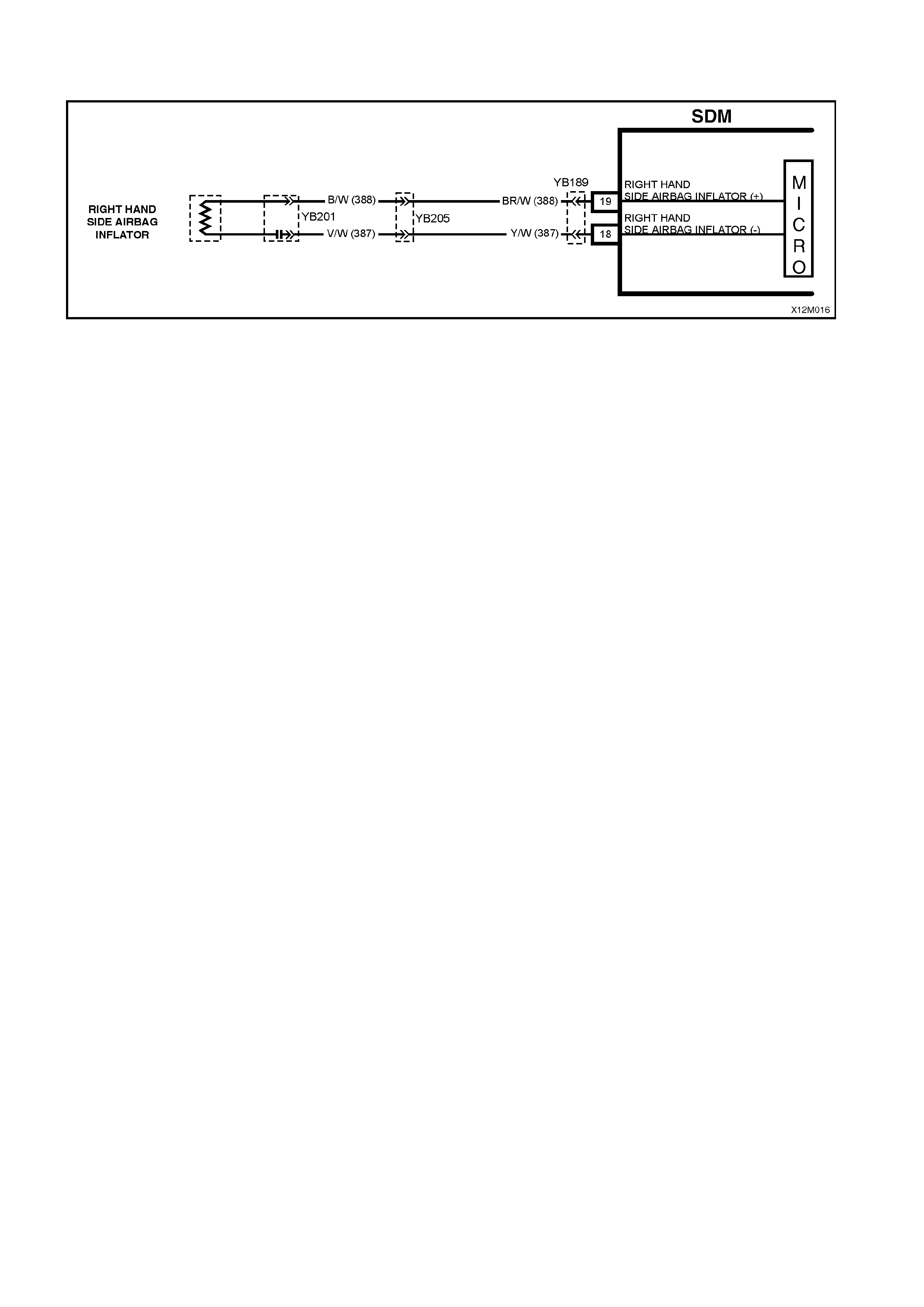
DTC 98 - RIGHT HAND SIDE AI R BAG CIRCUIT SHORT TO EARTH
Figure 12M-72
CIRCUIT DESCRIPTION
At ignition on, and on a constant monitoring cycle of every 500 milliseconds during the ignition cycle, the SDM
performs a system self check. If the SDM detects a resistance to earth of less than three kohms in either the
positive or negative inflator circuit for more than 3 - 5 seconds, a current DTC 98 will set (refer to
SRS SELF DIAGNOSTICS in Section 12M SUPPLEMENTAL RESTRAINT SYSTEM (Version 8.0 & 8.1) of the VT
Series I Service Information for more details).
DTC 98 will set if circuits 388 (side air bag positive side) and/or 387 (side air bag negative side) are shorted to
earth.
When DTC 98 sets, the SDM illuminates the SRS warning lamp and sets a current DTC 98. Should the fault
conditions detected by the SDM clear during the same ignition cycle, the current code will clear and become a
history DTC 98. The SRS warning lamp will remain on for the remainder of the ignition cy cle.
If a DTC 98 is set, the SRS warning lamp is illuminated on each ignition cycle, even if the DTC is set as a history
DTC, until the fault conditions for setting DTC 98 are rectified and the DTC (current or history) can then be cleared
from the SDM via TECH 2.
If DTC 98 is set, the SRS, including the right hand side air bag, may still be operational.
Test Description
The following numbers refer to step numbers in the following diagnostic chart:
1. Uses TECH 2 to check if DTC 98 is current or history.
2. TECH 2 in this mode should display approx 1.6 - 6.4 ohms if the passenger’s air bag loop circuit is OK.
3. If screen display changes during a wiring 'wiggle' test, a fault with the wiring is at that location.
4. T ool AU485 is a dum m y load taking the place of the side air bag inf lator m odule. If T ECH 2 displays the correct
resistance of the dummy load, the system fault is in the side air bag inflator module assembly (or the ‘pigtail’
wiring harness that connects to the side air bag module).
5. This test checks the wiring between the SDM wiring harness connector YB189, terminal 18 and the right hand
side air bag inflator module connector YB205 for faults.
6. This test checks the wiring between the SDM wiring harness connector YB189, terminal 19 and the right hand
side air bag inflator module connector YB205 for faults.
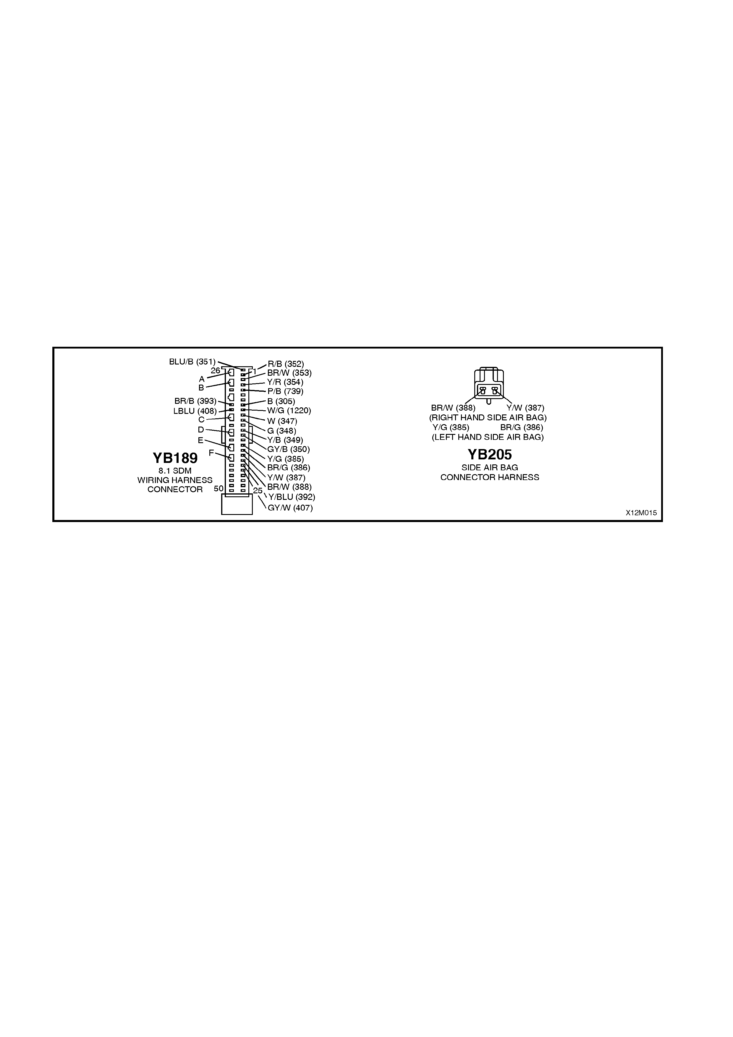
Notes on Diagnostic Chart
1. For all wiring harness checking procedures, refer to Section 12P WIRING DIAGRAMS of the VT Series I
Service Information.
2. Refer to 2.8 SRS WIRING REPAIR in Section 12M SUPPLEMENTAL RESTRAINT SYSTEM (Version 8.0 &
8.1) of the VT Series I Service Information before conducting any SRS wiring harness repairs.
3. Due to the design of the anti-back-out connector on the side air bag module assembly, connector YB201 can
not be dis c onnec ted f rom the s ide air bag module ass embly without damaging the assembly. Therefor e, repair s
to the SRS ‘pigtail’ wiring harness that run thr ough the front s eat are not to be attem pted. If this ‘pigtail’ harness
is damaged in any way, the harness and side air bag module assembly must be replaced as an assembly.
4. Wir ing s hould be c hec k ed at point where TECH 2 scr een display changed status. If nec es sar y, split open wiring
harness.
5. Refer to T ECH 2 DIAGNOST ICS in Section 12M SUPPLEMENT AL RESTRAINT SYST EM (Version 8.0 & 8.1)
of the VT Series I Service Information for connecting and using TECH 2.
6. To enable or disable the SRS system, refer to 2.2 SYSTEM DISABLING AND ENABLING PROCEDURE in
Section 12M SUPPLEMENTAL RESTRAINT SYSTEM (Version 8.0 & 8.1) of the VT Series I Service
Information.
7. SDM connector YB189 is equipped with a shorting link busbar which needs to be opened before checking the
circuit, re fer to 2.5 DIAGNOSTIC CHARTS in this Section for additional information.
Figure 12M-73

DTC 98 - RIGHT HAND SIDE AI R BAG CIRCUIT SHORT TO EARTH
STEP ACTION VALUE YES NO
1. • Connect TECH 2 to DLC.
• Select Body / SRS / Diagnostic Trouble Codes /
Read DTC Information (refer NOTE 5 on previous
page).
• Does TECH 2 display DTC 98 as a Current DTC?
Go to Step 2. Go to Step 3.
2. • With TECH 2 still connected to DLC, select Body /
SRS / Data Display and scroll to RIGHT HAND
SIDE AIR BAG LOOP RESISTANCE.
• Is the resistance value displayed on TECH 2 as
specified?
Approx.
1.6 - 6.4
ohms
Go to Step 3. Go to Step 4.
3. • With TECH 2 still connected, select Diagnostic
Trouble Codes / Clear DTC Information and clear all
(if any) DTCs.
• Select Diagnostic Trouble Codes / Read DTC
Information and monitor the TECH 2 screen display
to see if it changes status while performing the
following:
Put right hand front seat through it’s full adjustment
(forward / backward, up / down and full recline).
'Wiggle' SRS wiring harness at all accessible
locations between the SDM and the side air bag
wiring harness connector YB205.
• Does TECH 2 screen display change status from No
Diagnostic Trouble Codes?
Make repairs as
necessary (refer
NOTES 2, 3 & 4
on previous
page).
Clear DTC and
recheck system to
verify repair.
Fault not present.
Check all system
wiring harness
connectors, and
terminals.
Clear DTC and
recheck system.
4. • Disable the SRS (refer NOTE 6 on previous page).
• Disconnect SRS wiring harness connector YB205
(located next to the right hand front seat) from the
right hand side air bag inflator module ‘pigtail’
harness.
• Connect Tool No. AU485 to SRS wiring harness
connector YB205.
• Enable the SRS (reconnect battery).
• Connect TECH 2 to DLC and select Body / SRS /
Data Display and scroll to RIGHT HAND SIDE AIR
BAG LOOP RESISTANCE'.
• Is the resistance value displayed on TECH 2 as
specified?
Approx.
2.0 ohms Replace right
hand side air bag
inflator module
and ‘pigtail’ wiring
harness
assembly, refer
Section 12M
SUPPLEMENTAL
RESTRAINT
SYSTEM (Version
8.0 & 8.1) of the
VT Series I
Service
Information (refer
NOTE 3 on
previous page).
Clear DTC and
recheck system to
verify repair.
Go to Step 5.
5. • Disable the SRS (refer NOTE 6 on previous page).
• Disconnect SDM wiring harness connector YB189
from the SDM.
• Remove Tool AU485 from YB205.
• Using Tool KM-609-20, check wiring between SDM
wiring harness connector YB189, terminal 18 and
SRS connector YB205, circuit 387 (Yellow/White
wire) for short to earth (refer NOTES 1 & 7 on
previous page).
• Is all OK?
Go to Step 6. Make repairs as
necessary (refer
to NOTE 2 on
previous page).
Clear DTC and
recheck system to
verify repair.
6. • With SDM wiring harness connector YB189
disconnected from the SDM and using Tool KM-
609-20, check wiring between SDM wiring harness
connector YB189, terminal 19 and SRS connector
YB205, circuit 388 (Brown/W hite wire) for a short to
earth (refer to NOTES 1 & 7 on previous page).
• Is all OK?
Replace SDM,
refer Section 12M
SUPPLEMENTAL
RESTRAINT
SYSTEM (Version
8.0 & 8.1) of the
VT Series I
Service
Information.
Recheck circuit to
verify repair.
Make repairs as
necessary (refer
to NOTE 2 on
previous page).
Clear DTC and
recheck system to
verify repair.
WHEN ALL DIAGNOSIS AND REPAIRS ARE COM PLETED, ENSURE ALL SRS COMPONENTS ARE
RECONNECTED, CLEAR ALL DTC’S, ENABLE THE SRS AND VERIFY CORRECT OPERATION

DTC 99 - RIGHT HAND SIDE A IR BAG CIRCUIT CAPACITANCE TOO HIGH
Figure 12M-74
CIRCUIT DESCRIPTION
At ignition on, and on a constant monitoring cycle of every 500 milliseconds during the ignition cycle, the SDM
performs a system self check.
If the SDM detects the capacitance in the right hand side air bag circuit is too high (greater than 550 nF) for longer
than 3 - 5 seconds, a current DTC 99 will set (refer to SRS SELF DIAGNOSTICS in Section 12M SUPPLEMENTAL
RESTRAINT SYSTEM (Version 8.0 & 8.1) of the VT Series I Service Information for more details).
DTC 99 will set if the in-built capacitor in the SRS wiring harness connector YB201 is faulty.
When DTC 99 sets, the SDM illuminates the SRS warning lamp and sets a current DTC 99. Should the fault
conditions detected by the SDM clear during the same ignition cycle, the current code will clear and become a
history DTC 99. The SRS warning lamp will remain on for the remainder of the ignition cy cle.
If a DTC 99 is set, the SRS warning lamp is illuminated on each ignition cycle, even if the DTC is set as a history
DTC, until the fault conditions for setting DTC 99 are rectified and the DTC (current or history) can then be cleared
from the SDM via TECH 2.
ACTION REQUIRED
If DTC 99 is set, the right hand side air bag may not operate and therefore, the SRS side air bag and ‘pigtail’ wiring
harness assembly must be replaced. Refer to Section 12M SUPPLEMENTAL RESTRAINT SYSTEM (Version 8.0
& 8.1) of the VT Series I Service Information for the correct procedure on replacing the side air bag and ‘pigtail’
wiring harness connector.
NOTE: Due to the design of the anti-back-out connector on the side air bag module assembly, connector YB201
can not be disconnected from the side air bag module assembly without damaging the assembly. Therefore, repairs
to the SRS ‘pigtail’ wiring harness that run through the front seat are not to be attempted (this includes the capacitor
in connector YB201). If this ‘pigtail’ harness is damaged in any way, the harness and side air bag module assembly
must be replaced as an assembly.
After the SRS side air bag and ‘pigtail’ wiring harness assemblies have been replaced, ensure all SRS components
are reconnected, clear DTCs, enable the SRS and verify the correct operation of the system (i.e. warning lamp not
illuminated after five seconds of ignition being switched ON).
NOTE: After replacement, the front seat should be put through its full adjustment (forward/backwards, full recline
and up and down) to ensure that the wiring harness does not foul with any of the seat components.

DTC 100 - RIGHT HAND SIDE AIR BAG CIRCUIT CAPACITANCE TOO LOW
Figure 12M-75
CIRCUIT DESCRIPTION
At ignition on, and on a constant monitoring cycle of every 500 milliseconds during the ignition cycle, the SDM
performs a system self check.
If the SDM detects the capacitance in the right hand side air bag circuit is too low (less than 390 nF) for longer than
3 - 5 seconds, a current DTC 100 will set (refer to SRS SELF DIAGNOSTICS in Section 12M SUPPLEMENTAL
RESTRAINT SYSTEM (Version 8.0 & 8.1) of the VT Series I Service Information for more details).
DTC 100 will set if the in-built capacitor in the SRS wiring harness connector YB201 is faulty.
When DTC 100 sets, the SDM illuminates the SRS warning lamp and sets a current DTC 100. Should the fault
conditions detected by the SDM clear during the same ignition cycle, the current code will clear and become a
history DTC 100. The SRS warning lamp will remain on for the remainder of the ignition cy cle.
If a DTC 100 is set, the SRS warning lamp is illuminated on each ignition cycle, even if the DTC is set as a history
DTC, until the fault conditions for setting DTC 100 are rectified and the DTC (current or history) can then be cleared
from the SDM via TECH 2.
ACTION REQUIRED
If DTC 100 is set, the right hand side air bag may not operate and therefore, the SRS side air bag and ‘pigtail’ wiring
harness assembly must be replaced. Refer to Section 12M SUPPLEMENTAL RESTRAINT SYSTEM (Version 8.0
& 8.1) of the VT Series I Service Information for the correct procedure on replacing the side air bag and ‘pigtail’
wiring harness connector.
NOTE: Due to the design of the anti-back-out connector on the side air bag module assembly, connector YB201
can not be disconnected from the side air bag module assembly without damaging the assembly. Therefore, repairs
to the SRS ‘pigtail’ wiring harness that run through the front seat are not to be attempted (this includes the capacitor
in connector YB201). If this ‘pigtail’ harness is damaged in any way, the harness and side air bag module assembly
must be replaced as an assembly.
After the SRS side air bag and ‘pigtail’ wiring harness assemblies have been replaced, ensure all SRS components
are reconnected, clear DTCs, enable the SRS and verify the correct operation of the system (i.e. warning lamp not
illuminated after five seconds of ignition being switched ON).
NOTE: After replacement, the front seat should be put through its full adjustment (forward/backwards, full recline
and up and down) to ensure that the wiring harness does not foul with any of the seat components.

DTC 101 - RIGHT HAND SIDE AIR BAG CIRCUIT RESISTANCE TOO HIGH
Figure 12M-76
CIRCUIT DESCRIPTION
At ignition on, and on a constant monitoring cycle of every 500 milliseconds during the ignition cycle, the SDM
performs a system self check.
If the SDM detects a resistance in the right hand side air bag circuit that is too high (greater than 10 ohms) for
longer than 3 - 5 seconds, a current DTC 101 will set (refer to SRS SELF DIAGNOSTICS in Section 12M
SUPPLEMENTAL RESTRAINT SYSTEM (Version 8.0 & 8.1) of the VT Series I Service Information for more
details).
DTC 101 will set if circuits 387 or 388 (including the side air bag inflator module) are open circuit.
When DTC 101 sets, the SDM illuminates the SRS warning lamp and sets a current DTC 101. Should the fault
conditions detected by the SDM clear during the same ignition cycle, the current code will clear and become a
history DTC 101. The SRS warning lamp will remain on for the remainder of the ignition cy cle.
If a DTC 101 is set, the SRS warning lamp is illuminated on each ignition cycle, even if the DTC is set as a history
DTC, until the fault conditions for setting DTC 101 are rectified and the DTC (current or history) can then be cleared
from the SDM via TECH 2.
If DTC 101 is set, dependent on where the fault is, the right hand side air bag may not operate.
Test Description
The following numbers refer to step numbers in the following diagnostic chart:
1. Uses TECH 2 to check if DTC 101 is current or history.
2. Checks for intermittent fault by monitoring TECH 2 screen. If screen display changes during a wiring 'wiggle'
test, a fault with the wiring is at that location.
3. T ool AU485 is a dum m y load taking the place of the side air bag inf lator m odule. If DT C 101 becom es a history
DTC with dum my load connected, the system f ault is in the s ide air bag inf lator module as sembly (or the ‘pigtail’
wiring harness that connects to the side air bag module).
4. Checks circuit 388 for open circuit.
5. Checks circuit 387 for open circuit.
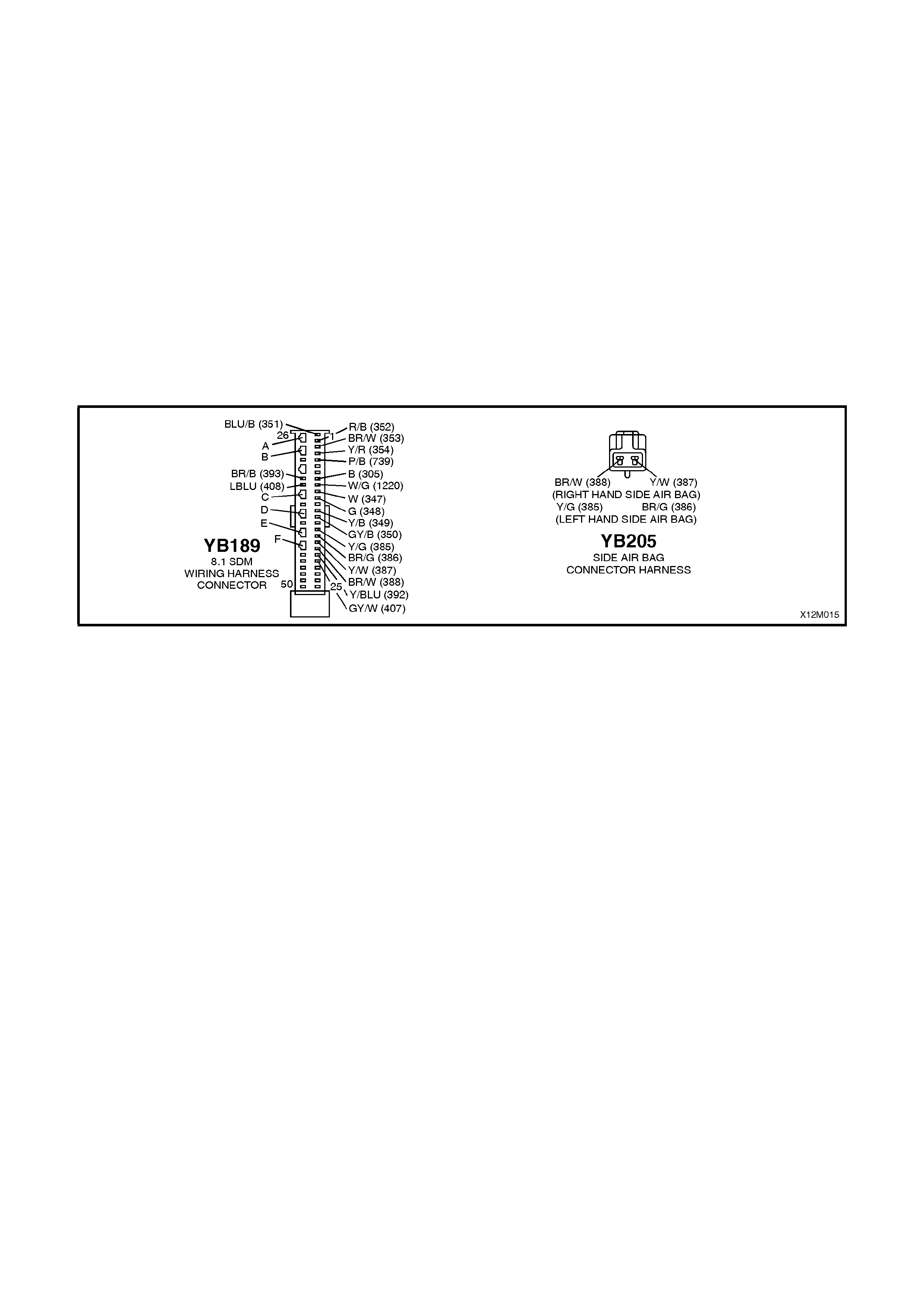
Notes on Diagnostic Chart
1. For all wiring harness checking procedures, refer to Section 12P WIRING DIAGRAMS of the VT Series I
Service Information.
2. Refer to 2.8 SRS WIRING REPAIR in Section 12M SUPPLEMENTAL RESTRAINT SYSTEM (Version 8.0 &
8.1) of the VT Series I Service Information before conducting any SRS wiring harness repairs.
3. Due to the design of the anti-back-out connector on the side air bag module assembly, connector YB201 can
not be dis c onnec ted f rom the s ide air bag module ass embly without damaging the assembly. Therefor e, repair s
to the SRS ‘pigtail’ wiring harness that run thr ough the front s eat are not to be attem pted. If this ‘pigtail’ harness
is damaged in any way, the harness and side air bag module assembly must be replaced as an assembly.
4. Wir ing s hould be c hec k ed at point where TECH 2 scr een display changed status. If nec es sar y, split open wiring
harness.
5. Refer to T ECH 2 DIAGNOST ICS in Section 12M SUPPLEMENT AL RESTRAINT SYST EM (Version 8.0 & 8.1)
of the VT Series I Service Information for connecting and using TECH 2.
6. To enable or disable the SRS system, refer to 2.2 SYSTEM DISABLING AND ENABLING PROCEDURE in
Section 12M SUPPLEMENTAL RESTRAINT SYSTEM (Version 8.0 & 8.1) of the VT Series I Service
Information.
7. SDM connector YB189 is equipped with a shorting link busbar which needs to be opened before checking the
circuit, re fer to 2.5 DIAGNOSTIC CHARTS in this Section for additional information.
Figure 12M-77

DTC 101 - RIGHT HAND SIDE AIR BAG CIRCUIT RESISTANCE TOO HIGH
STEP ACTION VALUE YES NO
1. • Install TECH 2 to DLC.
• Select Body / SRS / Diagnostic Trouble Codes /
Read DTC Information (refer NOTE 5 on previous
page).
• Is DTC 101 current?
Go to Step 3. Go to Step 2.
2. • With TECH 2 still connected, select Diagnostic
Trouble Codes / Clear DTC Information and clear
all (if any) DTCs.
• Select Diagnostic Trouble Codes / Read DTC
Information and monitor the TECH 2 screen display
to see if it changes status while performing the
following:
Put right hand front seat through it’s full adjustment
(forward / backward, up / down and full recline).
'Wiggle' SRS wiring harness at all accessible
locations between the SDM and the side air bag
wiring harness connector YB205.
• Does TECH 2 screen display change status from
No Diagnostic Trouble Codes?
Make repairs as
necessary (refer
to NOTES 2, 3 &
4 on previous
page).
Clear DTC and
recheck system to
verify repair.
Fault not present.
Check all system
wiring harness
connectors, and
terminals.
Clear DTC and
recheck system.
3. • Disable the SRS (refer NOTE 6 on previous page).
• Disconnect SRS wiring harness connector YB205
(located next to the right hand front seat) from the
right hand side air bag inflator module ‘pigtail’
harness.
• Connect Tool No. AU485 to SRS wiring harness
connector YB205.
• Enable the SRS (reconnect battery).
• Connect TECH 2 to DLC and select Body / SRS /
Diagnostic Trouble Codes / Read DTC Information
• Is DTC 101 still current?
Go to Step 4. Replace right
hand side air bag
inflator module
and ‘pigtail’ wiring
harness
assembly, refer
Section 12M
SUPPLEMENTAL
RESTRAINT
SYSTEM (Version
8.0 & 8.1) of the
VT Series I
Service
Information (refer
to NOTE 3 on
previous page).
Clear DTC and
recheck system to
verify repair.
4. • Disable the SRS (refer NOTE 6 on previous page).
• Disconnect SDM wiring harness connector YB189
from the SDM.
• Using Tool KM-609-20, check wiring between SDM
wiring harness connector YB189, terminal 19 and
SRS wiring harness connector YB205, circuit 388
(Brown/W hite wire) for open circuit (refer to NOTES
1 & 7 on previous page).
• Is all OK?
Go to Step 5. Make repairs as
necessary (refer
to NOTE 2 on
previous page).
Clear DTC and
recheck system to
verify repair.
5. • With SDM wiring harness connector YB189
disconnected from the SDM and using Tool KM-
609-20, check wiring between SDM wiring harness
connector YB189, terminal 18 and SRS wiring
harness connector YB205, circuit 387
(Yellow/White wire) for open circuit (refer to
NOTES 1 & 7 on previous page).
• Is all OK?
Replace SDM,
refer Section 12M
SUPPLEMENTAL
RESTRAINT
SYSTEM (Version
8.0 & 8.1) of the
VT Series I
Service
Information.
Recheck circuit to
verify repair.
Make repairs as
necessary (refer
to NOTE 2 on
previous page).
Clear DTC and
recheck system to
verify repair.
WHEN ALL DIAGNOSIS AND REPAIRS ARE COM PLETED, ENSURE ALL SRS COMPONENTS ARE
RECONNECTED, CLEAR ALL DTC’S, ENABLE THE SRS AND VERIFY CORRECT OPERATION

DTC 102 - RIGHT HAND SIDE AIR BAG CIRCUIT RESISTANCE TOO LOW
Figure 12M-78
CIRCUIT DESCRIPTION
At ignition on, and on a constant monitoring cycle of every 500 milliseconds during the ignition cycle, the SDM
performs a system self check.
If the SDM detects a resistance in the right hand side air bag circuit that is too low (less than 0.6 ohm) for longer
than 3 - 5 seconds, a current DTC 102 will set (refer to SRS SELF DIAGNOSTICS in Section 12M
SUPPLEMENTAL RESTRAINT SYSTEM (Version 8.0 & 8.1) of the VT Series I Service Information for more
details).
DTC 102 will set if circuits 387 or 388, (including the side air bag inflator module assembly) are shorted together.
When DTC 102 sets, the SDM illuminates the SRS warning lamp and sets a current DTC 102. Should the fault
conditions detected by the SDM clear during the same ignition cycle, the current code will clear and become a
history DTC 102. The SRS warning lamp will remain on for the remainder of the ignition cy cle.
If a DT C 102 is set, the SRS warning lamp is illuminated on each ignition cycle, even if the DT C is set as a history
DTC, until the f ault c onditions f or s etting DTC 102 are rec tif ied and the DTC (cur rent or his tory) can then be cleared
from the SDM via TECH 2.
If DTC 102 is set, dependent on where the fault is, the right hand side air bag may not operate.
Test Description
The following numbers refer to step numbers in the following diagnostic chart:
1. Uses TECH 2 to check if DTC 102 is current or history.
2. Checks for intermittent fault by monitoring TECH 2 screen. If screen display changes during a wiring 'wiggle'
test, a fault with the wiring is at that location.
3. T ool AU485 is a dum m y load taking the place of the side air bag inf lator m odule. If DT C 102 becom es a history
DTC with dum my load connected, the system f ault is in the s ide air bag inf lator module as sembly (or the ‘pigtail’
wiring harness that connects to the side air bag module).
4. This test checks the wiring between the SDM wiring harness connector YB189 and SRS wiring harness
connector YB205 for a short circuit.
Notes on Diagnostic Chart
1. For all wiring harness checking procedures, refer to Section 12P WIRING DIAGRAMS of the VT Series I
Service Information.
2. Refer to 2.8 SRS WIRING REPAIR in Section 12M SUPPLEMENTAL RESTRAINT SYSTEM (Version 8.0 &
8.1) of the VT Series I Service Information before conducting any SRS wiring harness repairs.
3. Due to the design of the anti-back-out connector on the side air bag module assembly, connector YB201 can
not be dis c onnec ted f rom the s ide air bag module ass embly without damaging the assembly. Therefor e, repair s
to the SRS ‘pigtail’ wiring harness that run thr ough the front s eat are not to be attem pted. If this ‘pigtail’ harness
is damaged in any way, the harness and side air bag module assembly must be replaced as an assembly.
4. Wir ing s hould be c hec k ed at point where TECH 2 scr een display changed status. If nec es sar y, split open wiring
harness.
5. Refer to T ECH 2 DIAGNOST ICS in Section 12M SUPPLEMENT AL RESTRAINT SYST EM (Version 8.0 & 8.1)
of the VT Series I Service Information for connecting and using TECH 2.
6. To enable or disable the SRS system, refer to 2.2 SYSTEM DISABLING AND ENABLING PROCEDURE in
Section 12M SUPPLEMENTAL RESTRAINT SYSTEM (Version 8.0 & 8.1) of the VT Series I Service
Information.
7. SDM connector YB189 is equipped with a shorting link busbar which needs to be opened before checking the
circuit, re fer to 2.5 DIAGNOSTIC CHARTS in this Section for additional information.
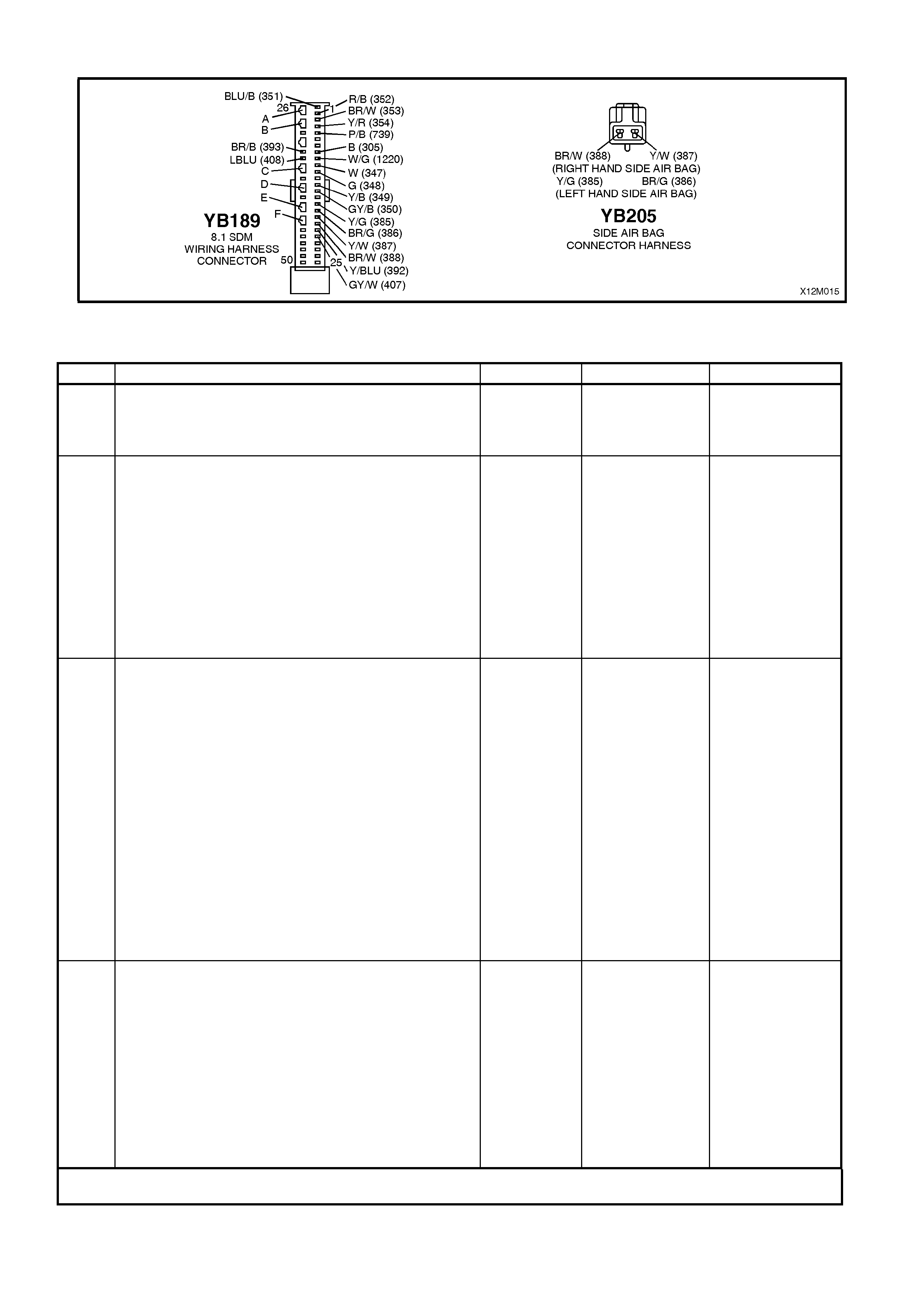
Figure 12M-79
DTC 102 - RIGHT HAND SIDE AIR BAG CIRCUIT RESISTANCE TOO LOW
STEP ACTION VALUE YES NO
1. • Install TECH 2 to DLC.
• Select Body / SRS / Diagnostic Trouble Codes /
Read DTC Information (refer NOTE 5 on previous
page).
• Is DTC 102 current?
Go to Step 3. Go to Step 2.
2. • With TECH 2 still connected, select Diagnostic
Trouble Codes / Clear DTC Information and clear
all (if any) DTCs.
• Select Diagnostic Trouble Codes / Read DTC
Information and monitor the TECH 2 screen display
to see if it changes status while performing the
following:
Put right hand front seat through it’s full adjustment
(forward / backward, up / down and full recline).
'Wiggle' SRS wiring harness at all accessible
locations between the SDM and the side air bag
wiring harness connector YB205.
• Does TECH 2 screen display change status from
No Diagnostic Trouble Codes?
Make repairs as
necessary (refer
to NOTES 2, 3 &
4 on previous
page).
Clear DTC and
recheck system
to verify repair.
Fault not present.
Check all system
wiring harness
connectors, and
terminals.
Clear DTC and
recheck system.
3. • Disable the SRS (refer NOTE 6 on previous page).
• Disconnect SRS wiring harness connector YB205
(located next to the right hand front seat) from the
right hand side air bag inflator module ‘pigtail’
harness.
• Connect Tool No. AU485 to SRS wiring harness
connector YB205.
• Enable the SRS (reconnect battery).
• Connect TECH 2 to DLC and select Body / SRS /
Diagnostic Trouble Codes / Read DTC Information.
• Is DTC 102 still current?
Go to Step 4. Replace right
hand side air bag
inflator module
and ‘pigtail’ wiring
harness
assembly, refer
Section 12M
SUPPLEMENTAL
RESTRAINT
SYSTEM (Version
8.0 & 8.1) of the
VT Series I
Service
Information (refer
to NOTE 3 on
previous page).
Clear DTC and
recheck system to
verify repair.
4. • Disable the SRS (refer NOTE 6 on previous page).
• Disconnect SDM wiring harness connector YB189
from the SDM.
• Disconnect Tool No. AU485 from SRS wiring
harness connector YB205.
• With SRS wiring harness connector YB205
disconnected, and using Tool KM-609-20, check
for continuity between SDM wiring harness
connector YB189, terminal 18, circuit 387
(Yellow/White wire) and terminal 19, circuit 388
(Brown/White wire)(refer to NOTES 1, 3 & 7 on
previous page).
• Does continuity exist?
Repair short in
circuits 387 and
388, between
SDM wiring
harness
connector YB189
and YB205 as
necessary (refer
to NOTE 2 on
previous page).
Clear DTC and
recheck system
to verify repair.
Replace SDM,
refer Section 12M
SUPPLEMENTAL
RESTRAINT
SYSTEM (Version
8.0 & 8.1) of the
VT Series I
Service
Information.
Recheck circuit to
verify repair.
WHEN ALL DIAGNOSIS AND REPAIRS ARE COM PLETED, ENSURE ALL SRS COMPONENTS ARE
RECONNECTED, CLEAR ALL DTC’S, ENABLE THE SRS AND VERIFY CORRECT OPERATION

DTC 247 - RIGHT HAND SIDE IMPACT AIR BAG CIRCUIT POWER STAGE ERROR
T12M131
SDM
M
I
C
R
O
YB189
YB201
RIGHT HAND
SIDE AIRBAG
INFLATOR
RIGHT HAND
SIDE AIRBAG INFLATOR (+)
RIGHT HAND
SIDE AIRBAG INFLATOR (-)
19
18
YB205
BR/W (388)
Y/W (387)
Figure 12M-80
CIRCUIT DESCRIPTION
At ignition on, the SDM perfor ms an initial system self check of the SDM power s tages. If during this initial self test
the SDM detects a f ault with the Right Hand Side Im pact Air Bag Circ uit power stage a current DTC 247 Right Hand
Side Impact Air Bag Circuit Power Stage Error will set. On completion of the initial system self test the SDM then
performs a test of the Right Hand Side Impact Air Bag Circuit. If the SDM detects a problem with this circuit the
associated Right Hand Side Impact Air Bag Circuit DTC will be set and the DTC 247 Right Hand Side Impact Air
Bag Circuit Air Bag Circuit Power Stage Error will become a history DTC.
DTC 247 Right Hand Side Im pact Air Bag Cir cuit Power Stage Error will set if a fault occ urs in the Right Hand Side
Impact Air Bag, connector YB201 with the in-built capacitor, connector YB205, the SRS wiring harness, connector
YB189/YB190 or SDM.
W hen a history DTC 247 Right Hand Side Impact Air Bag Circuit Power Stage Error sets, the SDM illum inates the
SRS warning lam p. Should the f ault conditions detected by the SDM clear during the same ignition cycle the code
will remain a his tory DT C 247 Right Hand Side Impact Air Bag Cir cuit Power Stage Error fo r all ignition cycles until
cleared. The SRS warning lamp will remain on for the remainder of the ignition cycle.
When a DTC 247 Right Hand Side Impact Air Bag Circuit Power Stage Error sets, the SDM illuminates the SRS
warning lamp for the remainder of the ignition cycle. Should the fault conditions detected by the SDM clear during
the same ignition c ycle the code will remain a his tor y DTC 247 Right Hand Side Im pac t Air Bag Cir c uit Power Stage
Error for all ignition cycles until cleared. The SRS warning lamp will also remain illuminated until the history DTC
247 Right Hand Side Impact Air Bag Circuit Power Stage Error is cleared.
If a DT C 247 Right Hand Side Im pact Air Bag Cir cuit Power Stage is s et, dependent on where the fault is, the Right
Hand Pre-Tensioner may not operate.
ACTION REQUIRED
If DTC 247 Right Hand Side Impact Air Bag Circuit Power Stage Error and any other DTC is set then the
diagnostics for the other DTC should be car r ied out fir st. F or ex ample if a DT C 247 Right Hand Side Impac t Air Bag
Circuit Power Stage Error and a DTC 101 Right Hand Side Impact Air Bag Circuit Resistance High are set, the
diagnostics for a DTC 101 Right Hand Side Impact Air Bag Circuit Resistance High should be carried out first.
If only a DTC 247 Right Hand Side Impact Air Bag Circuit Power Stage Error is set then the SDM should be
replaced.
NOTE: An intermittent in the Right Hand Side Im pac t Air Bag Circuit may caus e a DTC 247 Right Hand Side Impac t
Air Bag Circuit Power Stage Error to set.
After the fault has been rectified, ensure that all SRS components are reconnected, clear DTCs, enable the SRS
and verify the correct operation of the system (i.e. warning lamp not illum inated after five seconds of ignition being
switched ON).
NOTE: After replacement, the front seat should be put through its full adjustment (forward/backwards, full recline
and up and down) to ensure the wiring harness does not foul with any of the seat components.
Test Description
The following numbers refer to Step numbers in the following diagnostic chart.
1. Us es T ECH 2 to check if a DT C 247 Right Hand Side Im pact Air Bag Cir cuit Power Stage Error is history c ode,
and if any other Right Hand Side Im pact Air Bag Circuit c urrent or history DTCs are set. If any other DT Cs are
set refer to these DTCs first.
2. Checks for intermittent fault by monitoring TECH 2 screen during ignition on cycle. If screen display changes
during a wiring 'wiggle' test, a fault with the wiring is at that location.
3. If no other DT Cs are set and there are no intermittents in the Right Hand Side Impact Air Bag Circuit then the
SDM should be replaced.
Notes on Diagnostic Chart
1. For all wiring harness checking procedures, refer to VT Series 1 Service Information, WIRING DIAGRAMS,
SECTION 12P.
2. Refer to VT Series 1 Service Information Section 12M, SRS VERSION 6.2, 2.8 SRS WIRING REPAIR before
conducting any SRS wiring harness repairs.
T12M176
YB189
8.1 SD M WIRING HARNESS
CONNECTOR
BR/B (393)
26
50 25
1
BLU/B ( 351) R/B (352)
BR/W ( 353 )
Y/R (354)
P/B (739)
B (30 5)
G/W (1220)
W (347)
G (348)
Y/B (349)
GY/B (350)
Y/G (385 )
BR/G (386)
Y/W (387)
BR/W ( 388 )
Y/BLU (392)
GY/W (407)
LBLU (408) Y/W (387) BR/W (388)
(RIGHT HAND SIDE AIR BAG)
BR/G (386) Y/G (385)
(LEFT HAND SIDE AIR BAG)
YB205
SIDE AIR BAG
CONNECTOR HARNESS
Figure 12M-81
DTC 247 - RIGHT HAND SIDE IMPACT AIR BAG CIRCUIT AIR BAG CIRCUIT POWER STAGE ERROR
STEP ACTION VALUE YES NO
1. • Install TECH 2 to DLC.
• Select Body / SRS / Diagnostic Trouble Codes /
Read DTC Information.
• Is a DTC 247 Right Hand Side Impact Air Bag
Circuit Power Stage Error a history DTC, and are
any other Right Hand Side Impact Air Bag Circuit
DTCs set?
Go to other Right
Hand Side
Impact Air Bag
Circuit DTC
diagnostic chart
in this Section.
Go to Step 2.
2. • With TECH 2 still connected, select Diagnostic
Trouble Codes / Clear DTC Information and clear all
(if any) DTCs.
• Select Diagnostic Trouble Codes / Read DTC
Information and monitor the TECH 2 screen display
to see if it changes status while performing the
following:
Put right hand front seat through it’s full adjustment
(forward / backward, up / down and full recline).
'Wiggle' SRS wiring harness, at all accessible
locations between the SDM and the side impact air
bag wiring harness connector YB205.
• Does TECH 2 screen display change status from
No Diagnostic Trouble Codes?
Go to applicable
DTC chart in this
Section.
Go to step 3.
3 • Replace SDM, refer to VT Series 1 Service
Information Section 12M, SRS VERSION 8.0 & 8.1,
2.4 SENSING AND DIAGNOSTIC MODULE (SDM).
Recheck circuit to verify repair.
WHEN ALL DIAGNOSIS AND REPAIRS ARE COM PLETED, ENSURE ALL SRS COMPONENTS ARE
RECONNECTED, CLEAR ALL DTC’S, ENABLE THE SRS AND VERIFY CORRECT OPERATION

DTC 129 - LEFT PERIPHERAL ACCELERATION SENSOR LINE FAULT
T12M132
SDM
M
I
C
R
O
YB189
LEFT HAND PERIPHERAL
ACCELERATION SENSOR (+)
LEFT HAND PERIPHERAL
ACCELERATION SENSOR (-)
20
33
YB196
Y/BL U (392)
BR/B (393)
LEFT HAND
PERIPHERAL
ACCELERATION
SENSOR
Figure 12M-82
CIRCUIT DESCRIPTION
The peripheral acceleration sensor communicates continuously with the SDM by modulating the consumed current
at a constant voltage.
If this communication is interrupted or disturbed by a short circuit to earth, between the SDM and the left hand
peripheral acceleration sensor, for longer than 3 - 5 seconds, a current DTC 129 is set (refer to
SRS SELF DIAGNOSTICS in Section 12M SUPPLEMENTAL RESTRAINT SYSTEM (Version 8.0 & 8.1) of the VT
Series I Service Information for more details).
DTC 129 will set if circuit 392 is shorted to earth.
When DTC 129 sets, the SDM illuminates the SRS warning lamp and sets a current DTC 129. Should the fault
conditions detected by the SDM clear during the same ignition cycle, the current code will clear and become a
history DTC 129. The SRS warning lamp will remain on for the remainder of the ignition cy cle.
If a DTC 129 is set, the SRS warning lamp is illuminated on each ignition cycle, even if the DTC is set as a history
DTC, until the fault conditions for setting DTC 129 are rectified and the DTC (current or history) can then be cleared
from the SDM via TECH 2.
If DTC 129 is set the left hand side air bag may not operate.
Test Description
The following numbers refer to step numbers in the following diagnostic chart:
1. Uses TECH 2 to check if DTC 129 is current or history.
2. Checks for intermittent fault by monitoring TECH 2 screen. If screen display changes during a wiring 'wiggle'
test, a fault with the wiring is at that location.
3. Checks circuit 392 for short to earth.
4. By swapping the left hand peripheral acceleration sensor with a known good one (right hand side peripheral
acceleration sensor), determines whether the peripheral acceleration sensor or the SDM is causing the
problem.
Notes on Diagnostic Chart
1. For all wiring harness checking procedures, refer to Section 12P WIRING DIAGRAMS of the VT Series I
Service Information.
2. Refer to 2.8 SRS WIRING REPAIR in Section 12M SUPPLEMENTAL RESTRAINT SYSTEM (Version 6.2) of
the VT Series I Service Information before conducting any SRS wiring harness repairs.
3. Do not loosen or unscrew the two nuts retaining the peripheral acceleration sensor to the mounting bracket. The
peripheral acc eler ation sens or must only be removed fr om the B pillar with the m ounting br acket attached, r ef er
to 2.5 PERIPHERAL ACCELERATION SENSOR in Section 12M SUPPLEMENTAL RESTRAINT SYSTEM
(Version 8.0 & 8.1) of the VT Series I Service Information for the correct removal procedure.
4. Refer to T ECH 2 DIAGNOST ICS in Section 12M SUPPLEMENT AL RESTRAINT SYST EM (Version 8.0 & 8.1)
of the VT Series I Service Information for connecting and using TECH 2.
5. To enable or disable the SRS system, refer to 2.2 SYSTEM DISABLING AND ENABLING PROCEDURE in
Section 12M SUPPLEMENTAL RESTRAINT SYSTEM (Version 8.0 & 8.1) of the VT Series I Service
Information.
6. SDM connector YB189 is equipped with a shorting link busbar which needs to be opened before checking the
circuit, re fer to 2.5 DIAGNOSTIC CHARTS in this Section for additional information.

Figure 12M-83
DTC 129 - LEFT PERIPHERAL ACCELERATION SENSOR LINE FAULT
STEP ACTION VALUE YES NO
1. • Install TECH 2 to DLC.
• Select Body / SRS / Diagnostic Trouble Codes /
Read DTC Information (refer NOTE 4 on previous
page).
• Is DTC 129 current?
Go to Step 3. Go to Step 2.
2. • With TECH 2 still connected, select Diagnostic
Trouble Codes / Clear DTC Information and clear
all (if any) DTCs.
• Select Diagnostic Trouble Codes / Read DTC
Information, 'wiggle' SRS wiring harness at all
locations between the SDM and the left hand
peripheral acceleration sensor wiring harness
connector YB196, while monitoring TECH 2 screen
display.
• Does TECH 2 screen display change status from
No Diagnostic Trouble Codes?
Make repairs as
necessary (refer
to NOTE 2 on
previous page).
Clear DTC and
recheck system to
verify repair.
Fault not present.
Check all system
wiring harness
connectors, and
terminals.
Clear DTC and
recheck system.
3. • Disable the SRS (refer NOTE 5 on previous page).
• Disconnect SRS wiring harness connector YB196
from the left hand peripheral acceleration sensor.
• Disconnect SDM wiring harness connector YB189
from the SDM.
• Using Tool KM-609-20, check wiring between SDM
wiring harness connector YB189, terminal 20 and
SRS wiring harness connector YB196, circuit 392
(Yellow/Blue wire) for a short to earth (refer to
NOTES 1 & 6 on previous page).
• Is all OK?
Go to Step 4. Make repairs as
necessary (refer
to NOTE 2 on
previous page).
Clear DTC and
recheck system to
verify repair.
4. • Disable the SRS (refer NOTE 5 on previous page).
• Reconnect SRS wiring harness connector YB189
to the SDM.
• Disconnect the left hand peripheral acceleration
sensor from connector YB196 and install a known
good peripheral acceleration sensor into connector
YB196 (right peripheral acceleration sensor and
bracket assembly).
Refer to NOTE 3 on previous page.
• Enable the SRS (reconnect battery).
• Install TECH 2 to DLC
• Select Body / SRS / Diagnostic Trouble Codes /
Read DTC Information.
• Is DTC 129 current?
Replace SDM,
refer Section 12M
SUPPLEMENTAL
RESTRAINT
SYSTEM (Version
8.0 & 8.1) of the
VT Series I
Service
Information.
Recheck circuit to
verify repair.
Replace left hand
peripheral
acceleration
sensor and
bracket assembly,
refer Section 12M
SUPPLEMENTAL
RESTRAINT
SYSTEM (Version
8.0 & 8.1) of the
VT Series I
Service
Information).
Clear DTC and
recheck system to
verify repair.
WHEN ALL DIAGNOSIS AND REPAIRS ARE COM PLETED, ENSURE ALL SRS COMPONENTS ARE
RECONNECTED, CLEAR ALL DTC’S, ENABLE THE SRS AND VERIFY CORRECT OPERATION
DTC 130 - RIGHT PERIPHERAL ACCELERATION SENSOR LINE FAULT
T12M133
SDM
M
I
C
R
O
YB189
RIGHT HAND
PERIPHERAL
ACCELERATION
SENSOR
RIGHT HAND PERIPHERAL
ACCELERATION SENSOR (+)
RIGHT HAND PERIPHERAL
ACCELERATION SENSOR (-)
21
34
YB196
GY/W (407)
LBLU (408)
Figure 12M-84
CIRCUIT DESCRIPTION
The peripheral acceleration s ensor com municates c ontinuously with the SDM by m odulating the consum ed current
at a constant voltage.
If this communication is interrupted or disturbed by a short circuit to earth, between the SDM and the right hand
peripheral acceleration sensor, for longer than 3 - 5 seconds, a current DTC 130 is set (refer to
SRS SELF DIAGNOSTICS in Section 12M SUPPLEMENT AL RESTRAINT SYST EM (Version 8.0 & 8.1) of the VT
Series I Service Information for more details).
DTC 130 will set if circuit 407 is shorted to earth.
When DTC 130 sets, the SDM illuminates the SRS warning lamp and sets a current DTC 130. Should the fault
conditions detected by the SDM clear during the same ignition cycle, the current code will clear and become a
history DTC 130. The SRS warning lamp will remain on for the remainder of the ignition cy cle.
If a DT C 130 is set, the SRS warning lamp is illuminated on each ignition cycle, even if the DT C is set as a history
DTC, until the f ault c onditions f or s etting DTC 130 are rec tif ied and the DTC (cur rent or his tory) can then be cleared
from the SDM via TECH 2.
If DTC 130 is set the right hand side air bag may not operate.
Test Description
The following numbers refer to step numbers in the following diagnostic chart:
1. Uses TECH 2 to check if DTC 130 is current or history.
2. Checks for intermittent fault by monitoring TECH 2 screen. If screen display changes during a wiring 'wiggle'
test, a fault with the wiring is at that location.
3. Checks circuit 407 for short to earth.
4. By swapping the right hand peripheral acceleration sensor with a known good one (left hand side peripheral
acceleration sensor), determines whether the peripheral acceleration sensor or the SDM is causing the
problem.
Notes on Diagnostic Chart
1. For all wiring harness checking procedures, refer to Section 12P WIRING DIAGRAMS of the VT Series I
Service Information.
2. Refer to 2.8 SRS WIRING REPAIR in Section 12M SUPPLEMENTAL RESTRAINT SYSTEM (Version 6.2) of
the VT Series I Service Information before conducting any SRS wiring harness repairs.
3. Do not loosen or unscrew the two nuts retaining the peripheral acceleration sensor to the mounting bracket. The
peripheral acc eler ation sens or must only be removed fr om the B pillar with the m ounting br acket attached, r ef er
to 2.5 PERIPHERAL ACCELERATION SENSOR in Section 12M SUPPLEMENTAL RESTRAINT SYSTEM
(Version 8.0 & 8.1) of the VT Series I Service Information for the correct removal procedure.
4. Refer to T ECH 2 DIAGNOST ICS in Section 12M SUPPLEMENT AL RESTRAINT SYST EM (Version 8.0 & 8.1)
of the VT Series I Service Information for connecting and using TECH 2.
5. To enable or disable the SRS system, refer to 2.2 SYSTEM DISABLING AND ENABLING PROCEDURE in
Section 12M SUPPLEMENTAL RESTRAINT SYSTEM (Version 8.0 & 8.1) of the VT Series I Service
Information.
6. SDM connector YB189 is equipped with a shorting link busbar which needs to be opened before checking the
circuit, re fer to 2.5 DIAGNOSTIC CHARTS in this Section for additional information.
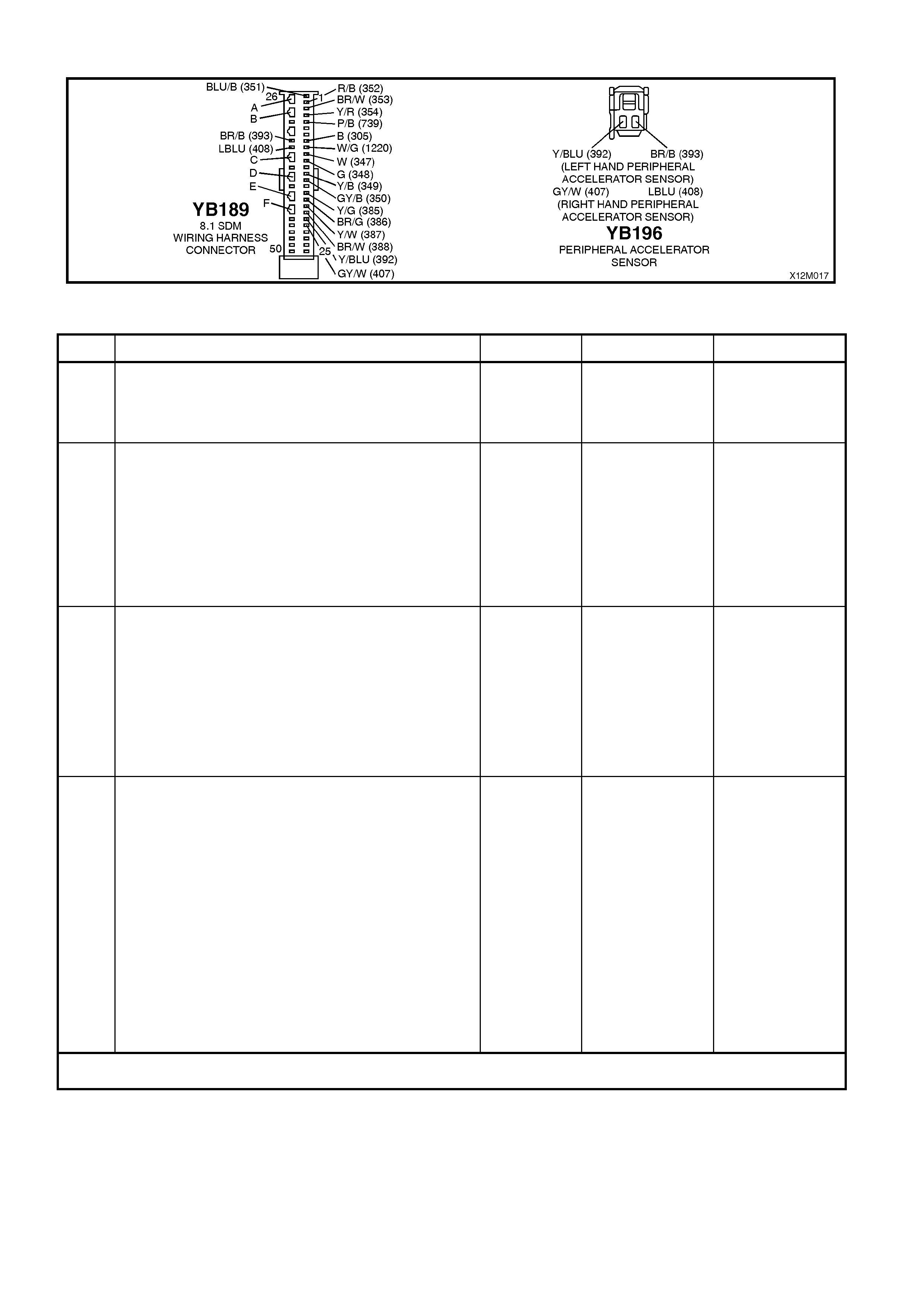
Figure 12M-85
DTC 130 - RIGHT PERIPHERAL ACCELERATION SENSOR LINE FAULT
STEP ACTION VALUE YES NO
1. • Install TECH 2 to DLC.
• Select Body / SRS / Diagnostic Trouble Codes /
Read DTC Information (refer NOTE 4 on previous
page).
• Is DTC 130 current?
Go to Step 3. Go to Step 2.
2. • With TECH 2 still connected, select Diagnostic
Trouble Codes / Clear DTC Information and clear
all (if any) DTCs.
• Select Diagnostic Trouble Codes / Read DTC
Information, 'wiggle' SRS wiring harness at all
locations between the SDM and the right hand
peripheral acceleration sensor wiring harness
connector YB196, while monitoring TECH 2 screen
display.
• Does TECH 2 screen display change status from
No Diagnostic Trouble Codes?
Make repairs as
necessary (refer
to NOTE 2 on
previous page).
Clear DTC and
recheck system to
verify repair.
Fault not present.
Check all system
wiring harness
connectors, and
terminals.
Clear DTC and
recheck system.
3. • Disable the SRS (refer NOTE 5 on previous page).
• Disconnect SRS wiring harness connector YB196
from the right hand peripheral acceleration sensor.
• Disconnect SDM wiring harness connector YB189
from the SDM.
• Using Tool KM-609-20, check wiring between SDM
wiring harness connector YB189, terminal 21 and
SRS wiring harness connector YB196, circuit 407
(Grey/White wire) for a short to earth (refer to
NOTES 1 & 6 on previous page).
• Is all OK?
Go to Step 4. Make repairs as
necessary (refer
to NOTE 2 on
previous page).
Clear DTC and
recheck system to
verify repair.
4. • Disable the SRS (refer NOTE 5 on previous page).
• Reconnect SRS wiring harness connector YB189
to the SDM.
• Disconnect the right hand peripheral acceleration
sensor from connector YB196 and connect a
known good peripheral acceleration sensor into
connector YB196 (left peripheral acceleration
sensor and bracket assembly).
Refer to NOTE 3 on previous page.
• Enable the SRS (reconnect battery).
• Install TECH 2 to DLC.
• Select Body / SRS / Diagnostic Trouble Codes /
Read DTC Information.
• Is DTC 129 current?
Replace SDM,
refer Section 12M
SUPPLEMENTAL
RESTRAINT
SYSTEM (Version
8.0 & 8.1) of the
VT Series I
Service
Information.
Recheck circuit to
verify repair.
Replace right
hand peripheral
acceleration
sensor and
bracket assembly,
refer Section 12M
SUPPLEMENTAL
RESTRAINT
SYSTEM (Version
8.0 & 8.1) of the
VT Series I
Service
Information in this
Section.
Clear DTC and
recheck system to
verify repair.
WHEN ALL DIAGNOSIS AND REPAIRS ARE COM PLETED, ENSURE ALL SRS COMPONENTS ARE
RECONNECTED, CLEAR ALL DTC’S, ENABLE THE SRS AND VERIFY CORRECT OPERATION

DTC 131 - LEFT PERIPHERAL ACCELERATION SENSOR COMMUNICATION FAULT
T12M132
SDM
M
I
C
R
O
YB189
LEFT HAND PERIPHERAL
ACCELERATION SENSOR (+)
LEFT HAND PERIPHERAL
ACCELERATION SENSOR (-)
20
33
YB196
Y/BL U (392)
BR/B (393)
LEFT HAND
PERIPHERAL
ACCELERATION
SENSOR
Figure 12M-86
CIRCUIT DESCRIPTION
The peripheral acceleration sensor communicates continuously with the SDM by modulating the consumed current
at a constant voltage.
If this communication is interrupted between the SDM and the left hand peripheral acceleration sensor for longer
than 3 - 5 seconds, a current DTC 131 is set (refer to SRS SELF DIAGNOSTICS in Section 12M SUPPLEMENTAL
RESTRAINT SYSTEM (Version 8.0 & 8.1) of the VT Series I Service Information for more details).
DTC 131 will set if circuits 392 or 393 (including the peripheral acceleration sensor) are open circuit.
When DTC 131 sets, the SDM illuminates the SRS warning lamp and sets a current DTC 131. Should the fault
conditions detected by the SDM clear during the same ignition cycle, the current code will clear and become a
history DTC 131. The SRS warning lamp will remain on for the remainder of the ignition cy cle.
If a DTC 131 is set, the SRS warning lamp is illuminated on each ignition cycle, even if the DTC is set as a history
DTC, until the fault conditions for setting DTC 131 are rectified and the DTC (current or history) can then be cleared
from the SDM via TECH 2.
If DTC 131 is set, the left hand side air bag may not operate.
Test Description
The following number refer to step numbers in the following diagnostic chart:
1. Uses TECH 2 to check if DTC 131 is current or history.
2. Checks for intermittent fault by monitoring TECH 2 screen. If screen display changes during a wiring 'wiggle'
test, a fault with the wiring is at that location.
3. Checks circuit 392 for an open circuit.
4. Checks circuit 393 for an open circuit.
5. By swapping the left hand peripheral acceleration sensor with a known good one (right hand side peripheral
acceleration sensor), determines whether the peripheral acceleration sensor or the SDM is causing the
problem.
Notes on Diagnostic Chart
1. For all wiring harness checking procedures, refer to Section 12P WIRING DIAGRAMS of the VT Series I
Service Information.
2. Refer to 2.8 SRS WIRING REPAIR in Section 12M SUPPLEMENTAL RESTRAINT SYSTEM (Version 6.2) of
the VT Series I Service Information before conducting any SRS wiring harness repairs.
3. Do not loosen or unscrew the two nuts retaining the peripheral acceleration sensor to the mounting bracket. The
peripheral acc eler ation sens or must only be removed fr om the B pillar with the m ounting br acket attached, r ef er
to 2.5 PERIPHERAL ACCELERATION SENSOR in Section 12M SUPPLEMENTAL RESTRAINT SYSTEM
(Version 8.0 & 8.1) of the VT Series I Service Information for the correct removal procedure.
4. Refer to T ECH 2 DIAGNOST ICS in Section 12M SUPPLEMENT AL RESTRAINT SYST EM (Version 8.0 & 8.1)
of the VT Series I Service Information for connecting and using TECH 2.
5. To enable or disable the SRS system, refer to 2.2 SYSTEM DISABLING AND ENABLING PROCEDURE in
Section 12M SUPPLEMENTAL RESTRAINT SYSTEM (Version 8.0 & 8.1) of the VT Series I Service
Information.
6. SDM connector YB189 is equipped with a shorting link busbar which needs to be opened before checking the
circuit, re fer to 2.5 DIAGNOSTIC CHARTS in this Section for additional information.
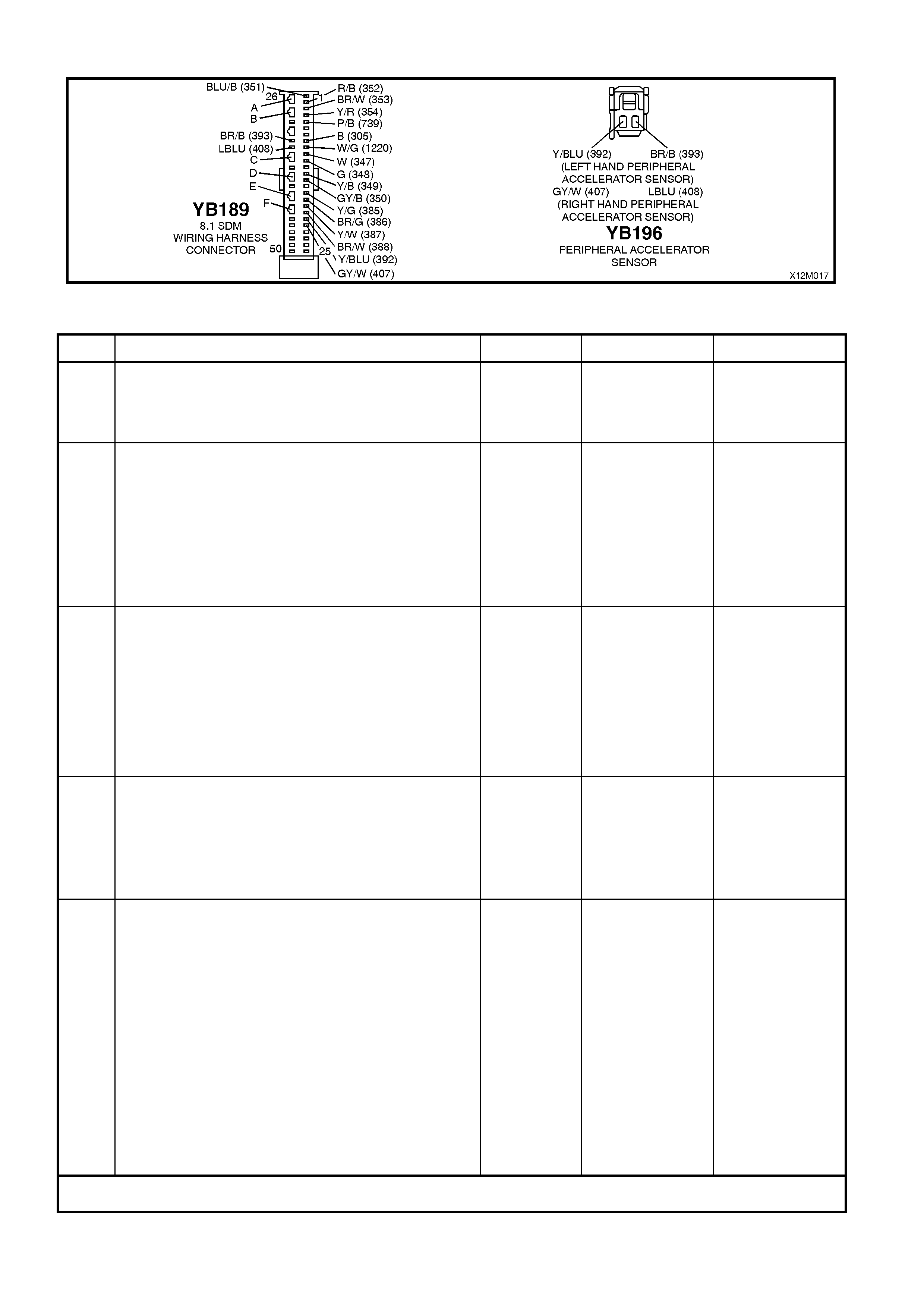
Figure 12M-87
DTC 131 - LEFT PERIPHERAL ACCELERATION SENSOR COMMUNICATION FAULT
STEP ACTION VALUE YES NO
1. • Install TECH 2 to DLC.
• Select Body / SRS / Diagnostic Trouble Codes /
Read DTC Information (refer NOTE 4 on previous
page).
• Is DTC 131 current?
Go to Step 3. Go to Step 2.
2. • With TECH 2 still connected, select Diagnostic
Trouble Codes / Clear DTC Information and clear
all (if any) DTCs.
• Select Diagnostic Trouble Codes / Read DTC
Information, 'wiggle' SRS wiring harness at all
locations between the SDM and the left hand
peripheral acceleration sensor wiring harness
connector YB196, while monitoring TECH 2 screen
display.
• Does TECH 2 screen display change status from
No Diagnostic Trouble Codes?
Make repairs as
necessary (refer
to NOTE 2 on
previous page).
Clear DTC and
recheck system to
verify repair.
Fault not present.
Check all system
wiring harness
connectors, and
terminals.
Clear DTC and
recheck system.
3. • Disable the SRS (refer NOTE 5 on previous page).
• Disconnect SRS wiring harness connector YB196
from the left hand peripheral acceleration sensor.
• Disconnect SDM wiring harness connector YB189
from the SDM.
• Using Tool KM-609-20, check wiring between SDM
wiring harness connector YB189, terminal 20 and
SRS wiring harness connector YB196, circuit 392
(Yellow/Blue wire) for an open circuit (refer to
NOTES 1 & 6 on previous page).
• Is all OK?
Go to Step 4. Make repairs as
necessary (refer
to NOTE 2 on
previous page).
Clear DTC and
recheck system to
verify repair.
4. • With the SRS disabled and connectors YB189 and
YB196 disconnected, use Tool KM-609-20 to check
wiring between SDM wiring harness connector
YB189, terminal 33 and SRS wiring harness
connector YB196, circuit 393 (Brown/Black wire) for
an open circuit (refer to NOTES 1 & 6 on previous
page).
• Is all OK?
Go to Step 5. Make repairs as
necessary (refer
to NOTE 2 on
previous page).
Clear DTC and
recheck system to
verify repair.
5. • With the SRS disabled reconnect SRS wiring
harness connector YB189 to the SDM.
• Disconnect the left hand peripheral acceleration
sensor from connector YB196 and connect a
known good peripheral acceleration sensor into
connector YB196 (right peripheral acceleration
sensor and bracket assembly).
Refer to NOTE 3 on previous page.
• Enable the SRS (reconnect battery).
• Install TECH 2 to DLC.
• Select Body / SRS / Diagnostic Trouble Codes /
Read DTC Information.
• Is DTC 131 current?
Replace SDM,
refer Section 12M
SUPPLEMENTAL
RESTRAINT
SYSTEM (Version
8.0 & 8.1) of the
VT Series I
Service
Information.
Recheck circuit to
verify repair.
Replace left hand
peripheral
acceleration
sensor and
bracket assembly,
refer Section 12M
SUPPLEMENTAL
RESTRAINT
SYSTEM (Version
8.0 & 8.1) of the
VT Series I
Service
Information in this
Section.
Clear DTC and
recheck system to
verify repair.
WHEN ALL DIAGNOSIS AND REPAIRS ARE COM PLETED, ENSURE ALL SRS COMPONENTS ARE
RECONNECTED, CLEAR ALL DTC’S, ENABLE THE SRS AND VERIFY CORRECT OPERATION

DTC 132 - RIGHT PERIPHERAL ACCELERATION SENSOR COMMUNICATION FAULT
T12M133
SDM
M
I
C
R
O
YB189
RIGHT HAND
PERIPHERAL
ACCELERATION
SENSOR
RIGHT HAND PERIPHERAL
ACCELERATION SENSOR (+)
RIGHT HAND PERIPHERAL
ACCELERATION SENSOR (-)
21
34
YB196
GY/W (407)
LBLU (408)
Figure 12M-88
CIRCUIT DESCRIPTION
The peripheral acceleration s ensor com municates c ontinuously with the SDM by m odulating the consum ed current
at a constant voltage.
If this com m unication is interrupted between the SDM and the right hand peripheral acceleration f or longer than 3 -
5 seconds, a current DTC 132 is set (refer to SRS SELF DIAGNOSTICS in Section 12M SUPPLEMENTAL
RESTRAINT SYSTEM (Version 8.0 & 8.1) of the VT Series I Service Information for more details).
DTC 132 will set if circuits 407 or 408 (including the peripheral acceleration sensor) are open circuit.
When DTC 132 sets, the SDM illuminates the SRS warning lamp and sets a current DTC 132. Should the fault
conditions detected by the SDM clear during the same ignition cycle, the current code will clear and become a
history DTC 132. The SRS warning lamp will remain on for the remainder of the ignition cy cle.
If a DT C 132 is set, the SRS warning lamp is illuminated on each ignition cycle, even if the DT C is set as a history
DTC, until the f ault c onditions f or s etting DTC 132 are rec tif ied and the DTC (cur rent or his tory) can then be cleared
from the SDM via TECH 2.
If DTC 132 is set, the right hand side air bag may not operate.
Test Description
The following numbers refer to step numbers in the following diagnostic chart:
1. Uses TECH 2 to check if DTC 132 is current or history.
2. Checks for intermittent fault by monitoring TECH 2 screen. If screen display changes during a wiring 'wiggle'
test, a fault with the wiring is at that location.
3. Checks circuit 407 for an open circuit.
4. Checks circuit 408 for an open circuit.
5. By swapping the right hand peripheral acceleration sensor with a known good one (left hand side peripheral
acceleration sensor), determines whether the peripheral acceleration sensor or the SDM is causing the problem.
Notes on Diagnostic Chart
1. For all wiring harness checking procedures, refer to Section 12P WIRING DIAGRAMS of the VT Series I
Service Information.
2. Refer to 2.8 SRS WIRING REPAIR in Section 12M SUPPLEMENTAL RESTRAINT SYSTEM (Version 6.2) of
the VT Series I Service Information before conducting any SRS wiring harness repairs.
3. Do not loos en or uns c rew the two nuts retaining the per ipheral ac c eleration s ens or to the mounting brac ket. T he
peripheral acc eleration sensor m ust only be rem oved from the B pillar with the mounting brac ket attached, refer
to 2.5 PERIPHERAL ACCELERATION SENSOR in Section 12M SUPPLEMENTAL RESTRAINT SYSTEM
(Version 8.0 & 8.1) of the VT Series I Service Information for the correct removal procedure.
4. Refer to TECH 2 DIAGNOSTICS in Section 12M SUPPLEMENTAL RESTRAINT SYSTEM (Version 8.0 & 8.1)
of the VT Series I Service Information for connecting and using TECH 2.
5. To enable or disable the SRS system, refer to 2.2 SYSTEM DISABLING AND ENABLING PROCEDURE in
Section 12M SUPPLEMENTAL RESTRAINT SYSTEM (Version 8.0 & 8.1) of the VT Series I Service
Information.
6. SDM connector YB189 is equipped with a shorting link busbar which needs to be opened before checking the
circuit, re fer to 2.5 DIAGNOSTIC CHARTS in this Section for additional information.

Figure 12M-89
DTC 132 - RIGHT PERIPHERAL ACCELERATION SENSOR COMMUNICATION FAULT
STEP ACTION VALUE YES NO
1. • Install TECH 2 to DLC.
• Select Body / SRS / Diagnostic Trouble Codes /
Read DTC Information (refer NOTE 4 on previous
page).
• Is DTC 132 current?
Go to Step 3. Go to Step 2.
2. • With TECH 2 still connected, select Diagnostic
Trouble Codes / Clear DTC Information and clear
all (if any) DTCs.
• Select Diagnostic Trouble Codes / Read DTC
Information, 'wiggle' SRS wiring harness at all
locations between the SDM and the right hand
peripheral acceleration sensor wiring harness
connector YB196, while monitoring TECH 2 screen
display.
• Does TECH 2 screen display change status from
No Diagnostic Trouble Codes?
Make repairs as
necessary (refer
to NOTE 2 on
previous page).
Clear DTC and
recheck system to
verify repair.
Fault not present.
Check all system
wiring harness
connectors, and
terminals.
Clear DTC and
recheck system.
3. • Disable the SRS (refer NOTE 5 on previous page).
• Disconnect SRS wiring harness connector YB196
from the right hand peripheral acceleration sensor.
• Disconnect SDM wiring harness connector YB189
from the SDM.
• Using Tool KM-609-20, check wiring between SDM
wiring harness connector YB189, terminal 21 and
SRS wiring harness connector YB196, circuit 407
(Grey/White wire) for an open circuit (refer to
NOTES 1 & 6 on previous page).
• Is all OK?
Go to Step 4. Make repairs as
necessary (refer
to NOTE 2 on
previous page).
Clear DTC and
recheck system to
verify repair.
4. • With the SRS disabled and connectors YB189 and
YB196 disconnected, use Tool KM-609-20 to check
wiring between SDM wiring harness connector
YB189, terminal 34 and SRS wiring harness
connector YB196, circuit 408 (Light Blue wire) for
an open circuit (refer to NOTES 1 & 6 on previous
page).
• Is all OK?
Go to Step 5. Make repairs as
necessary (refer
to NOTE 2 on
previous page).
Clear DTC and
recheck system to
verify repair.
5. • With the SRS disabled reconnect SRS wiring
harness connector YB189 to the SDM.
• Disconnect the right hand peripheral acceleration
sensor from connector YB196 and connect a
known good peripheral acceleration sensor into
connector YB196 (left peripheral acceleration
sensor and bracket assembly).
Refer to NOTE 3 on previous page.
• Enable the SRS (reconnect battery).
• Install TECH 2 to DLC.
• Select Body / SRS / Diagnostic Trouble Codes /
Read DTC Information.
• Is DTC 132 current?
Replace SDM,
refer Section 12M
SUPPLEMENTAL
RESTRAINT
SYSTEM (Version
8.0 & 8.1) of the
VT Series I
Service
Information.
Recheck circuit to
verify repair.
Replace right
hand peripheral
acceleration
sensor and
bracket assembly,
refer Section 12M
SUPPLEMENTAL
RESTRAINT
SYSTEM (Version
8.0 & 8.1) of the
VT Series I
Service
Information in this
Section.
Clear DTC and
recheck system to
verify repair.
WHEN ALL DIAGNOSIS AND REPAIRS ARE COM PLETED, ENSURE ALL SRS COMPONENTS ARE
RECONNECTED, CLEAR ALL DTC’S, ENABLE THE SRS AND VERIFY CORRECT OPERATION

DTC 133 - LEFT PERIPHERAL ACCELERATION SENSOR IDENTIFICATION FAULT
CIRCUIT DESCRIPTION
Peripheral acceleration sensors are programmed during manufacture for a particular vehicle / application type.
During this proc ess, the per ipheral acc eleration sens or is given a unique identif ication c ode which cor responds with
the SDM. If this c ode does not corres pond with the SDM, a current DTC 133 will be set and the SRS warning lam p
will be illuminated with the ignition on.
ACTION REQUIRED
If DTC 133 is set, the left hand side air bag may not operate and therefore, the left hand side peripheral acceleration
sensor and bracket assembly must be replaced with the correct peripheral acceleration sensor for that particular
vehicle.
Always ref er to the lates t Holden spare par ts inf orm ation (Part Finder) f or the c or rec t par t number of the peripher al
acceleration sensor and bracket assembly for that particular vehicle. To replace the peripheral acceleration sensor
and bracket assembly, refer to
2.5 PERIPHERAL ACCELERATION SENSOR (SIDE AIR BAG SENSOR) in Section 12M SUPPLEMENTAL
RESTRAINT SYSTEM (Version 8.0 & 8.1)of the VT Series I Service Information.
After the peripheral acceleration sensor and bracket assembly have been replaced, ensure that all SRS
components are reconnected, clear DTCs, enable the SRS and verify the correct operation of the system (i.e.
warning lamp not illuminated after five seconds of ignition being switched ON).

DTC 134 - RIGHT PERIPHERAL ACCELERATION SENSOR IDENTIFICATION FAULT
CIRCUIT DESCRIPTION
Peripheral acceleration sensors are programmed during manufacture for a particular vehicle / application type.
During this proc ess, the per ipheral acc eleration sens or is given a unique identif ication c ode which cor responds with
the SDM. If this c ode does not corres pond with the SDM, a current DTC 134 will be set and the SRS warning lam p
will be illuminated with the ignition on.
ACTION REQUIRED
If DTC 134 is set, the right hand side air bag may not operate and therefore, the right hand side peripheral
acceleration s ensor and brac ket ass embly must be r eplaced with the correct peripheral acc eleration sensor for that
particular vehicle.
Always ref er to the latest Holden spare par ts inform ation (Part Finder) for the correct part num ber of the peripheral
acceleration sensor and bracket assembly for that particular vehicle. To replace the peripheral acceleration sensor
and bracket assembly, refer to 2.5 PERIPHERAL ACCELERATION SENSOR (SIDE AIR BAG SENSOR) in
Section 12M SUPPLEMENTAL RESTRAINT SYSTEM (Version 8.0 & 8.1) of the VT Series I Service Information.
After the peripheral acceleration sensor and bracket assembly have been replaced, ensure that all SRS
components are reconnected, clear DTCs, enable the SRS and verify the correct operation of the system (i.e.
warning lamp not illuminated after five seconds of ignition being switched ON).

DTC 135 - LEFT PERIPHERAL ACCELERATION SENSOR HA RDWARE FAULT
CIRCUIT DESCRIPTION
At ignition on, and on a constant monitoring cycle of every 500 milliseconds during the ignition cycle, the SDM
performs a system self check. If the SDM detects an internal fault in the left hand side peripheral acceleration
sensor, a DTC 135 will be set and the SRS warning lamp will be illuminated continuously with the ignition on.
ACTION REQUIRED
If DTC 135 is set, the left hand side air bag may not operate and therefore, the left hand side peripheral acceleration
sensor and bracket assembly must be replaced. Refer to
2.5 PERIPHERAL ACCELERATION SENSOR (SIDE AIR BAG SENSOR) in Section 12M SUPPLEMENTAL
RESTRAINT SYSTEM (Version 8.0 & 8.1) of the VT Series I Service Information.
After the peripheral acceleration sensor and bracket assembly have been replaced, ensure that all SRS
components are reconnected, clear DTCs, enable the SRS and verify the correct operation of the system (i.e.
warning lamp not illuminated after five seconds of ignition being switched ON).

DTC 136 - RIGHT PERIPHERAL ACCELERATION SENSOR HARDWARE FAULT
CIRCUIT DESCRIPTION
At ignition on, and on a constant monitoring cycle of every 500 milliseconds during the ignition cycle, the SDM
performs a system self check. If the SDM detects an internal fault in the right hand side peripheral acceleration
sensor, a DTC 136 will be set and the SRS warning lamp will be illuminated continuously with the ignition on.
ACTION REQUIRED
If DTC 136 is set, the right hand side air bag may not operate and therefore, the right hand side peripheral
acceleration sensor and bracket assembly must be replaced. Refer to
2.5 PERIPHERAL ACCELERATION SENSOR (SIDE AIR BAG SENSOR) in Section 12M SUPPLEMENTAL
RESTRAINT SYSTEM (Version 8.0 & 8.1) of the VT Series I Service Information for the correct replacement
procedure.
After the peripheral acceleration sensor and bracket assembly have been replaced, ensure that all SRS
components are reconnected, clear DTCs, enable the SRS and verify the correct operation of the system (i.e.
warning lamp not illuminated after five seconds of ignition being switched ON).

DTC 161 - CONFIGURATION MISMATCH: TOO LITTLE OR TOO MANY LOOPS IN SRS
CIRCUIT DESCRIPTION
NOTE 1: DTC 161 will only be set and displayed by
TECH 2 as a history DTC even if it is current.
NOTE 2: T he instr um ents m ust be pr ogram m ed f or
the correct vehicle configuration, refer to Section
12C INSTRUMENTS, WIPERS/WASHERS AND
HORN of the VT Series II Service Information for
the procedure on programming the instruments.
The SDM will set a hist ory DT C 161 because it has
been internally configured for a two, three, four or
six loop system but at the same time has detected
a mismatch with the actual vehicle configuration.
To identify the different SDMs, refer to the
identification label on the top of the SDM. The last
digit of the part number identifies the number of
loops the SDM is designed for: 2, 3, 4 or 6.
NOTE: Always refer to the latest VX spare parts
information (Part Finder) for the latest part
numbers when ordering SRS components.
TECH 2 is capable of displaying the SDM part
number ; connect TECH 2 to DLC, selec t Diagnosis
/ Body / SRS / turn ignition on and the system
identification screen will display the SDM part
number.
As an aid to the technician to diagnose the source
of the mismatch, always check for other DTCs set
in the system first. Faults setting other DTCs
should be rectified first, all DTCs cleared from the
SDM and system retested to determine if DTC 161
will set again. If DTC sets again, install the correct
SDM.
2 Loop System Seat Belt Pre-tensioners only
3 Loop System Seat Belt Pre-tensioners and
Driver’s Air Bag Only
4 Loop System Seat Belt Pre-tensioners,
Driver’s and Front
Passenger’s Air Bag Only
6 Loop System Seat Belt Pre-tensioners,
Driver’s, Front Passenger’s
and Side Air Bags
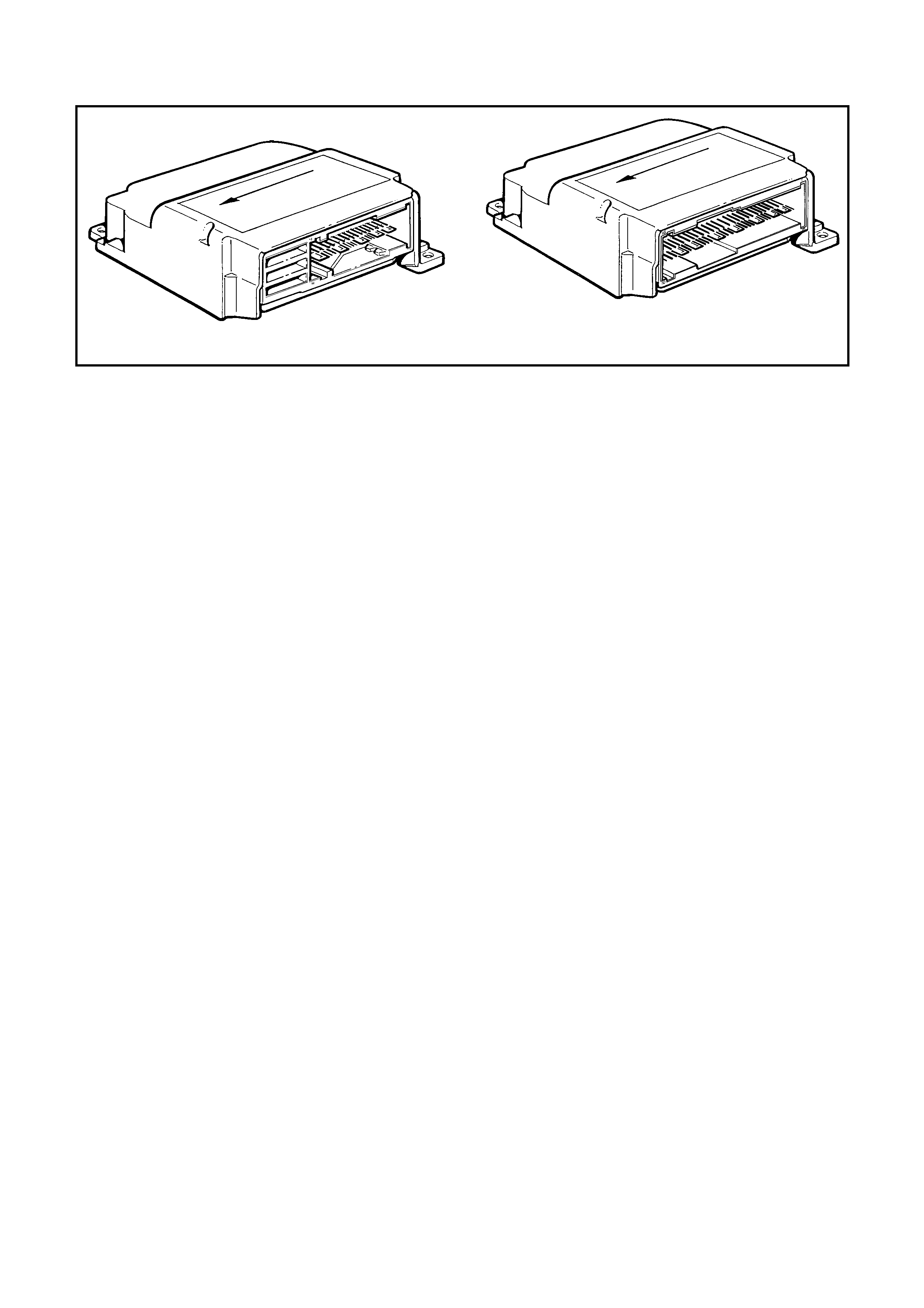
DTC 163 - SDM INTERNAL FAULT
1
T12M171
Figure 12M-90
CIRCUIT DESCRIPTION
NOTE: DTC 163 will only be set and displayed by TECH 2 as a history DTC even if it is current.
At ignition on, and on a constant monitoring cycle of every 500 milliseconds during the ignition cycle, the SDM
perfor ms a system self check . If the SDM detects a f ault in itself, a DT C 163 will be set and the SRS warning lam p
will be illuminated continuously with the ignition on.
ACTION REQUIRED
If DTC 163 is set, the SRS may not operate and therefore, the SDM must be replaced.
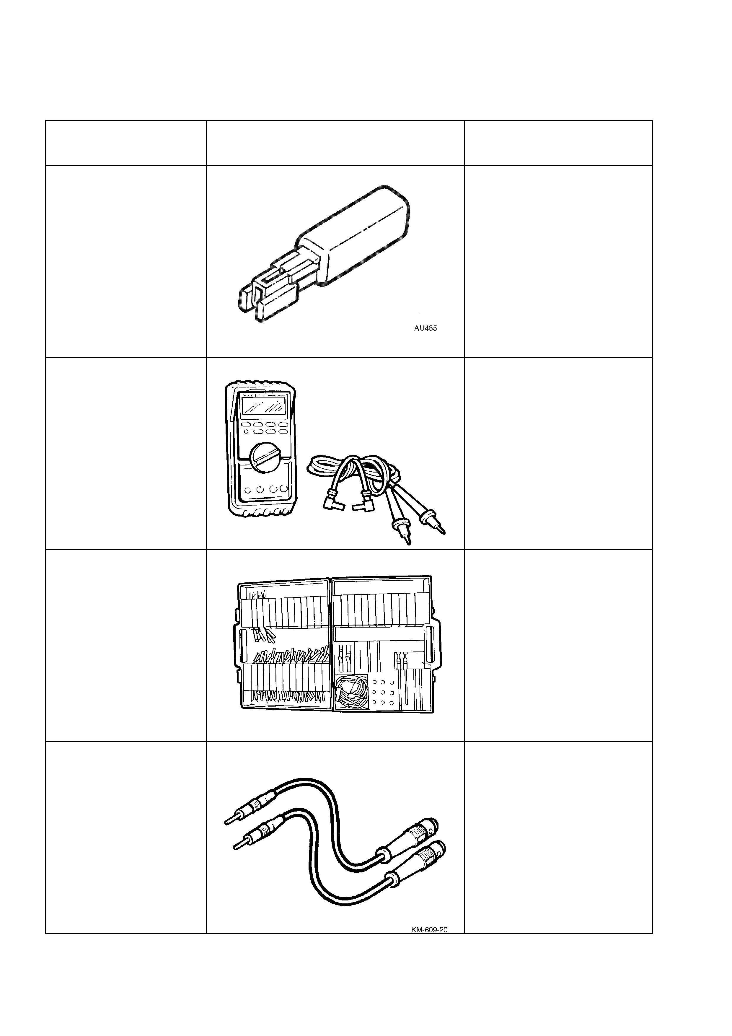
3. SPECIAL TOOLS
TOOL NO. REF
IN TEXT TOOL DESCRIPTION COMMENTS
AU485 DUMMY LOAD
PREVIOUSLY RELEASED
FOR SIDE AIR BAG
J39200 DIGITAL MULTIMETER
TOOL NO. J39200
PREVIOUSLY RELEASED, OR
USE COMMERCIALLY
AVAILABLE EQUIVALENT.
MUST HAVE 10 MOHM INPUT
IMPEDANCE AND BE
CAPABLE OF READING
CAPACITANCE
KM-609 ELECTRONIC KIT
USED IN CONJUNCTION
WITH A MULTIMETER FOR
MEASURING VOLTAGES AND
RESISTANCE’S WITHOUT
DAMAGING WIRING
HARNESS CONNECTORS
KM-609-20 SRS TEST LEAD SET
PREVIOUSLY RELEASED
(AVAILABLE SEPARATELY OR
PART OF KM-609)
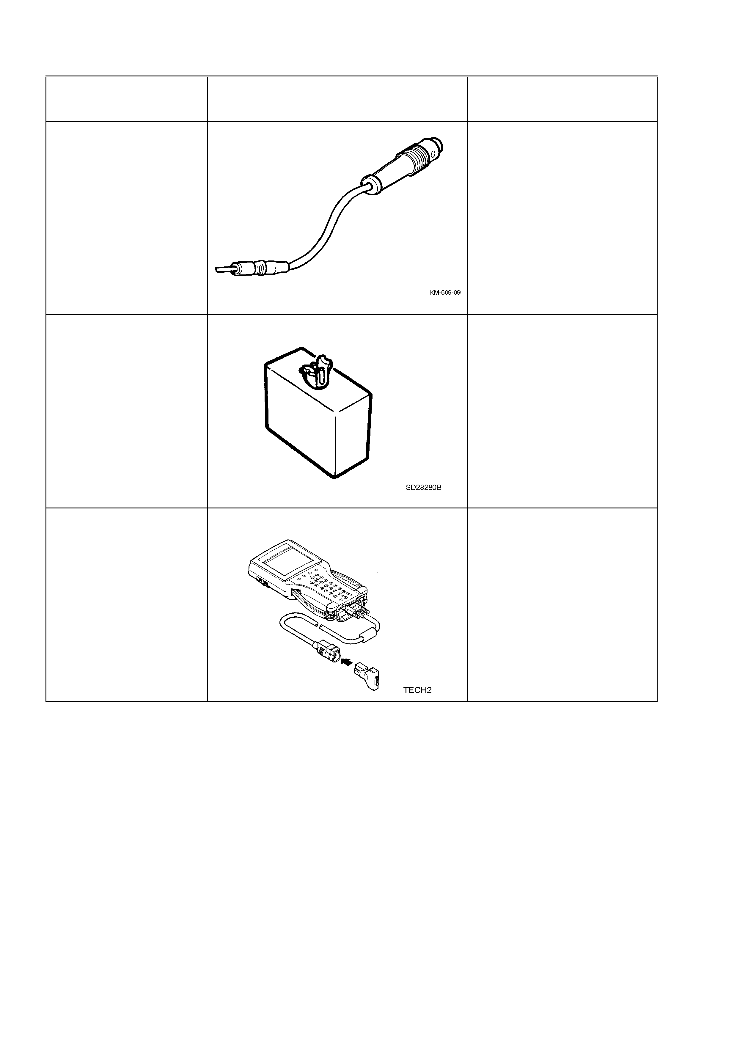
TOOL NO. REF
IN TEXT TOOL DESCRIPTION COMMENTS
KM-609-09 TEST LEAD
CAN BE USED TO OPEN THE
SHORTING LINK BUSBAR IN
CONNECTOR YB189
(AVAILABLE SEPARATELY OR
PART OF KM-609)
SD28280B DUMMY LOAD
FOR SEAT BELT PRE-
TENSIONERS, AND DRIVER’S
AND FRONT PASSENGER’S
AIR BAGS
TECH 2 DIAGNOSTIC SCAN TOOL
PREVIOUSLY RELEASED