SECTION 3 - FRONT SUSPENSION
IMPORTANT
Before p erforming any Serv ice Operation or other procedu re described in this Section , refer to Section
00 CAUTIONS AND NOTES of the VX Series Service Information for correct workshop practices with
regard to safety and/or property damage.
1. GENERAL DESCRI PTI O N
The front suspension for VX models, carries over from VT Series II vehicles, except for the minor changes
described in this Section. For all remaining service operations and specifications, refer to
Section 3. FRONT SUSPENSION, of the VT Series I and SECTION 3 - FRONT SUSPENSION - BEFORE
PRODUCTION SERIAL NUMBER L 492505 or SECTION 3 - FRONT SUSPENSION - AFTER PRODUCTION
SERIAL NUMBER L 492505 of the VT Series II Service Information.
New, light weight front struts and a re-designed stabiliser bar spacer stud, insulating bushes, retainers and
attaching nuts, form the changes made to the front suspension for VX models. The lower end of the spacer stud
now has a ball joint, attached to the stabiliser bar with a ball joint stud and nut.
Minor revisions have also been made to the wheel alignment specification range to improve vehicle tracking, that
applies to earlier build vehicles. Therefore, refer to VT Series II Service Information for the relevant changes that
also apply to VX Series vehicles.
The front suspension fitted to VX models with the revised components, continues to operate on the MacPherson
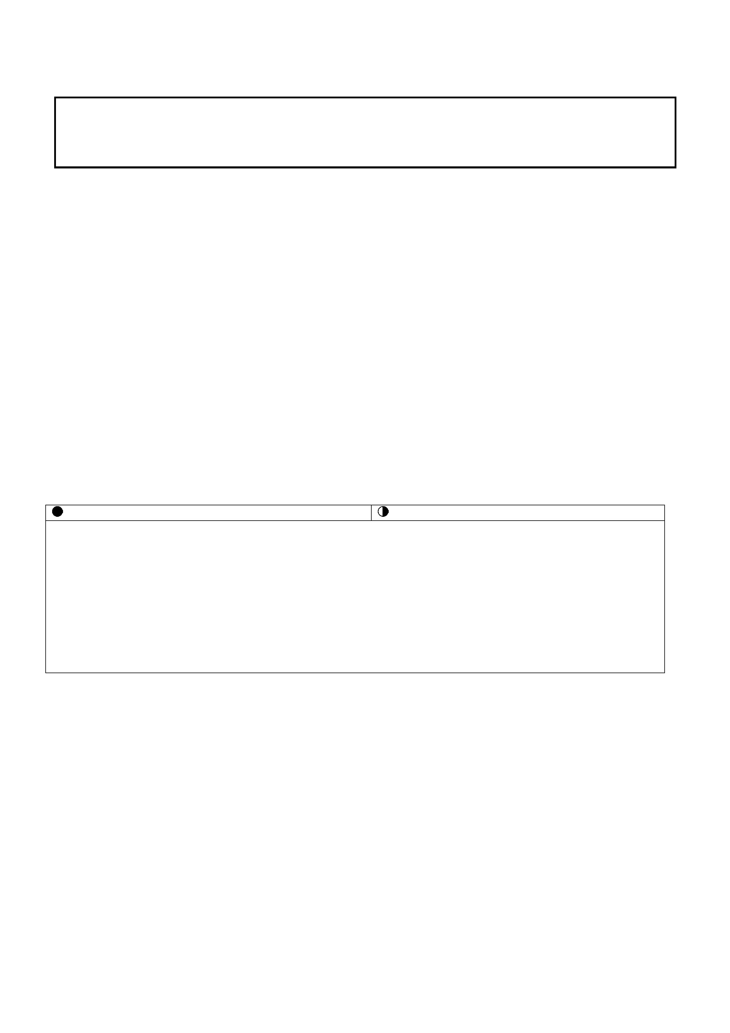
strut princ iple. The assem bly cons ists of the fr ont crossm ember, control arm s, tension rods, stabiliser bar and strut
assemblies (Refer to Fig. 3-1).
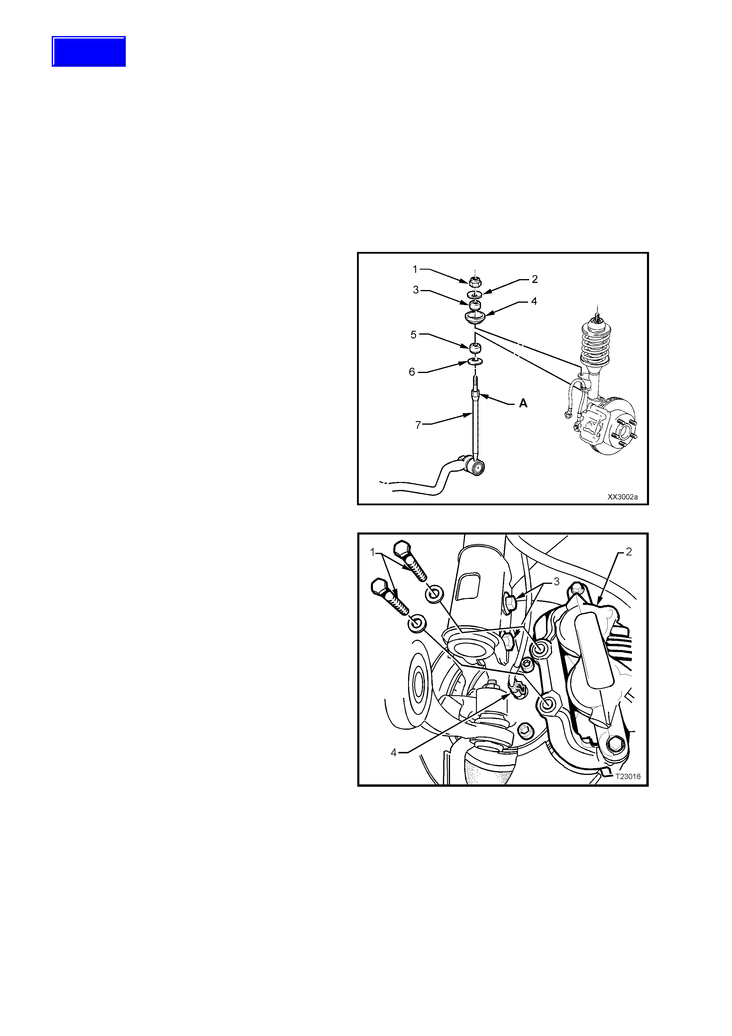
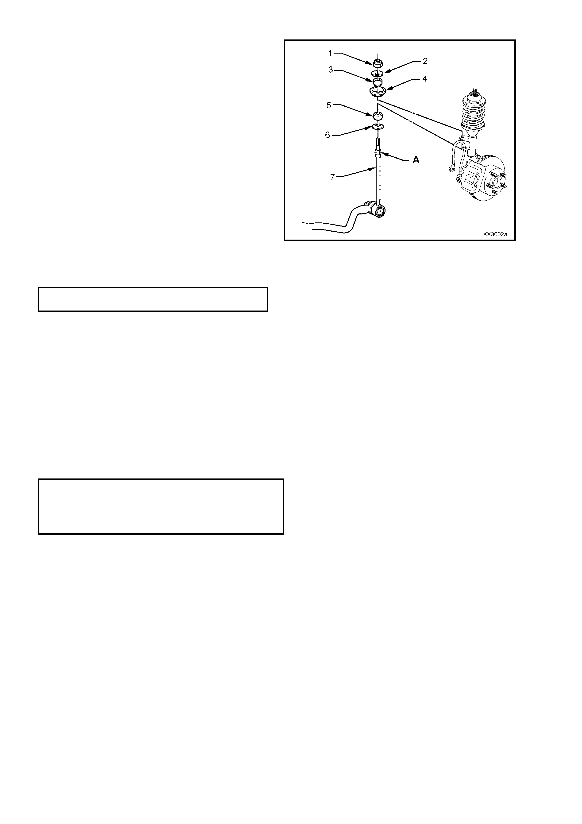
Legend for Fig. 3-1
Stud to be held while nuts are torqued to specification Fastener must be new and assembled dry.
1. Nut (2 places) 11. Insulator (2 places) 20. Washer – Cupped (2 places)
2. Washer (2 places) 12. Bar – Stabiliser 21. Control Arm (2 places)
3. Bush (2 places) 13. Bolt – Front, Flanged (2 places) 22. Washer (2 places)
4. Seat (2 places) 13a. Bolt – Rear, Plain (2 places) 23. Nut - Stepped (2 places)
5. Bush (2 places) 14. Nut (8 places) 24. Bolt (2 places)
6. Washer (2 places) 15. Nut (2 places) 25. Cover - Dust (2 places)
7. Stabiliser Bar Spacer Stud (2 places) 16. Bush – Tension Rod (2 places) 26. Nut (2 places)
8. Nut (2 places) 17. Washer (1 on driver’s side only) 27. Locating Disc (2 places)
9. Nuts (4 places) 18. Nut (2 places) 28. Crossmember
10. Bracket (2 places) 19 Rod – Tension (2 places) ‘A-A’ - Assemble washer ‘20’ as shown
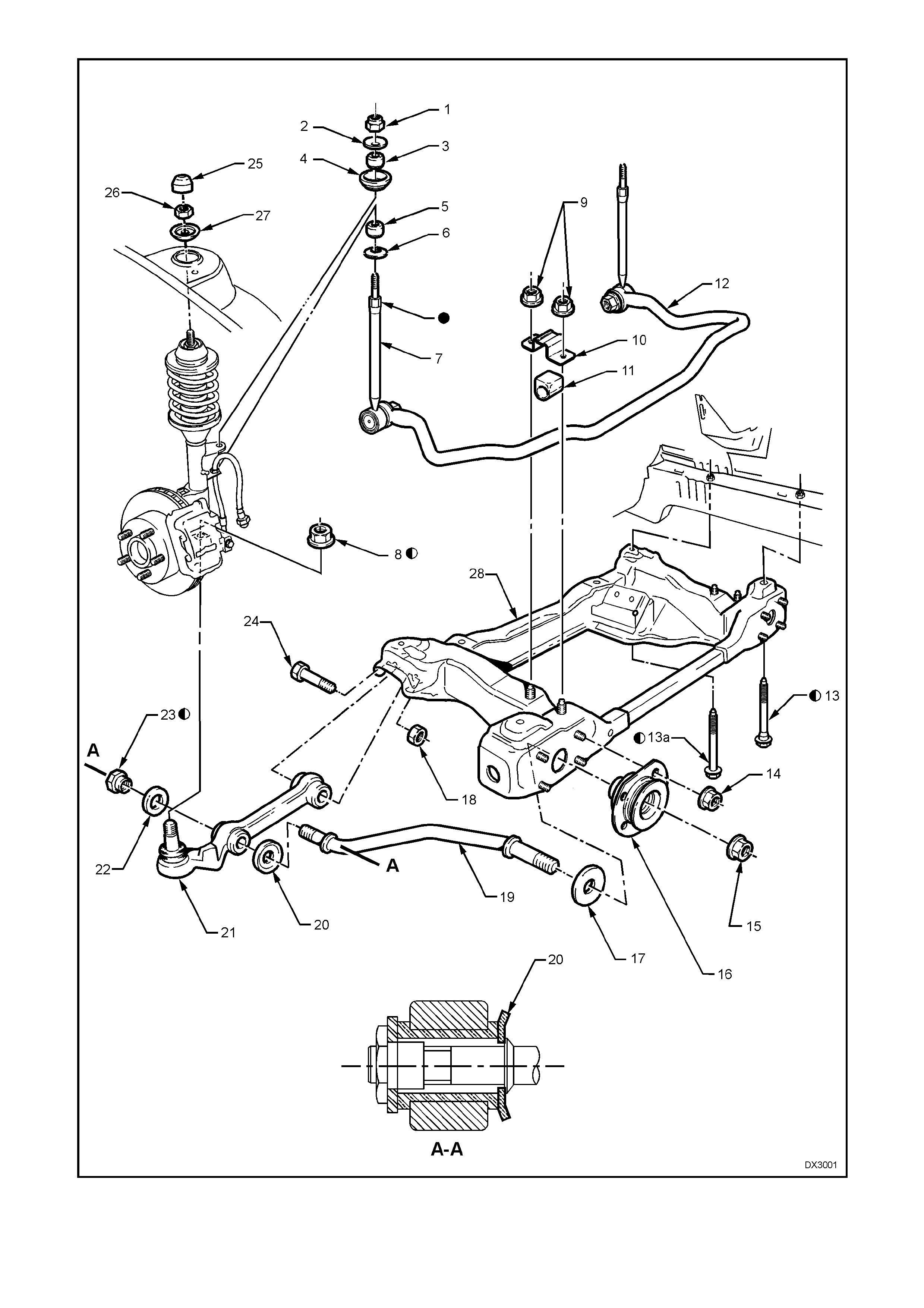
Figure 3-1
2. SERVICE OPERATIONS
CAUTION:
Whenever any component that forms part of the ABS or ABS/ETC is disturbed during Service Operations, it
is vital that the complete ABS or ABS/ETC system is checked, using the procedure as detailed in 4.
DIAGNOSIS, ABS or ABS/ETC FUNCTION CHECK, in Section 12L ABS & ABS/ETC, of the VT Series I
Service Information (V6) or of the VT Series II Service Information (GEN III V8).
2.1 STABILISER BAR LINK
REPLACE
1. Jack up f ront of vehicle and place s afety stands
under side frame members. Observe jacking
precautions as outlined in
2.3 JACKING PRECAUTIONS in VT Series I,
3. FRONT SUSPENSION.
2. Remove decorative road wheel retaining nut
caps, if fitted.
3. Mar k relationship of wheel to hub. Loos en, then
remove road wheel attaching nuts. Remove
road wheel.
4. Using a suitable size spanner, hold the
stabiliser bar spacer stud (7) at ‘A’, then use
another spanner to loosen and remove the
stabiliser bar spacer stud nut (1).
5. Remove the washer (2), upper bush (3) and
seat (4).
6. If requir ed, repeat steps 4 and 5 f or the second
side.
NOTE: If both sides are disconnected from the
strut brackets, the spacer stud can be disengaged
from the strut bracket, by pushing down on the
stabiliser bar. Otherwise proceed as in step 7.
Figure 3-2
Techline
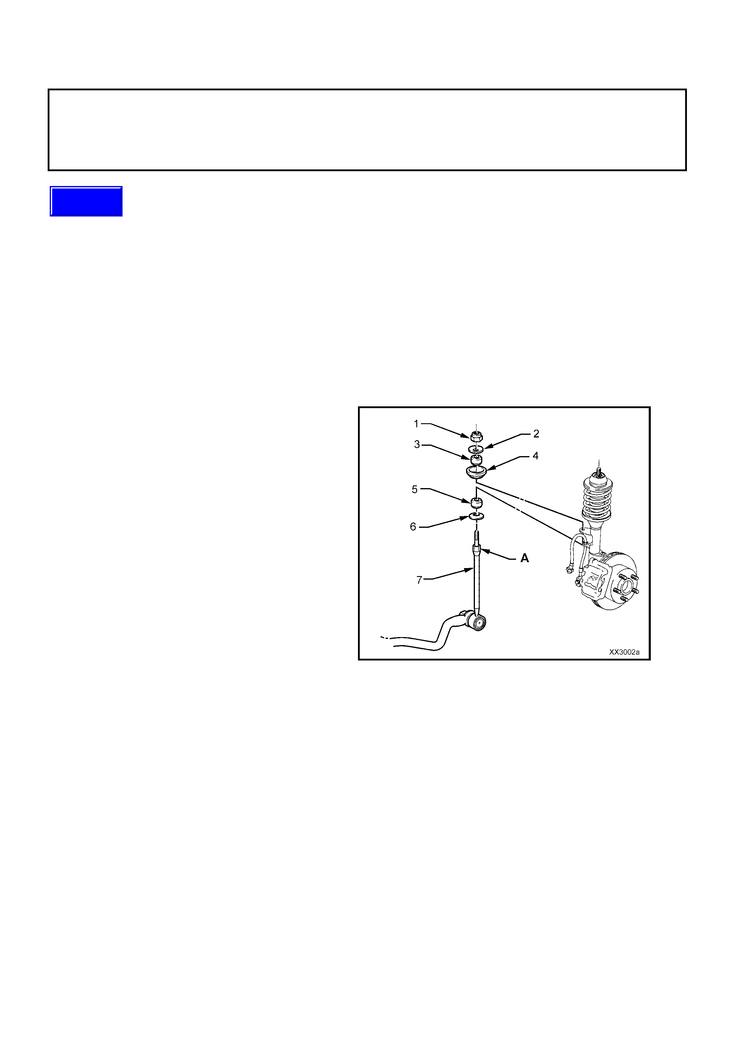
7. With a backing set spanner holding the
stabiliser bar link inner stud hexagon (3), use a
second spanner to loosen then remove the
retaining nut (4).
8. Separate the stabiliser bar link (1) from the
stabiliser bar (2) and remove from the vehicle.
The reinstallation procedure is the reverse to
removal, except for the following points.
9. As required, the lower link bush (5) and washer
(6) may be replaced (refer to Fig. 3-3).
10. Before reinstallation of the stabiliser bar link (1)
to the stabiliser bar (2), insert the upper
threaded end of the link (1) into the strut
mounting bracket.
11. Reinstall the link ball joint stud to the stabiliser
bar (2), tighten the retaining nut (4) to the
correct torque specification, while holding the
inner stud hexagon (3) with a backing spanner.
STABILISER BAR LINK BALL
JOINT STUD RETAINING NUT 45 – 55 Nm
TORQUE SPECIFICATION
Figure 3-3
12. Reinstall the seat (4), upper bush (3) and seat
(2).
13. Reinstall the upper link retaining nut (1) and
tighten to the correct torque specification, while
holding the link at the upper hexagonal section
(A). DO NOT over-tighten.
STABILISER BAR LINK UPPER
NUT TORQUE SPECIFICATION 13 – 18 Nm
14. Reinstall road wheels, aligning marks made
prior to removal.
15. Remove safety stands and lower vehicle.
16. Tighten road wheel attaching nuts to the
correct torque specification, working in a ‘star’
pattern, as indicated in 3. FRONT
SUSPENSION, in SECTION 3 - FRONT
SUSPENSION - Before Production Serial
Number L 492505 or SECTION 3 - FRONT
SUSPENSION - After Production Serial
Number L 492505 of the VT Series II Service
Information.
ROAD WHEEL ATTACHING NUT
TORQUE SPECIFICATION 110 – 140 Nm
17. Reinstall decorative road wheel retaining nut
caps, as required.
18. Bounce vehicle up and down several times to
settle suspension.
Figure 3-4
2.2 FRONT STRUT ASSEMBLY
REMOVE
1. Raise front of vehicle and support on safety
stands. Observe jacking precautions as outlined
3. FRONT SUSPENSION,
2.3 JACKING PRECAUTIONS in VT Series I,
Service Information.
2. Remove decorative road wheel retaining nut
caps, if fitted.
3. Mark relationship of road wheel to hub or brake
disc. Loosen then remove road wheel attaching
nuts. Remove road wheel.
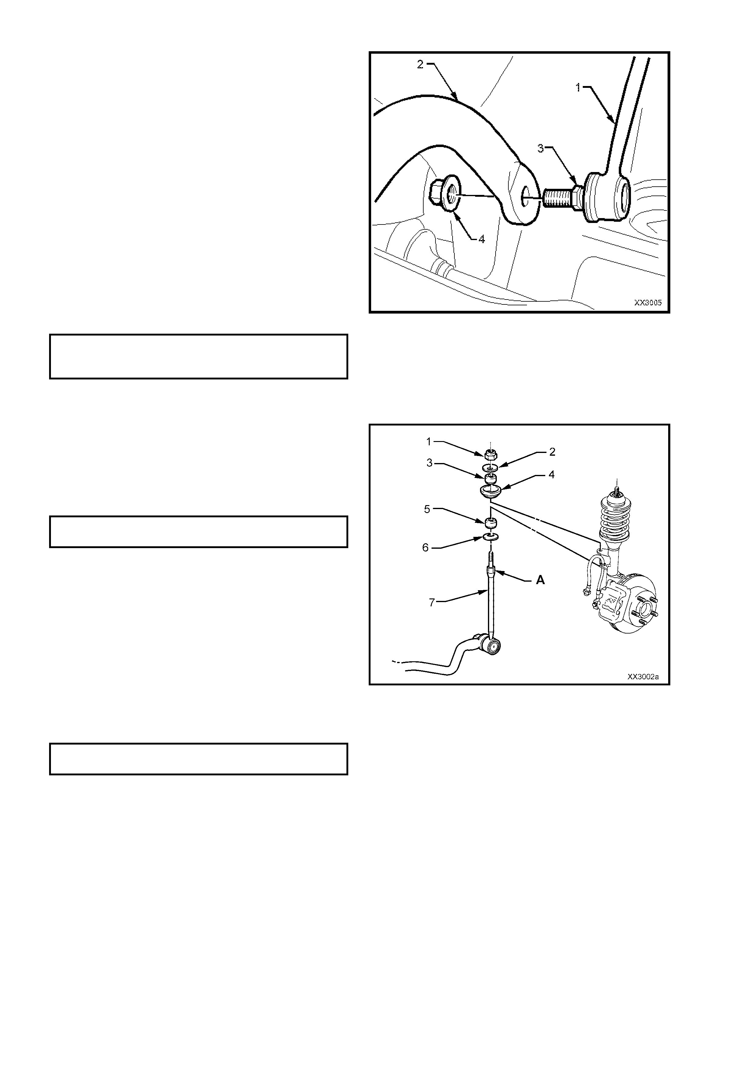
4. Position a suitable size open end spanner to
hold the stabiliser bar spacer stud (7) at ‘A’,
use another spanner to loosen and remove
upper nut (1), washer (2), bush (3) and seat
(4).
5. Disconnect the wheel speed sensor cable and
insulator from the strut bracket.
Figure 3-5
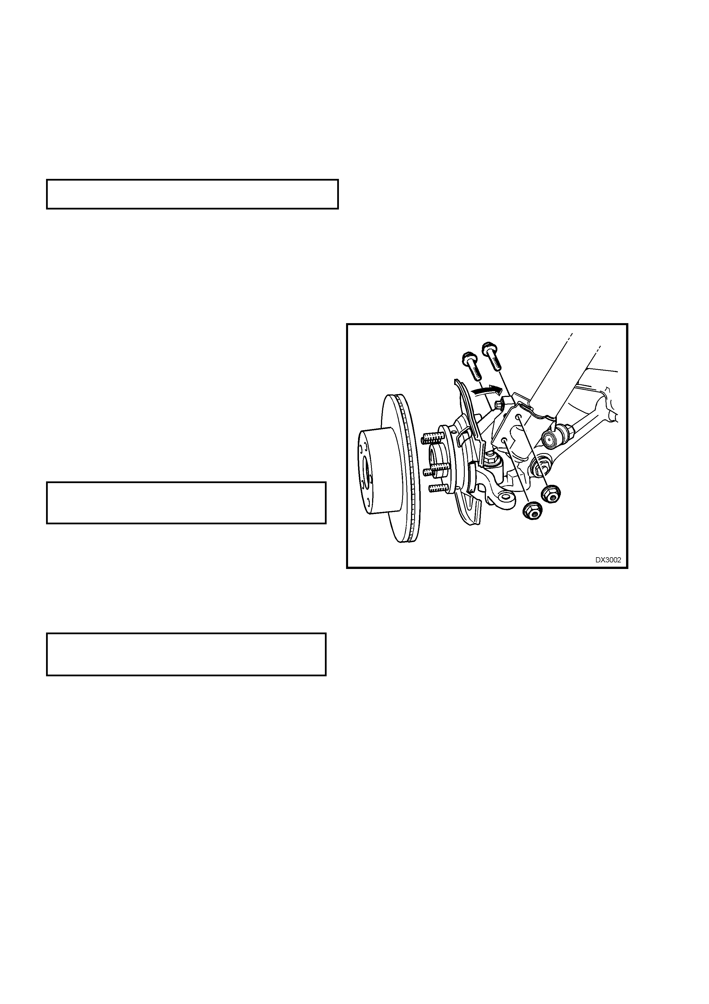
6. Remove the brake caliper anchor plate
retaining bolts and washers (1), lift the caliper
assembly (2) from the brake disc and support
in such a way that no strain is placed on the
brake hose. THE BRAKE CALIPER IS NOT
TO HANG BY THE BRAKE HOSE.
NOTE: T his step is nec essary to provide access to
the lower strut mounting bolts and nuts (3).
7. If required, remove brake disc from the wheel
bearing hub. While the brake disc to hub
relationship is marked during production,
ensure that the disc to hub position is carefully
marked.
NOTE: This is necessary to overcome the
possibility of inducing a brake shudder condition
after reassembly.
8. Remove brake hose from the strut housing
bracket by turning plastic sleeve on the hose
until flats on sleeve align with bracket opening.
9. Using a suitable floor jack f itted with a block of
wood, position under the control arm, just
sufficient to support the weight.
10. Loosen, remove and DISCARD the two lower
strut to knuckle attaching bolts and nuts (3).
11. To avoid placing strain on the ABS sensor
lead, release the connector locking tang and
pull on the sens or lead c onnec tor ( 4) to remove
from the sensor.
12. Pull the steering knuckle clear of the strut.
Figure 3-6
Techline
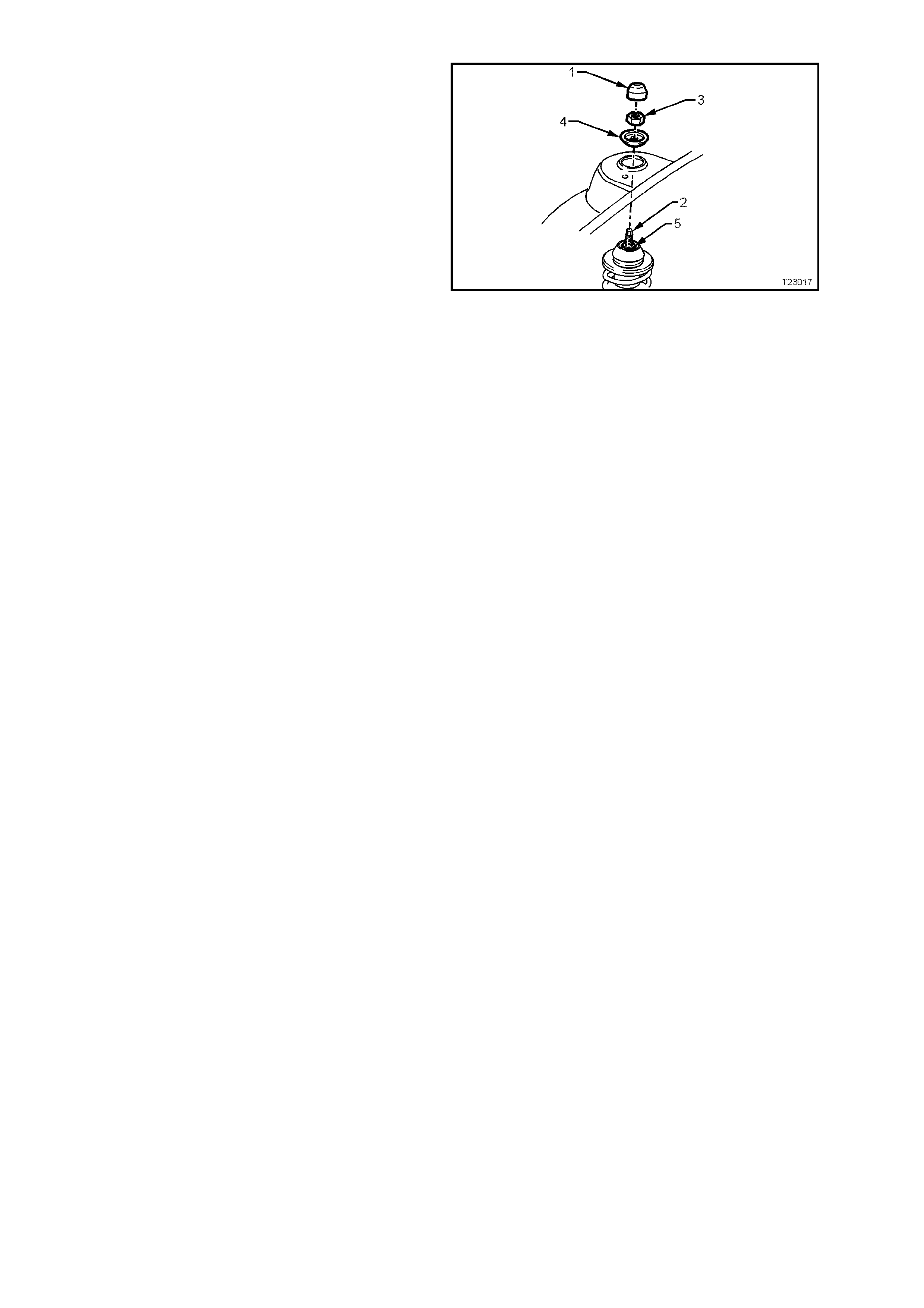
13. Remove the dus t c over (1) f rom the upper strut
support, in the engine compartment.
14. While holding the strut rod shaft (2) with a 10
mm socket, remove the self-locking nut (3),
using a 24 mm (15/16") ring spanner, then
remove the locating disc (4). DISCARD THE
STRUT ROD NUT.
15. Carefully lower the strut from the tower,
manipulate the strut to remove the stabiliser
stud from the bracket on the strut and remove
the assembly from the vehicle.
Figure 3-7
REINSTALL
NOTE: In the interests of vehicle safety, it is
important that fasteners are replaced with new parts
where stated during the reinstallation process
described here.
Important: The torque of the strut bearing
retaining nut (‘5’ in Fig. 3-6) MUST be checked
for correct tightness BEFORE installing the strut
into the vehicle!
UPPER STRUT BEARING RETAINING
NUT TORQUE SPECIFICATION 70 - 85 Nm
1. Manipulate the strut assembly so that the
stabiliser bar stud is located in the strut bracket,
then locate strut assembly into the spring strut
tower.
2. After installing the locating disc, partially install a
NEW upper nut to the strut rod. Do not tighten at
this time.
3. Pivot the hub and steering knuck le assem blies,
sufficient to line up the bolt holes in the
steering knuckle and the lower end of the strut
assembly.
4. Install NEW retaining bolts and nuts, and
tighten to a preliminary torque of 85 Nm.
5. Use a 10 mm socket to hold the strut rod from
turning, then tighten the upper strut rod
retaining nut (‘3’ in Fig. 3-6) to the correct
torque specification, using a 24 mm (15/16")
ring spanner with a torque wrench attached.
UPPER STRUT LOCATING
PLATE RETAINING NUT 50 - 60 Nm
TORQUE SPECIFICATION
6. Install the brake hose to the strut bracket by
turning plastic s leeve on the hose until the flats
on the sleeve align with the bracket opening.
7. If removed, install the brake disc, aligning
marks made prior to removal.
8. Reinstall the brake caliper, tightening the
attaching bolts to specification.
BRAKE CALIPER ANCHOR 80 - 90 Nm,
PLATE RETAINING BOLTS then turn through
TORQUE SPECIFICATION 40° - 50°
9. Reinstall the wheel speed sensor connector,
pushing firmly onto the sensor until the
retaining tang is secure. Then, reinstall the
sensor lead and insulator into the strut
mounting bracket.
Figure 3-8
10. Reinstall stabiliser bar spacer stud nut (1) after
ensuring that all components are assembled as
shown. While holding the spacer stud (7) with a
suitable open end spanner at ‘A’, use another
spanner to tighten the upper retaining nut (1)
until the end of the thread on the stud is
contacted.
NOTE: Do not use power tools for this tightening
operation, otherwise thread damage will result.
11. Install road wheel, aligning the marks made
prior to removal.
12. Remove safety stands and lower vehicle.
13. Tighten road wheel attaching nuts to
the correct torque specification, working
in a ‘star’ pattern, as indicated
in 3. FRONT SUSPENSION,
SECTION 3 - FRONT SUSPENSION - Before
Production Serial Number L 492505 or
SECTION 3 - FRONT SUSPENSION - After
Production Serial Number L 492505 of the VT
Series II Service Information.
ROAD WHEEL ATTACHING NUT
TORQUE SPECIFICATION 110 - 140 Nm
14. Reinstall decorative road wheel retaining nut
caps, as required.
15. Bounce vehicle up and down several times to
settle suspension.
16. Check wheel alignment, as detailed
in 2.1 WHEEL ALIGNMENT CHECKING
AND ADJUSTMENT, SECTION 3 - FRONT
SUSPENSION - Before Production Serial
Number L 492505 or SECTION 3 - FRONT
SUSPENSION - After Production Serial
Number L 492505 of the VT Series II Service
Information.
17. Tighten the steering knuckle to strut bolts and
nuts to the specified torque values.
Figure 3-9
STEERING KNUCKLE TO STRUT
ATTACHING BOLTS & NUTS..
TORQUE SPECIFICATION ..... Stage 1 85 Nm
Stage 2 100 Nm
Stage 3 Turn through 90°
3. SPECIFICATIONS
SUSPENSION
Type ........................................................................ MacPherson Wet Strut
Application............................................................... All VX Models
Travel
Compression (2/3compression of bumper)
Standard and V5W........................................... 90 mm
FE2................................................................... 80 mm
Rebound
Standard and V5W........................................... 110 mm
FE2................................................................... 120 mm
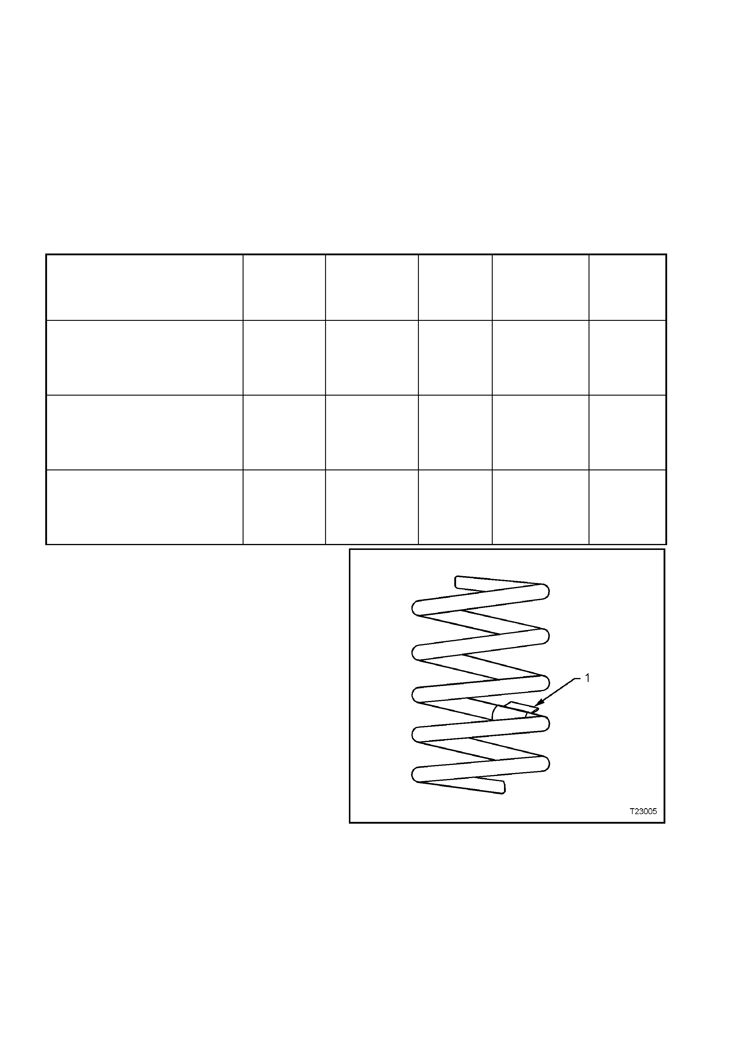
FRONT SPRING SPECIFICATIONS
SEDAN & STATION WAGON
MODELS
Approximat
e
Number
COILS
Approximate
FREE
LENGTH
(mm)
INSIDE
DIAMETE
R
(mm)
PROD. I.D.
CODE
(Tag on
spring)
SPRING
TYPE &
RATE
STANDARD SUSPENSION –
ALL ENGINE S and BODY S T Y LES 6.05 444 136 ± 1.5 HN VARIABLE
19 - 23
N/mm
(3700 ± 110 N
@ 210 mm)
FE2 SPORTS SUSPENSION –
ALL ENGINE S and BODY S T Y LES 5.25 341 136 ± 1.5 HJ VARIABLE
24 – 31
N/mm
(3660 ± 110 N
@ 200 mm)
V5W COUNTRY PACK SUSPENSION –
ALL ENGINE S and BODY S T Y LES 6.05 444 136 ± 1.5 HN VARIABLE
19 - 23
N/mm
(3700 ± 110 N
@ 210 mm)
Legend
1. Production Identification Code Tag
Figure 3-10
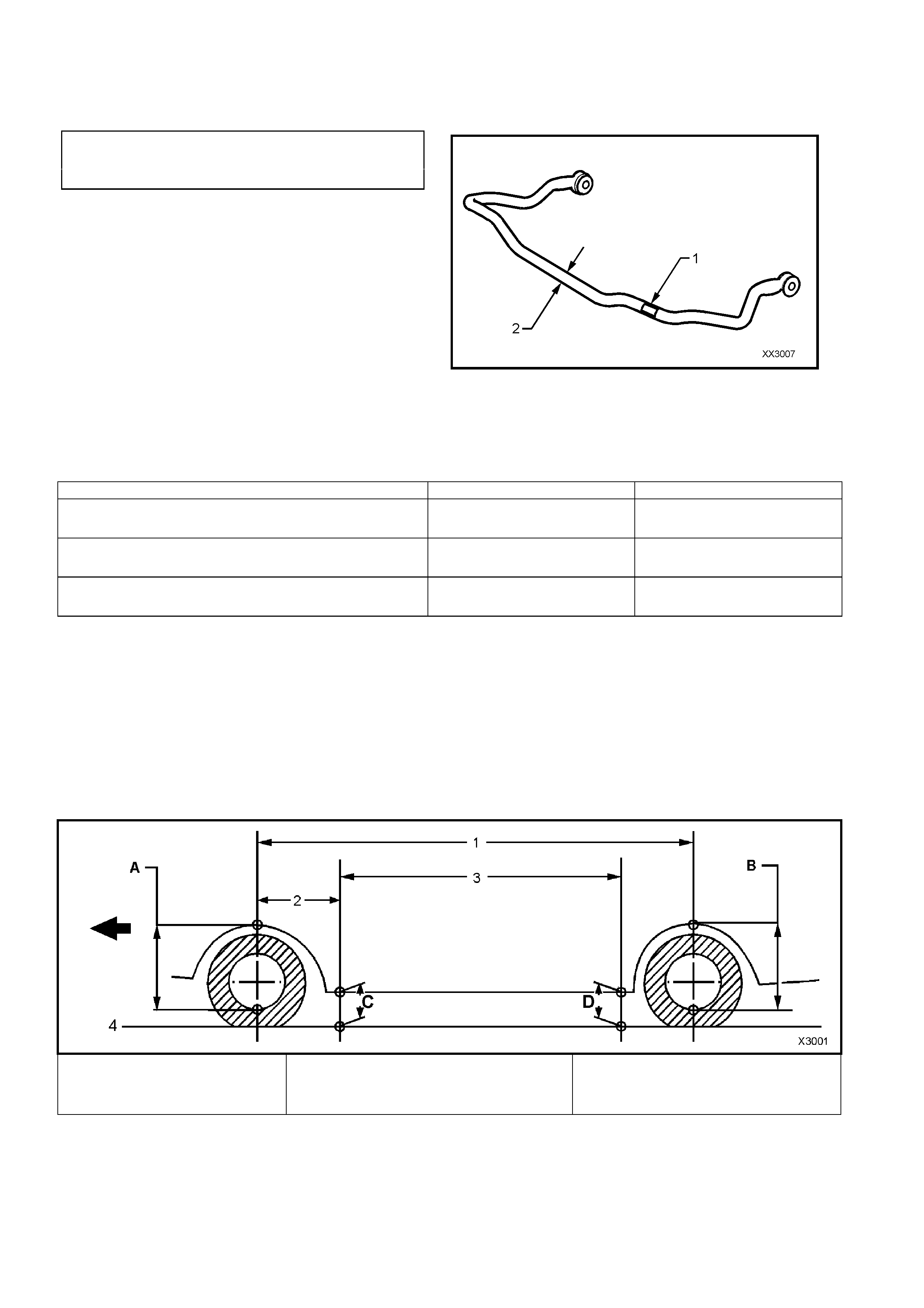
STABILISER BAR (FRONT)
Type .................................................................. Decoupled
STABILISER BAR IDENTIFICATION
I.D. Diameter
MODELS CODE mm
(1) (2)
All VX Models and Suspensions
except for Vehicles with FE2 YB 26.0
All VX Models with the FE2
Sports Suspe ns io n YA 27.0
Legend
1. Production Identification Code Tag
2. Stabiliser Bar Diameter
Figure 3-11
FRONT STRUT
Type ................................................................. Wet strut – non-serviceable
FRONT STRUT IDENTIFICATION
Suspension and Application Right Hand Side Left Hand Side
STANDARD SUSPENSION –
ALL BODY STYLES AND ENGINES ZM ZN
SPORTS SUSPENSION –
ALL BODY STYLES AND ENGINES ZP ZR
COUNTRY PACK SUSPENSION –
ALL BODY STYLES AND ENGINES ZS *ZT
CONTROL ARM
Type ................................................................. Forged with rubber bushes for attachment to front
crossmember and tension rod. Ball joint is a press fit
into the control arm. The ball joint is not serviced separately.
FRONT WHEEL BEARINGS
Type ................................................................. Double row ball bearing
Lubricant........................................................... Sealed for life: non-adjustable
SUSPENSION and TRIM HEIGHT SPECIFICATIONS
A Front Suspension Height Locati on
B Rear Suspension Height Location
C Front Trim Height Check Locati on
D Rear Trim Hei ght Check Location
1. Wheelbase:
All VX Sedan – 2788 mm
All Station Wagon – 2938 mm
2. Ref erence Point : All Models – 584.5 mm
3. Trim Hei ght Spacing:
All Sedan – 1615 mm
All Station Wagon – 1765 mm
4. Ground Line
Figure 3-12
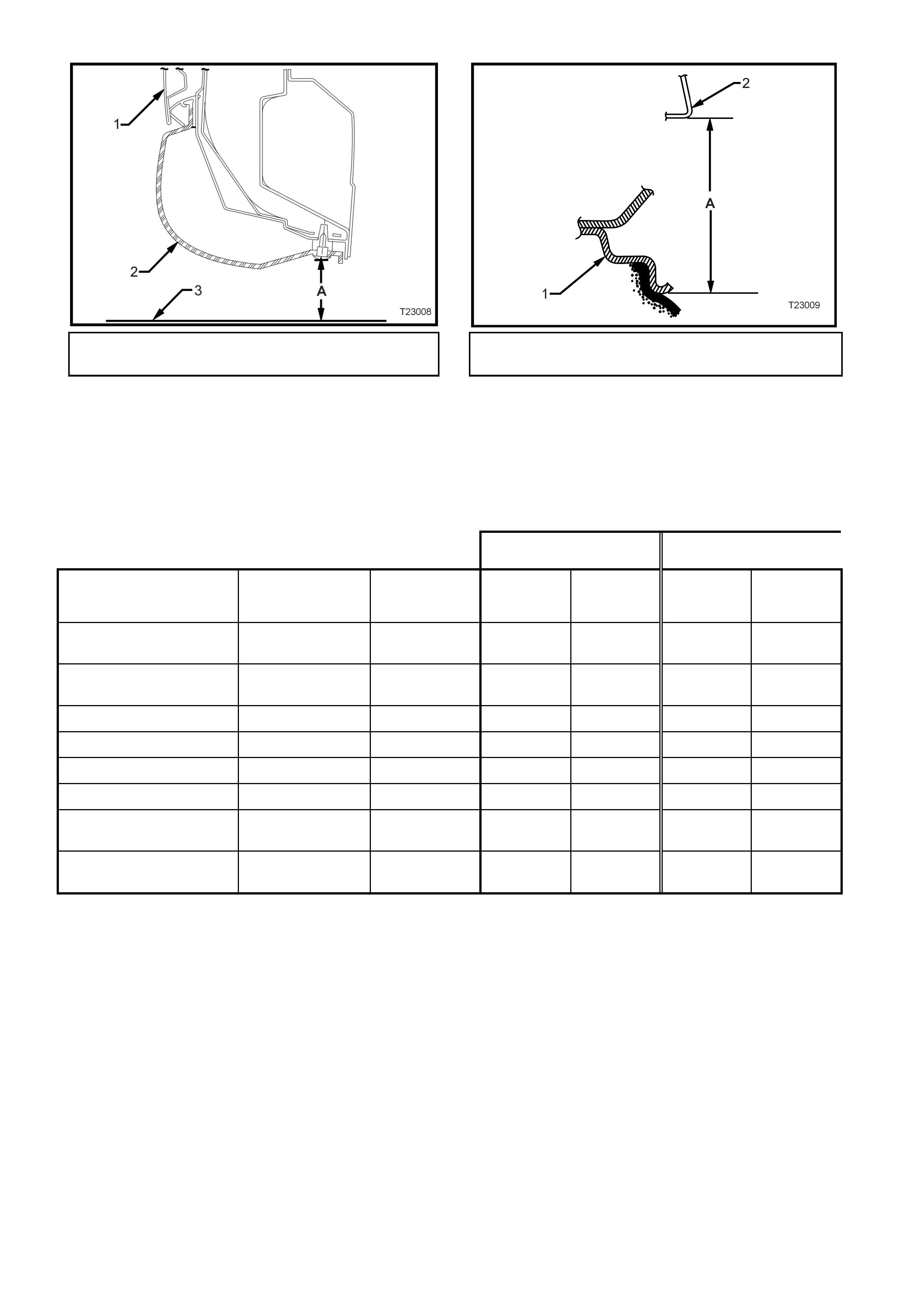
1. Door 2. Trim
3 Ground Line ‘A’ Trim Height 1. Wheel Rim
2. Fender Opening ‘A’ Suspension Height
Figure 3-13 – Rear Trim Height Checking Location (Front
Similar) Figure 3-14 – Front and Rear Suspension Height
Checking Location
NOTE: The following suspension/trim height dimensions are intended for reference only and are
intended to be a guide only. Refer to 3.3 SUSPENSION AND TRIM HEIGHT, CHECK
SECTION 3 - FRONT SUSPENSION - BEFORE PRODUCTION SERIAL NUMBER L 492505 or
SECTIO N 3 - FRONT SUSPENSION - AFT ER PRODUCTION SERIAL NUMBER L 492505 in VT Series II Service
Information for ride height variations and additional procedures.
VX MODELS SUSPENSION HEIGHT
(mm) TRIM HEIGHT
(mm)
VEHICLE
DESCRIPTION TRANSMISSION SUSPENSION FRONT
(‘A’ in
Fig. 3-12)
REAR
(‘B’ in
Fig. 3-12)
FRONT
(‘C’ in
Fig. 3-12)
REAR
(‘D in
Fig. 3-12)
Executive/Acclaim/Berlina
Sedan Manual/Automatic Standard/V5W 605 594 192 201
Executive/Acclaim/Berlina
Sedan Manual/Automatic FE2 583 581 172 186
‘S’ Pack Sedan Manual/Automatic FE2 605 603 172 186
‘SS’ Sedan Manual/Automatic FE2 611 609 172 186
Calais Sedan Automatic Standard/V5W 618 607 192 201
Calais Sedan Automatic FE2 596 608 172 186
Executive/Acclaim/Berlina
Wagon Manual/Automatic Standard/V5W 601 583 192 210
Executive/Acclaim/Berlina
Wagon Manual/Automatic FE2 586 568 177 195

4. TORQUE SPECIFICATIONS
NOTE: For those torque specifications not listed here, refer to 3 FRONT SUSPENSION in VT Series I and
Section 3 - FRONT SUSPENSION - Before Production Serial Number L 492505 or Section 3 - Front
Suspension - After Production Serial Number L 492505 of the VT series II Service Information.
Nm
Brake Caliper Anchor Plate Retaining Bolts.............Stage 1....... 80 - 90
Stage 2....... Turn through 40° - 50°
Road Wheel Attaching Nut........................................................... 110 – 140
Stabiliser Bar Link Ball Joint Stud Retaining Nut.......................... 45 – 55
Stabiliser Bar Link Upper Nut....................................................... 13 – 18
Steering Knuckle to Strut Attaching Bolts and Nuts Stage 1....... 85
Stage 2....... 100
Stage 3....... Turn through 90°
Upper Strut Bearing Retaining Nut............................................... 70 - 85
Upper Strut Locating Plate Retaining Nut..................................... 50 - 60