
SECTION 7B3 - MANUAL TRANSMISSION –
GEN III V8 ENGINE
IMPORTANT
Before performing any Service Operation or other procedure described in this Section, refer to Section
00 CAUTIONS AND NOTES for correct workshop practices with regard to safety and/or property damage.
1. GENERAL I NFORMATI O N
The 6 speed manual transmission available as an option for VX Series models equipped with the GEN III V8
engine, remains unchanged from the assembly used for VT Series II models, except for the minor change to the
remote shifter mechanism described in this Section.
Apart fr om this change, r efer to Section 7B3 MANUAL TRANSMISSION – GEN III V8 ENGINE, in the VT Series II
Service Information, for all information relating to this transmission.
Techline
Techline
Techline
2. SERVICE OPERATIONS
2.1 REMOTE CONTROL SHIFT MECHANISM
REMOVE
Refer 4.3 TRANSMISSION DISASSEMBLE, in the
VT Series II Service Information.
DISASSEMBLE
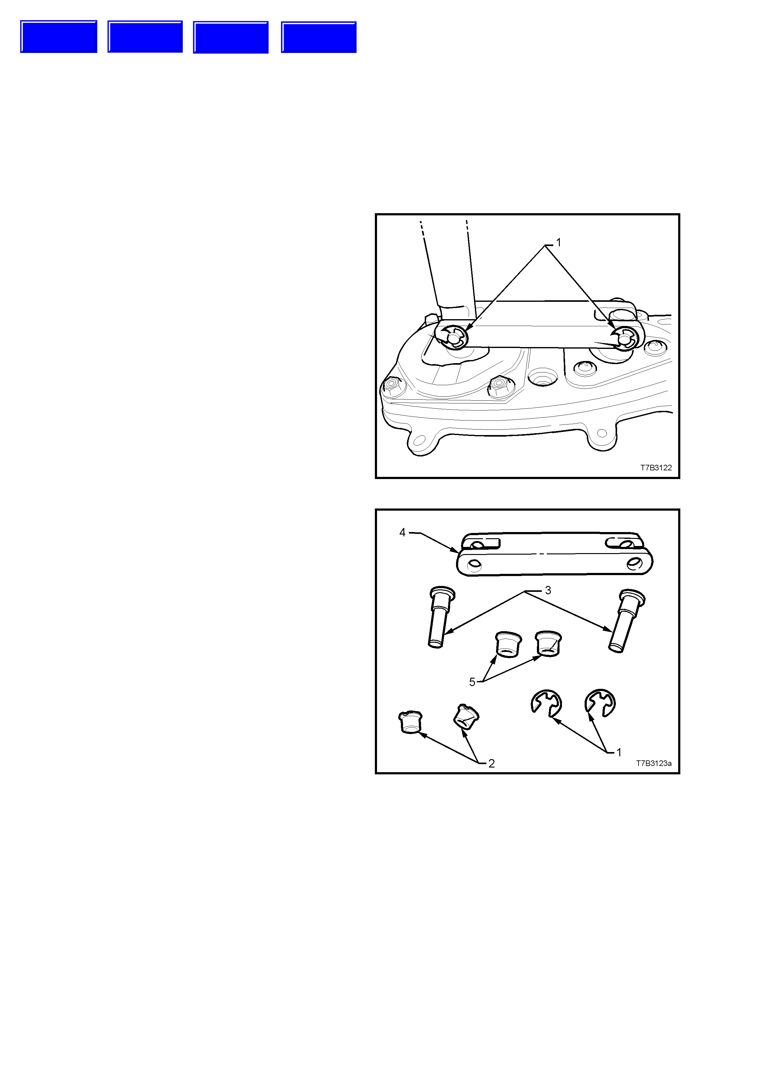
1. With the boot and dust cover removed, use a
small screwdriver to remove both ‘E’ clips (1).
CAUTION: Wear safety glasses to avoid
possible eye injury.
Figure 7B3-1
2. Tap the two pins (3) free from the bridging
piece (4). T hese two pins ar e an interference fit
into each of the two pivot pieces and must be
replaced after removal.
3. Remove both the smaller (2) and larger (5)
bushes from the bridging piece (4).
Figure 7B3-2
Techline
Techline
Techline
Techline
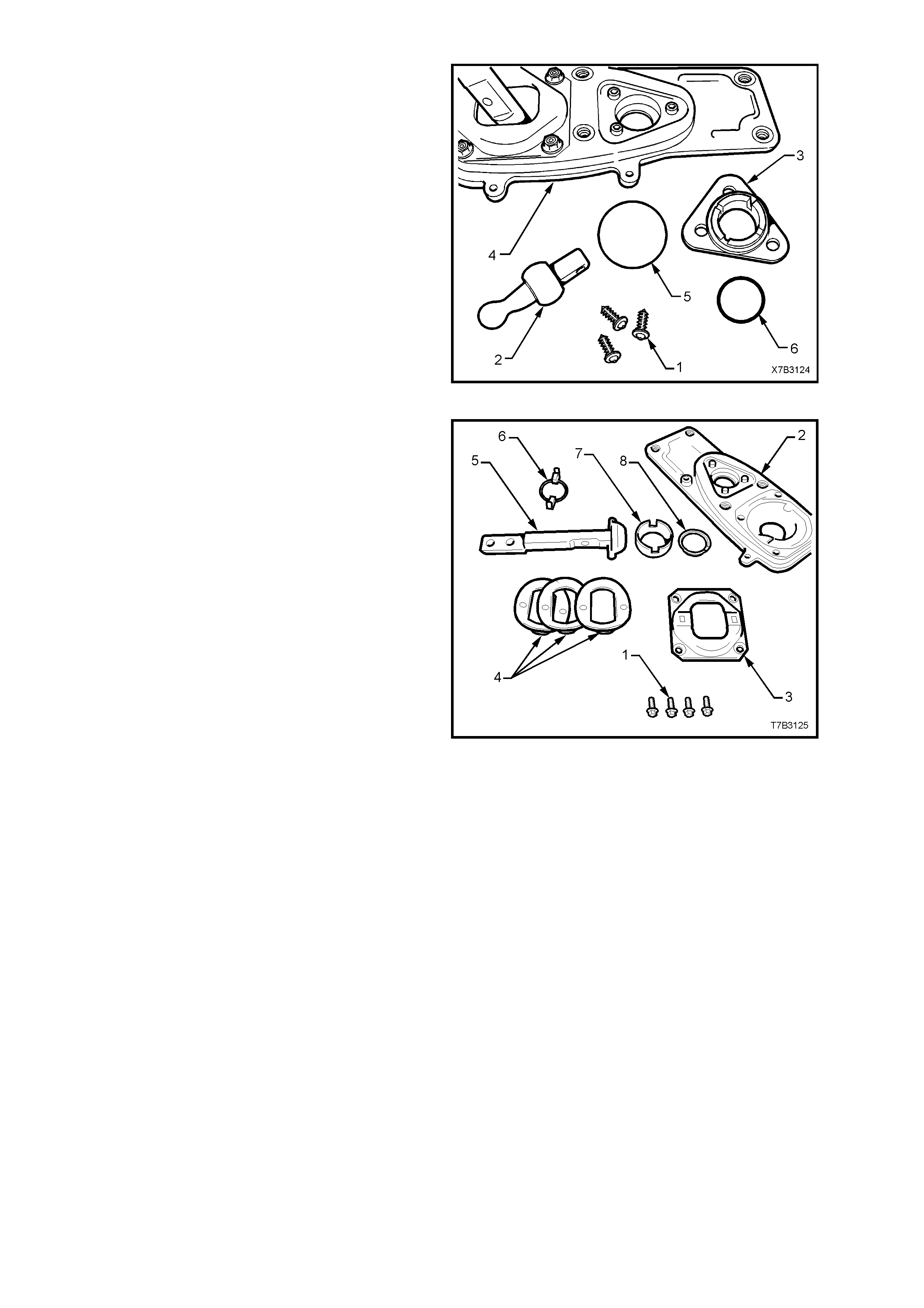
4. To disassemble the front pivot assembly,
unscrew the three self tapping screws (1),
using a Phillips No. 2 screwdriver.
5. By grasping the remote selector pivot (2), pull
the pivot (2) and seat assembly (3) from the
baseplate (4).
6. Remove the O-ring seals (5 and 2) from the
seat (3).
7. Separate the selector pivot (2) from the seat
assembly (3) by supporting the seat assembly
over the open jaws of a vice assembly, then tap
the ball end of the selector pivot (2) free from
the seat (3).
Figure 7B3-3
8. The rear remote shifter assembly can be
disassembled by first removing the four plate
(3) retaining bolts (1) from the baseplate (2).
9. Remove the wave springs (4), remote shifter
shaft (5) and guide (6), from the base plate (2).
10. Finally, remove the ball seat (7) and seat
support ring (8) from the base plate (2).
Figure 7B3-4
CLEAN AND INSPECT
Clean
After removing rubber insulating bushes and seal to the
extension housing, thoroughly was h all com ponents in a
suitable cleaning solvent. Dry all parts with clean, dry
compressed air.
CAUTION: Wear safety glasses to avoid eye injury.
Inspect
1. Inspect pins, bushes, ball seats and other
components for wear or damage, replacing as
required.
2. Inspect the O-ring seal at the front pivot assembly,
the cover plate insulating r ubber bushes and seal to
the extension housing, for deterioration or damage,
replacing as required.
REASSEMBLE
While reassembly is the reverse to disassembly,
there are some specific procedures such as;
1. Apply 10% molybdenum disulphide grease
such as Moybond GA 10 or equivalent (to
Holden’s Specification HN 1271) to all moving
parts in the rear remote shifter assembly.
2. Reassemble all parts in the reverse order of
disassem bly.
3. Install the four bolts (1) securing the plate to
baseplate, tightening to the correct torque
specification.
REAR REMOTE SHIFT LEVER COVER
BOLT TORQUE SPECIFICATION.................. 10 - 12 Nm
Figure 7B3-5
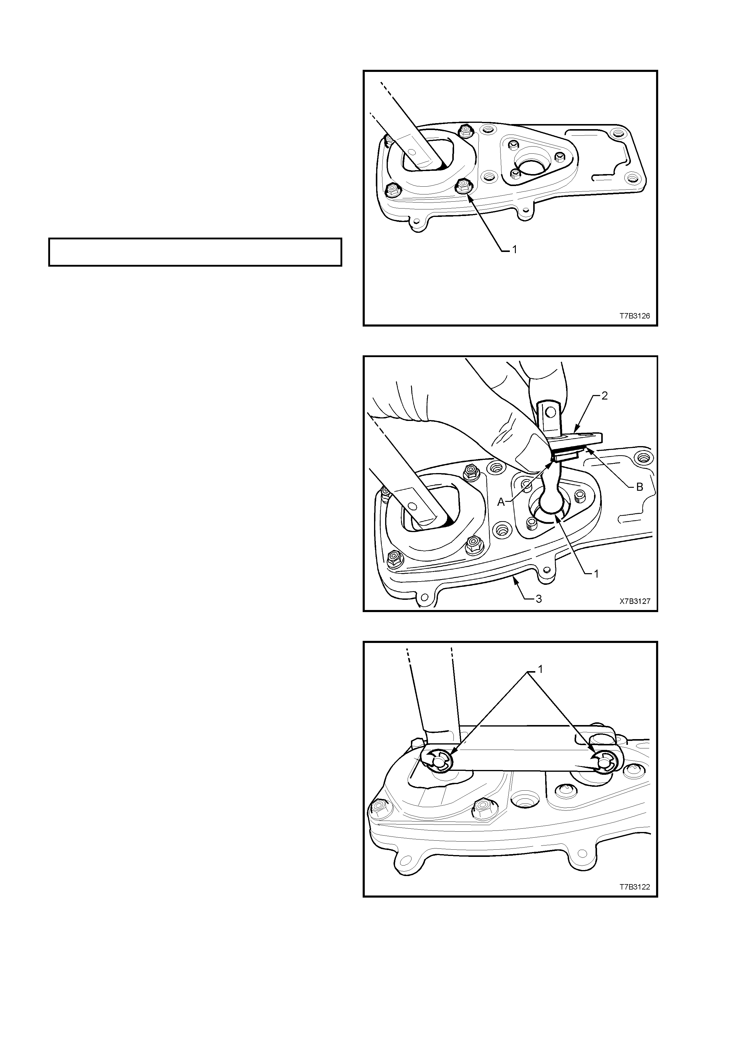
4. Apply NLGI No. 4 EP grease to the ball socket
of the front selector pivot (2), then reassemble
by tapping the front selector pivot (1) into the
plastic ball socket (2).
5. Install the O-ring seals ‘A’ and ‘B’ to the ball
socket (2), replacing with new parts if the
originals are damaged.
6. Reinstall the front selector pivot assembly to
the baseplate (3), install the three retaining
screws and tighten securely.
Figure 7B3-6
7. Install the bridging piece to the two remove
lever assemblies.
8. Install new bushes to the bridging piece after
lubricating with NLGI No. 4 EP grease.
9. Install NEW pivot pins to each location and tap
home with a hammer.
NOTE: These pins are designed to be an
interference fit to the front and rear remote shifter
levers and not be free floating.
10. Fit NEW ‘E’ clips (1) to secure each pin.
CAUTION: Wear safety glasses to avoid eye
injury.
NOTE: the dust cover and boot assembly will be
installed after the remote shifter assembly is
installed to the transmission extension housing.
Figure 7B3-7
REINSTALL
Refer 4.7 TRANSMISSION REASSEMBLE, Extension
Housing, in the VT series II Service Information.