
SECTION 7C4 - HYDRA-MATIC 4L60-E AUTOMATIC
TRANSMISSION ON-VEHICLE SERVICING
IMPORTANT
Before p erforming any Serv ice Operation or other procedu re described in this Section , refer to Section
00 CAUTIONS AND NOTES for correct workshop practices with regard to safety and/or property
damage.
1. GENERAL I NFORMATI ON
Information in this Section, details service operations that can be carried out on a transmission while it is still
installed in the vehicle.
Introduced as a running change in VT Series II m odels a revised des ign autom atic trans m ission f luid cooler with an
increased heat tr ans f er ef ficiency was fitted, from a production s erial num ber of L579900 and date of April 10, 2000.
On V6 naturally aspirated engined vehicles, this cooler design change m eans that the external cooler the can now
been deleted.
Those VX Series models fitted with the V6 Supercharged engine retains the single in-tank radiator cooler and
external cooler intr oduced as a r unning c hange in VT Ser ies II vehic les from a pr oduc tion ser ial number of L518684
and date of October 18, 1999. Refer Section 7C4 ON-VEHICLE SERVICING in the VT Series II Service Information.
The automatic transm ission oil cooler design f or those VX Series m odels f itted with the GEN III V8 engine remains
unchanged from the original. For information relating to this oil cooler package, refer to
Section 7C4 ON-VEHICLE SERVICING in the VT Series II Service Information.
As a change in procedure, a tool has been released that allows the replacement of the manual shaft oil seal, without
requiring the removal of the oil pan, control valve body and manual shift shaft.
Only these items ar e detailed here. T heref ore, for on-vehicle s ervice operations not included in this Section, ref er to
7C4 AUTOMATIC TRANSMISSION ON-VEHICLE SERVICING in the VT Series I and VT Series II Service
Information.
A minor change to the cooling fan wiring has been im plemented, involving a single, sealed connector . T his change
however, does not affect the operation of the cooling fans. For additional information, refer to
Sections 12N FUSES, RELAYS & WIRING HARNESSES and Sections 12P WIRING DIAGRAMS in the VX
Series Service Information.
Techline
Techline
Techline
Techline
2. ON-VEHICLE SERVICE OPERATIONS
2.1 NEUTRAL START AND BACK-UP LAMP SWITCH
REMOVE
1. Raise the front of the vehicle and place on
safety stands. Refer
Section 0A, GENERAL INFORMATION in the
VT Series I Service Information for the location
of recommended jacking points.
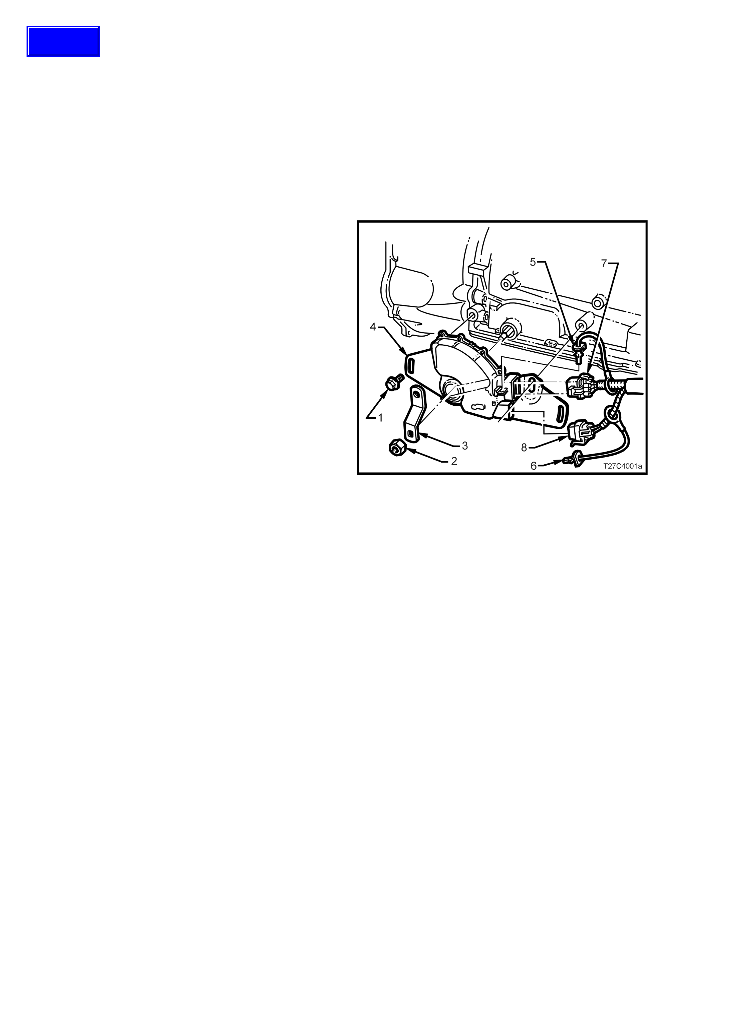
2. While holding the lower selector lever (3) with
an adjus table wr ench, remove the retaining nut
(2).
3. Carefully remove the lever (3) from the
transmission manual shaft.
4. Prise the wiring harness connector CPA
(Connector Position Assurance) securing pins
(5 and 6) from the neutral start and back-up
lamp switch (4), taking care not to break the
pins in the process. Disconnect the two wiring
harness connectors (7 and 8) from the switch
assembly (4).
5. Remove the two switch retaining screws (1),
then slide the switch assembly (4) over the
manual shaft and remove from the vehicle.
Figure 7C4-1
Techline

REINSTALL
Reinstallation of the neutral start and back-up lamp
switch is the reverse of the removal procedure
except for the following:
1. W hen installing the two switch sec uring screws,
leave them finger tight, until the adjustment
process has been completed.
2. After installing the selector lever and retaining
nut, hold the lever with an adjustable wrench
and tighten the nut to the correct torque
specification.
SELECTOR LEVER RETAINING
NUT TORQUE SPECIFICATION..................... 15 - 35 Nm
3. Check the selector linkage adjustment. Refer
3.2 SELECTOR LINKAGE, in 7C4
AUTOMATIC TRANSMISSION ON-VEHICLE
SERVICING in the VT Series I Service
Information.
4. On completion of the neutral start and back-up
lamp switch adjustment procedure that follows,
check that the engine can only be started when
the gearshift lever is either in the ‘P’ (Park) or
‘N’ (Neutral) positions.
ADJUST
1. With the vehicle raised, rotate the neutral start
and back-up lamp switch back and forth until a
central position is attained, then lightly tighten
the front bolt to retain.
2. With the ignition switched to the ON position,
check that the engine can only be started in
both the Park and Neutral selector positions. A
further minor adjustment may be required to
achieve this state.
Also check that the Reverse lamps illuminate
when Reverse range is selected.
3. After switch adjustment, tighten the switch
retaining bolts to the correct torque
specification.
NOTE: To gain access to the rear bolt, it will be
necessary to remove the wiring harness connector.
NEUTRAL START & BACK-UP
LAMP SWITCH RETAINING BOLT
TORQUE SPECIFICATION ............................. 15 - 35 Nm
4. Following the bolt tightening pr ocedure, reinstall
the connector/s and the CPA securing pin/s.
5. Lower the vehicle to the ground and check the
operation of the neutral start and back-up lamp
switch. T he vehicle should only start in either ‘P’
(Park) or ‘N’ (Neutral) ranges and the reverse
lamps should only illuminate when the ‘R’
(Reverse) range is selected.
2.2 MANUAL SHAFT OIL SEAL
REPLACE
1. Raise the front of the vehicle and place on
safety stands. Refer to
Section 0A, GENERAL INFORMATION in the
VT Series I Service Information for the location
of recommended jacking points.
2. Remove the Neutral Start and Back-Up Lamp
Switch. Refer to
2.1 NEUTRAL START AND BACK-UP LAMP
SWITCH in this Section.
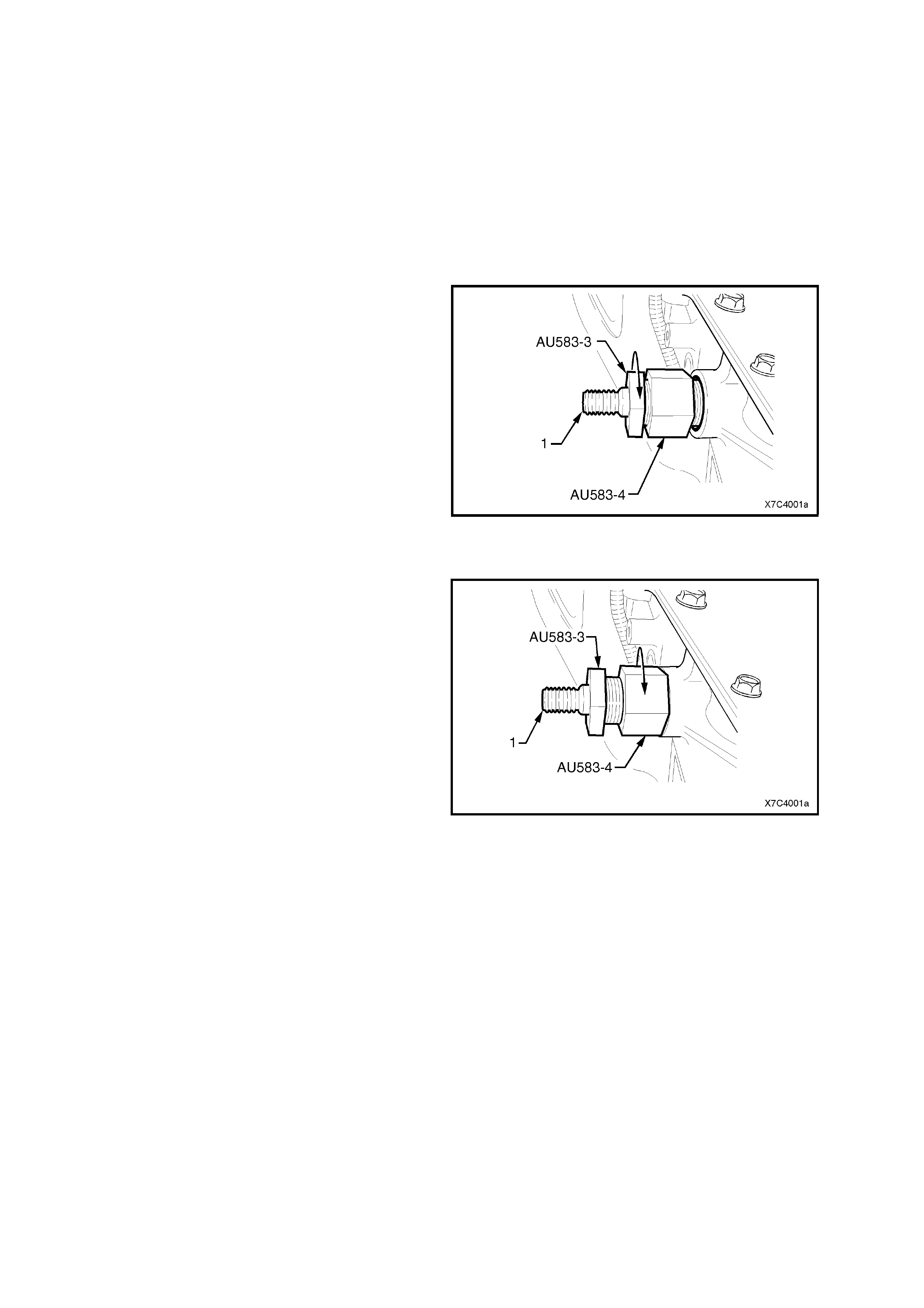
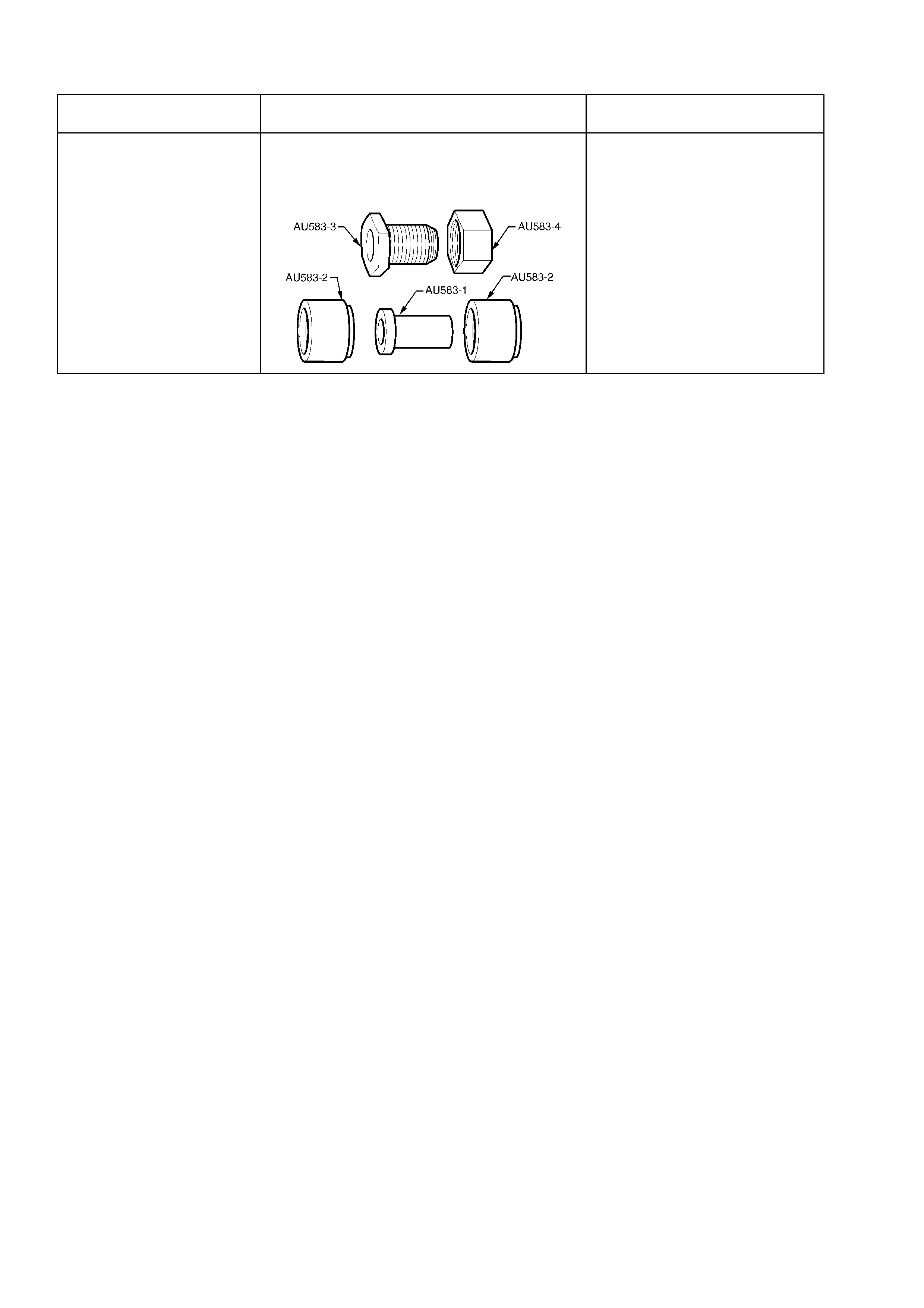
3. Assemble the remover nut (Tool No. AU583-4)
with the threaded section closest to the
hexagonal head of the seal remover AU583-3.
Install the nut up to the hexagonal end.
4. Install the pre-assembled remover (Tool Nos.
AU583-3 and AU583-4) over the manual shaft
(1) and engage the tapered thread end of the
seal remover into the seal. Tighten the seal
remover until the tool thread grips the steel
shell of the seal.
NOTE: Do not overtighten the seal remover in the
seal.
Figure 7C4-2
5. While holding the seal remover (AU583-3),
screw the remover nut (AU583-4) up to the
transmission case.
6. Continue tightening the remover nut until the
seal is removed into the remover nut cavity.
7. Discard the removed seal.
Figure 7C4-3
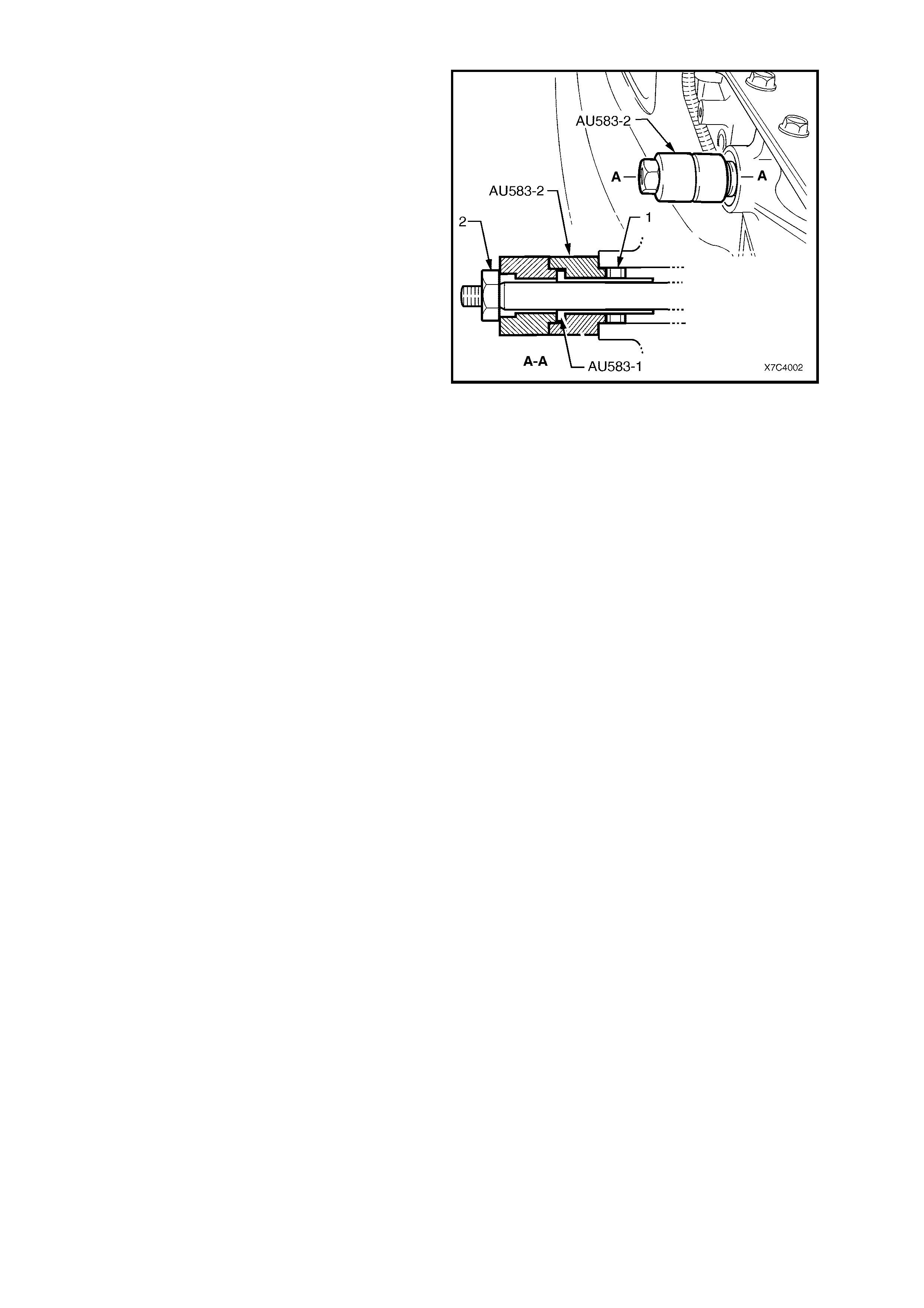
8. Pre-as sem ble the s eal protector (AU583-1) into
one of the plastic seal installers (AU583-2), as
shown in the sectioned view.
9. Lubricate the seal lip of a new seal (1) with
Dexron® III automatic transmission fluid, then
install it (with the steel seal casing facing the
installer) over the seal protector sleeve
(AU583-1).
10. Install the seal protector (AU583-1), seal
installer (AU583-2) and seal (1), over the
manual shaft and up to the transmission case.
NOTE: If the s leeve jams on the m anual shaf t, then
the shaf t will be bur red over the f lats that locate the
selector lever. Use a fine file to remove burrs, then
proceed.
11. Install the second plastic seal installer over the
manual shaft until it seats against the first
installer.
12. Install the manual shaft lever retaining nut (2)
and tighten it to install the seal fully into place in
the transmission case.
NOTE: Two plastic seal installers (AU583-2) are
required, because of the restricted space between
the end of the manual shaft and the floor pan.
13. Remove installer tools, AU583-2 (two pieces)
and seal protector AU583-1 from the manual
shaft.
Figure 7C4-4
14. Reinstall the Neutral Safety and Back -Up Lamp
Switch and adjust as detailed in 2.1 NEUTRAL
START AND BACK-UP LAMP SWITCH
REINSTALL AND ADJUST, in this Section.
15. Lower the vehicle to the ground, check and top
up the automatic transmission fluid level, as
required. Refer 2.1 FLUID LEVEL CHECK, in
the VT Series II Service Information.
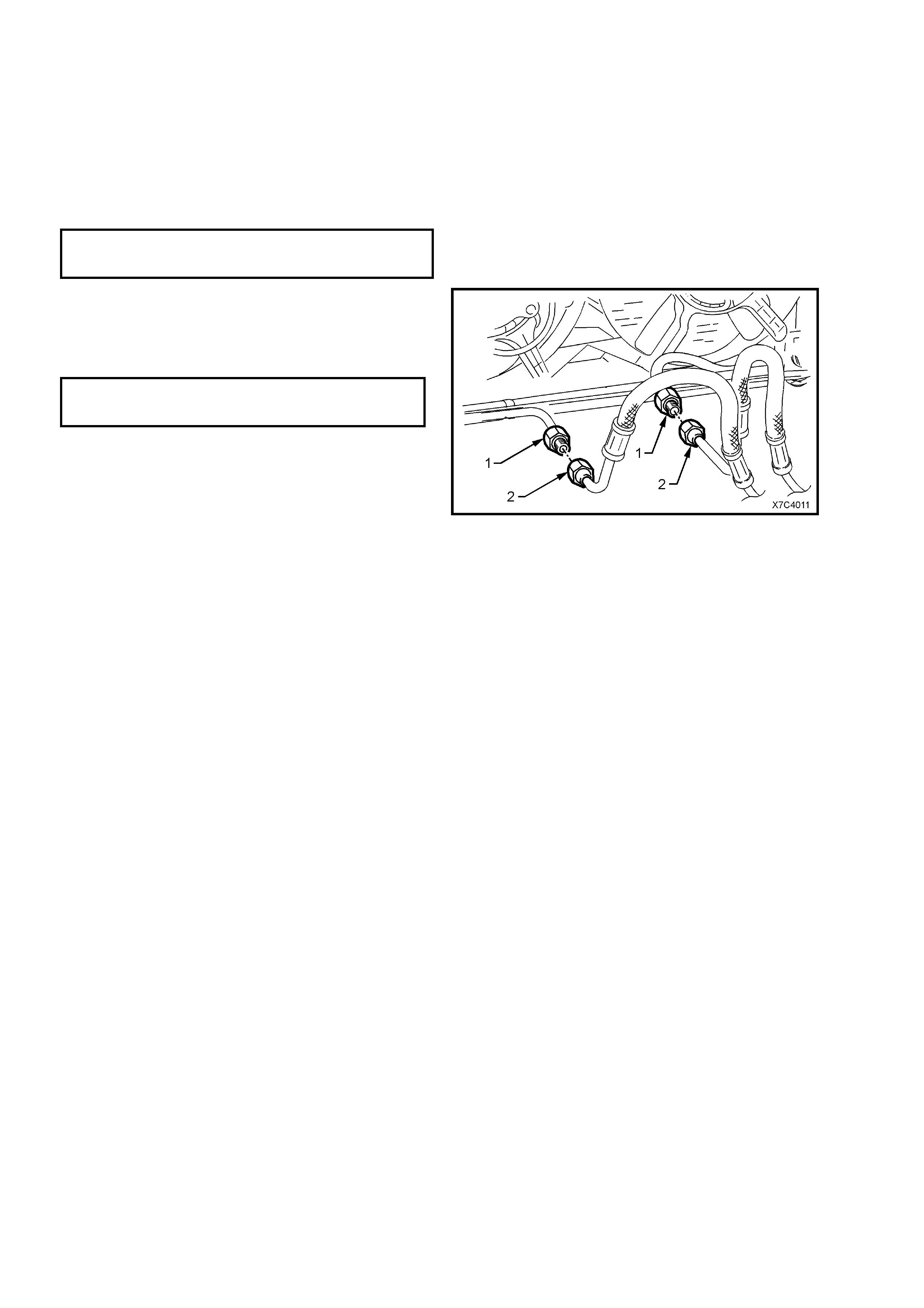
2.3 TRANSMISSION COOLER PIPES/HOSES
REMOVE (V6 NON SUPERCHARGED ENGINE ONLY)
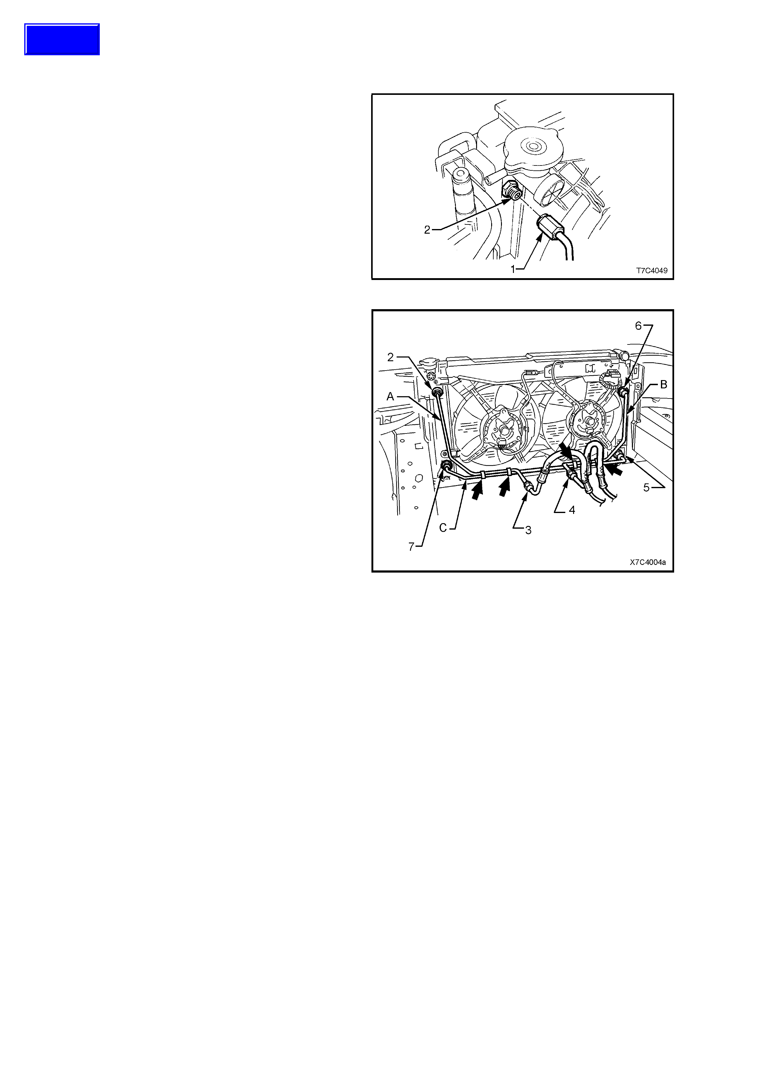
1. Hold the radiator flare nut fitting (2) with a back-
up spanner, then loosen and disconnect the
outlet oil cooler pipe (1) from that location.
Figure 7C4-5
2. Remo ve the clips (bold arr ows) securing the oil
cooler pipes to each other.
3. While us ing a bac k-up spanner on the fitting (3)
at the oil cooler hose end, loosen then
disconnect the transmission outlet line pipe,
flare nut.
4. Remove the inlet cooler pipe (A) from the
vehicle.
5. Repeat steps 1 and 3 to 4 for the return oil
cooler pipe (B) and the crossover pipe (C).
Figure 7C4-6
Techline
REINSTALL
Referr ing to Figure 7C4- 5, the reinstallation proc ess
of the oil cooler pipes, is the reverse to removal,
except for the following:
1. When tightening oil cooler pipes to the radiator
fittings (2, 5, 6 and 7), ALW AYS use a back-up
spanner on the radiator flare nut fitting BEFORE
tightening the flare nuts to the correct torque
specification.
TRANSMISSION COOLER PIPE
FLARE NUT TO RADIATOR FITTING
TORQUE SPECIFICATION............................. 25 – 30 Nm
2. Before tightening the transmission oil cooler
pipe fittings (1) to the cooler hose fittings (2), a
back-up spanner MUST be used on the oil
cooler hose fittings (2) BEFORE tightening to
the correct torque specification.
TRANSMISSION COOLER PIPE
FLARE NUT TO COOLER HOSE
TORQUE SPECIFICATION............................. 25 – 30 Nm
3. Check and top up the automatic transmission
fluid level, as required. Refer
Section 7C4 ON-VEHICLE SERVICING, 2.1
FLUID LEVEL CHECK, in the VT Series II
Service Information.
Figure 7C4-7
NOTE: For the remainder of the oil cooler pipe
removal and reinstallation procedures, refer
Section 7C4 ON-VEHICLE SERVICING in the VT
Series II Service Information.

3. TORQUE WRENCH SPECIFICATIONS
NOTE: For a complete listing of specifications as they apply to com ponents not discussed in this Section, refer to
Section 7C4 HYDRA-MATIC 4L60- E AUTO MATIC T RANSMISSION: ON-VEHICLE SERVICING in the VT Series I
and VT Series II Service Information and Section 7C5 HYDRA-MATIC 4L60-E AUTOMATIC TRANSMISSION:
UNIT REPAIR, in the VX Series Service Information. Nm
Neutral Start and Back-Up Lamp Switch Retaining Bolt................................. 15 – 35
Selector Lever Retaining Nut.......................................................................... 15 – 35
Transmission Cooler Pipe Flare Nut to Radiator Fitting................................. 25 – 30
Transmission Cooler Pipe Flare Nut to Cooler Hose...................................... 25 – 30
4. SPECIAL TOOLS
TOOL No. REF. in TEXT TOOL DESCRIPTION COMMENTS
AU583 SELECTOR SHAFT SEAL REMOVER/
INSTALLER
New release.
Use to remove and install the
manual shaft oil seal, with the
transmission installed in the
vehicle.