
SECTION 8A2 - LPG SYSTEM
IMPORTANT
Before performing any Service Operation or other procedure described in this Section, refer to Section
00 CAUTIONS AND NOTES for correct workshop practices with regard to safety and/or property damage.
1. GENERAL I NFORMATI O N
Liquefied Petroleum Gas (LPG) Production Option KL7 is available for all VX Series Models with V6 engine and
automatic transmissions.
The system used on VX Series Models is essentially the same as detailed in the VT Series Service Information,
noting the following:
• Software for the Powertrain Control Module (PCM) has been modified, allowing for:
- Deletion of the Adaptive Digital Processor (ADP), thus allowing for theft deterrent functions to be
controlled by the PCM. Also provides a simplified set-up procedure.
- As the PCM used on the VX Series Model is flash programmable, a unique LPG PROM is not required.
- Allows for the switching of fuel modes (LPG to petrol or petrol to LPG) whilst the vehicle is being driven.
- Diagnostic Trouble Code (DTC) support of the LPG system.
• A new Fuel Control Valve (FCV). This valve is the same valve as used for purge control on the GEN III V8
engine and is functionally the same as the FCV used on the VT Series Model.
• Some minor modifications to the routing or hoses and pipes.
• As a running change to VT Series Models LPG was made available (ac c ess or y fitted LPG only) to vehicles with
traction control (ET C). When a vehic le with trac tion c ontrol is oper ated on LPG, trac tion control is disabled and
the TRAC OFF lamp in the instrument cluster is illuminated, warning the driver that traction control has been
disabled.
NOTE: For information not covered in this Section, refer to either the VT Series I Service Information
Sedan LPG system or Wagon and Sedan accessory LPG system.
Figures 8A2-1 (sedan) and 8A2-2 (wagon) show the location of the LPG components used on VX Series Models.
Figures 8A2-3 (sedan) and 8A2-4 (wagon) show the operation of the LPG system. Figure 8A2-5 shows the LPG
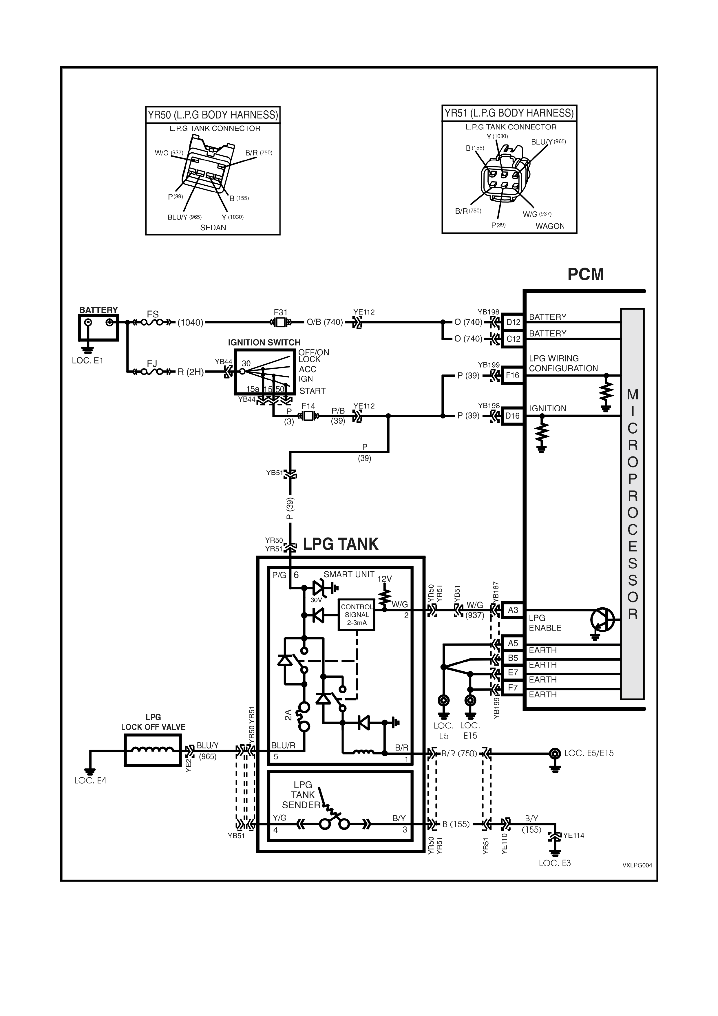
System Circuit Diagram.
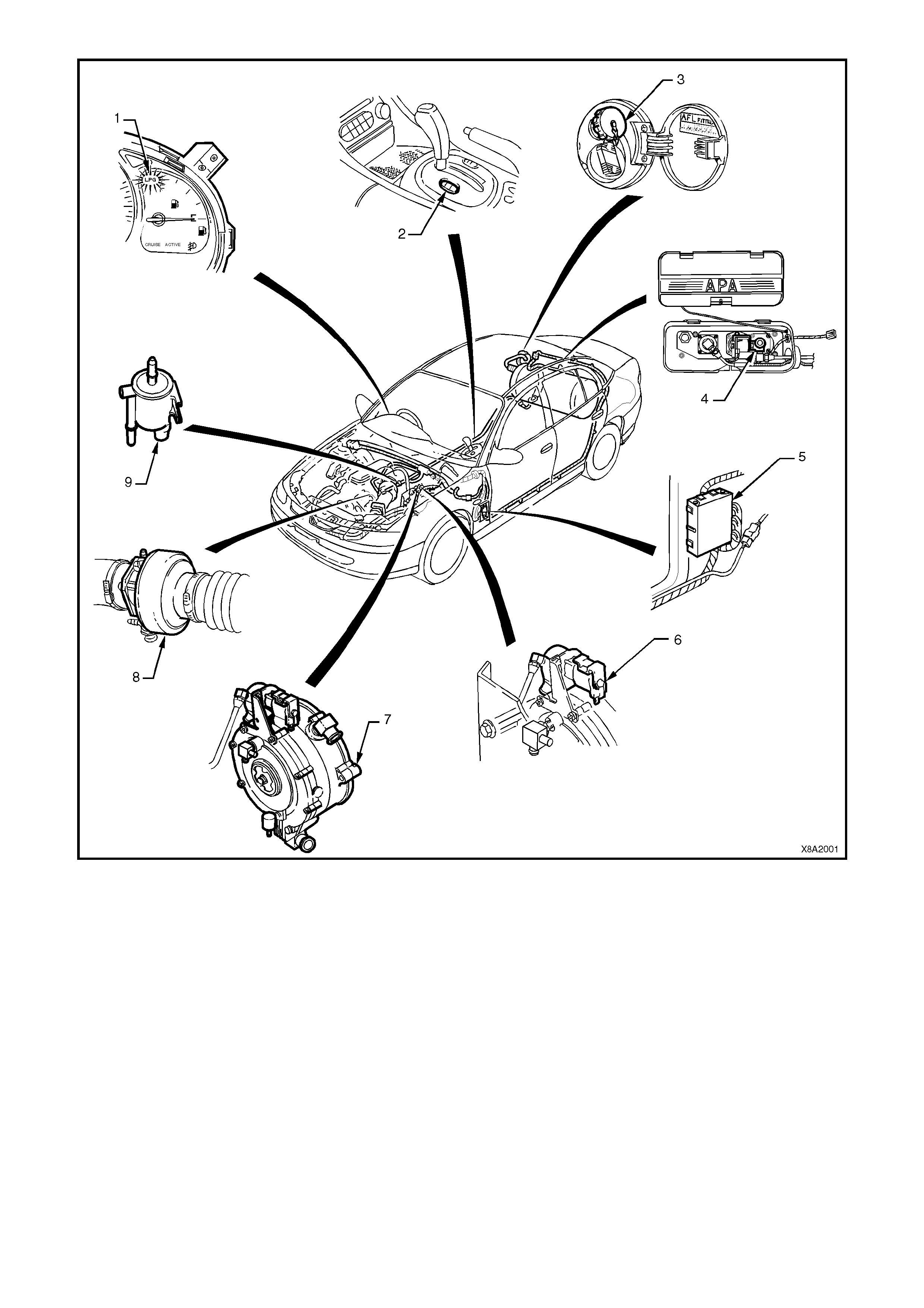
Figure 8A2-1 SEDAN LPG SYSTEM COMPONENT LOCATIONS
1. LPG Lamp 6. LPG Lock-off
2. Fuel Mode Switch (production fitment) 7. Converter
3. LPG Filler Valve 8. Mixer
4. Solenoid & Manual Service Valve Assembly 9. Fuel Control Valve
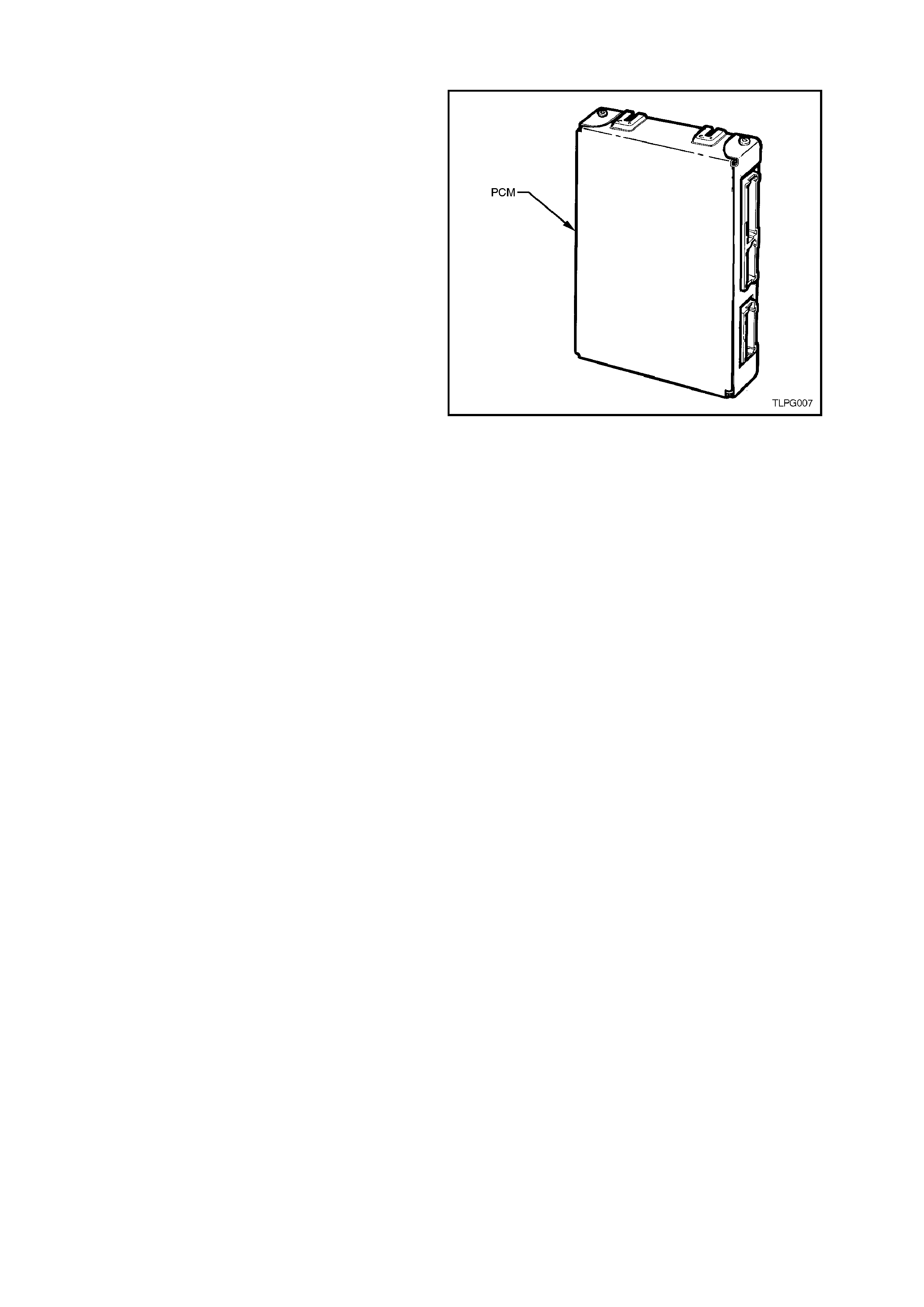
5. Powertrain Control Module (PCM)
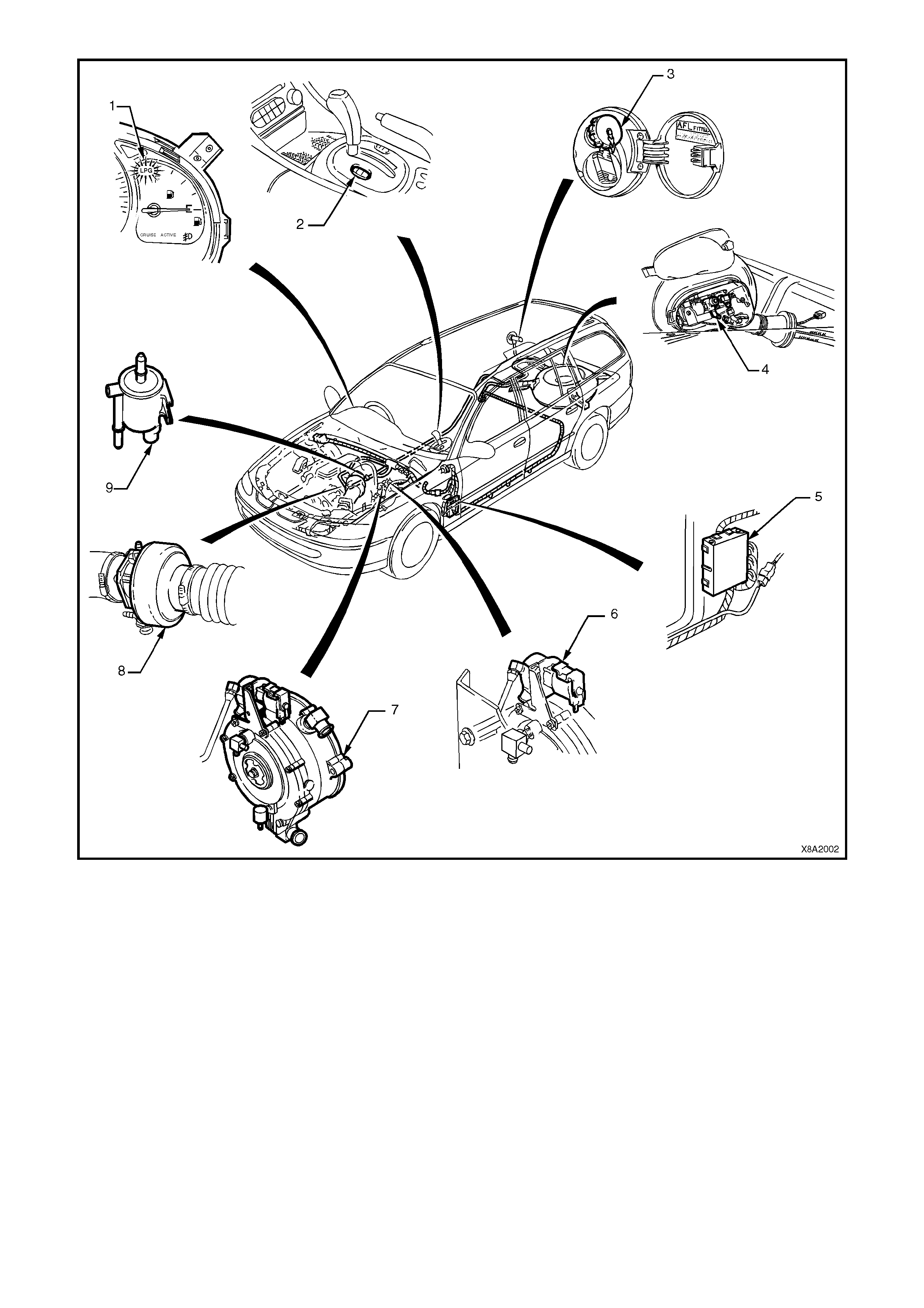
Figure 8A2-2 WAGON LPG SYSTEM COMPONENT LOCATIONS
1. LPG Lamp 6. LPG Lock-off
2. Fuel Mode Switch 7. Converter
3. LPG Filler Valve 8. Mixer
4. Solenoid & Manual Service Valve Assembly 9. Fuel Control Valve
5. Powertrain Control Module (PCM)
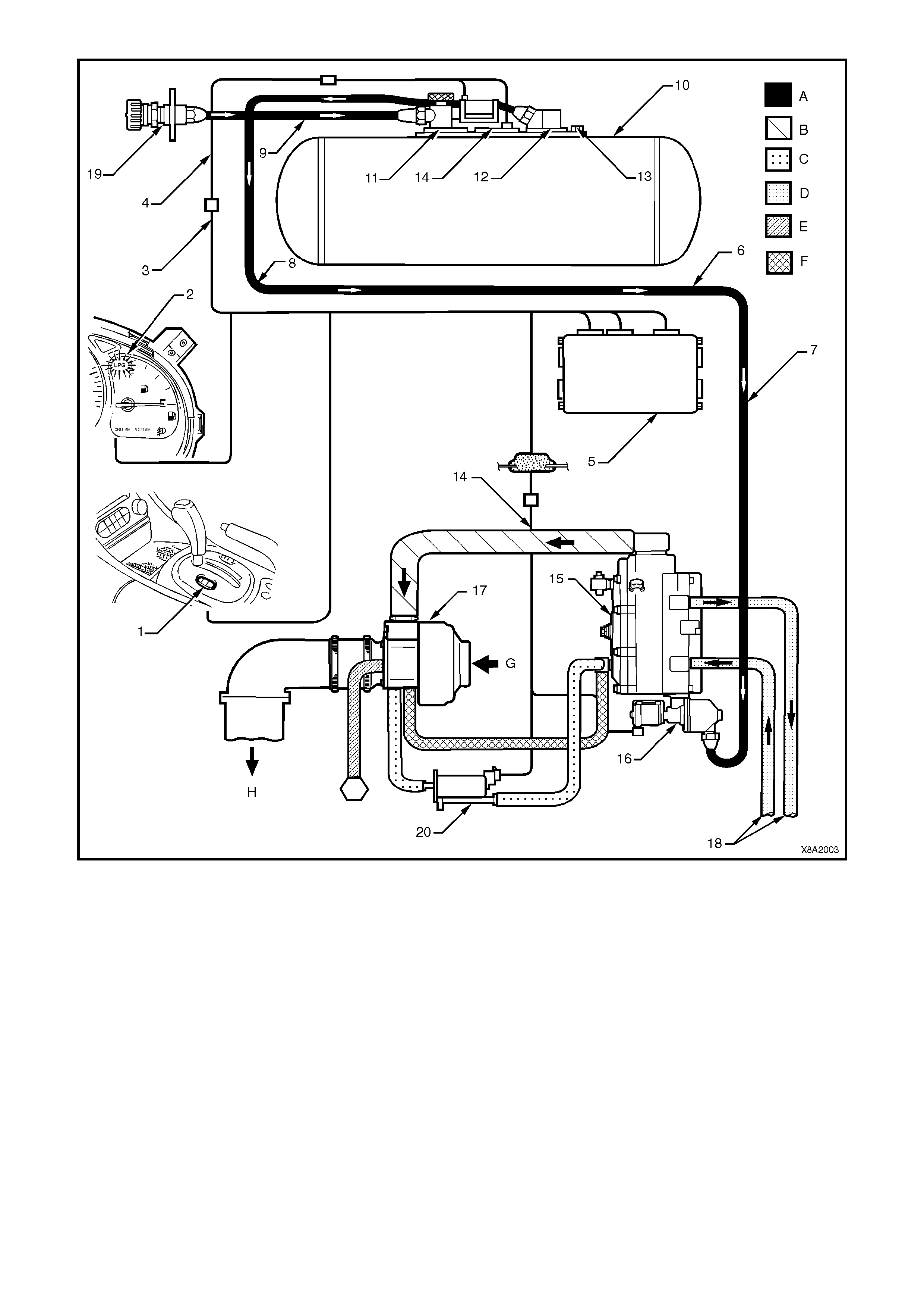
Figure 8A2-3 SEDAN LPG SYSTEM OPERATION - TYPICAL
1. Fuel Mode Switch 16. LPG Lock-off
2. LPG Lamp 17. Mixer
3. Main Wiring Harness 18. Coolant Hoses
4. Body Wiring Harness 19. LPG Filler Valve
5. Powertrain Control Module (PCM) 20. Fuel Control Valve
6. Intermediate Service Line
7. Front Service Line A. Liquid
8. Rear Service Line B. Vapour
9. Filler Line C. Vacuum
10. LPG Cylinder Assembly D. Coolant
11. AFL E. Breather
12. Solenoid & Manual Service Valve Assembly F. Balance / Vacuum
13. Relief Valve G. Air Intake
14. Fuel Gauge H. To Engine Inlet Manifold
15. Converter
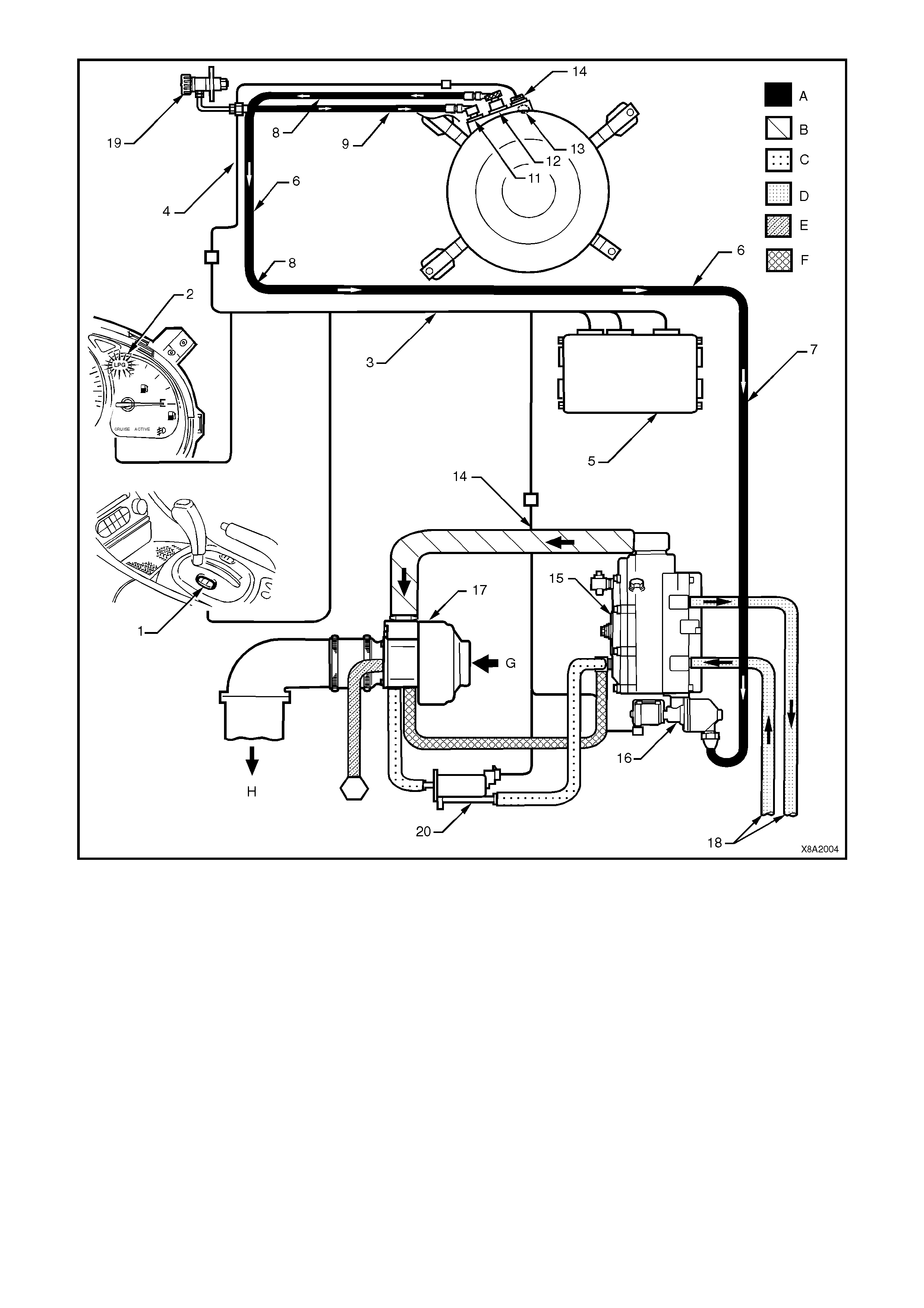
Figure 8A2-4 WAGON LPG SYSTEM OPERATION - TYPICAL
1. Fuel Mode Switch 16. LPG Lock-off
2. LPG Lamp 17. Mixer
3. Main Wiring Harness 18. Coolant Hoses
4. Body Wiring Harness 19. LPG Filler Valve
5. Powertrain Control Module (PCM) 20. Fuel Control Valve
6. Intermediate Service Line
7. Front Service Line A. Liquid
8. Rear Service Line B. Vapour
9. Filler Line C. Vacuum
10. LPG Cylinder Assembly D. Coolant
11. Automatic Fill Limiter (AFL) E. Breather
12. Solenoid & Manual Service Valve Assembly F. Balance / Vacuum
13. Relief Valve G. Air Intake
14. Fuel Gauge H. To Engine Inlet Manifold
15. Converter
VXPCM021
INSTRUMENT
PCM
LPG
LAMP
19
BATTERY POWER
IGNITION
20
IGN ITIO N SWITCH
BATTERY
FJ
FS
O/B (740) O (740)
R (2H)
(1040)
15a 15 50
30 ACC
IGN
START
F21
F13
F14
P (3)
Y/G
CONTROL
SIGNAL
2-3mA
B/Y
P/G
43
30V
2A
W/G
B/R
BLU/R
2
5
6
1
LPG
TANK
SENDER
SMART UNIT
LPG
SENDER
FUEL
GAUGE
W/G (937) A3
A5
B5
E7
F7
LPG
ENABLE
EARTH
EARTH
EARTH
EARTH
EARTH
FUEL MODE SW ITCH
LPG FCV
LPG WIRING
CONFIGURATION
BATTERY
BATTERY
IGNITION
12
SERIAL
DATA
5V
G / W (122 0) R/B (1 221) C13 SERIAL
DATA
5V
12V
P/B (39)
O/Y (1340)
Y (1030)
P/BLU (44)
M
I
C
R
O
P
R
O
C
E
S
S
O
R
M
I
C
R
O
P
R
O
C
E
S
S
O
R
F31
O (740)
P (39)
P (39)P/B (39)
D5
C9
GY /B (1 4 13)
G/Y (1412)
A
B
RIGHT HAN D
OXYGEN SENSOR
RH O2
SIGNAL LO
RH O2
SIGNAL HI
IC
450 mV
B/ R (7 5 0)
LOC. E 4
LOC. E 3
LOC. E 3
LOC. E 5/E15
LOC.
E5 LOC.
E15
B (155)
B/ Y
(155)
B/Y (155)
BCM
E2
D2
E9
D3
LOC. E1
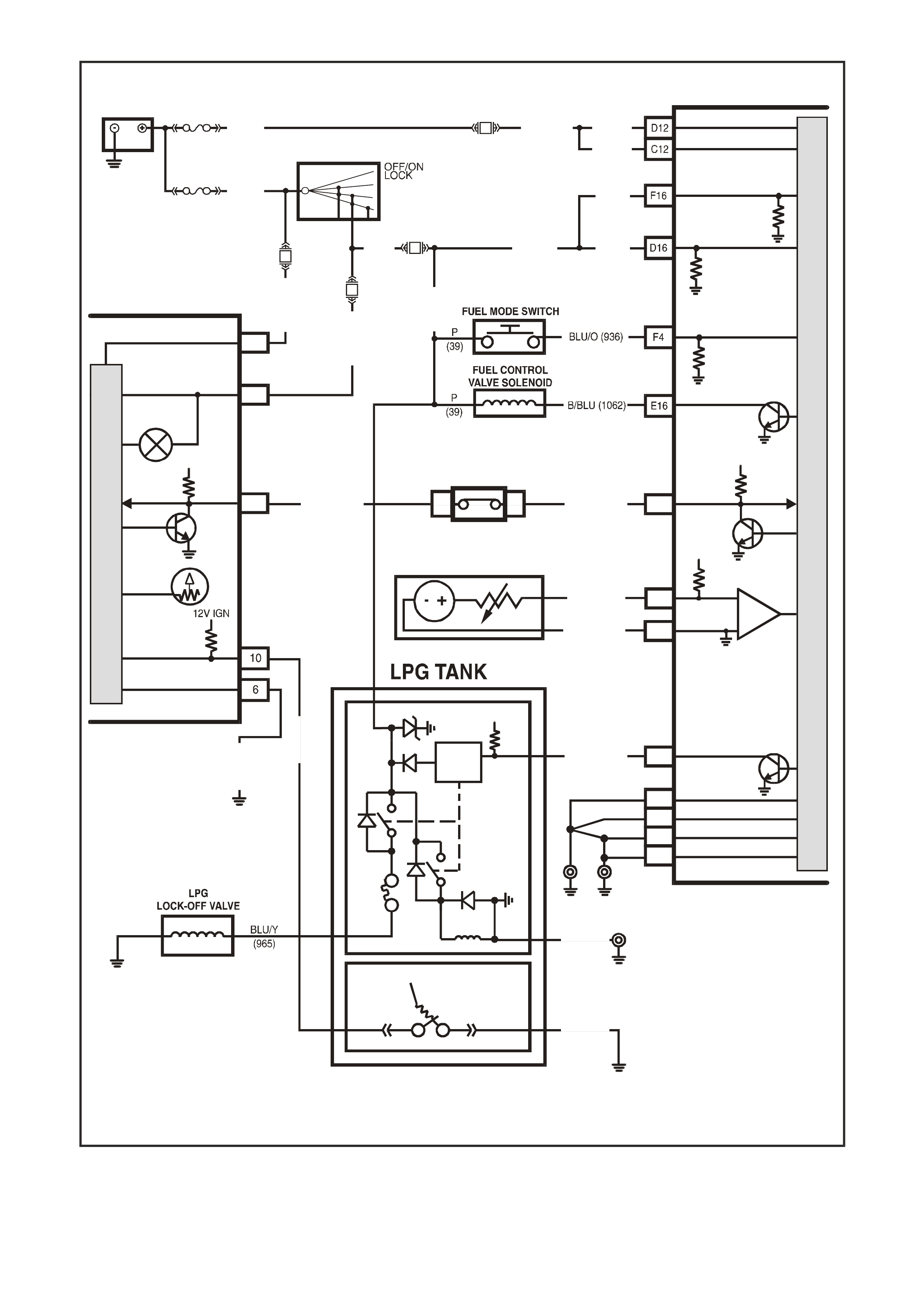
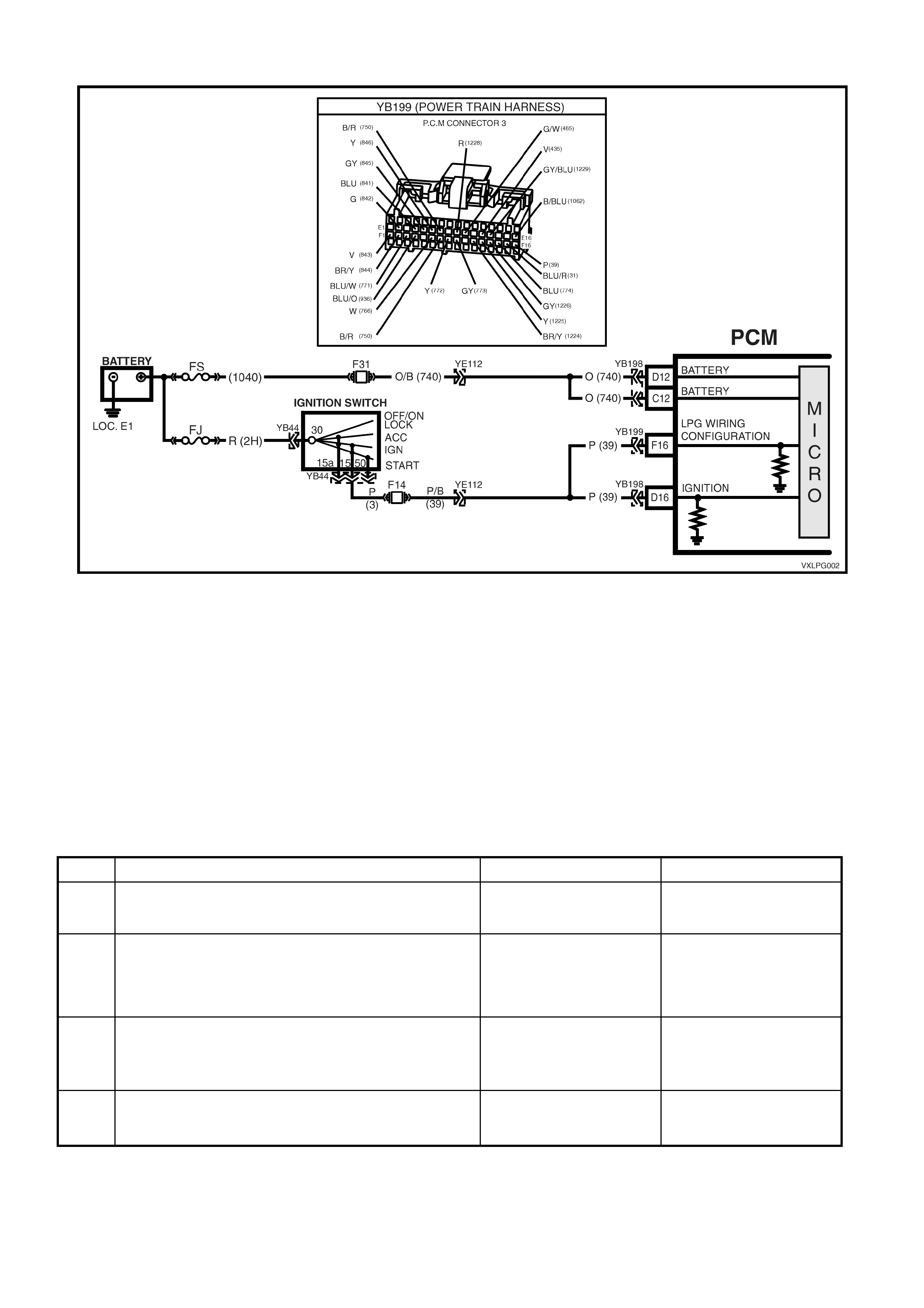
Figure 8A2-5 LPG System Circuit Diagram
2. PRINCIPLES OF OPERATION
NOTE: Excluding the following, principles of
operation for the LPG system used on VX Series
Models are as detailed in the VT Series I Service
Information – VT Sedan with Production LPG and
VT Sedan with Accessory LPG and VT Wagon.
2.1 FUEL CONTROL VALVE
A new type of Fuel Control Valve (FCV) is used on
VX Series Models.
The Fuel Control Valve (FCV) is used to control
fuel delivery. Because the diaphragm of the
converter is very large, little movement is required
to control the amount of LPG delivered. The fuel
control valve is connected into the balance line
between the atmospheric vent of the converter
secondary diaphragm and the air valve venturi of
the mixer. This applies a very low vacuum to the
atmospheric side of the converter secondary
diaphragm. Any pressure less than atmospheric
results in a reduction in LPG delivery. This ass ures
extremely accurate LPG delivery and rapid
response time.
With the exhaust gas oxygen sensor at operating
temperature and the Powertrain Control Module
(PCM) operating in closed loop mode, there is a
wide range of control. This permits the PCM to
optimise the air/fuel mixture to varying engine
requirements.
The FCV is controlled by the PCM. To open the
FCV and decrease the pressure acting on the
secondary diaphragm of the converter, the PCM
pulses the FCV on and off at a frequency of 10Hz.
The ratio between the on and off time is called the
duty cycle. To open the FCV the PCM increases
the duty cycle, which decreases the pressure
applied to the secondary diaphragm. The amount
of time the FCV is on will determine the pressure
acting on the converter secondary diaphragm. In
this way, the PCM can control the air/fuel ratio.
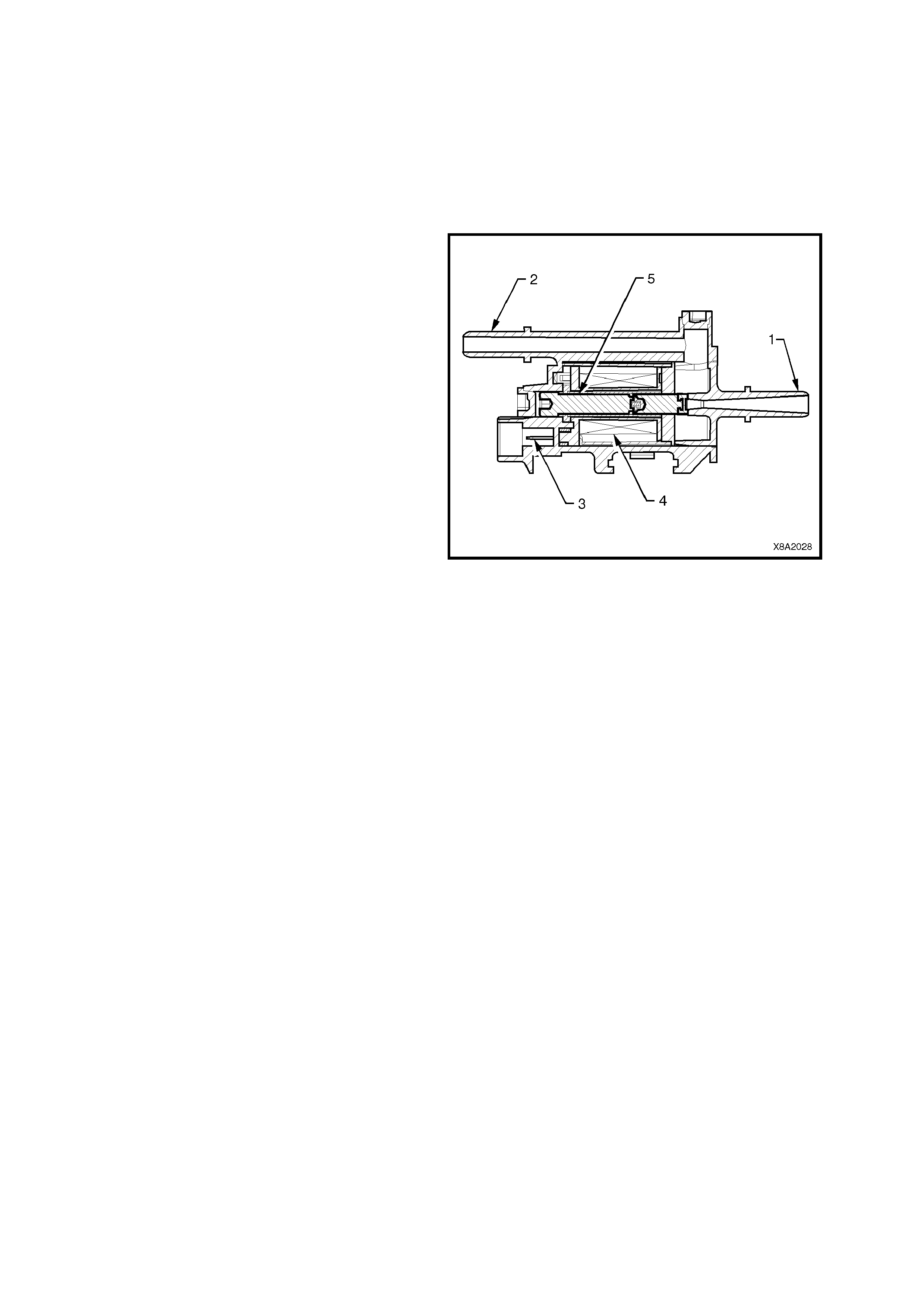
Figure 8A2-6 Fuel Control Valve Assembly
1. Vacuum inlet 4. Coil
2. Vacuum outlet (to converter) 5. Plunger assembly
3. Coil terminals
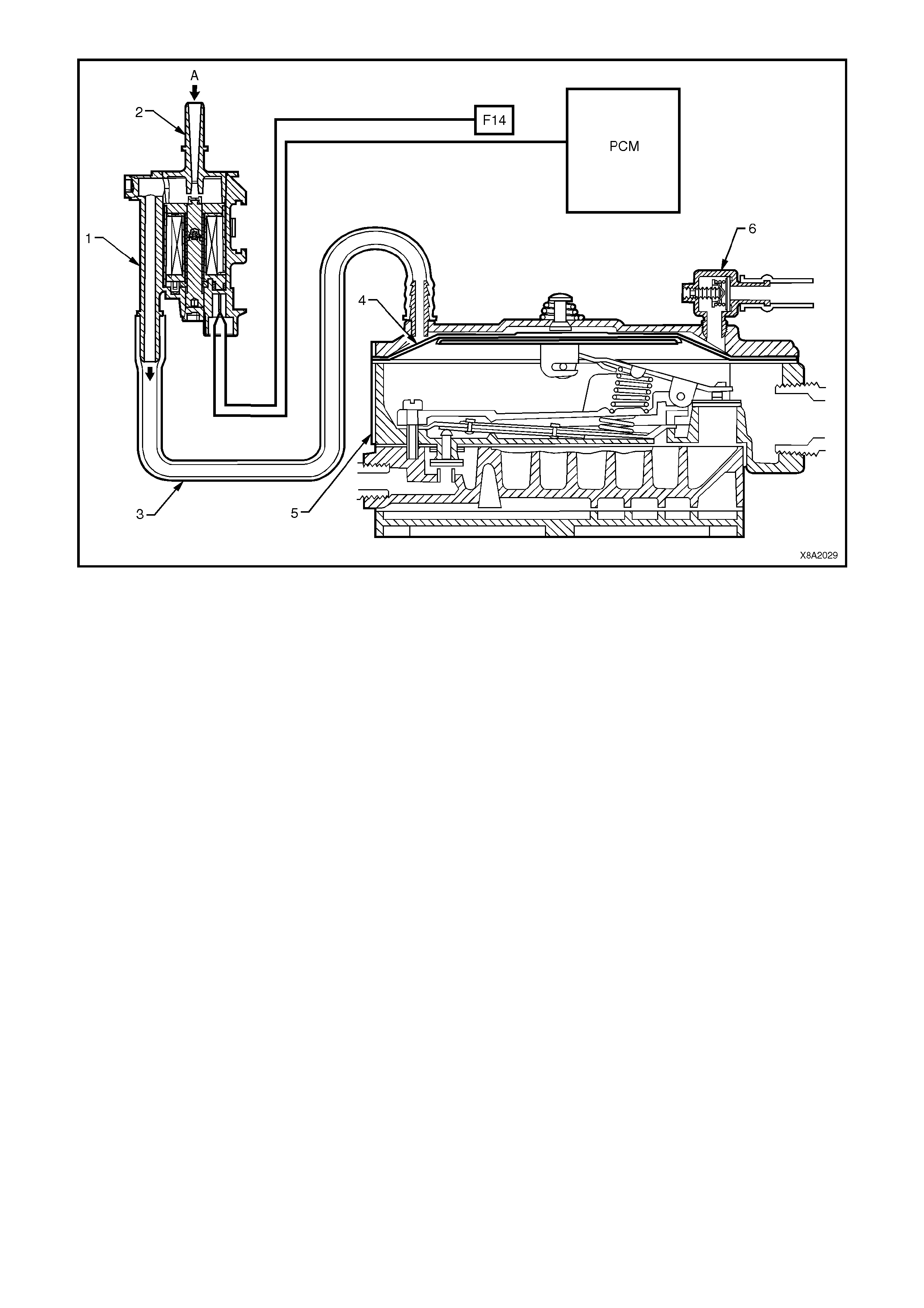
Figure 8A2-7 Fuel control valve operation
1. FCV
2. Vacuum inlet
3. Balance hose
4. Secondary diaphragm
5. Converter
6. Regulator check valve
A. Vacuum from mixer

2.2 FUEL MODE S WITCH
On all vehicles fitted with an LPG system, the fuel
mode switch is m ounted in the centre cons ole. The
switch is a momentary contact type switch.
When the fuel mode switch is pressed, the switch
supplies 12 volts to PCM terminal F4. The PCM
sees this voltage as a request to change over from
petrol to LPG or from LPG to petrol.
NOTE: The PCM will only toggle between the
petrol and LPG mode if the ignition is on and
the engine is not running, or if the engine
speed is greater that 1300 RPM.
The operational mode of the PCM in is stored in the
PCM m em ory so that the engine s tarts in the sam e
mode on the next ignition cycle.
Figure 8A2-8 Fuel mode switch
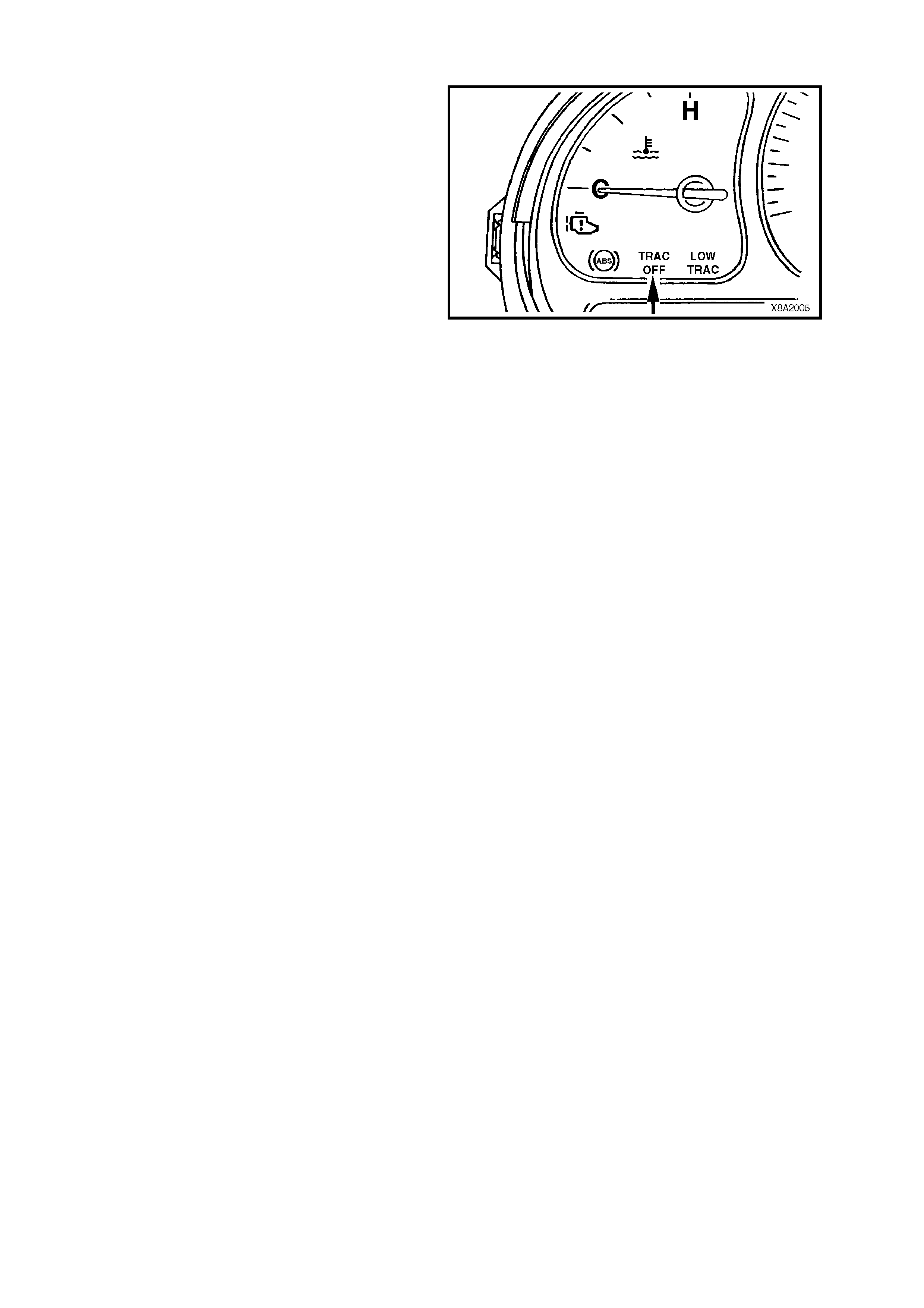
2.3 TRACTION CONTROL (ETC) OPERATION
Whenever the vehicle is operating in the LPG
mode, the traction control system (if fitted) is
disabled and the TRAC OFF warning lamp in the
instrument cluster is illuminated, warning the driver
that the traction control system (ETC) has been
disabled.
The tr action c ontr ol system is disabled by the PCM,
which sends a message to the ABS/ETC control
module via the serial data circuit, requesting the
traction control system be switched off.
Figure 8A2-9
2.4 POWERTRAIN CONTROL MODULE
The Powertrain Control Module (PCM) when
programmed with the correct LPG calibration is
capable of operating in either of two operating
modes, PETROL or LPG.
PETROL MODE
W hen operating in petrol m ode, the LPG system is
turned off and the vehicle operates on petrol with
full engine management control in the same
manner as a vehicle not fitted with LPG. In this
mode, the instrument cluster fuel gauge will show
the amount of petrol in the petrol fuel tank.
LPG MODE
When operating in the LPG mode, the engine
managem ent sys tem is s witched to LPG m ode and
the LPG system is turned on, enabling the vehicle
to operate on LPG. In this mode the LPG lam p will
be turned on and the instrument cluster fuel gauge
will show the amount of LPG in the LPG cylinder.
The PCM controls the flow of LPG, by sending a
signal to the smart unit via circ uit 937 W/G wire. On
receiving this signal the smart unit energises the
solenoid valve. The smart unit also energises the
LPG lock-off via circuit 965 BLU/Y wire.
Figure 8A2-10
NOTE: In the LPG mode, the following changes
have been made so the engine can operate on
LPG. These changes only effect the operation of
the PCM when operating in LPG mode.

INJECTOR PULSE WIDTH
The injector pulse width is set to zero in all LPG operating modes, except during engine cranking or, on when the
vehicle runs in “engine valve recession protection mode”.
During engine cranking the amount of petrol delivered is determined by the engine coolant temperature and the
engine crank time. The injection of petrol during engine cranking is to aid engine starting. If the engine stalls no
petrol will be injected during cranking, unless the ignition is cycled off and on.
When operating in LPG mode under conditions of prolonged high speed / high load, a small amount of petrol is
injected into the engine to cool the valves and catalytic converter.
FUEL PUMP
To pr ovide petrol when starting in the LPG m ode, the fuel pum p will r un for two sec onds when the ignition is turned
to the ON position and continue to run when the engine is being cranked, but will be turned off five seconds after the
engine starts.
The fuel pump will also operate under high load conditions. This allows for petrol to be injected into the engine when
the vehicle goes into the engine valve recession protection mode.
As a protection devise to the fuel pump, the PCM will switch off the fuel pump and disable the engine valve seat
recess ion protec tion m ode, if there is less than s ix litres of f uel in the petrol tank . T he PCM m onitors the s erial data
normal mode message to determine the amount of fuel in the petrol tank.
ELECTRONIC SPARK TIMING
A specif ic Electronic Spark T iming ( EST) m ap is used when in the LPG mode and the PCM has been progr amm ed
to provide optimum EST f or LPG oper ation. If the engine speed dr ops below 300 RPM, the PCM prevents the s par k
plugs from firing by setting the ignition dwell to zero.
FUEL USAGE SIGNAL OUTPUT
The PCM fuel us age output signal is us ed by the trip computer to deter m ine the fuel cons um ption display and is re-
calibrated to suit LPG.
ENGINE CRANKING
If the throttle opening is greater than 7% when operating in LPG mode, the PCM will prevent the engine from
cranking by not energising the starter relay.

3. SERVICE OPERATIONS
Service Operations for the LPG system used on VX Series Models are as detailed in the VT Series I Service
Information, VT Sedan with Production LPG or VT Sedan with Accessory LPG and VT Wagon.
NOTE 1: Some components used on VT Series Models are not required on VX Series Models, i.e. ADP control
module, LPG diagnostic interconnect diagnostic connector and the LPG relay.
NOTE 2: Some of the Service Operations detailed for the VX Series LPG system are identical for the VT Series
however, pictorially, some illustrations shown in the VT Series Service Manual may differ slightly. Only where
significant differences exist or where the illustration has a significant bearing on the particular Service Operation, will
the Service Operation be republished.
3.1 CONVE RTE R
CONVERTER ON VEHICLE TEST PROCEDURE
(REFER TO FIGURE 8A2-13)
1. Park the vehicle in a well ventilated area, away
from any ignition source.
2. Drain the service lines of LPG, refer to
Section 2 SERVICE OPERATIONS
in the VT Series I Service Information,
VT Sedan with Production LPG or
VT Sedan with Accessory LPG and
VT Wagon.
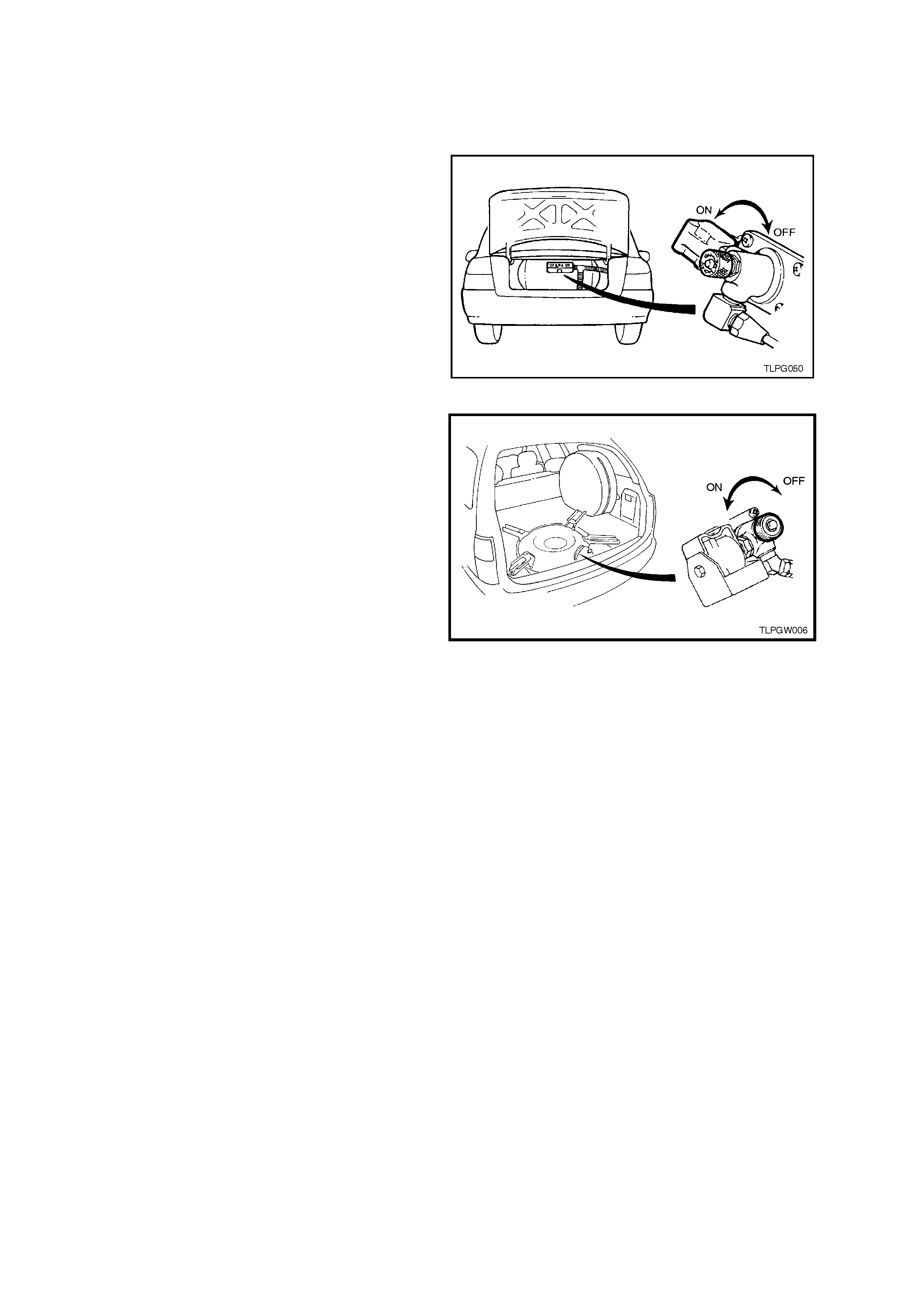
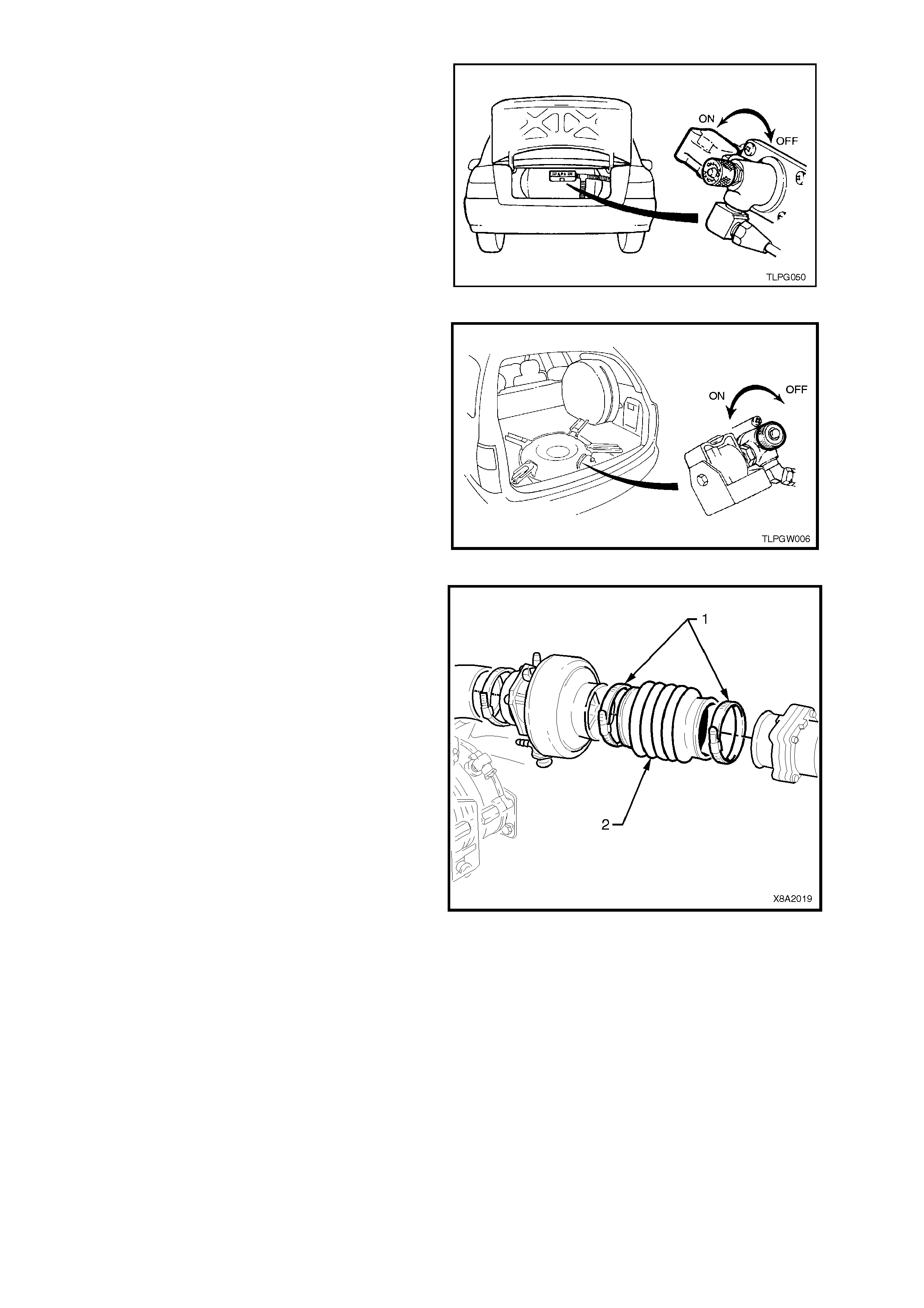
3. Ensure the manual service valve is turned
'OFF' and the battery earth lead is
disconnected.
4. Remove plug from the converter primary test
port (5) and install straight test nipple into
converter primary test port.
5. Connect the pressure gauge hose to the
straight nipple and to the HI connection of the
0-5 PSID pressure gauge of LPG test kit (refer
to Section 7 SPECIAL TOOLS).
6. Remove plug from the converter secondary
test port (12) and install test elbow into
secondary test port.
7. Connect vac uum gauge hos e to sec ondary test
elbow and the LO connection of 0-10 INCHES
W.C. vacuum gauge LPG test kit 1.
8. Turn 'ON' manual service valve and check test
connections for leaks.
9. With fuel mode switch in LPG position start
engine and allow to idle.
NOTE: If engine will not star t, crank the engine and
record pressures.
10. Converter primary pressure should be 1.0-1.5
psi (7-10 kPa).
11. Disconnect FCV to converter balance lines at
converter.
12. Secondary converter pressure should be
negative 1-1.5 inches W.C. (negative 24-38
mm W.C.).
13. Reconnect balance line and secondary
pressure gauge should fluctuate from 1 - 5
inches W.C. (24-38 mm W.C.)
14. Turn 'OFF' engine, gauges should hold
pressure for at least five minutes.
Figure 8A2-11
Figure 8A2-12
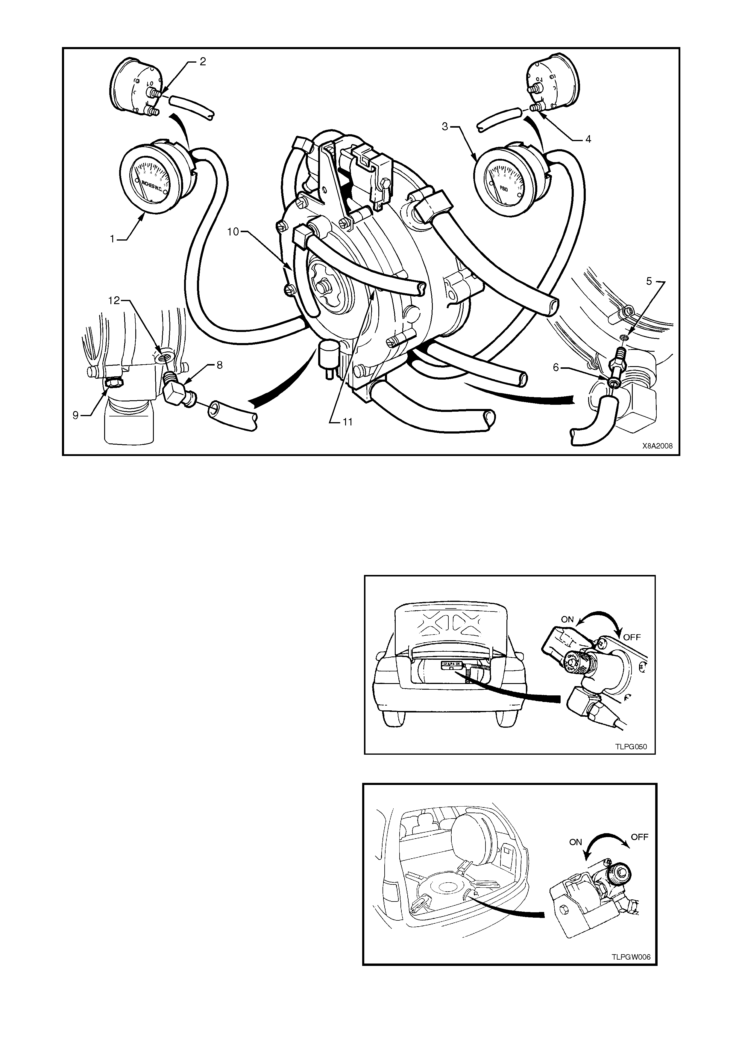
Figure 8A2-13
1. Inches W.C. gauge
(secondary pressure)
2. Low port
3. PSID gauge (primary pressure)
4. High port
5. Primary pressure port
6. Straight test nipple
7. Vapour hose
8. Test elbow
9. Water drain
10. Balance hose (to mixer)
11. Balance hose (to FSV)
12. Secondary pressure port
REMOVE
1. Park the vehicle in a well ventilated area, away
from any ignition source.
2. Drain the service lines of LPG, refer to
Section 2 SERVICE OPERATIONS in the
VT Series I Service Information,
VT Sedan with Production LPG or
VT Sedan with Accessory LPG and
VT Wagon.
3. Ensure the manual service valve is turned
'OFF' and the battery earth lead is
disconnected.
4. Depressurise engine cooling system by
removing radiator cap in two stages.
CAUTION: DO NOT REMOVE RADIATOR CAP
WHILE T HE ENGINE COOLANT TEM PERAT URE
IS ABOVE 50oC AS PERSONAL INJURY MAY
RESULT.
Figure 8A2-14
Figure 8A2-15
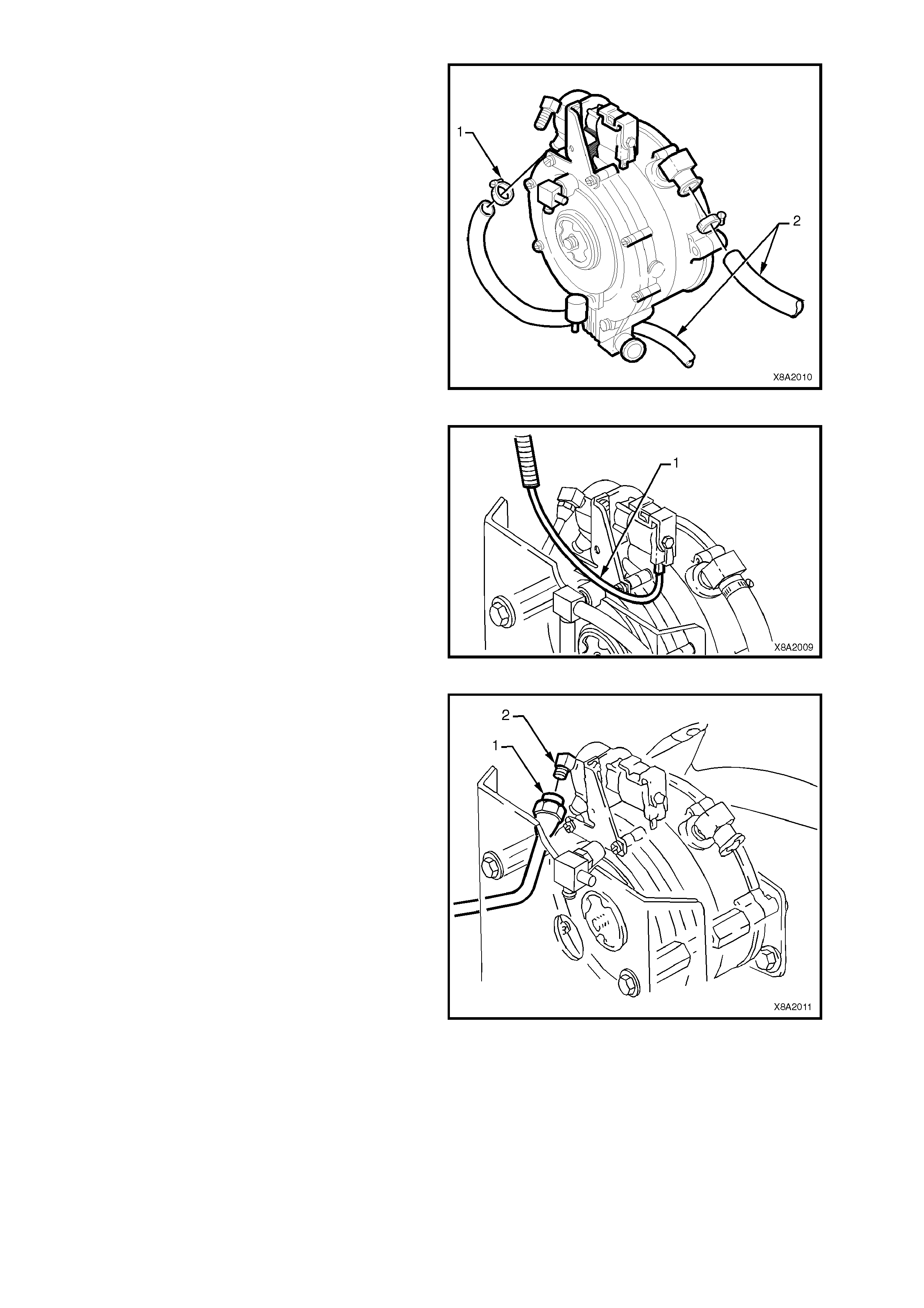
5. Place drain tray beneath vehicle. Loosen
clamps (1) securing engine coolant hoses (2)
to converter coolant inlet and outlet elbows.
Remove coolant hoses from converter and lay
back away from converter.
Figure 8A2-16
6. Disconnect LPG-off harness connector (1) from
LPG lock-off (2).
Figure 8A2-17
7. Loosen and disconnect front service line (1)
from the LPG lock-off inlet connection (2).
Figure 8A2-18
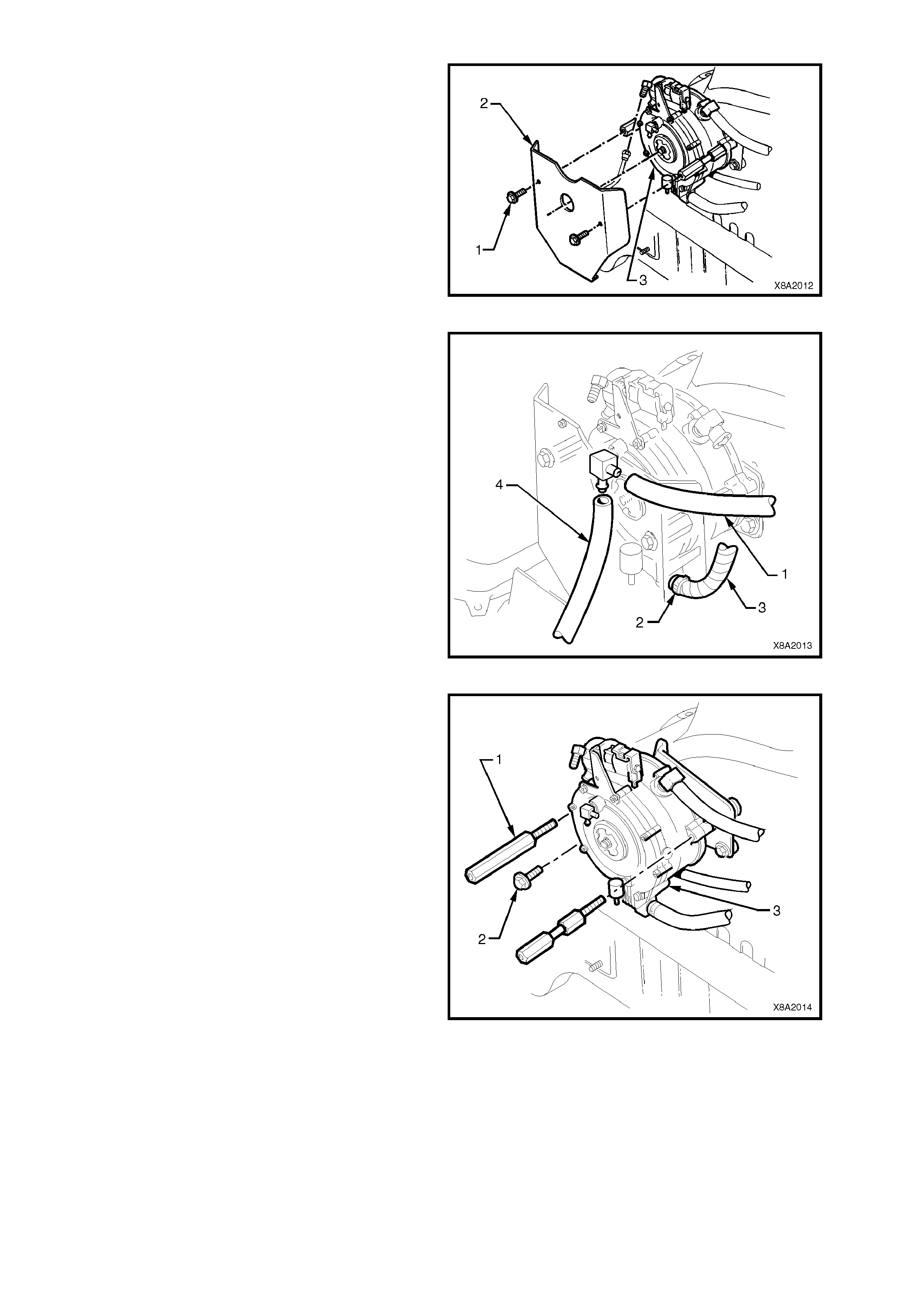
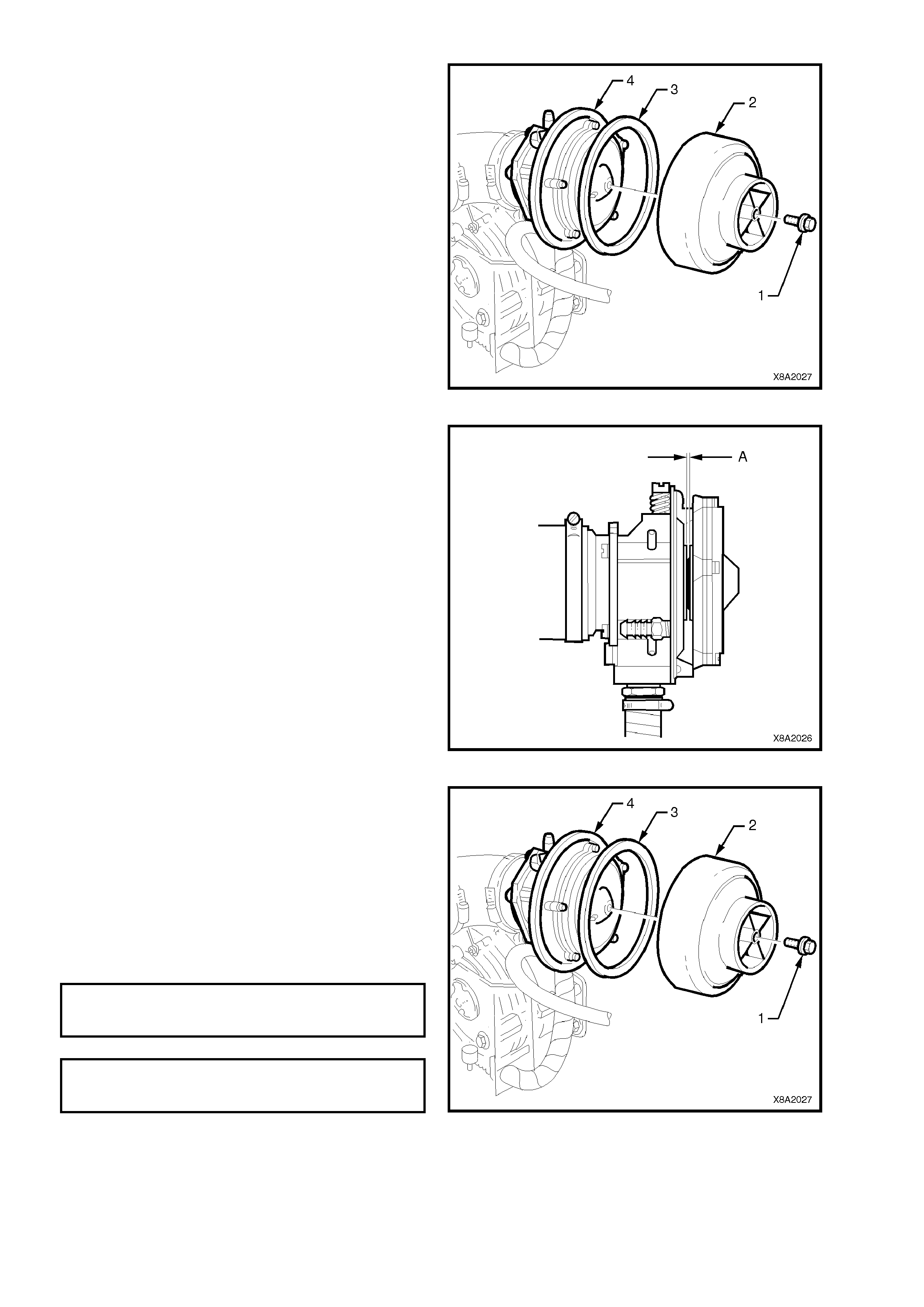
8. Remove the two screws (1) securing the
converter heat shield (2) to the converter (3)
and remove heat shield.
Figure 8A2-19
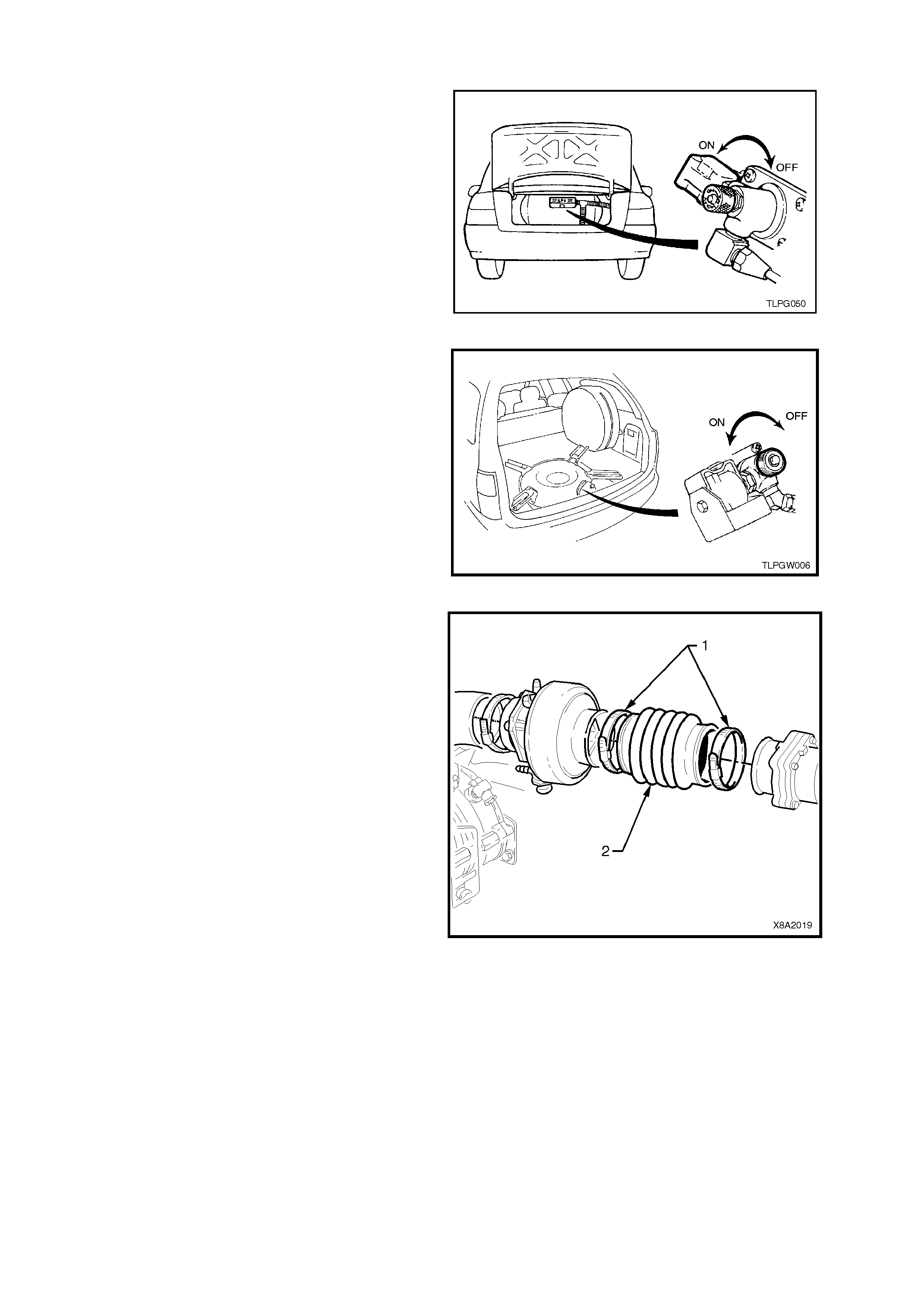
9. Remove FCV balance hose (1) and vacuum
hose (4) from converter connections.
10. Loosen mixer to converter vapour hose clamp
(2) at converter vapour outlet and disconnect
vapour hose (3) from converter.
Figure 8A2-20
11. Loosen and remove the two heat shield support
bolts (1) (2 places) and the converter retaining
bolt (2).
12. Remove converter assembly (3).
13. Rem ove engine coolant inlet and outlet elbows,
vapour outlet, FCV balance hose connection
and lock-off assembly if required.
If carrying out the following overhaul procedure
on the converter assembly, loosen and
unscrew the LPG lock-off to converter
connection, remove the connection and LPG
lock-off from the converter.
Figure 8A2-21

OVERHAUL
The proc edure f or overhauling the c onverter is as detailed in Sectio n 2 SERVICE OPERATIONS in the VT Series I
Service Information – VT sedan with Production LPG.
CONVERTER OFF VEHICLE TEST
With the converter removed from the vehicle, proceed as follows:
1. Rem ove plug from the converter prim ary test point and ins tall straight test nipple (1) into converter primar y test
point (2) .
2. Connect the pressure gauge hose (3) to the straight test nipple and to the high connection of the of the
0 - 5 PSID pressure gauge (4) of LPG test kit 1.
3. Remove plug from the converter secondary test point and install test elbow (5) into secondary test point (6).
4. Connect vacuum gauge hose (7) to test elbow and the 'LOW' connection of 0 - 10 INCHES W.C. vacuum
gauge (8) of LPG test kit 1.
5. Remove converter to LPG lock-off connector (9) from LPG lock-off and reinstall into converter. Tighten
connector securely.
6. Connect an air supply (10) into the converter to LPG lock-off connector and adjust air supply pressure to 875
kPa (125 psi).
7. Note the pressure reading on the primary pressure gauge. Primary converter pressure should be 7 - 10 kPa
(1.0 - 1.5 psi).
8. Disconnect air supply, The converter should hold primary pressure for at least five minutes.
NOTE: The following step involves the use of a domestic vacuum cleaner as a vacuum source.
9. Reconnect regulated air s upply to the converter to LPG lock-of f c onnec tor. While watching the primary pressure
gauge, bring the vacuum nozzle of the vacuum cleaner (11) to the converter vapour outlet (12). When the
primary pressure gauge needle moves (indicating start point of vapour supply out of secondary), note and
record the secondary vacuum gauge reading.
Secondary converter pressure should be negative 1 - 1.5 inches W.C. (negative 24 - 38 mm W.C.).
If during this test the specified primary and/or secondary pressures cannot be achieved, the converter must be
overhauled.

Figure 8A2-22
REINSTALL
Reinstallation of the converter is the reverse of the removal procedure, noting the following points:
1. If rem oved, ens ure that the engine coolant inlet and outlet elbows, vapour outlet, FCV balance hos e connection
threads and converter mating threads are clean.
Apply Loctite 567 sealant to coolant and vapour elbow threads and tighten these elbows to positions shown in
Figure 8A2-23.
2. Ensure that the LPG lock -off to converter connector and front service line to lock-of f connector mating threads
are clean.
If removed, also clean LPG lock-off connector and LPG lock-off mating threads.
Apply Loctite 577 sealant to LPG lock-off connector ensuring that flared surfaces are free of sealant and
contaminants. Install LPG lock-off connector to LPG lock-off and tighten securely.
Install LPG loc k-of f to the conver ter and tighten securely and if necess ary, further tighten it s o as to align it with
the retaining bracket.
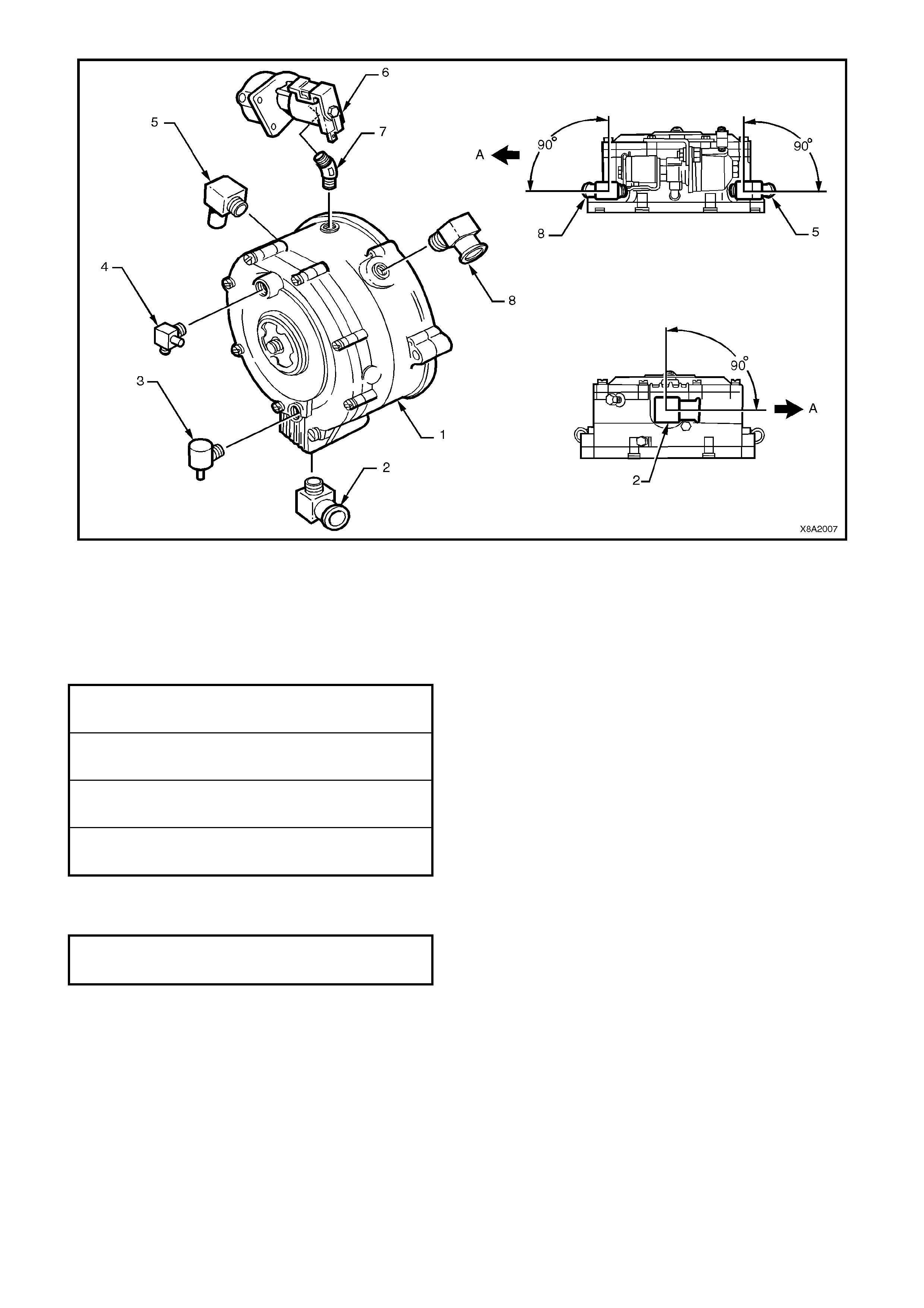
Figure 8A2-23
1. Converter
2. Vapour outlet elbow
3. FCV balance hose connector
4. Nipple
5. Coolant elbow
6. LPG lock-off
7. Connector
8. Coolant elbow
A. Front of vehicle
3. Tighten all fasteners to the correct torque
specification
LOCK-OFF BRACKET TO
CONVERTE RATTACHI NG SCREW
TORQUE SPECIFICATION
3.0 - 5.0 Nm
CONVERTE R RE T AINING BOLT T O
SUPPORT BRACKET
TORQUE SPECIFICATION
10.0 - 12.0 Nm
HEAT SHIELD SUPPORT BOLT TO
SUPPORT BRACKET
TORQUE SPECIFICATION
10.0 - 12.0 Nm
HEAT SHIELD RETAINING SCREW
TO HEAT SHIELD SUPPORT BOLT
TORQUE SPECIFICATION
3.0 - 5.0 Nm
4. Apply Loctite 577 to lock-off connector and
tighten front service line to LPG lock-off
connector to the correct torque specification.
FRONT SERVICE LI NE CONNECTOR
TO LPG LOCK-OFF
TORQUE SPECIFICATION
12.0 - 15.0 Nm
5. Leak test LPG system, refer to
Section 2 SERVICE OPERATIONS in the
VT Series I Service Information –
VT Sedan with Production LPG and
VT Sedan with Accessory LPG and
VT Wagon.
6. Refill cooling system with coolant to the
correct concentration level, refer to
2.3, CHECKING AND FILLING COOLING
SYSTEM, and pressure test the system, refer
2.7, PRESSURE TESTING in the VT Series I
Service Information Section 6B1 ENGINE
COOLING.
3.2 REGULATOR CHECK VALVE (RCV)
TEST
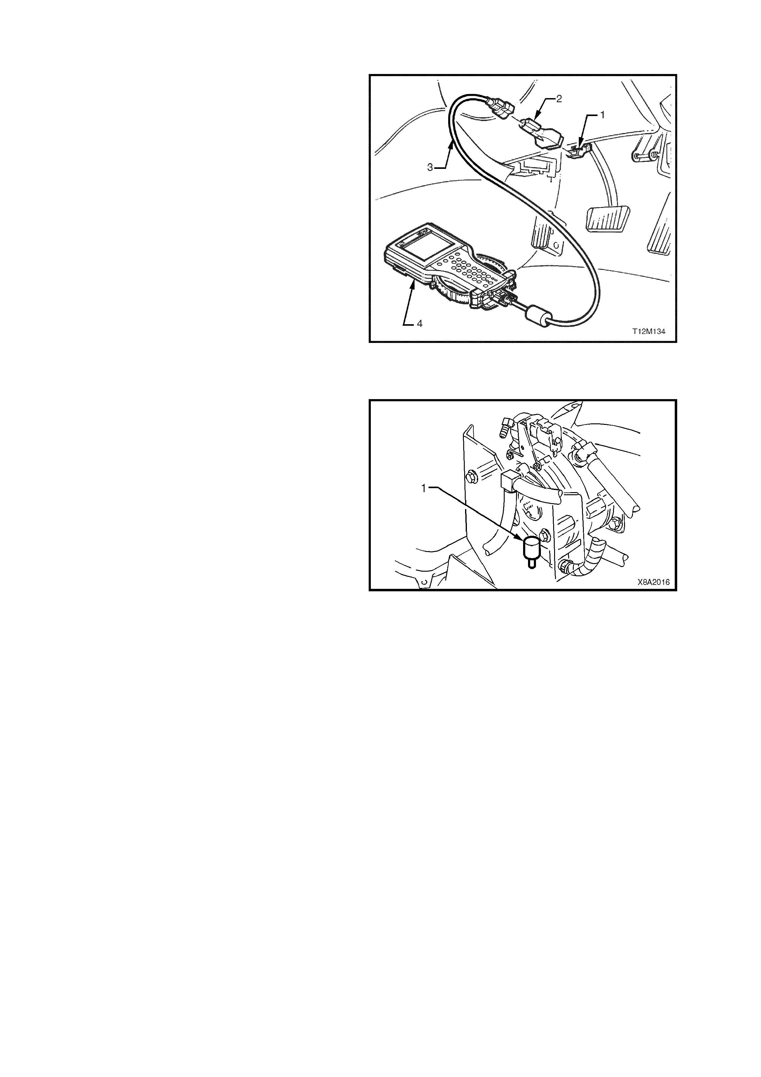
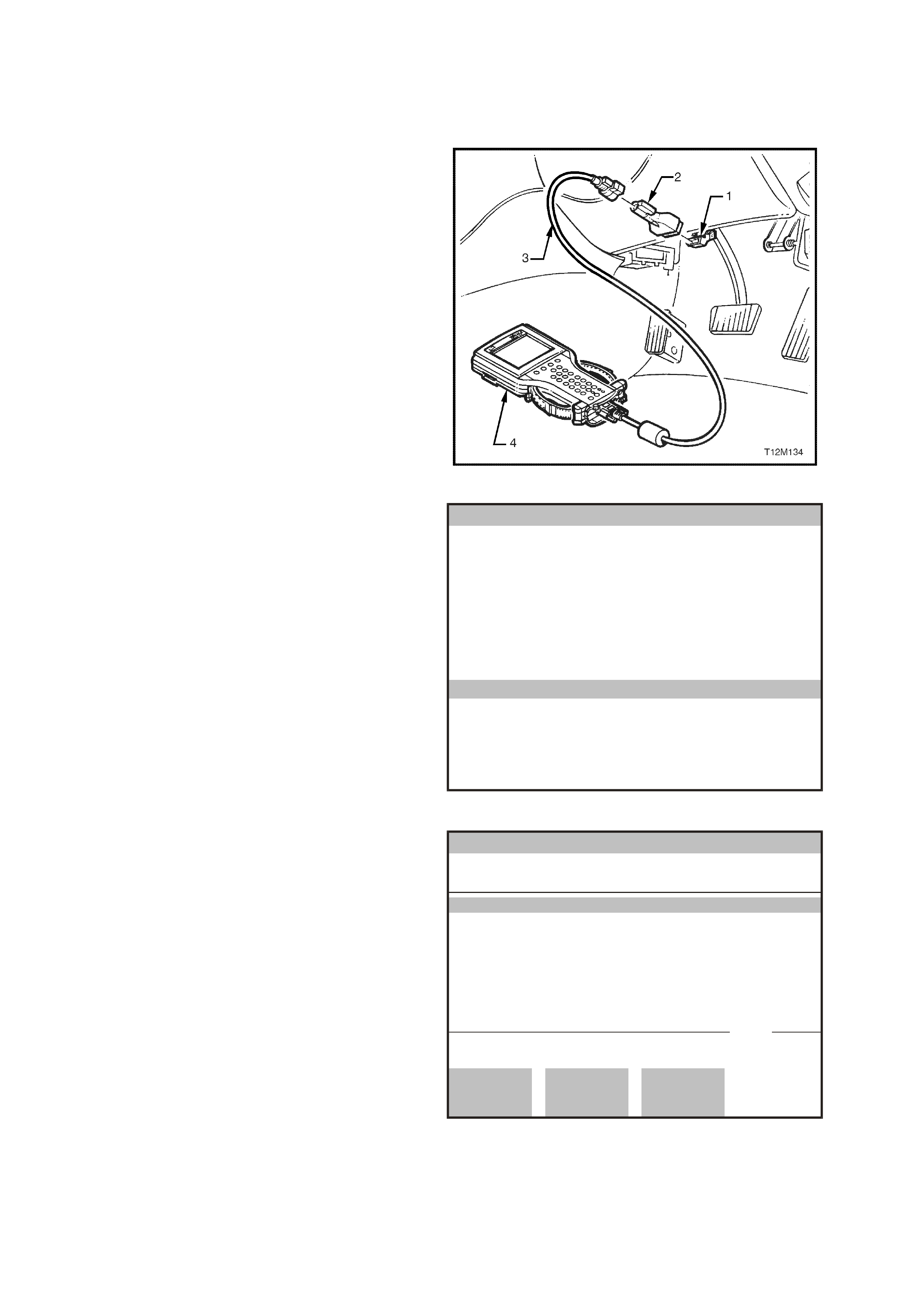
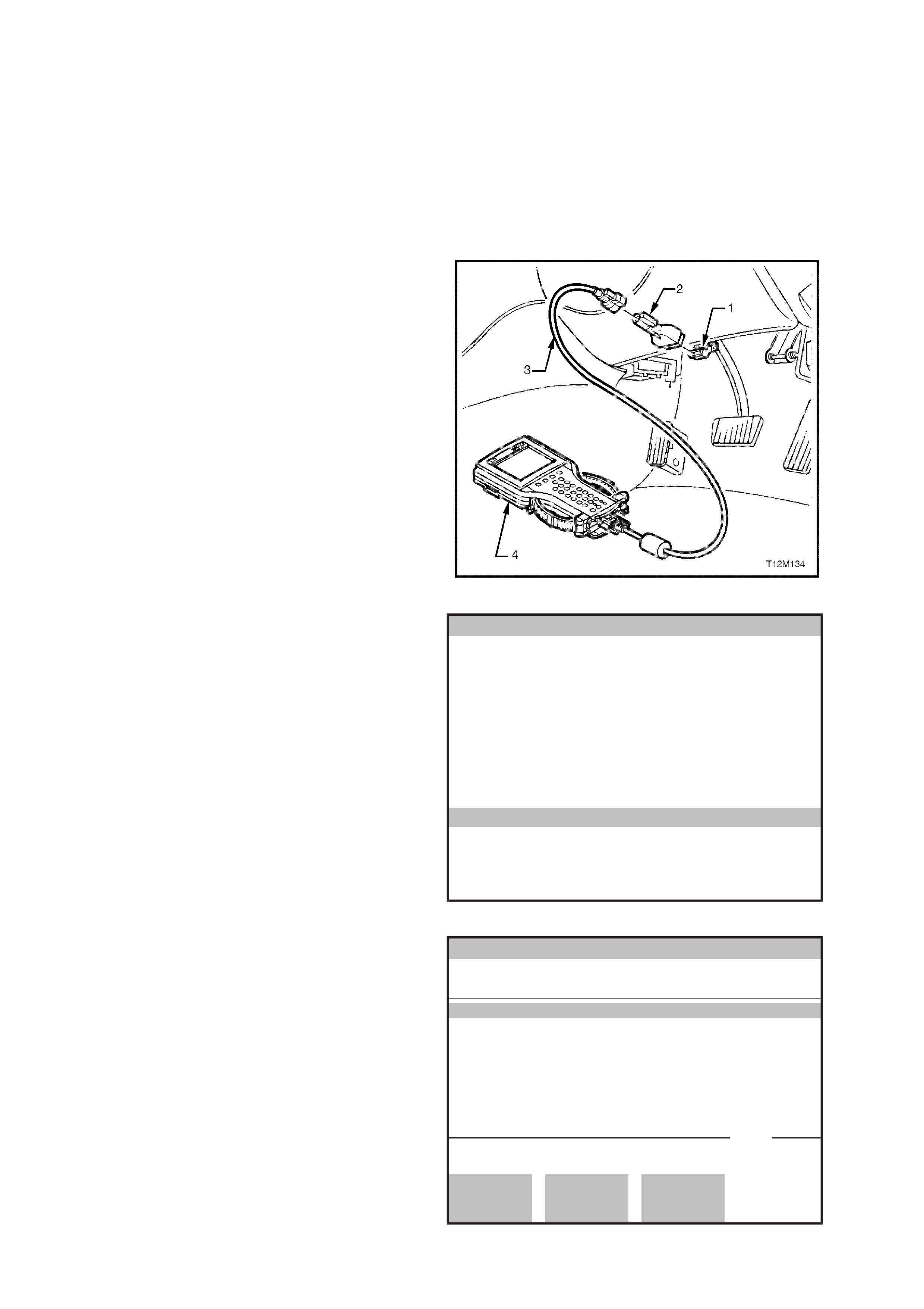
1. Connect TECH 2 to the DLC.
1. DLC
2. DLC Adaptor
3. DLC Cable
4. TECH 2
NOTE: For additional information on connecting
and operating TECH 2, refer to
Section 0C TECH 2 in the VX Series Service
Information.
2. Select: Diagnostics / Appropriate Model Year /
VX Commodore / Engine / V6 / Turn the
ignition as instructed by TECH 2 and confirm
the System Identification / Data Display / All
Data.
3. Scroll to LPG FCV Duty Cycle.
4. Start the engine and take note of the duty
cycles displayed on the TECH 2 screen for the
FCV.
Figure 8A2-24
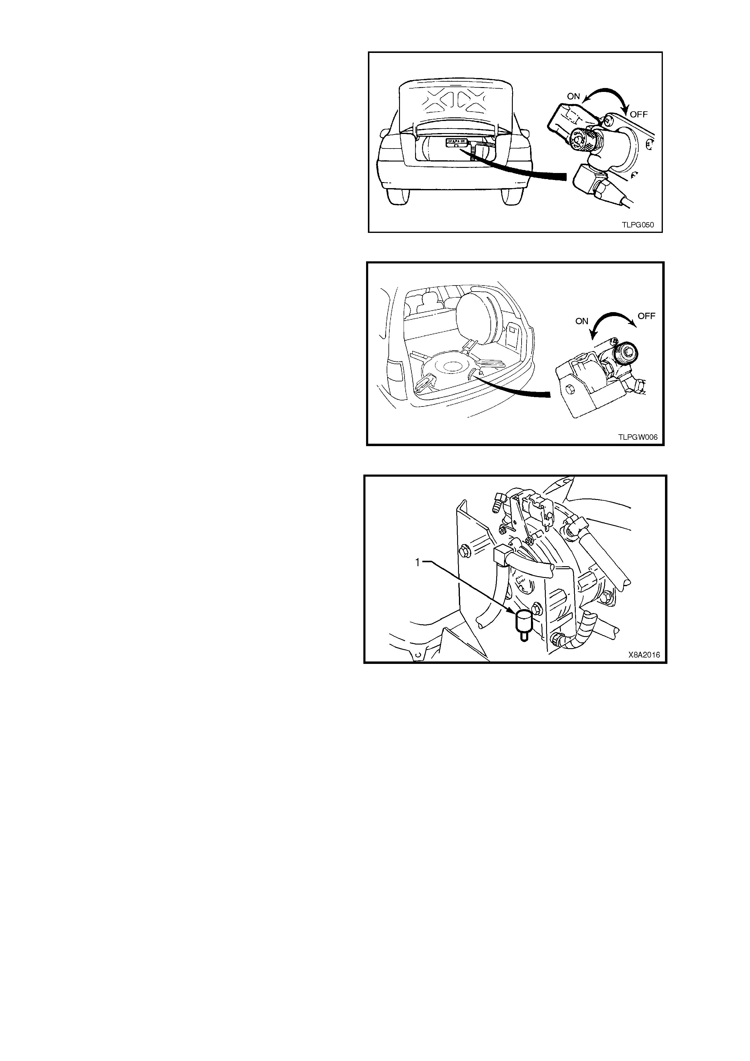
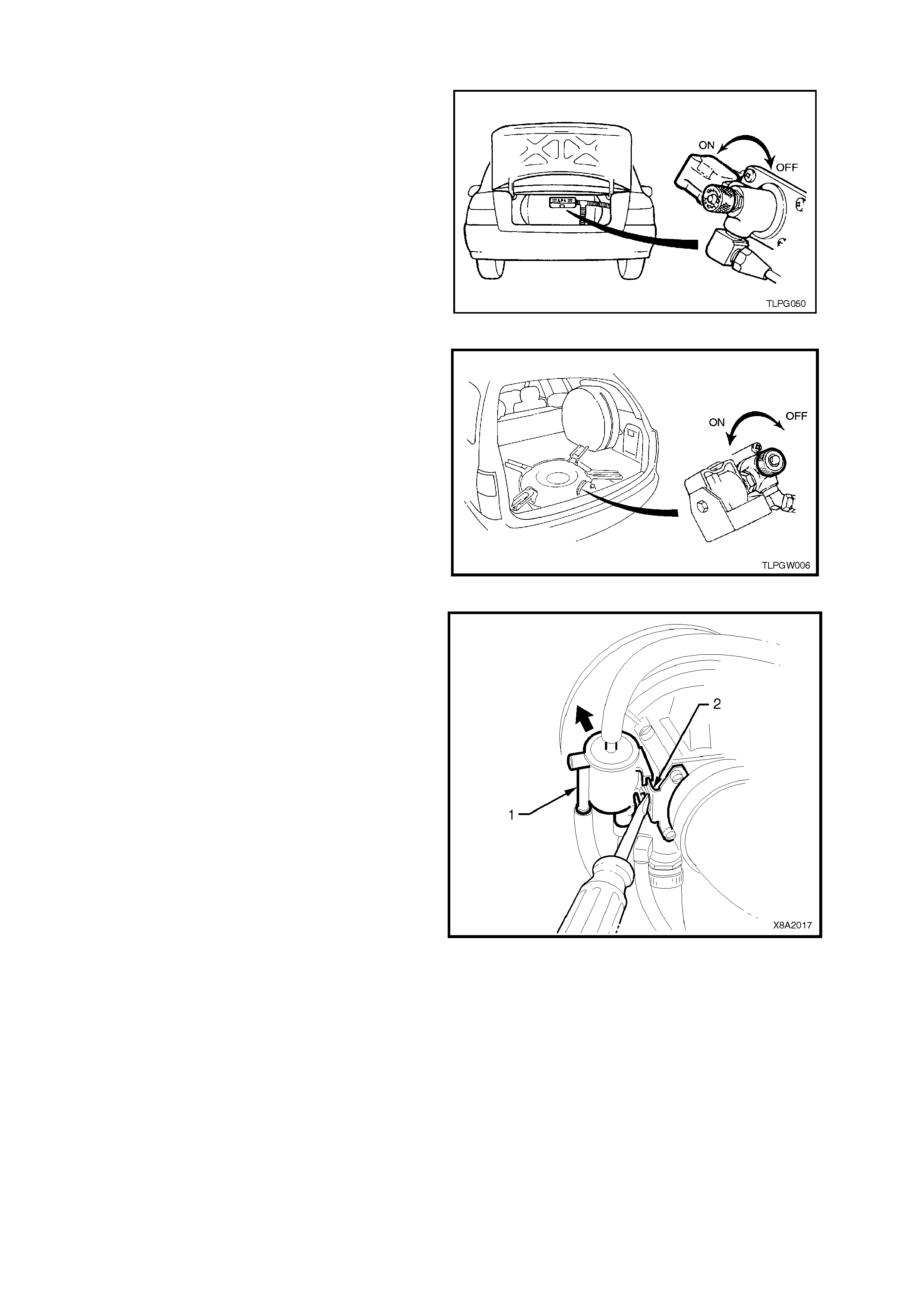
5. Place a finger over the RCV (1) atmospheric
port (large opening Figure 8A2-25.) and take
note of the FCV duty cycles.
There should be little or no change in the duty
cycle.
6. Place a 3/8” inside diameter hose over the
RCV atm ospheric port (large opening). Apply a
sm all amount of air pr es su re to the open end of
the hose (physically blow through hose) and
take note of the duty cycles displayed for the
FCV.
If duty cycles do not change, it indicates the
RCV is not opening as required and should be
replaced.
Figure 8A2-25
REMOVE
1. Park the vehicle in a well ventilated area, away
from any ignition source.
2. Drain the service lines of LPG, refer to
Section 2 SERVICE OPERATIONS in the
VT Series I Service Information,
VT Sedan with Production LPG or
VT Sedan with Accessory LPG and
VT Wagon.
3. Ensure the manual service valve is turned
'OFF' and the battery earth lead is
disconnected.
Figure 8A2-26
Figure 8A2-27
4. If necessary, remove the two screws securing
the heat shield to the converter heat shield
support bolts and remove heat shield.
5. Unscrew the RCV from the converter.
REINSTALL
Reinstallation of the RCV is the reverse of the
removal procedure, noting the following.
Apply Loctite 567 sealant to RCV threads, install
RCV to the converter and tighten securely and if
necessary, further tighten it so as to align it as
shown in shown in Figure 8A2-28.
Figure 8A2-28
3.3 FUEL CONTROL VALVE
REMOVE
1. Park the vehicle in a well ventilated area, away
from any ignition source.
2. Drain the service lines of LPG, refer to
Section 2 SERVICE OPERATIONS in the
VT Series I Service Information,
VT Sedan with Production LPG or
VT Sedan with Accessory LPG and
VT Wagon.
.
3. Ensure the manual service valve is turned
'OFF' and the battery earth lead is
disconnected.
Figure 8A2-29
Figure 8A2-30
4. Using a flat bladed screwdriver, gently lever the
retaining tang on the FCV retaining bracket (2)
towards the rear of the vehicle and slide the
FCV (1) outwards.
5. With the FCV removed from the retaining
bracket, disconnect the wiring harness
connector, remove the balance and vacuum
hoses from the FCV. Remove FCV from
vehicle.
Figure 8A2-31
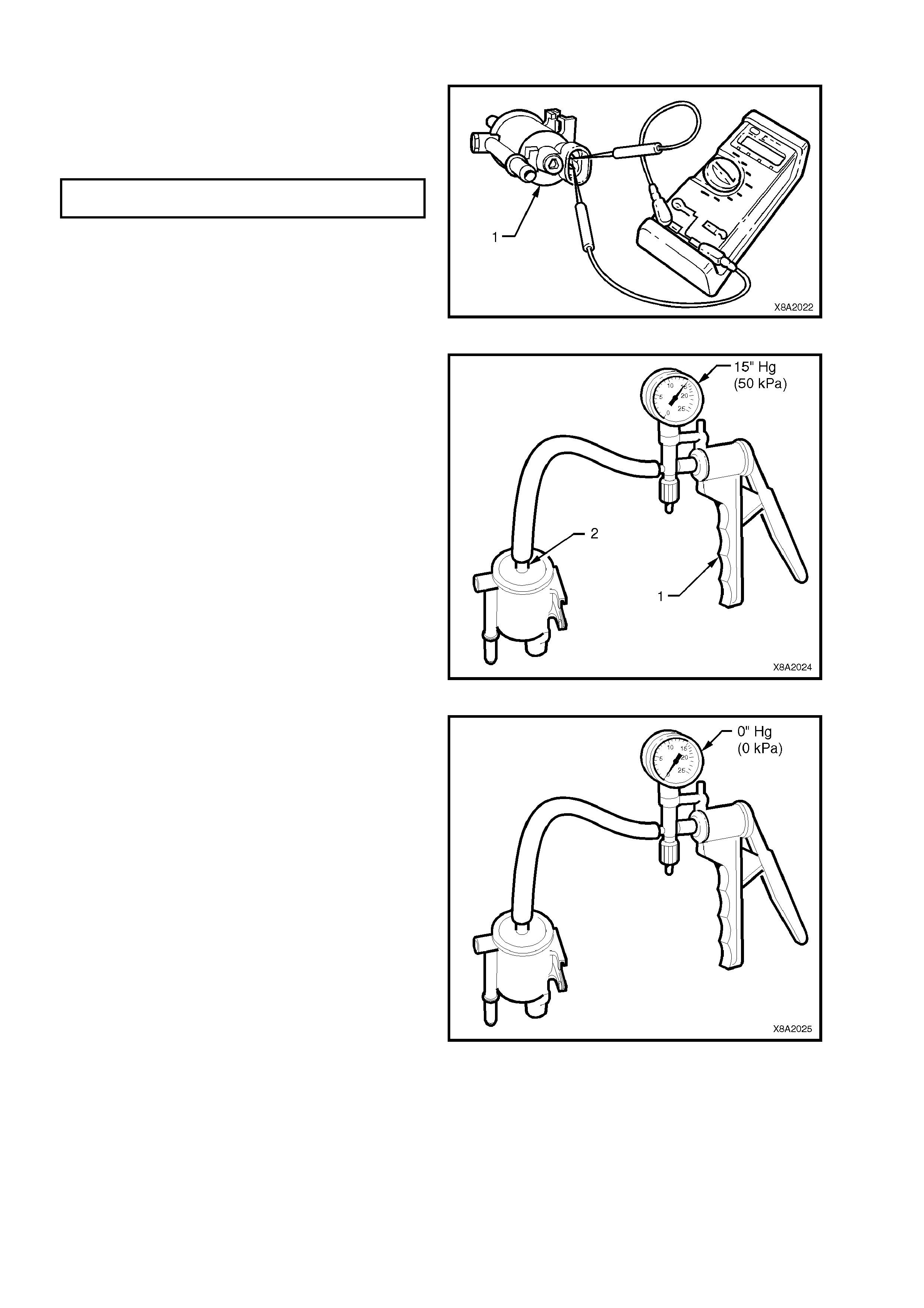
TEST
1. Connect an Ohm m eter to coil term inals of FCV
(1), refer to Figure 8A2-32.
If the coil resistance of the FCV is not as
specified, the fuel control valve should be
replaced.
FUEL CONTROL VALVE COIL 19 - 21 OHMS
RESISTANCE @ 20°C
Figure 8A2-32
2. Connect a vacuum pump (1) such as Tool No.
J23738-A, to the vacuum connector of the
fuel control valve assembly (2), refer
Figure 8A2-33.
3. Operate the vacuum pump until 15 inches Hg.
(50 kPa) of vacuum is applied to the FCV.
Figure 8A2-33
4. Note the time tak en for the vacuum to bleed of f
through the FCV.
If 15 inc hes Hg. (50 kPa) of vacuum c annot be
created, or the bleed of f tim e is less than three
to five seconds, then the FCV should be
replaced.
Figure 8A2-34
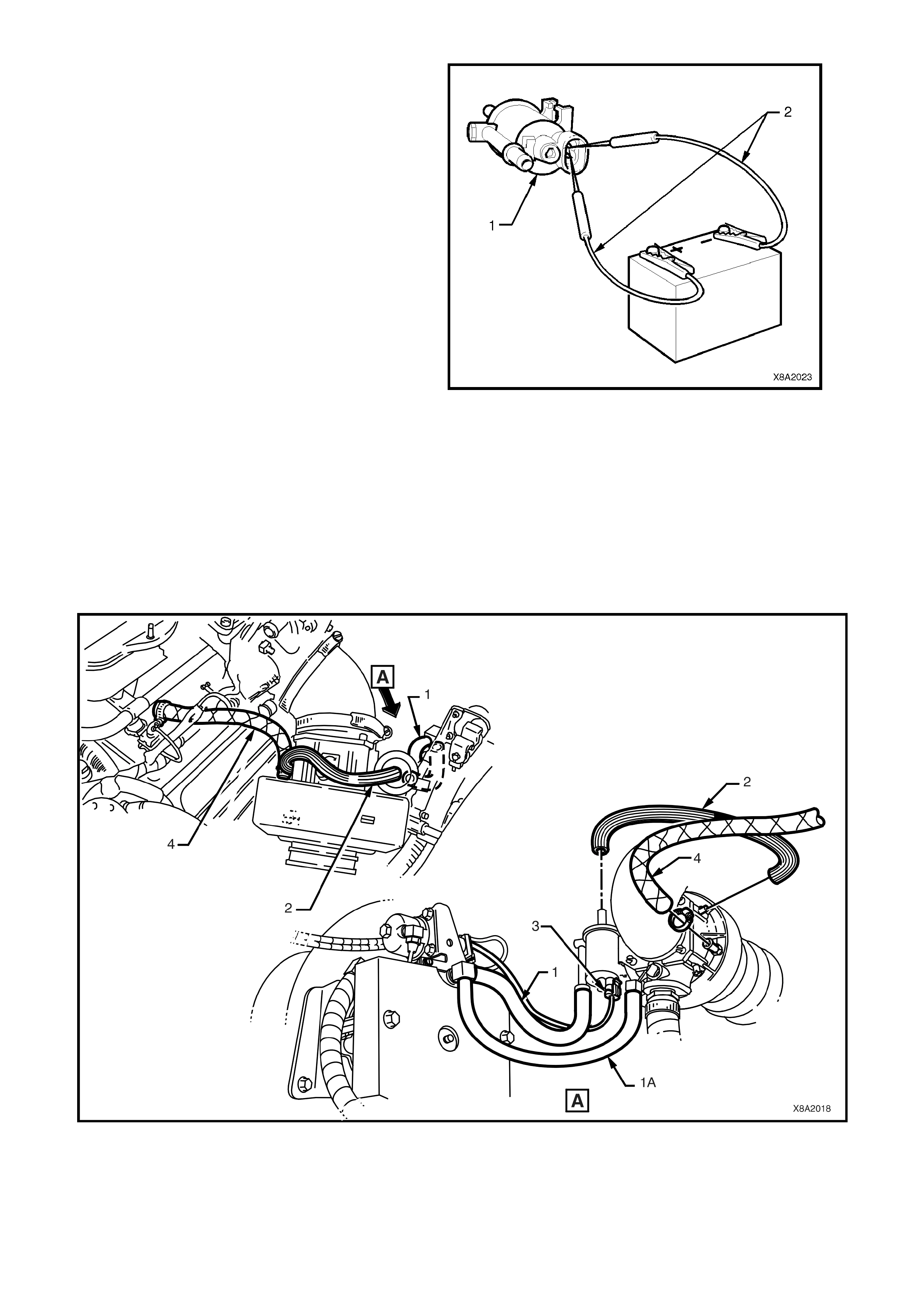
5. Using appropriate tes t leads (2) (suc h as those
found in KM-609) and connect 12 volts (vehic le
battery) to the FCV coil terminals (1), refer
Figure 8A2-35.
If the valve does not open (should be heard to
click as 12 volts applied – can blow through
FCV valve with 12 volts applied), the fuel
control valve should be replaced.
Figure 8A2-35
REINSTALL
Reinstallation of the FCV is the reverse of the
removal procedure noting the following:
1. Ensure FCV balance and vacuum hoses are
routed correctly, refer to Figure 8A2- 36.
2. Connect LPG wiring harness connector to FCV,
ensuring that it is routed correctly, refer Figure
8A2-36.
Figure 8A2-36
1. Balance hose (Atmospheric) 2. Vacuum hose 4. Breather hose
1A. Balance hose (Vacuum) 3. FCV wiring harness connector
3.4 MIXER
TEST
1. Park the vehicle in a well ventilated area, away
from any ignition source.
2. Drain the service lines of LPG, refer to
Section 2 SERVICE OPERATIONS in the
VT Series I Service Information,
VT Sedan with Production LPG or
VT Sedan with Accessory LPG and
VT Wagon.
3. Ensure the manual service valve is turned
'OFF'.
4. Disconnect the Mass Air Flow Sensor
connector YE100.
5. With the Petrol mode selected via the fuel
mode switch, start the engine and allow to idle
until the Check Powertrain Lamp is illuminated,
then turn the engine ‘OFF’
NOTE: Running the engine with the Mass Air Flow
Sensor connector YE100 disconnected will cause
DTC P0101 to set. Setting DTC P0101 will allow
the engine to start with the air duct removed as
described in Step 8 of this procedure.
Figure 8A2-37
Figure 8A2-38
6. Loosen clamps (1) on either end of air duct
boot (2), between mixer and Mass Air Flow
Sensor, remove air duct boot.
Figure 8A2-39
7. Loosen and remove bell housing to air valve
cover attaching bolt (1) and separate bell
housing (2) and gasket (3) from mixer body (4).
Figure 8A2-40
8. With the Petrol mode selected via the fuel
mode switch, start engine and allow to idle.
9. Observe mixer diaphragm position. Diaphragm
should lift slightly (A) as engine is cranked.
Also, diaphragm lift should increase as engine
RPM is increased.
10. If diaphragm does not lift as RPM increases,
check for vacuum leaks between mixer and
throttle body. If no vacuum leaks, overhaul
mixer, refer MIXER-OVERHAUL in the
VT Series I Service Information,
VT Sedan with Production LPG or
VT Sedan with Accessory LPG and
VT Wagon.
Figure 8A2-41
11. Reinstall bell housing gasket (3) bell housing
(2) and the bell housing to air valve cover
attaching bolt (1) and tighten to the correct
torque specification.
12. Reinstall air duct and tighten air duct clamps
refer Figure 8A2-39 and tighten to correct
torque specification.
13. Clear all DTC’s using Tech 2.
BELL HOUSING TO AIR
VALVE COVER ATTACHING 1.0 – 3.0 Nm
BOLT TORQUE SPECIFICATION
AIR DUCT CLAMPS 1.5 – 2.5 Nm
Figure 8A2-42
REMOVE
1. Park the vehicle in a well ventilated area, away
from any ignition source.
14. 2. Drain the service lines of LPG, refer to
Section 2 SERVICE OPERATIONS in the
VT Series I Service Information,
VT Sedan with Production LPG or
VT Sedan with Accessory LPG and
VT Wagon.
3. Ensure the manual service valve is turned
'OFF' and the battery earth lead is
disconnected.
Figure 8A2-43
Figure 8A2-44
4. Remove the Fuel Control Valve (FCV) from
the mixer assembly, refer to
3.3 FUEL CONTROL VALVE in this Section.
5. Loosen clamps (1) on either end of air duct
boot (2), between mixer and MAF sensor,
remove air duct boot.
Figure 8A2-45
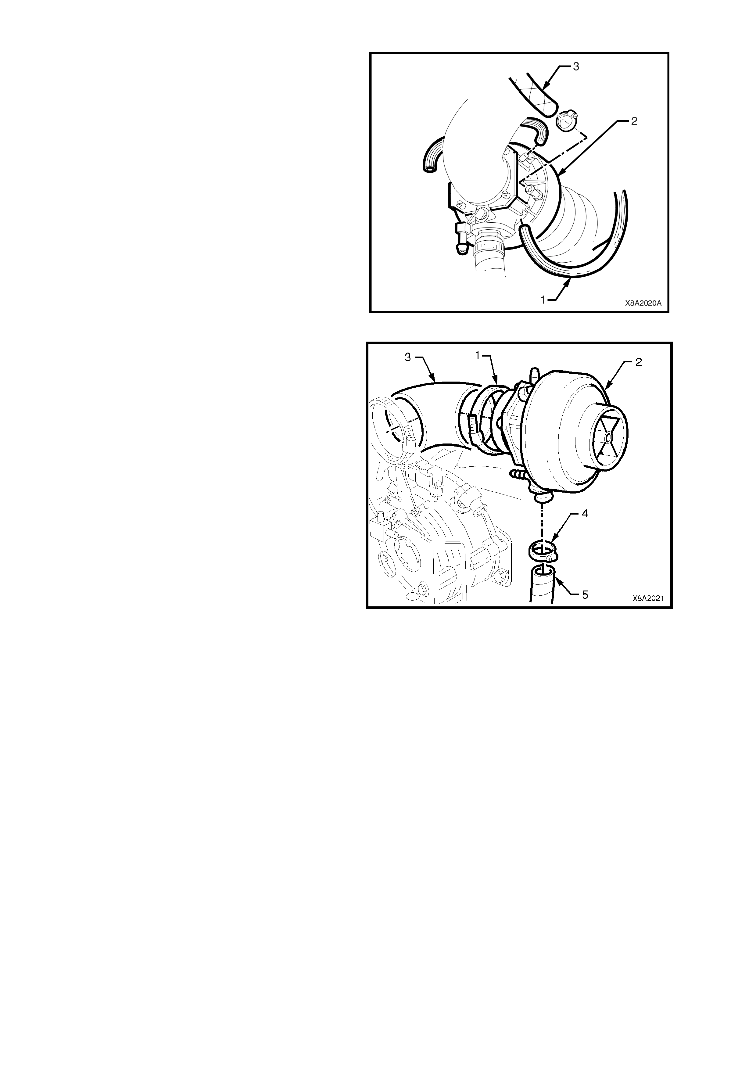
6. Remove the F CV vacuum s upply hose (1) from
the mixer (2).
7. Disconnect the crankcase breather hose (3)
from the mixer assembly connector.
Figure 8A2-46
8. Loosen the adaptor hose clamp (1) at the mixer
end (2).
Pull the mixer from the adaptor hose (3).
9. Loosen vapour hose to mixer inlet clamp (4),
disconnect vapour hose (5) and remove mixer.
Figure 8A2-47
OVERHAUL
15. The procedure for overhauling the mixer is as
detailed in Section 2 SERVICE OPERAT IONS in
the VT Series I Service Information,
VT Sedan with Production LPG or
VT Sedan with Accessory LPG and
VT Wagon.
.
REINSTALL
Reinstallation of the mixer is the reverse of the
removal procedure noting the following point:
1. Ensure FCV balance and vacuum hoses are
routed correctly, refer to Figure 8A2-48.
2. Connect LPG wiring harness connector to FCV,
ensuring that it is routed correctly, refer Figure
8A2-48.
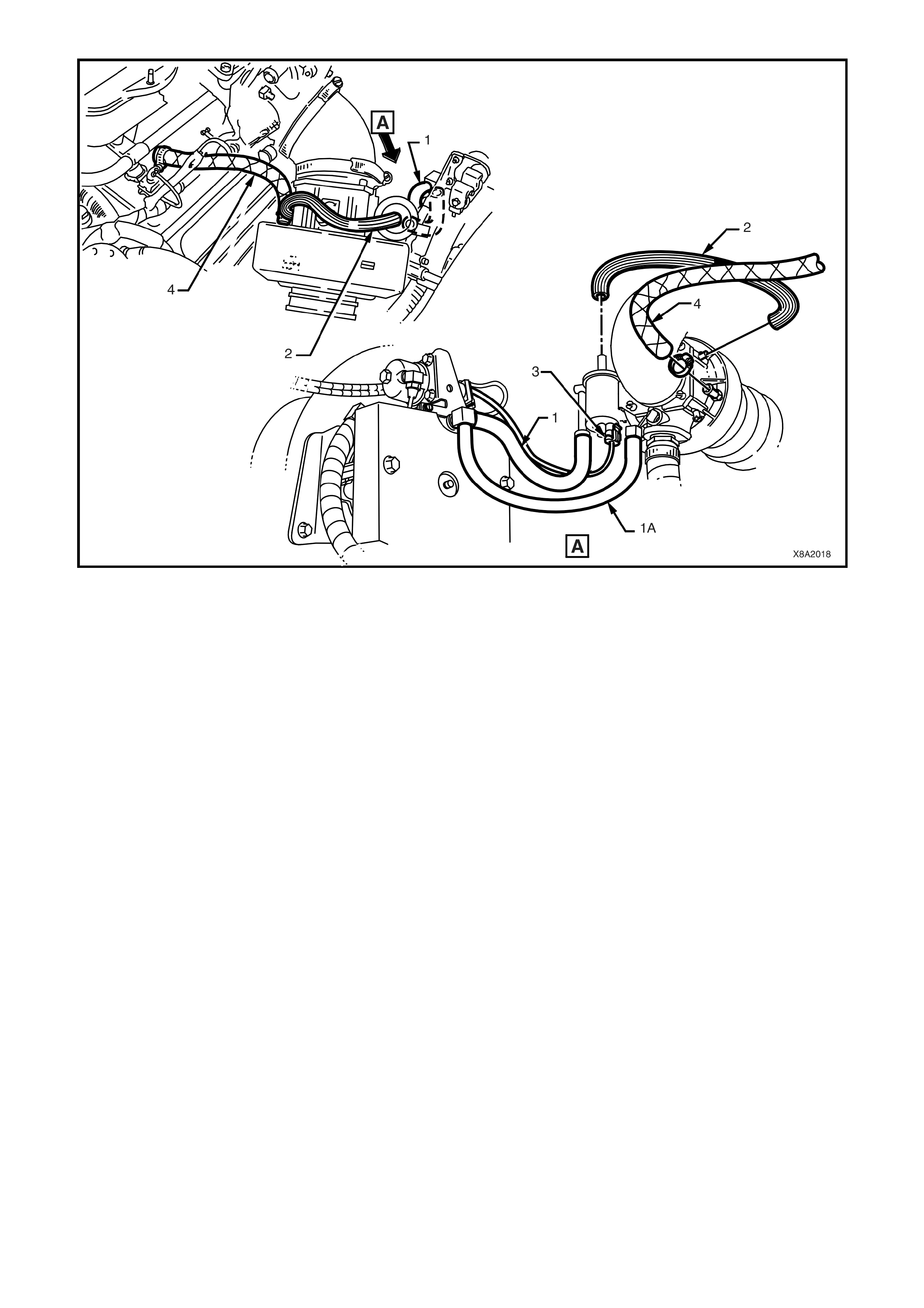
Figure 8A2-48
1. Balance hose (Atmospheric) 2. Vacuum hose 4. Breather hose
1A. Balance hose (Vacuum) 3. FCV wiring harness connector

3.5 LPG SE TUP PROCEDURE
NOTE: The following LPG Setup Procedures
must be carried out when any LPG system
component (mixer, converter, FCV or PCM) has
been replaced, overhauled, reprogrammed, or
when the engine assembly has been replaced or
overhauled.
The LPG Setup procedure allows you to adjust the
idle mixture under controlled conditions, these
conditions are:
Short and Long Term Fuel Trim Cells set to zero.
Fixed Spark advance.
Fixed idle air control valve steps.
Fuel control valve duty cycle fixed at 40%.
1. Connect TECH 2 to the DLC.
1. DLC
2. DLC Adaptor
3. DLC Cable
4. TECH 2
2. With the LPG mode selected, start the engine
and with no load on the engine, air conditioning
off (if fitted), all electrical consumers turned off
and park position selected, allow engine and
oxygen sensor to reach operating temperature.
.
Figure 8A2-49
3. Select: Diagnostics / Appropriate Model Year
(1) 2001 / VX Commodore / Engine / V6 /
Function Tests/ LPG Setup.
During the setup pr ocedur e Tech 2 ensur es the
follow engine operating conditions are met and
maintained.
Engine Coolant Temperature greater than 91°C
Operating in closed loop.
Right hand oxygen senor is ready.
The engine cooling fan is off
(engine coolant temperature less than 104°C).
Once all the preconditions have been met,
Tech 2 will display the Right O2 Sensor Voltage
and Status.
Engine
LPG Se tup
Right O2 Sensor
Righ t O2 Status 500 mV
Rich
VXLPG001
Confirm
Figure 8A2-50
4. Adjust the idle mixture screw until the right
hand oxygen sensor voltage is as close to 500
mV as possible and the status of the right O2
Sensor is constantly toggling between rich and
lean.
Oxygen sensor voltages greater than 500 mV
indicates a rich mixture turn the idle mixture
screw anti-clockwise to lean off the mixture.
Oxygen sensor voltages less than 500 mV
indicates a lean mixture turn the idle mixture
screw clockwise to richen the mixture.
If the engine coolant temperature exceeds
104°C the engine cooling fan will be turned on
and Tech 2 will suspend the setup procedure,
when the engine cools down and the cooling
fan is turned off, Tech 2 will continue with the
setup procedure.
Figure 8A2-51
3.6 LPG FUEL CONTROL VALVE TEST
The LPG Fuel Control Valve Test is used to
command the LPG Fuel Control Valve from 10% to
90% in steps of 10%.
1. Connect TECH 2 to the DLC.
1. DLC
2. DLC Adaptor
3. DLC Cable
4. TECH 2
Figure 8A2-52
2. Select: Diagnostics / Appropriate Model Year
(1) 2001 / VX Commodore / Engine / V6 /
Miscellaneous Tests/ LPG Fuel Control Valve
Test.
M isc ellaneou s Tes ts
VXLPG005
F0 : Output Tes ts
F1 : IAC System
F2: EGR Co ntrol
F3: Re se t Ce lls
F4 : B ypass Spark
F5 : Air Fuel Ra tio
F6: LPG Fuel Control Valve Test
F7 : LPG Enable
Figure 8A2-53
3. With the LPG mode selected, start the engine
and allow the engine to idle.
4. The FCV duty cycle can be increased and
decreased using the decrease or increase soft
keys. Increasing the duty cycle will cause a
leaner air fuel ratio, decreasing the duty cycle
will cause a richer air fuel ratio.
NOTE: The FCV can only be commanded if the
engine is running in the LPG mode.
LPG Fuel C ontrol Valve
(1) 2001 V X Commodore
Engine: V6
Engine Speed
Des ired En gine Idle Spe
EC T S ens or (E ng ine Coo l
Co olant Temp era tu re
IAT Se nso r (Intake A ir
Intake Air Temp eratu re
M AF S ens or (Ma ss Air Fl
833
825
1.25
83
2.45
28
2730
RPM
RPM
V
C
V
C
Hz
o
o
LPG Fuel C ontrol Valve
VX0C051
Quit Decrease Increase
1 / 85
45 %
Figure 8A2-54
3.7 LPG ENABLE TEST
The LPG Enable Test is used to enable the LPG
operating mode. When commanded on the PCM
will switch to the LPG operating mode, when
commanded off the PCM will switch to the Petrol
operating mode, refer following note.
NOTE: The PCM will only toggle between the Petrol
and LPG m ode if the ignition is on and the engine is
not running or if the engine speed is greater that
1300 RPM.
1. Connect TECH 2 to the DLC.
1. DLC
2. DLC Adaptor
3. DLC Cable
4. TECH 2
.
Figure 8A2-55
2. Select: Diagnostics / Model Year (1) 2001 /
VX Commodore / Engine / V6 / Miscellaneous
Tests/ LPG Enable Test.
M isc ellaneou s Tes ts
VXLPG006
F0 : Output Tes ts
F1 : IAC System
F2: EGR Co ntrol
F3: Re se t Ce lls
F4 : B ypass Spark
F5 : Air Fuel Ra tio
F6: LPG Fuel Control Valve Test
F7 : LPG Enable
Figure 8A2-56
4. With the ignition on and the engine not
operating or with the engine operating above
1300 RPM, the LPG mode can then be
commanded On or Off using the ON and Off
soft keys. When commanded On the PCM will
switch to the LPG mode, when c omm anded Of f
the PCM will switch to the Petrol Mode.
LPG Enable
(1) 2001 V X Commodore
Engine: V6
Engine Speed
Des ired En gine Idle Spe
EC T S ens or (E ng ine Coo l
Co olant Temp era tu re
IAT Se nso r (Intake A ir
Intake Air Temp eratu re
M AF S ens or (Ma ss Air Fl
833
825
1.25
83
2.45
28
2730
RPM
RPM
V
C
V
C
Hz
o
o
LPG M ode Enabled
VX0C052
Quit Off On
1 / 85
Yes
Figure 8A2-57

4. DIAGNOSIS
4.1 PREREQUISITES TO DIAGNOSIS AND TROUBLESHOOTING
PRELIMINARY SYSTEM REQUIREMENTS
The prerequisites before proceeding with system checks are:
• Ensure that sound ear th connections are available for all f unctioning com ponents, par ticularly at the body earth
connection (fender panel inner stud, adjacent to the battery).
• Ensure the battery is in good condition and adequately charged (above 12.5 volts) before carrying out any
electrical checks.
SAFETY REQUIREMENTS
Disconnect the battery when carrying out work which involves the risk of an electrical short circuit.
Do not touch mechanical components during function checks, to avoid the risk of a hand being caught in the
mechanism.
All Safety Standards and Regulations pertaining to LPG must be followed at all times.
CHECKING EQUIPMENT
Tech 2 scan tool.
A digital multimeter, with a minimum 10 Megohm impedance MUST be used when undertaking any electrical
checks on these systems.
Exercise care when taking readings from wiring harness connectors. It is preferred that the back probing method
with individual connectors is employed wherever possible, to avoid terminal damage and subsequent connection
failure.
When carrying out wiring c hec k s as direc ted to by the diagnostic charts, rather than probe terminals and connectors
with incorrec t sized multim eter connec tions, use the adaptors contained in connector test adaptor kit KM-609. This
will prevent any possibility of spreading or damaging wiring harness terminals.
IMPORTANT:
• ENSURE THAT THE IGNITION IS TURNED OFF AND THE BATTERY EARTH LEAD IS DISCONNECTED
BEFORE ANY TEST THAT REQUIRES DISCONNECTION OR RECONNECTION OF ANY CONTROL
MODULE CONNECTORS.
• When checking the complete sy stem, the exact order of the test steps should be observed.
• If the requir ed nominal value is not ac hieved in any stage, then the problem must be rec tif ied before proc eeding
further.
• Unless the multimeter being used has an auto ranging function, check that the correct range, as specified, is
selected before the test is carried out.
• Testing of the system will involve gaining access to specific wiring harness connectors. For the location of
connectors not detailed in this Section, refer to Section 12N FUSES AND WIRING HARNESSES in the VX
Series Service Information.

4.2 GENERAL INFORMATION
The procedures outlined in the LPG VEHICLE PRELIMINARY DIAGNOSTIC CHART MUST be carried out
first whenever diagnosing a problem in a LPG vehicle.
The LPG system is designed to operate in LPG mode when LPG has been selected via the fuel mode switch. When
diagnosing the LPG system , unless other wise directed. Ens ure that the LPG m ode has been selected, there is LPG
in the LPG cylinder and the manual service valve is turned 'ON'.
When LPG has been selected via the fuel mode switch the PCM will operate in the LPG mode if the operating
parameters sensed by the PCM permit the switching to the LPG mode.
Before any diagnostic procedures are carried out on the LPG system you must first confirm that the vehicle
operates on petrol without any problems.

4.3 LPG VEHICLE PRELIMINARY DIAGNOSIS
TEST DESCRIPTION
The numbers below refer to step numbers in the following diagnostic chart.
1. If the Check Powertrain Lam p illum inates the PCM is being powered up. If the Check Powertrain Lam p does not
illuminate you should refer to the ON-BOARD DIAGNOSTIC SYSTEM CHECK, Section 6C1 in this Service
Information.
2. Ensures Tech 2 is functioning correctly.
3. Checks if Tech 2 can communicate with the PCM.
4. Checks if any PCM DTCs are present.
5. Checks if the PCM can operate in the LPG mode.
6. Checks if the LPG switch is operating correctly.
7. Checks the operation of the LPG lamp.
8. Checks if the engine will operate on petrol.
9. Checks if the engine will crank when LPG has been selected.
10. Checks if the engine will run when LPG has been selected.
STEP ACTION YES NO
1. 1. Turn ignition on.
2. Does the Check Powertrain Lamp illuminate for at
least two seconds?
Go to Step 2. Refer ON-BOARD
DIAGNOSTIC SYSTEM
CHECK, Section 6C1 in
this Service Information.
2. 1. Turn ignition off, install Tech 2 to DLC, turn ignition
on and turn on Tech 2.
2. Does Tech 2 power up (screen will illuminate and
display Tech 2)?
Go to Step 3. Refer Tech 2
DIAGNOSIS, Section
0C Tech 2 in this
Service Information.
3. 1. With Tech 2 still connected and ignition on, press
the ENTER key then select Diagnostics / (1) 2001 /
VX Commodore / F0: Engine / V6 and then follow
the screen instructions.
2. Does Tech 2 display PCM system identification
information?
Go to Step 4. Refer ON-BOARD
DIAGNOSTIC SYSTEM
CHECK, Section 6C1 in
this Service Information.
4. 1. At the Tech 2 PCM System Identification screen
Press the Confirm Soft key, from the Engine
application menu select F1: Diagnostic Trouble
Codes / Read Current DTC.
2. Are any DTCs present?
Refer ON-BOARD
DIAGNOSTIC SYSTEM
CHECK, Section 6C1 in this
Service Information.
Go to Step 5.
5. 1. Return to the Tech 2 Engine application menu and
select / F2: Data Display / F0: All Data / Scroll to
“LPG Fuel Enabled”.
2. Does Tech 2 display LPG Fuel Enabled YES?
Go to Step 6. Refer 4.4 DOES NOT
OPERATE ON LPG, in
this Section.
6. 1. With Tech 2 still connected, scroll to “Fuel”.
2. Select LPG via the fuel mode switch.
3. Does Tech 2 Data parameter “Fuel” change from
Petrol to LPG?
Go to Step 7. Refer 4.5 FUEL MODE
SWITCH DOES NOT
OPERATE, in this
Section.
7. 1. With the LPG Mode selected.
(Tech 2 Data parameter “Fuel” displaying LPG).
2. Is the LPG lamp illuminated?
Go to Step 8. Refer 4.6 LPG LAMP
DOES NOT OPERATE
in this Section.

STEP ACTION YES NO
8. 1. Select Petrol via the fuel mode switch.
2. Will the engine crank and start immediately the
ignition key is turned from off to start (no delay)?
Go to Step 9. Refer ON-BOARD
DIAGNOSTIC SYSTEM
CHECK, Section 6C1 in
this Service Information.
9. 1. Select LPG via the fuel mode switch.
2. W ill the engine crank immediately the key is turned
from off to start (no delay)?
Go to Step 10. Refer 4.7 ENGINE
DOES NOT CRANK in
this Section.
10. 1. Does engine start and run on LPG? Go to Step 11. Refer 4.8 ENGINE
CRANKS DOES NOT
START ON LPG in this
Section.
11. 1. Does engine backfire when operated on LPG? Refer Diagnostic Chart 4.9
ENGINE BACKFIRES ON
LPG in this Section.
Go to Step 12.
12. 1. Does engine lack power, sluggish or have poor
performance when operating on LPG?
Refer Diagnostic Chart 4.10
POOR PERFORMANCE,
SLUGGISH OR POOR FUEL
CONSUMPTION WHEN
OPERATING ON LPG in this
Section.
Go to step 13
13. 1. Does fuel gauge operate correctly? LPG Diagnostic Check
completed. Refer 4.12 FUEL
GAUGE DOES NOT
OPERATE in this
Section.
4.4 DOES NOT OPERATE ON LPG
Figure 8A2-58
TEST DESCRIPTION
The numbers below refer to step numbers in the following diagnostic chart.
1. The LPG VEHICLE PRELIMINARY DIAGNOSIS CHECK must be the first step when diagnosing any LPG
system problem.
2. The PCM will not operate in the LPG mode if the PCM has not been programmed to operate on LPG. Refer to
the latest technical publications for the correct PROM application.
3. When the ignition is turned on battery voltage is applied to terminal F16 of the PCM. This enables the PCM to
operate in either the Petrol or LPG mode. If battery voltage is not applied to PCM terminal F16 the PCM will only
operate in the Petrol mode.
4. This test confirms that the PCM connector terminal retention is not causing the problem. The terminal retention
should always be checked before a PCM is replaced.
STEP ACTION YES NO
1. 1. Has an LPG VEHICLE PRELIMINARY DIAGNOSIS
CHECK been performed. Go to step 2 Perform an LPG
VEHICLE PRELIMINARY
DIAGNOSIS CHECK.
2. 1. Has the PCM been programmed for LPG operation?
Go to step 3. Perform SPS to program
the PCM for LPG
operation. Refer SPS,
Section 0C Tech 2 in this
Service Information.
3. 1. Ignition on.
2. Measure the voltage at PCM terminal F16 connector
YB199 circuit 39 pink wire.
3. Is battery voltage present?
Go to step 4. Repair open in circuit 39
between fuse F14 and
PCM terminal F16.
Verify repair.
4. 1. Check PCM connector terminal retention.
If retention OK replace PCM.
2. Is terminal retention OK?
Replace PCM.
Verify repair. Repair terminals.
Verify repair.
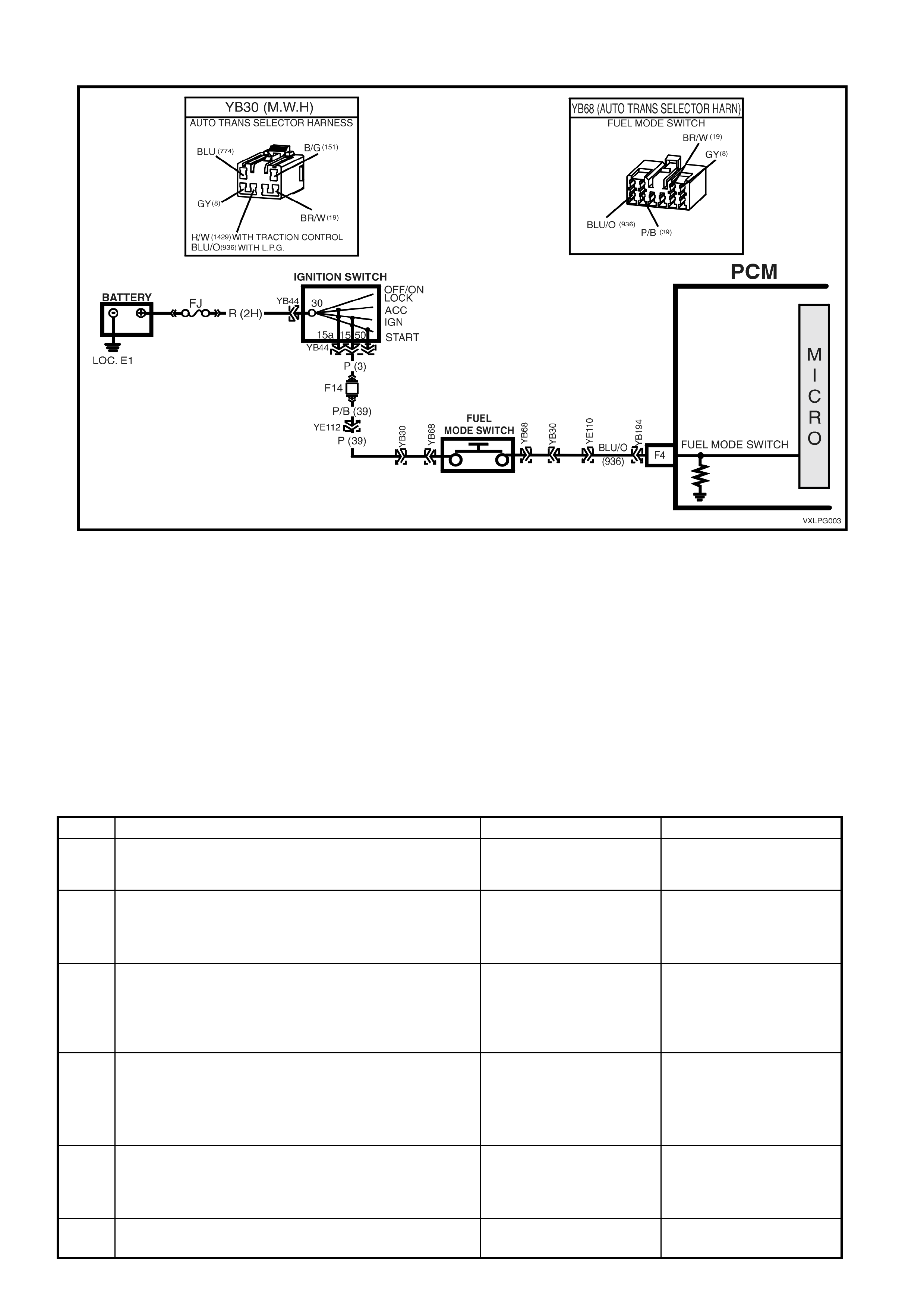
4.5 FUEL MODE SWITCH DOES NOT OPERATE
Figure 8A2-59
TEST DESCRIPTION
The numbers below refer to step numbers in the following diagnostic chart.
1. The LPG VEHICLE PRELIMINARY DIAGNOSIS CHECK must be the first step when diagnosing any LPG
system problem.
2. Checks for battery voltage when the Fuel Mode switch is activated.
3. Tests operation of fuel mode switch.
4. Checks for voltage at the fuel mode switch. If voltage is not present, circuit 39 is open between the fuel mode
switch and fuse F14. If voltage is present there is an open circuit between the fuel mode switch and PCM
terminal F4.
5. This test check for an open in the fuel mode switch circuit 936.
6. This test confirms that the PCM connector terminal retention is not causing the problem. The terminal retention
should always be checked before a PCM is replaced.
STEP ACTION YES NO
1. 1. Has an LPG VEHICLE PRELIMINARY DIAGNOSIS
CHECK been performed. Go to step 2 Perform an LPG
VEHICLE PRELIMINARY
DIAGNOSIS CHECK.
2. 1. Ignition On
2. Measure the voltage at PCM terminal F4.
3. Is battery voltage present when the fuel mode
switch is depressed?
Go to step 6. Go to step 3.
3. 1. Test fuel mode switch.
Refer 2.22 FUEL MODE SWITCH TEST in Section
8A2 in the VT Series I LPG System Service
Information.
2. Is the fuel mode switch OK.
Go to step 4. Replace fuel mode
switch.
Verify repair.
4. 1. Ignition on.
2. Measure the voltage at the fuel mode switch
connector YB68 circuit 39 (Pink wire).
3. Is battery voltage present?
Go to step 5. Repair open in circuit 39
between fuse F14 and
fuel mode switch.
Verify repair.
5. 1. Check for open in circuit 936 (Blue/Orange wire)
between fuel mode switch and PCM terminal F4.
2. Is circuit open?
Repair open in circuit 936.
Verify repair. Go to step 6.
6. 1. Check PCM connector terminal retention.
2. Is terminal retention OK. Replace PCM.
Verify repair. Repair terminals.
Verify repair.

4.6 LPG LAMP DOES NOT OPERATE
TEST DESCRIPTION
The numbers below refer to step numbers in the following diagnostic chart.
1. The LPG VEHICLE PRELIMINARY DIAGNOSIS CHECK must be the first step when diagnosing any LPG
system problem.
2. If the LPG Lamp is not enabled, it will not be illuminated when operating in the LPG mode. Refer to
Section 12C INSTRUMENTS, WIPERS / WASHERS AND HORNS in the VT Series II Service Information for
instrument programming options.
3. Tests the operation of the LPG lamp using Tech 2 to command the lamp on and off.
4. This step determines if the bulb or socket is defective.
5. T his st ep chec k s if the PCM is c om m anding the instr um ent to turn on the LPG lam p. If the PCM is c om m anding
the instrument to turn on the LPG lamp and it does not the instrument is defective. If the PCM is not
commanding the instrument to turn on the LPG lamp then the PCM if defective.
STEP ACTION YES NO
1. 1. Has an LPG VEHICLE PRELIMINARY DIAGNOSIS
CHECK been performed. Go to step 2 Perform an LPG
VEHICLE PRELIMINARY
DIAGNOSIS CHECK.
2. 1. Is the LPG Lamp Enabled?
Go to Step 3. Enable LPG Lamp, refer
to Section 12C
INSTRUMENTS, WIPERS
/ WASHERS AND
HORNS in the VT Series
II Service Information.
3. 1. Install Tech 2 to DLC.
2. Select Body / Instruments / Miscellaneous Tests /
Lamps / LPG In Use Lamp.
3. Command LPG In Use Lamp On and Off.
4. Does the LPG Lamp turn On and Off when
commanded?
Go to Step 5. Go to step 4.
4. 1. Remove Instrument Cluster, refer Section 12C
INSTRUMENTS, WIPERS / WASHERS AND
HORNS in the VT Series II Service Information.
2. Remove LPG lamp bulb and socket from instrument
cluster and check bulb and socket condition.
3. Is bulb and socket OK?
Go to Step 5. Replace bulb and/or
socket.
Verify Repair.
5. 1. W ith Tech 2 still connected select Engine / V6 / F0:
Normal Mode.
2. Scroll to Fuel Type.
3. Does the Tech 2 display LPG, when LPG is selected
via the fuel mode switch.
Replace instrument
cluster, refer to Section
12C INSTRUMENTS,
WIPERS / WASHERS
AND HORNS in the VT
Series II Service
Information.
Replace PCM refer to
Section 6C1-3 SERVICE
OPERATIONS - V6
ENGINE in this Service
Information.

4.7 ENGINE DOE S NOT CRANK
TEST DESCRIPTION
The numbers below refer to step numbers in the following diagnostic chart.
1. The LPG VEHICLE PRELIMINARY DIAGNOSIS CHECK must be the first step when diagnosing any LPG
system problem.
2. The Theft Deterrent System must be disarmed before the engine will crank. If the Theft Deterrent System cannot
be disarmed, refer to Theft Deterrent Diagnostics in Section 12J1 in the VX Series Service Information for
vehicles fitted with Low Series BCM’s or Section 12J2 in the VT Series I Service Information for vehicles fitted
with High Series BCM’s in this Service Information.
3. When PETROL is selected the engine should c rank im mediately the ignition switch is turned from off to start. If
the engine does not crank im m ediately, then ref er to ON-BOARD DIAGNOST IC SYSTEM CHECK , Sec tion 6C1
in this Service Information.
4. When LPG is s elected The engine should c rank im mediately the ignition switch is turned fr om off to start. If the
engine cranks immediately system is operating correctly.
5. When LPG is s elected the PCM will prevent the engine from c rank ing if the PCM deter m ines the throttle is open
more than 7%. This tests uses Tech 2 to monitor the Throttle Position sensor operation.
STEP ACTION YES NO
1. 1. Has an LPG VEHICLE PRELIMINARY DIAGNOSIS
CHECK been performed. Go to step 2 Perform an LPG
VEHICLE PRELIMINARY
DIAGNOSIS CHECK.
2. 1. Ignition On.
2. Is theft deterrent system disarmed?
(Theft Deterrent LED not flashing).
Go to Step 3. Refer Section 12J1 Low
Series BCM or 12J2 High
Series BCM in this
Service Information.
3. 1. Ignition on, Select Petrol via the fuel mode switch.
2. Turn ignition switch from “OFF” to “START” for a
maximum of five seconds or until engine starts to
crank.
3. Does engine crank immediately (less than one
second)?
Go to Step 4. Refer ON-BOARD
DIAGNOSTIC SYSTEM
CHECK, Section 6C1 in
this Service Information.
4. 1. Ignition on select LPG via the fuel mode switch.
2. Turn ignition switch from “OFF” to “START” for a
maximum of five seconds or until engine starts to
crank.
3. Does engine crank immediately (less than one
second)?
System operating
correctly.
Check for intermittent
connections.
Go to Step 5.
5. 1. Turn ignition off.
2. Install Tech 2 to DLC.
3. Turn ignition ON.
4. Push power button on Tech 2.
5. Select ENGINE / V6 / Data List / All Data.
6. Scroll to Throttle Position Sensor.
7. Is Throttle Position sensor displaying 0%?
Refer ON-BOARD
DIAGNOSTIC SYSTEM
CHECK, Section 6C1 in
this Service Information.
Refer Chart A-6.2 TP
SENSOR OUTPUT
CHECK, Section 6C1-2A
in this Service
Information.

4.8 ENGINE CRANKS BUT WILL NOT START ON LPG (1)
Figure 8A2-60

TEST DESCRIPTION
The numbers below refer to step numbers in the following diagnostic chart.
1. The LPG VEHICLE PRELIMINARY DIAGNOSIS CHECK must be the first step when diagnosing any LPG
system problem.
2. These initial checks are designed to verify that the engine is capable of operating on LPG.
3. Voltage is supplied to the LPG lock-off from the smart unit when the ignition is first turned on and when the
engine is crank ing or running. If voltage is not present at these tim es the loc k-of f will not be energised and LPG
will not flow to the converter.
4. This test confirms correct converter operation. Incorrect converter pressures can cause the engine not to start.
5. This test determines if the ADP is causing the no start condition.
6. Vacuum leaks or blockages can cause a variety of system operating problems all hoses and vacuum lines
should be checked.
7. This tests confirms correct mixer operation.
8. This tests confirms correct ADP set up.
STEP ACTION YES NO
1. 1. Has an LPG VEHICLE PRELIMINARY DIAGNOSIS
CHECK been performed. Go to step 2. Perform an LPG
VEHICLE PRELIMINARY
DIAGNOSIS CHECK.
2. INITIAL CHECKS:
1. Has LPG been selected via the fuel mode switch?
2. Has the PCM been programmed to operate on LPG?
3. Is the manual service valve open?
4. Is there any LPG present in the LPG cylinder, check
contents gauge?
If yes to all, go to Step 3. Repair any faults.
Recheck starting on LPG.
3. 1. Measure the voltage at LPG lock-off connector YE2
circuit 965 (Blue/Yellow wire).
2. Is voltage above nine volts for three seconds when
the ignition is first turned on or while the engine is
cranking?
Go to Step 4. Go to Diagnostic Chart
ENGINE CRANKS BUT
WILL NOT START ON
LPG (2) on the following
page in this Section.
4. 1. Test for presence of LPG in system by checking
converter pressures.
(Refer 3.1 CONVERTER in this Section).
2. Are converter pressures OK?
Go to Step 5. Go to Diagnostic Chart
ENGINE CRANKS BUT
WILL NOT START ON
LPG (3) in this Section.
5. 1. Ignition on, select Petrol via the fuel mode switch.
2. Start engine and bring to 2000 RPM.
3. Select the LPG mode via the fuel mode switch.
4. Does the engine continue to run?
Setup LPG System. Refer
3.5 LPG SETUP
PROCEDURE in this
Section
Recheck starting on LPG.
Go to Step 6.
6. 1. Check for vacuum leaks or incorrect routing in
vacuum or vapour feed lines between mixer and
converter, or a blocked balance line, FCV or
Regulator Check Valve.
2. Are there any leaks, incorrect routing or blockages?
Repair vacuum leaks or
blockages.
Recheck starting on LPG.
Go to Step 7.
7. 1. Test mixer operation
(refer 3.4 MIXER in this Section).
2. Is mixer operating correctly?
Go to Step 8. Check and repair any air
leaks between mixer and
throttle body, if no leaks
overhaul mixer. Refer
2.18 MIXER in the VT
Series I Service
Information - LPG
System.
Recheck starting on LPG.
8. 1. Perform an LPG Setup (refer 3.5 LPG SETUP
PROCEDURE in this Section) and recheck starting
on LPG.
2. Does engine start on LPG?
System OK. Go to Diagnostic Chart
ENGINE CRANKS BUT
WILL NOT START ON
LPG (2) on the following
page in this Section.
ENGINE CRANKS BUT WILL NOT START ON LPG (2)
Figure 8A2-61

TEST DESCRIPTION
1. This test checks that the smart unit is supplying voltage to circuit 965.
2. This test checks if circuit 965 is shorted to earth.
NOTE: the sm art unit has a current protection device on this circuit, if circuit 965 is shorted to earth the smart unit
will shutdown. The ignition must be cycled from on to off to reset the smart unit.
3. T his test chec ks the continuity of the sm art unit earth circuit if the smart unit does not have a good earth then it
will not operate.
4. This test checks that voltage is being applied to the smart unit from Fuse F14.
5. Ignition voltage should be present at PCM terminal F16 circuit 39 whenever the ignition is on.
6. When operating in the LPG mode, the PCM puls es the 12 volt pull up in the smart unit to earth via circ uit 937 at
a 50% duty cycle. Therefore the voltage at PCM terminal A3 should be approximately five volts when the ignition
is first turned on or when the engine is cranking.
7. This test checks the continuity of circuit 937(White/Green wire).
8. This test checks if circuit 937(White/Green wire) is shorted to earth.
STEP ACTION YES NO
1. 1. Ignition On, LPG selected.
2. Measure the voltage at smart unit connector
YR50/YR51 circuit 965 (Blue/Yellow wire).
3. Is voltage above nine volts for three seconds when
the ignition is first turned on or while the engine is
being cranked?
Repair open in LPG lock-
off circuit 965 between
smart unit and lock-off.
Recheck starting on LPG.
Go to Step 2.
2. 1. Check for short to earth in LPG lock-off circuit 965
between smart unit and lock-off.
2. Is circuit 965 shorted to earth?
Repair short to earth in
LPG lock-off circuit 965
between smart unit and
lock-off.
Recheck starting on LPG.
Go to step 3.
3. 1. Check continuity of smart unit earth circuit 750
(Black/Red wire) between smart unit connector
YR50/YR51 and a known good earth.
2. Is there continuity?
Go to step 4. Repair open in circuit 750
(Black/Red wire).
Recheck starting on LPG.
4. 1. Ignition On.
2. Measure the voltage at smart unit connector
YR50/YR51 circuit 39 (Pink wire).
3. Is battery voltage present?
Go to Step 5. Repair open in circuit 39
(Pink wire) between the
Fuse F14 and smart unit.
5. 1. Ignition On.
2. Measure the voltage at PCM terminal F16 circuit 39
(Pink wire).
3. Is battery voltage present?
Go to step 6. Repair open in circuit 39
(Pink wire) between the
Fuse F14 and PCM
terminal F16.
Recheck starting on LPG.
6. 1. With LPG selected via the fuel mode switch.
2. Disconnect smart unit connector YR50/YR51.
3. Measure the voltage at smart unit connector
YR50/YR51 circuit 937 PCM side (White/Green
wire).
4. Turn the ignition from Off to On, is voltage
approximately five volts for three seconds when the
ignition is first turned on or when the engine is
cranking?
Check smart unit
connector terminal
retention if OK, replace
Smart Unit.
Verify repair.
Go to step 7.
7. 1. With LPG selected via the fuel mode switch.
2. Measure the voltage at PCM terminal A3 circuit 937
(White/Green wire).
3. Turn the ignition from Off to On, is voltage
approximately five volts for three seconds when the
ignition is first turned from Off to On or when the
engine is cranking?
Go to step 8. Check PCM connector
terminal retention, if OK,
Replace PCM.
Recheck starting on LPG.
8. 1. Check continuity of circuit 937 (White/Green wire)
between smart unit connector YR50/YR51 and PCM
connector YB197 terminal A3.
2. Is there continuity?
Go to step 9. Repair open in circuit 937
(White/Green wire).
Verify repair.
9. 1. Check for a short to earth in circuit 937
(White/Green wire) between smart unit connector
YR50/YR51 and PCM connector YB197 terminal A3.
2. Is there a short to earth?
Repair short to earth in
circuit 937
(White/Green wire).
Verify repair.
Check PCM connector
terminal retention, if OK,
Replace PCM.
Recheck starting on LPG.

ENGINE CRANKS BUT WILL NOT START ON LPG (3)
TEST DESCRIPTION
1. Low primary converter pressure can be caused by low supply pressure or a faulty converter.
2. If the primary converter pressure is too high the converter will have to be overhauled.
3. If the primary converter pressure is within specification but the secondary converter pressure is out of
specification the converter will have to be overhauled.
4. This test checks if the solenoid valve is restricting the flow of LPG.
5. This tests check the flow of LPG from the LPG cylinder to the LPG lock-off.
6. This tests determines if the LPG lock-off or the converter is causing the problem.
7. T his tes ts check if the service line is block ed. If the ser vice line is not blocked then the m anual service valve or
the LPG cylinder pick up must be blocked.
8.
STEP ACTION YES NO
1. 1. Is primary converter pressure below specification? Go to Step 4. Got to Step 2.
2. 1. Is primary converter pressure above specification? Repair converter, refer 3.1
CONVERTER in this
Section. Recheck starting
on LPG.
Go to Step 3.
3. 1. If primary converter pressure is within specification,
is the secondary converter pressure out of
specification?
Repair converter, refer
2.15 CONVERTER in the
VT Series I Service
Information - LPG
System. Recheck starting
on LPG.
Go to step 4.
4. 1. Ignition off.
2. Close manual service valve.
3. Remove the solenoid valve from the manual service
valve assembly and reinstall solenoid sleeve, refer
2.8 SMART UNIT AND SOLENOID VALVE
in the VT Series I Service Information - LPG System.
4. Does engine start and run on LPG?
Replace Smart unit and
solenoid valve.
Recheck starting on LPG.
Go to Step 5.
5. 1. Ignition off.
2. Close manual service valve.
3. With the solenoid valve still removed from the
manual service valve assembly.
4. Disconnect the front service line at the LPG lock-off.
5. In accordance with AS-1425, have a second
technician slowly open the manual service valve so
that the excess flow valve doesn’t shut LPG flow off
(if a click is herd at the manual service valve, the
excess flow valve has closed).
6. Does LPG flow from the front service line?
Go to Step 6. Go to Step 7.
6. 1. Test LPG lock-off (refer 2.14 LPG LOCK-OFF in the
VT Series I Service Information - LPG System).
2. Is LPG lock-off OK?
Repair converter, refer
2.14 CONVERTER in the
VT Series I Service
Information - LPG
System. Recheck starting
on LPG.
Repair LPG lock-off, refer
2.14 LPG LOCK-OFF in
the VT Series I Service
Information - LPG
System. Recheck starting
on LPG.
7. 1. Disconnect rear service line at manual service valve.
2. With front service line still disconnected, blow air
through service line to check for blockages
3. Does air flow through service line?
Check for manual service
valve or LPG cylinder fuel
pick-up blockage or fault.
Repair or replace blocked
or damaged components.
Recheck starting on LPG.
Check for damaged or
blocked service lines.
Repair or replace blocked
or damaged components.
Recheck starting on LPG.

4.9 ENGINE BACKFIRES ON LPG
TEST DESCRIPTION
The numbers below refer to step numbers in the following diagnostic chart.
NOTE: Whenever a engine backfire has occurred the complete intake system including the mixer should be
checked for damage.
1. The LPG VEHICLE PRELIMINARY DIAGNOSIS CHECK must be the first step when diagnosing any LPG
system problem.
2. An ON BOARD DIAGNOSTIC SYSTEM CHECK should be performed to confirm that a problem with the
Powertrain Management system is not causing the engine to backfire when operating on LPG?
3-7 An ignition system that is not operating at it’s full potential can cause an engine to backfire when operating on
LPG. Ignition leads that operate quite well when operating on petrol, can cause problems when operating on
LPG. Therefore, all ignition system components must be at here optimum when operating on LPG.
8. Vacuum leaks or blocked vacuum lines can cause incorrect system operation, causing engine backfire.
9. Incorrect mixer operation can cause incorrect air/fuel ratios. Incorrect air/fuel ratios can cause engine backfire.
10. Incorrect ADP set-up can cause incorrect system operation, causing engine backfire.
11. Incorrect converter operation can cause incorrect air/fuel ratios. Incorrect air/fuel ratios can cause engine
backfire.
12. This test confirm correct Regulator Check Valve (RCV) operation, incorrect RCV operation can cause slow
converter response causing engine backfire.
13. Engine mechanical condition can cause engine operating problems that do not effect the engine when operating
on petrol. The engine must be in optimum operating condition to prevent the engine backfiring when operating
on LPG.
STEP ACTION YES NO
1. 1. Has an LPG VEHICLE PRELIMINARY DIAGNOSIS
CHECK been performed. Go to step 2 Perform an LPG VEHICLE
PRELIMINARY DIAGNOSIS
CHECK.
2. 1. Has an ON BOARD DIAGNOSTIC SYSTEM CHECK
been performed?
Refer ON-BOARD DIAGNOSTIC SYSTEM CHECK,
Section 6C1 in this Service Information.
Go to Step 3. Perform ON-BOARD
DIAGNOSTIC SYSTEM
CHECK. Refer Section 6C1 in
this Service Information.
Recheck for engine backfire.
3. 1. Check spark plug leads for tracking or cracks in
insulation and resistance (refer Section 6D1 in this
Service Information).
2. Are the spark plugs leads OK?
Go to Step 4. Replace spark plug leads.
Recheck for engine backfire.
4. 1. Remove and inspect spark plugs for fouling.
2. Are the spark plugs OK? Go to Step 5. Replace spark plugs. Recheck
for engine backfire.
5. 1. Re-gap spark plugs to minimum specification.
2. Have spark plugs been re-gaped to minimum
specification?
Go to Step 6. Re-gap spark plugs to
minimum specification
Recheck for engine backfire.
6. 1. Check coil resistance (refer Section 6D1 in this
Service Information).
2. Is the ignition coil resistance within specification?
Go to Step 7. Replace faulty ignition coil.
Recheck for engine backfire.
7. 1. Check PCM, DIS and Crank Angle sensor wiring
harness terminal retention.
2. Is terminal retention OK?
Go to Step 8. Resize terminals. Recheck for
engine backfire.
8. 1. Check for vacuum leaks in vacuum or vapour feed
lines between mixer and converter, or a blocked
balance line, FCV or Regulator Check Valve.
2. Are there any leaks or blockages?
Repair vacuum
leaks or blockages.
Recheck for engine
backfire.
Go to Step 9.
9. 1. Test mixer operation (refer 3.4 MIXER in this
Section).
2. Is mixer operating correctly?
Go to Step 10. Overhaul mixer. Refer 2.18
MIXER in the VT Series I
Service Information - LPG
System.
Recheck for engine backfire.
10. 1. Is the LPG Setup correct?
(refer 3.5 LPG SETUP PROCEDURE in this
Section).
Go to Step 11. Carry out LPG Setup
Procedure.
Recheck for engine backfire.
11. 1. Test converter pressures. (Refer 3.1 CONVERTER
in this section).
2. Are converter pressures OK?
Go to Step 12. Overhaul converter.
(Refer 2.15 CONVERTER in
the VT Series I Service
Information - LPG System).
12. 1. Test Regulator Check Valve operation (refer 3.2
REGULATOR CHECK VALVE in this Sec t ion).
2. Is Regulator Check Valve operating correctly?
Go to Step 13. Replace Regulator Check
Valve (refer 3.2 REGULATOR
CHECK VALVE in this Section)
Recheck for engine backfire.
13. 1. Check engine mechanical condition by checking
compression, valve timing, intake and exhaust
valves and manifolds for casting flash.
2. Is the engine mechanical condition OK?
Check for incorrectly
routed harnesses,
ignition leads
or non genuine
accessories.
Repair any faults. Recheck for
engine backfire.

4.10 POOR PERFORMANCE, FLAT SPOTTING, SLUGGISH OR POOR
FUEL CONSUMPTION WHEN OPERATING ON LPG
Because of the nature of LPG, a minimal loss of power may be experienced under heavy acceleration, this
is expected and quite normal.
TEST DESCRIPTION
The numbers below refer to step numbers in the following diagnostic chart.
1. The LPG VEHICLE PRELIMINARY DIAGNOSIS CHECK must be the first step when diagnosing any LPG
system problem.
2. An ON BOARD DIAGNOSTIC SYSTEM CHECK should be performed to confirm that a problem with the
Powertrain Management system is not causing the engine to backfire when operating on LPG?
3. These symptoms checks this the most common causes of engine drivability problems.
4. Incorrect ADP operation can cause incorrect air/fuel ratios.
5. Incorrectly tensioned air valve to diaphragm attaching screws can cause incorrect mixer operation.
6. Correct mixer operation is required so that the correct air/fuel ratio is achieved.
7. A regulator check valve that is blocked or opening at the wrong vacuum can cause incorrect converter operation.
8. T he converter is one of the key components in the control of the delivery of LPG. Incorrect converter operation
can cause rich or lean mixtures.
STEP ACTION YES NO
1. 1. Has an LPG VEHICLE PRELIMINARY DIAGNOSIS
CHECK been performed. Go to step 2 Perform an LPG
VEHICLE PRELIMINARY
DIAGNOSIS CHECK.
2. 1. Has an ON BOARD DIAGNOSTIC SYSTEM CHECK
been performed?
Refer ON-BOARD DIAGNOSTIC SYSTEM CHECK,
Section 6C1 in this Service Information.
Go to Step 3. Perform ON-BOARD
DIAGNOSTIC SYSTEM
CHECK. Refer Section
6C1 in of this Service
Information.
Recheck performance.
3. 1. Carry out SYMPTOMS CHECK (refer Section, 6C1-
2B in this Service Information).
2. Are all checks OK?
Go to Step 4. Repair any faults.
Recheck performance.
4. 1. Has an LPG Setup Procedure been performed?
(refer 3.5 LPG SET-UP PROCEDURE in this
Section).
Go to Step 5. Carry out the LPG Setup
Procedure.
Recheck performance.
5. 1. Check air valve to diaphragm attaching screws for
correct torque.
(refer 2.18 MIXER in the VT Series I Service
Information - LPG System).
2. Are screws tightened to the correct torque?
Go to Step 6. Tension Screws to the
correct torque
specification. Refer 2.18
MIXER in the VT Series I
Service Information - LPG
System. Recheck
performance.
6. 1. Test mixer operation (refer 3.4 MIXER in this
Section).
2. Is mixer operating correctly?
Go to Step 7. Overhaul mixer. Refer
2.18 MIXER in the VT
Series I Service
Information - LPG
System.
Recheck performance.
7. 1. Test Regulator Check Valve operation (refer 3.2
REGULATOR CHECK VALVE in this Sec t ion).
2. Is Regulator Check Valve operating correctly?
Go to Step 8. Replace Regulator Check
Valve.
Recheck performance.
8. 1. Test converter operation (refer 3.1 CONVERTER in
this Section).
2. Is converter operating correctly?
Repair converter, refer
2.16 CONVERTER in the
VT Series I Service
Information - LPG
System. Recheck
performance.
4.11 FUEL CONTROL VALVE DOES NOT OPERATE
Figure 8A2-62
TEST DESCRIPTION
The numbers below refer to step numbers in the following diagnostic chart.
1. The LPG VEHICLE PRELIMINARY DIAGNOSIS CHECK must be the first step when diagnosing any LPG
system problem.
2. This test confirm if the FCV is operating correctly.
3. This test confirms the continuity of the FCV circuit 39 and 1062.
4. This test confirms that the PCM is pulsing the FCV circuit to earth.
5. This test confirms that voltage is being applied to the FCV from fuse F14.
6. This test confirms that circuit 1062 is not open or shorted to battery voltage.
7. This test confirms that circuit 1062 is not shorted to earth.
8. This test checks the operation of the FCV.
9. This test confirms the retention of the PCM terminals. If the terminal retention is OK, the PCM should be
replaced.

STEP ACTION YES NO
1. 1. Has an LPG VEHICLE PRELIMINARY DIAGNOSIS
CHECK been performed? Go to step 2. Perform an LPG
VEHICLE PRELIMINARY
DIAGNOSIS CHECK.
2. 1. Perform a Fuel Control Valve Test (refer 3.3 FUEL
CONTROL VALVE TEST in this Section).
2. Is the Fuel Control Valve Operating correctly
Fuel Control Valve
operation is intermittent.
Check all FCV circuit
terminal retention.
Go to Step 3.
3. 1. Ignition off, disconnect PCM Connector YB199.
2. Ignition on.
3. Measure the voltage at the FCV circuit 1062
(Black/Blue wire) between the PCM connector
YB199 and earth.
4. Is battery voltage present?
Reconnect PCM
Connector YB199
Go to Step 5.
Reconnect PCM
Connector YB199
Go to Step 4.
4. 1. Ignition On, LPG selected.
2. Measure the voltage PCM terminal E16 connector
YB199 circuit 1062 (Black/Blue wire) and earth.
3. Turn the ignition from off to on, is at least nine volts
present for three seconds when the ignition is first
turned on or when the engine is cranking?
Go to step 8. Go to Step 5.
5. 1. Ignition off.
2. Disconnect FCV connector YE35.
3. Ignition on.
4. Measure the Voltage at the FCV connector YE35
circuit 39 (Pink wire) and earth.
5. Is battery voltage present?
Go to step 6. Repair open in circuit 39
(Pink/Black wire) between
fuse F14 and connector
YE35.
6. 1. Check for open or short to voltage in circuit 1062
(Black/Blue wire) between FCV connector YE35 and
the PCM.
2. Is circuit open or shorted to voltage?
Repair open or short to
voltage circuit 1062
(Black/Blue wire).
Verify repair.
Go to Step 7.
7. 1. Check for a short to earth in circuit 1062 (Black/Blue
wire).
2. Is circuit 1062 (Black/Blue wire) shorted to earth?
Repair short to earth in
circuit 1062
(Black/Blue wire).
Verify repair.
Go to step 8.
8. 1. Test operation of FCV, (refer 3.3 FUEL CONTROL
VALVE in this Section ).
2. Is FCV operating correctly?
Fuel Control Valve
operation is intermittent.
Check all FCV circuit
terminal retention.
Replace FCV.
Verify repair.
9. 1. Check PCM connector terminal retention.
2. Is PCM terminal retention OK. Replace PCM.
Recheck starting on LPG. Repair PCM terminals.

4.12 FUEL GAUGE DOES NOT OPERATE
Figure 8A2-63
TEST DESCRIPTION
CAUTION: All safety precautions listed in 2.12 CYLINDER FUEL GAUGE ASSEMBLY in the VT Series I
Service Info rmation, VT Sedan with Production LPG or VT Sed an wit h Accessory LPG an d VT W agon must
be adhered to when carrying out the procedur es listed in this diagnostic chart.
The numbers below refer to step numbers in the following diagnostic chart.
1. The LPG VEHICLE PRELIMINARY DIAGNOSIS CHECK must be the first step when diagnosing any LPG
system problem.
2. In this test Tech 2 is used to test the operation of the instrument fuel gauge.
3. This test confirms the operation of the fuel gauge when the vehicle is operating on petrol.
4. This test confirms correct operation of the cy linder fuel gauge assembly.
5. If the Tech 2 instrument LPG sender signal is displaying 5 volts the LPG sender circuit is open circuited.
6. If the Tech 2 instrument LPG sender signal is displaying 0 volts the LPG sender circuit is short to earth.

7. In this test step circuit 1030 is checked for a short to earth.
8. In the test step earth circuit 155 is checked for continuity.
9. This test step checks the continuity of circuit 1030 between the cylinder fuel gauge and the instrument assembly.
10. In this test step the cylinder fuel gauge assembly is removed from the LPG cylinder and checked for correct
operation.
STEP ACTION YES NO
1. 1. Has an LPG VEHICLE PRELIMINARY DIAGNOSIS
CHECK been performed. Go to step 2 Perform an LPG
VEHICLE PRELIMINARY
DIAGNOSIS CHECK.
2. 1. Install Tech 2 to DLC.
2. Select Body / Instruments / F4: Miscellaneous Tests
/ F7: Control Tests / F3: Fuel Gauge Level
3. Run Fuel Gauge Level test.
4. Does fuel gauge operate correctly?
Go to Step 3. Replace instrument
cluster, refer to Section
12C INSTRUMENTS,
WIPERS / WASHERS
AND HORNS in VT Series
II Service Information.
3. 1. Does fuel gauge operate when petrol is selected via
the fuel mode switch.
Go to step 4. Refer 3.13 FUEL GAUGE
DOES NOT OPERATE
WHEN PETROL
SELECTED in this
Section.
4. 1. Test operation of cylinder fuel gauge.
(refer 2.12 CYLINDER FUEL GAUGE ASSEMBLY in
the VT Series I LPG System Service Information).
2. Is cylinder fuel gauge operating correctly?
Go to step 5. Replace cylinder fuel
gauge. (refer 2.12
CYLINDER FUEL
GAUGE ASSEMBLY in
VT Series I Service
Information - LPG
System).
5. 1. Install Tech 2 to DLC select Body/ Instruments / F2:
Data Display / F0: Instrument.
2. Scroll to LPG Sender Signal.
3. Is the LPG Sender Signal 5 Volts.
Go to step 7. Go to step 6.
6. 1. In test step 5 was the LPG Sender Signal 0 Volts?
Go to step 7. Go to step 8.
7. 1. Check for short to earth in circuit 1030 (Yellow wire).
2. Is circuit 1030 (Yellow wire) shorted to earth?
Repair short to earth in
circuit 1030 (Yellow wire).
Verify Repair.
Go to step 9.
8. 1. Check continuity of circuit earth circuit 155, (Black
wire) between connector YR50 and a known good
earth.
2. Is there continuity?
Go to step 9. Repair open in earth
circuit 155,
(Black/Yellow wire).
Verify Repair.
9. 1. Check continuity of circuit 1030, (Yellow wire)
between connector YR50 and instrument assembly
connector YB66.
2. Is there continuity?
Go to step 10. Repair open in circuit
1030 (Yellow wire).
Verify Repair.
10. 1. Remove cylinder fuel gauge assembly.
(refer 2.12 CYLINDER FUEL GAUGE ASSEMBLY in
Section 2 of the VT Series I Service Information -
LPG System).
1. Check operation of cylinder fuel gauge assembly.
(Check for binding, jammed & smooth operation).
2. Does cylinder fuel gauge assembly operate
correctly?
Check all connector
terminal retention.
Monitor Tech 2 Instrument
Data List while
manipulating wiring
harness to check for an
intermittent connection.
Replace cylinder fuel
gauge assembly. (refer
2.12 CYLINDER FUEL
GAUGE ASSEMBLY in
VT Series I Service
Information - LPG
System).
Verify repair.
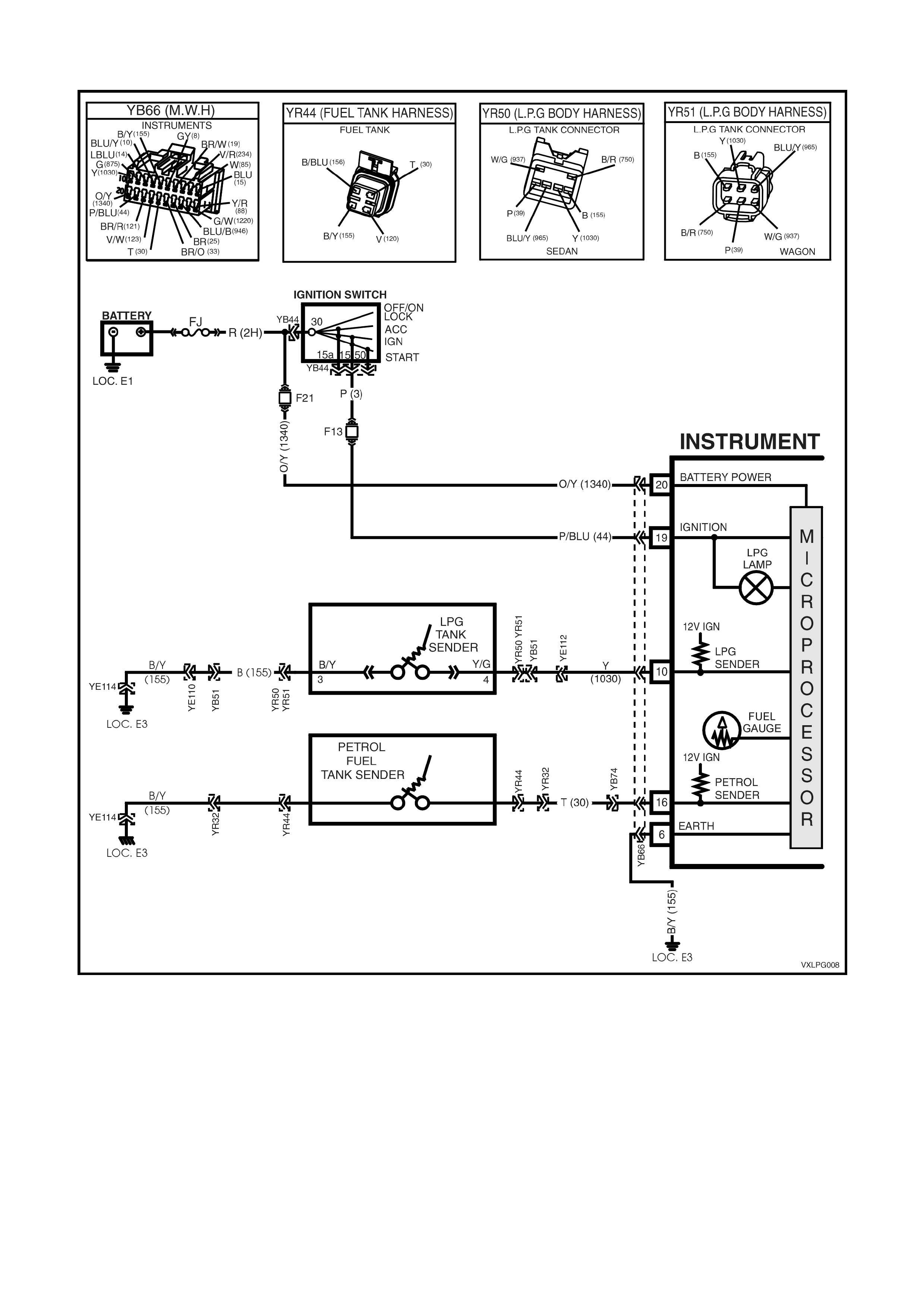
4.13 FUEL GAUGE DOES NOT OPERATE WHEN PETROL SELECTED
Figure 8A2-64

TEST DESCRIPTION
The numbers below refer to step numbers in the following diagnostic chart.
1. The LPG VEHICLE PRELIMINARY DIAGNOSIS CHECK must be the first step when diagnosing any LPG
system problem.
2. In this test Tech 2 is used to check the signal from the fuel gauge sender.
3. In this tes t T ech 2 is us ed to check circuit 30 (T an wire), if the f uel gauge sender unit s ignal is not 0 volts circuit
30 is open.
4. In this tes t T ech 2 is us ed to check circuit 30 (T an wire), if the f uel gauge sender unit s ignal is not 5 volts circuit
30 is shorted to earth.
5. This test confirms correct operation of the fuel gauge sender unit.
6. This test confirms correct fuel gauge sender unit operation.
STEP ACTION YES NO
1. 1. Has an LPG VEHICLE PRELIMINARY DIAGNOSIS
CHECK been performed. Go to step 2 Perform an LPG
VEHICLE PRELIMINARY
DIAGNOSIS CHECK.
2. 1. Install Tech 2 to DLC select Body/ Instruments / F2:
Data Display / F0: Instrument.
2. Scroll to Fuel Gauge Sender Signal.
3. Is the Fuel Gauge Sensor Signal 5 Volts.
Go to step 3. Go to step 4.
3. 1. With Tech 2 still connected.
2. Disconnect fuel gauge sender unit connector YR44.
3. Jumper circuit 30 (Tan wire) to a known good earth.
4. Is the Fuel Gauge Sensor Signal 0 Volts.
Go to step 6. Repair open in circuit 30
(Tan wire).
Verify repair.
4. 1. With Tech 2 still connected.
2. Disconnect fuel gauge sender unit connector YR44.
3. Is the Fuel Gauge Sensor Signal 5 Volts.
Go to step 5. Repair short to earth in
circuit 30 (Tan wire).
Verify repair.
5. 1. Disconnect connector YR44.
2. Check continuity of fuel gauge sender unit earth
circuit 155 (Black/Yellow wire) between connector
YR44 and a known good earth.
3. Is there continuity?
Go to step 6. Repair open in earth
circuit 156,
(Black/Blue wire).
Verify Repair.
6. 1. Test operation of fuel gauge sender unit.
(refer 2.3 SENDER UNIT in Section 12C of the VT
Series I Service Information).
2. Is fuel gauge sender unit operating correctly.
Check all connector
terminal retention.
Monitor Tech 2 Instrument
Data List while
manipulating wiring
harness to check for an
intermittent connection.
Replace fuel gauge
sender unit.
(refer 2.2 & 2.3 FUEL
SENDER ASSEMBLY in
Section 8A Fuel Tank of
the VT Series I Service
Information.

4.14 TECH 2 SCAN TOOL: ENGINE DATA
NOTE: When operating in the LPG mode all of the lef t hand oxygen sensor inf or mation will be fr ozen or invalid, this
is because the PCM only monitors the right hand oxygen sensor when operating on LPG. The values that are frozen
or invalid are shaded in the following table.
TYPI CAL D ATA VALUE S
SCAN POSITION Q UNITS DISP L AYED R IGNITION ON T ENGI NE RUNNING U
ENGINE SPEED RPM 0 RPM ± 100 RPM FROM DESIRE D RP M
(± 50 RPM IN DRIVE )
DESIRED IDLE S PEED RPM 0 RPM PCM IDLE COMMAND (V ARIES WITH
TEMPERATURE)
ENG. COOLANT TEMP (ECT) VOLTS VARIES VARIES
COOLANT TEMPERATURE DEGREES C VARIES VARIES
IAT VOLTS VARIES VARIES
INTAKE AIR TEMPERATURE DEGREES C VARIES VARIES
MAF SENSOR FREQUENCY Hz 0 Hz 2200-2500 Hz
MASS AI R FLOW GRA M /S EC 0 g/s 5 –10 g/s
MASS AI R FLW/CYL Mg/S 0.0 Mg/S 140 to 150 Mg/S
TPS SI GNA L VOLTS 0.36 V 0.36 V
THROTTLE ANGLE 0-100 % 0 % 0 %
RH 02 SENSOR READY YES/NO NO YES
LH 02 SENSOR READY YES/NO NO YES
RH 02 SENSOR Mv 447 Mv 100-1000 Mv AND VARYI NG
LH 02 SENSOR Mv 447 Mv 100-1000 Mv AND VARYI NG
RH ST FUEL TRIM + 100% TO –100% +0% + 0% +10% TO –10%
LH ST FUEL TRIM + 100% TO –100% +0% + 0% +10% TO –10%
LT FUEL TRIM R + 100% to – 100 % + 0 % + 0 % + 10% to – 10%
LT FUEL TRIM L + 100% to – 100 % + 0 % + 0 % + 10% to – 10%
LTFT ENABLE YES / NO NO NO
FUELING MODE OP EN / CLOSED
LOOP OPE N LOOP CLOSED LOOP
LTFT CELL CELL # 0 0
RH O2 STATUS RICH / LEAN LE A N LEAN
LH O2 STATUS RICH / LE A N LEAN LEAN
RH O2 CROSS CNTS COUNTS 0 0
LH O2 CROSS CNTS COUNTS 0 0
STFT DELTA 0 – 100 % 0 % 0 %
LTFT DELTA 0 – 100 % 0 % 0 %
DECEL FUEL CUTOFF NO/YES NO NO
INJ. P ULS E TIME Ms 27.5 Ms 3.25 Ms
INJECTOR V OLTA G E VOLTS 11.4 V 14.0 V
AIR / FUE L RATIO % 0.0 : 1 14.7 : 1
PURGE PWM % 0 % 10 %
EGR POS. COMMANDED % 0% 0%
EGR POS. FEEDBACK. % 0% 0%
EGR PINTLE S ENSOR VOLTS VOLTS 0.6 VOLT 0.6 V O LT
BATTERY VOLTAGE VOLTS 11. 3 V 14.0 V
REFERENCE V O LTS VOLTS 4.99 V 4.99 V
3X SIGNAL MISSING / PRESENT MISSING PRESENT
18X SIGNAL MISSING / PRESENT MISSING PRESENT
CAM SIGNAL MISSING / PRESENT MISSING PRESENT
IAC POSITION STEPS 169 STEPS 22 STEPS
LITERS P ER HOUR L/HR 00.00 1 – 2 L/Hour
IDL E RPM VAR IANT. RPM 0 R PM 0 RPM

TECH 2 SCAN DATA ENGINE STREAM (CONTINUED)
TYPICAL DATA VALUE S
SS
S
SCAN POSITION Q
QQ
Q UNITS DISPLAYED R
RR
R IGNITION "ON" T
TT
T ENGINE RUNNING U
UU
U
SPARK MODE BYPASS/EST BYPASS EST
SPARK ADVANCE DEGREES BTDC 14 ° BTDC + 14° BTDC
KNOCK SIGNAL CYLINDER 1 NONE/KNOCK
DETECTED NONE NONE
KNOCK SIGNAL CYLINDER 2 NONE/KNOCK
DETECTED NONE NONE
KNOCK SIGNAL CYLINDER 3 NONE/KNOCK
DETECTED NONE NONE
KNOCK SIGNAL CYLINDER 4 NONE/KNOCK
DETECTED NONE NONE
KNOCK SIGNAL CYLINDER 5 NONE/KNOCK
DETECTED NONE NONE
KNOCK SIGNAL CYLINDER 6 NONE/KNOCK
DETECTED NONE NONE
KNOCK SIGNAL ANY CYLINDER KNOCK/NONE NONE NONE
KNOCK RETARD # OF DEGREES 0 ° 0 °
KNOCK RETARD CYLINDER 1 # OF DEGREES 0 ° 0 °
KNOCK RETARD CYLINDER 2 # OF DEGREES 0 ° 0 °
KNOCK RETARD CYLINDER 3 # OF DEGREES 0 ° 0 °
KNOCK RETARD CYLINDER 4 # OF DEGREES 0 ° 0 °
KNOCK RETARD CYLINDER 5 # OF DEGREES 0 ° 0 °
KNOCK RETARD CYLINDER 6 # OF DEGREES 0 ° 0 °
TCC SOLENOID ON / OFF OFF OFF
VEHICLE SPEED KM / H 0 KM/H 0 KM/H
A/C REQUEST ON /OFF OFF OFF
A/C CLUTCH ON /OFF OFF OFF
A/C PRESS. VOLTS VOLTS 1 - 2 V 1 - 2 V
A/C PRE S SURE SENS OR kP a 352 kPa 600 - 700 kPa A/C OFF
800 - 1000 kPa A/C ON
HIGH SPEED FAN ON / OFF OFF OFF
LOW SPEED FAN REQUEST ON / OFF OFF OFF
THEFT STATUS NO START/START START START
STARTER RELAY OFF/ON ON ON
FUEL PUMP RELAY ON / OFF OFF ON
CRANK TIME SEC 0.0 SEC 0.5 SEC
DTC STA T US NO DTC(s)/
DTC(s) SET NO DTC(s) NO DTC(s)
TIME FROM START TIME 0:00:00 VARIES
CHECK P OWERTRAI N
LAMP OFF/ON ON OFF
REQUESTE D TORQUE Nm 214 Nm 642Nm
(N.m WILL VARY DEPENDING ON T HE
ABS/ETC CONTROL MODULE
REQUEST ED TORQUE)
ACTUAL TORQUE Nm 0 Nm 35-45 N.m
(Nm WILL CLOSELY FOLLOW
REQUEST ED TORQUE DURING
TRACTION CONT ROL)
LOW OIL PRESSURE NO/YES YES NO
LPG SWITCH OFF/ON OFF OFF
LPG FUEL ENABLE NO/YES YES YES
FUEL PETROL / LPG LPG LPG
LPG FUEL CONTROL VALVE 0-100 % 100% 40%
LPG MODE ENABLED NO/YES NO YES
LPG LOW PETROL CUTOUT NO/YES NO NO
LPG SMART SOLENOID
ENABLED ON/OFF OFF OFF

5. SPECIFICATIONS
LPG cylinder ‘fillable’ capacity - Sedan................................................ 74 litres (± 2 litres)
LPG tank ‘fillable’ capacity - Wagon .................................................... 60 litres (± 2 litres)
Converter primary pressure ................................................................. 1 - 1.5 psi (7 - 10 kPa)
Converter secondary pressure ............................................................ Negative 1 - 1.5 inches W.C
(Negative 24 - 38 mm W.C.)
Contents gauge sender unit resistance ............................................... Empty : 40 Ohms
Full: 255 Ohms
Fuel Control Valve (FCV) resistance ................................................... 19 - 21 Ohms @ 20°C
LPG lock-off coil resistance ................................................................ 17 - 27 Ohms @ 20°C
LPG lock-off pressure rating................................................................ 1200 kPa
Spark plug gap..................................................................................... 1.4mm

