SECTION 4A - REAR SUSPENSION
IMPORTANT:
Before perfo rming any Service O peration or oth er procedu re described in t his Sectio n, refer to Section 00
CAUTIONS AND NOTES for correct workshop practices with regard to safety and/or property damage.
1. GENERAL I NFORMATION
1.1 VX SERIES II MODELS
The IRS as fitted to VX Series II Models carries over from VT Series II Models, noting the following:
• For improved handling, multi-link control arm s have been added as s tandard equipment. Ref er to Fig. 4A-1 for
information relating to the multi-link control arm components.
• For improved handling, new voided type inner trailing arm bushes have been introduced.
• For improved handling, the rear suspension trailing arms have been revised to decrease rear wheel camber.
For information relating to the rear suspension as fitted to VX Series II Models not covered in this Section, refer to
Section 4A REAR SUSPENSION in the VT Series I and VT Series II Service Information.
Techline

1.2 WH SERIES II MODELS
The IRS as fitted to VU Series II Models carries over from VU Series I Models.
• For improved handling, the rear suspension trailing arms have been revised to decrease rear wheel camber.
NOTE: Multi-link control arms are not fitted to VU Series II Models
For information r elating to the rear s us pension as f itted to VU Ser ies II Models not co vered in this Sec tion, refer to Sec tion
4A REAR SUSPENSION in the VU Series I Service Information, in conjunction with Section 4A REAR SUSPENSION in
the VT Series I and VT Series II Service Information.
1.3 WH SERIES II MODELS
The IRS as fitted to WH Series II Models carries over from WH Series I Models, noting the following:
• For im proved handling, additional control ar ms have been added as s tandard equipment. Ref er to Fig 4A-1 for
information relating to the multi-link control arm components.
• For improved handling, the rear suspension trailing arms have been revised to decrease rear wheel camber.
• For improved handling, new voided type inner trailing arm bushes have been introduced.
• Level ride suspension is only available as a production option (FX3) on all WH Series II Models.
• T he height s ensor brack et in Ser ies II Models, f itted with level ride suspension, has been revised to pr event the
harness fouling with the RH drive shaft.
For inf orm ation relating to the rear suspension as fitted to WH Series II Models not c overed in this Section, ref er to
Section 4A REAR SUSPENSION in the WH Series I Service Information, in conjunction with Section 4A REAR
SUSPENSION in the VT Series I and VT Series II Service Information.
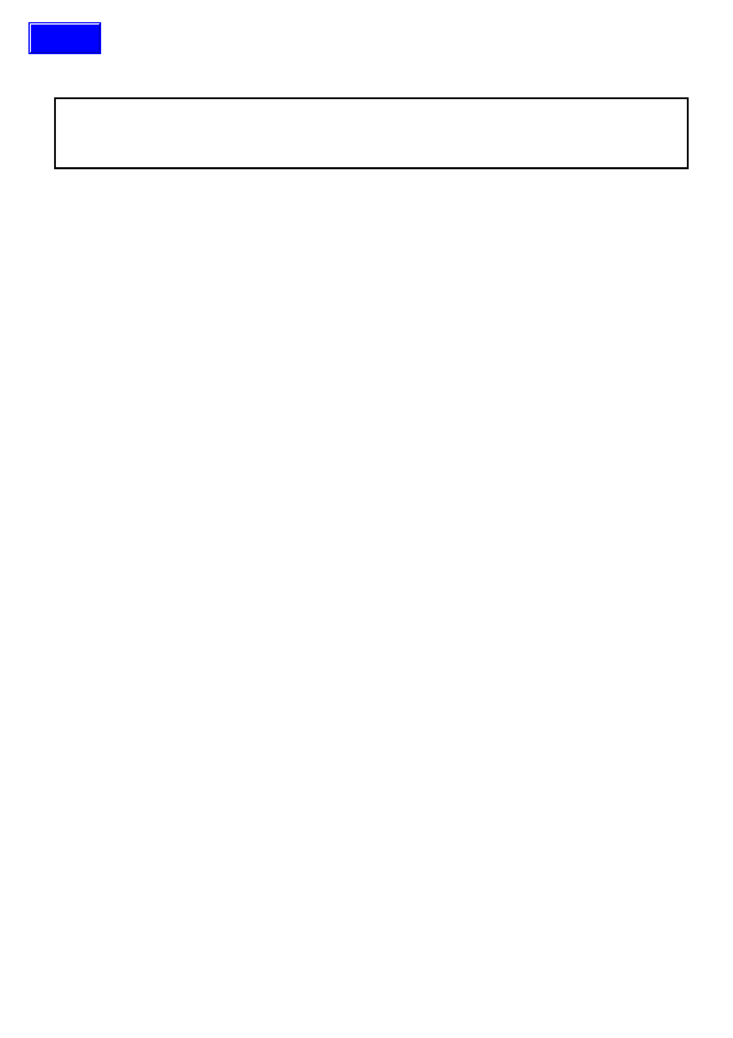
Figure 4A-1
Legend
1. Multi-link control arm outer shaft 3. Multi-link control arm inner shaft
2. Multi-link control arm adjuster shaft 4. Multi-link control arm adjuster lock nuts

2. SERVICE OPERATIONS
2.1 SERVICE NOTES
All rear suspension fasteners are important attaching parts because they affect the performance of vital
components and/or could result in major repair expense. Where specified in this Section, fasteners MUST be
replaced with ones of the same part number or with an equivalent part. Do not use a replacement part of inferior
quality or substitute design.
Torque values must be used as specified during reassembly to ensure proper retention of all rear suspension
components.
To ens ure pr oper retention of the m ulti- link contr ol ar m, the ball joint s tud and the c or res ponding taper ed hole in the
semi-trailing arm must be cleaned of dirt and foreign matter prior to reinstallation.
2.2 TRAILING ARM BUSHES
REPLACE
1. Remove the trailing arm, refer to
2.3 TRAILING ARM in Section 4A REAR
SUSPENSION in the VT Series II Service
Information
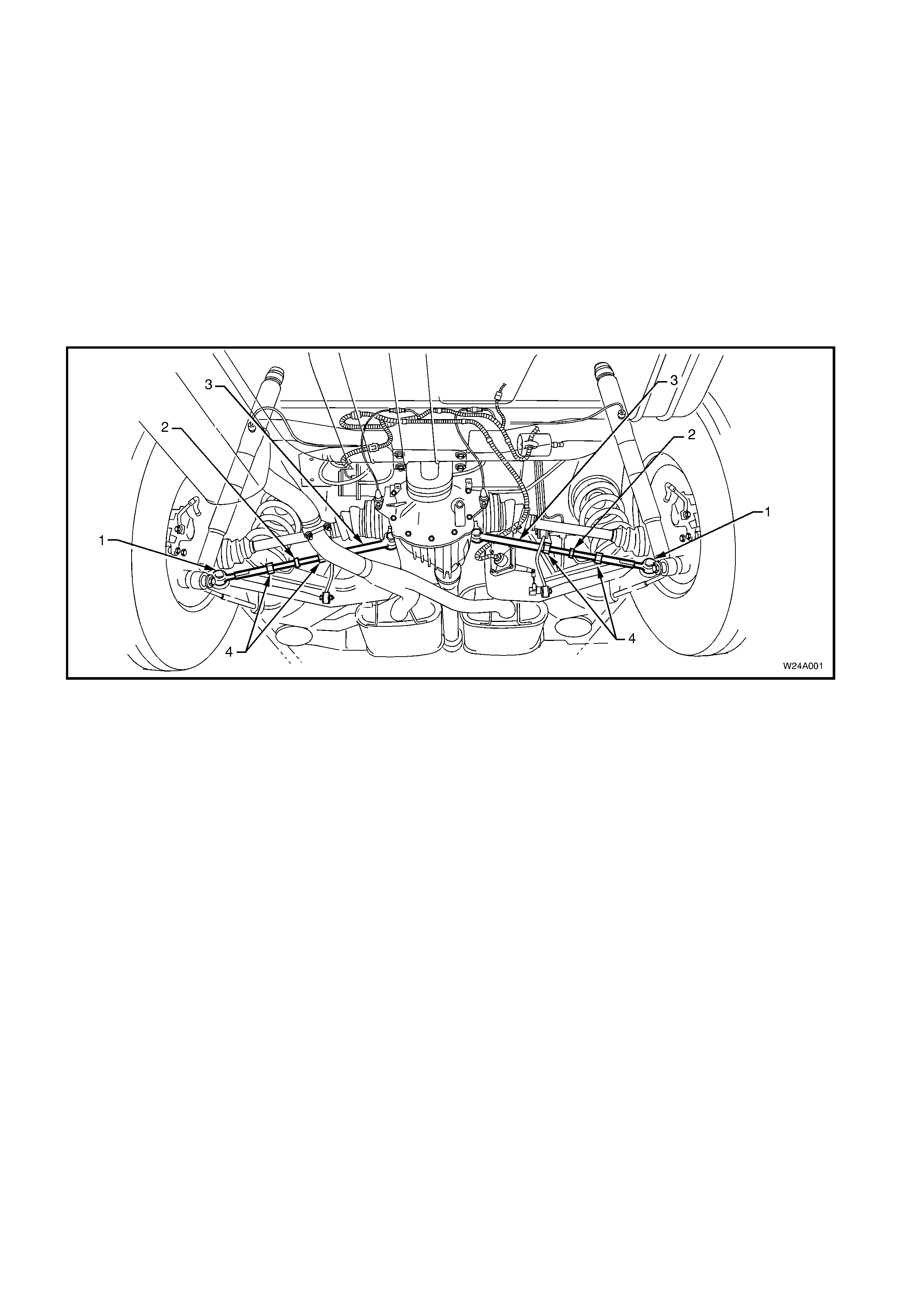
2. With the trailing arm (1) removed, press the
bushing (2) from the trailing arm using Special
tools number KM619-3 and KM619-4.
Figure 4A-2
3. Lightly coat the outside surface of the new
bushing with a soapy water solution.
4. Position the new bus h into the rear suspension
control arm, ensuring to align the edge of one
of the voids (1) in the bush with the welded
seam in the tr ailing arm ( 2) as shown in Figure
4A-3.
Figure 4A-3
5. Press the new bushing (1) into the rear
suspension control arm (2) using Special tools
number KM619-1, KM619-2 and KM619-4.
Figure 4A-4

2.3 MULTI-LINK CONTROL ARM
Figure 4A-5
INSPECT
Inspection of the multi-link control arm may be required
in the following circumstances:
• Poor handling.
• Uneven tyre wear.
A visual inspection of the multi-link control arm should
be perfor med with the arm installed to the vehicle. The
following conditions would require replacement of the
multi-link control arm or some of its components:
• Bent or damaged shafts.
• Bent or damaged adjusting shaft.
• Excessive play in the ball joint.
• Excessive play in the inner bush.
• Damaged ball joint boot. Legend
1. Ball joint retaining nut
2. Multi-link control arm outer shaft
3. Outer adjuster lock nut
4. Adjusting shaft
5. Inner adjuster lock nut
6. Multi-link control arm inner shaft
7. Multi-link control arm inner bush
8. Multi-link control arm to rear suspension crossmember
retaining bolt
REMOVE
1. Using a floor jack under the centre of the
differential carrier, jack up rear of vehicle then
place safety stands under trailing arms to support
weight of vehicle.
2. If multi-link control arm is being disassembled,
measure and record the length of the adjusting
shaft between the lock nuts.
3. Loos en multi- link contr ol arm ball j oint retaining nut
until level with the top of the ball joint stud.
4. Using special tool No. E-9332-A (1), tighten the
lever forcing screw (2) to press the ball joint stud
free from the taper in the semi trailing arm and
remove ball joint retaining nut.
5. Remove the multi-link control arm to rear
suspension crossmember retaining nut and bolt.
6. Carefully manoeuvre the multi-link control arm
from the vehicle.
NOTE: The following fasteners MUST be replaced
when performing this operation:
n
nn
n
Multi-link control arm ball joint to semi trailing
arm attaching nut.
n
nn
n
Multi-link control arm to rear suspension
crossmember attaching nut.
Figure 4A-6
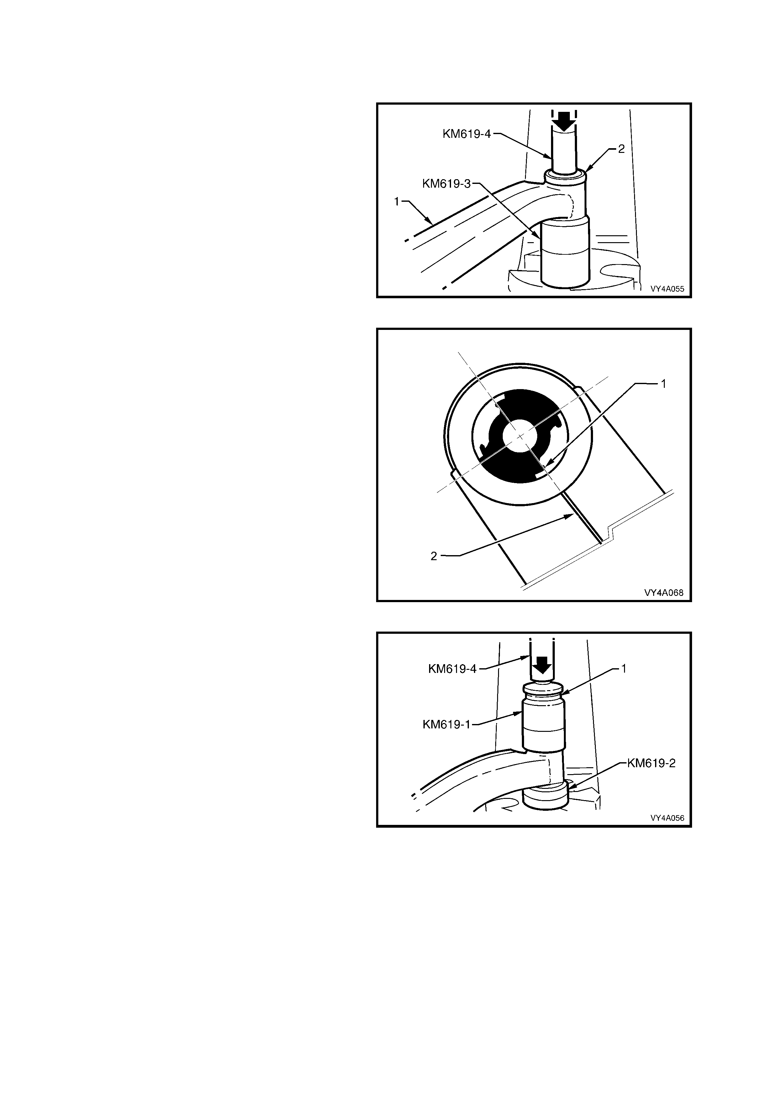
DISASSEMBLE
1. Using a suitable vice with soft jaws, retain the
centre adjusting shaft (1) and loosen the two lock
nuts (2).
2. Rotate the inner shaft (3) clockwise (noting the
number of tur ns ) until the inner shaf t is disengaged
from the threaded area of the adjusting shaft.
NOTE: The inner multi-link c ontrol ar m s haf t, the inner
lock nut and the corresponding end of the adjuster
shaft have left-hand threads.
3. Rotate the outer shaft counter clockwise (noting
the number of turns) until the outer shaft is
disengaged from the threaded area of the
adjusting shaft.
4. Remove the lock nuts from the adjusting shaft.
Figure 4A-7
REASSEMBLE
The reassembly procedure for the multi-link control
arm is the reverse of the disassembly procedure.
Ensure that the inner and outer shafts are installed
onto the adjusting shaft with the correct number of
turns and that the arm, when assembled, is set to the
correct length.
NOTE 1: The inner multi-link control arm shaft, the
inner lock nut and the corresponding end of the
adjuster contain left-hand threads.
NOTE 2: The multi-link control arm lock nuts should
only be tightened when the arm is installed into the
vehicle and the suspension is under load.
MULTI-LINK CONTROL ARM BALL
JOINT RETAINING NUT 55 – 70 Nm
TORQUE SPECIFICATION
MULTI-LINK CONTROL ARM INNER
SHAFT ATTACHING NUT 55 – 70 Nm
TORQUE SPECIFICATION
MULTI-LINK CONTROL ARM INNER
SHAFT ATTACHING BOLT 55 – 70 Nm
TORQUE SPECIFICATION
MULTI-LINK CONTROL ARM
ADJUSTING SHAFT LOCK NUT 50 Nm
TORQUE SPECIFICATION
REINSTALL
The re installation procedure f or the m ulti-link control arm is the reverse of the rem oval procedure, ensuring that the
inner and outer shafts are installed with the correct num ber of turns and that the arm, when installed, is set to the
correct length.
NOTE 1: T he multi- link contr ol ar m lock nuts s hould only be tightened when the arm is ins talled into the vehic le and
the suspension is under load.
NOTE 2: The ball joint may be over extended if allowed to move during the tightening of the lock nut, resulting in
possible dam age to ball joint internals. When tightening the m ulti-link contr ol arm lock nuts, use a suitable spanner
on the hexagonal crimped section near the ball joint to prevent the ball joint from being deflected.
NOTE 3: To ensur e proper retention of the m ulti-link control arm , the ball joint stud and the corres ponding tapered
hole in the semi-trailing arm must be cleaned of dirt and foreign matter prior to reinstallation.
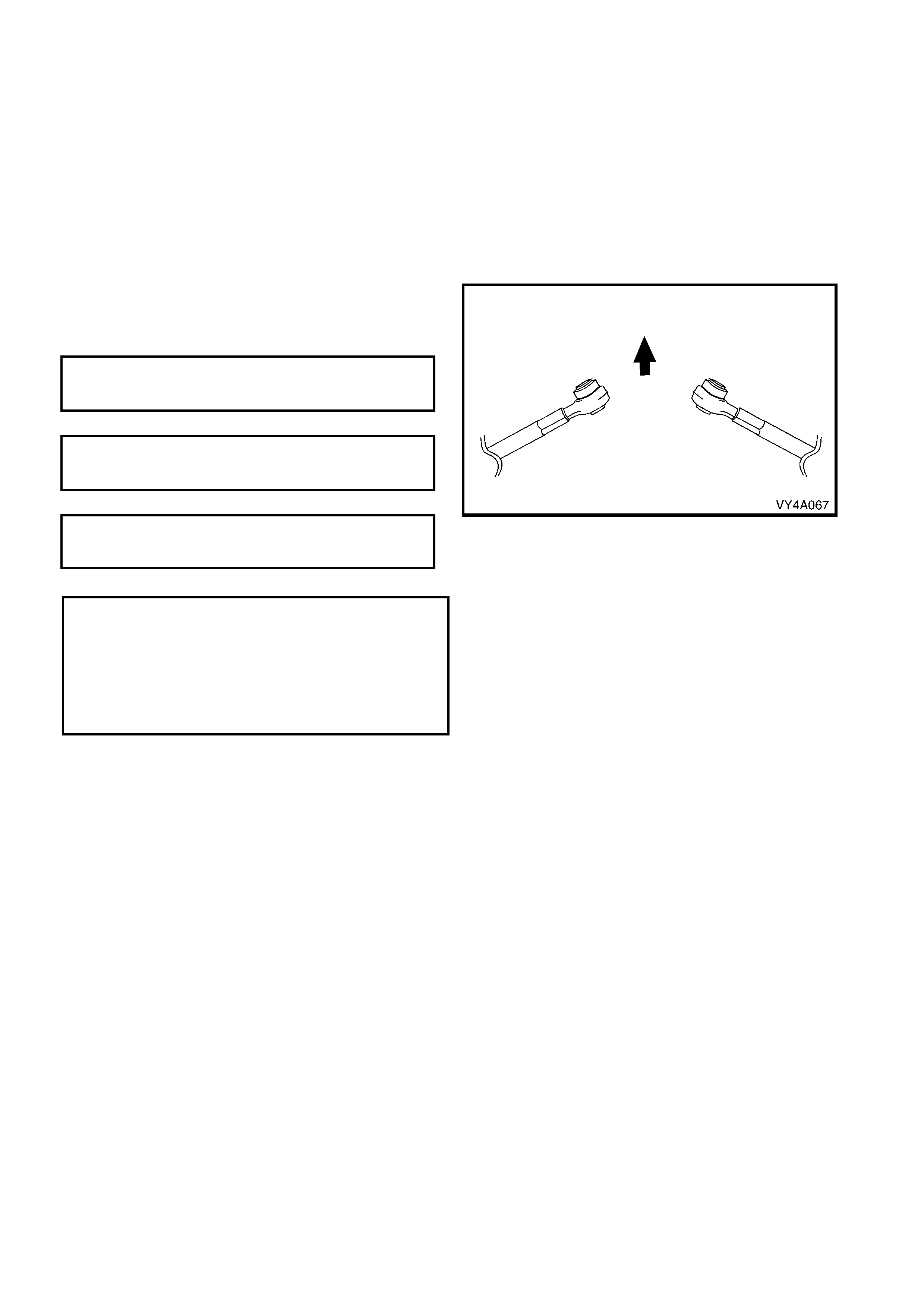
NOTE 4: The inner additional control arm shaft,
MUST be installed into the vehicle with the
protruding side of the bush towards the front of the
vehicle.
( $ ) ADDITIONAL CONTROL ARM BALL
JOINT RETAINING NUT
TORQUE SPECIFICATION 55 – 70 Nm
( $ ) ADDITIONAL CONTROL ARM INNER
SHAFT ATTACHING NUT
TORQUE SPECIFICATION 55 – 70 Nm
ADDITIONAL CONTROL ARM INNER
SHAFT ATTACHING BOLT
TORQUE SPECIFICATION 55 – 70 Nm
Figure 4A-8
NOTE: The following fasteners MUST be replaced
when performing this operation:
n
nn
n
Multi-link control arm ball joint to sem i trailing arm
attaching nut.
n
nn
n
Multi-link control arm to rear suspension
crossmember attaching nut.
2.4 REAR WHEEL ALIGNMENT CHECKING
CAMBER AND TOE CHECK
The following conditions must be checked to ensure accurate measurement of rear wheel alignment.
1. Tread on rear tyres must be uniform and in a roadworthy condition.
2. Tyre pressures must be equal on both sides and to the correct pressure. Refer to the tyre placard on the vehicle
for correct tyre pressures.
3. Wheel rim flange lateral run-out should be checked and to specification, refer to Section 10 WHEELS AND
TYRES in the VX Series I, VU Series I or WH Series I Service Information.
4. The vehicle must be at kerb height, i.e. vehicle ready to drive with all fluids at recommended levels, fuel tank
full, without driver, passengers or luggage.
5. Stabilise vehicle springs by bouncing the rear of vehicle several times.
This step is very important, particularly if the vehicle was raised before checking. In that instance, the camber
angle measured will be incorrect, because the trailing arms will not have resumed their normal position.
NOTE 1: Camber is not adjustable. If there is any deviation from specification, the condition and alignment of the
crossmember, trailing arms and bushes should be checked.
NOTE 2: W hen checking wheel toe, if one side has excessive toe-in and the opposite side has excessive toe-out,
this may be due to:
a. The trailing arm attaching nuts being tightened when the vehicle was not at kerb height.
b. The rear crossmember not correctly aligned to the vehicle centreline.
To correct such a condition, check the rear crossmember alignment, as detailed in Section 1A2 BODY
DIMENSIONS, in the VT Series I Servic e Information. F ollowing the alignm ent procedure, tighten fastenings to the
following torque specifications.
NOTE: Those fasteners marked ($) below must be replaced after loosening.
REAR CROSSMEMBER FRONT
MOUNTING BOL T
TORQUE SPECIFICATION 125 Nm, plus
30° – 40°
turn angle
($) REAR CROSSMEMBER REAR MOUNT
TO VEHICLE BODY ATTACHING BOLT
TORQUE SPECIFICATION 30 – 40Nm
($) TRAILING ARM TO REAR
CROSSMEMBER ATTACHING NUT
TORQUE SPECIFICATION 95 – 105Nm
Important: Alignment of the rear crossmember requires the use of a special tool. Attempting to align the rear
crossmember without it will not prove to be successful.
2.5 REAR SUSPENSION TOE ADJUSTMENT
The rear suspension toe setting is adjustable in
vehicles equipped with the multi-link rear suspension
by varying the length of the multi-link control arm. To
adjust toe setting:
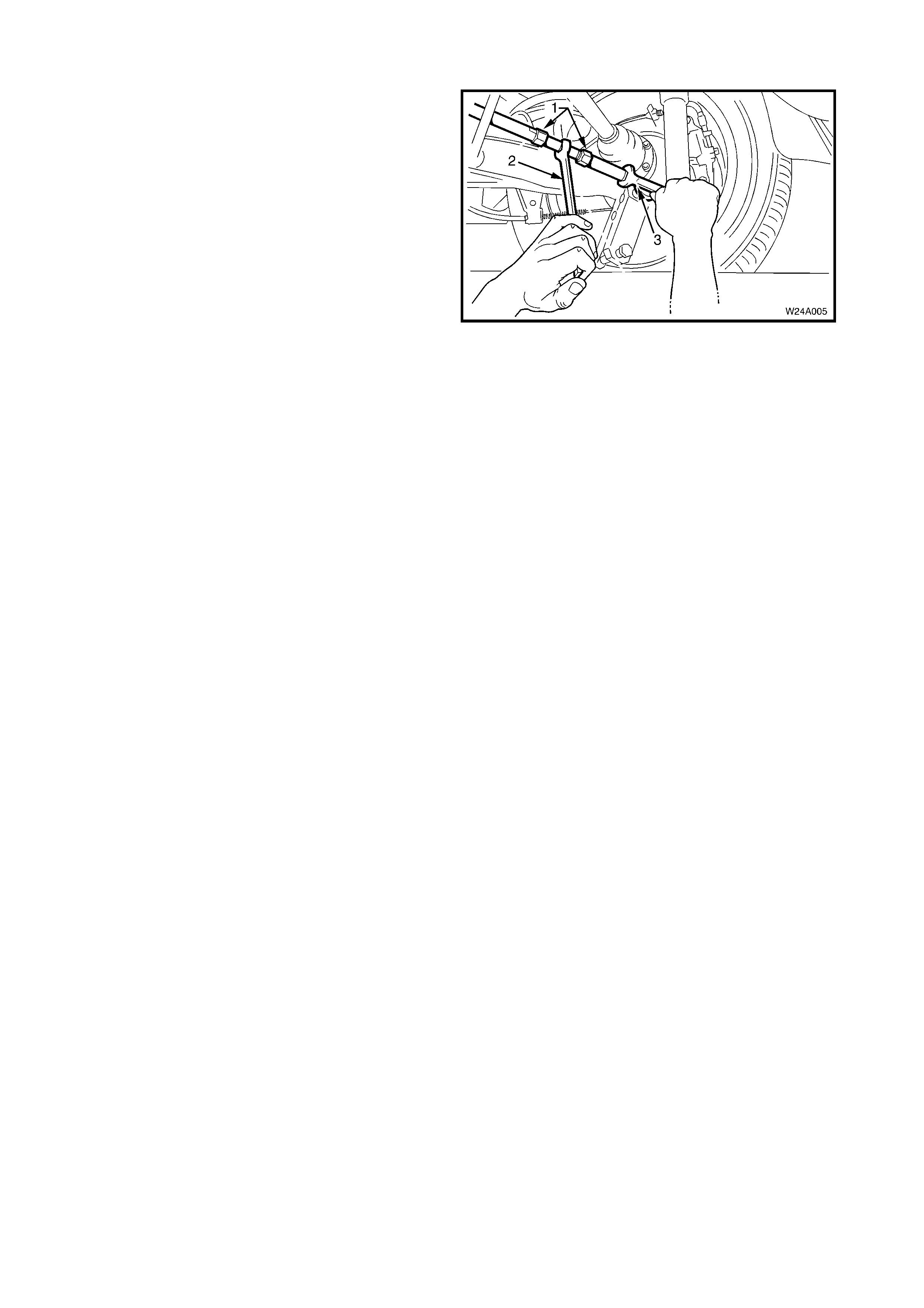
1. Loosen the two lock nuts (1).
2. Using a suitable spanner (2), rotate the centre
adjusting shaft.
3. Tighten the two lock nuts.
NOTE 1: The inner multi-link control arm shaft, the
inner lock nut and the corresponding end of the
adjuster have left-hand threads.
NOTE 2: Increasing the multi-link control arm length
will increase rear wheel toe in and visa versa.
NOTE 3: The ball joint may be over extended if
allowed to move during the tightening of the lock nuts
causing damage to ball joint internals. During the toe
adjustment procedure, use a suitable spanner (3) on
the hexagonal crimped section near the ball joint to
prevent the ball joint from being deflected.
Figure 4A-9
3. SPECIFICATIONS
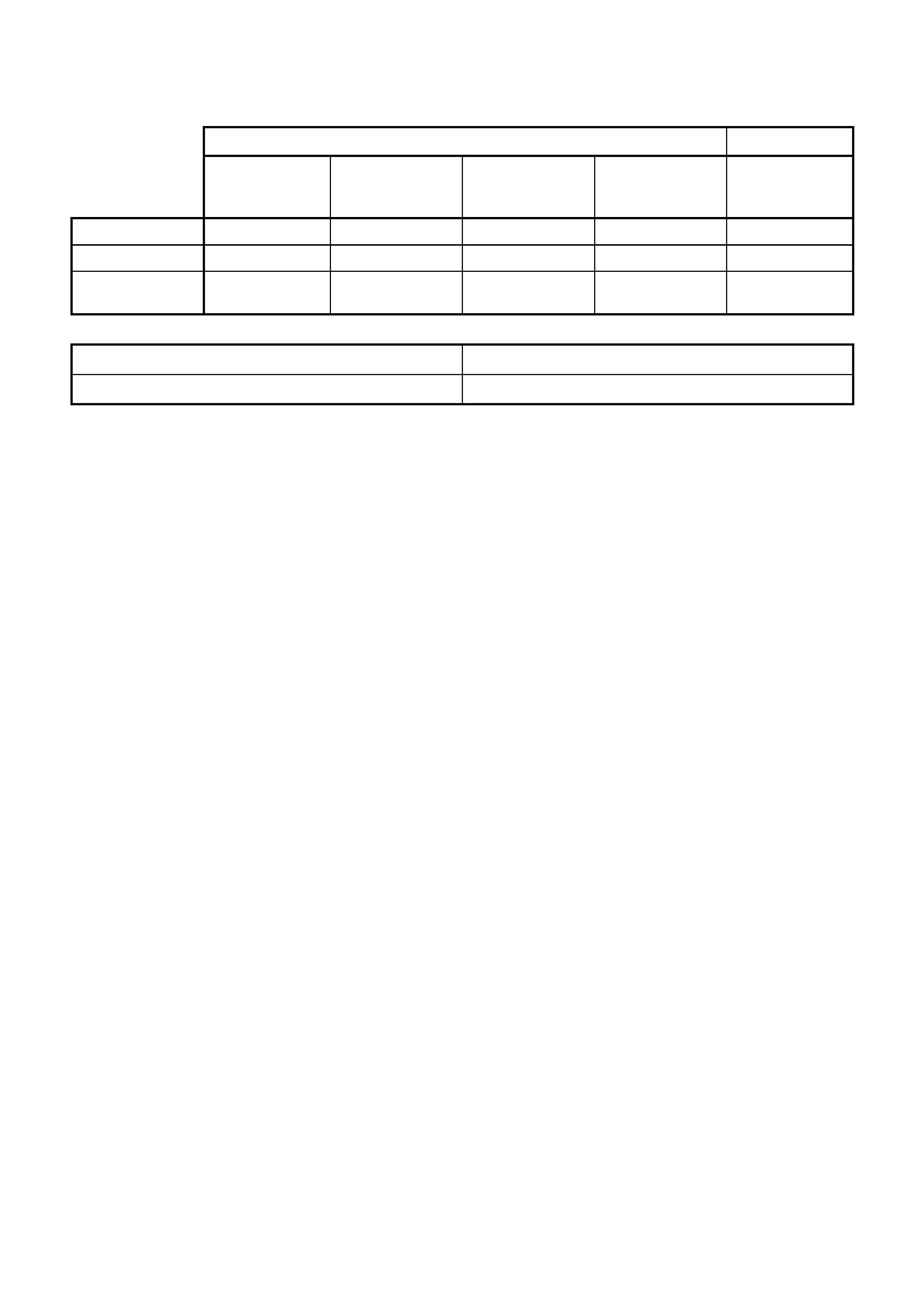
REAR SUSPENSION: SERVICE ALIGNMENT DATA
SWB Sedan, Wagon and Utility LWB Sedan
Standard
Suspension
(Exc Calais)
Standard
Suspension
(Calais)
Sports
Suspension
(FE2)
Country pack
suspension
(V5W)
Standard
Suspension
REAR TRACK 1577 mm 1567mm 1572 mm 1572 mm 1567 mm
CAMBER -0° 7' to -1° 23’ -0° 7' to -1° 23’ -0° 25' to -1° 41’ +0° 13' to -1° 03’ -0° 7' to -1° 23’
TOE - Degrees
per Wheel +0° 20' to +0° 0' +0° 20' to +0° 0' +0° 22' to +0° 02' +0° 18' to -0° 02' +0° 20' to +0° 0'
VARIATION SIDE TO SIDE (ALL MODELS)
Camber 0° 35’ Maximum
Wheel Toe 0° 20’ Maximum
Dimens ions s hown are for a vehic le at curb height, i.e. vehic le ready to drive with all fluids at the rec om m ended
levels, the fuel tank full and without driver, passenger/s or luggage.
Refer to 2.4 REAR WHEEL ALIGNMENT CHECKING in this Section, for specific details.

4.TORQUE WRENCH SPECIFICATIONS
Nm
§
Multi-link Control Arm Ball Joint to Semi Trailing Arm
Retaining Nut........................................................................... 55 – 70
§
Multi-link Control Inner Shaft to Rear Suspension
Crossmember Retaining Nut................................................... 55 – 70
§
Multi-link Control Inner Shaft to Rear Suspension
Crossmember Retaining Bolt................................................... 55 – 70
• Multi-link Control Adjusting Shaft Lock Nut ............................. 50
§
Fasteners must be replaced after loosening.
• Vehicle must be at curb height before final tightening.
♦ Fasteners have micro encapsulated sealant applied
and should be replaced after being loosened. If in
doubt, replacement is recommended.
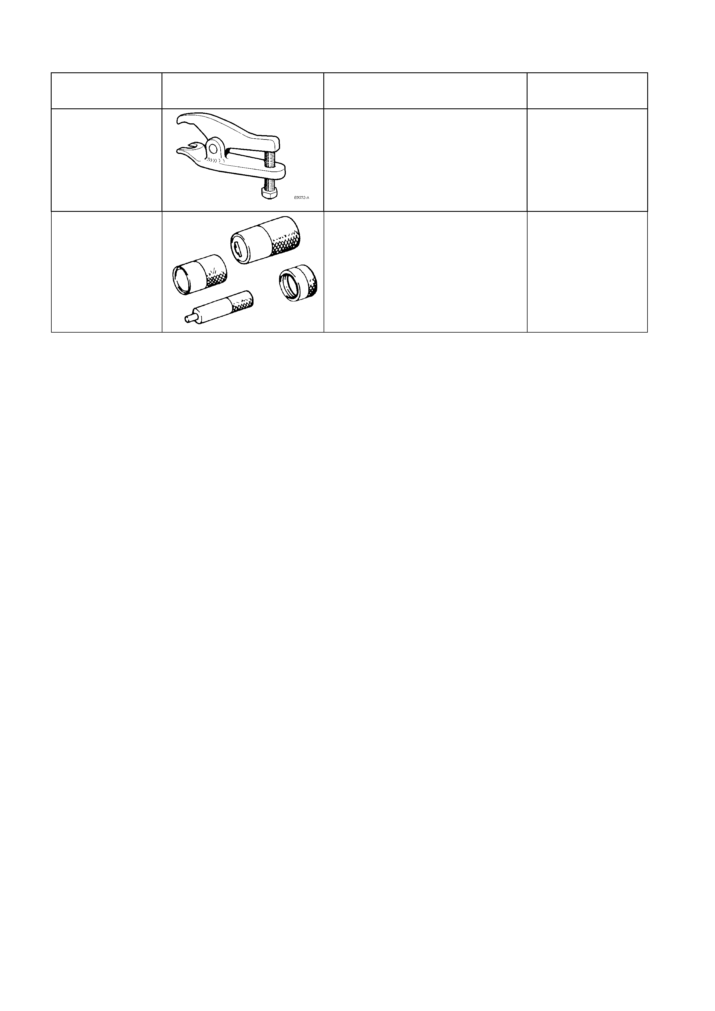
5. SPECIAL TOOLS
TOOL NUMBER ILLUSTRATION DESCRIPTION TOOL
CLASSIFICATION
E 9332-A
BALL JOINT RELEASE TOOL
Used to release the multi-link
control arm ball joint from the semi
trailing arm.
Previously released.
Desirable
KM619 REMOVER/INSTALLER
Previously released.
Used to press bushing from and
into trailing arms.