
SECTION 8A2 - LPG SYSTEM
IMPORTANT:
Before performing any Service Operation or other procedure described in this Section, refer to Section
00 CAUTIONS AND NOTES for correct workshop practices with regard to safety and/or property
damage.
1. GENERAL INFORMA TION
1.1 VX SERIES II MODELS
Liquef ied P etrol eum Gas (LPG ) Pro duc ti on O ption KL7 as f itte d t o VX S eries II Mo dels c arr ies o ver f rom VX S eries
I Models noting the following:
• The remote filler assembly has been revised in sedan models.
• The filler line f rom the rem ote fil ler as sem bl y to the LPG c ylinder has been re-r outed in s edan m odels and no w
enters the load compartment through the same point as the rear service line.
• The convoluted tube in the load compartment that contained the filler line has been deleted in sedan models.
• The convoluted tube from the elbow at the LPG cylinder to the load compartment floor that previously
contained the rear service line also contains the filler line for Sedan Models.
• The elbow for the convoluted tubes connection to the LPG cylinder in VX Series I Sedan Models, has been
removed from VX Series II Sedan Models. B oth filler line and rear service line (LPG cylinder to floor) are now
contained in one convoluted tube.
For information relating to the LPG system as fitted to VX Series II Models not covered in this section, refer to
Section 8A2 LPG SYSTEM in the VX Series I Service Information, in conjunction with SEDAN LPG SYSTEM or
WAGON AND SEDAN ACCESSORY LPG SYSTEM in the VT Series I and VT Series II Service Information.

1.2 VU SERIES II MODELS
Liquef ied Petro le um Gas ( LPG) Prod uc tio n O pti on KL7 as f itted to VU S eries II Mo dels car ries o ver f r om VU Series
I Models For information relating to the LPG system as fitted to VU Series II Models not covered in this section,
refer to Section 8A2 LPG SYSTEM in the VU Series I Service Information, in conjunction with Section 8A2 LPG
SYSTEM in the VX Series I Service Information, in conjunction with SEDAN LPG SYSTEM or WAGON AND
SEDAN ACCESSORY LPG SYSTEM in the VT Series I and VT Series II Service Information.
NOTE: Liquified Petroleum Gas (LPG) is not available for WH Series Models.
2. SERVICE OPERATIONS
2.1 REMOTE FILLER VALVE AND CONNECTOR PIPE - SEDAN
REMOVE
CAUTION: Ensure that there are no naked flames or
other sources of ignition in the vicinity.
1. Park the vehicle in a well ventilated area, away
from any ignition source.
2. From inside the rear load compartment, remove
the cylinder valve box cover.
3. Ensure the manual service valve is turned 'OFF'
and the battery earth lead is disconnected.
4. Drain the service lines of LPG, refer
2.1 DRAINING THE SERVICE LINES in Section
2 LPG SYSTEM, VT SEDAN WITH
PRODUCTION LPG in the VT Series II Service
Information.
WARNING: The vehicle CANNOT be run on LPG in
the workshop unless the w orkshop is a “Specia list
Gas Workshop” (in accordance with the current
Australian Standards AS2746 – 1985) and LPG is
specifically required for testing.
Theref ore, the vehic le ma y only enter t he work shop at
the completion of the service line draining procedure,
with the manual service valve closed, all LPG in the
service lines exhausted and the vehicle running on
petrol. Then, and only then, can the vehicle enter the
workshop.
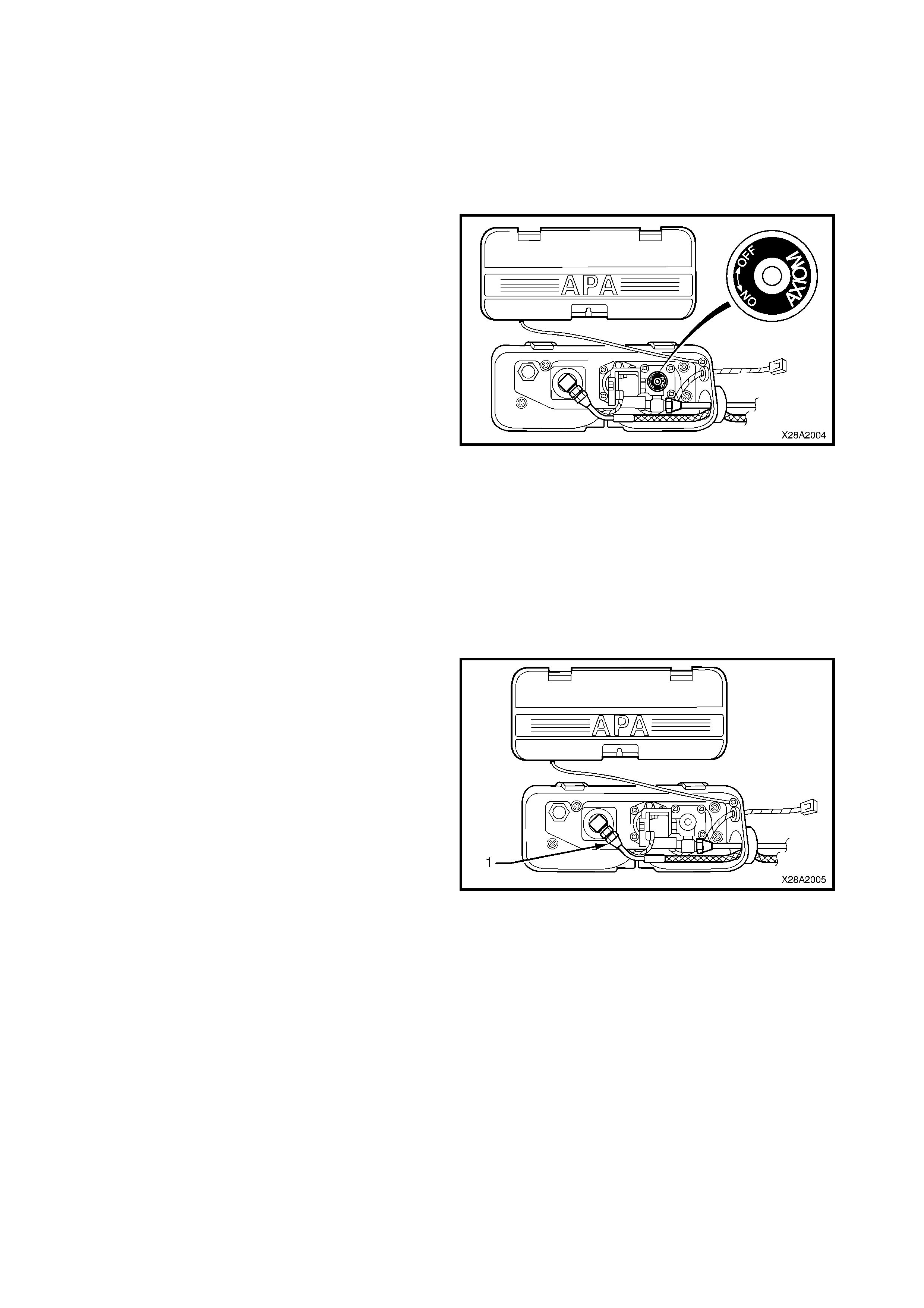
Figure 8A2-1
5. From inside the LPG valve box, (while holding AFL
elbow) crack open filler line to AFL elbow
connector (1) and allow residual LPG to escape.
CAUTION: The filler line will contain LPG under
pressure. Once all the LPG in the line has
dispersed, unscrew filler line connector
completely from AFL elbow.
Figure 8A2-2
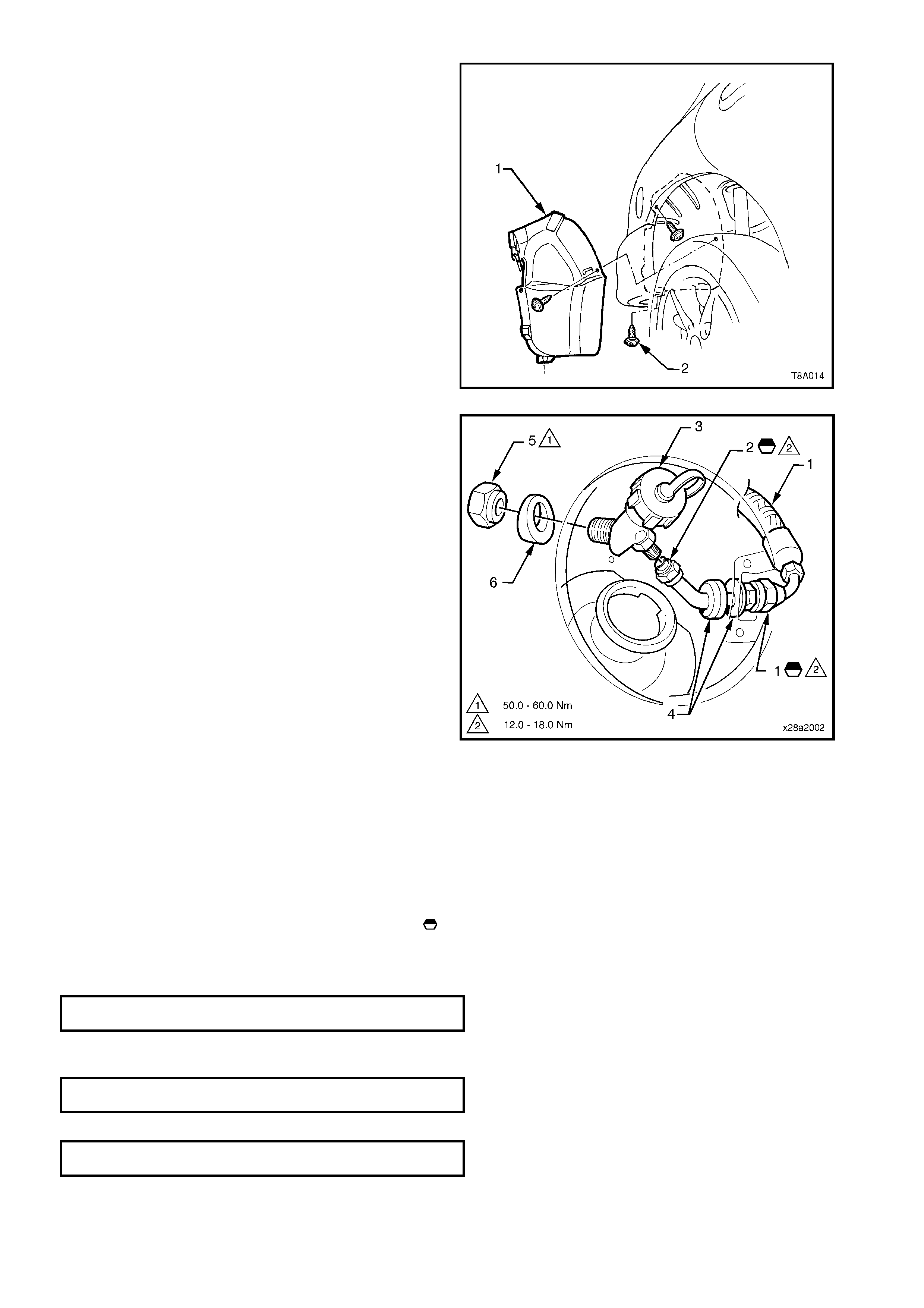
6. Remove the six screws (2) retaining the RH rear
wheelhouse liner (1) and remove liner from
wheelhouse.
Figure 8A2-3
7. From inside the rear wheel house, disconnect the
rear filler line hose (1) from the filler valve
connector pipe (2).
8. Disconnect the connector pipe from the remote
filler v al ve (3) a nd car ef ul l y moneuvre the pi pe an d
two grommets (4) into fuel filler recess.
9. From inside the rear wheelhouse, remove the nut
(5) and spacer (6) retaining the remote filler to th e
fuel filler recess.
10. Remove the remote filler valve
Figure 8A2-4
REINST ALL
Reinstallation if the remote filler valve and connector
pipe is the reverse of the removal procedur e, noting the
following:
1. Clean the mating threads on filler line, connector
pipe and remote filler valve.
2. Apply Loctite 577 sealant to filler line, connector
pipe and remote filler valve threads marked in
Figs. 8A2-4 and 8A2-7.
3. Tighten remote filler valve retaining nut to the
specified torque specification.
FILLER VALVE RETAINING NUT
TORQUE SPECIFICATION 50 - 60Nm
4. Tighten filler line connectors to the specified torque
specification.
CONNECTOR PIPE TO FILLER VALVE
TORQUE SPECIFICATION 12 - 18Nm
CONNECTOR PIP E TO FILLER L INE
TORQUE SPECIFICATION 12 - 18Nm
2.2 FILLER LINE - SEDAN
REMOVE
CAUTION: Ensure that there are no naked flames or
other sources of ignition in the vicinity.
1. Park the vehicle in a well ventilated area, away
from any ignition source.
2. With the rear decklid cover open, remove the
cylinder valve box cover.
3. Ensure the manual service valve is turned 'OFF'
and the battery earth lead is disconnected.
4. Drain the service lines of LPG, refer
2.1 DRAINING THE SERVICE LINES in Section
2 LPG SYSTEM, VT SEDAN WITH
PRODUCTION LPG in the VT Series II Service
Information.
WARNING: The vehicle CANNOTbe run on LPG in
the workshop unless the w orkshop is a “Specia list
Gas Workshop” (in accordance with the current
Australian Standards AS2746 – 1985) and LPG is
specifically required for testing.
Theref ore, the vehic le ma y only enter t he work shop at
the completion of the service line draining procedure,
with the manual service valve closed, all LPG in the
service lines exhausted and the vehicle running on
petrol. Then, and only then, can the vehicle enter the
workshop.
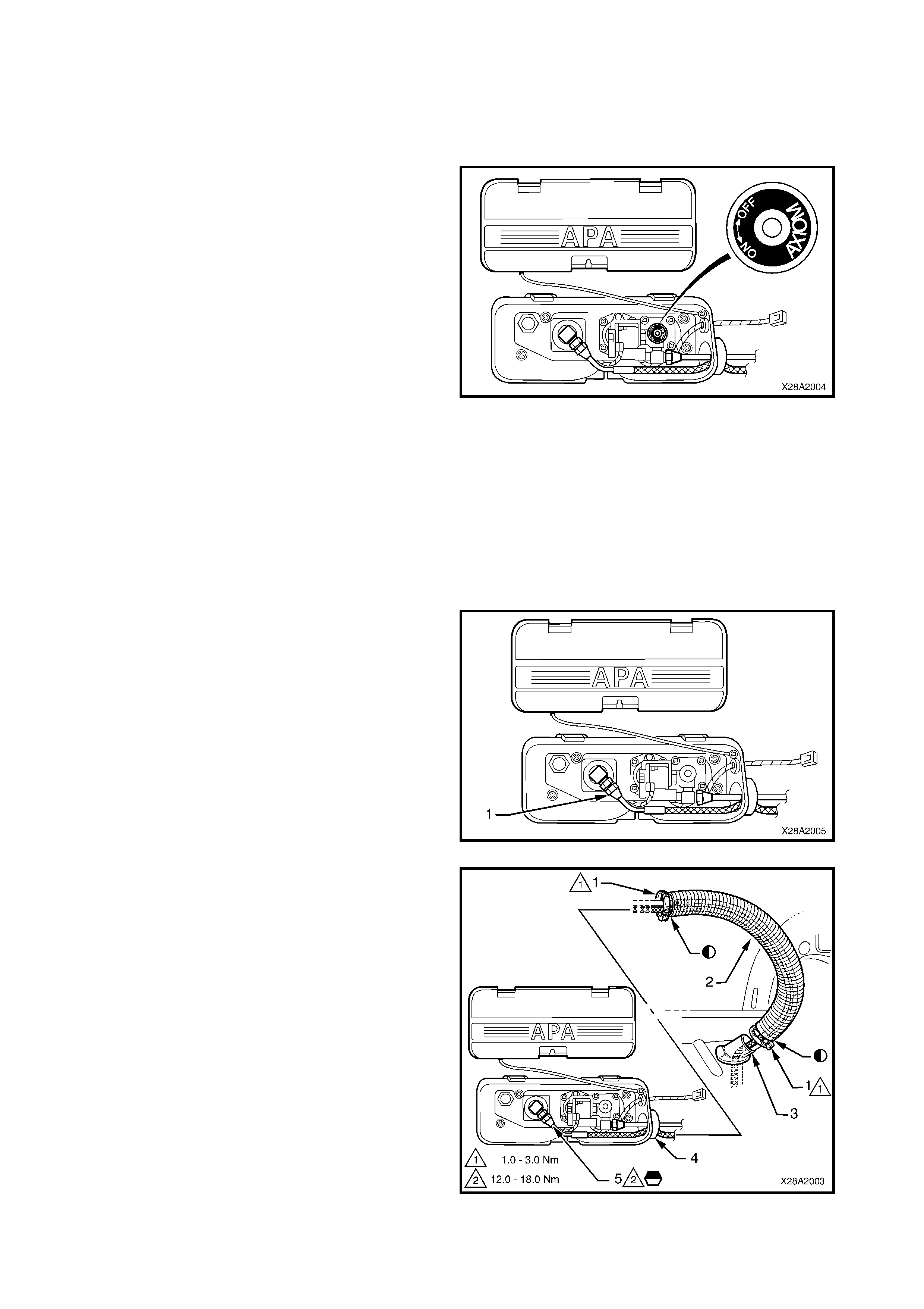
Figure 8A2-5
5. Remove th e cylinder valve box cov er. From inside
the LPG valve box, (while holding AFL elbow)
crack open filler line to AFL elbow connector (1)
and allow residual LPG to escape.
CAUTION: The filler line will contain LPG under
pressure. Once all the LPG in the line has
dispersed, unscrew filler line connector
completely from AFL elbow.
6. Using a suita ble sp ann er to pr eve nt th e AFL el bo w
rotating, disconnect the filler line (1) from the AFL
valve.
Figure 8A2-6
7. Remove the two hose clamps (1) securing the
convoluted tube (2) to the fitting on the load
compartment floor (3) and the LPG valve box (4).
8. Remove the rear fender liner, refer Fig 8A2-3 in
this Section.
9. Disconnect filler line from remote filler connector
pipe and remove the LPG filler line from within
convoluted tube, refer to Fig 8A2-4 in this Section.
10. From inside the rear load compartment, withdraw
the filler line (5) through convoluted tube and
remove.
Figure 8A2-7
REINST ALL
Reinstallation of the filler line is the reverse of the
removal procedure, noting the following:
1. Clean mating threads on LPG cylinder AFL elbow,
filler line and filler valve connector pipe.
2. Apply Loctite 577 sealant to LPG cylinder AFL
elbow and remote filler pipe connector threads
marked in Figs. 8A2-4 and 8A2-7, ensuring that
flared surfaces are free of sealant and
contaminants.
3. Apply silicone sealer to Holden Specification
HN1886 to mating surfaces on convoluted tubing
marked . in Fig.8A2-7.
4. Tighten filler line connectors to the specified torque
specification.
FILLER LINE CONNE CT O RS
TORQUE SPECIFICATION 12 - 18Nm
5. Leak test LPG s ystem , refer 2.3 LEAK TESTING in
Section 2 LPG SYSTEM, VT SEDAN WITH
PRODUCTION LPG in the VT Series II Service
Information.
6. Apply silicon sealer to convoluted tube mating
surfaces,. Tighten convoluted tube hose clamps to
specified torque.
CONVOLUTED TUBE HOSE CLAMPS
TORQUE SPECI FI CAT ION 1 - 3Nm

3. TORQUE WRENCH SPECIFIC ATIONS
LPG service line connectors................................................. 12-18 Nm
LPG service line retaining clamp bolt ................................... 12-15 Nm
LPG filler line connectors...................................................... 12-18 Nm
Convoluted tube hose clamps .............................................. 2-3 Nm