
SECTION 3 - FRONT SUSPENSION
IMPORTANT
Before performing any Service Operation or other procedure described in this Section, refer to Section
00 CAUTIONS AND NOTES for correct workshop practices with regard to safety and/or property damage.
CONTENTS
1. GENERAL DESCRIPTION
2. WHEEL ALIGNMENT
2.1 STEERING GEOMETRY
CASTER
CAMBER
WHEEL TOE
STEERING AXIS INCLINATION
SCRUB RADIUS
INCLUDED ANGLE
TOE-OUT ON TURNS
2.2 WHEEL ALIGNMENT CHECKING AND
ADJUSTMENT
PRELIMINARY INSPECTION
CASTER ADJUSTMENT
CAMBER ADJUSTMENT
TOE ADJUSTMENT
2.3 JACKING PRECAUTIONS
2.4 FRONT WHEEL HUB ASSEMBLY - END
FLOAT CHECKING PROCEDURE
3. SERVICE OPERATIONS
3.1 SERVICE NOTES AND CAUTIONS
3.2 SUSPENSION AND TRIM HEIGHT, CHECK
3.3 FRONT WHEEL HUB ASSEMBLY, BRAKE
ROTOR AND/OR BRAKE SHIELD
REMOVE
INSPECT
REINSTALL
3.4 FRONT WHEEL HUB STUDS
REPLACE
3.5 FRONT STRUT ASSEM BLY
REMOVE
REINSTALL
3.6 UPPER STRUT SUPPORT BEARING
AND MOUNT
REMOVE
REINSTALL
3.7 FRONT SPRING
REMOVE
REINSTALL
3.8 FRONT STRUT UNIT
REPLACE
3.9 STEERING KNUCKLE
REMOVE
REINSTALL
3.10 FRONT LOWER CONTROL ARM
REMOVE
REINSTALL
3.11 FRONT LOWER CONTROL ARM SOCKET
INSPECT
3.12 FRONT LOWER CONTROL ARM
PIVOT BUSHING
REPLACE
3.13 FRONT LOWER CONTROL ARM ROD
BUSHING
REPLACE
3.14 FRONT LOWER CONTROL ARM ROD
REMOVE
REINSTALL
3.15 FRONT LOWER CONTROL ARM ROD
INSULATING BUSHING
REPLACE
3.16 FRONT SUSPENSION CROSSMEMBER
REMOVE
REINSTALL
3.17 STABILIZER SHAFT LINK
REPLACE
3.18 STABILIZER SHAFT
REMOVE
REINSTALL
4. DIAGNOSIS
4.1 DIAGNOSIS GUIDE
5. SPECIFICATIONS
SUSPENSION TRAVEL
FRONT SPRING DETAILS
FRONT STABILIZER SHAFT DETAILS
FRONT STRUT DETAILS
FRONT LOWER CONTROL ARM DETAILS
FRONT WHEEL BEARINGS
SUSPENSION AND TRIM HEIGHT
SPECIFICATIONS
FRONT WHEEL ALIGNMENT
SPECIFICATIONS
6. TORQUE WRENCH SPECIFICATIONS
7. SPECIAL TOOLS
Techline
Techline
Techline

1. GENERAL DESCRI PTI O N
The front suspension fitted to all MY 2003 VY and V2 Series Models operates on the MacPherson strut principle.
The assembly consists of the front crossmember, front lower control arms, front lower control arm rods, stabilizer
shaft and light weight strut assemblies (Refer to Figure 3-1).
The crossmember is bolted to both longitudinal frame side members. The front crossmember to side member
attaching bolts incorporate a tapered boss near the head of the bolt to aid in f ront crossm ember to body alignm ent
during assembly while the pivots of the front lower control arms are rubber bushed and are attached to the
crossmem ber by bolts and nuts. The outer end of each front lower control arm is connected to the k nuckle on the
strut assembly through a front lower control arm socket assembly.
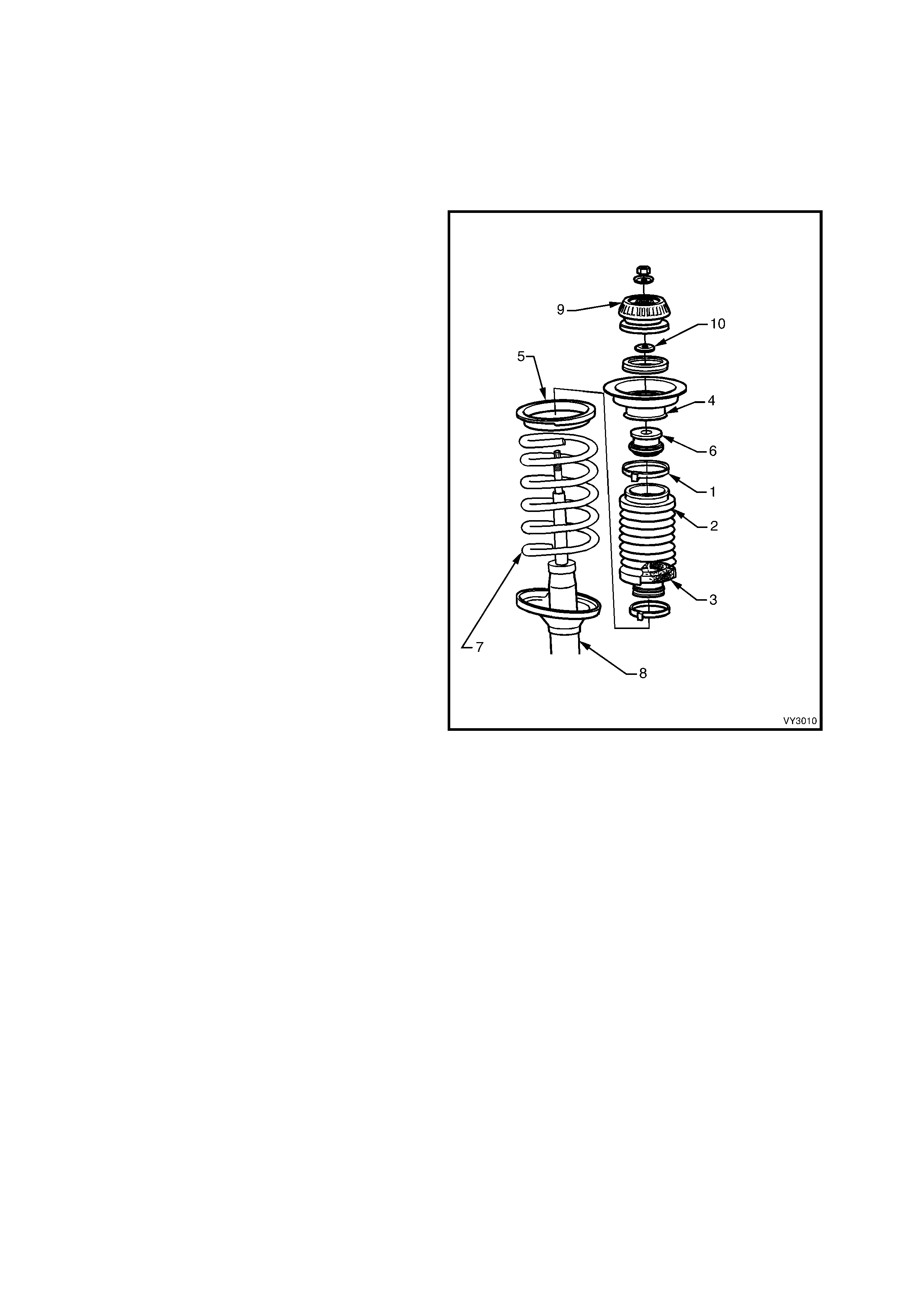
The strut assem bly incorporates a hydraulic wet sleeve type dam per inside the strut tube, a rubber front strut dust
shield assembly with air filter and compression rubber, a coil type suspension spring mounted between the strut
housing and upper spring seat collar, a bearing assembly and an upper strut support.
The strut assembly is located at the upper end to the body structure by an upper strut support and secured by a
self-locking nut and locating disc. The lower end of the strut tube is fastened to the steering knuckle by two bolts
and nuts.
Positioning of the front lower control arm assembly is controlled by a front lower control arm rod, which connects the
front lower control arm to the front suspension crossmember. The front lower control arm rod is mounted in a
rubber bushing at the front lower control arm end and a fluid filled insulator at the other.
A stabilizer shaf t is m ounted to the side m embers of the cros sm ember by two brackets and insulating rubbers, and
attached to eac h st rut tube by a spacer stud, ins ulator s, r etainer s and attac hing nuts . T he lower end of the s tabilizer
shaft spacer stud is connected to the stabilizer shaft with a socket stud and nut.
For identification information and specification details for the STANDARD or FE2 suspension types, refer to
5. SPECIFICATIONS in this Section.
NOTE: There are three suspension options available f or MY 2003 VY Series Models; Standard (Production Option
FE1), Sports (Production Option FE2) and Country Pack (FR1). There are also numerous configurations for each
suspension option, depending on body type and powertrain combination. For further information regarding the
identification of which suspension option is fitted to a particular vehicle, refer to 9.3 BODY AND OPTION PLATE in
Section 0A, GENERAL INFORMATION. For all other information regarding the suspension application fitted to a
particular vehicle, refer to 5. SPECIFICATIONS in this Section.
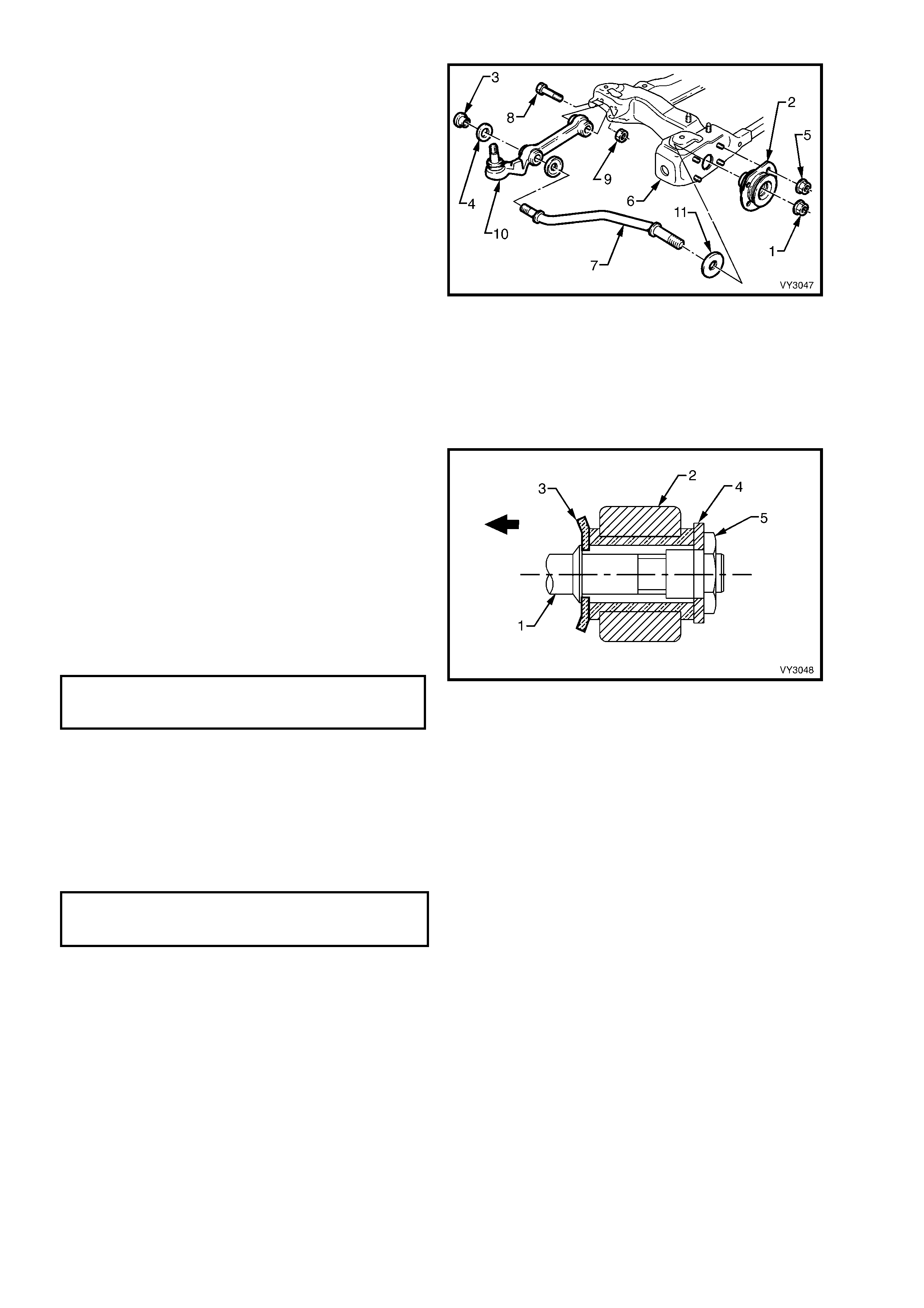
Legend for Figure 3-1
1. Nut (2 Plac es) 11. Insulator (2 Places) 19. Front Lower Control Arm Rod (2 P l aces)
2. Washer (2 Pl aces) 12. Shaft – S tabilizer 20. Washer – Cupped (2 Places)
3. Insulat or (2 Places) 13. Bolt – Front , Fl anged (2 Places) 21. Control Arm (2 Places)
4. Seat (2 Pl aces) 13a. Bolt – Rear, Plain (2 Places) 22. Washer (2 Places)
5. Insulator (2 Places) 14. Nut (8 Places) 23. Nut – Stepped (2 Places)
6. Washer (2 Pl aces) 15. Nut (2 Places) 24. Bolt (2 Places)
7. Stabilizer Shaft Stud (2 Places) 16. Insulator Bushing – Front Lower Control 25. Cover – Dust (2 Places)
8. Nut (2 Plac es) Arm Rod (2 Places ) 26. Nut (2 Places)
9. Nut (4 Plac es) 17. Washer (1 On Driver’s Side Only) 27. Loc ating Disc (2 Places)
10. Bracket (2 Places) 18. Nut (2 Plac es) 28. Front Sus pension Cross mem ber
‘A-A’ - Assemble washer ‘20’ as shown.
Stud to be hel d while nut s are torqued to s pecific ation.
Fastener must be new and ass embled dry.
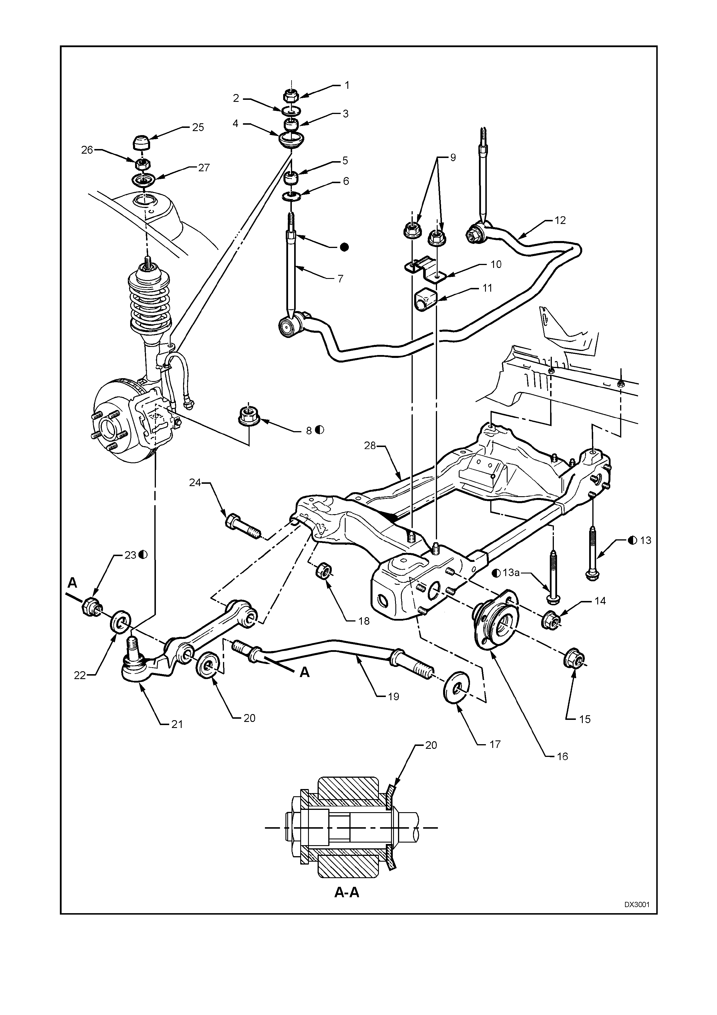
Figure 3-1
2. WHEEL ALIGNMENT
IMPORTANT
All front suspension fasteners are important attaching parts as they affect the performance of vital
components and/or could result in major repair expense. Where specified in this Section, fasteners
MUST be replaced with parts of the same part number or a GM approved equivalent. Do not use
fasteners of an inferior quality or substitute design.
Torque values must be used as specified during reassembly to ensure proper retention of all front
suspension components.
Throughout this Section, fastener torque wrench specifications may be accompanied with the following
identification marks:
+
++
+ Fasteners must be replaced after loosening.
&
&&
& Vehicle must be at curb height before final tightening.
6
66
6 Fasteners either have micro encapsulated sealant applied or incorporate a mechanical thread lock
and should only be re-used once. If in doubt, replacement is recommended.
If one of these identification marks is present alongside a fastener torque wrench specification, the
recommendation regarding that fastener must be adhered to.
2.1 STEERING GEOMETRY
To achieve the desired handling characteristics of a vehicle under various operating conditions, modern steering
geometry relates to both front and rear suspension systems. It m ust also be realised that the various, measurable
angles that can be checked while the vehicle is stationary, are no real indication of the changes that occur in a
dynamic situation, when the vehicle is required to have directional stability, during normal manoeuvres, such as
straight ahead driving, cornering or braking.
Even though some of the following descriptions of front wheel alignment angles are not normally measurable and
(in some instances) not adjustable, each is an inherent part of the vehicle's dynamic suspension tuning that has
been developed over an extended testing program.
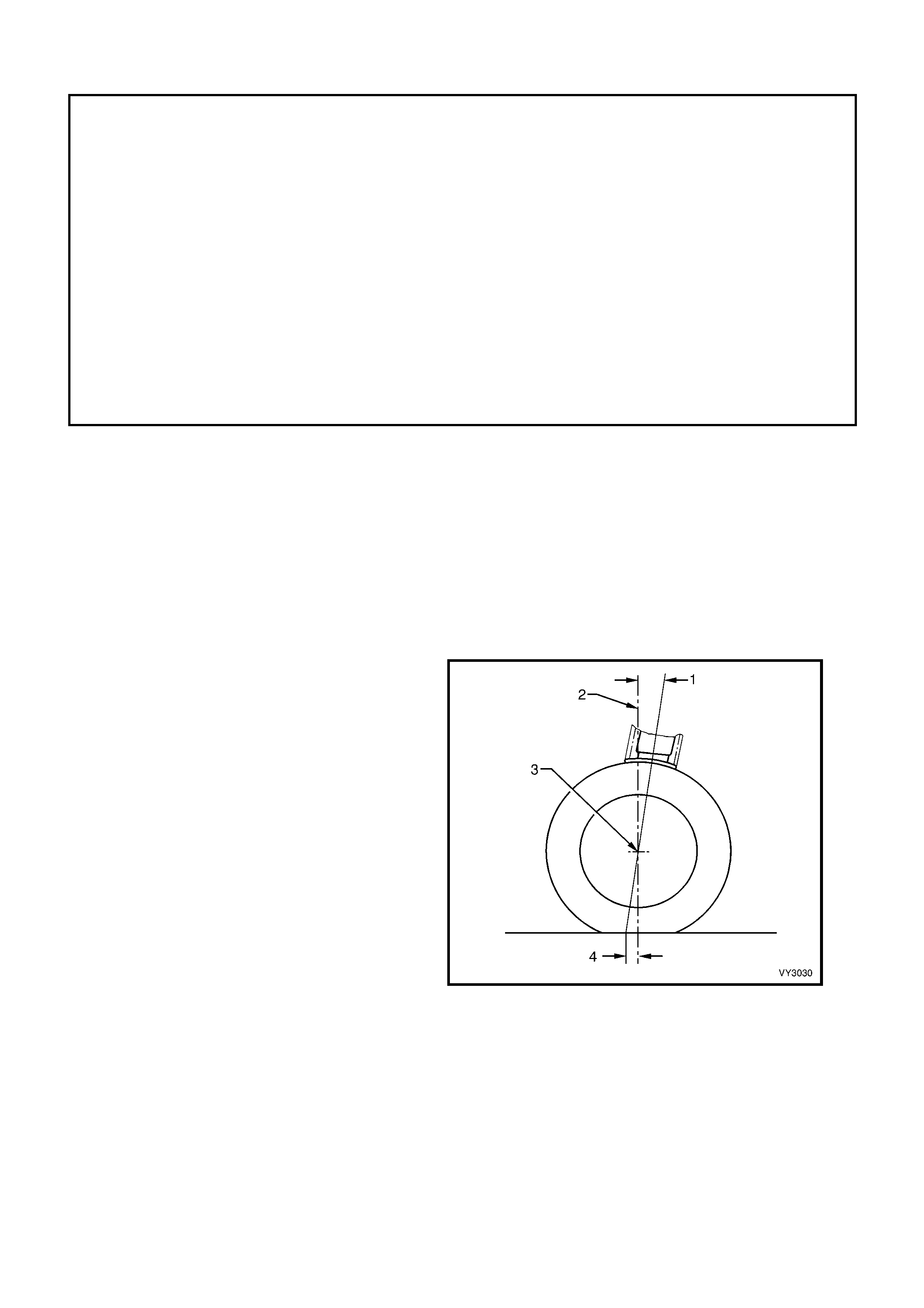
CASTER
It is usual to describe this front wheel alignment
angle as the tilting of the steering axis either
forward or backward (1) from the vertical (2) when
viewed from the s ide of the vehicle. A back ward tilt
at the top steering axis point is said be positive (+)
and a forward tilt is said to be negative (-).
Measurement is usually expressed as an angle in
degrees and minutes. Figure 3-2 shows the usual
practice where the vertical and steering axis
centrelines both pass through the wheel centre (3).
This results in a caster distance (4), which can be
described as being the distance in side view,
between the point where the steering axis contacts
the ground and the centre of the tyre’s footprint
contact.
Figure 3-2
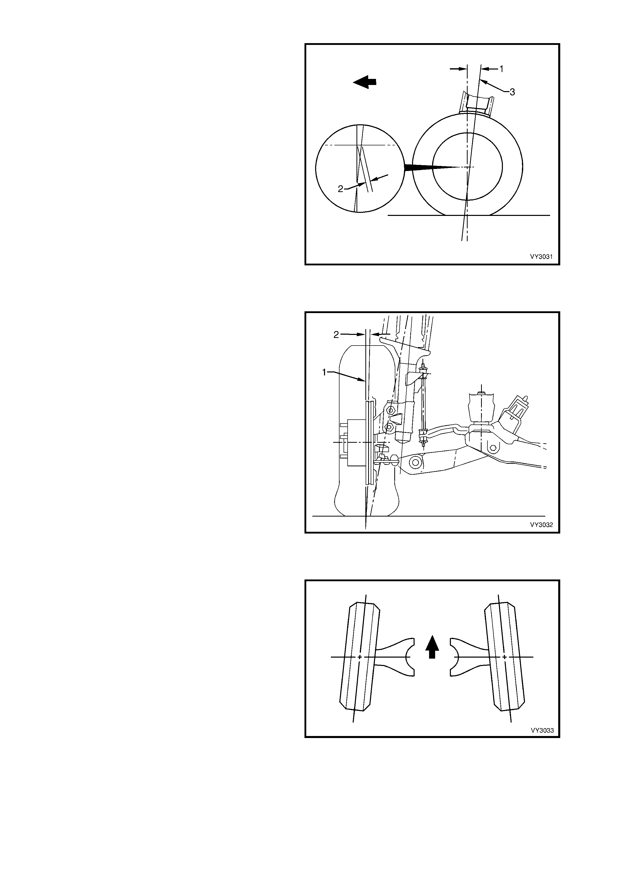
The amount of caster angle (1) will determine the
ability of the steering to retur n to the straight ahead
position after a cornering manoeuvre. Too high an
angle though, can result in an excessive steering
effort with associated ‘wheel fight' and ‘kickback'.
To optimise vehicle handling and control during
cornering and to maintain the benefits of positive
caster , MY 2003 VY or V2 Series Models have a 12
mm caster offset (2) incorporated into the
suspension design.
This is achieved by moving the wheel spindle
centreline (3) forward (in this instance, by 12 mm),
which will effectively reduce the caster distance by
that amount (Refer to Figure 3-3). This action
reduces the undesirable effects of a high caster
angle but maintains the directional stability,
increased front axle lateral grip and steering feel
that a high caster angle normally provides.
Figure 3-3
CAMBER
This angle is the tilting of the wheels from the
vertical (1) when viewed from the front of the
vehicle. When the wheels tilt outward at the top, the
camber (2) is said to be positive (+). When the
wheels tilt inward at the top, camber is said to be
negative (-). The amount of tilt is measured in
degrees from vertical and this measurement is
called the camber angle.
While unequal camber may result in unstable
steering or wander, unequal and/or excessive
camber can also cause rapid tyre wear.
Figure 3-4
WHEEL TOE
Wheel Toe (Refer to Figure 3-5), is the turning in
(or out) of the wheels when viewed from the
overhead position. The actual amount of toe is
normally only a few minutes of a degree. The
purpose of a static toe specification is to ensure
parallel rolling of the wheels, once the vehicle is in
a dynamic state.
Excess ive toe-in or toe-out m ay increase tyre wear.
With rear wheel drive vehicles, a slight amount of
toe-in, measured statically with the vehicle at rest,
is required to off-set the small deflections due to
rolling resis tanc e and brake applications which tend
to turn the wheels outward.
Figure 3-5
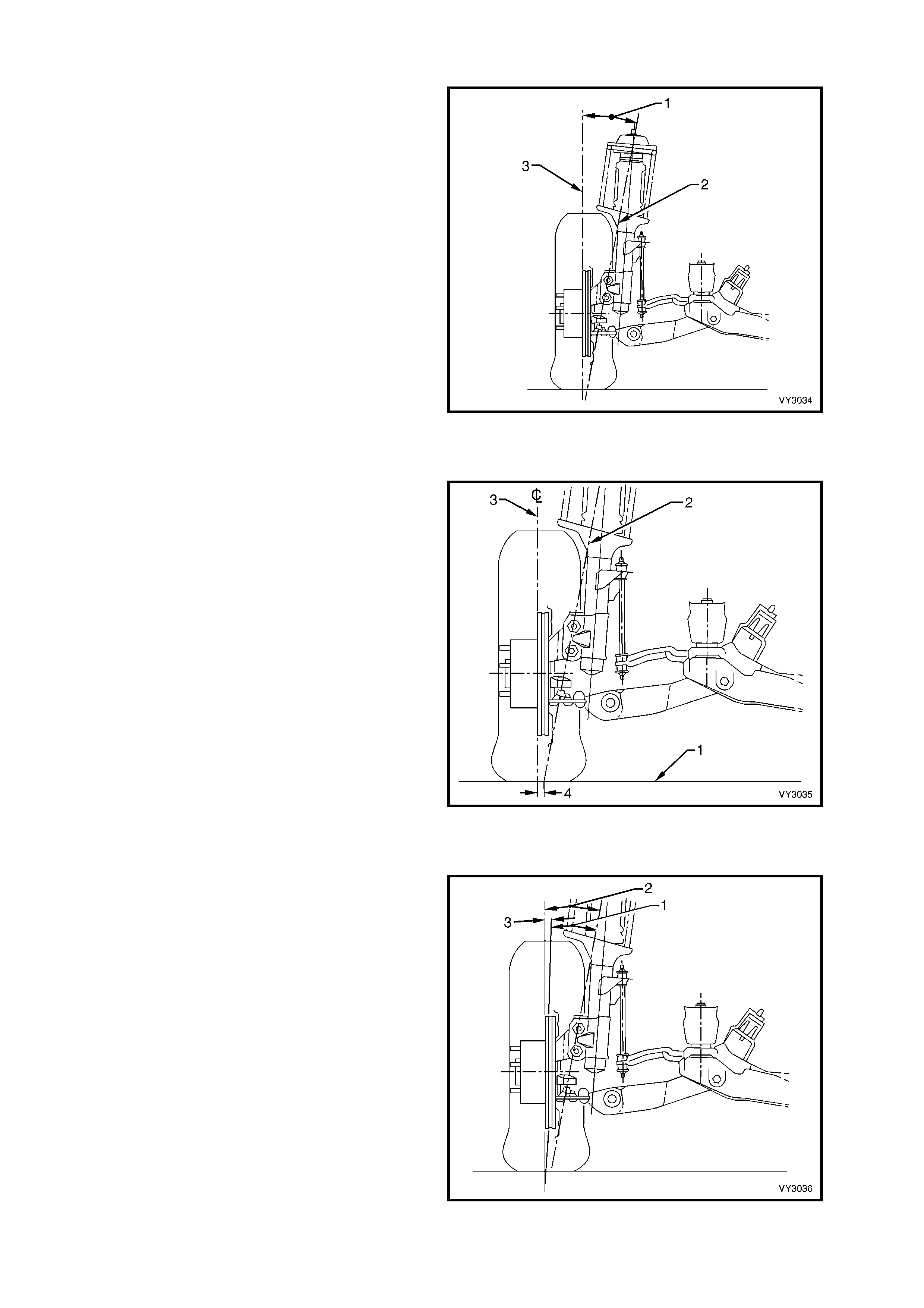
STEERING AXIS INCLINATION
When viewed from the vehicle front, Steering Axis
Inclination (1) can be described as being the angle
formed between the steering axis (2) and the true
vertical ( 3), where the steer ing ax is is the imaginar y
centreline through the upper strut support bearing
and the front lower control arm socket assembly,
both components being the pivot points of the strut
assembly.
The Steering Axis Inclination angle is an important
factor in determining steering effort and directional
stability of the vehicle, by assisting caster in
keeping the front wheels in a central position.
Steering Axis Inclination also provides a self-
centring effect after cornering.
Figure 3-6
SCRUB RADIUS
This term refers to the distance that two imaginary
points ar e apart, at the road surf ace (1). T hese two
imaginary points are;
a. The inters ection of the steering ax is (2) and the
road surface.
b. The centreline of the tyre (3) at the road
surface.
As road wheel offset will affect scrub radius (4), in
the interests of vehicle handling and safety, non-
standard road wheels ar e not to be fitted to any MY
2003 VY or V2 Series vehicle.
With rear wheel drive vehicles, it is usual practice
to maintain a positive scrub radius (as shown in
Figure 3-7) to make the steering more responsive
and direc t, thereby providing the driver with a more
positive sense of the tyre and road surface
interaction.
Figure 3-7
INCLUDED ANGLE
When both the Steering Axis Inclination angle (1)
and Camber angle (2) are combined, the resulting
angle is referred to as the Included Angle (3). This
information can be effectively used to determine if a
component is damaged or whether an adjustment
is responsible for an out-of-specification condition
occurring.
While Figure 3-8 shows a positive camber angle,
this has only been used to clarify the term ‘Included
Angle'.
Figure 3-8
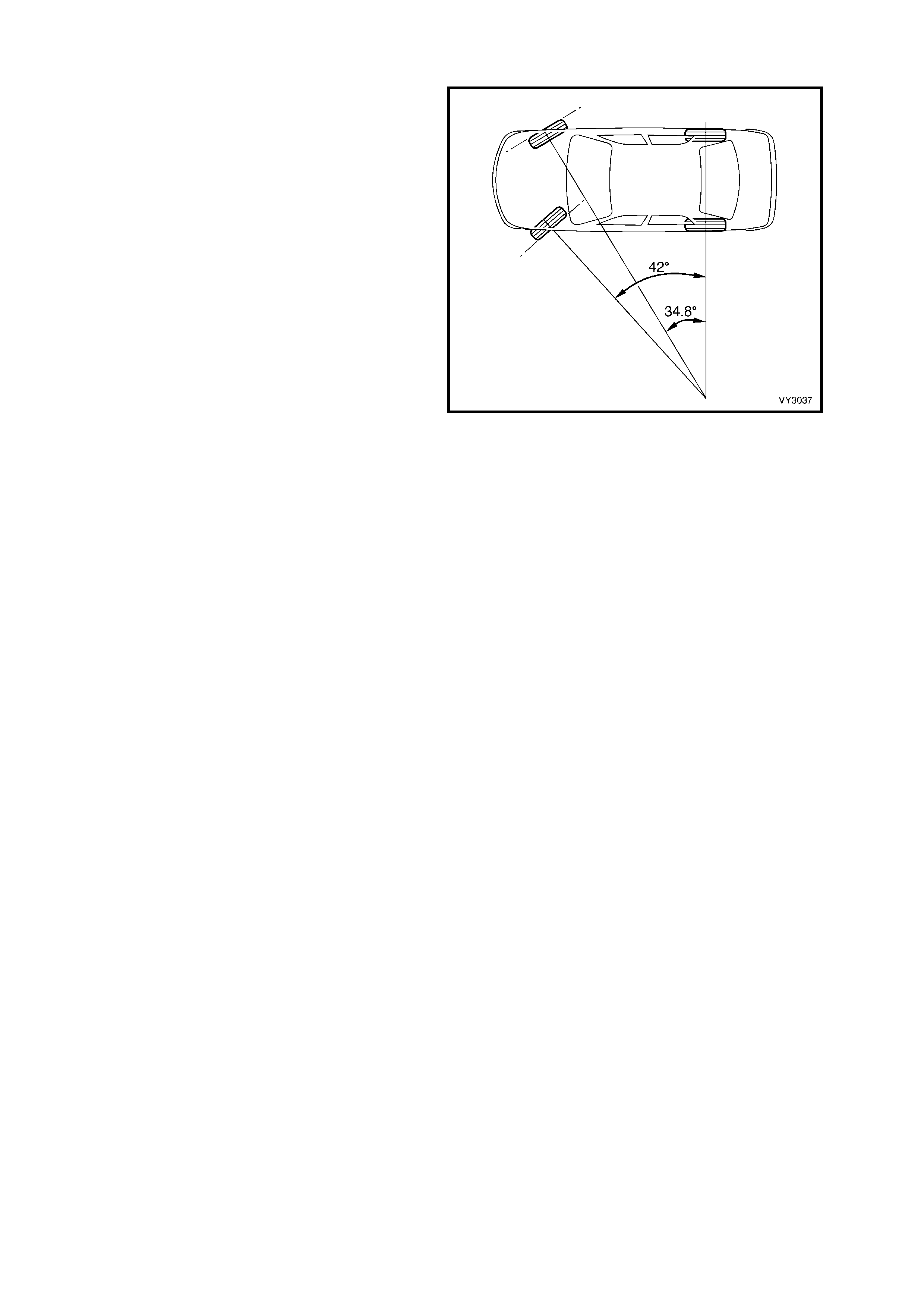
TOE-OUT ON TURNS
During cornering operations, a vehicle's road
wheels all turn about a common turning point,
causing the outer wheels to try and turn through a
greater radius than the inner. To overcome the
tendency for wheel slip under these conditions, the
outer wheel is commonly caused to toe-out, to
compensate for this increased turning circle.
The amount of toe-out during cornering, is
governed by the angle of the steering arms, which
are an inherent part of the steering knuckle.
Figure 3-9
2.2 WHE EL ALIGNMENT CHECKING AND ADJUSTMENT
LT Section No. – 06-212
NOTE: The following fastener MUST be replaced
when performing this operation:
+
++
+
Steering knuckle to strut attaching nuts and
bolts.
PRELIMINARY INSPECTION
Before any attempt is made to check camber, caster or toe-in, these preliminary checks should be carried out.
1. Check tyre and tyre mountings. Always check camber and toe-in at the mean run-out position on the tyre or rim.
2. Check and adjust tyre pressures to recommended values.
3. Front wheel bearing end float is to be checked to ensure it is within specification, as detailed in
2.4 FRONT WHEEL HUB ASSEMBLY END FLOAT CHECKING PROCEDURE in this Section.
4. Front lower control arm socket assembly and pivot bushing should be checked for wear, refer to
3.11 FRONT LOWER CONTROL ARM SOCKET ASSEMBLY in this Section.
5. Check steering gear mounting bolts for tightness and steering linkage outer tie rod sockets for wear, refer to
3.6 RIGHT-HAND DRIVE POWER STEERING GEAR or 3.7 LEFT-HAND DRIVE POWER STEERING GEAR
in Section 9, STEERING as applicable.
6. The vehicle should be at curb weight, fuel tank full, without driver, passengers or luggage etc.
7. Check for improperly operating front struts or rear shock absorbers.
8. Check for loose or missing stabilizer shaft or front lower control arm rod attachments.
9. Before checking the front wheel alignment, refer to 2.12 REAR WHEEL ALIGNMENT CHECKING in Section
4A, REAR SUSPENSION for rear wheel alignment details.
CASTER ADJUSTMENT
W hile one bright f inished spaced washer (1) will be
fitted to the driver’s s ide front lower contr ol arm r od
(2), the fitment of an additional was her is permitted
to correct minor caster adjustments
NOTE: Only one additional spacer washer is to be
fitted and is to be added to the s ide with the higher
caster reading.
Figure 3-10
CAMBER ADJUSTMENT
1. Raise the front of the vehicle and support on
safety stands under the front side members.
Refer to 2.3 JACKING PRECAUTIONS in this
Section.
2. Remove the wheel cover (steel wheels) or
centre cap and decorative wheel nut caps (alloy
wheels) and mark the relationship of the wheel
to the hub stud, using a felt tipped pen or
similar.
3. Remove the wheel attaching nuts and remove
the wheel.
4. Loosen, r emove and discar d the two lower strut
attaching bolts and nuts (1).
Install NEW lower s trut attac hing bolts and nuts
but do not tighten fully to specification until
after the camber has been adjusted to the
recommended specification.
5. Install the road wheel, aligning the
previously made mark s . Tighten the road wheel
attaching nuts to correct torque specification,
working in a ‘star’ pattern. Ref er to Section 10,
WHEELS AND TYRES f or detailed inform ation
regarding the installation procedure for the road
wheels.
ROAD WHEEL ATTACHING NUT
TORQUE SPECIFICATION ................110 – 140 Nm
Figure 3-11
6. Lower the vehicle to the ground and bounce several times to settle the suspension.
7. Check the camber angle.
8. If required, adjust the camber by turning the camber adjusting screw (2) in the required direction; clockwise to
reduce negative camber, anti-clockwise to reduce positive camber.
NOTE: The camber adjusting screw has thread sealant applied in the form of micro-encapsulation and does not
require a lock nut.9. Raise vehicle once again, support on safety stands and remove the front road wheels.
10. Tighten both steering knuckle bolts and nuts to the correct torque specification.
( + ) STEERING KNUCKLE TO STRUT
ATTACHING BOLTS AND NUTS
TORQUE SPECIFICATION ................ Stage 1 85 Nm
Stage 2 100 Nm
Stage 3 Turn
through 90°
11. Install the road wheels, aligning the marks made prior to removal.
12. Remove the jack stands and lower the vehicle.
13. Tighten the road wheel attaching nuts to the correct torque specification, working in a ‘star’ pattern. Refer to
Section 10, WHEELS AND TYRES for detailed information regarding installation procedure for the road
wheels.
ROAD WHEEL ATTACHING NUT
TORQUE SPECIFICATION ................ 110 - 140 Nm
14. Install the wheel cover/centre cap.
15. Check the camber angle again to ensure that it is still within specification.

TOE ADJUSTMENT
Toe of both front wheels, is checked with the
wheels in the straight ahead position.
Adjustment is achieved by winding the steering
linkage outer tie rods in or out of the steering
linkage outer tie rod sockets, thus increasing or
decreasing their length and thereby altering the toe-
in setting.
1. Set steering gear and wheels in straight ahead
position.
2. To check if steering gear is in straight ahead
position (on-centre), the pinion (input) shaft (1)
should be aligned as shown.
NOTE: While the one-piece steering rack housing
is shown in Figure 3-12, the on-centre position is
the same for all steering racks.
Figure 3-12
3. Before adjusting the steering linkage outer tie
rods (1), disconnect the steering gear outer
boot clips (2).
4. Loosen the lock nut (3) at the end of each
steering linkage outer tie rod.
5. Turn each steering linkage outer tie rod as
required, until the correct toe is obtained.
NOTE: During the toe adjustment, ensure that the
steering wheel is held in the straight ahead
position.
6. Tighten the lock nuts to the correct torque
specification, ensuring that the steering linkage
outer tie rod soc kets are in alignm ent with their
ball studs.
STEERING LINKAGE OUTER TIE ROD TO
STEERING LINKAGE OUTER TIE ROD SOCKET
ASSEMBLY LOCK NUT
TORQUE SPECIFICATION ...................... 58 – 71 Nm
7. Tighten the outer boot clips securely, making
sure that the convolutions of the boots are not
distorted.
8. With the steering gear in the straight ahead
position, ensure that the steering wheel is
centralised. If not, remove and reposition the
steering wheel, refer to 2.4 STEERING
WHEEL ASSEMBLY in Section 9, STEERING.
Figure 3-13
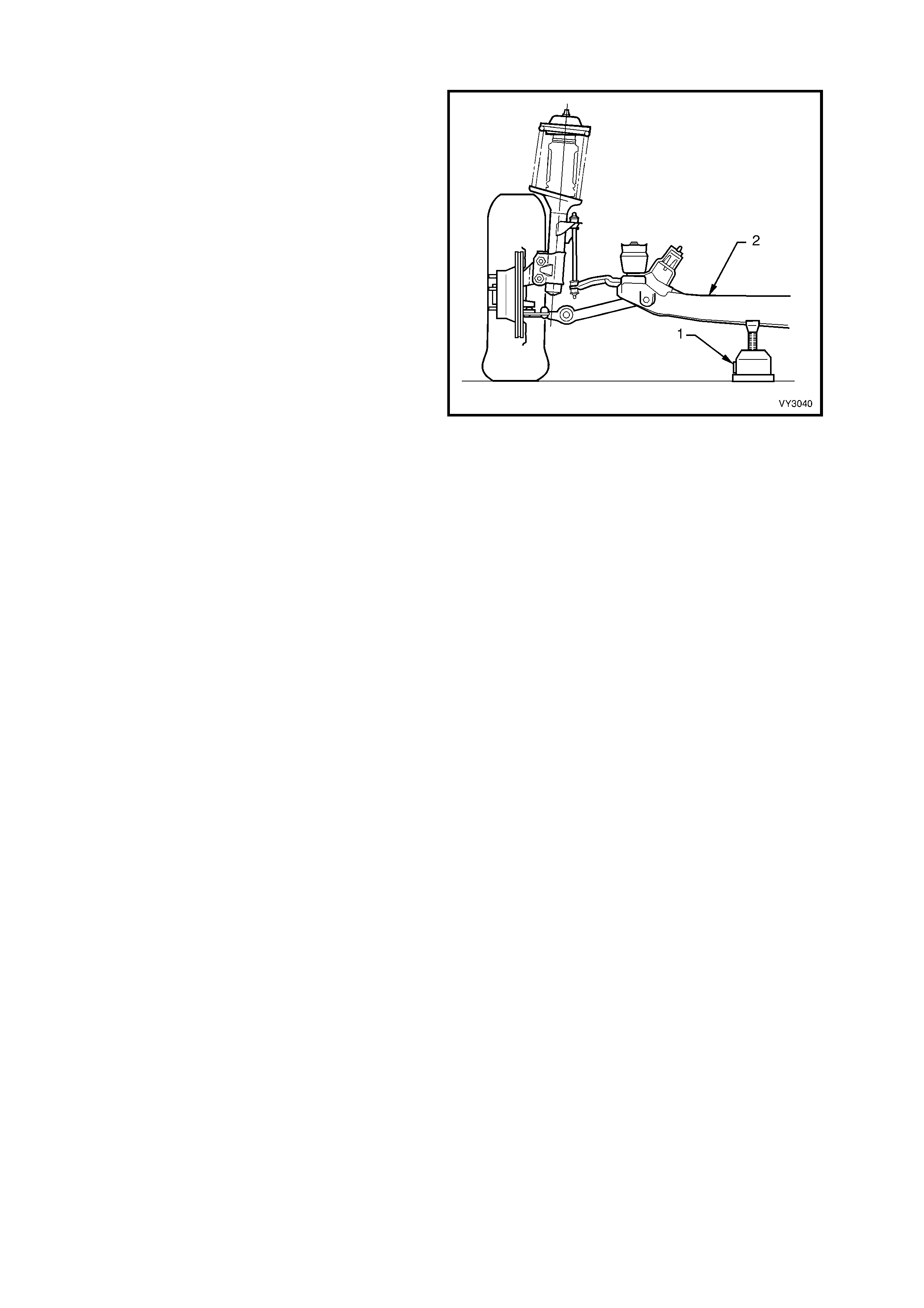
2.3 JACKING PRECAUTIONS
When rais ing the f ront of the vehicle with a jack (1),
the jack should be placed under the centre of the
front crossmember (2). THE WEIGHT OF THE
VEHICLE MUST NOT BE LIFTED UNDER THE
CONTROL ARMS.
When the vehicle is raised on the jack, it must be
firm ly supported on safety stands located under the
fram e s ide m embers before any work is attem pted.
If a vehicle is not correctly supported by safety
stands, serious injury can result if the vehicle
should slip off the jack.
For further information relating to the location
of jacking and support points, refer to
Section 0A, GENERAL INFORMATION.
Figure 3-14

2.4 FRONT WHEEL HUB ASSEMBLY - END FLOAT CHECKING PROCEDURE
LT Section No. – 06-212
1. Raise the front of the vehicle and place on safety stands. Observe the jacking precautions as detailed in
2.3 JACKING PRECAUTIONS in this Section.
2. Remove the wheel cover (steel wheels) or centre cap and decorative wheel nut caps (alloy wheels).
3. Mark the relationship of the wheel hub assembly to the brake rotor to preserve on-vehicle wheel balancing.
Remove the wheel attaching nuts and remove road wheel.
4. Temporarily install three, reversed wheel nuts
with a flat washer under each nut, to prevent
damage to the nut thread.
5. Mount a dial indicator on to a suitable m agnetic
stand and attach to the f ront str ut tube. Position
the dial indicator pointer at the outer diameter
of the rotor, as shown.
IMPORTANT: The dial indicator guage MUST be
mounted at right-angles (90°) to the brake rotor
friction surface.
6. Apply an outward, 10 kg force to the outer
brake rotor diameter, in an opposite position
(180°) to the dial indicator. To maintain
consistency, a spring balance capable of
measuring this force, MUST be used. W ith the
force applied, zero the dial indicator.
7. Apply an inward, 10 k g forc e to the outer brak e
rotor diameter and note the dial indicator
reading.
8. The reading obtained is the angular movem ent
(NOT end float) and to determine the bearing’s
serviceability, compare the measured result
with the following specifications.
WHEE L BEARING ANGULAR ‘F LOAT’
SPECIFICATION
NEW BEARING 0.106 mm Maximum
USED BEARING 0.213 mm Maximum
9. Should this inspection show that the wheel
bearing assembly is outside the specified,
angular ‘float’ dim ension, then the hub m ust be
replaced. Refer to 3.3 FRONT WHEEL HUB
ASSEMBLY BRAKE ROTOR OR BRAKE
SHIELD in this Section.
10. Remove the dial indicator and stand, and the
three wheel nuts and flat washers.
11. Install the r oad wheel, aligning the mar ks m ade
prior to removal and secure with attaching nuts.
12. Raise the vehicle, remove the safety stands
and lower vehicle to the ground. Tighten road
wheel attaching nuts to correct torque
specification, working in a ‘star’ pattern. Refer
to Section 10, WHEELS AND TYRES for
detailed information regarding the installation
procedure for the road wheels.
ROAD WHEEL ATTACHING NUT
TORQUE SPECIFICATION ................ 110 – 140 Nm
13. Install the wheel cover/centre cap.
Figure 3-15

3. SERVICE OPERATIONS
IMPORTANT
All front suspension fasteners are important attaching parts as they affect the performance of vital
components and/or could result in major repair expense. Where specified in this Section, fasteners
MUST be replaced with parts of the same part number or a GM approved equivalent. Do not use
fasteners of an inferior quality or substitute design.
Torque values must be used as specified during reassembly to ensure proper retention of all front
suspension components.
Throughout this Section, fastener torque wrench specifications may be accompanied with the following
identification marks:
+
++
+ Fasteners must be replaced after loosening.
&
&&
& Vehicle must be at curb height before final tightening.
6
66
6 Fasteners either have micro encapsulated sealant applied or incorporate a mechanical thread lock
and should only be re-used once. If in doubt, replacement is recommended.
If one of these identification marks is present alongside a fastener torque wrench specification, the
recommendation regarding that fastener must be adhered to.
3.1 SERV ICE NOTES AND CAUTIONS
NOTE: Whenever a road wheel and/or brake rotor is removed from or installed to a MY 2003 VY or
V2 Series vehicle, it MUST be done in accordance with the procedure provided in
2.3 WHEEL REMOVAL AND INSTALLATION in Section 10, WHEELS AND TYRES.
CAUTION: Whenever any component that forms part of the ABS (if fitted) is disturbed during Service
Operations, it is vital that the complete ABS system be checked, using the procedure as detailed in
4.4 ABS & T CS FUNCTION CHECK (V6 engin es) o r 5.4 ABS & TCS FUNCTION CHECK (GEN III V8 engines),
in Section 5B, ABS & TCS.

3.2 SUSPENSION AND TRIM HEIGHT, CHECK
The suspension and trim height dimensions for standard vehicles with base equipment only, are provided in
5. SPECIFICATIONS in this Section.
The dimensions are for a new vehicle built to standard specification and only intended as a guide w hen
check ing suspens ion and trim height dim ensions at norma l curb weight. Norm al curb weight is defined as a vehic le
with a full tank of fuel, all fluids at the specified levels, spare tyre included, tyre pressures as specified and no
passengers . Ac c umulated dir t, dis tanc e travelled, etc ., must als o be taken into cons ideration when chec king vehicle
heights.
The following procedure should be followed before checking any suspension or trim height.
1. All c hec ks must be c ar ried out on a LEVEL s urface, af ter the vehicle's tyre pressures have been c hec k ed and it
has been confirmed that the vehicle has not been subjected to accident damage.
2. On average, all MY 2003 VY and V2 Series Models will sit approximately 4 mm lower at the right hand side
front, because of the vehicle's battery weight.
3. Push the vehicle up and down several times at the front bumper bar with a decreasing force and then gently
remove hands, allowing vehicle to settle on its own. Carry out vehicle front trim and suspension height check.
4. Push the vehicle up and down several times at the rear bumper bar with a decreasing force and then gently
remove hands, allowing vehicle to settle on its own. Carry out vehicle rear trim and suspension height check.
As shown in the specification listing (refer to 5. SPECIFICATIONS in this Section), there are two different
dimens ions that must be chec ked and the location f or the measur ements to be taken is c ritic al to c orr ec tly establish
a standard vehicle condition. When checking a vehicle's ride height, the following tolerances must also be taken into
account, before any spring is replaced.
RIDE HEIGHT VARIATIONS FROM SPECIFICATION
FRO NT TO REAR ± 20 mm
SIDE TO SIDE ± 10 mm
NORMAL SPRING SETTLING ± 5 mm
NOTE: Ride height variation may also be due to any one or a combination of the following:
a. Spring seat location on the suspension/body.
b. Incorrect springs; Check spring identification against the table shown in 5. SPECIFICATIONS in this
Section.
c. Non-standard, additional vehicle weight, such as a tow bar and/or after-market LPG fitment.
d. Any combination of the above.
CAUTION: Good judgement must be exercised before replacing a spring or springs from a vehicle whose
height is w ithin the limits quoted. Even if a v ehicle's dimensions should prove to be slightly outside these
tolerances, the vehicle could well be in a serviceable condition. Spring replacement under conditions of
excessive weight due to non-standard fittings, undercoating, road dirt, etc; will assist very little in restoring
the vehicle to its specified height.

3.3 FRONT WHEEL HUB ASSEMBLY, BRAKE ROTOR AND/OR BRAKE SHIELD
LT Section No. – 06-212
NOTE 1: The following fasteners have either micro
encapsulation or incorporate a mechanical thread lock
and should only be used once. If in doubt, r eplacement
is recommended when performing this operation:
♦ Front wheel hub assembly to steering knuckle
attaching bolt.
NOTE 2: The following fasteners MUST be replaced
when performing this operation:
+
++
+
Front strut to steering knuckle attaching nuts
and bolts.
+
++
+
Brake caliper retaining bolts.
NOTE 3: Apart from wheel stud replacement, there are no serviceable items in the front wheel hub assembly. As
the unit is a 'sealed f or life' as sembly, neither bearing adjus tment nor lubr ication m aintenance is required. Should a
non-standard condition develop, then the hub assembly must be replaced as a complete unit.
NOTE 4: W hile the front wheel hub assembly is designed to have zero axial free play or ‘end-float’, some angular
movement may be evident when a rocking force is applied to the mounted wheel and tyre assembly. Before a hub is
replaced, refer to checking procedure as detailed in 2.4 FRONT WHEEL HUB ASSEMBLY – END FLOAT
CHECKING PROCEDURE in this Section.
REMOVE
1. Observing the jacking precautions as outlined in 2.3 JACKING PRECAUTIONS in this Section, raise the front of
the vehicle and support on safety stands.
2. Remove the wheel cover (steel wheels) or centre cap and decorative wheel nut caps (alloy wheels).
3. Mark the relationship of the road wheel to hub or brake rotor. Loosen, then remove the road wheel attaching
nuts. Remove the road wheel.
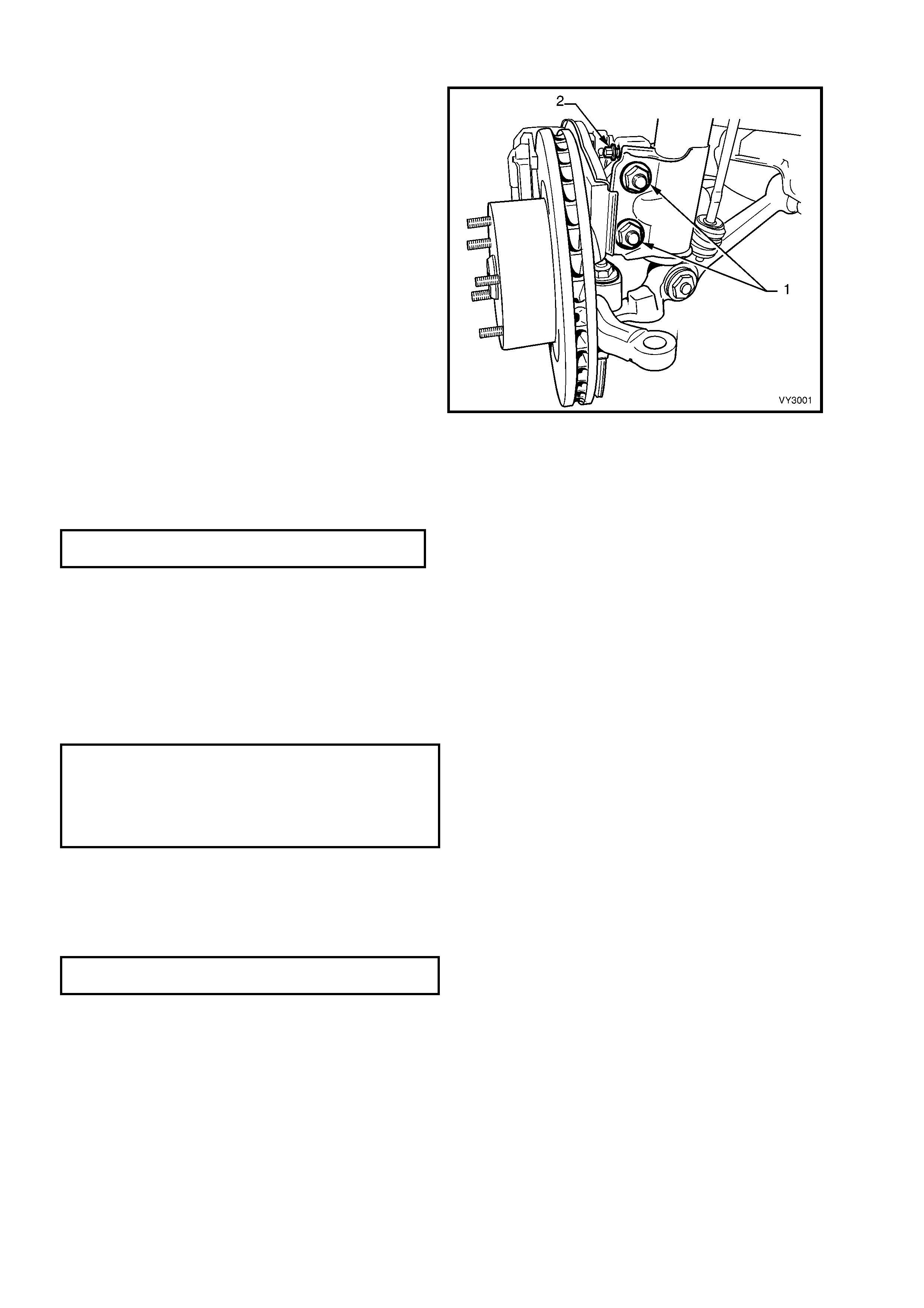
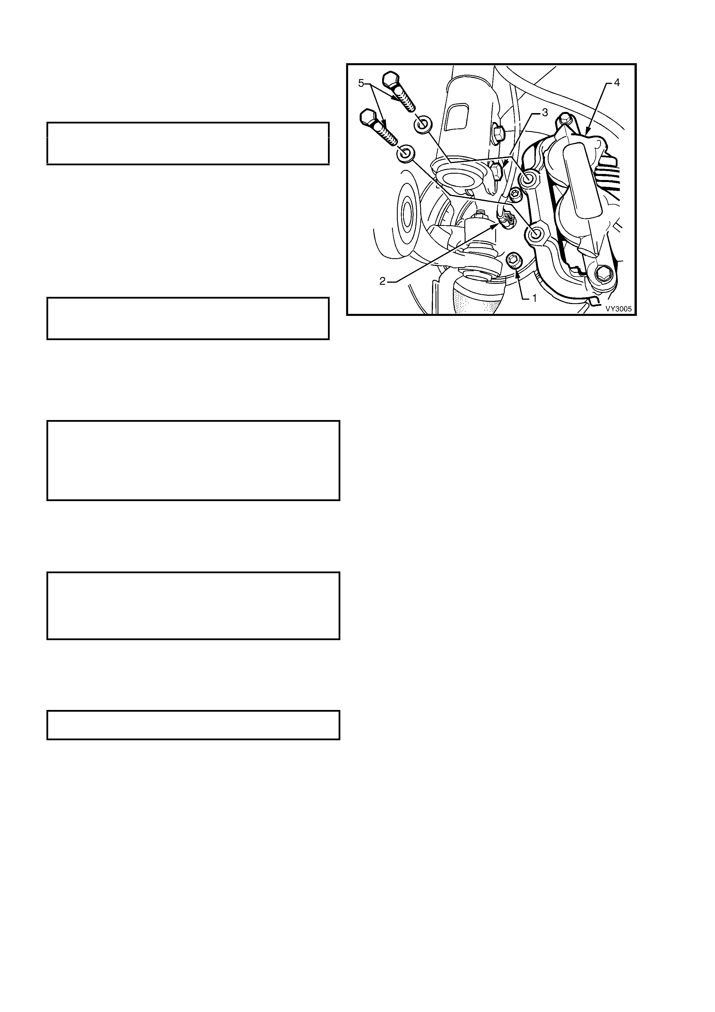
4. Remove the brake caliper retaining bolts and
washers (1) and lift the caliper assembly (2)
from the brake rotor. Position caliper in such a
way that no strain is placed on the brake hose.
If necessary, tie caliper to the suspension
spring with a piece of wire. THE CALIPER IS
NOT TO HANG BY THE BRAKE HOSE.
5. The brake rotor to hub location is marked in
production. To maintain this relationship,
ensure that the rotor to hub position is car efully
marked.
NOTE 1: This is necessary to overcome the
possibility of inducing a brake shudder condition
after reassembly.
6. Remove the brake rotor from the wheel hub
assembly.
NOTE 2: For vehicles equipped with ABS,
disconnect the wheel speed sensor connector (3)
from the hub sensor connector, by lifting the
connector locking tab and pulling on the connector
to disconnect.
Figure 3-16
7. Using a commercially available 10 mm Allen key socket and a suitable socket bar, loosen each of the three
bolts (4) holding the hub to the steering knuckle.
NOTE 3: If the Allen key socket is too long to fit into the front, upper hub bolt, then the lower strut to steering
knuckle nut (and bolt) will need to be loosened and removed. Discard the removed bolt and nut, as they must be
replaced on reassembly.
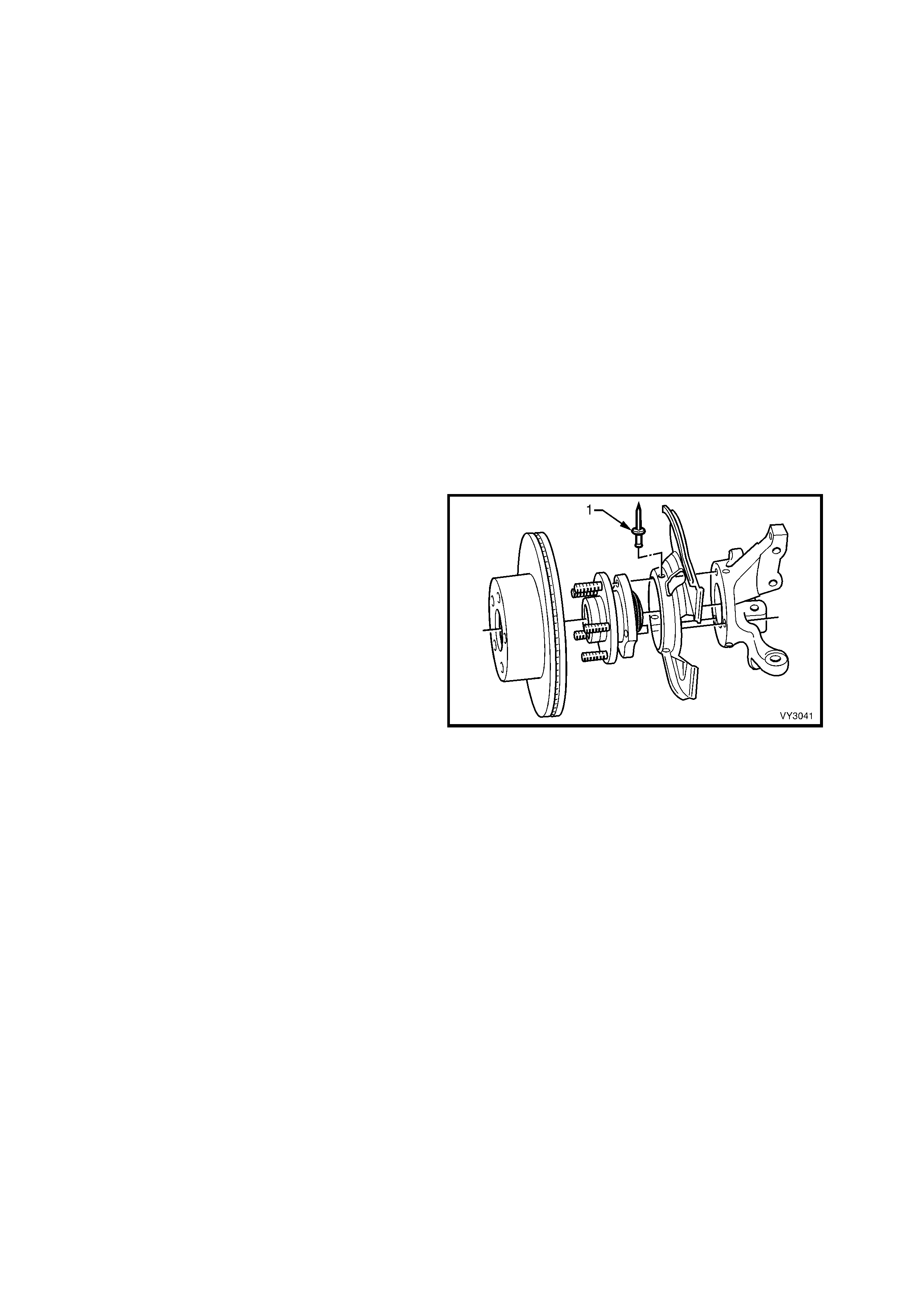
NOTE 4: For the front lower hub bolt, turn wheel outwards to provide sufficient clearance.
8. If the hub is a tight fit to the knuckle, it may be necessary to loosen the three bolts and tap on the heads. DO
NOT STRIKE THE HUB.
9. Remove the three bolts and then the hub from steering knuckle.
10. W here rem oval of the brak e shield is nec essary, drill the heads from the three rivets sec uring the shield to the
steering knuckle support.
11. After removal of the shield, carefully drill out the remainder of the rivets, using a suitable sized drill.
INSPECT
1. Check wheel studs are pressed firmly into the front wheel hub assembly and ensure threads are not damaged.
If one or more of the wheel studs require replacement, refer to 3.4 FRONT WHEEL HUB STUDS in this Section
for details.
2. Examine the brake rotor for scores or damage.
If either of these conditions exist, the brake rotor should be machined. Refer to Section 5A, SERVICE AND
PARK BRAKING SYSTEM for details.
3. Check f or damage to the shield that may cause f ouling of any rotating parts and if s us pec t, the shield s hould be
replaced.
REINSTALL
Installation of the front wheel hub assembly, brake rotor and brake shield is the reverse of removal procedures,
except for the following points:
ALL MODELS:
1. If the brake shield has been removed, install
three, common pop rivets (1), using a
commercially available pop rivet gun.
NOTE: Install the first rivet in the brake shield hole
with the round hole. This will ensure that the
clearance to brake caliper is correct.
2. Before installing the hub, inspect both mating
surfaces to make sure that they are clean and
free from burrs that could prevent correct
alignment of both parts, once installed.
Figure 3-17
WITHOUT ABS:
3. Install the hub assembly on to the steering
knuckle.
4. Install the three attaching bolts (1) and tighten
to the correct torque specification.
( 6 ) FRONT WHEEL HUB ASSEMBLY TO STEERING
KNUCKLE ATTACHING BOLT
TORQUE SPECIFICATION ................ 100 – 115 Nm
NOTE: The three hub attaching bolts are micro-
encapsulated with thread sealant and are not to be
re-used more than thr ee times. If in doubt, the bolts
should be replaced.
WITH ABS:
5. Carefully align the sensor connection on the
hub, with the hole in the steering knuckle, then
install the three hub attaching bolts (1) and
tighten to the correct torque specification.
( 6 ) FRONT WHEEL HUB ASSEMBLY TO STEERING
KNUCKLE ATTACHING BOLTS
TORQUE SPECIFICATION ................ 100 – 115 Nm
6. Fit the wheel speed sensor connector (2),
ensuring that the locking tang is in place.
Figure 3-18
ALL MODELS:
7. If removal of the lower strut to steering knuckle bolt and nut (3) was necessary, the bolt and nut, must be
replaced with new parts. Tighten the bolt and nut to the correct torque specification.
( + ) FRONT STRUT TO STEERING
KNUCKLE ATTACHING NUTS AND BOLTS
TORQUE SPECIFICATION ................ Stage 1 85 Nm
Stage 2 100 Nm
Stage 3 Turn
through 90°
8. Install brake rotor, aligning the marks made before removal.
NOTE: If the hub was replaced, then runout checks must be carried out on the installed brake rotor. Refer to
Section 5A, SERVICE AND PARK BRAKING for important information regarding these checks.
9. Install the brake caliper (4) and attaching bolts (5) and tighten to the correct torque specification.
( + ) BRAKE CALIPER ANCHOR
PLATE RETAINING BOLTS
TORQUE SPECIFICATION ............. 80 – 90 Nm
then turn through
40° - 50°
10. Install the road wheel, aligning the marks made prior to removal and secure with the attaching nuts.
11. Remove the jack stands and lower the vehicle.
12. Tighten the road wheel attaching nuts to correct torque specification, working in a ‘star’ pattern as shown in
2.3 WHEEL AND TYRE REMOVAL AND INSTALLATION in Section 10, WHEELS AND TYRES.
ROAD WHEEL ATTACHING NUT
TORQUE SPECIFICATION ................ 110 – 140 Nm
13. Install the wheel cover/centre cap.
3.4 FRONT W HE EL HUB STUDS
LT Section No. – 06-212
NOTE: The following fastener MUST be replaced
when performing this operation:
+
++
+
Brake caliper attaching bolts.
REPLACE
1. Observing the jacking precautions as outlined in 2.3 JACKING PRECAUTIONS in this Section, raise the front of
the vehicle and support on safety stands..
2. Remove the wheel cover (steel wheels) or centre cap and decorative wheel nut caps (alloy wheels).
3. Mark the relationship of the wheel to the hub and rotor. Remove the wheel attaching nuts and remove the
wheel.
4. Remove the brake caliper retaining bolts and
washers, lift the caliper assembly from the
brake rotor. Suspend the caliper on a wire or
hook to avoid strain on the hose. DO NOT
ALLOW CALIPER TO HANG BY BRAKE
HOSE.
5. Remove the brake rotor from the hub.
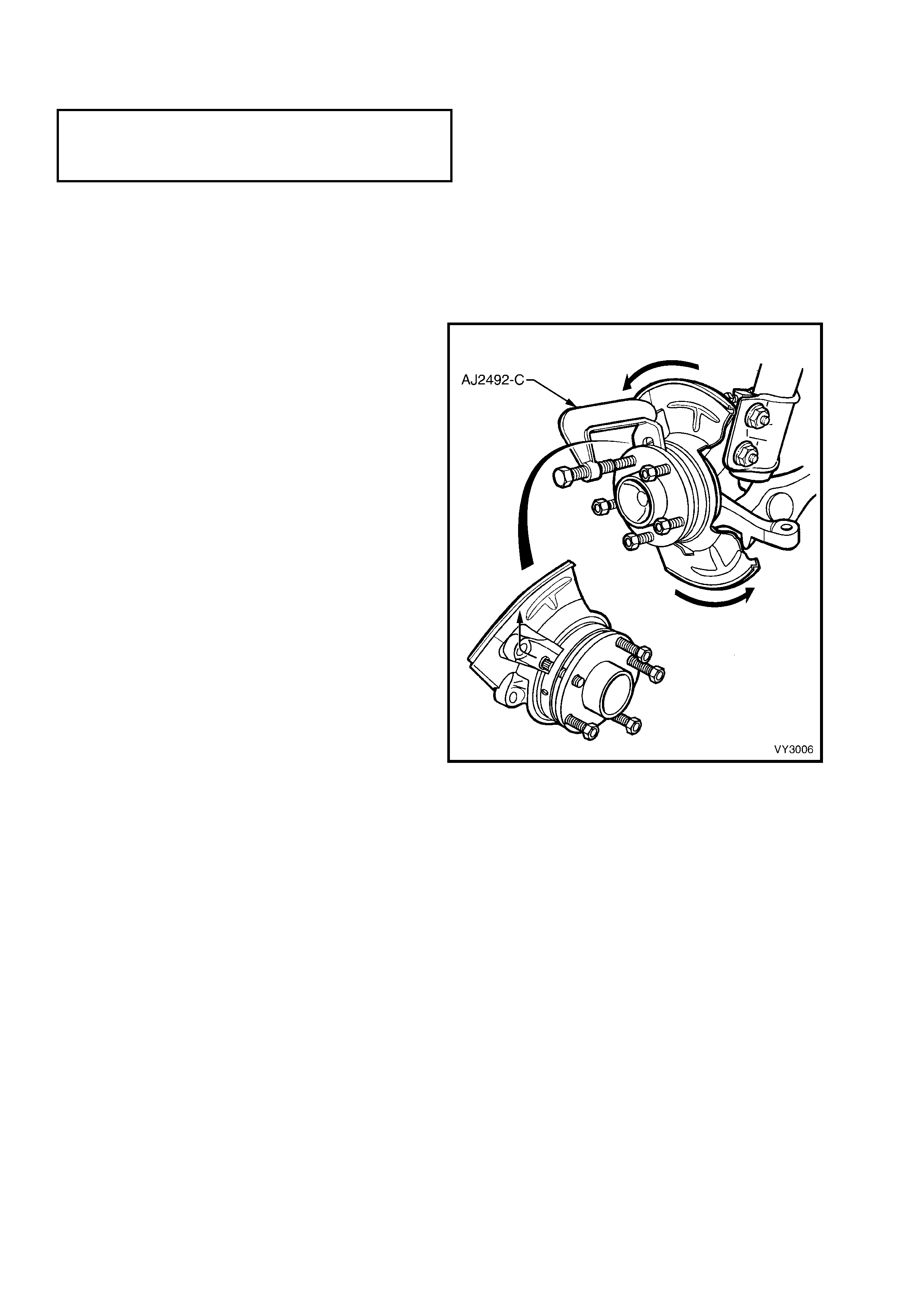
6. Install a wheel nut until the nut is flush with the
end of the stud, then, using Tool No. AJ24292-
C or equivalent, press the stud/s from the front
wheel hub assembly.
NOTE 1: To avoid the unnecessary rem oval of the
micro-encapsulated studs retaining the front wheel
hub assembly to the steering knuckle, it is
recommended that wheel stud/s replacement be
carried out with the hub left undisturbed.
NOTE 2: To remove the stud/s, first drill out the
three rivets securing the brake shield to the
steering knuckle. Then rotate the shield and
remove the wheel stud by manipulating the head
under the shield and into the one recess in the
steering knuckle, at approximately the 11 o'clock
position, as shown.
Figure 3-19
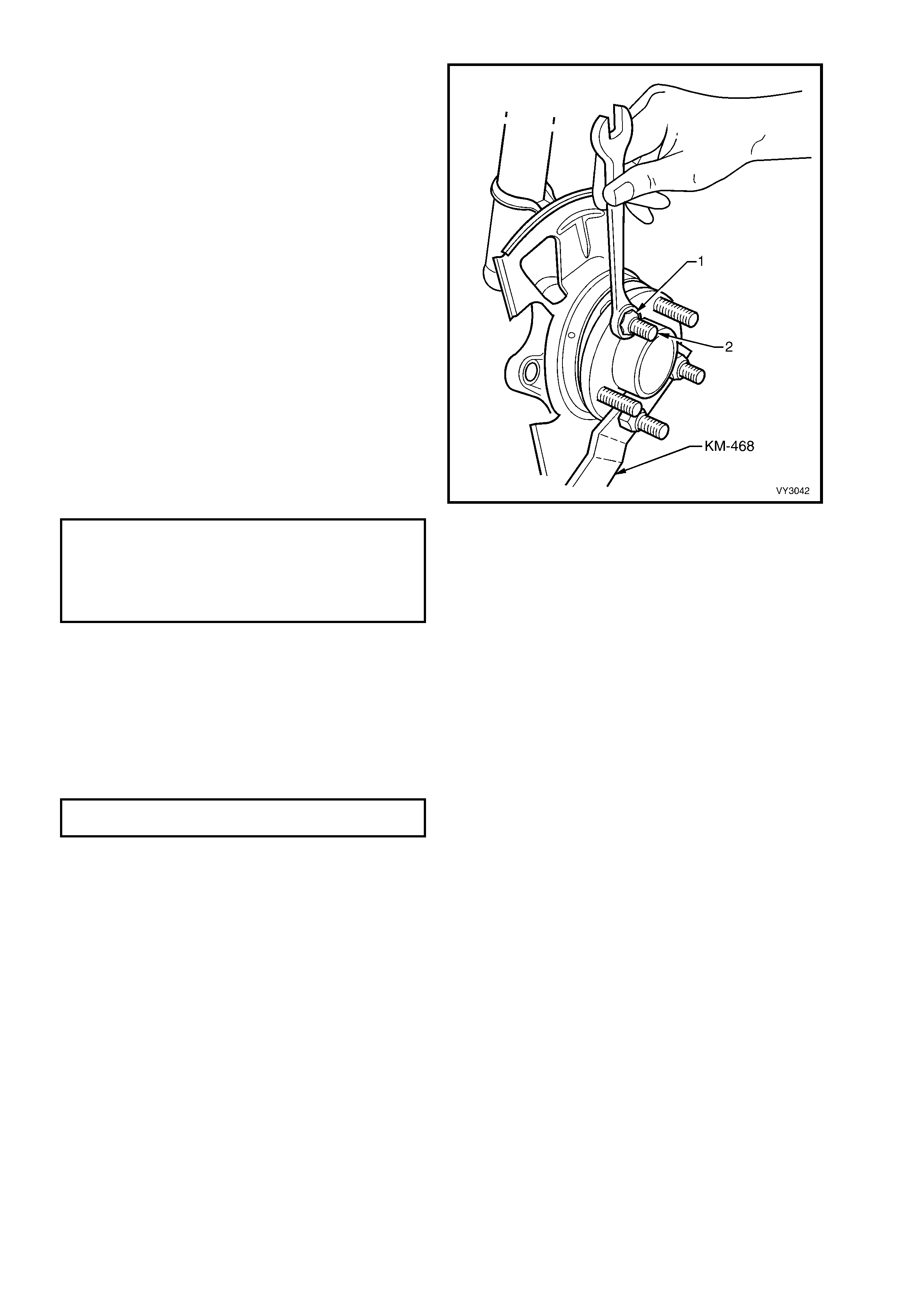
7. New studs can be installed as follows;
a. Install T ool No. KM468, using two revers ed
wheel nuts.
b. Install the replacement stud by first
manipulating the s tud under the f ront brak e
shield and into the wheel hub flange. Then,
after assembling a suitable sized flat
washer and reversed wheel nut (1) onto the
replacem ent st ud (2), hold T ool No. KM468
and tighten the wheel nut to draw the stud
into place.
c. Install any remaining studs in the same
manner. Remove Tool No. KM-468.
8. Using a suitable sized drill, remove the shanks
of the three brake shield retaining rivets. Then
use common pop rivets and a commercially
available pop rivet gun to install the brake
shield.
NOTE: Install the f irst rivet in the brak e shield hole
with the round hole. This will ensure that the
clearance to brake caliper is correct.
9. Install the brake rotor and caliper, tightening
the caliper retaining bolts to the correct torque
specification.
( + ) BRAKE CALIPER ANCHOR
PLATE RETAINING BOLTS
TORQUE SPECIFICATION ................ 80 – 90 Nm
Then turn
through
40° - 50°
10. Install the r oad wheel, aligning the mar ks m ade
prior to removal and secure with the attaching
nuts.
11. Remove the jack stands and lower the vehicle.
12. Tighten the road wheel attaching nuts to
correct the torque specification, working in a
‘star’ pattern. Refer to Section 10, WHEELS
AND TYRES for detailed information regarding
the installation procedure for the road wheels.
ROAD WHEEL ATTACHING NUT
TORQUE SPECIFICATION ................ 110 – 140 Nm
13. Install the wheel cover/centre cap.
Figure 3-20
3.5 FRONT STRUT ASSEMBLY
LT Section No. – 06-212
NOTE: The following fasteners MUST be replaced
when performing this operation:
+
++
+
Upper strut locating plate retaining nut.
+
++
+
Brake caliper retaining bolts.
+
++
+
Steering knuckle to strut attaching nuts and
bolts.
REMOVE
1. Observing the jacking precautions as outlined in 2.3 JACKING PRECAUTIONS in this Section, raise the front of
the vehicle and support on safety stands.
2. Remove the decorative road wheel retaining nut caps, if fitted.
3. Mark the relationship of the road wheel to hub or brake rotor. Loosen, then remove the road wheel attaching
nuts. Remove the road wheel.
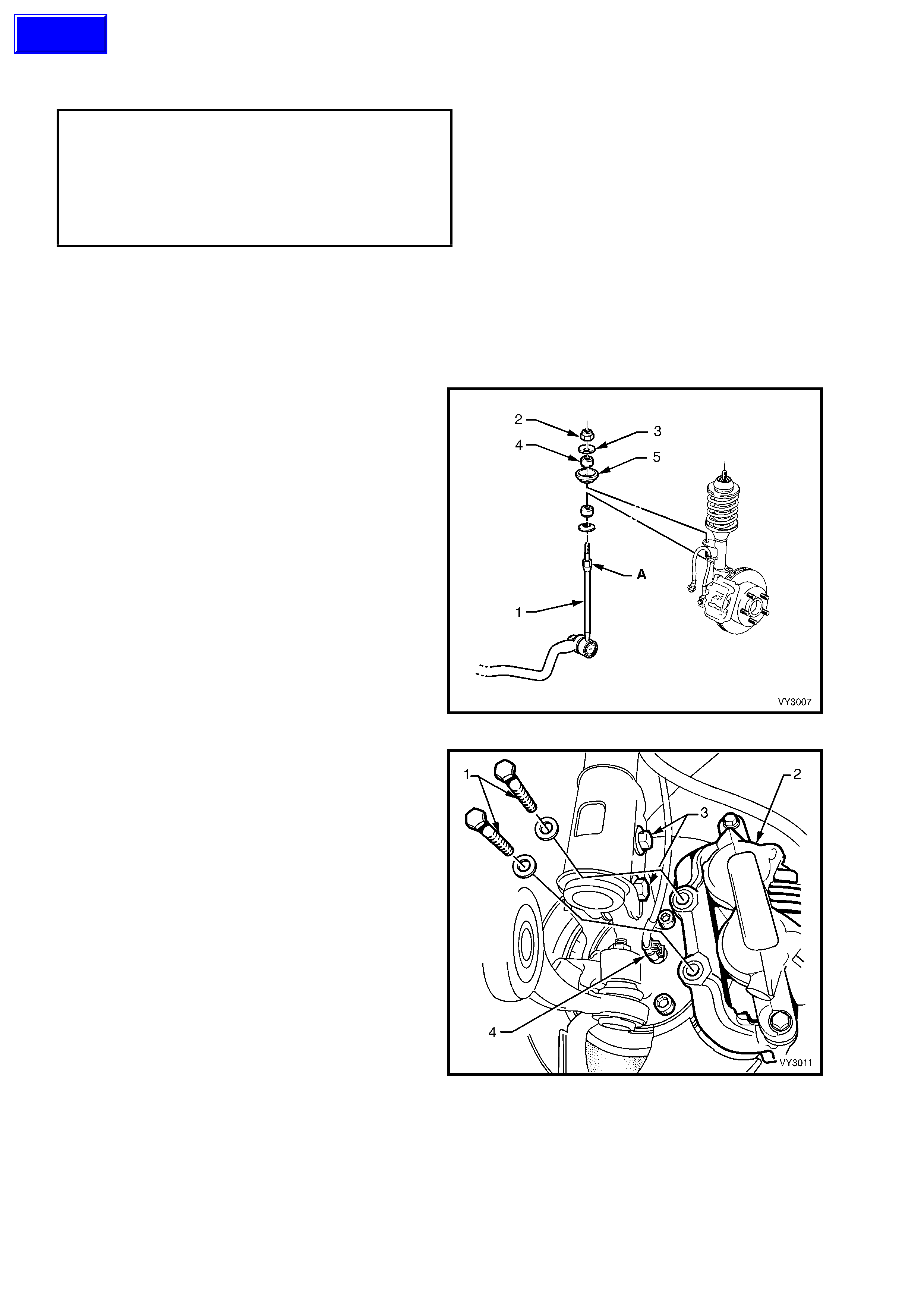
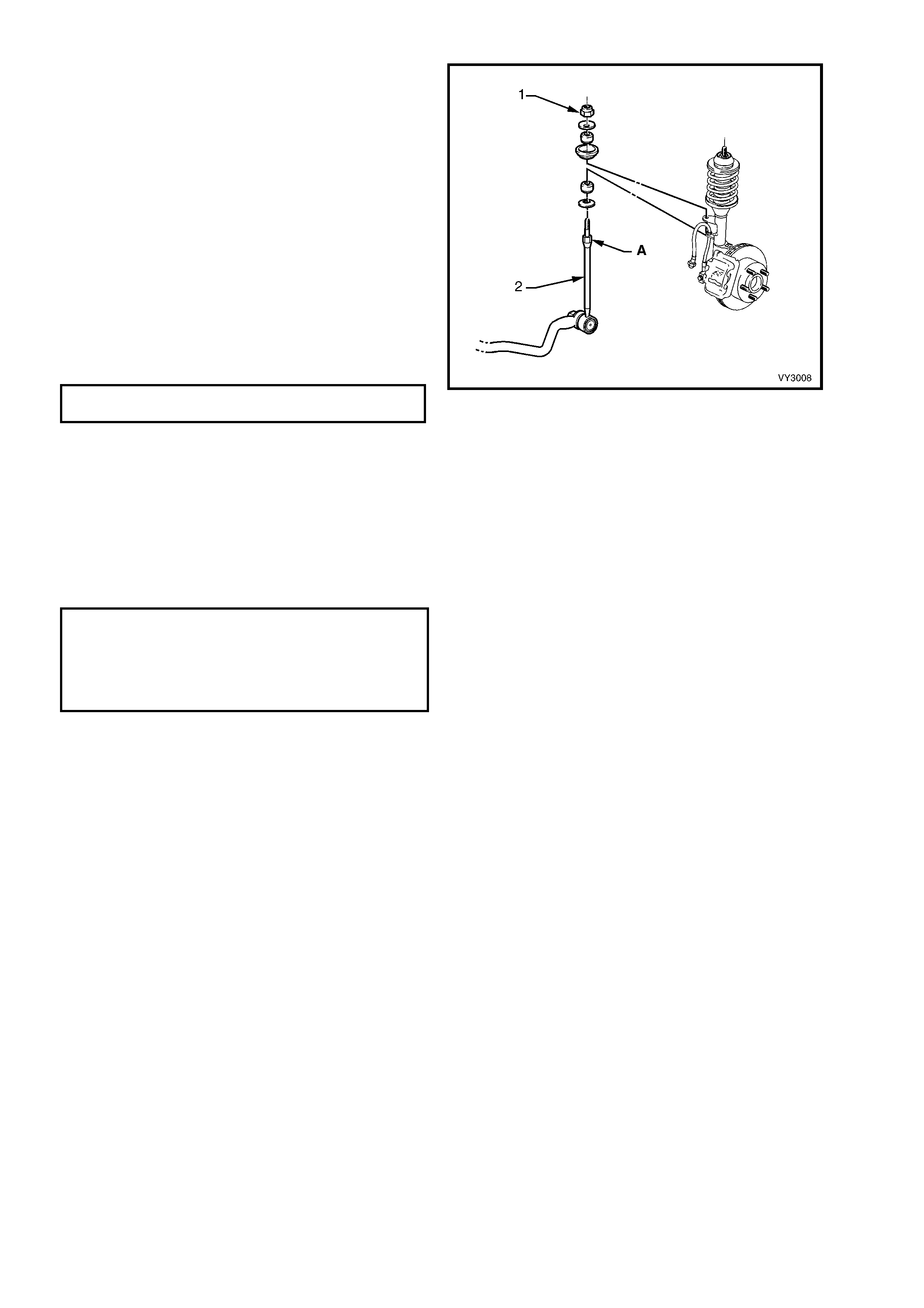
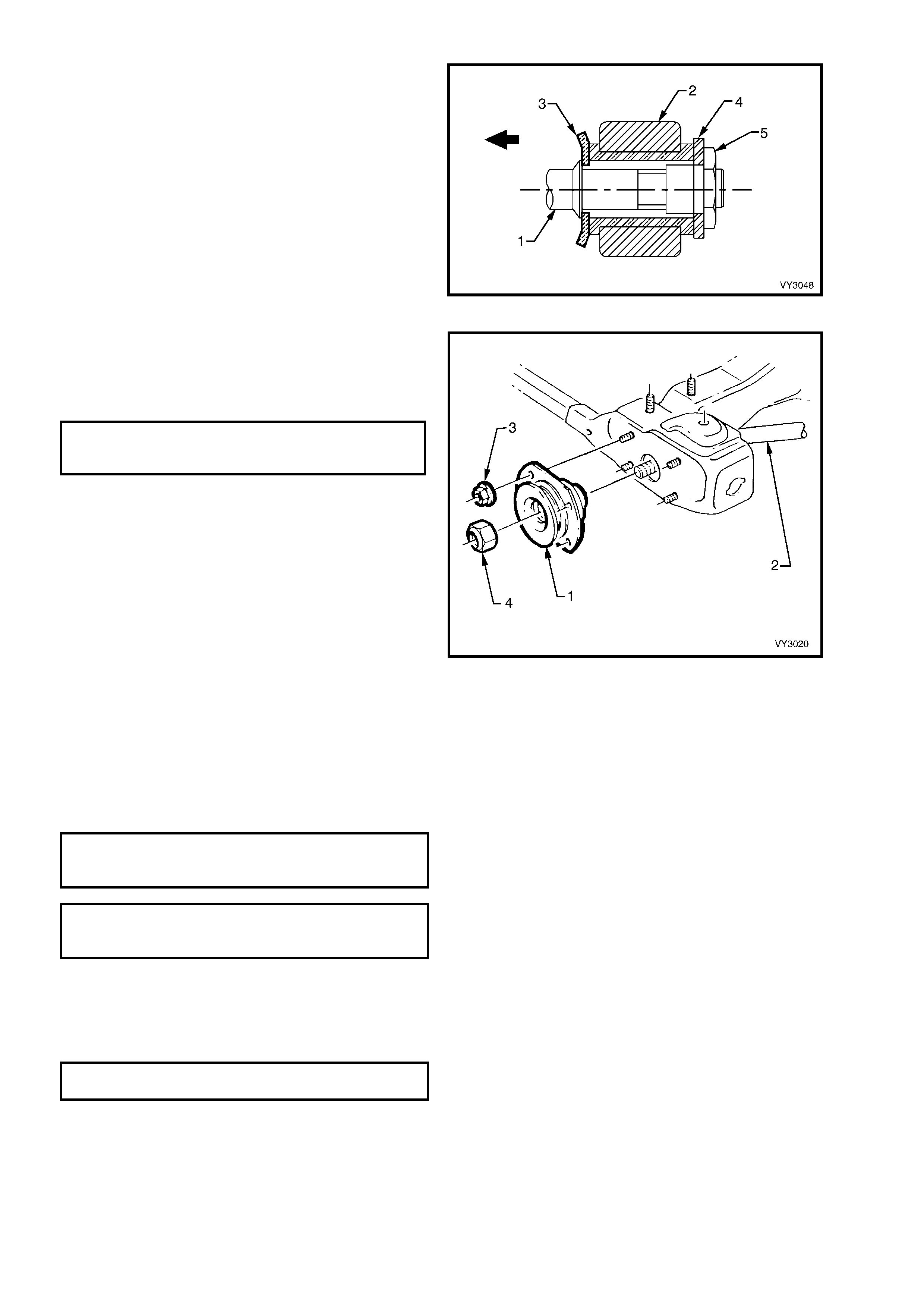
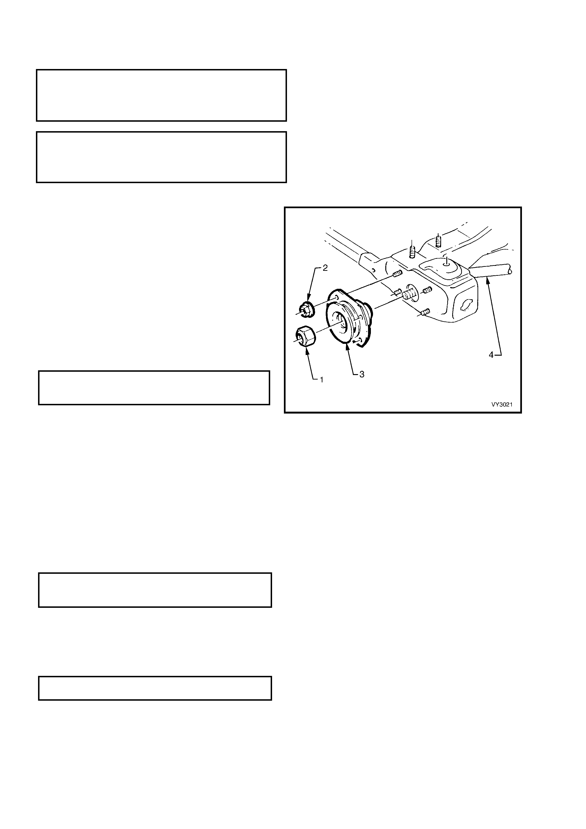
4. Position a suitable size open end spanner to
hold the stabilizer shaft spacer stud (1) at ‘A’,
use another spanner to loosen and remove the
upper nut ( 2), washer (3) , ins ulator ( 4) and s eat
(5).
5. Disconnect the wheel speed sensor cable and
insulator from the strut bracket.
Figure 3-21
6. Remove the brake caliper retaining bolts and
washers (1), lift the caliper assembly (2) from
the brake rotor and support in such a way that
no strain is placed on the brake hose. THE
BRAKE CALIPER IS NOT TO HANG BY THE
BRAKE HOSE.
NOTE 1: This step is necessary to provide access
to the lower strut mounting bolts and nuts (3).
7. If required, remove the brake rotor from the
wheel hub assembly. The brake rotor to hub
relationship is marked during production. To
ensure this relationship is maintained, ensure
that the rotor to hub position is carefully
marked.
NOTE 2: This is necessary to overcome the
possibility of inducing a brake shudder condition
after reassembly.
Figure 3-22
8. Remove the brake hose from the strut housing bracket by turning the plastic sleeve on the hose until the flats
on the sleeve align with the bracket opening.
9. Position a suitable floor jack fitted with a block of wood on the lift pad under the control arm, and raise it
sufficiently to support the weight.
10. Loosen, remove and DISCARD the two lower strut to knuckle attaching bolts and nuts.
Techline
11. To avoid plac ing strain on the ABS sensor lead, release the connec tor lock ing tang and pull on the sens or lead
connector (4) to remove from the sensor.
12. Pull the steering knuckle clear of the strut.
13. Rem ove the dust cover ( 1) fr om the upper str ut
support, in the engine compartment.
14. While holding the strut rod shaft (2) with a 10
mm socket, remove the self-locking nut (3),
using a
24 mm ring spanner, then remove the locating
disc (4). DISCARD THE STRUT ROD NUT.
15. Carefully lower the strut (5) from the tower,
manipulate the strut to remove the stabilizer
stud from the bracket on the strut and remove
the assembly from the vehicle.
Figure 3-23
REINSTALL
Important: The torque of the strut bearing retaining nut (‘5’ in Figure 3-23) MUST be check ed for correct tightness
BEFORE installing the strut into the vehicle!
UPPER STRUT BEARING RETAINING
NUT TORQUE SPECIFICATION.............. 70 – 85 Nm
1. Manipulate the strut assembly so that the stabilizer shaft stud is located in the strut bracket, then locate the strut
assembly into the spring strut tower.
2. After installing the locating disc, partially install a NEW upper nut to the strut rod. Do not tighten at this time.
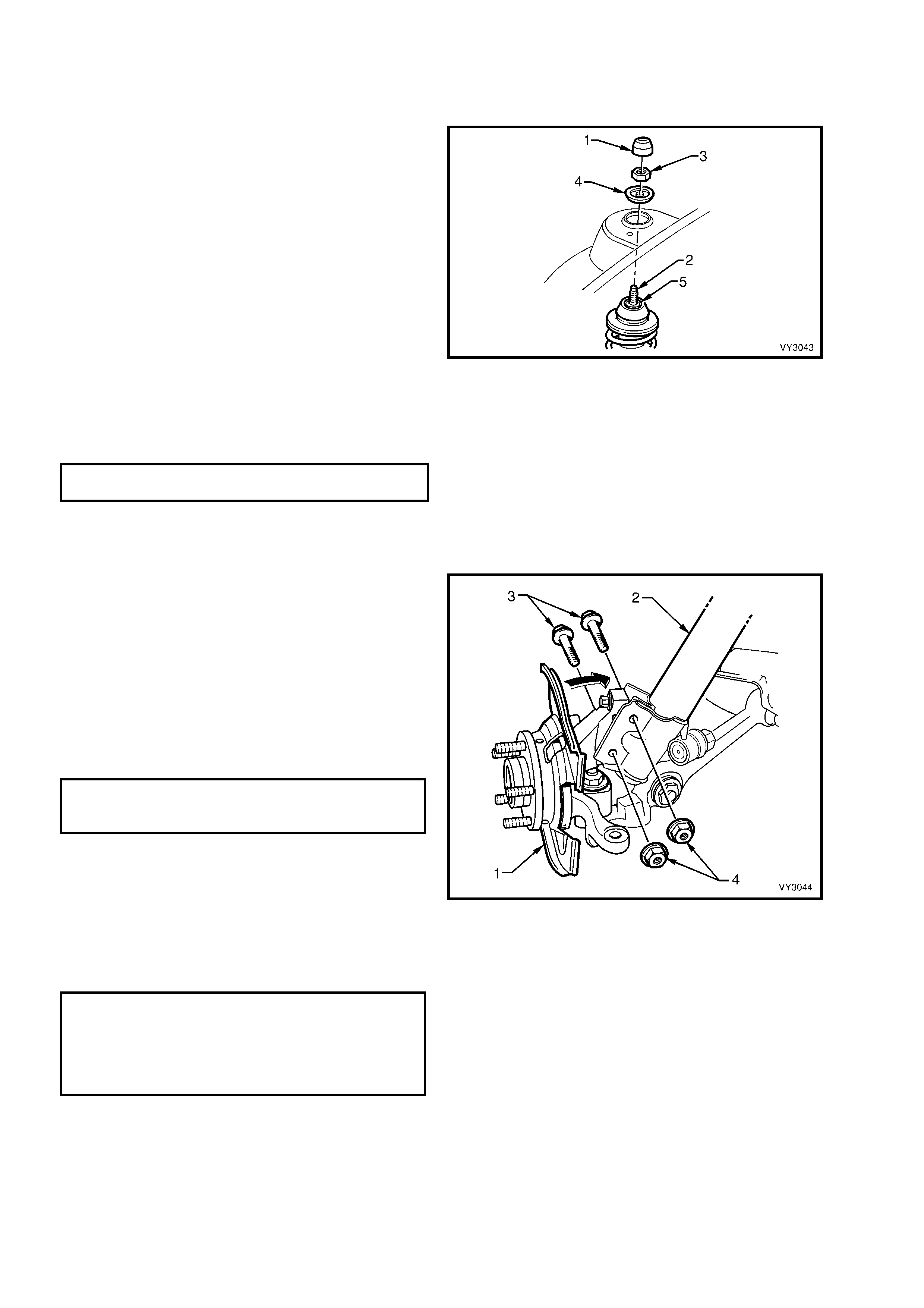
3. Pivot the hub and steering knuckle assembly
(1), sufficiently to line up the bolt holes in the
steering knuckle and the lower end of the strut
assembly (2).
4. Install NEW retaining bolts (3) and nuts (4),
and tighten to a preliminary torque of 85 Nm.
5. Use a 10 mm socket to hold the strut rod from
turning, then tighten the upper strut rod
retaining nut (‘3’ in Figure 3-23) to the correct
torque specification, using a 24 mm ring
spanner with a torque wrench attached.
( + ) UPPER STRUT LOCATING
PLATE RETAINING NUT
TORQUE SPECIFICATION ................... 50 – 60 Nm
6. Install the brake hose to the strut bracket by
turning the plastic sleeve on the hose until the
flats on the sleeve align with the bracket
opening.
7. If removed, install the brake rotor, aligning the
marks made prior to removal.
8. Install the brake caliper, tightening the
attaching bolts to specification.
( + ) BRAKE CALIPER ANCHOR
PLATE RETAINING BOLTS
TORQUE SPECIFICATION ................... 80 – 90 Nm
Then turn
through
40° - 50°
9. Install the wheel speed sensor connector,
pushing firmly onto the sensor until the
retaining tang is secure. Then, install the
sensor lead and insulator into the strut
mounting bracket.
Figure 3-24
10. Install the stabilizer shaft spacer stud nut (1)
after ensuring that all the components are
assem bled as shown. While holding the spacer
stud (2) with a suitable open end spanner at ‘A’,
use another spanner to tighten the upper
retaining nut until the end of the thread on the
stud is contacted.
NOTE: Do not use power tools for this tightening
operation, otherwise thread damage will result.
11. Install the r oad wheel, aligning the mar ks m ade
prior to removal .
12. Remove the safety stands and lower vehicle.
13. Tighten road wheel attaching nuts to the
correct torque specification, working in a ‘star’
pattern, as shown in 2.3 WHEEL AND TYRE
REMOVAL AND INSTALLATION in Section
10, WHEELS AND TYRES.
ROAD WHEEL ATTACHING NUT
TORQUE SPECIFICATION ................ 110 - 140 Nm
14. Install the decorative road wheel retaining nut
caps, as required.
15. Bounce the vehicle up and down several times
to settle the suspension.
16. Check the wheel alignment, as detailed in
2.2 WHEEL ALIGNMENT CHECKING AND
ADJUSTMENT in this Section.
17. Tighten the steering knuckle to strut bolts and
nuts to the specified torque values.
Figure 3-25
( + ) STEERING KNUCKLE TO STRUT
ATTACHING NUTS AND BOLTS
TORQUE SPECIFICATION ............. Stage 1 85 Nm
Stage 2 100 Nm
Stage 3 Turn
through 90°
3.6 UPPER STRUT SUPPORT BEARING AND MOUNT
LT Section No. – 06-210
REMOVE
1. Remove the front strut (1) as detailed in
3.5 FRONT STRUT ASSEMBLY in this
Section.
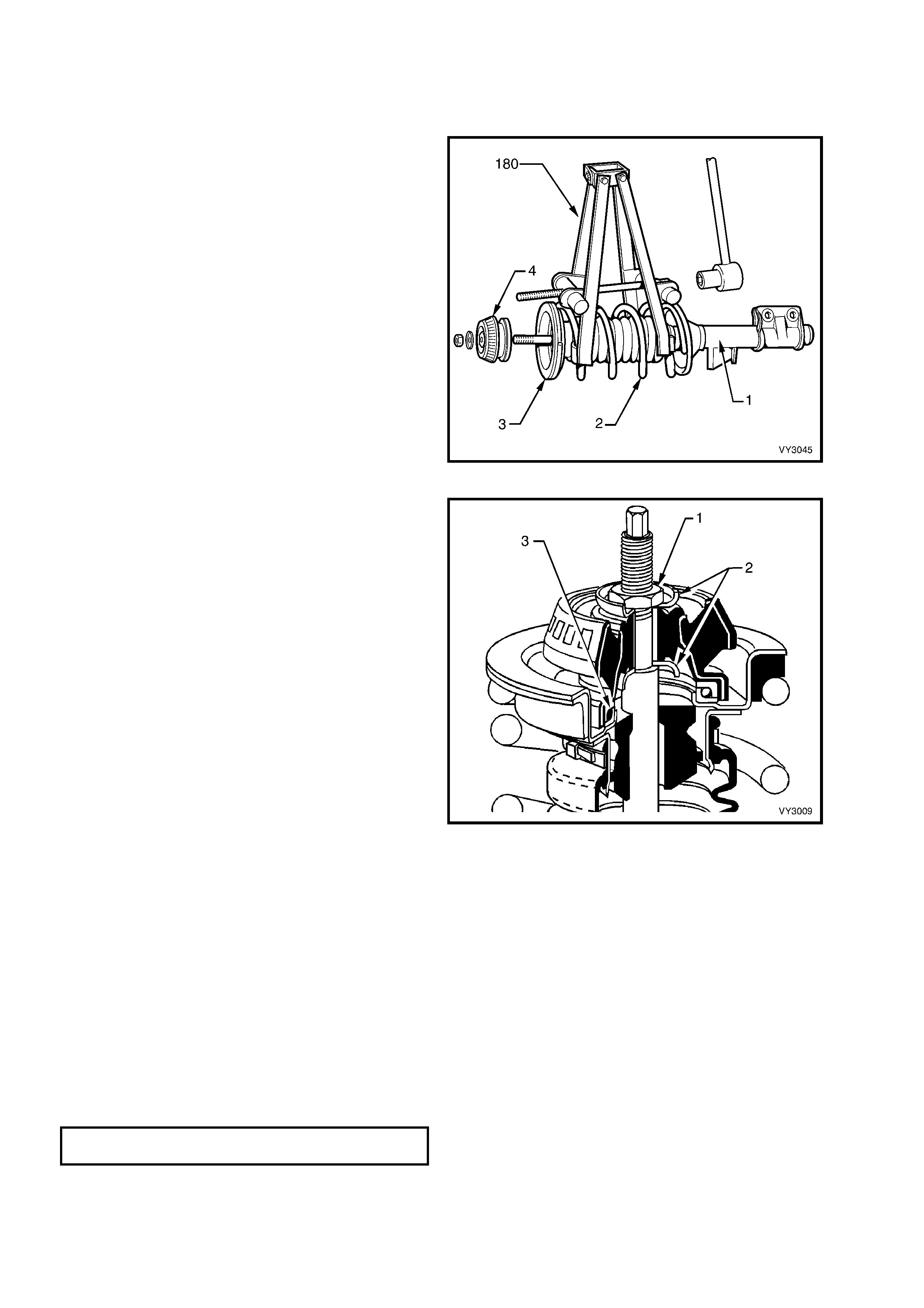
2. Fit Tool No. 180 (or a commercially available
equivalent) on to the front spring as shown.
Compr es s the spring (2) until the upper suppor t
bearing (3) has clearance at the spring seat
collar (4).
Figure 3-26
CAUTION: Do not attempt to remove the
retaining nut from the strut rod shaft before
compressing the spring.
3. W hile holding the strut rod shaft with a 10 mm
socket, remove the upper strut bearing to strut
rod retaining nut (1), using a 24 mm ring
spanner.
4. Remove the front suspension strut mount
assembly and the two washers (2) either side.
NOTE 1: The lower washer may be binding with the
lower edge of the mount.
5. Remove the strut bearing (3) from the upper
spring seat collar, taking particular note of
the bearing's orientation.
NOTE 2: The upper support bearing is self-
lubricated and no servicing requirements are
necessar y. If cons idered to be faulty, the bearing is
to be replaced as an assembly.
NOTE 3: Under no circumstances is the machined
surface of the piston rod section to be gripped
directly on its outer surface.
Figure 3-27
REINSTALL
1. Pull the strut rod through the upper spring seat to its maximum length, then remove the strut rod nut.
2. Install the upper bearing with the same orientation as noted on removal. Generally, the coloured or narrow,
outer section, faces towards the upper spring seat collar.
3. While holding the strut rod extended and, after installing the first mount washer with the dished shape facing
downward (refer to Item 2 in Figure 3-27), install the upper front suspension strut mount assembly over the
bearing and washer.
4. Install the second washer with the dished shape facing upward (refer to Item 2 in Figure 3-27) and install the
retaining nut.
5. Using a 10 m m s ocket and a 24 m m ring spanner with a torque wrench attached, tighten the nut to the correct
torque specification.
UPPER STRUT BEARING RETAINING
NUT TORQUE SPECIFICATION.............. 70 – 85 Nm
6. Release the spring compressor and remove it from the spring.
7. Install the front strut as detailed in 3.5 FRONT STRUT ASSEMBLY in this Section.
3.7 FRONT SPRING
LT Section No. – 06-210
REMOVE
1. Remove the front strut, refer to 3.5 FRONT STRUT ASSEMBLY in this Section.
2. Remove the front strut dust shield assembly, as detailed in 3.6 UPPER STRUT SUPPORT BEARING AND
MOUNT in this Section.
3. Remove the clamp (1) securing the front strut
dust shield assembly (2) and filter (3) to the
upper spring seat collar (4) and discard.
4. Remove the upper spring seat collar, spring
insulator (5) and compression bum per (6) from
the top of the spring (7).
5. Remove the spring from the strut (8) and
release the spring compressor.
REINSTALL
NOTE 1: If installing a replacement spring, ensure
that the spring is the correct type for the
suspension system fitted to the vehicle. Refer to
5. SPECIFICATIONS in this Section for details.
1. Position spring on strut with straight projecting
end of spring correctly located in spring seat.
2. Install spring compressor Tool No. 180 or a
com m erc ially available equivalent to the spring
(refer to Figure 3-26) and compress it.
3. Install the upper spring insulator, spring seat
collar and compression bumper so that the
double notch in the upper flange of the spring
seat collar is assembled, facing inward. The
spring insulator has a step which locates on to
the straight projecting end of the spring.
4. Install the upper support plate (9) as detailed in
3.6 UPPER STRUT SUPPORT BEARING
AND MOUNT in this Section.
NOTE 2: The lower washer (10) may be binding
with the lower edge of the mount.
5. Fit the upper end of the front strut dust shield
assembly over the lower flange of the spring
seat collar and secure with a retaining clamp.
Tighten the clam p until the boot rubber is firm ly
secured.
6. Install front strut as detailed in
3.5 FRONT STRUT ASSEMBLY in this
Section.
Figure 3-28
3.8 FRONT STRUT UNIT
LT Section No. – 06-212
REPLACE
NOTE 1: When replacing the front strut, ensure that the replacement unit is the correct type for the suspension
system fitted to the vehicle. Refer to 5. SPECIFICATIONS in this Section for details.
NOTE 2: As the strut assembly is a sealed component, no overhaul procedures are possible. If any strut
component is found to be unserviceable, the complete strut must be replaced.
1. Remove the front strut assembly as detailed in 3.5 FRONT STRUT ASSEMBLY in this Section.
2. Rem o ve the upper support c om ponents as detailed in 3.6 UPPER ST RUT SUPPORT BEARING AND M O UNT
in this Section.
3. Remove the spring as detailed in 3.7 FRONT SPRING in this Section.
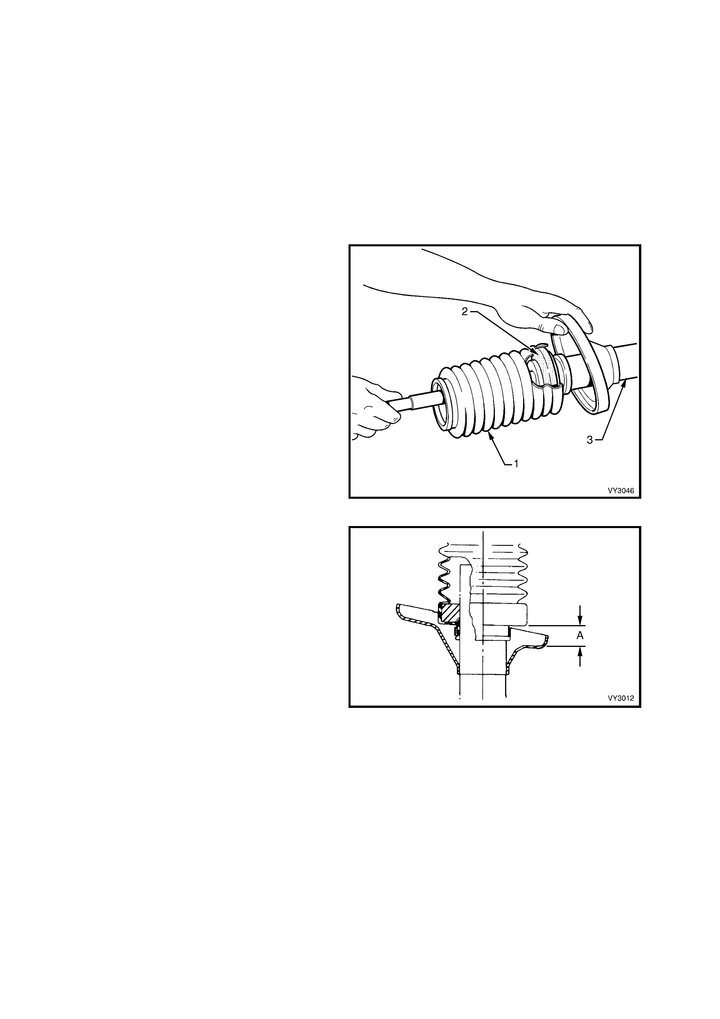
4. Remove the lower boot retaining clamp and
discard. Slide the front strut dust shield
assembly (1) and filter (2) from the strut
assembly (3).
5. Pull the strut rod fully up and, while supporting
the rod to stop it from slipping back into the
strut, install the front str ut dust shield ass embly
over the strut tube, ensuring that the filter
remains seated inside the boot assembly.
Figure 3-29
6. Ensure that the bottom of the front strut dust
shield assembly is positioned so that distance
‘A’ is between 30 - 35 mm.
7. Install the retaining clamp and tighten until the
rubber on the f ront s tr ut dust shield assembly is
firmly secured.
8. Install the front spring as detailed in
3.7 FRONT SPRING in this Section.
9. Install the upper strut support assembly as
detailed in 3.6 UPPER STRUT SUPPORT
BEARING AND MOUNT in this Section.
10. Install the front strut assembly as detailed in
3.5 FRONT STRUT ASSEMBLY in this
Section.
Figure 3-30
3.9 STEE RING KNUCKLE
LT Section No. – 06-212
NOTE 1: The following fasteners have either micro
encapsulation or incorporate a mechanical thread lock
and should only be used once. If in doubt, r eplacement
is recommended when performing this operation:
♦ Front lower control arm socket stud nut.
NOTE 2: The following fastener MUST be replaced
when performing this operation:
+
++
+
Front strut to steering knuckle attaching nuts
and bolts.
REMOVE
1. Remove the front brake rotor, wheel hub
assembly and brake shield, as detailed in
3.3 FRONT WHEEL HUB ASSEMBLY,
BRAKE ROTOR OR BRAKE SHIELD in this
Section.
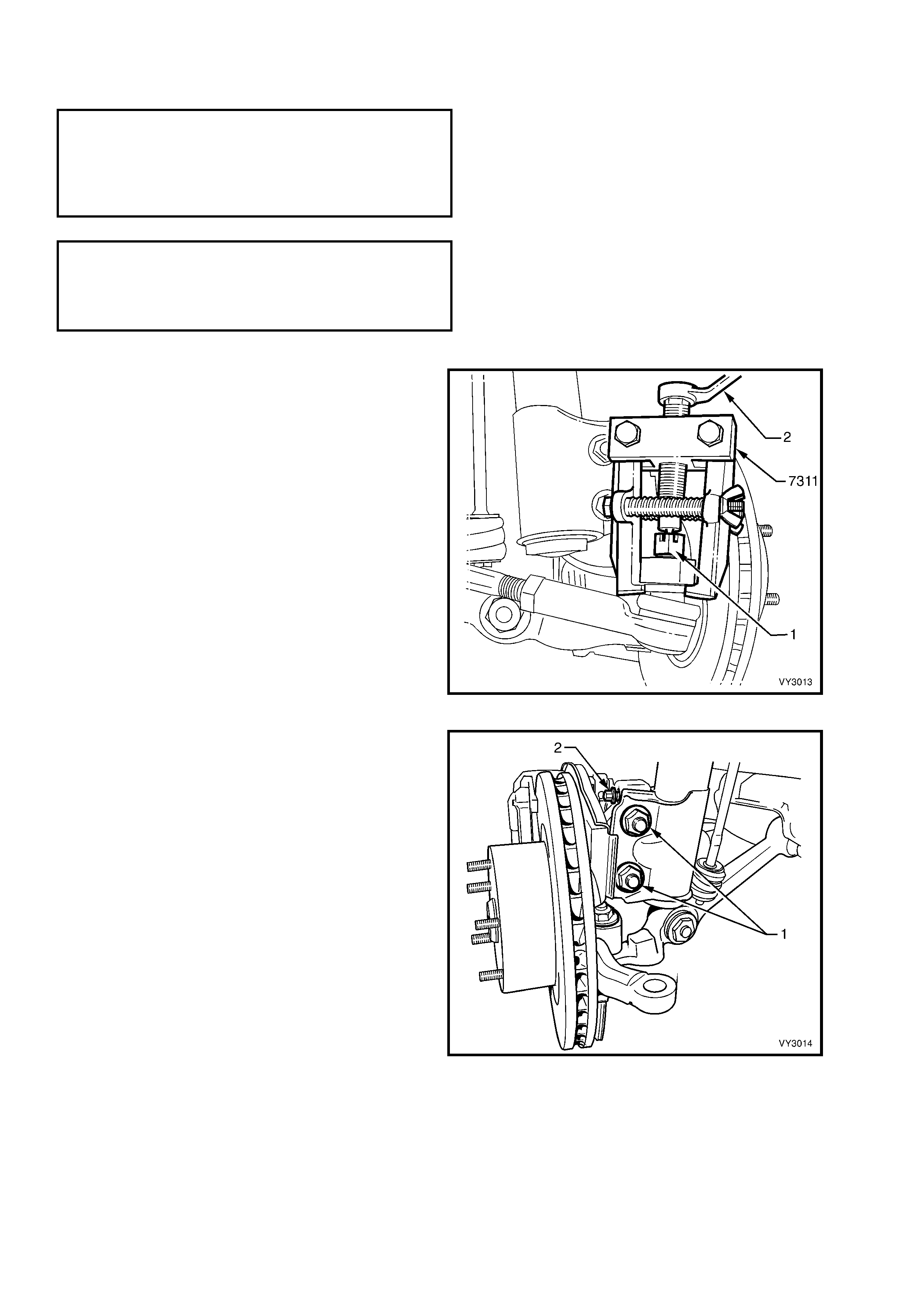
2. Remove the s plit pin and loosen the castellated
nut (1) until the nut is flush with the end of the
steering linkage outer tie rod socket assembly
stud.
3. Install Tool No. 7311 as shown and, using a
ring spanner (2), press the stud out from the
steering knuckle.
Figure 3-31
4. Loosen, r emove and discar d the two lower strut
attaching bolts and nuts (1).
5. If the steering knuckle is to be replaced,
remove the camber adjusting bolt (2) from the
arm.
Figure 3-32

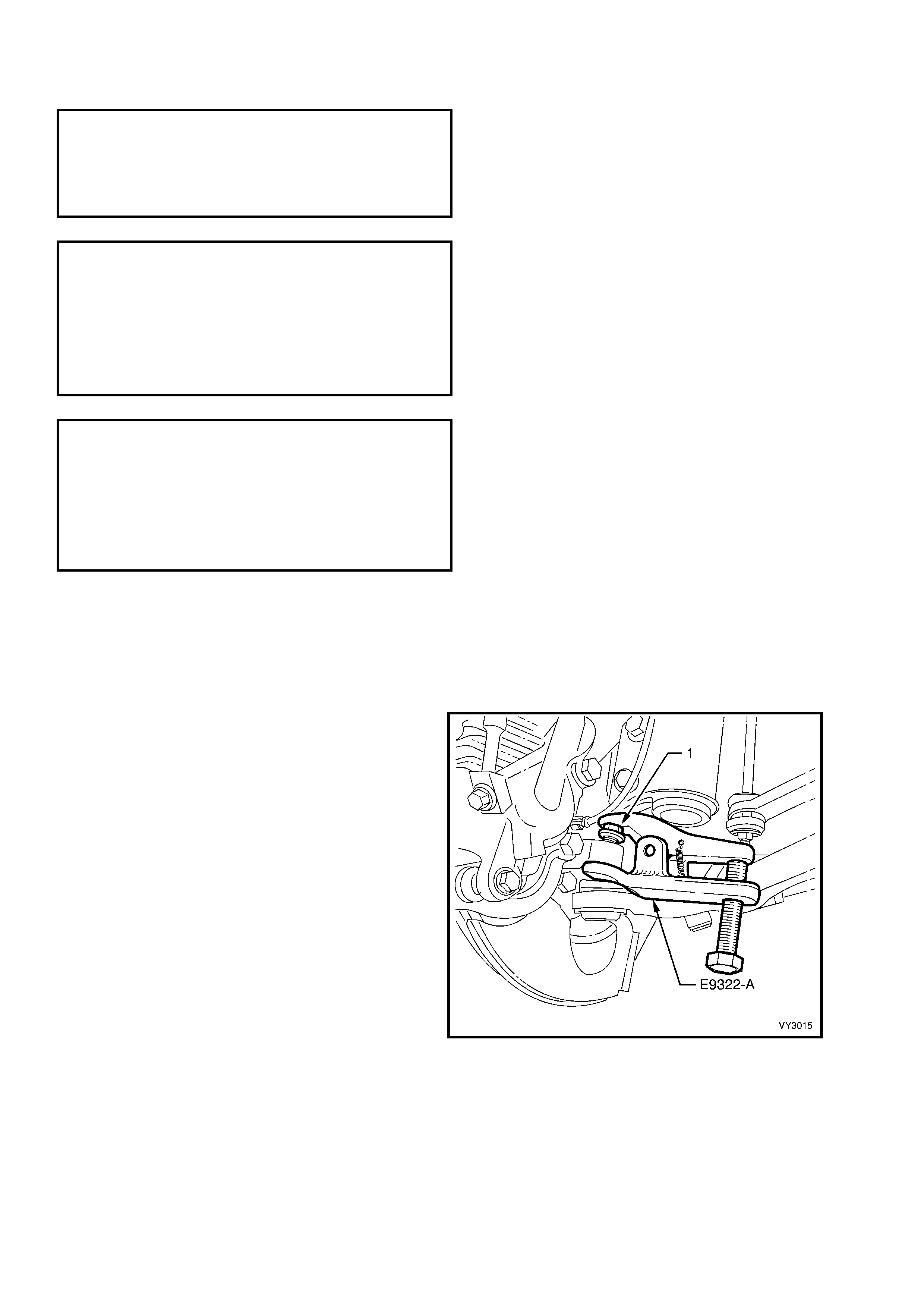
6. Loosen the front lower control arm socket
retaining nut (1) until the nut is flush with the
end of the front lower control arm socket stud
thread.
NOTE: Because the nut has micro-encapsulated
sealant applied to the threads, it must be replaced
after removal.
7. Install release Tool No. E9332-A as shown,
then apply force to the top of the front lower
control arm socket stud by tightening the
forcing bolt on the tool, separating the front
lower control arm socket from the knuckle.
NOTE: Once load is applied by the release tool
loading bolt, a sharp tap on the nut end of the tool
will lessen the apply force required.
8. Temporarily jam the front lower control arm
socket stud taper into the knuckle to hold the
stud, before fully removing the retaining nut.
Discard the removed nut as it has micro-
encapsulation sealant applied and must be
replaced on reassembly.
9. Separate the knuckle from the front lower
control arm socket stud and remove from the
vehicle.
Figure 3-33
REINSTALL
Installation is the reverse of the removal procedures except for the following:
1. Ins tall the steer ing knuc k le over the fr ont lower control ar m sock et s tud, then install NEW lower strut to steering
knuckle, bolts and nuts but do not tighten fully at this stage.
2. Position a suitable floor jack with a block of wood fitted to the lift pad under the front lower control arm, and
raise sufficiently to support the weight and jam the front lower control arm socket stud taper into the knuckle.
3. Install a NEW self-locking nut on to the front lower control arm socket stud and tighten the nut to the correct
torque specification.
( 6 ) FRONT LOWER CONTROL ARM
SOCKET STUD NUT
TORQUE SPECIFICATION ...................... 50 – 70 Nm
4. Ins tall the steer ing steering outer steering link age outer tie r od sock et s tud into the steering k nuc kle and tighten
the castellated attaching nut to the correct torque specification. Install new split pin.
STEERING LINKAGE OUTER TIE ROD SOCKET
ASSEMBLY STUD CASTELLATED NUT
TORQUE SPECIFICATION ...................... 58 – 71 Nm
5. Install the brake shield, wheel hub assembly and front brake rotor, as detailed in 3.3 FRONT WHEEL HUB
ASSEMBLY, BRAKE ROTOR OR BRAKE SHIELD in this Section.
NOTE: The brake rotor must be installed, aligning the marks made prior to removal.
6. Temporarily install the road wheel/s and lower the vehicle to the ground.
7. Bounce the vehicle up and down several times to settle the suspension.
8. Check the wheel alignment, as detailed in 2.2 WHEEL ALIGNMENT CHECKING AND ADJUSTMENT in this
Section.

9. Following the wheel alignment, it will be neces sary to raise the vehicle and tighten the NEW steer ing k nuck le to
strut bolts and nuts to the correct torque specification.
( + ) STEERING KNUCKLE TO STRUT
ATTACHING BOLTS AND NUTS
TORQUE SPECIFICATION ................ Stage 1 85 Nm
Stage 2 100 Nm
Stage 3 Turn
through 90°
10. Lower the vehicle to the ground and tighten the road wheel attaching nuts to the correct torque specification,
working in a ‘star’ pattern, as shown in 2.3 WHEEL AND TYRE REMOVAL AND INSTALLATION in Section 10,
WHEELS AND TYRES.
ROAD WHEEL ATTACHING NUT
TORQUE SPECIFICATION ................ 110 – 140 Nm
11. Install the wheel cover/centre cap.
3.10 FRONT LOWER CONTROL ARM
LT Section No. – 06-200
NOTE 1: The following fasteners have either micro
encapsulation or incorporate a mechanical thread lock
and should only be used once. If in doubt, r eplacement
is recommended when performing this operation:
♦ Front lower control arm socket stud nut.
NOTE 2: The following fasteners MUST be replaced
when performing this operation:
+
++
+
Front lower control arm pivot nut.
+
++
+
Front lower control arm rod to front lower
control arm attaching nut.
+
++
+
Front lower control arm rod to insulating
bushing attaching nut.
NOTE 3: The following fasteners MUST be at curb
height before final tightening:
• Front lower control arm pivot nut.
• Front lower control arm rod to front lower
control arm attaching nut.
• Front lower control arm rod to insulating
bushing attaching nut.
REMOVE
1. Observing the jacking precautions as outlined in 2.3 JACKING PRECAUTIONS in this Section, raise the front of
the vehicle and place safety stands under the side frame members.
2. Remove the wheel cover (steel wheels) or centre cap and decorative wheel nut caps (alloy wheels).
3. Mark the relationship of the wheel to hub. Loosen, then remove the road wheel attaching nuts and remove the
wheel.
4. Turn the steering out on full lock.
5. Loosen the front lower control arm socket
retaining nut (1) until the top of the nut is flush
with the top of the front lower control arm
socket assembly stud thread.
6. Install the r elease Tool No. E9332- A as shown,
then apply force to the top of the front lower
control arm sock et assem bly stud by tightening
the f orcing bolt on the tool, separating the f ront
lower control arm socket assembly from the
knuckle.
NOTE: Once load is applied by the release tool
loading bolt, a sharp tap on the nut end of the tool
will lessen the apply force required.
7. Temporarily jam the front lower control arm
socket assembly stud taper into the knuckle to
hold the stud, before fully removing the
retaining nut. Dis car d the r emoved nut as it has
micro-encapsulation sealant applied and
should be replaced on reassembly.
Figure 3-34
8. Separate the front lower control arm socket
assembly stud from the knuckle.
9. Hold the steering knuckle away from the front
lower control arm by using a suitable length
prop.
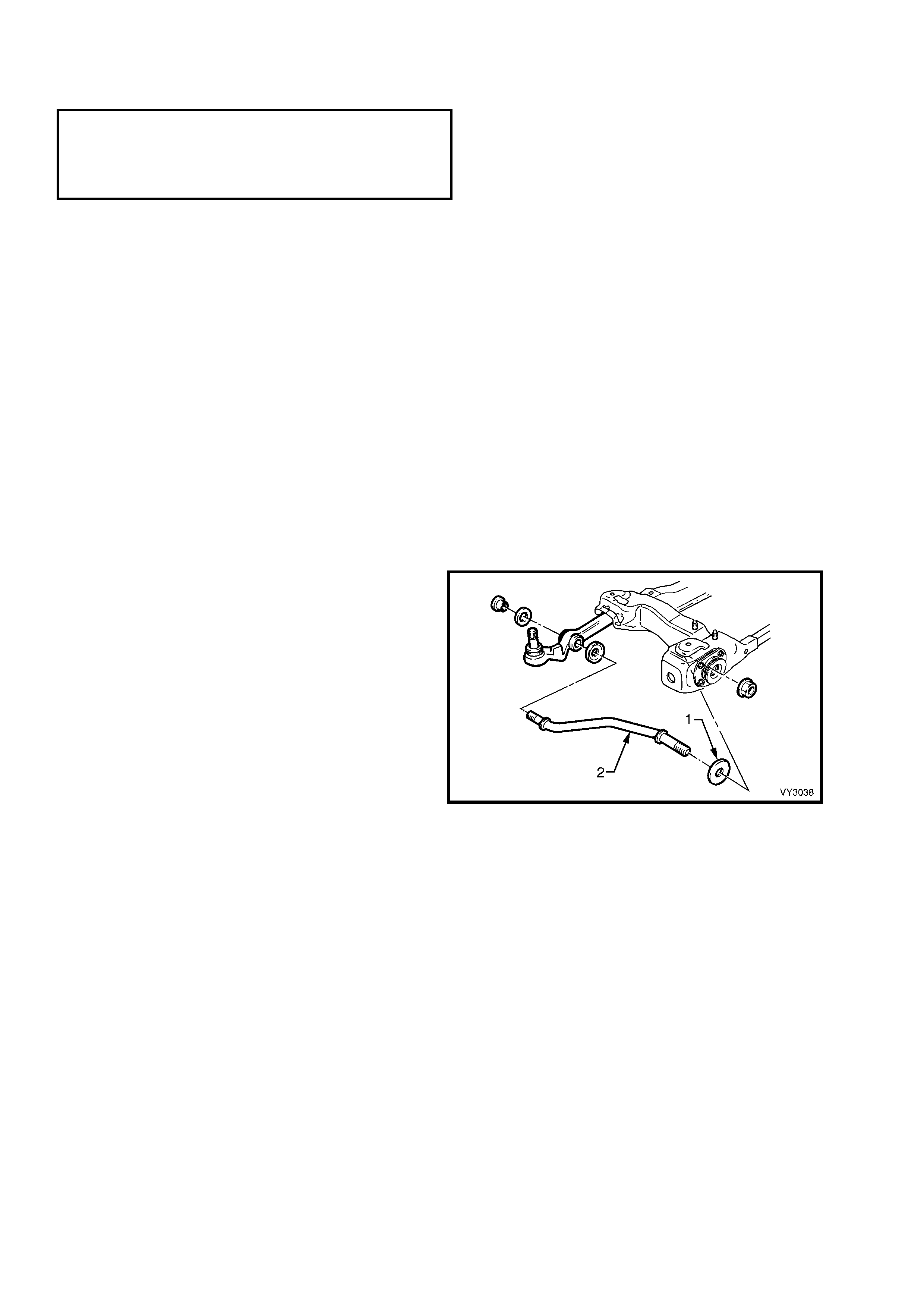
10. Loosen the fr ont lower control arm r od fr ont nut
(1) at the front lower control arm rod insulating
bushing assembly (2).
11. Remove the front lower c ontrol arm rod to front
lower control arm attaching nut (3) and washer
(4). Discard the nut.
12. Remove the four nuts (5) securing the front
lower control arm rod insulating bushing to the
crossmember (6), then remove the front lower
control arm rod (7) from the front lower control
arm rod bushing.
13. Remove the front lower control arm pivot bolt
(8) and nut (9). Discard the nut.
14. Remove the front lower control arm (10) and
bright finished washer (11) from the vehicle.
Figure 3-35
REINSTALL
1. Install the front lower control arm on to the
crossmember, install the bolt (‘8’ in Figure 3-
36), then install a NEW nut (‘9’ in Figure 3-36),
but do not fully tighten at this stage.
2. Install the front lower control arm rod (1) to the
front lower c ontrol arm (2) with the convex side
of the cupped washer (3) toward the f ront lower
control arm bushing.
3. Install the front lower control arm rod to front
lower control arm washer (4) with a NEW
attaching nut (5) but do not fully tighten at this
stage.
4. Install front lower control arm rod and the
insulating bushing into the c ros s mem ber , install
the four r etaining nuts and tighten to the correc t
torque specification.
FRONT LOWER CONTROL ARM ROD INSULATING
BUSHING ASSEMBLY ATTACHING
TORQUE SPECIFICATION ...................... 20 – 26 Nm
NOTE: Install a NEW front lower control arm rod
nut on to the f ront of the f ront lower contr ol arm rod
but do not tighten at this stage.
Figure 3-36
5. Using a s uitable f loor jack f itted with a block of wood positioned under the f ront lower c ontrol ar m, rais e the j ac k
suff ic iently to support the weight of the strut as s embly and jam the front lower control arm socket assembly s tud
taper into the knuckle.
6. Install the self-locking nut into the front lower control arm socket assembly stud and tighten the nut to the
correct torque specification.
( 6 ) FRONT LOWER CONTROL ARM
SOCKET ASSEMBLY STUD NUT
TORQUE SPECIFICATION ...................... 50 - 70 Nm
7. Ins tall the road wheel, aligning m ark s m ade pr ior to rem oval. T ighten the wheel nuts progr essively, work ing in a
‘star’ pattern as shown in 2.3 WHEEL AND TYRE REMOVAL AND INSTALLATION in Section 10, W HEELS
AND TYRES.
8. Remove the safety stands and lower vehicle.
9. Bounce the vehicle up and down several times to settle the suspension.
10. W ith the weight of the vehicle on the suspension components, tighten the front lower control arm pivot bolt to
the correct torque specifications.
( + & ) FRONT LOWER CONTROL
ARM PIVOT NUT
TORQUE SPECIFICATION ................... 95 – 100 Nm
10. T ighten both f ront lower c ontrol arm r od nuts ( at the front lower contr ol arm and the f ront lower control arm rod
insulating bushing), to the correct torque specifications.
Important: The weight of the vehicle m ust be on all f our wheels before tightening the f ront lower control arm rod to
specification. Tensioning the front lower control arm rod nuts when the insulating bushing is incorrectly pre-loaded
will result in reduced insulator bushing life and will adversly affect the ride and handling characteristics of the
vehicle.
( + & ) FRONT LOWER CONTROL ARM ROD
TO CONTROL ARM ATTACHING NUT
TORQUE SPECIFICATION ................... 95 – 110 Nm
( + & ) FRONT LOWER CONTROL ARM ROD TO
INSULATOR BUSHING ATTACHING NUT
TORQUE SPECIFICATION ................ 140 – 155 Nm
12. Tighten the r oad wheel attac hing nuts to the c orr ect torque s pec if ic ation, work ing in a ‘s tar’ patter n, as s hown in
2.3 WHEEL AND TYRE REMOVAL AND INSTALLATION in Section 10, WHEELS AND TYRES.
ROAD WHEEL ATTACHING NUT
TORQUE SPECIFICATION ................ 110 – 140 Nm
13. Install the wheel cover/ centre cap.
14. Check the wheel alignment, as detailed in 2.2 WHEEL ALIGNMENT CHECKING AND ADJUSTMENT in this
Section.

3.11 FRONT LOWER CONTROL ARM SOCKET ASSEMBLY
LT Section No. – 06-200
INSPECT
The following procedure should be used when checking the front lower control arm socket assembly for wear.
1. Jack the vehicle up with the jack lift pad located under the centre of the front crossmember.
2. Holding the road wheel at the top and bottom, c heck f or play in the front lower c ontrol ar m sock et ass embly by
rocking the wheel.
3. If any up or down movement of stud in front lower control arm socket assembly housing is detected, the front
lower control arm and socket assembly must be replaced.
NOTE: The front lower control arm socket is not serviced seperately. If the front lower control arm socket is found to
be faulty, the com plete front lower control arm assem bly m ust be replaced. For inform ation relating to the removal
and installation procedures for the front lower control arm, refer to 3.10 FRONT LOWER CONTROL ARM in this
Section.

3.12 FRONT LOWER CONTROL ARM PIVOT BUSHING
LT Section No. – 06-200
REPLACE
1. Remove the front lower control arm (1) as
detailed in 3.10 FRONT LOWER CONTROL
ARM in this Section.
2. Support the front lower control arm with two
pieces of square scrap (2) and press the
bushing from the arm, using Tool No. AU162.
Figure 3-37
3. Using Tool Nos. AU160-1 and KM157-2, install
the new bushing from the fr ont side of the fr ont
lower control arm (1), until flange (2) on the
outer s leeve is flus h with the front lower control
arm.
Figure 3-38
NOTE 1: Tool No KM157-2 is used in the reverse
direction to some previous ‘V’ car models.
NOTE 2: The front lower control arm pivot bushing
(1) m ay be lubricated with a soapy water solution to
ease the installation process.
NOTE 3: The bus hing MUST be aligned, as shown
in Figure 3-39.
4. Install the front lower control ar m as detailed in
3.10 FRONT LOWER CONTROL ARM in this
Section.
Figure 3-39
3.13 FRONT LOWER CONTROL ARM ROD BUSHING
LT Section No. – 06-200
REPLACE
1. Remove the f ront lower control arm as detailed
in 3.10 FRONT LOWER CONTROL ARM in
this Section.
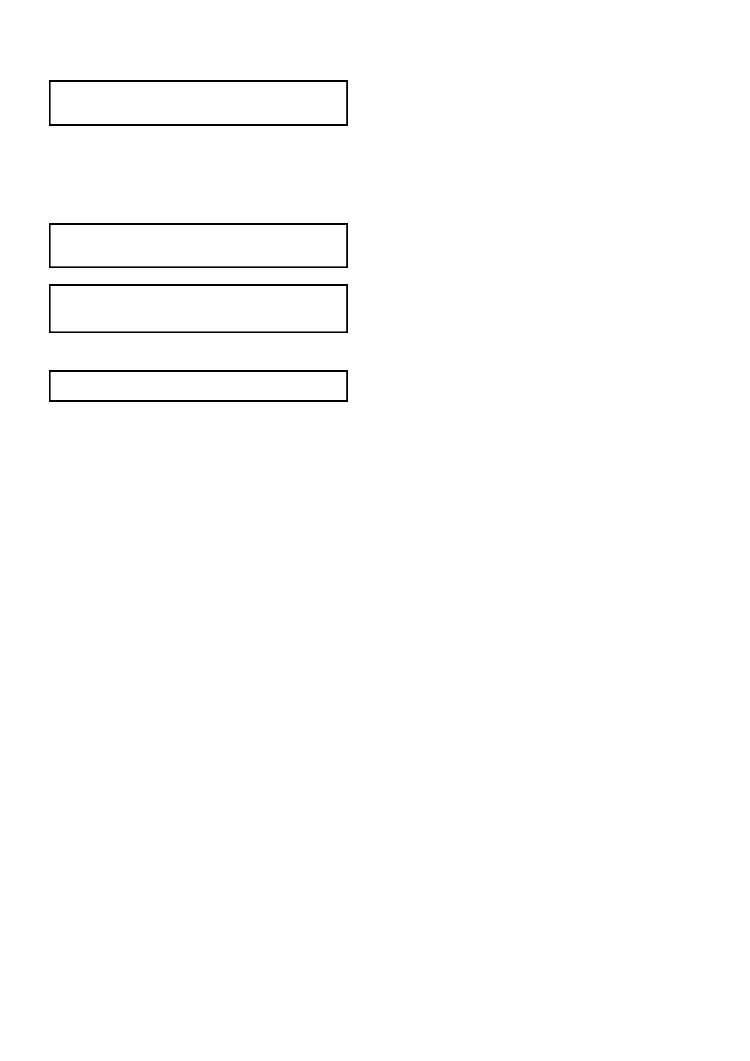
2. Press the front lower control arm rod bushing
from the front lower control arm (1) using Tool
No AU158 and KM158-2 as shown.
Figure 3-40
3. Press in a new front lower control arm rod
bushing (2) using Tool No.s AU158, AU159
and KM158-2 as shown. To assist in
installation, dip the bushing in a soapy water
solution. Install the bushing with the larger
diameter of the stepped fr ont lower control arm
rod mounting hole toward the rear of the front
lower control arm (1).
NOTE: Press the bushing in until it is centrally
located in the front lower control arm.
4. Install the front lower control ar m as detailed in
3.10 FRONT LOWER CONTROL ARM in this
Section.
Figure 3-41
3.14 FRONT LOWER CONTROL ARM ROD
LT Section No. – 06-200
NOTE 1: The following fasteners MUST be replaced
when performing this operation:
+
++
+
Front lower control arm rod to front lower
control arm attaching nut.
+
++
+
Front lower control arm rod to insulating
bushing attaching nut.
NOTE 2: The following fasteners MUST be at curb
height before final tightening:
• Front lower control arm rod to front lower
control arm attaching nut.
• Front lower control arm rod to insulating
bushing attaching nut.
REMOVE
1. Before raising the vehicle, loosen the front lower control arm rod nut (‘7’ in Figure 3-42).
2. Observing the jacking precautions as outlined in 2.3 JACKING PRECAUTIONS in this Section, raise the front of
the vehicle and place safety stands under the side frame members..
3. Rem ove the wheel cover (steel wheels) or centre cap and dec orative wheel nut caps (alloy wheels) on the side
where the front lower control arm rod is to be removed.
4. Mark the relationship of the road wheel to the hub and brak e rotor. Loosen, then remove road wheel attaching
nuts and remove the road wheel.
5. Rem ove the f ront lower control arm rod to fr ont
lower control arm attaching nut (1) and washer
(2). Discard the nut.
6. Remove the four nuts (3) attaching the front
lower control arm rod insulating bushing (4) to
the crossmember outrigger.
7. Rem ove the front lower c ontrol arm rod (5) and
insulating bushing assembly from the front
lower control arm (6) and remove the rod out
through the crossmember outrigger.
8. Secure the front lower control arm rod in
protected vice jaws, then remove the front
lower contr ol arm rod to fr ont lower control arm
rod insulator bushing retaining nut (7). Discard
the nut.
9. Remove the bright finished washer (8), from
the driver’s side front lower control arm rod.
Figure 3-42
REINSTALL
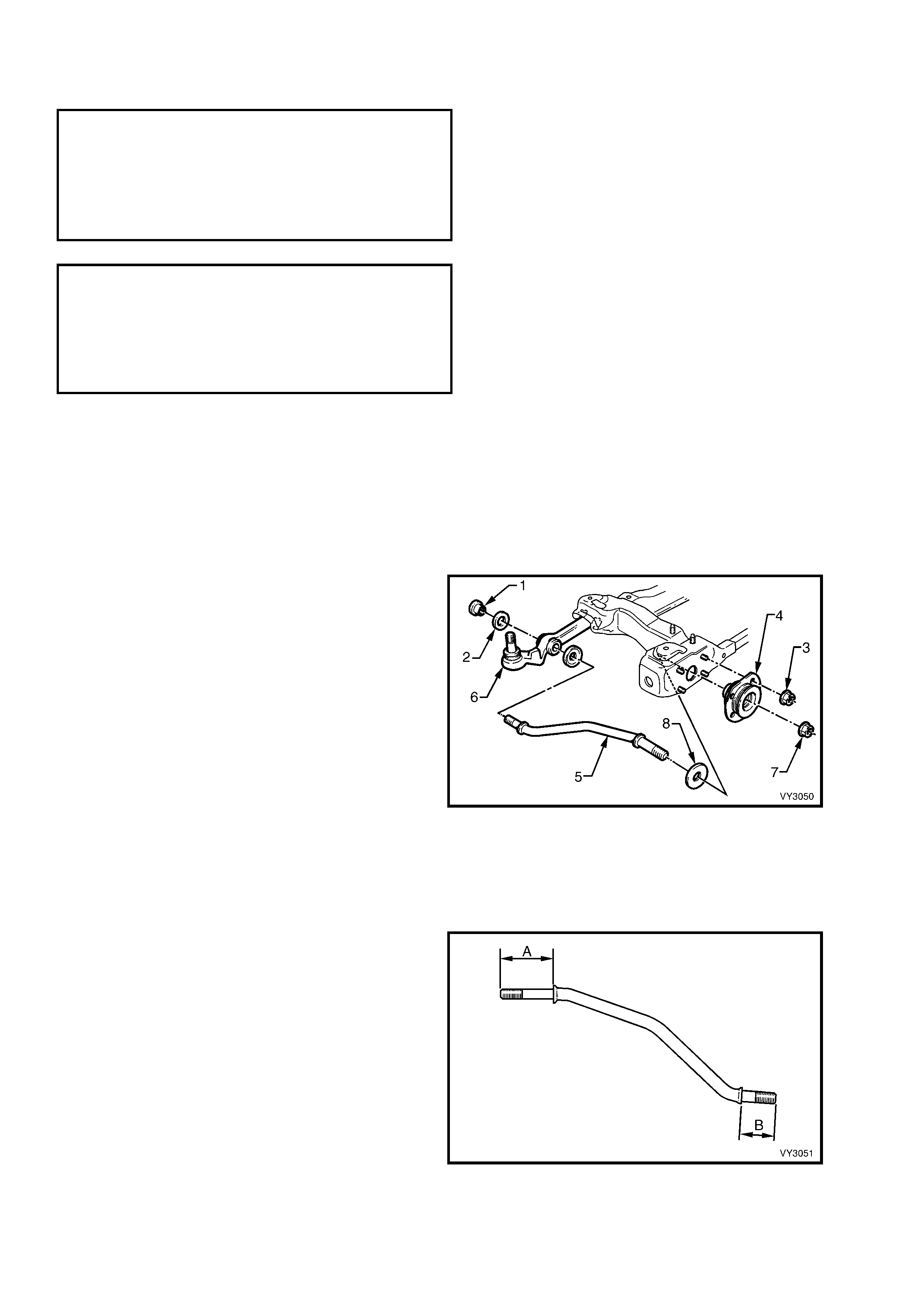
1. Install the bright finished inner washer onto the
front end of the f ront lower control arm rod (A),
on the driver’s side ONLY.
NOTE: The front end of the f ront lower control arm
rod is identified by the longer length of the
shouldered ends (‘A’ compared to ‘B’).
Figure 3-43
2. Install the front lower control arm rod (1) into
the hole in the crossmember outrigger and then
into the front lower control arm (2), with the
cupped washer (3) installed as shown. Install
the front lower control arm rod to front lower
control arm washer (4) with a NEW attaching
nut (5) but do not fully tighten at this stage.
Figure 3-44
3. Install the f ront lower control arm rod insulating
bushing assembly (1), over the front lower
control arm rod ( 2) and install the four retaining
nuts (3) to the crossmember outrigger studs.
Tighten to the correct torque specification.
FRONT LOWER CONTROL ARM ROD
INSULATOR BUSHING ATTACHING
NUT TORQUE SPECIFICATION.............. 20 – 26 Nm
4. Install a NEW front lower control arm rod
retaining nut (4) but do not fully tighten at this
stage.
NOTE: If fitted, ensure that the spacer washer is
installed over the front lower control arm rod and
then the flat washer, before fitting the front lower
control arm rod insulator bushing.
Figure 3-45
5. Install the road wheel, aligning the marks made prior to rem oval and secure with the attaching nuts, tightening
progressively in a ‘star’ pattern as shown in 2.3 WHEEL AND TYRE REMOVAL AND INSTALLATION in
Section 10, WHEELS AND TYRES.
6. Remove the safety stands and lower the vehicle to the ground.
7. Bounce the vehicle up and down several times to settle the suspension.
8. With the vehicle at cur b position, tighten both the front lower c ontrol arm rod to insulating bushing and the front
lower control arm rod to front lower control arm attaching nuts to the correct torque specifications.
( + & ) FRONT LOWER CONTROL ARM ROD TO
INSULATOR BUSHING ATTACHING NUT
TORQUE SPECIFICATION ................ 140 – 155 Nm
( + & ) FRONT LOWER CONTROL ARM ROD
TO CONTROL ARM ATTACHING NUT
TORQUE SPECIFICATION ................... 95 – 110 Nm
Important: The weight of the vehicle must be on all four wheels before tightening each end of the front lower
control arm rod to specification. Otherwise the fluid filled front lower control arm rod insulating bushing will be
incorrectly preloaded, reducing the life of the bushing and effect ride and handling.
9. T ighten the road wheel attaching nuts to the c or rec t tor que spec if ic ation, working in a ‘star’ patter n, as s hown in
2.3 WHEEL AND TYRE REMOVAL AND INSTALLATION in Section 10, WHEELS AND TYRES.
ROAD WHEEL ATTACHING NUT
TORQUE SPECIFICATION ................ 110 – 140 Nm
10. Install the wheel cover/centre cap.
11. Check the wheel alignment, as detailed in 2.2 WHEEL ALIGNMENT CHECKING AND ADJUSTMENT in this
Section.
3.15 FRONT LOWER CONTROL ARM ROD INSULATING BUSHING
LT Section No. – 06-200
NOTE 1: The following fasteners MUST be replaced
when performing this operation:
+
++
+
Front lower control arm rod to insulating
bushing attaching nut.
NOTE 2: The following fasteners MUST be at curb
height before final tightening:
• Front lower control arm rod to insulating
bushing attaching nut.
REPLACE
1. Remove the lower front lower control arm rod,
front retaining nut (1) and discard. Refer to
3.14 FRONT LOWER CONTROL ARM ROD in
this Section for more details.
2. Remove the four nuts (2) securing the front
lower control arm rod insulating bushing
assembly (3) to the crossmember outrigger
studs. Remove insulator bushing from the
vehicle.
3. Install the f ront lower control arm rod insulating
bushing over the front lower c ontrol arm r od (4)
and install the four retaining nuts onto the
cross member outrigger s tuds and tighten to the
correct torque specification.
FRONT LOWER CONTROL ARM ROD
INSULATOR BUSHING ATTACHING
NUT TORQUE SPECIFICATION.............. 20 – 26 Nm
4. Install a NEW front lower control arm rod
retaining nut but do not fully tighten at this
stage.
NOTE: If fitted, ensure that the spacer washer is
installed over the f ront lower control arm rod befor e
fitting the front lower control arm rod insulator
bushing.
Figure 3-46
5. Install the road wheel, aligning the marks made prior to removal and secure with the attaching nuts. Do not
overtighten.
6. Remove the safety stands and lower the vehicle.
7. Bounce the vehicle up and down several times to settle suspension.
8. With the vehic le at curb position, tighten the f ront lower control arm rod to hydraulic attaching nut to the correct
torque specification.
( + & ) FRONT LOWER CONTROL ARM ROD TO
INSULATOR BUSHING ATTACHING NUT
TORQUE SPECIFICATION ................ 140 – 155 Nm
Important: The weight of the vehicle m ust be on all f our wheels before tightening the f ront lower control arm rod to
specification. Otherwise the fluid filled front lower control arm rod insulating bushing will be incorrectly preloaded,
reducing the life of the insulator bushing and adversly effect ride and handling.
9. Tighten road wheel attaching nuts to the correct torque specification working in a ‘star’ pattern, as shown in
2.3 WHEEL AND TYRE REMOVAL AND INSTALLATION in Section 10, WHEELS AND TYRES.
ROAD WHEEL ATTACHING NUT
TORQUE SPECIFICATION ................ 110 – 140 Nm
10. Install the wheel cover/centre cap.
11. Check the wheel alignment, as detailed in 2.2 WHEEL ALIGNMENT CHECKING AND ADJUSTMENT in this
Section.
3.16 FRONT SUSPENSION CROSSMEMBER
LT Section No. – 06-200
NOTE 1: The following fasteners have either micro
encapsulation or incorporate a mechanical thread lock
and should only be used once. If in doubt, r eplacement
is recommended when performing this operation:
♦ Front lower control arm socket assembly stud
nut.
♦ Steering gear to crossmember mounting nut.
NOTE 2: The following fasteners MUST be replaced
when performing this operation:
+
++
+
Front lower control arm pivot nut.
+
++
+
Crossmember to side member attaching bolt.
+
++
+
Front lower control arm rod to front lower
control arm attaching nut.
+
++
+
Front lower control arm rod to insulating
bushing attaching nut.
NOTE 3: The following fasteners MUST be at curb
height before final tightening:
• Front lower control arm pivot nut.
• Front lower control arm rod to front lower
control arm attaching nut.
• Front lower control arm rod to insulating
bushing attaching nut.
REMOVE
1. Observing the jacking precautions as outlined in 2.3 JACKING PRECAUTIONS in this Section, ra ise the front
of vehicle and place safety stands under the side frame members.
2. Remove the wheel cover (steel wheels) or centre cap and decorative wheel nut caps (alloy wheels).
3. Mark the relationship of the wheel to the hub and rotor. Loosen, then remove the road wheel attaching nuts.
Remove the road wheel.
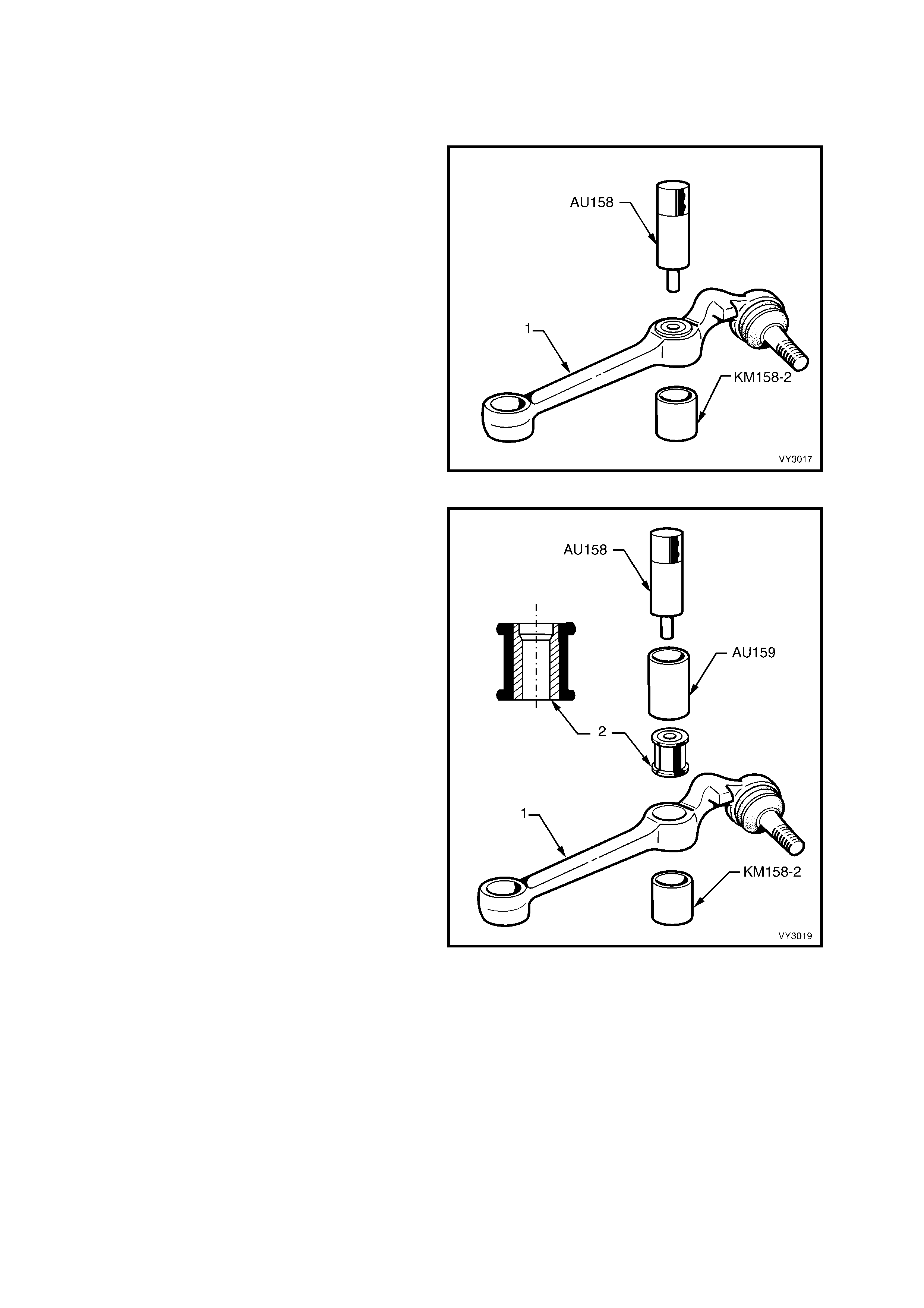
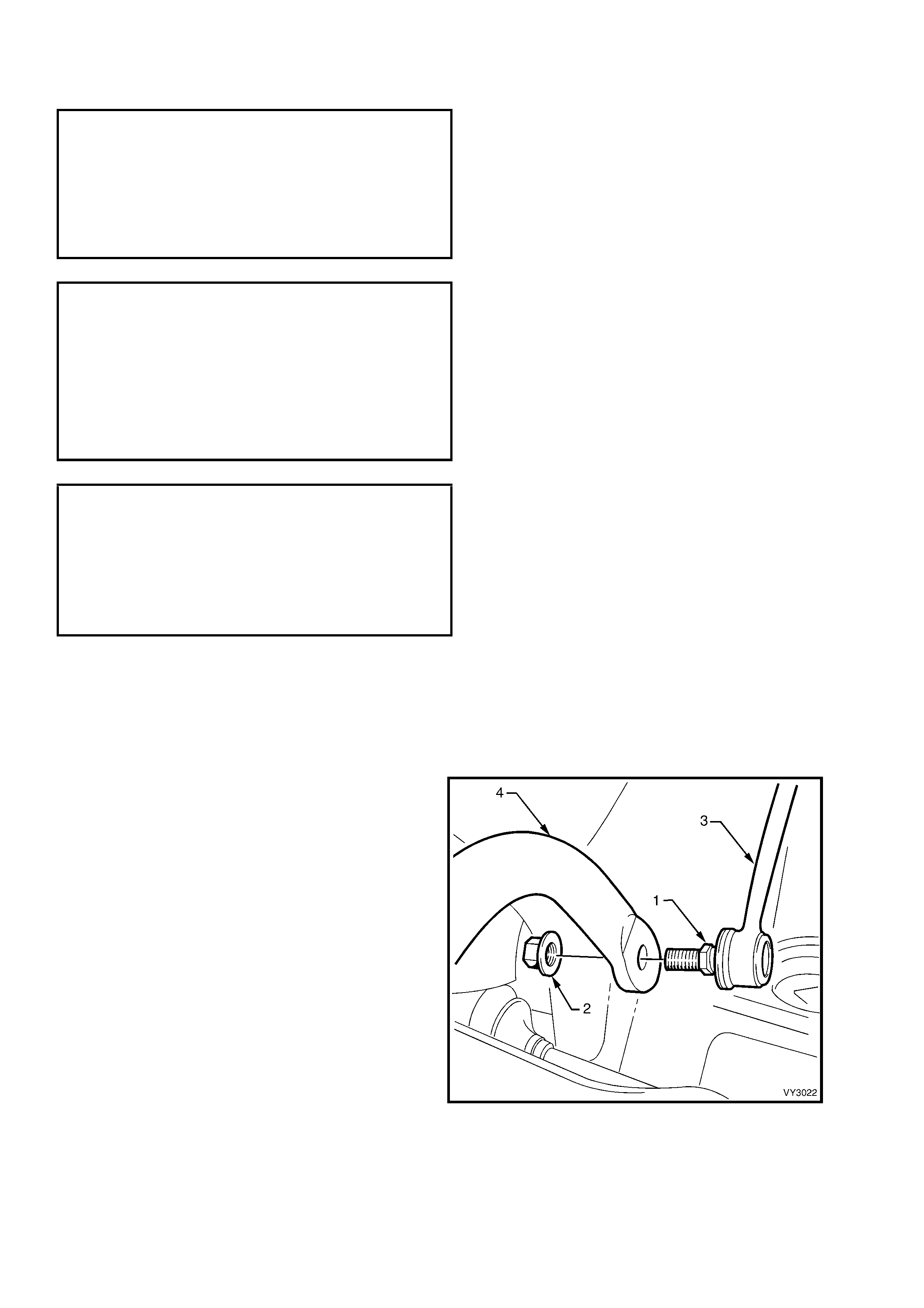
4. With a backing set spanner holding the
stabilizer shaf t link inner stud hexagon (1), use
a second spanner to loosen then remove the
retaining nut (2).
5. Separate the stabilizer shaft link (3) from the
stabilizer shaft (4) and remove from the
vehicle.
Figure 3-47
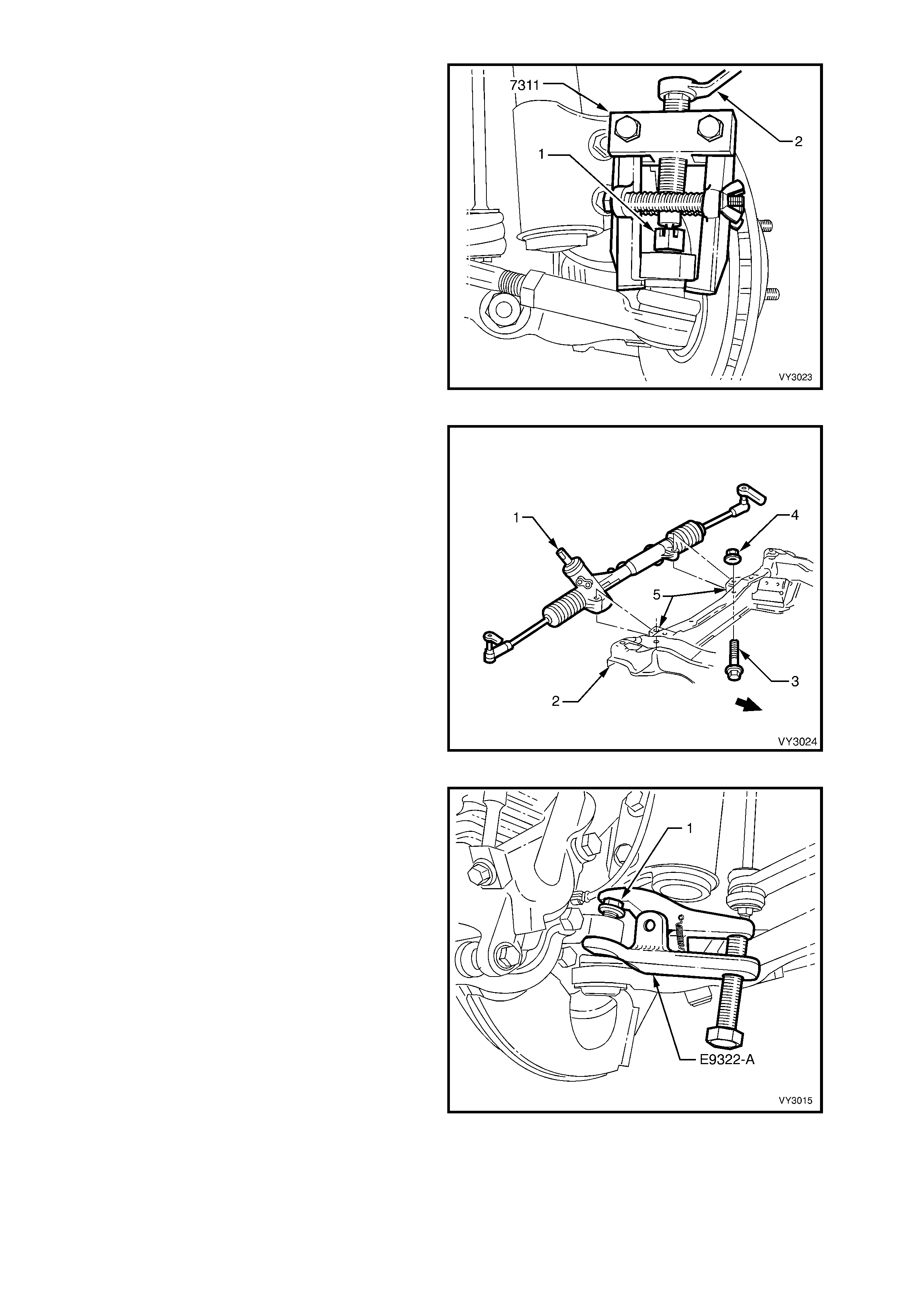
6. Remove the split pin from the steering linkage
outer tie rod socket assembly castellated nut
(1), then loosen the nut until the top of the nut
is level with the top of the steering linkage outer
tie rod socket stud.
7. Install Tool No. 7311 and use a ring spanner
(2) to separate the steering linkage outer tie rod
socket assembly stud from the steering
knuckle.
Figure 3-48
8. Remove the steering gear housing (1) to front
crossmember (2) mounting bolts (3) and nuts
(4). Remove the steering gear housing from the
crossmember mountings (5).
Figure 3-49
9. Turn each wheel out in turn.
10. Loosen the front lower control arm socket
assembly retaining nut (1) until the top of the
nut is flush with the top of the front lower
control arm socket assembly stud thread.
11. Install release Tool No. E9332-A as shown,
then apply force to the top of the front lower
control arm sock et assem bly stud by tightening
the f orcing bolt on the tool, separating the f ront
lower control arm socket assembly from the
knuckle.
NOTE: Once load is applied by the release tool
loading bolt, a sharp tap on the nut end of the tool
will lessen the apply force required.
12. Temporarily jam the front lower control arm
socket assembly stud taper into the knuckle to
hold the stud, before removing the retaining
nut. Discard the removed nut as it has micro-
encapsulation sealant applied and must be
replaced on reassembly.
13. Separate the knuckle from the front lower
control arm socket assembly stud.
Figure 3-50
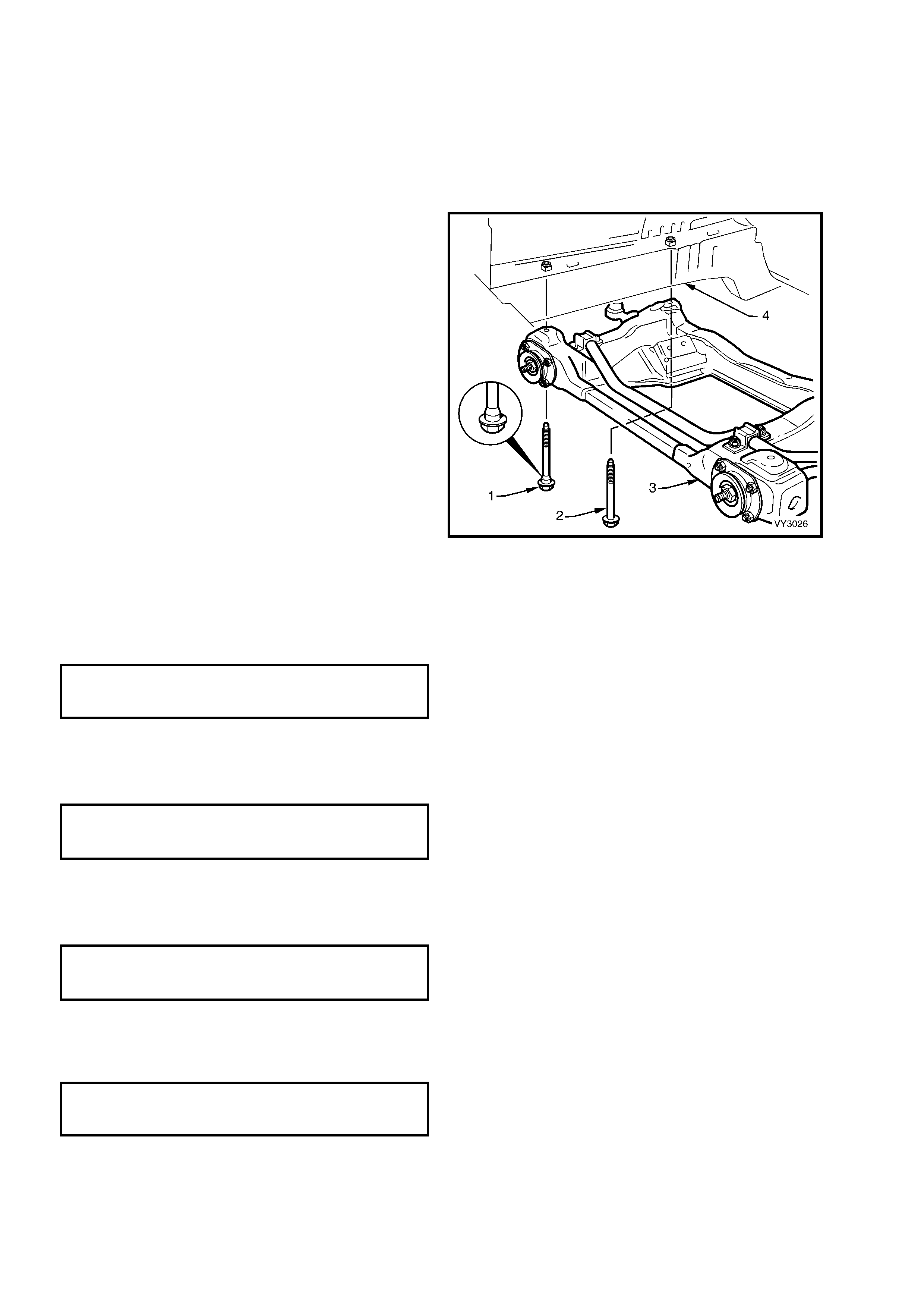
14. Mark the hood hinge positions with a felt tipped
pen and remove the engine hood.
15. Support the engine on a suitable lifting hook
and rem ove the engine mount to crossm em ber
bolts or nuts, refer to Section 6A1, ENGINE
MECHANICAL - V6 ENGINE or Section 6A3,
ENGINE MECHANICAL - GEN III V8 ENGINE
for details.
16. Support the crossmember (3) on a jack and
remove the four bolts (1 and 2) securing the
crossmember to the side frame members (4).
17. Lower, then remove the crossmember
assembly (3) from vehicle.
18. As required, remove the front lower control
arms, front lower control arm rod insulating
bushings, front lower control arm rods and
stabilizer shaft from the crossmember.
Figure 3-51
REINSTALL
While the majority of the installation process is the reverse of the removal procedures, note the following points:
1. Install the s tabilizer shaf t ins ulating rubber s and brac kets onto the c ros s mem ber , tightening the retaining nuts to
the correct torque specification.
STABILIZER SHAFT SUPPORT
BRACKET RETAINING NUT
TORQUE SPECIFICATION ...................... 24 - 30 Nm
2. When ins talling the c ros s member, install the two f ront, blac k colour ed and stepped bolts ( ‘1’ in Figure 3- 51) and
tighten to the correct torque specification. This will correctly align the crossmember to the side frames.
3. Install the two rear , silver coloured, plain shank ed bolts (‘2’ in Figure 3- 51) to the two rear positions and tighten
them to the correct torque specification.
( + ) CROSSMEMBER TO SIDE
MEMBER BOLT (ALL)
TORQUE SPECIFICATION 120 – 125 Nm
4. Install the two f ront lower control arms to the crossm ember, installing the pivot bolts from the rear to the front.
Install the NEW nuts but do not fully tighten at this stage.
5. If the front lower control arms were removed with the crossmember, install the front lower control arm socket
assembly stud into each steering knuckle, install the nut and tighten to the correct torque specification.
( 6 ) FRONT LOWER CONTROL ARM
SOCKET ASSEMBLY STUD NUT
TORQUE SPECIFICATION ...................... 50 – 70 Nm
6. If removed, install both front lower control arm rods, loosely installing the washers and NEW retaining nuts, as
detailed in 3.14 FRONT LOWER CONTROL ARM ROD in this Section. Do not tighten at this time. However,
the front lower control arm rod insulating bushing mounting nuts can be tightened to the correct torque
specification.
FRONT LOWER CONTROL ARM ROD
INSULATOR BUSHING ATTACHING
BOLT TORQUE SPECIFICATION............ 20 - 26 Nm

7. Install the steering gear housing to the crossmember and tighten the mounting nuts to the correct torque
specification.
( 6 ) STEERING GEAR HOUSING TO
CROSSMEMBER MOUNTING
NUT TORQUE SPECIFICATION.............. 70 - 85 Nm
8. Reconnect the engine mounts to the crossmember, refer to Section 6A1 ENGINE MECHANICAL - V6
ENGINE or Section 6A3 ENGINE MECHA NICAL - GEN III V8 ENGINE for details.
9. Install the road wheels, aligning marks made prior to removal. Tighten the road wheel attaching nuts to the
correct torque specification, working in a ‘star’ pattern, as shown in 2.3 WHEEL AND TYRE REMOVAL AND
INSTALLATION in Section 10, WHEELS AND TYRES.
10. Install the engine hood.
11. Remove the safety stands and lower the vehicle.
12. Bounce the vehicle up and down several times to settle the suspension.
13. Tighten the front lower control arm pivot bolt nuts to the correct torque specification.
( + & ) FRONT LOWER CONTROL ARM PIVOT
NUT TORQUE SPECIFICATION........... 95 - 100 Nm
14. With the vehicle at cur b position, tighten the front lower c ontrol arm rod attaching nuts at the front lower control
arm and the insulating bushing, to the correct torque specifications.
( + & ) FRONT LOWER CONTROL ARM ROD TO
CONTROL ARM ATTACHING NUT
TORQUE SPECIFICATION ................... 95 – 110 Nm
( + & ) FRONT LOWER CONTROL ARM ROD
TO INSULATOR BUSHING ATTACHING NUT
TORQUE SPECIFICATION ................ 140 - 155 Nm
Important: The weight of the vehicle m ust be on all f our wheels before tightening the f ront lower control arm rod to
specif ication. If not, the fluid filled fr ont lower control arm r od insulating bushing will be ruptur ed, once the vehicle is
put back into service.
15. Check the wheel alignment, as detailed in 2.2 WHEEL ALIGNMENT CHECKING AND ADJUSTMENT in this
Section.
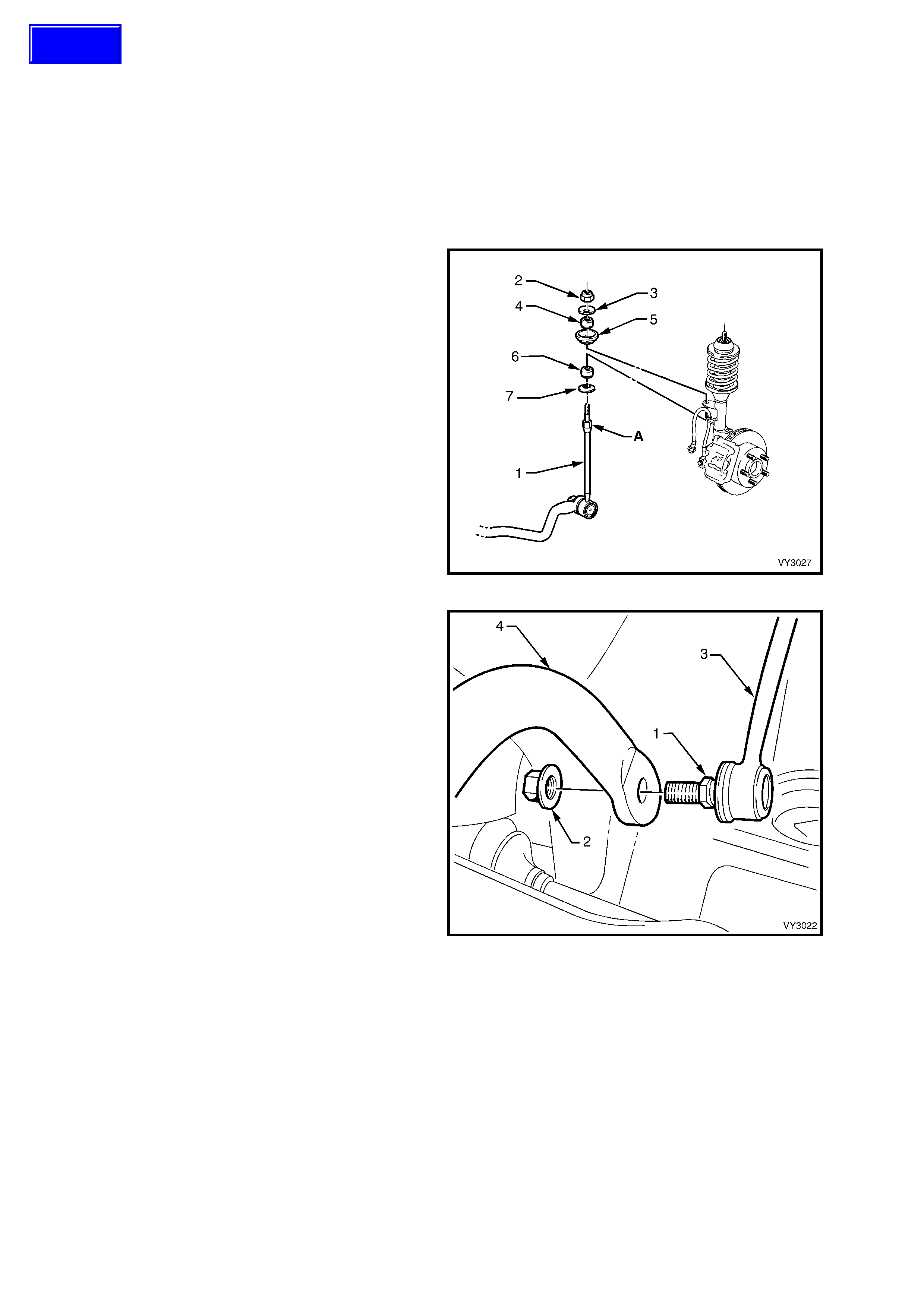
3.17 STABILIZER SHAFT LINK
LT Section No. – 06-205
REPLACE
1. Observing the jacking precautions as outlined in 2.3 JACKING PRECAUTIONS in this Section, raise the front of
the vehicle and place safety stands under side frame members..
2. Remove the wheel cover (steel wheels) or centre cap and decorative wheel nut caps (alloy wheels).
3. Mark the r elationship of the wheel to the hub and br ake rotor, then loos en and r emove the road wheel attaching
nuts and remove the road wheel.
4. Using a suitable size spanner, hold the
stabilizer shaft spacer stud (1) at ‘A’, then use
another spanner to loosen and remove the
stabilizer shaft spacer stud nut (2).
5. Remove the upper washer (3), upper insulator
(4) and centre washer (5).
6. If required, repeat s teps 4 and 5 for the s econd
side.
Figure 3-52
7. With a backing set spanner holding the
stabilizer shaf t link inner stud hexagon (1), use
a second spanner to loosen then remove the
retaining nut (2).
8. Separate the stabilizer shaft link (3) from the
stabilizer shaft (4) and remove from the
vehicle.
Figure 3-53
Techline
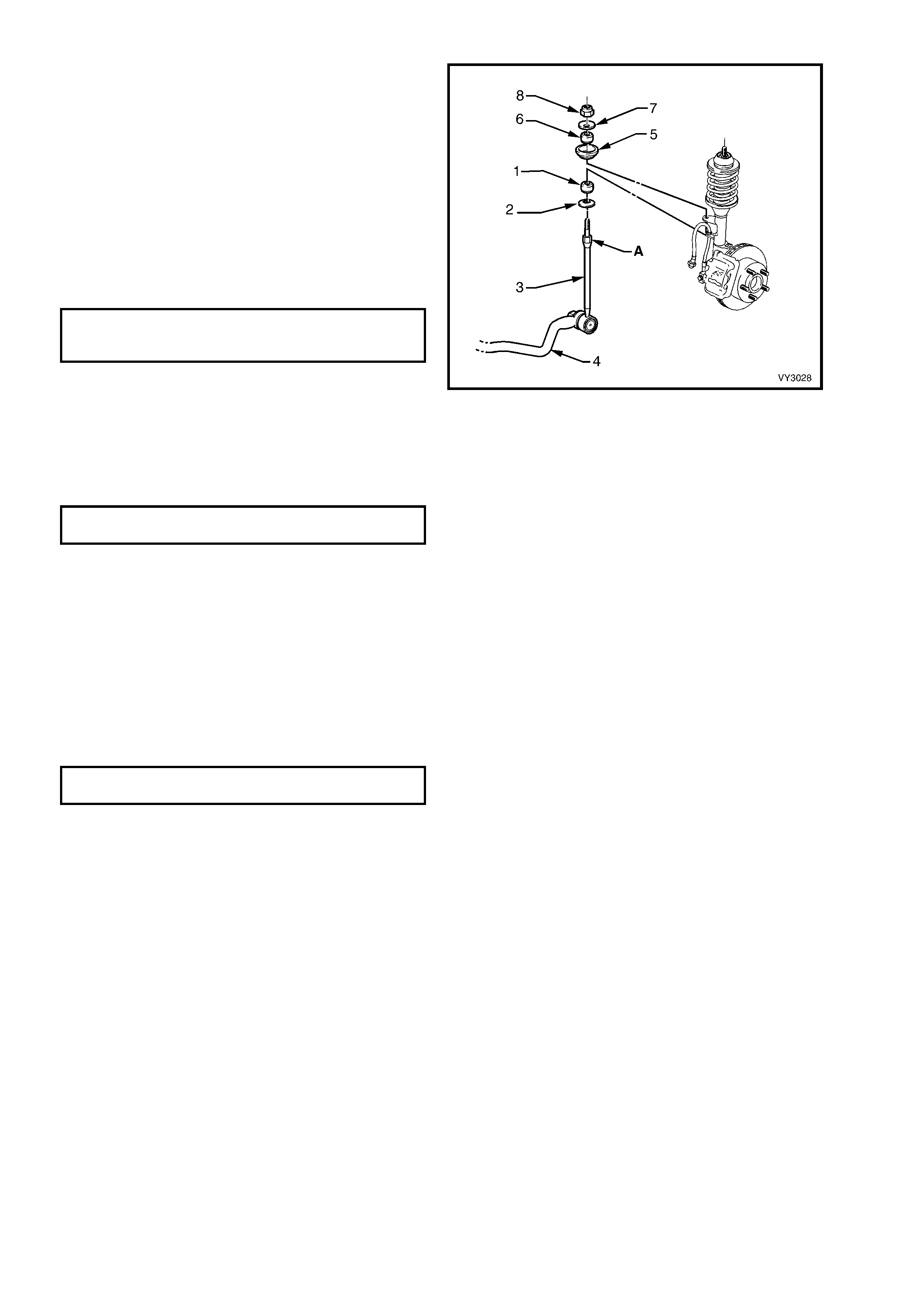
The installation procedure is the reverse to
removal, except for the following points.
9. As required, the lower link insulator (1) and
washer (2) may be replaced.
10. Before installation of the stabilizer shaft link (3)
to the stabilizer shaft (4), insert the upper
threaded end of the link into the strut mounting
bracket.
11. Install the link sock et s tud to the stabilizer shaf t
(4), tighten the retaining nut (2) to the correct
torque specification, while holding the inner
stud hex agon (1) with a back ing spanner (refer
to Figure 3-53).
STABILIZER SHAFT LINK
SOCKET RETAINING NUT
TORQUE SPECIFICATION ...................... 45 – 55 Nm
12. Install the seat (5), upper insulator (6) and
washer (7).
13. Install the upper link retaining nut (8) and
tighten to the correc t tor que spec ification, while
holding the link at the upper hexagonal section
(A). DO NOT over-tighten.
STABILIZER SHAFT LINK UPPER
NUT TORQUE SPECIFICATION.............. 13 – 18 Nm
14. Install the road wheels, aligning the marks
made prior to removal, and secure with the
wheel attaching nuts, but do not tighten to
specification at this time.
15. Remove the safety stands and lower the
vehicle.
16. Tighten the road wheel attaching nuts to the
correct torque specification, working in a ‘star’
pattern, as shown in 2.3 WHEEL AND TYRE
REMOVAL AND INSTALLATION in Section
10, WHEELS AND TYRES.
ROAD WHEEL ATTACHING NUT
TORQUE SPECIFICATION ................ 110 – 140 Nm
17. Install the wheel cover (steel wheels) or centre
cap and decorative wheel nut caps (alloy
wheels).
Figure 3-54

3.18 STABILIZER SHAFT
LT Section No. – 06-205
NOTE: To remove the stabilizer shaft completely from the vehicle, it will first be necessary to remove the
crossmember. Refer to 3.16 FRONT SUSPENSION CROSSMEMBER in this Section. Alternatively, the stabilizer
shaft insulators and mounting brack ets, and/or the spacer stud, nuts, discs or insulators, can all be replaced without
removing the stabilizer shaft from the vehicle.
REMOVE
1. Observing the jacking precautions as outlined in 2.3 JACKING PRECAUTIONS in this Section, raise the front of
the vehicle and support on safety stands.
2. After scribing the crossmember alignment marks on the side frame members, remove the front suspension
crossmember mounting bolts, then lower enough to enable removal of the stabilizer shaft from the vehicle.
3. Remove the nuts securing the support bracket to each side of the crossmember, then remove the stabilizer
shaft, support brackets and insulators from the crossmember.
4. Remove the insulators from the stabilizer shaft.
5. With a backing set spanner holding the
stabilizer shaf t link inner stud hexagon (1), use
a second spanner to loosen then remove the
retaining nut (2).
6. Separate the stabilizer shaft link (3) from the
stabilizer shaft (4) and remove the stabilizer
shaft from the vehicle.
Figure 3-55
REINSTALL
The installation procedure of the stabilizer shaft is the reverse of the removal procedure, noting the following:
1. Assemble the two insulators and support brackets onto the stabilizer shaft and bolt the brackets to the
crossmember outrigger.
NOTE: T he s lot in each ins ulator s hould f ac e f or ward, and the rounded s ec tions on the ins ulator s should s eat in the
mating recesses in the crossmember side frame.
2. Tighten the stabilizer shaft support bracket bolts to the correct torque specification.
STABILIZER SHAFT SUPPORT
BRACKET RETAINING NUTS
TORQUE SPECIFICATION ...................... 24 – 30 Nm
3. Install the stabilizer shaft link socket stud nut and tighten to the correct torque specification.
STABILIZER SHAFT LINK SOCKET
STUD RETAINING NUT
TORQUE SPECIFICATION ...................... 45 – 55 Nm
4. Install the f ront suspens ion cross mem ber, as detailed in 3.16 F RONT SUSPENSION CROSSMEM BER in this
Section.
5. Remove the safety stands and lower vehicle.

4. DIAGNOSIS
GENERAL
When diagnosing suspected front suspension problems, it should be remembered that steering,
wheels and tyres all have an effect on front end performance. Refer to Section 9, STEERING and
Section 10, WHEELS AND TYRES for details.
STRUT DIAGNOSIS
1. Test by quickly pushing up and down on the bumper bar at the front corner of the vehicle. Compare the
resistance to movement with a similar vehicle having acceptable ride quality.
2. Inspect the struts for excessive fluid leakage.
ACCEPTANCE CRITERIA
A strut DOES NOT require replacement, if any or a combination of the following are present:
• An oily build-up at the end of the piston rod, up to 1 cm wide.
• Oily ‘sludge’ accumulated from normal operating conditions to 4 cm from the top of the strut body.
• Road greas e, oil, s and and dus t disc olour ation on the body, does not constitute a leaking strut. If this condition is
evident, the strut should be wiped clean and checked at a later service.
NOTE: Should one strut pr ove to be leak ing and require replac em ent, provided the remaining s trut is s erviceable, it
does not also need to be replaced.

4.1 DIAGNOSIS GUIDE
SYMPTOM AND PROBABLE CAUSE REMEDY
HARD OR HEAVY STEERING
1. Low or uneven tyre pressures.
2. S teering gear or connections too tight or misaligned.
3. I nsufficient fl ui d i n steering gear.
4. Excessive caster.
5. Lower front l ower cont rol arm/s and/or front lower cont rol
arm rod/s bent.
6. S teering knuckle bent.
7. Excessive toe-in.
1. I nflate tyres to specified press ure f or specifi c load
conditi ons. Refer t o tyre placard att ached to the vehicle.
2. A dj ust st eeri ng gear or repl ace com ponents as necessary.
Refer to Section 9, S T EERING.
3. Chec k steeri ng gear f l ui d l e vel . Top up, using only
DEXRON III® fluid. Check sys t em for leaks. Ref e r t o Section
9, STEERING.
4. Chec k front wheel alignment. Adjust as necessary. Refer t o
2.2 WHEEL ALIGNMENT CHECKING AND ADJUSTMENT in
this Section.
5. Chec k alignment of front lower control arms and front l ower
control arm rods. Replace components as necess ary.
Refer to 2.2 W HEEL ALIGNMENT CHECKING AND
ADJUSTMENT in this Section.
6. Replace steeri ng knuckle. Refer to 3. 9 S T EERING KNUCK LE
in this Section.
7. Chec k and adjust wheel toe. Refer to 2.2 WHEEL
ALIGNMENT CHECKING AND ADJUSTMENT in this
Section.
EXCESSIVE PLA Y OR LOOSENESS IN
STEERING
1. S teering gear or connections loose or worn.
2. Front l ower cont rol arm soc ket loose or worn.
3. Front wheel bearings worn.
4. Loose attachment of crossmember to fram e.
1. A dj ust st eeri ng gear or i nstall new components as required.
Refer to Section 9, S T EERING.
2. Replace front lower cont rol arm assembly. Refer to 3.10
FRONT LOWER CONT ROL A RM in this Section.
3. Replace front wheel hub ass embly assembl y. Ref e r t o 3.3
FRONT WHEEL HUB, BRAKE ROTOR OR BRAKE
SHIELD in this Section.
4. Chec k, align and t i ghten crossmember attaching nuts. Refer
to 3.16 FRONT SUSPENSION CROSSMEMBER in this
Sect i on f or al i gnment proc edures.
ERRATIC STEERING ON APPLICATION OF
BRAKES
1. Low or uneven tyre pressures.
2. E xces sive front brake rotor runout.
3. Front brake pads cont aminated with l ubri cant.
4. I nsuffi cient or uneven caster.
5. S teering knuckle bent.
6. E xces sive play in s teering gear.
1. I nflate tyres to specified press ure f or specifi c load
conditi ons. Refer t o the tyre placard at tached to t he vehi cle.
2. Machi ne front rotors . Refer to S ection 5A, SERVICE AND
PARK BRAKING SYSTEM.
3. Replace brake pads. Correct c ause of lubric ant leakage. Refer
to Section 5A, SERVICE AND PARK BRAKING SYSTEM.
4. Chec k front wheel alignment. Refer to 2.2 WHEEL
ALIGNMENT CHECKING AND ADJUSTMENT in this Section.
5. Replace steeri ng knuckle. Refer to 3. 9 S T EERING KNUCK LE
in this Section.
6. A dj ust st eeri ng gear or repl ace worn components. Refer t o
Section 9, STEERING.

4.1 DIAGNOSIS GUIDE - Cont'd
SYMPTOM AND PROBABLE CAUSE REMEDY
VEHICLE PULLS TO ONE SIDE
1. Low or uneven tyre pressures.
2. Rear wheels not tracki ng with f ront wheels.
3. Front brake pads cont aminated with l ubri cant.
4. Toe-in incorrect.
5. I n correct or uneven c aster or camber.
6. Rear axle assembly s hi fted.
7. S teering knuckle bent.
1. I nflate tyres to specified press ure f or specifi c load
conditi ons. Refer t o tyre placard att ached to the vehicle.
2. Chec k alignment of rear wheels with front wheels and
correct as necessary. Refer t o Secti on 4A , REAR
SUSPE NS ION for detail s of rear wheel alignm ent.
3. Replace brake pads. Correct c ause of lubric ant leakage. Refer
to Section 5A, SERVICE AND PARK BRAKING SYSTEM.
4. A dj ust toe-in to specificati on. Refer to 2. 2 WHEEL
ALIGNMENT CHECKING AND ADJUSTMENT in this Section.
5. Chec k wheel alignment. Adjust as nec essary. Ref er to 2.2
WHEEL ALIGNMENT CHECKING AND ADJUSTMENT in this
Section.
6. Chec k attac hi ng bol ts for looseness and front lower control
arm bus hi ng for wear. Refer to Section 4A, REAR
SUSPENSION.
7. Replace steeri ng knuckle. Refer to 3. 9 S T EERING KNUCK LE
in this Section.
FRONT OR REAR WHEEL TRAMP
1. Wheels and tyres out of balance.
2. Front struts or rear shock absorbers operating
incorrectly, leaking fluid or inoperative.
1. B al ance wheels and tyres. A l so check for ecc entric or
bulged tyres. Repl ace as necessary. Ref er to Sect i on 10
WHEELS AND TYRES.
2. Chec k operation and replace com ponents as nec essary.Ref er
to 3.8 FRONT ST RUT UNI T i n t hi s sect i on or S ection 4A,
REAR SUSPENSION as necessary.
ROAD SHOCKS
1. Incorrect tyre pressures.
2. S teering gear incorrectly adjus ted.
3. Front struts or rear shock absorbers operating
incorrec tly or unevenly, leaking flui d or i noperative.
4. Compress i on or rebound rubbers damaged or missing.
5. Unbalanced wheels.
6. I ncorrect wheel alignment.
1. I nflate tyres to specified press ure f or specifi c load
conditi ons. Refer t o tyre placard att ached to the vehicle.
2. A dj ust st eeri ng gear. Refer to S ection 9, STEERI NG for
details.
3. Chec k operation and replace com ponents as nec essary.
Refer to 3.8 FRONT S T RUT UNI T i n this sec tion or
Sect i on 4A, REAR SUSPENSION as necessary.
4. Replace missing or damaged parts. Refer to 3.8 FRONT
STRUT UNIT i n this Section or Section 4A, REAR
SUSPENSION as necessary.
5. B al ance wheels as detail ed i n Section 10, WHEELS AND
TYRES.
6. Chec k and adjust. Refer to 2. 2 WHEEL ALI GNMENT
CHECKING AND ADJUSTMENT in this Section.
SCUFFED TYRES
1. Toe-in incorrect.
2. Tyres improperly infl ated.
3. Wheels or tyres out-of-true.
4. Front lower control arm soc ket/s worn.
5. Uneven cas ter and cam ber.
6. Lower front lower control arm/s or front lower control arm
rod/s bent.
7. Steering knuckle bent.
1. A dj ust toe-in. Refer to 2.2 WHEEL ALI G NMENT CHE CK ING
AND ADJUSTMENT in this Section.
2. I nflate tyres to specified press ure f or specifi c load
conditi ons. Refer t o the tyre placard at tached to t he vehi cle.
3. Chec k for wheel and tyre wobble. Check that the wheels
and tyres are correctly mounted. Bal ance wheels and
tyres. Ref e r t o S ection 10, WHEELS AND TYRES .
4. Replace worn components. Refer to 3.10 FRONT LOWER
CONTROL ARM in this Sect i on.
5. Chec k wheel alignment. Adjust as nec essary. Ref er to 2.2
WHEEL ALIGNMENT CHECKING AND ADJUSTMENT in this
Section.
6. Chec k alignment of front lower control arm/s and f ront lower
control arm rod/s .
Replace components as necessary. Refer to 3. 10 CONTROL
ARM and 3.14 FRONT LOWER CONTROL A RM ROD in thi s
Section.
7. Replace steeri ng knuckle. Refer to 3. 9 S T EERING KNUCK LE
in this Section.

4.1 DIAGNOSIS GUIDE - Cont'd
SYMPTOM AND PROBABLE CAUSE REMEDY
CUPPED TYRES
1. Tyres improperly infl ated.
2. Wheels and tyres out-of-bal ance.
3. Dragging brakes.
4. Front lower control arm soc ket/s and/or wheel bearings
worn.
5. Uneven caster.
6. Steering knuckle bent.
1. I nflate tyres to specified press ure f or specifi c load
conditi ons. Refer t o the tyre placard at tached to t he vehi cle.
2. B al ance wheels and tyres. A l so check for ecc entric or
bulged tyres. Repl ace as necessary. Ref er to Sect i on 10
WHEELS AND TYRES.
3. Chec k for sei zing of the brake c al i pers and/or park brake
mec hanism . Refer to S ection 5A, SERVICE AND PARK
BRAKING SYSTEMS.
4. Replace worn components. Refer t o 3.10 CONTROL ARM
or 3.3 FRONT WHEEL HUB ASSEMBLY, BRAKE ROTOR
OR BRAKE SHIELD in this Section.
5. Chec k wheel alignment. Adjust as nec essary. Ref er to 2.2
WHEEL ALIGNMENT CHECKING AND ADJUSTMENT in this
Section.
6. Replace steeri ng knuckle. Refer to 3. 9 S T EERING KNUCK LE
in this Section.
FRONT WHEEL SHIMMY
1. Low or uneven tyre pressures .
2. Steeri ng connections incorrec t l y adj usted or worn.
3. Front lower control arm soc ket/s and/or wheel bearings
worn.
4. Wheels and tyres out-of-bal ance.
5. Wheels or tyres out-of-true.
6. Inc orrect or uneven cas ter or incorrec t toe-in setting.
7. Steering knuckle bent.
1. I nflate tyres to specified press ure f or specifi c load
conditi ons. Refer t o the tyre placard at tached to t he vehi cle.
2. A dj ust st eeri ng gear or i nstall new components as needed.
Refer to Section 9, S T EERING.
3. Replace worn components. Refer t o 3.10 CONTROL ARM or
3.3 FRONT WHEE L HUB A SSEMBLY, B RA KE ROTOR OR
BRAKE SHIELD in this Section.
4. B al ance wheels and tyres. A l so check for ecc entric or
bulged tyres. Repl ace as necessary. Ref er to Sect i on 10
WHEELS AND TYRES.
5. Chec k for wheel and tyre wobble. Check that the wheels
and tyres are correctly mounted. Bal ance wheels and
tyres. Ref e r t o S ection 10, WHEELS AND TYRES .
6. Chec k and adjust. Refer to 2. 2 WHEEL ALI GNMENT
CHECKING AND ADJUSTMENT in this Section.
7. Replace steeri ng knuckle. Refer to 3. 9 S T EERING KNUCK LE
in this Section.
CAR WANDERS
1. Low or uneven tyre pressures .
2. Steeri ng connections loose or worn.
3. Steeri ng gear connections adjusted too tightl y.
4. Front lower control arm soc ket/s worn.
5. Wheel t oe settings outside specifi cations.
6. Inc orrect or uneven cas ter.
7. Steeri ng knuckl e bent .
8. Rear axle shifted.
9. Loose attachm ent of front suspensi on crossmemeber to
side members.
1. I nflate tyres to specified press ure f or specifi c load
conditi ons. Refer t o the tyre placard at tached to t he vehi cle.
2. A dj ust st eeri ng gear or i nstall new components as needed.
Refer to Section 9, S T EERING.
3. Tes t steering system for binding with f ront wheels off the
ground. Refer t o S ections 9, STEE RI NG.
4. Replace worn components. Refer to 3.10 FRONT LOWER
CONTROL ARM in this Sect i on.
5. A dj ust toe-in. Refer to 2.2 WHEEL ALI G NMENT CHE CK ING
AND ADJUSTMENT in this Section.
6. Chec k wheel alignment. Adjust as nec essary. Ref er to 2.2
WHEEL ALIGNMENT CHECKING AND ADJUSTMENT in
this Section.
7. Replace steeri ng knuckle. Refer to 3. 9 S T EERING KNUCK LE
in this Section.
8. Chec k all att achment fast eners for sec uri ty, tight eni ng t o
specificati on, as required. Refer to Sec tion 4A, RE A R
SUSPENSION.
9. Chec k, align and t i ghten all fas teners to s pecification. Ref er to
3.16 FRONT SUSPENSION CROSSMEMBER.
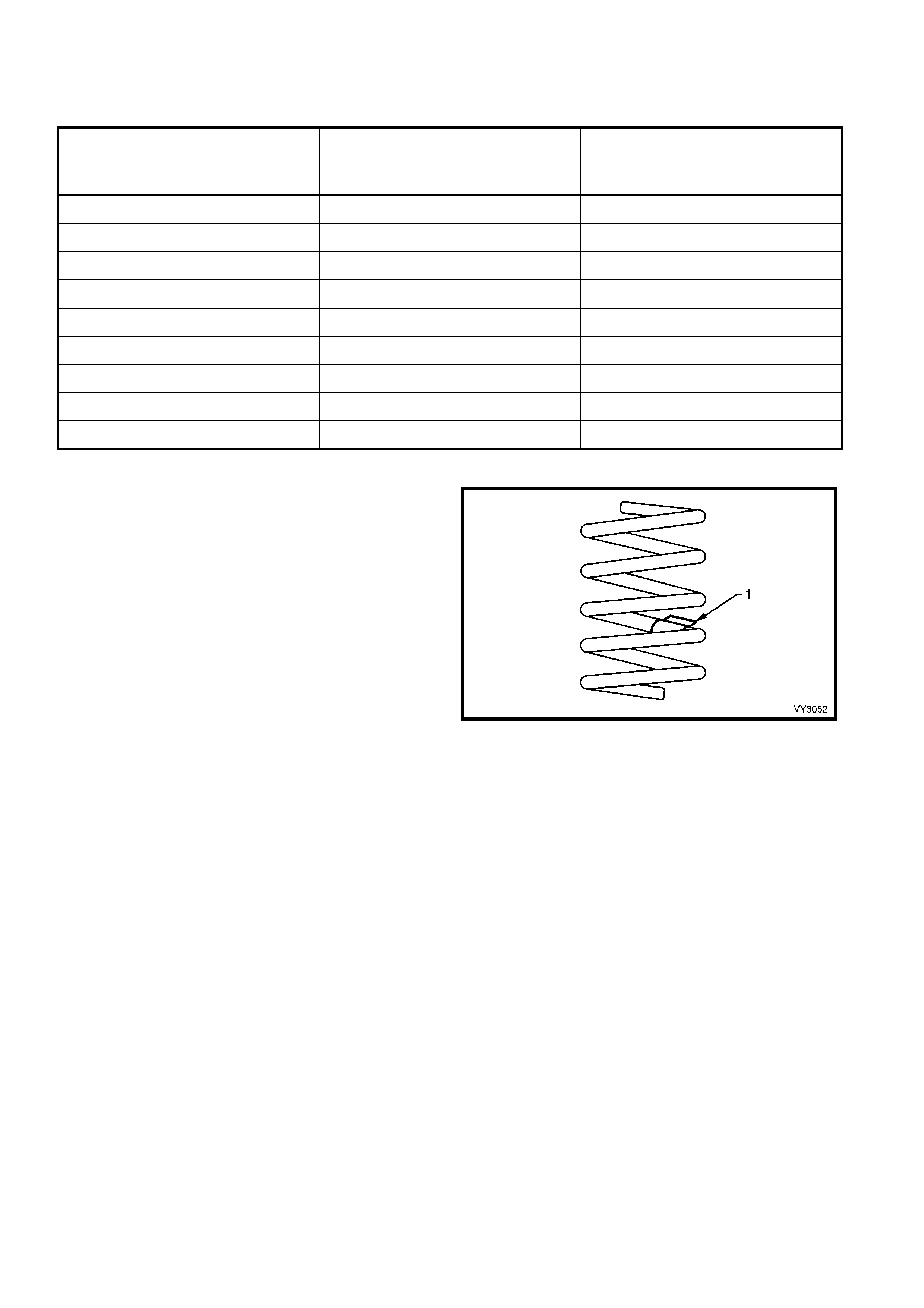
5. SPECIFICATIONS
SUSPENSION TRAVEL
SUSPENSION CONFIGURATION COMPRESSION – 2/3
COMPRESSION OF BUMPER
(mm)
REBOUND
(mm)
COUPE 61 115
SEDAN FE1 83 93
SEDAN FR1 103 73
SEDAN FE2 61 115
WAGON FE1 83 93
WAGON FR1 105 71
WAGON FE2 61 115
UTILITY FE1 105 71
UTILITY FE2 61 115
FRONT SPRING DETAILS
Identification of the front spring fitted to a particular
vehicle can be achieved by cross-referencing the two
digit code provided on the production identification tag
(1) with the table below.
Figure 3-56

SUSPENSION
CONFIGURATION NUMBER OF
COILS FREE LENGTH
(mm) INSIDE
DIAMETER SPRING TYPE
AND RATE PRODUCTION I.D.
CODE
COUPE 5.25 355 VARIABLE
24 – 31 N/mm
(3660 ± 110N
@ 200mm)
KA
SEDAN FE1 6.05 444 VARIABLE
19 – 23 N/mm
(3700 ± 110N
@ 210mm)
HN
SEDAN FR1 5.74 363 VARIABLE
27 – 35 N/mm
(3600 ± 110N
@ 230mm)
JM
SEDAN FE2 5.25 355 VARIABLE
24 – 31 N/mm
(3660 ± 110N
@ 200mm)
HJ
WAGON FE1 6.05 444 VARIABLE
19 – 23 N/mm
(3700 ± 110N
@ 210mm)
HN
WAGON FR1 5.74 363 VARIABLE
27 – 35 N/mm
(3600 ± 110N
@ 230mm)
JM
WAGON FE2 5.25 355 VARIABLE
24 – 31 N/mm
(3660 ± 110N
@ 200mm)
HJ
UTILITY FE1 5.74 363 VARIABLE
27 – 35 N/mm
(3600 ± 110 N
@ 230mm)
JN
UTILITY FE2 5.74 351
136 ± 1.5
VARIABLE
27 – 35 N/mm
(3850 ± 110 N
@ 209mm)
HJ
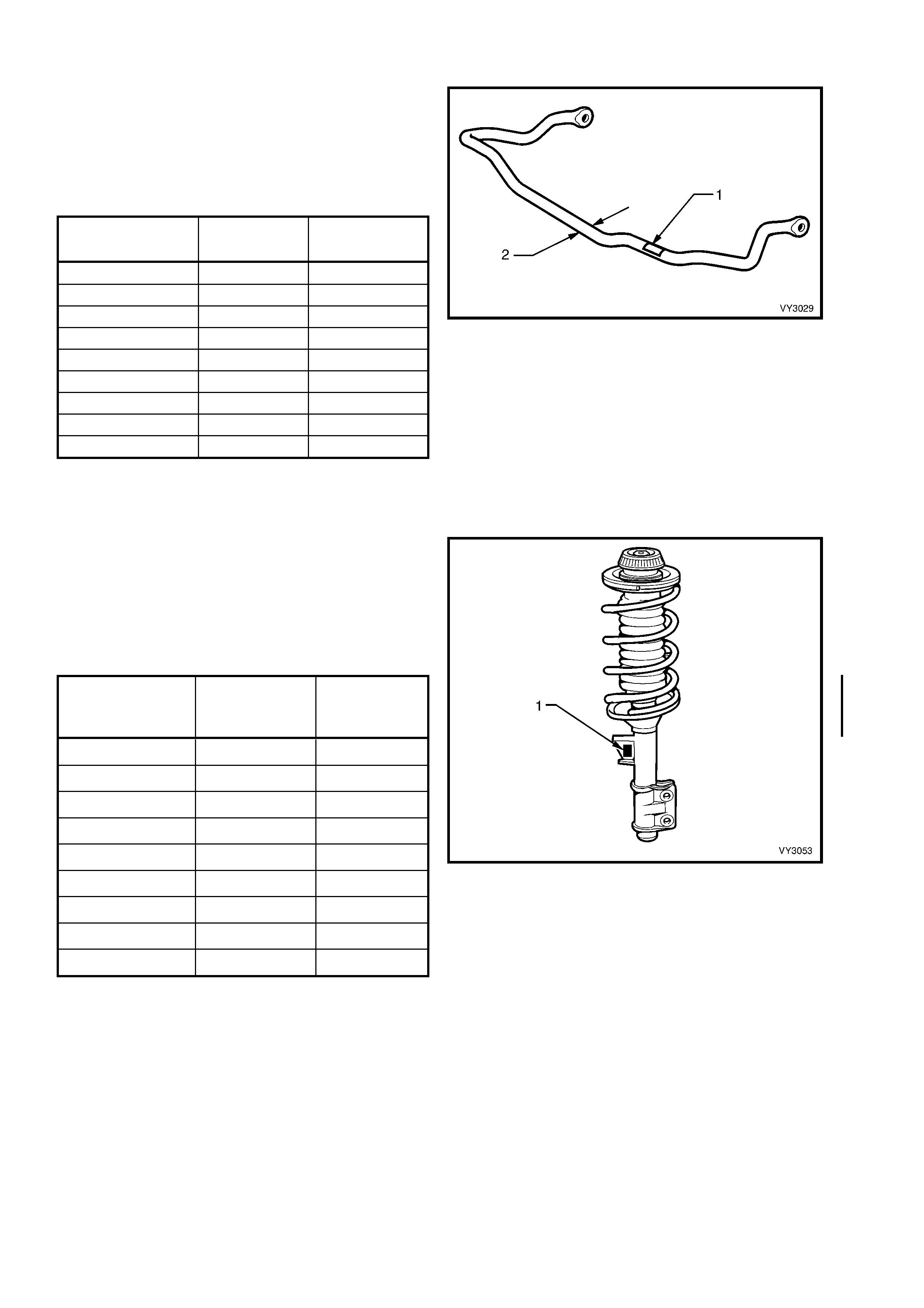
FRONT STABILIZER SHAFT DETAILS
Identification of the front stabilizer shaft fitted to a
particular vehicle can be achieved by cross-
referencing the two digit code provided on the
production identification tag (1) with the table
below.
The table also provides stabilizer shaft diameters
(2).
SUSPENSION
CONFIGURATION DIAMETER
(mm) PRODUCTION
I.D. CODE
COUPE 27 YA
SEDAN FE1 27 YA
SEDAN FR1 26 YB
SEDAN FE2 27 YA
WAGON FE1 27 YA
WAGON FR1 27 YA
WAGON FE2 27 YA
UTILITY FE1 27 YA
UTILITY FE2 27 YA
Figure 3-57
FRONT STRUT DETAILS
Type................................................................................ Wet strut – non-serviceable
Piston Diameter.............................................................. 30 mm
Identification of the front s trut assem blies f itted to a
particular vehicle can be achieved by cross-
referencing the two digit code provided on the
production identification tag (1) with the table
below.
SUSPENSION
CONFIGURATION RIGHT-HAND
PRODUCTION
ID CODE
LEFT-HAND
PRODUCTION
ID CODE
COUPE ZJ ZK
SEDAN FE1 MD MC
SEDAN FR1 RS LS
SEDAN FE2 RT LT
WAGON FE1 MD MC
WAGON FR1 RS LS
WAGON FE2 RT LT
UTILITY FE1 RS LS
UTILITY FE2 RT LT
Figure 3-58
FRONT LOWER CONTROL ARM DETAILS
Type......................Forged with rubber bushing for attachment to front
crossmember and front lower control arm rod. Front lower control
arm socket assembly is a press fit into the front lower control arm
and is not serviced seperately.
FRONT WHEEL BEARINGS
Type......................Double row ball bearing
Lubricant...............Sealed for life, non-adjustable
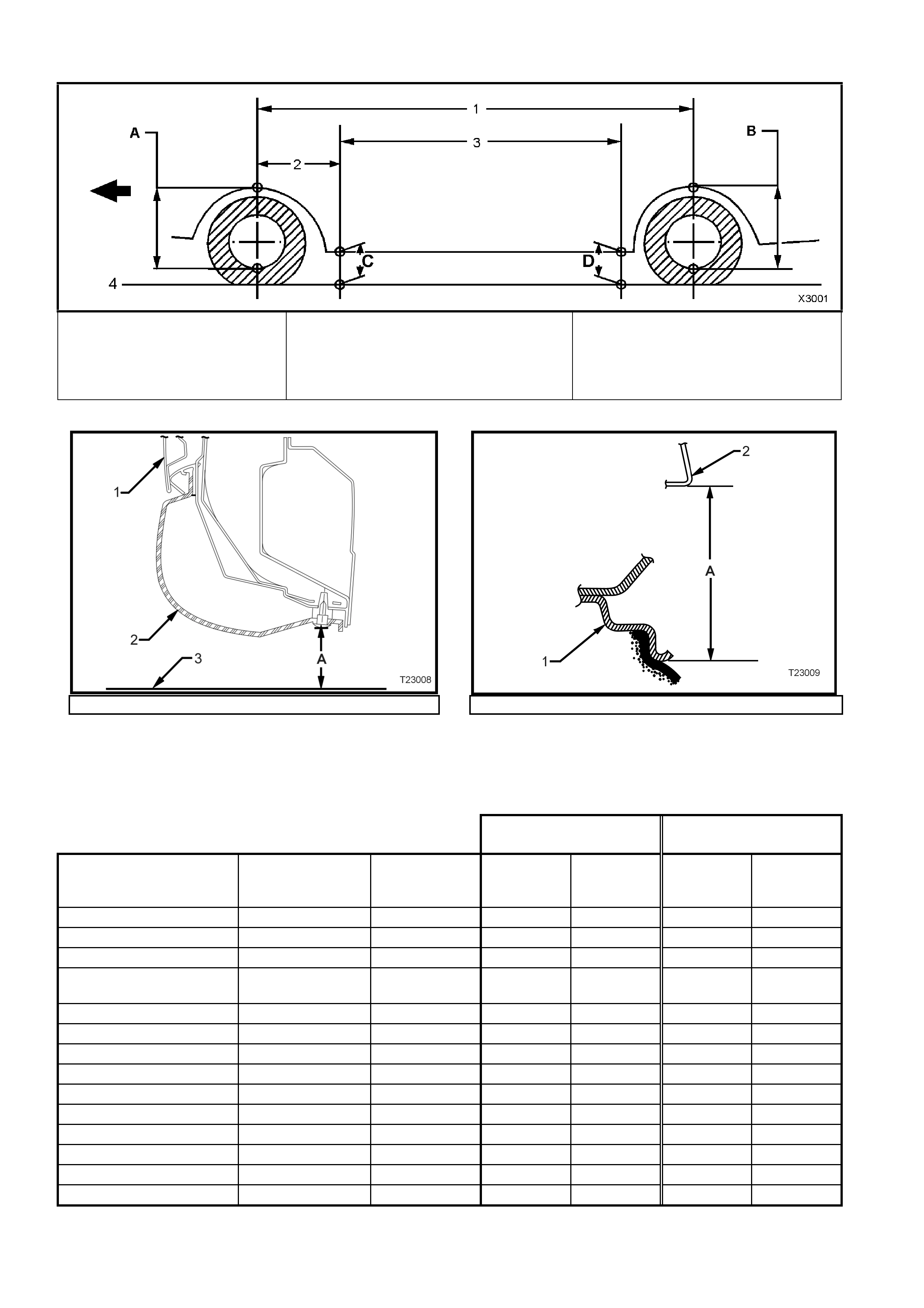
SUSPENSION A ND TRIM HEIGHT SPECIFICATIONS
A Front S uspension Height Location
B Rear S uspension Height Location
C Front Trim Height Chec k Location
D Rear Trim Height Check Location
1. Wheelbase:
Sedan – 2788 mm
Coupe – 2788 mm
Station Wagon – 2938 mm
Utility – 2938 mm
2. Reference Point: All Models – 584.5 mm
3. Trim Height Spacing:
Sedan – 1615 mm
Coupe – 1615 mm
St ation Wagon – 1765 mm
Utilit y – 2938 mm
4. Ground Line
Figure 3-59
1. Door 2. Trim 3 Ground Line ‘A’ Trim Height 1. Wheel Rim 2. Fender Opening ‘A’ Suspens i on Hei ght
Figure 3-60 – Rear Trim Height Checking Location (Front
Similar) Figure 3-61 – Front and Rear Suspension Height Checking
Location
NOTE: T he follow ing suspension/trim height dimensions are for reference only and are only intended to be
a guide. Refer to 3.2 SUSPENSION AND TRIM HEIGHT, CHECK for ride height variations and additional
procedures.
MY 2003 VY AND V2 MODELS SUSPENSION HEIGHT
(mm) TRIM HEIGHT
(mm)
VEHICLE
DESCRIPTION TRANSMISSION SUSPENSION FRONT
(‘A’ in
Fig. 3-61)
REAR
(‘B’ in
Fig. 3-61)
FRONT
(‘C’ in
Fig. 3-60)
REAR
(‘D in
Fig. 3-60)
Coupe Level 1 Automatic FE2 611 609 172 186
Coupe Level 3 Manual/Automatic FE2 624 622 176 190
Level 1 and 2 Sedan Manual/Automatic FE1/FR1 605 594 192 201
Level 1 and 2 Sedan
(exc ‘S’ and ‘SS’) Manual/Automatic FE2 583 581 172 186
‘S’ Sedan Manual/Automatic FE2 605 603 172 186
‘SS’ Sedan Manual/Automatic FE2 611 609 172 186
Level 3 Sedan Automatic FE1/FR1 618 607 192 201
Level 3 Sedan Automatic FE2 596 608 172 186
Level 1 and 2 Wagon Manual/Automatic FE1/FR1 601 583 192 210
Level 1 and 2 Wagon Manual/Automatic FE2 586 568 177 195
Level 1 Utility Manual/Automatic FE1 616 641 210 235
‘S’ Utility Manual/Automatic FE1 629 654 210 235
‘S’ Utility Manual/Automatic FE2 619 654 202 233
‘SS’ Utility Manual/Automatic FE2 619 644 185 210
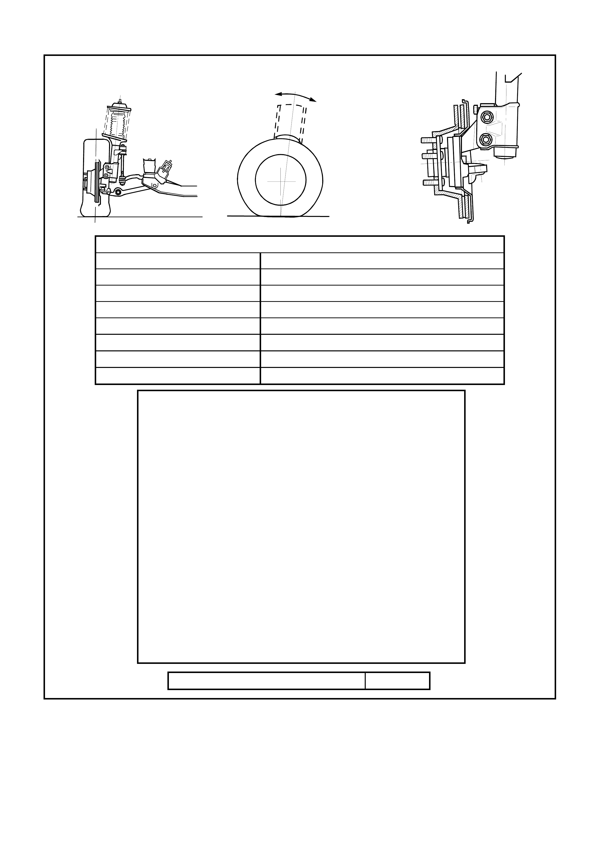
FRONT WHEEL ALIGNMENT SPECIFICATIONS
FRONT WHEEL ALIGNMENT AT CURB WEIGHT
Wheel Alignment Angle Specifications - All Models
Camber -0° 12' ± 0° 18'
Caster 7° 45' ± 1° 15'
Toe-in Degrees Total 0° 10’ ± 0° 10'
Degrees per Wheel 0° 5’ ± 0° 5’
Toe-out on Turns 1° 42’ @ 20 ° turn angle ± 1° 30'
Steering Axis Inclination Angle 12° 52’ ± 1° 30'
Included Angle 12° 40’ ± 1° 30'
SERVICE INFORMATION
• The adjusting values for camber, caster and toe-in must remain
within the tolerances specified. The difference between left and
right must not exceed the following:
CASTER............ 0° 36'
CAMBER ........... 0° 48'
TOE-IN............... 0° 10'
• The specifications listed are the nominal value, with acceptable
variance from this central point. Where possible, an attempt should
always be made to achieve the nominal settings when adjusting.
• Front wheel camber alters as a function of front suspension height.
• Cam ber adjusting bolt: After loosening both lower strut to steering
knuc kle bolts and nuts, adjus t camber by turning the adjus ting bolt
clockwise to decrease negative camber and anti-clockwise to
increase negative camber. After adjustment, both bolts and nuts
MUST be replaced with new parts and tightened to the
recommended torque setting.
• The rear wheel alignment should be checked and corrected if
necessary (refer to Section 4A, REAR SUSPENSION) before
checking front wheel alignment.
Fuel Mass with Full Tank - All Models 56 kg
Figure 3-62

6. TORQUE SPECIFICATIONS Nm
+ Brake Caliper Retaining Bolts..................................Stage 1 : 80 - 90
Stage 2 : Turn through 40° - 50°
Stabilizer Shaft Link Socket Stud Retaining Nut................... 45 - 55
Stabilizer Shaft Support Bracket Retaining Nut.................... 24 - 30
Stabilizer Shaft Link Upper Nut............................................. 13 - 18
6 Front Wheel Hub Assembly To Steering Knuckle
Attaching Bolt........................................................................ 100 - 115
Steering Linkage Outer Tie Rod Socket Assembly Stud
Castellated Nut ..................................................................... 50 - 80
Steering Linkage Outer Tie Rod To Steering Linkage Outer
Tie Rod Socket Assembly Lock Nut ..................................... 40 - 60
+ Steering Knuckle To Strut Attaching Bolt.................Stage 1: 85
Stage 2: 100
Stage 3: Turn through 90°
Wheel Speed Sensor (Abs) Cable Retaining Screw............. 6 - 14
Upper Strut Bearing Retaining Nut ....................................... 70 - 85
+ Upper Strut Locating Plate Retaining Nut............................. 50 - 60
6 Front Lower Control Arm Socket Assembly Stud Nut........... 50 - 70
Steering Linkage Outer Tie Rod Socket Assembly Stud
Castellated Nut ..................................................................... 58 - 71
+ & Front Lower Control Arm Pivot Bolt And Nut ........................ 95 - 100
+ & Front Lower Control Arm Rod To Front Lower Control Arm
Attaching Nut ........................................................................ 95 - 110
+ & Front Lower Control Arm Rod To Insulating Bushing
Retaining Nut........................................................................ 140 - 155
Front Lower Control Arm Rod Insulating Bushing
Assembly Attaching Nut........................................................ 20 - 26
+ Crossmember To Side Frame Bolt....................................... 100 - 125
6 Steering Gear Housing To Crossmember Mounting Nut...... 70 - 85
Road Wheel Attaching Nut ................................................... 110 - 140
§
Fasteners must be replaced after loosening.
• Vehicle mus t be at curb height before final tightening.
♦ Fasteners either have micro encapsulated sealant applied or incorporate a
mechanical thread lock and should only be re-used once. If in doubt, replacement is
recommended.
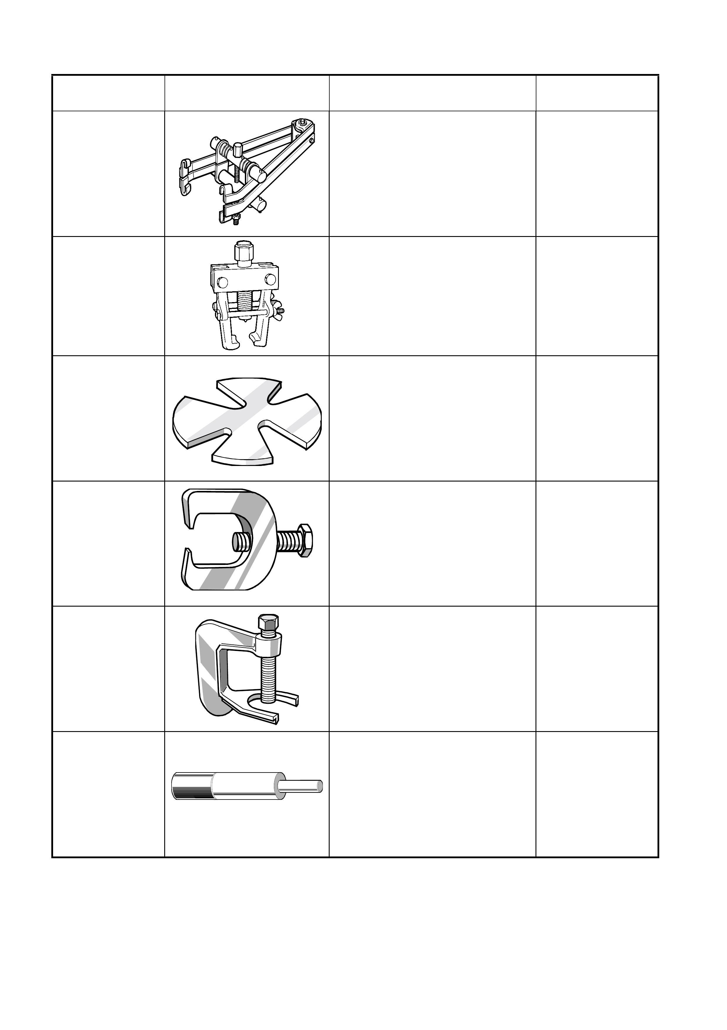
7. SPECIAL TOOLS
TOOL NUMBER ILLUSTRATION DESCRIPTION TOOL
CLASSIFICATION
180
SPRING COMPRESSOR
Previously released.
7311
STEERING LINKAGE OUTER TIE
ROD SOCKET ASSEMBLY
REMOVER
Previously released.
Can also be used on earlier ‘V’ cars
for the same purpose.
7A42
PRESS PLATES
Previously released.
9A10
STEERING LINKAGE OUTER TIE
ROD SOCKET ASSEMBLY
REMOVER
Previously released for ‘V’ car.
AJ24292-C
PRESS TOOL
Previously released for ‘VQ’
vehicles.
Used to remove wheel studs from
front wheel hub assembly.
AU158
FRONT LOWER CONTROL ARM
ROD BUSHING REMOVER AND
INSTALLER MANDREL
Previously released for ‘V’ car.
Used with KM158-2 for removing
bush and AU159 and KM157-2 for
installing.
TOOL NUMBER ILLUSTRATION DESCRIPTION TOOL
CLASSIFICATION
AU158-2
FRONT LOWER CONTROL ARM
ROD BUSHING INSTALLING
SUPPORT SLEEVE
Previously released for ‘V’ car.
Used with AU158 and AU159.
AU159 FRONT LOWER CONTROL ARM
ROD BUSHING REPLACER
SLEEVE
Previously released for ‘V’ car.
AU160-1 SUPPORT
Previously released.
Used to support front lower control
arm when installing a new inner
insulator.
AU162 FRONT LOWER CONTROL ARM
PIVOT BUSHING
REMOVAL MANDREL
Used with AU160-1 and KM157-2.
Previously released for ‘V’ car.
AU534 TORQUE LIMITING SOCKET
Previously released.
Used in conjunction with an impact
gun to tighten wheel nuts.
This is a mandatory
tool.
E7115 ANGLE WRENCH
Previously released for 'J' and 'V'
cars.
Used to tighten component
fasteners when angle torque is
required.

TOOL NUMBER ILLUSTRATION DESCRIPTION TOOL
CLASSIFICATION
E9332-A FRONT LOWER CONTROL ARM
SOCKET ASSEMBLY RELEASE
TOOL
Previously released.
Used to release the front lower
control arm socket from the
steering knuckle.
KM157-2
FRONT LOWER CONTROL ARM
PIVOT BUSHING INSTALLER
Previously released for ‘V’ car.
Used with AU158 and AU159.
KM158-2
FRONT LOWER CONTROL ARM
ROD BUSHING INSTALLING
SUPPORT SLEEVE
Previously released for ‘V’ car.
Used with AU158 and AU159.
KM468 HOLDING BAR
Previously released for 'J' car.
Used to hold front wheel hub
assembly from rotating.