
SECTION 6A3 - ENGINE MECHANICAL -
GEN III V8 ENGINE
IMPORTANT
Before performing any Service Operation or other procedure described in this Section, refer to Section
00 CAUTIONS AND NOTES for correct workshop practices with regard to safety and/or property damage.
CONTENTS
1. GENERAL DESCRIPTION
1.1 SERVICE INFORMATION
1.2 ENGINE SERIAL NUMBER
1.3 ENGINE CONSTRUCTION
CYLINDER BLOCK
CYLINDER HEADS
VALVE TRAIN
CRANKSHAFT
PISTONS AND CONNECTING RODS
CAMSHAFT AND DRIVE
INTAKE MANIFOLD
EXHAUST MANIFOLD
ACCESSORY DRIVE
OIL PAN
1.4 ENGINE LUBRICATION SYSTEM
OIL PUMP
CRANKSHAFT OIL SEALS
POSITIVE CRANKCASE VENTILATION
SYSTEM
1.5 SERVICE NOTES
CLEANLINESS AND CARE
REPLACING ENGINE GASKETS
USE OF RTV AND ANAEROBIC
SEALER
SEPARATING PARTS
TOOLS AND EQUIPMENT
FASTENERS
2. MINOR SERVICE OPERATIONS
2.1 ENGINE OIL LEVEL CHECK
2.2 ENGINE OIL - CHANGE
2.3 ENGINE OIL FILTER & ADAPTOR
REPLACE
2.4 ENGINE OIL PRESSURE - CHECK
2.5 COMPRESSION CHECK
INTERPRETING COMPRESSION
READINGS
2.6 ENGINE DRIVE BELTS - REPLACE
ENGINE ACCESSORY BELT
AIR CONDITIONING COMPRESSOR
BELT
2.7 ACCESSORY BELT IDLER PULLEY
REPLACE
2.8 A/C BELT IDLER PULLEY
REPLACE
2.9 ACCESSORY BELT TENSIONER
REPLACE
2.10 A/C BELT TENSIONER
REPLACE
2.11 OIL PRESSURE SENSOR
REPLACE
2.12 MANIFOLD ABSOLUTE PRESSURE
SENSOR
REPLACE
2.13 FUEL SYSTEM PRESSURE RELIEF
2.14 INTAKE MANIFOLD
REMOVE
DISASSEMBLE
CLEAN AND INSPECT
REASSEMBLE
REINSTALL
2.15 VAPOUR VENT PIPE
REMOVE
REINSTALL
2.16 ENGINE VALLEY COVER
REMOVE
CLEAN AND INSPECT
REINSTALL
2.17 VALVE ROCKER ARM COVER
REMOVE
CLEAN AND INSPECT
REINSTALL
2.18 VALVE ROCKER ARMS & PUSH RODS
REMOVE
CLEAN AND INSPECT
REINSTALL
2.19 VALVE STEM OIL SEAL AND/OR VALVE
SPRING
REPLACE
2.20 OIL LEVEL INDICATOR AND TUBE
REPLACE
2.21 EXHAUST MANIFOLD
REMOVE
INSPECT
REINSTALL
2.22 CYLINDER HEAD
REMOVE
DISASSEMBLE
CLEAN
INSPECT
REASSEMBLE
REINSTALL
2.23 VALVE LIFTERS
REMOVE
DISASSEMBLE
CLEAN AND INSPECT
REASSEMBLE
TEST LIFTER LEAKDOWN RATE
REINSTALL
2.24 CRANKSHAFT BALANCER
REMOVE
CLEAN AND INSPECT
REINSTALL
2.25 COOLANT PUMP
REMOVE
DISMANTLE
CLEAN AND INSPECT
REASSEMBLE
REINSTALL
Techline
Techline
Techline
Techline
Techline
Techline

2.26 CRANKSHAFT FRONT OIL SEAL
REPLACE
2.27 ENGINE MOUNTS
CHECK
REMOVE
REINSTALL
3. MAJOR SERVICE OPERATIONS
3.1 ENGINE ASSEMBLY
REMOVE
DISASSEMBLE
REASSEMBLE
REINSTALL, SET-UP AND TESTING
3.2 CAMSHAFT LOBE LIFT
MEASURE
3.3 OIL PAN
REMOVE
DISASSEMBLE
CLEAN AND INSPECT
REASSEMBLE
REINSTALL
3.4 ENGINE FRONT COVER
REMOVE
CLEAN AND INSPECT
REINSTALL
CRANKSHAFT FRONT SEAL -
REINSTALL
3.5 ENGINE FLYWHEEL/FLEXPLATE
REMOVE
CLEAN AND INSPECT
REINSTALL
3.6 ENGINE FLYWHEEL RING GEAR
REPLACE
3.7 CRANKSHAFT SPIGOT BEARING
REPLACE
3.8 ENGINE REAR COVER
REMOVE
CLEAN AND INSPECT
REINSTALL
CRANKSHAFT REAR SEAL - INSTALL
3.9 OIL PUMP, PUMP SCREEN AND
DEFLECTOR
REMOVE
OIL PUMP DISASSEMBLE
CLEAN AND INSPECT
OIL PUMP REASSEMBLE
REINSTALL
3.10 TIMING CHAIN AND SPROCKETS
REMOVE
CLEAN AND INSPECT
REINSTALL
3.11 CAMSHAFT
REMOVE
CLEAN AND INSPECT
REINSTALL
3.12 PISTON, CONNECTING ROD AND
BEARING
REMOVE
DISASSEMBLE
CLEAN AND INSPECT
REASSEMBLE
REINSTALL
3.13 CRANKSHAFT AND BEARINGS
REMOVE
CLEAN AND INSPECT
REINSTALL
3.14 ENGINE BLOCK PLUGS
REMOVE
REINSTALL
3.15 CYLINDER BLOCK
CAMSHAFT BEARINGS - REPLACE
CYLINDER BLOCK CLEAN, INSPECT
AND MEASURE
CYLINDER BORING AND HONING
3.16 THREAD REPAIR
GENERAL INFORMATION
GENERAL THREAD REPAIR
CYLINDER HEAD BOLT HOLE
THREAD REPAIR
MAIN CAP BOLT HOLE THREAD
REPAIR
3.17 THREAD REPAIR SPECIFICATIONS
ENGINE BLOCK - FRONT VIEW
ENGINE BLOCK - REAR VIEW
ENGINE BLOCK - LEFT SIDE VIEW
ENGINE BLOCK - RIGHT SIDE VIEW
ENGINE BLOCK - BOTTOM VIEW
ENGINE BLOCK - TOP VIEW
CYLINDER HEAD - TOP VIEW
CYLINDER HEAD - END VIEW
CYLINDER HEAD – EXHAUST
MANIFOLD SIDE VIEW
CYLINDER HEAD - INTAKE MANIFOLD
SIDE VIEW
4. DIAGNOSIS
4.1 BASIC ENGINE MISFIRE DIAGNOSIS
GENERAL INFORMATION
DIAGNOSTIC PROCEDURE
4.2 ENGINE NOISE DIAGNOSIS
4.3 VALVE TRAIN DIAGNOSIS
GENERAL INFORMATION
DIAGNOSTIC PROCEDURE
DIAGNOSTIC TABLE
4.4 OIL CONSUMPTION DIAGNOSIS
4.5 OIL PRESSURE DIAGNOSIS
4.6 OIL LEAK DIAGNOSIS
5. SPECIFICATIONS
6. TORQUE WRENCH SPECIFICATIONS
7. SPECIAL TOOLS
1. GENERAL DESCRIPTION
The 2003 Model Year 5.7 litre, GEN III, V8 engine (production option LS1), carries over from earlier build engines,
except for minor changes, detailed here. Minor changes to some service operations have also been made, that
reflect a modified approach to various tasks. As a result, the procedures contained in this Section have been
reproduced in full and should be followed when service operations are carried out on MY 2003 GEN III V8 engines.
Note that some vehicle specifications may include manual transmission and/or automatic transmission fitment, in
addition to left and right hand drive. Unless noted otherwise, the information contained within this Section is
appropriate for all vehicle specifications.
1.1 SERVICE INFORMATION
In summary, the following reflects changes that have been introduced with the 2001 Model Year release of the
GEN III V8 engine.
1. The engine accessory drive belt, coolant pump pulley is an integral part of the coolant pump and is not serviced
separately.
2. The pistons and piston rings have been through several changes, involving different piston skirt treatments and
the second compression piston ring design has also changed. For these reasons, it is vital that only parts listed
in the current PartFinder® CD are fitted to this engine.
3. The cylinder head gasket material has changed from a graphite layered design to a laminated steel type.
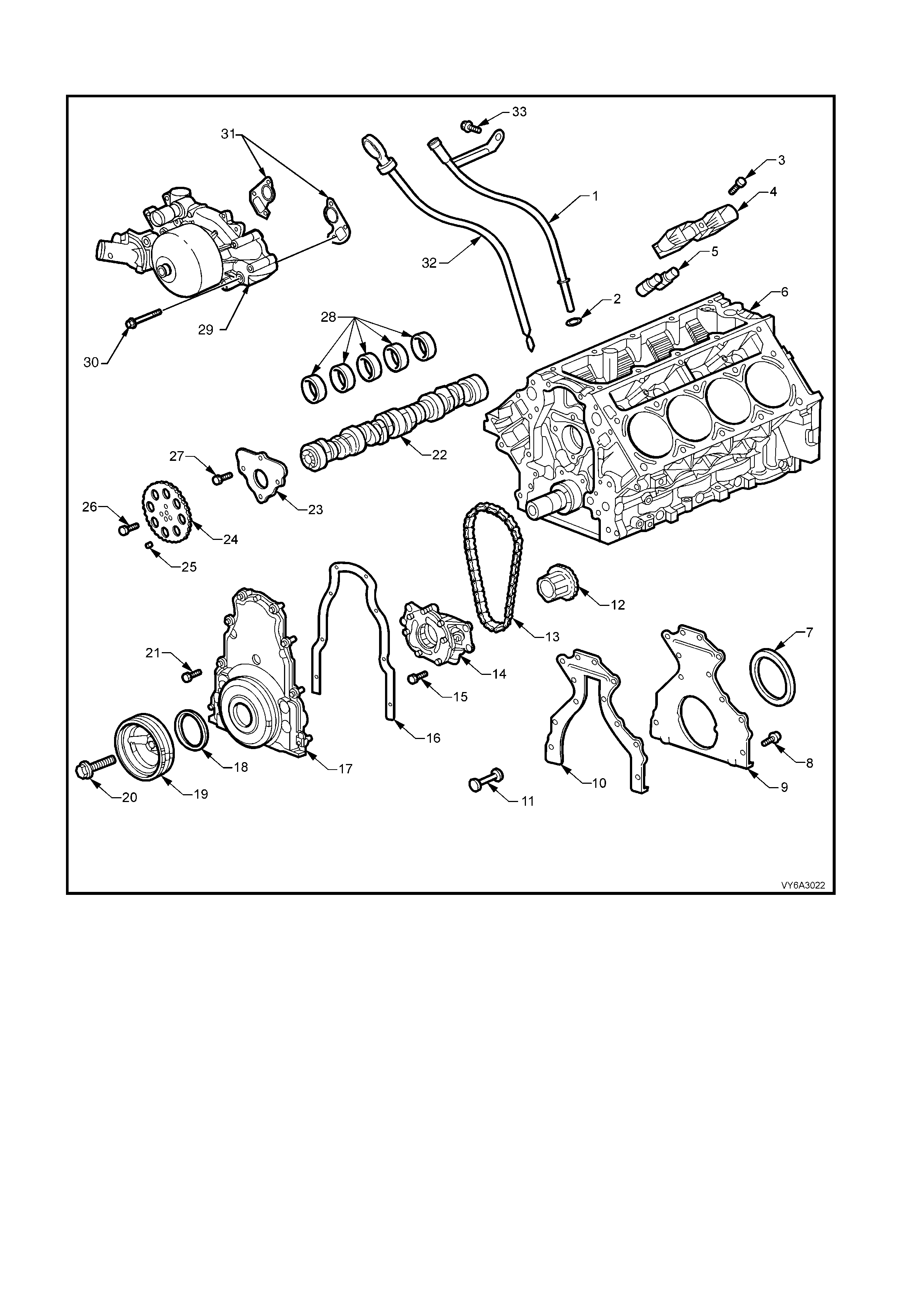
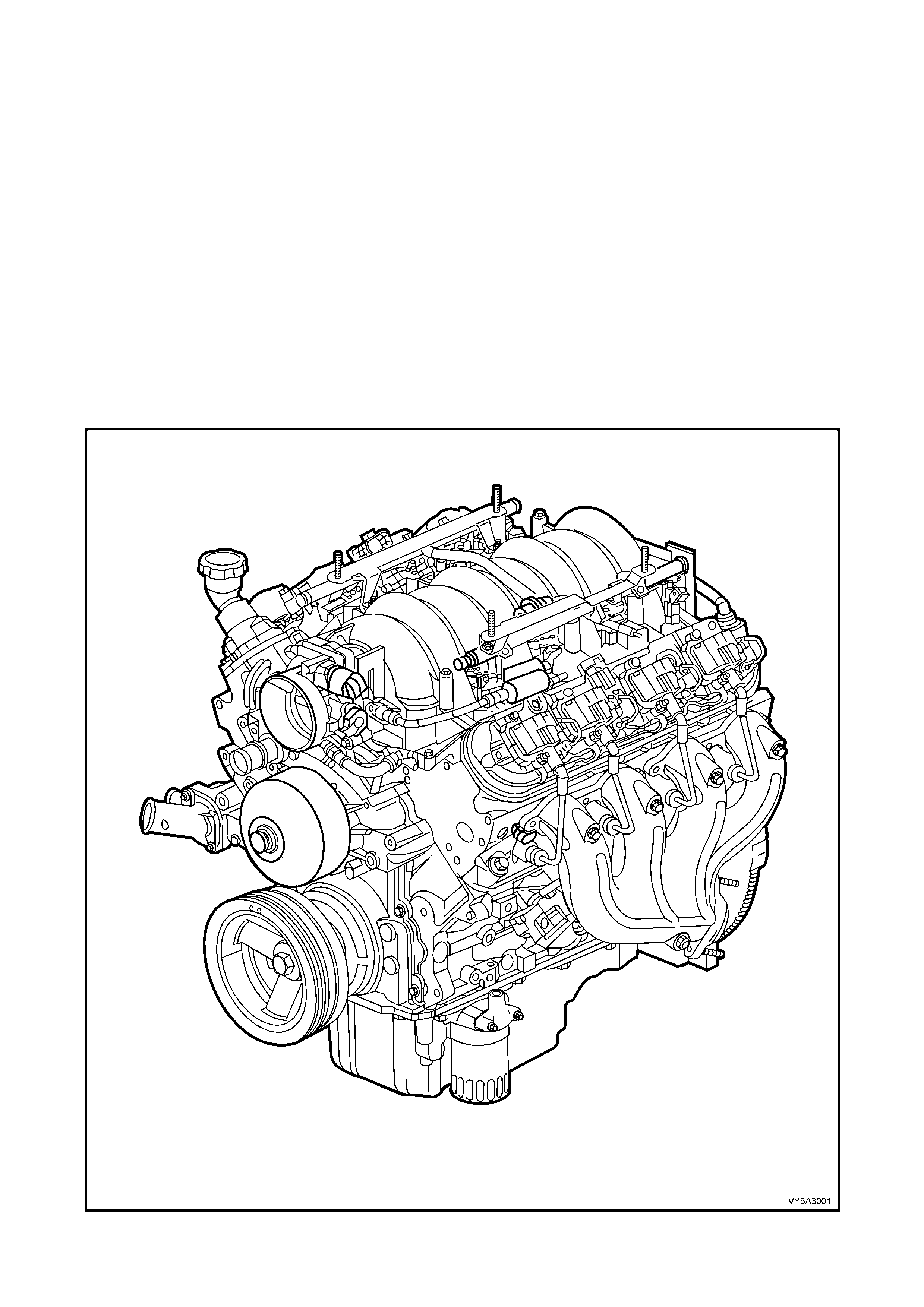
Figure 6C3-1-1 GEN III V8 Engine View Left Hand Side
(Power Steering Pump and Air Conditioning Compressor Not Shown)
Figure 6A3-2 - Lower Front of Engine
Legend
1. Tube – Oil Level Indicator
2. O-ring Seal – Oil Lever Indicator Tube
3. Bolt – Valve Lifter Guide
4. Guide – Valve Lifter
5. Lifter – Valve
6. Engine Block
7. Oil Seal – Crankshaft Rear
8. Bolt – Engine Rear Cover
9. Cover – Engine Rear
10. Gasket – Engine Rear Cover
11. Plug – Engine Block Rear Oil Gallery
12. Crankshaft Sprocket
13. Chain – Camshaft Timing
14. Oil Pump Assembly
15. Bolt – Oil Pump Assembly
16. Gasket – Engine Front Cover
17. Engine Front Cover
18. Oil Seal – Crankshaft Front
19. Balancer – Crankshaft
20. Bolt – Crankshaft Balancer
21. Bolt – Engine Front Cover
22. Camshaft
23. Retainer – Camshaft
24. Sprocket – Camshaft
25. Locating Pin – Camshaft Sprocket
26. Bolt – Camshaft Sprocket
27. Bolt – Camshaft Retainer
28. Bearings – Camshaft
29. Coolant Pump
30. Bolt – Coolant Pump
31. Carrier Gaskets – Coolant Pump
32. Indicator – Oil Level
33. Bolt – Oil Level Indicator Tube
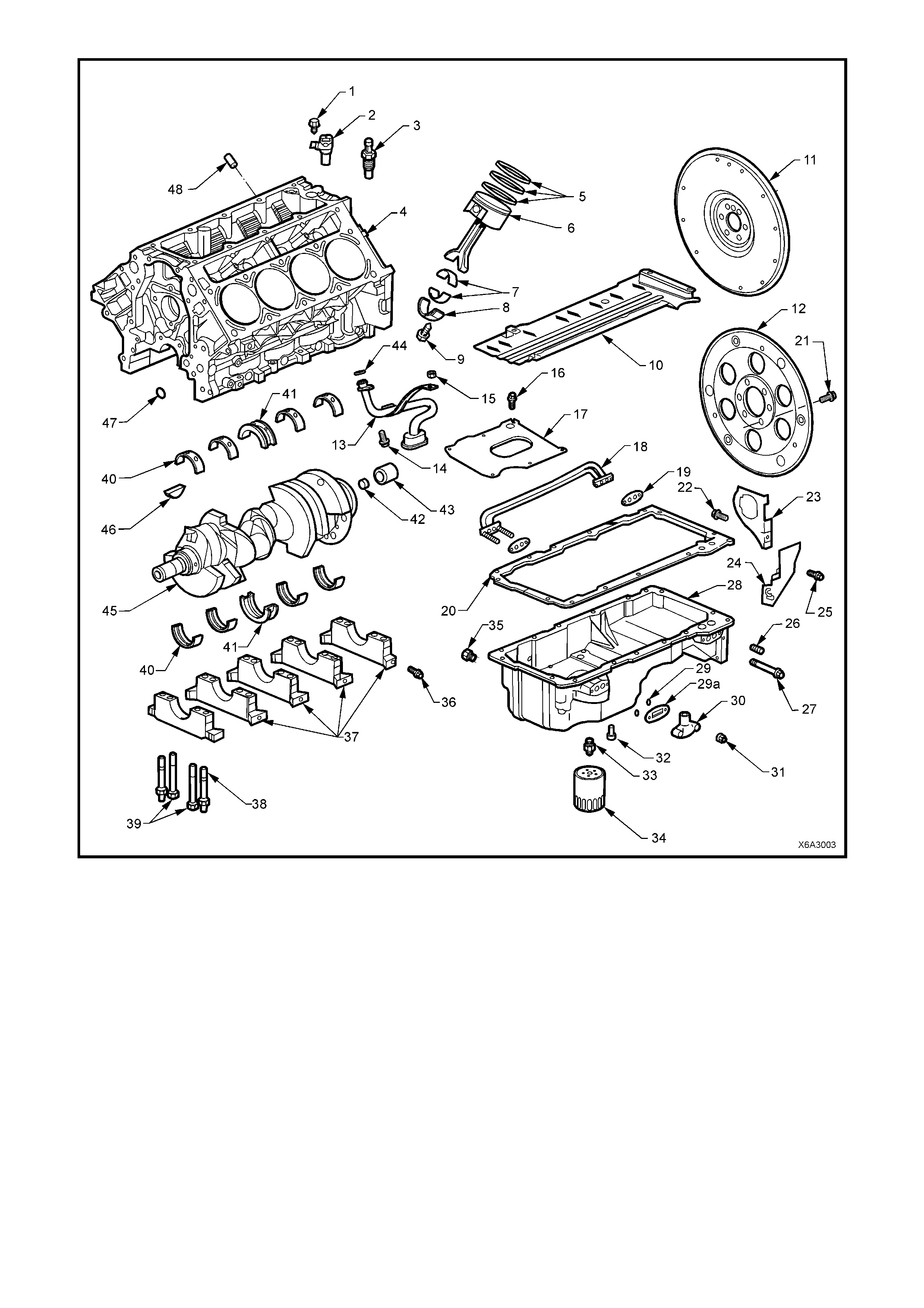
Figure 6A3-3 - Lower Engine Assembly
Legend
1. Bolt – Camshaft Position Sens or
2. Camshaft Position Sensor
3. Oil Pressure Sensor
4. Engine Cylinder Block
5. Piston Rings
6. Piston and Connect i ng Rod Assembly
7. Connecting Rod Bearings
8. Connecting Rod Cap
9. Bolt – Connecting Rod
10. Crankshaft Oil Deflector
11. Engine Flywheel – Manual Trans.
12. Engine Flexplate – Automatic Trans.
13. Screen and Pipe – Oil Pump Pick-up
14. Screw – Oil Pump Pick-up to Pump
15. Nut – Oil Deflector and Oil Pump Pick-up
16. Bolt – Oil Pan Baffl e
17. Baffle – Oil Pan
18. Tube – Oil Transfer
19. Gasket – Oil Transfer Tube
20. Gasket – Oil Pan
21. Bolt – Engine Flexplate
22. Screw – Oil Pan Closeout Cover (RHS)
23. Cover – Oil Pan Closeout (RHS)
24. Cover – Oil Pan Closeout (LHS)
25. Screw – Oil Pan Closeout Cover (LHS)
26. Plug – Oil Pan Gallery
27. Bolt – Oil Pan Transfer Tube
28. Oil Pan
29. O-Ring Seal – Oil Transfer Cover Stud
29a. Gask et – Oil Transfer Cover
30. Cover – Oil Transfer
31. Nut – Oil Transfer Cover
32. Valve – Oil Bypass
33. Adaptor – Oil Filter
34. Oil Filter
35. Plug – Oil Drain
36. Bolt – Crankshaft Bearing Cap Side
37. Caps – Crankshaft Main Bearing
38. Stud – Main Bearing Cap
39. Bolt – Main Bearing Cap
40. Bearings – Crankshaft Main
41. Bearings – Crankshaft Main Thrust
42. Plug – Rear Crankshaft
43. Bush – Manual Transmission Spigot
44. O-Ring Seal – Oil Pump Pick-up
45. Crankshaft
46. Key – Crankshaft Sprocket
47. Plug – Engine Block Front Oil Gallery
48. Plug – Cylinder Block in Unused Hole
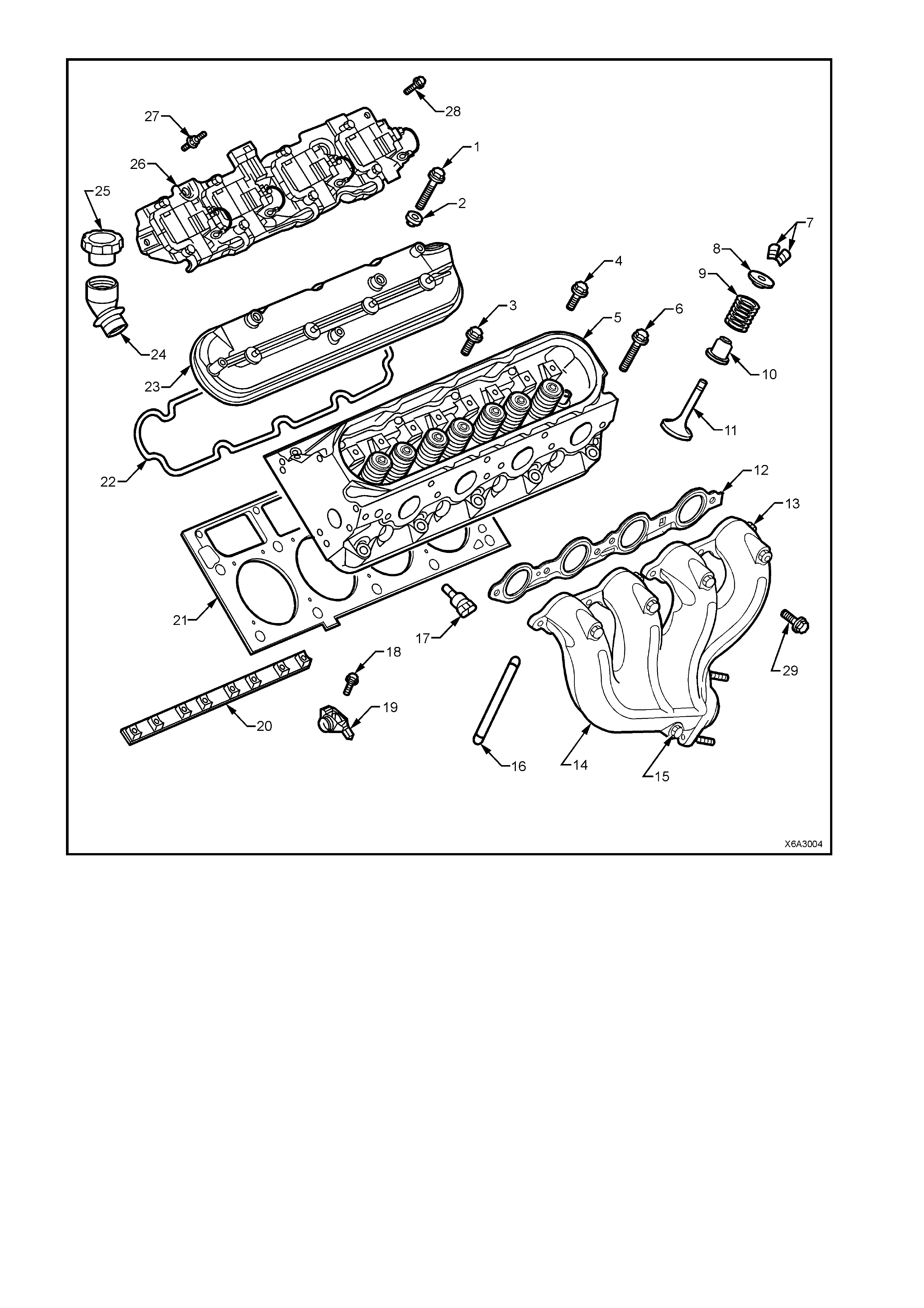
Figure 6A3-4 - Cylinder Head/Upper Engine
Legend
1. Bolt – Valve Rocker Arm Cover
2. Grommet – Valve Rocker Arm Cover
3. Bolt – Cylinder Head (Short)
4. Bolt – Cylinder Head (Medium)
5. Cylinder Head
6. Bolt – Cylinder Head (Long)
7. Collets – Valve Stem Keys
8. Cap – Valve Spring
9. Spring – Valve
10. Oil Seal/Valve Spring Shim – Valve Stem
11. Valve
12. Gasket – Exhaust Manifold
13. Manifold – Exhaust
14. Heat Shield – Exhaust Manifold
15. Bolt – Exhaust Manifold Heat Shield
16. Pushrod
17. Sensor – Coolant Temperature
18. Bolt – Valve Rocker Arm
19. Arm – Valve Rocker
20. Support – Valve Rocker Arm Pivot
21. Gasket – Cylinder Head
22. Gasket – Valve Rocker Arm Cover
23. Cap – Oil Fill Tube
24. Cover – Valve Rocker Arm
25. Tube – Oil Fill
26. Assembly – Ignition Coil and Bracket
27. Stud – Ignition Coil Bracket Assembly
28. Screw – Ignition Coil Bracket Assembly. Rear on each side
29. Bolt – Exhaust Manifold
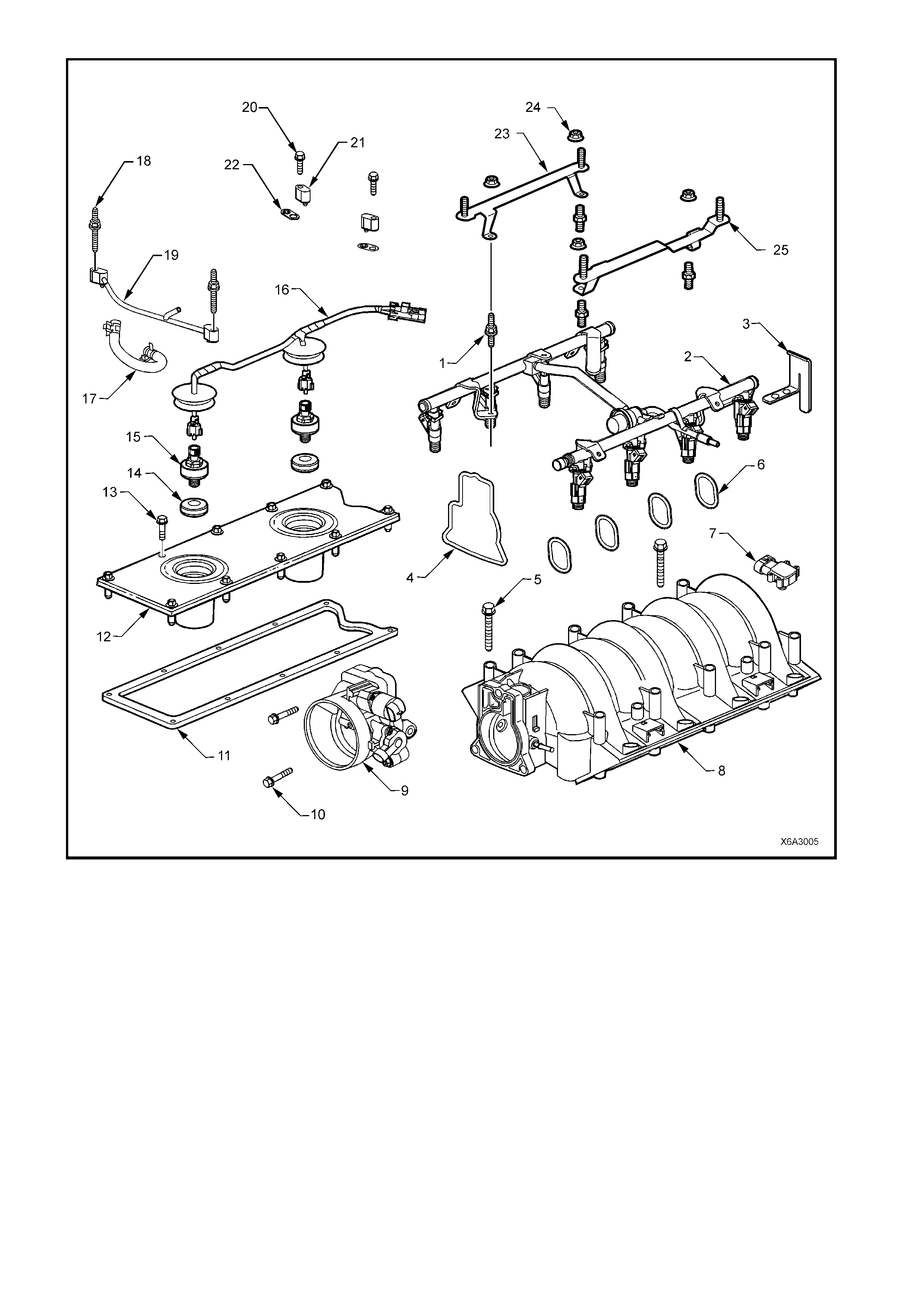
Figure 6A3-5 - Intake Manifold/Upper Engine
Legend
1. Stud – Fuel Rail to Intake Manifold (4 places)
2. Fuel Rail (with Injectors)
3. Bracket – Fuel Rail Stop
4. Gasket – Throttle Body
5. Bolt – Intake Manifold (10 places)
6. Gaskets – Intake Manifold (8 places)
7. Sensor – Manifold Absolute Pressure (MAP)
8. Intake Manifold
9. Throttle Body
10. Bolt – Throttle Body (3 places)
11. Gasket – Valley Cover
12. Valley Cover
13. Bolt – Valley Cover (10 places)
14. Oil Seal – Knock Sensor (2 places)
15. Knock Sensor (2 places)
16. Knock Sensor Wire Harness
17. Hose – Vapour Vent Tube
18. Stud – Vapour Vent Tube (2 places)
19. Vapour Vent Tube
20. Bolt – Vapour Vent Tube
21. Cover – Vapour Vent (2 places)
22. Gasket – Vapour Vent Tube (4 places)
23. Bracket – Engine Dress Cover, Right Hand Side
24. Nut – Engine Dress Cover Bracket
25. Bracket – Engine Dress Cover, Left Hand Side
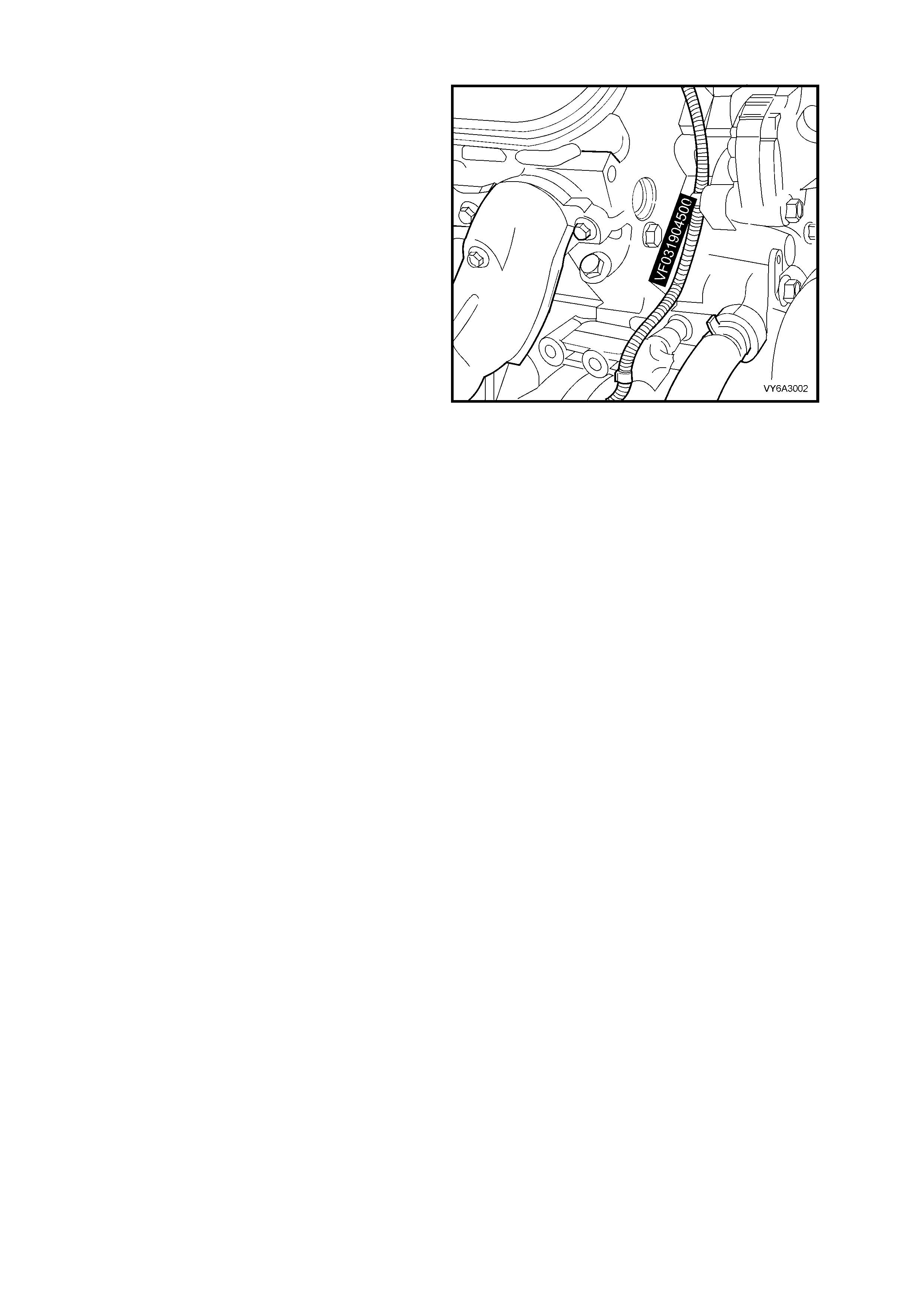
1.2 ENGINE SERIAL NUMBER
The engine number is stamped on the right hand
side front of the engine cylinder block, as shown.
The number is prefixed by the letters ‘VF’.
A breakdown of the engine numbering system,
using and example of ‘VF031904500’, is;
• First two numbers (‘03’ = 2003) indicates the
engine model year.
• Next three numbers (‘190’) is the Julian date
(day of the year), the engine was
manufactured.
• Next four numbers are the daily, sequential
build num ber .
Figure 6A3-6
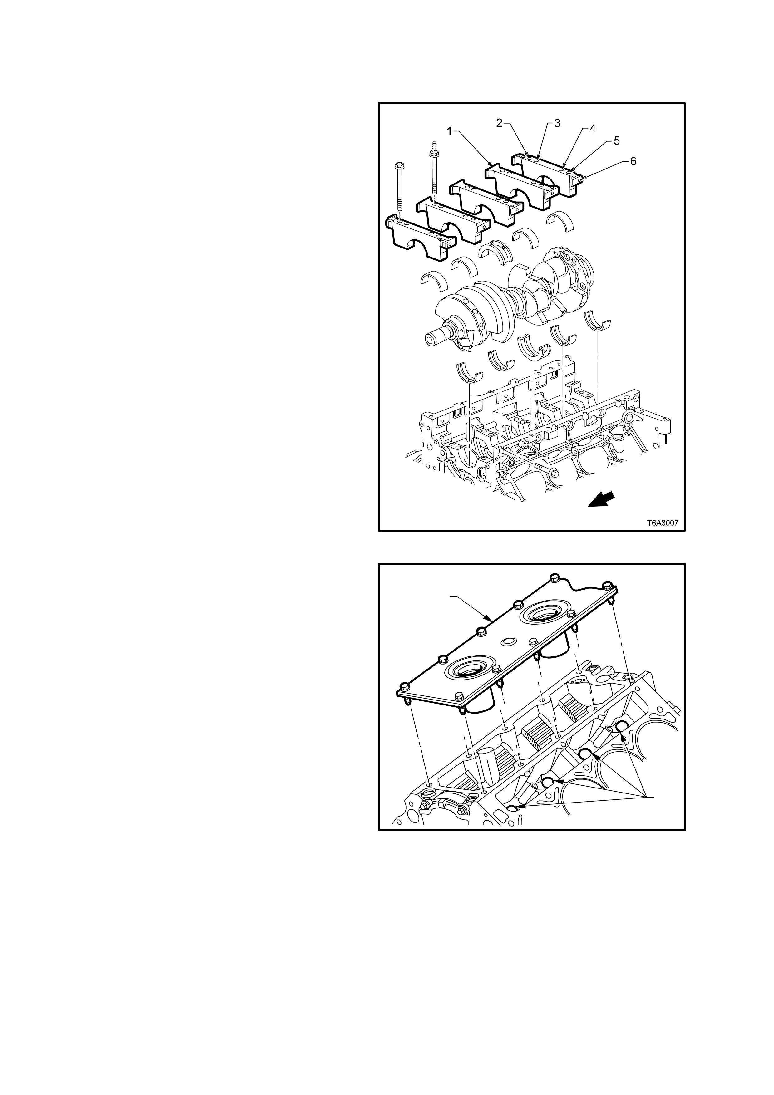
1.3 ENGINE CONSTRUCTION
CYLINDER BLOCK
The engine cylinder block is a cam-in-block, deep
skirt, 90° ‘V’ configuration with five crankshaft
bearing caps, m anufactured from forged powdered
metal. The engine block is aluminium with cast in
place, cast iron cylinder bore liners. The five
cross-bolted crankshaft bearing caps each have
four ver tical M10 ( 2, 3, 4, a nd 5) and t wo hor izontal
M8 (1 and 6) mounting bolts. Only cylinder honing
is permitted.
The c rank c ase sk ir t length, beari ng c ap width, dec k
width and upper rails have been optimised for
strength, using finite element analysis.
The camshaft is supported by five camshaft
bearings pressed into the block.
Figure 6A3-7
The cylinder block incorporates enclosed valve
lifter bores (2) under each cylinder head, that
results in a more stiff structure with quiet operation.
Utilising a structural die cast aluminium valley
cover (1), ties both cylinder banks together,
increasing the block’s torsional and bending
frequencies. Having a closed valley area also
prevents hot oil from contacting the lower surface
of the intake manifold, allowing cooler air to enter
the cylinders.
Overall, the cylinder block construction weighs
48% less than an equivalent cast iron block and
the structural design features, coupled with the
inherently light cylinder heads, combine into an
engine with unique stiffness and light weight.
T6A3008
2
1
Figure 6A3-8
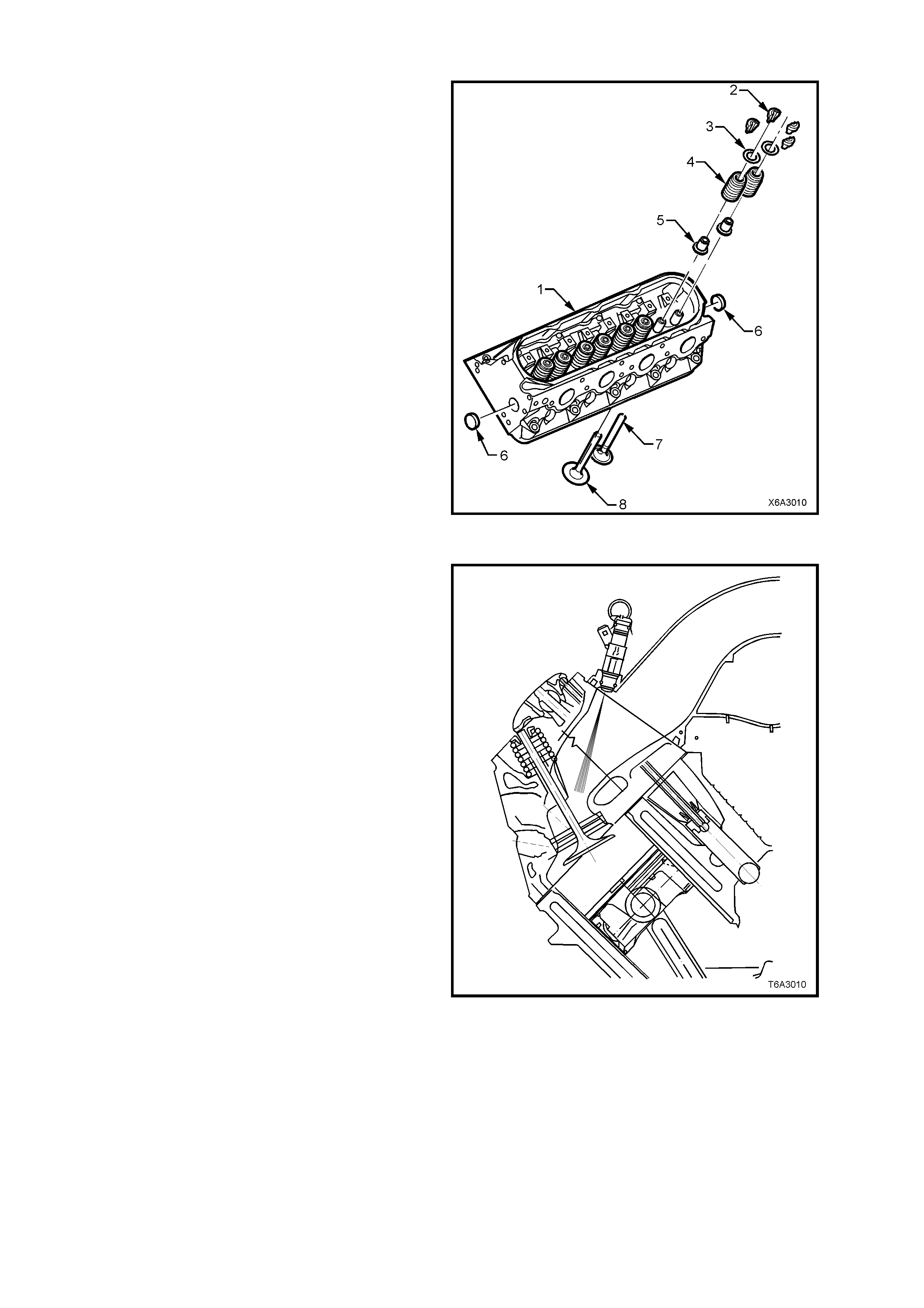
CYLINDER HEADS
The cylinder head assemblies are cast aluminium
and have pressed in place, powdered metal valve
guides and valve seats.
Intake and exhaust ports are identical for each
cylinder, ensuring a balanced air-flow distribution
for balanced combustion, resulting in a smoother
running eng ine .
The cylinder head is attached using a four bolt per
cylinder, deep threaded arrangement for minimal
bore distortion, allowing low friction pistons and
rings for reduced fuel consumption.
Cylinder head gaskets are now a laminated steel
type and feature stainless steel PTFE coated
flanges and lacing. The revised material gaskets
are now common for both right and left hand sides.
Legend
1. Cylinder Head
2. Valve Stem Collets
3. Valve Spring Cap
4. Valve Spring
5. Valve Stem Oil Seal/S him Com binati on
6. Cylinder Head Core P l ugs
7. Exhaust Valve
8. Intake Valve
Figure 6A3-9
The intake ports are very tall, which enhances fuel
injector targeting. As air flows down to the valve
guide, it widens and shortens to the size of the
intake valve seat.
Figure 6A3-10
VALVE TRAIN
Motion is transmitted from the camshaft through
the hydraulic roller valve lifters and tubular
pushrods to the rocker arms. The valve lifter
guides pos ition and r etain the roller h ydraulic valve
lifters. The valve rocker arms for each bank of
cylinders are mounted on pedestals (pivot
supports) . Eac h rocker arm is r etaine d on t he pi vot
support and cylinder head by a bolt. Valve lash is
adjusted automatically each cycle by the hydraulic
valve lifters.
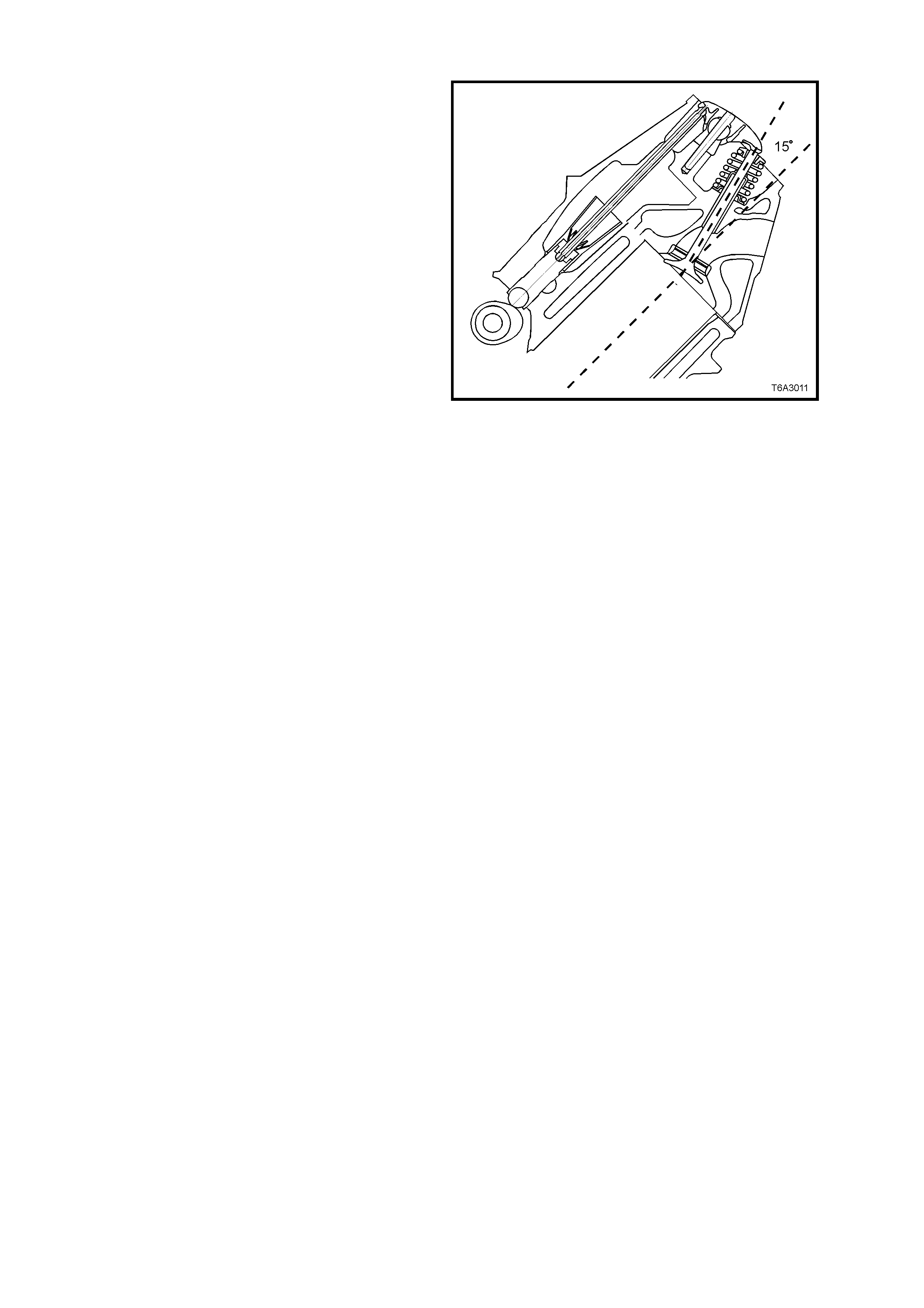
Both valves are angled at 15° to the cylinder bore
centreline, which creates a shallow combustion
chamber and a flat top piston, creating a
compression ratio of 10.1:1.
Both the exhaust and intake valve seat angles are
45° with an i ntake valv e head diam eter of 50.8 mm
and exhaust of 39.4 mm .
Valve spr ings are con ical or ‘beeh ive’ in s hape and
made from chromium Silicone wire. The springs
are double shot peened to provide maximum
reliability. The reduced diam eter end coils allo ws a
smaller diameter, lower mass, steel spring retainer
to be used, with s ingle bea d, valve s tem ke ys. This
spring design also reduces spring mass and,
coupled with the increased stiffness in the valve
train, results in a reduction in the valve spring pre-
load, thereby reducing friction and valve train
noise.
The ro cker arms are made of inves tment c ast steel
and have a ratio of 1.7:1, that allows a lower cam
lobe lift, resulting in lower valve train loading and
less noise.
The valve rocker arm covers are cast aluminium
and use a pre-moulded silicone gasket for sealing.
Mounted to each rocker cover are four individual
ignition coils. Incorporated into the covers are the
oil fill tube, the Positive Crankcase Ventilation
(PCV) system passages, and the engine fresh air
passages.
Figure 6A3-11
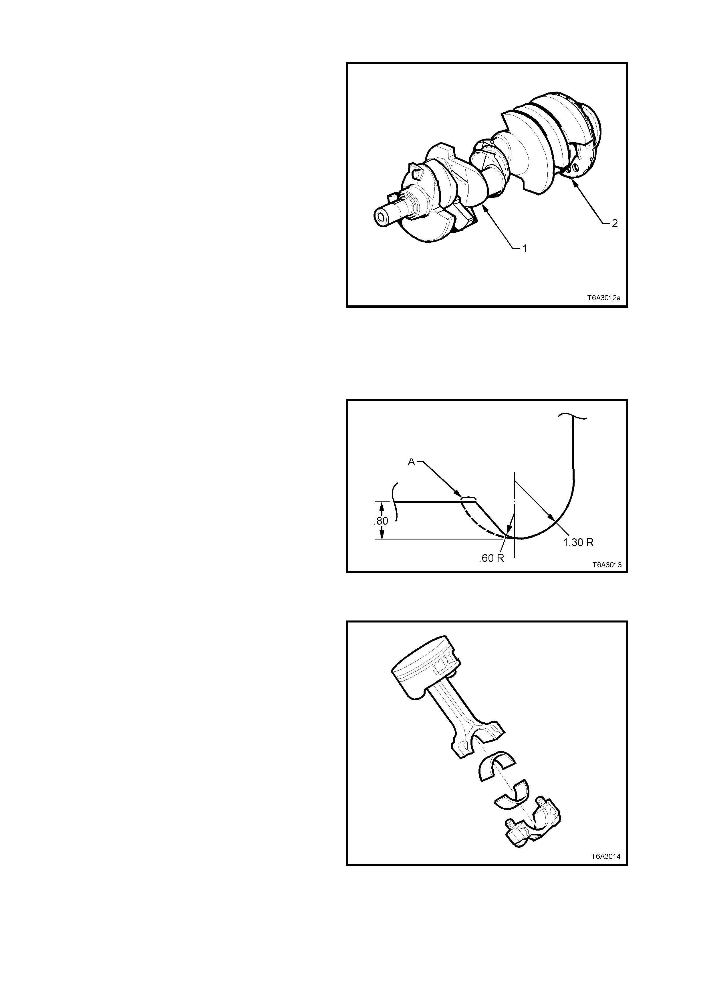
CRANKSHAFT
Manufactured from cast nodular iron, the
crankshaft (1) is supported by five crankshaft
bearings and are retained by 6 bolt crankshaft
bearing caps. The main bearing caps are
machined with the engine block for the proper
alignment and clearance.
A 24X crankshaft position reluctor ring (2) is
mounted at the r ear of the number eight c ranks haft
counter weight. The reluctor ring is not serviced
separately.
Crankshaft thrust is taken by the centre (No. 3)
main bearing. This location is used to reduce the
expansion differences between the cast iron
crankshaft and the aluminium cylinder block.
By adopting a firing order of 1, 8, 7, 2, 6, 5, 4, 3,
crank throw stresses are reduced and main
bearing performance is improved.
The crankshaf t has a drilled 25.4 m m hole through
the centre of main journals 2, 3, 4 and 5. Apart
from a reduction in crankshaft weight, this also
achieves engine breathing enhancement at low
speeds.
Figure 6A3-12
A variable radii undercut increases the effective
bearing widths by 0.4 m m each side ( A), c om pared
to a uniform undercut and rolled fillets are utilised
for improved fatigue strength.
Figure 6A3-13
PISTONS AND CONNECTING RODS
The pistons are cast aluminium and have two
compression rings and one oil control ring
assembly fitted. Piston rings are of a thin, low
fric tion desi gn, with t he top r ing loc ate d c lose t o the
top of the piston crown to reduce hydrocarbon
emissions. The piston is a low friction, lightweight
design with a flat top and barrel shaped skirt.
Piston pins are chromium steel and are a floating fit
in the piston and a press fit in the connecting rod.
The connecting rods are forged powdered metal.
The connecting rod cap is separated during the
manufacturing pr oces s , us ing the ‘f r actur e’ method.
This creates a stronger, visually seamless rod to
cap union. The reassembled rod is then machined
for the proper clearance.
A 0.25 mm oversize piston and piston ring set are
available for service, should cylinder honing be
required.
Figure 6A3-14
CAM SHAFT AND DRIVE
A billet st eel, o ne piece c am shaf t is suppor ted b y five bear ings pressed i nto the eng ine bl ock . T he cam shaft has a
machined camshaft sensor reluctor ring incorporated between the fourth and fifth bearing journals. To reduce
valve train noise, both the intake and exhaust cam lobes have slow closing velocity ramps.
To reduce weight, the camshaft has a 17 mm gun-drilled hole down its length.
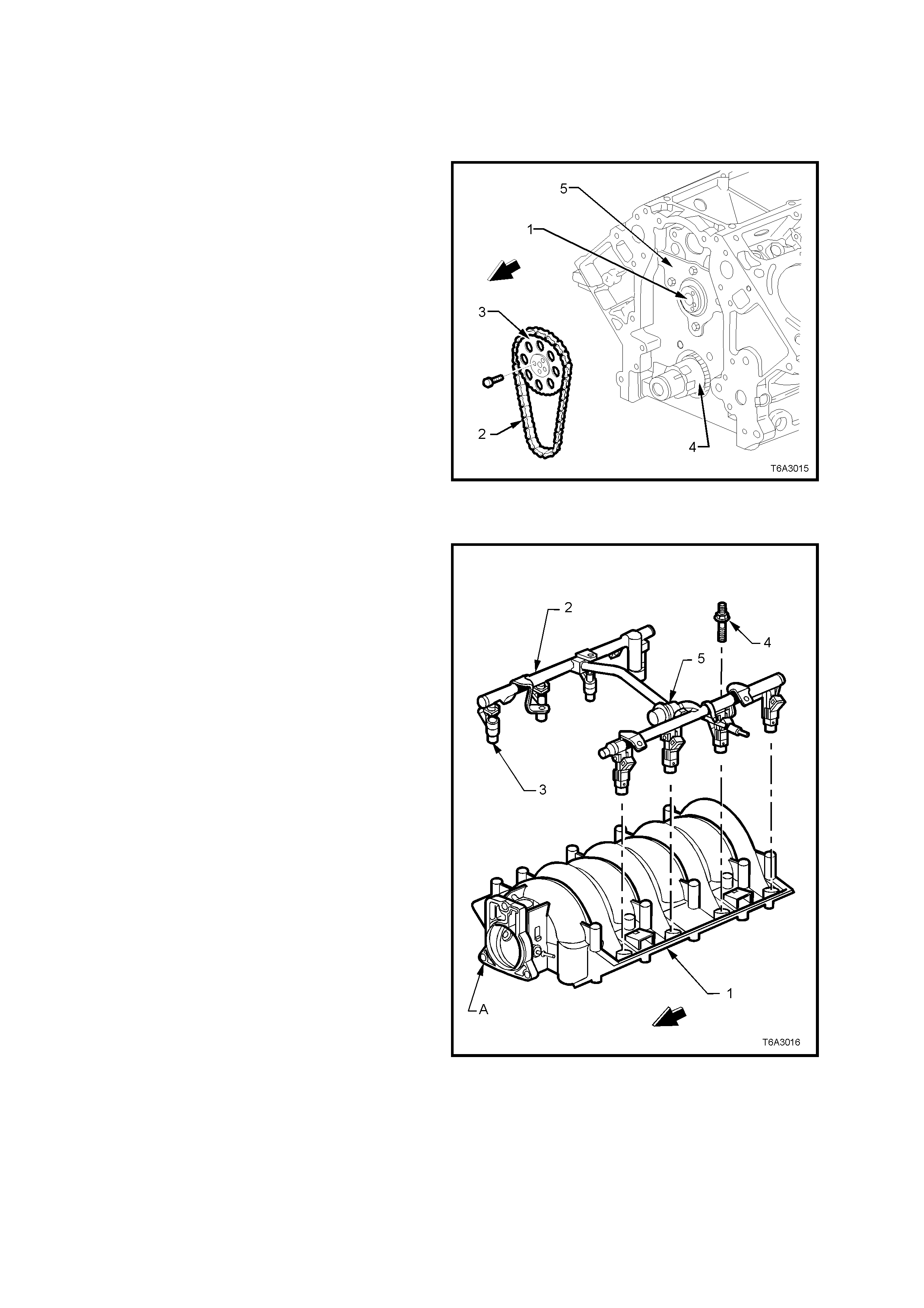
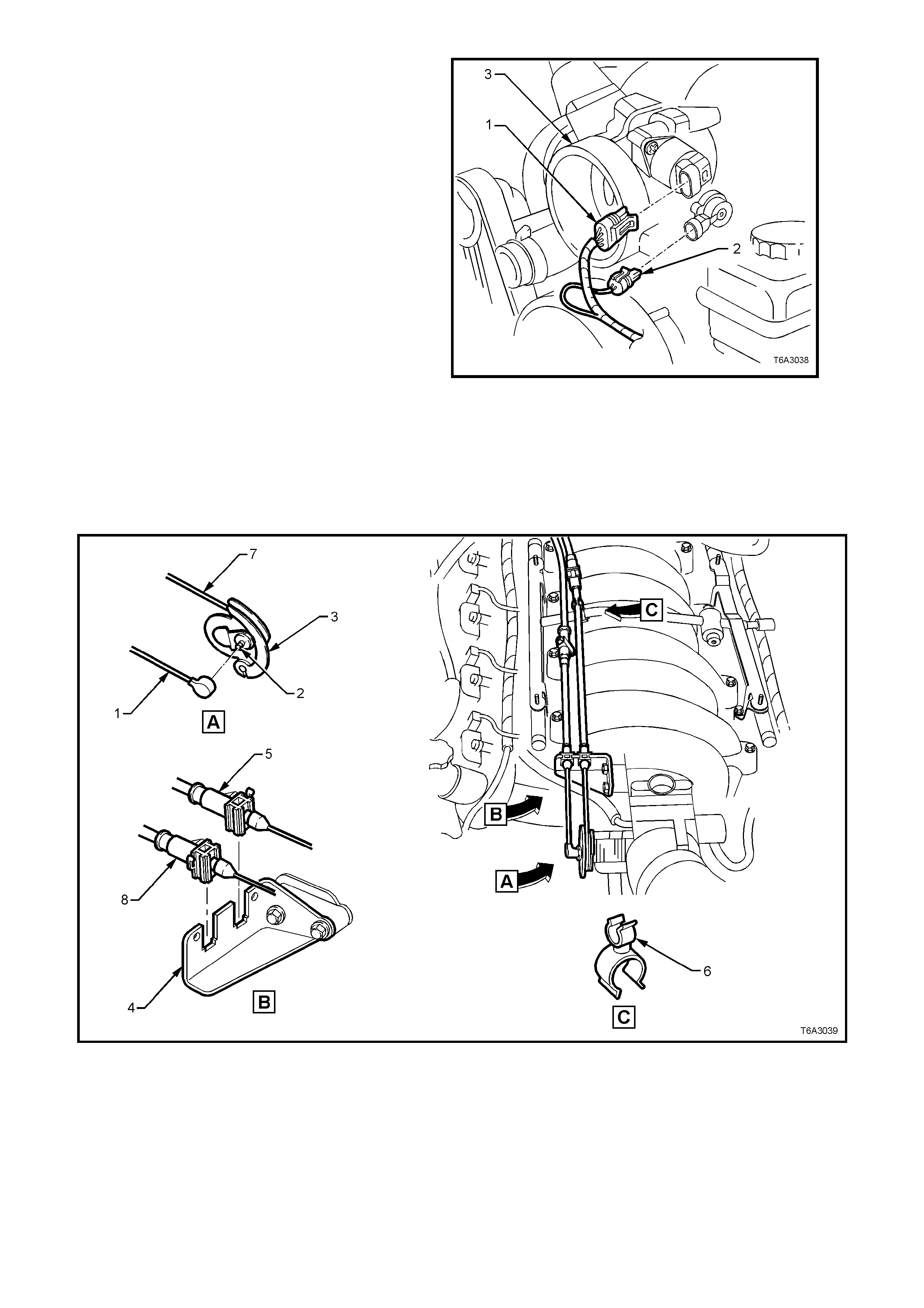
The c amshaft (1) is dr iven by a traditiona l 9.52 mm
pitch roller chain (2) and powdered metal timing
sprockets mounted to the front of the camshaft (3)
and crankshaft (4). The crankshaft sprocket (4) is
splined and drives the oil pump driven gear. A
retaining plate (5) mounted to the front of the
engine block maintains the camshaft location. No
chain tensi oner is req uired.
Figure 6A3-15
INTA KE MANIFOLD
The intake manifold (1) is a one piece composite
design that incorporates metal threaded inserts for
mounting the fuel rail (2), throttle cable bracket,
and throttle body.
The intak e m anifold is sealed t o the c ylinder he ads
by eight separate non-reusable silicone sealing
gaskets which press into the grooves of the intake
housing.
The cable-actuated throttle body assembly bolts to
the front of the intake manifold (A). The throttle
body is sealed to the intake manifold by a one
piece, push-in-place silicone gasket.
The fuel rail assembly (2) with eight separate fuel
injectors (3) is retained to the intake manifold by
four bolts (4). The injectors are seated in their
individual manifold bores with O-ring seals to
provide sealing. The fuel pulsation damper (5) is
incorporated into the fuel rail design. A fuel rail
stop bracket is retained at the rear of the left fuel
rail by the intake manifold mounting bolts (not
shown).
The Manifold Absolute Pressure (MAP) sensor is
installe d in the snap f it MAP sensor housing th at is
mounted at the rear of the manifold and sealed by
an O-ring seal (not shown).
There are no coolant passages within the intake
manifold.
Figure 6A3-16
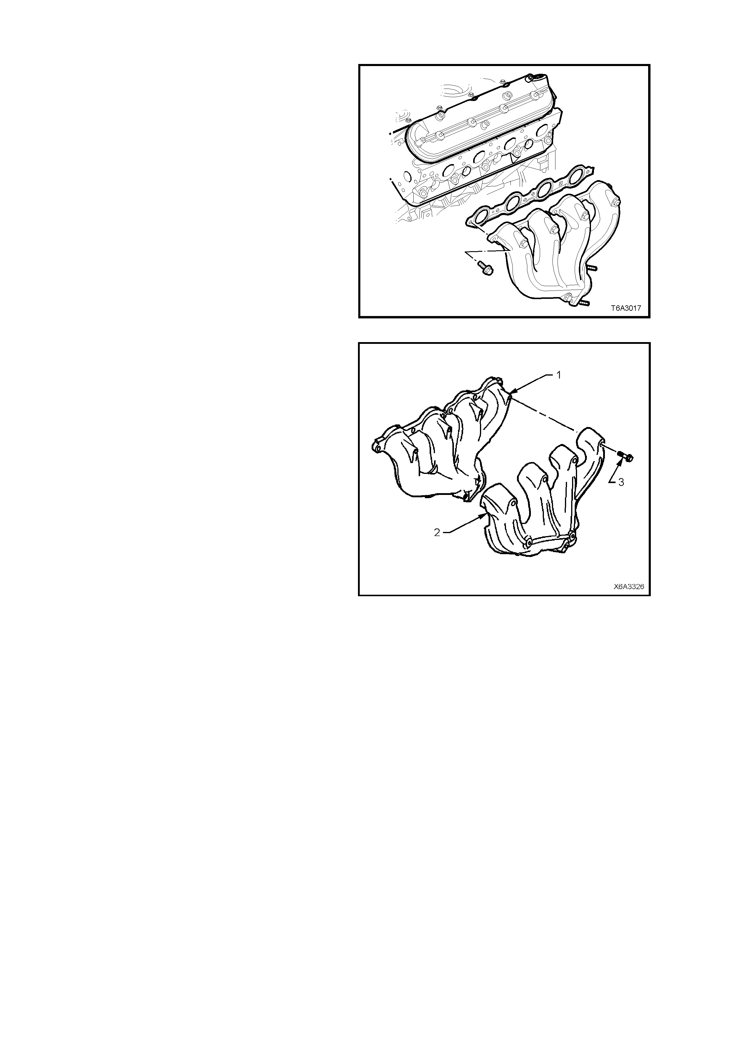
EXHAUST MANIFOLD
The exhaust manifolds are one piece, of high
temperature silicone molybdenum cast iron and
direct exhaust gases from the combustion
chambers to the exhaust system.
Figure 6A3-17
Each manifold (1) also has an externally mounted
dual wall heat shield (2) attached, that is made of
aluminiumised steel and attached by five screws
(3).
Figure 6A3-18
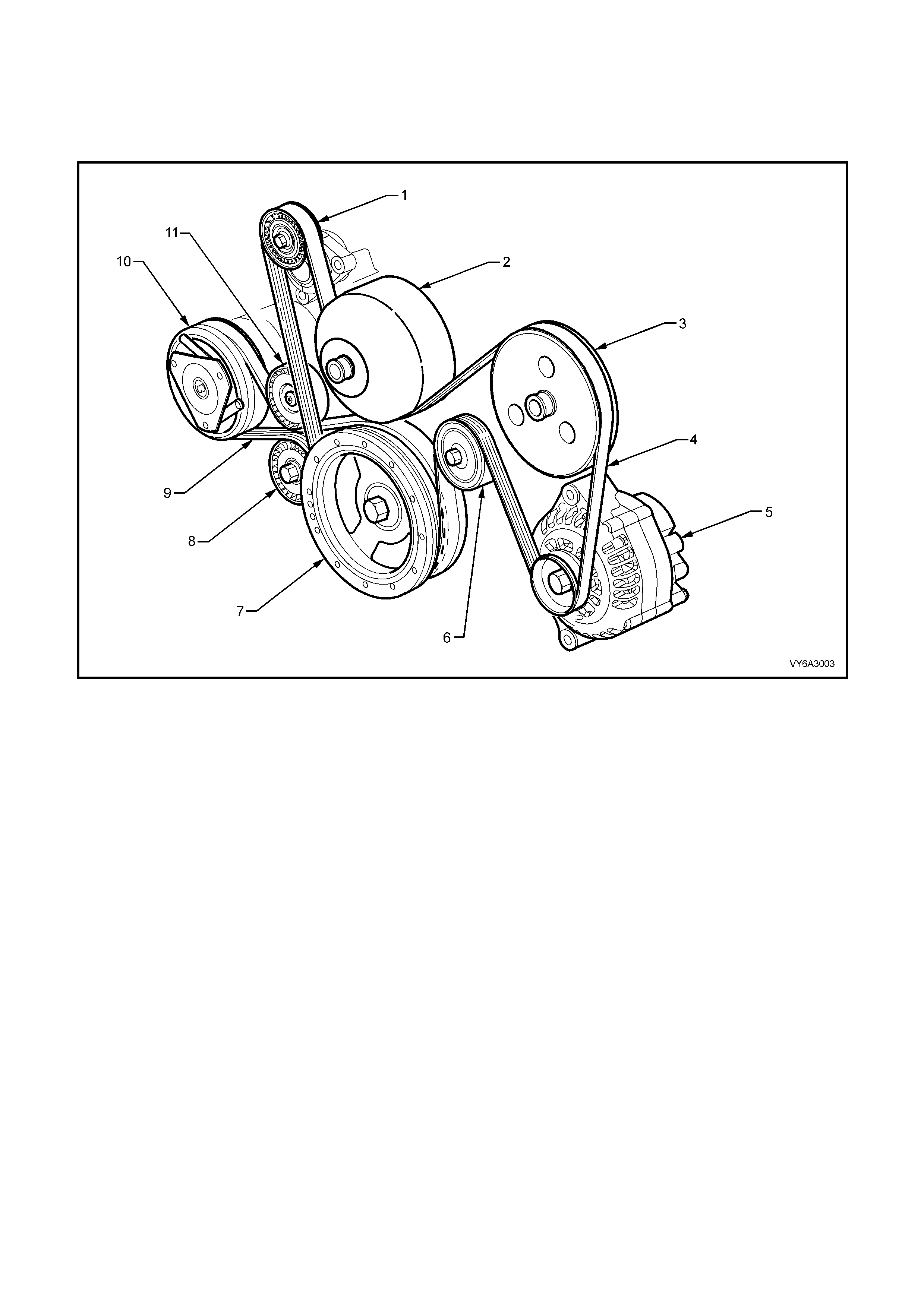
ACCESSORY DRIVE
The engine accessory drive consists of dual serpentine belts, that decouple the generator and air conditioning
compressor for improved noise isolation. Using dual belts also provides design flexibility to optimise structural
stiffness of support brackets.
The system includes two automatic belt tensioners with a low static tension for increased belt and bearing life.
Figure 6A3-19
Legend
1. Accessory Drive Belt, Automatic Tensioner
2. Water Pump Pulley
3. Power Steering Pump Pulley
4. Engine Accessory Drive Belt
5. AC Generator
6. Accessory Drive Belt, Idler Pulley
7. Crankshaft Balancer Pulley
8. Air Conditioning Compressor Drive Belt Automatic Tensioner
9. Air Conditioning Compressor Drive Belt
10. Air Conditioning Compressor
11. Air Conditioning Compressor Drive Belt, Idler Pulley
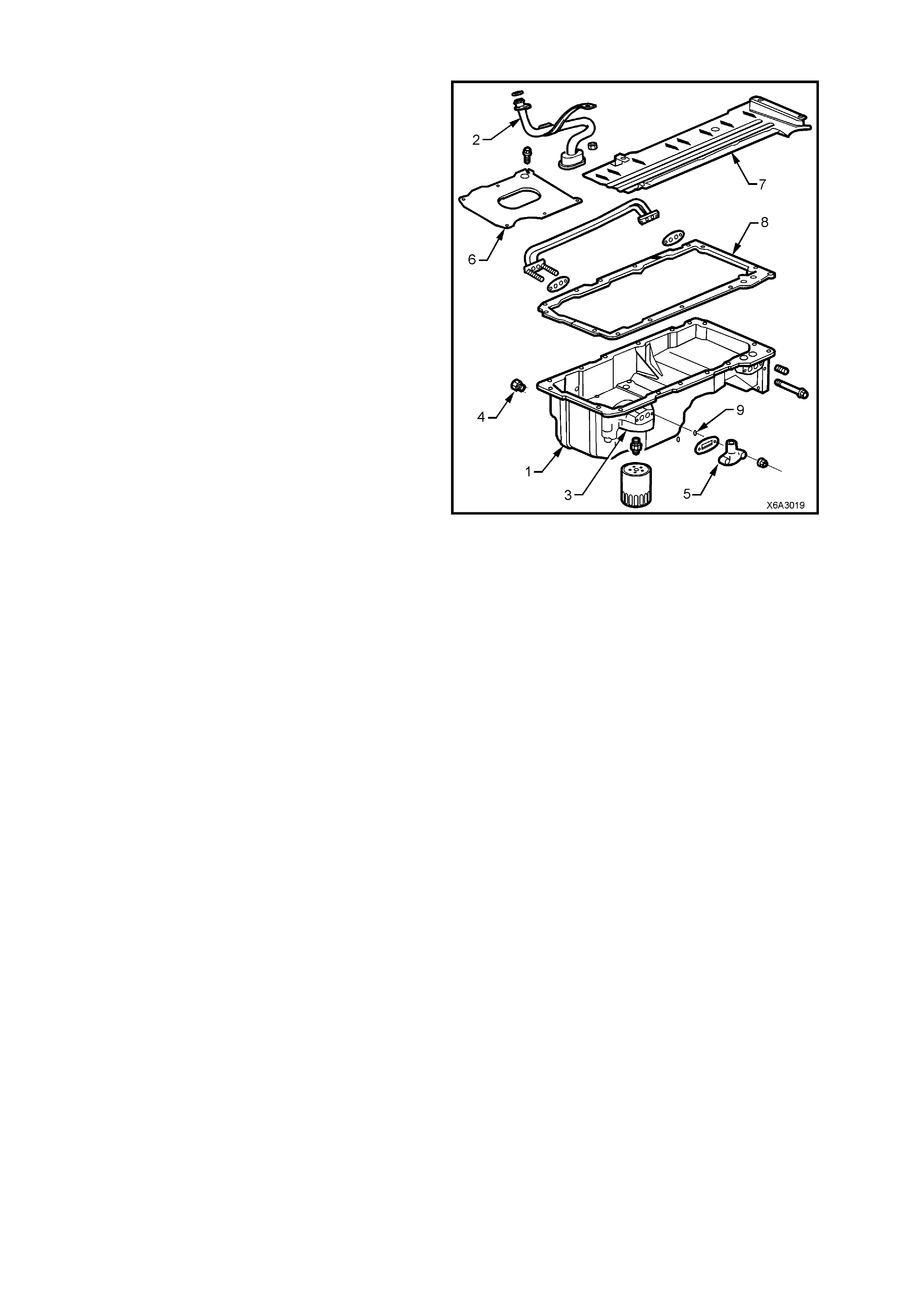
OIL PAN
The oil pan (1) is cast aluminium and forms a
structural part of the powertrain, by providing a
360° mounting for the transmission, whether it be
Manual or Automatic.
Cast-in dams incorporated into the oil pan design,
minim ise oil m igrati on duri ng br ak ing and cor ner ing
manoeuvr es a nd oil is gui ded to the p ick -up s creen
(2), via strategically placed openings in the dam
walls.
Incorporated into the design are the oil filter
mounting boss (3), an opening for the drain plug
(4), and a stamped, oil pan baffle (6).
The oil pan baffle (6), maintains an area around the
pick-up screen to prevent oil starvation/aeration.
A crankshaft oil deflector (7) mounted to the main
bearing caps controls windage, scrapes oil from
the crankshaft, facilitates drainback and reduces
aeration.
The oil pan gasket (8), is a controlled com pression
aluminium carrier gasket with silicone used as the
sealing age nt.
Two O-ring seals (9) were introduced as a running
change to stop oil wicking along the studs,
resulti ng in an oi l l eak from this are a. As the o il pan
requires chamfers to be machined around each of
the two stud holes, fitment of the O-rings to earlier
build engines without the machined chamfers, is
not possible without also changing the oil pan.
Figure 6A3-20
1.4 ENGINE LUBRICATION SYSTEM
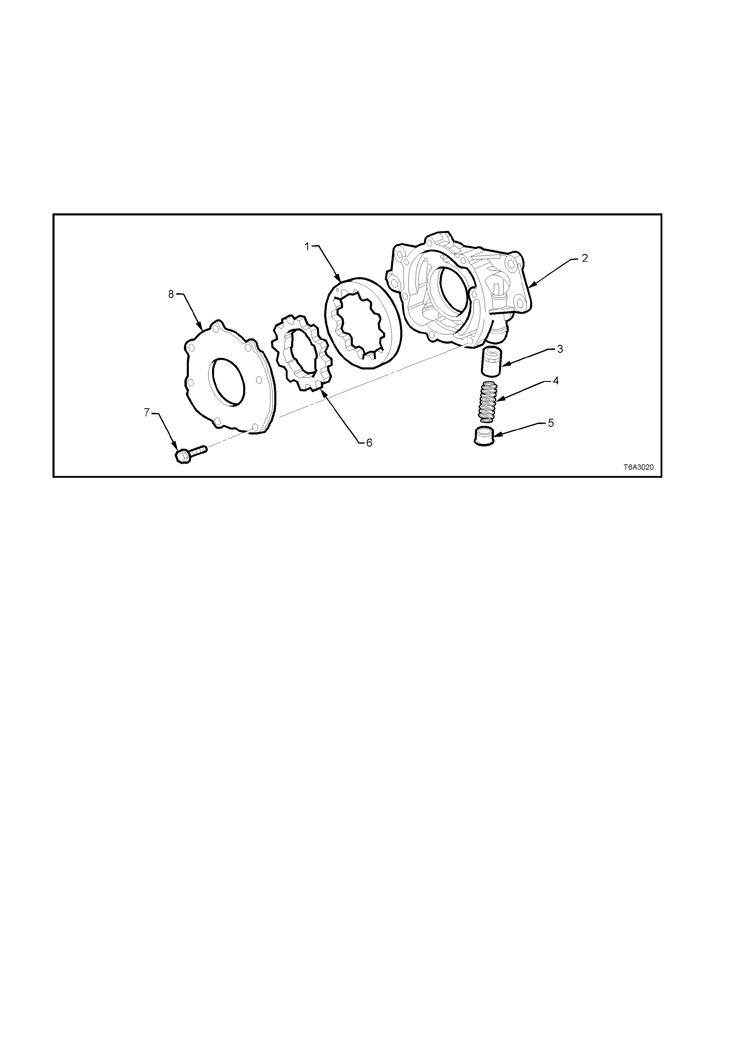
OIL PUMP
Engine lubrication is supplied by a “Gerotor” type oil pump assembly. The pump is mounted on the front of the
engine b lock and driven directly by the crankshaft sprock et. The pump gears rotate and draw oil from the oil pan
sump thr ough a pick - up screen a nd pip e. The oil is pr ess urised as it pass es thro ugh the pump and is s ent throug h
the engine block oil galleries.
Contained within the oil pump assembly is a pressure relief valve that maintains oil pressure within a specified
range. Pr essurised o il is dir ected throug h the lower ga llery to the full flow oil filter where harmf ul contaminant s are
removed. A bypass valve is incorporated into the oil filter that still allows oil to flow in the event that the filter
becomes blocked.
Figure 6A3-21 - Oil Pump Assembly
Legend
1. Driven Gear
2. Oil Pump Housing
3. Pressure Relief Valve
4. Spring – Pressure Relief Valve
5. Plug
6. Drive Gear
7. Bolt – Cover
8. Cover
At the rear of the block, oil is directed to the upper main oil galleries which are drilled just above the camshaft
assem bly. From ther e, oil is then dir ected t o the crank shaft and c ams haft bear ings. O il that has entered t he upper
ma in oil galler ies als o pr es suris es the va lve l ifter assem blies and is then pum ped throug h the pus hrods to lu bric ate
the valve rocker arms and valve stems.
Oil returning to the pan is directed by the crankshaft oil deflector.
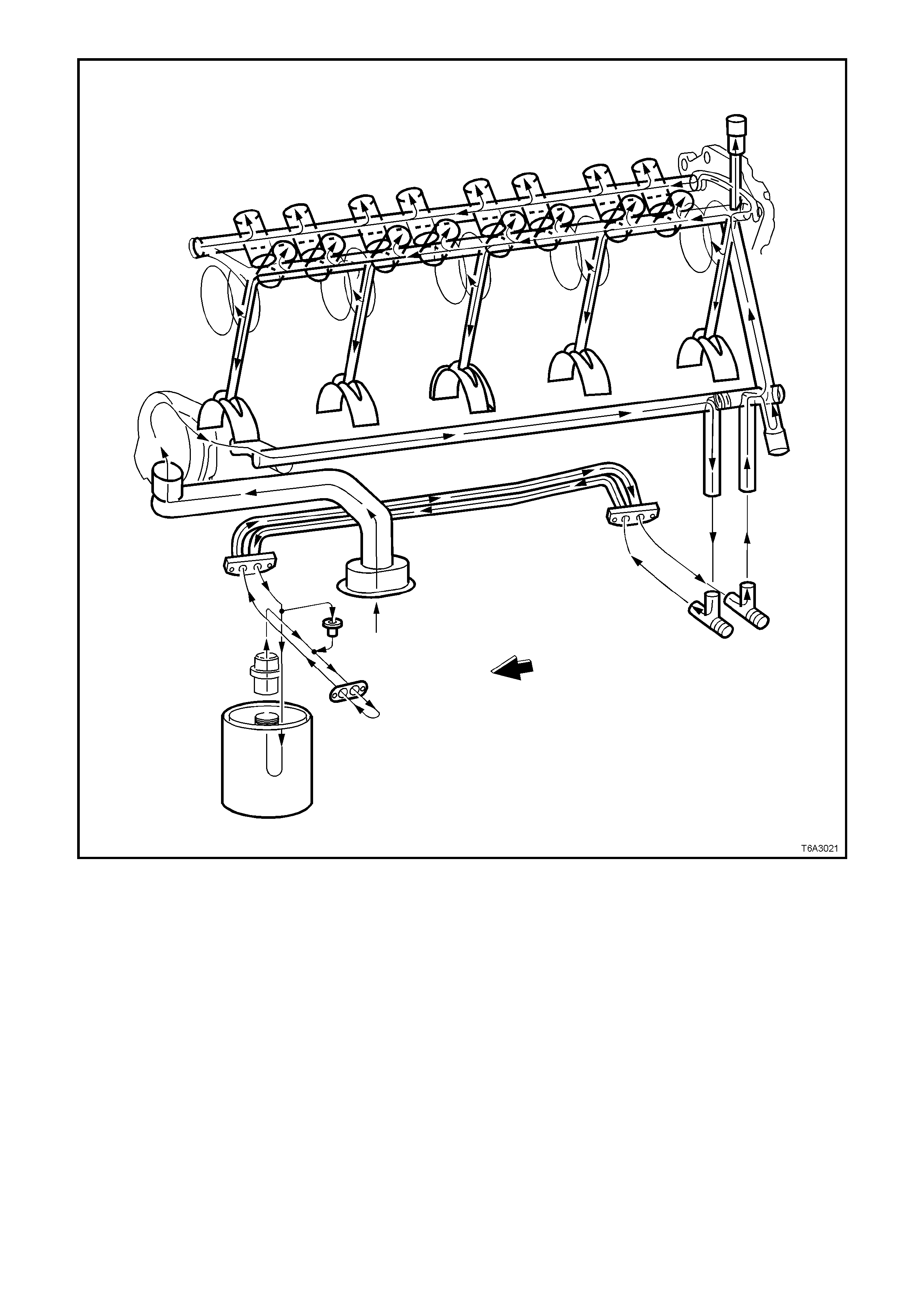
Figure 6A3-22 - Lubrication Flow Schematic
CRANKSHAFT OIL SEALS
The GEN III V8 engine uses a multiple lip
crankshaft rear main oil seal, designed for long life
operation.
The s eal inclu des a PTFE (Teflon®) centre lip (1) to
minim ise a major caus e of rear m ain oil seal leak s.
The anti-friction pr oper t ies of the PT FE r educes the
chances of “chok ing” or build-up of degraded oi l on
the lip (causing the lip to lift off the shaft), resulting
in a leak.
Like the rear main oil seal, the front crankshaft oil
seal also incorporates a PTFE lip.
Service implications for this seal material are that
no lubricant is to be added to the seal lip on
installation, as this will prevent correct ‘break-in’ of
the seal. The PTFE is actually deposited on the
dry crankshaft seal surface during initial operation
by the heat generated from the rotating shaft.
The outs ide of the s eal m ay be lubr icat ed spar ingl y
to ease installation.
Figure 6A3-23
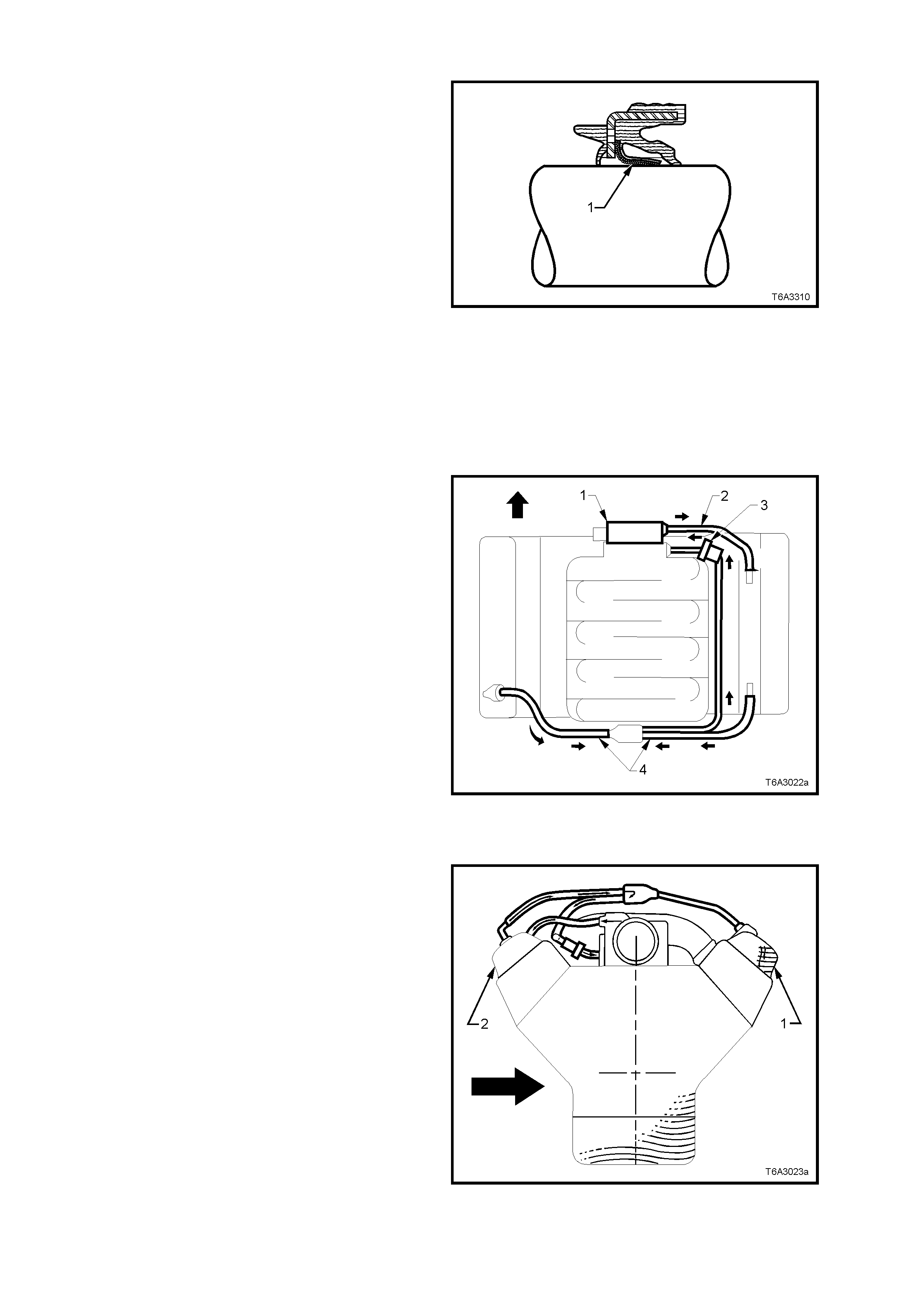
POSIT IVE CR ANKCASE VENT IL ATION SYSTEM
The engine ventilation system was developed to
minimise oil consumption and ensure that oil
ingestion could not occur during severe vehicle
handling manoeuvres.
Filtered fresh air is routed from upstream of the
throttle blade to the front of the right rocker cover
via a formed rubber hose (2). To reduce the
potential of oil pullover into the throttle bore area
due to back flow of the ventilation system, the
fitting in the right side rocker cover is located in a
“quiet” area located between, and shielded from,
the rocker arms. Crankcase blowby gases are
routed fr om the rear of both rocker covers , through
moulded nylon lines to a tee fitting, located on the
centreline of the engine at the rear of the intake
manifold (4). From there, a single hose carries
crankcase vapours throug h an externally mounte d,
horizontal PCV valve (3) and enters the intake
manifold behind the throttle body (1).
The hoses are foam insulated and the PCV valve
(3) is conduction-heated from the cylinder block.
Figure 6A3-24
This “dual draw system” was developed to meet
high ‘g’ forces (bold arrow) incurred during severe
cornering manoeuvr es. Dur ing sust ained m aximum
lateral accelerations, the outboard rocker cover (1)
may fill with oil.
The “dual draw” system “passively switches”,
allowing the PCV v alve to d r aw on th e roc ker c over
with the leas t resistance . This res ults in the s ystem
drawing on the air filled, or inboard, rocker cover
(2) and eliminates oil pullover that would result
from drawing on the oil filled outboard rocker cover.
Sectione d view shown is look ing rear ward from the
engine front.
Figure 6A3-25

1.5 SERVICE NOTES
CLEANLINESS AND CARE
• Throughout this Section, it must be understood that proper cleaning and protection of machined surfaces and
friction areas is a part of the repair procedure. This is considered standard Workshop practice, even if not
specifically stated.
• When any internal engine parts are serviced, care and cleanliness is important.
• W hen components are rem ove d f or se rv ic e, they shou l d be mark ed, or gan is ed or r etain ed in a s pec if ic ord er f or
reassem bly. Refer to Separating Parts.
• At the time of installation, components should be installed in the same location and with the same mating
surface as when removed.
• Any engine is a combination of many machined, honed, polished and lapped surfaces with tolerances that are
measured in hundredths of millimetres. These surfaces should be covered or protected to avoid component
damage.
• A liberal co a tin g of c lean e ngi ne oil s hou ld be ap pl ie d to fric tion areas dur in g ass embl y, as proper lubricati o n wil l
protect and lubricate friction surfaces during the initial engine start-up.
REPL ACING ENG INE G ASKET S
• Re-using gaskets and applying sealants.
− Do not reuse any gasket unless specified.
− Gaskets that can be reused will be identified in the service procedure.
− Do not apply sealant to any gasket or sealing surface unless called out in the service information.
• Separating components
− Use a rubber mallet to separate components.
− Bump the part sideways to loosen the components.
− Bumping should be done at bends or reinforced areas to prevent distortion of parts.
• Cleaning gasket surfaces
− Remove all gasket and sealing material from the part using a plastic or wood scraper (if required).
− Care must be used to avoid gouging or scraping the sealing surfaces.
− Do not use any other method or technique to remove sealant or gasket material from a part.
− Do not use abrasive pads, sand paper, or power tools to clean the gasket surfaces.
∗ These methods of cleaning can cause damage to the component sealing surfaces.
∗ Abrasive pads also produce a fine grit that the oil filter cannot remove from the oil.
∗ This grit is abrasive and has been known to cause internal engine damage.
• Assembling components
− When assembling components, use only the sealant specified or equivalent in the service procedure.
− Sealing surfaces should be clean and free of debris or oil.
− Specific components such as crankshaft oil seals or valve stem oil seals may require lubrication during
assembly.
− Components requir i ng lubric ation will be ide nt if ied in th e servic e proced ur e.
− When applying sealant to a component, apply the amount specified in the service procedure.
− Do not allow the sealant to enter into any blind threaded holes, as it may prevent the bolt from clamping
properly or cause component damage when tightened.
− Only ever tighten bolts to specifications. Do not overtighten.

USE OF RTV AND ANAEROBIC SEALER
IMPORTANT: A number of sealant types are commonly used in engines. Examples are; Room Temperature
Vulcanising (RTV) sealer, anaerobic gasket eliminator sealer, anaerobic thread sealant and pipe joint compound.
The correct sealant and a mount must be used in the specified location to prevent oil leaks. DO NOT interchange
the different types of sealers. Use only the specific sealer or the equivalent as recommended in the service
procedure.
Pipe Joint Compound
• Pipe joi nt com pound is a pliable s ealer th at does n ot com pletel y harden. Th is type of sealer is used where tw o
non-rigid parts (such as pressed steel and machined surfaces) are assembled together.
• Do not use pipe joint compound in areas where extreme temperatures are expected. These areas include:
exhaust manifold, head gasket, or other surfaces where gasket eliminator is specified.
• Follow all safety recommendations and directions that are on the container.
• To remove the sealant or the gasket material, refer to Replacing Engine Gaskets in this Section.
• Apply the pipe joint compound to a clean surface. Use a bead size or quantity as specified in the procedure.
Run the bead to the i ns ide of any bolt ho les . Do not al low the seal er to e nter a ny blind t hr ead ed hol es, as it may
prevent the bolt from clamping properly or cause component damage when the bolt is tightened.
• Apply a continuous bead of pipe joint compound to one sealing surface. Sealing surfaces to be resealed must
be clean and dry.
• Tighten the bolts to specifications. Do not overtighten.
Exam ples of loc atio ns where a pipe s ea la nt type mater ial suc h as Loc tit e 56 5 ( or other c om merc ial equivalen t) is to
be used, are:
• Engine block coolant and oil gallery plugs.
• Oil pressure sensor threads.
• Engine block oil pan surface.
RTV Sealer
• Room T emperature Vulc anising ( RTV) seala nt harden s when expose d to air. T his type of s ealer is used where
two non-rigid parts (such as the intake manifold and the engine block) are assembled together.
• Do not use RT V sealant in areas where ex treme tem peratures are exper ienced. T hese areas incl ude: exhaust
manifold, head gasket, or other surfaces where a gasket eliminator is specified.
• Follow all safety recommendations and directions that are on the container.
• To remove the sealant or the gasket material, refer to Replacing Engine Gaskets.
• Apply RTV to a clean surface. Use a bead size as specified in the service procedure. Run the bead to the
inside of any bolt holes. Do not allow the sealer to enter any blind threaded holes, as it may prevent the bolt
from clamping properly or cause damage when the bolt is tightened.
• Assemble components while RTV is still wet (within 3 minutes). Do not wait for RTV to skin over.
• Tighten bolts to specifications. Do not overtighten.
Anaerobic Sealer
• Anaerobic gasket eliminator or thread sealant, hardens in the absence of air. This type sealer is used where
two rigid parts (s uch as c astings ) ar e ass embled toget her or wher e f as teners ar e subj ec ted to vibr at ion or wh ere
the holes are not blind. When two rigid parts are disassembled and no sealer or gasket is readily noticeable,
the parts were probably assembled using a gasket eliminator.
• Follow all safety recommendations and directions that are on the container.
• To remove the sealant or the gasket material, refer to Replacing Engine Gaskets in this Section.
• Apply a continuous bead of gasket eliminator to one flange or on the bolt/stud thread. All surfaces must be clean
and dry.
• Spread the sealer evenly with your finger to get a uniform coating on the sealing surface.
• Do not allow the sealer to enter an y blind threaded holes, as it m ay prevent the bolt from clamping pr operly or
cause damage when tightened.
IMPORTANT: Anaerob ic s ealed j oi nts that are par t ia lly torqued and a ll o wed to c u re m or e than f ive minutes may
result in incorrect shimming and sealing of the joint.
• Only ever tighten bolts to specification. Do not overtighten.
• After properly tightening the fasteners, remove the excess sealer from the outside of the joint.

Examples where thread locking sealants such as Loctite 242 or Loctite 272 (or other commercial equivalents) are
to be used, are the fasteners for:
• Fuel rail. .................................... ‘242’
• Intake manifold.......................... ‘242’
• Cylinder head M8...................... ‘242’
• Exhaust manifold. ..................... ‘272’
SEPARATING PARTS
IMPORTANT: Many internal engine components will develop specific wear patterns on their friction surfaces. So,
when disassembling the engine, internal components MUST be separated, marked, or organised in a way to
ensure reinstallation to their original location and position.
Separate, mark, or organise the following components:
− Piston and the piston pin.
− Piston to the specific cylinder bore.
− Piston rings to the specific piston.
− Connecting rod to the crankshaft journal.
− Connecting rod to the bearing cap.
− Crankshaft main and connecting rod bearings.
− Camshaft and valve lifters.
− Valve lifters, guides, pushrods, pivot supports and rocker arms.
− Valve to the valve guide.
− Valve spring and shim to the cylinder head location.
− Engine block main bearing cap location and direction.
− Oil pump drive and driven gears.
TO OL S AND EQUIPM ENT
Special tools are listed and illustrated throughout this Section with a complete listing at the end of the Section.
These tools (or their equivalents) are specially designed to quickly and safely accomplish the operat ions for which
they are intended. The use of these special tools will also minimise possible damage to engine components.
Some precision measuring tools are required for inspection of certain critical components. Torque wrenches and
torque angle tools are necessary for the proper tightening of various fasteners.
To properly service the engine assembly, the following items should be readily available:
− Approved eye protection and safety gloves.
− A clean, well-lit, wor k area.
− A suitable parts cleaning tank.
− A compressed air supply.
− Trays or storage containers to keep parts and fasteners organised.
− An adequate set of hand tools.
− Approved engine repair stand.
− An approved engine lifting device that will adequately support the weight of the components.
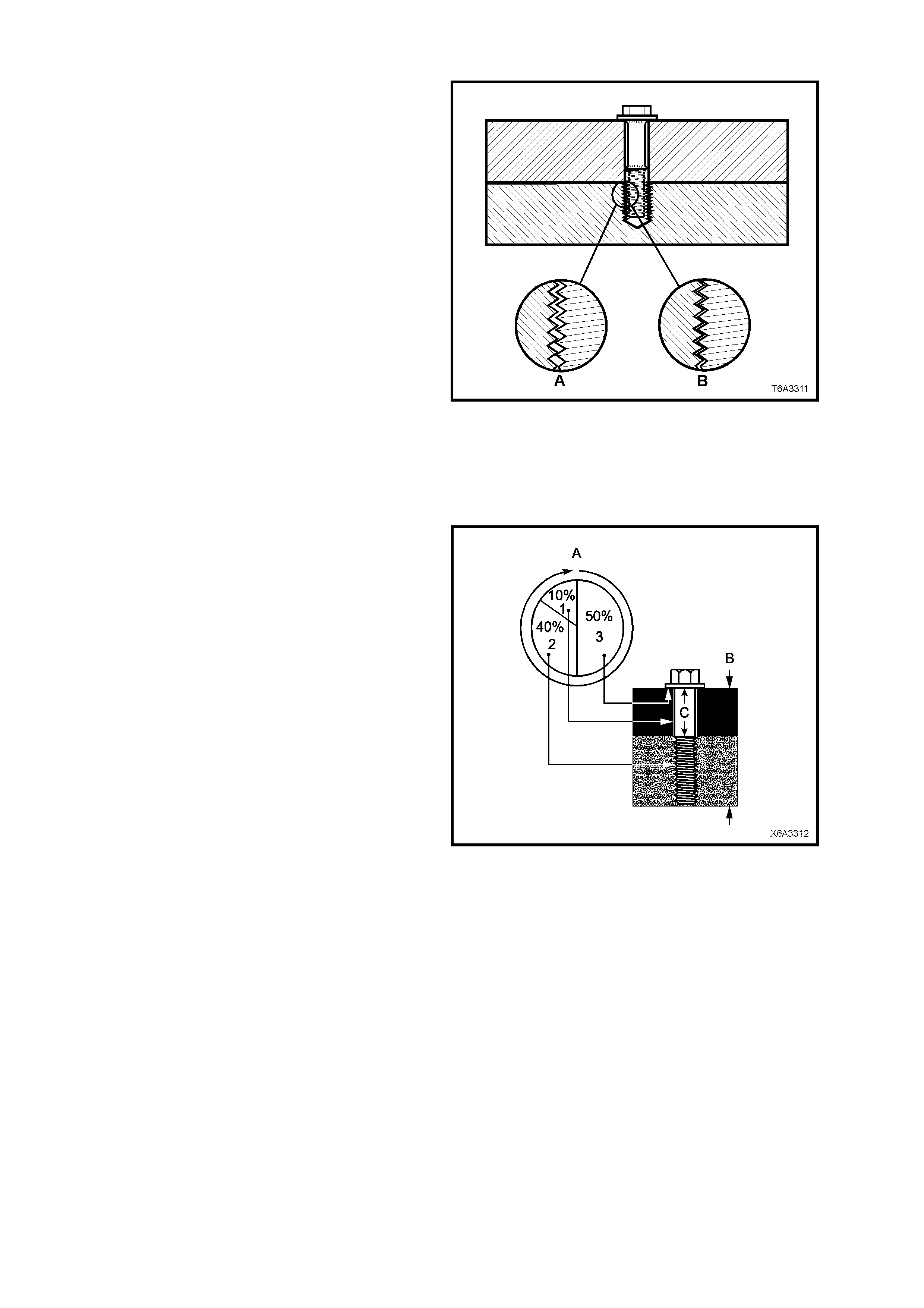
FASTENERS
Fasteners are central to the reliable operation of
any engine and the GEN III V8 engine is no
exception.
Whenever any bolt or any other threaded
component is removed from the engine, it is
necessary to first allow the engine to cool (inset ‘B’)
before attempting fastener removal.
Because of the greater thermal expansion of
aluminium , bolt threads will change dimension to a
greater ext ent when hot with this materia l (ins et ‘ A’)
when compared to cast iron.
If a bolt or other threaded component is removed
before the engine is allowed to cool to at least 50°
C, threads could be pulled from the cylinder block
or cylinder head.
Also, DO NOT use impact tools to remove bolts
during engine disassembly. While this may be
common practice with cast iron engine
components, use of these tools is more likely to
pull the aluminium threads in the cylinder block or
head of this engine.
Figure 6A3-26
Clamp Load
When torque is applied to a fastener, the fastener
stretches and the joint compresses. The force
develope d in the fas tener d ue to its stretc h is cal le d
tension (‘C’), while the force applied to the joint is
call ed “clamp load” (‘B’).
As shown, only a small portion of the applied
torque (‘A’) is transferred to the clamp load (inset
‘1’). Friction under the bolt head (inset ‘3’) and in
the threads (inset ‘2’) absorbs much of the applied
torque (‘A’). Typically, only 10% (inset ‘1’) of the
torque is a vailabl e to deve lop str etch (or tension) i n
the fastener and clamp load in the joint.
Therefore, a slight variation in friction in the thread
or under th e b olt he ad, r es ults in a wide v ariat io n i n
the clamp load applied to the joint.
Torque Angle and Torque to Yield Fasteners
The torque angle method of applying torque to a
fastener has been developed to overcome the
effects of friction variation in fastener applications.
The application of the torque angle method does
not always mean that the fastener has to be
replaced after loosening. It is only when the
fastener has been angle tightened to the extent
that the “yield” point has been exceeded, that the
fastener must be replaced.
Examples in the GEN III V8 engine are the main
bearing caps that are angle tightened but the bolts
can be re-used, whereas the M11 cylinder head
bolts that ar e “Torque to Yi eld” fastener s, MUST be
replaced after loosening.
Figure 6A3-27

2. MINOR SERVICE OPERATIONS
2.1 ENGINE OIL LEVEL CHECK
1. Engine must be at normal operating temperature (drive the vehicle for 15 minutes).
2. Park vehicle on level surface (as this will affect the accuracy indicated on dipstick:- this is a critical
requirement).
3. Do not check oil level for at least 10 minutes after engine shut down to allow oil to drain back into the oil pan.
4. Remove dipstick and wipe clean.
5. Reinstall dipstick, with the “ADD/FULL” marks facing towards the centre of the engine, ensuring that it is fully
seated. After leaving for several seconds, slowly remove to avoid smearing, then hold horizontally to avoid oil
running alo ng dipstick .
6. Observe the oil level where it passes over the centre line of the dipstick.
7. W hen topping up th e engin e oil, al low appr oximatel y 15 m inutes for the oil added to f ully dra in into t he oil pan.
Alternatively, add 55 ml of oil for each millimetre below the “FULL” mark on the dipstick.
2.2 ENGINE OIL - CHANGE
NOTE 1: Quicker and more complete draining will occur if the engine oil is at operating temperature. However, care
must be taken to avoid scalding from the hot oil.
NOTE 2: W hile the oil pan is alum inium, it is fitted with a s teel thread inser t to incr ease durabi lity of the thr ead and
to avoid thread tearing when the drain plug is removed from a hot engine
NOTE 3: It is also recommended that the oil filter is changed at each engine oil change, refer
2.3 ENGINE OIL FILTER & ADAPTOR, in this Section.
1. Raise the engine hood and remove the oil fill cap.
2. Raise the vehicle front and rear to maintain a level attitude and support with safety stands. This is to ensure
complete draining. Refer to Section 0A GENERAL INFORMATION.
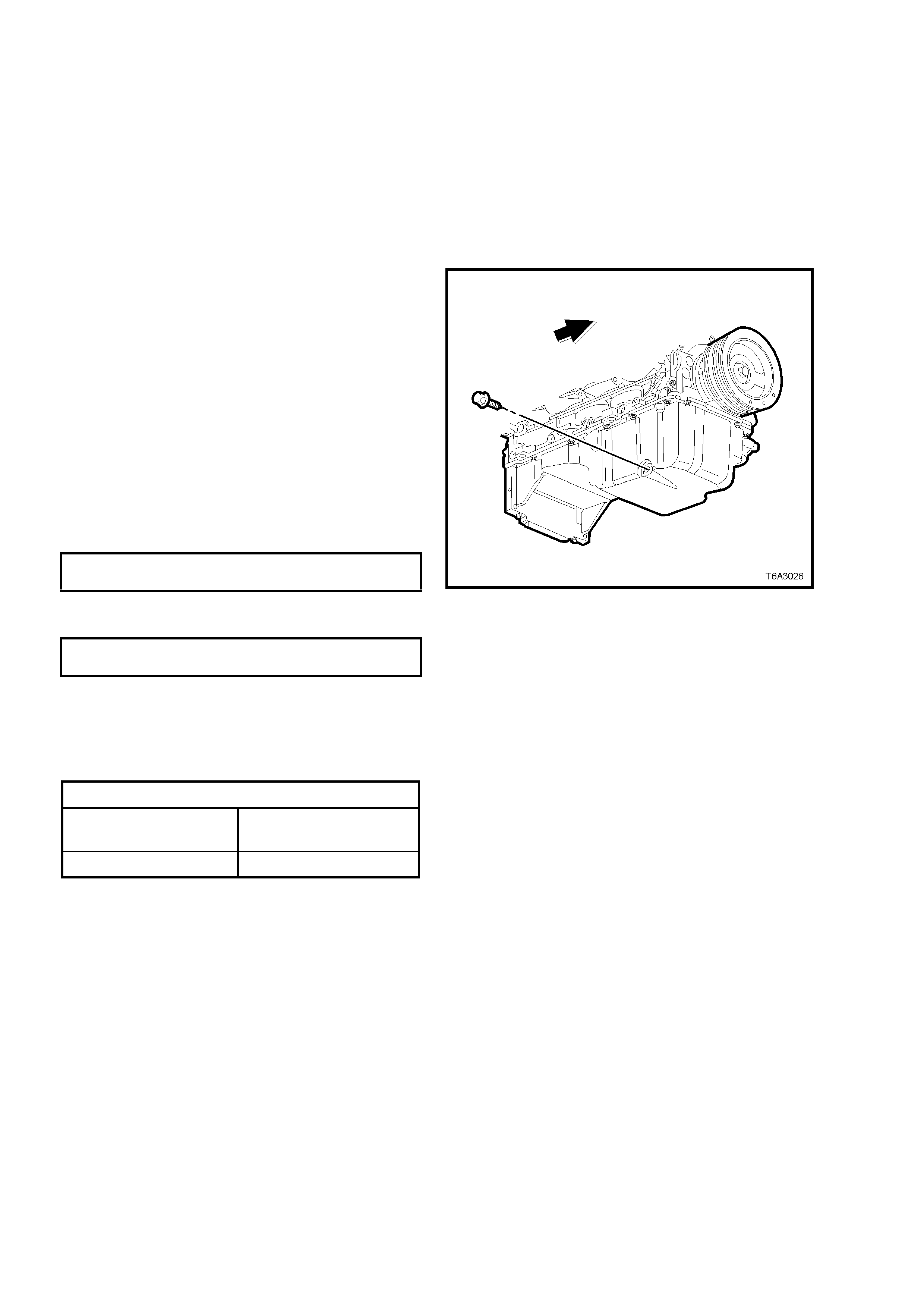
3. Remove the four bolts securing the oil pan
under-tray.
4. Clean any foreign material from around the oil
pan drain plug.
5. Place an oil drain tray beneath the engine.
6. Using a 15 mm ring s p ann er, r emove t he drai n
plug, tak ing care to avoid sc alding with the hot
waste oil.
7. When the oil has drained sufficiently, reinstall
the drain plug, after inspecting and cleaning
the threads and inspecting the magnetic plug
end for ferrous m aterial. The drain plug O-ring
seal may be re-used if not cut or damaged.
Tighten the drain plug to the correct torque
specification.
ENGINE OIL PAN DRAIN PLUG
TORQUE SPECIFICATION 25 Nm
8. Reinstall the oil pa n under-tra y and tighten th e
four bolts to the correct torque specification.
OIL PAN UNDER-TRAY BOLT
TORQUE SPECIFICATION 32 Nm
9. Lower the vehicle and fill the crankcase with
the required am ount of 10W 30 SJ ILSAC GF2
engine oil.
NOTE: If this oil is unavailable, a 20W50 SJ or
15W/40 SJ engine oil should be used.
Figure 6A3-28
ENGINE OIL CAPACITY
Without Oil Filter
Change 5.2 litres
With Oil Filter Change 5.7 litres
NOTE: Synthetic oils of this viscosity are also an
acceptab le eng in e lubr icant.
10. Start the engine and check for oil leaks.
2.3 ENGINE OIL FILTER & ADAPTOR
LT Section No. – 01-500
NOTE: The oil filter should be replaced at the time or distance intervals, specified in the Owner’s Handbook or
whenever the engine oil is changed.
REPLACE
1. Raise the engine hood and remove the oil fill cap.
2. Raise the vehicle front and rear to maintain a level attitude and support with safety stands. This is to ensure
complete draining. Refer to Section 0A GENERAL INFORMATION.
3. Remove the four bolts securing the oil pan under-tray.
4. Drain the engine oil as detailed in 2.2 ENGINE OIL - CHANGE, in this Sec ti on.
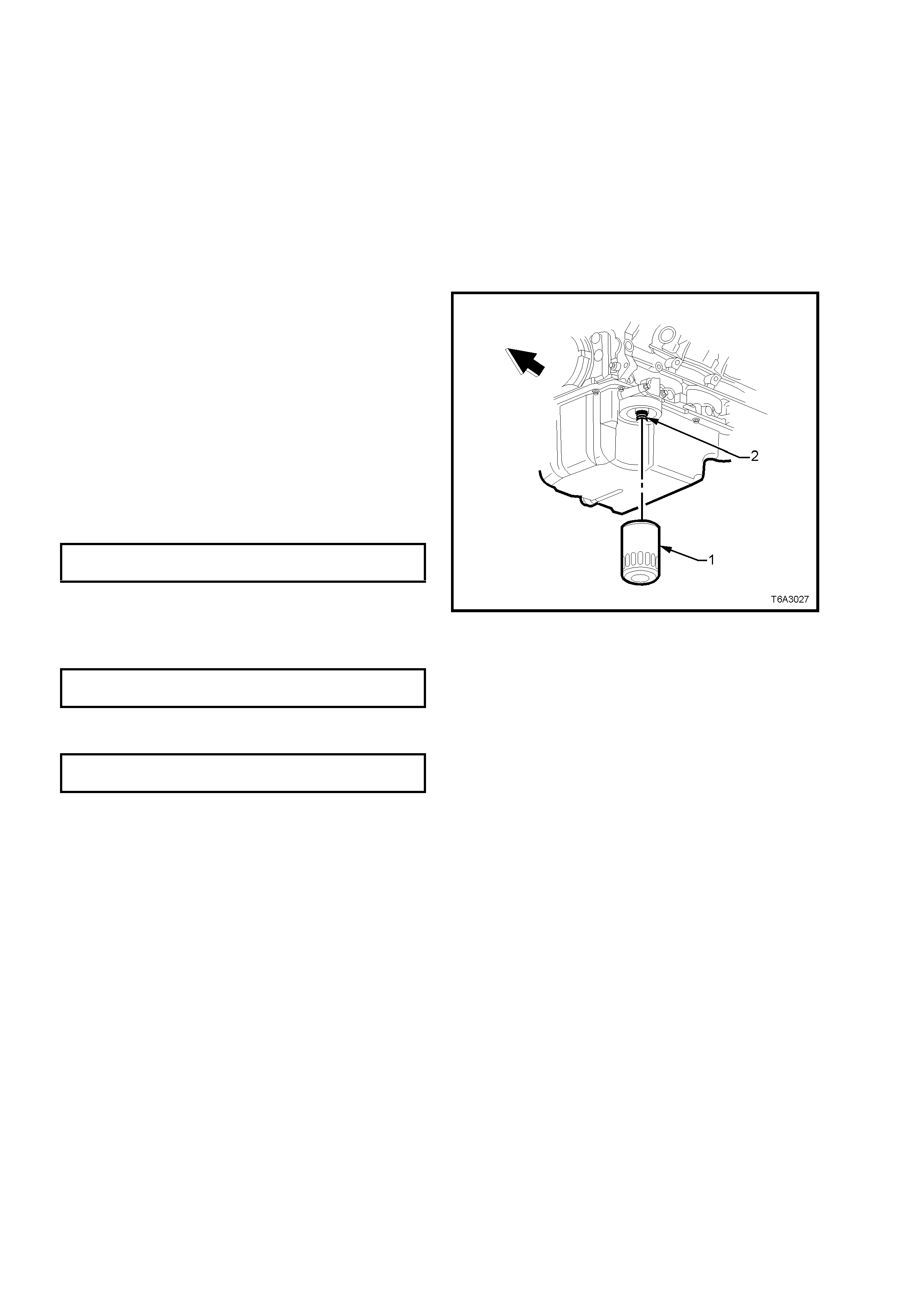
5. Remove the oil filter (1), using a commercially
available tool, taking care to avoid being
scalded wit h the hot waste oil .
6. Should it be required, remove the oil filter
adaptor (2) from the oil pan filter mounting
flange, using a suitable socket.
7. After checking that the filter seal has not
adhered to the oil pan flange, inspect the oil
filter sealing surface for scratches or other
damage and c heck the oil f ilter ad aptor t hreads
for damage.
8. If removed, reinstall the oil filter adaptor and
tighten to the correct torque specification.
OIL FILTER ADAPTOR
TORQUE SPECIFICATION 55 Nm
9. Sm ear some new engine oil o nto the new filter
seal, then install filter assembly to engine.
10. Tighten oil filter to the correct torque
specification.
ENGINE OIL FILTER
TORQUE SPECIFICATION 30 Nm
11. Reinstall the oil pan under-tray and tighten the
four bolts to the correct torque specification.
OIL PAN UNDER-TRAY BOLT
TORQUE SPECIFICATION 30 Nm
12. Lower the vehicle and fill the crankcase with
the required amount of recommended, new
lubricant. Refer to 2.2 ENGINE OIL –
CHANGE, in this Sec ti on f or the r ec om mended
procedure.
13. Start the engine and check for oil leaks.
Figure 6A3-29
2.4 ENGINE OIL PRESS URE - CHECK
1. Ensur e that en gi ne is at op er atin g t emperatur e.
Driving a cold vehicle for 15 minutes, should be
sufficient to normalise the temperature.
2. Remove oil filter; refer 2.3 ENGINE OIL
FILTER & ADAPTOR, in this Section.
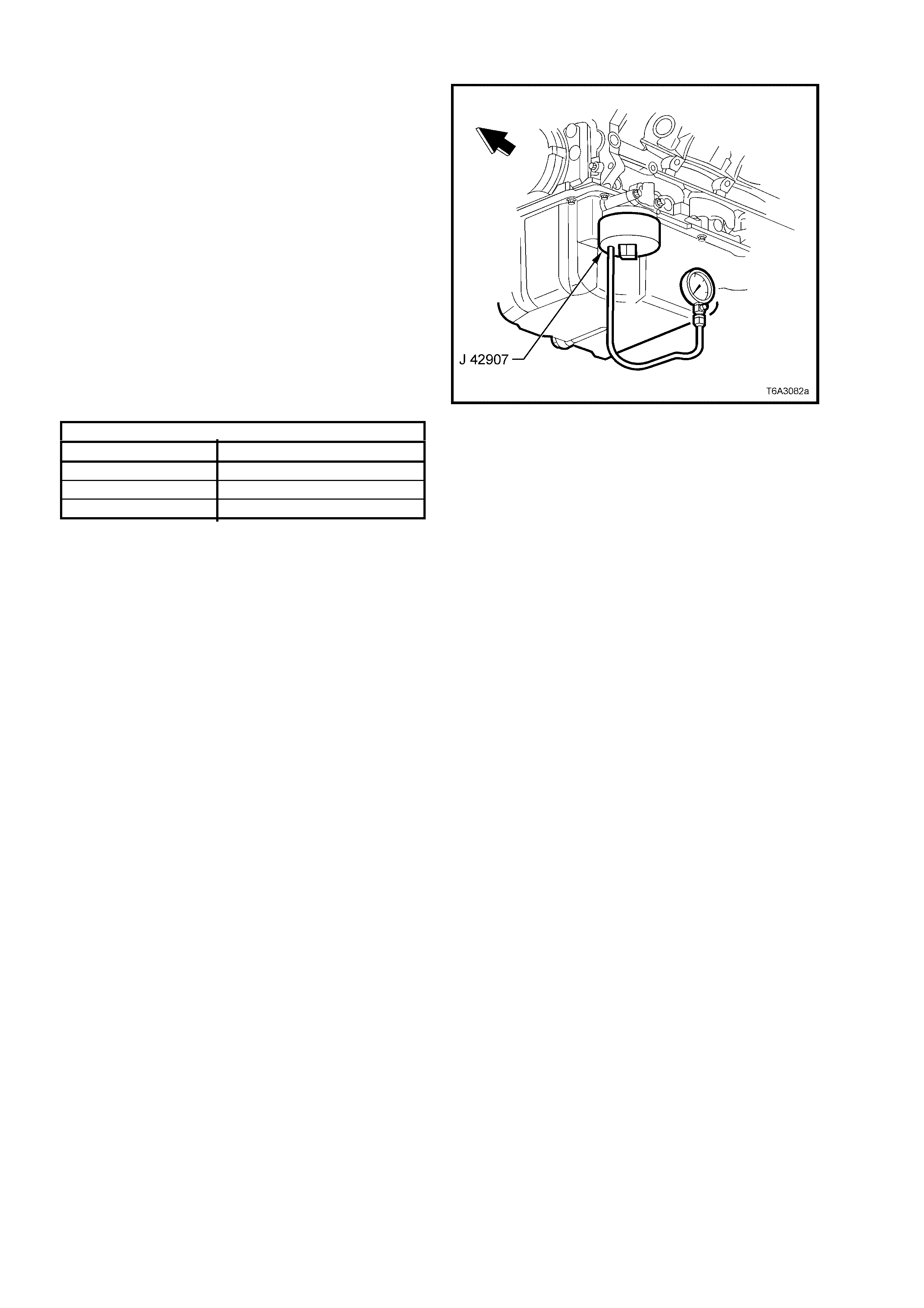
3. Install adaptor J 42907 to the oil filter adaptor.
4. On a level surface, check engine oil level and
top up as re quired. Refer to 2. 2 ENG INE O IL –
CHANGE, in this Section.
5. Install commercially available, accurate oil
pressur e gau ge (c ap ab le of r eading 800 kPa or
higher) and suitably rated pressure hose, to
adaptor J 42907.
6. Start the engine and check the oil pressure
with the engin e runnin g with no load.
7. Check that the oil pressure is within the
following specifications.
ENGINE OIL PRESSURE SPECIFICATION
ENGINE SPEED OIL PRESSURE READING
1,000 rpm 90 kPa (Minimum, Hot)
2,000 rpm 125 kPa (Minimum, Hot)
4,000 rpm 165 kPa (Minimum, Hot)
NOTE: If the oil pressure check indicates that the
oil pressure is not to specification, then refer to
4.5 OIL PRESSURE DIAGNOSIS, in this Section.
Figure 6A3-30
8. After completing the pressure check, stop the engine and remove the oil pressure gauge and adaptor
assembly.
9. Install the oil filter. Refer 2.3 ENGINE OIL FILTER & ADAPTOR, in this Sec t ion.
10. Top up engine oil level as required.
2.5 COMPRES SION CHECK
1. Before conducting this check, ensure that the:
a. Battery is at or near a full state of charge.
c. Spark plugs are all removed.
d. Throttle plate is held wide open.
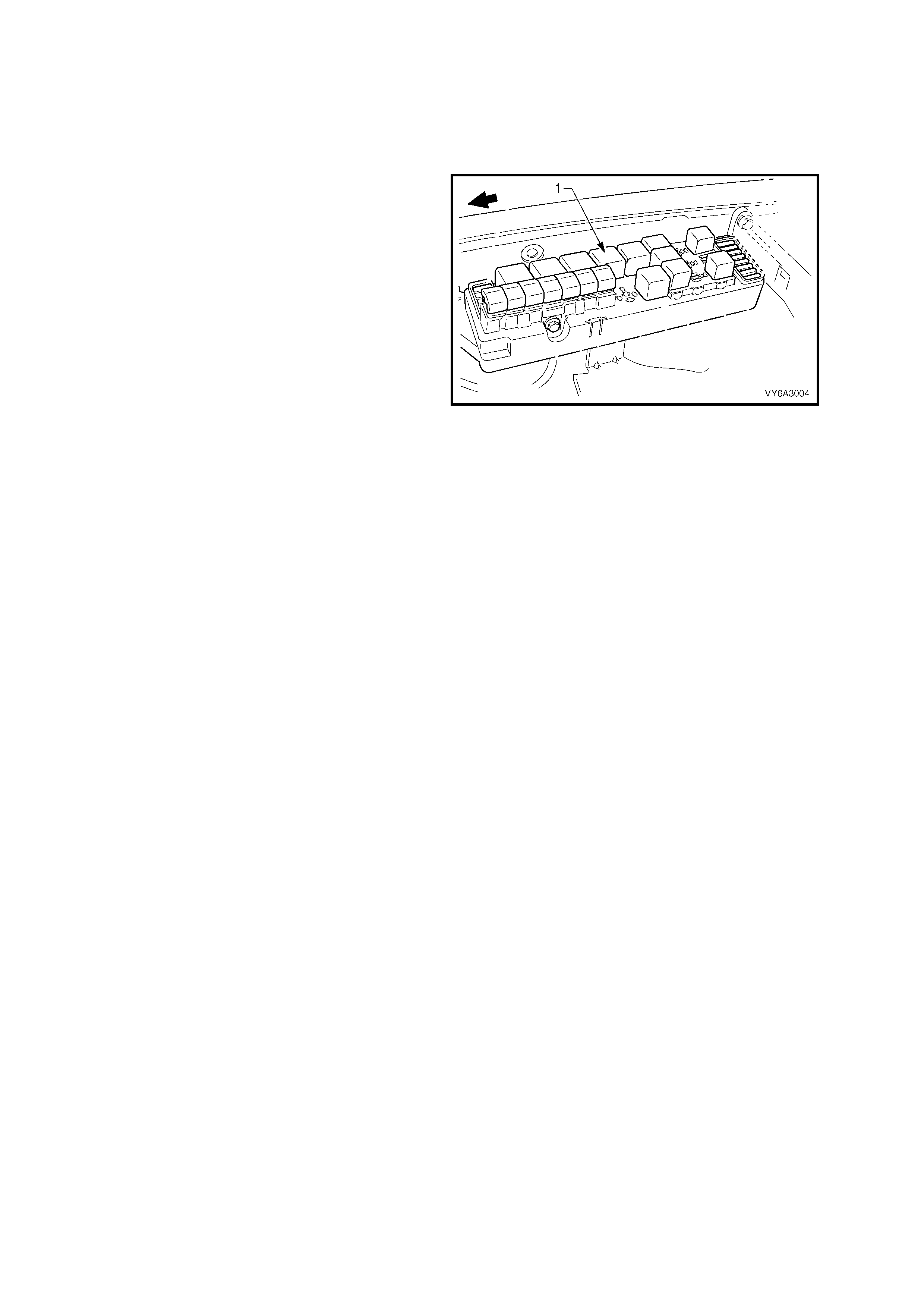
2. With the ignition switched OFF, disable the
ignition system and fuel injectors, by removing
the Engine Control (EFI) relay X4, located in
the underhood electrical centre.
3. Install a suitable, commercially available and
accurate, compression tester, that has been
reset to zero.
4. Crank the engine through approximately four
compression strokes (four ‘puffs’). Record the
reading.
5. Repeat this compression check for each
cylinder. Ag ai n, recor d each readin g.
6. If a cylinder has low compression, inject about
15 ml (one tablespoon) of engine oil into the
combustion chamber through the spark plug
hole.
7. Recheck the compression and record the
reading.
Figure 6A3-31
INTERPRETING COMPRESSION READINGS
The minimum compression in any one cylinder should not be less than 70% of the highest cylinder. No cylinder
should read less than 690 kPa. For example, if the highest pressure in any one cylinder is 1035 kPa, the lowest
allowable pressure for any other cylinder would be 725 kPa. (1,035 x 70% = 725).
NORMAL - Compression builds up quickly and evenly to the specified compression for each cylinder.
PISTON RINGS LEAKING - Compression is lo w on the first stroke. Compression then builds up with the following
strokes but does not reach normal. Compression improves considerably when you add oil.
VALVES LEAKING - Compression is low on the first stroke. Compression usually does not build up on the following
strokes. Compression does not improve much when you add oil.
CYLINDER HEAD GASKET LEAKING - If two adjacent cylinders have lower than normal compression and
injecting oil into the cylinders does not increase the compression, the cause may be a head gasket leaking
between the cylinders.
2.6 ENGINE DRIV E BELTS – REPLACE
LT Section No. – 01-003
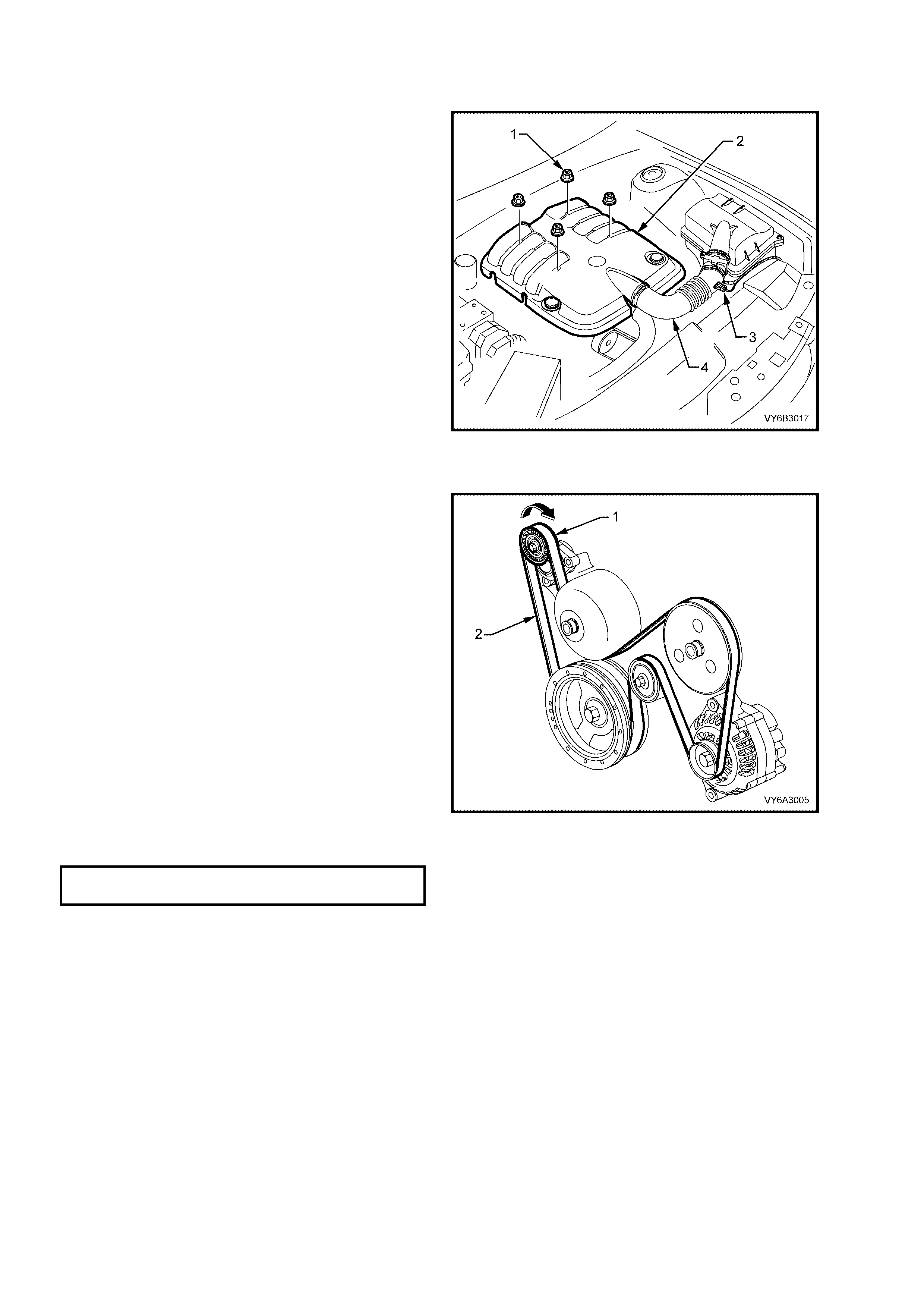
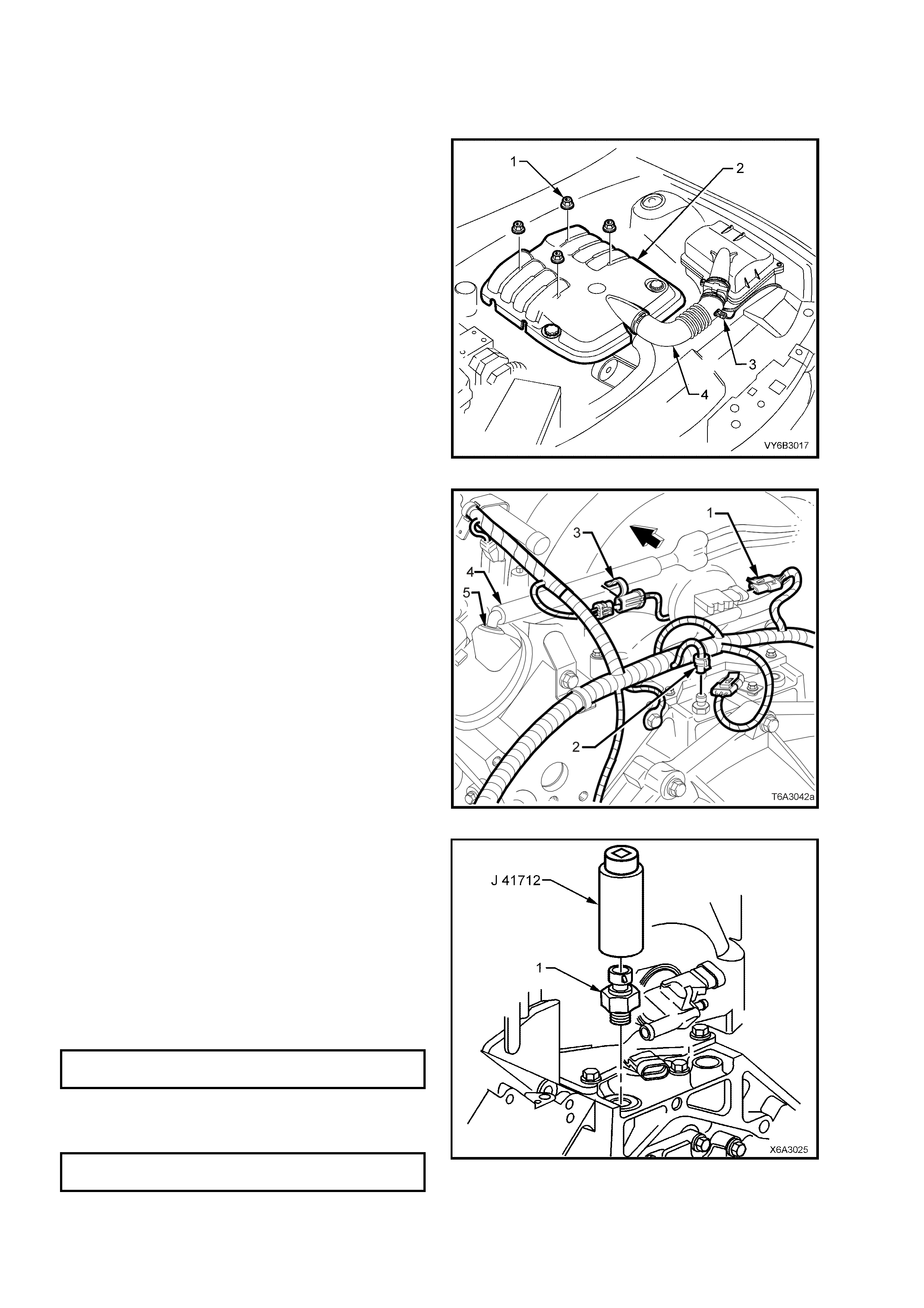
1. Remove the four engine dress cover
decorative nuts (1), then remove the dress
cover (2) from the engine.
2. Remove the air intake sensor wiring harness
connector (3), then loosen both hose clamps
securing t he int ak e hose (4 ) to the MAF s ensor
and the throttle body. Remove the hose (4)
from the engine.
Figure 6A3-32
ENGINE ACCESSORY DRIVE BELT
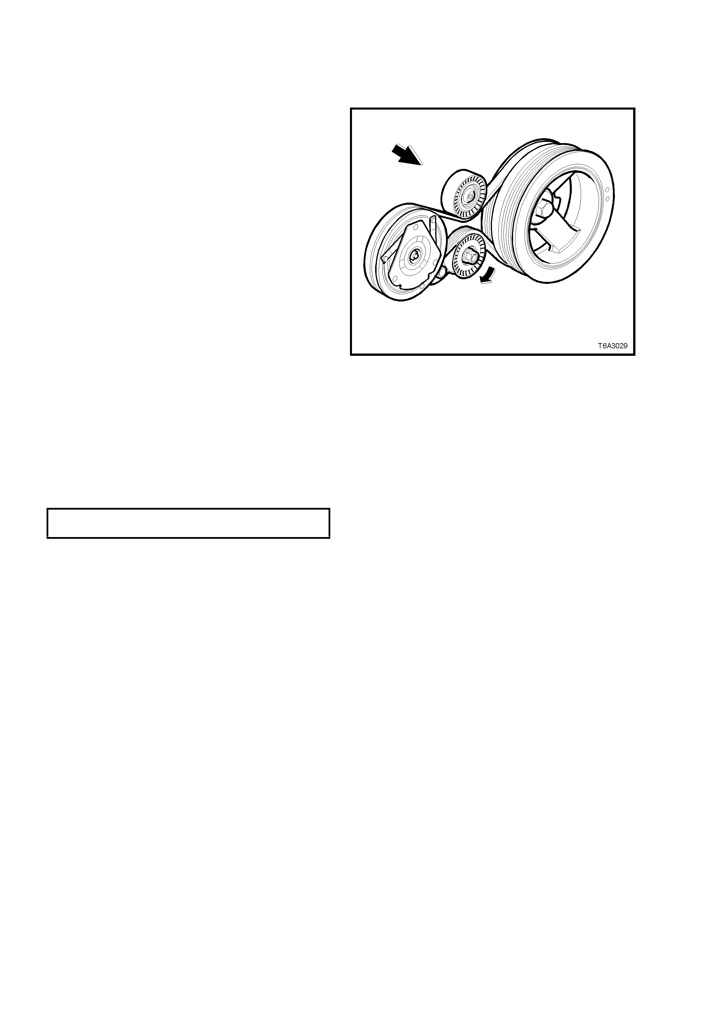
1. Using a 15 mm ring spanner, rotate the
acces sory autom atic drive belt tensioner ( 1), in
the direction indicated, to reduce belt tension.
2. While holding the tensioner in the reduced
tension position, remove the accessory drive
belt (2), taking note of the belt routing.
NOTE: Use an assistant to maintain the tensioner
in the required position.
3. Clean the accessory drive belt running
surfaces and inspect the belt for damage.
4. While rotating the accessory drive belt
tensioner (1) in the direction indicated, install
the drive belt (2) over the pulleys, routing the
belt correctly, as shown.
5. Inspect the i nstallat ion to ens ure that the b elt is
correctly aligned on all pulleys.
6. Reinst all the engine dr ess cover, securing with
the four decorative nuts and tightening to the
correct torque specification.
ENGINE DRESS COVER NUT
TORQUE SPECIFICATION 10 Nm
7. Start the eng ine to ensure corr ec t operat ion .
Figure 6A3-33
A IR CONDITIONING COMPRESSOR BELT
NOTE: The accessory drive belt must be removed
first to allow access to this belt. Refer to the
previous operation for details.
1. Raise the vehicle and support with safety
stands. Refer to Section 0A GENERAL
INFORMATION.
2. Remove the four bolts securing the oil pan
under-tray.
3. From under the vehicle, rotate the A/C drive
belt tensioner in the direction shown, using a
15 mm set spanner, to relieve belt tension.
4. While using an assistant to maintain the
tensioner in the required position, remove the
drive belt from the pulleys.
NOTE: An alternative to using an assistant, would
be to secure the spanner using tie wire.
5. Clean the A/C drive belt running surfaces and
inspect the belt for damage.
6. While holding the A/C drive belt tensioner in
the direction indicated, install the drive belt
over the pulleys, routing the belt correctly, as
shown.
7. Inspect the i nstallat ion to ens ure that the b elt is
correctly aligned on all pulleys.
8. Reinstall the accessory drive belt as described
in the previous operation.
9. Start the eng ine to ensure corr ec t operat ion .
10. Reinstall the oil pan under-tray and tighten the
bolts to the correct torque specification.
OIL PAN UNDER-TRAY BOLT
TORQUE SPECIFICATION 30 Nm
11. Lower the vehicle and test for correct
operation.
Figure 6A3-34
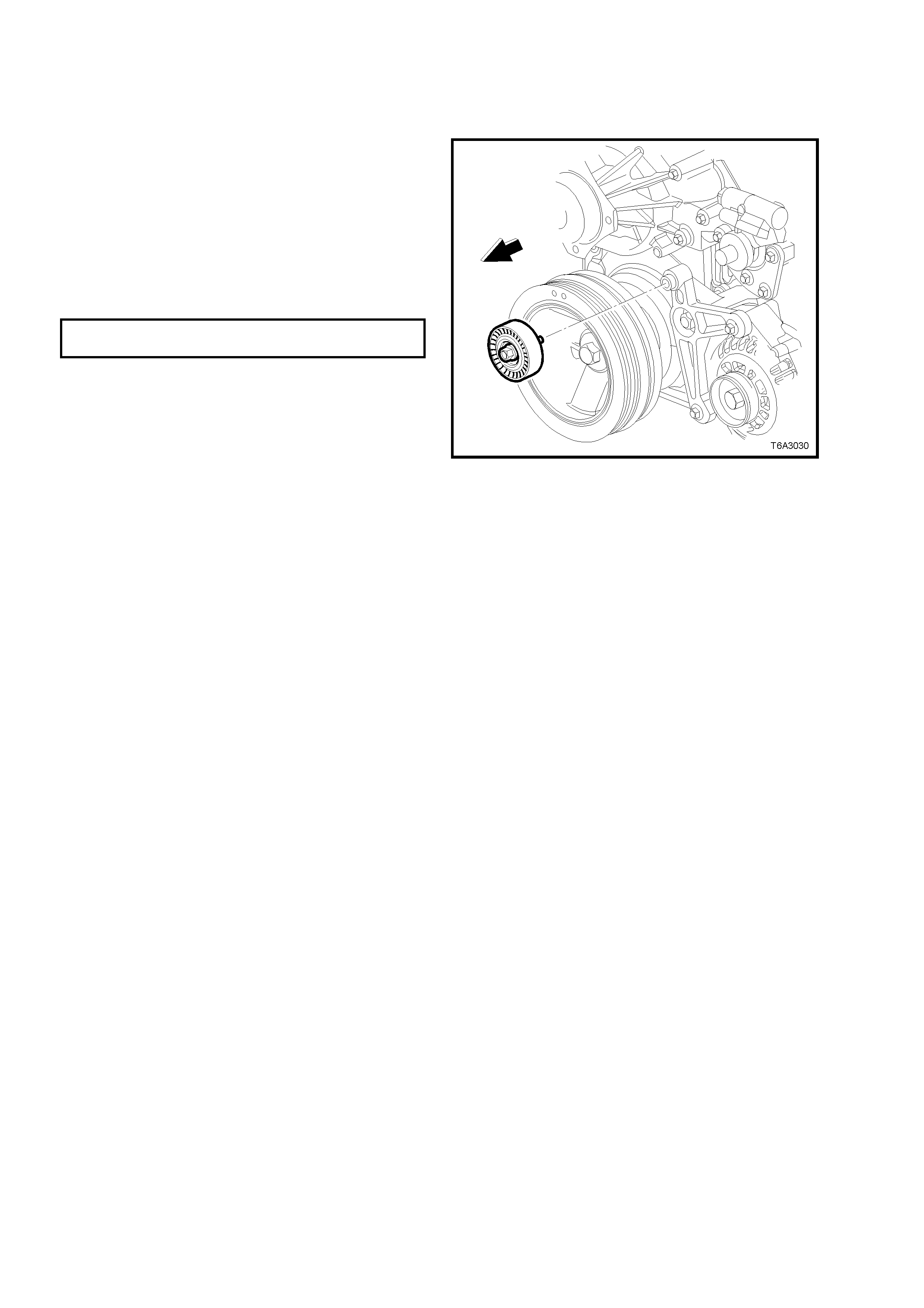
2.7 ACCESSORY BELT IDLER PULLEY
LT Section No. – 01-020
REPLACE
1. Remove the e ngine acces sory drive belt . Refer
to 2.6 ENG INE DRIV E BELT S – REPL ACE, in
this Section for the necessary procedure.
2. Remove the idler pulley retaining bolt, then
remove the pulley from its mounting boss, on
the generator mounting bracket.
3. Install the idler pulley to its mounting boss.
4. Install the idler pulley retaining bolt and t ighten
to the correct torque specification.
ACCESSORY BELT IDLER PULLEY
TORQUE SPECIFICATION 50 Nm
5. Install t he engin e acces sor y driv e bel t. Ref er to
2.6 ENGINE DRIVE BELTS – REPLACE, in
this Section for the necessary procedure.
Figure 6A3-35
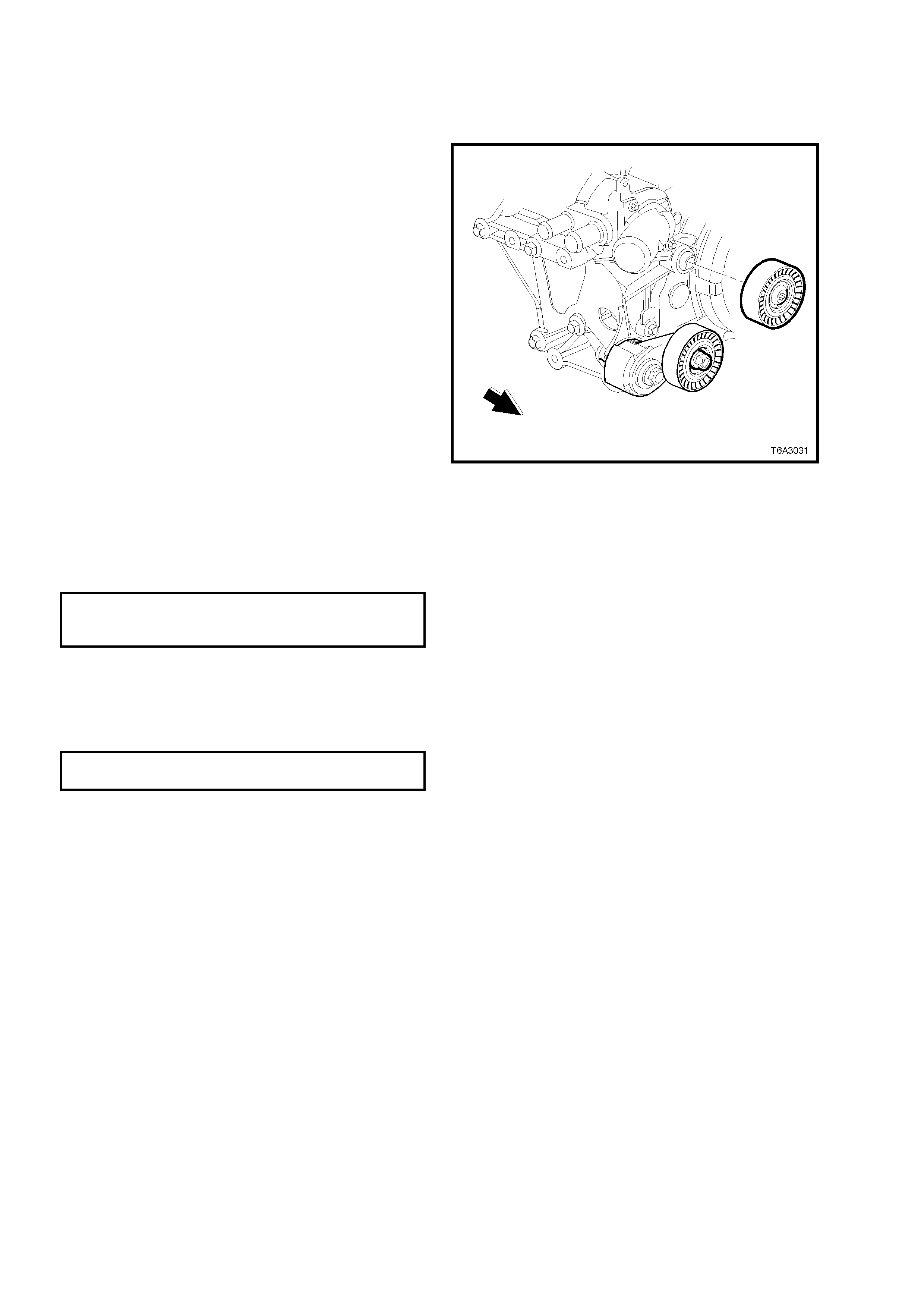
2.8 A/C BELT IDLER PULLEY
LT Section No. – 01-020
REPLACE
1. Raise the vehicle and support with safety
stands. Refer to Section 0A GENERAL
INFORMATION.
2. Remove the four bolts securing the oil pan
under-tray.
3. From under the vehicle, rotate the A/C drive
belt tensioner in the direction shown in Figure
6A3-34, using a 15 mm set spanner, to relieve
belt tension.
4. While using an assistant to maintain the
tensioner in the required position, remove the
drive belt from the pulleys but leave hanging on
the crankshaft pulley.
NOTE: An alternative to using an assistant, would
be to secure the spanner using tie wire.
5. Using a commercially available Torx bit T50,
remove the bolt securing the A/C compressor
drive belt idler pulley to its mounting boss on
the coolant pump housing, then remove the
pulley assembly.
6. Install the idler pulley to its mounting boss.
7. Install the idler pulley retaining bolt and t ighten
to the correct torque specification.
A/C COMPRESSOR BELT
IDLER PULLEY BOLT
TORQUE SPECIFICATION 50 Nm
8. Install the A/C compressor drive belt. Refer to
2.6 ENGINE DRIVE BELTS – REPLACE, in
this Section for the necessary procedure.
9. Reinstall the oil pan under-tray and tighten the
bolts to the correct torque specification.
OIL PAN UNDER-TRAY BOLT
TORQUE SPECIFICATION 30 Nm
10. Lower the vehicle and test for correct
operation.
Figure 6A3-36
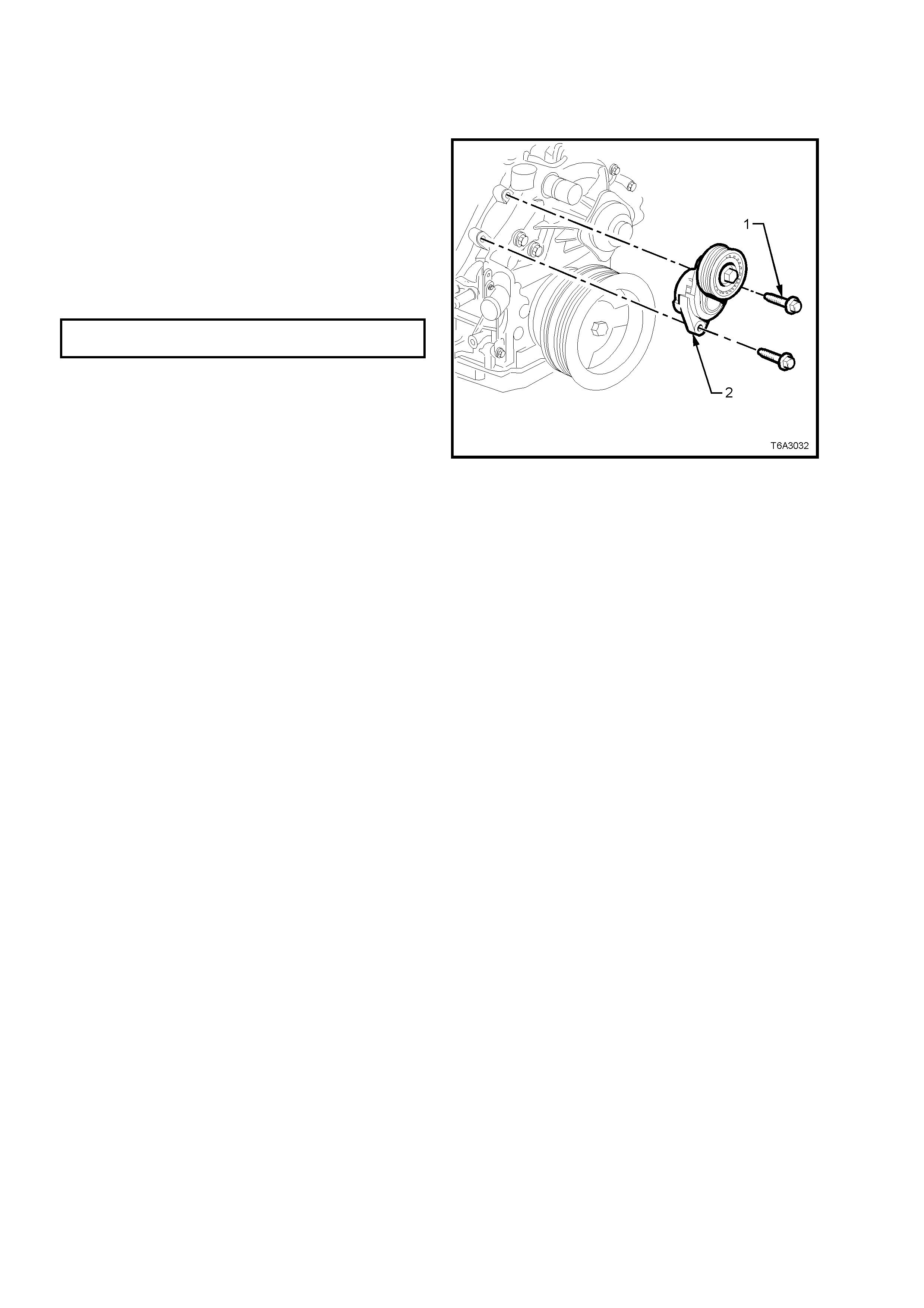
2.9 ACCESSORY BELT TENSIONER
LT Section No. – 01-020
REPLACE
1. Remove the e ngine acces sory drive belt . Refer
to 2.6 ENG INE DRIV E BELT S – REPL ACE, in
this Section for the necessary procedure.
2. Remove the tensioner pulley bracket retaining
bolts (1), then remove the assembly (2).
3. Install the tensioner assembly (2) and the two
mounting bolts.
4. Tighten both mounting bolts (1) to the correct
torque specification.
ACCESSORY BELT TENSIONER
BOLT TORQUE SPECIFICATION 50 Nm
5. Install t he engin e acces sor y driv e bel t. Ref er to
2.6 ENGINE DRIVE BELTS – REPLACE, in
this Section for the necessary procedure.
Figure 6A3-37
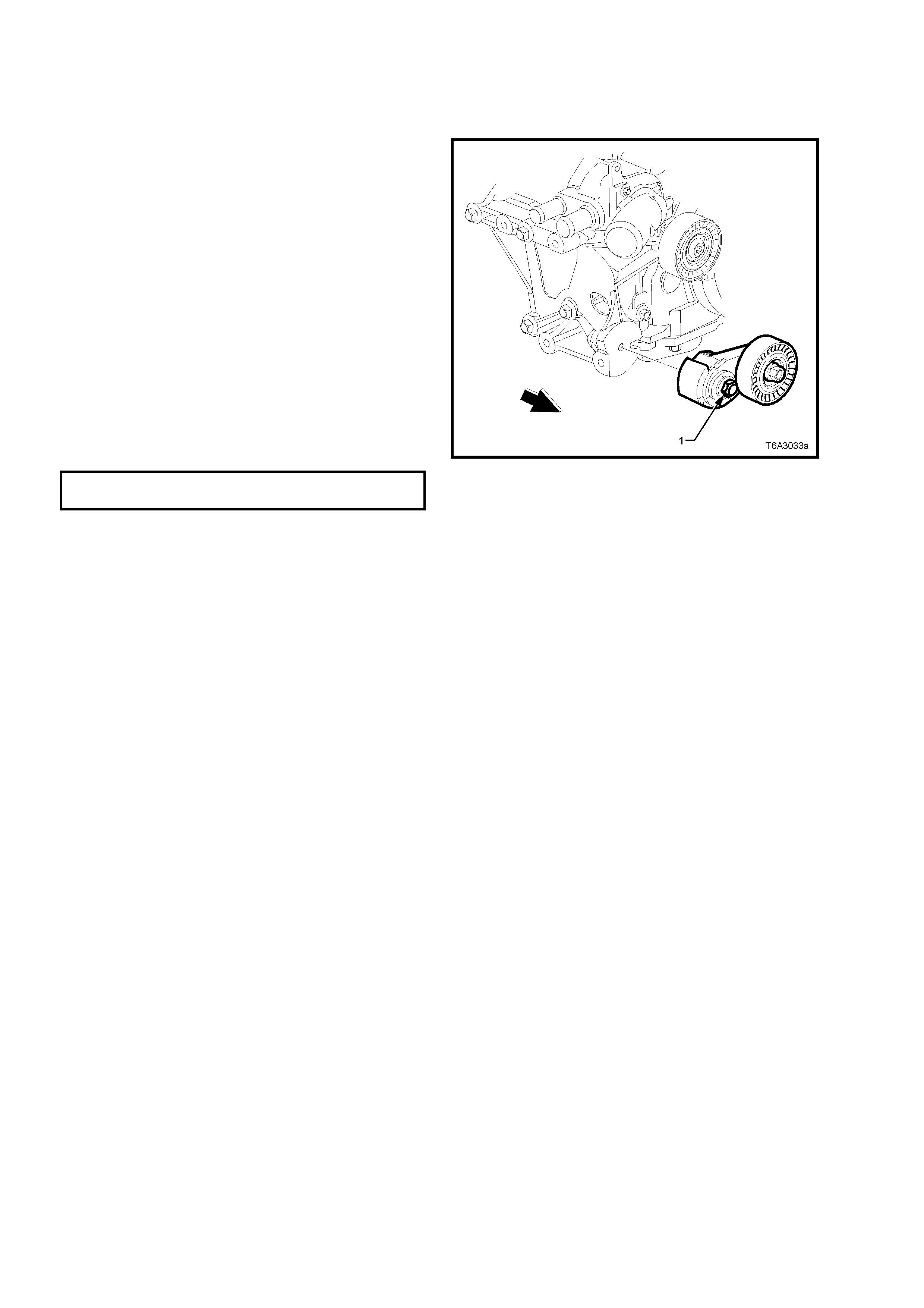
2.10 A/C BELT TENSIONER
LT Section No. – 01-020
REPLACE
1. From under the vehicle, rotate the A/C drive
belt tensioner in the direction shown in Figure
6A3-34, using a 15 mm set spanner, to relieve
belt tension.
2. While using an assistant to maintain the
tensioner in the required position, remove the
drive belt from the pulleys but leave hanging on
the crankshaft pulley.
NOTE: An alternative to using an assistant, would
be to secure the spanner using tie wire.
3. Remove the bolt (1) securing the A/C
compressor drive belt tensioner, then remove
the assembly.
4. Install the tensioner assembly and the
mounting bolt.
5. Tighten the tensioner mounting bolt to the
correct torque specification.
A/C COMPRESSOR BELT TENSIONER
BOLT TORQUE SPECIFICATION 25 Nm
6. Install the A/C compressor drive belt. Refer to
2.6 ENGINE DRIVE BELTS – REPLACE in
this Section for the necessary procedure.
Figure 6A3-38
2.11 OIL PRESSURE SENSOR
LT Section No. – 02-000
REPLACE
1. Remove the four engine dress cover
decorative nuts (1), then remove the dress
cover (2) from the engine.
Figure 6A3-39
2. Release the wiring harness connector locking
tang from the oil pres sure s ensor, then r emove
the connector (2) from the sensor.
Figure 6A3-40
3. Using Tool N o. J 41712 and suitab le 3/8” dri ve
socket equipment, remove oil pressure sensor
(1) from the left hand rear of the engine
cylinder bl oc k.
4. Prior to reinstallation apply Loctite 565 sealant
(or equivalent) to the cleaned oil pressure
sensor threads.
5. Reinstall the oil pressure sensor (1) and tighten
with Tool No. J 41712 and suitable 3/8” drive
socket equipment, to the correct torque
specification.
OIL PRESSURE SENSOR
TORQUE SPECIFICATION 20 Nm
6. Reinst all the engine dr ess cover, securing with
the four decorative nuts and tightening to the
correct torque specification.
ENGINE DRESS COVER NUT
TORQUE SPECIFICATION 10 Nm
7. Start the eng ine to ensure corr ec t operat ion .
Figure 6A3-41
2.12 MANIFOLD ABSOLUTE PRESSURE SENSOR
LT Section No. – 02-000
REPLACE
1. Remove the four engine dress cover
decorative nuts (1), then remove the dress
cover (2) from the engine.
Figure 6A3-42
2. Release the wiring harness connector locking
tang (1) from the manifold absolute pressure
(MAP) se nsor , then rem ove the c onnec tor f rom
the sensor.
Figure 6A3-43
3. Grasp the MAP sensor (1) at the rear of the
intake manifold and twist back and forth while
pulling upward, to remove.
4. Check the silicone rubber seal (2) on the MAP
sensor to ensure it is not torn or damaged.
5. Reinstall the MAP sensor by pushing it down,
into the fitting at the rear of the intake manifold.
6. Reinstall the wiring harness connector to the
MAP sens or, ensur ing that the locking t ab is in
place.
7. Reinst all the engine dr ess cover, securing with
the four decorative nuts and tighten to the
correct torque specification.
ENGINE DRESS COVER NUT
TORQUE SPECIFICATION 10 Nm
8. Start the eng ine to ensure corr ec t operat ion .
Figure 6A3-44
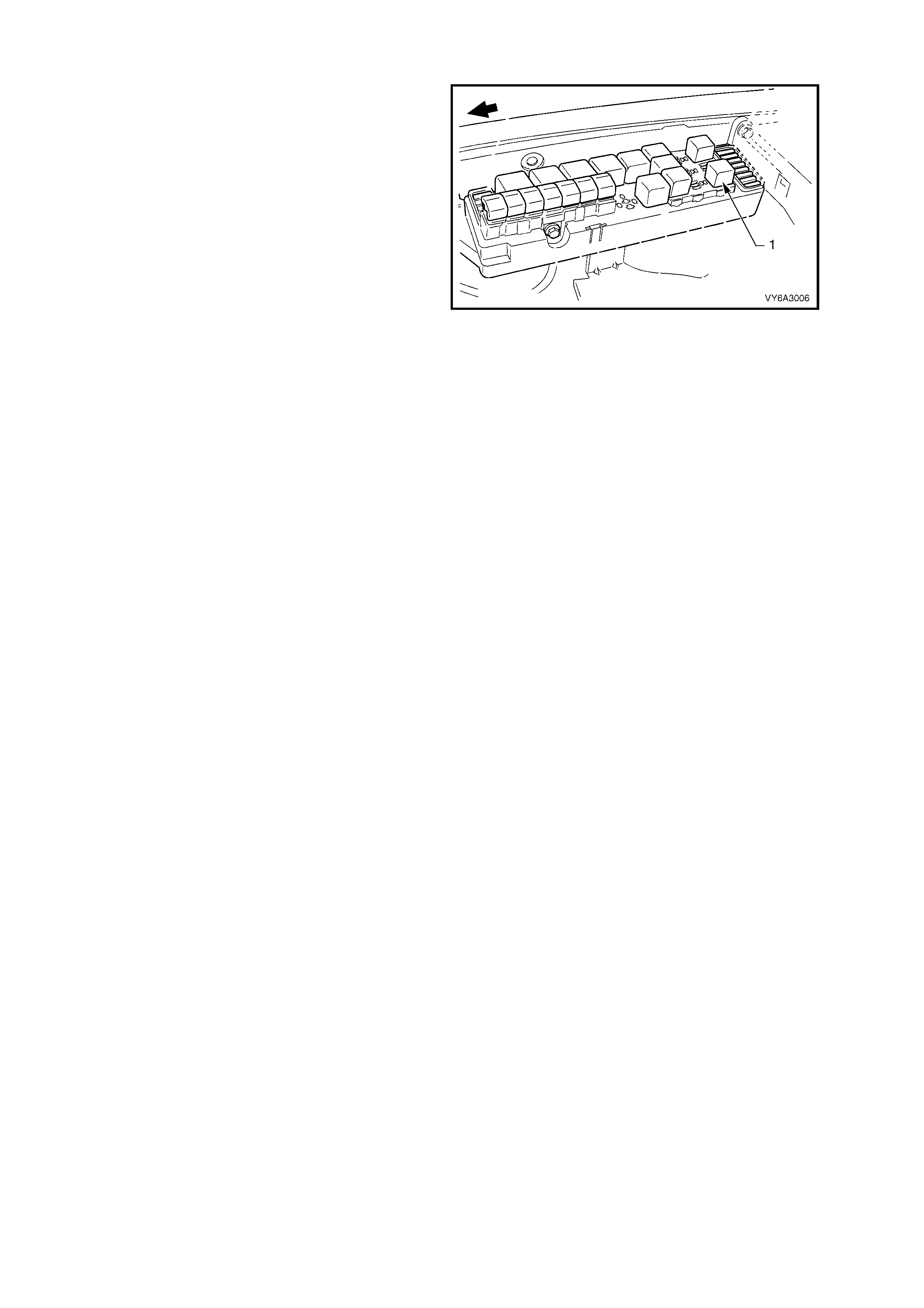
2.13 FUEL SYSTEM PRESSURE RELIEF
1. After removing the cover from the underhood
electrical centre, remove the fuel pump relay,
X16 (1).
2. With the throttle closed, crank the engine.
NOTE: The engine m ay start and run until the fuel
supply remaining in the fuel delivery system is
burned.
3. When the engine stops, re-engage the starter
motor for 10 seconds to ensure that the line
pressure has been fully relieved.
4. Reinstall the fuel pump relay, taking care that
the wiring harness relay connector is not
dislodged and that the relay is fully installed.
CAUTION: Unless this procedure is followed
before servicing the fuel lines or fuel
connections, fuel spray into the engine
compartment could occur!
Figure 6A3-45
2.14 INTAKE MANIFOLD
LT Section No. – 00-375
REMOVE
NOTE: Unless components such as the throttle body, fuel injection rail and/or injectors are to be removed
individually, then it is recommended that the com plete intake manifold assembly be rem oved, as described in this
service operation.
1. Disconnect the ground cable from the battery.
IMPORTANT: Disconnection of the battery affects certain vehicle electronic systems. Refer to
Section 00 CAUTIONS, 5. BATTERY DISCONNECTION PROCEDURES befor e disc onn ec tin g the battery.
2. Drain the cooling system. Refer to Section 6B3 ENGINE COOLING - GEN III V8 ENGINE.
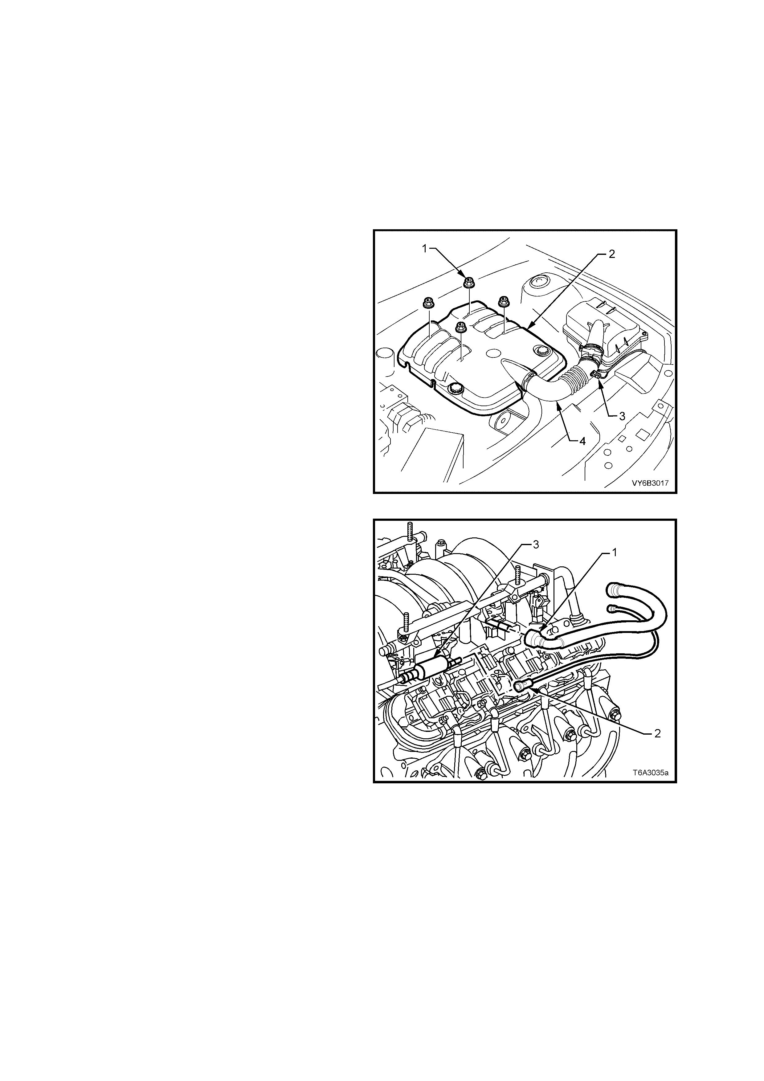
3. Remove the four engine dress cover
decorative nuts (1), then remove the dress
cover (2) from the engine.
4. Remove the air intake sensor wiring harness
connector (3), then loosen both hose clamps
securing the intake duct (4) to the MAF sensor
and the throttle body. Remove the duct (4)
from the engine.
5. De-pressurise fuel rail. Refer to
2.13 FUEL SYSTEM PRESSURE RELIEF, in
this Section.
Figure 6A3-46
6. Using quick connect release Tool No. 7371
(not shown in Figure 6A3-47), install over fuel
line .
7. While holding the fuel line quick connect (1),
push on Tool 7371 to release the quick
connect fitting (1) from the fuel rail. Pull back
on the quick connect and remove.
8. Disconnect the vapour line connector (2) from
the EVAP purge valve (3).
IMPORTANT: Cap the fuel line fittings and plug the
holes after separating the fuel lines to prevent fuel
leaking and/or dirt and other contaminants from
entering the fuel system.
Figure 6A3-47
9. Disconnect wiring harness connector (1) from
the Intake Air Control (IAC) motor, at the
throttle body (3).
10. Disconnect the wiring harness connector (2)
from the Throttle Position (TP) sensor at the
throttle body (3).
Figure 6A3-48
11. Disconnect the cruise control cable (1) (if fitted) from the stud (2) on the throttle body valve lever (3), then
remove the outer cable (8) from the retainer bracket (4). Refer Figure 6A3-49.
12. Lift the throttle cable (5) from the clip at the f uel rail crossover pipe (6), then lift the cable (5) from the retainer
bracket (4).
13. Remove the inner throttle cable (7) from the throttle body valve lever (3).
14. Set the cable/s to one side.
Figure 6A3-49 – (RHD Shown, LHD Similar)
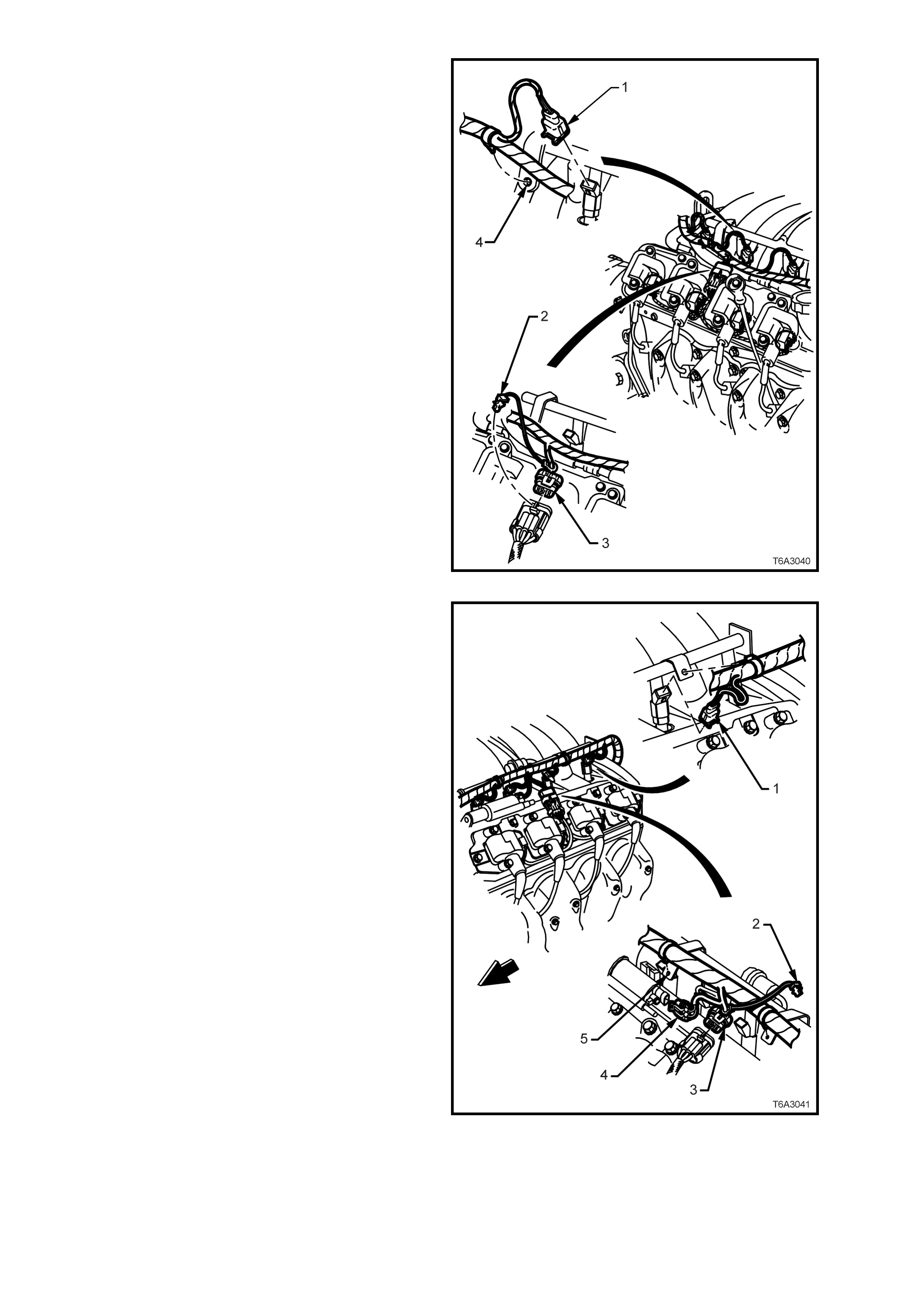
15. Disconnect the fuel injector wiring harness
connectors (1) from the right bank of fuel
injectors (4 places).
16. Remove the CPA lock (2) from the ignition coil
main connector (3) on the right hand side,
remove the connector (3), then the harness
securing clips from the fuel rail brackets (4)
and set the harness to one side.
Figure 6A3-50
17. Disconnect the fuel injector wiring harness
connectors (1) from the left bank of fuel
injectors (4 places).
18. Remove the CPA lock (2) from the ignition coil
main connector (3) on the left hand side, then
remove the wiring harness connector (3).
19. Remove the wiring harness c onnector from the
canister purge valve (4).
20. Remove the harness securing clips from the
fuel rail br ackets ( 5) and set the harness to on e
side.
Figure 6A3-51
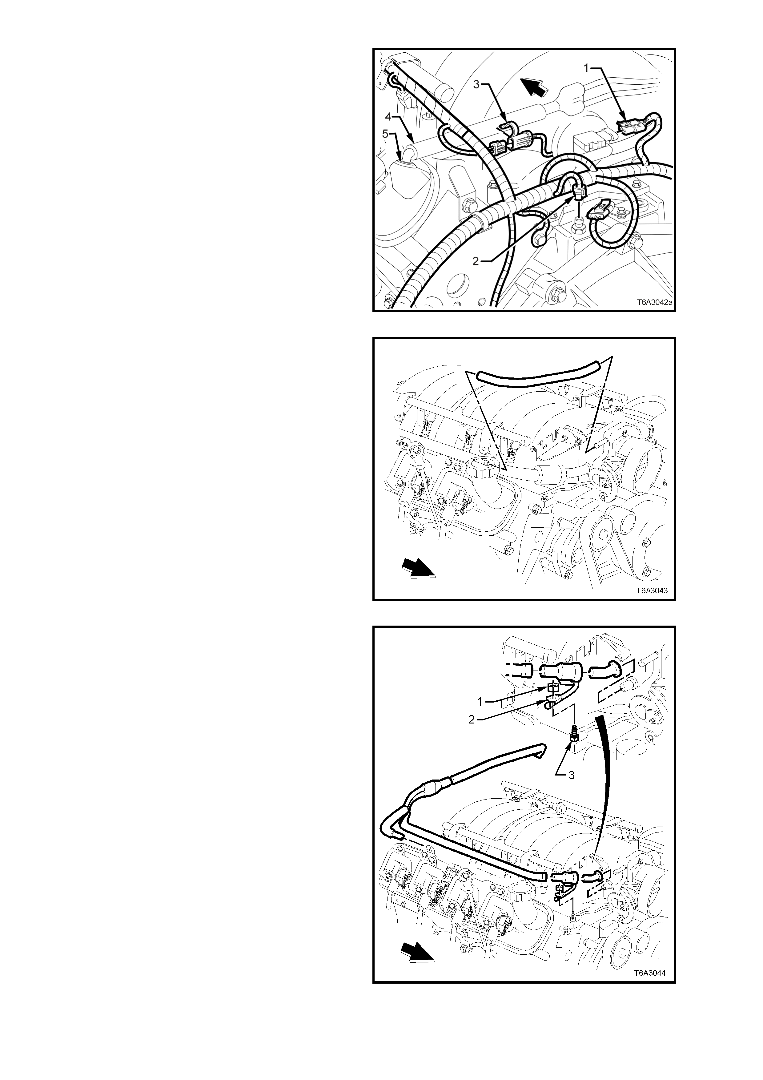
21. Disconnect the wiring harness connector (1)
from the MAP sensor , loc ated at t he rear of the
intake manifold.
22. Remove the knock sensor patch harness
connector retaining clip (3) from the PCV hose
and disconnect the wiring harness connector.
23. Remove the PCV hose (4) from the PCV vent
valve grommet (5) (left bank).
Figure 6A3-52
24. Remove the f resh air hose from the front f itting
of the rocker cover and the throttle body.
Figure 6A3-53
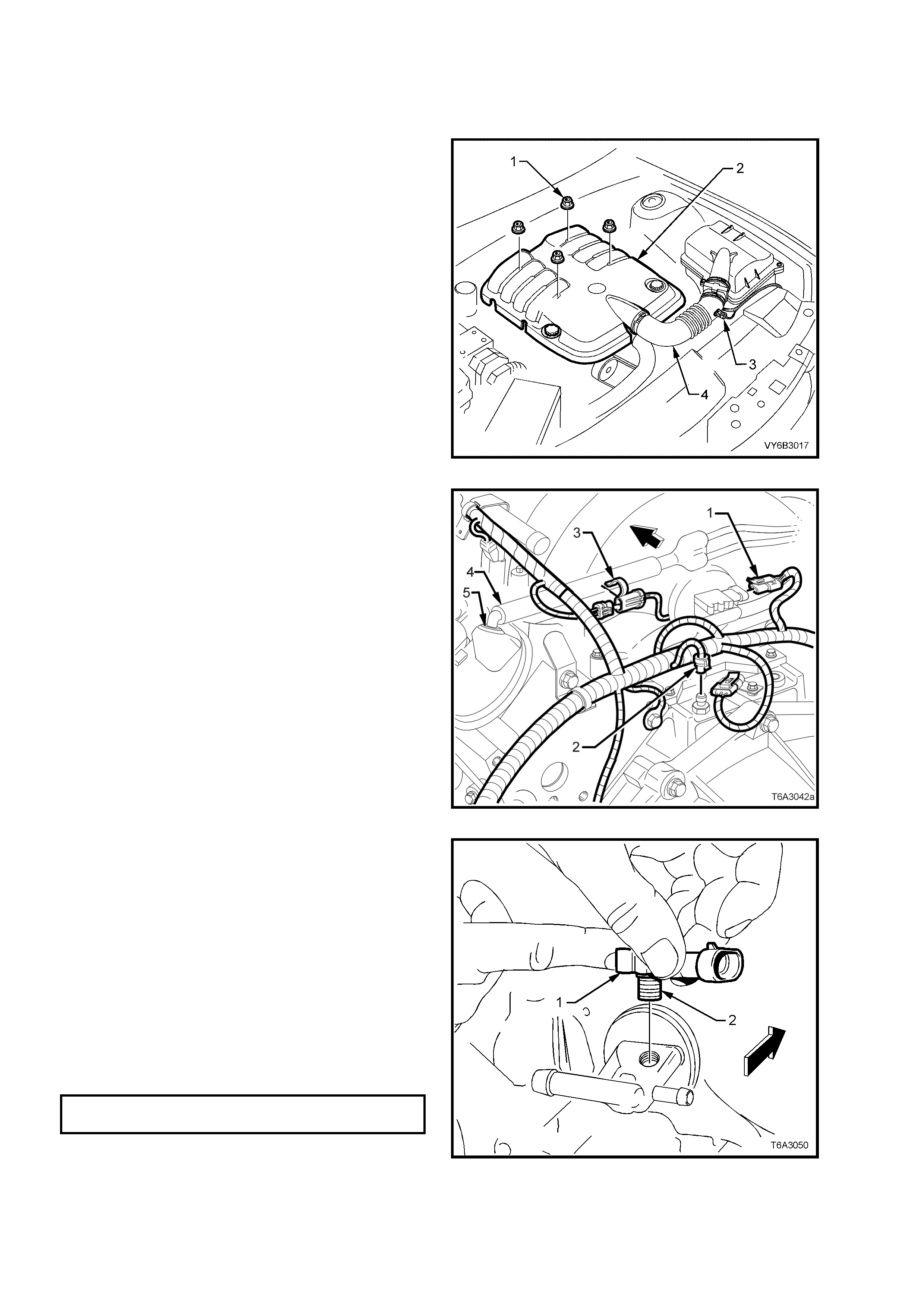
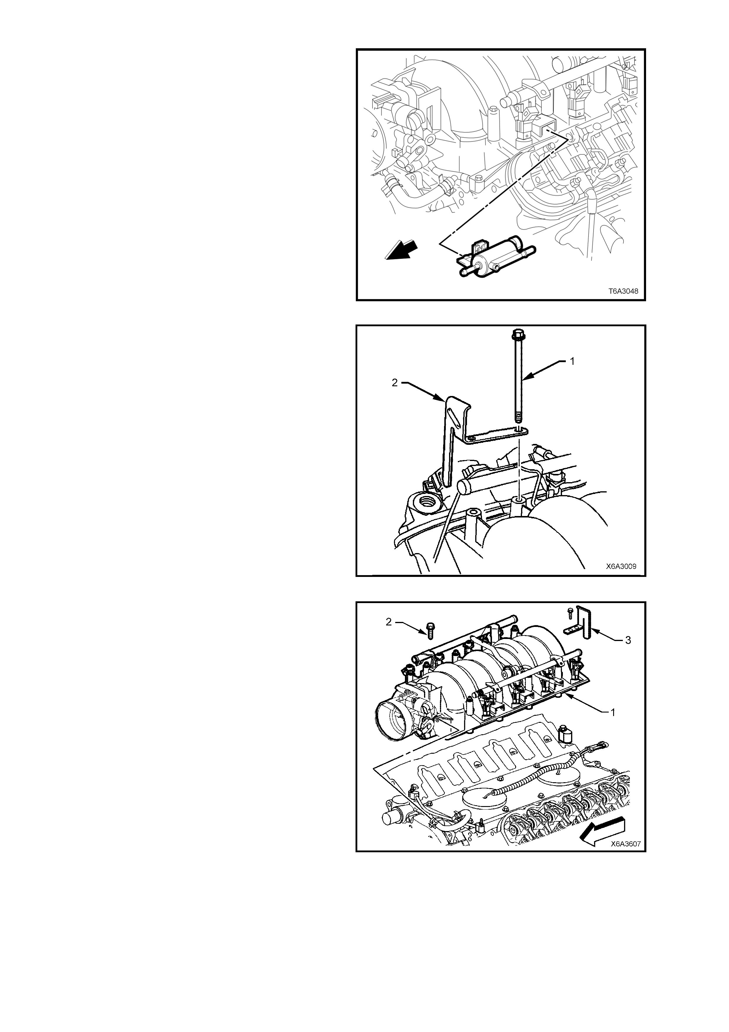
25. Remove the nut (1) securing the PCV valve,
heat conducting strap (2) from the front right
hand vapour pipe screw (3).
26. Remove the PCV valve hose from the throttle
body and right hand rocker cover, rear fitting.
27. Remove the PCV valve and hose assembly
from the left hand rocker cover clip, then lift
hoses and valve assembly from the engine.
Figure 6A3-54
28. Remove the engine coolant, vapour vent hose
from the throttle body and the vapour vent
pipe.
Figure 6A3-55
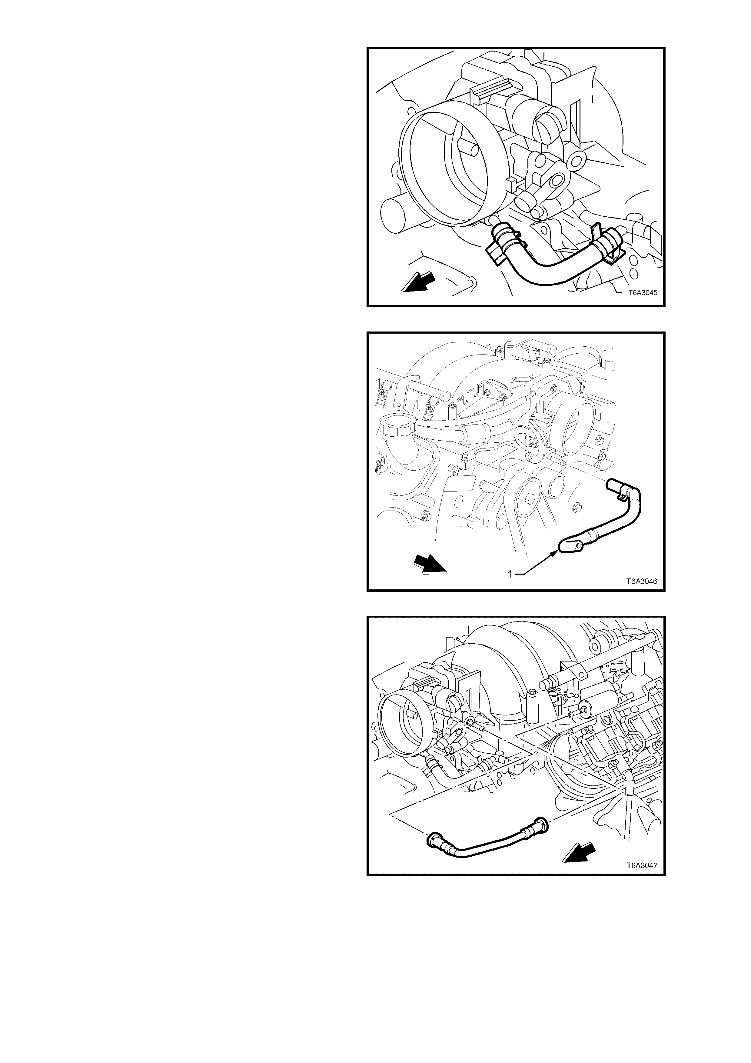
29. Remove the engine coolant vapour vent outlet
hose (1) from the throttle body and left hand
radiator tank.
Figure 6A3-56
30. Remove the evaporative (EVAP) canister
purge valve tube from the purge valve and the
throttle body.
Figure 6A3-57
31. Remove the EVAP canister purge valve and
bracket from the intake manifold.
Figure 6A3-58
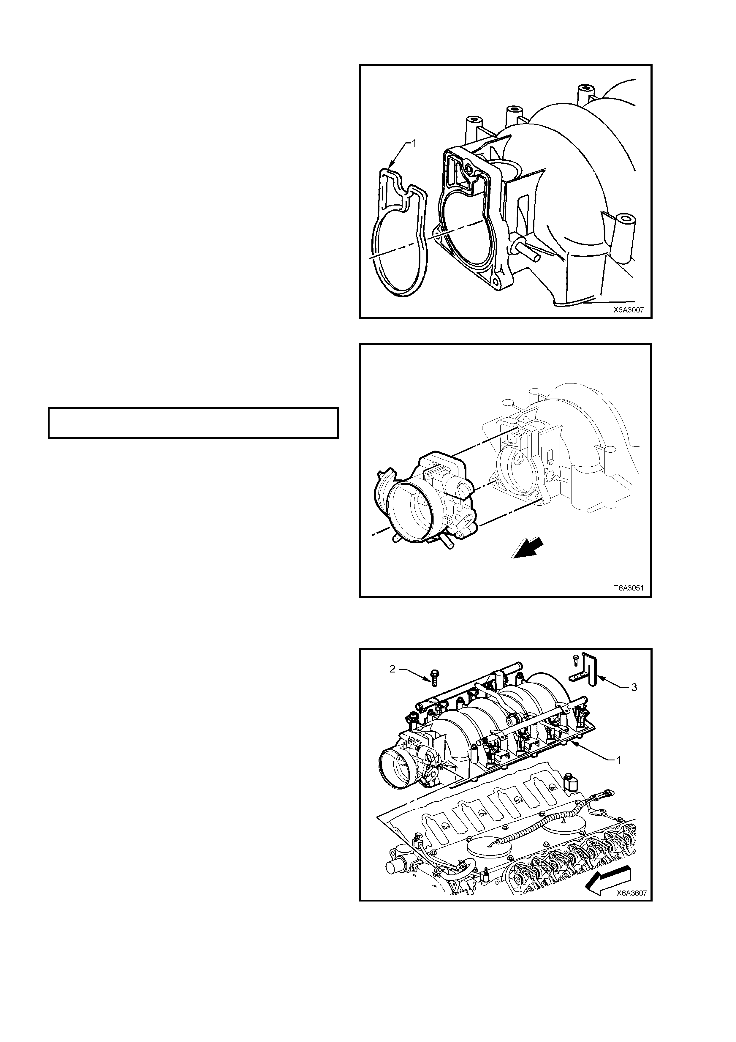
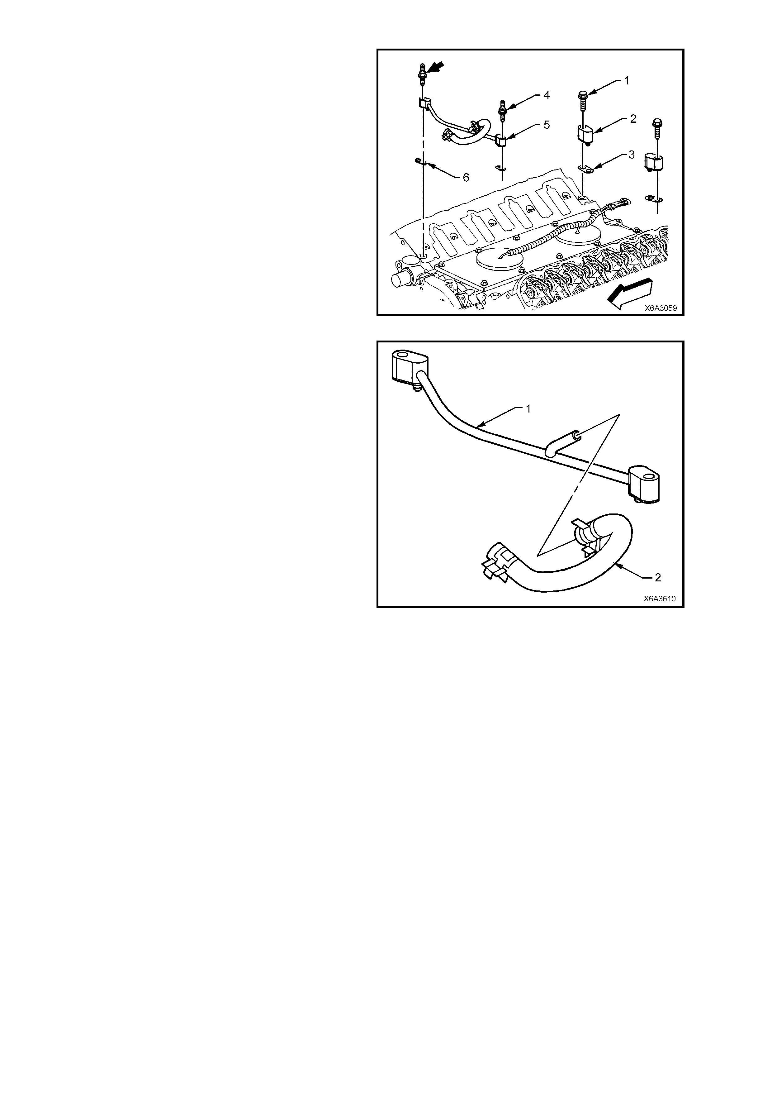
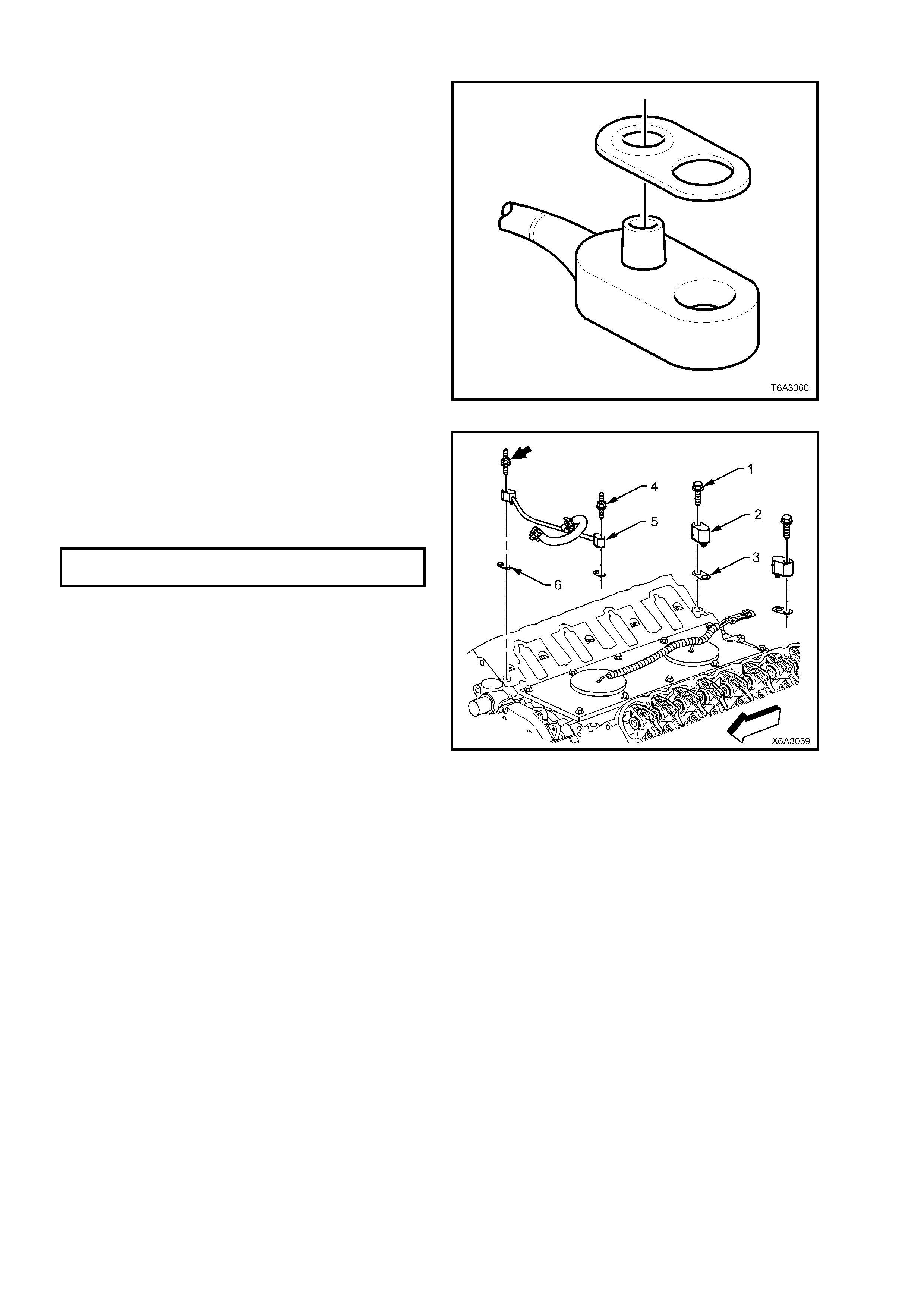
32. Progressively loosen the 10 intake manifold
retaining bolts (1), working diagonally from
outside to inside.
33. Remove the fuel rail stop bracket (2) with the
two, left rear bolts and set to one side.
Figure 6A3-59
34. Carefully bump the intake manifold assembly
(1) to break the gasket seal, then lift from the
engine.
Figure 6A3-60
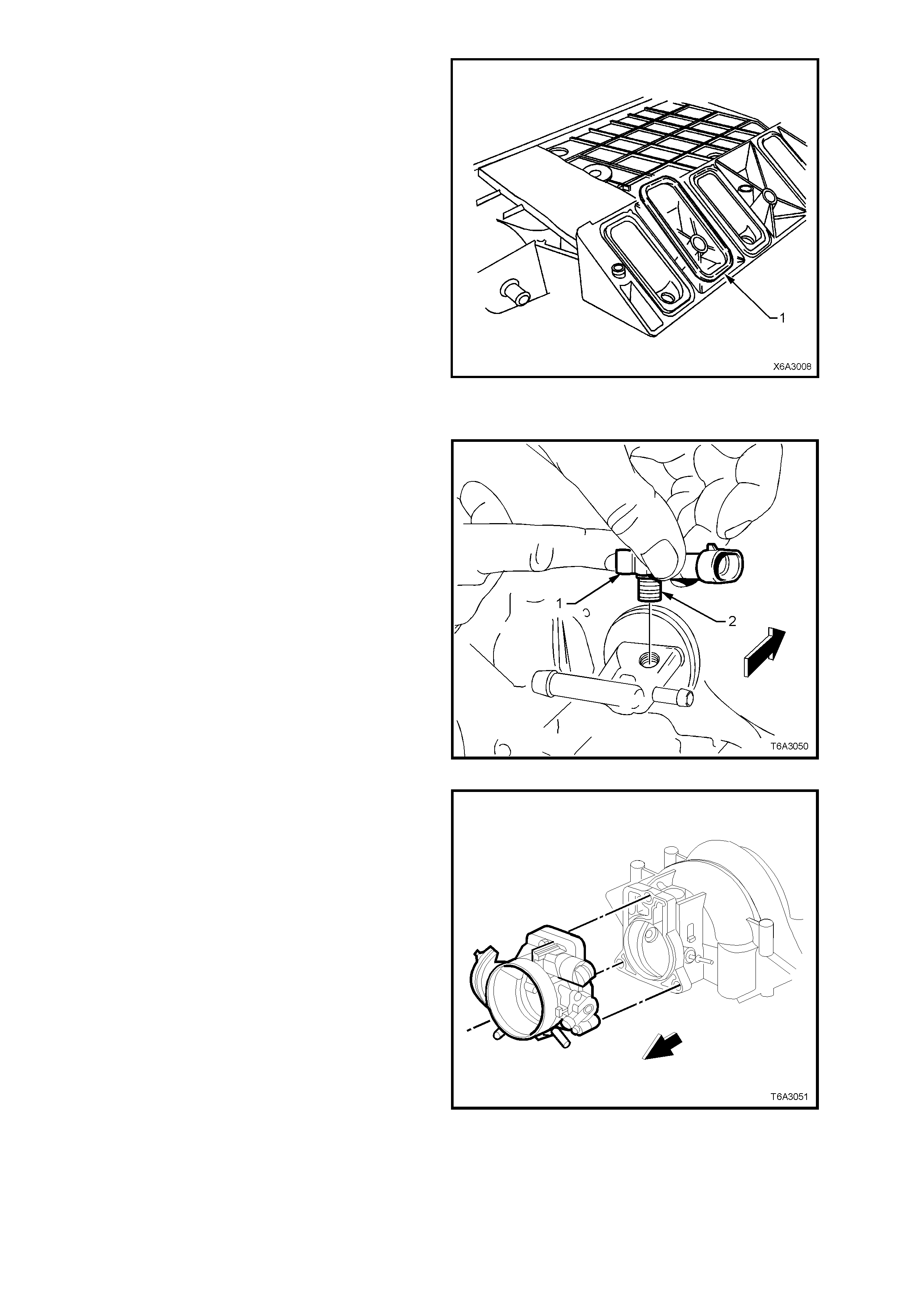
35. Remove the intake manifold to cylinder head
gaskets (1) and discard.
Figure 6A3-61
DISASSEMBLE
If required, the following components can be
removed from the intake manifold:
1. Remove the Manifold Absolute Pressure
(MAP) sensor (1) from the fitting at the rear of
the intake manifold by twisting back and forth
while pulling on the sensor.
2. Check the silicone rubber seal (2) on the MAP
sensor to ensure that it is not torn or damaged.
Figure 6A3-62
3. Remove the throttle body retaining bolts, then
the throttle body and gasket. Discard the
gasket.
Figure 6A3-63
4. Remove the O-ring seal and discard.
NOTE: Do not re-use this O-ring seal.
Figure 6A3-64
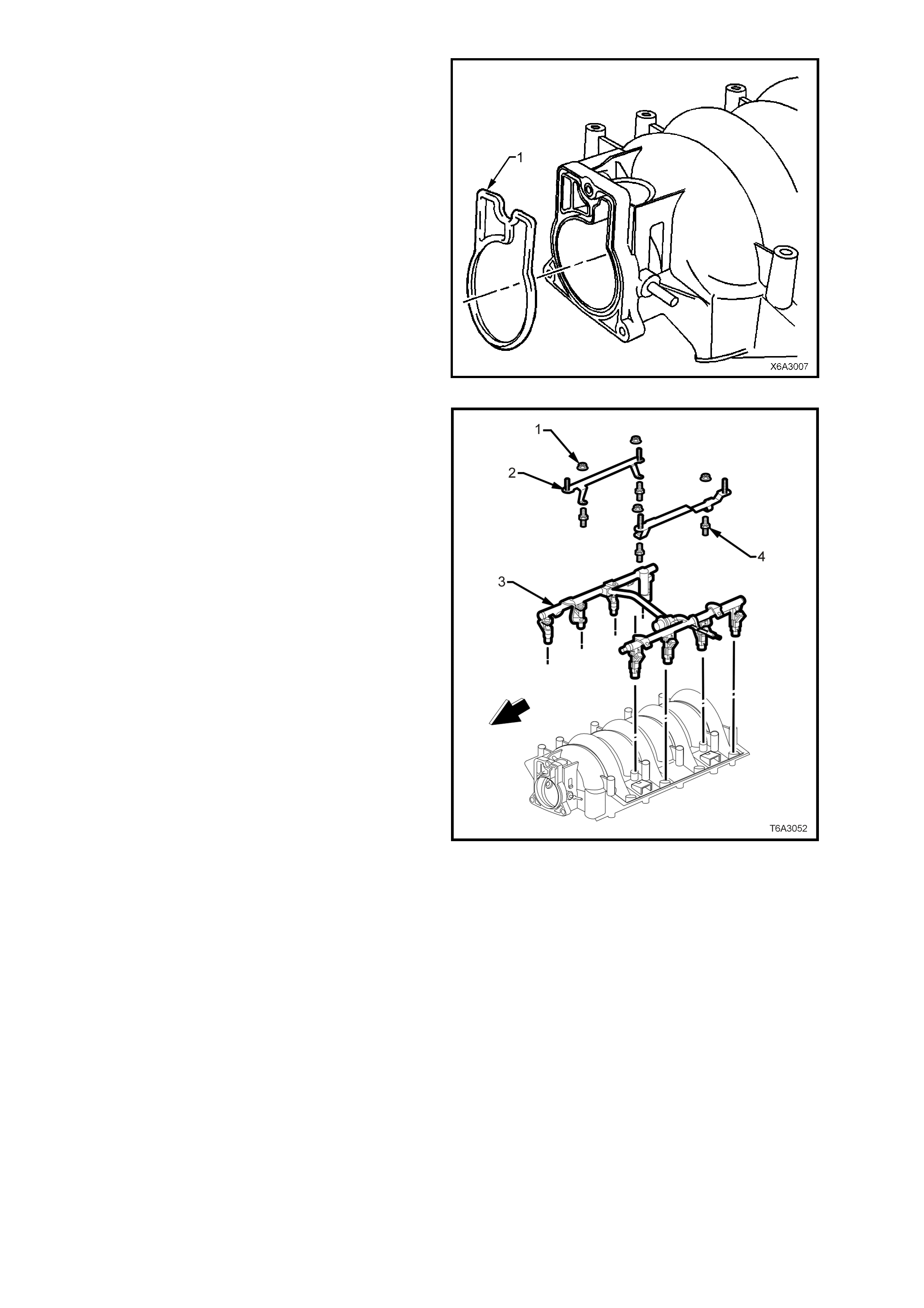
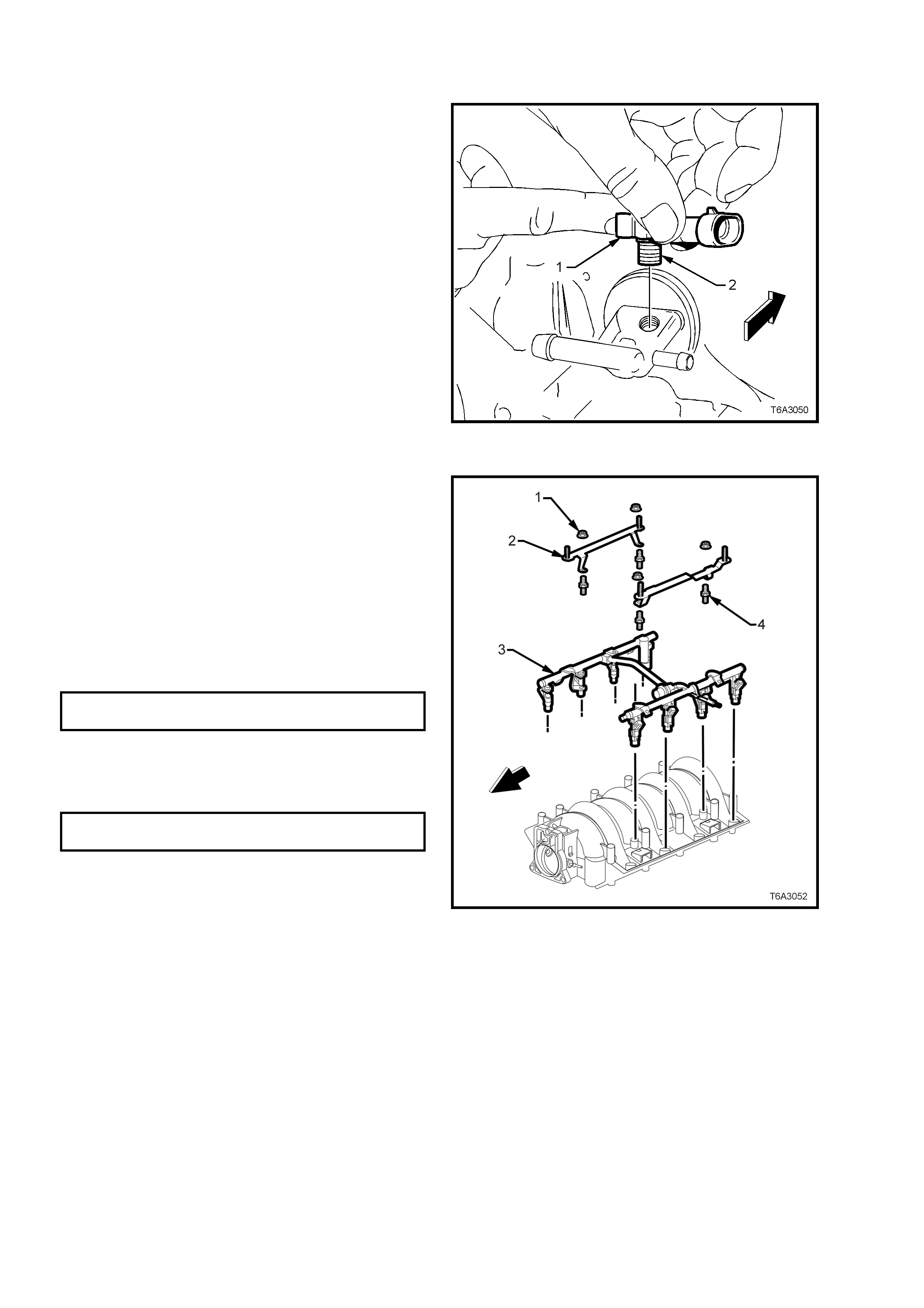
5. Remove the four nuts (1) securing the engine
dress cover brackets (2) to the fuel rail (3),
then lift the two brackets from the fuel rail.
6. Remove the st uds (4) sec uring the fuel r ail and
injectors to the intake manifold, then carefully
remove the fuel rail and injectors as an
assembly.
Should further disassembly of the fuel injectors be
required, refer to Section 6C3-3 SERVICE
OPER ATION S – GEN III V8 ENGINE.
Figure 6A3-65
CLEAN AND INSPECT
1. After cleaning the intake manifold in a suitable solvent, dry off using compressed air.
CAUTION: Wear safety glasses to avoid eye injury.
2. Ensure that the intake m anifold gask et grooves and v acuum passages in the rea r of the intak e manif old are all
clean and clear.
3. Inspect throttle body and fuel rail bolt inserts in the composite intake manifold, for looseness and/or damaged
threads.
4. Inspect the intake manifold for cracks or damage, including the areas between the intake runners.
5. Inspect the fuel injector bores for excessive scoring or damage.
6. Inspect the intake manifold to cylinder head faces for warpage, as follows:
a. Locate a straight edge across each of the two surfaces and check for warpage, using feeler gauges.
b. An intake manifold with warpage in excess of 0.5 mm, must be replaced.
REASSEMBLE
Manifold Absolute Pressure (MAP) Sensor
If removed, install the MAP sensor as follows:
1. Check the MAP sensor seal (2) to ensure it is
seated correctly on the sensor.
2. Install the Manifold Absolute Pressure (MAP)
sensor (1) into the fitting at the rear of the
intake manifold by pushing the sensor into the
fitting. If necess ary appl y a sm ear of petrole um
jelly (Vaseline™ or equivalent).
Figure 6A3-66
Fuel Rail and Injectors
1. Lubricate NEW injector O-ring seals with c lean
engine oil.
2. Install the NEW O-rings to the fuel injectors.
3. Install the fuel rail (with injectors) into the
intake manifold, pressing evenly on each side
until the injectors are all seated in their bores.
4. Apply a 5 mm band of thread sealant such as
Loctite 24 2 (or other commercial equivalent) to
the cleaned threads of the fuel rail attaching
studs (4) and install, tightening to the correct
torque specification.
FUEL RAIL ATTACHING BOLTS
TORQUE SPECIFICATION 10 Nm
5. Install the engine dress cover attaching
brackets (2) to the fuel rail attaching studs (4),
fit the retaining nuts (1) and tighten to the
correct torque specification.
ENGINE DRESS COVER BRACKET
STUDS TORQUE SPECIFICATION 5 Nm
Figure 6A3-67
Throttle Body
1. Install a NEW throttle body O-ring seal (1) to
the intake m anif old.
Figure 6A3-68
2. Install the throttle body and bolts to the intake
manifold.
3. Tighten the throttle body bolts to the correct
torque specification.
THROTTLE BODY BOLT
TORQUE SPECIFICATION 12 Nm
Figure 6A3-69
REINST ALL
1. Install NEW intake manifold to cylinder head
gaskets, then install the intake manifold
assembly (1).
2. Apply a 5 mm band of thread sealant such as
Loctite 242 (or equivalent), to the cleaned
threads of the 10 intake manifold attaching
bolts (2).
3. Install all intake manifold bolts (2), including the
two at the left han d rear, als o securing t he fuel
rail stop bracket (3).
CAUTION: Do not overlook installing the fuel
stop bracket (3). The stop bracket serves as a
protective shield fo r the fuel rail in the event of
a vehicle frontal collision. If the fuel stop
bracket is not installed and the vehicle is
involved in a collision, fuel could be sprayed,
possibly causing a fire and personal injury
from burns.
Figure 6A3-70
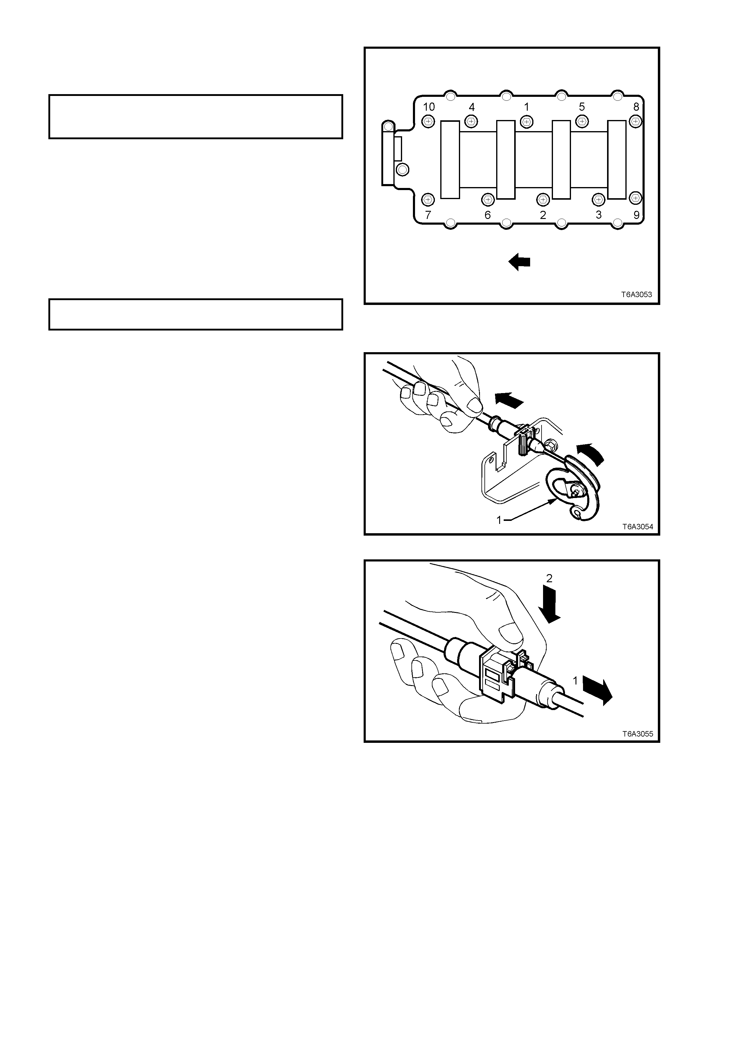
4. Tighten the i ntak e m anifold bo lts in t wo st ages,
in the sequence shown, to the correct torque
specification.
INTAKE MANIFOLD BOLTS
TORQUE SPECIFICATION Stage 1 – 5 Nm
Stage 2 – 10 Nm
NOTE: The f uel stop brac k et is sec ured by bolts ‘3’
and ‘9’.
The remainder of the installation process is the
reverse of the removal operations, except for the
following;
5. Install Positive Crankcase Ventilation (PCV)
System heat conducting strap to the vapour
vent pipe stud at the front right of the engine,
install the retaining nut and tighten to the
correct torque specification.
PCV VALVE HEAT STRAP RETAINING
NUT TORQUE SPECIFICATION 12 Nm
Figure 6A3-71
6. After installation, the throttle cable is to be
adjusted, as det aile d:
a. Attach all cable fittings.
b. W ith the outer cab le adjus ter un lock ed, ap pl y a
tension to t he a dj us ter, un ti l the thro ttl e c am (1)
begins to move.
Figure 6A3-72
c. Release the tension on the adjuster until the
throttle cam is back at rest (1), then slightly
compress the adjuster (2) about 1 mm to lock.
Figure 6A3-73
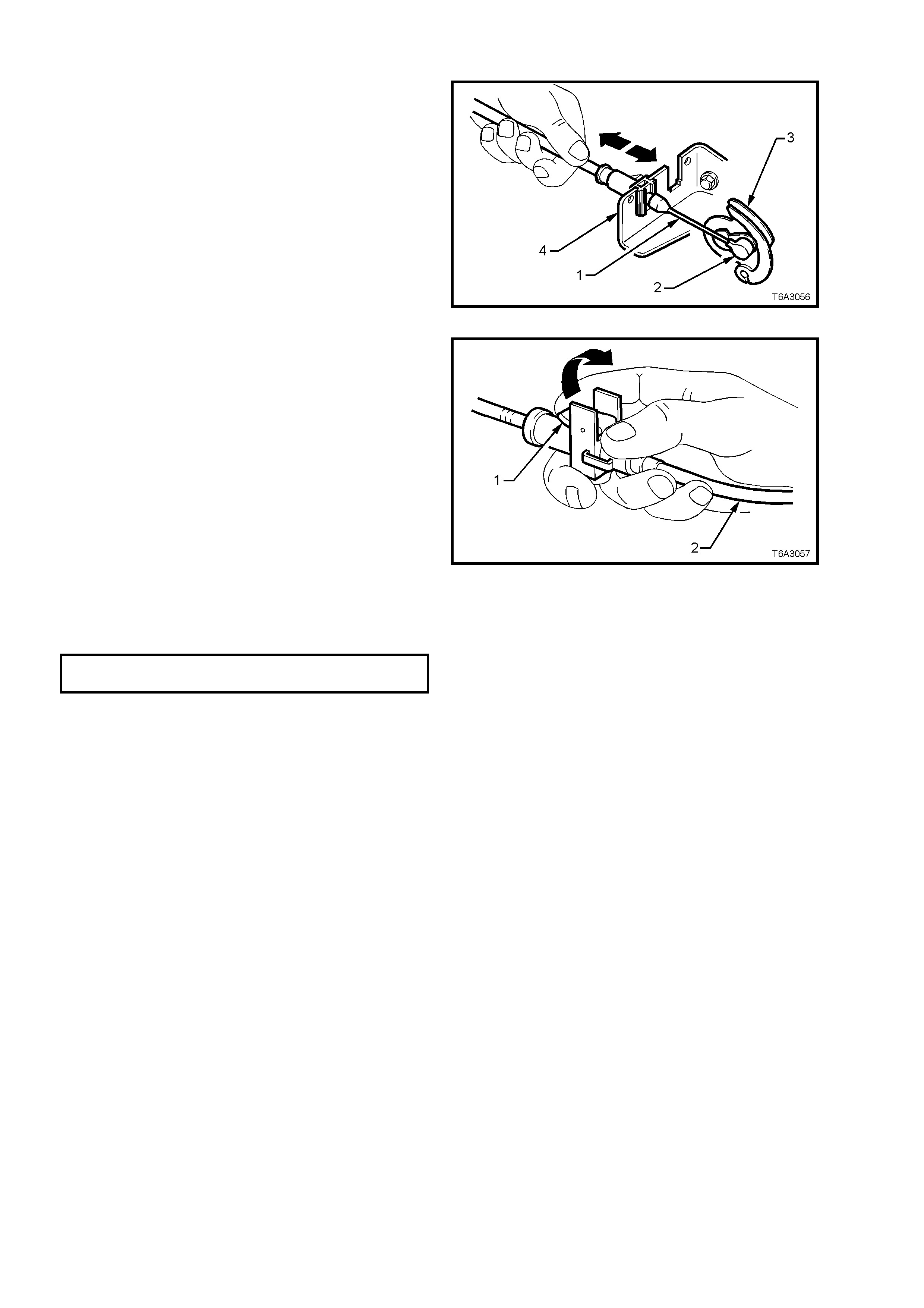
7. If fitted, the cruise control cable must be
adjusted, as f ollo ws:
a. Connect the inner cable (1) to the stud (2)
on the throttle cam (3), then slide the outer
cable into position in the throttle cable
bracket (4).
Figure 6A3-74
b. Unlock the adjustment locking lever (1).
c. Ensure that the throttle is fully closed, then
adjust the outer cruise control cable (2), to
achieve minimum slack in the inner cable.
d. Flip the adjustment lever (1) to lock the
outer cable (2) into position.
Figure 6A3-75
8. Install engine dress cover and the four
retaining n uts and tighten to the correct torque
specification.
ENGINE DRESS COVER DOME
TORQUE SPECIFICATION 10 Nm
9. Fill the cooling system. Refer to
Section 6B3 ENGINE COOLING - GEN III V8
ENGINE.
10. Start engine, check for leaks and normal
operation.
2.15 VAPOUR VENT PIPE
LT Section No. – 00-249
REMOVE
1. Disconnect the ground cable from the battery.
IMPORTANT: Disconnection of the battery affects
certain vehicle electronic systems. Refer to
Section 00 CAUTIONS, 5. BATTERY
DISCONNECTION PROCEDURES before
disconnecting the battery.
2. Drain the cooling system. Refer to
Section 6B3 ENGI NE COO LING - GEN III V8
ENGINE.
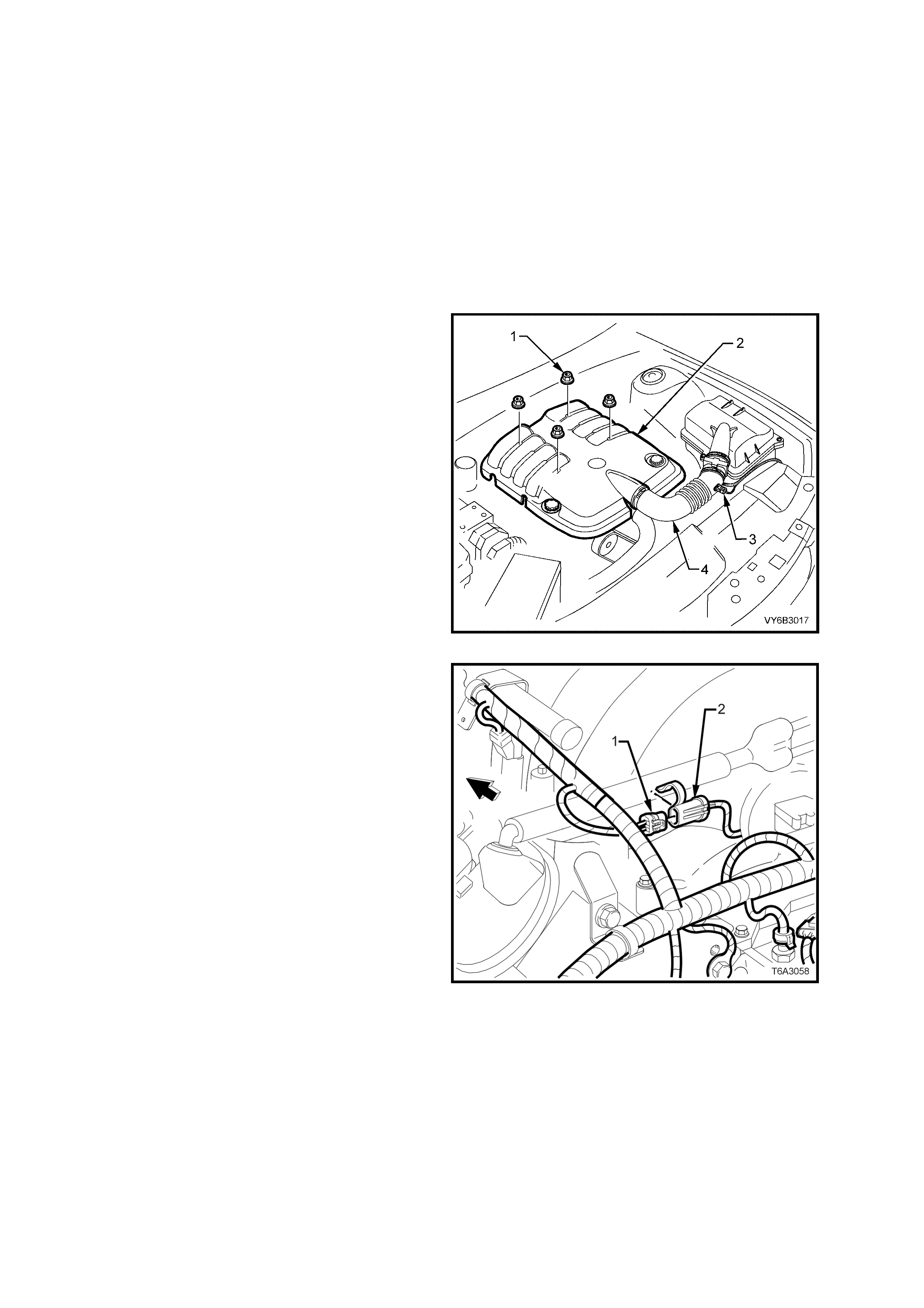
3. Remove the four engine dress cover
decorative nuts (1), then remove the dress
cover (2) from the engine.
4. De-pressurise fuel rail. Refer to
2.13 FUEL SYSTEM PRESSURE RELIEF, in
this Section.
5. Remove the air intake sensor wiring harness
connector (3), then loosen both hose clamps
securing the intake duct (4) to the MAF sensor
and the throttle body. Remove the duct (4)
from the engine.
Figure 6A3-76
6. Remove intake manifold. Refer
2.14 INT AKE M ANIFOLD, in this Section.
7. Remove the wiring harness connector (1) from
the knock sensor patch harness (2).
Figure 6A3-77
8. If required, remove the retaining bolts (1) from
the rear engine coolant vapour bleed vent
covers (2). Remove covers and gaskets (3).
Discard the gaskets.
9. Remove the vapour vent pipe retaining studs
(4) and the front engine coolant vapour bleed
pipe (5), together with both gaskets (6).
Discard the gaskets.
NOTE: Both front studs are double sided, with the
right hand one (bold arrow) being used to secure
the PCV valve braided strap, disconnected during
the intake manifold removal operation.
Figure 6A3-78
10. If required, loosen the engine coolant to vent
pipe clam p, then remove the hose (2) from the
vent pipe (1).
Figure 6A3-79
REINST ALL
1. Correctly install NEW vapour pipe gaskets by
fitting the O-ring seal part, over the pipe fitting
nipple, as shown.
Figure 6A3-80
2. Install the vapour vent pipe (5), vapour vent
covers (2) and gaskets (‘6’ and ‘3’) to the
cylinder hea ds .
3. Install the vapo ur vent pipe bolts/studs (‘1’ and
‘4’) and tighten to the correct torque
specification.
VAPOUR VENT PIPE BOLT/STUD
TORQUE SPECIFICATION 12 Nm
4. Install the intake manifold, as described in
2.14 INTAKE MANIFOLD - REINSTALL, in
this Section.
5. Install th e vap our vent hos e to the t hrott le bod y
and install the hos e clamp sec urel y.
Figure 6A3-81
2.16 ENGINE VALLEY COVER
LT Section No. – 02-000
REMOVE
1. Disconnect the ground cable from the battery.
IMPORTANT: Disconnection of the battery affects certain vehicle electronic systems. Refer to
Section 00 CAUTIONS, 5. BATTERY DISCONNECTION PROCEDURES befor e disc onn ec tin g the battery.
2. Drain the cooling system. Refer to Section 6B3 ENGINE COOLING - GEN III V8 ENGINE.
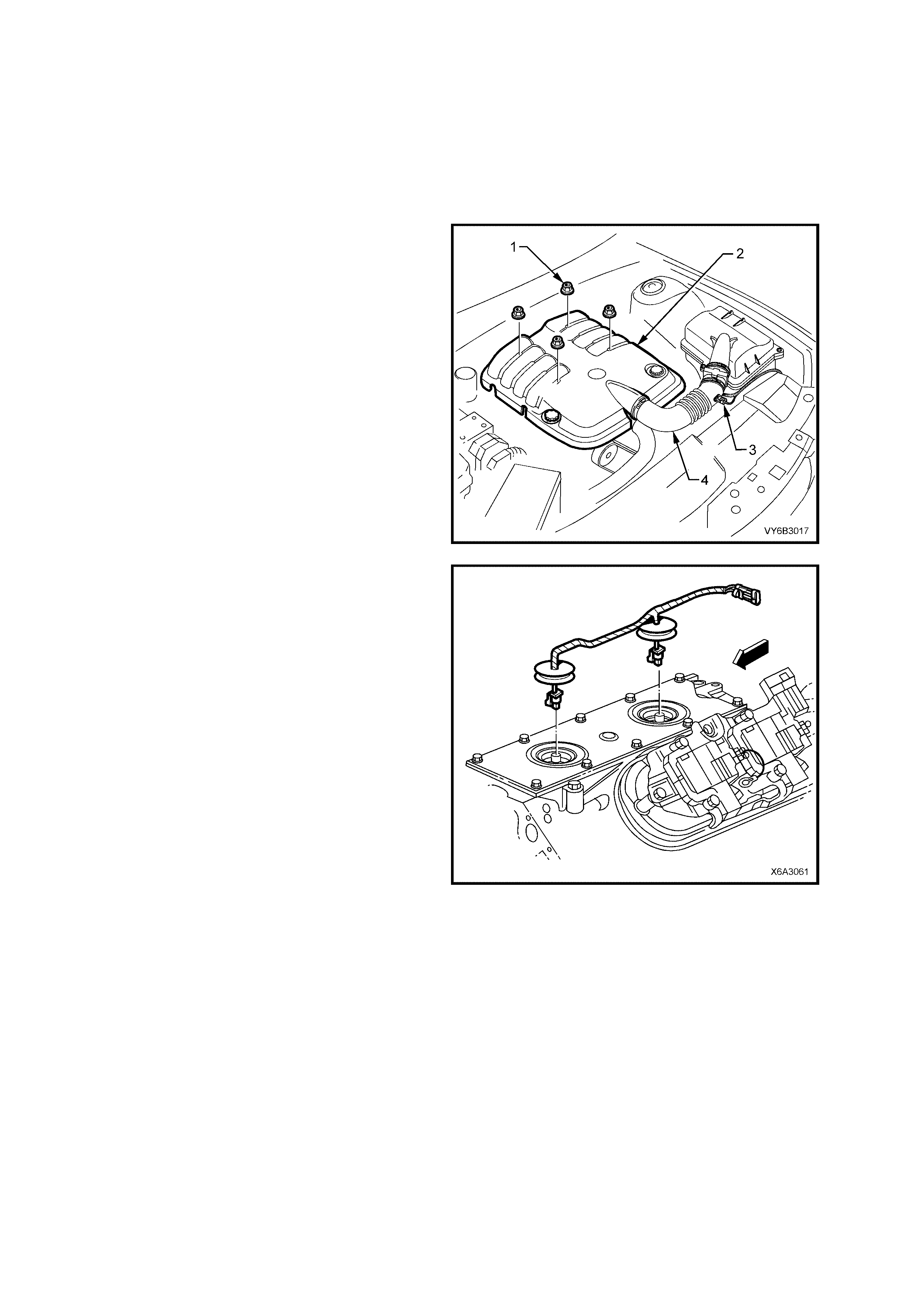
3. Remove the four engine dress cover
decorative nuts (1), then remove the dress
cover (2) from the engine.
4. De-pressurise fuel rail. Refer to
2.13 FUEL SYSTEM PRESSURE RELIEF, in
this Section.
5. Remove the air intake sensor wiring harness
connector (3), then loosen both hose clamps
securing the intake duct (4) to the MAF sensor
and the throttle body. Remove the duct (4)
from the engine.
6. Remove intake manifold. Refer
2.14 INT AKE M ANIFOLD.
7. Remove vapour vent pipe. Refer
2.15 VAPOUR VENT PI PE .
Figure 6A3-82
8. To remove the knock sensor wiring harness,
carefully lift each sealing plug from the valley
cover, release each knock sensor harness
connector locking tab, then remove each
connector. Lif t the knoc k sensor wirin g har ness
from the engine.
Figure 6A3-83
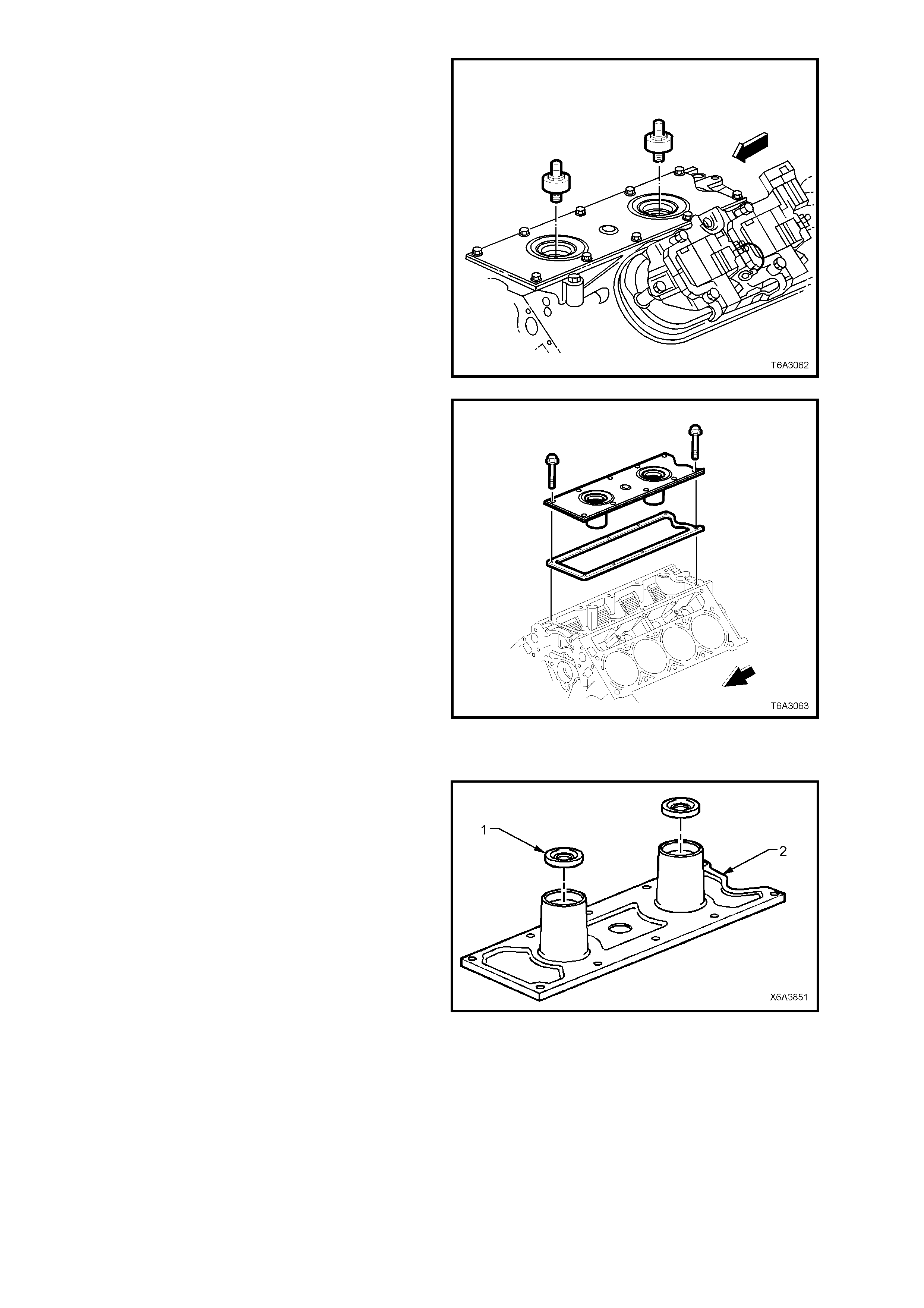
9. Remove both knock sensors, using a
commercially available, 22 mm deep socket.
NOTE: Unless a deep socket is used, damage to
the sensor connector will result.
Figure 6A3-84
10. Remove the valley cover retaining bolts.
11. Remove the valley cover and gasket from the
cylinder block. Discard the gasket.
Figure 6A3-85
CLEAN AND INSPECT
1. Remove both knock sensor oil seals (1) from
the valley cover (2).
2. Clean the valley cover in suitable solvent and
dry off with compressed air
CAUTION: Wear safety glasses to avoid eye
injury.
3. Inspect the valley cover sealing surfaces and
oil seal bores for excessive scratches or other
damage.
Figure 6A3-86

REINST ALL
Reinstallation is the reverse of removal operations, except for the following items.
1. Install NEW knock sensor oil seals into the valley cover and lubricate with clean engine oil (refer ‘1’ in Figure
6A3-86).
2. Fit a NEW gasket to the valley cover and install cover to the engine (refer to Figure 6A3-85).
3. Install valley cover bolts and tighten to the correct torque specification.
ENGINE VALLEY COVER BOLT
TORQUE SPECIFICATION 25 Nm
4. Install the knock sensors and tighten to the correct torque specification.
KNOCK SENSOR
TORQUE SPECIFICATION 20 Nm
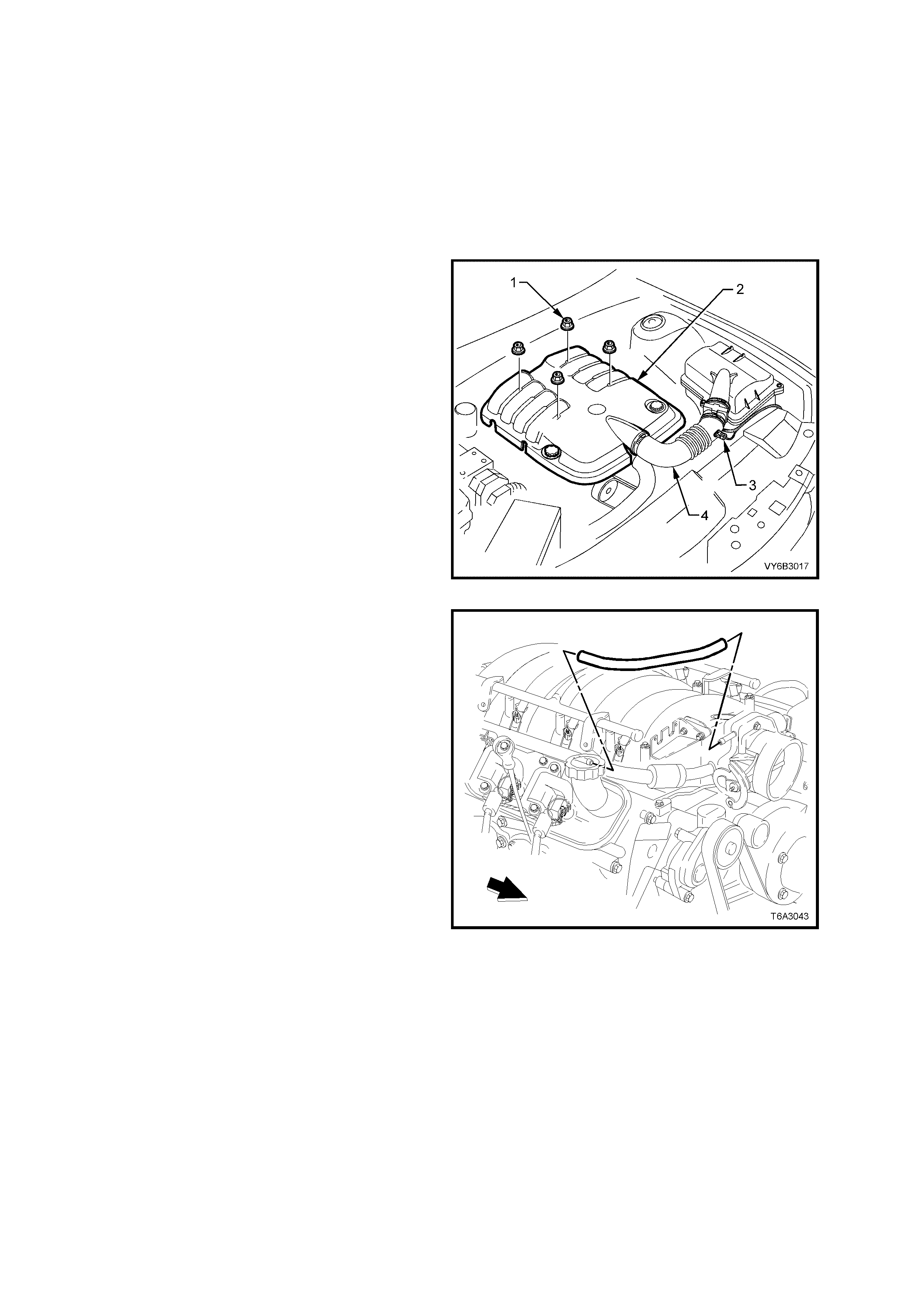
2.17 V ALVE ROCKER ARM COVER
LT Section No. – 00-050
REMOVE
1. Disconnect the ground cable from the battery.
IMPORTANT: Disconnection of the battery affects
certain vehicle electronic systems. Refer to
Section 00 CAUTIONS, 5. BATTERY
DISCONNECTION PROCEDURES before
disconnecting the battery.
2. Remove the four engine dress cover
decorative nuts (1), then remove the dress
cover (2) from the engine.
Figure 6A3-87
3. For the right hand rocker cover, remove the
fres h air hose f rom the front fitting of the r ock er
cover and from the throttle body.
Figure 6A3-88
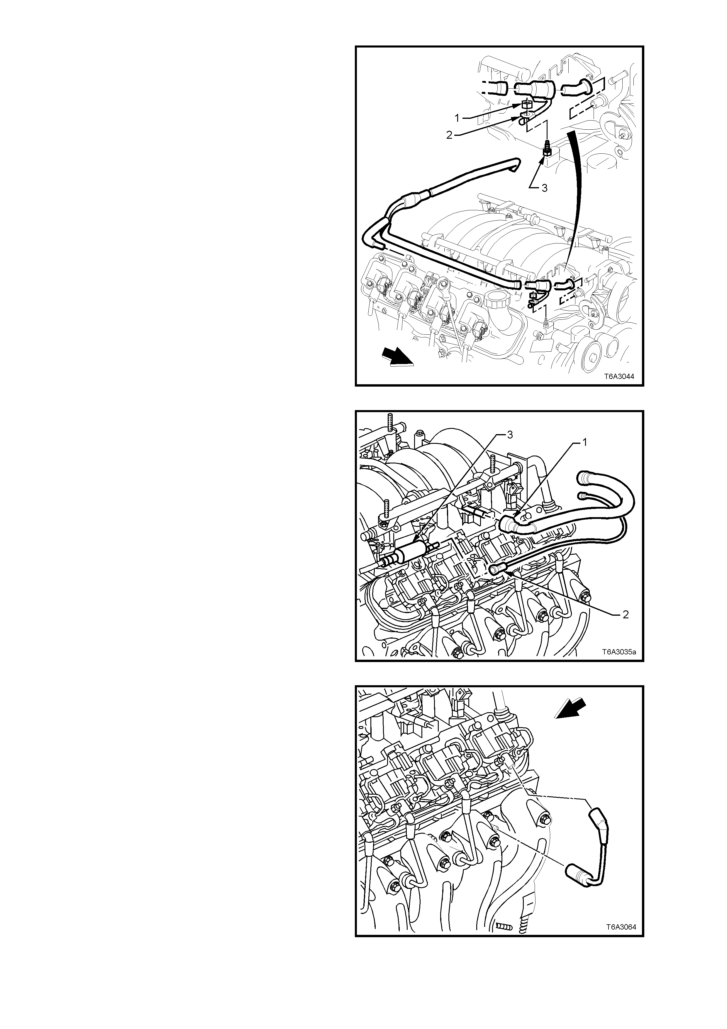
4. Remove the PCV hose connection from the
rear f itting at t he end of the rock er cover, be ing
removed.
Figure 6A3-89
5. Using quick connect release Tool No. 7371
(not shown in Figure 6A3-90), install over fuel
line.
6. While holding the fuel line quick connect (1),
push on Tool 7371 to release the quick
connect fitting (1) from the fuel rail. Pull back
on the quick connect and remove.
7. Disconnect the vapour line connector (2) from
the EVAP purge valve (3).
IMPORTANT: Cap the fuel line fittings and plug the
holes after separating the fuel lines to prevent fuel
leaking and/or dirt and other contaminants from
entering the fuel system.
Figure 6A3-90
8. Remove the spark plug leads.
NOTE: Handle the boot only. DO NOT pull on the
lead. T wist the boo t firs t to break the seal, th en pull
to remove.
Figure 6A3-91
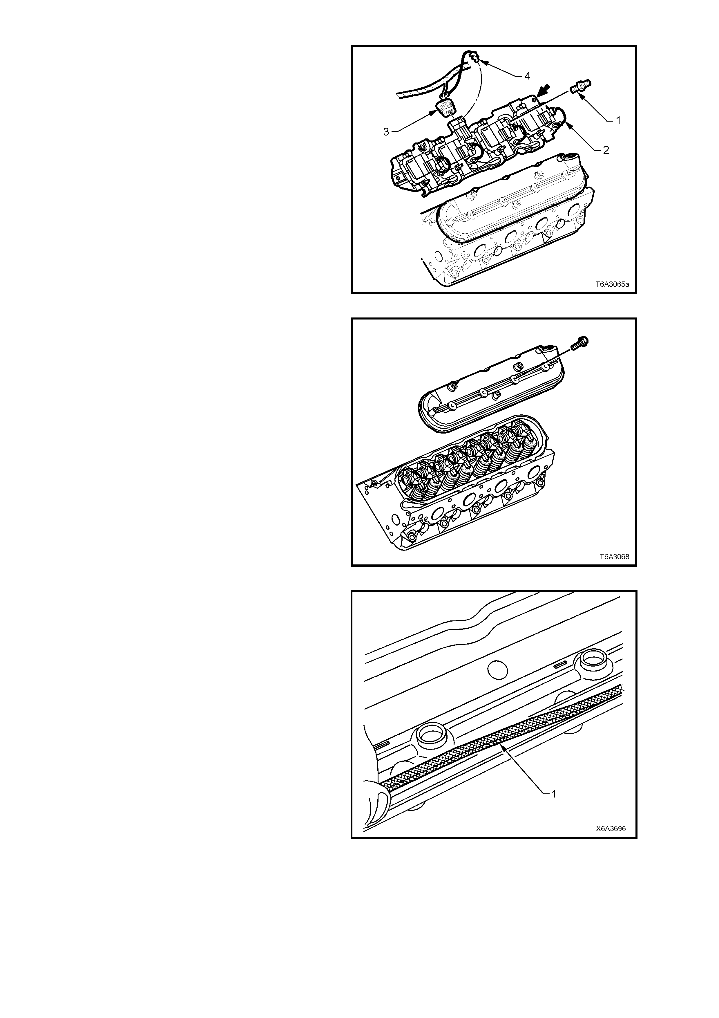
9. Remove the CPA lock (4) from the ignition coil
main connector on the rocker cover being
removed, then remove the wiring harness
connector (3).
10. Remove the 4 studs (1) and one screw
securing the ignition coil mounting bracket (2)
to the rock er cover being r emoved, then l ift the
ignition coils, wiring and bracket from the
engine.
NOTE: The rear attaching bolt on each coil
assembly (arrow) is a conventional screw and not a
stepped stud. Fitment of this screw in the correct
position on reassembly is important to avoid
possible chaffing.
Figure 6A3-92
11. Remove the 4 valve rocker cover bolts, then
remove the cover and gasket from the c ylinder
head.
NOTE: Do not r em ove the oil f ill tu be from the r ight
hand rocker cover unless replacement is required.
Figure 6A3-93
12. Remove the gasket (1) from the cover and
discard.
NOTE: The cover securing bolt grommets may be
re-used if not damaged.
Figure 6A3-94
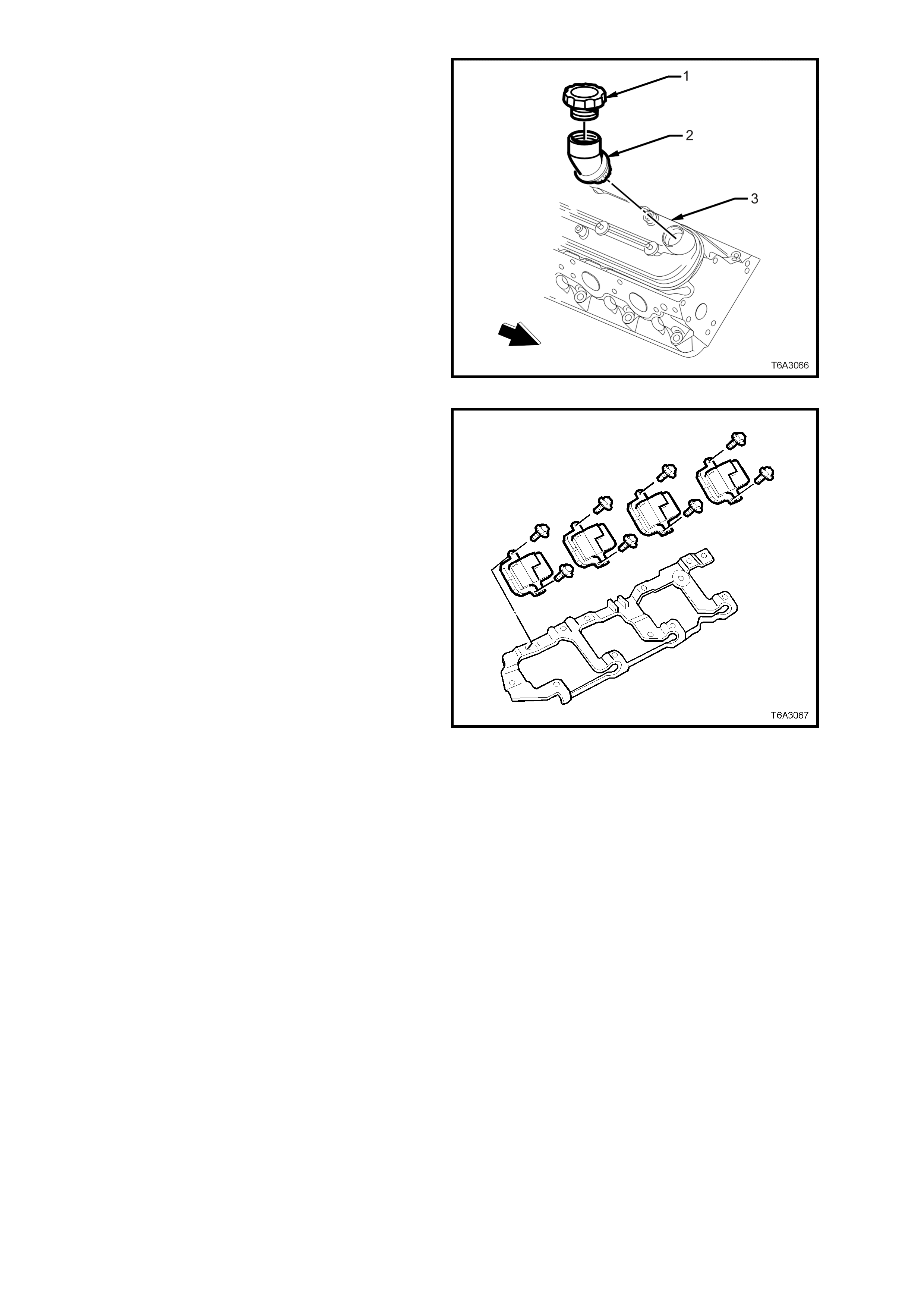
13. If required, remove the oil fill cap(1) and/or fill
tube (2) from the right hand rocker cover (3).
Discard the oil fill tube (2), as permanent
dam age will occ ur on rem ova l.
Figure 6A3-95
14. If required, remove the bolts securing the
ignition coils to the mounting bracket and
remove the coils and wiring harness.
Figure 6A3-96
CLEAN AND INSPECT
1. Clean the rocker cover in a suitable solvent and dry off with compressed air.
CAUTION: Wear safety glasses to avoid eye injury.
2. Inspect the ventilation system passages for restriction.
3. Inspect the rocker cover gasket groove for damage.
4. Inspect the ignition coil mounting boss threads for damage.
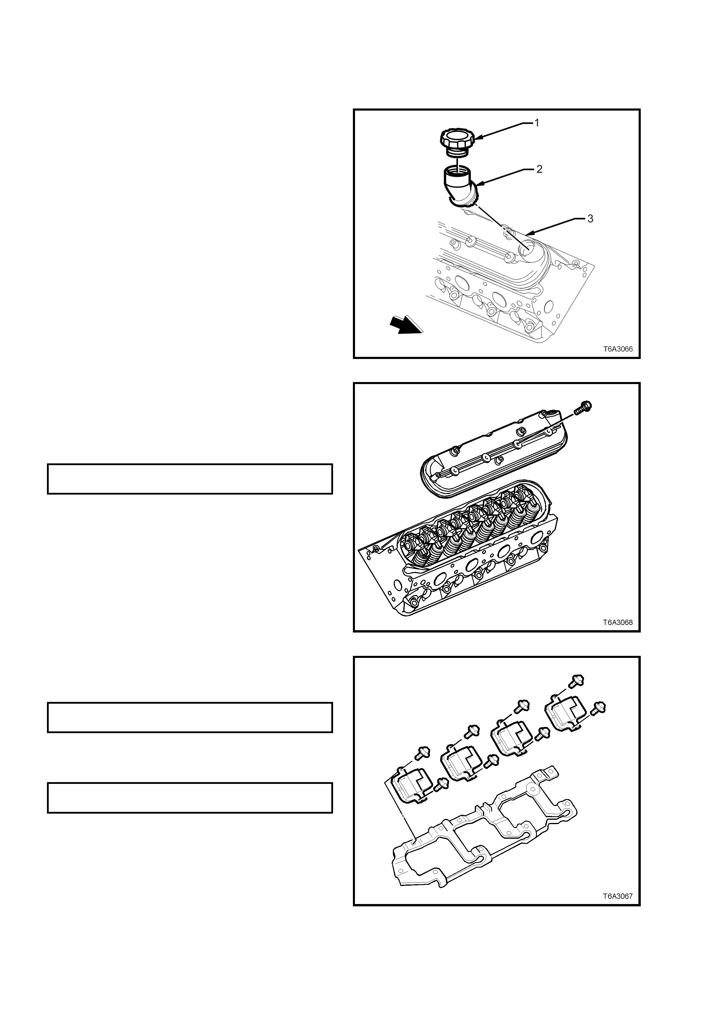
REINST ALL
Reinstallation of the rocker cover is the reverse to
the removal procedure except for the following
items.
1. If the o il f i ll tub e ( 2) was r e moved f r om the rig ht
hand roc ker cover ( 3), it m ust be rep laced with
a NEW part (when installed, it is permanent).
2. Lubricate the O-ring seal of the NEW oil fill
tube (2) with clean engine oil.
3. Install the oil fill tube into the rocker cover (3),
rotating the tube clockwise until lock ed into the
correct position.
4. Install the o il fill cap ( 1), rotatin g clock wise unti l
locked into place.
Figure 6A3-97
5. Install a NEW gasket to the rocker cover.
6. Install the rocker cover bolts.
7. Install the rocker cover onto the cylinder head
and tighten the rocker cover studs to the
correct torque specification.
ROCKER COVER BOLT
TORQUE SPECIFICATION 12 Nm
Figure 6A3-98
8. Install the ignition coils and coil wiring harness
to the mounting bracket and tighten the to the
correct torque specification.
IGNITION COIL SCREW
TORQUE SPECIFICATION 12 Nm
9. Install the ignition coils and bracket assembly
to the rocker cover, and tighten the studs and
screw to the correct torque specification.
IGNITION COIL BRACKET STUD/
SCREW TORQUE SPECIFICATION 12 Nm
NOTE: The r ear , left hand c oil brac ket f ast ener is a
plain screw and not a stepped stud as are the
others. Fitm ent of this screw in the correct position
is important to avoid fuel/vapour line chaffing.
10. After installation of the ignition coil main
harness connector, install the CPA lock,
ensuring it is fitted securely.
Figure 6A3-99
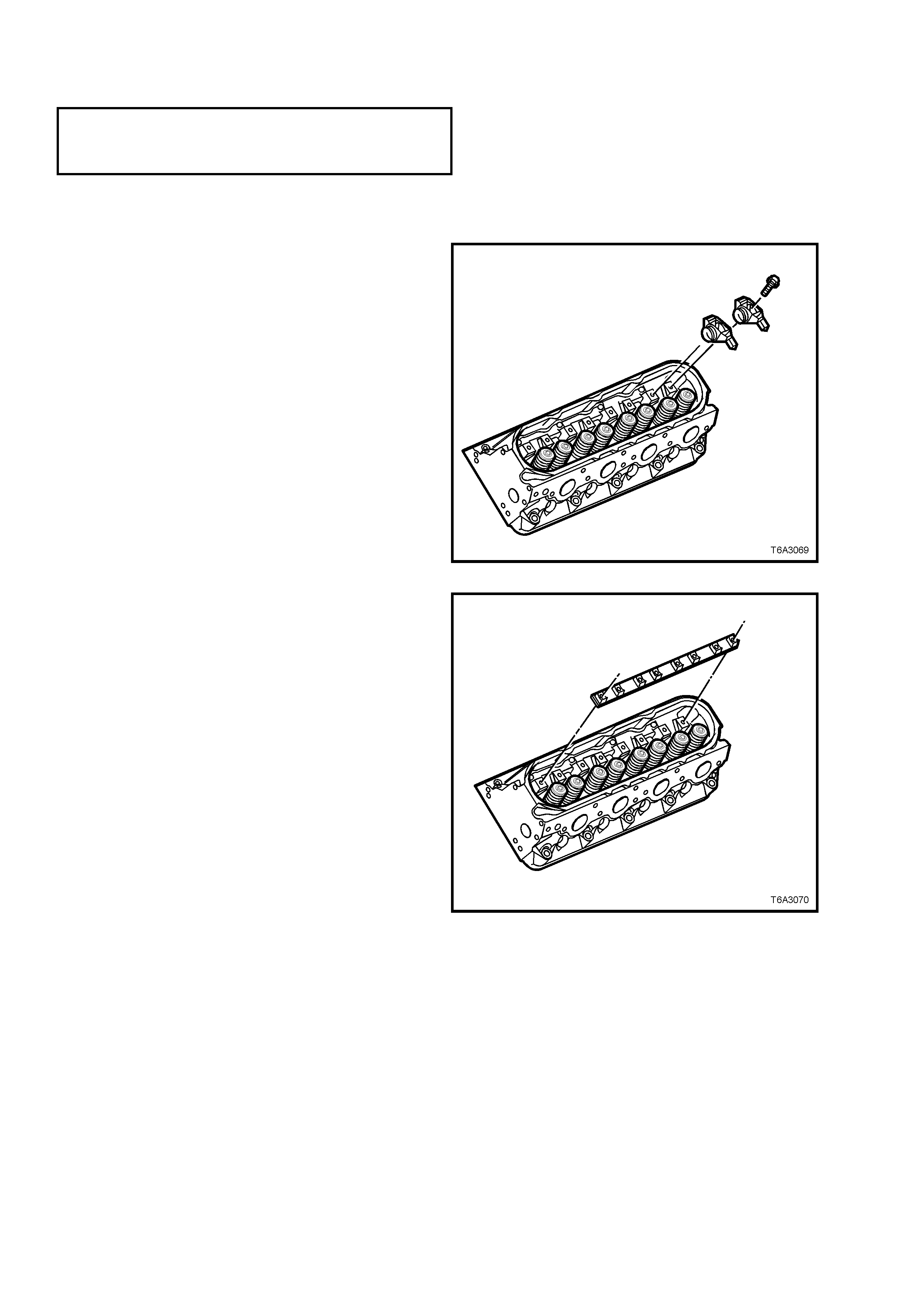
2.18 V ALVE ROCKER ARMS AND PUSH RODS
LT Section No. – 00-050
NOTE: The following fasteners MUST be replaced ( ! )
when performing this operation:
! Rocker arm retaining bolts.
REMOVE
NOTE: W hile s ome vie ws may show a cylinder head t hat is n ot s p ec if ic to th e o n e r eq uired, unl es s no ted, i t c an b e
assumed that the operation is the same for either cylinder head.
1. Remove the valve rocker arm cover/s. refer to
2.17 VALVE ROCKER ARM COVER, in this
Section.
IMPORTANT: Store all removed valve operating
mechanis m com ponents in a su itable rac k to avoid
being mixed. This will ensure that parts reinstalled
will be in the same relationship as on removal.
2. Rem ove all t he rock er arm bolts on the s pec ific
cylinder hea d.
3. Remove associated valve rockers arms.
Figure 6A3-100
4. Remove the valve rocker arm pivot support.
Figure 6A3-101
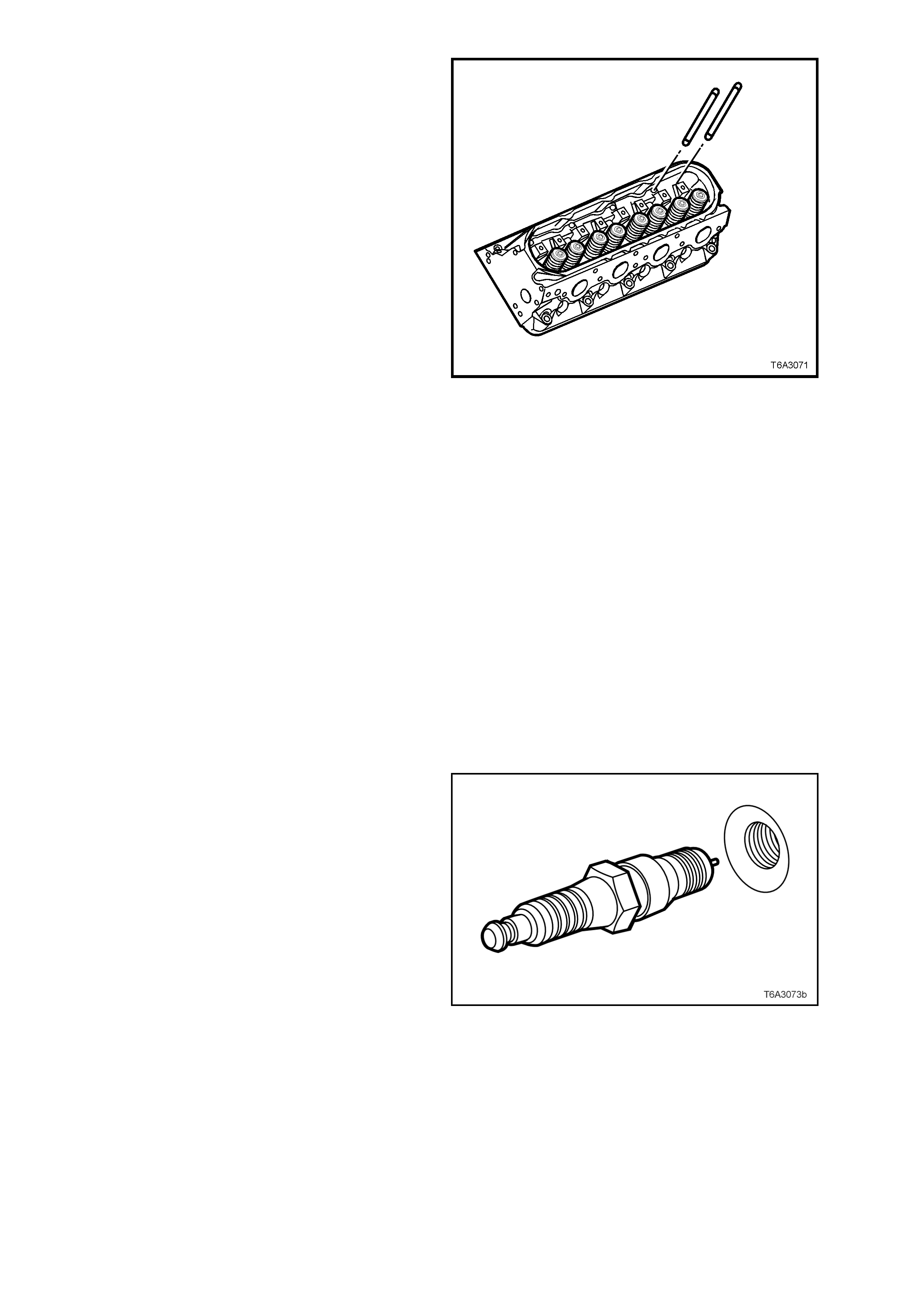
5. Remove the push rods.
Figure 6A3-102
CLEAN AND INSPECT
1. Mark, sort or organise removed parts to retain in order removed.
2. Clean parts in a suitable solvent, then dry with compressed air.
CAUTION: Wear safety glasses to avoid eye injury.
3. Inspect parts, as follows:
a. Valve rocker arm bearings for binding or roughness.
b. Valve rocker arm push rod sockets and valve stem mating surfaces for wear and/or roughness.
c. Pushrods for worn or scored ends.
d. Also check for bent pushrods by rolling on a flat surface.
e. Pushrod oil passages for restrictions.
f. Pivot supports for cracks, wear or other damage.
REINST ALL
While the reinstallation process is the reverse of
the removal procedure, there are some specific
operations that must be complied with, and are
detailed here.
1. To reduce the ef fort require d to turn the eng ine
over by hand, remove the spark plugs, taking
note of the following;
a. The engine coolant is to be 50° C or less. If
not, then the spark plug and cylinder head
threads may bind, causing the cylinder head
threads to be torn.
b. When removing spark plug leads, only handle
the boot on each lead, twist to break the seal,
them pull to remove. DO NOT pull on the lead
itself.
c. Loosen the spark plug/s, then re-tighten to
break away any carbon deposits on the
threads.
d. Loosen the spark plug/s once again but, this
time, only one or two turns. Then use
compressed air to remove any foreign m aterial
that may otherwise enter the combustion
chamber.
CAUTION: Wear eye protection to avoid injury.
e. Continue to remove the spark plug/s.
Figure 9A-103
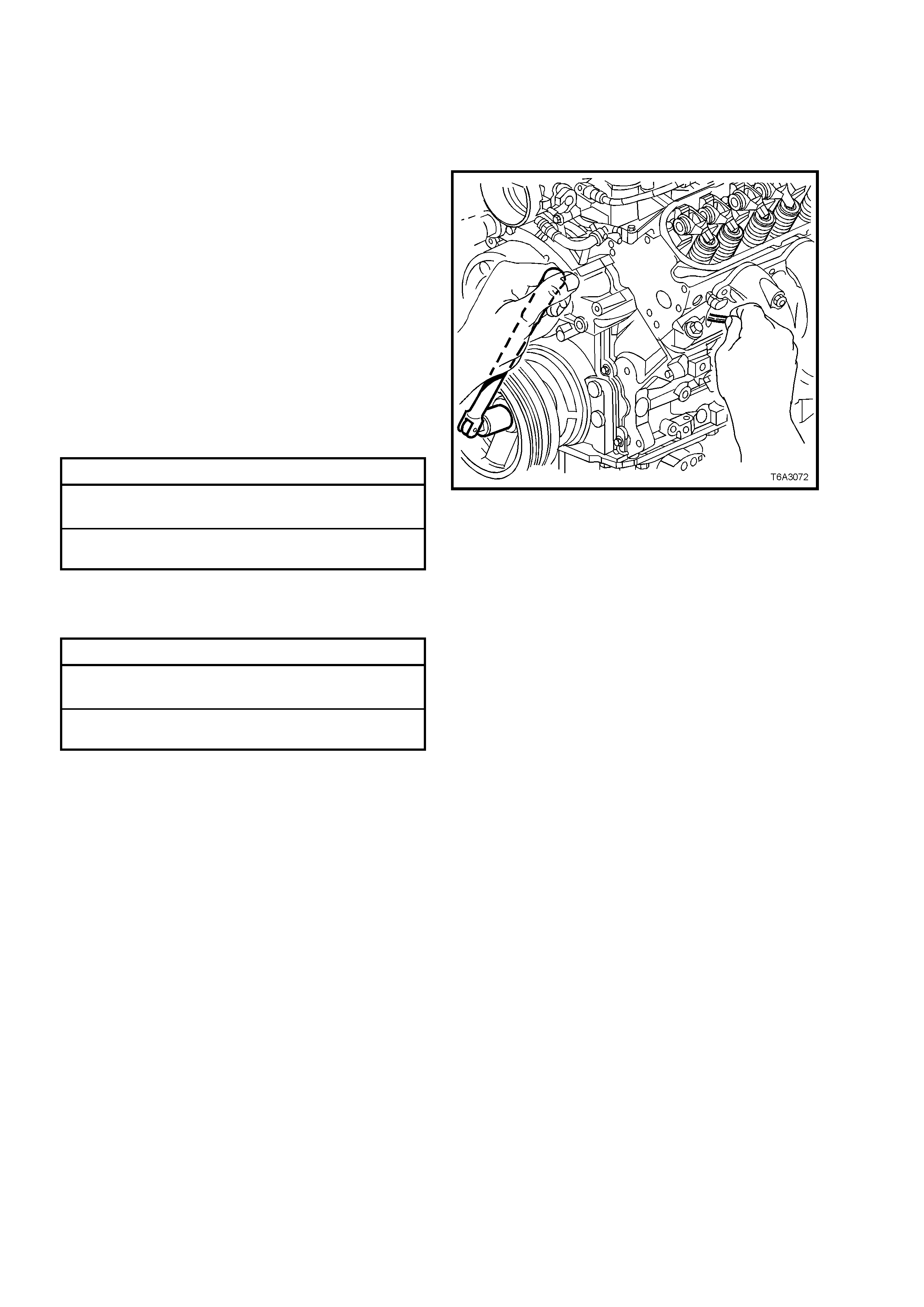
2. Lubricate the following parts in clean engine oil before installation:
a. All valve rocker arms and pushrods.
b. The flanges of all rocker arm bolts.
3. Install all push rods, checking that each seats correctly to the hydraulic valve lifter sockets.
4. Install all rocker arms, bearings and NEW retaining bolts but DO NOT TIGHTEN fully at this time.
5. Rotate the crankshaft until No. 1 piston is at
Top Dead Centre (TDC), on the compression
stroke.
NOTE 1: Inserting a finger into the spark plug hole
will determine if the piston is rising on the
compression stroke, by the compressed air
escaping. Finally, a suitable piece of wire can be
used as shown, to determine when the piston is at
TDC.
NOTE 2: The engine firing order is 1, 8, 7, 2, 6, 5,
4, 3 and c ylinder num bers are 1, 3 , 5, 7, on th e left
bank and 2, 4, 6, 8, are on the right bank.
6. W ith No. 1 pisto n on TDC compression strok e,
tighten the following rocker arm bolts to the
correct torque specification:
ROCKER ARM BOLT TORQUE SPECIFICATION
Exhaust Valve, Cylinder No. 1, 2, 7 and 8, to 30
Nm
Intake Valve, Cylinder No. 1, 3, 4 and 5, to 30
Nm
7. Rotate the crankshaft 360°.
8. Tighten the following rocker arm bolts to the
correct torque specification:
ROCKER ARM BOLT TORQUE SPECIFICATION
Exhaust Valve, Cylinder No. 3, 4, 5 and 6, to 30
Nm
Intake Valve, Cylinder No. 2, 6, 7 and 8, to 30
Nm
9. Reinstall the rocker cover/s. Refer
2.17 VALVE ROCKER ARM COVER, in this
Section, for the necessary procedure.
Figure 6A3-104
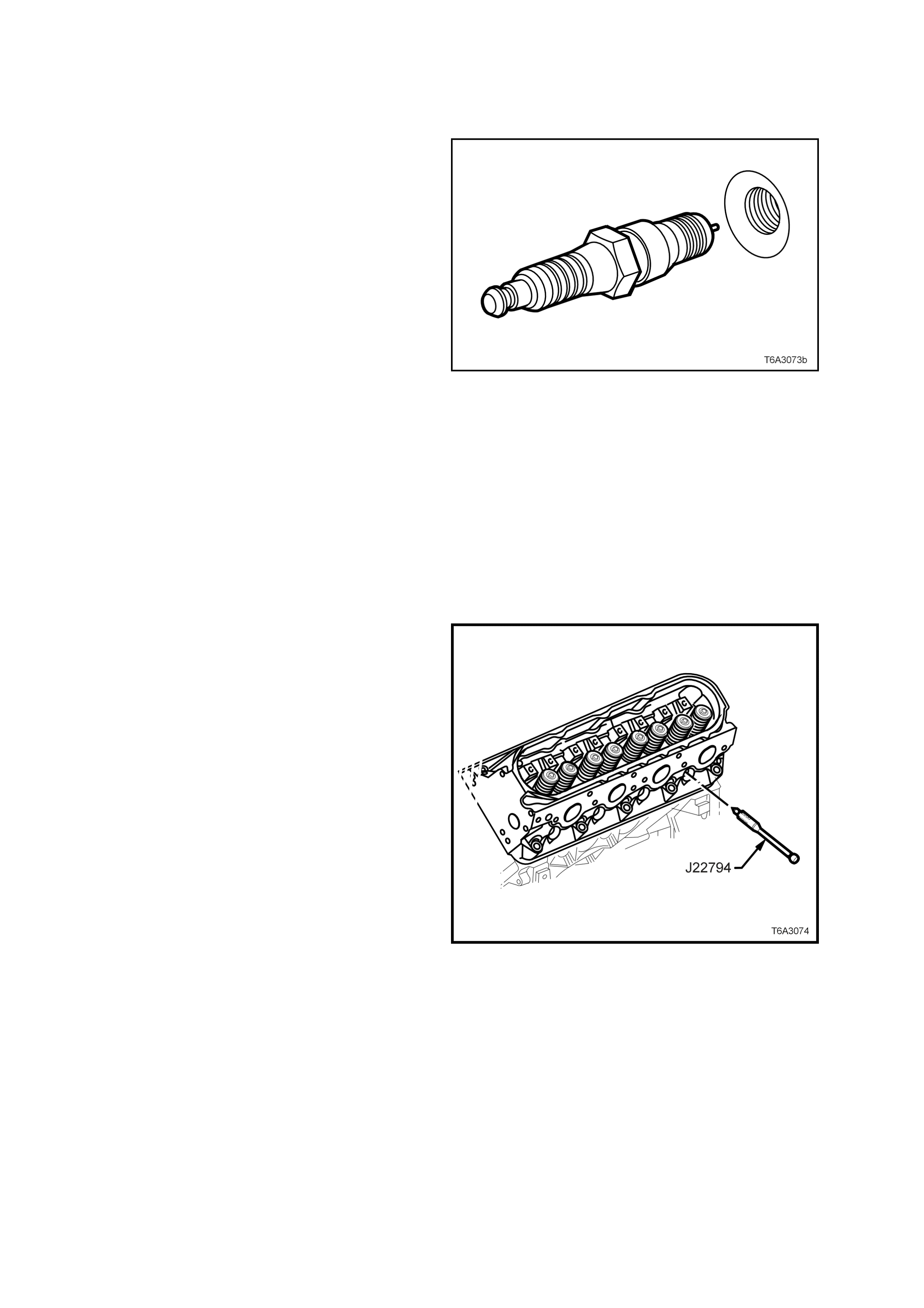
2.19 VALVE SPRING AND/OR VALVE STEM OIL SEAL
LT Section No. – 00-075
REPLACE
1. Remove the spark plugs from the cylinder/s
being serviced, taking note of the following;
a. The engine coolant is to be at 50° C or less. If
not, then the spark plug and cylinder head
threads may bind, causing the cylinder head
threads to be torn.
b. When removing spark plug leads, only handle
the boot on each lead, twist to break the seal,
them pull to remove. DO NOT pull on the lead
itself.
c. Loosen the spark plug/s, then re-tighten to
break away any carbon deposits on the
threads.
d. Loosen the spark plug/s once again but, this
time, only one or two turns. Then use
compressed air to remove any foreign material
that may otherwise enter the combustion
chamber.
CAUTION: Wear eye protection to avoid
injury.
e. Continue to remove the spark plug/s.
2. Remove the valve rocker arms, valve rocker
arm pivot support, and valve pushrods. Refer
to 2.18 VALVE ROCKER ARMS & PUSH
RODS.
Figure 6A3-105
3. Insert a suitable piece of wire into the spark
plug hole and turn the crankshaft balancer bolt
until the piston is at or near Top Dead Centre
(TDC).
4. Ins tall S par k Plug Por t Ada ptor Tool J 227 94 or
a comm ercial equiv alent to the spark plug hole
of the cylinder being serviced.
5. Using suitable adaptors, attach a compressed
air line to J 22794 and app ly a constant su pply
of compressed air to the cylinder being
serviced.
Figure 6A3-106
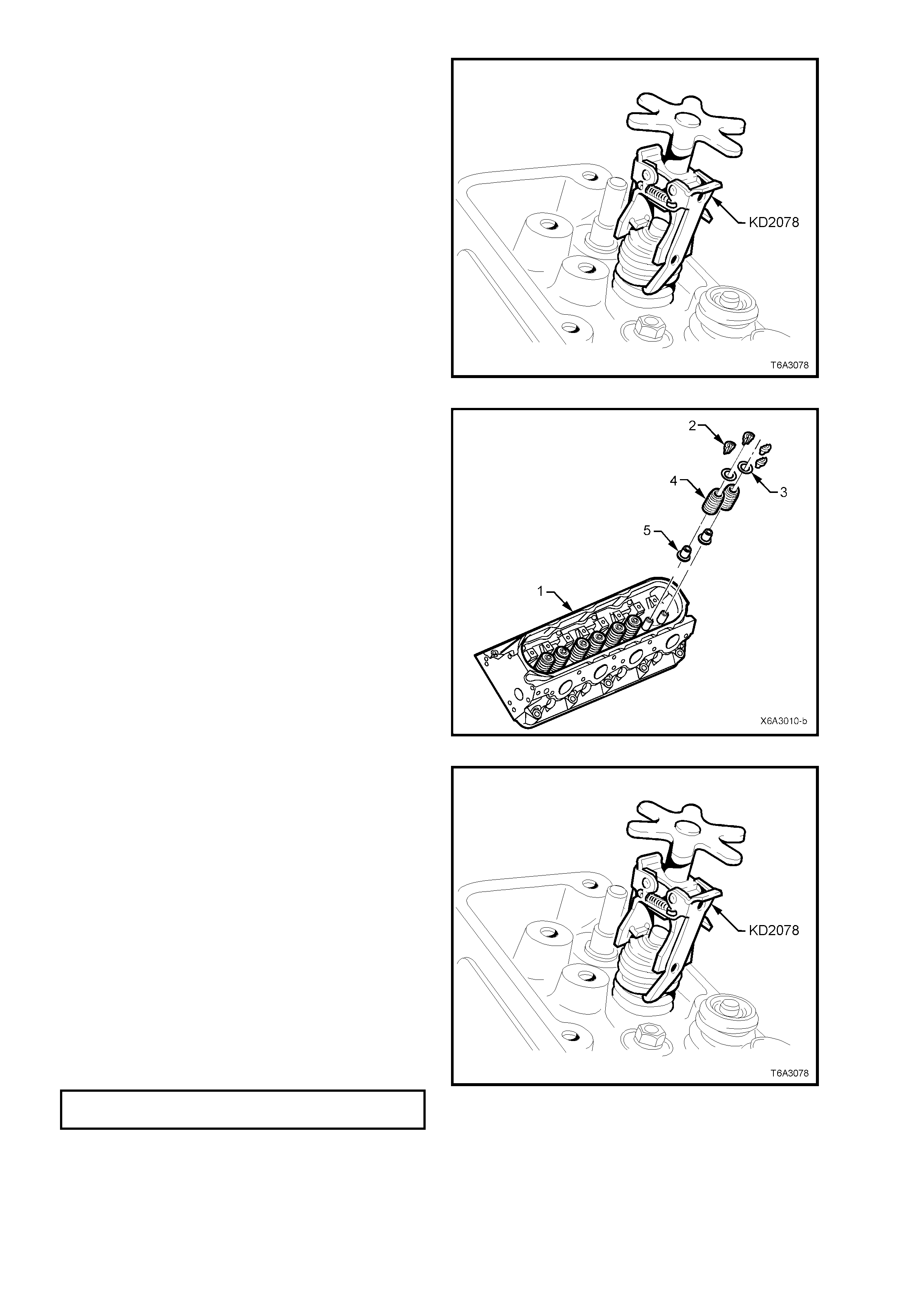
6. Compres s one of the valv e s prings , using val ve
spring compressor, KD2078.
Figure 6A3-107
7. Remove valve stem collets (2).
8. Release the valve spring compressor and
remove:
a. Valve spring cap (3).
b. Valve spring (4).
c. Valve spring oil seal and spring shim
combination (5) (if being replaced).
9. Install a new valve stem oil seal and shim
assembly (second design) to the valve guide,
by hand, until the shim seats against the
cylinder h ead. No specia l tools are r equired f or
this operation.
Figure 6A3-108
10. Install the valve spring with the smaller wound
coils facing up, then install the spring cap.
11. Compress the spring using Tool No. KD2078
until sufficient space is allowed for the valve
collets to be installed.
12. Install both valve stem collets, using clean
grease or petroleum jelly to retain.
13. Releas e the v al ve spr ing c ompres s or, checking
that both valve stem collets are seated
correctly.
14. Lightly tap the valve stem with a soft faced
hammer to ‘seat’ the valve stem collets.
15. Remove the compressed air supply.
16. Remove the spark plug adaptor, Tool J22794.
17. Install the spark plug, tightening to the correct
torque specification.
SPARK PLUG
TORQUE SPECIFICATION 15 Nm
18. Reverse the removal procedure to complete
this operation.
Figure 6A3-109
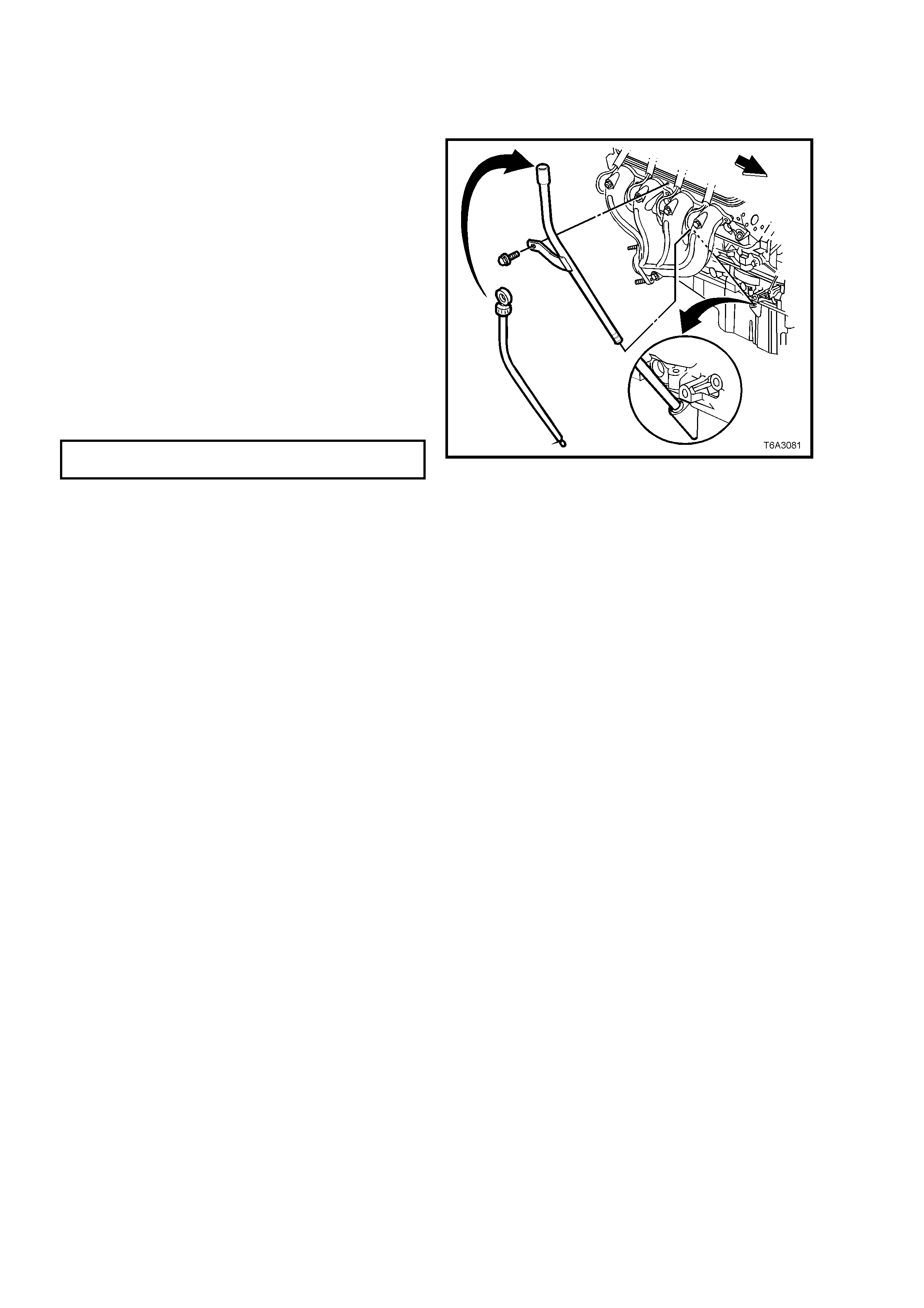
2.20 OIL LEVEL INDICATOR AND TUBE
LT Section No. – 00-580
REPLACE
1. Remove the oil level indicator from the tube.
2. Remove the oil level indica tor tube br acket bolt
from the right hand exhaust manifold
3. Remove the tube from the engine, then remove
the O-ring.
NOTE: If the tube is not to be reinstalled
immediately, plug the opening to prevent dirt entry.
4. After cleaning the tube, inspect the O-ring,
which can be re-used if undamaged. Install O-
ring to the lower end of the tube
5. Install the tube to the engine and rotate to the
correct position.
6. Install the oil level indicator tube bracket bolt
and tighte n in two s tages, to th e correct t orque
specification.
OIL LEVEL TUBE RETAINING
BOLT TORQUE SPECIFICATION 25 Nm
7. Install the oil level indicator to the tube.
Figure 6A3-110
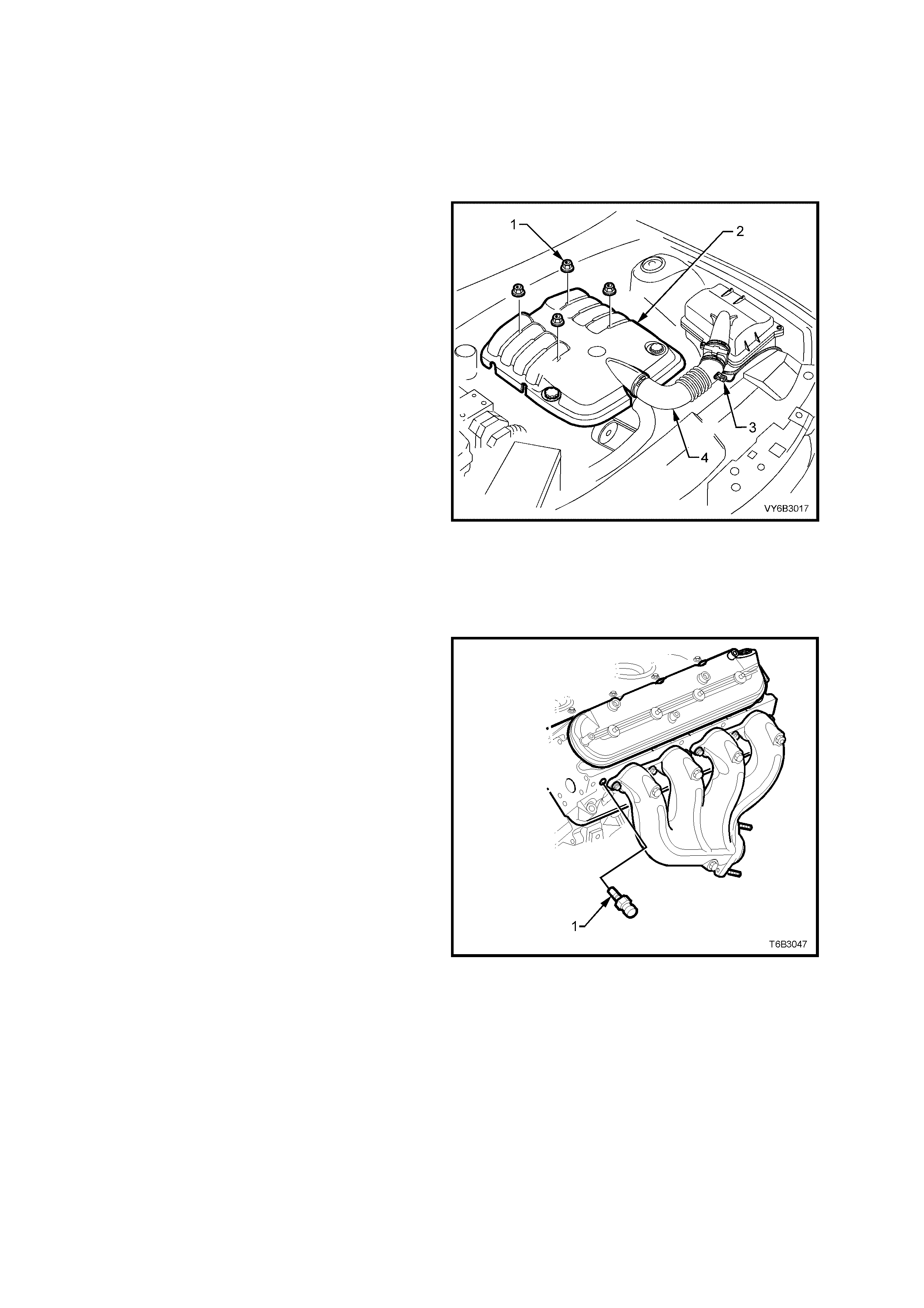
2.21 EXHAUST MANIFOLD
LT Section No. – 00-450
REMOVE
1. Disconnect the ground cable from the battery.
IMPORTANT: Disconnection of the battery affects certain vehicle electronic systems. Refer to
Section 00 CAUTIONS, 5. BATTERY DISCONNECTION PROCEDURES before disconnecting the battery.
2. Remove the four engine dress cover
decorative nuts (1), then remove the dress
cover (2) from the engine.
3. De-pressurise fuel rail. Refer to 2.13 FUEL
SYSTEM PRESSURE RELIEF, in this Section.
4. Remove the air intake sensor wiring harness
connector (3), then loosen both hose clamps
securing the intake duct (4) to the MAF sensor
and the throttle body. Remove the duct (4)
from the engine.
a.
Figure 6A3-111
5. For the right hand side exhaust manifold:
a. Rem ove the eng ine oil l evel ind icator and tube. Ref er to 2. 20 OIL LEVEL INDIC ATOR AND TUBE, in this
Section.
b. Plug the opening in the cylinder block to prevent entry of foreign matter.
6. For the left hand side exhaust manifold:
a. Remove the engine coolant temperature
sensor (1) from the cylinder head to avoid
possible damage during exhaust manifold
removal.
7. Raise the front of the vehicle and place on
safety stands. Refer to Section 0A GENERAL
INFORMATION for location of jacking and
support points.
Figure 6A3-112
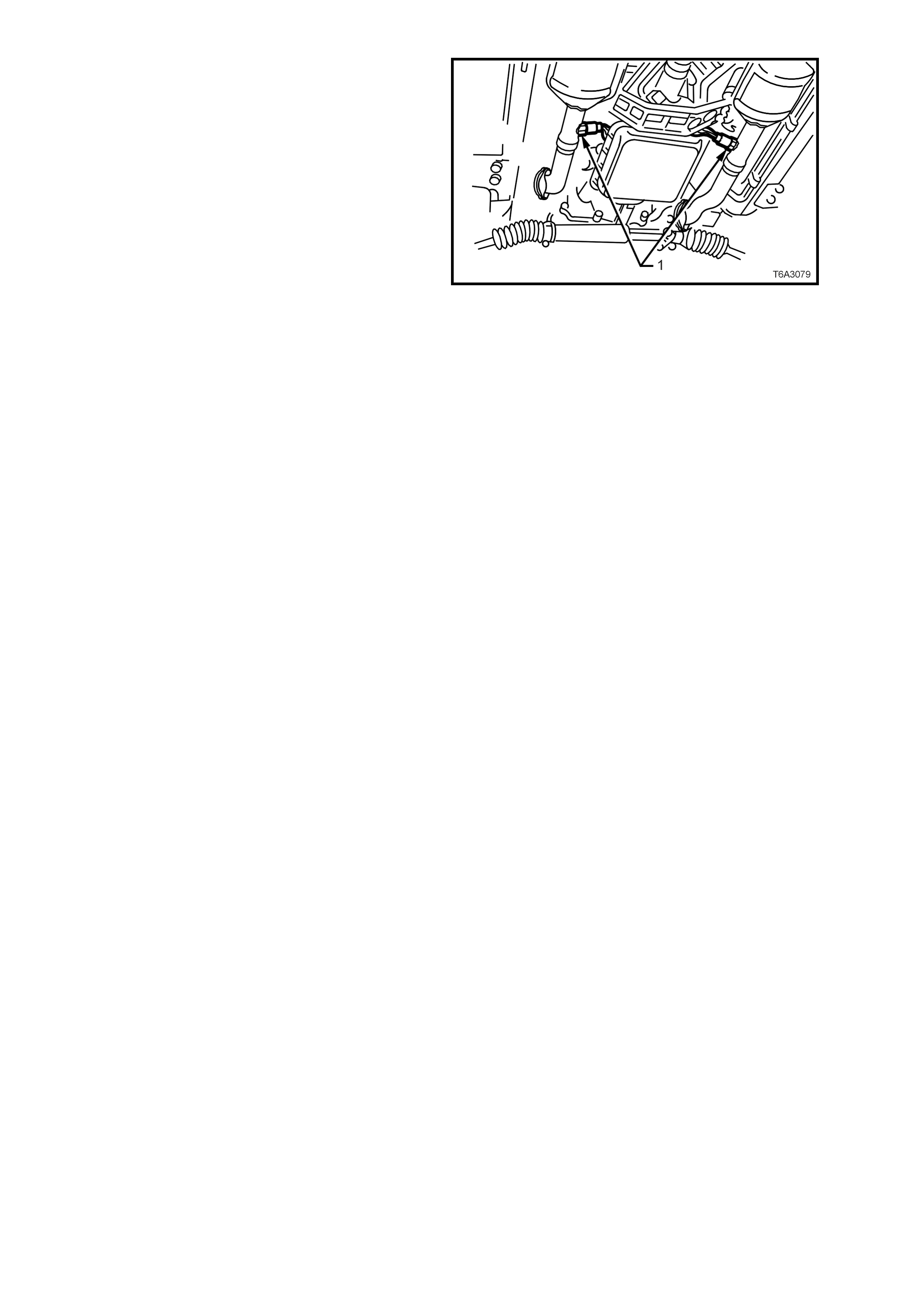
8. W hile not essential , it is re comm ended that the
oxygen sensor/s (1) are removed from the
exhaust pipe/s, to avoid accidental damage.
a. Disconnect the wiring harness connector/s
from the oxygen sensor/s.
b. Remove the ox ygen sensor /s from the ex haust
pipe/s.
Figure 6A3-113
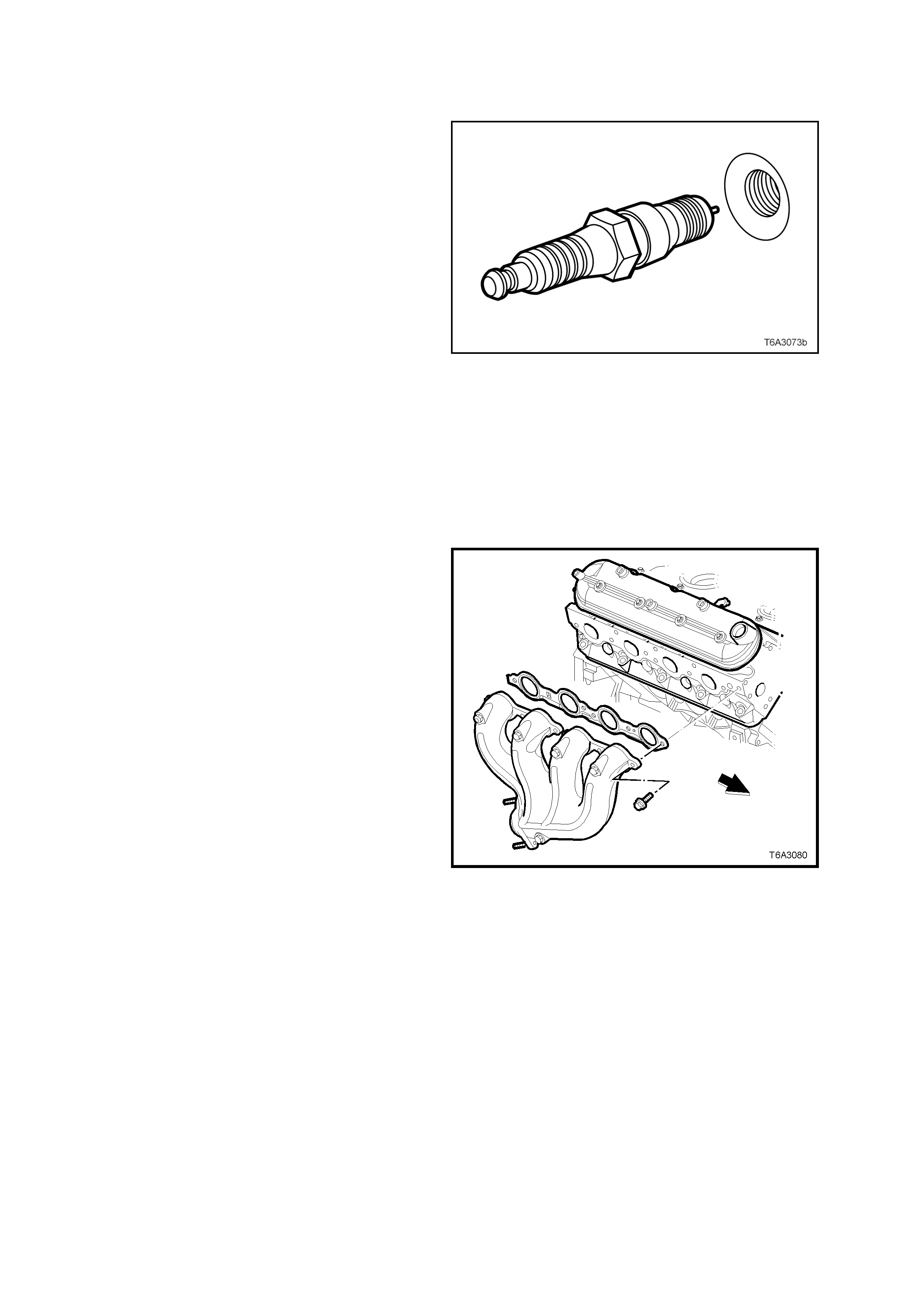
9. Remove the exhaust manifold to exhaust pipe
flange nuts.
10. Lower ve hic l e to the groun d.
11. Remove the spark plugs from the cylinder head
on the exhaust manifold side being removed,
taking note of the following;
a. The engine coolant is to be at 50° C or less. If
not, then the spark plug and cylinder head
threads may bind, causing the cylinder head
threads to be torn.
b. When removing spark plug leads, only handle
the boot on each lead, twist to break the seal,
them pull to remove. DO NOT pull on the lead
itself.
c. Loosen the spark plug/s, then re-tighten to
break away any carbon deposits on the
threads.
d. Loosen the spark plugs once again but, this
time, only one or two turns. Then use
compressed air to remove any foreign m aterial
that may otherwise enter the combustion
chamber.
CAUTION: Wear eye protection to avoid
injury.
e. Continue to remove the spark plugs.
Figure 6A3-114
12. Progressively loosen, then remove exhaust
manifold bolts, working from the outside in to
the centre.
13. Remove ex haust m anifold and gas ket from the
cylinder hea d.
Figure 6A3-115
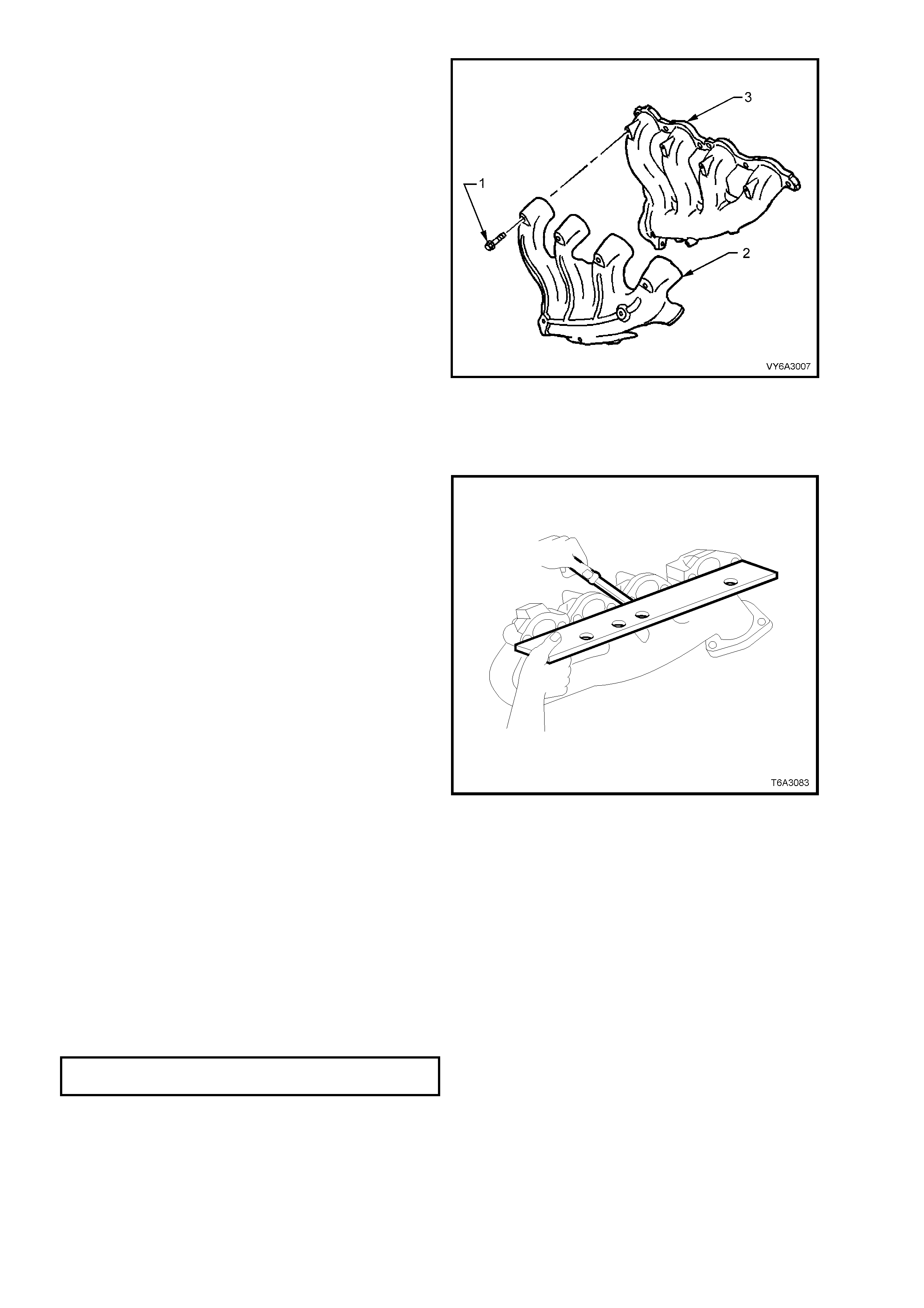
14. If required, remove the heat shield retaining
bolts (1) and the heat shield (2) from the
exhaust manifold (3).
NOTE: While the right hand side exhaust manifold
is shown, the left hand side arrangement is similar.
Figure 6A3-116
INSPECT
1. Inspect for a loose or damaged heat shield.
2. Inspect the exhaust pipe flange stud threads for damage.
3. Inspect the exhaust pipe flange stud threads
for damage.
4. Inspect exhaust manifold to cylinder head
mounting surface for scratches or damage.
5. Using a s tr aig ht e dge and f eel er gau ges, c hec k
that the cylinder head mounting face of the
exhaust manifold does not exceed the
maximum distortion specification of 0.25 mm.
An exhaust manifold exceeding this maximum,
must be machined to correct the misalignment.
Figure 6A3-117
REINST ALL
The reinstallation procedure is the reverse of the removal operation, except for the following items:
NOTE 1: Correct installation of the exhaust manifold gaskets and the adherence to the specified tightening
sequence and torque applied to the exhaust manifold attaching bolts is critical to ensure a gas tight seal and
compliance with emission regulations.
NOTE 2: The exhaust manifold bolt hole threads must be clean and free of debris or threadlocking compound.
NOTE 3: All gaskets, O-rings and seals must be replaced with new parts on assembly.
NOTE 4: Do not apply thread sealant to the first three threads of any exhaust manifold mounting bolt.
1. If the heat shie ld was removed , apply an ant i-seize co mpound such as Caltex Kopr -Kote (or equiv alent) to the
cleaned heat shield bolt threads, reinstall the heat shield and bolts to the exhaust manifold and tighten the
retaining bolts to the correct torque specification.
EXHAUST MANIFOLD HEAT SHIELD
BOLT TORQUE SPECIFICATION 9 Nm
2. Apply a 5 mm wide band of Loctite 272 thread sealant (or equivalent), to the threads of the exhaust manifold
mounting bolts.
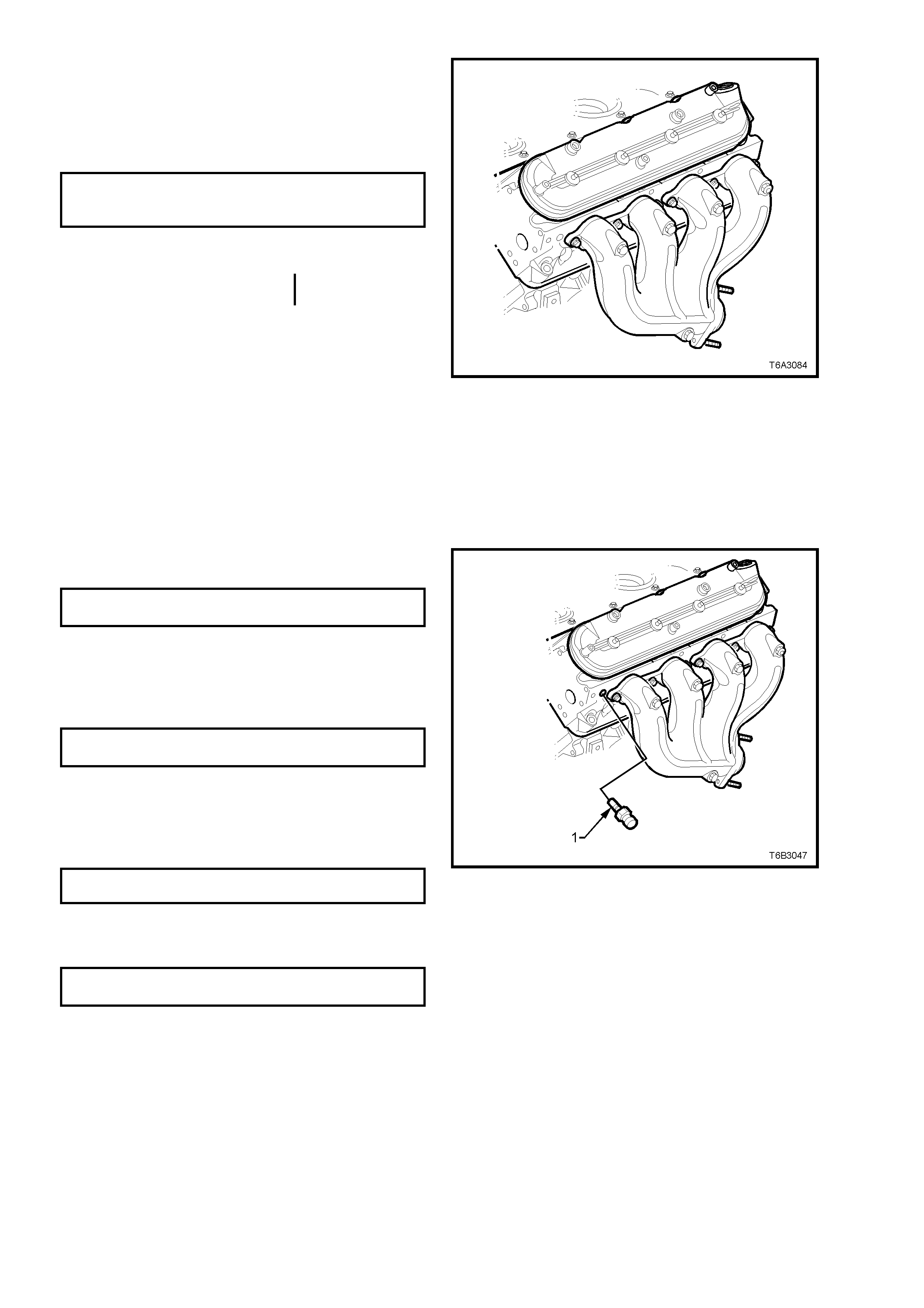
3. Install a NEW exhaust manifold to cylinder
head gasket, install the manifold and bolts.
4. Tighten the exhaust manifold bolts to the
specified, two stage torque specification,
beginning with the centre two bolts, then
alternate from side to side, to the outside bolts.
EXHAUST MANIFOLD BOLT
TORQUE SPECIFICATION Stage 1 – 15 Nm
Stage 2 – 25 Nm
5. Using a flat punch, bend over the exposed
edge of the exhaust manifold gasket at the
front of the right hand cylinder head and the
rear of the left hand cylinder head.
6. If removed, install t he oxygen sens or/s into t he
exhaust pipe/s.
IMPORTANT: A special anti-seize compound is
used on the oxygen sensor threads. New or
service sensors will already have the compound
applied to the threads. If an oxygen sensor is
removed and is to be reinstalled, then the threads
must have the specified anti-seize compound
applied before reinstallation.
This specific anti-seize compound is available
through Service Parts Operations, as Part Number
5613695 and is to be applied to the cleaned
threads of the oxygen sensor.
Figure 6A3-118
7. Tighten the oxygen sensor/s to the correct
torque specification.
OXYGEN SENSOR
TORQUE SPECIFICATION 41 Nm
8. Apply an anti-seize compound such as Caltex
Kopr-Kote (or equivalent) to the cleaned
exhaust pipe flange stud threads.
9. Install and ti ghten the ex haust pipe to m anifold
flange nuts to the correct torque specification.
EXHAUST PIPE FLANGE NUT
TORQUE SPECIFICATION 28 Nm
10. Apply thread sealant such as Loctite 565 (or
equivalent), to the cleaned threads of the
coolant temperature sensor (1).
11. Install and tighten the coolant temperature
sensor (1) to the correct torque specification.
COOLANT TEMPERATURE
TORQUE SPECIFICATION 20 Nm
12. Reinstall spark plugs tightening to the correct
torque specification, then reinstall the spark
plug leads.
SPARK PLUG
TORQUE SPECIFICATION 15 Nm
Figure 6A3-119
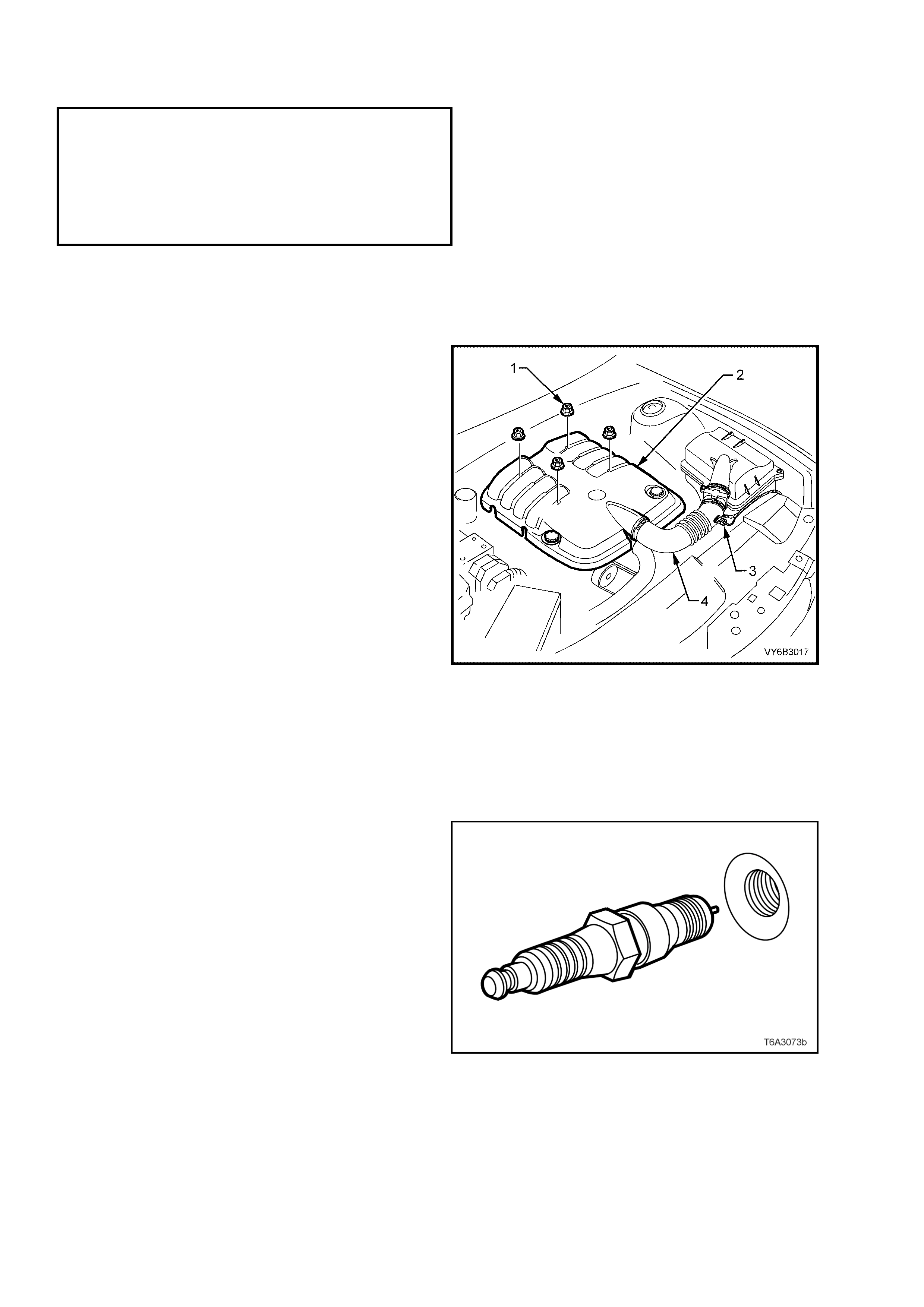
2.22 CYLINDER HEAD
LT Section No. – 00-075
NOTE: The following fasteners MUST be replaced ( ! )
when performing this operation or have either micro
encapsulation or incorporate a mechanical thread lock ( " )
and should only be used once. If in doubt, replacement is
recommended:
! All M11 cylinder head bolts.
" Threads of the M8 bolts.
REMOVE
1. Disconnect the ground cable from the battery.
IMPORTANT: Disconnection of the battery affects certain vehicle electronic systems. Refer to
Section 00 CAUTIONS, 5. BATTERY DISCONNECTION PROCEDURES bef ore dis c onn ectin g the battery.
2. Remove the four engine dress cover
decorative nuts (1), then remove the dress
cover (2) from the engine.
3. De-pressurise fuel rail. Refer to
2.13 FUEL SYSTEM PRESSURE RELIEF, in
this Section.
4. Remove the air intake sensor wiring harness
connector (3), then loosen both hose clamps
securing the intake duct (4) to the MAF sensor
and the throttle body. Remove the duct (4)
from the engine.
5. Remove the e ngine acces sory drive belt . Refer
to 2.6 ENGINE DRIVE BELTS, in this Section.
6. Remove intake manifold. Refer to
2.14 INT AKE M ANIFOLD, in this Section.
7. Remove vapour vent pipe. Refer to
2.15 VAPOUR VENT PI PE , in this Section.
8. Remove va lve r oc k er arm cover on t he cylind er
head to be removed. Refer to
2.17 VALVE ROCKER ARM COVER, in this
Section.
9. Remove valve rocker arms and push rods on
the cylinder head to be removed. Refer to
2.18 VALVE ROCKER ARMS AND PUSH
RODS, in this Secti on.
Figure 6A3-120
10. Remove the spark plugs from the cylinder head
being removed, noting the following:
a. The engine coolant is to be at 50° C or less. If
not, then the spark plug and cylinder head
threads may bind, causing the cylinder head
threads to be torn.
b. When removing spark plug leads, only handle
the boot on each lead, twist to break the seal,
them pull to remove. DO NOT pull on the lead
itself.
c. Loosen the spark plug/s, then re-tighten to
break away any carbon deposits on the
threads.
a. Loosen the spark plug/s once again but,
this time, only one or two turns. Then use
compressed air to remove any foreign
material that may otherwise enter the
combustion chamber.
CAUTION: Wear eye protection to avoid injury.
e. Continue to remove the spark plug/s.
Figure 6A3-121
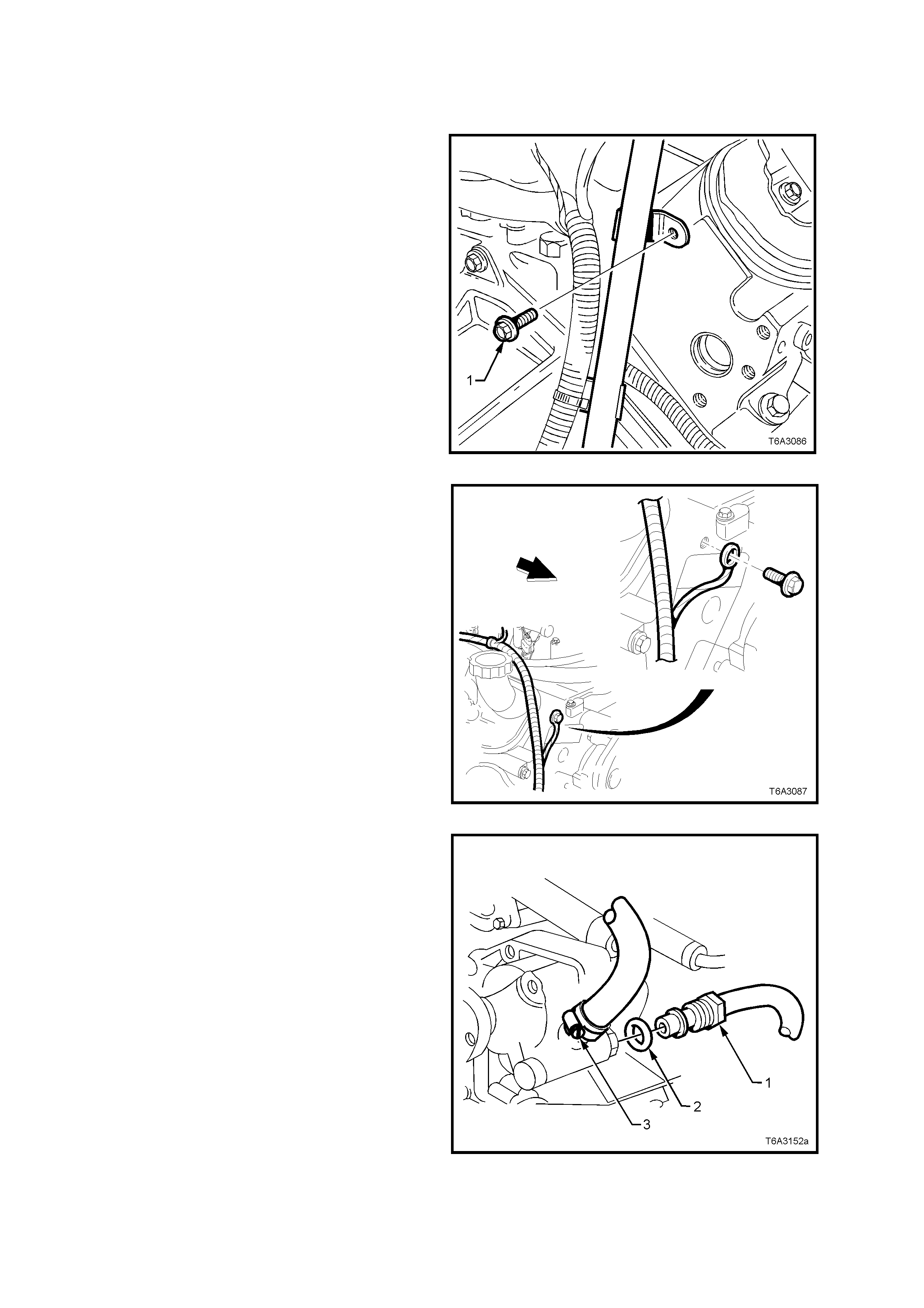
11. For the right hand side cylinder head, first
remove the engine oil level indicator and tube.
Refer to 2.20 OIL LEVEL INDICATOR AND
TUBE, in this Section.
12. Remove the exhaust manifold on the cylinder
head to be removed. Refer to 2.21 EXHAUST
MANIFOLD, in this Sec ti on .
13. For the right hand cylinder head:
a. Remove the bolt securing the automatic
transmission dipstick tube bracket bolt (if
fitted).from the rear of the cylinder head
Figure 6A3-122
b. Remove the bolt securing the powertrain
harness ground strap from the front of the
right hand cylinder hea d.
Figure 6A3-123
14. For the left hand cylinder head:
a. Place a drain tray beneath power steering
pump assembly.
b. Remove the p ower steer ing f luid reservoir from
its bracket by levering the bracket locking tab
with a screwdriver or similar lever, to release
the reservoir. Refer to Section 9A STEERING.
c. Loosen and r emove high pr es sur e li ne f lare nut
(1) and O-ring (2) from pump outlet fitting,
using a back-up spanner on the pump outlet
fitting.
NOTE: Fluid will drain from the reservoir so
have a suitable container available.
d. Loosen low pressure hose clamp (3) and
remove hose from pump inlet fitting.
NOTE: Plug or tap e th e pu m p and hose fitti ngs
to prevent dirt entry.
Figure 6A3-124
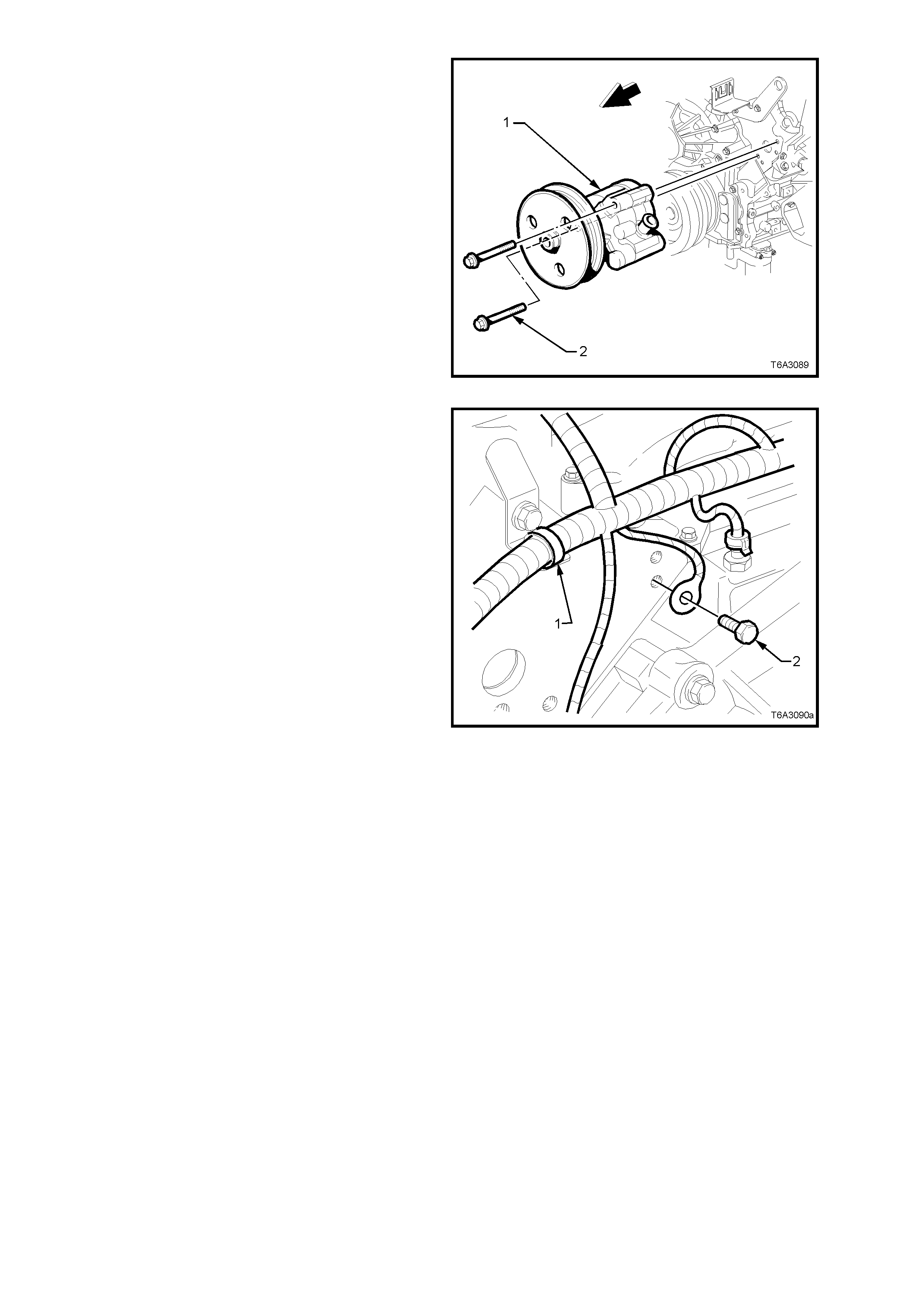
d. Remove both bolts (2) securing the power
steering pump (1) to the front of the left hand
cylinder hea d.
NOTE: Access to the two bolts can be made
through the pulley holes, using a suitable
socket and extension.
e. Secure th e res er voir and pum p to one s ide,
using tie wire or sim ilar .
Figure 6A3-125
c. Remove the powertrain wiring harness strap
(1) from the bracket at the rear of the cylinder
head.
d. Remove the bolt (2) securing the powertrain
harness ground cable at the rear of the cylinder
head.
Figure 6A3-126
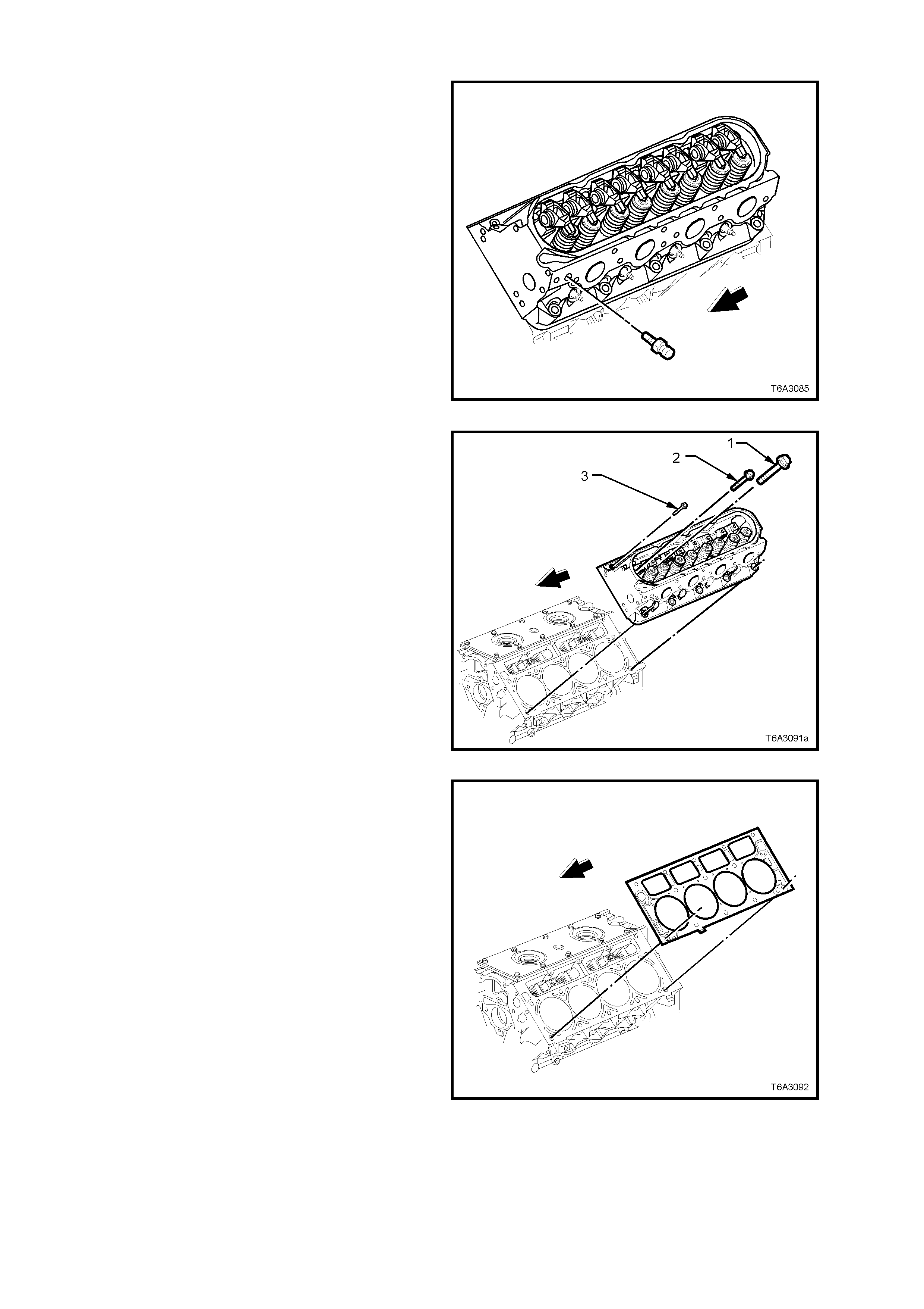
e. Remove the coolant temperature sensor (1).
NOTE: This step is necessary to allow the lower
left cylinder head bolt to be removed and to avoid
the risk of accidental damage to the sensor.
Figure 6A3-127
15. Progressively loosen cylinder head bolts
starting with the M8 bol ts (3) fir st, working f rom
the outside to the centre.
NOTE: Discard all M11 bolts (1 and 2) after
removal, as these are ‘torque to yield’ bolts. Also
note the location of the two shorter, M11 bolts (2).
The M8 bolts (3) can be re-used.
16. Remove the cylinder head from the cylinder
block and place on two blocks of wood. This is
most important to avoid scratching the
machined surface.
Figure 6A3-128
17. Remove and discard the cylinder head gasket.
Figure 6A3-129
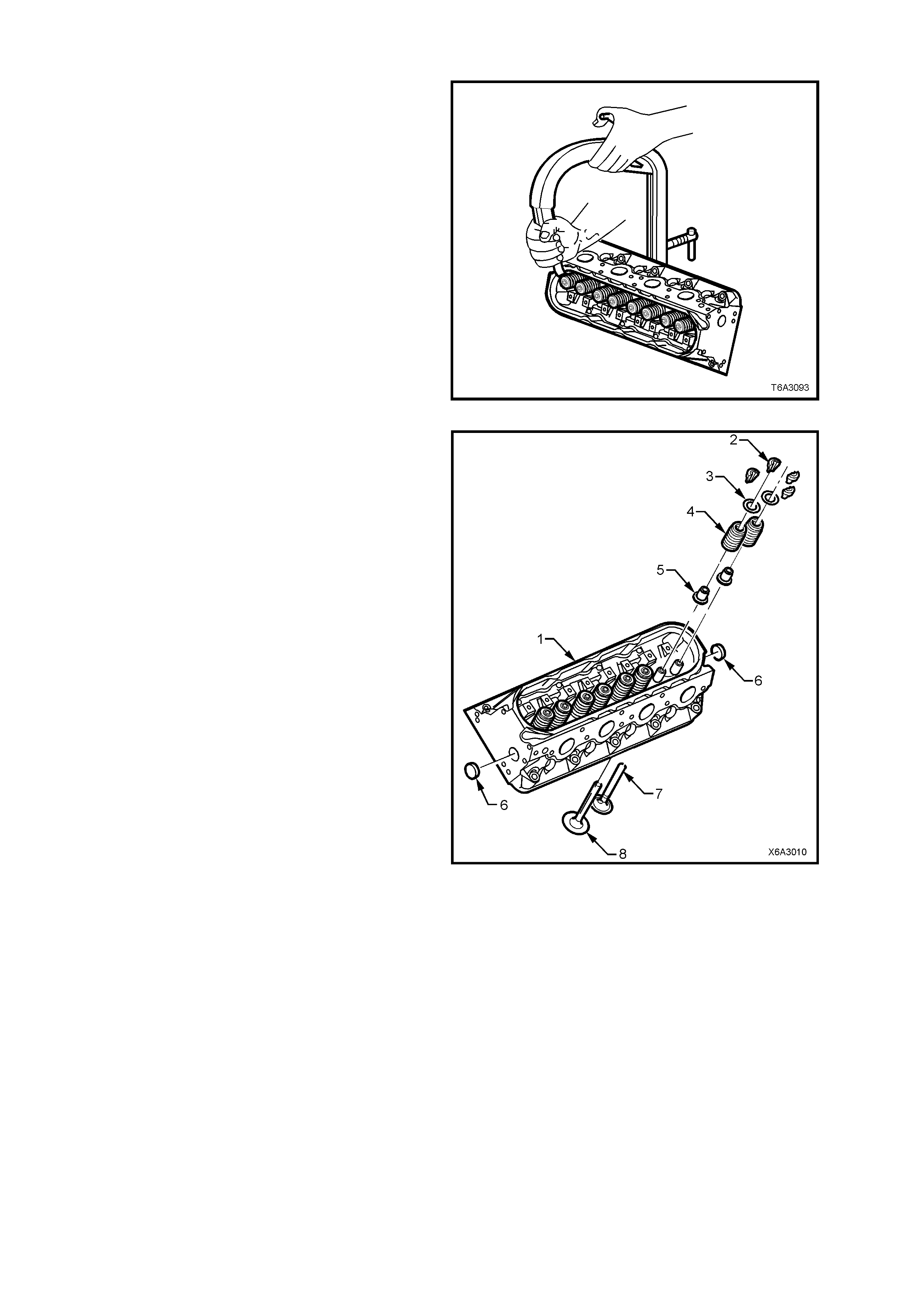
DISASSEMBLE
NOTE: Do not mix r em ove d c omponents. O r g anise
all parts in the order removed, to ensure that parts
reinstalled are fitted to their original locations.
1. Use a commercially available valve spring
compressor to compress the valve spring.
NOTE: It may be necess ary to tap th e valve spring
end of the com pr essor with a plastic f aced ham m er
to loosen jammed valve collets.
Figure 6A3-130
2. Remove the following components from the
cylinder hea d (1):
a. Valve stem collets (2).
b. Valve spring cap (3).
c. Valve spring (4).
d. Valves (7, 8).
e. Valve stem oil seal and shim assembly (5).
NOTE: Do not remove coolant core plugs (8)
unless servicing is required.
Figure 6A3-131
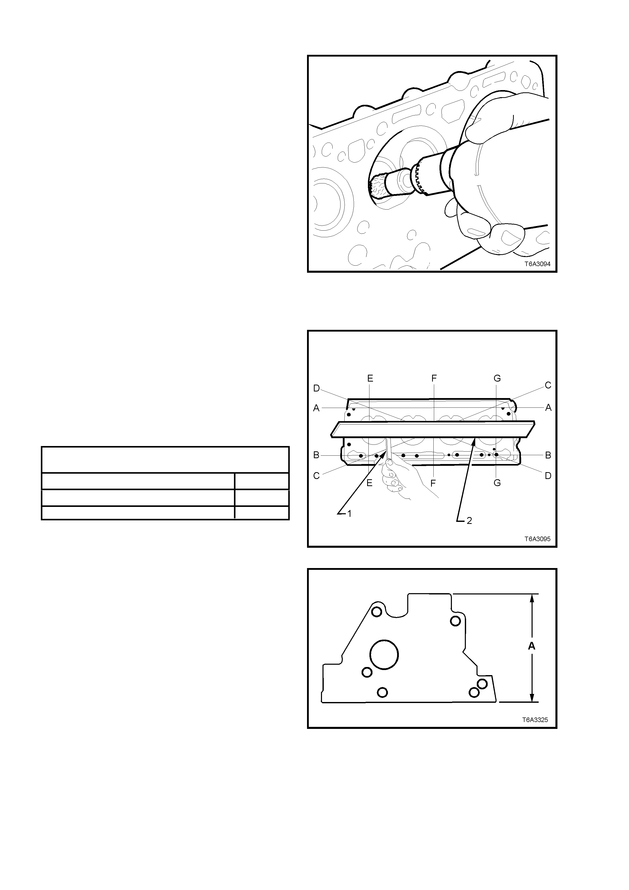
CLEAN
1. Use a c ommerciall y avai la b le rotary wire brush,
clean all carbon deposits from the combustion
chambers and valve ports, taking care not to
scuff or damage the aluminium cylinder head
surfaces.
CAUTION: Wear safety glasses to avoid eye
injury.
2. Clean carbon deposits from valve stems and
heads on a buffing wheel.
3. Check all bolt threads for dam age and remove
all threadlocking compound from both the
threaded holes and bolts.
Figure 6A3-132
INSPECT
Cylinder Head
1. Check cylinder head deck, inlet and exhaust
manif old mating s urfaces for dis tortion, using a
straight e dge (2) and f eeler gauges ( 1). Check
lengthwise, diagonally and crosswise, as
shown by the alp hab etic a l order, in F ig ure 6A3-
133.
2. Check the cylinder head deck to exhaust
manifold the cylinder head deck to intake
manifold surfaces for flatness.
CYLI NDER HEAD FLAT NESS SPECI FICATION
(Measured Over the Cylinder Head Lengt h)
CYLINDER HEAD, ENGINE BLOCK DECK 0.22 mm
CYLINDER HEAD, EXHAUST MANIFOLD DECK 0.22 mm
CYLINDER HEAD, INTAKE MANIFOLD DECK 0.22 mm
Figure 6A3-133
NOTE: If any of these surfaces are outside
specification, the cylinder head may be machined,
provided the minimum overall height of 120.2 mm
(dimension ‘A’) is not exceeded.
3. Inspect all threaded holes for damage,
repairing as required with suitable thread
inserts. Refer to 3.16 THREAD REPAIR, in
this Section for more information.
4. Clean any residue of cylinder head bolt thread
sealant from the cylinder block threads, using
installer , Too l No. J-4238 5-107 (this tool is par t
of the thread repair kit, J-42385).
IMPORTANT: Do not use anything but this thread
tool to clean the cylinder head threads in the
cylinder bl oc k.
5. Use compressed air to clean all residue from
bolt holes.
CAUTION: Wear eye protection to prevent
injury.
Figure 6B3-134
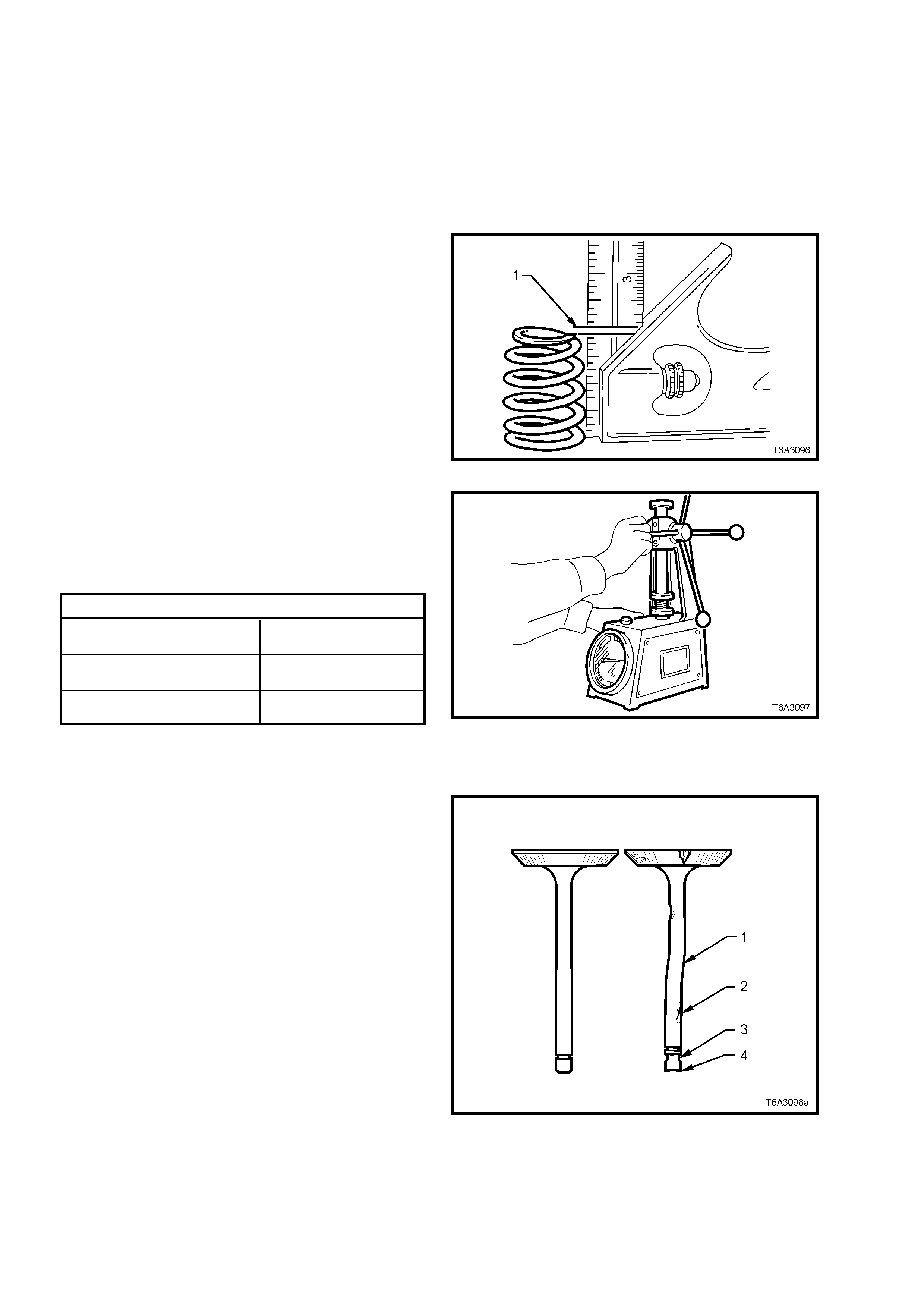
6. Inspect coolant jacket expansion plugs for signs of corrosion, replace plugs as necessary.
NOTE: If replacing expansion plugs, apply a coating of Loctite 242 or equivalent around plug sealing surface.
7. Inspect cylinder head for cracks, especially between valve seats or exhaust ports.
8. Inspect cylinder block deck surface for distortion, refer to 3.15 CYLINDER BLOCK.
9. Clean the M8 cylinder head bolt threads, replacing any bolt that has suspect threads, stretched or damaged
heads caused by improper use of tools.
NOTE: Discard all M11 bolts after removal, as these are “torque to yield” bolts.
Valve Springs
1. Check all valve springs for distortion. There
should be no more than 1.6 mm variance
(distance ‘1’) of the s prin g end, whi le t he s pri ng
is being rotated on a flat surface. Replace
springs that exceed this specification.
Figure 6A3-135
2. Use a commercially available valve spring
tester to m easur e each valve s pring f ree heig ht
and tension.
3. Discard any spring that does not conform to
specification.
VALVE SPRING SPECIFI C ATION S
VALVE SPRING FREE HEIGHT
(INTAKE and EXHAUST 52.9 mm
VALVE SPRING TENSION 310 N at 45.75 mm
SPECIFICATION (Closed Valve, Minimum)
VALVE SPRING TENSION 980 N at 33.55 mm
SPECIFICATION (Open Valve, Minimum)
Figure 6A3-136
Valves
1. Inspect valve stems for burrs and scratches. If
minor, these can be removed with an oil stone.
Valves with excessive stem wear or that are
warped (1 and 2), should be replaced.
Inspect the valve stem end (4) for wear. If
required wear can be corrected by grinding,
provide d the stem end is ground at ri ght angl es
to the valve stem.
2. Inspect valve stem collet gr oove ( 3) f or wear or
damage.
Figure 6A3-137
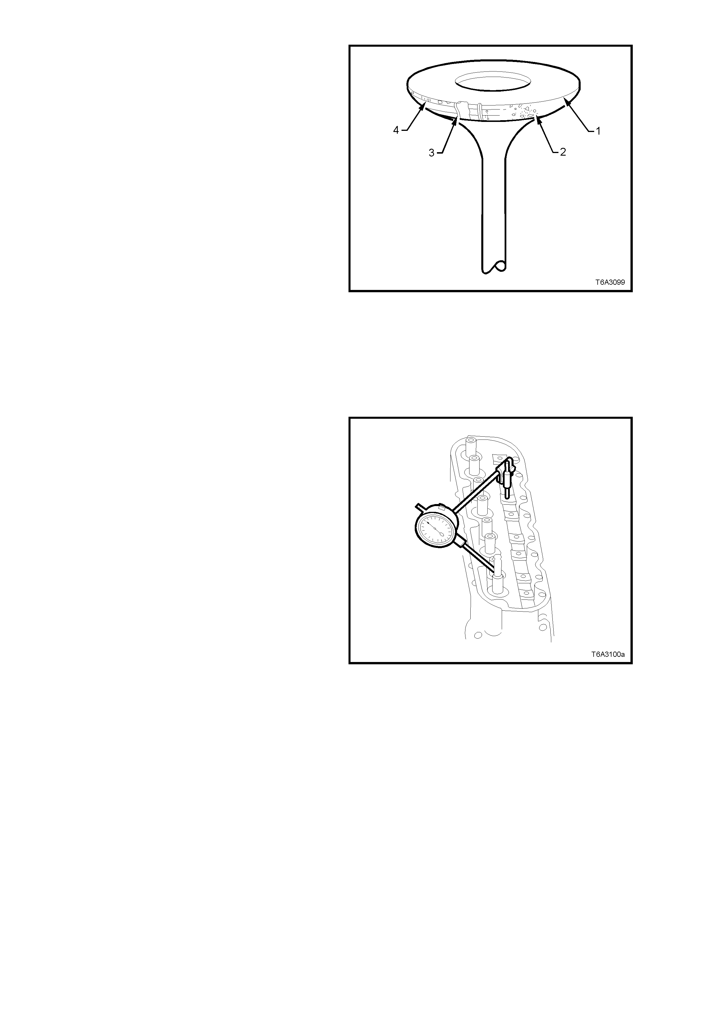
3. Check valve face for the following:
Either no m argin (1) or les s tha n 1 .25 m m after
grinding (4 ).
Excessive pitting (2).
Burnt or corroded areas (3).
4. If an exhaust valve is to be reconditioned, the
face can be ground, using a valve refacing
m achine. The va lv e seat an gle is 45°.
The equipment manufacturer’s
recom mendatio ns m us t be c aref ully fo llo wed to
achieve the required standard of finish.
NOTE: If an exhaus t valve face is regr ound, it may
be necessary to shim the valve spring to achieve
the correct spring installed height. Refer to
Cylinder Head Reassemble in this Section, for
details.
IMPORTANT: Intake valve faces must not be
refaced. Intake valves that are worn or have
face damage MUST be replaced.
5. Measure the valve stem diameter. A valve
stem diameter of less than 7.95 mm must be
replaced
Figure 6A3-138
Valve Guides
Excessive valve stem to guide clearance may
cause a no isy valve tr ain, prem ature valve stem oil
seal wear, co mponent dam age an d/or ex ces s ive o il
consumption.
Insuff ic ient val ve s t em to guid e cle ar anc e will r es u lt
in nois y or s ticking val ves. Valves that are to o tight
may disturb engine smoothness or lead to
component damage.
Measure clearance as outlined in the following
steps.
1. Insert valve into its guide.
2. Clamp a dial indicator to a valve rocker arm
bolt that has been temporarily installed, in a
position where sideways movement of the
valve stem will cause movement of the
indicator nee dle .
To obtain a correct indication of wear, the
indicator stem must contact the side of the
valve s tem, from 8 - 12 mm above top of valv e
guide.
3. With the valve head dropped approximately 2
mm off its seat, move the stem of the valve
side to s ide aga ins t th e d ial ind ica tor us i ng light
force, to obtain a clearance reading.
NOTE: Provided the valve stem diameter is within
specifications but the valve stem to guide
clearance exceed 0.093 mm (either intake or
exhaust), the clearance must be corrected or the
cylinder hea d rep lace d.
Figure 6A3-139
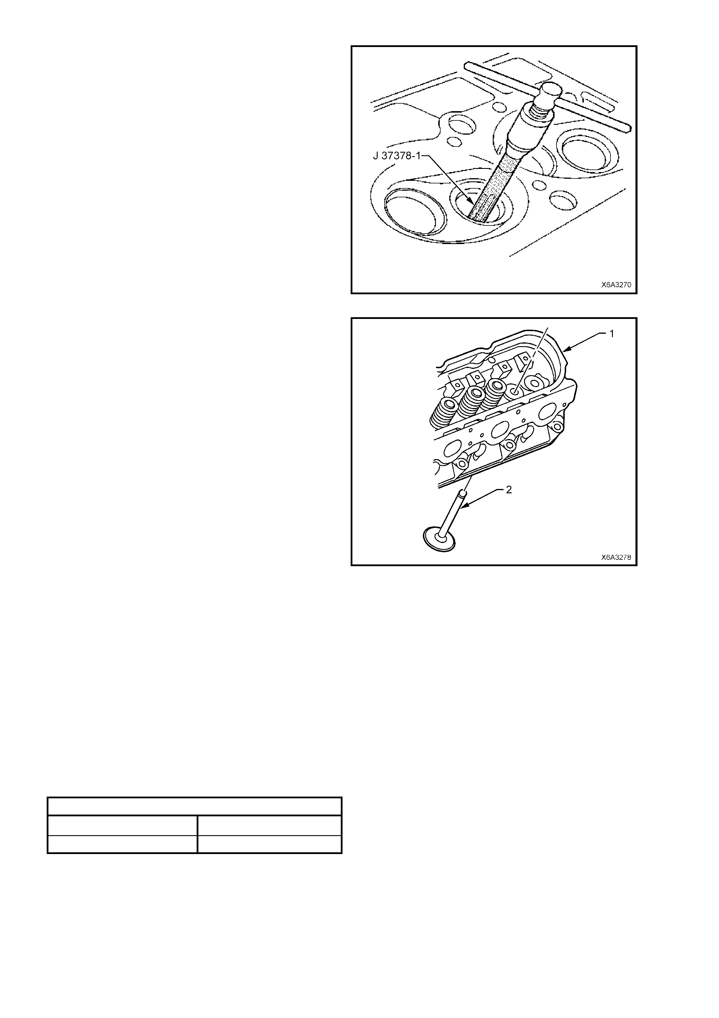
4. Ream the valve guide using Tool J 37378-1.
5. Clean the valve guide bore of all metal
shavings and debris.
Figure 6A3-140
6. Install the oversize valve (2) into the reamed
valve guide.
7. T he val ve should s lide f r eel y witho ut r esistance
or drag. The clearance must also not exceed
specification.
Figure 6A3-141
Valve Seats
Reconditioning the valve seats is ver y important because the seating of the valves must be precise f or the engine
to deliver the power and performance built into it.
Another important factor is the cooling of the valve head. Good contac t between each valve and its seat in the head
is imperative to ensure that the heat in the valve head will be transferred efficiently.
Severa l differ ent types of e quipment ar e available f or recondit ioning va lve seats with an oscillat ing type va lve seat
grinder being preferred. The recommendations of the manufacturer of the equipment being used should be
carefully followed to attain proper results.
1. Check valv e seats f or any evide nc e of pitt in g or d amage at va l ve cont ac t s urf ac e. If pitti ng is ev ide nt, t he va l ve
seats will nee d to be recondition ed.
NOTE: Since the valve guide serves to support and centre the valve seat grinder, it is essential that valve guide
wear is checked, as detailed in the previous operation.
Both the intake and exhaust valve seat angles are 46° and seat width shou ld not e xc eed specificati on.
VALVE SEAT W IDTH SPECIFICATION
INTAKE 1.02 mm maximum
EXHAUST 1.78 mm maximum
If valve seats are recond itioned and the exhaust valve faces ground, then light lapping will ensure a gas tight seal
when closed.
NOTE: New valves must not be lapped, as this will destroy the protective coating on the valve face.
After refacing an existing valve or installing a new valve, correct seating must be checked as follows:
a. Lightly coat valve face with bearing (Prussian) blue.
b. Insert the valve and rotate about 1/6th of a turn.
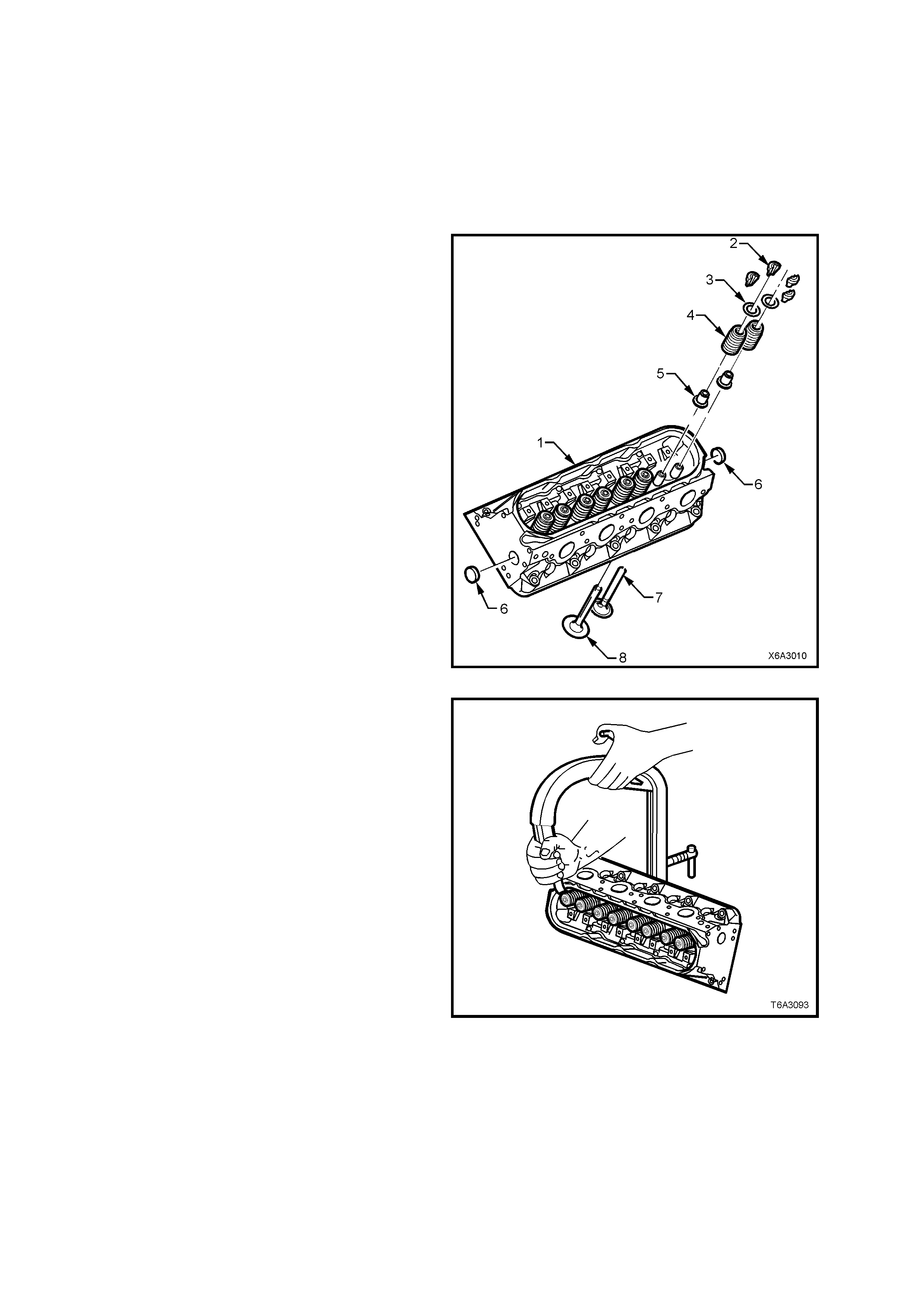
c. Remove valve and check its contact with the seat.
d. If full contact is indicated, valve and seat are acceptable.
However, if only par tial contac t is shown, reinstall th e valve a nd rotate f or one full tur n. If blue now indicat es a
full contact then the valve m ust be refaced or replaced. If the blue contact still onl y shows partial cont act then
regrind the valve seat.
e. Clean all traces of blue from the valves and seats, then clean thoroughly before applying clean engine oil to
both surfaces to protect from rusting.
REASSEMBLE
NOTE: Ensure th at all r e-used par ts are r einstalle d
to their original locations.
1. Lubricate all valve stems, guides and valve
faces with clean engine oil, then install valves
(7, 8) to their correct ports.
2. Install a new valve stem oil seal and shim
assem bly b y hand, unti l the shim seats agai nst
the cylinder hea d. No s peci al to ols are requ ired
for this operation.
IMPORTANT: The valve stem oil seal alignment
and position on the valve stem is critical. An
improperly installed valve stem oil seal will lead to
excessive oil consumption and increased exhaust
emissions.
Figure 6A3-142
3. Inst all th e v al ve spr i ngs an d c aps to e ac h val ve
stem.
4. Use a commercially available valve spring
compressor to compress the valve spring.
5. Install valve stem collets, retaining with
petroleum jelly if required.
6. Ensure that the both collets are correctly
located before releasing the valve spring
compressor.
7. Tap the end of each installed valve stem, with
a plastic faced hammer to seat the collets.
Figure 6A3-143
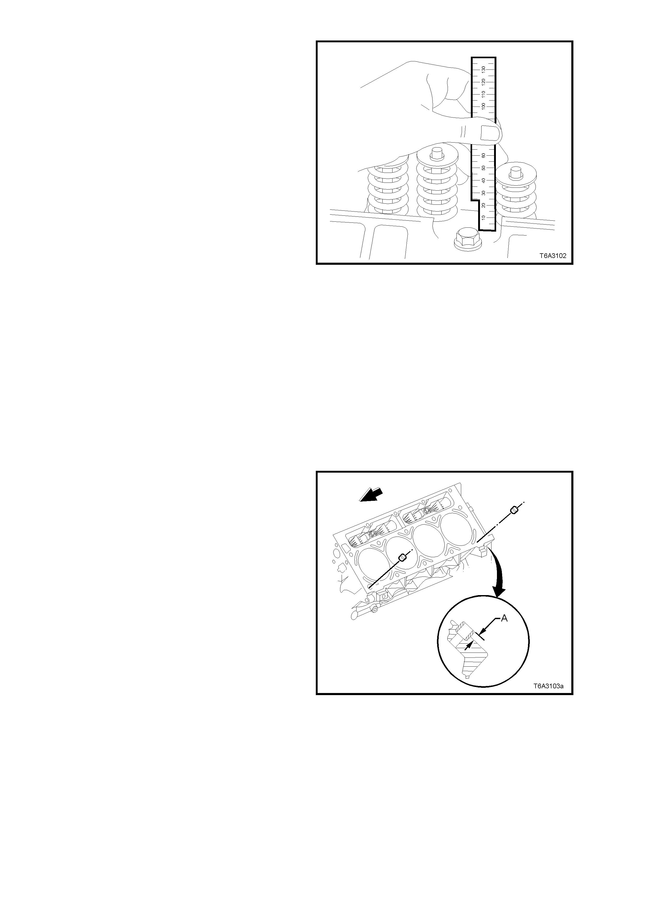
8. Measure the v alve spring i nstalled hei ght using
a ruler or vernier calipers. Measurement is to
be taken from the base of the valve spring to
the top.
9. If the measurement exceeds 46.25 mm, a
commercially available, stainless steel shim
must be installed between the valve stem oil
seal/shim combination and the cylinder head,
to achieve the required spring height.
NOTE 1: Do not shim the valve spring to obtain
less than the specified height.
NOTE 2: W hen replacing v alve stem oil seals, o nly
use the later design that c ombines the oil seal and
the valve spring shim.
10. Install the remaining valves, springs and other
components, checking each spring height as it
is assembled.
11. If the cylinder head core plugs were removed,
install with sealant such as Loctite 565 (or
equivalent) before plug installation.
Figure 6A3-144
REINST ALL
Reinstallation of either or both cylinder heads is the
reverse to the removal procedure, except for the
follo wing po ints .
NOTE 1: Do not refit removed M11 cylinder head
bolts. Always use NEW bolts when installing a
cylinder hea d.
NOTE 2: Do not use any sealant on the cylinder
head gas ket, nor thr eadloc k com pound on th e M11
cylinder hea d bolts .
1. Check the cylinder head locating sleeves for
correct installation. Dimension ‘A’ is to be 8.3
mm, when the revised design cylinder head
gasket is used.
NOTE: When the earlier design cylinder head
gaskets were used, this dimension was 6 mm.
Figure 6A3-145
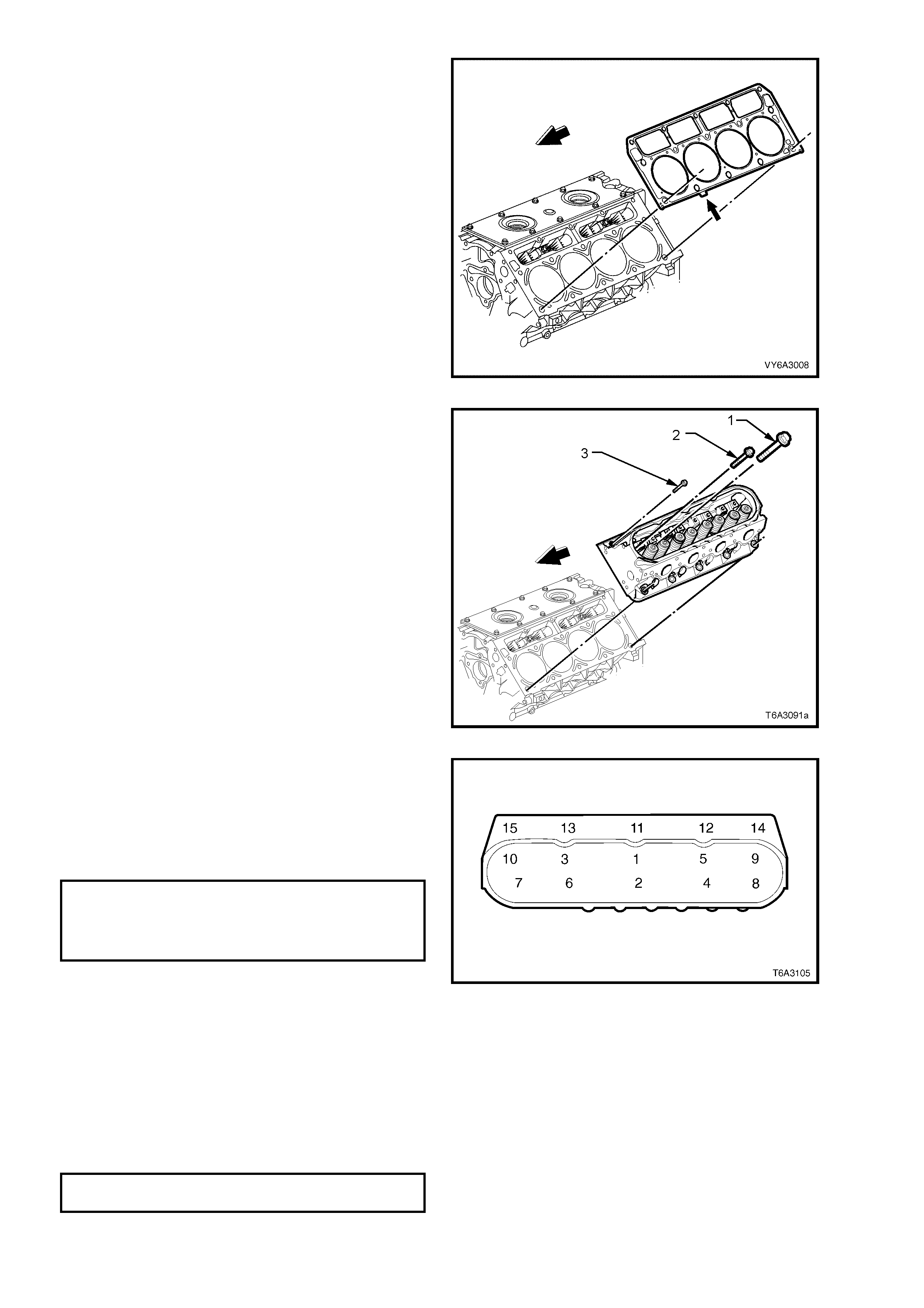
2. Install a NEW cylinder head gasket correctly
over the locating sleeves.
NOTE 1: When correctly installed, the tab (arrow)
on the cylinder head gasket will be located to the
front half point (small arrow). This applies with
either cylinder head gasket.
NOTE 2: The cylinder head gaskets will fit on
either side. The only condition is that the word
‘FRONT’ stamped on the gasket must face the
engine front. The tab should also have “5.7”
imprinted on it.
Figure 6A3-146
3. Install the cylinder head over the locating
sleeves and the previously installed gasket.
4. Apply a 5 mm band of threadlock such as
Loctite 242, ONLY to the threads of the M8
bolts (3).
5. Install the M8 cylinder head bolts (3), then
loosely install NEW M11 bolts (1 and 2).
Figure 6A3-147
6. T ighten the c ylinder head bolts in the sequ ence
shown and to the correct torque specification.
NOTE 1: Use a tor que a ngl e meter s uch as E 7115
to achieve an accurate turn angle reading.
NOTE 2: Bolt numbers 1 to 10 inclusive are the
M11 bolts, while bolts 11 to 15 are the M8 bolts.
CYLINDER HEAD BOLT TORQUE SPECIFICATION
Stage 1 (All M11 and M8 Bolts) 30 Nm
Stage 2 (All M11 Bolts only) 90° turn angle
Stage 3 (M11 Bolt s 1 to 8 only) 90° turn angle
(M11 Bolts 9 and 10 only) 50° turn angle
For the rem ainder of reins tallation proc ess, refer to
the following procedures, in the order listed:
2.18 VALVE ROCKER ARM S AND PUSH RODS.
2.17 VALVE ROCKER ARM COVER.
2.15 VAPOUR VENT PIPE .
2.14 INT AKE M ANIFOLD.
2.21 EXH AUST M ANIFOLD/S.
NOTE: If a cylinder head is replaced, the initial
spark plug torque specification, must be amended
to:
SPARK PLUG TORQUE SPECIFICATION
(NEW CYLINDER HEAD) 20 Nm
2.20 OIL LEVEL INDICATOR AND TUBE.
Figure 6A3-148
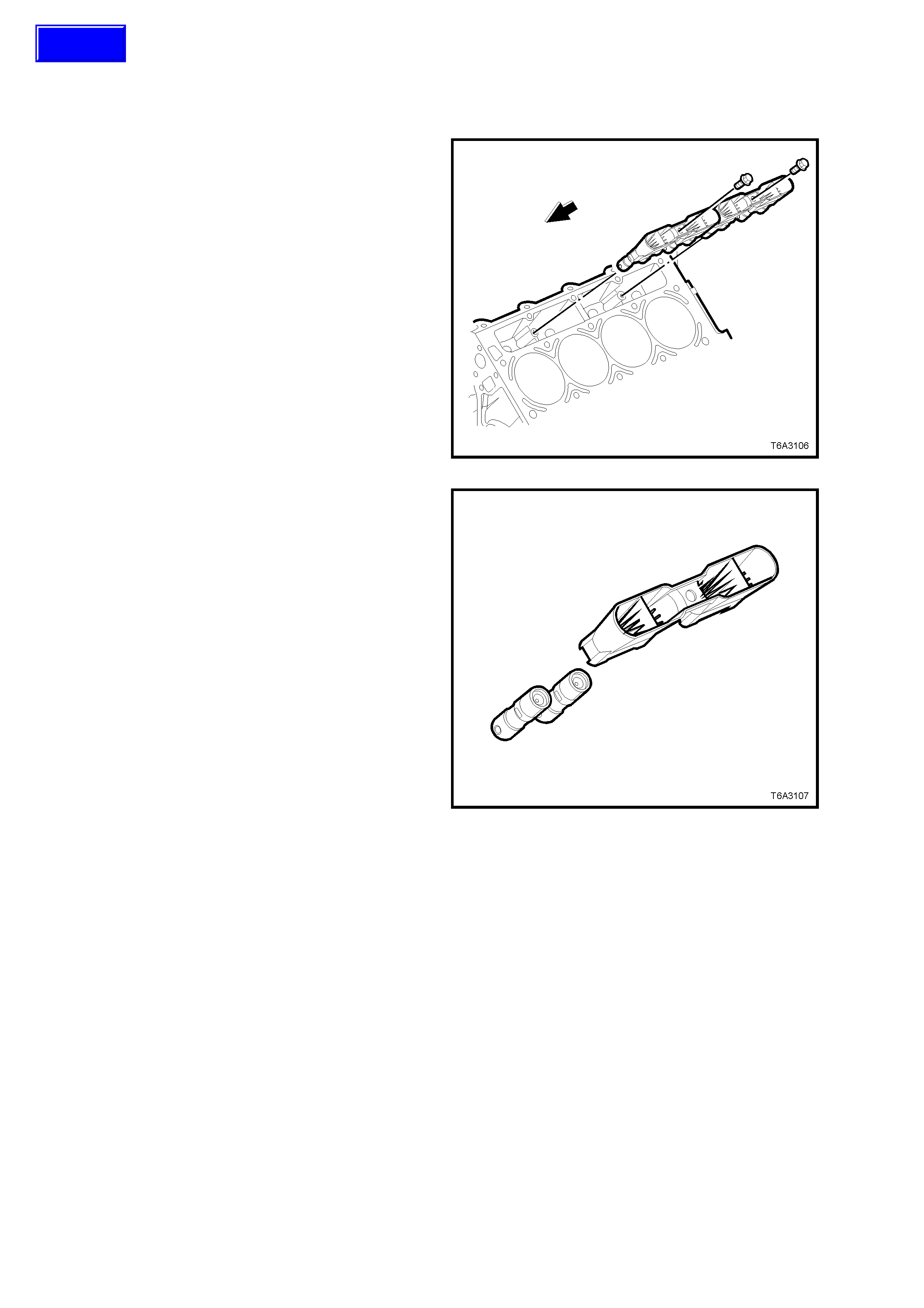
2.23 VALVE LIFTERS
LT Section No. – 00-050
REMOVE
NOTE: Ensure that all valve train components are
kept in order so they may be reinstalled, if required,
in their orig ina l loc at ions.
1. Remove the cylinder head on the side requiring
hydraulic lifter removal. Refer 2.22 CYLINDER
HEAD - REMOVE, in this Section.
2. Remove both valve lifter guide retaining bolts.
3. Remove valve lifters and guides.
Figure 6A3-149
4. Remove the valve lifters from the guide/s.
Figure 6A3-150
Techline
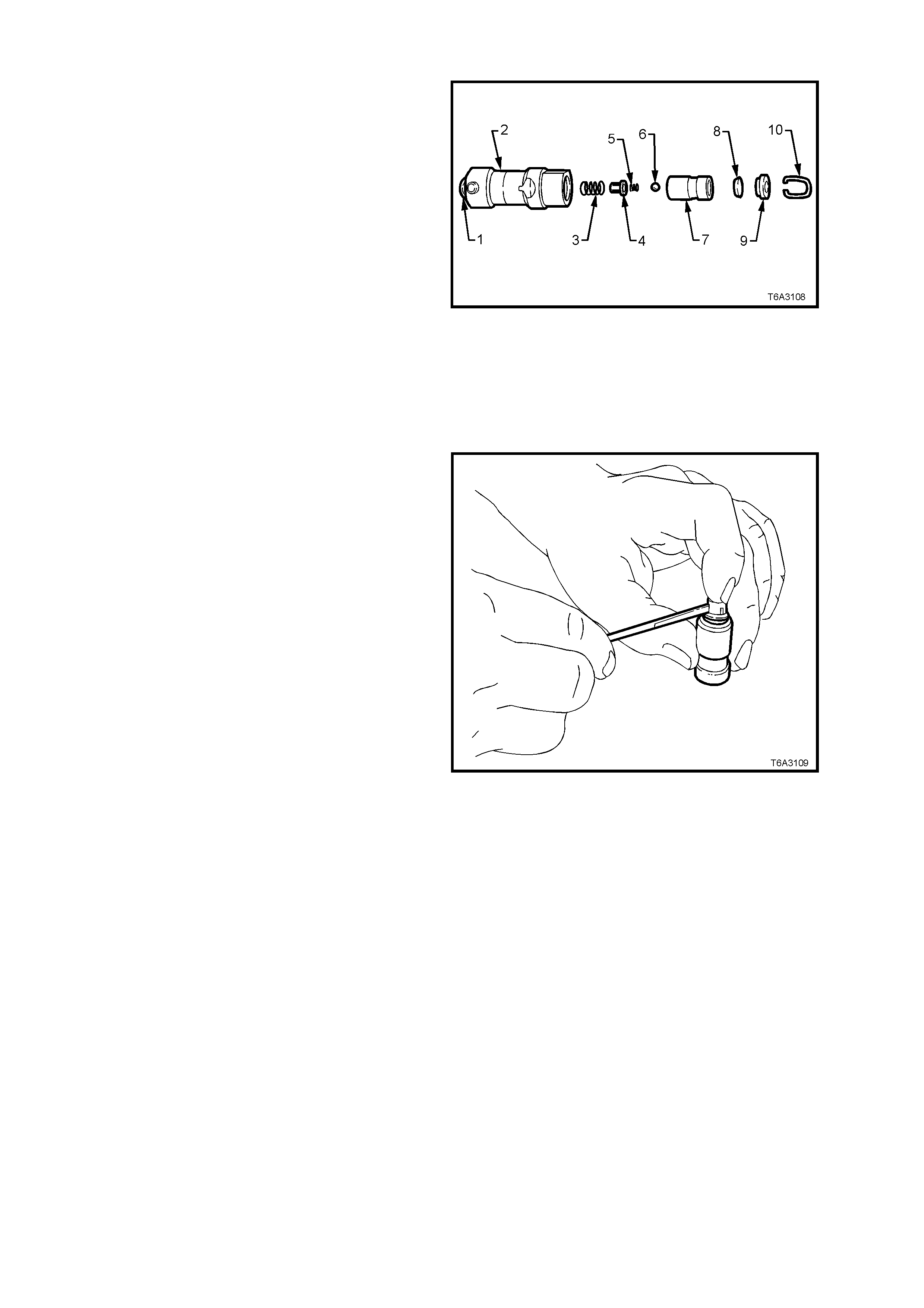
DISASSEMBLE
1. Using a small, f ine bladed scr ewdriver , remove
push rod seat retaining clip (10).
2. Remove push rod seat (9), oil metering valve
(8), plunger assembly (7) and plunger spring
(3) from lifter body (2).
NOTE: If the plunger is stu ck in the lifter body, turn
lifter body upside down and tap lifter body on a
block of wood. If this is not effective, soak lifter
assembly in a suitable cleaning fluid.
Legend:
1. Roller.
2. Lifter Body.
3. Plunger Spring.
4. Ball Check Retainer.
5. Ball Check Spring.
6. Ball Check.
7. Plunger.
8. Oil Metering Valve.
9. Push Rod Seat.
10. Push Rod Seat Retaining Clip.
Figure 6A3-151
3. Remove ball check retainer (4), ball check
spring (5) and ball (6) from the plunger (7).
Figure 6A3-152
CLEAN AND INSPECT
1. Thoroughly clean all parts in a suitable
cleaning fluid. Blow all parts dry with
compressed air.
CAUTION: Wear safety glasses to avoid eye
injury.
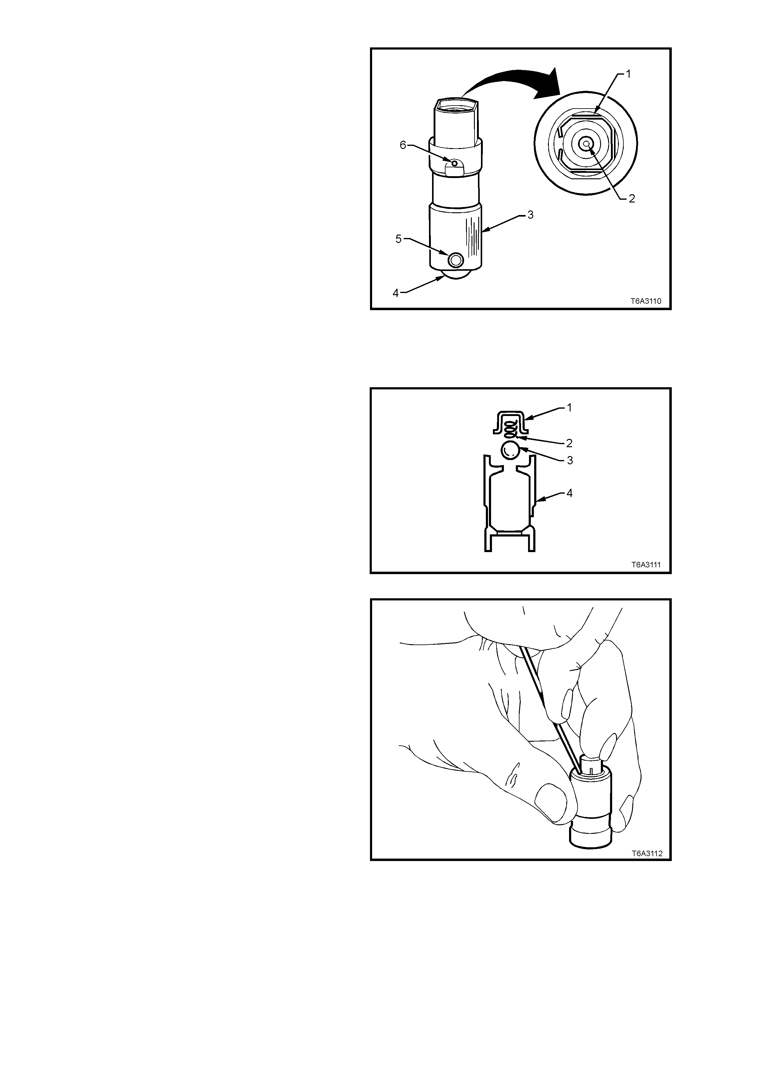
2. Inspect valve lifters for:
a. Bent or broken clip (1).
b. Worn pushrod socket (2). If the seat is
worn, inspect the matching push rod.
Replace the push rod if worn.
c. Scuffed or worn lifter bod y (3). Also inspect
lifter bore in the cylinder block.
d. Flat spots on roller (4). Replace lifter if the
roller is worn.
e. Loose or damaged pin (5).
f. Partially blocked oil hole (6).
g. Worn or damaged roller bearing. Replace
lifter if roller binds or roughness can be felt.
3. Inspect valve lifter guides for;
a. Cracks or damage.
b. Excessive wear in the lif ter mounting bores .
Figure 6A3-153
REASSEMBLE
NOTE 1: Do not attempt to recondition a lifter by
taking parts from other unserviceable lifters.
NOTE 2: Cleanliness is extremely important when
handling valve lifters. Lint or dirt can result in a
failed lif ter .
1. Place check ball (3) on the small hole in the
plunger (4).
Figure 6A3-154
2. Carefully place check ball spring and retainer
over ball and press retainer into position in the
plunger with a small bladed screwdriver.
3. Half fill valve lifter body with test fluid No.
E1151.
Figure 6A3-155
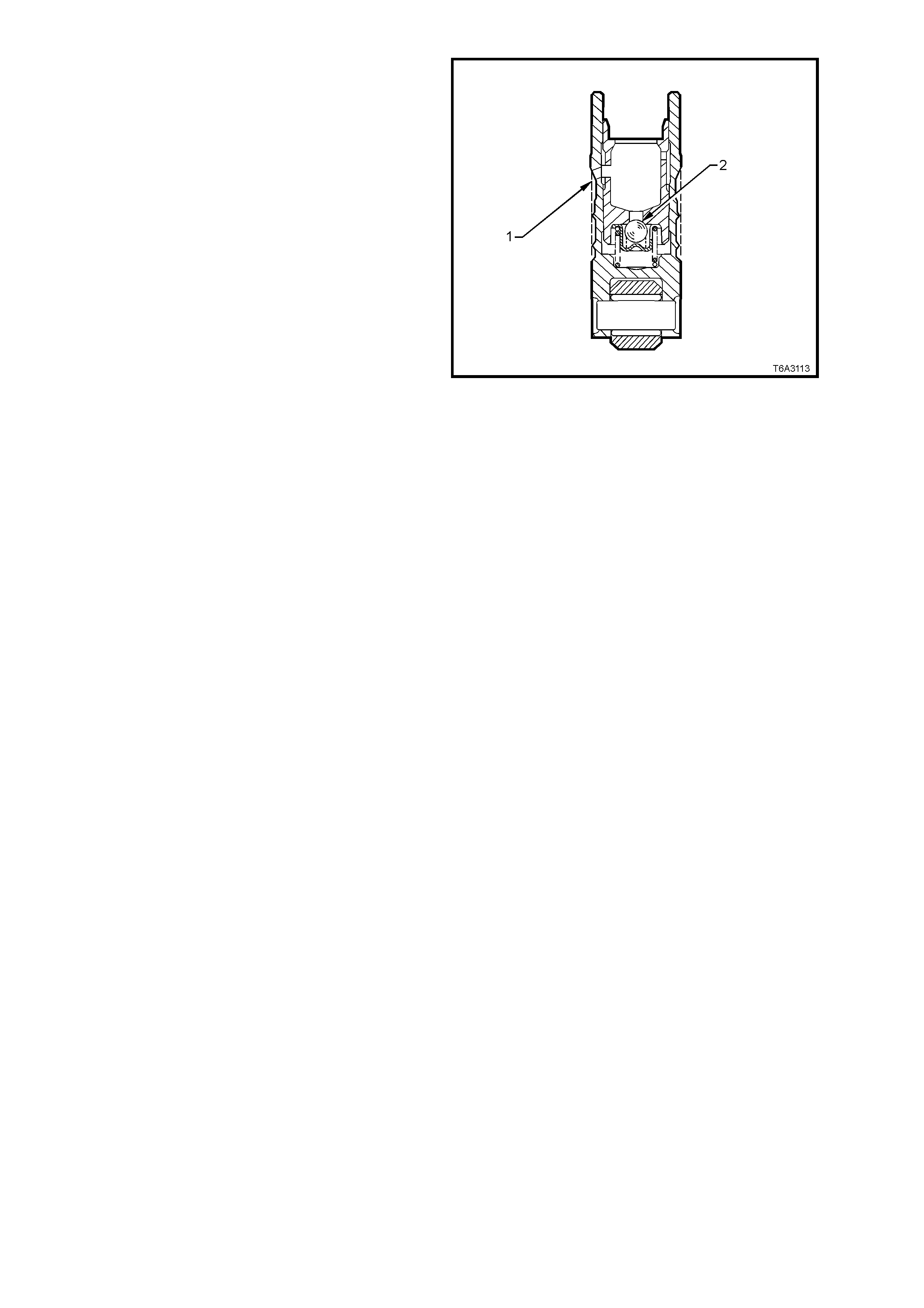
4. Reinstall plunger spring into the lifter body.
5. Install p lunger ass em bly in bod y, tak ing care to
align oil feed holes
6. Using a 1 mm diameter pin punch or similar,
unseat the check ball (2) in the plunger, then
push plunger down to the full extent of its
travel.
7. Use Tool 6A24 (or a suitable sized pin punch)
to align the oil feed holes (1) in the body and
plunger.
8. Fill the lifter with test fluid.
9. Reinstall the oil metering valve, push rod seat
(cup side facing out) and the retaining clip.
Figure 6A3-156
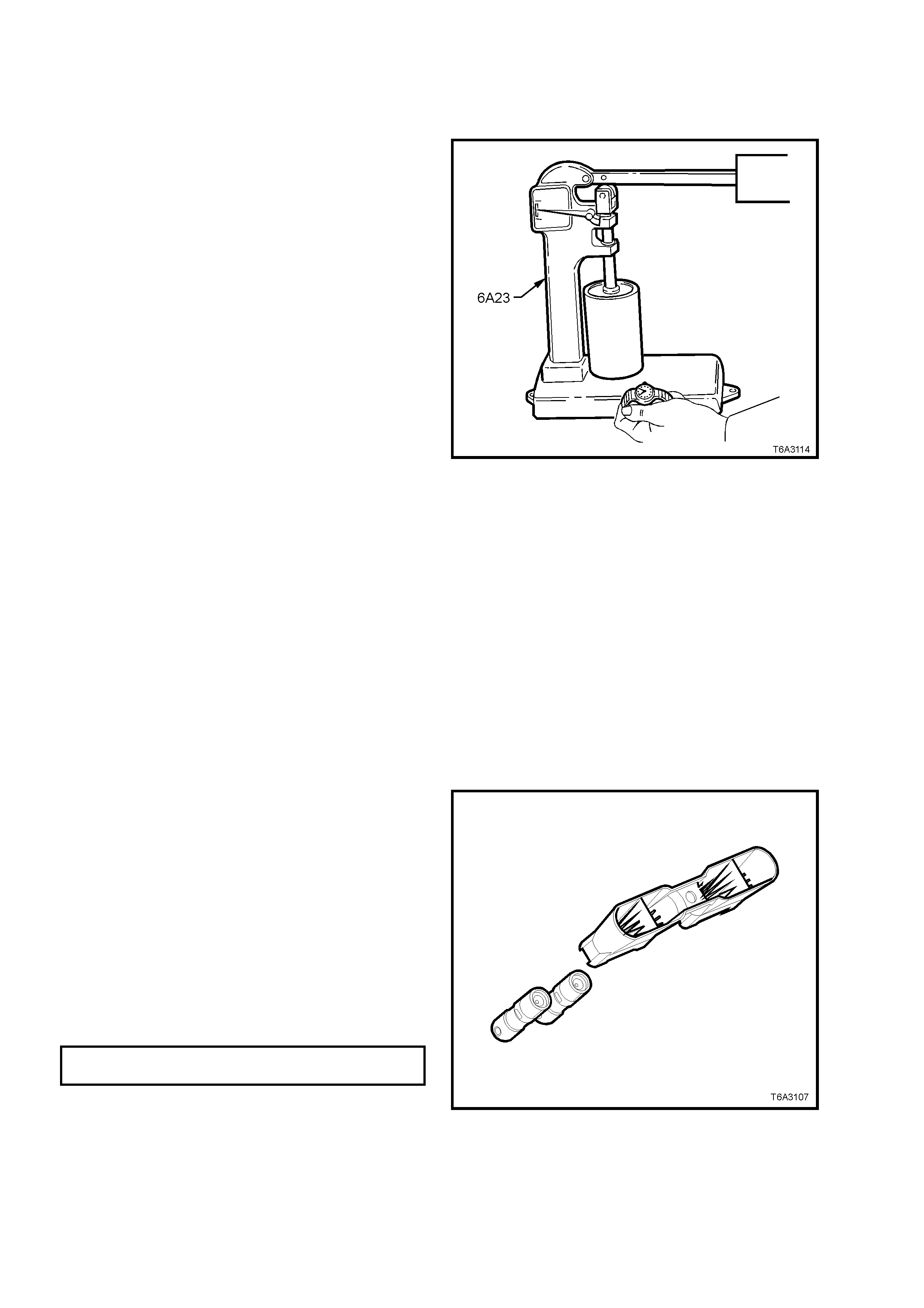
TESTING LIFTER LEAKDOWN RATE
After an hydraulic lifter has been cleaned, inspected and reassembled, it must be tested before being reinstalled.
Lifter tes t f ix ture, Tool No 6A23 has be en d esig ned to test the leakdown rat e of the lifter , to ens ure t hat the lif ter wil l
operate as intended, when reinstalled.
1. Ensure the test cup is clean. Install the cup on
the fixture and place the lifter in the cup.
NOTE: Some versions of Tool No. 6A23 may
require modification to hold the base of the lifter
inside the tester cup.
2. Add test fluid, No. E1151 to completely cover
the lifter.
3. Place ball bearing supplied with test fixture in
the push rod seat of the lifter.
4. Lower test fixture ram to rest on ball bearing.
5. Operate lifter plunger through its maximum
travel to force all air out of lifter by using a
vigorous pumping action on test fixture weight
arm. Continue pumping action until
considerable resistance is built up in lifter and
lifter becomes solid.
6. Raise weight arm to allow lifter plunger to
come up to its retainer, then lower arm to rest
on ram.
7. Use a stop watch to m easure the tim e required
for the indicator needle on the tester to travel
from 'START' to the 0.125" position on the
scale.
8. The leak down rate (time between 'Start' and
the 0.125" position) must be between 10 to 30
seconds to assure satisfactory lifter operation.
Figure 6A3-157
NOTE 1: A doubtful lifter should be tested several times before being discarded.
NOTE 2: Clean cup and refill with fresh test fluid after several lifters have been tested.
9. Stan d test ed lif ters upright s o that fluid does not dr ai n f r om oil holes.
10. After all lifters have been tested, place a cover over the test fixture to keep dirt and dust from the cup.
REINST ALL
NOTE: Ensure that reinstalled lifters are fitted to the original locations.
1. Check that all valve lifter bores and adjacent
areas are clean.
2. Lubricate valve lifter bodies and their bores
with Lubrizol 6612 (or equivalent), then install
lifters.
3. Install valve lifters into the guides, aligning the
flat area at the top of the lifter with the flats in
the lifter guide bore. Push the lifter completely
into the guide bore
4. Install the valve lifters and guide assembly into
the engine block.
5. Install each valve lifter guide retaining bolt/s
and tighten to the correct torque specification.
VALVE LIFTER GUIDE BOLT
TORQUE SPECIFICATION 12 Nm
6. Reinstall the cylinder head/s. Refer to
2.22 CYLINDER HEAD - REINSTALL in this
Section.
Figure 6A3-158
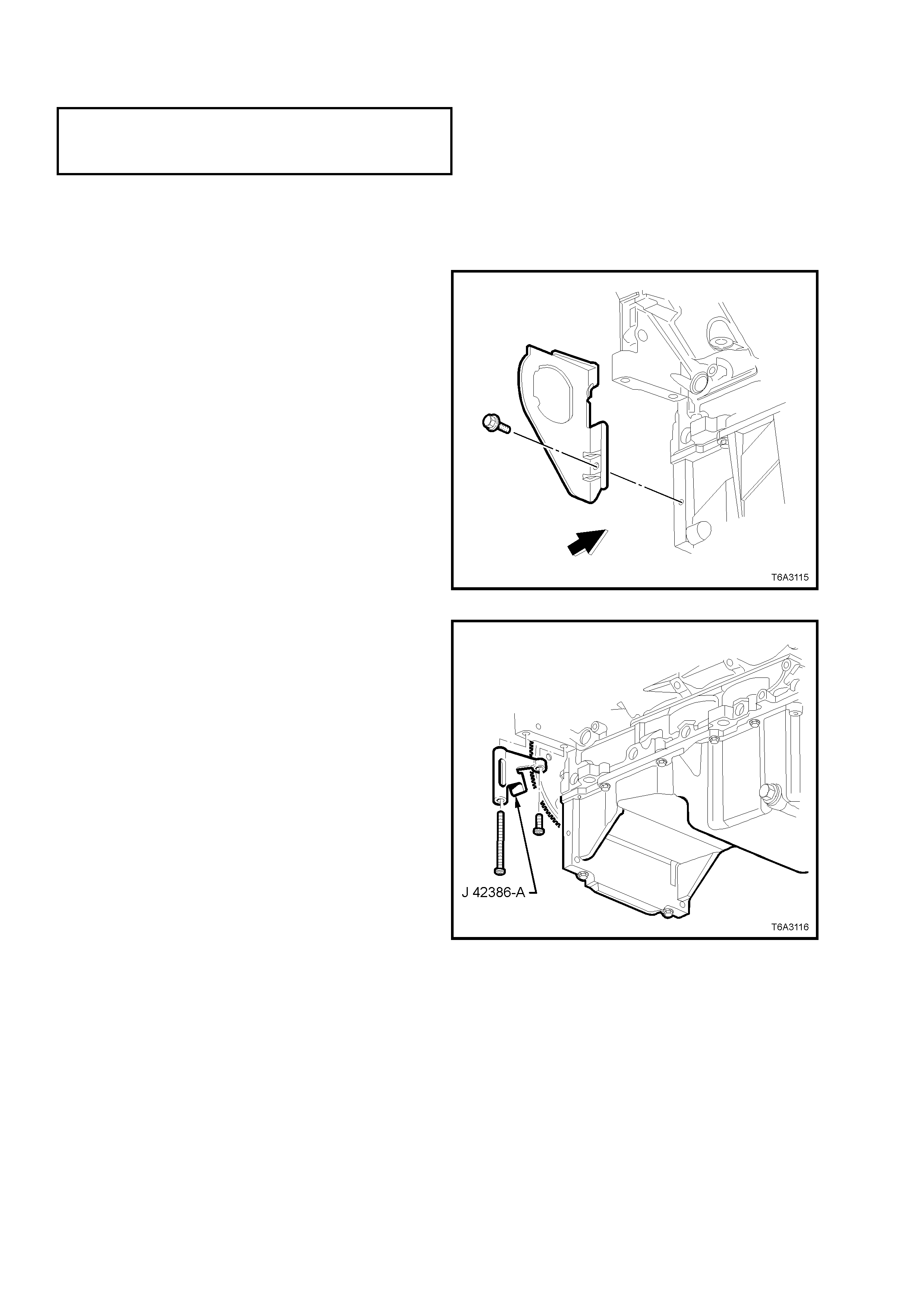
2.24 CRANKSHAFT BALANCER
LT Section No. – 00-540
NOTE: The following fasteners MUST be replaced ( ! )
when performing this operation:
! Crankshaft balancer bolt.
REMOVE
1. Disconnect the ground cable from the battery.
IMPORTANT: Disconnection of the battery affects certain vehicle electronic systems. Refer to
Section 00 CAUTIONS, 5. BATTERY DISCONNECTION PROCEDURES before dis c onn ectin g the battery.
2. Remove radiator, refer Section 6B3 ENGINE
COOLING – GEN III V8 ENGINE.
3. Remove the engine accessory and air
conditioning compressor drive belts. Refer
2.6 ENGINE DRIVE BELTS - REPLACE, in
this Section.
4. Remove the starter motor. Refer to
Section 6D3-2 STARTI NG SYSTEM.
5. Remove the right hand side close-out cover
retaining bolt, then the cover.
Figure 6A3-159
6. Using the two starter motor bolts, install ring
gear holding Tool No. J 42386-A and tighten
fasteners to 50 Nm.
NOTE: Ensure that the teeth of the holding tool
engage correctly with the ring gear, before
tightening the fasteners.
Figure 6A3-160
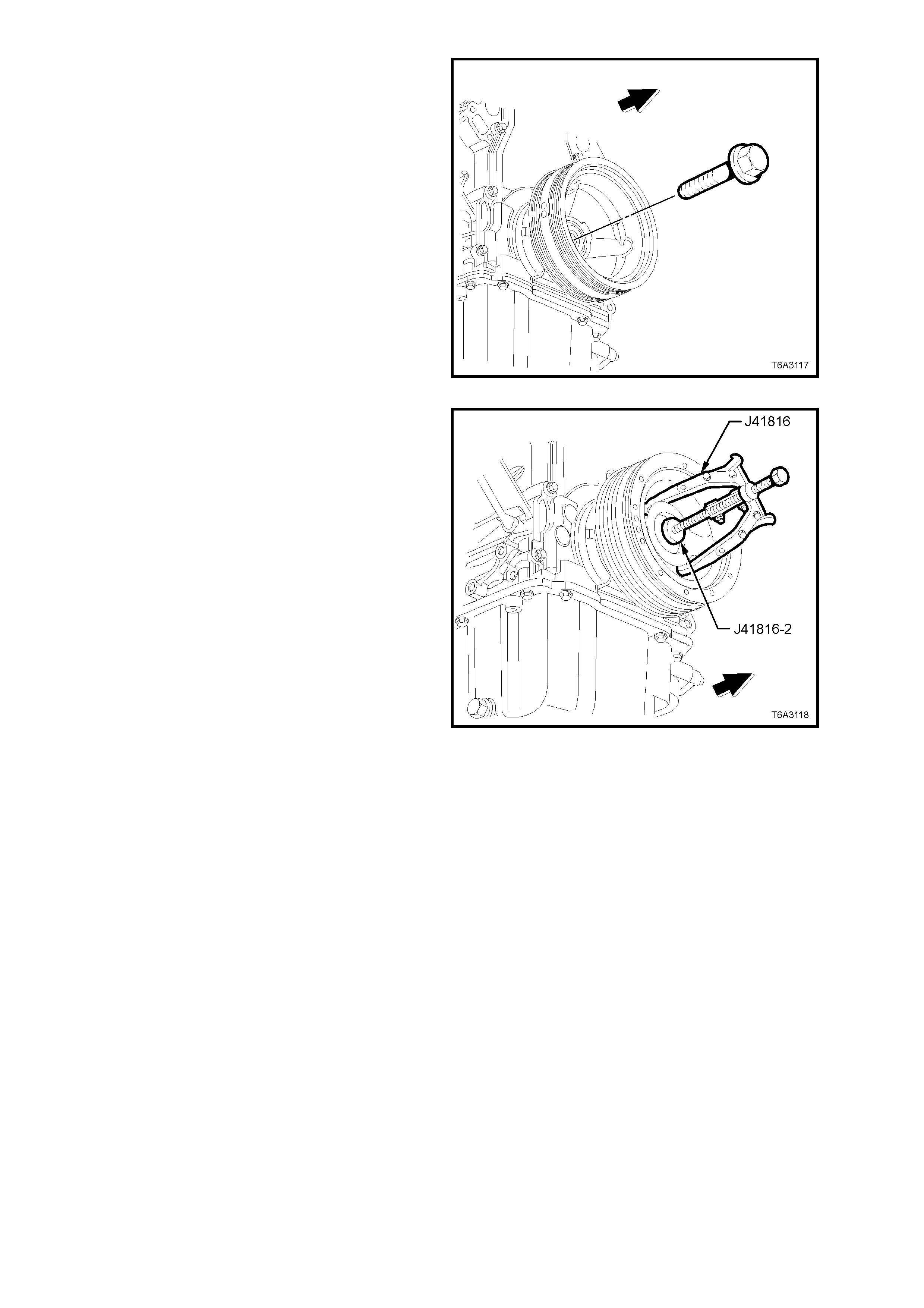
7. Remove the crankshaft balancer bolt. Do not
discard bolt as it will be required for the
reinstallation process.
Figure 6A3-161
8. Use crankshaft end protector J 41816-2 and
puller J41816 (or three legged commercial
equivalent), to remove the crankshaft balancer.
Figure 6A3-162

CLEAN AND INSPECT
1. Clean the crankshaft balancer in suitable
solvent.
2. Clean the belt grooves of all dirt or debris with
a wire brush.
3. Dry the crankshaft balancer with compressed
air.
4. Inspect the crankshaft balancer for the
following:
• Worn, grooved, or damaged hub seal
surface.
• A crank shaft balanc er hub s eal surf ace with
excessive scoring, grooves, rust or other
damage must be replaced.
• Minor im per fec tions on th e hub seal surf ace
may be removed with polishing compound
or fine grade emery cloth.
• Dirty or damaged be lt gro o ves.
• The bal ancer belt grooves shoul d be free of
any nicks, gouges, or other damage that
may not allow the belt to track properly.
IMPORTANT: F or the belt to track properl y,
the belt grooves should be free of all dirt or
debris.
• Minor im perf ections m ay be rem oved with a
fine file.
• Worn, chunking or deteriorated rubber
between the hub an d pull e y.
Figure 6A3-163
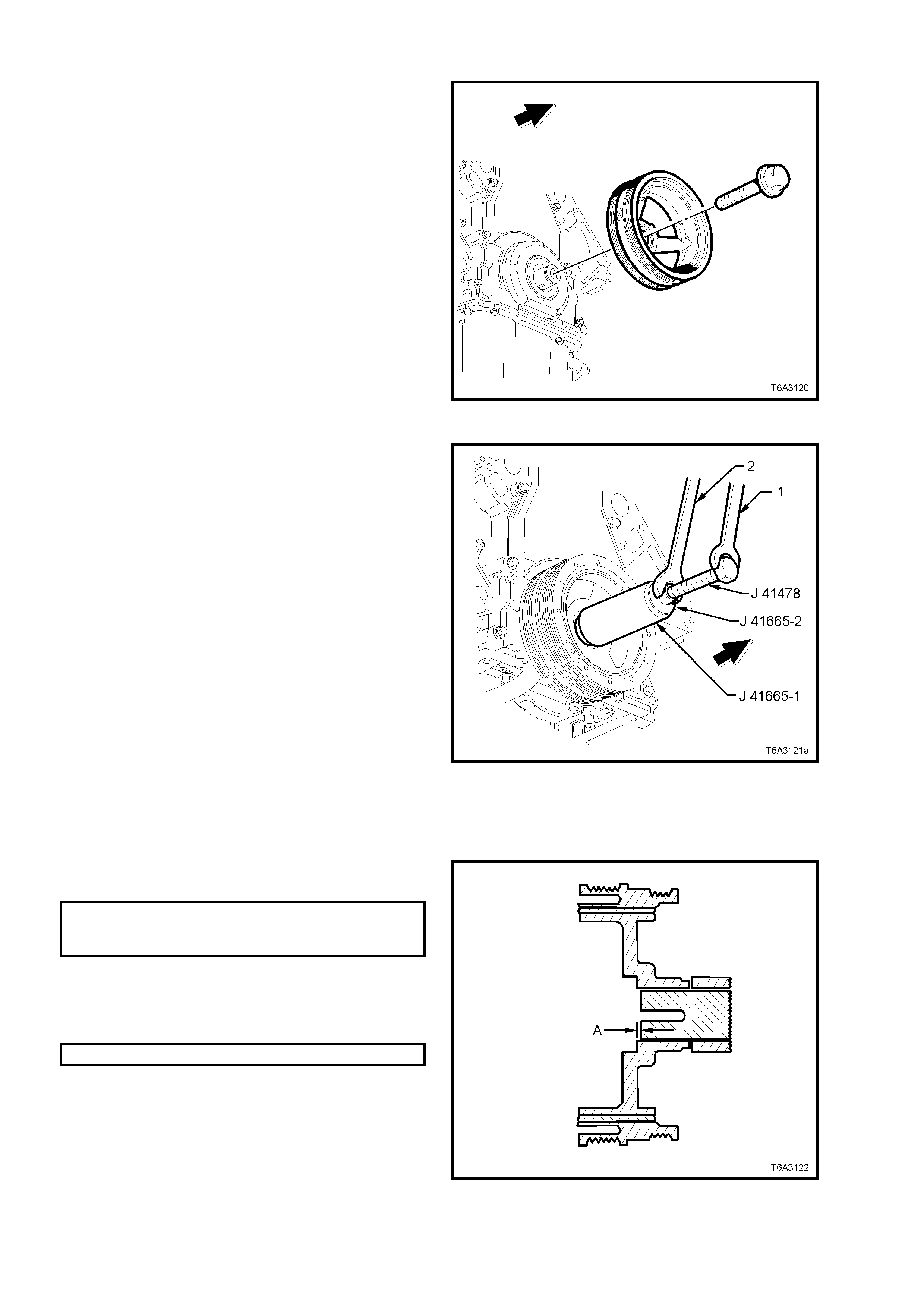
REINST ALL
IMPORTANT: The crankshaft balancer
reinstallation and bolt tightening involves a multi-
stage tightening process. The first pass ensures
that the balancer is installed completely onto the
crankshaft. The remaining passes tighten the new
bolt to the proper torque.
The us ed cr ankshaf t balan c er bolt wil l b e us ed on l y
during the first pass of the balancer installation
procedure. Only inst all a NEW crank shaft balancer
bolt and tighten as described in the remaining
passes of the balancer bolt tightening procedure.
1. Ensure that the teeth of the ring gear locking
Tool No. J 42386-A are correctly engaged.
2. Appl y a sm ear of c lean engine oil onto t he se al
surface of the balancer, then install the
balancer onto the end of the crankshaft.
IMPORTANT: The balancer should be positioned
onto the end of the crankshaft as straight as
possible, before to tool installation.
Figure 6A3-164
3. Use installer, Tool No. J 41665 to install the
crankshaft balancer, as follows:
a. Select the threaded rod, nut, washer and
installer, from tool J 41478.
b. Insert the installer sleeve, J 41665-1 into
the front of the balancer and back up with
the plate, J 41665-2.
NOTE: Insert the stepped end of sleeve J
41665-1 into the balancer, in this initial stage.
c. Use a set spanner (1) to hold the
hexagonal end of the threaded rod.
d. Use a second spanner (2) to rotate the
installation tool nut clockwise until the
balancer is started onto crankshaft.
e. Remove the stepped sleeve of J 41665-1
and revers e it, so t hat the l arger end of the
installer is against the front of the balancer.
f. Repeat steps ‘a.’ through ‘d.’ above, until
the balancer is installed onto the
crankshaft.
g. Remove the balancer inst a llation tool.
Figure 6A3-165
4. Install the used crankshaft balancer bolt and
tighten to the specified torque.
CRANKSHAFT BALANCER
INSTALLATION
TORQUE SPECIFICATION 330 Nm
5. Remove the used balanc er bolt and discar d.
6. Measure the distance the balancer protrudes
from the crankshaft nose and check that
dimension ‘A’ is to specification.
DISTANCE ‘A’ 2.40 - 4.48 mm
7. If the dimension is not correct, reinstall Tool J
41665 and repeat the installation procedure.
Figure 6A3-166
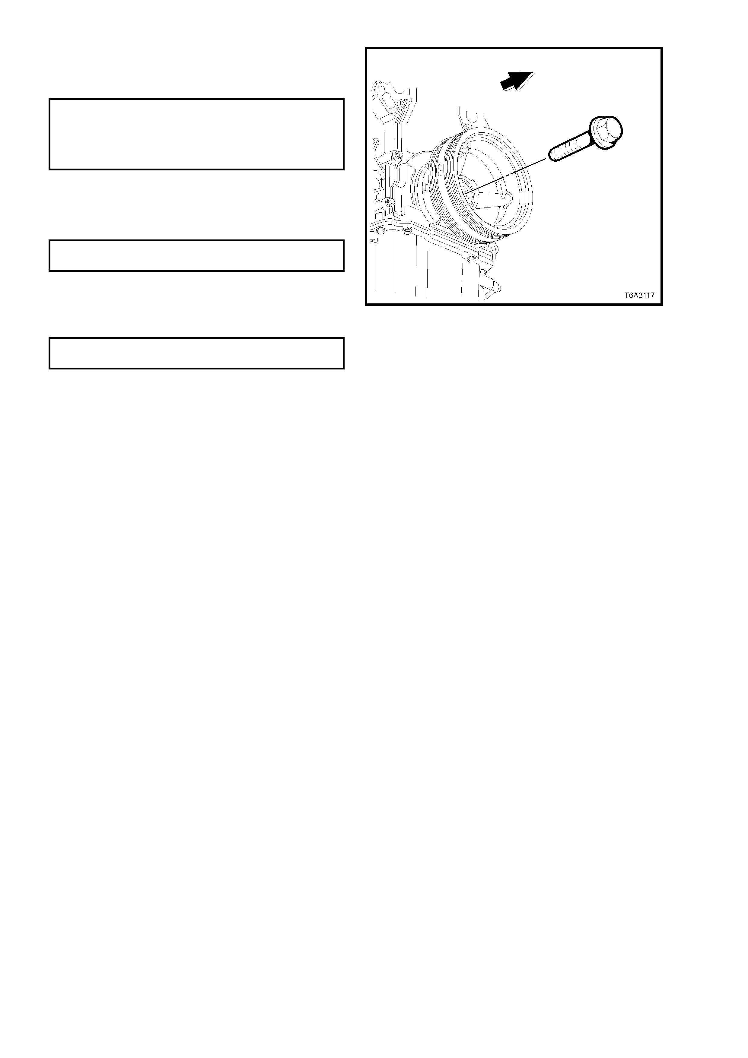
8. Install a NEW crankshaft balancer bolt.
9. Tighten the crankshaft balancer bolt to the
correct torque specification, in two stages.
CRANKSHAFT
BALANCER BOLT
TORQUE SPECIFICATION Stage 1: 50 Nm
Stage 2: 140°
Turn angle
10. Rem ove the r i ng g ear l oc king tool N o. J 423 86-
A.
11. Reinstall the close-out cover and tighten the
bolt to the correct torque specification.
RIGHT HAND CLOSE-OUT C OVER
SCREW TORQUE SPECIFICATION 10 Nm
12. Install the starter motor. Refer to
Section 6D3-2 STARTING SYSTEM and
tighten the m ounting bolts t o the correct torque
specification.
STARTER MOTOR MOUNTING
BOLT TORQUE SPECIFICATION 50 Nm
13. Reinstall the radiator, refer Section 6B3
ENGINE COOLING – GEN III V8 ENGINE.
Figure 6A3-167
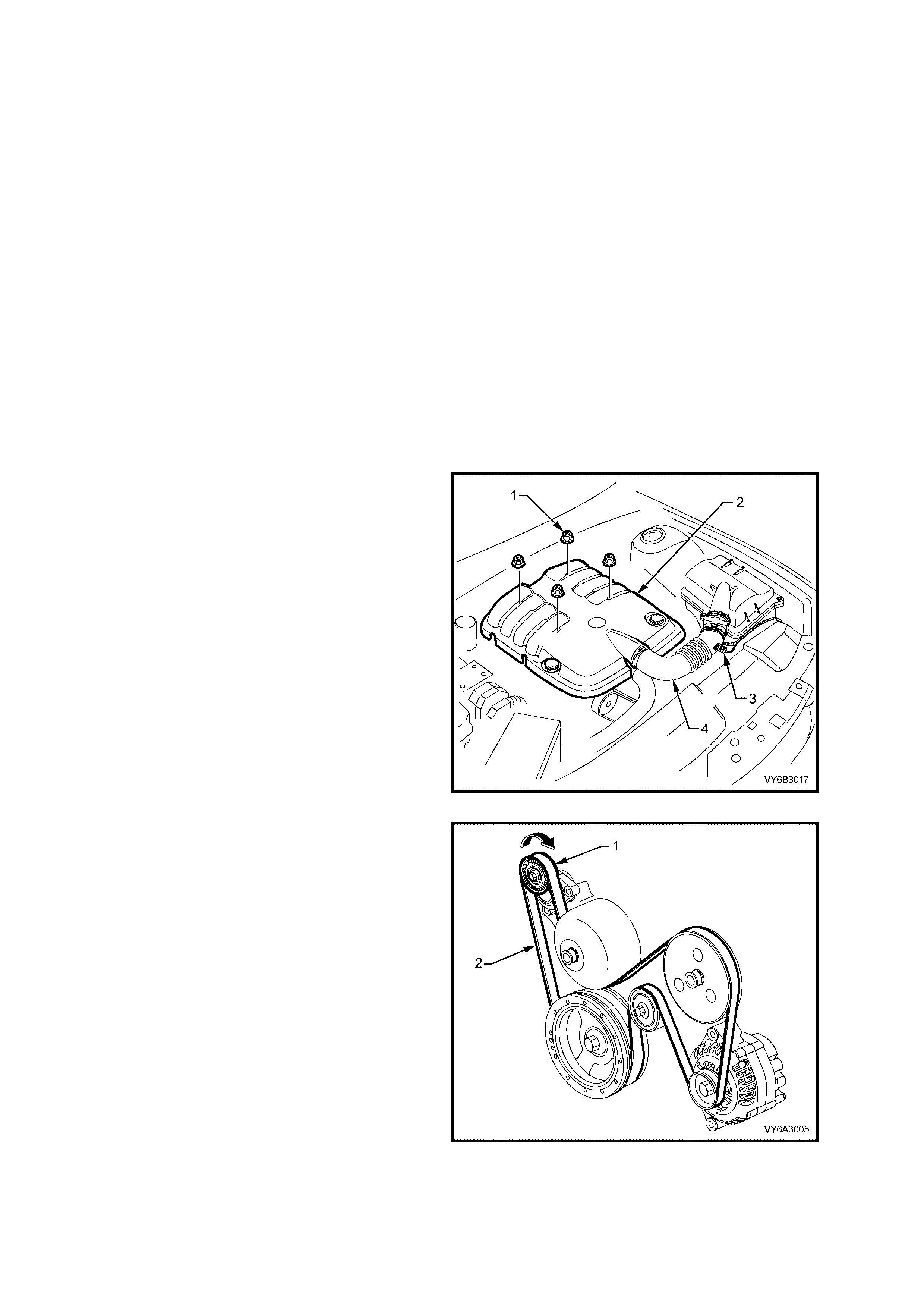
2.25 COOLANT PUMP
LT Section No. – 00-325
REMOVE
NOTE: Apart from the rear cover, O-ring and
thermostat assembly, the coolant pump is not
serviceable and if found to be faulty must be
replaced as an assembly.
1. Allow engine to cool to ambient temperature
(less than 5 0°C), then slow ly rem ove screw-on
pressure cap from the coolant reservoir.
CAUTION: DO NOT REMOVE SCREW-ON
PRESSURE CAP WHILE THE ENGINE
COOLANT TEMPERATURE IS ABOVE 50°
°°
°C, AS
PERSONAL INJURY MAY RESULT.
2. Disconnect the ground cable from the battery.
IMPORTANT: Disconnection of the battery affects
certain vehicle electronic systems. Refer to
Section 00 CAUTIONS, 5. Battery
Disconnection Procedures before disconnecting
the battery.
3. Remove the four engine dress cover
decorative nuts (1), then remove the dress
cover (2) from the engine.
4. Remove the air intake sensor wiring harness
connector (3), then loosen both hose clamps
securing the intake duct (4) to the MAF sensor
and the throttle body. Remove the duct (4)
from the engine.
5. Loosen coolant pump drive pulley bolts.
Figure 6A3-168
6. Remove engine accessory drive belt (2), using
a 15 mm ring spanner, refer to 2.6 ENGINE
DRIVE BELTS - REPLACE, in this Section.
Figure 6A3-169
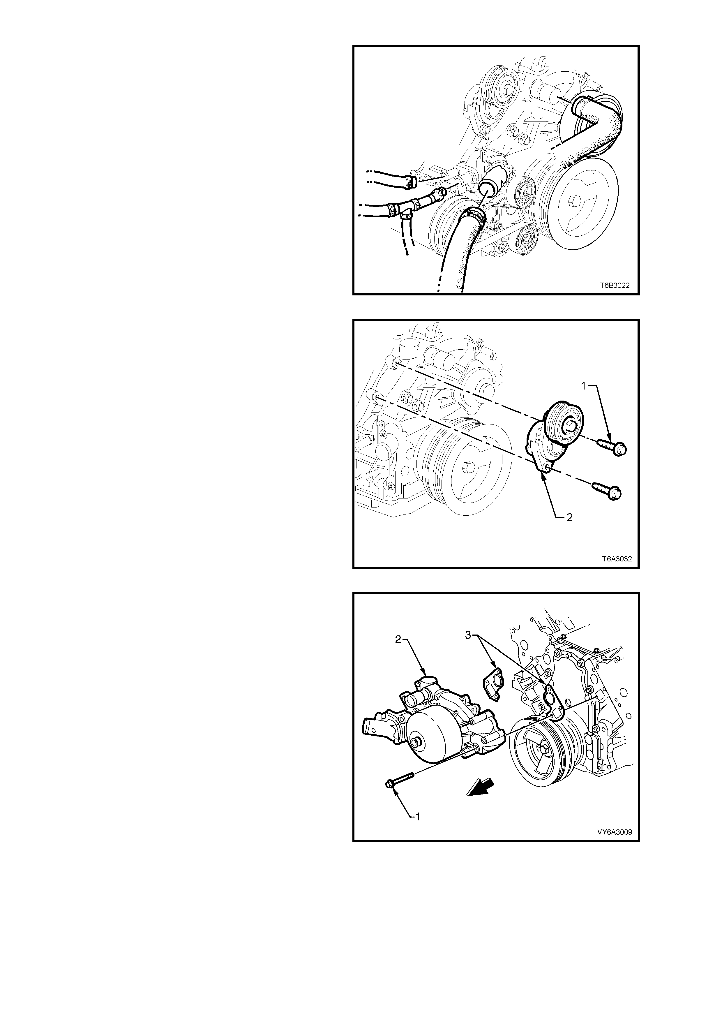
7. Drain engine coolant. Refer to 2.3 DRAINING
AND FILLING COOLING SYSTEM, in Section
6B3 ENGINE COOLING.
IMPORTANT: The information in 2.1 SERVICE
NOTES (Environmental Issues), Section 6B3
ENGINE COOLING is to be read and acted upon.
8. Disconnect both heater hoses, the outlet and
inlet hoses from the coolant pump.
CAUTION: Always wear protective safety
glasses when working with spring type hose
clamps. Failure to do so could result in eye
injury.
Figure 6A3-170
9. Remove the two bolts (1) securing the drive
belt tensioner (2) to the coolant pump housing
and set the tensioner to one side.
Figure 6A-171
10. Loosen, then remove the six bolts (1) securing
the coolant pump (2) to the cylinder block.
11. If nec es s ar y, use a sof t faced ham mer to lig htly
tap coolant pump housing (2) to dislodge it
from the cylinder block.
12. Rem ove coolant pum p, carr ier type gask ets (3)
and discard.
Figure 6A-172
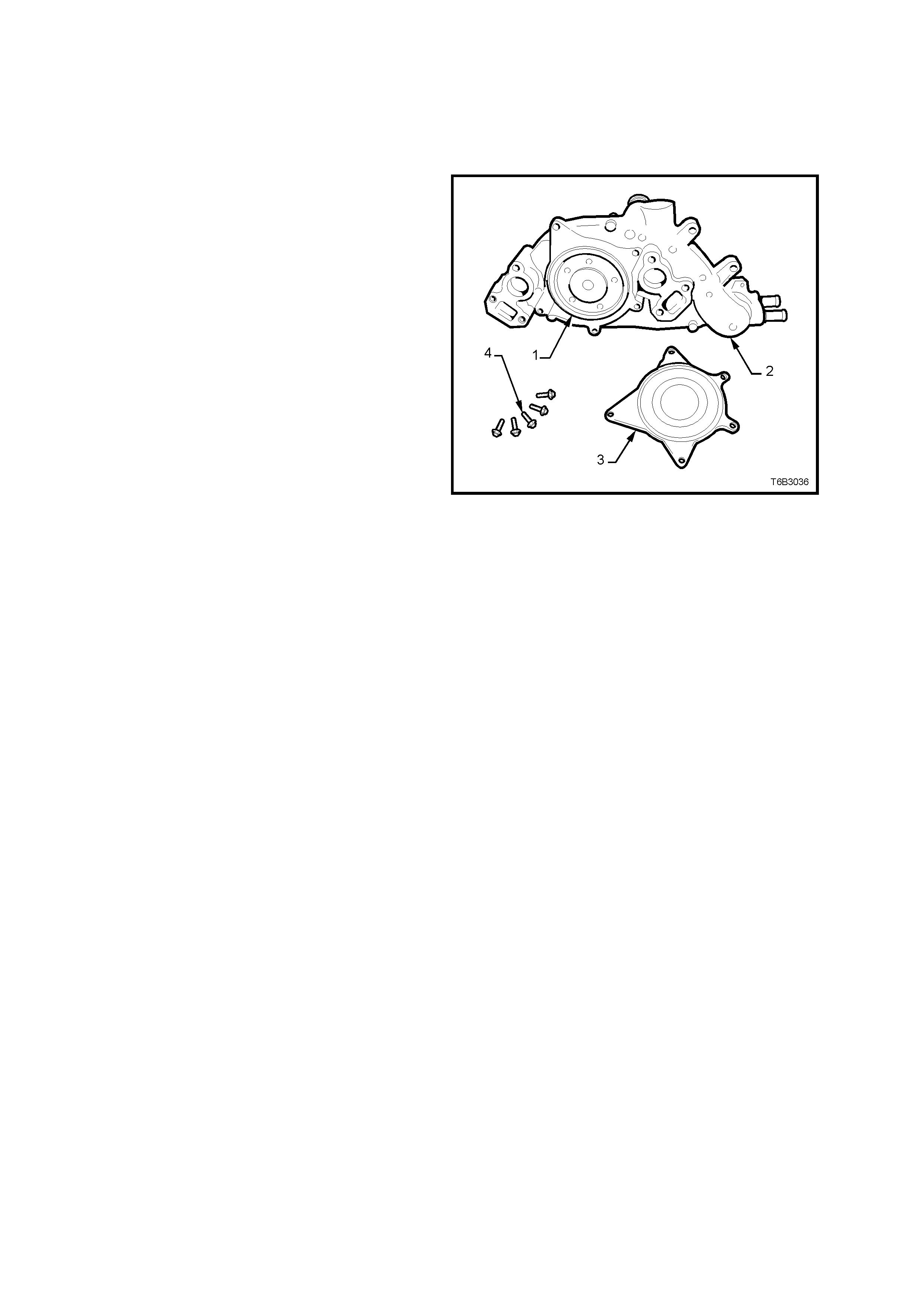
DISMANTLE
NOTE: Apart from the service operations
described here, there are no other serviceable
parts in the coolant pump assembly and if required,
then the as s embly m us t be repl ac ed as a complet e
unit.
1. If required, remove the five bolts (4) securing
the rear cover (3) to the coolant pump (2). Tap
with a sof t faced h amm er to dislodge the cover
from the pump body.
2. Rem ove the sea ling O-r ing (1) from the c oolant
pump body (2).
3. For thermostat remove, test and reinstall
procedures, refer to 2.9 THERMOSTAT, in
Section 6B3 ENGINE COOLING.
Figure 6A-173
CLEAN AND INSPECT
1. Remove the old gasket or gasket material from the coolant pump sealing surfaces and cylinder block, taking
care not to scratch the machined surfaces.
2. Clean all dirt and debris from the coolant pump housing.
3. Inspect the coolant pump for the following:
• Gasket surfaces for excessive scratches or gouging.
• Hose sealing surfaces for scratches, gouging or corrosion.
• Restrictions, corrosion or evidence of cavitation within the internal coolant passages or on the pump
impeller.
• Excessive side-to-side play in the pulley shaft.
• A loose belt pulley or a pulley with excessive wear or scoring on the belt tracking area.
• Evidenc e of c oolant leak age at th e coolant o utlet h ous ing or re ar cover gask et ( if these parts h ave not been
removed).
• Leakage at the coolant pump vent hole. A stain around the vent hole is acceptable. If leakage occurs
(dripping) with the engine running and the cooling system pressurised, replace the coolant pump.

REASSEMBLE
1. Install a new O-ring seal to the cleaned groove in the pump housing, then install the cover and retaining bolts.
2. Gradually tighten every second bolt until the correct torque specification is reached.
COOLANT PUMP REAR COVER
TORQUE SPECIFICATION 14 Nm
REINST ALL
Installation is the reverse to removal except for the following items:
1. Ensure that the coolant pump and cylinder block surfaces are clean and dry.
2. Using two bolts inserted into the coolant pump on each side as guides, install NEW gaskets over them and
install the coolant pump to the cylinder block.
3. Install remaining bolts and tighten to the correct torque specification, in two stages.
COOLANT PUMP BOLT
TORQUE SPECIFICATION Stage 1: 15 Nm
Stage 2: 30 Nm
4. Install the engine accessory drive belt tensioner and attaching bolts, tightening to the correct torque
specification.
ENGINE ACCESSORY DRIVE BELT
TENSIONER BOLT
TORQUE SPECIFICATION 40 - 60 Nm
5. Install all removed radiator hoses and clamps.
CAUTION: ALWAYS WEAR PROTECTIVE SAFETY GLASSES WHEN WORKING WITH SPRING TYPE HOSE
CLAMPS. FAILURE TO DO SO COULD RESULT IN EYE INJURY.
6. Install the engine accessory drive belt. Refer 2.6 ENGINE DRIVE BELTS - REPLACE in t his Secti on.
7. Refill cooling system, refer to 2.3 DRAINING AND FILLING COOLING SYSTEM in Section 6B3 ENGINE
COOLING.
8. Check for cooling system leaks, refer to 2.8 PRESSURE TEST ING in Section 6B3 ENGINE COOLING.
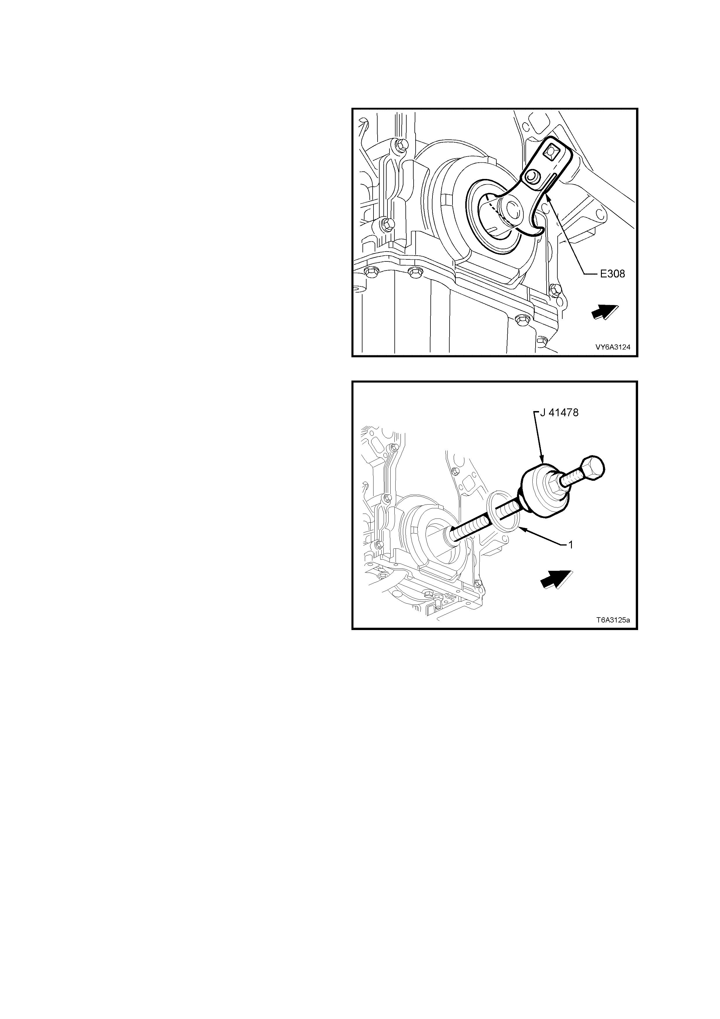
2.26 CRANKSHAFT FRONT OIL SEAL
LT Section No. – 00-325
REPLACE
1. Remove the crankshaft balancer. Refer
2.24 CRANKSHAFT BALANCER in this
Section.
2. Using Tool No. Eb
308 (or commercial equivalent) remove seal from
the front cover.
Figure 6A3-174
3. Lubricate the outer edge of a NEW oil seal (1)
and the front cover oil seal bore with clean
engine oil.
IMPORTANT: Do not lubricate the oil seal sealing
surface. Refer CRANKSHAFT OIL SEALS, in
1.4 ENGINE LUBRICATION SYSTEM, in this
Section.
4. Install the crankshaft front oil seal (1) onto the
guide of Tool No. J 41478.
5. Install the threaded rod (with nut, washer,
guide, and oil seal) of Tool No. J 41478 into the
end of the crankshaft.
6. Using a set spanner, hold the head of the
installer bolt, then rotate the installer nut
clockwise, using a second set spanner, until
the seal bottoms in the cover bore.
7. Remove the tool from the crankshaft.
8. Inspect the oil seal for correct installation. The
oil seal should be installed evenly and
completely into the front cover bore.
9. Install the crankshaft balancer, refer
2.24 CRANKSHAFT BALANCER, in this
Section.
Figure 6A3-175
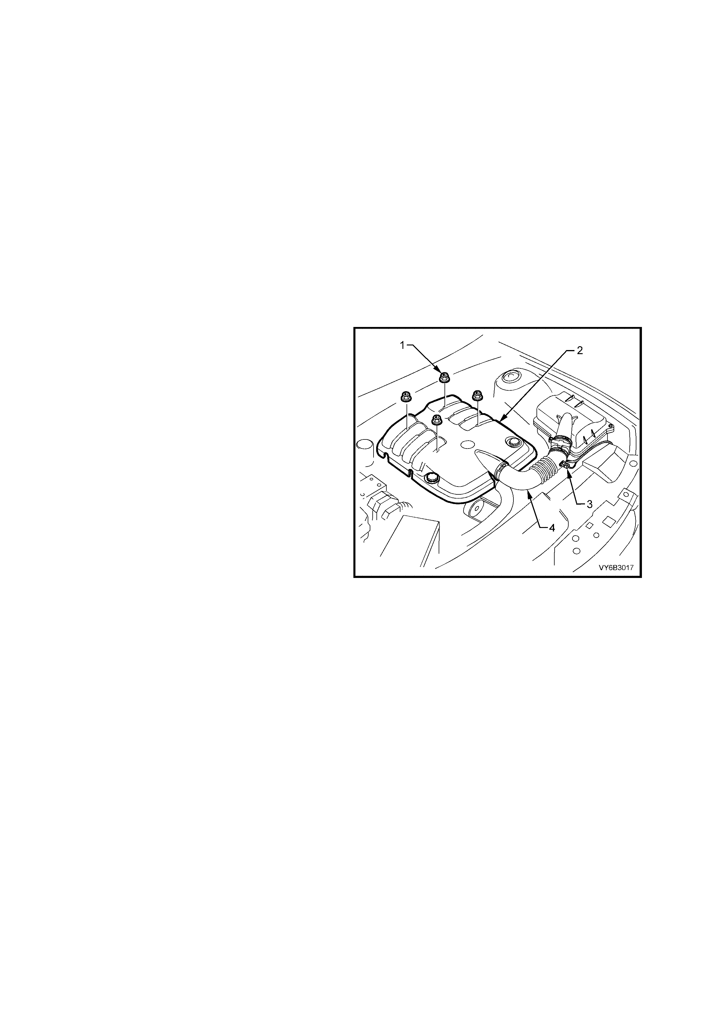
2.27 ENGINE MOUNTS
LT Section No. – 00-475
CHECK
1. Check in the area of the mounts for signs of fluid leakage. If oil leakage from a mount is visible, the mount is
defective and must be replaced.
2. Using a suitable engine lifting crane, raise the engine to remove the weight from the mounts and to place
rubber in slight tension. Then, ch eck that the m ounting rubber has not deteriorated, split or separated from its
metal plates.
3. Replace mount if found to be defective.
REMOVE
1. Disconnect the ground cable from the battery.
IMPORTANT: Disconnection of the battery affects certain vehicle electronic systems. Refer to
Section 00 CAUTIONS, 5. BATTERY DISCONNECTION PROCEDURES befor e disc onn ec tin g the battery.
2. Drain the cooling system. Refer to Section 6B3 ENGINE COOLING - GEN III V8 ENGINE.
IMPORTANT: The inf ormation i n 2. 1 SERVIC E NOT ES (Enviro nment al Issue s), Section 6B3 ENGINE COOLING
is to be read and acted upon.
3. Remove the four engine dress cover
decorative nuts (1), then remove the dress
cover (2) from the engine.
4. Remove the air intake sensor wiring harness
connector (3), then loosen both hose clamps
securing the intake duct (4) to the MAF sensor
and the throttle body. Remove the duct (4)
from the engine.
5. Raise front of vehicle and place on safety
stands. For location of jacking and support
points, refer to Section 0A GENERAL
INFORMATION.
6. Remove the exhaust pipe to manifold flange
nuts on the engine mount side to be removed.
7. From under the vehicle, remove the lower
mounting to crossmember nut for both mounts.
NOTE: A commercially available, 18 mm deep
socket will be required for this operation.
8. Lower the vehicle to the ground, then remove
the exhaust manifold on the engine mounting
side to be removed. Refer to 2.21 EXHAUST
MANIFOLD - REMOVE, in this Section.
9. Use suitable engine lifting equipment to raise
the engine, removing the weight from the engine
mounts.
Figure 6A3-176
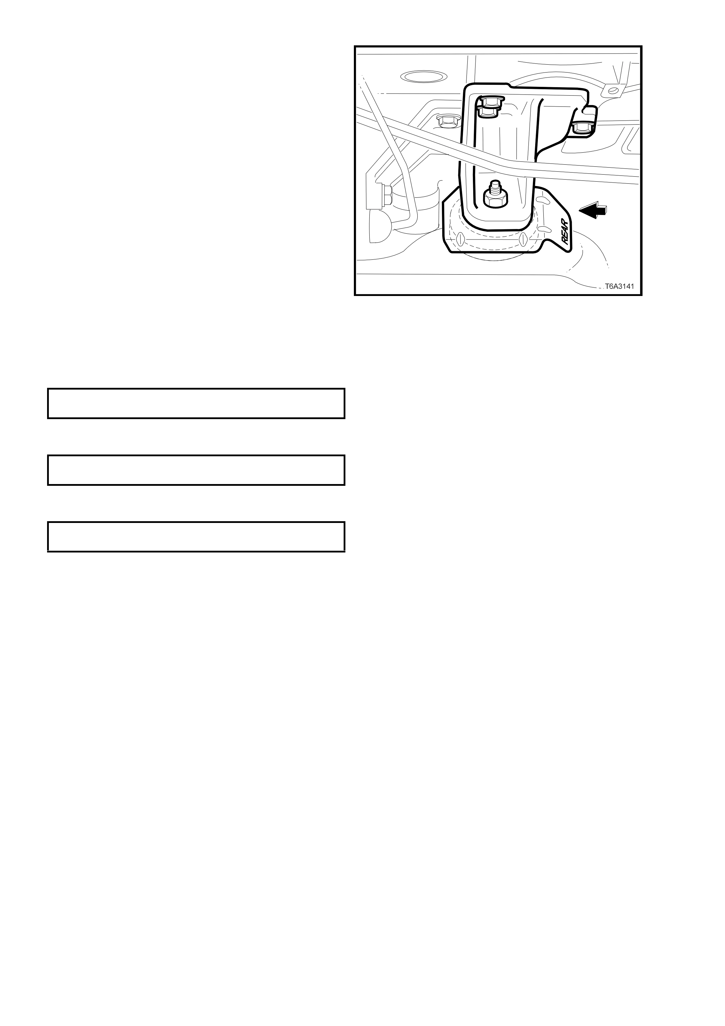
10. Remove the mount bracket to engine block
bolts.
11. Lift the mount and bracket assembly from the
crossmember and remove from the vehicle.
12. Remove the engine mount to bracket nut and
separate the heat shield and mount from the
bracket.
NOTE: While the left hand mount is shown, the
operation is similar for either engine mount except
that, for the right hand engine mount, remove the
battery harness bracket bolt, before removing the
mounting bracket to engine block bolts.
Figure 6A3-177
REINST ALL
Reinstallation of either or both engine mounts is the reverse to removal, except for the following points.
1. If removed from the bracket, reinstall the engine mount and heat shield, then tighten the nut to the correct
torque specification.
ENGI N E MOUNT TO BRACKET NU T
TORQUE SPECIFICATION 80 Nm
2. Install the engine mount stud into the crossm ember, then install th e bracket to cylinder block bolts and tighten
to the correct torque specification.
ENGINE MOUNTING BRACKET BOL T
TORQUE SPECIFICATION 50 Nm
3. Lower the e ngine allo wing the weight to se ttle on the crossm ember , install bot h engine m ount nuts and tighten
to the correct torque specification.
ENGINE MOUNT TO CROSSMEMBER
TORQUE SPECIFICATION 80 Nm
4. Install exhaust manifold. Refer to 2.21 EXHAUST MANIFOLD - REINSTALL in this Section.
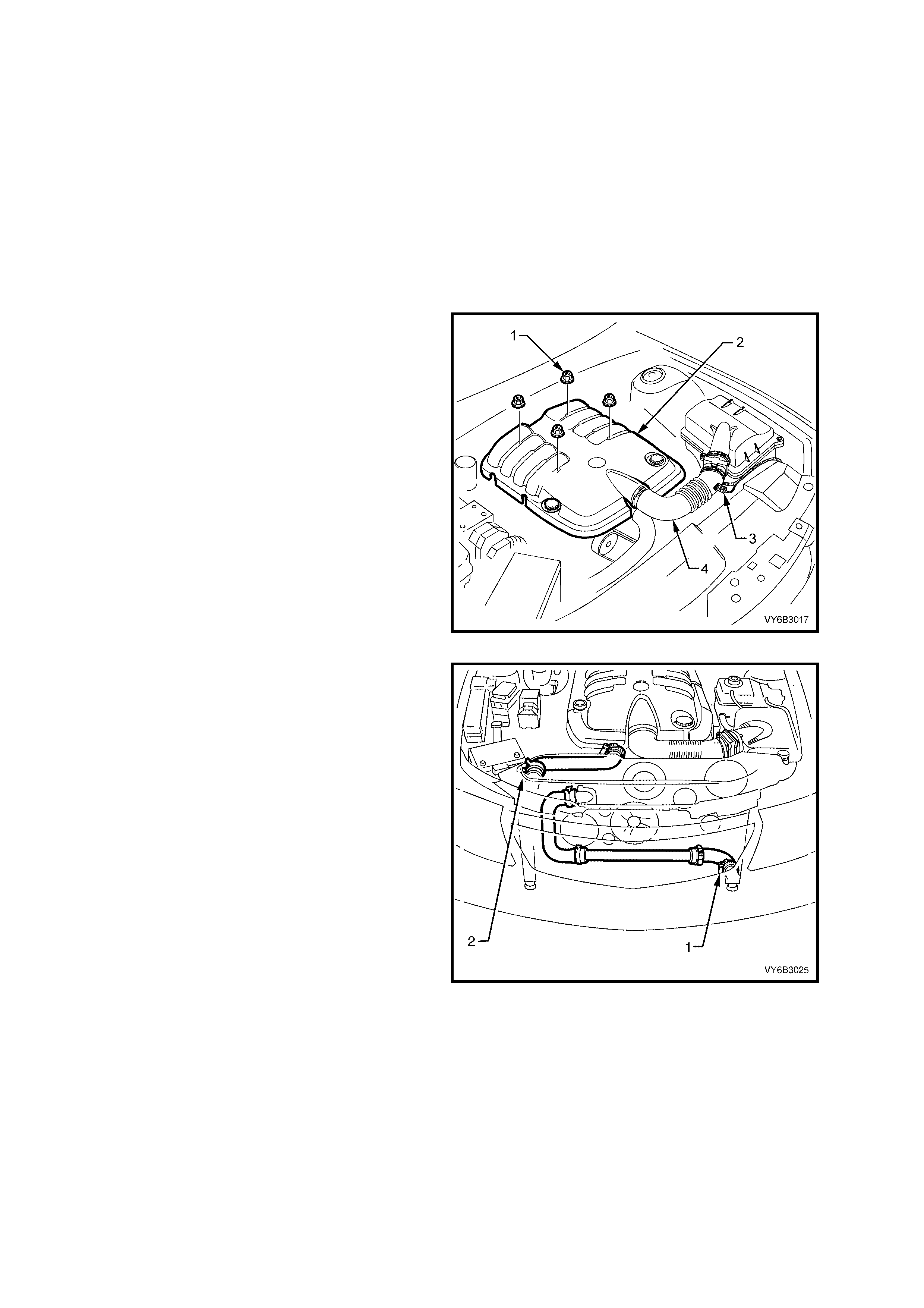
3. MAJOR SERVICE OPERATIONS
3.1 ENGINE ASSEMBLY
LT Section No. – 00-500
REMOVE
1. Disconnect the ground cable from the battery.
IMPORTANT: Disconnection of the battery affects certain vehicle electronic systems. Refer to
Section 00 CAUTIONS, 5. Battery Disconnection Procedures before disconnecting the battery.
2. Loosen the screw-on pressure cap on the coolant surge tank to relieve any system pressure, then remove cap.
CAUTION: To avoid serious personal injury, never remove the screw-on pressure cap when the engine is
hot. Sudden release of cooling system pressure is very dangerous and could cause personal injury.
3. Remove the four engine dress cover
decorative nuts (1), then remove the dress
cover (2) from the engine.
4. Remove the air intake sensor wiring harness
connector (3), then loosen both hose clamps
securing the intake duct (4) to the MAF sensor
and the throttle body. Remove the duct (4)
from the engine.
5. De-pressurise fuel rail. Refer to
2.13 FUEL SYSTEM PRESSURE RELIEF, in
this Section.
Figure 6A3-178
IMPORTANT: Before draining coolant, the
information in 2.1 SERVICE NOTES
(Environmental Issues), Section 6B3 ENGINE
COOLING is to be read and acted upon.
6. Place a suit able drain tr ay beneath the engine,
then loosen the worm drive hose clamp (1) on
the lower hose at the left hand radiator tank,
remove the hose and drain the coolant.
7. Loosen the second worm drive hose clamp
securing the lower left hand hose to the
transfer tube and remove the lower left hand
hose from the vehicle.
CAUTION: Wear safety glasses to avoid eye
injury.
NOTE: If acces s to the transfer tube hose clam p is
poor, then disconnect the lower hose from the
radiator, left hand tank. After the radiator is
removed (Step 10), the transfer tube and all lower
hoses can then be removed as an assembly.
8. Loosen top radiator worm drive hose clamp at
the engine and a spring type clamp at the
radiator (2), then rem ove the top hose f rom the
engine.
9. Remove the engine cooling fans and radiator.
Refer to Section 6B3 ENGINE COOLING –
GEN III V8 ENGINE.
Figure 6A3-179
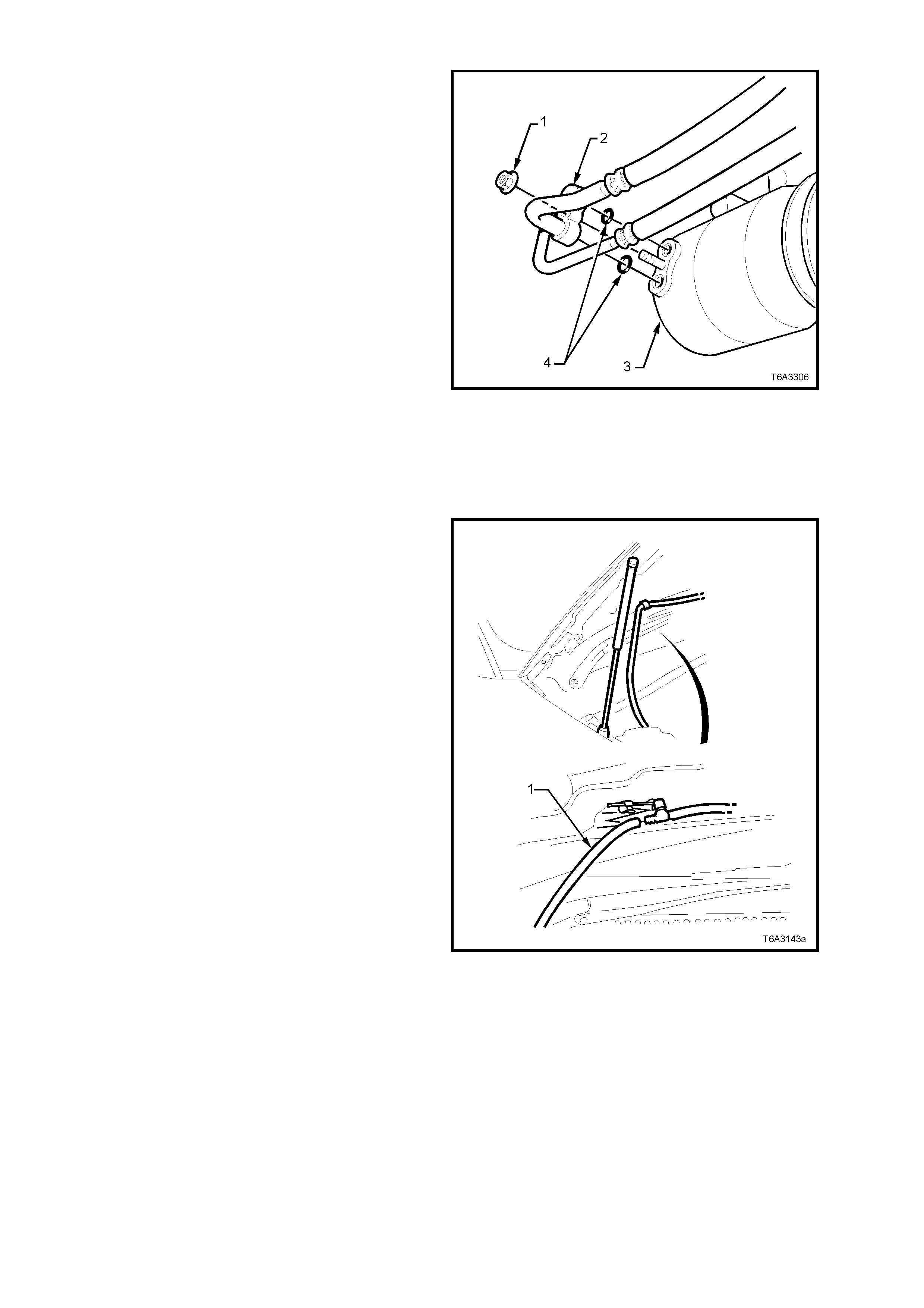
10. Recover refrigerant charge, refer to
Section 2C AIR CONDITIONING –
SERVICI NG AND DIAGNOSIS.
Figure 6A3-180
12. After removing the four oil pan under-tray
bolts, rem ove the tra y from the vehicle.
13. Rem ove oil pan dr ain plu g and drain eng ine oil
into a suitable container. Reinstall drain plug
once oil has drained sufficiently.
14. Disconnect windshield washer hose (1) at the
in-line connector located at the rear, left hand
side of the engine hood.
Figure 6A3-181
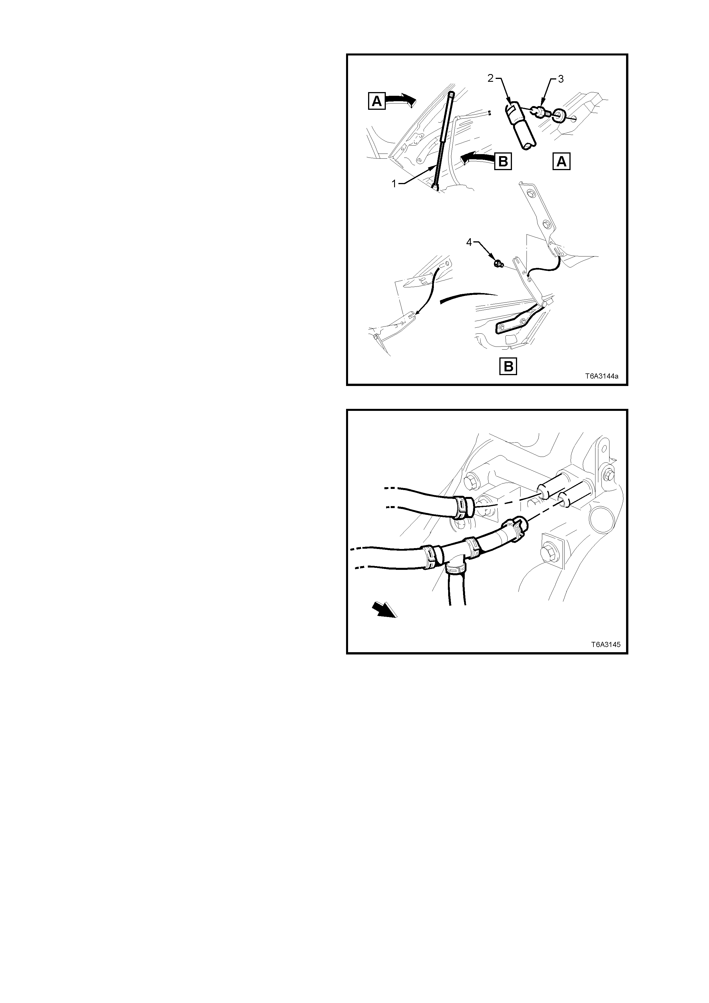
15. With engine hood adequately supported,
remove clips (2) securing upper ends of struts
(1) to hood pivots (3).
Disengage struts (1) from hood pivots (3) and
lay struts onto inner fender panel.
16. Using an assistant to hold the hood assembly,
remove the engine hood bracket to hinge
attaching bolts (4), as shown, then carefully lift
the hood assembly clear of the vehicle.
Figure 6A3-182
17. Remove both heater hose clamps at the
engine water pump, taking note of the hose
layout. Plug open ends to prevent dirt entry.
Figure 6A3-183
18. Remove the screw (1) securing the ground
lead to the engine cylinder block and from the
left hand engine mount (2).
19. Remove the nut (3) securing the battery
harness ground terminals to the ABS/TCS
control module bracket stud (4).
20. Rem ove the ground terminal (5) at the batter y,
followed by the positive lead (6). Lay the
harness on the engine.
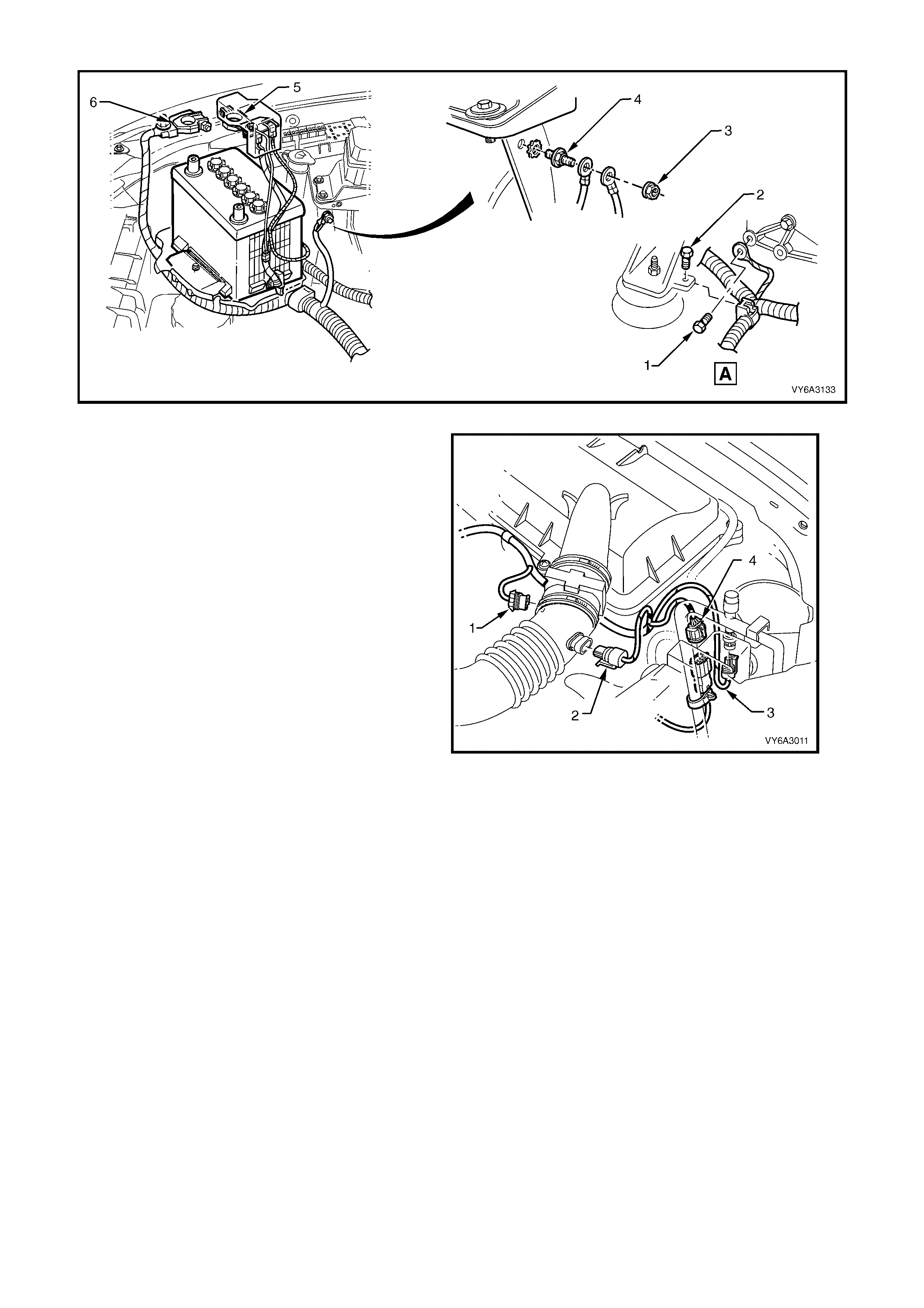
Figure 6A3-184
21. Disconnect the wiring harness connectors
from:
1. Mass Air Flow Sensor.
2. Intake Air Temperature Sensor.
3. Air Cond iti on ing Pres s ure Sens or .
4. Main to Powertrain Wiring Harness.
Figure 6A3-185
22. Disconnect powertrain wiring harness clips (6)
from the engine compartment dash panel
retaining bracket (‘5’, view D), refer Figure
6A3-186.
23. Referring to Figure 6A3-186, disconnect
powertrain wiring harness connectors from the
surge ta nk, lo w cool ant s witch ( ‘1’, v iew A) and
the theft deterrent horn (‘4’, view C).
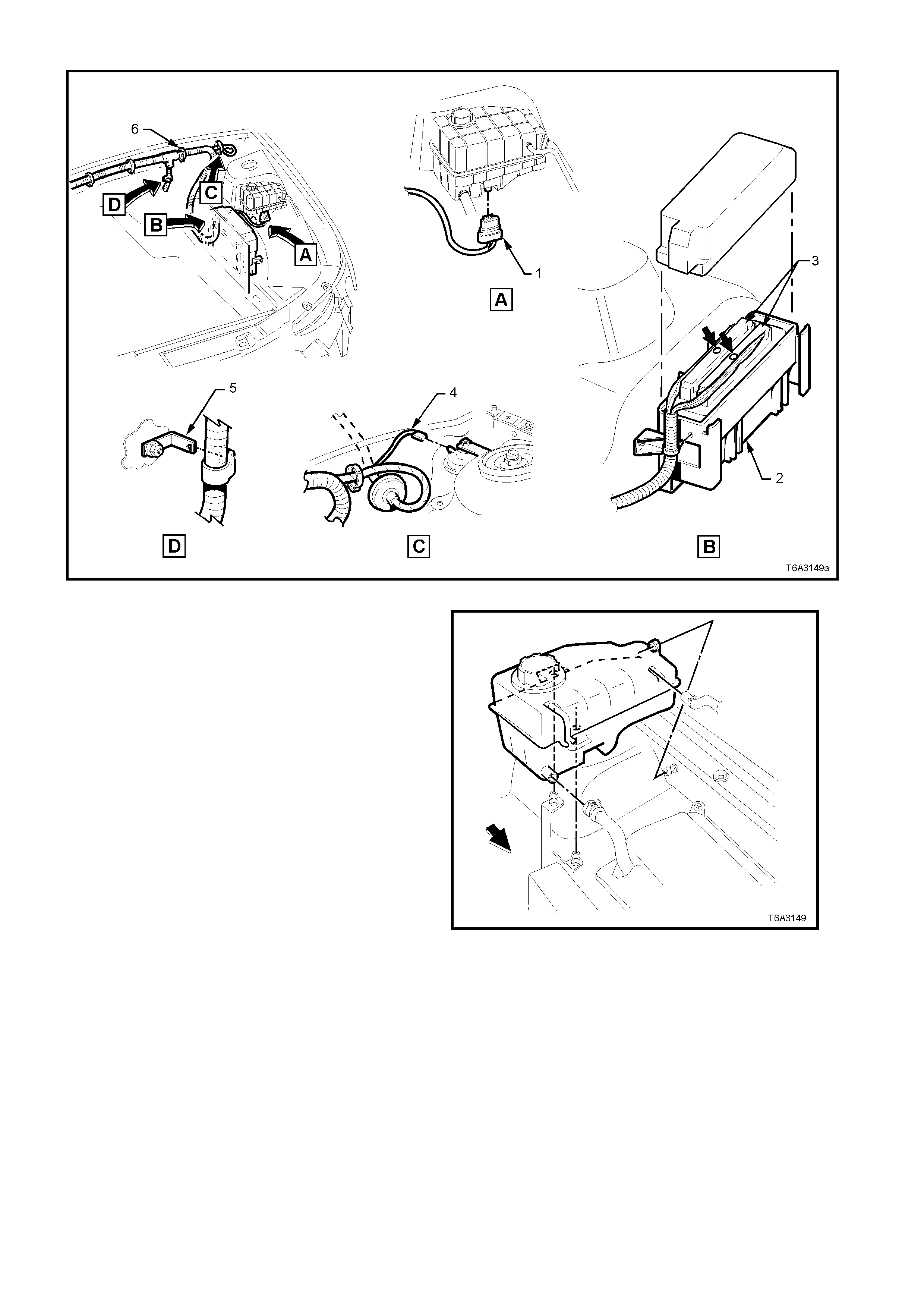
Figure 6A3-186
24. Loosen hose clamps and remove hoses from
the coolant surge tank. Then grasp the surge
tank and firmly pull to remove it from the
retaining pegs.
25. Rem ove the cover from the Powertrain Control
Module (PCM).
26. Rem ove both PCM c onnectors (see ‘3’, view B
in Figure 6A3-186) in the engine bay, after
removing the retaining screw (bold arrows)
from each connector.
27. Remove the PCM wiring harness retaining clip
from the PCM container, to free the harness.
28. Remove the engine wiring harness retaining
clip fr om the power ste erin g pipe br ack et at the
engine front.
Figure 6A3-187
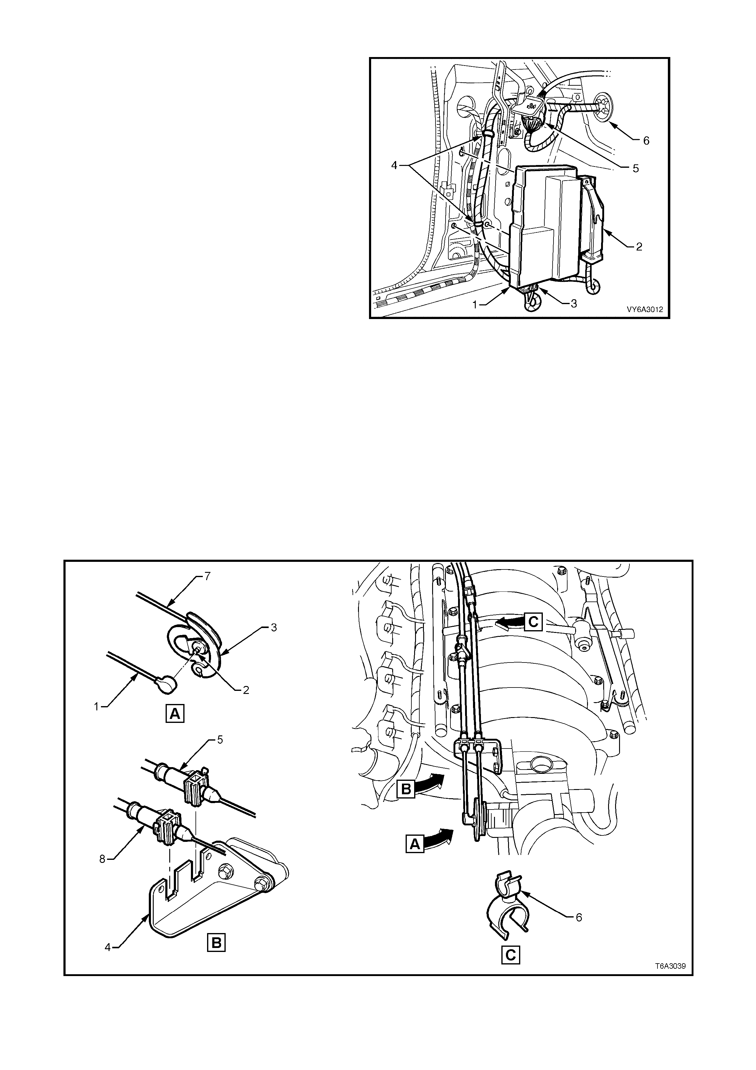
29. From ins ide the passenger compartment of the
vehicle, remove the left hand shroud panel
trim , and glo ve box ass embl y. For det ails , ref er
Section 1A3 INSTRUMENT PANEL AND
CONSOLE.
30. Remove the PIM ( 1), e ither by usin g f ingers (or
a flat bladed screwdriver) to push on and
dislodge the retaining hook, then remove the
PIM and Throttle Relaxer Module (TRM) (if
fitted), as an assembly.
31. Remove the (TRM) connector (2) (if fitted), as
follows:
– Lift the lock ing lev er on the T RM connector (2),
pivot do wn and rem ove the connec tor from the
lower hook .
32. Remove the wiring harness connector (3) from
the Powertrain Interface Module (PIM).
33. Cut the wiring harness straps (4) and discard.
34. Disconnect the Powertrain to Main wiring
harness connector, X206 (5).
35. Release the harness to dash panel grommet
(6) and feed the harness and connectors out
into the engine bay.
36. La y the po wertrai n wiring har ness on t op of th e
engine.
Figure 6A3-188
37. Disconnect the cruise control cable (1) (if fitted) (refer Figure 6A3-189) from the stud (2) on the throttle body
valve lever (3), then remove the outer cable (8) from the retainer bracket (4).
38. Lift the throttle cable (5) from the clip (6) at the fuel rail crossover pipe, then lift the cable (5)
from the retainer bracket (4).
39. Remove the inner throttle cable (7) from the throttle body valve lever (3).
40. Set the cable/s to one side.
Figure 6A3-189
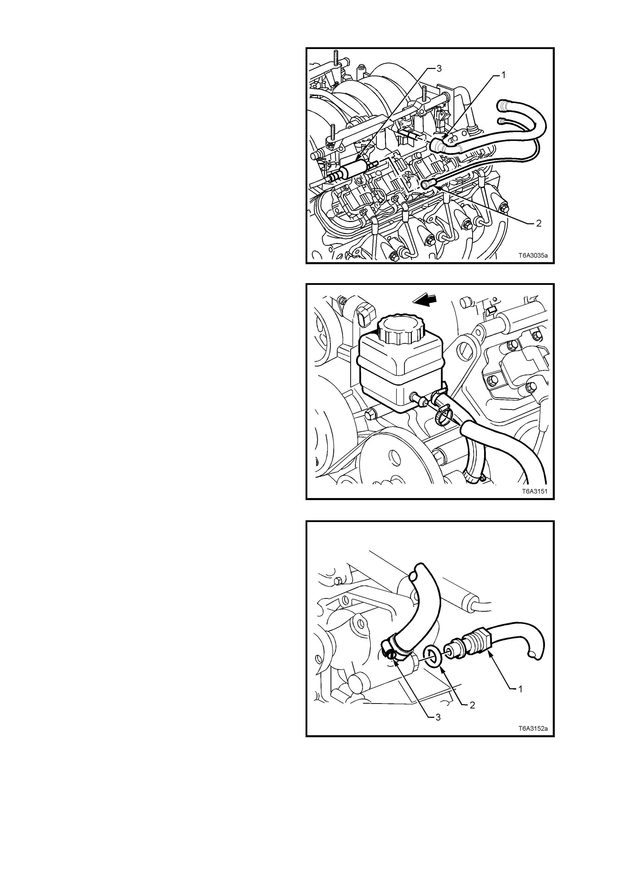
41. Using quick connect release Tool No. 7371,
open tool and install over fuel rail line.
42. Close 7371 and pull into fuel rail line quick
connect (1) to release it from the fuel rail, pull
back on the quick connect (1), to remove.
Remove the quick connect release tool from
the fuel rail line.
43. Disconnect the vapour line (2) connection to
the EVAP purge control valve (3) and set to
one side.
IMPORTANT: Plug all openings to prevent fuel
leaking an d dir t/co ntaminan ts from enter ing the f uel
system.
Figure 6A3-190
44. Loosen the hose clamp on the return hose at
the power steering reservoir end.
45. After placing a suitable container under the
reservoir, remove the hose and drain the
reservoir fluid.
IMPORTANT: Plug both openings to prevent dirt
entry.
46. Using tie wire or similar, secure the hose to
one side.
Figure 6A3-191
47. Loosen an d r emove the hi g h pr ess ur e l ine f lar e
nut (1) and O-ring (2) from the pump outlet
fitting at the rear of the power steering pump.
Use a back-up spanner on the outlet fitting
when loosening the flare nut.
IMPORTANT: Plug both openings to prevent fluid
loss and/or dirt entry.
Figure 6A3-192
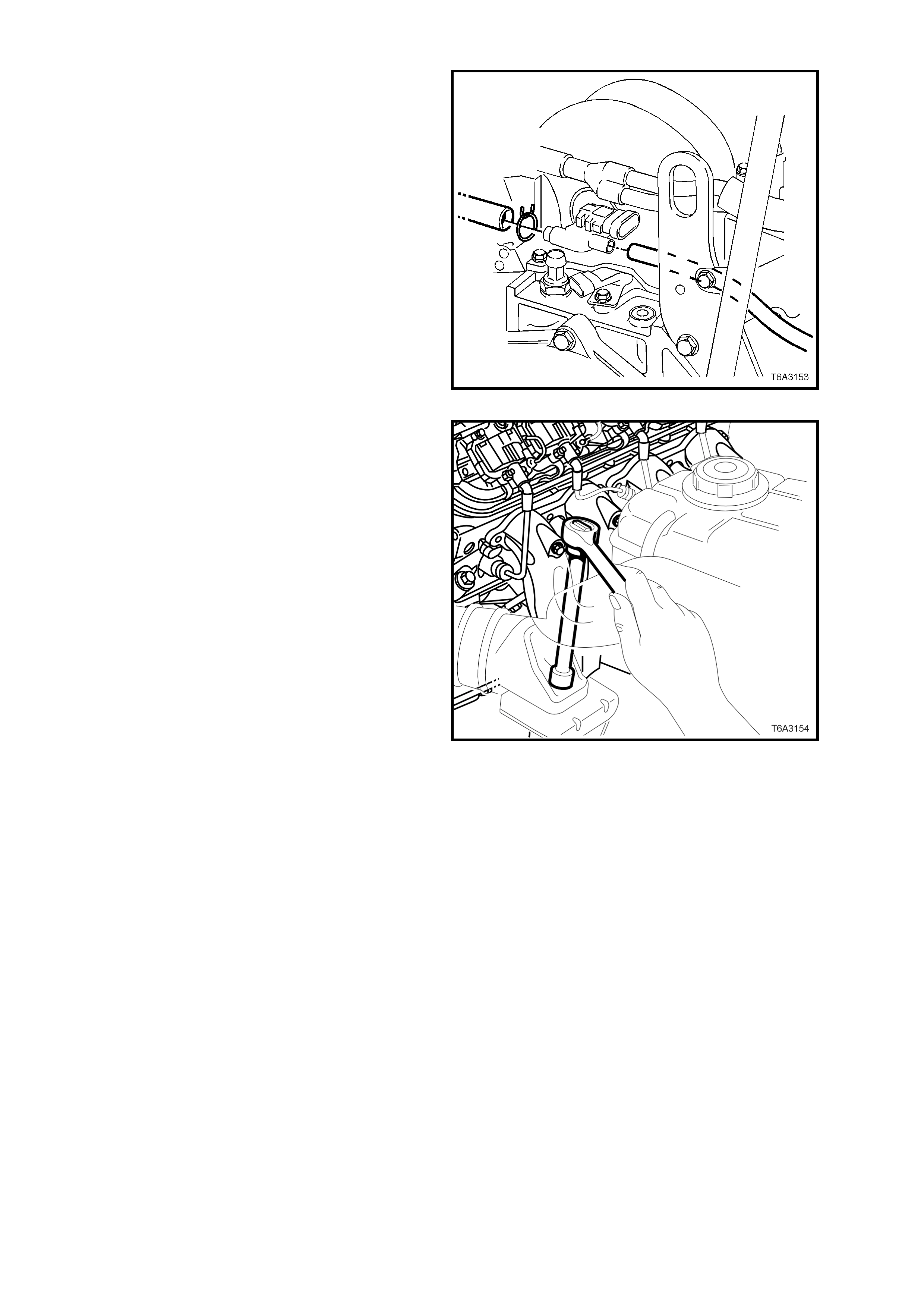
48. Disconnect the brake booster and heater
control, vacuum hoses from the rear of the
intake manifold.
Figure 6A3-193
49. Remove number 3 spark plug lead and plug
from the left bank, then remove the upper left
engine mount to engine bracket nut, using a
socket, universal joint, long extension and
ratchet.
50. For the right hand engine mount, repeat the
above process by removing the second spark
plug lead and plug (or cylinder No. 4 spark
plug), to gain access to the upper, right hand
engine mount nut. To improve the removal
process, also remove the lower mount
retaining nut.
NOTE: To improve access to these two nuts, an
alternative method is to remove both exhaust
manifolds. Refer to 2.21 EXH AU ST MANIFOLD, in
this Section, for the necessary procedure, if
required.
Figure 6A3-194
51. Remove the ignition coil and module for cylinder number 8 for right hand drive vehicles or number 7 for left
hand drive vehicles. Refer to Section 6C3-3 SERVICE OPERATIONS.
NOTE: This step is necessary to gain additional clearance around the brake vacuum booster, when the engine is
lifted during the removal process.
52. With manual transmission equipped vehicles, remove the bolt securing the clutch master cylinder reservoir
bracket to the end of the master cylinder. Refer to Section 7A2 CLUTCH for further information.
NOTE: This step is necessary to reduce the possibility of damage to the reservoir, during the engine removal
procedure.
53. Raise vehicle front and rear and support on safety stands. For location of jacking and support points, refer to
Section 0A GENERAL INFORM ATION.
54. Remove the three bolts and nuts securing the propeller shaft, front coupling. Refer to
Section 4C PRO PELLER SH AFT AND UNIVER SAL JOINT S. To discon nect t he pr opel ler sh aft f rom the front
spigot. It m ay be nec essar y to rem ove the t wo centr e b earin g to u nderbod y bol ts a nd lo wer the pr ope ller shaft.
Use tie wire to secure the sliding yoke to the rear of the transmission.
55. Disconnect the gear shift control from the transmission. Refer to Section 7B2 MANUAL TRANSMISSION -
GEN III V8 ENGINE, or Section 7C4 AUTOMATIC TRANSMISSION - ON-VEHICLE SERVICING.
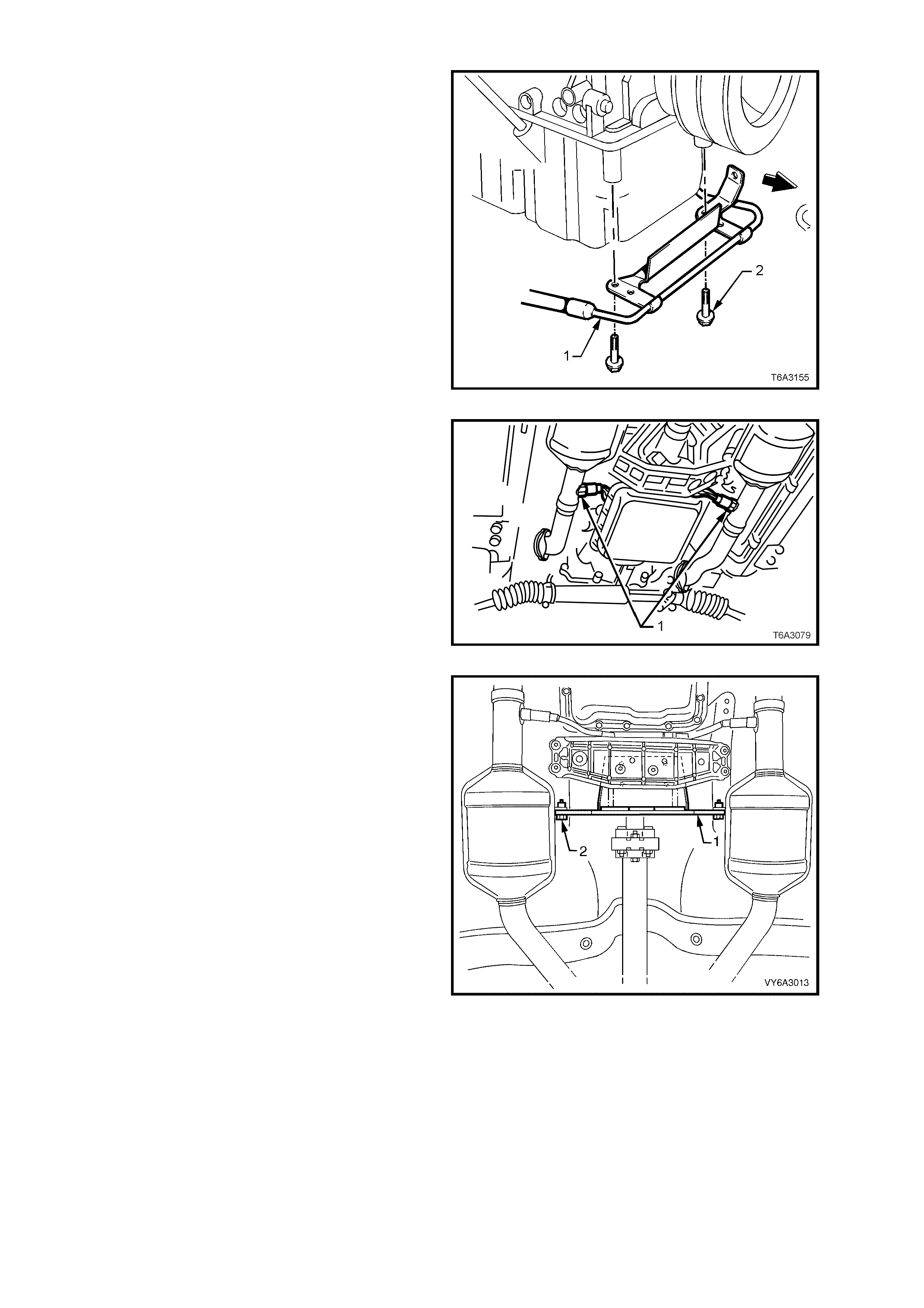
56. F rom under the fr ont of the vehicle , rem ove the
four bolts securing the oil pan under-tray.
57. Remove the two bolts (2) holding the power
steering, high pressure line (1) brackets to the
oil pan.
Figure 6A3-195
58. W hile not ess ential, it is rec ommended th at the
oxygen sensors (1) are removed from the
exhaust pipes, to avoid accidental damage.
a. Disconnect the wirin g harn ess connector s from
each oxygen sensor.
b. Remove both oxygen sensors from the exhaust
pipes.
c. Plug openings in exhaust pipes.
59. Remove both exhaust pipe to manifold flange
nuts.
Figure 6A3-196
60. Rem ove the t wo bolts (2) s ecuring the ca talytic
converter bracket (1).
IMPORTANT: Take note of any spacers that may
be included between the bracket and the catalytic
converter, as these must be reinstalled when the
engine is fitted back into the vehicle.
NOTE: While Figure 6A3-197 shows an automatic
transm iss ion equipped vehi cle, th is oper ation is the
same for manual transmission vehicles.
61. Lower the ve hic l e to the ground.
Figure 6A3-197
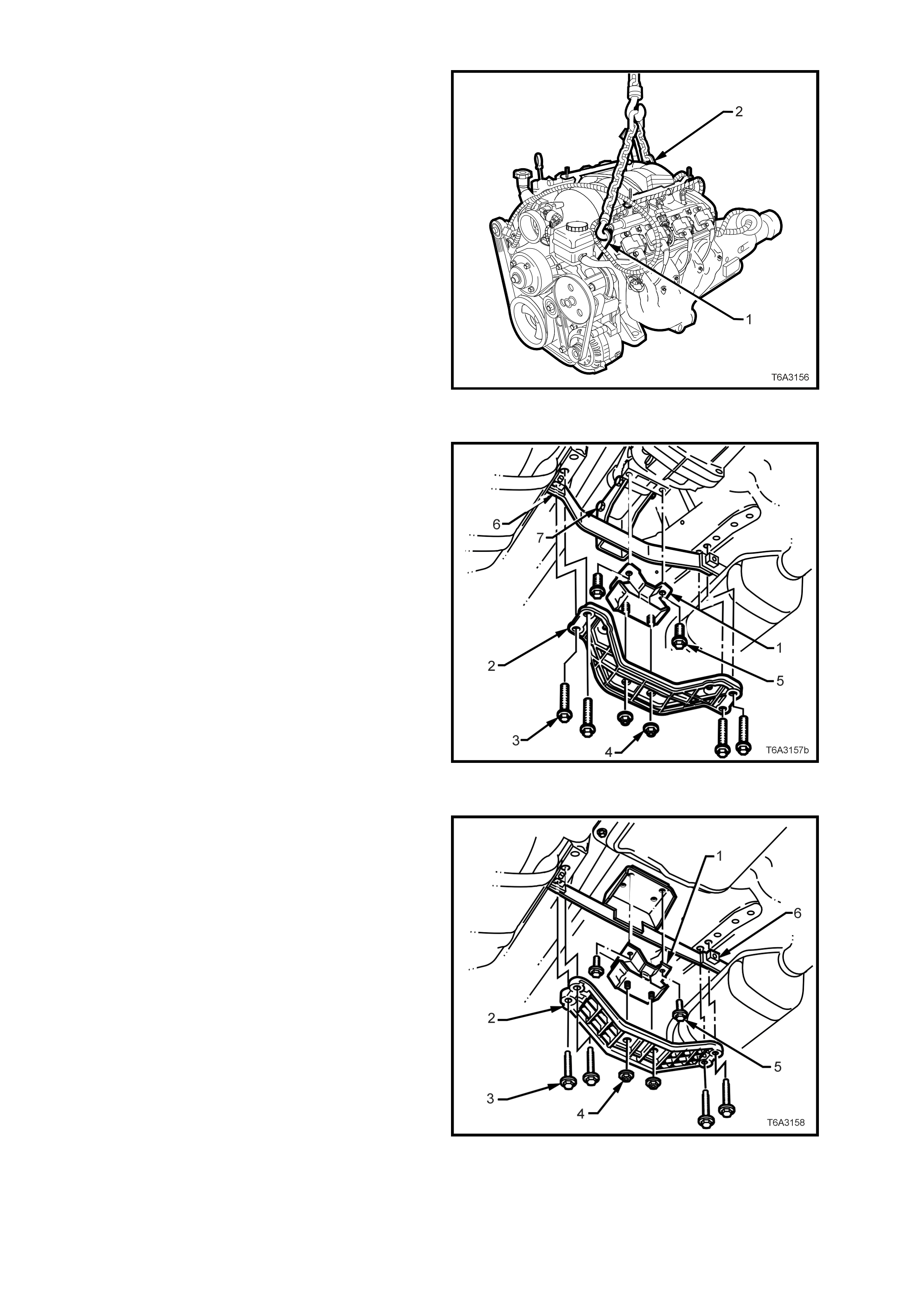
62. Attach a suitable lifting chain and hooks to the
engine lifting brackets located at the left hand
front (1) and right hand rear (2) of the engine.
63. Using a suitable lifting crane, raise the engine
slightly to take the weight off the engine
mounts.
Figure 6A3-198
Vehicles with Manual Transmission
64. Mark the relationship of the engine rear
crossmember (2) to the frame, to assist with
alignment on reassembly.
65. Remove the four bolts (3) holding the rear
crossm em ber ( 2) to the f ram e, r emove th e rear
mounting to crossmember nuts (4), then
remove the crossmember from the vehicle.
66. Remove the catalytic converter bracket to
transm ission extension bolts (7) and nuts, then
remove the bracket (6) from the vehicle and set
to one side.
Figure 6A3-199
Vehicles with Automatic Transmission
67. Us ing a scr iber or s im ilar, m ark the relations hip
of the engine rear crossmember (2) to the
frame, to assist with alignment on reassembly.
68. Remove the four bolts (3) holding the rear
crossm em ber ( 2) to the f ram e, r emove th e rear
support to crossmember nuts (4), then remove
the crossmember from the vehicle.
69. Remove the rear mount to transmission
extension housing bolts (5) and nuts, then
remove the mount (1) and the catalytic
converter bracket (6).
Figure 6A3-200
70. Raise engine and transmission assembly with
front tilted upward and a floor jack supporting
the rear of the transmission assembly.

IMPORTANT: Take care when removing engine and transmission assembly, that no part of the assembly is
allowed to rest on the power steering rack.
NOTE: Do not allow the engine to swing forward and damage the air conditioning condenser (if fitted).
71. Continue to lift and manoeuvre the engine and transmission assembly clear of the engine bay.
DISASSEMBLE
1. Rem ove the wiri ng har ness connector s an d earth c onn ections f rom the engi ne an d transm is sion assem bl y and
carefully set the wiring harness to one side.
2. Remove the transmission and mount the engine assembly in a suitable engine stand. The most practical
position overall, is to mount the engine on the side, using the engine mount bolt holes.
IMPORTANT: If the eng in e is to be dism antled a nd in par ticu lar, the c am shaf t is t o be r em oved, the n the c am shaft
lobe lift check should be carried out, prior to the removal of the cylinder heads. Refer to 3.2 CAMSHAFT LOBE
LIFT MEASURE for details.
3. Drain engine oil into a suitable, clean container.
4. Remove the following components, as described in either this Section or other, designated Sections:
a. Oil filter, refer to 2.3 ENGINE OIL FILTER & ADAPTOR REPLACE in this section.
b. Engine drive belts, refer to 2.6 ENGINE DRIVE BELTS – REPLACE ENGINE ACCESSORY BELT AIR
CONDITIONG COMPRESSOR BELT in this section.
c. Air conditioning compressor, refer Section 2B, AIR CONDITIONING - REMOVAL AND INSTALLATION
d. Engine accessory drive belt idler and tension pulley assemblies, refer to 2.7 ACCESSORY BELT IDLER
PULLEY REPLACE and 2.9 ACCESSORY BELT TENSIONER REPLACE in this section.
e. Air conditioning drive belt idler and tension pulley assemblies, refer to 2.8 A/C BELT IDLER PULLEY
REPLACE and 2.10 A/C BELT TENSIONER in this section.
f. Generator and mounting brackets, refer Section 6D3-1 CHARGING SYSTEM - GEN III V8 ENGINE.
g. Intake manifold, refer to 2.14 INTAKE MANIFOLD in this section.
h. Vapour vent pipe, refer to 2.15 VAPOUR VENT PIPE in this section.
i. Engine valley cover, refer to 2.16 ENGINE VALLEY COVER in this sect ion.
j. Valve rocker arm covers, refer to 2.17 VALVE ROCKER ARMS & PUSH RODS in this section.
k. Valve rock er arm s and pus h rods, r efer to 2 .18 V ALVE ST EM OIL SE AL AND.OR V ALVE SPRING in t his
section.
l. Oil level indicator and exhaust manifolds (if not already removed), refer to 2.20 OIL LEVEL INDICATOR
AND TUBE and 2.21 EXHAUST MANIFOLD in this section. Plug the oil level indicator hole in the oil pan to
avoid dirt entry.
m. Cylinder heads and valve lifters, refer to 2.22 CYLINDER HEAD and 2.23 VALVE LIFTERS in this section.
n. Starter motor, refer Section 6D3-2 STARTING SYSTEM - GEN III V8 ENGINE.
o. Crankshaft balancer, refer to 2.24 CRANKSHAFT BALANCER in this section.
p. Coolant pump assembly, refer to 2.25 COOL ANT PUM P in this section.
REASSEMBLE
Reassembly of the components listed in step 4. of the DISASSEMBLE description above, is the reverse of the
disassembly procedures, except for specific points stated in each description for that component.
For other engine components that are detailed in this Section, the reassembly process is also detailed.

REINSTALL, SET UP AND T ESTING
Installation of the engine assembly is the reverse of removal procedures, noting the following points:
1. Ensure that all fasteners are tightened to the correct torque specifications, as detailed in
6. TORQUE SPECIFICA TIONS, at the end of this Section.
2. Use onl y the specif ied eng ine lu bricant t ype and qu antit y. It is rec omm ended that a f luoresc ent oil d ye, such as
that contained in J 28481-B, be added to assist in any future oil leak diagnosis.
3. Fill the c ooling s ystem with the prop er quant ity and grade of coolant. Refer S ection 6B3 ENGINE COO LING -
GEN III V8 ENGINE.
4. Check transmission fluid level, topping up as requir ed, using the specified lubric ant for the transm ission fitted.
Refer Section 7C4 AUTOMATIC TRANSMISSION - ON-VEHICLE SERVICING.
5. Disable the ignition system. Refer to 2.5 COMPRESSION CHECK in this Section, for details.
6. Crank the engine several times. Listen for any unusual noises or evidence that parts are binding.
7. Enable the ignition system, start the engine and listen for unusual noises.
8. Check the vehic le oil pres s ure gauge or warn ing lam p and conf irm that the eng ine has ac ceptab le oil pres sur e.
If necessary, install an oil pressure gauge and measure the engine oil pressure. Refer to 2.4 ENGINE OIL
PRESSURE - CHECK, in this Section.
9. Run the engine speed at about 1,000 rpm until the engine has reached normal operating temperature.
10. Listen for sticking lifters and other unusual noises.
11. Check for oil, fuel, coolant and exhaust leaks while the engine is running, correcting as required.
12. Perform a final inspection for the proper engine oil and coolant levels.
13. Check engine hood alignment.
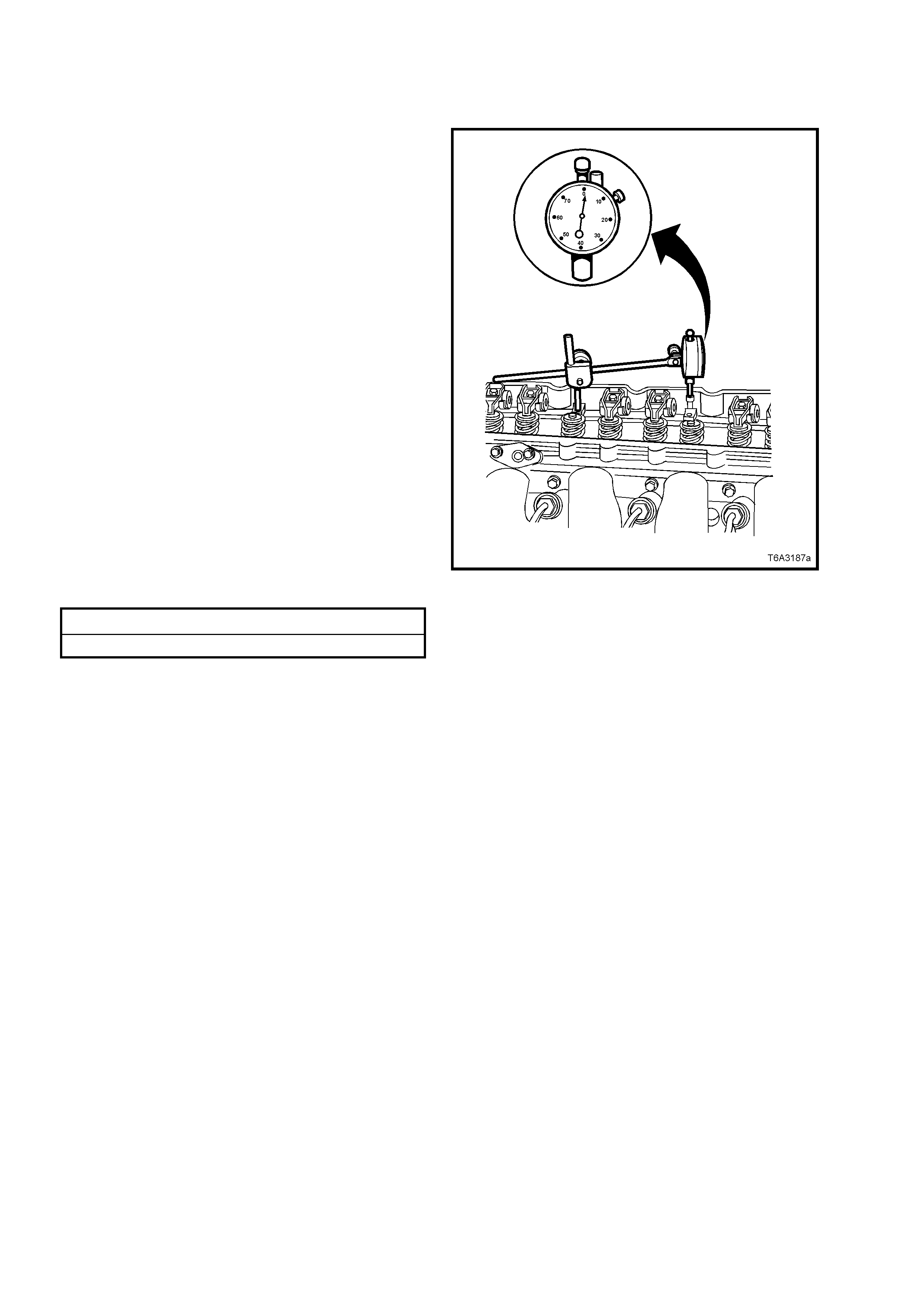
3.2 CAMSHAFT LOBE LIFT
MEASURE
IMPORTANT: Measuring camshaft lobe lift is a
procedure used to determine if the camshaft lobes
have worn. This test is to be performed prior to
engine disassembly and with the camshaft, push
rods and valve lifters installed in the engine.
1. To measure the camshaft lobe lift, proceed as
follows:
a. Remove the valve rocker arms and bolts.
Refer 2.18 VALVE STEM OIL SEAL
AND.OR VALVE SPRING, in this Section.
b. Install an M8 x 1.25 dial indicator mounting
stud into the valve rocker arm bolt hole.
c. Assemble the components of a
commercially available dial indicator (or
Tool J 8520) and position onto the installed
stud, as shown.
d. Position the shaft of the dial indicator onto
the end of the pushrod.
e. Zero the dial indicator dial.
f. Slowly rotate the crankshaft clockwise until
the dial indicator obtains its highest and
lowest readings.
g. Repeat for all valves and compare the
readings obtained against specifications.
Camshaft Lobe Lift Specification:
Intake Lobe 7.43 mm
Exhaust Lobe 7.43 mm
NOTE: If the readings are not within specification,
then the camshaft lobes are worn and require
further investigation when the camshaft is
removed.
Figure 6A3-201
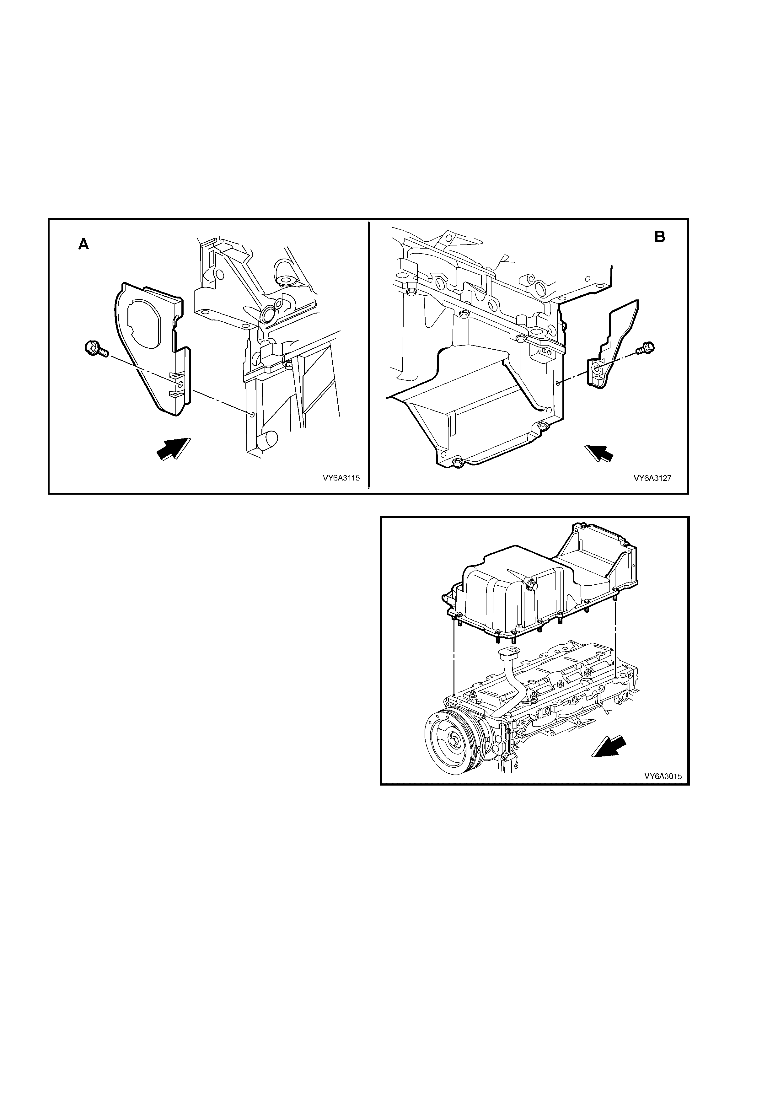
3.3 OIL PAN
LT Section No. – 00-275
REMOVE
IMPORTANT: Bec aus e of c ritical alignm ent pr ocedur es require d for oil pa n instal latio n, it is stron gl y recom mende d
that the engine assembly is removed from the vehicle, before oil pan removal.
1. Remove the starter motor. Refer Section 6D3-1 STARTING MOTOR – GEN III V8 ENGINE.
2. Remove the right close-out cover screw and cover (View ‘A’).
3. Remove the left close-out cover screw and cover (View ‘B’).
Figure 6A3-202
4. Invert the engine assembly.
5. Remove the oil pan bolts, loosening gradually
from the ends and working inwards toward the
centre.
6. Bump the oil pan sideways with the heel of a
hand or a rubber hammer, to dislodge the seal.
Figure 6A3-203
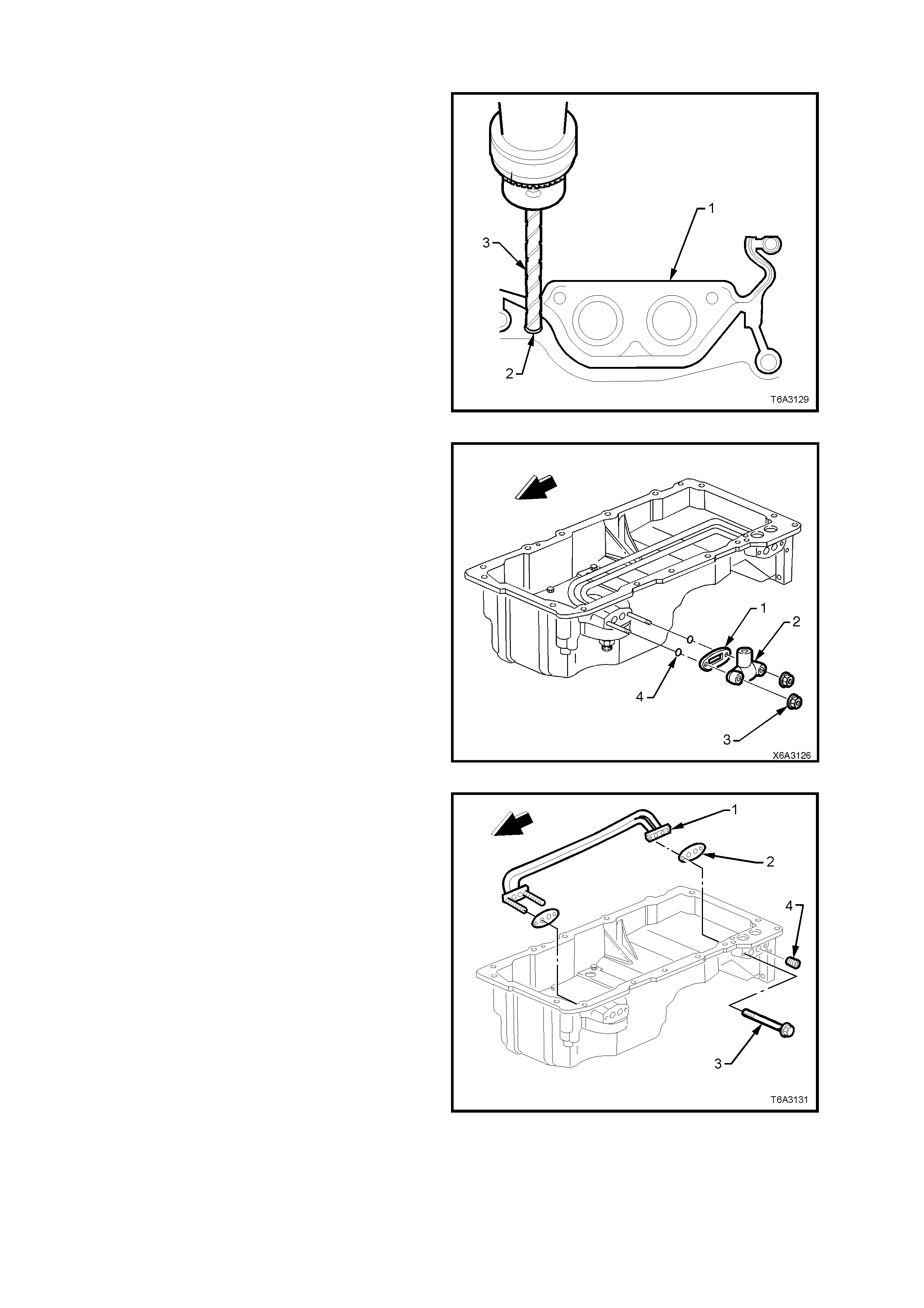
DISASSEMBLE
NOTE: The original oil pan gasket is retained and
aligned to the oil pan by rivets. When installing a
new gasket as a service replacement, it is not
necessary to install new oil pan gasket rivets.
IMPORTANT: Do not al lo w m etal s hav ings or other
foreign material to enter the oil passages in the oil
pan during gasket removal. Plug all openings
before commencing drilling operations.
1. Use a s har p t wist dr ill ( 3) to dril l o ut e a ch of the
retaining rivets (2), as required.
2. Remove the oil pan gasket (1) from the oil pan.
3. Discard the gasket and rivets.
Figure 6A3-204
4. Remove the oil transfer cover nuts (3), cover
(2), and gasket (1). Discard the gasket (1).
5. Remove the two O-rings (4) and discard.
NOTE: If removal of the oil transfer cover nuts (3)
is required while the oil pan is still installed (e.g.
during fitment of an external oil cooler), the studs
MUST NOT be removed. Otherwise the transfer
pipes and gasket inside the oil pan, may become
dislodged.
Figure 6A3-205
6. Remove the two oil filter transfer tube bolts (3).
7. Remove the oil filter transfer tubes (1) and
discard the gaskets (2).
8. If required, use an Allen key socket to remove
the oil gallery plugs (4).
NOTE: Because of thread sealant applied to the
threads, it is recomm ended that the front studs are
left attached to the transfer tube assem bly and the
whole assembly withdrawn from inside the oil pan.
Figure 6A3-206
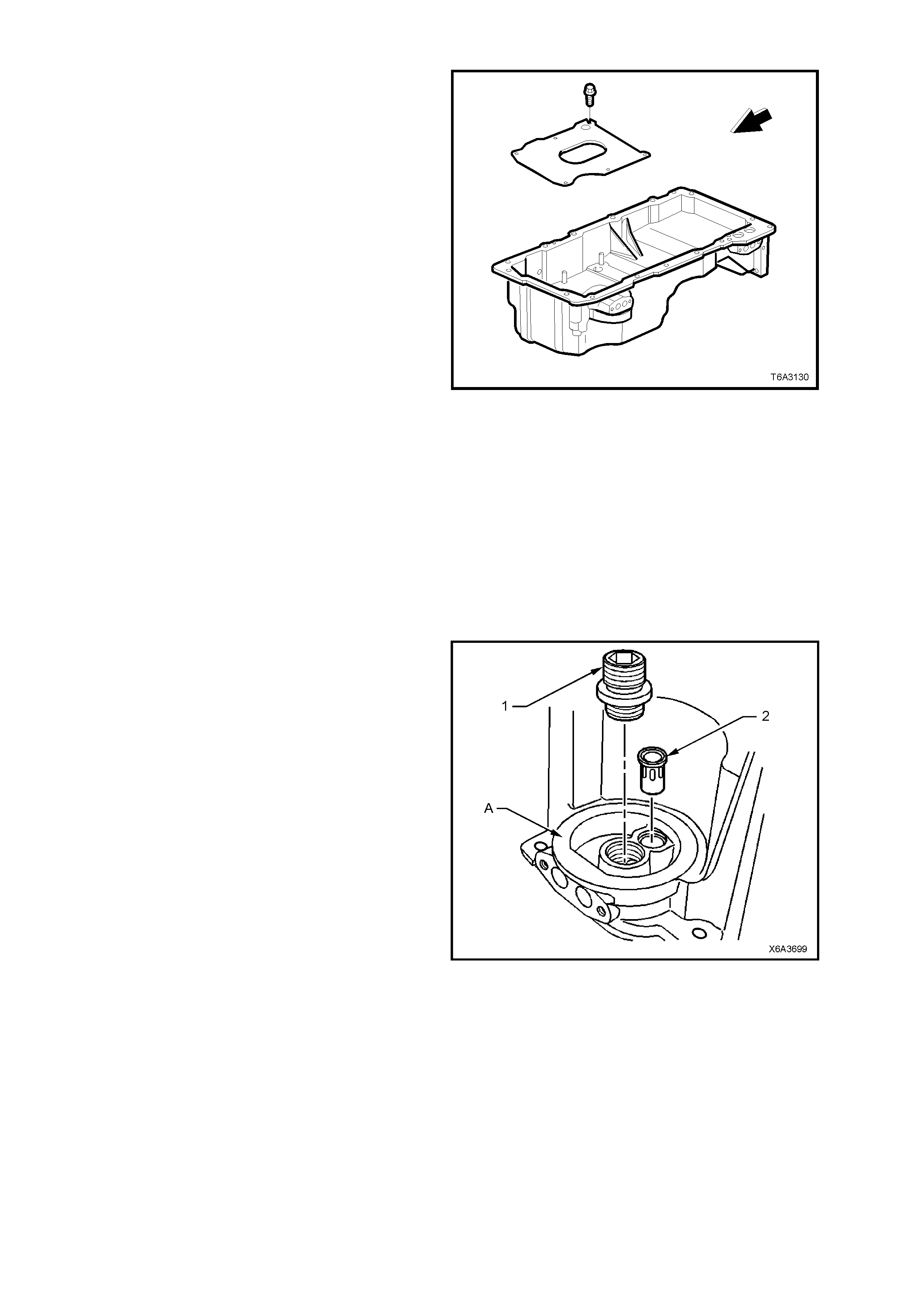
9. Remove the oil pan baffle bolts (six places)
and baff le.
Figure 6A3-207
CLEAN AND INSPECT
1. Clean the oil pan in a suitable solvent. Ensure that all oil passages and recesses are thoroughly cleaned.
2. Clean the oil pan gasket surfaces, using a plastic scraper to avoid scratching or damaging the machined
surfaces.
3. Dry the oil pan with compressed air.
CAUTION: Wear safety glasses to avoid eye injury.
4. Inspect the oil pan for the following:
a. Gasket sealing surfaces for excessive scratches or gouging.
b. Oil pan dr ain p lug an d thr e aded dr a in hol e f or damaged threa ds . The dra in plu g O-ring s ea l may be reus e d
if not cut or damaged.
c. Oil filter sealing surface (A) for scratches
or gouging.
d. Oil filter adaptor (1) for a loose fit or
damaged threads.
e. Oil passages for restrictions.
f. Oil filter bypass valve (2) in the oil filter
flange f or pr oper op er at ion Lig htly push the
bypass valve into the bore. The valve
spring should reseat the valve to the
proper position.
5. Inspect the oil transfer tube for damage or
restrictions.
Figure 6A3-208
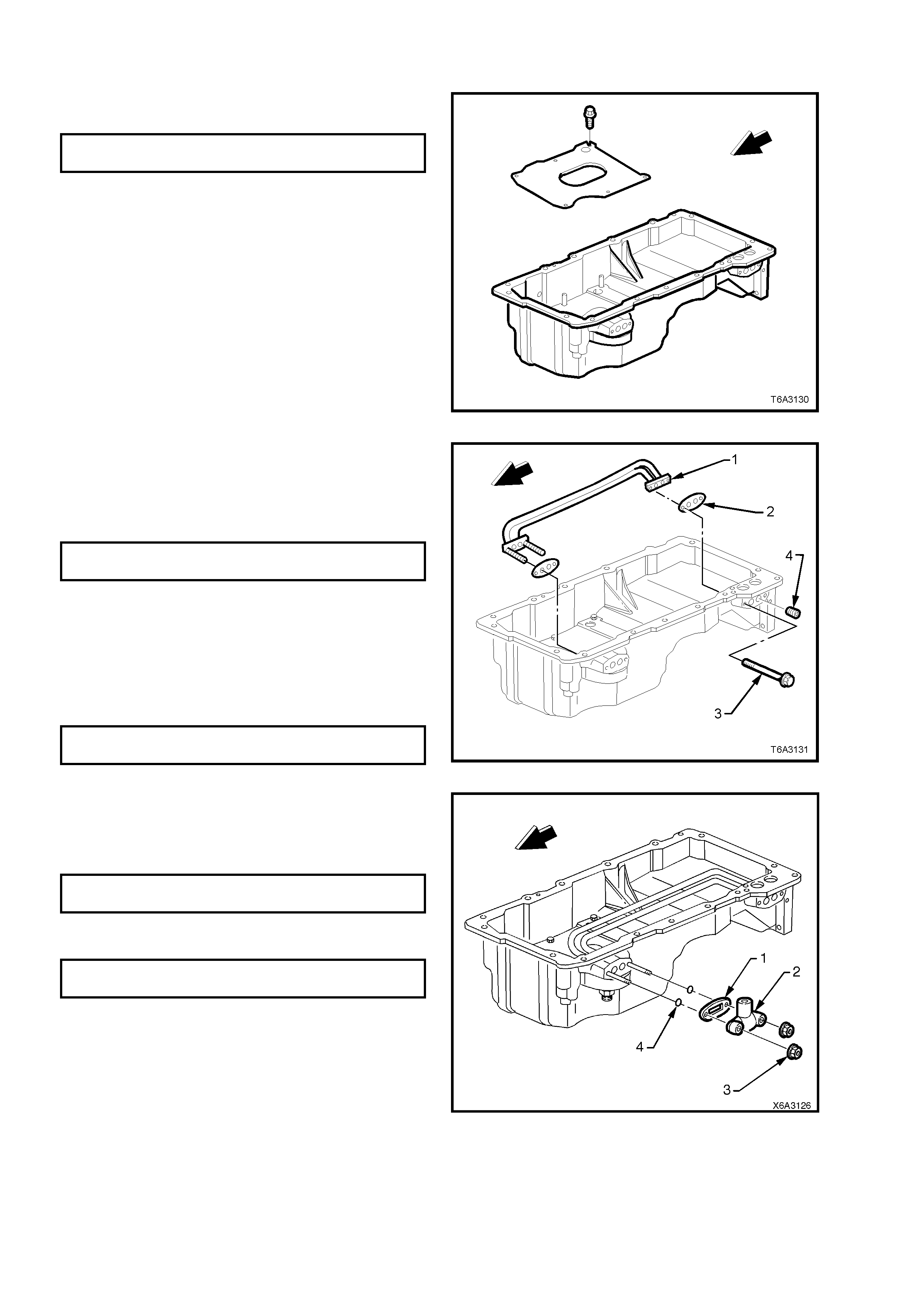
REASSEMBLE
1. Install the oil pa n baffle and r etaining bolts an d
tighten to the correct torque specification.
OIL PAN BAFFLE BOLT
TORQUE SPECIFICATION 12 Nm
Figure 6A3-209
2. If removed, apply thread lock compound such
as Loctite 242 (or equivalent) to the cleaned
threads of the oil gallery plugs (4).
3. Use an Allen key socket and tighten the oil
gallery plugs to the correct torque specification.
OIL GALLERY PLUG
TORQUE SPECIFICATION 25 Nm
4. Apply thread lock compound such as Loctite
242 (or equivalent) to the cleaned threads of
the oil transfer tube bolts (3)
5. Using NEW gaskets (2), install the oil filter
transfer tubes (1).
6. Install the two bolts (3) and tighten to the
correct torque specification.
OIL FILTER TRANSFER TUBE
TORQUE SPECIFICATION 12 Nm
Figure 6A3-210
7. Install NEW oil pan transfer cover O-rings (4),
gasket (1), cover (2) and nuts (3).
8. Tighten the nuts to the correct torque
specification.
OIL PAN TRANSFER COVER NUT
TORQUE SPECIFICATION 12 Nm
9. If removed, install the oil filter adaptor and
tighten to the correct torque specification.
OIL FILTER ADAPTOR
TORQUE SPECIFICATION 55 Nm
10. If requir ed, insta ll a NEW oil f ilter bypas s valve ,
using a suitable size socket and hammer to
fully seat in the oil filter flange.
Figure 6A3-211
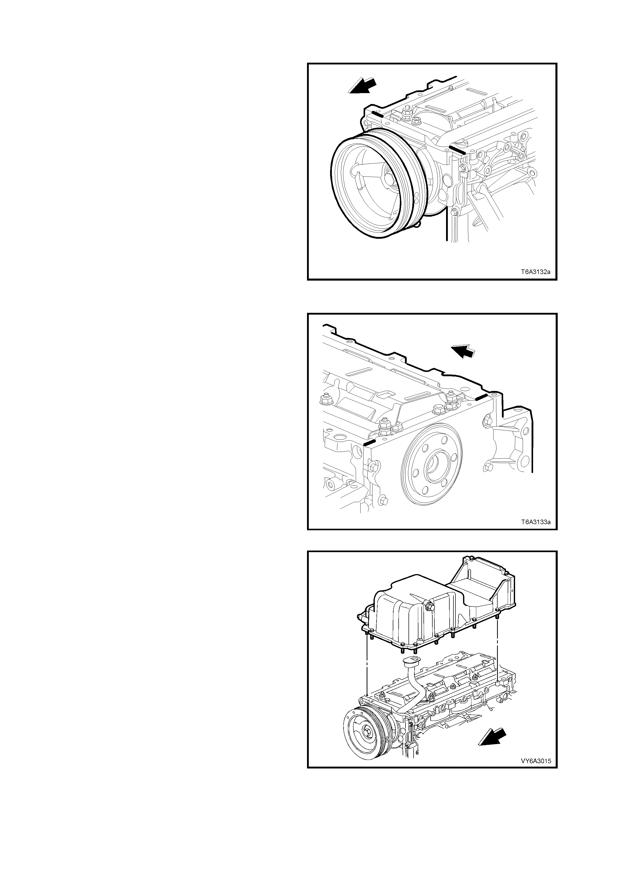
REINST ALL
IMPORTANT: The alignment of the structural oil
pan is critic al. The r ear bolt hole locations of the oil
pan provide mounting points for the transmission
bell housing. To ensure the rigidity of the
powertra in and correc t transm ission alignm ent, it is
important that the rear of the engine block and the
rear of the oil pan are flus h. The rear of the oil pan
must NEVER protrude beyond the engine block
and transmission bell housing plane.
NOTE 1: Do NOT reuse the oil pan gasket.
NOTE 2: It is not necessary to rivet the NEW
gasket to the oil pan.
1. Apply a 5 mm wide bead of sealant such as
Loctite 565 or equivalent, 20 mm long to the
engine block, as shown. Apply the sealant
directly onto the tabs of the front cover gasket
that protrude into the oil pan surface.
Figure 6A3-212
2. Apply a 5 mm wide bead of sealant such as
Loctite 565 or equivalent, 20 mm long, to the
engine block, as shown. Apply the sealant
directly onto the tabs of the rear cover gasket
that protrude into the oil pan surface.
Figure 6A3-213
3. Pre-assemble the oil pan gasket to the oil pan.
IMPORTANT: Be sure to align the oil gallery
passages in the oil pan and engine block properly
with the oil pan gasket.
4. Install the oil pan bolts to the pan and through
the gask et. Install the oil pan, gasket and bo lts
to the engine block. Tighten bolts finger tight.
Do not over-tighten.
5. Place a straight edge across the rear of the
engine block and the rear of the oil pan at the
transmission bell housing mounting surfaces.
Figure 6A3-214
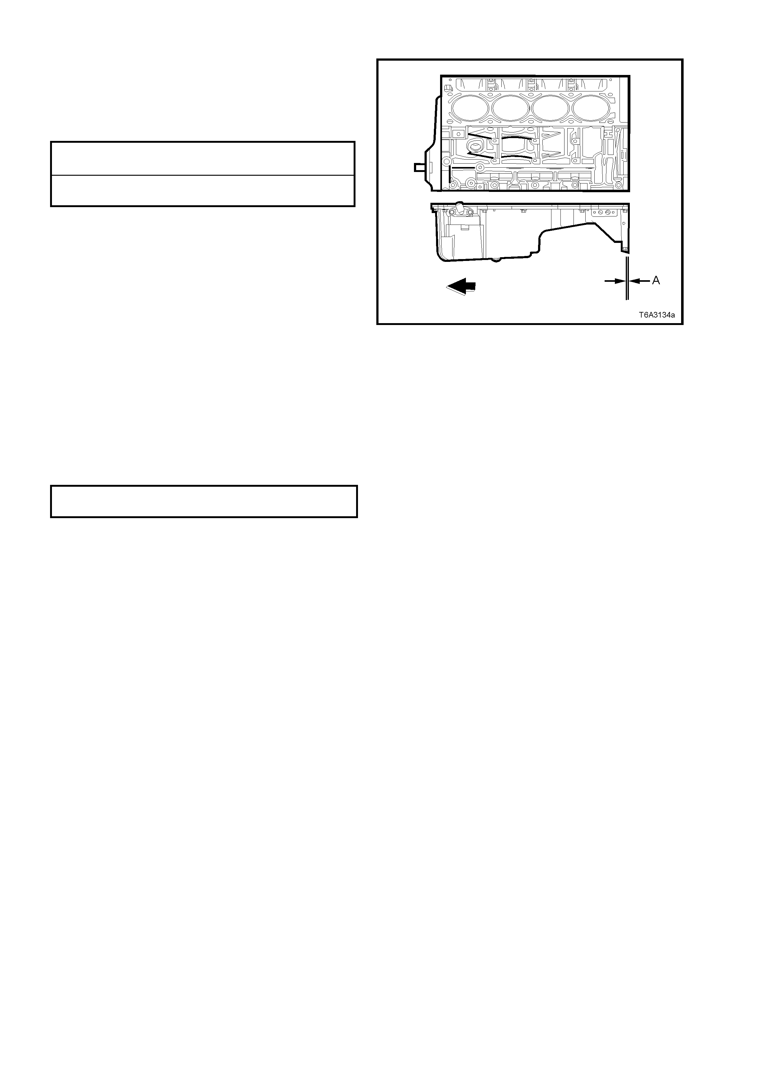
6. Align the oil pan until the rear of engine block
and rear of oil pan are flush or even.
7. Inst all the oil pan t o f r ont c over bo lts and t he o il
pan to rear cover bol ts , tigh tening to the corr ec t
torque specifications.
OIL PAN TO FRONT COVER
TORQUE SPECIFICATION 25 Nm
OIL PAN TO REAR COVER BOLT
TORQUE SPECIFICATION 12 Nm
NOTE: This pr elim inar y step is requir ed to a void oil
pan ‘creep’ and create a misalignment condition.
8. Place a straight edge across the rear of the
engine block and rear of oil pan at the
transmission bell housing mounting surfaces.
9. Insert a feeler gauge between the straight edge
and the oil pan transmission bell housing
mounting surface and check to make sure that
the oil pan is flush to no more than a 0.25 mm
gap between the pan and straight edge
(dimension ‘A’).
IMPORTANT: T he rear of the oil pan m ust NEVER
protrude beyond the en gi ne bloc k and trans mission
bell housing mounting surfaces.
10. Install remaining oil pan to cylinder block bolts
and tighten to the correct torque specification.
Figure 6A3-215
OIL PAN TO CYLINDER BLOCK
TORQUE SPECIFICATION 25 Nm
If the oil pan alignment is not within specification,
remove the oil pan and repeat the above
procedure.
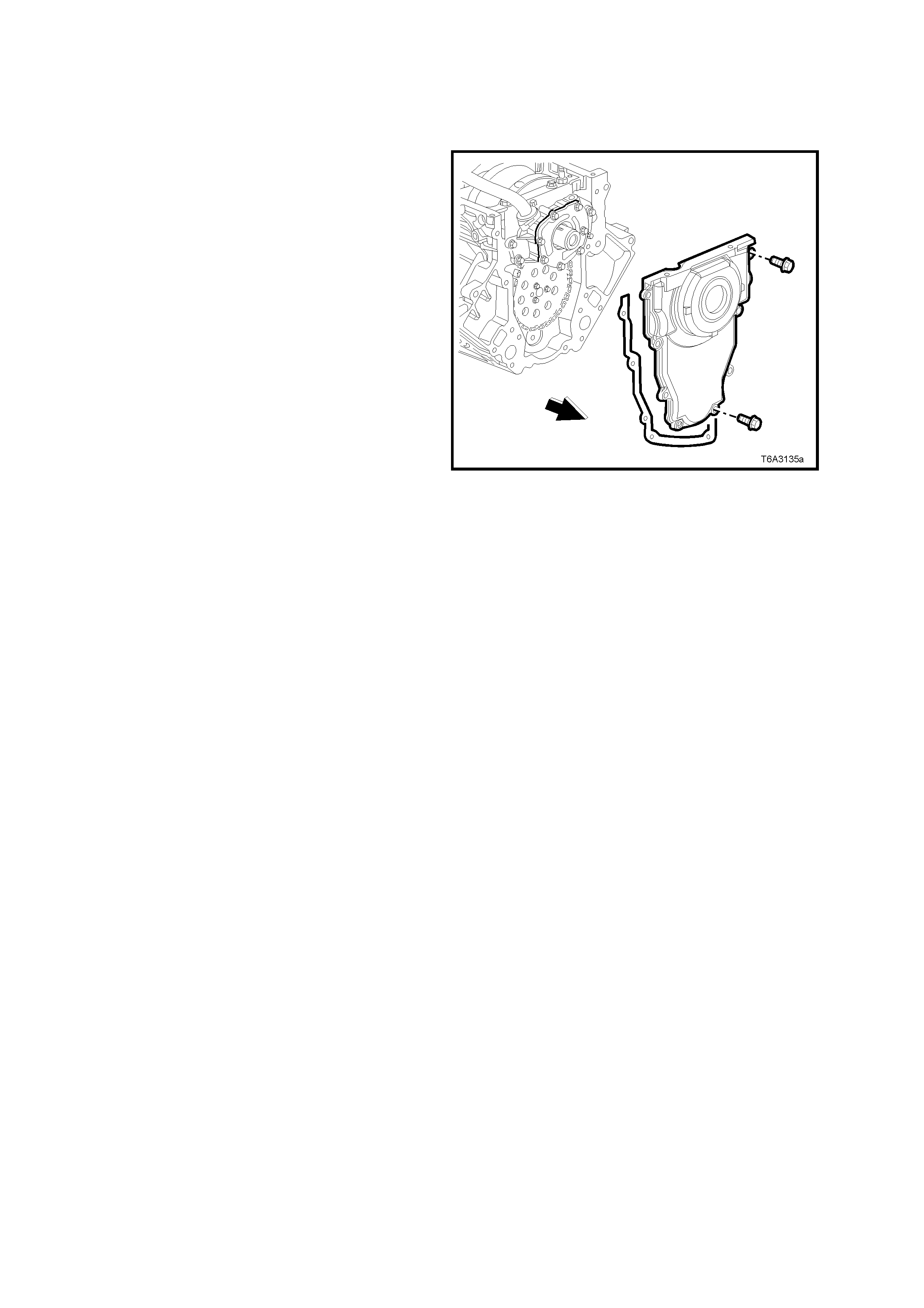
3.4 ENGINE FRONT COVER
LT Section No. – 00-375
REMOVE
IMPORTANT: Because of critical alignment
procedures required for the reinstallation of the
front c over and oil pan, i t is strongl y recomm ended
that the engine assembly is removed from the
vehicle, before oil pan removal.
1. Remove the crankshaft balancer. Refer
2.24 CRANKSHAFT BALANCER - REMOVE,
in this Section.
2. Remove the front cover bolts.
3. Remove the front cover and gasket. If the
gasket is undamaged, it maybe re-used.
Figure 6A3-216
CLEAN AND INSPECT
1. Prise the old oil seal from the front cover and discard.
2. Clean the front cover in a suitable solvent and blow dry.
CAUTION: Wear safety glasses to avoid eye injury.
3. Inspect the front cover sealing surfaces for excessive scratches and/or gouges.
4. Inspect the front cover gasket for damage to the membrane or distortion to the aluminium carrier.
5. Inspect the front cover to oil pan threaded holes for damaged threads or debris. Refer to
3.16 THREAD REPAIR, in this Section, if rectification is required.
6. Inspect the cover crankshaft oil seal bore for damage.
REINST ALL
NOTE 1: Do not reuse the crankshaft oil seal if inspection shows it to be damaged in any way.
NOTE 2: Do not apply any type of sealant to the front cover gasket.
NOTE 3: The special tools in this procedure must be used to properly align the engine front cover at the oil pan
surface and to centre the crankshaft front oil seal.
NOTE 4: All gasket surfaces should be free of oil or other foreign material during assembly.
NOTE 5: T he crank shaf t front oil s eal MU ST be c entr ed in re lation to the c rank shaf t. The oi l pan s ealing s urf ace at
the front cover and engine block MUST also be aligned within specifications.
NOTE 6: An improperly aligned front cover may cause premature front oil seal wear and/or engine assembly oil
leaks.
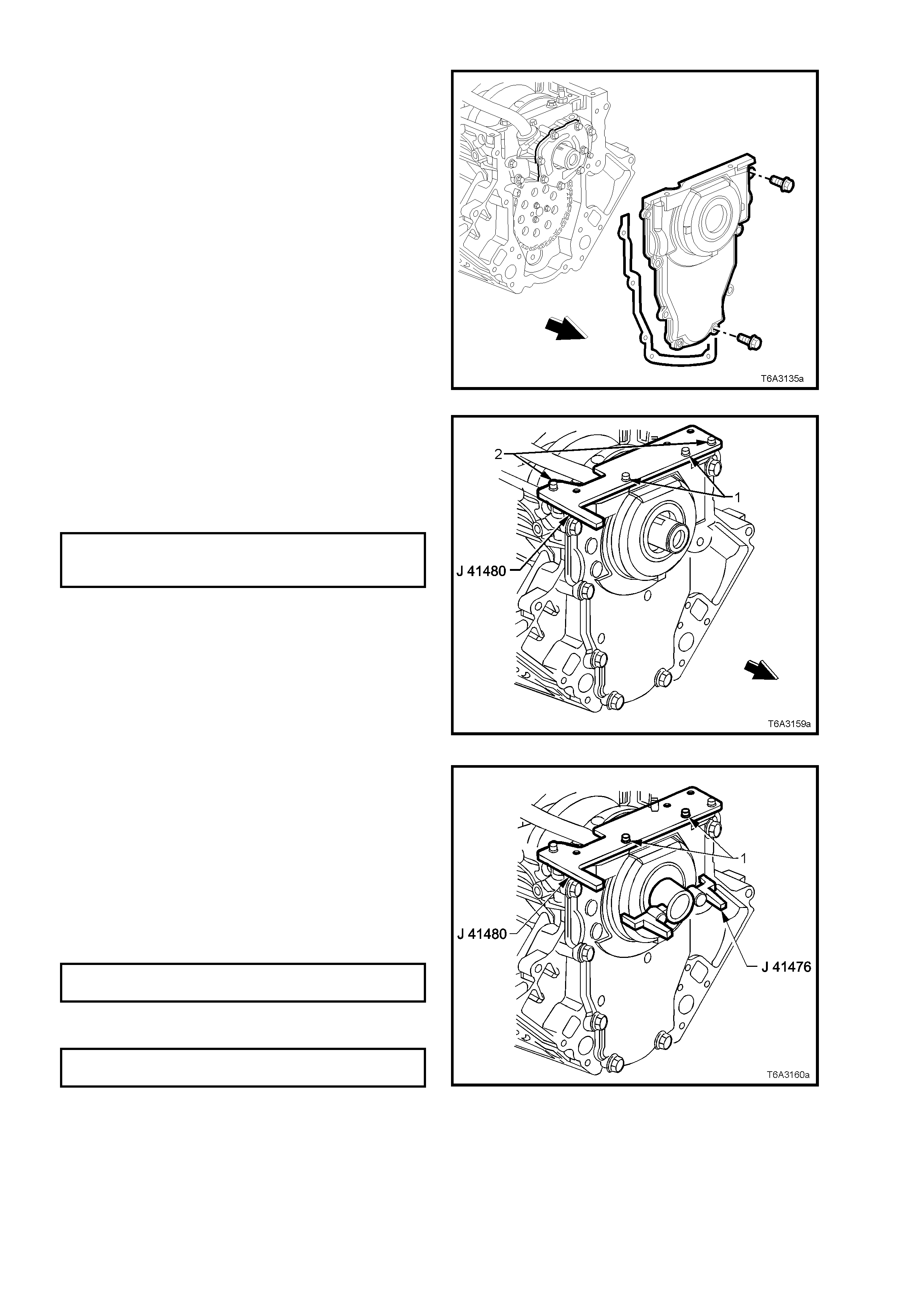
1. Install the front cover gasket, cover, and bolts
onto the engine.
2. T ighten th e c o ver bo lts f ing er tigh t on ly. Do not
tighten.
Figure 6A3-217
3. Assem ble alig nm ent tool J 4148 0 to f ront cover
and install bolts (1) (part of Tool J 41480), in
the locations sho wn but do not tigh ten.
4. Install the alignment tool bolts (2) (part of Tool
J 41480) t o the engine blo ck and tighten to the
specified torque.
FRONT COVER ALIGNMENT TOOL
BOLT TO ENGINE BLOCK
TORQUE SPECIFICATION 25 Nm
Figure 6A3-218
5. Install centralising Tool J 41476 as shown and
hold in position by hand.
IMPORTANT: DO NOT install the crankshaft
balancer bo lt to reta in the ali gnment too l. If the bolt
is installed and over-tightened the alignment tool
will be destroyed!
NOTE: Align the tapered legs of the tool with the
machined alignment surfaces on the front cover.
6. Tighten the t wo bolts (1) secur ing Tool J 41480
to the front cover, to the specified torque.
ALIGNMENT TOOL TO FRONT COVER
BOLT TORQUE SPECIFICATION 25 Nm
7. Tighten the engine front cover bolts to the
correct torque specification.
ENGINE FRONT COVER BOLT
TORQUE SPECIFICATION 25 Nm
8. Remove the alignment tools.
Figure 6A3-219
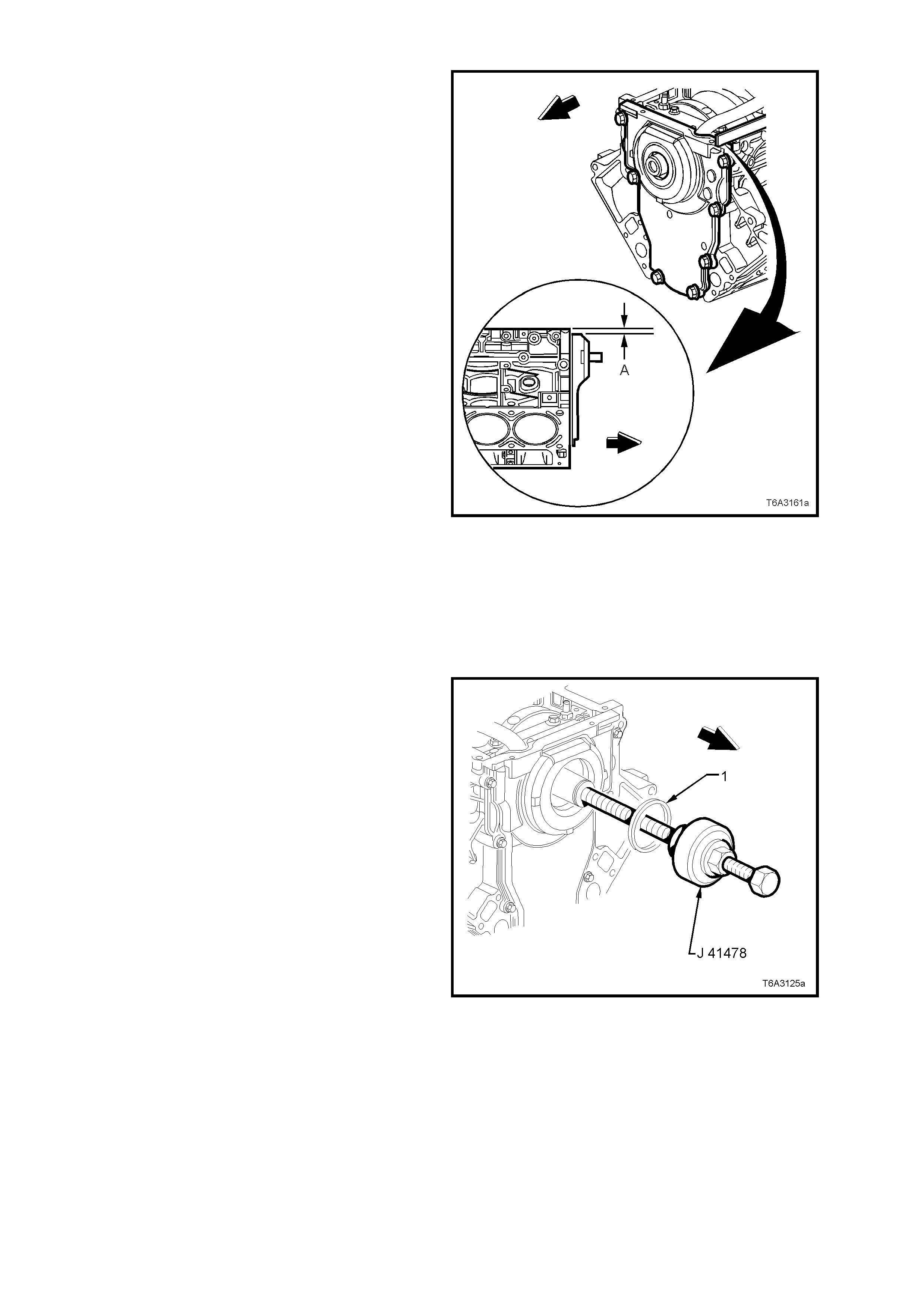
9. Measure the oil pan surface to front cover for
flatness, as follows:
a. Place a straight edge across the engine block
and front cover oil pan sealing surfaces. Avoid
contact with the portion of the gasket that
protrudes into the oil pan surface.
b. Insert a feeler gauge between the front cover
and the straight edge tool. The cover must be
flush with the oil pan surface or no more than
0.25 mm below flush (dimension ‘A’).
c. If the front cover-to-engine block oil pan
surface alignment is not within specifications,
repeat the cover alignment procedure.
10. If the correct front cover to engine block
alignm ent c ann ot b e o bta in ed, r e plac e the f r ont
cover.
Figure 6A3-220
CRANKSHAFT FRONT OIL SEAL – INSTALL
IMPORTANT: Do not lubricate the oil seal sealing
surface.
1. Lubricate the o uter edge of the oil sea l (1) and
the front cover oil seal bore with clean engine
oil.
2. Install the crankshaft front oil seal (1) onto the
guide of Tool No. J 41478.
3. Install the threaded rod (with nut, washer,
guide, and oil seal) of Tool No. J 41478 into the
end of the crankshaft.
4. Using a set spanner, hold the head of the
installer bolt, then rotate the installer nut
clockwise, using a second set spanner, until
the seal bottoms in the cover bore.
5. Remove the tool from the crankshaft.
6. Inspect the oil seal for correct installation. The
oil seal should be installed evenly and
completely into the front cover bore.
7. Install the crankshaft balancer, refer
2.24 CRANKSHAFT BALANCER, in this
Section.
8. Reinstall oil pan. Refer 3.3 OIL PAN -
REINSTALL, in this Section.
Figure 6A3-221
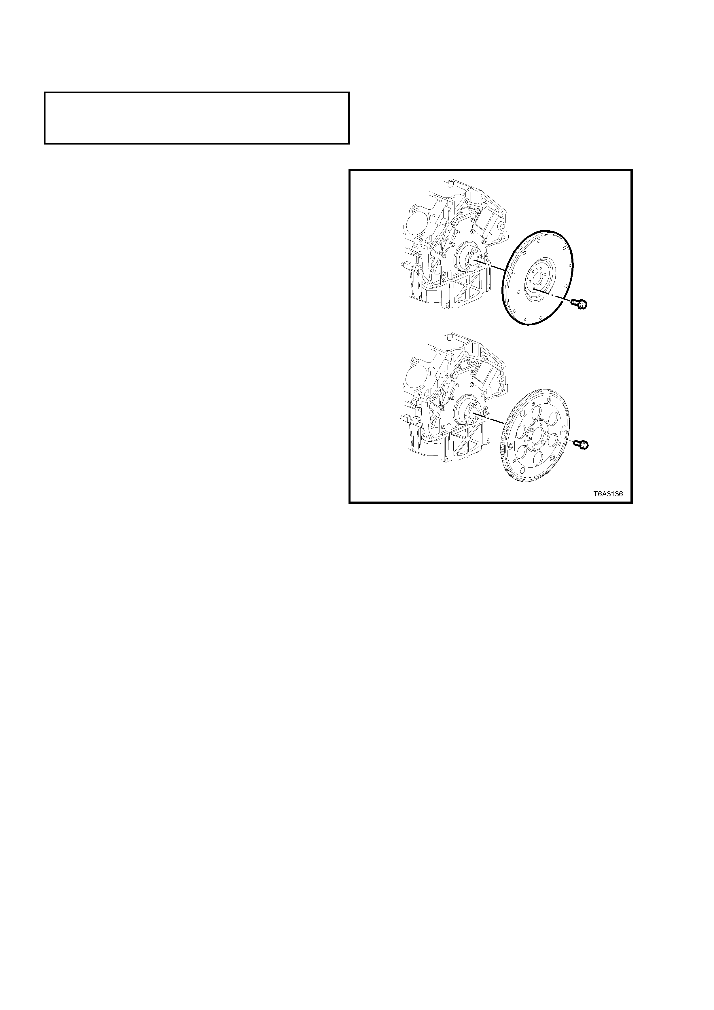
3.5 ENGINE FLYWHEEL/FLEXPLATE
LT Section No. – 00-400
NOTE: The following fasteners MUST be replaced ( ! )
when performing this operation:
! Flywheel/Flexplate retaining bolts.
REMOVE
IMPORTANT: Note the position and direction of
the engine flywheel before removal. The flywheel
does not use a locating pin for alignment. Mark or
scribe the end of the crankshaft and the flywheel
before component removal. The engine flywheel
must be reinstalled to the original position and
direction. The engine flywheel will not initially seat
against the crankshaft flange, but will be pulled
onto the crankshaft by the engine flywheel bolts.
This procedure requires a three stage tightening
process.
If replacing a flywheel, note the location of any
existing balance weight pins (relative to the
position of the flywheel locating hole). If replacing
the flywheel and balance weight pins are installed
in the original flywheel, then use a suitable pin
punch and remove the pins from the old flywheel
and then reinstall them in the same relative
location in the repl ac ement part.
NOTE 1: Balance weight pins will only be fitted to
some engines that may have been dynamically
balanced at manufacture, where balance weight
pins are required to balance the
crankshaft/flywheel assembly. Hence the need to
reinstall them to a new flywheel, in the same
position.
NOTE 2: A correctly installed balance weight pin
will be either flush or below flush with the machined
surface of the flywheel.
1. If this operation is to be carried out with the
engine installed in the vehicle, remove the
transmission and clutch assembly (if required).
Refer :
Section 7B2 MANUAL TRANSMISSION -
GEN III V8 ENGINE,
Section 7A2 CLUTCH - GEN III V8 ENGINE
Section 7C4 AUTOMATIC TRANSMISSION.
2. Mark the end of the crankshaft and the
flywheel/ flexplate, using a felt tipped pen or
similar. Remove the engine flywheel/ flexplate
bolts.
3. Remove the engine flywheel/flexplate.
Figure 6A3-222
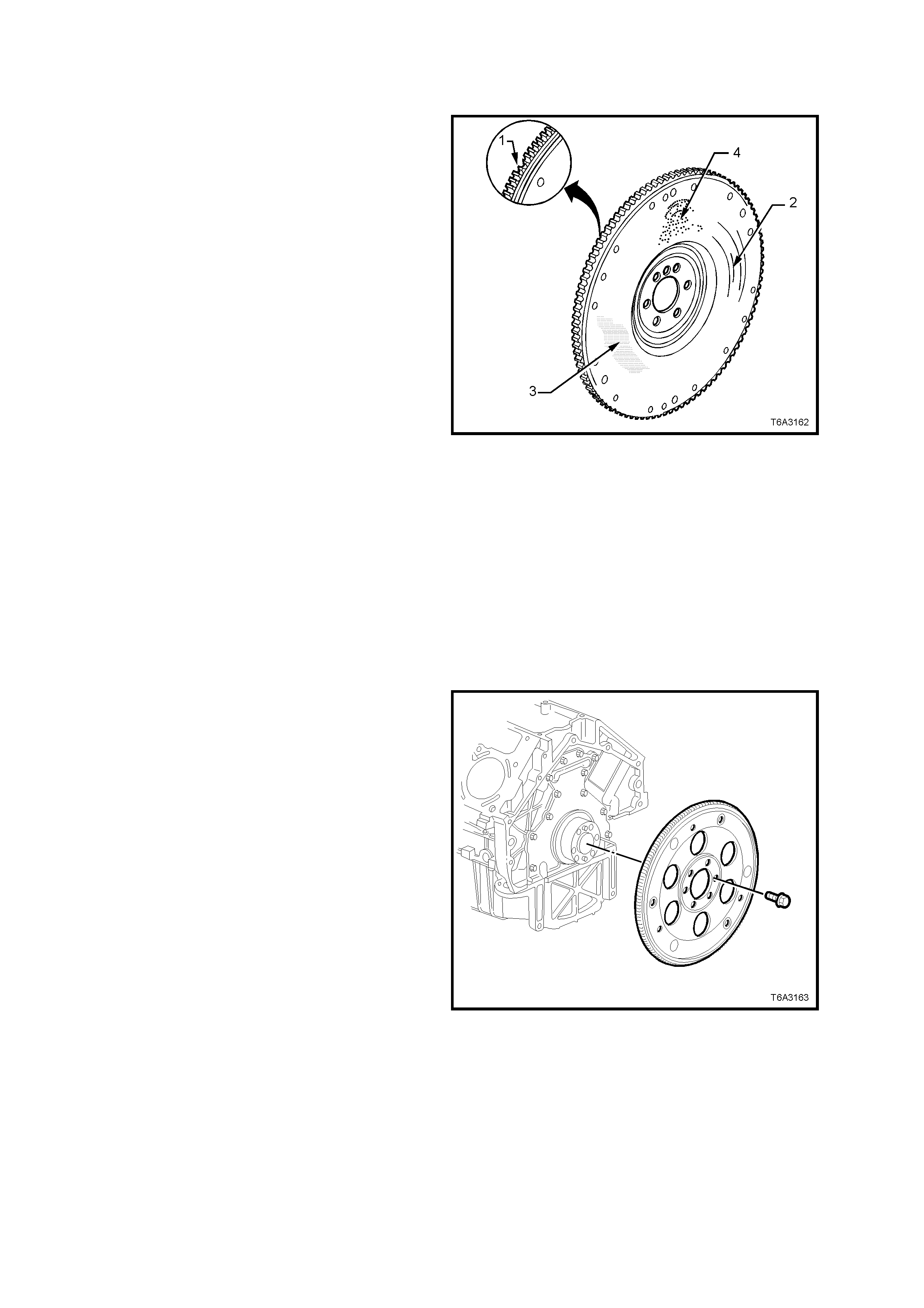
CLEAN AND INSPECT
Flywheel
1. Clean the flywheel in a suitable solvent and
blow dry with compressed air.
CAUTION: Wear safety glasses to avoid eye
injury.
2. Inspect the flywheel for loose or improperly
installed balance weights (if applicable). A
correctly installed balance weight should be
either flush or below the machined surface of
the flywheel.
3. Inspect the flywheel for the following:
a. Damaged ring gear teeth (1).
b. Grooves or scoring (2).
c. Rusted surface (3).
d. Pitted surfaces (4).
e. Loose or incorrectly positioned ring gear.
The ring gear is an inter ference f it onto t he
flywheel and should be positioned
completely against the flange of the
flywheel.
f. Missing, bent or damaged pressure plate
locating pins. The two locating pins are
pressed into the flywheel and are spaced
170° apart.
IMPORTANT: In order to maintain the correct
component balance, contact surface taper and
heat transfer, should any flywheel damage be
observe d, t hen t he f lywheel is NO T to be mac hined
and must be replaced.
Figure 6A3-223
Flexplate
4. Inspect the flexplate for the following:
a. Damaged ring gear teeth.
b. Stress cracks around the crankshaft bolt
hole locations.
c. Welded areas that retain the ring gear to
the flexplate.
IMPORTANT: Do not atte mpt to repair any welded
areas that retain the ring gear to the flexplate.
Replace the flexplate assembly if welds are
cracked.
Figure 6A3-224
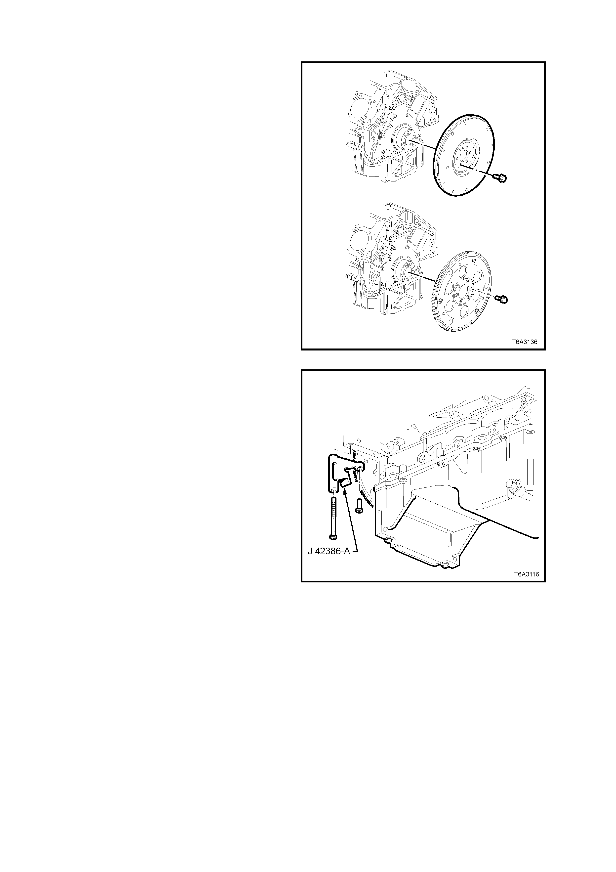
REINST ALL
1. If replacing a flywheel;
a. Install any balance weights, as required, in
the same locations as noted on the old
flywheel. Location is important, as the
presence of balance weight pins in the old
flywheel are an indication that the
cranks haft and f lywhe el we re ba lanced as a
complete unit in original manufacture.
b. Use the flywheel locating hole as reference
and scribe an alignment mark
corresponding to the one on the original
flywheel.
2. Install the flywheel/flexplate, aligning the
scribed marks on the crankshaft and
flywheel/flexplate.
Figure 6A3-225
3. Loosely install NEW flywheel/flexplate bolts,
tightening in the sequence shown in Figure
6A3-227, to an initial torque specification of 20
Nm.
4. Install the ring gear holding Tool No. J 42386-
A, using the two starter motor bolts. Tighten
both bolts to 50 Nm.
NOTE: Ensure that the teeth of the holding tool
engage correctly with the ring gear teeth , before
tightening the fasteners.
Figure 6A3-226
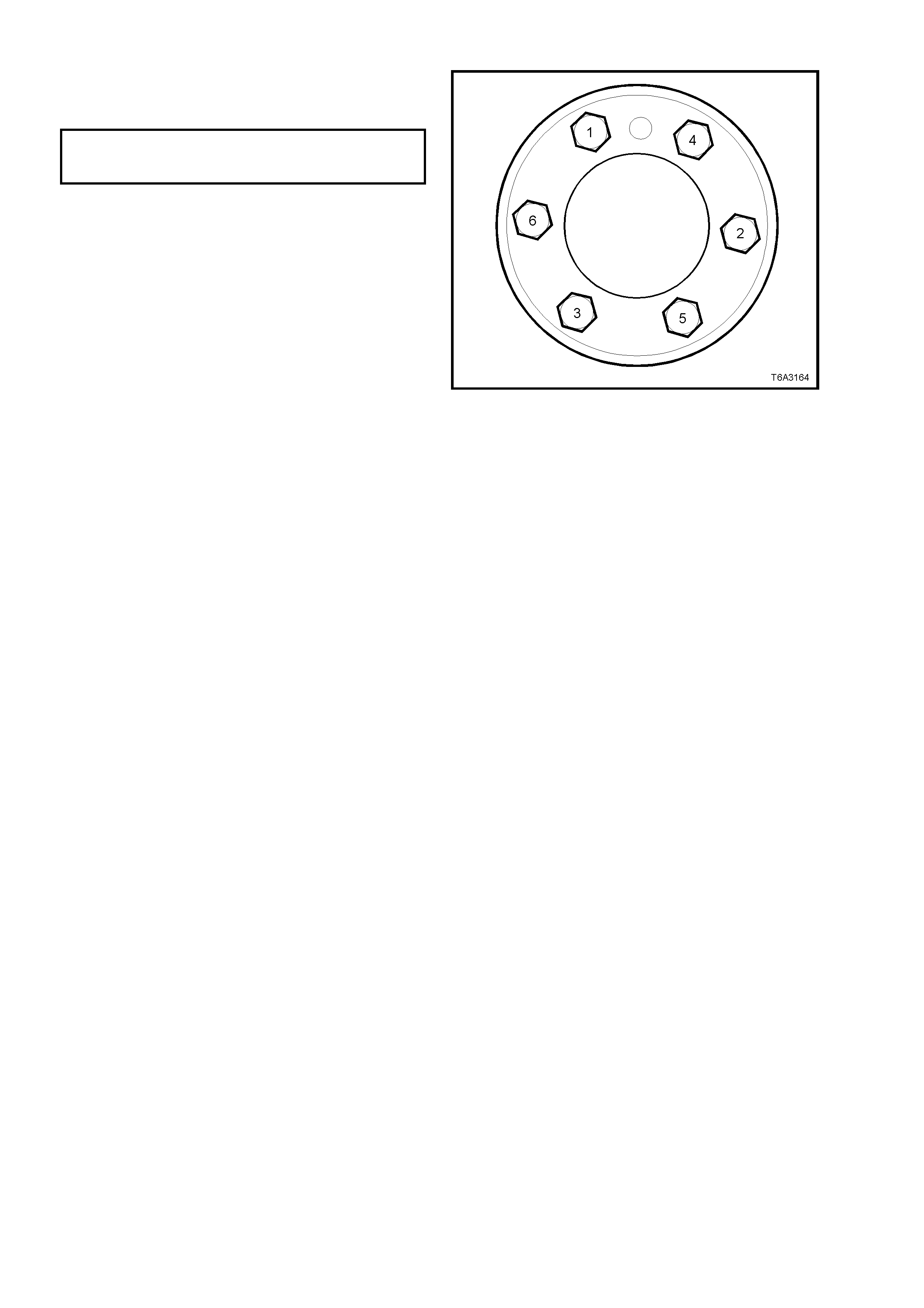
5. Continue to tighten the flywheel/flexplate bolts
in the sequence shown, in two additional
stages and to the correct torque specification.
FLYWHEEL/FLEXPLATE BOLTS
TORQUE SPECIFICATION Stage 2: 50 Nm
Stage 3: 100 Nm
6. Reinstall clutch and transmission, as required.
Refer Section 7A2 CLUTCH - GEN III V8
ENGINE, Section 7B2 MANUAL
TRANSMISSION - GEN III V8 ENGINE or
Section 7C4 AUTOMATIC TRANSMISSION.
Figure 6A3-227

3.6 ENGINE FLYWHEEL RING GEAR
REPLACE
Automatic Transmission:
The ring gear is welded to the flexplate and is serviced only as an assembly. Refer to
3.5 ENGINE FLY W HEEL /F L EXPLATE, in this Section.
Manual Transmission:
W hile previousl y, the ring gear was welde d to the flywhee l, the flywhee l/ring gear c om bination is no w a on e-piece,
pressed as sem bl y and, as s uch, is no longer serv icea ble. Sh ould a ny dam age be evident to the r ing gear, t h en the
flywheel must be replaced. Refer to 3.5 ENGINE FLYWHEEL/FLEXPLATE, in this Section.
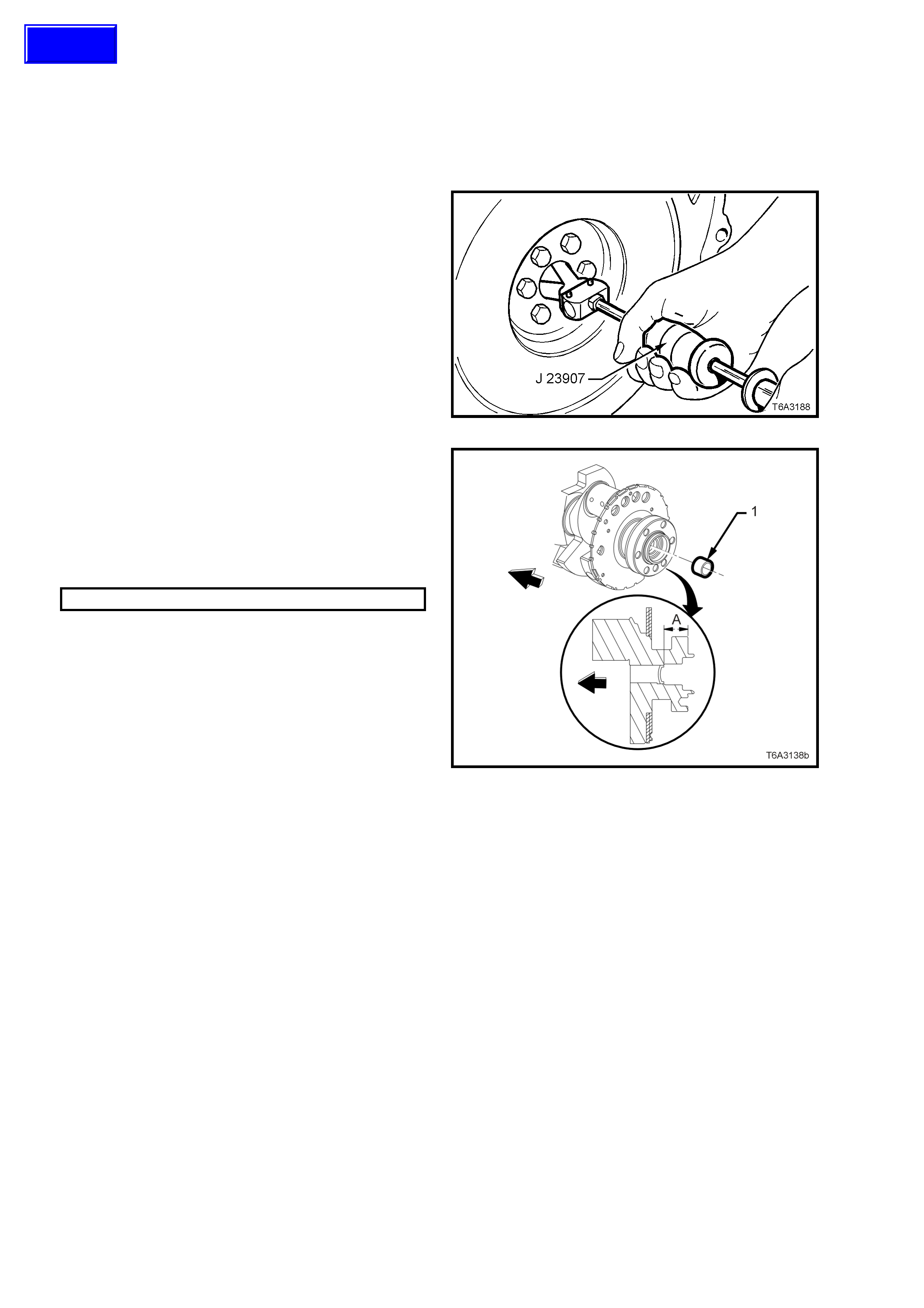
3.7 CRANKSHAFT SPIGOT BEARING
REPLACE
1. Disc onnec t batt er y grou nd lead.
IMPORTANT: Disconnection of the battery affects certain vehicle electronic systems. Refer to
Section 00 CAUTIONS, 5. Battery Disconnection Procedures before disconnecting the battery.
2. Remove manual transmission and the clutch
assembly, refer to Section 7B2, MANUAL
TRANSMISSION - GEN III V8 ENGINE and
Section 7A2 CLUTCH - GEN III V8 ENGINE.
3. Using Tool J 23907, (also released as Tool
6A22-2 and s l ide ham mer 7A28) or c ommercial
equivalent, rem ove the spigot bearing from the
rear of the crankshaft. Discard the removed
bearing.
Figure 6A3-228
4. Check that the crankshaft rear oil gallery plug
is not a loose fit, damaged or leaking.
5. If replacement is required, apply sealant such
as Loctite 242 or equivalent, to the sides of a
new plug (1) and install to the correct depth.
Crankshaft Rear Oil gallery Plug Depth
Specification
DISTANCE ‘A’ 31.2 – 31.6 mm
Figure 6A3-229
Techline
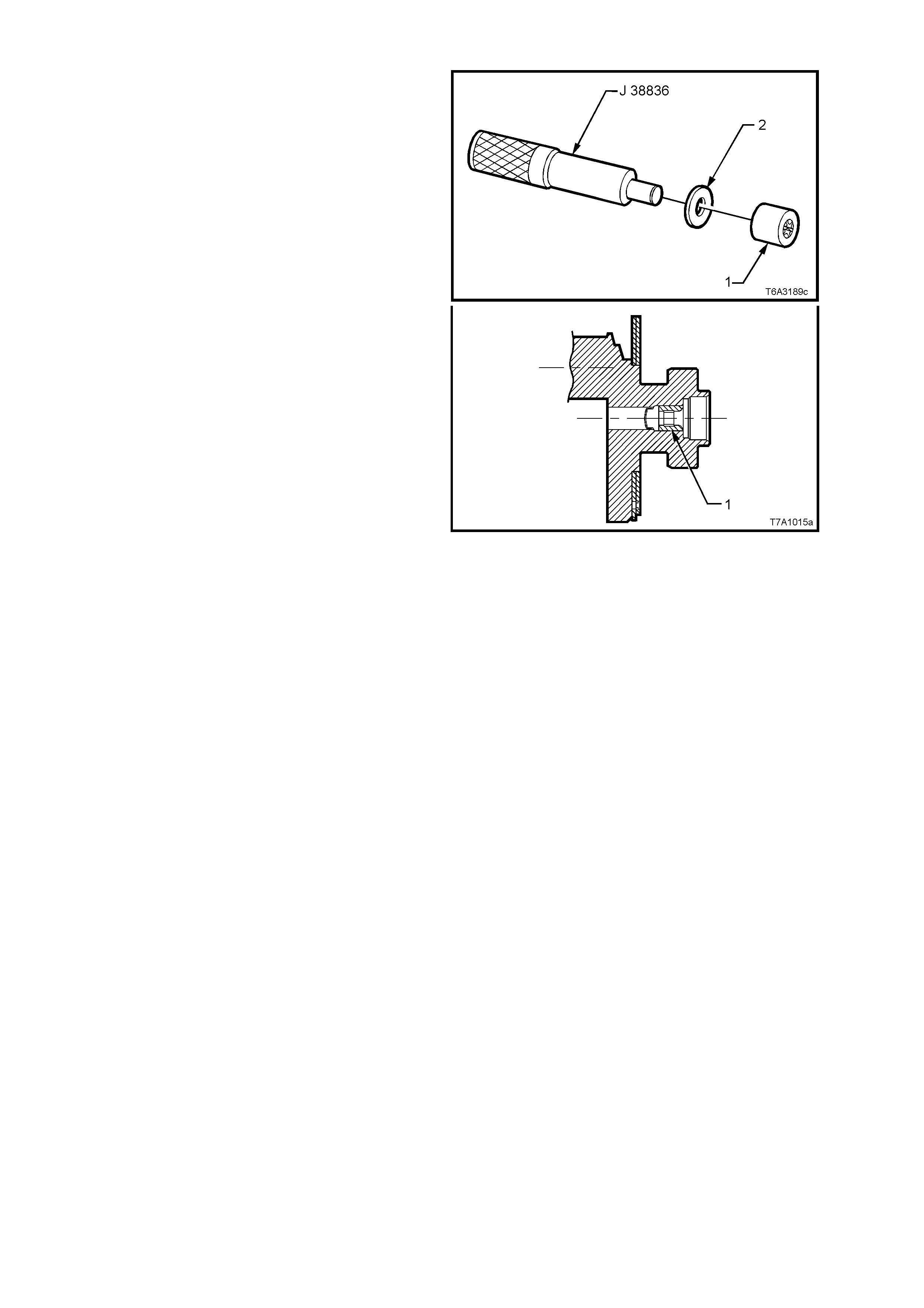
6. Using a suitable, stepped (or piloted ) driver
such as Tool J 38836 and flat washer (2),
install a repl acem ent bush ( 1) to t he rear of the
crankshaft, until flush with the crankshaft
counter-bore, as shown.
7. Lubricate the bearing with a small amount of
SAE 90 gear oil.
8. Reinstall clutch assembly and manual
transmission, refer to Section 7A2 CLUTCH -
GEN III V8 ENGINE and
Section 7B2 MANUAL TRANSMISSION -
GEN III V8 ENGINE.
9. Reinstall the s tarter m otor. Refer Section 6D3-
2 STARTING SYSTEM - GEN III V8 ENGINE.
10. Reconn ec t batter y ground l ead.
11. Check starter motor operation and road test
vehicle to check transmission and clutch
operation.
Figure 6A3-230
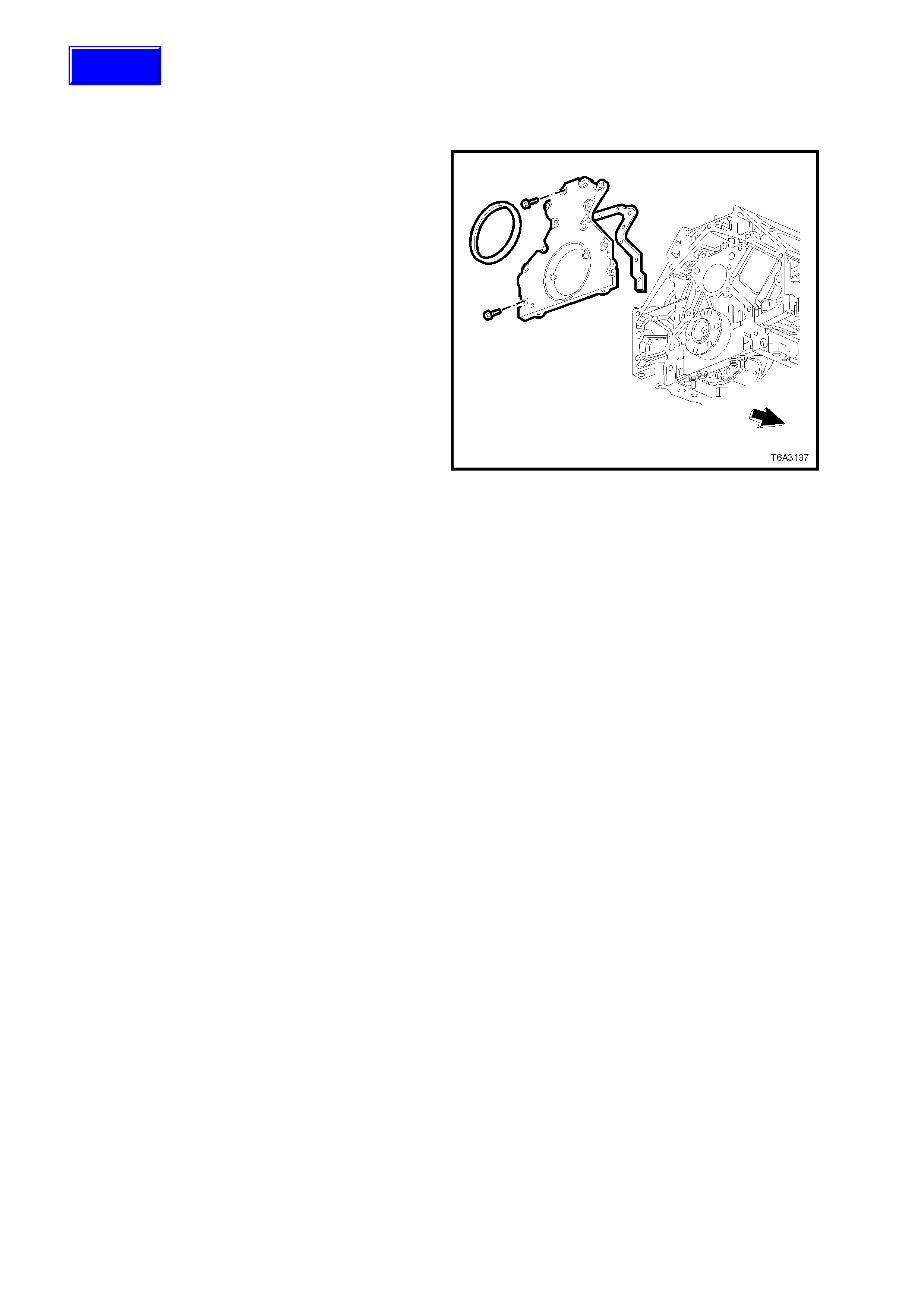
3.8 ENGINE REAR COVER
LT Section No. – 00-200
REMOVE
IMPORTANT: Because of critical alignment
procedures required for the reinstallation of the
rear cover and oil pan, it is strongly recommended
that the engine assembly is removed from the
vehicle, before oil pan removal.
1. With the flywheel/flexplate removed, refer
3.5 ENGINE FLYWHEEL/FLEXPLATE, in this
Section, remove the rear cover bolts.
2. Remove the rear cover and gasket. If the
gasket is undamaged, it may be re-used.
3. Prise the rear main oil seal from the housing,
taking care not to distort the rear cover nor
scratch the oil seal bore in the rear housing.
Figure 6A3-231
CLEAN AND INSPECT
1. Clean the cover in a suitable solvent and blow dry with compressed air.
CAUTION: Wear safety glasses to avoid eye injury.
2. Inspect the gasket sealing surface for excessive scratching or gouging.
3. Inspect the gasket for damage to the seal membrane or distortion to the aluminium carrier.
4. Inspect the cover to oil pan threaded holes for debris or damage. Refer to 3.16 THREAD REPAIR, in this
Section, if rectification is required.
5. Inspect the rear main oil seal bore for damage.
REINST ALL
NOTE 1: Do not reuse the crankshaft rear oil seal.
NOTE 2: Do not apply any type of sealant to the rear cover gasket.
NOTE 3: T he special tools in t his proce dure ar e used to pr operl y align the engine rear cover at the oi l pan s urface
and to centre the crankshaft rear main oil seal.
NOTE 4: All gasket surfaces should be free of oil or other foreign material during assembly.
NOTE 5: T he c r anks haf t r ear main oil se al MUST be c entr ed in re lat io n to the cra nkshaft and is to be ins ta lled after
the rear cover installation. The oil pan sealing surface at the rear cover and engine block MUST also be aligned
within specifications.
NOTE 6: An improperly aligned rear cover may cause premature oil seal wear and/or engine assembly oil leaks.
Techline
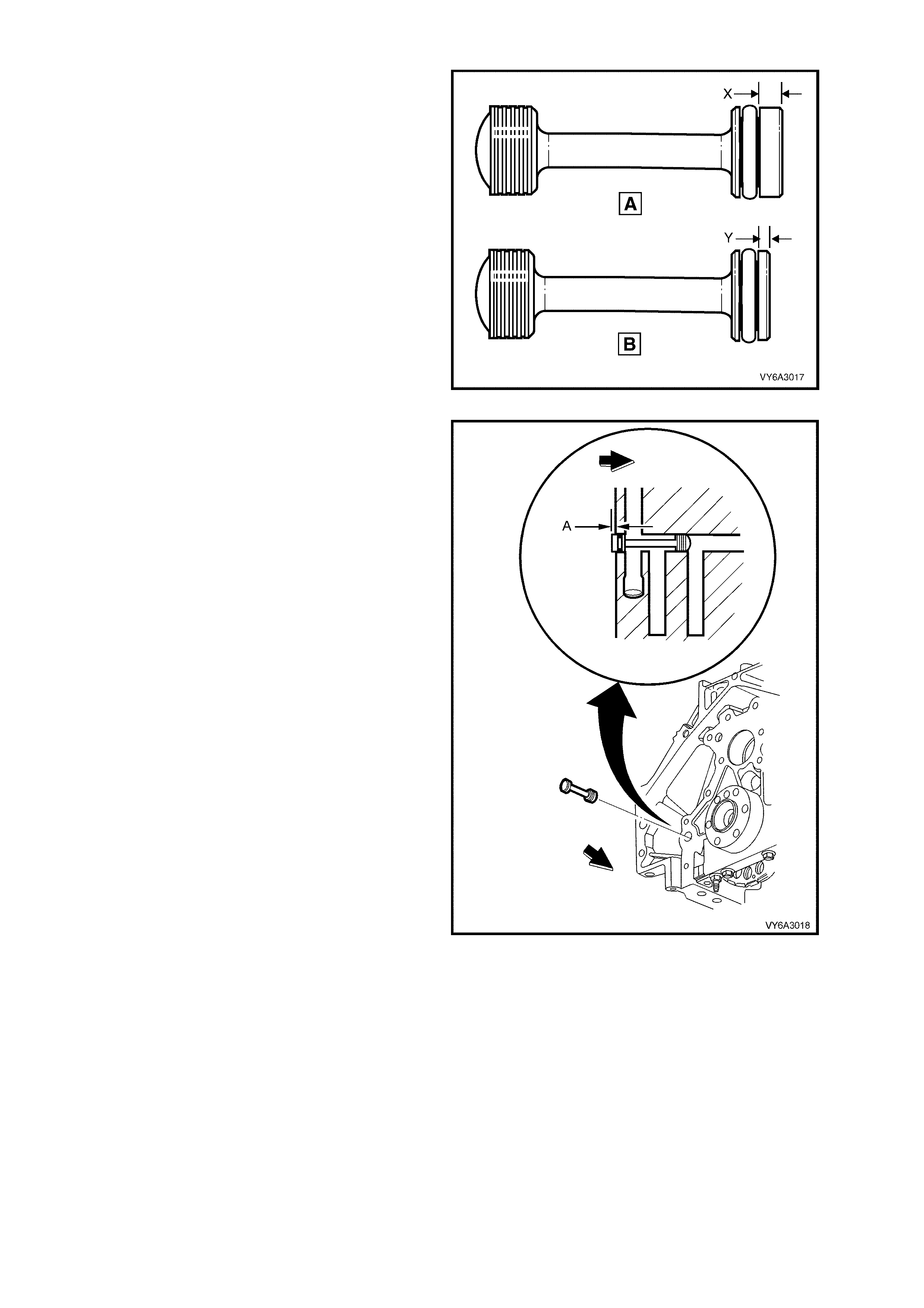
1. If removed, inspect the rear main oil gallery
plug and ensure that it is of the later design
(‘A’). If of the ear l ier d es ign ( ‘B ’) th en it must be
replaced.
NOTE: Visually, the later plug has a thicker end
boss (‘X’) that the earlier design (‘Y’).
Figure 6A3-232
2. Lubricate the O-ring with clean engine oil and
install the plug into the rear of the cylinder
block . Caref ull y install u ntil the plu g com es to a
stop agains t the steppe d bore of the oil galler y.
At this point, the plug should be protruding by
approximately 1.2 mm (distance ‘A’).
NOTE: When the rear cover and gasket are
installed, the plug protrusion will rest against the
rear cover machined internal surface.
Figure 6A3-233
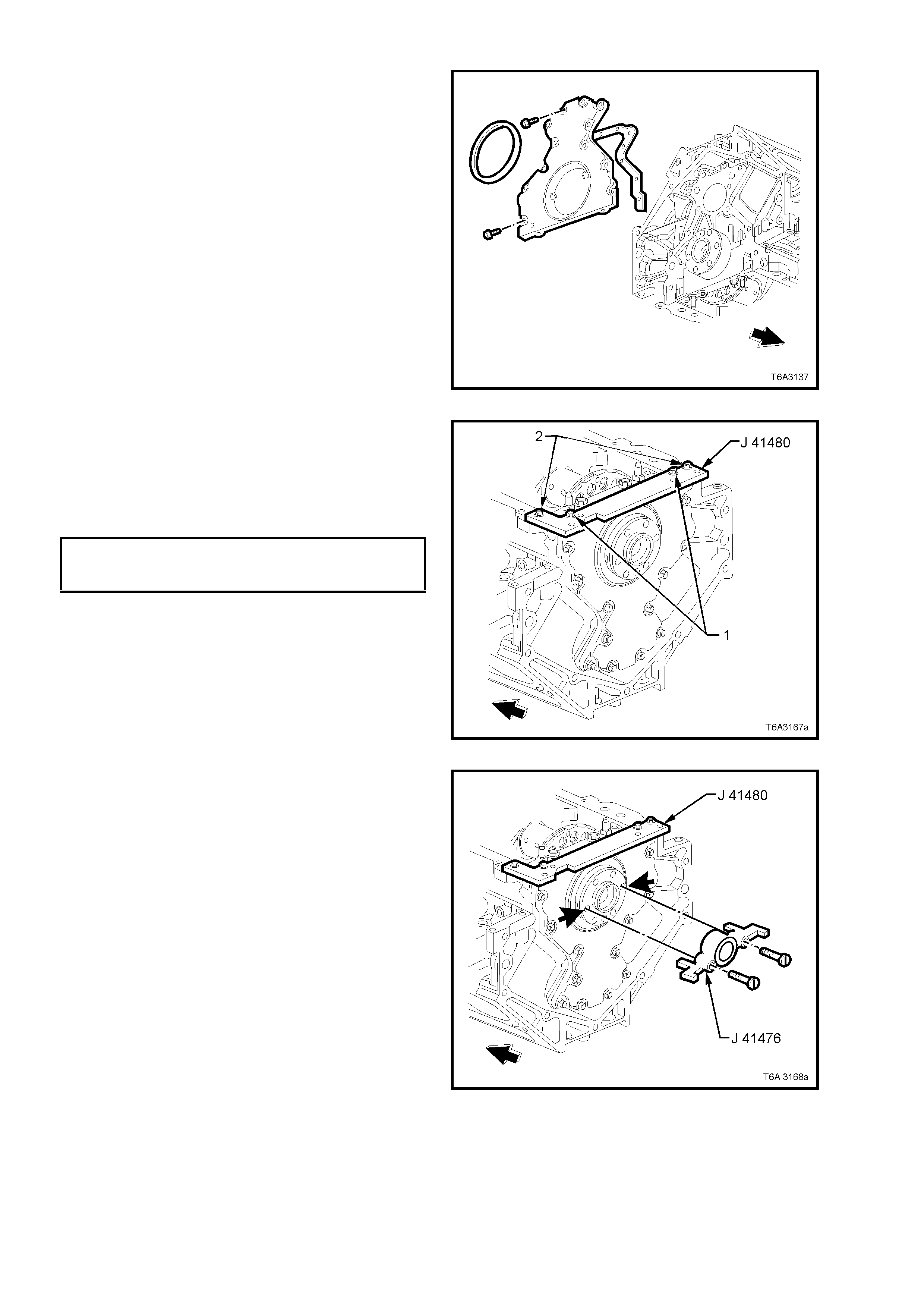
3. Install the rear cover gasket, the rear cover and
bolts.
NOTE: If undamaged, the original cover gasket
can be re-used.
4. Only tighten the rear cover bolts finger tight.
Do not overtighten.
Figure 6A3-234
5. Assemble the alignment tool J 41480 to rear
cover and install bolts (1) (part of Tool J 41480)
in the locations shown but do not tighten.
6. Install bolts (2) (part of Tool J 41480) to the
engine block and tighten to the specified
torque.
REAR COVER ALIGNMENT TOOL
BOLT TO ENGINE BLOCK
TORQUE SPECIFICATION 25 Nm
Figure 6A3-235
7. Rotate the crankshaft until two opposing
flywheel/ flexplate mounting bolt holes are
parallel to the oil pan surface of the engine
block (arrows).
8. Inst all al ig nment Tool J 41476 to th e rear of the
crankshaft.
NOTE: The tapered le gs of the alignm ent too l m ust
enter the rear cover oil seal bore.
9. Install the two screws supplied with Tool J
41476 and tighten with a screwdriver until
snug. Do not over-tighten.
Figure 6A3-236
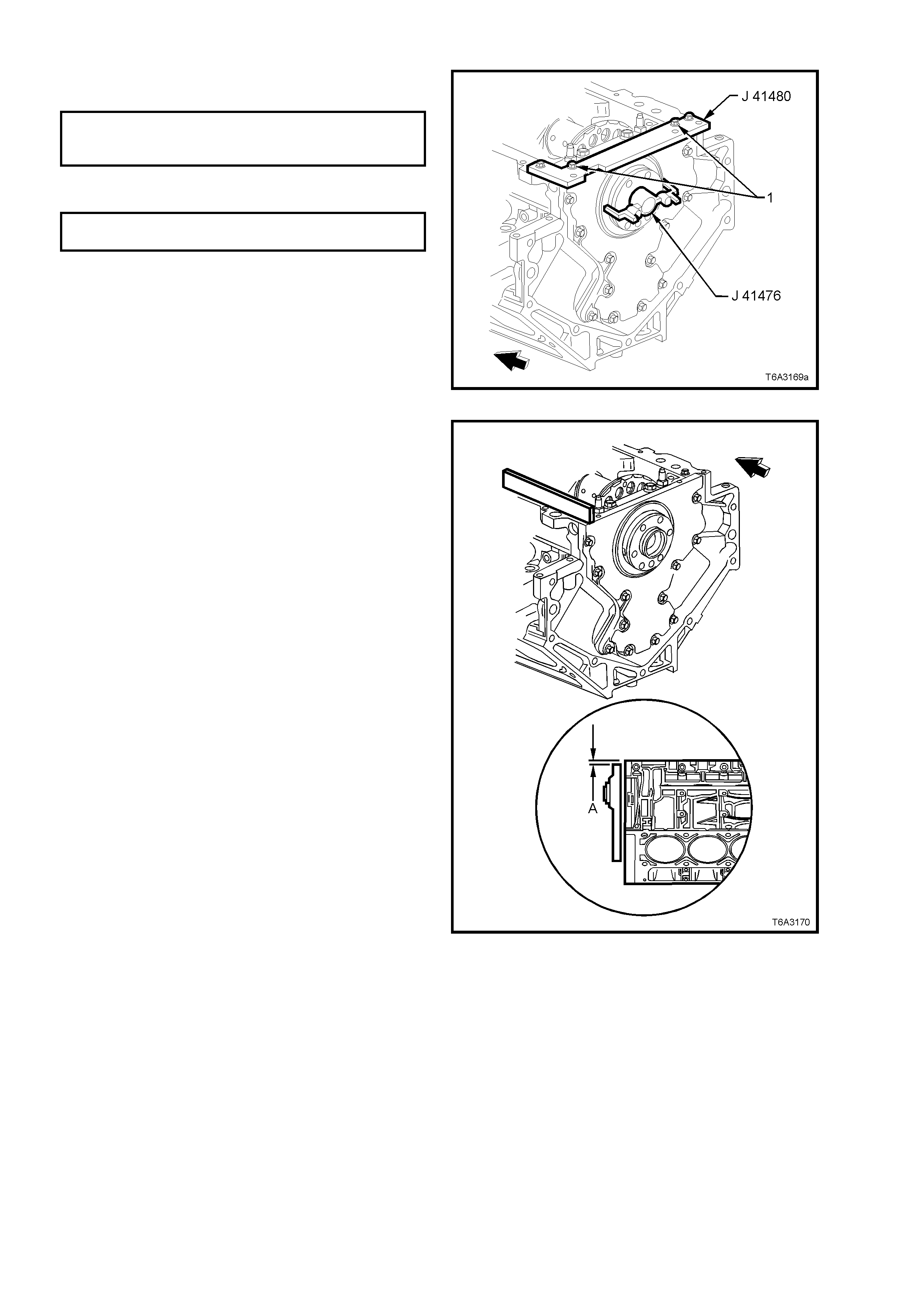
10. T ighten the alignm ent T ool J 4148 0 bolts (1) to
the rear cover to the specified torque.
REAR COVER ALIGNMENT TOOL
BOLT TO REAR COVER
TORQUE SPECIFICATION 12 Nm
11. Tighten the engine rear cover bolts to the
correct torque specification.
ENGINE REAR COVER BOLT
TORQUE SPECIFICATION 25 Nm
12. Remove the alignment tools.
Figure 6A3-237
13. Measure the oil pan surface to rear cover for
flatness, as follows:
a. Place a straight edge across the engine
block and rear cover oil pan sealing
surfaces. Avoid contact with the portion of
the gasket that protrudes into the oil pan
surface.
b. Insert a feeler gauge between the rear
cover an d the st raight e dge tool . T he cover
must be f lush with the oil p an sur fac e or no
mo re than 0.25 m m below flush ( dimension
‘A’).
c. If the rear cover-to-engine block oil pan
surface alignment is not within
specifications, repeat the cover alignment
procedure.
14. If the correct rear cover to engine block
alignm ent cannot be obtained, replac e the rear
cover.
Figure 6A3-238
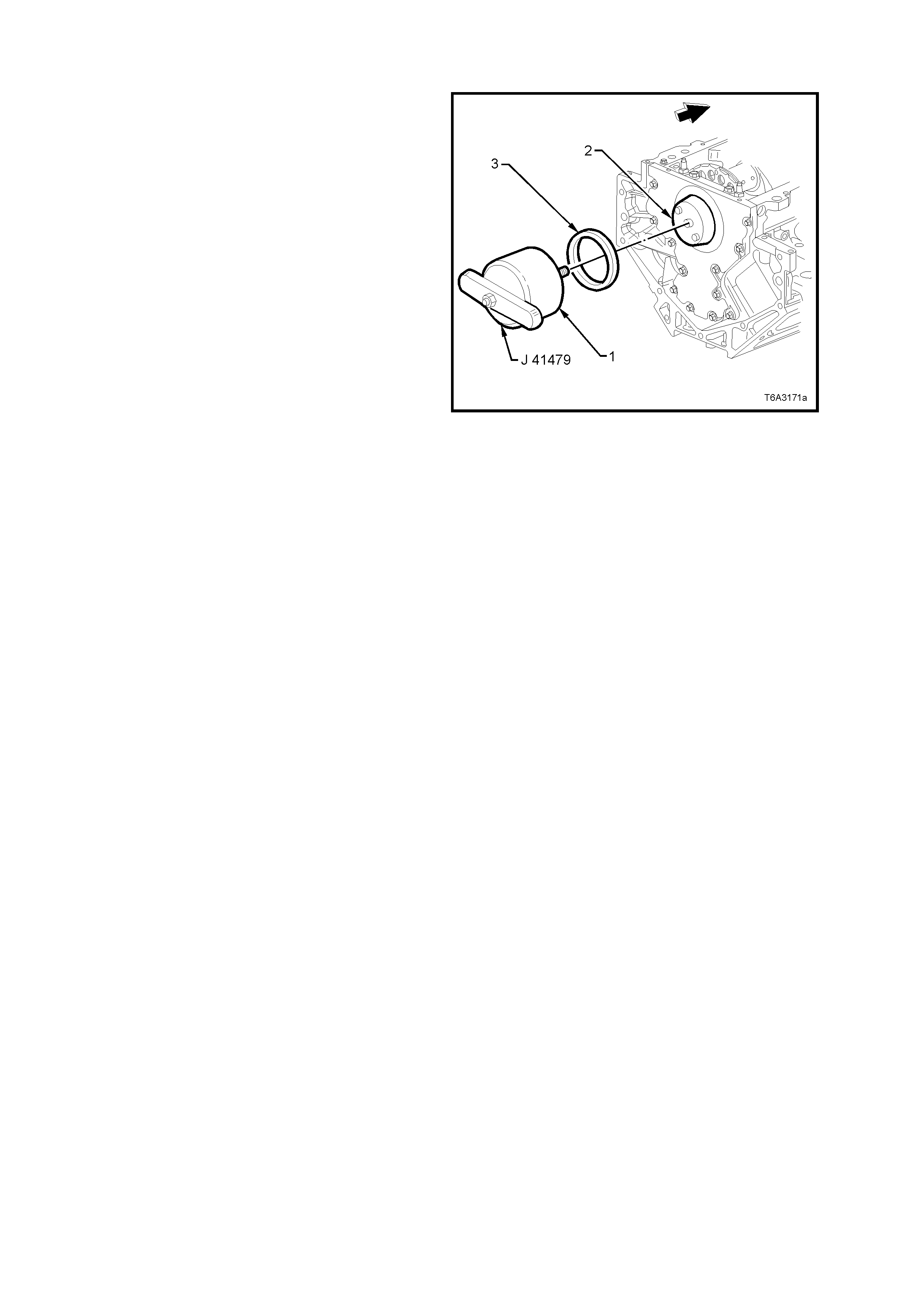
CRANKSHAFT REAR OIL SEAL - INSTALL
IMPORTANT: Do not lubricate the oil seal inside
diameter (ID) nor the crankshaft seal surface
1. Lubricate the outer edge of the oil seal (OD)
with clean engine oil.
DO NOT allow oil or other lubricants to come
into contact with the seal surface.
2. Lubricate the rear cover oil seal bore (2) with
clean engin e oil.
DO NOT allow oil or other lubricants to come
into contact with the crankshaft seal surface.
3. Install the cone (2) of installation Tool No. J
41479 with bolts, to the rear of the crankshaft.
Tighten the bolts until snug. Do not over-
tighten.
4. Install a NEW oil seal (3) onto the taper of the
installation tool (2) and push the seal to the
rear cover bore.
5. Install the threaded rod of the installation Tool
No. 41479 (1), into the tapered part (2), until
the tool contacts the oil seal.
6. Align the oil seal (3) with the tool, then rotate
the handle of the tool (1) clockwise until the
seal enters then bottoms into the rear cover
bore.
7. Remove both parts of the installation tool.
Figure 6A3-239
8. Reinstall flywheel. Refer to 3.5 ENGINE FLY W HEEL/FLEX PLATE, in this Section.
9. Reinstall clutch and transmission, as required. Refer Section 7A2 CLUTCH - GEN III V8 ENGINE,
Section 7B2 MANUAL TRANSMISSION - GEN III V8 ENGINE or Section 7C4 AUTOMATIC
TRANSMISSION.
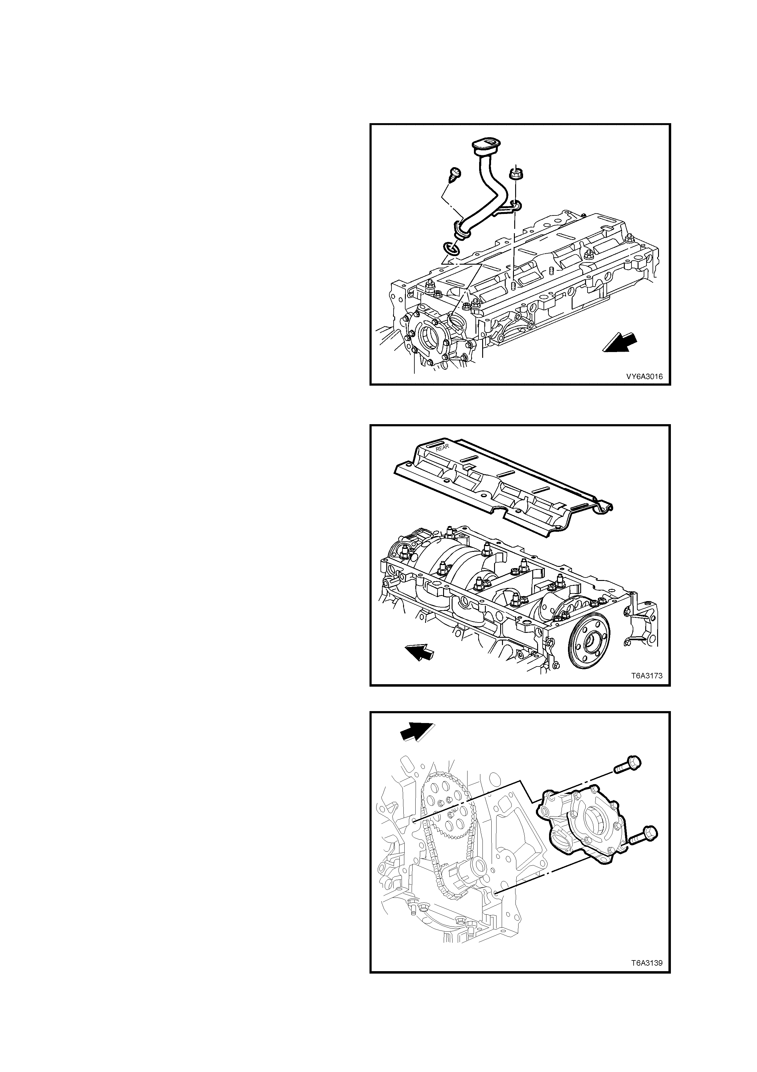
3.9 OIL PUMP, PUMP SCREEN, AND DEFLECTOR
LT Section No. – 00-251
REMOVE
IMPORTANT: Because of critical alignment
procedures required for the reinstallation of the
front c over and oil pan, i t is strongl y recomm ended
that the engine assembly is removed from the
vehicle, before this service operation is carried out.
1. Remove oil pan, refer 3.3 OIL PAN –
REMOVE, in this Section.
2. If the harmonic balancer and front cover have
not already been removed, refer to
2.24 H ARMONIC B ALANCER - REM OVE and
3.4 ENGINE FRONT COVER - REMOVE, in
this Section.
3. Remove the oil pump pick-up screen bracket
nut from the crankshaft oil deflector and the
tube retaining screw from the oil pump body.
4. Remove the oil pump screen and tube
assembly, and the O-ring seal from the oil
pump bore.
Discard the O-ring.
Figure 6A3-240
5. Remove the remaining crankshaft oil deflector
nuts.
6. Remove the c r ank s haf t oil deflector, noting that
the cover orientation is stamped ‘REAR’ to
assist in correct installation.
Figure 6A3-241
7. Remove the four bo lts sec uring the o il pum p to
the front of the engine, then remove the oil
pump from the crankshaft.
8. If the oil pump is not being opened, plug all
openings to avoid the entry of dirt or debris or
wrap in a plastic bag.
Figure 6A3-242
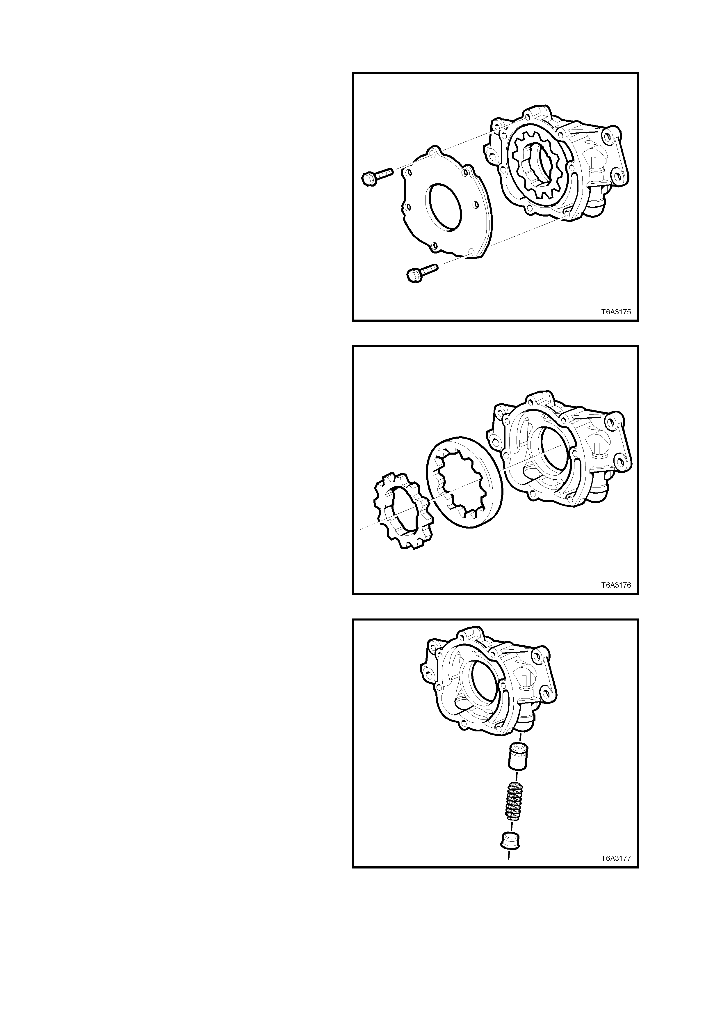
OIL PUMP DISASSEMBLE
1. Remove oil pum p cover bolts , then remove th e
cover.
Figure 6A3-243
IMPORTANT: Mark or identify the relationship of
the gears for reassembly.
2. Remove the inner drive gear and outer driven
ring, from the oil pump body.
Figure 6A3-244
3. Unscrew the oil pressure relief valve plug and
remove spring and valve from the oil pump
body.
Figure 6A3-245
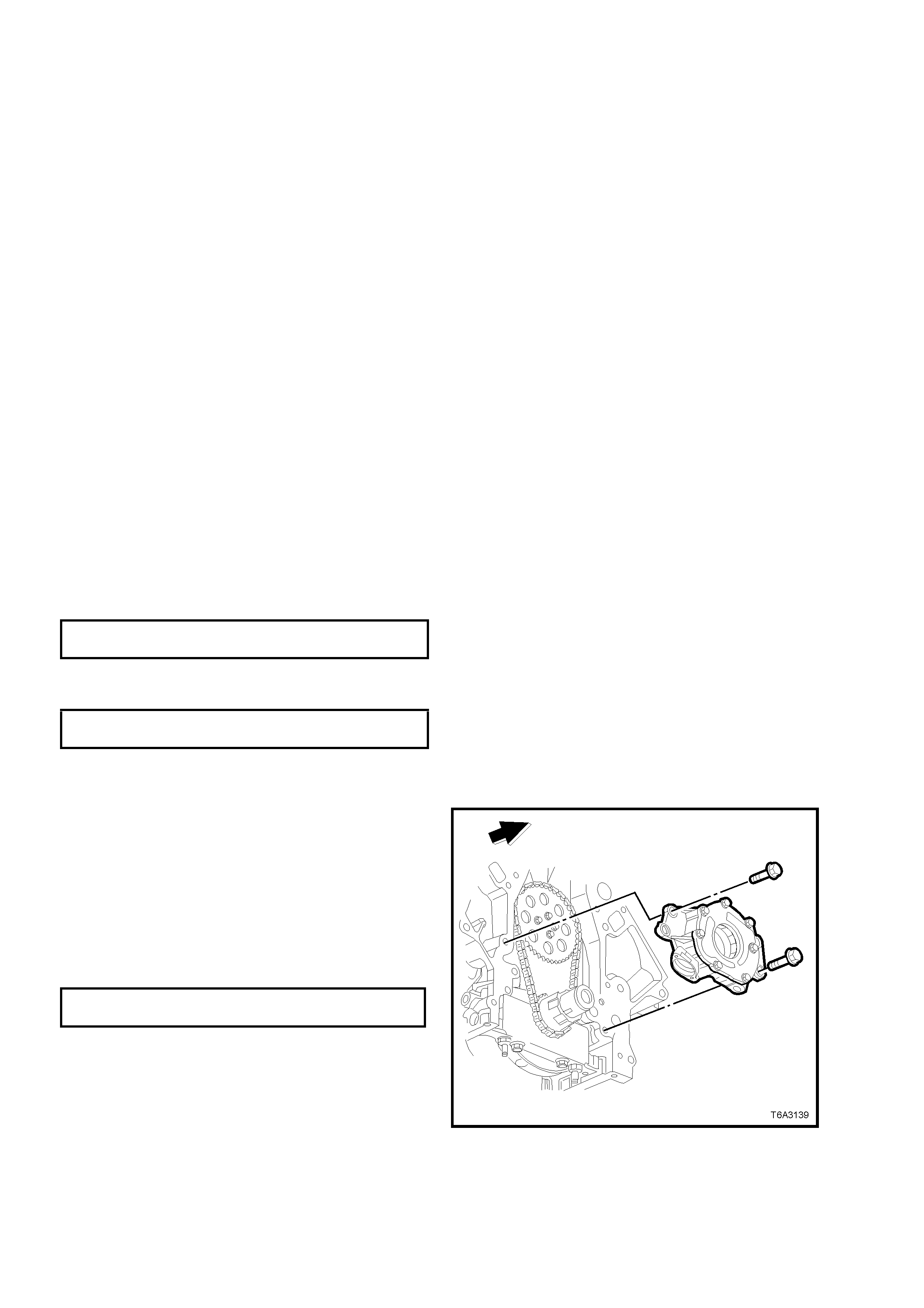
CLEAN AND INSPECT
NOTE: Apart from the oil pr ess ur e relief valve spr i ng, t her e are no oth er parts of the oil pump nor the oil pump pick-
up screen and pipe that are serviced separately. If either component is found to be worn or damaged, then that
assembly must be replaced. Do not attempt any repairs to either component.
Apart from thread reclam ation and the correction of minor conditions, replace the oil pump assembly if any of the
following conditions are observed.
1. Clean all parts in a suitable solvent and blow dry with compressed air.
CAUTION: Wear safety glasses to avoid eye injury.
2. Inspect the oil pump housing for cracks, excessive wear, scoring or casting imperfections.
3. Inspect the oil pump housing to engine block oil gallery surface for scratches or gouging.
4. Inspect the oil pump housing for damaged bolt hole threads. See Section 3.16 THREAD REPAIR, if requir ed.
5. Inspect the oil pump relief valve plug and bore for scratched or damaged surfaces and the screw thread for
damage. The pressure relief valve must move freely in its bore with no restrictions.
6. Inspect the oil pump internal oil passages for restrictions.
7. Inspect the drive and driven gears for chipping galling or wear. Minor burrs or imperfections on the gears can
be removed with a fine oil stone.
8. Inspect the inner gear drive splines for excessive wear.
Replace the oil pump pick-up screen and pipe assembly if either of the following conditions are observed.
1. Inspect the oil pump pick-up screen for clogging with debris or restriction.
2. Inspect the screen mesh for broken or loose strands.
OIL PUMP REASSEMBLE
Reassembly is the reverse of the disassembly process, except for the following items:
1. Liberally coat all oil pump components with clean engine oil before assembly.
2. Take note of the relationship of the inner to the outer oil pump gears when assembling.
3. Tighten the oil pump cover screws to the correct torque specification.
OIL PUMP COVER TO BODY SCREW
TORQUE SPECIFICATION 12 Nm
4. Install a NEW pressure relief valve spring.
5. Tighten the pressure relief valve plug to the correct torque specification.
OIL PUMP PRESSURE RELIEF PLUG
TORQUE SPECIFICATION 12 Nm
6. Rotate the assembled pump, checking for smoothness of operation by rotating the inner drive gear.
REINST ALL
1. Chec k the oil pump and e n g in e bloc k oil ga llery
passages to ensure that any debris is
removed.
2. Align the splined surfaces of the crankshaft
sprocket and the oil pump drive gear and install
the oil pump onto the sprocket, until the pump
housing contacts the face of the engine block.
3. Install the oil pump bolts and tighten to the
correct torque specification.
OIL PUMP BOLT
TORQUE SPECIFICATION 25 Nm
Figure 6A3-246
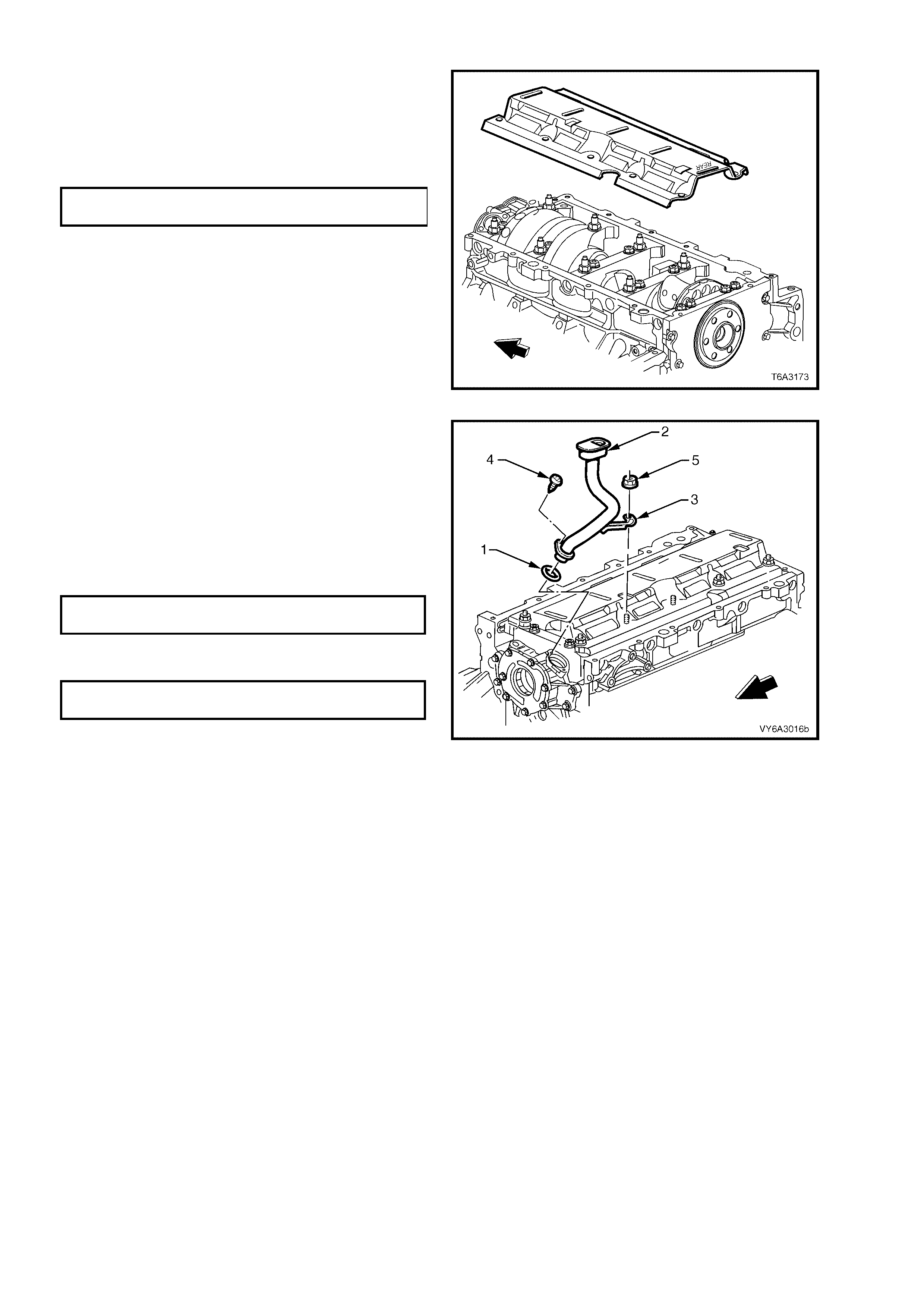
4. Install the crankshaft oil deflector, noting that
the ‘REAR ’ s tamping o n th e def lec tor is loc a ted
at the rear of the engine.
5. Install a ll the c rank shaf t oil deflec tor nu ts to t he
main bearing cap studs and tighten to the
correct torque specification.
CRANKCASE OIL DEFLECTOR
NUT TORQUE SPECIFICATION 25 Nm
NOTE: Do not install a nut to the stud used to
secure the oil p ick- up bracket, at this time. Refer to
Figure 6A3-248 for the location.
Figure 6A3-247
6. Lubricate a NEW oil pump pick-up tube O-ring
(1) with clean engine oil a nd install onto the oil
pump pick-up tube (2).
7. Fully install the pick-up tube (2) into the oil
pump housing, aligning the support bracket (3)
with the main bearing cap stud.
8. Reinstall the remaining nut (4) to the main
bearing cap stud and tighten to the correct
torque specification.
CRANKCASE OIL DEFLECTOR
NUT TORQUE SPECIFICATION 25 Nm
9. Install the pic k-up tube sc rew (5) and tighte n to
the correct torque specification.
OIL PUMP PICK-UP TUBE SCREW
TORQUE SPECIFICATION 12 Nm
NOTE: Ensure that the pick-up tube is fully
installed before tightening the retaining screw.
10. Reinstall the oil pan, refer to 3.3 OIL PAN -
REINSTALL, in this Section.
11. Reinstall the front cover, refer to 3.4 ENGINE
FRONT COVER – REINSTALL and
2.24 HARMONIC BALANCER - REINSTALL,
in this Section.
Figure 6A3-248
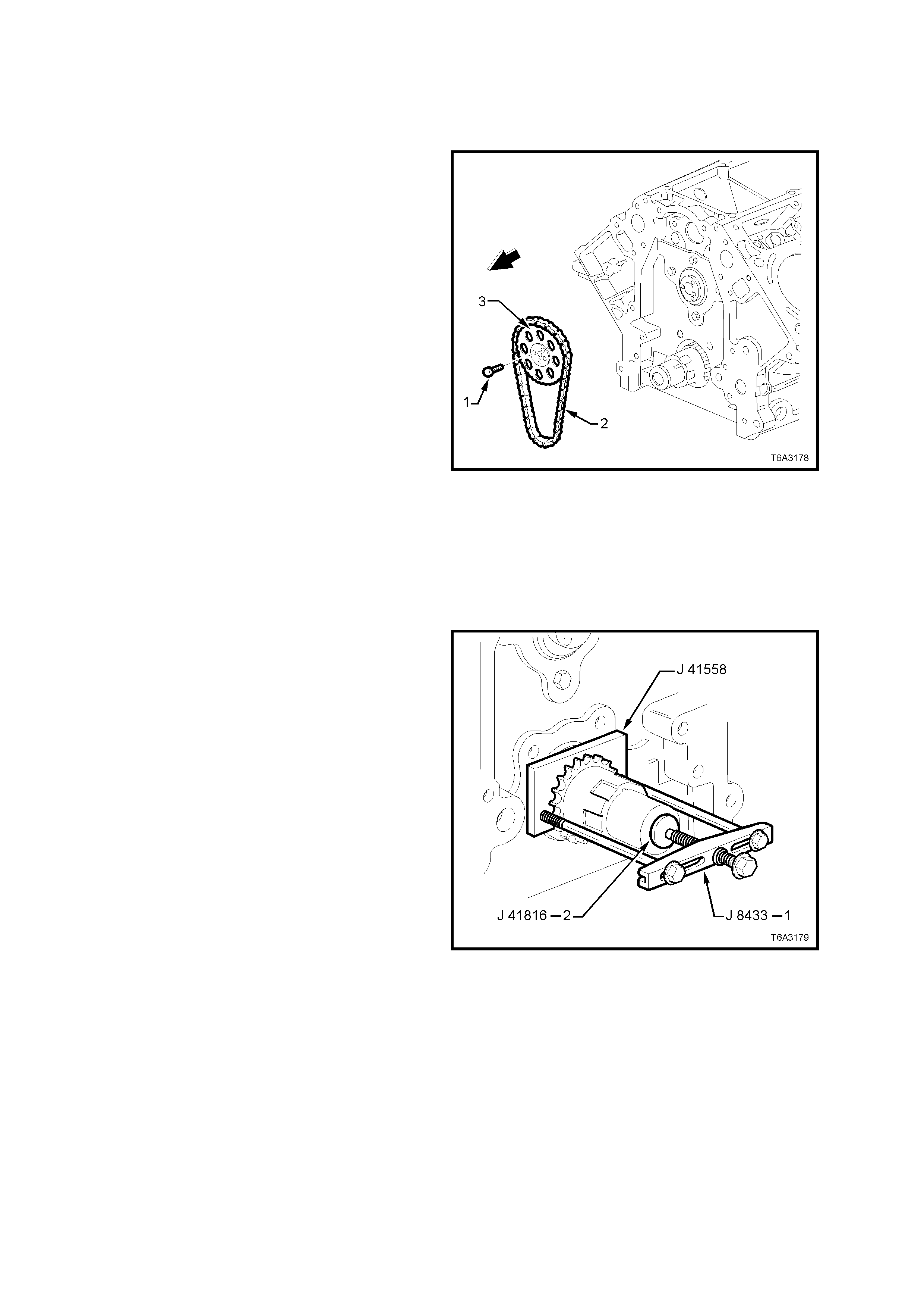
3.10 TIMING CHAIN AND SPROCKETS
LT Section No. – 00-225
REMOVE
IMPORTANT: Because of critical alignment
procedures required for the reinstallation of the
front c over and oil pan, i t is strongl y recomm ended
that the engine assembly is removed from the
vehicle, before this service operation is carried out.
1. Remove oil pan, refer 3.3 OIL PAN -
REMOVE, in this Section.
2. If the harmonic balancer and front cover have
not already been removed, refer to
2.24 HARMONIC BALANCER – REMOVE
and 3. 4 ENGINE FRON T COVER – REM OVE,
in this Section.
3. Remove the oil pump, refer 3.9 OIL PUMP,
PUMP SCREEN AND DEFLECTOR, in this
Section.
NOTE: If the c ylinder head s and v alve tr ain are s till
installed, temporarily install the harmonic balancer
bolt and turn engine until the timing marks on the
crankshaft and camshaft sprockets are aligned,
refer Figure 6A3-257. Remove the harmonic
balancer bolt.
4. Remove the camshaft sprocket bolts (1), then
rem ove the sprock et (2) and chain (3) f rom the
camshaft and crankshaft sprocket.
Figure 6A3-249
5. Use Tool No’s J 41558, J 41816-2, the bolts
from J 21427-01 and puller J 8433-1, assemble
as shown and remove the crankshaft sprocket
from the nose of the crankshaft
6. Remove the c r ankshaf t s procket drive key from
the crankshaft nose, if required.
Figure 6A3-250
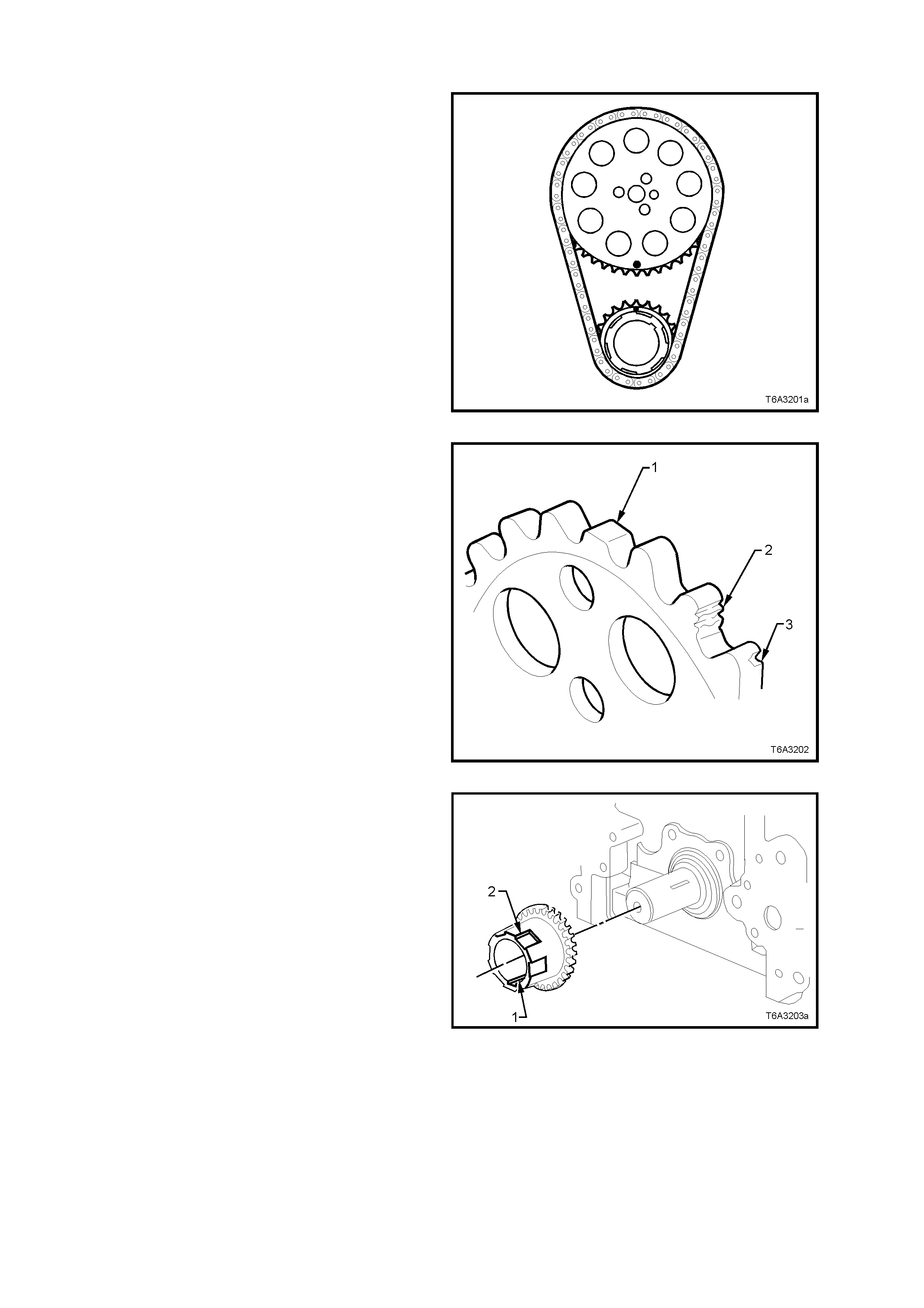
CLEAN AND INSPECT
1. Clean the sprockets and timing chain in
suitable solvent and blow dr y with com pressed
air.
CAUTION: Wear safety glasses to avoid eye
injury.
2. Inspect the timing chain for binding or wear.
Figure 6A3-251
3. Inspect the camshaft and crankshaft sprockets
for:
a. Worn teeth (1 ).
b. Damaged teeth (2).
c. Chipped teeth (3).
d. Worn valleys between the sprocket teeth.
Figure 6A3-252
4. Inspect the crankshaft sprocket keyway (1) for
wear.
5. Inspect the crankshaft sprocket oil pump drive
splines (2) for wear.
Figure 6A3-253
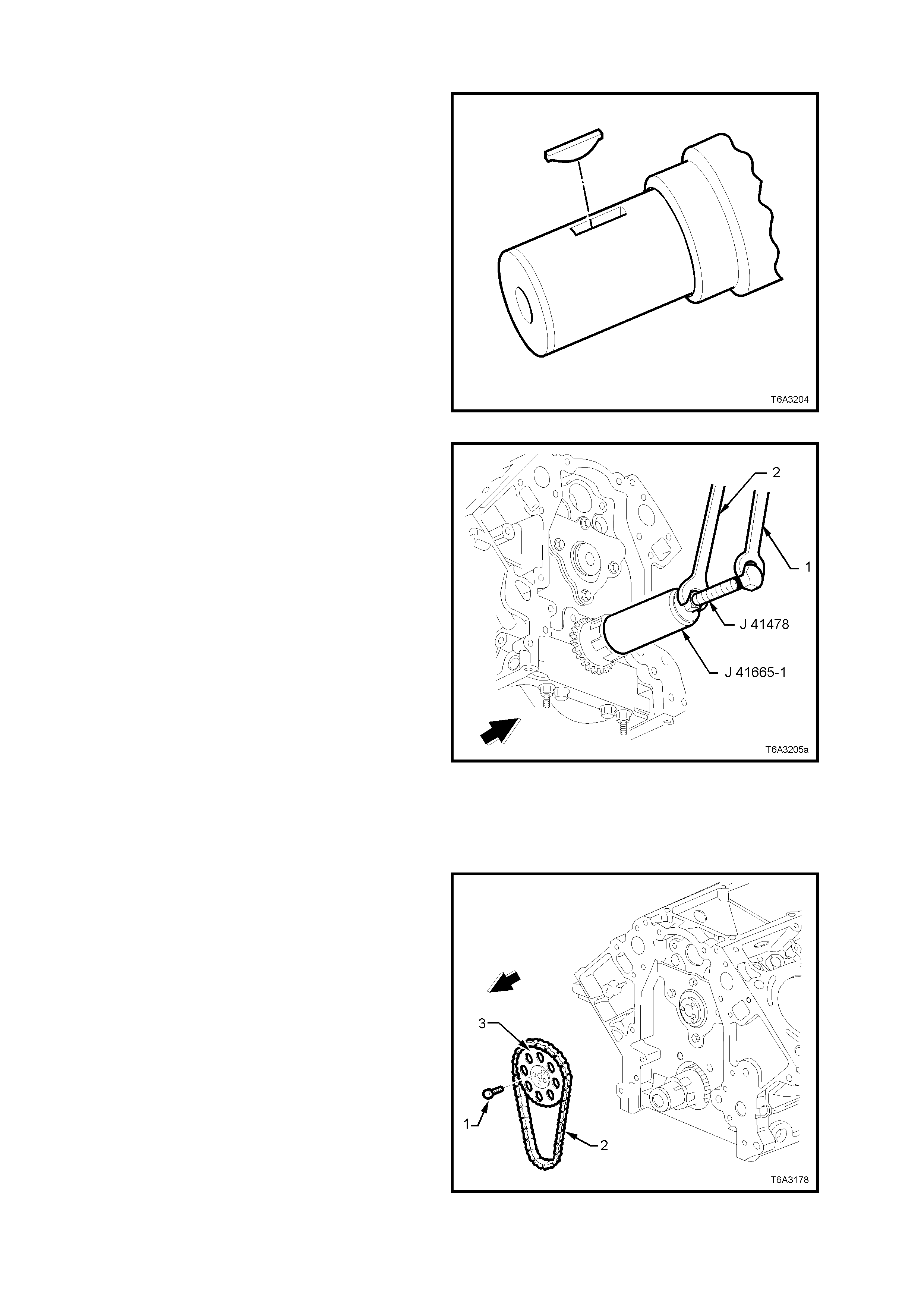
REINST ALL
1. If r em oved, ins ta ll th e c r an k shaf t s pr ocket drive
key into the crankshaft.
T he key should be ta pped into place un til each
end bottoms on the crankshaft.
Figure 6A3-254
2. Install the crankshaft sprocket onto the
crankshaft nose, aligning the keyway with the
key.
3. Use installer J 41665 to install the crankshaft
sprocket, as follows:
a. Install the threaded bolt, nut and flat washer
from Tool J 41478) through the end plate and
stepped sleeve of Tool J 41665.
b. Screw threaded bolt into the crankshaft, using
set spanner (1).
c. While holding the threaded bolt with set
spanner (1), turn the nut on the threaded bolt
with a sec ond set sp anner ( 2), moving ins taller
J 41665 to fully install the crankshaft sprocket
onto the crankshaft nose.
d. When crankshaft sprocket has been fully
installed, remove installation tools.
4. If required, temporarily install the harmonic
balancer bo lt and r otate the crank shaf t until the
timing alignment mark is at the 12 o’clock
position. Refer Figure 6A3-263.
Figure 6A3-255
5. Install the camshaft sprocket (3), aligning the
peg on the camshaft with the sprocket hole.
Check that the timing mark is at the 6 o’clock
position. Refer Figure 6A3-263.
6. If required, temporarily install the camshaft
sprocket bolts and use a suitable lever to rotate
the camshaft sprocket until the timing mark is
correctly aligned. Remove the bolts (1) and
sprocket (3).
7. Install the timing chain (2) to the camshaft
sprocket (3), align the camshaft peg with the
camshaft sprocket hole by eye, then install the
timing chain to the crankshaft sprocket.
8. Inst all the camshaf t s pr ock et o ver t he c amshaft
peg.
Figure 6A3-256
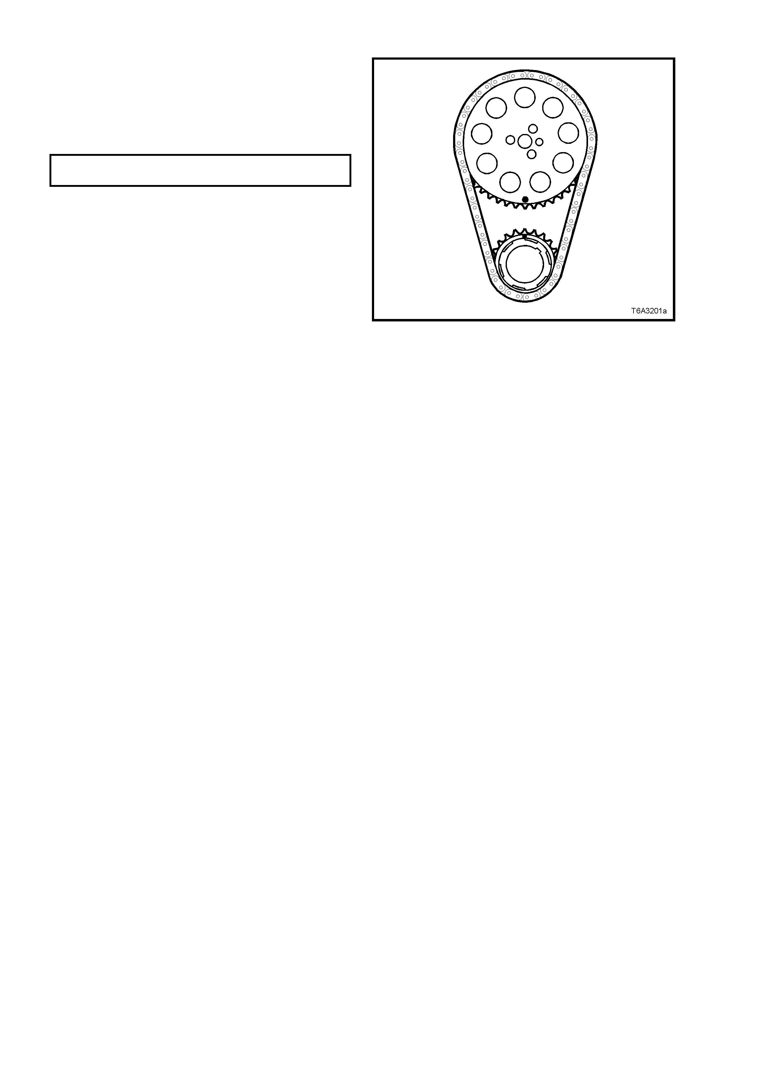
9. Before installing the camshaft sprocket bolts
(‘1’ in Figure 6A3-262), check that the timing
marks are aligned as shown. If not, repeat
Steps 4 to 8 above.
10. Install the camshaft sprocket bolts and tighten
to the correct torque specification.
CAMSHAFT SPROCKET BOL T
TORQUE SPECIFICATION 35 Nm
11. Reinstall the oil pump, refer 3.9 OIL PUMP,
PUMP SCREEN AND DEFLECTOR, in this
Section.
12. Reinstall oil pan, refer 3.3 OIL PAN –
REMOVE, in this Section.
13. Reinstall the front cover and harmonic
balancer. Refer 3.4 ENGINE FRONT COVER
– REINSTALL and 2.24 HARMONIC
BALANCER – REINSTALL, in this Section.
Figure 6A3-257
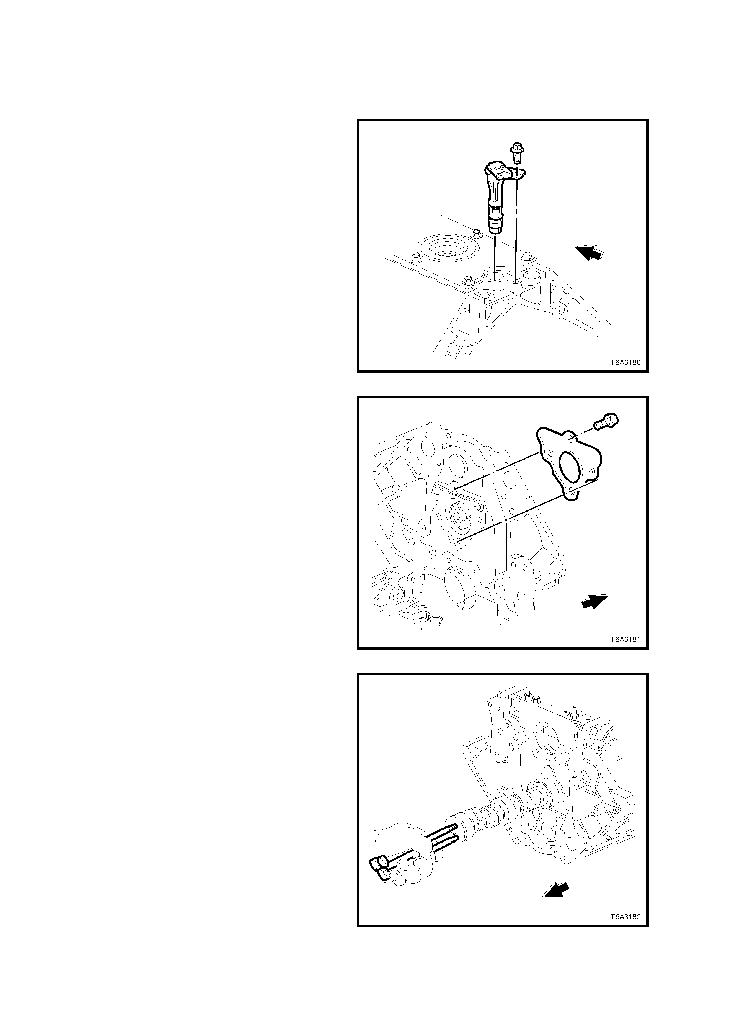
3.11 CAMSHAFT
LT Section No. – 00-175
REMOVE
IMPORTANT: Because of critical alignment
procedures required for the reinstallation of the
front c over and oil pan, i t is strongl y recomm ended
that the engine assembly is removed from the
vehicle, before this service operation is carried out.
1. Remove the intake manifold assembly, if this
operation has not already been carried out.
Refer 2.14 INTAKE MANIFOLD – REMOVE,
in this Section.
2. Remove the camshaft sensor bolt and sensor
from the engine block.
Figure 6A3-258
3. Remove oil pan, refer 3.3 OIL PAN -
REMOVE, in this Section.
4. If the harmonic balancer and front cover have
not already been removed, refer to
2.24 H ARMONIC B ALANCER - REM OVE and
3.4 ENGINE FRONT COVER - REMOVE, in
this Section.
5. Remove the oil pump, refer 3.9 OIL PUMP,
PUMP SCREEN AND DEFLECTOR, in this
Section.
6. Remove the camshaft chain and sprocket.
Refer 3.10 TIM ING CHAIN AND SPROCKETS
- REMOVE in this Section.
7. Remove the camshaft retainer bolts then
remove the retainer and gasket.
Figure 6A3-259
8. Install three, M8 x 1.25 x 100 mm bolts (e.g.
rem oved coolant pump bo lts) in th e front of the
camshaft and use as a handle to rotate and
remove the camshaft from the engine block.
NOTE: As all camshaft bearing journals are the
same size, care must be taken when removing the
camshaft, to avoid damaging the bearings.
9. Remove the three bolts from the camshaft.
Figure 6A3-260
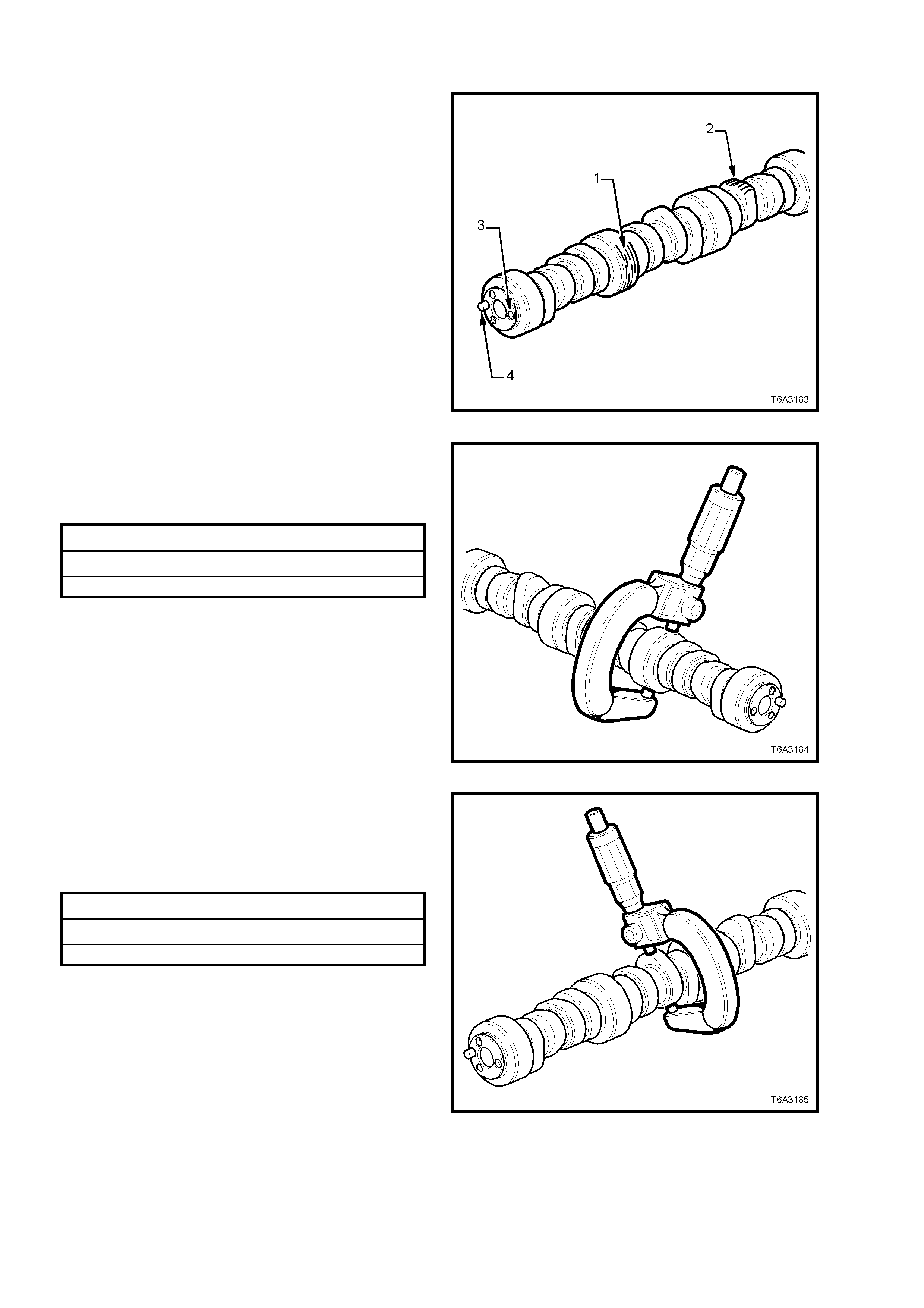
CLEAN AND INSPECT
1. Clean all components with a suitable solvent
and blow dry with compressed air.
CAUTION: Wear safety glasses to avoid eye
injury.
2. Inspect the camshaft for:
a. Scoring or excessive wear to the bearing
journals (1).
b. Scoring or excessive wear to the camshaft
lobes (2).
c. Damaged threads (3) or debris in threaded
holes.
d. Damage to the camshaft sprocket pin (4).
e. Nicks or damage to the camshaft position
reluctor ring.
Figure 6A3-261
3. Measure the camshaft journals for wear and
out-of-round, using a micrometer.
Replace the camshaft if either of these
measurements is outside specification.
Camshaft Journal Specifications
Camshaft Jour nal Out- of-R ou n d 0.025 mm Max.
Camshaft Bearing Journal Diameter 54.99 mm Min.
Figure 6A3-262
4. Measure camshaft lobes for wear, using a
micrometer
Replace the camshaft when the cam lobe
dimension is to the minimum specification or
less, for either the intake or exhaust lobes.
Camshaft Journal Specifications
Intake Lobe Height 46.67 mm Min.
Exhaust Lobe Height 46.67 mm Min.
Figure 6A3-263
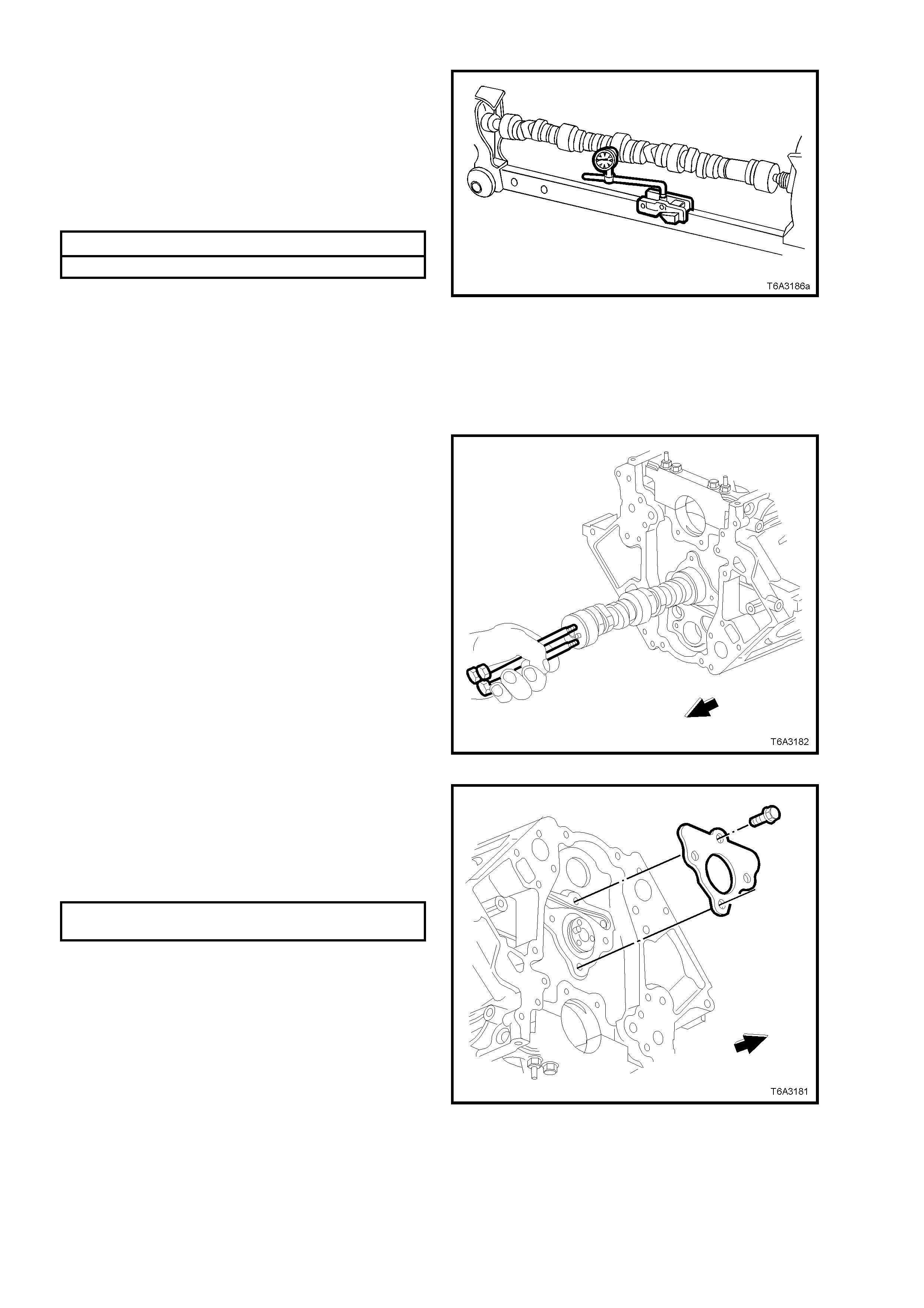
5. Mount the camshaft either in Vee blocks or
between centres.
6. Using a suitable dial indicator mounted as
shown, rotate the camshaft and check the
runout on the centre bearing journal.
Replac e th e c amshaf t if the r unout exc eeds th e
specification.
Idler Gear End Play Spec.
Camshaft Runout Specification
Camshaft Runout 0.05 mm Maximum
7. Inspect the camshaft retainer plate for wear or
a damaged sealing gasket.
If the gasket is not cut or damaged, it may be
re-used.
Figure 6A3-264
REINST ALL
NOTE: If camshaft replacement is required, the valve lifters must also be renewed.
1. Lubricate camshaft journals and the bearings
with clean engine oil.
2. Install three M8 x 1.25 x 100 mm bolts into the
camshaft front journal.
3. Using the b olts as a han dle, c aref ully instal l the
camshaft into the engine block.
NOTE: As all the cam shaf t bearing jour nals are the
same size, care must be taken to avoid bearing
damage during camshaft installation.
4. Remove the three bolts after camshaft
installation.
Figure 6A3-265
5. Ensure that the engine block surface is clean
and free of debris, then install the camshaft
retainer pl ate with th e seali ng gask et f acing the
engine bloc k.
6. Install the camshaft retainer bolts and tighten
to the correct torque specification.
CAMSHAFT RETAINER BOLT
TORQUE SPECIFICATION 25 Nm
Figure 6A3-266
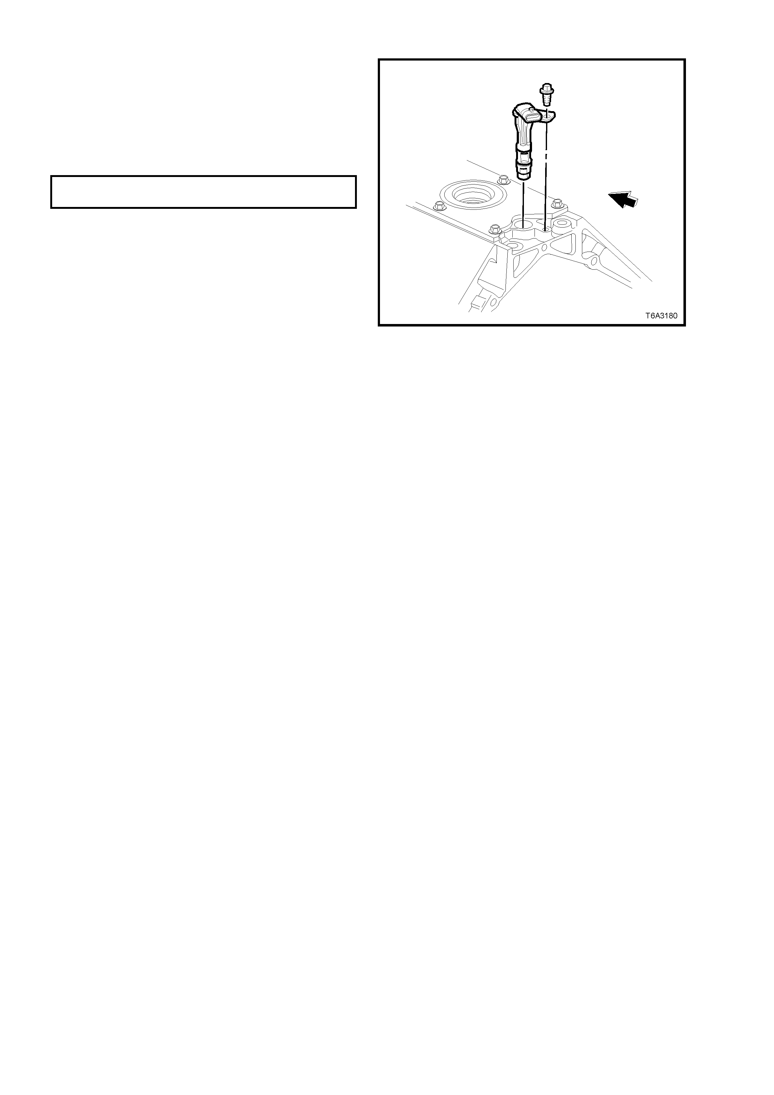
7. Inspect the camshaft position sensor O-ring,
renewing if it is cut or damaged.
8. Lubricate the O-ring with clean engine oil,
install to the sensor.
9. Install the camshaft position sensor and the
retaining bolt and tighten to the correct torque
specification.
CAMSHAFT POSITION SENSOR
BOLT TORQUE SPECIFICATION 25 Nm
10. Reinstall the camshaft chain and sprocket.
Refer 3.10 TIMING CHAIN AND
SPROCKETS, in this Section.
11. Reinstall the oil pump, refer 3.9 OIL PUMP,
PUMP SCREEN AND DEFLECTOR, in this
Section.
12. Reinstall the front cover and harmonic
balancer. R efer 2.24 HARMONIC BALANCER
and 3.4 ENGINE FRONT COVER, in this
Section.
13. Remove oil pan, refer 3.3 OIL PAN –
REMOVE, in this Section.
14. If required, reinstall the intake manifold
assembly. Refer 2.14 INTAKE MANIFOLD, in
this Section.
Figure 6A3-267
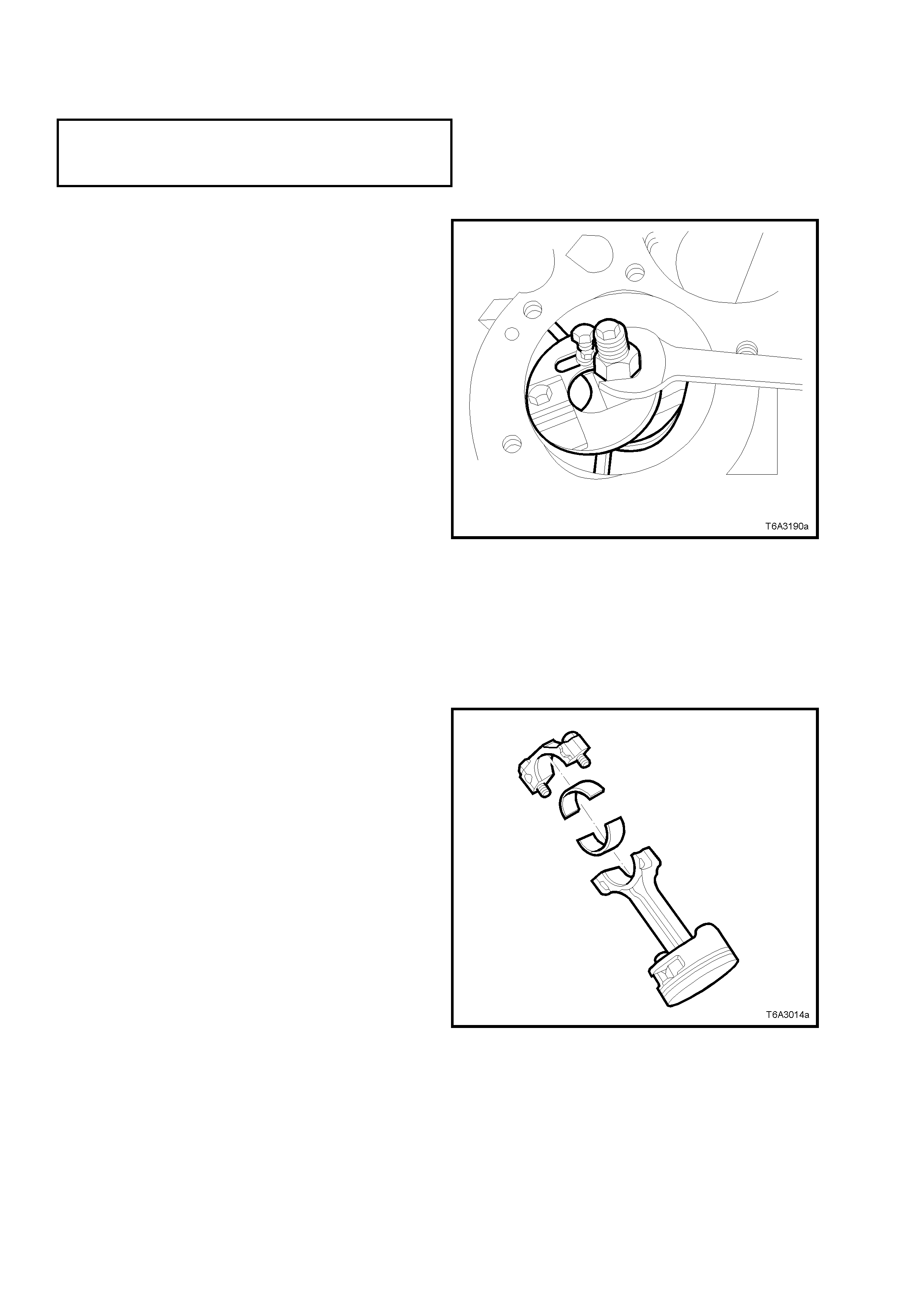
3.12 PISTON, CONNECTING ROD AND BEARING
LT Section No. – 00-550
NOTE: The following fasteners MUST be replaced ( ! )
when performing this operation:
! Connecting rod bolts and nuts.
REMOVE
IMPORTANT: Because of critical alignment
procedures required for the reinstallation of the oil
pan, it is strongly recommended that the engine
assembly is removed from the vehicle, before this
service operation is carried out.
1. Remove both cylinder heads. Refer
2.22 CYLINDER HEAD – REMOVE, in this
Section.
2. Remove oil pan, pump screen and deflector,
refer 3.3 OIL PAN – REMOVE and
3.9 OIL PUMP, PUM P SCREEN AND CO VER
– REMOVE, in this Section.
3. If required, use a commercially available
cylinder ridge remover, to remove any cylinder
ridge present, adopting the following
procedure:
a. Rotate the crankshaft until the piston is at the
bottom of its stroke (BDC).
b. Place a cloth on top of the piston.
c. Use the cylinder ridge remover to remove the
cylinder ridge.
d. Again ro tate the cr anks haft unt il the p iston is at
the top of its stroke (TDC).
e. Rem ove the clot h and an y m etal shavin gs f rom
the piston crown.
Figure 6A3-268
4. Using a paint stick or etching tool, matchmark
each connecting rod and its cap. The
connecting rod caps MUST be assembled to
the original position and direction.
DO NOT apply a stam ping mark on the side of
the connecting rod and/or cap as this may
affect alignment and the geometry of the
assembly.
5. Mark the top of each piston to identify its
specific bore.
6. Remove the connecting rods bolts, loosening
progressively from side to side.
IMPORTANT: Ensure that the connecting rod
bearings are organised so they will be installed in
the original position and location.
7. Remove each connecting rod cap.
Figure 6A3-269
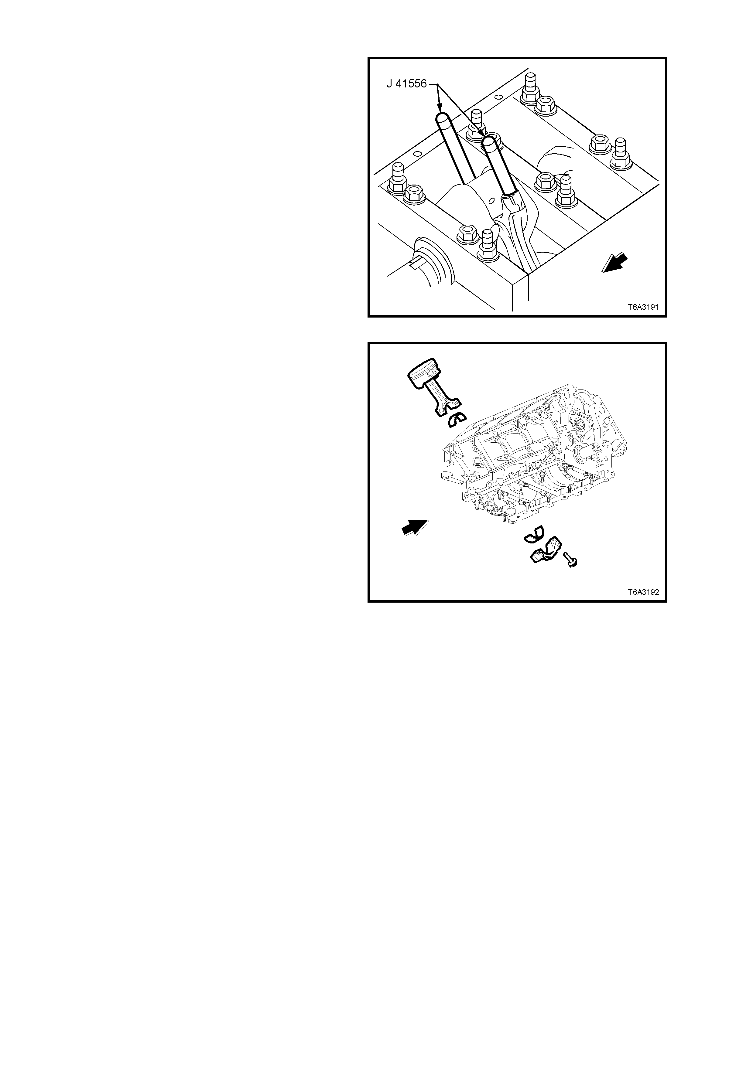
8. Install guide pins Tool J 41556 to the
connecting rod to be removed.
Figure 6A3-270
9. Use a ham mer handle to tap lightl y on the end
of the guide pin Tool J 41556 and remove the
piston and connecting rod from the cylinder
bore.
10. Once removed, assemble the connecting rod
cap, bearing shells and bolts to the matching
connecting rod.
Figure 6A3-271
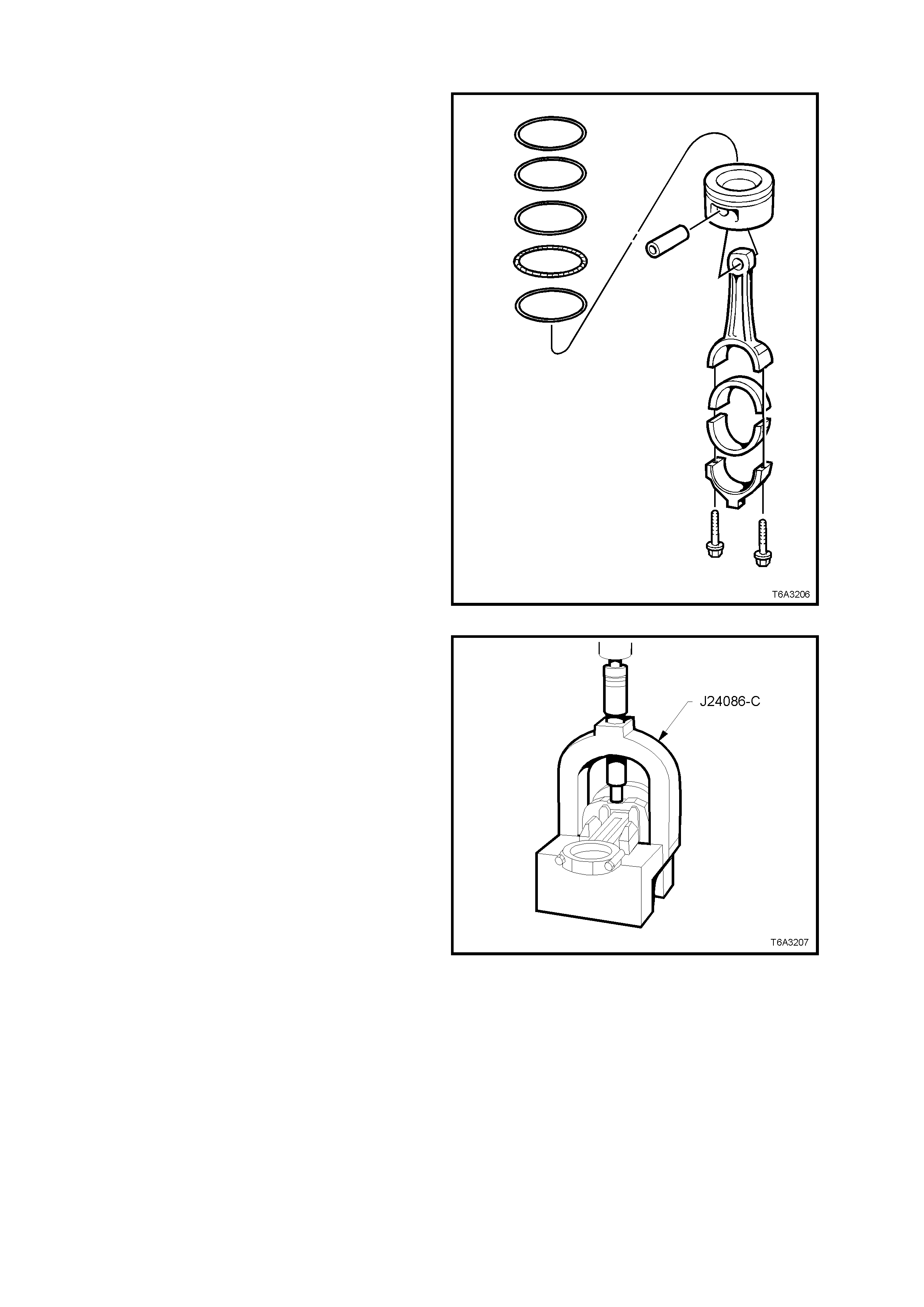
DISASSEMBLE
1. Remove the piston rings from the piston.
Figure 6A3-272
2. Insert fork insert J 24086-905 onto the bridge
of Tool J 24086-C. Mount the piston assembly
so that the fork insert is between the
connecting rod and the piston. Install pin
remover J 24086-8A.
3. Place the assembly under an hydraulic press
and remove the piston pin from the piston and
connecting rod assembly.
NOTE: The piston and pin are a matched set and
are not serviced separately. Mark the pin to piston
to ensure cor rect reas sem bly if original p arts are to
be re-used.
Figure 6A3-273
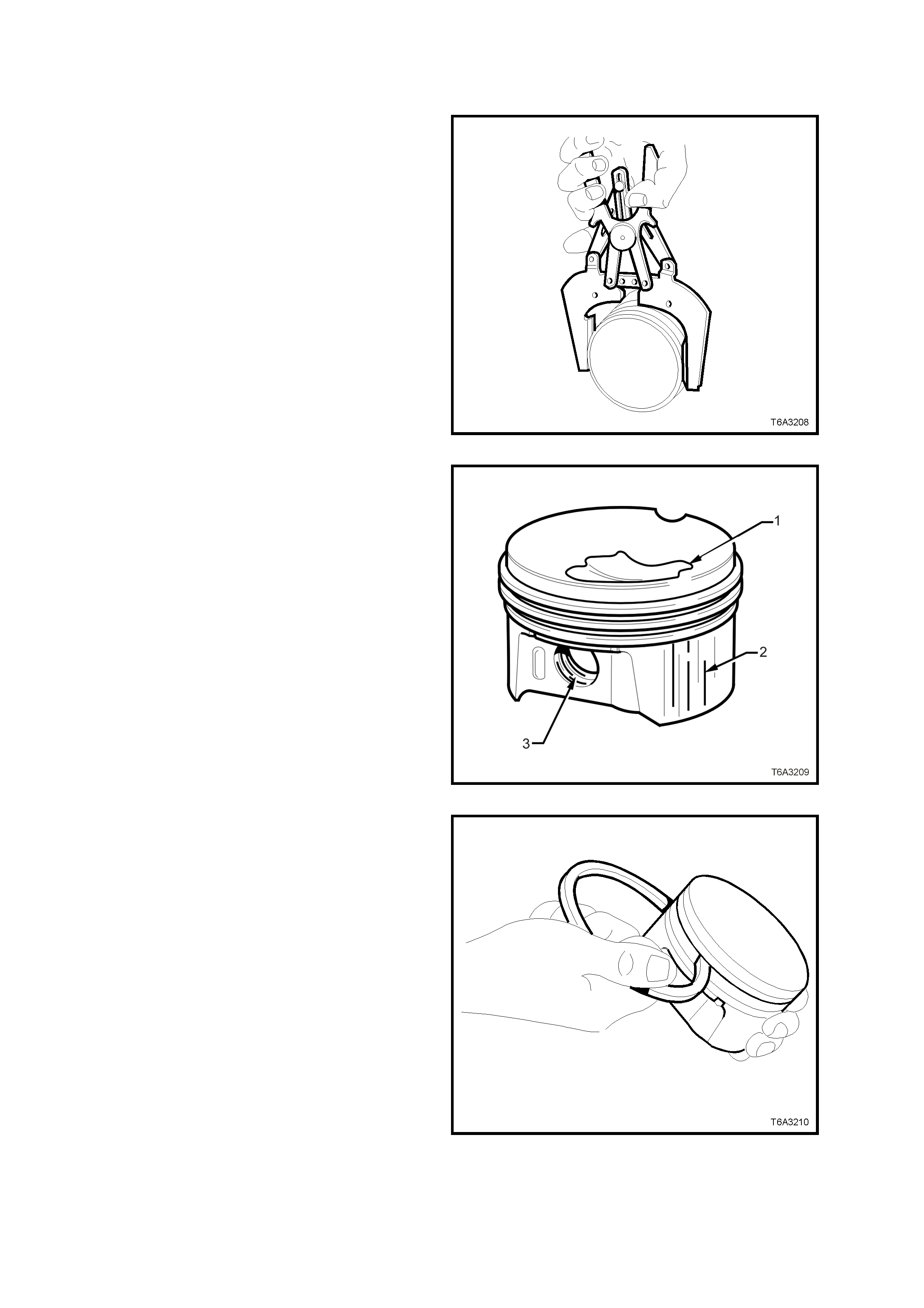
CLEAN AND INSPECT
Piston and Pin
1. Clean a ny var nish f rom the pis ton an d pin, with
a suitable cleaning solvent. DO NOT use a
wire brush for this process.
2. Dry the cleaned parts with compressed air.
CAUTION: Wear safety glasses to avoid eye
injury.
3. Clean the piston ring grooves with a
comm er c ially availab le too l.
4. Clean the oil lubrication holes and slots in the
ring grooves.
Figure 6A3-274
5. Inspect each piston and pin for the following:
a. Cracks in the piston lands, skirt or the pin
bosses.
b. Piston ring grooves for nicks, burrs or
warpage which may cause the piston ring
to bind. MINOR imperfections may be
removed by using a fine file.
c. Eroded areas on top of the piston (1).
d. Scuffed or damaged skirts (2).
e. Scoring to the piston pin bore (3) or the
piston pin.
Figure 6A3-275
6. Measure the piston ring to piston groove side
clearance, as follows:
a. Insert the edge of a NEW piston ring into
the correct piston ring groove.
b. Roll the piston ring around the groove.
NOTE 1: If binding is caused by a distorted piston
ring groov e, MINOR rin g groove im perf ections m ay
be removed with a fine file.
NOTE 2: If binding is caused by a distorted piston
ring, replace the ring.
Figure 6A3-276
NOTE: For each of the following measurements,
ensure that the micrometer zeroing has been
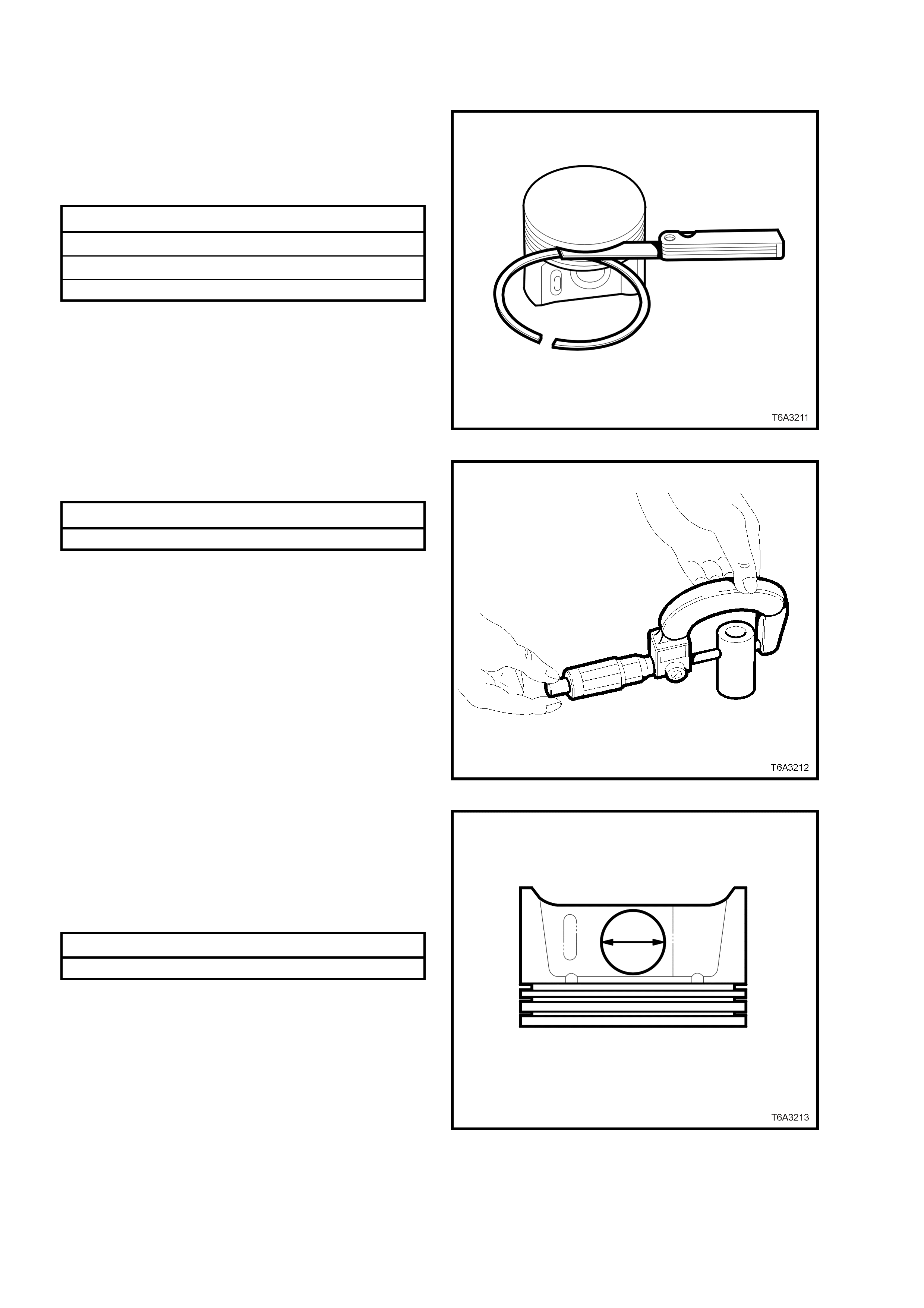
carried out and the measurements are all taken
with components at room temperature.
7. Again using a new piston ring in the correct
location, check the side clearance using a
feeler gauge. If side clearance exceeds
specification, try another piston ring set before
condemning the piston.
Piston Ring Side Clearance Specification
Top compression ring 0.040 - 0.085 mm
Second compression ring 0.040 - 0.080 mm
Oil control ring 0.010 - 0.220 mm
8. If the piston ring side clearance exceeds
specif ic atio n, t he pis to n a n d pi n ass embl y m us t
be replaced.
Figure 6A3-277
9. To measure the pin-to-bore clearance, first
measure the pin with a micrometer.
Piston Pin Specification
Piston Pin Diameter 23.997 - 24.000 mm
Figure 6A3-278
10. Using a suitable inside micrometer, measure
the matching piston pin bore on each side.
11. Subtract the piston pin dimension from the
piston pin bore size to obtain the clearance.
12. If the clearance exceeds specification, the
piston and pin assembly must be replaced.
Piston Pin to Bore Clearance Specification
Piston pin clearance (Maximum) 0.010 - 0.020 mm
Figure 6A3-279
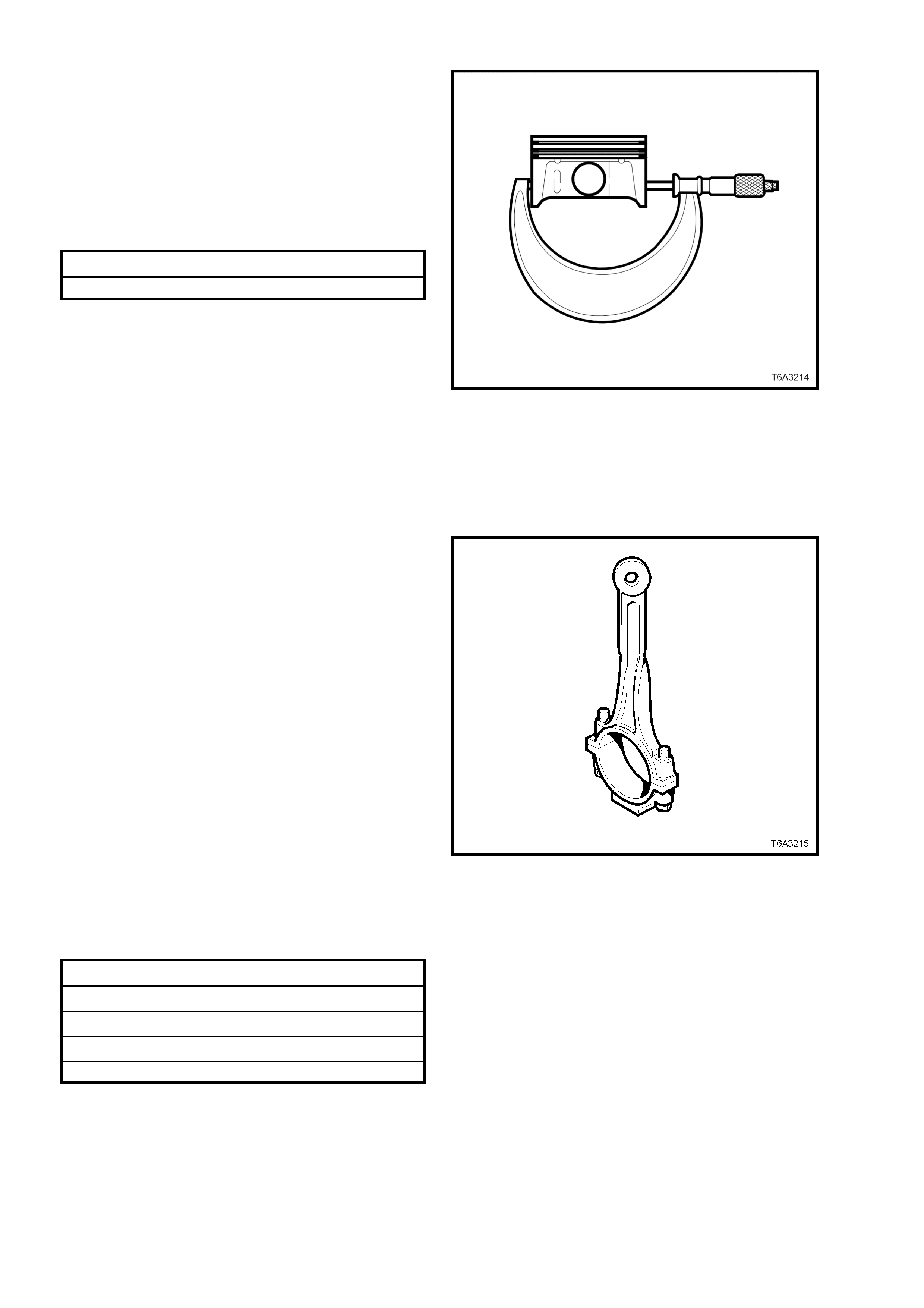
13. Measure the piston for out-of-round, as follows:
a. With a suitable sized micrometer at right
angles to the piston pin bore, measure the
piston skirt dimension, 11 mm above the
bottom of the skirt.
b. Measure the piston at two different points
and compare the readings
c. If the difference exceeds specification, then
replace the pist on a nd pin ass em bl y.
Piston Skirt Out-of Round Specification
Piston skirt dimension variation 0.018 mm Maximum
Figure 6A3-280
Connecting Rods and Bearings
NOTE: The powdered metal connecting rod and
cap are machined for the correct clearances. The
connecting rod and the cap must be used as an
assembly, with no repairs or modifications carried
out to either mating surface.
1. Clean each connecting rod and matching cap
in a suitable solvent.
2. Clean the connecting rod bolt threads and
inspect for damage. Do not attempt to repair
damaged threads in this location. Replace the
connecting rod, cap and bolts as an assembly
if thread damage is found.
3. Blow parts dry using compressed air.
CAUTION: Wear safety glasses to avoid eye
injury.
4. Inspect the connecting rod for the following
defects:
a. Twisting, using commercially available
alignment equipment.
b. Bending. Check leng th with s uitable m easuring
equipment.
c. Nicks or gouging in the bearing bore.
d. Damage to the bearing locating slots in the
bearing bore.
e. Correct fit of the connecting rod and cap
mating surfaces.
Connecting Rod Specification
Centre to Centre Length 154.90 ± 0.02 mm
Width 24.00 ± 0.05 mm
Twist 0.010 mm Maximum
Bend 0.02 mm Maximum
Figure 6A3-281
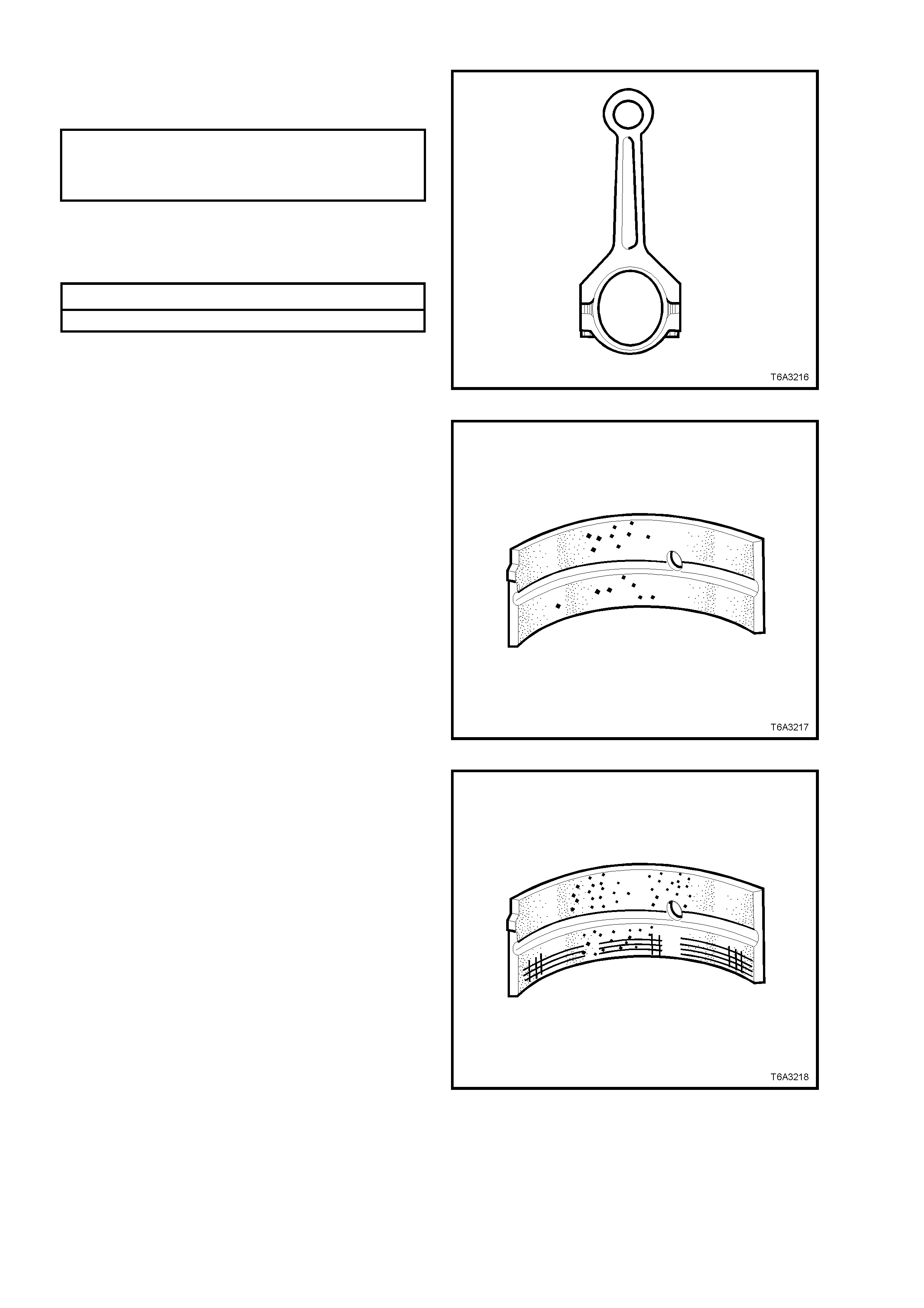
5. Reinstall the connecting rod big end cap and
bolts. Tighten bolts to the correct torque
specification.
CONNECTING ROD CAP BOL T
TORQUE SPECIFICATION Stage 1: 20 Nm
Stage 2: 60°
turn angle
6. Measure the connecting rod big end bore,
using a suitable inside micrometer, checking
for ovality. Replace any connecting rod
assembly that exceeds specification.
Connecting Rod Big End Ovality Specification
Connecting rod big end ovality 0.008 mm Maximum
Figure 6A3-282
7. Inspect connecting rod bearing halves for
craters or pockets. Flattened sections on the
bearing halves als o ind ic at e fatigu e.
Figure 6A3-283
8. Inspect connecting rod bearing halves for
excessive scoring or discolouration.
9. Inspect the connecting rod bearings for dirt or
debris embedded into the bearing material or
backing metal.
Figure 6A3-284
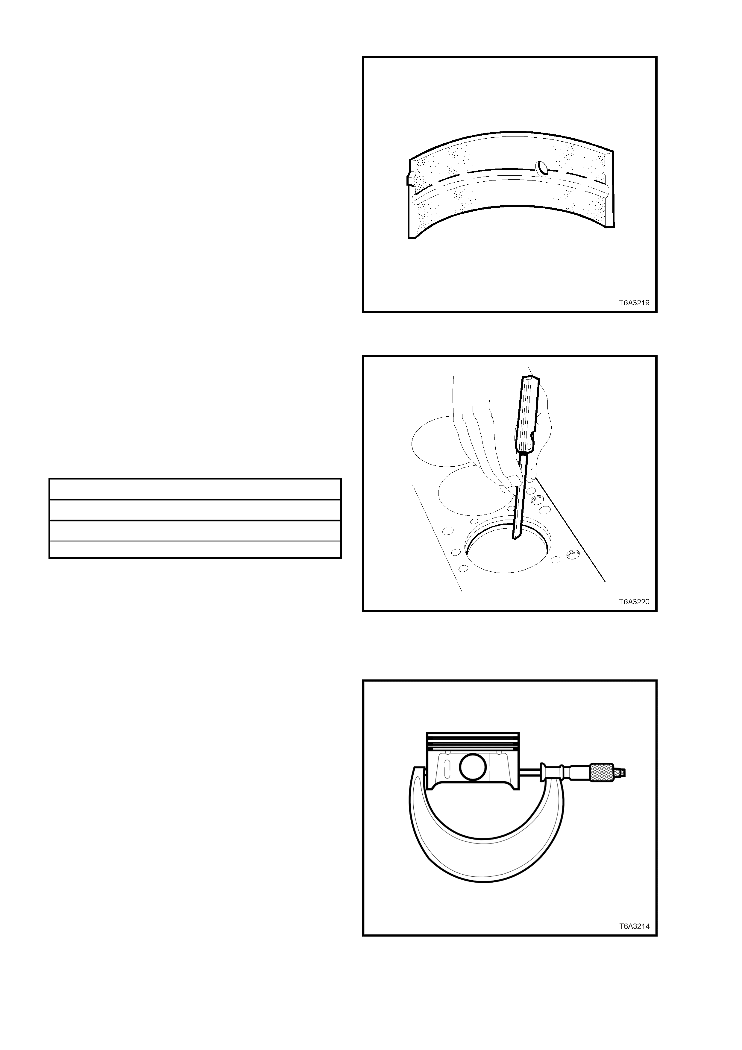
10. Inspect connecting rod bearing halves for
improper seating, indicated by bright, polished
section/s on the bearing material.
Figure 6A3-285
Measuring Piston Ring End Gap
1. Insert a new piston ring into the bore that it is
to be fitted and push it down the bore, using
the piston, invert ed in the bore, until the ring is
approximately 6.5 mm below the piston ring
travel area.
2. Insert a feeler gauge and measure the piston
ring end gap. End gap specifications are as
follows:
Piston Ring End Gap Specifications
Top compression ring 0.230 - 0.380 mm
Second compression ring 0.440 - 0.640 mm
Oil control ring 0.180 - 0.690 mm
Figure 6A3-286
REASSEMBLE
Piston Selection
NOTE 1: All measurements should be taken at
normal room temperature.
NOTE 2: A used piston and pin set may be
reinstalled if, after cleaning and inspection, they
are both within specification.
1. With a micrometer at right angles to the piston
pin bore, measure the piston skirt at 11 mm
from the lower edge.
2. Record the piston diameter.
Figure 6A3-287
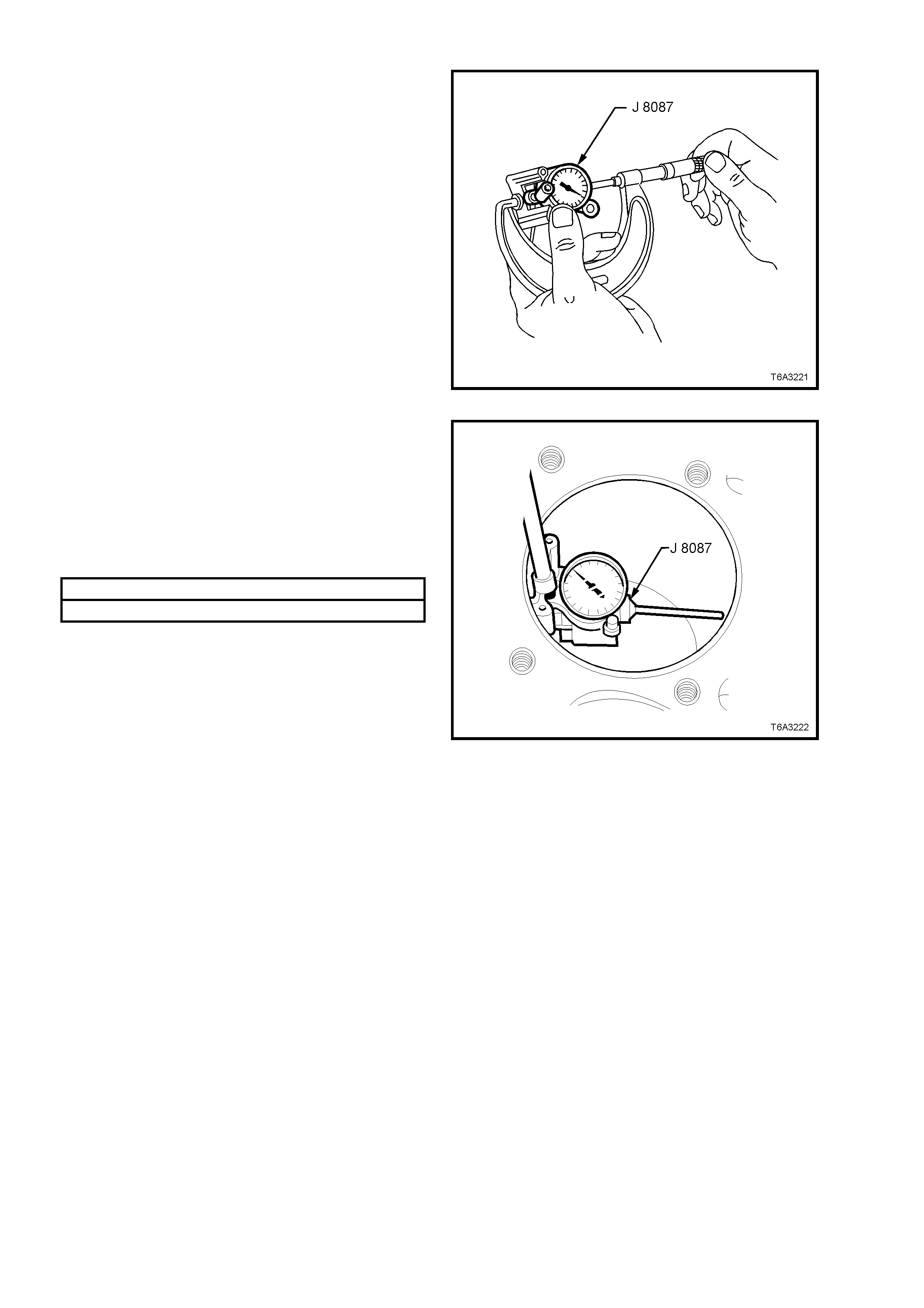
3. Check that the micrometer is at the recorded
piston diameter.
4. With Tool J 8087 (or commercial equivalent),
held between the micrometer anvils as shown,
zero the dial ind ic ator.
Figure 6A3-288
5. Use bore gauge J 8087 (or commercial
equivalent), measure the cylinder bore
diameter, at a point 57 mm from the top of the
bore.
6. Record the cylinder bore diameter.
7. Subtract the piston diameter from the cylinder
bore measurement, in order to determine the
piston to bore clearance.
Piston to Bore Clearance Specification
Clearance range 0.018 - 0.054 mm
8. If the clearance is outside this specification,
select another piston and measure it and re-
calculate the clearance. If the correct clearance
cannot be obtai ned us ing t his m ethod, then t he
cylinder bore may require honing for an
oversize piston fitment, or the cylinder block
will need to be replaced.
9. When the correct piston to bore clearance is
obtained, mark the piston crown for correct
installation.
NOTE: The cylinder bore must be checked for
ovalit y and taper bef or e th i s operatio n is attempted.
Refer 3.15 CYLINDER BLOCK - CYLINDER
BLOCK CLEAN, INSPECT AND MEASURE, in
this Section.
Figure 6A3-289
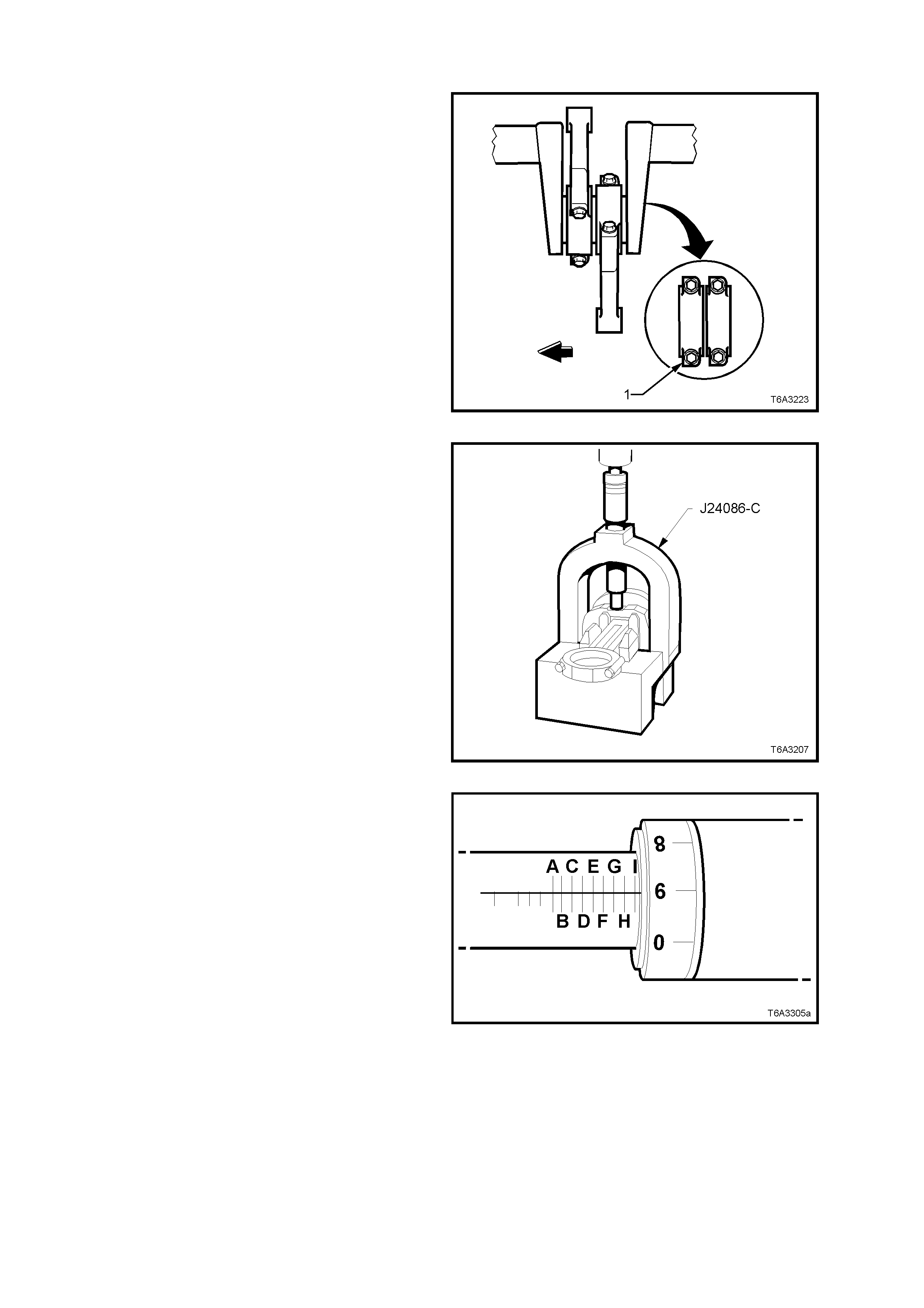
Piston to Connecting Rod
NOTE: Take particular care when assembling the
piston to the connecting rod, that component
matching and orientation is correct.
1. The connecting rod alignment should be with
the flat portion of the bolt flange (1) facing
forward. Also note that the piston alignment
mark has the correct orientation.
2. Lubricate the piston pin bore and piston pin
with clean engine oil.
Figure 6A3-290
3. With the connecting rod inserted with the
correct orientation into the piston, insert the
Black piston p in guide, J 24086- 1A from Tool J
24086-C, into the lower piston pin boss to pre-
align the piston and connecting rod pin holes.
4. Insert fork insert J 24086-905 between the
piston and connecting rod, around the piston
pin guide J 24086-1A, then mount the
assembly into the fork bridge of Tool J 24086-
C.
Figure 6A3-291
5. Adjust installer, J 24086-9, to a setting of “I-9”,
as shown. Lock this position with the knurled
ring.
Figure 6A3-292
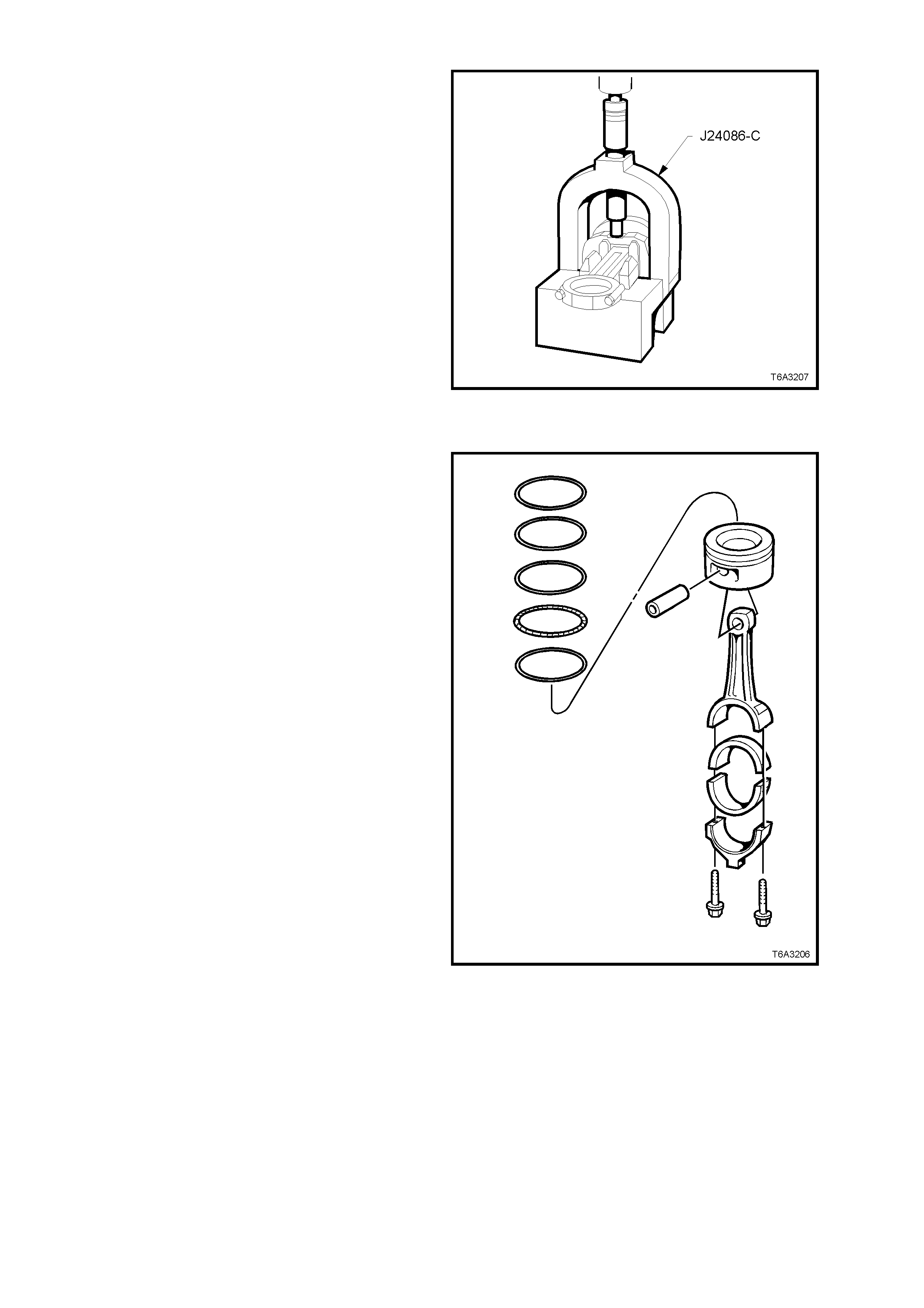
6. Insert the adjusted installer to Tool J 24086-C
and press the piston pin into the connecting
rod, until the installer bottoms out.
7. Check that the piston pin has been installed
correctly.
The piston pin will be installed correctly, if the
piston pin is centred in the piston and the
connecting rod is also centred between the
piston pin bosses, i.e. the connecting rod
should h ave equal s pacing on each sid e of the
piston pin boss.
Figure 6A3-293
PISTON RINGS
NOTE: Use commercially available piston rings
pliers and on ly expand th e piston r ing suf f iciently to
slide over the piston. Excessive expansion will
permanently distort the piston ring.
1. Install the piston rings to each piston, in the
following manner:
a. Install the oil control spacer to the lower ring
groove. Ensure that the ends do not
overlap.
b. Install the lower oil control ring segment.
There are no identifying marks, indicating
orientation, as this ring may be installed in
either direction.
c. Install the upper oil control ring segment in
a similar manner.
d. Stagger the en ds of the three oil c on tr ol ri ng
components b y at least 90°.
e. Using commercially available piston ring
pliers, install the second compression ring,
noting that the dimple or orientation mark
must face upwards to the piston crown.
f. Using commercially available piston ring
pliers, install the top compression ring. This
ring has no orientation marks and may be
installed in either direction.
g. Stagger the compression ring gaps a
minimum of 25 mm.
Figure 6A3-294
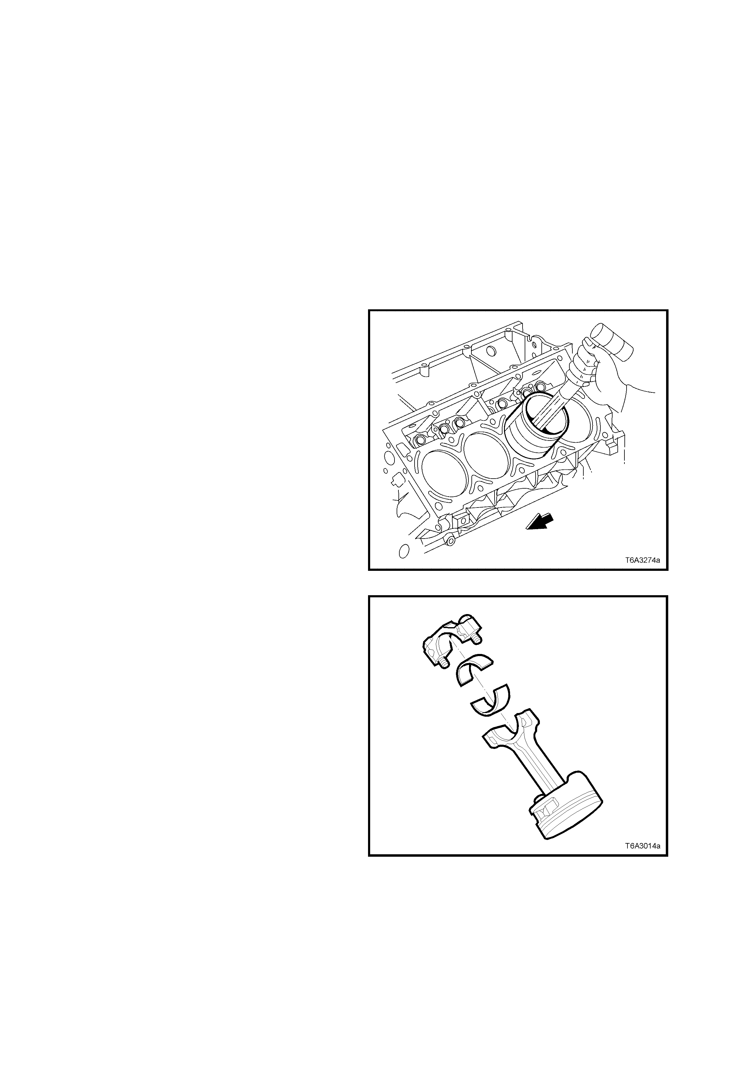
REINST ALL
NOTE 1: Before installation, check that the piston
ring end gaps are staggered correctly and that the
piston has been assembled to the connecting rod
in the correct manner.
NOTE 2: Before honing the cylinders, refer to
3.15 CYLINDER BLOCK, BORING AND
HONING, in this Section for important information,
relating to this task.
1. Lightly lubricate the piston, cylinder bore,
piston rings and bearing surfaces with clean
engine oil.
2. Remove the connecting rod cap and bearing
shell from the connecting rod being installed
and install the connecting rod guide pins, Tool
J 41556.
3. Install a commercially available piston ring
compressor over the piston rings and
compress.
4. Install the piston and connecting rod assembly
into the cor rect c ylinder bor e, check ing that the
piston alignment mark is facing the front of the
engine.
5. While holding the piston ring compressor
squarely and firmly against the engine block,
gently tap the piston into the bore, using a
wooden hammer handle, until all piston rings
have entered the bore.
6. Complete installation by using the pins, Tool J
41556 to guide the connecting rod onto the
crankshaft journal.
Figure 6A3-295
7. Remove connecting rod guides, Tool J 41556
and check that the upper bearing shell is
correctly installed in the connecting rod. Apply
clean engine oil to the upper bearing shell.
8. Install lower connecting rod bearing into the
cap, lubricate with clean engine oil and install,
ensuring that the cap orientation is correct.
Refer Figure 6A3-296.
IMPORTANT: The bearing oil clearance must be
checked before final installation of the connecting
rod caps. Refer to 3.13 CRANKSHAFT AND
BEARINGS, Main Bearing Oil Clearance - Check,
in this Section.
Figure 6A3-296
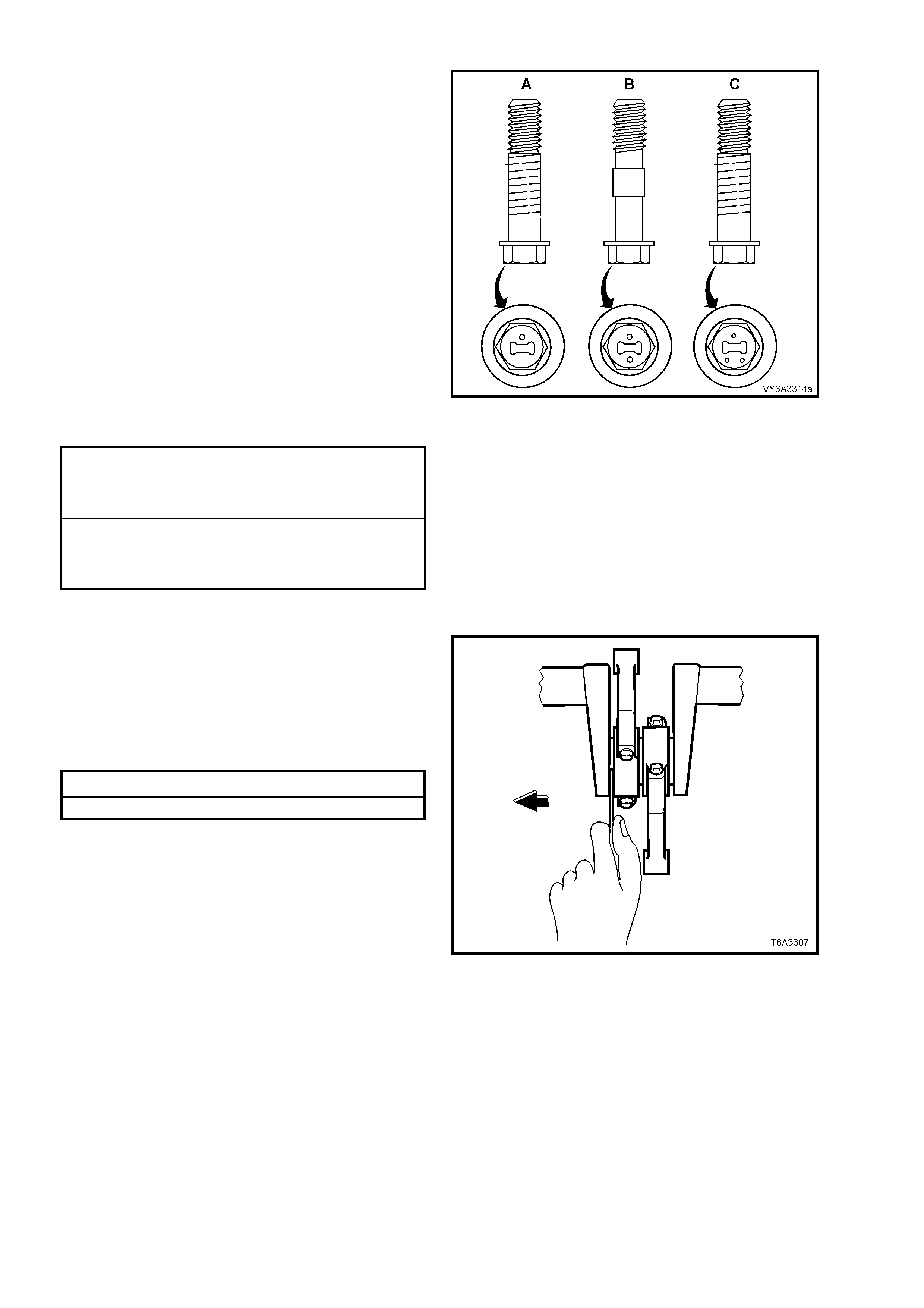
9. Install NEW connecting rod cap bolts and
tighten in two stages, to the correct torque
specification.
NOTE: Since inception, there have a been a
number of changes to the connecting rod bolts.
Regardless of when the engine was built, the
critical aspect relating to connecting rod bolts is
that a ‘matched pair’ must be used on each
connecting rod.
The most visible identification of a ‘matched pair’
can be determ ined by the presence of 'dim ples' on
the bolt head, witnessed by one, two or three, as
shown.
IMPORTANT: As bolt design 'A' has a different
torque specification than bolts 'B' and 'C',
replacement connecting rod bolts, MUST be of the
same design for each connecting rod. Using
different design bolts on the one connecting rod will
apply uneven clamp loads and/or connecting rod
bore distortion.
DESIGN ‘A’
CONNECTING ROD CAP BOL T
TORQUE SPECIFICATION Stage 1: 20 Nm
Stage 2: 60° turn angle
DESIGNS ‘B’ and ‘C’
CONNECTING ROD CAP BOL T
TORQUE SPECIFICATION Stage 1: 20 Nm
Stage 2: 75° turn angle
NOTE: Use torque angle meter Tool E7115 to
achieve the second reading.
Figure 6A3-297
10. With a pair of connecting rods installed onto
the same crankshaft journal, use a plastic
faced hammer to lightly tap each connecting
rod sideways to settle and ensure that side
clearance exists.
11. Using feeler gauges check that the connecting
rod side clearance is to specification.
Connecting Rod Side Clearance Specification
Side Clearance 0.11 - 0.51 mm
NOTE: If side clearance is insufficient, re-check
bearing oil clearance and/or connecting rod
alignment.
12. Reinstall oil deflector, oil pump screen and oil
pan, refer 3.9 OIL PUMP, PUMP SCREEN
AND COVER - REINSTALL and
3.3 OIL PAN - REINSTALL, in this Section.
13. Reinstall both cylinder heads. Refer
2.22 CYLINDER HEAD - REINSTALL, in this
Section.
Figure 6A3-298
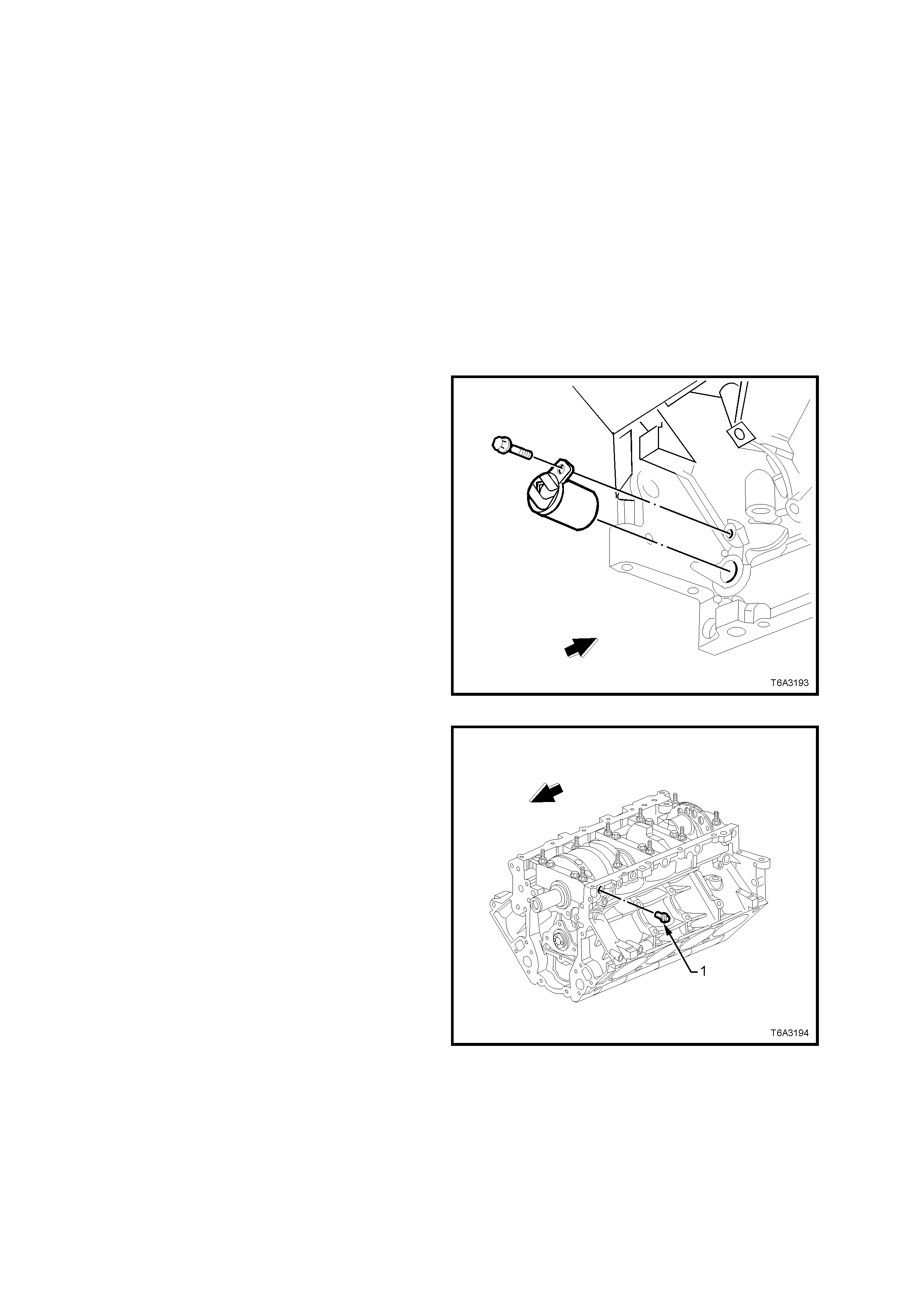
3.13 CRANKSHAFT AND BEARINGS
LT Section No. – 00-200
REMOVE
1. Remove engine from vehicle, refer 3.1 ENGINE ASSEMBLY - REMOVE, in this Section.
2. Remove the following items from the engine assembly;
a. Starter motor, refer Section 6D3-2 STARTING SYSTEM - GEN III V8 ENGINE.
b. Oil pan, refer 3.3 OIL PAN, in this Section.
c. Crankshaft balancer, refer 2.24 CRANKSH AFT B ALANCER, in this Sec t ion.
d. Front cover, refer 3.4 FRONT COVER, in this Section.
e. Oil pump, screen and deflector, refer 3.9 OIL PUMP, PUMP SCREEN AND DEFLECTOR, in this Section.
f. Timing chain, refer 3.10 TIMING CHAIN AND SPROCKETS, in this Section.
g. Flywheel/Flex plate, refer 3.5 FLYWHEEL/ FLEXPLATE, in this Section.
h. Rear cover, refer 3.8 ENGINE REAR COVER, in this Section.
3. Remove the crankshaft position sensor
retainin g bolt, the n rem ove the sensor from the
cylinder bl oc k.
Figure 6A3-299
4. Remove the crankshaft main bearing cap M8
side bolts (1). While these bolts must be
renewed o n final assem bly, place the removed
bolts to one side, as they will be requir ed when
checking the main bearing oil clearance.
5. Remove the main bearing cap M10 bolts and
studs, loosening each pair gradually. Take note
of the stud positions for reassembly.
Figure 6A3-300
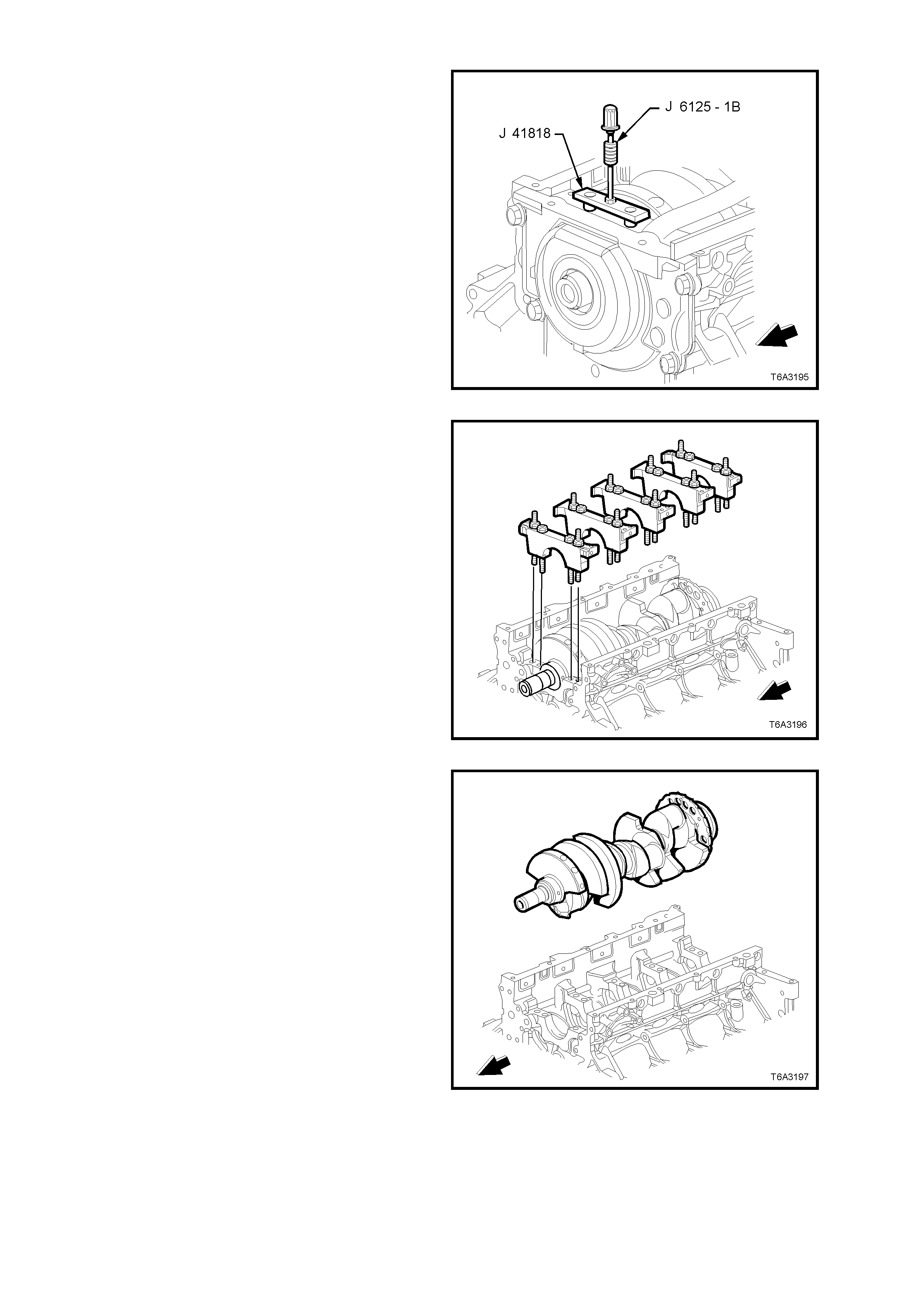
6. Loosen the bolts of m ain bearing rem oval Tool
J 41818 to separate the chamfered collets.
Then install the chamfered sections into each
ma in bearing cap bolt h ole, aligni ng the flats of
the collets with those in the holes.
7. Tighten the bolts of Tool J 41818 to 11 Nm.
8. Install slide hammer, Tool J 6125-1B to J
41818 and remove main bearing cap.
Figure 6A3-301
9. Remove the remaining main bearing caps in
the same way. Check that the lower main
bearing shells are also removed with each cap.
Figure 6A3-302
10. Rem ove the c rank shaf t fr om the cylind er block ,
lifting evenly to avoid jamming against the main
thrust bearing.
Figure 6A3-303
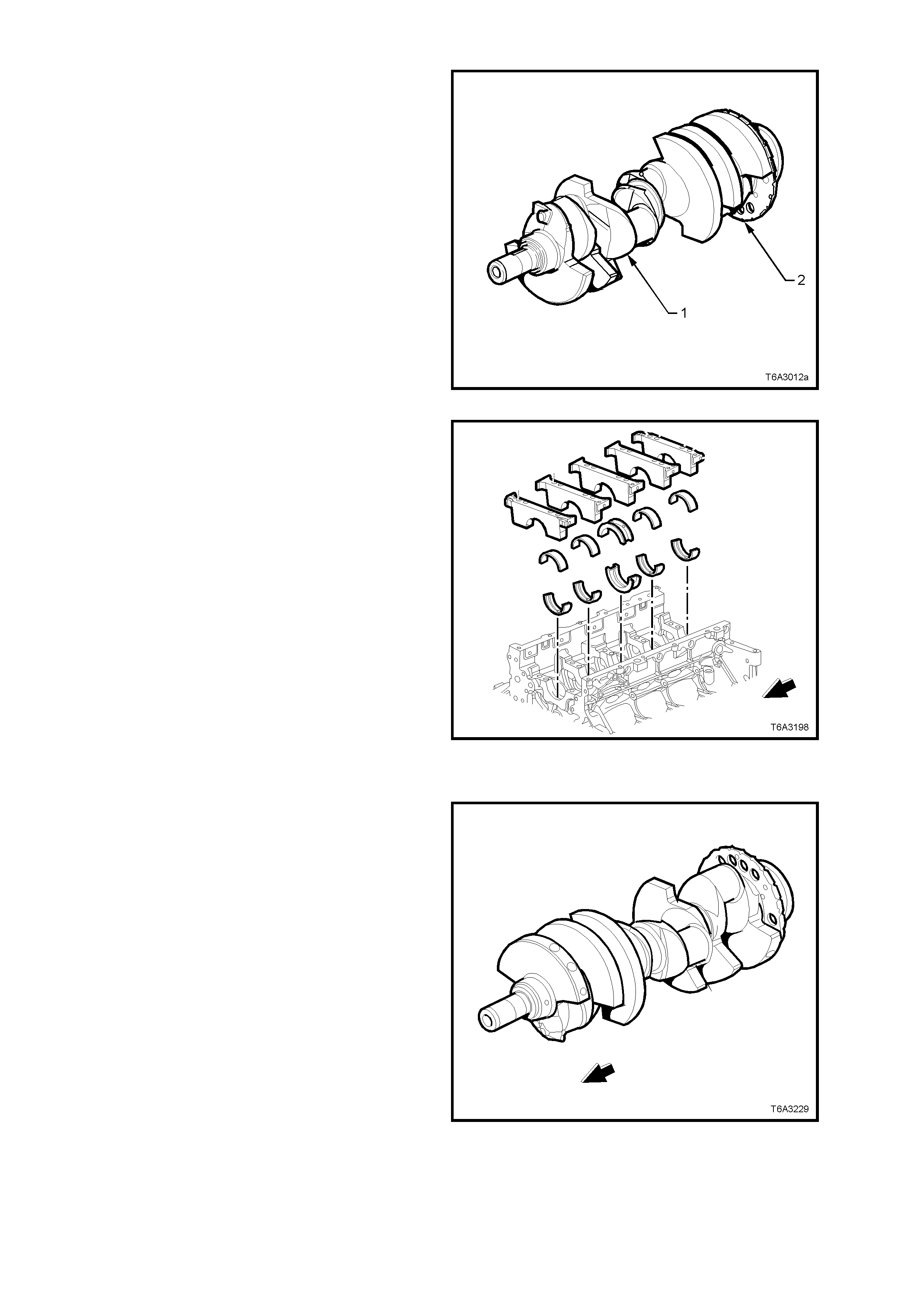
IMPORTANT: When the crankshaft (1) has been
removed, take particular care that the reluctor ring
(2) is not damaged, as this part is an integral part
of the crankshaft and is not serviced separately.
Therefore, it is suggested that the removed
crankshaft be supported on two wooden ‘V’ blocks
or other suitable soft surface.
Figure 6A3-304
11. Rem ove the crank shaft m ain bearings from the
cylinder block and the main bearing caps.
NOTE: Take par ticu lar car e to organ ise al l par ts s o
they can be reinstalled in their original positions.
Figure 6A3-305
CLEAN AND INSPECT
IMPORTANT: Take care not to damage the
reluctor ring on the crankshaft, as this part is non-
serviceable.
1. Clean the crankshaft with a suitable solvent.
2. Thoroughly clean all oil passages and inspect
for restrictions or burrs.
3. Blow dry with compressed air.
CAUTION: Wear safety glasses to avoid eye
injury.
4. Carry out a visual inspection of the crankshaft
for damage.
5. Inspect the crankshaft reluctor ring lobes for
damage. The reluctor ring teeth should not
have imperfections on either the rising or falling
edges.
Figure 6A3-306
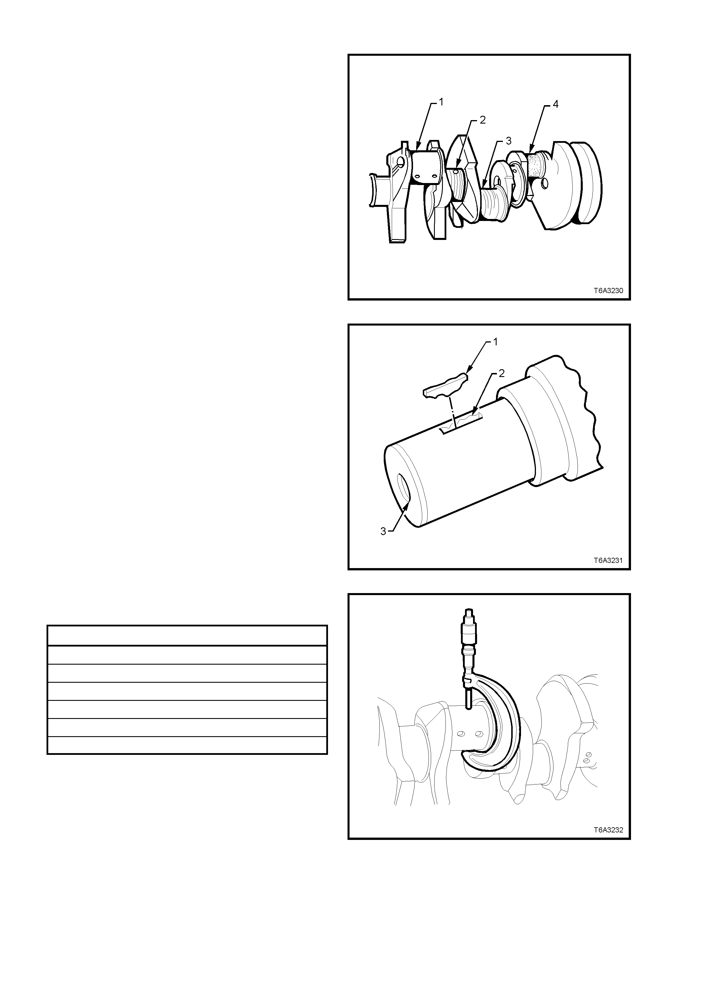
6. Inspect the crankshaft journals for wear (1).
Journals should be smooth with no signs of
scoring, wear or damage.
7. Inspect the crankshaft journals for grooves or
scoring (2).
8. Inspect the crank shaft journals for scratches or
wear (3).
9. Inspect the crankshaft journals for pitting or
embedded bearing material (4).
Figure 6A3-307
10. Inspect the crankshaft key (1), keyway (2) and
threaded hole (3) for damage.
Figure 6A3-308
11. Measure all crankshaft journals for wear and
out-of-round.
Crankshaft Journal Specific ations
Connecting Rod Journal Diameter 53.308 mm Min.
Connecting Rod Journal Out-of-Round 0.010 mm Max.
Connecting Rod Journal Taper 0.010 mm Max.
Main Bearing Journal Diameter 64.993 mm Min.
Main Bearing Journal Out-of-Round 0.008 mm Max.
Main Bearing Journal Taper 0.020 mm Max.
Figure 6A3-309
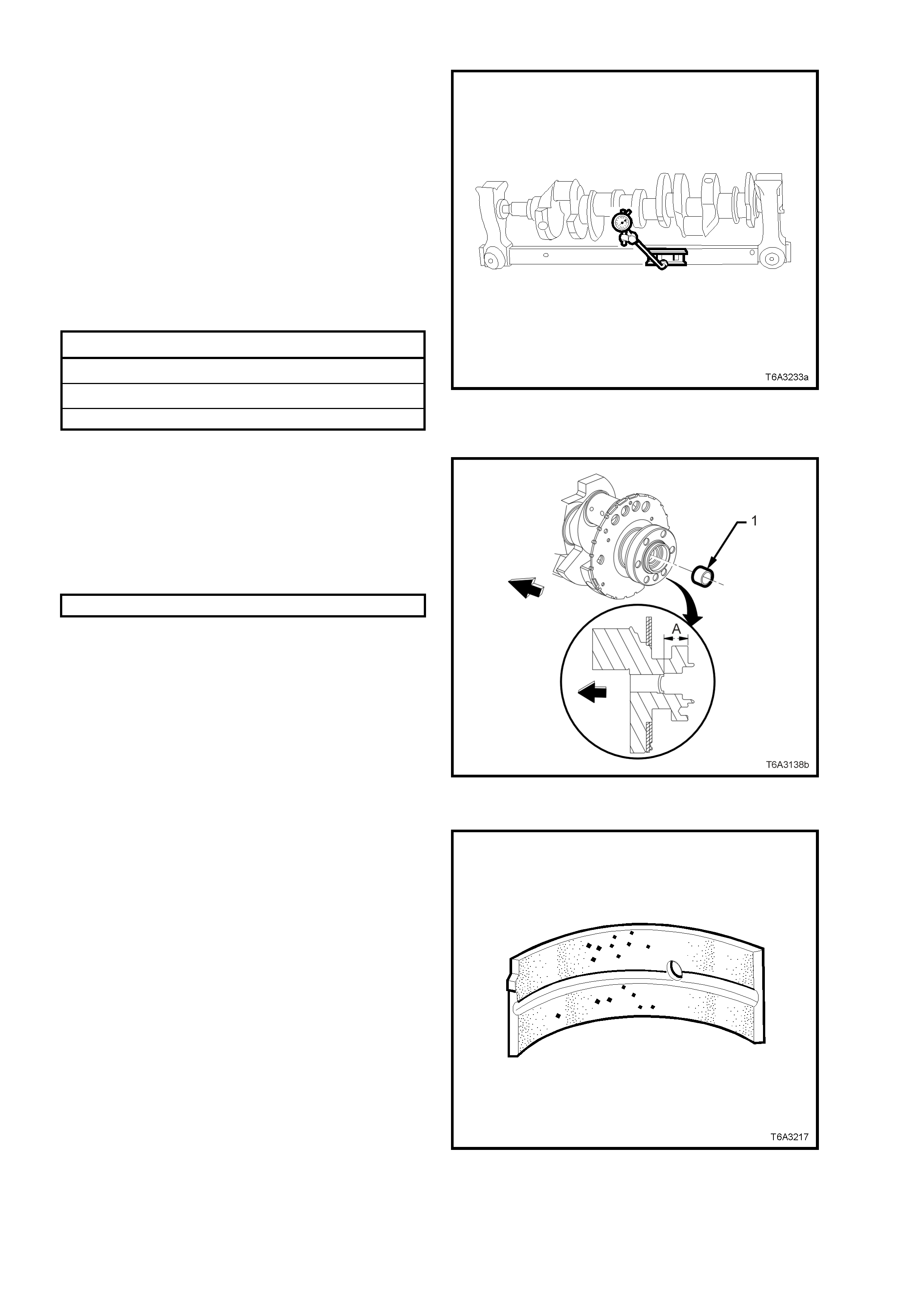
12. Support the crankshaft, either on ‘V blocks on
a flat surface or in a commercial jig as shown.
13. Using a commercially available dial indicator,
mounted to a magnetic stand, measure the
following crankshaft main bearing journal
runout dim ens ions:
Crankshaft runout at the front and rear,
intermediate main bearing journals.
Crankshaft rear flange.
Reluctor ring (measured 1.00 mm below the
minimum tooth diameter), at the rear surface.
Crankshaft thrust wall at the centre main
bearing.
Main Bearing Journal Runout Specifications
Reluctor Ring Lateral Runout 0.250 mm Maximum
Crankshaft Thrust Wall Runout 0.025 mm Maximum
Crankshaft Rear Flange Runout 0.050 mm Maximum
Figure 6A3-310
14. Check the rear crankshaft oil gallery plug for a
loose fit or leaking.
15. If replacement is required, apply sealant such
as Loctite 242 or equivalent, to the sides of a
new plug (1) and install to the correct depth.
Crankshaft Rear Oil gallery Plug Depth
Specification
DISTANCE ‘A’ 31.2 – 31.6 mm
NOTE: If a manual transmission is fitted to the
vehicle, it will be necessary to first remove the
spigot bush. Refer to 3.7 CRANKSHAFT SPIGOT
BEARI NG – R EP LACE, in this Sec tio n.
Figure 6A3-311
Main Bearings - Inspect
1. Inspect connecting rod bearing halves for
craters or pockets. Flattened sections on the
bearing halves als o ind ic at e fatigu e.
Figure 6A3-312
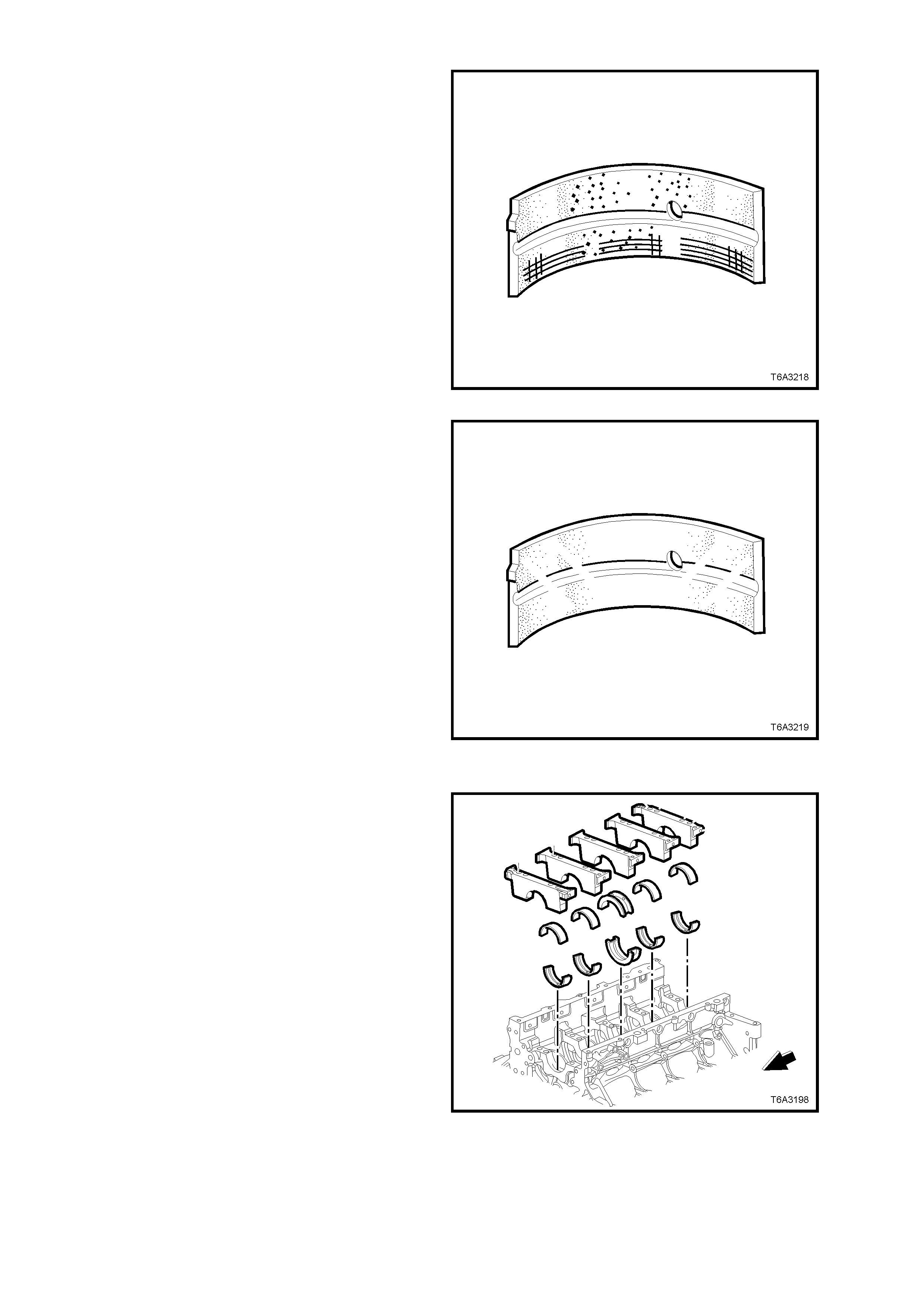
2. Inspect connecting rod bearing halves for
excessive scoring or discolouration.
3. Inspect the connecting rod bearings for dirt or
debris embedded into the bearing material or
backing metal.
Figure 6A3-313
4. Inspect connecting rod bearing halves for
improper seating, indicated by bright, polished
section/s on the bearing material.
Figure 6A3-314
Main Bearing Oil Clearance - Check
1. After thoroughly cleaning all relevant parts,
install bearing halves into the cylinder block
and main bearing caps.
Figure 6A3-315
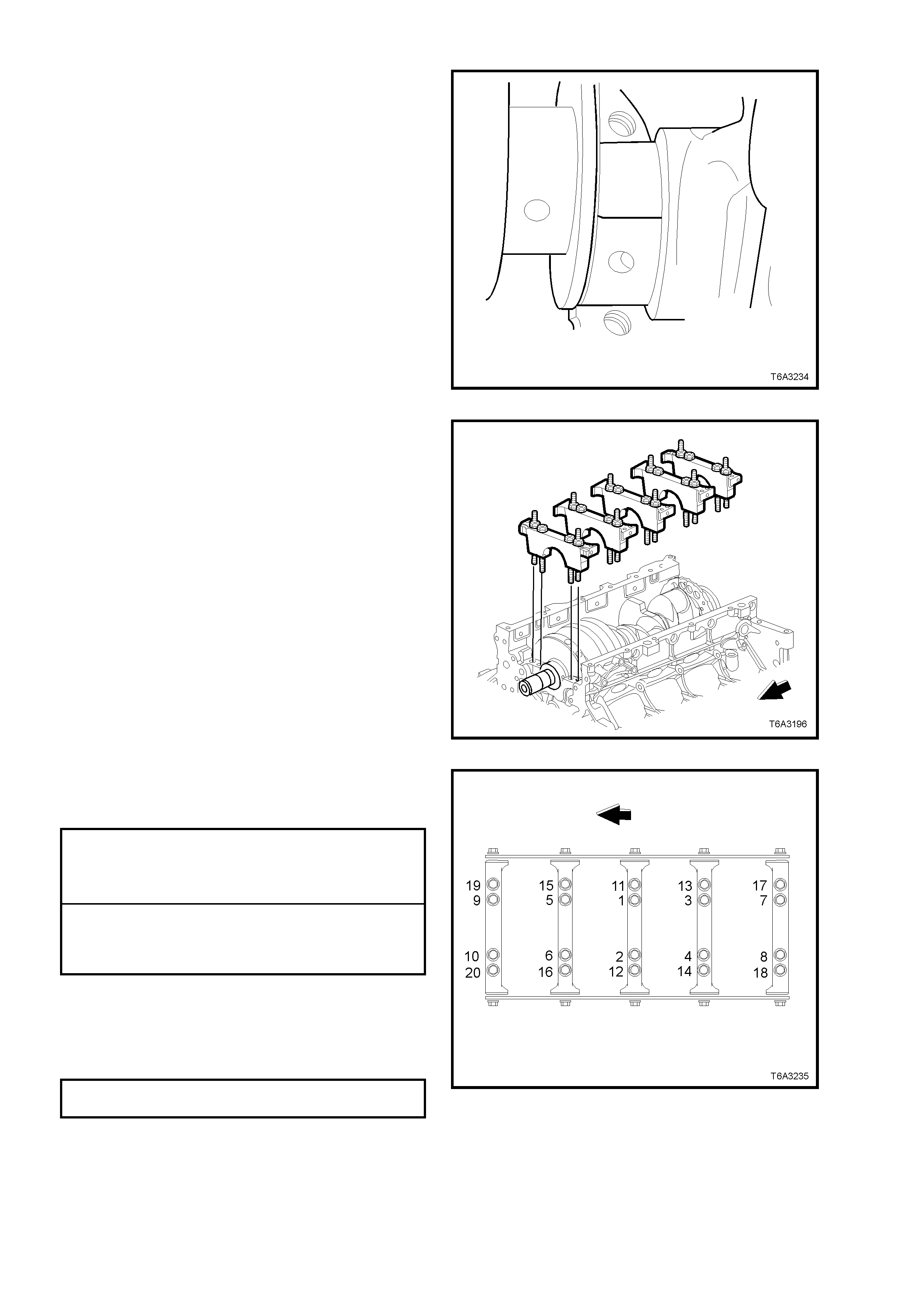
2. Install crankshaft to cylinder block, ensuring
that the crankshaft is held square to avoid
jamming/ damaging the centre main thrust
bearing.
3. Install a small strip of plastic gauging material
across the full width of the main bearing
journal.
NOTE 1: Do not p lace the gaugin g material acr oss
an oil feed hole.
NOTE 2: Ensure that the crankshaft does not
rotate during this process.
Figure 6A3-316
4. Install main bearings, caps, bolts and studs in
the same order as removal.
Figure 6A3-317
5. Tighten main bearing cap bolts and studs to
the correct torque specification and in the
correct sequence.
MAIN BEARING INNER
BOLTS (1 - 10)
TORQUE SPECIFICATION Stage 1: 20 Nm
Stage 2: 80° turn angle
MAIN BEARING OUTER
STUDS (11 - 20)
TORQUE SPECIFICATION Stage 1: 20 Nm
Stage 2: 53° turn angle
NOTE: Use torque angle meter E7115 to achieve
an accurate second reading.
6. Tighten the side ca p bolts to the cor rect torque
specification, first on one side, then on the
other.
MAIN BEARING CAP SIDE BOLTS
TORQUE SPECIFICATION 25 Nm
Figure 6A3-318
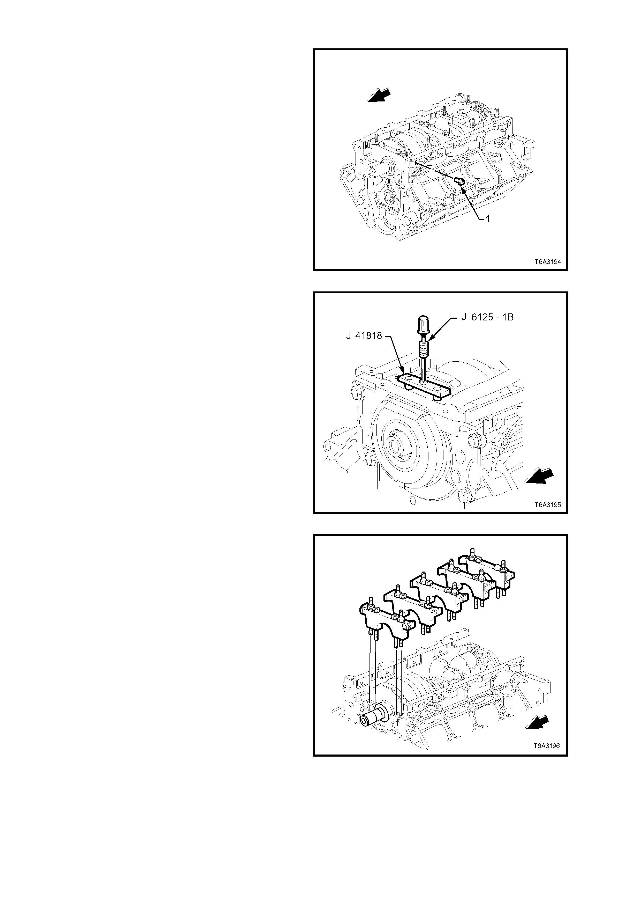
7. Remove the main bearing cap M8 side bolts
(1) and discard, as new bolts m ust be used on
final assembly.
Figure 6A3-319
8. Loosen the bolts of m ain bearing rem oval Tool
J 41818 to separate the chamfered collets,
then install the chamfered sections into each
ma in bearing cap bolt h ole, aligni ng the flats of
the collets with those in the holes.
9. Tighten the bolts of Tool J 41818 to 11 Nm.
10. Install slide hammer, Tool J 6125-1B to
J 41818 and remove main bearing caps.
Figure 6A3-320
11. Remove the remaining main bearing caps in
the same way.
Figure 6A3-321
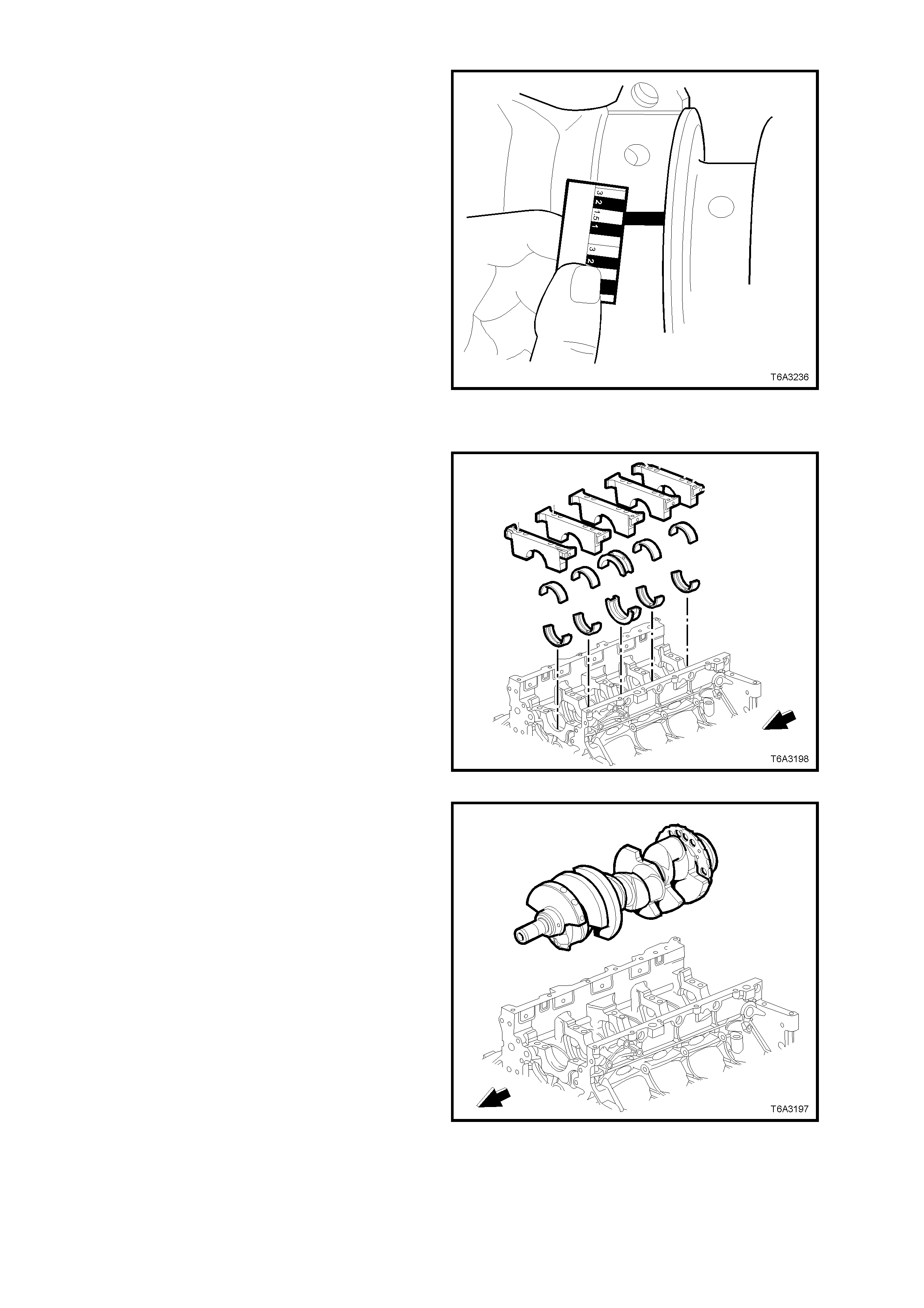
12. Using the scale supplied with the gauging
plastic, measure the deformed plastic at its
widest part.
• If the def ormed st rip shows a width var i ation
exceeding 0.020 mm, remove the
crankshaft and measure the journal with a
micrometer.
• If the bearing clearance is greater than
0.076 mm (connecting rod) or 0.065 mm
(main), select and install an undersized
bearing set, then re-check the oil clearance.
• If clearance specification cannot be
obtained, the crankshaft must be reground
for use with the next under-sized bearings.
Figure 6A3-322
REINST ALL
1. Apply clean engine oil to the bearing halves
and crankshaft journals.
Figure 6A3-323
2. Install crankshaft to cylinder block, ensuring
that the crankshaft is held square to avoid
jamming/ damaging the centre main thrust
bearing.
Figure 6A3-324
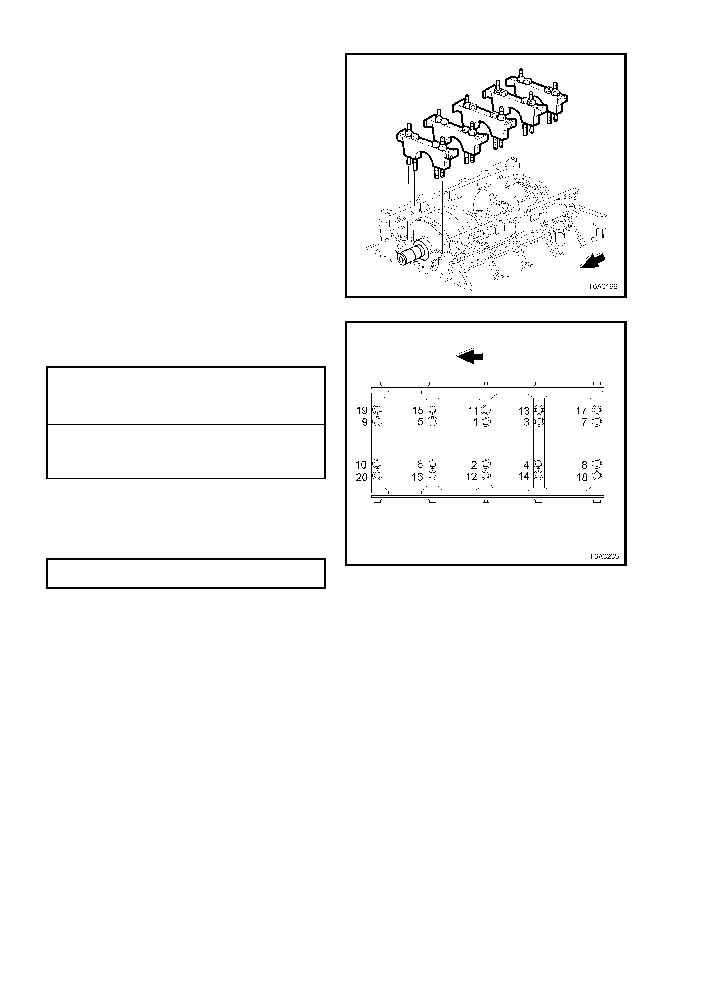
3. Install main bearings, caps, bolts and studs in
the correct order.
Figure 6A3-325
4. Tighten main bearing cap bolts and studs to
the correct torque specification, in the correct
sequence.
MAIN BEARING INNER
BOLTS (1 - 10)
TORQUE SPECIFICATION Stage 1: 20 Nm
Stage 2: 80° turn angle
MAIN BEARING OUTER
STUDS (11 - 20)
TORQUE SPECIFICATION Stage 1: 20 Nm
Stage 2: 53° turn angle
NOTE: Use torque angle meter E7115 to achieve
an accurate second reading.
5. Install NEW M8 main bearing cap side bolts
and tighten to the correct torque specification,
first on one side, then on the other.
MAIN BEARING CAP SIDE BOLTS
TORQUE SPECIFICATION 25 Nm
NOTE: New main bearing cap side bolts have a
sealant patch applied to the bolt flange.
Figure 6A3-326
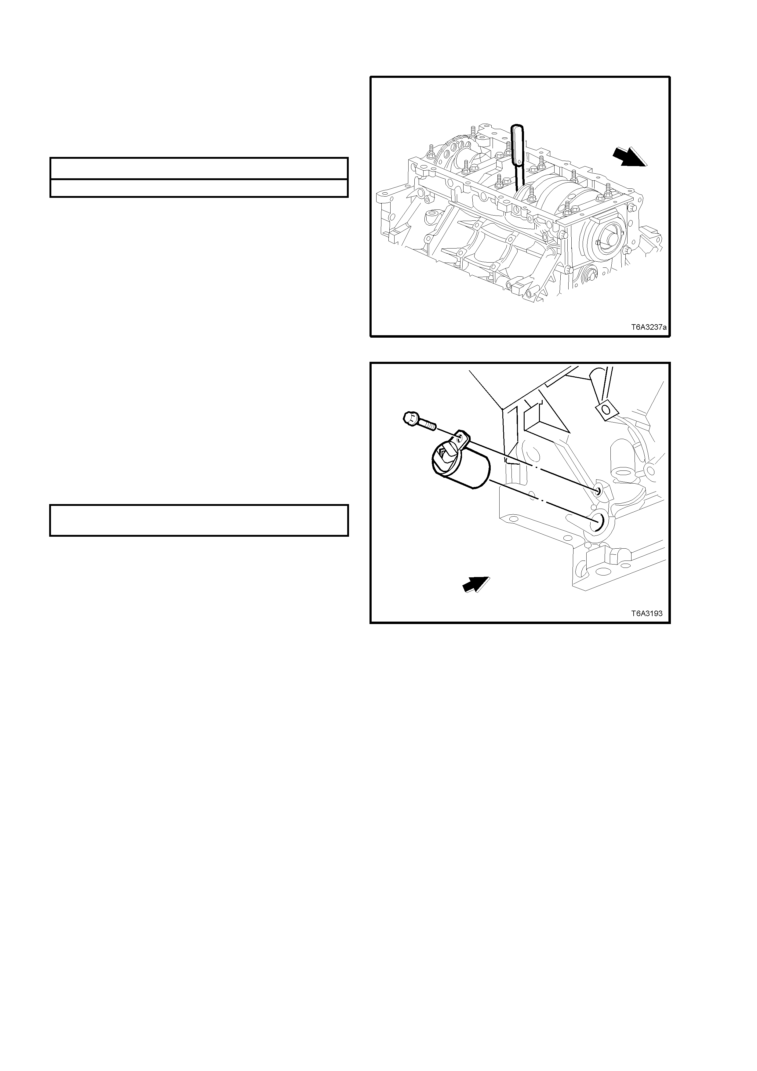
6. Thrust the crankshaft rearward then forward,
using a suitab le le ver .
7. Insert a feeler gauge between the centre main
bearing and the crankshaft thrust bearing
surface.
Crankshaft End Play Specification
Crankshaft End Play 0.040 - 0.20 mm
NOTE 1: If the bearing clearance is not within
specification, inspect the thrust surfaces for nicks,
gouges or rais ed metal. Mi nor imperfections c an be
removed with a fine stone.
NOTE 2: After measuring crankshaft end float,
leave the crankshaft in the forward position.
Particularly when a manual transmission if fitted to
the engine, this wil l lessen bearing shoc k when the
engine is started and the clutch is first released.
Figure 6A3-327
8. Inspect the crankshaft position sensor O-ring
for nick s, cuts or other dam age. If undamaged,
the O-ring may be re-used.
9. Coat the O-ring with clean engine oil.
10. Instal l th e s ens or, al ig ni ng t he r et ain in g br ac ket
notch with the threaded holed in the cylinder
block.
11. Install the retaining bolt, tightening to the
correct torque specification.
CRANKSHAFT POSITION SENSOR
TORQUE SPECIFICATION 25 Nm
12. Reinstall the following items to the engine
assembly;
a. Rear cover and flywheel/Flex plate, refer
3.8 ENGINE REAR COVER and
3.5 FLYWHEEL/ FLEXPLATE, in this Section.
b. Timing chain, refer 3.10 TIMING CHAIN AND
SPROCKETS, in this Section.
c. Oil pump, screen and deflector, refer
3.9 OIL PUMP, PUMP SCREEN AND
DEFLECTOR, in this Section.
d. Front cover and crankshaft balancer, refer
3.4 FRONT COVER and 2.24 CRANKSHAFT
BALANCER in this Section.
e. Oil pan, refer 3.3 OIL PAN, in this Section.
f. Starter motor, refer Sectio n 6D3-2 ST ARTI NG
SYSTEM - GEN III V8 ENGINE.
13. Reinst all engin e into veh icle, ref er 3.1 ENGIN E
ASSEMBLY – REINSTALL in this Section.
Figure 6A3-328
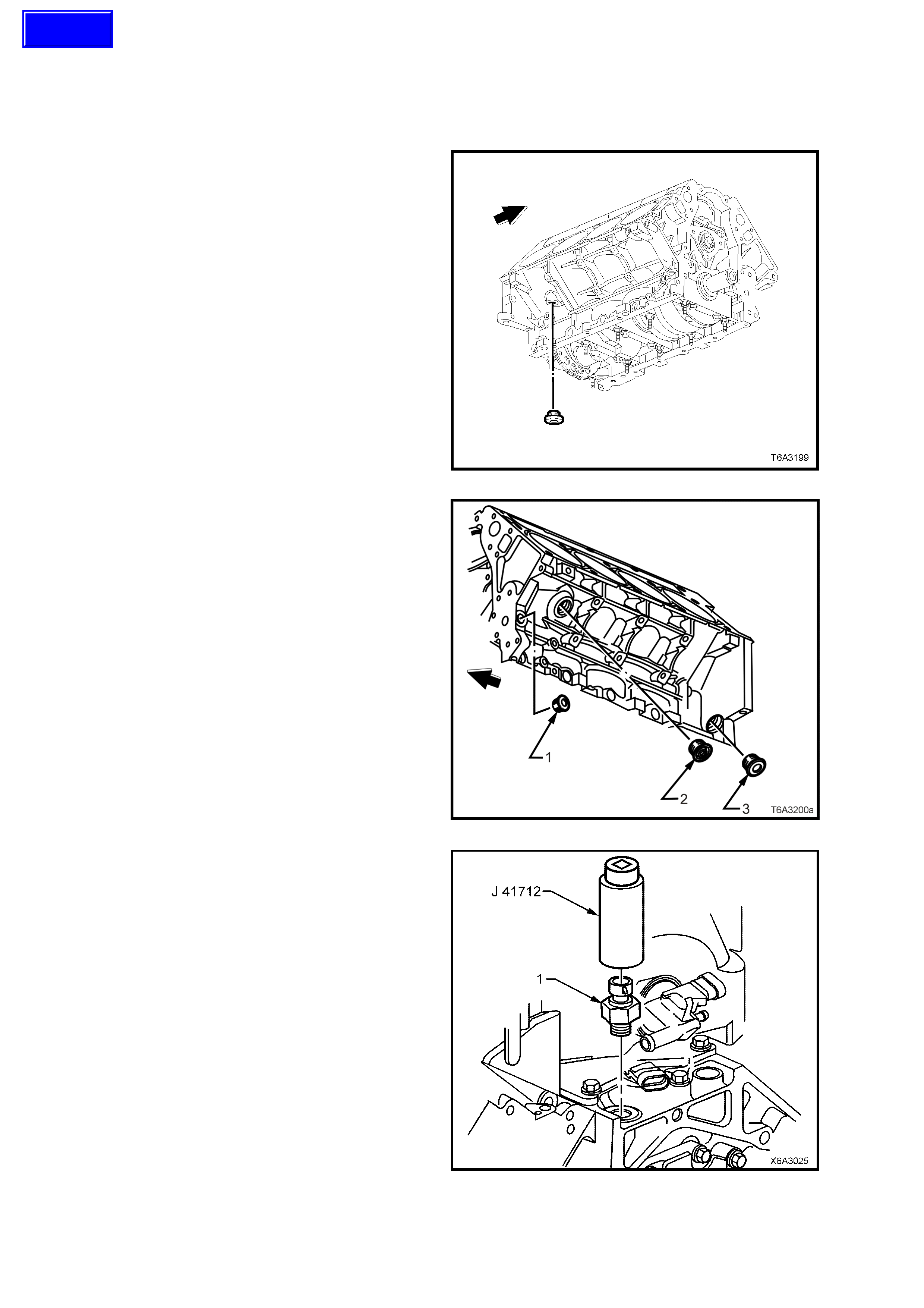
3.14 ENGINE BLOCK PLUGS
LT Section No. – 00-248
REMOVE
1. Using an 8 mm Allen key socket and bar,
remove the coolant drain plug from the right
hand rear of the cylinder block.
Figure 6A3-329
2. Rem ove the three plugs from the lef t hand s ide
of the cylinder block, using an 8 mm Allen key
socket and bar for plugs ‘1‘ and ‘3’ and a 17
mm Allen key socket for plug ‘2’.
Figure 6A3-330
3. If not removed in previous operations, remove
the oil pressure sensor (1) from the top of the
cylinder block, at the left hand rear, using Tool
J 41712 and suitable 3/8” drive socket bar.
Figure 6A3-331
Techline
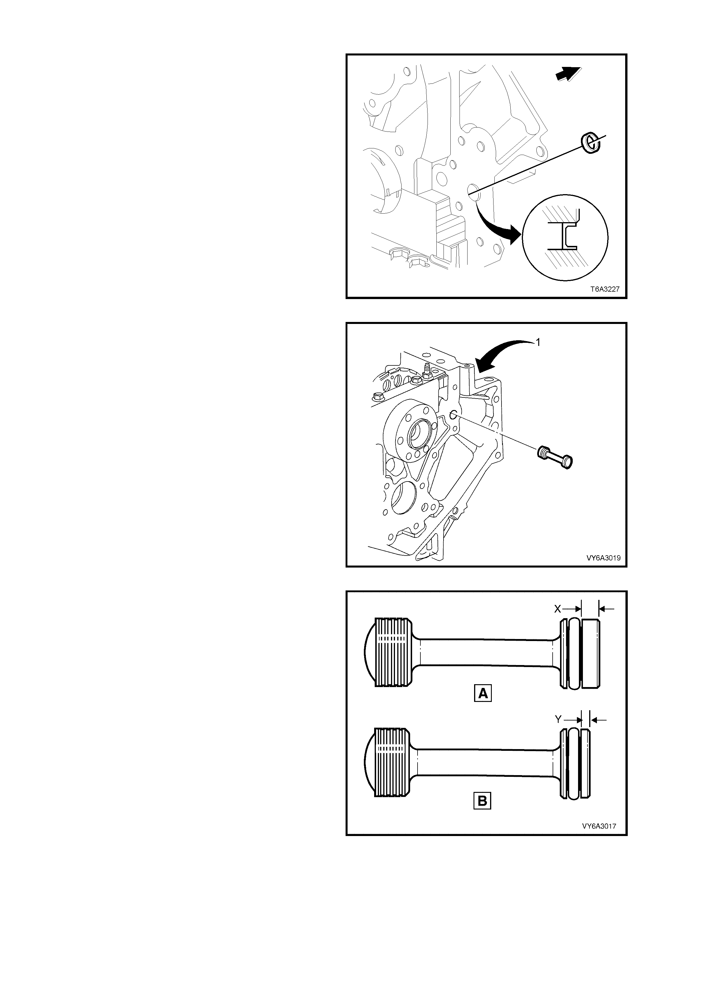
NOTE: Only remove the plug from the front of the
engine block, if replacement is required.
4. Rem ove the e ngine b lock , front o il g allery p lug.
A suggested method is to:
a. Drill a small pilot hole through the plug.
b. Install a self tapping screw into the plug.
c. Using a slide ham mer with a suitable
fitting, remove the plug.
d. Discard the removed plug.
Figure 6A3-332
5. To remove the rear oil gallery plug, either one
of two methods can be used:
a. With the fr ont plug r em oved, use a suit able
length of MS rod (e.g. 5 mm ) inserted from
the front of the eng in e bloc k and a h am mer
to tap the rear oil gallery plug free.
b. With the cylinder b loc k plug r emoved (#3 i n
Figure 6A3-330 and position ‘1’), use a
small screwdriver inserted in the plug
aperture to prise the oil galley plug free.
CAUTION: Take care not to slip during this
latter operation, as the machined edges of
aluminium components are extremely sharp.
6. Inspect the O-ring seal on the rem oved gallery
plug and if undamaged, it may be re-used
during assembly.
Figure 6A3-333
7. If removed, inspect the rear main oil gallery
plug and ensure that it is of the later design
(‘A’). If of the ear l ier d es ign ( ‘B ’) th en it must be
replaced.
NOTE: Visually, the later plug has a thicker end
boss (‘X’) that the earlier design (‘Y’).
Figure 6A3-334
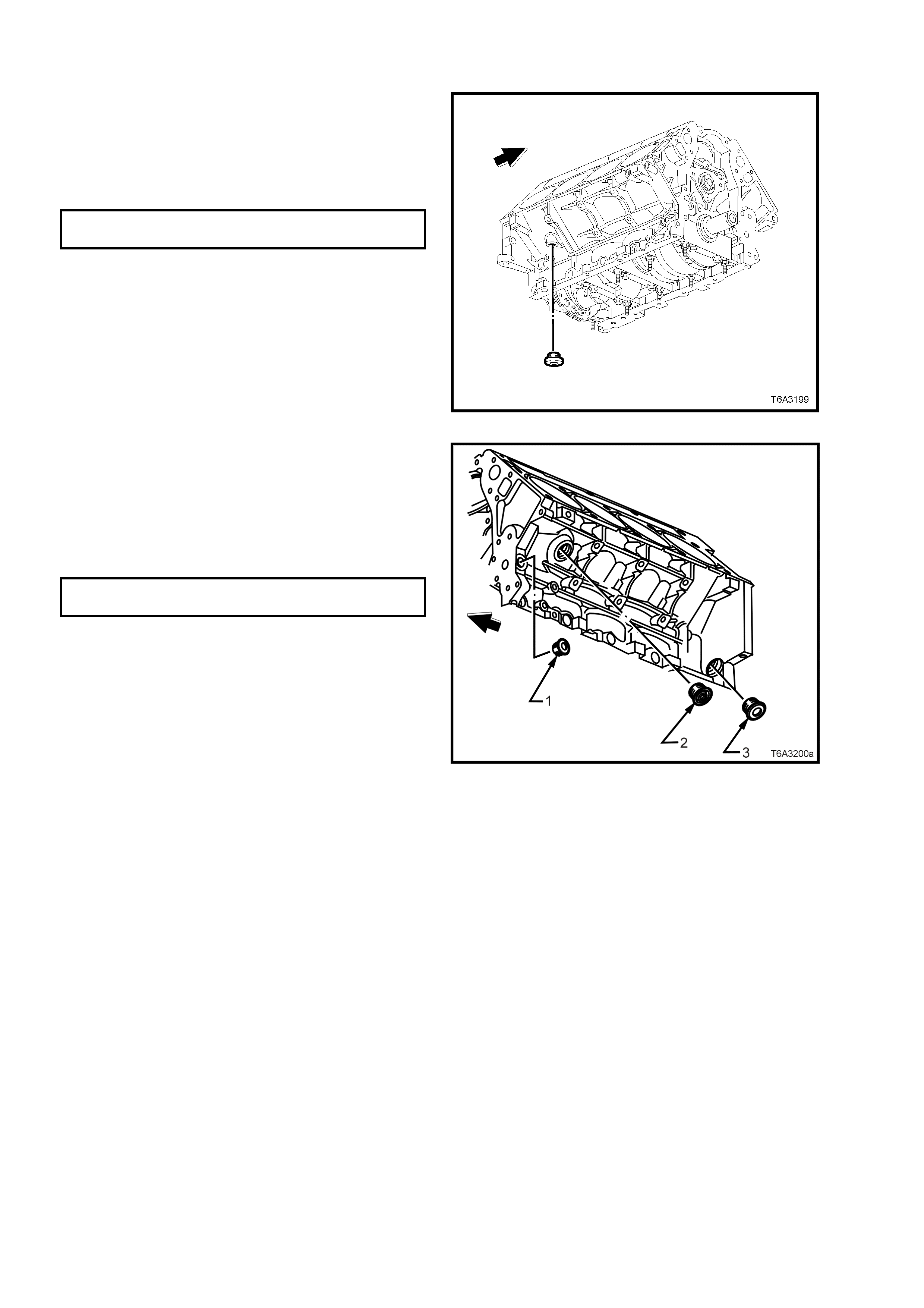
REINST ALL
1. Apply a 3 mm bead of sealant such as Loctite
565 or equivalent, to the right hand rear,
engine block coolant drain plug sealing
washer.
2. Inst all th e pl ug a nd t igh ten t o the c or rec t torq ue
specification, using an 8 mm Allen key socket.
COOLANT DRAIN PLUG
TORQUE SPECIFICATION 60 Nm
Figure 6A3-335
3. Apply a 3 mm bead of sealant such as Loctite
565 or equivalent, to the sealing washer on
each of the left hand side engine block plugs.
4. Install each plug and tighten to the correct
torque specification, using an 8 mm Allen key
socket for plugs ‘1’ and ‘3’ and a 17 mm Allen
key socket for plug ‘2’.
COOLANT DRAIN PLUG – ALL
TORQUE SPECIFICATION 60 Nm
Figure 6A3-336
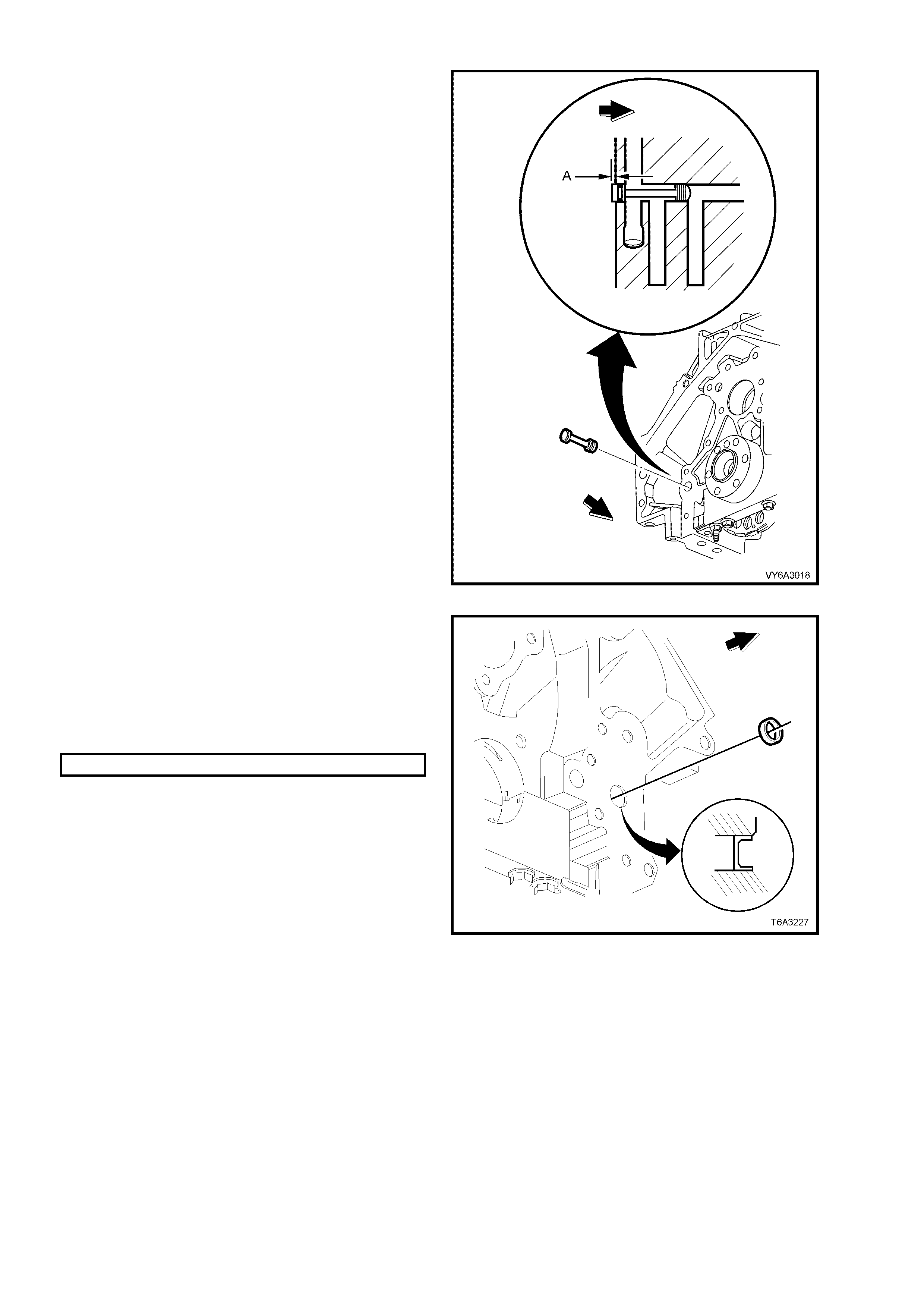
5. Lubricate the O-ring with clean engine oil and
install the plug into the rear of the cylinder
block . Caref ull y install u ntil the plu g com es to a
stop agains t the steppe d bore of the oil galler y.
At this point, the plug should be protruding by
approximately 1.2 mm (distance ‘A’).
NOTE: When the rear cover and gasket are
installed, the plug protrusion will rest against the
rear cover machined internal surface.
Figure 6A3-337
6. Apply a sealant such as Loctite 242 or
equivale nt to the s ide of a NEW front oil gallery
plug.
7. Install the NEW, front oil gallery plug to the
engine bloc k to the specif ie d dep th, to clear t he
engine bloc k chamfer .
Front Oil Gallery Plug Installation Specification
Below Flush 2.2 - 2.8 mm
Figure 6A3-338
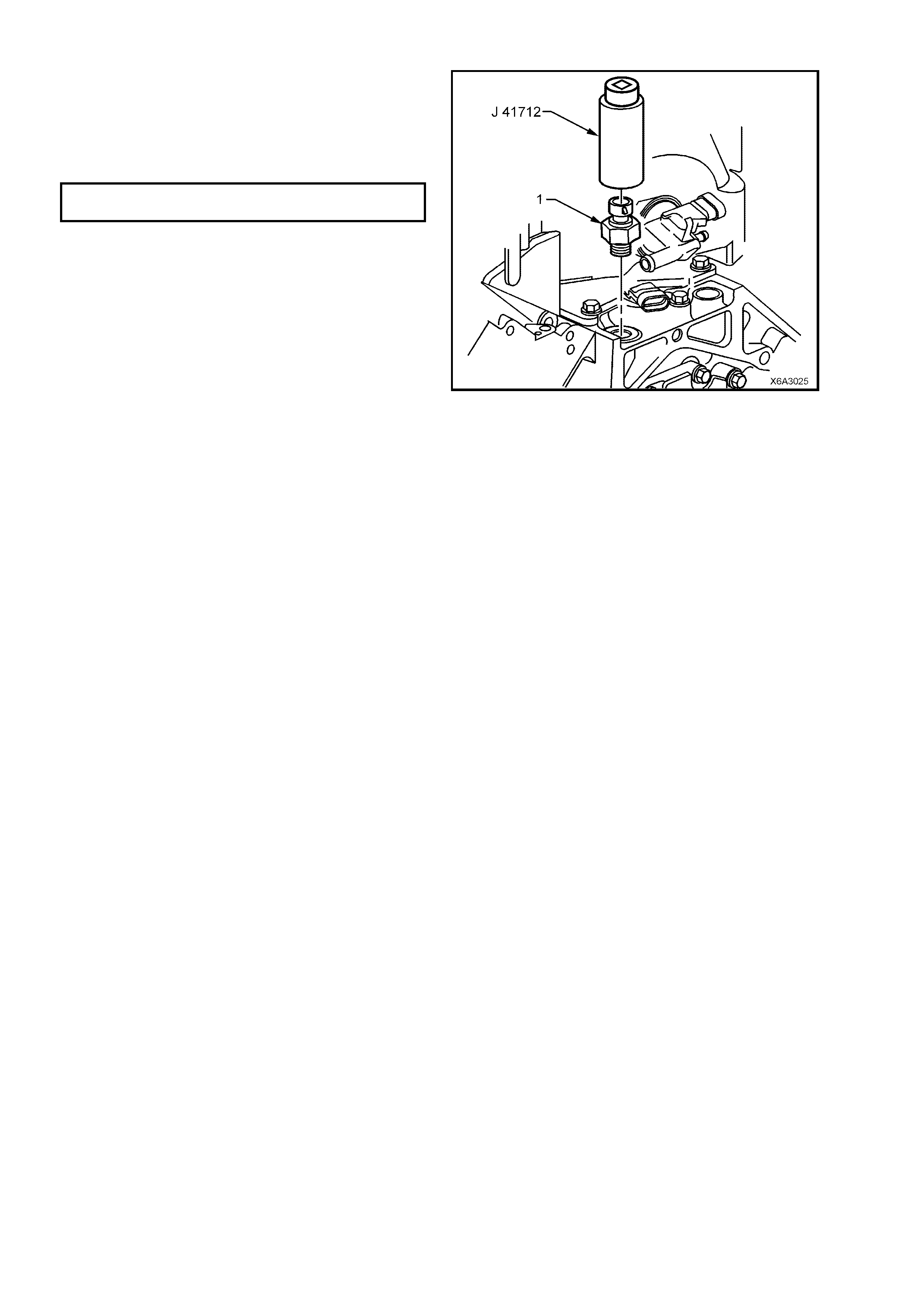
8. App l y seal ant s uch as Loc t i te 56 5 or e qui va le nt
to the cleaned threads of the oil pressure
sensor (1) and reinstall, using Tool No. J
41712 and suitable 3/8” drive socket
equipment. Tighten to the correct torque
specification.
OIL PRESSURE SENSOR
TORQUE SPECIFICATION 20 Nm
Figure 6A3-339
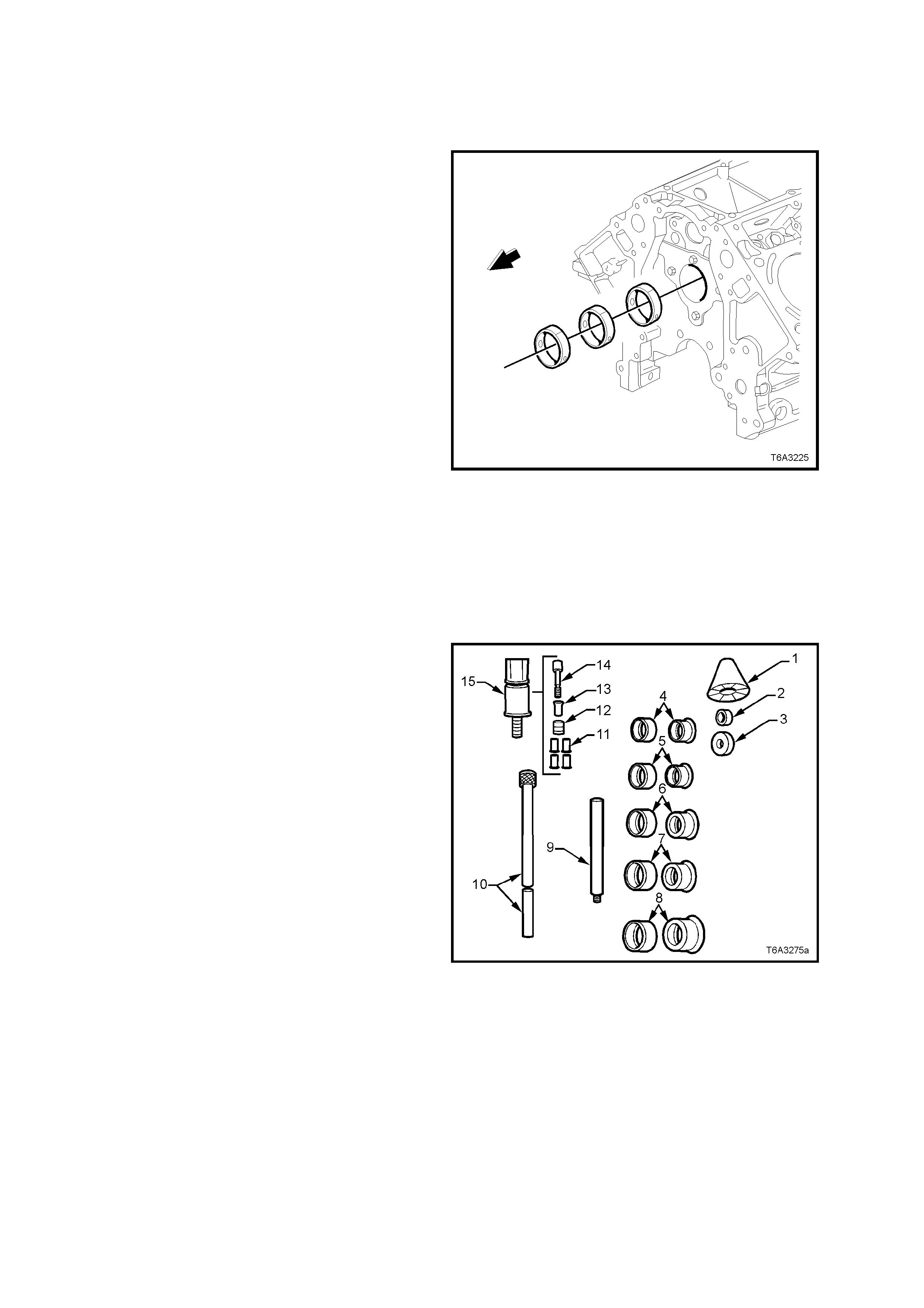
3.15 CYLINDER BLOCK
LT Section No. – 00-248
CAMSHAFT BEARINGS - REPLACE
NOTE 1: Care must be taken during bearing
removal and installation, not to damage bearings
that are not being replaced.
NOTE 2: The following operations involve the use
of universal camshaft bearing remover/installer,
Tool J 33049 and finished size camshaft bearings.
If installing unfinished size bearings, installation
must be carried out by a specialist machine shop
and then line bored to the correct finished size.
NOTE 3: While it is preferred that the camshaft
bearings are removed and installed in a bare
cylinder block, the operation can be carried out by
removing the crankshaft and the camshaft, even
though it is difficult to negotiate the tool past the
connecting rod big end journals.
The camshaft can be removed without having to
first remove the cylinder heads and hydraulic
lifters . By removi ng the push r ods and inver ting the
engine, the hydraulic lifters will drop sufficient to
clear the camshaft journals.
1. Prior to bearing removal, inspect all camshaft
bearings for a loose fit in the engine block
bearing bores .
NOTE: If a bearing is found to be loose, it may
have been caused by an enlarged, out of round or
damaged engine block bearing bore.
Figure 6A3-340
2. The universal camshaft bearing
rem over/installer, Tool J 3 3049, consis ts of the
following components;
Nylon Guide Cone (1).
Small Driving Washer (2).
Large Driving Washer (3).
Expanding Drivers and Rubber Sleeves (4 - 8).
Driver Extension Bar (9).
Driver Bar (10).
Expander Assembly (15). Consists of parts 11 -
14.
3. To replace the camshaft bearings on the GEN
III V8 engine, select the following components
from Tool J 33049:
Nylon Guide Cone (1).
Large Driving Washer (3).
Expanding Drivers and Rubber Sleeve (7).
Driver Bar (10).
Expander Assembly (15).
Figure 6A3-341
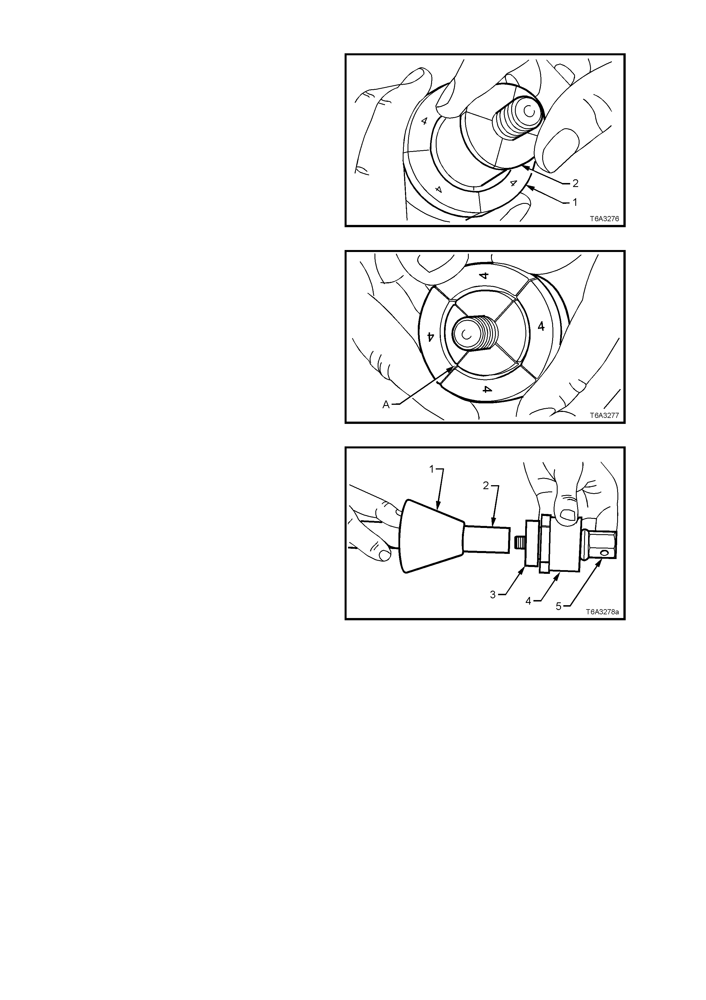
4. Install expanding driver with its rubber sleeve
(1), over the expander assembly (2), with the
numbered flanges of the expanding driver
facing the threaded end of the expander
assembly (2), as shown.
Figure 6A3-342
5. Once installed, ensure that the separations in
the expander assembly segments, are aligned
with those of the expanding driver as shown
(‘A’).
Figure 6A3-343
6. Manoeuvre the assembly into the cylinder
block, in front of the bearing to be removed,
then install the large driving washer (3) over
the threaded end of the expander assembly
(5).
7. Slide the nylon cone (1) over the driver bar (2)
with the smaller diameter toward the cylinder
block.
NOTE: The components shown in Figure 6A3-349
are shown removed from the cylinder block for
clarity.
8. Carefully insert the driving bar through the
camshaft bearings, from the front of the
cylinder block and screw the bar to the
expander assembly.
9. With the expander assembly inserted into the
camshaft bearing, hold the hexagonal end of
expander assembly (5) with a spanner and
hand tighten the driver bar until the expanding
driver (4) is tight in the bearing shell.
IMPORTANT: Do not overlook fitting the driving
washer over the threaded end of the expander
assembly before installing the driver bar.
Figure 6A3-344
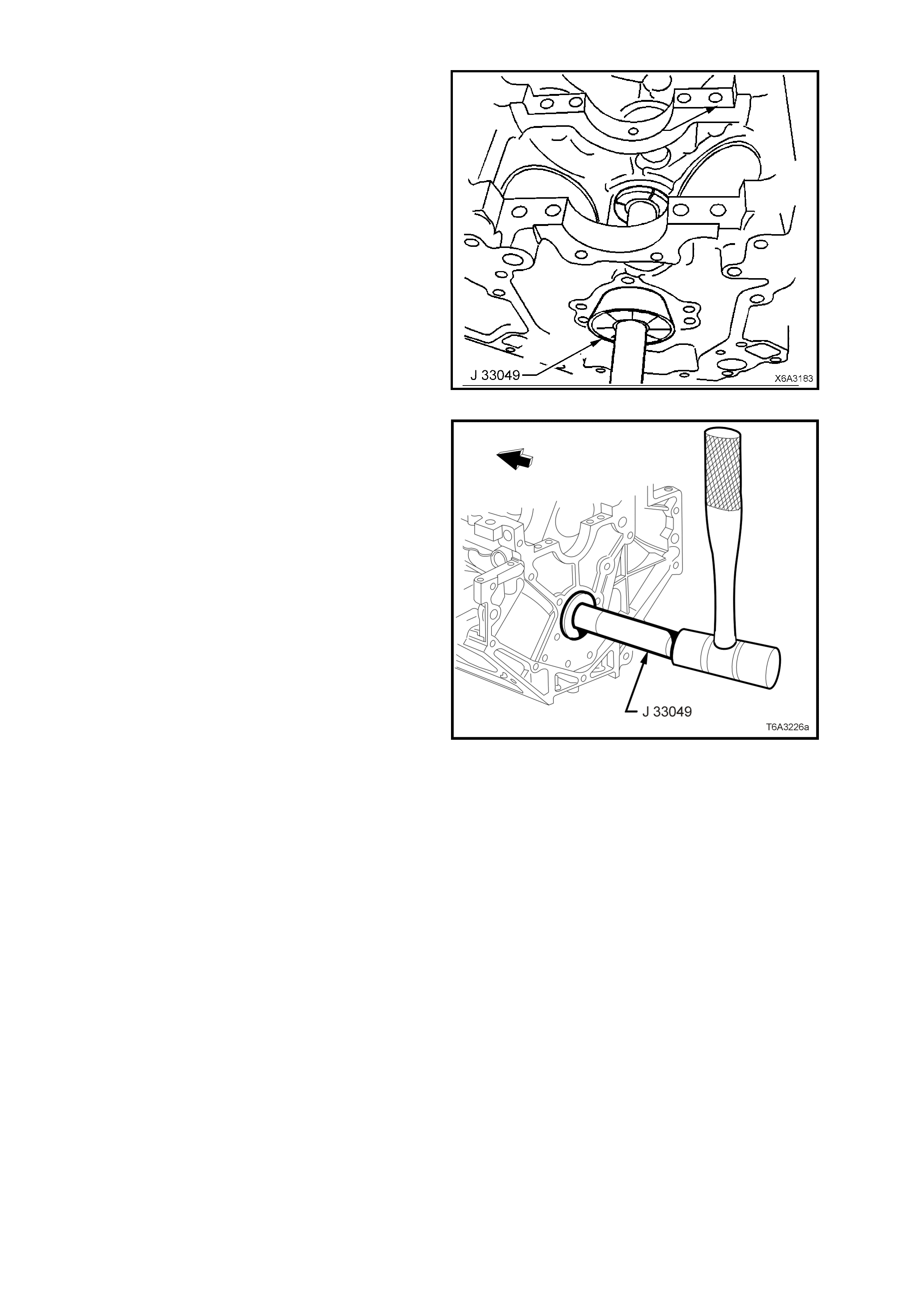
10. Push the guide cone into the front camshaft
bearing to align the driver bar.
11. W hile holding the guide cone in place with on e
hand, drive the bearing from the cylinder block.
12. Repeat this process with the remaining
bearings being removed.
Figure 6A3-345
NOTE: To remove the front bearing, install the
driver bar from the rear of the cylinder block , using
the guide cone in the rear camshaft bearing bore,
as shown in Figure 6A3-350.
Figure 6A3-346
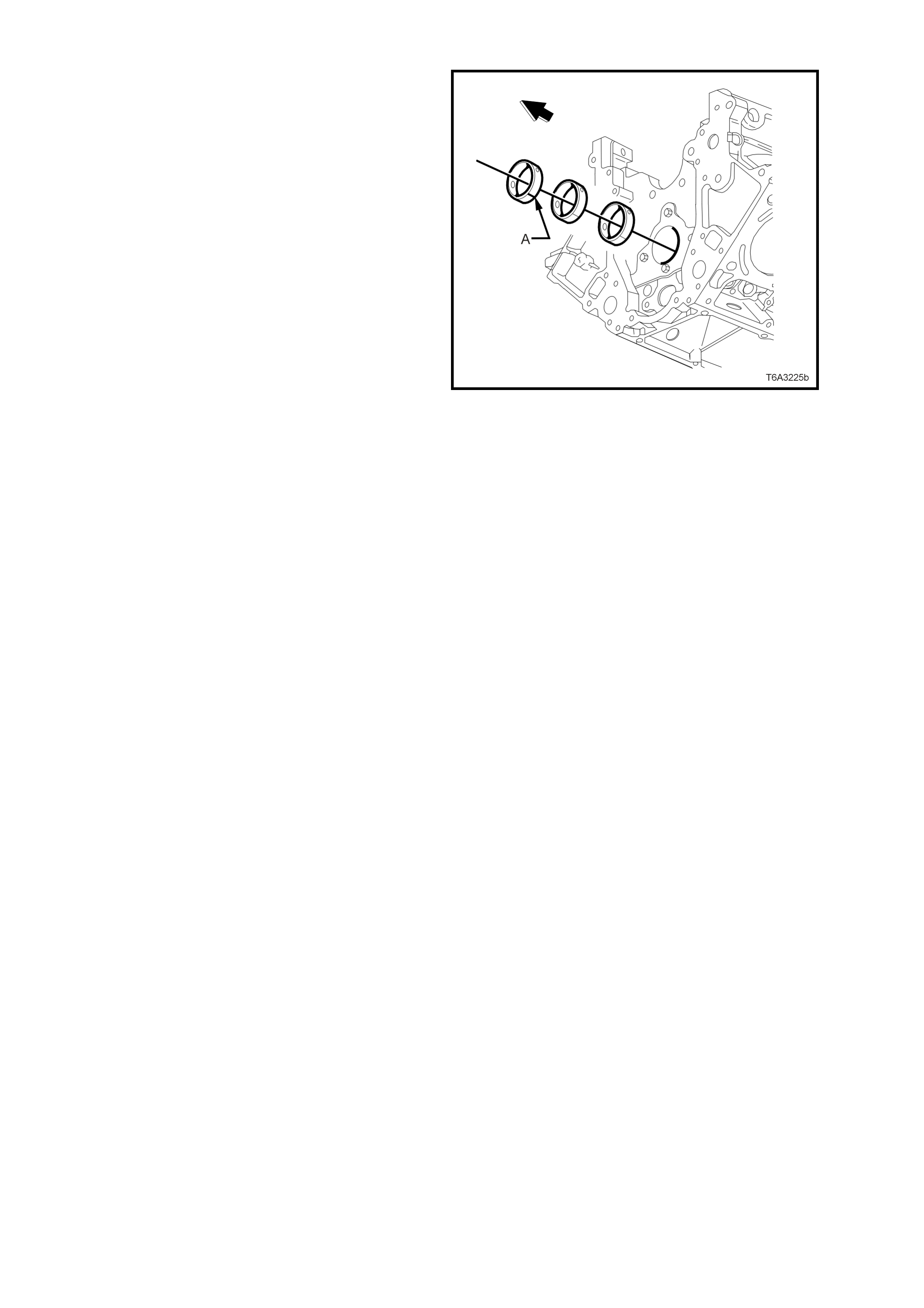
13. To install a new bearing, proceed in a similar
way to bearing removal, except for the
follo wing items :
a. The join in the new camshaft bearing (‘A’)
must be aligned with the top of the engine
block. To assist with alignment, use a felt tip
pen to mark the back of the bearing, 180°
from the join, as this will be visible when
install ing the bear ing .
b. While the o il feed is generous in length and
allows some degree of hole misalignment,
as much care as possible must be made
during installation.
c. Install each bearing until it is centrally
located in the cylinder block bore, then use
a thin piece of wire to ensure that the oil
feed passage is not obstructed in any way.
d. To install the front camshaft bearing, install
the driver bar into the rear bearing and use
the guide cone at that location.
IMPORTANT: Take care when installing the
driver bar through the newly installed bearings
to avoid damage.
Figure 6A3-347
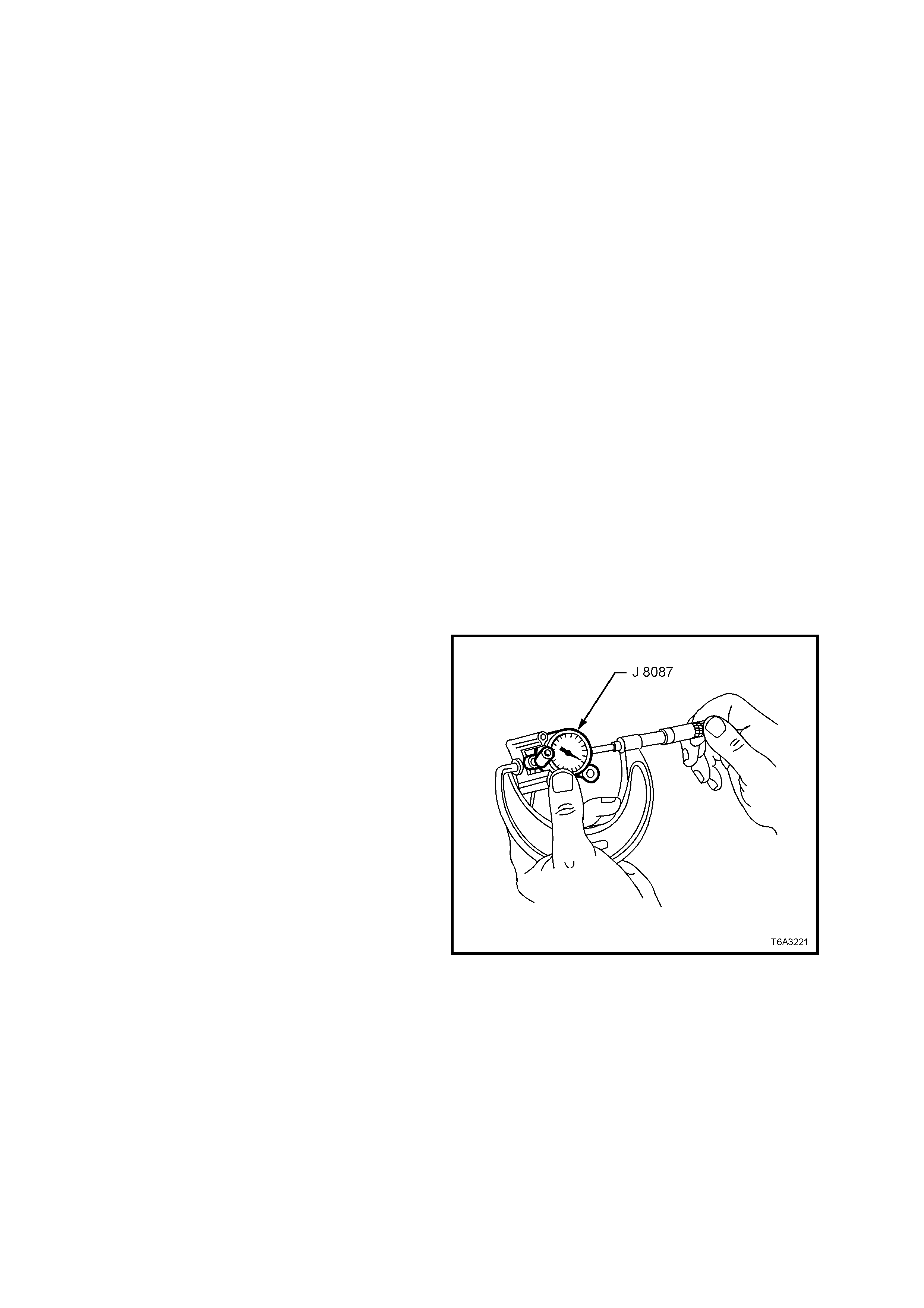
CYLINDER BLOCK, CLEAN, INSPECT AND MEASURE
Clean
NOTE 1: Do not use a caustic solution to clean the aluminium engine block.
NOTE 2: When cleaning an engine block in a thermal type oven, do not exceed 232° C.
1. Clean the engine block in a suitable solvent, to remove all sludge, dirt, or debris.
2. Dry the block with compressed air.
CAUTION: Wear safety glasses to avoid eye injury.
3. Clean all gasket surfaces, taking care to only use a plastic scraper to avoid damaging machined surfaces.
4. After removing all engine block plugs (Refer 3.14 ENGINE BLOCK PLUGS, in this Section), clean all coolant
passages and oil galleries.
5. Clean the main bearing caps, taking care not to mix them from their original order.
6. Clean a ny res idue of c ylinder hea d bo lt thre ad se alant fr om the c ylinder b lock threads , us ing ins taller, Tool No.
J-42385-107 (this tool is part of the thread repair kit, J-42385).
IMPORTANT: Do not use anything but this thread tool to clean the cylinder head threads in the cylinder block.
7. Use compressed air to clean all residue from bolt holes.
CAUTION: Wear eye protection to prevent injury.
Inspect
Inspect the following areas:
1. The cylinder walls for excessive scratches, gouging, or ring ridge.
2. The coolant jacket for cracks.
3. The valve lifter bores for excessive scoring or wear.
4. The crankshaft bearing webs for cracks.
5. The gasket sealing surfaces for excessive scratches or gouging.
6. The oil galleries for restrictions.
7. All threaded bolt holes for damage.
Measure Cyli nder Bore
1. Adjust the micrometer to 96.0 mm.
2. Insert the bore gauge into the micrometer and
zero the bore gauge dial, Tool J 8087 (or
commercial equivalent).
Figure 6A3-348
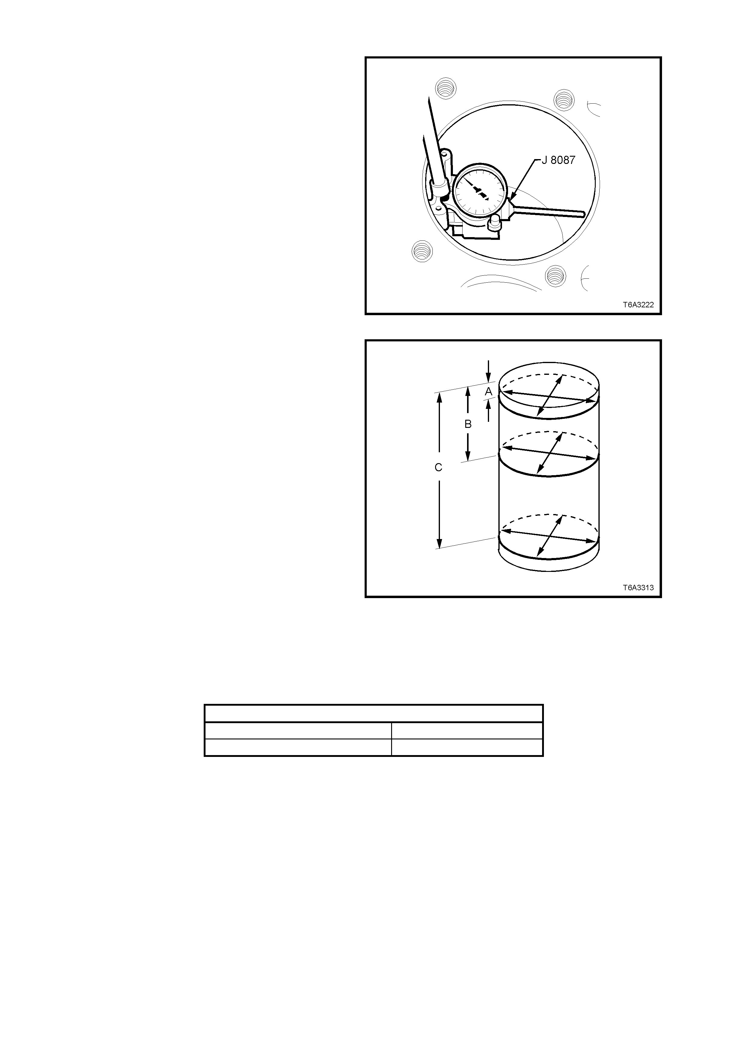
3. Use a bore gauge and measure the cylinder
bore for taper.
• Slide the bore gauge up and down
throughout the length of the cylinder bore.
Check the bore both parallel and
perpendicular to the centreline of the
crankshaft.
• Recondition cylinders with less than 0.018
mm taper with a hone. Refer CYLINDER
BORING AND HONING, in this Section.
• Cylinders with more than 0.018 mm taper
must be fitted with an oversize piston.
Figure 6A3-349
4. Use a bore gauge and measure the cylinder
bore for out-of-round:
• Measure the bore, both in line with the
centreline and perpendicular to the engine
centreline . Chec k for bore out- of - round at a
depth of 9 mm (‘A’), 57 mm (‘B’) and 127
mm (‘C’) from the cylinder head surfaces.
• Calculate the difference between the two
measurements at each location. The
results will indicate any out-of-round bore
condition.
• Cylinders with more than 0.18 mm out-of-
round must be honed and fitted with an
oversi ze piston.
Figure 6B3-350
Measure En gine Bl oc k Cylinder Head Deck
1. Using a straight edge and feeler gauges, check the flatness of the engine block, cylinder head deck surfaces.
If found to be outside specification, the engine block must be replaced, as machining is not recommended.
Engine Block Cylinder Head Flatness Specification
Measured within a 150 mm area 0.11 mm Maximum
Measured over block length 0.22 mm Maximum
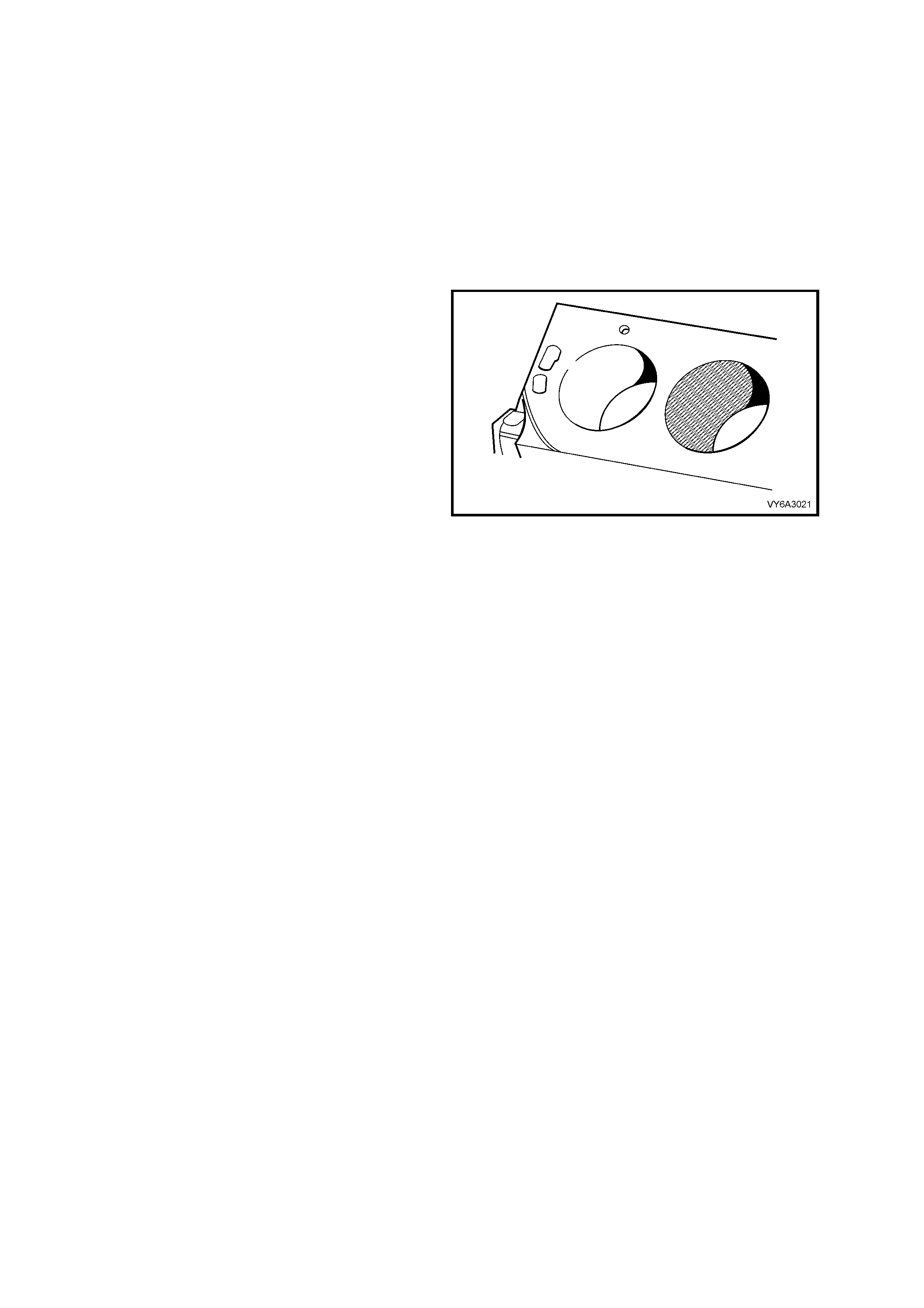
CYLINDER BORING AND HONING
Boring Proc edure
1. Oversize service piston and piston ring sets
are available in 0.25 mm.
IMPORTANT: GEN III V8 cylinder boring is not
permitted.
2. It is recommended to hone the cylinder to
achieve proper f it for the o vers ize pisto n. Refer
to the CYLINDER HONING PROCEDURE for
the proper honing information.
Honing Proced ur e
1. When honing the cylinders, follow the
manufacturer's recommendations for
equipment use, cleaning, and lubrication. Use
only clean, sharp stones of the proper grade
for the amount of material you remove. Dull,
dirty stones cut unevenly and generate
excessive heat. Do not hone to final clearance
with a coarse or medium-grade stone. Leave
sufficient metal so that a ll stone marks m ay be
removed with fine-grade stones. Perform final
honing with a fine-grade stone, honing the
cylinder to the proper clearance.
2. During the honing operation, thoroughly clean
the cylinder bore. Repeatedly check the
cylinder bore for f it with the s elected pis ton. All
measurements of the piston or the cylinder
bore should be made with the components at
normal room temperature.
3. When honing a cylinder for fit to an oversize
piston, f irst perform the preliminar y ho ning with
a 100 grit stone.
Figure 6A3-351
4. Perform final cylinder honing with a 240 grit stone and obtain a 45 degree cross hatch pattern.
5. A 240 grit stone is preferred for final honing. If a 240 grit stone is not available, a 220 grit stone may be used as
a substitute.
6. When honing to eliminate taper in the cylinder, make full strokes for the complete bore length. Repeatedly
check the measurement at the top, the middle, and the bottom of the bore.
7. The finis h marks should be clean b ut not sharp. T he finish m ark s should also b e free fr om embedded p articles
and torn or folded metal.
8. By measurin g the select ed piston at the sizi ng point a nd by addin g the aver age of the c learance spec ificati on,
the final cylinder honing dimension required, can be determined.
9. When finished, the reconditioned cylinder bores should have less than or meet the specified out-of-round and
taper requirements.
10. After f inal ho nin g a nd bef or e th e p ist on is c hec ked for fit, c lean th e cylinder bor es with hot water an d d eter g e nt.
Scrub the bores with a stiff bristle brush and rinse the bores thoroughly with hot water. Do not allow any
abrasive m ater ial to rem ain in the c ylinder b ores . This abrasive m aterial m a y cause prem ature we ar of the ne w
piston rings and the cylinder bores. Abrasive material will also contaminate the engine oil and may cause
premature wear of the bearings. After washing the cylinder bore, dry the bore with a clean rag.
11. Perform final measurements of the piston and the cylinder bore.
12. Permanently mark the top of the piston for the specific cylinder to which it has been fitted.
13. Apply clean engine oil to each cylinder bore in order to prevent rusting.
Deglazing Procedure
Using a ball type or self centring honing tool, deglaze the cylinder bore lightly. Deglazing should be done only to
remove any deposits that may have formed. Use a 240 grit stone of silicone carbide or equivalent material when
performing the deglazing procedure.
A 240 grit s tone is preferred f or final honing. If a 240 grit stone is not av ailable, a 220 grit s tone ma y be us ed as a
substitute.
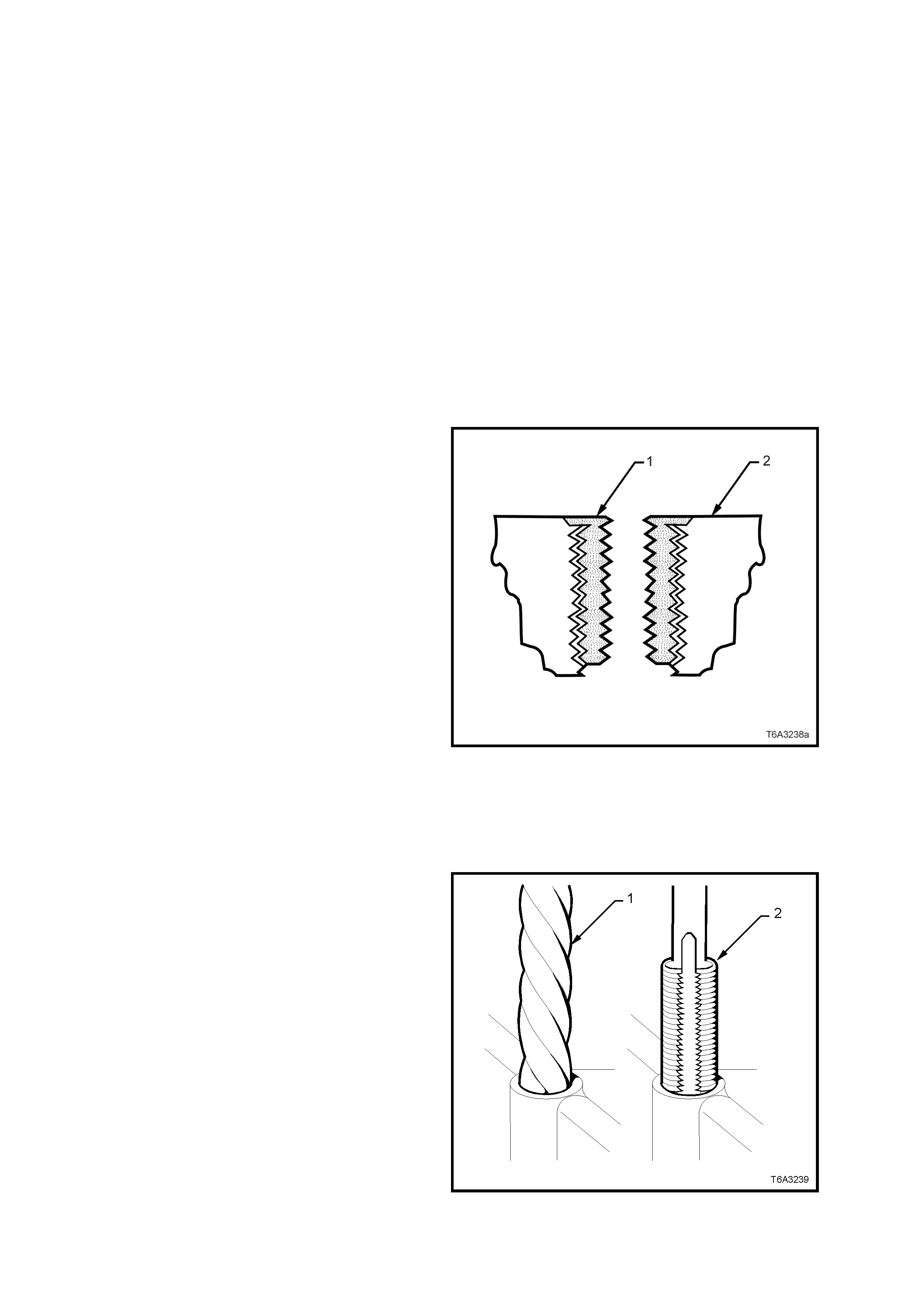
3.16 THRE AD REPAIR
GENERAL INFORMATION
With the extensive use of aluminium alloy in the
construction of the GEN III V8 engine, thread
repair skills are required to repair damaged threads
caused by careless handling or over-torquing of
fasteners.
This Section describes the recommended method
of repairing threads in three specific areas of the
engine;
• General Thread Repair.
• Cylinder Head Bolt Hole Thread Repair.
• Main Cap Bolt Hole Thread Repair.
Detailed descriptions of all thread specifications
used in this engine are listed in 3.17 THREAD
REPAIR SPECIFICATIONS in this Section,
contains .
The available Thread Repair Kit, Tool J
42385/100/200/ 300, uses the Time Sert thread
repair process that involves a solid, thin walled,
self-locking, carbon steel, bushing type insert (1).
During the bushing installation process, the driver
tool expands the bottom external threads of the
insert into the base material (2). This action
mechanically locks the insert in place.
Also, when installe d to the proper de pth, the flang e
of the insert will be seated against the counterbore
of the repaired hole.
CAUTION: Wear safety glasses to avoid eye
injury.
IMPORTANT: The use of a cutting type fluid GM
P/N 1052864, (or WD 40, or equivalent) is
recommended when performing the drilling,
counter-boring, and tapping procedures.
Driver oil MUST be used on the installer driver tool.
The tool kits are designed for use with either a
suitable tap wr enc h or dri ll motor.
Figure 6A3-352
GENERAL THREAD REPAIR
1. Drill out the t hreads of the dam aged hole (1) to
the correct depth for the thread being repaired:
• M6 inserts require a minimum drill depth of
15 mm.
• M8 inserts require a minimum drill depth of
20 mm.
• M10 inser ts requir e a minimum dr ill de pth of
23.5 mm.
2. Using compressed air, clean out any chips.
CAUTION: Wear safety glasses to avoid eye
injury.
Figure 6A3-353
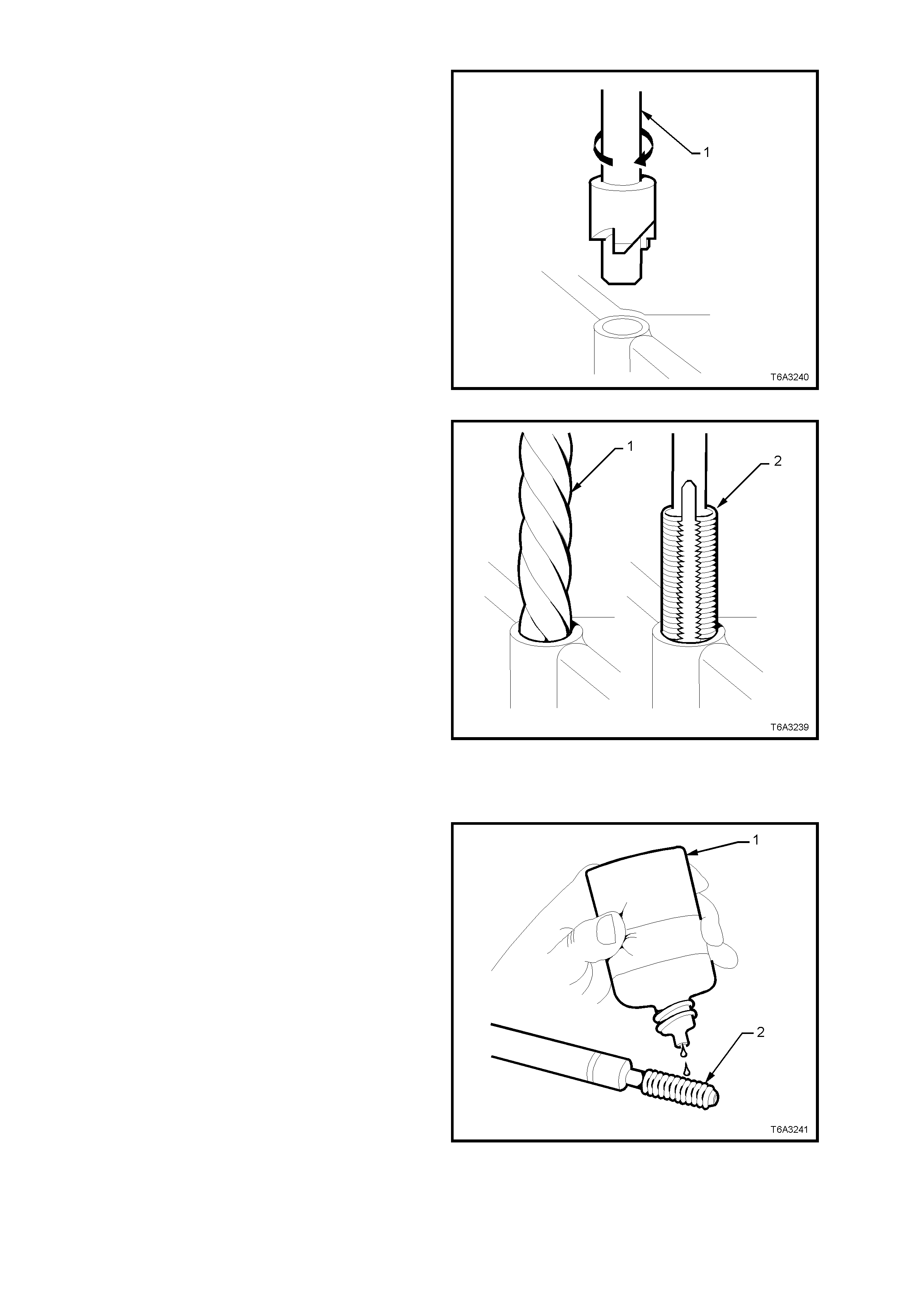
3. Counterbore the hole to the full depth permitted
by the tool (1).
4. Using compressed air, clean out any chips.
CAUTION: Wear safety glasses to avoid eye
injury.
Figure 6A3-354
5. Using a tap wrench (2), tap the threads of the
drilled hole to the correct depth for the thread
being repaired.
• M6 inserts require a minimum tap depth of
15 mm.
• M8 inserts require a minimum tap depth of
20 mm.
• M10 inser ts requ ire a m inim um tap depth of
23.5 mm.
6. Using compressed air, clean out any chips.
7. Spray a suitable cleaner such as GM P/N
12346139, P/N 12377981 or equivalent, into
the hole.
IMPORTANT: Do n ot use any cleani ng agents tha t
contain Trichloralethane, as this is harmful to
aluminium.
8. Using compressed air, clean any cutting oil and
chips out of the hole.
CAUTION: Wear safety glasses to avoid eye
injury.
Figure 6A3-355
9. Lubricate the threads of the installer tool (2)
with the driver oil ( 1).
IMPORTANT: Do not allow oil or other foreign
material to contact the outside diameter (OD) of the
insert.
Figure 6A3-356
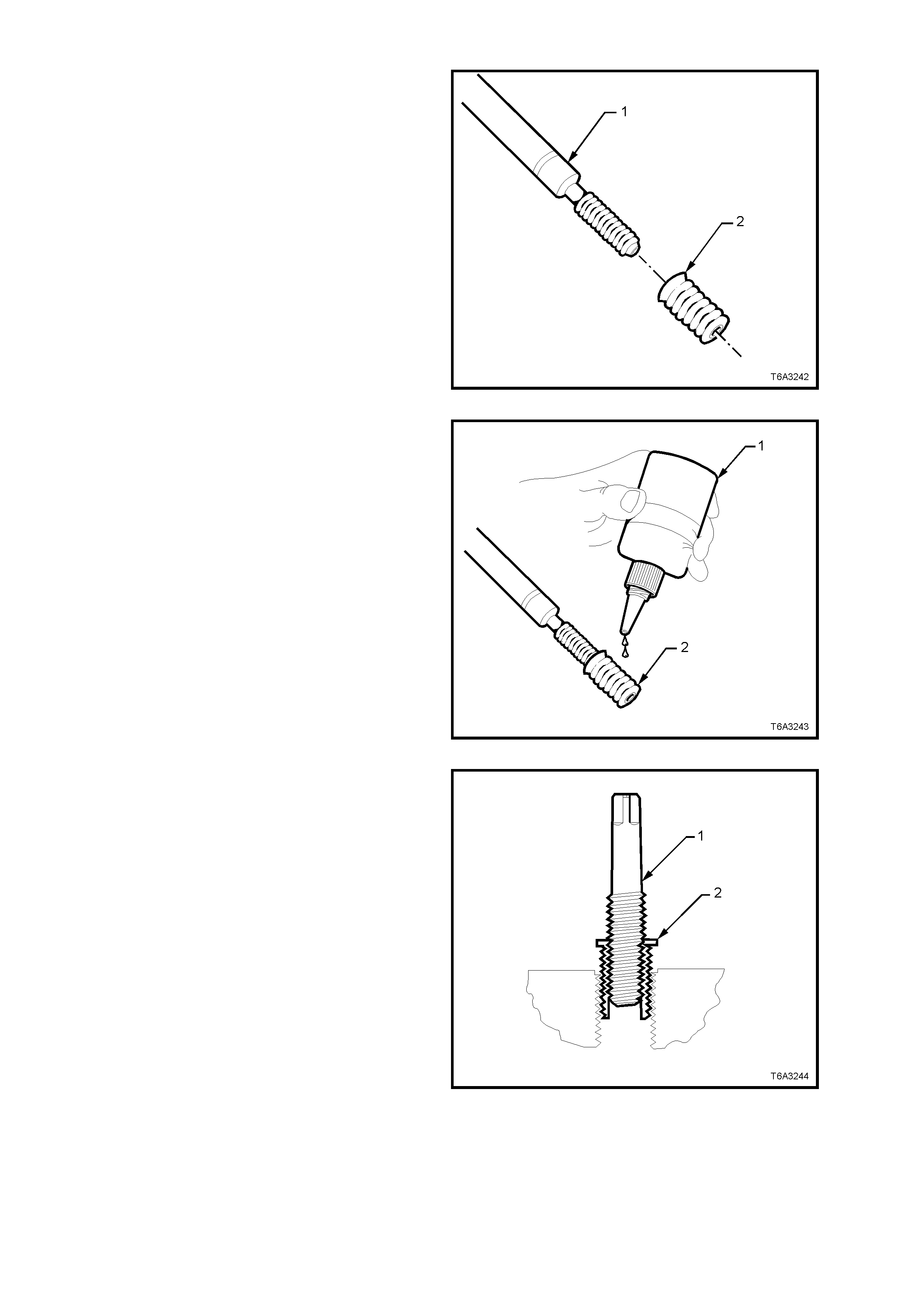
10. Install the insert (2) onto the driver tool (1).
Figure 6A3-357
11. Apply threadlock Loctite 272 (1) or equivalent
(GM P/N 12345493) to the insert OD threads
(2).
Figure 6A3-358
12. Using the installer tool (1), install the insert (2)
into the hole.
13. Continue to install the insert until the flange of
the insert contacts the counter-bored surface.
14. Continue to rotate the installer tool (1) through
the insert. The installer tool (1) will tighten up
before screwing completely through the insert.
This is normal since the bottom threads of the
insert are being formed and mechanically
locked into the hole.
15. Remove the driver. The repair is complete.
Figure 6A3-359
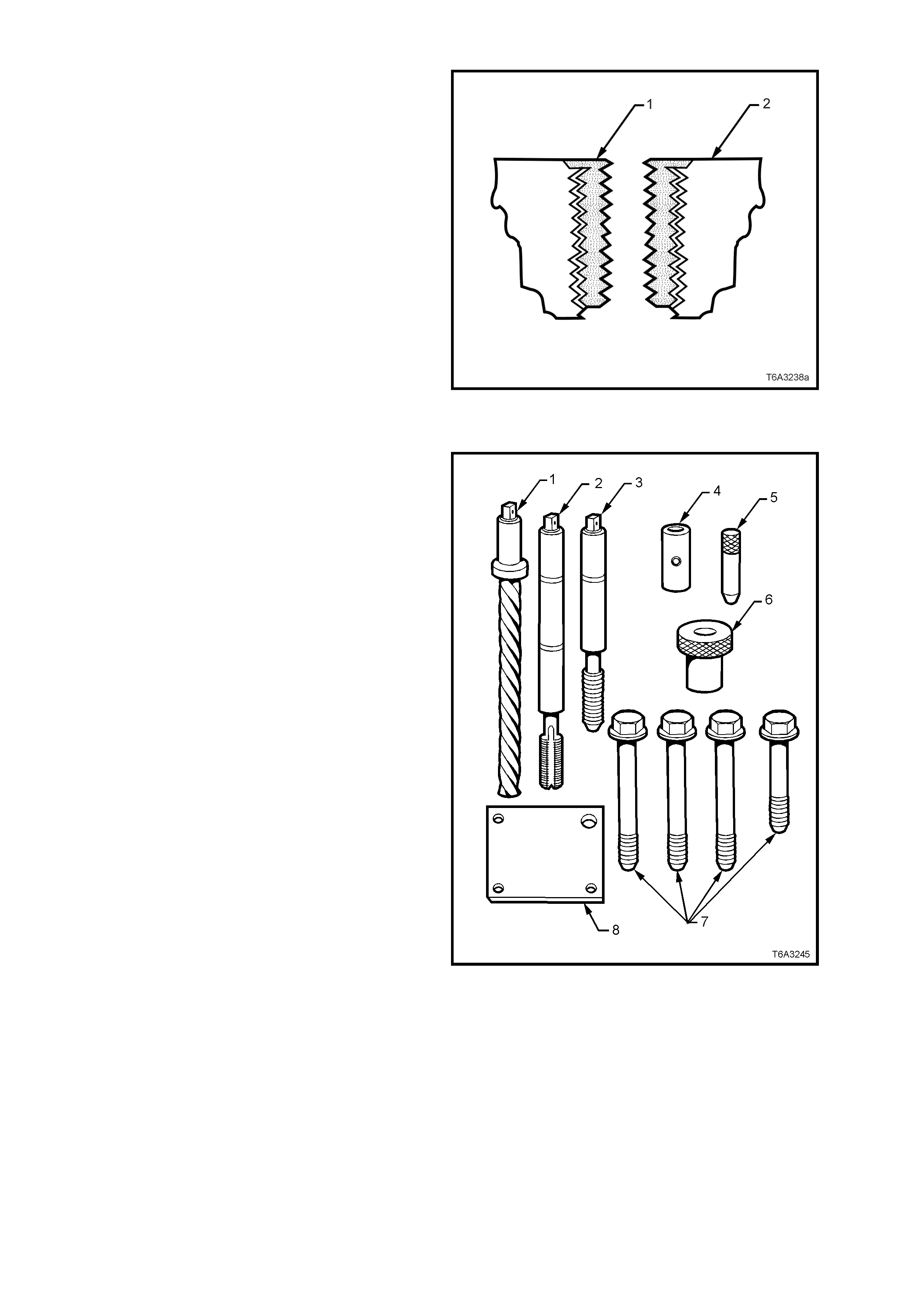
16. Ins pect t he ins ert f or pr oper ins tallati on int o the
hole.
17. A properly installed insert (1) will be either flush
or slightly below flush with the surface of the
base material (2).
Figure 6A3-360
CYLINDER HEAD BOLT HOLE THREAD REPAIR
The cylinder head bolt hole thread repair kit
consists of the following items:
1. Drill
2. Tap
3. Installer
4. Sleeve
5. Alignment Pin
6. Bushing
7. Bolts
8. Fixture Plate
Figure 6A3-361
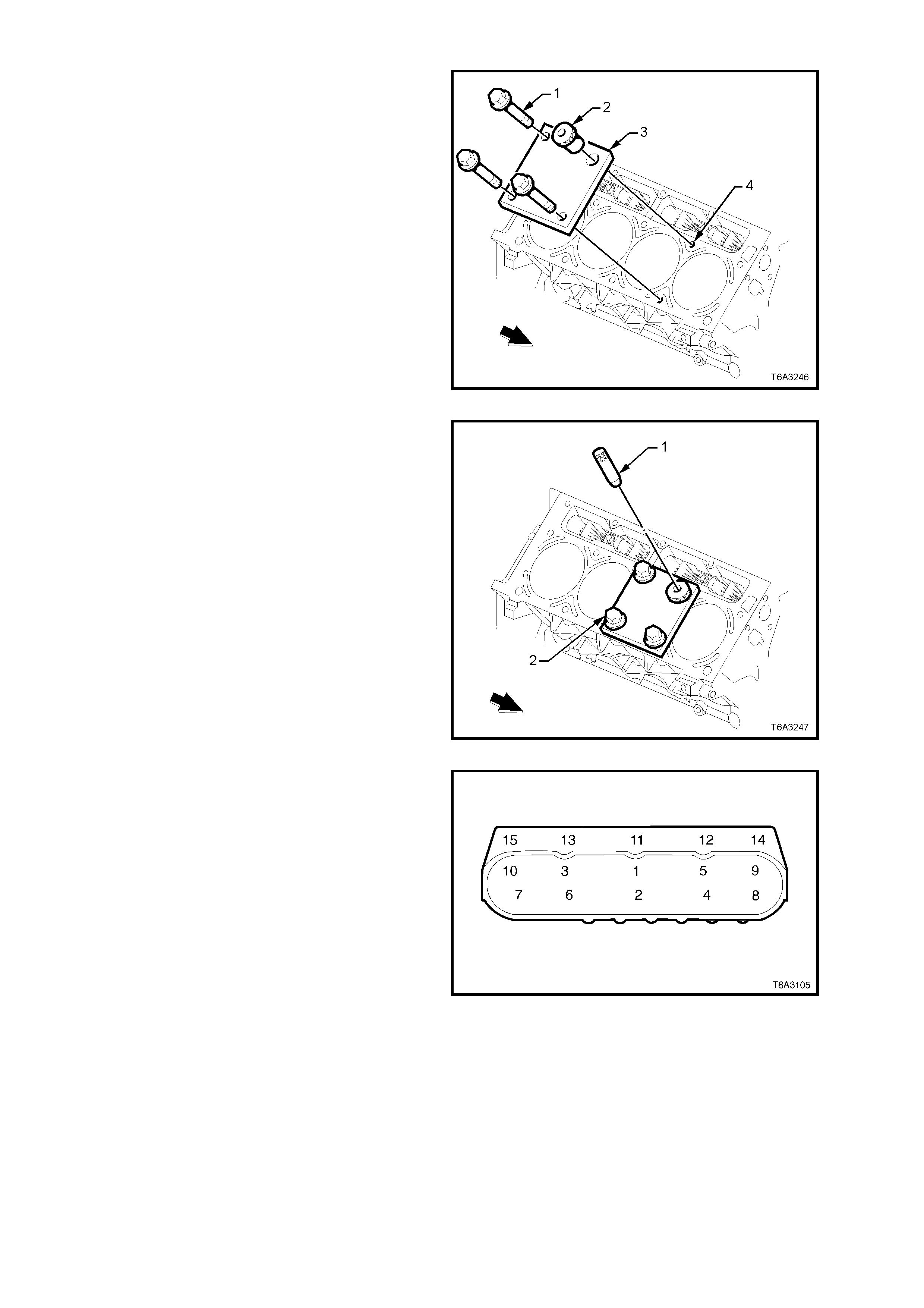
CAUTION: Wear safety glasses to avoid eye
injury.
IMPORTANT: The use of a cutting type fluid GM
P/N 1052864, (or WD 40, or equivalent) is
recommended when performing the drilling,
counter-boring, and tapping procedures.
Driver oil MUST be used on the installer driver tool.
The tool kits are designed for use with either a
suitable tap wr enc h or dri ll motor.
1. Install the fixture plate (3), bolts (1), and
bushing (2) onto the engine block deck.
2. Position the fixture plate and bushing over the
hole that is to be repaired (4).
Figure 6A3-362
3. Position the alignment pin (1) through the
bushing and into the hole.
4. With the alignment pin in the desired hole,
tighten the fixture retaining bolts (2).
5. Remove the alignment pin from the hole.
Figure 6A3-363
6. Cylinder head bolt holes 1-8 are the deep
holes and will be dr illed without the dr il l slee ve.
7. C ylinder h ead b olt ho les 9 and 10 ar e the more
shallow holes, so drilling MUST be done with
the drill sleeve in place
Figure 6A3-364
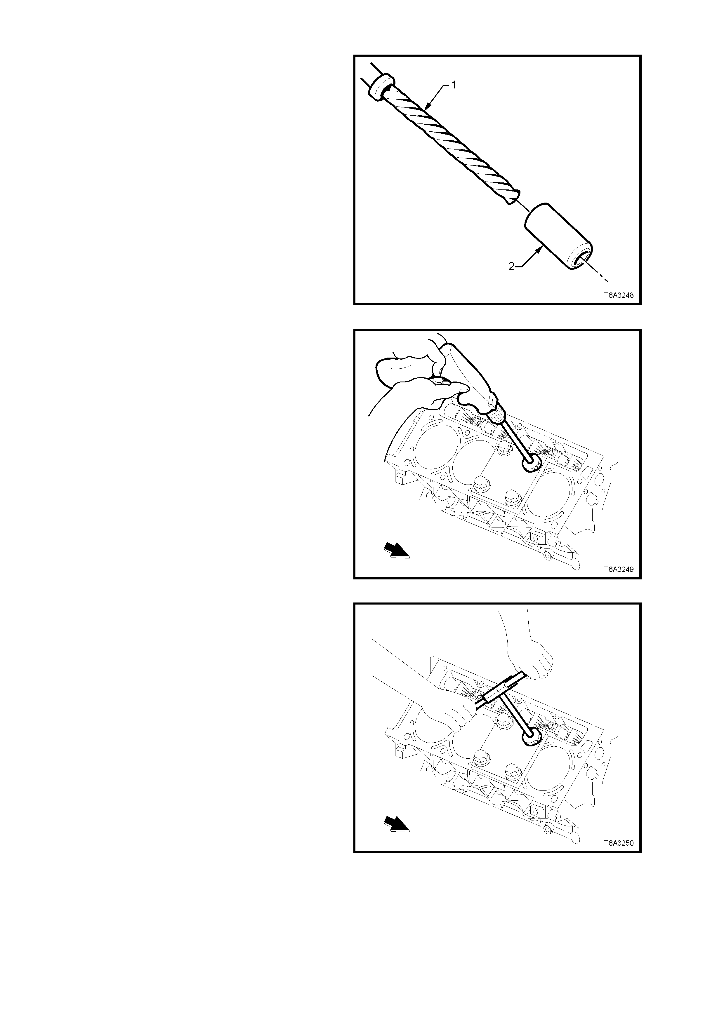
8. Install the sleeve (2) onto the drill (1) (if
required).
Figure 6A3-365
9. Drill out the threads of the damaged hole.
10. Drill the hole until the stop collar of the drill bit
or the sleeve contacts the bushing.
11. Using compressed air, clean out any chips.
CAUTION: Wear safety glasses to avoid eye
injury.
Figure 6A3-366
12. Using a tap wrench, tap the threads of the
drilled hole.
Figure 6A3-367
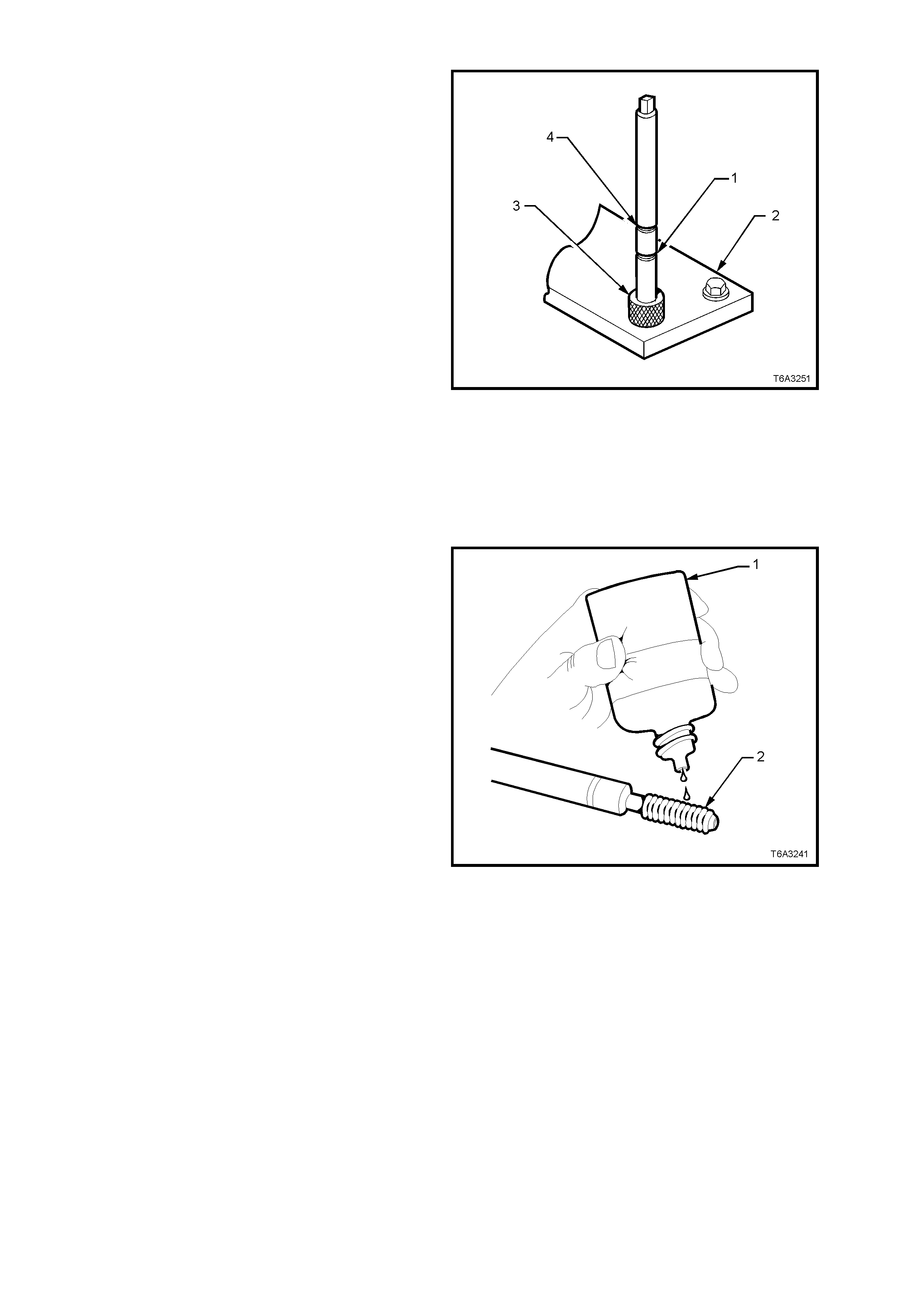
13. In order to tap the new threads to the proper
depth, rotate the tap into the hole until the
marks (1 or 4) on the tap align with the top of
the drill bushing (3), as follows:
• For the deeper cylinder head bolt holes (1-
8), rotate the t ap unt il th e u pper mark on the
tap (4) aligns with the top of the drill
bushing.
• For the shallower cylinder head bolt holes
(9 and 10), rotate the tap until the lower
mark on the tap (1) aligns with the top of the
drill bushing.
14. Remove the fixture plate (2), bushing (3), and
bolts.
15. Using compressed air, clean out any chips.
16. Spray a suitable cleaner such as GM P/N
12346139, P/N 12377981 or equivalent, into
the hole.
IMPORTANT: Do n ot use any cleani ng agents tha t
contain Trichloralethane, as this is harmful to
aluminium.
17. Using compressed air, clean any cutting oil and
chips out of the hole.
CAUTION: Wear safety glasses to avoid eye
injury.
Figure 6A3-368
18. Lubricate the threads of the installer tool (2)
with the driver oil ( 1).
IMPORTANT: Do not allow oil or other foreign
material to contact the outside diameter (OD) of the
insert.
Figure 6A3-369
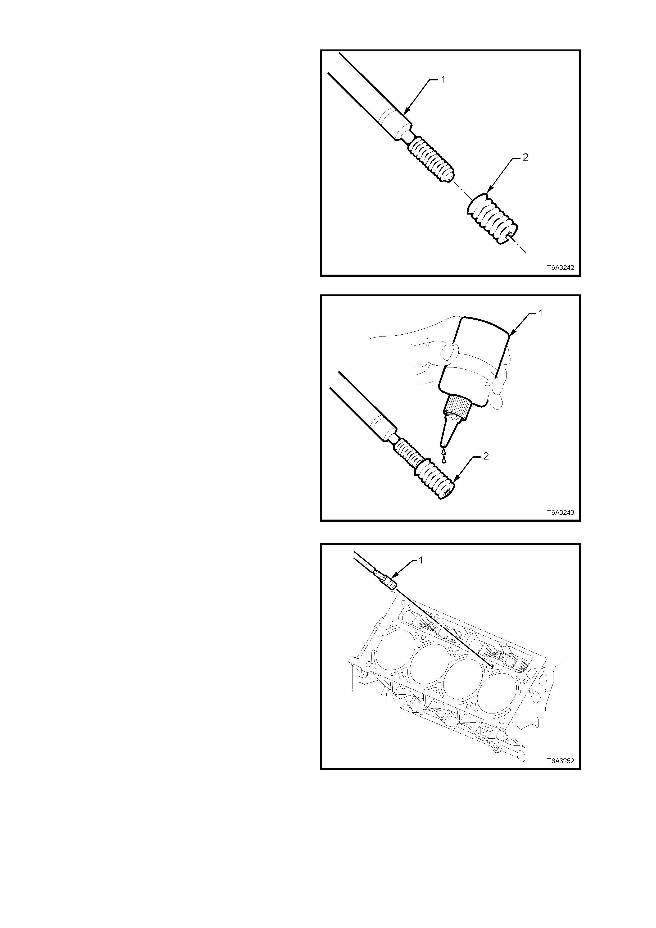
19. Install the insert (2) onto the driver tool (1).
Figure 6A3-370
20. Apply threadlock Loctite 272 (1) or equivalent
(GM P/N 12345493) to the insert OD threads
(2).
Figure 6A3-371
21. Install the insert and driver (1) into the hole.
22. Continue to install the insert until the flange of
the insert contacts the counter-bored surface.
23. Continue to rotate the installer tool (1) through
the insert. The installer tool (1) will tighten up
before screwing completely through the insert.
This is normal since the bottom threads of the
insert are being formed and mechanically
locked into the hole.
24. Remove the driver. The repair is complete.
Figure 6A3-372
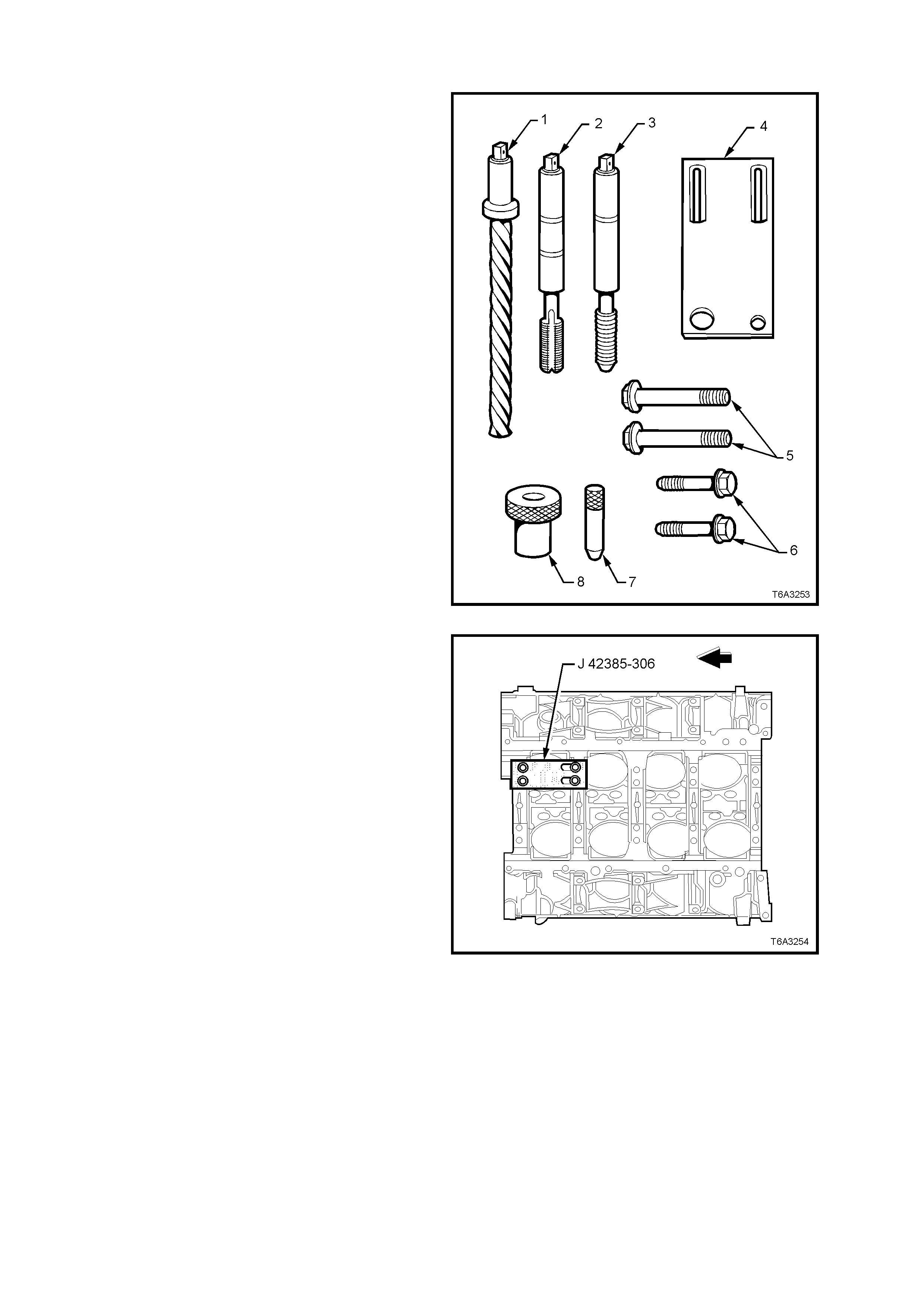
MAIN CAP BOLT HOLE THREAD REPAIR
The m ain cap bolt hole thr ead repair k it consists of
the following items:
1. Drill
2. Tap
3. Installer
4. Fixture Plate
5. Long Bolts
6. Short Bolts
7. Alignment Pin
8. Bushing
Figure 6A3-373
CAUTION: Wear safety glasses to avoid eye
injury.
IMPORTANT: The use of a cutting type fluid GM
P/N 1052864, (or WD 40, or equivalent) is
recommended when performing the drilling,
counter-boring, and tapping procedures.
Driver oil MUST be used on the installer driver tool.
The tool kits are designed for use with either a
suitable tap wr enc h or dri ll motor.
1. Position the fixture plate and bushing over the
hole that is to be repaired. Position the
alignment pin in the desired hole and tighten
the fixture retaining bolts.
Figure 6A3-374
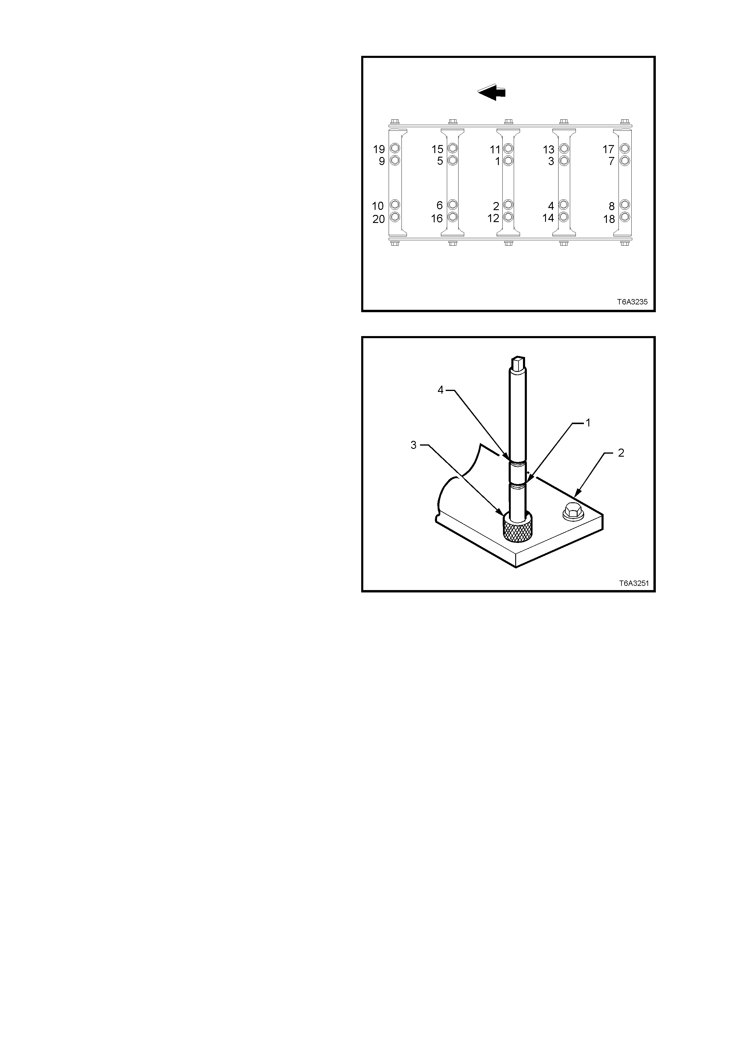
2. Drill out the damaged hole.
NOTE: The outer bolt hole locations (11-20) have
the shallower counter-bores. Use bushing (8), J
42385-316 with the drill.
3. Drill until the stop collar of the drill bit or the
sleeve contacts the bushing.
4. Using compressed air, clean out any chips.
CAUTION: Wear safety glasses to avoid eye
injury.
Figure 6A3-375
5. In order to tap the new threads to the proper
depth, rotate the tap into the hole until the
marks (1 or 4) on the tap align with the top of
the drill bushing (3), as follows:
• For the deeper main cap holes (1-10),
rotate the tap until the upper mark (4) on
the tap aligns with the top of the bushing
(3).
• For the shallower main cap holes (11-20),
rotate the tap until the lower mark (1) on
the tap aligns with top of the bushing (3).
6. Remove the fixture plate (2), bushing (3), and
bolts.
7. Using compressed air, clean out any chips.
8. Spray a suitable cleaner such as GM P/N
12346139, P/N 12377981 or equivalent, into
the hole.
IMPORTANT: Do n ot use any cleani ng agents tha t
contain Trichloralethane, as this is harmful to
aluminium.
9. Using compressed air, clean any cutting oil and
chips out of the hole.
CAUTION: Wear safety glasses to avoid eye
injury.
Figure 6A3-376
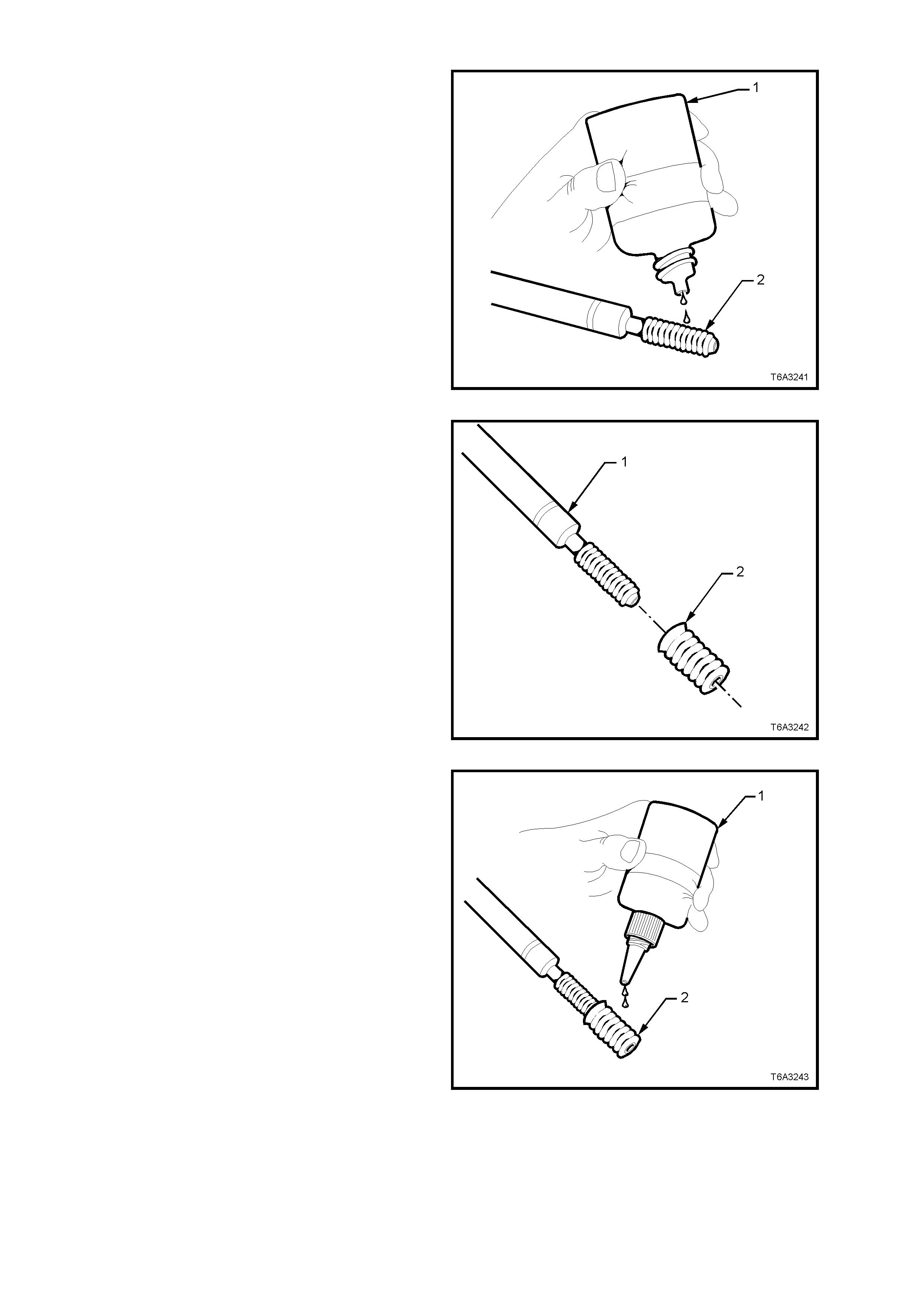
10. Lubricate the threads of the installer tool (2)
with the driver oil ( 1).
IMPORTANT: Do not allow oil or other foreign
material to contact the outside diameter (OD) of the
insert.
Figure 6A3-377
11. Install the insert (2) onto the driver tool (1).
Figure 6A3-378
12. Apply threadlock Loctite 272 (1) or equivalent
(GM P/N 12345493) to the insert OD threads
(2).
Figure 6A3-379
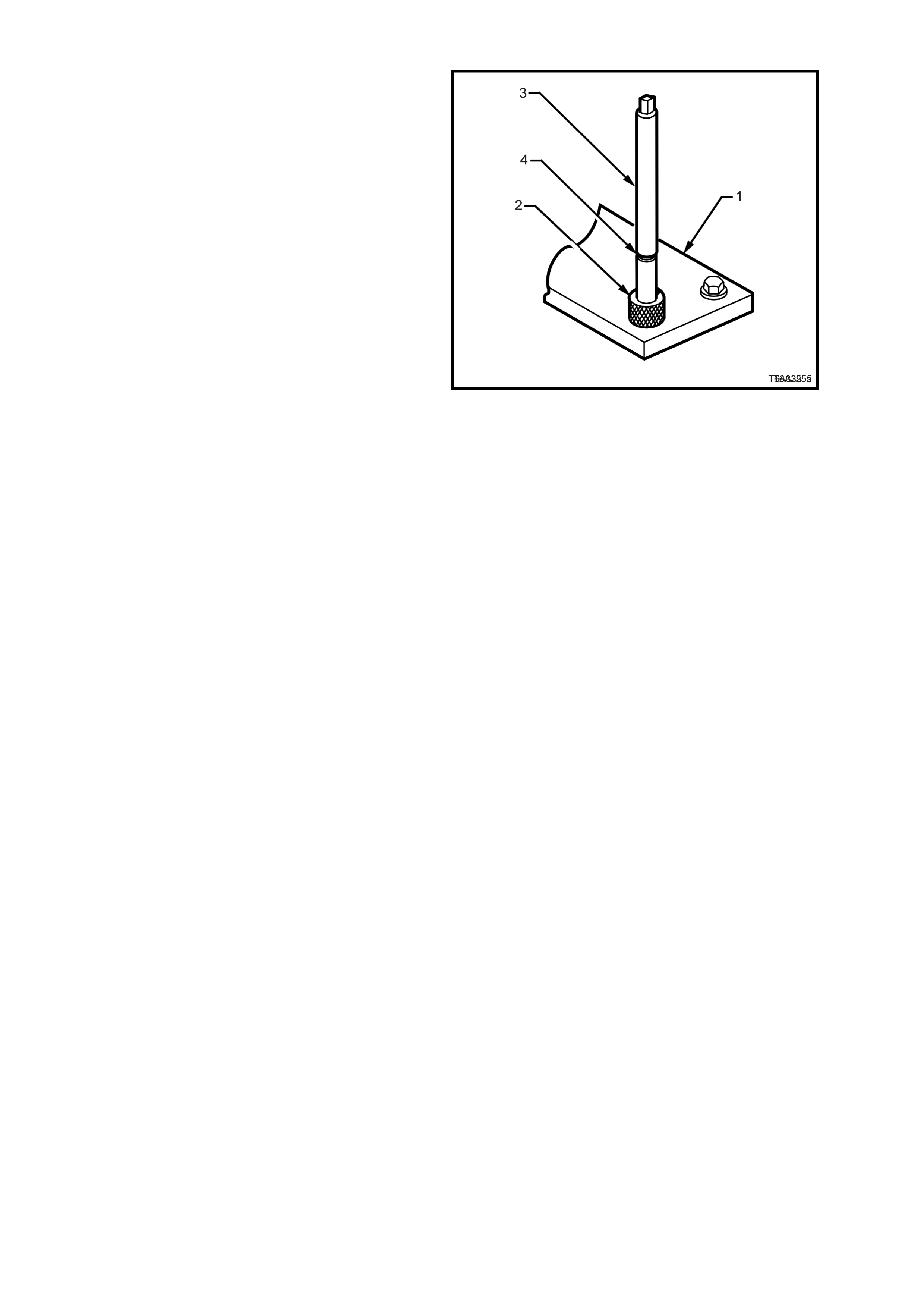
IMPORTANT: T he fixture plate ( 1) and bushin g (2)
remains installed onto the engine block during the
insert installation procedure.
13. Install the insert and driver (3) through the
fixtur e plate and bushi ng a nd into the ho le.
14. Rotate t he driver too l until the m ark on the tool
(4) aligns with the top of the bushing (2).
NOTE: The installer tool will tighten up before
screwing completely through the insert. This is
normal since the bottom threads of the insert are
being formed and mechanically locked into the
hole.
15. Remove the driver. The repair is complete.
Figure 6A3-380
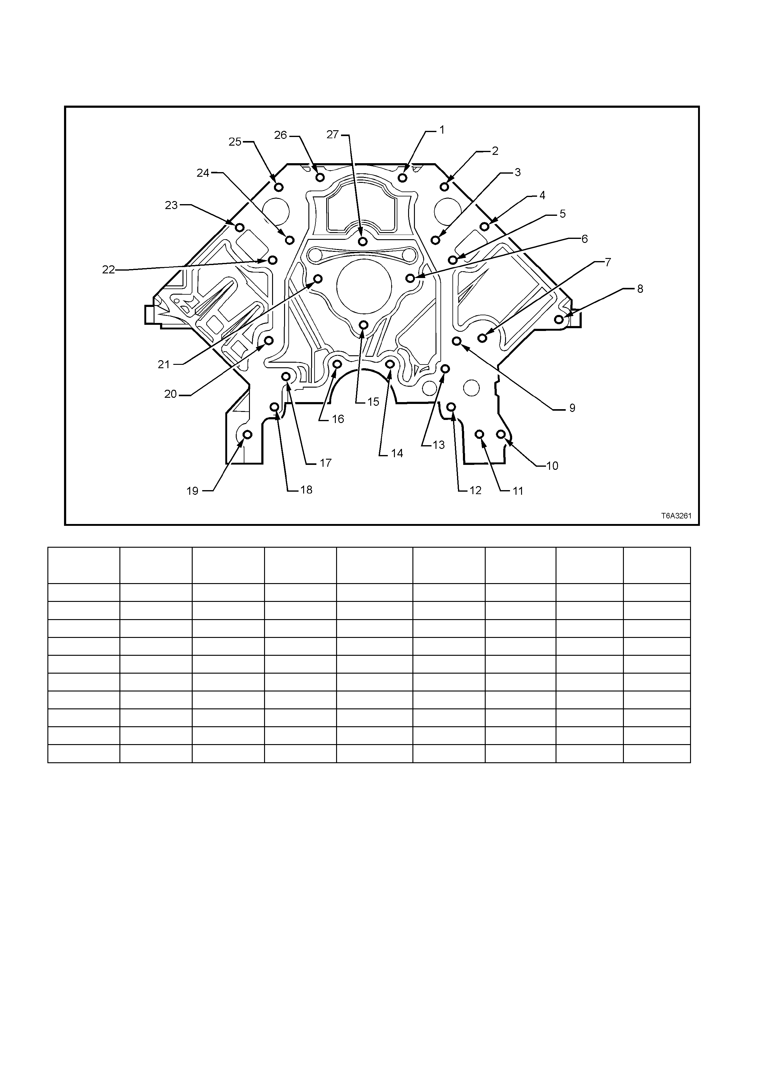
3.17 THREAD REPAIR SPECIFICATIONS
ENGINE BLOCK - FRONT VIEW
Figure 6A3-381
Hole Thread Size Insert Drill Counterbore
Tool Tap Driver
Maximum
Drill Depth
mm
Maximum
Tap Depth
mm
1-6 M8 x 1.25 J 42385-210 J 42385-206 J 42385-207 J 42385-208 J 42385-209 22.5 17.5
7 M10 x 1.5 J 42385-215 J 42385-211 J 42385-212 J 42385-213 J 42385-214 25.0 19.5
8 M10 x 1.5 J 42385-215 J 42385-211 J 42385-212 J 42385-213 J 42385-214 32.5 25.0
9 M8 x 1. 25 J 42385-210 J 42385-206 J 42385-207 J 42385-208 J 42385-209 22.5 17. 5
10 M10 x 1.5 J 42385-215 J 42385-211 J 42385-212 J 42385-213 J 42385-214 Through Through
11-13 M8 x 1.25 J 42385-210 J 42385-206 J 42385-207 J 42385-208 J 42385-209 22.5 17. 5
14 M8 x 1.25 J 42385-210 J 42385-206 J 42385-207 J 42385-208 J 42385-209 Through 18.0
15 M8 x 1.25 J 42385-210 J 42385-206 J 42385-207 J 42385-208 J 42385-209 22.5 17.5
16 M8 x 1.25 J 42385-210 J 42385-206 J 42385-207 J 42385-208 J 42385-209 Through 18.0
17-27 M8 x 1.25 J 42385-210 J 42385-206 J 42385-207 J 42385-208 J 42385-209 22.5 17. 5
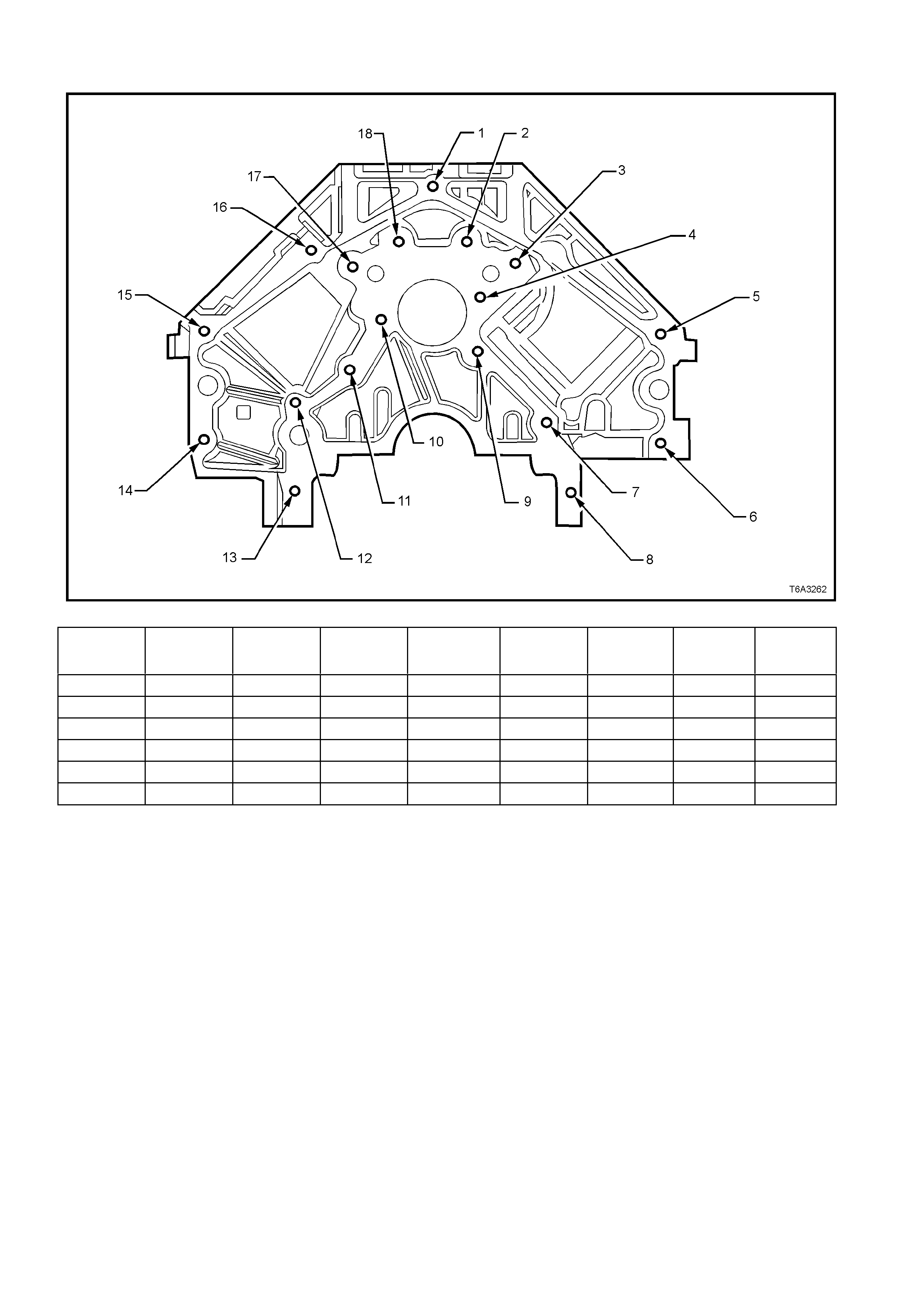
ENGINE BLOCK - REAR VIEW
Figure 6A3-382
Hole Thread Size Insert Drill Counterbore
Tool Tap Driver
Maximum
Drill Depth
mm
Maximum
Tap Depth
mm
1 M10 x 1.5 J 42385-215 J 42385-211 J 42385-212 J 42385-213 J 42385-214 27.0 21.5
2-4 M8 x 1.25 J 42385-210 J 42385-206 J 42385-207 J 42385-208 J 42385-209 22.5 17.5
5-6 M10 x 1.5 J 42385-215 J 42385-211 J 42385-212 J 42385-213 J 42385-214 27.0 21.5
7-13 M8 x 1.25 J 42385-210 J 42385-206 J 42385-207 J 42385-208 J 42385-209 22. 5 17.5
14-16 M10 x 1.5 J 42385-215 J 42385-211 J 42385-212 J 42385-213 J 42385-214 27.0 21. 5
17-18 M8 x 1.25 J 42385-210 J 42385-206 J 42385-207 J 42385-208 J 42385-209 22.5 17. 5
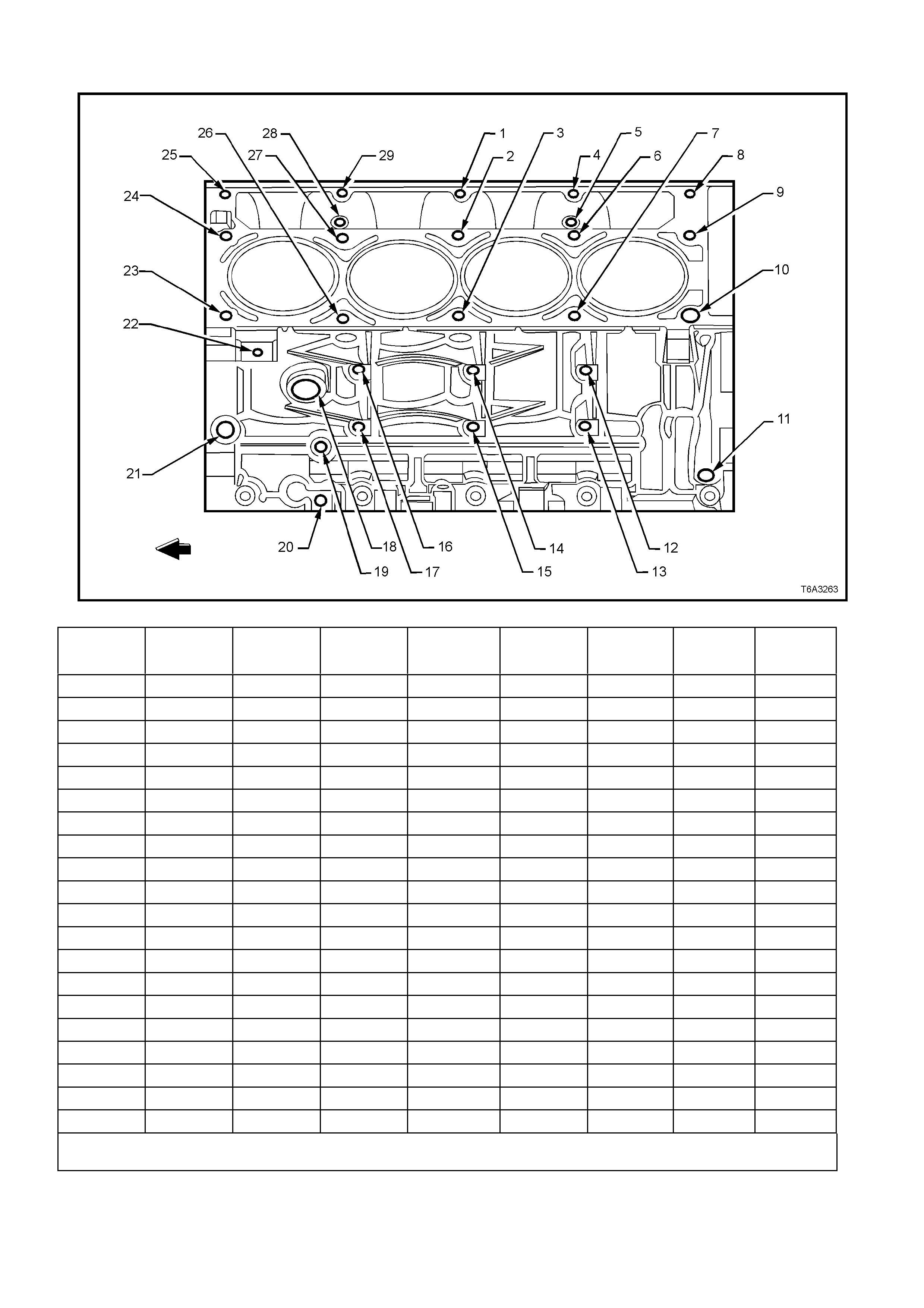
ENGINE BLOCK - LEFT SIDE VIEW
Figure 6A3-383
Hole Thread Size Insert Drill Counterbore
Tool Tap Driver
Maximum
Drill Depth
mm
Maximum
Tap Depth
mm
1 M8 x 1. 25 J 42385-210 J 42385-206 J 42385-207 J 42385-208 J 42385-209 26.5 19. 0
2-3 M11 x 2.0 J 42385-108 J 42385-105 J 42385-106 J 42385-107 124.0 115.0
4 M8 x 1. 25 J 42385-210 J 42385-206 J 42385-207 J 42385-208 J 42385-209 26.5 19. 0
5 M6 x 1.0 J 42385-205 J 42385-201 J 42385-202 J 42385-203 J 42385-204 22.5 16.0
6-7 M11 x 2.0 J 42385-108 J 42385-105 J 42385-106 J 42385-107 124.0 115.0
8 M8 x 1. 25 J 42385-210 J 42385-206 J 42385-207 J 42385-208 J 42385-209 26.5 19. 0
9 M11 x 2.0 J 42385-108 J 42385-105 J 42385-106 J 42385-107 69.0 60. 0
10 M11 x 2.0 J 42385-108 J 42385-105 J 42385-106 J 42385-107 124.0 115.0
11
12-17 M10 x 1.5 J 42385-215 J 42385-211 J 42385-212 J 42385-213 J 42385-214 29.0 23. 0
18 M28 x 1.25
19-20 M8 x 1.25 J 42385-210 J 42385-206 J 42385-207 J 42385-208 J 42385-209 21.0 16. 0
21 M16 x 1.5
22 M10 x 1.5 J 42385-215 J 42385-211 J 42385-212 J 42385-213 J 42385-214 27. 0 21.5
23 M11 x 2.0 J 42385-108 J 42385-105 J 42385-106 J 42385-107 124.0 115.0
24 M11 x 2.0 J 42385-108 J 42385-105 J 42385-106 J 42385-107 69.0 60.0
25 M8 x 1.25 J 42385-210 J 42385-206 J 42385-207 J 42385-208 J 42385-209 26.5 19.0
26-27 M11 x 2.0 J 42385-108 J 42385-105 J 42385-106 J 42385-107 124.0 115.0
28 M6 x 1.0 J 42385-205 J 42385-201 J 42385-202 J 42385-203 J 42385-204 22. 5 16.0
29 M8 x 1.25 J 42385-210 J 42385-206 J 42385-207 J 42385-208 J 42385-209 26.5 19.0
• Bolt holes 2, 3, 6, 7, 10, 23, 26, and 27 have a 85 mm counterbore included in the 124.0 mm drill depth.
• Bolt holes 9 and 24 have a 30 mm counterbore included in the 69.0 mm drill depth. Use sleeve J 42385-315 with the drill and tap.
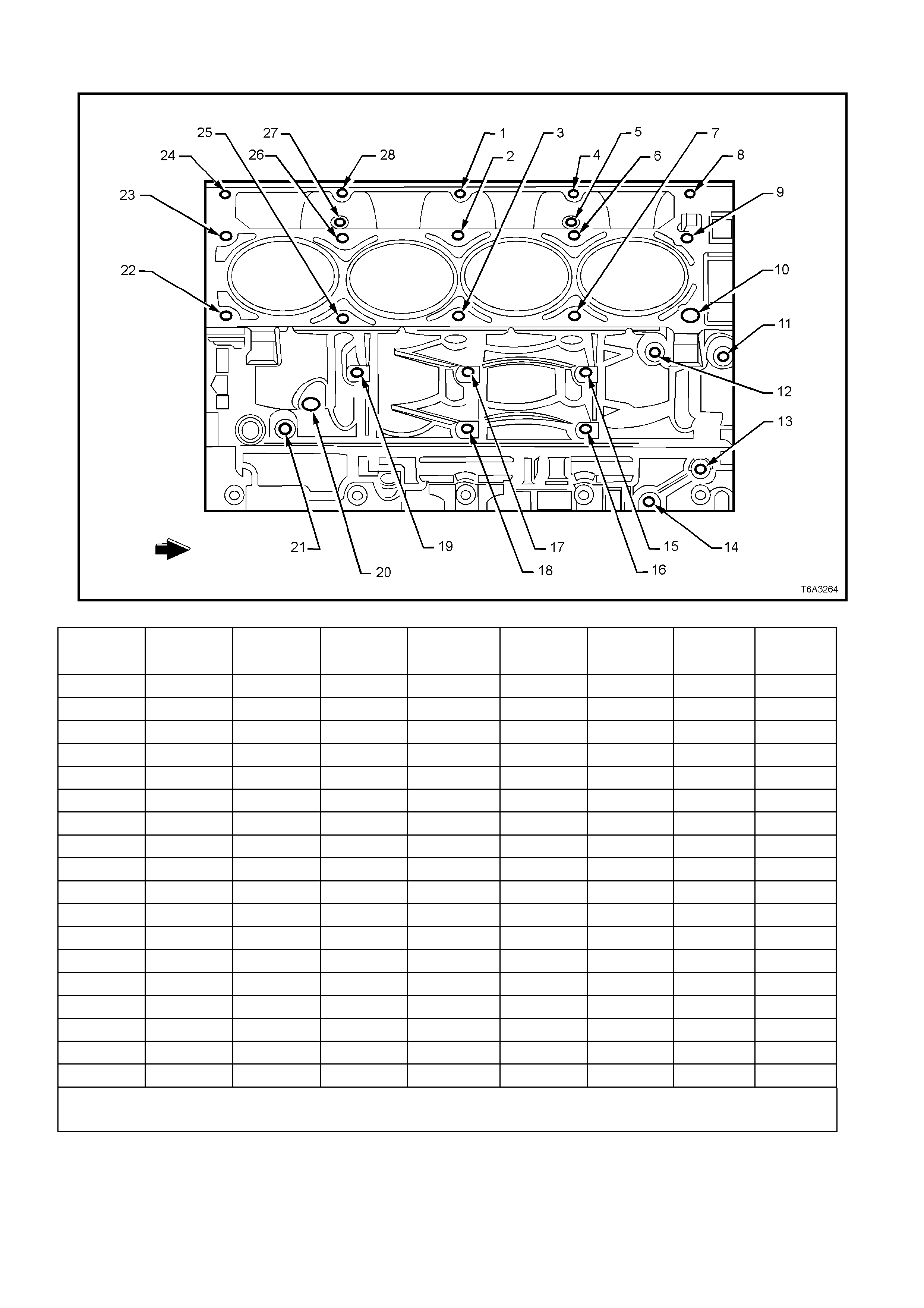
ENGINE BLOCK - RIGHT SIDE VIEW
Figure 6A3-384
Hole Thread Size Insert Drill Counterbore
Tool Tap Driver
Maximum
Drill Depth
mm
Maximum
Tap Depth
mm
1 M8 x 1. 25 J 42385-210 J 42385-206 J 42385-207 J 42385-208 J 42385-209 26.5 19. 0
2-3 M11 x 2.0 J 42385-108 J 42385-105 J 42385-106 J 42385-107 124.0 115.0
4 M8 x 1. 25 J 42385-210 J 42385-206 J 42385-207 J 42385-208 J 42385-209 26.5 19. 0
5 M6 x 1.0 J 42385-205 J 42385-201 J 42385-202 J 42385-203 J 42385-204 22.5 15.0
6-7 M11 x 2.0 J 42385-108 J 42385-105 J 42385-106 J 42385-107 124.0 115.0
8 M8 x 1. 25 J 42385-210 J 42385-206 J 42385-207 J 42385-208 J 42385-209 26.5 19. 0
9 M11 x 2.0 J 42385-108 J 42385-105 J 42385-106 J 42385-107 69.0 60. 0
10 M11 x 2.0 J 42385-108 J 42385-105 J 42385-106 J 42385-107 124.0 115.0
11-14 M10 x 1.5 J 42385-215 J 42385-211 J 42385-212 J 42385-213 J 42385-214 27.0 21. 5
15-19 M10 x 1.5 J 42385-215 J 42385-211 J 42385-212 J 42385-213 J 42385-214 29.0 23. 0
20 M16 x 1.5
21 M8 x 1.25 J 42385-210 J 42385-206 J 42385-207 J 42385-208 J 42385-209 22.5 17.5
22 M11 x 2.0 J 42385-108 J 42385-105 J 42385-106 J 42385-107 124.0 115.0
23 M11 x 2 J 42385-108 J 42385-105 J 42385-106 J 42385-107 69.0 60. 0
24 M8 x 1.25 J 42385-210 J 42385-206 J 42385-207 J 42385-208 J 42385-209 26.5 19.0
25-26 M11 x 2.0 J 42385-108 J 42385-105 J 42385-106 J 42385-107 124.0 115.0
27 M6 x 1.0 J 42385-205 J 42385-201 J 42385-202 J 42385-203 J 42385-204 22. 5 15.0
28 M8 x 1.25 J 42385-210 J 42385-206 J 42385-207 J 42385-208 J 42385-209 26.5 19.0
• Bolt holes 2, 3, 6, 7, 10, 22, 25, and 26 have a 85 mm counterbore included in the 124.0 mm drill depth.
• Bolt holes 9 and 23 have a 30 mm counterbore included in the 69.0 mm drill depth. Use sleeve J 42385-315 with the drill and tap.
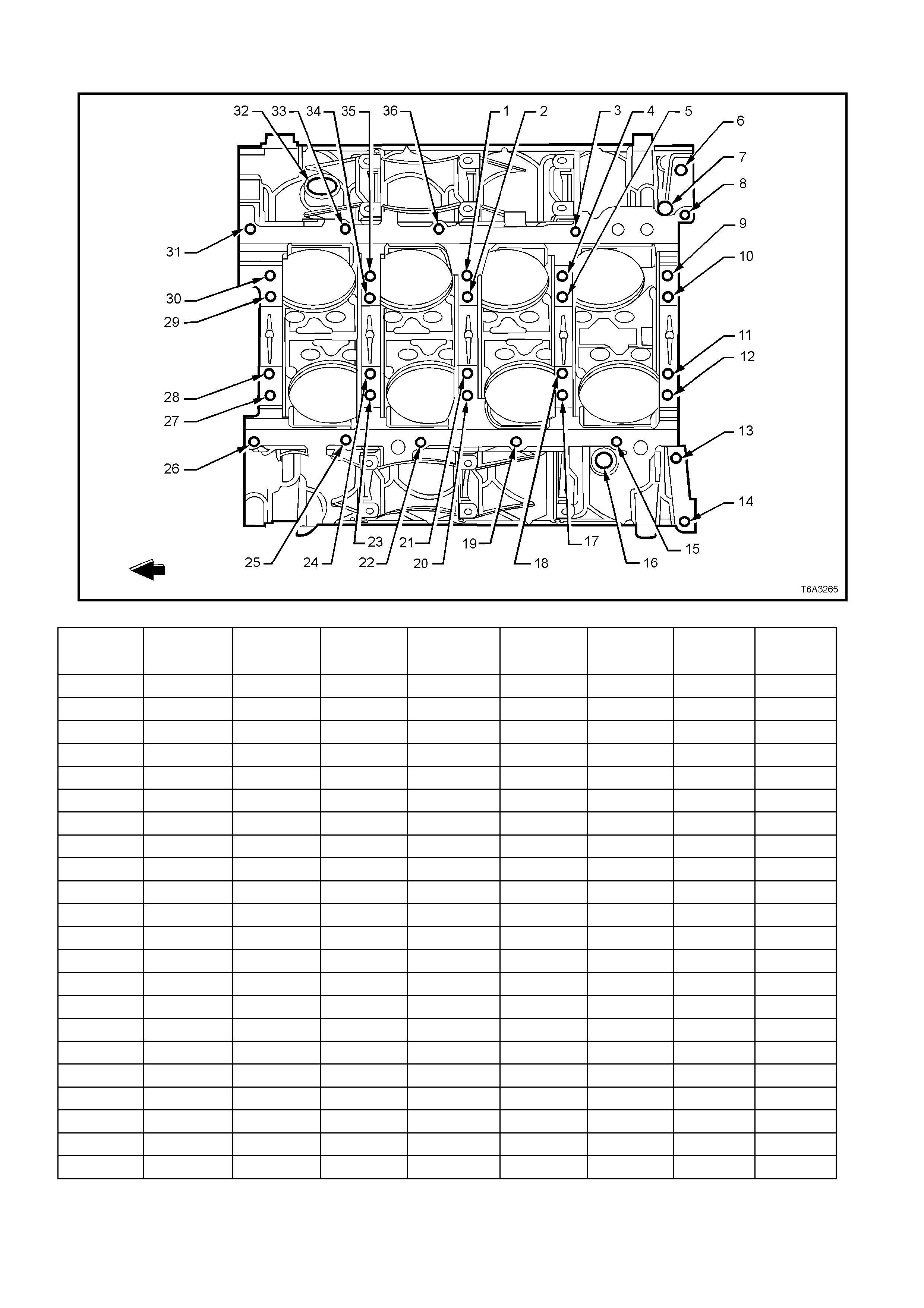
ENGINE BLOCK - BOTTOM VIEW
Figure 6A3-385
Hole Thread Size Insert Drill Counterbore
Tool Tap Driver
Maximum
Drill Depth
mm
Maximum
Tap Depth
mm
1 M10 x 2.0 J 42385-104 J 42385-101 J 42385-102 J 42385-103 31.0 25.5
2 M10 x 2.0 J 42385-104 J 42385-101 J 42385-102 J 42385-103 53.5 44.0
3 M8 x 1.25 J 42385-210 J 42385-206 J 42385-207 J 42385-208 J 42385-209 22.5 17.5
4 M10 x 2.0 J 42385-104 J 42385-101 J 42385-102 J 42385-103 31.0 25.5
5 M10 x 2.0 J 42385-104 J 42385-101 J 42385-102 J 42385-103 53.5 44.0
6 M16 x 1.5
7 N/A
8 M8 x 1.25 J 42385-210 J 42385-206 J 42385-207 J 42385-208 J 42385-209 22.5 17.5
9 M10 x 2.0 J 42385-104 J 42385-101 J 42385-102 J 42385-103 31.0 25.5
10-11 M10 x 2.0 J 42385-104 J 42385-101 J 42385-102 J 42385-103 53.5 44. 0
12 M10 x 2.0 J 42385-104 J 42385-101 J 42385-102 J 42385-103 31.0 25.5
13-14 M10 x 1.5 J 42385-215 J 42385-101 J 42385-213 J 42385-214 42.5 37. 0
15 M8 x 1.25 J 42385-210 J 42385-206 J 42385-207 J 42385-208 J 42385-209 22.5 17. 5
16 M16 x 1.5
17 M10 x 2.0 J 42385-104 J 42385-101 J 42385-102 J 42385-103 53.5
18 M10 x 2.0 J 42385-104 J 42385-101 J 42385-102 J 42385-103 31.0 25.5
19 M8 x 1.25 J 42385-210 J 42385-206 J 42385-207 J 42385-208 J 42385-209 22.5 17. 5
20 M10 x 2.0 J 42385-104 J 42385-101 J 42385-102 J 42385-103 53.5 44.0
21 M10 x 2.0 J 42385-104 J 42385-101 J 42385-102 J 42385-103 31.0 25.5
22 M8 x 1.25 J 42385-210 J 42385-206 J 42385-207 J 42385-208 J 42385-209 22.5 17. 5
23 M10 x 2.0 J 42385-104 J 42385-101 J 42385-102 J 42385-103 31.0 25.5
24 M10 x 2.0 J 42385-104 J 42385-101 J 42385-102 J 42385-103 53.5 44.0
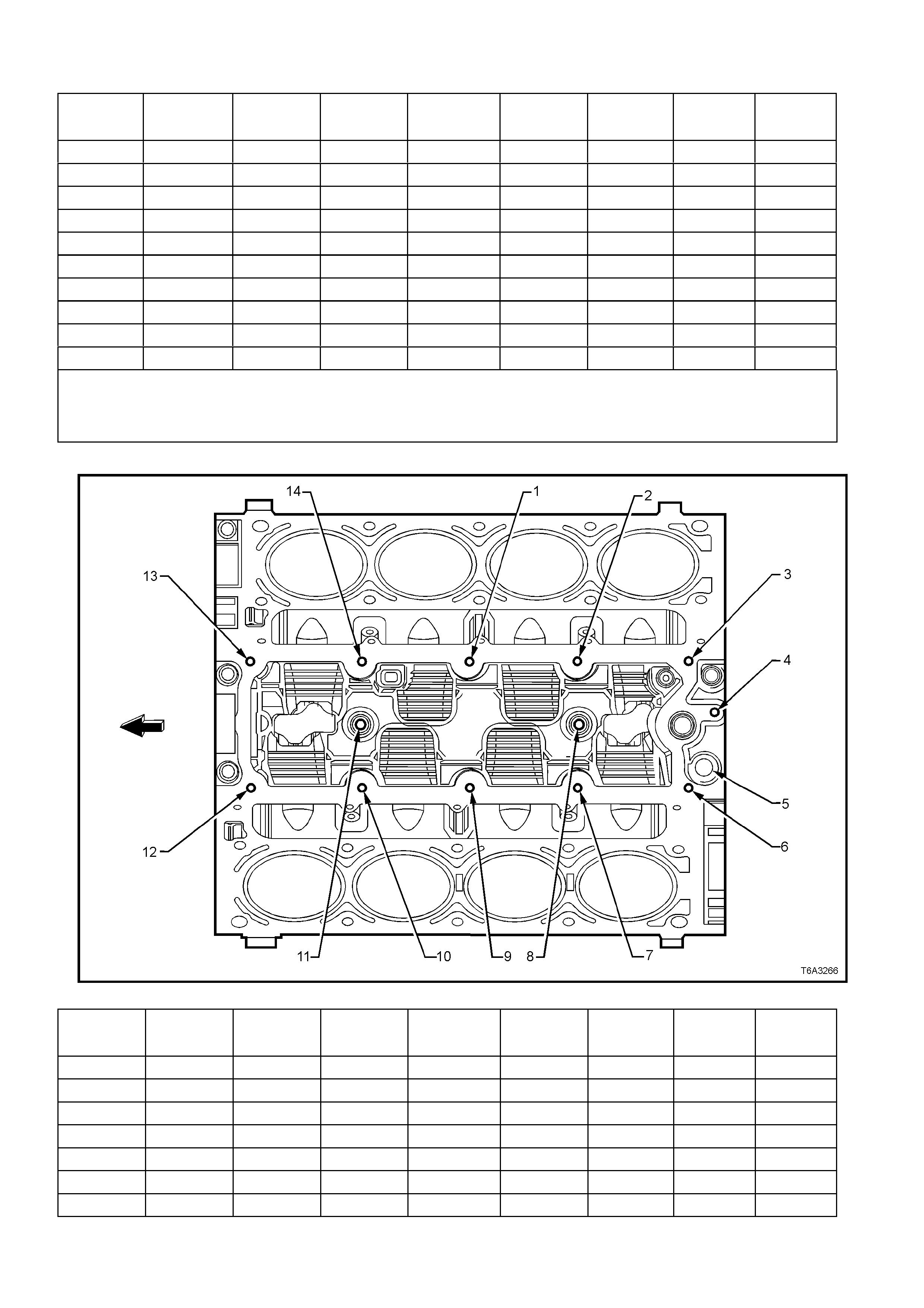
Hole Thread Size Insert Drill Counterbore
Tool Tap Driver
Maximum
Drill Depth
mm
Maximum
Tap Depth
mm
25-26 M8 x 1.25 J 42385-210 J 42385-206 J 42385-207 J 42385-208 J 42385-209 22.5 17.5
27 M10 x 2.0 J 42385-104 J 42385-101 J 42385-102 J 42385-103 31.0 25.5
28-29 M10 x 2.0 J 42385-104 J 42385-101 J 42385-102 J 42385-103 53.5 44. 0
30 M10 x 2.0 J 42385-104 J 42385-101 J 42385-102 J 42385-103 31.0 25.5
31 M8 x 1.25 J 42385-210 J 42385-206 J 42385-207 J 42385-208 J 42385-209 22.5 17. 5
32 M28 x 1.25
33 M8 x 1.25 J 42385-210 J 42385-206 J 42385-207 J 42385-208 J 42385-209 22.5 17. 5
34 M10 x 2.0 J 42385-104 J 42385-101 J 42385-102 J 42385-103 53.5 44.0
35 M10 x 2.0 J 42385-104 J 42385-101 J 42385-102 J 42385-103 31.0 25.5
36 M8 x 1.25 J 42385-210 J 42385-206 J 42385-207 J 42385-208 J 42385-209 22.5 17. 5
• Bolt holes 2, 5, 10, 11, 18, 21, 24, 28, 29, and 34 have a 20.5 mm counterbore included in the 53.5 mm drill depth.
• Bolt holes 1, 4, 9, 12, 17, 20, 23, 27, 30, and 35 have a 1.5 mm counterbore included in the 31.0 mm drill depth. Use sleeve J 42385-
316 with the drill and tap..
• Bolt holes 13 and 14 have a 11.5 mm counterbore included in the 42.5 mm drill depth. Use sleeve J 42385-311 wi t h t he drill and tap.
ENGINE BLOCK - TOP VIEW
Figure 6A3-386
Hole Thread Size Insert Drill Counterbore
Tool Tap Driver
Maximum
Drill Dept h
mm
Maximum
Tap Depth
mm
1-4 M8 x 1.25 J 42385-210 J 42385-206 J 42385-207 J 42385-208 J 42385-209 26.5 19.0
5 M16 x 1.5
6-7 M8 x 1.25 J 42385-210 J 42385-206 J 42385-207 J 42385-208 J 42385-209 26.5 19.0
8 M10 x 1.5 J 42385-216 J 42385-211 J 42385-212 J 42385-213 J 42385-214 22.5 17. 0
9-10 M8 x 1.25 J 42385-210 J 42385-206 J 42385-207 J 42385-208 J 42385-209 26.5 19.0
11 M10 x 1.5 J 42385-216 J 42385-211 J 42385-212 J 42385-213 J 42385-214 22.5 17.0
12-14 M8 x 1.25 J 42385-210 J 42385-206 J 42385-207 J 42385-208 J 42385-209 26.5 19. 0
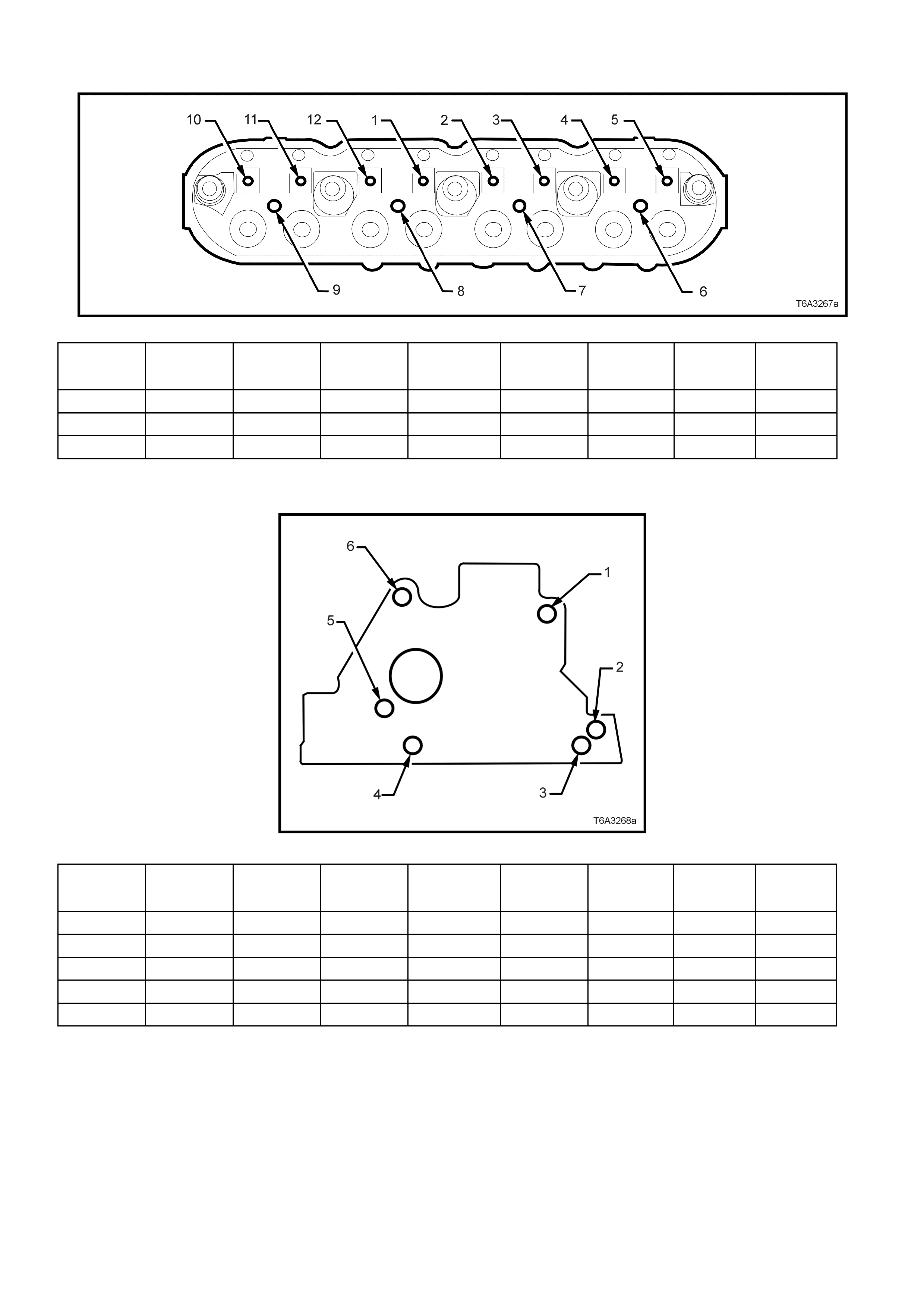
CYLINDER HEAD - TOP VIEW
Figure 6A3-387
Hole Thread Size Insert Drill Counterbore
Tool Tap Driver
Maximum
Drill Dept h
mm
Maximum
Tap Depth
mm
1-5 M8 x 1.25 J 42385-210 J 42385-206 J 42385-207 J 42385-208 J 42385-209 26.5 19.0
6-9 M6 x 1.0 J 42385-205 J 42385-201 J 42385-202 J 42385-203 J 42385-204 20.05 16.05
10-12 M8 x 1.25 J 42385-210 J 42385-206 J 42385-207 J 42385-208 J 42385-209 26.5 19.0
CYLINDER HEAD - END VIEW
Figure 6A3-388
Hole Thread Size Insert Drill Counterbore
Tool Tap Driver
Maximum
Drill Dept h
mm
Maximum
Tap Depth
mm
1 M10 x 1.5 J 42385-215 J 42385-211 J 42385-212 J 42385-213 J 42385-214 28.0 20. 0
2 N/A
3 M10 x 1.5 J 42385-215 J 42385-211 J 42385-212 J 42385-213 J 42385-214 28.0 20. 0
4 N/A
5-6 M10 x 1.5 J 42385-215 J 42385-211 J 42385-212 J 42385-213 J 42385-214 28.0 20.0
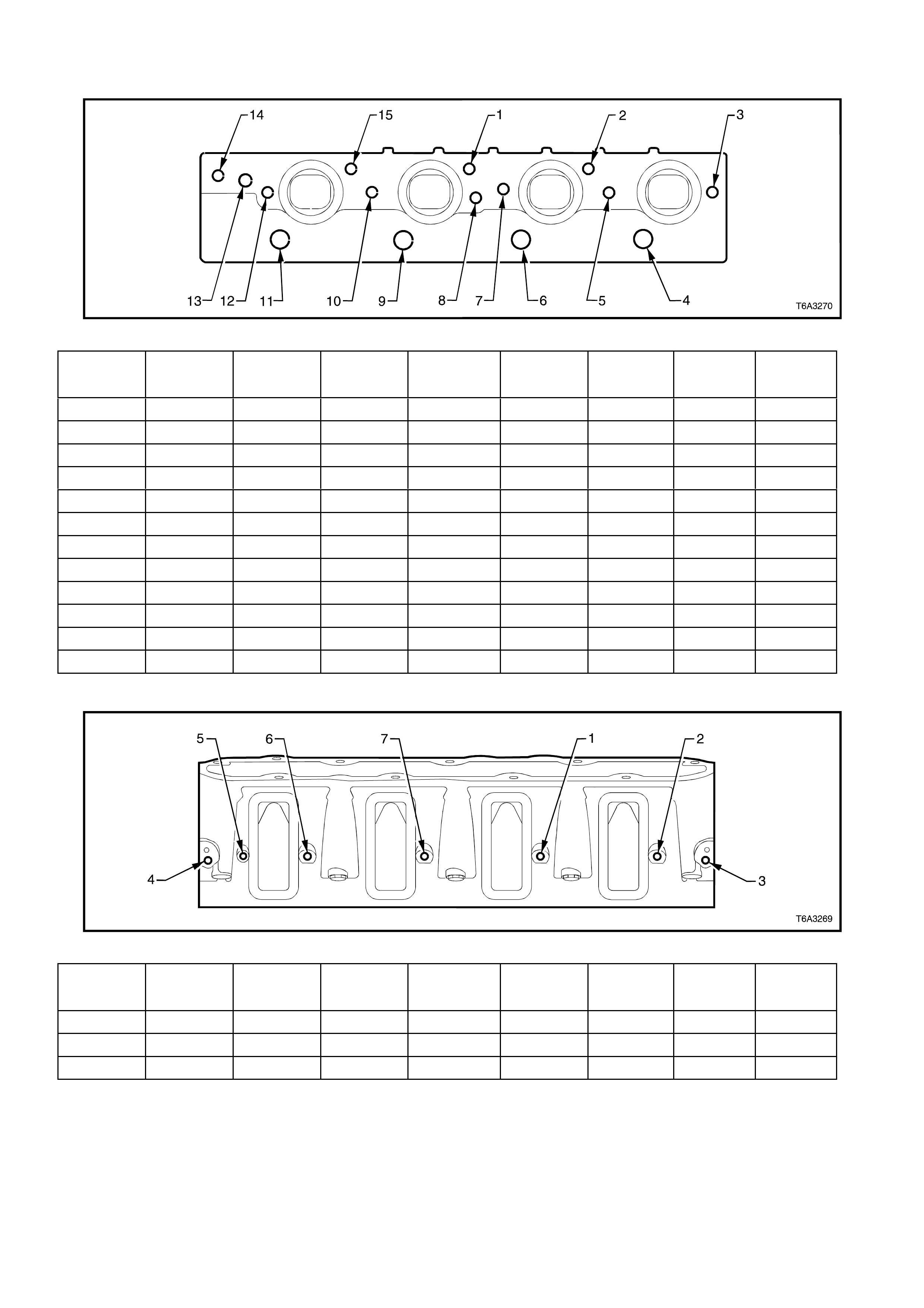
CYLINDER HEAD - EXHAUST MANIFOLD SIDE VIEW
Figure 6A3-389
Hole Thread Size Insert Drill Counterbore
Tool Tap Driver
Maximum
Drill Dept h
mm
Maximum
Tap Depth
mm
1-2 M10 x 1.5 J 42385-215 J 42385-211 J 42385-212 J 42385-213 J 42385-214 28.0 20.0
3 M8 x 1.25 J 42385-210 J 42385-206 J 42385-207 J 42385-208 J 42385-209 21.0 16.0
4 M14 x 1.25
5 M8 x 1.25 J 42385-210 J 42385-206 J 42385-207 J 42385-208 J 42385-209 21.0 16.0
6 M14 x 1.25
7-8 M8 x 1.25 J 42385-210 J 42385-206 J 42385-207 J 42385-208 J 42385-209 21.0 16.0
9 M14 x 1.25
10 M8 x 1.25 J 42385-210 J 42385-206 J 42385-207 J 42385-208 J 42385-209 21.0 16.0
11 M14 x 1.25
12 M8 x 1.25 J 42385-210 J 42385-206 J 42385-207 J 42385-208 J 42385-209 21.0 16.0
13 M12 x 1.5
14-15 M10 x 1.5 J 42385-215 J 42385-211 J 42385-212 J 42385-213 J 42385-214 28.0 20. 0
CYLINDER HEAD - INTAKE MANIFOLD SIDE VIEW
Figure 6A3-390
Hole Thread Size Insert Drill Counterbore
Tool Tap Driver
Maximum
Drill Dept h
mm
Maximum
Tap Depth
mm
1-2 M6 x 1.0 J 42385-205 J 42385-201 J 42385-202 J 42385-203 J 42385-204 Through Through
3-4 M6 x 1.0 J 42385-205 J 42385-201 J 42385-202 J 42385-203 J 42385-204 22.5 15.0
5-7 M6 x 1.0 J 42385-205 J 42385-201 J 42385-202 J 42385-203 J 42385-204 Through Through

4. DIAGNOSIS
4.1 BASIC ENGINE MISFIRE DIAGNOSIS
GENERAL INFORMATION
1. Engine performance diagnosis procedures are covered in Section 6C3 POWERTRAIN MANAGEMENT GEN
III V8 ENGINE and should be referred to for diagnosis of any Driveability, Emissions, or Check Powertrain
Lamp concerns.
2. The following diagnosis covers common concerns and possible causes.
3. When the proper diagnosis is made, the co ncern shou ld be corrected by adjustm ent, repair or r eplacement as
required.
4. Refer to the appropriate section of the service manual for each specific procedure.
5. This diagnostic table will assist in engine misfire diagnosis due to a mechanical concern such as a faulty
camshaft, worn or damaged bearings or bent pushrod.
6. This table will not isolate a crossed injector wire, fault y injector or any other driveability component f ailure that
may cause a misfire.
7. The Powertrain On-Board Diagnostic System checks must be performed first. Refer to
Section 6C3-2A POWERTRAIN MANAGEMENT GEN III V8 ENGINE, DIA GNOSTIC CHARTS.
8. When using this table to make a Base Engine Misfire diagnosis, begin with the preliminary information below
and then proceed to the specific category.
DIAGNOSTIC PROCEDURE
Checks Action
Preliminary 1. Perform a visual inspectio n of the following:
• A loose or improperly installed engine flywheel or crankshaft balancer.
• Worn, damaged, or misaligned accessory drive system components.
2. Listen to the engine for any abnormal internal engine noises.
3. Inspect the engine for acceptable oil pressure. Refer to 2.4 ENGINE OIL
PRESSURE – CHECK in this Section.
4. Verify if the engine has excessive oil consumption. Refer to 4.4 OIL
CONSUMPTION DIAGNOSIS, in this Section.
5. Verify if the engine has coolant consumption.
6. Perform a compression test on the engine.
Intake Manifold Leaks 1. An intake manifold that has a vacuum leak may cause a misfire.
2. Inspect for the following:
• Improperly installed or damaged vacuum hoses.
• Faulty or improperly installed intake manifold and/or gaskets.
• Cracked or damaged intake manifold.
• Inspect the areas between the intake runners.
• Improperly installed or damaged Manifold Absolute Pressure (MAP) sensor
housing (located at the rear of the intake manifold).
• Improperly installed or damaged MAP sensor housing O-ring seal.
• Improperly installed MAP sensor.
• The sealing grommet of the MAP sensor should not be torn or damaged.
• Improperly installed throttle body or damaged gasket.
• Warped intake manifold.
• Warped or damaged cylin der head sea lin g surfa ce.
Coolant Cons umption 1. Coolant consumption may or may not cause the engine to overheat. Inspect for
the following:
• External coolant lea ks.
• Faulty cylinder head gasket.
• Warped cylinder head.
• Cracked cylinder head.
• Damaged engine block.
Techline

Checks Action
Oil Consumption 1. Oil consumption may or may not cause the engine to misfire. Remove the spark
plugs and inspect for an oil fouled spark plug.
2. Perform a cylinder compression test. Refer to 2.5 COMPRESSION CHECK in
this Section.
3. If the compression test indicates worn valves or valve guides, inspect for the
following:
• Worn valve guides.
• Worn valve stems.
• Worn or burnt valves or valve seats.
• Worn, brittle, or improperly installed valve stem oil seals.
4. If the compression test indicates worn or damaged piston rings, inspect the
following:
• Broken or improperly seated piston rings.
• Excessive piston ring end gap.
• Excessive cylinder bore wear or taper.
• Cylinder damage.
• Pist on damage.
Abnormal Internal Engine Noises 1. With the engine running, try and determine if the noise is timed to camshaft
speed or crankshaft spe ed.
NOTE: Using a timing light, two knocks per flash is crankshaft speed and one knock
per flash is camshaft spe ed.
2. If the noise is timed to camshaft speed, inspect the following:
• Missing or loose valve train components.
• Worn or loose valve rocker arms.
• Worn or bent pushrods.
• Faulty valve springs.
• Bent or burnt valves.
• Worn camshaft lobes.
• Worn or damaged timing chain and/or sprockets.
IMPORTANT: A slight COLD knock or piston slapping noise could be considered
normal if not present after the engine has reached normal operating temperatures.
3. If the knock is timed to crankshaft speed, inspect the following:
• Worn crankshaft main or connecting rod bearings.
• Piston or cylinder damage.
• Worn piston or piston pin.
• Damaged or faulty connecting rod.
• Excessive carbon build-up on the top of the piston.
No Abnormal Internal Engine Noise 1. Inspect for a worn or improperly installed timing chain and/or sprockets.
2. Remove the valve rocker arm cover on the side of the engine with the cylinder
that is misfiring.
3. Inspect for the following:
• Loose valve rocker arm bolts.
• Bent push rods.
• Faulty valve springs.
• Faulty valve lifters (bleeding down).
• Worn or improperly seated valves.
• Worn camshaft lobes.

4.2 ENGINE NOISE DIAGNOSIS
There are four steps to diagnosing engine noise. You must determine the following:
The type of noise. For example, is the noise a light rattle/tapping or a low rumble/knocking?
The exact operating condition under which the noise exists. Note factors such as the ambient temperature, the
amount of engine warm-up time, the engine temperature, engine speed other specifics.
At what rate the noise occurs, and at what location in the engine. Remember, engine noises are generally
synchronised to either engine speed (crankshaft, flywheel, connecting rods, balancer, or pistons and related
components) or one-half engine speed (valve train noise such as rocker arms, valve lif ters, and tim ing chain). Try
to determine the rate at which the noise is occurring.
Compare the engine sounds to other engines. This is required to make sure you are not trying to correct a
normal condition.
Checks Action
Noise on Start-Up but Only Lasts a
Few Seconds 1. This noise condition may be cause d by:
• Improper oil viscosity. Install the recommended oil viscosity for the expected
temperatures.
• Incorrect oil filter without the a nti-dra inb ac k feature.
• Worn or dirty hydraulic valve lifters.
• Excessive piston to bore clearance.
• Excessive piston pin to piston clearance.
• Excessive crankshaft bearing clearance.
Knocks Cold and Continues for 1 to
2 Minutes 1. Common causes for a cold start knock, are:
• Loose or broken crankshaft ba lanc er or acces sory driv e com ponen ts.
• Excessive piston to bore clearance.
• A cold piston knock which disappears in 1.5 minutes should be considered
acceptable.
• A cold engine knock usually disappears when the specific cylinders
secondary ignition circuit is earthed.
Intermittent Noise on Idle,
Disappearing When Engine Speed
is Increased
1. Intermittent noises at idle can be caused by:
• Improper oil viscosity. Install the recommended oil viscosity for the expected
temperatures.
• Lower than specified oil pressure. Install an oil pressure gauge and measure
the engine oil pressure.
• Dirty or worn hydraulic valve lifter.

Checks Action
Valve Train Noise (Rattle/Tapping) 1. The following conditions may cause valve train noise:
• Lower than specified oil pressure.
• Worn or faulty oil pump.
• Loose oil pump-to-engine block bolts.
• Loose or damaged oil transfer tube and/or gaskets.
• Loose valve rocker arm attachments.
• Worn valve rocker arm bearings.
• Worn valve rocker arm and/or pushrod.
• Broken valve spring.
• Sticki ng valves.
• Worn, dirty, or faulty hydraulic valve lifters.
• Worn camshaft lifter lobes.
• Worn valve guides or valve stems.
• Bent, broken, or damaged timing chain sprocket teeth.
Knocks at Idle Hot
(Rumble/Knocking) 1. The following conditions may cause a knocking noise:
• Malfunctioning accessory drive system components.
• Loose or broken crankshaft ba lanc er.
• Detonation or spark knock.
• Check for proper operation of the cooling, knock, and ignition control
components.
• Refer to diagnostic information in 6C3 POWERTRAIN MANAGEMENT -
GEN III V8 ENGINE.
• Excessive connecting rod bearing clearance.
• Excessive piston pin to bore clearance.
• Bent connecting rod.
• Excessive crankshaft main or thrust bearing clearance.
• Loose torque converter bolts.
• Cracked or damaged flywheel.
• Exhaust leak at the manifold.
Exhaust System Noise and/or
Leakage 1. Exhaust system noise and/or leakage may be caused by the following conditions:
• Improperly installed or misaligned exhaust system components.
• A cracked or broken exhaust manifold.
• Damaged or worn gaskets and/or seals.
• Burned or rusted out exhaust system compo nen ts.
• A broken or loose exhaust clamp and/or bracket.

4.3 VALVE TRAIN DIAGNOSIS
GENERAL INFORMATION
• A light tapping noise at one-half engine speed, or any varying frequency, may indicate a valve train problem.
Thes e tapping nois es will t ypic ally increase with eng ine speed.
• Before attempting to diagnose valve train noise, check for the proper oil level and thoroughly warm up the
engine. By doing this you will bring all engine components to a normal state of expansion.
• While sitting in the drivers seat, run the engine at various speeds and listen for any abnormal engine noise.
• Whenever Valve Lifter Diagnosis is necessary, always use a listening device such as a stethoscope. Tools
such as this will help to isolate any lifter noise and identify noises that could be mis-diagnosed as lifter noise.
DIAGNOSTIC PROCEDURE
Checks Action
A light tapping noise similar to valve
train noise.
1. This light type of noise may be caused by the following:
• Fuel injectors.
• Evaporative emission (EVAP) purge solenoid.
• Detonation.
• Loose heat shields.
Causes of Valve Train Noise
1. Any or a combination of the following can cause valve train noise:
• Poor oil quality caused by water contamination, aeration, or fuel dilution.
• Low engine oil pressure.
• Worn or faulty oil pump.
• A loose or plugged oil pump screen.
• Loose or damaged oil transfer tube.
• Loose valve rocker arm attachments (causing excessive valve lash).
• Worn or damaged valve rocker arm bearings.
• Worn valve rocker arm and/or pushrod.
• Broken valve spring.
• Sticki ng valves.
• Valve lifters worn, dirty, or faulty.
• Broken valve lifter guide.
• Camshaft valve lifter lobes worn.
• Worn valve guides or valve stems.
• Worn, damaged, or missing valve keys.
• Bent pushrods.
• Excessive play in the camshaft timing chain.
• Bent, broken, or damaged timing chain sprocket teeth.
Techline

DIAGNOSTIC TABLE
Definition: A light tapping noise at one half engine speed, or any varying frequency.
Step Action Value(s) Yes No
1 Is there valve train noise? − Go to Step 2 System OK
2 Check for a high engine oil level. A engine with the oil level
above the FULL mark allows the crankshaft counterweights to
churn the oil into foam. When foamy oil is pumped into the
lifters, the lifters become noisy. A solid column of oil ensures
proper lifter operation.
Is the oil level too high?
− Go to Step 3 Go to Step 4
3 Drain engine oil until level is correct.
Is there valve train noise? − Go to Step 4 System OK
4 Check for a low engine oil level. A engine with the oil level
below the ADD mark may allow the oil pump to pump air at
high engine speeds .
Is the oil level too low?
− Go to Step 5 Go to Step 6
5 Add oil as required.
Is there valve train noise? − Go to Step 6 System OK
6 Check for proper engine oil pressure. Refer to 2.4 ENGINE
OIL PRESSURE – CHECK, in this Section.
Is the engine oil pressure within specifications?
− Go to Step 7 Go to Step 7
7 1. Check the oil pump screen for damage or a loose fit to the
oil pump.
2. Inspect for a missing or damaged oil pump screen O-ring
seal.
Is the oil pump screen loose or is the screen or O-ring seal
damaged?
− Go to Step 8 Go to Step 9
8 Repair as required.
Is there valve train noise? − Go to Step 9 System OK
9 Check for a damaged oil pump or loose mounting bolts. Refer
to Oil Pump Clean and Inspect, in this Section.
Is the oil pump damaged or are the fasteners loose?
− Go to Step 10 Go to Step 11
10 Repair as required.
Is there valve train noise? − Go to Step 11 System OK
11 Remove and inspect the valve lifters, guides, rocker arms, and
pushrods. Refer to Valve Rocker Arm and Push Rods Clean
and Inspect and Valve Lifters and Guides Clean and Inspect,
in this Section.
Are components worn or damaged?
− Go to Step 12 Go to Step 13
12 Repair as required.
Is there valve train noise? − Go to Step 13 System OK
13 Perform a camshaft lobe lift test. Refer to 3.2 CAMSHAFT
LOBE LIFT – Measure in this Section.
Is the test within specification?
Go to Step 17 Go to Step 14
14 Remove the engine front cover and inspect the timing chain
and sprockets for excessive wear or damage. Refer to 3.8
TIMING CHAIN AND SPROCKETS, in this Section.
IMPORTANT: Pushrod engines are designed so that a timing
chain more than one tooth improperly positioned will cause
valve interference with the piston.
Are the components worn or damaged, or improperly
positioned?
− Go to Step 15 Go to Step 16
15 Replace components as required.
Is there valve train noise? − Go to Step 16 System OK
16 Replace camshaft and/or bearings and all hydraulic valve
lifters. Refer to 3.9 CAMSHAFT, in this Section.
Is there valve train noise?
− Go to Step 17 System OK
17 Perform a complete disassembly of the engine and inspect all
components.
Are components worn or damaged?
− Go to Step 18 System OK
18 Replace the worn/damaged components as required. − System OK −

4.4 OIL CONSUMPTION DIAGNOSIS
Definition: Excess ive oil c onsumption ( not due to lea ks) is the use of 0.95 l itres or m ore of engine oi l within 2,500
kilometres.
Checks Action
Preliminary 1. The causes of excessive oil consumption may include the following conditions:
• External oil leaks. Refer to 4.6 OIL LEAK DIAGNOSIS in this Section.
• Incorrect oil level or improper reading of the oil level indicator. W ith the vehicle on
a level surface, run the engine for a few minutes, allow adequate drain down time
(2-3 minutes) and check for the correct eng ine oil lev el.
• Improper oil viscosity. Refer to the vehicle Owners Manual and use the
recommended SAE grade and viscosity for the prevailing temperatures.
• Continuous high speed driving and/or severe usage.
• Crankcase ventilation system restrictions or malfunctioning components.
• Worn valve guides and/or valve stems.
• Worn or improperly installed valve stem oil seals.
• Piston rings broken, worn, not seated properly. Allow adequate time for the rings
to seat. Replace worn piston rings as necessary.
• Piston and rings improperly installed or incorrectly fitted to the cylinder bore.
• Excessive piston to bore clearance.

4.5 OIL PRESSURE DIAGNOSIS
Conduct an oil pressure check, as detailed in 2.4 ENGINE OIL PRESSURE - CHECK, in this Sec ti on
Checks Action
Oil Pressure Below Specification 1. Inspect the engine for one or more of the following:
• Oil pump worn or dirty.
• Oil pump to engine block bolts loose.
• Oil pump screen loose, plugged or damaged.
• Oil pump screen O-ring seal missing or damaged.
• Malfunctioning oil pump oil pressure relief valve.
• Excessive bearing clearances.
• Cracked, porous or restricted oil galleries.
• Oil gallery plugs leaking, missing or incorrectly installed.
• Broken/malfunctioning hydraulic valve lifters.
Oil Pressure Above Specification 1. Inspect for one or more of the following:
• Plugged or incorrect oil filter fitted.
• Malfunctioning oil by-pass valve.
• Malfunctioning oil pressure gauge or sensor.

4.6 OIL LEAK DIAGNOSIS
NOTE: Most fluid leaks can be repaired by visually locating the leak, repairing or replacing the component, or by
resealing the gasket surface. When a leak has been located, determine the cause of the leak. Otherwise the leak
will most probably re-occur.
Step Action Value(s) Yes No
1. 1. Operate the vehicle until it reaches normal operating
temperature.
2. Park the vehicle on a level surface, over a large sheet of
paper or other clean surface.
3. Wait for at least 15 minutes.
4. Check for oil drips.
Are oil drips present?
− Go to Step 2 Go to Step 3
2. 1. Identify the type of fluid and the approximate location of
the leak.
Can you identify the type of fluid and the approximate location
of the leak?
− Go to Step 10 Go to Step 3
3. 1. Visually inspec t the suspected area. Use a small mirror to
assist in looking at hard to see areas.
2. Check for leaks at the following locations:
• Sealing surfaces.
• Fittings
• Cracked or damaged components.
Can you identify the source of the leak?
− Go to Step 10 Go to Step 4
4. 1. Completely clean the entire engine and surrounding
components.
2. Operate the vehicle for several miles at normal operating
temperature and at varying speeds.
3. Park the vehicle on a level surface, over a large sheet of
paper or other clean surface.
4. Wait for at least 15 minutes.
5. Identify the type of fluid, and the approximate location of
the leak.
Can you identify the type of fluid and the approximate location
of the leak?
− Go to Step 10 Go to Step 5
5. 1. Visually inspec t the suspected area. Use a small mirror to
assist in looking at hard to see areas.
2. Check for leaks at the following locations:
• Sealing surfaces.
• Fittings.
• Cracked or damaged components.
Can you identify the source of the leak?
− Go to Step 10 Go to Step 6
6. 1. Completely clean the entire engine and surrounding
components.
2. Apply an aerosol-type powder (baby powder, foot powder,
etc.) to the suspected area.
3. Operate the vehicle for several miles at normal operating
temperature and at varying speeds.
4. Identify the type of fluid, and the approximate location of
the leak, from the powder surface discolouration.
Can you identify the type of fluid and the approximate location
of the leak?
− Go to Step 10 Go to Step 7
7. 1. Visually inspec t the suspected area. Use a small mirror to
assist in looking at hard to see areas.
2. Check for leaks at the following locations:
• Sealing surfaces.
• Fittings.
• Cracked or damaged components.
Can you identify the source of the leak?
− Go to Step 10 Go to Step 8

Step Action Value(s) Yes No
8. 1. Using the Dye and Black Light Kit, Tool J 42220, identify
the type of fluid, and the approximate location of the leak.
Refer to the manufacturer's instructions when using the
tool.
Can you identify the type of fluid and the approximate location
of the leak?
− Go to Step 10 Go to Step 9
9. 1. Visually inspec t the suspected area. Use a small mirror to
assist in looking at hard to see areas.
2. Check for leaks at the following locations:
• Sealing surfaces.
• Fittings.
• Cracked or damaged components.
Can you identify the source of the leak?
− Go to Step 10 System OK
10. 1. Check for the following conditions:
• Higher than recommended fluid levels.
• Higher than recommended fluid pressures.
• Plugged or malfunctioning fluid filters or pressure
bypass valve.
• Plugged or malfunctioning engine ventilation system.
• Improperly tightened or damaged fasteners.
• Cracked or porous compon ents.
• Improper sealant s or gasket s w here required.
• Improper sealant or gasket ins talla tion .
• Damaged or worn gaskets or seals.
• Damaged or worn sealing surfaces.
Is there mechanical damage to the engine?
− Go to Step 11 −
11. Repair or replace all damaged components. − Go to Step 1 −

5. SPECIFICA T IONS
GENERAL
Engine Type....................................................................... V8 OHV
Displacement ..................................................................... 5.7 litre (5,670 cm3 - 346 in3)
Bore.................................................................................... 99.0 – 99.018 mm
Stroke................................................................................. 92.0 mm
Compression Ratio............................................................. 10.1:1
Firing Order........................................................................ 1-8-7-2-6-5-4-3
Spark Plug Type................................................................. AC 41-952 or Denso PTJ16R15
Spark Plug Gap.................................................................. 1.52 ± 0.05 mm
LUBRIC ATION SYSTEM
Oil Capacity (without Oil Filter Change)............................. 5.2 litres
Oil Capacity (with Oil Filter Change).................................. 5.7 litres
Oil Pressure (Minimum-Hot) .............................................. 90 kPa @ 1,000 rpm
125 kPa @ 2,000 rpm
165 kPa @ 4,000 rpm
Oil Type.............................................................................. 10W - 30 SJ GF2 (Service Refill)
CAMSH AFT
End Play............................................................................. 0.025 - 0.305 mm
Journal Diameter................................................................ 54.99 - 55.04 mm
Journal Diameter Out-of-Round......................................... 0.025 mm (Maximum)
Lobe Lift (Intake and Exhaust)........................................... 7.43 mm
Lobe Height (Intake and Exhaust) ..................................... 46.67 mm (Minimum)
Runout (Measured at the Intermediate Journals) .............. 0.050 mm
CONNECTING ROD
Centre to Centre Length .................................................... 154.90 ± 0.02 mm
Width.................................................................................. 24.00 ± 0.05 mm
Bearing Bore Diameter ...................................................... 56.505 - 56.525 mm
Bearing Bore Out-of-Round (Production) .......................... 0.004 mm
Bearing Bore Out-of-Round (Service Limit) ...................... 0.008 mm
Bearing Clearance (Production)......................................... 0.023 - 0.065 mm
Bearing Clearance (Service Limit)..................................... 0.023 - 0.076 mm
Side Clearance................................................................... 0.110 - 0.510 mm
Twist................................................................................... 0.010 mm Maximum
Bend................................................................................... 0.02 mm Maximum

CRANKSHAFT
End Play............................................................................. 0.040 - 0.200 mm
Connecting Rod Journal
Bearing Clearance (Production) ................................... 0.023 - 0.065 mm
Bearing Clearance (Service Limit)................................ 0.023 - 0.076 mm
Diameter (Production)................................................... 53.318 - 53.338 mm
Diameter (Service Limit) ............................................... 53.308 mm (Minimum)
Taper (Production)........................................................ 0.005 mm (Maximum for 1/2 of the Journal Length)
Taper (Service Limit)..................................................... 0.020 mm (Maximum)
Out-of-Round (Production)............................................ 0.005 mm
Out-of-Round (Service Limit)........................................ 0.010 mm
Main Journal
Bearing Clearance (Production) ................................... 0.020 - 0.052 mm
Bearing Clearance (Service Limit)................................ 0.020 - 0.065 mm
Diameter (Production)................................................... 64.993 - 65.007 mm
Diameter (Service Limit) ............................................... 64.993 mm (Minimum)
Out-of-Round (Production)............................................ 0.003 mm
Out-of-Round (Service Limit)........................................ 0.008 mm
Taper (Production)........................................................ 0.010 mm
Taper (Service Limit)..................................................... 0.020 mm (Maximum)
Reluctor Ring Runout
(Measured 1.0 mm below Tooth Diameter).................. 0.700 mm (Maximum)
Runout (at Rear Flange) .................................................... 0.050 mm (Maximum)
Thrust Wall Runout ............................................................ 0.025 mm
Thrust Wall Width (Production).......................................... 26.14 - 26.22 mm
Thrust Wall Width (Service) ............................................... 26.2 mm (Maximum)
CYLINDER BORE
Cylinder Bore Diameter...................................................... 99.0 - 99.018 mm
Cylinder Bore Taper and Out-of-Round............................. 0.018 mm (Maximum)
CYLINDER HEAD
Engine Block Deck Flatness
(Measured within a 150 mm area)................................ 0.080 mm
Engine Block Deck Flatness
(Measured over Full Length of Cylinder Head)............. 0.100 mm
Exhaust Manif old Dec k Flatness........................................ 0.22 0 mm
Intake Manifold Deck Flatness........................................... 0.220 mm
Height (Measured from the Cylinder Head Deck to
the Valve Rocker Arm Cover Seal Surface) ................. 120.2 mm (Minimum)
ENGINE BLOCK
Camshaft Bearing Bore Diameter...................................... 55.063 - 55.088 mm
Cylinder Head Deck Surface Flatness
(Measured within a 150 mm area)................................ 0.080 mm
(Measured over Full Length of Block Deck).................. 0.220 mm
Cylinder Head Deck Height
(Measured from Crankshaft centreline to Deck Face).. 234.57 - 234.82 mm
Main Bearing Bore Diameter (Production)......................... 69.871 - 69.889 mm
Main Bearing Bore Out-of-Round ...................................... 0.005 mm
Valve Lifter Bore Diameter (Production)............................ 21.417 - 21.443 mm
INTA KE MANIFOLD
Intake Manifold Cylinder Head Deck Flatness
(Measured at Gasket Sealing Surfaces)....................... 0.50 mm

OIL PAN AND FRONT/REAR COVER ALIGNMENT
Oil Pan to Rear of Engine Block Alignment
(at Transmission Housing Mounting Surface)............... 0.000 - 0.250 mm (Maximum)
Front Cover Alignment (at Oil Pan Surf ace) ...................... 0.00 - 0.50 mm
Rear Cover Alignment (at Oil Pan Surface)....................... 0.00 - 0.50 mm
PISTON
Piston Outside Diameter (at Size Point) ............................... 98.964 - 98.982 mm
Piston Skirt, Dimensional Variation....................................... 0.018 mm (Maximum)
Piston to Bore Clearance (Production) ................................. 0.018 - 0.054 mm
Piston to Bore Clearance (Service Limit).............................. 0.018 - 0.054 mm (Maximum)
Piston Pin
Pin Clearance to Piston Bore (Production)................... 0.010 - 0.020 mm
Pin Clearance to Piston Bore (Service Limit)................ 0.010 - 0.020 mm (Maximum)
Pin Diameter ................................................................. 23.997 - 24.0 mm
Pin Fit in Connecting Rod............................................. 0.020 - 0.043 mm (Interference)
Piston Rings
Top Compression Ring End Gap (Production)
(Measured in Cylinder Bore)......................................... 0.230 - 0.380 mm
2nd Compression Ring End Gap (Production)
(Measured in Cylinder Bore)......................................... 0.440 - 0.640 mm
Oil Control Ring End Gap (Production)
(Measured in Cylinder Bore)......................................... 0.180 - 0.690 mm
Top Compression Ring End Gap (Service)
(Measured in Cylinder Bore)......................................... 0.230 - 0.380 mm (Maximum)
2nd Compression Ring End Gap (Service)
(Measured in Cylinder Bore)......................................... 0.440 - 0.640 mm (Maximum)
Oil Control Ring End Gap (Service)
(Measured in Cylinder Bore)......................................... 0.180 - 0.690 mm (Maximum)
Top Compression Ring Groove Clearance (Production)... 0.040 - 0.085 mm
2nd Compression Ring Groove Clearance (Production) ... 0.040 - 0.080 mm
Oil Control Ring Groove Clearance (Production)............... 0.010 - 0.220 mm
Top Compression Ring Groove Clearance (Service) ........ 0.040 - 0.085 mm (Maximum)
2nd Compression Ring Groove Clearance (Service)......... 0.040 - 0.080 mm (Maximum)
Oil Control Ring Groove Clearance (Service Limit)........... 0.010 - 0.220 mm (Maximum)

VALVE SYST EM
Valve Lifter ............................................................................ Hydraulic Roller
Valve Rocker Arm Ratio........................................................ 1.70:1
Valve Lash............................................................................. Net Lash-No Adjustment
Valve Margin ......................................................................... 1.25 Minimum
Valve Face Angle.................................................................. 45 degrees
Valve Seat Angle................................................................... 46 degrees
Valve Seat Runout ................................................................ 0.050 mm (Maximum)
Width (Intake)..................................................................... 1.020 mm (Maximum)
Width (Exhaust).................................................................. 1.780 mm (Maximum)
Valve Stem Clearance (Production-Intake)........................... 0.025 - 0.066 mm
Clearance (Production-Exhaust)........................................ 0.025 - 0.066 mm
Clearance (Service-Intake) ................................................ 0.093 mm (Maximum)
Clearance (Service-Exhaust)............................................. 0.093 mm (Maximum)
Diameter (Production)........................................................ 7.955 - 7.976 mm
Diameter (Service)............................................................. 7.95 mm (Minimum)
Valve Spring Free Length ..................................................... 52.9 mm
Pressure (Closed Valve).................................................... 340 N at 45.75 mm (Minimum)
Pressure (Open Valve) ...................................................... 980 N at 33.55 mm (Minimum)
Installed Height (Intake)..................................................... 45.75 mm
Installed Height (Exhaust).................................................. 45.75 mm
Valve Lift Intake..................................................................... 11.99 mm
Exhaust .............................................................................. 12.15 mm
Valve Guide Installed Height (From Cylinder Head Spring
Seat Surface to Top of the Valve Guide).......................... 17.32 mm
SEALAN T S AND ADH E S I V E S
Coolant Sensor Threads....................................................... Loctite 565 or equivalent (GM P/N 12346004)
Crankshaft Rear Oil Gallery Plug.......................................... Loctite 242 or equivalent (GM P/N 12345382)
Cylinder Head Core Hole Plugs............................................ Loctite 242 or equivalent (GM P/N 12345382)
Cylinder Head Expansion Plugs ........................................... Loctite 242 or equivalent (GM P/N 12345382)
Cylinder Head M8 Bolt Threads............................................ Loctite 242 or equivalent (GM P/N 12345382)
Engine Block Front Oil Gallery Plug...................................... Loctite 242 or equivalent (GM P/N 12345382)
Engine Block Coolant Drain Plug Sealing Washers ............. Loctite 565 or equivalent (GM P/N 12346004)
Engine Flywheel Bolt Threads .............................................. Loctite 242 or equivalent (GM P/N 12345382)
Exhaust Manifold Bolt Threads............................................. Loctite 272 or equivalent (GM P/N 12345493)
Fuel Rail Bolt Threads........................................................... Loctite 242 or equivalent (GM P/N 12345382)
Ignition Coil and Bracket Assembly Bolt Threads................. Loctite 242 or equivalent (GM P/N 12345382)
Intake Manifold Bolt Threads ................................................ Loctite 242 or equivalent (GM P/N 12345382)
Oil Pan Surface at Front and Rear Covers........................... Loctite 565 or equivalent (GM P/N 12378190)
Oil Pressure Sensor Threads................................................ Loctite 565 or equivalent (GM P/N 12346004)
Oil Transfer Tube Bolts and Stud Threads ........................... Loctite 242 or equivalent (GM P/N 12345382)

6. TORQUE WRENCH SPECIFICATIONS
NOTE
!
!!
!
Fasteners must be replaced after loosening.
•
••
•
Vehicle must be at curb height before final tightening.
"
""
"
Fasteners either have micro encapsulated sealant applied or incorporate a mechanical thread lock and
should only be re-used once. If in doubt, replacement is recommended.
Nm
Air Conditioning Compressor Drive Belt Idler Pulley Bolt ................................. 50
Air Conditioning Compressor Mounting Bracket to Cylinder Block Bolts.......... 50
Air Conditioning Compressor to Mounting Bracket Bolts.................................. 50
Accelerator Control Cab le Brac k et Bolts........................................................... 10
Accessor y Drive Belt Idler Pul ley Bolt............................................................... 50
Accessory Drive Belt Tensioner Bolt................................................................. 50
Alternator Bracket to Cylinder Block Bolts ........................................................ 50
Alternator Support Bracket to Cylinder Block Bolts .......................................... 30
Catalytic Converter Bracket Bolts to Catalytic Converters................................ 25
Catalytic Converter Bracket Bolts/Nuts to Manual Transmission Extension .... 50
Camshaft Retainer Bolts................................................................................... 25
Camshaft Position Se ns or Bol t ......................................................................... 25
Camshaft Sprocket Bolts................................................................................... 35
Close-out Cover Retaining Bolt (Each Side)..................................................... 12
Clutch Housing to Engine Block Bolt (Manual Transmission)........................... 50
!
Connecting Rod Bolts .......................Stage 1 (‘A’, ‘B’ and ‘C’ designs)............ 20
Stage 2 (‘A’ design only)........................ 60° turn angle
Stage 2 (‘B’ and ‘C’ designs).................. 75° turn angle
"
Coolant Temperature Sensor............................................................................ 20
Coolant Inlet Housing Bol ts............................................................................... 15
Coolant Pump Bolts ..........................First Pass ............................................... 15
Final Pass .............................................. 30
!
Crankshaft Balancer Bolt: .................Stage 1 with new Bolt............................. 50
Stage 2 with new Bolt............................. 140° turn angle
Crankshaft Main Bearing Cap Bolts..(Inner – Stage 1 in Sequence)............... 20
(Inner – Stage 2 in Sequence)............... 80° turn angle
Crankshaft Main Bearing Cap Studs.(Outer – Stage 1 in Sequence) .............. 20
(Outer – Stage 2 in Sequence) .............. 53° turn angle
! "
Crankshaft Main Bearing Cap Side Bolts ........................................................ 25
Crankshaft Oil Deflector Nuts............................................................................ 25
Crankshaft Position Sensor Bolt ....................................................................... 25
"
Cylinder Head Bolts (in Sequence)...Stage 1 – all M11 and M8 Bolts............. 30
!
..........................................................Stage 2 – all M11 Bolts.......................... 90° turn angle
Stage 3 – only Longer M11 Bolts........... 90° turn angle
Stage 3 – only Medium Length Bolts..... 50° turn angle
Cylinder Head Coolant Plug.............................................................................. 20
Cylinder Head Core Hole Plug.......................................................................... 20
"
Engine Block Coolant Drain Plugs.................................................................... 60
"
Engine Block Oil Gallery Plugs ......................................................................... 60
Engine Dress Cover Bracket Nut...................................................................... 6
Engine Dress Cover Retaining Nut................................................................... 10
Engine Front Cover Bolts.................................................................................. 25
Engine Mount to Bracket or Crossmember Nut................................................ 80
Engine Mount Bracket to Cylinder Block Bolt ................................................... 50

Engine Rear Cover Bolts................................................................................... 25
Engine Rocker Cover Bolts............................................................................... 12
Engine Service Lift Bracket M10 Bolts.............................................................. 50
Engine Service Lift Bracket M8 Bolt.................................................................. 25
Engine Valley Cover Bolts................................................................................. 25
" Ex haus t Man ifold Bo lts...........................Stage 1.............................................. 15
...............................................................Stage 2.............................................. 25
Exhaust Manifold Heat Shi eld Bo lt.................................................................... 9
! Flywheel/Flexplate Bolts (in Sequence) Stage 1.............................................. 20
Stage 2.............................................. 50
Stage 3.............................................. 100
" Fuel Rail Bolts................................................................................................... 10
" Ignition Coil-to-Bracket Bolts............................................................................. 12
" Ignition Coil Bracket-to-Valve Rocker Arm Cover Bolts.................................... 12
" Intake Manifold Bolts (in Sequence) ......Stage 1 ............................................. 5
Stage 2.............................................. 10
Knock Sensors.................................................................................................. 20
Oil Filter............................................................................................................. 30
Oil Filter Adaptor ............................................................................................... 55
Oil Level Indicator Tube Bolt............................................................................. 25
Oil Pan Blanking Sc re w Plug ............................................................................ 25
Oil Pan Baffle Bolts ........................................................................................... 12
Oil Pan Closeout Cover Bolt (Either Sid e) ........................................................ 10
Oil Pan Drain Plug............................................................................................. 25
" O il Pan Gal ler y Screw Plug............................................................................... 25
Oil Pan M8 Bolts (Oil Pan to Engine Block and to Front Cover)....................... 25
Oil Pan M6 Bolts (Oil Pan-to-Rear Cover)........................................................ 12
Oil Pan Transfer Cover Nut............................................................................... 12
Oil Pan Under-Tra y Bolt.................................................................................... 30
" Oil Pressure Sensor.......................................................................................... 20
Oil Pump-to-Eng ine Bloc k Bolts........................................................................ 25
Oil Pump Cover Bolts........................................................................................ 12
Oil Pump Relief Valve Plug............................................................................... 12
Oil Pump Pick-Up Tube to Oil Pump Screw...................................................... 12
Oil Transfer Cover Nuts .................................................................................... 12
" Oil Transfer Tube Bolts..................................................................................... 12
" Oil Transfer Tube Nuts...................................................................................... 12
" Oxygen Sensor ................................................................................................. 41
Positive Crankcase Ventilation (PCV) System Strap Nut................................. 12
Spark Plugs (New Cylinder Head - ‘Coining’)).................................................. 20
Spark Plugs....................................................................................................... 15
Starter Motor Bolt.............................................................................................. 48
Throttle Body Bolts............................................................................................ 12
Torque Converter Housing to Engine Block Bolts (Automatic Transmission) .. 50
" Torque Converter to Flexplate Attaching Bolts (Automatic Transmission)....... 65
Transmission Crossmember to Side Frame Bolts ............................................ 25
Transmission Support to Crossmember Nuts................................................... 60
Transmission Support to Transmission Extension Housing Bolts .................... 25
Valve Lifter Guide Bolts..................................................................................... 12
! Valve Rocker Arm Bolts.................................................................................... 30
Vapour Vent Pipe Bolts and Studs.................................................................... 12
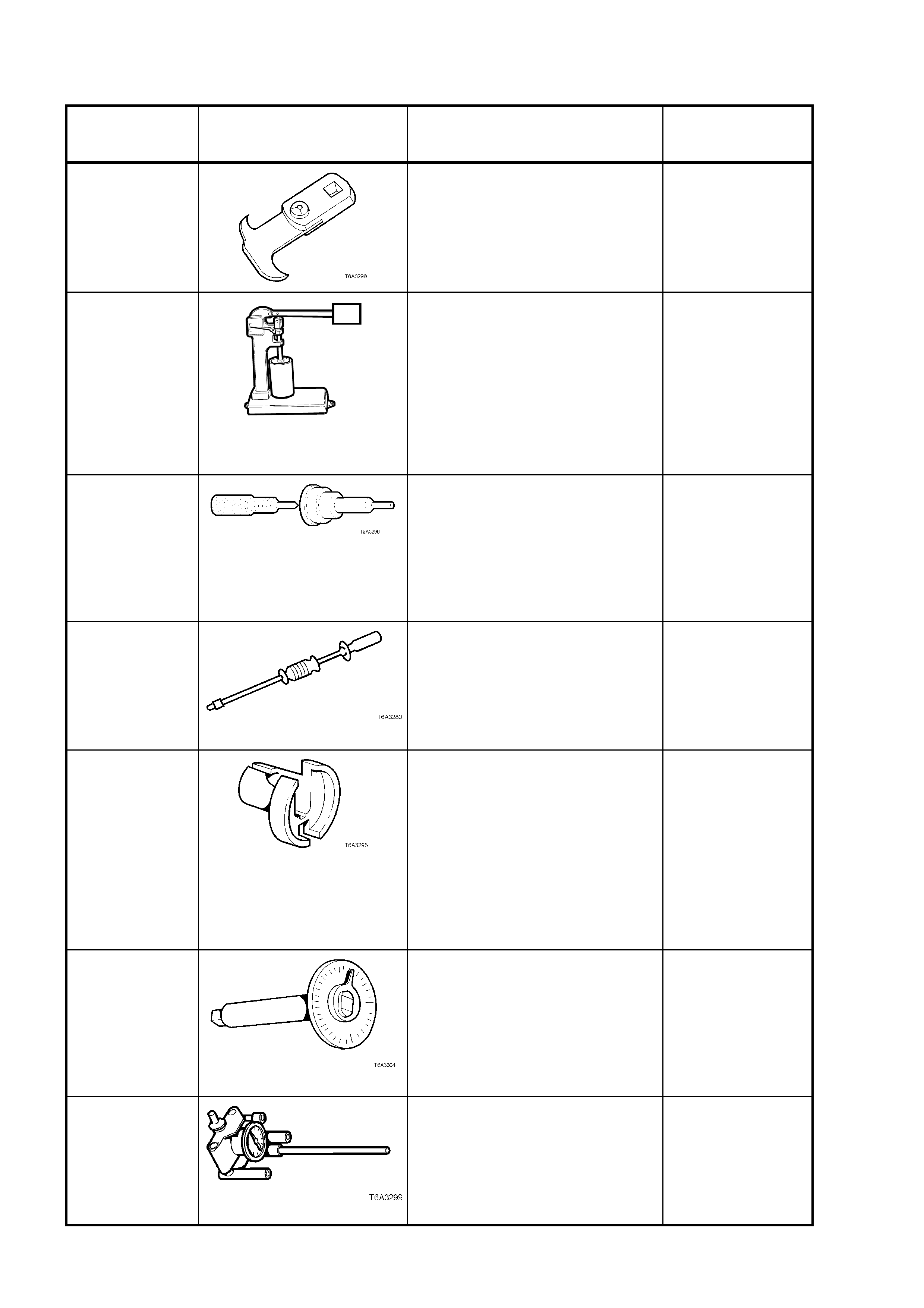
7. SPECIAL TOOLS
TOOL
NUMBER ILLUSTRATION DESCRIPTION CLASSIFICATION
E308
SEAL REMOVER
Previously released.
Also num ber ed, 5675 0
Desirable
49 U012 006
T6A3114b
HYDRAULIC VALVE LIFTER
TESTER
Previously released.
Used in conjunction with testing
fluid SPx No. E1151
Also num ber ed 6A23.
Unique
E1152
VALVE LIFTER ASSEMBLY
TOOLS
Used to assist in assembly of the
hy draulic valve lifters.
Previously released, as 6A24.
Unique
J6125-1B SLIDE HAMMER
Used in conjunction with J 41818
to remove main bearing caps.
Previously released.
Unique
7371
QUICK CONNECT RELEASE
TOOL
Previously released for releasing
fuel line quick connects on V6 S/C
engine after fuel system has been
de-pressurised.
Used on GEN III V8 engine for the
same purpose
Mandatory
E 7115
TORQUE ANGLE WRENCH
Used to accuratel y tighten
fasteners when an angle torque is
required.
Previously released.
Unique
J 8087 CYLINDER BORE CHECKING
GAUGE
Also as a commercial equivalent.
Previously released.
Unique
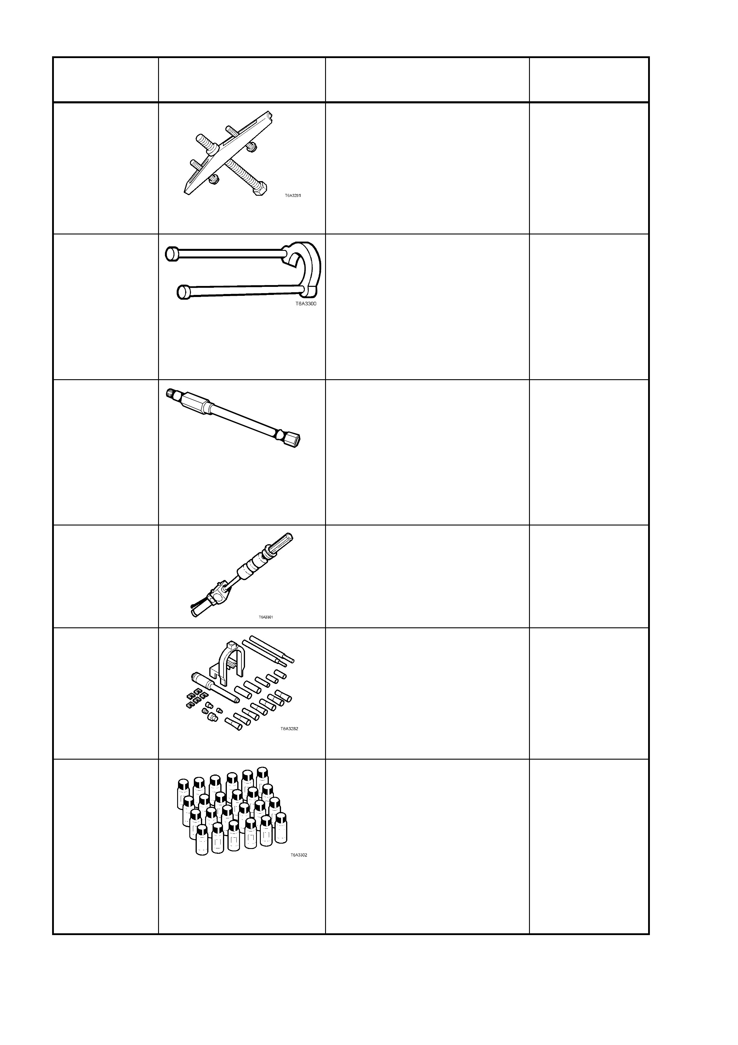
TOOL
NUMBER ILLUSTRATION DESCRIPTION CLASSIFICATION
J 8433-1
PULLEY PULLER
Used to remove GEN III V8
engine crankshaft timing gear
sprocket, in conjunction with J
41558 and J 41816 –2.
Previously released.
Unique
J 21427-01 PULLER AD APT O R
Used in conjunction with J 8433-1,
J 41558 and J 41816-2 to remove
crankshaft timing gear sprocket.
Previously released to remove
automatic transmission speed
sensor ring.
Unique
J 22794
T6A3256a
ADAPTOR
Used to facilitate the application of
air pressure to a cylinder when
replac ing a val ve sprin g or va lv e
stem oil seal with the cylinder
head installed.
Previously released.
Desirable
J 23907
SLIDE HAMMER
Also released as remover, 6A22-2
and slide hammer 7A28.
Previously released.
Unique
J 24086-C
PISTON PIN
REMOVER/INSTALLER
Universal tool containing selective
components to suit multiple
engine applicati ons.
Previously released.
Unique
J 28431-B
FLUID DYE
Used in conjunction with black
light, leak detection lamp J 42220
to locate various types of vehicle
fluid leak s .
Supplied in packs of 24, 1 ounce
bottles.
Previously released.
Desirable
TOOL
NUMBER ILLUSTRATION DESCRIPTION CLASSIFICATION
J 33049
CAMSHAFT BEARING
REMOVER/ INSTALLER
Universal tool containing selective
components to suit multiple
engine applicati ons.
Previously released.
Unique
J 37378-1
VALVE GUIDE REAMER
Used to ream worn valve guides
to su it oversize valve stem.
Previously released.
Unique
J 38836
T6A3 189b
PILOTED DRIVER
Used to install the spigot bush in
the crankshaft.
Previously released.
Unique
J 41476
T6A3257a
FRONT AND REAR COVER
ALIGNMENT TOOL
Used to align both the front and
rear engine covers during
installation.
Previously released.
Desirable
J 41478
T6A3258a
CRANK SHAFT FRONT OIL SEAL
INSTALLER
Threaded bolt, nut and washer are
also used in conjunction with
J 41665 to install the crankshaft
balancer.
Previously released.
Desirable
J 41479
T6A3259
CRANKSHAFT REAR OIL SEAL
INSTALLER
Previously released.
Desirable
J 41480
T6A3260a
FRONT AND REAR COVER
ALIGNMENT TOOL
Used in conjunction with
alignment tool J 41476, to
correctly align the front and rear
engine covers.
Previously released.
Desirable
TOOL
NUMBER ILLUSTRATION DESCRIPTION CLASSIFICATION
J 41556 CONNECTING ROD GUIDES
Used to assist in piston and
connecting rod installation.
Previously released.
Desirable
J 41558 CRANKSHAFT SPROCKET
REMOVER
Used in conjunction with the bolts
from J 21427-01 and pulley puller
J 8433, to remove the crankshaft
sprocket.
Previously released.
Desirable
J 41665
CRANKSHAFT BALANCER
INSTALLER
Comprises stepped sleeve, J
41665-1 and end plate J 41665-2.
Used in conjunction with Tool J
41478, to install the crankshaft
balancer and crankshaft sprocket.
Previously released.
Desirable
J 41712
OIL PRESSURE SENSOR
SOCKET
Used in conjunction with 3/8” drive
socket equipment to
rem ove/r eins ta ll oi l press ure
sensor.
Previously released.
Desirable
J 41816
THREE LEGGED PULLER
Used in conjunction with J 41816-
2 to remove crankshaft balancer.
Also commercially available.
Previously released.
Desirable
J 41816-2
ADAPTOR
Used in conjunction with puller J
41816 to remove crankshaft
balancer.
Previously released.
Desirable
TOOL
NUMBER ILLUSTRATION DESCRIPTION CLASSIFICATION
J 41818
CRANKSHAFT BEARING CAP
REMOVER
Used in conjunction with slide
hammer J 6125-1B to remove
main bearing caps.
Previously released.
Desirable
16296 BLACK LIGHT, LEAK
DETECTION LAMP
Used with dye, Tool J 28431-B to
locate the source of various
ve hicle fluid leaks.
Previously released.
Desirable
J 42385
THREAD REPAIR KIT
Comprises;
Cylinder Head/Rear Main
Bearing Cap K it J 42385-
100
General Kit J 42385-200
Fixtures /Hard war e Kit J 42385-
300
Previously released.
Unique
J 42386
FLYWHEEL HOLDING TOOL
Previously released.
Desirable
J 42907
OIL PRESSURE ADAPTOR
Fitted to the oil filter adaptor and
used in conjunction with a
comm er c ially avai lab le oi l
pressure gauge and hose.
Previously released.
Desirable
J38606
VALVE SPRING COMPRESSOR
Used in conjunction with spark
plug adaptor J 22794 to remove
valve springs with cylinder head/s
installed.
Previously released as KD2078,
for the V6 engine.
Desirable