SECTION 2A - ELECTRONIC CLIMATE CONTROL
(ECC) - PRINCIPLES AND OPERATION
IMPORTANT
Before performing any Service Operation or other procedure described in this Section, refer to Section
00 CAUTIONS AND NOTES for correct workshop practices with regard to safety and/or property damage.
1. GENERAL I NFORMATI O N
An integrated air conditioning sy stem is standard on WH Statesman and Caprice. This integrated system combines
both the heating and cooling functions in a single unit. The system is switched OFF or ON via the ECC module
located in the centre dash facia.
The vehicles interior can be heated, cooled or vented (or a combination of these operations) depending on the
setting of the ECC module.
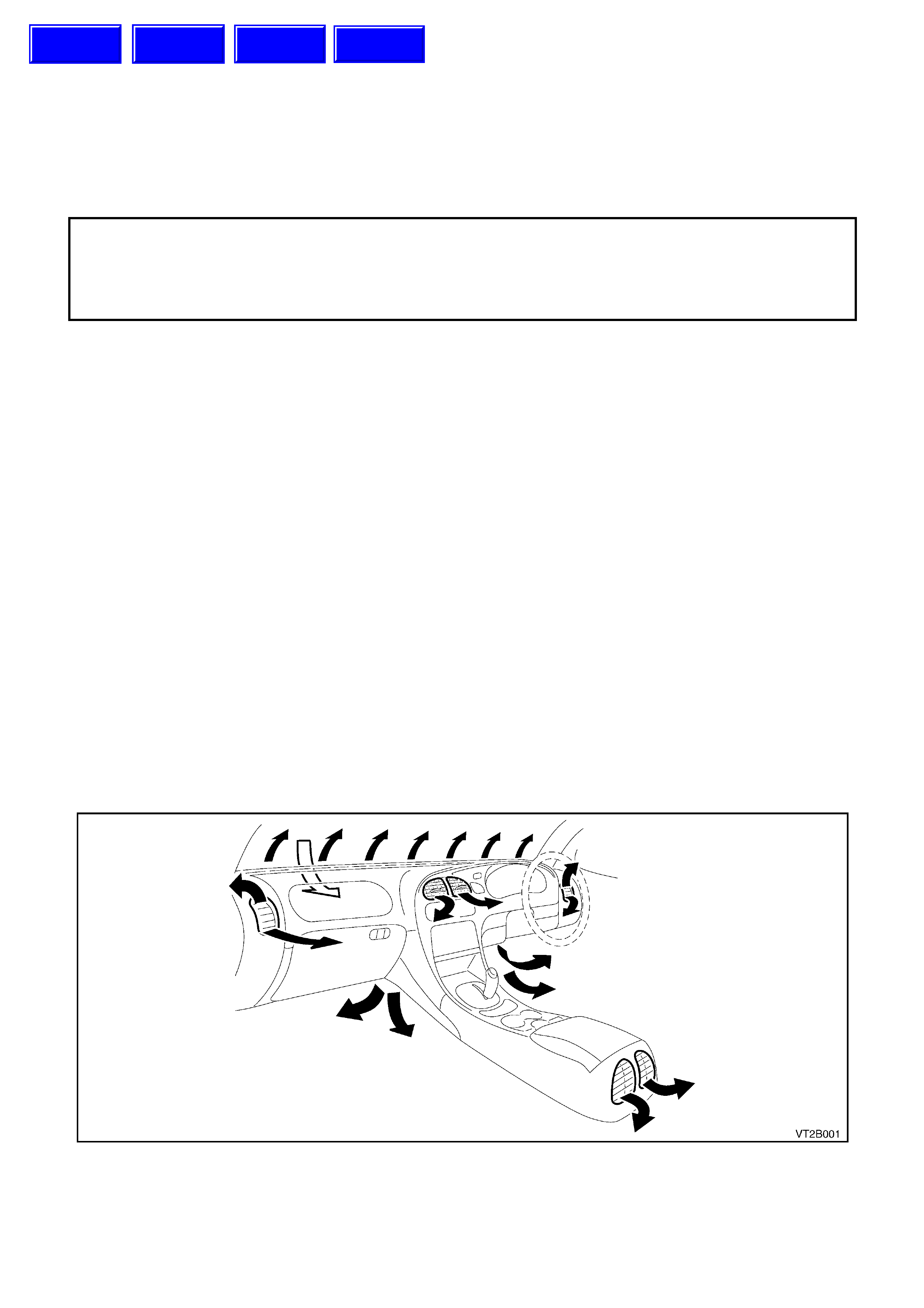
Air enters the ECC system from under the plenum chamber cover. The air then passes through the blower motor,
evaporator and heater assemblies, to be cooled or heated as required. It then exits through the centre, side, floor or
demist outlets into the vehicle interior. The air outlets are dependent on the position activated via the ECC module.
The centre ventilator outlet can be ‘turned down’ to increase airflow to rear outlets once face comfort is achieved.
A five speed blower fan forces air from the plenum chamber through the evaporator and heater assembly, then out
through the various outlets into the vehicle interior.
Outside air is used in all mode positions except when recirculate is selected. This mode can be selected via the
mode control switch and is used to close off the vehicle interior from any outside air.
Recirculate mode is normally selected for:-
•Quick cool down of vehicle interior especially after the vehicle has been parked in direct sunlight for a length
of time.
•Improve heat up time as no cooler outside air can flow into the vehicle interior.
•Driving on unsealed roads to prevent dust entering the vehicle interior.
CAUTION: DO NOT drive a vehicle for extended periods in the recirculation mode as the lack of fresh air
into the vehicle will cause drowsiness and possibly impair driving performance.
Figure 2A-1
Techline
Techline
Techline
Techline

1.1 REFRIGERANT CIRCUIT
The refrigerant circuit illustrated in Fig. 2A-2 (on the following page) incorporates the following major components:
Compressor (5)
Condenser (10)
Evaporator (1)
Thermal Expansion Valve (Block Valve) (2)
Filter Drier Receiver (FDR) (11)
Pressure Transducer (9)
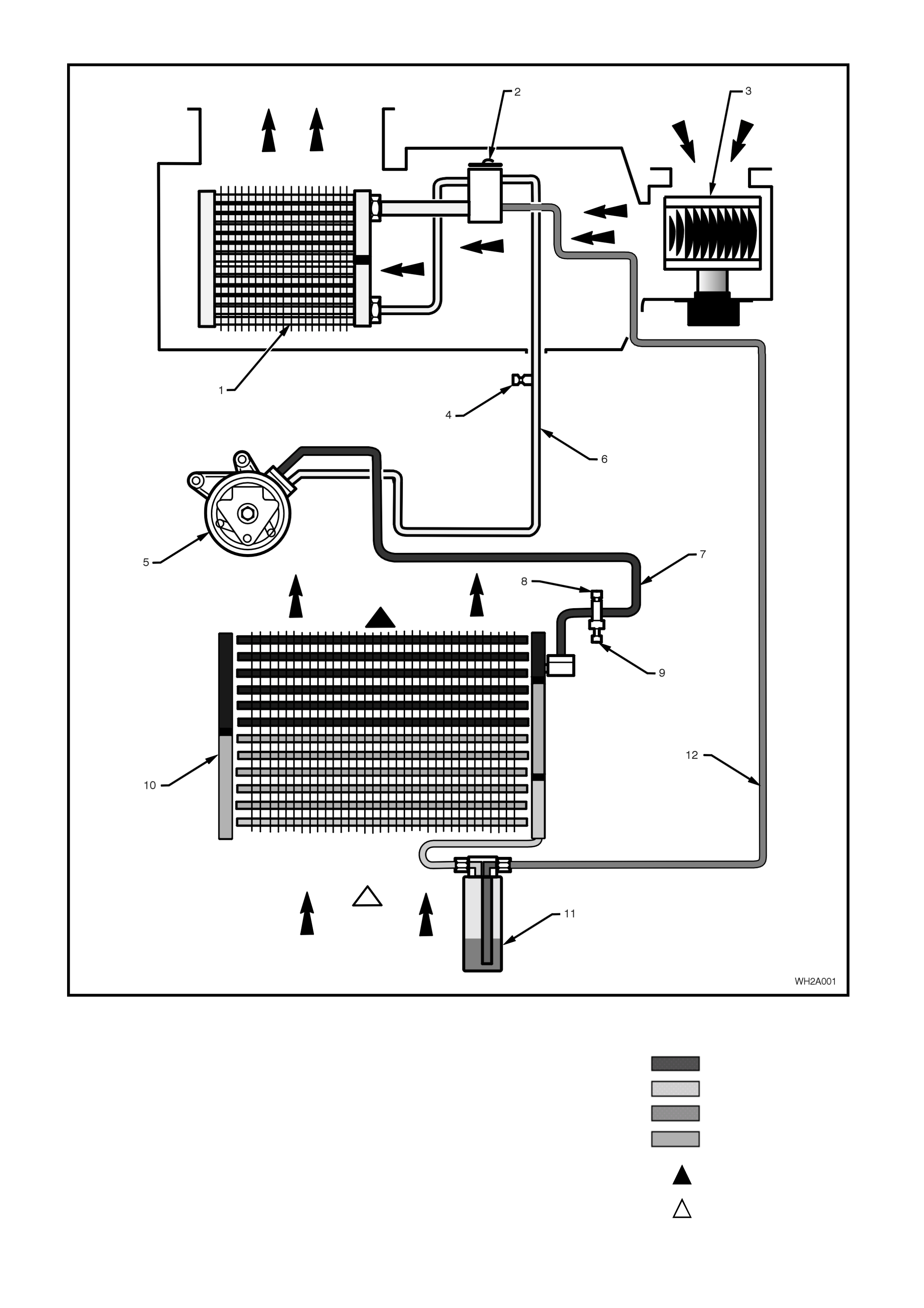
Figure 2A-2
Legend
1. Evaporator
2. Block Valve (thermal expansion device)
3. Blower motor
4. Lowside charging port
5. Compre ssor (HARISSON/DELPHI V5/V7)
6. Suction hose (Lowside)
7. Discharge hose (High side)
8. High side charging port
9. Pressure transducer
10. Condenser (Parallel flow design)
11. Filter drier receiver (FDR)
12. Liquid tube (High side)
H/P Vapour
L/P Vapour
H/P Liquid
L/P Liquid
Heat given off
Ambient
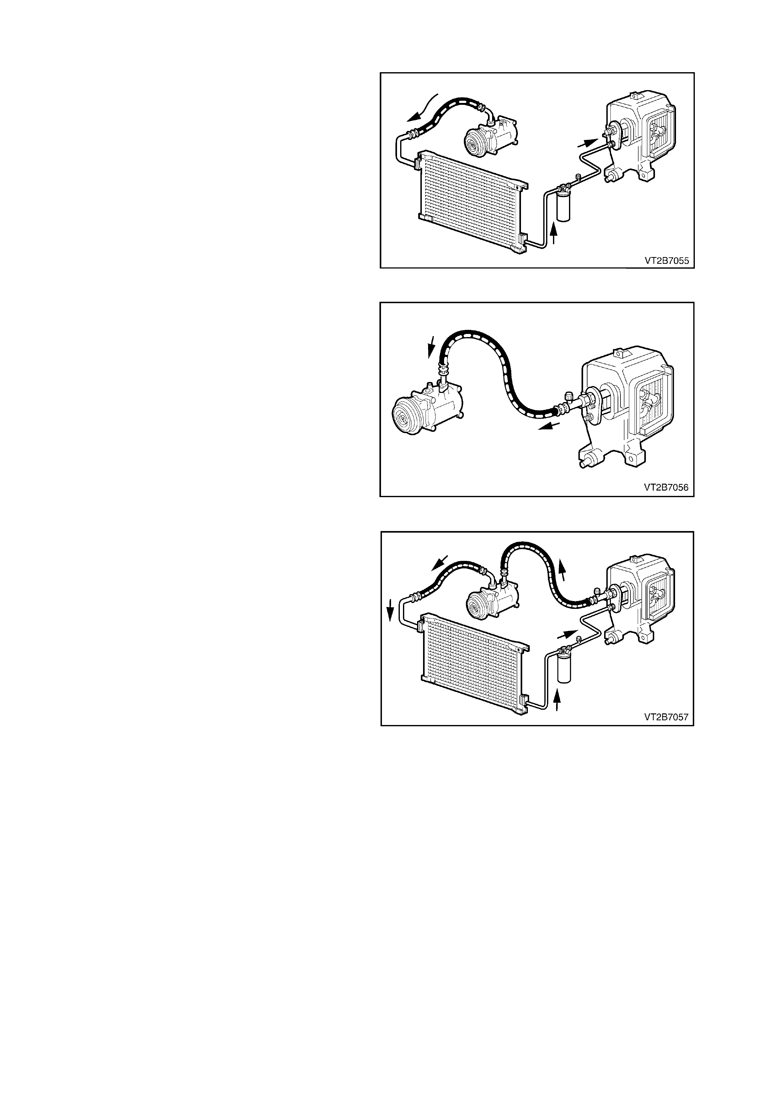
1. 2 PRINCIPLES OF AIR CONDITIONING (TXV SYSTEM)
HIGH PRESSURE SIDE
Low pressure R134a vapour entering the
compressor is compressed to become high-
pressure high temperature R134a vapour. This is
then circulated along with lubricating oil to the
condenser. As the high pressure high temperature
vapour travels through the condenser, heat is
released to the cooler ambient air passing over the
condenser tubes condensing the vapour into a
liquid. This high pressure high temperature liquid
travels through the filter drier (FDR) where it is
cleaned and dried into the therm al expansion valve
(TXV) where a small variable orifice provides a
restriction against which the compressor pushes. Figure 2A-3
LOW PRESSURE SIDE
Liquid R134a is pushed into the evaporator and
suction from the compressor pulls the high
pressure high temperature vapour through the
small variable orifice of the thermal expansion
valve (TXV) and into the low pressure side of the
A/C system. T he R134a is now under low pressure
and becomes a low pressure low temperature
vapour where heat from the cabin being blown over
the evaporator coil surface is absorbed into the
vapour, which then flows on to the compressor.
The A/C cyc le begins again as the R134a vapour is
compressed and discharged under pressure. Figure 2A-4
HEAT TRANSFER
R134a in the HIGH PRESSURE side is HOT and
the cooler ambient air moving over the condenser
can absorb heat from it.
R134a in the LOW PRESSURE side is COLD and
can absorb large quantities of heat from the air
moving over the evaporator.
Figure 2A-5
Summary
• When the R134a pressure is high, the R134a
temperature is high.
• When the R134a pressure is low, the R134a
temperature is low.
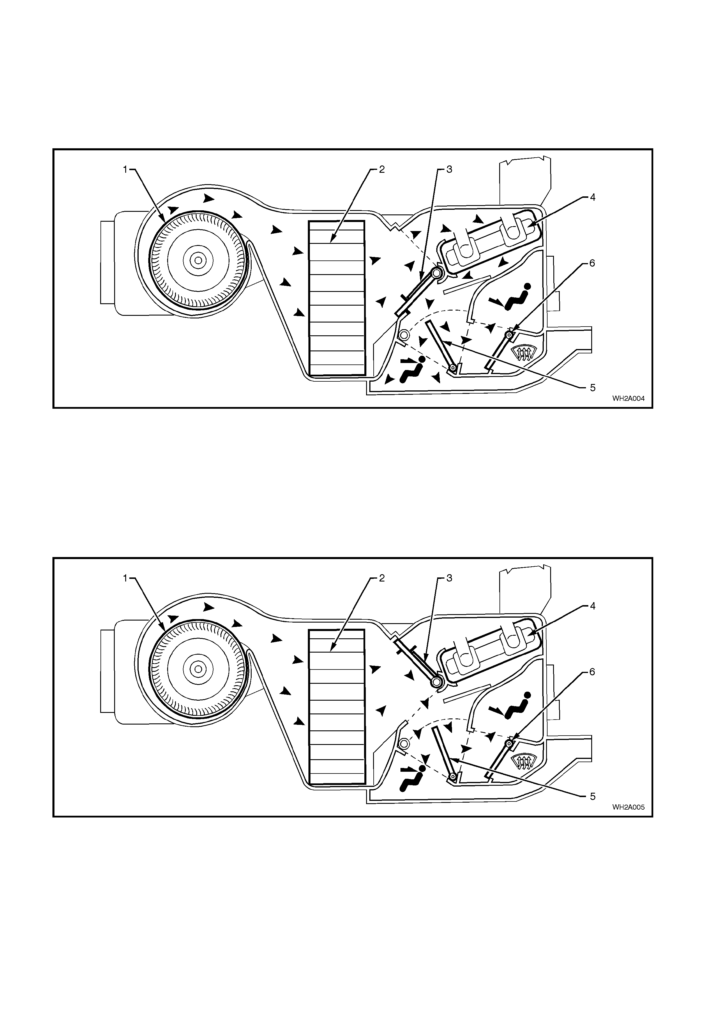
1.3 HEATING, VENTILATION AND AIR CONDITIONING (HVAC) UNIT
AIR FLOW MODE S
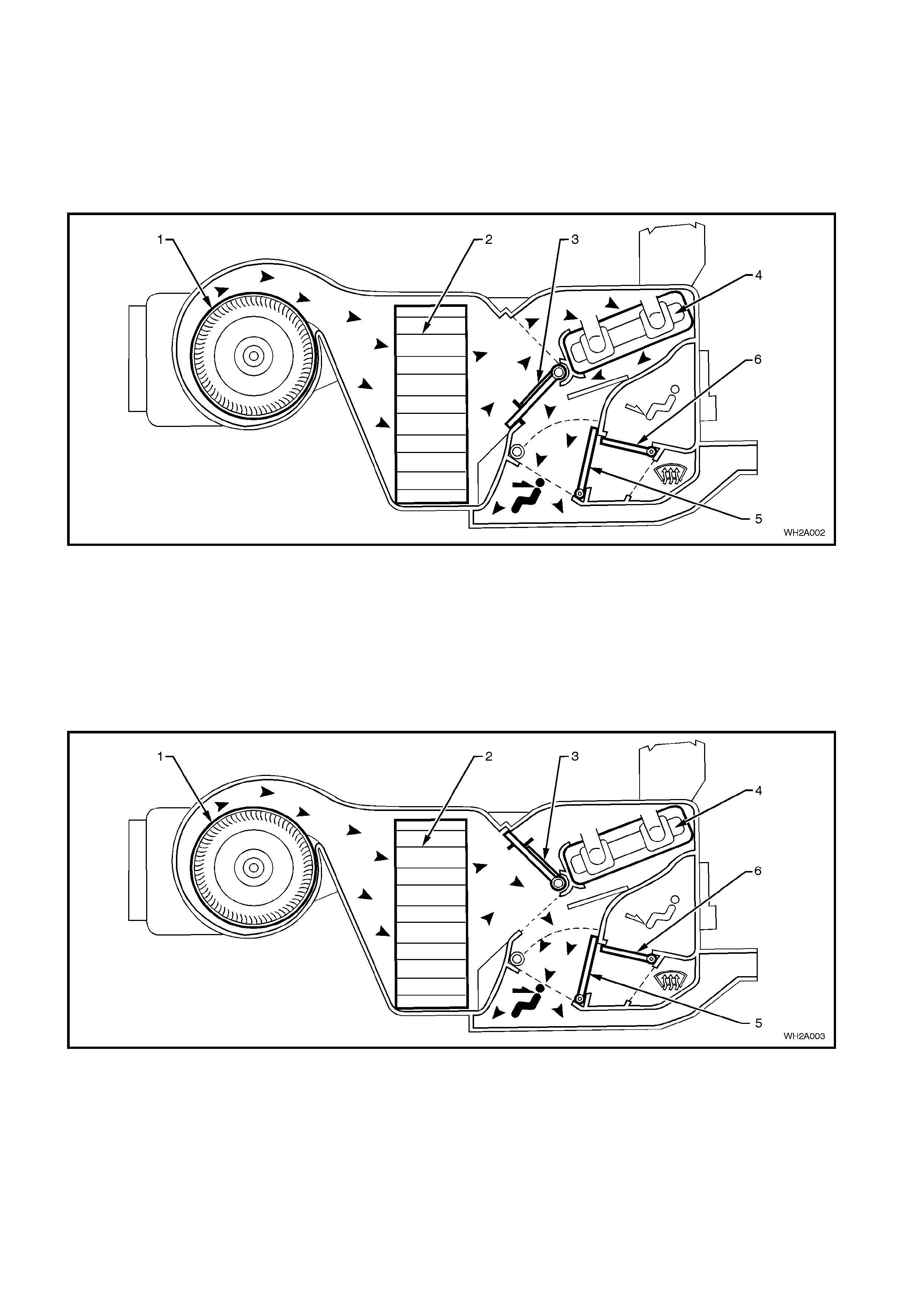
FACE MODE
Full Heat
Air is drawn into the HVAC unit by the blow er motor. This air is then forced through the evaporator core fins; through
the hot heater core fins and directed through the open mode door onto the centre and side vents.
Figure 2A-6
Legend
1. Blower fan.
2. Evaporator core. 3. Air mix door.
4. Heater core. 5. Mode door.
6. Demist/Floor door.
Full Cold
Air is drawn into the HVAC unit by the blower motor, and is then forced through the cold evaporator fins. In full cold
mode, the air mix door is fully closed sealing off the passage through the heater core. The cold air travels through
the open mode door and is directed through the centre and side vents.
Figure 2A-7
Legend
1. Blower fan.
2. Evaporator core. 3. Air mix door.
4. Heater core. 5. Mode door.
6. Demist/Floor door.
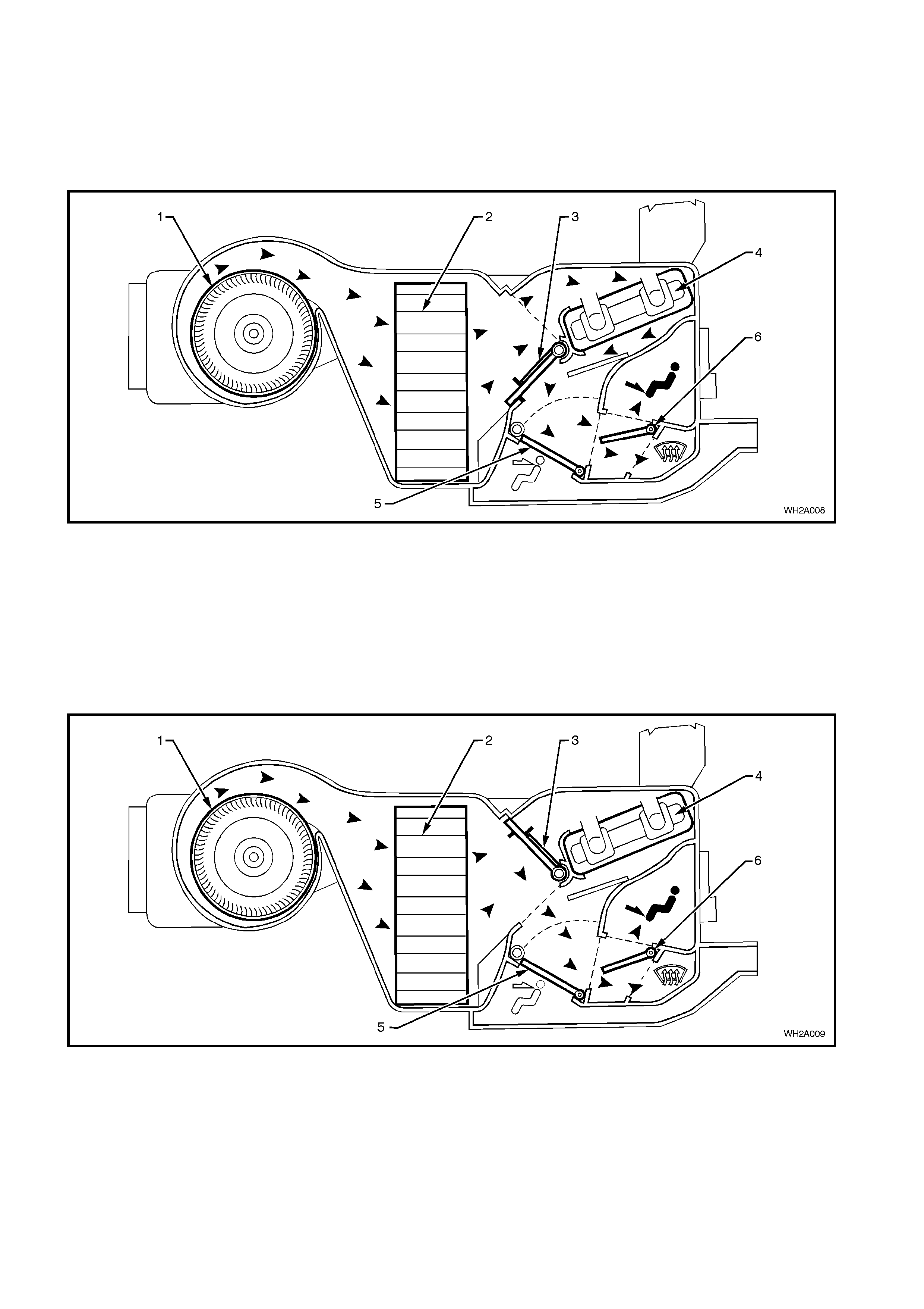
BI-LEVEL MODE
Full Heat
Air is drawn into the HVAC unit by the blower motor. This air is then forced through the evaporator fins. In full heat
mode, the air mix door is fully open allowing all the air to flow through the hot heater core fins, picking up heat as it
travels. From the heater core the heated air travels around the half opened mode door and is directed to both the
floor ducts, centre and side vents.
Figure 2A-8
Legend
1. Blower fan.
2. Evaporator core. 3. Air mix door.
4. Heater core. 5. Mode door.
6. Demist/Floor door.
Full Cold
Air is drawn into the HVAC unit by the blow er motor. This air is then forced through the cold evaporator core fins. In
full cold mode, the air mix door is fully closed sealing off the passage to the heater core. The cold air then travels
around the half opened mode door and is directed to both the floor ducts, centre and side vents.
Figure 2A-9
Legend
1. Blower fan.
2. Evaporator core. 3. Air mix door.
4. Heater core. 5. Mode door.
6. Demist/Floor door.

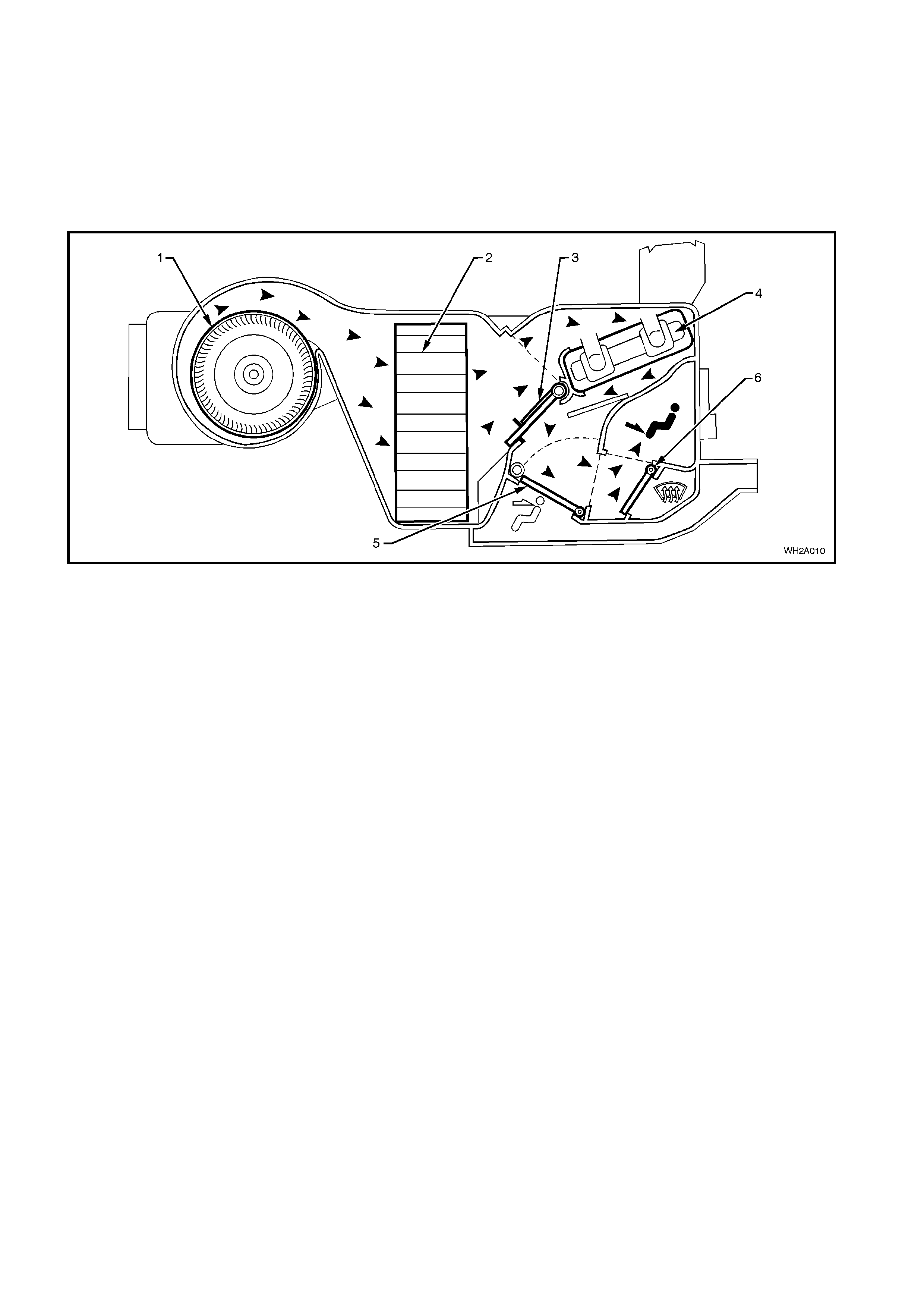
FLOOR MODE
Full Heat
Air is drawn into the HVAC unit by the blow er motor. This air is then forced through the non evaporator fins. In full
heat mode, the air mix door is fully open. This allows all the air to flow through the hot heater core fins, picking up
heat as it travels. From the heater core the heated air travels through the open demist/floor door and is directed to
the floor.
Figure 2A-10
Legend
1. Blower fan.
2. Evaporator core. 3. Air mix door.
4. Heater core. 5. Mode door.
6. Demist/Floor door.
Full Cold
Air is drawn into the HVAC unit by the blower motor. This air is then forced through the cold evaporator fins. In full
cold mode, the air mix door is fully closed sealing off the passage to the heater core. The cold air then travels
through the open demist/floor door and is directed to the floor.
Figure 2A-11
Legend
1. Blower fan.
2. Evaporator core. 3. Air mix door.
4. Heater core. 5. Mode door.
6. Demist/Floor door.
BLEND MODE
Full Heat
Air is drawn into the HVAC unit by the blower motor. This air is then forced through the evaporator fins. In full heat
mode, the air mix door is fully open. This allows all the air to flow through hot heater core fins, picking up heat as it
travels. From the heater core the heated air travels around the half open demist/floor door and is directed to both
the front windscreen and floor.
Figure 2A-12
Legend
1. Blower fan.
2. Evaporator core. 3. Air mix door.
4. Heater core. 5. Mode door.
6. Demist/Floor door.
Full Cold
Air is drawn into the HVAC unit by the blow er motor. This air is then forced through the cold evaporator core fins. In
full cold mode, the air mix door is fully closed sealing off the passage to the heater core. The cold air then travels
around the half open demist/floor door and is directed to both the front windscreen and floor.
Figure 2A-13
Legend
1. Blower fan.
2. Evaporator core. 3. Air mix door.
4. Heater core. 5. Mode door.
6. Demist/Floor door.
DEMIST MODE
Full Heat and A/C Activated
Air is drawn into the HVAC unit by the blower motor. This air is then forced through the cold evaporator fins. In full
heat mode, the air mix door is fully open. This then allows all cooled air to flow through the hot heater core fins,
picking up heat as it travels. From the heater core the heated air travels around to the demist passage and onto the
front windscreen via the demist vents.
NOTE: By activating the A/C compressor in this mode dehumidification will take place, de-fogging the front
windscreen and side windows in a shorter duration.
Figure 2A-14
Legend
1. Blower fan.
2. Evaporator core. 3. Air mix door.
4. Heater core. 5. Mode door.
6. Demist/Floor door.
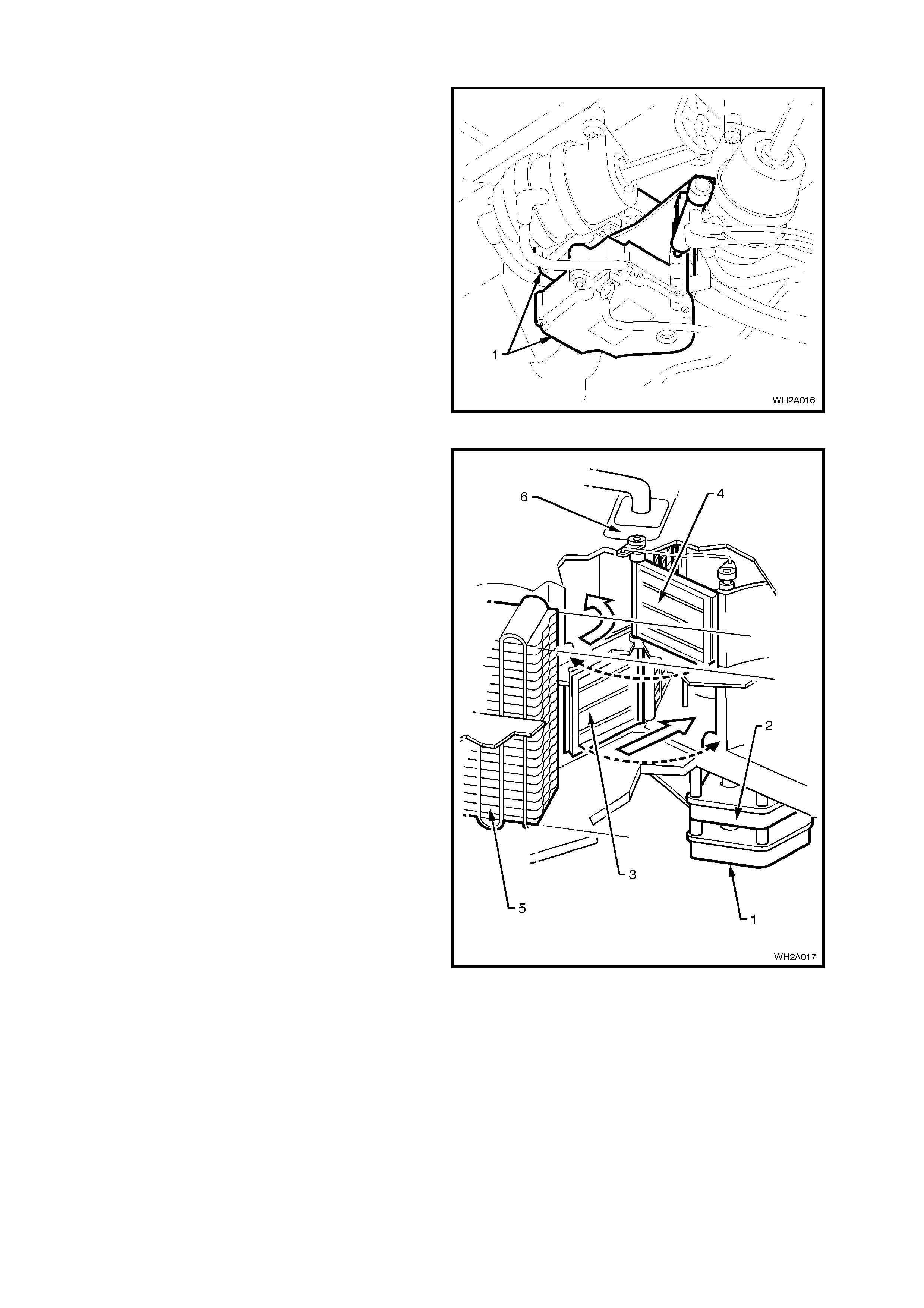
1.4 A/C SYSTEM COMPONENTS
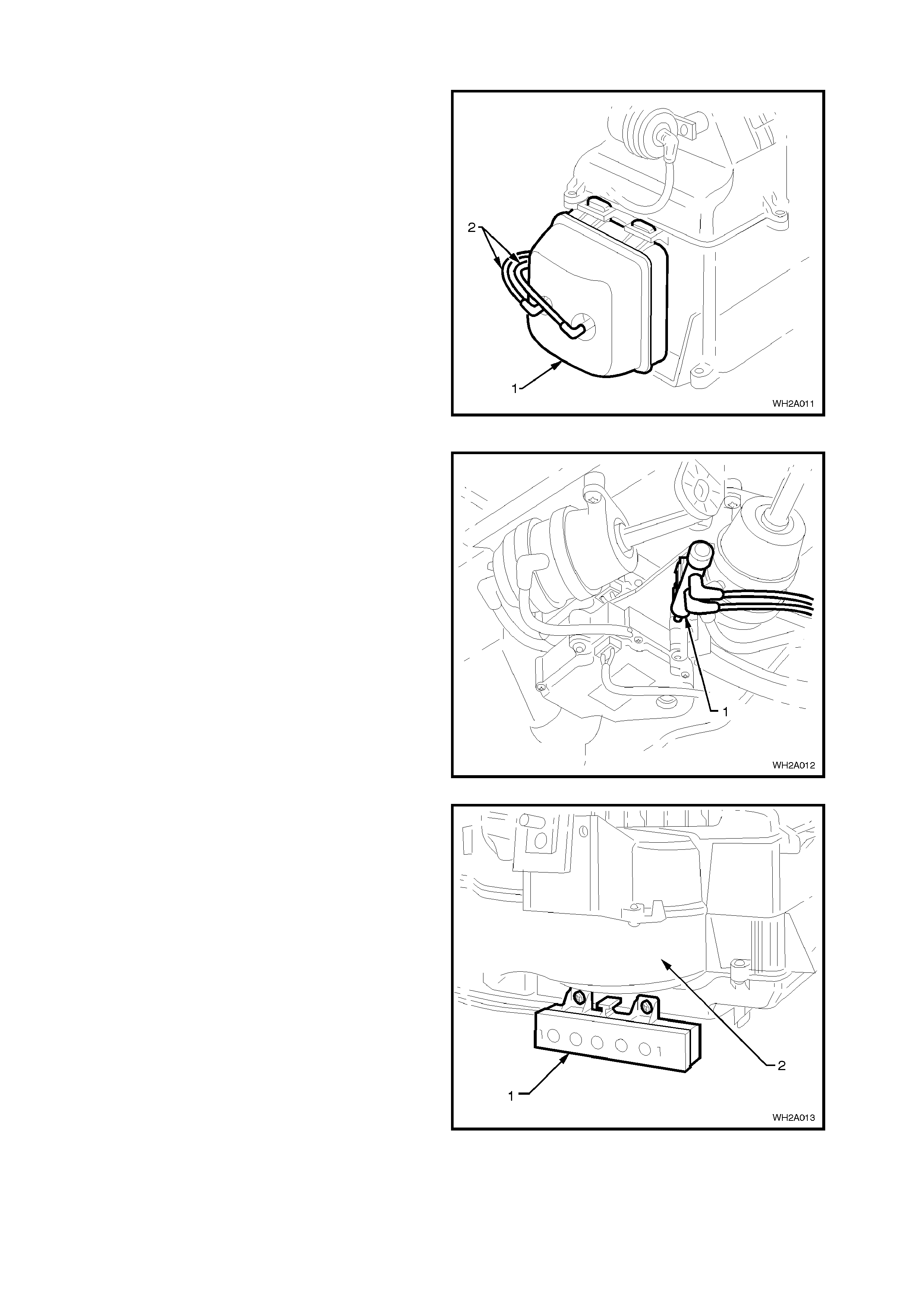
VACUUM TANK
The vacuum tank (1) is located on the left side of
the HVAC unit and is secured with one self tapping
screw.
This tank is used to maintain vacuum to the
vacuum actuators (which operate the different vent
positions) via vacuum lines (2) during driving
situations where the vacuum source is low such as
full engine throttle. A one way valve is located in the
vacuum source line from the inlet manifold.
Figure 2A-15
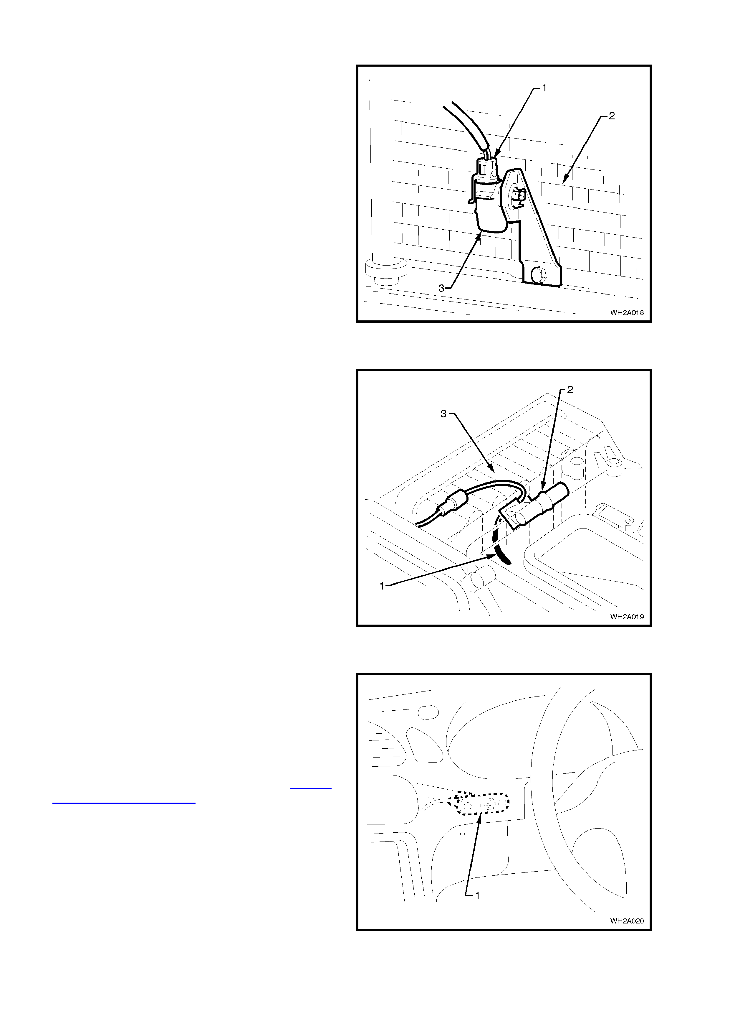
VACUUM SWITCH
A vacuum switch (1) is located on the underside of
the HVAC unit between the vacuum actuators.
The heater water valve is held in the OFF position
by vacuum. A lever attached to the air mix motor
activates a plunger on the vacuum switch. As the
air mix m otor opens the air mix door from full cold,
the vacuum switch plunger is activated and the
vacuum in the heater water valve line is vented
allowing hot water to flow into the heater core.
Figure 2A-16
VACUUM SOLENOID PACK
Located on the lower rear of blower motor housing
(2), the vacuum solenoid pack (1) consists of a
band of five electronically activated vacuum
solenoids used to apply or remove vacuum to the
vacuum actuators to alter air distribution positions.
Power is used to engage these s olenoids and allow
vacuum to flow to an actuator. Removing this
power de-energises the solenoid pack and allows
any vacuum contained in the actuator and line to
vent through the front section of the solenoid pack.
Figure 2A-17
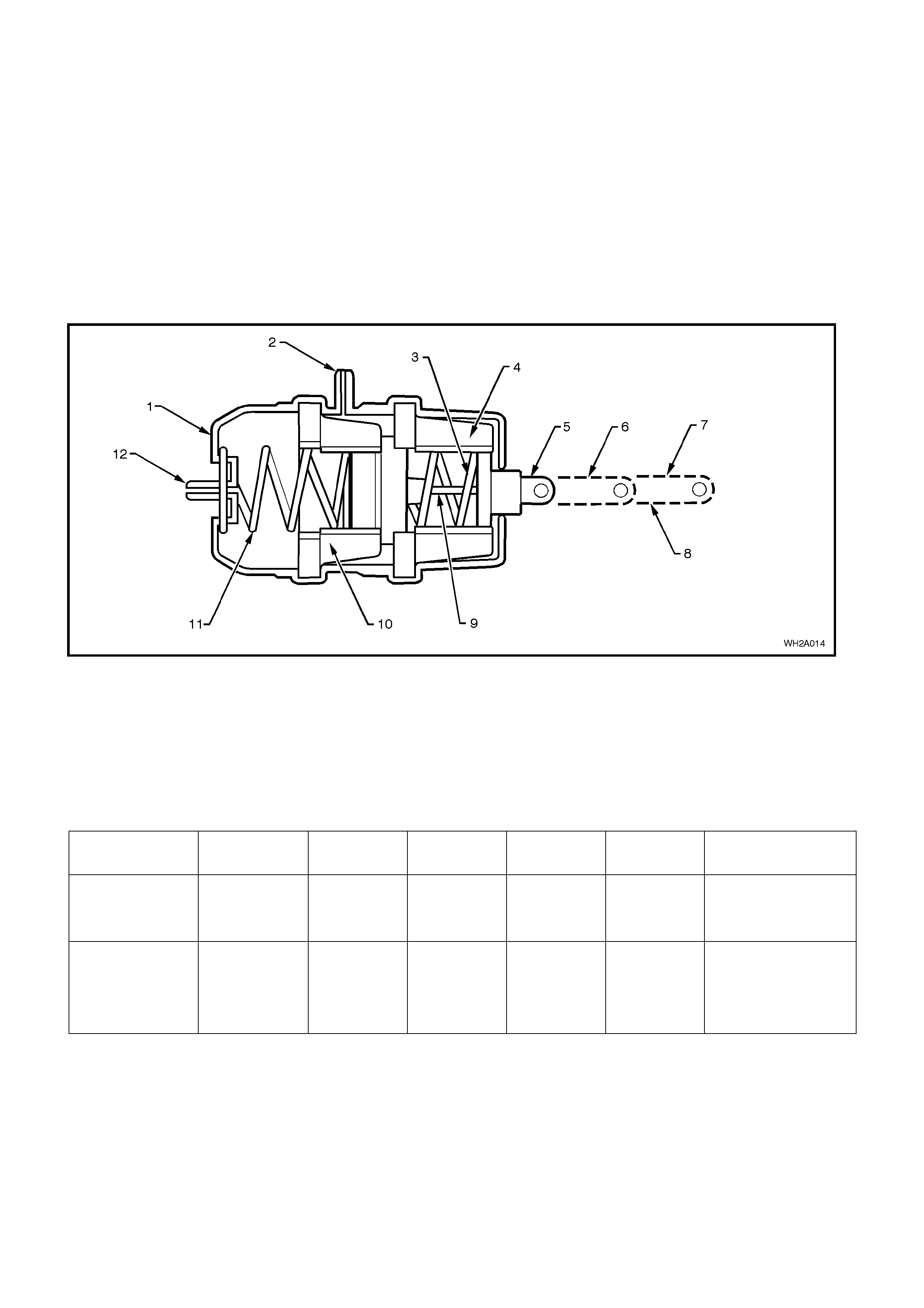
TWO STAGE VACUUM ACTUATOR
Operation
The HVAC unit has doors that are required to open half way while another door closes fully. With normal single
stage vacuum actuators, this would require a complicated linkage set-up and additional actuators.
To overcome this situation ‘two stage’ actuators are used. Through their design they can move the actuating rod
fully (second stage), half way (1st stage) and fully extended (no vacuum). This enables some doors housed within
the HVAC unit to be only half open when a ‘blend’ mode is selected, and other doors to be closed at the same time
via another actuator.
When vacuum is directed to the first stage vacuum port only the first stage rubber diaphragm is pulled (towards the
rear of the housing), moving the actuator rod only half way. Once the second stage is selected vacuum is also
directed to the second stage vacuum port which pulls on the second stage rubber diaphragm, fully retracting the
actuator rod. The extent of actuator rod travel in either first or second stage is governed by compressing two springs
on each vacuum diaphragm. Both these springs are of differing tensions.
Figure 2A-18
Legend
1. Housing.
2. Vacuum port 1ST stage.
3. Spring.
4. 1ST Stage diaphragm.
5. 2ND Stage.
6. 1ST STAGE (Half)
7. Fully extended.
8. Actuation rod.
9 2ND Stage diaphragm
10. Spring.
11. Actuation rod.
Identification
Black-Blend (Demist/Floor).
White-Bi-Level/Centre Vent.
12. Vacuum port 2ND stage.
ACTUATOR CENTRE
VENT BI-LEVEL FLOOR BLEND DEMIST RECIRCULATION
DEMIST/FLOOR
ACTUATOR
(BLACK ROD)
FULLY
EXTENDED 2ND STAGE 2ND STAGE 1ST STAGE FULLY
EXTENDED FULLY EXTENDED
MODE
ACTUATOR
(WHITE ROD)
BI-LEVEL/FACE
2ND STAGE 1ST STAGE FULLY
EXTENDED FULLY
EXTENDED FULLY
EXTENDED 2ND STAGE

VACUUM CIRCUIT
Vacuum is used to control the ON/OFF functions of the vent modes and the heater tap. This vacuum is provided by
the engine.
The engine vacuum moves from the inlet manifold to a vacuum tank located on the HVAC unit. This vacuum tank is
used to store vacuum in times when engine vacuum is low such as at full engine throttle. A check valve is fitted on
the supply line from the engine inlet manifold.
Through a black plastic vacuum tube, the vacuum moves to the vacuum solenoid pack. This black plastic tube is
also teed off to the vacuum control valve. From the control valve, vacuum moves into a yellow plastic tube and onto
the vacuum operated heater water valve. Vacuum is used to maintain full closure of this valve and no hot water can
flow.
As the ECC mode switch is selected, electronic solenoids are activated in the solenoid pack causing vacuum to
move to the desired vacuum actuator through different coloured plastic tubing. This vacuum will activate the
vacuum actuator rod, which then moves a vent position door.
Fig. 2A-18 shows which vacuum actuators are applied with vacuum in a certain mode.
Vacuum is vented from the vacuum actuator/plastic tube once the vacuum ECC mode switch is used to select a
different setting.
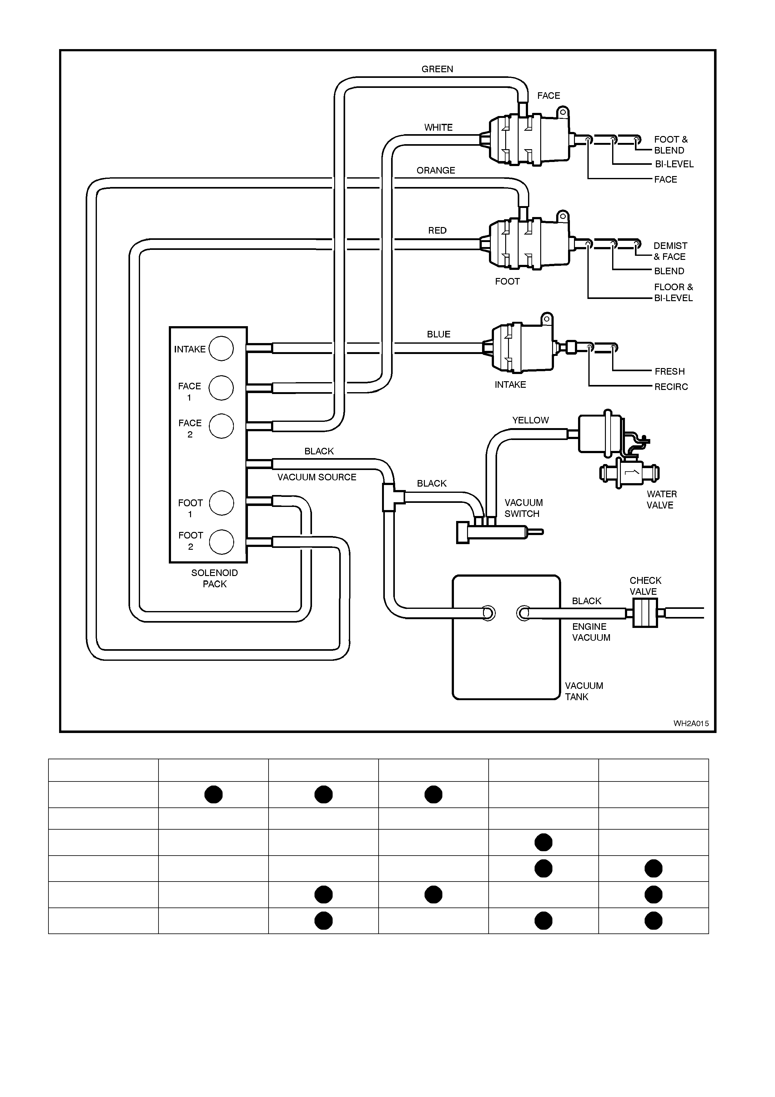
Figure 2A-19
MODE INTAKE FACE 1 FACE 2 FOOT 1 FOOT 2
RECIRC
DEMIST
BLEND
FOOT
FACE
BI-LEVEL
VACUUM DEFAULT MODE: FRESH AIR AND DEMIST
AIR MIX DOOR MOTORS
The air mix door motor(s), or stepper motor(s) (1)
are located under the HVAC unit. T hey ar e used to
operate the air mixing door(s) and are connected
either directly to the air mix door shaft or indirectly
via a rod.
The ECC has two air mix motors operating two
individual air mixing doors.
Air mix motor movement is achieved by sending a
12 volt signal between the ECC module to the air
mix motor. There is also a 3.5 ±0.2 volt ‘feedback’
signal from the air mix motor to the ECC module as
to the location of the air mix door (in relation to air
mix motor drive location).
Figure 2A-20
1. Primary air mix motor (drivers side).
2. Secondary air mix motor (passenger side).
3. Air mix door lower (drivers side).
4. Air mix door upper (passenger side).
5. Evaporator core.
6. Heater core.
Figure 2A-21
AMBIENT TEMPERATURE SENSOR
The ambient temperature sensor (3) is located on
the lower driver’s side of the A/C condenser (2).
It is a therm istor type (NTC) res is tor and is us ed to
monitor the ambient (outside) temperature. This
sensor is slow reacting due to the dense plastic
housing surrounding it. The ECC takes into account
road speed before updating the temperature
display to avoid false readings in heavy traffic or
extended idle conditions.
Resistance signals are sent directly from the
ambient tem perature sens or to the ECC m odule f or
interpretation.
Figure 2A-22
EVAPORATOR AIR TEMPERATURE SENSOR
The evaporator air temperature sensor (1) is
located on top of the evaporator blower assembly
case near the aspirator venturi (2).
It is a thermistor type (NTC) resistor used to
monitor the temperature of the air into the HVAC
unit after it has passed through the evaporator coil
(3). Resis tance values are read direc tly to the ECC
Module for interpretation.
Figure 2A-23
IN-CAR TEMPERATURE SENSOR
The in-c ar tem perature sensor (1) is located on the
lower driver’s s ide dash panel between the st eering
wheel and console.
It is also a thermistor type (NTC) resistor used to
monitor the vehicle’s interior temperature.
Resistance signals are read directly by the ECC
Module for interpretation.
It is essential that the aspirator tube (refer 1.4 A/C
SYSTEM COMPONENTS – Aspirator Tube in this
Section) is connected to give correct operation.
Figure 2A-24
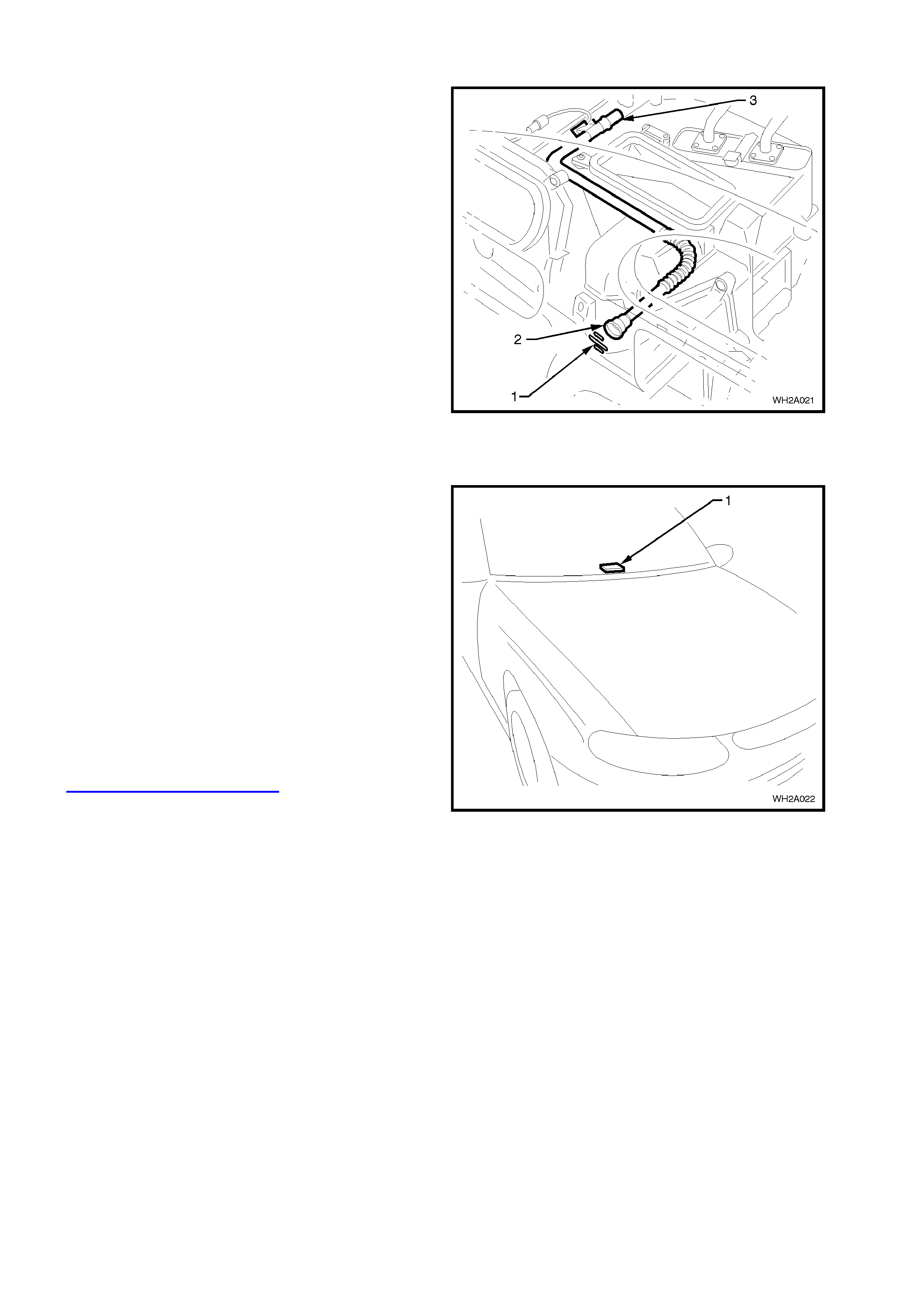
ASPIRATOR TUBE
Located on the top of the HVAC unit case to the
rear of the in-car temperature sensor (1), the
aspirator tube (2) is a convoluted plastic tube
attached from a venturi to the rear of the in-car
temperature sensor housing. Once any fan speed
is selected air from the vehicle interior is sucked to
the in-car temper ature sensor via the as pirator tube
and aspirator venturi (3). T his is used to aid the in-
car temperature to react quickly to any changes
taking place within the vehicle interior.
Figure 2A-25
SOLAR SENSOR
The solar sensor (sun sensor / remote receiver
module) (1) is located in the centre of the Demist
panel and is us ed to monitor the sun load upon the
vehicle. It is a photochem ical type sensor , m eaning
that a small electrical current will be created
depending on the sun load (s trength) over it. W hen
the sun load is high, a higher blower fan speed and
increased cooling will be selected by the ECC
Module automatically. Likewise, when the sun load
is low, such as going into an underground car park ,
the ECC Module will automatically reduce the fan
speeds and increase heating slightly.
Signals are sent from the solar sensor directly to
the BCM then to the ECC Module via the serial
data.
NOTE: Solar sensor diagnostics can be found in
Section 2C Air Conditioning – ECC – Servicing
and Diagnosis. Figure 2A-26
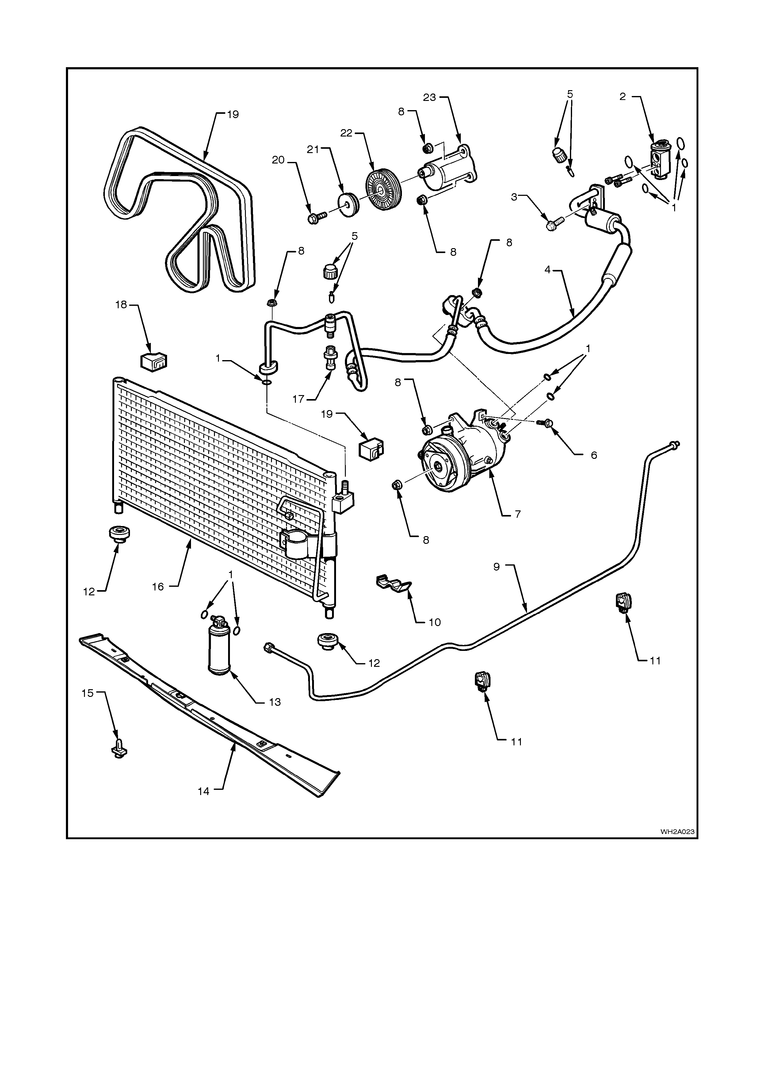
ENGINE BAY COMPONENTS V6
Figure 2A-27
Legend
1. O-Ring 9. Liquid tube 17. Pressure transducer
2. Thermal expansion valve (or block valve) 10. Clamp 18. Upper mounting grommet
3. Bolt 11. Clip 19. Drive belt
4. Suction hose 12. Lower mounting grommet 20. Idler pulley mounting bolt
5. Schraeder valve and cap 13. Filter Drier Receiver (FDR) 21. Idler pulley cover
6. Bolt 14. Air chute lower baffle 22. Idler pulley
7. Compressor 15. Scrivet 23. Idler pulley mounting bracket
8. Nut 16. Condenser
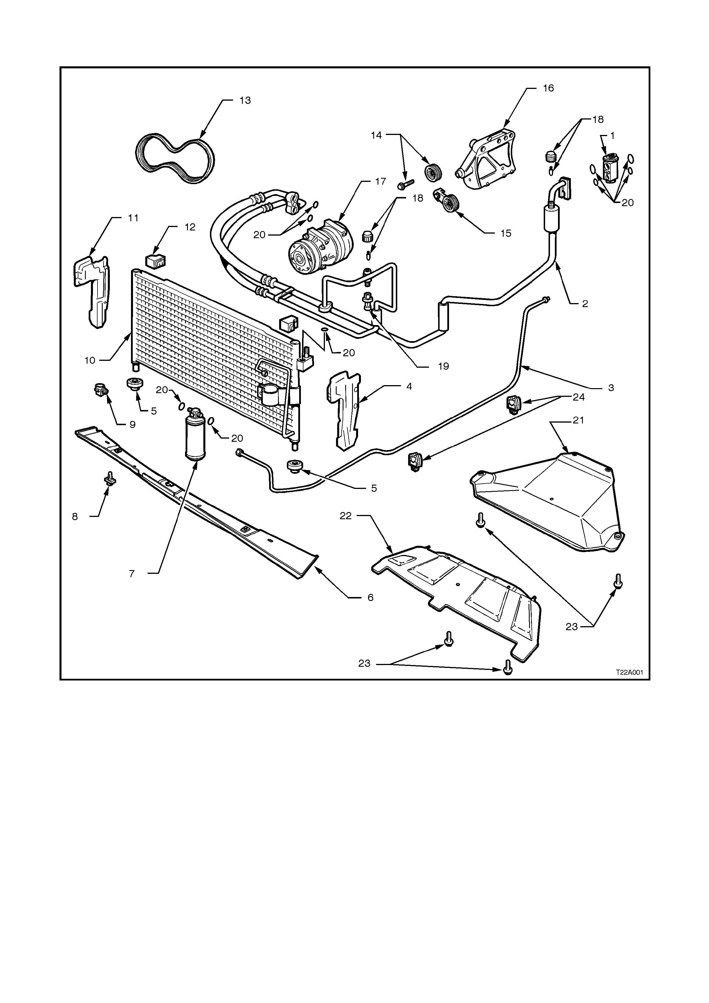
ENGINE BAY COMPONENTS GEN III V8
Figure 2A-28
Legend
1. Thermal expansion valve (or block valve) 10. Condenser 19. Pressure transducer
2. Discharge/Suction hose tube assembly 11. RH air chute 20. O-Ring
3. Liquid line 12. Upper mounting grommet 21. Oil pan guard
4. LH air chute 13. Drive belt 22. Lower air chute extension
5. Lower mounting grommet 14. Drive belt idler pulley 23. Bolt
6. Air chute lower baffle 15. Drive belt tensioner 24. Clip
7. Filter Drier Receiver (FDR) 16. Compressor mounting bracket
8. Scrivet 17. Compressor
9. Ambient air temperature sensor 18. Schraeder valve and cap
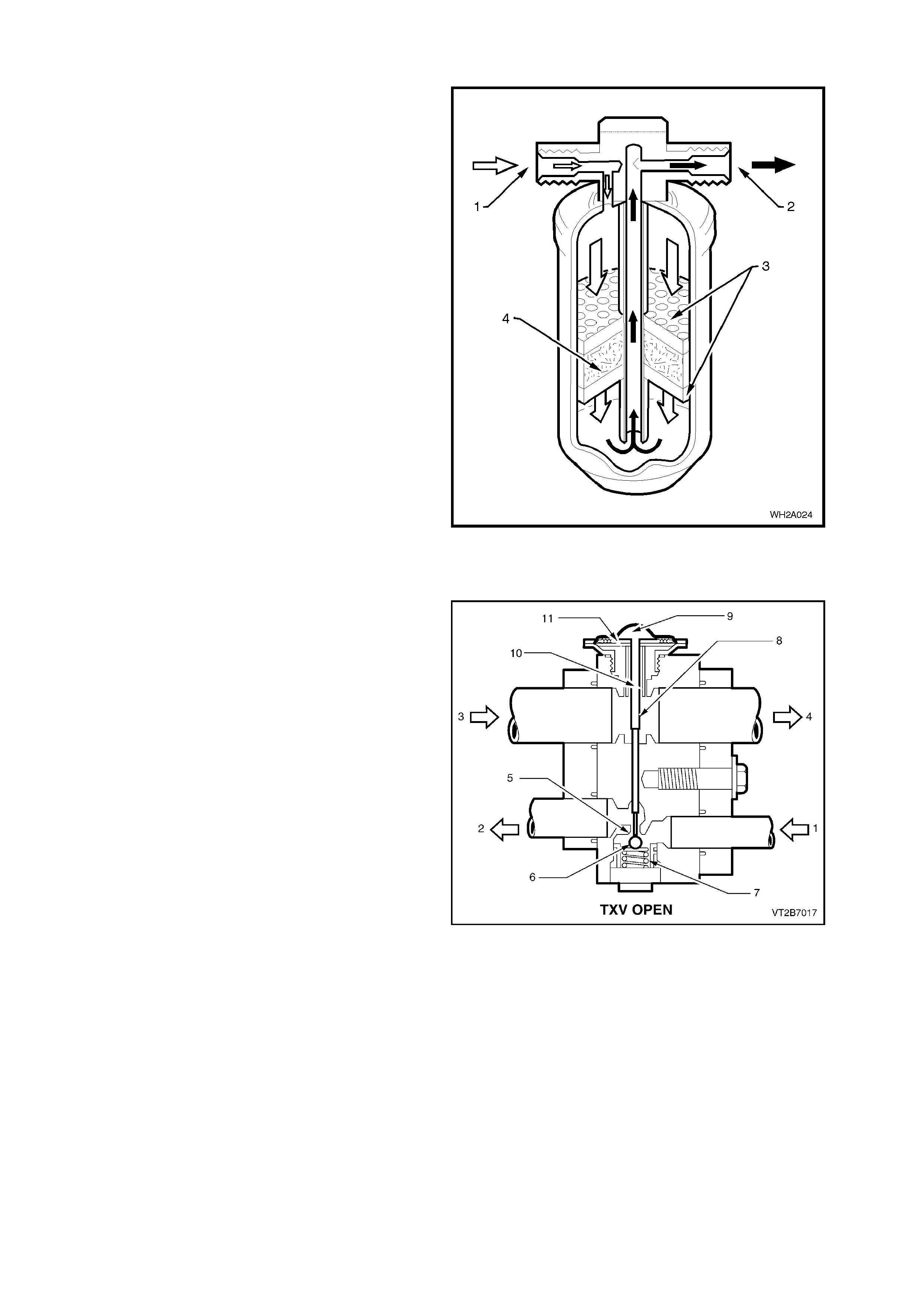
FILTER DRIER RECEIVER
The filter drier acts as a particle filter, refrigerant
storage container and most importantly a moisture
absorber.
Moisture, temperature and R134a cause
hydrofluoric and hydrochloric acid. The silica gel
beads (desiccant) located in the FDR absorb small
quantities of moisture thus preventing acid
establishment.
NOTE: Ensure the connection indicated with the
word ‘IN’ is connected to the condenser outlet.
1. From condenser - High pressure liquid.
2. To evaporator - High pressure liquid.
3. Strainer.
4. Desiccant.
Figure 2A-29
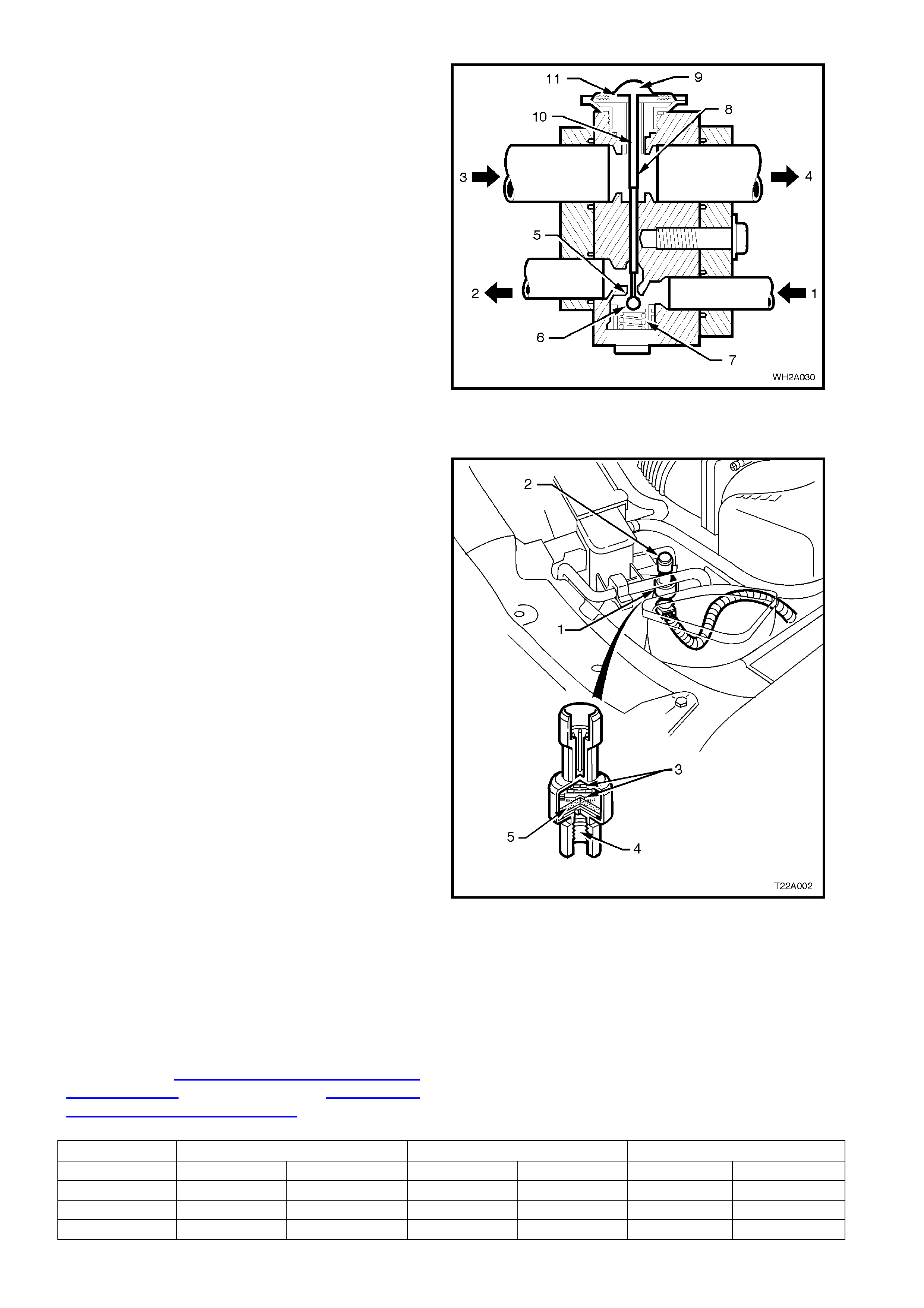
THERMAL EXPANSION VALVE (BLOCK VALVE)
This valve has two refrigerant passages. One is in
the refrigerant line from the condenser to the
evaporator and contains a ball and spring valve.
The other passage is in the refr igerant line fr om the
evaporator to the compressor and contains the
temperature sensing element.
1. From Filter Drier
2. To Evaporator Coil
3. From Evaporator
4. To Compressor
5. Metering Orifice
6. Ball
7. Spring
8. Activating Pin
9. Refrigerant
10. Pressure Compensation Under Diaphragm
11. Metallic Diaphragm
Opening
As the non-cooled refrigerant from the evaporator
coil flows thr ough the block valve outlet (suc tion), it
makes contact with the underside of the thin
metallic diaphragm (11) and reacts on the
refrigerant contained above that diaphragm. This
refrigerant then expands forcing the pin (8)
downwards moving the ball (6) off its seat (5),
compressing the spring (7) and allowing more
refrigerant to enter the evaporator.
Figure 2A-30
Closing
Similar operation as opening but now the
refrigerant from the evaporator is cold. The
refrigerant contained above the diaphragm now
contracts. The ball (6) moves towards the seat (5)
aided by the compressed spring, reducing
refrigerant flow.
NOTE: Low pressure liquid R134a travelling
through the evaporator should be completely
vaporised by the time it reaches the block valve
outlet side.
Figure 2A-31
PRESSURE TRANSDUCER
The pressure transducer is a sealed gauge
refer ence capacitive pressure s ensor with on board
signal conditioning. It provides a 0 to 5 volt output
and requires a 5 volt regulated power supply.
In operation the transducer senses applied
pressure via the deflection of a two piece ceramic
diaphragm with one half being a parallel plate
capacitor. Changes in capacitance influenced by
the refrigerant pressure under the ceramic
diaphragm are converted to an analogue output by
the transducers integral signal electronics.
The pressure transducer’s electronics are on a
flexible circuit board contained in the upper section
of the transducer. T hey provide linear calibration of
the capacitance signal from the ceramic sensing
diaphragm.
Benefits of using the pressure transducer over a
normal type pressure switch is that the transducer
is constantly monitoring pressures and sending
signals to the Powertrain Control Module (PCM).
The normal type pressure s witch only has an upper
and lower cut out point. The PCM will disengage
the A/C compressor at low or high refrigerant
pressures (refer following chart) and electronic
diagnostic equipment can be used to extract
system pres sure inform ation mak ing it easier when
diagnosing problems.
NOTE: 1 Fig. 2A-32 shows the V6 application. The
pressure transducer on WH Series Models with
GEN III V8 engines is identical and in the same
location, however, removal of the upper radiator
shroud is necessary to gain access.
NOTE: 2 Pressure transducer diagnostics can be
found in Section 6C1 POWERTRAIN
MANAGEMENT - V6 ENGINE or Section 6C3
POWERTRAIN MANAGEMENT - GEN III V8
ENGINE.
Figure 2A-32
1. Pressure transducer
2. High pressure charge port
3. Signal electronics
4. Pressure port
5. Ceramic diaphragm
Engine Variant Low Pressure High Pressure High Speed Fan
Cut Out Cut In Cut Out Cut In On Off
Gen III V8 180 240 2900 2000 2400 1900
S/C V6 180 240 2900 2400 2600 2300
V6 180 240 2900 2000 2000 1500
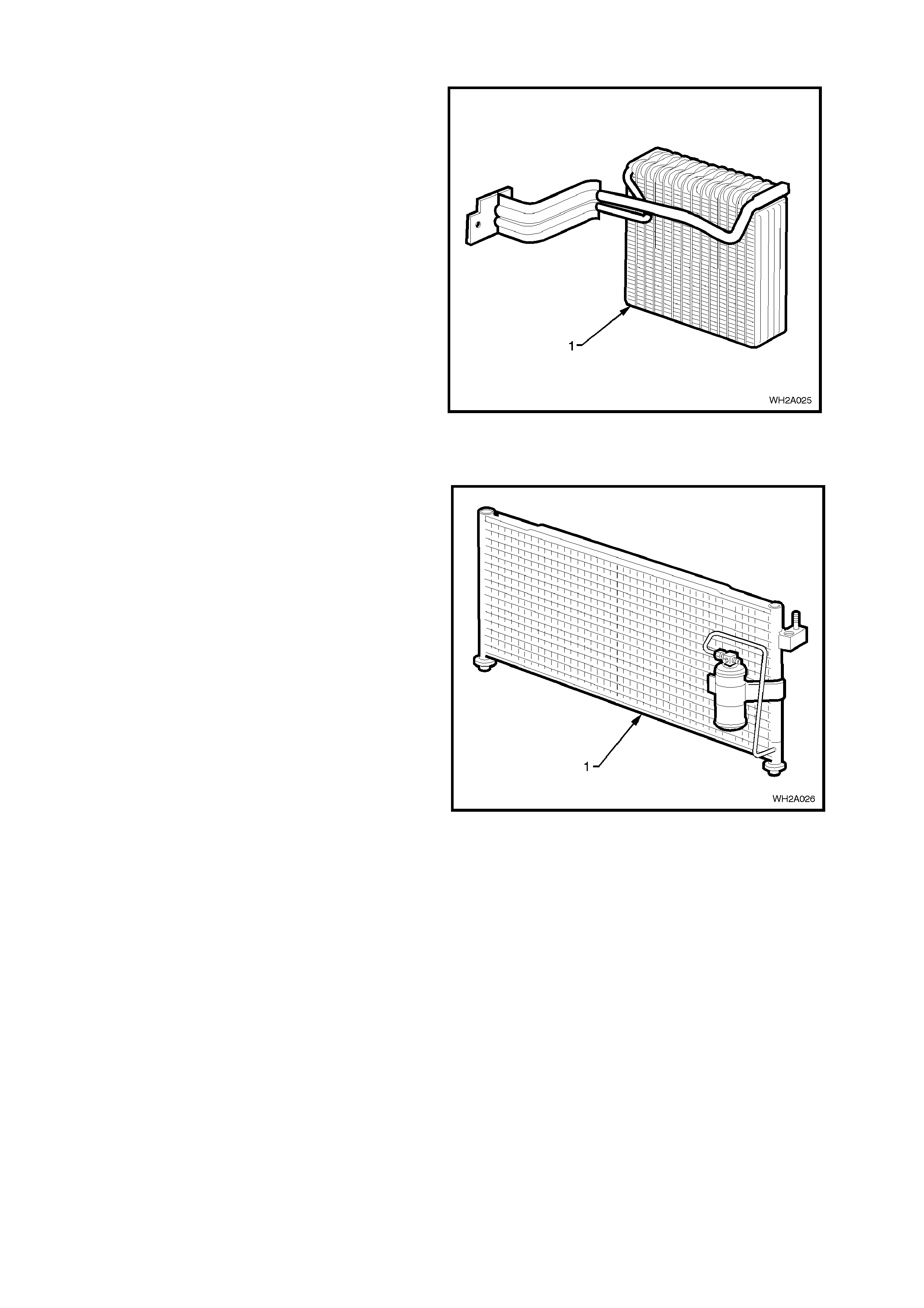
EVAPORATOR
The evaporator (1) is located inside the vehicle
housed behind the instrument panel facia in the
HVAC unit.
The evaporator core which is aluminium, is the
actual cooling unit of the A/C system. As the low
pressure, low temperature refrigerant enters the
evaporator it begins to boil and evaporate. This
evaporation process absorbs heat from the air
being circulated through the evaporator core by the
blower fan.
Due to the evaporator being so cold, condensation
forms on the surface. This condensation is
moisture taken from the air (humidity). Also any
dust particles in the air passing through the
evaporator become lodged in the condensate water
droplets, thus filtering the air from contaminants.
Figure 2A-33
CONDENSER
The condenser (1) is mounted forward of the
radiator and is therefore exposed to a flow of ram
air from the movement of the vehicle, and engine
cooling fan.
The purpose of the condenser is the opposite of the
evaporator. The condenser receives high pressure
high temperature refrigerant vapour from the
compressor and as the high pressure high
temperature vapour travels through the condenser
tubes, heat is given off to the cooler ambient air
surrounding the condenser. The vapour then
condenses into a high pressure, high temperature
liquid.
Figure 2A-34
HARRISON V5 AND DELPHI V7 COMPRESSOR
The Harrison V5 (V6 engine) and Delphi V7 (V8 GEN III engine) compressors can match the air conditioning
demand under all conditions without cycling. The basic compressor mechanism is a variable angle wobble-plate
with five (V5) or seven (V7) axially oriented cylinders. The control mechanism of the compressor displacement is a
bellows actuated control valve located in the rear head of the compressor which senses compressor suction
pressure. The wobble-plate angle and compressor displacement are controlled by the compressor crankcase-
suction pressure differential.
When the A/C capacity demand is high, the suction pressure will be above the control point. The valve will maintain
a bleed from the compressor crankcase to suction, no crankcase-suction pressure differential and the compressor
will have maximum displacement.
When the A/C capacity demand is lower and the suction pressure reaches the control point, the valve will bleed
discharge gas into the crankcase and close off a passage from the compressor crankcase to the suction plenum.
The pressure differential creates a total force on the pistons resulting in a movement about the wobble-plate pivot
pin that reduces the plate angle.
The V5 compressor has a pumping capacity of 156cc while the V7 has a pumping capacity of 179cc.
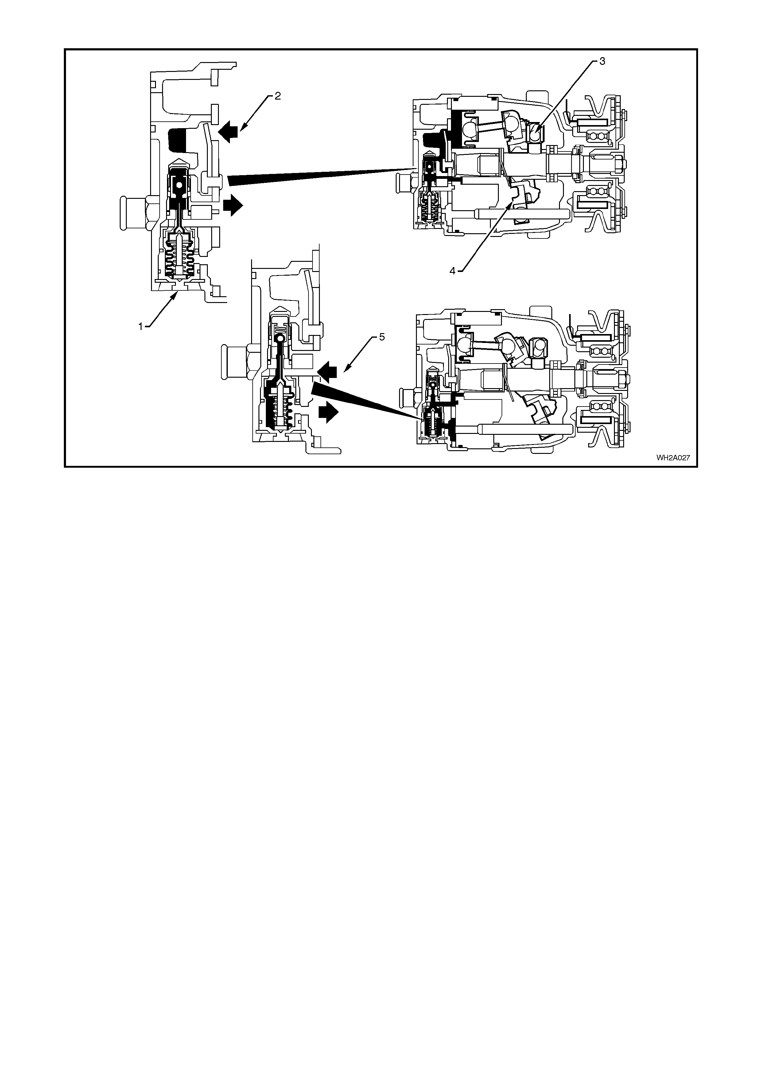
Figure 2A-35
Legend
1. Control valve.
2. A/C demand low reduced
displacement.
3. Pivot
4. Wobble plate. 5. A/C demand high maximum
displacement.

ENGINE COOLI NG FAN APPLICA TION
WH Series Models with standard V6 engines have two electric engine cooling fans. One fan operates at 'Low
Speed’; both operate at 'High Speed'. WH Models with GEN III V8 engine and V6 Supercharged are equipped with
two, two speed electric cooling fans.
The engine cooling fan assemblies provide the primary means of moving air through the engine radiator. These
fans are placed between the radiator and the engine and have their own shroud. There is no fan in front of the A/C
condenser.
The electric engine cooling fans are used to cool engine coolant flowing through the radiator.
On vehicles with V6 engines, the engine cooling fan motors have two terminals; one positive and one negative. The
positive terminals are permanently connected to battery voltage. When the negative terminal is pulled to earthed
through the low speed cooling fan relay, the low speed cooling fan will operate. When the negative terminal is pulled
to earth via the high speed cooling fan relay, both cooling fans will operate.
On vehicles with either V6 supercharged or GEN III V8 engines, the engine cooling fan motors have four terminals,
two negative and two positive terminals. The two positive terminals are permanently connected to battery voltage.
When one of the negative terminals is earthed, both cooling fan motors will operate at low speed. When both
negative terminals are earthed, both cooling fans will operate at high speed.
Regardless of the engine configuration, the low speed cooling fan operation is enabled when the low speed engine
cooling fan micro relay (located in the engine compartment relay housing, labelled Lo Fan) is energised by the Body
Control Module (BCM) via a request from the Powertrain Control Module (PCM). The PCM will request low speed
fan enable and disable via serial data communication to the BCM on circuit 1221 (Red/Black wire). After the PCM
requests a change in the state of the low speed relay (i.e. OFF to ON or ON to OFF), the BCM will send a serial
data response message back to the PCM confirming it received the message.
NOTE: On vehicles with GEN III V8 engines, serial data communication between the PCM and BCM is via the
Powertrain Interface Module (PIM).
The PCM determines when to enable the low speed fan relay based on inputs from the A/C request signal, Cooling
Temperature Sensor (CTS) and the Vehicle Speed Sensor (VSS).
Low speed fan operation
The low speed cooling fan relay will be turned ON when:
•Air conditioning request indicated (YES) and the vehicle speed is less than 30 km/h or
•Air conditioning pressure is greater than 1500 kPa or
•Coolant temperature is greater than 104°C (V6 and V6 supercharged) / 98°C (GEN III V8) or
•Vehicles with V6 and V6 supercharged engines; an engine coolant temperature sensor failure is detected by the
PCM, refer to Section 6C1 POWERTRAIN MANAGEMENT - V6 ENGINE for additional information.
Vehicles with GEN III V8 engines; when a coolant temperature sensor failure in conjunction with an Intake Air
Temperature (IAT) sensor failure is detected by the PCM, refer to Section 6C3 POWERTRAIN
MANAGEMENT - GEN III V8 ENGINE for additional information.
•When the ignition switch is turned from O N to O FF and the engine coolant temper ature is above 117°C (V6 and
V6 supercharged) / 113°C (GEN III V8) the BCM will continue to energise the low speed engine cooling fan
micro relay for four minutes
The PCM will request the BCM to switch off the low speed cooling fan relay when the following conditions have
been met:
•Air conditioning request not indicated (NO) and the coolant temperature is less than 99°C (V6 and V6
supercharged) / 95°C (GEN III V8) or
•Air conditioning reques t indicated (YES) with pressure les s than 1170 kPa, vehic le speed gr eater than 50 km /h
and coolant temperature less than 99°C (V6 and V6 supercharged engines) / 98°C (GEN III V8).
•NOTE: The low speed cooling fan has a minimum run on time of 30 seconds (GEN III V8 ONLY).
High speed fan operation
The high speed cooling fan relay will be turned ON if the low speed cooling fan relay has been energised for one
second and the following conditions have been met:
•Vehicles with V6 or V6 supercharged engines; if there is a BCM message response fault, setting a DTC 92 or
•Vehicles with V6 and V6 supercharged engines; an engine coolant temperature sensor failure is detected by the
PCM, refer to Section 6C1 POWERTRAIN MANAGEMENT - V6 ENGINE for additional information or
•Engine coolant temperature is above 107°C (V6), 111°C (V6 supercharged engines) 108°C (GEN III V8) or
•Air conditioning pressure is greater than 2000 kPa. (V6) 2600 kPa (V6 supercharged) 2400 kPa (GEN III V8).
NOTE: If the low speed cooling fan is off when the criteria for turning the high speed cooling fan on are first met, the
high speed cooling fan will turn on five seconds (V6 and V6 supercharged) one second (GEN III V8) after the low
speed cooling fan is switched on.
If both the high and low speed cooling fans are enabled, the PCM will turn the high speed cooling fan off when:
•The engine coolant temperature is less than 103°C (V6) 108°C (V6 supercharged) 102°C (GEN III V8) and
•Air conditioning request is not indicated (NO) or
•Air conditioning request is indicated (YES) and the pressure is less than 1500 kPa (V6) 2300 kPa (V6
supercharged) 1900 kPa (GEN III V8).
NOTE: The high speed cooling fan has a minimum run on time of 30 seconds (GEN III V8 ONLY).
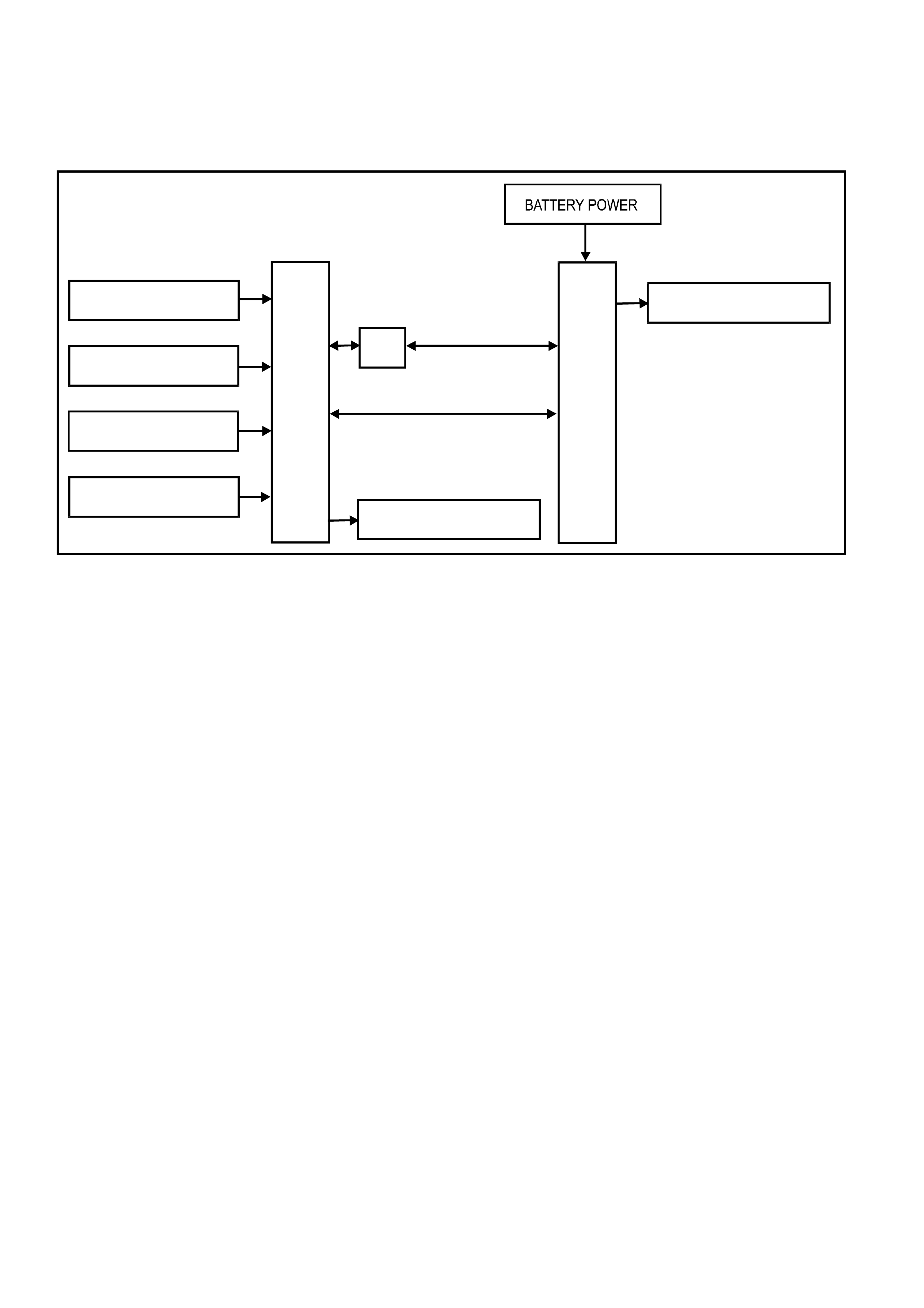
T22A003
PCM
HIGH SPEED COOLING
FAN RELAY
PIM BCM
LOW SPEED C OOLING
FAN RELAY
IGNITION SWITCH ON
VEHICLE SPEED
SENSOR
ENGINE COOLANT
TEMP. SENSOR
AIR CONDITIONING
REQUEST
V6 & V6 S/C ENGINE
GEN III V8 ENGINE
Figure 2A-36 System Overview
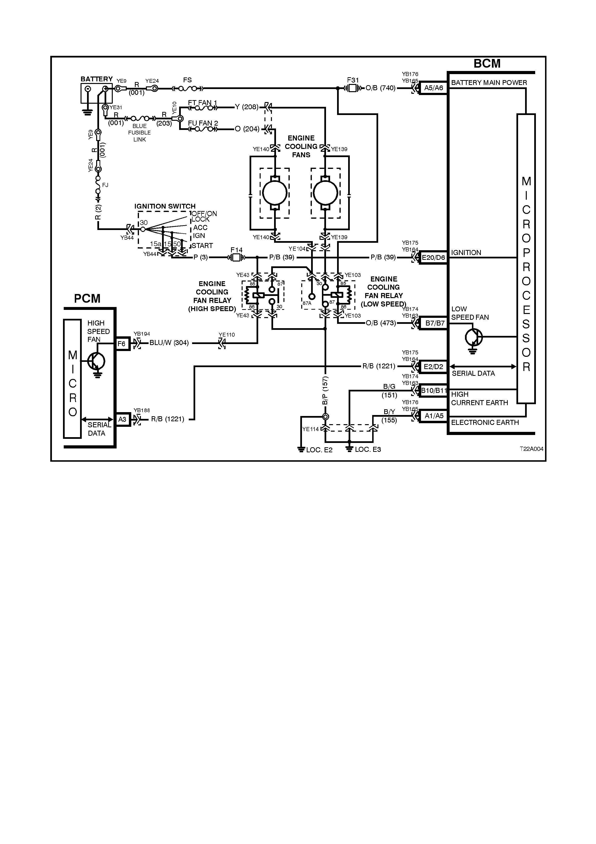
V6 ENGINE - LOW SPEED COOLING FAN ACTIVATION
Figure 2A-37
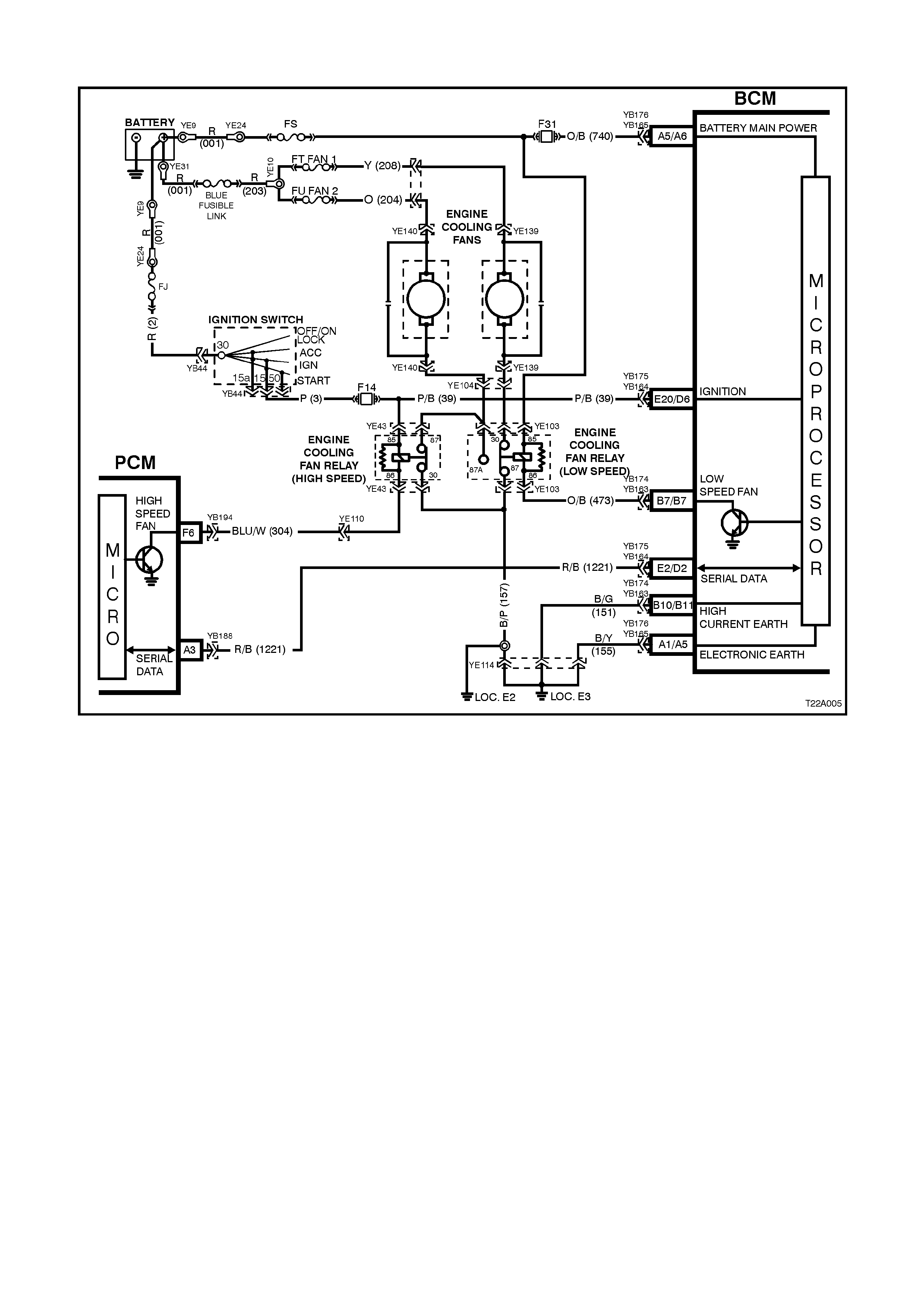
V6 ENGINE - HIGH SPEED COOLING FAN ACTIVATION
Figure 2A-38

V6 SUPERCHARGED AND GEN III V8 ENGINE - LOW SPEED COOLING FAN ACTIVATION
Figure 2A-39
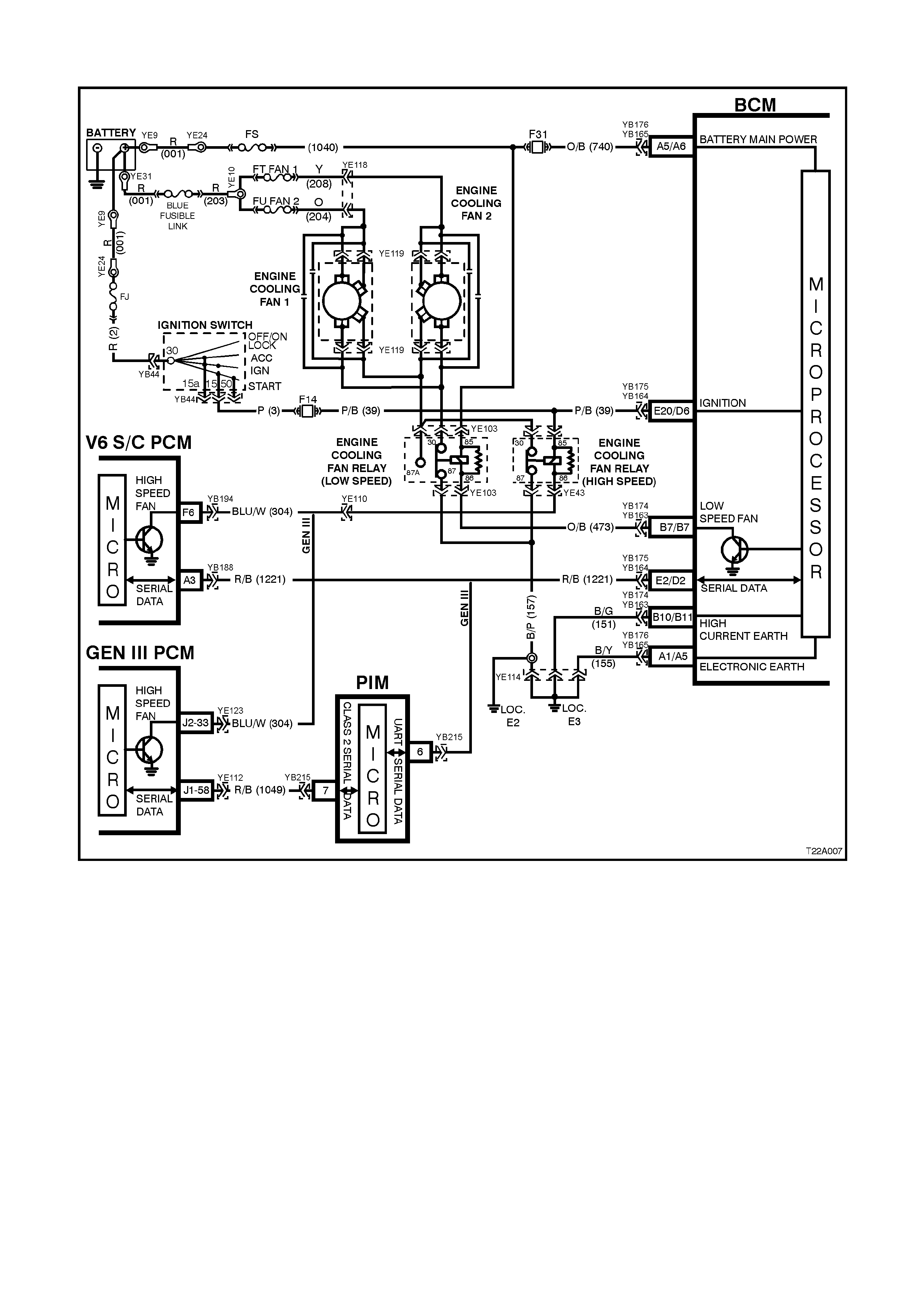
V6 SUPERCHARGED AND GEN III V8 ENGINE - HIGH SPEED COOLING FAN ACTIVA TION
Figure 2A-40
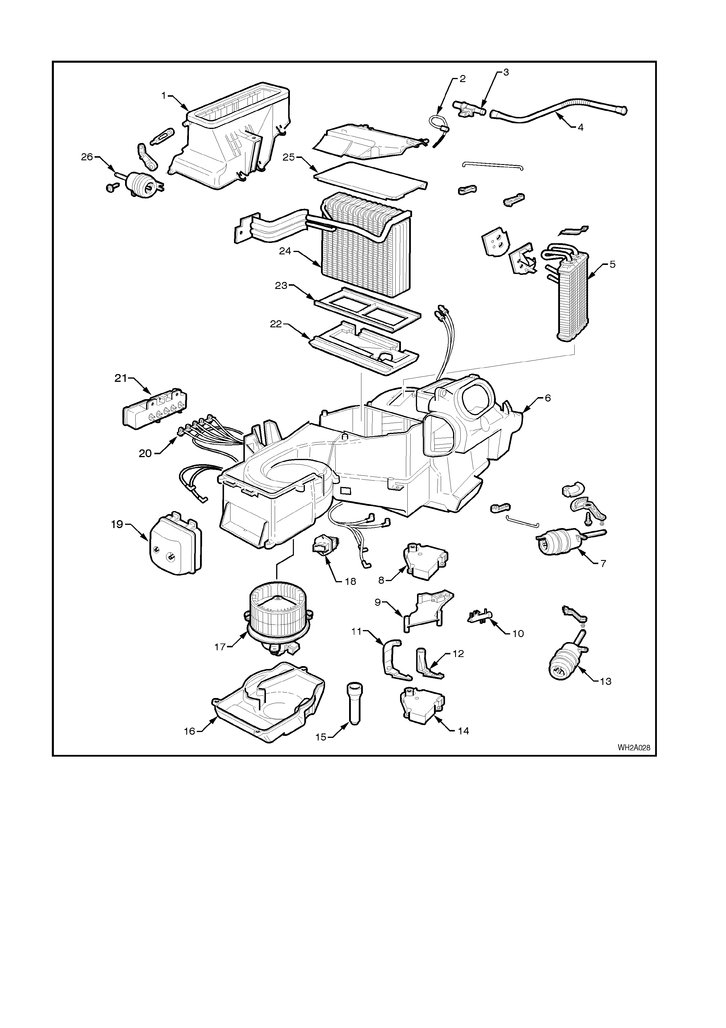
HVAC SYSTEM COMPONENTS
Figure 2A-41
Legend
1. Fresh/Recirculation housing.
2. Evaporator air temperature
sensor.
3. Aspirator venturi.
4. Aspirator tube.
5. Heater core.
6. Heating Ventilation & Air
Conditioning unit (HVAC).
7. Demist floor actuator.
8. Upper air mix motor (dual
zone).
9. Air mix motor mounting
bracket.
10. Heater valve vacuum switch.
11. Lever (dual zone).
12. Bi level centre/vent actuator
13. Lower air mix motor.
14. Drain hose.
15. Blower motor cover.
16. Blower motor.
17. Blower speed resistor.
18. Vacuum storage tank.
19. Vacuum tube harness.
20. Vacuum solenoid pack.
21. Lower insulator.
22. Evaporator support.
23. Evaporator coil.
24. Upper insulator.
25. Fresh/Recirculation
mode vacuum actuator.

2. GENERAL DESCRI PTI O N - ECC
The Electronic Climate Control (ECC) Sy stem is a Dual Zone system.
2.1 DESCRIPTION AND OPERATION
The ECC Module uses a microprocessor to monitor inputs, process data and thus control outputs.
The inputs used by the ECC are as follows:
•Serial Data information:
Sunlight level, priority key us er & ignition of f tim e f rom BCM, engine RPM, coolant tem per ature, road s peed
and A/C pressure from PCM.
•In-car temperature sensor.
•Ambient temperature sensor.
•Evaporator temperature sensor.
•Air mix potentiometer (PBR).
•Ignition Voltage.
•Blower Fan Voltage.
•Customer settings by way of the ECC buttons.
The outputs controlled by the ECC module controls are as follows:
•Serial Data information:
Sunlight level for instrument dimming of cruise and power indicators, A/C request to the PCM.
•Air Distribution Mode (demist, foot, foot & face, face) by controlling the logic of four vacuum solenoids.
•Vent Air Temperature by controlling the position of the Air mix door (2 for dual zone systems) (between
approximately 5°C (with A/C on) and approximately 70°C (with warm engine).
•Air Inlet Mode (i.e. Fresh or Recirculated) by controlling a vacuum solenoid.
•Blower fan speed by an analogue signal sent to the blower speed controller which amplifies this signal &
thus controls the blower voltage.
•Maximum blower relay.
•Rear window demist relay.
ECC display and LED's to indicate ECC status.
RECOMMENDED SETTINGS
The customer should be encouraged to use the ECC in full Auto mode (green Auto LED ON) and a set temperature
of 23°C.
Changing the set temperature to suit different conditions could cause the ECC to behave differently from what the
customer expects (eg. setting to 17°C on a hot day could cause the customer to complain the blower speed is to
high on hot days). This should be discouraged.
EVAPORATOR TEMPERATURE CONTROL
In the ECC system, an evaporator sensor is only used to sense A/C temperature for ECC software calculations, not
to cycle the compressor on/off. Anti ice-up is governed by the evaporator pressure control valve located within the
compressor.
BLOWER FAN CONTROL
There are stepless varying blower fan speeds available in the automatic mode and five speeds in the manual mode.
Manual fifth speed is the same as highest automatic blower fan speed.
W hen the engine is not running, the actual blower speed will not be higher than approximately fan speed three, in
order to improve battery life.
AUTOMATIC MODE
The blower speed will vary according to:
•In-car Temperature
•Ambient Temperature
•Sunload
•Drivers Set Temperature
•Coolant Temperature
•Air Distribution Mode

If the cabin is at the required temperature, the blower will be at a minimum. An increase in sunload in these
conditions would cause the blower to increase.
If heating of the cabin is required (eg. After a cold night), the blower would gradually increase as the coolant
temperature increased to approximately 70°C. Then, as the In-car temperature increased, the blower would
decrease.
If extreme cooling of the cabin were required, the blower would increase to maximum speed (over about 15
seconds). Then, as the In-car temperature decreased, the blower would also decrease.
If cooling of the cabin is required, an increase in sunload will cause the blower speed to increase. If heating up of
the cabin is required, an increase in sunload will normally cause the blower speed to decrease.
If the air distribution mode changes, (eg. From Face to Face/Floor) the fan speed may also change.
In order to maintain a constant air flow, the blower voltage compensated for:
•Road Speed
•Air Inlet mode
•Ignition Voltage
AIR DISTRIBUTION CONTROL
There are five distribution modes that can be selected either automatically or manually. These are:
•Demist
•Foot/Demist
•Foot
•Foot/Face
•Face
AUTOMATIC MODE
The air distribution mode selected will vary according to:
•In-car Temperature
•Ambient Temperature
•Sun load
•Drivers Set Temperature
•Start Up conditions
If the cabin is at the desired temperature, the ECC will select either Foot/Face of Face (depending on if the cabin
needed to be warmed up or cooled down).
If cooling of the cabin were required, foot mode may be selected for a short time (A/C purge), followed by face
mode.
If heating of the cabin is required, demist mode would be selected until the coolant is warm enough (Demist Delay),
followed by Foot/Demist. Then, as the in-car temperature increased, the mode should change to Foot/Face.
If heating is requires and the coolant is warm, foot mode may be selected for a short time (Purge), followed by
Foot/Face mode (or Foot/Demist mode depending on conditions).
AIR INLET CONTROL
When recirculate is selected either manually or automatically, the ECC will return the inlet to fresh air mode after
approximately 40 minutes. This is to avoid stuffiness in the car. The customer can return to recirculate by pressing
the recirculate button.
AUTOMATIC MODE
The air inlet mode selected will vary according to:
•In-car Temperature
•Ambient Temperature
•Sun load
•Drivers Set Temperature
•Start Up conditions
•Evaporator Temperature
•AC Pressure
•Coolant Temperature
If the cabin does not require cooling or A/C is off, fresh air will be selected.
If extreme cooling of the cabin were required, Fresh maybe selected for a short time (Fresh Delay), then recirculate
mode will be selected until the cabin has cooled down sufficiently. Then, fresh air mode will be selected.

If the cabin needs cooling down, the air mix is at full cold, the evaporator temperature is high and the A/C pressure
is high, recirculate mode may be selected (ie. heavy traffic on a hot day). Then, as the in-car temperature
decreases to a suitable level, fresh air mode will be selected.
If the coolant temperature gets very high, recirculate may be selected to increase the cooling capacity of the
radiator.
VENT AIR TEMPERATURE CONTROL
The vent temperature will vary between approximately 5°C (with A/C on and air mix door at minimum) and
approximately 70°C (with 90°C coolant and air mix door at maximum).
MANUAL MODE
If the set temperature is set to C, the air mix door will be set to minimum.
If the set temperature is set to H, the air mix door will be set to maximum.
AUTOMATIC MODE
When a set temperature of between 17°C and 30°C is selected, the vent air temperature will be controlled
automatically.
The vent air temperature will vary according to:
•In-car Temperature
•Ambient Temperature
•Sun load
•Drivers or Passengers Set Temperature
When the cabin is at the desired temperature, the average vent air temperature should be approximately the same
as the set temperature.
If the cabin requires cooling, the ECC will try to control the vent temperature to less than the set temperature. The
more cooling required, the lower the vent temperature should be.
If the cabin requires heating, the ECC will try to control the vent temperature to be more than the set temperature.
The more cooling required, the higher the vent temperature should be.
Generally, the automatic blower will be at a fairly low level (less than 50%) before the ECC starts to control the
temperature. (eg. When extreme cooling is required, the blower will start on maximum and the Air mix will start at
minimum. As the cabin cools down the blower will decrease gradually, while the air mix will stay at minimum, when
the blower is approximately 40%, the air mix door may be opened to turn the water valve on. As the cabin keeps
cooling down, the blower is gradually decreased as the vent temperature is increased).
Increasing the set temperature will increase the vent temperature (provided air mix is not at maximum).
Decreasing the set temperature will decrease the vent temperature (provided air mix is not at minimum).
As the in-car temperature increases the vent temperature will decrease.
As the in-car temperature decreases the vent temperature will increase.
As the sun load increases the vent temperature will decrease.
As the sun load decreases the vent temperature will increase.
As the ambient temperature increases the vent temperature will decrease.
As the ambient temperature decreases the vent temperature will increase.
The ECC controls the air mix position to achieve the required vent temperature, compensating for:
•Evaporator Temperature
•Coolant Temperature
•Inlet Mode
•Air Distribution Mode
ECC COLD START-UP ROUTINES
There are four cold start-up routines incorporated in the ECC system logic to cater for various conditions on first
starting the vehicle, typically at low ambient temperatures.
Each routine has its own respective set or criteria to satisfy before the routine is executed:
Recirculation delay: Automatically defaults to recirculation mode to prevent cold air from entering the vehicle
interior.
Demist delay: To eliminate cold air at floor during warm-up and prevents drivers breath from fogging front
windscreen.
Purge: Allows coolant to heat-up the heater core and avoid humidity to face/windscreen when the blower fan is
activated.
A/C Purge: To avoid hot air blowing on face when the blower fan is activated.
Fresh delay: Uses cooler outside air to purge hot air from the vehicle.
SENSOR MALFUNCTION INDICATOR
If a sensor open circuits due to an electrical connector disconnection or damaged wiring, an X will appear on the RH
side of the ECC Module LCD display. This X will disappear once the problem has been rectified.
DEFAULT MODE: VACUUM
When a leak is apparent in the vacuum system, the air direction will automatically default to demist and fresh air.
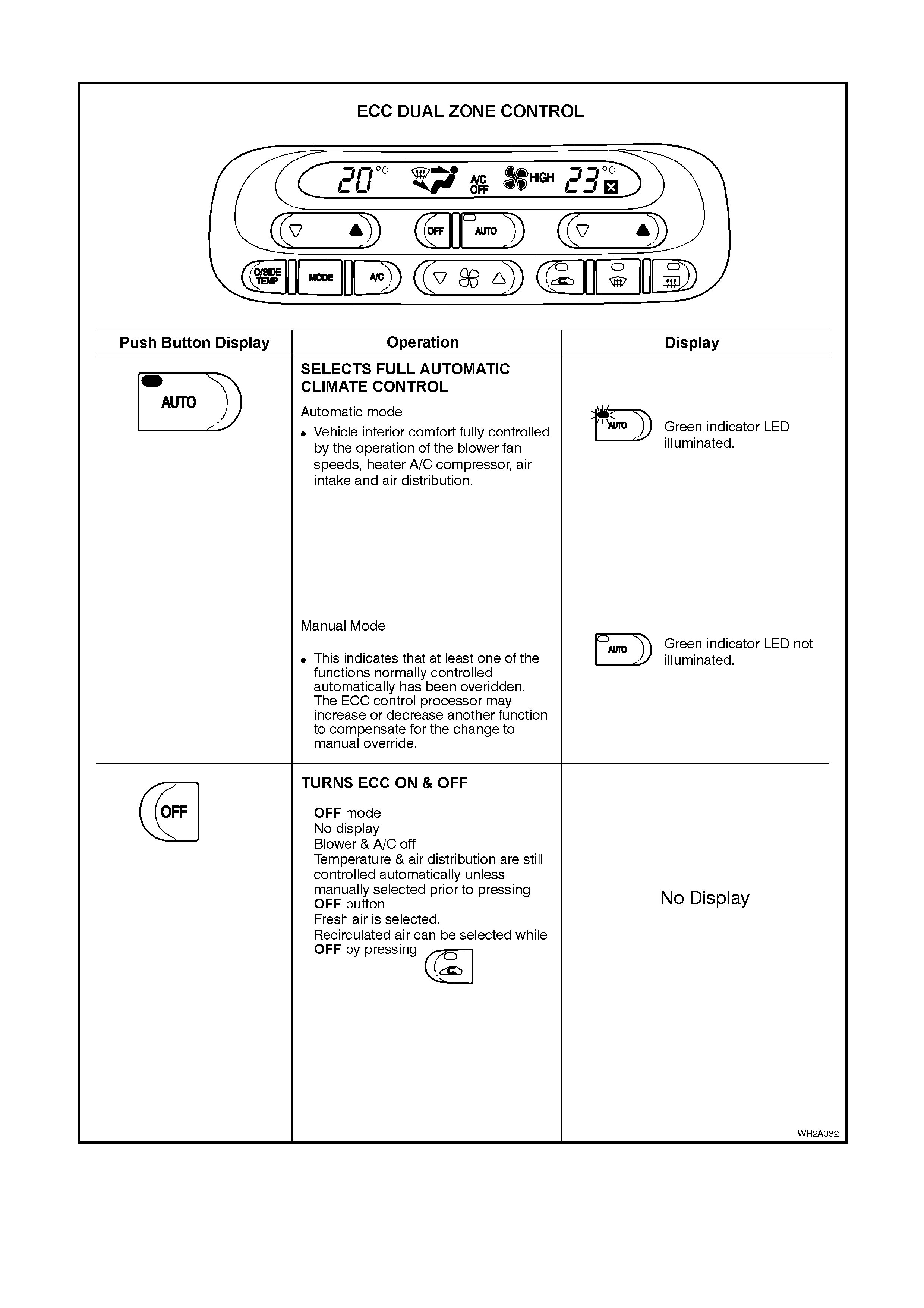
AUTOMATIC OPERATION
In fully automatic mode, the microprocessor uses the sunlight, in-car temperature, ambient temperature, evaporator
temperature and customer set temperature to decide and control the amount of blower voltage, and the air inlet
mode.
• The auto button contains a green LED.
Auto LED ON: indicates the ECC is in full Auto mode
(i.e. all functions are controlled automatically).
• The auto LED OFF indicates the ECC is in part manual mode (i.e. at least one function is not being controlled
automatically).
Any of the auto functions can be manually overridden by pressing the appropriate button.
NOTE: If one function has been selected manually, other functions still operate automatically.
The ECC uses the in-car temperature sensor, the ambient temperature sensor, the sun load input from the BCM
and the ‘set’ temperature to determine if the cabin needs to be warmed, cooled or maintained. The following tables
provide examples of what the ECC system will attempt under various conditions:
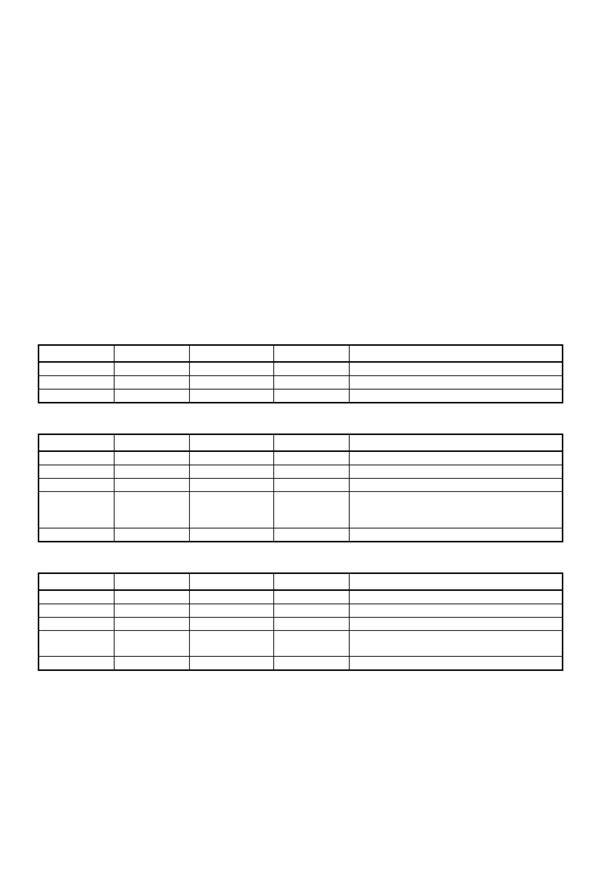
If the cabin is ‘Just Right’, the ECC will try to maintain the cabin temp in the following situations:
SET TEMP IN-CAR TEMP AMBIENT TEMP SUN LOAD TYPICAL SITUATION
23 25 23 Low Driving for a while on a warm night
23 27 12 Low Driving for a while on a cold night
23 23 23 Medium Driving for a while on a spring afternoon
The ECC will try cooling down the cabin in the following situations
SET TEMP IN-CAR TEMP AMBIENT TEMP SUN LOAD TYPICAL SITUATION
23 40 23 Low Dusk, car has been sitting in the sun
23 23 23 High Been driving for a while in early afternoon sun
23 23 30 Low Been driving for a while on a hot night
23 55 30 High Car has been sitting in sun on a hot summers
day
Extreme cooling is required
17 23 23 Low Driver wants to cool down quickly.
The ECC will try heating up the cabin in the following situations
SET TEMP IN-CAR TEMP AMBIENT TEMP SUN LOAD TYPICAL SITUATION
23 15 15 Medium Morning drive after a cool night
23 20 20 Low Early morning drive after a mild night
23 23 10 Low Been driving for a while on a cold night
23 5 5 Low Morning drive after a cold night
Extreme heating is required
30 25 20 Low Driver wants to warm up quickly.
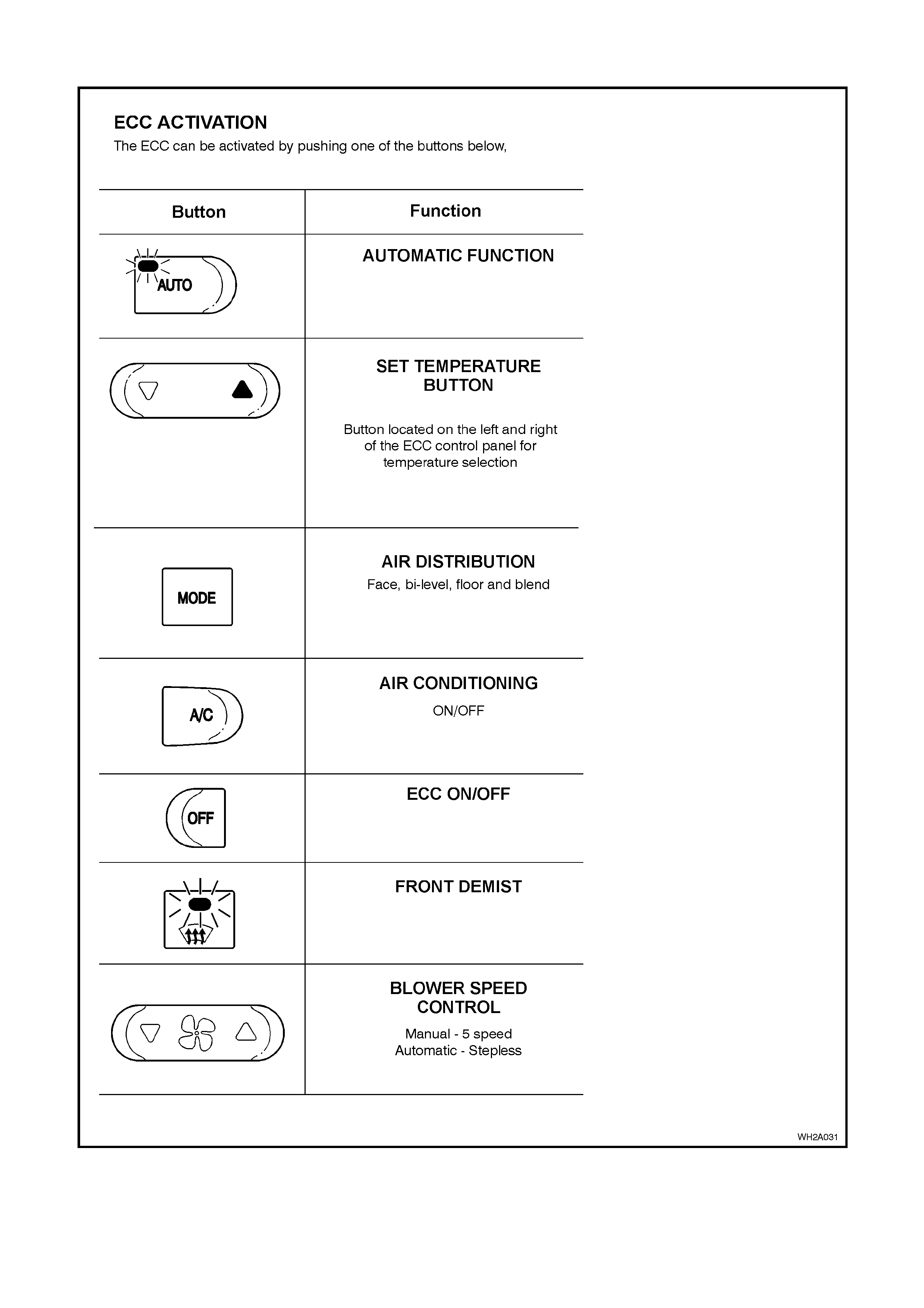
ECC ACTIVATION
Figure 2A-43
ECC CONTROLS
Figure 2A-44
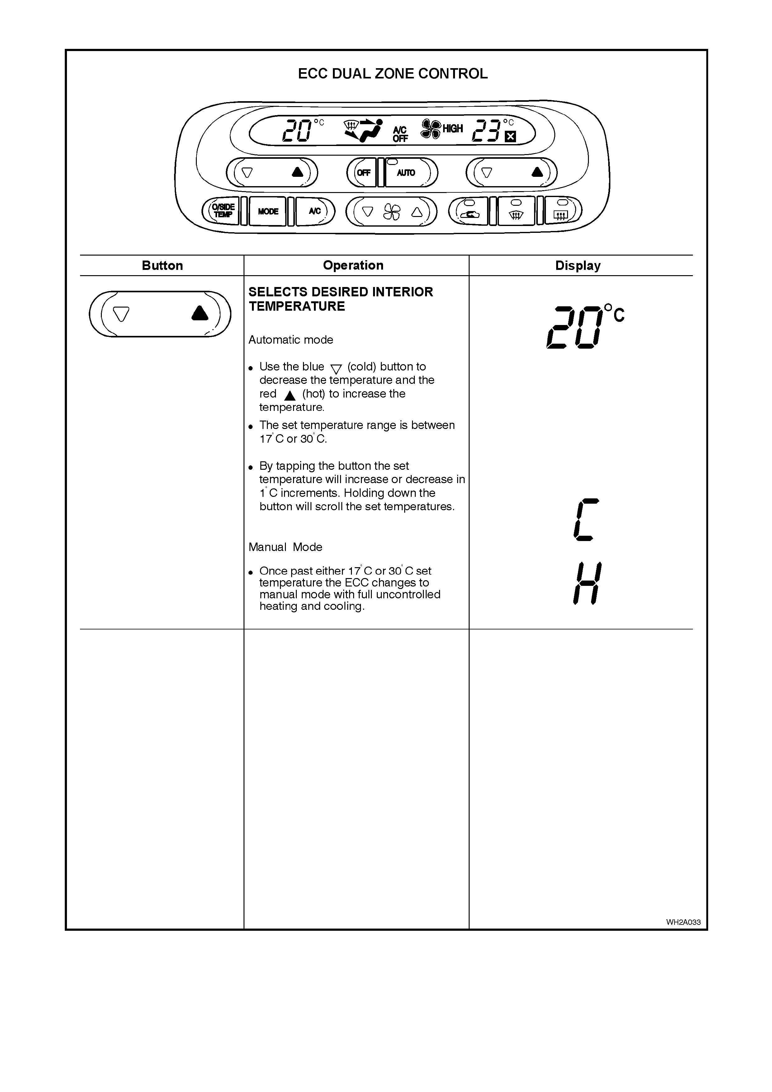
Figure 2A-45
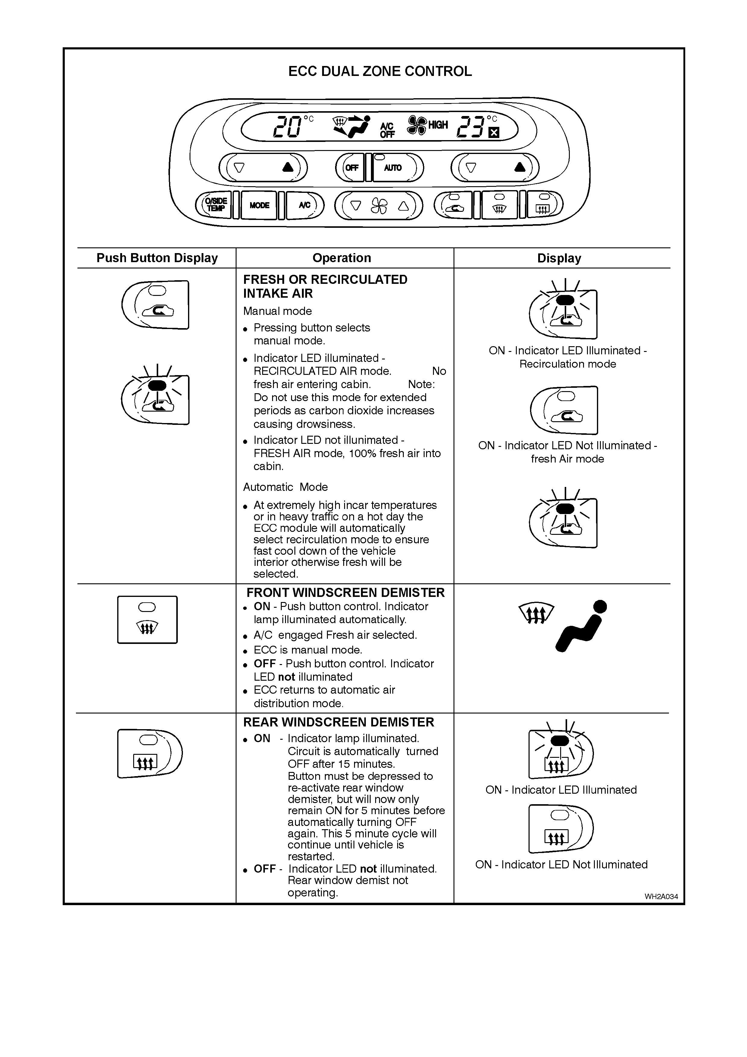
Figure 2A-46
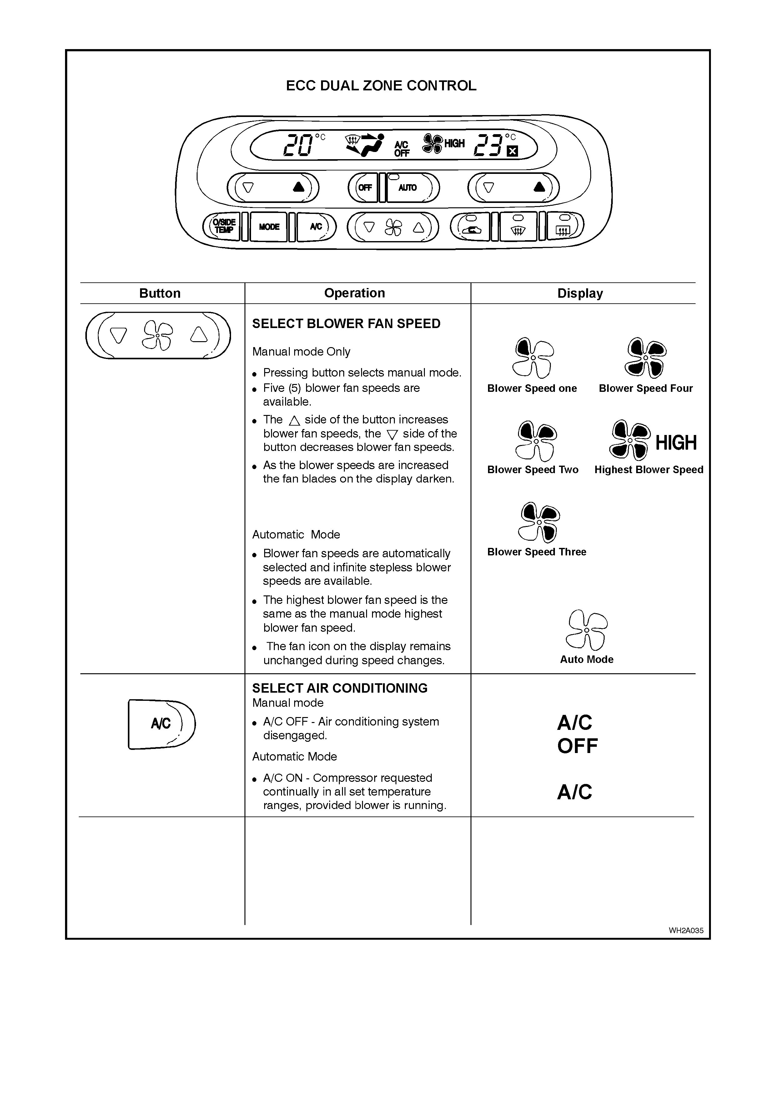
Figure 2A-47
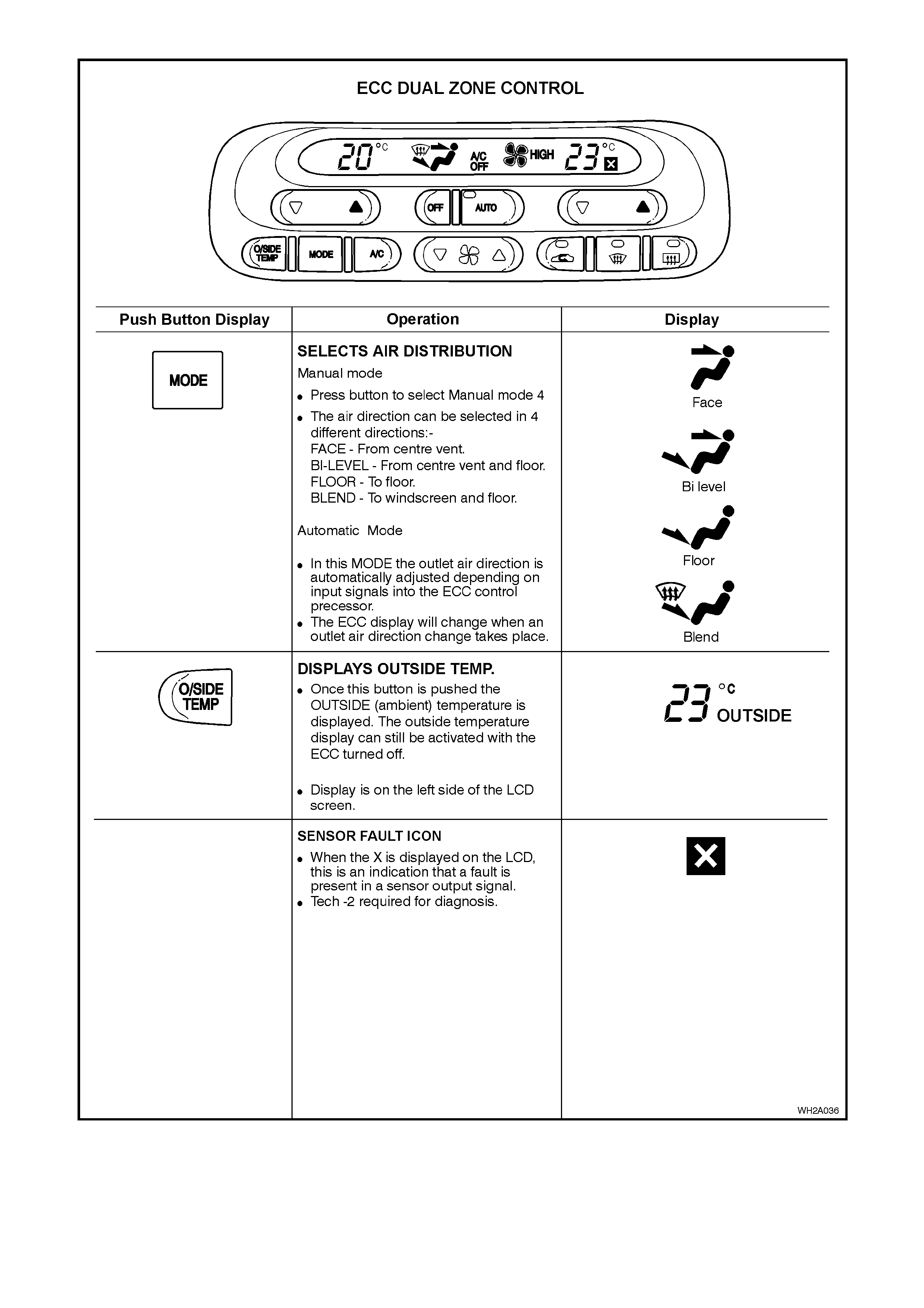
Figure 2A-48

ECC DUAL ZONE CONTROLS
General Information
The Dual Zone ECC system has features to maximise passenger comfort, the following describes the operation of
the controls:
Link mode
The link mode refers to the mode when the operation of both the passenger and driver air mix motors is
synchronised.
When the driver ‘set’ temperature is changed, likewise the passenger ‘set’ temperature changes to the same value.
To access the ‘link’ mode press and hold the ‘auto’ button for two seconds.
Unlink mode
This mode is when the passenger sets their desired temperature independent of the driver.
To access the ‘unlink’ mode, press the passenger side temperature button.
NOTE: If the ECC was in link mode this will alter to unlink mode.
Mode control
It is NOT possible for the passenger to alter the mode positions such as Floor, Demist, Centre Vent etc. There is no
individual control. Mode positions will be the same for both passenger and driver.
Fan speed control
As with the mode control it is NOT possible for the passenger to alter the blower fan speeds as an individual
function. Once the blower speeds have been selected, blower speeds for both the passenger and driver will be the
same.
ECC REAR REMOTE CONTROL
The ECC rear remote control functions as an extension to the main control located in the instrument panel.
The buttons above the words ‘Climate Control’ increase or decrease the temperature.
The buttons below the words ‘Climate Control’ increase or decrease the fan speed.
If the climate control is linked the changes made by the roof control alters air issuing from the front and rear vents. If
the climate control is not linked, the changes made by the roof control alters air issuing from the rear vents and from
the driver’s vents.
Pressing both fan buttons simultaneously switches the climate control to AUTO. Holding both buttons depressed for
more than 2 seconds links the climate control.
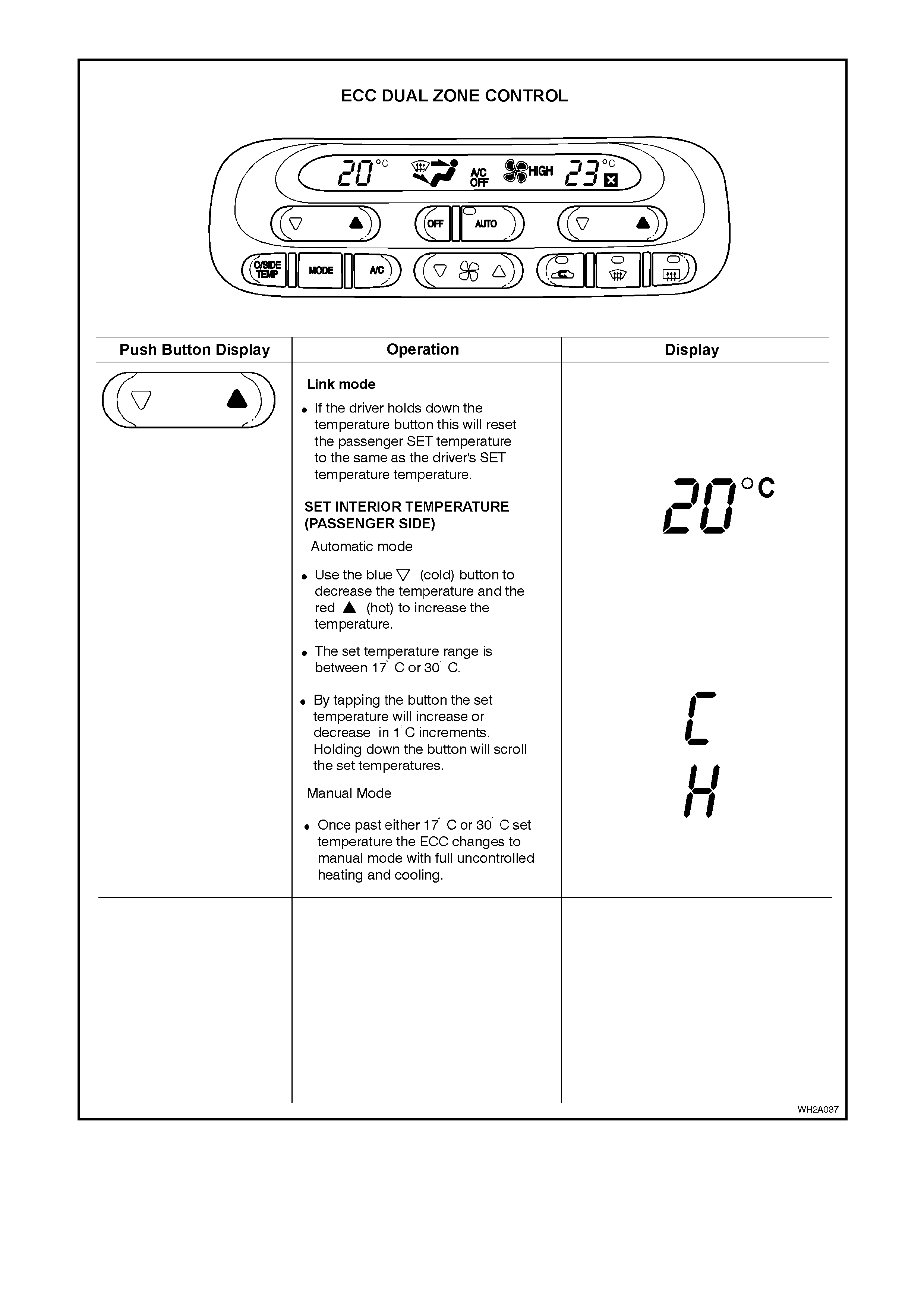
Figure 2A-49

Figure 2A-50