
SECTION 2B - ELECTRONIC CLIMATE CONTROL -
REMOVAL AND INSTALLATION
IMPORTANT
Before performing any Service Operation or other procedure described in this Section, refer to Section
00 CAUTIONS AND NOTES for correct workshop practices with regard to safety and/or property damage.
1. GENERAL I NFORMATI O N
This Section details the Service Operations necessary for maintenance of the ECC system. Care should be taken to
ensure that whenever any component is disconnected that plugs are immediately inserted into any open
connections. Failure to follow these precautions could render the components unserviceable.
Whenever any diagnosis or repairs to the electrical connectors and wiring is required, reference to the ECC wiring
diagrams, connecter terminal assignments or diagnosis procedures should be made. Refer to the appropriate
Sections in this Service Information Supplement.
Techline
Techline
Techline
Techline
Techline
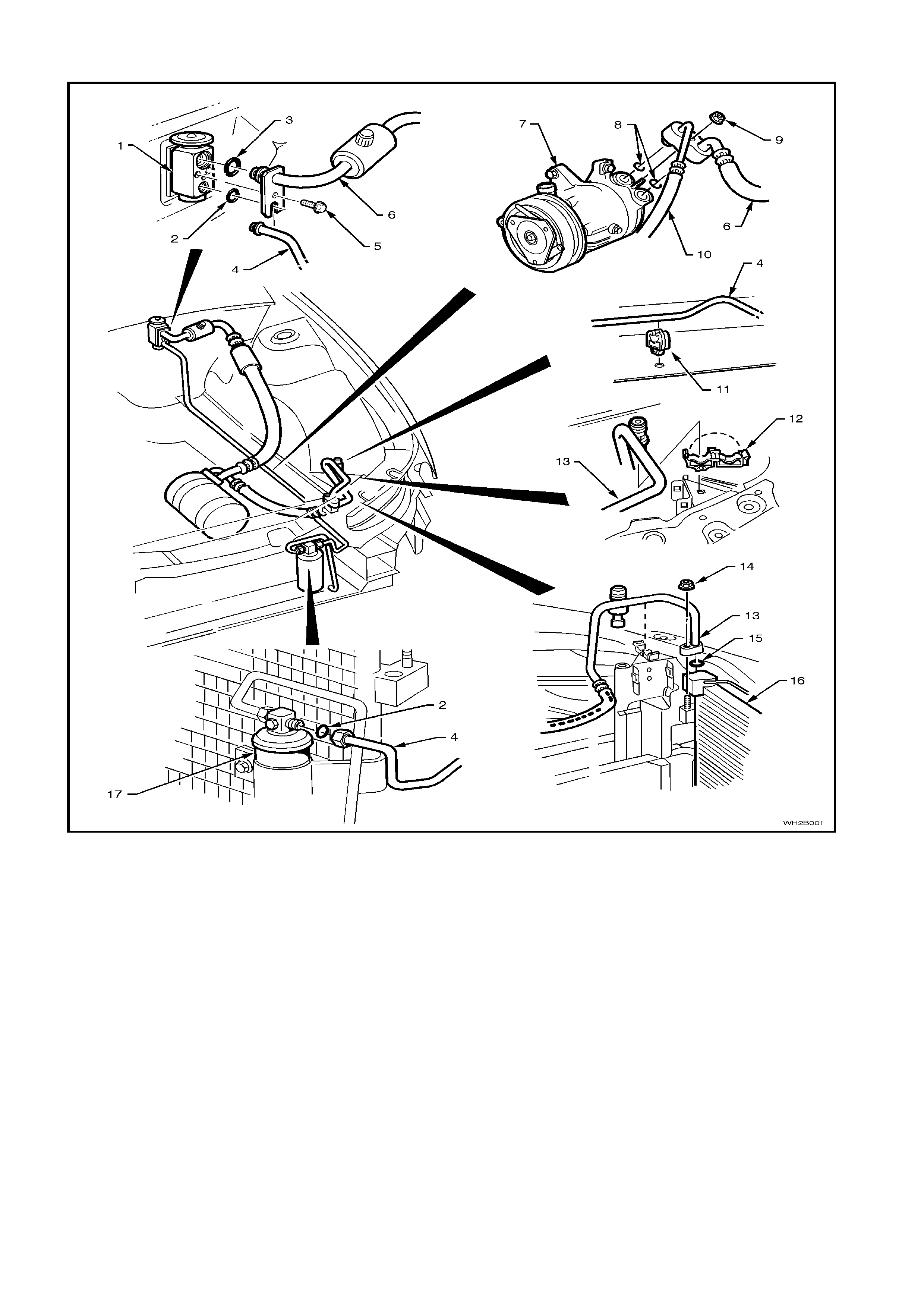
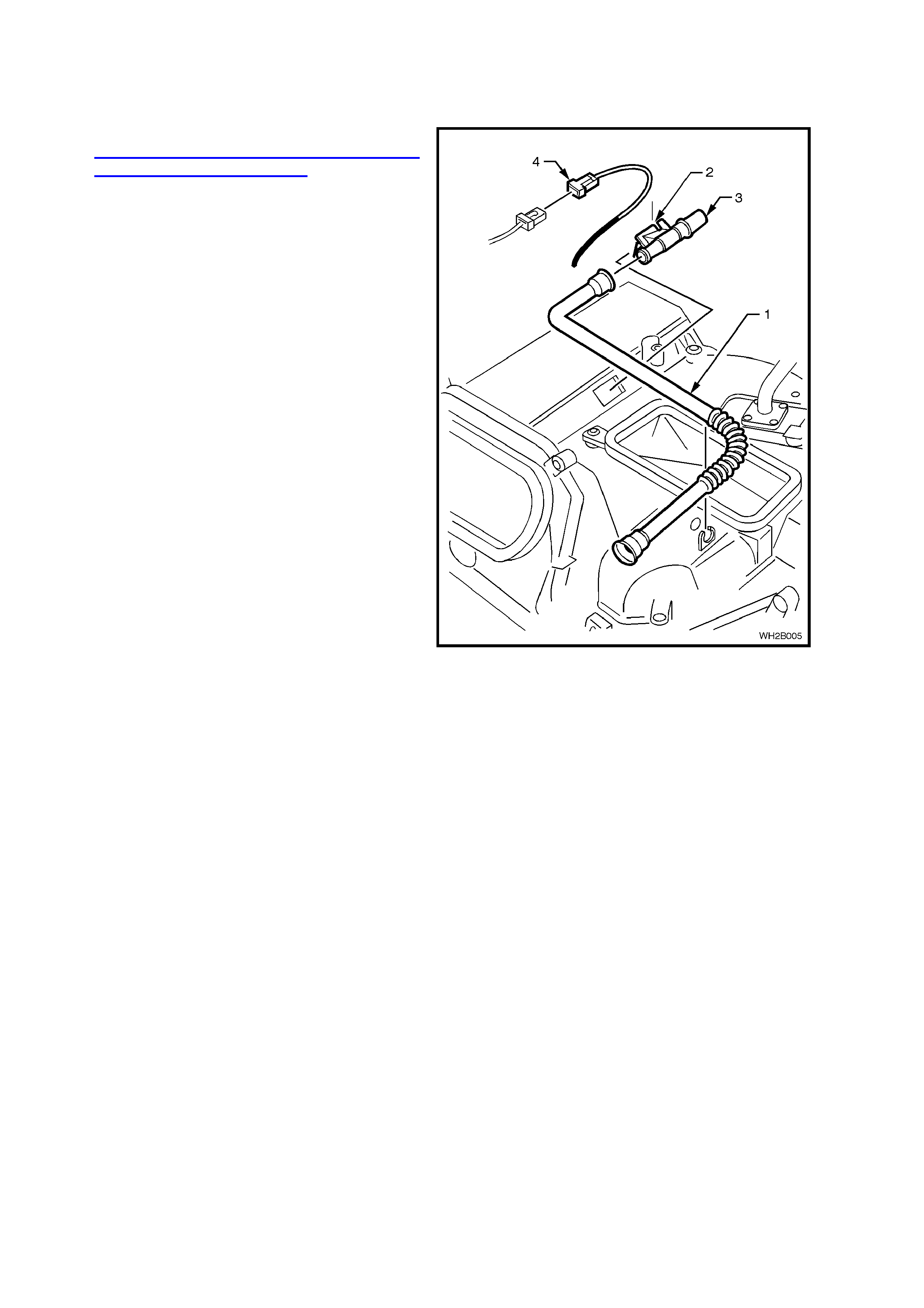
HOSE LAYOUT V6
Figure 2B-1
Legend
1. Thermal expansion valve (or block valve)
2. O-Ring 6.07 X 1.78 mm
3. O-Ring 15.54 X 2.62 mm
4. Liquid tube
5. Retaining screw
6. Suction tube/hose
7. Compressor
8. Bonded sealing washers
9. Retaining nut
10. Discharge hose
11. Liquid tube retaining clip
12. Discharge tube retaining clip
13. Discharge tube
14. Discharge tube retaining nut
15. O-Ring 9.19 X 2.62 mm
16. Condenser
17. Filter Dryer Receiver (FDR)
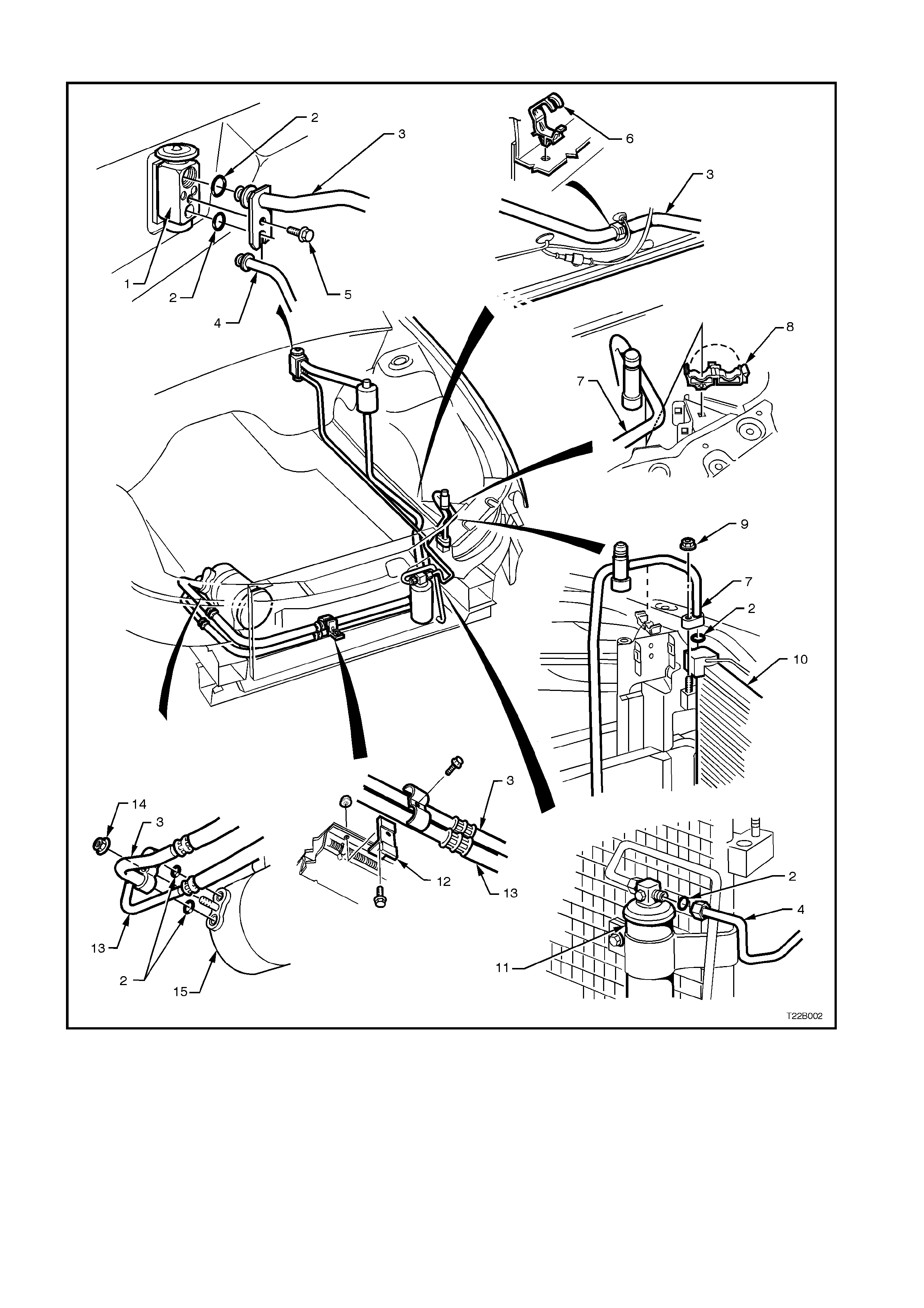
HOSE LAYOUT GEN III V8
Figure 2B-2
Legend
1. Thermal expansion valve (or block valve)
2. O-Ring
3. Suction hose
4. Liquid tube
5. Retaining screw
6. Suction tube retaining clip
7. Discharge tube
8. Discharge tube retaining clip
9. Discharge tube retaining nut
10. Condenser
11. Filter Dryer Receiver (FDR)
12. Retaining clamp
13. Discharge tube/hose
14. Retaining nut
15. Compressor
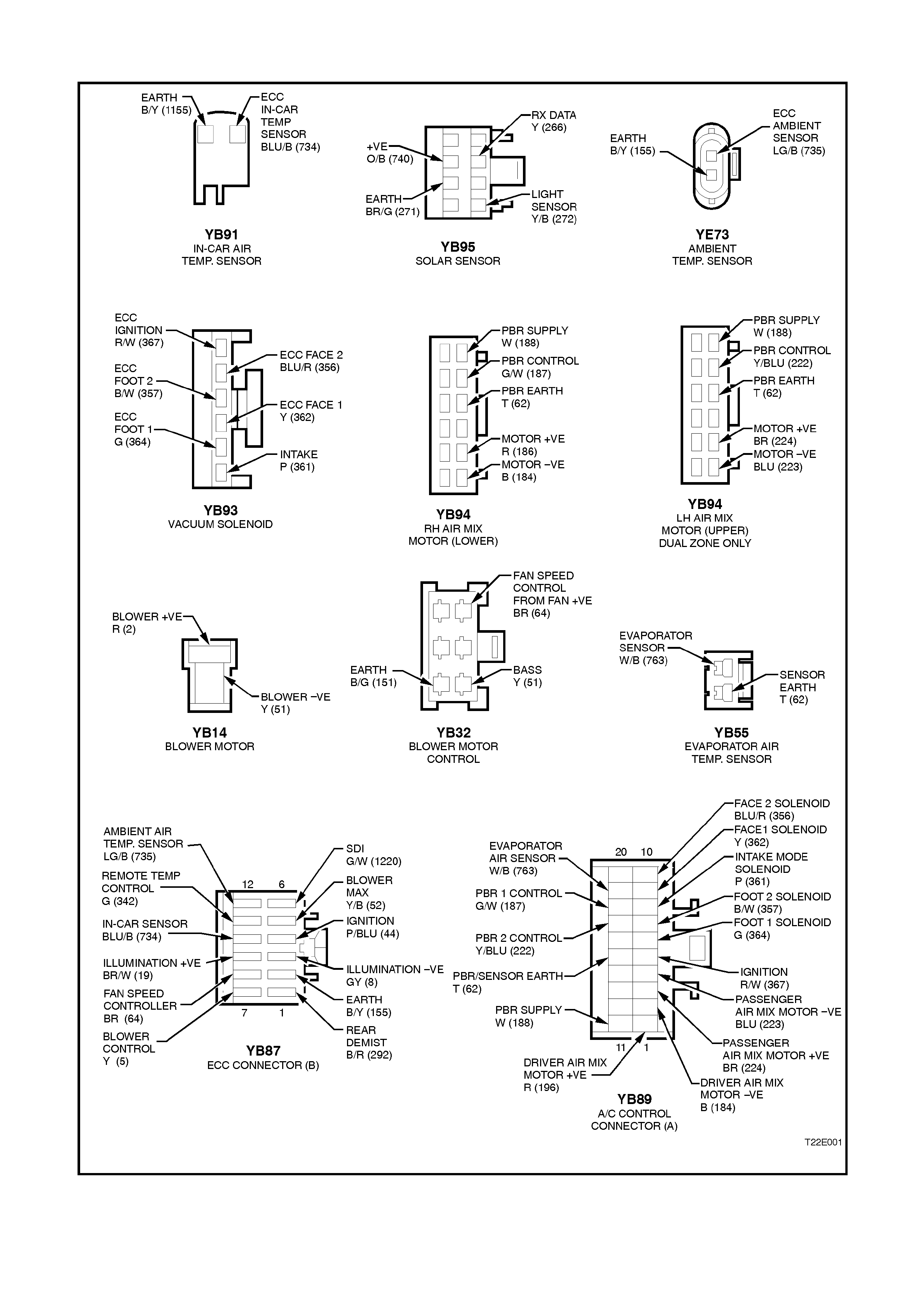
ECC ELECTRICAL CONNECTORS
Figure 2B-3
2. SERVICE OPERATIONS
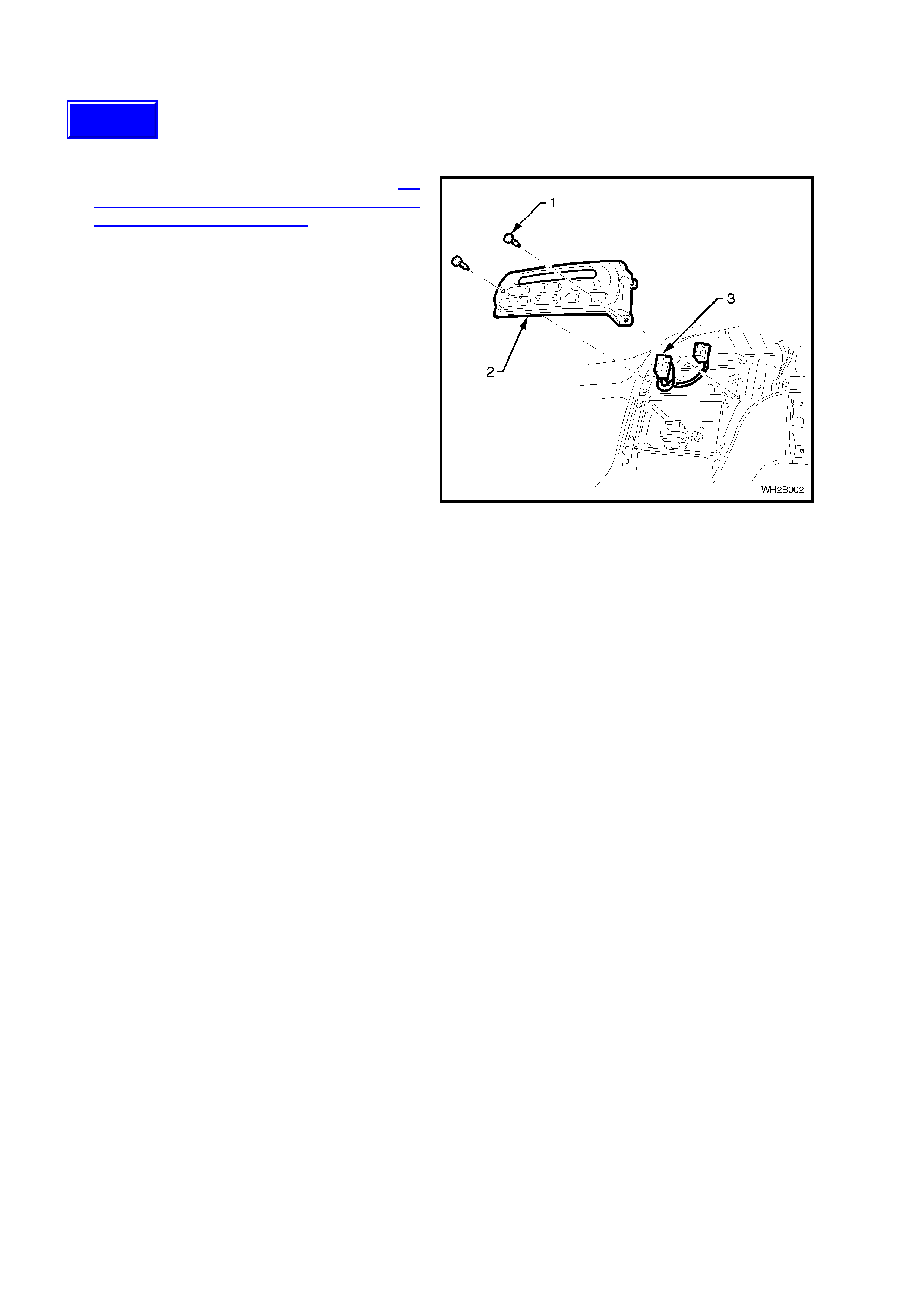
2.1 ECC MODULE
REMOVE
1. Detach the instrument facia panel, refer to 2.7
HEATING, VENTILATION AND AIR
CONDITIONING (HVAC) UNIT in this Section.
2. Locate and rem ove the two s elf-t apping sc rews
(1) used to retain the ECC Module (2) to the
instrument panel carrier.
3. Disconnect the two ECC Module electrical
connectors (3).
REINSTALL
Reinstallation is the reverse order of removal.
NOTE: If installing a new ECC module, ensure the
most current software version is loaded in module.
Figure 2B-4
Techline
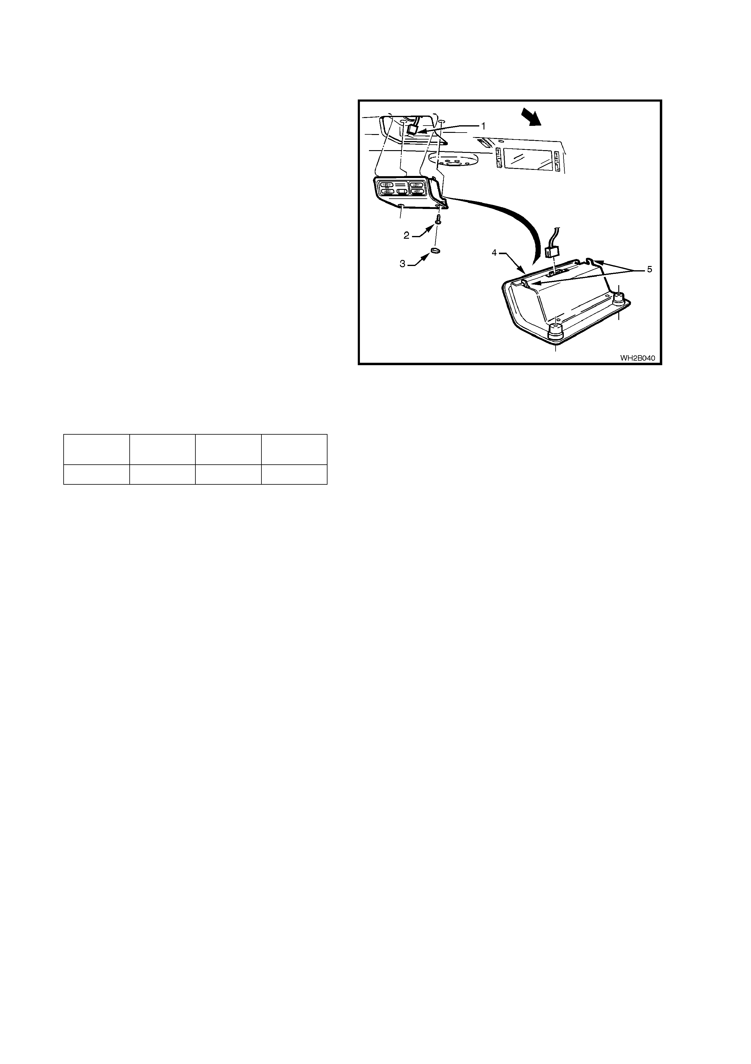
2.2 REAR REMOTE CONTOL
REMOVE
1. Remove the plugs (3) concealing the remote
control retaining screws (2) and remove the
retaining screws.
2. Lower the front of the remote control assembly
(4) disengaging the support lugs (5).
3. Disconnect the body wiring harness electrical
connector (1) and remove the remote control
assembly.
REINSTALL
Reinstallation is the reverse of removal operations.
TEST
The rear remote control is a non-serviceable unit
and as such can only be tested for switch
resistance values which are listed in the following
table.
1. Connect an ohmmeter to the two terminals on
the side of the connector corresponding to the
climate controls. Press each button and check
for the following readings.
Figure 2B-5
TEMP
DOWN TEMP UP FAN
DOWN FAN UP
47Ω120Ω330Ω560Ω
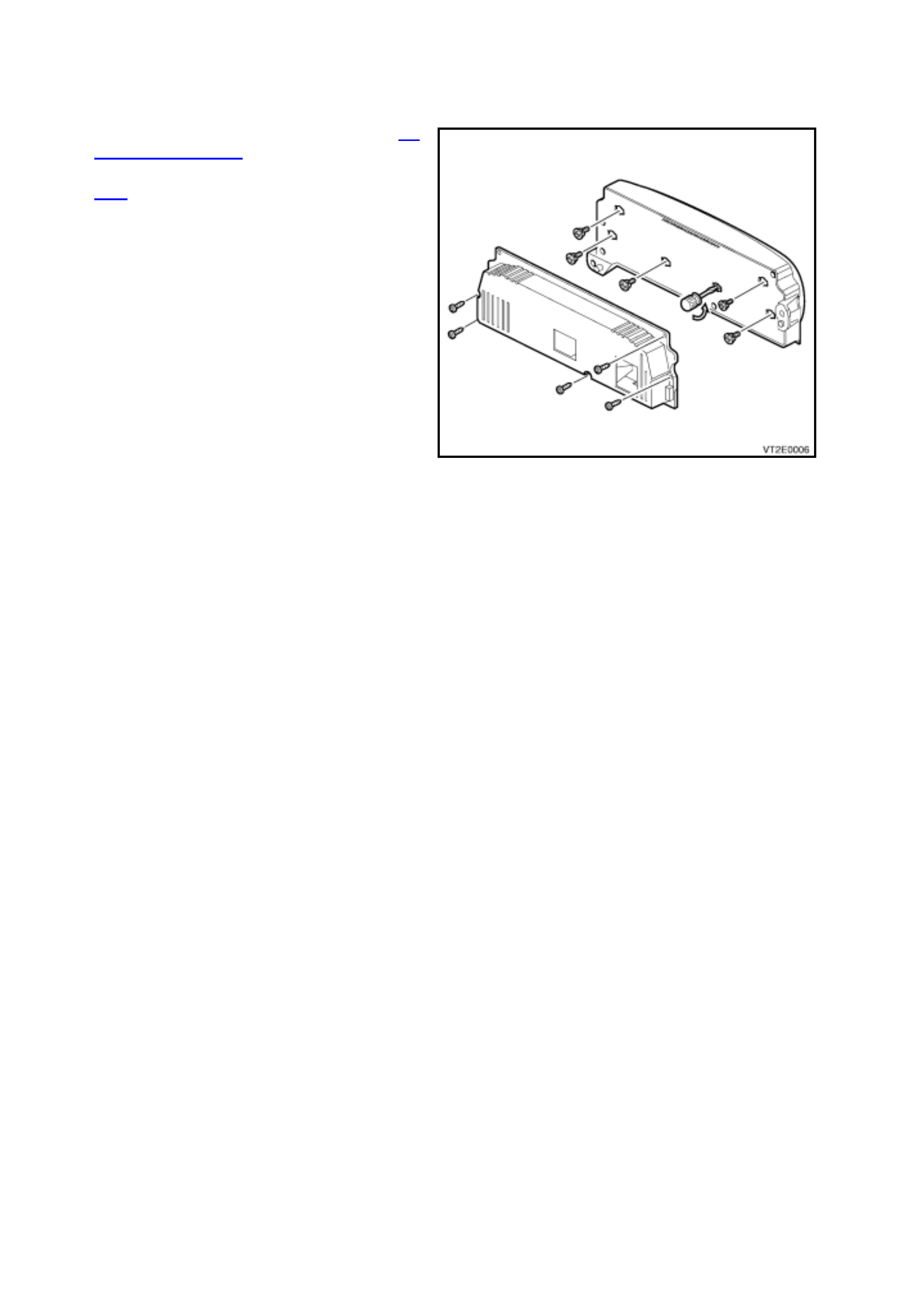
2.3 CONTROL ILLUMINATION
REMOVE
1. Remove the ECC Module refer to 2.1
CONTROL MODULE in this Section.
2. Disconnect the two electrical connectors, Fig.
2B-4.
3. Unscrew the five self tapping screws retaining
the rear housing of the ECC Module.
4. Insert a flat blade screwdriver in the plastic
globe holder slot (as shown) then twist anti-
clockwise until the holder stops. Gently ease
globe holder out of the front housing.
REINSTALL
Reinstallation is the reverse order of removal.
Figure 2B-6
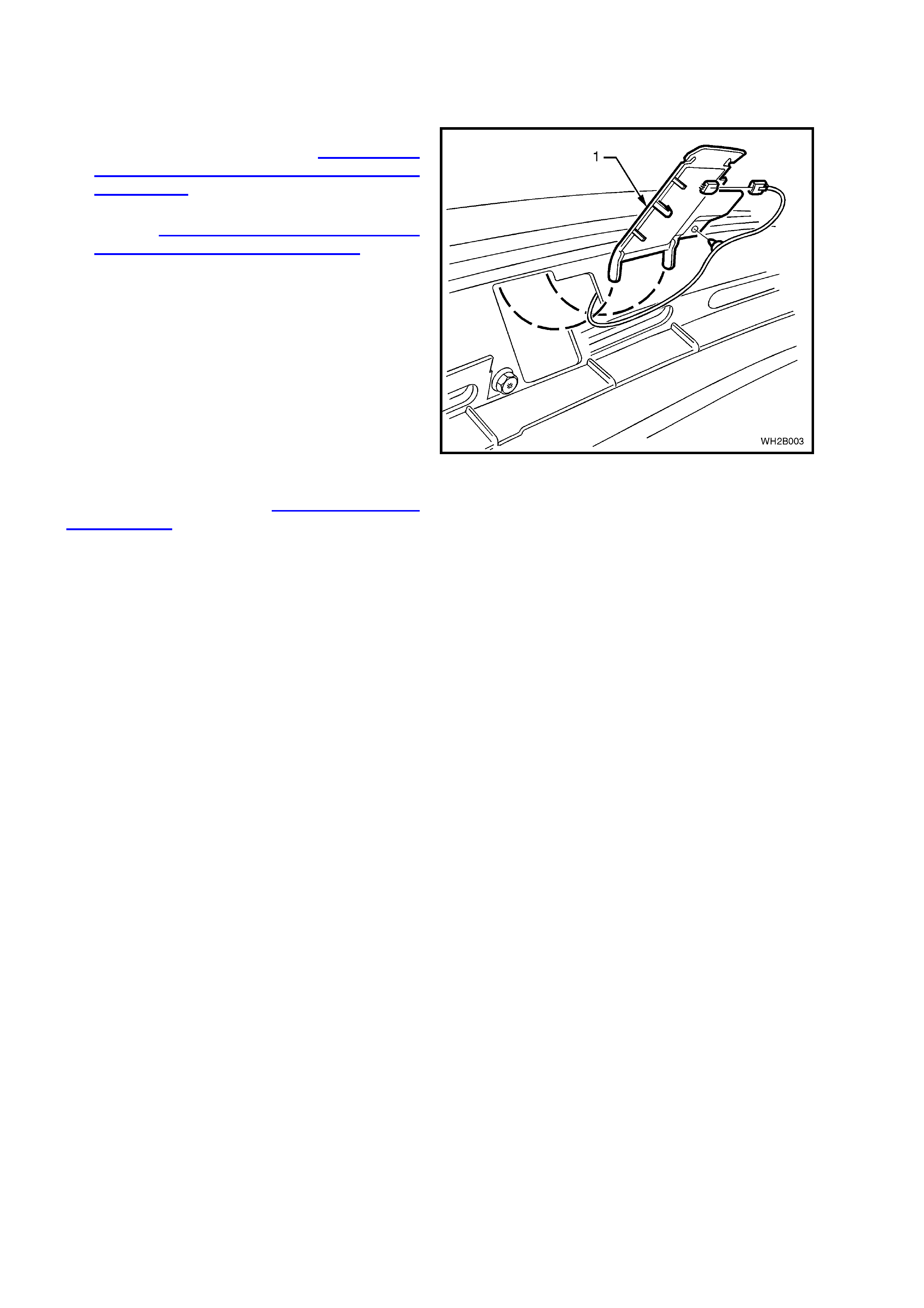
2.4 SUN SENSOR/REMOTE RECEIVER MODULE
REMOVE
1. Remove the right and lef t hand side instrum ent
panel end cap covers, refer to 2.8 HEATING,
VENTILATION AND AIR CONDITIONING
(HVAC) UNIT in this Section.
2. Remove the right and left hand demist panels,
refer to 2.8 HEATING, VENTILATION AND
AIR CONDITIONING (HVAC) UNIT in this
Section.
3. Unclip the Sun Sensor/Remote Receiver
Module (1) from the dash panel by lifting from
the bottom then pulling downward to disengage
the locking legs. Disconnect the electrical
connector and unclip wiring.
REINSTALL
Reinstallation is the reverse order of removal.
NOTE: Sun Sensor/Remote Receiver Module
diagnostics can be found in Section 12J-2 HIGH
SERIES BCM, of the VT Series II Service
Information.
Figure 2B-7
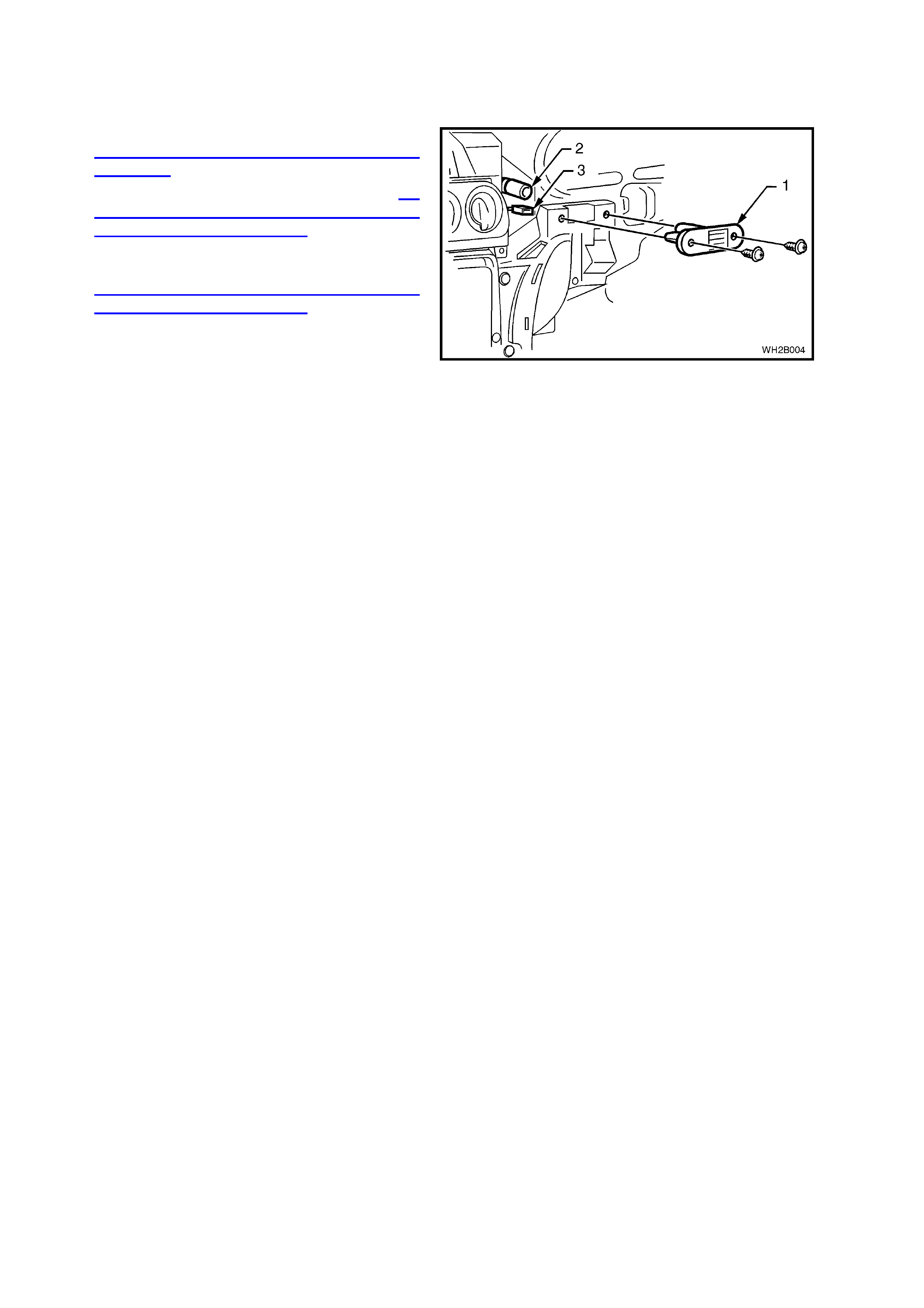
2.5 IN-CAR TEMPERATURE SENSOR
REMOVE
1. Remove the transmission console, refer to
Section 1A3 INSTRUMENT PANEL AND
CONSOLE of the WH Service Information.
2. Remove the radio from the dash, refer to 2.8
HEATING, VENTILATION AND AIR
CONDITIONING (HVAC) UNIT in this Section.
3. Remove the instrum ent panel lower cover right
side and the instrument facia assembly, refer to
2.8 HEATING, VENTILATION AND AIR
CONDITIONING (HVAC) UNIT in this Section.
4. Remove the in-car temperature sensor (1) two
self tapping screws.
4. Disconnect the electrical connector (3) and
aspirator tube (2) and remove the sensor.
REINSTALL
1. Reinstallation takes place in reverse order of
removal.
2. Reset radio security code, refer to the Owner’s
Handbook.
Figure 2B-8
2.6 INTAKE AIR TEMPERATURE SENSOR AND AS PIRATOR TUBE
REMOVE
1. Remove the instr ument f acia as s embly, refer to
2.8 HEATING, VENTILATION AND AIR
CONDITIONING (HVAC) UNIT in this Section.
2. The intake air temperature sensor (4), venturi
(3) and aspirator tube (1) is located on top of
the HVAC unit.
3. Gently unclip the venturi (3) from the
evaporator top cover.
4. Work ing through ventur i opening, us e a thin f lat
blade screwdriver to gently pry the sensor wire
from the plastic retaining clip.
NOTE: Avoid dam aging the evaporator c oil surf ace
when removing sensor wire.
REINSTALL
1. Reinstallation is the reverse order of removal.
2. When installing the intake air temperature
sensor wire, ensure that the wiring runs in the
recess (2) provided in the venturi housing.
IMPORTANT: Ensure the evaporator air sensor
probe clip is re-affixed in exactly the same position
as when removed.
Figure 2B-9
2.7 AMBIENT TEMPERATURE SENSOR
REMOVE
1. Through the front bumper bar opening, detach
the ambient temperature sensor electrical
connector (1).
3. Using a flat blade screwdriver gently pry the
sensor (2) away from the retaining bracket (3).
The sensor is clipped into position.
REINSTALL
Reinstallation is the reverse order of removal.
Figure 2B-10
Techline
2.8 HEATING, VENTILATION AND AIR CONDITIONING (HVAC) UNIT
REMOVE
CAUTION: Disable the SRS (Air Bag). Refer to
DISABLING THE SRS, Section 12M SRS of the
VT Series I Service Information or Section 00
CAUTIONS AND NOTES of this WH Service
Supplement.
IMPORTANT: As a theft deterrent, WH series
vehicles are fitted with a security coded audio
system. After the power supply is interrupted, the
radio will rem ain inoperative af ter reinstallation until
the pin number is entered into the system. The
procedure is described in the glove box literature
accompanying the Owner’s Handbook.
1. Disconnect the battery negative and positive
cables.
2. Drain engine cooling system, refer to Section
6B1 ENGINE COOLING - V6 ENGINE,
Section 6B1-1 ENGINE COOLING - V6
SUPERCHARGED of the VT Series I Service
Information or Section 6B3 ENGINE
COOLING - GEN III V8 ENGINE of the VT
Series II Service Information.
3. Discharge the air conditioning system, refer to
Section 2C AIR CONDITIONING -
SERVICING AND DIAGNOSIS of this Service
Information CD.
4. Depressurise the fuel system, refer to Section
6C1 POWERTRAIN MANAGEMENT - V6
ENGINE of the VT Series I Service Inform ation
or Section 6C3 POWERTRAIN
MANAGEMENT - GEN III V8 ENGINE of the
VT Series II Service Information.
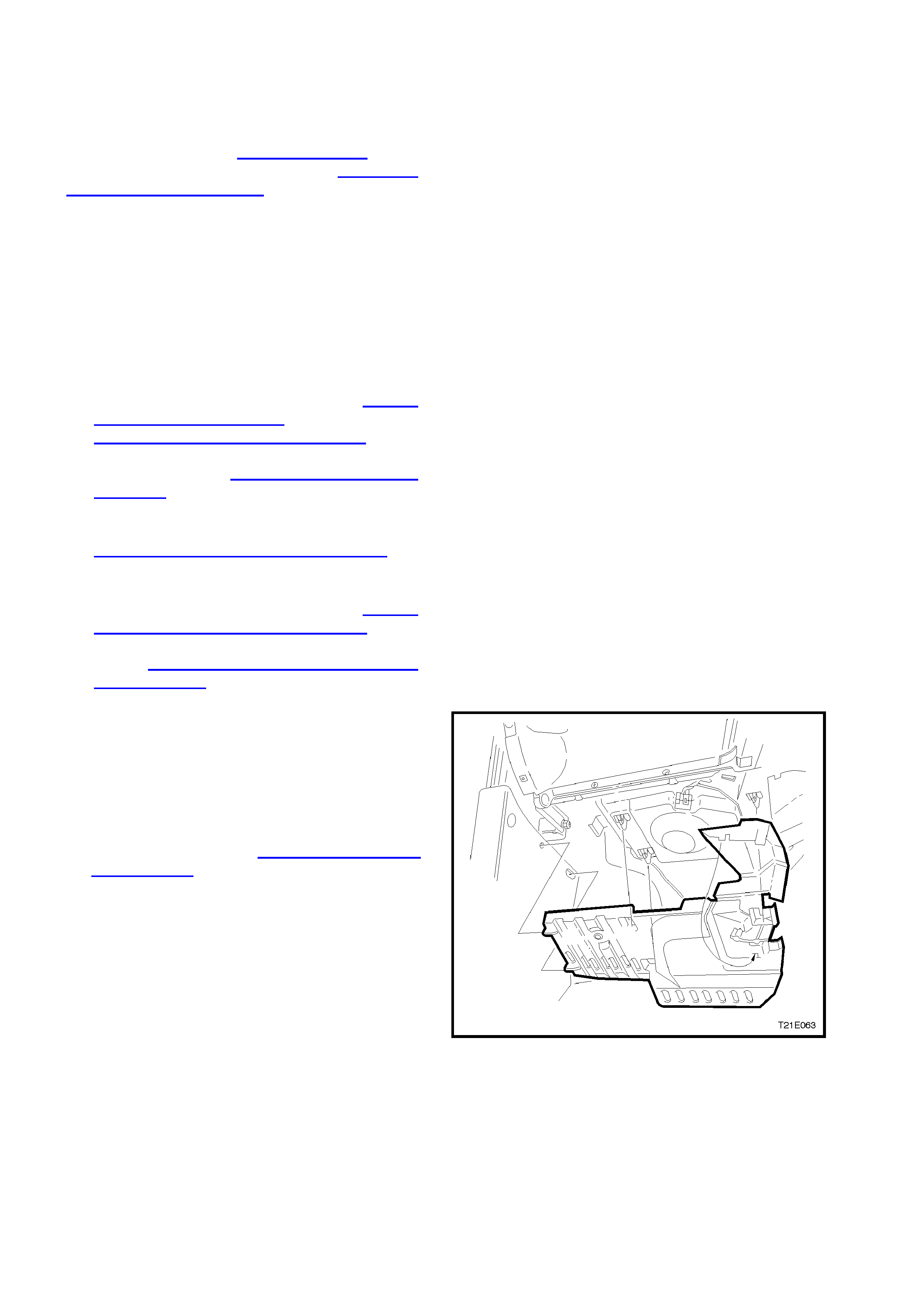
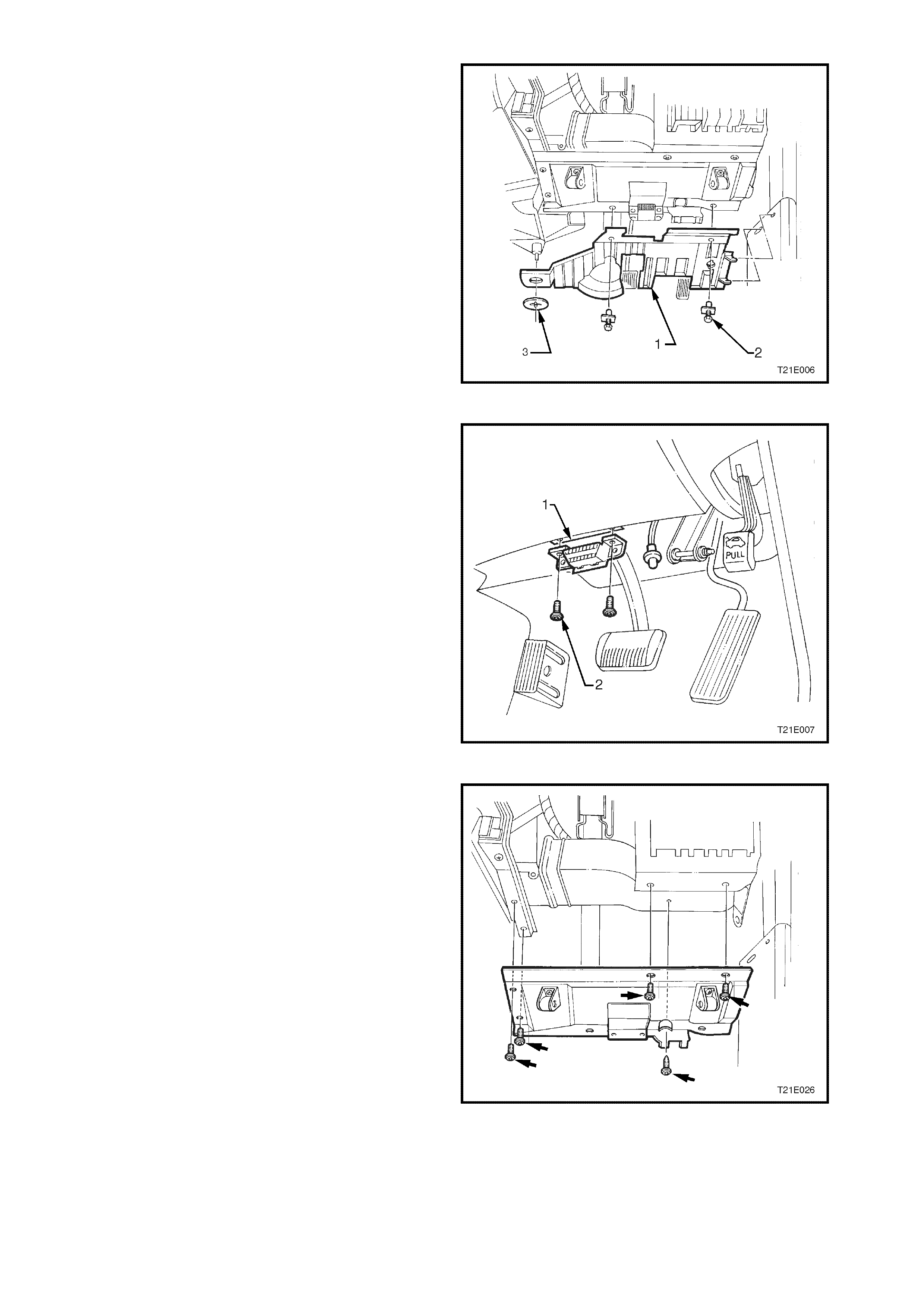
5. Unclip duct cover flap on right hand side of foot
well upper closing panel left side. Disengage
the locating lugs to passenger side shroud
lower. Grasp closing panel firm ly and detach by
pulling left side down first, then disengage right
side clip and remove panel.
6. Remove passenger side shroud lower trim
assembly, refer to Section 1A1 BODY
DIMENSIONS of this Service Information CD.
Figure 2B-11
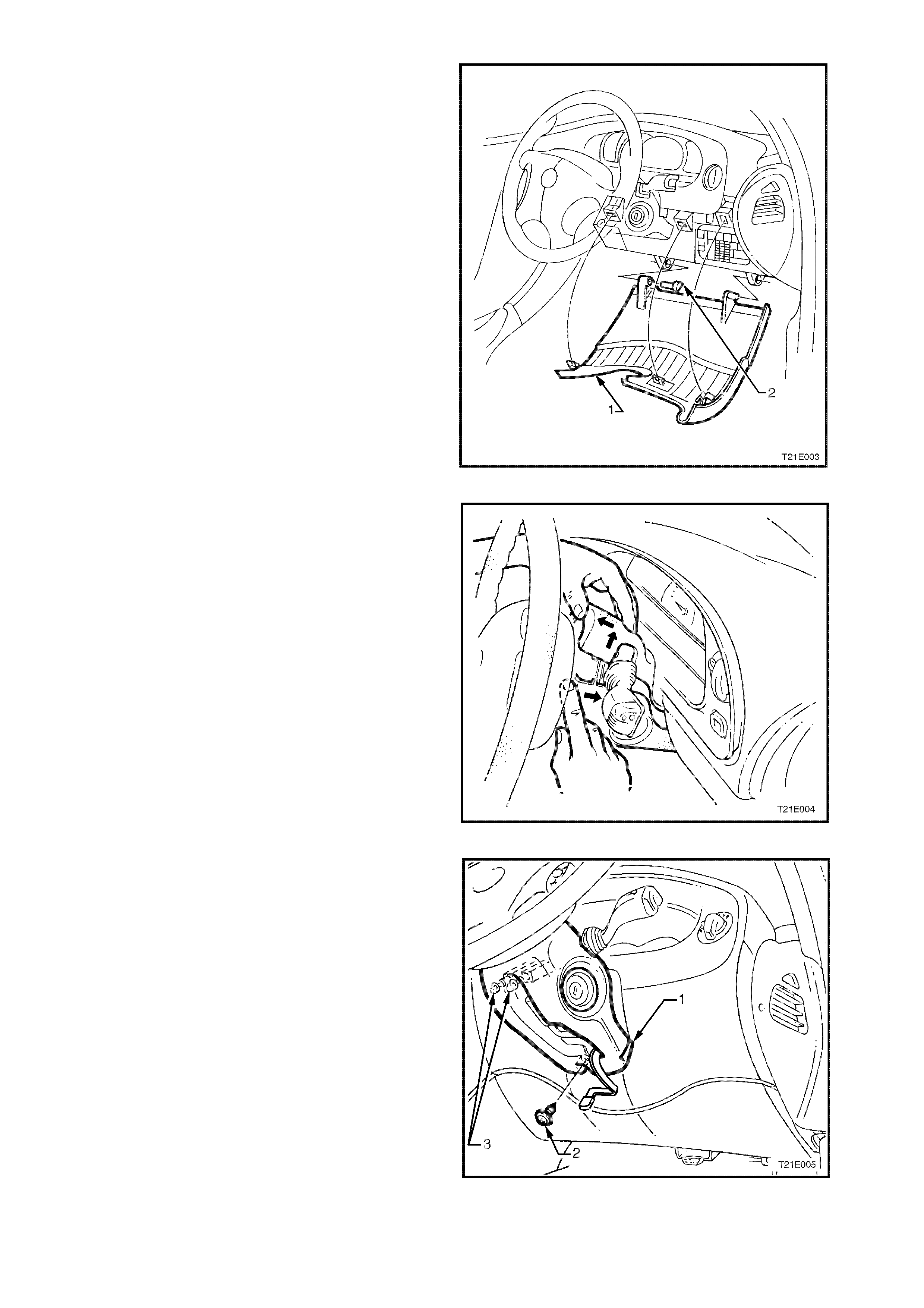
7. Adjust steering wheel to upper most position.
Grasp the right hand side of the instrument
panel lower cover panel (1) firmly and pull
towards rear of vehicle. Repeat the procedure
for the left hand side of the cover.
Using a flat bladed screwdriver, prise the left
hand instrument panel lower cover panel hinge
pin (2) out.
Tilt the instrument panel lower cover down on
the left side and dis engage the right hand hinge
pin. Remove panel.
Figure 2B-12
8. Release the steering column height adjuster,
com pletely lower steering colum n and leave lever
in the released position.
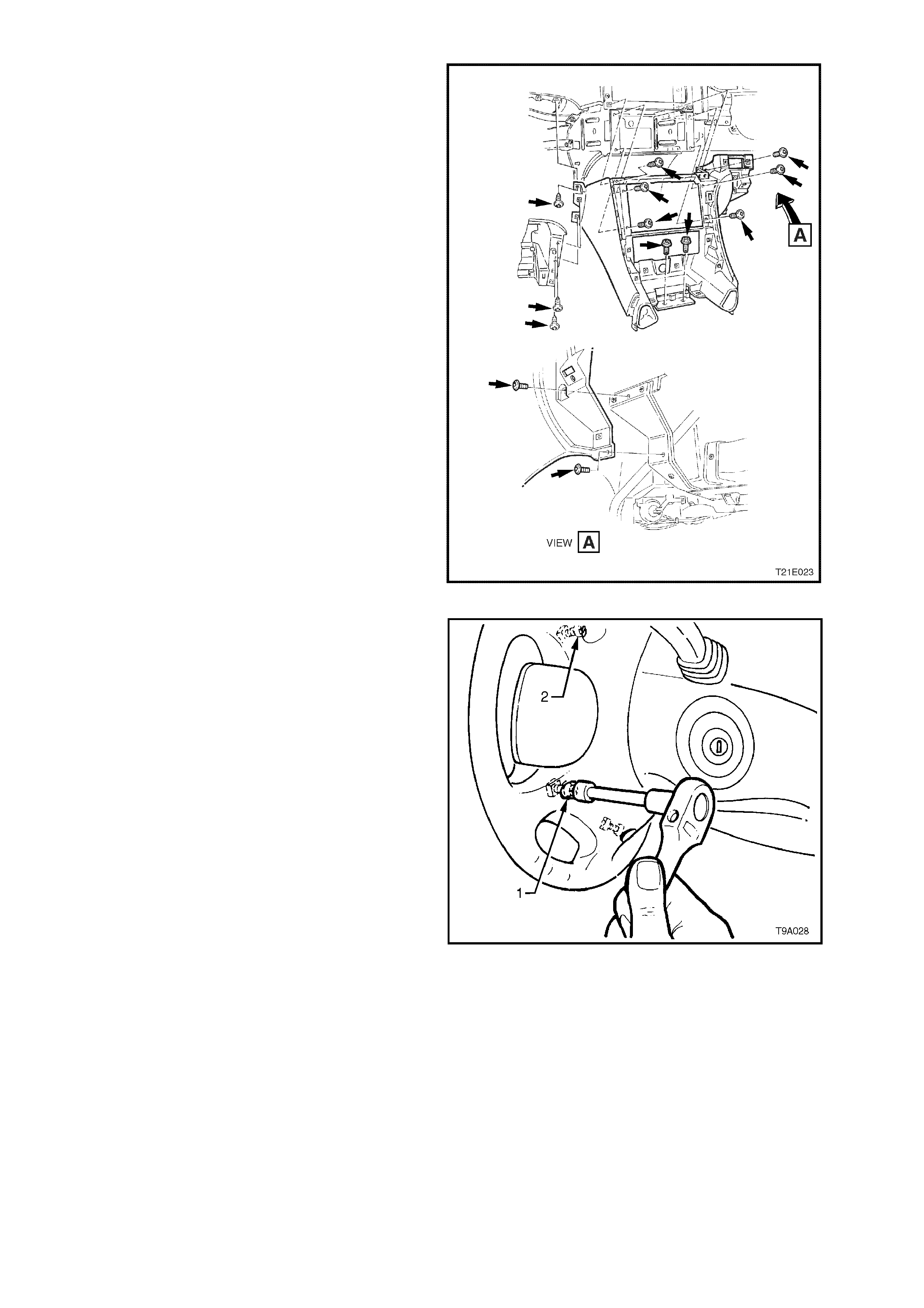
9. Insert finger between the steering wheel and the
lower cover as shown in Fig. 2B-13 and apply a
small amount of pressure (pushing towards the
instrument cluster) while lifting the upper cover
upwards.
Figure 2B-13
10. Remove screw (2) securing the lower cover (1)
to the steering column.
11. Slide lower cover toward the steering wheel to
release cover fr om the two retaining tangs ( 3) on
the steering column.
12. While feeding the key reader outer surround
from lower cover, remove cover.
Figure 2B-14
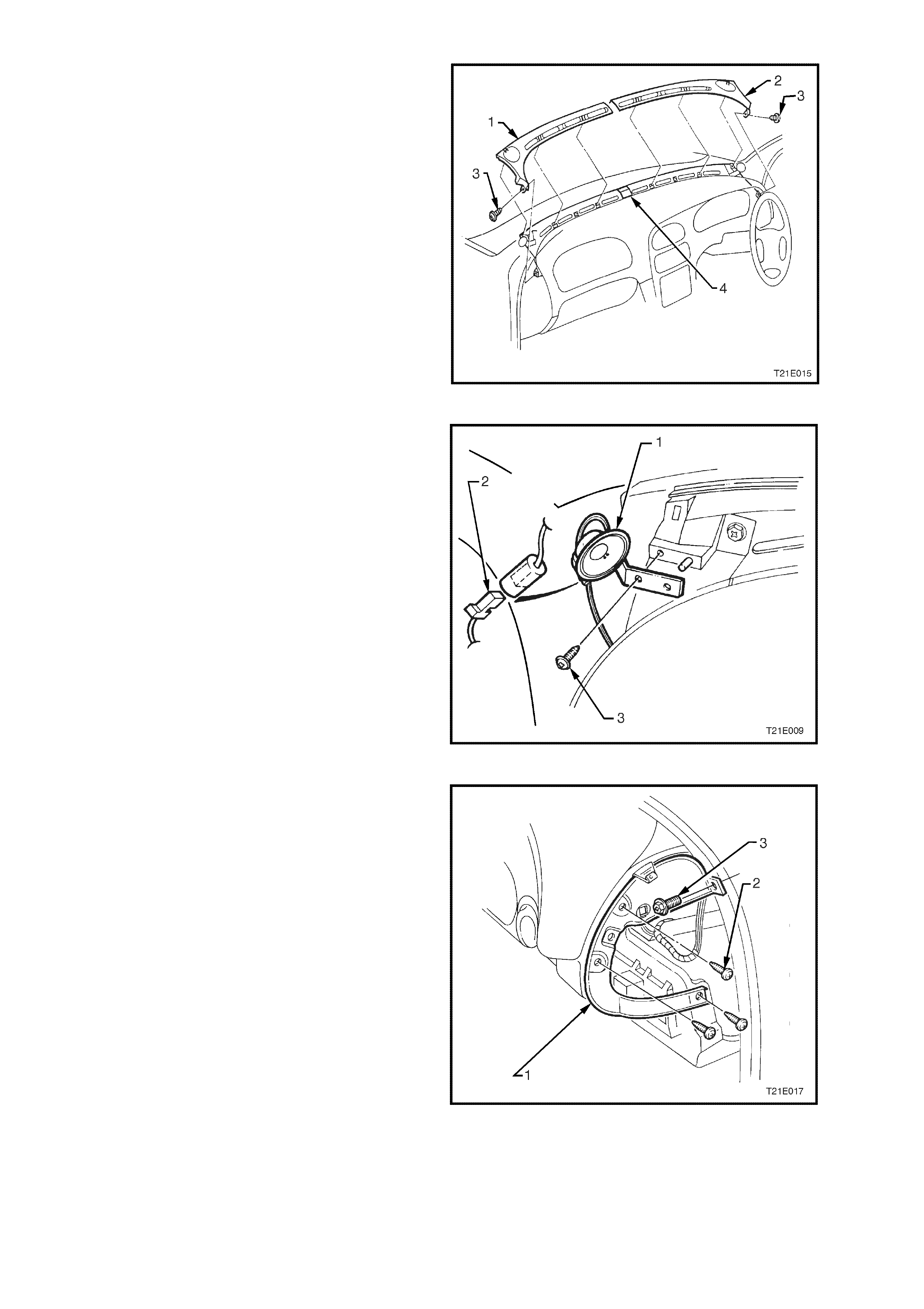
13. Rem ove the two scrivets (2 ) securing the f ootwell
upper closing panel (1).
Prise off the retaining button (3) and detach the
footwell upper closing panel.
Disconnect front footwell lamp from footwell
upper closing panel.
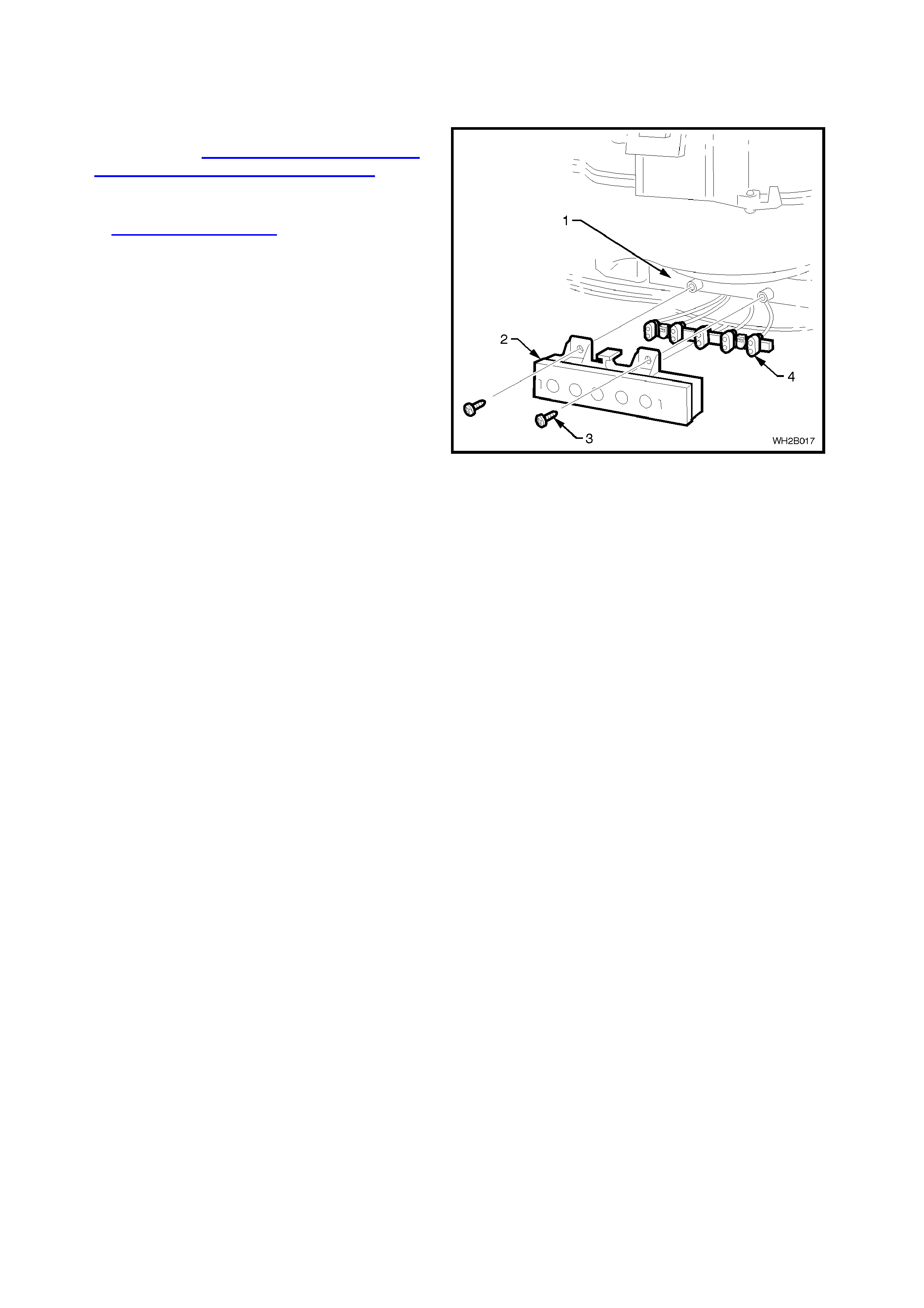
Figure 2B-15
14. Remove two screws (2) securing the diagnostic
link connector (1) to the instrument panel lower
trim right side assembly .
Figure 2B-16
15. Remove the five screws attaching the instrument
panel lower trim right side rail assembly,
disengage BCM from panel and remove panel.
Figure 2B-17
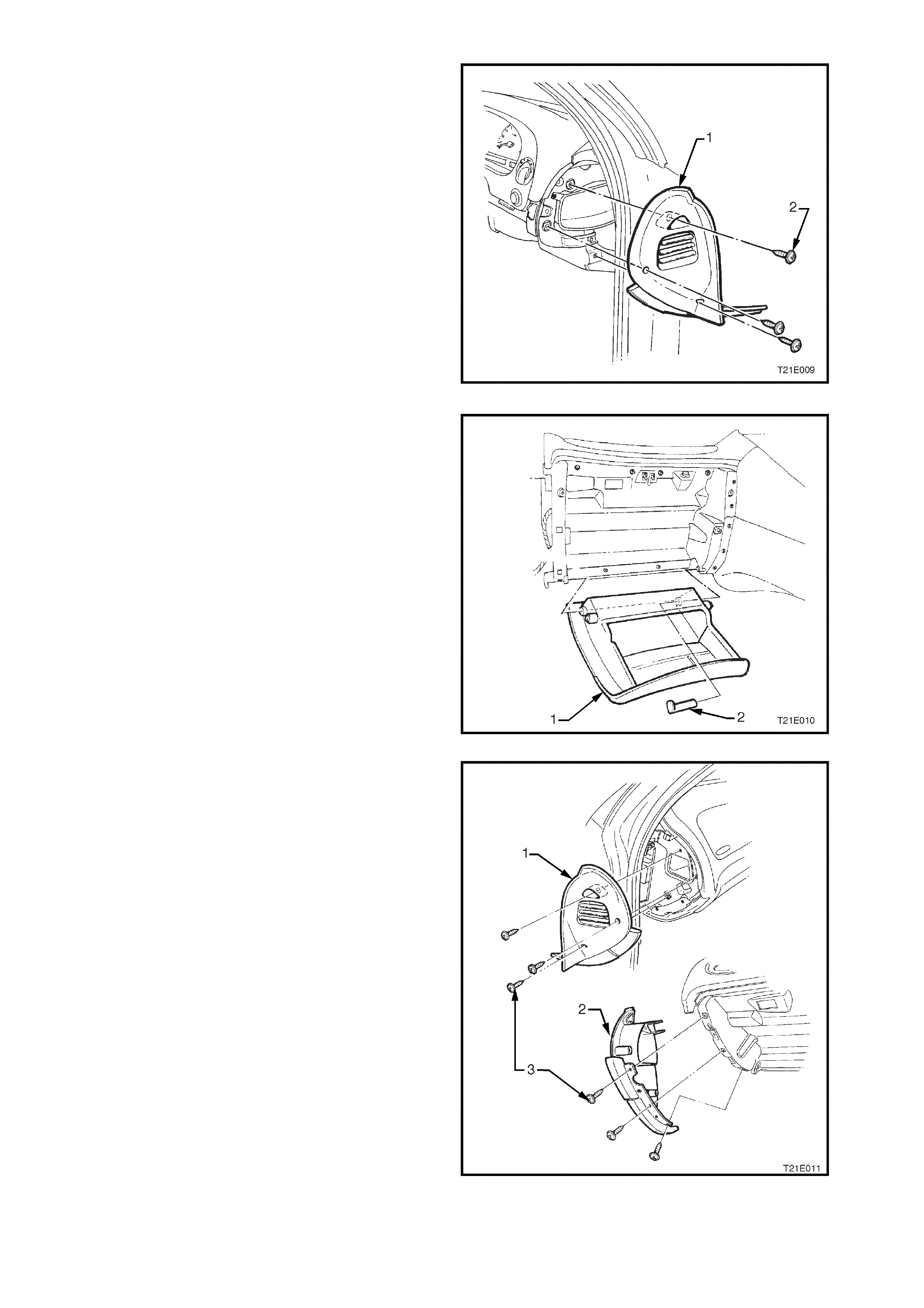
16. Remove the three screws (2) securing the right
hand instrument panel end cap (1) to the
instrument panel and remove end cap.
Figure 2B-18
17. Open the instrument panel compartm ent (1), and
lever the hinge pin (2) from the right side of the
compartment. Lower compartment and withdraw
the pin. Disengage right hand travel limiting peg
from slot in instrument panel roof by deforming
plastic tang.
Figure 2B-19
18. Rem ove the six screws (3) securing the left hand
instrument panel end cap cover (1) and end cap
(2) to the instrument panel and remove end cap
cover and end cap.
Figure 2B-20
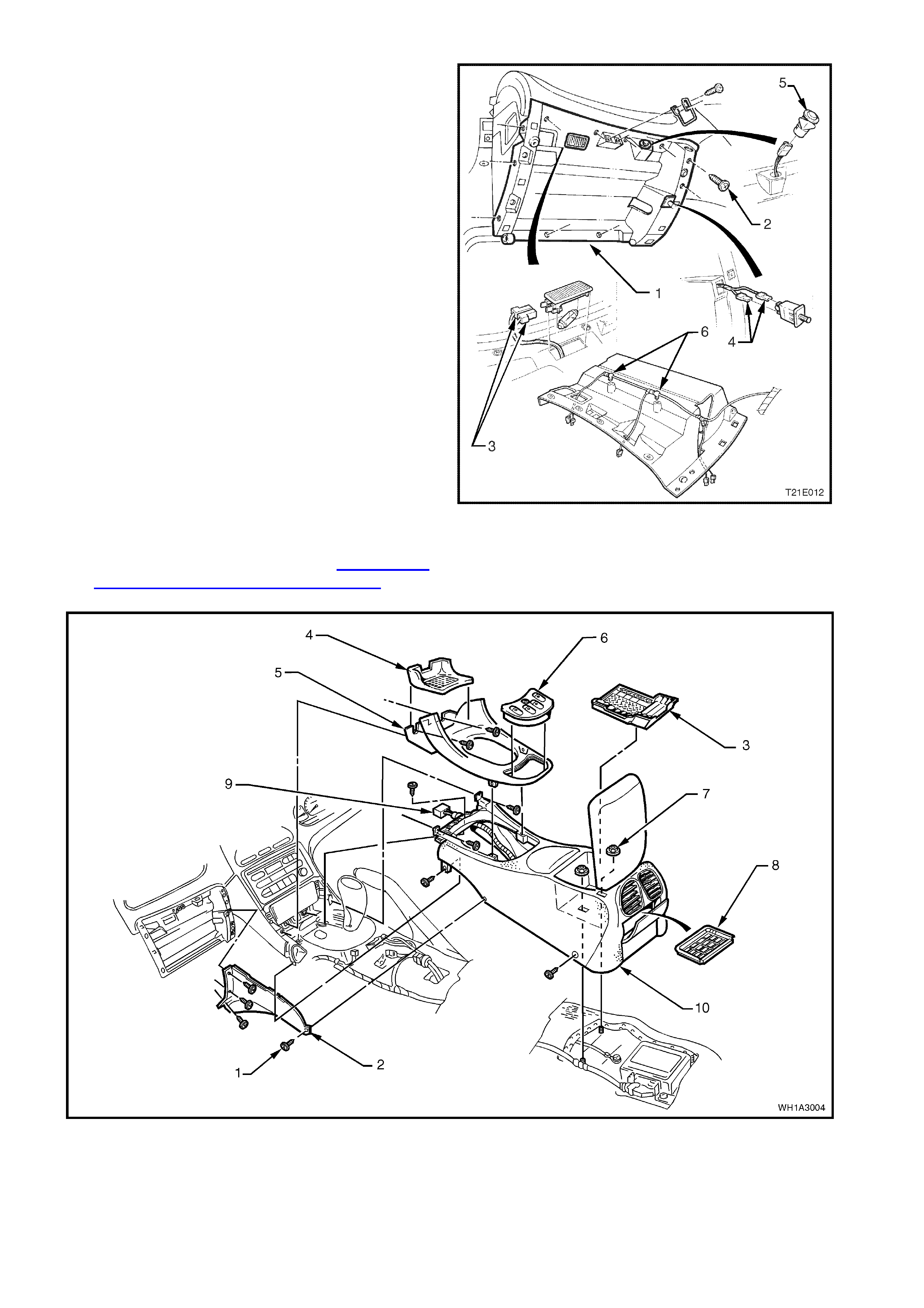
19. Remove the 11 retaining screws (2) from
instrument panel compartment roof (1).
Disconnect the instrument panel compartment
lamp (3) and switch (4) connectors, disconnect
the luggage compartment lock switch connector
(5) and unclip instrument panel compartment
wiring harness (6).
Figure 2B-21
20. Remove the transmission console and detach
console wiring harness, refer to Section 1A3
INSTRUMENT PANEL & CONSOLE of this
Service Information CD.
Figure 2B-22
Legend
1. Screw (11 places)
2. Centre facia side extension left side shown
3. Insert
4. Rubber cap
5. Transmission console cap
6. Power window switch assembly
7. Nut (2 places)
8. Insert
9. Console harness
10. Centre console
21. Remove the two retaining screws (3) from the
left (1) and right (2) hand demist nozzles and,
taking care not to damage the SUN
SENSOR/REMOTE RECEIVER MODULE /
remote receiver module, remove both demist
nozzles.
Figure 2B-23
21. Disconnect the left and right front instrument
panel speaker wiring harness connectors (2).
Using a Phillip’s head screwdriver, remove the
two screws (3) (one each side) attaching front
instrum ent panel speakers (1) and rem ove both
speakers.
Figure 2B-24
22. Remove the four retaining screws (2 & 3) from
the instrument panel carrier end panel (1) right
side and remove panel.
Figure 2B-25
23. Remove the four attaching screws (2) securing
instrument panel carrier end panel (1) left side
and three bolts (3) attaching the passenger air
bag support rail, lower lef t side r ail, and rem ove
panel.
Figure 2B-26
24. Remove screws (3) retaining the instrument
facia (2) and instrument facia storage
compartment assembly (4).
25. Remove instrument facia storage compartment
and pull instrument facia escutcheon (1) from
retaining clips.
26. Remove instrument facia by pulling facia from
retaining clips.
NOTE: Care must be taken to disconnect the
headlamp switch connector, fog lamp switch
connector, trip computer switch connector, clock
connector and hazard switch connector from main
wiring harness.
Figure 2B-27
27. Remove left hand centre facia side extension,
unclip antenna leads from inboard end of
glovebox lower rail.
NOTE: This is necessary to provide enough
antenna cable to pull radio forward.
28. Remove service tool hole snap on covers (2)
and remove radio/cassette/CD from instrument
panel using service tool 179 1308 0000 (1).
Figure 2B-28
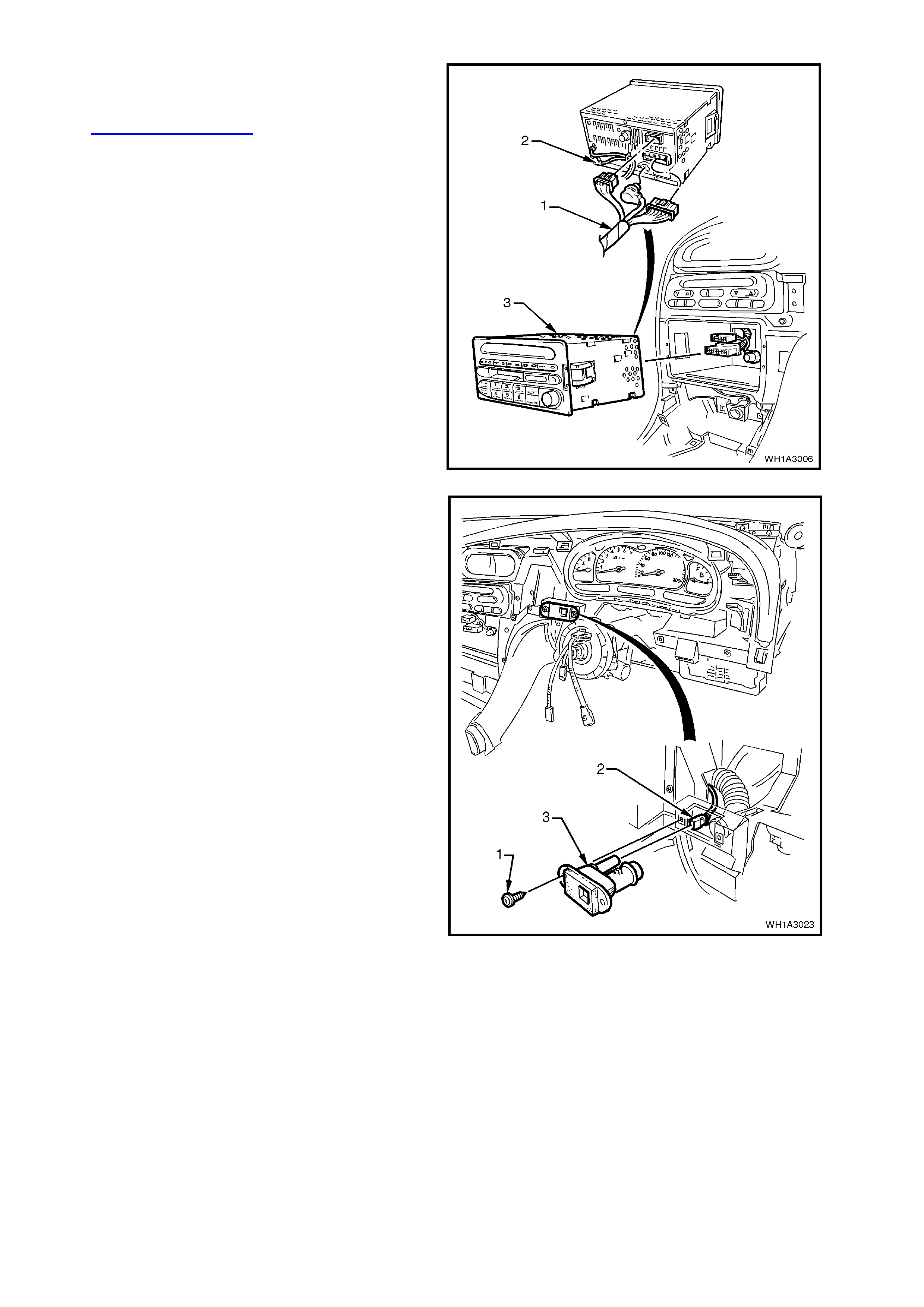
29. Disconnect radio/cassette harness and CD
connector. Disconnect antenna and diversity
antenna. For further information, refer to
Section 12D RADIO of the WH Service
Supplement.
Figure 2B-29
30. Rem ove the two screws (1) securing the in-car
temperature sensor to the instrument panel
and remove the in-car sensor. Disconnect the
wiring harness connector (2) and as pirator tube
from the in-car temperature sensor (3).
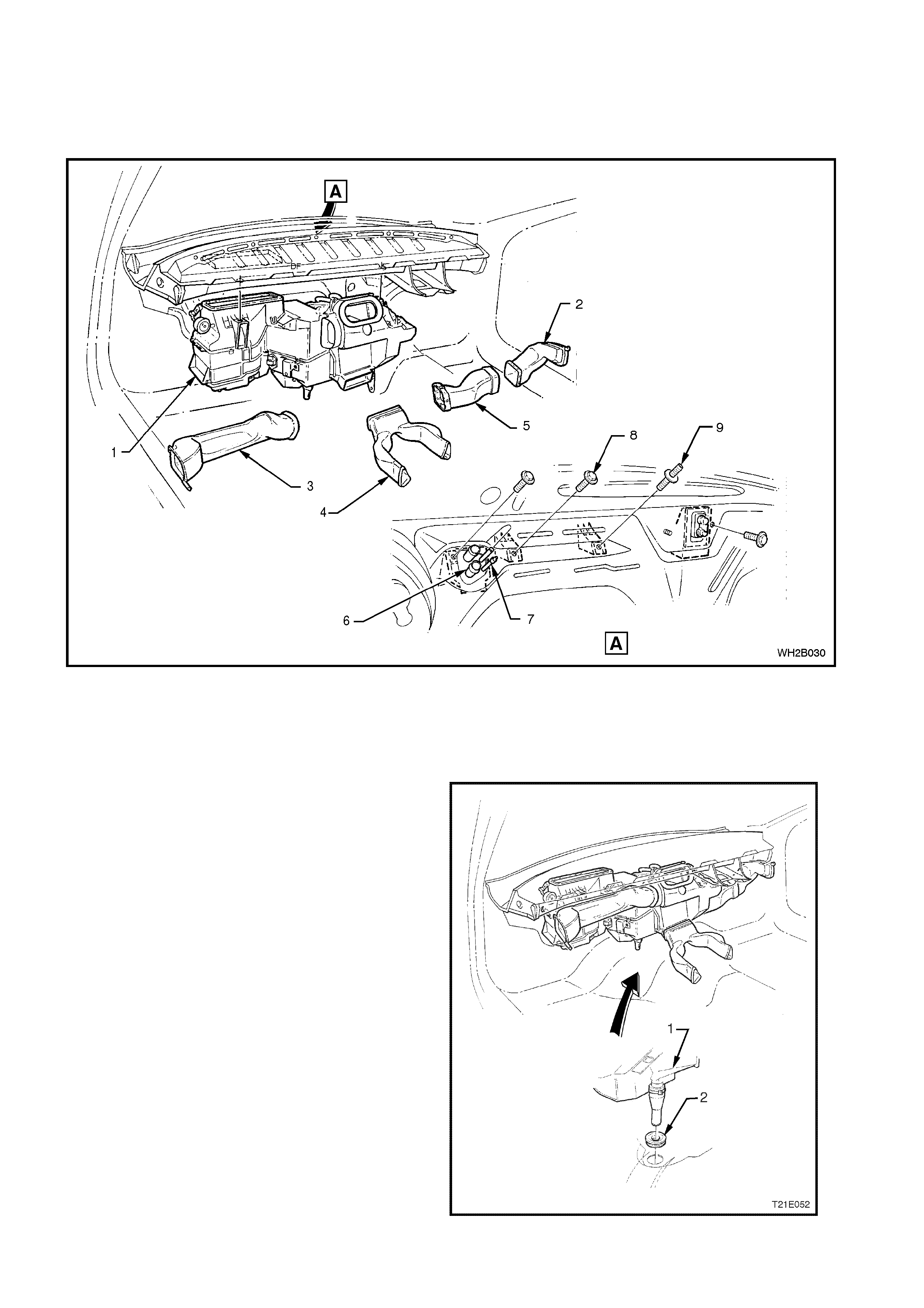
Figure 2B-30
31. Remove the 13 screws securing the c entre f ac ia
assembly to the instrument panel and remove
centre facia assembly.
Figure 2B-31
32. Using a number T30H Torx bit (1),
commercially available or Tool No. ETX30H
and a suitable holder suc h as T ool No. J 25359-
8, loosen and remove four screws (2) from the
rear of steering wheel securing the horn bar
and air bag inflator module assembly to the
steering wheel.
Figure 2B-32
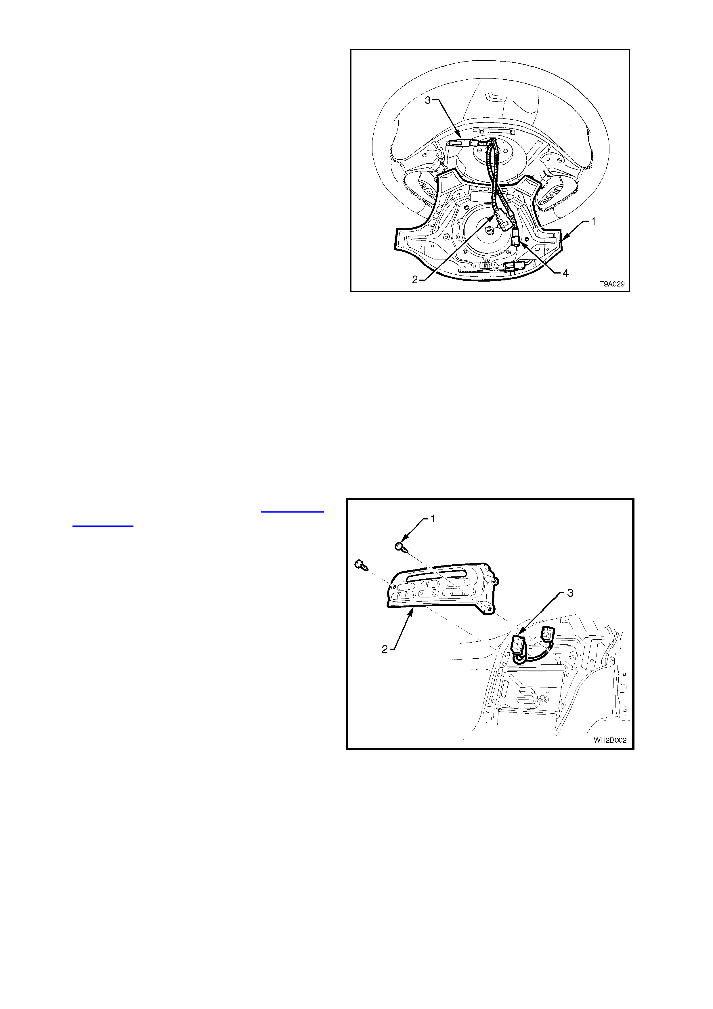
33. Lift up horn bar and air bag inflator module
assembly (1) from the steering wheel, remove
the yellow clock spring to inflator assembly
connection (2) and disconnect wiring harness
connectors (3 and 4) from rear of assembly,
refer to Fig 2B-33.
NOTE: Take extrem e care when disconnecting the
left hand horn pad connector (3) from the stereo
control wiring connector otherwise, damage to the
stereo control wiring could result.
34. Remove horn bar and air bag inflator module
assembly.
CAUTION: When carrying a live (undeployed)
horn bar and air bag inflator module assembly,
make sure the bag opening in the horn bar is
pointed away from you. Never carry the horn
bar and air bag inflator module assembly by the
horn bar wires or connectors on the underside
of the assembly. In case of an accidental
deployment, the bag will then deploy with
minimal chance of injury.
When placing a live horn bar and air bag
inflator module assembly on a bench or other
surface, always face the bag and horn bar up,
away from the surface. Never rest the horn bar
and air bag inflator module assembly with the
horn bar f ace down . This is necessary so th at a
free space is provided to allow the air bag to
expand in the unlikely event of accidental
deployment. Otherwise, personal injury may
result.
Figure 2B-33
35. Remove the steering wheel, refer Section 9A
STEERING of the VT Series I Service
Information.
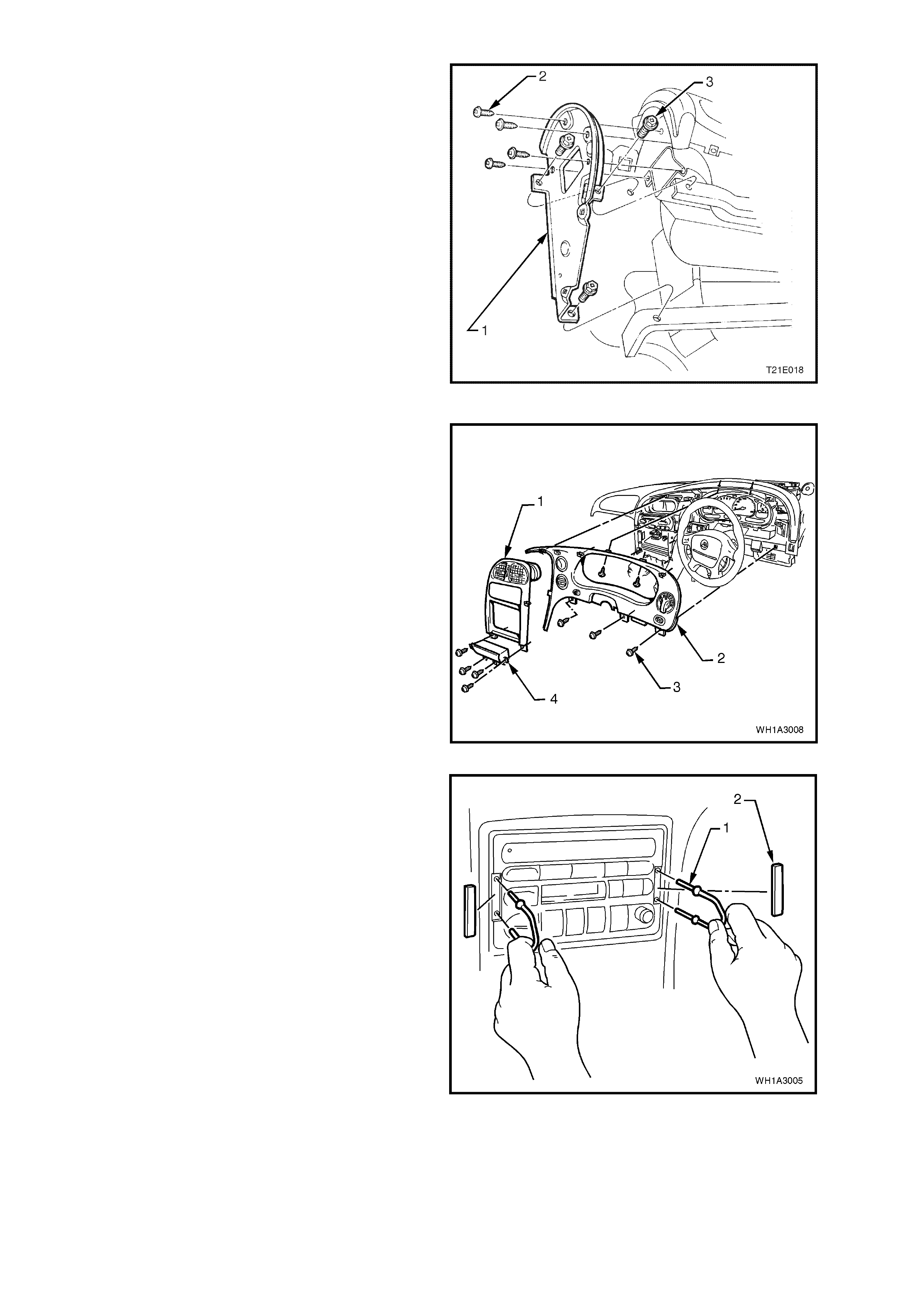
36. Remove the screws (1) securing the ECC
module (2) to the instrument panel.
37. Disconnect the wiring harness connections (3).
Remove the ECC module.
Figure 2B-34
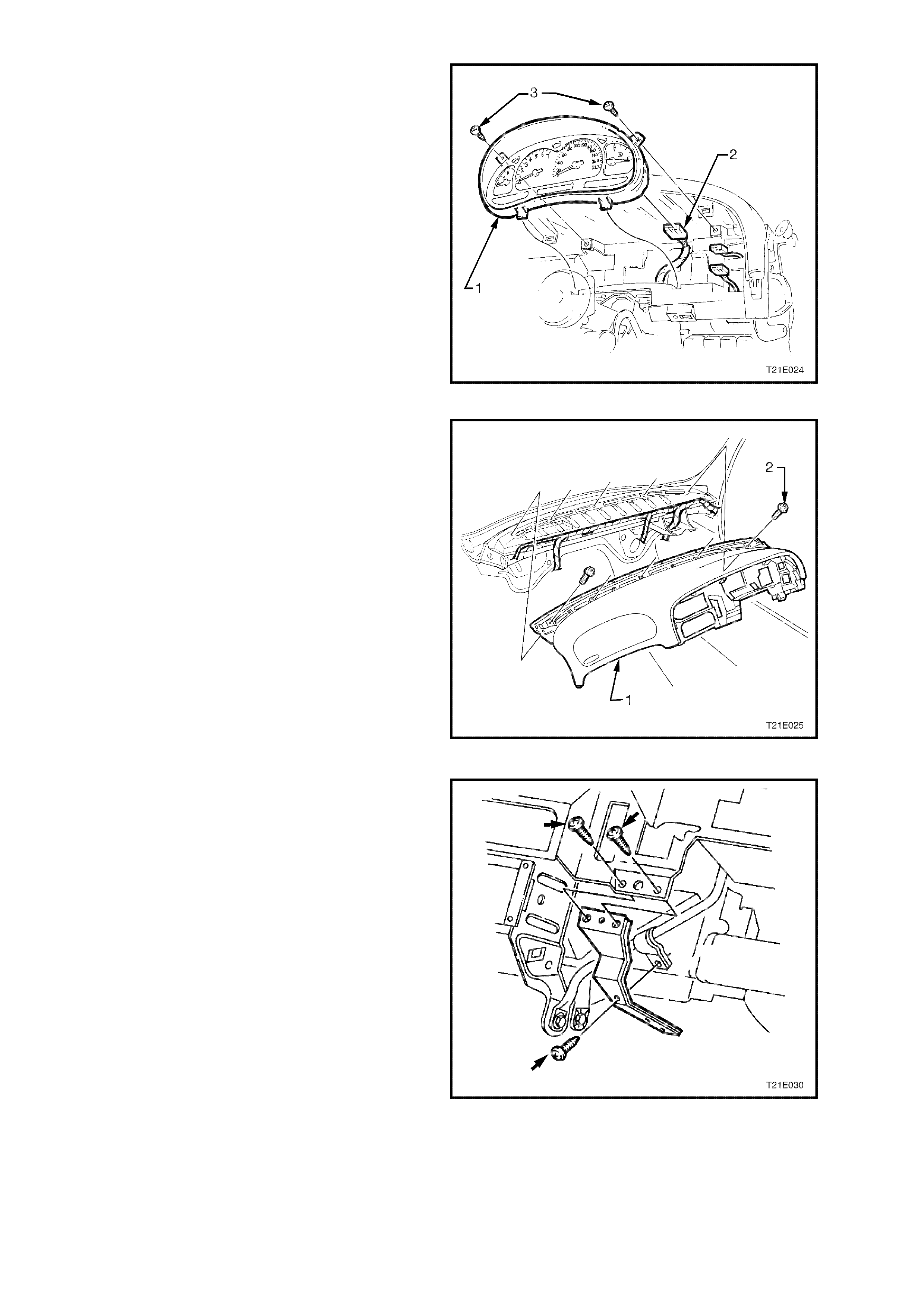
38. Remove the two screws (3) securing the
instrument cluster assembly (1) and disconnect
instrument connector (2).
Figure 2B-35
39. Remove the five retaining screws (2) along top
edge of instrument panel pad (1) and remove
pad.
Figure 2B-36
40. Remove the three screws securing the centre
facia support rail to the instrument panel, and
remove support rail.
Figure 2B-37
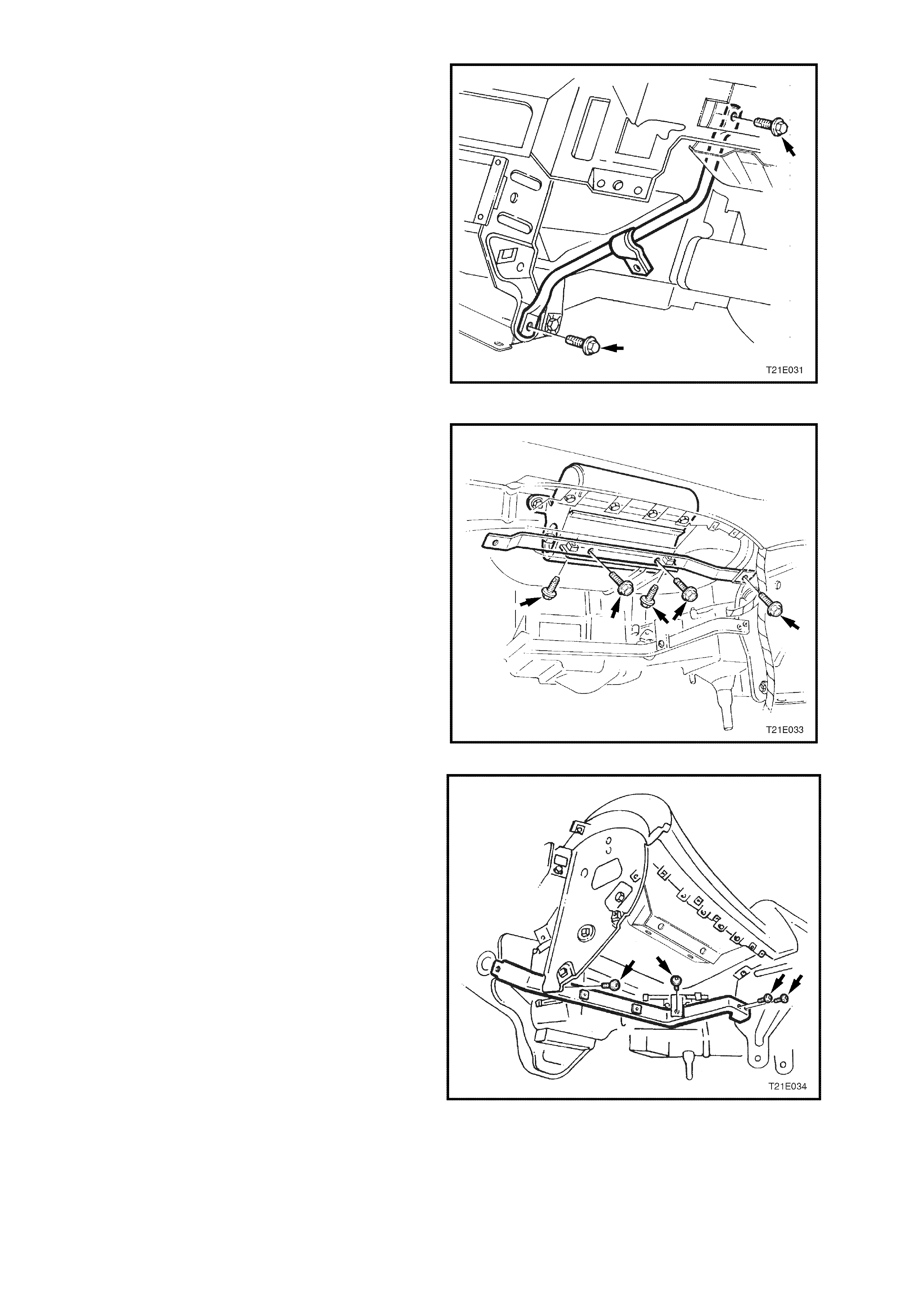
41. Remove the lower steering column inner
bracket screws (2) and remove bracket.
Figure 2B-38
42. Remove the f ive sc r ews sec ur ing the pas s enger
air bag support rail assembly and remove rail.
Figure 2B-39
43. Remove two screws connecting lower left side
rail to instrument panel carrier assembly.
Remove single screw connecting lower left side
rail to instrument panel carrier end panel left
side. Rem ove single sc rew connecting lower lef t
side rail to body mount.
Figure 2B-40
44. Remove the six instrument panel carrier rail
assembly retaining screws and remove carrier
rail.
Figure 2B-41
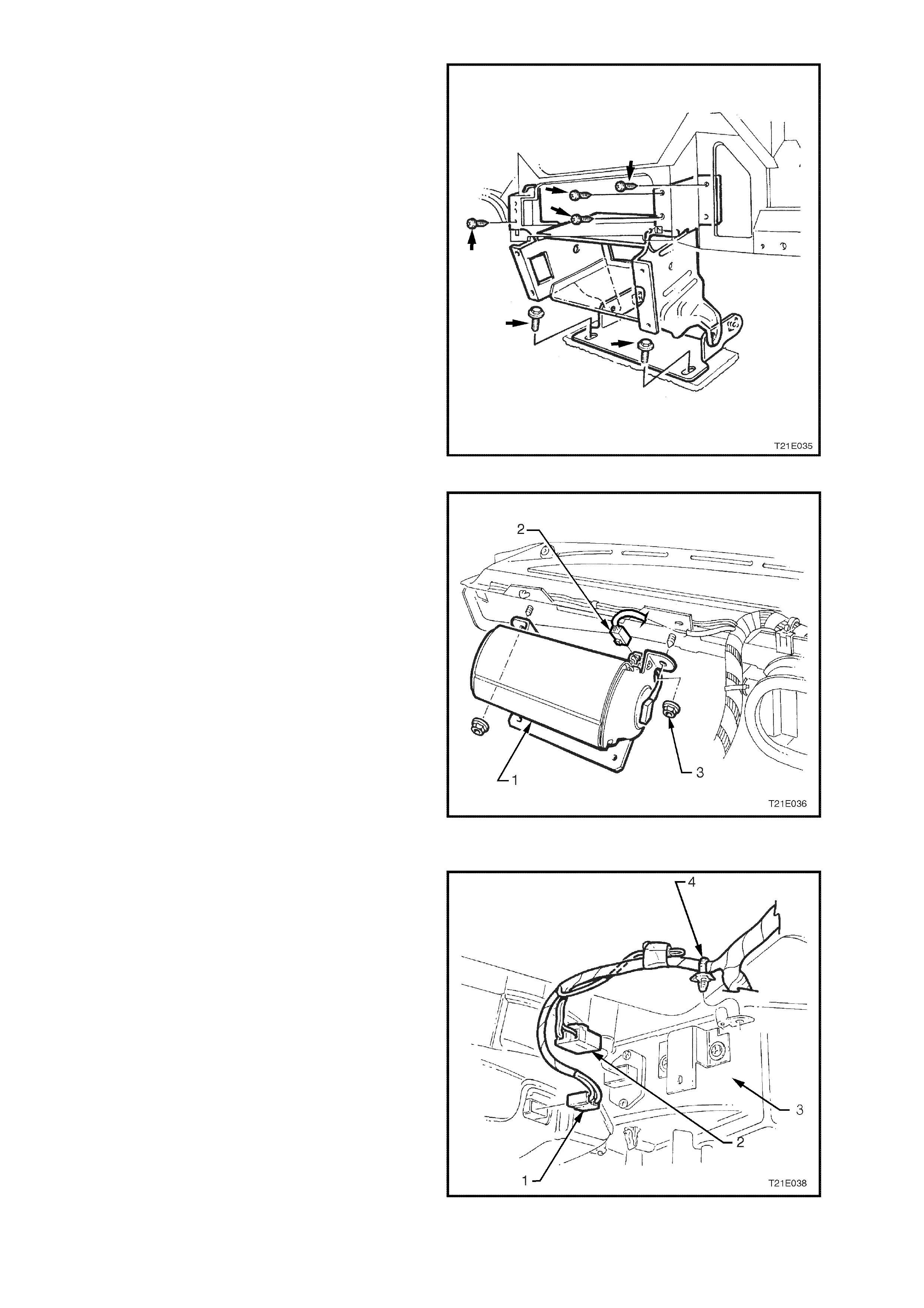
45. Disconnect the passenger air bag connector (2)
located on the right hand side of air bag (1).
Remove the two nuts (3) attac hing the air bag to
instrument panel assembly.
CAUTION: When carrying a live (undeployed)
front passenger's air bag inflator module
assembly, make sure the b ag openin g is poin ted
away from you. In case of an accidental
deployment, the bag will then deploy with
minimal chance of injury. When placing a live
front passenger's air bag inflator module
assembly on a bench or other surface, always
face with the air bag up, away from the surface.
Never rest the air bag inflator module assembly
wit h the air bag f ace down . This is necessary so
that a free space is provided t o allow t he air bag
to expand in the unlikely event of accidental
deployment. Otherwise, personal injury may
result. Figure 2B-42
46. Disconnect the blower motor wiring harness
connector (1) and fan speed control wiring
harness connector (2) from the HVAC unit (3).
Detach wiring harness retaining clip (4) from
HVAC unit.
Figure 2B-43
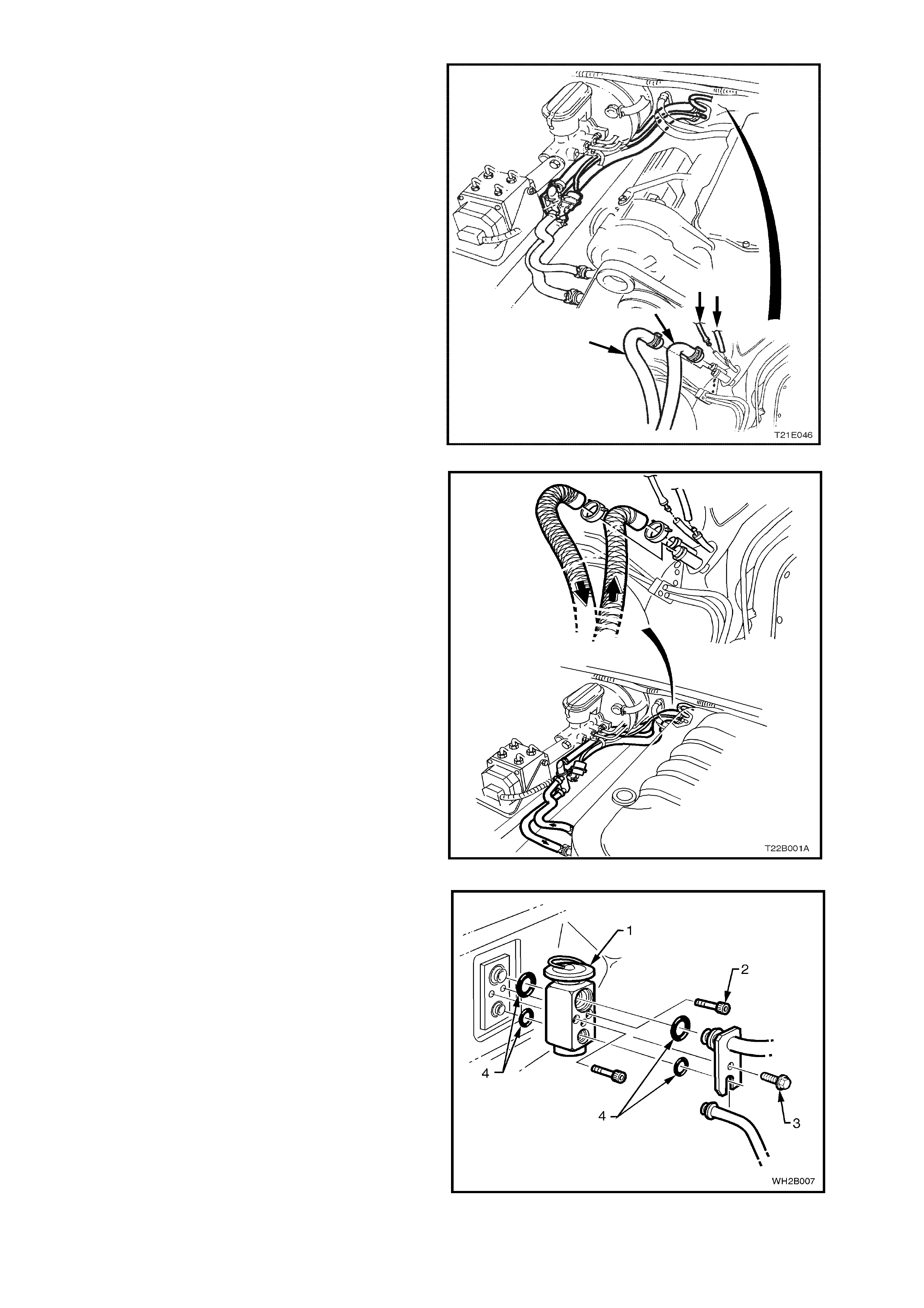
47. Tag and disconnect the heater hoses and
vacuum lines at the cockpit module, refer Fig.
2B-44 (V6 application) or Fig. 2B-45 (GEN III V8
application).
Figure 2B-44
Figure 2B-45
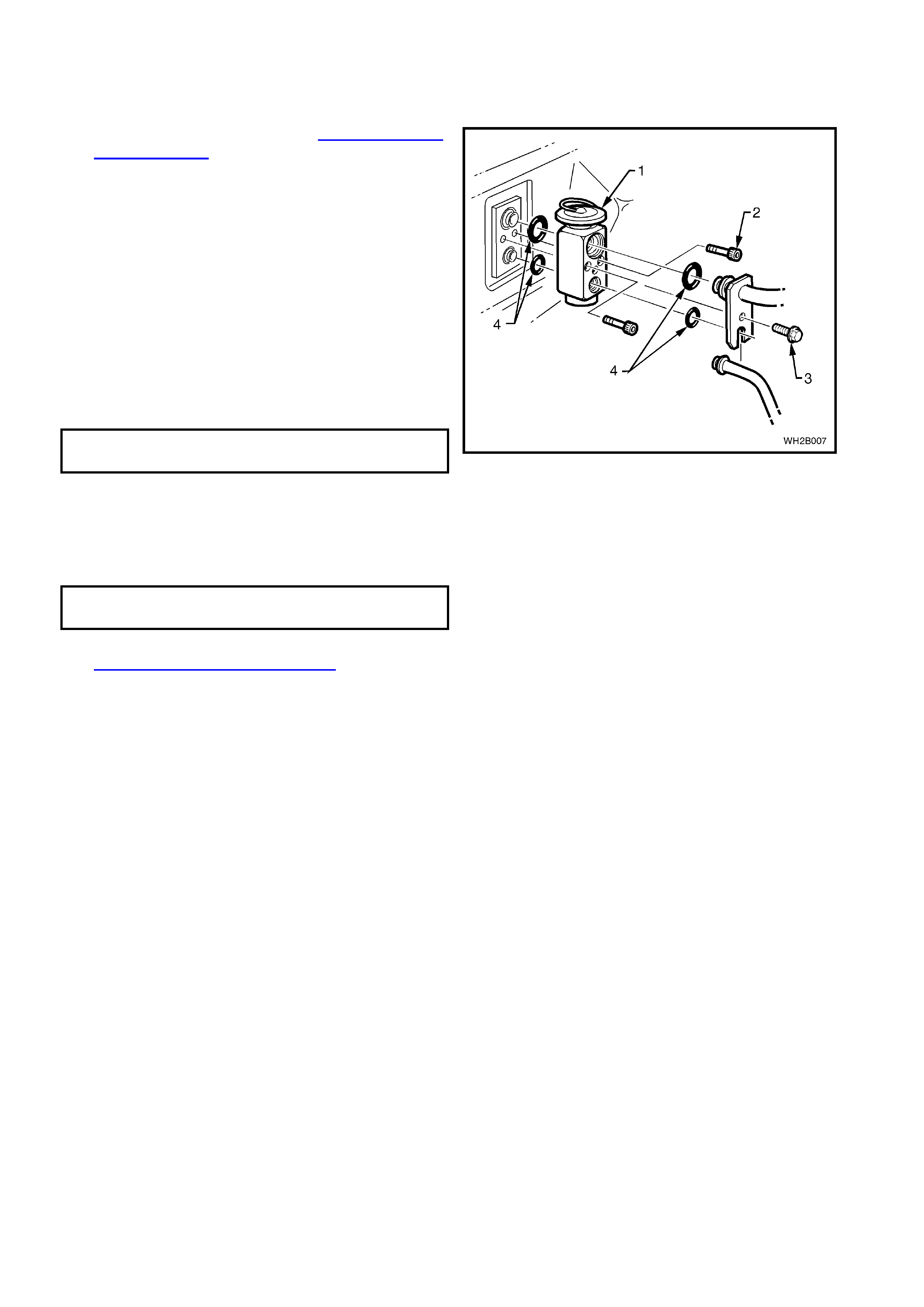
48. Rem ove the washer f aced bolt (3) retaining the
tube plate to the TXV (1).
49. Discard O – rings (4).
50. Unscrew two capscrews (2) and remove TXV
(1).
51. Plug all fittings
Figure 2B-46
52. From within the engine compartment, remove
the three screws and one stud securing the
heater case assembly to the cockpit module.
53. Disconnect right and left side air ducting and
rear compartment ducting from HVAC case.
Figure 2B-47
Legend
1. HVAC unit
2. Outer RHS duct
3. Outer LHS duct
4. Rear duct
5. Inner RHS duct
6. Heater hose connections
7. HVAC vacuum hose connections
8. Screw (3 places)
9. Stud (1 place)
54. Remove the HVAC unit (1) from the vehicle by
disengaging the drain grommet (2) and easing
the assem bly from the vehicle tak ing c are not to
strain the heater core tubes.
Figure 2B-48

REINSTALL
Reinstallation is the reverse of removal pr ocedures
ensuring that all fastners are tightened to the
correct torque specification, refer 4. TORQUE
WRENCH SPECIFICATIONS in this Section.
IMPORTANT: Enable the SRS (Air Bag). Refer to
ENABLING THE SRS, Section 12M SRS of the
VT Series I Serv ice Information or in Section 00
CAUTIONS AND NOTES the the WH Service
Information.
2.9 EV APORATOR CORE
REMOVE
1. Recover refrigerant, refer to Section 2C AIR
CONDITIONING ECC - SERVICING AND
DIAGNOSIS of the WH Service Information.
2. Drain cooling system, refer to Section 0B
LUBRICATION AND SERVICE of the WH
Service Information.
3. Remove the instrument panel carrier, refer to
2.8 HEATING, VENTILATION AND AIR
CONDITIONING (HVAC) UNIT in this Section.
4. Remove the heating, ventilation and air
conditioning (HVAC) unit, refer to 2.8
HEATING, VENTILATION AND AIR
CONDITIONING (HVAC) UNIT.
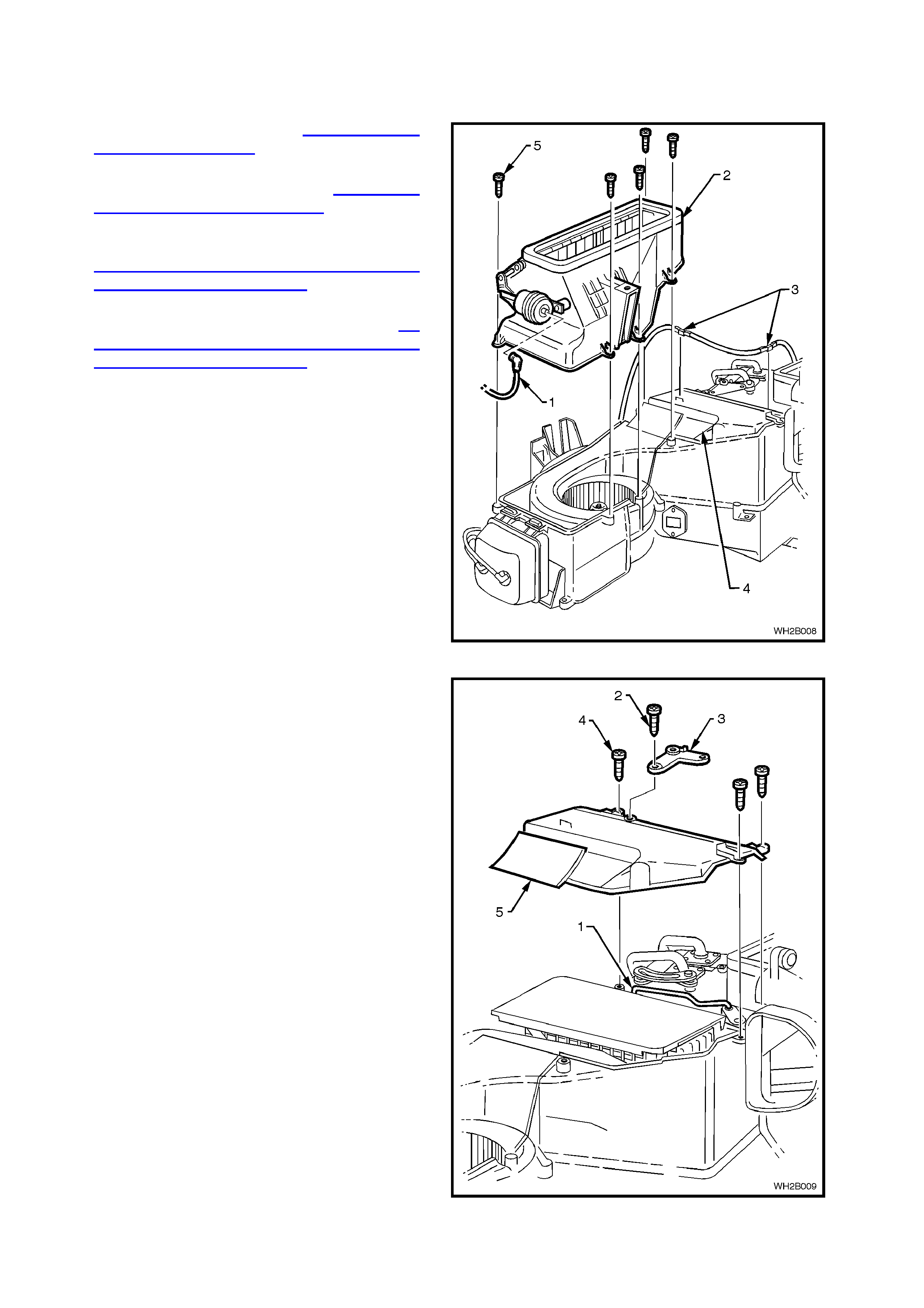
5. Disconnect the vacuum hose (1) from the
fresh/ recirculation actuator and vacuum tube
harness clips (3).
6. Remove the fres h/r ecir culation hous ing f ive s elf
tapping screws (5). Remove fresh/recirculation
housing.
Figure 2B-49
7. Disconnect the vacuum tube harness retaining
clips above the evaporator core cover (5).
8. Remove the aspirator tube and evaporator air
sensor electrical connector.
9. Remove the four evaporator core cover self
tapping screws (3), remove the core cover.
Figure 2B-50
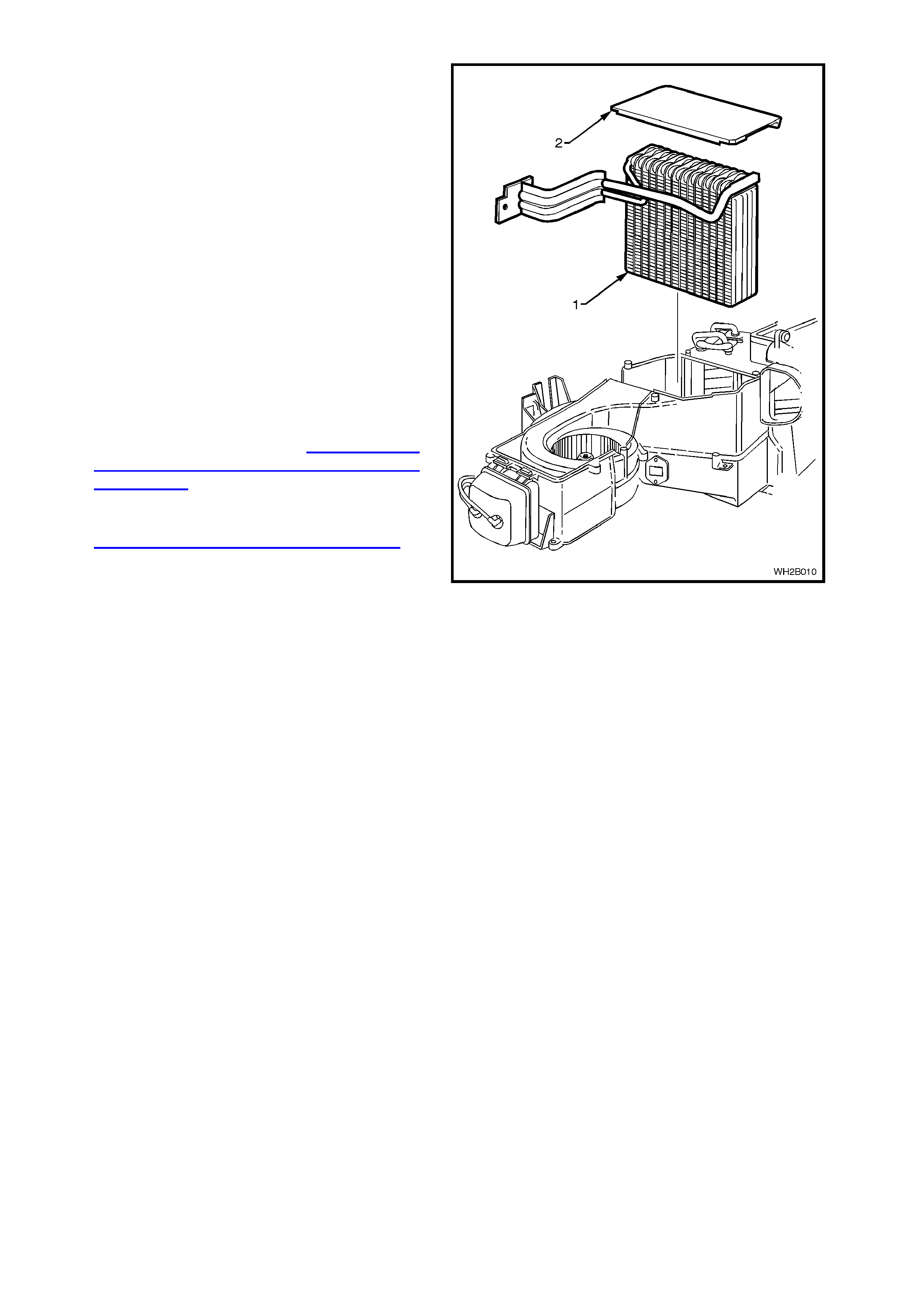
10. Lift of f the upper insulator (2) and gently lift out
the evaporator core (1) ensuring no damage
occurs to the foam liners.
REINSTALL
1. Reinstall the evaporator core in the reverse
order of removal.
2. Reinstall the HVAC unit and instrument panel
carrier as described in 2.8 HEATING,
VENTILATION AND AIR CONDITIONING
(HVAC) UNIT.
3. Evacuate and charge the system with
775 - 825 g of R134a refrigerant, refer to
Section 2C AIR CONDITIONING ECC -
SERVICING AND DIAGNOSIS of the WH
Service Information. Figure 2B-51
2.10 HE ATER CORE
REMOVE
1. Recover refrigerant, refer to Section 2C AIR
CONDITIONING ECC - SERVICING AND
DIAGNOSIS of the WH Service Information.
2. Drain cooling system, refer to Section 0B
LUBRICATION AND SERVICE of the WH
Service Information.
3. Remove instrument panel carrier, refer to 2.8
HEATING, VENTILATION AND AIR
CONDITIONING (HVAC) UNIT in this Section.
4. Remove HVAC unit, refer to 2.8 HEATING,
VENTILATION AND AIR CONDITIONING
(HVAC) UNIT.
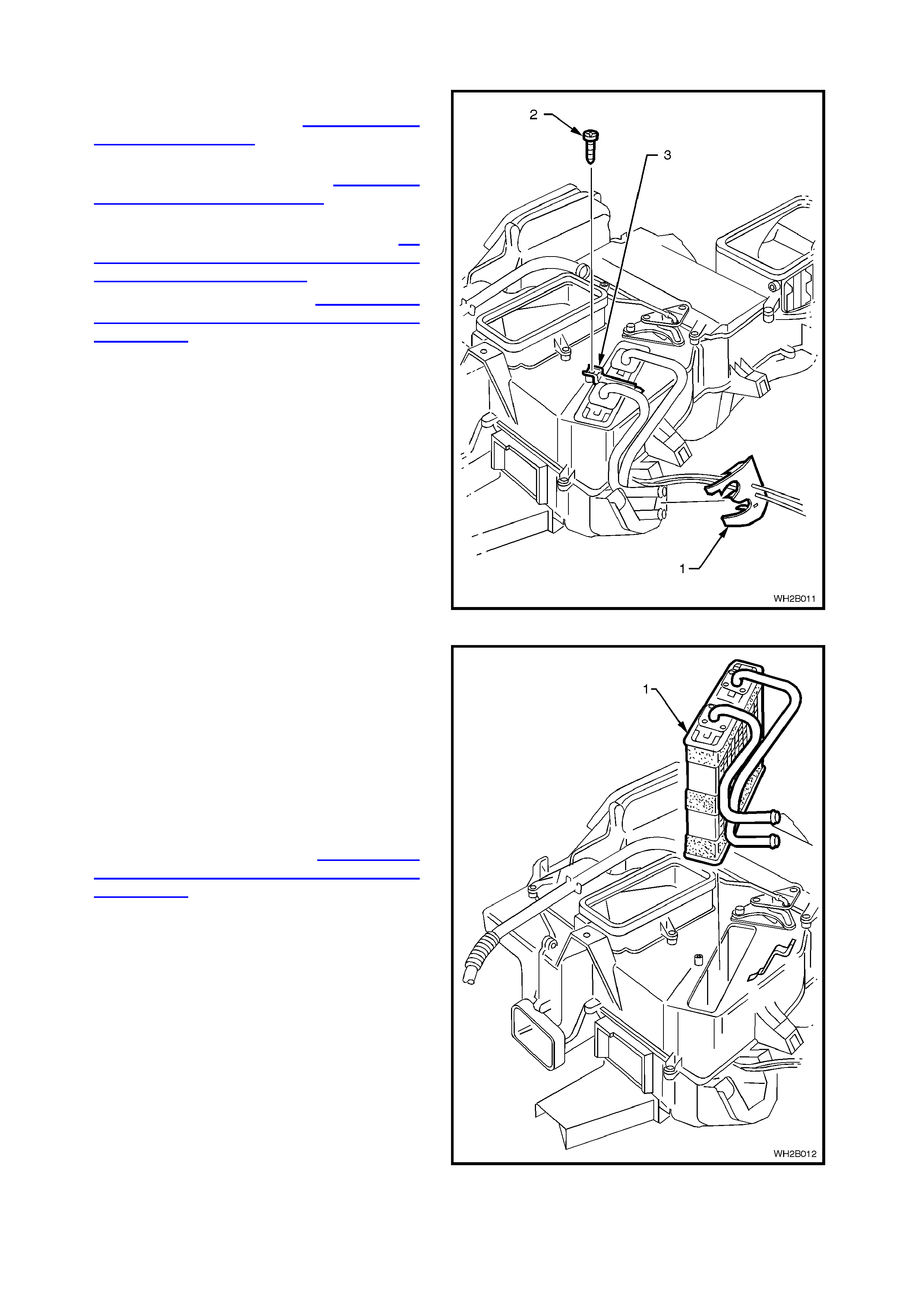
5. Unclip and remove plastic heater pipe retainer
(1) from rear of the HVAC unit.
6. Unscrew the self tapping screw (2) from the
plastic heater core retaining (3) strap and
remove strap.
7. Gently lift out the heater core assembly.
Figure 2B-52
REINSTALL
1. Slide the heater core (1) into the aperture
provided in the HVAC unit.
NOTE: Ensure the foam seals are not damaged
when inserting heater core.
2. Install the heater core plastic retaining strap.
Slide one side under the HVAC unit case and
secure with one self tapping screw.
3. Install the heater core pipe plastic retainer
located at the rear of the case.
4. Install the HVAC unit, refer to 2.8 HEATING,
VENTILATION AND AIR CONDITIONING
(HVAC) UNIT in this Section.
5. Install the instrument panel carrier.
6. Refill the cooling system and bleed.
7. Evacuate and charge the system with
775 - 825g of R134a refrigerant.
Figure 2B-53
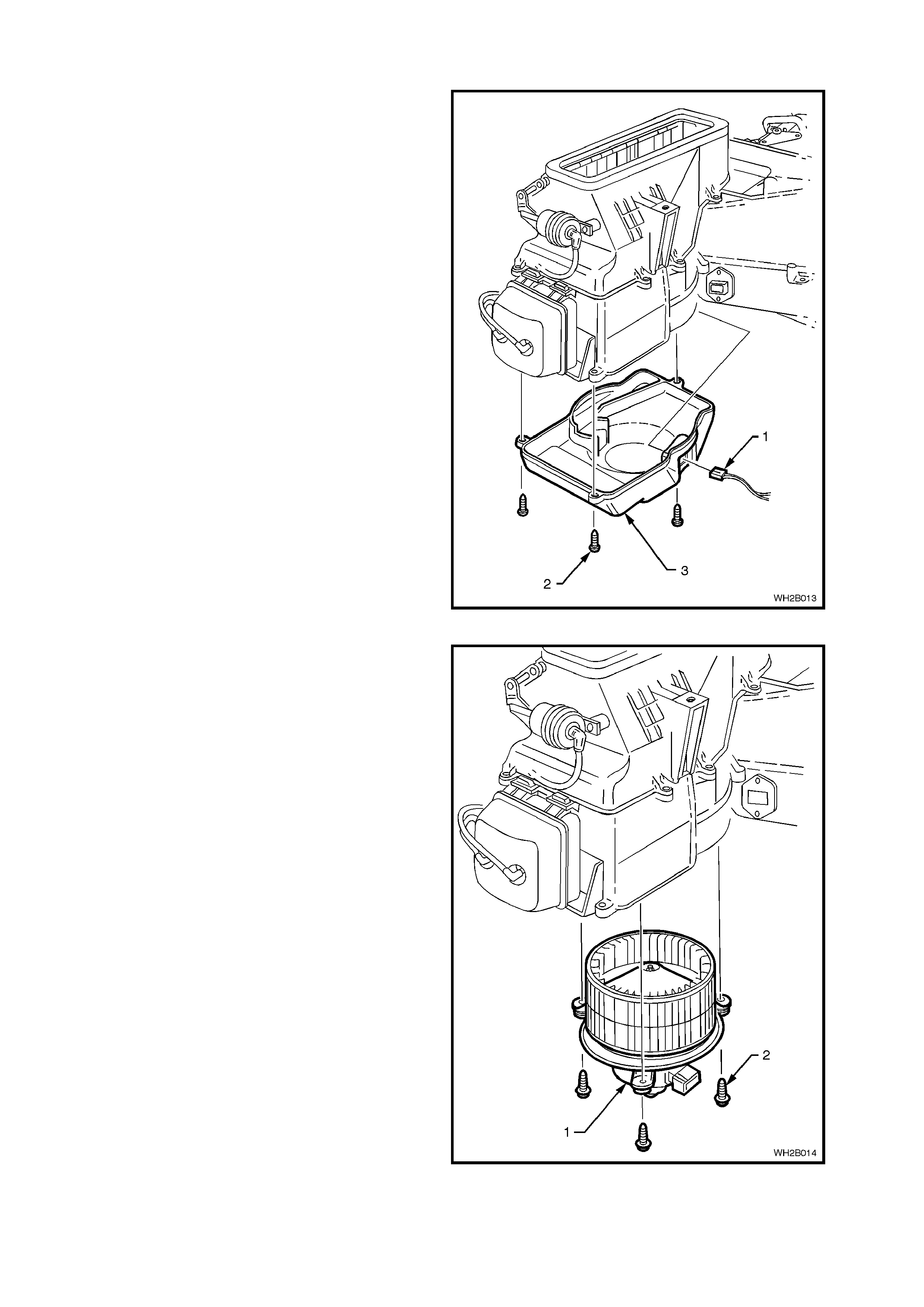
2.11 BLOWER MOTOR
REMOVE
1. Remove the footwell upper closing panel left
side (unclip).
2. Disconnect the blower motor electrical
connector (1).
3. Unscrew the blower motor access cover (3)
three self tapping screws (2).
Figure 2B-54
4. Locate the three blower motor retaining screws
and remove.
5. Gently remove the blower motor assembly.
NOTE: Ensure the blower motor wheel balancing
clips are not dislodged during removal.
REINSTALL
1. Install the blower motor (1) using three self
tapping screws ( 2). Ensur e the flat washers are
on the self tapping screws.
NOTE: When installing the blower motor ensure
that the balance clips have not been dislodged from
the blower motor wheel.
2. Install the blower motor access cover using the
three self tapping screws.
3. Connect the blower motor electrical plug to the
blower motor.
4. Install the footwell upper closing panel left side.
Figure 2B-55
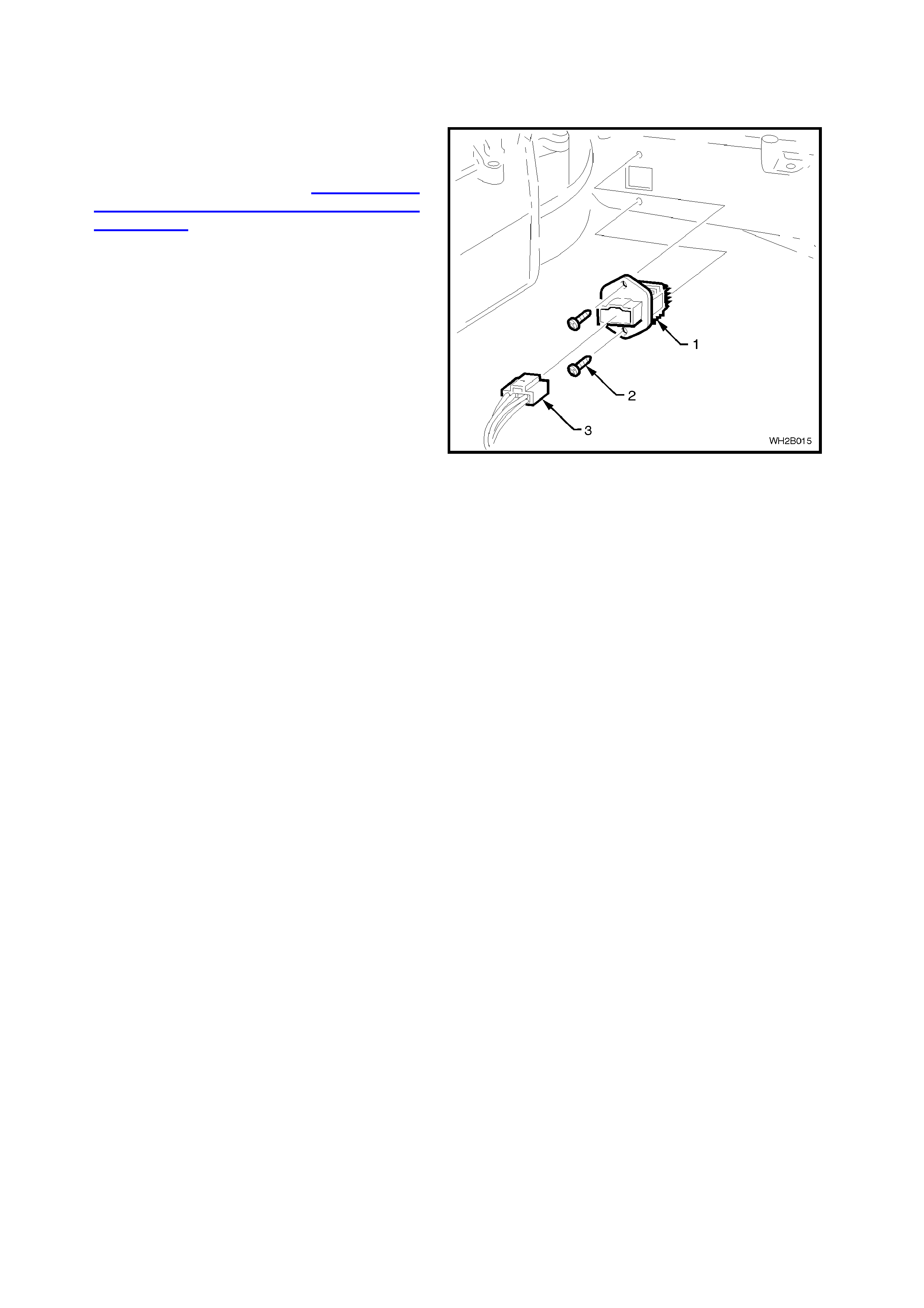
2.12 BLOWER MOTOR RESISTOR
REMOVE
1. Remove the instrument panel lower
compartment, the instrument panel end cap
cover left-hand side and the instrument
compartment roof refer to 2.8 HEATING,
VENTILATION AND AIR CONDITIONING
(HVAC) UNIT in this Section.
2. Detach the electrical connector (3) and two self
tapping screws (2) retaining the blower motor
resistor (1).
4. Remove the resistor assembly.
REINSTALL
1. Install the blower motor resistor using the
original two self tapping screws.
2. Reconnect the electrical connector.
3. Replace the instrument compartment roof
using original screws.
4. Install the instrument panel end cap cover left
side using original screws.
5. Reinstall the instrument panel lower
compartment using original pins.
Figure 2B-56
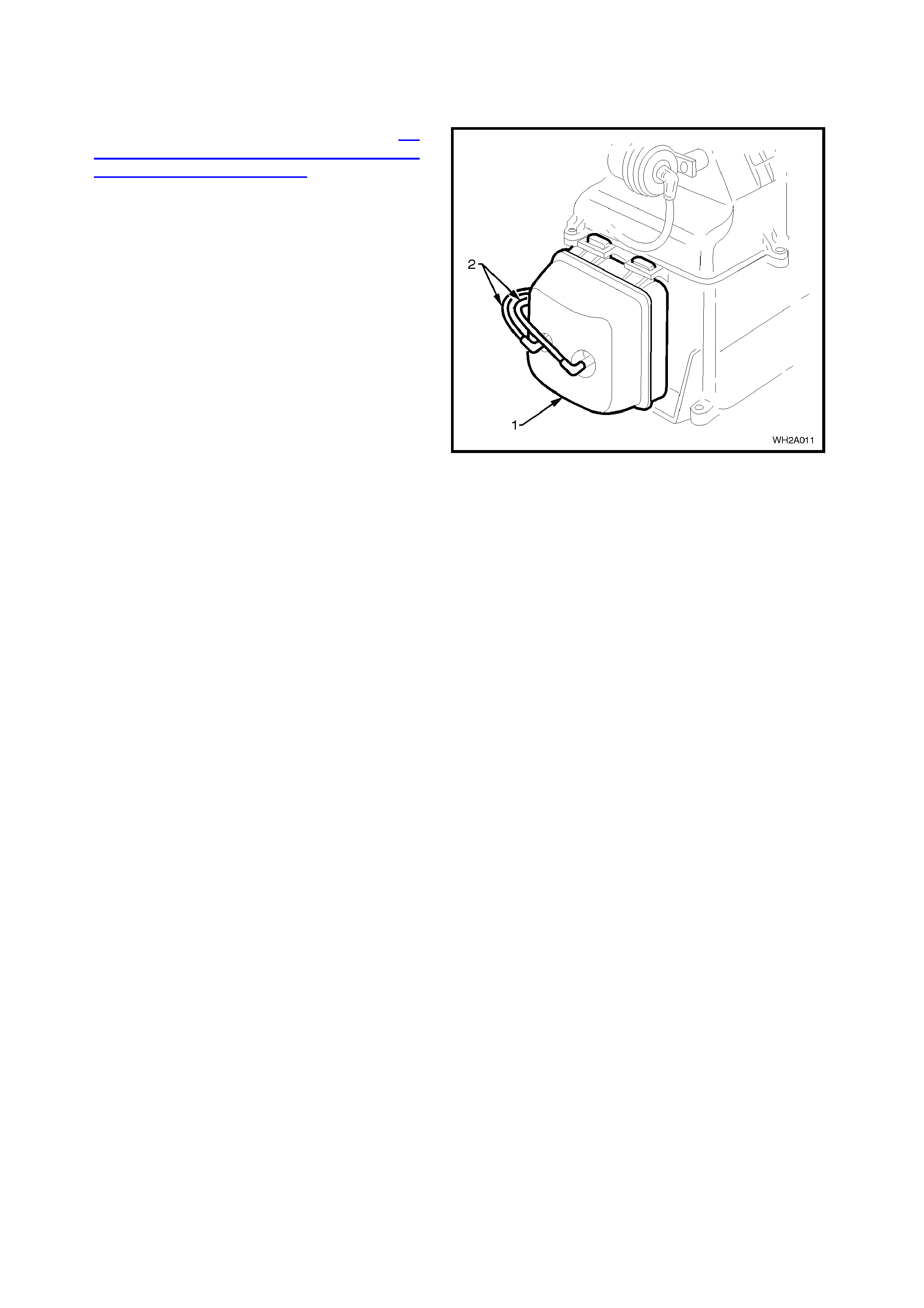
2.13 VACUUM TANK
REMOVE
1. Remove instrument facia assembly, refer to 2.8
HEATING, VENTILATION AND AIR
CONDITIONING (HVAC) UNIT in this Section.
2. Disconnect the two vacuum connections (2) at
the vacuum tank (1).
3. Unscrew the one self tapping screw from the
lower section of the tank.
5. Move vacuum tank outwards and down to
dislodge the retaining tangs.
REINSTALL
Reinstall the vacuum tank in the reverse order of
removal. Figure 2B-57
2.14 VACUUM SOLENOID PACK
REMOVE
1. Remove the footwell upper closing panel left
side, refer to 2.8 HEATING, VENTILATION
AND AIR CONDITIONING (HVAC) UNIT in this
Section.
2. Remove the blower motor access cover, refer
to 2.11 BLOWER MOTOR in this Section.
3. Disconnect the vacuum solenoid pack vacuum
manifold (4).
5. Remove the two self tapping screws (3) and
detach the vacuum solenoid pack (2) from the
blower motor access cover (1).
REINSTALL
Reinstall is the reverse order of removal. Figure 2B-58
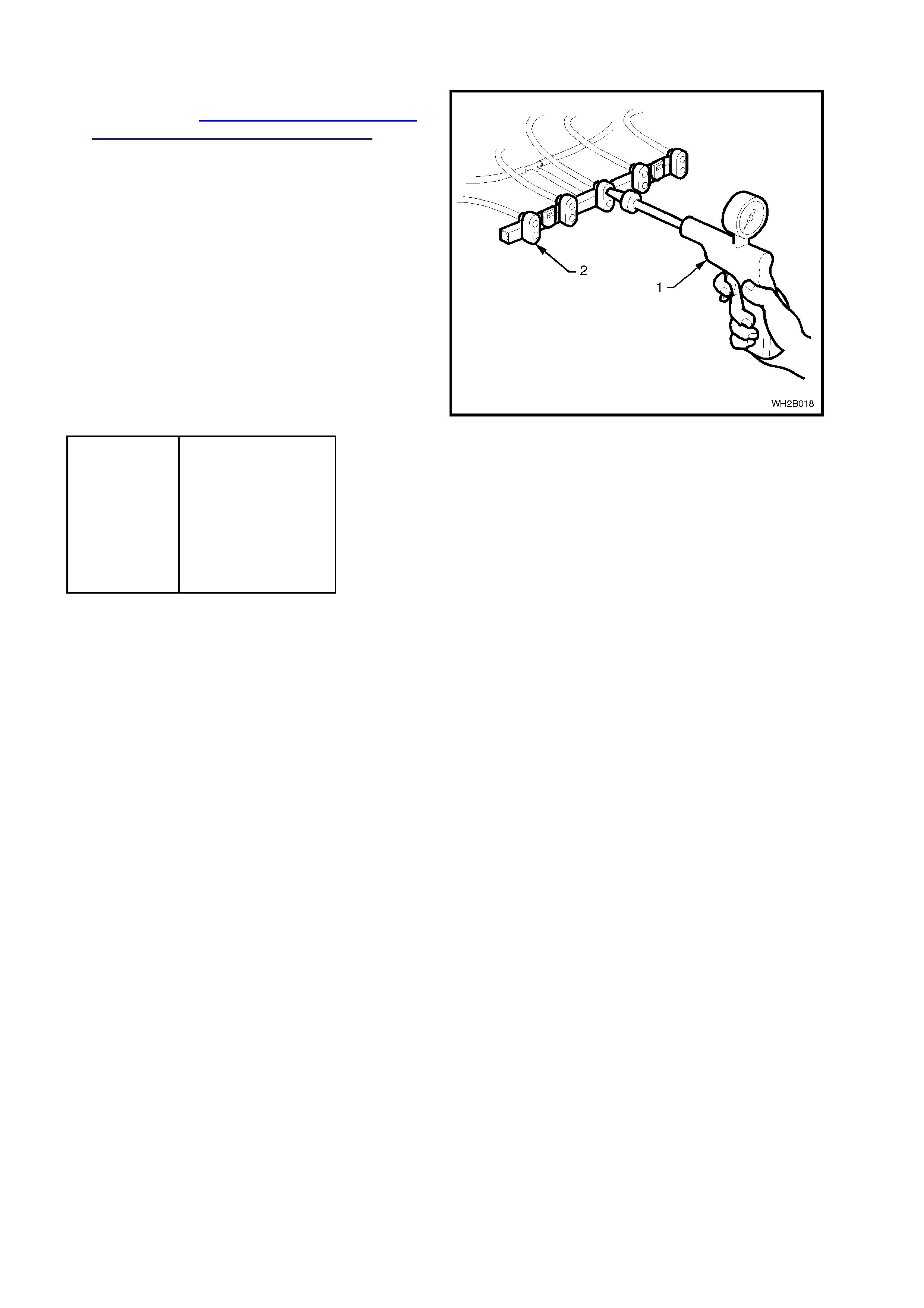
2.15 VACUUM LINE CHECK
1. Remove the footwell upper closing panel left
side, refer to 2.8 HEATING, VENTILATION
AND AIR CONDITIONING (HVAC) UNIT in this
Section.
2. Locate the vacuum solenoid pack and
disconnect the plastic vacuum manifold (2).
3. Using a Mityvac (1) or similar, connect to the
appropriate port of the plastic vacuum m anifold
(see table below).
4. Create a vacuum, view Mityvac gauge to see if
the needle rises to positive pressure indicating
a vacuum leak.
5. If a vacuum leak is indicated it could be either
the vacuum tubing or the vacuum actuator
(check to see if the vacuum tubing is dislodged
from the vacuum actuator). Each of these
components will have to be vacuum leak
checked individually.
COLOUR FUNCTION
Green Bi-level
Red Floor
White Centre Vent
Orange Foot / Demist
Blue Recirc / Fresh
Black Vacuum Source
6. Once check is completed, reinstall all removed
com ponents ens uring that the vac uum tubing is
secure and correctly connected.
Figure 2B-59
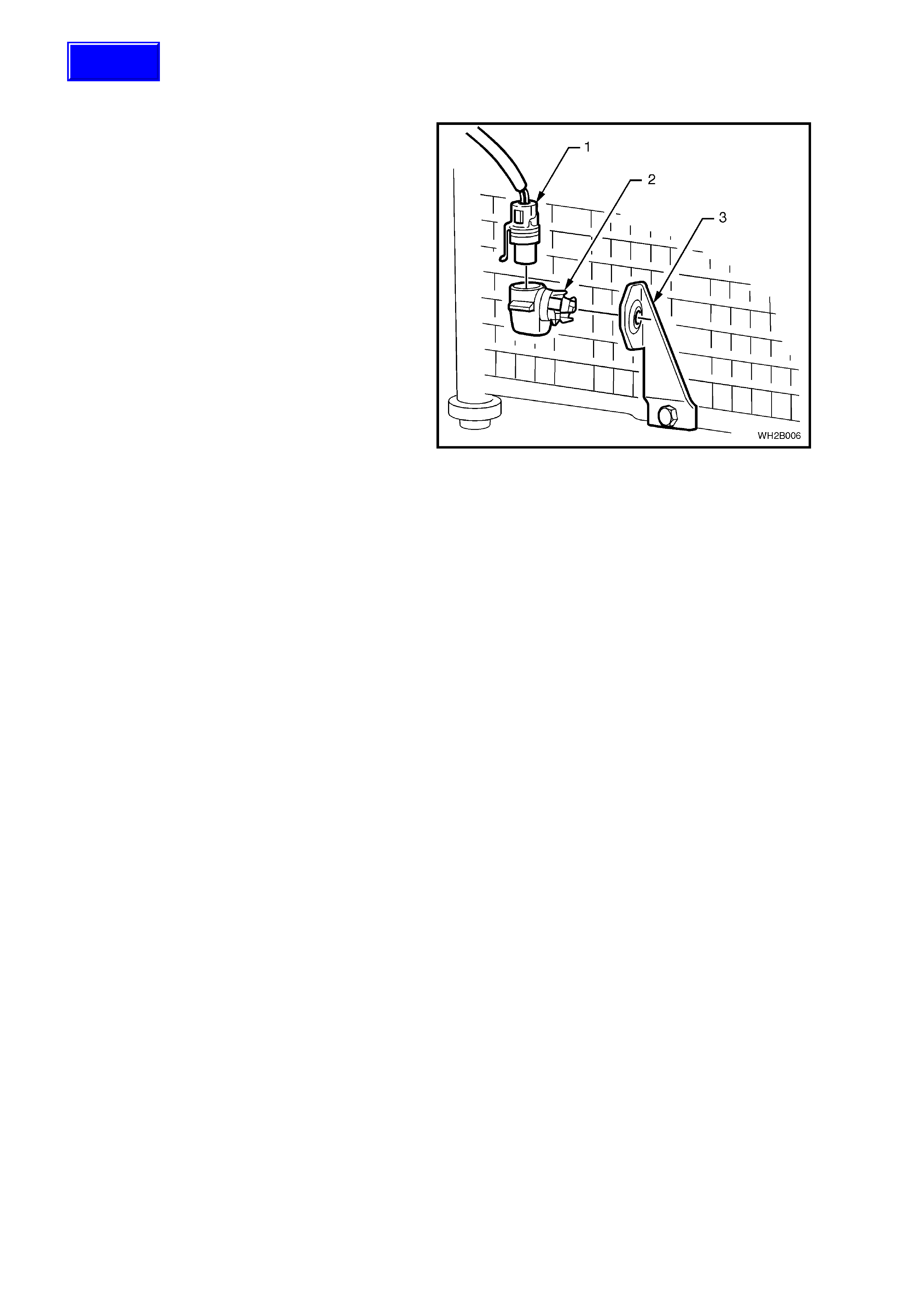
2.16 HE ATER VALVE VACUUM SWITCH
REMOVE
1. Remove the right hand side centre facia
extension, refer Section 1A3 INSTRUMENT
PANEL & CONSOLE of the WH Service
Information.
2. Locate the vacuum switch (1) adjacent to the
air mix motor (6) and remove the vacuum port
manifold (2).
3. From the upper section of the vacuum switch
bracket (3) push the two locking legs (4)
together and remove the vacuum switch.
REINSTALL
1. Firmly insert the vacuum switch into the
mounting bracket ensuring the three locating
pins (5) slide into their positions.
2. Re-connect the vacuum port manifold (one
directional fit).
3. Re-attach right hand side centre facia
extension. Figure 2B-60
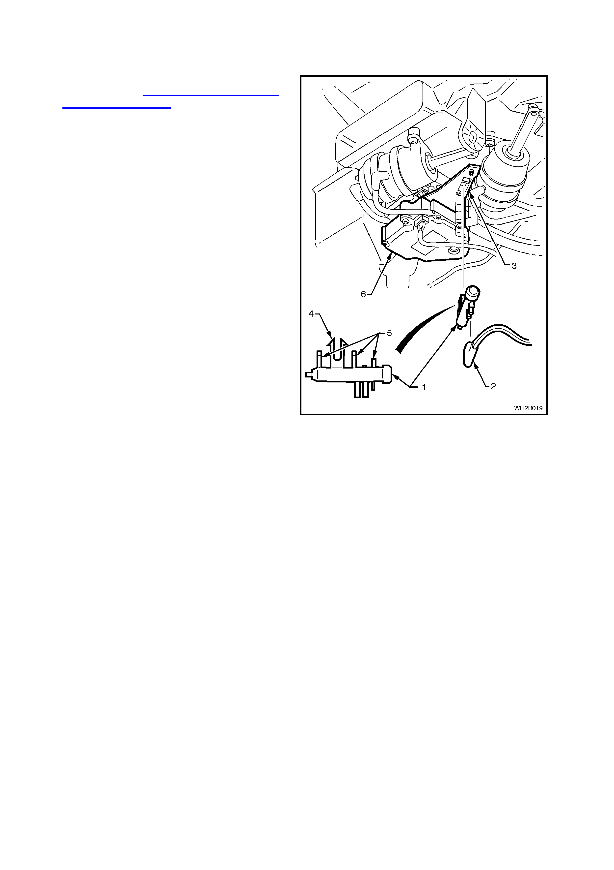
2.17 FRESH/RE CIRCULATION ACTUATOR
REMOVE
1. Remove the instrument panel lower
compartment, the instrument panel end cap
cover left side and the footwell upper closing
panel left side refer to 2.8 HEATING,
VENTILATION AND AIR CONDITIONING
(HVAC) UNIT in this Section.
2. Disconnect the vacuum tube (3) and vacuum
actuator rod (1) from the fresh/recirculation
lever.
3. Using a stubby Phillip’s head screwdriver
remove the vacuum actuator two self tapping
screws (2).
REINSTALL
Reinstallation takes place in the reverse order of
removal.
Figure 2B-61
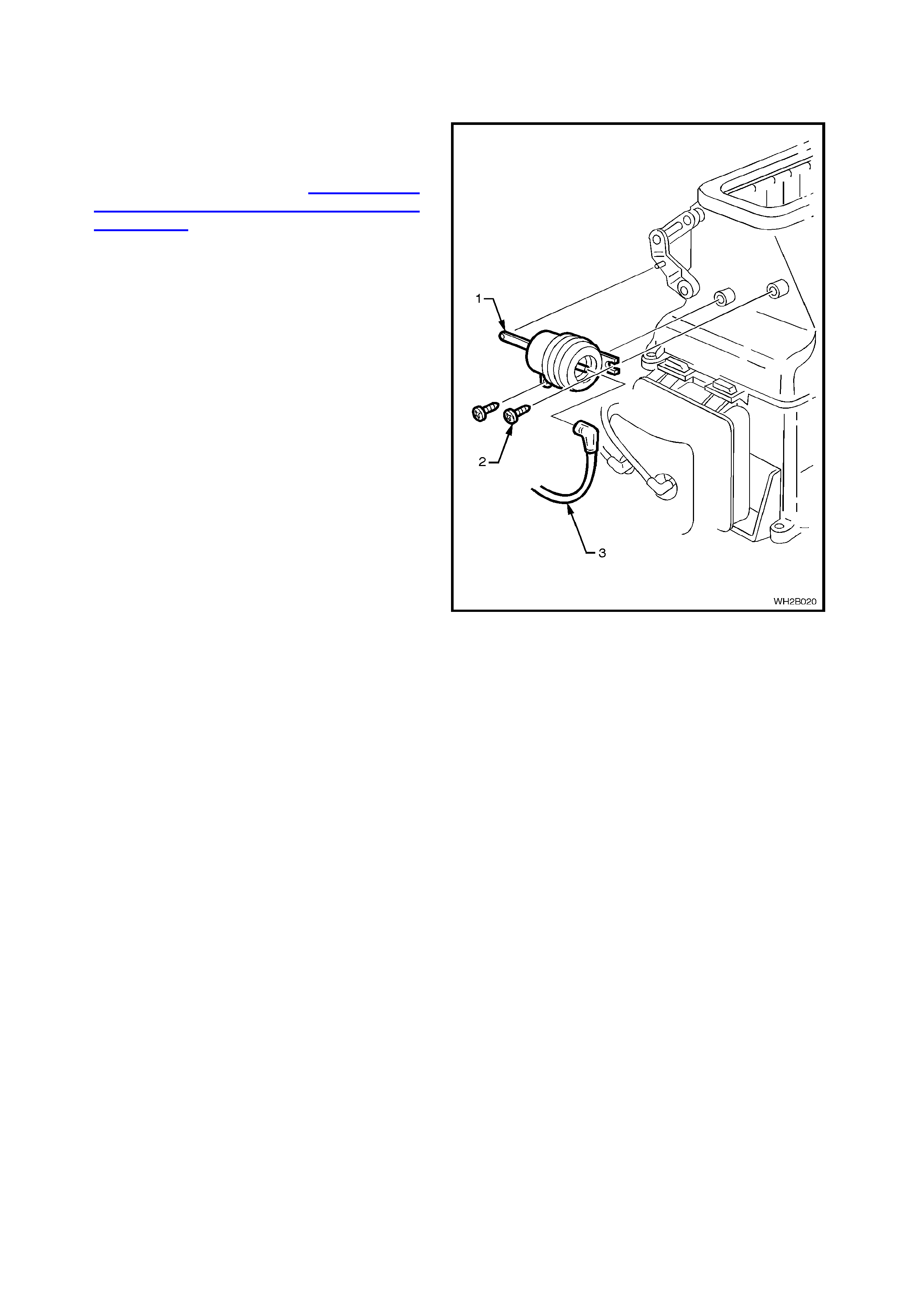
2.18 BI-LEVEL/CENTRE VENT AND DEMIST/FOOT ACTUATOR
REMOVE
1. Remove instrument panel carrier, refer to 2.8
HEATING, VENTILATION AND AIR
CONDITIONING (HVAC) UNIT in this Section.
2. Remove the HVAC unit (ref er to 2.8 HEAT ING,
VENTILATION AND AIR CONDITIONING
(HVAC) UNIT.
3. From the underside of the HVAC unit, locate
the vacuum actuator for removal.
4. Gently unclip the white Bi level/centre vent
vacuum actuator rod (1) from the door lever.
Remove the coloured vacuum tubing (2 and 3)
from the ports.
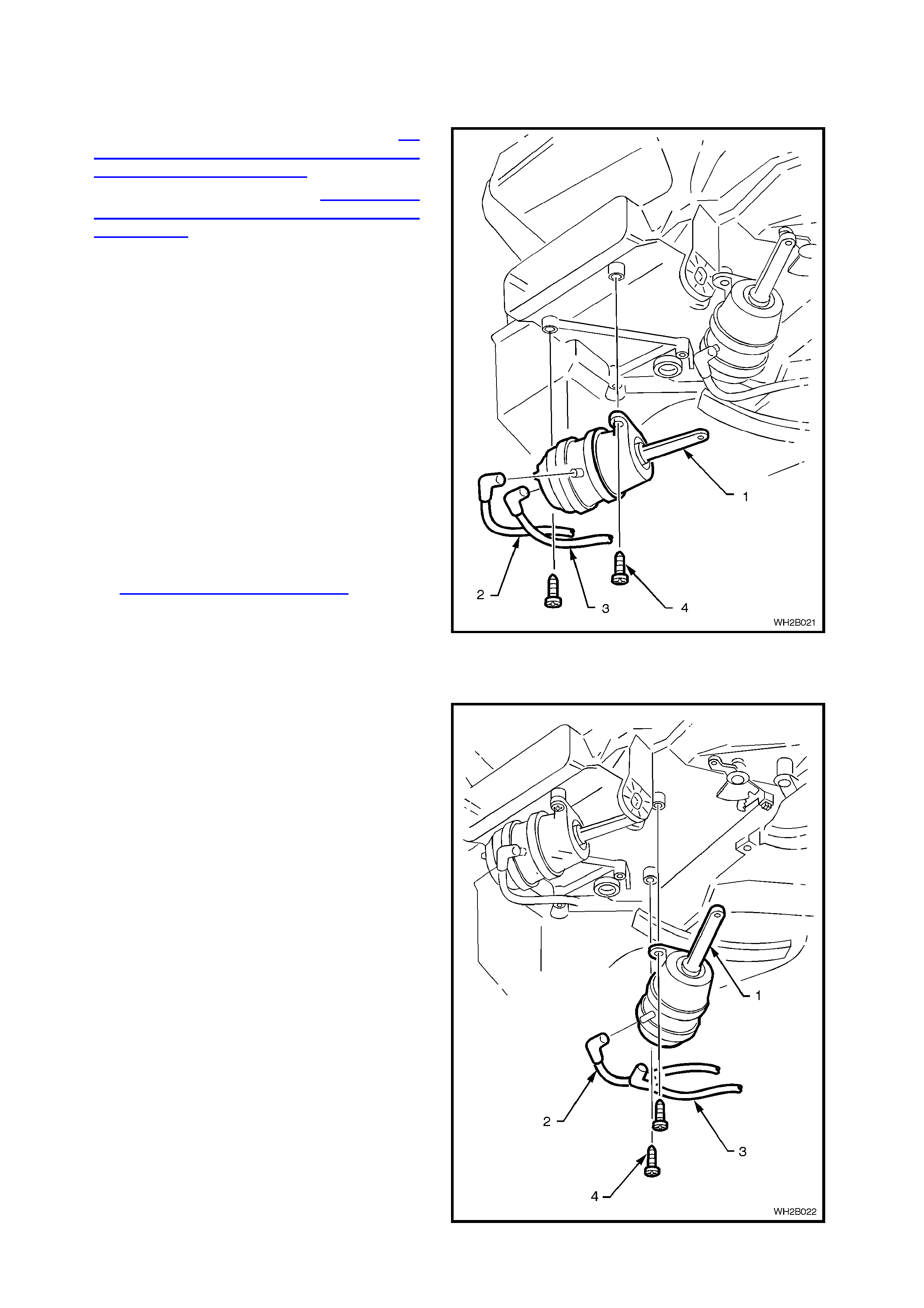
NOTE: Take note of the vacuum tubing positions.
Orange vacuum line (2)
Red vacuum line (3)
4. Detach the vacuum actuator two self tapping
screws (4).
REINSTALL
Reinstall the vacuum actuator in the reverse order
of removal.
NOTE: If in doubt about the correct colour coding
of the vacuum tubes to the vacuum actuator’s ports
refer to Section 2A AIR CONDITIONING - ECC -
PRINCIPLES AND OPERATION, Fig. 2A-19.
NOTE: Vacuum actuator with WHITE rod - connect
to WHITE coloured levers.
Vacuum actuator with BLACK rod - connect to
BLACK coloured gears.
Figure 2B-62
Legend
1. Demist/floor actuator rod (black).
2. Vacuum line (orange).
3. Vacuum line (red).
4. Screws (2).
Figure 2B-63
2.19 AIR MIX MOTORS
REMOVE
1. Remove HVAC, refer to 2.8 HEATING,
VENTILATION AND AIR CONDIT IONING (HVAC)
UNIT in this Section.
2. From the underside of the HVAC unit, locate the
air mix motors (1,2).
3. Disconnect the vac uum m anifold from the vacuum
switch (3), two electrical connections (4,5) and the
upper mixing door lever (6).
5. Unscrew the three self tapping screws (7) used to
retain the air mix motor pack and remove.
REINSTALL
1. Align the HVAC shaft end with the upper air mix
motor drive (1) (left hand side) and hold in position.
2. Install the intermediate mounting plate (8) under
the upper air mix motor (1).
3. Install the lower air m ix motor (2) (right hand side)
and secure the air m ix m otor pac k with the or iginal
three self tapping screws (7).
4. Re-connect the electrical connections (4,5),
vacuum switch (3) and upper mixing door lever (6).
5. Refit the HVAC unit. Figure 2B-64
2.20 THERMAL EXPANSION VALVE (TXV)
REMOVE
1. Recover refrigerant, refer to Section 2C AIR
CONDITIONING - SERVICING AND DIAGNOSIS
of the WH Service Information.
2. Remove the washer faced bolt (3) retaining the
tube plate to the TXV (1).
3. Discard O - rings (4).
4. Unscrew two capscrews (2) and remove TXV (1).
REINSTALL
1. Lubricate and fit two new O - rings to the
evaporator tubes.
2. Insert the TXV (diaphragm facing upwards) onto
the evaporator tubes.
3. Secur e the TX V to the evaporator tube plate using
the two cap screws.
EVAPORATOR TUBE PLATE
SECURING SCREWS 4.0 - 4.5 Nm
TORQUE SPECIFICATION
4. Fit two new lubricated O - rings to the liquid and
suction tubes.
5. Insert the liquid and suction tubes and retaining
plate onto the TXV.
6. Secure using original bolt.
WASHER FACED TUBE PLATE
RETAINING BOLT 7.5 - 12.5 Nm
TORQUE SPECIFICATION
7. Evacuate and charge the A/C system refer to
Section 2C AIR CONDITIONING - SERVICING
AND DIAGNOSIS of the WH Service Information.
Figure 2B-65
2.21 CONDE NSER - V6 & V8
REMOVE
1. Recover refrigerant from the A/C system, refer
to Section 2C AIR CONDITIONING -
SERVICING AND DIAGNOSIS of the WH
Service Information.
2. Remove the radiator assembly, refer to
Section 6B1 ENGINE COOL ING - V6 ENG INE
of the VT Series I Service Information or
Section 6B3 ENGINE COOLING - GEN III V8
ENGINE of the VT Series II Service
Information.
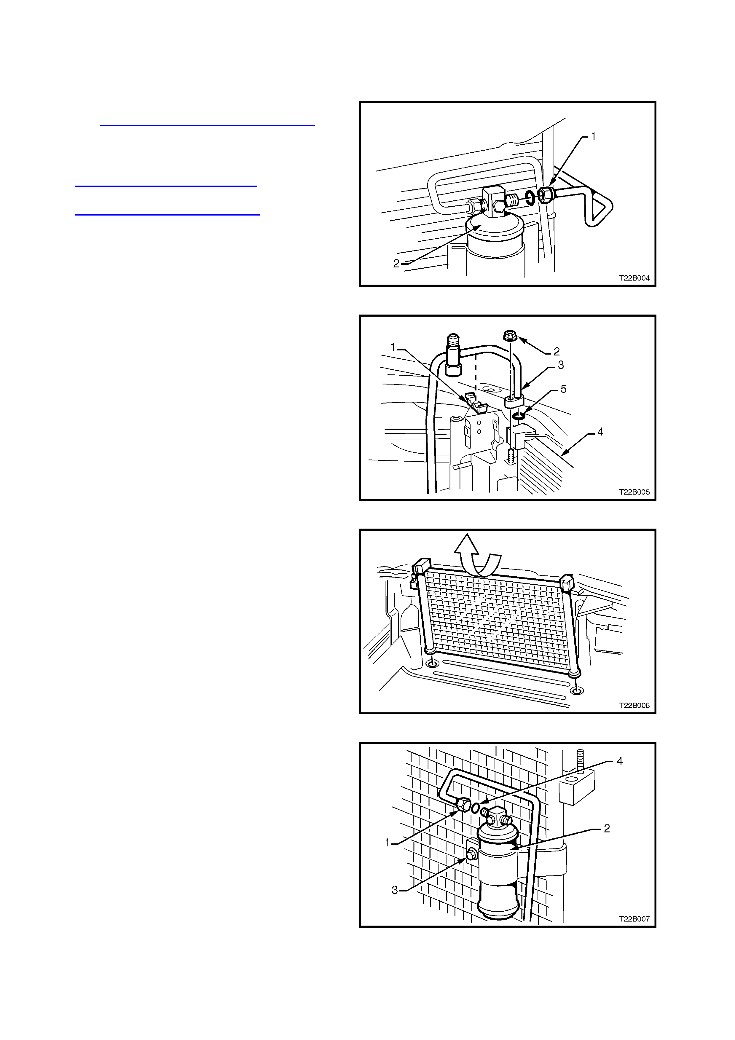
3. Through the front bumper bar opening,
unscrew the liquid tube f itting (1) f rom the Filter
Drier Receiver (FDR) (2) outlet. Figure 2B-66
4. Gently prise open discharge tube retaining clip
(1).
5. Remove nut (2) retaining the discharge hose
pad fitting (3) to the condenser (4).
6. Cap all open tubes/hoses to avoid moisture
from entering the system.
7. Discard O - rings (5).
Figure 2B-67
8. Disconnect the ambient temperature sensor
electrical connector from the front right hand
side of the condenser.
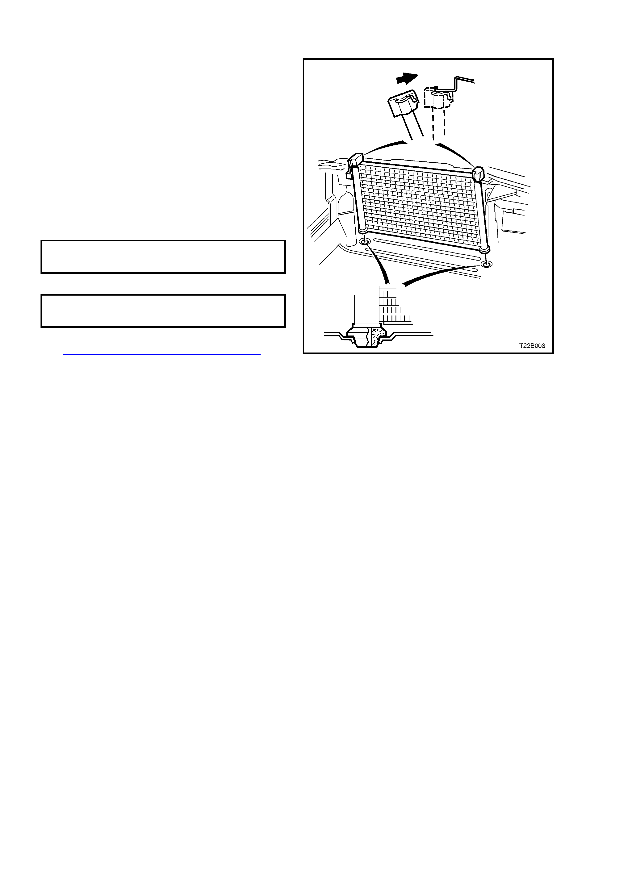
9. Tilt the condenser towards engine and lift
upwards.
Figure 2B-68
10. Mark mounting position of FDR for correct
reinstallation.
11. Unscrew the FDR inlet fitting (1) loosen the
FDR mounting brack et bolt (3) and remove the
FDR (2).
12. Discard O - ring (4).
NOTE: Mark mounting position of FDR for correct
repositioning.
Figure 2B-69
REINSTALL
Reinstallation of the condenser is the reverse of
removal procedure, noting the following.
1. Always use new O - rings and lubricate with
PAG refrigerant oil (part number 12345923)
before fitting.
CAUTION: Do not allow PAG refrigerant oil to
contact bare skin or vehicle paintwork. If contact
occurs to either, wash PAG refrigerant oil off
immediately.
2. When reinstalling the FDR, ensure the FDR
inlet tube is connected to the f itting on the FDR
with the word 'IN' refer to markings on FDR
before removal.
DISCHARGE TUBE PAD
RETAINI NG NUT 7.5 - 12.5 Nm
TORQUE SPECIFICATIO N
AIR CONDIT IONING TUB E
FITTING TO FDR TORQUE 7.5 - 12.5 Nm
SPECIFICATION
5. Recharge air conditioning system, refer to
Section 2C AIR CONDITIONING -
SERVICING AND DIAGNOSIS of the WH
Service Information. Figure 2B-70
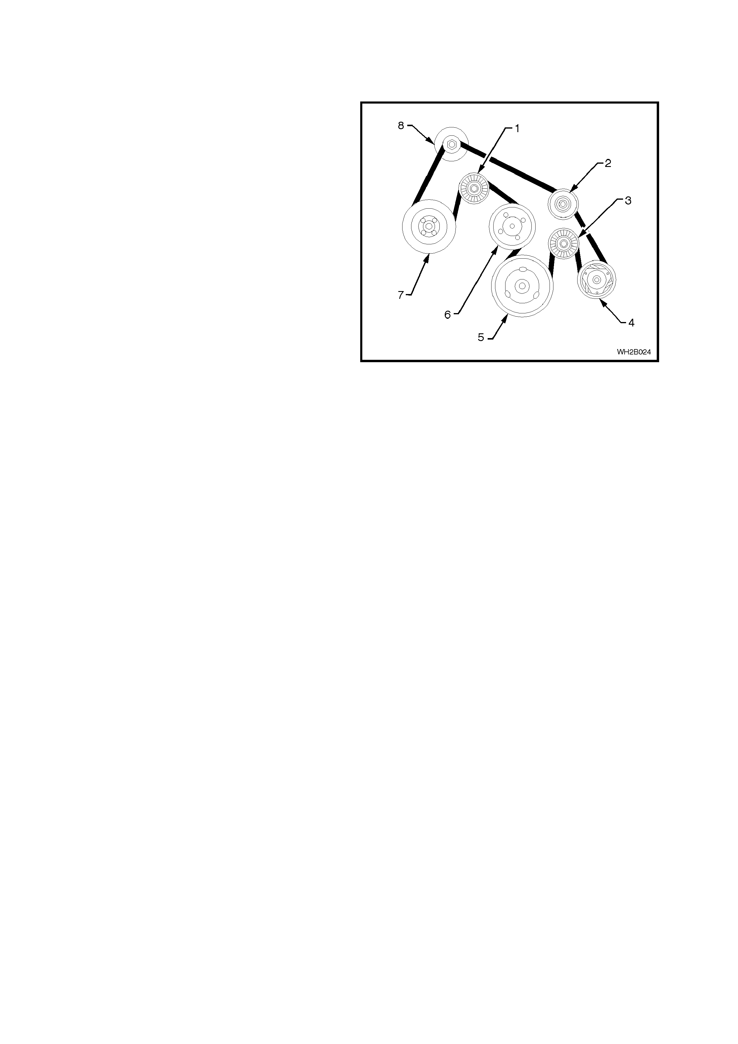
2.22 A/C DRIVE BELT - V6 ENGINE
REMOVE
1. Using a 17mm ring spanner on the drive belt
tensioner pulley retaining bolt, release the belt
tension.
2. Starting at the water pump pulley remove the
drive belt.
REINSTALL
1. Using the diagram in Fig. 2B-71 fit the drive
belt starting at the water pump pulley.
2. Ensure the vee grooves of the drive belt align
with the grooves in the pulley s.
Legend
1. Drive belt tensioner
2. Idler pulley
3. A/C idler pulley
4. Compressor
5. Crankshaft pulley
6. Water pump pulley
7. Power steering pump pulley
8. Generator pulley
Figure 2B-71
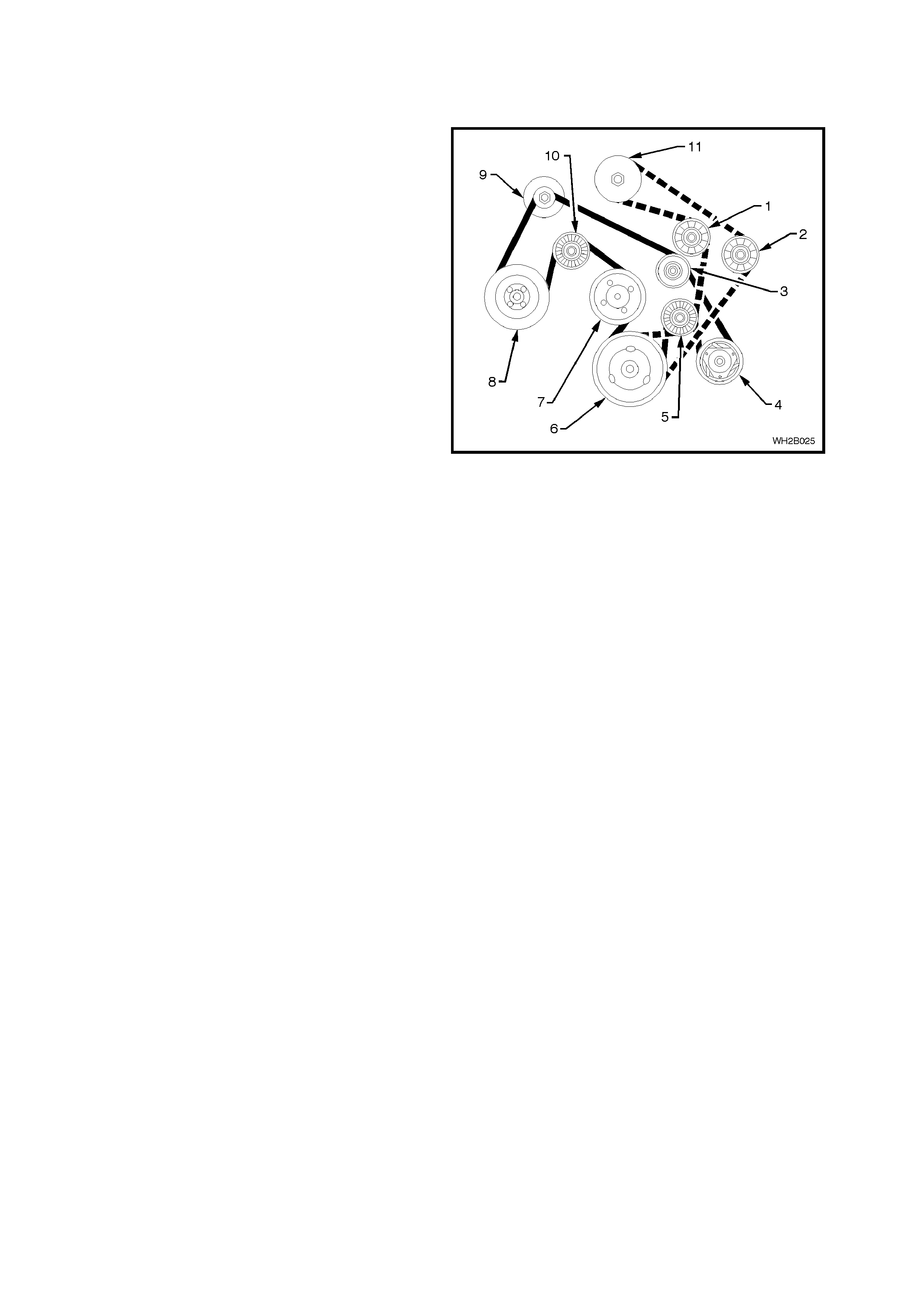
2.23 A/C DRIVE BELT - V6 SUPERCHARGED ENGINE
REMOVE
1. Using a 17mm ring spanner on the
supercharger drive belt tensioner (1), release
the supercharger drive belt tension.
2. Remove the supercharger drive belt starting at
the double idler pulley (5).
3. Using a 17mm ring spanner on the main drive
belt tensioner pulley retaining bolt (10), release
the belt tension.
4. Starting at the water pump pulley (7) remove
the drive belt.
REINSTALL
1. Using the diagram in Fig. 2B-72 fit the drive
belt and then the supercharger belt starting at
the water pump pulley (drive belt) and double
idler pulley (supercharger drive belt).
2. Ensure that the vee grooves of both dr ive belts
align with the pulley grooves.
Legend
1. Supercharger drive tensioner.
2. Idler.
3. Accessory drive idler.
4. Compressor.
5. Double idler pulley.
6. Crankshaft.
7. Water pump.
8. Power steering pump.
9. Alternator.
10. Drive belt tensioner.
11. Supercharger.
Figure 2B-72
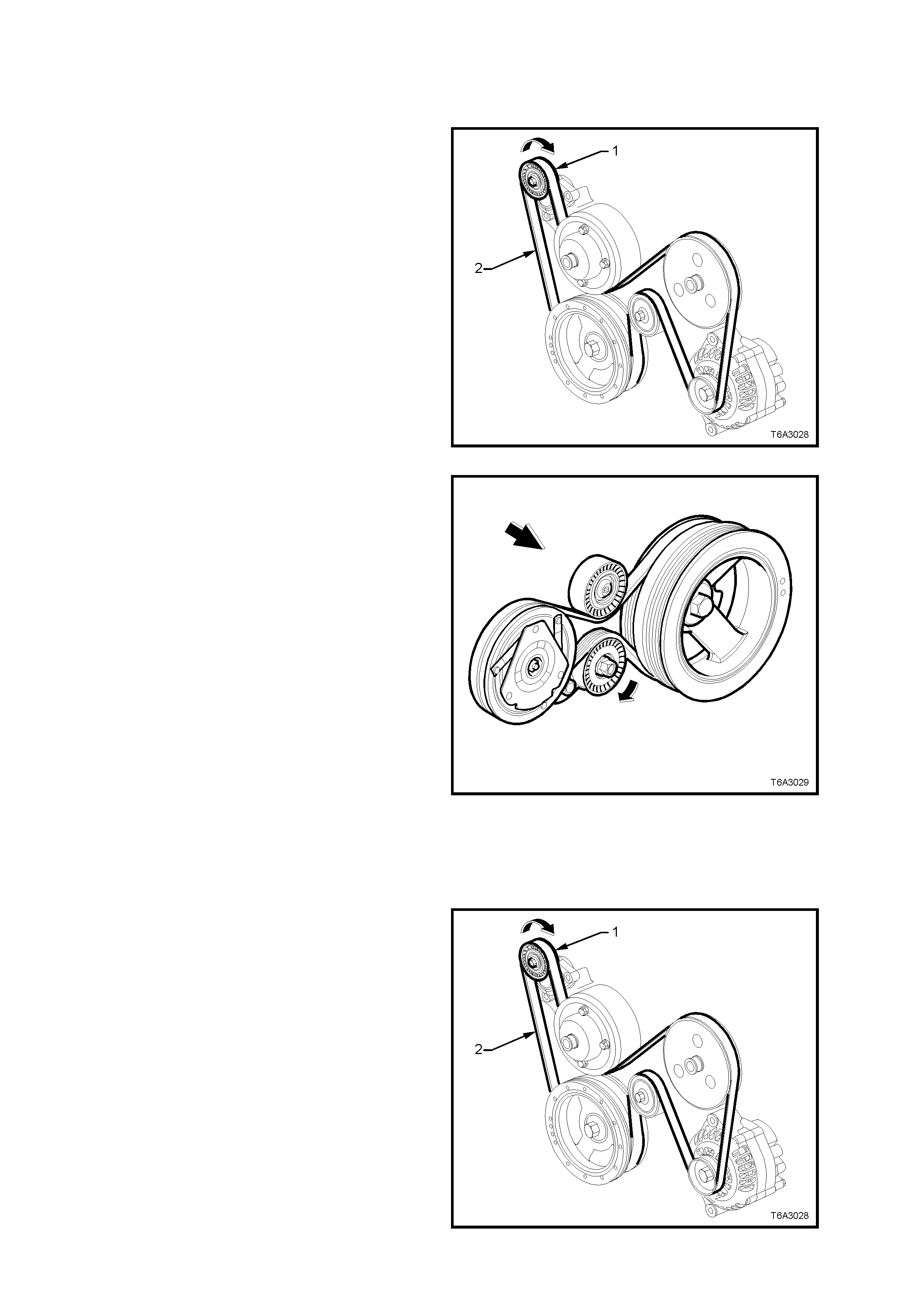
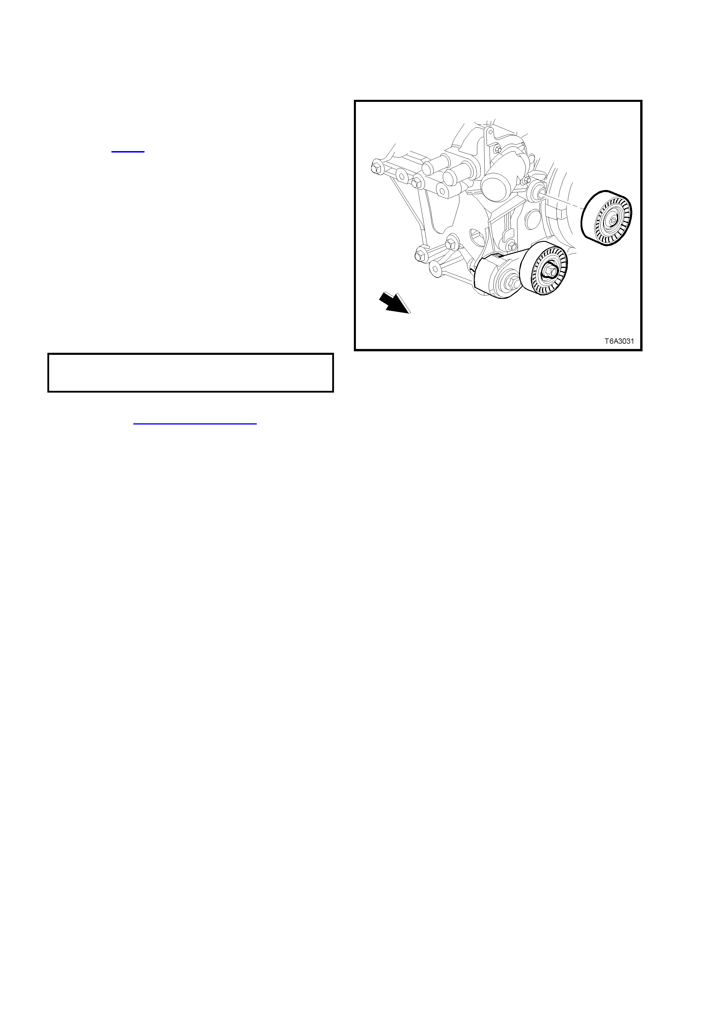
2.24 A/C DRIVE BELT - GEN III V8 ENGINE
REMOVE
1. Using a 15mm socket attached to the centre
bolt of the tensioner, rotate the engine
accessory drive belt tensioner (1), in the
direction indicated, to reduce belt tension.
2. Remove the engine drive belt (2), taking note of
the belt routing.
Figure 2B-73
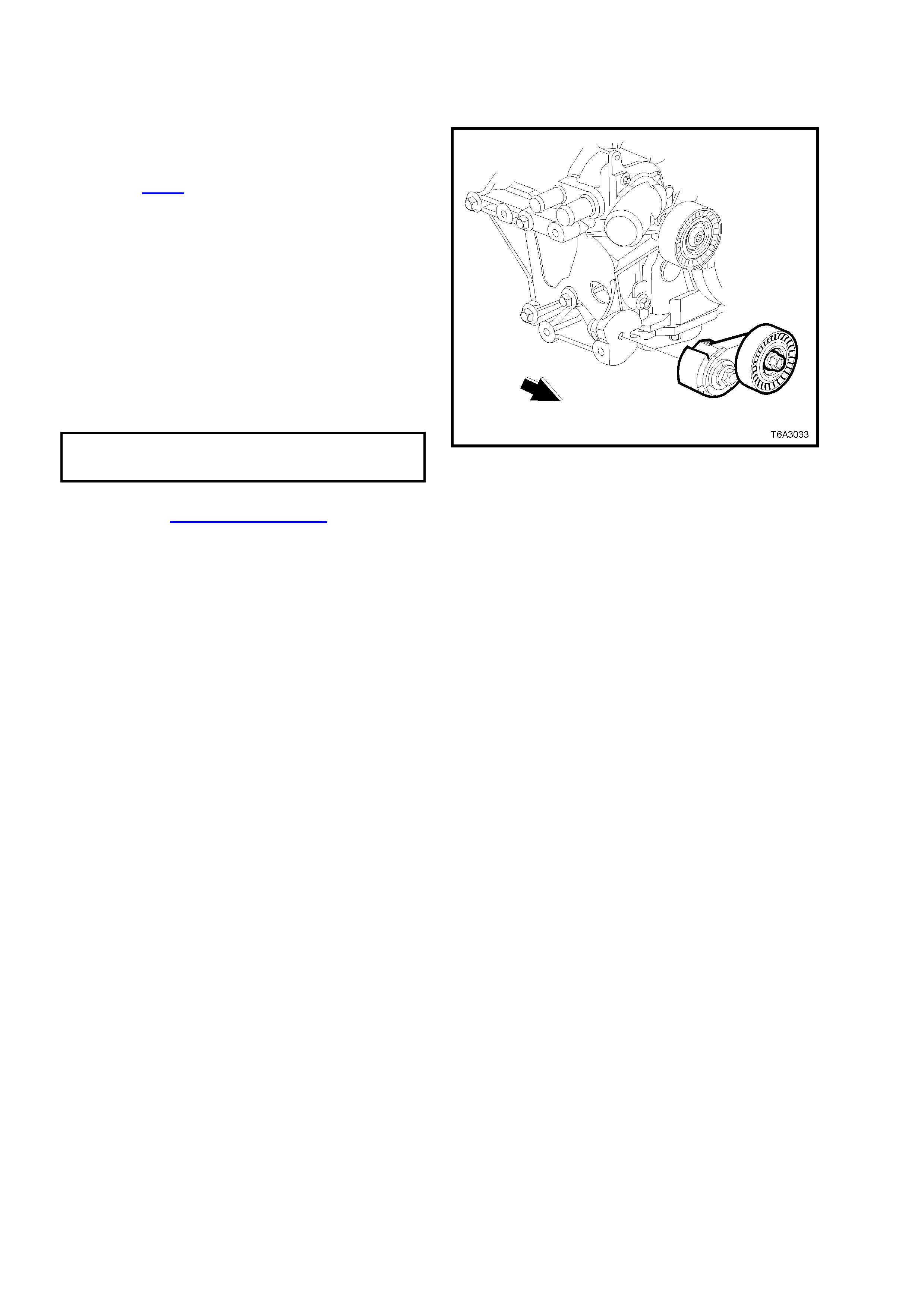
3. Using a 15mm socket attached to the centre
bolt of the tensioner, rotate the air conditioning
drive belt tensioner in the direction shown, to
relieve belt tension.
4. Rem ove the air conditioning drive belt f rom the
pulleys.
4. Inspect belts for damage and replace if
necessary.
REINSTALL
1. Clean the engine accessory and air
conditioning drive belt running surfaces
2. Using a 15mm socket attached to the centre
bolt of the tensioner, rotate the air conditioning
drive belt tensioner in the direction shown,
install the drive belt over the pulleys, routing the
belt correctly as shown.
3. Inspec t the ins tallation to ensure that the belt is
correctly aligned on all pulleys.
Figure 2B-74
4. Using a 15mm socket attached to the centre
bolt of the tensioner, rotate the engine
accessory drive belt tensioner (1), in the
direction indicated, inst all the engine accessory
drive belt (2) over the pulleys, routing the belt
correctly, as shown.
5. Inspec t the ins tallation to ensure that the belt is
correctly aligned on all pulleys.
6. Start the engine to ensure correct operation.
Figure 2B-75
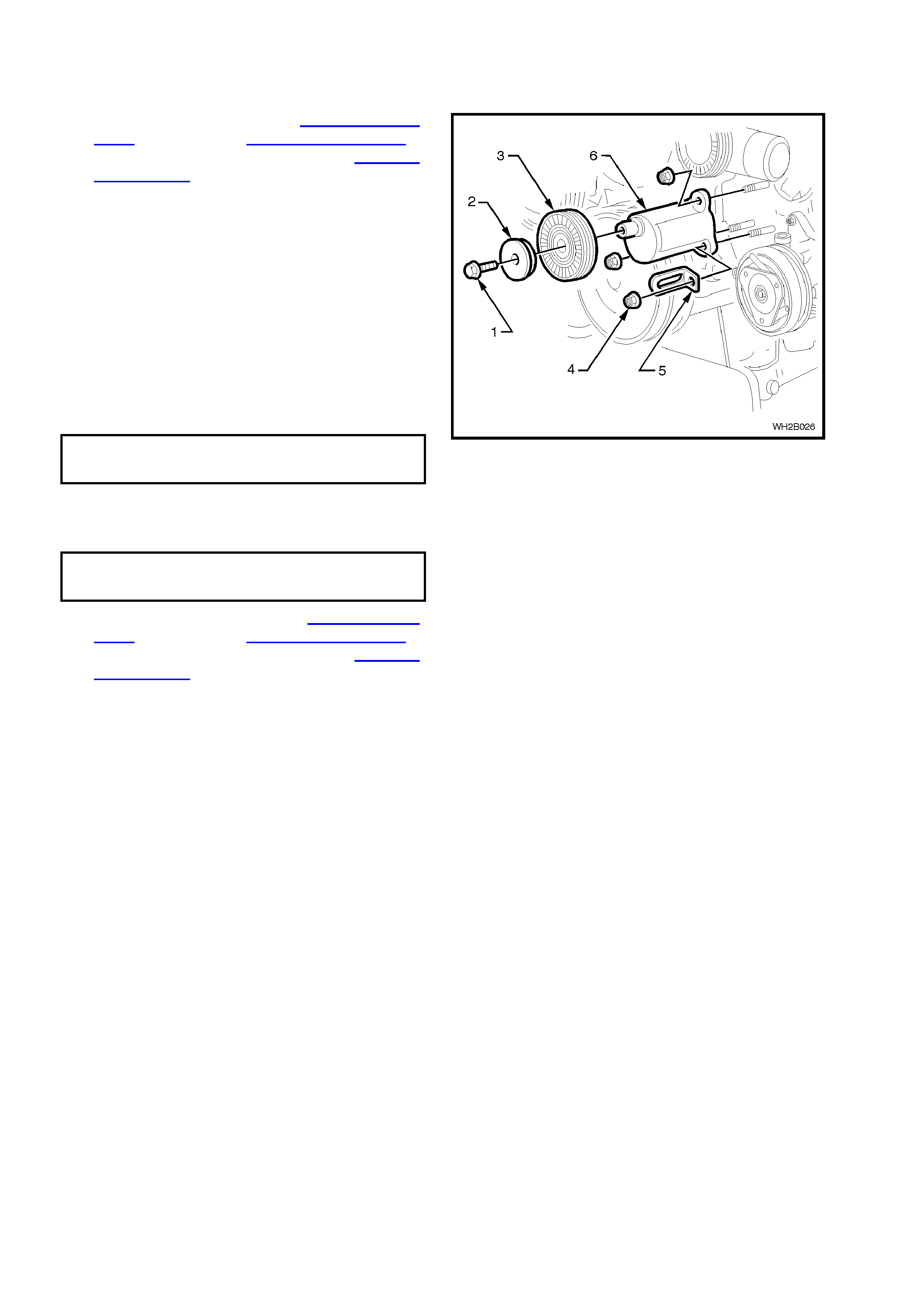
2.25 A/C DRIVE BELT IDLER PULLEY - V 6 ENGINE
REMOVE
1. Remove drive belt, refer to 2.22 A/C DRIVE
BELT – V6 ENGINE, 2.23 A/C DRIVE BELT –
V6 SUPERCHARGED ENGINE or 2.24 A/C
DRIVE BELT – GEN III V8 ENGINE in this
Section.
2. Unscrew the idler pulley retaining bolt (1).
3. Remove bolt, washer (2) and pulley (3).
4. Unscrew and remove the three mounting
bracket nuts (4).
5. Detach the idler mounting bracket from engine
(6).
REINSTALL
1. Fit the idler mounting bracket to engine.
2. Install the harness clip (5) as shown.
3. Install the three nuts.
MOUNTING BRACKET
RETAINING NUTS 20 - 30 Nm
TORQUE SPECIFICATION
4. Replace the pulley, washer and bolt onto the
idler pulley bracket.
5. Tighten the idler pulley retaining bolt.
IDLER PULLE Y
RETAINI NG B OLT 45 - 50 Nm
TORQUE SP ECIFI CA T ION
6. Replace the drive belt, refer to 2.22 A/C DRIVE
BELT – V6 ENGINE, 2.23 A/C DRIVE BELT –
V6 SUPERCHARGED ENGINE or 2.24 A/C
DRIVE BELT – GEN III V8 ENGINE in this
Section
Figure 2B-76
2.26 A/ C DRIVE BELT IDLER PULLEY - GEN III V8 ENGINE
REMOVE
1. Using a 15mm socket attached to the centre
bolt of the tensioner, rotate the air conditioning
drive belt tensioner in the direction shown in
Figure 2B-74, to relieve belt tension.
2. Rem ove the air conditioning drive belt f rom the
pulleys but leave hanging on the crankshaft
pulley.
3. Using a commercially available, Torx bit T50,
remove the bolt securing the air conditioning
compressor drive belt idler pulley to its
mounting boss on the water pump housing,
then remove the pulley assembly.
REINSTALL
1. Install the idler pulley to its mounting boss.
2. Install the idler pulley retaining bolt and tighten
to the correct torque specification.
AIR CONDIT IONING COMPRESSOR
DRIVE B ELT IDLER P ULLE Y BOLT 40.0 - 60.0 Nm
TORQUE SPECIFICATION
3. Reinstall the air conditioning compressor drive
belt. Refer 2.24 A/C DRIVE BELT – GEN III V8
ENGINE - REINSTALL in this Section for the
necessary procedure.
Figure 2B-77
2.27 A/CONDITIONING DRIVE BELT TENSIONER - GEN III V8 ENGINE
REMOVE
1. Using a 15mm socket attached to the centre
bolt of the tensioner, rotate the air conditioning
drive belt tensioner in the direction shown in
Figure 2B-74, to relieve belt tension.
2. Rem ove the air conditioning drive belt f rom the
pulleys but leave hanging on the crankshaft
pulley.
3. Remove the bolt securing the air conditioning
compressor drive belt tensioner, then remove
the assembly.
REINSTALL
1. Install the tensioner assembly and the
mounting bolt.
2. Tighten the tensioner mounting bolt to the
correct torque specification.
AIR CONDI T I O NING DRIVE BELT
TENSIONER BOLT 21.0 - 29.0 Nm
TORQUE SP ECIFI CA T ION
3. Reinstall the air conditioning compressor drive
belt. Refer 2.24 A/C DRIVE BELT – GEN III V8
ENGINE - REINSTALL in this Section for the
necessary procedure.
Figure 2B-78
2.28 COMPRESSOR - V6 ENGINE
REMOVE
1. Disconnect the battery ground cable.
2. Recover refrigerant charge, refer Section
2C AIR CONDITIONING - ECC SERVICING
AND DIAGNOSIS of the WH Service
Information.
3. Remove the suction/discharge hose pad fitting
nut (3) from the compressor (4 ).
4. Cap or plug disconnected suction (1) and
discharge (2) hoses and ports immediately to
prevent absorption of moisture from the
atmosphere.
5. Remove the A/C drive belt, refer 2.22 A/C
DRIVE BELT – V6 ENGINE, 2.23 A/C DRIVE
BELT – V6 SUPERCHARGED ENGINE in this
Section.
6. Jack up the vehicle and place the vehicle on
jack stands.
7. Disconnect the compressor clutch electrical
connector.
8. Rem ove the two nuts and one bolt retaining the
compressor to the engine block.
Figure 2B-79
REINSTALL
1. Fit the compressor to the engine using the
original two nuts and bolt. Torque to
specifications.
COMPRESSOR ASSEMBLY
RETAINING NUT 40 - 55 Nm
TORQUE SPECIFICATION
COMPRESSOR ASSEMBLY
RETAINING BOLT 20 - 30 Nm
TORQUE SPECIFICATION
2. Fit the A/C drive belt.
3. Remove the compressor port protection caps.
4. Fit two new port sealing washers (5).
5. Secur e the suction/dis charge hos e ass em bly to
the compressor with original nut.
SUCTION/DISCHA RGE HOSE
ASSEMBLY SECURING NUT 28 - 42 Nm
TORQUE SPECIFICATION
6. Evacuate and charge the A/C system with
775 - 825 g of R134a refrigerant, refer to
Section 2C AIR CONDITIONING - ECC
SERVICING AND DIAGNOSIS of the WH
Service Information.
NOTE: If r eplacing with a new compr essor, refer to
Section 2C AIR CONDITIONING - ECC
SERVICING AND DIAGNOSIS for lubrication
requirements. Figure 2B-80
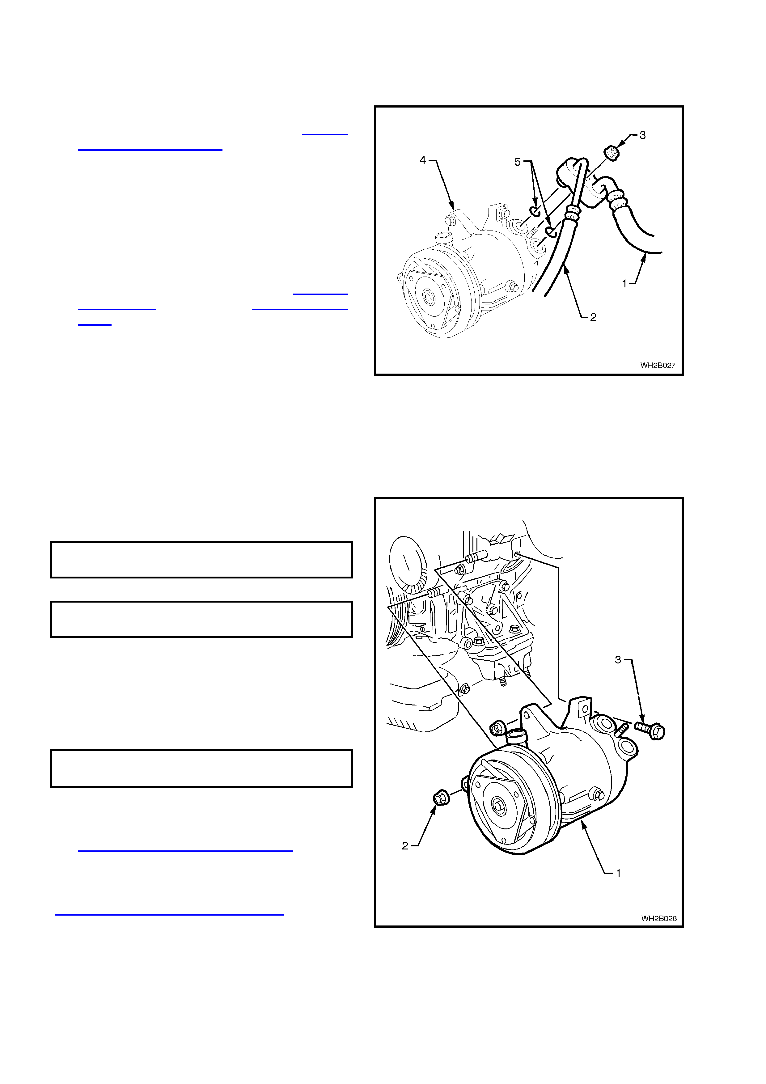
2.29 COMPRESSOR - GEN III V8 ENGINE
REMOVE
1. Disconnect the battery ground cable.
2. Drain coolant and remove the heater hoses
and lower radiator coolant hose from the
cylinder block, refer to Section 6B3 ENGINE
COOLING - GEN III V8 ENGINE of the VT
Series II Service Information.
3. Recover refrigerant charge, refer to Section
2C AIR CONDITIONING - ECC SERVICING
AND DIAGNOSIS of the WH Service
Information.
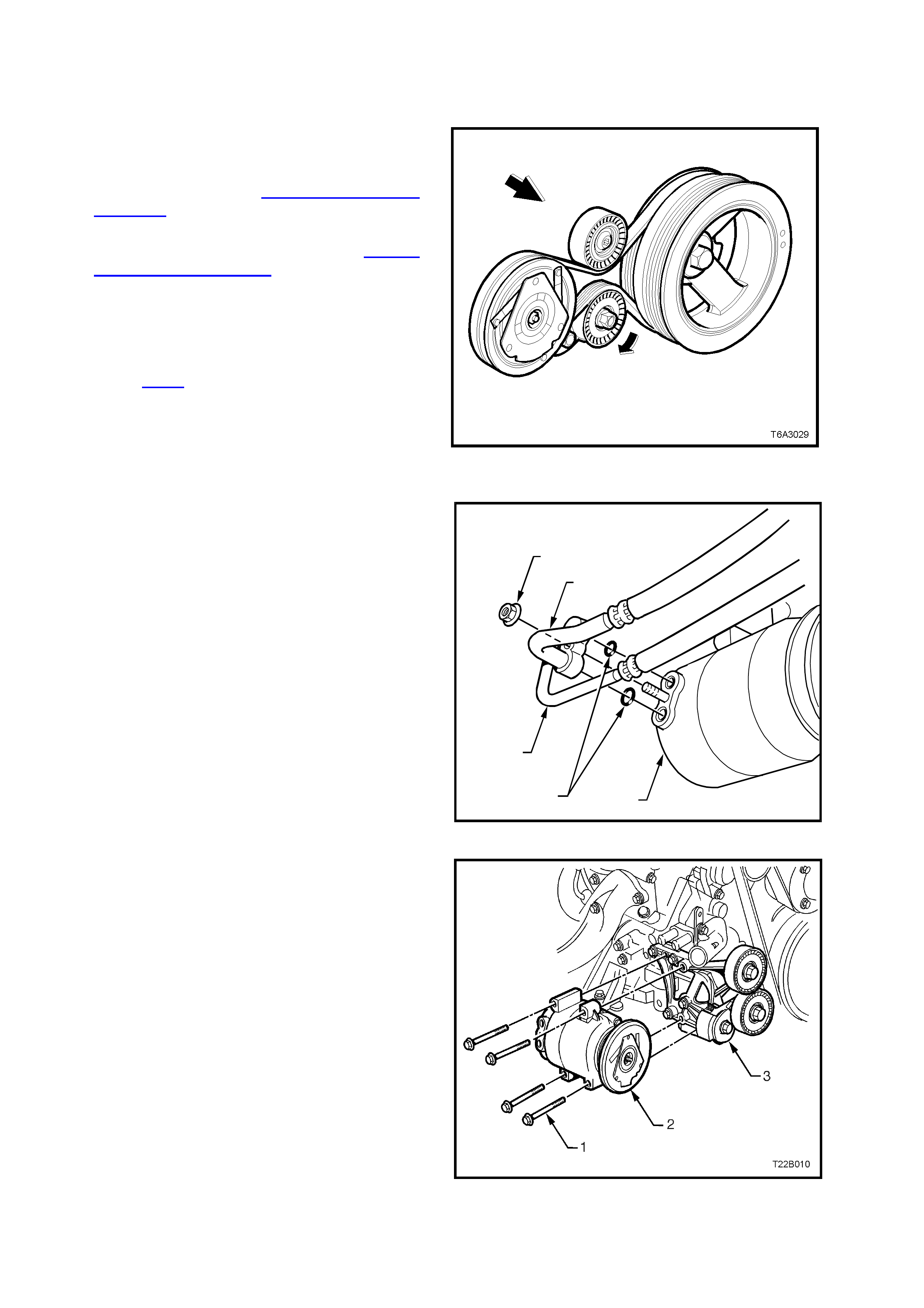
4. Using a 15mm socket attached to the centre
bolt of the air conditioning drive belt tensioner,
rotate the tensioner in the direction shown in
Figure 2B-74, to relieve belt tension.
5. Rem ove the air conditioning drive belt f rom the
pulleys but leave hanging on the crankshaft
pulley.
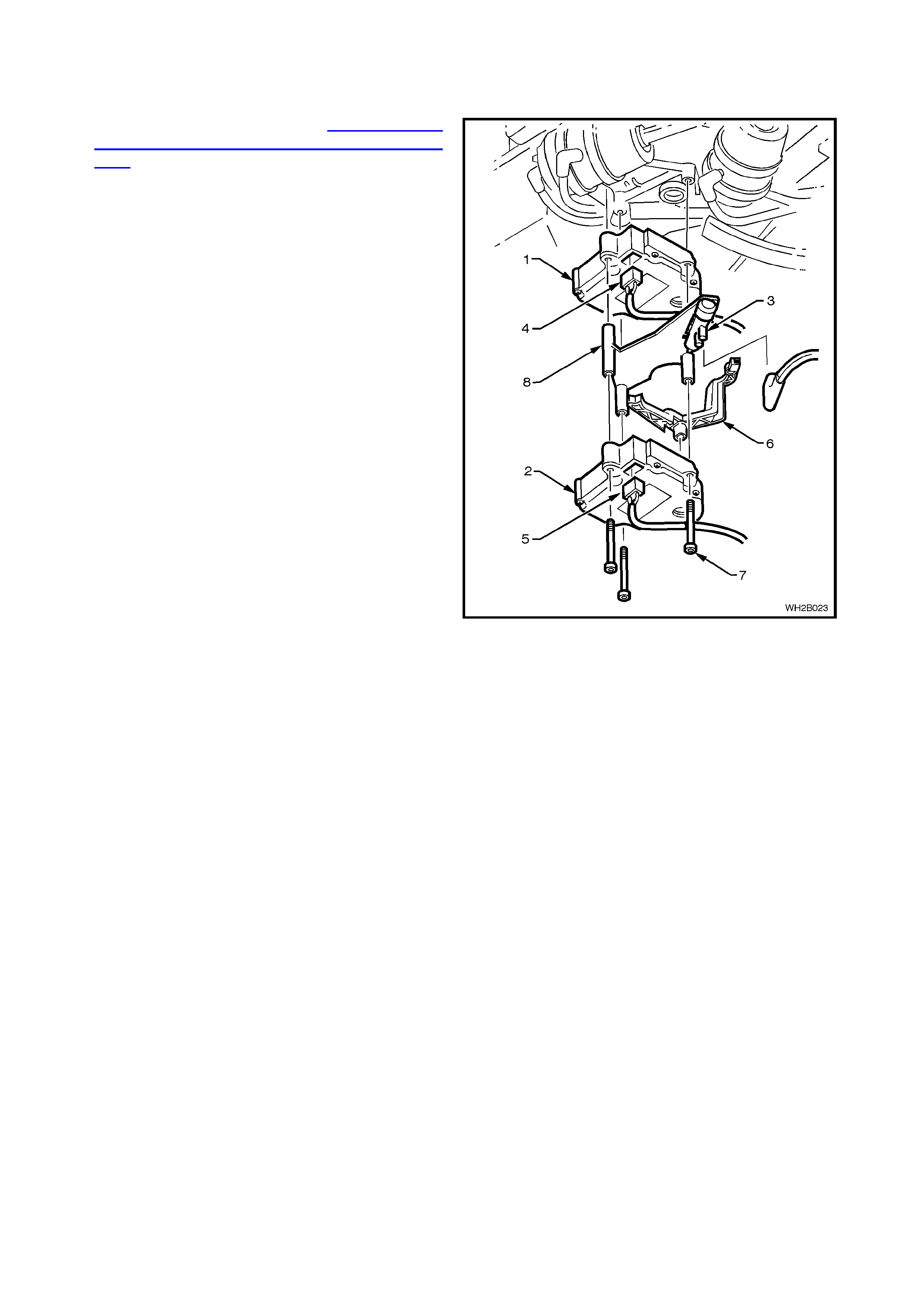
Figure 2B-81
6. Loosen and remove the nut (1) retaining the
suction (2) and discharge (3) hoses to the
compressor (4). Remove the hoses (2 & 3)
from the compressor.
7. Discard O-ri ngs (5).
8. Cap or plug the ports immediately to prevent
entry of moisture from the atmosphere.
9. Disconnect the compressor clutch electrical
connector.
T22B009
1
2
3
54
Figure 2B-82
10. Remove the four bolts (1) retaining the
compressor (2) to the mounting bracket (3).
NOTE: Figure 2B-83 shows several components
removed for clarity only (ie. heater and coolant
hoses). To remove the compressor, it is not
necessary to remove these components.
11. Remove compressor.
12. If necessary, remove the four bolts retaining
the compressor mounting bracket to the
cylinder block and remove the mounting
bracket.
Figure 2B-83

REINSTALL
1. If removed, reinstall the compressor mounting
bracket and tighten the four retaining bolts to
the correct torque specification.
COMPRESS OR MOUNT I NG BRACKE T
RETAINI NG B OLT 40.0 - 60.0 Nm
TORQUE SPECIFICATIO N
NOTE: If replacing with a new compressor refer to
Section 2C AIR CONDITIONING - ECC
SERVICING AND DIAGNOSIS of the WH Service
Information for lubrication
requirements/specifications.
2. Fit the compressor to the compressor
mounting bracket, install the four retaining bolts
and tighten to the correct torque specification.
COMPRESSOR RE TA INING BOLT 40.0 - 60.0
TORQUE SPECIFICATIO N Nm
3. Reinstall the air conditioning compressor drive
belt. Refer 2.24 A/C DRIVE BELT-
REINSTALL in this Section for the necessary
procedure.
4. Remove caps from compressor ports and
install new sealing washers.
5. Using new O-rings lubricated with PAG
refrigerant oil (part number 12345923) install
the air conditioning suc tion and dis charge hose
pad fitting onto the compressor.
CAUTION: Do not allow PAG refrigerant oil to
contact bare skin or vehicle paint work. If contact
occurs to either, wash PAG refrigerant oil off
immediately.
6. Install the suction and discharge hose pad
retaining nut and tighten to the correct torque
specification.
SUCTION AND DISCHA RGE HOSE
PAD RETA INING NUT 28.0 - 42.0 Nm
TORQUE SPECIFICATIO N
7. Connect the compressor clutch electrical
connector.
8. Connect heater and lower radiator coolant
hoses, refill coolant s ystem with c or re ct coolant
and pressure test coolant system, refer to
Section 6B3 ENGINE COOLING - GEN III V8
ENGINE of the VT Series II Service
Information.
9. Recharge air conditioner system, refer to
Section 2C AIR CONDITIONING - ECC
SERVICING & DIAGNOSIS of the W H Service
Information.
3. M INOR COM PRESSOR REPAIR PROCEDURES
The illustration used in the following procedure show the compressor removed from the vehicle for easier viewing.
When servicing the compressor, remove only the parts that preliminary diagnosis shows are in need of service.
Removal and installation of external compressor parts and disassembly/assembly of internal parts must be
performed on a clean workbench. The work area, tools and parts must be clean at all times.
NOTE: The only components that can be serviced are:-
Control Valve
Port Sealing Washers
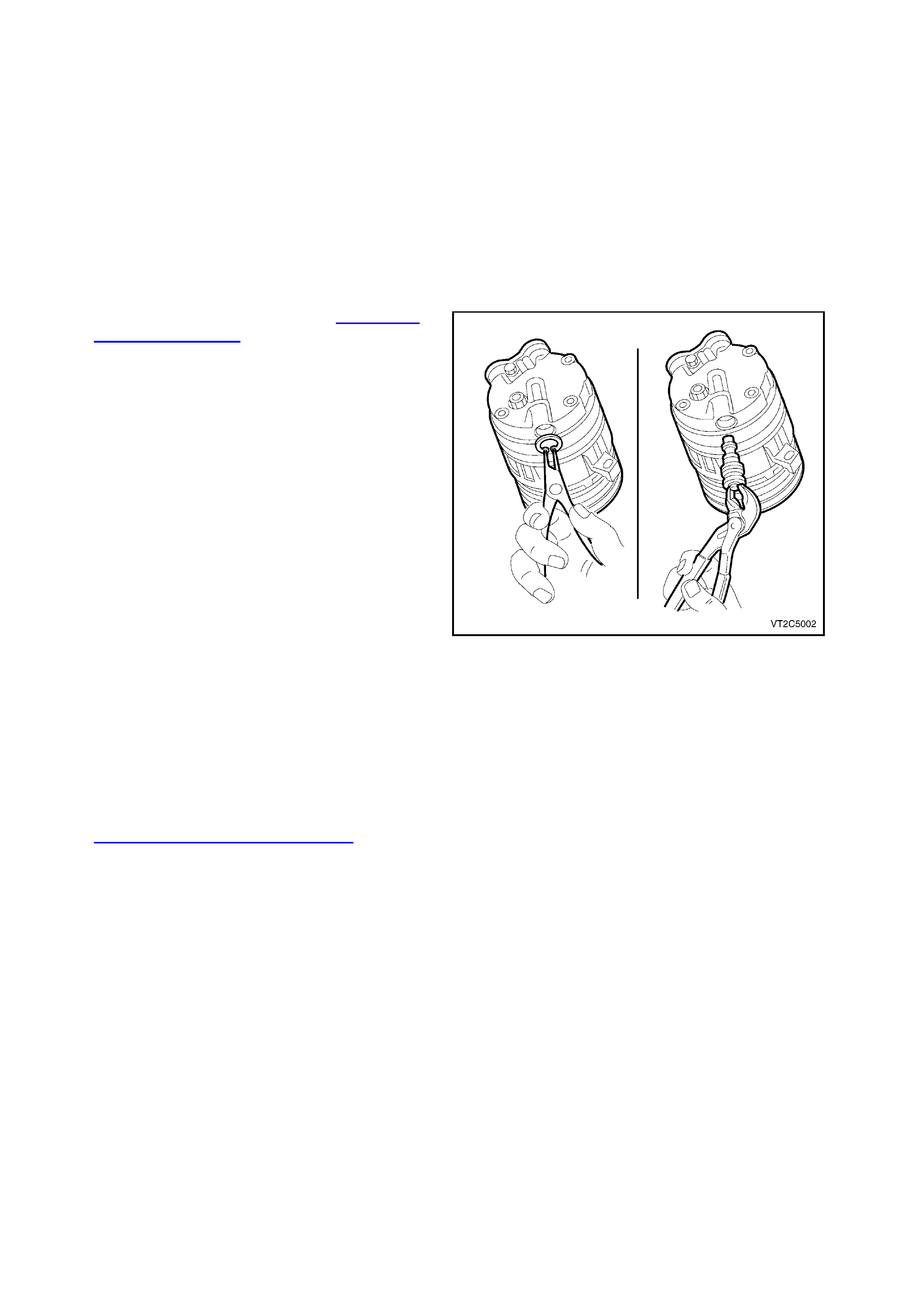
3.1 COMPRESSOR CONTROL VALVE
REMOVE
1. Recover the refrigerant, refer to Section 2C
AIR CONDITIONING - ECC SERVICING AND
DIAGNOSIS of the WH Service Information.
2. Jack vehicle up and place on jack stands.
3. From beneath the vehicle remove the circlip
securing the control valve to the compressor.
4. Using a pair of s uitable c irc lip plier s r emove the
control valve from the compressor by pulling
downwards. Quickly insert replacement control
valve (this will avoid any minor oil loss).
REINSTALL
1 Lubricate the control valve O - rings and
carefully push control valve into the
compressor.
NOTE: V6 and V8 control valves have different
control settings. Ensure that the correct valve is
installed.
2. Inspect original control valve retaining circlip, if
undamaged use to secure valve, if not replace
with new circlip. Ensure circlip is FULLY
seated.
3. Add to the compress or through the suc tion port
any new lubricating oil required, if oil had been
lost during control valve removal.
4. Evacuate and charge the A/C system with
775 - 825 g of R134a refrigerant, refer to
Section 2C AIR CONDITIONING - ECC
SERVICING AND DIAGNOSIS.
Figure 2B-84

4. TORQUE WRENCH SPECIFI CATIONS
Nm
Lower steering column shroud screw ................................... 0.5 - 2
Instrument panel end cap cover attaching screws................ 1 - 3
Instrument panel compartment attaching screws................. 1 - 3
Instrument panel compartment lock striker attaching screws 1 - 3
Centre console securing screws........................................... 1 - 3
Centre console bin retaining nuts ......................................... 1 - 3
Transmission console retaining screws................................ 1 - 3
Centre console storage compartment securing screws........ 1 - 3
Demist nozzle retaining screws ............................................ 1 - 3
Front dash speaker retaining screws.................................... 1 - 2
Instrument panel carrier end panel attachment screws........ 1 - 3
Instrument facia assembly retaining screws......................... 1 - 3
Centre facia assembly securing screws ............................... 1 - 3
ECC securing screws............................................................ 1 - 3
Combined instruments assembly securing screws............... 1 - 3
Instrument panel carrier retaining screws............................. 7 - 12
Instrument panel lower trim right side rail assembly
retaining screws.................................................................... 1 - 3
Centre facia side extension support rail attaching screws.... 1 - 3
Support steering column bracket inner securing screws...... 3 - 5
Passenger air bag support rail securing screws................... 2.5 - 5
Lower left side rail connecting screws .................................. 1 - 3
Instrument panel carrier rail assembly securing screws....... 1 - 3
Passenger side air bag securing nuts................................... 15 - 25
TXV attaching screws........................................................... 3 - 8
Heating, ventilation and air conditioning unit attachment
screws to the passenger compartment................................. 6 - 14
Heating, ventilation and air conditioning unit attachment
screws to the engine bay...................................................... 2 - 5
Evaporator tube plate securing screws................................. 4.0 - 4.5
Washer faced tube plate retaining bolt................................. 7.5 - 12.5
TXV Pipe bracket retaining bolt ............................................ 7.5 - 12.5
FDR pipe flange nut.............................................................. 7.5 - 12.5
Condenser discharge pad retaining nut................................ 7.5 - 12.5
Condenser inlet pad fitting nut.............................................. 7.5 - 12.5
Air conditioning tube fittings to FDR...................................... 7.5 - 12.5
GEN III V8 ENGINE
Air conditioning compressor drive belt idler pulley bolt......... 40. - 60
Air conditioning compressor drive belt tensioner bolt ........... 21 - 29
Compressor mounting bracket retaining bolt........................ 40 - 60
Compressor retaining bolt..................................................... 40 - 60
Compressor suction and discharge hose pad retaining nut.. 28 - 42
V6 ENGINE
Compressor retaining bolt..................................................... 20 - 30
Compressor retaining nut ..................................................... 40 - 55
Idler pulley mounting bracket retaining nut .......................... 20 - 30
Idler pulley retaining bolt....................................................... 40 - 50
Compressor suction and discharge hose retaining nut......... 28 - 42
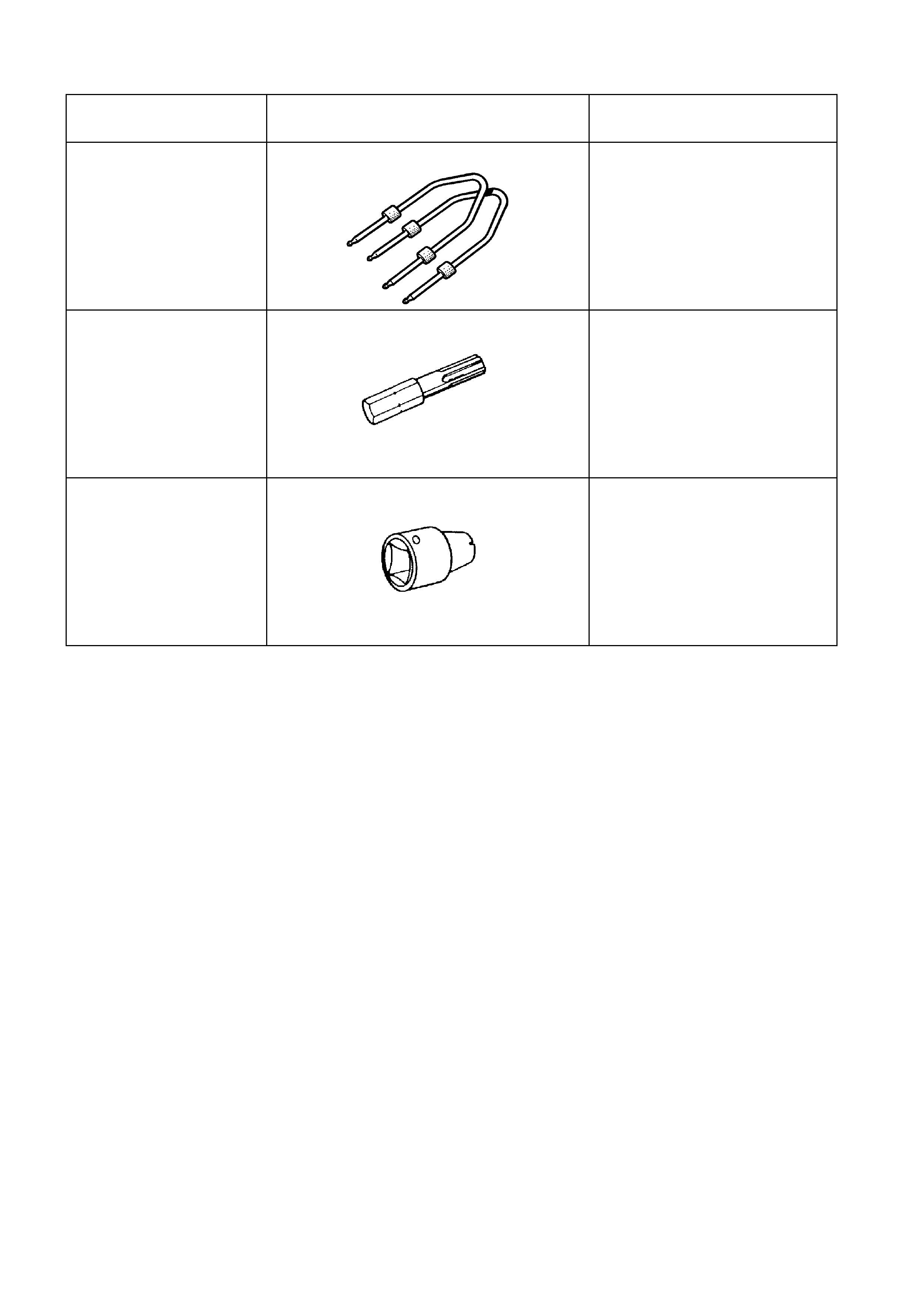
5. SPECIAL TOOLS
TOOL NO. REF
IN TEXT TOOL DESCRIPTION COMMENTS
179 1308 0000 RADIO REMOVAL TOOL
ETX30H T30H TORX BIT Used to remove screws securing
horn bar and air bag inflator
module assembly to steering
wheel and SRS SDM to floor
mounting bracket
Previously released.
J25359-8 TORX BIT HOLDER Used with ETX30H Torx bit
Previously released.