
SECTION 2C - AIR CONDITIONING - ECC
SERVICING AND DIAGNOSIS
IMPORTANT
Before performing any Service Operation or other procedure described in this Section, refer to
Section 00 CAUTIONS AND NOTES for correct workshop practices with regard to safety and/or
property damage.
1. GENERAL I NFORMATI ON
With the introduction of the GEN III V8 engine, and in particular the accompanying Delphi V7 Compressor, some
minor changes to air conditioning system diagnosis have been made.
Techline
Techline
Techline
Techline
Techline
Techline
Techline

2. PRECAUTIONS IN HANDLING REFRIGERANT
In any vocation or trade, there are established procedures and practices which have been developed after many
years of experience. In addition, occupational hazards may be present that requires the observation of certain
precautions, or use of special tools and equipment. Observing the procedures, practices and precautions of
servicing refrigeration equipment will greatly reduce the possibility of damage to the customer’s equipment, as well
as virtually eliminating the element of hazard to the serviceman.
Care should be taken when discharging the air conditioning system to ensure the refrigerant is not released to the
atmosphere but captured for recycling. Environment friendly refrigerant R134a is not an ozone depleting substance
but its release would add to the green house warming effect.
Refrigerant R134a is transparent and colourless in both the gaseous and liquid states. At all normal temperatures
and pressures, it will be a vapour. The vapour is heavier than air and is non-flammable, non-explosive, non-
poisonous and non-corrosive (except when in contact with moisture).
The following precautions in handling R134a should be observed at all times:
NOTE: R134a and R12 are not compatible and must never be mixed.
1. Always us e saf ety glasses and gloves when handling or servic ing air conditioning s ystems. If R134a does enter
the eye, freezing of the eye can occur and could res ult in blindness. T he proc edure outlined below is sugges ted
if R134a enters the eyes.
a. Keep calm.
b. Do not rub eyes.
c. Splash large quantities of cool water into the eyes to increase the temperature.
d. Tape a sterile eye patch in place to prevent dirt from entering the eye.
e. Go immediately to a doctor or hospital for professional care.
DO NOT ATTEMPT TO TREAT YOURSELF
2. Always use proper workshop practices. Skylarking is dangerous!
3. Always work in a well ventilated area.
4. Avoid skin contact, as R134a will cause frostbite on contact with bare skin.
5. Do not abuse the refrigerant cylinder, or any other tools you may need to use.
6. Do not weld or steam clean on or near any air conditioning components when pressurised. This may cause a
dangerous pressure build up in the system.
7. Do not discharge refrigerant into an enclosed area.
8. When purging a system, discharge the refrigerant slowly.
9. If it is necessary to transport or carry a cylinder of refrigerant in a car, keep it in a luggage compartment.
10. Refrigerant cylinders should always be protected from the radiant heat of the sun.
11. W hen f illing a refr igerant cylinder, never com pletely f ill it. Always leave space for expansion. If the cylinder was
completely filled and the temperature increased, hydraulic pressure with its tremendous force would result.
REMEMBER: Prevention is better than cure.
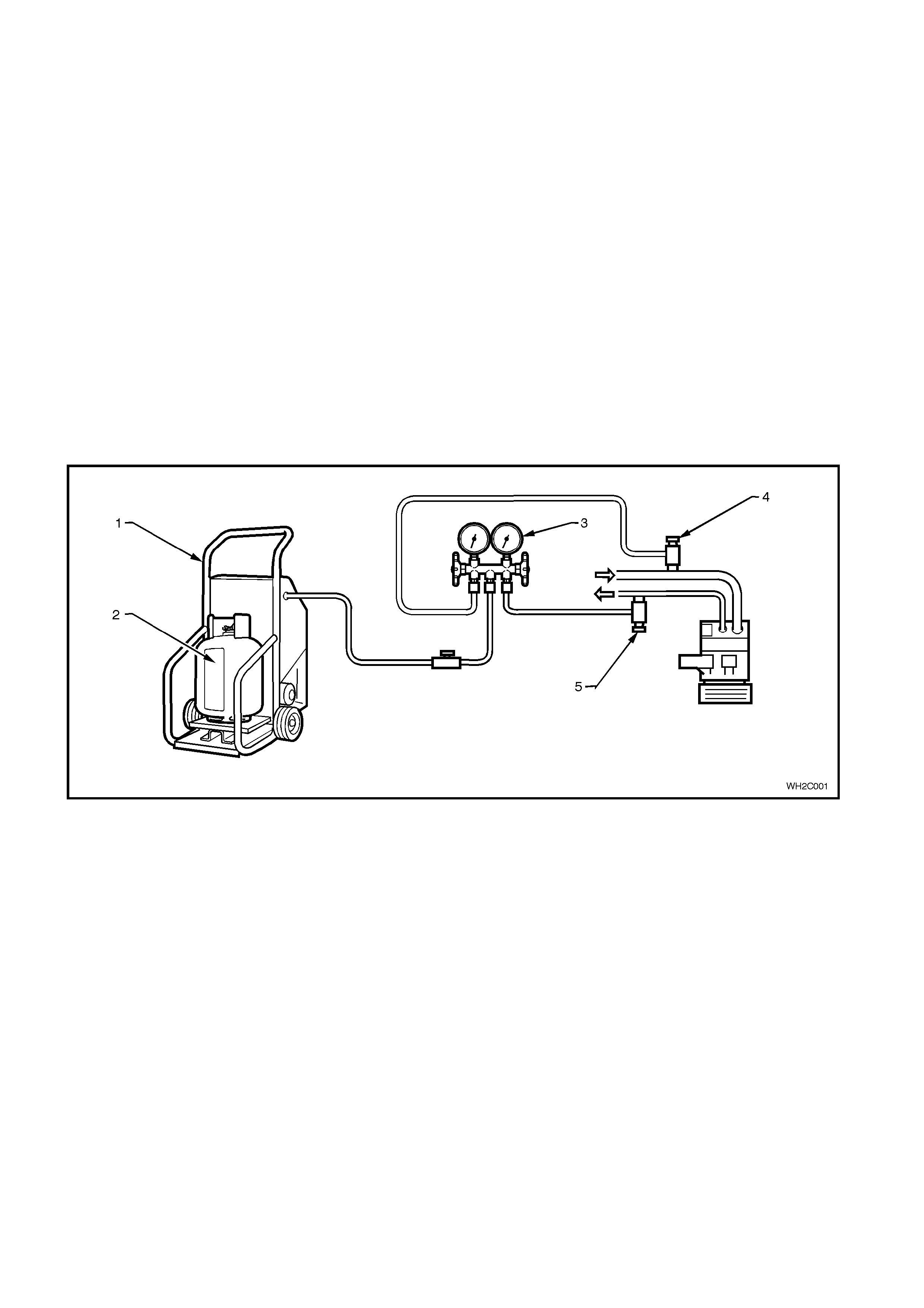
2.1 DISCHARGING SYSTEM - REFRIGERANT RECOVERY
NOTE: Care should be taken when discharging the air conditioning system to ensure the refrigerant is not released
to the atmosphere but captured for recycling. R134a is not an ozone depleting substance but its cost and the fact
that it does contribute to the greenhouse effect, make it essential that it is recovered.
Various Refrigerant Recovery Units (RRU) are now available. The following procedure is typical for the use of these
units when recovering refrigerant from a vehicle air conditioning system.
1. Connect the RRU outlet to a R134a recovery cylinder with a refrigerant hose and open the valve on the cylinder.
Ensure that the cylinder has suf ficient capac ity to hold the ref rigerant in the s ystem to be ser viced. T his can be
confirmed by weighing the cylinder or by referring to the volume gauge if fitted.
2. Connect a gauge m anifold s et to the car air conditioner. Connect to both the s uction and dis charge sides of the
system. Connect the centre hose of the gauge set to the inlet of the recovery unit. Connect the RRU to electrical
supply.
3. Open the gauge set and quick ly connect stop taps to allow refrigerant to enter the RRU via the c entre hose. At
this point, depending on which unit is being used, the RRU will switch on. If the RRU is not the autom ated type,
switch the unit on.
4. The autom atic recover y unit will operate until the air conditioning system has been emptied of refrigerant down
to atmospheric pressure. The cylinder can now be closed.
5. Measure the amount of PAG oil removed f r om the A/C system. This oil is nor mally separated from the incoming
refrigerant into the RRU. New clean PAG oil must be added into the system before recharging with refrigerant.
Figure 2C-1
Legend
1. Re frigerant re covery unit (RRU)
2. Refrigerant recovery cylinder
3. Manifold/Gauge set
4. Low side charging adaptor
5. High side charging adaptor
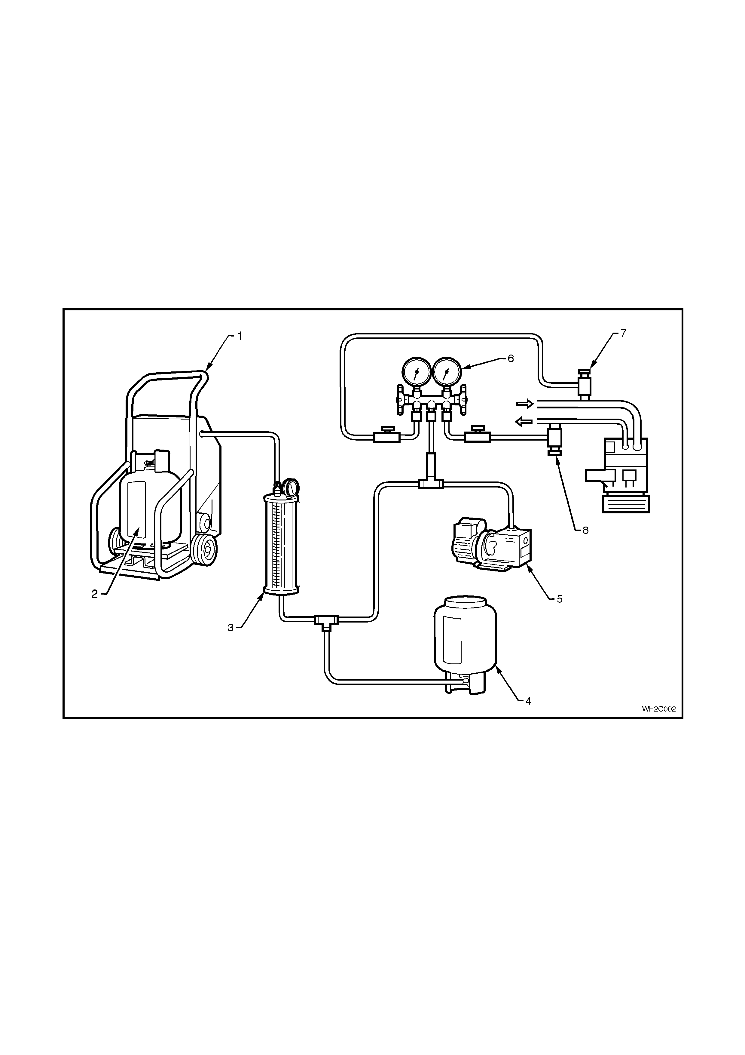
2.2 SYSTEM CHARGING AND EVACUATION
The following equipment is required for system charging and evacuation procedures:-
1. Refrigerant calibration charging cylinder or weighing device.
2. Pressure gauges and hoses.
3. Vacuum pump.
4. Refrigerant Recovery Unit (including compressor and oil collector).
5. Electronic leak detector.
CAUTION: The wearing of safety goggles and gloves is mandatory during system charging or discharging.
NOTE: All hoses at point of connection to the system must have isolation valves fitted.
Charging the system includes the following steps:-
1. Filling charging cy linder.
2. Evacuation and leak test.
3. Charging system.
4. Performance test.
Figure 2C-2
Legend
1. Re frigerant re covery unit (RRU)
2. Refrigerant recovery cylinder
3. 'Dial A Charge' charging cylinder
4. R134a supply cylinder
5. Vacuum pump
6. Manifold gauge set
7. Low side charging adaptor
8. High side charging adaptor
FILLING A DIAL-A-CHARGE CYLINDER
1. Open valve on bottom of charging cylinder, allowing refrigerant to enter cylinder from storage cylinder.
2. Bleed cylinder via valve on top (behind pressure gauge) as required allowing refrigerant to enter. This valve
should be connected via a hose to a Refrigerant
Recovery Unit (RRU) and recovery cylinder. When refrigerant reaches the desired level, close valve at bottom
of cylinder and be certain that bleed valve is securely closed.

EVACUATION AND LEAK TEST
1. Check that both manifold hand valves of gauge set are closed and turn RRU off.
2. Connect the charging hoses onto the suction (low) and discharge (high) service valves in the system.
NOTE: DO NOT USE SPANNERS.
3. Connect the centre manifold charging hose to the vacuum pump inlet.
4. Start vacuum pum p and s lowly open LOW SIDE manifold hand valve. Low side gauge r eading s hould decr eas e
to 98 - 102 kPa vacuum and high side gauge should read slightly below the zero index of gauge. If high side
gauge reading does not register, check system for blockage or leak.
NOTE: When high side gauge is slightly below the zero index of gauge, open high side manifold hand valve.
5. After evacuating the system for 15 minutes, to a vacuum of -100 kPa, close both the low and high side hand
valves, then stop the vacuum pump. The system must hold the vacuum of -100kPa for a minimum of
15 minutes. If vacuum is held then the system has no leaks and may continue to be evacuated for a further
15 minutes.
6. Wear safety goggles.
7. Connect the centre charging hose to the charging cylinder hand valve on the bottom of the cylinder. Open the
bottom charging cylinder hand valve. Do not open the low or high side valves on the manifold gauge at this
time.
8. Loosen the centre charging hose nut connected to the centre fitting of the manifold gauge set until a hiss can be
heard. Allow the air to escape for a few seconds, then re-tighten nut.
NOTE: DO NOT START ENGINE.
9. Partially charge the system with 200g of R134a by slowly opening the high side manifold hand valve; low side
gauge should register a pressure, if not, check f or blockage. Close the high side m anifold hand valve as soon
as 200g of R134a has entered the system.
10. Check system for leak s with an electronic detector. If a leak is detected, r emove ref rigerant from syst em using
the RRU and repair the faulty component or connection. Repeat steps 4 to 10 after repair of leak.
NOTE: Various types and makes of leak detectors are currently in use. Whichever leak detector is used, it is
important to follow the manufacturer’s instructions in regard to adjustment and setting the instrument prior to
conducting the test. Inspect for leaks by slowly moving the probe of the detector around all hose connections and
points of possible leakage. Refrigerant R134a is heavier than air and will be more apparent at the bottom of a fitting.

CHARGING SYSTEM
After leak check has proven the system to be leak free, charge the proper amount of refrigerant into the system as
follows:-
1. Open the HIGH SIDE manifold hand valve slowly. Fill the system with as much of the specified charge as
possible, then close the high side manifold hand valve.
2. Rotate the com pr es sor by hand for 12 revolutions to ensur e no liquid refrigerant is trapped in the s uc tion s ide of
the compressor. Failure to comply with this step may result in irreversible damage to the compressor.
3. Start the engine and engage compressor clutch and evaporator fan on high speed.
4. Set engine speed to 1500 - 1700 rpm.
5. If the system has been charged with the specified amount (775 - 825g), go to step 7.
6. To complete the charging of the system, slowly open the LOW side manifold hand valve until the specified
amount has been charged into the system.
CAUTION: Do not allow more than 275 kPa to be registered on the LOW pressure gauge.
7. Perform Cooling System Pressure Test, refer to COOLING SYSTEM PRESSURE TEST in Section 6B1-1
ENGINE COOLING - V6 or Section 6B1-2 ENGINE COOLING - V6 SUPERCHARGED, of the VT Series I
Service Information or Section 6B3 ENGINE COOLING GEN III ENGINE, of the VT Series II Service
Information. If unit operates satisfactorily, stop engine, shut stop valves at hose connections to system and
disconnect hoses taking extreme caution, as the discharge hose can have up to 2070 kPa stored in it. Install
service valve caps as required.
WARNING: NEVER RUN COMPRESSOR WITHOUT REFRIGERANT IN SYSTEM AS COMPRESSOR
LUBRICANT RELIES ON REFRIGERANT FLOW.
No sight glass is fitted to the system due to PAG oil’s foaming properties, which may be confused with a
low gas charge. Topping up the system is not recommended.
Accurate system refrigerant charge may only be determined by charging the correct amount of R134a.
Pressure gauge readings together with face air outlet temperatures are the only method of checking and diagnosing
the system cooling capacity (comparing results with the appropriate graph).
If in doubt as to gas charge, e.g:
Suction pressure low,
Discharge pressure low,
Air outlet temperature (face) above graph range,
Recover refrigerant from the system using R134a specific equipment.
Evacuate system. Charge with 775 - 825g of R134a.
Carry out cooling system pressure test and suction (low side) pressure readings comparisons.

2.3 CHECKING SYSTEM OIL CHARGE
The compressor is charged at the factory with 265cm3 of Harrison PAG refrigerant oil (Part No. 12345923), which
circulates within the entire A/C system. Only this type of oil which is blue in colour must be used when adding or
changing oil. This oil is not compatible with any other PAG oil.
Although it is not necessary to regularly check the oil level within the system, all the A/C system components will
hold a quantity of the oil circulated. Therefore whenever an A/C system component is replaced, a quantity of new
refrigerant (PAG) oil must be added to the system. Where a major loss of system oil has occurred, due to:
* A broken hose or severed leak,
* Collision damage to refrigerant system components, or
* If excess oil is suspected to be in the system, then
1. Recover refrigerant from the system, then remove the compressor.
2. Carefully drain the refrigerant oil.
3. Flush remaining oil from the rest of the system using R134a refrigerant.
CAUTION: A refrigerant Recovery Unit (RRU) should be used to flush the system, ensuring that the R134a
is not vented to the atmosphere. The R134a must be reclaimed via the RRU into a separate bottle.
4. Add 265cm3 of new refrigerant oil to the compressor.
5. Install the com press or, replacing the s uction and discharge O - rings. Ensur e O - r ings are not twisted and that
the seals and O - rings are clean.
6. Evacuate then recharge the system.
PAG OIL PRECAUTIONS: DO NOT allow PAG oil to contact either bare skin or vehicle paintwork. IF CONTACT
OCCURS, WASH PAG OIL OFF IMMEDIATELY.
Techline
FLUSHING THE A/C SYSTEM FOR CONTAMINA TION OR LUBRICATING OIL
REMOVAL
Some oil is lost whenever air conditioning system components are replaced.
Where the system has been ruptured, contaminated, or a compressor has to be removed and reinstalled or
replaced, the system should be checked for contamination and, if so, the entire system must be flushed.
Currently the only method recommended when flushing is with refrigerant R134a. Other flushing agents are
currently under investigation.
CAUTION: A Refrigerant Recovery Unit (RRU) should be used to capture the R134a used for flushing. The
R134a must be reclaimed via the RRU into a separate bottle. Use only a dedicated R134a RRU.
IMPORTANT: The complete air conditioning system must contain 265 ±10cm3 of factory installed refrigerant oil.
NOTE: A new compressor will contain 265cm3 of factory installed lubricating oil.
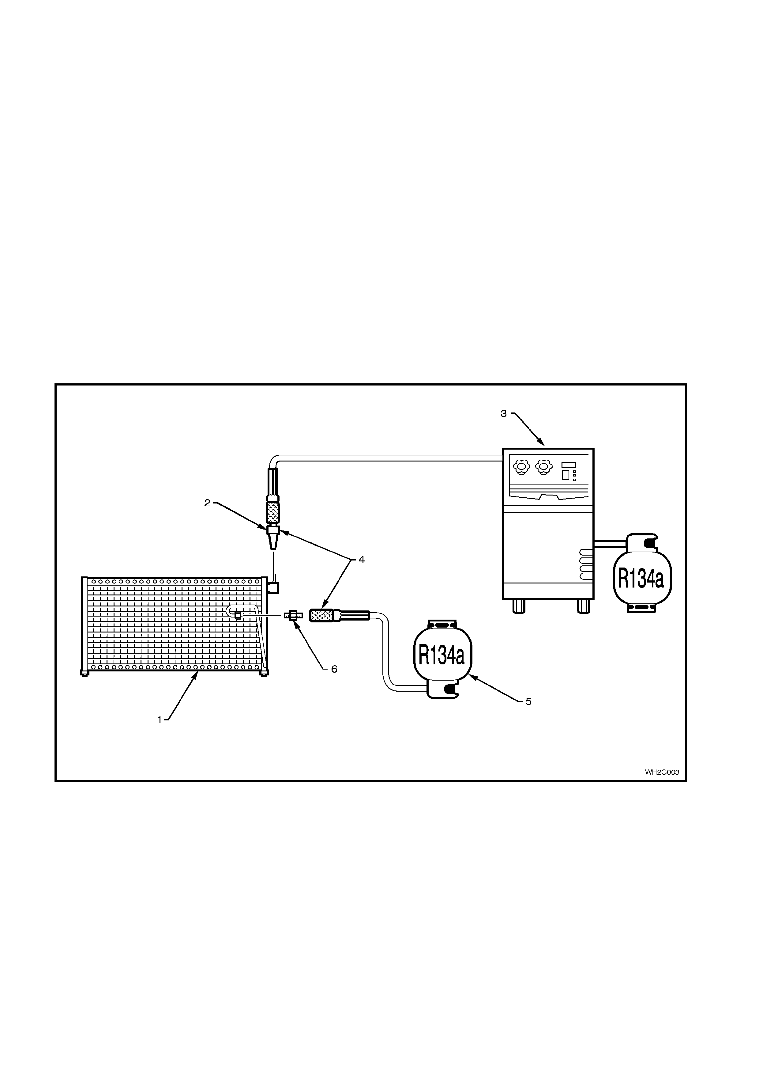
1. Flush individual components.
2. Self m ade flushing f ittings will be required as A/C s ystem com ponent fittings all dif fer in size, shape and thread
size.
3. Invert decanting cylinder to use refrigerant in liquid form.
4. Reverse flush components.
5. Do not flush through a compressor otherwise possible internal damage could occur.
6. Recover/recycle flushing refrigerant, the recovery device will remove contaminants through a filtration system.
Figure 2C-3
Legend
1. Condenser
2. Flush gun 3. Recovery device
4. Flush, then reverse flush 5. Inverted decanting cylinder (liquid)
6. Self made fitting
COMPRESSOR
Reinstalling the Original Compressor
1. Drain and measure the refrigerant oil contained in the compressor.
2. Charge oil through the discharge port of the compressor with the same amount of new refrigerant oil.
NOTE: If the amount of oil in the original compressor was not checked, then approximately 150cm3 of new oil
should be added to the compressor being installed. (This is assuming the compressor being installed has first been
drained).
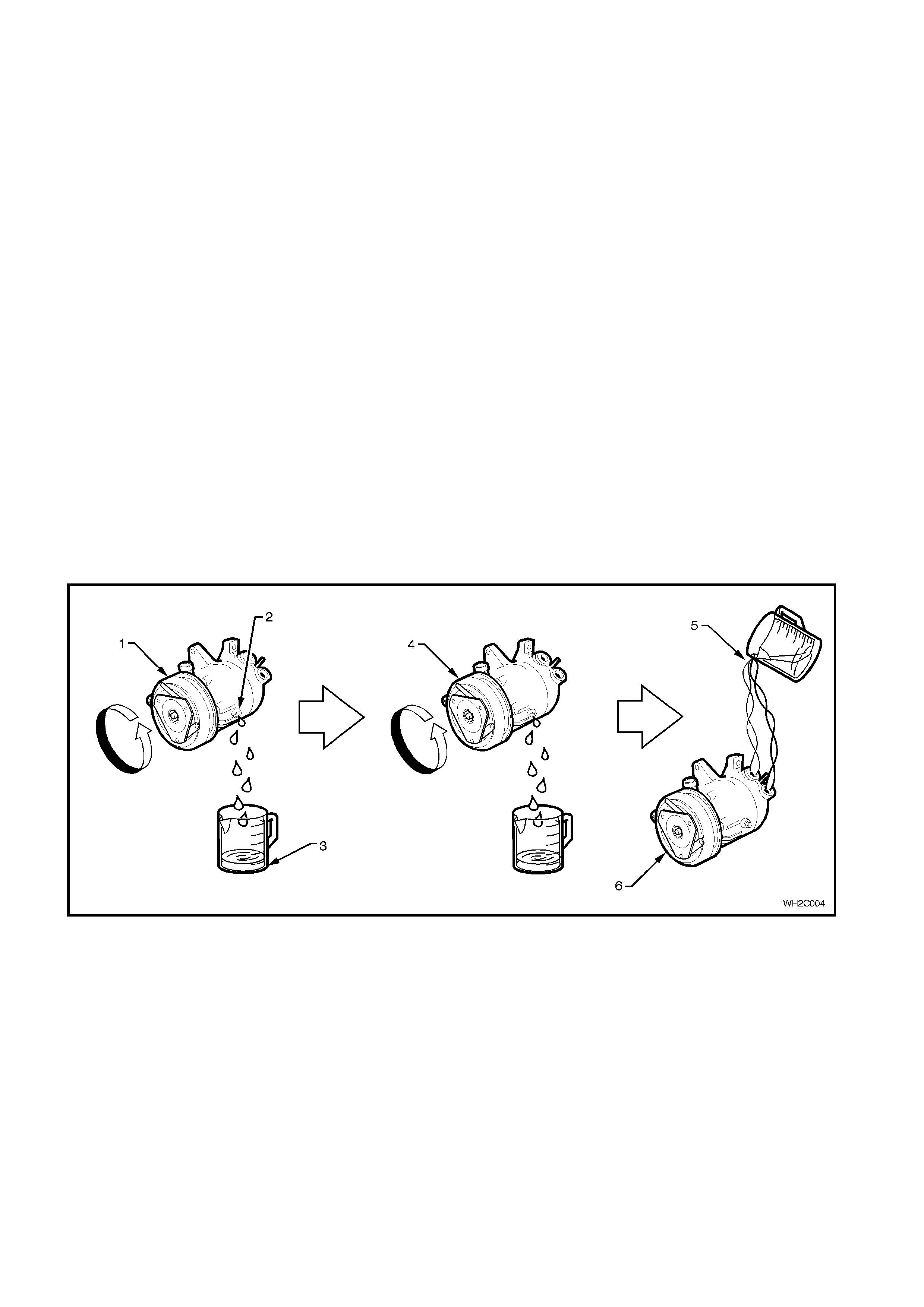
Installing a New Compressor
1. Drain and measure refrigerant oil from the original compressor.
2. Drain factory installed refrigerant oil from new compressor drain plug (total lubricant quantity 265cc).
3. Measure the same amount of new refrigerant oil that was drained from the original compressor. Install this
amount of oil into the new com pressor through the suction/discharge port whilst turning the compressor clutch
pulley front face.
Evaporator or Condenser
Drain as much of the original oil as possible from the evaporator or condenser. Add the same amount of new
refrigerant oil, either to the original or new evaporator or condenser.
If replacing condenser - add approximately 40cm3.
If replacing evaporator - add approximately 50cm3.
Filter Drier Receiver (FDR)
If replacing the FDR - add approximately 15cm3.
The FDR must be replaced whenever the system has been opened to the atmosphere for repair.
Blown or Ruptured Pipe/Hose
When replacement is required add approximately 40cm3.
Figure 2C-4
Legend
1. Faulty compressor
2. Drain plug 3. E.G. 100cc removed
4. New compressor 5. E.G. 100cc installed
6. New compressor

3. DIAGNOSIS
3.1 PREREQUISITES AND PRELIMINARY CHECKS FOR DIAGNOSIS AND
TROUBLESHOOTING
The following list are the prerequisites and preliminary checks that should be performed before proceeding with any
system diagnosis.
1. Perform a visual inspection of all interior and under-hood components. Many problems can be detected by a
thorough inspection of system components without having to perform any system diagnosis. Repair system as
necessary.
2. Ensure the ECC system is functioning correctly, refer to Section 2A AIR CONDITIONING - ECC - PRINCIPLES
AND OPERATION of the WH Service Information.
3. Ensure air conditioning fuses are okay.
4. Ensure the blower fan is operating correctly.
5. Ensure the temperature door is moving freely from hot to cold.
6. Ensure the condenser airflow is not restricted by foreign matter.
7. Ensure the compressor clutch coil and pressure switch connections are okay.
8. Engine cooling fans are operating correctly. (At idle, the cooling fans must be on at any A/C mode and cooling
fans must be operating in the correct direction; drawing ambient air through the condenser toward engine).
9. If the air conditioning system is noisy, particularly from or around the compressor, check for (and repair as
necessary):
Damaged or slipping compressor drive belt.
Idler pulleys for bearing roughness or damage.
Drive belt tensioner.
Loose compressor mounting bolts.
Ensure air conditioning pipes do not contact the vehicle bodywork.
Techline
Techline

3.2 GENERAL AND SPECIFIC SYSTEM CONDITION CHARTS
The charts and graphs in this Section were developed in a climatic controllable wind tunnel by producing known
system problems and recording pressures at various ambient temperatures. Results were then validated using the
same vehicle set up in a service environment.
The air conditioning diagnosis chart is the starting point for verifying and diagnosing all air conditioning and HVAC
control related complaints. The chart represents the correct path to follow from a customer complaint or condition
through delivery of the vehicle back to the customer.
In general, there are some variances in the readings between systems of different vehicles; however, the target
areas have been developed to accommodate these changes.
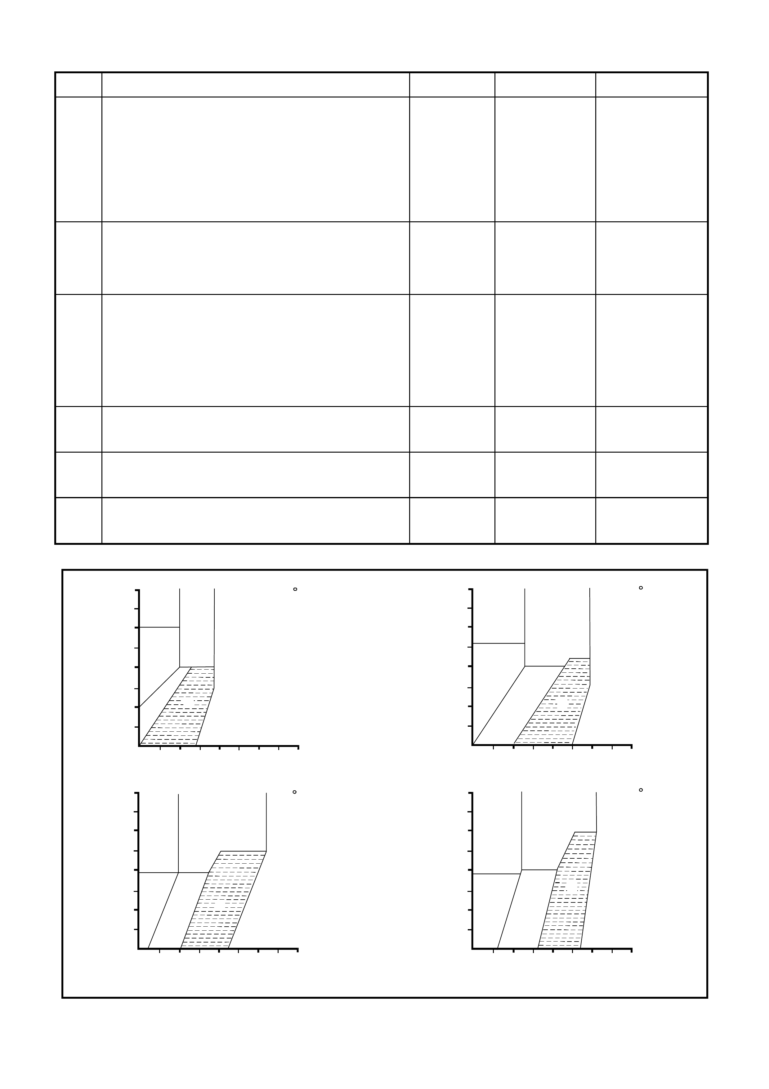
3.3 AIR CONDITIONING DIAGNOSIS CHART
STEP ACTION VALUE YES NO
1. • Ensure all the preliminary checks been performed as
per 3.1 PREREQUISITES AND PRELIMINARY
CHECKS FOR DIAGNOSIS AND
TROUBLESHOOTING.
• Have all the checks and prerequisites been
performed and met?
Go to Step 2 Perform checks
and ensure
prerequisites are
met as per 3.1
prerequisites and
preliminary checks
for diagnosis and
troubleshooting in
this Section.
2. • Check performance of the air conditioning system as
per 3.4 AIR CONDITIONING PERFORMANCE
TEST.
• Is the air conditioning system operating as specified
in this test?
System OK Go to Step 3.
3. • Compare gauge readings and ambient temperature
recorded in the performance test with the following
diagnostic chart graphs, refer Fig. 2C-5. Read the
high and low pressures and note where they
intersect in the graph.
• Do pressure readings intersect within area A of the
diagnostic chart graph (refer Fig. 2C-5) for the
relevant ambient temperature?
System OK Go to Step 4.
4. • Do pressure readings intersect areas B or D of the
diagnostic chart graph (refer Fig. 2C-5) for the
relevant ambient temperature?
Refer to Repair
Procedure 1 in
this Section
Go to Step 5.
5. • Do pressure readings intersect area C of the
diagnostic chart graph (refer Fig. 2C-5) for the
relevant ambient temperature?
Refer to Repair
Procedure 2 in
this Section
Go to Step 6.
6. • Do pressure readings intersect area E of the
diagnostic chart graph (refer Fig. 2C-5) for the
relevant ambient temperature?
Refer to Repair
Procedure 3 in
this Section
Refer to Repair
Procedure 4 in this
Section
D
F
B
E
C
A
21 C
560
490
420
350
280
210
140
1400 2100 2800
700
70
HI GH SIDE PR ESSURE
LOW SIDE PRESSURE
(kpa)
(kpa)
D
F
B
E
C
A
26.5 C
560
490
420
350
280
210
140
1400 2100 2800700
70
HI GH SIDE PRESSUR E
LOW SIDE PRESSURE
(kpa)
(kpa)
D
F
B
E
C
A
32 C
560
490
420
350
280
210
140
1400 2100 2800
700
70
HI GH SIDE PR ESSURE
LOW SIDE PRESSURE
(kpa)
(kpa)
D
F
B
E
C
A
37.5 C
560
490
420
350
280
210
140
1400 2100 2800700
70
HI GH SIDE PRESSUR E
LOW SIDE PRESSURE
(kpa)
(kpa)
T22C001
Figure 2C-5 Diagnostic Chart Graphs

REPAIR PROCEDURE 1 (AREA S B AND D PRESSURE READING IN FIG. 2C-5)
CONDITION / COMPLAINT POSSIBLE CAUSE ACTION
Discharge Air:- Slightly cool to
warm.
Thermal expansion valve
sweating or has a frost build up
on it.
Low Side Gauge Reading:- Low
(or vacuum)
High Side Gauge Reading :-
Low
Thermal expansion valve remains closed
or blocked.
Thermal expansion valve jammed closed
causing insufficient refrigerant flow to the
suction side of the compressor. This is
normally related to the thermal expansion
valve sensing bulb malfunction or from
being disconnected from the tube, foreign
material in thermal expansion valve or
moisture entry causing rust formations.
Confirm by thorough physical inspection of
all tubes, hoses and components. In
normal operation, the evaporator inlet
temperature is hot. If the inlet pipe is cool,
check for high side restriction. If the inlet
pipe is room temperature, confirm thermal
expansion valve is blocked by running
engine at 2000 RPM - neither high or low
pressure should change by more than 140
kPa.
If the thermal expansion valve proves to be
blocked, replace thermal expansion valve.
Verify repair by repeating the performance
test as detailed in this Section.
Discharge Air:- Slightly cool to
warm.
High pressure side tubes are
cool and showing signs of
sweating or moisture build up at
a point after a restriction
Low Side Gauge Reading:- Low
High Side Gauge Reading :-
Low
Restriction in high side of system or faulty
compressor control valve.
Foreign material causing blockage
between the compressor outlet and
evaporator inlet (high side).
Very little or no refrigerant flow to suction
(low) side of compressor.
Test compressor control valve by running
engine at 1500 rpm for 10 minutes with air
conditioning controls set to; maximum/full
cold with lowest blower fan speed. Close
doors and windows, open engine hood.
If the low side gauge reads less than
200kPa, replace the compressor control
valve.
If the compressor control valve is okay,
check system for blockages and repair as
necessary.
Verify repair by repeating the performance
test as detailed in this Section.
Discharge Air:- Slightly cool to
warm.
Low Side Gauge Reading:- Low
High Side Gauge Reading :-
Low
Refrigerant undercharged.
Refrigerant leak from system. Evacuate and leak test the air conditioning
system, refer 2.2 SYSTEM CHARGING
AND EVACUATION
Verify repair by repeating the performance
test as detailed in this Section.
REPAIR PROCEDURE 2 (AREA C PRESSURE READING IN FIG. 2C-5)
CONDITION / COMPLAINT POSSIBLE CAUSE ACTION
Discharge Air:- Slightly cool to
warm.
Compressor clutch may
continually cycle on the high
pressure switch. Compressor
may also be noisy when
operating.
Low Side Gauge Reading:- Low
to normal
High Side Gauge Reading :-
high to very high
Refrigerant overcharged, restricted filter
drier receiver, blocked or obstructed
condenser fins (airflow), cooling system
overheating, faulty cooling fan operation,
or drive belt slippage.
Referring to the appropriate Sections of
this Service Information CD, check, and
repair as necessary, the following:
• Ensure cooling fans are operating
correctly.
• Check cooling system operation.
• Physically check for blocked or
restricted condenser fins, clean or
remove obstruction.
• Check compressor drive belt for
damage, slippage or incorrect
operation.
• Touch the filter drier receiver inlet and
outlet pipes; if there is a temperature
difference between these two pipes,
replace the filter drier receiver.
If all the above are okay, recharge the air
conditioning system with refrigerant, refer
to 2.2 SYSTEM CHARGING AND
EVACUATION
Verify repair by repeating the performance
test as detailed in this Section.

REPAIR PROCEDURE 3 (AREA E PRESSURE READING IN FIG. 2C-5)
CONDITION / COMPLAINT POSSIBLE CAUSE ACTION
Discharge Air:- May perform
normally, but on an extended
journey the air temperature may
go warm temporarily and then
correct itself after vehicle shut
down.
Compressor may produce a
‘slugging’ noise.
Low Side Gauge Reading: -
High.
High Side Gauge Reading: -
normal to high.
Thermal expansion valve stuck open To check the thermal expansion valve;
• Run blower fan on high.
• Air conditioning on.
• Fast idle engine for two minutes, then
turn engine off for three minutes.
• Restart engine and turn air conditioner
off and let RPM stabilise.
• Turn blower fan to low speed, turn air
conditioner on.
• With engine hood closed, listen for a
‘slugging’ sound.
If a ‘slugging’ noise can be heard, replace
thermal expansion valve.
If thermal expansion valve is okay, check
for a faulty compressor control valve, refer
Repair Procedure 1 in this Section.
Verify repair by repeating the performance
test as detailed in this Section.
REPAIR PROCEDURE 4 (AREA F PRESSURE READING IN FIG. 2C-5)
CONDITION / COMPLAINT POSSIBLE CAUSE ACTION
Discharge Air: - warm; outlet
temperature will be the same as
ambient air temperature.
Low Side Gauge Reading: -
High.
High Side Gauge Reading: -
Low.
Compressor faulty or possible blockage in
the suction. Test compressor as per the following
compressor diagnostic chart.
Verify repair by repeating the performance
test as detailed in this Section.

COMPRESSOR DIAGNOSTIC CHART
STEP ACTION VALUE YES NO
1. • With refrigerant recovery unit manifold pressure
gauges connected to the high and low service valves,
start the engine and run engine at 3000 rpm.
• Set air conditioner controls to blower speed high,
temperature setting on maximum cold and fresh
(outside) air mode.
• Close the vehicles windows and doors.
• Run vehicle under these conditions for five minutes.
• Are the high and low pressure gauge readings within
210kPa of each other.
Go to Step 2. Go to Step 5.
2• Turn engine off.
• With compressor disengaged, turn the compressor
clutch front plate (not the drive belt pulley) by hand.
• Does the compressor clutch front plate turn freely?
Go to Step 5. Go to Step 3.
3• Replace compressor and recharge air conditioning
system.
• Repeat performance test as detailed in this Section to
verify repair.
• Has fault been rectified?
System OK. Go to Step 4.
4Leak test air conditioning system, refer 2.2 SYSTEM
CHARGING AND EVACUATION
• Was a leak found?
Repair leak as
necessary. Verify
repair by
repeating
performance test
as detailed in this
Section.
Go to Step 5.
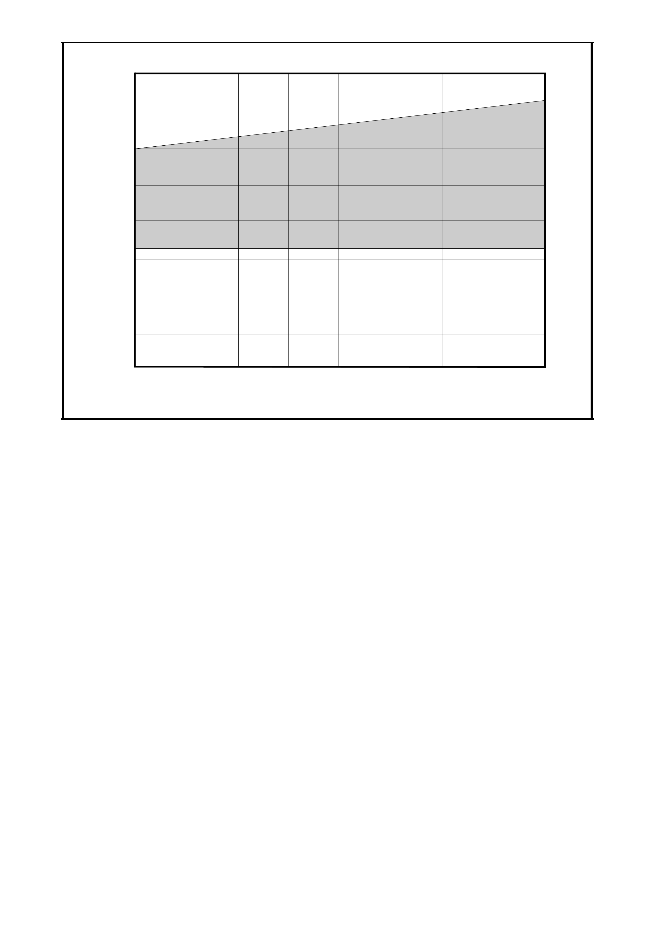
5• With refrigerant recovery unit manifold pressure
gauges connected to high and low service valves,
start engine and run at 1500 rpm.
• Set air conditioner controls to blower speed low,
temperature setting on maximum cold and
recirculated air mode.
• Close vehicle windows and doors.
• Run vehicle under these conditions for five minutes.
• Do high and low pressure gauge readings intersect
within shaded area of Compressor Control Valve Test
specification graph, refer Fig. 2C-6.
System OK. Replace
compressor
control valve
Refer Section 2B
Air Conditioning
ECC Removal &
Installation. Verify
repair by
repeating
performance test
as detailed in this
Section.
500 1000 1500 2000 2500
0
50
100
150
200
250
300
350
400
HIGH PRESSURE SIDE (kPa)
LOW PRES SU RE SID E (kPa)
T22C002
Figure 2C-6Harrison V5 and Delphi V7 compressor control valve test specification
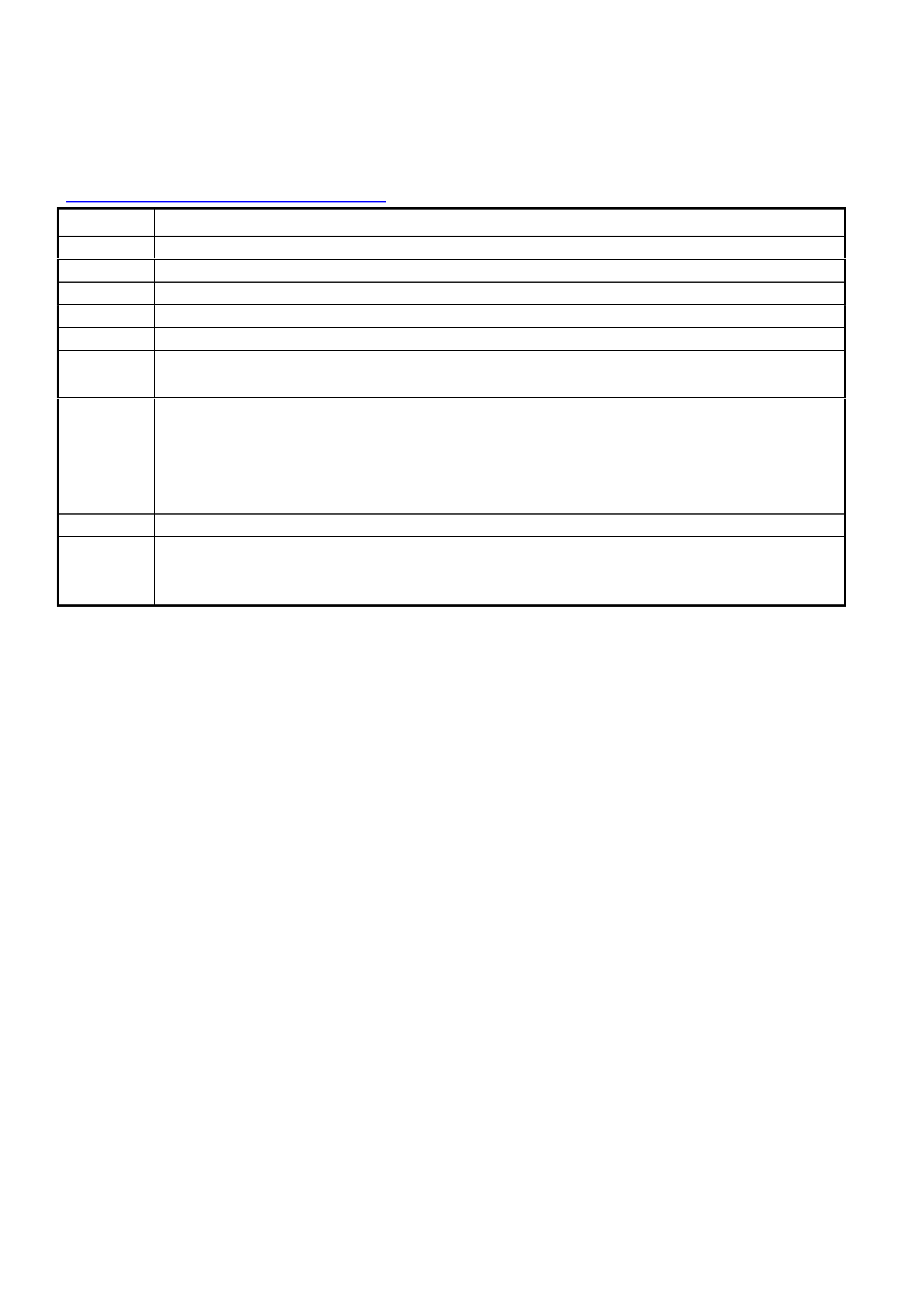
3.4 AIR CONDITIONING PERFORMANCE TEST
NOTE: The following performance test is designed to put the air conditioning system under an increased load. If an
air conditioning system can perform to the manufacturers specifications under these loads, in normal driving
situations, engine hood down, windows closed and possibly a lower blow er speed, the centre vent temperatures will
be lower.
If the air conditioning system performs outside the specified range, as detailed in Fig. 2C-7and 2C-8 refer, to
3.3 AIR CONDITIONING DIAGNOSIS CHART.
STEP No. ACTION
1Park vehicle in a shaded area.
2Measure and record the ambient temperature.
3Open both front windows and engine hood.
4Connect both high and low pressure service hose coupling valves to the system filling ports.
5Open all dash louvres and adjust to the straight ahead position.
6Insert thermometer probe approximately 50mm into the centre vent louvre.
NOTE: Ensure both sides of the centre vent are checked to ensure temperature performance is correct.
7Set air conditioning controls to:
a. Fresh air position
b. Face vent mode
c. Maximum cooling (ECC system select C maximum cooling)
d. A/C on
e. Highest blower speed
8Start engine and bring engine speed to 1700rpm. Allow pressure gauge needles to stabilise.
9Take pressure and centre vent temperature readings. Compare recorded values of vehicle against
performance charts in Figures 2C-7 and 2C-8.
NOTE: Only take pressure and temperature readings when the compressor is engaged.
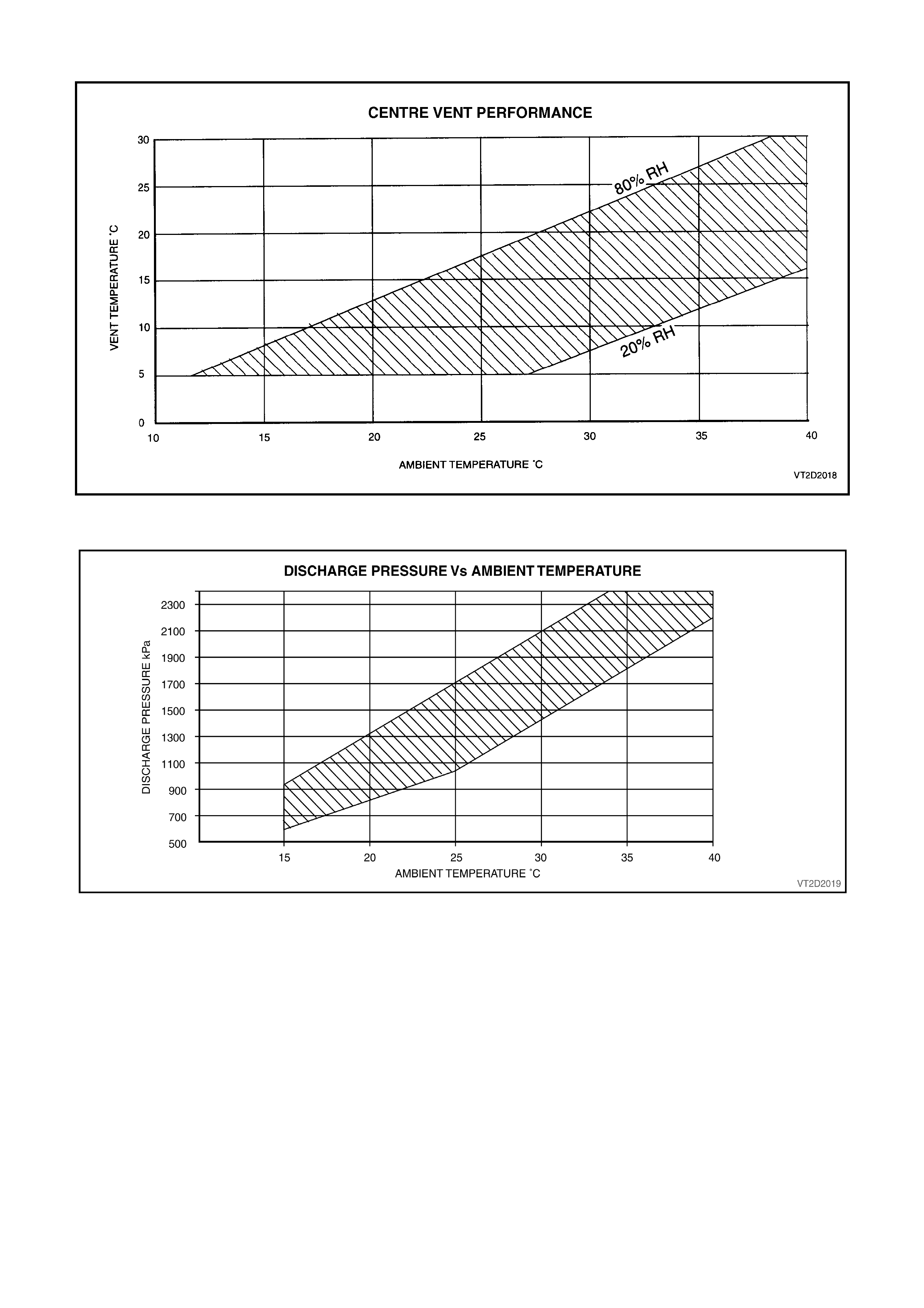
Figure 2C-7 Performance Chart A
Figure 2C-8 Performance Chart B