
SECTION 12B - LIGHTING SYSTEM
IMPORTANT
Before performing any Service Operation or other procedure described in this Section, refer to
Section 00 CAUTIONS AND NOTES for correct workshop practices with regard to safety and/or
property damage.
1. GENERAL DESCRI PTI O N
The front lamp assemblies on WH Series models comprise a semi-sealed headlamp and a turn signal lamp and a
parking lamp.
The parking lamp is incorporated in the headlamp assembly and the turn signal assembly is next to the headlamp
assembly.
The headlamp features a dual pocket reflector, quartz halogen bulbs and a parking lamp bulb. The reflector is of
homofocal design, with both inner and outer pockets used for high beam.
The turn signal lamp has a clear appearance lens. The illumination bulb has a orange coloured glass and has offset
locating pins on its base.
Fitted into each front fender, is a turn signal side repeater lamp assembly.
Fog / Cornering lamp assemblies are fitted to the front bumper bar assembly as standard equipment.
The fog lamps are controlled by a switch assembly located in the instrument facia, below the headlamp switch.
The fog lamps operate when the headlamps are switched on and the fog lamp switch button depressed. If the
headlamps are operating on high beam, switching on the fog lamps turns the headlamp low beam off. If the
headlamps are on low beam, they remain on when the fog lamps are switched on.
The cornering lamps operate individually and are operated by the indicator switch and only when either the
headlamps or the park lamps are turned on.
All WH vehicles have a rear quarter lamp housing with stop/tail and turn signal bulbs. The turn signal bulb glass is
coloured orange and has offset locating pins. The orange coloured bulb glass provides the amber light behind the
clear lens of the lamp. Also, different rear quarter lamp harnesses with specific bulb sockets are used for each type
of bulb locating pin style.
The rear compartment lid is provided with separate lamps including; back-up lamp bulb and an additional tail lamp
bulb and rear licence plate lamps. The licence plate lamps are located in the rear compartment lid decor panel,
above the licence plate.
All vehicles are fitted with hazard warning flashers, which are operated by a switch in the instrument facia, located
below the air outlets.
All vehicles are fitted with courtesy lamps in the passenger compartment (dome lamp), ignition lock and glove
compartment. Additional interior lighting is provided by courtesy lamps in door trims, front and rear footwells, rear
compartment, front reading lamp assemblies, rear reading lamps and console bin lamp.
Operation of the parking/tail and headlamps is controlled by a headlamp switch located in the instrument facia, to
the right of the steering wheel. Headlamp high beam or headlamp flash control is by the headlamp and turn signal
control switch stalk to the right of the steering column.
Various relays, located in the engine compartment relay housing and passenger compartment fuse panel, are used
for headlamp, hazard warning, turn signals and fog lamp control.
Turn signal control is by the headlamp and turn signal control switch stalk to the right of the steering column.
Stop lamps operation is controlled by a stop lamp switch fitted into a tubular clip in the brake pedal support.
Back-up lamp operation is controlled by the neutral start/back-up lamp switch which is attached to the side of the
gearshift assembly on the automatic transmission, beneath the console cap.
The WH Series models are fitted with a High Series Body Control Module (BCM). The BCM provides additional
lighting system enhancements. These features are:
1. Automatic Lights Off.
This system deactivates the head and parking/tail lamps when the ignition has been switched from on to off and the
driver’s door is opened. The lamps switch back on when the ignition is switched on, if the headlamps switch is still
turned on. An adjustable time delay can be applied before the headlamps are automatically switched off.
Techline
Techline

2. Dome Lamp Delay.
Additional control of the dome lamp operation by the BCM allows for 30 second delay period to turn the dome lamp
off after all doors are closed. Should the dome lamp be left on by the dome lamp switch, and with ignition off, the
BCM will turn off the dome lamp after a maximum period of two hours to prevent battery drain.
3. Instrument Dimming Control.
Incorporated in the headlamp switch assembly is a control for variable instrument cluster illumination intensity.
4. Rear Lamp Failure Warning.
This system checks for bulb or fuse failure associated with the stop or tail lamps including the high level stop lamp.
For additional information on these systems, including diagnostics, refer Section 12J - BODY CONTROL
MODULES of this Service Information CD.
2. SERVICE OPERATIONS
2.1 AIMING OF HEADLAMPS AND FOG LAMPS
The headlamps and fog lamps must be correctly
aimed in order to obtain the maximum road
illumination and safety that has been built into the
vehicle lighting system. The headlamps and fog
lamp s m us t be chec ked for co rr ec t aim whenever a
bulb or headlamp/fog lamp assembly is replaced,
and after any adjustments or repairs to the front
end sheet metal.
Headlamp aiming machines are in general use.
When using one of these machines, ensure that it
is in good condition and carefully follow the
instructions of the manufacturer.
Regardless of the method used for checking
headlamp and fog lam p aim, the vehic le must be at
kerb weight, that is, with fuel, oil, water and spare
tyre but no passengers. The tyres must be
uniformly inflated to their specified pressure.
NOTE: If the vehic le will regular ly carr y an unus ual
load in the rear com partm ent or tow a trailer, these
loads should be on the vehicle when the
headlamps/fog lamps are checked.
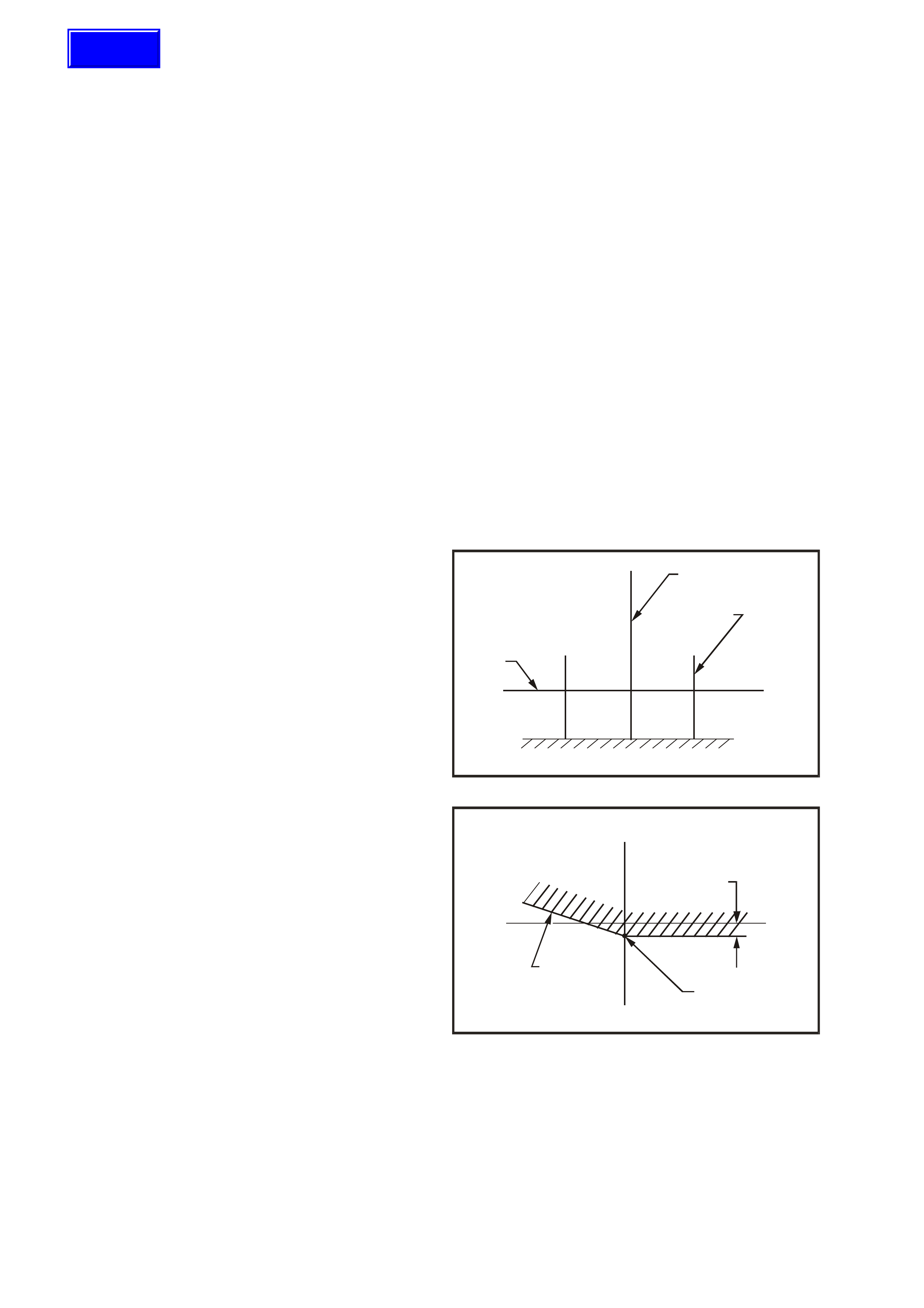
HEADLAMP AIM
1. If suitable test equipment is not available, set
up a screen or use vertical wall, in conjunction
with a flat horizontal floor. Park vehicle
immediately in front of screen and mark
horizontal (1) and ver tical centre lines of left ( 2)
and right (4) headlamps, and vehicle centre line
(3) on the screen or wall.
2. Park vehicle 10 metres in front of screen or
wall ensuring the vehicle is aligned with vehicle
centre line mark on screen.
WH12B001
V
H
H
V2
3
4
1
Figure 12B-1
3. Individually aim each headlamp to a point (1)
on its vertical centre line, 110 mm below the
headlamp horizontal centre line. Item 2 is the
cut-off line.
WH12B002
V
HH
V
110 mm
2
1
Figure 12B-2
Techline
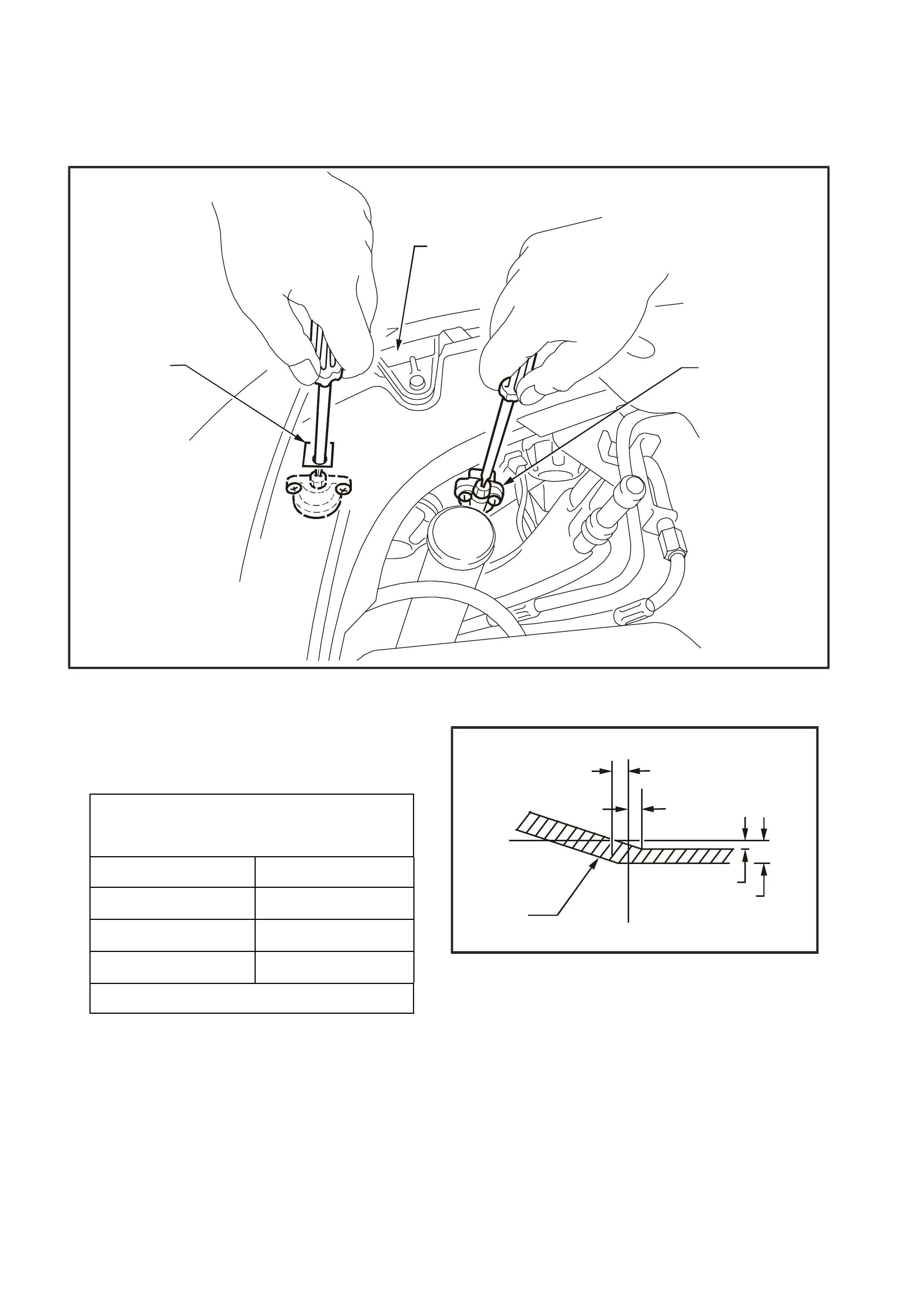
a. Adjust inboard adjuster (1) to achieve
correct vertical beam height.
b. Adjust outboard adjuster (2) to centralise
beam.
Aiming directions (3) for each adjuster are
visible on the headlamp assembly.
WH12B003
3
21
Figure 12B-3
HEADLAMPS AIMING.
ACCEPTABLE VARIATIONS IN
HEADLAMP AIMING POINTS
HL 100 mm
HR 0 mm
V1 100 mm
V2 120 mm
Maximum allowable vertical variation between
any pair of headlamps is not to exceed 20 mm.
4. The allowable variations on headlamp aiming
point settings shown in Fig. 12B-4 are specif ied
as follows:
NOTE: Cut-off line must be within zone (1).
WH12B004
V
H
H
V
1V2
V1
HL
HR
Figure 12B-4
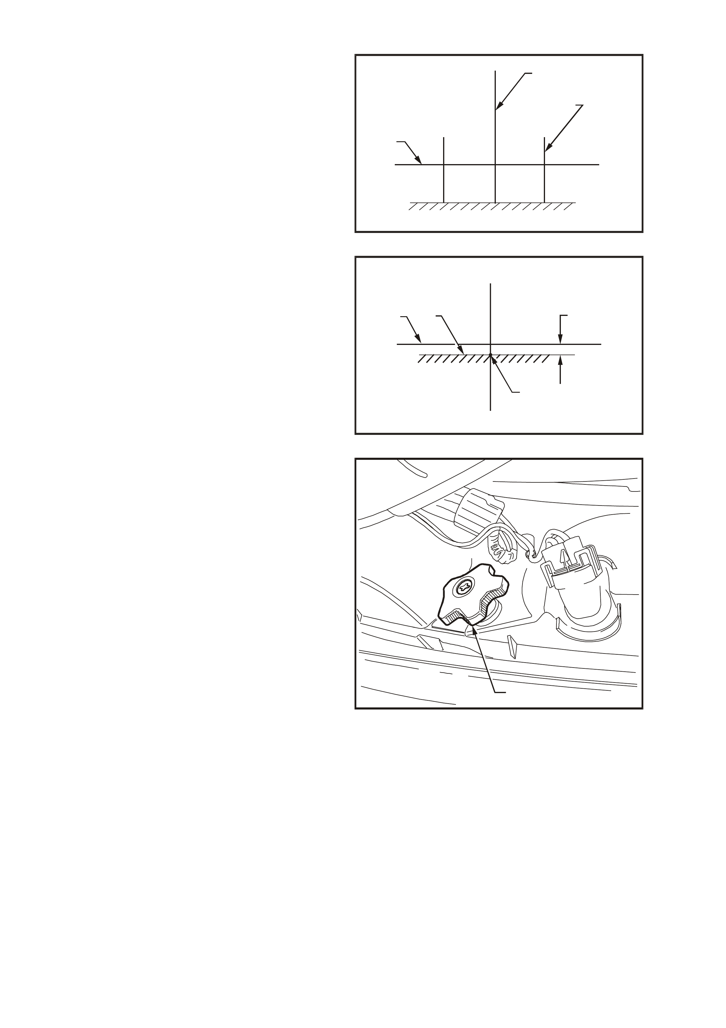
FOG LAMP AIM
1. If suitable headlamp aiming check equipment is
not available, set up a screen or use a vertical
wall, in conjunction with a flat horizontal floor.
Park vehicle im mediately in front of screen and
mark horizontal (1) and vertical centre lines of
left (2) and right (4) headlamps, and vehicle
centre line (3) on the screen.
2. Park vehicle 10 metres in front of screen,
ensuring the vehicle is aligned with centre line
mark on screen.
WH12B001
V
H
H
V2
3
4
1
Figure 12B-5
3. Check headlamp aim and adjust as required,
refer previous instructions.
4. With headlamps turned on low beam, turn fog
lamps on. Individually aim each fog lamp to a
point symmetrical about V axis (2) with cut-off
line (3) 200 mm below headlamp horizontal
centre line (1).
WH12B005
200 mm
2
3
1
V
HH
V
Figure 12B-6
NOTE: There is no provision for horizontal
adjustment. Fog lamps are fixed to vertical
centreline.
Fog lamp aim adjustment is made by rotating
adjuster knob (1) on the back of the lamp
housing. Turning the adjuster anti-clockwise
lowers the beam, turning the adjus ter c loc k wise
raises the beam.
WH12B006
1
Figure 12B-7
2.2 HEADLAMP BULB
REPLACE
1. Open engine compartment.
Driver’s side headlamp only
V6 engine models:
Disconnect battery terminals, remove battery
retaining clamp and manoeuvre battery to gain
access to headlamp dust cap.
GEN III V8 engine models:
Disconnect battery terminals, remove battery
retaining clamp and remove battery from
engine compartment.
Passenger’s side headlamp only
GEN III V8 engine models:
Remove four scrivets securing upper radiator
support cover and remove cover.
Remove air inlet snorkel from air cleaner
housing by pulling snorkel straight out from air
cleaner housing.
Driver’s side and passenger’s side
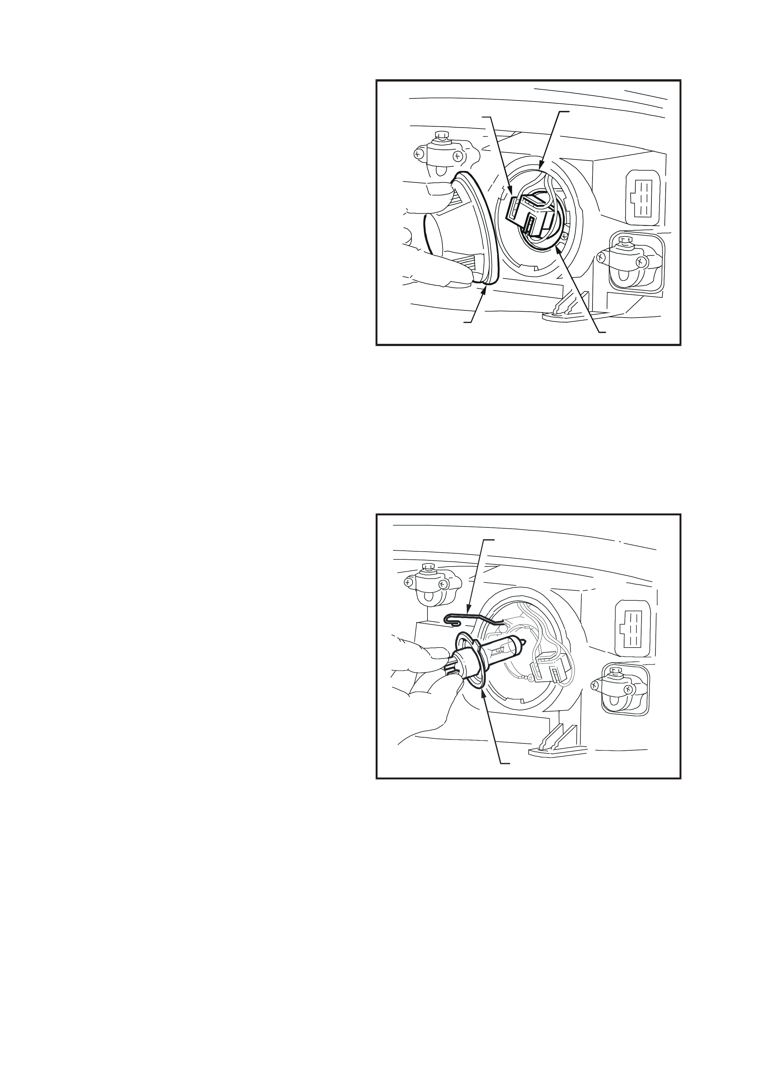
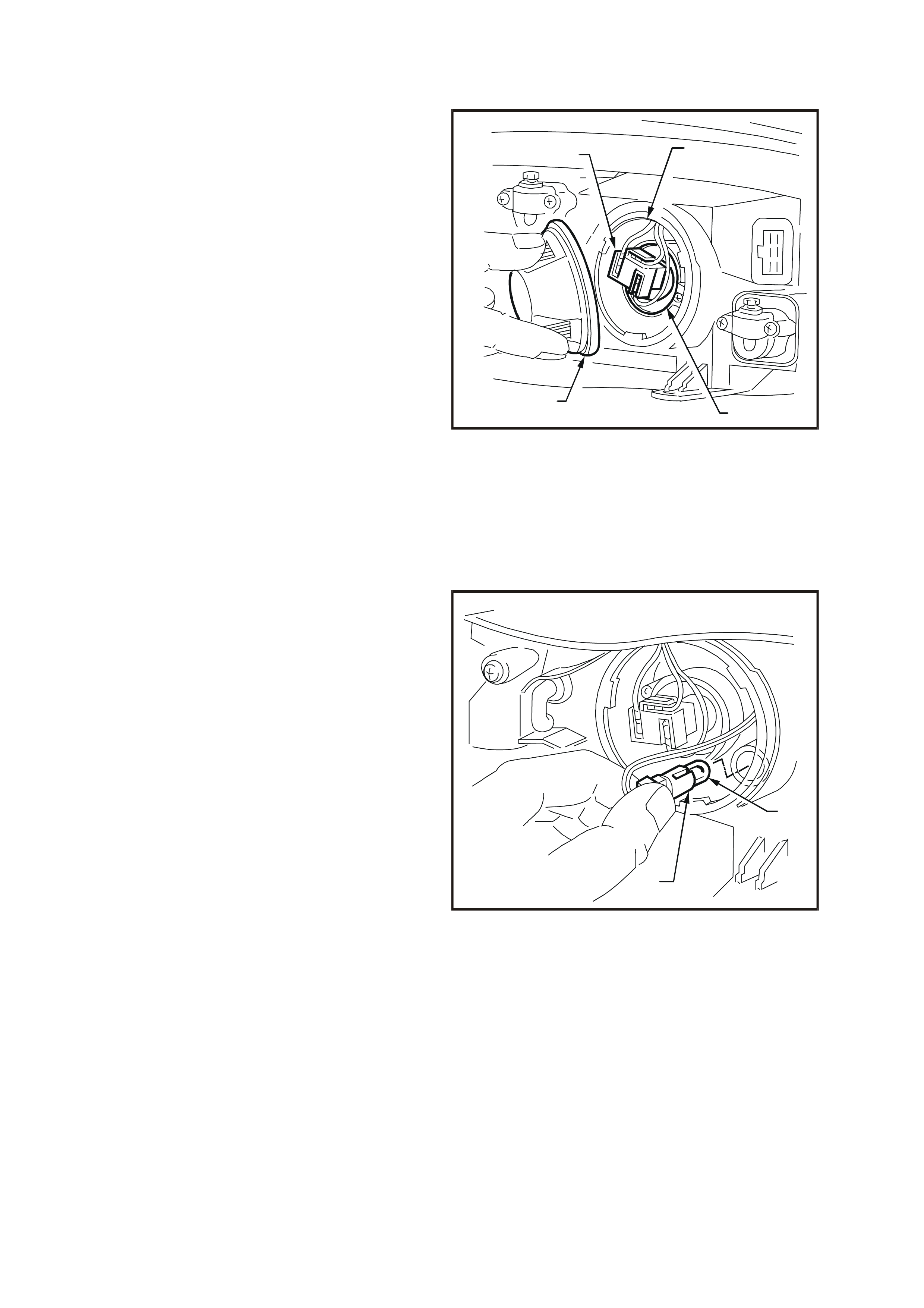
2. From inside engine compartm ent, remove dust
cap (1) from rear of headlam p assembly (2) by
turning dust cap anti-clockwise and pulling
away from headlamp assembly. If dust cap seal
stays on headlamp ass embly, rem ove seal and
install onto cap.
3. Carefully pull wiring harness connec tor (3) f rom
rear of bulb (4).
32
14
WH12B007
Figure 12B-8
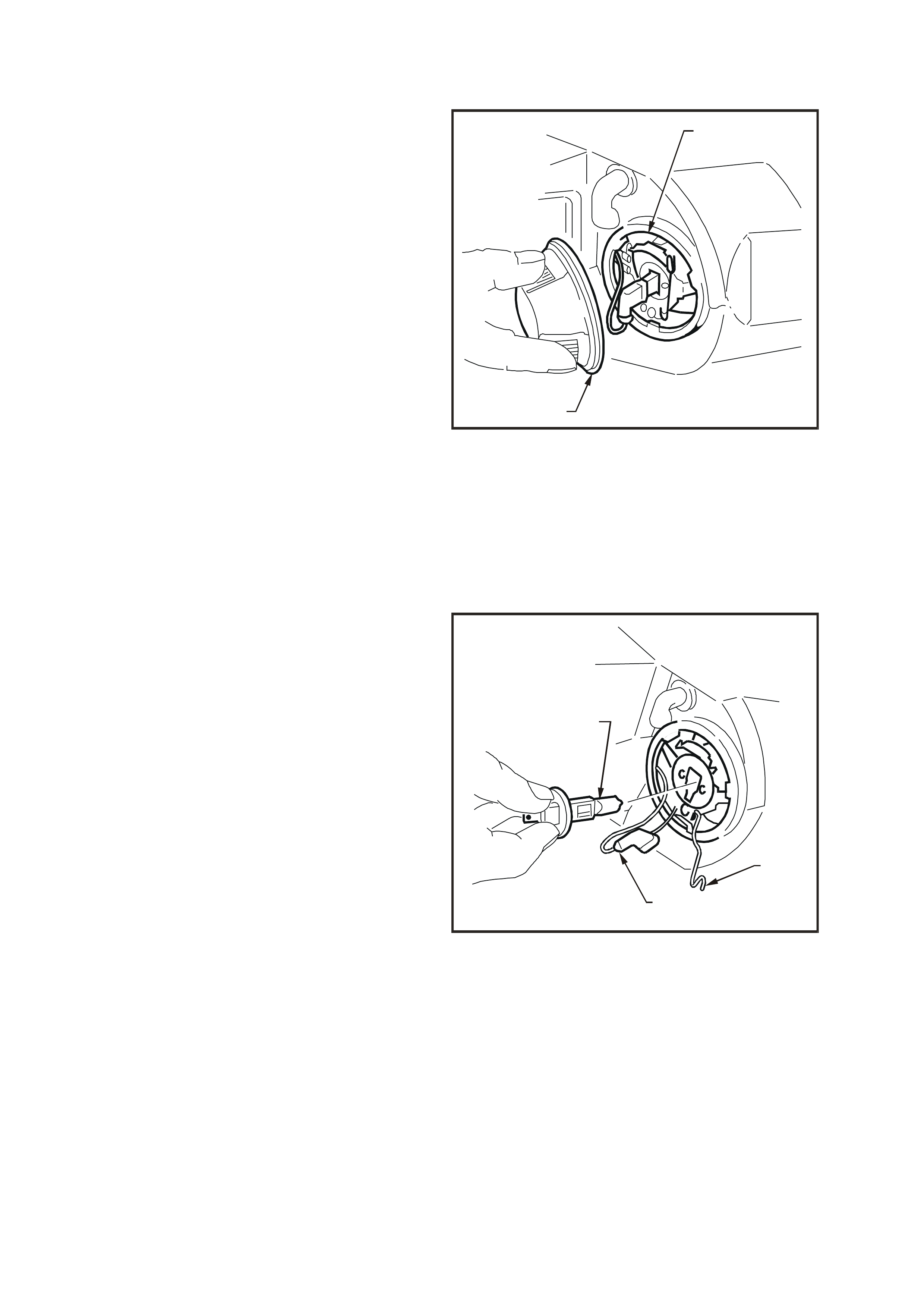
4. Depress and unclip bulb s pring retainer (1) and
pivot clear of bulb. Remove bulb (2) from
reflector.
NOTE: Do not handle quartz envelope of headlamp
bulb. If touched accidentally, wipe im mediately with
methylated spirits or bulb performance will
deteriorate.
5. Install new bulb (2) into reflector, ensuring
correct mating of bulb base locating tangs with
reflector cut-outs. Install s pring retainer (1) and
wiring harness connector.
NOTE: The different sized locating tangs on the
bulb base and mating cut-outs in the reflector will
allow the bulb to seat correctly into the reflector in
one location only. This ensures correct relationship
of the bulb to the reflector.
6. Inspect rubber seal in dust cap to ensur e that it
is not damaged and that it is seated cor rect ly in
cap. Replace seal if damaged.
7. Install cap to rear of headlamp housing with
cap tang located facing down. Lock cap into
place by turning clockwise.
WH12B008
1
2
Figure 12B-9

Driver’s side only
Install battery if removed, secure battery retaining
clamp and reconnect battery terminals.
Driver’s side and passenger’s side
8. Check headlamp operation and aim headlamps
(headlamp aim varies from bulb to bulb), refer to
2.1 AIMING OF HEADLAMPS AND FOG LAM PS
in this Section.
Passenger’s side (with GEN III V8 engine) only
Install air inlet snorkel into air cleaner housing by
aligning snorkel with air cleaner housing and
pushing firmly into place.
Position upper radiator support cover and install
four scrivets to secure cover.
2.3 PARKING LAMP BULB
REPLACE
1. Open engine compartment hood.
Driver’s side headlamp only
V6 engine models:
Disconnect battery terminals, remove battery
retaining clamp and manoeuvre battery to gain
access to headlamp dust cap.
GEN III V8 engine models:
Disconnect battery terminals, remove battery
retaining clamp and remove battery from
engine compartment.
Passenger’s side headlamp only
GEN III V8 engine models:
Remove four scrivets securing upper radiator
support cover and remove cover.
Remove air inlet snorkel from air cleaner
housing by pulling snorkel straight out from air
cleaner housing.
Driver’s side and passenger’s side
2. From inside engine compartm ent, remove dust
cap (1) from rear of headlam p assembly (2) by
turning dust cap anti-clockwise and pulling
away from headlamp assembly. If dust cap seal
stays on headlamp ass embly, rem ove seal and
install onto cap.
32
14
WH12B007
Figure 12B-10
3. Remove parking lamp socket (1) from
reflector (2). Alternatively, use pointed nose
pliers to pull out parking lamp socket if access
is difficult. Pull bulb (3) from socket.
4. Insert new bulb into socket and install socket
into reflector.
5. Inspect rubber seal in dust cap to ensur e that it
is not damaged and that it is seated cor rect ly in
cap.
Install cap to rear of headlamp housing and
lock cap into place by turning clockwise.
Driver’s side only
Install battery if removed, secure battery
retaining clamp and reconnect battery
terminals.
Driver’s side and passenger’s side
6. Check parking lamp operation.
Passenger’s side (with GEN III V8 engine) only
Install air inlet snorkel into air cleaner housing
by aligning snork el with air cleaner housing and
pushing firmly into place.
Position upper radiator support cover and
install four scrivets to secure cover.
WH12B009
1
2
Figure 12B-11
2.4 INBOARD HIGH BEAM BULB
REPLACE
1. Open engine compartment.
Driver’s side headlamp only
V6 engine models:
Disconnect battery terminals, remove battery
retaining clamp and manoeuvre battery to gain
access to headlamp dust cap.
GEN III V8 engine models:
Disconnect battery terminals, remove battery
retaining clamp and remove battery from
engine compartment.
Passenger’s side headlamp only
GEN III V8 engine models:
Remove four scrivets securing upper radiator
support cover and remove cover.
Remove air inlet snorkel from air cleaner
housing by pulling snorkel straight out from air
cleaner housing.
Driver’s side and passenger’s side
2. From inside engine compartment, remove
inboard high beam dust cap (1) from rear of
headlamp assembly (2) by turning dust cap
anti-clock wise and pulling away f rom headlam p
assembly. If dust cap seal stays on headlamp
assembly, remove seal and install onto cap.
WH12B010
2
1
Figure 12B-12
3. Disconnect harness connector (1) from
bulb (2). Depress and unclip bulb retaining
clip (3) to release, and allow to fall clear of
bulb. Pull out bulb.
4. Install new bulb into reflector, ensuring that
locating lug on bulb housing aligns with square
edge on bulb and locating lugs on bulb mate
with holes on bulb housing. Reconnect bulb
retaining clip. Connect bulb harness connector.
NOTE: Do not handle quartz envelope of inboard
high beam bulb. If touched accidentally, wipe
immediately with methylated spirits or bulb
performance will deteriorate.
5. Inspect rubber seal in dust cap to ensur e that it
is not damaged and that it is seated correctly.
Install dust cap onto rear of headlamp housing
and lock into place by turning clockwise.
Driver’s side only
Install battery if removed, secure battery
retaining clamp and reconnect battery
terminals.
Driver’s side and passenger’s side
6. Test operation of inboard high beam lamp bulb.
Passenger’s side (with GEN III V8 engine) only
Install air inlet snorkel into air cleaner housing
by aligning snork el with air cleaner housing and
pushing firmly into place.
Position upper radiator support cover and
install four scrivets to secure cover.
WH12B011
2
1
3
Figure 12B-13
2.5 FRONT TURN SIGNAL LAMP BULB
REPLACE
NOTE: If replacing a front turn signal lamp bulb,
ensure the cor rect type is fitted. For all m odels, the
bulb glass is coloured orange and has offset
locating pins.
1. Open engine compartment.
Driver’s side headlamp only
V6 engine models:
Disconnect battery terminals, remove battery
retaining clamp and manoeuvre battery to gain
access to headlamp dust cap.
GEN III V8 engine models:
Disconnect battery terminals, remove battery
retaining clamp and remove battery from
engine compartment.
Passenger’s side headlamp only
GEN III V8 engine models:
Remove four scrivets securing upper radiator
support cover and remove cover.
Remove air inlet snorkel from air cleaner
housing by pulling snorkel straight out from air
cleaner housing.
Driver’s side and passenger’s side
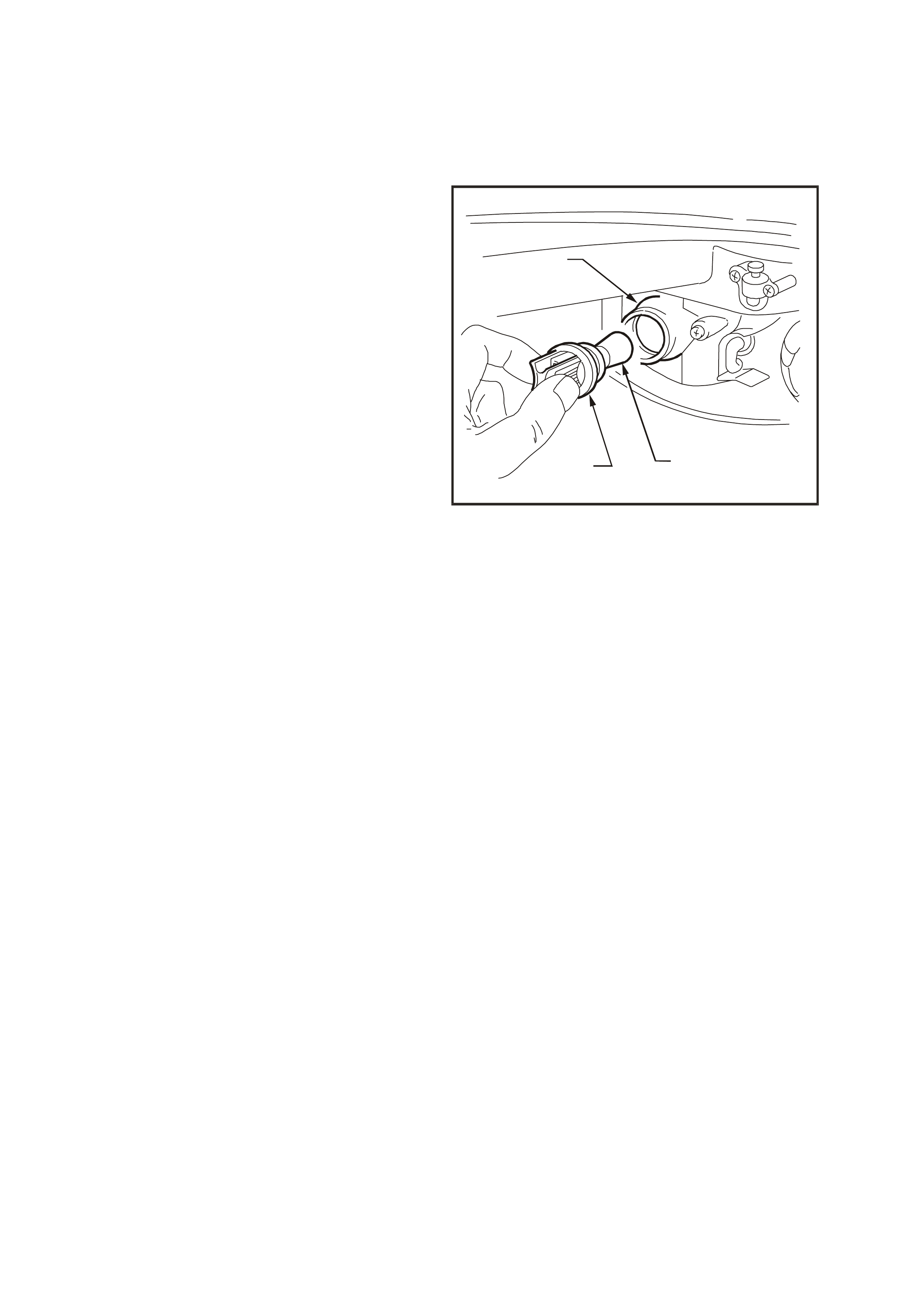
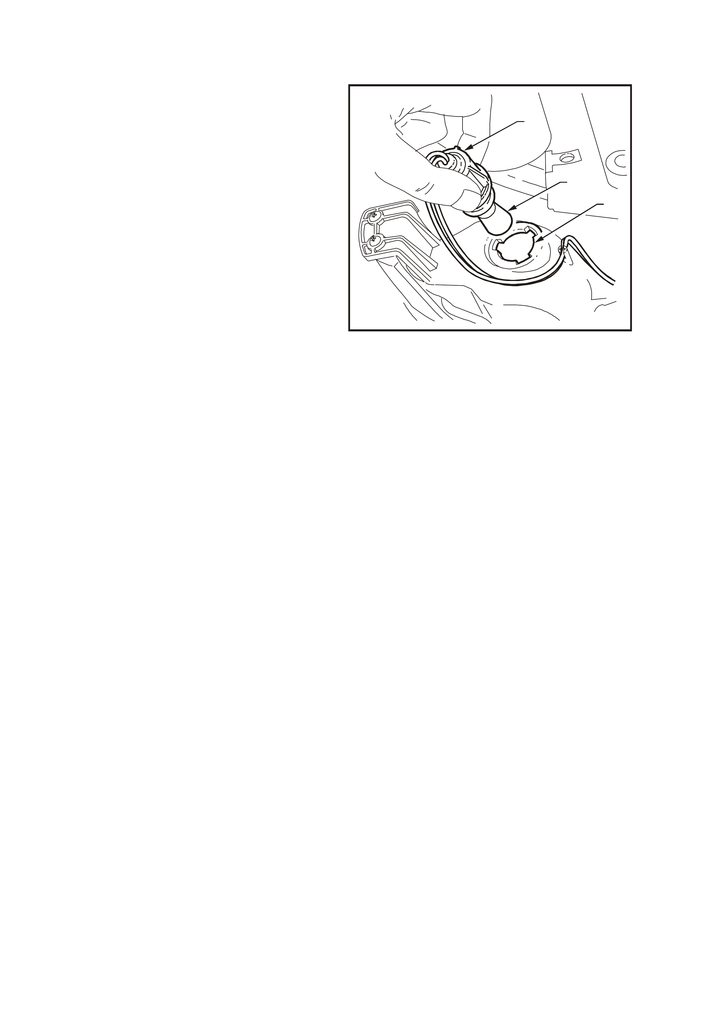
2. From inside engine compartment, twist to
release bulb socket (1) from behind headlamp
assembly (2).
3. Depress bulb (3) into socket (1) and rotate to
remove.
4. Inspect O-ring on bulb socket for damage and
correct seating. Replace O-ring if necessary.
5. Install new bulb into socket, install socket into
housing and twist to lock into position.
Driver’s side only
Install battery if removed, secure battery
retaining clamp and reconnect battery
terminals.
Driver’s side and passenger’s side
6. Check turn signal lamp operation.
Passenger’s side (with GEN III V8 engine) only
Install air inlet snorkel into air cleaner housing
by aligning snork el with air cleaner housing and
pushing firmly into place.
Position upper radiator support cover and
install four scrivets to secure cover.
WH12B012
1
2
3
Figure 12B-14

2.6 HEADLAMP AND TURN SIGNAL/PARKING LAMP ASSEMBLY
REMOVE
1. Open engine compartment.
Driver’s side headlamp only
V6 engine models:
Disconnect battery terminals, remove battery
retaining clamp and manoeuvre battery to gain
access to headlamp dust cap.
GEN III V8 engine models:
Disconnect battery terminals, remove battery
retaining clamp and remove battery from
engine compartment.
Passenger’s side headlamp only
GEN III V8 engine models:
Remove four scrivets securing upper radiator
support cover and remove cover.
Remove air inlet snorkel from air cleaner
housing by pulling snorkel straight out from air
cleaner housing.
Driver’s side and passenger’s side
2. From inside engine compartment, disconnect
wiring harness connector from headlamp
assembly. Remove turn signal lamp bulb
socket from headlamp assembly.
3. Remove two bumper f a cia r etaining sc r ivets ( 1)
from behind number plate.
4. Remove screws (2) securing bumper facia
sides to front fender inner liner at wheel arch
opening.
5. Remove two screws (3) securing bumper facia
to radiator support upper panel.
6. From behind front spoiler, disconnect main
wiring harness from harness connectors on
fog / cornering lamp assemblies (4).
7. With the facia supported, pull the facia side
members out, disconnect the facia side
supports, then slide the facia (5) forward
rem oving the facia assem bly, refer to Fig. 12B-
15
NOTE: When removing facia (5), support the upper
centre support facia (6), which is held in place by
bumper facia and will otherwise fall.
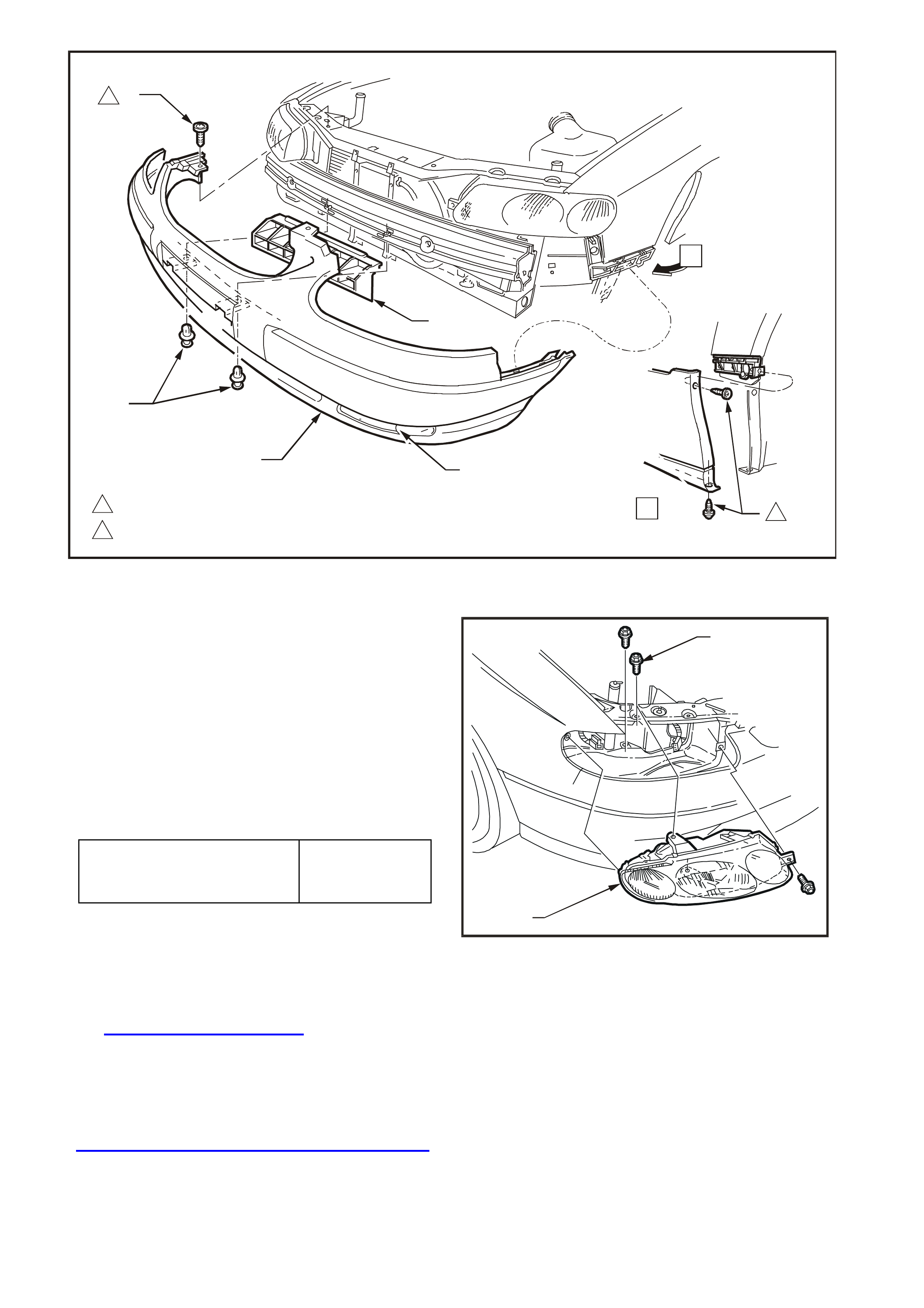
WH12B013
3
1
54
6
A
1
2.5 - 4.0 Nm
2
2
1.0 - 3.0 Nm
2
A
1
Figure 12B-15
HEADLAMP AND TURN
SIGNAL /PARKING LAMP
ASSEMBLY RETAINING SCREW
TORQUE SPECIFICATION 2 – 5 Nm
8. Remove three headlamp retaining screws (1)
and remove headlamp & turn signal / parking
lamp assembly (2).
REINSTALL
Installation of the headlamp & turn signal / parking
lamp assembly is the reverse of removal
procedure, noting the following points:
1. Install headlamp and turn signal / park ing lamp
assembly (2) and tighten retaining screws (1) to
the correct torque specification.
2. Install front bumper facia assembly by
snapping the facia onto the retainers at guide
rails, one side at a time.
3. Ensure correct fender, hood and headlamp
clearance, adjust facia if necessary, refer
Section 1D BUMPER BARS of the VT Ser ies I
Service Information.
4. Reconnect all wiring harness connectors and
check operation of headlamp and turn
signal/parking lamps and fog / cornering lamps.
Check headlamp (and fog lamps) aim, refer to
2.1 AIMING OF HEADLAMPS AND FOG LAMPS
in this Section.
WH12B014
2
1
Figure 12B-16
2.7 HEADLAMP ADJUSTER
REMOVE
1. Remove headlamp assembly refer to
2.6 HEADLAMP AND TURN
SIGNAL/PARKING LAMP ASSEMBLY in this
Section.
2. Remove two screws securing headlamp
adjuster to headlamp assembly and remove
adjuster.
3. Inspect adjuster and replace if worn or
damaged.
REINSTALL
Installation of the headlam p adjuster is the reverse
of removal procedure, noting the following point:
1. Align bevel gear to avoid tooth abutment with
mating gear prior to tightening securing screws.
WH12B015
1
2
Figure 12B-17
2.8 FOG LAMP BULB
REPLACE
1. From behind the front spoiler, twist to release
bulb socket (2) from fog / cornering lamp
assembly and remove bulb socket from lamp
assembly.
2. Pull bulb (1) from socket and inspect condition
of soc ket O- ring seal. Replace seal if dam aged
or deformed.
3. Insert new bulb into socket, then install bulb
socket into lamp assembly and twist to lock.
NOTE: Do not handle quartz envelope of fog lamp
bulb. If touched accidentally, wipe im mediately with
methylated spirits or bulb performance will
deteriorate.
WH12B016
21
Figure 12B-18
2.9 FOG / CORNERING LAMP ASSEMBLY
REMOVE
1. From behind front spoiler, disconnect main
wiring harness (1) from fog / cornering lamp
assembly harness connector.
2. Remove three Philips head s cr ews ( 2) s ec uring
the fog / cornering lamp assembly (3).
3. Pull cornering lamp end of as sembly away from
bumper bar, then slide fog lamp end of
assem bly out from behind lug in fog / cor nering
lamp aperture.
REINSTALL
Installation of the f og lamp as sembly is the r everse
of removal procedures, noting the following points:
1. Ins tall fog lam p assem bly to bum per bar beam ,
ensuring that locating screw in lamp mounting
frame is located in the mating hole in the
bumper bar beam.
2. Tighten lamp mounting frame to bumper bar
beam and facia screws to the correct torque
specification.
WH1D008
3
1
2
2
Figure 12B-19
FOG LAMP TO BUMPER BAR
FACIA RETAINING SCREW
TORQUE SPECIFICATION 2 – 5 Nm
3. Check fog lamp operation. Recheck fog lamp
aim, refer to 2.1 AIMING OF HEADLAMPS
AND FOG LAMPS in this Section.
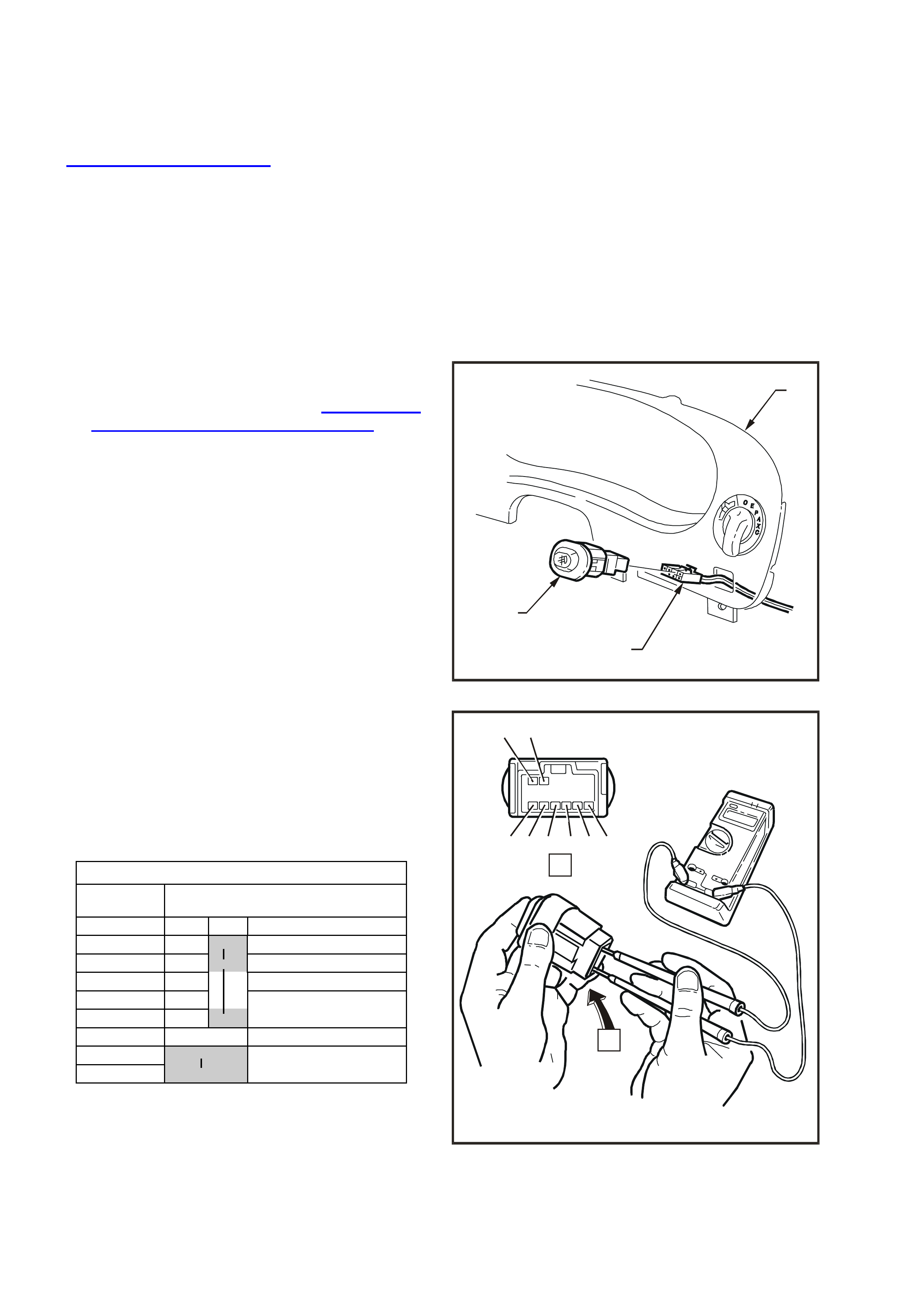
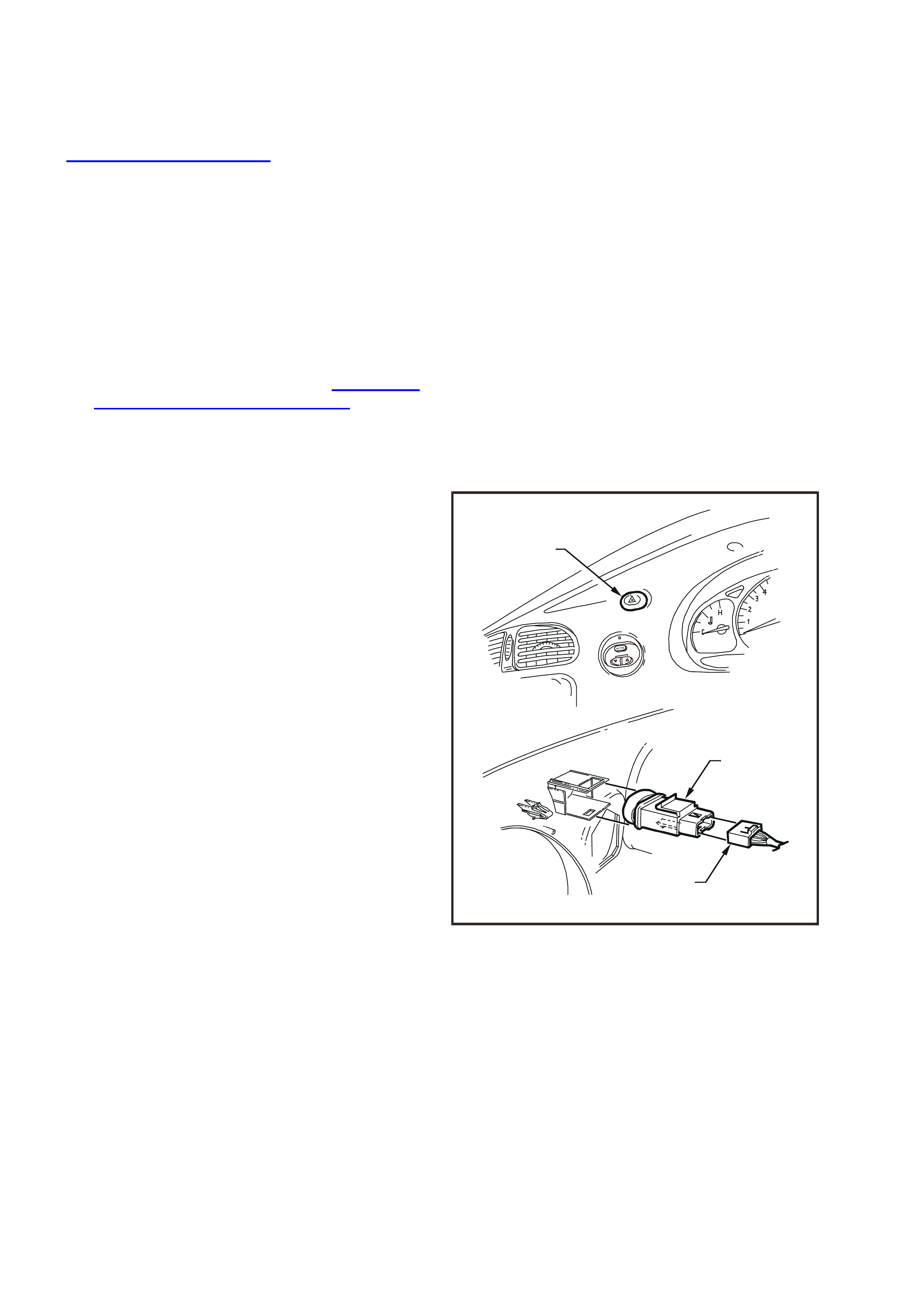
2.10 FOG LAMP SWITCH
REMOVE
1. Disconnect battery earth lead.
CAUTION: Disable the SRS (Air Bag). Refer to
DISABLING THE SRS, Section 12M
SUPPLEMENTAL RESTRAINT SYSTEM of the
VT Series I Service Information.
2. Release steering c olumn height adj usting lever
and completely lower steering column, lock
lever in this position.
Place a clean shop rag over and around
steering column upper cover. This step is
important so as to prevent any possibility of
damage to cover when removing the
instrument facia.
3. Remove instrument facia panel (1) in order to
gain access to rear of fog lamp switch (3). For
further information refer to Section 1A3
INSTRUMENT PANEL AND CONSOLE of the
VT Series I Service Information.
4. Depress retaining tang on instrument harness
to fog lam p switch connector ( 2), pull connector
from switch.
5. Squeeze together retaining tangs at side of
switch and push switch out from facia.
WH12B018
3
2
1
Figure 12B-20
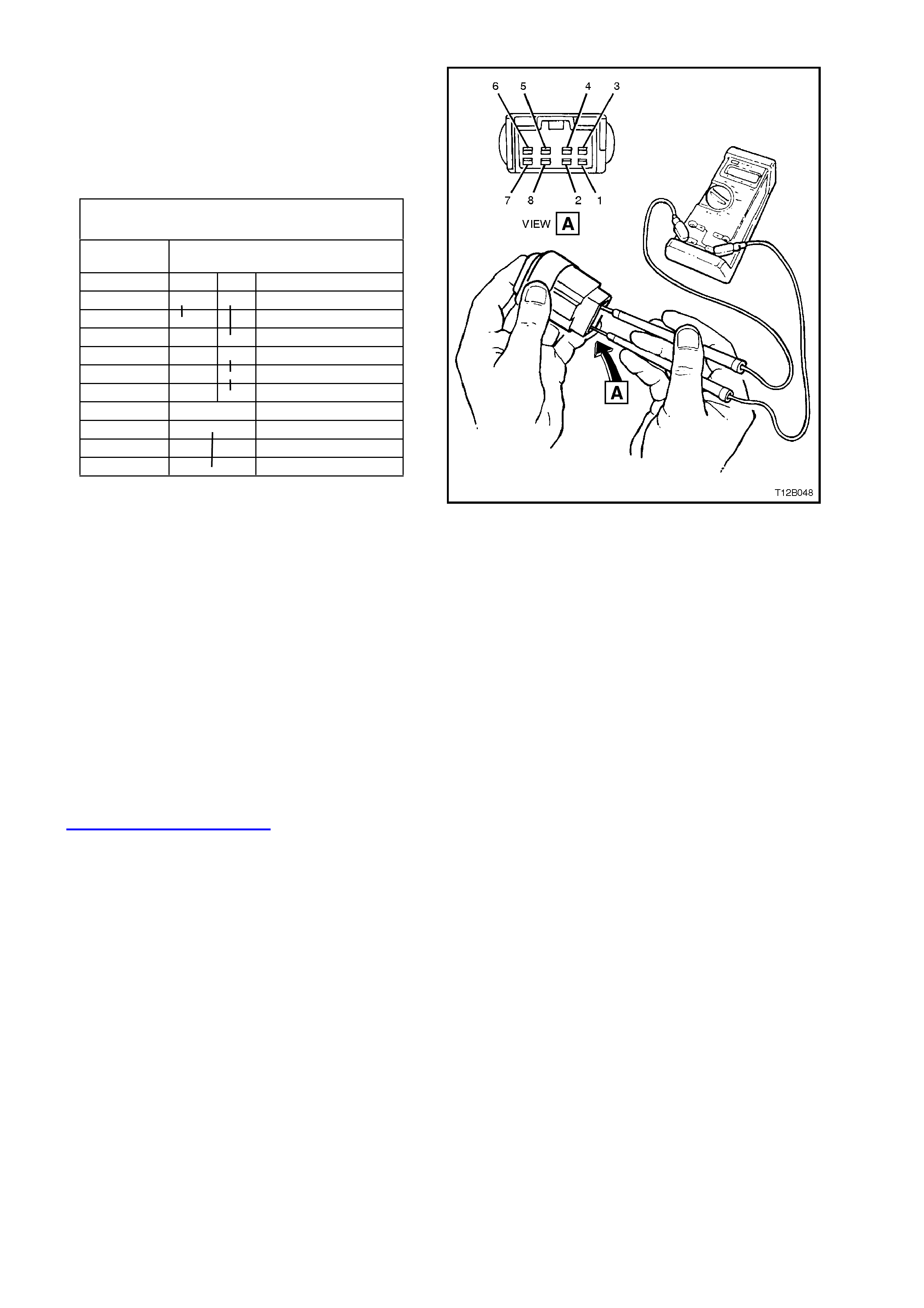
FOG LAMP SWITCH CONTACTS
TERMINAL
NO. SWITCH
STATUS
OFF ON
1 O
2 O
3
4 Switch On Indi cator
5 O
6
7 OIlluminat i on B ul b
8 O
TEST
With the aid of an ohmmeter, check continuity of fog
lamp switch contacts using the following chart.
If continuity is not as specified at any switch
position, replace switch assembly.
WH12B019
A
A
654 3 12
87
Figure 12B-21

REINSTALL
Installation of the fog lamp switch is the reverse of
removal procedures, noting the following points:
1. If, when instrum ent fac ia was pulled away fr om
instrument panel pad, the pad retaining clips
came away with the facia lugs, pull clips from
lugs and install into pad holes.
If fitted, ensure that steering column to
instrument facia screen lip is fitted correctly to
edge on instrument panel pad. Install
instrument facia and ensure that it is held to the
instrument panel pad securely.
2. Check fog lamp operation and ensure that
switch illumination bulb illuminates when the
headlamps are turned on.
IMPORTANT: Enable the SRS (Air Bag). Refer to
ENABLING THE SRS, Section 12M
SUPPLEMENTAL REST RAINT SYSTEM of the VT
Series I Service Information.
2.11 CORNERING LAMP BULB
REPLACE
1. From behind the front spoiler, twist to release
bulb socket (2) from fog / cornering lamp
assembly (3) and remove bulb socket from
lamp assembly.
2. Pull bulb (1) from socket and inspect condition
of sock et O-ring seal. Replace seal if dam aged
or deformed.
3. Insert new bulb into socket, then install bulb
socket into lamp assembly and twist to lock.
2
3
1
WH12B062
Figure 12B-22
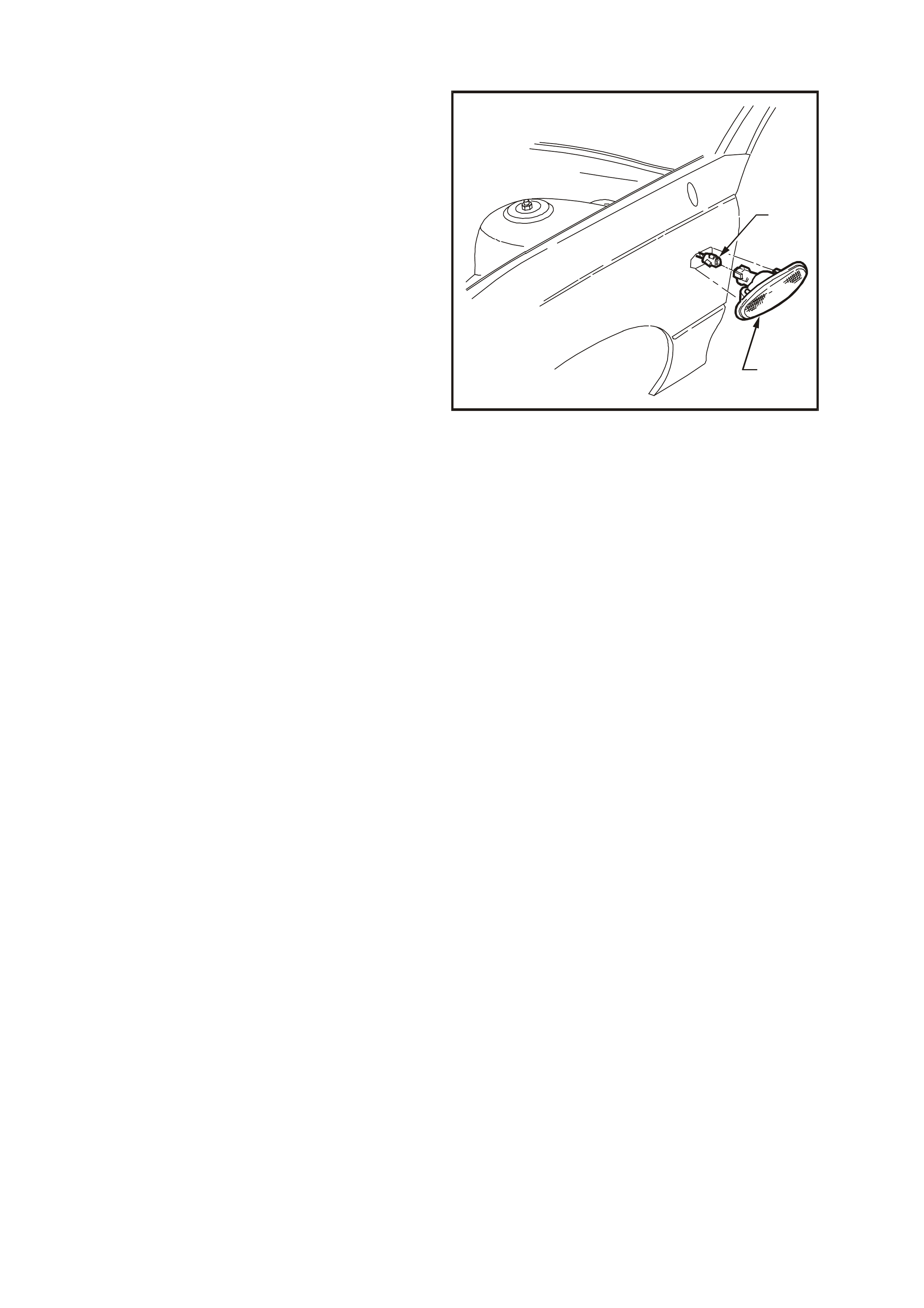
2.12 SIDE REPEATER LAMP
REMOVE
1. Grip rear edge of lamp housing (2) with finger
tips and pull housing forward and outwards
from fender panel. Once housing has released
from fender panel, remove housing and twist
bulb socket to release from housing.
2. If required, pull bulb from socket to replace.
3. Inspect lam p housing and bulb sock et seals f or
damage, replace if necessary.
REINSTALL
1. If necessary, install new bulb to socket.
2. Assem ble repeater lam p housing to s ock et and
twist socket to lock into housing.
3. Install lamp housing into fender opening with
housing locking nib facing forward and
engaging into opening.
4. Push rear of lamp hous ing into fender opening,
ensuring lamp housing is securely locked to
fender.
5. Check repeater lamp operation.
WH12B020
1
2
Figure 12B-23
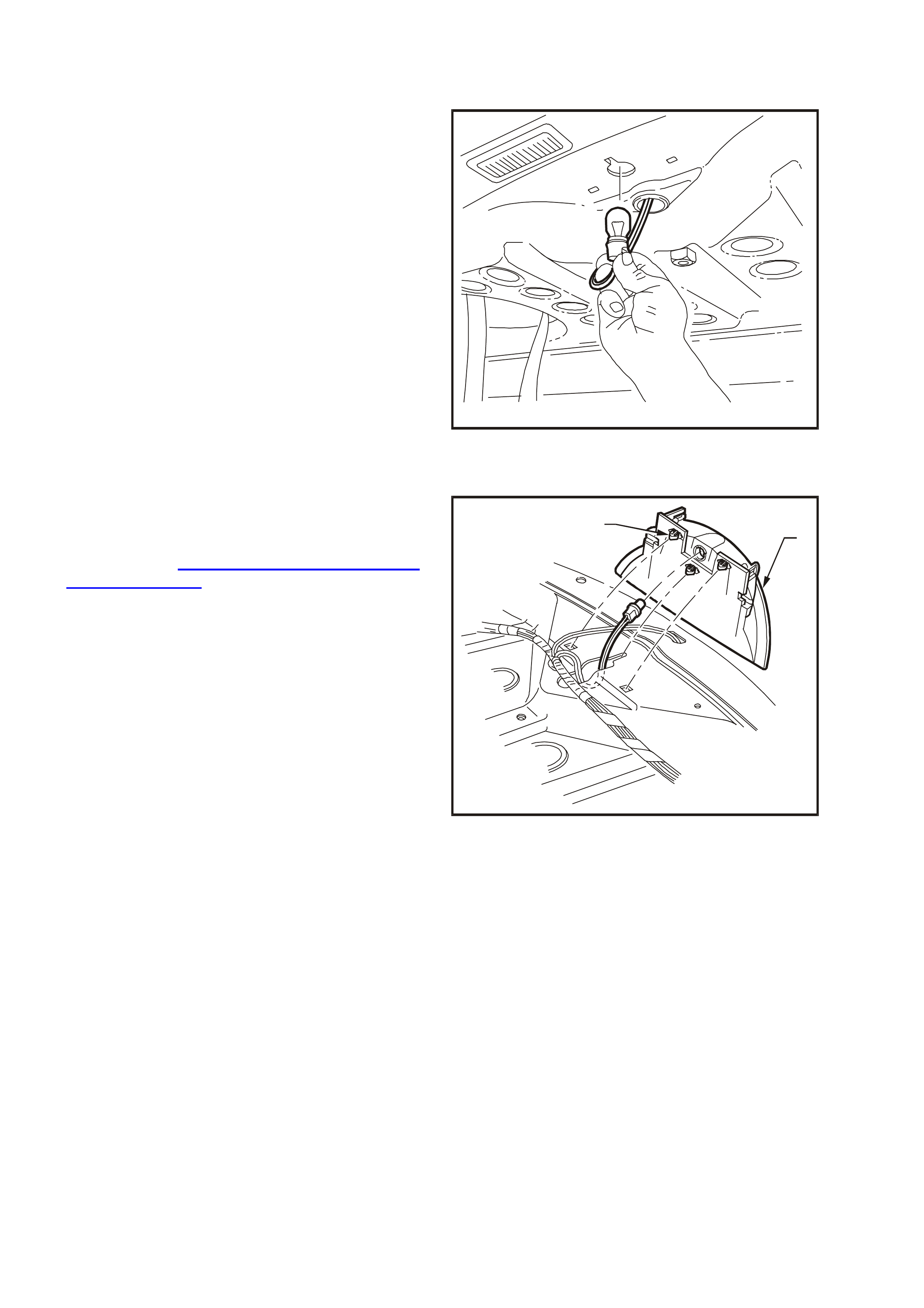
2.13 HIGH LEVEL STOP LAMP
BULB REPLACEMENT
Access to the bulb is thr ough the rear c ompartment
and up through the upper rear panel opening
beneath the stop lamp mounting.
1. Twist bulb socket to release from lamp. Pull
socket down into rear compartment and pull
bulb from socket.
NOTE: It may be necessary to use a pair of pointed
nose pliers to hold and release bulb socket.
2. Install new bulb into socket and install bulb
socket into housing.
WH12B021
Figure 12B-24
LAMP REPLACEMENT
Fig. 12B-25 illustrates the installation of the high
level stop lamp.
To remove lamp assembly (2), remove rear parcel
shelf, refer to Section 1A8 HEADLINING AND
REAR END TRIM of the VT Series I Service
Inform ation. Remove bulb and s ocket as described
previously. Disengage retaining clips (1) securing
high level stop lamp to upper back panel and
remove lamp assembly.
On installation of high mount stop lamp, ensure that
stop lamp housing is pushed fully rearward before
engaging retaining clips.
WH12B022
12
Figure 12B-25
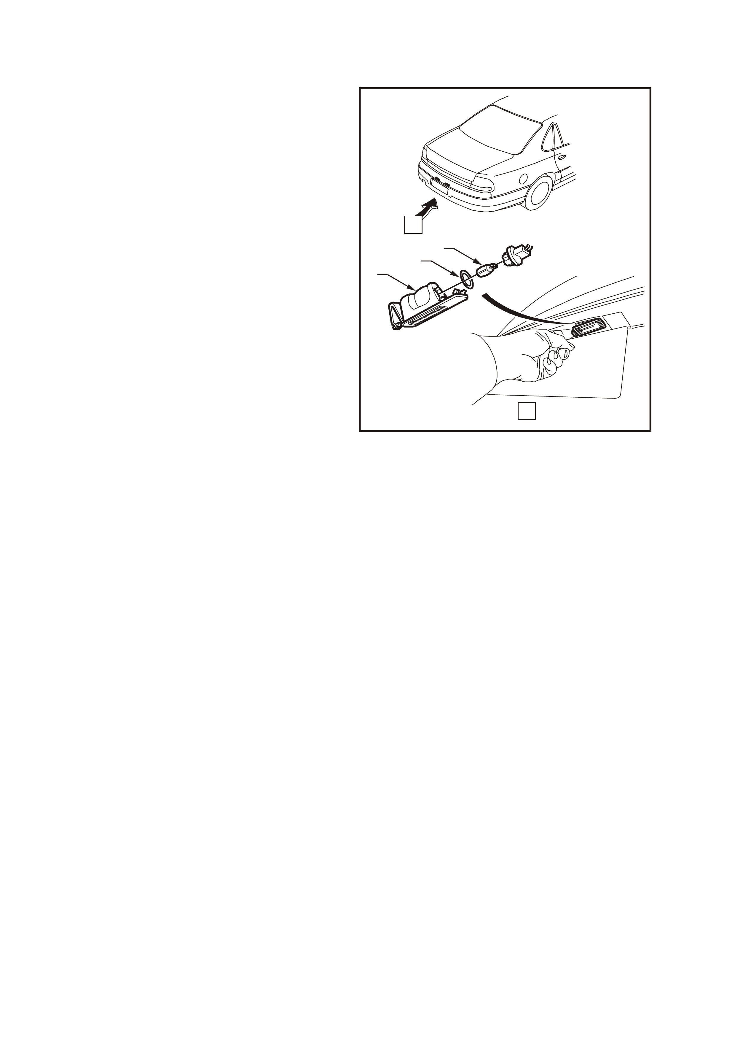
2.14 LICE NCE PLATE LAMP/BULB
REMOVE
1. Push locking tang located at end of lamp
assembly (1) towards lamp and pivot lamp
assembly down to remove from aperture.
2. Withdraw socket and bulb assembly from lamp.
3. Pull bulb (3) from socket.
4. Inspect bulb socket sealing ring (2), lamp lens,
lamp locking tang and lamp locating lugs for
damage, replace lamp if required.
REINSTALL
1. Push new bulb into bulb socket.
2. Check lamp operation.
3. Install lamp assembly, ensuring that locking
tang secures lamp assembly.
WH12B024
A
A
123
Figure 12B-26
2.15 REAR LAMP BULBS
STOP/TAIL AND TURN SIGNAL LAMP BULBS
REPLACE
1. Open rear compartment.
2. Remove rear lamp assembly (1) refer to
2.16 REAR LAMP ASSEMBLY in this Section.
3. Remove appropriate bulb socket (2) or (3) by
turning and removing socket.
4. Remove bulb (4) from socket by depressing
bulb into its socket and then rotate to remove.
Inspect bulb socket to lamp housing seals for
damage, replace if necessary.
5. Insert new bulb into socket and install socket
into lamp housing, ensuring socket locks
securely into place.
6. Check rear lamp operation.
WH12B025
2
1
4
3
Figure 12B-27
Techline
2.16 REAR LAMP ASSEMBLY
REAR QUARTER LAMP ASSEMBLY
REMOVE
1. Open rear compartment.
Remove rear quarter lamp assembly (1) to
body attaching screws (2).
2. Pull rear quarter lamp assembly (1) rearward
out from panel so that locating pegs on side of
lamp assembly snap free from retainers. W hile
supporting lamp housing, remove bulb sockets
by turning and removing socket.
1
2
WH12B023
A
A
Figure 12B-28
REINSTALL
1. Insert bulb sockets into rear quarter lamp
housing, ensuring sockets lock securely into
place.
2. Ensure that rear quarter lamp harness
grommet is seated correctly. Assemble lamp
housing to body, ensuring locating pegs snap
into retainers and install and tighten attaching
screws to the correct torque specification.
REAR QUARTER LAMP
HOUSING TO BODY
ATTACHING SCREW
TORQUE SPECIFICATION
3 – 4 Nm
3. Check rear lamp operation.
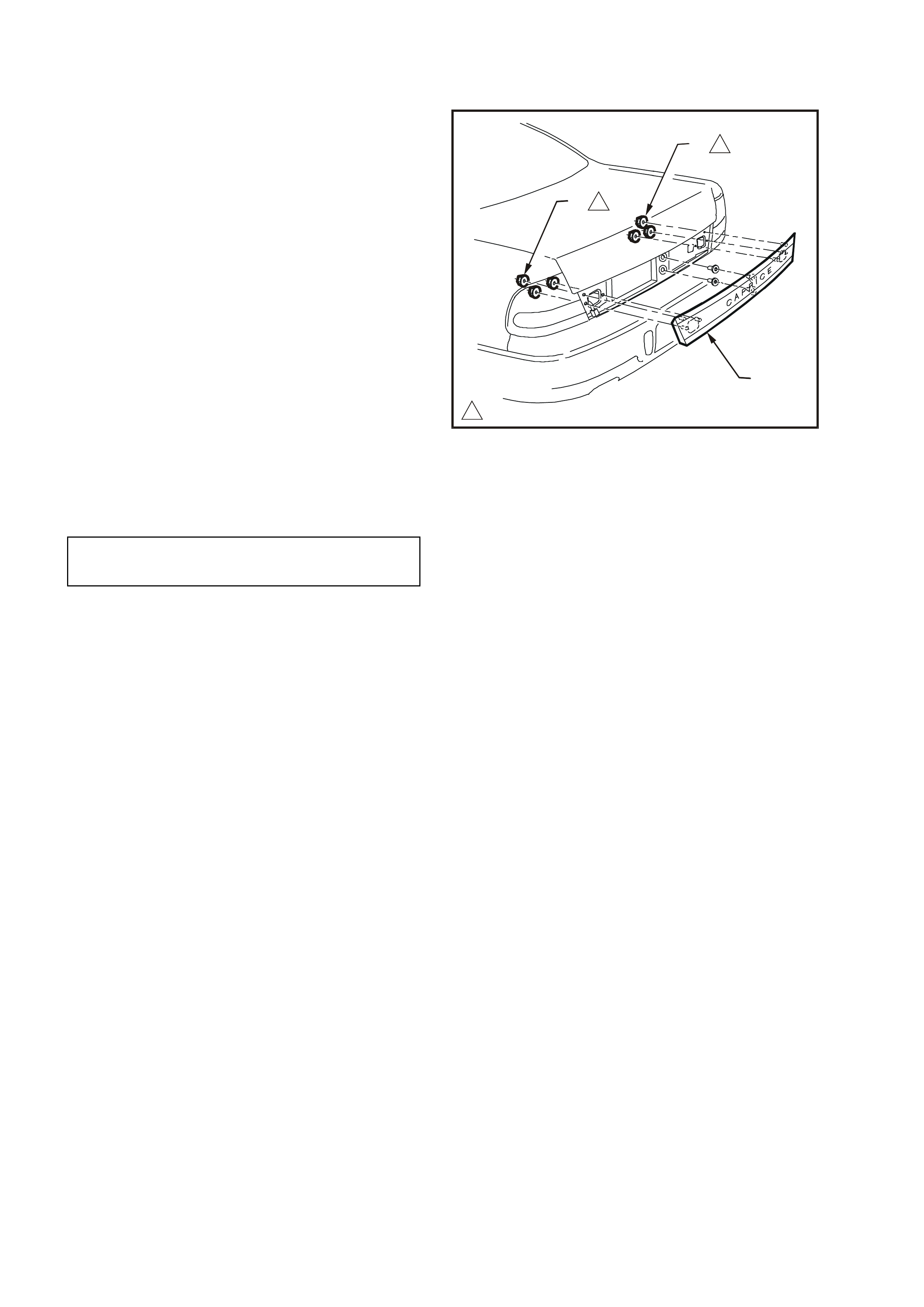
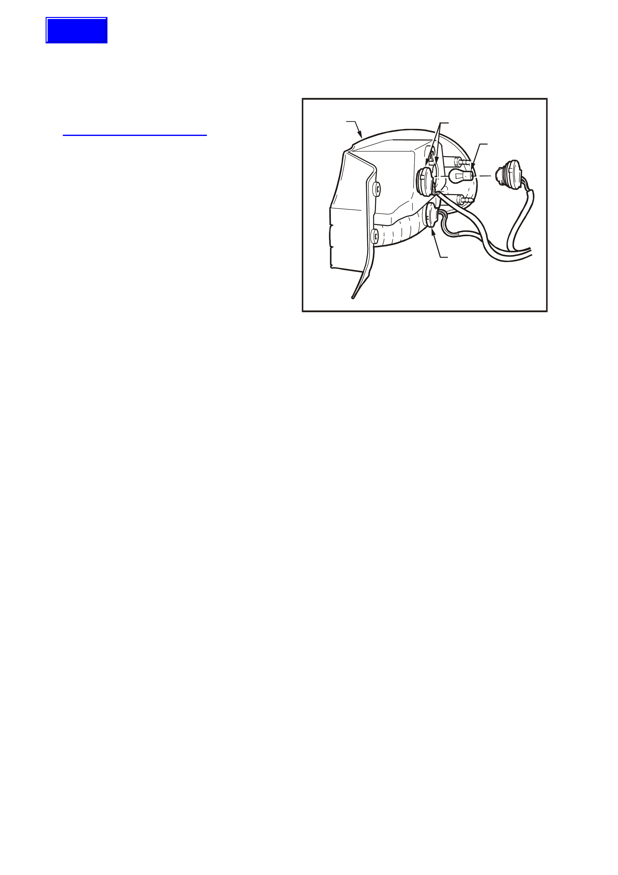
2.17 REAR COMPARTMENT LID LAMP ASSEMBLY
REMOVE
3. Reconnect wiring harness connec tor and install
reverse lamp bulb and socket assemblies.
4. Check rear lamp operation.
1. Open rear compartment lid.
2. From inside rear compartment lid, remove
cover trim and remove reverse lamp socket
and bulb assemblies by turning and pulling
sockets from compartment lid lamp assembly
(2).
3. Remove lamp assembly to rear compartment
lid attaching nuts (1).
NOTE: Carefully pull lamp assembly away from
compartment lid ensuring that studs, positioned
centrally in lamp assembly, do not bind in nutserts
which could damage the lamp assembly.
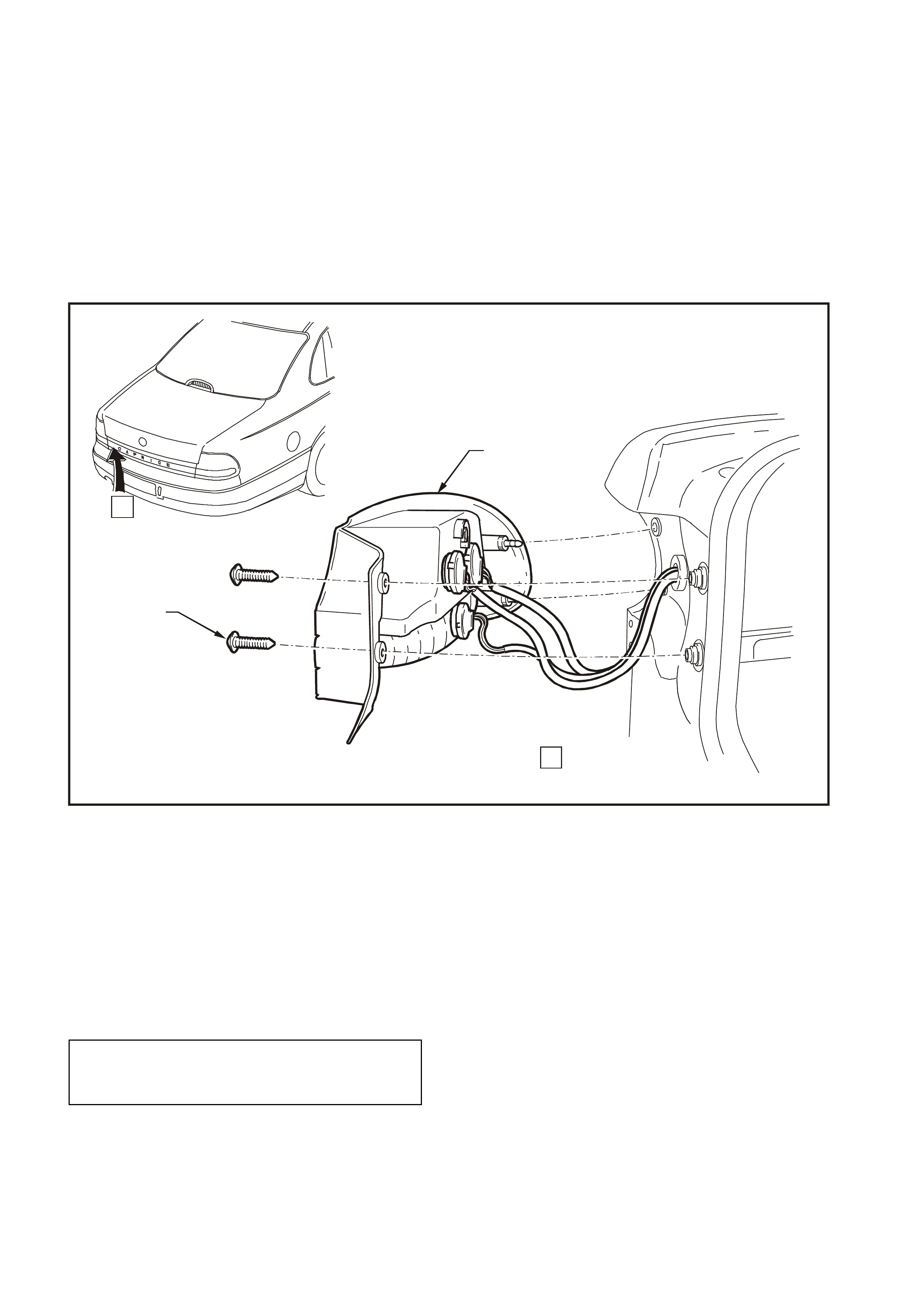
REINSTALL
1. Check condition of lamp housing to rear
compartment lid rubber sealing gasket and
replace if damaged.
2. Position lamp assembly (2) on rear
compartment lid, engaging lamp assembly
tongue in and around moulding mounting boss
grommet. Install and tighten attaching nuts (1)
to the correct torque specification.
2
1
1
1
1
1
2.0 - 5.0 Nm WH12B026
Figure 12B-29
REAR COMPARTMENT LID LAMP
ASSEMBLY ATTACHING NUT
TORQUE SPECIFICATION 2 – 5 Nm
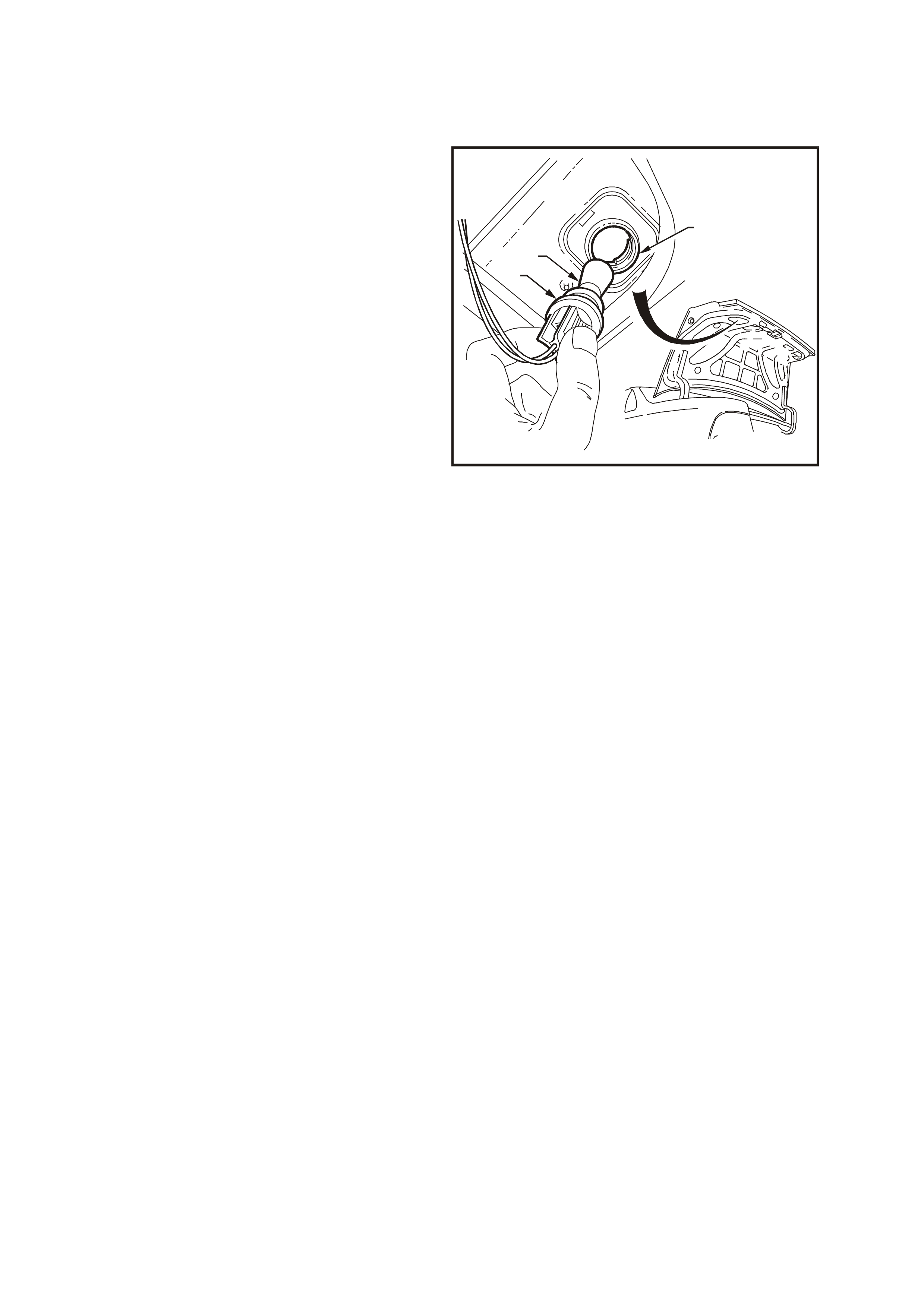
2.18 RE AR COMPARTMENT LID LAMP BULB
REVERSE LAMP BULB
REPLACE
1. Open rear compartment lid.
2. From inside rear compartment lid, remove
cover trim and remove reverse lamp socket
and bulb assembly (3) by turning and pulling
sockets from compartment lid lamp
assembly (1).
3. Remove bulb (2) from socket by depressing
bulb into its socket and then rotate to remove.
Inspect bulb socket to lamp housing seals for
damage, replace if necessary.
4. Insert new bulb into socket and install socket
into lamp housing, ensuring socket locks
securely into place, then install cover trim.
5. Check rear lamp operation.
WH12B063
1
2
3
Figure 12B-30
2.19 INTERIOR LAMPS
NOTE: The interior lighting configuration is
dependant on the vehicle model and trim level.
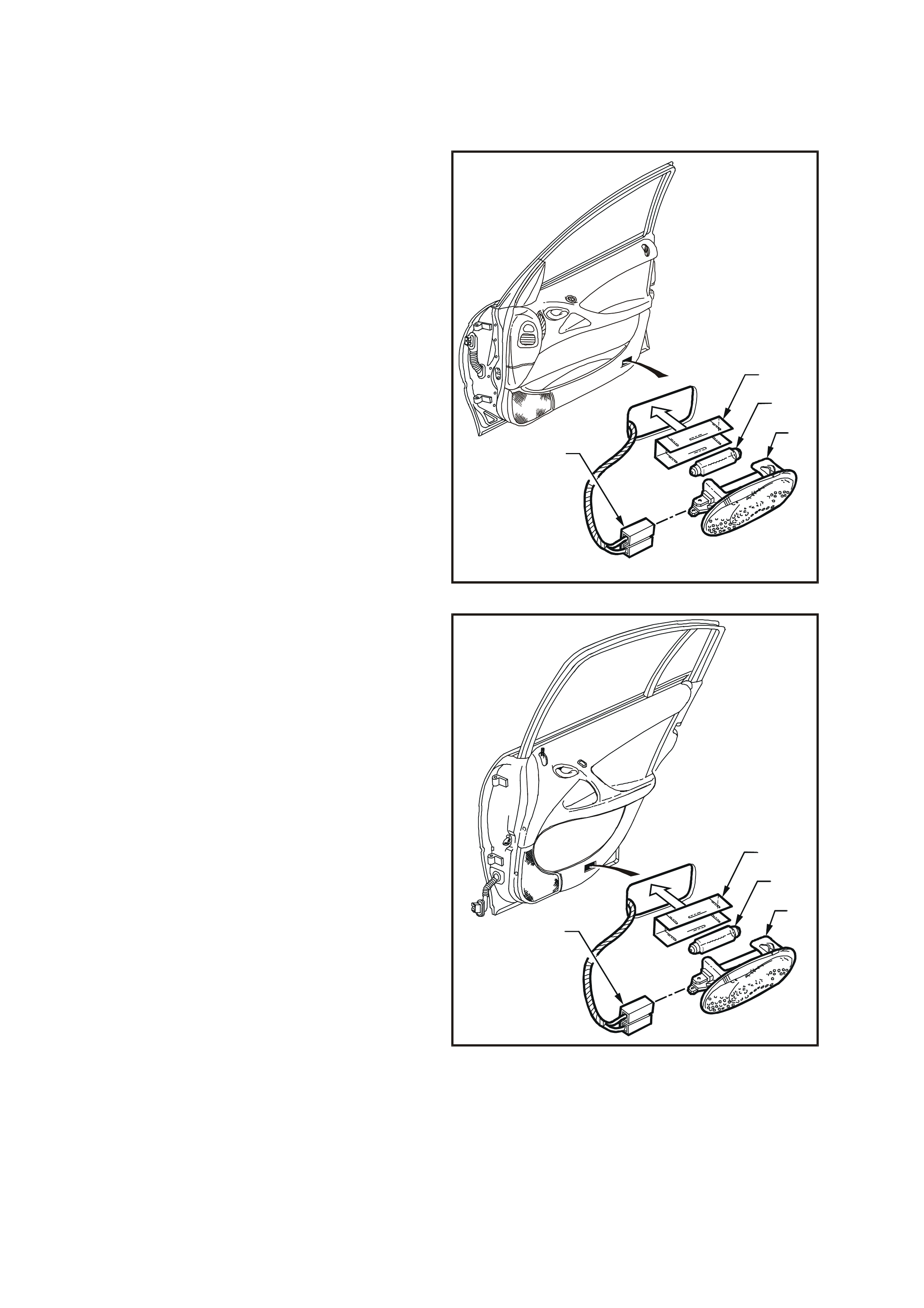
DOOR COURTESY LAMPS
Figs. 12B-31 and 12B-32 illustrate the installation of
the front and rear door courtesy lamps.
REMOVE
1. To remove lamp assembly use a fine bladed
screwdriver inserted between notch in lens
surround and door trim. Pus h sc r ewdriver down
to depress locking tang and prise edge of
courtesy lamp (3) away from door trim.
2. Insert screwdriver in notch at bottom edge of
lamp, depress locking tang, prise bottom edge
of lam p away from door and rem ove lam p from
door aperture. Disconnect wiring harness
connector (4).
3. To remove bulb from lamp, pull protective
metal cover (1) from back of lamp to gain
access to bulb (2), then bend back lever
contact retaining the bulb and remove bulb.
WH12B027
4
1
3
2
Figure 12B-31
REINSTALL
1. Insert new bulb (2), ensuring that lever contact
retains bulb securely.
2. Slide protective m etal cover (1) into position on
back of lamp (3).
3. Connect wiring harness connector (4) to
terminals on lamp.
4. Install lamp (3) into aperture in door, ensuring
that wiring harness and connectors are
positioned behind door trim, then push lamp
assembly firmly into position.
WH12B028
4
1
3
2
Figure 12B-32
GLOVE COMPARTMENT LAMP
Fig. 12B-33 illustrates the installation of the glove
com partm ent lamp. To gain ac cess to bulb ( 2), use
a fine bladed screwdriver to carefully lever out lens
(1) from instrument panel.
To rem ove bulb f rom lens, bend bac k lever contact
retaining the bulb and remove bulb. If necessary,
remove harness connector (3) to provide better
access to bulb.
When installing bulb, ensure that lever contact
retains bulb securely.
WH12B029
1
3
2
Figure 12B-33
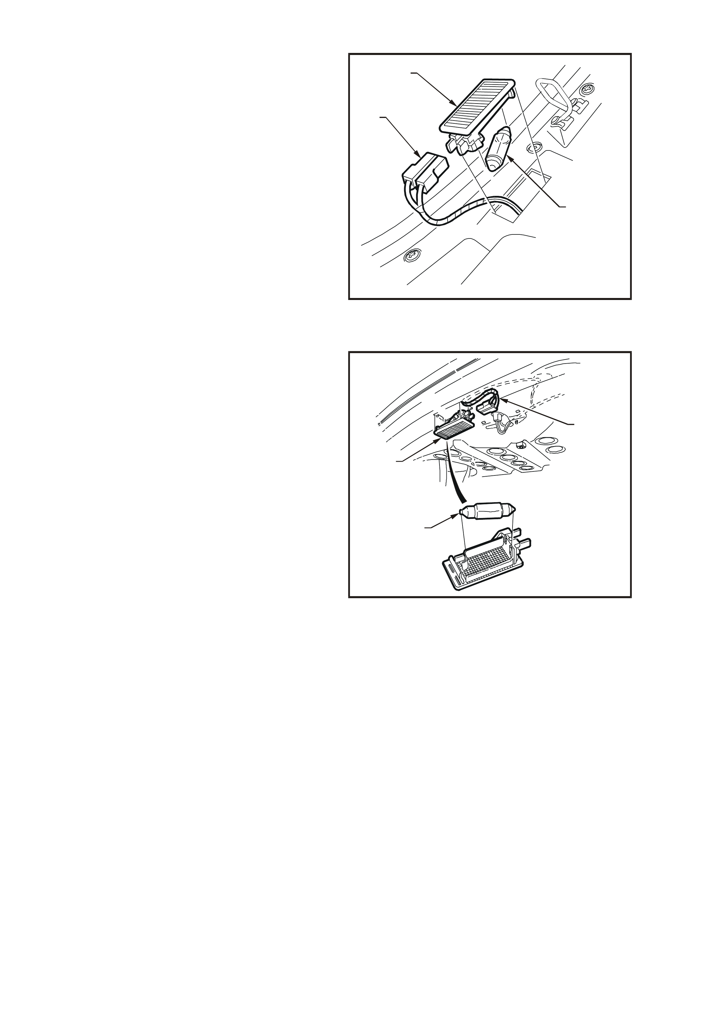
REAR COMPARTMENT LAMP
Fig. 12B-34 illustrates the installation of the rear
compartment lamp. To gain access to bulb, use a
fine bladed screwdriver to carefully lever out lens
(3).
To remove bulb (2) from lens, bend back lever
contact retaining bulb and remove bulb. If
necessary, remove harness connector (1) to
provide better access to bulb.
When installing bulb, ensure that lever contact
retains bulb securely.
WH12B030
2
3
1
Figure 12B-34
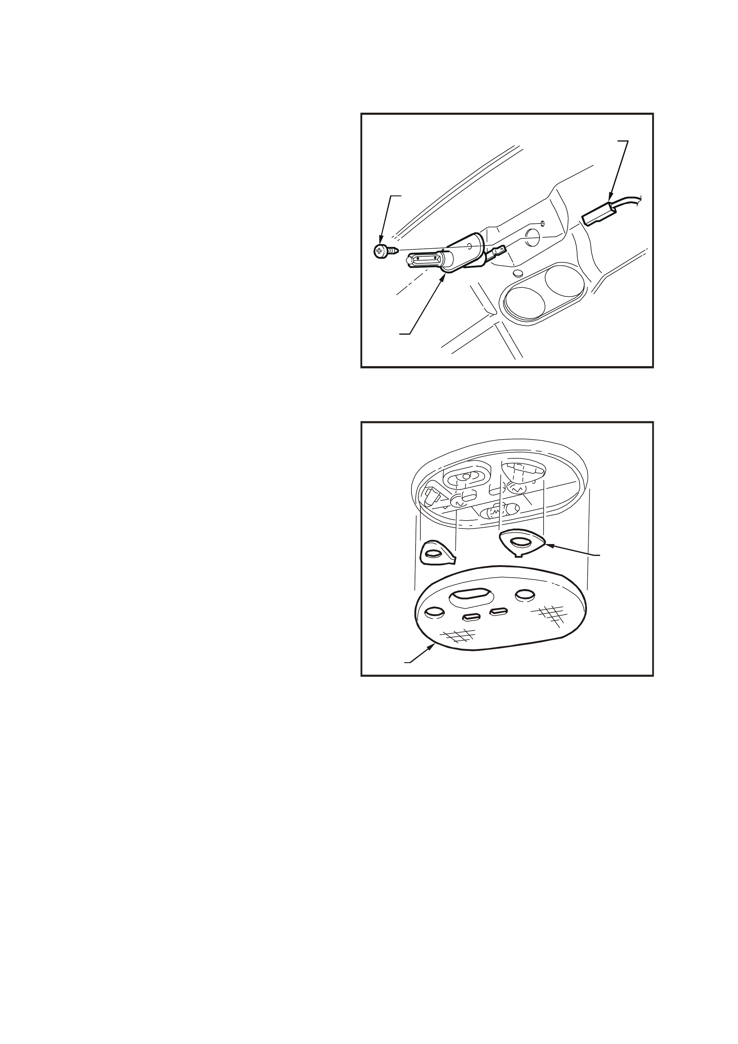
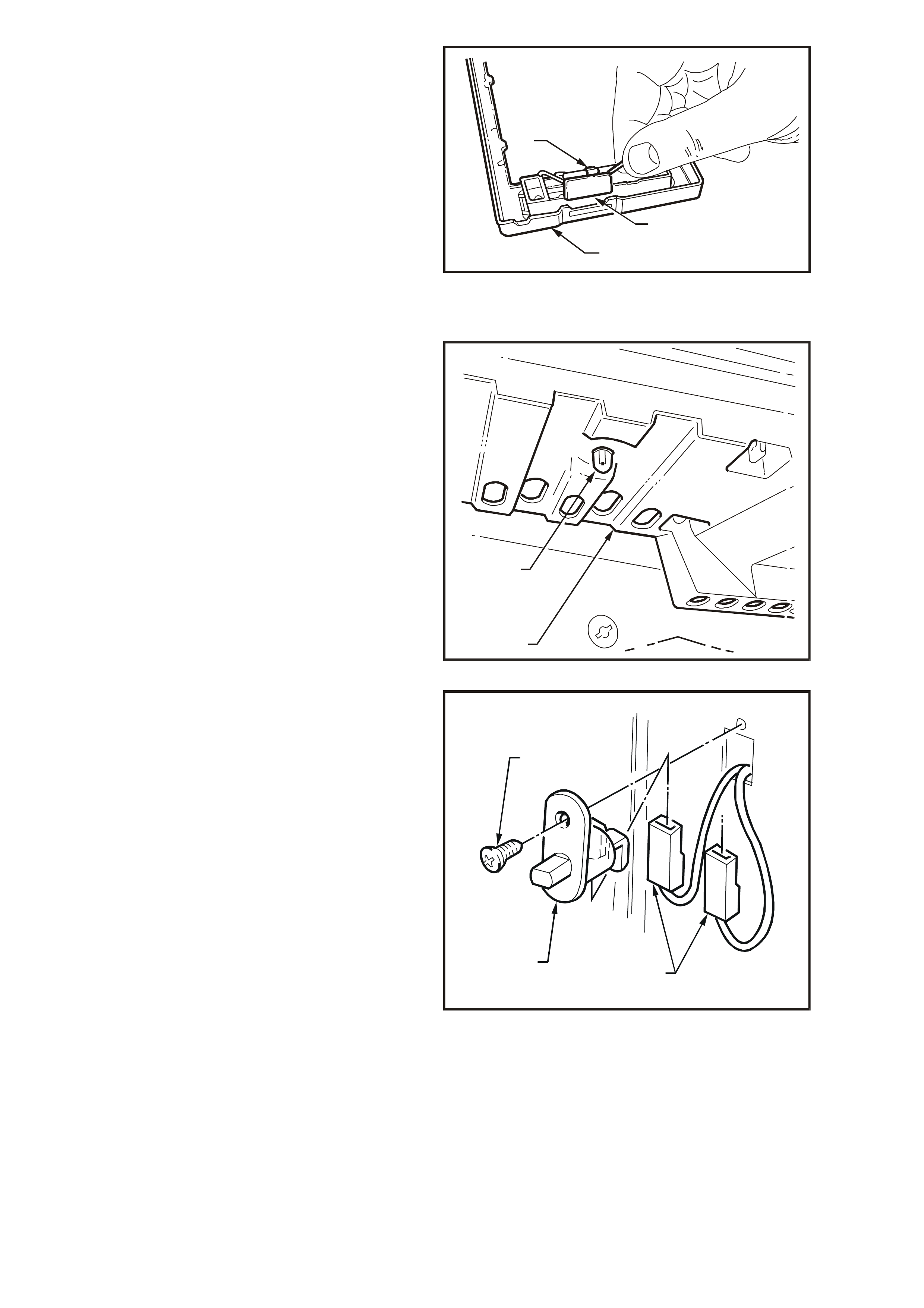
REAR COMPARTMENT LAMP SWITCH
The rear compartment lamp is operated by a
switch attached to the rear compartment lid.
REMOVE
1. Remo ve attaching screw (1) and pull s witch (3)
out far enough to gain ac ces s to wiring har ness
connector (2).
2. Disconnect wiring harness connector and
remove switch.
REINSTALL
Installation is the reverse of the removal procedure.
1
2
3
WH12B031
Figure 12B-35
DOME AND FRONT READING LAMPS
Fig. 12B-36 illustrates the installation of the dome
and front reading lamp assembly. To gain access
to bulb, use a fine bladed screwdriver inserted
between notch in lens surround and edge of lens.
Carefully lever out lens (2) from housing, gently
prising from all four notches, ensuring no damage
is made to housing surround or headlining.
The dome lamp bulb is a festoon bulb and can be
removed by bending contacts out from bulb. Once
installed, ensure that they are lock ed fir mly in place
in their sockets.
To gain access to the reading lamp bulbs, remove
bulb cover plates (1) by gently levering thin tab
away fr om housing using a f ine bladed s crewdriver .
Reading lamp bulbs are festoon bulbs and can be
removed by bending contacts out from bulb. Once
installed, ensure that they are lock ed fir mly in place
in their sockets. Install bulb cover plates and click
firmly into place.
Install lens.
WH12B032
2
1
Figure 12B-36
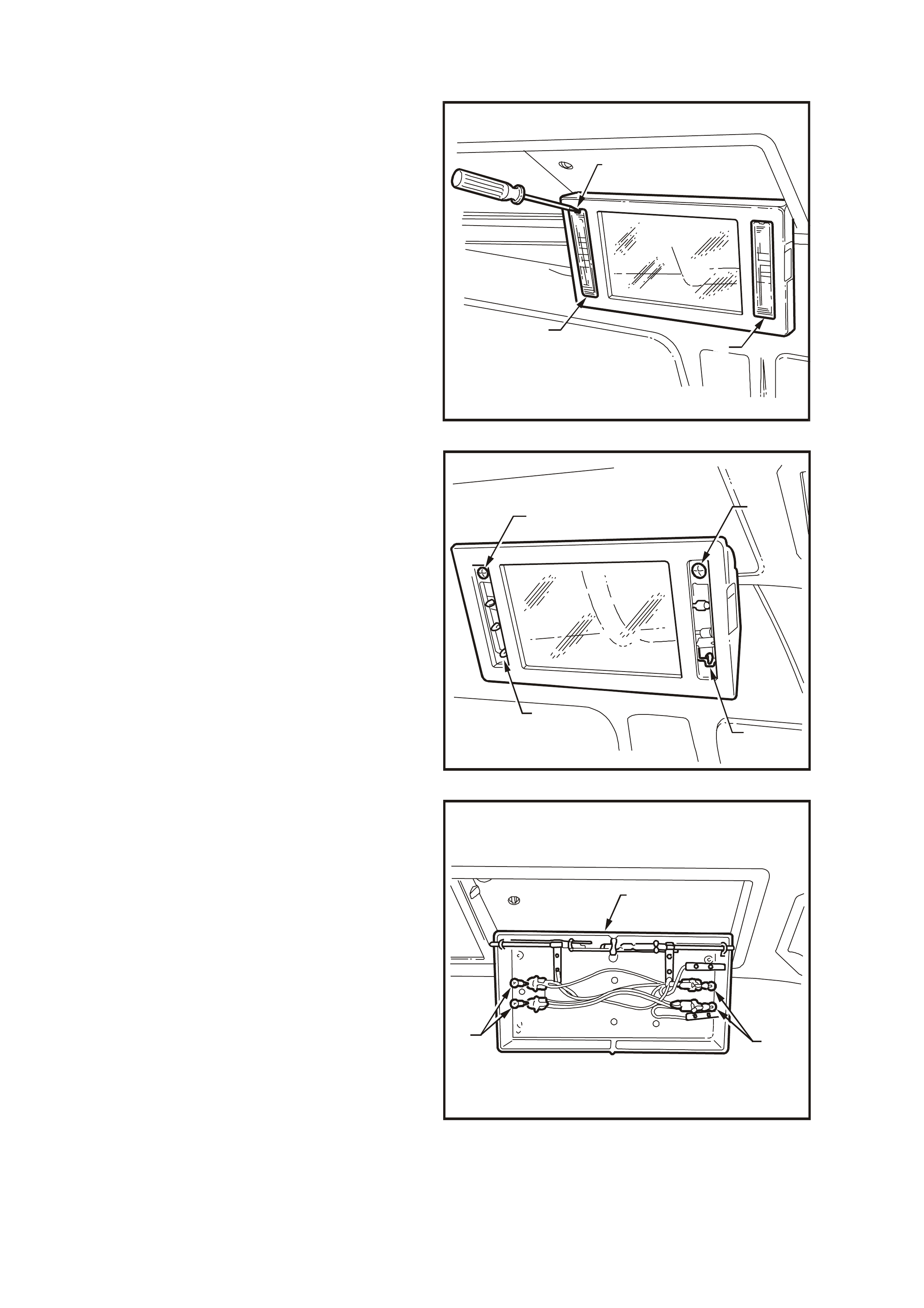
REAR VANITY MIRROR LAMP BULBS
REPLACE
1. Depress vanity mirror button and allow vanity
mirror to swing down.
2. Using a fine blade screwdriver, carefully lever
notched ends of mirror lamp lens from mirror
housing.
WH12B058
1
2
3
Figure 12B-37
3. Remove two screws from mirror housing.
4. Using a fine blade screwdriver, lever up
housing body retainers and pull mirror housing
lower half bottom edge from top half.
NOTE: Take care not to lose lamp switch slider as
mirror housing is separated.
WH12B059
1
32
1
Figure 12B-38
5. Pull Bulb/s from socket.
6. Install new bulb/s.
WH12B060
2
11
Figure 12B-39
7. Install lamp switch slider into housing lower
half, ensur e that it is located cor rectly in slot on
side of housing.
8. Engage housing lower half onto top edge
retainer of housing upper half. Squeeze
together lower corners of housing halves to
engage retainers in each bottom corner.
9. Install and tighten mirror housing screws.
10. Install m irror lamp lens into m irror housing with
notched ends facing upward.
11. Switch mirror lamp on and ensure that bulbs
illuminate.
WH12B061
1
2
3
Figure 12B-40
FOOTWELL LAMPS
Front footwell lamp bulbs are located in sockets
which are a twist fit into right and left hand
instrument panel side trims (1).
Bulbs (2) are a push fit into socket. Bulbs are fitted
with a green cover. When installing new bulb,
ensure that new cover is installed onto bulb.
The sockets are part of the main wiring harness.
WH12B033
2
1
Figure 12B-41
DOOR JAMB SWITCHES
The door j amb s witches are installed in eac h of the
door hinge pillars. When the door of the vehicle is
closed, a plunger in the switch is depressed,
creating an open circuit in the earth circuit. When
the door is opened, the plunger is released and
completes the circuit to earth.
Remove Philips head screw (1) securing switch to
door pillar, withdraw switch (3) from pillar and
disconnect wiring harness connectors (2).
Installation of the switch is reverse of the removal
procedure.
WH12B034
1
2
3
Figure 12B-42
CONSOLE BIN LAMP
From inside of console, use a fine bladed
screwdriver to carefully lever lamp (1) from side of
console. To provide better access to lamp,
disconnect wiring harness connectors from lamp
and remove lamp from console bin.
Bulb (2) can be replaced by bending back contact
retaining bulb and removing bulb.
When installing bulb, ensure that lever contact
retains bulb securely.
Connect wiring harness connectors to lamp, then
insert wiring harness and lamp into aperture in
console bin.
WH12B035
1
2
Figure 12B-43
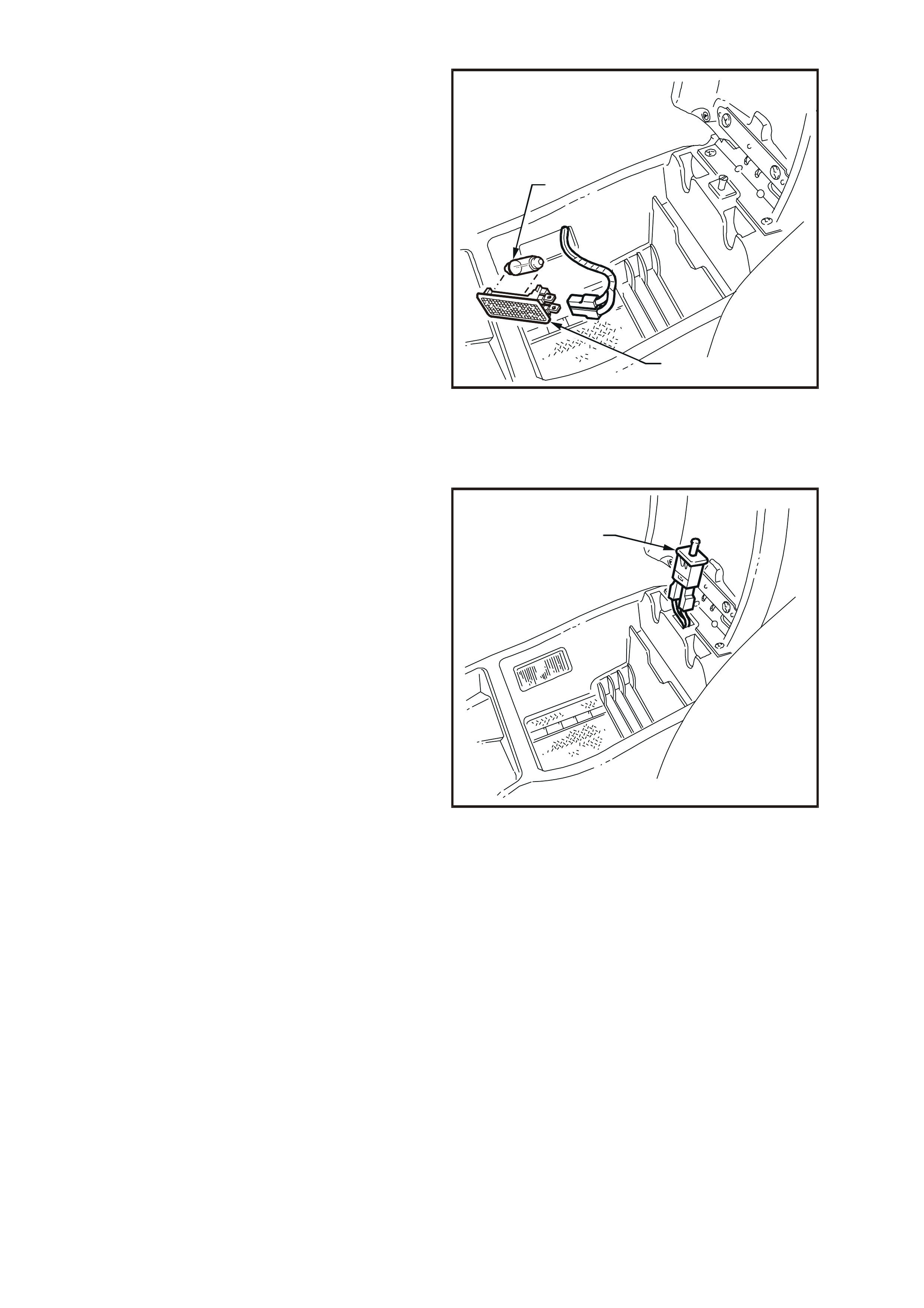
CONSOLE BIN LAMP SWITCH
REMOVE
1. Open console bin and pull switch (1) from
console bin assembly.
2. Disconnect wiring connector from switch and
remove switch from console bin.
WH12B036
1
Figure 12B-44
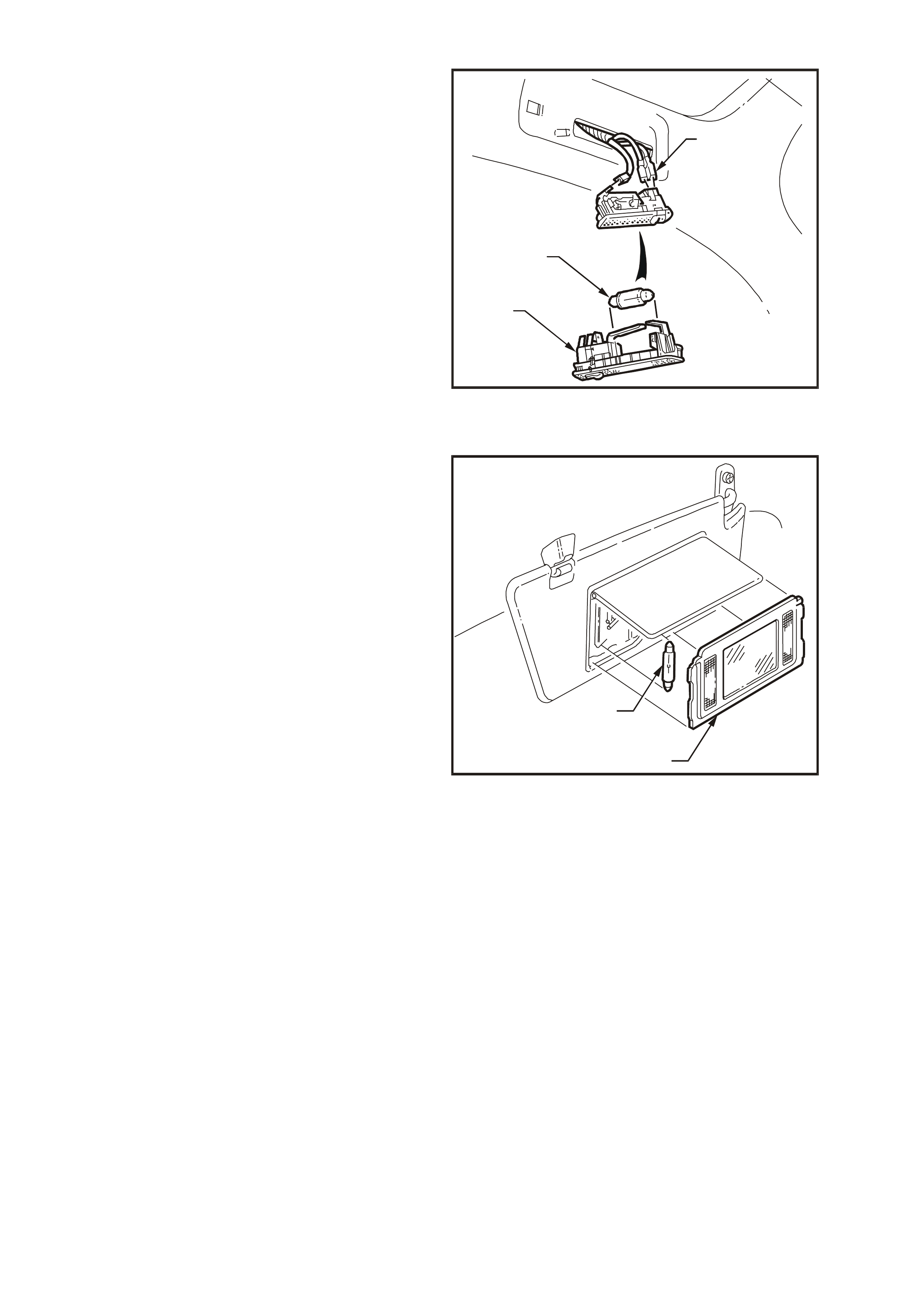
REAR READING LAMP
Fig. 12B-45 illustrates the installation of the rear
reading lamp assembly. To gain access to bulb,
use fine bladed screwdriver and gently lever
lamp (2) from aperture in headlining, ensuring no
damage is made to lens or headlining.
Bulb (3) can be replaced by bending back contact
retaining bulb and removing bulb. If necessary,
disconnect wiring harness connectors (1) from
lamp.
When installing bulb, ensure that lever contact
retains bulb securely.
Connect wiring harness connectors to lamp, then
insert wiring harness and lamp into aperture in
headlining. Push lamp firmly into aperture.
WH12B037
1
2
3
Figure 12B-45
FRONT VANITY MIRROR LAMP
Fig. 12B-46 illustrates the installation of the front
vanity mirror lamp. Lower visor and lift flap to
expose vanity mirror and lamp assembly. To gain
access to bulb, use fine bladed screwdriver and
gently lever front vanity mirror lamp cover
assembly (1) from visor and pivot assembly.
NOTE: Damage to vanity mirror lamp surround will
occur if car e is not taken when levering lamp c over
assembly.
Bulb (2) can be replaced by bending back contact
retaining bulb and removing bulb.
When installing bulb, ensure that lever contact
retains bulb securely.
If replacing lamp housing, pull wiring harness
connectors from lamp housing terminals.
WH12B038
2
1
Figure 12B-46
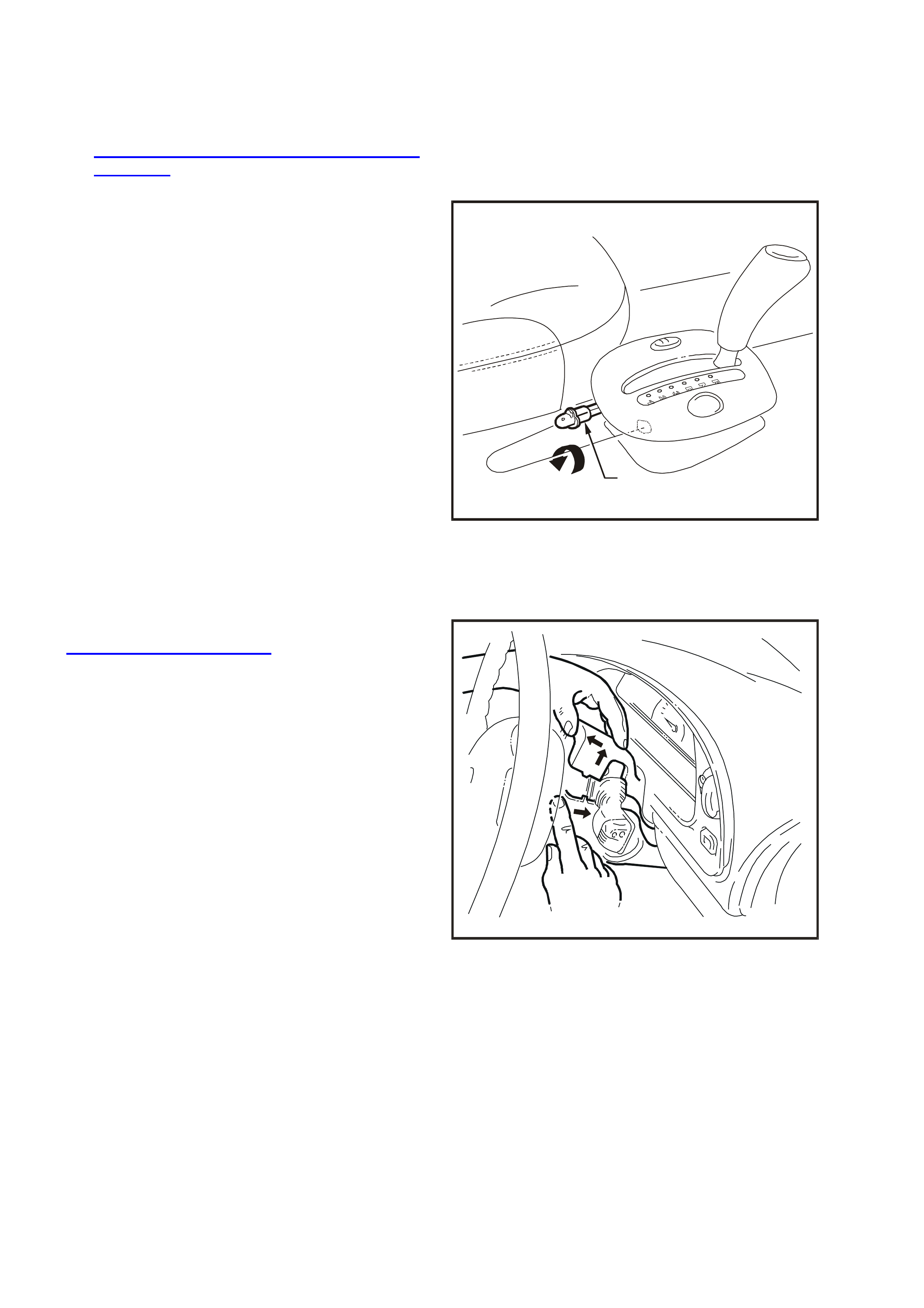
GEARSHIFT INDICATOR LAMP BULB
REPLACE
1. Disconnect battery earth lead.
2. Remove transmission console as described in
Section 1A3 INSTRUMENT PANEL &
CONSOLE of the VT Series I Service
Information.
3. From beneath cons ole cap, disconnec t cons ole
wiring harness to illumination connectors.
4. Disconnect illumination bulb socket and pull
bulb (1) from socket.
5. Install new bulb into socket. Install socket into
holder and twist clockwise to retain.
6. Install transmission console cap assembly,
reverse to removal procedures, ensuring all
connectors are reconnected.
7. Connect battery earth lead.
8. Turn headlamps on and ensure bulb
illuminates.
WH12B039
1
Figure 12B-47
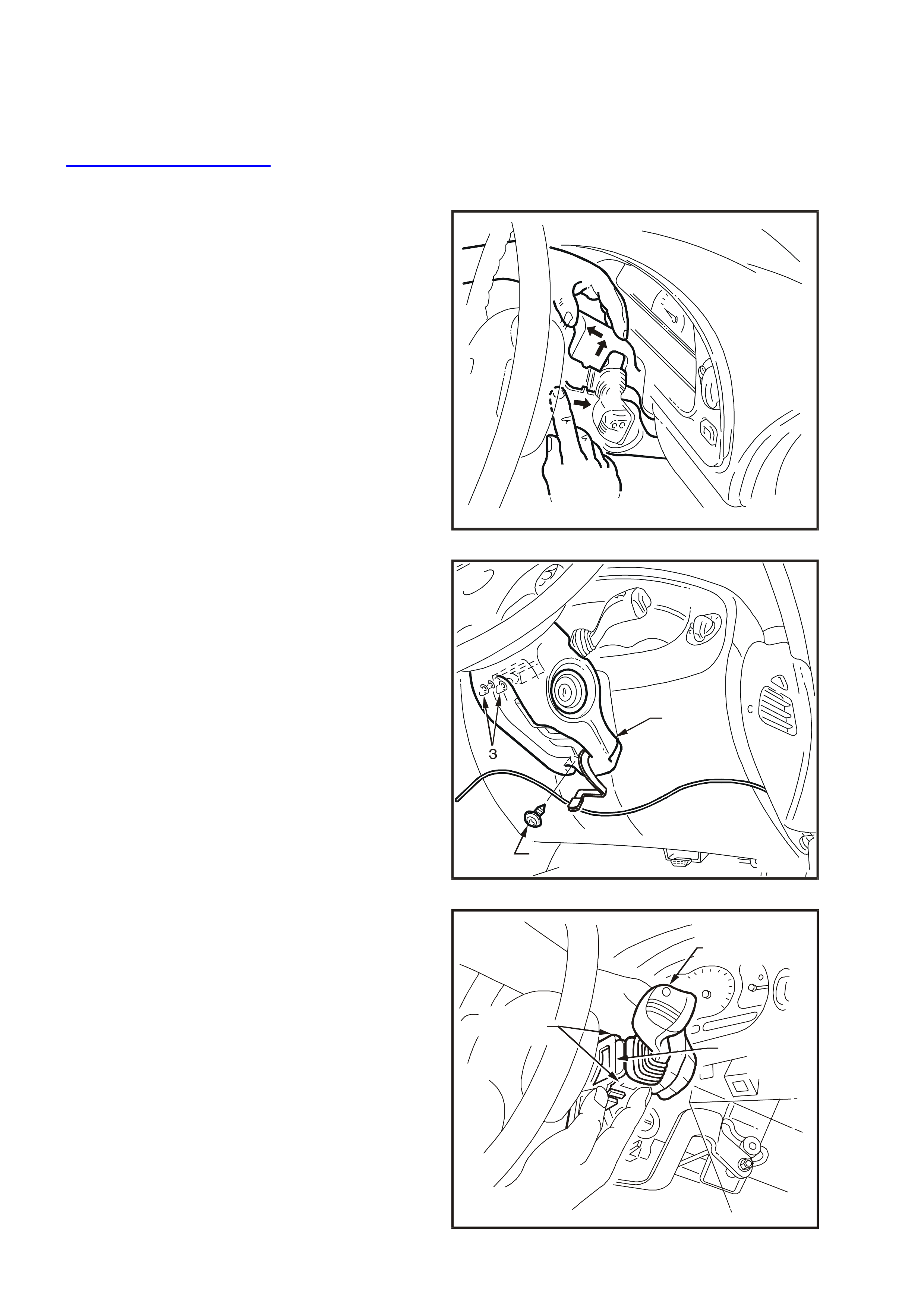
IGNITION LOCK LAMP
REPLACE
CAUTION: Disable the SRS (Air Bag). Refer to
DISABLING THE SRS, Section 12M
SUPPLEMENTAL RESTRAINT SYSTEM of the
VT Series I Service Information.
1. Release steering column height adjuster,
com pletely lower s teering c olumn and leave the
lever in the released position.
2. Insert finger between the steering wheel and
the lower cover as shown in Fig. 12B-48 and
apply a small amount of pressure (pushing
towards the instrument cluster) while lifting the
upper cover upwards.
WH12B041
Figure 12B-48
3. Remove screw (2) securing the lower cover (1)
to the steering column.
4. Slide the lower cover towards the steering
wheel to release the cover from the two
retaining tangs (3) on the steering column.
5. Remove the lower cover, while feeding the key
reader outer surround from the lower cover.
2
1
WH12B040
Figure 12B-49
6. Pull ignition lock lamp socket (1) from lamp
housing on key reader assembly (3).
7. Pull bulb (2) from socket.
8. Replace bulb and install lamp housing to key
reader assembly.
9. Install steering column covers in reverse order
of removal procedure.
IMPORTANT: Enable the SRS (Air Bag). Refer to
ENABLING THE SRS, Section 12M
SUPPLEMENTAL REST RAINT SYSTEM of the VT
Series I Service Information.
WH12B042
321
Figure 12B-50
INSTRUMENT CLUSTER ASSEMBLY LAMP BULBS
The instrument assembly and warning lamp
illumination bulbs ar e a push fit into a so cket, which
in turn are a twist fit into the rear of the instrument
case and flexible printed circuit board.
To remove the lamp socket (1), remove the
instrument cluster, refer to Section 12C
INSTRUMENTS, WIPERS/ WASHERS AND
HORN of this Ser vice Inform ation CD. Rem ove the
lamp socket (1) from the printed circuit board and
pull bulb from its socket.
Installation of the ins trum ent c luster assembly lam p
bulbs is the reverse of removal procedure.
WH12B043
1
Figure 12B-51
TRIP COMPUTER SWITCH ASSEMBLY ILLUMINATION BULB
The trip computer assembly illumination bulb is a
push fit into a socket, which in turn is a twist f it into
the rear of the trip computer flexible printed circuit
board.
To remove the lamp socket (1), remove the trip
computer switch assembly (2), refer to Section
12C INSTRUMENTS, WIPERS/WASHERS AND
HORN of this Ser vice Inform ation CD. Rem ove the
lamp socket (1) from the printed circuit board and
pull bulb from its socket.
NOTE: Procedures for replacing the trip computer
assembly illumination lamps are covered in
Section 12C INSTRUMENTS,
WIPERS/WASHERS AND HORN of this Service
Information CD.
WH12B044
2
1
Figure 12B-52
INSTRUMENT FACIA AND CENTRE FACIA ESCUTCHEON SWITCH ILLUMINATION BULBS
The instrument facia and centre facia escutcheon
switch assemblies are illuminated by a bulb and
socket assembly which is a twist fit into the
underside of the switch assembly.
To remove switch assembly (1), refer to Section
12C INSTRUMENTS, WIPERS/WASHERS AND
HORN of this Service Inform ation CD. Then, using
a fine bladed screwdriver, inserted into cross on
bulb socket, twist socket anti-clockwise, remove
bulb and socket assembly (2).
Installation of the bulb and socket assembly is the
reverse of the removal procedure.
WH12B045
1
2
Figure 12B-53
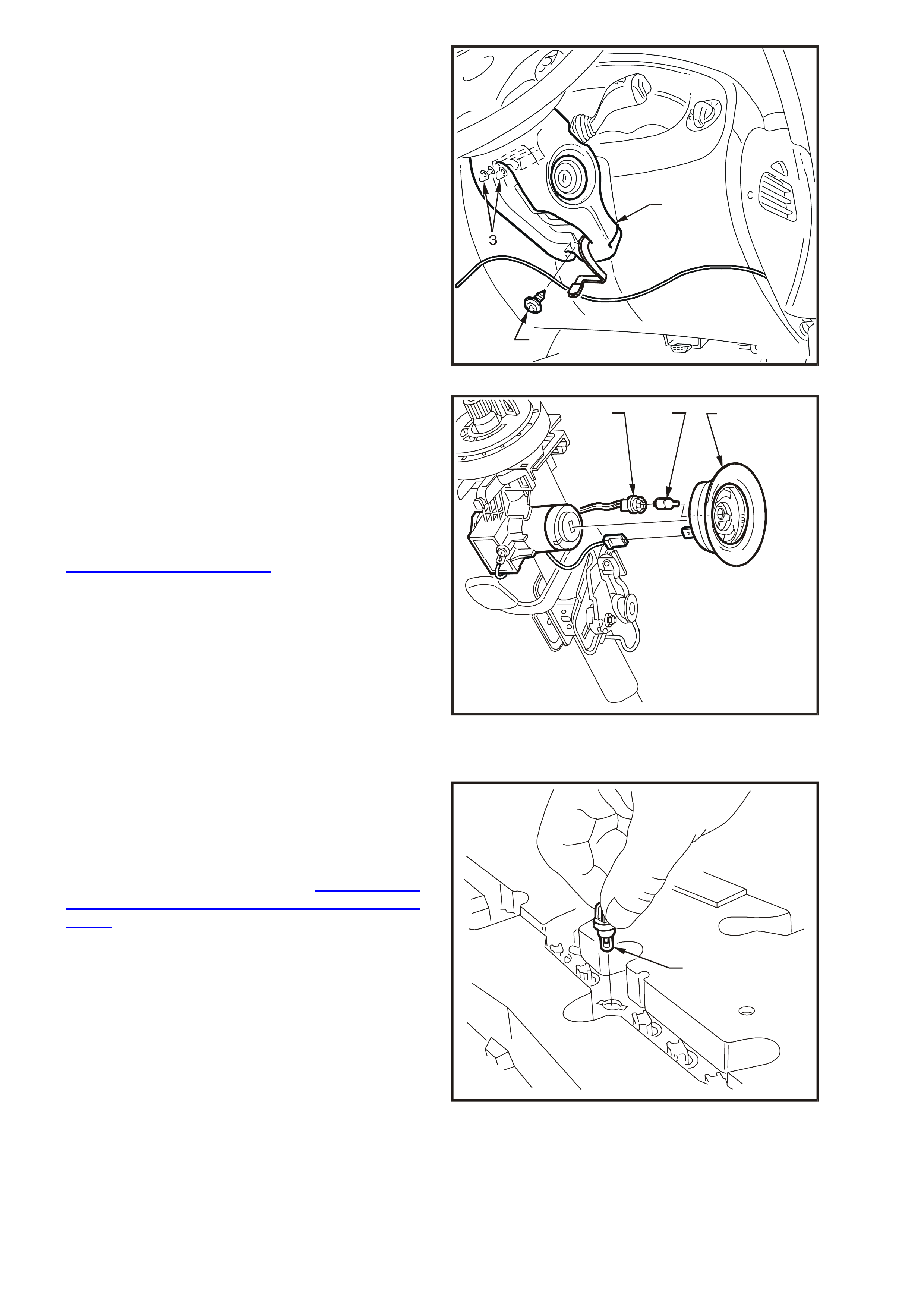
2.20 STOP LAMP SWITCH
REMOVE
1. Disconnect wiring harness connector (1) from
the stop lamp switch (2).
2. Rotate switch anticlockwise and remove from
the mounting nut.
WH12B046
21
Figure 12B-54
REINSTALL AND ADJUST
1. Install the stop lamp switch (1) into the
mounting nut (2) on the brake pedal support
(3).
2. With the brake pedal (4) in its rest position,
install switch into mounting nut (2). Adjust the
switch to the clearanc e dim ension shown in F ig
12B-55.
3. Connect wiring harness connector to switch.
T212E046
1
3
2
4
6 0.5mm
A
A
1
3
4
2
A
-A
+
Figure 12B-55
TESTING SWITCH CONTACTS
1. Check adjustment of the stop lamp switch (1),
refer to the following switch installation and
adjustment procedure and adjust the switch as
required.
Ensure that the brake lights ar e operating when
the brake pedal is depressed.
If brake lights are not operating, repair as
necessary, refer to Section 12B LIGHTING
SYSTEM of the VT Series I Service
Information.
2. Remove wiring harness connector (2) from the
terminals of the stop lamp switch (1).
3. Connect an ohmmeter across the switch
terminals and the ohmmeter should indicate
open circuit with the brake pedal at rest.
4. Depress the brake pedal and the ohmmeter
should indicate continuity.
T212E045
2
3
1
Figure 12B-56
5. Replace the switch if the tests pr ove the switch
to be faulty.
6. If the test proves the switch to be OK, connect
the wiring harness connector to the switch.
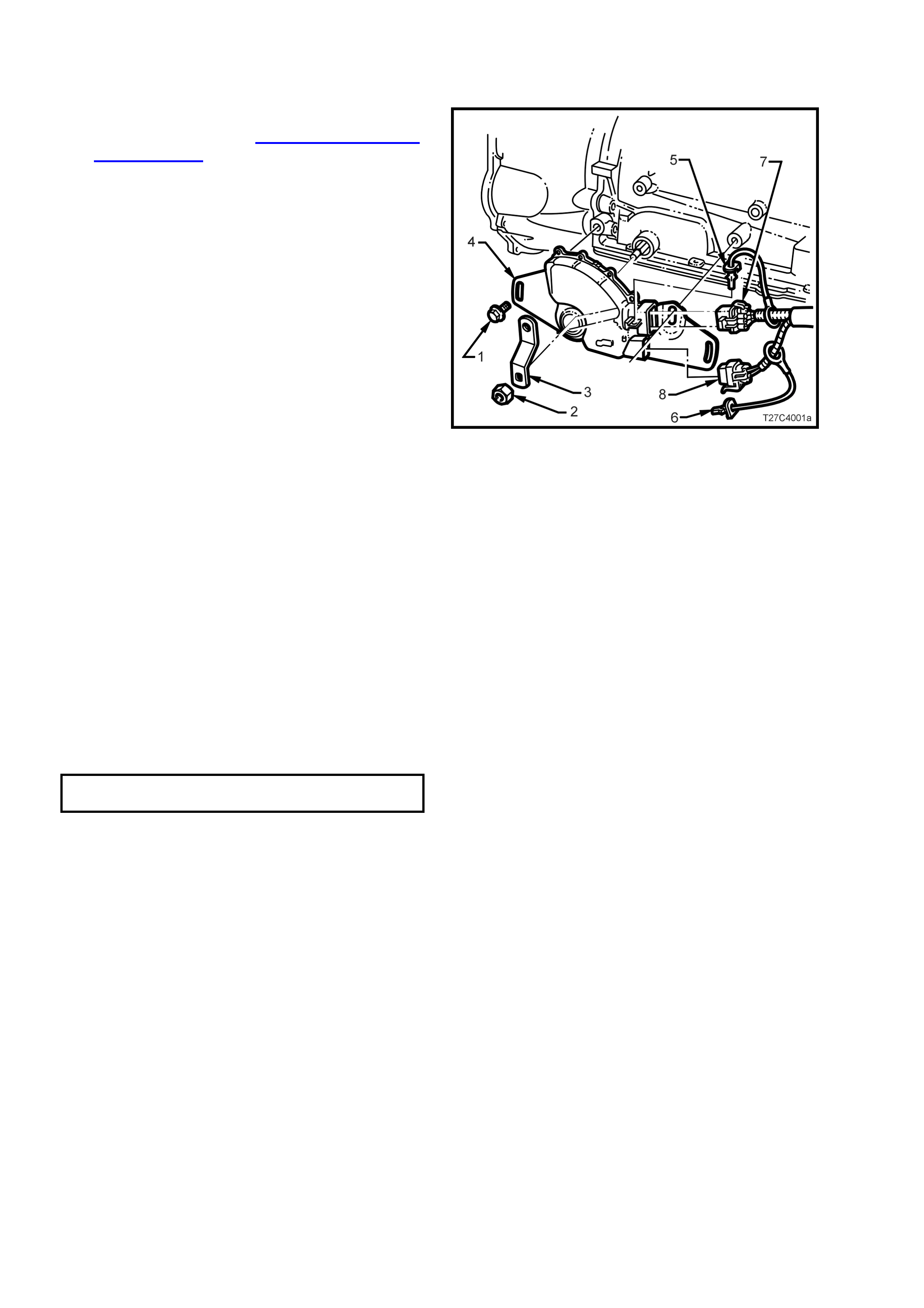
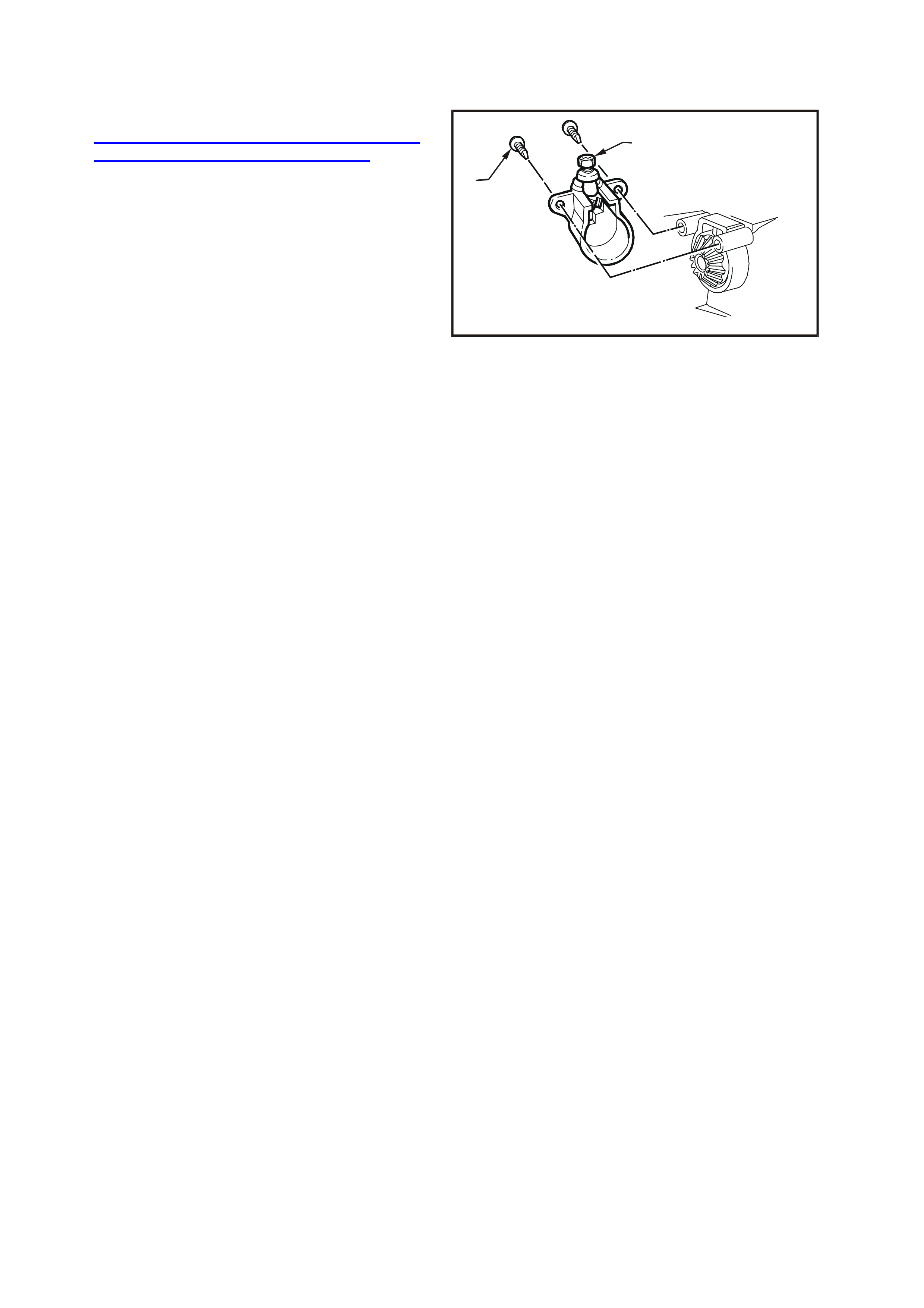
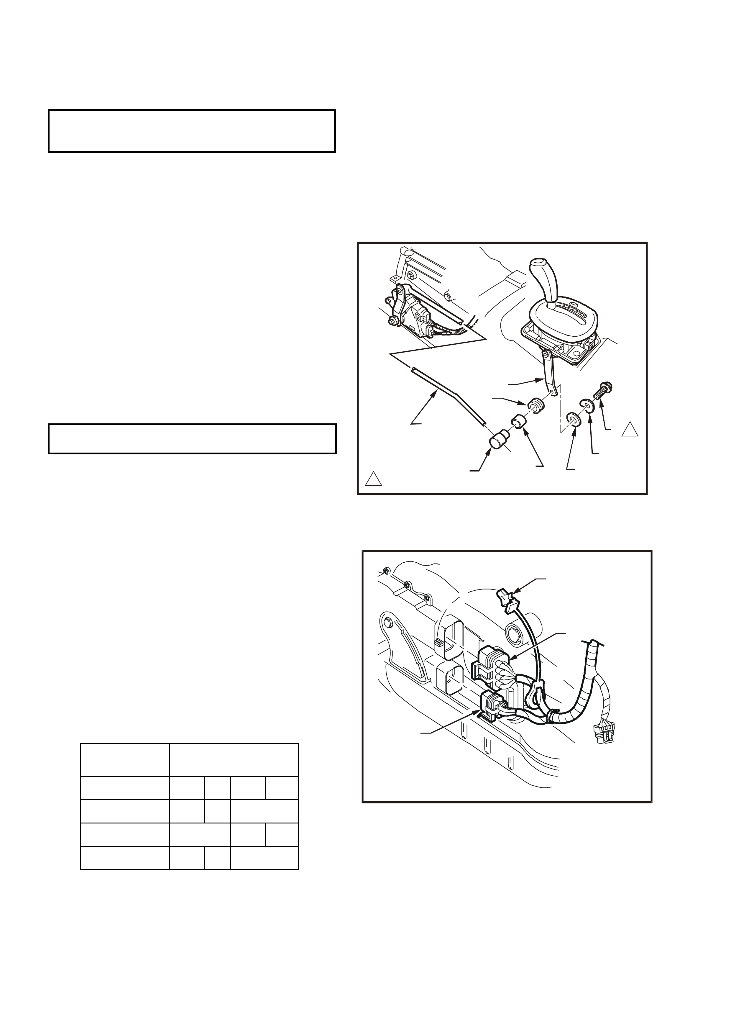
2.21 NEUTRAL START/BACK-UP LAMP SWITCH
REMOVE
1. Raise the front of the vehicle and place on
safety stands. Refer to Sect ion 0A, GENERAL
INFORMATION of the VT Series I Service
Information for the location of recommended
jacking points.
2. While holding the lower selector lever (3) with
an adjustable wrench, r emove the retaining nut
(2).
3. Carefully remove the lever (3) from the
transmission manual shaft.
4. Prise the wiring harness connector CPA
(Connector Position Assurance) securing pins
(5 and 6) from the neutral start and back-up
lamp switch (4), taking care not to break the
pins in the process. Disconnect the two wiring
harness connectors (7) from the switch
assembly (8).
5. Remove the two switch retaining screws (1),
then slide the switch assembly (4) over the
manual shaft and remove from the vehicle.
NOTE: Connector ‘8’ and the CPA ‘6’, are used f or
the PRNDL indicator in the instrument panel.
Figure 12B-57
REINSTALL
Reinstallation of the neutr al start and bac k -up lamp
switch is the reverse of the removal procedure
except for the following:
1. When installing the two switch sec uring s crews
(‘1’ in Fig. 12B-57), leave them f inger tight, until
the switch adjustment process has been
completed.
2. After installing the selector lever and retaining
nut, hold the lever with an adjustable wrench
and tighten the nut to the correct torque
specification.
SELECTOR LEVER RETAINING
NUT TORQUE SPECIFICATION 15 – 35 Nm
3. On completion of the neutral start and back -up
lamp switch adj ustment proc edure that follows,
check that the engine c an only be s tarted when
the gearshift lever is either in the ‘P’ (Park) or
‘N’ (Neutral) positions.
ADJUST
1. With the vehicle raised, rotate the neutral start
and back-up lamp switch back and forth until
the best ‘neutral’ position is attained, then
lightly tighten the front bolt to retain.
2. With the ignition switched to the ON position,
check that the engine can only be started in
either the Park or Neutral selector positions. A
further light adjustment may be required to
achieve this state.
Also check that the engine will not crank in any
of the rem aining selec tor positions and that the
Reverse lam ps illuminate when Reverse range
is selected.
3. After switch adjustment, tighten the switch
retaining bolts to the correct torque
specification.
NOTE: To gain access to the rear bolt, it will be
necessary to rem ove the wiring harness connector
(‘7’ in Fig. 12B-57). Following the bolt tightening
procedure, reinstall the connector/s and the CPA
securing pin/s.
NEUTRAL START & BACK-UP
LAMP SW ITCH RETAINING BOLT 15 - 35 Nm
TORQUE SPECIFICATION
4. Lower the vehicle to the ground and check the
operation of the neutral start and bac k-up lam p
switch. The vehicle should only start in either
‘P’ (Park) or ‘N’ (Neutral) ranges and the
reverse lamps should only illuminate when the
‘R’ (Reverse) range is selected.
5. Check the selector linkage adjustment.
Proceed as follows:
1. Loosen locking screw (1) at selector
control lever (7) to allow selector rod (8) to
slide through trunnion (4).
2. At neutral/start and back-up switch end of
selector rod (8), move transmission
selector lever into P (Park) position.
3. Move selector control (gearshift) lever into
P (Park) position, then tighten locking
screw (1) at selector control lever (7) to
specified torque.
SELECTOR LEVER LOCKING
BOLT TORQUE SPECIFICATION 15 – 35 Nm
WH12B064
1
1
2
3
4
6
5
7
8
1
15.0 - 35.0 Nm
Figure 12B-58
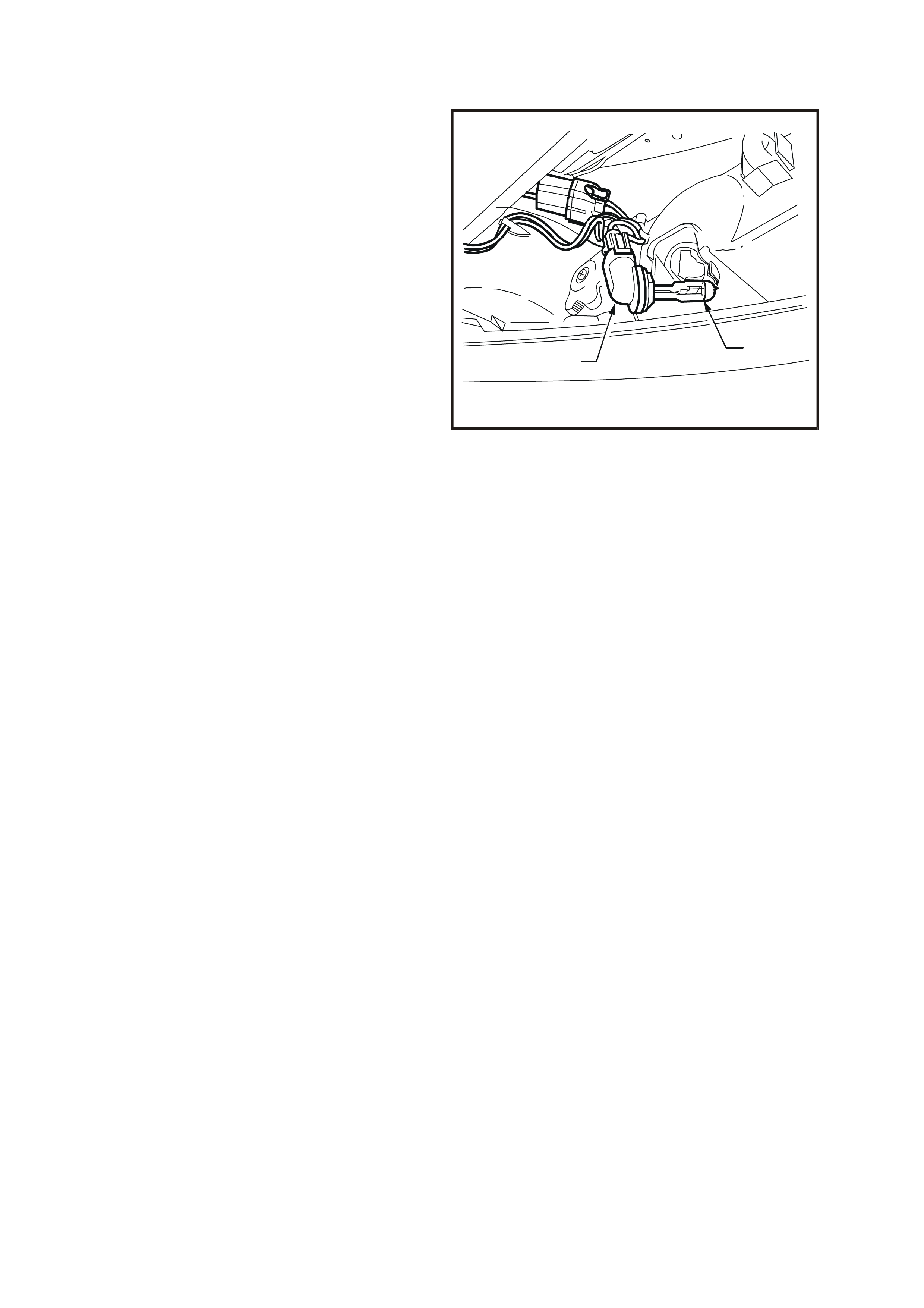
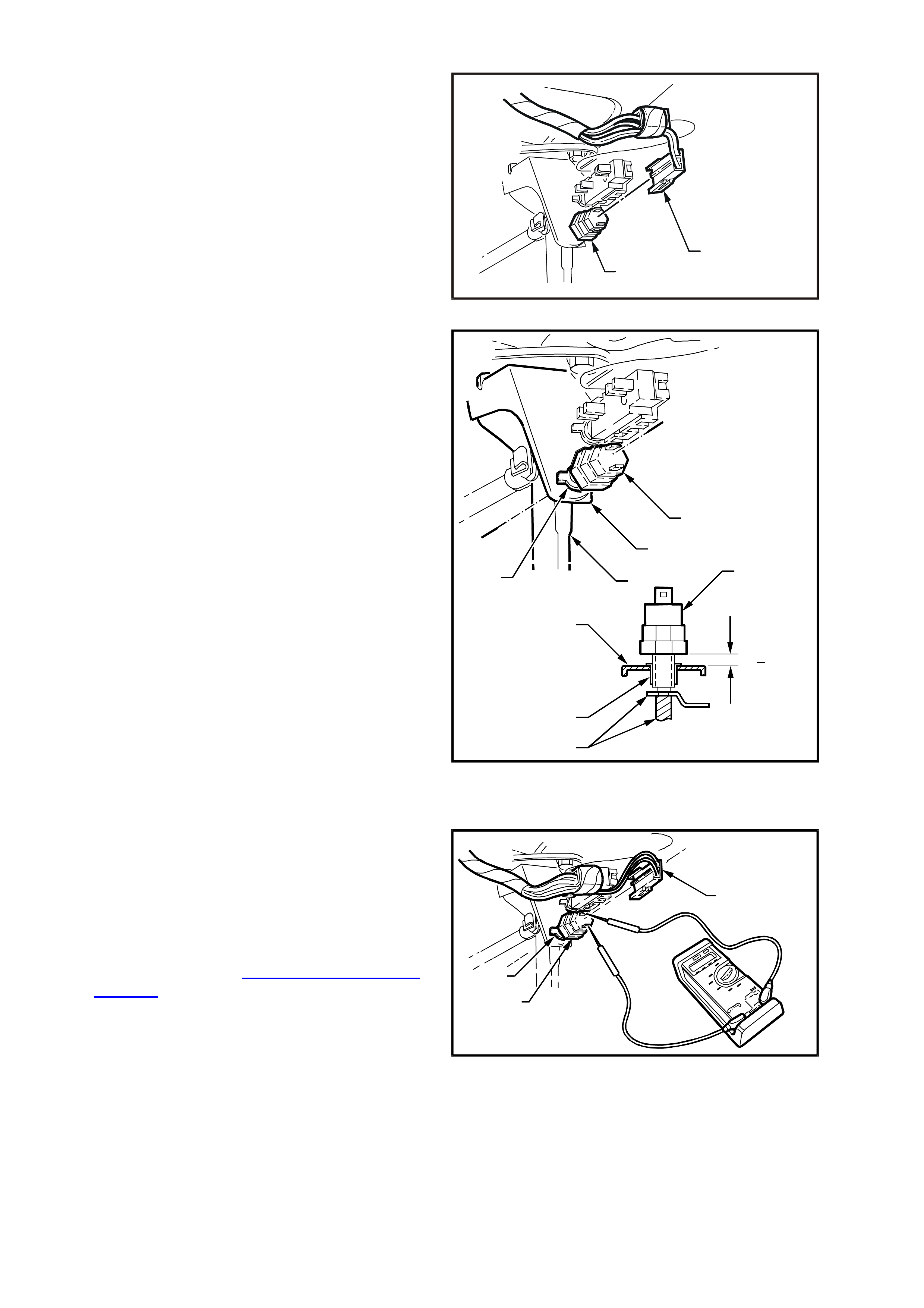
TEST
Before c onducting the following test, ensure that the
gearshift linkage is correctly adjusted, refer to
previous instructions on gearshift adjustment.
1. Disconnect battery earth lead.
2. Pull back harness connector retainer (1) and
disconnect main wiring harness connector (2)
from neutral start/back -up switch wiring harness
connector.
3. Using an ohmmeter connected to switch wiring
harness connector terminals, select each gear
and check for continuity between switch
terminals as per the following chart.
If continuity between terminals is not as
specified, replace switch as detailed in Remove
and Reinstall, detailed in this Section.
WH12B049
1
2
3
Figure 12B-59
SWITCH
POSITION TERMINAL No
339 24 434 150
PO
OO
O––––
––––––––
––––O
OO
O
RO
OO
O––––
––––––––
––––O
OO
O
NO
OO
O––––
––––––––
––––O
OO
O
2.22 HEADLAMP AND TURN SIGNAL CONTROL SWITCH ASSEMBLY
REMOVE
1. Disconnect battery earth lead.
CAUTION: Disable the SRS (Air Bag). Refer to
DISABLING THE SRS, Section 12M
SUPPLEMENTAL RESTRAINT SYSTEM of the
VT Series I Service Information.
2. Release steering column height adjuster,
com pletely lower s teering c olumn and leave the
lever in the released position.
3. Insert finger between the steering wheel and
the lower cover as shown in Fig. 12B-59 and
apply a small amount of pressure (pushing
towards the instrument cluster) while lifting the
upper cover upwards.
WH12B041
Figure 12B-60
4. Remove screw (2) securing the lower cover (1)
to the steering column.
5. Slide the lower cover towards the steering
wheel to release the cover from the two
retaining tangs (3) on the steering column and
remove the lower cover.
2
1
WH12B040
Figure 12B-61
6. On headlamp and turn signal control switch (1)
with integrated cruise control switch contacts,
disconnect wiring harness connector to cruise
control switch harness connector.
7. Depress r etaining tangs (3) on s witch ass embly
and withdraw switch from switch hous ing (2) on
steering column.
8. Depress wiring harness connector retaining
tangs and pull connectors from rear of switch.
WH12B050
1
2
3
Figure 12B-62
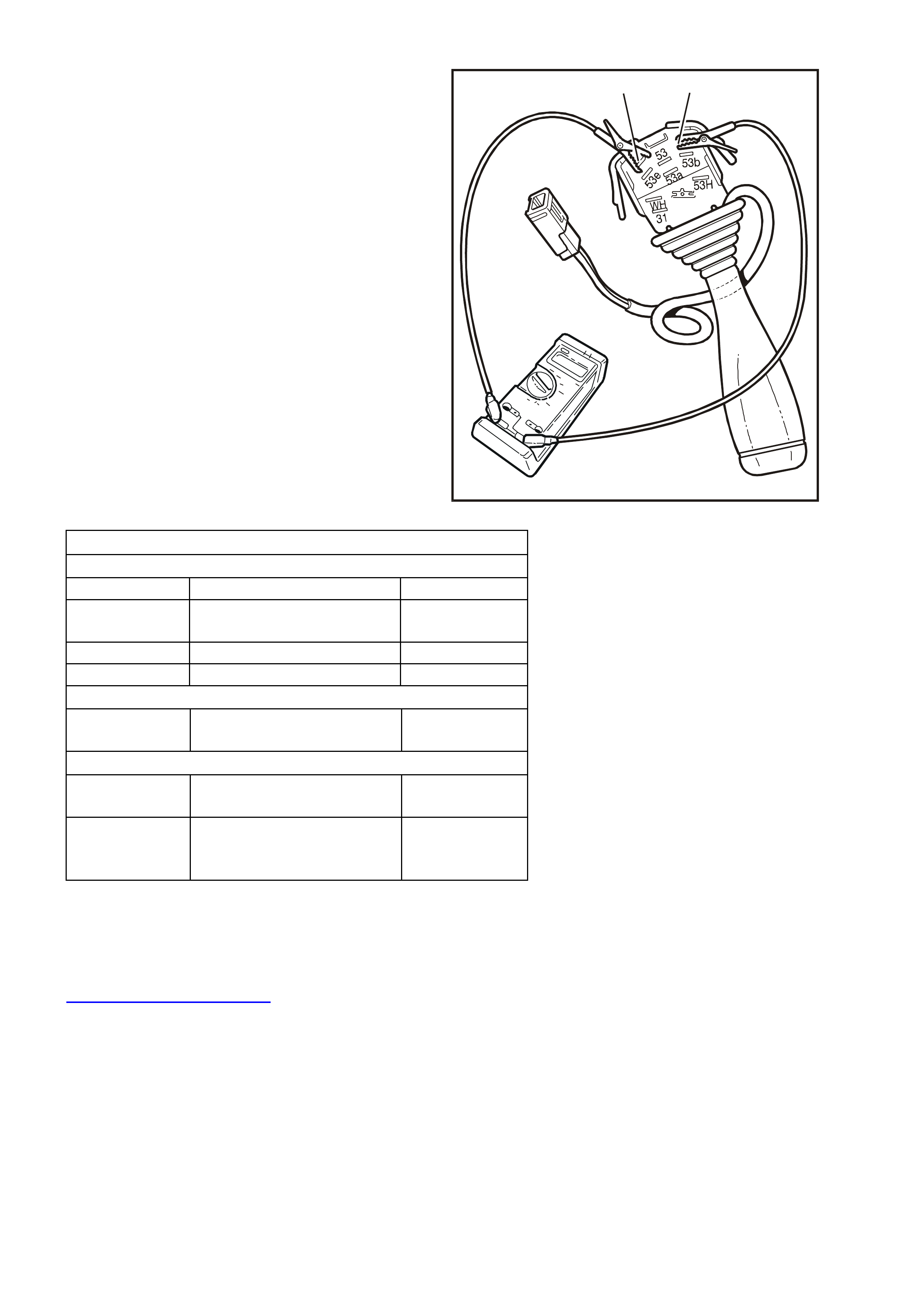
TESTING SWITCH
Using an ohmmeter, check switch contacts for
continuity at each switch position as indic ated in the
following chart.
If continuity between switch terminals is not as
specified, replace switch assembly.
NOTE: Switch terminal numbering is indicated on
the switch body, adjacent to each terminal.
WH12B051
49a49aR
Figure 12B-63
HEADLAMP AND TURN SIGNAL CONTROL SWITCH ASSEMBLY
TURN SIGNAL SWITCH CONTACTS
Switch Terminals Switch Pos i tion Indicat i on If OK
49a and 49aR
49a and 49aL Switch in cent ral position Open circuit
49a and 49aR Switch in right-hand turn position Continuity
49a and 49aL Switch in left-hand turn posit i on Continuity
HEADLAMP F L A SH CONTACTS
30 and 56a Flash positi on
High beam or central posi tion Continuity
Open circui t
HEADLAMP HIGH BEAM CONTACTS
56 and 56a Flash or central position
High beam position Open circui t
Continuity
56 and 56b Central posit i on
High beam position
Flash position
Continuity
Open circui t
Continuity
REINSTALL
Installation of the s witch assem bly is the reverse of
the removal procedure, noting the following points:
1. Check switch operation once it is installed.
IMPORTANT: Enable the SRS (Air Bag). Refer to
ENABLING THE SRS, Section 12M
SUPPLEMENTAL RESTRAINT SYSTEM of the VT
Series I Service Information.
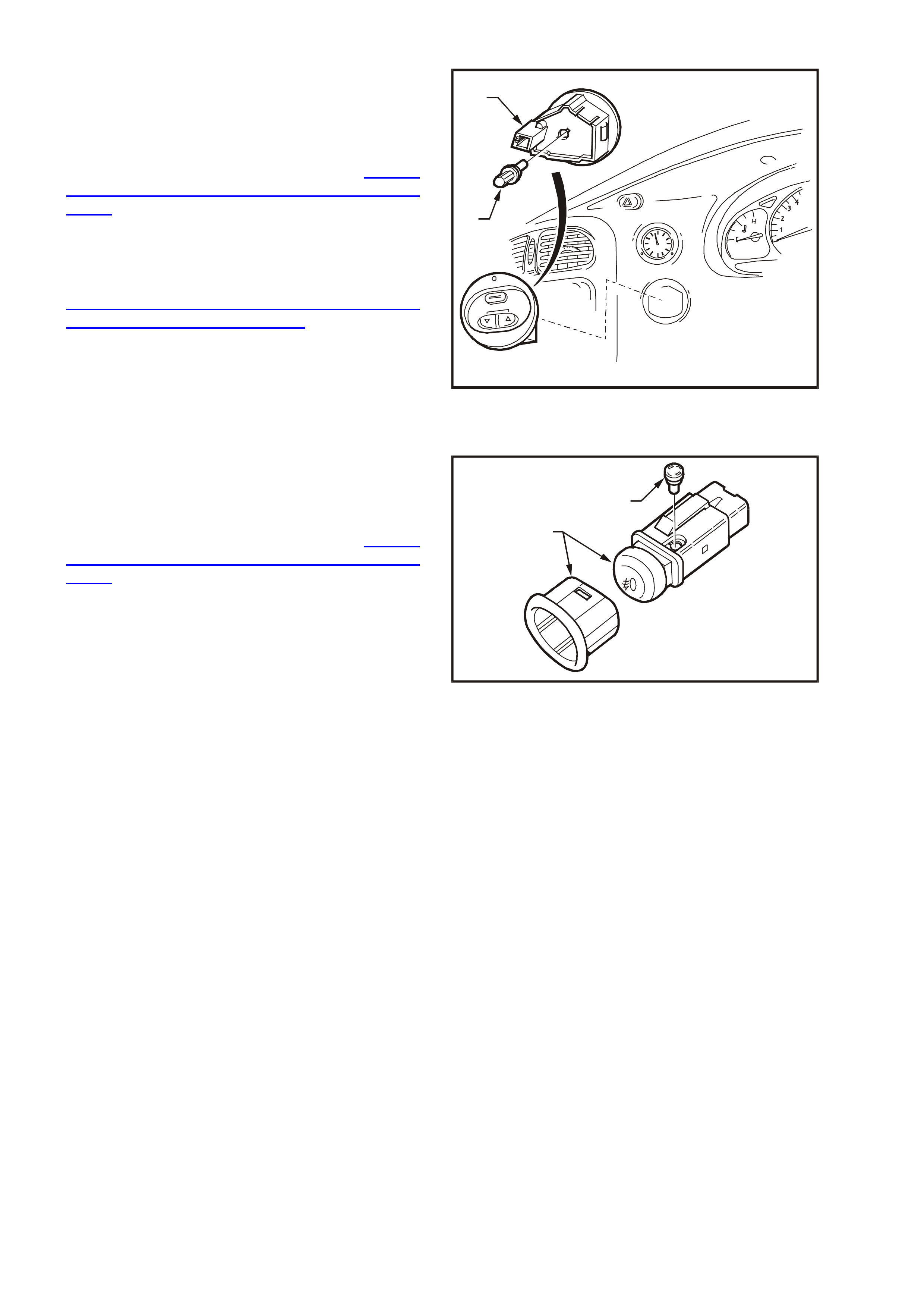
2.23 HEADLAMP SWITCH
REMOVE
1. Disconnect battery earth lead.
CAUTION: Disable the SRS (Air Bag). Refer to
DISABLING THE SRS, Section 12M
SUPPLEMENTAL RESTRAINT SYSTEM
2. Release steering colum n height adjusting lever
and completely lower steering column. Lock
lever in this position.
3. Place a clean shop rag over and around
steering column upper cover. This step is
important so as to prevent any possibility of
damage to cover when removing the
instrument facia.
4. Remove fasteners securing instrument facia to
instrument panel, refer to Section 1A3
INSTRUM ENT PANEL & CONSOLE of the VT
Series I Service Information
5. Pull instrument facia out only far enough to
gain access to rear of headlamp switch.
6. Pull connector (1) from headlamp switch (2).
7. Depress retaining tang on headlamp switch
connector and remove switch from facia.
WH12B047
1
2
Figure 12B-64
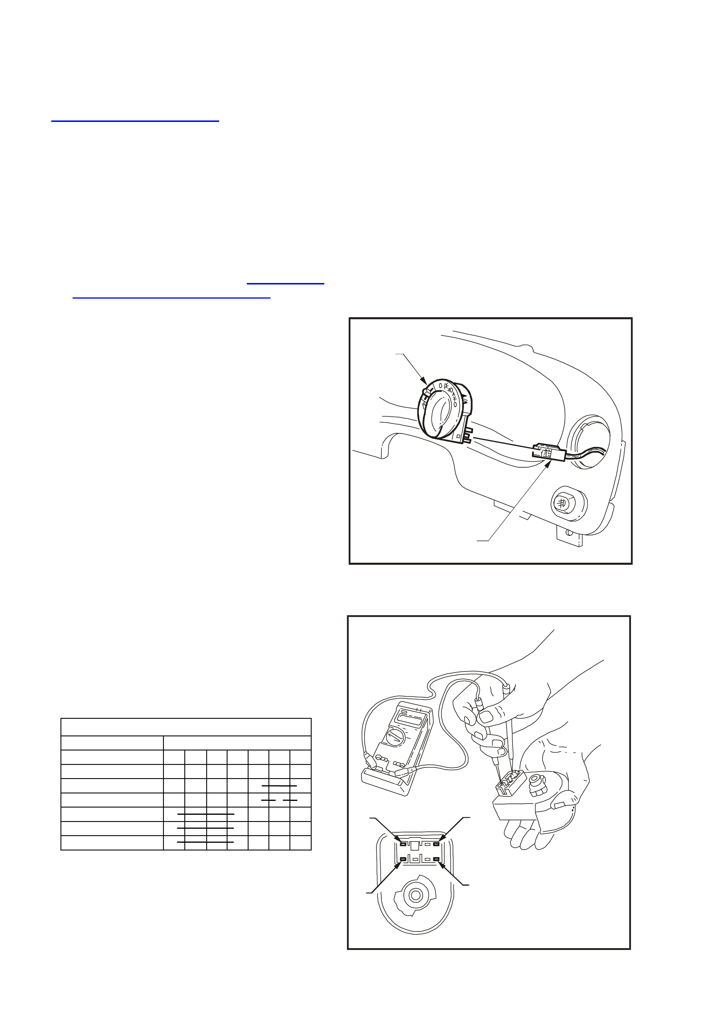
TESTING SWITCH
HEADLAMP SWITCH
Switch Position Terminal No.
1234567
Off
Park Lamps O O
Headlamps O O O
Low Intensity O O
High Intensity O O
Dome Lamp O O
With the aid of an ohmmeter, check continuity of
headlamp switch contacts, using the following
chart.
If continuity is not as specified at any switch
position, replace switch cluster assembly.
At low intensity setting, reading should be approx.
2.65 kΩ and at high intensity setting, approx. 5.3
kΩ.
WH12B048
75
4
1
Figure 12B-65

REINSTALL
Installation of the headlamp switch is the reverse of
the removal procedure, noting the following points:
1. If, when instrum ent fac ia was pulled away fr om
instrument panel pad, the pad retaining clips
came away with the facia lugs, pull clips from
lugs and install into pad holes. Fit instrument
facia and ensure that it is held to the
instrument panel pad securely.
2. Check for correct operation of headlamps and
switch.
IMPORTANT: Enable the SRS (Air Bag). Refer to
ENABLING THE SRS, Section 12M
SUPPLEMENTAL RESTRAINT SYSTEM of the VT
Series I Service Information.
2.24 HAZARD WARNING FLASHER S WITCH
REMOVE
1. Disconnect battery earth lead.
CAUTION: Disable the SRS (Air Bag). Refer to
DISABLING THE SRS, Section 12M
SUPPLEMENTAL RESTRAINT SYSTEM of the
VT Series I Service Information.
2. Release steering colum n height adjusting lever
and completely lower steering column, lock
lever in this position.
3. Place a clean shop rag over and around
steering column upper cover. This step is
important so as to prevent any possibility of
damage to cover when removing the
instrument facia.
4. Remove fasteners securing instrument facia to
instrument panel, refer to Section 1A3
INSTRUM ENT PANEL & CONSOLE of the VT
Series I Service Information.
Pull instrument facia out only far enough to
gain access to rear of all instrument facia
switches.
5. Depress retaining tangs on instrum ent harness
to facia s witch connector (2) and pull connec tor
from switches.
6. Remove instrument facia.
7. Squeeze together retaining tangs at side of
hazard warning flasher switch (1) and push
switch out from facia.
WH12B054
1
1
2
Figure 12B-66
TEST
REINSTALL
Installation of the hazard warning flasher switch is
the reverse of removal procedures, noting the
following points:
1. If, when instrum ent fac ia was pulled away fr om
instrument panel pad, the pad retaining clips
came away with the facia lugs, pull clips from
lugs and install into pad holes. Install
instrument facia and ensure that it is held to
the instrument panel pad securely.
2. Check hazard warning flasher switch operation
and ensure that switch illumination bulb
illuminates when the headlamps are turned on.
IMPORTANT: Enable the SRS (Air Bag). Refer to
ENABLING THE SRS, Section 12M
SUPPLEMENTAL RESTRAINT SYSTEM of the VT
Series I Service Information.
With the aid of an ohmmeter, check continuity of
hazard warning flasher switch contacts, using the
following chart.
If continuity is not as specified at any switch
position, replace switch assembly.
Figure 12B-67
HAZARD WARNING FLASHER SWITCH
CONTACTS
Terminal
No. Switch
Status
OFF ON
1 O O Flasher unit
2 O Ignition
3 O Battery
4 O Flasher unit
5 O Lamp
6 O Lamp
7 O Illum i nat i on +
Approx. 35 ohms
8 O Illum i nat i on –
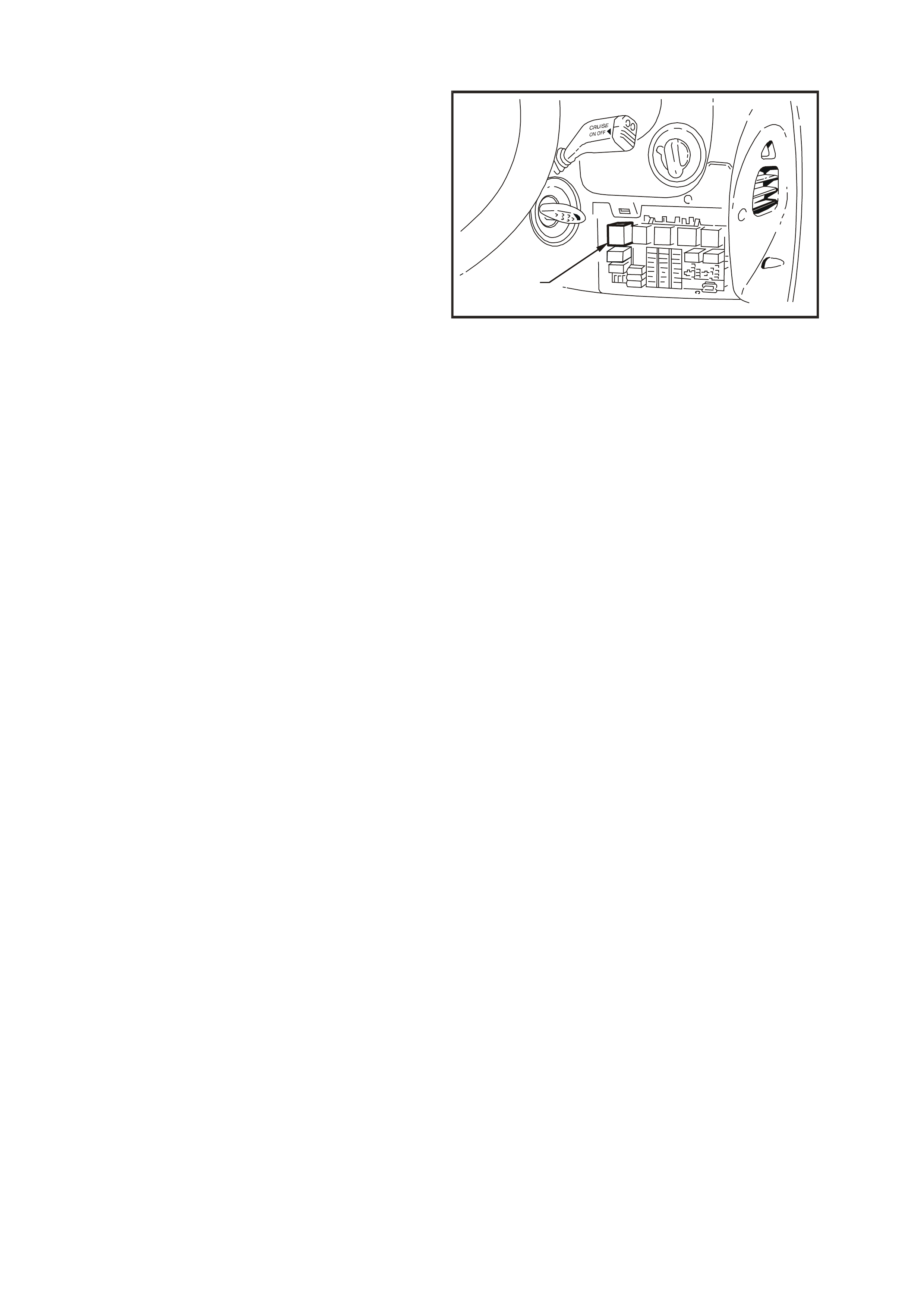
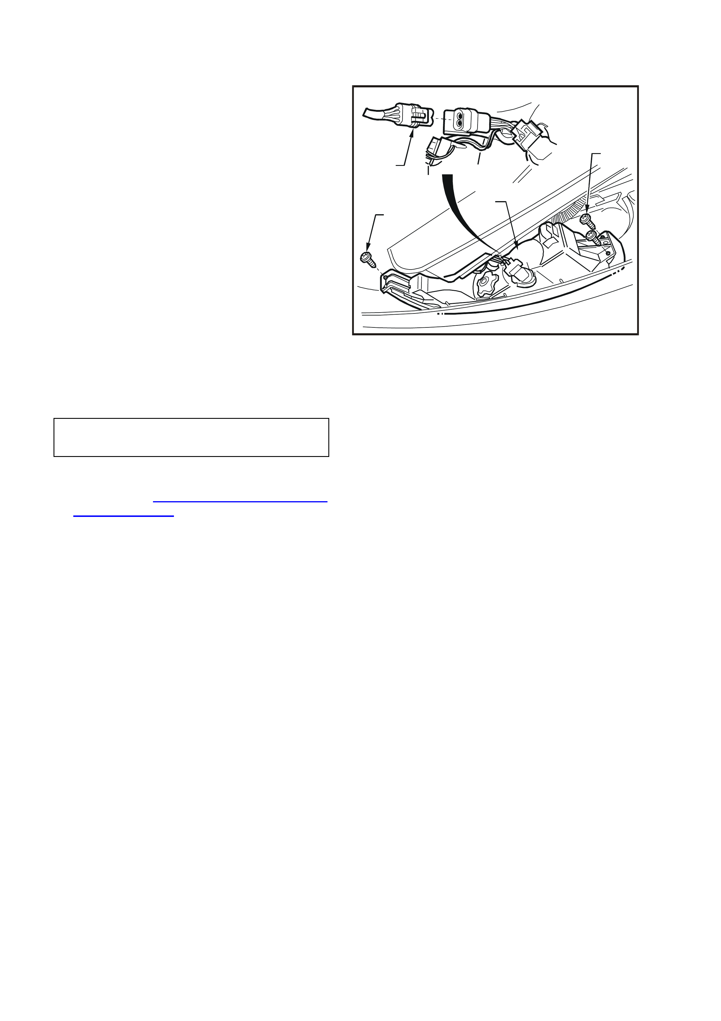
2.25 TURN S IGNAL AND HAZARD FLASHER UNIT
REPLACE
Fig. 12B-67 illustrates the location on the interior
fuse panel and installation of the turn signal and
hazard flasher unit (located inside the vehicle,
attached to the fuse panel).
Access to the turn signal and hazard flasher unit is
by gripping the upper portion of the instrument
panel right-hand cover assembly and pulling down,
disengaging the retaining clips.
WH12B055
1
Figure 12B-68
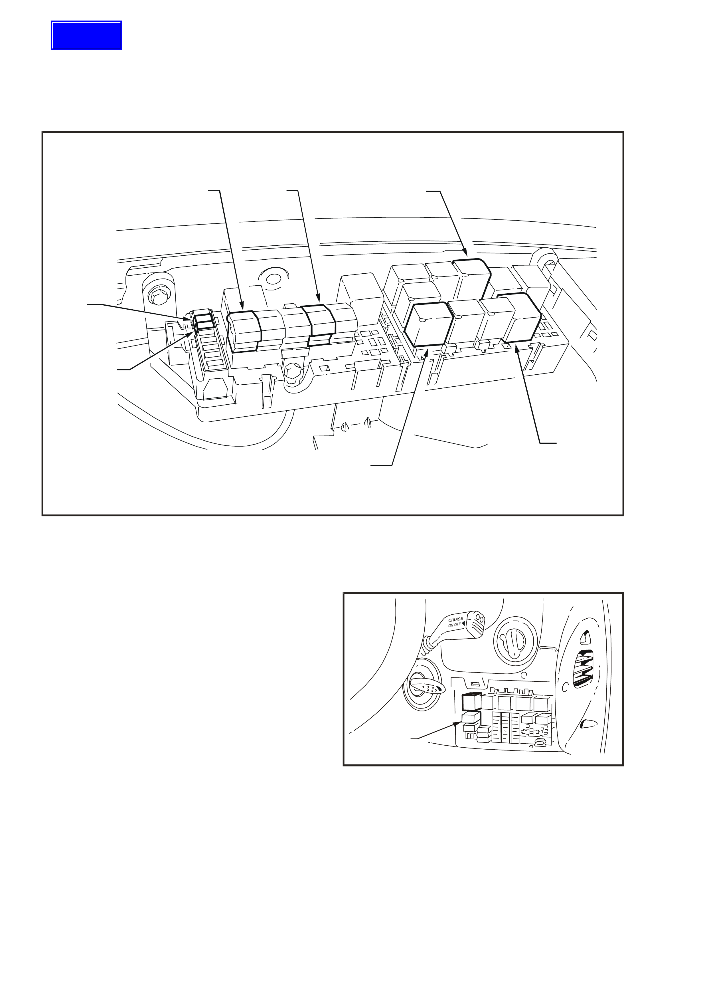
2.26 HEADLAMPS AND PARKING LAMPS RELAYS
REPLACE
Fig. 12B-68 illustrates the location in the engine
compartment relay housing of the relays used for
the headlamp operation, fog lamp relay and the
fusible link FJ.
WH12B056
123
4
5
6
7
Figure 12B-69
1. Headlamp fusible links 4. Headlamp high beam relay 6. Left-hand headlamp fuse
2. Main fusible link 5. Headlamp low beam relay 7. Right-hand headlamp fuse
3. Fog lamp relay
The parking lamps relay is located inside the
vehicle, attached to the fuse panel. Access to the
parking lamps relay is by opening the instrument
panel right-hand cover.
WH12B057
1
Figure 12B-70
Techline

3. SPECIFICATIONS
BULB POWER RATING
(WATTS) BASE TYPE
Headlamps:
Hi/Lo Beam (Outboard)
Inboard High Beam 60/55
55 H4
H1
Fog Lamps 27 H27W/2
Parking Lamps (Front) 5 Wedge
Turn Signal Lamps (Front) 21 Offset Pin (Orange glass)
Side Repeater Lamp 5 Wedge
Turn Signal (Rear) 21 Offset Pin (Orange glass)
Back-Up Lamp 21 Std. Parallel Pin
Stop And Tail Lamp 21/5 Std. Parallel Pin
Licence Plate Lamp 5 Wedge
Instrument Cluster Illumination
Lamp 5 Wedge
Instrument Cluster Warning
Cluster Lamp 1.2 Wedge
Trip Computer Illumination Lamp 1.2 Wedge
Rear Compartment 10 Festoon
Dome (Courtesy) Lamp 10 Festoon
Front Seat Reading Lamp 5 Std. Parallel Pin
Rear Seat Reading Lamp 5 Wedge
Glove Compartment Lamp 10 Festoon
Front Footwell Lamps 2.7 Wedge
Front Vanity Mirror Lamp 1.4 Wedge
Door Courtesy Lamp 5 Festoon
Console Bin Lamp 5 Festoon
High Mounted Stop Lamp 18 Wedge
Front And Rear Cigar Lighter
Lamp 1.2 Wedge
Ignition Lock Lamp 1.2 Wedge

4. TORQUE WRENCH SPECIFI CATIONS
Nm
Headlamp and turn signal/parking lamp
assembly securing screws.................................................... 2 – 5
Fog lamp to bumper bar facia retaining screws.................... 2 – 5
Dome lamp attaching screws................................................ 3 – 5
Door jamb switch attaching screws ...................................... 3 – 5
Headlamp adjuster attaching screws.................................... 3 – 5
Rear compartment lid lamp assembly attaching nuts........... 2 – 5
Rear compartment lamp switch attaching screw.................. 1 – 3
Rear lamp housing retaining screw....................................... 1 – 3
Transmission selector lever locking bolt............................... 15 – 35
Rear quarter lamp housing attaching screws ....................... 3 – 4
Selector lever retaining nut................................................... 15 – 35
Neutral/Start and Back-up switch retaining screw ................ 15 – 35