SECTION 12C - INSTRUMENTS, WIPERS/WASHERS
& HORN
IMPORTANT
Before performing any Service Operation or other procedure described in this Section, refer to
Section 00 CAUTIONS AND NOTES for correct workshop practices with regard to safety and/or
property damage.
1. GENERAL DESCRI PTI O N
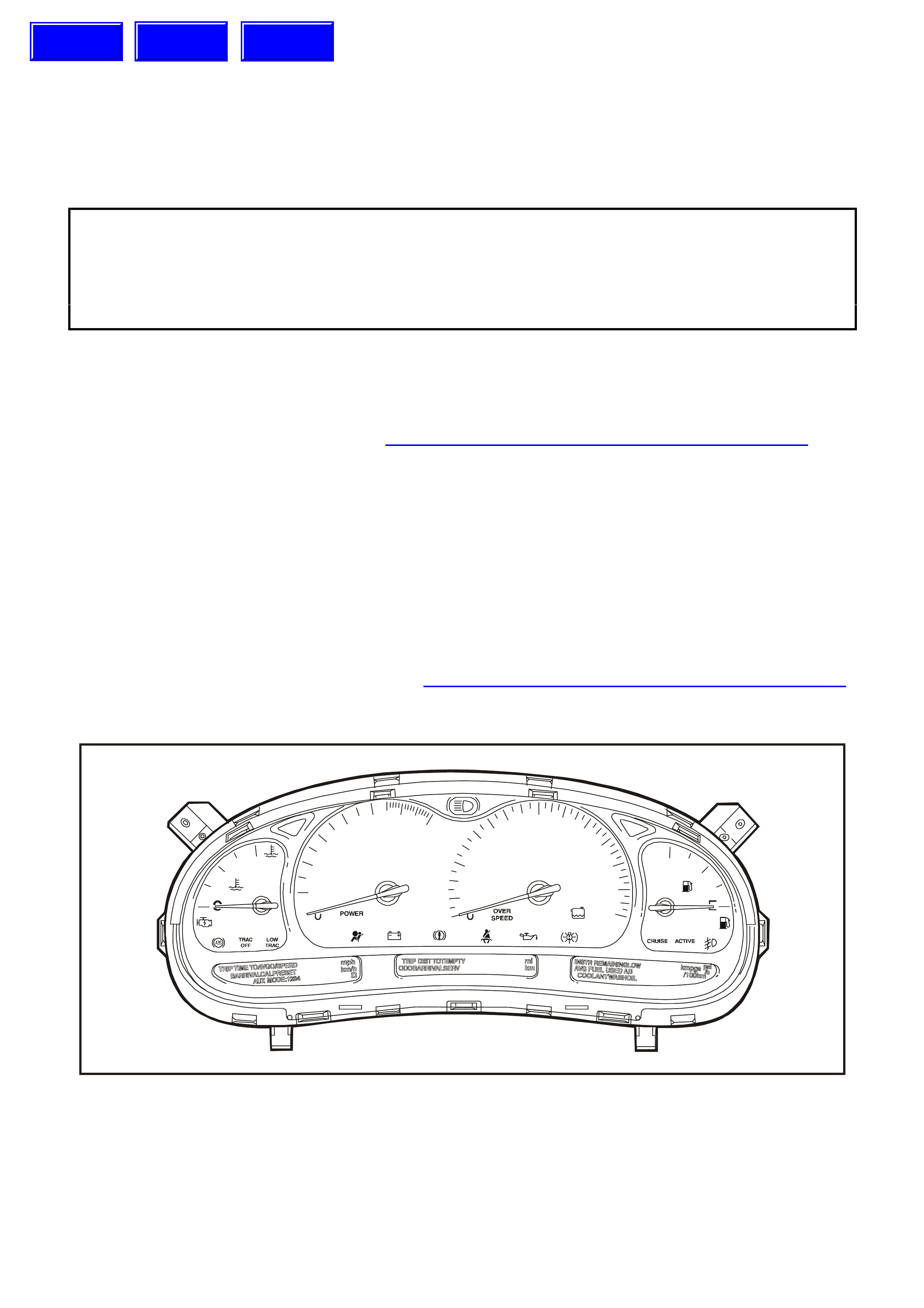
The WH Statesman and Caprice models incorporate a triple window display instrument cluster, which is the same
as the triple window display fitted to the VT Series II. Many features and service operations are similar to the
existing VT Series II, and these are detailed in Section 12C INSTRUMENTS, WIPERS/WASHERS & HORN of the
VT Series II Service Information.
The triple window display instrument cluster is illustrated in Fig. 12C-1.
The automatic transmission gear selection is shown on the instrument cluster between the speedometer and the
tachometer.
The POWER lamp on the instrument cluster illuminates when the driver selects the Power Mode on the
ECONOMY/POWER button. For vehicles fitted with V6 and V6 Supercharged engines, the POWER lamp remains
illuminated when cruise control is engaged. However, for vehicles fitted with the GEN III V8 engine, the POWER
lamp extinguishes when cruise control is engaged, and illuminates again when cruise control is disengaged.
An analogue clock is incorporated in the instrument panel to the left of the instrument cluster.
The design of the trip computer switch for the WH Series Statesman has changed but the functions remain the
same as the VT Series II. The new trip computer switch is located in the instrument panel beneath the clock.
For further details on the instrument cluster, refer to Section 12C INSTRUMENTS, WIPERS/WASHERS & HORN
of the VT Series II Service Information.
T212C043
H
7
6
x1000 rpm km h
5
4
3
2
120
1
2
3
D
N
RP
4060 80 100 120140
160 F
180
200
220
LPG
Figure 12C-1
Techline
Techline
Techline
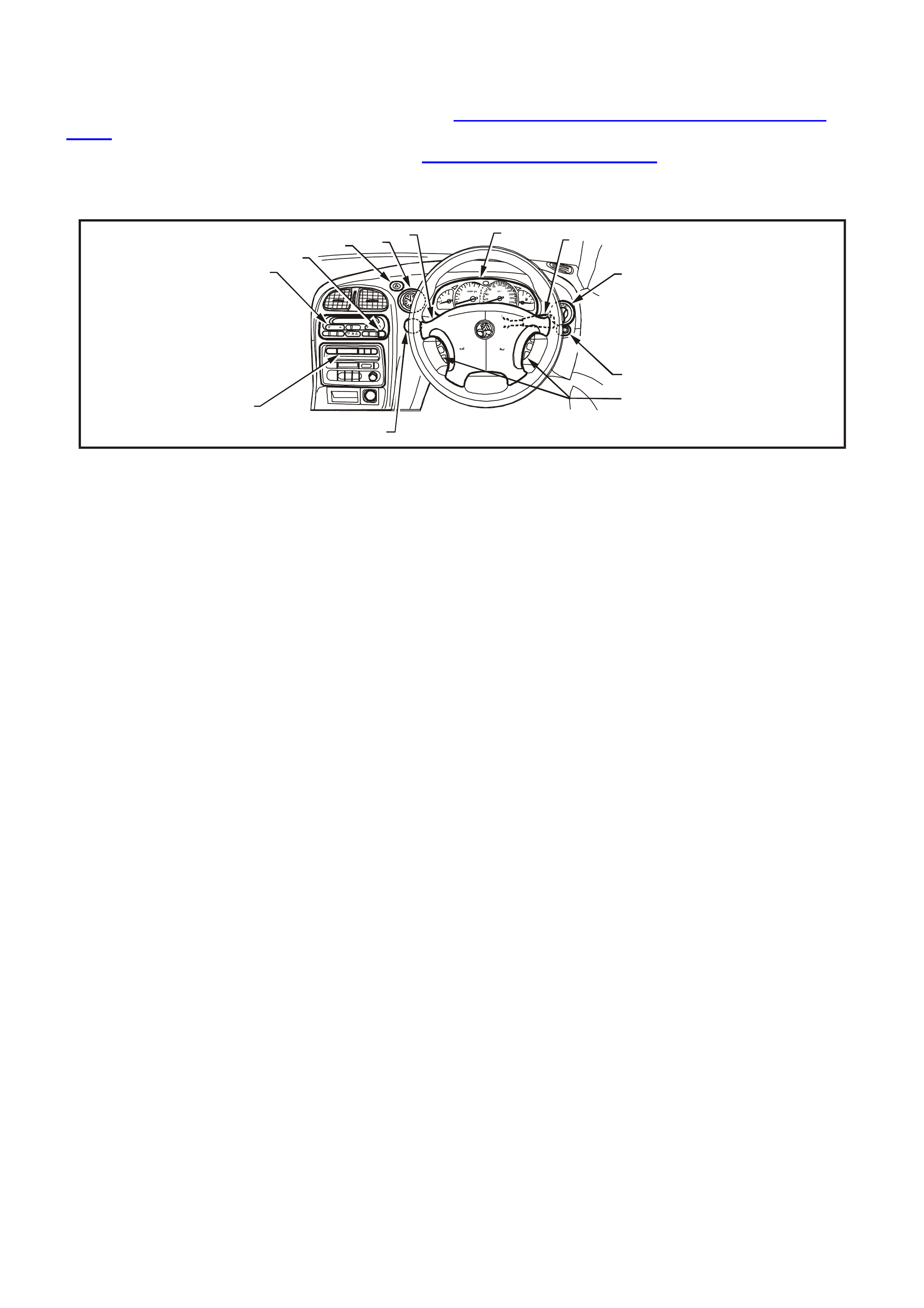
1.1 INSTRUME NT FACIA SWITCHES
Fig. 12C-2 illustrates the various switch locations in the instrument facia for the WH Series models. Some switches
are the same as those fitted to the VT Series II. Refer to Section 12C INSTRUMENTS, WIPERS/WASHERS &
HORN of the VT Series II Service Information.
For testing of the instrument facia switches, refer to Section 12B LIGHTING SYSTEM of the VT Series I Service
Information.
0
1
2
34567
C
H
P
R
N
D
3
20
20
40
60 80 100120
140
160
180
200
220
F
E
O/S
TEMP MO DE
A/C
OFF
AUTO
MIN
MAX
A
U
T
O
1234567
8
9
10
11
12
WH12C001
Figure 12C-2
1. Climate Controls 5. Wipers and Washers 9. Fog Lamp Switch
2. Heated Rear Window Switch 6. Instrument Cluster 10. Steering Wheel Audio System Controls
3. Hazard Warning Switch 7. Turn Signal, High/Low Beam and
Cruise Control 11. Trip Computer Switch
4. Clock 8. Headlamp Switch 12. Audio System Controls


1.4 CLOCK
OPERATION
The + (forwards) and – (backwards) control buttons are used to adjust the time. Each button can be either held
down for fast scrolling, or tapped for individual adjustment.
1.5 TRIP COMPUTER — TRIPLE WINDOW TYPE
OPERATION
The operation of the triple window type trip computer on the WH Series models is the same as for that fitted to the
VT Series II. Refer to Section 12C INSTRUMENTS, WIPERS/WASHERS & HORN of the VT Series I Service
Information.
BASIC FUNCTIONS
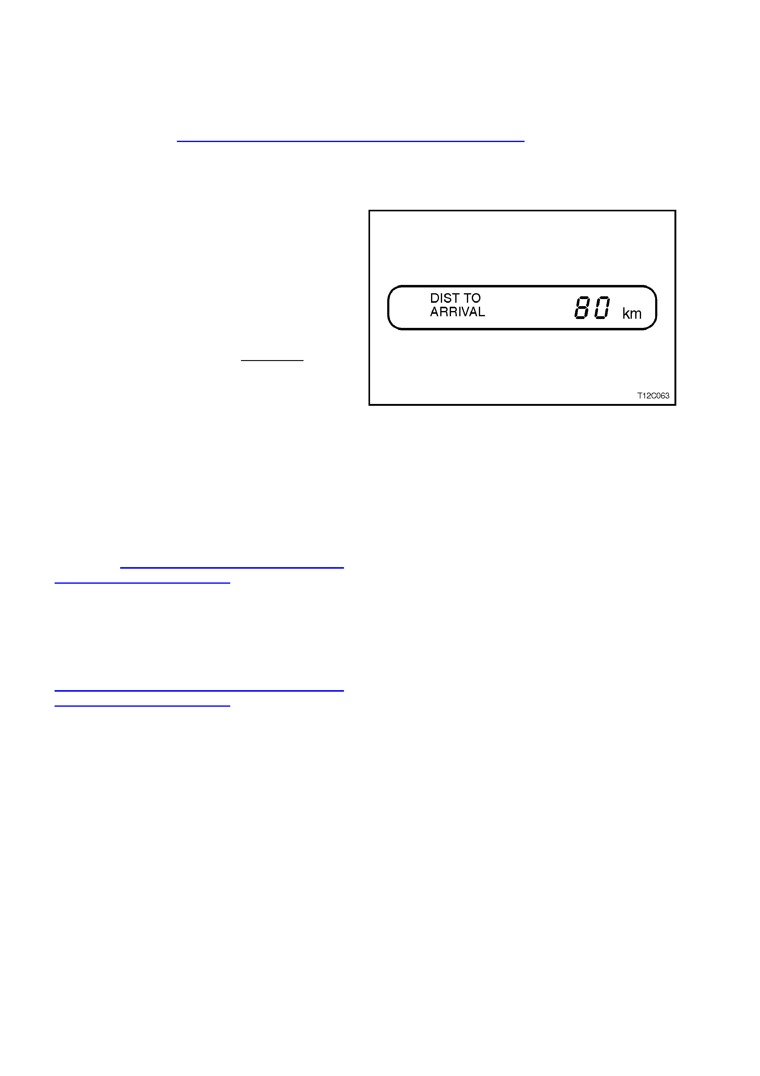
Distance to Arrival
At the start of a trip estimate distance to arrival
(from maps, road signs etc.). Tap the ▲ or ▼
buttons until the display shows estimated trip
distance. When the vehicle is driven the computer
will constantly update time to arrival, based on
changing driving speeds. The ▲ or ▼ buttons can
be used to adjust the kilometres any time this
display is shown.
Even if DISTANCE T O ARRIVAL is tur ned of f us ing
customise mode, it can still be temporarily turned
on by the following quick method:
Press MODE button until the TRIP display is
shown, press the ▲ and ▼ buttons together to zero
the trip display, then increase the distance up by
pressing the ▲ button.
However, when the trip distance reaches zero the
function will turn off again. Use the customise mode
to permanently turn the above displays on.
Figure 12C-3
The remaining basic functions of the triple window
type trip computer on the WH Series models are
the same as for that fitted to the VT Series II. Refer
to Section 12C INSTRUMENTS,
WIPERS/WASHERS & HORN of the VT Series II
Service Information.
ADDITIONAL FUNCTIONS
The additional functions of the triple window type
trip computer on the WH Series models are the
same as for that fitted to the VT Series II. Refer to
Section 12C INSTRUMENTS,
WIPERS/WASHERS & HORN of the VT Series II
Service Information.


2.2 INSTRUME NT CLUSTER INPUTS
The instrument cluster inputs are the same as for that fitted to the VT Series II. Refer to Section 12C
INSTRUMENTS, WIPERS/WASHERS & HORN of the VT Series II Service Information.
CHECK
To check the input voltage or wiring continuity between the various sensors/senders to the instrument cluster
connector, refer to 5. DIAGNOSTICS in this Section.

2.3 SENDER UNITS
VEHICLE SPEED SENDER
Automatic Transmission
For all details of the automatic transmission vehicle speed sensor removal, testing, installation instructions, refer to
Section 6C1 POWERTRAIN MANAGEMENT — V6 ENGINE of the VT Series I Service Information, or Section
6C3-3 SERVICE OPERATIONS — GEN III V8 ENGINE of the VT Series II Service Information.
FUEL GAUGE SENDER UNIT
The service operations for the fuel gauge sender unit on the WH Series models are the same as for that fitted to the
VT Series II. Refer to Section 12C INSTRUMENTS, WIPERS/WASHERS & HORN of the VT Series I Service
Information.
LOW COOLANT SENDER UNIT
The service operations for the low coolant sender unit fitted to the GEN III V8 engine are detailed in Section 6C3-3
SERVICE OPERATIONS — GEN III V8 ENGINE of the VT Series II Service Information.

2.4 TRIP COMPUTER SWITCH ASSEMBLY
REMOVE
1. Remove the instrument panel facia, refer to
Section 1A3 INSTRUMENT PANEL AND
CONSOLE in this Supplement.
2. Grasp the trip computer switch (1) locking tabs
from behind the switch, squeeze the tabs and
push the switch from the instrument panel facia.
3. Disconnect the electrical connector (2) from the
trip comput er switch.
WH12C002
12
Figure 12C-4
REINSTALL
Installation is the reverse of the removal procedure.

2.5 CLOCK
REMOVE
1. Remove the instrument panel facia, refer to
Section 1A3 INSTRUMENT PANEL AND
CONSOLE in this Supplement.
2. Grasp the clock (1) lock ing tabs f rom behind the
clock , squeeze the tabs and push the clock from
the instrument panel facia.
3. Disconnect the electrical connector (2) from the
clock.
12
WH12C003
Figure 12C-5
REINSTALL
Installation is the reverse of the removal procedure.


5. INSTRUMENT DIAGNOSTICS
5.1 BASIC KNOWLEDGE REQUIRED
Before attempting to diagnose the instrument cluster you must have a good understanding of electrical system
basics and the use of circuit testing tools. Without this basic knowledge it will be difficult to use the diagnostic
procedures detailed in this Section.
Some electrical basics, as well as basic troubleshooting procedures and hints as the use of circuit testing tools are
covered in Section 12P WIRING DIAGRAMS of the VT Series I Service Information.
Basic Electrical Circuits - You should understand the basic theory of electricity, series and parallel circuits, and
voltage drops across series resistors. You should know the meaning of voltage (volts), current (amps), and
resistance (ohms). You should understand what happens in a circuit with an open or shorted wire (shorted either to
voltage or earth). You should also be able to read and understand a wiring diagram.
Additionally, a knowledge of AC theory including; inductance, capacitance and impedance would be useful.
Use of Circuit Testing Tools - You should know how to use a jumper lead to test circuits. You should be familiar with
the use of a high input impedance (10 Mohm) digital type multimeter such as Tool No. J39200 or equivalent and be
able to measure voltage, current, and resistance. You should be familiar with the proper use of the TECH 2
Diagnostic Scan Tool.
NOTE: The vehicle’s battery must be removed before performing any earth resistance checks with a high
impedance multimeter.
Techline

5.2 PRELIMINARY SYSTEM DIAGNOSIS
When investigating any complaint of an instrument cluster problem or malfunction, always begin diagnosis with a
circuit check, refer to 5.8 INSTRUMENT DIAGNOSTIC PROCEDURES, DIAGNOSTIC CIRCUIT CHECK chart in
this Section.
The diagnostic circuit check is a preliminary procedure that checks to ensure the instrument cluster is
communicating on the serial data line as well as helping to identify the problem.

5.3 INSTRUME NT CLUS TER DIAGNOSTICS
The instrument cluster is equipped with a self-diagnostic capability that can detect and isolate instrument problems
or failures. When a fault is detected, the instrument cluster sets a Diagnostic Trouble Code (DTC) that represents
that particular problem or failure. When a DTC is set, an icon is shown in the left-hand instrument window.
However, DTC 16 to DTC 20 do not set the icon on the instrument cluster as these represent a fault condition
logged by one of the various vehicle control modules.
DIAGNOSTIC TROUBLE CODES
There are two types of DTC, current and history.
• A Current DTC is active only for the period that the fault is present and is indicated by the icon on the instrument
cluster. When the fault is cleared, the Current DTC and the icon are also cleared.
• The History DTC is set at the same time as the Current DTC, and is stored in memory within the instrument
cluster to provide information on vehicle system operation over a period of time. History DTC are cleared from
memory 100 ignition cy cles after the last DTC of any type was set.
DIAGNOSTIC MODE OPERATION
To enter the instrument cluster diagnostic mode, press the trip computer switch MODE button down together with
the ▲
▲▲
▲ button while turning the ignition from off to on. Further pressing the MODE button will step through the various
instrument cluster information displays.
When the Diagnostic Mode Display is reached, pressing the ▲
▲▲
▲ button increments the DTC number and related
information displayed, while the ▼
▼▼
▼ button can be used to decrement the DTC number and related information. To
exit the instrument cluster diagnostic mode, press both the ▲
▲▲
▲ button and the ▼
▼▼
▼ button together.
A DTC is shown on the Diagnostic Mode Display as ‘t NN XY’ , where:
t= diagnostic trouble code (DTC),
NN = the actual DTC number,
X= the history DTC status (H for active and – for inactive), and
Y= the current DTC status (C for active and – for inactive).
In instances where the DTC is disabled due to the particular model configuration the letters nu (not used) appear in
the XY position. For example, a vehicle which is not fitted with ABS or ABS/ETC will have DTC 8 shown as ‘t 08 nu’.
Similarly, DTC 4, DTC 5 and DTC 6 will appear as not used on a vehicle which is not fitted with LPG.
It is important to note that an open circuit fuel (petrol) gauge sender unit is recognised by the instrument cluster self-
diagnostics as ‘t 00 H C’, whereas the TECH 2 Diagnostic Tool will recognise the same fault as DTC 3.
A DTC may also be cleared from the instrument cluster using the trip computer switches while in the diagnostic
mode. With the DTC displayed in the instrument cluster window, press both the ▲
▲▲
▲ button and the ▼
▼▼
▼ button together
for more than 2 seconds. Pressing these buttons for less than 2 seconds will exit the instrument cluster diagnostic
mode.
Faults can be identified by using TECH 2 to test instruments and force values and conditions into the instrument
cluster. The results of these tests can be used to diagnose problems in the instrument cluster such as inoperative
bulbs and faulty gauges and switches.
Faults within other components can be identified after using TECH 2 to confirm correct operation of the instruments.
For example, if there was a reported fault with the speedometer gauge and TECH 2 diagnosed the gauge as
working correctly, then the fault would lie in the Powertrain Control Module (PCM) or in the harness from the speed
sensor to the PCM, both of which would then require further testing.
USE OF TECH 2 DIA GNOSTIC TOOL WITH INTERMITTENT FAULTS
The TECH 2 Diagnostic Tool allows manipulation of wiring harnesses, while observing the TECH 2 Diagnostic Tool
readout. If the problem seems to be related to certain parameters that can be checked on the TECH 2 Diagnostic
Tool, they should be checked while driving the vehicle. If there does not seem to be any connection between the
problem and any specific circuit, the TECH 2 Diagnostic Tool can be used to monitor each parameter, watching for
a period of time to see if there is any change in the readings that indicates intermittent operation.
The TECH 2 Diagnostic Tool saves time in diagnosis and helps to prevent the replacement of good parts. The key
to using the TECH 2 Diagnostic Tool successfully is the technicians ability to understand the system being
diagnosed, as well as understanding the TECH 2 Diagnostic Tool operation and limitations. The technician should
read the TECH 2 User’s Guide to become familiar with the TECH 2 Diagnostic Tool operation.
With an understanding of the data which the tool displays, and knowledge of the circuits involved, the tool can be
very useful in obtaining information which would be more difficult or impossible to obtain with other equipment.
The TECH 2 Diagnostic Tool does not make the use of diagnostic charts unnecessary, nor can it indicate exactly
where a problem is in a particular circuit. Diagnostic charts incorporate diagnostic procedures that require the use
of a TECH 2 Diagnostic Tool.
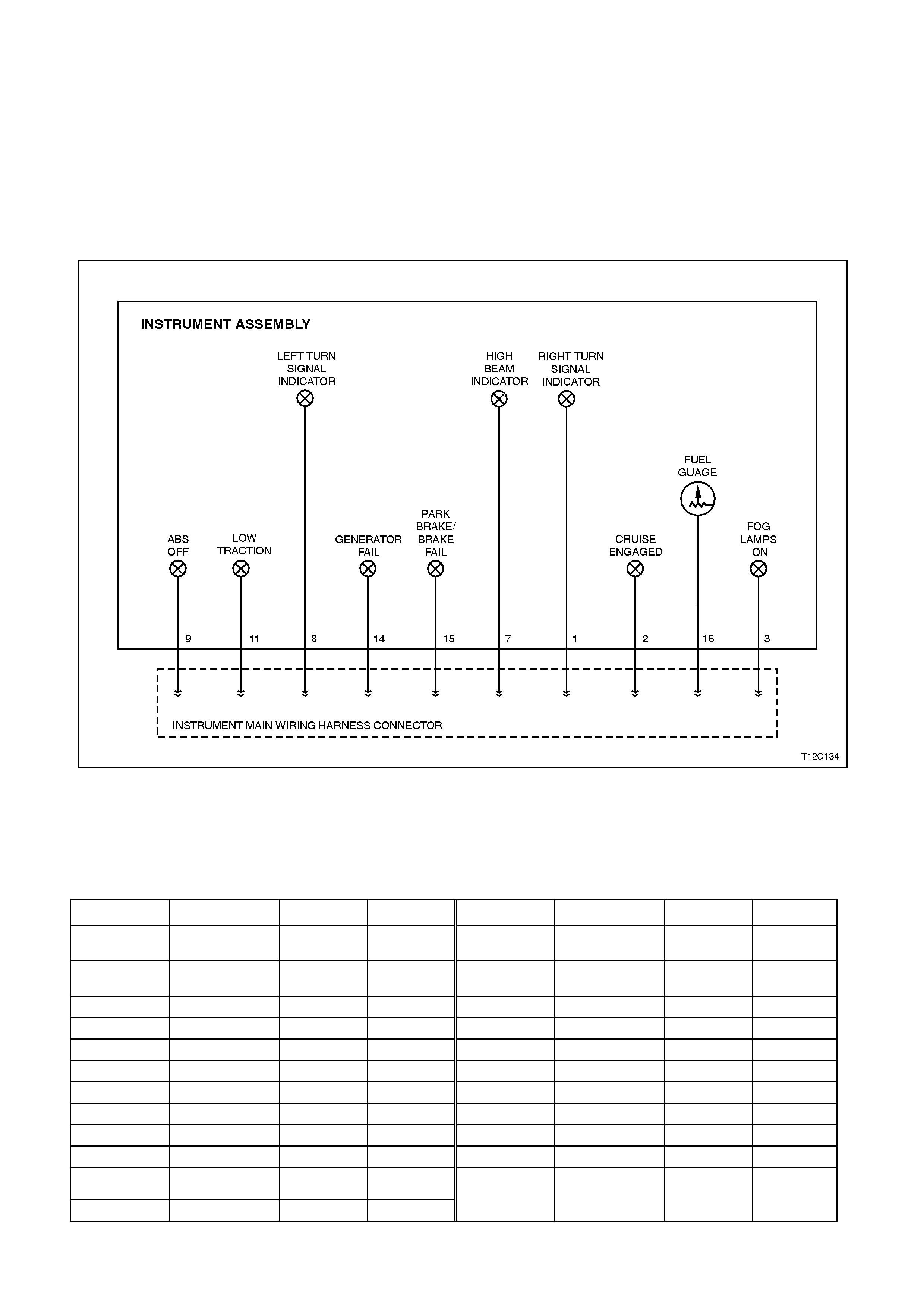
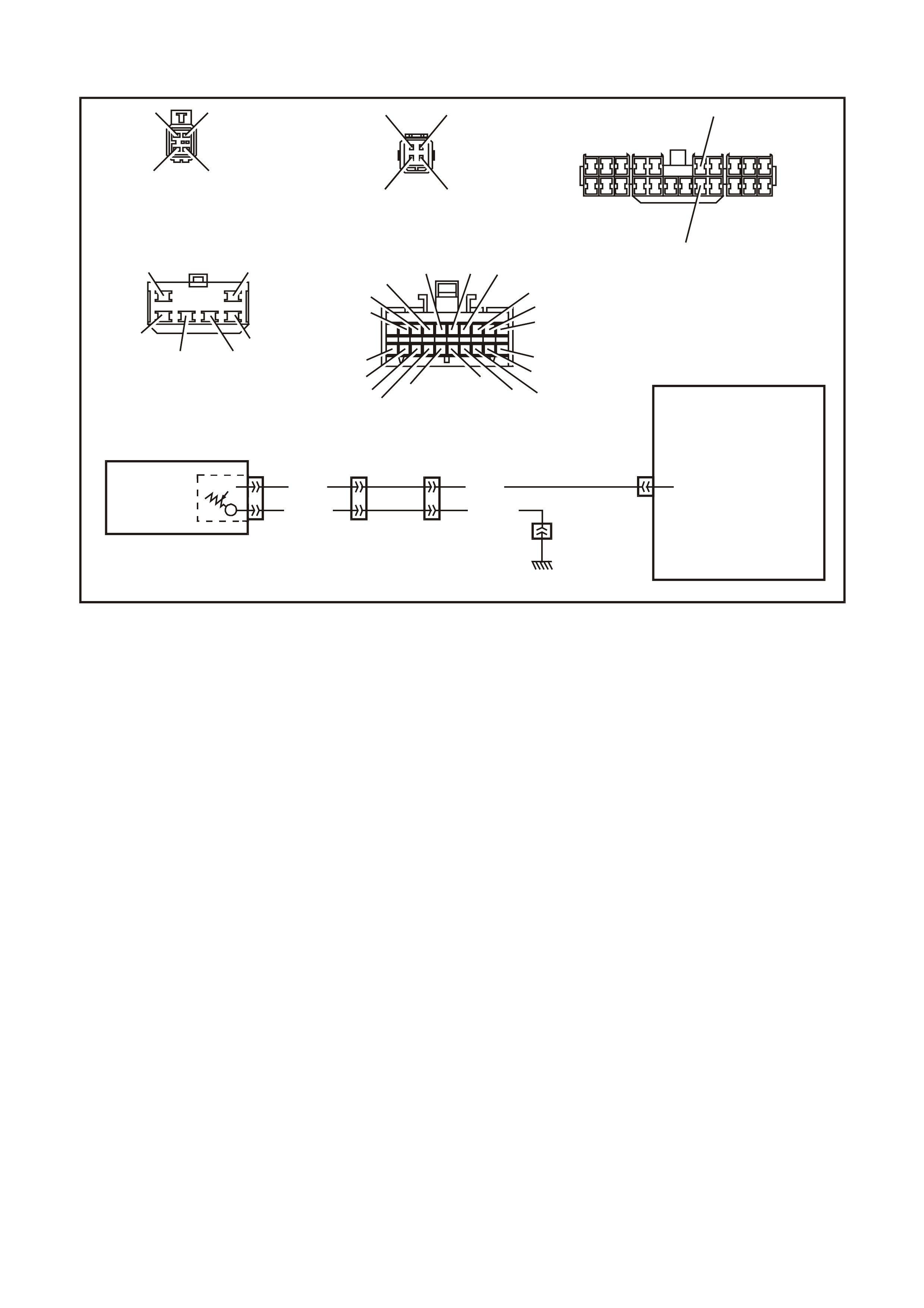
5.4 DIAGNOS I NG FAULTS NOT COVERED BY TECH 2 DIAGNOSTIC TOOL
Some components of the instrument cluster cannot be diagnosed by the TECH 2, although their operation can be
tested using the F4: Miscellaneous Tests function of the TECH 2. These components must be dealt with separately
and include the following instrument tell-tale lamps:
• Fog lamps on lamp
• Cruise engaged lamp
• Low traction lamp
• ABS off lamp
• Park brake/brake fail warning lamp
• Generator lamp
• Turn signal indicator lamps
• High beam lamp
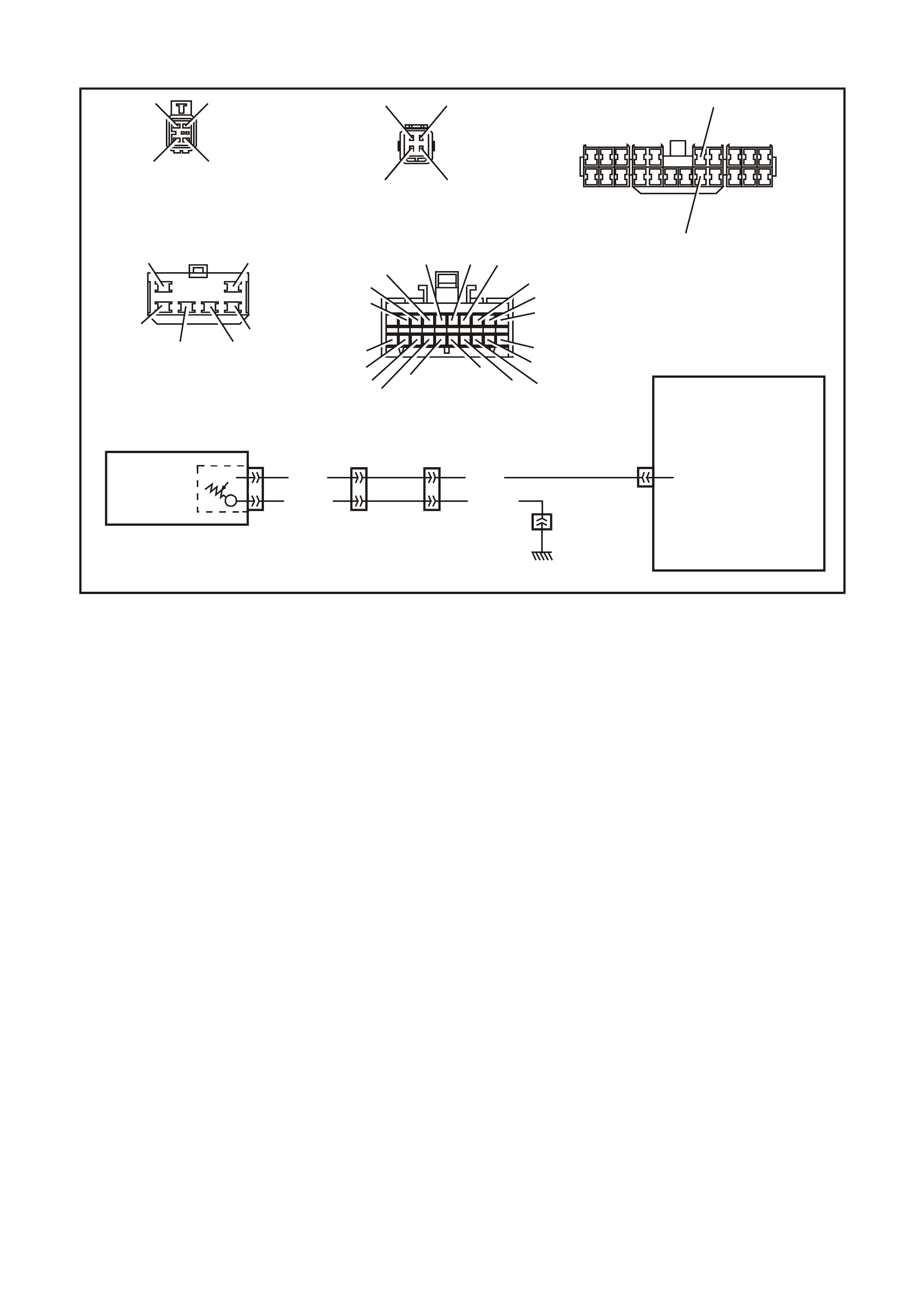
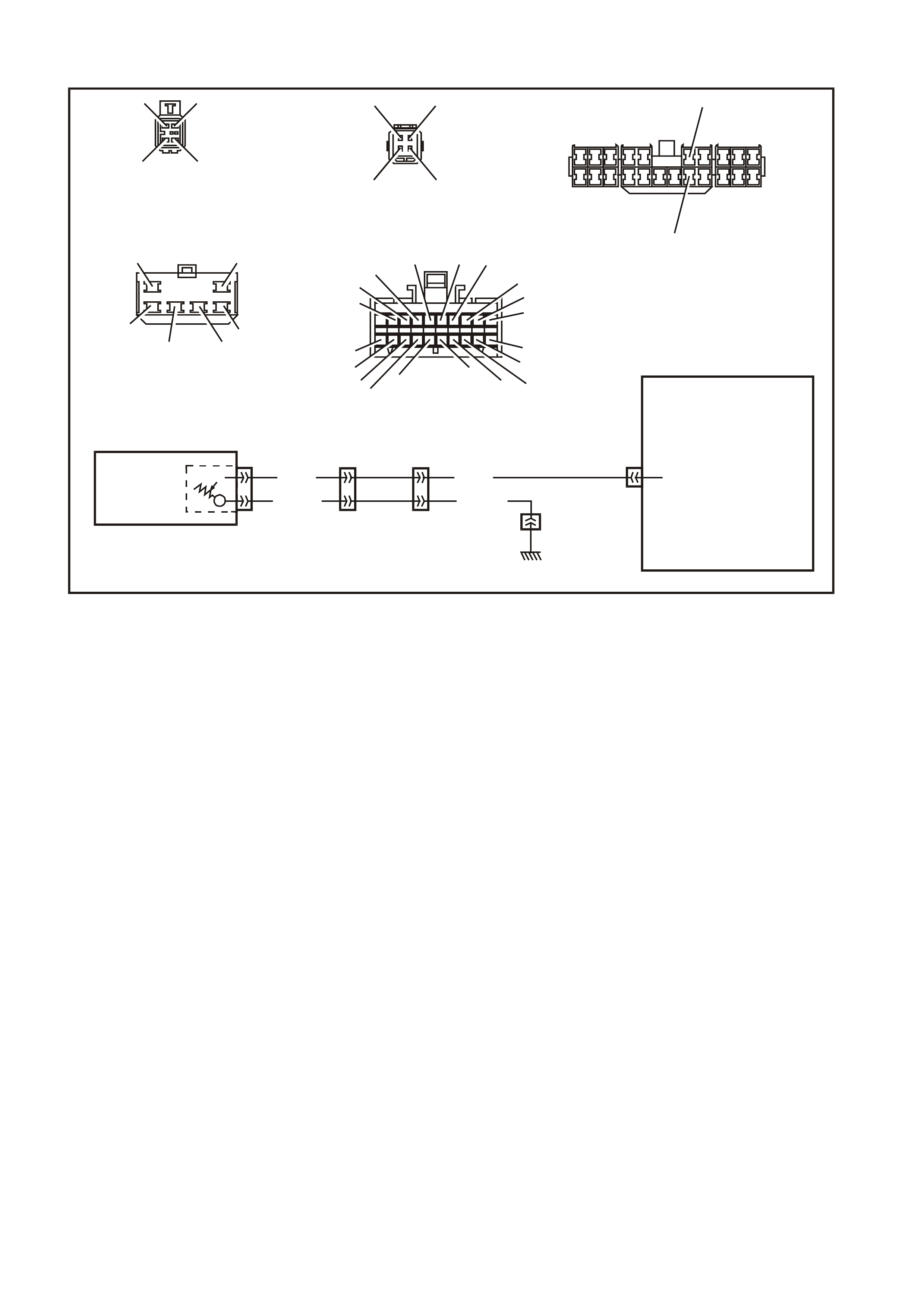
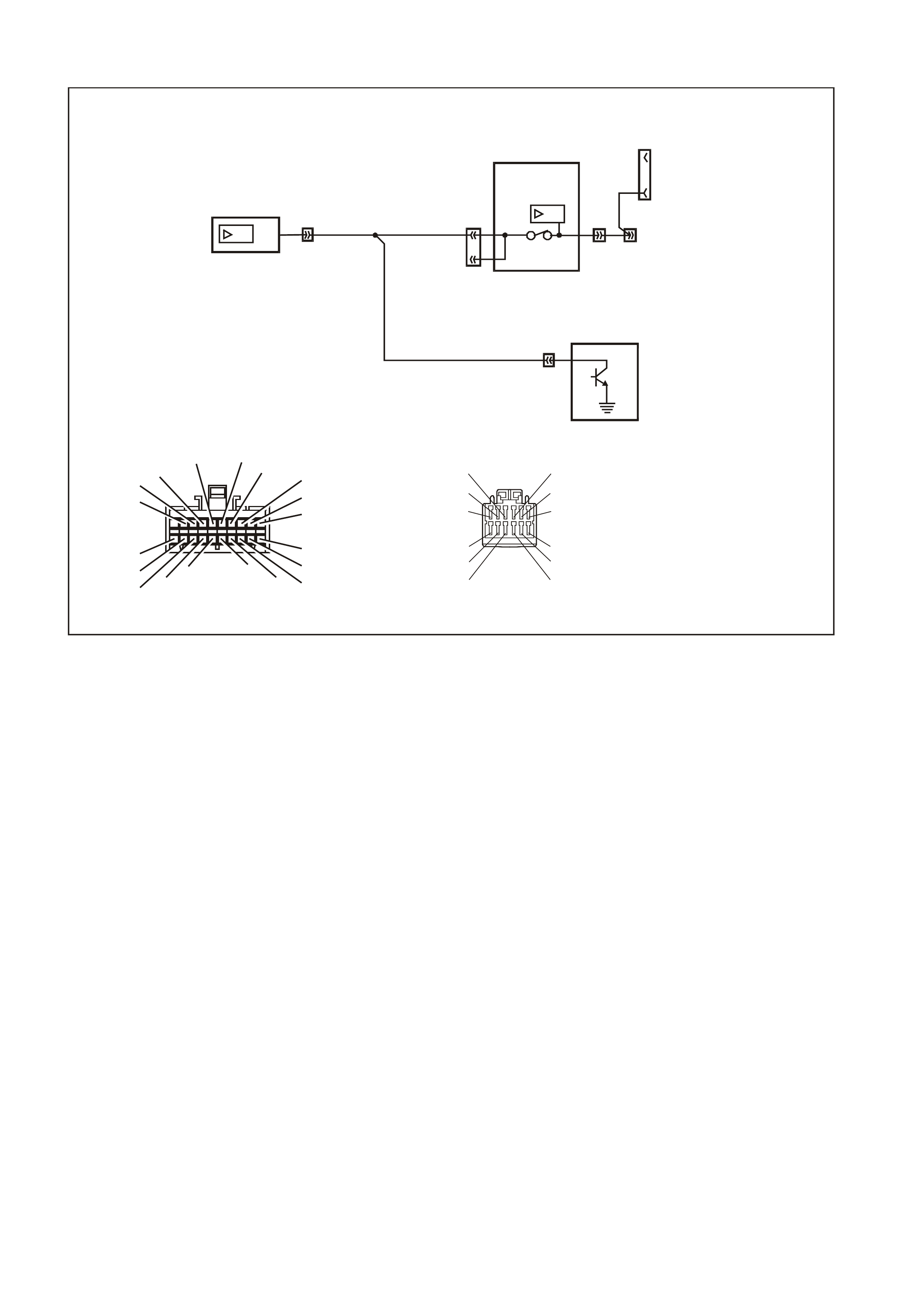
Fig. 12C-3 illustrates the components of the instrument cluster which are exclusively not on the serial data line.
Figure 12C-6
Warning Lamp Application Char t
The following table indicates the wiring configuration for the instrument cluster warning lamps.
NOTE: Some lamps may not be installed in all models.
LAMP CONFIGURATION STATESMAN CAPRICE LAMP CONFIGURATION STATESMAN CAPRICE
High Beam HW X X High
Temperature SD X X
Left Turn HW X X Check
Powertrain SD X X
Right Turn HW X X ABS Of f HW X X
Power Shift SD X X Traction Off SD X X
Overspeed INT X X Low Coolant SD X X
LPG SD — — Low Traction HW X X
Air Bag SDXXCruise SDXX
Gen Fail HW X X Cruise Active HW X X
Brake Park/Fail HW X X Fog Lamps HW X X
Seat Belt INT X X Low Fuel INT X X
Oil Pres sure SD X X Selec tor Lever
Position SD X X
Rear Lamp Fail SD X X (PRND123)
INT = Internal HW = Hard Wired SD = Serial Data

Fuel Gauge Sender
When investigating complaints regarding the operation of the fuel gauge, use the TECH 2 diagnostic tool to
ascertain whether the problem lies in the fuel sender or in the fuel gauge.
If the fuel gauge does not respond to any of the control tests, ie the gauge remains stationary below the empty
mark, then there may be a faulty connection between the fuel sender and the instrument cluster. Verify that these
connections are reliable before commencing any further diagnostic work.
To check the fuel sender, connect TECH 2 to the data link connector as detailed in 5.6 CONNECTING TECH 2
FOR SYSTEM DIAGNOSIS in this Section.
Refer to 5.9 USING TECH 2 TO DIA GNOSE THE INSTRUMENT CLUSTER in this Section to initiate the diagnostic
procedures. Select F1: Diagnostic Trouble Codes and then F0: Read DTC Information. If any trouble codes have
been logged by the fuel sender, these will appear as DTC 1, 2 or 3.
IMPORTANT: An open circuit fuel gauge sender unit is shown as DTC 3 on the TECH 2, whereas the instrument
cluster diagnostic mode display shows the same fault as ‘t 00 H C’.
If no diagnostic trouble codes relating to the fuel sender have been logged, the operation of the fuel gauge can be
checked by performing control tests, refer to 5.9 USING TECH 2 TO DIAGNOSE THE INSTRUMENT CLUSTER in
this Section to initiate the diagnostic procedures. Select F4: Miscellaneous Tests and then F7: Control Tests. Fuel
Gauge can be selected and it is possible to verify that the gauge operates accurately within the specified ranges.
If, when performing the control test, the fuel level indicated by the fuel gauge varies more than 3° than the
commanded fuel level (at empty, half and full marks) then the instrument cluster will need to be replaced, and a new
one installed and programmed.
Fog Lamps On Indicator Lamp
A failure of the fog lamps on indicator lamp can be caused by any of the following:
• Faulty connection from fog lamp switch connector (Violet/Red wire).
• Faulty connection on pin 3 on the instrument cluster harness connector.
• A non-functioning fog lamps on indicator lamp bulb.
Cruise Enga ged (ACTIVE) Lamp
A failure of the cruise engaged warning lamp can be caused by any of the following:
• Faulty connection from the cruise control actuator harness connector (White wire) to instrument harness
connector terminal 2, resulting in cruise engaged lamp failing to operate at all.
• A non-functioning cruise engaged lamp.
Low Traction Warning Lamp
A failure of the low traction warning lamp can be caused by any of the following:
• Faulty connection from the ABS/ETC module harness connector (Yellow/Red wire) to instrument harness
connector terminal 11, resulting in low traction lamp failing to operate at all.
• A non-functioning low traction warning lamp.
ABS Off Warning Lamp
The ABS off warning lamp is illuminated when the ABS/ETC module is disabled due to a fault with the module. A
failure of the ABS off warning lamp can be caused by any of the following:
• Faulty connection from the ABS/ETC module harness connector (Green wire) to instrument harness connector
terminal 9, resulting in low traction lamp failing to operate at all.
• A non-functioning ABS off warning lamp.
Park Brake/Brake Fail Warning Lamp
A failure of the park brake/brake warning lamp can be caused by any of the following:
• Faulty connection from the brake fail warning switch connector (Brown/Orange wire) to instrument harness
connector terminal 15, resulting in park brake/brake fail warning lamp activated only by the park brake switch.
• Faulty connection from the park brake switch connector (Brown/Orange wire) to instrument harness connector
terminal 15, resulting in park brake/brake fail warning lamp activated only by the brake fail warning switch.
• A non-functioning brake fail warning switch.

Genera tor Warning Lamp
A failure of the generator warning lamp can be caused by any of the following:
• Faulty connection from the generator harness connector (Brown wire) to instrument harness connector terminal
14, resulting in generator lamp failure to operate at all.
• Short circuit of Brown wire to earth between instrument harness connector and generator harness connector,
resulting in generator warning lamp continually on.
• A non-functioning generator warning lamp bulb.
Turn Signal Indicator Lamps
A failure in one or both of the turn signal indicator lamps can be caused by any of the following:
• Faulty connection from terminal 49aL (Light Blue wire) from the turn signal switch (characterised by left-hand
turn signals inoperative).
• Faulty connection from terminal 49aR (Blue wire) from the turn signal switch (characterised by right-hand turn
signals inoperative).
• Faulty connection on pins 8 (left-hand indicator bulb) or 1 (right-hand indicator bulb) on the instrument cluster
harness connector.
• A non-functioning turn signal lamp bulb.
High Beam Indicator Lamp
A failure of the high beam indicator lamp can be caused by any of the following:
• Faulty connection from terminal turn signal switch 1 connector (Blue/Yellow wire) from flash/dip switch.
• Faulty connection on pin 7 on the instrument cluster harness connector.
• A non-functioning high beam indicator lamp bulb.
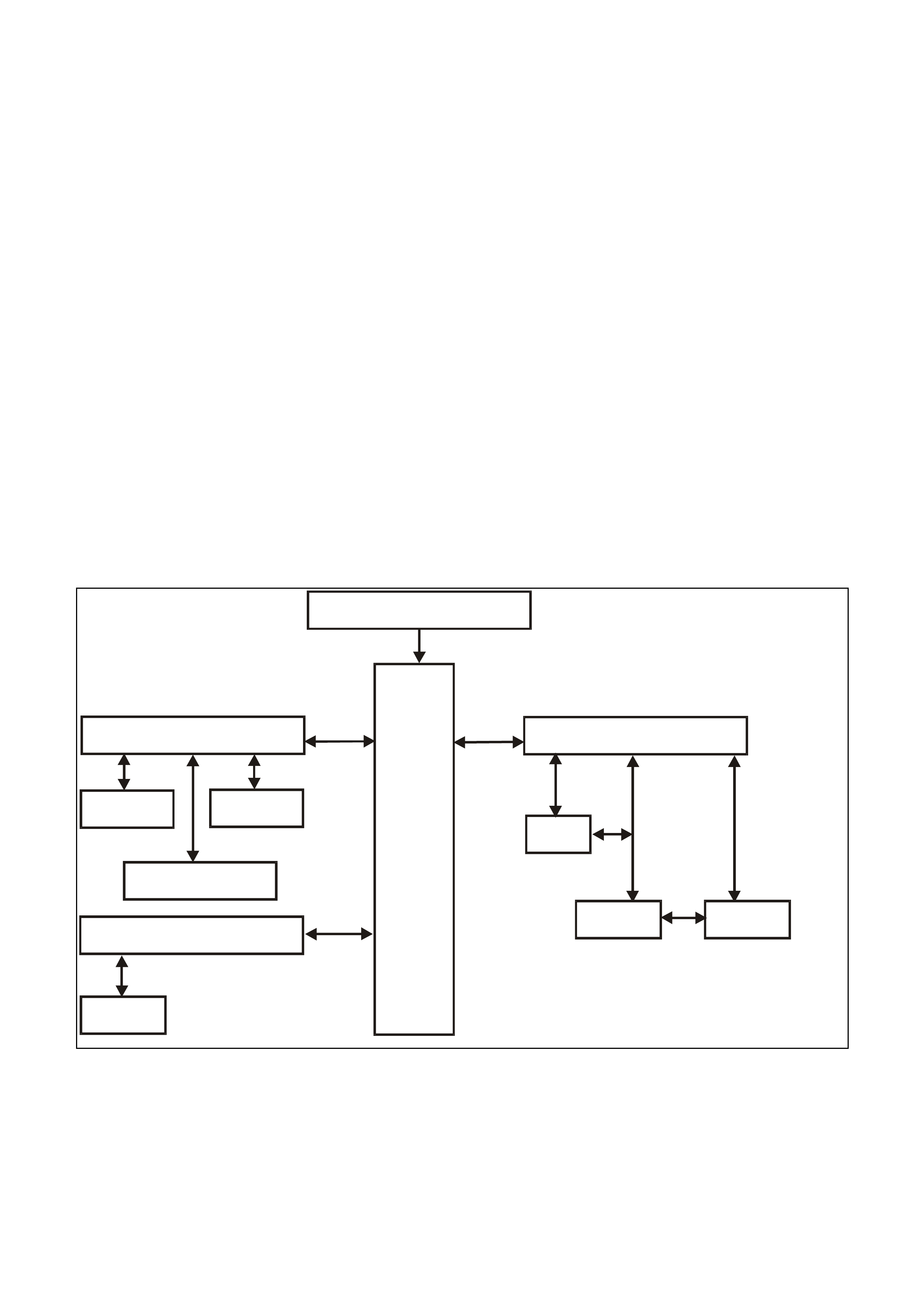
5.5 SERIAL DATA COMMUNICATION
GENERAL INFORMATION
The WH Series models use a BUS MASTER communication system, where the BCM is the bus master.
The BCM periodically polls (surveys) each device on the bus and requests status data.
The devices connected are:
• Body Control Module (BCM).
• Powertrain Control Module (PCM) for V6 and V6 supercharged engines.
• Powertrain Interface Module (PIM) for GEN III V8 engines only.
• Electronic Climate Control (ECC).
• Instrument Cluster (INS).
• Anti-lock Brake (ABS) or Anti-lock Brake / Electronic Traction Control (ABS/ETC).
• Supplementary Restraint System (SRS).
• External diagnostic tool (TECH 2).
The data provided by each device may be utilised by any device connected to the bus.
Each device has a unique response Message Identifier Word (MIW) for ease of identification.
The bus master (BCM) polls each device with a serial data message which includes that device’s MIW. The device
responds by putting a serial data message onto the bus which includes its MIW and data, which is retrieved and
utilised by any device requiring it.
The BCM polls each device for a status update, once every 300 milliseconds. The exception to this being the PCM
(V6) and PIM (GEN III V8) which are polled twice every 300 milliseconds.
The TECH 2 diagnostic tool can be used to read serial data on the data bus and analyse faults in the instrument
cluster and its related components.
BATTERY POWER
BCM
SERIAL DATA MAIN
DLC
SERIAL DATA A UX
ABS/ETC ECC
INSTRUMENTS
SRS SERIAL DATA AUX PIM PCM
SRS
GEN III V8
ENGINE V6 & V6 S/C
ENGINE
T212J2011
Figure 12C-7
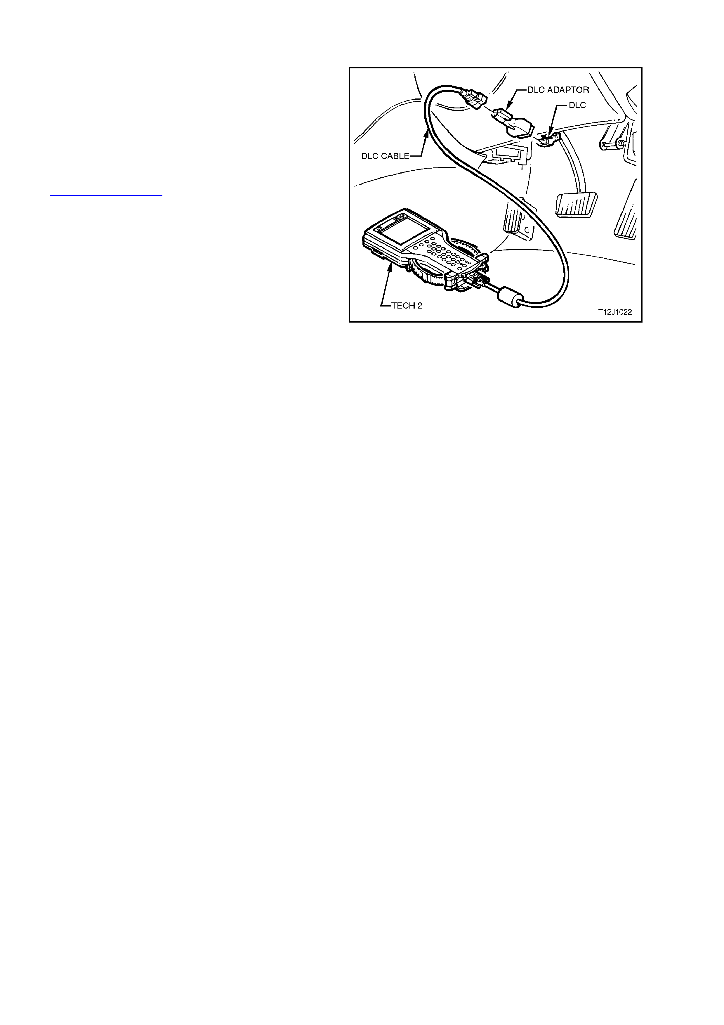
5.6 CONNECTING TECH 2 FOR SYSTEM DIAGNOSIS
TECH 2, with the appropriate software, cables and
adaptors, when connected to the Data Link
Connector (DLC) is capable of reading the
instrument cluster serial data. The DLC is
connected to the inst rument panel lower r ight hand-
trim, to the right of the steering column.
For additional general information on connecting
and operating TECH 2, refer to
Section 0C TECH 2 in of the VT Series II Service
Information.
Figure 12C-8

5.7 TECH 2 TE ST MODES AND DISP LAYS FOR INSTRUMENT DIAGNOSIS
A prerequisite of this diagnostic section is for the
user to be familiar with the proper use of TECH 2.
The following pages illustrate only the major TECH
2 screen dis plays and provide a brief ex planation of
their function for diagnosing the Instruments. If
additional information is required on the operation
of TECH 2, reference should be made to either
Section 0C TECH 2 of the VT Series II Service
Information or the TECH 2 User’s Guide.
W ith the ignition turned off, connect the TECH 2 to
the Data Link Connector (DLC) using the DLC
Adaptor, refer to 5.6 CONNECTING TECH 2 FOR
SYSTEM DIAGNOSIS in this Section.
MAIN MENU
Turn the ignition on and press the power button
(PWR) on the TECH 2.
The TECH 2 will perform a series of self-
diagnosing power on self tests (POST). Once this
has been completed successfully, the TECH 2
startup screen will be displayed. Press the Enter
key to continue.
The Main Menu screen should look as follows.
Press the F0 function button or Select F0:
Diagnostics by using the arrow keys until F0:
Diagnostics is highlighted and press the Enter key.
Ma in Me n u
F0: D iagno stics
F2: V ie w Capture Da ta
F4: Do wnload/Upload Help
F1: Service Program m ing System (SPS)
F3: Tool Options
T12C136A
Figure 12C-9
Model Year
Select the appropriate Model Year and press Enter.
V e hicle Iden tification
(X) 1999
(W)1998
(V) 1997
Select one of the follo w ing
Model Year(s)
T212C137
Figure 12C-10
Vehicle Identification Menu
Select the appropriate vehicle type and press Enter.
Vehicle Identification
VT Commodore
WH Statesman & Caprice
VS Commodor e
Corsa
Tigra
Astra - F
Astra - G
Zafira
Vectra - B
Omega - B
Select one of the following
Vehicle Type(s)
WH12C037
Figure 12C-11

SYSTEM SELECTION MENU
Select F3: Body from the System Selection Menu
and press Enter.
System Selection Menu
F0:
F1:
F2:
F3:
WH12C004
Engine
Transmission
Chassis
Body
(X) 1999 WH Statesman & Caprice
Figure 12C-12
Vehicle Identification Screen
Select Instrument and press Enter.
V e hicle Iden tification
B ody Control Mo dule
Po wertrain Inte rface M o du le
SRS
Instrument
Electronic Clim ate Control
DTC Check
Other
S elect one o f the follow ing
Body
T212C141
Figure 12C-13
System Identification Screen
Turn the ignition on (as requested) and press
Confirm soft key to continue.
Syste m Id ent i ficat io n
Turn On Ignition!
(X) 1999
Electronic System: Instrument
WH Statesman & Caprice
WH12C005
Figure 12C-14
The part number of the instrument cluster will be
displayed. Press the More soft key to display more
detailed information about the part.
Syste m Id ent i ficat io n
Partnumber XXXXXXXX
(X) 1999
Electronic System: Instrument
WH Statesman & Caprice
WH12C006
Figure 12C-15

Press the Confirm soft key to confirm these details.
Syste m Id ent i ficat io n
Partnumber
Software Date
Data Versio n Number
VAP Process Number
XXXXXXXX
XXXXXX
XX
XXX
(X) 1999
Electronic System: Instrument
WH Statesman & Caprice
WH12C007
Figure 12C-16
The Vehicle Identification Number/TIS Hardware
Key Number will now be displayed. Press Confirm
soft key to continue.
Syste m Id ent i ficat io n
Vehicle Identification Number / TIS
Hardware Key Number
123456
(X) 1999
Electronic System: Instrument
WH Statesman & Caprice
WH12C008
Figure 12C-17
BODY MENU
This m enu provides the TECH 2 us er with acc ess to
the various functions used to diagnose faults in the
instrument cluster and its related com ponents. The
six functions F0 to F5 are explained in more detail
in 5.9 USING TECH 2 TO DIAGNOSE THE
INSTRUMENT CLUSTER in this Section.

F0: Normal Mode
The instrument normal mode data list is used to
view serial data being sent from the instrument
cluster.
F1: Diagnostic Trouble Codes
In this m ode Diagnostic T rouble Codes can be read
and cleared.
F2: Data Display
In this test mode, TECH 2 displays the status of
inputs and outputs of the instrument cluster.
F3: Snaps hot
In this test mode, the TECH 2 captures data bef ore
and after a forced manual error. This is not
applicable to instrument diagnostics.
F4: Miscellaneous Tests
In this test mode, the TECH 2 can test and
diagnose faults in the instrument cluster. Telltale
lamps and instrument gauges can be tested in this
mode.
F5: Program
Instruments and options can be programmed when
this mode is selected.
Body
F0:
F1:
F2:
F3:
F4:
F5:
T12C140
Norm al Mode
Diagnostic Trouble Codes
Data Display
Snapshot
Miscellaneous Tests
Program
Figure 12C-18
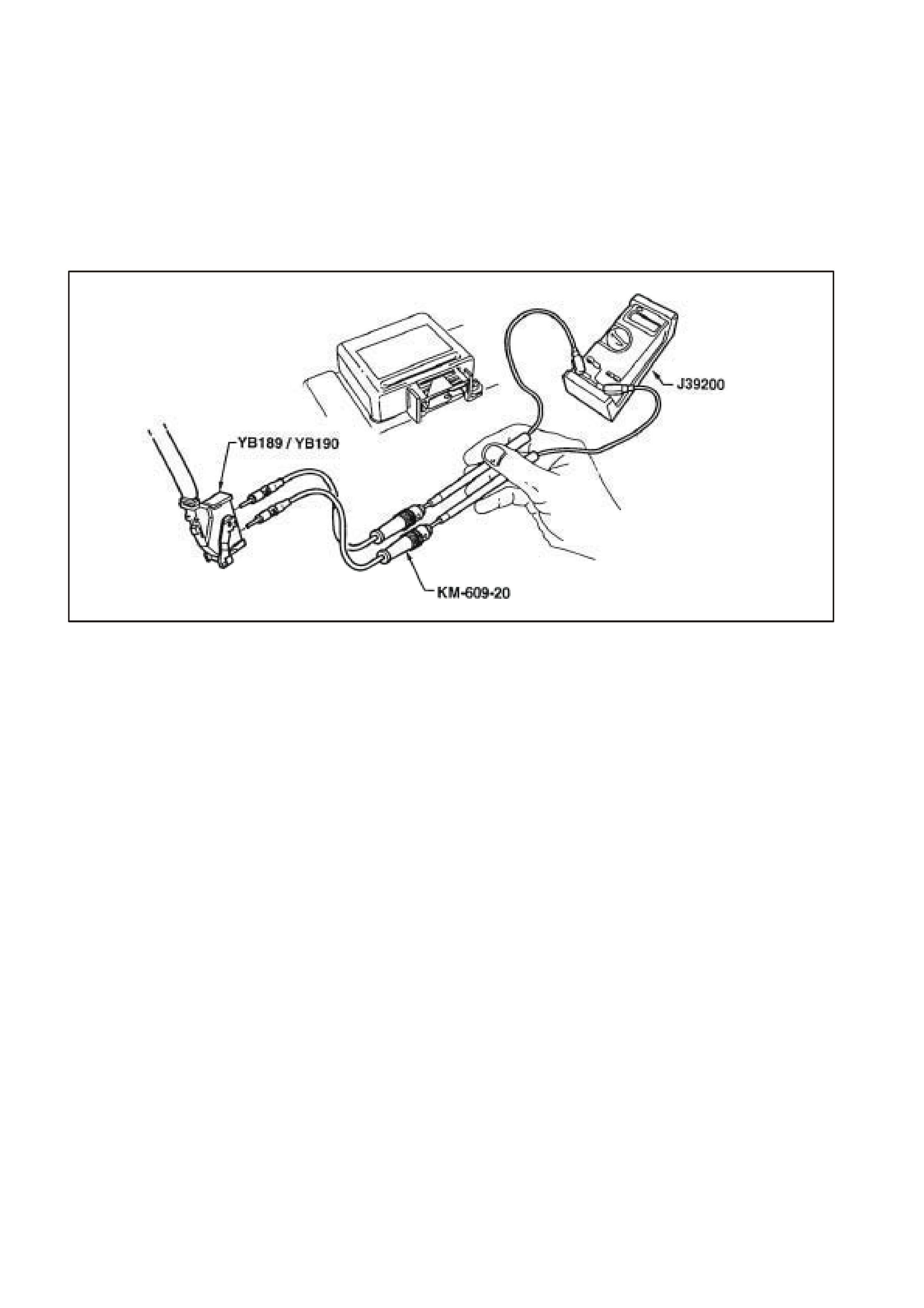
5.8 INSTRUMENT DIAGNOSTIC PROCEDURES
INTRODUCTION:
The following charts are designed to provide fast and efficient fault location of the instruments. Each diagnostic
chart consists of: a ‘diagnostic chart’ and pertinent information including Diagnostic Trouble Code (DTC) setting
parameters and, in most charts, circuit diagrams.
When carrying out wiring checks as directed by the diagnostic charts, rather than probe terminals and connectors
with incorrect sized multimeter connections, use the adaptors contained in connector test adaptor kit KM-609 as
shown in the following illustration. This will prevent any possibility of spreading or damaging wiring harness
terminals which may later cause a system intermittent
failure.
T12C194
Figure 12C-19
DIAGNOSTIC CIRCUIT CHECK
Circuit Description:
When investigating any complaint of an instrument cluster problem or malfunction, always begin diagnosis with the
following diagnostic circuit check. This check is a preliminary procedure that checks to ensure the instrument
cluster is communicating on the serial data line as well as helping to identify a problem or malfunction and directing
the reader to the appropriate diagnostic chart in this Section.
With TECH 2 connected to the DLC and the ignition switched on, TECH 2 should display serial data
communication. If TECH 2 does not display serial data, the serial data circuit maybe open or shorted.
There are several other control modules that are connected to the serial data line (PCM, PIM (GEN III V8 only),
BCM, ABS/ETC, ECC and SRS). ANY one of these control modules could cause a fault on the serial data line. This
fault could result in TECH 2 not being able to display serial data.

DIAGNOSTIC CIRCUIT CHECK PROCEDURE
STEP ACTION VALUE YES NO
1• Turn the igniti on on.
• Do any instrument cluster warning lamps illuminate?
Go to Step 5. Go to Step 2.
2• Check instrument cluster fuses F11, F13 and F21 i n
instrument panel compart ment.
• Are any fuses blown?
Replace blown fuses. Go t o S tep 3.
3• Check c ontinuity of circuit 155 (Black/Yellow wire)
between instrument cl uster connec tor YB66 and a known
good earth.
• Is there continuit y?
Go to Step 4. Check and repair open
in circ ui t 155.
4• With igni tion on, check for vol t age at instrument c l uster
connect or Y B66, terminals 19 and 20.
• Is voltage as spec i fied?
B+ Replace ins trument
cluster, refer t o 2.1
INSTRUMENT
CLUSTER i n this
Section.
Check and repair
circui ts 44 and/or 1340
as neces sary.
5• Turn ignition of f.
• Connect TECH 2 to DLC.
• Turn ignition on.
• Push power button on TECH 2.
Does TECH 2 power up? (Screen should illum i nate and
display TE CH 2).
Go to Step 6. Go to TECH 2
diagnosis , refer to
Secti on 0C TECH 2 of
the VT S eri es II
Service Inform ation.
6• At the TE CH 2 title s creen press the Enter key.
• Select Di agnostic s \ 1999 \ WH S tatesman & Capric e \
Body \ Instrument.
• Does TECH 2 display Instrument S ys tem I dentific ation
(ie. Part Number)?
Go to Step 7. Go to DTC-14 No
Serial Communi cation
In this Section.
7• With TECH 2 s till connected and instrum ent s selected,
select Diagnosti c Trouble Codes.
• Does TECH 2 display any DTC?
Refer to c orresponding
diagnosti c chart. Refer to 5.4
DIAGNOSING
FAULTS NOT
COVERED BY TECH 2
DIAGNOST I C T OOL i n
this Section.
WHEN ALL DIAGNOSIS AND REPAIRS ARE COMPLETED, CLEAR ALL DTC AND VERIFY CORRECT OPERATION
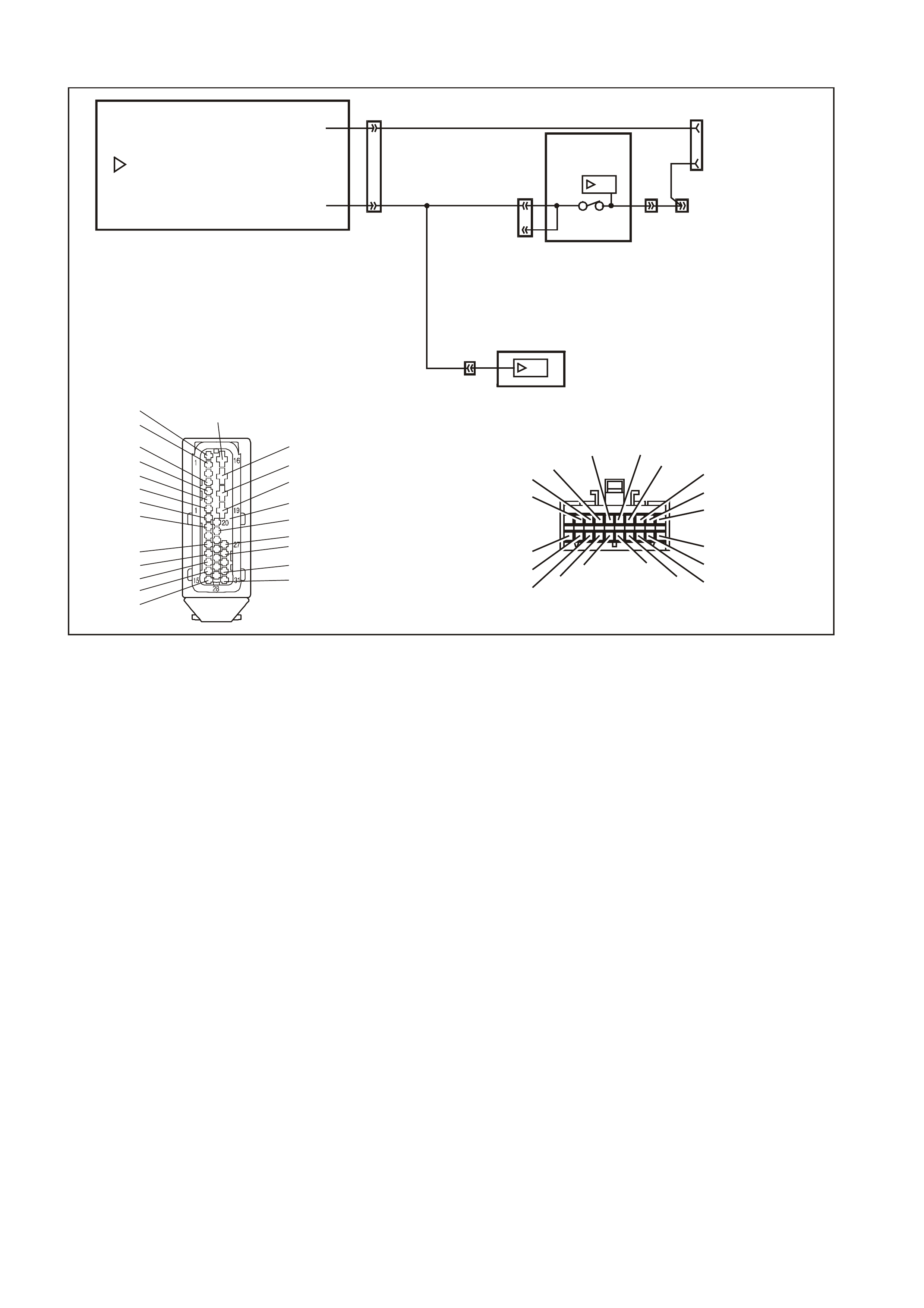
DTC 1 - FUEL GAUGE SENER UNIT - SHORT CIRCUIT
T (30)
B/Y (155)
YB74
BODY HAR NES S CONNE CT OR
T212C185A
YR44 YR32 YB74 YB66
YE114
LOC. E3
FUEL
GAUGE
SENDER
T (30)
T (30)
B/Y (155)B/Y (155)
INSTRUMENT
CLUSTER
16
Y
R32
FUEL TANK HARNESS
CONNECTOR
V/W (1120) S/C ONLY
OR
V (1 20)
T (30)
B/Y (155)
B/BLU (156)
OR
B/W (489) S/C ONLY
YB66
INSTRUMENTS CONNECTOR
10
20 1
11
B/Y (155) GY (8) BR/W (19)
BLU/Y (10)
T (30)
V/W (123)
BR/O (33)
BR (25)
V/R (234)
W ( 85 )
BLU (15)
Y/R (88)
G/W (1 220 )
BLU/B (946)
LBLU (14)
G (8 75 )
O/Y (1 340)
P/BLU (44)
BR/R (121)
YR44
FUEL TANK HA RNESS
CONNECTOR
T (30)B/BLU (156)
B/Y (155) V (120)
YE114
MAIN WIRING HARNESS
CONNECTOR
B/R (157)
B/G (151)
B/W (152) B (150) B/Y (155)
B/R (157)
CIRCUIT DESCRIPTION:
The instrum ent cluster supplies a 12 volt reference voltage and an earth circuit to the fuel gauge sender unit. The
fuel sender provides a resistanc e value to the instrument c luster based on its position relative to the f uel level. The
fuel sender resistance will vary between 37.5 ohms and 253.3 ohms from no fuel in the tank to full tank.
DTC 1 Will Set If:
• The fuel sender resistance is less than 12.9 ohms for a period of 30 seconds. The DT C is reset when the fuel
sender resistance returns to its normal operating range for a period of 60 seconds. The DTC is logged as a
History DTC.
When a DTC 1 is set the fuel gauge will display the fuel tank level as empty irrespective of actual fuel level.
Test Description:
Number(s) below refer to step number(s) in the following diagnostic chart.
2-4.Use of TECH 2 to view data being sent f rom f uel sender. If voltage is not within c orrec t operating spec ific ations
then there is either an open c ircuit, short circ uit or a faulty f uel sender. If open- or s hort-circuit then check s will
be made to locate the circuit interruption.
5. Use of TECH 2 to drive the gauge on the instrument cluster to verify that gauge is functioning correctly.
6. W ith the fuel sender disconnected, the fuel sender signal resistance value should be between 37.5 and 253.3
ohms, which is dependant on fuel level.
7. Continuity check of harness between voltage circuit 30 and earth circuit 155 at harness connector YB74 will
indicate a short circuit in harness between YB74 and instrument cluster.
8. Continuity check of harness between voltage circuit 30 and earth circuit 155 at harness connector YR32 will
indicate a short circuit in harness between YB74 and YR32.
9. Removal of fuel tank allows access to fuel sender. Continuity check of harness between voltage circuit 30 and
earth circuit 155 at harness connector YR44 will indicate a short circuit in harness between YR32 and YR44,
otherwise there is a fault in the fuel sender.

Diagnostic Aids:
The TECH 2 diagnostic tool reads fuel sender position as a voltage between 0 and 12 volts. The fuel sender signal
resistance should be between 37.5 to 253.3 ohms when the fuel sender is functioning correctly. The fuel sender
voltage should increase at a steady rate as the fuel level increases.
The multimeter allows continuity of the wiring harness to be checked. Harness voltage can also be confirmed at
connector locations.
Check for any damage to the harness which could cause an intermittent open or short to earth or backed-out
terminals at the instrument cluster connectors, broken connector locks, improperly formed or damaged terminals.

DTC 1 TEST PROCEDURE
STEP ACTION VALUE YES NO
1 • Was the Diagnostic Circuit Check performed? Go to Step 2. Go to Diagnostic
Circuit Check in this
Section.
2• Connect TECH 2 to DLC.
• Select 1999 \ WH St atesm an & Caprice \ Di agnostic s \
Body \ Instrument \ Data Display \ Instrument.
• Check t he petrol sender si gnal .
• Is pet rol sender signal voltage 0V?
Short ci rcuit from fuel
sender to instrum ent
cluster, go to Step 5.
Go to Step 3.
3• Is pet rol sender signal voltage 5V? Open circ ui t from f uel
sender to instrum ent
cluster, go to Step 5.
Go to Step 4.
4• Is petrol sender signal vol tage between 0V and 5V? Go to Step 5. Replace f aul t y f uel
sender. Ref er to
Secti on 8A FUEL
TANK of t he V T
Series I Service
Information.
5• Using TECH 2, run Control Tests, refer to 5.14 F4:
MISCELLANEOUS TEST in t hi s Secti on.
• Does the f uel gauge operat e correctl y?
Go to Step 6. Replace ins trument
cluster. Refer to 2.1
INSTRUMENT
CLUSTER i n this
Section.
6• Disconnect battery.
• Disconnect fuel tank harness from body harness
connect or Y R32 l ocated under the rear of vehi cle.
• Using an ohmmet er, check resist ance across fuel sender
circui ts 30 (Tan wire) and 155 (Black/Yell ow wire) on fuel
tank harnes s.
• Is res i stance within specifi ed range?
Between
37.5 ohm s
and
253.3 ohm s
Go to Step 7. Replace faul ty fuel
sender. Ref er to
Secti on 8A FUEL
TANK of t he V T
Series I Service
Information.
7• Using an ohmmet er check continuit y bet ween m ai n wiring
harness c i rcuit 155 (Bl ack/Y el l ow wire) and circui t 30 (Tan
wire) at connect or Y B74 in the passenger com partment .
• Is there continuity?
Short ci rcuit in main
wiring harness between
YB74 and YB 66.
Repair harness.
Go to Step 8.
8• Using an ohmmet er, check continuit y bet ween body
harness c i rcuit 155 (Bl ack/Y el l ow wire) and circui t 30 (Tan
wire) at connect or Y R32 under the vehicle.
• Is there continuity?
Short ci rcuit in body
harness bet ween YR32
and YB74. Repai r
harness.
Go to Step 9.
9• Drain and remove fuel tank, refer to Section 8A FUE L
TANK of the VT Series I Service Information.
• Using an ohmmet er, check continuit y bet ween fuel tank
harness c i rcuit 155 (Bl ack/Y el l ow wire) and circui t 30 (Tan
wire) at connect or Y R44 under the vehicle.
• Is there continuity?
Short ci rcuit in f uel tank
harness bet ween YR44
and YR32. Repair
harness.
Replace faul t y fuel
sender. Ref er to
Secti on 8A FUEL
TANK of t he V T
Series I Service
Information.
10 • Use TECH 2 to clear DTC.
• Has DTC cleared? End of diagnos tic
checking. Refer to c orresponding
diagnosti c chart.
W HE N ALL DIAGNOS I S AND REP AIRS ARE COMPLE TE D, CLEAR ALL DTC AND VERIFY CORRE CT OPERATION
DTC 2 - FUEL GAUGE S ENDER UNIT - INTERMITTENT
T (30)
B/Y (155)
YB74
BODY HAR NES S CONNE CT OR
T212C185A
YR44 YR32 YB74 YB66
YE114
LOC. E3
FUEL
GAUGE
SENDER
T (30)
T (30)
B/Y (155)B/Y (155)
INSTRUMENT
CLUSTER
16
Y
R32
FUEL TANK HARNESS
CONNECTOR
V/W (1120) S/C ONLY
OR
V (1 20)
T (30)
B/Y (155)
B/BLU (156)
OR
B/W (489) S/C ONLY
YB66
INSTRUMENTS CONNECTOR
10
20 1
11
B/Y (155) GY (8) BR/W (19)
BLU/Y (10)
T (30)
V/W (123)
BR/O (33)
BR (25)
V/R (234)
W ( 85 )
BLU (15)
Y/R (88)
G/W (1 220 )
BLU/B (946)
LBLU (14)
G (8 75 )
O/Y (1 340)
P/BLU (44)
BR/R (121)
YR44
FUEL TANK HA RNESS
CONNECTOR
T (30)B/BLU (156)
B/Y (155) V (120)
YE114
MAIN WIRING HARNESS
CONNECTOR
B/R (157)
B/G (151)
B/W (152) B (150) B/Y (155)
B/R (157)
CIRCUIT DESCRIPTION:
The instrum ent cluster supplies a 12 volt reference voltage and an earth circuit to the fuel gauge sender unit. The
fuel sender provides a resistanc e value to the instrument c luster based on its position relative to the f uel level. The
fuel sender resistance will vary between 37.5 ohms and 253.3 ohms from no fuel in the tank to full tank.
DTC 2 Will Set If:
• T here is an interm ittent fault in the connection between the fuel s ender and the instrum ent cluster. The DT C is
set when the fuel sender res istance is greater than 290 ohm s for 30 s econds or if the f uel sender resistanc e is
less than 37.5 ohms for 30 seconds. T he DTC is reset when the fuel sender is detected as being open circuit
or short circuit or the sender resistance is within its normal operating range for a period of 60 seconds. The
DTC is logged as a History DTC.
Test Description:
Number(s) below refer to step number(s) in the following diagnostic chart.
2-4.Use of TECH 2 to view data being sent f rom f uel sender. If voltage is not within c orrec t operating spec ific ations
then there is either an open c ircuit, short circ uit or a faulty f uel sender. If open- or s hort-circuit then check s will
be made to locate the circuit interruption.
5. Use of TECH 2 to drive the gauge on the instrument cluster to verify that gauge is functioning correctly.
6-9.Tes t dr iving the car and m anipulating the harnesses while viewing the serial data sent f rom the f uel sender will
indicate the presence of a circuit interruption as the voltage will fluctuate in the event of an open circ uit or short
circuit.
Additionally, viewing the DTC will indicate the presence of the intermittent fault if triggered by manipulating the
relevant harness.

Diagnostic Aids:
By manipulating the harnesses at the various connectors it is possible to isolate the cause of the circuit interruption.
By working through the chart in the specified order it is possible to work out which harness contains the fault. This
harness can then be removed and repaired.
The TECH 2 diagnostic tool reads fuel sender position as a voltage between 0 and 12 volts. The fuel sender signal
resistance should be between 37.5 to 253.3 ohms when the fuel sender is functioning correctly. The fuel sender
voltage should increase at a steady rate as the fuel level increases.
The multimeter allows continuity of the wiring harness to be checked. Harness voltage can also be confirmed at
connector locations.
Check for any damage to the harness which could cause an intermittent open or short to earth or backed out
terminals at the instrument cluster connectors, broken connector locks, improperly formed or damaged terminals.

DTC 2 TEST PROCEDURE
STEP ACTION VALUE YES NO
1 • Was the Diagnostic Circuit Check performed? Go to Step 2. Go to Diagnostic
Circuit Check in this
Section.
2• Connect TECH 2 to DLC.
• Select 1999 \ WH Statesm an & Caprice \ Di agnostics \
Body \ Instrument \ Data Display \ Instrument.
• Check t he petrol sender si gnal .
• Is pet rol sender signal voltage 0V?
Short ci rcuit from fuel
sender to instrum ent
cluster, go to Step 5.
Go to Step 3.
3• Is pet rol sender signal voltage 5V? Open circ ui t from f uel
sender to instrum ent
cluster, go to Step 5.
Go to Step 4.
4• Is petrol sender signal vol tage between 0V and 5V? Go to Step 5. Replace f aul t y f uel
sender. Ref er to
Secti on 8A FUEL
TANK of t he V T
Series I Servic e
Information.
5• Using TECH 2, run Control Tests, refer to 5.14 F4:
MISCELLANEOUS TEST in t hi s Secti on.
• Does the f uel gauge operat e correctl y?
Go to Step 6. Replace ins trument
cluster. Refer to 2.1
INSTRUMENT
CLUSTER i n this
Section.
6• Clear DTC 2 by selec ting Diagnostics \ 1999 \
WH Stat esman & Capri ce \ Body \ Instrument \ Di agnostic
Trouble Codes \ Cl ear DTC Inform at i on.
• Turn ignition of f then on.
• Select Di agnostic s \ 1999 \ WH S tatesman & Capric e \
Body \ In strum ent \ Data Display \ I nstrument and view
petrol sender signal data.
• Take vehicl e for a test dri ve and monitor t he petrol sender
signal.
• Did the volt age of the petrol s ender signal vary during the
manipul at i ons, or
• Did DTC 2 set agai n?
Repair fault y main
wiring harness. Go t o Step 7.
7• Clear DTC 2 by selec ting Diagnostics \ 1999 \
WH Stat esman & Capri ce \ Body \ Instrument \ Di agnostic
Trouble Codes \ Cl ear DTC Inform at i on.
• Turn ignition of f then on.
• Select Di agnostic s \ 1999 \ WH S tatesman & Capric e \
Body \ In strum ent \ Data Display \ I nstrument and view
petrol sender signal data.
• Have assistant manipulate harness at c onnector YB 74 i n
the pass enger compart ment to i nduce an intermittent
fault.
• Did the volt age of the petrol s ender signal vary during the
manipul at i ons, or
• Did DTC 2 set agai n?
Repair fault y body
harness or f aul ty main
wiring harness.
Go to Step 8.
8• Have assistant manipulate harness at c onnector YR32
under the vehicl e to induce an int ermittent fault .
• Did the volt age of the petrol s ender signal vary during the
manipul at i ons, or
• Did DTC 2 set agai n?
Repair fault y body
harness or f aul t y fuel
tank harnes s.
Go to Step 9.
9• Drain and remove fuel tank, refer to Section 8A FUEL
TANK of t he VT Series I Service Informat i on.
• Have assistant manipulate harness at c onnector YR44
under the vehicl e to induce an int ermittent fault .
• Did the volt age of the petrol s ender signal vary during the
manipul at i ons, or
• Did DTC 2 set agai n?
Repair fault y f uel t ank
harness. Replace faulty f uel
sender. Ref er to
Secti on 8A FUEL
TANK of t he V T
Series I Servic e
Information.
10 • Use TECH 2 to clear DTC.
• Has DTC cleared? End of diagnos tic
checking. Refer to c orresponding
diagnosti c chart.
WHEN ALL DIAGNOSIS AND REPAIRS ARE COMPLETED, CLEAR ALL DTC AND VERIFY CORRECT OPERATION
DTC 3 - FUEL GAUGE SENDER UNIT - OPEN CIRCUIT
T (30)
B/Y (155)
YB74
BODY HAR NES S CONNE CT OR
T212C185A
YR44 YR32 YB74 YB66
YE114
LOC. E3
FUEL
GAUGE
SENDER
T (30)
T (30)
B/Y (155)B/Y (155)
INSTRUMENT
CLUSTER
16
Y
R32
FUEL TANK HARNESS
CONNECTOR
V/W (1120) S/C ONLY
OR
V (1 20)
T (30)
B/Y (155)
B/BLU (156)
OR
B/W (489) S/C ONLY
YB66
INSTRUMENTS CONNECTOR
10
20 1
11
B/Y (155) GY (8) BR/W (19)
BLU/Y (10)
T (30)
V/W (123)
BR/O (33)
BR (25)
V/R (234)
W ( 85 )
BLU (15)
Y/R (88)
G/W (1 220 )
BLU/B (946)
LBLU (14)
G (8 75 )
O/Y (1 340)
P/BLU (44)
BR/R (121)
YR44
FUEL TANK HA RNESS
CONNECTOR
T (30)B/BLU (156)
B/Y (155) V (120)
YE114
MAIN WIRING HARNESS
CONNECTOR
B/R (157)
B/G (151)
B/W (152) B (150) B/Y (155)
B/R (157)
CIRCUIT DESCRIPTION:
The instrum ent cluster supplies a 12 volt reference voltage and an earth circuit to the fuel gauge sender unit. The
fuel sender provides a resistanc e value to the instrument c luster based on its position relative to the f uel level. The
fuel sender resistance will vary between 37.5 ohms and 253.3 ohms from no fuel in the tank to full tank.
IMPORTANT: An open circuit fuel gauge sender unit is shown as DTC 3 on the TECH 2, whereas the instrument
cluster diagnostic mode display shows the same fault as ‘t 00 H C’.
DTC 3 Will Set If:
The fuel sender circuit provides a resistance above 290 ohms for a duration longer than 30 seconds. The DTC is
reset when the fuel s ender resistanc e returns to its nor mal operating r ange for a period of 60 seconds . T he DTC is
logged as a History DTC.
When a DTC 3 is set the fuel gauge will display the fuel tank level as empty irrespective of actual fuel level.
Test Description :
Number(s) below refer to step number(s) in the following diagnostic chart.
2-4.Use of TECH 2 to view data being sent f rom f uel sender. If voltage is not within c orrec t operating spec ific ations
then there is either an open c ircuit, short circ uit or a faulty f uel sender. If open- or s hort-circuit then check s will
be made to locate the circuit interruption.
5. Use of TECH 2 to drive the gauge on the instrument cluster to verify that gauge is functioning correctly.
6. With the fuel sender disconnected, the fuel sender signal resistance value should be between 37.5 and
253.3 ohms, which is dependant on fuel level.
7. Probing circ uit 155 with a m ultimeter c onnected to body earth chec ks the fuel s ender earth circuit at connec tor
YR32.
8. Probing circ uit 155 with a m ultimeter c onnected to body earth chec ks the fuel s ender earth circuit at connec tor
YB74.
9. Probing circuit 30 with a multimeter connected to B+ checks the fuel sender voltage circuit at connector YR32.
10. Probing circuit 30 with a multimeter connected to B+ checks the fuel sender voltage circuit at connector YB74.
11. Removing fuel tank to gain access to fuel sender enables fuel tank harness, which can then be checked for
continuity at each end (ie, no circuit breaks).

Diagnostic Aids:
The TECH 2 diagnostic tool reads fuel sender position as a voltage between 0 and 12 volts. The fuel sender signal
resistance should be between 37.5 to 253.3 ohms when the fuel sender is functioning correctly. The fuel sender
voltage should increase at a steady rate as the fuel level increases.
The multimeter allows continuity of the wiring harness to be checked. Harness voltage can also be confirmed at
connector locations.
Check for any damage to the harness which could cause an intermittent open or short to earth or backed-out
terminals at the instrument cluster connectors, broken connector locks, improperly formed or damaged terminals.

DTC 3 TEST PROCEDURE
STEP ACTION VALUE YES NO
1 • Was the Diagnostic Circuit Check performed? Go to Step 2. Go to Diagnostic
Circuit Check in this
Section.
2• Connect TECH 2 to DLC.
• Select 1999 \ WH St atesm an & Caprice \ Di agnostics \
Body \ Instrument \ Data Display \ Instrument.
• Check t he petrol sender si gnal .
• Is pet rol sender signal voltage 0V?
Short ci rcuit from fuel
sender to instrum ent
cluster, go to Step 5.
Go to Step 3.
3• Is pet rol sender signal voltage 5V? Open circ ui t from f uel
sender to instrum ent
cluster, go to Step 5.
Go to Step 4.
4• Is petrol sender signal vol tage between 0V and 5V? Go to Step 5. Replace f aul t y f uel
sender. Ref er to
Secti on 8A FUEL
TANK of t he V T
Series I Servic e
Information.
5• Using TECH 2, run Control Tests, refer to 5.14 F4:
MISCELLANEOUS TEST in t hi s Secti on.
• Does the f uel gauge operat e correctl y?
Go to Step 6. Replace ins trument
cluster. Refer to 2.1
INSTRUMENT
CLUSTER i n this
Section.
6• Disconnect battery.
• Disconnect fuel tank harness from body harness
connect or Y R32 l ocated under the rear of the vehicle.
• Using an ohmmet er, check resist ance across fuel sender
circui ts 30 (Tan wire) and 155 (Black/Yell ow wire) on fuel
tank harnes s.
• Is res i stance within specifi ed range?
Between
37.5 ohm s
and
253.3 ohm s
Go to Step 7. Replace faul ty fuel
sender. Ref er to
Secti on 8A FUEL
TANK of t he V T
Series I Servic e
Information.
7• Using an ohmmet er, check continui ty of body harness
circui t 155 (Black/Yell ow wire) connect or YR32 to body
earth using suitable body eart h l ocation.
• Is there continuit y?
Go to Step 9. Go to Step 8.
8• Using an ohmmet er, check continui ty of body harness
circui t 155 (Black/Yell ow wire) at connec tor YB74 to earth
using sui table body earth loc ation.
• Is there continuit y?
Repair open circ ui t
between connectors
YR32 and YB74.
Repair open circ ui t
between YB74 and
YE114.
9• Using a multimeter, check vol t age across circuit 30 (Tan
wire) at connect or Y R32 to suitabl e body earth location.
• Is voltage as spec i fied?
+12V Go to Step 11. Go to Step 10.
10 • Using a multimeter, check vol tage of body harness circuit
30 (Tan wire) at connect or Y B74 to suitable body earth
location.
• Is voltage as spec i fied?
+12V Repair open circ ui t
between connectors
YR32 and YB74.
Repair open circ ui t
between connectors
YB74 and YB 66.
11 • Drain and remove fuel tank, refer to Section 8A FUEL
TANK of t he VT Series I Service Informat i on.
• Using an ohmmet er, check for continui ty of fuel t ank
harness at Y R44 between circuits 155 (Black/Yell ow wire)
and 30 (Tan wire).
• Is there continuit y?
Go to Step 13. Go to Step 12.
12 • Disconnect fuel sender harness f rom fuel sender.
• Using an ohmmet er, check continuit y across f uel sender.
• Is there continuit y?
Repair open circ ui t in
fuel tank harness. Replace faul t y fuel
sender. Ref er to
Secti on 8A FUEL
TANK of t he V T
Series I Servic e
Information.
13 • Use TECH 2 to clear DTC.
• Has DTC cleared? End of diagnos tic
checking. Refer to c orresponding
diagnosti c chart.
WHEN ALL DIAGNOSIS AND REPAIRS ARE COMPLETED, CLEAR ALL DTC AND VERIFY CORRECT OPERATION
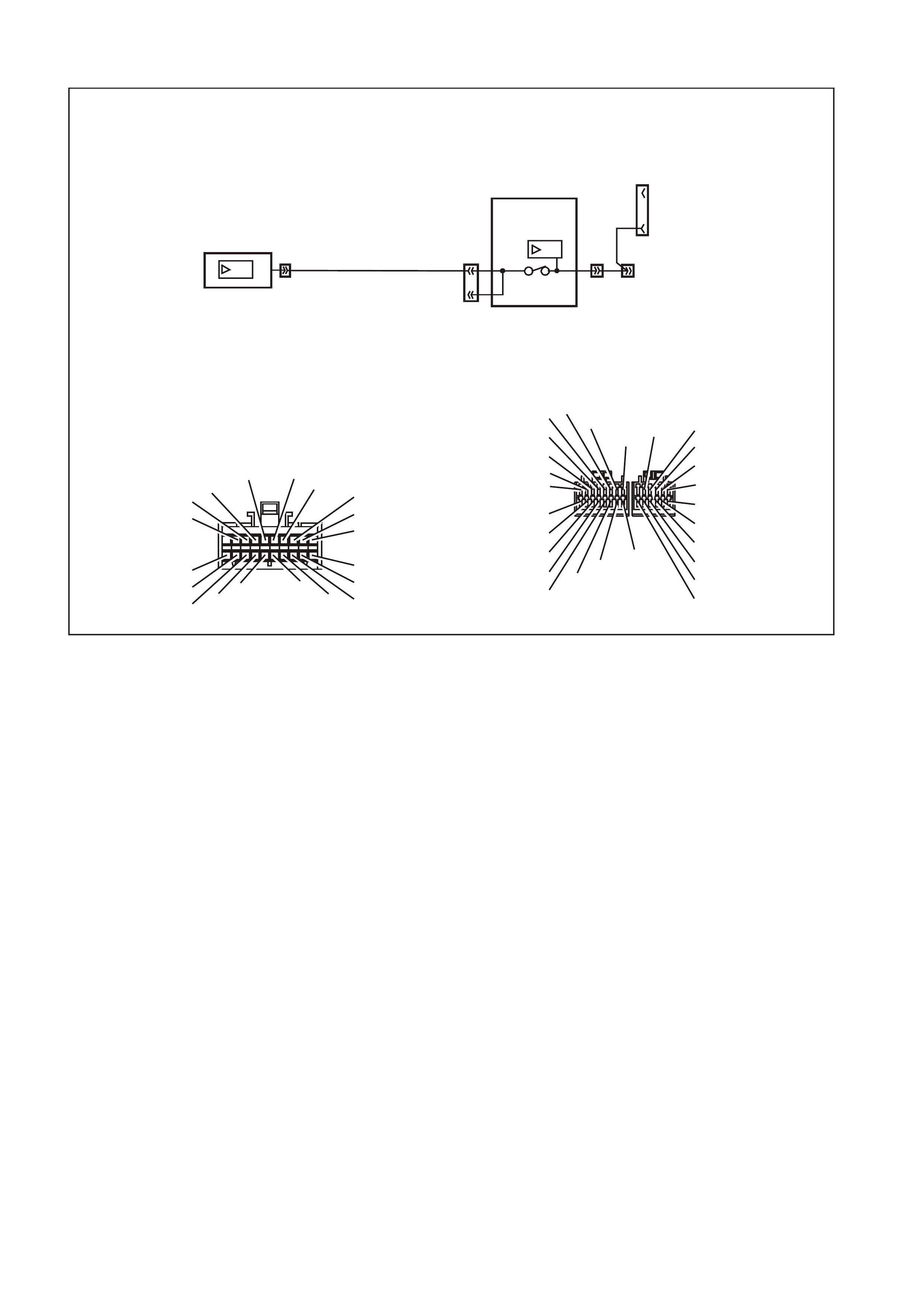
DTC 8 - NO SERIAL DATA FROM ABS
WH12C009
ABS/ETC MODULE
YE98 YB128
DIAG _E NABLE
SERIAL DATA
12
11
SDI
12
9
YB175 YB175
92
YE112
3
BODY
CONTROL
MODULE
SDI
INSTRUMENT
CLUSTER
DATA LINK
CONNECTOR
BL U/B (8 63)
G/W
(1220)
12
YB66
YE98
ABS /E T C MODULE CONNECTO R
B/O (154)
R (2R)
R (2R)
B (150)
Y/R (88)
G (875)
B/W (1427)
R/W (1429)
BR/R (121)
R (855)
BLU/R (20)
O/W (1426)
BLU/B (863)
G/W (1220)
V (884)
Y (885)
BR (830)
GY (833)
W (872)
R (873)
B (882) )
BLU (8 83)
Y
B66
INSTRUMENTS CO NNEC TOR
10
20 1
11
B/Y (155) GY ( 8)BR/W (19 )
BLU/Y (10)
T (30)
V/W (123) BR/O (33)BR (25)
V/R (234)
W (85)
BLU (15)
Y/R (88)
G/W (1220)
BL U/B (946 )
LBLU (14)
G (87 5)
O/Y (13 40)
P/BLU (44)
BR/R (121)
GY/B (1687)
CIRCUIT DESCRIPTION:
The ABS/ETC module sends serial data along the serial data line, circuit 1220. This is read by the instrument
cluster to indicate the status of the traction control. If traction control has been disabled by the ABS/ETC module,
the Traction Control Off lamp will illuminate.
DTC 8 Will Set If:
• There is no ABS data message on the SDI bus for more than 10 seconds. In practice the trouble code is set
somewhere between 10 and 20 seconds after the last ABS data message is received by the instrument. The
DTC is reset within 10 seconds of the arrival of an ABS data message on the SDI bus. The DTC is logged as a
History DTC.
Test Description:
Number(s) below refer to step number(s) in the following diagnostic chart.
1. Ensures that the Diagnostic Circuit Check has been performed.
2. Determines if the TECH 2 is powered up and operating correctly.
3. Checks for the presence of serial data from the ABS/ETC module. If this data can be read this indicates that the
problem is intermittent.
4. Checks the continuity of the serial data line (circuit 1220) between the ABS/ETC module and the instrument
cluster.
5. If the DTC can be cleared, the fault is intermittent. If the DTC cannot be cleared, the instrument cluster is faulty.
Diagnostic Aids:
By manipulating the harnesses at the various connectors it is often possible to isolate the cause of the circuit
interruption. This harness can then be removed and repaired.
Check for any damage to the harness which could cause an intermittent open or short to earth or backed out
terminals at the instrument cluster connectors, broken connector locks, improperly formed or damaged terminals.
The multimeter allows continuity of the wiring harness circuit 1220 to be checked.
If the fault cannot be found in the harness then the fault may lie in the ABS/ETC module or the BCM, both of which
can be diagnosed in their relevant Sections.

DTC 8 TEST PROCEDURE
STEP ACTION VALUE YES NO
1 • Was the Diagnostic Circuit Check performed? Go to Step 2. Go to Diagnostic
Circuit Check in this
Section.
2• Connect TECH 2 to DLC.
• Turn ignition on.
• Push power button on TECH 2.
• Does TECH 2 power up? (Screen should illuminate and
display TE CH 2).
Go to Step 3. Go to TECH 2
diagnosis , refer to
Secti on 0C TECH 2 of
the VT S eri es II
Service Inform ation.
3• At the TE CH 2 title s creen press the Enter key.
• Select Di agnostic s \ 1999 \ WH S tatesman & Capric e \
Chassis \ ABS/ETC.
• Turn on the ignit i on and press the Conf i rm sof t key.
• Does TECH 2 display the Electronic System: AB S /ETC
information (ie. P a rt Number / S ys tem I D / System)?
Go to Step 4. Go to Section 12L ABS
& ABS/ETC of the VT
Series I Service
Information. for V6
engine, or Sec tion 12L
ABS & ABS/ETC of the
VT Series II Service
Information for
GEN III V8 engine.
4• Using an ohmmet er, check for cont i nui t y of circui t 1220
(Green/Whit e wire) between ABS /ETC m odule connector
YE98 and ins trument cluster connector Y B 66.
• Is there continuit y?
Go to Step 5. Find source of open
circui t and repair fault y
main wiring harnes s.
5• Use TECH 2 to clear DTC.
• Has DTC cleared? DTC 8 is intermittent.
Check c i rcuit 1220
(Green/Whit e wire)
between ABS/E T C
module and i nstrum ent
cluster for an
intermittent fault.
Check t he i nstrum ent
cluster and ABS/ETC
module connectors for
term i nal ret ention. If
OK replace instrum ent
cluster, refer to 2.1
INSTRUMENT
CLUSTER i n this
Section.
WHEN ALL DIAGNOSIS AND REPAIRS ARE COMPLETED, CLEAR ALL DTC AND VERIFY CORRECT OPERATION
DTC 9 - NO SERIAL DATA FROM BCM
WH12C010
YB66
I NSTR UMENTS CONNECTOR
10
20 1
11
B/Y (15 5) GY (8)BR/W (19)
BLU/Y (10)
T (30)
V/W (123) BR/O (33)BR (25)
V/R (234)
W (85)
BLU (15)
Y/R (88)
G/ W ( 1220)
BLU/B (946)
LBLU (14)
G (875)
O/Y (1340)
P/BLU (44)
BR/R (121)
YB128
SDI
9
YB175 YB175
92
YE112
3
BODY
CONTROL
MODULE
SDI
INSTRUMENT
CLUSTER
DATA LINK
CONNECTOR
G/W
(1220)
12YB66
Y/R (143)
Y (43 )
O/BLU (6 40)
P/B (39)
GY/R (1391)
20
28
Y/B (260)
B/R (114 4)
R/W (261)
21 12
LBLU (161)
W/BLU (494)
W (160 )
13 6
GY/B (96) B/Y (556)
W (1220)
R/B (12 21)
V/R (229)
BR/G (271)
Y (266)
G/W (1220)
Y/B (272)
W ( 717)
W/R (308)
/G
1
7
Y
B175
BCM CONNECTOR (3)
HI GH SERIES
B (1150)
BLU/W (97)
GY (83)
LBLU (94)
O/W (840)
CIRCUIT DESCRIPTION:
The BCM s ends serial data along the ser ial data line, circuit 1220. T his is read by the instrum ent cluster to indicate
the status of the various components on the serial data line.
DTC 9 Will Set If:
• There is no BCM data message on the SDI bus for more than 10 seconds. In practice the trouble code is set
somewhere between 10 and 20 seconds after the last BCM data message is received by the instrument. The
DTC is reset within 10 seconds of the arrival of a BCM data message on the SDI bus. The DTC is logged as a
History DTC.
Test Description:
Number(s) below refer to step number(s) in the following diagnostic chart.
1. Ensures that the Diagnostic Circuit Check has been performed.
2. Determines if the TECH 2 is powered up and operating correctly.
3. Check s for the pr esence of s erial data from the BCM. If this data can be read this indicates that the problem is
intermittent.
4. Checks the continuity of the serial data line (circuit 1220) between the BCM and the instrument cluster.
5. If the DTC can be cleared, the fault is intermittent. If the DTC cannot be cleared, the instrument cluster is faulty.
Diagnostic Aids:
By manipulating the harnesses at the various connectors it is often possible to isolate the cause of the circuit
interruption. This harness can then be removed and repaired.
Check for any damage to the harness which could cause an intermittent open circuit or backed out terminals at the
instrument cluster connectors, broken connector locks, improperly formed or damaged terminals.
The multimeter allows continuity of the wiring harness circuit 1220 to be checked.
If the fault cannot be found in the harness then the fault may lie in the BCM which can be diagnosed in the relevant
Section.

DTC 9 TEST PROCEDURE
STEP ACTION VALUE YES NO
1 • Was the Diagnostic Circuit Check performed? Go to Step 2. Go to Diagnostic
Circuit Check in this
Section.
2• Connect TECH 2 to DLC.
• Turn ignition on.
• Push power button on TECH 2.
• Does TECH 2 power up? (Screen should illuminate and
display TE CH 2).
Go to Step 3. Go to TECH 2
diagnosis , refer to
Secti on 0C TECH 2 of
the VT S eri es II
Service Inform ation.
3• At the TE CH 2 title s creen press the Enter key.
• Select Di agnostic s \ 1999 \ WH S tatesman & Capric e \
Body \ Body Control Module.
• Turn on the ignit i on and press the Conf i rm sof t key.
• Does TECH 2 display the Electronic System: BCM
information (ie. B CM Level / BCM Type)?
Go to Step 4. Go to BCM Serial Data
Communication
Diagnosis i n S ection
12J-2 HIGH S E RIES
BODY CONTROL
MODULE of the V T
Series II Service
Information..
4• Using an ohmmet er, check for cont i nui t y of circui t 1220
(Green/Whit e wire) between BCM connec t or YB175 and
instrument c l uster connec tor YB66.
• Is there continuit y?
Go to Step 5. Find source of open
circui t and repair fault y
main wiring harnes s.
5• Use TECH 2 to clear DTC.
• Has DTC cleared? DTC 9 is intermittent.
Check c i rcuit 1220
(Green/Whit e wire)
between BCM and
instrument c l uster for
an intermittent fault.
Check t he i nstrum ent
cluster and BCM
connect ors for terminal
retention. If OK replac e
instrument c l uster,
refer to 2. 1
INSTRUMENT
CLUSTER i n this
Section.
WHEN ALL DIAGNOSIS AND REPAIRS ARE COMPLETED, CLEAR ALL DTC AND VERIFY CORRECT OPERATION
DTC 10 - NO SERIAL DATA FROM ECC
WH12C011
YB87
EC C CO NNEC TO R
GY (8)P/BLU (44)
Y/B (52)
G/W (1220)
LG/B (735)
G (342)
BLU/B (734)
B/Y (155)
B/R (292)
Y (51)
16
712
B/R (64)
BR/W (19)
YB66
INSTRUMENTS CONNECTOR
10
20 1
11
B/Y (155) GY (8)BR/ W ( 19)
BLU/Y (10)
T (3 0)
V/W (123) BR/O (33)BR (25)
V/R (234)
W ( 85)
BLU (15)
Y/R (88)
G/W (122 0)
BLU/B (946)
LBLU (14)
G (875)
O/Y (1340)
P/BLU (44)
BR/ R ( 121 )
YB128
SDI
9
YB175 YB175
92
YE112
3
BODY
CONTROL
MODULE
SDI
INSTRUMENT
CLUSTER
ELECTRONIC
CLIMATE
CONTROL
MODULE
DATA LINK
CONNECTOR
G/W
(1220)
YB87 6
12 YB66
CIRCUIT DESCRIPTION:
The ECC module sends serial data to the instrument cluster along the serial data line, circuit 1220.
DTC 10 Will Set If:
• There is no ECC data message on the SDI bus for more than 10 seconds. In practice the trouble code is set
somewhere between 10 and 20 seconds after the last ECC data message is received by the instrument. The
DTC is reset within 10 seconds of the arrival of a ECC data message on the SDI bus. The DTC is logged as a
History DTC.
Test Description:
Number(s) below refer to step number(s) in the following diagnostic chart.
1. Ensures that the Diagnostic Circuit Check has been performed.
2. Determines if the TECH 2 is powered up and operating correctly.
3. Checks for the presence of serial data from the ECC module. If this data can be read this indicates that the
problem is intermittent.
4. Checks the continuity of the serial data line (circuit 1220) between the ECC module and the instrument cluster.
5. If the DTC can be cleared, the fault is intermittent. If the DTC cannot be cleared, the instrument cluster is faulty.
Diagnostic Aids:
By manipulating the harnesses at the various connectors it is often possible to isolate the cause of the circuit
interruption. This harness can then be removed and repaired.
Check for any damage to the harness which could cause an intermittent open or short to earth or backed out
terminals at the instrument cluster connectors, broken connector locks, improperly formed or damaged terminals.
The multimeter allows continuity of the wiring harness circuit 1220 to be checked.
If the fault cannot be found in the harness then the fault may lie in the ECC module or the BCM, both of which can
be diagnosed in their relevant Sections.

DTC 10 TEST PROCEDURE
STEP ACTION VALUE YES NO
1 • Was the Diagnostic Circuit Check performed? Go to Step 2. Go to Diagnostic
Circuit Check in this
Section.
2• Connect TECH 2 to DLC.
• Turn ignition on.
• Push power button on TECH 2.
• Does TECH 2 power up? (Screen should illuminate and
display TE CH 2).
Go to Step 3. Go to TECH 2
diagnosis , refer to
Secti on 0C TECH 2 of
the VT S eri es II
Service Inform ation.
3• At the TE CH 2 title s creen press the Enter key.
• Select Di agnostic s \ 1999 \ WH S tatesman & Capric e \
Body \ El ectronic Cl i mate Cont rol .
• Turn on the ignit i on and press the Conf i rm sof t key.
• Does TECH 2 display the Electronic System: ECC
information?
Go to Step 4. Refer to Section 2F
AIR CONDIT IONING -
ECC DIAG NOSTICS i n
this S uppl ement.
4• Using an ohmmet er, check for cont i nui t y of circui t 1220
(Green/Whit e wire) between ECC module connector
YB87 and ins trument cluster connector Y B 66.
• Is there continuit y?
Go to Step 5. Repair fault y main
wiring harness.
5• Use TECH 2 to clear DTC.
• Has DTC cleared? DTC 10 is interm ittent.
Check c i rcuit 1220
(Green/Whit e wire)
between ECC module
and instrument c l uster
for an intermitt ent fault.
Check t he i nstrum ent
cluster and ECC
module connectors for
term i nal ret ention. If
OK replace instrum ent
cluster, refer to 2.1
INSTRUMENT
CLUSTER i n this
Section.
WHEN ALL DIAGNOSIS AND REPAIRS ARE COMPLETED, CLEAR ALL DTC AND VERIFY CORRECT OPERATION

DTC 11 - NO SERIAL DATA FROM PCM
CIRCUIT DESCRIPTION:
The PCM sends serial data to the BCM along the main serial data line, circuit 1221. Serial data is then sent to the
instrum ent cluster along the auxiliar y serial data line, cir cuit 1220. This is read by the instr ument c luster to indic ate
the status of the check power train lamp and the oil pressure warning lamp.
As the PCM used in conjunction with the GEN III V8 engine is different to that used with the V6 engine, a Powertrain
Interface Module (PIM) is required to convert the serial data generated by the PCM into serial data which is
compatible with the BCM.
DTC 11 Will Set If:
• There is no PCM data message on the SDI bus for more than 10 seconds. In practice the trouble code is set
somewhere between 10 and 20 seconds after the last PCM data message is received by the instrument. The
DTC is reset within 10 seconds of the arrival of a PCM data message on the SDI bus. The DTC is logged as a
History DTC.
Test Description:
Number(s) below refer to step number(s) in the following diagnostic chart.
1. Ensures that the Diagnostic Circuit Check has been performed.
2. Determines if the TECH 2 is powered up and operating correctly.
3. Check s for the pr esence of s erial data from the PCM. If this data can be read this indicates that the problem is
intermittent.
4. Checks the continuity of the serial data line (circuit 1221) between the BCM and the PCM (V6 engine).
5. Checks the continuity of the serial data line (circuit 1221) between the BCM and the PIM (GEN III V8 engine).
6. Checks the continuity of the serial data line (circuit 1049) between the PCM and the PIM (GEN III V8 engine).
7. Checks the continuity of the serial data line (circuit 1220) between the BCM and the instrument cluster.
8. If the DTC can be cleared, the fault is intermittent. If the DTC cannot be cleared, the instrument cluster is faulty.
Diagnostic Aids:
By manipulating the harnesses at the various connectors it is often possible to isolate the cause of the circuit
interruption. This harness can then be removed and repaired.
Check for any damage to the harness which could cause an intermittent open or short to earth or backed out
terminals at the instrument cluster connectors, broken connector locks, improperly formed or damaged terminals.
The multimeter allows continuity of the wiring harness circuits to be checked.
If the fault cannot be found in the harness then the fault may lie in the PCM, PIM (GEN III V8 only) or the BCM, all of
which can be diagnosed in their relevant Sections.
WH12C012
SDI
SDI
12 YB66
BODY
CONTROL
MODULE
G/W (1220)
INSTRUMENT
CLUSTER
POWERTRAIN
CONTROL MODULE
GEN lll V8 ENGINE
J1-58
POWERTRAIN
INTERFACE MODULE
GEN lll V8 ENGINE POWERTRAIN
CONTROL
MODULE
V6 ENGINE
711 6
A3
F14
12
69
YE122
YE110 YE111
YB215
YB188
R/B (1221)
YB194
W/B(451)
Y(1049)
YE112
YB175YB175 9
3
2
YB128
DA TA LINK CONNECTOR
A
1
B1
A12
B12
(481)
(417)
(740)
(1227)
(410) (472)
(259)
(750)
(750)
(750)
(750)
(1221)
(39)
(465)
(416)
(740)
B/R
B/R
B/R
B/R
R/B
P
G/B
BR
Y
G/W
GY
O/B
R
BLU
O/B B/Y
(415)
V/W
(1456)
LG
(1426)
(304)
BLU/W
O
P/BLU
G/W
V/W
B/W
(339)
(465)
(123)
(1427)
(482)
(481)
(59)
(366)
R
LG/B
LG
G
GY
G
P
(434)
(129)
(451)
(439)
Y
(1049)
W/B
YE110
ENGIN E CONNE CTOR (1)
YE111
ENGINE CONNECTOR (2)
1
BR/G
G/W
Y
Y/B
W
W/R
V/R
R/B
W/G
B/Y
GY/B
W
LBLU
(271)
(266)
(1220)
(272)
(717)
(308)
(229)
(1221)
(1220)
(556)
(96)
(160)
(161)
(143)
(43)
(640)
(39)
(1150)
(97)
(83)
(94)
(260)
(1144)
(840)
Y/RY
O/BLU
P/B
GY/R
(1391)
B
BLU/W
GY
LBLU
O/W
Y/B
B/R
613
20
28
21 12
7
(494)
W/BLU
R/W
(261)
YB175
BCM CONNECTOR (3)
HIGH SERIES
(875)
(14)
(10)
(155)
(1340)
(44)
(121)
(123)
(30) (33)
(25) (946)
(1220)
(88)
(15)
(85)
(19)
(8)
B/Y
BLU/Y
LBLU
G
O/Y
P/BLU
BR/R
V/WT
GY
BR/W
W
BLU
Y/R
G/W
BLU/B
BR
BR/O
1
11
10
20
V/R
(234)
YB66
INSTRUMENTS CONNECTOR
YB194
PCM CONNECTOR (3)
V6 ENGINE
YB188
PCM CONNECTOR (2)
V6 ENGINE
YE122
PCM CONNECTOR (1)
GEN lll V8 ENGINE
YB215
PIM CONN ECTOR
GE N lll V8 ENGIN E
LG/B
(366)
G
(843)
B/W
F16
B/Y
BR/Y
(1228)
(469)
Y
(776)
(451)
F1
P
GY Y
BLU/W
(841)
BLU
V
E1
LBLU
GY/BLU
(845)
BLU
B
(1226)
W
W/B
BLU/W
(1434)
V
R
(435)
(31)
(1229)
GY
(1224)
Y
(846)
GY
(842)
(452)
(774) (304)
BR/Y
(411)
(439)
(773) (772)(771)
GY/BLU
BLU
(1225)
E16
(1427)
(429)
(844)
B/O
GY
(434)MAN
OR AUTO
G
(69)
GY/B
(455)
BLU/W
(771)
G/W
(897)
BR
(86)
LG
(848)
W
(776)
GY
(845)
GY
(1412)
BLU
(841)
Y
(410)
G
(355)
Y
(846)
BR
(633)
R/B
(632)
B/Y
(452)
Y
(1049)
O
(740)
B
(421)
B/W
(1230)
W/R
(815)
V/W
(414)
V/W
(415)
BR/Y
(844)
P/B
(847)
B/R
(750)
L/G
(646)
V
(843)
G
(842)
BLU/Y
(334)
GY
(416)
LG/W
(826)
LBLU/W
(643)
B/R
(750)
Y
(772)
BLU
(774)
V
(412)
BLU/B
(413)
GY/B
(1413)
LBLU/B
(647)
O
(740)
P
(39)
GY
(1226)
Y
(1225)
1
41
40
80
(AUTO)
(1434)
GY/BLU
GY
(434)
(MAN)
B/R
(750)
P
(39)
W/B
(451)
Y
(1049)
R/B
(1221)
NO SERIAL DATA FROM PCM

DTC 11 TEST PROCEDURE
STEP ACTION VALUE YES NO
1 • Was the Diagnostic Circuit Check performed? Go to Step 2. Go to Diagnostic
Circuit Check in this
Section.
2 • Connect TECH 2 to DLC.
• Turn ignition on.
• Push power button on TECH 2.
• Does TECH 2 power up? (Screen should illuminate and
display TE CH 2).
Go to Step 3. Go to TECH 2
diagnosis , refer to
Secti on 0C TECH 2 of
the VT S eri es II
Service Inform ation.
3 • At the TECH 2 ti tle screen press the E nt er key.
• Select Di agnostic s \ 1999 \ WH S tatesman & Capric e \
Engine \ s el ect appropriate engi ne.
• Turn on the ignit i on and press the Conf i rm sof t key.
• Does TECH 2 display the Engine System: Ident i ficati on
inform ation (ie. P ROM Ident i ficati on)?
V6 engine, go t o
Step 4.
GEN III V8 engine, go
to Step 5.
Refer to Section 6C1
POWERTRAIN
MANAGEMENT - V6
ENGINE of the VT
Series I Service
Information or Section
6C3-2 DIAGNOS I S -
GEN III V8 ENGINE of
the VT S eri es II
Service Inform ation.
4 • Usi ng an ohmmeter, c heck for c ontinuity of circuit 1221
(Red/Blac k wire) between BCM connector YB175 and
PCM connect or Y B188.
• Is there continuit y?
Harness f rom BCM to
PCM OK. Go to Step 7. Repair faulty wiring
harness f rom BCM to
PCM.
5 • Usi ng an ohmmeter, c heck for c ontinuity of circuit 1221
(Red/Blac k wire) between BCM connector YB175 and
PIM connec tor YB215.
• Is there continuit y?
Harness f rom BCM to
PIM OK. Go t o S tep 6. Repair faulty wiring
harness f rom BCM to
PIM.
6 • Usi ng an ohmmeter, c heck for c ontinuity of circuit 1049
(Yellow wire) between PCM connector YE 122 and PIM
connect or Y B215.
• Is there continuit y?
Harness f rom PCM to
PIM OK. Go t o S tep 7. Repair faulty wiring
harness f rom PCM to
PIM.
7 • Usi ng an ohmmeter, c heck for c ontinuity of circuit 1220
(Green/Whit e wire) between BCM connec t or YB175 and
instrument c l uster connec tor YB66.
• Is there continuit y?
Harness f rom BCM to
instrument cl uster OK.
Go to Step 8.
Repair fault y wiring
harness f rom BCM to
instrument.
8 • Use TECH 2 to clear DTC.
• Has DTC cleared? DTC 11 is interm ittent.
Check c i rcuit 1221
(Red/Black wire)
between BCM and
PCM (V6 engine) or
BCM and PIM (GEN II I
V8 engine), c i rcuit
1049 (Yellow wire)
between PCM and PIM
(GEN III V8 engine)
and circui t 1220
(Green/Whit e wire)
between BCM and
instrument c l uster (both
engines) for an
intermittent fault.
Check t he i nstrum ent
cluster, PCM, PIM and
BCM connect ors as
appropriate for t e rminal
retention. If OK replac e
instrument c l uster,
refer to 2. 1
INSTRUMENT
CLUSTER i n this
Section.
WHEN ALL DIAGNOSIS AND REPAIRS ARE COMPLETED, CLEAR ALL DTC AND VERIFY CORRECT OPERATION
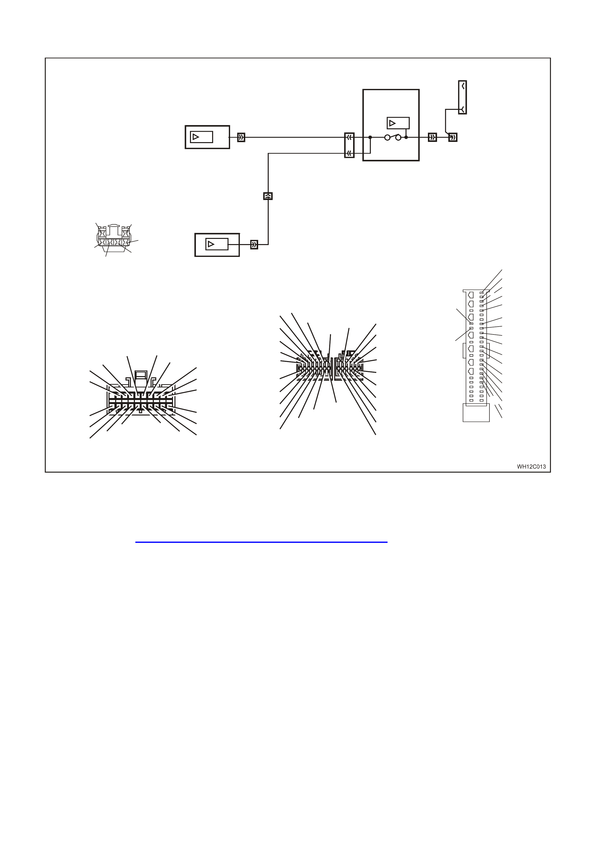
DTC 12 - NO SERIAL DATA FROM SDM
YB128
SDI
9
YB175 YB175
92
YE112
3
BODY
CONTROL
MODULE
SDI
SDI
INSTRUMENT
CLUSTER
DATA LINK
CONNECTOR
G/W (1220)
W (1220)/G
12 YB66
YB189
YB191
9
SRS SENSING AND
DIAGNOSTIC MODULE
YB66
INSTRUMENTS CONNECTOR
10
20 1
11
B/Y (155) GY (8)BR/W (19)
BLU/Y (10)
T (30)
V/W (123) BR/O (33)BR (25)
V/R (234)
W (8 5)
BLU (15)
Y/R (88)
G/W (1220)
BLU/B (946)
LBLU (14)
G (875)
O/Y (1340)
P/BLU (44)
BR/R (121)
Y/R (143)
Y (43)
O/BLU (6 40)
P/B (39)
GY/R (1391)
20
28
Y/B (260)
B/R (1 144)
R/W (261)
21 12
LBLU (161)
W/BLU (494)
W (1 60)
13 6
GY/B (96) B/Y (556)
W/ (1220)
R/B ( 1221)
V/R (229)
BR/G (271)
Y (26 6)
G/W (1220)
Y/B (272)
W ( 717)
W/R (308)
G
1
7
Y
B175
BCM CONN E CT O R (3 )
HI GH SERIES
B (1150)
BLU/W (97)
GY (83)
LBLU (94)
O/ W ( 840)
YB189
8.1 SDM WIRING HARNESS
CONNE CTO R
BR/B (393)
26
50 25
1
BLU/B (351)
R/B (352)
BR/W (353)
Y/R (354)
P/B (739)
B (30 5)
W (1220)/G
W (347)
G (348)
Y/B (349)
GY/B (350)
Y/G (385)
BR/G (386)
Y/W (387)
BR/W (388)
Y/ BL U (3 9 2)
GY/W (407)
LBLU (408)
P/B
(739) W
(1220)
/G
G (348)
GY/B
(350)Y/B (349)
W (347)
YB191
AI R BA G I NTE RFAC E
CONNECTOR
CIRCUIT DESCRIPTION:
The SRS Sensing and Diagnostic Module (SDM) sends serial data along the serial data line, via the BCM. This is
read by the instrument cluster to indicate the status of the SDM.
NOTE: The SDM used by the SRS on WH Statesman and Caprice is a version 8.1, 6-loop system. For more
information, refer to Section 12M SUPPLEMENTAL RESTRAINT SYSTEM of the VT Series I Service Information.
DTC 12 Will Set If:
• There is no serial data being received from the SDM. The DTC is reset within 10 seconds of the arrival of a SDM
data message on the SDI bus. The DTC is logged as a History DTC.
Test Description:
Number(s) below refer to step number(s) in the following diagnostic chart.
1. Ensures that the Diagnostic Circuit Check has been performed.
2. Determines if the TECH 2 is powered up and operating correctly.
3. Check s for the pr esence of s erial data from the SDM. If this data can be read this indicates that the problem is
intermittent.
4. Checks the continuity of the serial data line (circuit 1220) between the SDM and the BCM.
5. Checks the continuity of the serial data line (circuit 1220) between the BCM and the instrument cluster.
6. If the DTC can be cleared, the fault is intermittent. If the DTC cannot be cleared, the instrument cluster is faulty.

Diagnostic Aids:
By manipulating the harnesses at the various connectors it is often possible to isolate the cause of the circuit
interruption. This harness can then be removed and repaired.
Check for any damage to the harness which could cause an intermittent open or short to earth or backed out
terminals at the instrument cluster connectors, broken connector locks, improperly formed or damaged terminals.
The multimeter allows continuity of the wiring harness circuit 1220 to be checked.
If the fault cannot be found in the harness then the fault may lie in the SDM or the BCM, both of which can be
diagnosed in their relevant Sections.

DTC 12 TEST PROCEDURE
STEP ACTION VALUE YES NO
1 • Was the Diagnostic Circuit Check performed? Go to Step 2. Go to Diagnostic
Circuit Check in this
Section.
2• Connect TECH 2 to DLC.
• Turn ignition on.
• Push power button on TECH 2.
• Does TECH 2 power up? (Screen should illuminate and
display TE CH 2).
Go to Step 3. Go to TECH 2
diagnosis , refer to
Secti on 0C TECH 2 of
the VT S eri es II
Service Inform ation.
3• At the TE CH 2 title s creen press the Enter key.
• Select Di agnostic s \ 1999 \ WH S tatesman & Capric e \
Body \ SRS.
• Turn on the ignit i on and press the Conf i rm sof t key.
• Does TECH 2 display the Electronic System: Ident i ficati on
information (ie. P a rt Number / P roduction Date)?
Go to Step 4. Refer to Section 12M
SUPPLEMENTAL
RESTRAINT SYSTEM
of the VT S e ri es I
Service Inform ation.
4• Disable t he S RS , refer to S ection 12M SUPP LE MENTAL
RESTRAINT SYSTEM of the VT Series I Service
Information.
• Using an ohmmet er and Tool K M-609-20, check harnes s
for cont i nui t y of circuit 1220 (White/ G reen wire) between
SDM connect or Y B189/YB190 and B CM c onnector
YB175.
• Is there continuit y?
Harness f rom SDM to
BCM OK. Go to Step 5. Repair faulty wiring
harness f rom SDM to
BCM.
5• Using an ohmmet er, check for cont i nui t y of circui t 1220
(Green/Whit e wire) between BCM connec t or YB175 and
instrument c l uster connec tor YB66.
• Is there continuit y?
Harness f rom BCM to
instrument cl uster OK.
Go to Step 6.
Repair fault y wiring
harness f rom BCM to
instrument c l uster.
6• Enable the S RS , refer to Section 12M SUPP LE MENTAL
RESTRAINT SYSTEM of the VT Series I Service
Information.
• Use TECH 2 to clear DTC.
• Has DTC cleared?
DTC 12 is intermittent.
Check c i rcuit 1220
(White/ Green wire)
between SDM and
BCM, and circuit 1220
(Green/Whit e wire)
between BCM and
instrument c l uster for
an intermittent fault.
Check t he i nstrum ent
cluster, SDM and BCM
connect ors for terminal
retention. If OK replac e
instrument c l uster,
refer to 2. 1
INSTRUMENT
CLUSTER i n this
Section.
WHEN ALL DIAGNOSIS AND REPAIRS ARE COMPLETED, CLEAR ALL DTC AND VERIFY CORRECT OPERATION

DTC 13 - NO INSTRUMENT P O LL FROM BCM
WH12C010
YB66
I NSTR UMENTS CONNECTOR
10
20 1
11
B/Y (15 5) GY (8)BR/W (19)
BLU/Y (10)
T (30)
V/W (123) BR/O (33)BR (25)
V/R (234)
W (85)
BLU (15)
Y/R (88)
G/ W ( 1220)
BLU/B (946)
LBLU (14)
G (875)
O/Y (1340)
P/BLU (44)
BR/R (121)
YB128
SDI
9
YB175 YB175
92
YE112
3
BODY
CONTROL
MODULE
SDI
INSTRUMENT
CLUSTER
DATA LINK
CONNECTOR
G/W
(1220)
12YB66
Y/R (143)
Y (43 )
O/BLU (6 40)
P/B (39)
GY/R (1391)
20
28
Y/B (260)
B/R (114 4)
R/W (261)
21 12
LBLU (161)
W/BLU (494)
W (160 )
13 6
GY/B (96) B/Y (556)
W (1220)
R/B (12 21)
V/R (229)
BR/G (271)
Y (266)
G/W (1220)
Y/B (272)
W ( 717)
W/R (308)
/G
1
7
Y
B175
BCM CONNECTOR (3)
HI GH SERIES
B (1150)
BLU/W (97)
GY (83)
LBLU (94)
O/W (840)
CIRCUIT DESCRIPTION:
The BCM uses the serial data line (circuit 1220) to poll the instrument cluster for information.
DTC 13 Will Set If:
• There is no instrument poll from the BCM for more than 10 seconds. In practice the trouble code is set
somewhere between 10 and 20 seconds after the last instrument poll is received by the instrument. The DTC is
reset within 10 seconds of the arrival of an instrument poll from the BCM. The DTC is logged as a History DTC.
Test Description:
Number(s) below refer to step number(s) in the following diagnostic chart.
1. Ensures the Diagnostic Circuit Check has been performed.
2. Determines if the BCM can communicate with the TECH 2.
3. Checks if fault is common with other control modules connected to the serial data circuit.
4. Checks internal switch in BCM for open circuit.
5. Checks circuit 1220 and determines if fault is in wiring or a control module.
6. Checks circuit 1220 for open circuit.
7. Checks integrity of earth circuits for the instruments.
8. If the DTC can be cleared, the fault is intermittent. If the DTC cannot be cleared, the instrument cluster is faulty.
Diagnostic Aids:
By manipulating the harnesses at the various connectors it is often possible to isolate the cause of the circuit
interruption. This harness can then be removed and repaired.
Check for any damage to the harness which could cause an intermittent open or short to earth or backed out
terminals at the instrument cluster connectors, broken connector locks, improperly formed or damaged terminals.
The multimeter allows continuity of the wiring harness circuit 1220 to be checked.
If the fault cannot be found in the harness then the fault may lie in the BCM, which can be diagnosed in the relevant
Section.

DTC 13 TEST PROCEDURE
STEP ACTION VALUE YES NO
1 • Was the Diagnostic Circuit Check performed? Go to Step 2. Go to Diagnostic
Circuit Check in this
Section.
2• Connect TECH 2 to the DLC.
• Select Body / DTC Check / F0: DTC Check.
• Can TECH 2 communicate with the BCM?
NOTE: If ‘ No Dat a’ i s displayed next to the BCM, then t here i s
no com munication between TECH 2 and the BCM. I f 'No
DTC' or 'DTCs S et' is displayed then there i s com munic at i on
between the TECH 2 and the BCM.
Go to Step 3. Go to BCM Serial Data
Communication
diagnosti cs in Section
12J-2 HIGH S E RIES
BODY CONTROL
MODULE of the V T
Series II Service
Information.
3• In Step 2, was TE CH 2 abl e t o communicat e with all the
other control modules , except the Inst ruments , fitted to
the vehicl e (ABS/ E T C, ECC, S RS )?
NOTE: If ‘ No Dat a’ i s displayed next to a control module, then
there is no communicat i on bet ween TECH 2 and t hat control
module.
Go to Step 6. Go to Step 4.
4• Using an ohmmet er, check continuit y of circuits 1220
(Green/Whit e wire) and 1221 (Red/B l ack wire) between
BCM connect or Y B175, terminals 2 and 9.
• Does continuity exist?
Go to Step 5. Replace BCM, refer to
Secti on 12J-2 HIGH
SERIES BODY
CONTROL MODULE
of the VT S e ri es II
Service Inform ation.
5• Check c i rcuit 1220 for open, short t o earth or short t o
voltage between BCM and individual control modules.
• Is c i rcuit 1220 okay?
NOTE: Disconnect eac h control module in ci rcuit 1220 one at
a time to isol ate the fault in the ci rcuit or to i dentify the control
module causing the fault.
Refer to the
appropriate diagnos tic
procedure for t he f aul ty
control module.
Repair circ ui t 1220 as
necessary.
6• Using an ohmmet er, check for continui ty between BCM
connect or Y B175, terminal 9 and ins trument s connect or
YB66, terminal 12 (Green/ White wire).
• Does continuity exist?
Go to Step 7. Repair open in circuit
1220.
7• Check t he i ntegrity of the Inst ruments earth circui t by
perform i ng a vol t age drop on circuit 155 between
instrument c onnector YB66, term i nal 6 and earth point
E3.
• With igni tion on, is vol tage less t han the speci f i ed val ue?
0.15 volt Go to Step 8. Repair earth circuit as
necessary.
8• Use TECH 2 to clear DTC.
• Has DTC cleared? DTC 13 is interm ittent.
Check c i rcuit 1220
(Green/Whit e wire)
between BCM and
instrument c l uster for
an intermittent fault.
Check t he i nstrum ent
cluster and BCM
connect ors for terminal
retention. If OK replac e
instrument c l uster,
refer to 2. 1
INSTRUMENT
CLUSTER i n this
Section.
WHEN ALL DIAGNOSIS AND REPAIRS ARE COMPLETED, CLEAR ALL DTC AND VERIFY CORRECT OPERATION

DTC 14 - NO SERIAL COMMUNICATION
CIRCUIT DESCRIPTION:
When investigating any complaint of an Instrument problem or malfunction, always begin diagnosis with the
diagnostic circuit check. This check is a preliminary procedure that checks that the Instruments are communicating
on the serial data line as well as helping to identify a problem or malfunction and directing the reader to the
appropriate diagnostic chart in this section.
With TECH 2 connected to the DLC and ignition switched on, TECH 2 should display serial data communication. If
TECH 2 does not display serial data, the serial data circuit maybe open or shorted.
There are several other control modules that are connected to the serial data line (PCM, PIM (GEN III V8 only),
BCM, ECC, ABS/ETC, instruments and SDM). Any of these control modules could cause a fault on the serial data
line. This fault could result in TECH 2 not being able to display serial data.
Test Description:
Number(s) below refer to step number(s) in the following diagnostic chart.
1. Ensures the Diagnostic Circuit Check has been performed.
2. Determines if the BCM can communicate with the TECH 2.
3. Checks if fault is common with other control modules connected to the serial data circuit.
4. Checks internal switch in BCM for open circuit.
5. Checks circuit 1220 and determines if fault is in wiring or a control module.
6. Checks circuit 1220 for open circuit.
7. Checks integrity of earth circuits for the instruments.
8. If the DTC can be cleared, the fault is intermittent. If the DTC cannot be cleared, the instrument cluster is faulty.
Diagnostic Aids:
A fault with the serial data circuit could be caused by one or more of the several control modules connected to this
serial data circuit. Isolate the fault by disconnecting each control module, one at a time, until serial data
communication is restored.
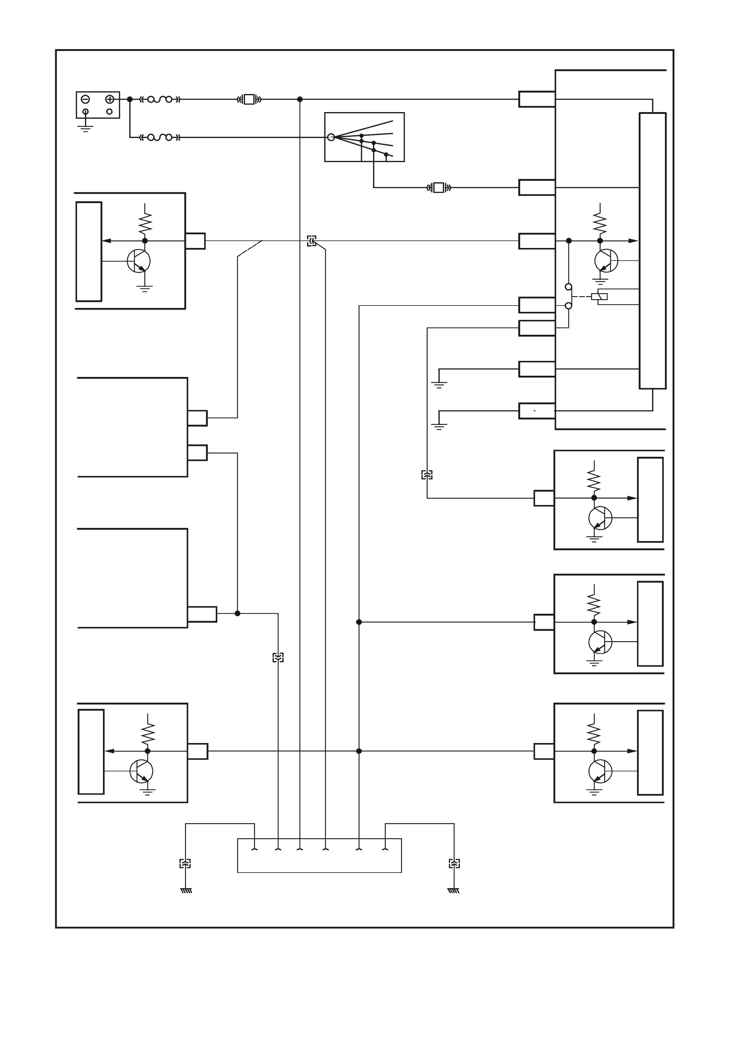
WH12C014
BATTERY
30 OFF/ON
LOCK
ACC.
IGN.
START
15A 15 50
P (3) P/B (39)
R/B (1221)
F13
BCM
SDM
ECC
INSTRUMENTSABS/ETC
PI M - GEN III V 8
PCM - GEN III V8
PCM - V6
M
I
C
R
O
P
R
O
C
E
S
S
O
R
M
I
C
R
O
M
I
C
R
O
BATTER Y MAIN POWER
A3
5V
SERIAL
DATA
YB188 YE112
FS
FJ
(1040)
R (2H)
F31
IGNITION SWITCH
A
5
E20
E2
E9
E3
B10
A1
O/B (740) YB176
YB175 IGNITION ON
SERIAL
DATA
MAIN
SERIAL
DATA AUX.
HIGH CURR ENT
EARTH
5V
5V
5V
5V5V
G/W (1220)
W/G (1220)
B/G (151)
B/Y (155)
LOC. E3
LOC. E3
YB174
YB176
ELECTRONIC EARTH
M
I
C
R
O
M
I
C
R
O
M
I
C
R
O
SERIAL
DATA
SERIAL
DATA
SERIAL
DATA
SERIAL
DATA
YB189
YB87
YB66YE98
YB215
YE122
YE110
Y (1049)
9
6
1211
7
6
J1-58
YB191
POWERTRAIN
INTERFACE
MODULE
(GEN III V8 ENGINE
ONLY)
POWERTRAIN
CONTROL
MODULE
(GEN III V8 ENGINE
ONLY)
YE114 YE114
LOC. E3LOC. E3
B/Y (155) B (150)
5216 9 14
Y
B128
DATA LINK CONNECTOR
CLAS S 2 SERIAL DATA
SERIAL DATA CIRCUIT

DTC 14 TEST PROCEDURE
STEP ACTION VALUE YES NO
1 • Was the Diagnostic Circuit Check performed? Go to Step 2. Go to Diagnostic
Circuit Check in this
Section.
2• Connect TECH 2 to the DLC.
• Select Body / DTC Check / F0: DTC Check.
• Can TECH 2 communicate with the BCM?
NOTE: If ‘ No Dat a’ i s displayed next to the BCM, then t here i s
no com munication between TECH 2 and the BCM. I f 'No
DTC' or 'DTCs S et' is displayed then there i s com munic at i on
between the TECH 2 and the BCM.
Go to Step 3. Go to BCM Serial Data
Communication
diagnosti cs in Section
12J-2 HIGH S E RIES
BODY CONTROL
MODULE of the V T
Series II Service
Information.
3• In Step 2, was TE CH 2 abl e t o communicat e with all the
other control modules , except the Inst ruments , fitted to
the vehicl e (ABS/ E T C, ECC, S RS )?
NOTE: If ‘ No Dat a’ i s displayed next to a control module, then
there is no communicat i on bet ween TECH 2 and t hat control
module.
Go to Step 6. Go to Step 4.
4• Using an ohmmet er, check continuit y of circuits 1220
(Green/Whit e wire) and 1221 (Red/B l ack wire) between
BCM connect or Y B175, terminals 2 and 9.
• Does continuity exist?
Go to Step 5. Replace BCM, refer to
Secti on 12J-2 HIGH
SERIES BODY
CONTROL MODULE
of the VT S e ri es II
Service Inform ation.
5• Check c i rcuit 1220 (Green/White wire) for open, short t o
earth or short t o vol t age between BCM and individual
control modules. Note that t he wire colour for circuit 1220
between the BCM and the SDM is White/Green.
• Is c i rcuit 1220 okay?
NOTE: Disconnect eac h control module in ci rcuit 1220 one at
a time to isol ate the fault in the ci rcuit or to i dentify the control
module causing the fault.
Refer to the
appropriate diagnos tic
procedure for t he f aul ty
control module.
Repair circ ui t 1220 as
necessary.
6• Using an ohmmet er, check for continui ty between BCM
connect or Y B175, terminal 9 and ins trument s connect or
YB66, terminal 12 (Green/ White wire).
• Does continuity exist?
Go to Step 7. Repair open in circuit
1220.
7• Check t he i ntegrity of the Inst ruments earth circui t by
perform i ng a vol t age drop on circuit 155 between
instrument c onnector YB66, term i nal 6 and earth point
E3.
• With igni tion on, is vol tage less t han the speci f i ed val ue?
0.15 volt Go to Step 8. Repair earth circuit as
necessary.
8• Use TECH 2 to clear DTC.
• Has DTC cleared? DTC 14 is interm ittent.
Check c i rcuit 1220
(Green/Whit e wire)
between BCM and
instrument c l uster for
an intermittent fault.
Check t he i nstrum ent
cluster and BCM
connect ors for terminal
retention. If OK replac e
instrument c l uster,
refer to 2. 1
INSTRUMENT
CLUSTER i n this
Section.
WHEN ALL DIAGNOSIS AND REPAIRS ARE COMPLETED, CLEAR ALL DTC AND VERIFY CORRECT OPERATION

DTC 15 - NO SUB-CLOCK
CIRCUIT DESCRIPTION:
The sub-clock is part of the printed circuit board housed within the instrument cluster, and provides timing pulses
required for the operation of the instrument cluster liquid crystal display when the ignition is off. If a DTC 15 has
been set, then the instrument cluster will need to be replaced.
DTC 15 Will Set If:
• An attempt to switch the low power sub-clock fails. This occurs 20 seconds after the ignition is switched off. The
DTC is reset when a switch to the low power sub-clock is successful. The DTC is logged as a History DTC.
DTC 15 TEST PROCEDURE
STEP ACTION VALUE YES NO
1 • Was the Diagnostic Circuit Check performed? Go to Step 2. Go to Diagnostic
Circuit Check in this
Section.
8• Use TECH 2 to clear DTC.
• Has DTC cleared? Instrument cluster OK.
End of diagnos tic
testing.
Replace ins trument
cluster, refer to 2.1
INSTRUMENT
CLUSTER i n this
Section.
WHEN ALL DIAGNOSIS AND REPAIRS ARE COMPLETED, CLEAR ALL DTC AND VERIFY CORRECT OPERATION

DTC 16 - ABS/ETC FAULT LOGGED
CIRCUIT DESCRIPTION:
The ABS/ETC module informs the instrument via the serial data bus whenever an ABS/ETC DTC has been set.
DTC 16 does not set the icon on the instrum ent cluster. Ref er to Section 12L ABS & ABS/ETC of the VT Series I
Service Information for fault diagnostic procedures on the V6 engine, or Section 12L ABS & ABS/ETC of the VT
Series II Service Information for the GEN III V8 engine.
DTC 16 is logged as a History DTC.

DTC 17 - BCM FAULT LOGGED
CIRCUIT DESCRIPTION:
The BCM inf orm s the instrum ent via the serial data bus whenever a BCM DT C has been set. DT C 17 does not set
the icon on the instrument cluster. Refer to Section 12J-2 HIGH SERIES BODY CONTROL MODULE of the VT
Series II Service Information for fault diagnostic procedures.
DTC 17 is logged as a History DTC.

DTC 18 - ECC FAULT LOGGED
CIRCUIT DESCRIPTION:
The ECC module informs the instrum ent via the s erial data bus whenever an ECC DTC has been set. DTC 18 does
not set the icon on the instrument cluster. Refer to Section 2F AIR CONDITIONING - ECC DIAGNOST ICS in this
Supplement for fault diagnostic procedures.
DTC 18 is logged as a History DTC.

DTC 19 - PCM FAULT LOGGED
CIRCUIT DESCRIPTION:
The PCM inf orm s the instrum ent via the serial data bus whenever a PCM DT C has been set. DT C 19 does not set
the icon on the instrum ent cluster. Refer to Section 6C1 POWERTRAIN MANAGEMENT - V6 ENGINE of the VT
Series I Service Information, or Section 6C3-2 DIAGNOSIS - GEN III V8 ENGINE of the VT Series II Service
Information for fault diagnostic procedures.
DTC 19 is logged as a History DTC.

DTC 20 - SDM FAULT LOGGED
CIRCUIT DESCRIPTION:
The SDM inf or ms the instr ument via the ser ial data bus whenever an SDM DT C has been s et. DT C 20 does not s et
the icon on the instrument cluster. Refer to Section 12M SUPPLEMENTAL RESTRAINT SYSTEM of the VT
Series I Service Information for fault diagnostic procedures.
DTC 20 is logged as a History DTC.

DTC 21 - TRIP SWITCH SHORT CIRCUIT
WH12C015
YB66
INS T RUME NTS CONNECTO R
V/W (123) BLU/B ( 9 46)
10
20 1
11
B/Y (155) GY (8) BR/W (19)
BLU/Y (10)
T (30) BR/O (33)BR (25)
V/R (234)
W (8 5 )
BLU (15)
Y/R (88)
G/W (1220)
LBLU (14)
G (87 5)
O/Y (1 340)
P/BLU ( 4 4)
BR/R (121)
INST RUME N T CLUSTER
413 YB 66
YB 56
YB 56
BR/W (19)
TRIP COMPUTER
SWITCH
SECU RITY LE D
TRIP COMPUTER SWITCH
ILLUMINATION
MODE
BL U/B (9 46)
F 1 1
65
GY
B/Y
YE114
B/Y (155)
(8)
(155)
GND
YB56
MA IN WIRING HARNESS
CONNECTOR
BR/W (19)
BLU /B (946 )
GY (8 )
LBLU (263)
B/Y (155)
Y
E114
MAIN WIRING HARNESS
CONNECTOR
B/R (157)B/G (151 )
B/W (152)
B (150) B/Y (155)
B/R (157)
CIRCUIT DESCRIPTION:
The res istance pr esented to the instr um ent cluster on term inal 13 is dependent upon the button s elected on the tr ip
computer switch.
DTC 21 Will Set If:
• When the trip computer switch resistance is less than 1000 ohms for 10 seconds. The DTC is reset as soon as
the switch resistance is greater than 1000 ohms. The DTC is logged as a History DTC.
Test Description:
Number(s) below refer to step number(s) in the following diagnostic chart.
1. Ensures the Diagnostic Circuit Check has been performed.
2. Determines if the BCM can communicate with the TECH 2.
3. Check for obvious physical damage or fault.
4. Continuity check of switch to determine if the switch is functioning correctly.
5. Check of main wiring harness circuit 946 (Blue/Black wire) for a short to earth.
6. If the DTC can be cleared, the fault is intermittent. If the DTC cannot be cleared, the instrument cluster is faulty.
Diagnostic Aids:
By manipulating the harnesses at the various connectors it is often possible to isolate the cause of the circuit
interruption. This harness can then be removed and repaired.
Check for any damage to the harness which could cause an intermittent open or short to earth or backed out
terminals at the instrument cluster connectors, broken connector locks, improperly formed or damaged terminals.
The multimeter allows continuity of the wiring harness circuit 946 to be checked.

DTC 21 TEST PROCEDURE
STEP ACTION VALUE YES NO
1 • Was the Diagnostic Circuit Check performed? Go to Step 2. Go to Diagnostic
Circuit Check in this
Section.
2• Connect TECH 2 to the DLC.
• Select Body / DTC Check / F0: DTC Check.
• Can TECH 2 communicate with the BCM?
NOTE: If ‘ No Dat a’ i s displayed next to the BCM, then t here i s
no com munication between TECH 2 and the BCM. I f 'No
DTC' or 'DTCs S et' is displayed then there i s com munic at i on
between the TECH 2 and the BCM.
Go to Step 3. Go to BCM Serial Data
Communication
diagnosti cs in Section
12J-2 HIGH S E RIES
BODY CONTROL
MODULE of the V T
Series II Service
Information.
3• Check t he switch for obvious signs of damage. Replace the switch,
refer to 2.4 TRIP
COMPUTER SWITCH
ASSEMBLY in this
Section.
Go to Step 4.
4• Remove the switch, refer to 2.4 TRIP COMPUTER
SW ITCH ASSEMBLY in this Section.
• Using an ohmmet er, test t he switch as detailed in
2.4 TRIP COMPUTER SWITCH ASSEMBLY in this
Section.
• Switch tests OK?
Go to Step 5. Replace the switch,
refer to 2.4 TRIP
COMPUTER SWITCH
ASSEMBLY in this
Section.
5• Disconnect ins t rument c l uster connector YB66.
• Using an ohmmet er, check main wiring harnes s circ ui t
946 (Blue/B l ack wire) for a short to earth.
• Short to earth exists?
Repair fault y main
wiring harness and
verify repair.
Go to Step 6.
6• Use TECH 2 to clear DTC.
• Has DTC cleared? DTC 21 is interm ittent.
Check c i rcuit 946
(Blue/B l ack wire)
between switch and
instrument c l uster for
an intermittent fault.
Check t he i nstrum ent
cluster and switch
connect ors for terminal
retention. If OK replac e
instrument c l uster,
refer to 2. 1
INSTRUMENT
CLUSTER i n this
Section.
WHEN ALL DIAGNOSIS AND REPAIRS ARE COMPLETED, CLEAR ALL DTC AND VERIFY CORRECT OPERATION
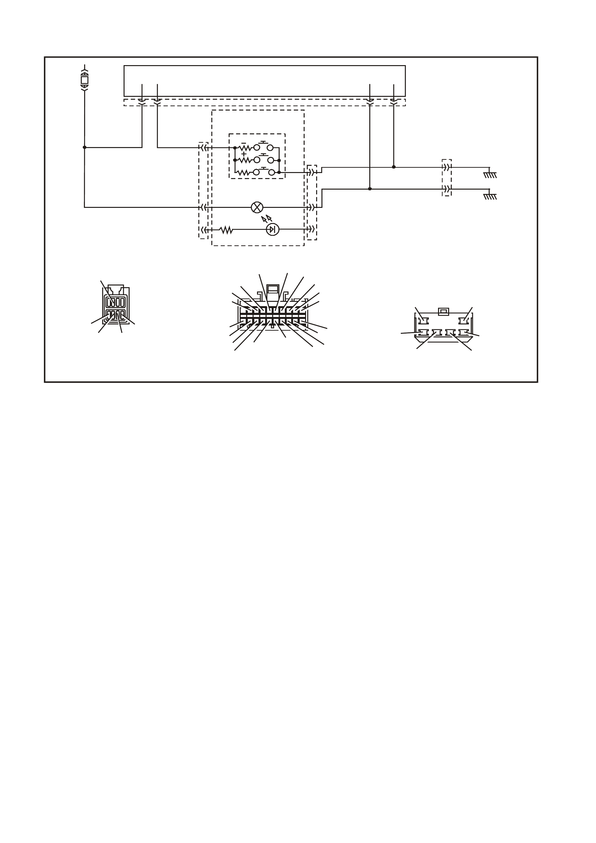
DTC 22 - TRIP SWITCH BUTTON STUCK
WH12C015
YB66
INS T RUME NTS CONNECTO R
V/W (123) BLU/B ( 9 46)
10
20 1
11
B/Y (155) GY (8) BR/W (19)
BLU/Y (10)
T (30) BR/O (33)BR (25)
V/R (234)
W (8 5 )
BLU (15)
Y/R (88)
G/W (1220)
LBLU (14)
G (87 5)
O/Y (1 340)
P/BLU ( 4 4)
BR/R (121)
INST RUME N T CLUSTER
413 YB 66
YB 56
YB 56
BR/W (19)
TRIP COMPUTER
SWITCH
SECU RITY LE D
TRIP COMPUTER SWITCH
ILLUMINATION
MODE
BL U/B (9 46)
F 1 1
65
GY
B/Y
YE114
B/Y (155)
(8)
(155)
GND
YB56
MA IN WIRING HARNESS
CONNECTOR
BR/W (19)
BLU /B (946 )
GY (8 )
LBLU (263)
B/Y (155)
Y
E114
MAIN WIRING HARNESS
CONNECTOR
B/R (157)B/G (151 )
B/W (152)
B (150) B/Y (155)
B/R (157)
CIRCUIT DESCRIPTION:
The res istance pr esented to the instr um ent cluster on term inal 13 is dependent upon the button s elected on the tr ip
computer switch.
DTC 22 Will Set If:
• When any button on the trip computer is pressed for longer than 120 seconds. The DTC is reset as soon as the
button is released, and the DTC is logged as a History DTC.
Test Description:
Number(s) below refer to step number(s) in the following diagnostic chart.
1. Ensures the Diagnostic Circuit Check has been performed.
2. Determines if the BCM can communicate with the TECH 2.
3. Check for obvious physical damage or fault.
4. Continuity check of switch to determine if the switch is functioning correctly.
5. If the DTC can be cleared, the fault is intermittent. If the DTC cannot be cleared, the instrument cluster is faulty.
Diagnostic Aids:
By manipulating the harnesses at the various connectors it is often possible to isolate the cause of the circuit
interruption. This harness can then be removed and repaired.
Check for any damage to the harness which could cause an intermittent open or short to earth or backed out
terminals at the instrument cluster connectors, broken connector locks, improperly formed or damaged terminals.

DTC 22 TEST PROCEDURE
STEP ACTION VALUE YES NO
1 • Was the Diagnostic Circuit Check performed? Go to Step 2. Go to Diagnostic
Circuit Check in this
Section.
2• Connect TECH 2 to the DLC.
• Select Body / DTC Check / F0: DTC Check.
• Can TECH 2 communicate with the BCM?
NOTE: If ‘ No Dat a’ i s displayed next to the BCM, then t here i s
no com munication between TECH 2 and the BCM. I f 'No
DTC' or 'DTCs S et' is displayed then there i s com munic at i on
between the TECH 2 and the BCM.
Go to Step 3. Go to BCM Serial Data
Communication
diagnosti cs in Section
12J-2 HIGH S E RIES
BODY CONTROL
MODULE of the V T
Series II Service
Information.
3• Check t he switch for obvious signs of a stuck button. Replace the switch,
refer to 2.4 TRIP
COMPUTER SWITCH
ASSEMBLY in this
Section.
Go to Step 4.
4• Remove the switch, refer to 2.4 TRIP COMPUTER
SW ITCH ASSEMBLY in this Section.
• Using an ohmmet er, test t he switch as detailed in
2.4 TRIP COMPUTER SWITCH ASSEMBLY in this
Section.
• Switch tests OK?
Go to Step 5. Replace the switch,
refer to 2.4 TRIP
COMPUTER SWITCH
ASSEMBLY in this
Section.
5• Use TECH 2 to clear DTC.
• Has DTC cleared? DTC 22 is interm ittent.
Check c i rcuit 946
(Blue/B l ack wire)
between switch and
instrument c l uster for
an intermittent fault.
Replace ins trument
cluster, refer to 2.1
INSTRUMENT
CLUSTER i n this
Section.
WHEN ALL DIAGNOSIS AND REPAIRS ARE COMPLETED, CLEAR ALL DTC AND VERIFY CORRECT OPERATION
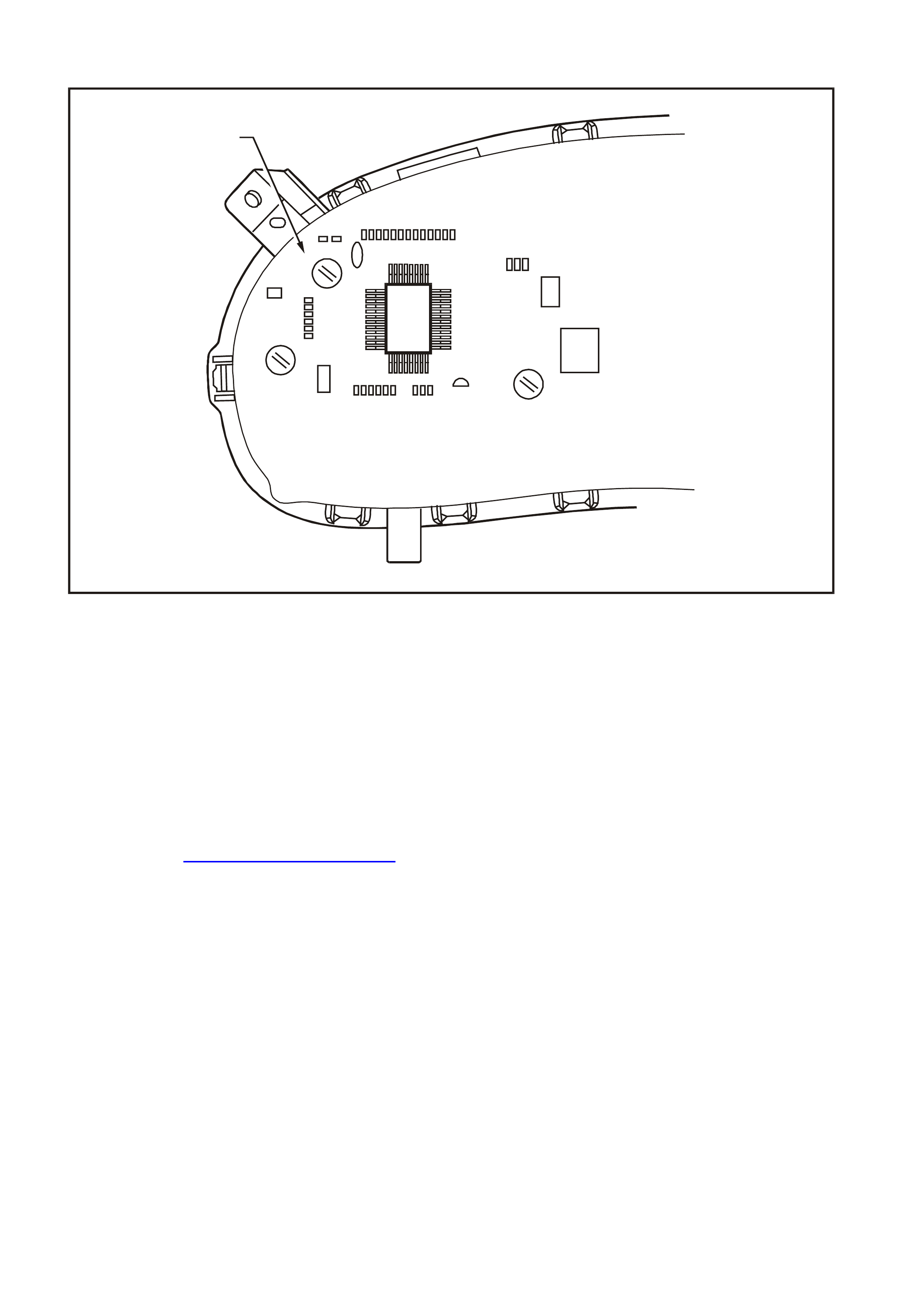
DTC 24 - EE CHECKSUM = FAILURE
T12C187
EEPROM
INSTRUME NT ASSEMBLY
CIRCUIT DESCRIPTION:
The EEPROM (Electrically Erasable Programmable Read Only Memory) is part of the printed circuit board housed
within the instrument cluster. It stores variables required in the operation of the instrument cluster and in the
interpretation of the incoming data and can be programmed for different instrument levels. If a DTC 24 was set as a
result of interrupted instrument programming then the following diagnostic table will need to be followed.
DTC 24 Will Set If:
• The EEPROM checksum is incorrect. The testing of the EEPROM checksum occurs every time the ignition is
turned on. The DTC is reset when the EEPROM checksum is tested as being correct. The DTC is logged as a
History DTC.
Diagnostic Aids:
If the programmed instrument cluster values are corrupted, reprogramming can be carried out via TECH 2 to rectify
the fault, refer to Section 5.15 - F5: PROGRAM in this Section.

DTC 24 TEST PROCEDURE
STEP ACTION VALUE YES NO
1 • Was the Diagnostic Circuit Check performed? Go to Step 2. Go to Diagnostic
Circuit Check in the
Section.
2• Go to Sect i on 5.15 F5: PROGRAM in thi s Secti on.
• Is programmi ng completed succ essful l y? Go to Step 3. Replace ins trument
cluster, refer to 2.1
INSTRUMENT
CLUSTER i n this
Section.
3• Use TECH 2 to clear DTC.
• Has DTC cleared? Instrument c l uster OK.
End of diagnos tic
testing.
EEPROM failed.
Replace ins trument
cluster, refer to 2.1
INSTRUMENT
CLUSTER i n this
Section.
W HE N ALL DIAGNOS IS AND RE PAIRS ARE COMPLETED, CLEAR ALL DTC AND VE RIFY CORRECT OPERATION

DTC 25 - ROM CHECKSUM = FAILURE
CIRCUIT DESCRIPTION:
The ROM (Read Only Memory) is part of the printed circuit board housed within the instrument cluster. It stores
variables required to initialise the instrument cluster. If a DTC 25 has been set, then the instrument cluster will need
to be replaced.
DTC 25 Will Set If:
• The ROM checksum is incorrect. The testing of the ROM checksum occurs when the instrument cluster is
reset (due to battery removal or low power cranking). The DTC is reset when the ROM checksum is tested as
being correct. The DTC is logged as a History DTC.
Diagnostic Aids:
If the ROM checksum is incorrect, the instrument cluster may need to be replaced and reprogrammed.
DTC 25 TEST PROCEDURE
STEP ACTION VALUE YES NO
1 • Was the Diagnostic Circuit Check performed? Go to Step 2. Go to Diagnostic
Circuit Check in this
Section.
2• Use TECH 2 to clear DTC.
• Has DTC cleared? Instrument c l uster OK.
End of diagnos tic
testing.
ROM checksum error.
Replace ins trument
cluster, refer to 2.1
INSTRUMENT
CLUSTER i n this
Section.
W HE N ALL DIAGNOS IS AND RE PAIRS ARE COMPLETED, CLEAR ALL DTC AND VE RIFY CORRECT OPERATION

DTC 26 - INTERNAL FAULT
CIRCUIT DESCRIPTION:
The instrument cluster is equipped with self-diagnostic capability that can detect an internal fault within the
instrument cluster. If a DTC 26 has been set, then the instrument cluster will need to be replaced.
DTC 26 Will Set If:
• The instrument has detected an internal fault. The DTC is reset when the RAM checksum is tested as being
correct. The DTC is logged as a History DTC.
DTC 26 TEST PROCEDURE
STEP ACTION VALUE YES NO
1 • Has diagnostic circuit check been carried out ? Go to Step 2. Go to Diagnostic
Circuit Check in this
Section.
2• Use TECH 2 to clear DTC.
• Has DTC cleared? Instrument c l uster OK.
End of diagnos tic
testing.
Internal f aul t.
Replace ins trument
cluster, refer to 2.1
INSTRUMENT
CLUSTER i n this
Section.
W HE N ALL DIAGNOS IS AND RE PAIRS ARE COMPLETED, CLEAR ALL DTC AND VE RIFY CORRECT OPERATION

TRIP COMPUTER DIAGNOS TIC FUNCTIONS -TRIPLE WINDOW DISPLAY
Description
On high series BCM equipped vehicles the instrument cluster is fitted with a triple window trip computer. The
purpose of this diagnostic chart is to determine if there is a fault with any of the display functions.
Because there ar e no repairable item s within the instrum ent cluster , if a f ault is detec ted the instrum ent c luster is to
be replaced, refer to 2.1 INSTRUMENT CLUSTER in this Section.
To enter DIAGNOSTIC MODE :
Press the MODE button down together with ▲
▲▲
▲ button while turning ignition from off to on.
Action Window 1 Displays Window 2 Displays Window 3 Displays
First di splay (Battery V ol tage)
V 00.0 (Software Vers i on)
YYMMDD (GMH Part Num ber)
XXXX P
Press MODE but ton (LPG Fuel Sender Voltage)
V L 0.0 (Button Vol t age/Button Test)
B V CUD 0.0 (Fuel S ender V ol tage)
FUEL 0.0
Press MODE button (Park Lamps On/Off)
P [ On/Off] (Engine Temperat ure)
TEMP 34°C (Instantaneous Fuel )
INST
FUEL 00.0 l/h
Press MODE button (Speedometer Reading)
SPEED 000 km/h
(Tachom et er Readi ng)
T XXXXX (Fuel Remai ni ng)
REMAINING
FUEL 00.0 L
Press MODE button (Diagnosti c Mode Display —
refer to Note)
t 00 - -
Press MODE button All s egments on All s egments on
All lamps on
Buzzer = 1 kHz
Temperature Gauge = 50%
Fuel Gauge = 50%
Tachom et er = 3000 rpm
Speedometer = 100 km /h
Sequential illum i nat ion of
PRND321 LEDs
All s egments on
To exit DIAGNOSTIC MODE :
Press the ▲
▲▲
▲ button together with ▼
▼▼
▼ button
Press ▲
▲▲
▲ & ▼
▼▼
▼ button to exit (Odomet er readi ng)
00000.0
NOTE: The diagnostic mode display uses the format t NN XY , where:
t= diagnostic trouble code (DTC),
NN = the actual DTC number,
X= the history DTC status (H for active and – for inactive), and
Y= the current DTC status (C for active and – for inactive).
IMPORTANT: An open c ircuit fuel gauge sender unit is shown by the instrument clus ter diagnostic m ode display as
‘t 00 H C’ whereas the TECH 2 shows the same fault as DTC 3.
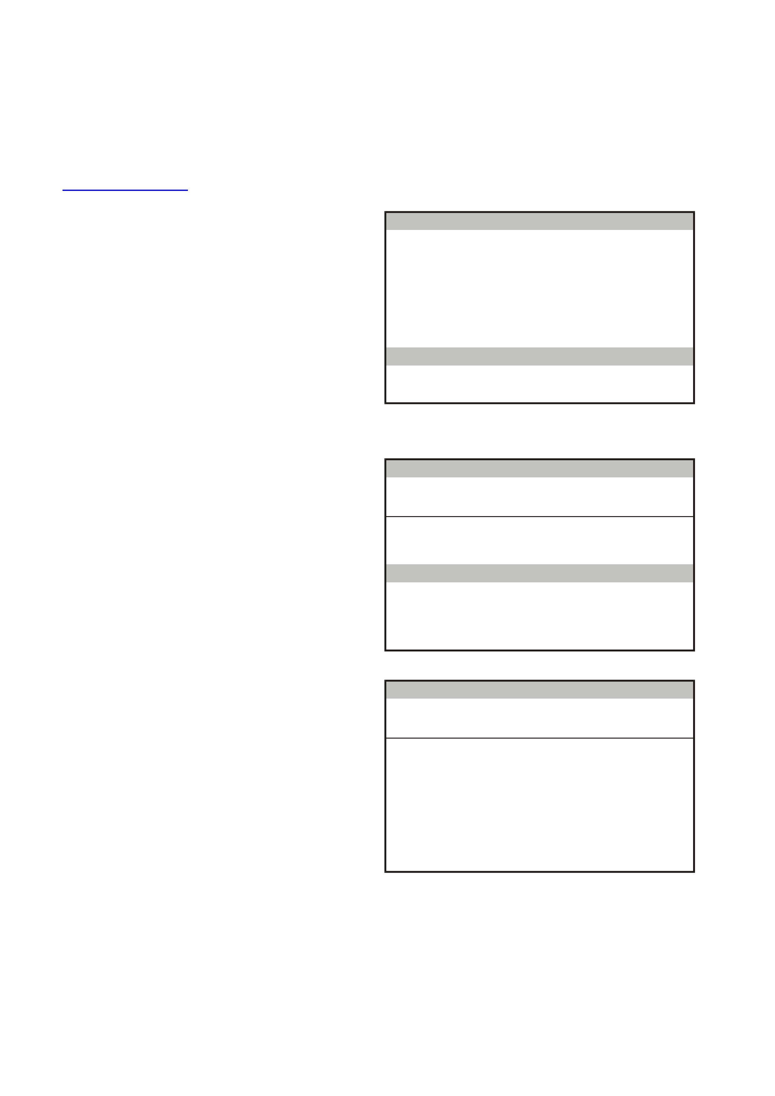
5.9 USING TECH 2 TO DIAGNOSE THE INS TRUMENT CLUSTER
A prerequisite to this diagnostic section is that the
user is f am iliar with the proper use of T ECH 2. T he
following pages illustrate only the major TECH 2
screen displays and provide a brief explanation of
their function for diagnosing the Instruments. If
additional information is required on the operation
of TECH 2, reference should be made to either
Section 0C TECH 2 of the VT Series II Service
Information or the TECH 2 User’s Guide.
SYSTEM SELECTION MENU
This mode contains all functions to test, diagnose,
monitor and program the vehicles body systems
including the Instruments as well as providing the
opportunity to check all DT C that may be set in the
vehicle.
With TECH 2 connected to the DLC:
• select F0: Diagnostics from the Main Menu,
• select the appropriate m odel year at the Vehicle
Identification Menu,
• select the appropriate vehicel type at the next
screen, and
• select F3: Body at the System Selection Menu.
System Selection Menu
F0:
F1:
F2:
F3:
WH12C004
Engine
Transmission
Chassis
Body
(X) 1999 WH Statesman & Capric e
Figure 12C-20
VEHICLE IDENTIFICATION MENU
Once F3: Body has been s elected fr om the System
Selection Menu, Instrument can be selected.
Select Instrument.
NOTE: If information regarding DTC set for the
vehicle is required, select DTC Check and press
enter to continue. T o return to the Instrum ent m ode
option from the DTC Check mode option screen
display, simply press the Exit key on TECH 2.
Once Instrument has been selected, the following
two System Identification s creens will appear which
require action.
V e hicle Iden tification
B ody Control Mo dule
Po wertrain Inte rface M o du le
SRS
Instrument
Electronic Clim ate Control
DTC Check
Other
S elect one o f the follow ing
Body
T212C141
Figure 12C-21
SYSTEM IDENTIFICATION
Turn the ignition on (as requested) and press
Confirm soft key to continue.
Syste m Id entificat io n
Turn On Ignition!
(X) 1999
Electronic System: Instrument
WH St atesman & Caprice
WH12C005
Figure 12C-22

The part number of the instrument cluster will be
displayed. Press the More soft key to display more
detailed information about the part.
Syste m Id entificat io n
Partnumber XXXXXXXX
(X) 1999
Electronic System: Instrument
WH St atesman & Caprice
WH12C006
Figure 12C-23
Press the Confirm soft key to confirm these details.
Syste m Id entificat io n
Partnumber
Software Date
Data Versio n Number
VAP Process Number
XXXXXXXX
XXXXXX
XX
XXX
(X) 1999
Electronic System: Instrument
WH St atesman & Caprice
WH12C007
Figure 12C-24
The Vehicle Identification Number / TIS Hardware
Key Number will be displayed.
Syste m Id entificat io n
Vehicle Identification Number / TIS
Hardware Key Number
123456
(X) 1999
Electronic System: Instrument
WH St atesman & Caprice
WH12C008
Figure 12C-25
Body Menu
The Body Menu will be displayed.
Body
F0:
F1:
F2:
F3:
F4:
F5:
T12C140
Normal Mode
Diagnostic Trouble Codes
Data Display
Snapshot
Miscellaneous Tests
Program
Figure 12C-26

5.10 F0 : NORMAL MODE
The instrument normal mode data list is used to
view serial data being sent from the instrument
cluster.
Norm al Mode
Engine O il L ife Reset
T ransm ission Fluid Life Reset
C ruise Con tro l En gaged
SRS Configuration
Fu el L ev el - P etro l
Fu el Lev el - LPG
IN S DTC Status
No
No
No
6 Loop SR S
0 L
0 L
No DTC
T12C182
Figure 12C-27

5.11 F1: DIAGNOSTIC TROUBLE CODE S
Diagnostic Trouble Codes Menu
F0: Read DTC Information - If this mode is
selected, a lis ting of all (if any) DT C that have been
set by the instrument cluster will be displayed.
NOTE: If any DTC are set, reference should be
made to the relevant diagnostic charts in this
Section.
F1: Clear DTC Information - DTC can be cleared
in this mode by simply selecting F1: Clear DTC
Information, pressing the Enter button on TECH 2
and confirming the action as instructed by TECH 2.
NOTE: TECH 2 will display Clear DTC Information
Failed if any DTC are still current.
Diagnostic Trouble Codes
F0: Read DTC Information
F 1 : C lea r D T C In fo rma tio n
T12C146
Figure 12C-28
Read DTC Information
Select F0: Read DTC Information.
Use the following table to assist in diagnosing and
rectifying DTC.
NOTE: Sc reen shot shows an exam ple of two DTC
only.
Read DTC Information
3 Current
Petrol Sender Open Circuit
12 Cu rre n t
No Serial Data From SDM
VTX12C510
Figure 12C-29

The following chart sets out all the possible TECH 2 diagnostic trouble codes.
DTC CODE DESCRIPTION ICON
ACTIVATED AD DITIONAL ENABL E
BIT
1Fuel gauge sender unit — short circuit Yes None
2Fuel gauge sender unit — i ntermittent Yes None
3Fuel gauge sender unit — open circuit (ref er to Note 1) Yes None
4 LPG option. Not used for WH Series models
5 LPG option. Not used for WH Series models
6 LPG option. Not used for WH Series models
8 No serial data from ABS/ETC Yes Tract i on of f enable
9 No serial dat a f rom BCM Yes None
10 No serial data f rom ECC Yes None
(refer to Note 2)
11 No serial data f rom PCM Yes None
12 No serial data f rom SDM Yes SRS lamp enable
13 No instrument poll f rom BCM Yes None
14 No serial communi cation Yes None
15 No Sub-clock Yes None
16 ABS/E T C fault logged No None
17 BCM fault logged No None
18 ECC fault logged No None
19 PCM fault logged No None
20 SDM fault logged No None
21 Trip switch short circuit Yes None
22 Trip switch butt on stuck Yes None
24 EE checksum error Yes None
25 ROM checksum error Yes None
26 In t ernal fault Yes None
NOTE 1: DTC 3 is recognised by t he i nstrum ent cluster self-di agnostic s as ‘t 00 H C”.
NOTE 2: The ECC EEPROM enable bit is programmed acti ve for the high seri es vehicles duri ng manufac ture.
5.12 F2: DATA DISPLAY
In this test mode, the status of the instrument
cluster inputs and outputs can be monitored.
Select either F0: Instrument or F1: Trip Computer
from the data display screen, and press Enter to
continue.
Figure 12C-30
F0: Instrument
The serial data from the instruments can be
check ed and tes ted by selecting the instr ument and
pressing the Select Items soft key. The list can be
scrolled by using the Up and Down arrow keys.
Instrument
Battery Voltage xx.x V
V ehicle Speed xxx km/h
Ignition Switch On
Engi ne Spe ed xxxx RPM
Instrument Lamp s xxx %
Park Lamp Input Off
Park Brake And Brake Fail Lamp On
Rear Lamp Failure Warning Lamp Off
Seat Belt Lamp Off
T212C149
Figure 12C-31
Use the Up and Down arrow keys to navigate
through the items.
Instrument
SRS La mp Off
Cr ui se C ontr ol En ga g e d Inpu t O ff
Cruise Control On Lamp Off
Low Fuel Lamp Off
Overspeed Lamp Off
Power Shift Lamp Off
PRN D L Pos itio n Inva lid
Oil Pre ssure La mp Off
High Coolant Temperature Lamp Off
T212C180
Figure 12C-32

NOTE: Traction control data list parameters are
only applicable if ABS/ETC is fitted.
Instrument
Low Coolant L evel Lam p O ff
E ng ine C o olant T e m p erature x xx C
Check P ow ertrain Lamp Off
Trac tio n C o ntro l O ff La mp O ff
LPG In U se La m p O ff
LPG Sender Signal xx.x V
LPG Sender Resistance xxx Ohm
Fuel Gauge Display xxx
Petrol Sender Signal xx.x V
Petrol Sender Resistance xxx Ohm
o
T12C181
Figure 12C-33
F1: Trip Computer
Trip C o m p u te r
Off
Off
Off
5.0 V
Off
Off
Off
Off
Off
Mode Button
Up Button
Down Button
Tr ip Comp ute r Sw itc h
LPG Mode
Park Lam ps
C ruise Eng aged
Sea t Belt Input
P a rk Brake Inpu t
T12C150A
Figure 12C-34
Trip C o m p u te r
Fuel Flo w 0.0 L/hou r
100.0 %
100.0 %D istance C a libration N umb er
Fuel Calibration Num ber
T12C151
Figure 12C-35

The following table lists each item contained in the data stream together with a brief description of its meaning.
DATA STREAM / SCREEN DISPLAY DESCRIPTION UNIT
Batt ery V o l tage Displays current bat tery voltage (approxim ately 12 volts ) Vol ts
Vehicl e Speed Displays current vehicle speed km /h
Igniti on S witch Displays the current status of the ignit i on switch On/Off
Engine Speed Displays current engine s peed rpm
Instrument Lamps Displays the current level of instrument lamps illumination
(0-100%) %
Park Lamp Input Displays status of the park l amps s witch On/Off
Park Brake and Brake Fail Lamp Used to chec k operation of brake lamp On/Off
Rear Bulb Failed Warning Lamp Used to check operation of bulb failed warning lamp On/Off
Seat Bel t Lamp Used to check operation of s eat belt lamp On/Off
SRS Lam p Used to check operation of SRS lamp On/Off
Cruise Control Engaged Input Displays status of cruis e control input On/Off
Cruise Control On Lamp Used to check operation cruise c ont rol l a mp On/Off
Low Fuel Lamp Us ed t o check operat i on of low fuel lam p On/Of f
Overspeed Lam p Used to c heck operation of overspeed lam p On/ O f f
Power Shift Lamp Displays status of power shi f t button On/Off
PRNDL Position Displays positi on of autom atic transmi ssion s el ector lever P/R/N/ D/ 1/2/3/
INVALID
Oil Pressure Lamp Used to check operati on of oi l pressure lamp On/Off
High Coolant Temperature Lam p Used to chec k operation of hi gh coolant temperature lamp On/ Off
Low Coolant Level Lamp Used to chec k operation of l ow coolant level lamp On/Off
Engine Coolant Temperature Displays signal from engine temperature On/Off
Check P owertrain Lamp Used to c heck operation of check powertrain l amp On/Off
Traction Cont rol Off Lam p Used to check operation of tract i on control dis abl ed l amp On/Of f
Fuel Gauge Display Used to check operation of fuel gauge dis pl ay %
Fuel Gauge Sender Signal Displays signal from fuel gauge s ender uni t 0 – 5 volts vari abl e
Fuel Sender Resi stance Displays fuel gauge sender unit resistance 35.2 – 256.3 ohms
variable

5.13 F3: SNAPSHOT
In this test mode, the TECH 2 captures data list information before and/or after a forced manual trigger.

5.14 F4: MISCELLANEOUS TESTS
Miscellaneous Tests allows for the testing of
various com ponents of the instrum ent c luster, s uch
as instrument and warning lamps, switches and
instrument gauges.
F0: Lamps - once this mode is selected, lamps in
the instrument cluster may be tested.
F1: Buzzer - operation of the buzzer c an be tested
with this function.
F2: PRNDL Lamps - operation of the automatic
transmission gear shift lever pattern can be tested
with this function.
F3: Trip Computer Buttons - once this mode is
selected, the buttons on the trip computer may be
tested.
F4: LPG Mode - not available on WH Statesman or
Caprice.
F5: Park Lamp Input - once this m ode is s elected,
the park lamp input may be tested.
F6: Brake (Park And Fail) Input - once this m ode
is selected, the park br ake and brak e fail input m ay
be tested.
F7: Control Tests - this func tion is used to tes t the
operation of the speedometer, tachometer, engine
coolant temperature, fuel gauge and sets the
function lamps illumination.
Miscellaneous Tests
F0: Lam ps
F3: Trip Computer Buttons
F2: PRNDL Lam ps
F5: P ark Lam p Input
F7: C ontrol Tests
F1: B uzzer
F4: LPG M ode
F6: Brake (Park and Fail) Input
T12C152
Figure 12C-36
F0: Lamps
F0: Lam ps f unc tion provides a means of tes ting the
correct operation of various warning/status lamps in
the instrument cluster.
Use the Up and Down arrow keys to scroll through
the list and highlight a lamp.
Press the Enter button to test the selected lamp.
Lamps
Brake (Park and F ail) Lam p
Over Speed Lamp
Low Fuel Lamp
Oil Pressure Lamp
Cruise Control On Lamp
SRS Lam p
Seat B elt Lam p
Check P o w ertrain Lam p
Power Shift Lamp
T12C153
Figure 12C-37
The adjacent figure shows the remainder of the
F0: Lamps menu.
Lamps
H igh C oolant T e m peratu re Lam p
Tractio n Control Off Lam p
Low Coolant Level Lam p
Rear Lam p Failure Warning Lam p
L P G In U s e L a mp
T12C154
Figure 12C-38

Once a lamp has been highlighted and selected,
the TECH 2 will show the following screen.
Current serial data will be shown at the top of the
screen and the s elected lam p and its current status
will be displayed at the bottom.
Press the On soft key to turn the selected lamp on
and note its status on the instrument cluster.
If the lamp does not come on and the TECH 2
display indicates that it is, there is a fault in the
lamp and the bulb will need to be replaced.
Press the Off soft key to turn the lamp off.
Press the Quit soft key and then the Confirm soft
key at the End of Test Screen to return to the
previous screen.
Pa r k B r ake An d Br ak e Fa il Lam p
V ehicle Speed xxx km/h
Battery Voltage xx.x V
Engine Speed xxxx RPM
Pa rk Lam p Input Off
Par k Brak e And Fa O ff
Electronic System: Instrument
Ig nition Switc h On
Instrument Lamps 100 %
WH12C016
(X) 1999 WH Statesman & Capric e
Figure 12C-39
F1: Buzzer
The operation of the buzzer can be tes ted, and a 1
kHz tone will be emitted from the instrument
buzzer.
Soft keys: Quit, On and Off.
F2: PRNDL Lamps
The operation of the automatic transmission gear
shift lever pattern can be tested by sequentially
illuminating the P, R, N, D, 1, 2 and 3 LEDs.
The appropriate lamp is indicated at the bottom of
the TECH 2 screen. Lamp control is provided by
the Quit, Off, On and Next Lamp soft keys.
F3: Trip Computer Buttons
F0: Mode Button
With this test a mode button press can be
sim ulated. This is to test if the button is s tuck or the
instrument is not working properly.
F1: Up Button
W ith this test an up button press c an be simulated.
This is to test if the button is stuck or the instrument
is not working properly.
F2: Down Button
With this test a down button press can be
sim ulated. This is to test if the button is s tuck or the
instrument is not working properly.
F4: LPG Mode
Not applicable to WH Statesman or Caprice.
F5: Park Lamp Input
This test allows the TECH 2 user to enable or
disable the park lamps input. This will dim the
Power, Cruise and LPG lamps only. It will have no
effect on the other warning lamps or instrument
cluster illumination.
F6: Brake (Park And Fail) Input
This function allows the TECH 2 user to enable or
disable the brake (park and fail) input.

F7: Control Tests
Control Tests allow the TECH 2 user to force
known values into the speedometer, tachometer,
engine coolant temperature gauge and fuel gauge
to verify their correct operation.
F0: Vehicle Speed
This function controls the speedometer.
Commanded vehicle speed can be adjusted up or
down in 20 km /h steps from 0 km /h to a m aximum
value of 220 km/h. Ensure that the speedom eter is
accurate according to the following table.
F1: Engine Speed
This functions controls the tachometer.
Commanded engine s peed can be adjus ted up and
down in 1000 rpm steps with a maximum value of
6000 rpm. Ensure that the tachometer is accurate
according to the following table.
F2: Engine Coolant Temperature
This function controls the temperature gauge.
There are three s teps when testing the temperature
gauge; cold, mid and hot. The test is conducted
using the Up and Down soft keys.
F3: Fuel Gauge
This function controls the fuel gauge. There are
three steps when testing the fuel gauge; empty, half
and full. The test is conducted using the Up and
Down soft keys.
F4: Function Lamps Illumination
This function controls the function lamps. Note that
this test applies only to the illumination level of the
Power and Cruise lamps. The illumination can be
adjusted in increments of 20% from 0% to 100%.
The function lamps are turned on automatically
when the test is being performed.
Control Tests
F0:
F1:
F2:
F3:
F4:
T12C156A
V e hicle Sp eed
Engine Speed
Engine Coolant T emperature Gauge
Fuel Gauge Level
Function Lam ps Illum ination
Figure 12C-40
Commanded
Vehicle
Speed
Speedo
Error Acceptable
Readings on
Speedometer
60 km / h –1/+3 km/ h 59 – 63 km/h
100 km / h –1/+3 km/h 99 – 103 km / h
160 km / h –1/+5 km/h 159 – 165 km/h
Commanded Engine
Speed Acceptable
Readings on
Tachometer
1000 rpm 860 – 1140 rpm
3000 rpm 2860 – 3140 rpm
5000 rpm 4860 – 5140 rpm

5.15 F5: PROGRAM
Turn ignition off.
Connect TECH 2 to the vehicle, refer to
5.6 CONNECTING THE TECH 2.
Navigate through the T ECH 2 menus to display the
Body Menu.
Select F5: Program from the Body Menu.
Body
F0: N orma l Mod e
F2: Data Display
F1: D iagnostic Trouble Co des
F3: Snaps hot
F4: Miscellaneous T ests
F5: Program
T12C157
Figure 12C-41
F0: Instrument Configuration
Select F0: Instrument Configuration.
Program
F0: Ins t rum e nt Co nf iguration
F2: Odometer Value
F1: Options
F3: Fuel Gauge Calibration
F4: Reset Service Interval
F 5: R eset U ser C alibr at i o n
T212C159
Figure 12C-42
Using the Next soft key, step through each
parameter and modify as necessary.
Press Confirm soft key to continue.
Instrument Configuration
Step Th ro ugh Ea c h Pa ra m eter An d Modify
If Necessary.
Co nfi r m Pr ogr amming A t The En d.
Electronic System: Instrument
WH12C017
(X) 1999 WH Statesman & Capric e
Figure 12C-43
1. SRS Configuration
Press Modify soft key to set to the following
option:
• 6 Loop SRS.
NOTE: Configuration of the various SRS
systems is as follows:
• a 2-loop system is for left-hand drive
vehicles with pre-tensioners only.
• a 3-loop system is for vehicles with pre-
tensioners and driver’s air bag only.
• a 4-loop system is for vehicles with pre-
tensioners, driver’s air bag and front
passenger’s air bag only.
• a 6-loop system is for vehicles with pre-
tensioners, driver’s air bag, front
passenger’s air bag and side air bags.
Instrument Configuration
SRS Configurat ion 6 Loop SRS
Electronic System: Instrument
WH12C018
(X) 1999 WH Statesman & Capric e
Figure 12C-44
Techline
2. SRS Lamp
Press Modify soft key to set to -
Enabled/Disabled.
• For all models, set to Enabled.
Instrument Configuration
SRS Lamp Enabled
Electronic System: Instrument
WH12C019
(X) 1999 WH Statesman & Capric e
Figure 12C-45
3. Speedometer Pulses
Press Modify soft key to set the speedometer
pulses per kilometre for the correct tyre size.
Nominal value is 6250 pulses per km.
• Tyre size 225 55 R16, select 6087 pulses.
Instrument Configuration
(X) 1999 WH Statesman & Caprice
Speedometer Pulses 6250
Electronic System: Instrument
WH12C020
Figure 12C-46
4. Speedometer Calibration
If the Police Mode has been enabled at
F5: Program / F1: Options, the speedometer
calibration sc r een appears nex t. This allows the
speedometer to be calibrated.
Press the Modify soft key to adjust the
speedom eter calibr ation, or the Next s oft k ey to
continue.
Instrument Configuration
(X) 1999 WH Statesman & Caprice
Speedometer Calibration 100%
Electronic System: Instrument
WH12C021
Figure 12C-47
5. Tachometer Ratio
Press Modify soft key to set to - V6 or
V8 Gen 3.
• Only V6 and V8 Gen 3 are applicable to the
WH Series models.
Instrument Configuration
(X) 1999 WH Statesman & Capric e
Tacho m et er Rat io V6
Electronic System: Instrument
WH12C022
Figure 12C-48
Techline

6. High Voltage Tachometer
Press Modify soft key to set to - Disabled.
• For V6 engine, set to Disabled.
• For GEN III V8 engine, set to Disabled.
Instrument Configuration
(X) 1999 WH Statesman & Caprice
High Voltage Tachometer Disabled
Electronic System: Instrument
WH12C023
Figure 12C-49
7. Progr am Instrument Confirm
Press Abort soft key to abandon process, or
press Program soft key to confirm parameters.
Press Confirm soft key when programming is
completed.
Instrument Configuration
SRS Configuration 6 Loop SRS
Speedometer Calibration
Speedometer Pulses 100%
6250
High Voltage Tachomet er Disabl ed
Electronic System: Instrument
SRS Lamp Enabled
Tachometer Ratio V6
WH12C024
(X) 1999 WH Statesman & Capric e
Figure 12C-50
F1: Options
Options such as instrument lamp illumination
enable/disable and Police Mode can be set by
selecting F1: Options from the Program Menu.
Program
F0: Ins t rum e nt Co nf iguration
F2: Odometer Value
F1: Options
F3: Fuel Gauge Calibration
F4: Reset Service Interval
F 5: R eset U ser C alibr at i o n
T212C159
Figure 12C-51
Using the Next soft key, step through each
parameter and modify as necessary.
Press Confirm soft key to continue.
Options
Step Th ro ugh Ea c h Pa ra m eter An d Modify
If Necessary.
Co nfi r m Pr ogr amming A t The En d.
Electronic System: Instrument
WH12C038
(X) 1999 WH Statesman & Capric e
Figure 12C-52
1. Rear Lamp Failure Lamp
Press Modify soft key to set to - Enabled.
• For WH Statesman and Caprice, set to
Enabled.
Options
Re a r La m p Failure La m p Enabled
Electronic System: Instrument
WH12C025
(X) 1999 WH Statesman & Capric e
Figure 12C-53
2. Traction Control Off Lamp
Press Modify soft key to set to -
Enabled/Disabled.
• For WH Statesman and Caprice, set to
Enabled.
Options
Traction Control Off Lamp Enabled
Electronic System: Instrument
WH12C026
(X) 1999 WH Statesman & Capric e
Figure 12C-54
3. LPG Lamp
Press Modify soft key to set to -
Enabled/Disabled.
• For V6 engine, check if the option is fitted. If
not fitted, set to Disabled.
• For GEN III V8 engine, set to Disabled.
Options
LPG Lamp Disabled
Electronic System: Instrument
WH12C027
(X) 1999 WH Statesman & Capric e
Figure 12C-55
4. Cruise On Lamp
Press Modify soft key to set to -
Enabled/Disabled.
• For WH Statesman and Caprice, set to
Enabled.
Options
Cruise On Lamp Enabled
Electronic System: Instrument
WH12C028
(X) 1999 WH Statesman & Capric e
Figure 12C-56
5. Police Mode
Press Modify soft key to set to -
Enabled/Disabled.
• For Police vehicles only, set to Enabled.
• For all other vehicles, set to Disabled.
Options
Police Mod e Disabled
Electronic System: Instrument
WH12C029
(X) 1999 WH Statesman & Capric e
Figure 12C-57
6. Low Coolant Lamp
Press Modify soft key to set to -
Enabled/Disabled.
• For V6 engine, set to Disabled.
• For GEN III V8 engine, set to Enabled.
Options
Low C oolant Lamp Disabled
Electronic System: Instrument
WH12C030
(X) 1999 WH Statesman & Capric e
Figure 12C-58
7. High Temperature Lamp
Press Modify soft key to set to - Enabled.
Options
High Temperature Lamp Enabled
Electronic System: Instrument
WH12C031
(X) 1999 WH Statesman & Capric e
Figure 12C-59
8. Program Options Confirm
Press Abort soft key to abandon process, or
press Program soft key to confirm parameters.
Press Confirm soft key when programming is
completed.
Options
Traction Control Lamp Enabled
Rear Lamp Failure La mp Enabled
Cruise On Lamp Enabled
Low Coolant Lamp Disabled
High Temperature Lamp Enabled
Electronic System: Instrument
LPG Lamp Disabled
Police Mode Disabled
WH12C032
(X) 1999 WH Statesman & Capric e
Figure 12C-60

9. Speedometer Calibration
NOTE: This is only available in TECH 2 when
instrument has been configured to Police
mode.
Turn the ignition off.
Hold down the MODE button as well as the ▲
and ▼ buttons on the trip computer.
Turn the ignition on while holding down the
three buttons.
Release the MODE button after 3 seconds,
then release the other two buttons. The
calibration value will now be flashing and C will
be displayed.
The calibration value (in percentage) can now
be adjusted with the ▲ and ▼ buttons. Set to
80% - 120% as necessary.
W hen the c alibration has been achieved, pr ess
the MODE button to lock in the calibr ation data
and return to the normal display.
F2: Odometer Value
NOTE: It is only possible to program the odometer
reading on an instrument once the TIS approval
code has been obtained and on an instrument
which presently reads no more than 100 km.
F3: Fuel Gauge Calibration
Select F3: Fuel Gauge Calibration.
Program
F0: Ins t rum e nt Co nf iguration
F2: Odometer Value
F1: Options
F3: Fuel Gauge Calibration
F4: Reset Service Interval
F 5: R eset U ser C alibr at i o n
T212C159
Figure 12C-61
The next screen displays the instrument Code
Index and Code Version. If these need to be
updated, press the Modif y soft key, otherwise press
the Okay soft key.
Fuel Gau ge Cali brat io n
Code Index
Code Version 1
0
Electronic System: Instrument
WH12C033
(X) 1999 WH Statesman & Capric e
Figure 12C-62

Select the vehicle type, press Enter and wait f or the
programming to be completed.
Press the Confirm soft key when programming is
completed.
Fuel Gau ge Cali brat i on
Electronic System: Instrument
WH12C034
Sedan Calibration
Wagon Calib ration
(X) 1999 WH Statesman & Caprice
Figure 12C-63
F4: Reset Service Interval
Select F4: Reset Service Interval.
Press the Abort soft k ey to abandon the process, or
press the Reset soft key to reset the service
interval.
Press the Confirm soft key when programming is
completed.
Re s et Se r vi c e Inte r va l
Reset Service Interval?
Electronic System: Instrument
WH12C035
(X) 1999 WH Statesman & Caprice
Figure 12C-64
F5: Reset User Calibration
Select F5: Reset User Calibration.
Press the Abort soft k ey to abandon the process, or
press the Reset soft key to reset the following
parameters:
• Trip Distance Calibration
• Fuel Used Calibration
• Speedometer Calibration
Press the Confirm soft key when programming is
completed.
Reset User Calibration
Reset User Calibrat ion?
Electronic System: Instrument
WH12C036
(X) 1999 WH Statesman & Caprice
Figure 12C-65