
HVAC Occupant Climat e Control (Auto A/ C) – Diagnostic s Page 2F–1
20–FEB–2003 Page 2F-1
Section 2F
HVAC Occupant Climate Control (Auto A/C) –
Diagnostics
ATTENTION
Before performing any Service Operation or other procedure described in this Section, refer to Section 00
WARNINGS, CAUTIONS AND NOTES for correct workshop practices with regard to safety and/or property
damage.
1 General Information............................................................................................................................... 3
2 Diagnostics............................................................................................................................................. 4
2.1 Diagnostic Trouble Codes.....................................................................................................................................4
2.2 Data Display............................................................................................................................................................6
F2: Data Display .....................................................................................................................................................6
F0: Data List............................................................................................................................................................6
F1: Switch Data.......................................................................................................................................................8
2.3 Miscellan eous Tests ............................................................................................................ ................................13
LCD Display Test..................................................................................................................................................13
3 Diagnostic Charts................................................................................................................................ 15
Introduction ..........................................................................................................................................................15
Chart A – Diagnostic Circuit Check....................................................................................................................16
Chart B – OCC System Does Not Power Up.......................................................................................................18
DTC 13 – Ambient Temperature Sensor Voltage Too High...............................................................................21
DTC 14 – Ambient Temperature Sensor Voltage Too Low ...............................................................................24
DTC 15 – In-car Temperature Sensor Voltage Too High...................................................................................27
DTC 16 – In-car Temperature Sensor Voltage Too Low....................................................................................30
DTC 17 – Evaporative Temperature Sensor Voltage Too High (LHD)..............................................................33
DTC 17 – Evaporative Temperature Sensor Voltage Too High (RHD) .............................................................37
DTC 18 – Evaporative Temperature Sensor Voltage Too Low (LHD)...............................................................41
DTC 18 – Evaporative Temperature Sensor Voltage Too Low (RHD) ..............................................................44
DTC 19 – Sun Load Sensor Error........................................................................................................................47
DTC 35 – No Serial Data From PCM....................................................................................................................51
DTC 36 – No Serial Data From BCM....................................................................................................................54
DTC 37 – ROM Checksum Error..........................................................................................................................57
DTC 38 – EEPROM Checksum Error...................................................................................................................59
DTC 39 – RAM Error.............................................................................................................................................61
DTC 40 – Air Mix Door Motor Driver Error..........................................................................................................63
DTC 40 – Air Mix Door Motor Driver Error (Driver’s Side Motor – RHD)..........................................................67
DTC 40 – Air Mix Door Motor Driver Error (Passenger Side Motor – RHD).....................................................71
DTC 41 – Solenoid Driver Error (LHD)................................................................................................................75
DTC 41 – Solenoid Driver Error (RHD)................................................................................................................79
DTC 43 – Driver’s Air Mix Door Motor Feedback Circuit Voltage Too Low (LHD) ..........................................83
DTC 43 – Driver’s Air Mix Door Motor Feedback Circuit Voltage Too Low (RHD)..........................................88
DTC 44 – Driver’s Air Mix Door Motor Feedback Circuit Voltage Too High (LHD)..........................................93
DTC 44 – Driver’s Air Mix Door Motor Feedback Circuit Voltage Too High (RHD).........................................98
DTC 45 – Passengers Air Mix Door Motor Feedback Circuit Voltage Too Low ............................................103
DTC 46 – Passengers Air Mix Door Motor Feedback Circuit Voltage Too High............................................108
DTC 47 – Drivers Air Mix Min. Calibration Error (LHD) ...................................................................................113
DTC 47 – Drivers Air Mix Min. Calibration Error (RHD)...................................................................................117
DTC 48 – Drivers Air Mix Max. Calibration Error (LHD)...................................................................................121
DTC 48 – Drivers Air Mix Max. Calibration Error (RHD)..................................................................................125
Techline
Techline
Techline
Techline

HVAC Occupant Climat e Control (Auto A/ C) – Diagnostic s Page 2F–2
20–FEB–2003 Page 2F-2
DTC 49 – Pass Air Mix Min. Calibration Error..................................................................................................129
DTC 50 – Pass Air Mix Max. Calibration Error .................................................................................................133
4 Wiring Diagrams ................................................................................................................................ 137
Connectors: HVAC OCC (Auto A/C) System....................................................................................................139
Connectors: HVAC OCC (Auto A/C) System Continued.................................................................................140
Connectors: HVAC OCC (Auto A/C) System Continued.................................................................................141
Wiring Diagram: HVAC OCC (Auto A/C) System – V6 (LHD)..........................................................................142
Wiring Diagram: HVAC OCC (Auto A/C) S ystem – V6 (RHD)..........................................................................143
Wiring Diagram: HVAC OCC (Auto A/C) System – GEN III V8 (LHD) .............................................................144
Wiring Diagram: HVAC OCC (Auto A/C) S ystem – GEN III V8 (RHD).............................................................145
Wiring Diagram: Rear Remote Control (Level 5 Models only)........................................................................146

HVAC Occupant Climat e Control (Auto A/ C) – Diagnostic s Page 2F–3
20–FEB–2003 Page 2F-3
1 General Information
The diagnostic information of the HVAC Occupant Climate Control (Auto A/C) system as fitted to Level 2 to 5 MY2004
WK Series models carries over from the information provided in Section 2F, HVAC Occupant Climate Control (Auto A/C)
– Diagnostics in the MY2003 VY and V2 Series Service Information, noting the following:
• While there are no additional DTCs applicable to MY2004 WK Series models, various wiring terminal assignments
are specific to the W K Series. This necessitates the provision of diagnostic charts applicable only to WK Series
Level 2 to 5 models.
• Level 5 MY2004 WK Series models are fitted with a rear remote control. Additional information is provided in the
Data List, Switch Data Test and Wiring Diagrams applicable to the rear remote control.
• Unlike MY2003 VY and V2 Series models, a diagnostic X symbol is not displayed if the OCC (Auto A/C) develops a
fault.
• All OCC (Auto A/C) control module functions are displayed on the Multi Function Display (MFD) as opposed to a
dedicated HVAC system LCD display as fitted to MY2003 VY and V2 Series models. For further information related
to the MFD, refer to Section 12I MULTI FUNCTION DISPLAY.
For additional diagnosis information on Level 2 to 5 WK MY2004 Series models, i.e. WK Series models equipped with
Occupant Climate Control (Auto A/C), which is not contained within this Section, refer to following Sections as required:
• Section 2C HVAC CLIMATE CONTROL (MANUAL A/C) – SERVICE AND DIAGNOSIS in the MY2003 VY and
V2 Series Service Information, for HVAC components common to Manual A/C and OCC (Auto A/C),
• Section 2F HVAC OCCUPANT CLIMATE CONTROL (AUTO A/C) – DIAGNOSTICS in the MY2003 VY and
V2 Series Service Information, for HVAC components applicable only to OCC (Auto A/C).
HVAC Occupant Climat e Control (Auto A/ C) – Diagnostic s Page 2F–4
20–FEB–2003 Page 2F-4
2 Diagnostics
2.1 Diagnostic Trouble Codes
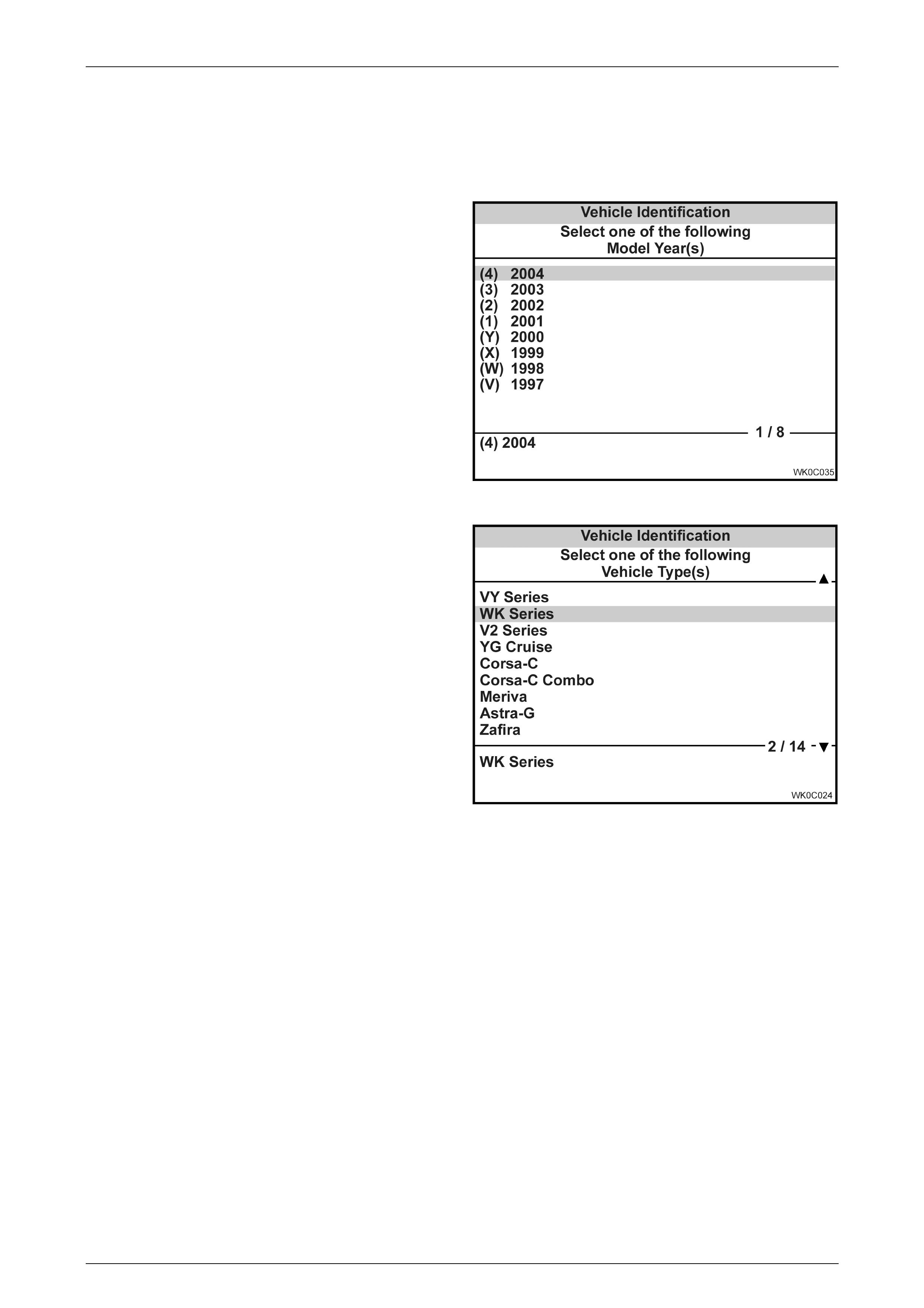
The diagnost ic infor mat ion ac c ess procedures are a
carry over from the MY2003 VY Series except that the
Model Year selection on TECH 2 is now (4) 2004.
Figure 2F – 1
The Vehicle Type selection is WK Series.
Figure 2F – 2

HVAC Occupant Climat e Control (Auto A/ C) – Diagnostic s Page 2F–5
20–FEB–2003 Page 2F-5
The following table lists all OCC system DTCs applicable to Level to 2 to 5 MY2004 WK Series vehicles.
DTC Code Description
13 Ambient temperature sensor voltage too high
14 Ambient temperature sensor voltage too low
15 In car temperature sensor voltage too high
16 In car temperature sensor voltage too low
17 Evaporative temperature sensor voltage too high
18 Evaporative temperature sensor voltage too low
19 Sun load sensor error
35 No serial data from PCM
36 No serial data from BCM
37 ROM checksum error
38 EEPROM checksum error
39 RAM error
40 Air mix door motor driver error
41 Solenoid driver error
43 Driver’s air mix door motor feedback circuit voltage too low
44 Driver’s air mix door motor feedback circuit voltage too high
45 Passenger’s air mix door motor feedback circuit voltage too low
46 Passenger’s air mix door motor feedback circuit voltage too high
47 Driver Airmix Min. Calibration Error
48 Driver Airmix Max. Calibration Error
49 Pass Airmix Min. Calibration Error
50 Pass Airmix Max. Calibration Error
NOTE: for diagnosis of the pressure transducer, refer to the following Sections in the MY2003 VY and V2 Series Service
Information:
• Section 6C1 POWERTRAIN CONTROL MODULE – V6 ENGINE.
• Section 6C2 POWERTRAIN CONTROL MODULE – V6 SUPERCHARGED ENGINE.
• Section 6C3 POWERTRAIN CONTROL MODULE – GEN III V8.
HVAC Occupant Climat e Control (Auto A/ C) – Diagnostic s Page 2F–6
20–FEB–2003 Page 2F-6
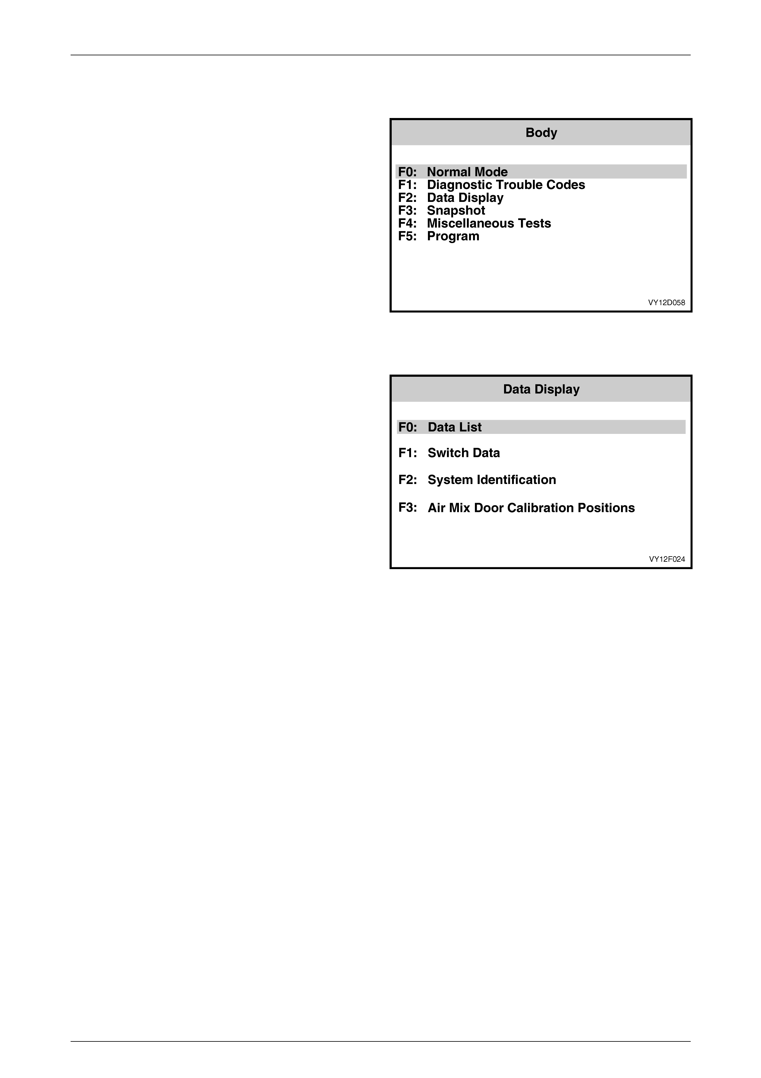
2.2 Data Displa y
F2: Data Display
If the F2: Data Display mode is selected from the Body
menu, an additional menu will appear giving the operator
the option of selecting:
F1: OCC Data List,
F2: OCC Switch Data,
F3: System Identification or,
Air Mix Door Calibration Positions.
Figure 2F – 3
F0: Data List
When F2: DATA DISPLAY is selected followed by
F0: DATA LIST, the Switch Data Table will be displayed.
The data list displays inputs and outputs of the OCC
system.
Figure 2F – 4

HVAC Occupant Climat e Control (Auto A/ C) – Diagnostic s Page 2F–7
20–FEB–2003 Page 2F-7
The following table shows all items in the DATA LIST, together with their expected readings:
OCC Type
Data List Reading Single
Zone Dual
Zone
System Status On/Off X X
Battery Voltage Approx 13.5 V X X
Ignition Status OFF/ON X X
Air Conditioning Request NO/YES X X
Evaporative Temperature Sensor 0 to 3.5 ± 0.2 V X X
Evaporative Temperature °C X X
Ambient Temperature Sensor 0 to 3.5 ± 0.2 V X X
Ambient Temperature Degrees °C X X
Dampened Ambient Temperature Degrees °C X X
In Car Temperature Sensor 0 to 3.5 ± 0.2 V X X
In Car Temperature Degrees °C X X
Blower Fan Speed Manual: 1234 and HIGH, Auto: Low, Mid and High X X
Desired Blower Fan Speed % X X
Blower Fan Speed Control % X X
Blower Fan Speed Feedback Voltage V X X
Drivers Air Mix Motor Position Desired % X X
Drivers Air Mix Motor Position Feedback % X X
Drivers Air Mix Motor Position Feedback Voltage 0 to 3.5 ± 0.2 V X X
Passengers Air Mix Motor Position Desired % X
Passengers Air Mix Motor Position Feedback % X
Passengers Air Mix Motor Position Feedback Voltage 0 to 3.5 ± 0.2 V X
*Rear Remote Control Input Voltage 5.0 V X X
Engine Coolant Temperature Degrees °C X X
Sun Load Steps: 0 – 255 X X
Driver Set Temperature Degrees °C X X
Passengers Set Temperature Degrees °C X
Operating Mode Manual/auto X X
Outlet Mode Face / floor / blend / foot X X
Inlet Mode Fresh / Recirc X X
Startup Strategy None, Recirc / Delay, Demist / Delay, Purge,
A/C Purge, Fresh / Delay X X
Fresh / Recirculation Solenoid Off/On X X
Water Valve Solenoid Off/On X X
Water Valve Closed/Open X X
Face 2 Solenoid Off/On X X
Face 1 Solenoid Off/On X X
Foot 2 Solenoid Off/On X X
Foot 1 Solenoid Off/On X X
High Fan Relay Inactive: 12 V Active: 0 V X X
Rear Demist Relay Off/On X X
Park Lamp Input Off/On X X
Front Demist LED Off/On X X
Rear Demist LED Off/On X X
• Applicable only to models fitted with rear remote control i.e. Level 5.
HVAC Occupant Climat e Control (Auto A/ C) – Diagnostic s Page 2F–8
20–FEB–2003 Page 2F-8
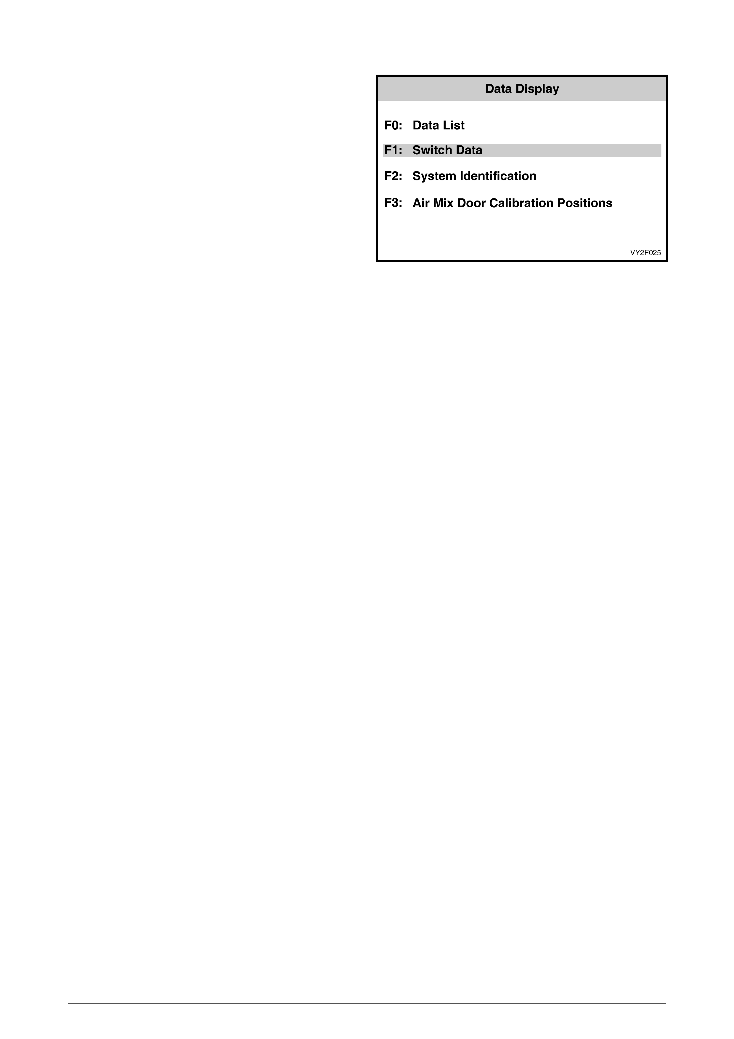
F1: Switch Data
In this mode, the operator is able to test the function of
each switch on the OCC control module and on level 5
models, the rear remote control. When F2: DATA
DISPLAY is selected followed by F1: SWITCH DATA,
the Switch Data Table will be displayed.
NOTE
The OCC control module buttons will need to
be held on when carrying out this test due to
a normal delay in information transfer.
To test the OCC control module switches in this mode,
turn on the ignition and the OCC system. Activate each
switch on the OCC control module and observe the
TECH 2 screen to see if the TECH 2 display changes the
switch status from Off to On.
Figure 2F – 5
HVAC Occupant Climat e Control (Auto A/ C) – Diagnostic s Page 2F–9
20–FEB–2003 Page 2F-9
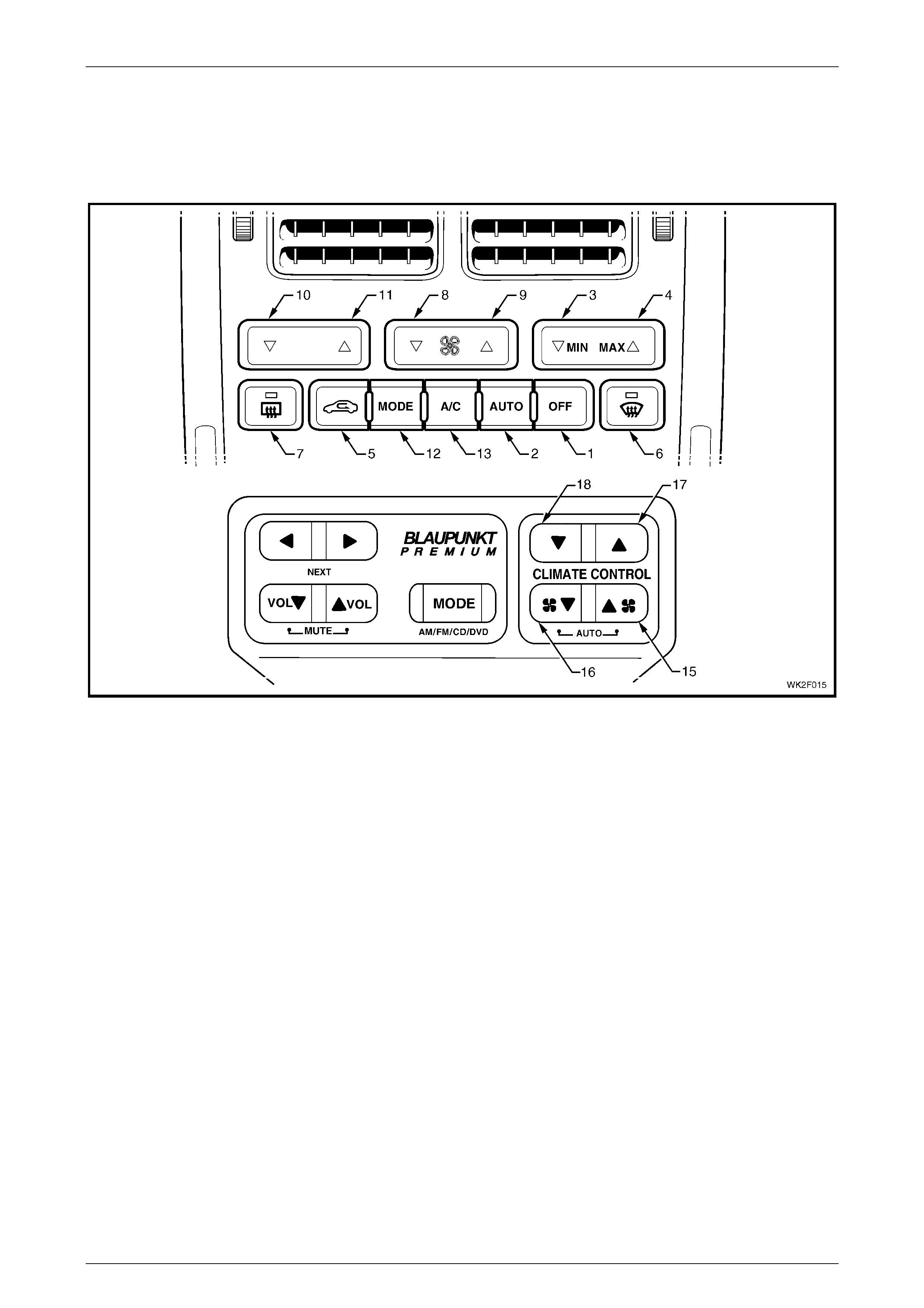
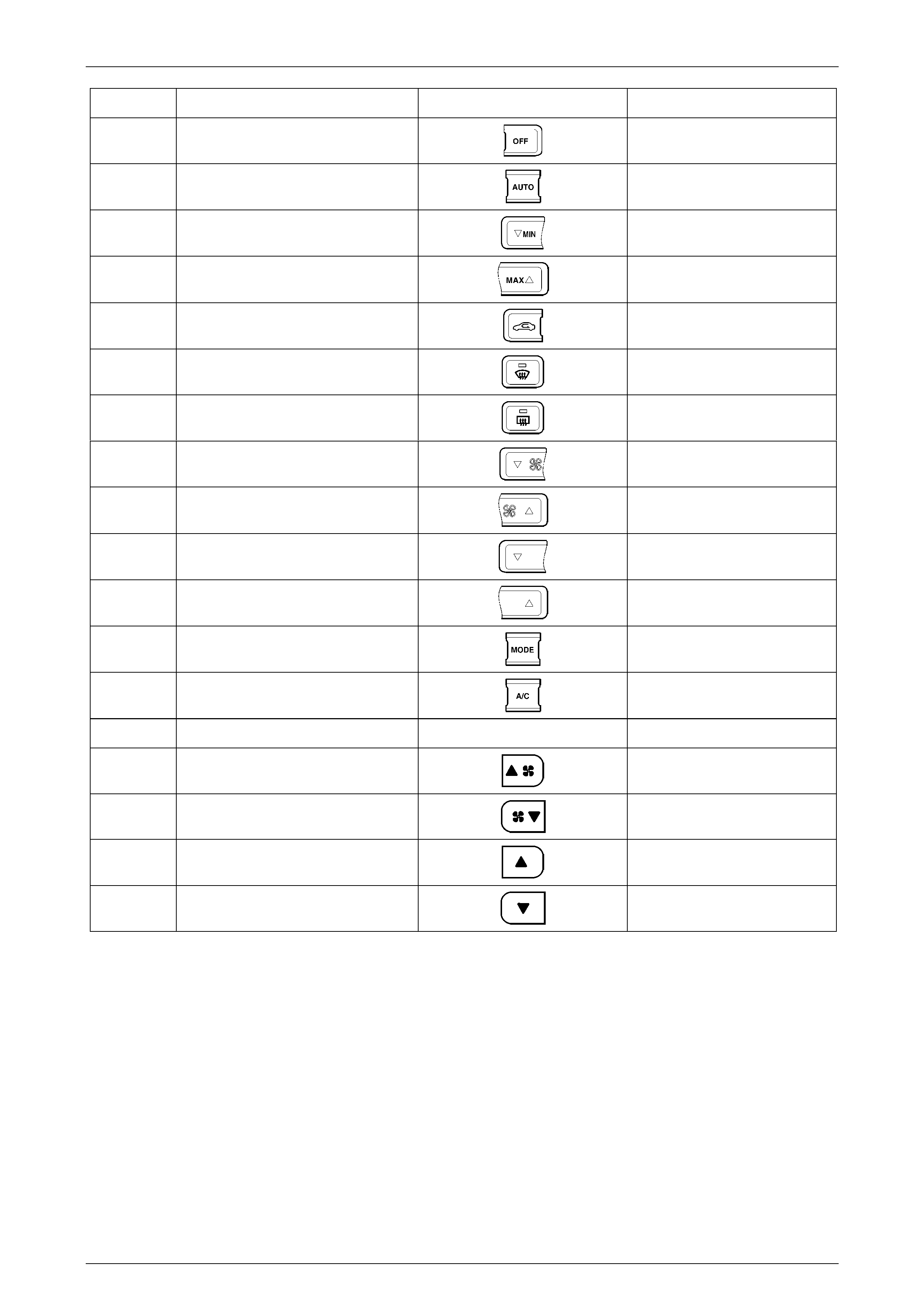
Figure 2F – 6 shows the OCC control module switch configuration applicable to LHD models in the upper section and the
rear remote switch configuration in the lower section. The switches are numbered in accordance test sequence in
Tech 2.The table following shows all items in the SWITCH DATA, the switch graphics and their expected test readings.
The progression of the table follows the switch test sequence in Tech 2. Turn each switch on and off beginning at the
OFF switch (1) and progress through the switch clusters of the OCC control module and on Level 5 models, the rear
remote control as shown in Figure 2F – 6.
Figure 2F – 6
HVAC Occupant Climat e Control (Auto A/ C) – Diagnostic s Page 2F–10
20–FEB–2003 Page 2F-10
Sequence Switch Data Switch Reading
1 Off Switch Off/On
2 Auto Switch Off/On
3 Minimum Temperature Switch Off/On
4 Maximum Temperature Switch Off/On
5 Recirculation Switch Off/On
6 Front Demist Switch Off/On
7 Rear Demist Switch Off/On
8 Fan Down Switch Off/On
9 Fan Up Switch Off/On
10 Temperature Down Switch Off/On
11 Temperature Up Switch Off/On
12 Mode Switch Off/On
13 Air Conditioning Switch Off/On
14 *Rear Remote Input
15 *Rear Remote Fan Up Off/On
16 *Rear Remote Fan Down Off/On
17 *Rear Remote Temperature Up Off/On
18 *Rear Remote Temperature Down Off/On
• Applicable to only to models fitted with rear remote control i.e. Level 5.

HVAC Occupant Climat e Control (Auto A/ C) – Diagnostic s Page 2F–11
20–FEB–2003 Page 2F-11
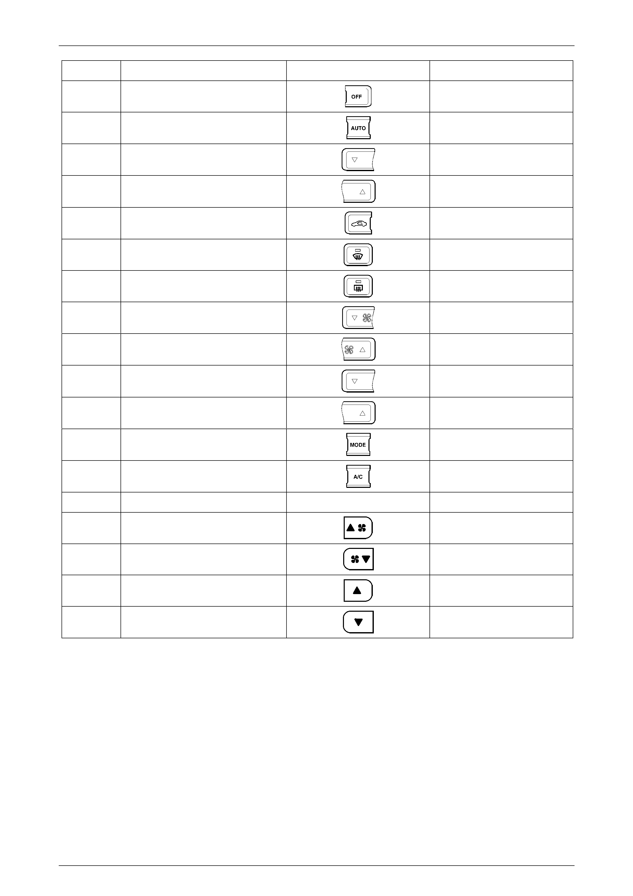
Figure 2F – 7 shows the OCC control module switch configuration applicable to RHD models in the upper section and
the rear remote switch configuration in the lower section. The switches are numbered in accordance test sequence in
Tech 2.The table following shows all items in the SWITCH DATA, the switch graphics and their expected test readings.
The progression of the table follows the switch test sequence in Tech 2. Turn each switch on and off beginning at the
OFF switch (1) and progress through the switch clusters of the OCC control module and on Level 5 models, the rear
remote control as shown in Figure 2F – 7.
Figure 2F – 7
HVAC Occupant Climat e Control (Auto A/ C) – Diagnostic s Page 2F–12
20–FEB–2003 Page 2F-12
Sequence Switch Data Switch Reading
1 Off Switch Off/On
2 Auto Switch Off/On
3 Driver’s Temp. Down Switch Off/On
4 Driver’s Temp. Up Switch Off/On
5 Recirculation Switch Off/On
6 Front Demist Switch Off/On
7 Rear Demist Switch Off/On
8 Fan Down Switch Off/On
9 Fan Up Switch Off/On
10 Passenger Temp. Down Switch Off/On
11 Passenger Temp. Up Switch Off/On
12 Mode Switch Off/On
13 Air Conditioning Switch Off/On
14* Rear Remote Input
15* Rear Remote Fan Up Off/On
16* Rear Remote Fan Down Off/On
17* Rear Remote Temperature Up Off/On
18* Rear Remote Temperature Down Off/On
* Applicable to only to models fitted with rear remote control i.e. Level 5.

HVAC Occupant Climat e Control (Auto A/ C) – Diagnostic s Page 2F–13
20–FEB–2003 Page 2F-13
2.3 Miscellaneous Tests
The majority of Miscellaneous Test procedures and expected results are the same or similar as those applying to
MY2003 VY and V2 Series vehicles. Accordingly, for the following Miscellaneous Test procedures, refer to Section 2F,
1.2 TECH 2 TEST MODES AND DISPLAYS FOR OCC DIAGNOSIS in the MY2003 VY and V2 Series Service
Information.
• Driver’s Air Mix Door
• Passenger’s Air Mix Door
• Blower Speed
• Maximum Fan Relay
• Outlet Mode
• Illumination
• Front Demist LED
• Rear Demist LED
• Rear Demist Relay
• A/C Request
• Solenoids
NOTE 1
During the Outlet Mode test on MY2003 VY and
V2 Series vehicles, the mode graphics are
displayed on the OCC control module LCD as
each mode is selected. The mode graphics are
not displayed on the Multi Function Display as
each mode is selected when this test is
conducted on WK Series models
NOTE 2
During the Illumination test, only the illumination
level of the graphics on the WK Series OCC
control module is altered. The illumination level of
the Multi Function Display remains unchanged.
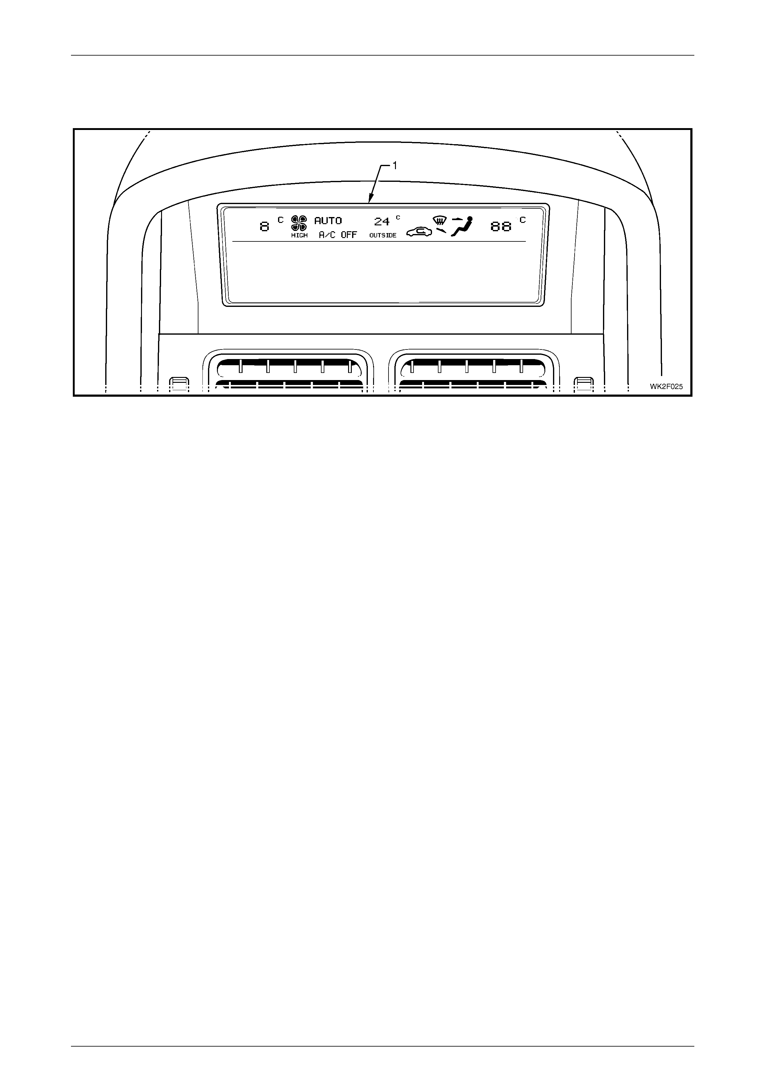
LCD Display Test
PURPOSE OF TEST:
To ensure that all segments are functioning and can be
displayed on the MFD screen.
PRE-CONDITION:
Engine not running.
PROCEDURE:
With TECH 2 connected to the DLC select:
Body /
Occupant Climate Control /
Miscellaneous Tests /
LCD Display Tes t.
Figure 2F – 8
HVAC Occupant Climat e Control (Auto A/ C) – Diagnostic s Page 2F–14
20–FEB–2003 Page 2F-14
Using the On/Off soft keys on TECH 2, activate and deactivate the upper section of the Multi Function Display. The MFD
should display upper screen detail identical to that shown in Figure 2F – 9. All segments should appear for approximately
5 seconds after the On soft key is activated.
Figure 2F – 9
For additional tests relating to the MFD display, refer to Section 12I, 3.6 MISCELLANEOUS TESTS.

HVAC Occupant Climat e Control (Auto A/ C) – Diagnostic s Page 2F–15
20–FEB–2003 Page 2F-15
3 Diagnostic Charts
Introduction
A number of wiring terminal assignments are specific to the MY2004 WK Series models necessitating the provision of the
following diagnostics charts applicable only to WK Series Level 2 to 5 models.
These charts are designed to provide fast and efficient fault location of the OCC (Auto A/C) system. Each diagnostic
chart consists of a diagnostic chart and pertinent information including Diagnostic Trouble Code (DTC) setting
parameters and, in most charts, a circuit diagram.
At the end of this Section electrical connector diagrams and wiring diagrams applicable to OCC (Auto A/C) systems as
fitted to Level 2 to 5 MY2004 WK Series vehicles are provided and can be used in conjunction with the diagnostic chart
circuit diagrams when diagnosing circuit faults. Refer to 4 Wiring Diagrams in this Section. For electrical connector
locations and additional wiring diagram information, refer to Section 12P WIRING DIAGRAMS.
When carrying out wiring checks as directed to by the diagnostic charts, rather than probe terminals and connectors with
incorrect sized multimeter connections, use the adaptors contained in connector test adaptor kit KM-609. This will
prevent any possibility of spreading or damaging wiring harness terminals.
Ensure that at the completion of any diagnostic procedure, all diagnostic tools are removed and all OCC (Auto A/C)
components are correctly con nect ed.

HVAC Occupant Climat e Control (Auto A/ C) – Diagnostic s Page 2F–16
20–FEB–2003 Page 2F-16
Chart A – Diagnostic Circuit Check
Circuit Description
When investigating any complaint of an OCC system problem or malfunction, always begin diagnosis with the following
diagnostic circuit check. This check is a preliminary procedure that checks to ensure the OCC system is communicating
on the serial data line as well as helping to identify a problem or malfunction and directing the reader to the appropriate
diagnostic chart in this Section.
With TECH 2 connected to the DLC and the ignition switched on, TECH 2 should display serial data communication. If
TECH 2 does not display serial data, the serial data circuit may be open or shorted.
In addition to the OCC control module there are several other control modules that are connected to the serial data line
(PCM, BCM, ABS/TCS, instruments and SDM). Any one of these control modules could cause a fault on the serial data
line. This fault could result in TECH 2 not being able to display serial data.
Test Description:
The numbers below refer to Step numbers in diagnostic
chart A.
1. This test checks if the OCC control module is being
powered up.
2. This test determines if TECH 2 is being powered up.
3. This test checks if TECH 2 can communicate with
the OCC control module. If TECH 2 cannot
communicate with the OCC control module, you will
not be able to determine which DTC has been
stored in the OCC control modules memory.
4. Determines which DTC has been stored in the OCC
control modules memory. This test determines if a
DTC was current and has been rectified. An
intermittent problem will cause a DTC to be stored.
5. During this test the OCC control module recalibrates
the air mix doors. An incorrectly calibrated air mix
door will cause incorrect operation of the OCC
system.
6. Che cks accur acy of OCC sensors.
7. During this test, the operation of the air conditioning
section of the OCC system is checked.
Notes On Diagnostic Chart:
1. Refer to Section 0C TECH 2 for connecting and using
TECH 2.
2. Refer to 1.2 TECH 2 TEST MODES AND DISPLAYS
FOR OCC DIAGNOSIS in the MY2003 VY and V2 Series
Service Information for further information on
programming of the OCC control module.
3. OCC sensors can be checked using the following
procedure and should also be checked in the order as
listed:
• In-car Temperature Sensor – connect TECH 2 to the
DLC, select Body / Occupant Climate Control / Data
Display / Data List / In Car Temperature Sensor.
• Ambient Temperature Sensor – connect TECH 2 to the
DLC, select Body / Occupant Climate Control / Data
Display / Data List / Ambient Temperature Sensor.
• Sun Load Sensor (Sun Sensor/Remote Receiver) –
refer to DTC 19 diagnostic chart in this Section for a
procedure on checking this sensor.
• Evaporative Sensor – connect TECH 2 to the DLC,
select Body / Occupant Climate Control / Data Display /
Data List / Evap Temperature Sensor.

HVAC Occupant Climat e Control (Auto A/ C) – Diagnostic s Page 2F–17
20–FEB–2003 Page 2F-17
Chart A – Diagnostic Circuit Check
STEP ACTION VALUE YES NO
1 Turn the ignition on.
Turn on OCC system.
Does MFD screen activate to display HVAC settings?
Go to Step 2. Go to Chart B –
OCC SYSTEM
DOES NOT
POWER UP in
this Section.
2 Connect TECH 2 to the DLC. (Refer to Notes on
Diagnostic Chart for this chart, Note 1.)
Turn the ignition on.
Push power button on TECH 2.
Does TECH 2 power up?
Go to Step 3. Go to TECH 2
diagnosis. Refer
to Section 0C,
TECH 2.
3 With TECH 2 connected, select Diagnostics / Model
Year / Vehicle Model / Body / Occupant Climate Control.
Does TECH 2 display OCC System Identification Screen
information (i.e. part number etc.)?
Go to Step 4. Go to BCM Serial
Data
Communication
diagnostics. Refer
to Section 12J,
4.2 SERIAL DATA
COMM UNICN
(BU S MAST ER)
in the MY2003
VY and V2
Series Service
Information.
4 With TECH 2 connected and the ignition on, select
Diagnostic Trouble Codes / Read DTC Information.
Does TECH 2 display any DTCs?
Go to applicable
DTC Chart in this
Section.
Go to Step 6.
5 With TECH 2 connected, the ignition on and OCC
system selected, select Program / Calibrate Air Mix Door
/ Calibrate.
Does TECH 2 display a value greater than 5%?
OCC air mix
doors have been
recalibrated.
Refer to DTC 48
to DTC 50 as
applicable, in this
Section.
6 Check the accuracy of the OCC sensors. (Refer to
3. ELECTRICAL COMPONEN T TESTS in this Section.)
Are the OCC sensors OK?
Go to Step 7. Replace the
faulty OCC
sensor, refer to
Section 2E,
HVAC
OCCUPANT
CLIMATE
CONTROL
(AUTO A/C) –
REMOVAL &
INSTALLATION.
7 Perform the DELPHI V5 and V7 compressor and TXV
system diagnosis. Refer to Section 2C, 4. DELPHI V5
AND V7 COMPRESSOR AND TXV SYSTEM
DIAGNOSTICS.
Does the system pass the diagnosis test?
No fault found
with OCC
system. System
Code Index may
need to be
Programmed.
Refer to
F1:PROGRAM
CODE INDEX in
this Section 2F,
1.2 TECH 2
TEST MODES
AND DISPLAYS
FOR OCC
DIAGNOSIS in
the MY2003 VY
and V2 Series
Service
Information.
Carry out repair
procedure as
detailed in Delph i
V5 and V7
Compressor TXV
System
Diagnosis. Refer
to Section 2C,
HVAC CLIMATE
CONTROL
(MANUAL A/C) –
SERVICING &
DIAGNOSIS in
the MY2003 VY
and V2 Series
Service
Information.
WHEN ALL DIAGNOSIS AND REPAIRS ARE COMPLETED, VERIFY CORRECT OPERATION

HVAC Occupant Climat e Control (Auto A/ C) – Diagnostic s Page 2F–18
20–FEB–2003 Page 2F-18
Chart B – OCC System Does Not Power Up
Figure 2F – 10
Circuit Description
Battery power is supplied to the OCC control module, terminal X1-6, with the ignition switch in the ignition or start
positions through fuse F13 (located in the passenger compartment fuse panel).

HVAC Occupant Climat e Control (Auto A/ C) – Diagnostic s Page 2F–19
20–FEB–2003 Page 2F-19
Test Description:
The numbers below refer to Step numbers in diagnostic
chart B:
1. The diagnostic circuit test is the beginning of all
diagnostics and should be performed whenever
diagnosing an OCC system complaint.
2. This test checks if the fuse F13 is OK.
3. This test determines if power is being supplied to
fuse F13.
4. This test determines if the OCC control module has
a power supply and a ground. If the OCC control
module has pow er and ground and the module is not
being activated when the ignition and the OCC
system is turned on.
5. If battery voltage was not available during Step 4,
this test determines if the power supply circuit 539 to
the OCC control module has continuity.
6. If battery voltage was not available during Step 4,
this test determines if the ground circuit 251 to the
OCC control module has continuity.
Notes On Diagnostic Chart:
1. Refer to 4 Wir ing Diagrams in this Section for views of
OCC system related electrical connectors and complete
OCC system wiring diagrams.
2. For electrical connector locations and additional wiring
diagram informat ion, refer to Section 12P WIRING
DIAGRAMS.

HVAC Occupant Climat e Control (Auto A/ C) – Diagnostic s Page 2F–20
20–FEB–2003 Page 2F-20
Chart B – OCC System Does Not Power Up Diagnostic Chart
STEP ACTION VALUE YES NO
1 Has the Diagnostic Circuit Check been performed? Go to Step 2. Go to Chart A –
DIAGNOSTIC
CIRCUIT
CHECK in this
Section.
2 Check fuse F13.
Is the fuse OK?
Go to Step 3. Check for cause
of blown fuse
and replace the
fuse.
3 Turn the ignition on.
Back-probe fuse F13, circuit 3 with a voltmeter to
ground. (Refer to Notes on Diagnostic Chart for this
chart, Note 1.)
Is the value as specified?
Battery
voltage Go to Step 4. Repair faulty
circuit 3.
4 Remove the OCC control module. (Refer to Section 2E,
OCCUPANT CLIMATE CON T ROL (AUTO A/C)
REMOVAL AND INSTALLATION.)
Turn the ignition on.
Probe between OCC control module (A14) connector
terminal X1-6, circuit 539 and terminal X1-7, circuit 251
with a voltmeter to ground.
Is the value as specified?
Battery
voltage Replace the
OCC contro l
module, refer to
Section 2E,
HVAC
OCCUPANT
CLIMATE
CONTROL
(AUTO A/C) –
REMOVAL &
INSTALLATION.
Install the OCC
control modu le
(Refer to
Section 2E,
OCCUPANT
CLIMATE
CONTROL
(AUTO A/C)
REMOVAL AND
INSTALLATION.)
and go to Step 5.
5 Turn the ignition off.
Back-probe between OCC control module terminal X1-6,
circuit 539 and fuse F13 with an ohmmeter to ground.
Is the value as specified?
Less than
1 ohm Go to Step 6. Repair faulty
circuit 539.
6 Turn the ignition off.
Back-probe OCC control module terminal X1-7,
circuit 251 with an ohmmeter to a known good ground.
Is the value as specified?
Less than
1 ohm Check for
intermittent
connect ion at
OCC contro l
module
connector
A14 X1. Check
sizing of
connector
A14 X1
terminals.
Repair faulty
circuit 251.
WHEN ALL DIAGNOSIS AND REPAIRS ARE COMPLETED, VERIFY CORRECT OPERATION
HVAC Occupant Climat e Control (Auto A/ C) – Diagnostic s Page 2F–21
20–FEB–2003 Page 2F-21
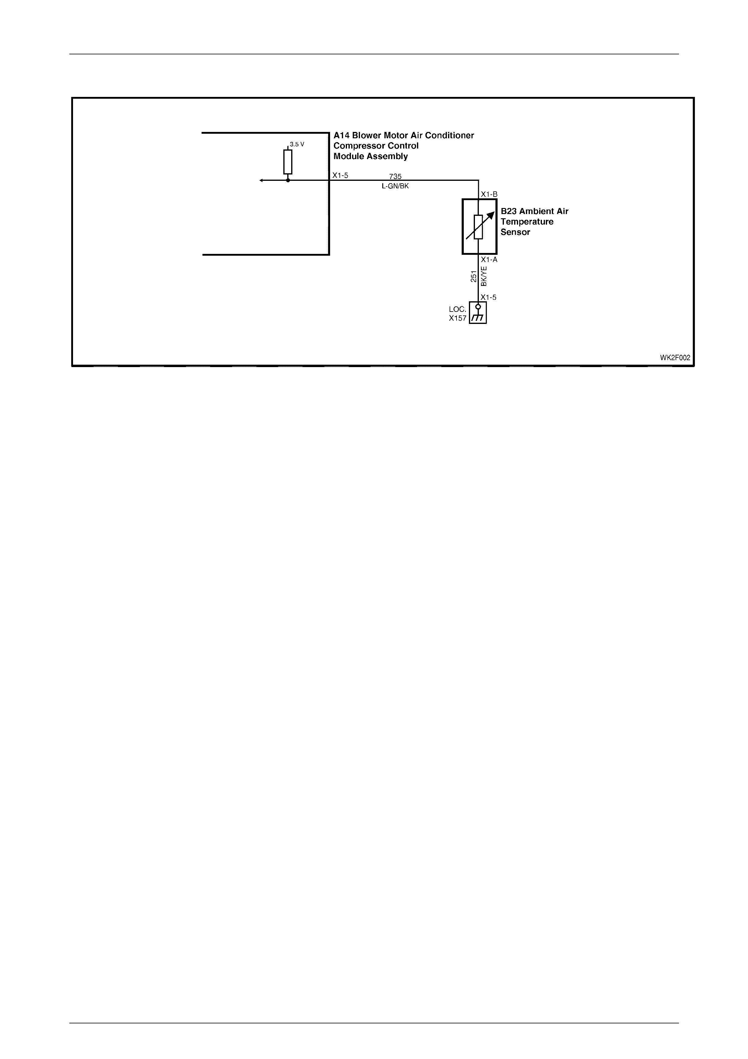
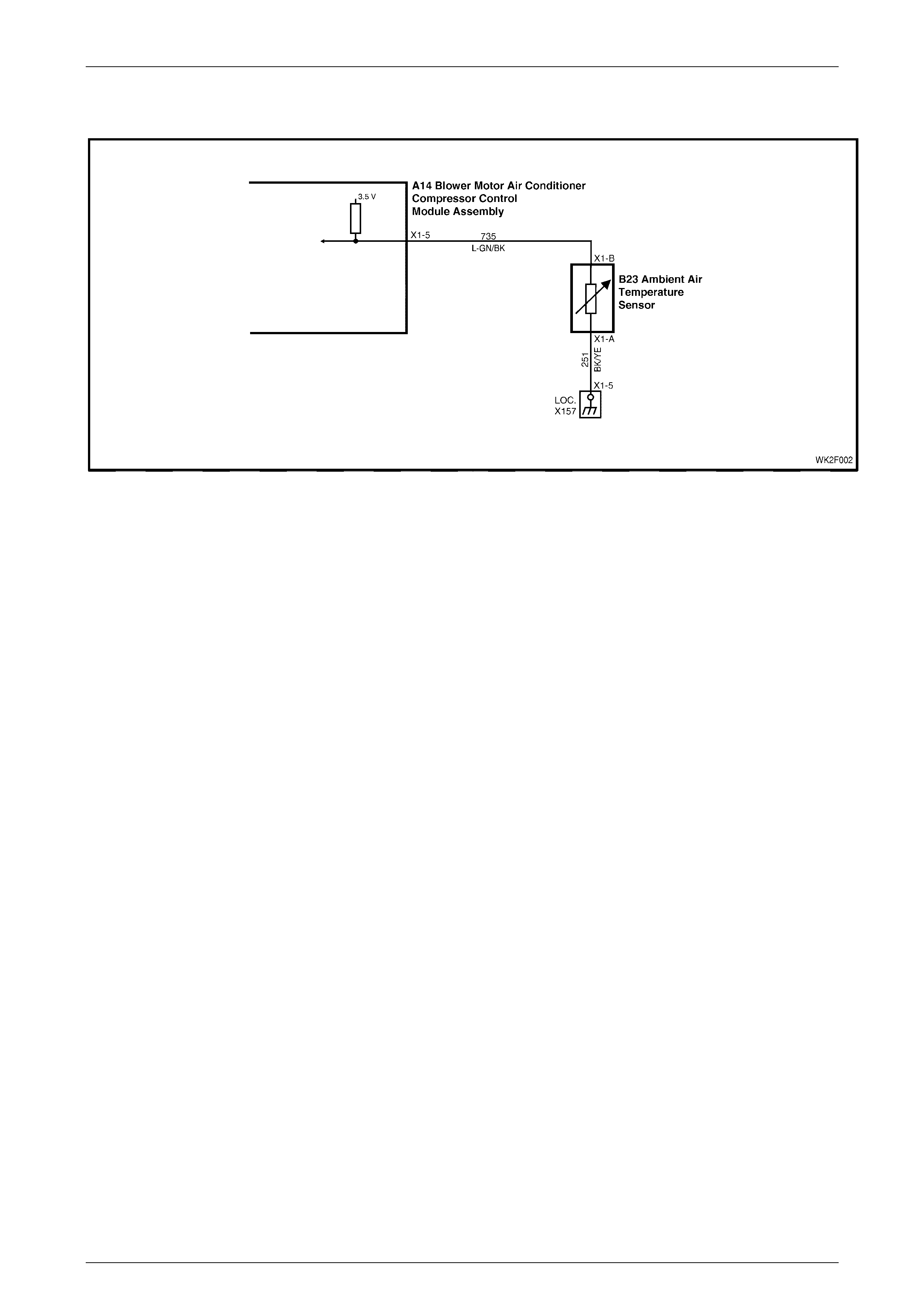
DTC 13 – Ambient Temperature Sensor Voltage Too High
Figure 2F – 11
Circuit Description:
The Ambient Temperature Sensor (ATS) uses a thermistor to control the signal voltage to the OCC control module. The
OCC control module applies a voltage of 3.2 ± 0.2 volts to the sensor. When the air is cold, the ATS resistance is high,
therefore the OCC control module will sense a high signal voltage. If the ambient air is warm, the ATS resistance is low
therefore the OCC control module will sense a low signal voltage.
DTC 13 will set if: the ATS sensor signal voltage is more than 3.5 ± 0.2 volts or if the ATS sensor wiring harness
(circuit 735) or connectors are open circuited for a period of 10 seconds.
Test Description:
Number(s) below refer to Step numbers in the following
Diagnostic Chart:
1. Ensures the Diagnostic Circuit Check has been
performed.
2. Checks that the conditions for setting the DTC are
present or if fault is intermitten t.
3. Checks integrity of circuit 735.
4. Checks if sensor is serviceable by testing resistance
across ATS.
5. Checks for an intermittent connection at ATS.
6. Checks for an open in circuit 251.
7. Checks for an open in circuit 735.
8. Checks for short to voltage in circuit 735.
Diagnostic Aids:
The default temperature for an open circuit is 22.5°C.
If the vehicle is left idling for an extended period, the ambient
temperature readings will rise owing to heat radiated by the
A/C condenser and lack of airflow.
When using the temperature/resistance chart less than, place
a thermometer as cl ose as po ssi ble to the sens or being
tested, compare this temperature figure taken to the
resistance value.
Notes On Diagnostic Chart:
1. Refer to 4 Wir ing Diagrams in this Section for views of
OCC system related electrical connectors and complete
OCC system wiring diagrams.
2. For electrical connector locations and additional wiring
diagram informat ion, refer to Section 12P WIRING
DIAGRAMS.
3. Refer to Section 0C TECH 2 for connecting and using
TECH 2.

HVAC Occupant Climat e Control (Auto A/ C) – Diagnostic s Page 2F–22
20–FEB–2003 Page 2F-22
Temperature Resistance Chart
AMBIENT°
°°
°C RESISTANCE Ω
ΩΩ
Ω
0 15920 – 16750
10 9715 – 10193
20 6107 – 6389
30 3943 – 4115
40 2610 – 2717
50 1767 – 1836
60 1201 – 1291
DTC 13 – Ambient Temperature Sensor Voltage Too High Diagnostic Chart
STEP ACTION VALUE YES NO
1 Was the Diagnostic Circuit Check performed? Go to Step 2. Go to Chart A –
DIAGNOSTIC
CIRCUIT
CHECK in this
Section.
2 Connect TECH 2 to the DLC.
Select Diagnostics / Model Year / Vehicle Model / Body /
Occupant Climate Control / Data Display / Data List /
Ambient Air Temperature Sensor.
Does TECH 2 display a value above 3.4 volts?
Go to Step 3. DTC 13
intermittent. If no
additional DTCs
were stored.
Refer to
3 DIAGNOSTIC
CHARTS in this
Section.
3 With TECH 2 connected and Ambient Air Temperature
Sensor displayed, disconnect the ambient air
temperature sensor wiring harness connector B23 X1.
Place a jumper wire between the two terminals of
connector B23 X1.
Does TECH 2 display a value less than 0.4 volt?
Go to Step 4. Go to Step 6
4 With the ambient air temperature sensor wiring harness
connector disconnected, probe between the ambient air
sensor terminals with an ohmmeter to ground.
Is the value as specified?
Refer to
DTC 13
Temp.
Resistance
Chart
outlined
previously.
Go to Step 5. Replace faulty
ambient air
temperature
sensor. Refer to
Section 2E,
HVAC
OCCUPANT
CLIMATE
CONTROL
(AUTO A/C)–
REMOVAL &
INSTALLATION.
5 Inspect the ambient air temperature sensor wiring
harness connector for an intermittent or loose terminal.
Is connector OK?
Go to Step 8 Repair faulty
connector.
6 With TECH 2 connected and Ambient Air Temperature
Sensor displayed, back-probe between OCC control
module connector terminal X1-5, circuit 735 and chassis
ground with a jumper lead.
Does TECH 2 display a value less than 0.4 volt?
Repair faulty
circuit 251. Go to Step 7
7 Check the integrity of circuit 735 between ambient air
temperature sensor connector terminal X1-B and OCC
control modu le con nect or term inal X 1-5.
Is the circuit OK?
Go to Step 8 Repair faulty
circuit 735.

HVAC Occupant Climat e Control (Auto A/ C) – Diagnostic s Page 2F–23
20–FEB–2003 Page 2F-23
STEP ACTION VALUE YES NO
8 Turn the ignition off.
Disconnect OCC wiring harness connectors A14 X1 and
A14 X2.
Remove the jumper lead from the ambient air
temperature sensor connector.
Turn the ignition on.
Back-probe ambient air temperature sensor wiring
harness connector terminal X1-B circuit 735 with a
voltmeter to chass is grou nd.
Is the value as specified?
0.4 volt Replace the
faulty OCC
control modu le.
Refer to
Section 2E,
HVAC
OCCUPANT
CLIMATE
CONTROL
(AUTO A/C) –
REMOVAL &
INSTALLATION.
Repair faulty
circuit 735.
WHEN ALL DIAGNOSIS AND REPAIRS ARE COMPLETED, VERIFY CORRECT OPERATION
HVAC Occupant Climat e Control (Auto A/ C) – Diagnostic s Page 2F–24
20–FEB–2003 Page 2F-24
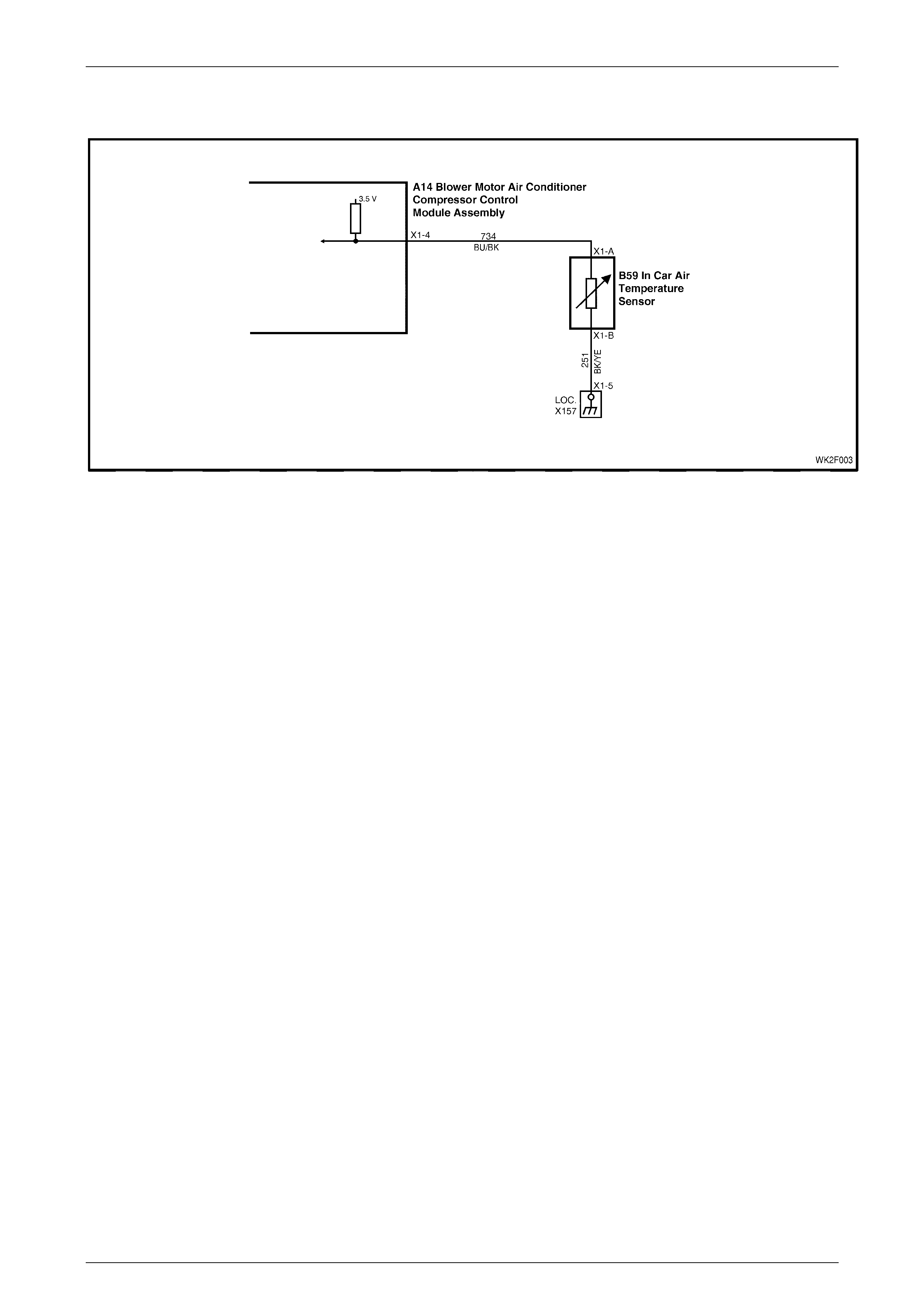
DTC 14 – Ambient Temperature Sensor Voltage Too Low
Figure 2F – 12
Circuit Description:
The Ambient Temperature Sensor (ATS) uses a thermistor to control the signal voltage to the OCC control module. The
OCC control module applies a voltage of 3.2 ± 0.2 volts to the sensor. When the air is cold, the ATS resistance is high,
therefore the OCC control module will sense a high signal voltage. If the ambient air is warm, the ATS resistance is low
therefore the OCC control module will sense a low signal voltage.
DTC 14 will set if: the ATS sensor signal voltage is more than 0.3 volts or if the ATS sensor wiring harness (circuit 735)
or connectors are open circuited for a period of 10 seconds.
Test Description:
Number(s) below refer to Step numbers in the following
Diagnostic Chart:
1. Ensures the Diagnostic Circuit Check has been
performed.
2. This test checks that the conditions that would set
the DTC, are present.
3. This test checks if the sensor is causing the short
circuit.
4. This test checks if sensor is functioning correctly.
5. Checks for intermittent connection at sensor.
6. Checks for a short circuit of sensor signal wire to
ground.
Diagnostic Aids:
The default temperature for an open circuit is 22.5°C.
If the vehicle is left idling for an extended period, the ambient
temperature readings will rise owing to heat radiated by the
A/C condenser and lack of airflow.
When using the temperature/resistance chart less than, place
a thermometer as cl ose as po ssi ble to the sens or being
tested, compare this temperature figure taken to the
resistance value.
Notes On Diagnostic Chart:
1. Refer to 4 Wir ing Diagrams in this Section for views of
OCC system related electrical connectors and complete
OCC system wiring diagrams.
2. For electrical connector locations and additional wiring
diagram informat ion, refer to Section 12P WIRING
DIAGRAMS.
3. Refer to Section 0C TECH 2 for connecting and using
TECH 2.

HVAC Occupant Climat e Control (Auto A/ C) – Diagnostic s Page 2F–25
20–FEB–2003 Page 2F-25
Temperature Resistance Chart
AMBIENT°
°°
°C RESISTANCE Ω
ΩΩ
Ω
0 15920 – 16750
10 9715 – 10193
20 6107 – 6389
30 3943 – 4115
40 2610 – 2717
50 1767 – 1836
60 1201 – 1291

HVAC Occupant Climat e Control (Auto A/ C) – Diagnostic s Page 2F–26
20–FEB–2003 Page 2F-26
DTC 14 – Ambient Temperature Sensor Voltage Too Low Diagnostic Chart
STEP ACTION VALUE YES NO
1 Was the Diagnostic Circuit Check performed? Go to Step 2. Go to Chart A –
DIAGNOSTIC
CIRCUIT
CHECK in this
Section.
2 Connect TECH 2 to the DLC.
Select Diagnostics / Model Year / Vehicle Model / Body /
Occupant Climate Control / Data Display / Data List /
Ambient Air Temperature Sensor.
Does TECH 2 display a value less than 0.4 volt?
Go to Step 3. DTC 14
intermittent. If no
additional DTCs
were stored,
refer to
3 DIAGNOSTIC
CHARTS in this
Section.
3 With TECH 2 connected and Ambient Air Temperature
Sensor displayed, disconnect ambient air temperature
sensor wiring harness connector B23 X1.
Does TECH 2 display a value more than 3.4 volts?
Go to Step 4. Go to Step 6.
4 With the ambient air temperature sensor wiring harness
connector disconnected, back-probe between the
ambient air sensor termi nal s.
Is the value as specified?
Refer to
DTC 14
Temp.
Resistance
Chart.
Go to Step 5. Replace the faulty
ambient air
temperature
sensor. Refer to
S e c t io n 2E, HVAC
OCCUPANT
CLIMATE
CONTROL
(AUTO A/C) –
REMOVAL &
INSTALLATION.
5 Check for an intermittent short to ground in circ uit 735
between OCC control module connector terminal X1-5
and ambient air sensor con ne ctor terminal X 1-B.
Is the circuit OK?
Repair faulty
connector. Replace the faulty
OCC control
module. Refer to
Section 2E,
HVAC
OCCUPANT
CLIMATE
CONTROL
(AUTO A/C) –
REMOVAL &
INSTALLATION.
6 Check circuit 735 for a short circuit to ground.
Is the circuit OK?
Replace the faulty
OCC control
module. Refer to
Section 2E,
HVAC
OCCUPANT
CLIMATE
CONTROL
(AUTO A/C) –
REMOVAL &
INSTALLATION.
Repair faulty
circuit 735.
WHEN ALL DIAGNOSIS AND REPAIRS ARE COMPLETED, VERIFY CORRECT OPERATION
HVAC Occupant Climat e Control (Auto A/ C) – Diagnostic s Page 2F–27
20–FEB–2003 Page 2F-27
DTC 15 – In-car Temperature Sensor Voltage Too High
Figure 2F – 13
Circuit Description:
The In-car Temperature Sensor (ITS) is a thermistor used to vary voltage signals to control the signal voltage to the OCC
control module. The OCC control module applies a voltage of 3.5 ±0.2 volts to the sensor, via circuit 734. When the
vehicle interior air is cold, the ITS resistance is high therefore the OCC control module will sense a high signal voltage. If
the air is warm, the ITS resistance is low, therefore the OCC control module will sense a low signal voltage.
DTC 15 will set: if the ITS signal voltage is more than 3.5 ± 0.2 volts or if the ITS sensor wiring harness (circuit 734) or
connect ors are open cir cuit ed for 10 second s.
Test Description:
Number(s) below refer to Step numbers in the following
Diagnostic Chart:
1. Ensures the Diagnostic Circuit Check has been
performed.
2. Checks that the conditions for setting the DTC are
present or if fault is intermitten t.
3. Checks integrity of circuit 734.
4. Checks if sensor is serviceable by testing resistance
across ITS.
5. Checks for an intermittent connection at ITS.
6. Checks for an open in circuit 251.
7. Checks for an open in circuit 734.
8. Checks for short to voltage in circuit 734.
Diagnostic Aid s:
The default temperature for an open circuit is 22.5°C.
When using the temperature/resistance chart less than, place
a thermometer as cl ose as po ssi ble to the sens or being
tested, compare this temperature figure taken to the
resistance value.
Notes On Diagnostic Chart:
1. Refer to 4 Wir ing Diagrams in this Section for views of
OCC system related electrical connectors and complete
OCC system wiring diagrams.
2. For electrical connector locations and additional wiring
diagram informat ion, refer to Section 12P WIRING
DIAGRAMS.
3. Refer to Section 0C TECH 2 for connecting and us ing
TECH 2.

HVAC Occupant Climat e Control (Auto A/ C) – Diagnostic s Page 2F–28
20–FEB–2003 Page 2F-28
Temperature Resistance Chart
AMBIENT°
°°
°C RESISTANCE Ω
ΩΩ
Ω
5 7009 – 7536
10 5477 – 5856
15 4310 – 4583
20 3416 – 3612
25 2725 – 2865
30 2175 –2299
35 1746 – 1857
40 1410 – 1508
45 1145 – 1231
50 935 – 1010

HVAC Occupant Climat e Control (Auto A/ C) – Diagnostic s Page 2F–29
20–FEB–2003 Page 2F-29
DTC 15 – In-car Temperature Sensor Voltage Too High Diagnostic Chart
STEP ACTION VALUE YES NO
1 Was the Diagnostic Circuit Check performed? Go to Step 2. Go to Chart A –
DIAGNOSTIC
CIRCUIT
CHECK in this
Section.
2 Connect TECH 2 to the DLC
Select Diagnostics / Model Year / Vehicle Model / Body /
Occupant Climate Control / Data Display / Data List / In-
car Temperature Sensor.
Does TECH 2 display a value above 3.4 volts?
Go to Step 3. DTC 15
intermittent. If no
additional DTCs
were stored,
refer to
3 DAGNOSTIC
CHARTS in this
Section.
3 With TECH 2 connected and In-car Temperature Sensor
displayed, disconnect the in-car temperature sensor
wiring harness connector B59 X1.
Probe between the two terminals of the connector with a
jumper wire.
Does TECH 2 display a value less than 0.4 volt?
Go to Step 4. Go to Step 6.
4 With the in-car temperature sensor wiring harness
connector disconnected, probe between the two
terminals of the connector with an ohmmeter. (Refer to
Notes on Diagnostic Chart for this chart, Note 1).
Is the value as specified?
Refer to
DTC 15
Temp.
Resistance
Chart.
Go to Step 5. Replace faulty
in-car
temperature
sensor. Refer to
Section 2E,
HVAC
OCCUPANT
CLIMATE
CONTROL
(AUTO A/C) –
REMOVAL &
INSTALLATION.
5 Inspect the in-car temperature sensor wiring harness
connector for an intermittent or loose terminal.
Is the connector OK?
Go to Step 8. Repair faulty
connector.
6 With TECH 2 connected and In-car Temperature Sensor
displayed, back-probe OCC connector terminal X1-4,
circuit 734 with a jumper lead to chassis ground.
Does TECH 2 display a value less than 0.4 volt?
Go to Step 7. Repair faulty
circuit 251.
7 Check the integrity of circuit 734 between the OCC
control module connector and in car temperature sensor
connector. (Refer to Notes on Diagnostic Chart for this
chart, Note 1.)
Is the circuit OK?
Go to Step 8. Repair faulty
circuit 734.
8 Turn the ignition OFF.
Disconnect the OCC control module wiring harness
connectors A14 X1 and A14 X2.
Remove jumper lead from the in-car temperature sensor
connector.
Turn the ignition on.
Back-probe in-car temperature sensor wiring harness
connector term inal X1-A, circuit 734 with a voltmeter to
chassis ground.
Is the value as specified?
Less than
0.4 volt Replace the
faulty OCC
control modu le.
Refer to
Section 2E,
HVAC
OCCUPANT
CLIMATE
CONTROL
(AUTO A/C) –
REMOVAL &
INSTALLATION.
Repair faulty
circuit 734.
WHEN ALL DIAGNOSIS AND REPAIRS ARE COMPLETED, VERIFY CORRECT OPERATION

HVAC Occupant Climat e Control (Auto A/ C) – Diagnostic s Page 2F–30
20–FEB–2003 Page 2F-30
DTC 16 – In-car Temperature Sensor Voltage Too Low
Figure 2F – 14
Circuit Description:
The in-car temperature sensor (ITS) is a thermistor used to vary voltage signals to the OCC control module. The OCC
control module applies a voltage of 3.5 ±0.2 volts to the sensor. When the vehicle interior air is cold, the ITS resistance is
high, therefore the OCC control module will sense a high signal voltage. If the air is warm, the ITS resistance is low,
therefore the OCC control module will sense a low signal voltage.
DTC 16 will set: if the ITS signal voltage is less than 0.3 volt or if the ITS sensor wiring harness (circuit 734) or
connect ors are open cir cuit ed for 10 second s.
Test Description:
Number(s) below refer to Step numbers in the following
Diagnostic Chart:
1. Ensures the Diagnostic Circuit Check has been
performed.
2. This test checks that the conditions that would set
the DTC, are present.
3. This test checks if the sensor is causing the short
circuit.
4. This test checks if sensor is functioning correctly.
5. Checks for intermittent connection at sensor.
6. Checks for a short circuit of sensor signal wire to
ground.
Diagnostic Aid s:
The default temperature for an open circuit is 22.5°C.
When using the temperature/resistance chart less than, place
a thermometer as cl ose as po ssi ble to the sens or being
tested, compare this temperature figure taken to the
resistance value.
Notes On Diagnostic Chart:
1. Refer to 4 Wir ing Diagrams in this Section for views of
OCC system related electrical connectors and complete
OCC system wiring diagrams.
2. For electrical connector locations and additional wiring
diagram informat ion, refer to Section 12P WIRING
DIAGRAMS.
3. Refer to Section 0C TECH 2 for connecting and us ing
TECH 2.

HVAC Occupant Climat e Control (Auto A/ C) – Diagnostic s Page 2F–31
20–FEB–2003 Page 2F-31
Temperature Resistance Chart
AMBIENT°
°°
°C RESISTANCE Ω
ΩΩ
Ω
5 7009 – 7536
10 5477 – 5856
15 4310 – 4583
20 3416 – 3612
25 2725 – 2865
30 2175 –2299
35 1746 – 1857
40 1410 – 1508
45 1145 – 1231
50 935 – 1010

HVAC Occupant Climat e Control (Auto A/ C) – Diagnostic s Page 2F–32
20–FEB–2003 Page 2F-32
DTC 16 – In-car Temperature Sensor Voltage Too Low Diagnostic Chart
STEP ACTION VALUE YES NO
1 Was the Diagnostic Circuit Check performed? Go to Step 2. Go to Chart A –
DIAGNOSTIC
CIRCUIT
CHECK in this
Section.
2 Connect TECH 2 to the DLC.
Select Diagnostics / Model Year / Vehicle Model / Body /
Occupant Climate Control / Data Display / Data List /
In-car Temperature Sensor.
Does TECH 2 display a value less than 0.4 volt?
Go to Step 3. DTC 16
intermittent. If no
additional DTCs
were stored,
refer to
3 DIAGNOSTIC
CHARTS in this
Section.
3 With TECH 2 connected and In-car Temperature Sensor
displayed, disconnect the in-car temperature sensor
wiring harness connector B59 X1.
Does TECH 2 display a value above 3.4 volts?
Go to Step 4. Go to Step 6.
4 With the in-car temperature sensor wiring harness
connector disconnected, probe between the in-car
sensor terminals with an ohmmeter. (Refer to Notes on
Diagnostic Chart for this chart, Note 1.)
Is the value as specified?
Refer to
DTC 16
Temp.
Resistance
Chart.
Go to Step 5. Replace the
faulty in-car
temperature
sensor. Refer to
Section 2E,
HVAC
OCCUPANT
CLIMATE
CONTROL
(AUTO A/C) –
REMOVAL &
INSTALLATION.
5 Check the in-car temperature sensor connectors B59 X1
and A14 X1, circuit 734 for an intermittent short to
ground. (Refer to Notes on Diagnostic Chart for this
chart, Note 1.)
Replace the faulty
OCC control
module. Refer to
Section 2E,
HVAC
OCCUPANT
CLIMATE
CONTROL
(AUTO A/C) –
REMOVAL &
INSTALLATION.
Repair faulty
connector.
6 Check the integrity of circuit 734. (Refer to Notes on
Diagnostic Chart for this chart, Note 1.).
Is the circuit OK?
Replace the faulty
OCC control
module. Refer to
Section 2E,
HVAC
OCCUPANT
CLIMATE
CONTROL
(AUTO A/C) –
REMOVAL &
INSTALLATION.
Repair faulty
circuit 734.
WHEN ALL DIAGNOSIS AND REPAIRS ARE COMPLETED, VERIFY CORRECT OPERATION

HVAC Occupant Climat e Control (Auto A/ C) – Diagnostic s Page 2F–33
20–FEB–2003 Page 2F-33
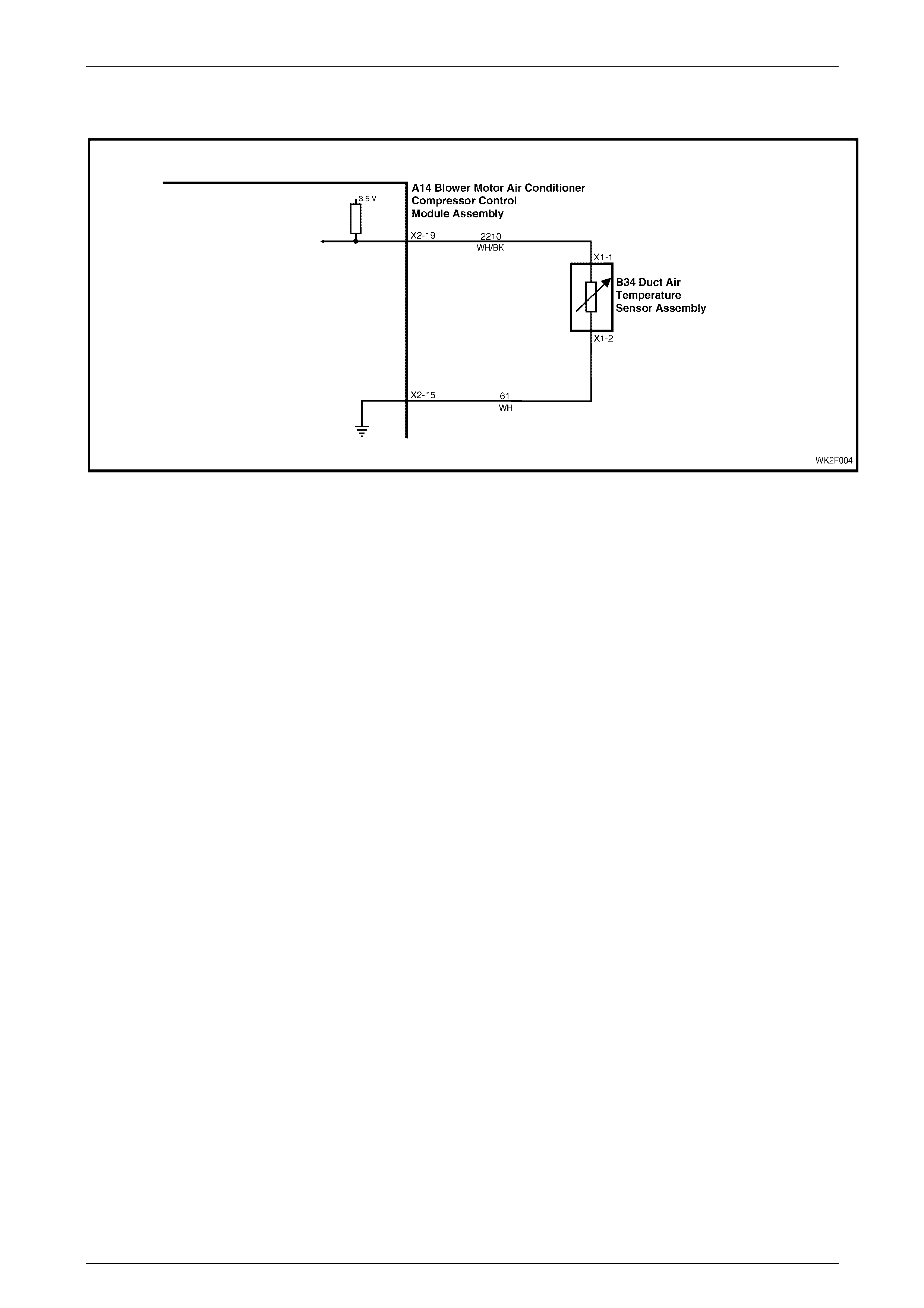
DTC 17 – Evaporative Temperature Sensor Voltage Too High (LHD)
Figure 2F – 15
Circuit Description:
The evaporative temperature sensor (ETS) uses a thermistor to vary voltage signals to the OCC control module. The
OCC control module applies a voltage of 3.6 ±0.18 volts to the sensor. When the air is cold, the ETS resistance is high;
therefore the OCC control module will sense a high signal voltage. If the air is warm the resistance is low, therefore the
OCC control module will sense a low signal voltage.
DTC 17 will set: if the ETS signal voltage is more than 3.4 volts or if the ETS sensor wiring harness (circuit 2210) or
connect ors are open cir cuit ed for 10 second s.
Test Description:
Number(s) below refer to Step numbers in the following
Diagnostic Chart:
1. Ensures the Diagnostic Circuit Check has been
performed.
2. This test checks that the conditions that would set
the DTC, are present.
3. This test checks if the wiring or sensor is open
circuit.
4. This test checks if wiring is shorted to the ignition
feed in the OCC harness.
5. This test checks if wiring is shorted to the 3.5 V feed
in the OCC harness.
6. This test checks if wiring is shorted to a voltage in
the main wiring harness.
7. Check for intermittent connection at OCC.
8. This test checks if sensor is functioning correctly.
9. Check for intermittent con nection at sensor.
10. This test checks for an open circuit sensor ground
wire.
11. This test checks for an open circuit sensor signal
wire.
Diagnostic Aid s:
The default temperature for an open circuit is 5°C.
When using the temperature/resistance chart less than, place
a thermometer in the centre vent, set temperature to full cold
and manual fan speed to 2. This will give an approximate
evaporative air temperature. Compare this figure taken to the
chart less than.
Notes On Diagnostic Chart:
1. Refer to 4 Wir ing Diagrams in this Section for views of
OCC system related electrical connectors and complete
OCC system wiring diagrams.
2. For electrical connector locations and additional wiring
diagram informat ion, refer to Section 12P WIRING
DIAGRAMS.
3. Refer to Section 0C TECH 2 for connecting and us ing
TECH 2.

HVAC Occupant Climat e Control (Auto A/ C) – Diagnostic s Page 2F–34
20–FEB–2003 Page 2F-34
Temperature Resistance Chart
AMBIENT°
°°
°C RESISTANCE Ω
ΩΩ
Ω
5 4300 – 4850
10 3600 – 4050
15 2950 – 3250
20 2320 – 2625
25 1990 – 2200
30 1675 –1850
35 1330 – 1470
40 1140 – 1260
45 950 – 1050
50 850 – 950

HVAC Occupant Climat e Control (Auto A/ C) – Diagnostic s Page 2F–35
20–FEB–2003 Page 2F-35
DTC 17 – Evaporative Temperature Sensor Voltage Too High Diagnostic Chart (LHD)
STEP ACTION VALUE YES NO
1 Was the Diagnostic Circuit Check performed? Go to Step 2. Go to Chart A –
DIAGNOSTIC
CIRCUIT
CHECK in this
Section.
2 Connect TECH 2 to the DLC.
Select Diagnostics / Model Year / Vehicle Model / Body /
Occupant Climate Control / Data Display / Data List /
Evap Temperature Sensor.
Does TECH 2 display a value above 3.4 volts?
Go to Step 3. DTC 17
intermittent. If no
additional DTCs
were stored,
refer to
3 DIAGNOSTIC
CHARTS in this
Section.
3 Disconnect OCC connector A14 X2.
Probe between OCC evaporative air temperature sensor
(ETS) terminals X2-19 and X2-15 with an ohmmeter.
(Refer to Notes on Diagnosti c Chart for this chart,
Note 1).
Is the value as specified?
Refer to
DTC 17
Temp.
Resistance
Chart.
Go to Step 4. Go to Step 8.
4 With the OCC connector A14 X2 disconnected, probe
between OCC harness connector terminals X2-5,
circuit 274 and X2-19, circuit 2210 with an ohmmeter.
Does a short exist?
NOTE: Any resistance measured here qualifies as a
short
Ohms Repair faulty
circuits 274 and /
or 2210.
Go to Step 5.
5 With the OCC connector A14 X2 disconnected, probe
between OCC harness connector terminal X2-11,
circuit 705 and connector terminal X2-19, circuit 2210.
Is the value as specified?
Less than
4 kilohms Repair faulty
circuits 705 and
2210.
Go to Step 6.
6 Turn the ignition on.
Back-probe OCC harness connector terminal X2-19,
circuit 2210 with a voltmeter to chassis ground.
Is the value as specified?
Less than
0.4 volt Go to Step 7. Repair faulty
circuit 2210.
7 Inspect the OCC harness connector A14 X2 for an
intermittent or loose terminal.
Is the connector OK?
Replace the faulty
OCC control
module. Refer to
Section 2E,
HVAC
OCCUPANT
CLIMATE
CONTROL
(AUTO A/C) –
REMOVAL &
INSTALLATION.
Repair faulty
connector
A14 X2.

HVAC Occupant Climat e Control (Auto A/ C) – Diagnostic s Page 2F–36
20–FEB–2003 Page 2F-36
STEP ACTION VALUE YES NO
8 Disconnect ETS connector B34 X1.
Probe between the evaporative air temperature sensor
terminals with an ohmmeter. (Refer to Notes on
Diagnostic Chart for this chart, Note 1.)
Is the value as specified?
Refer to
DTC 17
Temp.
Resistance
Chart.
Go to Step 9. Replace the faulty
evaporative
temperature
sensor. Refer to
Section 2E,
HVAC
OCCUPANT
CLIMATE
CONTROL
(AUTO A/C) –
REMOVAL &
INSTALLATION.
9 Inspect the evaporative air temperat ure sen sor harn ess
connector B34 X1 for an intermittent or loose terminal.
Is the connector OK?
Go to Step 10. Repair faulty
connector
B34 X1.
10 Check the integrity of circuit 61 between (B34) connector
terminal X1-2 and (A14) connector terminal X2-15.
(Refer to Notes on Diagnosti c Chart for this chart,
Note 1.)
Is the circuit OK?
Go to Step 11. Repair faulty
circuit 61.
11 Check the integrity of circuit 2210 between (B34)
connector terminal X1-1 and (A14) connector
terminal X2-19.
Is the circuit OK?
Reconnect
evaporative air
temp sensor
harness
connector
B34 X1 and go to
Step 4.
Repair faulty
circuit 2210.
WHEN ALL DIAGNOSIS AND REPAIRS ARE COMPLETED, VERIFY CORRECT OPERATION

HVAC Occupant Climat e Control (Auto A/ C) – Diagnostic s Page 2F–37
20–FEB–2003 Page 2F-37
DTC 17 – Evaporative Temperature Sensor Voltage Too High (RHD)
Figure 2F – 16
Circuit Description:
The evaporative temperature sensor (ETS) uses a thermistor to vary voltage signals to the OCC control module. The
OCC control module applies a voltage of 3.6 ±0.18 volts to the sensor. When the air is cold, the ETS resistance is high;
therefore the OCC control module will sense a high signal voltage. If the air is warm the resistance is low, therefore the
OCC control module will sense a low signal voltage.
DTC 17 will set: if the ETS signal voltage is more than 3.4 volts or if the ETS sensor wiring harness (circuit 2210) or
connect ors are open cir cuit ed for 10 second s.
Test Description:
Number(s) below refer to Step numbers in the following
Diagnostic Chart:
1. Ensures the Diagnostic Circuit Check has been
performed.
2. This test checks that the conditions that would set
the DTC, are present.
3. This test checks if the wiring or sensor is open
circuit.
4. This test checks if wiring is shorted to the ignition
feed in the OCC harness.
5. This test checks if wiring is shorted to the 3.5 V feed
in the OCC harness.
6. This test checks if wiring is shorted to a voltage in
the main wiring harness.
7. Check for intermittent connection at OCC.
8. This test checks if sensor is functioning correctly.
9. Check for intermittent con nection at sensor.
10. This test checks for an open circuit sensor ground
wire.
11. This test checks for an open circuit sensor signal
wire.
Diagnostic Aid s:
The default temperature for an open circuit is 5°C.
When using the temperature/resistance chart less than, place
a thermometer in the centre vent, set temperature to full cold
and manual fan speed to 2. This will give an approximate
evaporative air temperature. Compare this figure taken to the
chart less than.
Notes On Diagnostic Chart:
1. Refer to 4 Wir ing Diagrams in this Section for views of
OCC system related electrical connectors and complete
OCC system wiring diagrams.
2. For electrical connector locations and additional wiring
diagram informat ion, refer to Section 12P WIRING
DIAGRAMS.
3. Refer to Section 0C TECH 2 for connecting and us ing
TECH 2.

HVAC Occupant Climat e Control (Auto A/ C) – Diagnostic s Page 2F–38
20–FEB–2003 Page 2F-38
Temperature Resistance Chart
AMBIENT°
°°
°C RESISTANCE Ω
ΩΩ
Ω
5 4300 – 4850
10 3600 – 4050
15 2950 – 3250
20 2320 – 2625
25 1990 – 2200
30 1675 –1850
35 1330 – 1470
40 1140 – 1260
45 950 – 1050
50 850 – 950

HVAC Occupant Climat e Control (Auto A/ C) – Diagnostic s Page 2F–39
20–FEB–2003 Page 2F-39
DTC 17 – Evaporative Temperature Sensor Voltage Too High Diagnostic Chart (RHD)
STEP ACTION VALUE YES NO
1 Was the Diagnostic Circuit Check performed? Go to Step 2. Go to Chart A –
DIAGNOSTIC
CIRCUIT
CHECK in this
Section.
2 Connect TECH 2 to the DLC.
Select Diagnostics / Model Year / Vehicle Model / Body /
Occupant Climate Control / Data Display / Data List /
Evap Temperature Sensor.
Does TECH 2 display a value above 3.4 volts?
Go to Step 3. DTC 17
intermittent. If no
additional DTCs
were stored,
refer to
3 DIAGNOSTIC
CHARTS in this
Section.
3 Disconnect OCC connector A14 X2.
Probe between OCC evaporative air temperature sensor
(ETS) terminals X2-19 and X2-15 with an ohmmeter.
(Refer to Notes on Diagnosti c Chart for this chart,
Note 1.)
Is the value as specified?
Refer to
DTC 17
Temp.
Resistance
Chart.
Go to Step 4. Go to Step 8.
4 With the OCC connector A14 X2 disconnected, probe
between OCC harness connector terminals X2-5,
circuit 274 and X2-19, circuit 2210 with an ohmmeter.
Does a short exist?
NOTE: Any resistance measured here qualifies as a
short
Ohms Repair faulty
circuits 274 and /
or 2210.
Go to Step 5.
5 With the OCC connector A14 X2 disconnected, probe
between OCC harness connector terminal X2-11,
circuit 705 and connector terminal X2-19, circuit 2210.
Is the value as specified?
Less than
4 kilohms Repair faulty
circuits 705 and
2210.
Go to Step 6.
6 Turn the ignition on.
Back-probe OCC harness connector terminal X2-19,
circuit 2210 with a voltmeter to chassis ground.
Is the value as specified?
Less than
0.4 volt Go to Step 7. Repair faulty
circuit 2210.
7 Inspect the OCC harness connector A14 X2 for an
intermittent or loose terminal.
Is the connector OK?
Replace the faulty
OCC control
module. Refer to
Section 2E,
HVAC
OCCUPANT
CLIMATE
CONTROL
(AUTO A/C) –
REMOVAL &
INSTALLATION.
Repair faulty
connector
A14 X2.

HVAC Occupant Climat e Control (Auto A/ C) – Diagnostic s Page 2F–40
20–FEB–2003 Page 2F-40
STEP ACTION VALUE YES NO
8 Disconnect ETS connector B34 X1.
Probe between the evaporative air temperature sensor
terminals with an ohmmeter. (Refer to Notes on
Diagnostic Chart for this chart, Note 1).
Is the value as specified?
Refer to
DTC 17
Temp.
Resistance
Chart.
Go to Step 9. Replace the faulty
evaporative
temperature
sensor. Refer to
Section 2E,
HVAC
OCCUPANT
CLIMATE
CONTROL
(AUTO A/C) –
REMOVAL &
INSTALLATION.
9 Inspect the evaporative air temperat ure sen sor harn ess
connector B34 X1 for an intermittent or loose terminal.
Is the connector OK?
Go to Step 10. Repair faulty
connector
B34 X1.
10 Check the integrity of circuit 61 between (B34) connector
terminal X1-B and (A14) connector terminal X2-15.
(Refer to Notes on Diagnosti c Chart for this chart, Note
1.)
Is the circuit OK?
Go to Step 11. Repair faulty
circuit 61.
11 Check the integrity of circuit 2210 between (B34)
connector term inal X1-A and (A14) connector
terminal X2-19.
Is the circuit OK?
Reconnect
evaporative air
temp sensor
harness
connector
B34 X1 and go to
Step 4.
Repair faulty
circuit 2210.
WHEN ALL DIAGNOSIS AND REPAIRS ARE COMPLETED, VERIFY CORRECT OPERATION
HVAC Occupant Climat e Control (Auto A/ C) – Diagnostic s Page 2F–41
20–FEB–2003 Page 2F-41
DTC 18 – Evaporative Temperature Sensor Voltage Too Low (LHD)
Figure 2F – 17
Circuit Description:
The evaporative temperature sensor (ETS) uses a thermistor to control the signal voltage to the OCC control module.
The OCC control module applies a voltage of 3.6 ±0.18 volts to the sensor. When the air off the evaporator core is cold,
the ETS resistan ce is high, therefore the OCC control module will sense a high signal voltage. If the air is warm, the ETS
resistance is low, therefore the OCC control module will sense a low signal voltage.
DTC 18 will set: if the ETS signal voltage is less than 0.3 volt or if the ETS sensor wiring harness (circuit 2210) or
connect ors are open cir cuit ed for 10 second s.
Test Description:
Number(s) below refer to Step numbers in the following
Diagnostic Chart:
1. Ensures the Diagnostic Circuit Check has been
performed.
2. This test checks that the conditions that would set
the DTC, are present.
3. This test checks if the sensor or wiring is causing the
short circuit.
4. This test checks if sensor and wiring is functioning
correctly.
5. Check for intermittent con nec ti on at sensor
6. This test checks for a short circuit of the sensor
signal wire to ground.
7. This test determines if the sensor is shorted or the
wire is shorted.
Diagnostic Aid s:
The default temperature for an open circuit is 5°C.
When using the temperature/resistance chart less than, place
a thermometer in the centre vent, set temperature to full cold
and manual fan speed to 2. This will give an approximate
evaporative air temperature. Compare this figure taken to the
chart less than.
Notes On Diagnostic Chart:
1. Refer to 4 Wir ing Diagrams in this Section for views of
OCC system related electrical connectors and complete
OCC system wiring diagrams.
2. For electrical connector locations and additional wiring
diagram informat ion, refer to Section 12P WIRING
DIAGRAMS.
3. Refer to Section 0C TECH 2 for connecting and us ing
TECH 2.

HVAC Occupant Climat e Control (Auto A/ C) – Diagnostic s Page 2F–42
20–FEB–2003 Page 2F-42
Temperature Resistance Chart
AMBIENT°
°°
°C RESISTANCE Ω
ΩΩ
Ω
5 4300 – 4850
10 3600 – 4050
15 2950 – 3250
20 2320 – 2625
25 1990 – 2200
30 1675 –1850
35 1330 – 1470
40 1140 – 1260
45 950 – 1050
50 850 – 950

HVAC Occupant Climat e Control (Auto A/ C) – Diagnostic s Page 2F–43
20–FEB–2003 Page 2F-43
DTC 18 – Evaporative Temperature Sensor Voltage Too Low Diagnostic Chart (LHD)
STEP ACTION VALUE YES NO
1 Was the Diagnostic Circuit Check performed? Go to Step 2. Go to Chart A –
DIAGNOSTIC
CIRCUIT
CHECK in this
Section.
2 Connect TECH 2 to the DLC (Refer to Notes on
Diagnostic Chart for this chart, Note 2.)
Select Diagnostics / Model Year / Vehicle Model / Body /
Occupant Climate Control / Data Display / Data List /
Evap Temperature Sensor.
Does TECH 2 display a value less than 0.4 volt?
Go to Step 3. DTC 18
intermittent. If no
additional DTCs
were stored,
refer to 3
DIAGNOSTIC
CHARTS in this
Section
3 With TECH 2 connected and Evap Temperature Sensor
displayed, disconnect the OCC wiring harness A14 X2.
Does TECH 2 display a value above 3.4 volts?
Go to Step 4. Replace the faulty
OCC control
module. Refer to
Section 2E,
HVAC
OCCUPANT
CLIMATE
CONTROL
(AUTO A/C) –
REMOVAL &
INSTALLATION.
4 With the OCC connector A14 X2 disconnected, probe
between the OCC connector terminals X2-19 and X2-15
with an ohmmeter. (Refer to Notes on Diagnostic Chart
for this chart, Note 1.)
Is the value as specified?
Refer to
DTC 18
Temp.
Resistance
Chart.
Go to Step 5. Go to Step 7
5 With the OCC connector A14 X2 disconnected, probe
OCC harness connector terminal X2-19, circuit 2210
with an ohmmeter to ground.
Is the value as specified?
More than
0 ohm Repair faulty
circuit 2210. Go to Step 6
6 Inspect the OCC and evaporative air temperature sensor
wiring harness and connectors B34 X1 and A14 X2 for
an intermittent short.
Are the circuits OK?
Replace the faulty
OCC control
module. Refer to
Section 2E,
HVAC
OCCUPANT
CLIMATE
CONTROL
(AUTO A/C) –
REMOVAL &
INSTALLATION.
Repair faulty
circuits /
connect ors as
necessary.
7 Disconnect the evaporative temperature sens or
connector B24 X1.
Install OCC connectors A14 X1 and A14 X2.
With TECH 2 connected, select Body / Occupant
Climate Control / Data Display / Data List / Evap
Temperature Sensor.
Does TECH 2 display a value above 3.4 volts?
Replace the
faulty
evaporative
temperature
sensor. Refer to
Section 2E,
HVAC
OCCUPANT
CLIMATE
CONTROL
(AUTO A/C) –
REMOVAL &
INSTALLATION.
Repair faulty
circuit 2210.
WHEN ALL DIAGNOSIS AND REPAIRS ARE COMPLETED, VERIFY CORRECT OPERATION

HVAC Occupant Climat e Control (Auto A/ C) – Diagnostic s Page 2F–44
20–FEB–2003 Page 2F-44
DTC 18 – Evaporative Temperature Sensor Voltage Too Low (RHD)
Figure 2F – 18
Circuit Description:
The evaporative temperature sensor (ETS) uses a thermistor to control the signal voltage to the OCC control module.
The OCC control module applies a voltage of 3.6 ±0.18 volts to the sensor. When the air off the evaporator core is cold,
the ETS resistan ce is high, therefore the OCC control module will sense a high signal voltage. If the air is warm, the ETS
resistance is low, therefore the OCC control module will sense a low signal voltage.
DTC 18 will set: if the ETS signal voltage is less than 0.3 volt or if the ETS sensor wiring harness (circuit 2210) or
connect ors are open cir cuit ed for 10 second s.
Test Description:
Number(s) below refer to Step numbers in the following
Diagnostic Chart:
1. Ensures the Diagnostic Circuit Check has been
performed.
2. This test checks that the conditions that would set
the DTC, are present.
3. This test checks if the sensor or wiring is causing the
short circuit.
4. This test checks if sensor and wiring is functioning
correctly.
5. Check for intermittent con nec ti on at sensor
6. This test checks for a short circuit of the sensor
signal wire to ground.
7. This test determines if the sensor is shorted or the
wire is shorted.
Diagnostic Aid s:
The default temperature for an open circuit is 5°C.
When using the temperature/resistance chart less than, place
a thermometer in the centre vent, set temperature to full cold
and manual fan speed to 2. This will give an approximate
evaporative air temperature. Compare this figure taken to the
chart less than.
Notes On Diagnostic Chart:
1. Refer to 4 Wir ing Diagrams in this Section for views of
OCC system related electrical connectors and complete
OCC system wiring diagrams.
2. For electrical connector locations and additional wiring
diagram informat ion, refer to Section 12P WIRING
DIAGRAMS.
3. Refer to Section 0C TECH 2 for connecting and us ing
TECH 2.

HVAC Occupant Climat e Control (Auto A/ C) – Diagnostic s Page 2F–45
20–FEB–2003 Page 2F-45
Temperature Resistance Chart
AMBIENT°
°°
°C RESISTANCE Ω
ΩΩ
Ω
5 4300 – 4850
10 3600 – 4050
15 2950 – 3250
20 2320 – 2625
25 1990 – 2200
30 1675 –1850
35 1330 – 1470
40 1140 – 1260
45 950 – 1050
50 850 – 950

HVAC Occupant Climat e Control (Auto A/ C) – Diagnostic s Page 2F–46
20–FEB–2003 Page 2F-46
DTC 18 – Evaporative Temperature Sensor Voltage Too Low Diagnostic Chart (RHD)
STEP ACTION VALUE YES NO
1 Was the Diagnostic Circuit Check performed? Go to Step 2. Go to Chart A –
DIAGNOSTIC
CIRCUIT
CHECK in this
Section.
2 Connect TECH 2 to the DLC (Refer to Notes on
Diagnostic Chart for this chart, Note 2.)
Select Diagnostics / Model Year / Vehicle Model / Body /
Occupant Climate Control / Data Display / Data List /
Evap Temperature Sensor.
Does TECH 2 display a value less than 0.4 volt?
Go to Step 3. DTC 18
intermittent. If no
additional DTCs
were stored,
refer to 3
DIAGNOSTIC
CHARTS in this
Section
3 With TECH 2 connected and Evap Temperature Sensor
displayed, disconnect the OCC wiring harness A14 X2.
Does TECH 2 display a value above 3.4 volts?
Go to Step 4. Replace the faulty
OCC control
module. Refer to
Section 2E,
HVAC
OCCUPANT
CLIMATE
CONTROL
(AUTO A/C) –
REMOVAL &
INSTALLATION.
4 With the OCC connector A14 X2 disconnected, probe
between the OCC connector terminals X2-19 and X2-15
with an ohmmeter. (Refer to Notes on Diagnostic Chart
for this chart, Note 1.)
Is the value as specified?
Refer to
DTC 18
Temp.
Resistance
Chart.
Go to Step 5. Go to Step 7
5 With the OCC connector A14 X2 disconnected, probe
OCC harness connector terminal X2-19, circuit 2210
with an ohmmeter to ground.
Is the value as specified?
More than
0 ohm Repair faulty
circuit 2210. Go to Step 6
6 Inspect the OCC and evaporative air temperature sensor
wiring harness and connectors B34 X1 and A14 X2 for
an intermittent short.
Are the circuits OK?
Replace the faulty
OCC control
module. Refer to
Section 2E,
HVAC
OCCUPANT
CLIMATE
CONTROL
(AUTO A/C) –
REMOVAL &
INSTALLATION.
Repair faulty
circuits /
connect ors as
necessary.
7 Disconnect the evaporative temperature sens or
connector B24 X1.
Install OCC connectors A14 X1 and A14 X2.
With TECH 2 connected, select Body / Occupant
Climate Control / Data Display / Data List / Evap
Temperature Sensor.
Does TECH 2 display a value above 3.4 volts?
Replace the
faulty
evaporative
temperature
sensor. Refer to
Section 2E,
HVAC
OCCUPANT
CLIMATE
CONTROL
(AUTO A/C) –
REMOVAL &
INSTALLATION.
Repair faulty
circuit 2210.
WHEN ALL DIAGNOSIS AND REPAIRS ARE COMPLETED, VERIFY CORRECT OPERATION
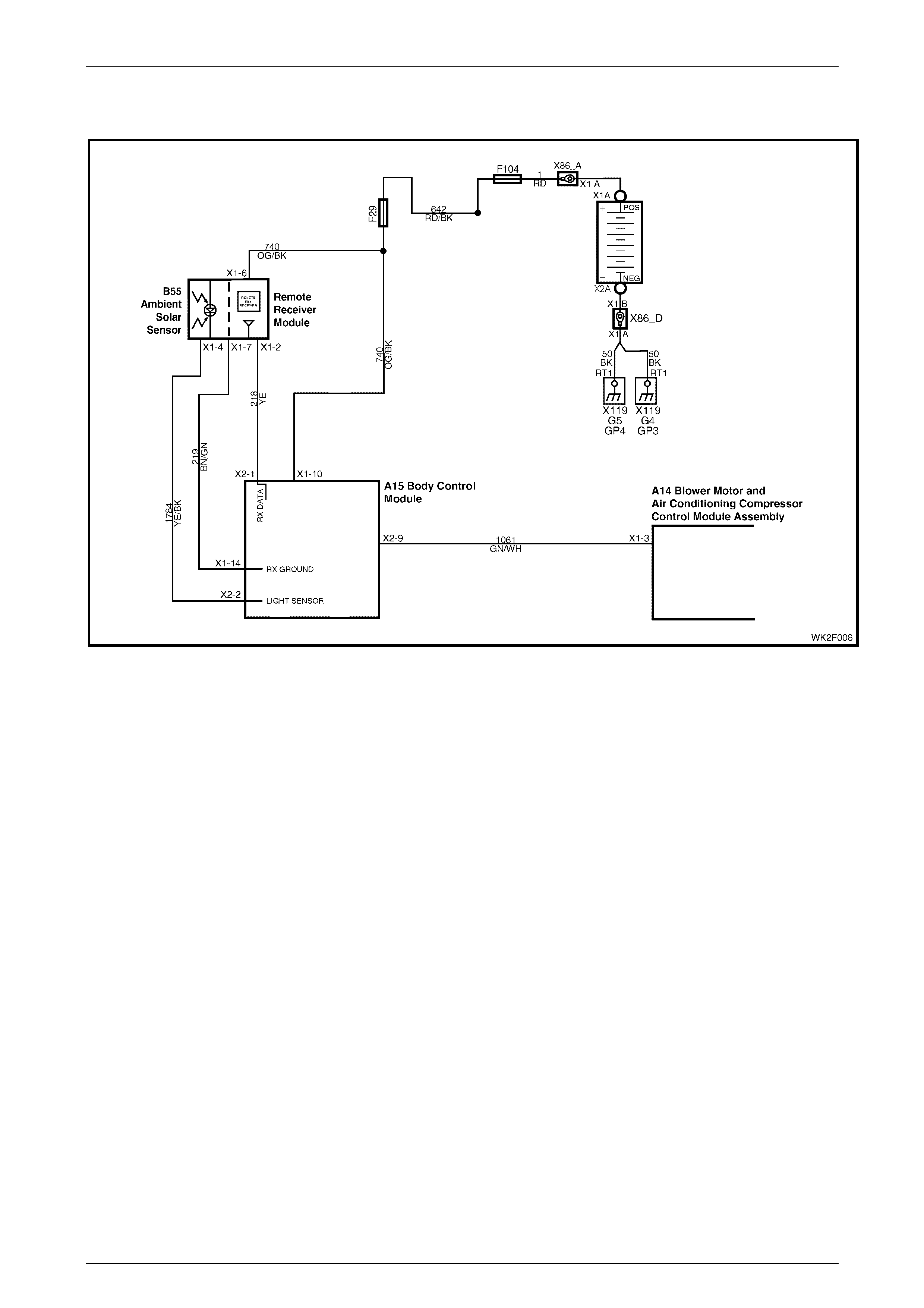
HVAC Occupant Climat e Control (Auto A/ C) – Diagnostic s Page 2F–47
20–FEB–2003 Page 2F-47
DTC 19 – Sun Load Sensor Error
Figure 2F – 19
Circuit Description:
The sun load sensor is mounted in the instrument panel pad between the demist ducts to monitor the amount of sun load
and ambient light in front of the vehicle. The ambient light monitored is used by the BCM for Auto Lights On operation
(twilight sentinel) and the sun load monitored is used by the OCC control module. The BCM monitors the voltage from
this sensor via circuit 1784 and converts this voltage signal into Steps, which it sends to the OCC control module via the
auxiliary serial data line, circuit 1061. The message sent will vary between 0 and 254 Steps, depending on the amount of
sun load
(0 = no sun load, 254 = maximum sun load).
DTC 19 will set if the BCM sends a sun load sensor value of 255 Steps to the OCC control module for 10 seconds. The
BCM will send this value if it detects a high sun load and a low twilight level.
NOTE
This trouble code is for information only; under no
circumstances should the OCC control module be
replaced due to this trouble co de.

HVAC Occupant Climat e Control (Auto A/ C) – Diagnostic s Page 2F–48
20–FEB–2003 Page 2F-48
Test Description:
Number(s) below refer to Step numbers in the following
Diagnostic Chart:
1. Ensures the Diagnostic Circuit Check has been
performed.
2 & 3. Uses TECH 2 to check ambient light level data
on the auxiliary serial data bus.
4 & 5. Uses TECH 2 to check ambient light level signal
at micr opro cessor of B CM.
6. Determines if the sun sensor / remot e receiver
module has power and ground by checking
operation of the remote coded key reader.
7 & 8. Checks ambient light level signal at input to
BCM.
9. Checks integrity of circuit 1784 (open, short to
ground or short to Battery voltage).
10. Checks battery voltage supply at sun sensor /
remote receiver module.
11. Checks integrity of circuit 219 (open, short to ground
or short to Battery voltage).
Notes On Diagnostic Chart:
1. Refer to 4 Wir ing Diagrams in this Section for views of
OCC system related electrical connectors and complete
OCC system wiring diagrams.
2. For electrical connector locations and additional wiring
diagram informat ion, refer to Section 12P WIRING
DIAGRAMS.
3. Refer to Section 0C TECH 2 for connecting and us ing
TECH 2.

HVAC Occupant Climat e Control (Auto A/ C) – Diagnostic s Page 2F–49
20–FEB–2003 Page 2F-49
DTC 19 – Sun Load Sensor Error
STEP ACTION VALUE YES NO
1 Was the Diagnostic Circuit Check performed? Go to Step 2. Go to Chart A –
DIAGNOSTIC
CIRCUIT
CHECK in this
Section.
2 Connect TECH 2 to the DLC.
Select Diagnostics / Model Year / Vehicle Model / Body /
Body Control Module / Normal Mode / Ambient Light
Level.
Cover the sun load sensor / remote receiver module
assembly.
Does TECH 2 display 1 Step?
Unco ver the sun
load sensor /
remote receiver
module assembly
and go to Step 3.
Go to Step 4.
3 With TECH 2 connected and the Ambient Light Level
displayed, shine a torch directly on the sun load sensor /
remote receiver module assembly.
Does TECH 2 display 254 Step?
Fault not found, if
no other DTCs
are stored, refer
to 3
DIAGNOSTIC
CHARTS in this
Section.
Go to Step 4.
4 With the sun load sensor / remote receiver module
assembly covered and TECH 2 connected, select Body /
Body Control Module / Data Display / Data List / Ambient
Light Sensor display.
Does TECH 2 display less than 0.5 volts?
Replace the
BCM. Refer to
Section 12J, 2.1
BODY
CONTROL
MODULE.
Go to Step 5.
5 With TECH 2 connected and the Ambient Light Sensor
displayed, shine a torch on the sun load sensor / remote
receiver module asse mbly .
Does TECH 2 display approximately 5 volts?
Replace the
BCM. Refer to
Section 12J, 2.1
BODY
CONTROL
MODULE.
Go to Step 6.
6 Check the operation of the remote coded key receiver by
locking and unlocking the doors using the remote coded
key (Lock and Unlock buttons).
Does remote coded key receiver operate?
Go to Step 7. Go to Step 10.
7 Back-probe BCM connector terminal X2-2, circuit 1784
with a voltmete r to ground. (Refer to Notes on
Diagnostic Chart for this chart, Note 1.)
Turn the ignition on.
Cover the sun load sensor / remote receiver module
assembly.
Is the value as specified?
Less than
0.5 volt Replace BCM.
Refer to Section
12J, 2.1 BODY
CONTROL
MODULE.
Go to Step 8.
8 Back-probe BCM connector terminal X2-2, circuit 1784
with a voltmeter to ground.
Turn the ignition on.
Shine a torch on the sun load sensor / remote receiver
module assembly.
Is the value as specified?
Approx.
5 volts Replace the
BCM. Refer to
Section 12J, 2.1
BODY
CONTROL
MODULE.
Go to Step 9.

HVAC Occupant Climat e Control (Auto A/ C) – Diagnostic s Page 2F–50
20–FEB–2003 Page 2F-50
STEP ACTION VALUE YES NO
9 Check the integrity of circuit 1784.
Is the circuit OK?
Replace the sun
sensor / remote
receiver module .
Refer to Section
12J, 2.1 BODY
CONTROL
MODULE.
Repair faulty
circuit 1784.
10 Back-probe sun sensor / remote receiver module
connector term inal X1-3, circuit 740 with a voltmeter to
ground.
Is the value as specified?
12 volts Go to Step 11. Repair faulty
circuit 740.
11 Check the integrity of circuit 219.
Is the circuit OK?
Go to Step 7. Repair faulty
circuit 219.
WHEN ALL DIAGNOSIS AND REPAIRS ARE COMPLETED, VERIFY CORRECT OPERATION

HVAC Occupant Climat e Control (Auto A/ C) – Diagnostic s Page 2F–51
20–FEB–2003 Page 2F-51
DTC 35 – No Serial Data From PCM
Figure 2F – 20 (V6 and V6 S/C)
Figure 2F – 21 (GEN III V8)
Circuit Description:
When investigating any complaint of an OCC problem or malfunction, always begin diagnosis with the following
diagnostic circuit check. This check is a preliminary procedure that checks to ensure the OCC control module is
communicating on the serial data line as well as helping to identify a problem or malfunction and directing the reader to
the appropriate diagnostic chart in this Section.
With TECH 2 connected to the DLC and ignition switched on, TECH 2 should display serial data communication.
If TECH 2 does not display serial data, the seri al data cir cui t may be open or shorted.
There are several other control modules that are connected to the serial data line (PCM, BCM, ABS/TCS, instruments
and SDM. Any of these control modules could cause a fault on the serial data line. This fault could result in TECH 2 not
being able to display serial data.
DTC will set if the serial data line (circuits 1061 or 800) is interrupted and the OCC does not receive data from the PCM
or BCM for 10 seconds.

HVAC Occupant Climat e Control (Auto A/ C) – Diagnostic s Page 2F–52
20–FEB–2003 Page 2F-52
Test Description:
Number(s) below refer to Step numbers in the following
Diagnostic Chart:
1. Ensures the Diagnostic Circuit Check has been
performed.
2. Determines if there is a fault in the serial data
circuit (800) between the BCM and PCM by starting
the engine. If serial data was lost while the engine
was running, the engine will restart but there will be
a one second delay.
3. Checks if fault is common with other control modules
connected to the serial data circuit.
4. Checks internal switch in BCM for open circuit.
5. Checks circuit 1061 and determine if fault is in wiring
or a control module.
6. Checks circuit 1061 for open circuit.
7. Checks integrity of ground circuits for the BCM,
PCM, PIM and OCC control module.
Diagnostic Aid s:
A fault with the serial data circuit could be caused by one or
more of the several control modules connected to this serial
data circuit. Isolate the fault by disconnecting each control
module, one at a time until serial data communication is
restored.
Notes On Diagnostic Chart:
1. Refer to Sect ion 12P, WIRING DIAGR AM S for
procedures on checking wiring faults.
2. Refer to Section 0C TECH 2 for connecting and us ing
TECH 2.
3. To check the integrity of the OCC control module ground
circuit; turn ignition and OCC system ON and check for a
voltage drop across circ uit 251 between OCC control
module connector A14 X1, terminal X1-2, and ground
point X157.
4. To check the integrity of the PCM ground circuit, refer to
Ground Credibility Check in the following Sections in the
MY2003 VY and V2 Series Service Information:
• Section 6C1, POWERTRAIN – V6
• Section 6C2, POWERTRAIN – V6 S/C
• Section 6C3, POWERTRAIN – GEN III V8

HVAC Occupant Climat e Control (Auto A/ C) – Diagnostic s Page 2F–53
20–FEB–2003 Page 2F-53
DTC 35 – No Serial Data From PCM Diagnostic Chart
STEP ACTION VALUE YES NO
1 Was the Diagnostic Circuit Check performed? Go to Step 2. Go to Chart A –
DIAGNOSTIC
CIRCUIT
CHECK in this
Section.
2 Connect TECH 2 to the DLC.
Select Diagnostics / Model Year / Vehicle Model / Body /
DTC Check / DTC Check.
Can TECH 2 communicate with the BCM and PCM?
NOTE: If No Data is displayed next to a module, then
there is no communication between TECH 2 and that
module.
Go to Step 3. Go to Section 12J,
4.2 SERIAL DATA
COMMUNICATIO
N (BUS
MAST ER) .
3 In Step 2, did TECH 2 communicate with all control
modules except the OCC control module? Go to Step 6. Go to Step 4.
4 Back-probe between BCM connector terminal X2-9,
circuit 1061 and X2-5, circuit 800 with an ohmmeter.
(Refer to Notes on Diagnosti c Chart for this chart,
Note 1.)
Is the value as specified?
Less than
1 ohm Go to Step 5. Replace the
BCM. Refer to
Section 12J, 2.1
BODY
CONTROL
MODULE.
5 Check the integrity of circuit 1061 between BCM
connector terminal X2-9 and the individual control
modules.
Is the circuit OK?
Disconnect each
control modu le in
circuit 1061 one
at a time to
isolate the fault in
the circuit or to
identify the
control modu le
ca using the fa ult.
Replace the
faulty control
module. Refer to
the relevant
Section in this
Service Manual.
Repair faulty
circuit 1061.
6 Back-probe between BCM connector terminal X2-9 and
OCC control module connector terminal X1-3,
circuit 1061 with an ohmmeter.
Is the value as specified?
Less than
1 ohm Go to Step 7. Repair faulty
circuit 1061.
7 Check the integrity of the ground circuits to the OCC
control module, BCM, PCM and PIM (GEN III V8) using
a voltmeter to a known good ground. (Refer to Notes on
Diagnostic Chart for this chart, Notes 3 and 4.)
Are the values as specified?
Less than
0.15 volt Replace the
OCC contro l
module. Refer to
Section 2E,
HVAC
OCCUPANT
CLIMATE
CONTROL
(AUTO A/C) –
REMOVAL &
INSTALLATION.
Repair faulty
ground circuit/s.
WHEN ALL DIAGNOSIS AND REPAIRS ARE COMPLETED, VERIFY CORRECT OPERATION
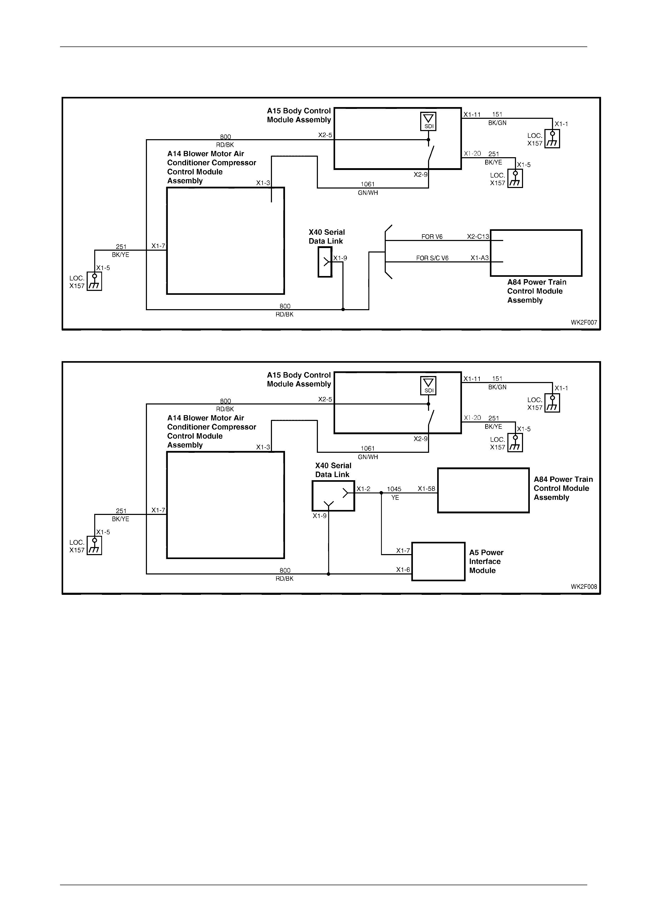
HVAC Occupant Climat e Control (Auto A/ C) – Diagnostic s Page 2F–54
20–FEB–2003 Page 2F-54
DTC 36 – No Serial Data From BCM
Figure 2F – 22 (V6 and V6 S/C)
Figure 2F – 23 (GEN III V8)
Circuit Description:
When investigating any complaint of an OCC problem or malfunction, always begin diagnosis with the following
diagnostic circuit check. This check is a preliminary procedure that checks to ensure the OCC control module is
communicating on the serial data line as well as helping to identify a problem or malfunction and directing the reader to
the appropriate diagnostic chart in this Section.
With TECH 2 connected to the DLC and ignition switched on, TECH 2 should display serial data communication.
If TECH 2 does not display serial data, the seri al data cir cui t may be open or shorted.
There are several other control modules that are connected to the serial data line (PCM, BCM, ABS/TCS, instruments
and SDM. Any of these control modules could cause a fault on the serial data line. This fault could result in TECH 2 not
being able to display serial data.
DTC will set if the serial data line (circuits 1061 or 800) is interrupted and the OCC does not receive data from the PCM
or BCM for 10 seconds.

HVAC Occupant Climat e Control (Auto A/ C) – Diagnostic s Page 2F–55
20–FEB–2003 Page 2F-55
Test Description:
Number(s) below refer to Step numbers in the following
Diagnostic Chart:
1. Ensures the Diagnostic Circuit Check has been
performed.
2. Determines if there is a fault in the serial data
circuit (800) between the BCM and PCM by starting
the engine. If serial data was lost while the engine
was running, the engine will restart but there will be
a one second delay.
3. Checks if fault is common with other control modules
connected to the serial data circuit.
4. Checks internal switch in BCM for open circuit.
5. Checks circuit 1061 and determine if fault is in wiring
or a control module.
6. Checks circuit 1061 for open circuit.
7. Checks integrity of ground circuits for the BCM,
PCM, PIM and OCC control module.
Diagnostic Aid s:
A fault with the serial data circuit could be caused by one or
more of the several control modules connected to this serial
data circuit. Isolate the fault by disconnecting each control
module, one at a time until serial data communication is
restored.
Notes On Diagnostic Chart:
1. Refer to Sect ion 12P, WIRING DIAGR AM S for
procedures on checking wiring faults.
2. Refer to Section 0C TECH 2 for connecting and us ing
TECH 2.
3. To check the integrity of the OCC control module ground
circuit; turn ignition and OCC system ON and check for a
voltage drop across circ uit 251 between OCC control
module connector A14 X1, terminal X1-2, and ground
point X157.
4. To check the integrity of the BCM ground circuit; turn the
ignition on and check for a voltage drop across
circuit 251, between BCM connector A15 X1,
terminal X1-20 and ground point X157.
5. To check the integrity of the PCM ground circuit, refer to
Ground Credibility Check in the following Sections in the
MY2003 VY and V2 Series Service Information:
• Section 6C1, POWERTRAIN – V6
• Section 6C2, POWERTRAIN – V6 S/C
• Section 6C3, POWERTRAIN – GEN III V8

HVAC Occupant Climat e Control (Auto A/ C) – Diagnostic s Page 2F–56
20–FEB–2003 Page 2F-56
DTC 35 – No Serial Data From BCM Diagnostic Chart
STEP ACTION VALUE YES NO
1 Was the Diagnostic Circuit Check performed? Go to Step 2. Go to Chart A –
DIAGNOSTIC
CIRCUIT
CHECK in this
Section.
2 Connect TECH 2 to the DLC.
Select Diagnostics / Model Year / Vehicle Model / Body /
DTC Check / DTC Check.
Can TECH 2 communicate with the BCM and PCM?
NOTE: If No Data displays next to a module, then there
is no communication between TECH 2 and that module.
Go to Step 3. Go to Section 12J,
4.2 SERIAL DATA
COMMUNICATIO
N (BUS
MAST ER) .
3 In Step 2, did TECH 2 communicate with all the control
modules, except the OCC control module (ABS,
instruments, SRS)?
NOTE: If No Data displays next to a module, then there
is no communication between TECH 2 and that module.
Go to Step 6. Go to Step 4.
4 Check the integrity of circuit 1061 and circuit 800
between BCM connector terminals X2-5 and X2-9.
(Refer to Notes on Diagnosti c Chart for this chart,
Note 1.)
Are the circuits OK?
Go to Step 5. Repair faulty
circuit 800
5 Check the integrity of circuit 1061 between BCM and the
individual con t rol mo dule s.
Is the circuit OK?
Disconnect each
control modu le in
circuit 1220 one
at a time to
isolate the fault in
the circuit or to
identify the
control modu le
ca using the fa ult.
Replace the
faulty control
module. Refer to
relevant Section
in this Service
Manual.
Repair faulty
circuit 1061.
6 Back-probe between BCM connector terminal X2-9 and
OCC control module connector terminal X1-3,
circuit 1061 with an ohmmeter.
Is the value as specified?
Less than
1 ohm Go to Step 7. Repair faulty
circuit 1061.
7 Check the integrity of the ground circuits to the OCC
control module, BCM, PCM and PIM (GEN III V8) with a
voltmeter to a known good ground.
Is the value as specified?
Less than
0.15 volts Replace the
OCC contro l
module. Refer to
Section 2E,
HVAC
OCCUPANT
CLIMATE
CONTROL
(AUTO A/C) –
REMOVAL &
INSTALLATION.
Repair faulty
ground circuit/s.
WHEN ALL DIAGNOSIS AND REPAIRS ARE COMPLETED, VERIFY CORRECT OPERATION

HVAC Occupant Climat e Control (Auto A/ C) – Diagnostic s Page 2F–57
20–FEB–2003 Page 2F-57
DTC 37 – ROM Checksum Error
Figure 2F – 24
Circuit Description:
When this diagnostic trouble code (DTC) is set, it indicates a failure attributed to the processor. The processor functions
are carried out by the printed circuit boards (1) installed between the front housing (2) and rear housing (3) of the OCC
control modu le (4).
DTC 37 will set: if the ROM checksum is incorrect. The testing of the ROM checksum occurs every time the OCC system
is reset due to battery disconnection or low power conditions.
If DTC 37 sets and reprogramming is unsuccessful, replace the OCC control module. Refer to Section 2E, 2.1 OCC
CONTROL MODULE.
Test Description:
Number(s) below refer to Step numbers in the following
Diagnostic Chart:
1. Ensures the Diagnostic Circuit Check has been
performed.
2. Determines if OCC control module is faulty by
re-programming the OCC control module.
3. Determines if OCC control module is faulty.
Notes On Diagnostic Chart:
1. Refer to Sect ion 12P, WIRING DIAGR AM S for
procedures on checking wiring faults.
Diagnostic Aid s:
If the OCC system programming is corrupted, recalibration
can be carried out via TECH 2. To calibrate the system refer
to Section 2F 1.2 TECH 2 TEST MODES AND DISPLAYS
FOR OCC DIAGNOSIS in this of the MY2003 VY and V2
Series Service Information.

HVAC Occupant Climat e Control (Auto A/ C) – Diagnostic s Page 2F–58
20–FEB–2003 Page 2F-58
DTC 37 – ROM Checksum Error Diagnostic Chart
STEP ACTION VALUE YES NO
1 Has the Diagnostic Circuit Check been performed? Go to Step 2. Go to Chart A –
DIAGNOSTIC
CIRCUIT
CHECK in this
Section.
2 Reprogram the OCC control module Code Version using
TECH 2. Refer to Section 2F 1.2 TECH 2 TEST MODES
AND SCREEN DISPLAYS FOR OCC DIAGNOSIS in
the MY2003 VY and V2 Series Service Information.
Was programming successful?
Go to Step 3. Repeat this Step
at least twice, as
the system may
have crashed
during this
process.
Replace the
OCC contro l
module. Refer to
Section 2E,
HVAC
OCCUPANT
CLIMATE
CONTROL
(AUTO A/C) –
REMOVAL &
INSTALLATION.
3 Connect TECH 2 to the DLC.
Select Diagnostics / Model Year / Vehicle Model / Body /
Occupant Control Module / Diagnostic Trouble Codes /
Clear DTC Information and clear DTCs.
Were all DTCs cleared?
System OK. Replace the
OCC contro l
module. Refer to
Section 2E,
HVAC
OCCUPANT
CLIMATE
CONTROL
(AUTO A/C) –
REMOVAL &
INSTALLATION.
WHEN ALL DIAGNOSIS AND REPAIRS ARE COMPLETED, VERIFY CORRECT OPERATION

HVAC Occupant Climat e Control (Auto A/ C) – Diagnostic s Page 2F–59
20–FEB–2003 Page 2F-59
DTC 38 – EEPROM Checksum Error
Figure 2F – 25
Circuit Description:
The EEPROM (Expandable, Erasable Program, Read Only, Memory) functions are carried out by the printed
circuit boards (1) installed between the front housing (2) and rear housing (3) of the OCC control module (4).
The purpose of the EEPROM is to store data used to control operating parameters of the OCC system.
When this DTC is set, and the EEPROM checksum is incorrect. The OCC system calibration is corrupted or the
EEPROM in the OCC control module has failed.
DTC 38 will set when the EEPRO M checksum is incorrect. The testing of the EEPROM occurs whenever the ignition is
turned on.
If DTC 38 sets and reprogramming is unsuccessful, replace the OCC control module. Refer to Section 2E, 2.1 OCC
CONTROL MODULE.
Test Description:
Number(s) below refer to Step numbers in the following
Diagnostic Chart:
1. Ensures the Diagnostic Circuit Check has been
performed.
2. Determines if OCC control module is faulty by
re-programming the OCC control module.
3. Determines if OCC control module is faulty.
Diagnostic Aid s:
If the OCC system programming is corrupted, recalibration
can be carried out via TECH 2. To calibrate the system refer
to Section 2F 1.2 TECH 2 TEST MODES AND DISPLAYS
FOR OCC DIAGNOSIS in this of the MY2003 VY and V2
Series Service Information.
Notes On Diagnostic Chart:
1. Refer to Sect ion 12P, WIRING DIAGR AM S for
procedures on checking wiring faults.

HVAC Occupant Climat e Control (Auto A/ C) – Diagnostic s Page 2F–60
20–FEB–2003 Page 2F-60
DTC 38 – EEPROM Checksum Error Diagnostic Chart
STEP ACTION VALUE YES NO
1 Has the Diagnostic Circuit Check been performed? Go to Step 2. Go to Chart A –
DIAGNOSTIC
CIRCUIT
CHECK in this
Section.
2 Reprogram the OCC control module Code Version using
TECH 2. Refer to Section 2F 1.2 TECH 2 TEST MODES
AND SCREEN DISPLAYS FOR OCC DIAGNOSIS in
the MY2003 VY and V2 Series Service Information.
Was programming successful?
Go to Step 3. Repeat this Step
at least twice, as
the system may
have crashed
during this
process.
Replace the
OCC contro l
module. Refer to
Section 2E,
HVAC
OCCUPANT
CLIMATE
CONTROL
(AUTO A/C) –
REMOVAL &
INSTALLATION.
3 Connect TECH 2 to the DLC.
Select Diagnostics / Model Year / Vehicle Model / Body /
Occupant Control Module / Diagnostic Trouble Codes /
Clear DTC Information and clear DTCs.
Were all DTCs cleared?
System OK. Replace the
OCC contro l
module. Refer to
Section 2E,
HVAC
OCCUPANT
CLIMATE
CONTROL
(AUTO A/C) –
REMOVAL &
INSTALLATION.
WHEN ALL DIAGNOSIS AND REPAIRS ARE COMPLETED, VERIFY CORRECT OPERATION
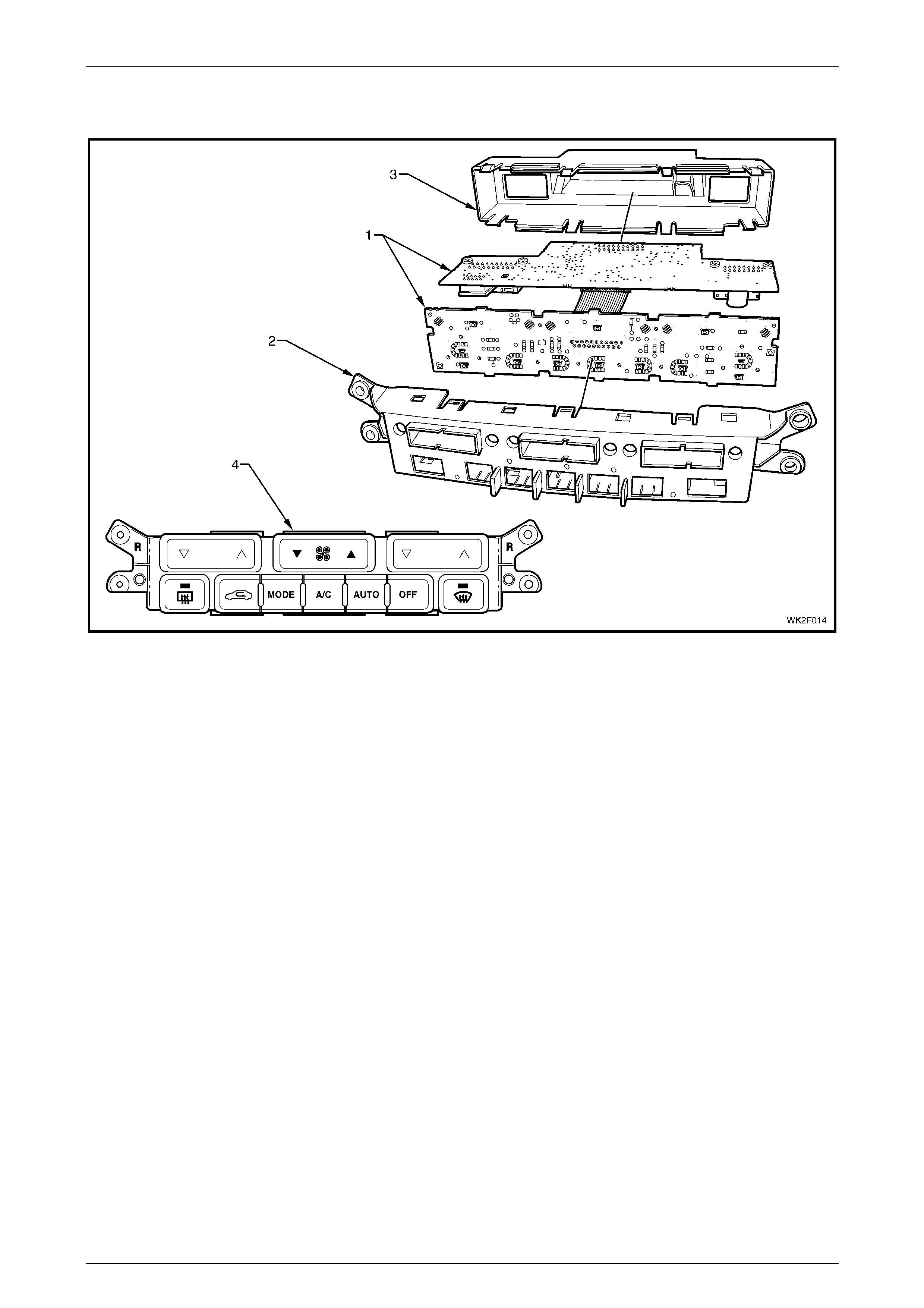
HVAC Occupant Climat e Control (Auto A/ C) – Diagnostic s Page 2F–61
20–FEB–2003 Page 2F-61
DTC 39 – RAM Error
Figure 2F – 26
Circuit Description:
The RAM (Random Access Memory) functions are carried out by the printed circuit boards (1) installed between the front
housing (2) and rear housing (3) of the OCC control module (4).
The purpose of the RAM is to store data used to control operating parameters of the OCC system.
When this DTC is set, it indicates that the RAM has been corrupted or failed.
DTC 39 will set when the microprocessor RAM test fails. The RAM is tested every time the cluster performs a cold reset
due to battery disconnection.
If DTC 39 sets and reprogramming is unsuccessful, replace the OCC control module. Refer to Section 2E, 2.1 OCC
CONTROL MODULE.
Test Description:
Number(s) below refer to Step numbers in the following
Diagnostic Chart:
1. Ensures the Diagnostic Circuit Check has been
performed.
2. Determines if OCC control module is faulty by
re-programming the OCC control module.
3. Determines if OCC control module is faulty.
Diagnostic Aid s:
If the OCC system programming is corrupted, recalibration
can be carried out via TECH 2. To calibrate the system refer
to Section 2F 1.2 TECH 2 TEST MODES AND DISPLAYS
FOR OCC DIAGNOSIS in this of the MY2003 VY and V2
Series Service Information.
Notes On Diagnostic Chart:
1. Refer to Sect ion 12P, WIRING DIAGR AM S for
procedures on checking wiring faults.

HVAC Occupant Climat e Control (Auto A/ C) – Diagnostic s Page 2F–62
20–FEB–2003 Page 2F-62
DTC 39 – RAM Error Diagnostic Chart
STEP ACTION VALUE YES NO
1 Has the Diagnostic Circuit Check been performed? Go to Step 2. Go to Chart A –
DIAGNOSTIC
CIRCUIT
CHECK in this
Section.
2 Reprogram the OCC control module Code Version using
TECH 2. Refer to Section 2F 1.2 TECH 2 TEST MODES
AND SCREEN DISPLAYS FOR OCC DIAGNOSIS in
the MY2003 VY and V2 Series Service Information.
Was programming successful?
Go to Step 3. Repeat this Step
at least twice, as
the system may
have crashed
during this
process.
Replace the
OCC contro l
module. Refer to
Section 2E,
HVAC
OCCUPANT
CLIMATE
CONTROL
(AUTO A/C) –
REMOVAL &
INSTALLATION.
3 Connect TECH 2 to the DLC.
Select Diagnostics / Model Year / Vehicle Model / Body /
Occupant Control Module / Diagnostic Trouble Codes /
Clear DTC Information and clear DTCs.
Were all DTCs cleared?
System OK. Replace the
OCC contro l
module. Refer to
Section 2E,
HVAC
OCCUPANT
CLIMATE
CONTROL
(AUTO A/C) –
REMOVAL &
INSTALLATION.
WHEN ALL DIAGNOSIS AND REPAIRS ARE COMPLETED, VERIFY CORRECT OPERATION

HVAC Occupant Climat e Control (Auto A/ C) – Diagnostic s Page 2F–63
20–FEB–2003 Page 2F-63
DTC 40 – Ai r M ix Door Motor Driver Error
Figure 2F – 27
Circuit Description:
The air mix motor is an electric motor used to operate the air mix door. The electric motor is sent a voltage signal of
12.5 volts from the OCC control module which causes the motor to turn, and in turn moves the air mix door towards or
away from the heater core. The direction change takes place by reversing the polarity of this motor.
A potentiometer (PBR) is housed in the air mix motor circuit, which feeds signals (3.6 ± 0.18 volts) back to the OCC
control module as to the positioning of the motor and consequently the air mix door.
NOTE 1
Refer to Figure 2F – 27 for LHD vehicles.
NOTE 2
Refer to Figure 2F – 28 and Figure 2F – 29 for
RHD vehicles.
DTC 40 will set when the Air Mix Motor Driver detects an error condition for a period of 1 second. An error condition
occurs when the Air Mix Motor Outputs are drawing excessive current or operating with an excessive voltage.

HVAC Occupant Climat e Control (Auto A/ C) – Diagnostic s Page 2F–64
20–FEB–2003 Page 2F-64
Test Description:
Number(s) below refer to Step numbers in the following
Diagnostic Chart:
1. Ensures the Diagnostic Circuit Check has been
performed.
2. This test checks to see whether the OCC is faulty.
3. This test checks whether the resistance across
terminals X2-1 and X2-2 indicates a faulty connector
or open circuit.
4. This test checks whether the resistance across
terminals X2-1 and X2-2 indicates a faulty circuit or
air mix door motor.
5. This test checks for a short to ground in circuit 1199.
6. This test checks for a short in circuit 1199 or 61.
7. This test checks for a short in circuit 1199 or 274.
8. This test checks for a short in circuit 1199 or 733.
9. This test checks for intermittent or loose terminals.
10. This test checks for open in circuits 1199 or 733.
11. This test checks for faulty connectors.
12. Ensures that DTC 43 has been cleared if present.
13. Ensures that DTC 44 has been cleared if present.
14. This test checks for physical fault in drivers air mix
door motor.
15. This test determines if the drivers air mix door motor
is faulty.
Diagnostic Aid s:
An air mix motor or door problem will always be associated
with non-regulated or incorrect temperatures from mode
positions.
The OCC control module, during calibration, sets a minimum
and a maximum PBR value for the air mix motor in its
memory. It is these values which determine the operating
range of the air mix motor and against which all movements
of the air mix adjustment are scaled. Any PBR signal value
outside the minimum or maximum value are considered a
motor fault.
The OCC control module monitors the rate of change of PBR
signal during air mix motor movement. If this rate of change
falls to 0 (such as a broken air mix motor wire or physical
jamb), the OCC control module will recognise the stoppage
and set the fault code.
If DTC 40 was present before turning the ignition off, when
the ignition is turned on again, the OCC control module will
automatically try to recalibrate the air mix door. This takes
approximately 15 seconds. If the recalibration fails, then
DTC 40 will be set again.
Notes On Diagnostic Chart:
1. Refer to Sect ion 12P, WIRING DIAGR AM S for
procedures on checking wiring faults.
2. Refer to Section 0C TECH 2 for connecting and us ing
TECH 2.

HVAC Occupant Climat e Control (Auto A/ C) – Diagnostic s Page 2F–65
20–FEB–2003 Page 2F-65
DTC 40 – Air Mix Motor Driver Error Diagnostic Chart (LHD)
STEP ACTION VALUE YES NO
1 Has the Diagnostic Circuit Check been performed? Go to Step 2. Go to Chart A –
DIAGNOSTIC
CIRCUIT
CHECK in this
Section.
2 Disconnect the OCC wiring harness connector A14 X2.
Connect TECH 2 to the DLC.
Select Diagnostics / Model Year / Vehicle Model / Body /
Occupant Climate Control / Data Display / Data List /
Drivers Air Mix Door Feedback.
Does TECH 2 display a value more than 3.4 volts?
Go to Ste p 3. Replace the OCC
control module.
Refer to
Section 2E,
HVAC
OCCUPANT
CLIMATE
CONTROL
(AUTO A/C) –
REMOVAL &
INSTALLATION.
3 With the OCC connector A14 X2 disconnected, probe
between OCC connector terminal X2-1, circuit 1199 and
connector terminal X2-2, circuit 733 with an ohmmeter.
Is the value as specified?
Less than
80 ohms Go to Step 4. Go to Step 9.
4 In Step 3, was the value specified? Less than
70 ohms Go to Step 8. Go to Step 5.
5 With the OCC connector A14 X2 disconnected, probe
terminal X2-1, circuit 1199 with an ohmmeter to chassis
ground.
Is the value as specified?
NOTE: Any resistance measured here qualifies as a
short.
Ohms Repair faulty
circuit 1199. Go to Step 6.
6 With the OCC connector A14 X2 disconnected, probe
between OCC connector terminal X2-1, circuit 1199 and
connector terminal X2-15, circuit 61 with an ohmmeter.
Is the value as specified?
NOTE: Any resistance measured here qualifies as a
short.
Ohms Repair faulty
circuit 1199
and/or 61.
Go to Step 7.
7 With the OCC connector A14 X2 disconnected, probe
between OCC connector terminal X2-1, circuit 199 and
connector terminal X2-5, circuit 274 with an ohmmeter.
Is the value as specified?
NOTE: Any resistance measured here qualifies as a
short.
Ohms Repair faulty
circuits 1199
and/or 274.
Go to Step 11.
8 Disconnect the driver’s air mix door motor
connector Y37 LHD X1.
With the OCC connector A14 X2 disconnected, probe
between OCC connector terminal X2-1, circuit 1199 and
connector terminal X2-2, circuit 733 with an ohmmeter.
Does the meter indicate a short?
NOTE: Any resistance measured here qualifies as a
short.
Ohms Repair faulty
circuit1199
and/or 733.
Replace the
drivers air mix
door motor.
Refer to
Section 2E,
HVAC
OCCUPANT
CLIMATE
CONTROL
(AUTO A/C) –
REMOVAL &
INSTALLATION.

HVAC Occupant Climat e Control (Auto A/ C) – Diagnostic s Page 2F–66
20–FEB–2003 Page 2F-66
STEP ACTION VALUE YES NO
9 Inspect wiring harness connectors A14 X2 and
Y37 LHD X1 for an intermittent or loose terminal.
Are the connectors OK?
Go to Step 10. Repair faulty
connector/s.
10 Check the integrity of circuit 1199 and circuit 733.
Are the circuits OK?
Replace air mix
door motor.
Refer to
Section 2E,
HVAC
OCCUPANT
CLIMATE
CONTROL
(AUTO A/C) –
REMOVAL &
INSTALLATION.
Repair faulty
circuit 1199
and/or 733.
11 Inspect wiring harness connectors A14 X2 and
Y37 LHD X1 for an intermittent or loose terminal and for
a short circuit between terminals.
Are the connectors OK?
Go to Step 12. Repair faulty
connector/s.
12 Does DTC 43 set as a current DTC? Go to Chart
DTC 43 –
DRIVERS AIR
MIX DOOR
MOTOR
FEEDBACK
CIRCUIT
VOLTAGE TOO
LOW (LHD) in
this Section.
Go to Step 13.
13 Does DTC 44 set as a current DTC? Go to Chart
DTC 44 –
DRIVERS AIR
MIX DOOR
MOTOR
FEEDBACK
CIRCUIT
VOLTAGE TOO
HIGH (LHD) in
this Section.
Go to Step 14.
14 Remove the driver’s air mix motor assembly. Refer to
Section 2E, HVAC OCCUPANT CLIMATE CONTROL
(AUTO A/C) – REMOVAL & INSTALLATION in the
MY2003 VY and V2 Series Service Information.
Move the air mix door by hand.
Is the door physically jammed or broken?
Repair faulty air
mix door. Go to Step 15.
15 Replace the air mix motor assembly. Refer to
Section 2E, HVAC OCCUPANT CLIMATE CONTROL
(AUTO A/C) – REMOVAL & INSTALLATION in the
MY2003 VY and V2 Series Service Information..
Is the problem resolved?
System OK. Replace the OCC
control module.
Refer to
Section 2E,
HVAC
OCCUPANT
CLIMATE
CONTROL
(AUTO A/C) –
REMOVAL &
INSTALLATION.
WHEN ALL DIAGNOSIS AND REPAIRS ARE COMPLETED, VERIFY CORRECT OPERATION

HVAC Occupant Climat e Control (Auto A/ C) – Diagnostic s Page 2F–67
20–FEB–2003 Page 2F-67
DTC 40 – Air Mix Door Motor Dri ver Er r or (Driver’s Side Mot or – RHD)
Figure 2F – 28
Circuit Description:
The air mix motor is an electric motor used to operate the driver’s side air mix door. The electric motor is sent a voltage
signal of 12.5 volts from the OCC control module which causes the motor to turn, and in turn moves the air mix door
towards or away from the heater core. The direction change takes place by reversing the polarity of this motor.
A potentiometer (PBR) is housed in the air mix motor circuit, which feeds signals (3.6 ± 0.18 volts) back to the OCC
control module as to the positioning of the motor and consequently the air mix door.
DTC 40 will set when the Air Mix Motor Driver detects an error condition for a period of 1 second. An error condition
occurs when the Air Mix Motor Outputs are drawing excessive current or operating with an excessive voltage.

HVAC Occupant Climat e Control (Auto A/ C) – Diagnostic s Page 2F–68
20–FEB–2003 Page 2F-68
Test Description:
Number(s) below refer to Step numbers in the following
Diagnostic Chart:
1. Ensures the Diagnostic Circuit Check has been
performed.
2. This test checks to see whether the OCC is faulty.
3. This test checks whether the resistance across
terminals X2-1 and X2-2 indicates a faulty connector
or open circuit.
4. This test checks whether the resistance across
terminals X2-1 and X2-2 indicates a faulty circuit or
air mix door motor.
5. This test checks for a short to ground in circuit 1199.
6. This test checks for a short in circuit 1199 or 61.
7. This test checks for a short in circuit 1199 or 274.
8. This test checks for a short in circuit 1199 or 733.
9. This test checks for intermittent or loose terminals.
10. This test checks for open in circuits 1199 or 733.
11. This test checks for faulty connectors.
12. Ensures that DTC 43 has been cleared if present.
13. Ensures that DTC 44 has been cleared if present.
14. This test checks for physical fault in drivers air mix
door motor.
15. This test determines if the drivers air mix door motor
is faulty.
Diagnostic Aid s:
An air mix motor or door problem will always be associated
with non-regulated or incorrect temperatures from mode
positions.
The OCC control module, during calibration, sets a minimum
and a maximum PBR value for the air mix motor in its
memory. It is these values which determine the operating
range of the air mix motor and against which all movements
of the air mix adjustment are scaled. Any PBR signal value
outside the minimum or maximum value are considered a
motor fault.
The OCC control module monitors the rate of change of PBR
signal during air mix motor movement. If this rate of change
falls to 0 (such as a broken air mix motor wire or physical
jamb), the OCC control module will recognise the stoppage
and set the fault code.
If DTC 40 was present before turning the ignition off, when
the ignition is turned on again, the OCC control module will
automatically try to recalibrate the air mix door. This takes
approximately 15 seconds. If the recalibration fails, then
DTC 40 will be set again.
Notes On Diagnostic Chart:
1. Refer to Sect ion 12P, WIRING DIAGR AM S for
procedures on checking wiring faults.
2. Refer to Section 0C TECH 2 for connecting and us ing
TECH 2.

HVAC Occupant Climat e Control (Auto A/ C) – Diagnostic s Page 2F–69
20–FEB–2003 Page 2F-69
DTC 40 – Air Mix Motor Driver Error Diagnostic Chart (Driver’s Side Motor – RHD)
STEP ACTION VALUE YES NO
1 Has the Diagnostic Circuit Check been performed? Go to Step 2. Go to Chart A –
DIAGNOSTIC
CIRCUIT
CHECK in this
Section.
2 Disconnect the OCC wiring harness connector A14 X2.
Connect TECH 2 to the DLC.
Select Diagnostics / Model Year / Vehicle Model / Body /
Occupant Climate Control / Data Display / Data List /
Drivers Air Mix Door Feedback.
Does TECH 2 display a value more than 3.4 volts?
Go to Ste p 3. Replace the OCC
control module.
Refer to
Section 2E,
HVAC
OCCUPANT
CLIMATE
CONTROL
(AUTO A/C) –
REMOVAL &
INSTALLATION.
3 With the OCC connector A14 X2 disconnected, probe
between OCC connector terminal X2-1, circuit 1199 and
connector terminal X2-2, circuit 733 with an ohmmeter.
Is the value as specified?
Less than
80 ohms Go to Step 4. Go to Step 9.
4 In Step 3, was the value specified? Less than
70 ohms Go to Step 8. Go to Step 5.
5 With the OCC connector A14 X2 disconnected, probe
terminal X2-1, circuit 1199 with an ohmmeter to chassis
ground.
Is the value as specified?
NOTE: Any resistance measured here qualifies as a
short.
Ohms Repair faulty
circuit 1199. Go to Step 6.
6 With the OCC connector A14 X2 disconnected, probe
between OCC connector terminal X2-1, circuit 1199 and
connector terminal X2-15, circuit 61 with an ohmmeter.
Is the value as specified?
NOTE: Any resistance measured here qualifies as a
short.
Ohms Repair faulty
circuit 1199
and/or 61.
Go to Step 7.
7 With the OCC connector A14 X2 disconnected, probe
between OCC connector terminal X2-1, circuit 199 and
connector terminal X2-5, circuit 274 with an ohmmeter.
Is the value as specified?
NOTE: Any resistance measured here qualifies as a
short.
Ohms Repair faulty
circuits 1199
and/or 274.
Go to Step 11.
8 Disconnect the driver’s air mix door motor
connector Y37 R X1.
With the OCC connector A14 X2 disconnected, probe
between OCC connector terminal X2-1, circuit 1199 and
connector terminal X2-2, circuit 733 with an ohmmeter.
Does the meter indicate a short?
NOTE: Any resistance measured here qualifies as a
short.
Ohms Repair faulty
circuit1199
and/or 733.
Replace the
drivers air mix
door motor.
Refer to
Section 2E,
HVAC
OCCUPANT
CLIMATE
CONTROL
(AUTO A/C) –
REMOVAL &
INSTALLATION.

HVAC Occupant Climat e Control (Auto A/ C) – Diagnostic s Page 2F–70
20–FEB–2003 Page 2F-70
STEP ACTION VALUE YES NO
9 Inspect wiring harness connectors A14 X2 and
Y37 R X1 for an intermittent or loose terminal.
Are the connectors OK?
Go to Step 10. Repair faulty
connector/s.
10 Check the integrity of circuit 1199 and circuit 733.
Are the circuits OK?
Replace air mix
door motor.
Refer to
Section 2E,
HVAC
OCCUPANT
CLIMATE
CONTROL
(AUTO A/C) –
REMOVAL &
INSTALLATION.
Repair faulty
circuit 1199
and/or 733.
11 Inspect wiring harness connectors A14 X2 and
Y37 R X1 for an intermittent or loose terminal and for a
short circuit between terminals.
Are the connectors OK?
Go to Step 12. Repair faulty
connector/s.
12 Does DTC 43 set as a current DTC? Go to Chart
DTC 43 –
DRIVERS AIR
MIX DOOR
MOTOR
FEEDBACK
CIRCUIT
VOLTAGE TOO
LOW (LHD) in
this Section.
Go to Step 13.
13 Does DTC 44 set as a current DTC? Go to Chart
DTC 44 –
DRIVERS AIR
MIX DOOR
MOTOR
FEEDBACK
CIRCUIT
VOLTAGE TOO
HIGH (LHD) in
this Section.
Go to Step 14.
14 Remove the driver’s air mix motor assembly. Refer to
Section 2E, HVAC OCCUPANT CLIMATE CONTROL
(AUTO A/C) – REMOVAL & INSTALLATION in the
MY2003 VY and V2 Series Service Information.
Move the air mix door by hand.
Is the door physically jammed or broken?
Repair faulty air
mix door. Go to Step 15.
15 Replace the air mix motor assembly. Refer to
Section 2E, HVAC OCCUPANT CLIMATE CONTROL
(AUTO A/C) – REMOVAL & INSTALLATION in the
MY2003 VY and V2 Series Service Information.
Is the problem fixed?
System OK. Replace the OCC
control module.
Refer to
Section 2E,
HVAC
OCCUPANT
CLIMATE
CONTROL
(AUTO A/C) –
REMOVAL &
INSTALLATION.
WHEN ALL DIAGNOSIS AND REPAIRS ARE COMPLETED, VERIFY CORRECT OPERATION

HVAC Occupant Climat e Control (Auto A/ C) – Diagnostic s Page 2F–71
20–FEB–2003 Page 2F-71
DTC 40 – Ai r Mix Door Motor Driver Error (Passenger Side Motor – RHD)
Figure 2F – 29
Circuit Description:
The air mix motor is an electric motor used to operate the passenger side air mix door. The electric motor is sent a
voltage signal of 12.5 volts from the OCC control module which causes the motor to turn, and in turn moves the air mix
door towards or away from the heater core. The direction change takes place by reversing the polarity of this motor.
A potentiometer (PBR) is housed in the air mix motor circuit, which feeds signals (3.6 ± 0.18 volts) back to the OCC
control module as to the positioning of the motor and consequently the air mix door.
DTC 40 will set when the Air Mix Motor Driver detects an error condition for a period of 1 second. An error condition
occurs when the Air Mix Motor Outputs are drawing excessive current or operating with an excessive voltage.

HVAC Occupant Climat e Control (Auto A/ C) – Diagnostic s Page 2F–72
20–FEB–2003 Page 2F-72
Test Description:
Number(s) below refer to Step numbers in the following
Diagnostic Chart:
1. Ensures the Diagnostic Circuit Check has been
performed.
2. This test checks to see whether the OCC is faulty.
3. This test checks whether the resistance across
terminals X2-3 and X2-4 indicates a faulty connector
or open circuit.
4. This test checks whether the resistance across
terminals X2-3 and X2-4 indicates a faulty circuit or
air mix door motor.
5. This test checks for a short to ground in circuit 1236.
6. This test checks for a short in circuit 1236 or 61.
7. This test checks for a short in circuit 1236 or 274.
8. This test checks for a short in circuit 1236 or 1646.
9. This test checks for intermittent or loose terminals.
10. This test checks for open in circuits 1236 or 1646.
11. This test checks for faulty connectors.
12. Ensures that DTC 45 has been cleared if present.
13. Ensures that DTC 46 has been cleared if present.
14. This test checks for physical fault in drivers air mix
door motor.
15. This test determines if the drivers air mix door motor
is faulty.
Diagnostic Aid s:
An air mix motor or door problem will always be associated
with non-regulated or incorrect temperatures from mode
positions.
The OCC control module, during calibration, sets a minimum
and a maximum PBR value for the air mix motor in its
memory. It is these values which determine the operating
range of the air mix motor and against which all movements
of the air mix adjustment are scaled. Any PBR signal value
outside the minimum or maximum value are considered a
motor fault.
The OCC control module monitors the rate of change of PBR
signal during air mix motor movement. If this rate of change
falls to 0 (such as a broken air mix motor wire or physical
jamb), the OCC control module will recognise the stoppage
and set the fault code.
If DTC 40 was present before turning the ignition off, when
the ignition is turned on again, the OCC control module will
automatically try to recalibrate the air mix door. This takes
approximately 15 seconds. If the recalibration fails, then
DTC 40 will be set again.
Notes On Diagnostic Chart:
1. Refer to Sect ion 12P, WIRING DIAGR AM S for
procedures on checking wiring faults.
2. Refer to Section 0C TECH 2 for connecting and us ing
TECH 2.

HVAC Occupant Climat e Control (Auto A/ C) – Diagnostic s Page 2F–73
20–FEB–2003 Page 2F-73
DTC 40 – Air Mix Motor Driver Error Diagnostic Chart (Passenger Side Motor – RHD)
STEP ACTION VALUE YES NO
1 Has the Diagnostic Circuit Check been performed? Go to Step 2. Go to Chart A –
DIAGNOSTIC
CIRCUIT
CHECK in this
Section.
2 Disconnect the OCC wiring harness connector A14 X2.
Connect TECH 2 to the DLC.
Select Diagnostics / Model Year / Vehicle Model / Body /
Occupant Climate Control / Data Display / Data List /
Drivers Air Mix Door Feedback.
Does TECH 2 display a value above 3.4 volts?
Go to Ste p 3. Replace the OCC
control module,
refer to
Section 2E,
HVAC
OCCUPANT
CLIMATE
CONTROL
(AUTO A/C) –
REMOVAL &
INSTALLATION.
3 With the OCC connector A14 X2 disconnected, probe
between OCC connector terminal X2-3, circuit 1236 and
connector term inal X2-4, circuit 1646 with an ohmmeter.
Is the value as specified?
Less than
80 ohms Go to Step 4. Go to Step 9.
4 In Step 3, was the value as specified? Less than
70 ohms Go to Step 8. Go to Step 5.
5 With the OCC connector A14 X2 disconnected, probe
connector terminal X2-3, circuit 1236 with an ohmmeter
to chassis ground.
Is the value as specified?
NOTE: Any resistance measured here qualifies as a
short.
Ohms Repair faulty
circuit 1236. Go to Step 6.
6 With the OCC connector A14 X2 disconnected, probe
between OCC connector terminal X2-3, circuit 1236 and
connector terminal X2-15, circuit 61 with an ohmmeter.
Is the value as specified?
NOTE: Any resistance measured here qualifies as a
short.
Ohms Repair faulty
circuit 1236
and/or 61.
Go to Step 7.
7 With the OCC connector A14 X2 disconnected, probe
between OCC connector terminal X2-3, circuit 1236 and
connector terminal X2-5, circuit 274 with an ohmmeter.
Is the value as specified?
NOTE: Any resistance measured here qualifies as a
short.
Ohms Repair faulty
circuit 1236
and/or 274.
Go to Step 11.
8 Disconnect air mix door motor connector Y37 L X1.
With the OCC connector A14 X2 disconnected, probe
between terminals X2-3, circuit 1236 and X2-4,
circuit 1646 with an ohmmeter.
Is the value as specified?
NOTE: Any resistance measured here qualifies as a
short.
Ohms Repair faulty
circuits 1236
and/or 1646.
Replace the air
mix door motor.
Refer to
Section 2E,
HVAC
OCCUPANT
CLIMATE
CONTROL
(AUTO A/C) –
REMOVAL &
INSTALLATION.
9 Inspect wiring harness connectors A14 X2 and Y37 L X1
for an intermittent or loose terminal.
Are the connectors OK?
Go to Step 10. Repair faulty
connector/s.

HVAC Occupant Climat e Control (Auto A/ C) – Diagnostic s Page 2F–74
20–FEB–2003 Page 2F-74
STEP ACTION VALUE YES NO
10 Check the integrity of circuits 1236 and 1646.
Are the circuits OK?
Repair faulty
circuit 1236
and/or 1646.
Replace the air
mix door motor.
Refer to
Section 2E,
HVAC
OCCUPANT
CLIMATE
CONTROL
(AUTO A/C) –
REMOVAL &
INSTALLATION.
11 Inspect the wiring harness connectors A14 X2 and
Y37 L X1 for an intermittent or loose terminal and for a
short circuit between terminals.
Are the connectors OK?
Go to Step 12. Repair faulty
connector/s.
12 Does DTC 45 set as a current DTC? Go to Chart
DTC 45 –
PASSENGERS
AIR MIX DOOR
MOTOR
FEEDBACK
CIRCUIT
VOLTAGE TOO
LO W in this
Section.
Go to Step 13.
13 Does DTC 46 set as a current DTC? Go to Chart
DTC 46 –
PASSENGERS
AIR MIX DOOR
MOTOR
FEEDBACK
CIRCUIT
VOLTAGE TOO
HIGH in this
Section.
Go to Step 14.
14 Remove the air mix motor assembly. Refer to
Section 2E, HVAC OCCUPANT CLIMATE CONTROL
(AUTO A/C) – REMOVAL & INSTALLATION in the
MY2003 VY and V2 Series Service Information.
Move the air mix door by hand.
Is the door physically jammed or broken?
Repair faulty air
mix door. Go to Step 15.
15 Replace the air mix motor assembly. Refer to
Section 2E, HVAC OCCUPANT CLIMATE CONTROL
(AUTO A/C) – REMOVAL & INSTALLATION in the
MY2003 VY and V2 Series Service Information.
Is the problem fixed?
System OK. Replace the OCC
control module.
Refer to
Section 2E,
HVAC
OCCUPANT
CLIMATE
CONTROL
(AUTO A/C) –
REMOVAL &
INSTALLATION.
WHEN ALL DIAGNOSIS AND REPAIRS ARE COMPLETED, VERIFY CORRECT OPERATION
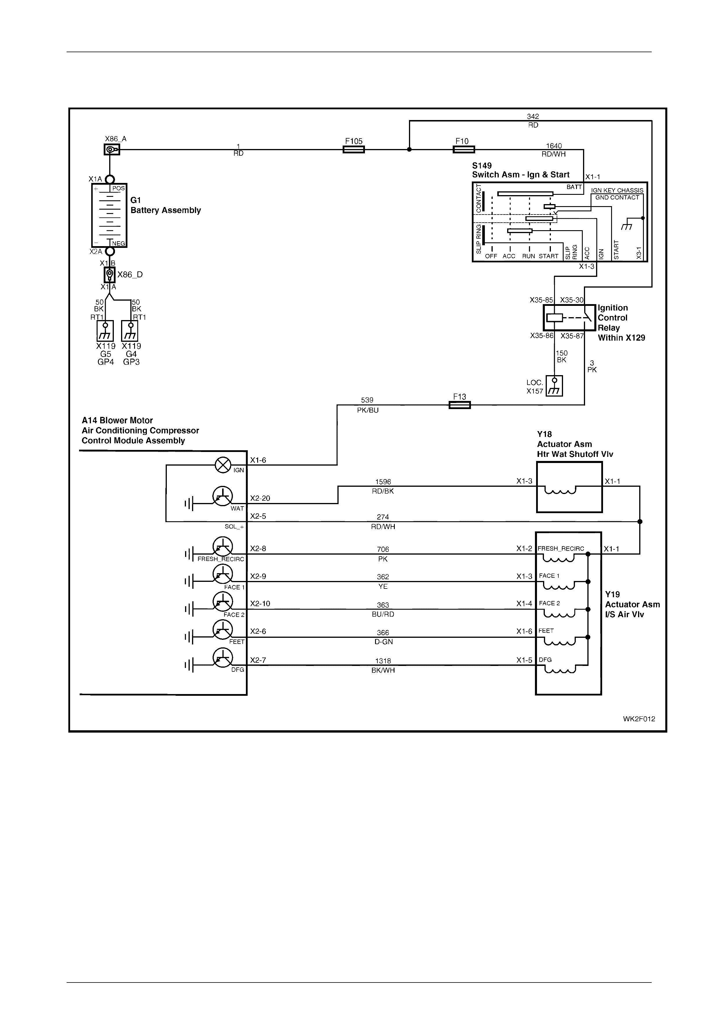
HVAC Occupant Climat e Control (Auto A/ C) – Diagnostic s Page 2F–75
20–FEB–2003 Page 2F-75
DTC 41 – Solenoid Driver Error (LHD)
Figure 2F – 30
Circuit Description:
The solenoid pack is activated when the OCC system is turned on. Individual solenoids are grounded by via the OCC
control module. In accordance to switching signals generated manually or automatically at the OCC control module, the
solenoid pack directs vacuum to the various vacuum actuators to achieve the desired ventilation mode. It also activates
the water valve for heating and demisting purposes.
DTC 41 will set when the Solenoid Driver detects an error condition for a period of 1 second. An error condition occurs
when the Solenoid Outputs are drawing excessive current and / or have reached an over temperature condition.

HVAC Occupant Climat e Control (Auto A/ C) – Diagnostic s Page 2F–76
20–FEB–2003 Page 2F-76
Test Description:
Number(s) below refer to Step numbers in the following
Diagnostic Chart:
1. Ensures the Diagnostic Circuit Check has been
performed.
2. This test checks the power supply to the solenoid
pack.
3. This test checks for open in circuit 274 between the
solenoid pack and the OCC control module.
4. This test checks power supply to water valve
vacuum switch valve.
5. This test checks for open in circuit 274 between
water valve vacuum switch valve and OCC control
module.
6. This test checks the functioning of the Face 1
solenoid.
7. This test checks for open in circuit 362 between
OCC control module and Face 1 solenoid.
8. This test checks the functioning of the Face 2
solenoid.
9. This test checks for open in circuit 363 between
OCC control module and Face 2 solenoid.
10. This test checks the functioning of the Feet solenoid.
11. This test checks for open in circuit 366 between OCC
control module and Feet solenoid.
12. This test checks the functioning of the DFG (Demist)
solenoid.
13. This test checks for open in circuit 1318 between OCC
control module and DFG (Demist) solenoid.
14. This test checks the functioning of the Fresh / Recirc
solenoid.
15. This test checks for open in circuit 706 between OCC
control module and Fresh_Recirc solenoid.
16. This test checks the functioning of the WAT (water valve
vacuum switch valve) solenoid.
17. This test checks for open in circuit 1596 between OCC
control module and WAT (water valve vacuum switch
valve) solenoid.
Notes On Diagnostic Chart:
1. Refer to Sect ion 12P, WIRING DIAGR AM S for
procedures on checking wiring faults.
2. Refer to Section 0C TECH 2 for connecting and us ing
TECH 2.

HVAC Occupant Climat e Control (Auto A/ C) – Diagnostic s Page 2F–77
20–FEB–2003 Page 2F-77
DTC 41 – Solenoid Driver Error Diagnostic Chart (LHD)
STEP ACTION VALUE YES NO
1 Has the Diagnostic Circuit Check been performed? Go to Step 2. Go to Chart A –
DIAGNOSTIC
CIRCUIT
CHECK in this
Section.
2 Turn the ignition on.
Back-probe solenoid pack connector Y19 terminal X1-1,
circuit 274 with a voltmeter to ground.
Is the value as specified?
12 volts Go to Step 4. Go to Step 3.
3 Turn the ignition off.
Back-probe between OCC control module connector
A 14 terminal X2-5, circuit 274 and the solenoid pack
connector Y19 terminal X1-1 circuit 274 with an
ohmmeter.
Is the value as specified?
Less than
1 ohm Go to Step 5. Repair faulty
circuit 274
4 Turn the ignition on.
Back-probe water valve vacuum switch valve solenoid
connector Y18 terminal X1-1, circuit 274 with a voltmeter
to ground.
Is the value as specified?
12 volts Go to Step 6. Go to Step 5.
5 Turn the ignition off.
Back-probe between OCC control module connector
A 14 terminal X2-5 and water valve vacuum switch valve
solenoid connector Y18 terminal X1-1, circuit 274 with
an ohmmeter.
Is the value as specified?
Less than
1 ohm Go to Step 6. Repair faulty
circuit 274
6 Turn the ignition on
Connect TECH 2 to the DLC.
Select Diagnostics / Model Year / Vehicle Model / Body /
Occupant Climate Control / Miscellaneous Tests /
Solenoids.
Activate the Face 1 solenoid.
Does the Face 1 solenoid Activate?
Go to Step 8. Go to Step 7.
7 Turn the ignition off.
Back-probe between OCC control module connector
A 14 terminal X2-9 and solenoid pack connector Y19
terminal X1-3, circuit 362 with an ohmmeter.
Is the value as specified?
Less than
1 ohm Go to OCC
Solenoid Pack
(LHD) resistance
test in this
Section.
Repair faulty
circuit 362.
8 With TECH 2 connected, activate the Face 2 solenoid.
Does the Face 2 solenoid activate?
Go to Step 10. Go to Step 9
9 Turn the ignition off.
Back-probe between OCC control module connector
A 14 terminal X2-10 and solenoid pack connector Y19
terminal X1-4, circuit 363 with an ohmmeter.
Is the value as specified?
Less than
1 ohm Go to OCC
Solenoid Pack
(LHD) resistance
test in this
Section.
Repair faulty
circuit 363.

HVAC Occupant Climat e Control (Auto A/ C) – Diagnostic s Page 2F–78
20–FEB–2003 Page 2F-78
STEP ACTION VALUE YES NO
10 With TECH 2 connected, activate the Feet solenoid.
Does the Feet solenoid activate?
Go to Step 12. Go to Step 11.
11 Turn the ignition off.
Back-probe between OCC control module connector
A 14 terminal X2-6 and solenoid pack connector Y19
terminal X1-6, circuit 366 with an ohmmeter.
Is the value as specified?
Less than
1 ohm Go to OCC
Solenoid Pack
(LHD) resistance
test in this
Section.
Repair faulty
circuit 366.
12 With TECH 2 connected, activate the DFG (Demist)
solenoid.
Does the DFG (Demist) solenoid activate?
Go to Step 14. Go to Step 13.
13 Turn the ignition off.
Back-probe between OCC control module connector
A 14 terminal X2-7 and solenoid pack connector Y19
terminal X1-5, circuit 1318 with an ohmmeter.
Is the value as specified?
Less than
1 ohm Go to OCC
Solenoid Pack
(LHD) resistance
test in this
Section.
Repair faulty
circuit 1318.
14 With TECH 2 connected, activate the
Fresh_Recirc.solenoid.
Does the Fresh_Resirc solenoid activate?
Go to Step 16. Go to Step 15.
15 Turn the ignition off.
Back-probe between OCC control module connector
A 14 terminal X2-8 and solenoid pack connector Y19
terminal X1-2, circuit 706 with an ohmmeter.
Is the value as specified?
Less than
1 ohm Go to OCC
Solenoid Pack
(LHD) resistance
test in this
Section.
Repair faulty
circuit 706.
16 With TECH 2 connected, activate the WAT (Water valve
vacuum switch valve) solenoid.
Does the WAT soleno id act iv ate?
System OK Go to Step 17.
17 Turn the ignition off.
Back-probe between OCC control module connector
A 14 terminal X2-20 and the WAT (Water valve vacuum
switch valve) solenoid Y18 terminal X1-3, circuit 1596
with an ohmmeter.
Is the value as specified?
Less than
1 ohm Go to OCC
Solenoid Pack
(LHD) resistance
test in this
Section.
Repair faulty
circuit 1596.
WHEN ALL DIAGNOSIS AND REPAIRS ARE COMPLETED, VERIFY CORRECT OPERATION
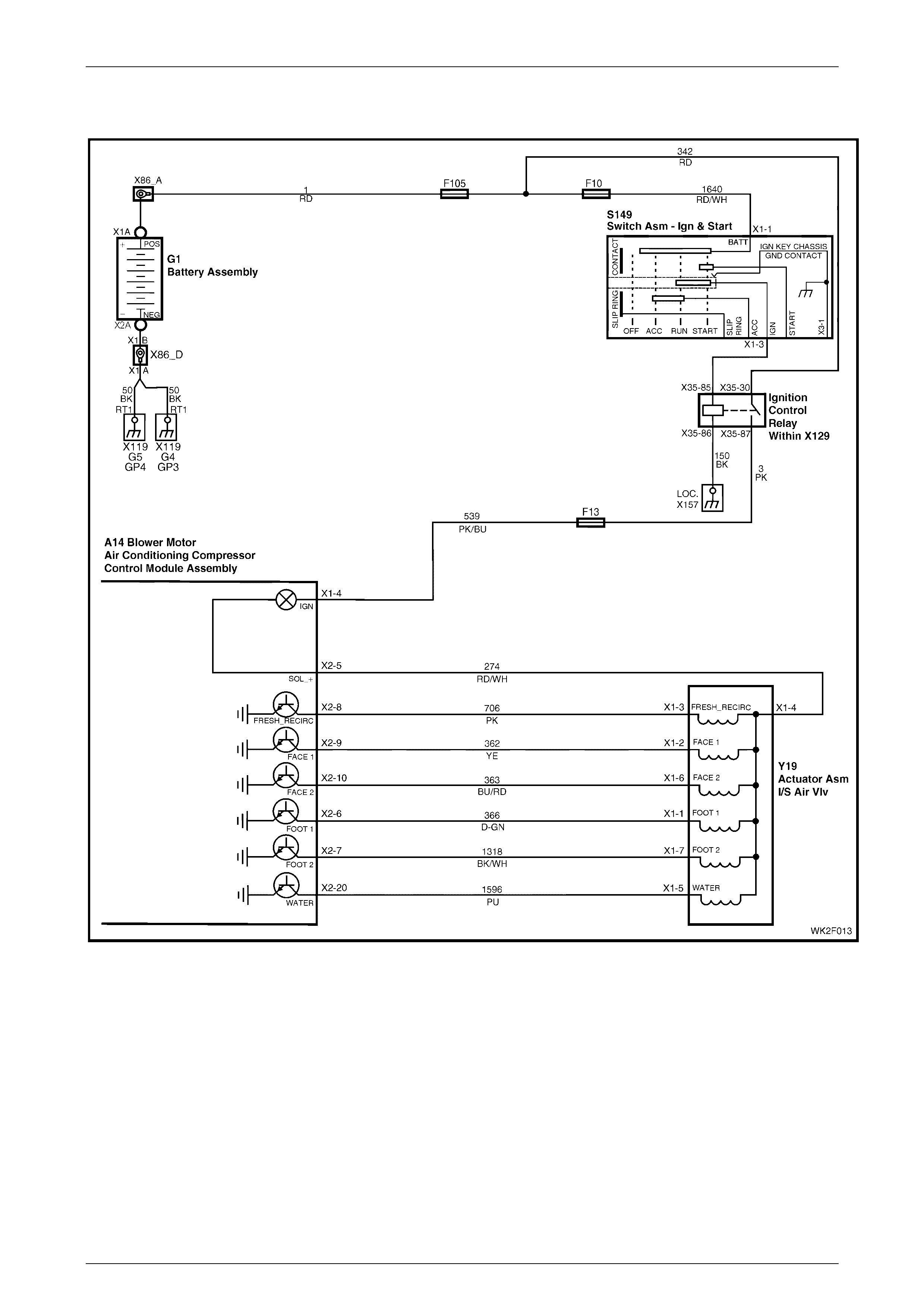
HVAC Occupant Climat e Control (Auto A/ C) – Diagnostic s Page 2F–79
20–FEB–2003 Page 2F-79
DTC 41 – Solenoid Driver Error (RHD)
Figure 2F – 31
Circuit Description:
The solenoid pack is activated when the OCC system is turned on. Individual solenoids are grounded by via the OCC
control module. In accordance to switching signals generated manually or automatically at the OCC control module, the
solenoid pack directs vacuum to the various vacuum actuators to achieve the desired ventilation mode. It also activates
the water valve for heating and demisting purposes.
DTC 41 will set when the Solenoid Driver detects an error condition for a period of 1 second. An error condition occurs
when the Solenoid Outputs are drawing excessive current and / or have reached an over temperature condition.

HVAC Occupant Climat e Control (Auto A/ C) – Diagnostic s Page 2F–80
20–FEB–2003 Page 2F-80
Test Description:
Number(s) below refer to Step numbers in the following
Diagnostic Chart:
1. Ensures the Diagnostic Circuit Check has been
performed.
2. This test checks the power supply to the solenoid
pack.
3. This test checks for open in circuit 274 between the
solenoid pack and the OCC control module.
4. This test checks the functioning of the Fresh_Recirc
solenoid.
5. This test checks for open in circuit 706 between
OCC control module and Fresh_Recirc solenoid.
6. This test checks the functioning of the Face 1
solenoid.
7. This test checks for open in circuit 362 between
OCC control module and Face 1 solenoid.
8. This test checks the functioning of the Face 2
solenoid.
9. This test checks for open in circuit 363 between OCC
control module and Face 2 solenoid.
10. This test checks the functioning of the Foot 1 solenoid.
11. This test checks for open in circuit 366 between OCC
control module and Foot 1 solenoid.
12. This test checks the functioning of the Foot 2 solenoid.
13. This test checks for open in circuit 1318 between OCC
control module and Foot 2 solenoid.
14. This test checks the functioning of the Water solenoid.
15. This test checks for open in circuit 1596 between OCC
control modu le and Water sole noid.
Notes On Diagnostic Chart:
1. Refer to Sect ion 12P, WIRING DIAGR AM S for
procedures on checking wiring faults.
2. Refer to Section 0C TECH 2 for connecting and us ing
TECH 2.

HVAC Occupant Climat e Control (Auto A/ C) – Diagnostic s Page 2F–81
20–FEB–2003 Page 2F-81
DTC 41 – Solenoid Driver Error Diagnostic Chart (RHD)
STEP ACTION VALUE YES NO
1 Has the Diagnostic Circuit Check been performed? Go to Step 2. Go to Chart A –
DIAGNOSTIC
CIRCUIT
CHECK in this
Section.
2 Turn the ignition on.
Back-probe solenoid pack connector Y19 terminal X2-5,
circuit 274 with a voltmeter to ground.
Is the value as specified?
12 volts Go to Step 4. Go to Step 3.
3 Turn the ignition off.
Back-probe between OCC control module connector
A 14 terminal X2-5, circuit 274 and the solenoid pack
connector Y19 terminal X1-4 circuit 274 with an
ohmmeter.
Is the value as specified?
Less than
1 ohm Go to Step 4. Repair faulty
circuit 274.
4 Turn the ignition on.
Connect TECH 2 to the DLC.
Select Diagnostics / Model Year / Vehicle Model / Body /
Occupant Climate Control / Miscellaneous Tests /
Solenoids.
Activate the Fresh_Recirc. solenoid.
Does the Fresh_Resirc solenoid activate?
Go to Step 6. Go to Step 5.
5 Turn the ignition off.
Back-probe between OCC control module connector
A 14 terminal X2-8 and solenoid pack connector Y19
terminal X1-3, circuit 706 with an ohmmeter.
Is the value as specified?
Less than
1 ohm Go to OCC
Solenoid Pack
(RHD) resistance
test in this
Section.
Repair faulty
circuit 706.
6 With TECH 2 connected, activate the Face 1 solenoid.
Does the Face 1 solenoid Activate?
Go to Step 8. Go to Step 7.
7 Turn the ignition off.
Back-probe between OCC control module connector
A 14 terminal X2-9 and solenoid pack connector Y19
terminal X1-2 circuit 362 with an ohmmeter.
Is the value as specified?
Less than
1 ohm Go to OCC
Solenoid Pack
(RHD) resistance
test in this
Section.
Repair faulty
circuit 362.
8 With TECH 2 connected, activate the Face 2 solenoid.
Does the Face 2 solenoid activate?
Go to Step 10. Go to Step 9
9 Turn the ignition off.
Back-probe between OCC control module connector
A 14 terminal X2-10 and solenoid pack connector Y19
terminal X1-6 circuit 363 with an ohmmeter.
Is the value as specified?
Less than
1 ohm Go to OCC
Solenoid Pack
(RHD) resistance
test in this
Section.
Repair faulty
circuit 363.
10 With TECH 2 connected, activate the Foot 1 solenoid.
Does the Foot 1 solenoid activate?
Go to Step 12. Go to Step 11.

HVAC Occupant Climat e Control (Auto A/ C) – Diagnostic s Page 2F–82
20–FEB–2003 Page 2F-82
STEP ACTION VALUE YES NO
11 Turn the ignition off.
Back-probe between OCC control module connector
A 14 terminal X2-6 and solenoid pack connector Y19
terminal X1-1, circuit 366 with an ohmmeter.
Is the value as specified?
Less than
1 ohm Go to OCC
Solenoid Pack
(RHD) resistance
test in this
Section.
Repair faulty
circuit 366.
12 With TECH 2 connected, activate the Foot 2 solenoid.
Does the Foot 2 solenoid activate?
Go to Step 14. Go to Step 13.
13 Turn the ignition off.
Back-probe between OCC control module connector
A 14 terminal X2-7 and solenoid pack connector Y19
terminal X1-7, circuit 1318 with an ohmmeter.
Is the value as specified?
Less than
1 ohm Go to OCC
Solenoid Pack
(RHD) resistance
test in this
Section.
Repair faulty
circuit 1318.
14 With TECH 2 connected, activate the Water solenoid.
Does the Water solenoid activate?
System OK Go to Step 15.
15 Turn the ignition off.
Back-probe between OCC control module connector
A 14 terminal X2-20 and the Water solenoid Y19
terminal X1-5, circuit 1596 with an ohmmeter.
Is the value as specified?
Less than
1 ohm Go to OCC
Solenoid Pack
(RHD) resistance
test in this
Section.
Repair faulty
circuit 1596.
WHEN ALL DIAGNOSIS AND REPAIRS ARE COMPLETED, VERIFY CORRECT OPERATION
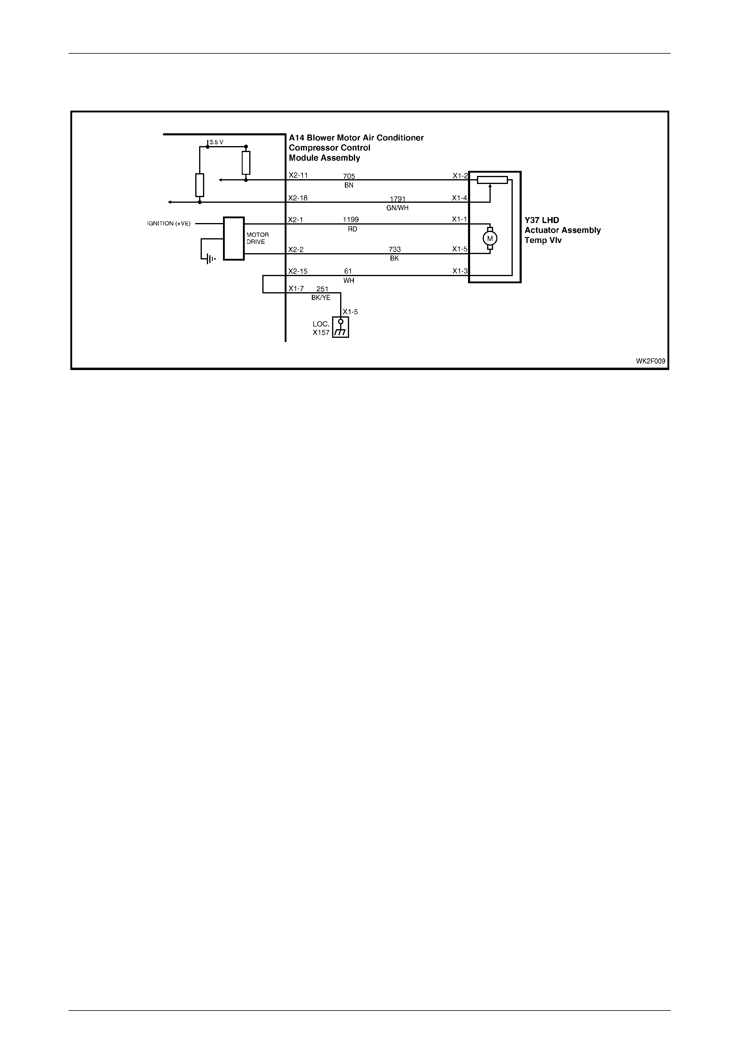
HVAC Occupant Climat e Control (Auto A/ C) – Diagnostic s Page 2F–83
20–FEB–2003 Page 2F-83
DTC 43 – Driver’s Air Mix Door Motor Feedback Circuit Voltage Too Low (LHD)
Figure 2F – 32
Circuit Description:
The air mix motor is an electric motor used to operate the air mix door. The electric motor is sent a voltage signal of
12.5 volts from the OCC control module which causes the motor to turn, and in turn moves the air mix door towards or
away from the heater core. The direction change takes place by reversing the polarity of this motor.
A potentiometer (PBR) is housed in the air mix motor circuit which, feeds signals (3.6 ± 0.18 volts) back to the OCC
control module as to the positioning of the motor and consequently the air mix door.
DTC 43 will set when the feedback signal from the Driver’s Air Mix Motor is open circuit for a period of 10 seconds.

HVAC Occupant Climat e Control (Auto A/ C) – Diagnostic s Page 2F–84
20–FEB–2003 Page 2F-84
Test Description:
Number(s) below refer to Step numbers in the following
Diagnostic Chart:
1. Ensures the Diagnostic Circuit Check has been
performed.
2. This test checks for faulty OCC.
3. This test checks for short to ground in circuit 705.
4. This test checks for a short in circuits 705 and 1199.
5. This test checks for a short in circuits 705 and 274.
6. This test checks that the resistance value of the
potentiometer does not exceed maximum
acceptable tolerance.
7. This test checks that the resistance value of the
potentiometer is not less than the minimum
acceptable tolerance.
8. This test checks that the signal from the
potentiometer does not exceed maximum
acceptable tolerance.
9. This test checks that the signal from the
potentiometer is not less than minimum acceptable
tolerance.
10. This test checks for intermittent or loose terminals in
the OCC and air mix door motor connectors.
11. This test checks for sufficient power supply for the
potentiometer from the OCC.
12. This test checks for short in circuit s 705 or 61.
13. This test checks for short in circuits 61 or 1791.
14. This test checks for short in circuit s 705 or 1791.
15. This test checks for intermittent or loose terminals in
the OCC and air mix door motor connectors.
16. This test checks for open in circuits 61, 1791 and
705.
17. Ensures that DTC 40 has been cleared if present.
18. This test checks to see if the air mix door is
physically jammed or broken.
19. This test determines whether the air mix motor
assembly is faulty.
Diagnostic Aid s:
An air mix motor or door problem will always be associated
with non-regulated or incorrect temperatures from mode
positions.
The OCC control module, during calibration, sets a minimum
and a maximum PBR value for the air mix motor in its
memory. It is these values which determine the operating
range of the air mix motor and against which all movements
of the air mix adjustment are scaled. Any PBR signal value
outside the minimum or maximum value are considered a
motor fault.
The OCC control module monitors the rate of change of PBR
signal during air mix motor movement. If this rate of change
falls to 0 (such as a broken air mix motor wire or physical
jamb), the OCC control module will recognise the stoppage
and set the fault code.
If DTC 43 was present before turning the ignition off, when
the ignition is turned on again, the OCC control module will
automatically try to recalibrate the air mix door. This takes
approximately 15 seconds. If the recalibration fails, then
DTC 43 will be set again.
Notes On Diagnostic Chart:
1. Refer to Sect ion 12P, WIRING DIAGR AM S for
procedures on checking wiring faults.
2. Refer to Section 0C TECH 2 for connecting and us ing
TECH 2.

HVAC Occupant Climat e Control (Auto A/ C) – Diagnostic s Page 2F–85
20–FEB–2003 Page 2F-85
DTC 43 –Driver’s Air Mix Door Motor Feedback Circuit Voltage Too Low Diagnostic Chart (LHD)
STEP ACTION VALUE YES NO
1 Has the Diagnostic Circuit Check been performed? Go to Step 2. Go to Chart A –
DIAGNOSTIC
CIRCUIT
CHECK in this
Section.
2 Disconnect the OCC wiring harness connector A14 X2.
Connect TECH 2 to the DLC.
Select Diagnostics / Model Year / Vehicle Model / Body /
Occupant Climate Control / Data Display / Data List /
Drivers Air Mix Door Feedback.
Does TECH 2 display a value more than 3.4 volts?
Go to Ste p 3. Replace the OCC
control module.
Refer to
Section 2E,
HVAC
OCCUPANT
CLIMATE
CONTROL
(AUTO A/C) –
REMOVAL &
INSTALLATION.
3 Install the driver’s air mix motor (if disconnected).
With the OCC connector A14 X2 disconnected, probe
OCC connector terminal X2-11, circuit 705 with an
ohmmeter to chassis ground.
Is the value as specified?
NOTE: Any resistance measured here qualifies as a
short.
Ohms Repair faulty
circuit 705. Go to Step 4.
4 With the OCC A14 X2 disconnected, probe between
OCC connector terminal X2-1, circuit 1199 and
connector terminal X2-11, circuit 705 with an ohmmeter.
Is the value as specified?
NOTE: Any resistance measured here qualifies as a
short.
Ohms Repair faulty
circuit 705 and/or
1199.
Go to Step 5.
5 With the OCC connector A14 X2 disconnected, probe
between OCC connector terminal X2-5, circuit 274 and
connector terminal X2-11, circuit 705 with an ohmmeter.
Is the value as specified?
NOTE: Any resistance measured here qualifies as a
short.
Ohms Repair faulty
circuit 274 and/or
705.
Go to Step 6.
6 With the OCC connector A14 X2 disconnected, probe
between OCC connector terminal X2-11, circuit 705 and
connector terminal X2-15, circuit 61 with an ohmmeter.
Is the value as specified?
Less than
12 kilohms Go to Step 7. Go to Step 15.
7 In Step 6, was the value as specified? More than
8 kilohms Go to Step 8. Go to Step 12.
8 With the OCC connector A14 X2 disconnected, probe
between OCC connector terminal X2-11, circuit 705 and
connector terminal X2-18, circuit 1791 wi th an
ohmmeter.
Is the value as specified?
Less than
8.5 kilohms Go to Step 9. Go to Step 15.
9 In Step 8, was the value as specified? More than
1.5 kilohms Go to Step 10. Go to Step 12.

HVAC Occupant Climat e Control (Auto A/ C) – Diagnostic s Page 2F–86
20–FEB–2003 Page 2F-86
STEP ACTION VALUE YES NO
10 Inspect the OCC wiring harness connector A14 X2 and
air mix motor connector Y37 L X1 for an intermittent or
loose terminal.
Are the connectors OK?
Repair faulty
connector/s. Go to Step11.
11 Install the OCC connectors A14 X2 and A14 X1 to OCC
control modu le.
Disconnect the driver’s air mix motor connector
Y37 LHD X1.
Turn the ignition on.
Back-probe between the driver’s air mix motor connector
Y37 LHD X1 terminal X1-3, circuit 61 and terminal X1-2
circuit 705.
Is the value as specified?
3.4 – 3.8
volts Go to Step 17. Replace the OCC
control module.
Refer to
Section 2E,
HVAC
OCCUPANT
CLIMATE
CONTROL
(AUTO A/C)–
REMOVAL &
INSTALLATION.
12 Disconnect the air mix motor connector Y37 LHD.
With the OCC connector A14 X2 disconnected, probe
between OCC connector terminal X2-11, circuit 705 and
connector terminal X2-15, circuit 61 with an ohmmeter.
Is the value as specified?
NOTE: Any resistance measured here qualifies as a
short.
Ohms Repair faulty
circuit 705 and/or
61.
Go to Step 13.
13 With OCC connectors A14 X2 and Y37 LHD X1
disconnect ed, probe betw een O CC connector
terminal X2-15, circuit 61 and connector term inal X2-18,
circuit 1791 with an ohmmeter.
Is the value as specified?
NOTE: Any resistance measured here qualifies as a
short.
Ohms Repair faulty
circuit 61 and/or
1791.
Go to Step 14.
14 With OCC connectors A14 X2 and Y37 LHD X1
disconnect ed, probe betw een O CC connector
terminal X2-11, circuit 705 and connector
terminal X2-18, circuit 1791 with an ohmmeter.
Is the value as specified?
NOTE: Any resistance measured here qualifies as a
short.
Ohms Repair faulty
circuit 705 and/or
1791.
Replace the air
mix door motor.
Refer to
Section 2E,
HVAC
OCCUPANT
CLIMATE
CONTROL
(AUTO A/C) –
REMOVAL &
INSTALLATION.
15 Inspect the wiring harness connectors A14 X2 and
Y37 LHD X1 for an intermittent or loose terminal.
Are the connectors OK?
Go to Step 16. Repair faulty
connector/s.
16 Check the integrity of circuits 61, 1791 and 705.
Are the circuits OK?
Replace the air
mix door motor.
Refer to
Section 2E,
HVAC
OCCUPANT
CLIMATE
CONTROL
(AUTO A/C) –
REMOVAL &
INSTALLATION.
Repair faulty
circuit/s.

HVAC Occupant Climat e Control (Auto A/ C) – Diagnostic s Page 2F–87
20–FEB–2003 Page 2F-87
STEP ACTION VALUE YES NO
17 Is DTC 40 currently recorded in TECH 2? Go to DTC 40 in
this Section and
clear DTC.
Go to Step 18.
18 Remove the driver’s air mix motor assembly. Refer to
Section 2E, HVAC OCCUPANT CLIMATE CONTROL
(AUTO A/C) – REMOVAL & INSTALLATION in the
MY2003 VY and V2 Series Service Information.
Move the air mix door by hand.
Is the door physically jammed or broken?
Repair faulty air
mix door. Go to Step 19.
19 Replace the air mix motor assembly. Refer to
Section 2E, HVAC OCCUPANT CLIMATE CONTROL
(AUTO A/C) – REMOVAL & INSTALLATION in the
MY2003 VY and V2 Series Service Information.
Is the problem fixed?
System OK. Replace the OCC
control module.
Refer to
Section 2E,
HVAC
OCCUPANT
CLIMATE
CONTROL
(AUTO A/C) –
REMOVAL &
INSTALLATION.
WHEN ALL DIAGNOSIS AND REPAIRS ARE COMPLETED, VERIFY CORRECT OPERATION

HVAC Occupant Climat e Control (Auto A/ C) – Diagnostic s Page 2F–88
20–FEB–2003 Page 2F-88
DTC 43 – Driver’s Air Mix Door Motor Feedback Cir cuit Voltage Too Low (RHD)
Figure 2F – 33
Circuit Description:
The air mix motor is an electric motor used to operate the air mix door. The electric motor is sent a voltage signal of
12.5 volts from the OCC control module which causes the motor to turn, and in turn moves the air mix door towards or
away from the heater core. The direction change takes place by reversing the polarity of this motor.
A potentiometer (PBR) is housed in the air mix motor circuit, which feeds signals (3.6 ± 0.18 volts) back to the OCC
control module as to the positioning of the motor and consequently the air mix door.
DTC 43 will set when the feedback signal from the Driver’s Air Mix Motor is open circuit for a period of 10 seconds.

HVAC Occupant Climat e Control (Auto A/ C) – Diagnostic s Page 2F–89
20–FEB–2003 Page 2F-89
Test Description:
Number(s) below refer to Step numbers in the following
Diagnostic Chart:
1. Ensures the Diagnostic Circuit Check has been
performed.
2. This test checks for faulty OCC.
3. This test checks for short to ground in circuit 705.
4. This test checks for a short in circuits 705 and 1199.
5. This test checks for a short in circuits 705 and 274.
6. This test checks that the resistance value of the
potentiometer does not exceed maximum
acceptable tolerance.
7. This test checks that the resistance value of the
potentiometer is not less than the minimum
acceptable tolerance.
8. This test checks that the signal from the
potentiometer does not exceed maximum
acceptable tolerance.
9. This test checks that the signal from the
potentiometer is not less than minimum acceptable
tolerance.
10. This test checks for intermittent or loose terminals in
the OCC and air mix door motor connectors.
11. This test checks for sufficient power supply for the
potentiometer from the OCC.
12. This test checks for short in circuit s 705 or 61.
13. This test checks for short in circuits 61 or 1791.
14. This test checks for short in circuit s 705 or 1791.
15. This test checks for intermittent or loose terminals in
the OCC and air mix door motor connectors.
16. This test checks for open in circuits 61, 1791 and
705.
17. Ensures that DTC 40 has been cleared if present.
18. This test checks to see if the air mix door is
physically jammed or broken.
19. This test determines whether the air mix motor
assembly is faulty.
Diagnostic Aid s:
An air mix motor or door problem will always be associated
with non-regulated or incorrect temperatures from mode
positions.
The OCC control module, during calibration, sets a minimum
and a maximum PBR value for the air mix motor in its
memory. It is these values which determine the operating
range of the air mix motor and against which all movements
of the air mix adjustment are scaled. Any PBR signal value
outside the minimum or maximum value are considered a
motor fault.
The OCC control module monitors the rate of change of PBR
signal during air mix motor movement. If this rate of change
falls to 0 (such as a broken air mix motor wire or physical
jamb), the OCC control module will recognise the stoppage
and set the fault code.
If DTC 43 was present before turning the ignition off, when
the ignition is turned on again, the OCC control module will
automatically try to recalibrate the air mix door. This takes
approximately 15 seconds. If the recalibration fails, then
DTC 43 will be set again.
Notes On Diagnostic Chart:
1. Refer to Sect ion 12P, WIRING DIAGR AM S for
procedures on checking wiring faults.
2. Refer to Section 0C TECH 2 for connecting and us ing
TECH 2.

HVAC Occupant Climat e Control (Auto A/ C) – Diagnostic s Page 2F–90
20–FEB–2003 Page 2F-90
DTC 43 –Driver’s Air Mix Door Motor Feedback Circuit Voltage Too Low Diagnostic Chart (RHD)
STEP ACTION VALUE YES NO
1 Has the Diagnostic Circuit Check been performed? Go to Step 2. Go to Chart A –
DIAGNOSTIC
CIRCUIT
CHECK in this
Section.
2 Disconnect the OCC wiring harness connector A14 X2.
Connect TECH 2 to the DLC.
Select Diagnostics / Model Year / Vehicle Model / Body /
Occupant Climate Control / Data Display / Data List /
Drivers Air Mix Door Feedback.
Does TECH 2 display a value above 3.4 volts?
Go to Ste p 3. Replace the OCC
control module.
Refer to
Section 2E,
HVAC
OCCUPANT
CLIMATE
CONTROL
(AUTO A/C) –
REMOVAL &
INSTALLATION.
3 Install the driver’s air mix motor (if disconnected).
With the OCC connector A14 X2 disconnected, probe
OCC connector terminal X2-11, circuit 705 with an
ohmmeter to chassis ground.
Is the value as specified?
NOTE: Any resistance measured here qualifies as a
short.
Ohms Repair faulty
circuit 705. Go to Step 4.
4 With the OCC connector A14 X2 disconnected, probe
between OCC connector terminal X2-1, circuit 1199 and
connector terminal X2-11, circuit 705 with an ohmmeter.
Is the value as specified?
NOTE: Any resistance measured here qualifies as a
short.
Ohms Repair faulty
circuit 705 and/or
1199.
Go to Step 5.
5 With the OCC connector A14 X2 disconnected, probe
between OCC connector terminal X2-5, circuit 274 and
connector terminal X2-11, circuit 705 with an ohmmeter.
Is the value as specified?
NOTE: Any resistance measured here qualifies as a
short.
Ohms Repair faulty
circuit 274 and/or
705.
Go to Step 6.
6 Disconnect the passenger’s air mix motor connector
Y37 L X1 (if fitted).
With the OCC connector A14 X2 disconnected, probe
between OCC connector terminal X2-11, circuit 705 and
connector terminal X2-15, circuit 61 with an ohmmeter.
Is the value as specified?
Less than
12 kilohms
Go to Step 7. Go to Step 15.
7 In Step 6, was the value as specified? More than
8 kilohms Go to Step 8. Go to Step 12.
8 With the OCC connector A14 X2 disconnected, probe
between OCC connector terminal X2-11, circuit 705 and
connector terminal X2-18, circuit 1791 wi th an
ohmmeter.
Is the value as specified?
Less than
8.5 kilohms Go to Step 9. Go to Step 15.
9 In Step 8, was the value as specified? More than
1.5 kilohms Go to Step 10. Go to Step 12.

HVAC Occupant Climat e Control (Auto A/ C) – Diagnostic s Page 2F–91
20–FEB–2003 Page 2F-91
STEP ACTION VALUE YES NO
10 Inspect the OCC wiring harness connector A14 X2 and
the air mix motor connector Y37 L X1 for an intermittent
or loose terminal.
Are the connectors OK?
Go to Step11. Repair faulty
connector/s.
11 Install OCC connectors A14 X2 and A14 X1.
Disconnect the driver’s air mix motor
connector Y37 R X1.
Turn the ignition on.
Back-probe between the driver’s air mix motor connector
Y37 R X1 terminal X1-1, circuit 61 and terminal X1-3,
circuit 705.
Is the value as specified?
3.4 – 3.8
volts Go to Step 17. Replace the OCC
control module.
Refer to
Section 2E,
HVAC
OCCUPANT
CLIMATE
CONTROL
(AUTO A/C)–
REMOVAL &
INSTALLATION.
12 Disconnect the air mix motor connectors Y37 R X1 and
Y37 L X1 (if fitted).
With the OCC connector A14 X2 disconnected, probe
between OCC connector terminal X2-11, circuit 705 and
connector terminal X2-15, circuit 61 with an ohmmeter.
Is the value as specified?
NOTE: Any resistance measured here qualifies as a
short.
Ohms Repair faulty
circuit 705 and/or
61.
Go to Step 13.
13 With OCC connectors A14 X2 and Y37 R X1
disconnect ed, probe betw een O CC connector
terminal X2-15, circuit 61 and connector term inal X2-18,
circuit 1791 with an ohmmeter.
Is the value as specified?
NOTE: Any resistance measured here qualifies as a
short.
Ohms Repair faulty
circuit 61 and/or
1791.
Go to Step 14.
14 With OCC connectors A14 X2 and Y37 R X1
disconnect ed, probe betw een O CC connector
terminal X2-11, circuit 705 and connector
terminal X2-18, circuit 1791 with an ohmmeter.
Is the value as specified?
NOTE: Any resistance measured here qualifies as a
short.
Ohms Repair faulty
circuit 705 and/or
1791.
Replace the air
mix door motor.
Refer to
Section 2E,
HVAC
OCCUPANT
CLIMATE
CONTROL
(AUTO A/C) –
REMOVAL &
INSTALLATION.
15 Inspect the wiring harness connectors A14 X2 and
Y37 R X1 for an intermittent or loose terminal.
Are the connectors OK?
Go to Step 16. Repair faulty
connector/s.
16 Check the integrity of circuits 61, 1791 and 705.
Are the circuits OK?
Replace the air
mix door motor.
Refer to
Section 2E,
HVAC
OCCUPANT
CLIMATE
CONTROL
(AUTO A/C) –
REMOVAL &
INSTALLATION.
Repair faulty
circuit/s.

HVAC Occupant Climat e Control (Auto A/ C) – Diagnostic s Page 2F–92
20–FEB–2003 Page 2F-92
STEP ACTION VALUE YES NO
17 Is DTC 40 currently recorded in TECH 2? Go to DTC 40 in
this Section and
clear DTC.
Go to Step 18.
18 Remove the driver’s air mix motor assembly. Refer to
Section 2E, HVAC OCCUPANT CLIMATE CONTROL
(AUTO A/C) – REMOVAL & INSTALLATION in the
MY2003 VY and V2 Series Service Information.
Move the air mix door by hand.
Is the door physically jammed or broken?
Repair faulty air
mix door. Go to Step 19.
19 Replace the air mix motor assembly. Refer to
Section 2E, HVAC OCCUPANT CLIMATE CONTROL
(AUTO A/C) – REMOVAL & INSTALLATION in the
MY2003 VY and V2 Series Service Information.
Is the problem fixed?
System OK. Replace the OCC
control module.
Refer to
Section 2E,
HVAC
OCCUPANT
CLIMATE
CONTROL
(AUTO A/C) –
REMOVAL &
INSTALLATION.
WHEN ALL DIAGNOSIS AND REPAIRS ARE COMPLETED, VERIFY CORRECT OPERATION

HVAC Occupant Climat e Control (Auto A/ C) – Diagnostic s Page 2F–93
20–FEB–2003 Page 2F-93
DTC 44 – Driver’s Air Mix Door Motor Feedback Circuit Voltage Too High (LHD)
Figure 2F – 34
Circuit Description:
The air mix motor is an electric motor used to operate the air mix door. The electric motor is sent a voltage signal of
12.5 volts from the OCC control module which causes the motor to turn, and in turn moves the air mix door towards or
away from the heater core. The direction change takes place by reversing the polarity of this motor.
A potentiometer (PBR) is housed in the air mix motor circuit, which feeds signals (3.6 ± 0.18 volts) back to the OCC
control module as to the positioning of the motor and consequently the air mix door.
DTC 44 will set when the feedback signal from the Driver’s Air Mix Motor is open circuit for a period of 10 seconds.

HVAC Occupant Climat e Control (Auto A/ C) – Diagnostic s Page 2F–94
20–FEB–2003 Page 2F-94
Test Description:
Number(s) below refer to Step numbers in the following
Diagnostic Chart:
1. Ensures the Diagnostic Circuit Check has been
performed.
2. This test checks for faulty OCC.
3. This test checks for short to ground in circuit 705.
4. This test checks for a short in circuits 705 and 1199.
5. This test checks for a short in circuits 705 and 274.
6. This test checks that the resistance value of the
potentiometer does not exceed maximum
acceptable tolerance.
7. This test checks that the resistance value of the
potentiometer is not less than the minimum
acceptable tolerance.
8. This test checks that the signal from the
potentiometer does not exceed maximum
acceptable tolerance.
9. This test checks that the signal from the
potentiometer is not less than minimum acceptable
tolerance.
10. This test checks for intermittent or loose terminals in
the OCC and air mix door motor connectors.
11. This test checks for sufficient power supply for the
potentiometer from the OCC.
12. This test checks for short in circuit s 705 or 61.
13. This test checks for short in circuits 61 or 1791.
14. This test checks for short in circuit s 705 or 1791.
15. This test checks for intermittent or loose terminals in
the OCC and air mix door motor connectors.
16. This test checks for open in circuits 61, 1791 and
705.
17. Ensures that DTC 40 has been cleared if present.
18. This test checks to see if the air mix door is
physically jammed or broken.
19. This test determines whether the air mix motor
assembly is faulty.
Diagnostic Aid s:
An air mix motor or door problem will always be associated
with non-regulated or incorrect temperatures from mode
positions.
The OCC control module, during calibration, sets a minimum
and a maximum PBR value for the air mix motor in its
memory. It is these values which determine the operating
range of the air mix motor and against which all movements
of the air mix adjustment are scaled. Any PBR signal value
outside the minimum or maximum value are considered a
motor fault.
The OCC control module monitors the rate of change of PBR
signal during air mix motor movement. If this rate of change
falls to 0 (such as a broken air mix motor wire or physical
jamb), the OCC control module will recognise the stoppage
and set the fault code.
If DTC 44 was present before turning the ignition off, when
the ignition is turned on again, the OCC control module will
automatically try to recalibrate the air mix door. This takes
approximately 15 seconds. If the recalibration fails, then
DTC 44 will be set again.
Notes On Diagnostic Chart:
1. Refer to Sect ion 12P, WIRING DIAGR AM S for
procedures on checking wiring faults.
2. Refer to Section 0C TECH 2 for connecting and us ing
TECH 2.

HVAC Occupant Climat e Control (Auto A/ C) – Diagnostic s Page 2F–95
20–FEB–2003 Page 2F-95
DTC 44 –Driver’s Air Mix Door Motor Feedback Circuit Voltage Too High Diagnostic Chart (LHD)
STEP ACTION VALUE YES NO
1 Has the Diagnostic Circuit Check been performed? Go to Step 2. Go to Chart A –
DIAGNOSTIC
CIRCUIT
CHECK in this
Section.
2 Disconnect the OCC wiring harness connector A14 X2.
Connect TECH 2 to the DLC.
Select Diagnostics / Model Year / Vehicle Model / Body /
Occupant Climate Control / Data Display / Data List /
Drivers Air Mix Door Feedback.
Does TECH 2 display a value more than 3.4 volts?
Go to Ste p 3. Replace the OCC
control module.
Refer to
Section 2E,
HVAC
OCCUPANT
CLIMATE
CONTROL
(AUTO A/C) –
REMOVAL &
INSTALLATION.
3 Install the driver’s air mix motor (if disconnected).
With the OCC connector A14 X2 disconnected, probe
OCC connector terminal X2-11, circuit 705 with an
ohmmeter to chassis ground.
Is the value as specified?
NOTE: Any resistance measured here qualifies as a
short.
Ohms Repair faulty
circuit 705. Go to Step 4.
4 With the OCC A14 X2 disconnected, probe between
OCC connector terminal X2-1, circuit 1199 and
connector terminal X2-11, circuit 705 with an ohmmeter.
Is the value as specified?
NOTE: Any resistance measured here qualifies as a
short.
Ohms Repair faulty
circuit 705 and/or
1199.
Go to Step 5.
5 With the OCC connector A14 X2 disconnected, probe
between OCC connector terminal X2-5, circuit 274 and
connector terminal X2-11, circuit 705 with an ohmmeter.
Is the value as specified?
NOTE: Any resistance measured here qualifies as a
short.
Ohms Repair faulty
circuit 274 and/or
705.
Go to Step 6.
6 With the OCC connector A14 X2 disconnected, probe
between OCC connector terminal X2-11, circuit 705 and
connector terminal X2-15, circuit 61 with an ohmmeter.
Is the value as specified?
Less than
12 kilohms Go to Step 7. Go to Step 15.
7 In Step 6, was the value as specified? More than
8 kilohms Go to Step 8. Go to Step 12.
8 With the OCC connector A14 X2 disconnected, probe
between OCC connector terminal X2-11, circuit 705 and
connector terminal X2-18, circuit 1791 wi th an
ohmmeter.
Is the value as specified?
Less than
8.5 kilohms Go to Step 9. Go to Step 15.
9 In Step 8, was the value as specified? More than
1.5 kilohms Go to Step 10. Go to Step 12.

HVAC Occupant Climat e Control (Auto A/ C) – Diagnostic s Page 2F–96
20–FEB–2003 Page 2F-96
STEP ACTION VALUE YES NO
10 Inspect the OCC wiring harness connector A14 X2 and
air mix motor connector Y37 L X1 for an intermittent or
loose terminal.
Are the connectors OK?
Repair faulty
connector/s. Go to Step11.
11 Install the OCC connectors A14 X2 and A14 X1 to OCC
control modu le.
Disconnect the driver’s air mix motor connector
Y37 LHD X1.
Turn the ignition on.
Back-probe between the driver’s air mix motor connector
Y37 LHD X1 terminal X1-3, circuit 61 and terminal X1-2
circuit 705.
Is the value as specified?
3.4 – 3.8
volts Go to Step 17. Replace the OCC
control module.
Refer to
Section 2E,
HVAC
OCCUPANT
CLIMATE
CONTROL
(AUTO A/C)–
REMOVAL &
INSTALLATION.
12 Disconnect the air mix motor connector Y37 LHD.
With the OCC connector A14 X2 disconnected, probe
between OCC connector terminal X2-11, circuit 705 and
connector terminal X2-15, circuit 61 with an ohmmeter.
Is the value as specified?
NOTE: Any resistance measured here qualifies as a
short.
Ohms Repair faulty
circuit 705 and/or
61.
Go to Step 13.
13 With OCC connectors A14 X2 and Y37 LHD X1
disconnect ed, probe betw een O CC connector
terminal X2-15, circuit 61 and connector term inal X2-18,
circuit 1791 with an ohmmeter.
Is the value as specified?
NOTE: Any resistance measured here qualifies as a
short.
Ohms Repair faulty
circuit 61 and/or
1791.
Go to Step 14.
14 With OCC connectors A14 X2 and Y37 LHD X1
disconnect ed, probe betw een O CC connector
terminal X2-11, circuit 705 and connector
terminal X2-18, circuit 1791 with an ohmmeter.
Is the value as specified?
NOTE: Any resistance measured here qualifies as a
short.
Ohms Repair faulty
circuit 705 and/or
1791.
Replace the air
mix door motor.
Refer to
Section 2E,
HVAC
OCCUPANT
CLIMATE
CONTROL
(AUTO A/C) –
REMOVAL &
INSTALLATION.
15 Inspect the wiring harness connectors A14 X2 and
Y37 LHD X1 for an intermittent or loose terminal.
Are the connectors OK?
Go to Step 16. Repair faulty
connector/s.
16 Check the integrity of circuits 61, 1791 and 705.
Are the circuits OK?
Replace the air
mix door motor.
Refer to
Section 2E,
HVAC
OCCUPANT
CLIMATE
CONTROL
(AUTO A/C) –
REMOVAL &
INSTALLATION.
Repair faulty
circuit/s.

HVAC Occupant Climat e Control (Auto A/ C) – Diagnostic s Page 2F–97
20–FEB–2003 Page 2F-97
STEP ACTION VALUE YES NO
17 Is DTC 40 currently recorded in TECH 2? Go to DTC 40 in
this Section and
clear DTC.
Go to Step 18.
18 Remove the driver’s air mix motor assembly. Refer to
Section 2E, HVAC OCCUPANT CLIMATE CONTROL
(AUTO A/C) – REMOVAL & INSTALLATION in the
MY2003 VY and V2 Series Service Information.
Move the air mix door by hand.
Is the door physically jammed or broken?
Repair faulty air
mix door. Go to Step 19.
19 Replace the air mix motor assembly. Refer to
Section 2E, HVAC OCCUPANT CLIMATE CONTROL
(AUTO A/C) – REMOVAL & INSTALLATION in the
MY2003 VY and V2 Series Service Information.
Is the problem fixed?
System OK. Replace the OCC
control module.
Refer to
Section 2E,
HVAC
OCCUPANT
CLIMATE
CONTROL
(AUTO A/C) –
REMOVAL &
INSTALLATION.
WHEN ALL DIAGNOSIS AND REPAIRS ARE COMPLETED, VERIFY CORRECT OPERATION

HVAC Occupant Climat e Control (Auto A/ C) – Diagnostic s Page 2F–98
20–FEB–2003 Page 2F-98
DTC 44 – Driver’s Air Mix Door Motor Feedback Circ uit Volt age Too High (RHD)
Figure 2F – 35
Circuit Description:
The air mix motor is an electric motor used to operate the air mix door. The electric motor is sent a voltage signal of
12.5 volts from the OCC control module which causes the motor to turn, and in turn moves the air mix door towards or
away from the heater core. The direction change takes place by reversing the polarity of this motor.
A potentiometer (PBR) is housed in the air mix motor circuit, which feeds signals (3.6 ± 0.18 volts) back to the OCC
control module as to the positioning of the motor and consequently the air mix door.
DTC 44 will set when the feedback signal from the Driver’s Air Mix Motor is open circuit for a period of 10 seconds.

HVAC Occupant Climat e Control (Auto A/ C) – Diagnostic s Page 2F–99
20–FEB–2003 Page 2F-99
Test Description:
Number(s) below refer to Step numbers in the following
Diagnostic Chart:
1. Ensures the Diagnostic Circuit Check has been
performed.
2. This test checks for faulty OCC.
3. This test checks for short to ground in circuit 705.
4. This test checks for a short in circuits 705 and 1199.
5. This test checks for a short in circuits 705 and 274.
6. This test checks that the resistance value of the
potentiometer does not exceed maximum
acceptable tolerance.
7. This test checks that the resistance value of the
potentiometer is not less than the minimum
acceptable tolerance.
8. This test checks that the signal from the
potentiometer does not exceed maximum
acceptable tolerance.
9. This test checks that the signal from the
potentiometer is not less than minimum acceptable
tolerance.
10. This test checks for intermittent or loose terminals in
the OCC and air mix door motor connectors.
11. This test checks for sufficient power supply for the
potentiometer from the OCC.
12. This test checks for short in circuit s 705 or 61.
13. This test checks for short in circuits 61 or 1791.
14. This test checks for short in circuit s 705 or 1791.
15. This test checks for intermittent or loose terminals in
the OCC and air mix door motor connectors.
16. This test checks for open in circuits 61, 1791 and
705.
17. Ensures that DTC 40 has been cleared if present.
18. This test checks to see if the air mix door is
physically jammed or broken.
19. This test determines whether the air mix motor
assembly is faulty.
Diagnostic Aid s:
An air mix motor or door problem will always be associated
with non-regulated or incorrect temperatures from mode
positions.
The OCC control module, during calibration, sets a minimum
and a maximum PBR value for the air mix motor in its
memory. It is these values which determine the operating
range of the air mix motor and against which all movements
of the air mix adjustment are scaled. Any PBR signal value
outside the minimum or maximum value are considered a
motor fault.
The OCC control module monitors the rate of change of PBR
signal during air mix motor movement. If this rate of change
falls to 0 (such as a broken air mix motor wire or physical
jamb), the OCC control module will recognise the stoppage
and set the fault code.
If DTC 44 was present before turning the ignition off, when
the ignition is turned on again, the OCC control module will
automatically try to recalibrate the air mix door. This takes
approximately 15 seconds. If the recalibration fails, then
DTC 44 will be set again.
Notes On Diagnostic Chart:
1. Refer to Sect ion 12P, WIRING DIAGR AM S for
procedures on checking wiring faults.
2. Refer to Section 0C TECH 2 for connecting and us ing
TECH 2.

HVAC Occupant Climat e Control (Auto A/ C) – Diagnostic s Page 2F–100
20–FEB–2003 Page 2F-100
DTC 44 –Driver’s Air Mix Door Motor Feedback Circuit Voltage Too High Diagnostic Chart (RHD)
STEP ACTION VALUE YES NO
1 Has the Diagnostic Circuit Check been performed? Go to Step 2. Go to Chart A –
DIAGNOSTIC
CIRCUIT
CHECK in this
Section.
2 Disconnect the OCC wiring harness connector A14 X2.
Connect TECH 2 to the DLC.
Select Diagnostics / Model Year / Vehicle Model / Body /
Occupant Climate Control / Data Display / Data List /
Drivers Air Mix Door Feedback.
Does TECH 2 display a value above 3.4 volts?
Go to Ste p 3. Replace the OCC
control module.
Refer to
Section 2E,
HVAC
OCCUPANT
CLIMATE
CONTROL
(AUTO A/C) –
REMOVAL &
INSTALLATION.
3 Install the driver’s air mix motor (if disconnected).
With the OCC connector A14 X2 disconnected, probe
OCC connector terminal X2-11, circuit 705 with an
ohmmeter to chassis ground.
Is the value as specified?
NOTE: Any resistance measured here qualifies as a
short.
Ohms Repair faulty
circuit 705. Go to Step 4.
4 With the OCC connector A14 X2 disconnected, probe
between OCC connector terminal X2-1, circuit 1199 and
connector terminal X2-11, circuit 705 with an ohmmeter.
Is the value as specified?
NOTE: Any resistance measured here qualifies as a
short.
Ohms Repair faulty
circuit 705 and/or
1199.
Go to Step 5.
5 With the OCC connector A14 X2 disconnected, probe
between OCC connector terminal X2-5, circuit 274 and
connector terminal X2-11, circuit 705 with an ohmmeter.
Is the value as specified?
NOTE: Any resistance measured here qualifies as a
short.
Ohms Repair faulty
circuit 274 and/or
705.
Go to Step 6.
6 Disconnect the passenger’s air mix motor connector
Y37 L X1 (if fitted).
With the OCC connector A14 X2 disconnected, probe
between OCC connector terminal X2-11, circuit 705 and
connector terminal X2-15, circuit 61 with an ohmmeter.
Is the value as specified?
Less than
12 kilohms
Go to Step 7. Go to Step 15.
7 In Step 6, was the value as specified? More than
8 kilohms Go to Step 8. Go to Step 12.
8 With the OCC connector A14 X2 disconnected, probe
between OCC connector terminal X2-11, circuit 705 and
connector terminal X2-18, circuit 1791 wi th an
ohmmeter.
Is the value as specified?
Less than
8.5 kilohms Go to Step 9. Go to Step 15.
9 In Step 8, was the value as specified? More than
1.5 kilohms Go to Step 10. Go to Step 12.

HVAC Occupant Climat e Control (Auto A/ C) – Diagnostic s Page 2F–101
20–FEB–2003 Page 2F-101
STEP ACTION VALUE YES NO
10 Inspect the OCC wiring harness connector A14 X2 and
the air mix motor connector Y37 L X1 for an intermittent
or loose terminal.
Are the connectors OK?
Go to Step11. Repair faulty
connector/s.
11 Install OCC connectors A14 X2 and A14 X1.
Disconnect the driver’s air mix motor
connector Y37 R X1.
Turn the ignition on.
Back-probe between the driver’s air mix motor connector
Y37 R X1 terminal X1-1, circuit 61 and terminal X1-3,
circuit 705
Is the value as specified?
3.4 – 3.8
volts Go to Step 17. Replace the OCC
control module.
Refer to
Section 2E,
HVAC
OCCUPANT
CLIMATE
CONTROL
(AUTO A/C)–
REMOVAL &
INSTALLATION.
12 Disconnect the air mix motor connectors Y37 R X1 and
Y37 L X1 (if fitted).
With the OCC connector A14 X2 disconnected, probe
between OCC connector terminal X2-11, circuit 705 and
connector terminal X2-15, circuit 61 with an ohmmeter.
Is the value as specified?
NOTE: Any resistance measured here qualifies as a
short.
Ohms Repair faulty
circuit 705 and/or
61.
Go to Step 13.
13 With OCC connectors A14 X2 and Y37 R X1
disconnect ed, probe betw een O CC connector
terminal X2-15, circuit 61 and connector term inal X2-18,
circuit 1791 with an ohmmeter.
Is the value as specified?
NOTE: Any resistance measured here qualifies as a
short.
Ohms Repair faulty
circuit 61 and/or
1791.
Go to Step 14.
14 With OCC connectors A14 X2 and Y37 R X1
disconnect ed, probe betw een O CC connector
terminal X2-11, circuit 705 and connector
terminal X2-18, circuit 1791 with an ohmmeter.
Is the value as specified?
NOTE: Any resistance measured here qualifies as a
short.
Ohms Repair faulty
circuit 705 and/or
1791.
Replace the air
mix door motor.
Refer to
Section 2E,
HVAC
OCCUPANT
CLIMATE
CONTROL
(AUTO A/C) –
REMOVAL &
INSTALLATION.
15 Inspect the wiring harness connectors A14 X2 and
Y37 R X1 for an intermittent or loose terminal.
Are the connectors OK?
Go to Step 16. Repair faulty
connector/s.
16 Check the integrity of circuits 61, 1791 and 705.
Are the circuits OK?
Replace the air
mix door motor.
Refer to
Section 2E,
HVAC
OCCUPANT
CLIMATE
CONTROL
(AUTO A/C) –
REMOVAL &
INSTALLATION.
Repair faulty
circuit/s.

HVAC Occupant Climat e Control (Auto A/ C) – Diagnostic s Page 2F–102
20–FEB–2003 Page 2F-102
STEP ACTION VALUE YES NO
17 Is DTC 40 currently recorded in TECH 2? Go to DTC 40 in
this Section and
clear DTC.
Go to Step 18.
18 Remove the driver’s air mix motor assembly. Refer to
Section 2E, HVAC OCCUPANT CLIMATE CONTROL
(AUTO A/C) – REMOVAL & INSTALLATION in the
MY2003 VY and V2 Series Service Information.
Move the air mix door by hand.
Is the door physically jammed or broken?
Repair faulty air
mix door. Go to Step 19.
19 Replace the air mix motor assembly. Refer to
Section 2E, HVAC OCCUPANT CLIMATE CONTROL
(AUTO A/C) – REMOVAL & INSTALLATION in the
MY2003 VY and V2 Series Service Information.
Is the problem fixed?
System OK. Replace the OCC
control module.
Refer to
Section 2E,
HVAC
OCCUPANT
CLIMATE
CONTROL
(AUTO A/C) –
REMOVAL &
INSTALLATION.
WHEN ALL DIAGNOSIS AND REPAIRS ARE COMPLETED, VERIFY CORRECT OPERATION

HVAC Occupant Climat e Control (Auto A/ C) – Diagnostic s Page 2F–103
20–FEB–2003 Page 2F-103
DTC 45 – Passengers Air Mix Door Motor Feedback Circuit Voltage Too Low
Figure 2F – 36
Circuit Description:
The air mix motor is an electric motor used to operate the air mix door. The electric motor is sent a voltage signal of
12.5 volts from the OCC control module which causes the motor to turn, and in turn moves the air mix door towards or
away from the heater core. The direction change takes place by reversing the polarity of this motor.
A potentiometer (PBR) is housed in the air mix motor circuit, which feeds signals (3.6 ± 0.18 volts) back to the OCC
control module as to the positioning of the motor and consequently the air mix door.
DTC 45 will set when the feedback signal from the passenger’s air mix motor is short circuited for a period of
10 seconds.

HVAC Occupant Climat e Control (Auto A/ C) – Diagnostic s Page 2F–104
20–FEB–2003 Page 2F-104
Test Description:
Number(s) below refer to Step numbers in the following
Diagnostic Chart:
1. Ensures the Diagnostic Circuit Check has been
performed.
2. This test checks for faulty OCC.
3. This test checks for short to ground in circuit 705.
4. This test checks for a short in circuits 705 and 1236.
5. This test checks for a short in circuits 705 and 274.
6. This test checks that the resistance value of the
potentiometer does not exceed maximum
acceptable tolerance.
7. This test checks that the resistance value of the
potentiometer is not less than the minimum
acceptable tolerance.
8. This test checks that the signal from the
potentiometer does not exceed maximum
acceptable tolerance.
9. This test checks that the signal from the
potentiometer is not less than minimum acceptable
tolerance.
10. This test checks for intermittent or loose terminals in
the OCC and air mix door motor connectors.
11. This test checks for sufficient power supply for the
potentiometer from the OCC.
12. This test checks for short in circuit s 705 or 61.
13. This test checks for short in circuits 61 or 2273.
14. This test checks for short in circuit s 705 or 2273.
15. This test checks for intermittent or loose terminals in
the OCC and air mix door motor connectors.
16. This test checks for open in circuits 61, 2273 and
705.
17. Ensures that DTC 40 has been cleared if present.
18. This test checks to see if the air mix door is
physically jammed or broken.
19. This test determines whether the air mix motor
assembly is faulty.
Diagnostic Aid s:
An air mix motor or door problem will always be associated
with non-regulated or incorrect temperatures from mode
positions.
The OCC control module, during calibration, sets a minimum
and a maximum PBR value for the air mix motor in its
memory. It is these values which determine the operating
range of the air mix motor and against which all movements
of the air mix adjustment are scaled. Any PBR signal value
outside the minimum or maximum value are considered a
motor fault.
The OCC control module monitors the rate of change of PBR
signal during air mix motor movement. If this rate of change
falls to 0 (such as a broken air mix motor wire or physical
jamb), the OCC control module will recognise the stoppage
and set the fault code.
If DTC 45 was present before turning the ignition off, when
the ignition is turned on again, the OCC control module will
automatically try to recalibrate the air mix door. This takes
approximately 15 seconds. If the recalibration fails, then
DTC 45 will be set again.
Notes On Diagnostic Chart:
1. Refer to Sect ion 12P, WIRING DIAGR AM S for
procedures on checking wiring faults.
2. Refer to Section 0C TECH 2 for connecting and us ing
TECH 2.

HVAC Occupant Climat e Control (Auto A/ C) – Diagnostic s Page 2F–105
20–FEB–2003 Page 2F-105
DTC 45 –Passenger’s Air Mix Door Motor Feedback Circuit Voltage Too Low Diagnostic Chart
STEP ACTION VALUE YES NO
1 Has the Diagnostic Circuit Check been performed? Go to Step 2. Go to Chart A –
DIAGNOSTIC
CIRCUIT
CHECK in this
Section.
2 Disconnect the OCC wiring harness connector A14 X2.
Connect TECH 2 to the DLC.
Select Diagnostics / Model Year / Vehicle Model / Body /
Occupant Climate Control / Data Display / Data List /
Drivers Air Mix Door Feedback.
Does TECH 2 display a value above 3.4 volts?
Go to Ste p 3. Replace the OCC
control module.
Refer to
Section 2E,
HVAC
OCCUPANT
CLIMATE
CONTROL
(AUTO A/C) –
REMOVAL &
INSTALLATION.
3 Install the passenger’s air mix motor (if disconnected).
With the OCC connector A14 X2 disconnected, probe
OCC connector terminal X2-11, circuit 705 with an
ohmmeter and chassis ground.
Is the value as specified?
NOTE: Any resistance measured here qualifies as a
short.
Ohms Repair faulty
circuit 705. Go to Step 4.
4 With the OCC connector A14 X2 disconnected, probe
between OCC connector terminal X2-3, circuit 1236 and
connector terminal X2-11, circuit 705 with an ohmmeter.
Is the value as specified?
NOTE: Any resistance measured here qualifies as a
short.
Ohms Repair faulty
circuit 705 and/or
1236.
Go to Step 5.
5 With the OCC connector A14 X2 disconnected, probe
between OCC connector terminal X2-5, circuit 274 and
connector terminal X2-11, circuit 705 with an ohmmeter.
Is the value as specified?
NOTE: Any resistance measured here qualifies as a
short.
Ohms Repair faulty
circuit 274
and/or 705.
Go to Step 6.
6 Disconnect the driver’s air mix motor
connector Y37 R X1.
With the OCC connector A14 X2 disconnected, probe
between OCC connector terminal X2-11, circuit 705 and
connector terminal X2-15, circuit 61 with an ohmmeter.
Is the value as specified?
Less than
12 kilohms Go to Step 7. Go to Step 15.
7 In Step 6, was the value as specified? More than
8 kilohms Go to Step 8. Go to Step 12.
8 With the OCC connector A14 X2 disconnected, probe
between OCC connector terminal X2-11, circuit 705 and
connector terminal X2-17, circuit 2273 wi th an
ohmmeter.
Is the value as specified?
Less than
8.5 kilohms Go to Step 9. Go to Step 15.
9 In Step 8, was the value as specified? More than
1.5 kilohms Go to Step 10. Go to Step 12.

HVAC Occupant Climat e Control (Auto A/ C) – Diagnostic s Page 2F–106
20–FEB–2003 Page 2F-106
STEP ACTION VALUE YES NO
10 Inspect the OCC wiring harness connector A14 X2 or air
mix motor connector Y37 L X1 for an intermittent or
loose terminal.
Are the connectors OK?
Repair faulty
connector/s. Go to Step11.
11 Install the OCC connectors A14 X2 and A14 X1.
Disconnect the passenger’s air mix motor
connector Y37 L X1.
Turn the ignition on
Probe the driver’s air mix motor connector Y37 R X1
between connector terminal X1-3 circuit 61 and
connector terminal X1-1 circuit 705 with a voltmeter.
Is the value as specified?
3.4 – 3.8
volts Go to Step 17. Replace the OCC
control module.
Refer to
Section 2E,
HVAC
OCCUPANT
CLIMATE
CONTROL
(AUTO A/C)–
REMOVAL &
INSTALLATION.
12 Disconnect the air mix motor connectors Y37 R X1 and
Y37 L X1.
With the OCC connector A14 X2 disconnected, probe
between OCC connector terminal X2-11, circuit 705 and
connector terminal X2-15, circuit 61 with an ohmmeter.
Is the value as specified?
NOTE: Any resistance measured here qualifies as a
short.
Ohms Repair faulty
circuit 705
and/or 61.
Go to Step 13.
13 With OCC connectors A14 X2 and Y37 L X1
disconnect ed, probe betw een O CC connector
terminal X2-15, circuit 61 and connector term inal X2-17,
circuit 2273 with an ohmmeter.
Is the value as specified?
NOTE: Any resistance measured here qualifies as a
short.
Ohms Repair faulty
circuit 61
and/or 2273.
Go to Step 14.
14 With OCC connectors A14 X2 and Y37 L X1
disconnect ed, probe betw een O CC connector
terminal X2-11, circuit 705 and connector
terminal X2-17, circuit 2273 with an ohmmeter.
Is the value as specified?
NOTE: Any resistance measured here qualifies as a
short.
Ohms Repair faulty
circuit 705
and/or 2273.
Replace the air
mix door motor.
Refer to
Section 2E,
HVAC
OCCUPANT
CLIMATE
CONTROL
(AUTO A/C) –
REMOVAL &
INSTALLATION.
15 Inspect the wiring harness connectors A14 X2 and
Y37 L X1 for an intermittent or loose terminal.
Are the connectors OK?
Go to Step 16. Repair faulty
connector/s.
16 Check the integrity of circuits 61, 2273 and 705.
Are the circuits OK?
Replace the air
mix door motor.
Refer to
Section 2E,
HVAC
OCCUPANT
CLIMATE
CONTROL
(AUTO A/C) –
REMOVAL &
INSTALLATION.
Repair faulty
circuits.

HVAC Occupant Climat e Control (Auto A/ C) – Diagnostic s Page 2F–107
20–FEB–2003 Page 2F-107
STEP ACTION VALUE YES NO
17 Is DTC 40 currently recorded in TECH 2? Go to DTC 40 in
this Section and
clear DTC.
Go to Step 18.
18 Remove passenger’s air mix motor assembly. Refer to
Section 2E, HVAC OCCUPANT CLIMATE CONTROL
(AUTO A/C) – REMOVAL & INSTALLATION in the
MY2003 VY and V2 Series Service Information.
Move the air mix door by hand.
Is the door physically jammed or broken?
Repair faulty air
mix door. Go to Step 19.
19 Replace the air mix motor assembly. Refer to
Section 2E, HVAC OCCUPANT CLIMATE CONTROL
(AUTO A/C) – REMOVAL & INSTALLATION in the
MY2003 VY and V2 Series Service Information.
Is the problem fixed?
System OK. Replace the OCC
control module.
Refer to
Section 2E,
HVAC
OCCUPANT
CLIMATE
CONTROL
(AUTO A/C) –
REMOVAL &
INSTALLATION.
WHEN ALL DIAGNOSIS AND REPAIRS ARE COMPLETED, VERIFY CORRECT OPERATION

HVAC Occupant Climat e Control (Auto A/ C) – Diagnostic s Page 2F–108
20–FEB–2003 Page 2F-108
DTC 46 – Passengers Air Mix Door Motor Feedback Circuit Voltage Too High
Figure 2F – 37
Circuit Description:
The air mix motor is an electric motor used to operate the air mix door. The electric motor is sent a voltage signal of
12.5 volts from the OCC control module which causes the motor to turn, and in turn moves the air mix door towards or
away from the heater core. The direction change takes place by reversing the polarity of this motor.
A potentiometer (PBR) is housed in the air mix motor circuit, which feeds signals (3.6 ± 0.18 volts) back to the OCC
control module as to the positioning of the motor and consequently the air mix door.
DTC 46 will set when the feedback signal from the passenger’s air mix motor is short circuited for a period of
10 seconds.

HVAC Occupant Climat e Control (Auto A/ C) – Diagnostic s Page 2F–109
20–FEB–2003 Page 2F-109
Test Description:
Number(s) below refer to Step numbers in the following
Diagnostic Chart:
1. Ensures the Diagnostic Circuit Check has been
performed.
2. This test checks for faulty OCC.
3. This test checks for short to ground in circuit 705.
4. This test checks for a short in circuits 705 and 1236.
5. This test checks for a short in circuits 705 and 274.
6. This test checks that the resistance value of the
potentiometer does not exceed maximum
acceptable tolerance.
7. This test checks that the resistance value of the
potentiometer is not less than the minimum
acceptable tolerance.
8. This test checks that the signal from the
potentiometer does not exceed maximum
acceptable tolerance.
9. This test checks that the signal from the
potentiometer is not less than minimum acceptable
tolerance.
10. This test checks for intermittent or loose terminals in
the OCC and air mix door motor connectors.
11. This test checks for sufficient power supply for the
potentiometer from the OCC.
12. This test checks for short in circuit s 705 or 61.
13. This test checks for short in circuits 61 or 2273.
14. This test checks for short in circuit s 705 or 2273.
15. This test checks for intermittent or loose terminals in
the OCC and air mix door motor connectors.
16. This test checks for open in circuits 61, 2273 and
705.
17. Ensures that DTC 40 has been cleared if present.
18. This test checks to see if the air mix door is
physically jammed or broken.
19. This test determines whether the air mix motor
assembly is faulty.
Diagnostic Aid s:
An air mix motor or door problem will always be associated
with non-regulated or incorrect temperatures from mode
positions.
The OCC control module, during calibration, sets a minimum
and a maximum PBR value for the air mix motor in its
memory. It is these values which determine the operating
range of the air mix motor and against which all movements
of the air mix adjustment are scaled. Any PBR signal value
outside the minimum or maximum value are considered a
motor fault.
The OCC control module monitors the rate of change of PBR
signal during air mix motor movement. If this rate of change
falls to 0 (such as a broken air mix motor wire or physical
jamb), the OCC control module will recognise the stoppage
and set the fault code.
If DTC 46 was present before turning the ignition off, when
the ignition is turned on again, the OCC control module will
automatically try to recalibrate the air mix door. This takes
approximately 15 seconds. If the recalibration fails, then
DTC 46 will be set again.
Notes On Diagnostic Chart:
1. Refer to Sect ion 12P, WIRING DIAGR AM S for
procedures on checking wiring faults.
2. Refer to Section 0C TECH 2 for connecting and us ing
TECH 2.

HVAC Occupant Climat e Control (Auto A/ C) – Diagnostic s Page 2F–110
20–FEB–2003 Page 2F-110
DTC 46 –Passenger’s Air Mix Door Motor Feedback Circuit Voltage Too High Diagnostic Chart
STEP ACTION VALUE YES NO
1 Has the Diagnostic Circuit Check been performed? Go to Step 2. Go to Chart A –
DIAGNOSTIC
CIRCUIT
CHECK in this
Section.
2 Disconnect the OCC wiring harness connector A14 X2.
Connect TECH 2 to the DLC.
Select Diagnostics / Model Year / Vehicle Model / Body /
Occupant Climate Control / Data Display / Data List /
Drivers Air Mix Door Feedback.
Does TECH 2 display a value above 3.4 volts?
Go to Ste p 3. Replace the OCC
control module.
Refer to
Section 2E,
HVAC
OCCUPANT
CLIMATE
CONTROL
(AUTO A/C) –
REMOVAL &
INSTALLATION.
3 Install the passenger’s air mix motor (if disconnected).
With the OCC connector A14 X2 disconnected, probe
OCC connector terminal X2-11, circuit 705 with an
ohmmeter and chassis ground.
Is the value as specified?
NOTE: Any resistance measured here qualifies as a
short.
Ohms Repair faulty
circuit 705. Go to Step 4.
4 With the OCC connector A14 X2 disconnected, probe
between OCC connector terminal X2-3, circuit 1236 and
connector terminal X2-11, circuit 705 with an ohmmeter.
Is the value as specified?
NOTE: Any resistance measured here qualifies as a
short.
Ohms Repair faulty
circuit 705 and/or
1236.
Go to Step 5.
5 With the OCC connector A14 X2 disconnected, probe
between OCC connector terminal X2-5, circuit 274 and
connector terminal X2-11, circuit 705 with an ohmmeter.
Is the value as specified?
NOTE: Any resistance measured here qualifies as a
short.
Ohms Repair faulty
circuit 274
and/or 705.
Go to Step 6.
6 Disconnect the driver’s air mix motor
connector Y37 R X1.
With the OCC connector A14 X2 disconnected, probe
between OCC connector terminal X2-11, circuit 705 and
connector terminal X2-15, circuit 61 with an ohmmeter.
Is the value as specified?
Less than
12 kilohms Go to Step 7. Go to Step 15.
7 In Step 6, was the value as specified? More than
8 kilohms Go to Step 8. Go to Step 12.
8 With the OCC connector A14 X2 disconnected, probe
between OCC connector terminal X2-11, circuit 705 and
connector terminal X2-17, circuit 2273 wi th an
ohmmeter.
Is the value as specified?
Less than
8.5 kilohms Go to Step 9. Go to Step 15.
9 In Step 8, was the value as specified? More than
1.5 kilohms Go to Step 10. Go to Step 12.

HVAC Occupant Climat e Control (Auto A/ C) – Diagnostic s Page 2F–111
20–FEB–2003 Page 2F-111
STEP ACTION VALUE YES NO
10 Inspect the OCC wiring harness connector A14 X2 or air
mix motor connector Y37 L X1 for an intermittent or
loose terminal.
Are the connectors OK?
Repair faulty
connector/s. Go to Step11.
11 Install the OCC connectors A14 X2 and A14 X1.
Disconnect the passenger’s air mix motor
connector Y37 L X1.
Turn the ignition on
Probe the driver’s air mix motor connector Y37 R X1
between connector terminal X1-3 circuit 61 and
connector terminal X1-1 circuit 705 with a voltmeter.
Is the value as specified?
3.4 – 3.8
volts Go to Step 17. Replace the OCC
control module.
Refer to
Section 2E,
HVAC
OCCUPANT
CLIMATE
CONTROL
(AUTO A/C)–
REMOVAL &
INSTALLATION.
12 Disconnect the air mix motor connectors Y37 R X1 and
Y37 L X1.
With the OCC connector A14 X2 disconnected, probe
between OCC connector terminal X2-11, circuit 705 and
connector terminal X2-15, circuit 61 with an ohmmeter.
Is the value as specified?
NOTE: Any resistance measured here qualifies as a
short.
Ohms Repair faulty
circuit 705
and/or 61.
Go to Step 13.
13 With OCC connectors A14 X2 and Y37 L X1
disconnect ed, probe betw een O CC connector
terminal X2-15, circuit 61 and connector term inal X2-17,
circuit 2273 with an ohmmeter.
Is the value as specified?
NOTE: Any resistance measured here qualifies as a
short.
Ohms Repair faulty
circuit 61
and/or 2273.
Go to Step 14.
14 With OCC connectors A14 X2 and Y37 L X1
disconnect ed, probe betw een O CC connector
terminal X2-11, circuit 705 and connector
terminal X2-17, circuit 2273 with an ohmmeter.
Is the value as specified?
NOTE: Any resistance measured here qualifies as a
short.
Ohms Repair faulty
circuit 705
and/or 2273.
Replace the air
mix door motor.
Refer to
Section 2E,
HVAC
OCCUPANT
CLIMATE
CONTROL
(AUTO A/C) –
REMOVAL &
INSTALLATION.
15 Inspect the wiring harness connectors A14 X2 and
Y37 L X1 for an intermittent or loose terminal.
Are the connectors OK?
Go to Step 16. Repair faulty
connector/s.
16 Check the integrity of circuits 61, 2273 and 705.
Are the circuits OK?
Replace the air
mix door motor.
Refer to
Section 2E,
HVAC
OCCUPANT
CLIMATE
CONTROL
(AUTO A/C) –
REMOVAL &
INSTALLATION.
Repair faulty
circuits.

HVAC Occupant Climat e Control (Auto A/ C) – Diagnostic s Page 2F–112
20–FEB–2003 Page 2F-112
STEP ACTION VALUE YES NO
17 Is DTC 40 currently recorded in TECH 2? Go to DTC 40 in
this Section and
clear DTC.
Go to Step 18.
18 Remove passenger’s air mix motor assembly. Refer to
Section 2E, HVAC OCCUPANT CLIMATE CONTROL
(AUTO A/C) – REMOVAL & INSTALLATION in the
MY2003 VY and V2 Series Service Information.
Move the air mix door by hand.
Is the door physically jammed or broken?
Repair faulty air
mix door. Go to Step 19.
19 Replace the air mix motor assembly. Refer to
Section 2E, HVAC OCCUPANT CLIMATE CONTROL
(AUTO A/C) – REMOVAL & INSTALLATION in the
MY2003 VY and V2 Series Service Information.
Is the problem fixed?
System OK. Replace the OCC
control module.
Refer to
Section 2E,
HVAC
OCCUPANT
CLIMATE
CONTROL
(AUTO A/C) –
REMOVAL &
INSTALLATION.
WHEN ALL DIAGNOSIS AND REPAIRS ARE COMPLETED, VERIFY CORRECT OPERATION

HVAC Occupant Climat e Control (Auto A/ C) – Diagnostic s Page 2F–113
20–FEB–2003 Page 2F-113
DTC 47 – Drivers Ai r M ix Min. Cali bration Error (LHD)
Figure 2F – 38
Circuit Description:
The air mix motor is an electric motor used to operate the air mix door. The electric motor is sent a voltage signal of
12.5 volts from the OCC control module which causes the motor to turn, and in turn moves the air mix door towards or
away from the heater core. The direction change takes place by reversing the polarity of this motor.
A potentiometer (PBR) is housed in the air mix motor circuit, which feeds signals (3.6 ± 0.18 volts) back to the OCC
control module as to the positioning of the motor and consequently the air mix door.
DTC 47 will set: if the PBR feedback signal fails to reach the requested value. This will occur if the PBR or motor is open
or short circuited, or an air mix door is jammed or sticking.

HVAC Occupant Climat e Control (Auto A/ C) – Diagnostic s Page 2F–114
20–FEB–2003 Page 2F-114
Test Description:
Number(s) below refer to Step numbers in the following
Diagnostic Chart:
1. Ensures the Diagnostic Circuit Check has been
performed.
2. This test checks that the DTC is current.
3. This test checks if the motor is moving.
4. This test checks that the motor is stopping within the
correct range @ full cold.
5. This test checks that the motor is stopping within the
correct range @ full hot.
6. Attempts to recalibrate and check DTC is still
current.
7. Determines if a PBR fault is the likely cause of the
problem.
8. Determines if a motor fault is more likely than a PBR
fault to be the cause of the problem.
9. Checks fault has been rectified.
Diagnostic Aid s:
An air mix motor or door problem will always be associated
with non-regulated or incorrect temperatures from mode
positions.
The OCC control module, during calibration, sets a minimum
and a maximum PBR value for the air mix motor in its
memory. It is these values which determine the operating
range of the air mix motor and against which all movements
of the air mix adjustment are scaled. Any PBR signal value
outside the minimum or maximum value are considered a
motor fault.
The OCC control module monitors the rate of change of PBR
signal during air mix motor movement. If this rate of change
falls to 0 (such as a broken air mix motor wire or physical
jamb), the OCC control module will recognise the stoppage
and set the fault code.
If DTC 47 was present before turning the ignition off, when
the ignition is turned on again, the OCC control module will
automatically try to recalibrate the air mix door. This takes
approximately 15 seconds. If the recalibration fails, then
DTC 47 will be set again.
Notes On Diagnostic Chart:
1. Refer to Sect ion 12P, WIRING DIAGR AM S for
procedures on checking wiring faults.
2. Refer to Section 0C TECH 2 for connecting and us ing
TECH 2.

HVAC Occupant Climat e Control (Auto A/ C) – Diagnostic s Page 2F–115
20–FEB–2003 Page 2F-115
DTC 47 –Driver’s Air Mix Min. Calibration Error (LHD) Diagnostic Chart
STEP ACTION VALUE YES NO
1 Has the Diagnostic Circuit Check been performed? Go to Step 2. Go to Chart A –
DIAGNOSTIC
CIRCUIT
CHECK in this
Section.
2 Turn the ignition off.
Connect TECH 2 to the DLC.
Select Diagnostics / Model Year / Vehicle Model / Body /
Occupant Climate Control / Diagnostic Trouble Codes /
Read Current DTC Information.
Does DTC 47 display as the current DTC?
Go to Step 3. Go to Step 9.
3 With TECH 2 connected, select Body / Occupant
Climate Control / Miscellaneous Tests / Drivers Side Air
Mix Motor – Door Movement.
Move the air mix door maximum then decrease to
minimum.
Does the TECH 2 value change accordingly?
Go to Step 4. Go to Step 7.
4 With the Drivers Side Air Mix Motor – Door Mo vement
test selected, decrease the air mix door to minimum.
Does TECH 2 display a value within 0.6 – 0.9 volt?
Go to Step 5. Go to chart
DTC 40 – AIR
MIX DOOR
MOTOR DRIVER
ERROR (LHD) in
this Section.
5 With the Drivers Side Air Mix Motor – Door Mo vement
test selected, increase the air mix door to maximum.
Does TECH 2 display a value within 2.6 – 2.9 volts?
Go to Step 6. Go to chart
DTC 40 – AIR
MIX DOOR
MOTOR DRIVER
ERROR (LHD) in
this Section.
6 With TECH 2 connected, select Body / Occupant
Climate Control / Program / Calibrate Air Mix Door.
Reprogram the air mix door.
Turn the ignition off.
Turn the ignition on.
Does DTC 47 set as the current DTC?
Go to chart
DTC 40 – AIR
MIX DOOR
MOTOR DRIVER
ERROR (LHD) in
this Section.
Go to Step 9.
7 In Step 3, did TECH 2 display less than 0.3 volt? Go to chart
DTC 43 –
DRIVERS AIR
MIX DOOR
MOTOR
FEEDBACK
CIRCUIT
VOLTAGE TOO
LOW (LHD) in
this Section.
Go to Step 8.

HVAC Occupant Climat e Control (Auto A/ C) – Diagnostic s Page 2F–116
20–FEB–2003 Page 2F-116
STEP ACTION VALUE YES NO
8 In Step 3, did TECH 2 display more than 3.4 volts? 3.4 volts Go to chart
DTC 44 –
DRIVERS AIR
MIX DOOR
MOTOR
FEEDBACK
CIRCUIT
VOLTAGE TOO
HIGH (LHD) in
this Section.
Go to chart
DTC 40 – AIR
MIX DOOR
MOTOR DRIVER
ERROR (LHD) in
this Section.
9 With TECH 2 connected, select Body / Occupant
Climate Control / Miscellaneous Tests / Drivers Side Air
Mix Motor– Door Movement.
Increase to max imum t hen de crea se to mini mum .
Does DTC 47 set as a current DTC?
Go to Step 3. Recalibration of
Air mix door may
have corrected
fault or DTC 47 is
intermittent.
(Carry out air mix
door calibration if
not already done
so. Refer to 1.2
TECH 2 TEST
MODES AND
DISPLAYS FOR
OCC
DIAGNOSIS
and/or refer to 3
Diagnostic
Charts in this
Section.
WHEN ALL DIAGNOSIS AND REPAIRS ARE COMPLETED, VERIFY CORRECT OPERATION

HVAC Occupant Climat e Control (Auto A/ C) – Diagnostic s Page 2F–117
20–FEB–2003 Page 2F-117
DTC 47 – Drivers Air Mix Min. Calibration Error (RHD)
Figure 2F – 39
Circuit Description:
The air mix motor is an electric motor used to operate the air mix door. The electric motor is sent a voltage signal of
12.5 volts from the OCC control module which causes the motor to turn, and in turn moves the air mix door towards or
away from the heater core. The direction change takes place by reversing the polarity of this motor.
A potentiometer (PBR) is housed in the air mix motor circuit, which feeds signals (3.6 ± 0.18 volts) back to the OCC
control module as to the positioning of the motor and consequently the air mix door.
DTC 47 will set: if the PBR feedback signal fails to reach the requested value. This will occur if the PBR or motor is open
or short circuited, or an air mix door is jammed or sticking.

HVAC Occupant Climat e Control (Auto A/ C) – Diagnostic s Page 2F–118
20–FEB–2003 Page 2F-118
Test Description:
Number(s) below refer to Step numbers in the following
Diagnostic Chart:
1. Ensures the Diagnostic Circuit Check has been
performed.
2. This test checks that the DTC is current.
3. This test checks if the motor is moving.
4. This test checks that the motor is stopping within the
correct range @ full cold.
5. This test checks that the motor is stopping within the
correct range @ full hot.
6. Attempts to recalibrate and check DTC is still
current.
7. Determines if a PBR fault is the likely cause of the
problem.
8. Determines if a motor fault is more likely than a PBR
fault to be the cause of the problem.
9. Checks fault has been rectified.
Diagnostic Aid s:
An air mix motor or door problem will always be associated
with non-regulated or incorrect temperatures from mode
positions.
The OCC control module, during calibration, sets a minimum
and a maximum PBR value for the air mix motor in its
memory. It is these values which determine the operating
range of the air mix motor and against which all movements
of the air mix adjustment are scaled. Any PBR signal value
outside the minimum or maximum value are considered a
motor fault.
The OCC control module monitors the rate of change of PBR
signal during air mix motor movement. If this rate of change
falls to 0 (such as a broken air mix motor wire or physical
jamb), the OCC control module will recognise the stoppage
and set the fault code.
If DTC 47 was present before turning the ignition off, when
the ignition is turned on again, the OCC control module will
automatically try to recalibrate the air mix door. This takes
approximately 15 seconds. If the recalibration fails, then
DTC 47 will be set again.
Notes On Diagnostic Chart:
1. Refer to Sect ion 12P, WIRING DIAGR AM S for
procedures on checking wiring faults.
2. Refer to Section 0C TECH 2 for connecting and us ing
TECH 2.

HVAC Occupant Climat e Control (Auto A/ C) – Diagnostic s Page 2F–119
20–FEB–2003 Page 2F-119
DTC 47 –Driver’s Air Mix Min. Calibration Error (RHD) Diagnostic Chart
STEP ACTION VALUE YES NO
1 Was the Diagnostic Circuit Check performed? Go to Step 2. Go to Chart A –
DIAGNOSTIC
CIRCUIT
CHECK in this
Section.
2 Turn the ignition off.
Connect TECH 2 to the DLC.
Select Diagnostics / Model Year / Vehicle Model / Body /
Occupant Climate Control / Diagnostic Trouble Codes /
Read Current DTC Information.
Does DTC 47 display as the current DTC?
Go to Step 3. Go to Step 9.
3 With TECH 2 connected, select Body / Occupant
Climate Control / Miscellaneous Tests / Drivers Side Air
Mix Motor – Door Movement.
Increase to max imum t hen de crea se to mini mum .
Does the TECH 2 value change accordingly?
Go to Step 4. Go to Step 7.
4 With Drivers Side Air Mix Motor – Door Mo vement test
selected, decrease the air mix door to minimum.
Does TECH 2 display a value within 0.6 – 0.9 volt?
Go to Step 5. Go to chart
DTC 40 – AIR
MIX DOOR
MOTOR DRIVER
ERROR (RHD
DRIVERS SIDE
MOTOR) in this
Section.
5 With Drivers Side Air Mix Motor – Door Mo vement test
selected increase the air mix door to maximum.
Does TECH 2 display a value within 2.6 to 2.9 volts?
Go to Step 6. Go to chart
DTC 40 – AIR
MIX DOOR
MOTOR DRIVER
ERROR (RHD
DRIVERS SIDE
MOTOR) in this
Section.
6 With TECH 2 connected, select Body / Occupant
Climate Control / Program / Calibrate Air Mix Door.
Reprogram the air mix doors.
Turn the ignition off.
Turn the ignition on.
Does DTC 47 set as a current DTC?
Go to chart
DTC 40 – AIR
MIX DOOR
MOTOR DRIVER
ERROR (RHD
DRIVERS SIDE
MOTOR) in this
Section.
Go to Step 9.
7 In Step 3, did TECH 2 display less than 0.3 volt? Go to chart
DTC 43 –
DRIVERS AIR
MIX DOOR
MOTOR
FEEDBACK
CIRCUIT
VOLTAGE TOO
LO W in this
Section .
Go to Step 8

HVAC Occupant Climat e Control (Auto A/ C) – Diagnostic s Page 2F–120
20–FEB–2003 Page 2F-120
STEP ACTION VALUE YES NO
8 In Step 3, did TECH 2 display more than 3.4 volts? Go to chart
DTC 44 –
DRIVERS AIR
MIX DOOR
MOTOR
FEEDBACK
CIRCUIT
VOLTAGE TOO
HIGH in this
Section .
Go to chart
DTC 40 – AIR
MIX DOOR
MOTOR DRIVER
ERROR (RHD
DRIVERS SIDE
MOTOR) in this
Section.
9 With TECH 2 connected, select Body / Occupant
Climate Control / Miscellaneous Tests / Drivers Side Air
Mix Motor– Door Movement.
Increase to max imum t hen de crea se to mini mum .
Does DTC 47 set as a current DTC?
Go to Step 3. Recalibration of
Air mix door may
have corrected
fault or DTC 47 is
intermittent.
(Carry out air mix
door calibration if
not already done
so. Refer to 1.2
TECH 2 TEST
MODES AND
DISPLAYS FOR
OCC
DIAGNOSIS
and/or refer to 3
Diagnostic
Charts in this
Section.
WHEN ALL DIAGNOSIS AND REPAIRS ARE COMPLETED, VERIFY CORRECT OPERATION

HVAC Occupant Climat e Control (Auto A/ C) – Diagnostic s Page 2F–121
20–FEB–2003 Page 2F-121
DTC 48 – Drivers Air M ix M ax. Calibrati on Error (LHD)
Figure 2F – 40
Circuit Description:
The air mix motor is an electric motor used to operate the air mix door. The electric motor is sent a voltage signal of
12.5 volts from the OCC control module which causes the motor to turn, and in turn moves the air mix door towards or
away from the heater core. The direction change takes place by reversing the polarity of this motor.
A potentiometer (PBR) is housed in the air mix motor circuit, which feeds signals (3.6 ± 0.18 volts) back to the OCC
control module as to the positioning of the motor and consequently the air mix door.
DTC 48 will set: if the PBR feedback signal fails to reach the requested value. This will occur if the PBR or motor is open
or short circuited, or an air mix door is jammed or sticking.

HVAC Occupant Climat e Control (Auto A/ C) – Diagnostic s Page 2F–122
20–FEB–2003 Page 2F-122
Test Description:
Number(s) below refer to Step numbers in the following
Diagnostic Chart:
1. Ensures the Diagnostic Circuit Check has been
performed.
2. This test checks that the DTC is current.
3. This test checks if the motor is moving.
4. This test checks that the motor is stopping within the
correct range @ full cold.
5. This test checks that the motor is stopping within the
correct range @ full hot.
6. Attempts to recalibrate and check DTC is still
current.
7. Determines if a PBR fault is the likely cause of the
problem.
8. Determines if a motor fault is more likely than a PBR
fault to be the cause of the problem.
9. Checks fault has been rectified.
Diagnostic Aid s:
An air mix motor or door problem will always be associated
with non-regulated or incorrect temperatures from mode
positions.
The OCC control module, during calibration, sets a minimum
and a maximum PBR value for the air mix motor in its
memory. It is these values which determine the operating
range of the air mix motor and against which all movements
of the air mix adjustment are scaled. Any PBR signal value
outside the minimum or maximum value are considered a
motor fault.
The OCC control module monitors the rate of change of PBR
signal during air mix motor movement. If this rate of change
falls to 0 (such as a broken air mix motor wire or physical
jamb), the OCC control module will recognise the stoppage
and set the fault code.
If DTC 48 was present before turning the ignition off, when
the ignition is turned on again, the OCC control module will
automatically try to recalibrate the air mix door. This takes
approximately 15 seconds. If the recalibration fails, then
DTC 48 will be set again.
Notes On Diagnostic Chart:
1. Refer to Sect ion 12P, WIRING DIAGR AM S for
procedures on checking wiring faults.
2. Refer to Section 0C TECH 2 for connecting and us ing
TECH 2.

HVAC Occupant Climat e Control (Auto A/ C) – Diagnostic s Page 2F–123
20–FEB–2003 Page 2F-123
DTC 48 –Driver’s Air Mix Max. Calibration Error (LHD) Diagnostic Chart
STEP ACTION VALUE YES NO
1 Has the Diagnostic Circuit Check been performed? Go to Step 2. Go to Chart A –
DIAGNOSTIC
CIRCUIT
CHECK in this
Section.
2 Turn the ignition off.
Connect TECH 2 to the DLC.
Select Diagnostics / Model Year / Vehicle Model / Body /
Occupant Climate Control / Diagnostic Trouble Codes /
Read Current DTC Information.
Does DTC 48 display as the current DTC?
Go to Step 3. Go to Step 9.
3 With TECH 2 connected, select Body / Occupant
Climate Control / Miscellaneous Tests / Drivers Side Air
Mix Motor – Door Movement.
Move the air mix door maximum then decrease to
minimum.
Does the TECH 2 value change accordingly?
Go to Step 4. Go to Step 7.
4 With the Drivers Side Air Mix Motor – Door Mo vement
test selected, decrease the air mix door to minimum.
Does TECH 2 display a value within 0.6 – 0.9 volt?
Go to Step 5. Go to chart
DTC 40 – AIR
MIX DOOR
MOTOR DRIVER
ERROR (LHD) in
this Section.
5 With the Drivers Side Air Mix Motor – Door Mo vement
test selected, increase the air mix door to maximum.
Does TECH 2 display a value within 2.6 – 2.9 volts?
Go to Step 6. Go to chart
DTC 40 – AIR
MIX DOOR
MOTOR DRIVER
ERROR (LHD) in
this Section.
6 With TECH 2 connected, select Body / Occupant
Climate Control / Program / Calibrate Air Mix Door.
Reprogram the air mix door.
Turn the ignition off.
Turn the ignition on.
Does DTC 48 set as the current DTC?
Go to chart
DTC 40 – AIR
MIX DOOR
MOTOR DRIVER
ERROR (LHD) in
this Section.
Go to Step 9.
7 In Step 3, did TECH 2 display less than 0.3 volt? Go to chart
DTC 43 –
DRIVERS AIR
MIX DOOR
MOTOR
FEEDBACK
CIRCUIT
VOLTAGE TOO
LOW (LHD) in
this Section.
Go to Step 8.

HVAC Occupant Climat e Control (Auto A/ C) – Diagnostic s Page 2F–124
20–FEB–2003 Page 2F-124
STEP ACTION VALUE YES NO
8 In Step 3, did TECH 2 display more than 3.4 volts? 3.4 volts Go to chart
DTC 44 –
DRIVERS AIR
MIX DOOR
MOTOR
FEEDBACK
CIRCUIT
VOLTAGE TOO
HIGH (LHD) in
this Section.
Go to chart
DTC 40 – AIR
MIX DOOR
MOTOR DRIVER
ERROR (LHD) in
this Section.
9 With TECH 2 connected, select Body / Occupant
Climate Control / Miscellaneous Tests / Drivers Side Air
Mix Motor– Door Movement.
Increase to max imum t hen de crea se to mini mum .
Does DTC 48 set as a current DTC?
Go to Step 3. Recalibration of
Air mix door may
have corrected
fault or DTC 48 is
intermittent.
(Carry out air mix
door calibration if
not already done
so. Refer to 1.2
TECH 2 TEST
MODES AND
DISPLAYS FOR
OCC
DIAGNOSIS
and/or refer to 3
Diagnostic
Charts in this
Section.
WHEN ALL DIAGNOSIS AND REPAIRS ARE COMPLETED, VERIFY CORRECT OPERATION
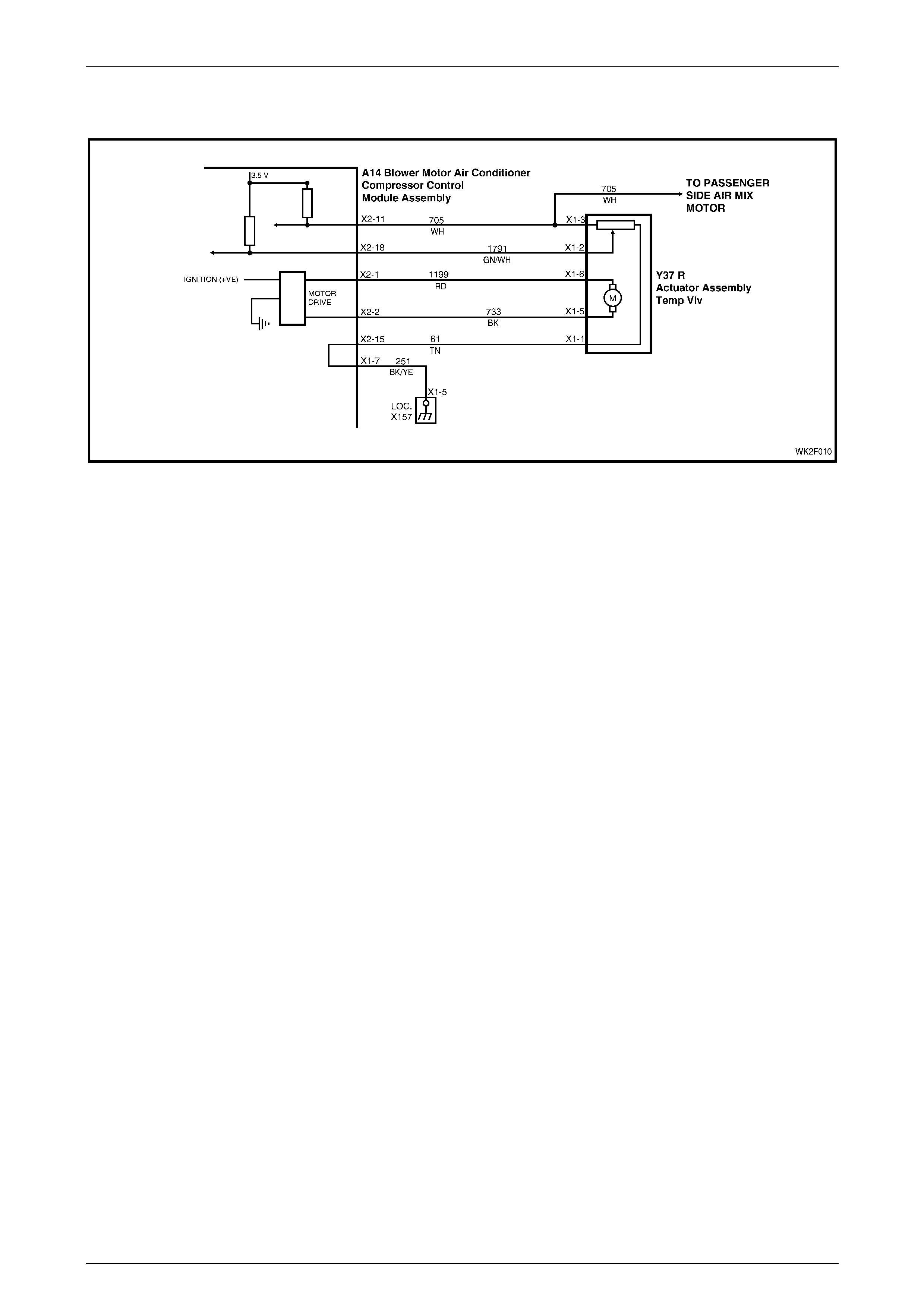
HVAC Occupant Climat e Control (Auto A/ C) – Diagnostic s Page 2F–125
20–FEB–2003 Page 2F-125
DTC 48 – Drivers Air Mix Max. Calibrat i on Error (RHD)
Figure 2F – 41
Circuit Description:
The air mix motor is an electric motor used to operate the air mix door. The electric motor is sent a voltage signal of
12.5 volts from the OCC control module which causes the motor to turn, and in turn moves the air mix door towards or
away from the heater core. The direction change takes place by reversing the polarity of this motor.
A potentiometer (PBR) is housed in the air mix motor circuit, which feeds signals (3.6 ± 0.18 volts) back to the OCC
control module as to the positioning of the motor and consequently the air mix door.
DTC 48 will set: if the PBR feedback signal fails to reach the requested value. This will occur if the PBR or motor is open
or short circuited, or an air mix door is jammed or sticking.

HVAC Occupant Climat e Control (Auto A/ C) – Diagnostic s Page 2F–126
20–FEB–2003 Page 2F-126
Test Description:
Number(s) below refer to Step numbers in the following
Diagnostic Chart:
1. Ensures the Diagnostic Circuit Check has been
performed.
2. This test checks that the DTC is current.
3. This test checks if the motor is moving.
4. This test checks that the motor is stopping within the
correct range @ full cold.
5. This test checks that the motor is stopping within the
correct range @ full hot.
6. Attempts to recalibrate and check DTC is still
current.
7. Determines if a PBR fault is the likely cause of the
problem.
8. Determines if a motor fault is more likely than a PBR
fault to be the cause of the problem.
9. Checks fault has been rectified.
Diagnostic Aid s:
An air mix motor or door problem will always be associated
with non-regulated or incorrect temperatures from mode
positions.
The OCC control module, during calibration, sets a minimum
and a maximum PBR value for the air mix motor in its
memory. It is these values which determine the operating
range of the air mix motor and against which all movements
of the air mix adjustment are scaled. Any PBR signal value
outside the minimum or maximum value are considered a
motor fault.
The OCC control module monitors the rate of change of PBR
signal during air mix motor movement. If this rate of change
falls to 0 (such as a broken air mix motor wire or physical
jamb), the OCC control module will recognise the stoppage
and set the fault code.
If DTC 48 was present before turning the ignition off, when
the ignition is turned on again, the OCC control module will
automatically try to recalibrate the air mix door. This takes
approximately 15 seconds. If the recalibration fails, then
DTC 48 will be set again.
Notes On Diagnostic Chart:
1. Refer to Sect ion 12P, WIRING DIAGR AM S for
procedures on checking wiring faults.
2. Refer to Section 0C TECH 2 for connecting and us ing
TECH 2.

HVAC Occupant Climat e Control (Auto A/ C) – Diagnostic s Page 2F–127
20–FEB–2003 Page 2F-127
DTC 48 –Driver’s Air Mix Max. Calibration Error (RHD) Diagnostic Chart
STEP ACTION VALUE YES NO
1 Was the Diagnostic Circuit Check performed? Go to Step 2. Go to Chart A –
DIAGNOSTIC
CIRCUIT
CHECK in this
Section.
2 Turn the ignition off.
Connect TECH 2 to the DLC.
Select Diagnostics / Model Year / Vehicle Model / Body /
Occupant Climate Control / Diagnostic Trouble Codes /
Read Current DTC Information.
Does DTC 48 display as the current DTC?
Go to Step 3. Go to Step 9.
3 With TECH 2 connected, select Body / Occupant
Climate Control / Miscellaneous Tests / Drivers Side Air
Mix Motor – Door Movement.
Increase to max imum t hen de crea se to mini mum .
Does the TECH 2 value change accordingly?
Go to Step 4. Go to Step 7.
4 With Drivers Side Air Mix Motor – Door Mo vement test
selected, decrease the air mix door to minimum.
Does TECH 2 display a value within 0.6 – 0.9 volt?
Go to Step 5. Go to chart
DTC 40 – AIR
MIX DOOR
MOTOR DRIVER
ERROR (RHD
DRIVERS SIDE
MOTOR) in this
Section.
5 With Drivers Side Air Mix Motor – Door Mo vement test
selected increase the air mix door to maximum.
Does TECH 2 display a value within 2.6 to 2.9 volts?
Go to Step 6. Go to chart
DTC 40 – AIR
MIX DOOR
MOTOR DRIVER
ERROR (RHD
DRIVERS SIDE
MOTOR) in this
Section.
6 With TECH 2 connected, select Body / Occupant
Climate Control / Program / Calibrate Air Mix Door.
Reprogram the air mix doors.
Turn the ignition off.
Turn the ignition on.
Does DTC 48 set as a current DTC?
Go to chart
DTC 40 – AIR
MIX DOOR
MOTOR DRIVER
ERROR (RHD
DRIVERS SIDE
MOTOR) in this
Section.
Go to Step 9.
7 In Step 3, did TECH 2 display less than 0.3 volt? Go to chart
DTC 43 –
DRIVERS AIR
MIX DOOR
MOTOR
FEEDBACK
CIRCUIT
VOLTAGE TOO
LO W in this
Section .
Go to Step 8

HVAC Occupant Climat e Control (Auto A/ C) – Diagnostic s Page 2F–128
20–FEB–2003 Page 2F-128
STEP ACTION VALUE YES NO
8 In Step 3, did TECH 2 display more than 3.4 volts? Go to chart
DTC 44 –
DRIVERS AIR
MIX DOOR
MOTOR
FEEDBACK
CIRCUIT
VOLTAGE TOO
HIGH in this
Section .
Go to chart
DTC 40 – AIR
MIX DOOR
MOTOR DRIVER
ERROR (RHD
DRIVERS SIDE
MOTOR) in this
Section.
9 With TECH 2 connected, select Body / Occupant
Climate Control / Miscellaneous Tests / Drivers Side Air
Mix Motor– Door Movement.
Increase to max imum t hen de crea se to mini mum .
Does DTC 48 set as a current DTC?
Go to Step 3. Recalibration of
Air mix door may
have corrected
fault or DTC 48 is
intermittent.
(Carry out air mix
door calibration if
not already done
so. Refer to 1.2
TECH 2 TEST
MODES AND
DISPLAYS FOR
OCC
DIAGNOSIS
and/or refer to 3
Diagnostic
Charts in this
Section.
WHEN ALL DIAGNOSIS AND REPAIRS ARE COMPLETED, VERIFY CORRECT OPERATION

HVAC Occupant Climat e Control (Auto A/ C) – Diagnostic s Page 2F–129
20–FEB–2003 Page 2F-129
DTC 49 – Pass Ai r M i x Min. Calibration Error
Figure 2F – 42
Circuit Description:
The air mix motor is an electric motor used to operate the air mix door. The electric motor is sent a voltage signal of
12.5 volts from the OCC control module which causes the motor to turn, and in turn moves the air mix door towards or
away from the heater core. The direction change takes place by reversing the polarity of this motor.
A potentiometer (PBR) is housed in the air mix motor circuit, which feeds signals (3.6 ± 0.18 volts) back to the OCC
control module as to the positioning of the motor and consequently the air mix door.
DTC 49 will set: if the PBR feedback signal fails to reach the requested value. This will occur if the PBR or motor is open
or short circuited, or an air mix door is jammed or sticking.

HVAC Occupant Climat e Control (Auto A/ C) – Diagnostic s Page 2F–130
20–FEB–2003 Page 2F-130
Test Description:
Number(s) below refer to Step numbers in the following
Diagnostic Chart:
1. Ensures the Diagnostic Circuit Check has been
performed.
2. This test checks that the DTC is current.
3. This test checks if the motor is moving.
4. This test checks that the motor is stopping within the
correct range @ full cold.
5. This test checks that the motor is stopping within the
correct range @ full hot.
6. Attempts to recalibrate and check DTC is still
current.
7. Determines if a PBR fault is the likely cause of the
problem.
8. Determines if a motor fault is more likely than a PBR
fault to be the cause of the problem.
9. Checks fault has been rectified.
Diagnostic Aid s:
An air mix motor or door problem will always be associated
with non-regulated or incorrect temperatures from mode
positions.
The OCC control module, during calibration, sets a minimum
and a maximum PBR value for the air mix motor in its
memory. It is these values which determine the operating
range of the air mix motor and against which all movements
of the air mix adjustment are scaled. Any PBR signal value
outside the minimum or maximum value are considered a
motor fault.
The OCC control module monitors the rate of change of PBR
signal during air mix motor movement. If this rate of change
falls to 0 (such as a broken air mix motor wire or physical
jamb), the OCC control module will recognise the stoppage
and set the fault code.
If DTC 49 was present before turning the ignition off, when
the ignition is turned on again, the OCC control module will
automatically try to recalibrate the air mix door. This takes
approximately 15 seconds. If the recalibration fails, then
DTC 49 will be set again.
Notes On Diagnostic Chart:
1. Refer to Sect ion 12P, WIRING DIAGR AM S for
procedures on checking wiring faults.
2. Refer to Section 0C TECH 2 for connecting and us ing
TECH 2.

HVAC Occupant Climat e Control (Auto A/ C) – Diagnostic s Page 2F–131
20–FEB–2003 Page 2F-131
DTC 49 –Pass Air Mix Min. Calibration Error Diagnostic Chart
STEP ACTION VALUE YES NO
1 Was the Diagnostic Circuit Check performed? Go to Step 2. Go to Chart A –
DIAGNOSTIC
CIRCUIT
CHECK in this
Section.
2 Turn the ignition off.
Connect TECH 2 to the DLC.
Select Diagnostics / Model Year / Vehicle Model / Body /
Occupant Climate Control / Diagnostic Trouble Codes /
Read Current DTC Information.
Does DTC 49 display as the current DTC?
Go to Step 3. Go to Step 9.
3 With TECH 2 connected, select Body / Occupant
Climate Control / Miscellaneous Tests / Passenger Side
Air Mix Motor – Door Movement and increase to
maximum then decrease to minimum.
Does the TECH 2 value change accordingly?
Go to Step 4. Go to Step 7.
4 With Passengers Side Air Mix Motor – Door Movement
test still selected, decrease air mix door to minimum.
Does TECH 2 display a value within 0.6 – 0.9 volt?
Go to Step 5. Go to chart
DTC 40 – AIR
MIX DOOR
MOTOR DRIVER
ERROR (RHD
PASSENGERS
SIDE MOTOR) in
this Section.
5 With Passengers Side Air Mix Motor – Door Movement
test still selected increase air mix door to maximum.
Does TECH 2 display a value within 2.6 to 2.9 volts?
Go to Step 6. Go to chart
DTC 40 – AIR
MIX DOOR
MOTOR DRIVER
ERROR (RHD
PASSENGERS
SIDE MOTOR) in
this Section.
6 With TECH 2 connected, select Body / Occupant
Climate Control / Program / Calibrate Air Mix Door.
Reprogram the air mix doors.
Turn the ignition off.
Turn the ignition on.
Does DTC 49 set as a current DTC?
Go to chart
DTC 40 – AIR
MIX DOOR
MOTOR DRIVER
ERROR (RHD
PASSENGERS
SIDE MOTOR) in
this Section.
Go to Step 9.
7 In Step 3, did TECH 2 display less than 0.3 volt? Go to chart
DTC – 45
PASSENGERS
AIR MIX DOOR
MOTOR
FEEDBACK
CIRCUIT
VOLTAGE TOO
LO W in this
Section.
Go to Step 8.

HVAC Occupant Climat e Control (Auto A/ C) – Diagnostic s Page 2F–132
20–FEB–2003 Page 2F-132
STEP ACTION VALUE YES NO
8 In Step 3, did TECH 2 display more than 3.4 volts? Go to chart
DTC – 46
PASSENGERS
AIR MIX DOOR
MOTOR
FEEDBACK
CIRCUIT
VOLTAGE TOO
HIGH in this
Section.
Go to chart
DTC 40 – AIR
MIX DOOR
MOTOR DRIVER
ERROR (RHD
PASSENGERS
SIDE MOTOR) in
this Section.
9 With TECH 2 connected, select Body / Occupant
Climate Control / Miscellaneous Tests / Passengers
Side Air Mix Motor– Door Movement.
Increase to max imum t hen de crea se to mini mum .
Does DTC 49 set as a current DTC?
Go to Step 3. Recalibration of
Air mix door may
have corrected
the fault or
DTC 49 is
intermittent.
(Carry out air mix
door calibration if
not already done
so. Refer to 1.2
TECH 2 TEST
MODES AND
DISPLAYS FOR
OCC
DIAGNOSIS
and/or refer to 3
DIAGNOSTIC
CHARTS in this
Section.
WHEN ALL DIAGNOSIS AND REPAIRS ARE COMPLETED, VERIFY CORRECT OPERATION
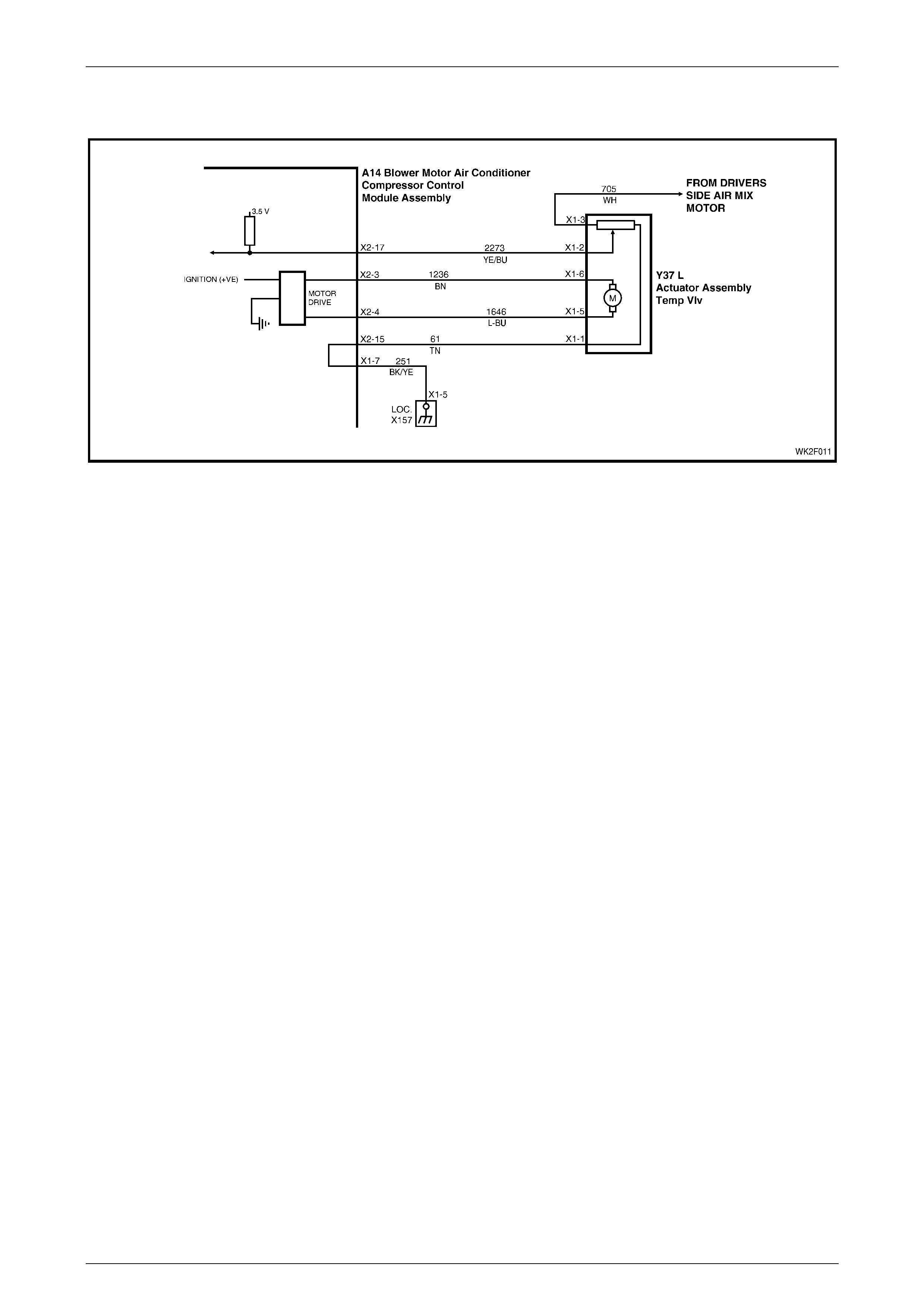
HVAC Occupant Climat e Control (Auto A/ C) – Diagnostic s Page 2F–133
20–FEB–2003 Page 2F-133
DTC 50 – Pass Ai r Mix Max. Calibration Error
Figure 2F – 43
Circuit Description:
The air mix motor is an electric motor used to operate the air mix door. The electric motor is sent a voltage signal of
12.5 volts from the OCC control module which causes the motor to turn, and in turn moves the air mix door towards or
away from the heater core. The direction change takes place by reversing the polarity of this motor.
A potentiometer (PBR) is housed in the air mix motor circuit, which feeds signals (3.6 ± 0.18 volts) back to the OCC
control module as to the positioning of the motor and consequently the air mix door.
DTC 50 will set: if the PBR feedback signal fails to reach the requested value. This will occur if the PBR or motor is open
or short circuited, or an air mix door is jammed or sticking.

HVAC Occupant Climat e Control (Auto A/ C) – Diagnostic s Page 2F–134
20–FEB–2003 Page 2F-134
Test Description:
Number(s) below refer to Step numbers in the following
Diagnostic Chart:
1. Ensures the Diagnostic Circuit Check has been
performed.
2. This test checks that the DTC is current.
3. This test checks if the motor is moving.
4. This test checks that the motor is stopping within the
correct range @ full cold.
5. This test checks that the motor is stopping within the
correct range @ full hot.
6. Attempts to recalibrate and check DTC is still
current.
7. Determines if a PBR fault is the likely cause of the
problem.
8. Determines if a motor fault is more likely than a PBR
fault to be the cause of the problem.
9. Checks fault has been rectified.
Diagnostic Aid s:
An air mix motor or door problem will always be associated
with non-regulated or incorrect temperatures from mode
positions.
The OCC control module, during calibration, sets a minimum
and a maximum PBR value for the air mix motor in its
memory. It is these values which determine the operating
range of the air mix motor and against which all movements
of the air mix adjustment are scaled. Any PBR signal value
outside the minimum or maximum value are considered a
motor fault.
The OCC control module monitors the rate of change of PBR
signal during air mix motor movement. If this rate of change
falls to 0 (such as a broken air mix motor wire or physical
jamb), the OCC control module will recognise the stoppage
and set the fault code.
If DTC 50 was present before turning the ignition off, when
the ignition is turned on again, the OCC control module will
automatically try to recalibrate the air mix door. This takes
approximately 15 seconds. If the recalibration fails, then
DTC 50 will be set again.
Notes On Diagnostic Chart:
1. Refer to Sect ion 12P, WIRING DIAGR AM S for
procedures on checking wiring faults.
2. Refer to Section 0C TECH 2 for connecting and us ing
TECH 2.

HVAC Occupant Climat e Control (Auto A/ C) – Diagnostic s Page 2F–135
20–FEB–2003 Page 2F-135
DTC 50 –Pass Air Mix Max. Calibration Error Diagnostic Chart
STEP ACTION VALUE YES NO
1 Was the Diagnostic Circuit Check performed? Go to Step 2. Go to Chart A –
DIAGNOSTIC
CIRCUIT
CHECK in this
Section.
2 Turn the ignition off.
Connect TECH 2 to the DLC.
Select Diagnostics / Model Year / Vehicle Model / Body /
Occupant Climate Control / Diagnostic Trouble Codes /
Read Current DTC Information.
Does DTC 50 display as the current DTC?
Go to Step 3. Go to Step 9.
3 With TECH 2 connected, select Body / Occupant
Climate Control / Miscellaneous Tests / Passenger Side
Air Mix Motor – Door Movement and increase to
maximum then decrease to minimum.
Does the TECH 2 value change accordingly?
Go to Step 4. Go to Step 7.
4 With Passengers Side Air Mix Motor – Door Movement
test still selected, decrease air mix door to minimum.
Does TECH 2 display a value within 0.6 – 0.9 volt?
Go to Step 5. Go to chart
DTC 40 – AIR
MIX DOOR
MOTOR DRIVER
ERROR (RHD
PASSENGERS
SIDE MOTOR) in
this Section.
5 With Passengers Side Air Mix Motor – Door Movement
test still selected increase air mix door to maximum.
Does TECH 2 display a value within 2.6 to 2.9 volts?
Go to Step 6. Go to chart
DTC 40 – AIR
MIX DOOR
MOTOR DRIVER
ERROR (RHD
PASSENGERS
SIDE MOTOR) in
this Section.
6 With TECH 2 connected, select Body / Occupant
Climate Control / Program / Calibrate Air Mix Door.
Reprogram the air mix doors.
Turn the ignition off.
Turn the ignition on.
Does DTC 50 set as a current DTC?
Go to chart
DTC 40 – AIR
MIX DOOR
MOTOR DRIVER
ERROR (RHD
PASSENGERS
SIDE MOTOR) in
this Section.
Go to Step 9.
7 In Step 3, did TECH 2 display less than 0.3 volt? Go to chart
DTC – 45
PASSENGERS
AIR MIX DOOR
MOTOR
FEEDBACK
CIRCUIT
VOLTAGE TOO
LO W in this
Section.
Go to Step 8.

HVAC Occupant Climat e Control (Auto A/ C) – Diagnostic s Page 2F–136
20–FEB–2003 Page 2F-136
STEP ACTION VALUE YES NO
8 In Step 3, did TECH 2 display more than 3.4 volts? Go to chart
DTC – 46
PASSENGERS
AIR MIX DOOR
MOTOR
FEEDBACK
CIRCUIT
VOLTAGE TOO
HIGH in this
Section.
Go to chart
DTC 40 – AIR
MIX DOOR
MOTOR DRIVER
ERROR (RHD
PASSENGERS
SIDE MOTOR) in
this Section.
9 With TECH 2 connected, select Body / Occupant
Climate Control / Miscellaneous Tests / Passengers
Side Air Mix Motor– Door Movement.
Increase to max imum t hen de crea se to mini mum .
Does DTC 50 set as a current DTC?
Go to Step 3. Recalibration of
Air mix door may
have corrected
the fault or
DTC 50 is
intermittent.
(Carry out air mix
door calibration if
not already done
so. Refer to 1.2
TECH 2 TEST
MODES AND
DISPLAYS FOR
OCC
DIAGNOSIS in
the MY2003 VY
and V2 Series
Service
Information.
WHEN ALL DIAGNOSIS AND REPAIRS ARE COMPLETED, VERIFY CORRECT OPERATION

HVAC Occupant Climat e Control (Auto A/ C) – Diagnostic s Page 2F–137
20–FEB–2003 Page 2F-137
4 Wiring Diagrams
The following figures provide electrical connector diagrams and wiring diagrams applicable to HVAC Occupant Climate
Control (Auto A/C) systems as fitted to Level 2 to 5 MY2004 WK Series vehicles. These diagrams should be used in
conjunction with the diagnostic chart circuit diagrams when diagnosing circuit faults. The content of these figures is as
follows:
• Electrical connectors (A15 – M7) – refer to Figure 2F – 44
• Electrical connectors continued (M3 – X119) – refer to Figure 2F – 45
• Electrical connectors continued (X126 – Y37) – refer to F igure 2F – 46
• Wiring diagram: HVAC OCC (Auto A/C) system V6 (LHD) – refer to Figure 2F – 47
• W iring diagram: HVAC OCC (Auto A/C) system V6 (RHD) – refer to Figure 2F – 48
• W iring diagram: HVAC OCC (Auto A/C) system GEN III V8 (LHD) – refer to Figure 2F – 49
• W iring diagram: HVAC OCC (Auto A/C) system GEN III V8 (RHD) – refer to Figure 2F – 50
• Wiring diagram: Rear Remote Control (Level 5 Models only) – refer to Figure 2F – 51

HVAC Occupant Climat e Control (Auto A/ C) – Diagnostic s Page 2F–138
20–FEB–2003 Page 2F-138
In the following wiring diagrams (Figure 2F – 47 to Figure 2F – 51) a ll co mpon ents are described and di splay ed in
accordance to the Integrated Vehicle Electrical Design (IVED) standard as applied to MY2004 WK Series vehicles. To
assist in wiring diagram interpretation, refer to the following table:
IVED Description IVED Component Identification Common Description
Switch Asm – Ign & Start S149 Ignition Switch
V6 Module Asm Pwrt Cont A84 V6 Powertrain Control Module
V8 Module Asm Pwrt Cont A84 GEN III V8 Powertrain Control Module
Module Asm Body Cont A15 Body Control Module
Motor Asm Blo M3 Blower Motor
Module Asm Bl o & Air Inl A13 Blower Motor Resistor
Module Asm Blo & A/C Cmpr A14_LHD OCC Control Module for LHD Models
Module Asm Blo & A/C Cmpr A14_RHD OCC Control Module for RHD Models
Module Asm Rdo Cont A94 Rear Remote Control
Actuator Asm Temp Vlv Y37 LHD Air Mix Motor for LHD Models
Actuator Asm Temp Vlv Y37 L Passenger’s Air Mix Motor for RHD Models
Actuator Asm Temp Vlv Y37 R Driver’s Air Mix Motor for RHD Models
Actuator Asm I/S Ai r Vlv Y19 Solenoid Pack
Actuator Asm Htr Wat Shutoff Vlv Y18_Lhd Water Valve VSV for LHD Models
Sensor Asm Amb Air Temp B23 Ambient Air Temperature Sensor
Sensor Asm I/S Air Temp B59 In-car Temperature Sensor
Sensor Asm Duct Air Temp B34 Evaporative Temperature Sensor
Coil A/c Clu L7 Compressor Clutch
Sensor Asm A/C Refrig Press B18 A/C Pressure Transducer
Motor Asm Eng Cool Fan M7_Std V6 Standard Cooling Fan System
Motor Asm Eng Cool Fan M7_HP V6 High Power Cooling Fan System
Motor Asm Eng Cool Fan M7_V8 GEN III V8 Cooling Fan System
Window Rear R22 Heated Rear Window
The following table lists the IVED standard wire colour abbreviations:
BK Black D-GN Dark green L-GN Light green RD Red
BU Blue GN Green OG Orange TN Tan
BN Brown GY Grey PK Pink WH White
D-BU Dark blue L-BU Light blue PU Purple YE Yellow
NOTE
For electrical connector locations and additional
wiring diagram information refer to Section 12P
WIRING DIAGRAMS.
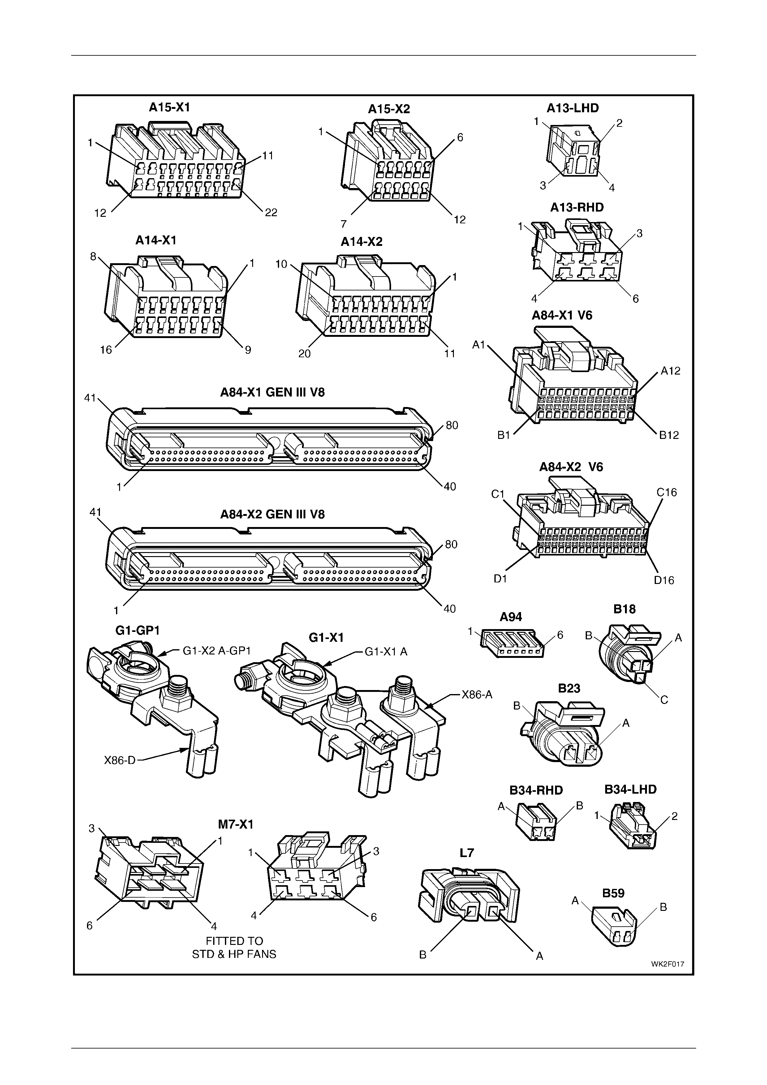
HVAC Occupant Climat e Control (Auto A/ C) – Diagnostic s Page 2F–139
20–FEB–2003 Page 2F-139
Connectors: HVAC OCC (Auto A/C) System
Figure 2F – 44
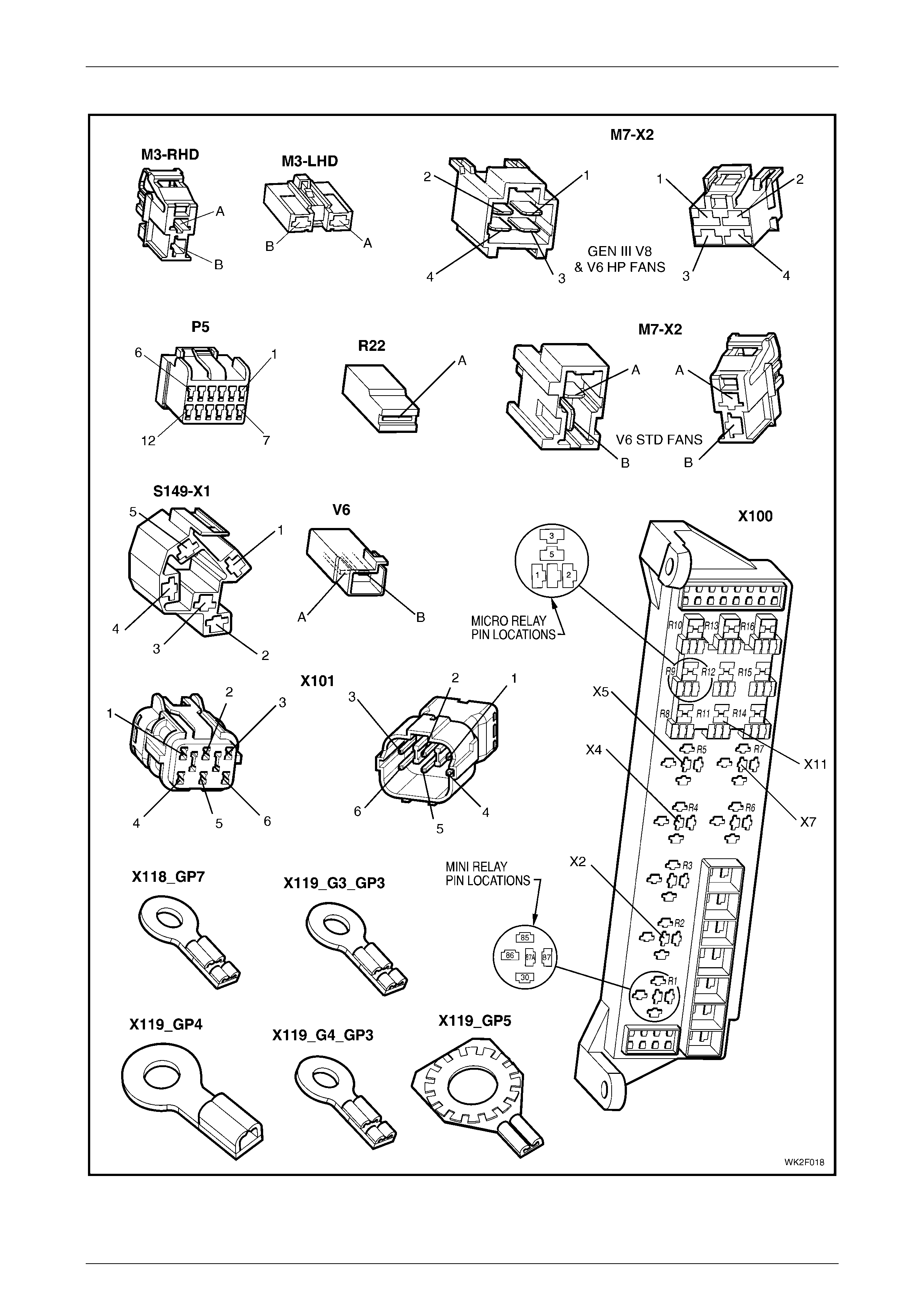
HVAC Occupant Climat e Control (Auto A/ C) – Diagnostic s Page 2F–140
20–FEB–2003 Page 2F-140
Connectors: HVAC OCC (Auto A/C) S ystem Continued
Figure 2F – 45
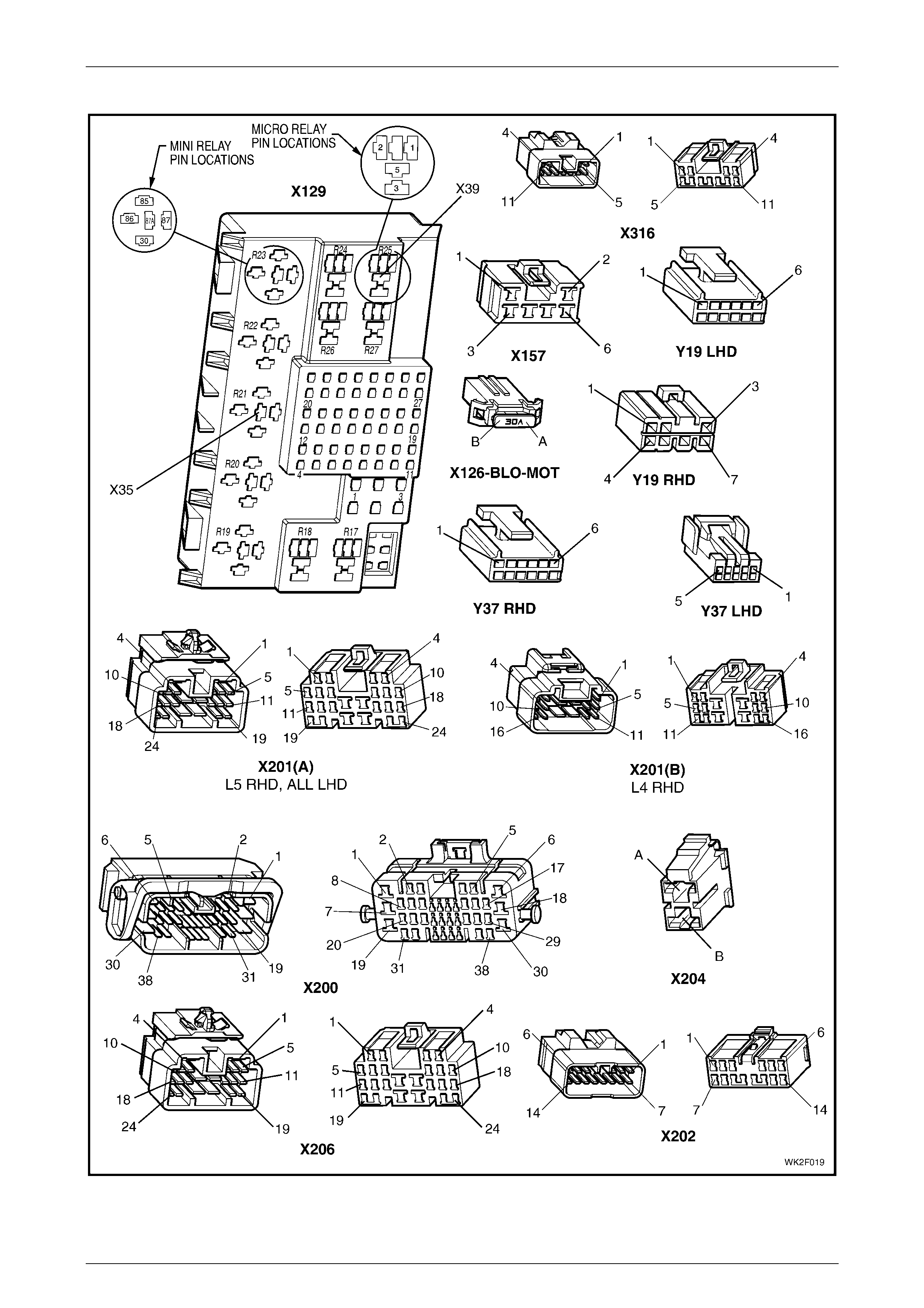
HVAC Occupant Climat e Control (Auto A/ C) – Diagnostic s Page 2F–141
20–FEB–2003 Page 2F-141
Connectors: HVAC OCC (Auto A/C) S ystem Continued
Figure 2F – 46
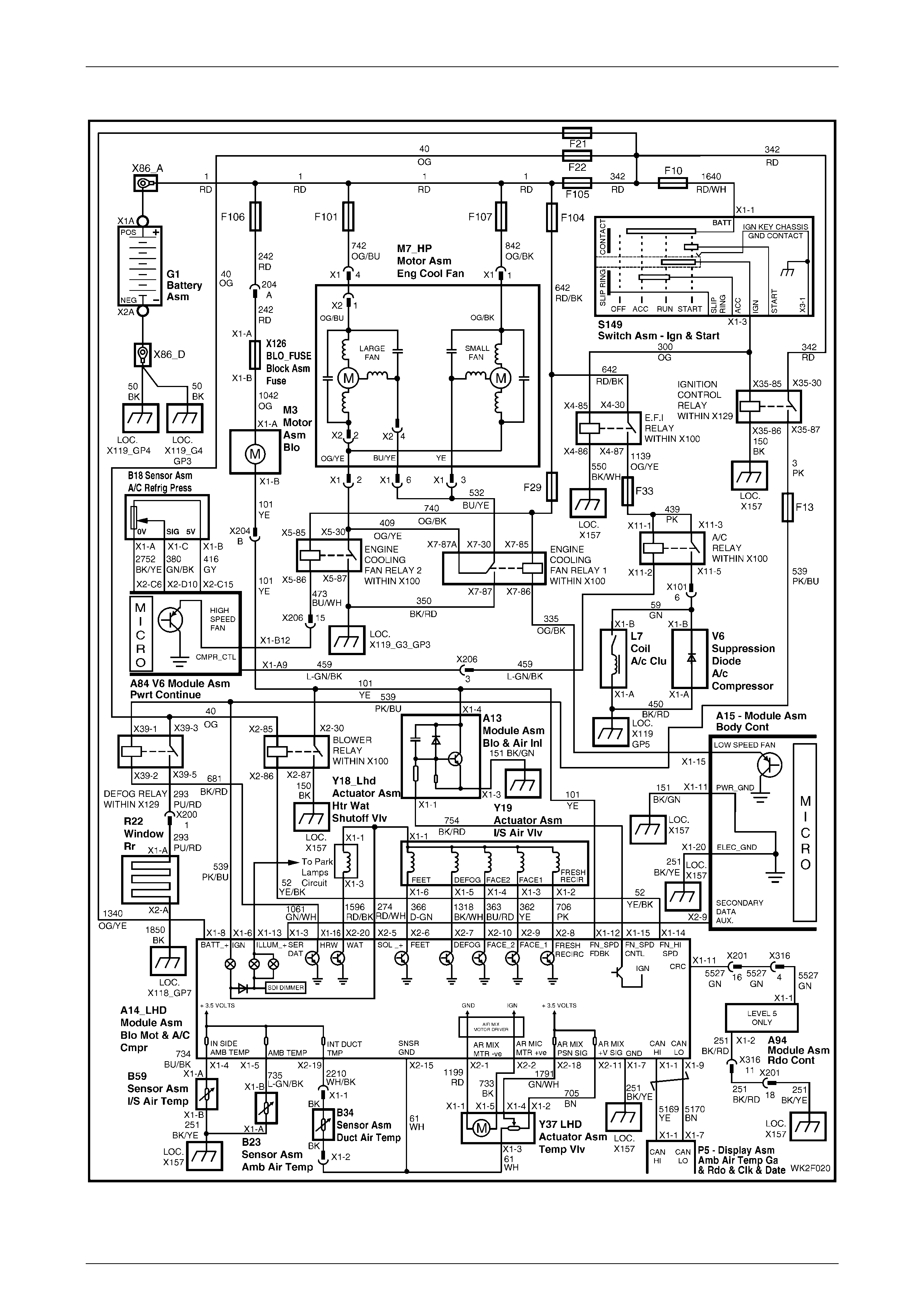
HVAC Occupant Climat e Control (Auto A/ C) – Diagnostic s Page 2F–142
20–FEB–2003 Page 2F-142
Wiring Diagr am: HVAC OCC (Auto A/C) System – V6 (LHD)
Figure 2F – 47
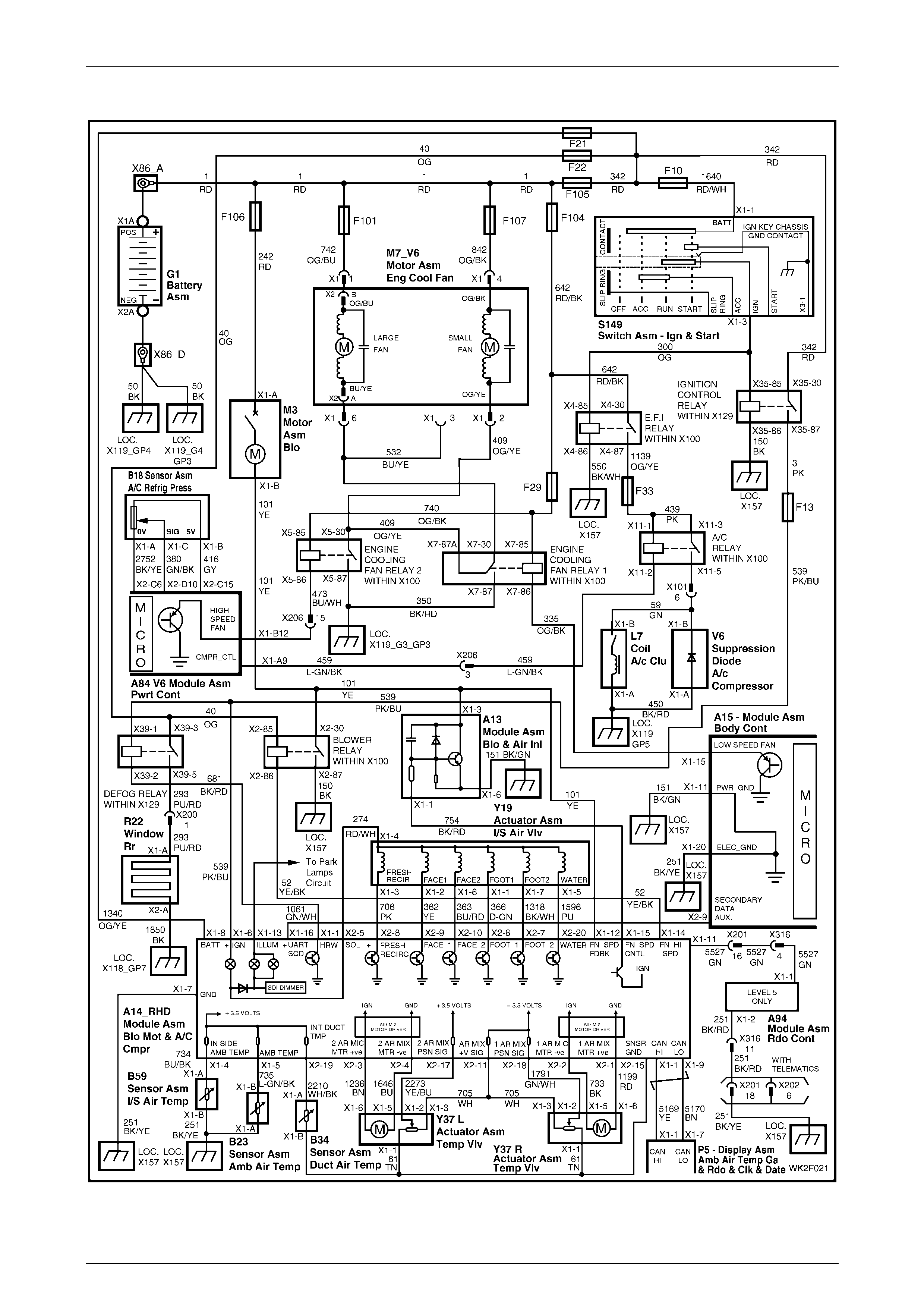
HVAC Occupant Climat e Control (Auto A/ C) – Diagnostic s Page 2F–143
20–FEB–2003 Page 2F-143
Wiring Diagr am: HV AC OCC (Auto A/C) S ystem – V6 (RHD)
Figure 2F – 48
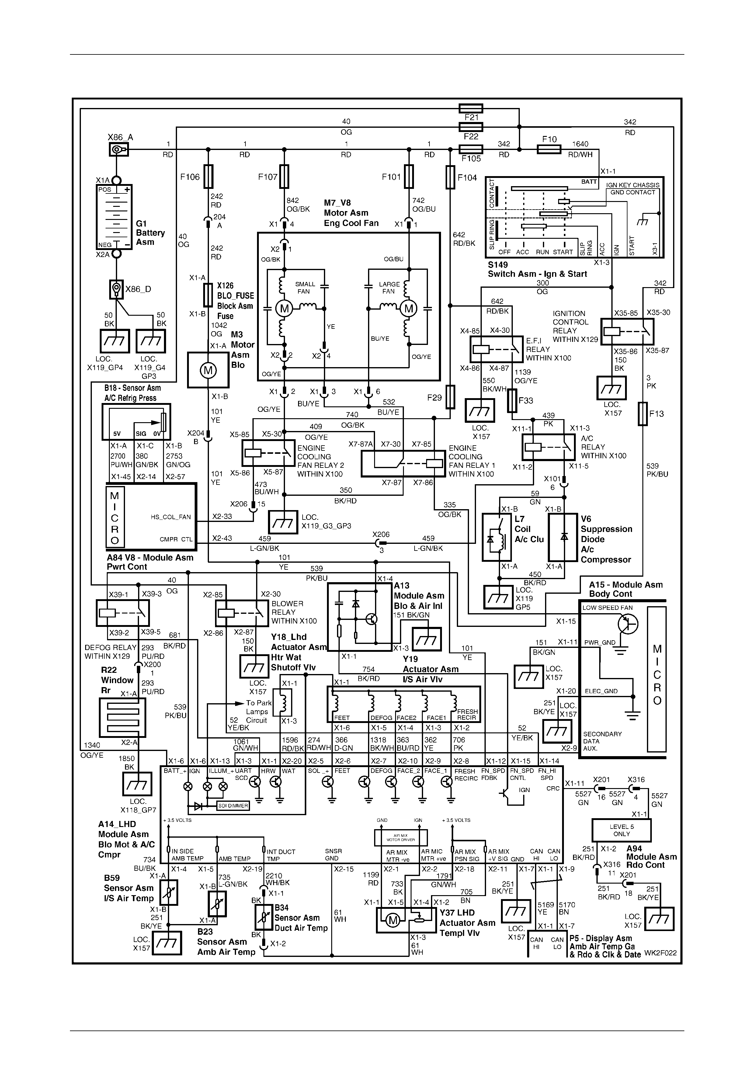
HVAC Occupant Climat e Control (Auto A/ C) – Diagnostic s Page 2F–144
20–FEB–2003 Page 2F-144
Wiri ng Diagram: HV AC OCC (Auto A/C) S ystem – GEN III V8 (LHD)
Figure 2F – 49
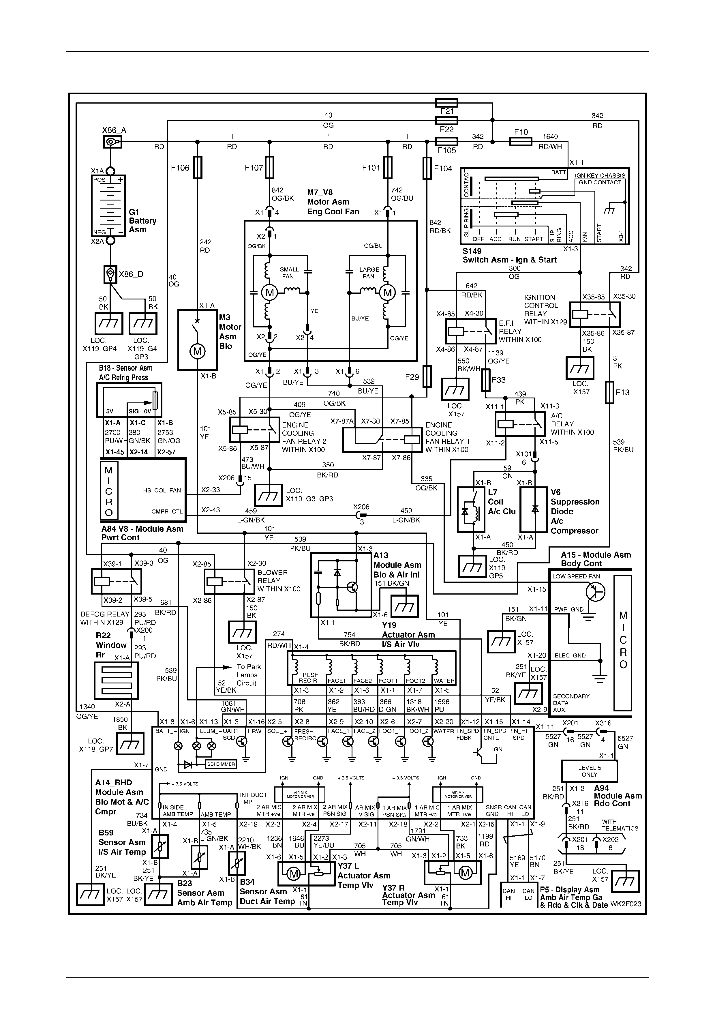
HVAC Occupant Climat e Control (Auto A/ C) – Diagnostic s Page 2F–145
20–FEB–2003 Page 2F-145
Wiri ng Diagram: HV AC OCC (Auto A/C) S ystem – GEN III V8 (RHD)
Figure 2F – 50
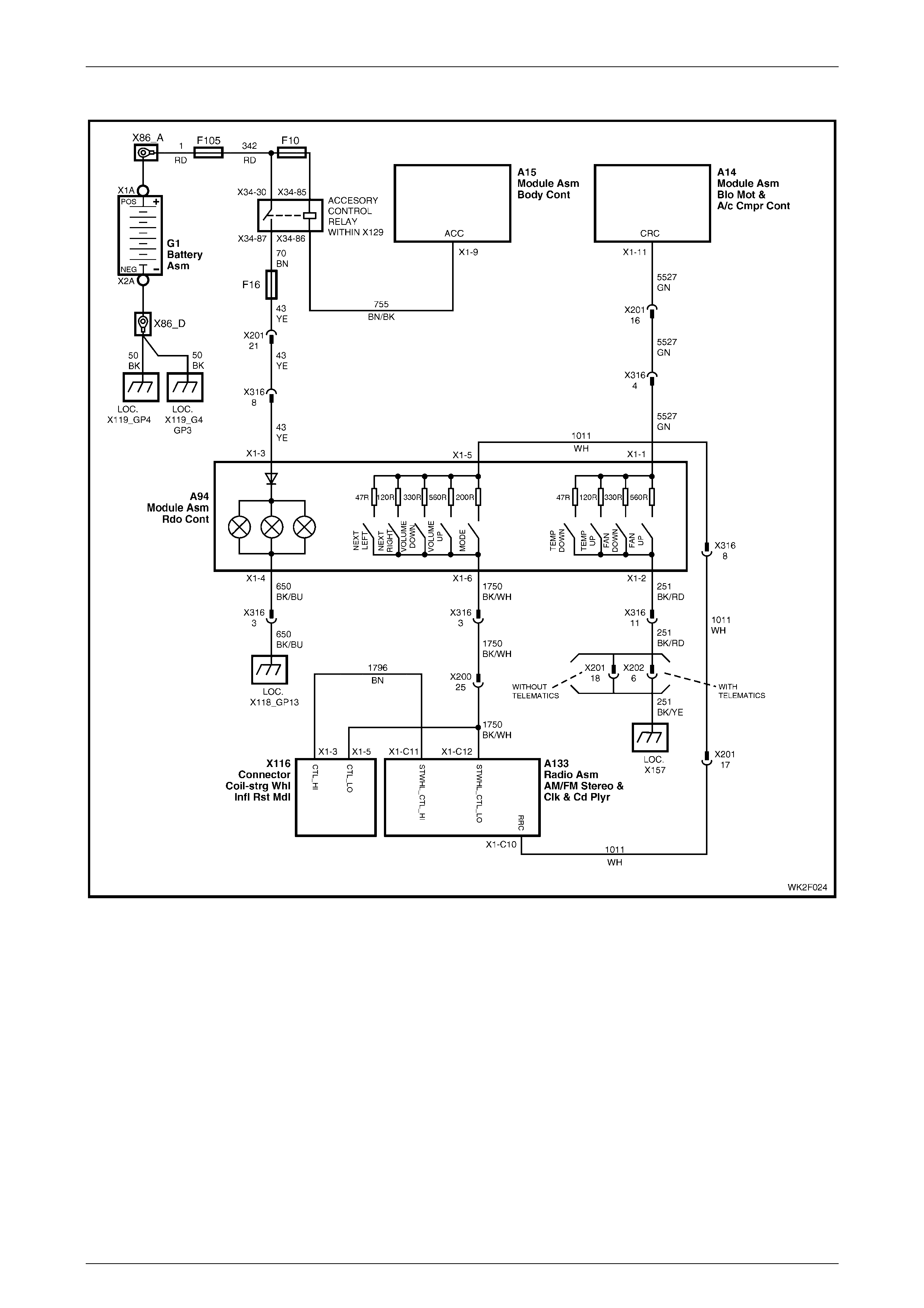
HVAC Occupant Climat e Control (Auto A/ C) – Diagnostic s Page 2F–146
20–FEB–2003 Page 2F-146
Wiring Diagram: Rear Remote Control (Level 5 Models only)
Figure 2F – 51