
SECTION 1B - AIR CONDITIONING
1. GENERAL DESCRIPTION
1.1 REFRIGERANT CIRCULATION
1.2 REFRIGERANT TYPE
1.3 MAJOR COMPONENT S AND
LOCATION
2. DIAGNOSIS
2.1 GENERAL DIAGNOSIS TABLE
2.2 ABNORMAL NOISE DIAGNOSIS
Abnormal Noise From Compressor
Ab normal Noise Fr om
Magnetic Clutch
Ab normal Noise Fr om Tubing
Ab normal Noise Fr om
Condenser Assembly
Ab normal Noise Fr om
Crankshaft Pulley
Ab normal Noise Fr om
Tension Pulley
Ab normal Noise Fr om
A/C Evaporator
Ab normal Noise Fr om B lo we r
Fan Motor
2.3 QUICK CHECK OF
REFRIGERANT CHARGE
Checking Refrige rant Charge
2.4 PERFORMANCE DIAGNOSIS
Performance Di agnosis
Table
High Pressure Gauge
Low Pressure Gauge
Thermometer At Centre Duct
Detail Diagnosis Table
(Ambient Temperature at 30°c)
2.5 COMPRESSOR DRIVE BELT
Inspection
Adjustment
Replacement
3. ELECTRICAL DIAGNOSIS
3.1 WIRING DIAGRAM
3.2 A/C SYSTEM INSPECTION OF
ECM AND ITS CIRCUITS
Vol tage Check
ECM Vol tage Va lu es Ta ble fo r
A/C Control
4. REFRIGERANT RECOVERY,
EVACUATING AND CHARGING
4.1 OPERATING PROCEDURE FOR
REFRIGERANT CHARGING
4.2 RECOVERY
Refrigerant Recovery
4.3 REPLENISHING
COMPRESSOR OIL
WARNING:
For vehicles equipped with Supplem en tary Restra int (Airbag) System:
• Service on and around the airbag system components or wiring must be performed only by an
authorised HOLDEN retailer. Refer to AIRBAG SYSTEM-COMPONENTS and WIRING LOCATION
VIEW under GENERAL DESCRIPTION in Section 10B AIRBAG SYSTEM in order to confirm
whether you are performing service on or near the airbag system co mponents or wiring. Please
observe all WARNINGS and SER VICE PRECA UTIONS u nder ON- VEHICLE SER VI CE i n Sectio n 10B
AIRBAG SYSTEM before performing service on or around the air bag syste m co m po nen ts o r wir-
ing. Failure to follow WARNINGS could result in unintentional activation of the system or could
render the system inoper ative. Either of these two conditions may result in severe injury.
• Technical service work must be started at least 90 seconds after the ignition switch is turne d to
the “LOCK” position and the negative cable is disconn ected from the battery. Otherwise , the sys-
tem may be activated by reserve energ y in the Sensing and Diagnostic Module (SDM).
CAUTION:
The ai r conditioning system of this vehi c l e uses refri gerant HFC-134a (R-134a).
Neither the refrige rant, compr essor o il or com ponent p arts ar e interchang eable betw een the differ-
ent types of A/C refrigerant.
For identification of which refrigerant is used, refer to 1.1 REFRIGERANT TYPE in this Section.
When replenish ing or changi ng refrigerant and compressor oil and when replacing parts, make sure
that the material or the part to be used is appropriate to the A/C refrigerant installed in the vehicle
being ser viced. Use of inco rrect par ts will resul t in leakage o f refriger ant, damage to par ts or other
faulty conditions.
Techline

Wh en C harging with
Refrigerant Only
When Rep lacing Comp resso r
When Rep lacing Other Parts
4.4 EVACUATING
Evacu ating Proce dure
4.5 CHECKING SYSTEM FOR
PRESSURE LEAKS
4.6 CHARGING
Charging Procedure
4.7 REMOVING MANIFOLD
GAUGE SET
4.8 LEAK TEST
Liquid Leak Detectors
5. ON-VEHICLE SERVICE
5.1 SERVICE PRECAUTION
Refrigerant Line
Handling Refrigerant
HFC-134a (R-134a)
Refrigerant Reco very
Refrigerant Charge
5.2 CONDENSER ASSEMBLY
Inspection
Removal
Installation
5.3 RECEIVER/DRIER
Removal
Installation
5.4 CONDENSER COOLING FAN
Removal
Installation
Inspection
5.5 COOLING UNIT (EVAPORATOR)
Removal
Inspection
Installation
5.6 A/C EVAPORATOR
TEMPERATURE SENSOR
5.7 EXPANSION VALVE
Removal
Installation
Inspection
5.8 A/C REFRIGERANT PRESSURE
SWITCH
Inspection
5.9 A/C SWITCH
Removal and Installation
Inspection
5.10 COMPRESSOR RELAY AND
CONDENSER COOLI NG
FAN RELAY
Inspection
5.11 COMPRESSOR
Removal
Installation
5.12 MAGNETIC CLUTCH
Inspection
Removal
Installation
5.13 LIP TYPE SEAL
Removal
Installation
6. REQUIRED SERVICE MATERIAL
7. SPECIAL TOOLS
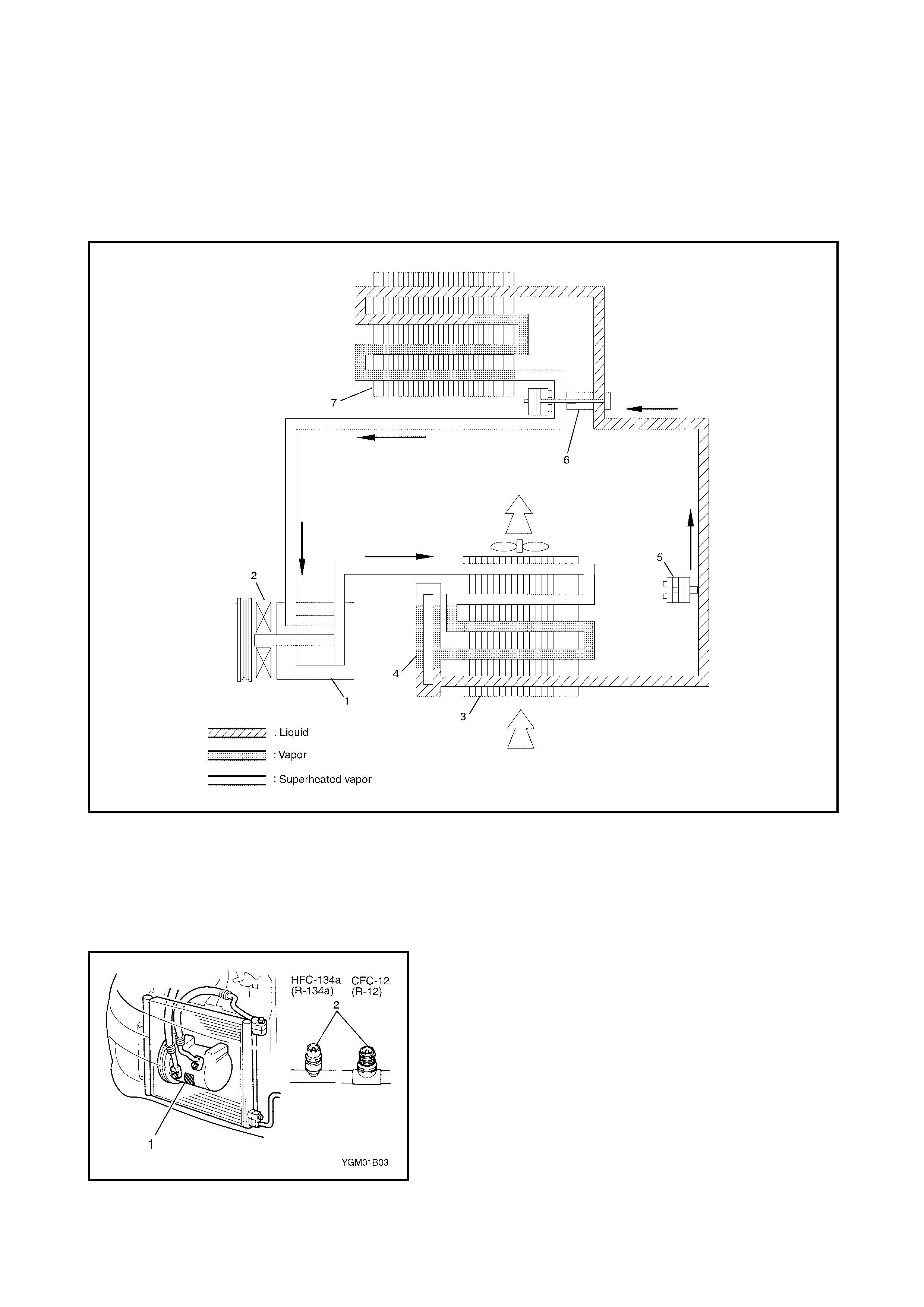
1. GENERAL DESCRIPTIO N
1.1 REF RIGERANT CIRCULATION
Legend
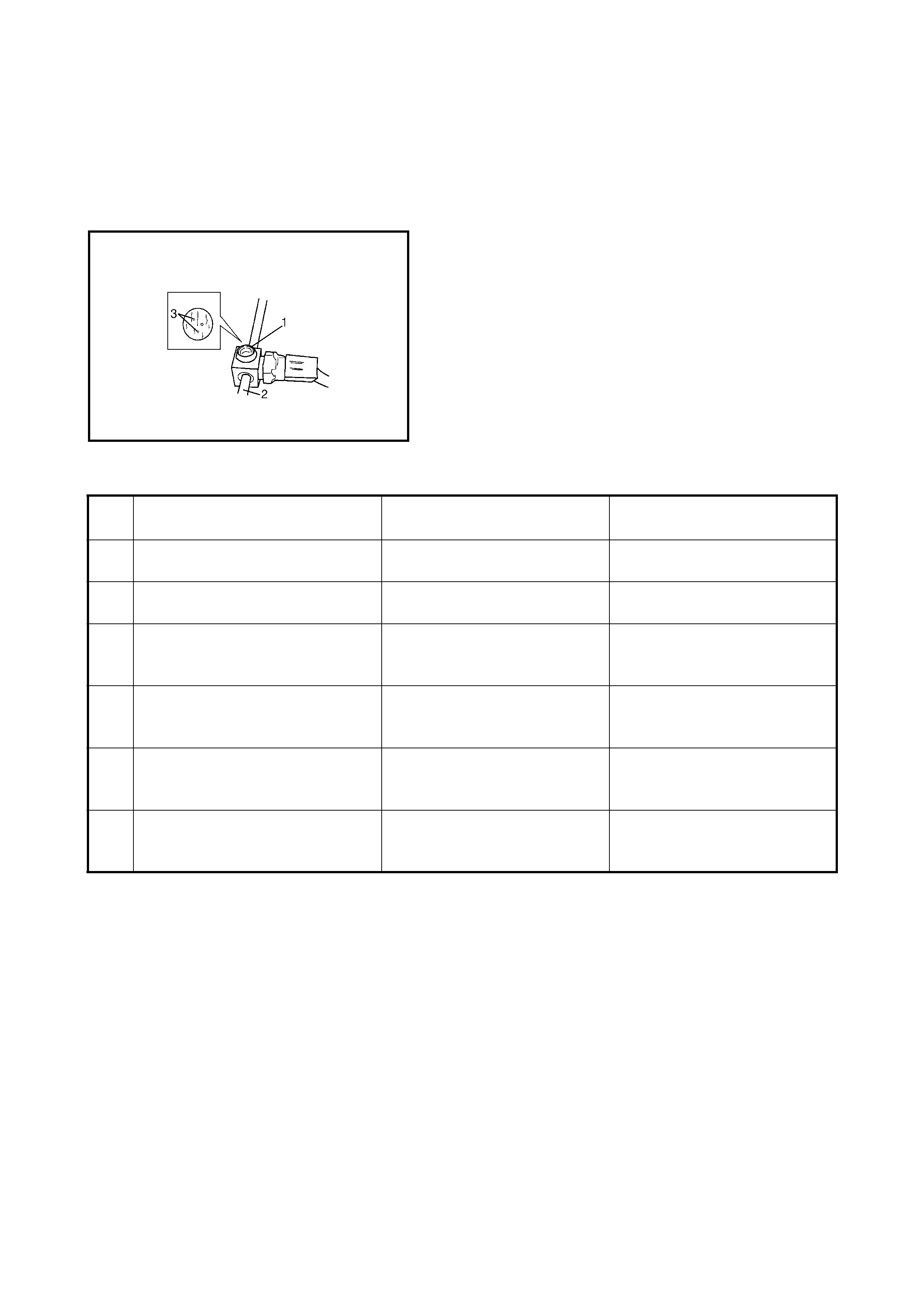
1.2 REFRIGERANT TYPE
The refrigerant used in this vehicle is HFC-134a (R134a).
This can be confirmed on the compressor label (1) or by
the shape of the service (charge) valve (2).
1. Compressor 4. Receiver/drier 7. Evaporator
2. Magnet cl utch 5. A/C refrigerant pressure swi t ch
3. Condense r assembly 6. Expansion valve
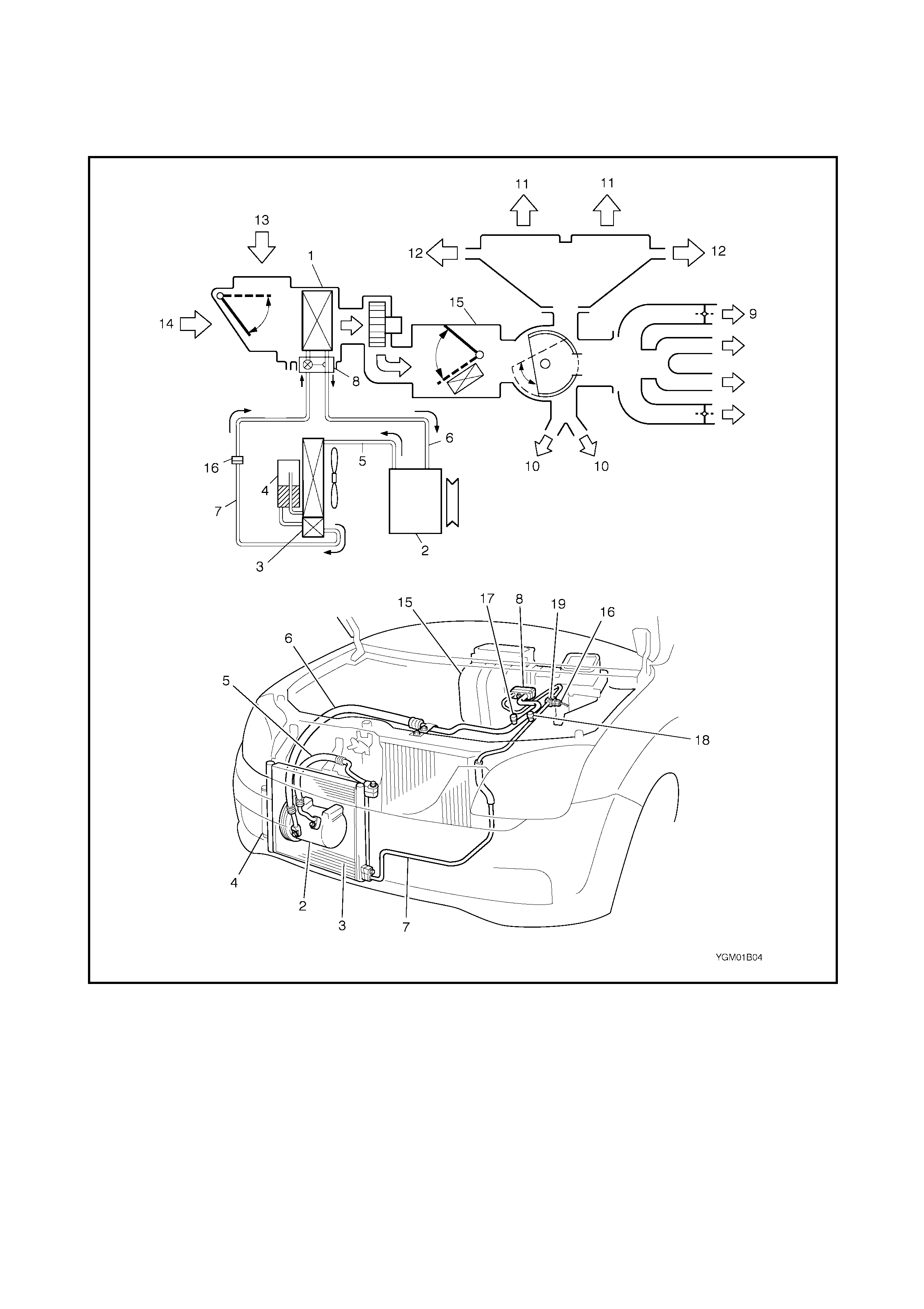
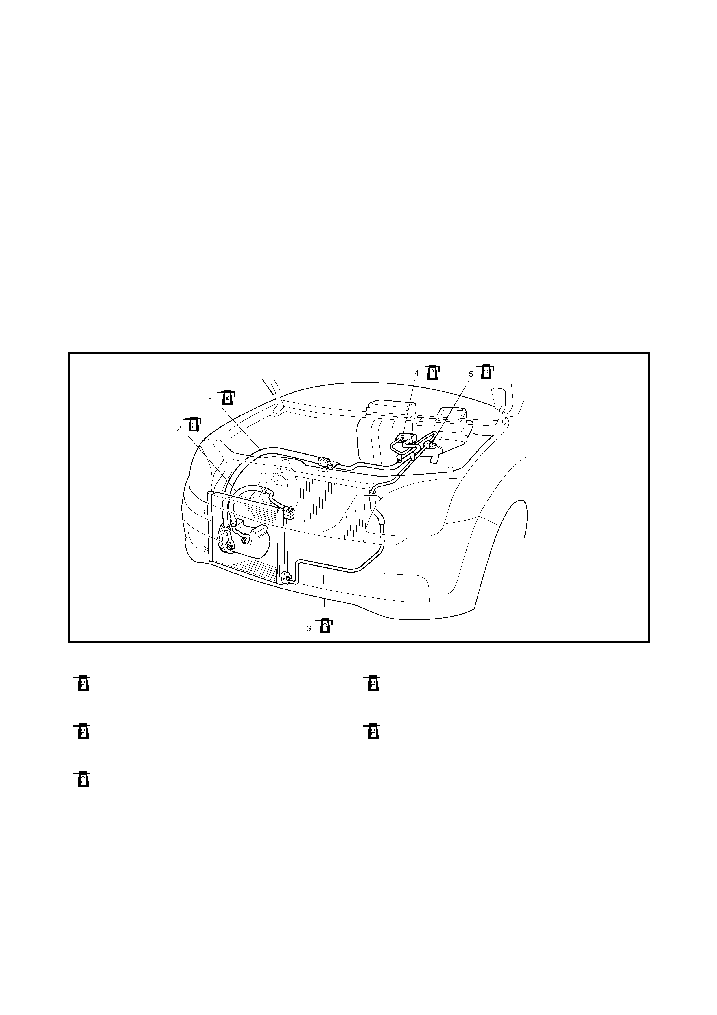
1.3 MAJOR COMPONENTS AND
LOCATION
Legend
1. Cooling unit 8. Expansion valve 15. Heater unit
2. Compress or 9. Ventilation air 16. A / C refrigerant pressure switch
3. Condenser assembly 10. F oot air 17. Low pressure charge valve
4. Receiver drier 11. Defroster air 18. Hi gh pr essure charge valve
5. Discharge hose 12. Demister air 19. S igh t glass
6. Suction pipe 13. Fresh air
7. Condenser outlet (liquid)
tube 14. Recirculation air
2. DIAGNOSIS
2.1 GENERAL DIAGNOSIS TABLE
Condition Possible Cause Correction
N o cool air flow
(A/C system won’t
operative)
No refrigerant Perform recover, e vacuation and charging.
Fuse blown Check fuses in circuit fuse and main f use
boxes, and check short circuit to ground.
A/C switch faul ty Check A/C switch.
Blower f an switch faul ty Check blower f an switch, refer to Sec tion
1A - HEATER AND VENTILATION.
A/C evaporator temperature sensor
faulty Chec k A/C evaporator temperature sen-
sor.
A/C refrigerant pressure switch faulty Check A/C refrigerant pressure switch.
Wi ring or grounding faul ty Repair as necessary.
ECT sensor faulty Check ECT sensor, refer to Section 6E1 -
ENGINE AND EMI SSION CONTROL
SYSTEM
ECM and its circuit f aulty Check ECM and its circuit, refe r to Section
6E1 - ENGINE AND EMISSION
CONTROL SYSTEM.
N o cool air flow
(A/C comp resso r
won’t operati ve)
ECM f aul ty Check ECM and its ci rcuit refer to Section
6E1 - ENGINE AND EMISSION
CONTROL SYSTEM.
Magnet clutch faulty Check magnet i c clutch.
Compressor dri ve belt loosen or bro-
ken Adjust or replace drive belt.
Compressor faulty Check compressor.
Compressor thermal swi tch faulty Check compressor th e rmal s wit ch
N o cool air flow
(A/C conden ser
cooling fan motor
won’t operati ve)
Fuse blown Check fuses in circuit fuse and main f use
boxes, and check short circuit to ground.
Wi ring or grounding faul ty Repair as necessary.
Radiator/cond ens er cooling fan motor
relay faulty Check radiator/condenser c ooling f an
moto r relay No. 1 , No.2 and No.3.
Radiator/cond ens er cooling fan motor
faulty Chec k radiator/condenser c ooling f an
motor.
ECM f aul ty Check ECM and its ci rcuit refer to Section
6E1 - ENGINE AND EMISSION
CONTROL SYSTEM
N o cool air flow
(Blower fan moto r
won’t operati ve)
Fuse blown Check “HTR” fuse in circuit fus e box and
main fuses, and check short circuit to
ground.
Blower fan motor resistor faul ty Check blower f an motor resi st or, refer to
Section 1A - HEATER AND
VENTILATION.
Blower f an switch faul ty Check blower f an switch, refer to Sec tion
1A - HEATER AND VENTILATION.
Wi ring or grounding faul ty Repair as necessary.
Blower f an motor faulty Check blower f an motor, ref er to Section
1A - HEATER AND VENTILATION.
N o cool air flow or
coolin g is inadequ a t e
(A/C system op erates
normally)
Insufficient or excessive charge of
refrigerant Check refri gerant charge and system for
leaks.
Condens er clogged Check condens er.
A/C e vaporator cl ogged or frost ed Check A/C ev aporator and A/C e vaporator
temperature sensor.
A/C evaporator temperature sensor
faulty Chec k A/C evaporator temperature
sensor.
Expansion val ve f aulty Check e xpansion valve.
Receiver/drier clogged Check receiver/dr ier.
Compressor dri ve belt loose or broken Adjust or replace drive belt.
Magneti c clutch faulty Chec k magnet i c clutch.
Compressor faulty Check compressor.
Air in A/C system Replace receiver/drier, and perform
evacuation and charging.
Air leaking from cooling unit or air duct Repair as necessary.
Heater and ventilation system faulty Check air inlet box (cooling unit), heater
control assembly and heater unit referring
to Section 1A - HEATER AND
VENTILATION.
Blower f an motor faulty Check blower f an motor, ref er to Section
1A - HEATER AND VENTILATION.
Excessive compre ssor oil exis ti n g in
A/C syste m Dr ain exce ss co mpresso r oil from A/C
syste m circuit a nd check compress or.
N o cool air flow or
intermittent cool air
flow only
Wi ring connect ion faul ty Repai r as nec essary.
Expansion val ve f aulty Check e xpansion valve.
Excessive moisture in A/C system Replace receiver/drie r and perform
evacuation and charging.
Magneti c clutch faulty Chec k magnet i c clutch.
Excessive charge of refrigerant Check charge of refrigerant.
C ool a ir flows only at
hi gh vehicle speed Condens er clogged Check condens er.
Condenser cooling fan motor f aul ty Check condenser cooling fan motor.
Condens er cooling fan motor relay
faulty Check condenser cooling fan motor relay
Condensder cooling fan blade faulty Check condenser cooling fan blade
Insufficient charge of refrig erant Check refrigerant charge.
Air in A/C system Replace receiver/drier, and perform evac-
uation and charging.
Compressor dri ve belt loose or
broken Adjust or replace drive belt.
Compressor faulty Check compressor.
Co ol air flow only at
hi gh vehicle speed Excessive charge of refrigerant Check charge of refrigerant.
A/C e vaporator frost ed Check A/C e v aporator and A/C e vaporator
temperature sensor.
Insu ffi cient strength
of cool air flow A/C e vaporator clogged or froste d Check A/C e v aporator and A/C e vaporator
temperature sensor.
Air leaking from cooling unit or air duct Repair as necessary.
Blower f an motor faulty Check blower f an motor, ref er to Section
1A - HEATER AND VENTILATION.
Wi ring or grounding faul ty Repair as necessary.
Condition Possible Cause Correction

2.2 ABNOR MAL NOISE DIAGNOSIS
There are variou s types of n oise, ranging from t hose produced in the en gine compartment to thos e from t he
passeng er compartment , from rumbling to whistling noises.
ABNORMAL NOISE FROM COMPRESSOR
ABNORMAL NOISE FROM MAG NETIC CLUTCH
ABNORMAL NOISE FROM TUBING
ABNORMAL NOISE FROM CONDENSER ASSEMBLY
Condition Possible Cause Correction
During compressor
operation, a rumbling
noi se i s he ard pr opor-
tional to engine
revolutions.
Inadequate clearance in piston area (pi ston or
swash-plate) Repair or replace compressor as
necessary.
A loud noise is heard
at a certain rpm, dis-
proportionately to
engine re volution.
Loose or faulty compressor drive belt Adju st drive belt tension, or
replace drive belt.
Loose com pressor mount ing bolts Retighten mounting bolts.
A loud rattle is heard
at l ow en g ine rpm . Loose compressor clutch plate bolt Ret i ghten clutch plate bolt.
Replace compress or if it has oper-
ated in this condition for a long
time.
Condition Possible Cause Correction
A rumbling noise is
heard whe n comp res-
s or is not operating.
Worn or damaged bearings Replace magnetic cl utch
assembly.
A chattering noise is
heard whe n comp res-
s or is enga g e d.
Faulty clutch clearance (excessive) A dju st clutch clearance.
Worn clutch friction surface Re place magnet ic clutch
assembly.
Compress or oil leaked from lip type seal, con-
taminating the friction surface Replace compress or body
assembly.
Condition Possible Cause Correction
A droning noise is
heard inside vehi cle,
but no t partic ul a rly
noticeable in engine
compartment.
Faulty tubing clamps Repos ition clamps or increase the
number of clamps.
Resonance caus ed by pulsation from
variati ons in refrigerant pressure Attach a silencer to tubing, or
modi fy its position and length.
Condition Possible Cause Correction
Considerable
vibration in
condenser.
Resonance from condenser assembly bracket
and body Firmly insert a silencer between
condenser brac k et and body.
Loose condenser c ooling fan mounting bolts Re tighten mounting bolts
Faulty condenser cooling fan blade Replace condenser cooling fan
blade.

ABNORMAL NOISE FROM CRANKSHAFT PULLEY
ABNORMAL NOISE FROM TENSION PULLEY
ABNORMAL NOISE FROM A/C EVAPORATOR
ABNORMAL NOISE FROM BLOWER FAN MOTO R
Condition Possible Cause Correction
A loud ra tt ling no i se
is he ard at idle or on
sudd en accelerati on .
Loose crankshaft pulley bolt Re tighten bolt.
Condition Possible Cause Correction
Cl attering noise is
he ard from pu ll ey. Worn or damaged bearing Repl ace tension pulley.
Pul le y cranks upon
contact. Crack ed or l oose brack et Repl ace or retighten bracket .
Condition Possible Cause Correction
Whistlin g sound is
heard from A/C evap-
orator.
Depending on the combina tion of the interior/
ext erior temperatures, engine rpm and refrig-
erant pressure, the refrigerant flowing out of
the expansion valv e may, under c ertain condi-
tions, make a whistling sound
At times , slightly decreasi ng refrig-
erant volume ma y stop this noise.
Inspect expansion valve and
replace if faulty.
Condition Possible Cause Correction
Blower fan moto r
e m its a chir ping
sound in proportion
to its speed of
rotation.
Worn or damaged motor brushes or
commutator Repair or replace blower fan
motor.
Flu tt e ri ng noise or
la rge dr on in g noi se is
heard from blower fan
motor.
Leaves or other debr is introduced from fresh
air inlet to blower fan motor Re move debris and ensure the
fresh air inlet screen is intact.
2.3 QUICK CHECK OF REFRIGERANT CHARGE
The following procedure can be us ed for quickly checking if
the A/C system has a proper charge of refrigerant.
Run the engine at fast idle, and operate the A /C at its maxi-
mum cooling capacity for a few minutes.
Then look at the sight glass (1) on the condenser outlet
pipe (2) and compa re what is obser ved with the symptoms
listed i n the tabl e below.
CHECKING REFRIGERANT CHARGE
NOTE: For specified amount of refrigerant, refer to 4.1 OPERATION PROCEDURE FOR REFRIGERANT
CHARGING in this Section.
Item
No. Symptom Charge of refrigerant
condition Correction
1. Bu bbles (3) obser ved in sight
glass Insufficient charge of refriger ant
in system Check syst e m f o r leaks wit h a
leak tester.
2. No bubbles (3) observed in sight
glass No or insufficient charge of
ref rigera nt in system Refer to the items 3 and 4.
3. No temperature diff erence
between compressor inlet and out-
let
Empty or nearly emp ty system Evacuate and charge system
and then check it for leaks with
a leak tester.
4. Noticeable temperature difference
between compressor inlet and out-
let
Proper or too much charge of
ref rigera nt in system Refer to the items 5 and 6.
5. When A /C is turne d OFF, refriger-
ant in sight glass clears immedi-
ately and remains clear
Too much charge of refrigerant
in system Recharge with specified
amount of refrigerant.
6. When A /C is turne d OFF, refriger-
ant in sight glass initially produces
bubbles and then clears
Proper refrigerant charge in
system No correction needed bec ause
refrigerant charge is norm al .
2.4 PERFORMANCE DIAGNOSIS
1. Confirm that vehicle and environmental conditions are
as follows.
•Vehicle is not exposed to direct sun.
•Ambient temperatu re is within 15 – 35°C.
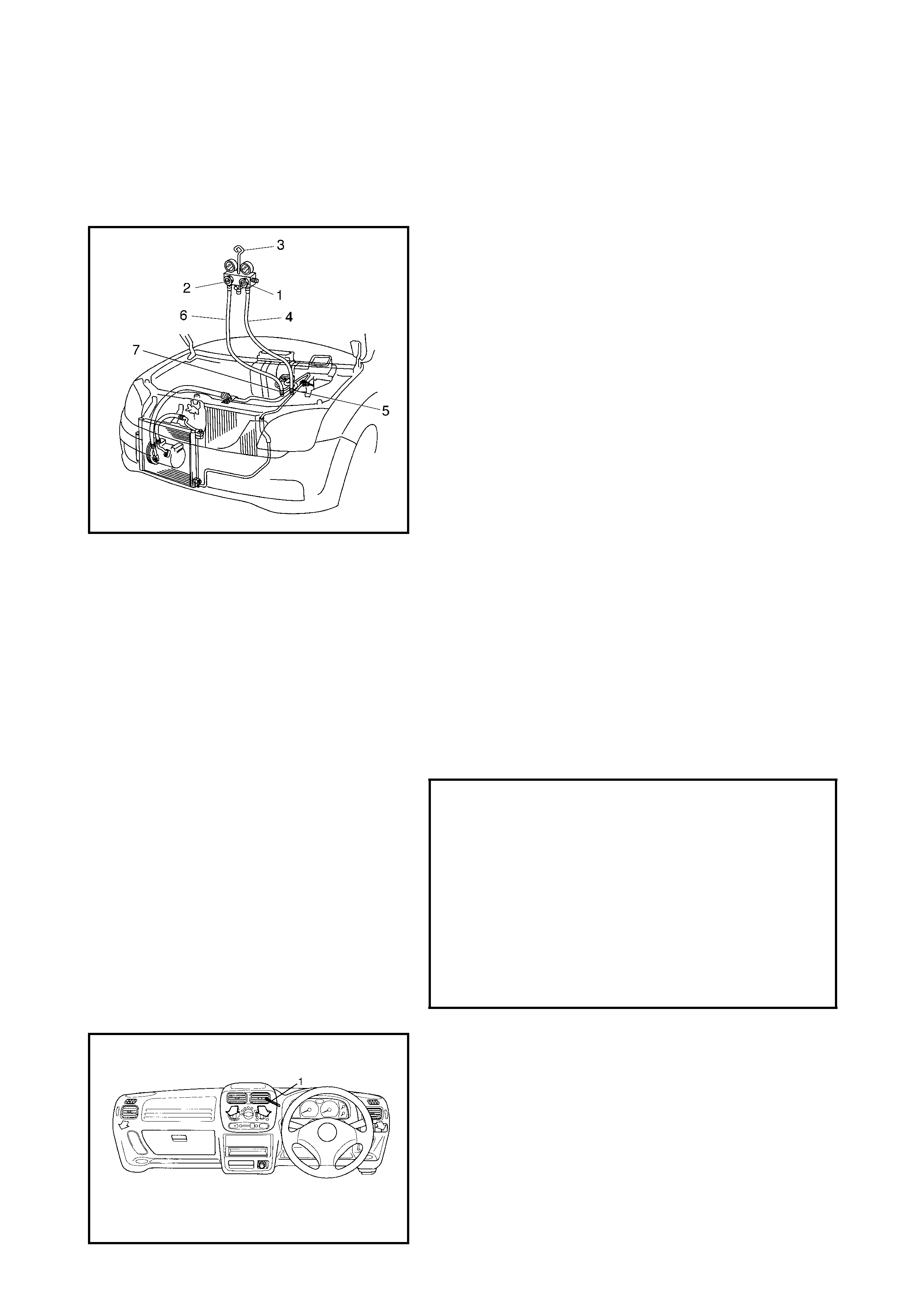
2. Make sure that high pressure valve (1) and low
pressure valve (2) of manifo ld gauge set (3) are firmly
closed.
3. Connect high pressure charging hose (4) to high
pressure service valve (5) and connect low pressure
charging hose (6) to low press ure service valve (7).
4. Bleed the air in charging hoses (4), (6) by loosening
their respective n uts on manifold gauge set (3), utiliz ing
the refrigerant pressure. When a hissing sound is
heard, imme diately tighten nut.
CAUTION: Do not interchange high and low pressure
charging hoses by mistake.
5. Warm up engine to normal operating temperature
(engine coolant temperature at 80 – 90°C) and keep it
at specified idle speed.
6. Turn A/C switch to ON position, and set blower fan
switch at “H” (4th position), temperature dial at
“COOL”, air outlet control dial at “FACE” and fresh/
recirculation control dial at “RECIRCULATION”.
(Confirm that A/C compressor and condenser cooling
fan are working. )
Keep all windows, doors and engine hood open.
Perf ormance diagnosis condition
7. With dry bulb thermometer (1) inserted into centre duct
air out let an d another one set near evaporator air inlet,
read temperature indica ted on each thermometer.
Ambient temperature 15 – 35°C
Engine rpm Keep to 1,500 rpm.
Blower f an switch “H” (4th position)
Temperature control “Cool”
Air outlet control “Face”
Vehicle Doors All open
Air inlet door position Recircula tion
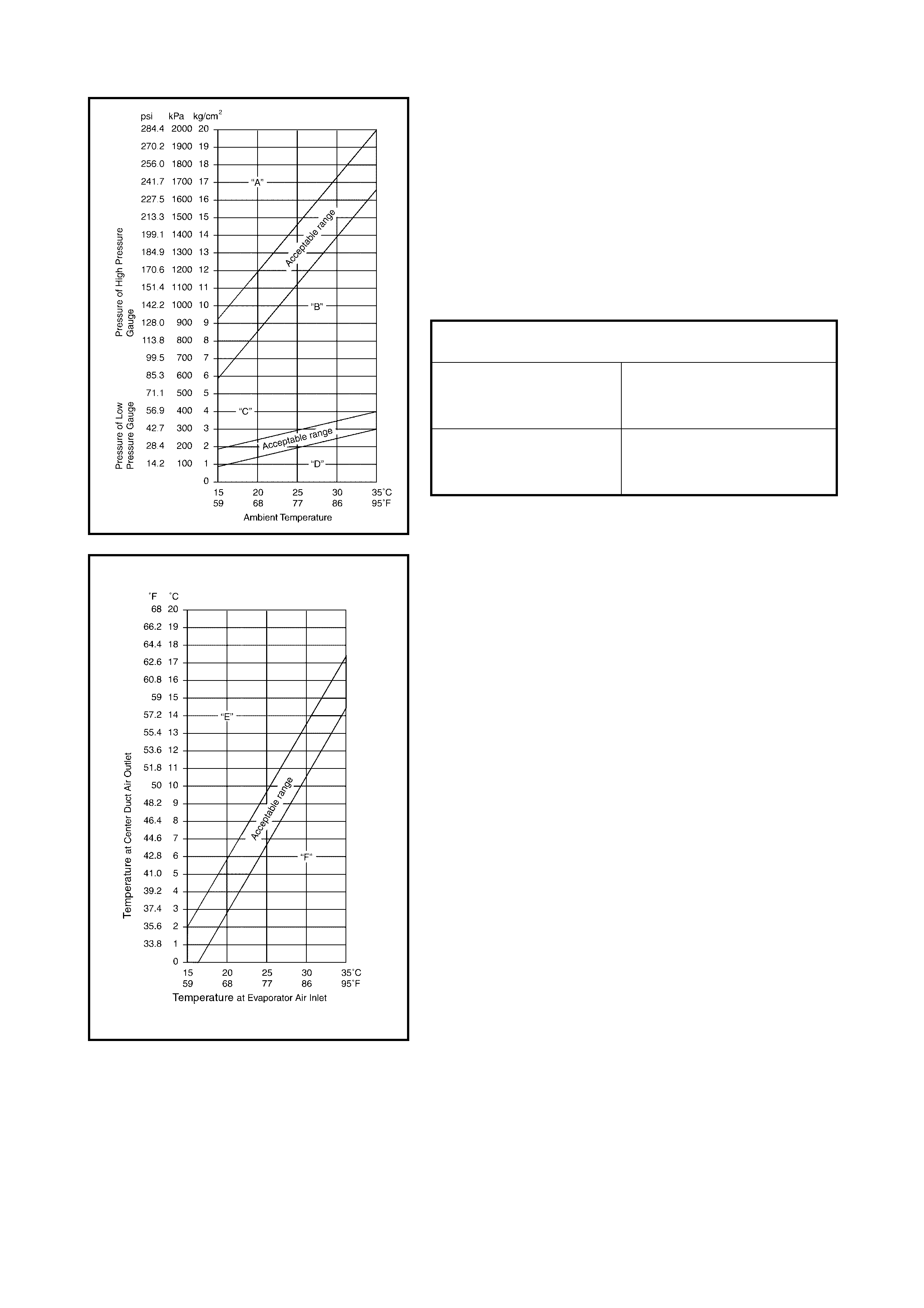
8. Check that the pressure of the low side and high side is
within the shaded range on the graph.
If each gauge reading is not within specified pressures,
correct defective part, refer to PERFORMANCE
DIAGNOSIS TABLE in 2.4 PERFORMANCE
DIAGNOSIS in this Section.
NOTE: Pressure registered on gauge varies with ambient
temperature. Therefore, use the graphs when determining
if pressures are normal or not.
Low side and high side pressure example:
9. Check inlet port temperature-to-outlet port temperature
relationship using graph.
For example, if evaporator inlet port temperature is
25°C and centre duct air outlet temperature is 8°C,
their crossing point is within acceptable range as
shown in graph.
If crossing point is out of acceptable range, diagnose
trouble, refer to PERFORMANCE DIAGNOSIS TABLE
in 2.4 PERFORMANCE DIAGNOSIS in this Section.
Gaug es sho uld read as follows when ambien t
tem pera ture is 30 °C.
Pressu re
on high pres sure gauge 1400 – 1750 kPa
14.0 – 17. 5 kg/cm2
199.1 – 248. 9 psi
Pressu re
on low pressure gauge 230 – 350 kPa
2.3 – 3.5 kg /cm2
32.7 – 49. 8 psi

PERFORMANCE DIAGNOSIS TABLE
NOTE: If ambient temperature is approximately 30°C, it is possible to diagnose A/C system in detail, refer to
DETAIL DIAGNOSIS TABLE (AMBIENT TEMPERATURE AT 30 °C) under 2.4 PERFORMANCE DIAGNOSIS
in th is Sec t io n. HIGH PRESSURE GAUGE
LOW PRESSURE GAUGE
THERMOMETER AT CENTRE DUCT
Cond ition Possible Cause Correction
Pr es sure high
(“A” area of hi gh side
graph)
Refrigerant overc harged Recharge.
Expansion valve frozen or clogged Check expansion valve.
Clogged refrigerant passage on high side Clean or replace.
Condenser cooling fan malfunction (Insufficient
cooling of condenser) Check condenser cooli ng f an.
Dirt y or bent condenser fins (Insufficient cool-
ing of condenser) Clean or repair.
Compressor malfunction (Insuff i ci ent oil etc.) Check compressor.
Engine overheating Check engine cooling system,
refer to Section 6B - ENGINE
COOLING.
Pressure low
(“B” area of hi gh side
graph)
Insufficient refriger ant (Insufficient charge or
leakage) Check for leakage, repa ir if
nec essary and recharge.
Expansion valve malfunction (valv e opens too
wide) Check expansion valve.
Compressor malfunction (Insufficient compres-
sion) Check compresso r.
Condition P ossible Cause Correction
Pr es sure high
(“C” area of low side
graph)
Expansion valve malfunction
(valve opening too wide) Check expansion valve.
Compressor malfunction
(Insufficient compression) Check compressor.
Pressure low
(“D” area of low side
graph)
Insufficient refrigerant
(Insufficient charge or leakage) Check for leakage, repair if
nece ssary and recharge.
Expansion valve malfunction
(valve opening too narro w) Check expansion valve.
Clogged refrigerant passage (crushed pipe) Repair or replace.
Condition P ossible Cause Correction
Outlet ai r tempera-
ture at centre duct is
high
(Cros sing poi nt i s in
area “E”)
Insufficient or excessive charge of refrigerant Ch eck refrigerant pressure.
Dirty or bent A/C evaporator fins Cl ean or repair.
Air leakage from cooling (heater) unit or air
duct Re pair or replace.
Malfunctioning switchover function of door in
cooling (heat er) unit Repair or replace.
Compressor malfun cti o n Check compressor.
Outlet ai r tempera-
ture at centre duct is
low
(Cros sing poi nt i s in
area “F”)
Insufficient air volume from centre duc t
(Heater blo wer malfunction) Chec k blower motor and fan.
Compressor malfun cti o n Check compressor.

DETAIL DIAGNO SI S TABLE (AMBIENT TEMPE RATURE AT 30 °C)
Condition
Possible Cause Correction
MANIFOLD
GAUGE MPa
(kg/cm2)
(psi)
Detail
Lo Hi
0.23 – 0.3 5
(2.3 – 3.5)
(33 – 50)
1.4 – 1.75
(14 – 17.5)
(200 – 249)
Normal condition ––
Negative
pressure 0.5 – 0.6
(5 – 6)
(71.2 – 85.3)
The low pressure sid e
reads a neg ative pres-
sure, and the high
pressu re side reads an
extremely low pres-
sure.
Prese nce of frost
around tubing to and
fr om receiver/drier and
expansion valve.
Dust particles or water
droplets are eit her stuck
or frozen inside expan-
sion valve , prev enting the
refrigerant from flo wing
Clean expansion valve.
Replace it if it c annot be
cleaned.
Replace receiver/drier .
Evacuate the A/C system
and recharge with fresh
refrigerant.
Normal :
0.23 – 0.3 5
(2.3 – 3.5)
(33 – 50)
¦ Ø
Abnormal :
Negative
pressure
Normal :
1.4 – 1.75
(14 – 17.5)
(200 – 249)
¦ Ø
Abnormal :
0.7 – 1.0
(7 – 10)
(100 – 142)
During A/C operation,
the low pressure side
sometimes indicates
negative pre ssure , and
sometimes normal
pressure. Also high
pressu re side reading
fluctuates between
abnormal and normal
pressure.
Expansion valve is frozen
due to moisture in the
system, and temporar ily
shuts off the refrigera-
tion cycle
Replace expans ion
valve.
Replace receiver/drier .
Eva cu a te A/C system
and recharge with fresh
refrigerant.
0.05 – 0.1 5
(0.5 – 1.5)
(4.2 – 21.3)
0.7 – 1.0
(7 – 10)
(100 – 142)
Bo t h low an d hi gh
pressu re sides in di-
cate low readings.
Co nt i nuous air bub-
bles are visible through
sight gl ass.
O u t p ut ai r is s l ight ly
cold.
Insufficient refriger ant in
system
(Refrigerant leaking)
Using leak detector,
check for leaks and
repair as necessary.
Recharge refrigerant to
the specified amou nt.
If the pressure readi ng is
almost 0 when the
manifold gauges are
attached, check for any
leaks, repair them, and
evacuate the system.
0.4 – 0.6
(4 – 6)
(56.9 – 85. 3)
Press ure on low pres-
sure side is high .
Pres sure on hi gh pres-
sure side is low.
Both pressure becom-
ing equal right after A/C
is turned OFF.
Internal leak in
compressor Inspect compresso r and
repair or replace as
necessary.
2.5 COMPRESSOR DRIVE BELT
INSPECTION
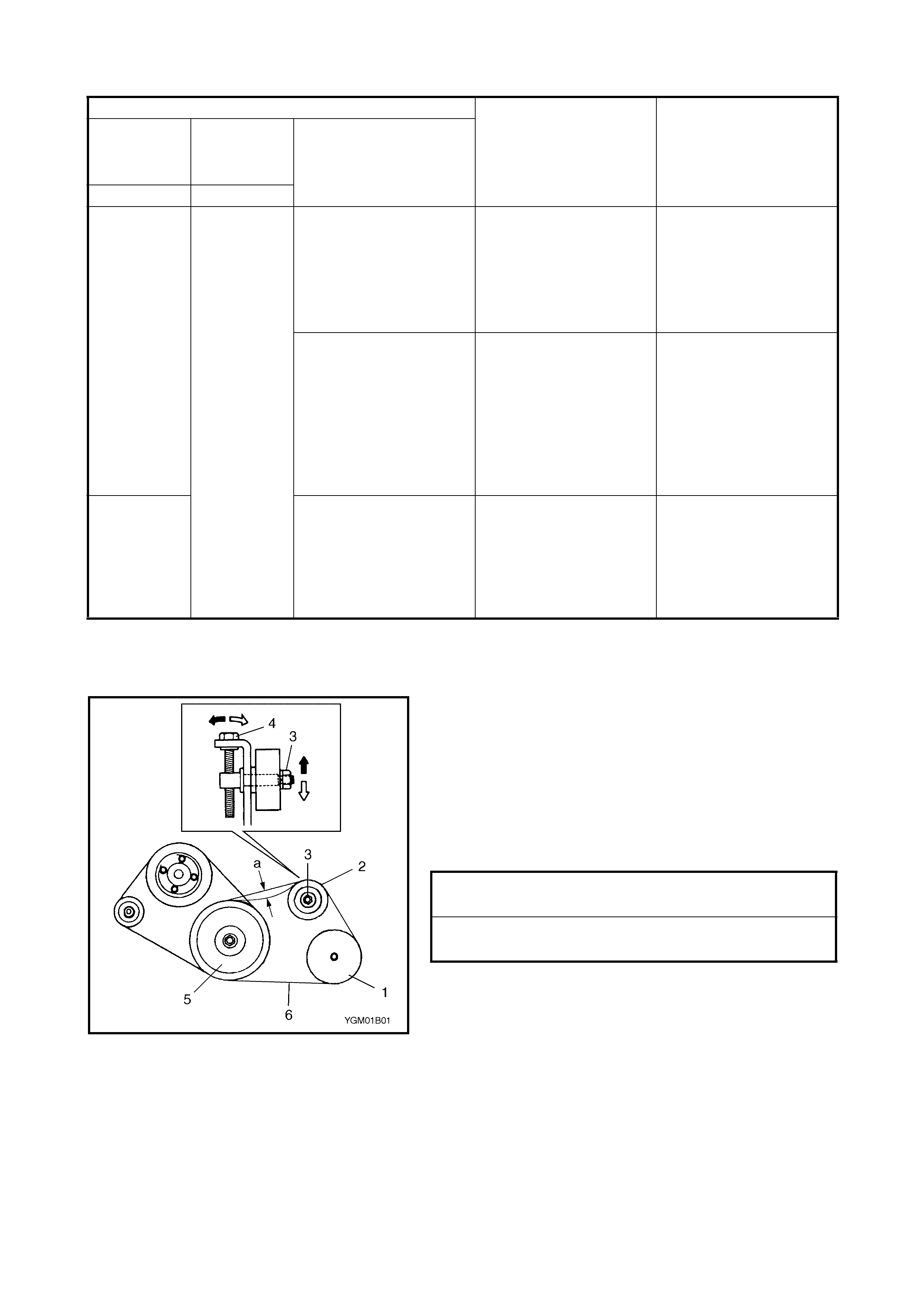
•Check compressor drive belt (6) for wear and cracks,
and replace as required.
•Check compressor drive belt (6) tension by measuring
how much it deflects when pushed at the midpoint
between the crankshaft pulley (5) and the tension pul-
ley (2) with about 100 N (10 kg) force after the crank-
shaft pulley is rotated 1 rev ol ution.
Adjust the belt tension if it is not within specifications,
refer to the follo wing procedures.
ADJUSTMENT
1. Loosen tension pulley nut (3).
2. Adju st the belt tension with the tension pulley adjusting
bolt (4).
3. Tighten tension pulley nut (3).
4. Turn the crank pulley (5) 1 revolution, then check belt
tension.
REPLACEMENT
1. Loosen tension pulley nut (3).
2. Loose n belt tension by loosening pulley adjusting
bolt (4).
3. Remove compressor driv e belt (6).
4. Install new compressor drive belt.
5. Adjust belt tension, refer to above proced ures.
0.35 – 0.4 5
(3.5 – 4.5)
(50 – 64)
2.0 – 2.5
(20 – 25)
(285 – 355)
High pressure reading
on both low and high
pressu re sides.
Air bubbles are not vis-
ible even when engine
rpm is l o wered.
Overcharged A/C system Adjust refr igerant to
specified amount .
Faul ty condens er
cooling oper ation Clean condenser.
Faul ty condens er
cooling fan operation I nspec t and repair
condenser cooling fan.
High pressure reading
on both low and high
pressu re sides.
Low pressure side tub-
ing is not cold when
touched.
Air bubbles are visible
throug h sight gla ss.
Presence of air in A/C
system
(Improperl y ev acuated)
Replace receiver/drier .
Inspect quan tity of com-
pressor oil and presence
of contam inants in o il.
Evacuate system and
recharge with fresh
refrigerant.
0.45 – 0.5 5
(4.5 – 5.5)
(64 – 78)
High pressure reading
on both low and high
pressu re sides.
La rge a m o unt of fros t
or dew on th e l ow pre s-
su re sid e tubi ng.
Faul ty expans ion valve
Refrigerant flow is not
regulated proper ly
Replace expans ion
valve.
Condition
Possible Cause Correction
MANIFOLD
GAUGE MPa
(kg/cm2)
(psi)
Detail
Lo Hi
COMPRESSOR DRIVE BELT
TENSION (a) 3 - 5 mm
NEW COMPRESS OR DRIVE BELT
TENSION (a) 2 - 4 mm
3. ELECTRICAL DIAGNOSIS
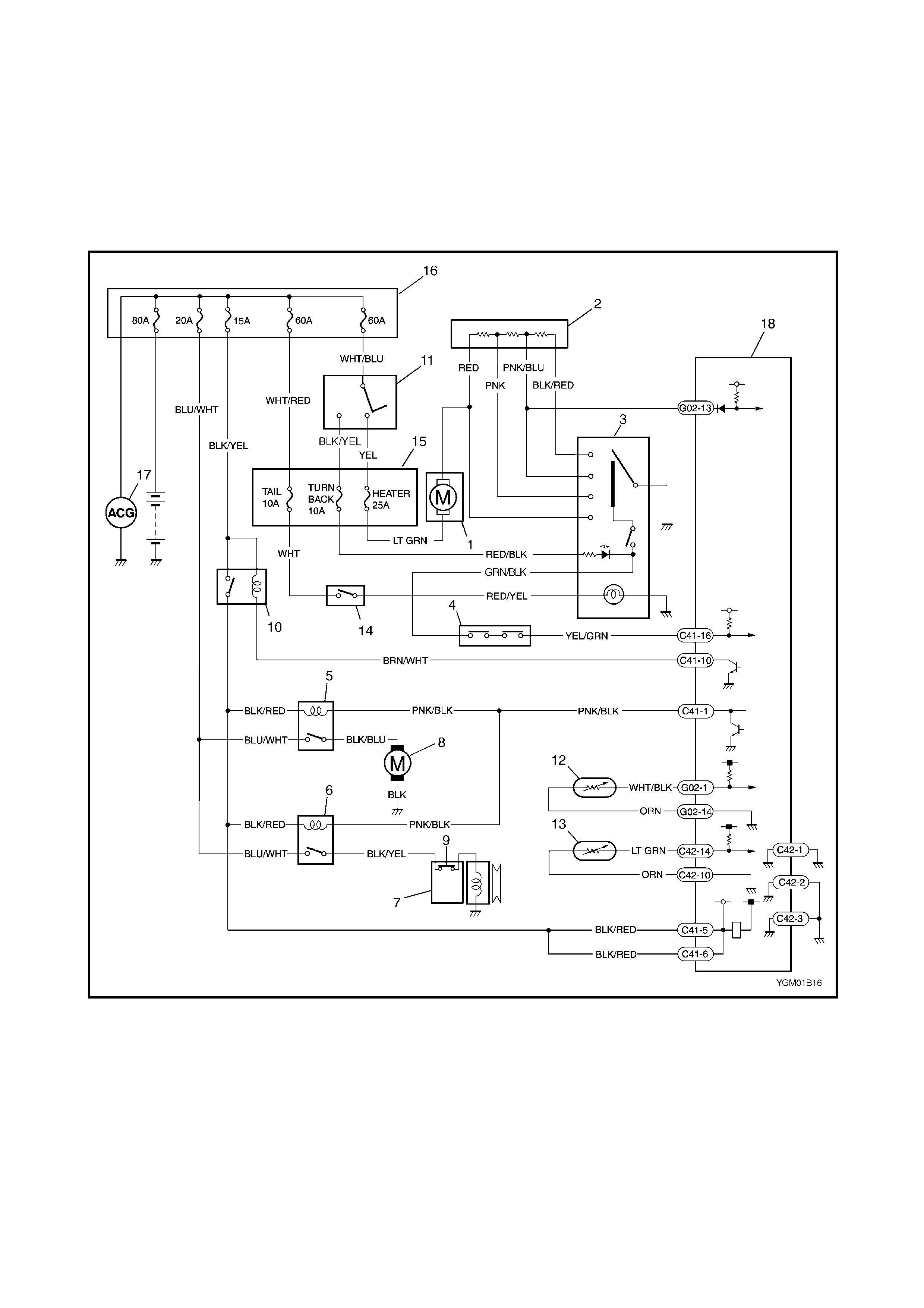
3.1 WIRING DIAGRAM
Legend
1. Blower fan m otor 6. Compres sor relay 13. ECT sensor
2. Blower fan m otor resistor 7. Com pres sor 14. Lighting switch
3. Blower fan sw itch and A/C
switch 8. Condenser cooling fan
motor 15. Circuit fuse box
16. Main fuse box
4. A/C refrigerant pressure
switch 9. Com pres sor ther m al switch 17. Generator
10. Main relay 18. ECM
5. Condenser cooling
fan motor relay 11. Ignition switch
12. A/C e vaporator temperature sensor
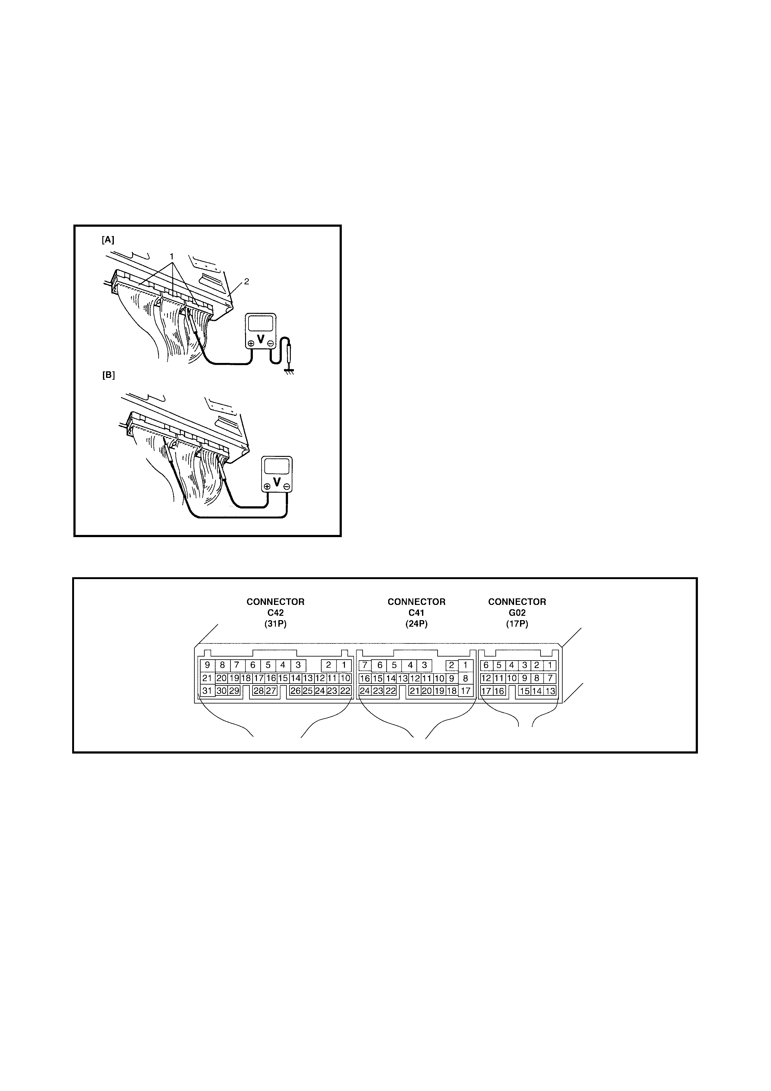
3.2 A/C SYSTEM INSP ECTION OF ECM AND ITS CIRCUITS
ECM and its circuits can be checked at ECM wiring con-
nectors by measuring voltage.
CAUTION:
ECM cannot be checked by itself. It is
strictly prohibited to connect voltmet er or ohmmeter to
ECM with connectors disconnected from it.
VOLTAGE CHECK
1. Remove ECM from vehicle, refer to Section 6E1,
2.3 ELECTRONIC CONTROL SYSTEM -
ECM REMOVAL AND INSTALLATION.
2. Connect ECM connectors (1) to ECM (2).
3. Check voltage at each terminal of connectors.
NOTE: As each terminal voltage is affected by the battery
voltage, confirm that the battery voltage is 11 V or more
when ignition switch is ON position
.
Terminal arrangement of ECM coupler (Viewed from harness side).

ECM VOLTAGE VALUES TABLE FOR A/C CONTROL
Terminal Wire Circuit Me asureme nt
ground Normal value Condition
C41-1 PNK/
BLK A /C co m pre ss or
clutch and
condenser f an
switch
Ground to
engine (Fig B) 0 – 1 V Fulfill all the following conditions:-
• Bl ower speed selector ON
• A/C switch ON
• Engi ne running
• A/C pre ssu r e sens o r ON
12 – 15 V Except the above mentioned condition
wit h engine runni ng
C41-5 BLK/
RED Main power
supply for ECM Ground to
engine (Fig B) 10 – 14 V Ignition switc h ON with engine not
running
C41-6 BLK/
RED Main power
supply for ECM Ground to
engine (Fig B) 10 – 14 V Ignition switc h ON with engine not
running
C41-10 BRN/
WHT Main relay drive Ground to
engine (Fig B) 0.5 – 1.2 V Ignition switch ON wit h engine not
running
10 – 14 V Igniti on switch OFF
C41-16 YEL/
GRN A/C switch input Ground to
engine (Fig B) 10 – 14 V Except the above mentioned condition
wit h engine runni ng
0 – 1 V Fulfill all the following con ditions:-
• Bl ower speed selector ON
• A/C switch ON
• Engi ne running
• A/C pre ssu r e sens o r ON
C42-1 BLK/
ORN Main ground for
ECM Ground to
body (F ig A) -0.5 – 1 V Engine running
C42-2 BLK ECM gr ound for
power c ircuit Ground to
body (F ig A) –0.5 – 1 V E ngine running
C42-3 BLK/
ORN ECM ground for
power c ircuit Ground to
body (F ig A) –0.5 – 1 V E ngine running
C42-10 ORN Sensor g r ound
for ECT sensor Ground to
body (F ig A) –0.5 – 1 V E ngine running
C42-14 LT
GRN ECT sensor
input Ground to
engine
(Fig B)
0.71 – 0.75 V
(298 – 320 9)Engine coolant temperature at
approximately 80°C with eng ine
running
0.35 – 0.37 V
(135 – 144 9)En gi ne coo lant tempe ra ture at Appro x i-
mately 110°C with engine running
If the te m pe ra tu r e i s mo r e than
112.5°C, compr essor and c ondenser
cooling fan shoul d stop (restart at less
than 110°C)
G02-1 WHT./
BLK A/C evaporator
temperature
sensor input
Ground to
engine (Fig B) 2.09 – 2.17 V
(1940 - 2060
9)
Evapor ator thermistor tempera ture at
approximately 25°C with eng ine
running
3.52 - 3.59 V
(6450 - 6859
9
A/C evaporator thermistor at
approximately 0°C wit h engine runnin g
If the temperature is less than approxi-
mately 2.5°C, compressor and con-
denser cooling fan should stop (restart
at more than approximately 4°C
G02-10 ORN Sensor ground
for A /C evapora-
tor temperature
sensor
Ground to
body (F ig A) -0.5 – 1 V Engine running
G02-13 PNK/
BLU Blower fan
speed input Ground to
engine (Fig B) 0 – 1 V Bl ower fan motor switch “ML”, “MH”, or
“H” with engine runni ng
4 – 7 V Blower fan mot or switch “L” position
wit h engine runni ng
10 – 14 V Blower fan motor switch OFF with
engine runnin g
4. REFRIGERANT RECOVERY, EVAC UATING AND CHARGING
WARNING
•Your eyes shou ld not be exposed to refrigeran t (liquid).
Any liquid HFC-134a (R-134a) escap in g by accident has a tempera ture as low as approxima tely
–6°C below freezing point. Should liquid HFC-134a (R-134a) get into your eyes, it may cause a seri-
ous injury. Always wear goggles to protect your eyes against accidental injury. Should HFC-134a
(R-134a) contact your eyes, consult a doctor immed iately.
•Do not rub the affected eye(s). Instead, use large quantities of fresh cold water to sp lash over the
affected area to gradually raise the temperature above freezing point.
•Obtain proper treatment as soon as possible from a doctor or eye speci alist.
•Should t he HFC-134a (R-134a) liquid come into contact with your skin, the affected area should be
treated in the same as when skin is frostbitten or frozen.
•Refrigerant must not be handled near where welding or steam cleaning is being performed.
•Refrig eran t sho uld b e ke pt i n a cold and dark place. It shoul d never b e stor ed whe re h igh temper-
atures are anticipated, e.g. exposure to direct sun light, close to fire or inside vehicle (including
boot).
Avoid breathing fumes produced when HFC-134a (R-134a) is burned. Such fumes may be hazardous
to health.
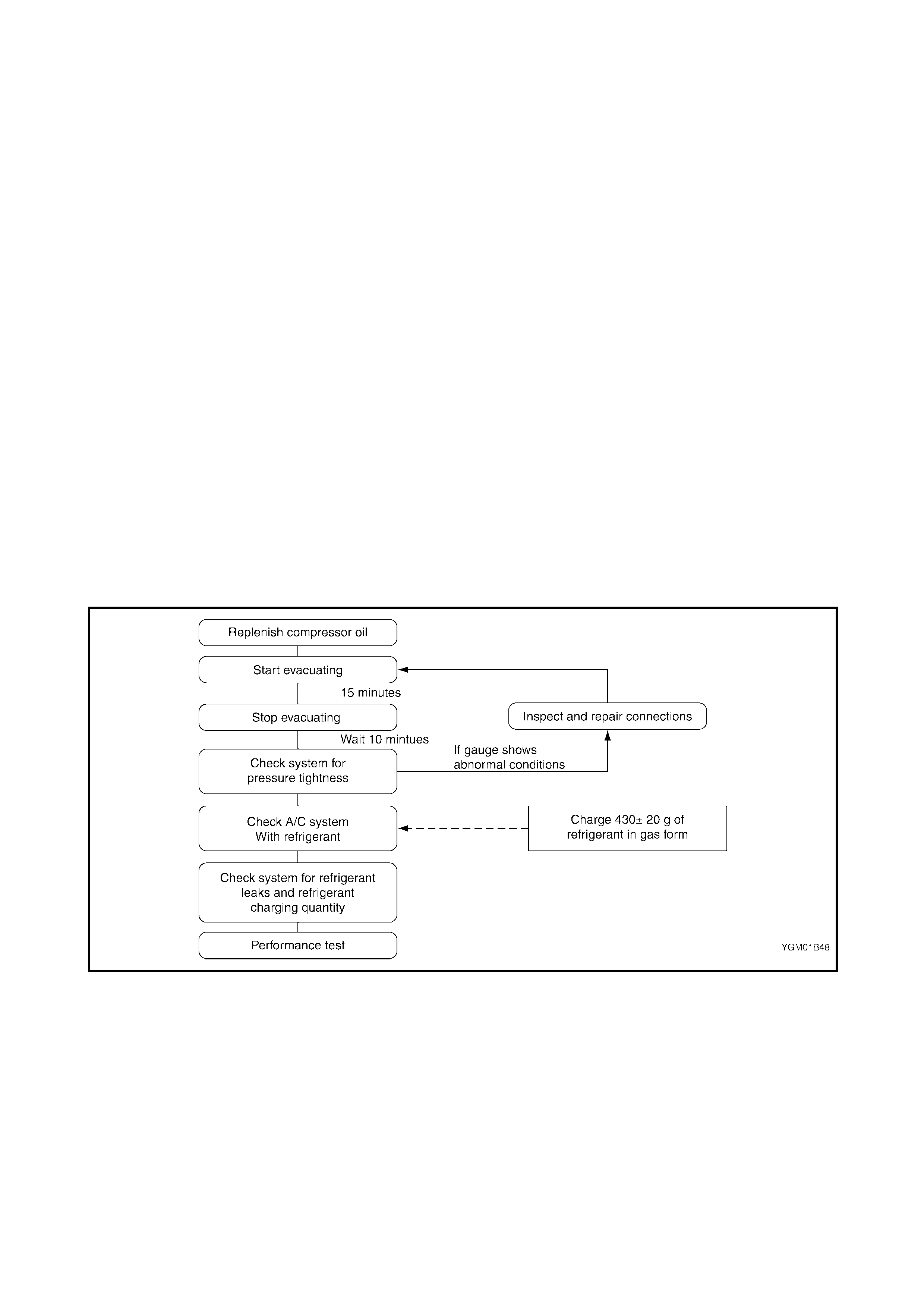
4.1 OPERATING PROCEDURE FOR RE FRIGERANT CHARGING
4.2 RECOVERY
REFRIGERANT RECOVERY
When discharging refrigerant from the A/C system, always
recover it using refrigerant recovery and recycling equip-
ment. Discharging refrigerant HFC-134a (R-134a) into the
atmosphere could cause an adverse effect to the environ-
ment.
NOTE:
•After recovering refrigerant from the system, the
amount of removed compressor oil must be measured
to all o w f or accurat e replenishment.
•When using recov ery and recycling equipment, be sure
to foll ow the manufactures instruct i ons.
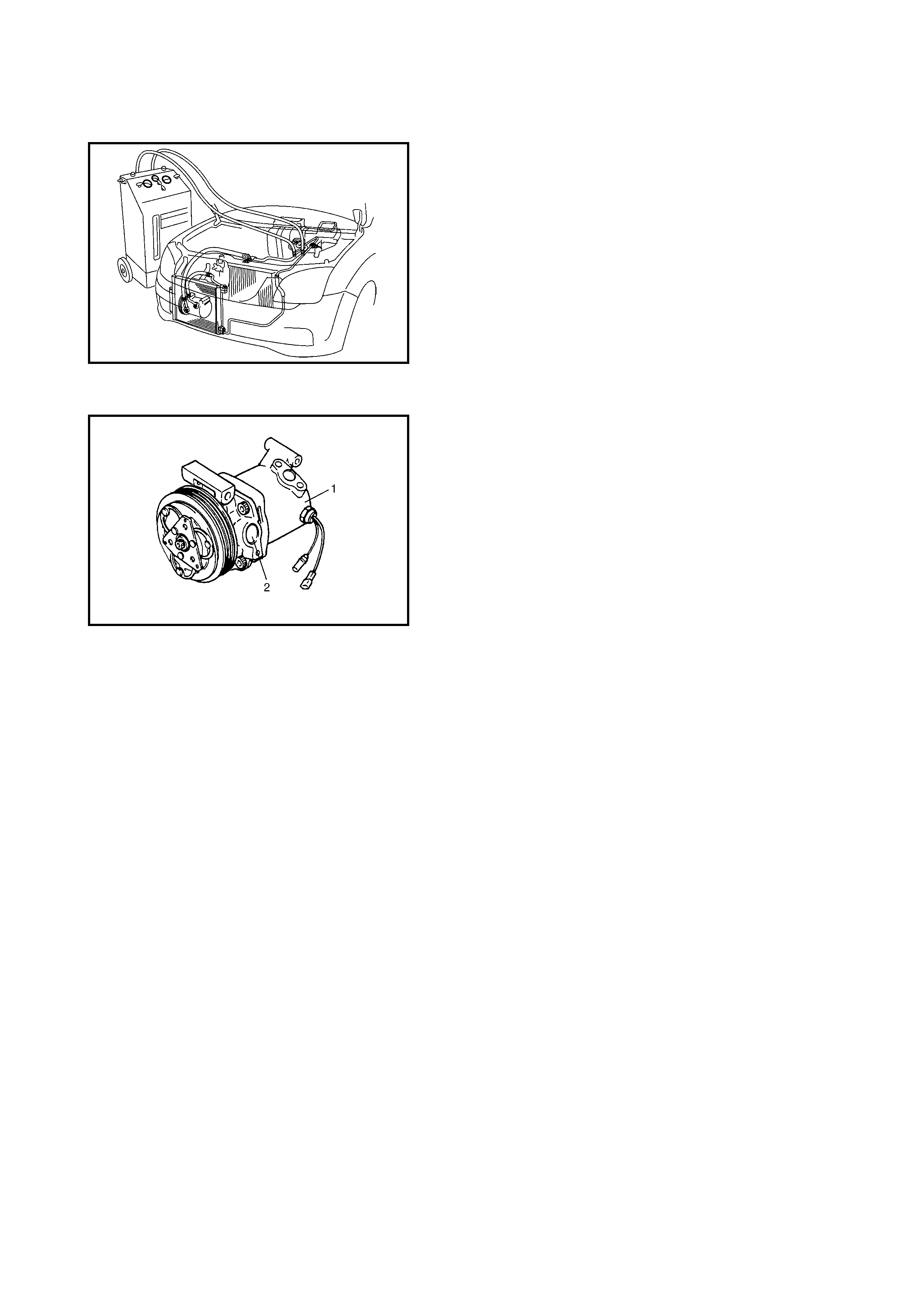
4.3 REPLENISHING COMPRESSOR OIL
Repleni sh the compressor (1) w ith the sp ecified am ount of
compressor oil via the compressor suction port (2) before
evacuating and charging the system with refrigerant.
WHEN CHARGING WITH REFRIGERANT ONLY
When charging the system with refrigerant without replac-
ing any components, replenish the same amount of com-
pressor oil that was measured when the refrigerant was
recovered (if no measurement w as tak en, replenish with 30
cc of compressor oil).
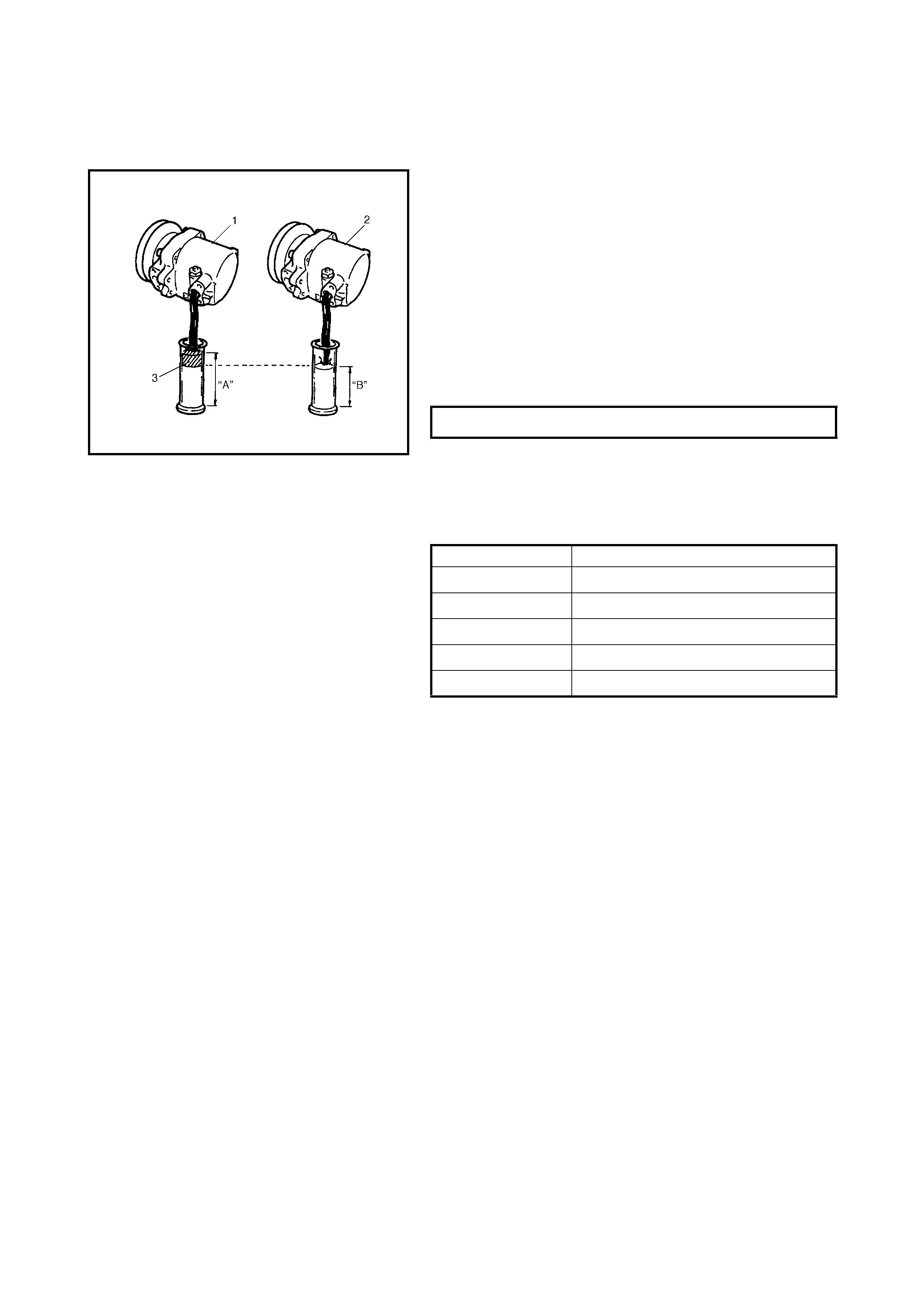
WHEN R EPLACIN G COM PRES SOR
CAUTION: Be sure to use HFC-134a (R-134a) com-
pr essor oil.
The correct amount of compressor oil for the A/C system is
sealed in each new compressor. When using a new com-
pressor as a replacement, compressor oil will need to be
drained from it to allo w f or oil already present i n the system.
Calculate the correct amount as follows.
“C” = “A” – “B”
“C”: Amount of oil to be drained (3).
“A”: Amount of oil sealed in a new compressor (1).
“B”: Amount of oil remaining in removed compressor (2).
NOTE: Factory supplied compressor assembly contains
the following amount of oil.
WHEN REPLACING OTHE R PARTS
When the parts listed below are replaced, replenish the
compressor with the quantity of compressor oil indicated.
OIL AMOUNT IN COMPRESSOR 120 cc
Replaced part Amou nt of compresso r oi l
Evaporator 25 cm3 (25 cc)
Condenser 15 cm3 (15 cc)
drier 20 cm3 (20 cc)
Hoses 10 cm3 (10 cc) each
Pipes 10 cm3 (10 cc) each
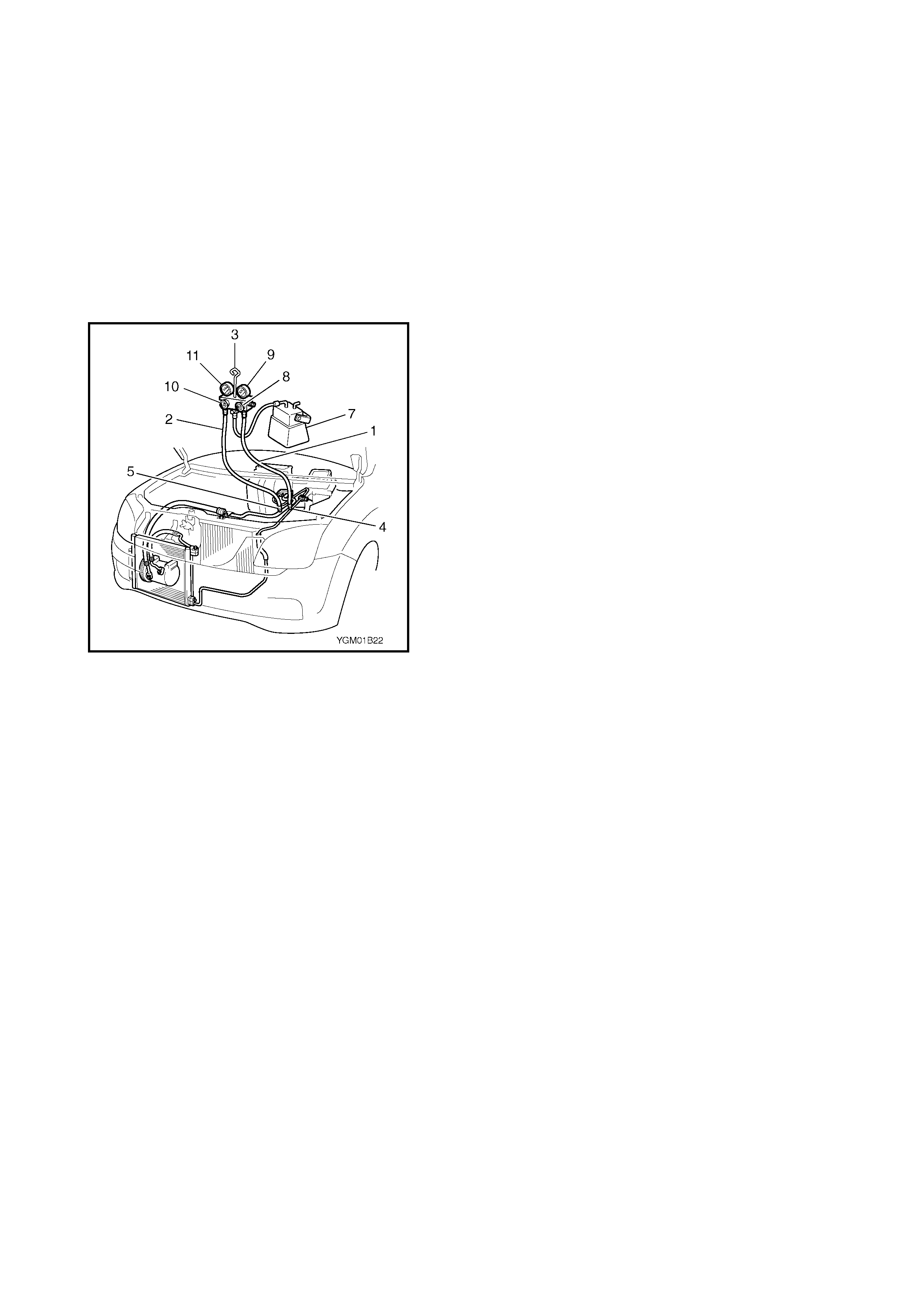
4.4 EVACUATING
EVACUATING PROCEDURE
CAUTION: Do not evacuate before recovering refriger-
ant in syst em.
NOTE: Whenever opened (exposed to atmospheric air),
the air conditioning sy stem must be e vac uated using a vac-
uum pump. A manifold gauge set should be connected to
the A/C system which should be evacuated for approxi-
mately 15 minutes.
1. Connect high pressure (HI) charging hose (1) and low
pressure (LO) c hargi ng hose (2) of the manifold gau ge
set (3) as follows:
High pressure charging hose (1) ® High pressure
charge port (4) on con denser outlet (liquid) tube.
Low pressure charging hose (2) ® Low pressure
charge port (5) on suction tube.
2. Attach centre charging hose (6) of manifold gauge set
(3) to vacuum pump (7).
3. Operate vacuum pump (7), and open the discharge
side valve (HI) (8) of the manifold gauge set (3).
If there is no blockage in the system, there will be an
indication on the high pressure gauge (9).
In this cas e, open the other side valve (LO) (10) of t he
set and evacu ate th e syste m.
4. After appro ximately 10 minutes the low pressure gauge
(11) should show a vacuum lower than –760 mmHg
providing no leakage exists.
NOTE:
•If the system does not show a vacuum below –760
mmHg, close both valves, stop the vacuum pump and
watch the movemen t of the low pressure gauge.
•Increas e in the gauge readi ng sugges ts existence of a
leak. In this case, repair the system before continuing
with the evacuation.
•If the gauge shows a stable reading (suggesting no
leakage), continue evacuation.
5. Evacuation should be carried out for a total of at least
15 minutes.
6. Continue evacuation until low pressure gauge (9)
indicates a vacuum less than –760 mmHg, and then
close both valves (8), (10).
7. Stop vacuum pump (7). Disconnect centre charging
hose (6) from pump inlet. Now, the system is ready for
charging refrigerant.
4.5 CHECKING SYSTEM FOR PRESSURE LEAKS
After completing the evacuation, close the manifold gauge
high pressure valve and low pressure valve and wait 10
minutes. Verify that low pressure gauge reading has not
changed.
CAUTION: If the gauge reading moves closer to “0”,
there is a leak somewhere. Inspect the tubing connec-
tions, make necessary repairs, evacuate the system
once again, ensuri ng there are no leaks.
4.6 CHARGING
CAUTION:
•Always charge through the low pressure side of the A/C system once the initial charging proce-
dure is perfor m ed f rom the high pressure side wi t h the engine not runnin g.
•Never charge to the high pressure side of the A/C system with the engine running.
•Do not charge wh ile comp resso r is hot.
•When installin g a tap valve to a refrigera nt contain er, carefully follow directions given by the man-
ufacturer.
•A pressure gaug e shoul d always be used before and during charging.
•The refrigerant container should be com pletely emptied of refrigerant before being discarded.
•The refrigerant container should not be subjected to a heat of 40°C or ov er.
The refrigerant container should not be upended during charging. Upending the container could
cause liquid refrigerant to enter the compressor, creating problems such as compression of liquid
refrigerant.
NOTE: The air conditioning system contains HFC-134 a (R-134a).
The following method for charging the refrigerant system uses refrigerant from a ref rigerant service container.
When cha rging with refrigerant recovered using refrigerant and recycling equipment (when recycling refriger-
ant), follow the equipment manufacturer’s instructions.
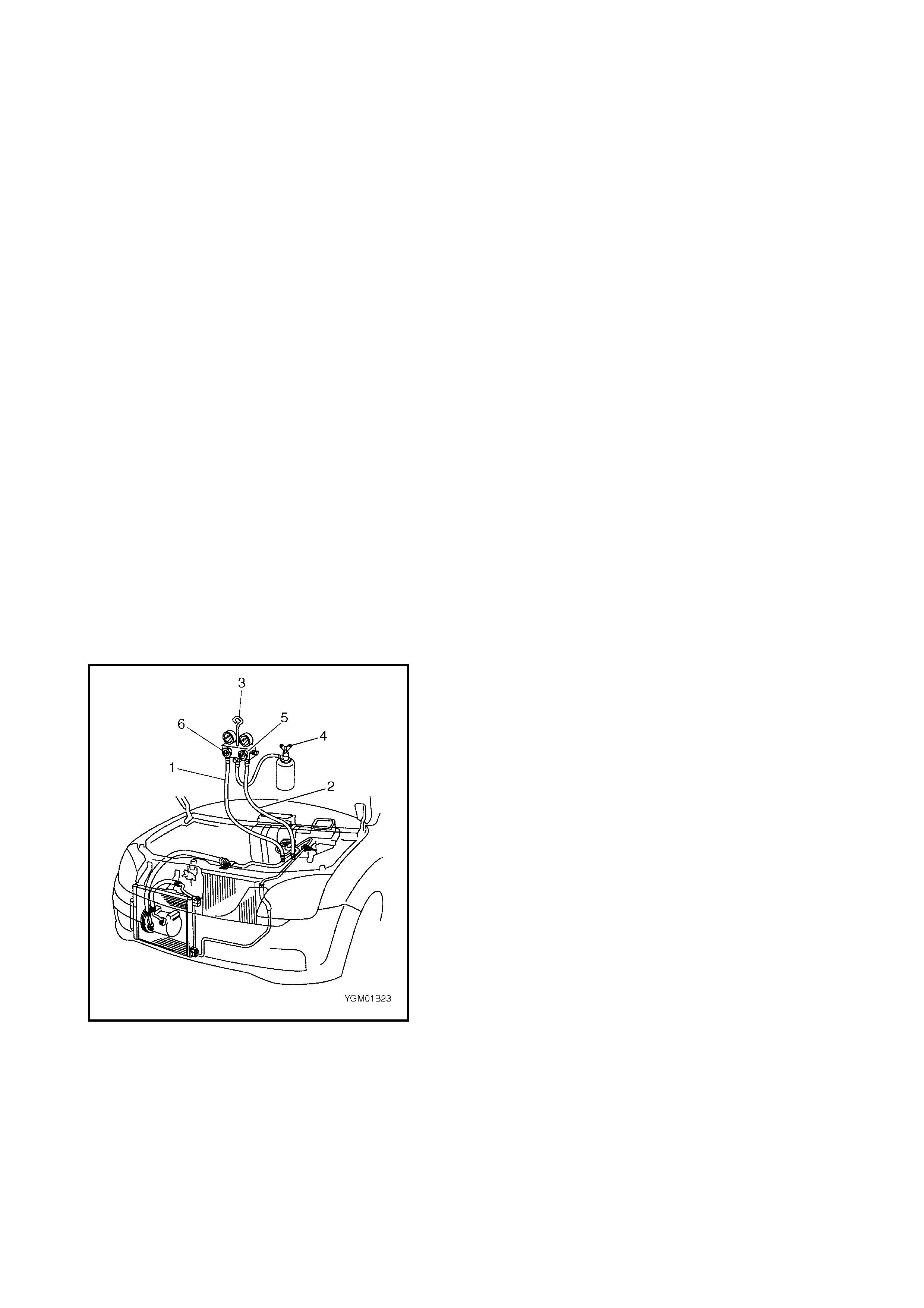
CHARGING PR OCEDURE
Initial charging of the A/C system is performed from the
high pressure side with the engine not running.
This must be followed by charging from the low pressure
side with the engine running.
1. Check to mak e sure that the hos es are routed correctly
after e va cua ti ng the syst em.
2. Connect the Low pressure charging hose (1) and the
High press ure chargin g hose (2) of t he m anifold gauge
set (3) in the correct manner as shown. Open the
refrigerant container valve (4) to purge the charging
line.
3. Open the high pressure side valve (5) and charge
refrigerant to system.
4. After a short period, open the low pressure side valve
(6) and close the high pressure side valve (5).
WARNING: Make sure that the high pressure side
valve is closed securely.
5. Star t t he engine a nd maintain engin e speed at 1500 r/
min. Operate the air conditioning.
6. Charge the A/C system with refrigerant in a vapor state
(at this stage, the refrigerant container (4) should
remain upr ight).
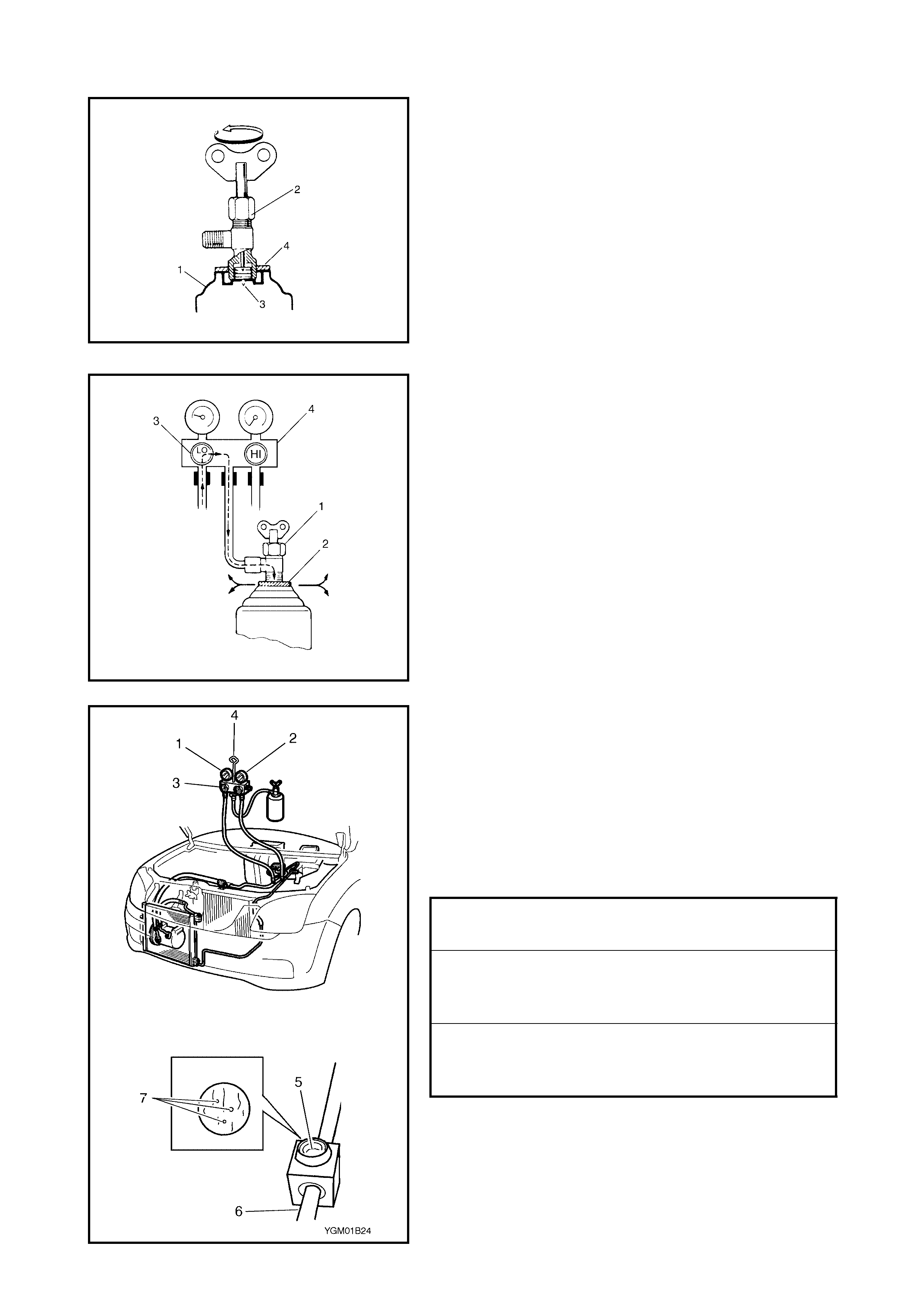
7. When the refrigerant container (1) is empty and
charging is not complete, use the following procedure
to replace it.
a. Close the low pressure valve.
b. Replace the empty container (1) with a refrigerant
container which has been charged with refrigerant.
If using a refrigerant container tap v al ve (2), use the
following procedure for replacem ent .
i. Retract needle (3) and remove refrigerant con-
tainer tap valve (2) by loosening its plate nut (4).
ii. Install the previously removed refrigerant con-
tainer tap valve (2) to a new refrigerant con-
tainer (1).
c. Purge any air existing in the centre charging hose
When using a refrigerant container tap valve, use
the following procedure to purge air.
i. Fully tighten the refrigerant container tap valve
(1), t hen loosen (open) plate nut (2) slight l y.
ii. Open the low pressure side valve (3) of the
manifold gauge set (4) a littl e.
iii. As soon as the refrigerant comes out with a
“hiss” through a cle arance between the refr iger-
ant contai ner and the tap valve, tighten plate nut
(2) as well as low pressure side val ve (3).
iv. Turn handle of tap valv e (1) clockwise so that its
needle is screwed into the new container to
allow for refrigerant flow.
5. After the system has been charged with the specified
amount (410 – 450 g) of refrigerant or when the low
pressure gauge (1) an d high pressure gauge (2) have
indicated t he following specified amount, clo se th e low
pressure side valve (3) on manifold gauge set (4). Look
into the sight gl ass (5) on the condenser o utlet (liquid)
tube (6) and check that there are no bubbles (7),
meani ng the system is fully charged.
Low side and high side pres sure example
Gauges should read as follows when ambi ent
temperature is 30°C.
Pressure
on high pressure gauge 1400 – 1750 kPa
14.0 – 17. 5 kg/cm2
199.1 – 248.9 psi
Pressure
on low pressure gaug e 230 – 350 kPa
2.3 – 3.5 kg/cm2
32.7 – 49.8 psi

4.7 REMOVING MANIFOLD GAUGE SET
CAUTION: High pressure side is normally under high pressure . Care must be taken to protect your
eyes and skin.
When th e A/C system has been charged with t he specified amount of refr igerant, remove the manifold gauge
set as foll ows:
1. Close the lo w pressure side valve on the manifold gauge set. (The high pressure side valve should remain
closed dur ing the process of charging.)
2. Close th e refrigerant container valve.
3. St op engine.
4. Us ing rag, remove charging hoses from charge ports. This operation must be performed rapidly.
5. Repla ce caps on charge por t s.
4.8 LEAK TEST
Whenever a refrigerant leak is suspected in the system or any service operation has been performed which
may result in disturbing lines or connections, it is advisable to test f or leaks.
Comm on sense should be used in performin g any refrigerant leak test, since the need and extent of any such
test wil l, in general, depend upon the nature of a complaint and t he type of a servic e performed on the system .
LIQUID LEAK DETECTORS
WARNING:
•To prevent explosions or fires, make sure that
there are no flammable materi als in the vicinity.
•When exposed to fire, the refrigerant turns into a
poison ous gas (phosg ene ). Do not inhale this gas.
There are numerous fittings and locations throughout the
air conditioning system where liquid leak detector solution
may be used to pinpoint refri gerant leaks.
By applying the solution to the area in question with a
swab, bubbles w ill qu ickly form if the re is a leak .
For confined are as, such as s ections of th e evaporator and
condenser, an electronic (refrigerant) leak detector (A) is
more practical for deter m ining leaks.
5 . ON-VEHICLE SERVICE
CAUTION: Should refrigerant HFC-134a (R-134a) make contact with your eye(s), consult a doctor
immediately.
•Do not use y our hand to rub affected eye(s). Use lar ge quantities of fresh cold water to spl ash over
the affected area to gradually raise the temperature above freezing point.
•Obtain medic al treatment as soon as possible from a doctor or eye specialist. Should liquid refrig-
erant HFC-134a (R-134a) contact your skin, the affected part should be treated in the same as
frostbitten or frozen skin.
5.1 SERVICE PRECAUTION
When servicing the air conditioning system , note the following instruc tions.
REFRIGERANT LINE
Legend
•Never use heat for bending pi pes. When bending a pipe, try to make the bend radius as sli ght as possible .
•Keep inter nal parts of air conditioni ng free from moisture a nd dir t. When disconn ecting any li ne from t he
system, install a blind plug or cap to the fitting immediately.
•When connecting hoses and pipes, apply a few drops of compressor oi l (refrigerant oil) to seats of cou-
pling nuts and O-rings .
•When tighteni ng or loosening a fitting, use two spanne rs, one for tu rn ing and the other for support.
1. S uc tion hose:
Appl y compresso r oil (refrig erant oil) to
O-ring.
4. E x pansion valve:
Apply comp ressor oil (refrigerant oil) to
O-ring.
2. Dis charge hos e:
Appl y compresso r oil (refrig erant oil) to
O-ring.
5. A /C refrig erant pressure switch:
Apply comp ressor oil (refrigerant oil) to
O-ring.
3. Condenser out let pipe:
Appl y compresso r oil (refrig erant oil) to
O-ring.

• Tighten flared nuts by the following the specified torque.
• Route the drain hose so that drained water does not make contact with vehicle components.
• If pipes or hoses are replaced, replenish specified amount of compressor oil to compressor suction side,
refer to 4.3 REPLENISHING COMPRESSOR OIL in this Section.
HANDLING REFRIGERANT HFC-134A (R-134A)
• Always wear goggles to protect your eyes.
• Avoid direct contact with liquid refrigerant.
• Do not heat refrigerant container higher than 40°C.
• Do not discharge refrigerant into the atmosphere.
• Do not allow liquid refrigerant to touch vehicle surfaces. Refrigerant combined with moisture is corrosive
and will tarnish surfaces of bright metals including chrome.
REFRIGERANT RECOVERY
When discharging refrigerant out of the A/C system, always recover it using refrigerant recovery and recycling
equipment. Discharging refrigerant HFC-134a (R-134a) into the atmosphere could cause adverse effects to
the environment.
REFRIGERANT CHARGE
After replenishing compressor oil and evacuating, recharge the system with the correct amount of refrigerant,
refer to 4.6 CHARGING in this Section.
CAUTION: Do not perform an additional refrigerant charge to the A/C system. This could cause it to
overcharge.
5.2 CONDENSER ASSEMBLY
CAUTION: Be careful not to damage condenser fins. If condenser fins are bent, straighten them
using a flat head screwdriver or pair of pliers.
INSPECTION
Check the following.
• Clogged condenser fins.
If, clogging is found, condenser fins should be washed with water, and dried with compressed air.
• Condenser fins for leakage and breakage.
If any defects are found, repair or replace condenser.
• Condenser fittings for leakage.
If any defects are found, repair or replace condenser.
REMOVAL
1. Disconnect negative (–) cable at battery.
2. Recover refrigerant from A/C system, refer to
4.2 RECOVERY in this Section.
NOTE: The amount of removed compressor oil must be
measured for correct replenishment of compressor oil.
3. Remove front bumper, refer to Section 9,
FRONT BUMPER and REAR BUMPER.
4. Disconn ect the co ndenser c ool ing fan motor connector
(1).
8mm PIPE
TORQUE SPECIFICATION 13 Nm
12mm PIPE
TORQUE SPECIFICATION 23 Nm
14.5mm PIPE
TORQUE SPECIFICATION 33 Nm
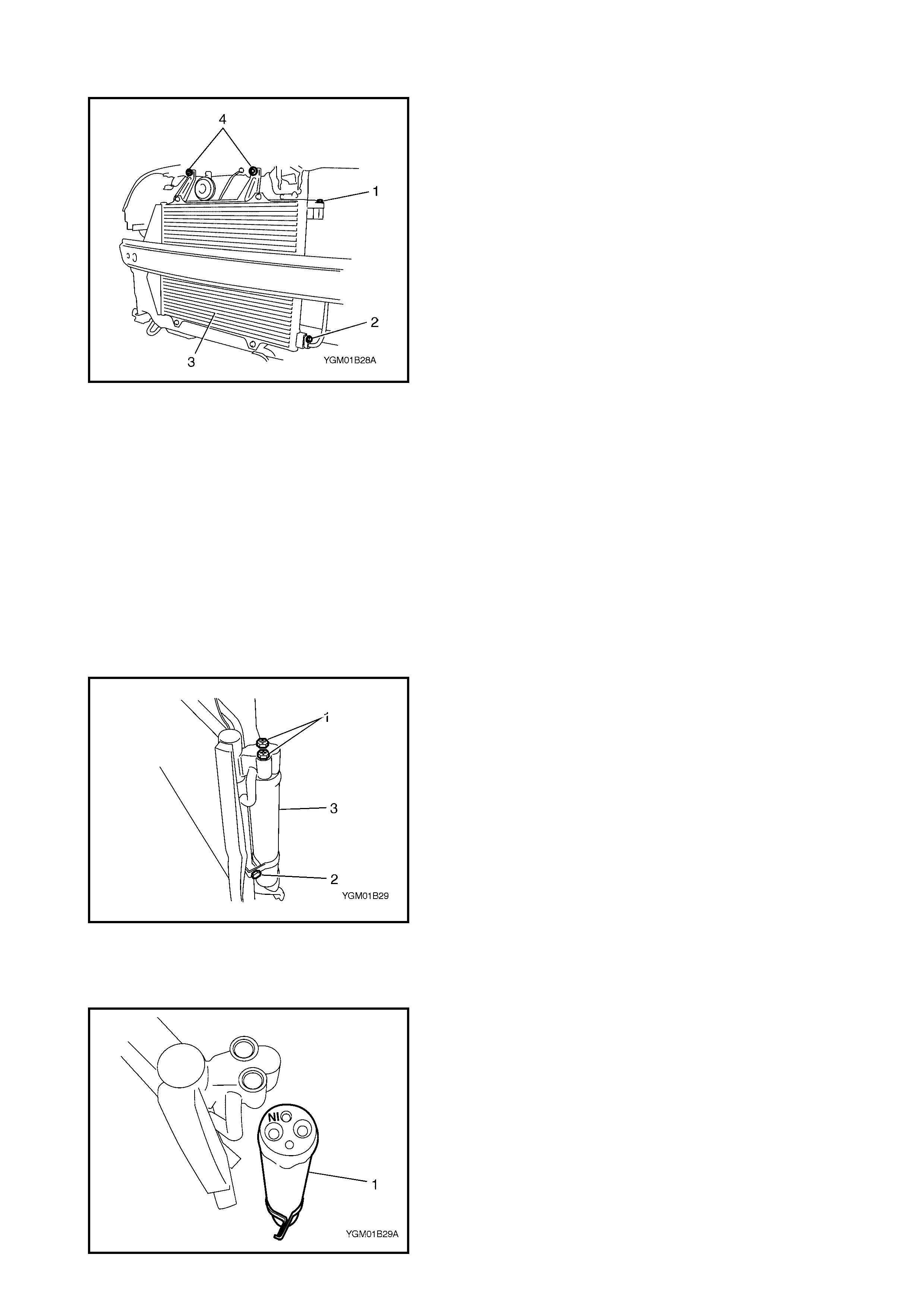
5. Disconnect discharge hose (1) and condenser outlet
(liquid) tube (2) from condenser (3).
NOTE: Cap open fittings immediately to keep moisture out
of system.
6. Remove condenser mounting bolts (4).
7. Remove condenser (3).
INSTALLATION
Reverse removal procedure to install condenser assembly
noting the following instructions.
• Replenish specified amount of compressor oil to com-
pressor suction side, refer to 4.3 REPLENISHING
COMPRESSOR OIL in this Section.
• Evacuate and charge system refrigerant, refer to
4.4 EVACUATING and 4.6 CHARGING in this Section.
5.3 RECEIVER/DRIER
REMOVAL
1. Remove condenser assembly, refer to
5.2 CONDENSER ASSEMBLY in this Section.
2. Loosen receiver/drier attaching bolts (1), (2).
3. Remove receiver/drier (3).
INSTALLATION
Reverse removal procedure to install receiver/drier noting
the following instructions.
• Replenish specified amount of compressor oil to com-
pressor suction side, refer to 4.3 REPLENISHING
COMPRESSOR OIL in this Section.
• Evacuate and charge system refrigerant, refer to
4.4 EVACUATING and 4.6 CHARGING in this Section.
•Be sure to i nstall receiver/drier (1) in the correct orien-
tation as shown.
5.4 CONDENSER COOLING FAN
REMOVAL
1. Remove condenser assembly, refer to
5.2 CONDENSER ASSEMBLY in this Section.
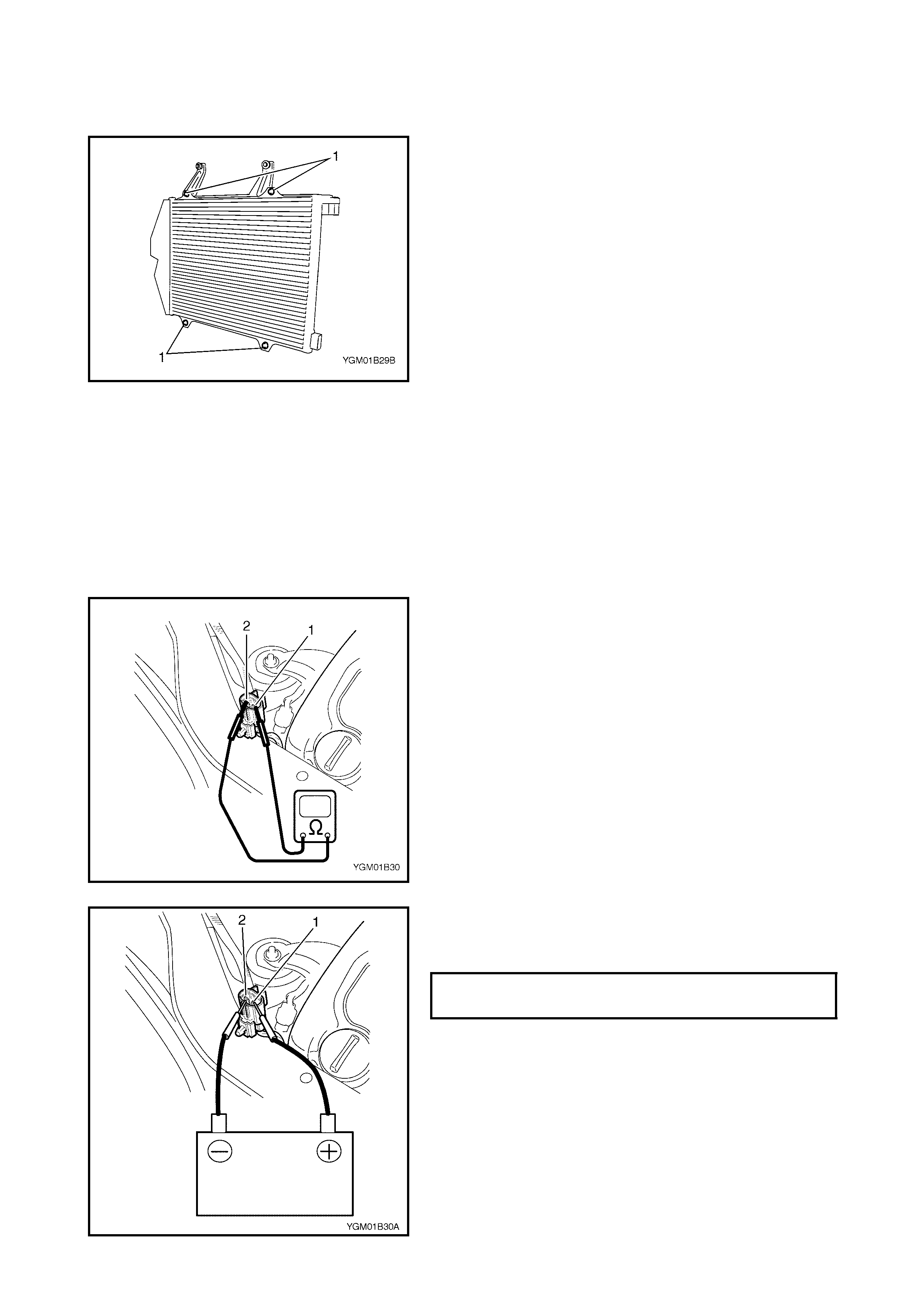
2. Remove condenser cooling fan motor mounting bolts
(1).
3. Remove conde nser cooling fan from condenser.
INSTALLATION
Reverse removal procedure to install condenser cooling fan
motor noting the following inst ructions.
•Replenish specified amoun t of compressor oil to com-
pressor suction side, refer to 4.3 REPLENISHING
COMPRESSOR OIL in this Section.
• Evacuate and charge refrigerant, refer to
4.4 EVACUATING and 4.6 CHARGING in this Section.
INSPECTION
1. Check condenser cooling fan motor for continuity
between term ina l (1) and (2) as shown.
If there is no continuity, repla ce condenser cooling fan
motor.
2. Connect battery to condenser cooling fan motor
ter m inal (1) and (2) as shown in figure, then ch eck that
the c ondenser c ooling f an motor operates smoothly.
3. Check condenser cooling fan blades f or damage. If any
damage is found, replace conde nser cooling fan blade.
CONDENSER COOLING FAN SPECI-
FIED CURRENT @ 12 VOLT 8 A MAX.

5.5 COOLING UNIT (EVAPORATOR)
Legend
CAUTION: Be careful not to damage A/C evaporator
fins. If A/C evaporator fins are bent, straighten them
using a flat head screwdriver or pair of pliers.
REMOVAL
1. Disconnect negative (–) cable at battery.
2. Recover refrigerant from A/C system, refer to
4.2 RECOVERY in this Section.
NOTE: The amount of removed compressor oil must be
measured for correct replenishment of compressor oil.
3. Remove glove box, refer to Section 9,
3.1 INSTRUMENT PANEL.
4. Remove f resh air control cable (1) and A/C evaporator
tempera ture sensor connector.
1. A/C evaporator 5. Cooling unit packing 11. O-ring
2. A/C evaporator tempe rature sensor 6. Dash seal 12. Door link
3. Expansion valve 7. Seal 13. Lower packing
4. Evaporator case
: Apply sealant, Three Bond 1216B to
hatched
part “A”.
8. Fres h air duct case Do not reuse.
9. Clamp
10. Air inlet door
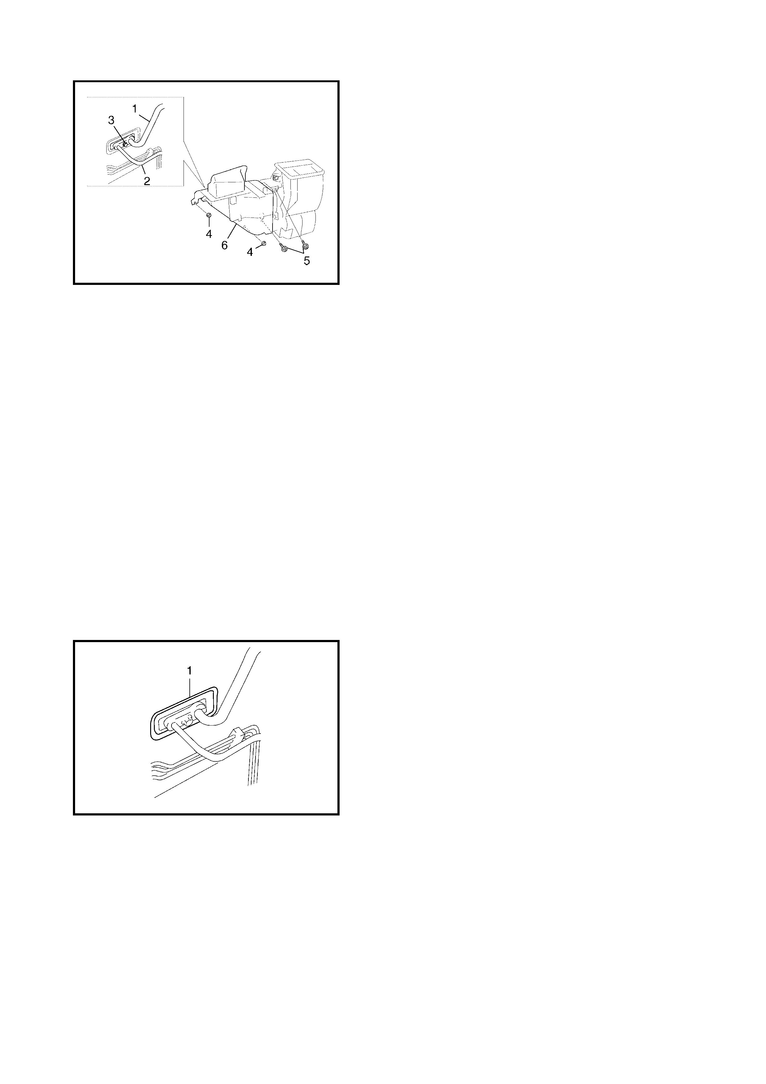
5. Disconnect suction hose (1) and condenser outlet hose
(2) by removing attaching bolt (3).
NOTE: Cap open fittings immediat ely to keep mois ture out
of system.
6. Remove cooling unit mounting nuts (4) and screws (5).
7. Remove cooling unit (6).
INSPECTION
Check the following.
• Clogging of A/C evaporator fins.
If any clog ging is fou nd, A/C evapo rator fins sho uld be
washed with water and dried with compressed air.
• A/C evaporator fins for leakage and breakage.
If any defects are found, repair or replace A/C evapora-
tor.
• A/C evaporator fittings for leakage.
If any defects are found, repair or replace A/C evapora-
tor.
INSTALLATION
Reverse removal procedure to inst all cooling unit noting the
following instructions.
• If the A/C evaporator temperature sensor was
removed, it must be reinstalled in the original position.
• Replenish specified amount of compressor oil to com-
pressor suction side, refer to 4.3 REPLENISHING
COMPRESSOR OIL in this Section.
• Ensure the seal (1) is fitted uniformly around the fire-
wall installation hole.
• Evacuate and charge refrigerant, refer to
4.4 EVACUATING and 4.6 CHARGING in this Section.
• Adjust fresh air control cable, refer to
Section 1A, 3.4 HEATER CONTROL ASSEMB LY.
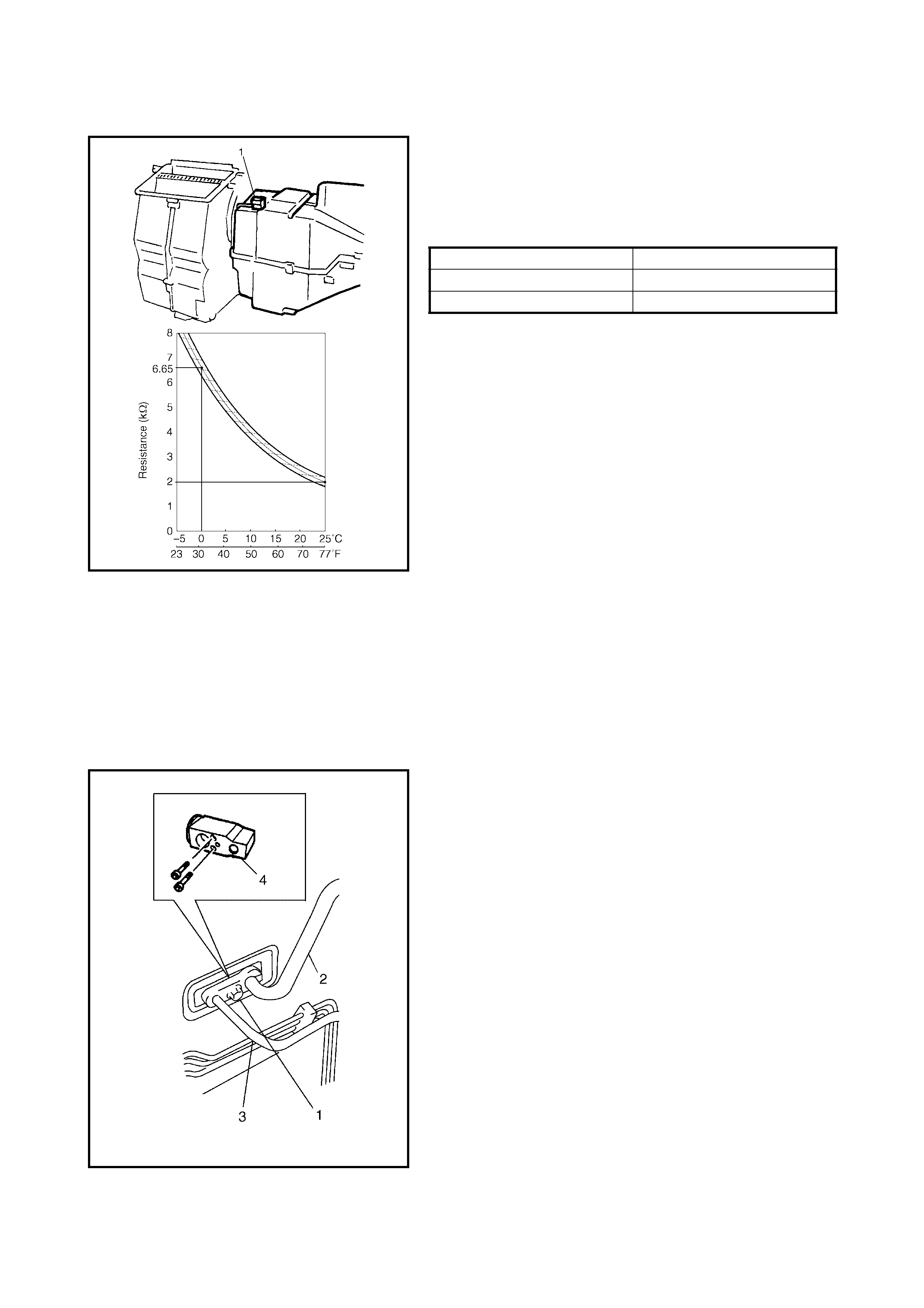
5.6 A/C EVAPORATOR TEMPERATURE SENSOR
Check the resistance between the terminals for the A/C
evaporator temperature sensor (1).
If results are not as specified, replace the A/C evaporator
temperature sensor.
A/C evaporator temperature sensor resistance
NOTE: When A/C evaporator temperature sensor is
removed, it must be reinstalled in original position.
5.7 EXPANSION VALVE
REMOVAL
1. Disconnect negative (–) cable at battery.
2. Recover refrigerant from the A/C system, refer to
4.2 RECOVERY in this Section.
NOTE: The amount of removed compressor oil must be
measured for correct replenishment.
3. Remove attaching bolt (1).
4. Remove suction hose (2) and receiver/drier outlet
(liquid) tube (3) from expansion valve (4).
NOTE: Cap open fittings immediately to keep moisture out
of system.
5. Remove expansion valve (4).
INSTALLATION
Reverse removal procedure to install expansion valve not-
ing the following instructions.
• Replenish the specified amount of compressor oil to
the compressor suction side, refer to 4.3 REPLENISHING
COMPRESSOR OIL in this Section.
• Evacuate and charge system refrigerant, refer to
4.4 EVACUATING and 4.6 CHARGING in this Section.
INSPECTION
Refer to 2.4 PERFORMANCE DIAGNOSIS in this Section.
Sensor Temperature Resi stance
0°C 6.4 – 6.9 k W
25°C1.8 – 2.2 kW
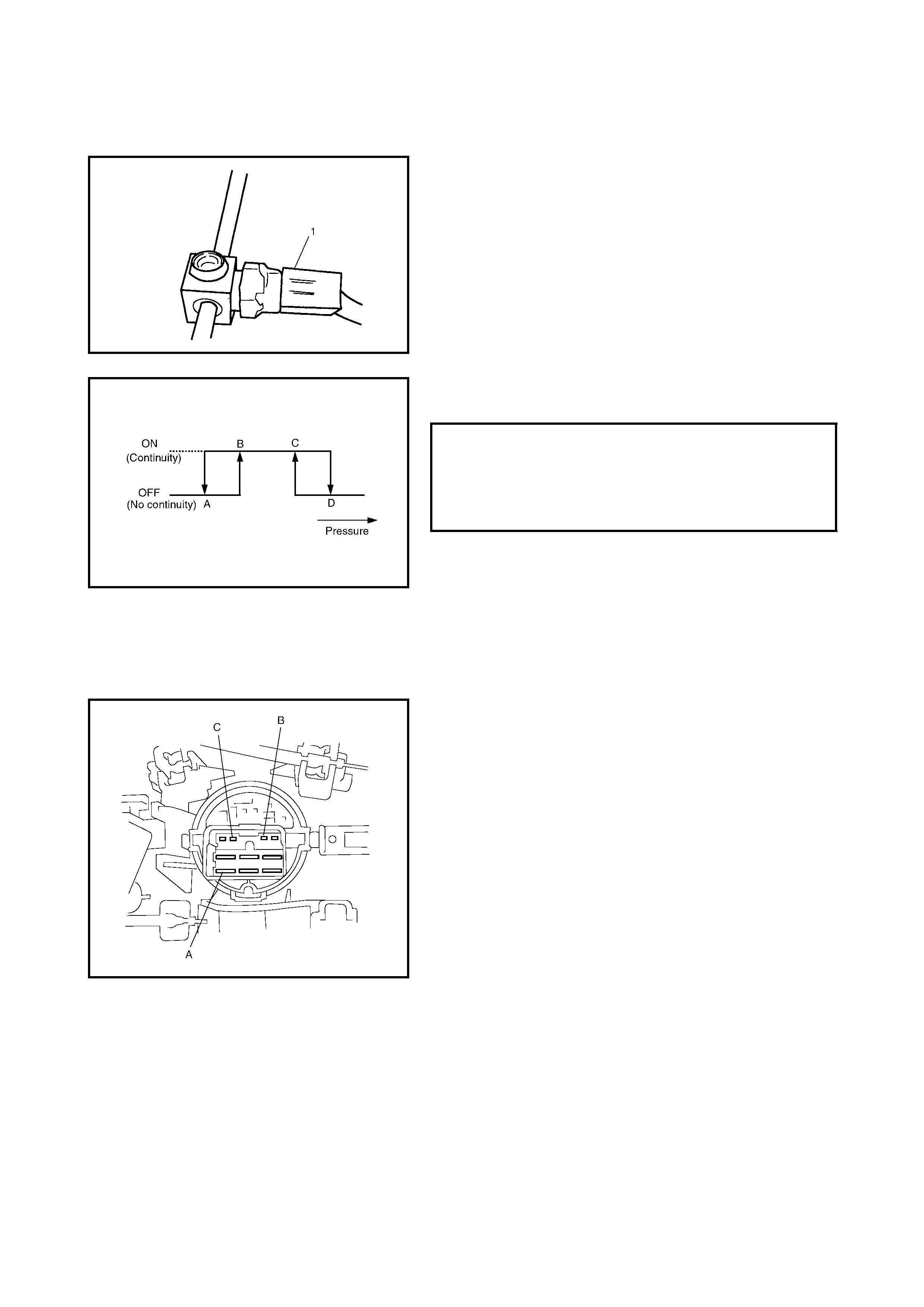
5.8 A/C REFRIGERANT PRESSURE SWITCH
INSPECTION
1. Check the A/C refrigerant pressure switch (1) for conti-
nuity at normal temperature (approximately 25°C)
when the A/C system has the correct charge of refrig-
erant and the A/C system (compressor) is operating.
The refrigerant pressure switch should show correct
continuity.
2. Check continuity between high and low pressure [A]
switch terminals (1) at specified pressure as shown.
5.9 A/C SWITCH
REMOVAL AND INSTALLATION
Refer to Section 1A, 3.4 HEATER CONTROL ASSEMBLY.
INSPECTION
•Press A/C switch button and check if there is continuity
between t erminal s (A) and (B).
•Connect battery voltage (+) to terminal (C) and (–) to
terminal (A), and then press A/C Switch button and
che ck if ind ic a tor lamp lights.
HIGH AND LOW PRESSURE SWITCH
SPECIFICATION (APPROX.) A
B
C
D
200 kPa
230 kPa
2600 kPa
3200 kPa

5.10 COMPRESSOR RELAY AND CONDENSER COOLING FAN RELAY
INSPECTION
1. Disconnect negative (-) cable at battery.
2. Remove condenser cooling fan relay (1) and compres-
sor relay (2) from main fuse box.
3. Check that there is no continuity between terminal (c)
and (d). If there is continuity, replace relay.
4. Connect battery positive (+) terminal to terminal (b) of
relay.
Connect battery negative (-) terminal to terminal (a) of
relay.
Check continuity between terminal (c) and (d).
If there is no continuity when relay is connected to the
battery, replace relay.
5.11 COMPRESSOR
REMOVAL
1. Run engine at idle speed with air conditioning ON for
10 minutes then stop the engine.
2. Disconnect negative (–) cable at battery.
3. Remove front bumper, refer to Section 9,
FRONT BUMPER and REAR BUMPER.
4. Remove condenser assembly, refer to
5.2 CONDENSER ASSEMBLY in this Section.
5. Remove compressor drive belt (1) by loosening tension
pulley nut (2) and adjusting bolt (3).
6. Disconnect magnetic clutch lead wire connector.
7. Disconnect suction pipe (4) and discharge hose (5)
from compressor (6).
NOTE: Cap open fittings immediately to keep moisture out
of system.
8. Remove compressor mounting bolts (7), and remove
compressor (6) from the compresso r mounting bracket.
INSTALLATION
Reverse removal procedure to install compressor noting
the following instructions.
• If the compressor is replaced, add new compressor oil,
refer to 4.3 REPLENISHING COMPRESSOR OIL in
this Section.
• Evacuate and charge system, refer to 4.2 RECOVERY
in this Section.
• Adjust drive belt tension, refer to 2.5 COMPRESSOR
DRIVE BELT in this Section.
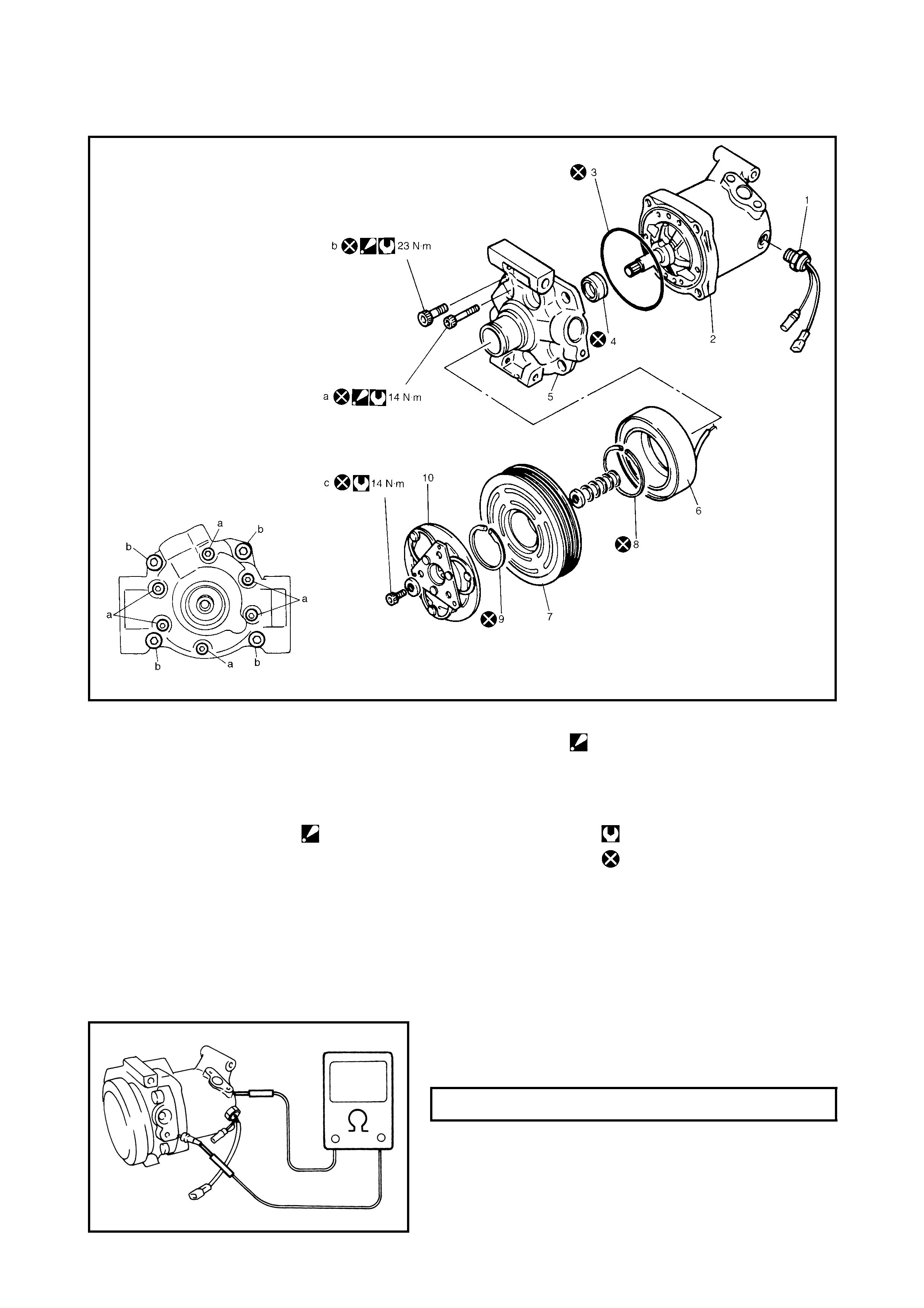
5.12 MAGNETIC CLUTCH
Legend
INSPECTION
•Check clutch plate and clutch pulley for wear and signs
of oil leakage.
•Check clutch pulley bearing for noise, wear and grease
leakage.
•Measure clutch coil for resistance at 20°C.
If the measured resistance does not remain within tol-
erance, replace ma gnet ic clutch assembly.
1. Compressor thermal
protection switch 7. Clutc h pulley b. Front head bolt
: Tighten bolt (a) first, and
next (b)
8. Circlip
2. Compressor body 9. Circlip
3. O-r ing 10. Clut ch plate c. C lutch plate bolt
4. Lip type seal a. Front head bolt
: Tighten bolt (a) first, and
next (b)
Tightening torque
5. Front head D o not reuse.
6. Clutch coil
CLUTCH COIL RESISTANCE 3.4 - 4. 1 W
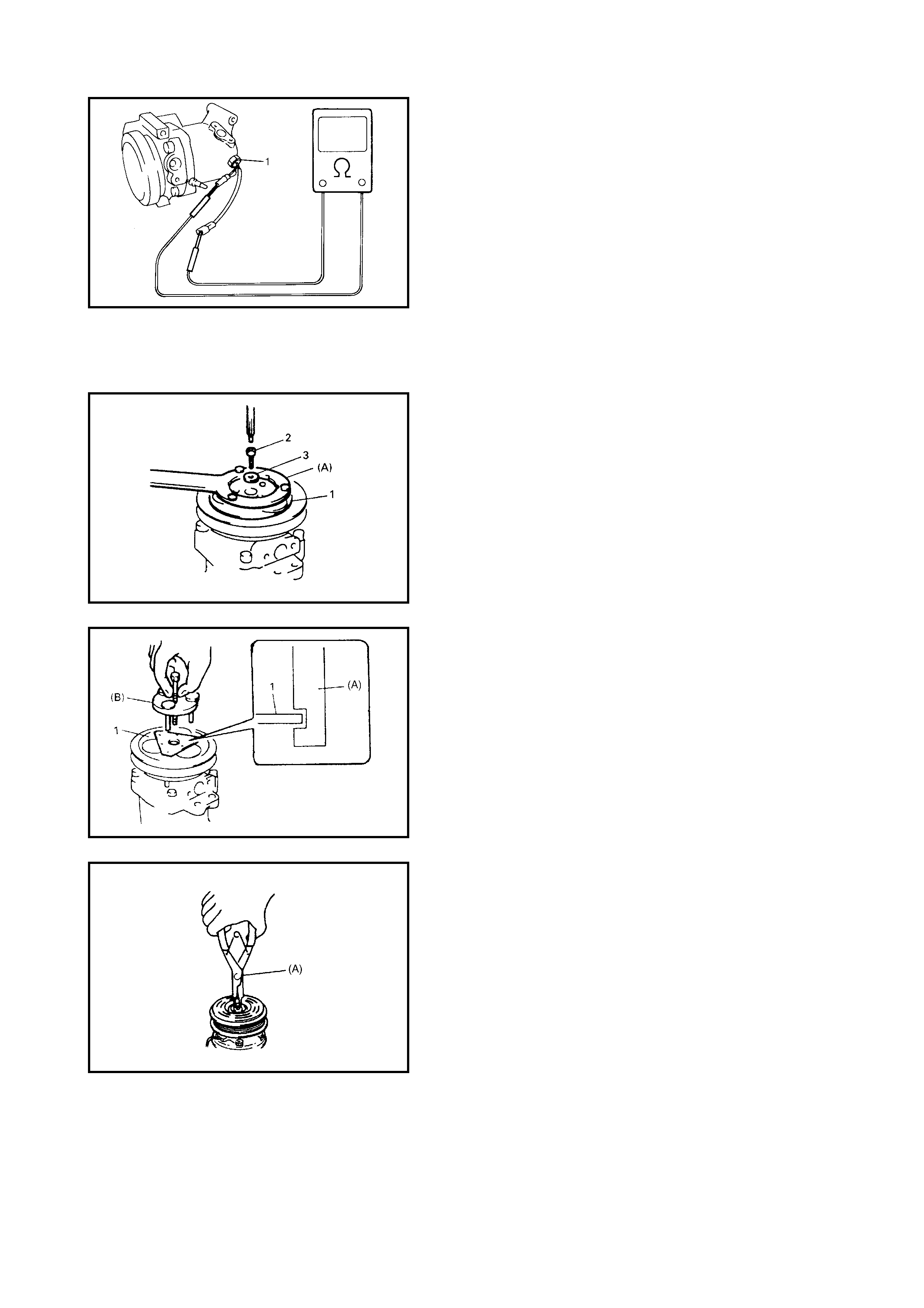
• Use an ohmmeter to check thermal protection switch
(1) for continuity.
If there is no continuity, replace switch.
REMOVAL
1. Remove compressor from vehicle. Refer to
5.11 COMPRESSOR in this Section.
2. Fit spec ial to ol 0 9991-060 20 (A ) t o clu tch p late (1) a nd
remov e clutch plat e bolt (2) and washer ( 3).
3. Using special tool 09991-06030 (A), remove clutch
plate (1).
4. Remove shims from shaft.
5. Using special tool 09900-06107 (A), remove circlip.
6. Remove clutch coil lead wire clamp by loosening its
screw and disconnect clutch coil lead wire from thermal
switch lead wire .
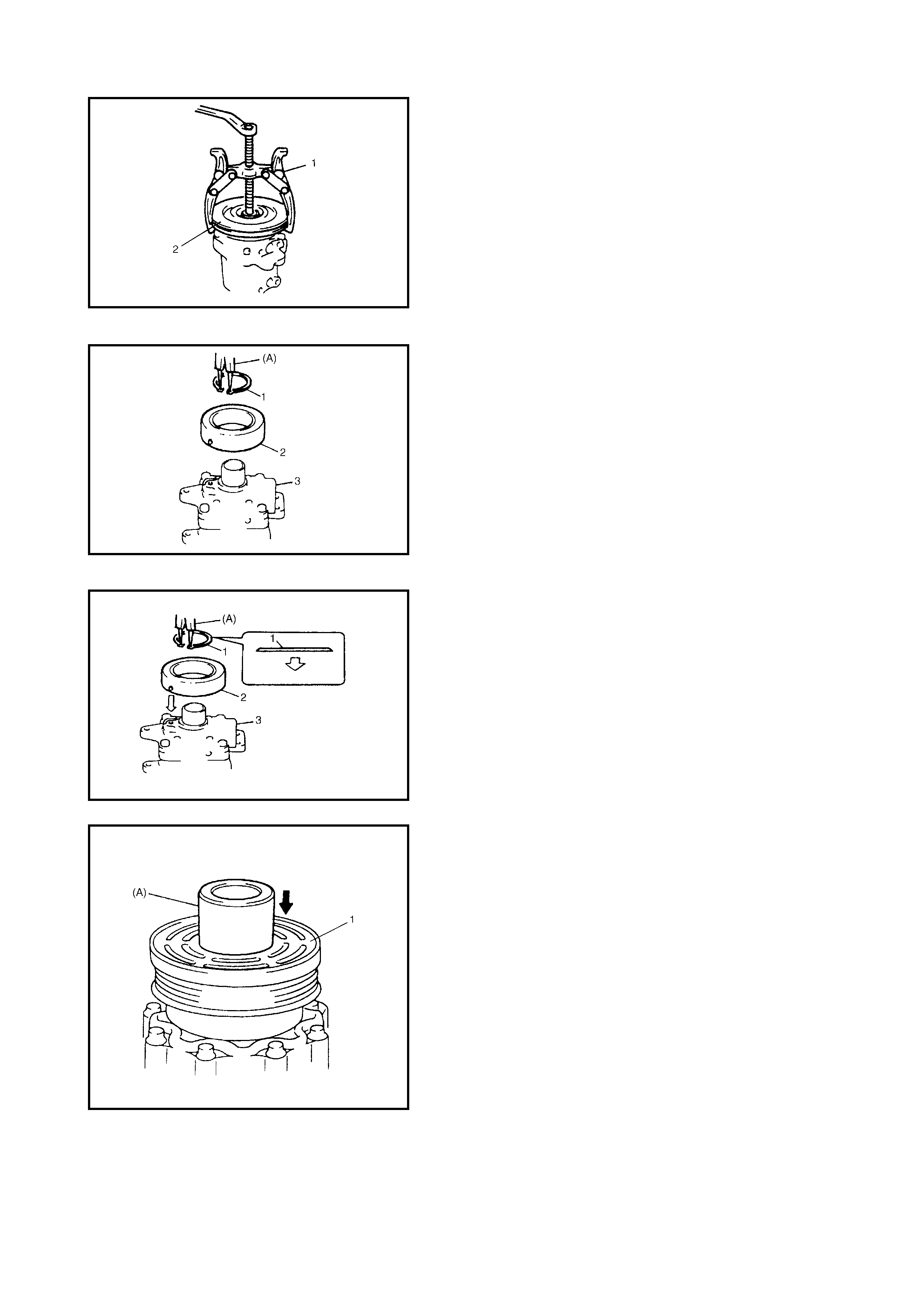
7. Remove the clutch pulley (2) with a suitable, commer-
cially av ailabl e puller (1).
NOTE:
•Take care not to damage pulley when removing.
•Be careful not to scratch beari ng.
8. Remove cl u tch co il.
9. Remove circlip (1) by using special tool 09900-06107
(A).
10. Remove clutch coil (2) from compressor (3).
INSTALLATION
1. Install clutch coil (2).
Protrus ion on underside of clutch coil must match ho le
in compressor (3) to prevent movement and to allow
correct location of lead wire.
2. Using special tool 09900-06107, install new circlip (1)
as shown.
3. Install clutch pulley (1).
a. Set clutch pulley (1) squarely over clutch pulley
installation boss.
b. Place special tool 099961-06010 (A) onto clutch
coil bearing.
Ensure that edge rests only on inner race of bear-
ing.
c. Inst a ll circl ip.
CAUTION: Be careful not to scratch bearing seat.
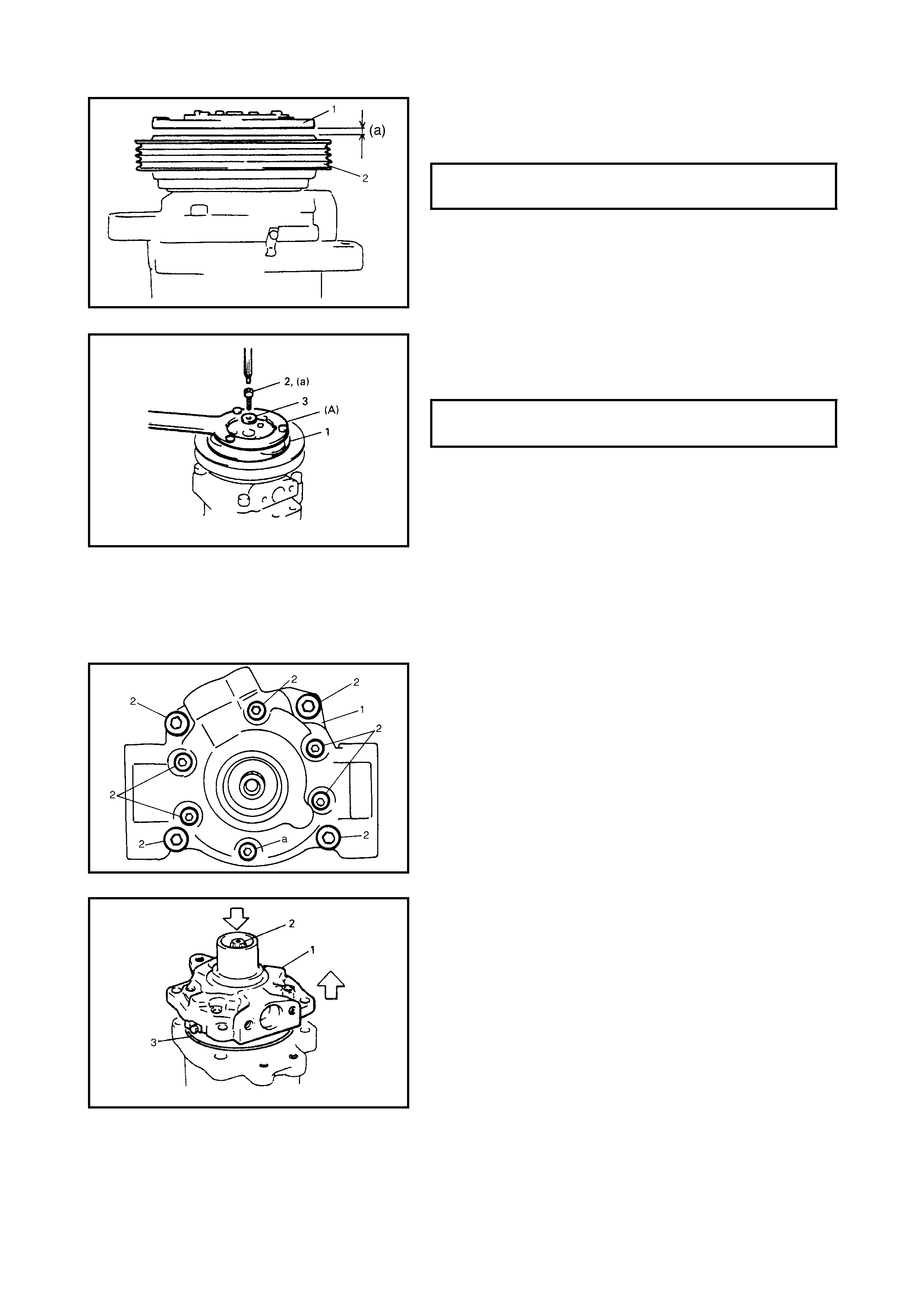
4. Adjust the clearance, between the clutch plate (1) and
the clutch pulley (2) by fitting shims on the compressor
shaft.
5. Secure the new clutch plate (1) with the clutch plate
bolt (2) and washer (3) to specified torque as shown
using special tool 09991-06020 (A).
5.13 LIP TYPE SEAL
REMOVAL
1. Remove the magnetic clutch, refer to 5.12 MAGNETIC
CLUTCH in this Section.
2. Remove front head (1) mounting bolts (2).
3. Remove front head (1) by pus hing cylinder shaft (2).
NOTE: Be careful not to remove cylinder f rom front head.
4. Remov e O-ring (3).
CLEARANCE BETWEEN CLUTCH
PLATE AND CLUTCH PULL EY (a) 0.3 - 0.6 mm
CLUTCH PLATE BOLT (a)
TORQUE SPECIFICATION 14 Nm
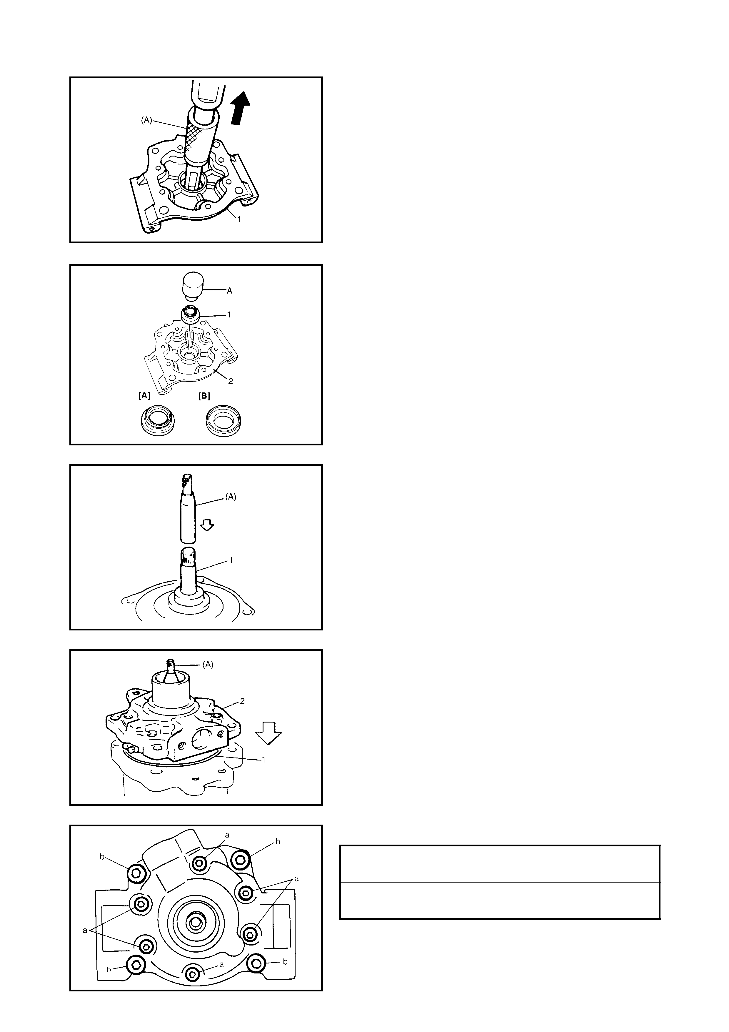
5. Remove lip type seal from f ront head (1) u sing speci al
tool 09923-73210 (A ).
INSTALLATION
1. Press-fit new lip type seal (1) into front head (2) u sing
specia l tool 09991-06 050. Ensure l ip type sea l is fitted
correctly, top side [A] up and back side [B] down.
CAUTION: Do not reuse lip type seal (1) once removed
from compressor.
2. Coat special too l 09991-06040 (A) surface with oil and
place it on cylinder shaft (1).
3. Install new O-ring (1) to case.
4. Appl y compresso r oil to lip type seal and O-ring (1).
5. Install front head (2).
6. Tighten new front head mounting bolts (a), (b).
NOTE:
•Be sure to use new front head mounting bolts .
•Tighten bolt (a) first, and next (b).
FRONT HEAD BOLT (a)
TORQUE SPECIFICATION 9 Nm
FRONT HEAD BOLT (b)
TORQUE SPECIFICATION 22 Nm
6. REQUIRED SERVICE MATERIAL
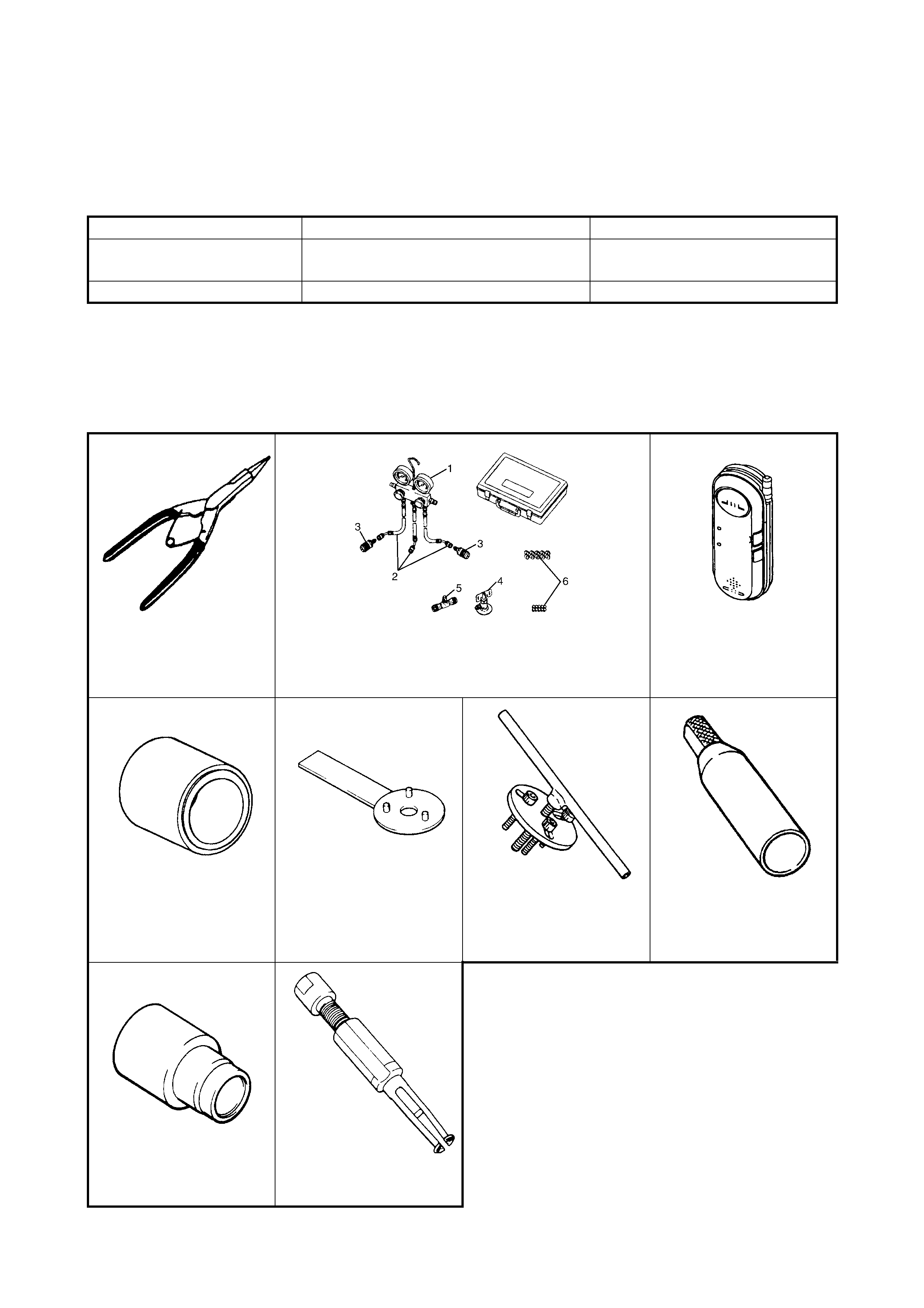
7. SPECIAL TOOLS
NOTE: Refer to Section 0A GENERAL INFORMATION - 7. CONSOLIDATED TOOLS for a detailed list of
special tools and the local equivalent if one is available.
NOTE: This kit includes the following items: 1. Manifold gauge, 2. Changing hose, 3. Quick connector, 4.
Refrigerant container tap valve, 5. Refrigerant container T joint, 6. Packing set
Material
Recommended product
Use
Compressor oil
(Refrigerant oil) COMPRESSOR OIL RS20 (150 cc) • O-ring
• Each component
Sealant Three BOND No.1216B • Cooling unit
09900-0 610 7 0 999 0-060 10 09990 -86011
Snap ring pliers
(Opening type) Manifold gauge set
See NOTE below. Gas leak detector
09991-06010 09991-06020 09991-06030 09991-06040
Magnet clutch pulley
installer Armature plate spanner Armature plate remover Lip type seal protector
09991-06050 09923-73210
Lip type seal installer Bearing remover