
SECTION 6A1 - ENGINE MECHANICAL (M15 ENGINE)
1. GENERAL DESCRIPTION
1.1 ENGINE
1.2 ENGINE LUBRI CATION
2. DIAGNOSIS
2.1 DIAGNOSIS TABLE
2.2 COMPRESSION CHECK
2.3 ENGINE VACUUM CHECK
2.4 OIL PRESSURE CHECK
2.5 VALVE LASH (CLEARANCE)
Inspection
Replacement of Shim
3. ON-VEHICLE SERVICE
3.1 AIR CLEANER ELEMENT
Removal
Inspection and Cleaning
Installation
3.2 AIR CLEANER ASSEMBLY AND
RESONATOR
Removal
Installation
3.3 KNOCK SENSOR
3.4 CYLINDER HEAD COVER
Removal
Installation
3.5 THROTTLE BODY AND INTAKE
MANIFOLD
Removal
Installation
3.6 EXHAUST MANIFOLD
Removal
Installation
3.7 OIL PAN AND OIL PUMP STRAINER
Removal
Clean
Installation
3.8 ENGINE MOUNTINGS
4. UNIT REPAIR AND OVERHAUL
4.1 ENGINE ASSEMBLY
Removal
Installation
4.2 TIMING CHAIN COVER
Removal
Clean
Inspection
Installation
4.3 OIL PUMP
Removal
Disassembly
Inspection
Measurement
Assembly
Installation
4.4 TIMING CHAIN AND CHAIN TENSIONER
Removal
Inspection
Installation
WARNING:
For vehicles equipped with Supplemental Restraint (Airbag) System:
• Service on and around the airbag system components or wiring must be performed only by
an authorised HO LDEN retailer. Please observe all WARNINGS and SERVICE PRECAUTIONS
refer to Se ction 10B AIRBA G SYSTEM, ON-V EHICLE SERVICE be fore performing s ervice on
or around the airbag system components or wiring. Failure to follow WARNINGS could result
in unintentional activation of the system or could render the system inoperative. Either of
these two conditions may r esult in severe injury.
• The procedures in this section must be followed in the order listed to temporarily disable the
airbag system and prevent false diagnostic codes from setting. Failure to follow procedures
could result in possible airbag system activation, personal injury or otherwise unneeded air-
bag system repairs.
• Technical service work must be started at least 90 seconds after the ignition switch is turned
to the “LOCK” position and the negative cable is disconnected from the battery. Otherwise,
the syst em may be act ivat ed by res er ve ene rgy i n the Sen sing and Diag nost i c Modu le (SDM) .

4.5 CAMSHAFT, TAPPET AND SHIM
Removal
Inspection
Installation
4.6 VALVES AND CYLINDER HEAD
Removal
Disassembly
Inspection
Assembly
Installation
4.7 PISTONS, PISTON RINGS,
CONNECTING RODS AND CYLINDERS
Removal
Disassembly
Cleaning
Inspection
Assembly
Installation
4.8 MAIN BEARINGS, CRANKSHAFT
AND CYLINDER BLOCK
Removal
Inspection
Main Bearings
Selection of Main Bearings
Cylinder Block
Installation
5. REQUIRED SERVICE MATERIAL
6. SPECIAL TOOLS
1. GENERAL DESCRIPTION
1.1 ENGINE
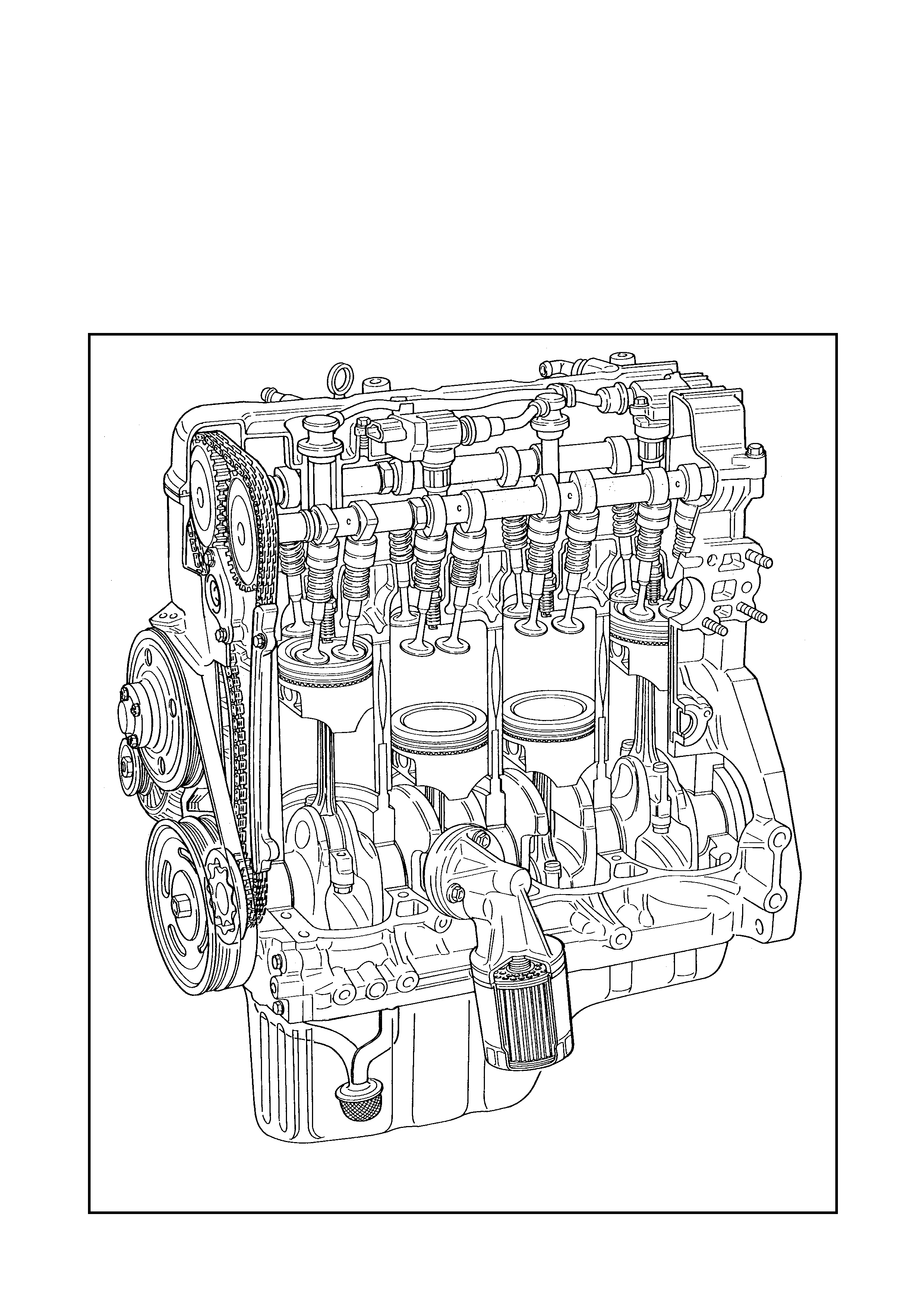
The engine is a water-cooled, in line 4 cylinder, 4 stroke petrol unit with Double Overhead Camshaft
(DOHC) valve mechanism arranged in a “V” type valve configuration with 16 valves (4 valves per
cylinder. The double overhead camshafts are mounted over the cylinder head and are driven from the
crankshaf t throu gh a timing chain. There are no push ro ds in the valve train system.
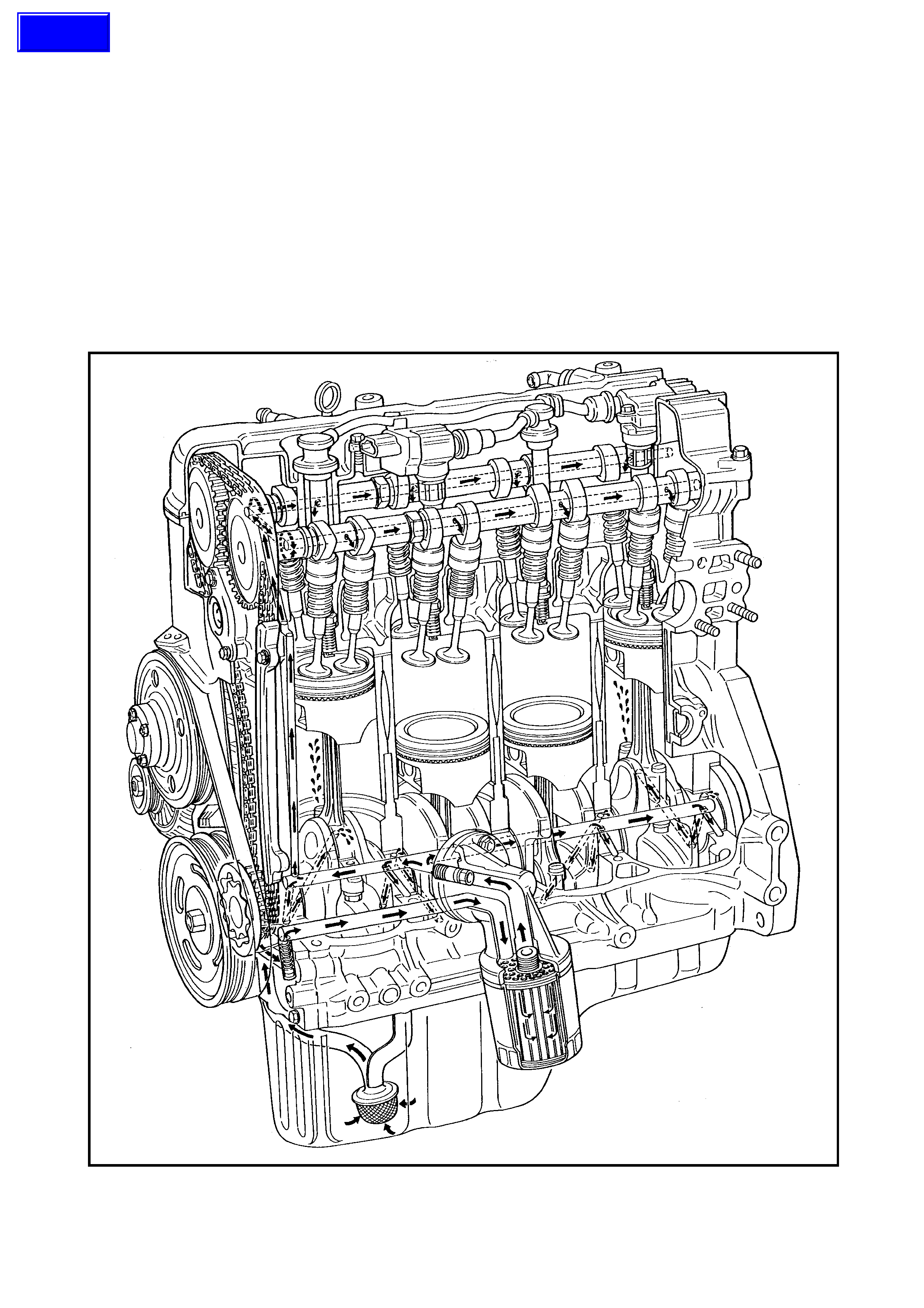
1.2 ENGINE LUBRICATION
The oil pump is a troc hoi d typ e, and mount ed on the crank sh aft. Oil is drawn up throug h t he oil pum p str ainer
and passed through the pum p to the oil filte r.
The filtered oil flows into two paths in the cylinder block.
Along one path, oil reaches the crankshaft journal bearings. Oil from the crankshaft journal bearings is sup-
plied to the conn ecting rod be arings via intersecting passag es drilled in the crank shaft, then is injected from
the big end of the connecting rod to lubricate the piston, rings, and cylinder wall.
In the second path, oil travels up to the cylinder head and lubricates the valves and camshafts, etc., after
passing through the internal oilway of the camshafts.
An oil relief valve is provided on the oil pump. This valve relieves oil pressure when the pressure exceeds
approximately 400 kPa.
Techline
2. DIAGNOSIS
2.1 DIAGNOSIS TABLE
Refer to Section 6, 2.4 ENGINE DIAGNOSTIC TABLE.
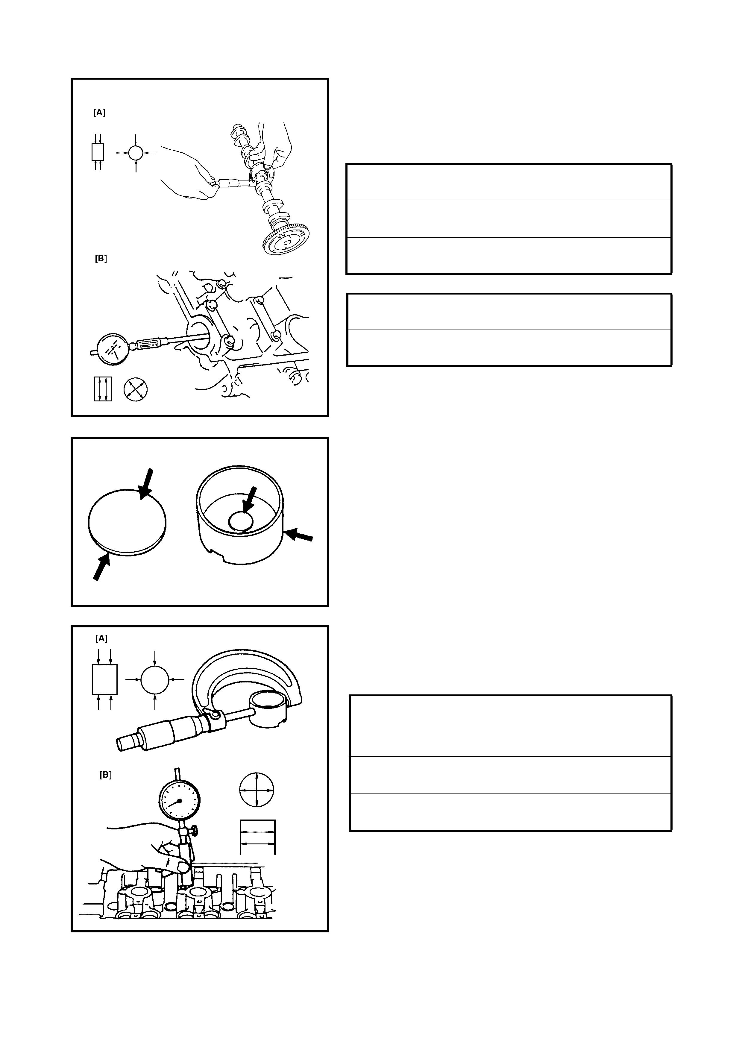
2.2 COMPRESSION CHECK
Check compression on all 4 cylinders as follows:
1. Warm up engine to normal operating temperature.
2. Stop engine after warming up.
NOTE: After warming up engine, place transmission gear
shift lever in Neutral (shift selector lever to “P” for A/T
vehicles), and set parking brake and block drive wheels
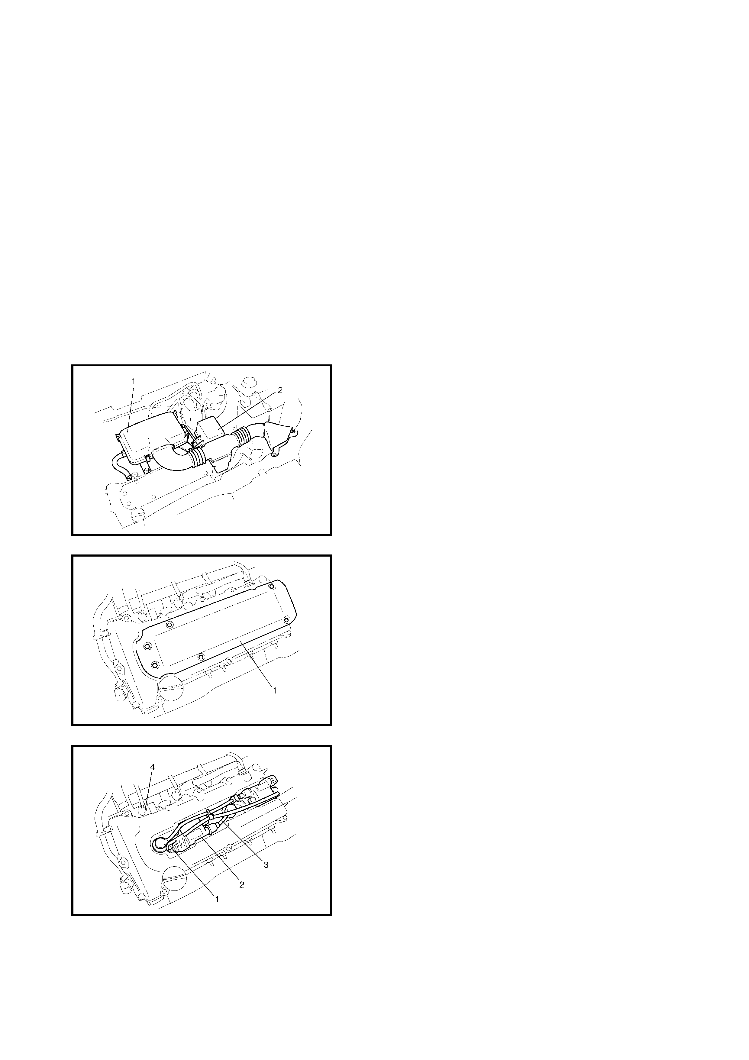
3. Remove air cleaner assembly (1), resonator (2) and
hoses. Refer to 3.2 AIR CLEANER ASSEMBLY AND
RESONATOR in this Section.
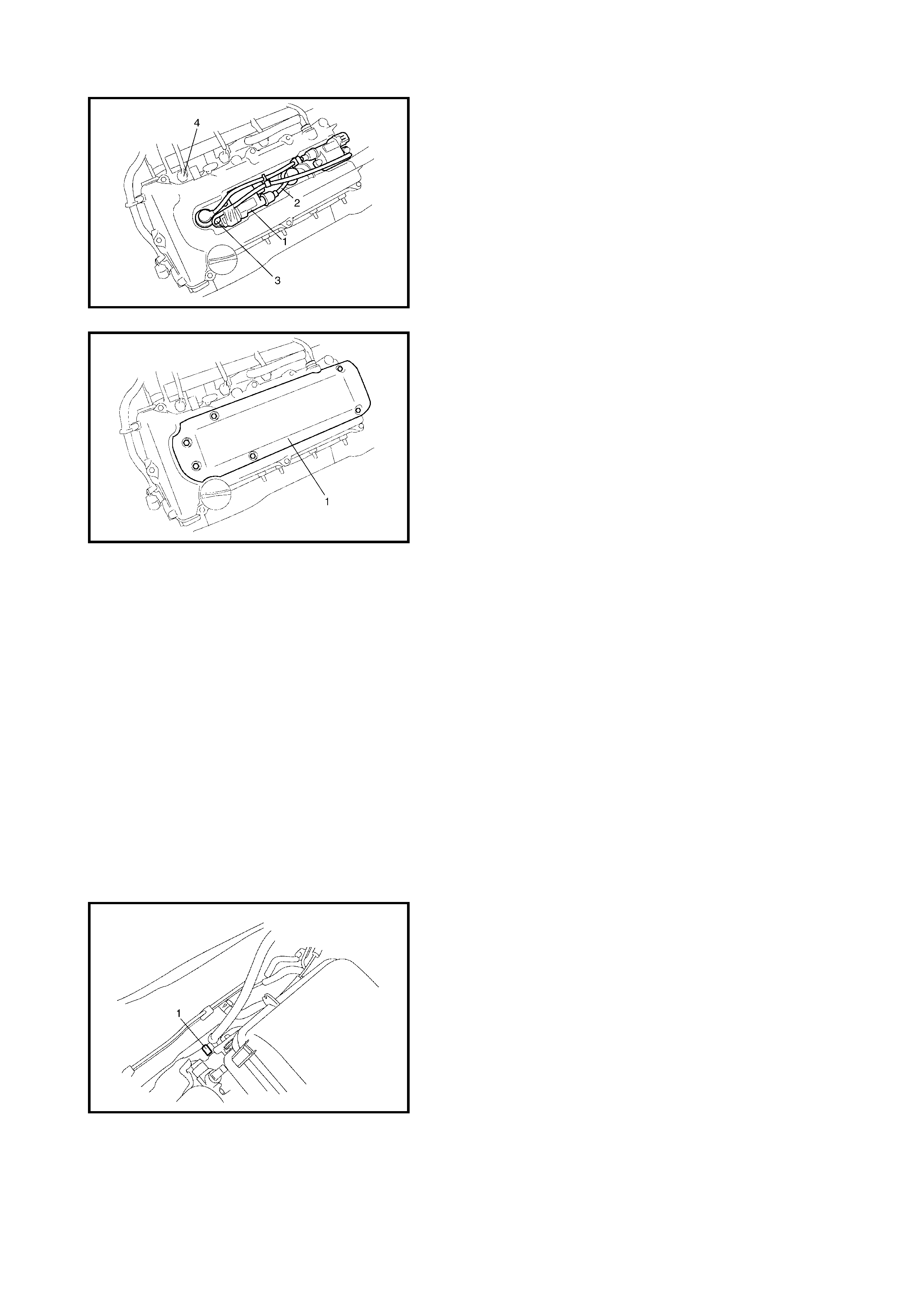
4. Remove the cylinder head upper cover (1).
5. Disconnect the ignition coil connectors (1).
6. Remove the ignition coil assemblies (2) with high-
tension leads (3).
7. Remove all spark plugs.
8. Disconnect fuel injector leads (4) at the connectors.
9. Install special tools (compression gauge) 09915-
64510-001 (A), 09915-64510-002 (B), 09915-64530
(C) and 09915-67010 (D) into spark plug hole.
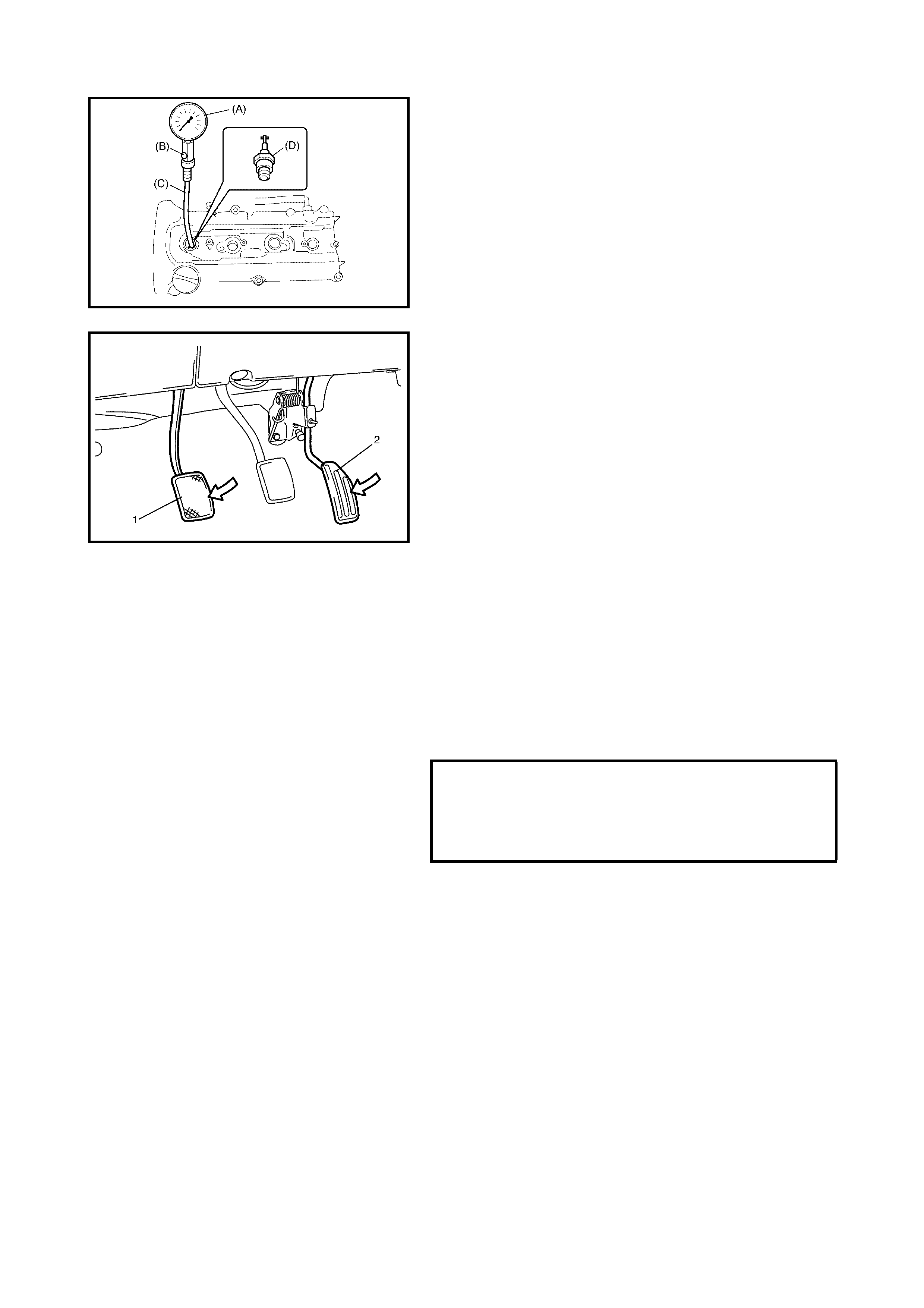
10. Disengage clutch (1) (to lighten starting load on
engine) fo r M/T v ehi cle, a nd depress a cc eler ato r p eda l
(2) all the way to make throttle fully open.
11. Crank engine with fully charged battery and read the
highest pressure on the compression gauge.
NOTE:
• To measu re th e engi ne com press ion, cra nk the en gin e
to at least 250 rpm using a fully charged battery.
• If the measured compression pressure is lower than
the limit value, ensure that the special tools are fitted
correctl y. If they are co rrectly i nstalled, the lik ely caus e
of compression pressure leakage will be from where
the piston rings contact the cylinder wall.
12. Carry out Steps 9 through 11 on each cylinder to obtain
four readings.
COMPRESSION PRESSURE
STANDARD
LIMIT
MAXIMUM DIFFERENCE BETWEEN
ANY TWO CYLINDERS
1400 kPa
1100 kPa
100 kPa
13. After checking, install the spark plugs and ignition coil
assemblies (1) with the high-tension leads (2).
14. Connect the ignition coil connectors (3).
15. Connect the fuel injector lead (4) connectors.
16. Check the c ylinde r head upper co ver g asket for deter i-
oration. Rep lace i f d ama ged. In stall th e gaske t i nto th e
groove in the cylinder head upper cover (1) securely.
17. Install the cylinder head upper cover with gasket onto
the cylinde r hea d cover.
18. Install the air cleaner assembly, resonator and hoses,
refer to 3.2 AIR CLEANER ASSEMBLY AND
RESONATOR INSTA LLATION in this Section.
2.3 ENGINE VACUUM CHECK
The engine vacuum that develops in the intake line is a
good indicator of the condition of the engine. The vacuum
checking procedure is as follows :
1. Warm up the engine to normal operating temperature.
NOTE: After warming up the engine, be sure to place the
transm ission gear shift lever in Neutral (shift selector lever
to P range for A/T vehicles), and set parking brake and
block dr ive wheel s.
2. Stop engine and turn off the all electric switches.
3. Remove cap (1) from the intake manifold.
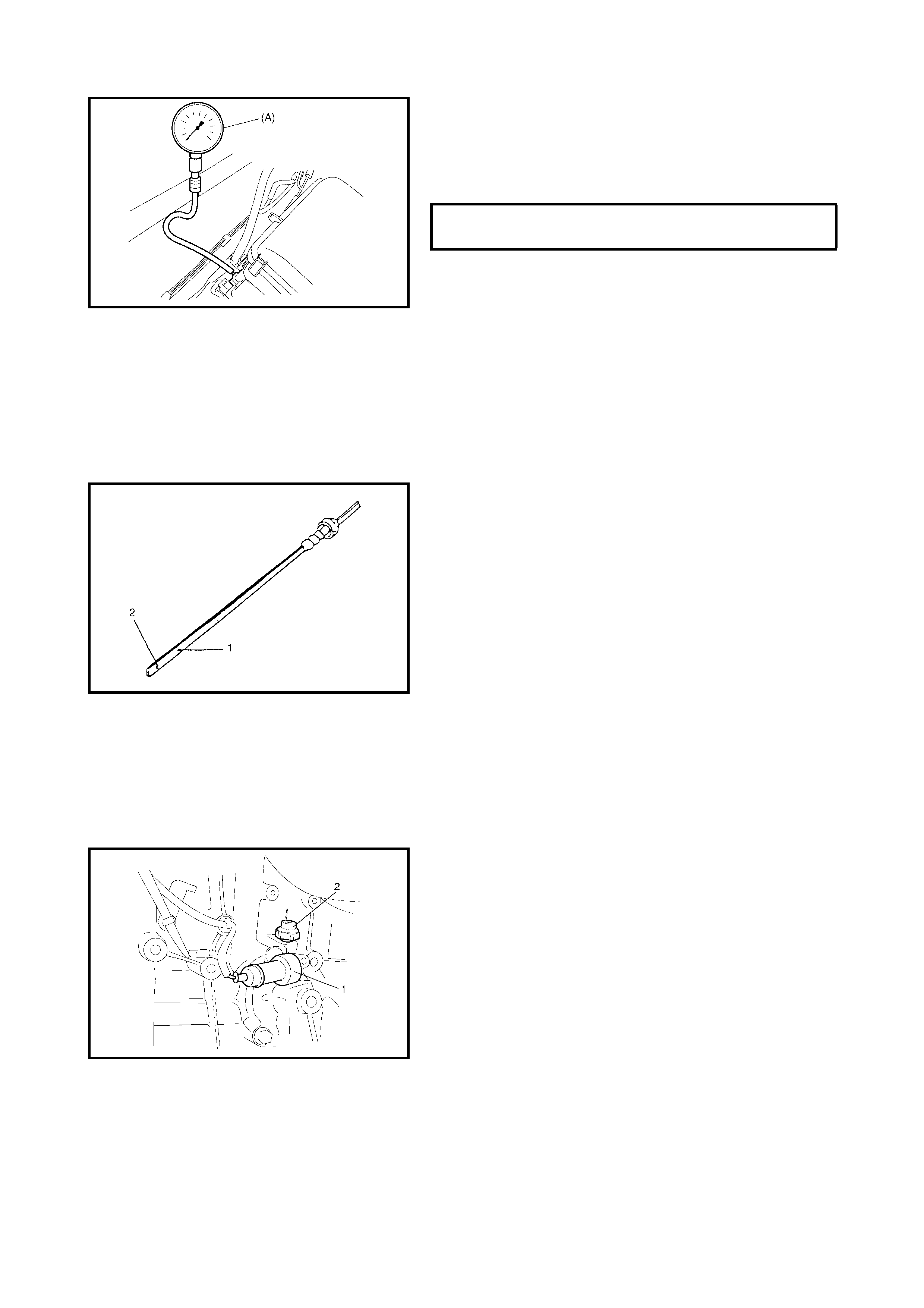
4. Connect special tool (Vacuum gauge) 09915-67310 (A)
to intake manifold.
5. Run the engine at specified idle speed and read the
vacuum gauge. The vacuum should be within specifi-
cation.
6. After checking, disconnect the special tool (Vacuum
gauge) from the intake manifold.
7. Refit the cap to the intake manifold.
2.4 OIL PRESSURE CHECK
NOTE: Prior to chec king the oil pressu re, che ck the follow-
ing items.
• Oil level in sump.
If oil le vel is low (2 ), add oil u p to the FULL le vel mark
(hole) (1) on the oil level gauge.
• Oil qualit y
If oil is discoloured, or has deteriorated, change it.
For particular oil to be used, refer to Section 0B,
4. RECOMMENDED FLUIDS AND LUBRICANTS.
•Oil leaks
If a leak is found, repair it.
1. Disconnect the oil pressure switch connector (1) and
remove the oil pressure switch (2) from the cylinder
block.
VACUUM SPECIFICATION (@ SEA
LEVEL) AT SPECIFIED IDLE SPEED 59 - 73 kPa
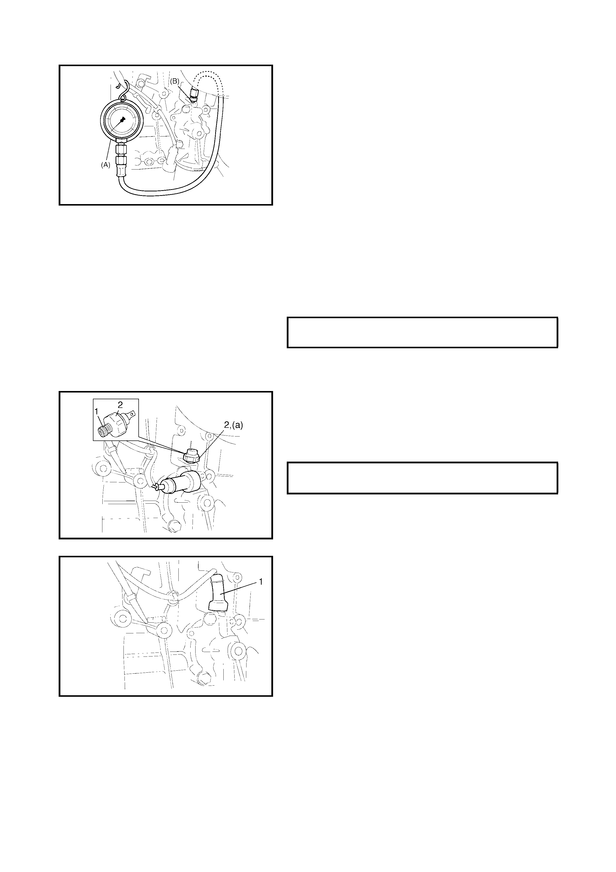
2. Install spec ial tool s 0991 5-77310 (A) and 0991 5-782 11
(B) (Oil pressure gauge) to the oil pressure switch
threaded hole.
3. Start the engine and warm it up to normal operating
temperature.
NOTE: Be sure to place the transmission gear shift lever in
NEUTRAL (shift control lever to P range for A/T vehicles),
and set the parking brake and block drive wheels.
4. After warming up, rai se the engine sp eed to 4,000 rp m
and measure the oil pressure .
5. Stop the engine and remove the oil pressure gauge
and attachment.
6. Before reinstalling the oil pressure switch (2), be sure
to wrap its thread with sealing tape (1) and tighten
switch to specified torque.
NOTE: If the sealing tape edge has bulged out from the
thread of the switch, trim it off.
7. Start the engine and check the oil pressure switch for
oil leakage.
If oil leakage occurs, rectify it.
8. Connect the oil pressure switch connector (1).
OIL PRESSURE SPECIFICATION @
4000 RPM MORE THAN
270 kPa
OIL PRESSURE SWITCH (a)
TORQUE SPECIFICATION 14 Nm
2.5 VALVE LASH (CLEARANCE)
INSPECTION
1. Remove the negative cable at battery.
2. Remove the cylinder head cover, refer to
3.4 CYLINDER HEAD COVER, REMOVAL in this
Section.
3. Remove the right side engine cover if necessary.
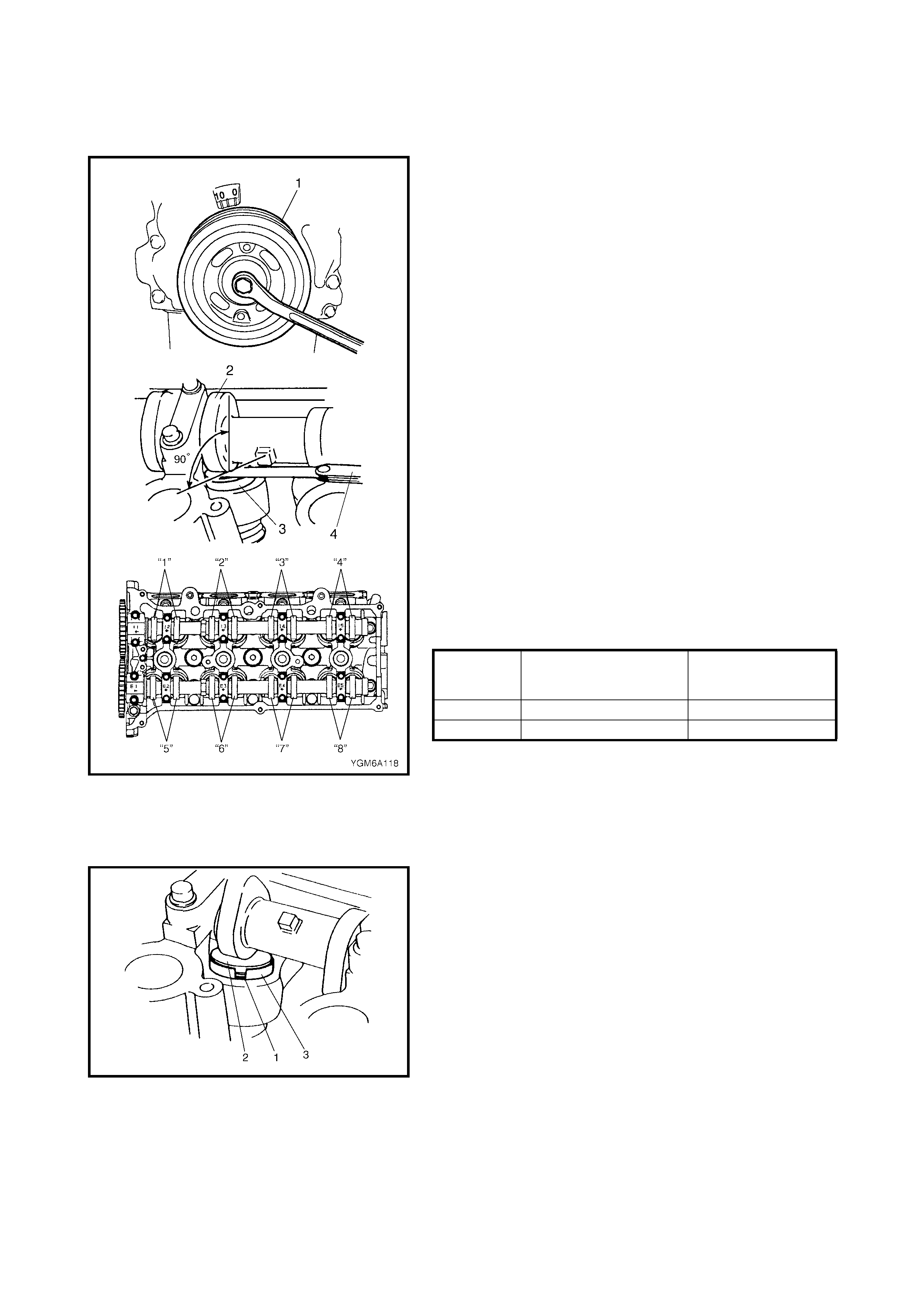
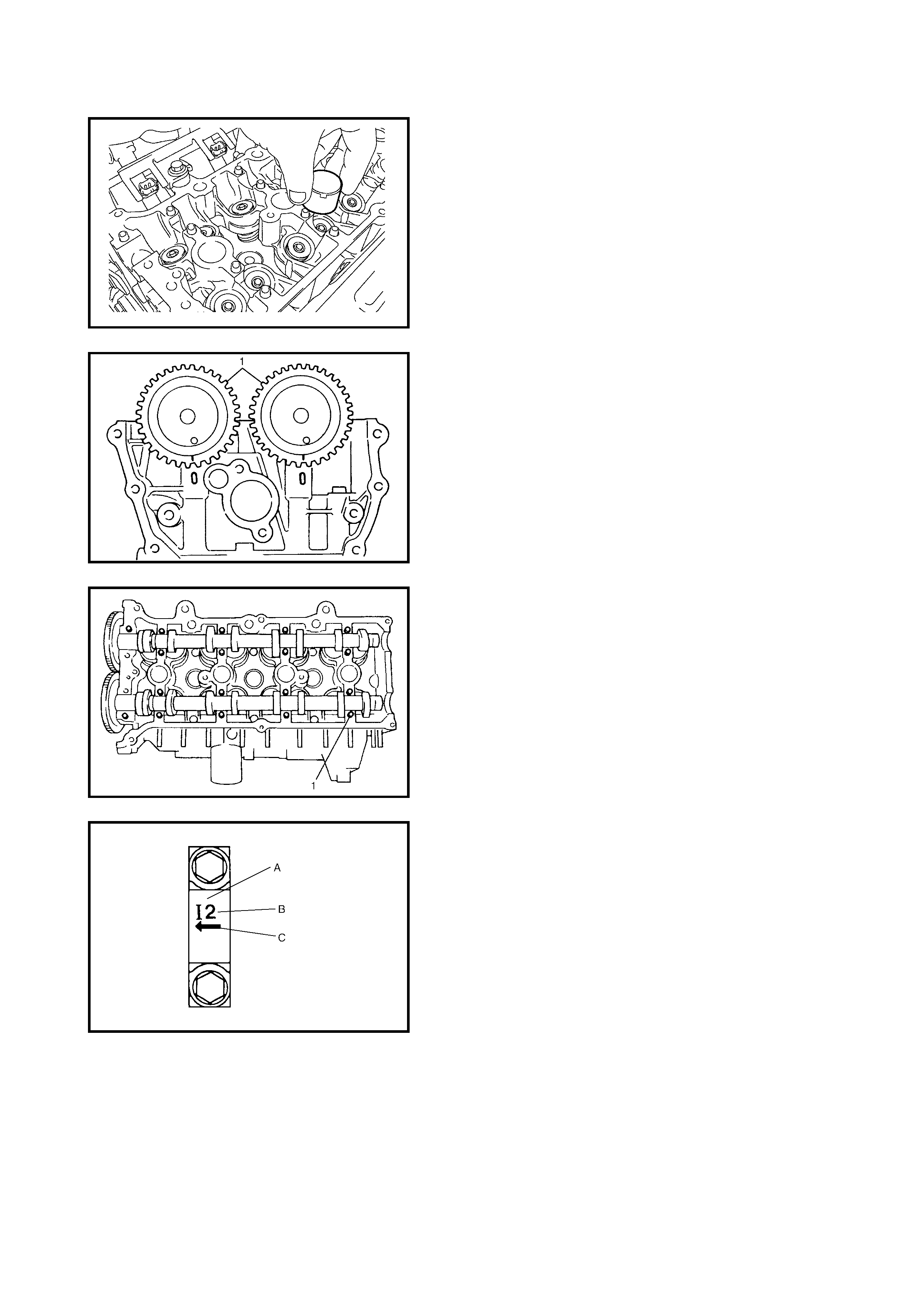
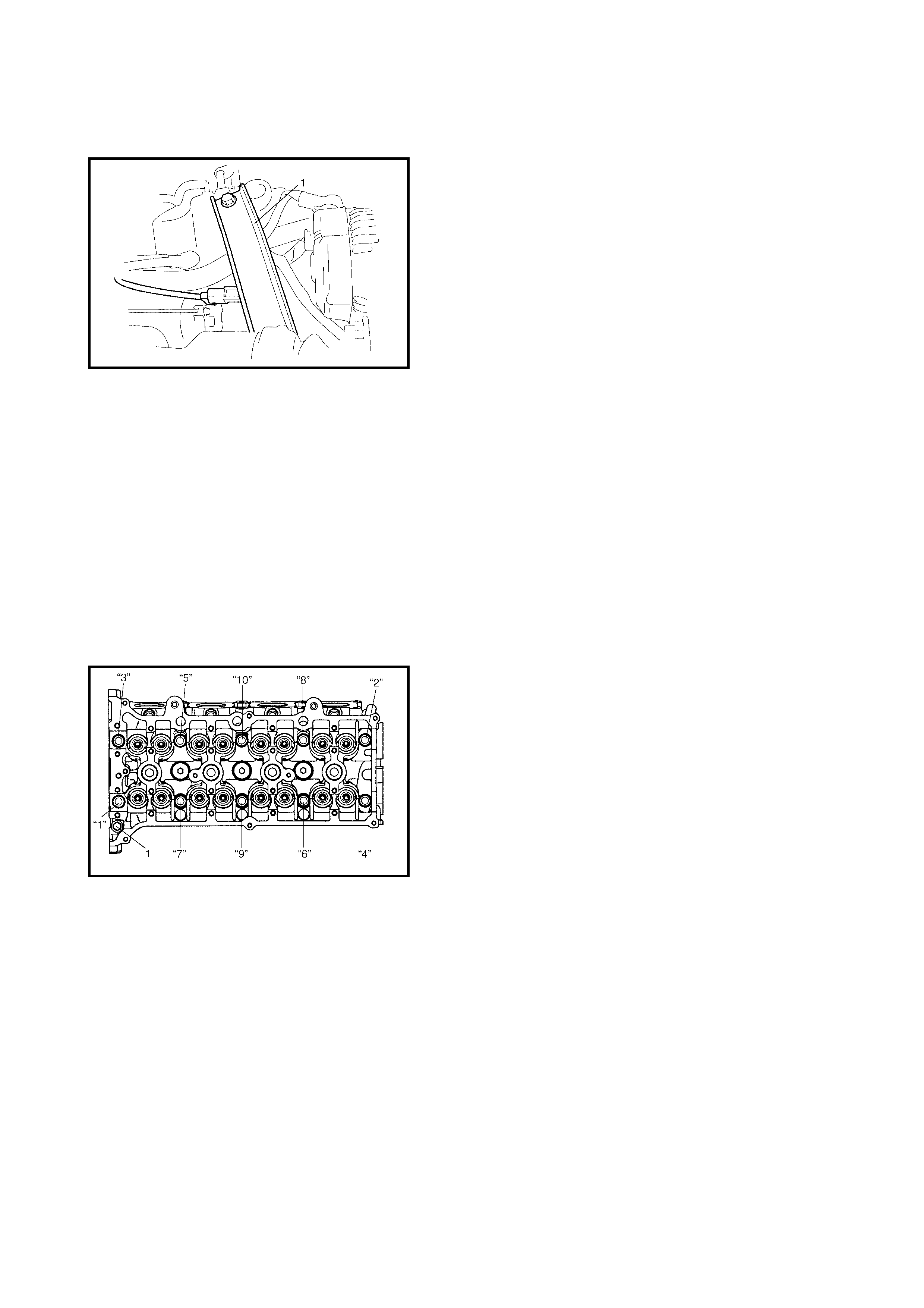
4. Using a 17 mm wrench, turn the crankshaft pulley (1)
clockwise until the cam lobes (2) become perpendicu-
lar to the shim faces (3) at valves “1” and “7” as shown
in the figure.
5. Check the valve lashes with a thickness gauge (4) as
indicated in the following steps.
a. Check and note the valve lashes at valves “1” and
“7”.
b. Turn the camshafts 90° (by turning the crankshaft
with a 17 mm wrench).
c. Make sur e that the c am lobes are perpendicu lar to
the shim faces at valves to be checked (in this
case, “3” and “8”), if not, adjust by turning crank-
shaft. Check and note the valve lashes.
d. As in Steps b and c, check and note the valve
lashes at valves “4” and “6”.
e. As in Steps b and c, check and note the valve
lashes at valves “2” and “5”.
Valve clearance specification
If the valv e lash i s not with in spe cificati on, recor d the va lve
lash and adjust it to specification by replacing shim.
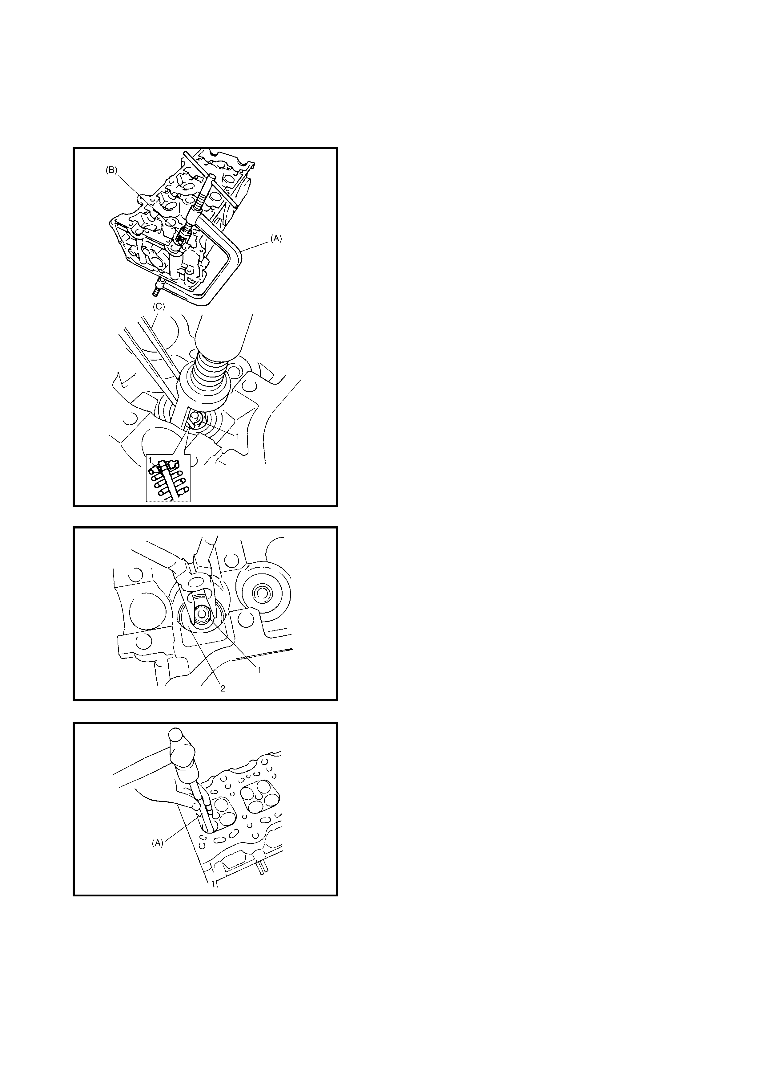
REPLACEMENT OF SHIM
1. Close the valve whose shim (2) is to be replaced by
turning the crankshaft using a 17 mm wrench, then turn
tappet (3) until its cut section (1) faces inwards as
shown in the figure.
WHEN COLD
(COOLANT TEMP. IS
15 – 25°C)
WHEN HOT
(COOLANT TEMP.
IS 60 – 68°C)
INTAKE 0.18 – 0.22 mm 0.21 – 0.27 mm
EXHAUST 0.28 – 0.32 mm 0.30 – 0.36 mm
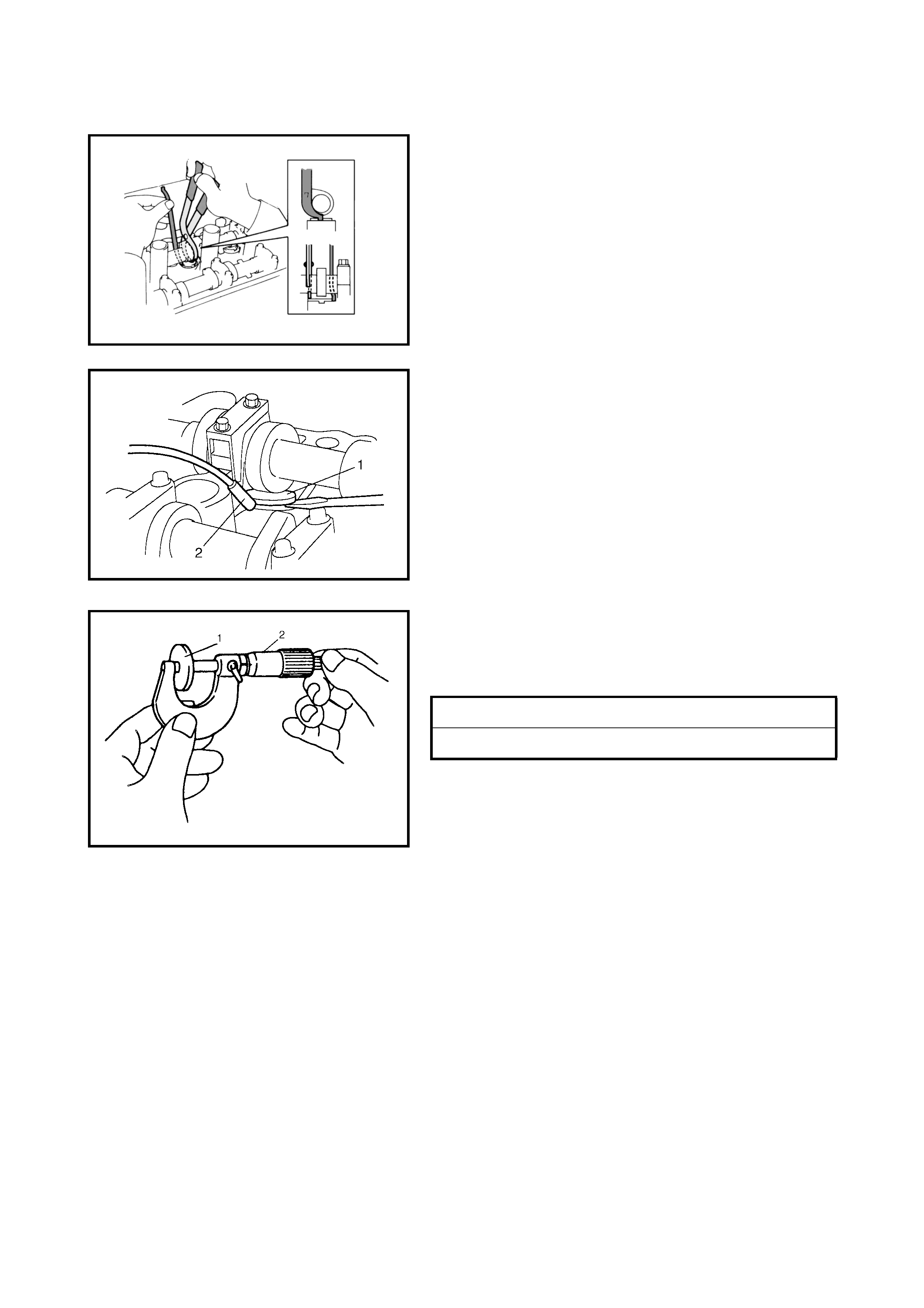
2. Place the J42689-AUS Pliers around the camshaft as
shown in the figure, and rotate the pliers to depress the
tappet.
3. Locate the 09222-2D000/2 Valve Shim Bucket Spacer
between the camshaft and the tappet edge as shown.
This will keep the tappet depressed while the shim is
replaced.
4. Remove the J42689-AUS Pliers
5. Remove the shim (1) using a magnet (2) as shown in
the figure.
WARNING: Never place hands between the camshaft
and the tappets.
6. Using a micrometer (2), measure the thickness of the
removed shim (1), then determine the required
thickness of the new replacement shim using the
following formula and table.
A : Thickness of new shim
B : Thickness of removed shim
C: Measured valve lash clearance
Intake side shim example:
When th e thickness of the removed shim is 2.40 mm, and
the measured valve clearance is 0.45 mm.
A = 2.40 mm + (0.45 mm – 0.20 mm) = 2.65 mm.
Calculated thickness of new shim = 2.65 mm.
SHIM THICKNESS - INTAKE SIDE A = B + (C – 0.20mm)
SHIM THICKNESS - EXHAUST SIDE A = B + (C – 0.30mm)
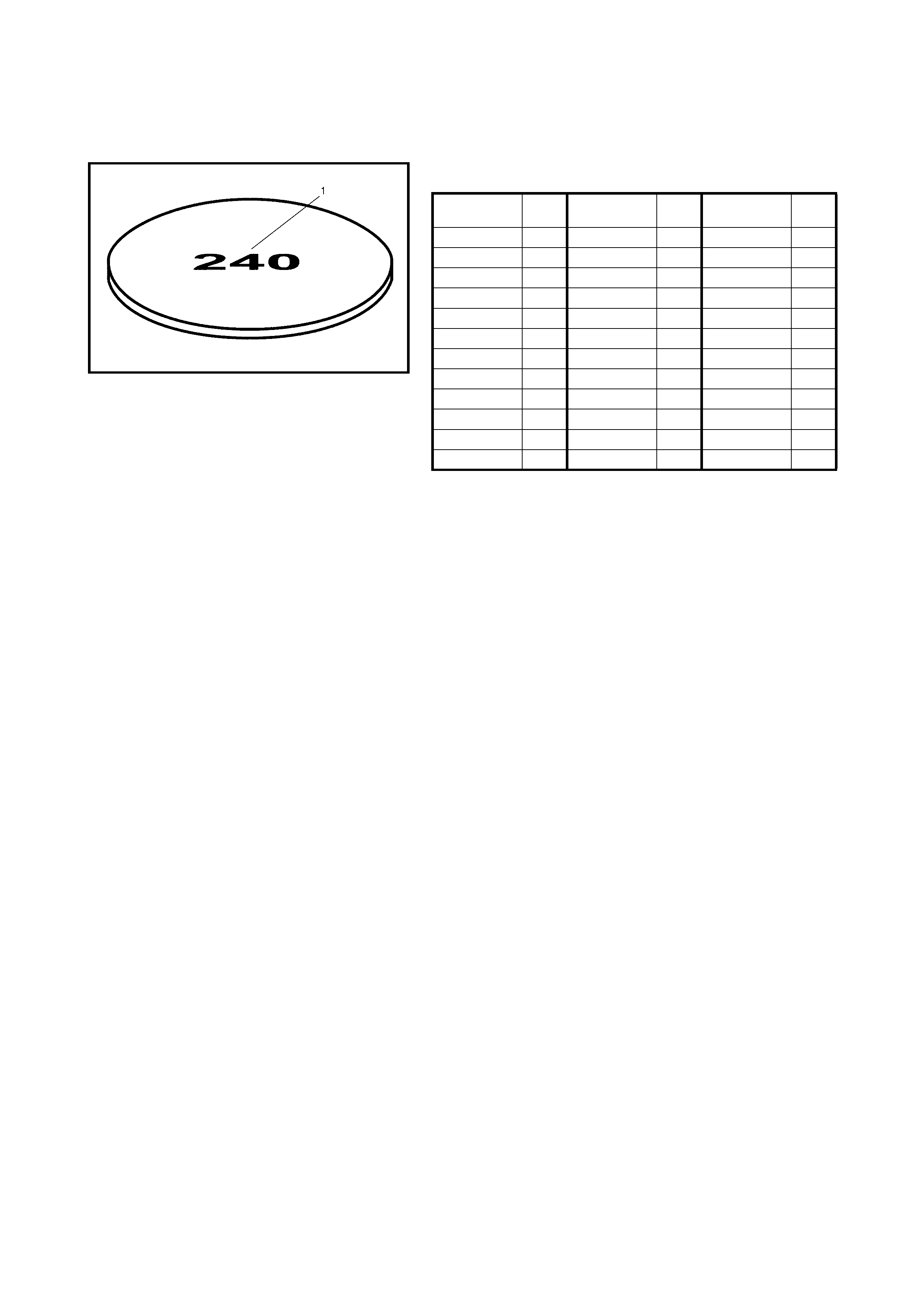
7. Select a n ew sh im No. (1 ) with a thi c kn es s as c lo se as
possible to the calculated valve.
Available new shims thickness and number.
8. Install the new shim with the shim number facing the
tappet.
9. Place the J42689-AUS Pliers around the camshaft,
then rotate the pliers to depress the tappet and remove
the 09222-2D000/2 Valve Shim Bucket Spacer.
10. Remove the J42689-AUS Pliers.
11. Recheck the valve lash clearance after replacing
shims.
12. After checking and adjusting all valves, install cylinder
head cover, refer to 3.4 CYLINDER HEAD COVER,
INSTALLATION in this Section.
THICKNESS
mm SHIM
No. THICKNESS
mm SHIM
No. THICKNESS
mm SHIM
No.
2.18 218 2.48 248 2.78 278
2.20 220 2.50 250 2.80 280
2.23 223 2.53 253 2.83 283
2.25 225 2.55 255 2.85 285
2.28 228 2.58 258 2.88 288
2.30 230 2.60 260 2.90 290
2.33 233 2.63 263 2.93 293
2.35 235 2.65 265 2.95 295
2.38 238 2.68 268 2.98 298
2.40 240 2.70 270 3.00 300
2.43 243 2.73 273
2.45 245 2.75 275
3. ON-VEHICLE SERVICE
3.1 AIR CLE A NER ELEMEN T
REMOVAL
1. Disconnect the air cleaner inlet hose (1) from the air
cleaner case (2).
2. Open the air cleaner case by unhooking its clamps.
3. Remove the air cleaner element from case.
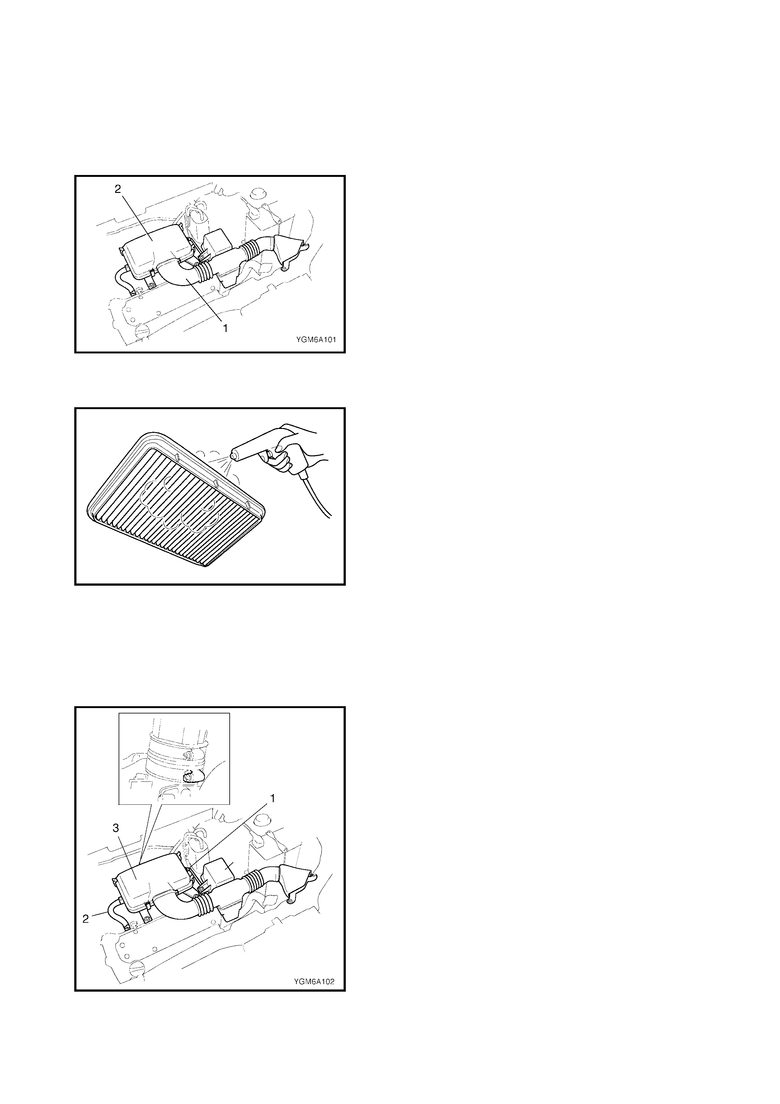
INSPECTION AND CLEANING
• Check air cleaner element for dirt.
• Blow off any dust using compressed air from the air
outlet side of the element.
• Replace excessively dirty element.
INSTALLATION
Reverse removal procedure for installation.
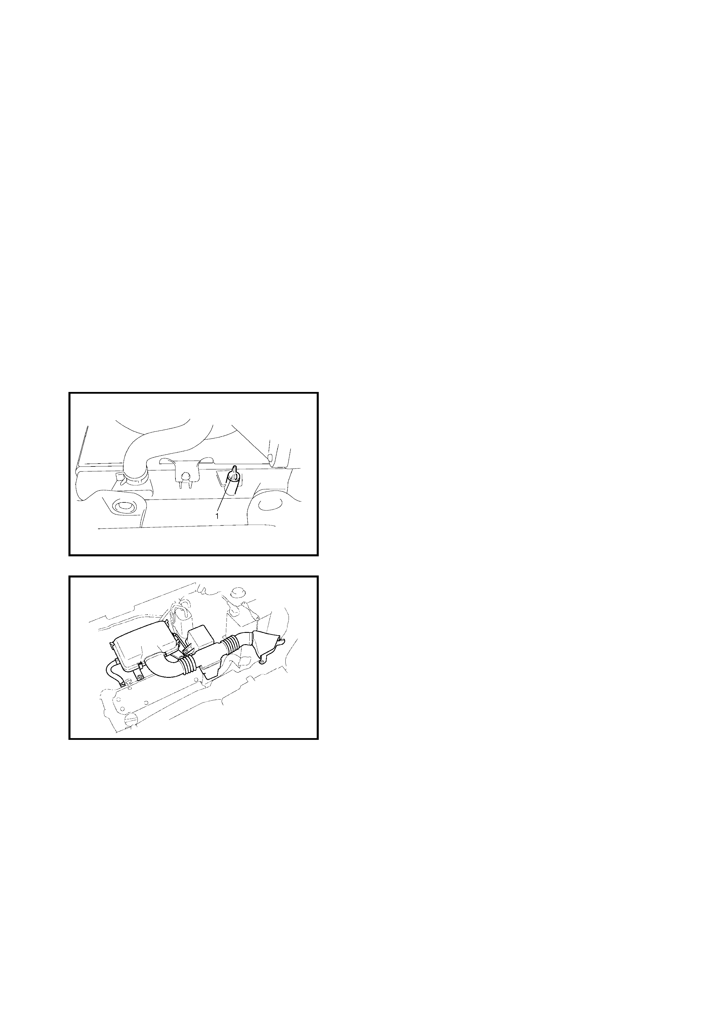
3.2 AIR CLE ANER ASSEMBLY AND RE SO N AT O R
REMOVAL
1. Disconnect negative cable at battery.
2. Disconnect intake air temperature (IAT) sensor
connector (1).
3. Disconnect the breather hose (2) from the cylinder
head cover.
4. Remove the air cleaner assembly (3), resonator (4)
and their hoses.
INSTALLATION
Reverse removal procedure for installation.
3.3 KNOCK SENSOR
Refer to Section 6E1, 2.3 ELECTRONIC CONTROL
SYSTEM, KNOCK SENSOR.
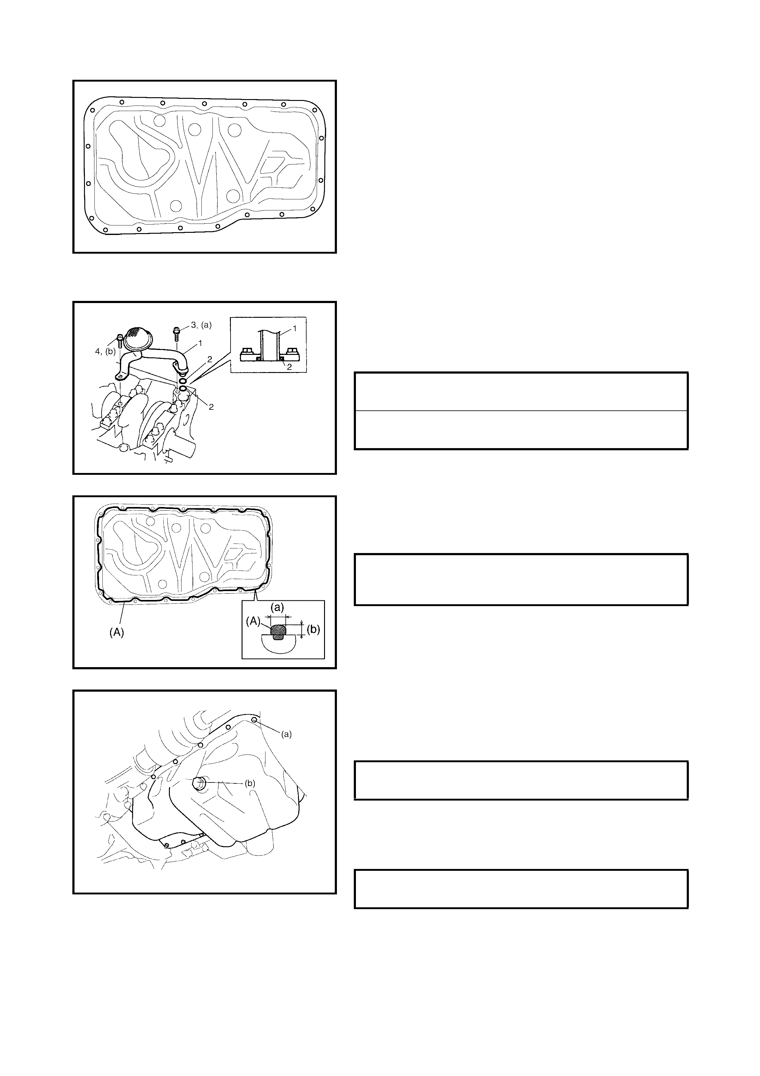
3.4 CYLINDE R HEAD COVER
REMOVAL
1. Disconnect negative cable at battery.
2. Remove the air cleaner assembly, resonator and
hoses, refer to 3.2 AIR CLEANER ASSEMBLY AND
RESONATOR REMOVAL.
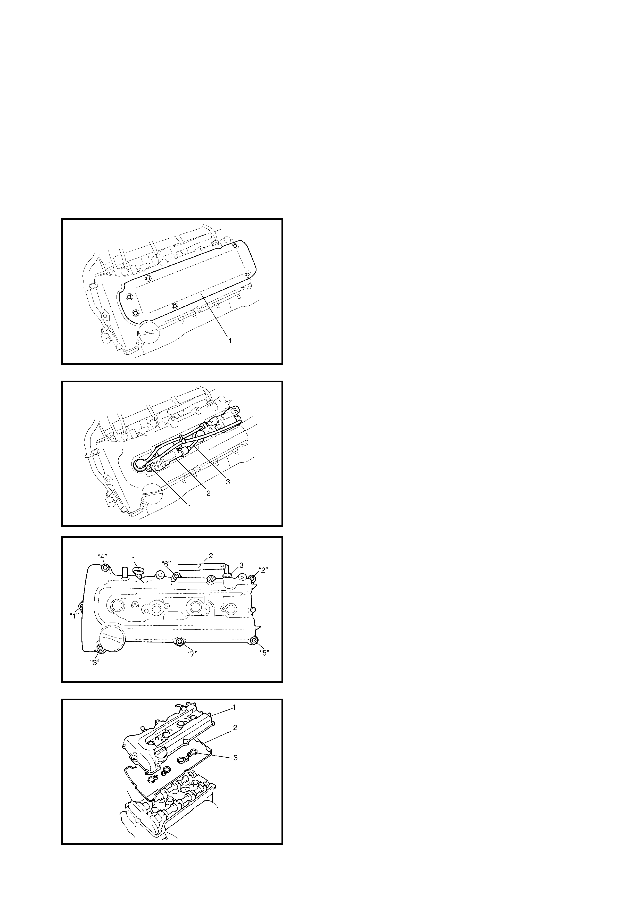
3. Remove cylinder head upper cover (1).
4. Disconnect ignition coil connectors (1).
5. Remove ignition coil assemblies (2) with high-tension
leads (3).
6. Remove the oil level gauge (1).
7. Disconnect the PCV hose (2) from the PCV valve (3)
and release the harness clamp.
8. Remove the cylinder head co ver mounting bolts in the
order shown in the figure.
9. Remove the cylinder head cover (1) with the cylinder
head cover gasket (2) and spark plug hole gaskets (3).
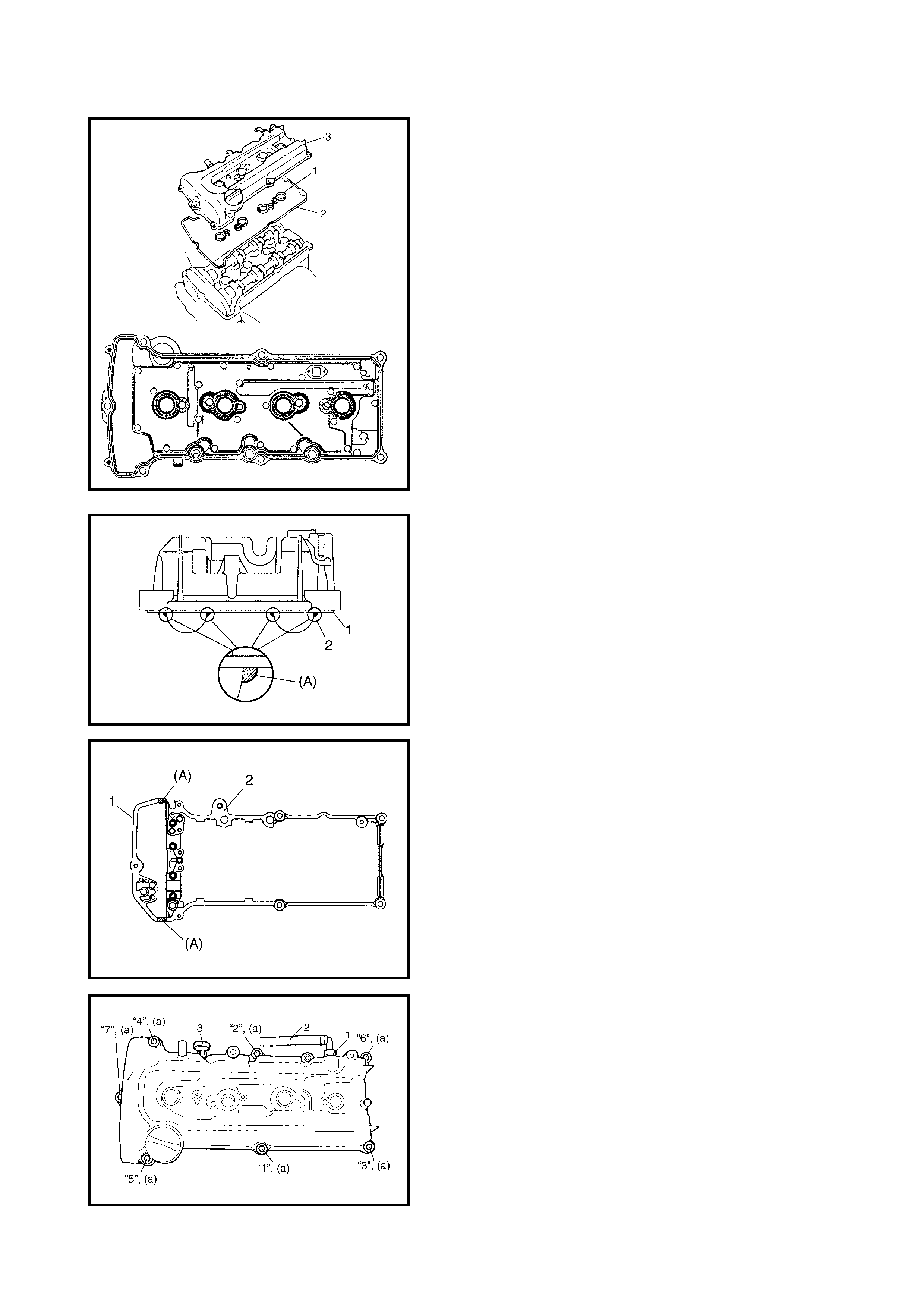
INSTALLATION
1. Install new spark plug hole gaskets (1) and a new
cylinder head cover gasket (2) to the cylinder head
cover (3) as shown in the figure.
2. Remove oil, old sealant, and dust from the sealing
surface on the cy l ind er h ead an d co ve r. After cl ea nin g ,
apply sealant “A” to the following points.
• Cylinder head cover gasket (1) sealing surface area (2)
as shown.
(A): Sealant - Three Bond No. 1207C
• Timing ch ain cove r (1) and cy linder head ( 2) matchin g
surface as shown.
(A): Sealant - Three Bond No. 1207C
3. Install cylinder head cover to cylinder head.
NOTE: When installing the cylinder head cover, ensure that
the cylinder head cover gasket and the spark plug hole
gaskets do not fall off or become misplaced.

4. Gradual ly tighten the bolts in the orde r indicated in the
figure until they reach the specified torque.
5. Connect the PCV hose (2) to the PCV valve (1).
6. Install the oil level gauge (3).
7. Install the ignition coil assemblies with the high-tension
leads.
8. Connect the ignition coil connectors and clamp
harness securely.
9. Install the cylinder head upper cover.
10. Install the air cleaner assembly, resonator and hoses,
refer to 3.2 AIR CLE ANER ASSEMBLY AND
RESONATOR, INSTALLATION in this Section.
11. Connect the negative cable at the battery.
CYLINDER HEAD COVER BOLTS (a)
TORQUE SPECIFICATION 8 Nm
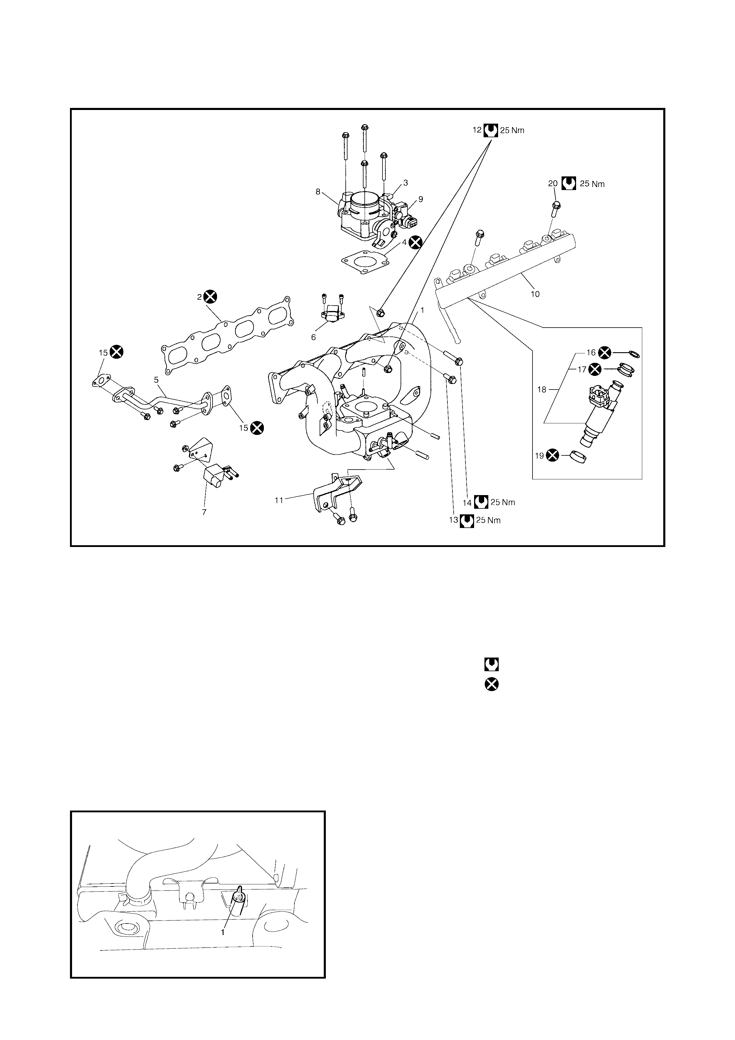
3.5 THROTTLE BODY AND INTAKE MANIFOLD
Legend
REMOVAL
1. Relieve the fuel p ressur e, refer to Sec tion 6 , 1.4 FUE L
PRESSURE RELIEF PROCEDURE.
2. Disconnect the negative cable at the battery.
3. Drain the coolant by loosening the drain plug (1).
WARNING: To avoid the dange r of being burned, do n ot
remove the drain plug (1) and radiator cap while the
engine and radiator are still hot. Scalding fluid and
steam can be blown out under pressure if the plug and
cap are taken off before the system has cooled suffi-
ciently.
1. Intake manifold 10. Fuel delivery pipe 17. Grommet
2. Intake manifold gasket 11. Intake manifold stiffener 18. Injector assembly
3. Throttle body 12. Intake manifold mounting nut 19. Cushion
4. Gasket 13. Intake manifold mounting bolt 20. Fuel delivery pipe mounting
5. EGR pipe (short) bolt
6. MAP sensor 14. Intake manifold mounting bolt Tightening torque
7. EVAP canister purge valve (long) Do not reuse.
8. TP sensor 15. EGR pipe gasket
9. IAC valve 16. O-Ring
4. Remove the air cleaner assembly, resonator and
hoses, refer to 3.2 AIR CLEANER ASSEMBLY AND
RESONATOR, REMOVAL in this Section.
5. Disconnect the following electric leads:
•IAC valve (1)
• TP sensor (2)
• EVAP canister purge valve (3)
• MAP sensor (4)
• Fuel injector wire harness at connectors (5)
• Wire harness clamps
6. Disconnect accelerator cable from throttle body.
7. Disconnect the following hoses :
• Brake booster hose (1) from the intake manifold
• PCV hose (2) from the PCV valve
• Canist er purge h ose (3) from the EVAP canist er purge
valve
• Water hoses (4) from the throttle body and thermostat
case
• Fuel feed hose (5) from the fuel delivery pipe
8. Remove fuel delivery pipe with fuel injectors from the
cylinder head.
9. Disconnect the EGR pipe (6) from the EGR valve.
10. Remove the intake manifold stiffener (1).
11. Remove the intake manifold (1) with the throttle body
(2) and the EGR pipe (3) from the cylinder head.
12. Remove the gasket from the intake manifold.
INSTALLATION
Reverse the removal procedure for installation noting the
following:
• Always use a new intake manifold gasket and EGR
pipe gasket.
• Tighten bolts (1) and nuts (2) to specified torque.
• Check to ensure that all removed parts have been
refitted.
• Adjust th e accel erator cab le pla y, refer to Se ction 6E 1,
2. ON VEHICLE SERVICE, ACCELERATOR CABLE
ADJUSTMENT.
• Refill cooling system, refer to Section 6B,
3.3 COOLING SYSTEM FLUSH AND REFILL.
• Once installation is complete turn the ignition switch
ON, but with the engine OFF, and check for fuel leaks.
• Finally, start the engine and check for engine coolant
leaks.
INTAKE MANIFOLD BOLTS & NUTS (a)
TORQUE SPECIFICATION 25 Nm
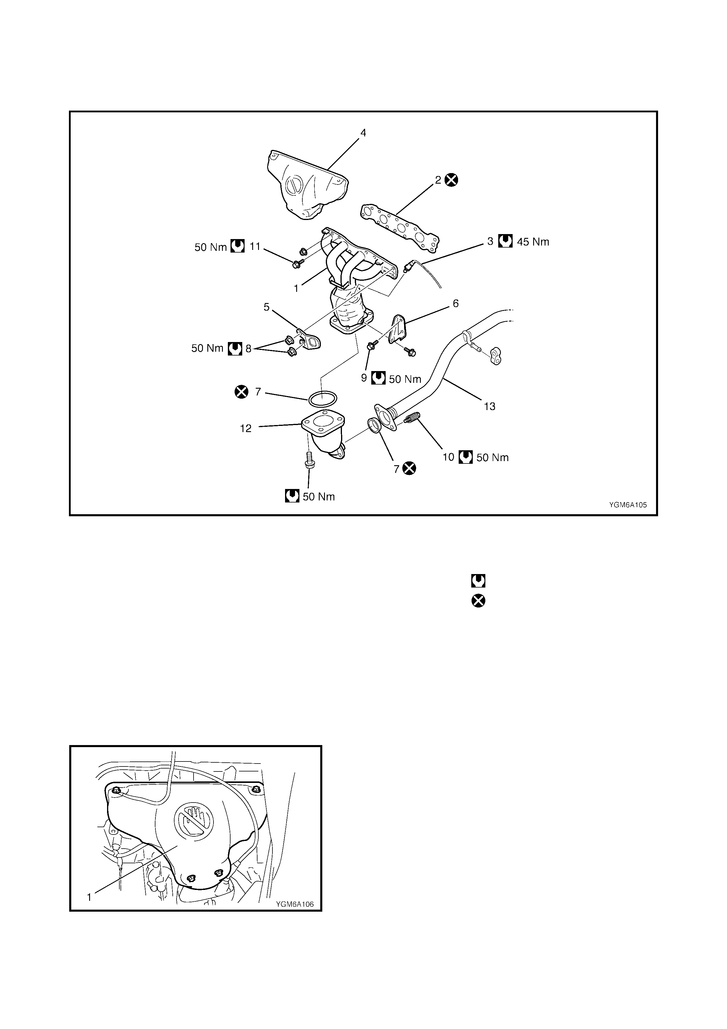
3.6 EXHAUST MANIFOLD
Legend
WARNING: To avoid being burned, do not service the exhaust system while it is still hot. Service
should be performed after the system cools down.
REMOVAL
1. Disconnect the negative cable at the battery.
2. Disconnect the heated oxygen sensor connector and
detach it from its stay.
3. Remove the front bumper with front grille, refer to
Section 9, 2.12 FRONT BUMPER, REMOVAL.
4. Remove radiator, refer to Section 6B, 4.6 RADIATOR,
REMOVAL.
5. With hose connected, detach the A/C condenser from
the vehicle body, refer to Secti on 1B,
5.2 CONDENSER ASSEMBLY, REMOVAL.
6. Remove exhaust manifold cover (1).
1. Exhaust manifold 8. Exhaust manifold mounting 12. Exhaust No.1 pipe
2. Exhaust manifold gasket nut 13. Exhaust No.2 pipe
3. Heated oxyge n sensor 9. Exhau st manifo ld sti ffener Tightening torque
4. Exhaust manifold cover bolt Do not reuse.
5. Engine hook 10. Exhaust No.2 pipe bolt
6. Exhaust manifold stiffener 11. Exhaust manifold mounting
7. Seal ring bolt
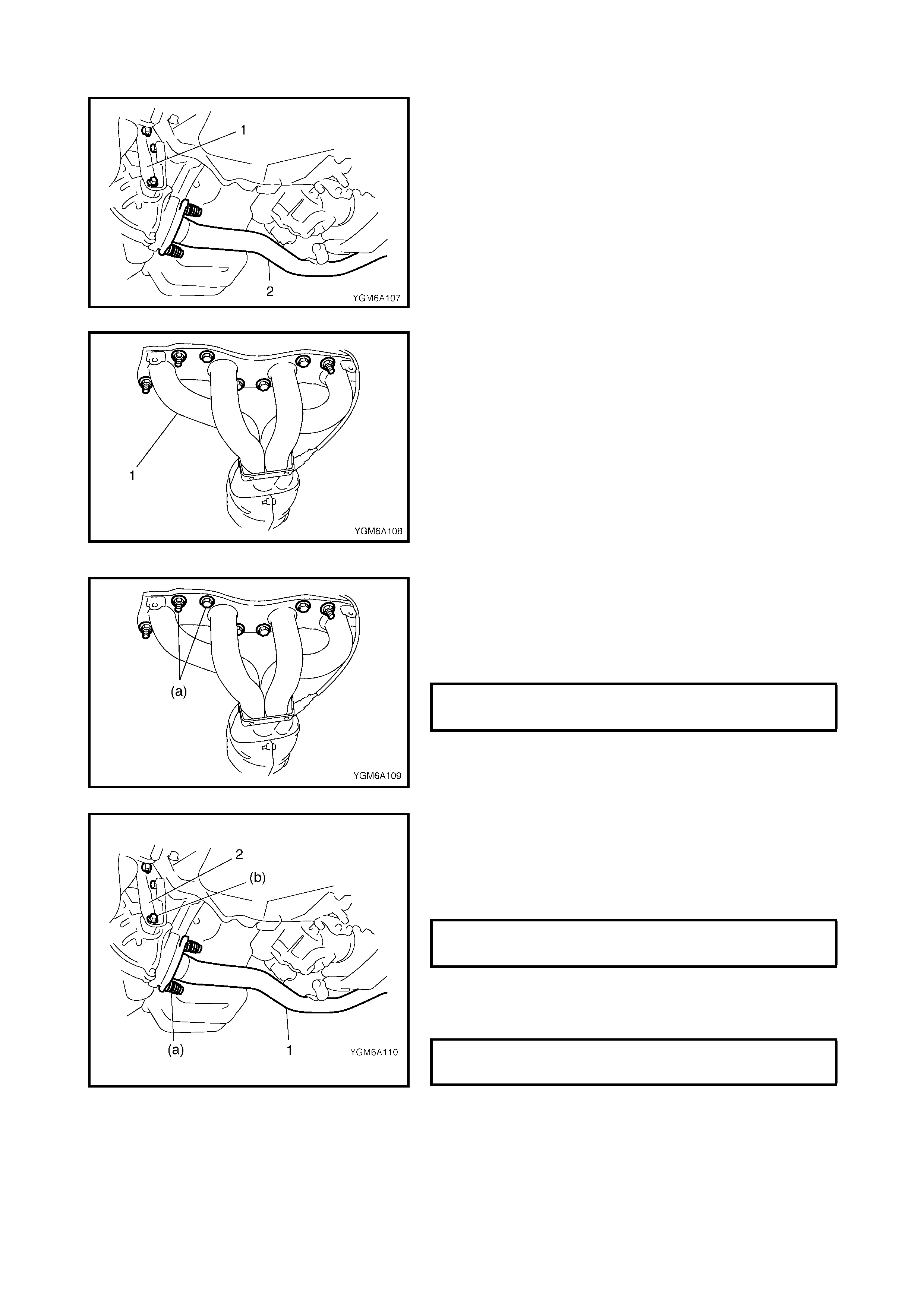
7. Remove the exhaust manifold stiffener (1).
8. Disconnect the exhaust No.2 pipe (2) from the exhaust
manifold.
9. Remove the exhaust manifold (1) and its gasket from
the cylinde r hea d.
INSTALLATION
1. Install a new exhaust manifold gasket on the cylinder
head.
Install the exhaust manifold.
Tighten the exhaust manifold bolts and nuts to
specified torque.
2. Check the seal ring for deterioration or damage and
replace as necessary.
Install the seal r ing and connect exhaust No.2 pip e (1)
to the exhaust manifold.
Tighten pipe fasteners to specified torque.
3. Install the exhaust manifold stiffener (2).
Tighten the exhaust manifold stiffener bolts to specified
torque.
EXHAUST MANIFOLD BOLTS & NUTS (a)
TORQUE SPECIFICATION 50 Nm
EXHAUST No.2 PIPE BOLTS (a)
TORQUE SPECIFICATION 50 Nm
EXHAUST MANIFOLD STIFFENER
BOLTS (b) 50 Nm
4. Install the exhaust manifold cover (1).
5. Install the A/C condenser to the vehicle, refer to
Section 1B, 5.2 CONDEN SER ASSEM BLY
INSTALLATION.
6. Install the radiator, refer to S ectio n 6B, 4. 6 RADIATOR
INSTALLATION.
7. Connect the heated oxygen sensor connector and fit
connector to bracket securely.
8. Install the front bumper with front grille, refer to
Section 9, 2.12 FRONT BUMPER INSTALLATION.
9. Connect the negative cable at the battery.
10. Check the exhaust system for exhaust gas leakage.
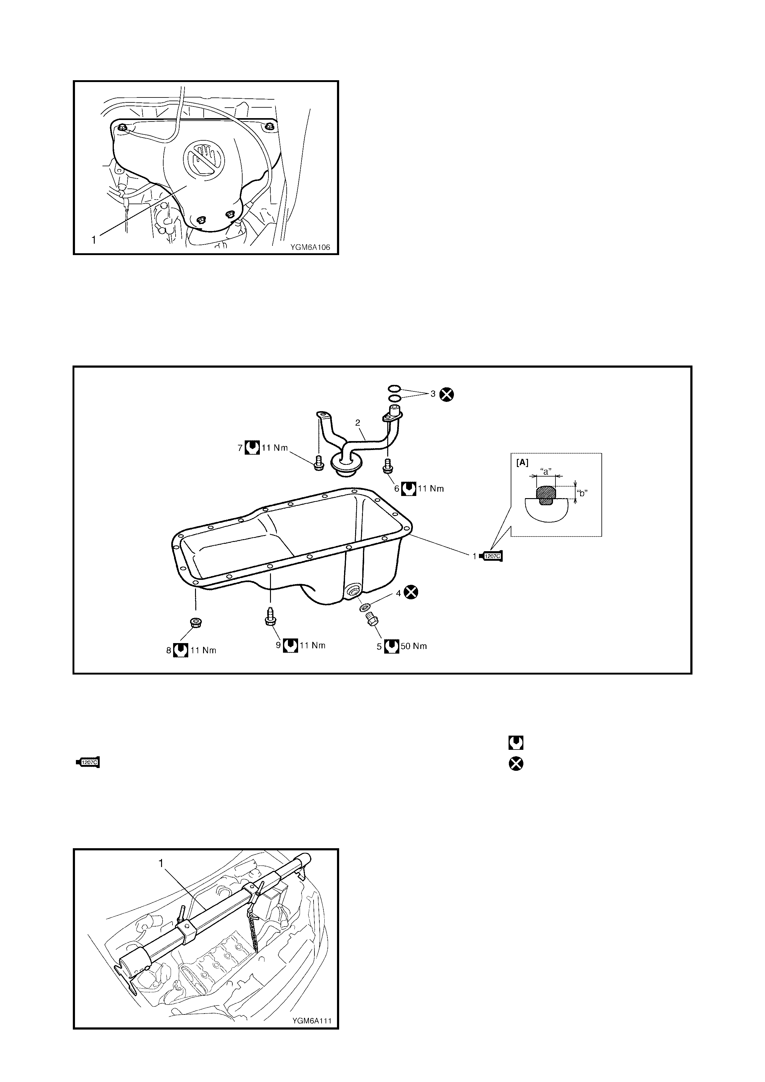
3.7 OIL PAN AND OIL PUMP STRAINER
Legend
REMOVAL
1. Disconnect the negative cable at the battery.
2. Remove the oil level gauge.
3. Support the engine with a support device (1).
[A] : Sealant application amount 2. Strainer 8. Oil pan nut
“a” : 3 mm (0.12 in.) 3. O-ring 9. Oil pan bolt
“b” : 2 mm (0.08 in.) 4. Gasket Tightening torque
1. Oi l pan
: Apply sealant - Three
Bond No. 1207C to mating
surface.
5. Drain plug Do not reuse.
6. Strainer bolt
7. Bracket bolt
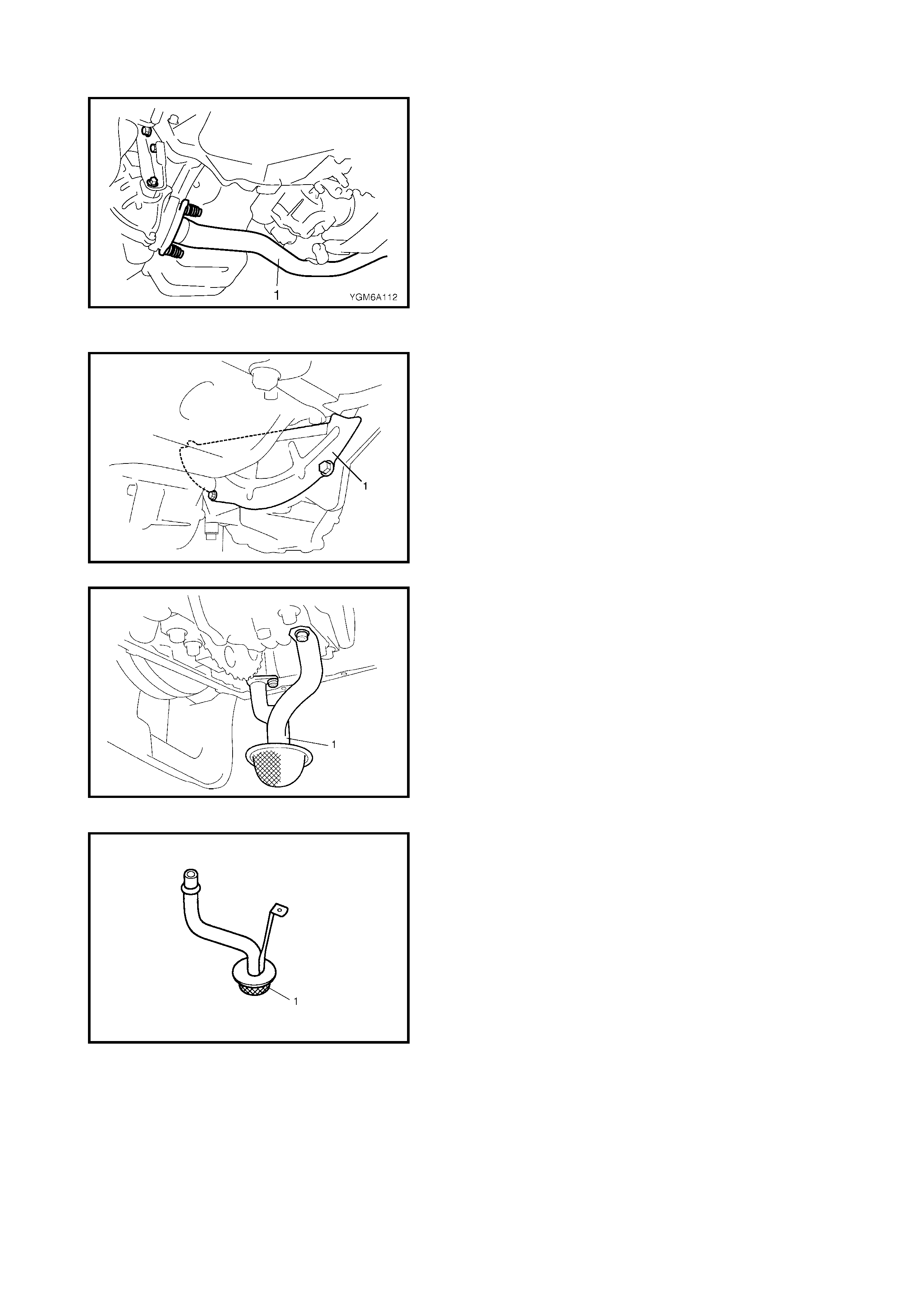
4. Remove exhaust No.2 pipe (1).
5. Drain the engine oil by removing drain plug.
6. Remove the clutch housing (torque converter housing
for A/T vehicle) lower plate (1).
7. Remove the transfer unit, refer to Section 7D,
4.1 TRANSFER UNIT, REMOVAL.
8. Remove the oil pan then the oil pum p straine r (1) from
the cylinde r blo ck.
CLEAN
• Clean the oil pump strainer screen (1).
• Clean th e sealing sur face on the oi l pan and the cylin-
der block.
Remove oi l, old s ealant and dust fro m the sea ling sur-
face.
INSTALLATION
1. Install new O -r ing s (2) to the oi l str ai ner p ipe as s ho wn
in the figure and install the oil pump strainer (1).
Tighten the strainer bolt (3) first and then the bracket
bolt (4) to specified torque.
2. Apply sealant continuously to the oil pan mating
surface as shown in the figure.
(A): Sealant - Three Bond No. 1207C
3. After fitting the oil pan to the cylinder block, loosely fit
the securing bolts. Start tightening the bolts at the
centre, moving outward, tightening one bolt at a time to
specified torque.
4. Install a new ga sket on th e drain plug then fit to the oil
pan.
Tighten drain plug to specified torque.
OIL SUMP STRAINER BOLT (a)
TORQUE SPECIFICATION 11 Nm
OIL PUMP STRAINER BRACKET BOLT (b)
TORQUE SPECIFICATION 11 Nm
SEALANT AMOUNT FOR OIL PAN
WIDTH (a)
HEIGHT (b) 3.0 mm
2.0 mm
OIL PAN BOLTS & NUTS (a)
TORQUE SPECIFICATION 11 Nm
OIL PAN DRAIN PLUG BOLT (b)
TORQUE SPECIFICATION 50 Nm
5. Install the clutc h housing (tor que converte r housing for
A/T vehicle) lower plate (1).
6. Install transfer unit, refer to Section 7D,
4.6 TRANSFER UNIT, INSTALLATION.
7. Install exhaust No.2 pipe (1).
Tighten bolts to specified torque.
8) Install th e oi l lev e l ga ug e .
9) Refill the engine with engine oil, refer to ENGINE
OIL AND FILTER in Section 0B , 2.1 ENG I N E.
10) Ensure there is no engine oil leakage from oil pan
or exhaust gas leakage at pipe conne ction.
EXHAUST No.2 PIPE BOLTS (a)
TORQUE SPECIFICATION 50 Nm
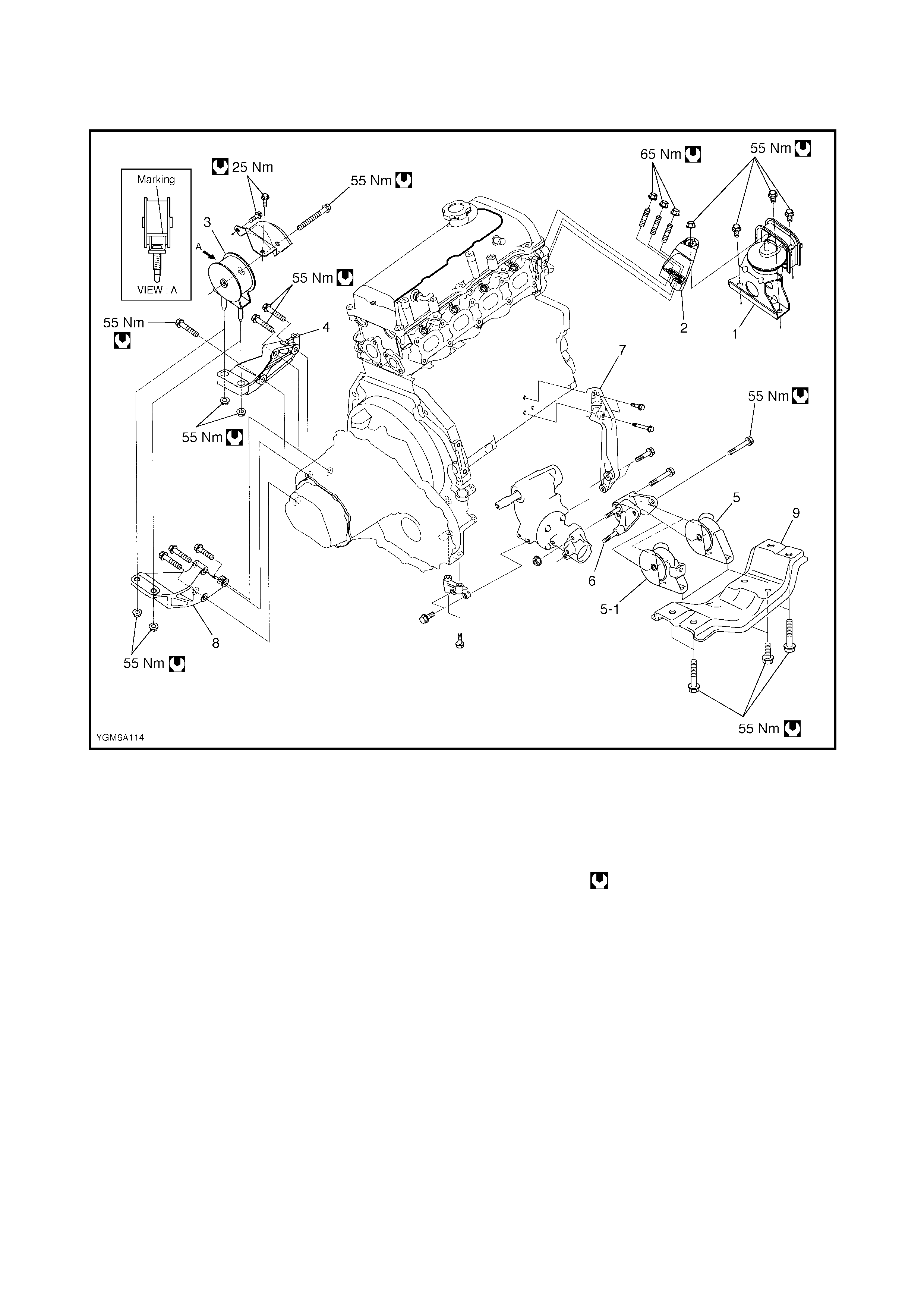
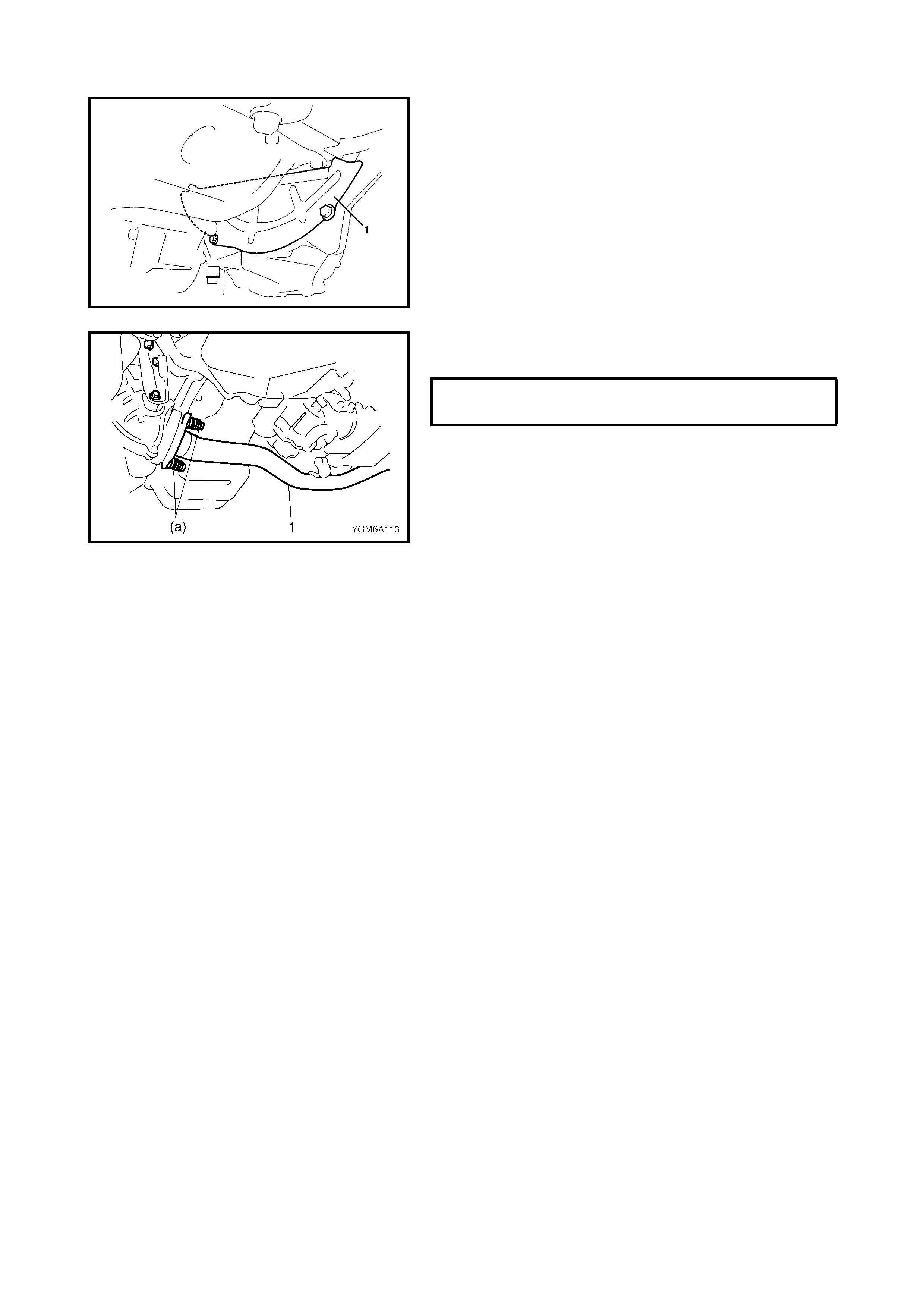
3.8 ENGINE MOUNTINGS
Legend
1. Engine right mounting 5. Engine rear mounting 7. Engine stiffener
2. Engine right mounting
bracket (M/T Vehicle ) 8. E ngi ne left mounti ng brack et
5-1. Engine rear mounting (for M/T vehicle)
3. Engine left mounting (A/T Vehicle) 9. Engine rear mounting member
4. Engine left mounting
bracket (for A/T vehicle) 6. Engine rear mounting Tightening torque
bracket
4. UNIT REPAIR AND OVERHAUL
4.1 ENGINE ASSEMBLY
REMOVAL
1. Relieve fuel pressure, refer to Section 6,
1.4 FUEL PRESSURE RELIEF PROCEDURE .
2. Disconnect the negative cable at the battery.
3. Remove the engine hood after disconnecting wind-
shield washer hose, refer to Section 9,
2.4 HOOD, REMO VA L .
4. Remove the right and left side engine under covers.
5. Remove th e A/C compresso r belt, refer to Section 1B,
2.5 COMPRESSOR DRIVE BELT, REPLACEMENT.
6. Remove water pump belt.
7. Drain engine oil, transmission oil or A/T fluid (for A/T
vehicle) and transfer oil.
8. Drain coolant.
WARNING: To avoid being burned, do not r emove drai n
plug (1) and radiator cap while engine and radiator are
still hot. Scalding fluid and steam can be blown out
under pressure if plug and cap are taken off before
system has cooled sufficiently.
9. Remove the air cleaner assembly, resonator and
hoses, refer to 3.2 AIR CLEANER ASSEMBLY AND
RESONATOR in this Section.
10. Remove the A/C condenser, refer to Section 1B,
5.2 CONDENSER ASSEMBLY, REMOVAL.
11. Remove the A/C compressor, refer to Section 1B,
5.11 COMPRESSOR, REMOVAL.
12. Disconnect the following electric leads:
• TP sensor (1)
• MAP sensor (2)
• ECT sensor
• CMP sensor
• CKP sensor
• Knock sensor
• Heated oxygen sensor
•EGR valve (3)
•IAC valve (4)
• EVAP canister purge valve (5)
• Injectors (6)
• Ignition coil assembly (7)
• Engine oil pressure switch
• Generator (8)
• Starting moto r
• Ground terminal (9) from exhaust manifold and cylin-
der block
•VSS
• Back up light switch (For M/T vehicle)
• Transmission range sensor (10) (For A/T vehicle)
• A/T VSS (11) (For A/T vehicle)
• Input shaft speed sensor (12) (For A/T vehicle)
• A/T shift solenoid and A/T temp. sensor (13) (For A/T
vehicle)
• Battery ground cable (14) from transmission
• Each wire harness clamps
13. Remove fuse box from its bracket.
14. Disconnect the following cables:
• Accel erator cable
• G ear select control cable (For M/T vehicle)
• Gear shift control cable (For M/T vehicle)
• Clutch cable (For M/T vehicle)
• Gear select cable (For A/T vehicle)
15. Disconnect the following hoses:
• Brake booster hose (1) from intake manifold
• Canister purge hose (2) from EVAP canister purge
valve
• Fuel feed hose (3) from fuel delivery pipe
• Heater inlet and outlet hoses from each pipe
• Radiator inlet and outlet hoses from each pipe
16. Remove the exhaust No.2 pipe (1).
17. Remove the right and left drive shafts, refer to
Section 4A, 3.1 DRIVE SHAFT ASSEMBLY,
REMOVAL.
18. Remove the propeller shaft., refer to Section 4B,
3 ON VEHICLE SERVICE, REMOVAL.
19. Remove the generator, refer to Section 6H,
3.3 GENERATOR, REMOVAL.
20. Install lifting device.
21. Remove the engine rear mounting member bolts (1),
engine left mounting bracket nuts (2) and engine right
mounting nuts (3).
22. Before rem oving the en gine a nd trans missi on from th e
vehicle, recheck to make sure all hoses, electric wires
and cables are disconnected from the engine and
transmission.
23. Lower the engine and the transmission from the
vehicle.
24. Remove the transfer unit from the transmission, refer
to Section 7D, 4.1 TRANSFER UNIT, REMOVAL.
25. Remove the transmission from the engine, refer to
Sections 7A MANUAL TRANSAXLE or
7B AUTOM AT IC TR AN S AXLE .
26. Remove the clutch cover and clutch disk, refer to
Section 7C (M/T), 4.1 CLUTCH COVER, CLUTCH
DISC AND FLYWHEEL, REMOVAL.
INSTALLATION
1. Install the clutch co ve r and c lut ch di sk, re fer t o S ec tio n
7C (M/T), 4.1 CLUTCH COVER, CLUTCH DISC AND
FLYWHEEL, INSTALLATION.
2. Fit the transmission to the engine, refer to
Sections 7A MANUAL TRANSAXLE or
7B, AUTOMATIC TRANSAXLE.
3. Install the transfer unit to the transmission, refer to
Section 7D, 4.6 TRANSFER UNIT, INSTALLATION.
4. Lift the engine with the transmission into the engine
compartment, but do not remove lifting device.
5. Install the engine rear mounting member bolts (1),
engine left mounting bracket nuts (2) and engine right
mounting nuts (3).
Tighten these bolts and nuts to specified torque.
6. Remove lifting device.
ENGINE MOUNTING BOLTS & NUTS -
M10 (a)
TORQUE SPECIFICATION 55 Nm
ENGINE RIGHT MOUNTING NUTS (b)
TORQUE SPECIFICATION 65 Nm

7. Install the generator, refer to Section 6H,
3.3 GENERATOR, INSTALLATIO N .
8. Install the propeller shaft, refer to Section 4B,
3 ON-VEHICLE SERVICE, INSTALLATION.
9. Install the drive shafts, refer to Section 4A,
3.1 DRIVE SHAFT ASSEMBLY, INSTALLATION.
10. Install the exhaust No.2 pipe and tighten pipe fasteners
to specified torque.
11. Refit disconnected hoses, cables and electric wires
previou sly remov ed .
12. Install air cleaner assembly, resonator and hoses, refer
to 3.2 AIR C LEANER ASSEM BLY A ND RESONATOR
in this Sectio n.
13. Install the A/C compressor, refer to Section 1B,
5.11 COMPRESSOR, INSTALLATION.
14. Install the A/C condenser, refer to Section 1B,
5.2 CONDENSER ASSEMBLY, INSTALLATION.
15. Adjust the water pump belt tension, refer to Section 6B,
4.9 WATER PUMP/GENERATOR DRIVE BELT
INSTALLATION.
16. Adjust the A/C compressor belt tension, refer to
Section 1B, 2.5 COMPRESSOR DRIVE BELT
ADJUSTMENT.
17. Adjust th e accel erator cab le pla y, refer to Se ction 6E 1,
2. ON-VEHICLE SERVICE ACCELERATOR CABLE
ADJUSTMENT.
18. Check to ensure that all removed parts are back in
place. Reinstall any necessary parts which have not
been reinstalled.
19. Refill cooling system with coolant, engine with engine
oil and A/T with specified A/T fluid (vehicle with A/T),
refer to Section 0B MAINTENANCE AND
LUBRICATION - 4. RECOMMENDED FLUIDS AND
LUBRICANTS.
20. Connect the negative cable at the battery.
21. Ensure ther e are no fuel leaks , co ol ant leak s , oil lea ks ,
A/T fluid leaks (vehicle with A/T) and exhaust gas
leaks.
EXHAUST No.2 PIPE BOLTS (a)
TORQUE SPECIFICATION 50 Nm
4.2 TIMING CHAIN COVER
Legend
[A] : Sealant application
amount 4. Timing chain cover 8. Oil pan mounting bolt
Apply sealant Three Bond
No. 1207B
to the mating surface of
cylinder and cylinder head.
: Apply sealant Three Bond
No. 1207C to the mating
surface of timing chain cover
referring to the figure of Step
1) in INSTALLATION.
9. Oil pan mounting nut
(a): 3 mm 10. Cylinder head cover
: apply sealant
Three Bond No.1207C to
the sealing point for
timing chain over mating
surface and cylinder head
gasket se ali ng poi nt.
Refer to 3.4 CYLINDER
HEAD COVER,
INSTALLATION
(b): 2 mm
1. Cr ank shaft pulle y
bolt
2. Cr ank shaft pulle y
3. Oil seal
: Apply engine oil to
oil seal lip. 5. Locating pin
6. Cylinder head cover gasket
7. Timing chain cover mounting Tightening torque
bolts Do not reuse.
REMOVAL
1. Remove the engine assembly from the vehicle, refer
to 4 .1 ENG INE AS SE MB LY REM O VAL in this Section.
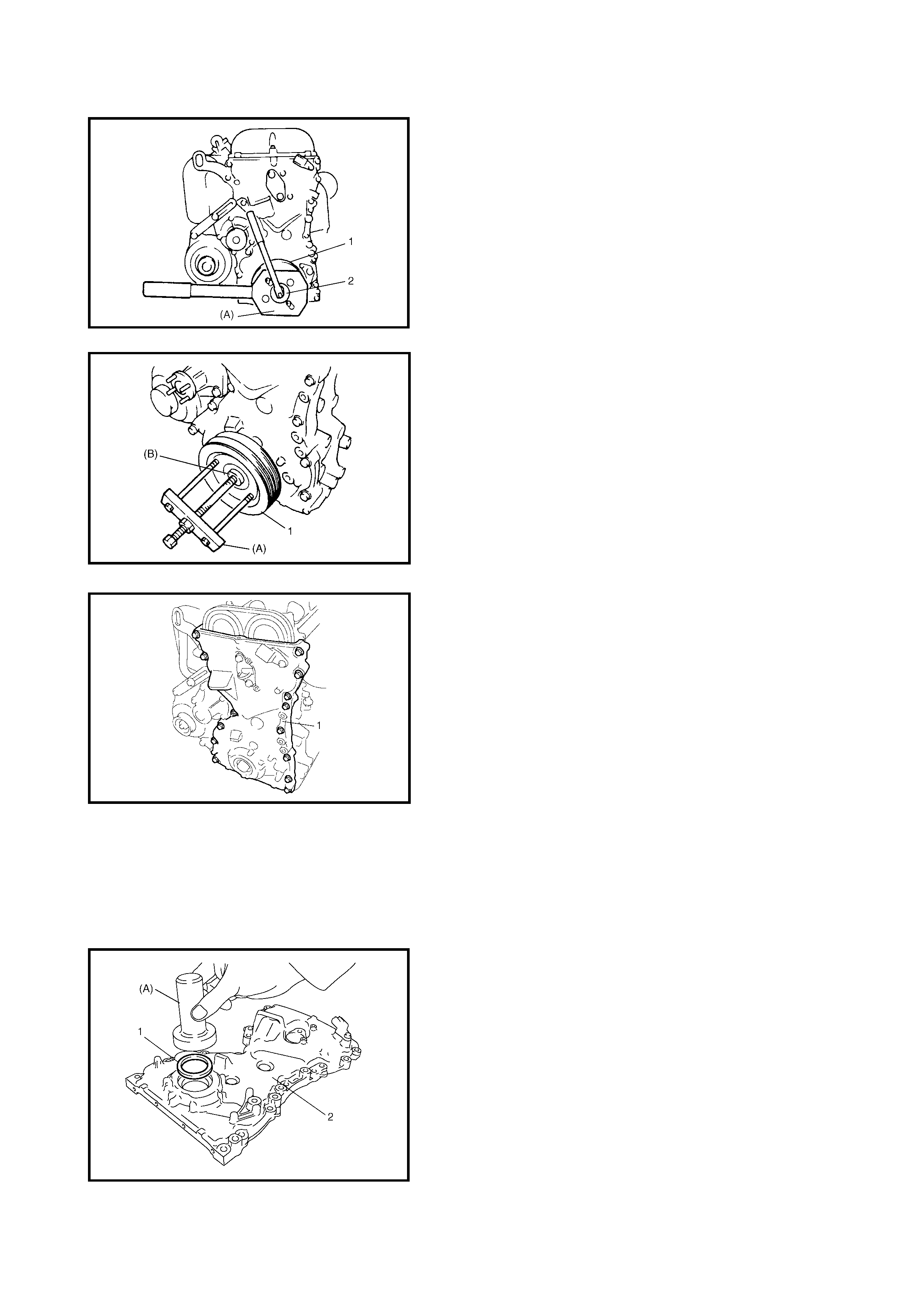
2. Remove the crankshaft pulley bolt (2).
To lock the crankshaft pulley (1), use special tool
09917-68221 (A) as shown in the figure.
3. Remove the crankshaft pulley (1).
If it is hard to remove, use special tools 09944-36011
(A) and 09926-58010 (B) as shown in the figure.
4. Remove the cylinder head cover, refer to
3.4 CYLINDER HEAD COVER in this Section.
5. Remove the oil pan, refer to 3.7 OIL PAN AND OIL
PUMP STRAINER in this Section.
6. Remove the water pump pulley.
7. Remove the timing chain cover (1).
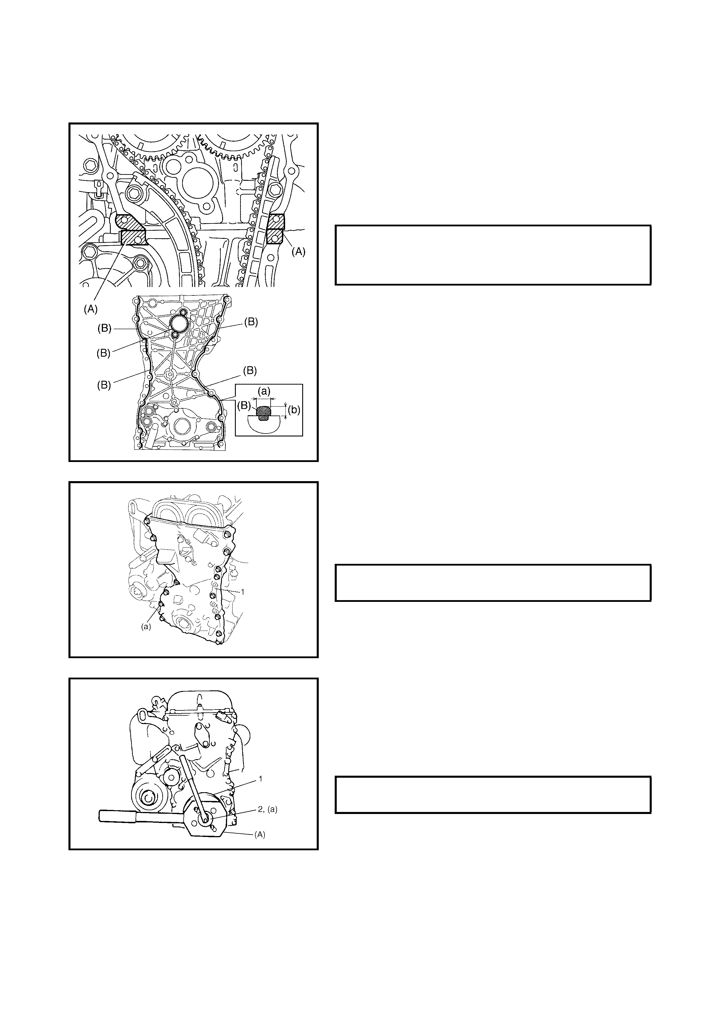
CLEAN
• Clean the sealing surface on the timing chain cover,
cylinder block and cylinder head.
Remove oil, old sealant and dust fr om the sealing
surface.
INSPECTION
• Check the oil seal (1) lip for wear or other damage.
Replace as necessary.
NOTE: When i nstalling a ne w oil seal , tap it in un til its su r-
face is flush with the edge of the timing chain cover (2).
To install oil seal, use special tool
(Bear ing insta ller ) 099 13-75 520 (A ).
INSTALLATION
Reverse the removal procedure to install the timing chain
cover, noting the following points.
1. Apply sealant (A) to the mating surface of the cylinder
and cylinder head and sealant (B) to the mating
surface of the timing chain cover as shown in the
figure.
(A): Sealant - Three Bond No. 1207B
(B): Sealant - Three Bond No. 1207C
2. Apply engine oil to the oil seal lip, then install the timing
chain cover (1).
Tighten bolts and nut to specified torque.
NOTE: Before installing the timing chain cover, check that
the locating pin is securely fitted.
3. Install the water pump pulley.
4. Install the cylinder head cover.
5. Install the oil pan.
6. Install the crankshaft pulley (1). Tighten bolt (2) to
specified torque. To lock the crankshaft pulley, use
special tool 09917-68221 (A) as shown in the figure.
7. Install the engine assembly to vehicle, refer to
4.1, ENGINE ASSEMBLY INSTALLATION in this
Section.
SEALANT AMOUNT FOR TIMING
CHAIN COVER WIDTH (a)
HEIGHT (b) 3.0 mm
2.0 mm
TIMING CHAIN COVER BOLTS (a)
TORQUE SPECIFICATION 23 Nm
CRANKSHAFT PULLEY BOLT (a)
TORQUE SPECIFICATION 150 Nm
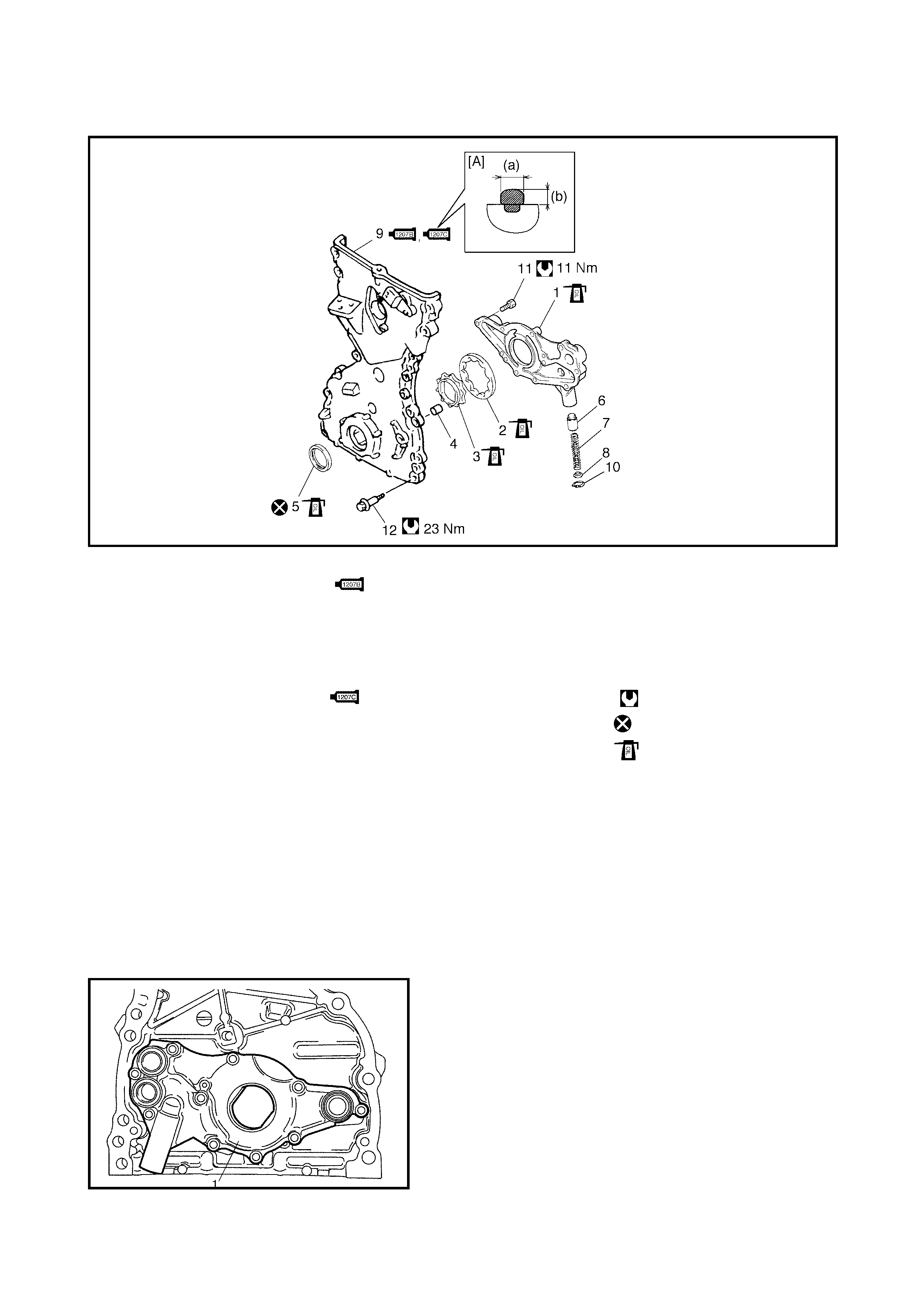
4.3 OIL PUMP
Legend
REMOVAL
1. Remove timing chain cover, refer to 4.2 TIMING
CHAIN COVER, REMOVAL in this Section.
DISASSEMBLY
1. Remove rotor plate (1) by removing its mounting bolts.
[A] : Sealant application amount 9. Timing chain cover 10. Circlip
(a): 3 mm (0.12 in.) :Apply sealant Three Bond
No. 11. Oil pump mounting bolt
(b): 2 mm (0.08 in.) 1207B to the mating surface of 12. Timing chain cover
1. Rotor plate cylinder and cylinder head. mounting bolts
2. Outer rotor : Apply sealant Three Bond
No. 1207C to mating surface
of timing chain cover, refer to
the figure in Step 1 in
4.2 TIMING CHAIN COVER,
INSTALLATION
Tightening torque
3. Inner rotor Do not reuse.
4. Pin Apply thin coat of engine oil
5. Oil seal to sliding surface of each
6. Relief valve parts.
7. Spring
8. Retainer
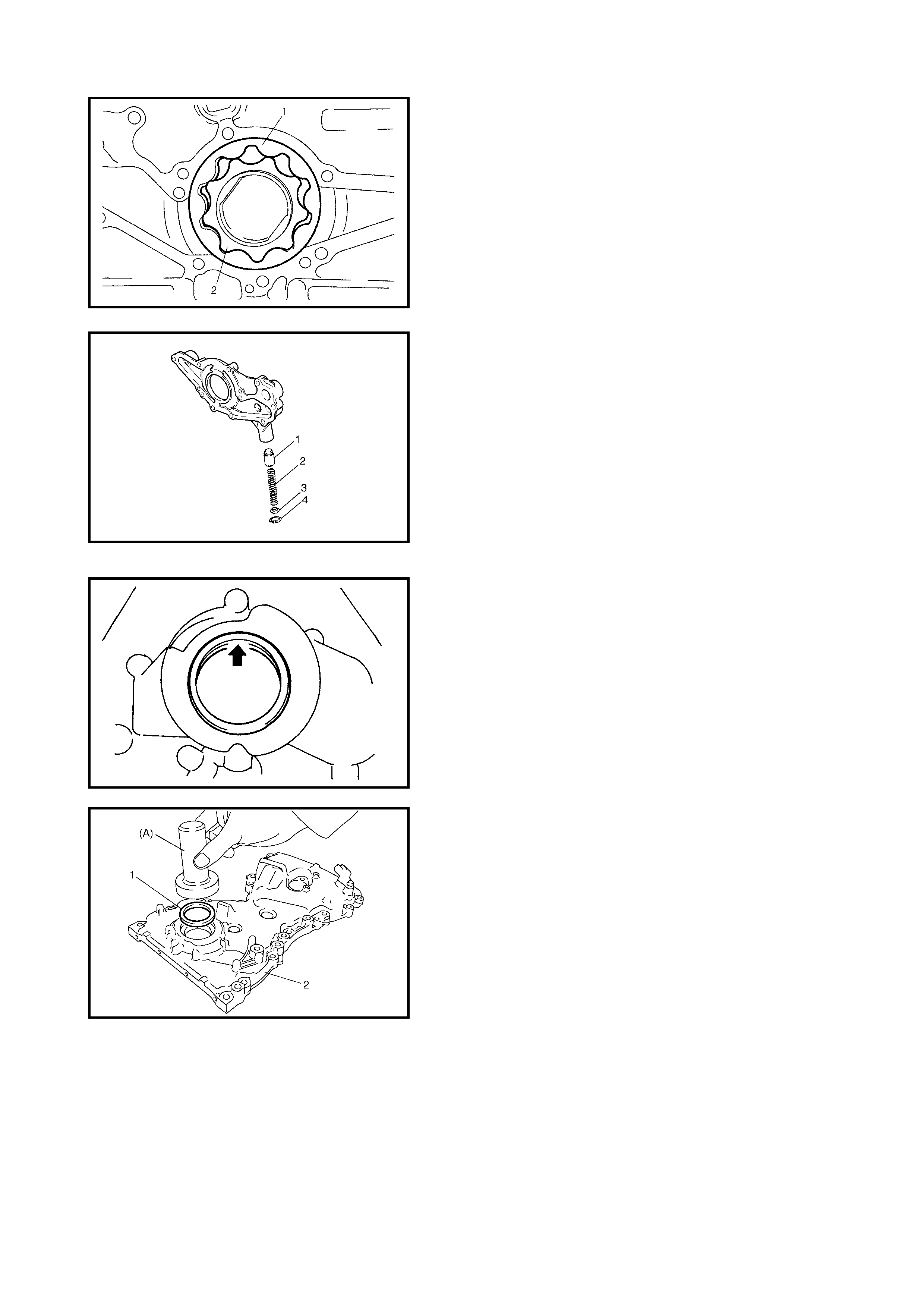
2. Remove outer rotor (1) and inner rotor (2).
3. Remove relief valve (1), spring (2) and retainer (3) by
removing circlip (4).
INSPECTION
• Check the oil seal lip for wear or other damage.
Replace as necessary.
NOTE: When installing a new oil seal (1), press-fit using
specia l tool 09 913-7552 0 (A) until i ts end face i s flush wi th
oil pump case (2) end face.
• Check outer (1) and inner rotors (2), rotor plate, and oil
pump case for excessive wear or damage.
• Check relief valve (1) for excessive wear or damage
and ensure it operates smoothly.
MEASUREMENT
Radial Clearance
Check radial clearance between outer rotor (1) and case
(2), using thickness gauge (3).
If clearance exceeds its limit, replace outer rotor or case.
Side Clearance
Using a straight edge (1) and thickness gauge (2), mea-
sure the side clearance.
LIMIT ON RADIAL CLEARANCE
BETWEEN OUTER ROTOR AND CASE
FOR OIL PUMP 0.310 mm
LIMIT ON SIDE CLEARANCE FOR OIL
PUMP INNER ROTOR 0.15 mm

ASSEMBLY
1. Wash, clean and dry all disassembled parts.
2. Apply a thin coat of engine oil to the inner and outer
rotors, oil seal lip portion, and inside surfaces of oil
pump case and plate.
3. Install outer (1) and inner rotors (2) to oil pump case.
4. Install relief valve components (1) to the rotor plate (2).
5. Install the rotor plate and tighten all bolts to specified
torque.
After installing the plate, ensure that rotors turn
smoothly by hand (0.3 Nm torque or below).
INSTALLATION
For installation, refer to 4.2 TIMING CHAIN COVER
INSTALLATION in this Section.
OIL PUMP ROTOR PLATE BOLTS (a)
TORQUE SPECIFICATION 11 Nm
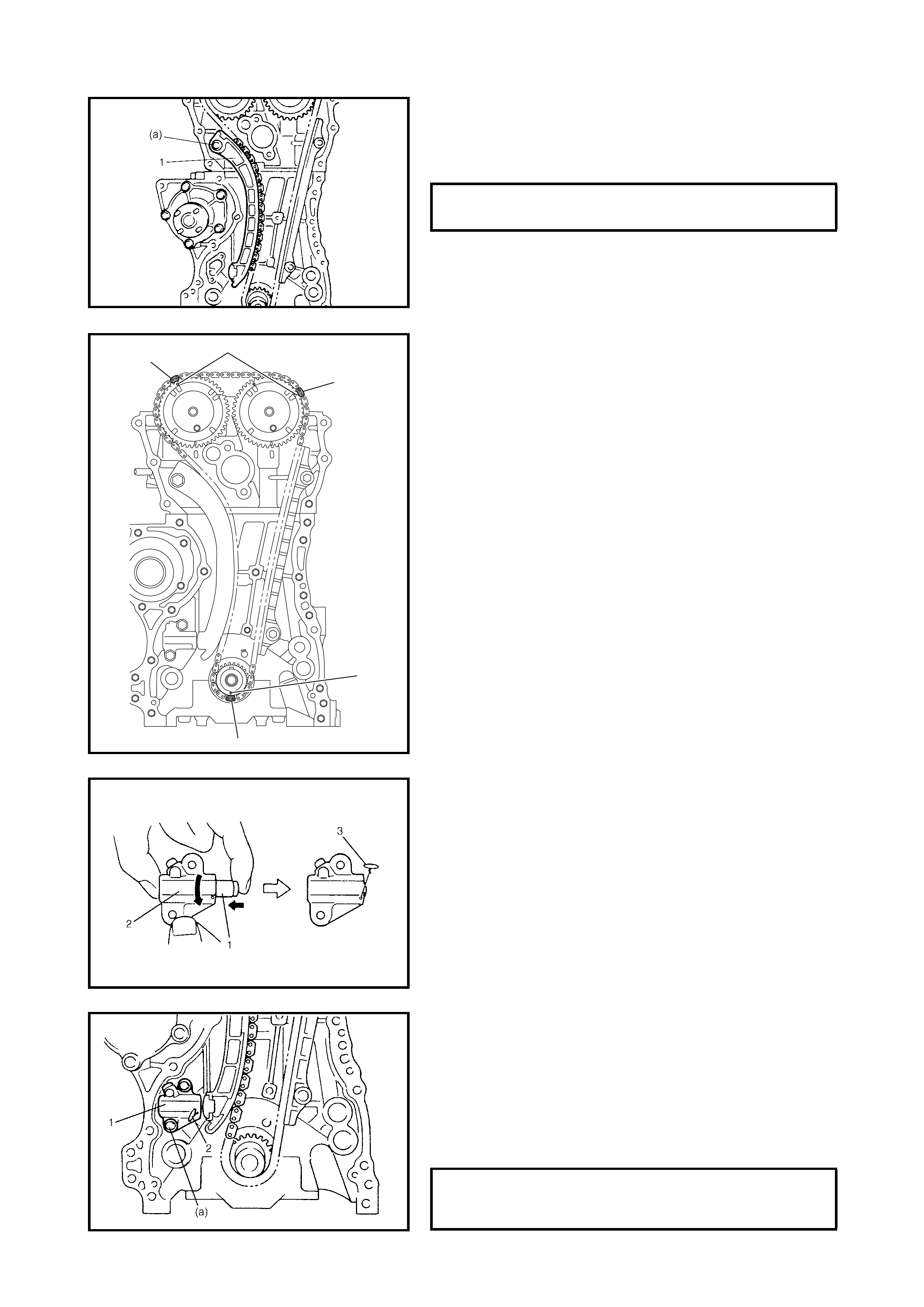
4.4 TIMING CHAIN AND CHAIN TENSIONER
Legend
REMOVAL
1. Remove the timing chain cover, refer to 4.2 TIMING
CHAIN COVER, REMOVAL in this Section.
2. Align both the intake and exhaust camshaft timing
sprocket marks (1) with the notches (2) on the cylinder
head respectively by turning the crankshaft.
3. Remove the timing chain tensioner adjuster assembly
(3).
4. Remove the timing chain tensioner (4).
5. Remove the timing chain No.1 guide (5).
6. Remove the timin g chai n (6 ) with the cran ksha ft timing
sprocket (7).
CAUTION: After the timing chain is removed, DO NOT
turn crankshaft and camshafts independently more
than the allowable turning range, refer to 4.4 TIMING
CHAIN AND TENSIONER, INSTALLATION in this
Section.
If turned, interference may occur between the piston
and valves, and valves themselves, and parts relating
to the piston and valves may be damaged.
1. Crankshaft timing sprocket 4. Timing chain tensioner
: Apply engine oil to sliding
surface.
7. Chain tensioner
mounting bolt
2. Timing cha in
: Apply engine oil. 8. Chain guide mounting
bolt
3. Timing chain No.1 guide
: Apply engine oil to sliding
surface.
5. Timing chain tensioner
adjuster assembly Tightening torque
6. Chain tensioner adjuster
mounting bolt
4
5
6
2
1
1
3
7
INSPECTION
Timing chain tensioner
• Check shoe (1) for wear or damage.
Crankshaft timing sprocket
• Check the teeth of the sprocket for wear or damage.
Timing chain
• Check the timing chain for wear or damage.
Timing chain tensioner adjuster
• Check that the tooth surfaces (1) are not damaged.
Timing chai n No .1 guide
• Check shoe (1) for wear or damage.
INSTALLATION
CAUTION: After the timing chain is removed, never
turn th e cra nksh a ft and camshafts independ ent ly more
than the limit (a) and (b) as shown in the figure.
If turned, interference may occur between the piston
and valves and the valves themselves, and parts
related to the piston and valves may be damaged.
1. Check that the matching marks (1) on the intake and
exhaust ca mshaft timing sp rockets matc h with notc hes
(2) on the cylinder head as shown in the figure.
2. Set key (3) and turn crankshaft to position key on the
upside of the crankshaft.
3. Install the timing chain by aligning the dark blue plate
(1) of the timing chain with the mark (2) on the
camshaft timing sprocket, then by aligning dark blue
plate (3) with the triangle mark (4) as shown in the
figure.
4. Fit the crankshaft timing sprocket to the timing chain by
aligning the gold plate (5) on the timing chain with mark
(6) on the crankshaft timing sprocket.
Install the crankshaft timing sprocket, with the chain
fitted in position, onto the crankshaft.
5. Apply engine oil to the sliding surface of the timing
chain No.1 guide (1) and install it as shown in the
figure.
Tighten the guide bolts to specified torque.
(a) 90° (5) Crankshaft allowable turning range.
By key on crankshaft, within 90° from top
on both right and left.
(b) 15° (4) Camshaft (INTAKE and EXHAUST)
allowable turning range.
By marks on camshaft timing sprocket
within 15° from notches on cylinder head
on both right and left.
TIMING CHAIN No.1 GUIDE BOLT (a)
TORQUE SPECIFICATION 9 Nm
6. Apply engine oil to the sliding surface of the chain
tensioner (1) and install the chain tensioner and
spacer.
Tighten tensioner bolt to specified torque.
7. Ensure that the matching marks (1) on the intake and
exhaust camshaft timing sprockets are correctly
aligned with the dark blue plates (2) on the timing chain
and matching mark (3) on the crankshaft timing
sprocket is correctly aligned with the gold plate (4) on
the timing chai n.
8. Screw in the timing chain tensioner adjuster plunger (1)
by turning the body (2) in the direction of the arrow.
Install a retainer (3) (wire) to hold the plunger in place.
9. Install the timing chain te nsion er adjus ter asse mbly (1)
with the retainer (2) still in place.
Tighten the adjuster bolts to the specified torque then
remove the retainer (wire) from the chain tensioner
adjuster assembly.
CAUTION: Ensure the plunger ret a iner is removed aft er
the timing chain adjuster is fitted.
TIMING CHAIN TENSIONER BOLT (a)
TORQUE SPECIFICATION 22 Nm
2
2
1
3
4
TIMING CHAIN TENSIONER
ADJUSTER BOLTS (a)
TORQUE SPECIFICATIONS 11 Nm
10. Apply engine oil to the timing chain then turn the crank-
shaft clockwise two revolutions. Check that the
matching marks (1) on the intake and exhaust
camshaft timing sprockets align with the notches (2) on
the cylinder hea d and that the key (3) is on the upside
of the crankshaft as shown in the figure.
If any of the alignment marks do not match, adjust
chain and/or sprockets, refer back to Step 7.
11. Install timing chain cover, refer to 4.2 TIMING CHAIN
COVER, INSTALLATION in this Section
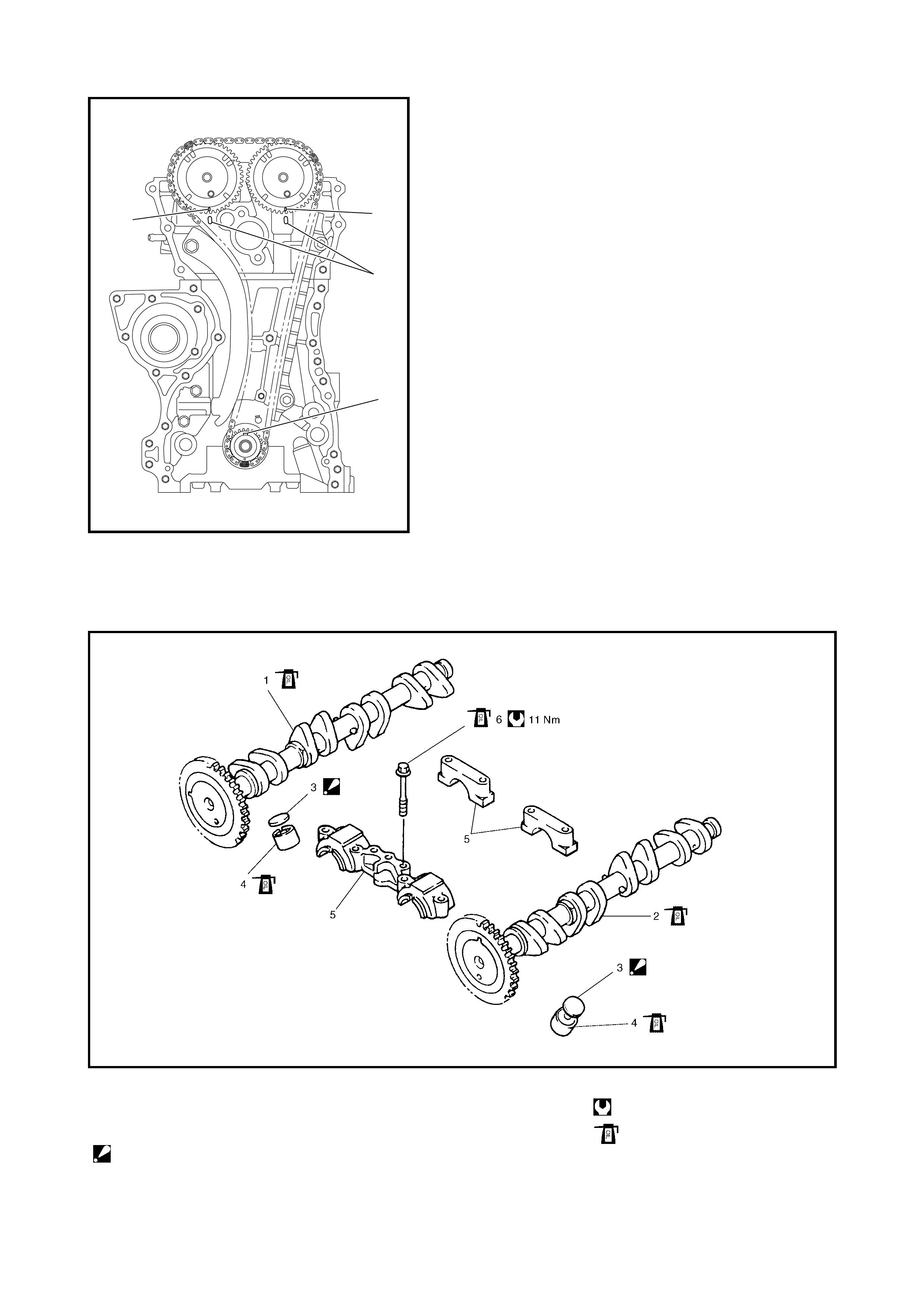
4.5 CAMSHAFT, TAPPET AND SHIM
Legend
2
1
1
3
1. Intake camshaft 4. Tappet Tightening torque
2. Exhaust camshaft 5. Camshaft housing Apply engine oil to sliding
surface of each part.
3. Shim
: Shim Number on it faces
the tappet side.
6. Camshaft housing bolt
REMOVAL
1. Remove the timing chain cover, refer to 4.2 TIMING
CHAIN COVER REMOVAL in this Section.
2. Remove the timing chain, refer to 4.4 TIMING CHAIN
AND CHAIN TENSIONER, REMOVAL in this Section.
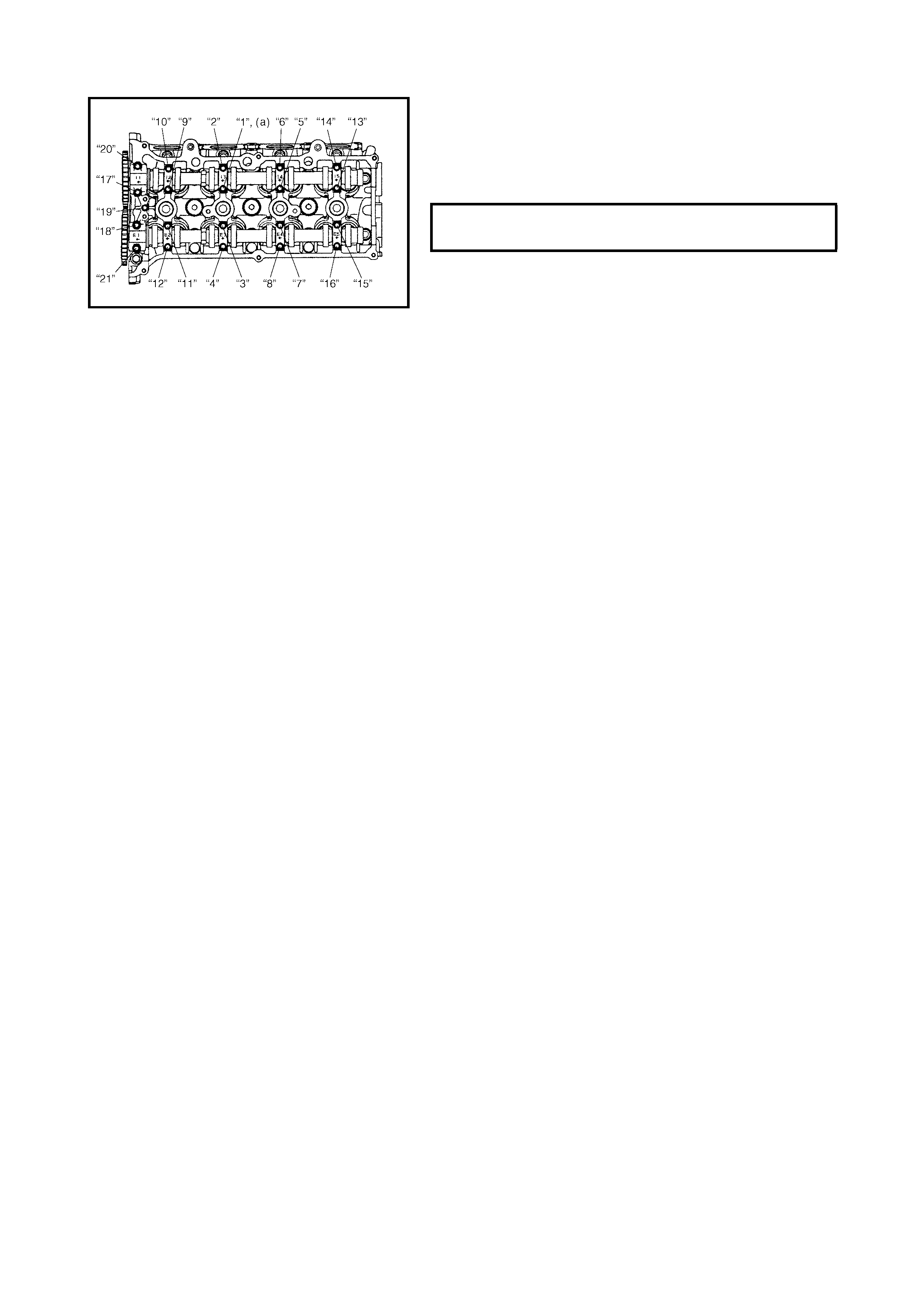
3. Loosen the camshaft housing bolts in the order
indicated in the figure then remove them.
4. Remove the camshaft housings.
5. Remove the intake and exhaust camshafts.
6. Remove the tappets (2) with the shims (1).
INSPECTION
Cam Wear
Using a micrometer, measure the cam height (a). If the
measured height is below the limit, replace the camshaft.
Camshaft Runout
Set the c amshaft betw een two “V” b locks a nd meas ure the
runout using a dial gauge.
If the meas ured runout e xceeds the lim it, replace the c am-
shaft.
INTAKE CAM HEIGHT (a) STANDARD
LIMIT 44.9 19 - 45.089 mm
44.81
EXHAUST CAM HEIGHT (a)
STANDARD
LIMIT 44.3 99 - 44.559 mm
44.28 mm
CAMSHAFT RUNOUT LIMIT 0.10 mm
Camshaft Journal Wear
Check the camshaft journals and camshaft housings for pit-
ting, scratches, wear or damage.
If any damage is found, replace the camshaft or cylinder
head with the housings. Never replace the cylinder head
without replacing the housings.
Check the camshaft journal clearance using gauging plas-
tic. Checking procedure is as follows.
1. Clean housings and camshaft journals.
2. Remove all tappets with shims.
3. Install the camshafts onto the cylinder head.
4. Place a piece of gauging plastic the full width of the
journal of the camshaft (parallel to camshaft).
5. Install the camshaft housings.
6. Gradually tighten the camshaft housing bolts in the
order indicated in the figure until they reach the
specified torque.
NOTE: Do not rotate the camshaft while the gauging plastic
is installed.
7. Remove the housings, and using the scale (2) on the
gauging plastic (1) envelope, measure the gauging
plastic width at its widest point.
CAMSHAFT HOUSING BOLTS (a)
TIGHTENING TORQUE 11 Nm
CAMSHAFT JOURNAL CLEARANCE -
INTAKE No.1 STANDARD
LIMIT 0.020 - 0.072 mm
0.12 mm
CAMSHAFT JOURNAL CLEARANCE -
OTHERS STANDARD
LIMIT 0.045 - 0.087 mm
0.12 mm
If the measured camshaft journal clearance exceeds the
limit, measure the journal (housing) bore and the outside
diameter of the camshaft journal. Replace the camshaft or
the cylinde r head assembly, which ever differs greater from
its specification.
Tappet and Shim Wear
Check tappet and shim for pitting, scratches or damage.
If any damage is found, replace.
Measur e the cylinder head tappet b ore and the tappet out-
side diameter to determine the cylinder head-to-tappet
clearance. If the clearance exceeds the limit, replace the
tappet or the cylinder head.
CAMSHAFT JOURNAL DIAMETER [A]
- INTAKE No.1 26.940 - 26.955 mm
CAMSHAFT JOURNAL DIAMETER [A]
- EX HAUST No.1 29.934 - 26.95 5 mm
CAMSHAFT JOURNAL DIAMETER [A]
- OTHER 22.934 - 22.955 mm
CAMSHAFT JOURNAL BEARING
BORE [B] - EXHAUST No.1 27.000 - 27.021 mm
CAMSHAFT JOURNAL BEARING
BORE [B] - OTHER 23.00 - 23.021 mm
CYLINDER HEAD TO TAPPET
CLEARANCE STANDARD
LIMIT 0.025 - 0.066 mm
0.15 mm
TAPPET OUTSIDE DIAMETER [A]
STANDARD 30.959 - 30.975 mm
CYLINDER HEAD TAPPET BORE [B]
STANDARD 31.000 - 31.025 mm
INSTALLATION
1. Apply engine oil around the tappets then install the
tappets and shims onto the cylinder head.
NOTE: When install ing th e shim, ma ke sur e the s him num-
ber faces the tappet.
2. Install the camshafts (1).
NOTE: Before install ing the camshafts, turn the cra nkshaft
until the key position faces upward. Refer to 4.4 TIMING
CHAIN AND CHAIN TENSIONER in this Section.
Apply engine oil to the sliding surface of each camshaft and
camshaft journal then install them as shown in the figure.
3. Install the camshaft housing pins (1), if removed, as
shown in the figure.
4. Check the position of the camshaft housings.
Embossed marks are provided on each camshaft
housing, indicating position and direction for installa-
tion. Install housings as indicated by these marks.
A: I = Intake side and E = Exhaust side.
B: Position from timing chain side.
C: Pointing to timing chain side.
5. Apply engine oil to the housing bolts, then fit loosely.
Gradually tighten the housing bolts by the following
numeric al order i n the fig ure. Tighten them evenly an d
repeat the tighten ing se quence two o r thr ee times u ntil
they reach the speci fi ed tor que .
6. Install the timing chain with the crankshaft sprocket,
refer to 4.4 TIMING CHAIN AND CHAIN TENSIONER
INSTALLATION in this Section.
7. Install the timing chain cover, refer to 4.2 TIMING
CHAIN COVER INSTALLATION in this Section.
8. Check valve lash clearance, refer to 2.5 VALVE LASH
(CLEARANCE) in this Section.
9. Refer to 4.2 TIMING CHAIN COVER, INSTALLATION
in this Section and perform Steps 1 to 3.
CAMSHAFT HOUSING BOLTS (a)
TORQUE SPECIFICATION 11 Nm
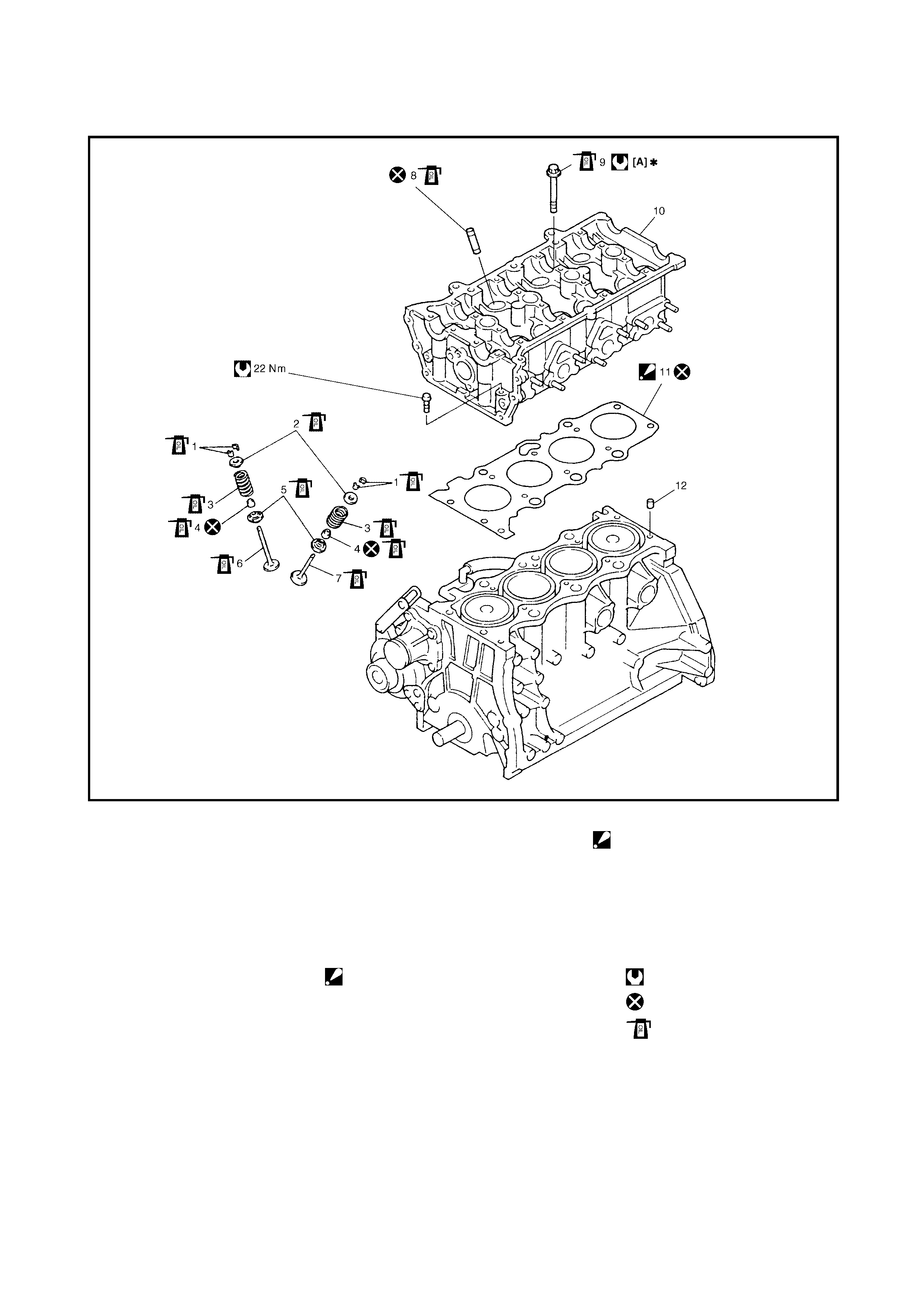
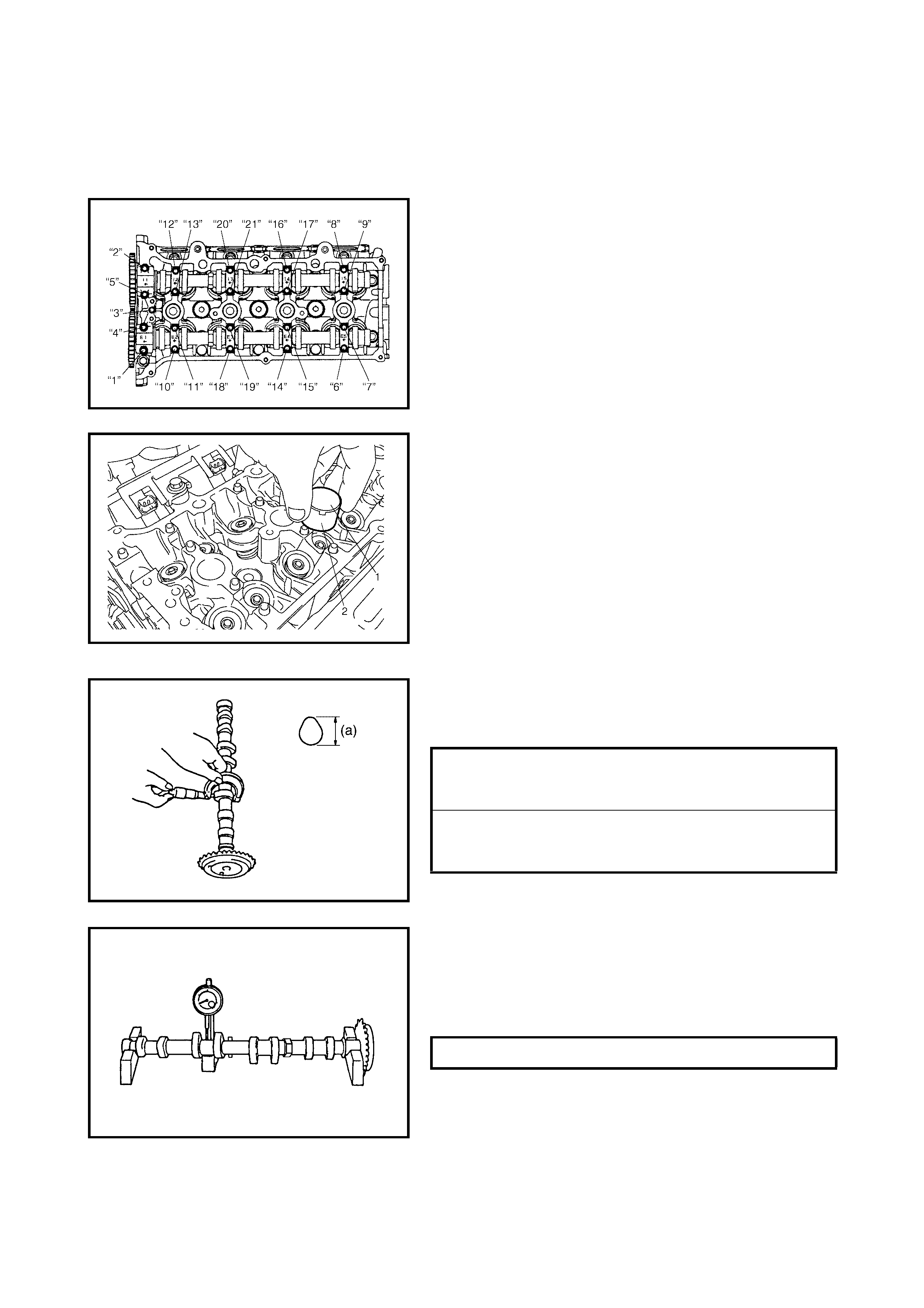
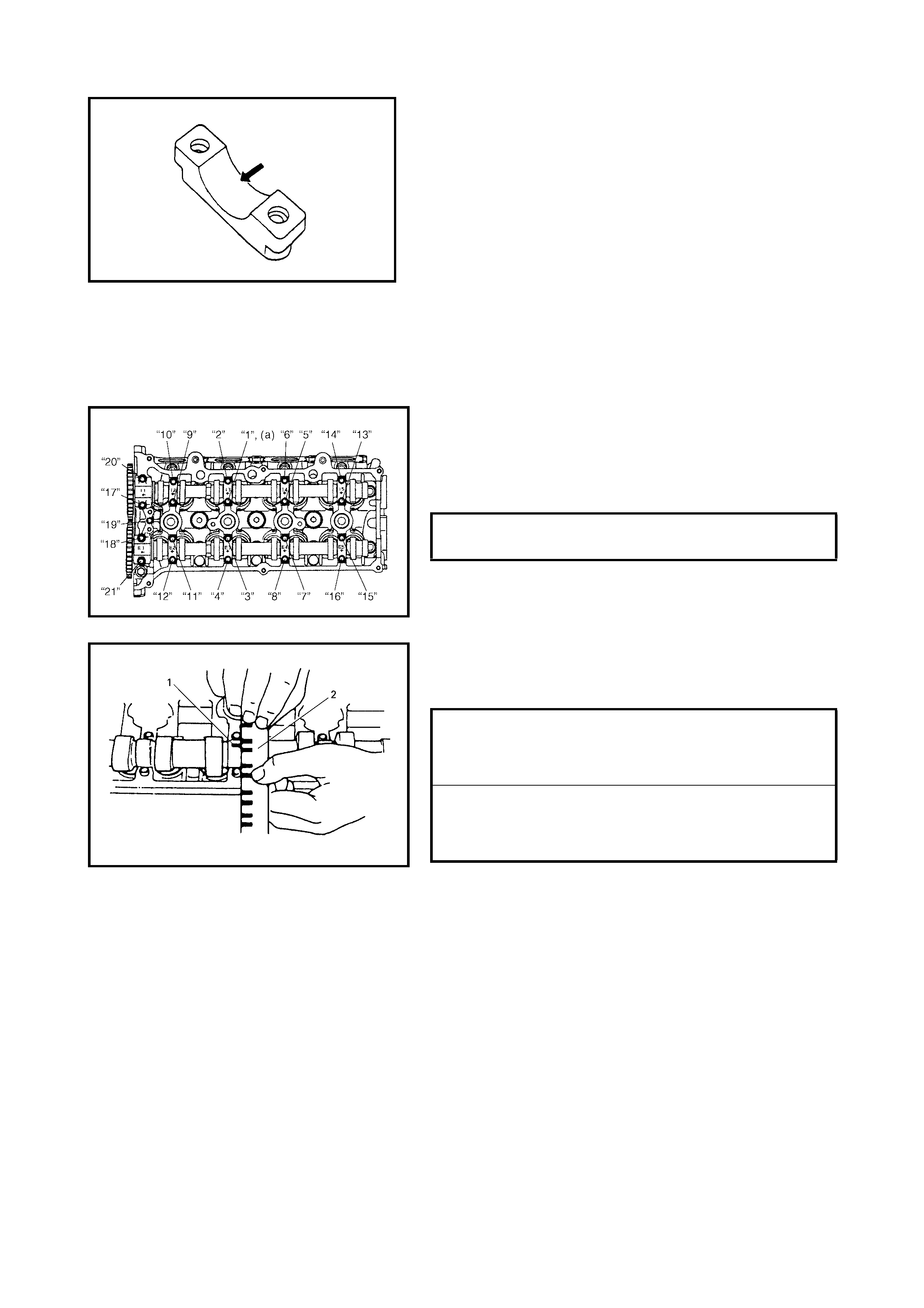
4.6 VALVES AND CYLINDER HEAD
Legend
[A] 1) T ighten all bolts at 40 Nm
2) Turn all bolts at 60°
3) Then, Turn all bolt at 60°
once again
4. Valve stem seal 11. Cylinder head gasket
: “TOP” mark stamped on
the gasket is positioned
on the crankshaft pulley
side, facing up.
✱5. Valve spring seat
6. Intake valv e
7. Exhaust valve
1. Valve cotters 8. Valve guide 12. Knock pin
2. Valve spring retainer 9. Cylinder head bolt Tightening torque
3. Valve spring 10. Cylinder head Do not reuse.
Apply engine oil to sliding
surface of each part.
REMOVAL
1. Remove engine assembly from vehicle, refer to
4.1, ENGINE ASSEMBLY, REMOVAL in this Section.
2. Remove intake manifold stiffener (1).
3. Remove the oil pan, refer to 3.7 OIL PAN AND OIL
PUMP STRAINER in this Section.
4. Remove the cylinder head cover, referring to
3.4 CYLINDER HEAD COVER, REMOVAL in this
Section.
5. Remove the timing chain cover, refer to Steps 2 to 6,
4.2 TIMING CHAIN COVER, REMOVAL in this
Section.
6. Remove the timing chain, refer to Steps 2 to 6,
4.4 TIMING CHAIN AND CHAIN TENSIONER,
REMOVAL in this Section.
7. Remove the intake and exhaust camshafts, refer to
Steps 3 to 6, 4.5 CAMSHAFT, TAPPET AND SHIM,
REMOVAL in this Section.
8. Loosen the cylinder head bolts in the order indicated in
the figure using a 12 corner socket wrench then
remove them.
NOTE:
• Remember to remove the (M8) bolt (1) as shown in the
figure.
9. Check the cylinder head and remove or disconnect any
further parts as necessary.
10. Remove the exhaust manifold, if necessary, refer to
3.6 EXHAUST MANIFOLD in this Se ct io n.
11. Remove the cylinder head with the intake manifold and
exhaust manifold (if still fitted). Use lifting device, if
necessary.
DISASSEMBLY
1. For ease in servicing the cylinder head, remove the
intake manifold, injectors and exhaust manifold from
the cylinde r hea d.
2. Using special tools (Valve lifter) 09916-14510 (A) and
09916-14910 (B), compress the valve springs and
remove the valve cotters (1) using special tool
(Forceps) 09916-84511 (C).
3. Release the special tool and remove the spring
retainer and valve spring.
4. Remove the valve from the combustion chamber side.
5. Remove the valve stem seal (1) from the valve guide,
then the valve spring seat (2 ).
NOTE: Do not reuse the seal once it has been disassem-
bled. Always use new oil seals when assembling.
6. Using sp ecial tool (valve guide remover) 0 9916-44910
(A), drive the valve guide out from the combustion
chamber side to the valve spring side.
NOTE: Do not reuse the valve guide once disassembled.
Be sure to use a new v alve gui de (Ov ersize) when ass em-
bling.
7. Place disassembled parts, except valve stem seals
and va lve gui des , i n o rd er so that they c an be in stalle d
in their original position.
INSPECTION
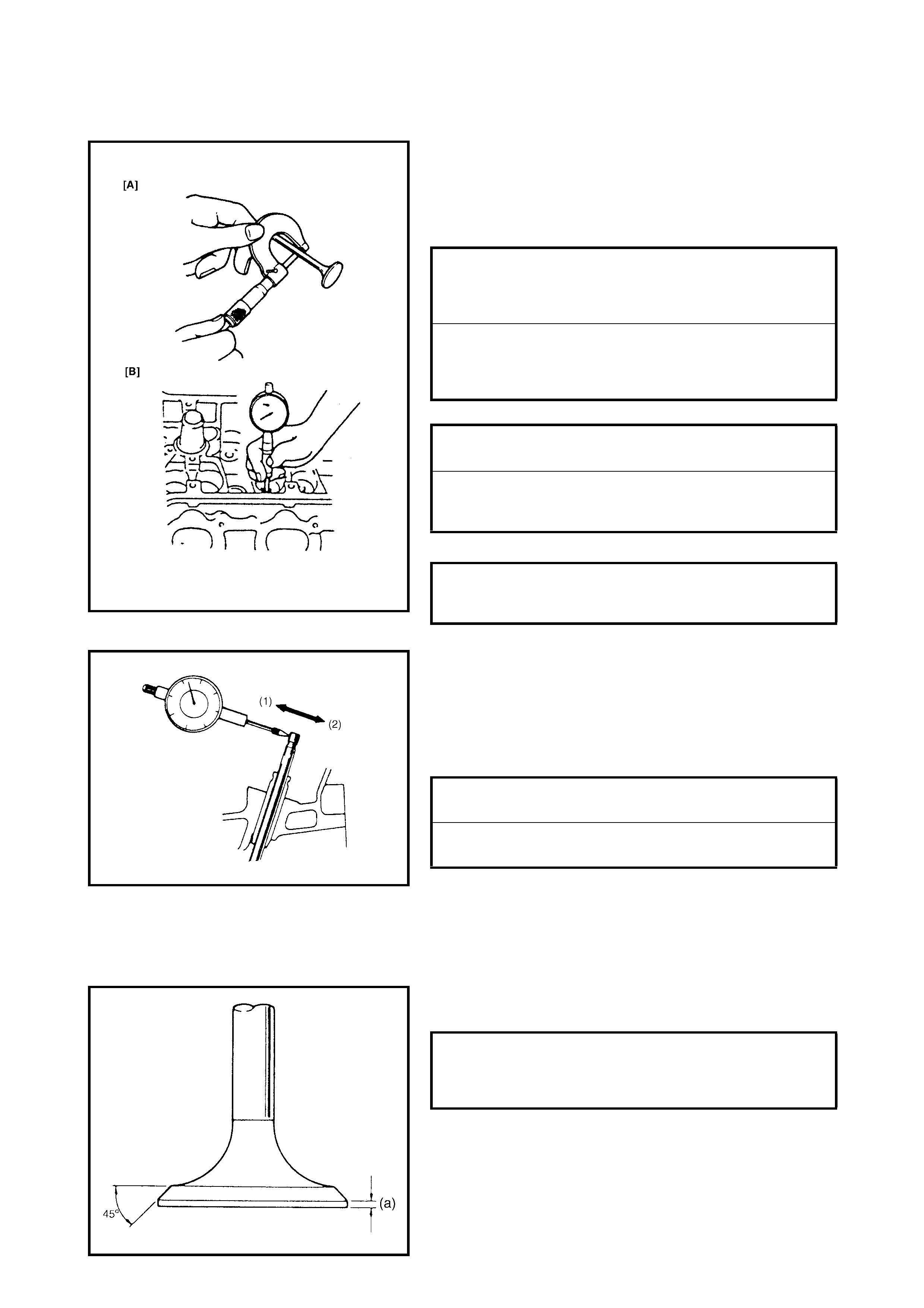
Valve Guides
Using a m ic rome ter and a bo re gau ge, take dia met er read-
ings of the valve stems and the valve guides to check
stem-to -guide clearan ce. Be sure to take readings at more
than one place along the length of each stem and guide.
If clearance exceeds limit, replace valve and valve guide.
If a bore gauge is not avail abl e, ch eck the end def lecti on of
the valve stem with a dial gauge.
Move t he stem e nd in directi ons (1 ) an d (2) to mea su re the
end deflection.
If the deflection exceeds the limit, replace the valve stem
and valve guide.
Valves
• Remove all carbon from valves.
• Inspect each valve for wear, burn or distortion on its
face and stem end, replace if necessary.
• Measure the thickness (a) of the valve head. If the
measured thickness exceeds the limit, replace valve.
INTAKE VALVE STEM-TO-GUIDE
CLEARANCE STANDARD
LIMIT 0.020 - 0.047 mm
0.07 mm
EXHAUST VALVE STEM-TO-GUIDE
CLEARANCE STANDARD
LIMIT 0.045 - 0.072 mm
0.09 mm
INTAKE VALVE STEM DIAMETER [A]
STANDARD 5.465 - 5.480 mm
EXHAUST VALVE STEM DIAMETER
[A] STANDARD 5.440 - 5.455 mm
INTAKE AND EXHAUST VALVE GUIDE
BORE [B] STANDARD 5.500 - 5.512 mm
INTAKE VALVE STEM END
DEFLECTION LIMIT 0.14 mm
EXHAUST VALVE STEM END
DEFLECTION LIMIT 0.18 mm
INTAKE & EXHAUST VALVE HEAD
THICKNESS STANDARD
LIMIT 1.22 - 1.55 mm
0.9 mm
• Inspect th e valve stem end face fo r pitting and wear. If
pitting or wear is evident, the valve stem end may be
resurfaced. If resurfacing the valve stem end removes
the chamfer, the valve must be replaced.
• Check each valve for radial runout with a dial gauge
and “V” block. To check runout, rotate valve slowly. If
runout exceeds its limit, replace valve.
• Seating contact width:
Create a contact pattern on each valve by applying a
uniform coat of marking compound to the valve seat
and tapping the seat with the valve head in a circular
motion. A valve lapper (tool used in valve lapping)
must be used.
The pattern produced on the seating face of the valve
must be a con tinuou s ring withou t any breaks , and the
width of the pattern must be within the specified range.
• Valve seat repair:
If the valve seat does not produce a uniform contact
pattern on the valve or the contact width of the seat is
out of the specified range it must be repaired.
Repair the valve seat by regrinding or by cutting and
regrinding then finish by lapping.
a. EXHAUST VALVE SEAT: Use valve seat cutters (1)
to make two cuts as illustrated in the figure. Two
cutters must be used: the first for making a 15°
angle, and the s econd for mak ing a 45° angle . The
second cut must be made to produce the desired
seat width.
LIMIT ON VALVE HEAD RADIAL
RUNOUT 0.08 mm
STANDARD SEATING WIDTH (a)
REVEALED BY CONTACT PATTERN
ON VALVE FACE - INTAKE & EXHAUST 1.1 - 1.3 mm
SEAT WIDTH FOR EXHAUST VALVE
SEAT (a) 1.1 - 1.3 mm
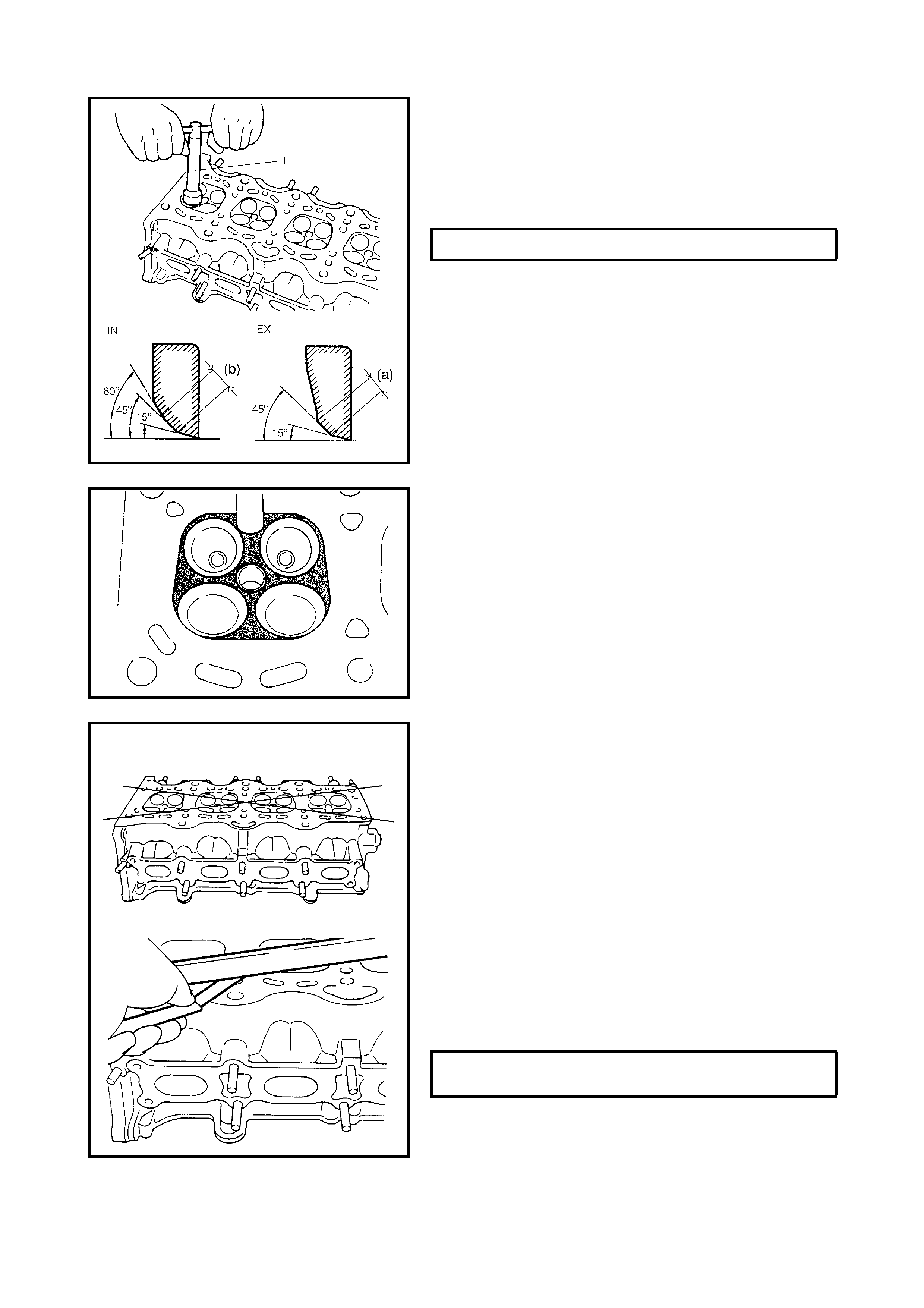
b. INTAKE VALVE SEAT: Use valve seat cutters to
make three cuts as illustrated in the figure. Three
cutters must be used: the 1st for making the 15°
angle, the 2nd for making the 60° angle, and 3rd for
making the 45° angle. The 3rd cut (45°) must be
made to produce the desired seat width.
c. VALVE LAPPING: Lap the valve seat in two steps,
first with a coars e lapping com pound a pplied to th e
face and second, with a fine compound, using a
valve lapper according to normal lapping proce-
dures.
Cylinder Head
• Remove all carbon deposits from the combustion
chambers.
NOTE: Do not use a sharp-edged tool to scrape off the car-
bon deposits. Take care not to scuff or nick the metal sur-
faces when decarbonizing. This also applies to the valves
and the valve seats.
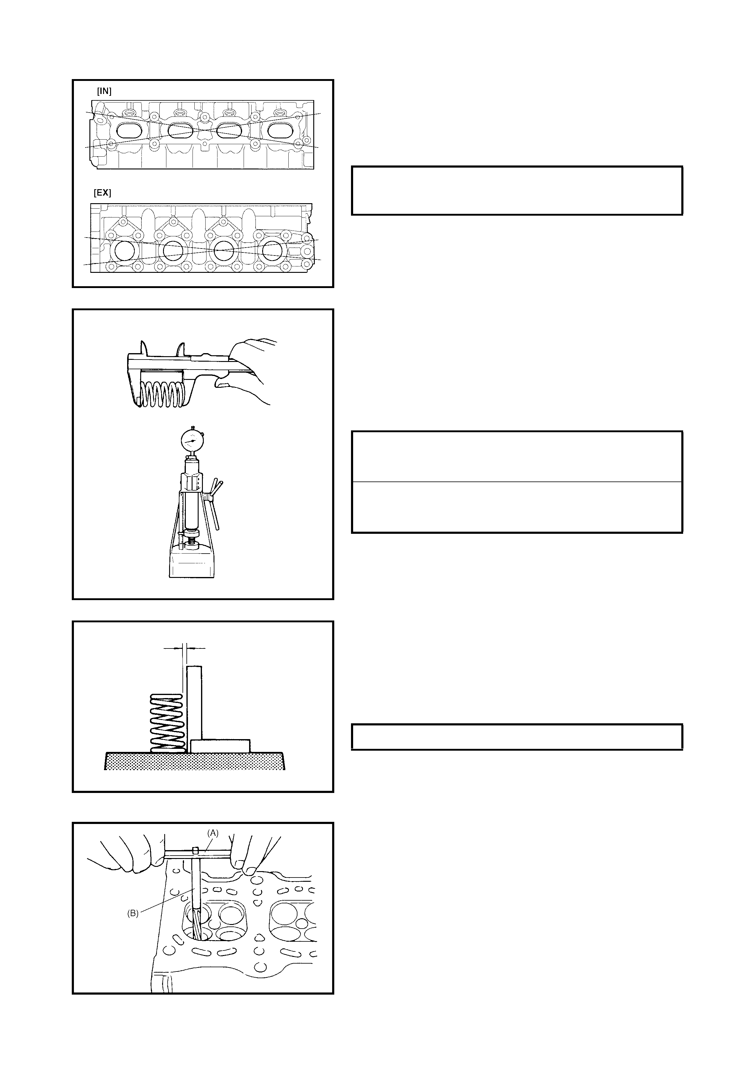
• Check the cylinder head for cracks around the intake
and exhaust ports, combustion chambers and head
surface.
Using a straightedge and a thickness gauge, check the
flatness of the gas keted surf ace at two loc ation s. If the
distortion limit, given below, is exceeded, repair the
gasketed surface with a surface plate and abrasive
paper of about No.400 (Waterproof silicon carbide
abrasive paper ): place abras ive paper on and over the
surface pl ate an d ru b th e g as ke ted su rf ace a gai ns t th e
paper to grind off any high spots. Should this fail to
reduce the thickness gauge readings to be within the
limit, replace the cylinder head.
Combustion gas leaks from the head gasket joint is
often due to a warped ga sketed su rface: su ch leakag e
results in reduced power output.
SEAT WIDTH FOR INTAKE VALVE SEAT (b) 1.1 - 1.3 mm
LIMIT OF DISTORTION FOR CYLINDER
HEAD SURFACE ON PISTON SIDE 0.03 mm
• Distortion of the manifold seating faces:
Check the manifold seating faces on the cylinder head,
using a straightedge and thickness gauge, to deter-
mine if these faces need to be corrected or the cylinder
head needs to be replaced.
Valve Springs
• Referring to the data given below, check that each
spring is in sound condition, free of any evidence of
breakage or weakening. Weakened valve springs can
cause chatter and a possibility of reduced power output
due to gas leakage caused by decreased seating pres-
sure.
• Spring squareness:
Use a squar e and a surfa ce plate to ch eck each va lve
spring for squareness, (i.e, the clearance between the
end of the v alve spring an d the square). Valve springs
that do not meet the specified limit given below must
be replaced.
ASSEMBLY
1. Before installing the valve guides into the cylinder
head, ream the guide hole with special tool (10.5 mm
reamer) 09916-34542 (A) and 09916-37320 (B) to
remove burrs and make it truly round.
LIMIT OF DISTORTION FOR CYLINDER
HEAD SURFACE ON INTAKE &
EXHAUST MANIFOLD 0.05 mm
VALVE SPRING FREE LENGTH
STANDARD
LIMIT 36.83
35.83
VALVE SPRING PRELOAD STANDARD
LIMIT 107 - 125 N
102 N
VALVE SPRING SQUARENESS LIMIT 1.6 mm
2. Install the valve guide to the cylinder head.
Heat the cylinder head uniformly to a temperature of 80
to 100 °C (176 to 212 °F) so that the head will not be
distorted, then drive the new valve guides into the
valve hole with special tools. Drive in the new valve
guide until special tool (Valve guide installer) 09916-
58210 (A) and 09916-56011 (B) contacts the cylinder
head.
After installation, make sure that the valve guide
protrudes by the specified dimension (a) from the
cylinder head.
NOTE:
• Always use new valve guides.
• Intake and exhaust valve guides are identical.
3. Ream the valve guide bore with special tool (5.5 mm
reamer) 09916-34542 (A) and 09916-34550 (B). After
reaming, clean bore.
4. Install the valve spring seat to the cylinder head.
5. Install a new valve stem seal (1) to the valve guide.
After applying engine oil to the seal and spindle of the
special tool (Valv e guide ins taller handle) , fit oil se al to
spindle, then install the seal to the valve guide by
pushing special tool 09917-98221 (A) and 09916-
58210 (B) by hand.
After installation, check that the seal is correctly fixed
to the valve guide.
NOTE:
• Do not reuse valve stem seals. Always install new
seals.
• When insta lling, nev er tap or hit the special too l with a
hammer. Only install the seal to the guide by pushing
the special tool by hand. Tapping o r hitting the special
tool may cause damage to the seal.
SPECIFICATION FOR INTAKE VALVE
GUIDE PROTRUSION (a) 11.1 - 11.5 mm
6. Install the valves to the valve guides.
Before installing the valve to the valve guide, apply
engine o il to th e st em seal, v al v e g uide bore an d valv e
stem.
7. Install the valve springs and spring retainers.
Each valve spring has a top end [large-pitch end (1)]
and a bottom end [small-pitch end (2)]. Be sure to
position the spring in place correctly with its bottom end
(small-pitch end) facing the bottom (valve spring seat
side) (B).
8. Using special tools (Valve lifter) 09916-14510 (A),
09916-14910 (B) and 09916-84511 (C), compress the
valve spring and fit the two valve cotters (1) into the
groove in the valve stem.
NOTE:
When compressing the valve spring, take care
not to damage the inside face of the tappet installation
hole.
9. Install the intake manifold, injectors and exhaust
manifold to the cylinder head.
INSTALLATION
1. Clean the mating surface of the cylinder head and
cylinder block.
Remove oil, old gasket and dust from the mating
surface.
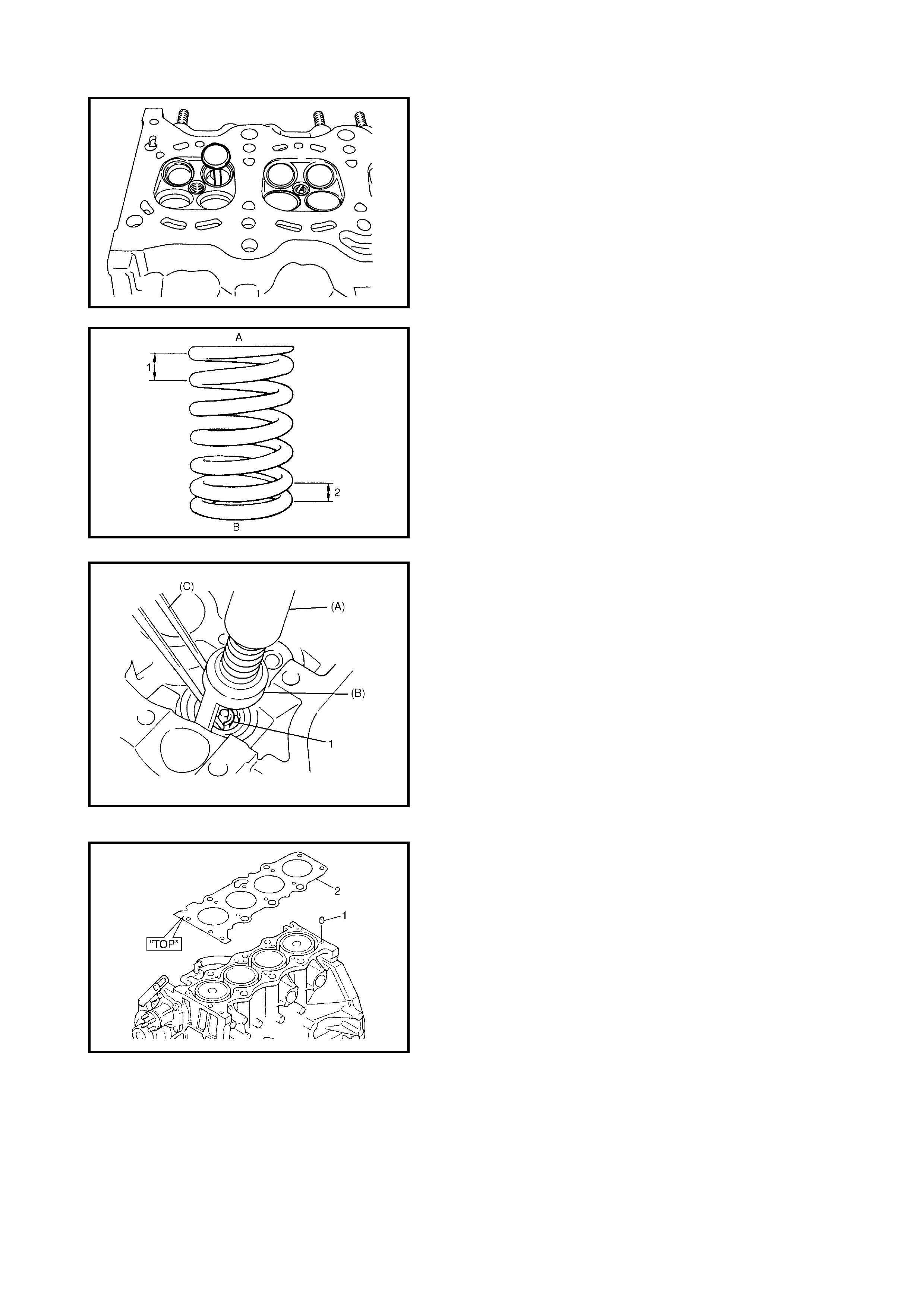
2. Install the knock pins (1) to the cylinder block.
3. Install a new cylinder head gasket (2) to the cylinder
block.
The TOP mark stamped on the gasket must be at the
crankshaft pulley end and facing up (toward the
cylinder head).
4. Make sure that the oil jet (venturi plug) (1) is installed
and that it is not clogged.
When installing the oil jet, be sure to tighten to
specified torque.
5. Install the cylinder head onto the cylinder block.
NOTE: If possible u se new cylinder head bolts. If they are
to be reused, check each bolt for thread deformation.
Measure the thread diameter of the cylinder head bolt (1) at
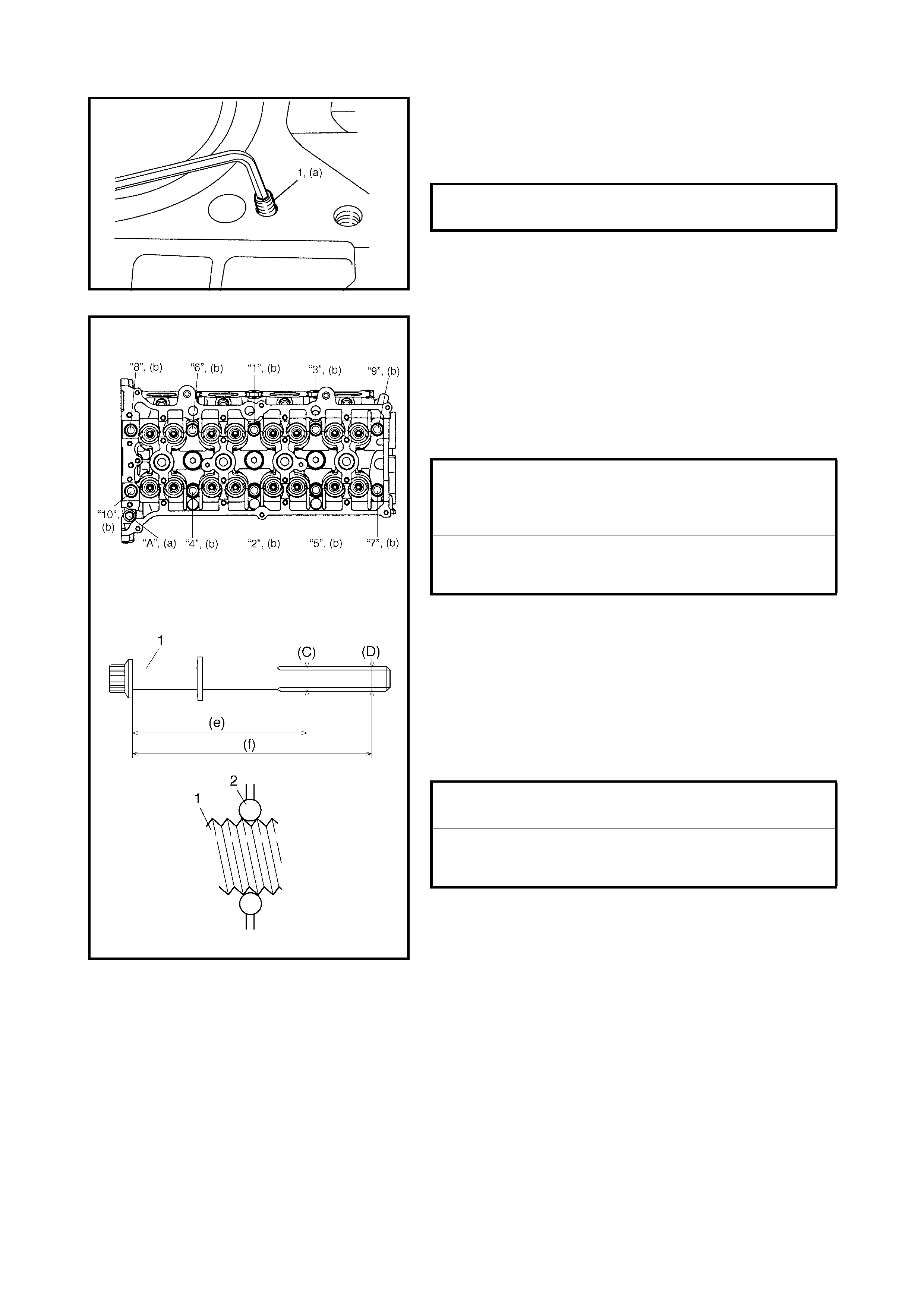
(C) and (D ) poin ts indicated i n the figure using a m icrome-
ter (2), an d calc ulate t he difference i n diame ters, (C) – ( D).
If it exceeds the limit, replace with new ones.
Apply engine oil to the cylinder head bolts and tighten them
gradually as follows.
a. Tighten the cylinder head bolts (“1” – “10”) to 20 Nm
following the numerical or der as shown, us ing a 12
corner socket wrench.
b. Repeat Step a, but tighten bolts to 40 Nm.
c. Turn all bolts 60° following the previous sequence.
d. Repeat Step c.
e. Tighten bolt “A” to specified torque.
6. Install the exhaust manifold stiffener, refer to 3.6
EXHAUST MANIFOLD INST ALLATION in this Section.
7. Install the camshafts, refer to 4.5 CAMSHAFT,
TAPPET AND SH IM INSTALL AT IO N in this Section.
8. Install the timing chain, refer to 4.4 TIMING CHAIN
AND CHAIN TENSIONER INSTALLATION in this
Section.
9. Install the timing chain cover, refer to 4.2 TIMING
CHAIN COVER in this Section.
10. Install the cylinder head cover, refer to 3.4 CYLINDER
HEAD COVER INSTALLATION in this Section.
11. Install the oil pan, refer to 3.7 OIL PAN AND OIL PUMP
STRAINER INSTALLATION in this Section.
12. Install the intake manifold stiffener and connect all
hoses, refer to 3.5 THROTTLE BODY AND INTAKE
MANIFOLD INSTALLATION in this Section.
13. Refer to 4.2, TIMING CHAIN COVER INSTALLATION
in this Section and perform Steps 3 to 7.
VENTURI PLUG (a)
TORQUE SPECIFICATION 5 Nm
CYLINDER HEAD BOLT DIAMETER
MEASUREMENTS POINTS (e)
(f) 83.5 mm
115 mm
CYLINDER HEAD BOLT DIAMETER
DIFFERENCE (DEFORMATION) LIMIT
(C) – (D) 0.1 mm
CYLINDER HEAD BOLT - M8 (a)
TORQUE SPECIFICATION 22 Nm
CYLINDER HEAD BOLTS - M10 (b)
TORQUE SPECIFICATION
20 Nm THEN
40 Nm THEN
TURN 60° TWICE
4.7 PISTONS, PISTON RINGS, CONNECTING RODS AND CYLINDERS
Legend
REMOVAL
1. Remove engine assembly from vehicle, refer to
4.1 ENGINE ASSEMBLY, REMOVAL in this Section
2. Remove cylinder head, refer to 4.6 VALVES AND
CYLINDER HEAD REMOVAL in this Section.
3. Mark cylinder number on all pistons, connecting rods
and connecting rod caps using silver pencil or quick
drying paint.
4. Remove connecting rod bearing caps.
[A] : 1) Tighten all nuts to
15 Nm
2) Turn all nuts to 45°
3) Then, turn all nuts 45°
5. Connecting rod
: Apply engine oil to sliding
surface ex cep t inne r
surface of big end, and
rod bolts. Make sure rod
bolt diameter when reuse
it due to plastic
deformation tightening.
Refer to 4.7 PISTONS,
PISTON RINGS,
CONNECTION RODS
AND CYLINDERS.
6. Connecting rod bearing
cap : Point arrow mark on
cap to crankshaft pulley
side.
once again 7. Connecting rod bearing
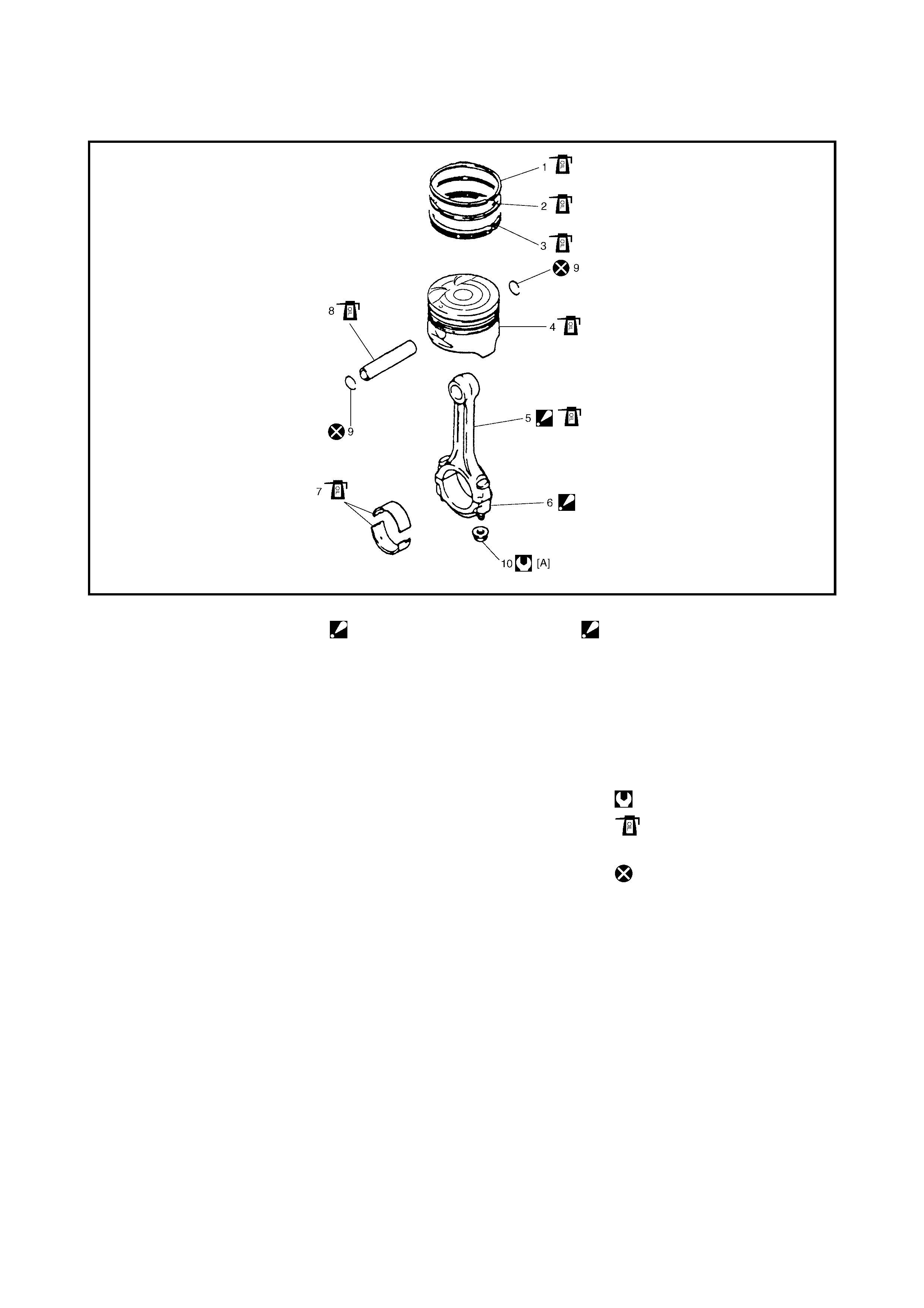
1. Top ri ng 8. Pisto n pin
2. 2nd ring 9. Piston pin circlip
3. Oil ring 10. Bearing cap nut
4. Pis ton Tightening torque
Apply engine oil to sliding
surface of each parts.
Do not reuse.
5. Install guide hose (1) over the threads of the rod bolts.
This prevents damage to the bearing journal and rod
bolt threads when removing the connecting rod.
6. Decarbonise the top of the cylinder bore before
removing the piston from the cylinder.
7. Push the piston and the connecting rod assembly out
through the top of the cylinder bore.
DISASSEMBLY
8. Using a piston ring expander, remove the two com-
pression rings (top and 2nd) and the oil ring from the
piston.
9. Remove the piston pin from the connecting rod.
• Ease out piston pin circlips (1), as shown.
• Force piston pin out.
CLEANING
Decarbonise the piston head and ring grooves, using a
suitable tool.
INSPECTION
Cylinder
• Inspect cylinder walls for scratches, roughness or
ridges which indicate excessive wear. If the cylinder
bore is very rough or deeply scratched or ridged,
rebore the cylinder and use an oversize piston.
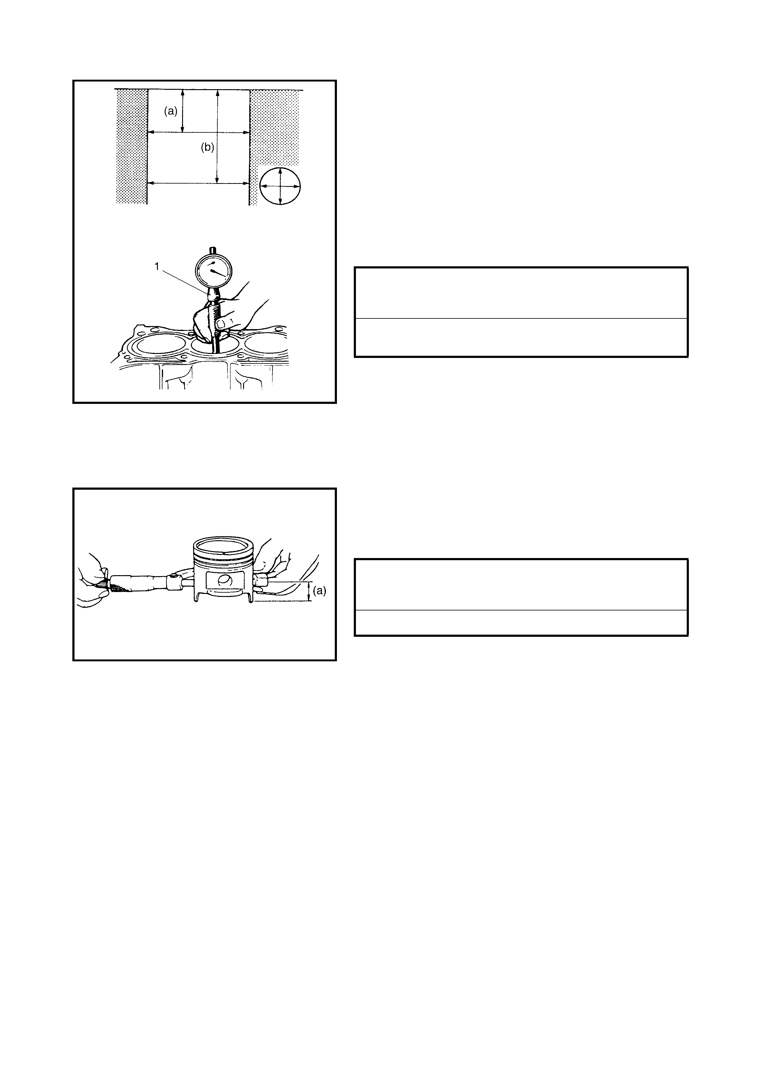
• Using a cylinder gauge (1), measure the cylinder bore
in the thrust and axial directions at two positions, (a) -
50 mm and (b) - 100 mm from the top of the cylinder
wall, as shown in the figure.
If any of the following conditions are noted, rebore the
cylinder.
1. The cylinder bore diameter exceeds the limit.
2. The difference in measurements at the two positions
exceeds the taper limit.
3. The difference between the thrust and axial measure-
ments exceeds the out-of-round limit.
NOTE: If any one of the four cylinders has to be rebored,
rebore all four to the same next oversize. This is necessary
to maintain uniformity and balance
.
Pistons
• Inspect pistons for faults, cracks or other damage.
Damaged or faulty pistons should be replaced.
• Piston diameter:
As indicated in the figure (a), the piston diameter
should be measured 19.5 mm from the piston skirt, in
the opposite direction to the piston pin.
CYLINDER BORE DIAMETER
STANDARD
LIMIT 78.00 - 78.014 mm
78.114 mm
CYLINDER TAPER & OUT-OF-ROUND
LIMIT 0.10 mm
PISTON DIAMETER SPECIFICATION
STANDARD SIZE
SIZE WITH COATING 77.9 53 - 77.968 mm
77.969 - 77.98 4 mm
0.5 mm OVERSIZE 78.453 - 78.468 mm
• Piston clearance:
Measure the piston diameter (1) at position (a), 19.5
mm from the piston skirt and the cylinder bore diameter
(2). Piston clearance is the difference in the two mea-
surements. Piston clearance should be within specifi-
cation as given below. If it is out of specification, rebore
the cylinde r and fit oversi ze pisto ns .
NOTE: Cylinder bore diameters used here are measured in
thrust direction at two positions.
• Ring groove clearance:
Before checking, the piston grooves must be clean, dry
and free from carbon deposits.
Fit the new piston ring (1) into the piston groove, and
measure the clearance between the ring and the ring
land using a thickness gauge (2). If the clearance is
outside the limit, replace the piston.
Piston Pin
• Check the piston pin, connecting rod small end bore
and piston bore for wear or damage, paying particular
attention to the c ond ition of the sm all end bo r e b ush. If
the pin, connecting rod small end bore or piston bore is
badly worn or damaged, replace the pin, connecting
rod and/or piston.
PISTON CLEARANCE
PISTON CLEARANCE WITH COATING 0.032 - 0.061 mm
0.016 -0.045 mm
TOP RING GROOVE CLEARANCE
STANDARD
LIMIT 0.03 - 0.07 mm
0.12 mm
2ND RING GROOVE CLEARANCE
STANDARD
LIMIT 0.02 - 0.06 mm
0.10 mm
OIL RING GROOVE CLEARANCE
STANDARD 0.03 - 0.17 mm
• Piston pin clearance:
Check the piston pin clearance in the small end and
piston. Repl ace the connecti ng rod and/or pist on if the
small end is badly worn or damaged or the measured
clearance exceeds the limit.
Piston Rings
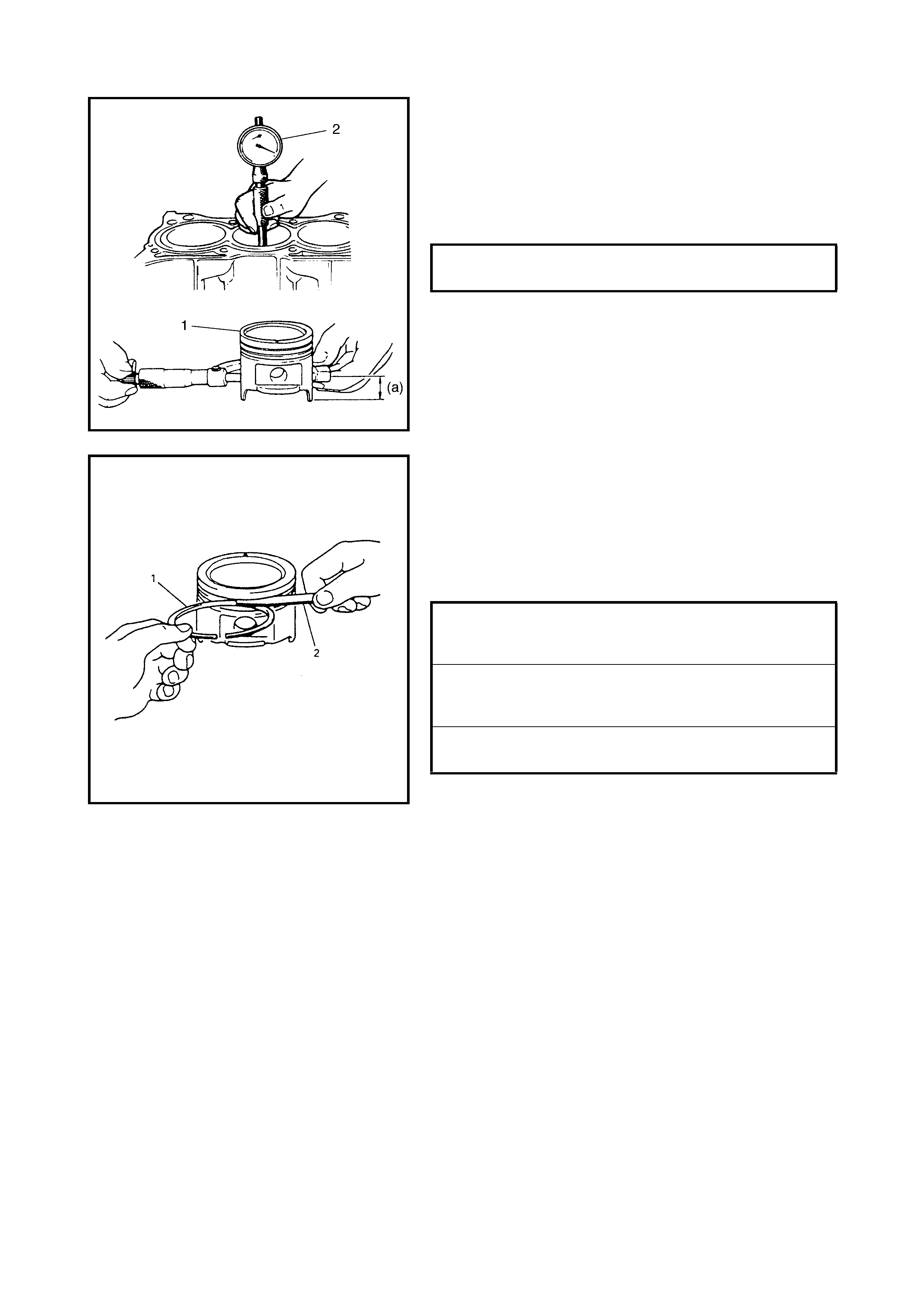
To measure the end gap, insert the piston ring (1) into the
cylinder bore and measure the gap using a thickness
gauge (2).
If the measured gap is out of specification, replace ring.
NOTE: Decarbonise and clean top of cylinder bore before
inserting piston ring.
Connecting Rod
• Big-end side c learance:
Check the big-end of the connecting rod for side
clearance, with the connecting rod fitted and con-
nected to the crank pin in the normal manner. If the
measured clearance is found to exceed the limit,
replace the connecting ro d.
PISTON PIN CLEARANCE IN
CONNECTING ROD SMALL. END 0.003 - 0.014 mm
PISTON PIN CLEARANCE IN
PISTO N 0.006 - 0.017 mm
SMALL END BORE 20.003 - 20.011 mm
PISTON PIN DIAMETER 19.997 - 20.000 mm
PISTON BORE 20.006 - 20.014 mm
TOP PISTON RING END GAP
STANDARD
LIMIT 0.20 - 0.35 mm
0.7 mm
2ND PISTON RING END GAP
STANDARD
LIMIT 0.30 - 0.45 mm
1.0 mm
OIL PISTON RING END GAP
STANDARD
LIMIT 0.20 - 0.70
1.5 mm
BIG-END SIDE CLEARANCE
STANDARD
LIMIT 0.25 - 0.40 mm
0.55 mm
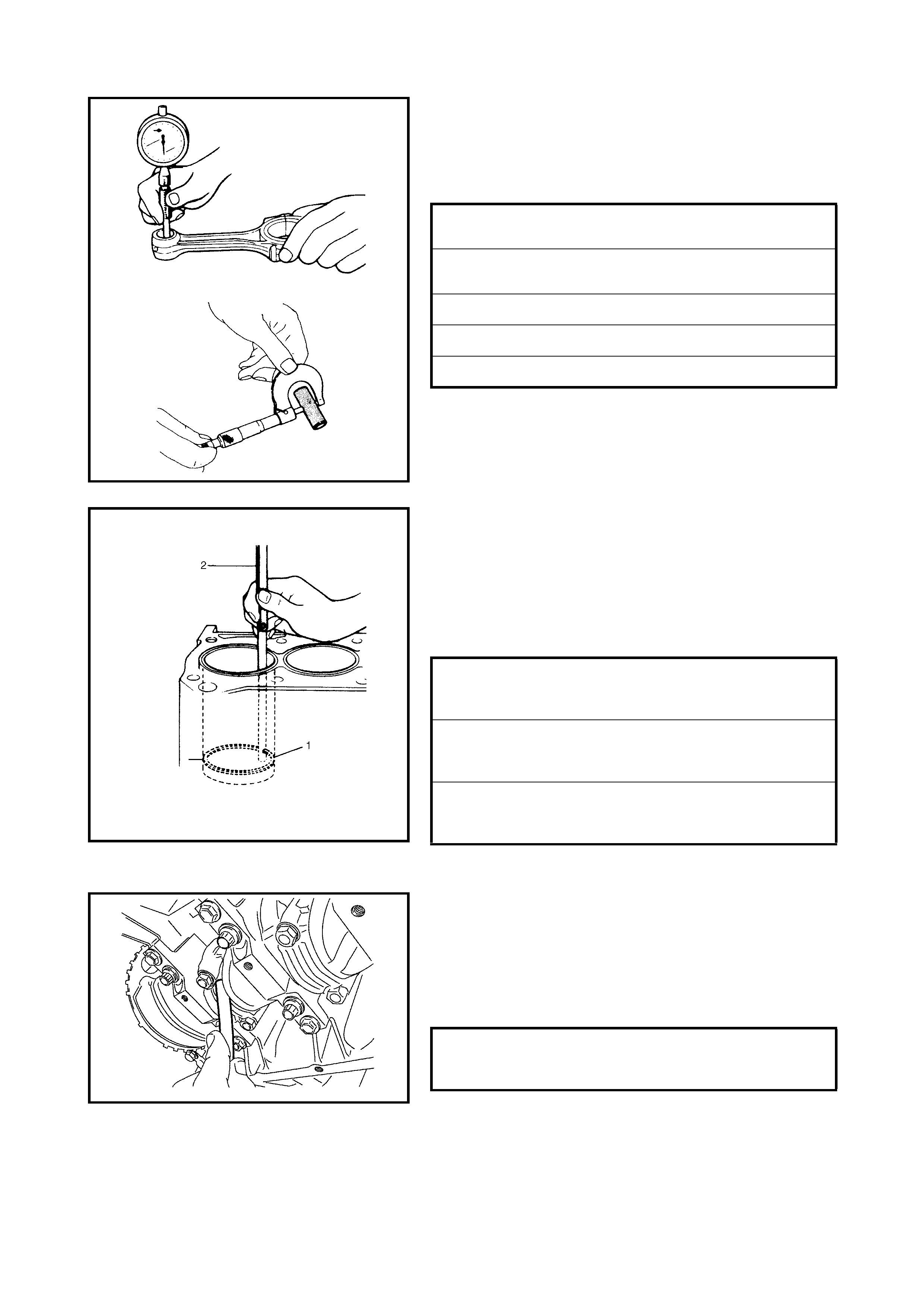
• Connecting rod alignment:
Mount the connecting rod on an aligner to check for
bow and twist. If the limit is exceeded, replace the con-
necting rod.
• Connecting rod (1) bolt deformation (Plastic deforma-
tion tightening bolt).
Measure the connecting rod bolt (2) thread diameter
with a micr om eter ( 3) at poi nts (A) and (B) as sh own in
the figure.
Calculate the difference in diameters (A) - (B). If it
exceeds the limit, replace the connecting rod.
Crank Pin and Connecting Rod Bearings
• Inspect the crank pin for uneven wear or damage.
Measure th e crank pin for out-of-round or taper with a
micrometer. If the crank pin is damaged, out-of round
or taper is outside the limit, replace the crankshaft or
regrind the crank pin to undersize and use an under-
size bearing.
CONNECTING ROD ALIGNMENT
LIMIT ON BOW
LIMIT ON TWIST 0.05 mm
0.10 mm
CONNECTING ROD BOLT
MEASUREMENT POINTS (a)
(b) 32 mm
40 mm
CONNECTING ROD BOLT DIAMETER
DIFFERENCE LIMIT (A) – (B) 0.1 mm
CRANK PIN DIAMETER
STANDARD CONNECTING ROD
BEARING SIZE
UNDERSIZE CONNECTING ROD
BEARING - 0.25 mm
41.982 - 42.00 0 mm
41.732 - 41.75 0 mm
CRANK PIN OUT-OF-ROUND
LIMIT (A – B) 0.01 mm
CRANK PIN TAPER LIMIT (a – b) 0.01 mm
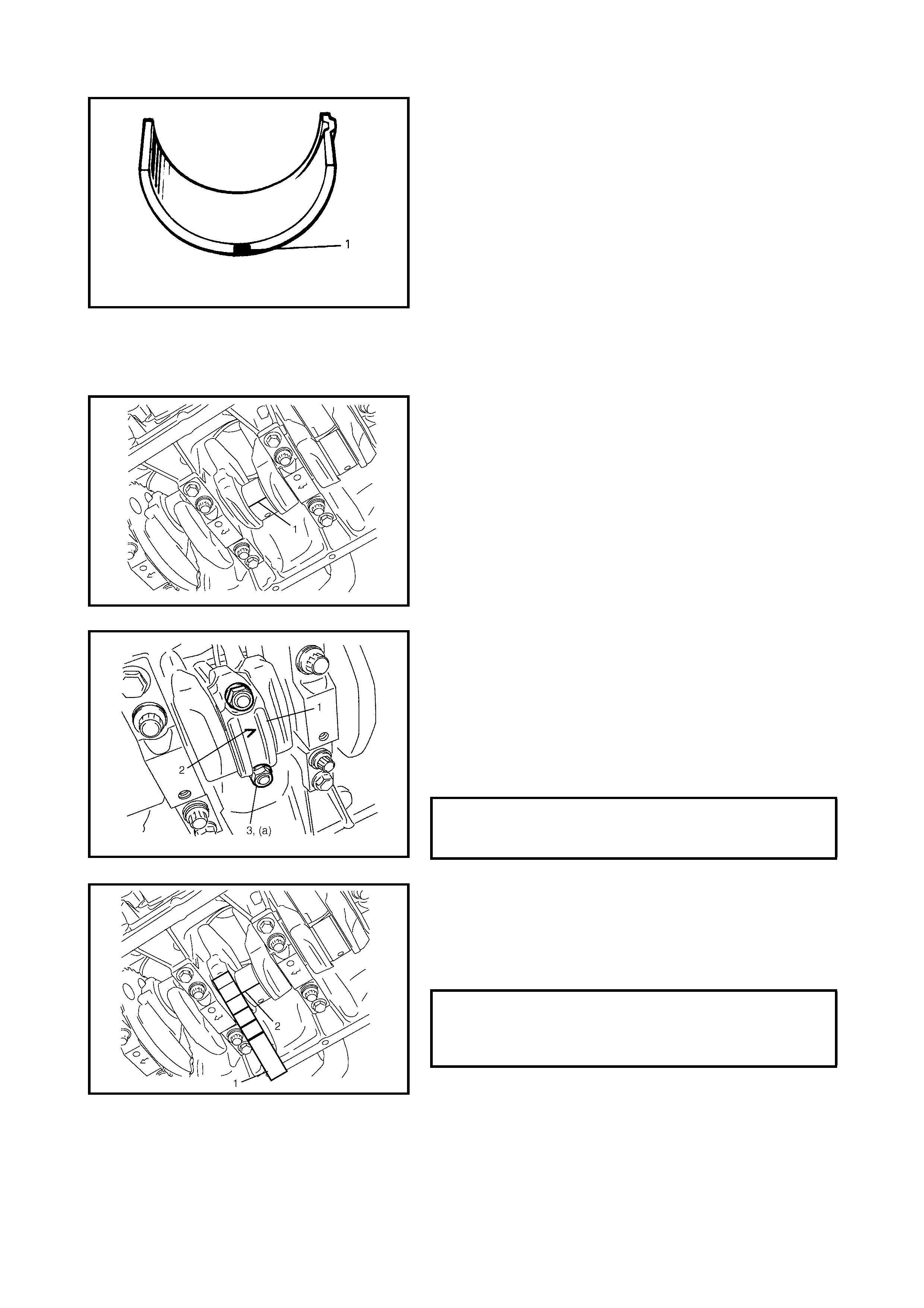
• Rod bearing:
Inspect the bearing shells for signs of fusion, pitting,
burn or flaking and observe contact pattern. Bearing
shells found to be defective must be replaced.
Two kinds of rod bearings are available; standard size
bearings and 0.25 mm undersize bearings. Undersize
bearings can be identified by red paint (1) at the posi-
tion indicated in the figure, undersize bearing thickness
is 1.605 – 1.615 mm at the centre point.
• Rod bearing clearance:
1. Before checking bearing clearance, clean bearing and
crank pin.
2. Install bearing in connecting rod and bearing cap.
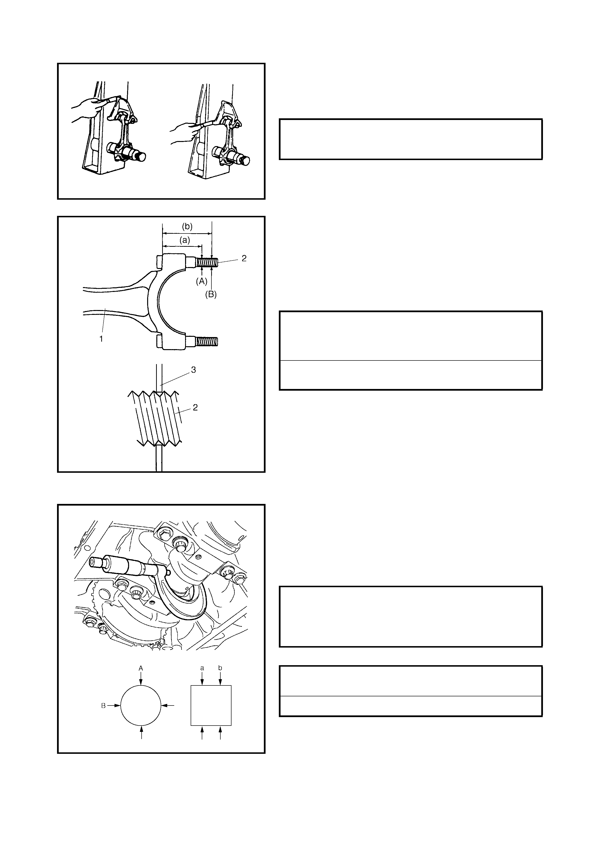
3. Place a piec e of gau gi ng pl astic (1) the ful l width of the
crank pin where contacted by the bearing (parallel to
the crankshaft), avoiding the oil hole.
4. Install the rod bearing cap (1) to the connecting rod.
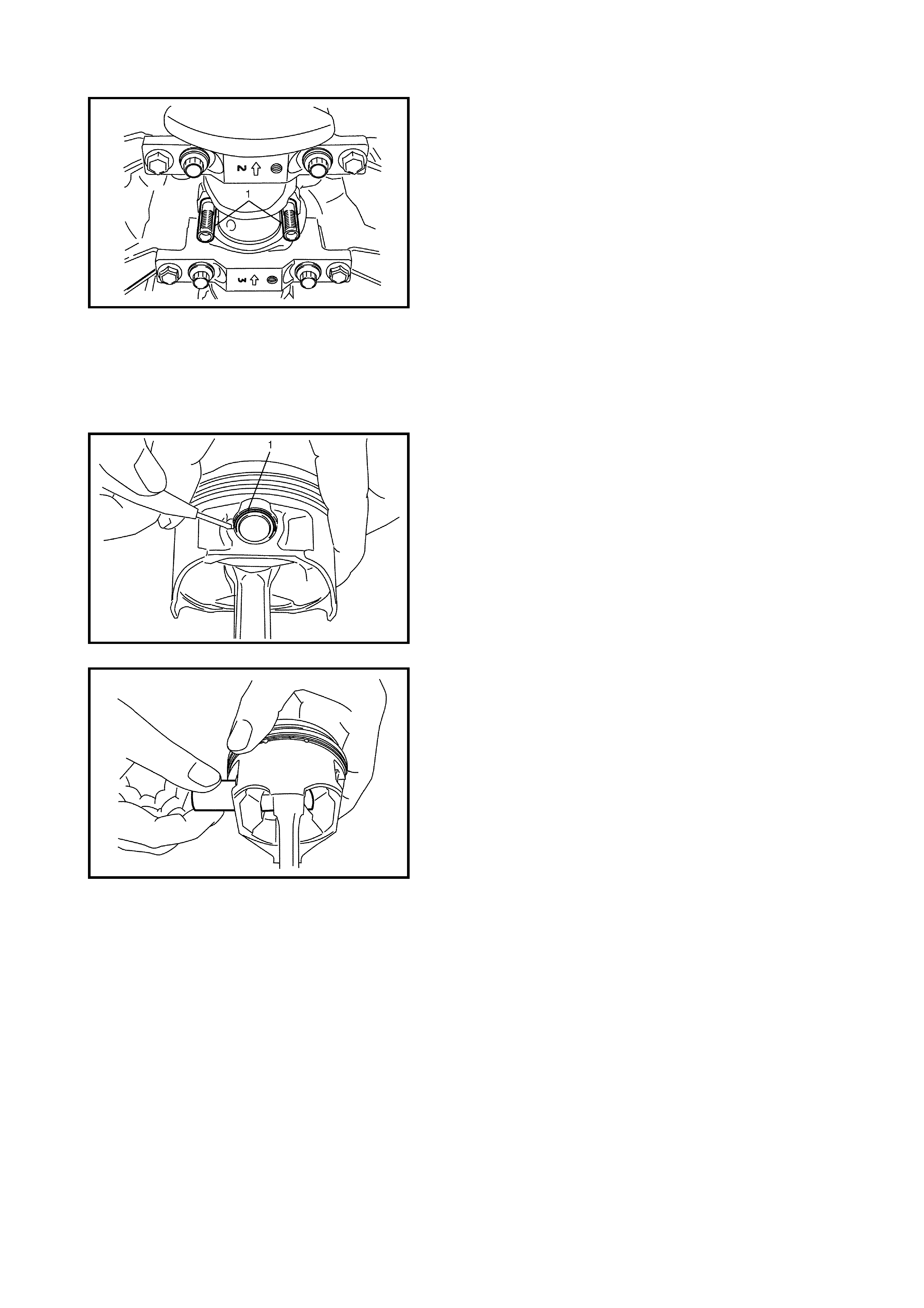
When installing cap, be sure to point arrow mark (2) on
cap towards the crankshaft pulley side, as shown in
the figure. After applying engine oil to the connecting
rod bolts, tighten cap nuts (3) gradually as follows.
a. Tighten all cap nuts to 15 Nm
b. Retighten them 45°.
c. Repeat Step b.
4. Remove the cap and using the scale (1) on the
gauging plastic (2) envelope, measure the gauging
plastic width at the widest point (clearance).
If the clear ance exce eds the limit, use a n ew standard
size bearing and remeasure clearance.
5. If the clearance cannot be brought within the limit, even
using a new standard size bearing, regrind the
crankpin to undersize and use a 0.25 mm undersize
bearing.
NOTE: After checking the rod bearing clearance, be sure to
check for Connecting rod bolt deformation.
Refer to 4.6 PISTONS, PISTON RINGS, CONNECTING
RODS AND CYLINDERS, INSPECTION in this Section.
CONNECTING ROD BEARING CAP
NUTS (a)
TORQUE SPECIFICATION 15 Nm THEN
TURN 45° TWICE
CONNECTING ROD BEARING
CLEARANCE STANDARD
LIMIT 0.029 - 0.047 mm
0.065 mm
ASSEMBLY
1. Install the pi ston pin to the piston (1) and the connect-
ing rod (2):
a. App ly en gin e oi l to th e pis ton p in and the pis to n pi n
holes in the piston and connecting rod.
b. Fit the connecting rod as shown in figure.
c. Insert the piston pin to the piston and connecting
rod.
d. Install the piston pin circlips (3).
NOTE: The c ircli p sh ould b e inst a lle d wit h it s cut pa rt fa cing
as shown in the figure. Install it so that the circlip end gap
comes within the range indicated by the arrow.
5. Install the piston rings to the piston:
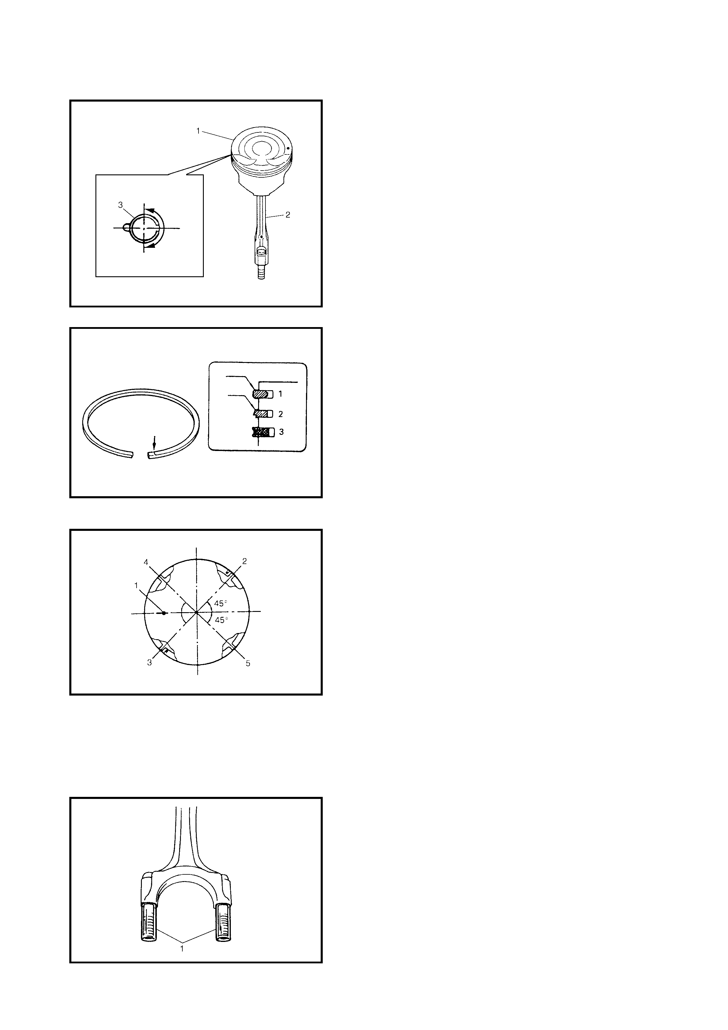
a. As indicated in the figure, the 1st and 2nd rings
both have a “T” mar k. When ins talling these piston
rings onto the piston, ensure the marked side of
each ring faces the top of the piston.
b. The 1st ring (1) differs from the 2nd ring (2) in thick-
ness, shape and the colour of the surface contact-
in g the cylinder wall.
Refer to the figure to distinguish the 1st ring from
the 2nd ring.
c. When installing the oil ring (3), install the spacer
first then the two rails.
4. After installing the three rings (1st, 2nd and oil rings),
distribute their end gaps as shown in the figure.
1 – Front mark
2 – 1st ring end gap
3 – 2nd ring end gap and oil ring spacer gap
4 – Oil ring upper rail gap
5 – Oil ring lower rail gap
INSTALLATION
1. Apply engine oil to pistons, rings, cylinder walls, con-
necting rod bearings and crankpins.
NOTE: Do not apply oil between the connecting rod and
the bearing or between the cap and the bearing.
2. Install guide hoses (1) over the connecting rod bolts.
These guide hoses protect the crank pin and threads of
the conne cting r od bolt from damage d uring th e instal-
lation of the connecting rod and piston assembly.
3. When installing the piston and the connecting rod
assembly into the cylinder bore, point the front mark on
the piston head towards the crankshaft pulley side (A).
4. Install the pi ston a nd con necting r od ass embly into th e
cylinder bore. Use special tool (Piston ring compres-
sor) 09916-77310 (A) to compress rings. Guide the
connecting rod into place on the crankshaft.
Using a hammer handle, tap the piston head to install
the piston into the bore. Hold the ring compressor
firmly against the cylinder block until all piston rings
have entered the cylinder bore.
5. Install bearing cap (1):
Point arrow mark (2) on the cap to the crankshaft
pulley side.
After applying oil to rod bolts and tighten cap nuts (3)
graduall y as follo ws.
a. Tighten all cap nuts to 15 Nm.
b. Retighten them to 45°.
c. Repeat Step b.
NOTE: Before installing the bearing cap, be sure to check
for connecting rod bolt deformation. Refer to 4.7 PISTONS,
PISTON RINGS, CONNECTING RODS AND
CYLINDERS, INSPECTION in this Section.
4. Reverse removal procedure for installation.
5. Refer to 4.2 TIMING CHAIN COVER, INSTALLATION
in this Section and perform Steps 3 to 7.
CONNECTING ROD BEARING CAP
NUTS (a)
TORQUE SPECIFICATION 15 Nm THEN
TURN 45° TWICE
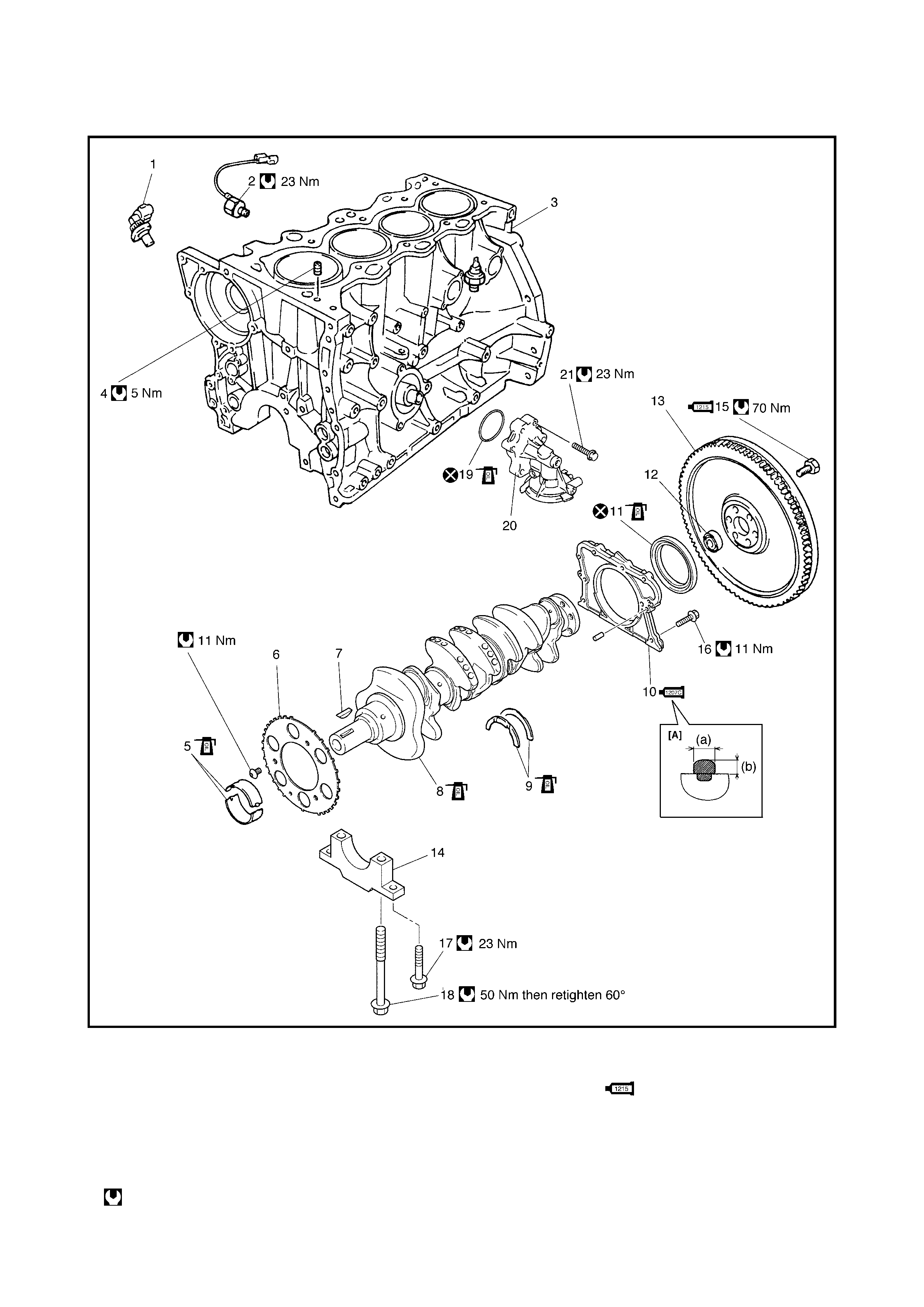
4.8
MAIN BEARINGS, CRANKSHAFT AND CYLINDER BLOCK
Legend
[A] : Sealant application 3. Cylinder block 14. Main bearing cap
amount 4. Venturi plug 15. Flywheel mounting
bolt
B]: 1) Tighten all bolts to 50 5. Main bearing
50 Nm 6. Sensor plate 16. Rear oil seal housing
2. Then, turn all bolts to 7. Crankshaft timing sprocket mounting bolt
60° key 17. Main bearing
Tightening torqu e 8. Cra nksha ft mounting No.2 bol t
REMOVAL
1. Remove the engine assembly from the vehicle, refer to
4.1 ENGINE ASSEMBLY REMOVAL in this Section.
2. Remove the clutch flywheel (drive plate for A/T) using
special tool 09924-17811 (A).
3. Remove the following parts from the engine as previ-
ously outlined.
• Oil pan and oil pump strainer, refer to 3.7 OIL PAN
AND OIL PUMP STRAINER, REMOVAL in this
Section.
• Intake manifold, refer to 3.5 THROTTLE BODY AND
INTAKE MANIFOLD, REMOVAL in this Section.
• Exhaust manifold, refer to 3.6 EXHAUST MANIFOLD,
REMOVAL in this Section.
• Cylinder head cover, refer to 3.4 CYLINDER HEAD
COVER, REMOVAL in this Section.
• Timing chain cover, refer to 4.2 TIMING CHAIN
COVER, REMOVAL in this Section.
• T iming chain guide, chain tensioner adjuster, chain ten-
sioner, timing chain and crankshaft timing sprocket,
refer to 4 .4 TIM ING CHAIN A ND CHAIN TEN SIONER,
REMOVAL in this Section.
• Camshaft, tappet and shim, refer to 4.5 CAMSHAFT,
TAPPET AND SHIM, REMOVAL in this Section.
• Cylinder head assembly, refer to 4.6 VALVES AND
CYLINDER HEAD, REMOVAL in this Section.
• Pistons and connecting rods, refer to 4.7 PISTONS,
PISTON RINGS, CONNECTING RODS AND
CYLINDERS, REMOVAL in this Section.
Do not reuse. 9. Thru st beari ng 18. Mai n bear ing
mounting No.1 bol t
Apply engine oil to inside / 10. Rear oil seal housing:
Apply sealant Three Bond
No. 1207C to mating surface.
sliding surface 19. O-ring
(a): 3 mm (0.12 in.) 20. Oil filter adapter case
(b): 2 mm (0.08 in.) 11. Rear oil seal 21. Oil filter adapter bolt
1. CKP sensor 12. Input shaft bearing
2. Knock sensor 13. Flywheel (Drive plate A/T)
4. Remove the rear oil seal housing (1).
5. Loosen the bearing cap No.1 and No.2 bolts in the
order indicated in the figure then remove them.
6. Remove the crankshaft from the cylinder block.
INSPECTION
Bearing Cap No.1 Bolt (Plastic Deformation Ti ghtening
Bolt)
Check all th e bea ring cap N o.1 bolts (1) for deform ation as
follows . Using a micromete r (2), me asure the t hread diam-
eter of the bearing cap bolts at points (A) and (B) as shown
in the figure. Calculate the difference in diameters (A) – (B).
If it exceeds the limit, replace the bolt.
Crankshaft Runout
Using a dial gauge, measure the crankshaft runout at
the centre journal. Rotate the crankshaft slowly. If the
runout exceeds the limit, replace the crankshaft.
BEARING CAP No.1 BOLT DIAMETER
MEASUREMENT POINTS (a)
(b) 60 mm
90 mm
BEARING CAP No.1 BOLT DIAMETER
DIFFERENCE (DEFORMATION) LIMIT
(A) – (B) 0.2 mm
CRANKSHAFT RUNOUT LIMIT 0.04 mm
Crankshaft thrust play
Measure the crankshaft thrust play with the crankshaft set
in the cylinder block in the normal manner, with the thrust
bearing (1) and journal bearing caps installed.
Tighten the bearing cap No.1 bolts (1) – (10) and No.2 bolts
(11) – (20) gradually as follows.
1. Tighten bolts (1) – (10) to 30 Nm according to the
numerical order in the figure.
2. As in Step 1, tighten them to 50 Nm.
3. As in Step 1, retighten them by turning a further 60°.
4. Tighten bolts (11) – (20) to 23 Nm according to the
numerical order in the figure.
Use a dial gauge to read the displacement in the axial
(thrust) direction of the crankshaft.
If the limit is exceeded, replace the thrust bearing with a
new standard one or oversize one to obtain standard thrust
play.
NOTE: After checking the thrust play, ensure that the
thread deformation of each bearing cap No.1 bolt is as
specified, refer to 4.8, MAIN BEARINGS, CRANKSHAFT
AND CYLINDER BLOCK, INSPECTION in this Section.
Out-of-round and taper (uneven wear) of journals
An uneve nly worn crankshaft journal shows up as a differ-
ence in diameter at cross sections or along its length (or
both). This difference, if any, is determined by taking
micrometer readings. If any one of journals is badly dam-
aged or if the wear exceeds the limit, regrind or replace the
crankshaft.
THICKNESS OF CRANKSHAFT
THRUST BEARING STANDARD
OVERSIZE 2.500 mm
2.563 mm
CRANKSHAFT BEARING CAP No.1
BOLTS (1) - (10)
TORQUE SPECIFICATION
30 Nm INITIALLY
THEN 50 Nm
THEN TURN 60°
CRANKSHAFT BEARING CAP No.2
BOLTS (11) - (20)
TORQUE SPECIFICATION 23 Nm
CRANKSHAFT THRUST PLAY
STANDARD
LIMIT 0.11 - 0.31 mm
0.35 mm
CRANKSHAFT OUT OF ROUND LIMIT
A – B 0.01 mm
CRANKSHAFT TAPER LIMIT a – b 0.01 mm
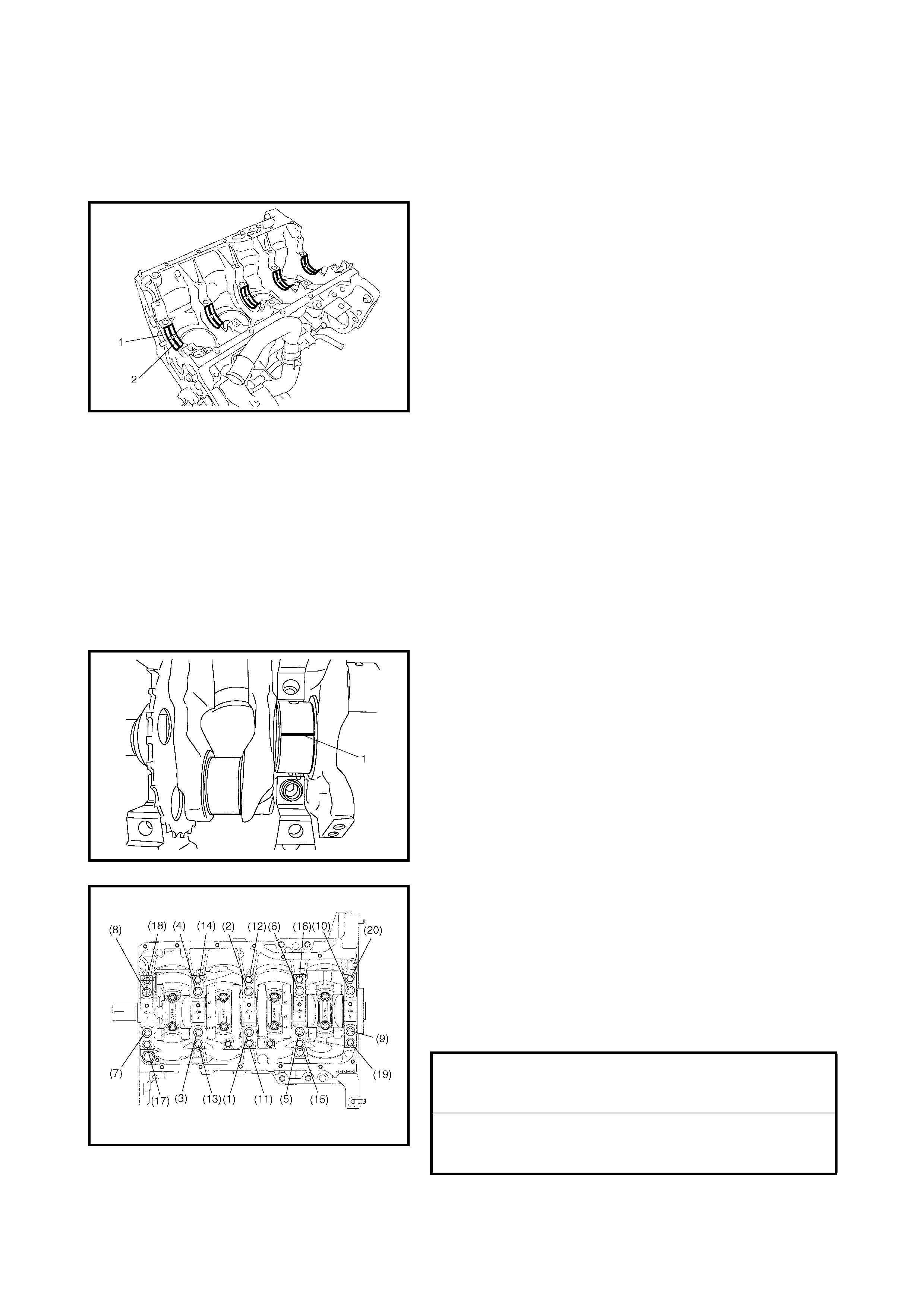
MAIN BEARINGS
General information
• Service main bearings are available in standard size
and 0.25 mm undersiz e, and each of th em has 5 ki nds
of bearings differing in tolerance.
• The upper ha lf of the bea ring (1 ) has an o il groove (2)
as shown in the figure .
Install the half with the oil groove onto the cylinder
block.
• The lower half of the bearing does not have an oil
groove.
Visual inspection
Check be ari ng s for pi tti ng , sc ra tch es , w ear or da m ag e .
If any damage is found, replace both upper and lower
halves. Never replace either half without replacing the
other half.
Main Bearing Clearance
Check cle arance by using g auging pl astic accor ding to th e
following procedure.
1. Remove bearing caps.
2. Clean bearings and main journals.
3. Place a piec e of gau gi ng pl astic (1) the ful l width of the
bearing (para llel to cranks haft) on th e jour nal, avoi ding
the oil hole.
4. Tighten the bearin g cap No.1 bolts (1) – (10) and No .2
bolts (11) – (20) gradually as follows.
a. Tighten bolts (1) – (10) to 30 Nm according to
numerical order in the figure.
b. As in Step a, tighten them to 50 Nm.
c. As in Step a, retighten them 60°.
d. Tighten bolts (11) – (20) to 23 Nm according to
numerical order in the figure.
NOTE: Do not rotate the crankshaft while the gauging plas-
tic is installed.
CRANKSHAFT BEARING No.1 BOLTS
(1) - (10)
TORQUE SPECIFICATION
30 Nm INITIALLY
THEN 50 Nm
THEN TURN 60°
CRANKSHAFT BEARING No.2 BOLTS
(11) - (20)
TORQUE SPECIFICATION 23 Nm
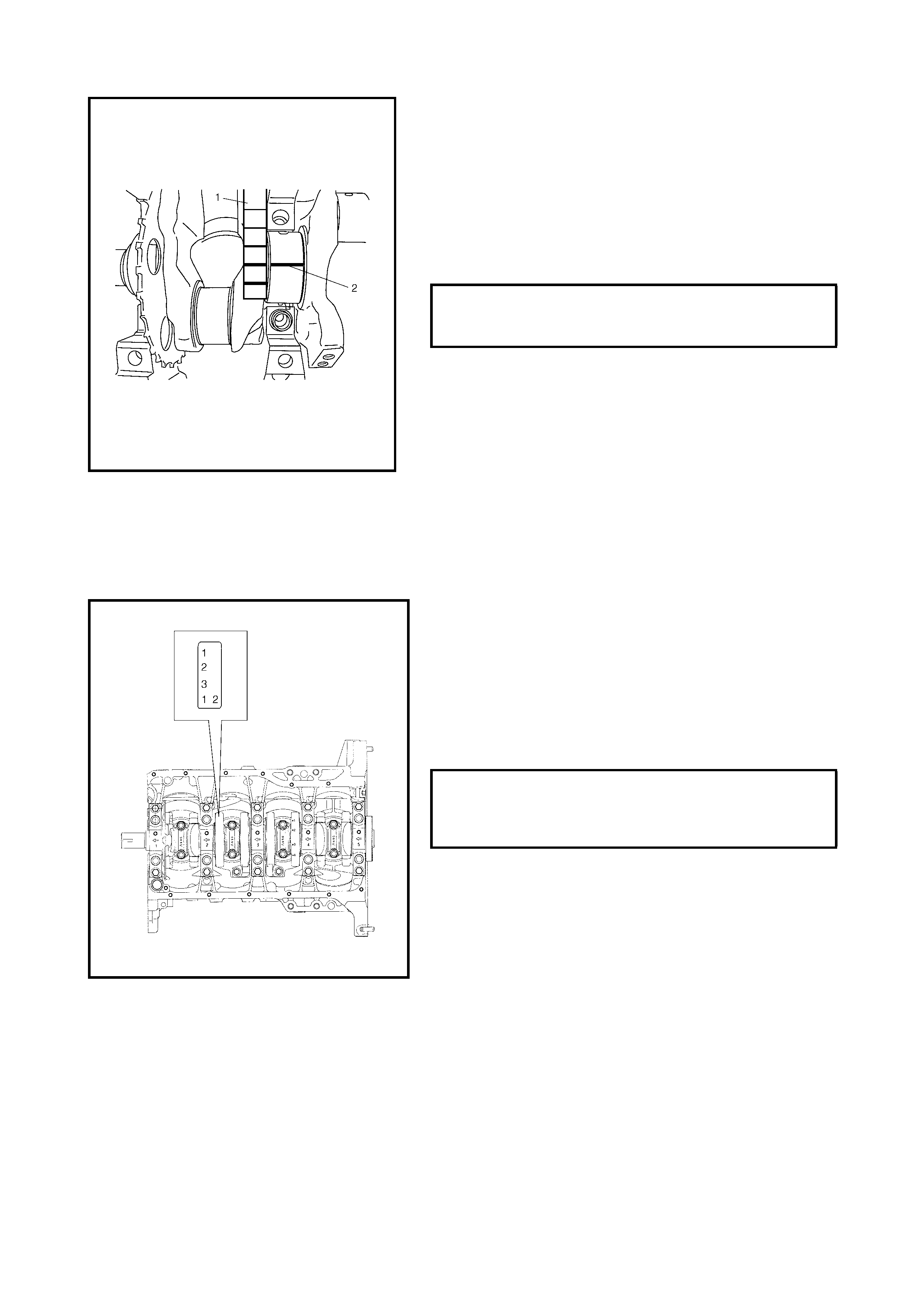
5. Remove the bearing caps and using the scale (1) on
the gauging plastic (2) envelope, measure the gauging
plastic width at its widest point. If the clearance
exceeds its limit, replace the bearing. Always replace
both upper and lower inserts as a unit.
A new standard bearing may produce proper clear-
ance. If not, it will be necessary to regrind the crank-
shaft journal for use of 0.25 mm undersize bearings.
After selecting a new bearing, recheck clearance.
NOTE: After checking the bearing clearance, ensure that
the thread deformation of each bearing cap No.1 bolt is as
specified, refer to 4.8, MAIN BEARINGS, CRANKSHAFT
AND CYLINDER BLOCK, INSPECTION in this Section.
SELECTION OF MAIN BEARINGS
Standard Bearing
If the bearing is damaged, or the bearing clearance is out
of specification, select a new standard bearing according to
the following procedure.
1. First check the journal diameter. The crankshaft web
No.2 has numbers (1, 2 and 3) stamped on it as shown
in the figure. These numbers, listed in journal order
(from the crankshaft pulley end) represent the journal
diameter as listed in the table below.
For example, number “1” stamped on the web at
position one wo ul d ind icate that th e jo ur nal di ame ter at
journal 1 is 51.994 - 52.000 mm.
MAIN BEARING CLEARANCE
STANDARD
LIMIT 0.021 - 0.041 mm
0.054 mm
CRANKSHAFT JOURNAL DIAMETER
STAMPED NUMBER 1
STAMPED NUMBER 2
STAMPED NUMBER 3
51.994 - 52.000 mm
51.988 - 51.994 mm
51.982 - 51.988 mm
2. Next, check the bearing cap bore diameter without its
bearing. On the mating surface of the cylinder block,
five letters or numbers (“A” or “1”, “B” or “2”, “C” or “3”)
are stamped as shown in the figure.
These letters or numbers, listed in journal order (from
the crankshaft pulley end) represent the cap bore
diameters. For example “B” or “2” stamped on the
cylinde r block at posi tion 3 would ind icate that the ca p
bore diameter at journal three is 56.006 - 56.012 mm.
3. Standard bearings come in five different thicknesses.
To distinguish them, they are painted in the following
colours at position (1) as shown in the figure.
Each colour indicates the following thickness at the
centre of the bearing.
4. From the number stampe d on the crank s haft web No.2
and the letter or number stamped on the cylinder block,
determine the new standard bearing to be installed to
the journal by referrin g to the table below.
For e xam ple, if t he n umb er st am ped on cr anks haf t web
No.2 is “1” and the letter or number stamped on
cylinder block is “B” or “2”, install a new standard
bearing painted BROWN to its journal.
New standard crankshaft main bearing selection table
CRANKSHAFT BEARING CAP BORE
DIAMETER (WITHOUT BEARING)
STAMPED LETTER “A”
OR NUMBER “1”
STAMPED LETTER “B”
OR NUMBER “2”
STAMPED LETTER “C”
OR NUMBER “3”
56.000 - 56.00 6 mm
56.006 - 56.01 2 mm
56.012 - 56.01 8 mm
STANDARD SIZE OF CRANKSHAFT
MAIN BEARING THICKNESS PURPLE
BROWN
GREEN
BLACK
COLOURLESS (NO PAINT)
1.992 - 1.996 mm
1.995 - 1.999 mm
1.998 - 2.002 mm
2.001 - 2.005 mm
2.004 - 2.008 mm
NUMBER STAMPED ON CRANK
WEB NO.2 (JOURNAL DIAMETER)
12 3
LETTER OR
NUMBER
STAMPED ON
CYLINDER
BLOCK (CAP
BORE DIA.)
A OR 1 PURPLE BROWN GREEN
B OR 2 BROWN GREEN BLACK
C OR 3 GREEN BLACK COLOUR-
LESS
(NO PAINT
NEW STANDARD BEARING TO BE
INSTALLED.

5. Using the scale (1) on the gauging plastic (2), check
the bearing clearance with the newly selected standard
bearing.
If the clearance still exceeds the limit, use the next
thicker bearing and recheck clearance.
6. When repl acing the cranks haft or the cy linder bl ock for
any reason, select new standard bearings to be
installed by referring to the number stamped on the
new crankshaft or the letters or numbers stamped on
the new cylinder blo ck.
Undersize Bearing (0.25 mm)
• 0.25 mm undersize bearings are available in five differ-
ent thicknesses.
To disti nguish them, e ach bearing is painted in the f ol-
lowing colours at position (1) as indicated in the figure.
Each colour represents the following thickness at the
centre of bearing.
• If necessary, regrind the crankshaft journal and select
the undersize bearing to use with it as follows.
• Regrind journal to the following finished diameter.
1. Using a micrometer, measure the reground journal
diameter.
The measurement should be taken in two directions,
opposite each other, to check for out-of-round.
2. Using the journal diameter measured above and the
letters or numbers stamped on the cylinder block,
select an undersize bearing by referring to the table
given.
Check the bearing clearance with the newly selected
undersize bearing.
New standard undersize crankshaft main bearing selection table.
UNDERSIZE CRANKSHAFT MAIN
BEARING THICKNESS
COLOUR PAINTED - RED & PURPLE
COLOUR PAINTED - RED & BROWN
COLOUR PAINTED - RED & GREEN
COLOUR PAINTED - RED & BLACK
COLOUR PAINTED - RED ONLY
2.117 - 2.121 mm
2.120 - 2.124 mm
2.123 - 2.127 mm
2.126 - 2.130 mm
2.129 - 2.133 mm
FINISHED DIAMETER 51.732 - 51.750 mm
MEASURED JOURNAL DIAMETER
51.732 - 51.738 mm 51.738 - 51.744 mm 51.744 - 51.750 mm
ALPHABETS OR
NUMBERS STAMPED
ON CYLINDER
BLOCK
A or 1 RED AND GREEN RED AND BROWN RED AND PURPLE
B or 2 RED AND BLACK RED AND GREEN RED AND BROWN
C or 3 RED ONLY RED AND BLACK RED AND GREEN
UNDERSIZE BEARING TO BE INSTALLED
Rear Oil Seal
Carefully inspect the oil seal (1) for wear or damage.
If its lip is worn or damaged, replace it.
Press-fit the rear oil seal (1) to the oil seal housing (2) using
special tool 09911-97820 (A) as shown in the figure.
Flywheel
• If the ring gear is damaged, cracked or worn, replace
the flywheel.
• If the sur fa ce c ontacting the c lu tch di sc is d ama ged, or
excessiv el y worn, replac e the flyw he el.
• Check the flywheel for face runout with a dial gauge.
If runout exceeds the limit, replace the flywheel.
Sensor plate
• Check the sensor plate for cracks or damage. If it is
damaged, replace it.
DRIVE IN DIMENSION (a) 3.0 mm
FLYWHEEL ON RUNOUT LIMIT 0.2 mm
CYLINDER BLOCK
Distortion of gasketed surface
• Using straightedge and thickness gauge, check gas-
keted surface for distortion and if flatness exceeds the
limit, correct it.
Honing or Reboring Cylinders
1. If a cylinder needs reboring, all the other cylinders
must be rebored at the same time.
2. Select an oversized piston according to the amount of
cylinder wear.
3. Using a micrometer, measure the piston diameter.
4. Calculate the cylinder bore diameter to be rebored as
follows.
D = A + B – C
D: Cylinder bore diameter to be rebored.
A: Piston diameter as measured.
B: Piston clearance = 0.032 – 0.061 mm
C: Allowance for honing = 0.02 mm
5. Rebore and hone cylinder to the calculated dimension.
NOTE: Before reboring, install all main bearing caps in
place and tighten to specification to avoid distortion of
bearing bores.
6. Measure piston clearance after honing
INSTALLATION
NOTE:
• If possible use new bearing cap No.1 bolts. If bolts are
to be reused check for deformation, refer to 4.8, MAIN
BEARINGS, CRANKSHAFT AND CYL INDER BLOCK,
INSPECTION in this Section.
• All parts to be installed must be perfectly clean.
• Be sure to oil crankshaft journals, journal bearings,
thrust bearings, crankpins, connecting rod bearings,
pistons, piston rings and cylinder bores.
• Journal bearings, bearings caps, connecting rods, rod
bearings, rod bearing caps, pistons and piston rings
are combi nation sets. Do not di stur b combi nation s and
ensure that each part goes back where it originally
came from, when installing.
CYLINDER BLOCK FLATNESS LIMIT 0.05 mm
OVERSIZE PISTON DIAMETER 0.50 78.453 - 78.468 mm
MEASUREMENT POSITION FOR
PISTON DIAMETER (a) 19.5 m.m.
1. Install the sensor plate (1) to the crankshaft (2) and
tighten bolts to specified torque.
NOTE: When installing the sensor plate, align spring pin (3)
on the crankshaft and hole of sensor plate.
2. Install the main bearings to the cylinder block.
The upper half of the bearing (1), has an oil groove (2).
Install it to cylinder block (3), and the other half (without
an oil groove) to the bearing cap.
Make sure that the two halves have the same colour
painted on them.
3. Install the thrust bearings (1) to the cylinder block
between the No. 2 and No.3 cylinders. Face oil groove
(2) sides towards the crank webs.
4. Confirm that the dowel pins (3) are installed to the
intake side of each journal.
5. Install the crankshaft to the cylinder block.
6. Install the bearing cap to the cylinder block, making
sure to point the arrow mark (on each cap) towards the
crankshaft pulley side. Fit them sequentially in
ascending order, 1, 2, 3, 4 and 5, starting from the
crankshaft pulley side.
After applying engine oil to the new bearing cap No.1
bolts ((1) – (10)) and bearing cap No.2 bolts ((11) –
(20)), tighten them gradually as follows.
a. Tighten bolts (1) – (10) to 30 Nm according to the
numeric al o rd er as sho wn us in g a 12 cor n er soc ke t
wrench.
b. As in Step a, tighten them to 50 Nm.
c. As in Step a, retighten them to 60°.
d. Tighten bolts (11) – (20) to 23 Nm acco rding to the
numerical order as shown.
SENSOR PLATE BOLTS (a)
TORQUE SPECIFICATION 11 Nm
CRANKSHAFT BEARING CAP No.1
BOLTS (1) - (10)
TORQUE SPECIFICATION
30 Nm INITIALLY
THEN 50 Nm
THEN TURN 60°
CRANKSHAFT BEARING CAP No.2
BOLTS (11) - (20) 23 Nm
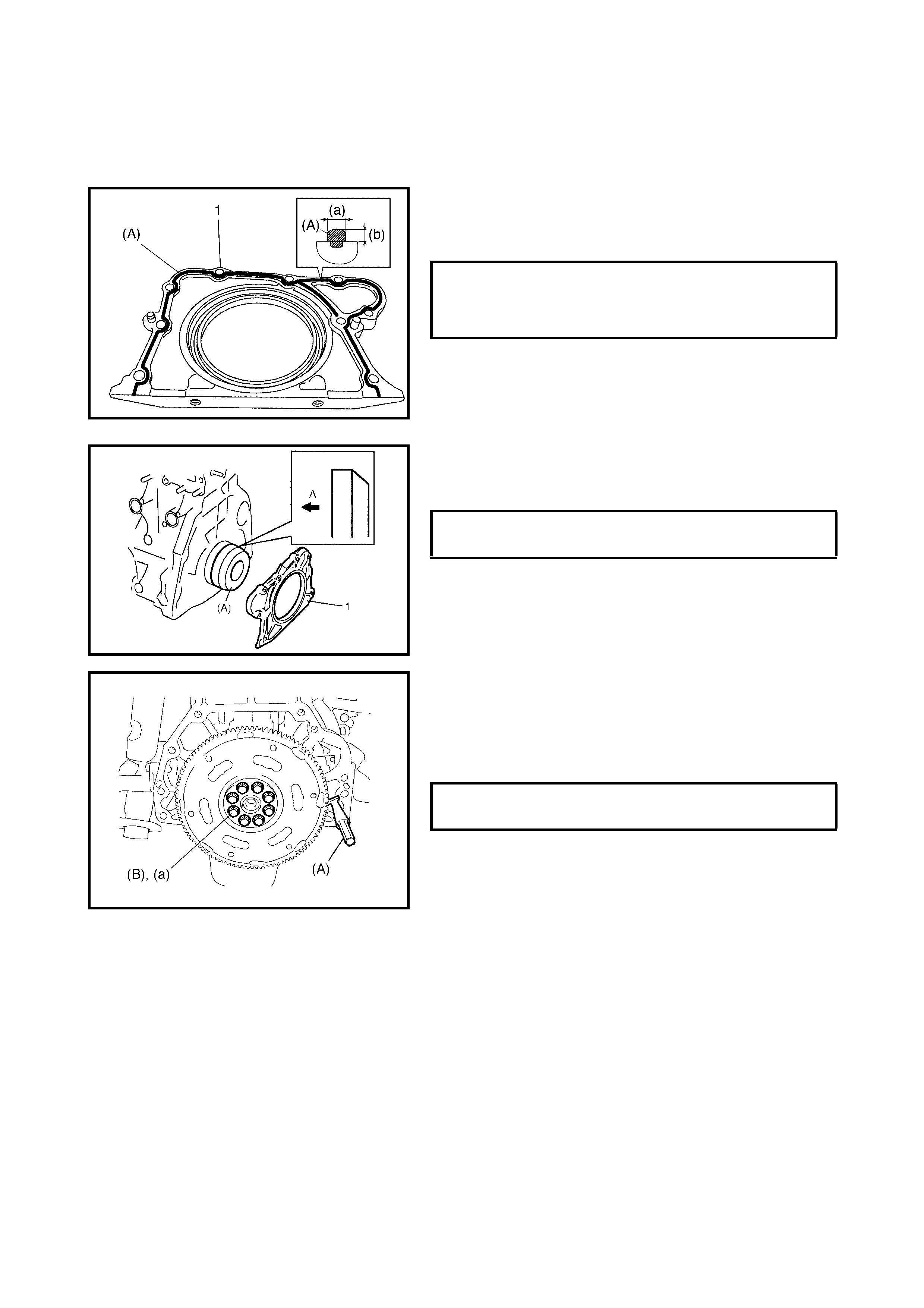
NOTE:
• After tightenin g the cap bolts, check to ensure tha t the
crankshaft rotates smoothly when turning it with 12 Nm
torque or below.
5) Apply sealant to the mating surface of the rear oil
seal housing (1).
(A): Sealant - Three Bond No. 1207C
6. Install the rear oil seal housing (1) and tighten the bolts
to the s peci fied torqu e using spe cial tool ( note orie nta-
tion A - crankshaft side) 09911-97720 (A).
7. Install flywheel (drive plate for A/T).
Using special tool 09924-17811 (A), lock flywheel or
drive plate, and tighten flywheel or drive plate bolts,
applied with sealant, to specification.
(B): Sealant - Three Bond No. 1215
8. Install the following parts to the engine as previously
outlined.
• Pistons and connecting rods, refer to 4.7 PISTONS,
PISTON RINGS, CONNECTING RODS AND
CYLINDERS in this Section.
• Cylinder head assembly, refer to 4.6 VALVES AND
CYLINDER HEAD in this Section.
• Camshafts, tappets and shims, refer to
4.5 CAMSHAFT, TAPPET AND SHIM in this Section.
• T iming chain guide, chain tensioner adjuster, chain ten-
sioner, timing chain and crankshaft timing sprocket,
refer to 4.4 TIMING CHAIN AND CHAIN TENSIONER
in this Sectio n.
• Timing chain cover, refer to 4.2 TIMING CHAIN
COVER in this Section.
• Cylinder head cover, refer to 3.4 CYLINDER HEAD
COVER in this Section.
SEALANT AMOUNT FOR REAR OIL
SEAL HOUSING WIDTH (a)
HEIGHT (b) 3 mm
2 mm
REAR OIL SEAL HOUSING BOLTS
TORQUE SPECIFICATION 11 Nm
FLYWHEEL OR DRIVE PLATE BOLTS (a)
TORQUE SPECIFICATION 70 Nm
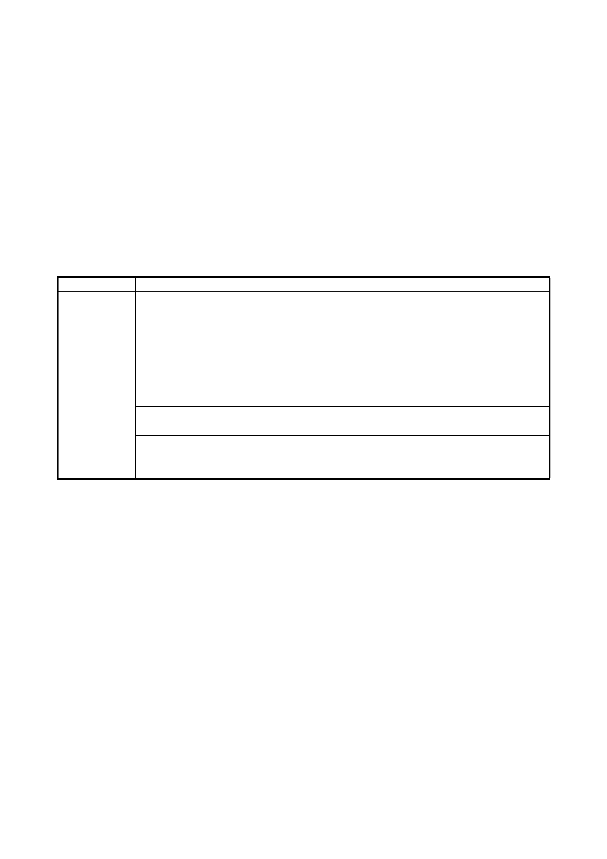
• Intake manifold, refer to 3.5 THROTTLE BODY AND
INTAKE MANIFOLD in this Section.
• Exhaust manifold, refer to 3.6 EXHAUST MANIFOLD
in this Sectio n.
• Oil pan and oil pump strainer, refer to 3.7 OIL PAN
AND OIL PUMP STRAINER in this Section.
9. Install clutch to flywheel (vehicle with M/T), refer to
Section 7C, CLUTCH.
10. Install engine assembly to vehicle, refer to 4.1 ENGI NE
ASSEMBLY, INSTALLATION in this Section.
5. REQUIRED SERVICE MATERIAL
Material
Recommended product
Use
Sealant Sealant Three Bond No.1207C
• To apply to mating surfa c es of cylinder block
and oil pan.
• To apply to mating surfa c es of cylinder block
and timing chain cover.
• To apply to sealing surfaces of cylinder head
cover.
• To apply to mating surfac es to rear oil seal
housing.
Sealant Three Bond No. 1207B
• To apply to mating surfac e of cylinder block,
cyli nder head and timing chain cover.
Sealant Three Bond No. 1215
• To appl y to t he th read of th e b ol t of wat er out l et
pipe.
• To flywhe el (M/T) or drive plate (A/T) bolts.
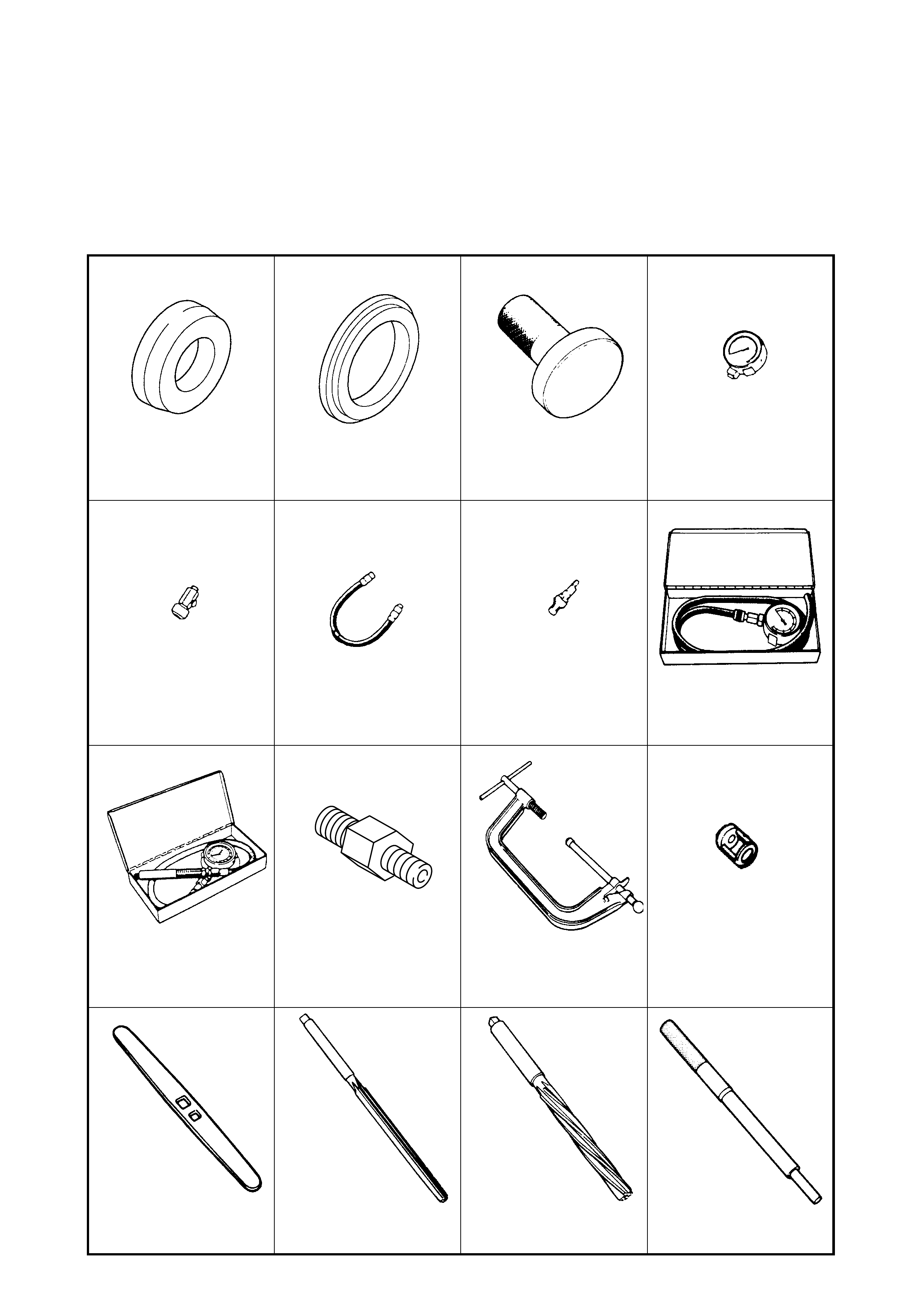
6. SPECIAL TO OLS
NOTE: Refer to Section 0A GENERAL INFORMATION – 7.CONSOLIDATED TOOLS for a detailed list of
special tools and the local equivalent if one is avail able
09911-97720 09911-97820 09913-75520 09915-64510-001
Oil seal guide Oil seal installer Bearing installer Compression gauge
09915-64510-002 09915-64530 09915-67010 09915-67310
Connector Hose Attachment Vacuum gauge
09915-77310 09915-78211 09916-14510 09916-14910
Oil pressure gauge Oil pressure gauge attach-
ment Valv e lifter Valve lifter attach m ent
09916-34542 09916-34550 09916-37320 09916-44910
Reamer handle Reamer (5.5 mm) Reamer (10.5 mm) Valve guide remover
09916-67020 09916-58210 09916-77310 09916-84511
Tappet holder Valve guide installer handle Piston ring compressor Forceps
09917-68221 09916-56011 09917-98221 09924-17811
Camshaft lock holder Valve guide installer Valve stem seal installer Flywheel holder
09926-58010 09944-36011 J42689-AUS 09222-2D000/2
Bearing puller attachment Steering wheel remover Pliers Valve Shim Bucket Spacer