
SECTION 6E1 - ENGINE AND EMISSION CONTROL SYSTEM
1. GENERAL DESCRIPTION
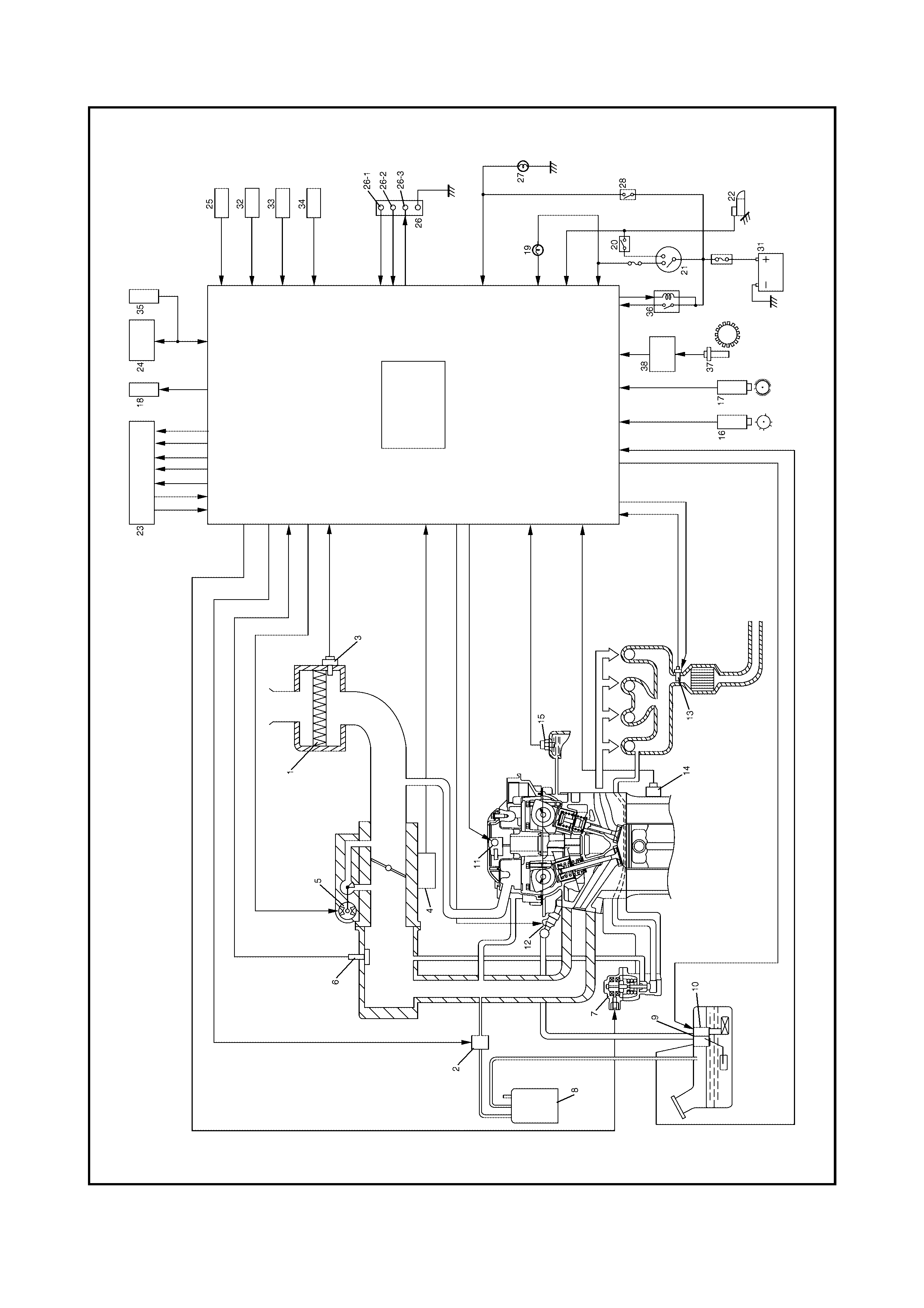
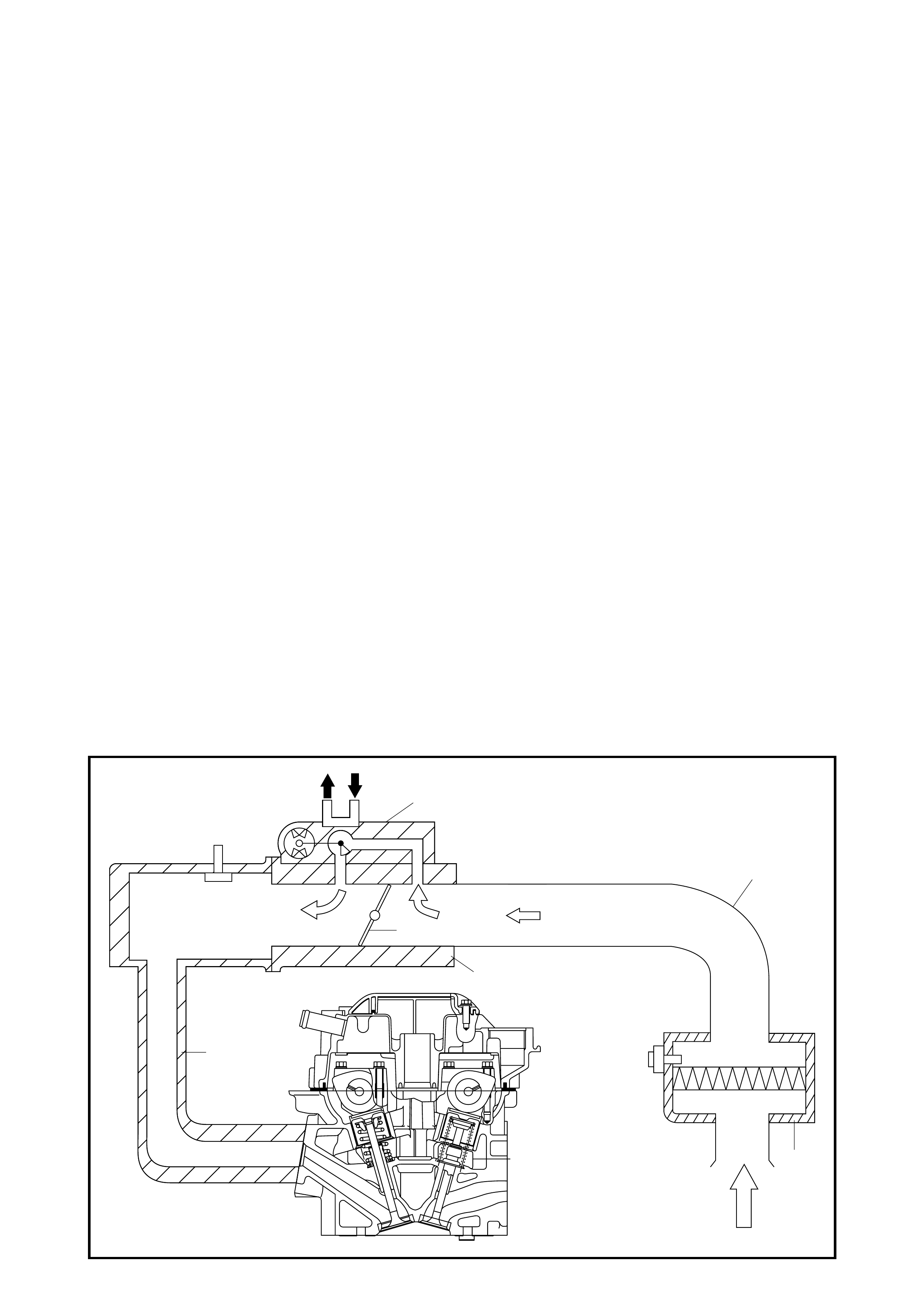
1.1 AIR INTAKE SYSTEM
1.2 FUEL DELIVERY SYSTEM
Fuel Pump
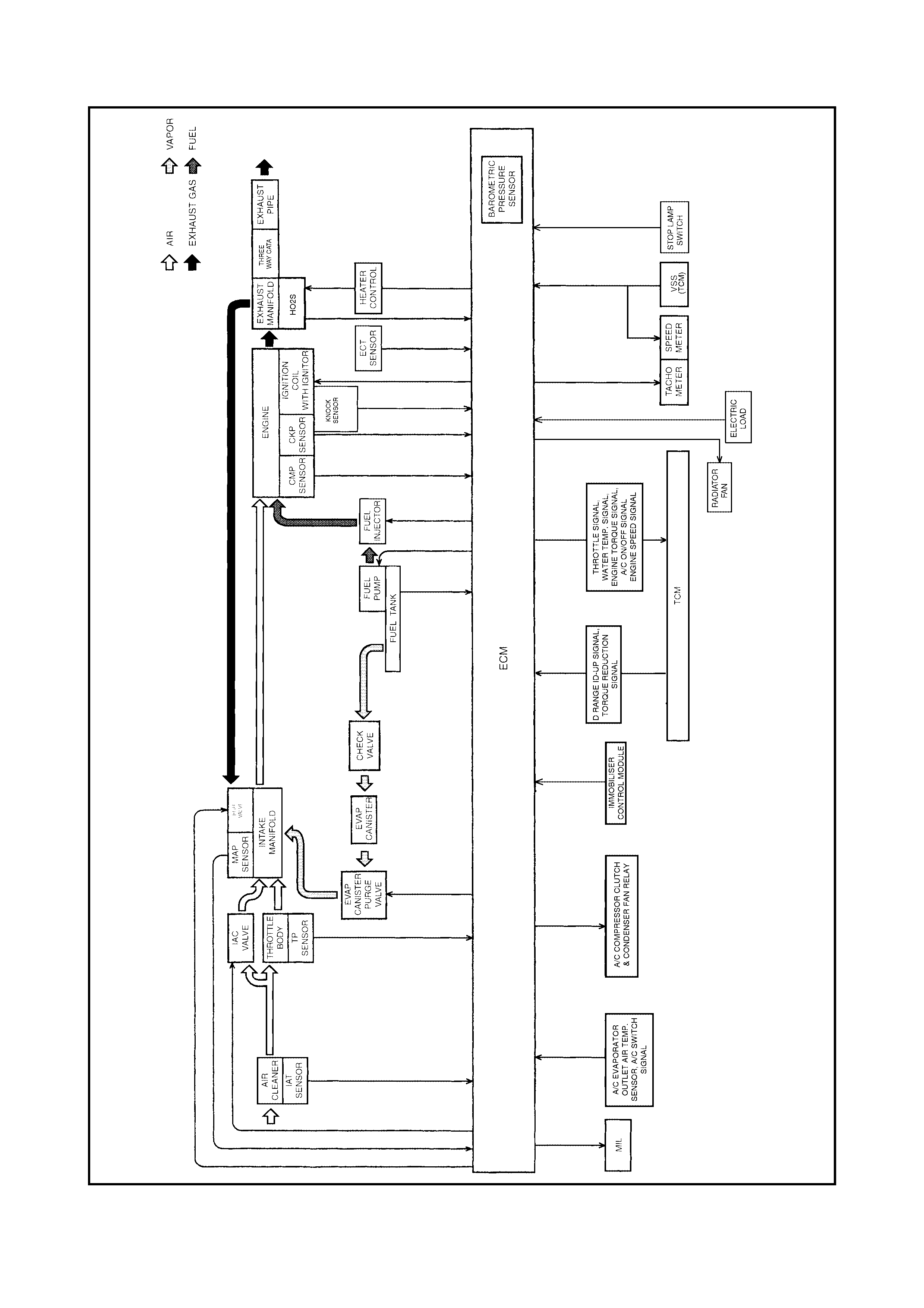
1.3 ELECTRONIC CONTROL SYSTEM
Engine & Emission Control Input/
Output Table
2. ON-VEHICLE SERVICE
Accelerator Cable Adjustment
Idle Speed/idle Air Control (IAC)
Duty Inspection
2.1 AIR INTAKE SYSTEM
Throttle Body
Idle Air Control Valve (IAC Valve)
2.2 FUEL DELIVERY SYSTEM
Fuel Pressure Inspection
Fuel Pump with Pressure Regulator
Fuel Injector
2.3 ELECTRONIC CONTROL SYSTEM
Engine Control Module (ECM)
Manifold Absolute Pressure Sensor
(MAP Sensor)
Throttle Position Sensor
(TP Sensor)
Intake Air Temperature
Sensor (IAT Sensor)
Engine Coolant Temperature Sensor
(ECT Sensor)
Heated Oxygen Sensor (HO2S)
Camshaft Position Sensor
Crankshaft Posi tion Sensor
Vehicle Speed Sensor (VSS)
Knock Sensor
Main Relay, Fuel Pump Relay And
Radiator Fan Relay No.1, No.2, No.3
Fuel Cut Operation
Radiator Fan Control System
Output Signals of Throttle Valve
Opening and Engine Coolant
Temperature (A/T Only)
2.4 EMISSION CONTROL SYSTEM
EGR Sys tem
Evaporative Emission
Control System
PCV System
3. SPECIAL TOOLS
WARNING:
For vehicles equipped with Supplement Restraint (Airbag) System
• Service on and around the airbag system components or wiring must be performed only by an
authorised HOLDEN retailer. Refer to S ection 10B A IRBAG SYSTEM COM PONENTS AND WIRI NG
LOCATION VIEW in GENERAL DESCRIPTION in order to confirm whether y ou are performin g ser-
vice on or near the airbag system components or wiring. Please observe all WARNINGS and SER-
VICE PRECAUTIONS, refer to Section 10B ON-VEHICLE SERVICE before performing service on or
around the airbag system components or wiring. Failure to follow WARNINGS could result in
unintentional activation of the system or could render the system inoperative. Either or these two
conditions may result in severe injury.
• Technical service work must not be started for at least 90 seconds after the ignition switch is
turned to the “LOCK” position and the negative cable is disconnected from the battery.
Otherwise, the system may be activated by reserve energy in the Sensing and Diagnostic Module
(SDM).
IMPORTANT:
Prior to connecting Tech 2 to the vehicle, refer to Section 0C TECH 2.
Techline
Techline

1. GENERAL DESCRIPTION
The engine and emission control system is divided into four major sub-systems:
• air intake system,
• fu el del iver y syst em,
• electronic control system, and
• emission control system.
The air intake system includes the air cleaner, throttle body, Idle Air Control (IAC) valve and intake manifold.
The fuel delivery system includes the fuel pump, delivery pipe, fuel pressure regulator, etc. The electronic
control system includes an Engine Control Module (ECM), various sensors and controlled devices. The emis-
sion control system includes the Exhaust Gas Recirculation (EGR), Evaporative emission control (EVAP) and
Positive Crankcase Ventilation (PCV) systems.
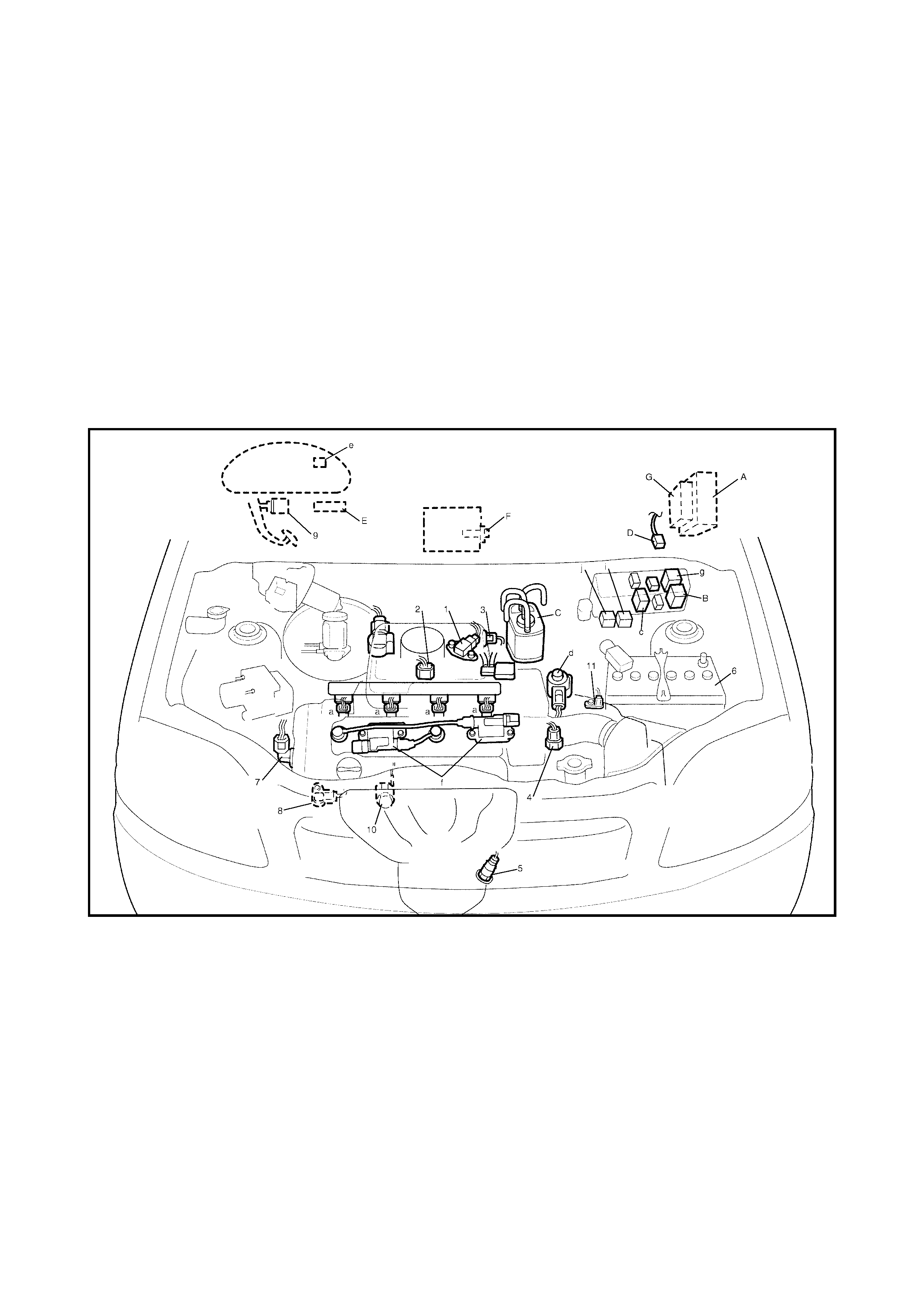
Legend
1.1 AIR INTAKE SYSTEM
The main components of the air intake system are the air cleaner (1), air cleaner outlet hose (2), throttle body
(3), idle air control valve (4) and intake manifold (5).
The ai r ( by the am ount corresp ondi ng to the throttl e v alve ( 6) op eni ng and eng ine s pee d) is fi lte red b y the air
cleaner (1), passes through the throttle body (3), is distributed by the intake manifold (5) and finally drawn into
each combustion chamber.
When the idle air control valve (4) is opened according to the signal from ECM, the air (7) bypasses the throt-
tle valve (6) through bypass passage and is finally drawn into the intake manifold (5).
1. Air Cleaner 22. Starter magneti c swit ch
2. EVAP canister purge valve 23. TCM
3. IAT sensor 24. DLC
4. TP sensor 25. Electric load
5. IAC valve 26. Diagnosis connector No. 1
6. MAP sensor 26-1. Diagnosis switch terminal
7. EGR valve 26-2. Test switch terminal
8. EVAP canister 26-3. Duty output terminal
9. Tank pressure control valve (built-in fuel pump) 27. Stop lamp
10. Fuel pump (with pressure regulator) 28. Stop lamp switch
11. Ignition coil assembly 29. ECM
12. Fuel injector 30. Barometric pressure sensor (if equipped)
13. Heated Oxyg en Sen so r (HO2 S) 31. Battery
14. Knock sensor 32. A/C compressor & condenser fan relay
15. ECT sensor 33. A/C switch
16. CMP sensor 34. A/C evaporator outlet air temp. sensor
17. CKP sensor 35. Immobiliser control module
18. Radiator fan 36. Main relay
19. Malfunction indicator lamp in combination meter 37. VSS
20. Park/Neutral position switch (A/T) 38. TCM (A/T only)
21. Ignition switch
5
4
2
1
6
3
7
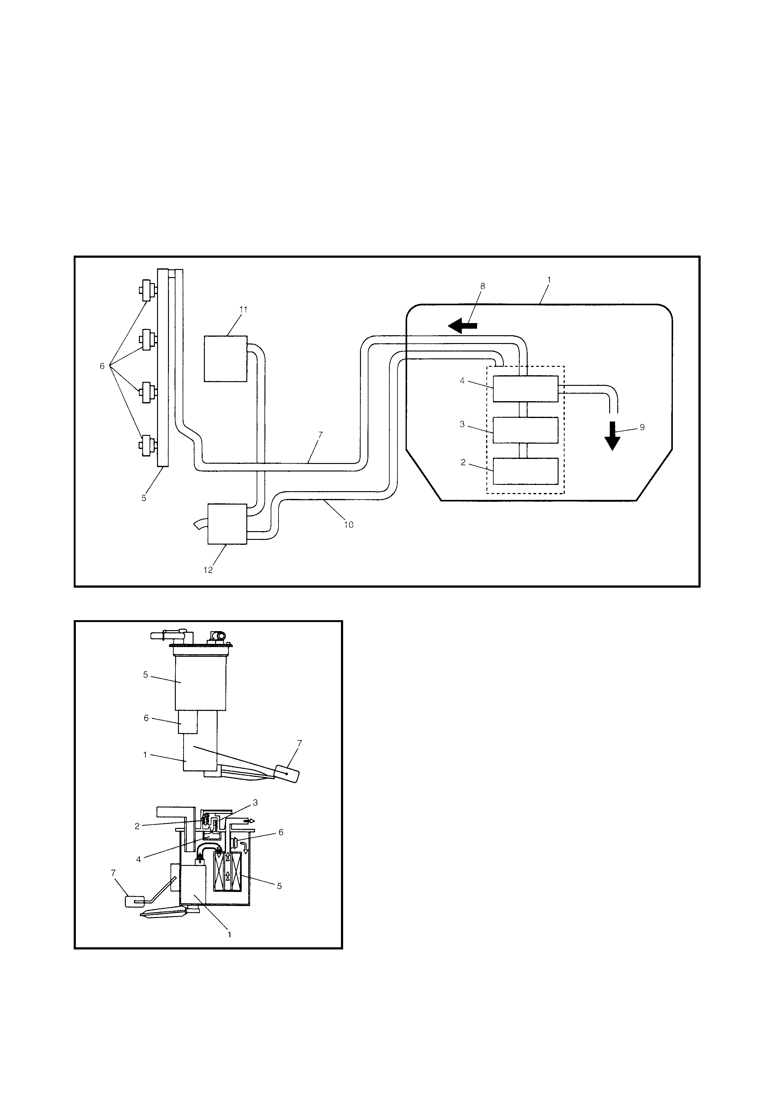
1.2 FUEL DELIVERY SYSTEM
The fu el sys tem c ons is ts of the fue l tank ( 1), fu el pump (2) w ith built-in fuel filte r (3 ) and fue l pr essu re r egu la-
tor (4), delivery pipe (5), injectors (6) and fuel feed line (7).
The fu el (8) in the fuel tank is fed by the fuel pump ( 2), into the de live ry pipe (5) an d inj ected by the injecto rs
(6) into the engine where it is mixed with air inducted through the intake manifold (11).
As the fuel pump assembly is equipped with built-in fuel filter and fuel pressure regulator, the fuel is filtered
and its pressure is regulated before being sent to the delivery pipe.
The excess fuel from fuel pressure regulation process is returned back (9) into the fuel tank.
Also, fuel vapour generated in fuel tank is led through the fuel vapor line (10) into the EVAP canister (12).
FUEL PUMP
An in-tank type e lectric fu el pump (1) is used. Incorpor ated
in the pump assembly are;
• Tank pressure control valve (2) which keeps the pres-
sure in the fuel tank constant, and prevents the fuel
from spouting and tank itself from being deformed.
• Relief valve (3) which prevents the pressure in tank
from rising excessively.
• Fuel cut valve (4) which closes as the float rises so that
the fuel will not enter the canister when the fuel level in
the tank rises, depending on the fuel level in the tank
and the vehicle tilt angle.
Also, a fuel filter (5) and a fuel pressure regulator (6) are
included and a fuel level gauge (7) is attached.
The addition of the fuel pressure regulator (6) to the fuel
pump makes it possible to maintain the fuel pressure at
constant level and ECM controls compensation for varia-
tion in the intake manifold pressure.
1.3 ELECTRONIC CONTROL SYSTEM
The ele ctronic con trol system c onsists of variou s sensors whi ch detect the state of engine and drivin g condi-
tions. An ECM controls various devices according to the signals from the sensors.
Functionally, it is divided into nine sub systems:
• Fuel injection control system
• Idle sp eed control sys tem
• Fuel pump control system
• A/C control system
• Radiator fan control system
• EGR system
• Evaporative emission control system
• Oxygen sensor heater control system
• Ignition control system
Also, with automatic transmission models, the ECM sends throttle valve opening, coolant temp., engine
torque, A/C and engine speed signals to the transmission control module which controls the transmission.
Legend
INFORMATION SENSORS CONTROL DEVICES OTHERS
1. MAP sensor a. Fuel injector A. ECM
2. TP sensor b. EVAP canister purge valve B. Main relay
3. IAT sensor c. Fuel pump relay C. EVAP canister
4. ECT sensor d. EGR valve (step motor) D. Diagnosis connector No. 1
5. Heated oxygen sensor e. Malfunction indicator lamp E. Data link connector
6. Battery f. Ignition coil assembly F. A/C evaporator outlet air temp. sensor
7. CMP sensor g. Radiator fan control relay No.1 G. TCM (A/T)
8. CKP sensor h. IAC valve
9. S top lamp switch i. Radiator fan control relay No.2
10. Knock sensor j. Radiator fan control relay No.2
11. VSS
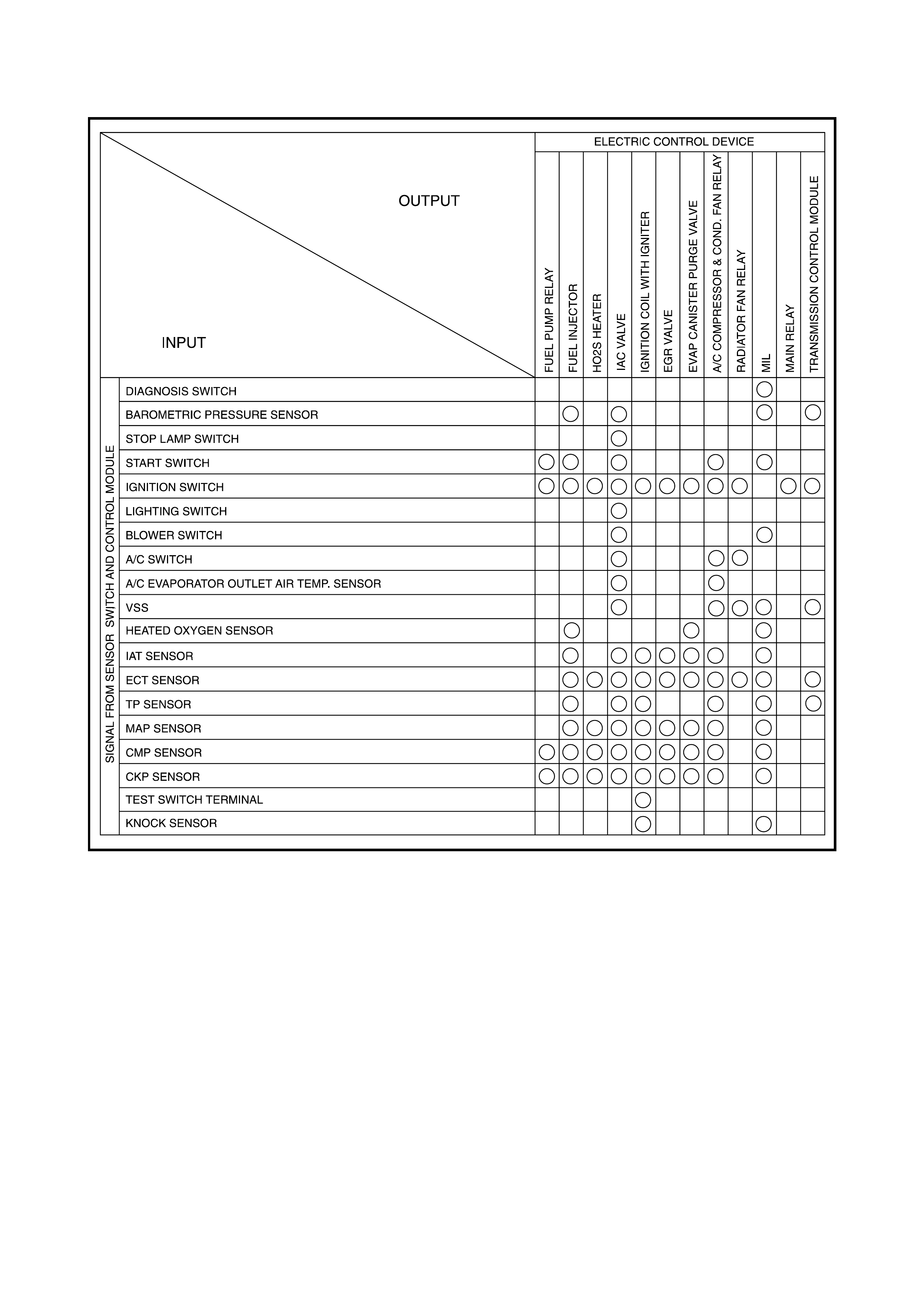
ENGINE & EMISSION CONTROL INPUT/OUTPUT TABLE
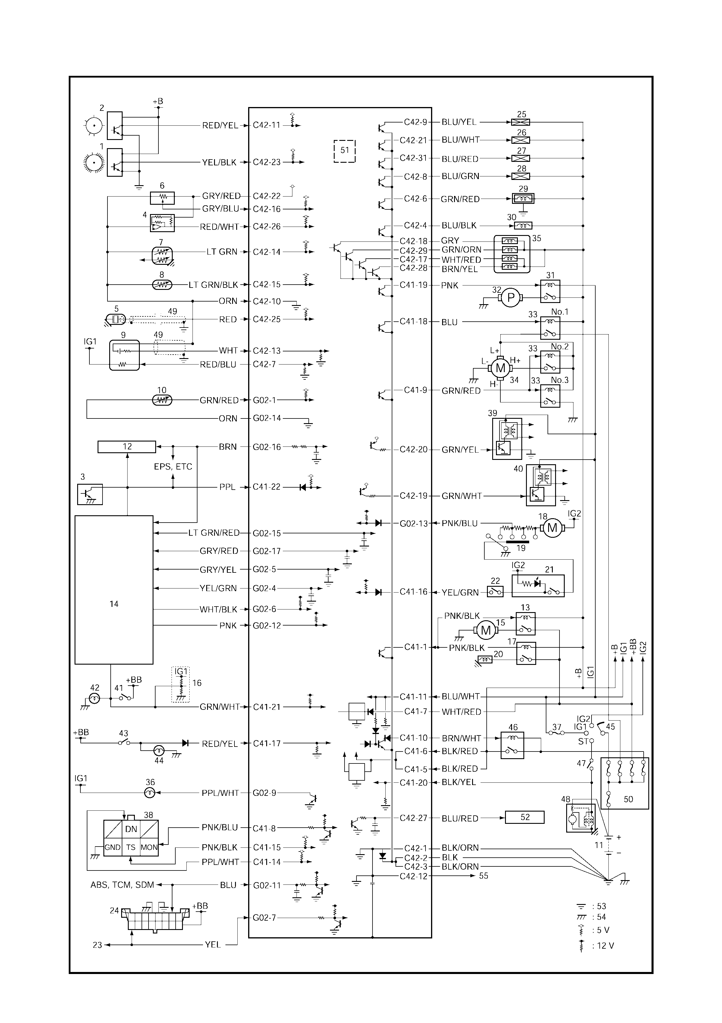

Legend
1. CKP sensor 20. A/C compressor clutch 39. Ignition coil ass’y (No.1 & No.4)
2. CMP sensor 21. A/C switch 40. Ignition coil ass’y (N o.2 & No .3)
3. VSS 22. A/C pressure switch 41. Stop lamp switch
4. MAP sensor 23. Immobiliser control module 42. Stop lamp
5. Knock sensor 24. Data link connector 43. Lighting switch
6. TP sensor 25. Injector No.1 44. Position lamp
7. ECT sensor 26. Injector No.2 45. Igniti on switch
8. IAT se nsor 27. Injector No.3 46. Main relay
9. Heated oxygen sensor 28. Injector No.4 47. Clutch switch (M/T)
10. A/C evap. outlet air temp. sensor 29. IAC valve Shift switch (A/T)
11. Battery 30. EVAP canister purge valve 48. Starter motor
12. Combination meter 31. Fuel pump relay 49. Shield wi re
13. A/C condenser fan relay 32. Fuel pump 50. Main fuse
14. TCM 33. Radiator fan relay 51. Barometric pressure sensor
15. A/C condens er fan mo tor 34. Radiator fan mot or 5 2. Generat or
16. ABS control module 35. EGR valve 53. Engine ground
17. A/C compressor relay 36. Malfunction indicator lamp 54. Body ground
18. Heater fan motor 37. IG METER fuse 55. Shield wire ground
19. Heater fan switch 38. Diagnosis connector No. 1
CONNECTOR TERMINAL WIRE COLOUR CIRCUIT
C41 1 PNK/BLK A/C compressor & condenser fan relay
2––
3––
4––
5 BLK/RED Power source
6 BLK/RED Power source
7 WHT/RED Back-up power source
8 PNK/BLU Duty output terminal
9 GRN/RED Radiator fan relay No.2
10 BRN/WHT Ground for main relay
11 BLK/WHT Ignition switch signal
12 – –
13 – –
14 PPL/WHT Diagnosis switch terminal
15 PNK/BLK Test switch terminal
16 YEL/GRN A/C switch signal
17 RED/YEL Electric load (+)
18 BLU Radiator fan relay No.1
19 PNK Fuel pump relay
20 BLK/YEL Engine start signal
21 GRN/WHT Stop lamp switch
22 PPL Vehicle speed sensor
23 – –
24 – –
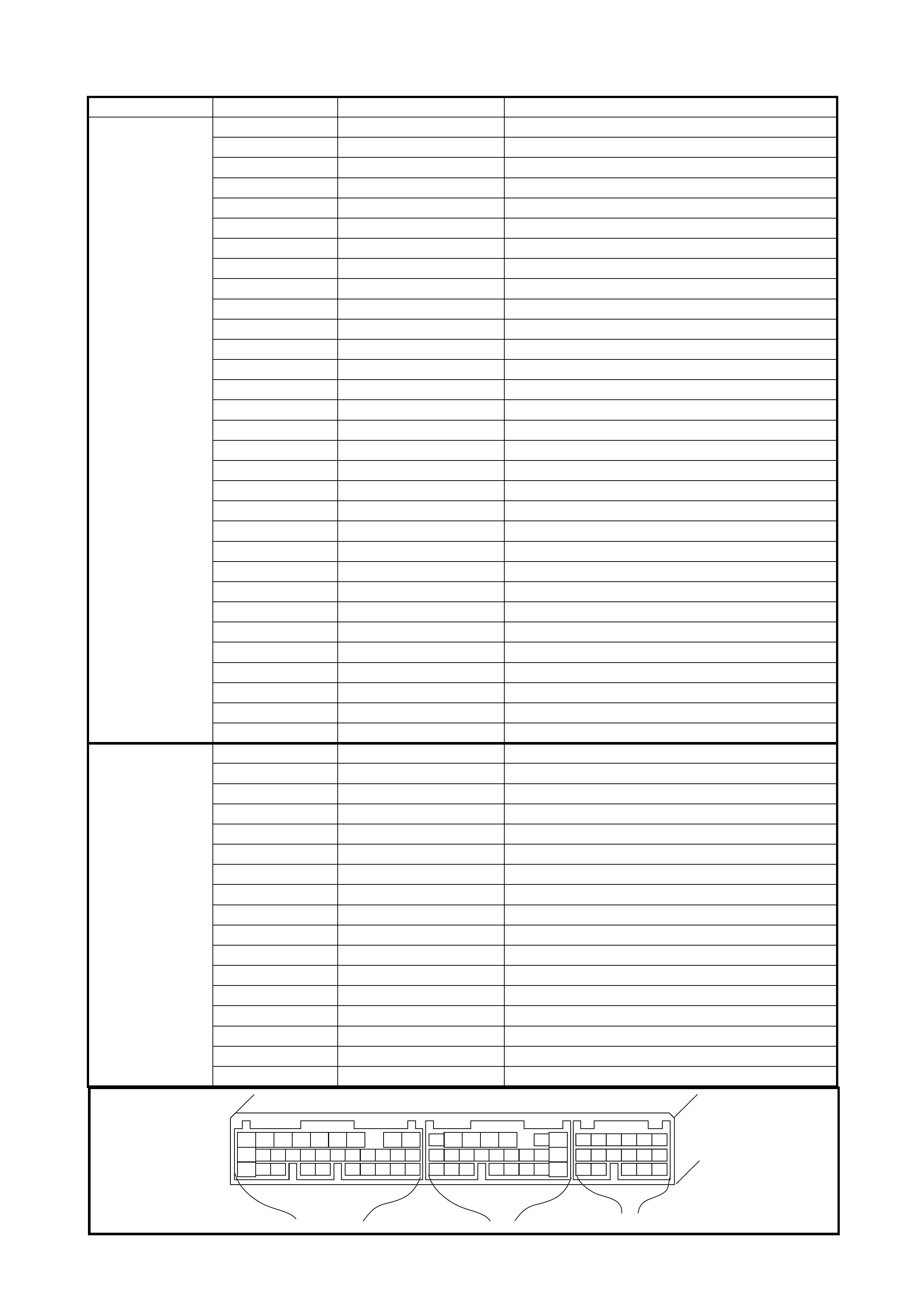
NOTE: For abbreviations of wire colours refer to Section 0A.
CONNECTOR TERMINAL WIRE COLOUR CIRCUIT
C42 1 BLK/ORN Ground for ECM
2 BLK Ground for drive circuit
3 BLK/ORN Ground for drive circuit
4 BLU/BLK Canister purge valve
5––
6 GRN/RED IAC valve
7 RED/BLU Heater of HO2S
8 BLU/GRN No.4 fuel injector
9 BLU/YEL No.1 fuel injector
10 ORN Ground for sensor circuit
11 RED/YEL CMP sensor
12 – ECM shield wire ground
13 WHT Heated oxygen sensor
14 LT GRN Coolant temp. sensor
15 LT GRN/BLK Intake air temp. sensor
16 GRN/BLU TP sensor
17 WHT/RED EGR valve stepper motor coil No.3
18 GRN EGR valve stepper motor coil No.1
19 GRN/WHT Ignition coil assembly (No.2 and 3 spark plugs)
20 GRN/YEL Ignition coil assembly (No.1 and 4 spark plugs)
21 BLU /WHT No.2 fu el injector
22 GRY/RED Power supply for sensor
23 YEL/BLK CKP sensor (+)
24 – –
25 RED Knock sensor
26 RED/WHT MAP sensor
27 BLU/RED Generator control
28 BRN/YEL EGR valve stepper motor coil No.4
29 GRN/ORN EGR valve stepper motor coil No.2
30 – –
31 BLU/ RED No.3 fuel injector
G02 1 GRN/WHT A/C evaporator outlet air temp. sensor
2––
3––
4 YEL/GRN A/C ON/OFF signal output
5 GRN/YEL Engine torque signal output
6 WHT/BLK D-range idle-up input
7 YEL Data link connector
8––
9 PPL/WHT Malfunction indicator lamp (MIL)
10 – –
11 BLU Data link connector
12 PNK Torque signal output
13 PNK/BLU Electrical load (-)
14 ORN Sensor ground
15 LT GRN/RED Throttle opening signal output (A/T)
16 BRN Tachometer signal
17 GRY/RED Coolant temp. signal output
C42 (31P) C41 (24P) G02 (17P)
123456789
101112131415161718192021
222324252628 27293031
56
1234567
1112
9101113 12141516
1617
12
78
1314
34
910
15
1718 8
192021222324
2. ON-VEHICLE SERVICE
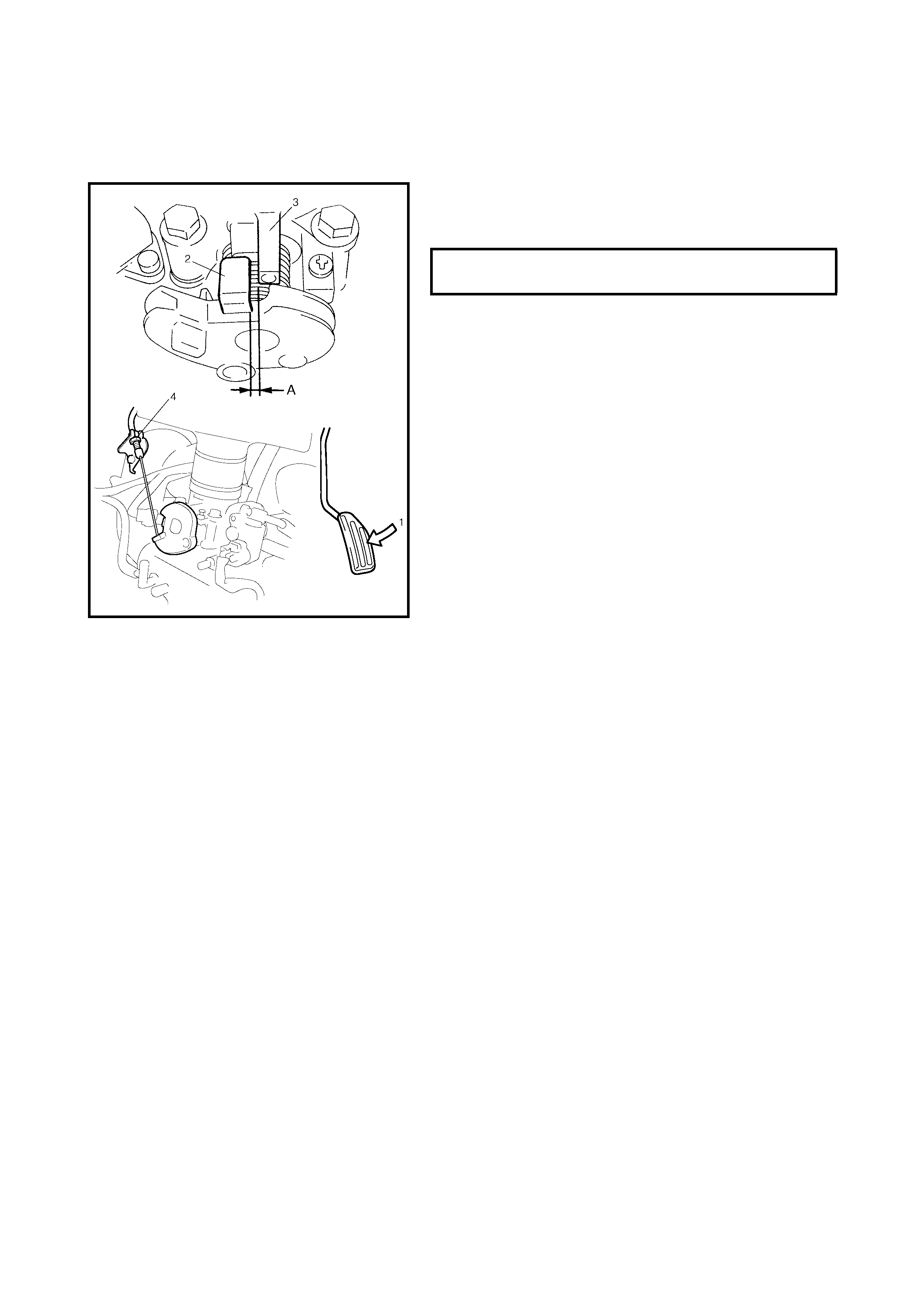
ACCELERATOR CABLE ADJUSTMENT
With the acc el erator ped al dep re ssed fully (1), chec k c lea r-
ance between the throttle lever (2) and lever stop (3) (throt-
tle body) is within specification.
If measured value is out of specification, adjust it to specifi-
cation with cable adjusting nut (4).
IDLE SPEED/IDLE AIR CONTROL (IAC) DUTY
INSPECTION
Before id le sp eed /IA C du ty c hec k, ma ke s ure o f th e f oll ow-
ing:
• Lead wires and hoses of electronic fuel injection and
engine emission control systems are connected
securely.
• Accelerator cable has a small amount of play.
• Valve lash is checked and adjusted according to the
maintenanc e sc hed ule.
• Ignition timing is within specification.
• All accessories (wipers, heater, lights, A/C, etc.) are
turned off.
• Air cleaner has been properly installed and is in good
condition.
• No abnormal air leaks into the air intake system.
After above items are all confirmed, check idle speed and
IAC duty as follows.
NOTE:
Before starting the engine, place transmission
gear shift lever in neutral or P, set the parking brake and
block the drive wheels.
ACCELERATOR CABLE CLEARANCE
(with pedal fully depressed) A 0.5 – 2.0 mm
NOTE:
Before starting the engine, place transmission
gear shift lever in neutral or P, set the parking brake and
block the drive wheels.
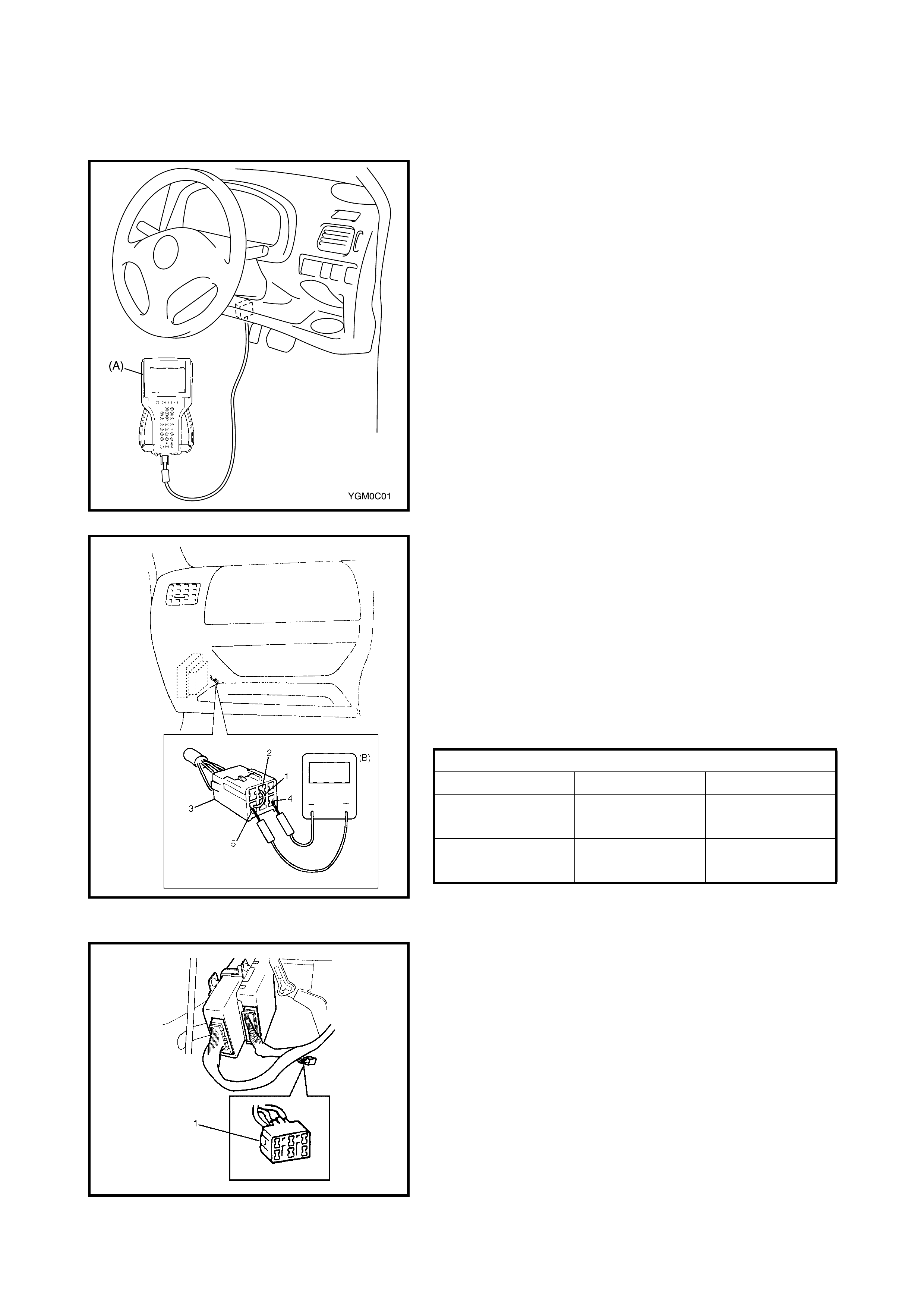
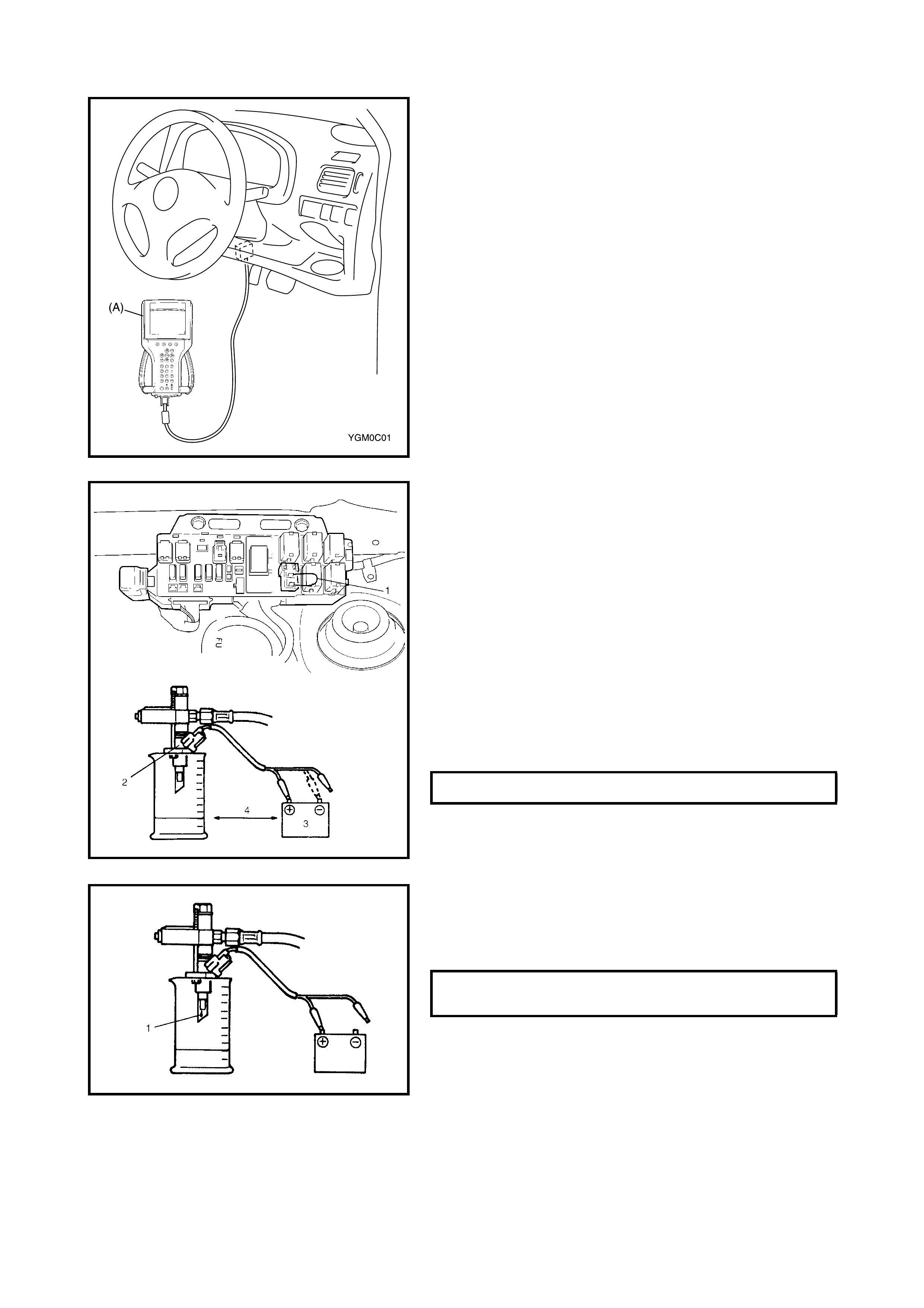
1. Connect Tech 2 (A) to DLC with ignition switch OFF, if it
is available.
2. Warm up engine to normal operating temperature.
3. Check engine idle speed and IAC duty as follows:
4. When using Tech 2:
a. Select Data List mode on Tech 2 to check IAC duty.
2. When using a duty meter (B):
a. Set tachometer.
b. Using service wire (1), ground Diag. switch terminal
(2) in the diagnosis connector No. 1 (3) and con-
nect duty meter between Duty output terminal (4)
and Ground terminal (5).
3. If duty and/or idle speed is out of specification, inspect
the idle air control system, refer to the diagnostic flow
2.27 TABLE B-4 IDLE AIR CONTROL SYSTEM
CHECK in Section 6.
NOTE: The above duty values are ON duty (low voltage
rate) meter indications.
4. Remove the ser vice wir e from the d iagnosis connec tor
No. 1 (1).
5. Check that th e specified engine idle speed is obtaine d
with A/C ON.
If not, check A/C ON signal circuit and idle air control
system.
Engin e idle speed and IAC duty
TRANSMISSION A/C OFF A/C ON
Manual in neutral 700 ± 50 rpm
5 – 25 % 850 ± 50 rpm
Auto. in P/N
range 750 ± 50 rpm
5 – 25 % 850 ± 50 rpm
2.1 AIR INTAKE SYSTEM
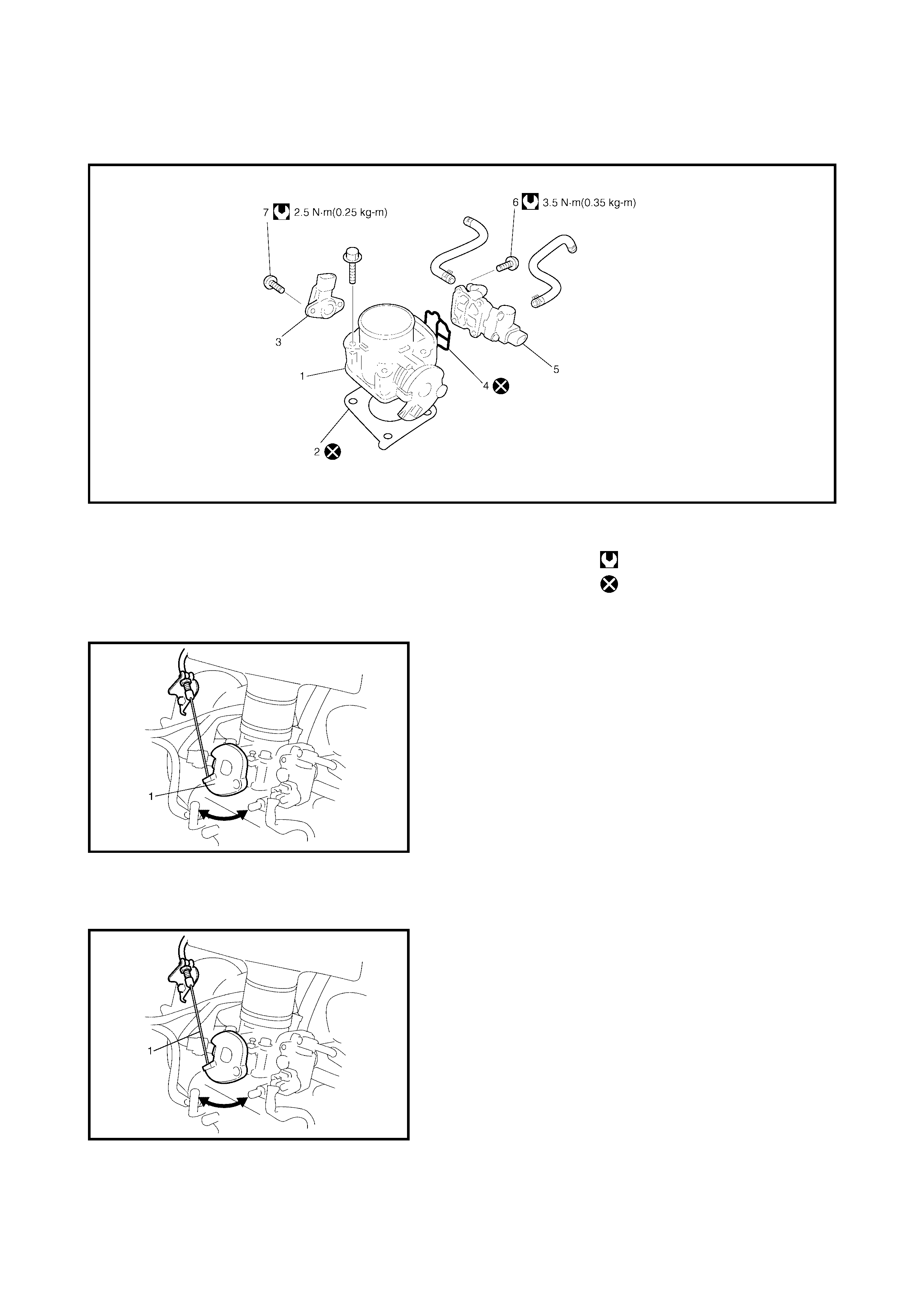
THROTTLE BODY
Legend
On-Vehicle Inspection
• Check that throttle valve lever (1) moves smoothly.
Removal
1. Disconnect negative cable at battery.
2. Drain the cooling system.
3. Disconnect the accelerator cable (1) from the throttle
valve lever.
4. Disconnect the IAT sensor connector and remove the
air cleaner assembly with air cleaner outlet hose.
1. Throttle body 4. Gasket 7. TP sensor screws
2. Throttle stop screw 5. Idle air control valve Tightening torque
3. TP sensor 6. IAC valve screws Do not reuse.
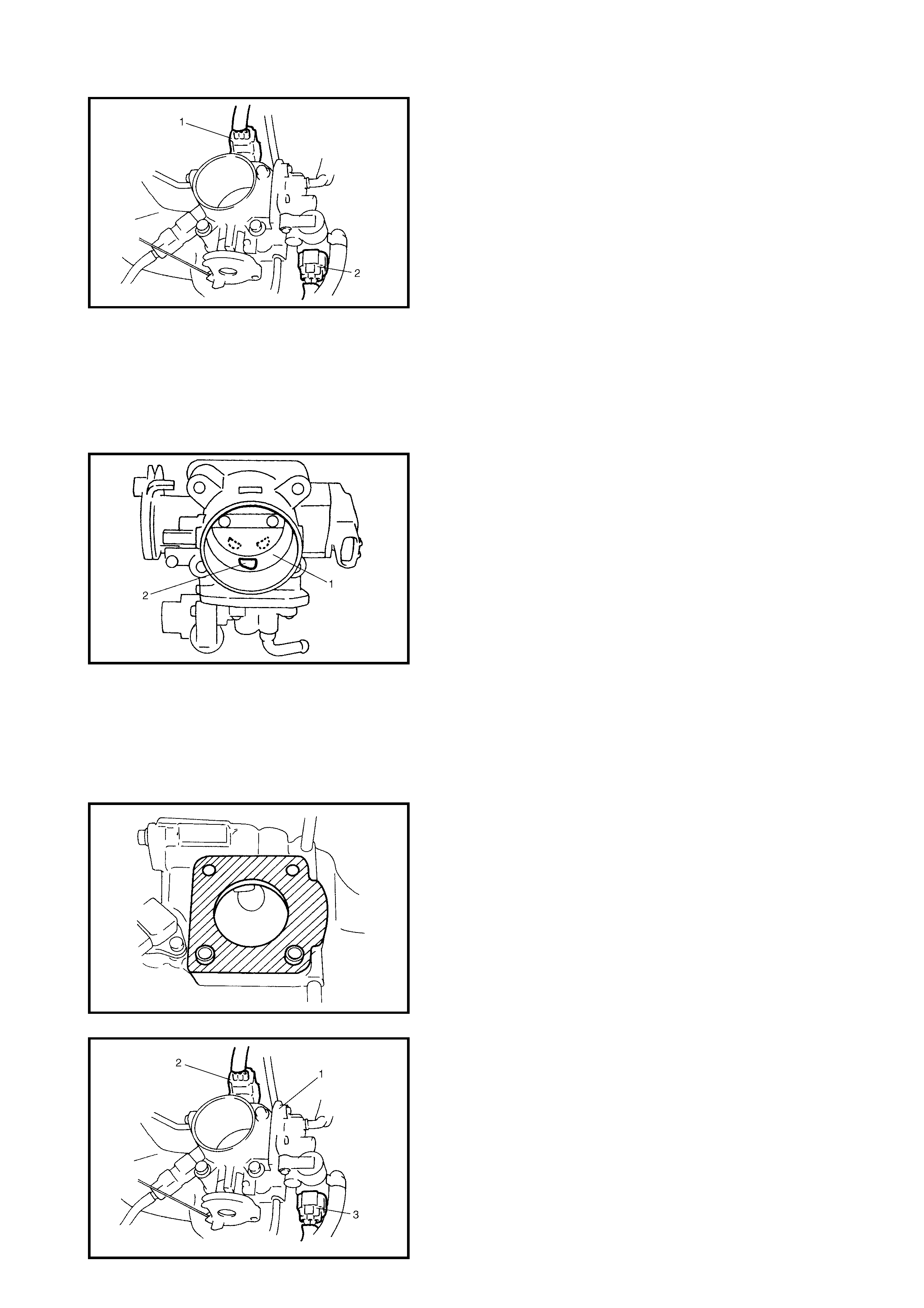
5. Disconnect electric connector from TP sensor (1) and
IAC valve (2).
6. Remove throttle body from intake manifold.
7. Disconnect engine coolant hoses from throttle body.
Disassembly
Remove the T P sens or an d IA C val ve f rom th r ottl e b ody.
NOTE: While disassembling and assembling the throttle
body, use special care not to deform the levers on the throt-
tle valve shaft or cause damage to any other parts.
Cleaning
Clean the thr ottle bo dy bore (1 ) and idle ai r passag e (2) by
blowing co mpres s ed air.
NOTE:
TP sensor, idle air control valve or other compo-
nents containing rubber must not be placed in a solvent
or cleaner bath. A chemical reaction will cause these
pa rts to swell, harden or get distorted.
Reassembly
1. Install IAC valve to throttle body refe rring to IAC valve
Installation section.
2. Install TP sensor to throttle body referring to TP sensor
Installation section.
Installation
1. Clean mating surfaces and install throttle body gasket
to intake manifold.
Use new gasket.
2. Connect engine coolant hoses.
3. Install throttle body (1) to intake manifold.
4. Connect co nnector to TP s ensor (2) and IAC v alve (3)
securely.
5. Connect accelerator cable and adjust cable play to
specification.
6. Install air cleaner assembly with air cleaner outlet hose
and connect IAT sensor connector.
7. Refill cooling system.
8. Connect negative cable at battery.
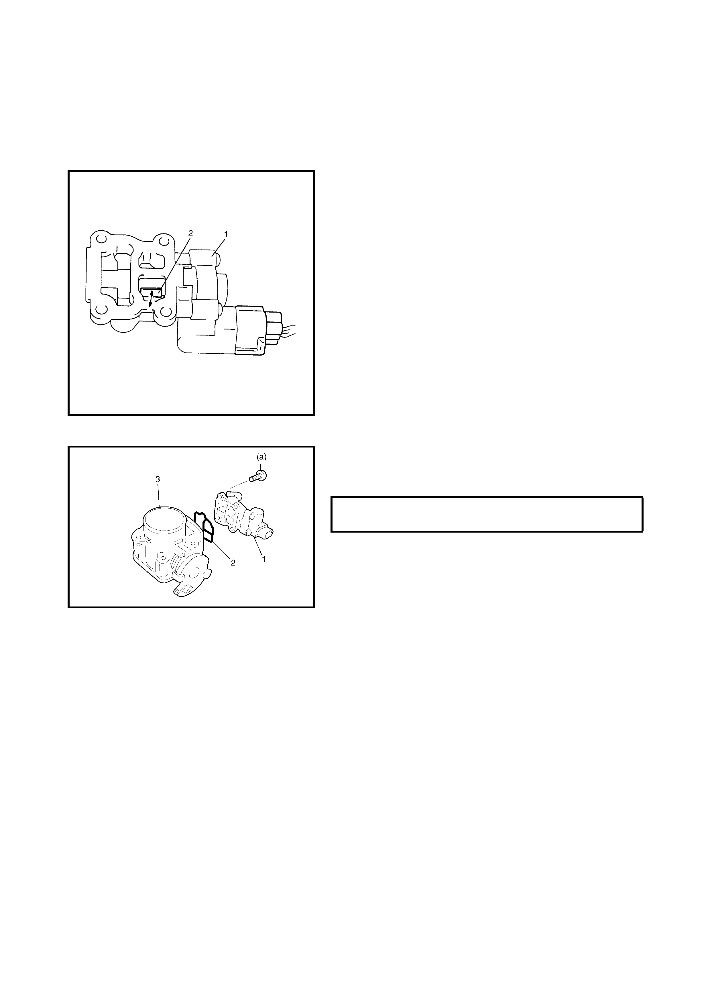
IDLE AIR CONTROL VALVE (IAC VALVE)
Removal
1. Remove the throttle body from the intake manifold as
previou sly desc ribed .
2. Remove the AC valve from throttle body.
Inspection
1. Connect each connector to IAC valve (1), TP sensor
and IAT sensor.
2. Check that rotary valve (2) of lAC valve opens and
closes o nce and then sto ps in about 60 ms as soon as
ignition switch is turned ON.
NOTE:
• This check should be performed by two people, one
person turns the ignition switch ON while the other
checks valve operation.
• As valve operation is momentary, it may be over-
looked. To prevent this, perform this operation check
three times or more continuously.
If the rotary v alve of the lAC valve does not op erate at
all, check wire harness for open and short. If the wire
harness is in good condition, replace the lAC valve and
recheck.
Installation
1. Install new gasket (2) to IAC valve (1).
2. Install IAC valve (1) to throttle body (3).
Tighten IAC valve screws to specified torque.
3. Install throttle body to the intake manifold as previously
described.
2.2 FUEL DELIVERY SYSTEM
FUEL PRESSURE INSPECTION
WARNING: To a void the risk of fire, p
erform work in a
well-ventilated area and away from any open flames.
1. Relieve fuel pressure in fuel feed line. Refer to
1.4 FUEL PRESSURE RELIEF PROCEDURE in
Section 6.
2. Disconnect fuel feed hose from fuel delivery pipe.
CAUTION:
A small amount of fuel may be released
when the fuel hose is disconnected. Place a con-
tainer under the joint with a shop cloth so that
released fuel is caught in the container or absorbed
in the cloth.
IAC VALVE SCREW TORQUE
SPECIFICATION (a) 35 Nm
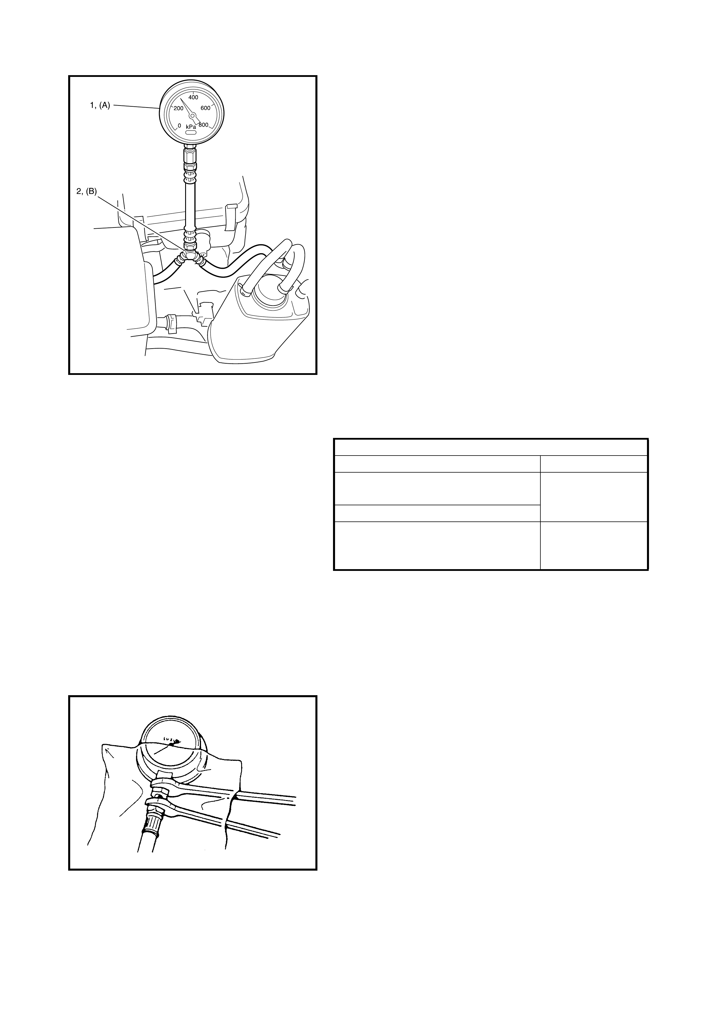
3. Connect special tools (A) SD28018 or AU338 and (B)
SD28057 between fuel delivery pipe and fuel feed
hose (1) as shown, and clamp hoses securely to
ensure no leaks occur during checking.
4. Check that battery voltage is above 11 V.
5. Turn the ignition switch ON to operate the fuel pump
and after 2 seconds turn it OFF. Repeat this 3 or 4
times and then check fuel pressure.
6. Start the engine and warm it up to normal operating
temperature.
7. Measure fuel pressure at idle.
If measured pressure does not meet specification,
refer to Section 6, 2.26 TABLE B-3 FUEL PRESSURE
CHECK, diagnostic flow table and check each possibly
defective part. Replace if found defective.
8. After checking fuel pressure, remove fuel pressure
gauge.
CAUTION: As fuel feed line is still under high fuel pres-
sure, r elease fuel p ressure acc ording to following pro-
cedures:
• Place fuel container under joint.
• Cover joint with a rag and loosen joint nut s lowly to
release fuel pressure gradually.
9. Remove special tools from fuel delivery pipe.
10. Connect fuel feed hos e to fuel d eliver y pipe and c lamp
it se curely.
11. With engine OFF and ignition switch ON, check for fuel
leaks.
FUEL PRESSURE SPECIFICATION
Condition Fuel Pressure
With fuel pump operating and engine
stopped 270 – 310 kPa
Engine at idle speed
1 min. after engine and fuel pump
has stopped
(Pressure reduces as time passes) over 250 kPa
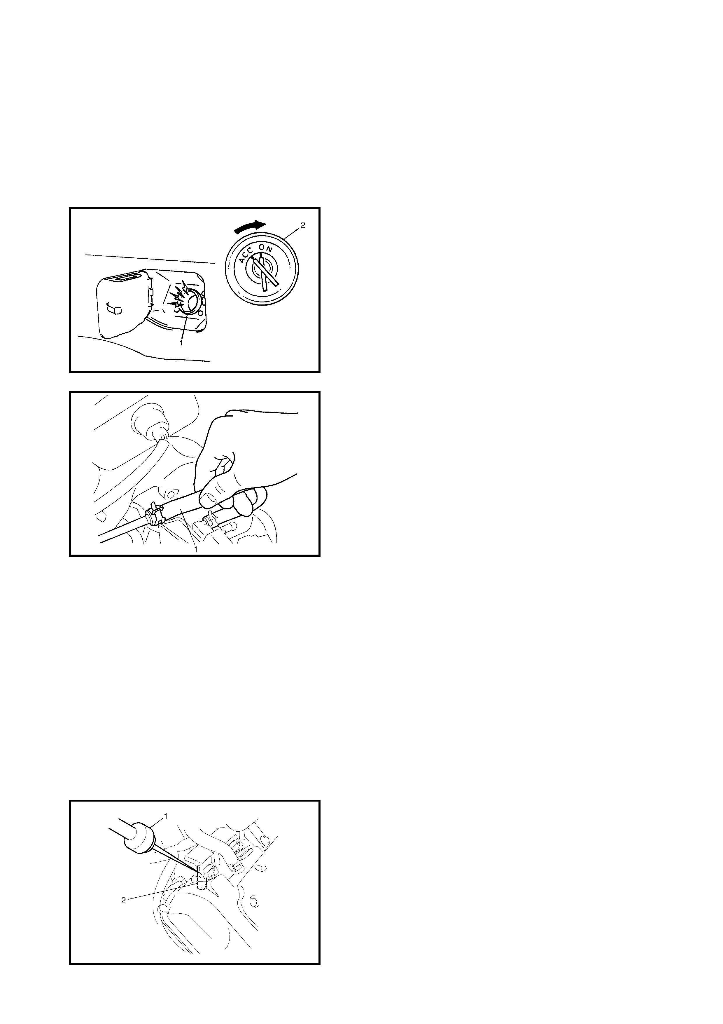
FUEL PUMP WITH PRESSURE REGULATOR
On-vehicle Inspection
CAUTION:
When the fuel filler cap is removed in any
procedure, work must be done in a well-ventilated
area, keep away from any open flames and do not
smoke.
NOTE:
The fuel pressure regulator is part of the fuel
pump assembly, individual inspection is not possible.
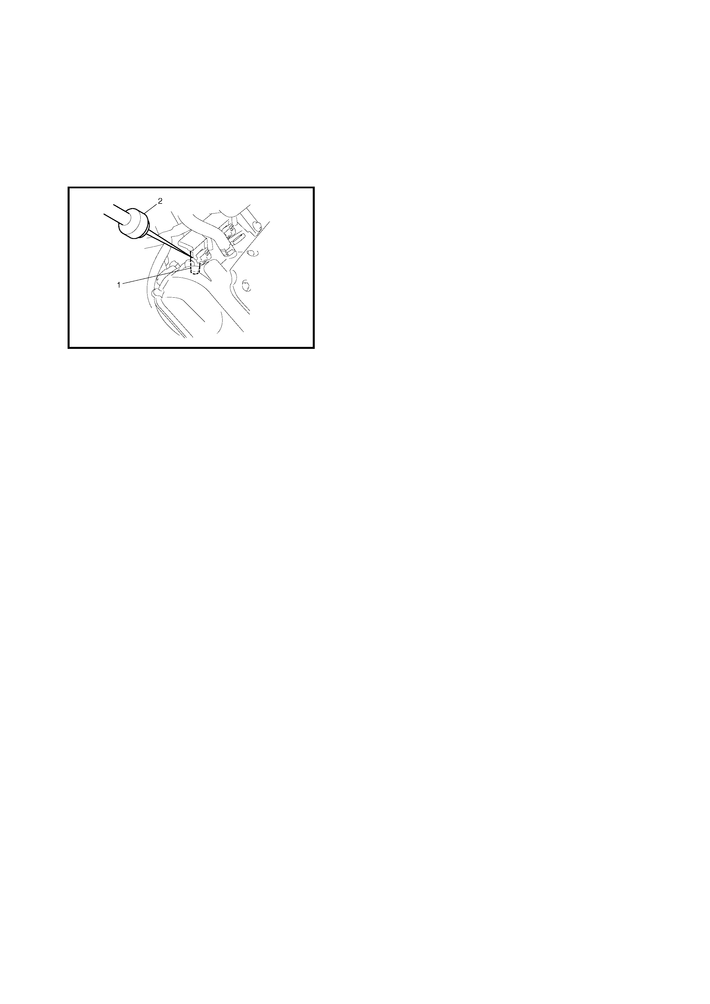
1. Remove filler cap and turn ON the ignition switch (2).
Then the fuel pump operating sound should be heard
from fuel filler (1) for about 10 seconds and stop.
Reinstall the fuel filler cap after checking.
If the above check result is not satisfactory, refer to
Section 6, 2.25 TABLE B-2 FUEL PUMP AND
CIRCUIT CHECK, diagnostic flow table.
2. Turn OFF ignition switch and leave for more than 10
minutes.
3. Fuel pressure should be felt at the fuel feed hose (1)
for about two seconds after ignition is switched ON.
If fuel pressure is not felt, refer to Section 6, 2.26
TABLE B-3 FUEL PRESSURE CHECK, diagnostic
flow table.
Removal
Remove the fuel tank, refer to Section 6C, ENGINE FUEL,
and remove the fuel pump from the fuel tank.
Inspection
Check the fuel pump filter for evidence of dirt and contami-
nation. If present, clean and check for presence of dirt in
the fuel tank.
Installation
1. Install the fuel pump to its bracket.
2. Install the fuel pump to the fuel tank and then install the
fuel tank, refer Section 6C, ENGINE FUEL.
FUEL INJECTOR
On-vehicle Inspection
1. Using a sound scope (1) or such, check operating
sound of each injector (2) when the engine is running
or cranking.
Cycle of operating sound should vary according to
engine speed.
If no sound or an unusual sound is heard, check
injector circuit (wire or connector) or injector (2).
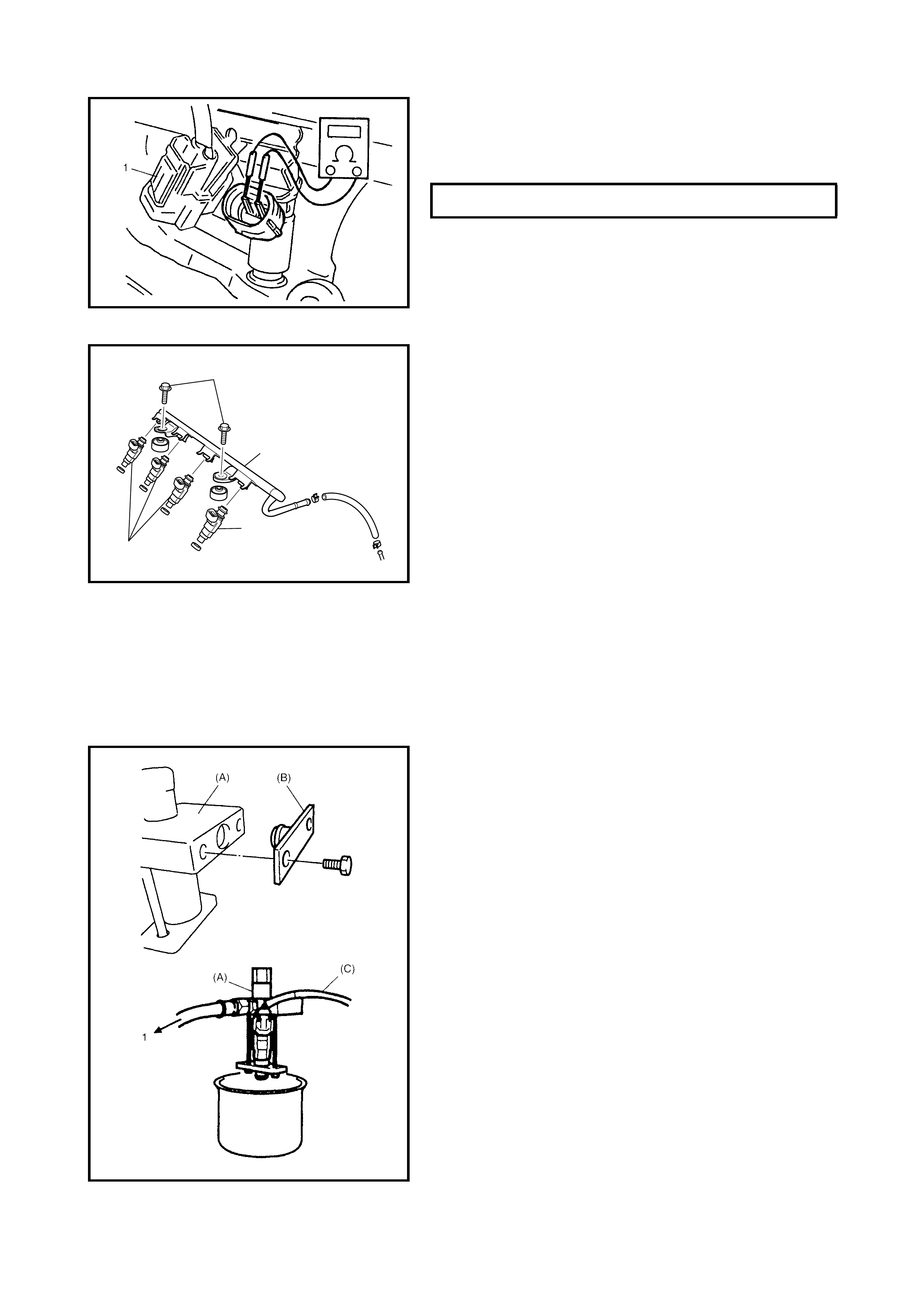
2. Disconnect connector (1) from the injector, connect an
ohmmeter between terminals of the injector and check
resistance.
If resistance is out of specification, replace injector.
3. Connect connector (1) to injector securely.
Removal
1. Relieve fuel pressure, refer to Section 6, 1.4 FUEL
PRESSURE RELIEF PROCEDURE.
2. Disconnect battery negative cable at battery.
3. Disconnect IAT sensor connector and remove the air
cleaner assembly with air cleaner outlet hose.
4. Disconnect the fuel injector connectors.
5. Disconnect the fuel feed hose from the fuel delivery
pipe (1).
6. Remove the fuel delivery pipe bolts (2).
7. Remove the fuel injector(s) (3).
CAUTION:
A small amo unt of f uel may co me out after
remova l of th e fu el i n je ct ors , co ver th em with a sh op
cloth.
Inspection
WARNING: As fuel is injected in this inspection, per-
form in a well ventilated area and away from open
flames.
Use spe cial care to preven t sparking whe n connectin g
and disconnecting test lead to and from battery.
1. Install injector to special tool (injector checking tool)
(A): 09912-58421 and (B): 09912-57610
2. Connect special tools (hose and attachment) to fuel
feed pipe (1) of vehicle.
3. Connect special tool (test lead) (C): 09930-88530 to
injector.
FUEL INJECTOR RESISTANCE @ 20°C 11.3 – 13.8
Ω
2
1
3
3
4. Install a suitable vinyl tube onto the injector nozzle to
prevent fuel from splas hing out when injecting.
5. Put graduated cylinder under injector as shown.
6. Operate fuel pump and apply fuel pressure to injector
as follows:
7. When using Tec h 2 (A):
a. Connect Tech 2 to DLC with ignition switch OFF.
b. Turn ignition switch ON, clear DTC and select
MISC TEST model.
c. Turn fuel pump ON by using Tech 2.
4. Without using Tech 2:
a. Remove fuel pump relay from connector.
b. Connect two terminals of relay connector using ser-
vice wire (1) as shown.
CAUTION:
Check to make sure that connection is
made between correct terminals. Wrong connection
can ca use damage to the ECM, wire harness, etc.
c. Turn ignition switch ON.
4. Apply battery voltage (3) to the injector (2) for 15
seconds and measure injected fuel volume in
graduated cylinder.
CAUTION: Keep battery as far away as possible (4).
5. Test each injector two or three times.
If not within specification, replace injector.
6. Check fuel leakage from injector nozzle. Do not
operate injector for this check (but fuel pump should be
operating).
If fuel leaks (1) more than specified, replace.
INJECTED FUEL VOLUME 43 – 47 cc/15 sec
FUEL LEAKAGE (1) L ess th an 1 drop /
min.
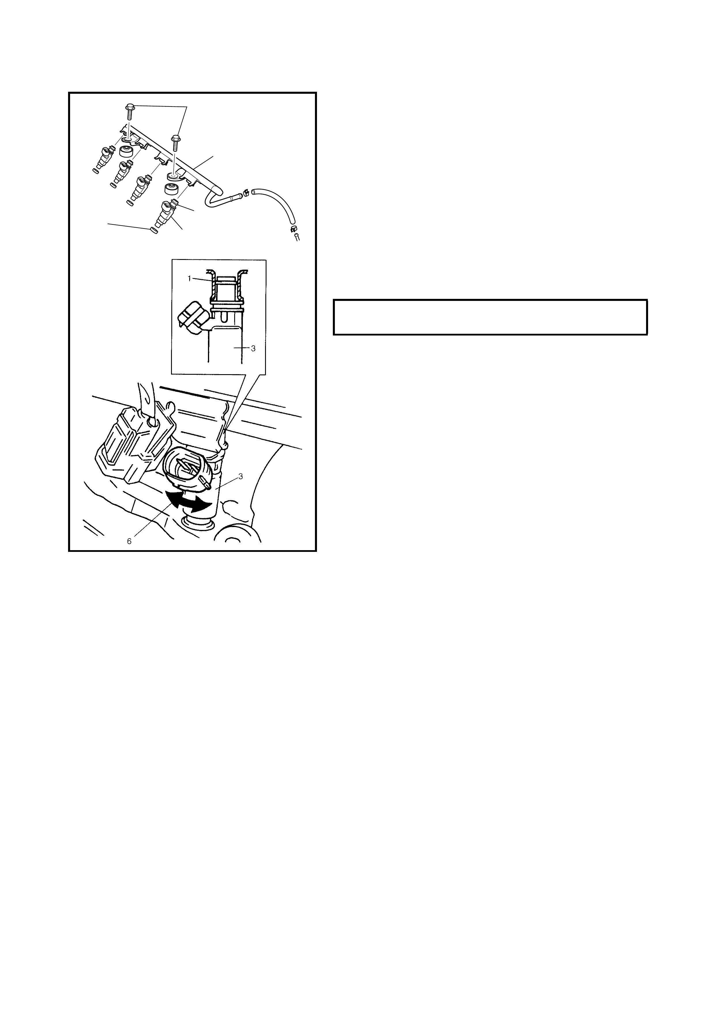
Installation
For installation, reverse removal procedure and note fol-
lowing precautions:
• Replace injector O-ring (1) with a new one using care
not to damage it.
• Check if cushion (2) is scored or damaged. If it is,
replace with a new one.
• Apply thin coat of fuel to O-rings (1) and then install
injectors (3) into delivery pipe (4) and intake manifold.
Make sure that the injectors (3) rotate smoothly (6). If
not, probable cause is incorrect installation of O-ring
(1). Replace O-ring (1) with a new one.
• Tighten delivery pipe bolts (5) and make sure that
injectors (3) rotate smoothly (6).
• After installation, with engine OFF and ignition switch
ON, check for fuel leaks around fuel line connection.
2.3 ELECTRONIC CONTROL SYSTEM
ENGINE CONTROL MODULE (ECM)
CAUTION:
As the ECM consists of precision parts,
be careful not to expose it to excessive shock.
Removal
1. Disconnect battery negative cable at battery.
2. Disable the airbag system, refer to DISABLING AIR
BAG SYSTEM in Section 10B, 3.1 SERVICE
PRECAUTIONS.
DELIVER Y PIPE BOLT TORQUE
SPECIFICATION (a) 28 Nm
5, (a)
4
1
3
2
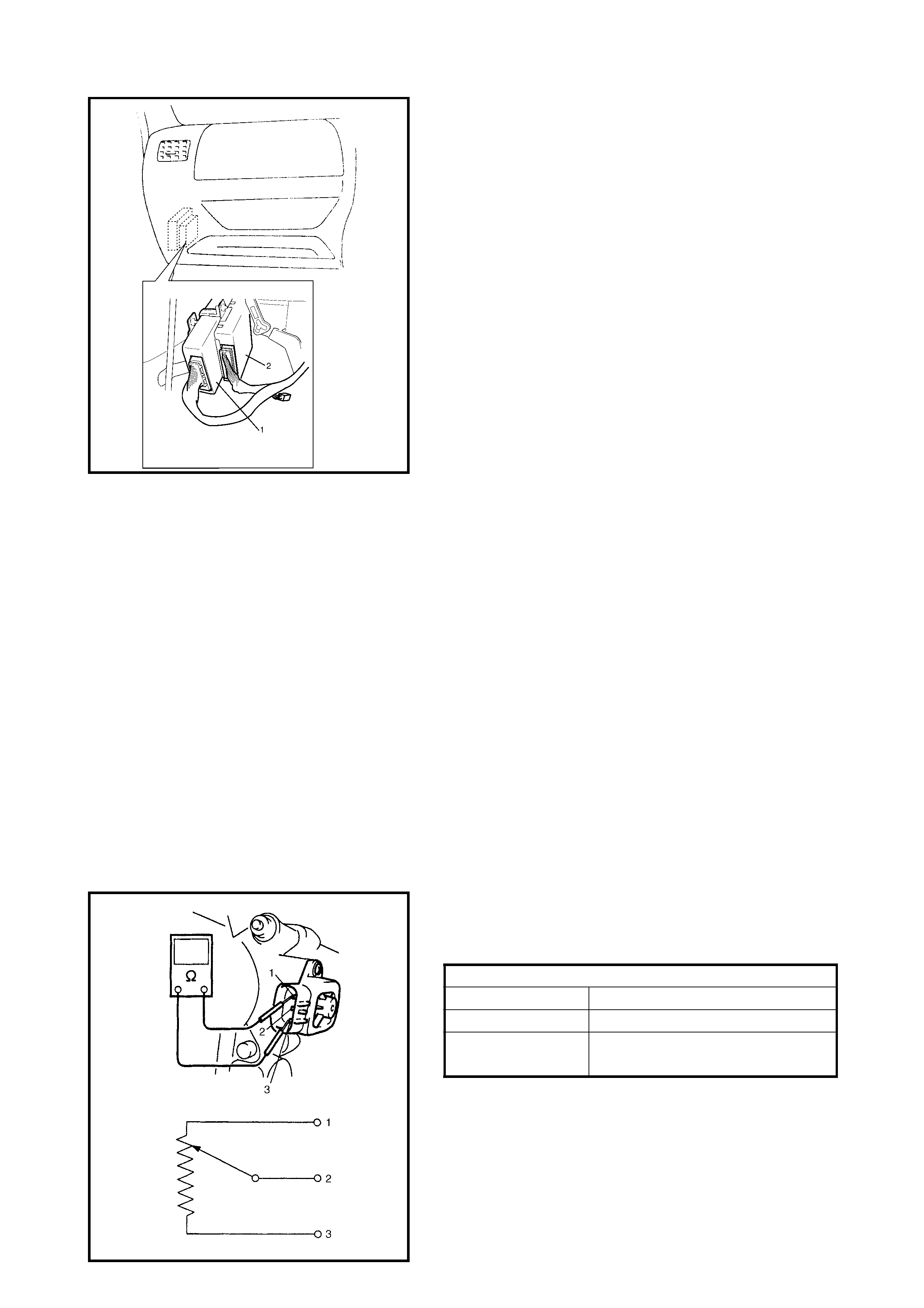
3. Disconnect the ECM (1) and TCM (2) (if equipped)
connectors.
4. Remove the bolt and nuts and remove the ECM and
TCM (if equipped).
Installation
Reverse removal procedure noting the following:
• Connect connectors to ECM and TCM (if equipped)
securely.
MANIFOLD ABSOLUTE PRESSURE SENSOR
(MAP SENSOR)
Inspection
Check the MAP sensor, refer to Section 6, 2.13 DTC P0105
(DTC NO. 11) MANIFOLD ABSOLUTE PRESSURE (MAP)
CIRCUIT MALFUNCTION & DTC P0105 (DTC NO. 11)
MANIFOLD ABSOLUTE PRESSURE (MAP) RANGE /
PERFORMANCE PROBLEM, flow table. If malfunction is
found, replace.
THROTTLE POSITION SENSOR (TP SENSOR)
Inspection
1. Disconnect negative cable at battery and connector
from IAT sensor.
2. Remove the air cleaner assembly with air cleaner
outlet hose and disconnect the TP sensor connector.
3. Using ohmmeter, check resistance between terminals
under each condition given in table below.
If check result is not satisfactory, replace TP sensor
NOTE:
There should be more than 2 kΩ resistance dif-
ference between when throttle valve is at idle position
and when it is fully open.
4. Connect TP sen so r conne cto r sec urel y.
5. Connect negative cable to battery.
Legend
TP SENSOR RESISTANCE
Terminals Resistance
Between 1 and 3 4.0 – 6.0 kΩ
Between 2 and 3 20 Ω – 6.0 k Ω, varying according
to throttle valve opening.
1. Reference voltage terminal
2. Output voltage terminal
3. Grou nd ter mi nal
Removal
1. Disconnect battery negative cable at battery.
2. Remove the throttle body from the intake manifold refer
to 2.1 AIR INTAKE SYSTEM, THROTTLE BODY
REMOVAL in this Section.
3. Remove the TP sensor from throttle body.
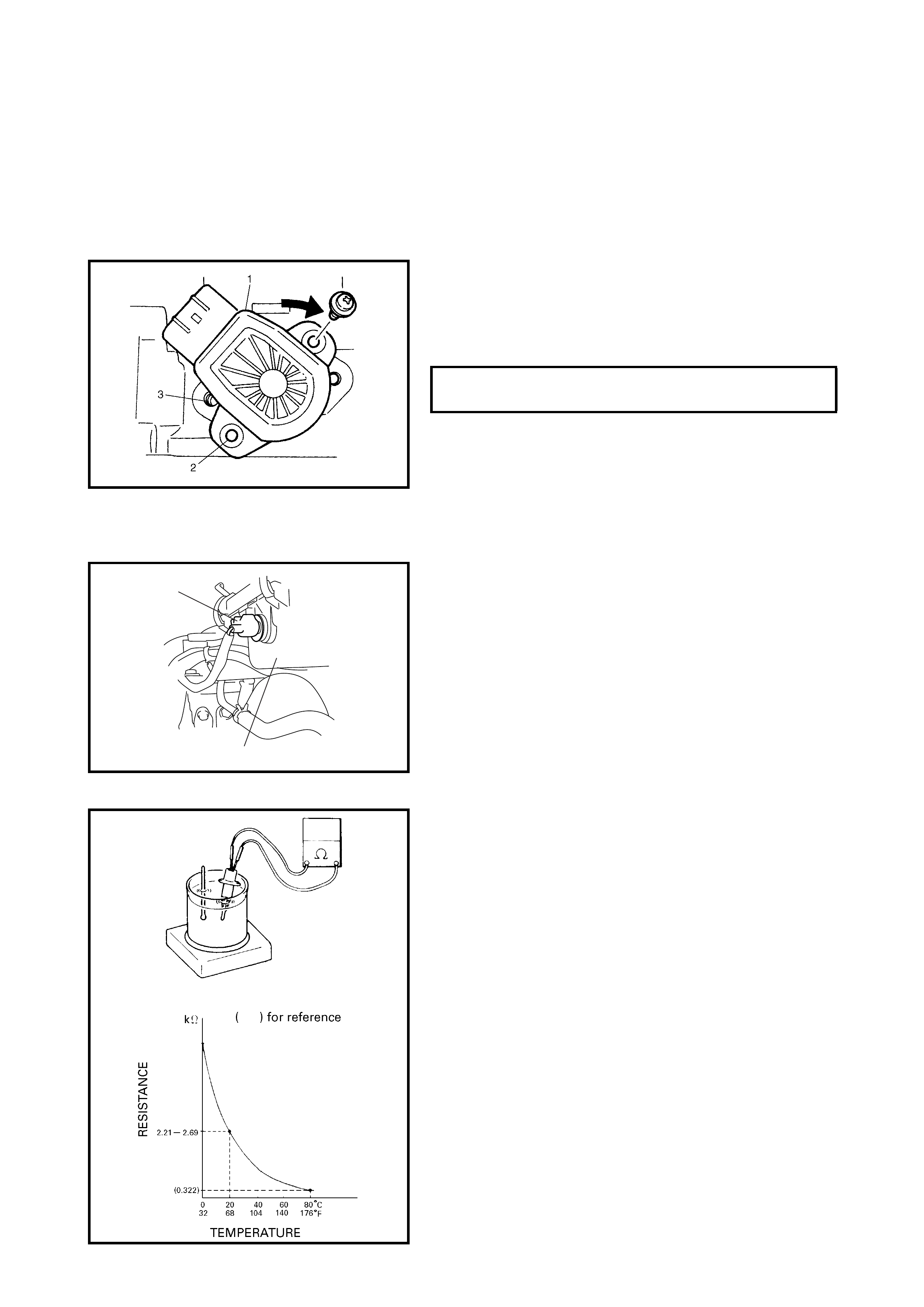
Installation
1. Install the TP sensor (1) to the throttle body.
Fit the TP sensor to the throttle body in such way that
its holes (3) are a little away from the TP s ensor sc rew
holes (2) as shown and turn TP sensor clockwise so
that those holes align.
2. Connect the connector to the TP sensor securely.
3. Connect battery negative cable to battery.
INTAKE AIR TEMPERATURE SENSOR (IAT
SENSOR)
Removal
1. Disconnect battery negative cable at battery.
2. Disconnect the connector (1) from the IAT sensor.
3. Remove the IAT sensor from the air cleaner case (2).
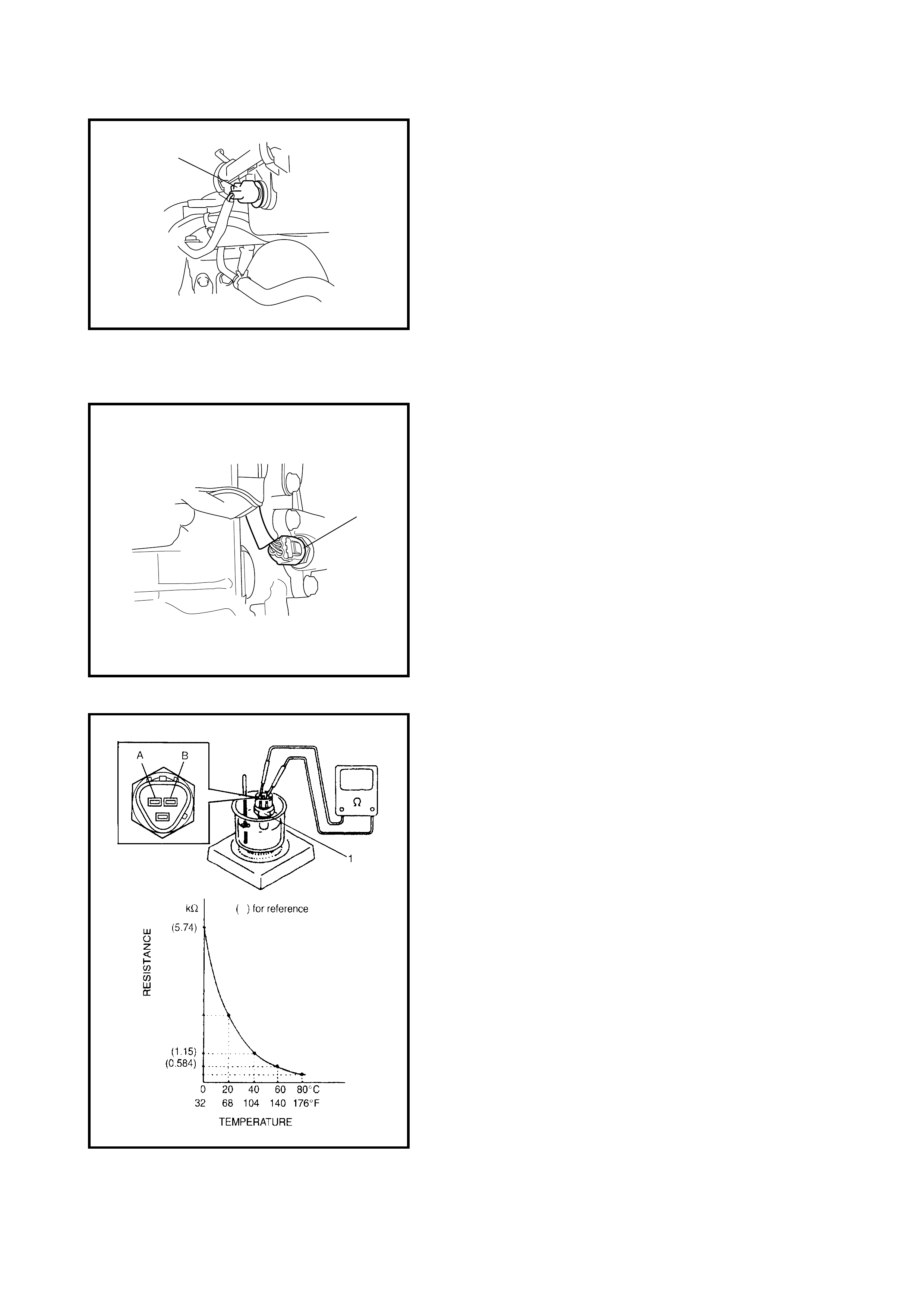
Inspection
Immers e the temperatur e sensing part of the IAT sensor in
water (or ice) and measure the resistance between the
sensor terminals while heating the water gradually.
If measured resistance doesn’t show such characteristic as
shown, replace the IAT sensor.
TP SENSOR SCREW TORQUE
SPECIFICATION (a) 2.5 Nm
1
2
Installation
Reverse removal procedure noting the following.
• Clean mating surfaces of the IAT sensor and air
cleaner case.
• Connect the IAT sensor connector (1) securely.
ENGINE COOLANT TEMPERATURE SENSOR
(ECT SENSOR)
Removal
1. Disconnect battery negative cable at battery.
2. Drain coolant, refer to Section 6B ENGINE COOLING.
WARNING: To avoid danger of being burned, do not
remove radiator cap while engine and radiator are still
hot. Scalding fluid and steam can be blown out under
pressure if cap is taken off too soon.
3. Remove air intake pipe.
4. Disconnect connector from ECT sensor.
5. Remove ECT sensor (1) from thermostat case.
Inspection
Immerse the temperature sensing part of the ECT sensor
(1) in water (or ice) and measure the resistance between
terminal A and B while heating the water gradually.
If measured resistance doesn’t show such characteristic as
shown, replace ECT sensor (1).
1
1
Installation
Reverse removal procedure noting the following:
• Clean the mating surfaces of the ECT sensor (1) and
thermostat case.
• Check O-ring for damage and replace if necessary.
• Tighten ECT sensor (1) to specified torque.
• Connect connector to ECT sensor (1) securely.
• Refill coolant referring to Section 6B.
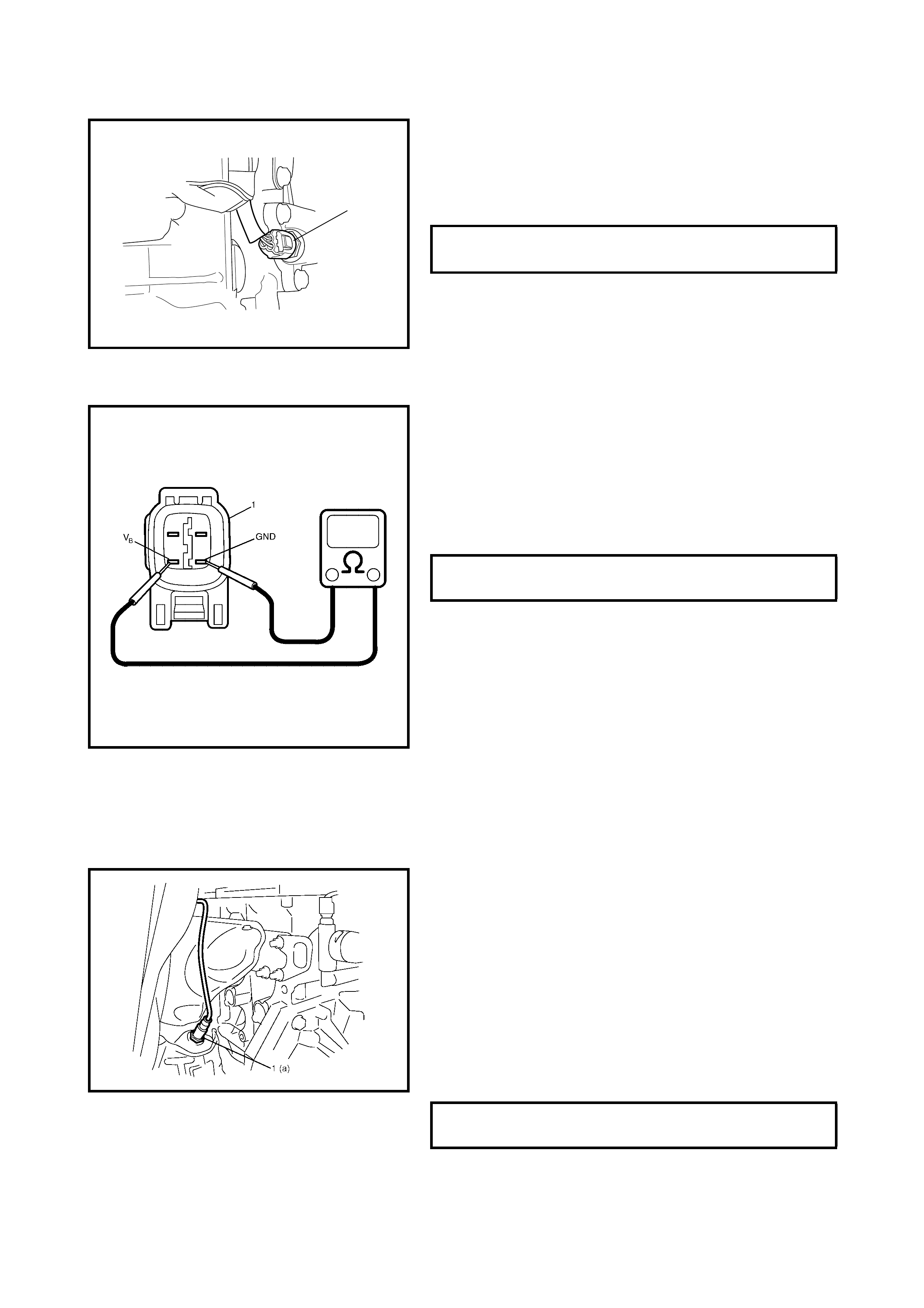
HEATED OXYGEN SENSOR (HO2S)
Oxygen Sensor Heater Inspection
1. Disconnect the sensor connector (1).
2. Using an ohmmeter, measure the resistance between
terminals V
B
and GND of the sensor connector.
If found faulty, replace oxygen sensor.
NOTE: Temperature of sensor affects resistance value
largely. Make sure that sensor heater is at correct tempera-
ture.
3. Connect sensor connector securely.
Removal
WARNING:
To avoid danger of being burned, do not
touch the exhaust system when system is hot. Oxy-
gen sensor removal should be performed when sys-
tem is cool.
1. Disconnect negative cable at battery.
2. Disconnect the heated oxygen sensor connector and
release its wire harness from the clamps, then remove
front bumper and heat insulator panel.
3. For a vehicle equipped with A/C, remove the radiator,
refer to Section 6B, 4.6 RADIATOR.
4. Remove the heated oxygen sensor (1) from the
exhaust manifold.
Installation
Reverse removal procedure noting the following.
• Tighten heated oxygen sensor (1) to specified torque.
• Connect heated oxygen sensor connector and clamp
wire harness securely.
• After installing the heated oxygen sensor, start engine
and check that no exhaust gas leakage exists.
ECT SENSOR TORQUE
SPECIFICATION (a) 15 Nm
1, (a)
OXYGEN SENSOR HEATER RESIS-
TANCE AT 20°C 5.0 – 6.4
Ω
HEATED OXYGEN SENSOR TORQUE
SPECIFICATION (a) 45 Nm
CAMSHAFT POSITION SENSOR
Inspection
Check camshaft position sensor, refer to Section 6, 2.21
DTC P0340 (No.15) CAMSHAFT POSITION (CMP)
SENSOR CIRCUIT MALFUNCTION, diagnostic flow table.
If malfunction is found, replace.
Removal
1. Disconnect negative cable at battery.
2. Disconnect the connector from the camshaft position
sensor.
3. Remove the camshaft position sensor from the timing
chain cover.
Installation
1. Check that the O-ring is free from damage.
2. Check that the camshaft position sensor and signal
rotor tooth are free from any metal particles and
damage.
3. Install the camshaft position sensor to the timing chain
cover.
4. Connect the connector securely.
5. Connect negative cable to battery.
CRANKSHAFT POSITION SENSOR
Inspection
Check the crankshaft position sensor, refer to Section 6,
Step 1 and 2, 2.20 DTC P0335 (No.23) CRANKSHAFT
POSITION SENSOR CIRCUIT SENSOR MALFUNCTION,
flow table. If malfunction is found, replace.
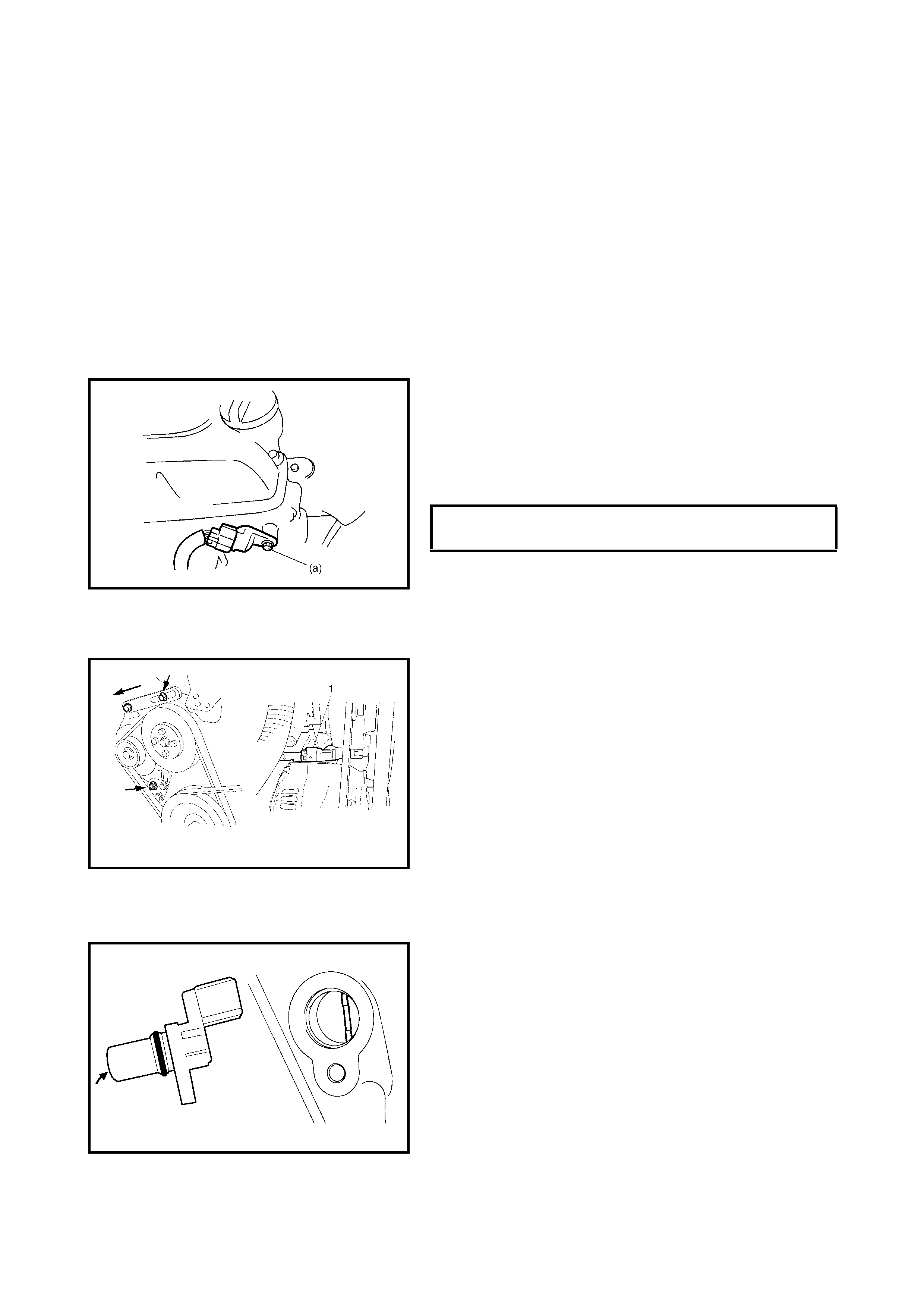
Removal
1. Disconnect negative cable at battery.
2. Remove the generator drive belt, loosen the pivot bolt
and move the generator outward.
3. Disconnect the connector from the crankshaft position
sensor.
4. Remove the crankshaft position sensor (1) from the
cylinder block.
Installation
1. Check to make sure that the crankshaft position sensor
and pulley tooth is free from any metal particles and
damage.
2. Install the crankshaft position sensor to the cylinder
block.
3. Connect the connector to it securely.
4. Adjust the generator belt tension, refer to
Section 6H 3.2 GENERATOR BELT.
5. Connect negative cable to battery.
CAMSHAFT POSITION SENSOR BOLT
TORQUE SPECIFICTION (a) 10 Nm
VEHICLE SPEED SENSOR (VSS)
Inspection
Check the vehicle speed sensor, refer to Section 6, Step 3,
2.22 DTC P0500 (No.16) VEHICLE SPEED SENSOR
MALFUNCTION, Flow Table. If malfunction is found,
replace.
Removal/Installation
Refer to Section 7A.
KNOCK SENSOR
Inspection
Check knock sensor refer to Section 6, 2.19 DTC P0325
(No.17) KNOCK SENSOR CIRCUIT MALFUNCTION, flow
table. If malfunction is found, replace.
Removal/Installation
1. Disconnect negative cable from the battery.
2. Hoist the vehicle.
3. Remove the intake manifold stiffener.
4. Disconnect the knock sensor connector (1).
5. Remove the knock sensor (2) from the cylinder block.
Installation
Reverse r emoval procedure for installation.
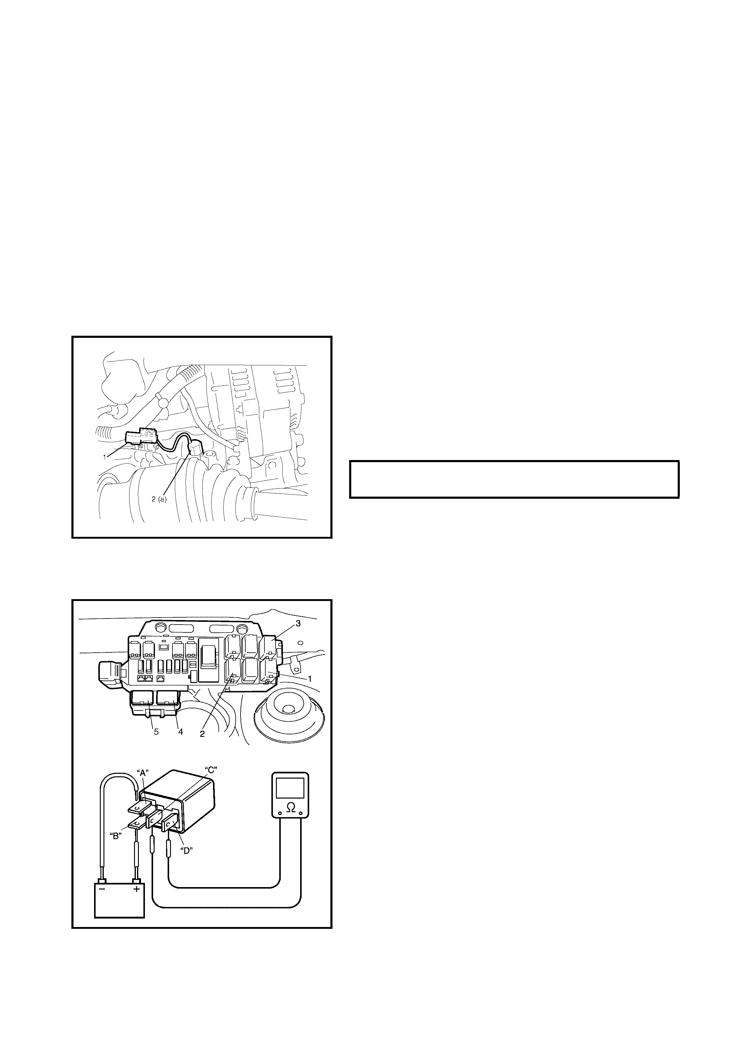
MAIN RELAY, FUEL PUMP RELAY AND RADIATOR
FAN RELAY NO.1, NO.2, NO.3
Inspection
1. Disconnect negative cable at battery.
2. Remove the main relay (1), fuel pump relay (2) and
radiator fan control relay No.1 (3), No.2 (4) and No.3
(5) from the vehicle.
3. Check that there is no continuity between terminal C
and D. If there is continuity, replace relay.
4. Connect battery positive (+) terminal to terminal B of
relay.
Connect the batter y negati ve (–) termi nal A of relay.
Check continuity between terminal C and D.
If there is no continuity when relay is co nnected to th e
battery, replace relay.
KNOCK SENSOR TORQUE
SPECIFICATION (a) 23 Nm
FUEL CUT OPERATION
Inspection
NOTE:
Before inspection, check that the gear shift lever
is in neutral position (with A/T model, selector lever in P
range), A /C is OFF an d tha t parki ng brak e l ever i s p ul led
all the w a y up .
1. Warm up engine to normal operating temperature.
2. While li steni ng to th e soun d of the injector (1) by usin g
sound scope (2) or such, increase engine speed to
higher than 3,000 r/min.
3. Check to make sure that the injector operation sound
stops when the throttle valve is closed instantly and is
heard again when engine speed is reduced to less
than about 2,000 r/min.
RADIATOR FAN CONTROL SYSTEM
System Inspection
WARNING:
Keep hands, tools, and clothing away
from the engine cooling fan to prevent personal
injury. This fan is electric and can come on whether
or not the engine is running. The fan can start auto-
matically in response to the ECT sensor with the
ignition switch in the ON position.
Check system for operation referring to 2.30 TABLE B-7
RADIATOR FAN CONTROL SYSTEM CHECK in Section
6. If the radiator fan fails to operate properly, check relay,
radiato r fan and electri ca l circuit.
OUTPUT SIGNALS OF THROTTLE VALVE
OPENING AND ENGINE COOLANT
TEMPERATURE (VEHICLE WITH A/T ONLY)
Throttle Valve Opening Signal Inspection
Check the throttle valve opening (throttle position) signal,
refe r to Ste p 1, Sec tio n 7B , 2.3 5 D TC P1 70 0 /DT C NO .3 2
OR NO.33 THROTTLE POSITION SIGNAL CIRCUIT
MALFUNCTION, flow table. If check result is not
satisfactory, check each wire harness, circuit connections
and TP sensor.
Engine Coolant Temperature Signal Inspection
Check engine the coolant temp. signal, refer to Step 1,
Section 7B, 2.37 DTC P1705/DTC NO.51 ENGINE COOL-
ANT TEMPERATURE SIGNAL CIRCUIT MALFUNCTION,
flow table. If check result is not satisfactory, check each
wire harness, circuit connection and ECT sensor.
2.4 EMISSIO N CO NTROL SYSTEM
EGR SYSTEM
Removal
1. Disconnect negative cable at battery.
2. Remove air intake pipe.
3. Remove EGR pipe.
4. Disconnect EGR valve connector.
5. Remove EGR valve and gasket from cylinder head.
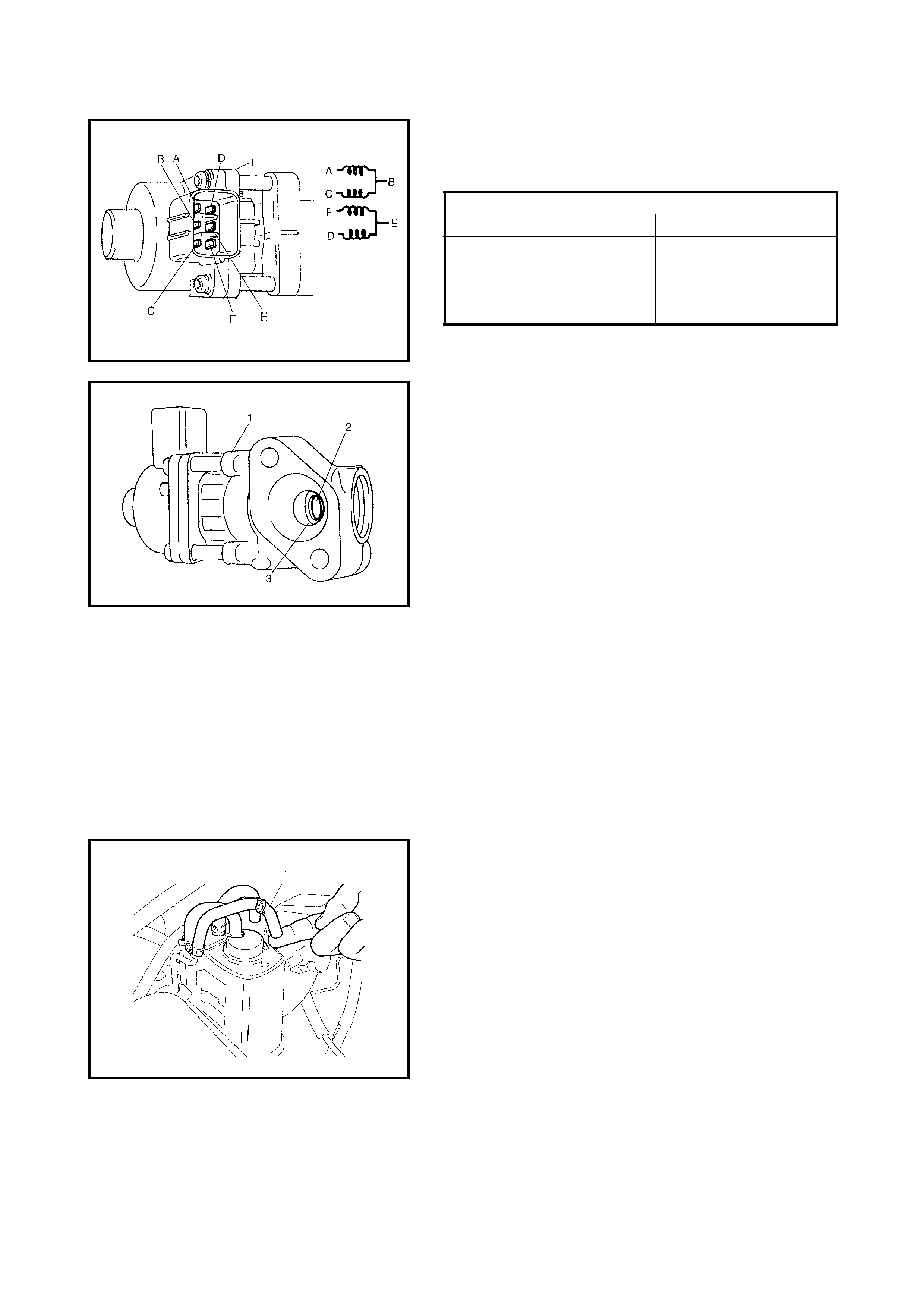
Inspection
1. Check resistance between following terminals of EGR
valve (1) in each pair.
If found faulty, replace EGR valve assembly.
2. Remove carbon from EGR valve gas passage.
NOTE: Do not use a sharp-edged tool to remove carbon.
Be car efu l no t to dam age or be nd t he E G R valv e (1 ), valve
seat (3) and rod.
3. Inspect the valve (2), valve seat and rod for fault,
cracks, bend or other damage.
If found faulty, replace the EGR valve assembly.
Installation
Reverse removal procedure noting following.
• Clean mating surface of valve and intake manifold.
• Use new gaskets.
EVAPORATIVE EMISSION CONTROL SYSTEM
Evap Canister Purge Inspecti on
NOTE:
Before inspection, check to make sure that the
gear shift lever is in neutral position (with A/T model,
selector lever in P range) and that the parking brake
lever is pulled all the way up.
1. Disconnect purge hose (1) from EVAP canister.
2. Place finger against the end of the disconnected hose
and check that vacuum is n ot felt when engine is cool
and running at idle speed.
3. Connect purge hose to EVAP canister and warm up
engine to normal operating temperature.
4. Disconnect purge hose from EVAP canister.
5. Also check that va cuum is felt when engine is running
at idle speed.
If check result is not satisfactory, check vacuum
passage, hoses, EVAP canister purge valve, wire
harness and ECM.
NOTE:
The EVAP canister purge system does not per-
form purging (vacuum is not detected at the pur ge hose)
unless the engine is sufficiently warmed up and the
heated oxygen sensor is activated fully. Also, when the
purge hose is disconnected in Step 4, the air is drawn
into the purge line. As a result, the ECM detects a
change in the purge gas concentration and sometimes
stops purging but this indicates nothing abnormal.
EGR VALVE RESISTANCE
Terminal Standard resistance
A – B
C – B
F – E
D – E
20 – 24 Ω
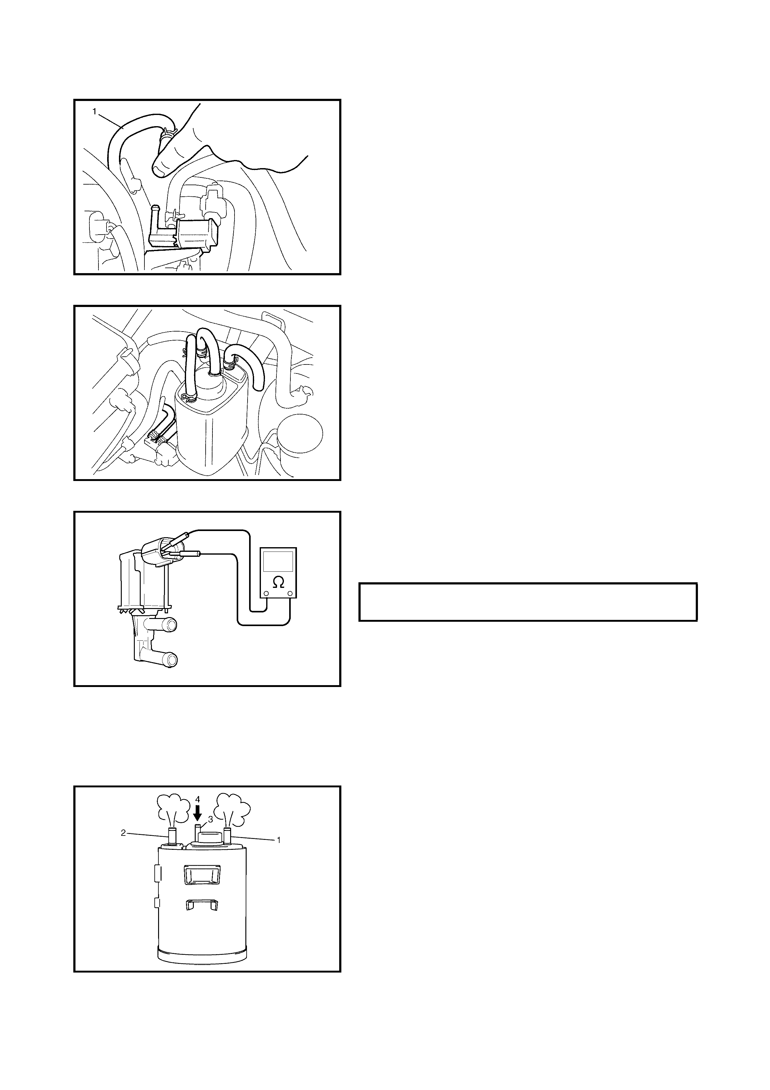
Vacuum Passage Inspection
Start the engine and run it at idle speed. Disconnect the
vacuum hose (1) from E VAP cani ster pu rge v alve (2 ). With
a finger placed against hose, check that vacuum is applied.
If it is not applied, clean the vacuum passage by blowing
compressed air.
Vacuum Hose Inspection
Check hoses for connection, leakage, clog and deteriora-
tion. Replace as necessary.
EVAP Canister Purge Valve Inspection
1. With the ig nition sw itch OF F, disconn ect the con nector
from the canister purge valve.
2. Check the res istance between the two terminals of the
EVAP canister purge valve.
If resistance is not as specified, replace.
EVAP Canister Inspection
WARNING:
Do not suck nozzles on EVAP canister.
Fuel vapor inside EVAP canister is harmful.
1. Check outside of EVAP canister visually.
2. Disconnect vacuum hoses from EVAP canister.
3. Check that there should be no restriction of flow
through purge pipe (1) and air pipe (2) when air is
blown (4) into tank pipe (3).
If any faulty condition is found in above inspection
replace.
EVAP CANISTER PURGE VALVE
INSPECTION 30 – 40
PCV SYSTEM
NOTE:
Check that there is no obstruction in the PCV
valve or its hoses before checking IAC duty, as an
obstructed PCV valve or hose hampers its accurate
adjustment.
PCV Hose Inspection
Check hos es for co nnecti on, leakag e, bloc kages and dete-
rioration.
Replace as necessary.
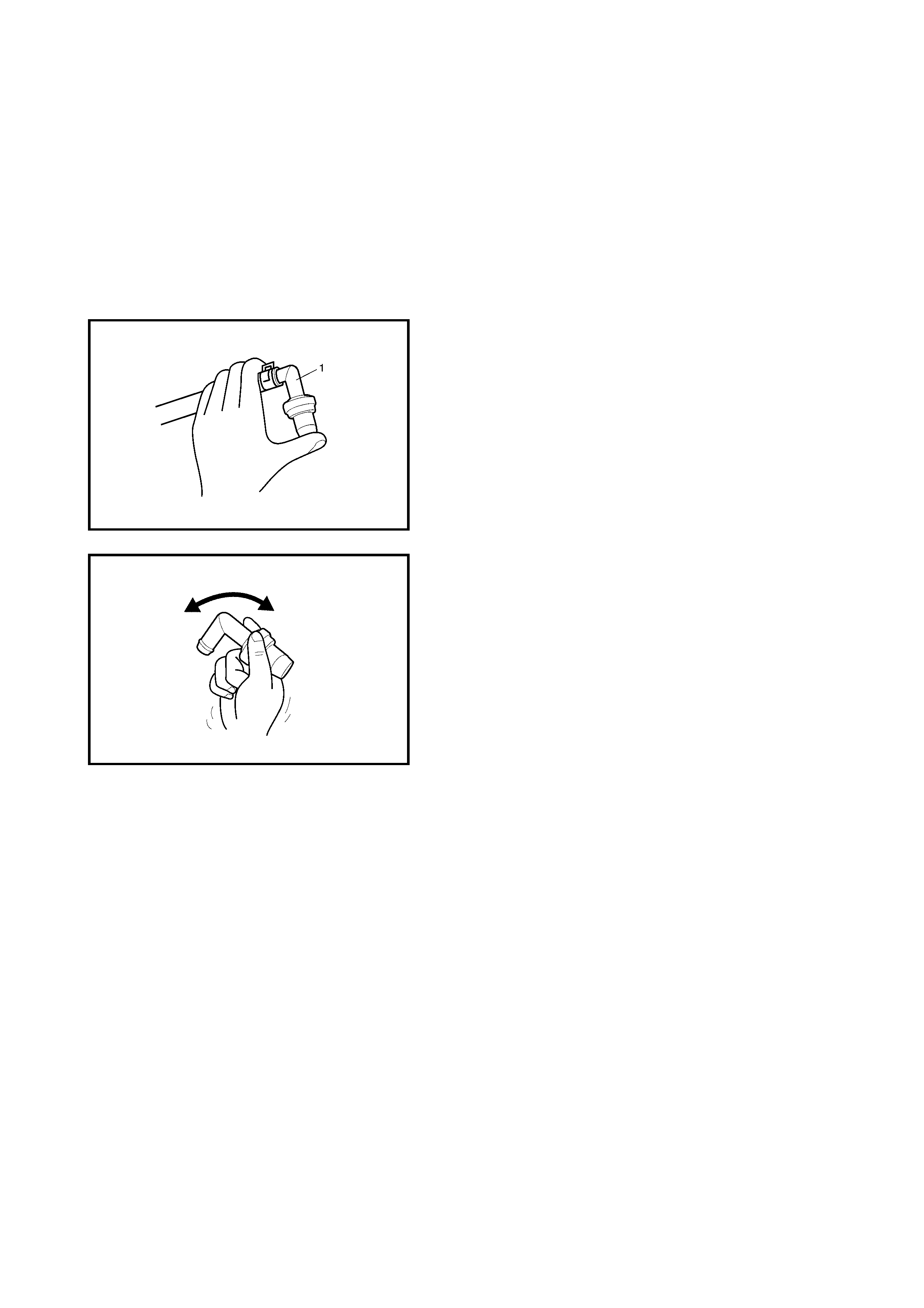
PCV Valve Inspection
1. Disconnect PCV valve (1) from cylinder head cover
and install plug to head cover hole.
2. Run engine at idle.
3. Place your finger over end of PCV valve (1) to check
for vacuum.
If there is no vacuum, check for clogged valve.
Replace as necessary.
4. After checking vacuum, stop engine and remove PCV
valve (1).
Shake valve and listen for the rattle of check needle
inside the valve. If valve does not the rattle, replace
valve.
5. After checking, remove plug and install PCV valve (1).
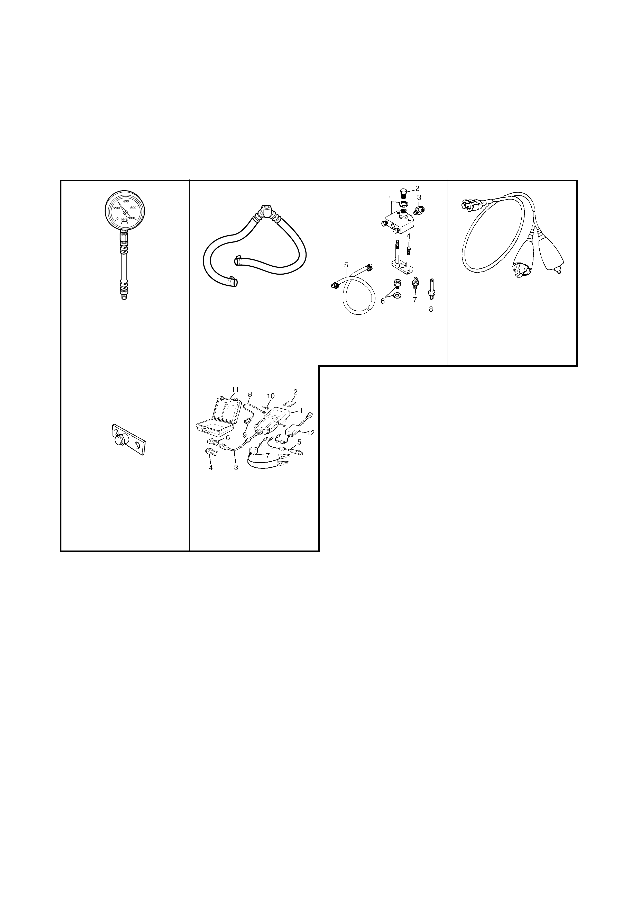
3. SPECIAL TOOLS
NOTE: Refer to Section 0A GENERAL INFORMATION – 7. CONSOLIDATED TOOLS for a detailed list of
special tools and the local equivalent if one is available.
NOTE A: This kit incl ud es the foll owi ng items .
1. Tool body & washer, 2. Body plug, 3. Body attachment-1, 4. Holder, 5. Return hose & clamp,
6. Body attachment-2 & washer, 7. Hose attachment-1, 8. Hose attachment-2.
NOTE: B
This kit includes the following items:
1. Tech 2, 2. PCMCIA card, 3. DLC cable, SAE 16/19 adapter, 5. Cigarette cable, 6. DLC loopback adapter,
7. Battery power cable, 8. RS232 cable, 9. RS232 adapter, RS232 loopback connector, 11. Storage case,
12. Power supply.
SD28018 or AU338 SD28057 09912-5 842 1 09930-88 530
Pressure gauge Fuel pressure gauge
hose Checking tool set
(See NOTE A.) Injector test lead
09912-57610
Checking tool plate Tech 2 kit (Scan Tool)
(See NOTE B below.)