
SECTION 6H - CHARGING SYSTEM
1. GENERAL DESCRIPTION
1.1 BATTERY
Carrier and Hold-down
Electrolyte Freezi ng
Sulfation
Care Of Battery
1.2 GENERATOR
2. DIAGNOSIS
2.1 BATTERY
Visual Inspection
Hydrometer Test
2.2 GENERATOR
Charging Indicator
Lamp Operation
Un derch arged Ba tte ry
No -load C hec k
Load Check
Overcharged Batte ry
3. ON- VEHIC LE SERVI CE
3.1 BATTERY
Jump Starting In Case of Emergency
with Auxiliary (Booster) Battery
Jum p Starting with
Charging Equipment
Removal
Handling
Installation
3.2 GENERATOR BELT
3.3 GENERATOR
Removal
Installation
Disass embl y and Reassem bly
Inspection
4. SPECIFICATION
4.1 BATTERY
4.2 GENERATOR
WARNING:
For vehicles equipped with Supplemental Restraint (Airbag) System :
• Service on and around the airbag system components or wiring must be performed only by
an authorised HOLDEN retailer. Refer to AIRBAG SYSTEM COMPONENTS and WIRING
LOCATION VIEW under GENERAL DESCRIPTI ON in Secti on 10B AIRB AG SYSTEM in order to
conf irm whet he r y o u are pe rformin g ser vic e on or near the airba g syst em com pone nt s or wi r-
ing. Please observe all WARNINGS and SERVICE PRECAUTIONS under ON-VEHICLE SER-
VICE in Section 10B AIRBAG SYSTEM before performing service on or around the airbag
system compone nts or wiring. Failure to follow WARNINGS coul d result in u nintentional acti-
vation of the system or could render the system inoperative. Either of these two conditions
may re sult in severe injury.
• Technical service work must be started at least 90 seconds after the ignition switch is turned
to the “LOCK” position and the negative cable is disconnected from the battery. Otherwise,
the system may be activated by reserve energy in the Sensing and Diagnostic Module (SDM).

1. GENERAL DESCRIPTION
1.1 BATTERY
The battery has three major functions in the electrical system.
• It is a source of electrical energy for cranking the engine.
• It acts as a voltage stabiliser for the electrical system.
• It can, for a limited time, provide energy when the electrical load exceeds the output of the generator.
CARRIER AND HOLD-DOWN
The battery carrier should be in good condition so that it will support the battery securely and keep it level.
Before installing the battery, the battery carrier and hold-down clamp should be clean and free from corrosion
Ensure there are no parts fouling the carrier.
To prevent the battery from shaking in its carrier, the hold-down bolts should be tight, but not over-tightened.
ELECTROLYTE FREEZING
The freezing point of electrolyte depends on its specific gravity. Since freezing may ruin a battery, it should be
protected against freezing by keeping it in a fully charged condition. If a battery is frozen accidentally, it should
not be charged until it is warmed.
SULFATION
If the battery is allowed to stand for a long period in a discharged condition, the lead sulfate becomes con-
verted into a hard, crystalline substance, which will not easily turn back to the active material again during the
subsequent recharging. SULFATION means the result, as well as the process, of that reaction. Such a battery
can be revived by very slow charging and may be restored to usable condition but its capacity will be lower
than before.
CARE OF BATTERY
WARNING:
• Never expose the battery to open flame or electric spark because the battery generates gas which
is flammable and explosive.
• Do not allow battery fluid to contact eyes, skin, fabrics, or painted surfaces as the battery fluid is a
corrosive acid. Flush any contaminated area with water immediately and thoroughly.
• Batteries should always be kept out of reach of children.
1. The battery is a very reliable component, but needs periodical attention.
• Keep the battery carrier clean.
• Prevent rust formation on the terminal posts.
• Keep the electrolyte up to the upper level uniformly in all cells.
• If vehicle is being stored for long periods or used infrequently, follow the instructions below.
- Weekly, start the engine and run it until it reaches normal operating temperature with an engine speed
of 2000 to 3000 rpm. Make sure all electric switches are off before storing the vehicle.
- Recharge the battery twice a month to prevent it from discharging excessively. This is especially
important when ambient temperature is low.
The battery discharges even when it is not used, while vehicles are being stored. Battery electrolyte
can freeze and the battery case can crack in cold ambient conditions if the battery is not properly
charged.
2. Keep the battery cable connections clean.
The cable connections, particularly the positive (+) terminal post, tends to become corroded. The product
of corrosion, or rust, on the mating faces of conductors resists the flow of current.
Clean the terminals and fittings periodically to ensure good metal-to-metal contact, and grease the
connections after each cleaning to protect them against rusting.
3. Always be aware of the state of charge of the battery. The simplest way to tell the state of charge is to
carry out a hydrometer test. The hydrometer is an instrument for measuring the specific gravity (S.G.) of
the battery electrolyte. The S.G. of the electrolyte is indicative of the state of charge. Refer to
2.1 BATTERY in this Section.
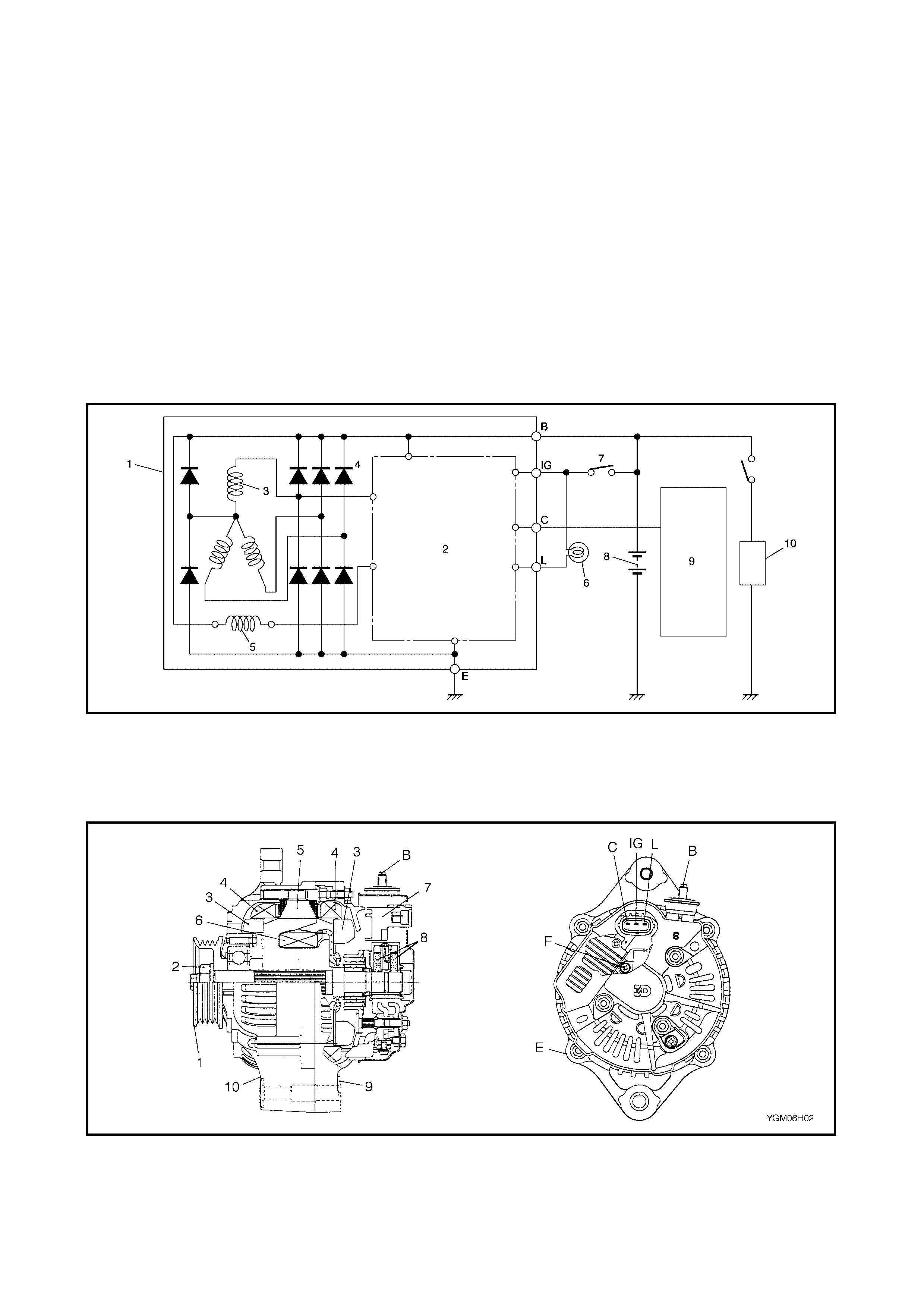
1.2 GENERATOR
The generator is a sm all, high perform anc e type with an integrated circuit (IC) regulator incorp orated.
The internal compo nents are connect ed electricall y as shown in th e figure below.
The generator’s features are as fol lows:
• A solid state regulator is mounted inside the generator.
• All regulator component s are enclosed in a solid mould.
• This unit along with the brush holder assembl y is attached to the rear housing.
• The IC regulator uses integrated circuits and controls the voltage produced by the generator, and the volt-
age setting cann ot be adjusted.
• The generator rotor bearings contain enough grease to eliminate the need for periodic lubrication. Two
brushes carr y current through the two slip rings to the field coil mounted on the rotor, and under nor mal
conditions will provide long periods of attention-free service.
• The stator windings are assembled on the inside of a laminated core that forms part of the generator
frame.
Legend
Legend
1. Generator with regulator ass’y 4. Di ode 7. Main switch 10. Load
2. I.C. regul ato r 5. Field coil (rotor coil) 8. Battery
3. Stator coil 6. Charge indicator light 9. ECM
1. Pul ley 5. Stator core 9. Rear end fram e E Ground
2. Pulley nut 6. Field coil 10. Drive end frame F Fi eld coil terminal
3. Rotor fan 7. Regulator B Gen erator output (Batter y ter m inal) IG Ignition terminal
4. Stator coil 8. Brush C Dummy terminal L Lamp terminal
2. DIAGNOSIS
2.1 BATTERY
VI SUAL IN SPECTION
Check for obvious damage, such as cra cked or broken case or c over, that cou ld perm it loss of electr olyte.
If obvious damage is noted, replace battery. Determine cause of damage and correct as needed.
HYDROMETER TEST
The direct method of che cki ng the batter y for s tate of c harge is to carr y out a high rate discharge test, which
involves a special precise voltmeter and an expensive instrument used in the service shops, but not recom-
mendable to the user of the vehicle.
At 20 °C batter y temperature (electrolyte temperature):
The battery is in a FULLY CHARGED STATE if the electrolyte S.G. is 1.280.
The batter y is in a HALF CHARGED STATE if the S.G. is 1.220.
The battery is in a NEARLY DISCHARGED STATE if the S.G. is 1.150 and is in danger of freezing.
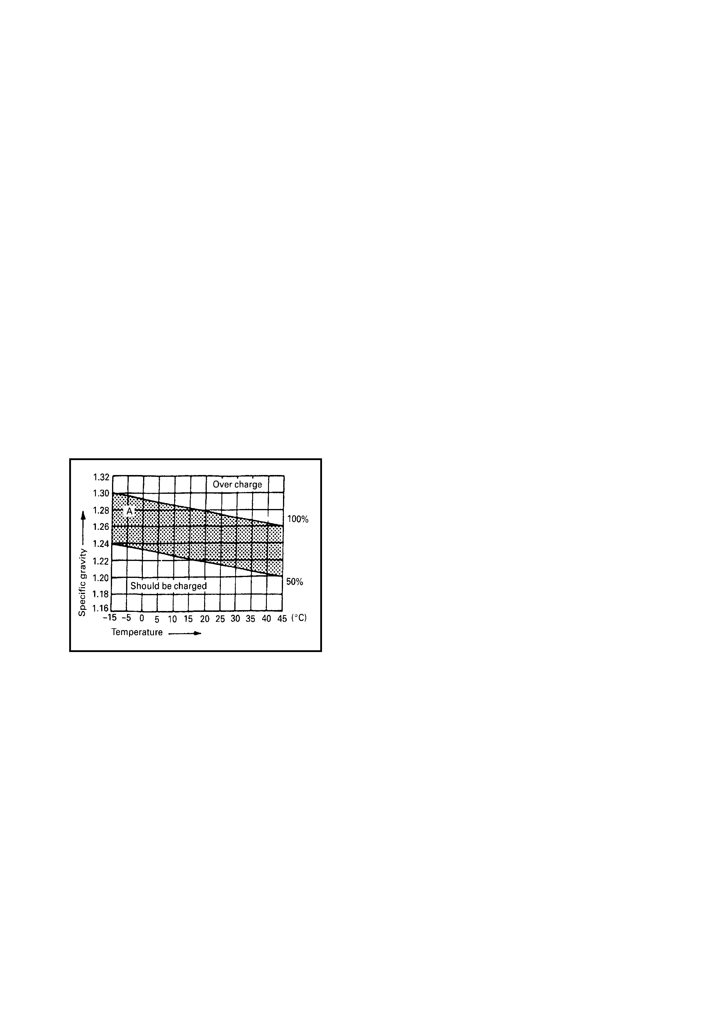
The S.G. var ies wi th the t em perature. If the batter y temperat ure i s not at 20°C, you have to correct your S.G.
reading (taken with your hydrometer) to the value at 20°C and apply the corrected S.G. value to the three-
point guide stated value.
F or the amount of correction, ref er to the gr aph (below) showing the relationship between S.G. value and tem-
perature.
How to use the temperature-corrected state-of-charge
graph
Supp os e your S.G. reading i s 1.28 and the batter y tem per-
ature is –5°C. Locate the intersection of the –5°C line and
the 1.28 S.G. line.
The intersection is within the “A” zone (shaded area in the
graph) and that means CHARGED STATE.
To know how m uch the batter y is charged , draw a line par-
allel to the zone demarcation li ne and extend it to the r ight
till it meets with the percentage scale. In the present ex am -
ple, the line meets at about 85% point on the percentage
scale. Therefore, the battery is charged up to the 85%
level.
2.2 GENERATOR
CAUTION:
• Do not mistake polarities of IG termin al and L terminal.
• Do no t create a short circuit between IG an d L termina ls. Always conn ect the se term ina ls th rough
a lamp.
• Do not connect any load between L and E.
•When connecting charger or booster battery to the vehicle battery, refer to this section
describing battery charging.
Problems with the charging system will show up as one or
more of the following conditions:
1. Faulty indicator lamp operation.
2. An undercharged battery as evidenced by slow
cranking.
3. An overcharged battery as evidenced by excessive
spewing of electrolyte from vents.
Noise from the generator may be caused by a loose drive
pulley, loose mounting bolts, worn or dirty bearings, a
defective diode or a defective stator.
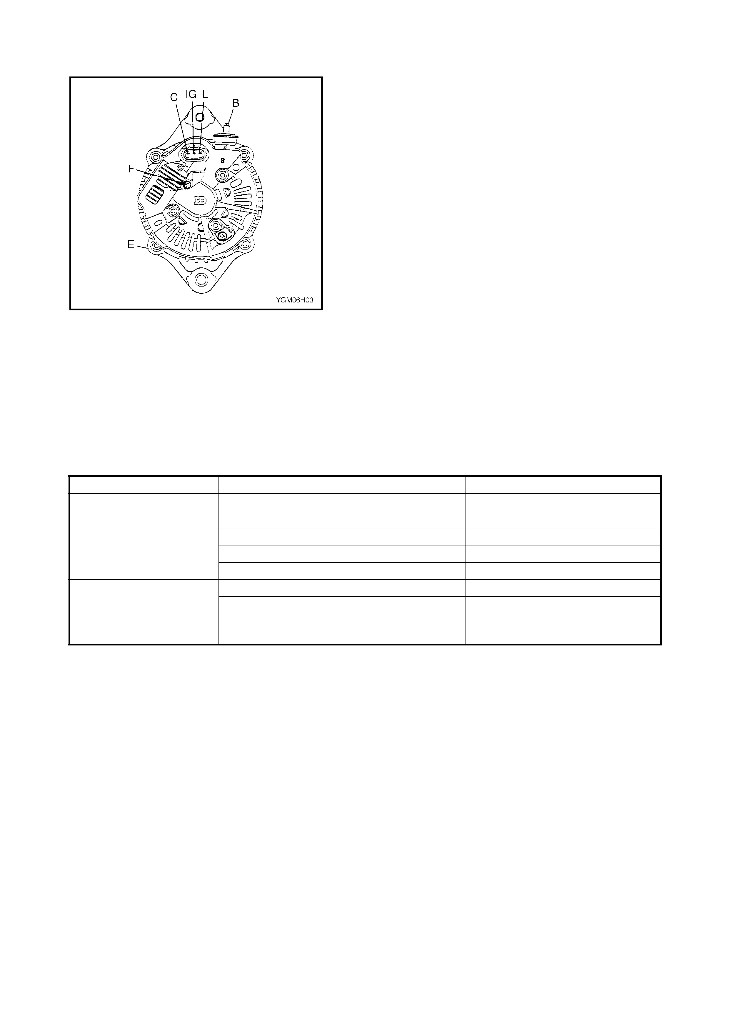
Legend
CHARGING INDICATOR LAMP OPERATION
UNDERCHARGED BATTERY
This condition, is evidenced by slow cranking or low spe-
cific gravity and can be caused by one or more of the fol-
lowing conditions, even though the indicator lamp may be
operating normally.
The following procedure also applies to cars with voltmeter
and ammeter.
• Make sure that the undercharged condition has not
been caused by accessories being left on for an
extended period of time.
• Check drive belt for proper tension.
• If a battery defect is suspected, refer to 2.1, BATTERY
in this Section.
• Inspect the wiring for defects. Check all connections for
tightness and cleanliness, battery cable connections
on the battery, starting motor and i gnition ground cabl e.
B Generato r output (Battery ter minal)
C C ter minal
E Ground
F Field coil terminal
IG Ignition terminal
L Lamp terminal
Condi tion Possible Cause Corr ection
C harge light does not
light with ignitio n ON
and engine off
Fuse blown Check fuse.
Light burned out Replace light.
Wiring connection loose Tighten loose connection.
IC regulator or field coil faulty Check generator.
Poor contact between brush and slip ring Repair or replace.
C harge light does not
go out with engine run-
ning (battery requi res
frequ ent recharging)
Driv e belt loose or worn Adjust or replace driv e belt.
IC regulator or generator faul ty Check charging system.
Wiring faul ty Repair wiring.
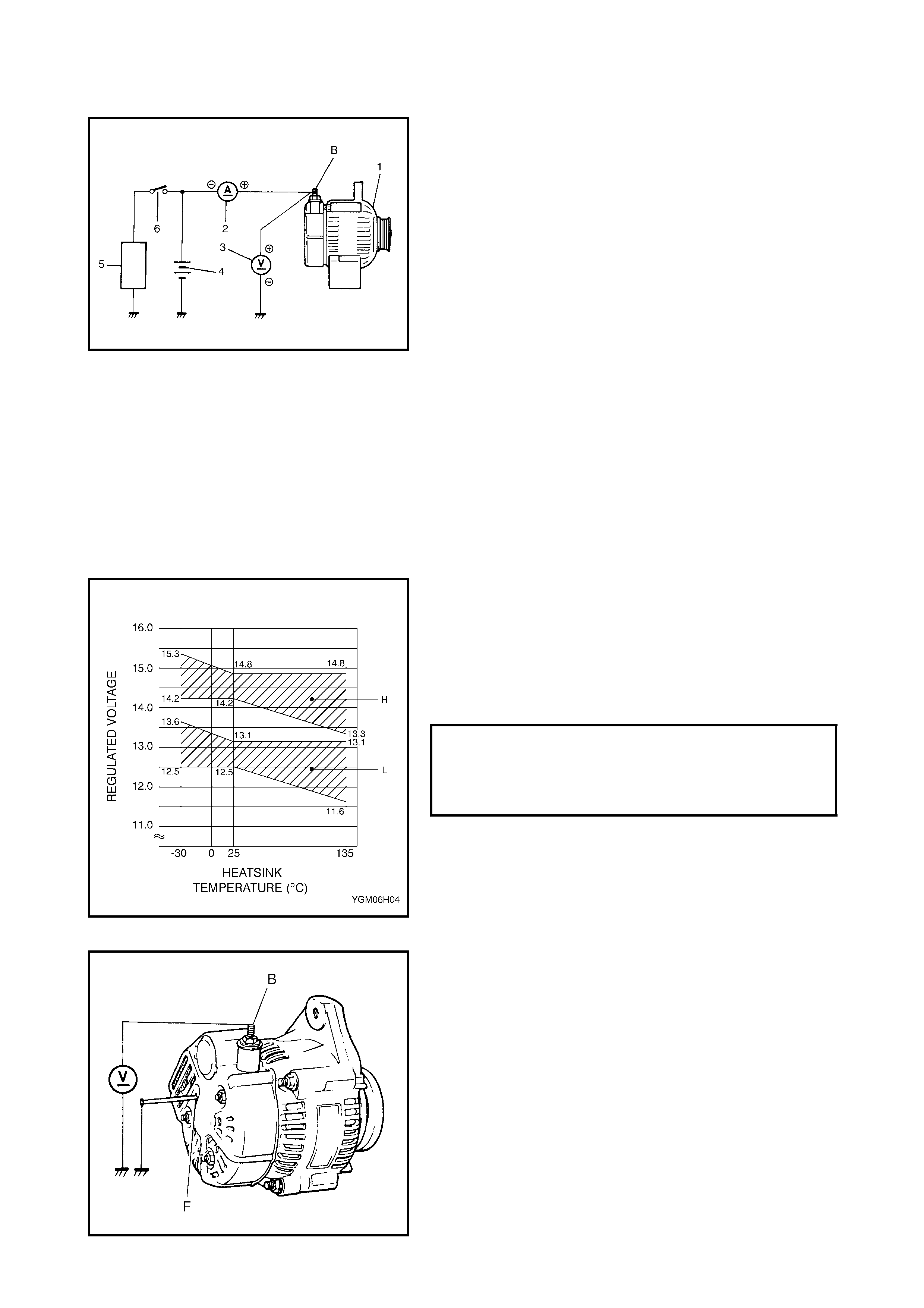
NO-LO AD CHECK
1. Connect a voltmeter and ammeter as shown in the
figure.
NOTE: Use fully charged battery.
Legend
2. Run the engine from idle up to 2,000 rpm with all
accessori es tur ned off and read meters.
If the voltage is higher than the standard value, check
the grounding of brus hes.
If brushes are not grounded, replace the IC regulator.
If the voltage is lower than the standard value, proceed
with the following check.)
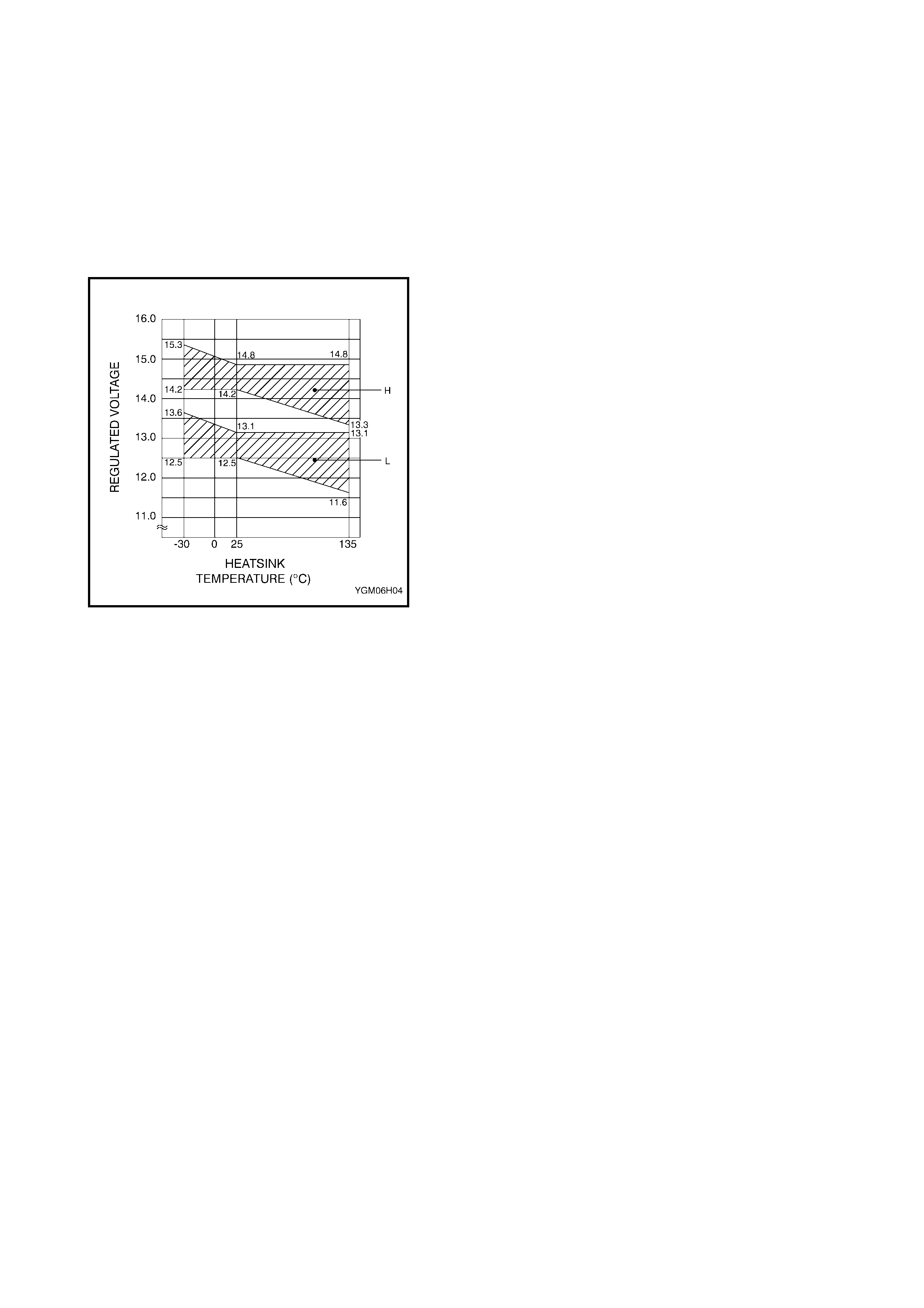
NOTE: Consideration should be given that the voltage will
differ somewhat with regu lator case temperature as shown
in the figure.
3. Ground F-terminal and start engine, then measure
vol tage at B-terminal as shown in the figure.
• If the voltage is higher than the standard value,
it is considered that the generator itself is good but t he
IC regulator has been damaged, replace the IC regula-
tor.
• If the vol tage is lower than the standard value,
the generator itself has a problem, chec k the generat or.
1. Generator
2. Am m eter (between generator B-term inal
and battery (+) ter m inal)
3. Voltmeter (between generator B-term inal
and groun d)
4. Battery
5. Load
6. Switch
VO LTAGE SPECIFICATIO N FOR
UNDERCHARGED BATTERY AT 25°C
(NO-LOAD CHECK) HI (H)
LO (L) 14.2 - 14.8 VOLTS
12.5 - 13.1 VOLTS
LOAD CHECK
1. Run the engine at 2,000 rpm and turn on the head
lights and heater blower motor.
2. Measure current and if it is less than 20 A, repair or
replace generator.
OVERCHARGED BATTERY
1. To determine the battery condition, refer to
2.1, BATTERY in this Section.
2. If an obvious overcharge condition exists as evidenced
by excessive spewing of electrolyte, measure the
generator B-terminal voltage at 2000 rpm engine
speed.
3. If the measured voltage is higher than the upper limit
value, disassemble generator.
4. Check gro und of brush es. If brushes are n ot grounded,
replace IC regulator. Check field coil for grounds and
shorts.
3 . ON-VEHICLE SE RVICE
3.1 BATTERY
JUMP STARTING IN CASE OF EMERGENCY WITH AUXILIARY (BOOSTER) BATTERY
CAUTION: If the vehicle is a manual transmission model and has a catalytic converter, do not
push or tow it to start. Damage to its emission system and/or to other parts may result.
Both booste r and discharged bat te r y should be treated carefully when us ing jumper cables. Follow procedure
outlined below, being careful not to cause sparks.
WARNING: Depar ture from the c ondition s or procedures describe d below could result in:-
• Serious personal injury (particularly to eyes) or property damage from such causes as battery
explosion, battery acid, or electrical bu rns.
• Damag e to electronic compon ents of either vehicle.
• Remove rings , watches, and other jewelr y. Wear approved eye protection.
• Take care th at metal to ols or jumper cables do n ot contac t the posi tive battery te rminal (or m etal
comes in contact wi th it) and any other metal on the vehicle , as a short circuit may occur.
WARNING: Do not connec t ne gat ive cabl e di re ct ly to ne g a tive ter m in a l of dead ba tt ery.
1. Set parking brake and place au tomatic transmission in PA RK (NEUT RAL on manual transmission). Tur n
off ignition, tu rn off lights and all other electr ical loads.
2. Check electrolyte level. I f it is be low low l eve l line, add distilled water.
3. At tach end of one jumper cable to positiv e t erminal of booster battery and the other end of the same cable
to positive ter min al of discharged battery. (Use 12-volt batter y only to jump start engine).
4. Attach one end of the rem aining negat ive cable to neg ative term inal of boost er batter y, and the other end
to a solid engine ground (such as exhaust manifo ld) at least 45 cm (18 in.) away from battery of vehicle
being started.
5. Star t engine of vehicle with booster battery and tur n off electrical accessories. Then Star t engine of the
vehicle with discharged batte ry.
6. Di sconnect jumper cables in exactly the reverse order .
JUMP STARTING WITH CHARGING EQUIPMENT
WARNING: Whe n jump star ting the en gine with charging eq uipment, be sure the equipment used is
12-volt and negative ground. Do not use 24-volt charging equipment. Using such equipment can
cause serious damage to electrical system or electronic parts.
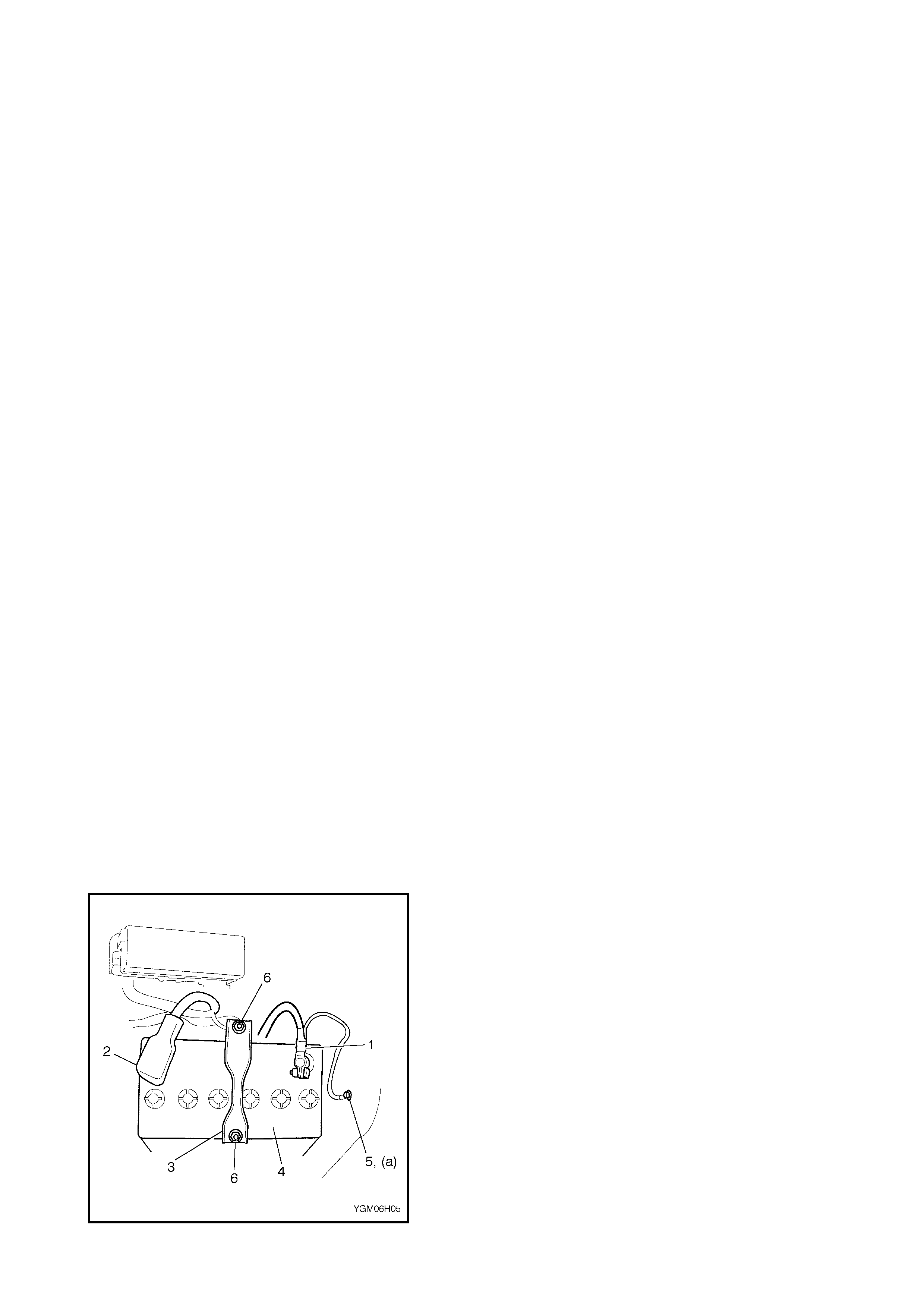
REMOVAL
1. Disconnect negative cable (1) and remove body
ground bolt (5).
2. Disconn ect positive c able (2).
3. Remove retainer (3) by loosening nuts (6).
4. Remov e battery (4).
HANDLING
W hen han dling the ba ttery, the following s afety precautions
sho uld be followed:
• Hydrogen gas is produced by the battery. A flame
or spark near the battery may cause the gas to
ignite.
• Batter y fluid is highly acidic. Avoid spilling on cloth-
ing or ot her fabr ic. Any spilled ele ctrolyte s hould be
flushed with large quantity of water and cleaned
immediately.
INSTALLATION
1. Reverse removal procedure.
2. Torque battery cables to specification.
NOTE: Ensure adequate clearance between hood and
negative battery cable.
3.2 GENERATOR BELT
Refer to Section 6B ENGINE COOLING.
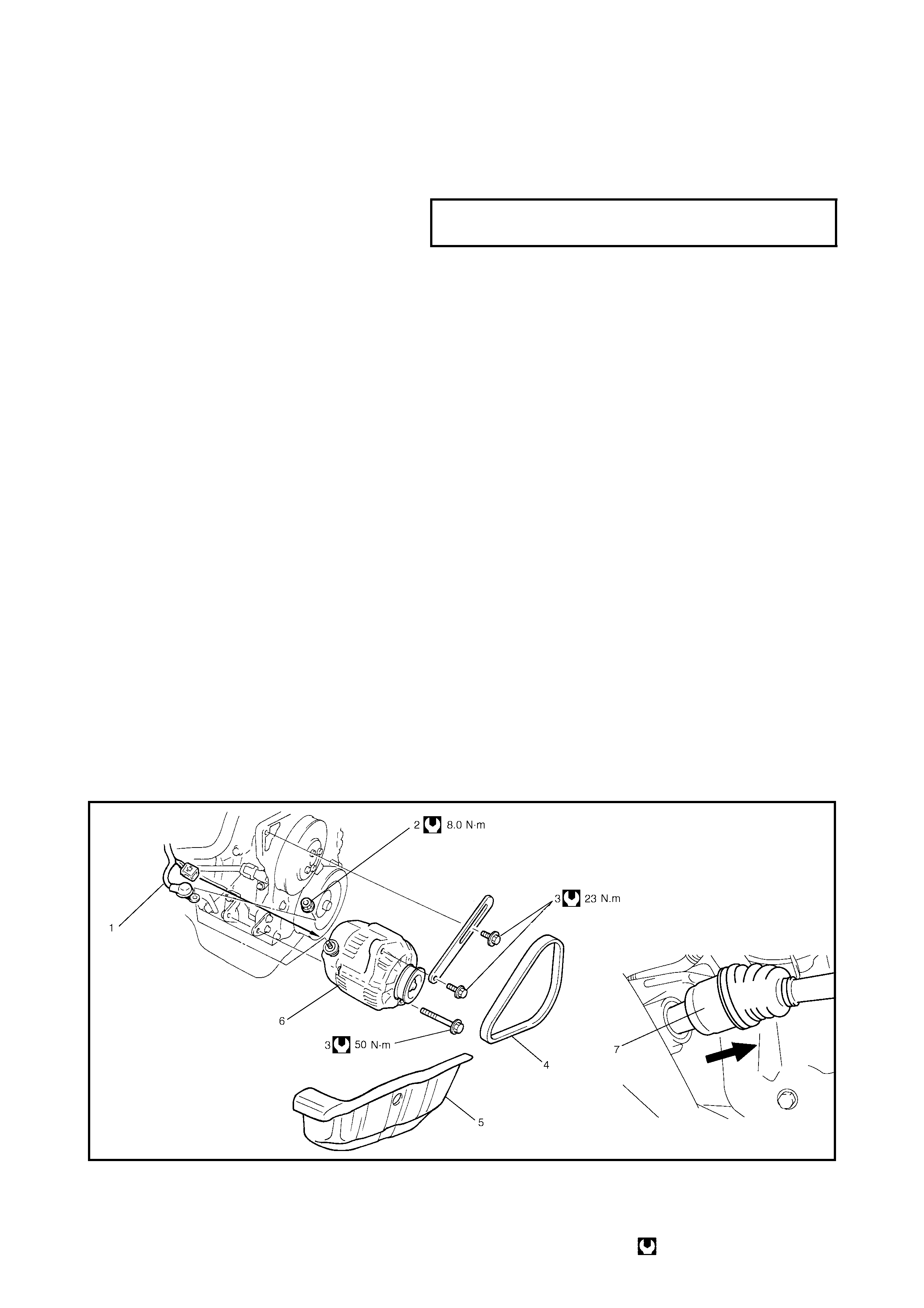
3.3 GENERATOR
REMOVAL
1. Remove RH side splash cover (5).
2. Disconnect front RH side drive shaft (7), refer to
Section 4A FRONT DRIVE SHAFTS.
3. Remove A/C drive belt, refer to Section 1B,
2.5 COMPRESSOR DRIVE BELT.
4. Remove generator drive belt (4), refer to Section 6B,
ENGINE COOLING.
5. Unplug connector from rear of generator and B-
terminal nut (2) and B-terminal eye connector from
generator body.
6. Support generator and remove generator mounting
bolts (3) and adjusting bracket.
INSTALLATION
1. Reverse removal procedure noting the following
instructions.
• Torque bolts to specifications, refer to the figure below.
• Tension generator drive belt, refer to Section 6B,
ENGINE COOLING.
• Tension A/C drive belt, refer to Section 1B,
2.5 COMPRESSOR DRIVE BELT.
Legend
BODY GROUND BOLT (a)
TORQUE SPECIFICATION 8.0 Nm
1. B-terminal wire 3. Generator bolt 5. Splash cover (Right) 7. Drive shaft (right side)
Refer to Section 4A
2. B-ter m inal nut 4. Generato r belt 6. Genera tor Tighteni ng torque
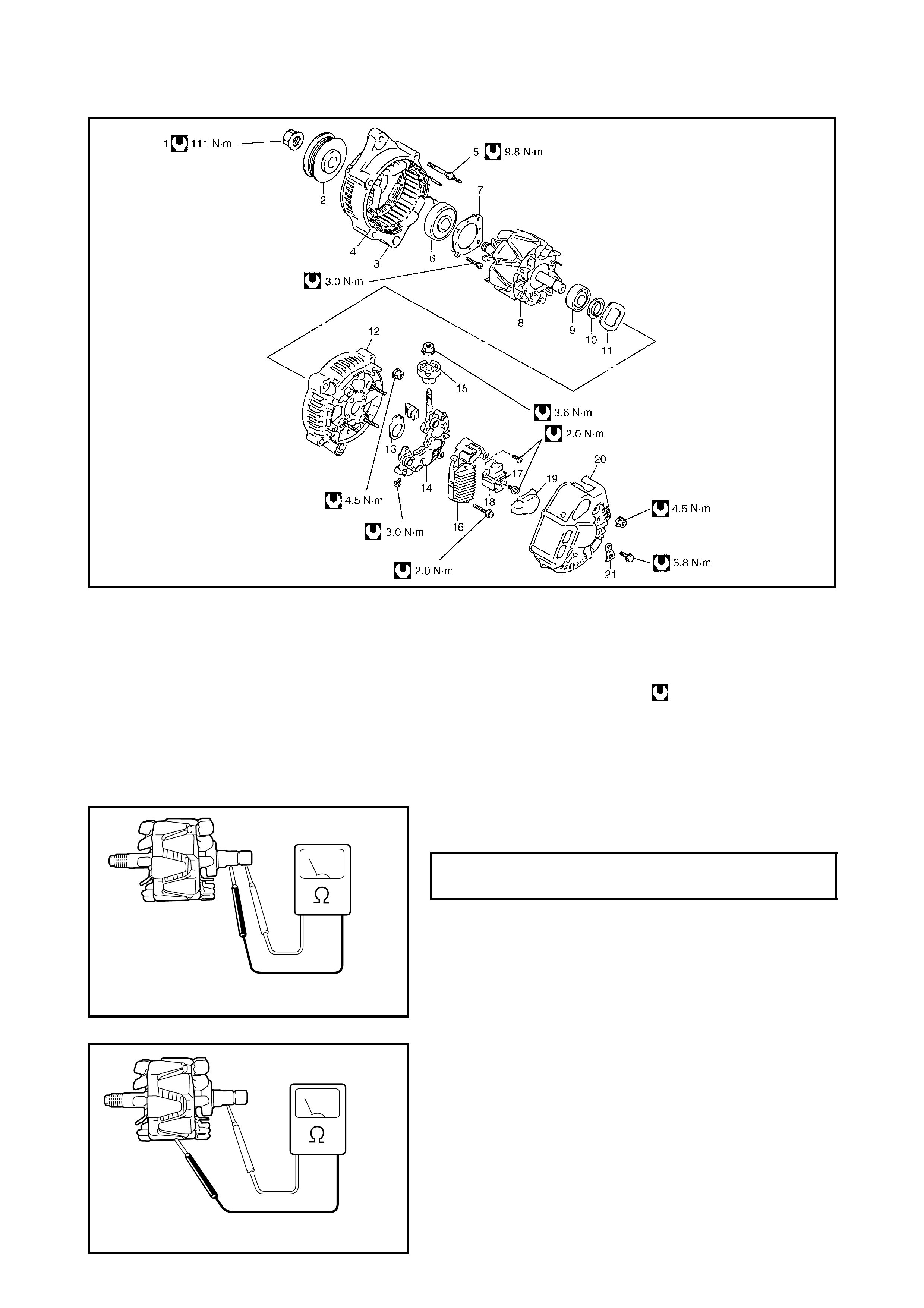
DISASSEMBLY AND REASSEMBLY
Legend
INSPECTION
Rotor
1. Using an ohmmeter, check for continuity between slip
r ings of rotor. If there is no continuity, replace rotor.
2. Using ohmmeter, check that there is no continuity
between slip ring and rotor. If there is continuity,
replace rotor.
1. Pulley nut 7. Bearing retainer 13. Seal plate 19. Brush hold er cover
2. Pulley 8. Ro tor 14. Rectifier 20. Rear end cover
3. Drive end frame 9. End housing bearing 15. Insulator 21. Terminal plate
4. St ator 10. Bearing cover 16. Regulator Tightening torque
5. Stud bol t 11. Wave washer 17. Brush
6. Drive end bearing 12. Rear end frame 18. Brush holder
STANDARD RESISTANCE BETWEEN
SLIP RINGS OF ROTOR 2.7 - 3. 1 Ω
@ 20°C
YGM06H06
YGM06H07
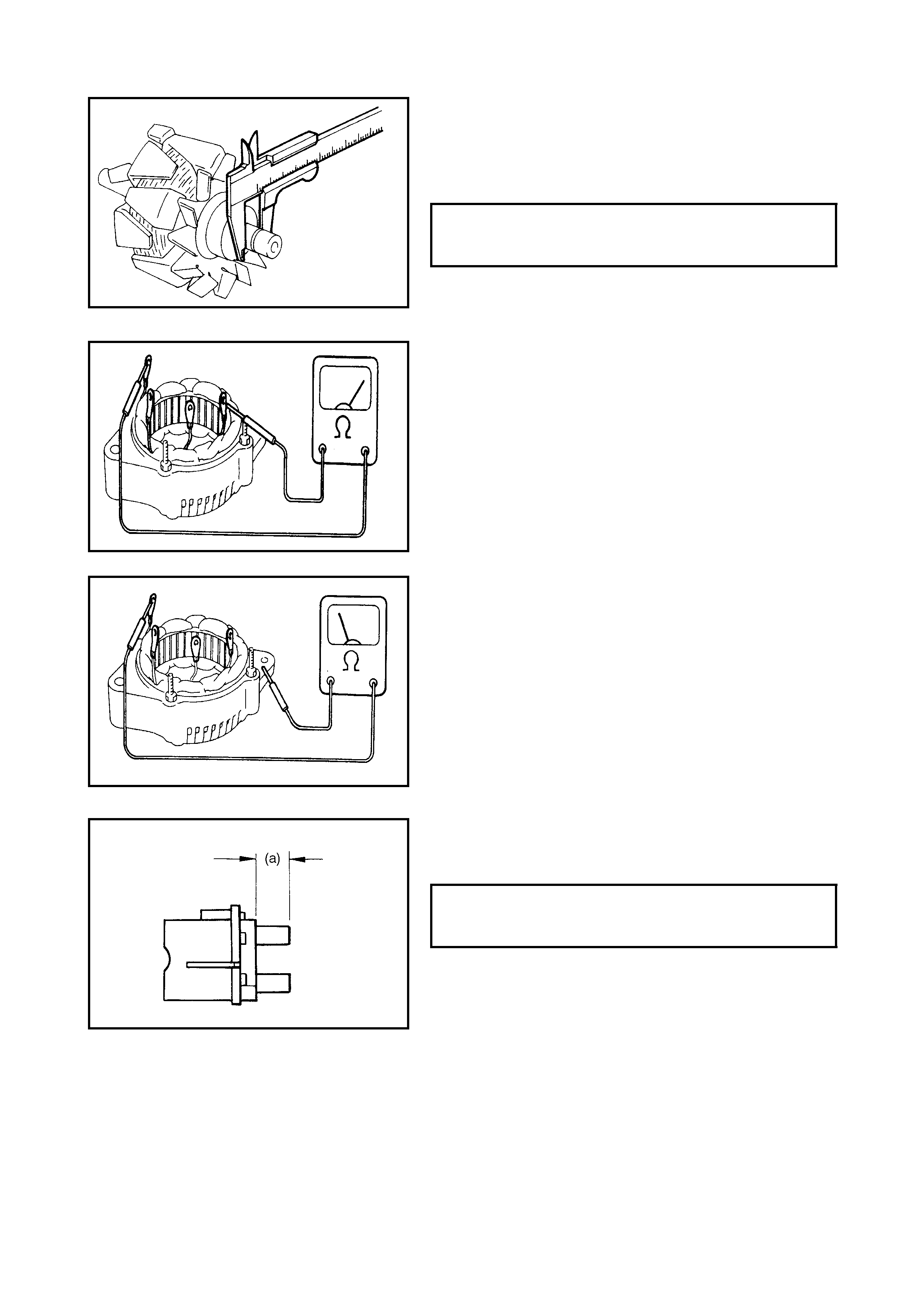
3. Check slip rings for roughness or scoring. If rough or
scored, replace rotor.
Using a vernier caliper, measure the slip ring diameter.
If the diameter is less than the minimum specification,
replace the rotor.
Stator
1. Using an ohmmeter, check all leads for continuity. If
there is no continuity, replace stator.
2. Using an ohmmeter, check that there is no continuity
between coil leads and stator core. If there is continuity,
replace stator.
Brush And Brush Holder
Check each brush for wear by measuring its length as
shown. If brush is found to be worn down to service limit,
replace brus h.
SLIP RING DIAMETER STANDARD
LIMIT 14.2 - 14.4 mm
12.8 mm
EXPOSED BRUSH LENGTH (a)
STANDARD
LIMIT 10.5 mm
1.5 mm
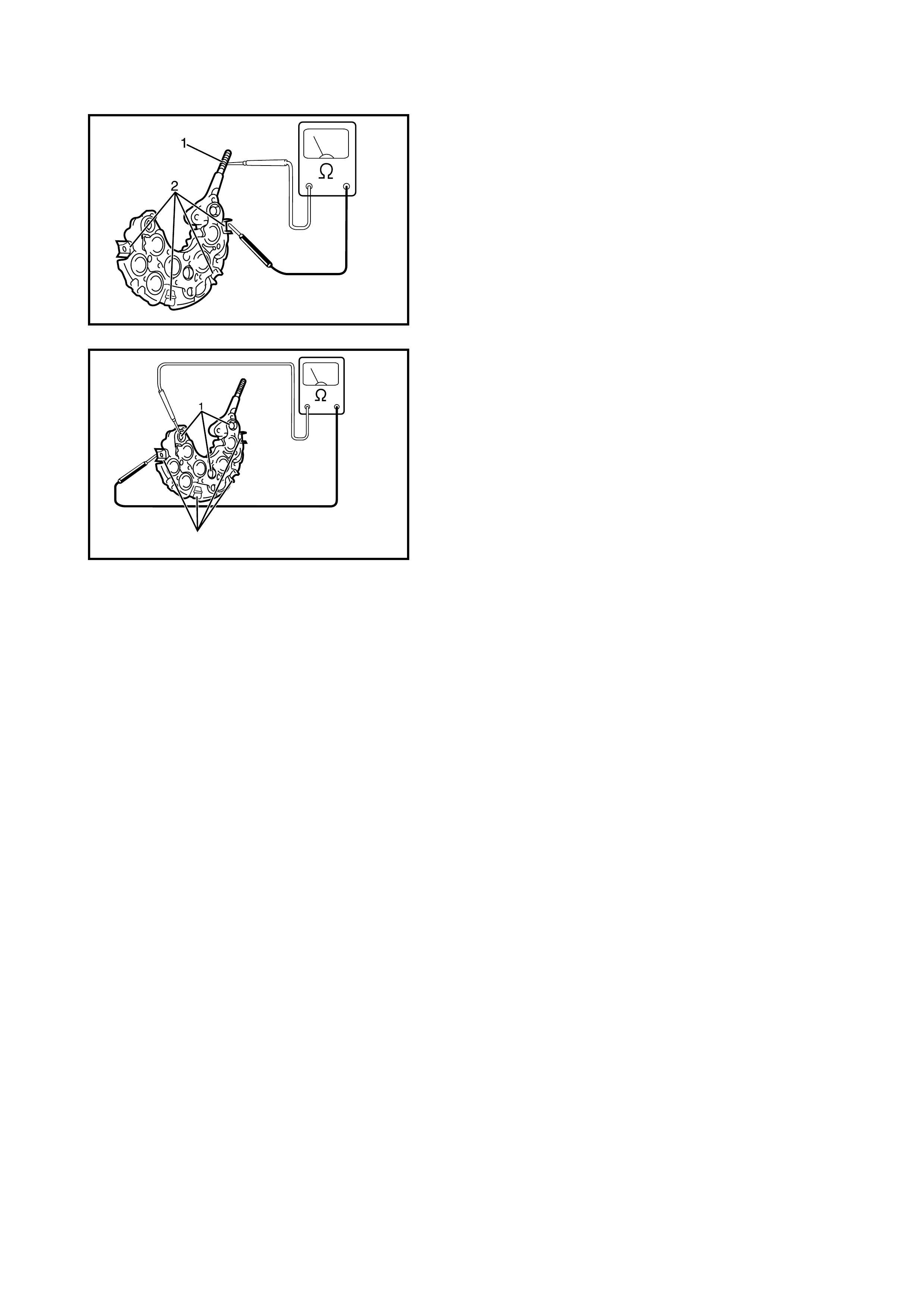
Rectifier
1. Using an ohmmeter, c onnect one tes ter probe t o the B
ter m inal (1) and the other to each rectifier term inal (2).
2. Reverse the polarity of the tester probes and repeat
step 1.
3. Check that one shows continuity and the other shows
no continuity.
If this condition is not met, replace the rectifier.
4. Using an oh mmeter, connect on e teste r probe to each
negative terminal (1) and the other to each rectifier
ter m inal (2).
5. Reverse the polarity of the tester probes and repeat
Step 4.
6. Check that one shows continuity and the other shows
no continuity.
If this condition is not met, replace the rectifier.
YGM06H08
YGM06H09
2

4. SPECI FICATION
4.1 BATTERY
4.2 GENERATOR
Batter y type 38B2 0L
Rate d capacity AH/5HR, 12 Volts 28
Electrolyte L 2.1
Electrolyte Specific Gravity (SG) 1.28 when fully charged at 20°C
Type 75 A type
Rated voltage 12 V
N ominal output 75 A
Permissible max. speed 18000 rpm.
N o-load speed 1020 r pm
Sett ing vo ltage 14.2 to 14.8 V
Exposed brush length Standard: 10.5 mm
Lim it: 1.5 mm
Permissible ambient temperature –30 to 90°C
Polarity Negative ground
R otation Clockwi se viewed from pulley si de