
1
19
99
99
9
S
SE
ER
RV
VI
IC
CE
E
T
TE
EC
CH
HL
LI
IN
NE
ES
S
© 2006 GM Holden LTD. A.B.N. 84 006 893 232
Service Department
A “HOLDEN” Product.
BRISBANE SYDNEY MELBOURNE ADELAIDE PERTH
For the latest and/or any missing Techline bulletins,
please refer to Holden Lionheart
HOLDEN SERVICE TECHLINE _______________________________________________________________ FEBRUARY 1999
1
HINT: PREVENTING FRONT SEAT SIDE
OUTER COVERS CRACKING
VT
(GROUP 1)
Excessive loading of the front seat side outer
covers by the seat cushion may cause the seat
side outer covers to crack.
In the event that a seat side outer cover is
cracked, ensure to check that the seat frame
protector strips are in place to prevent the seat
frame from damaging the seat cushion foam. If
the seat frame has damaged the foam, the seat
cushion wings may compress on to the top of the
seat side outer covers when the driver/passenger
sits in the vehicle causing the seat side covers to
crack.
PRODUCTION RECTIFICATIO N
The seat cushions were revised to include a thick
dark grey felt protecting strip, protecting the foam
from the frame, introduced as containment action
from L317553, build date 23/03/98. The final
solution comprises of the seat cushion frame
having a rolled flange at the top edge, introduced
fr om L349096, build date 24/06/98.
ISOVIN: Build Date:
6H8VTK35HWL31755
323/03/98
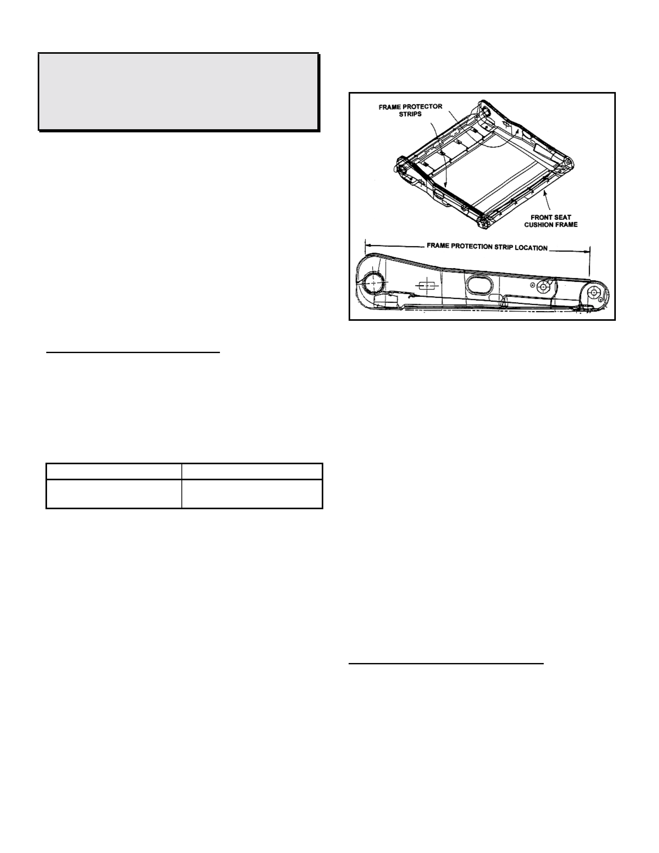
SEAT FRAME PROTECTOR CHECK:
[ONLY for vehicles before L317553]
When replacing the front seat side outer covers,
check that the black plastic seat frame protector
strip is properly retained and in it’s correct
position, as indicated in Figure 1. This can be
done by visually inspecting as f ollows:
1. Raise the seat fully, move the seat rearward.
2. Kneeling next to the vehicle, and using a
torch, pull back the foam and look up towards
the top of the seat cushion frame to observe
the position of the black plastic seat frame
protector st r ip.
Alternatively once you know what to look for a
physical check can be performed by sliding your
hand slowly up the side of the seat, between the
seat cushion and the seat r ail. You should be able
to feel the plastic seat frame protector strip if in
place.
FIGURE 1
If the seat frame protector strips aren’t located in
their correct positions, the strips need to be re-
adhered to the seat frame to avoid continuing
cushion damage.
1. Remove the affected seat from the vehicle
then remove the front seat cushion pad and
cover assembly as per the VT Series Service
Manual, Volume 1, Section 1A.
2. Both f rame protector s should be rem oved and
the frame edges wiped clean. Once clean,
apply a product similar to Loctite 7025
Activator to the edges of the f rame.
3. Using Loctite 480 or similar, re-adhere the
protector strip to the frame, ensuring the
adhesive is applied along the length of the
protector strip. Position protector strips on
seat f r am e edge as indicated in Figure 1.
4. Where necessary, replace the cushion pad
and cover assembly and re-assemble the
seat and refit to the vehicle.
WARRANTY CLAIM INFORMATION
Use existing information in the Labour Time
Manual.
HOLDEN SERVICE TECHLINE _______________________________________________________________ FEBRUARY 1999
2
VIBRATION OR RUMBLE FROM V8 A/C
COMPRESSOR – BRACE
VT V8
(GROUP 2)
PROBLEM DESCRI PTION
Some vehicles may exhibit a rumble or vibration
when the V8 air conditioning compressor is
operating in t he idle to 1500 rpm range.
PRODUCTION RECTIF ICATION
A brace was added to the compressor mounting
bracket to add rigidity to reduce noise and
vibration transfer through the vehicle. The brace
was introduced into production from L404040,
build date 20/11/98.
ISOVIN: Build Date:
6H8VTK69NXL404040 20/11/98
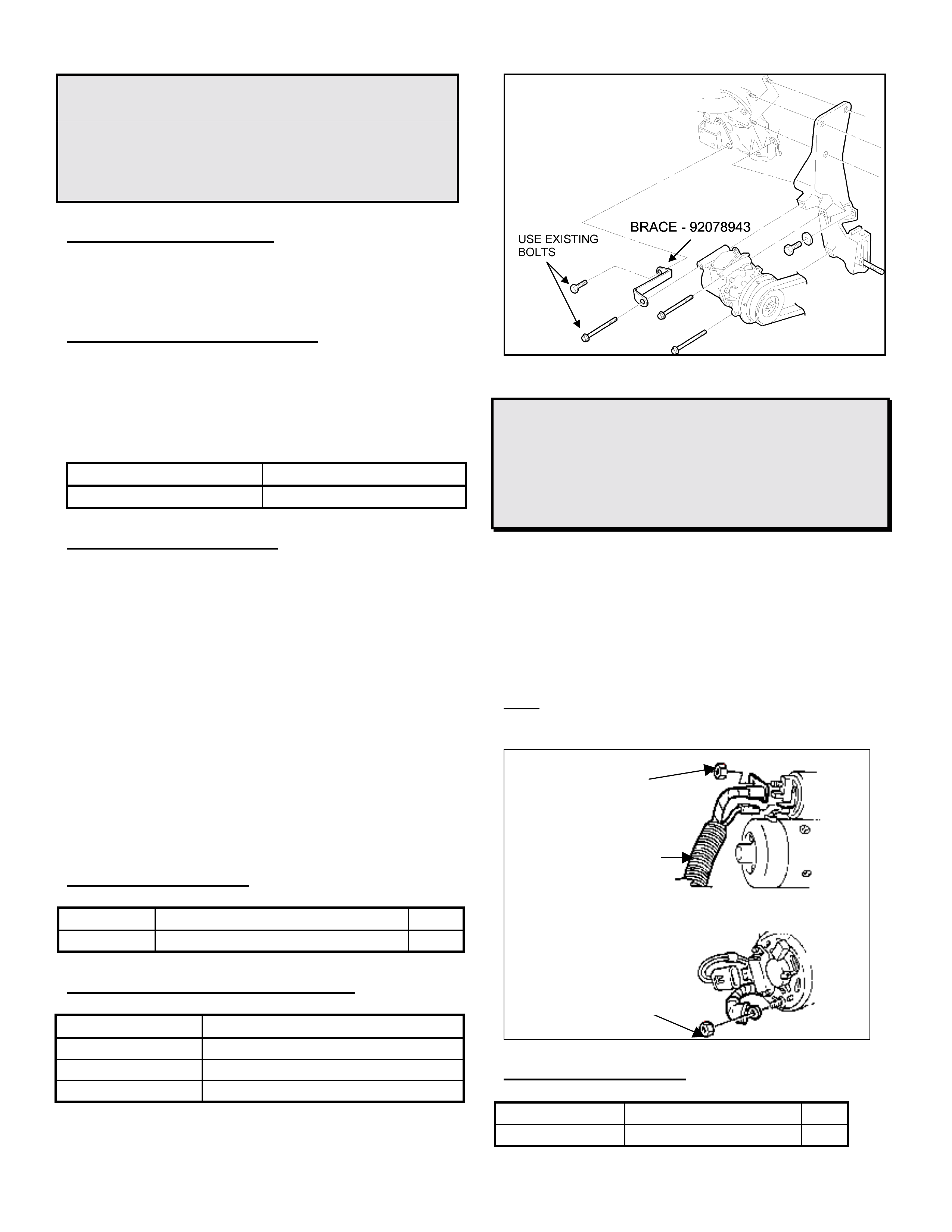
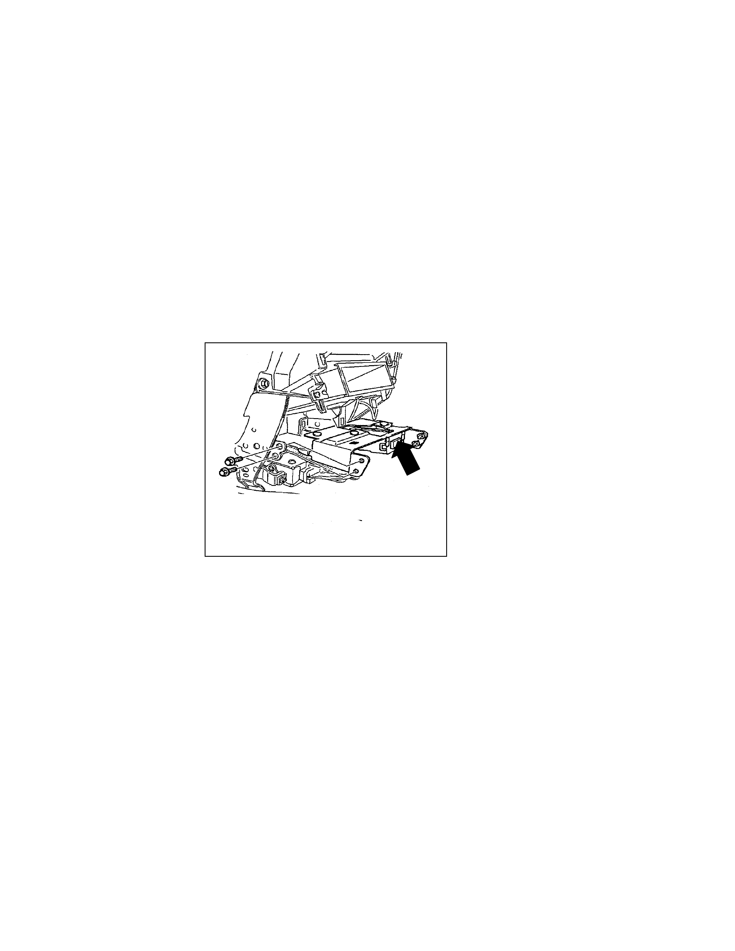
SERVICE RECTIFICATION
On those vehicles where the owner complains of
of a vibration or rumble in the rev range of idle to
1500 rpm, fit brace part number 92078943 from
the compressor to the engine mount as indicated
in the f igure below.
To fit the brace, remove the top rear compressor
mounting bolt and engine bracket to engine block
bolt, as indicated in Figure 1. Fit brace and
retorque bolts.
Once f itted, run t he engine bet ween idle and 1500
rpm with the air conditioning on and check that
the noise / vibration is elim inat ed.
If the noise or vibration is still noticeable, further
investigation will be required.
PARTS INFORMATION
Part No.: Description: Qty:
92078943 Brace – A/C Compr essor 1
WARRANTY CLAIM INFORMATION:
Description Install V8 Compressor Brace
Labour Op. No. D000203
Time 0.5 hr
Failure Code 36
FIGURE 1
REVISED ALTERNATOR B+ NUT,
STARTER MOTOR NUT
VS, VT
(GROUP 12)
A new NUT with improved electrical conductivity
and retentive properties will shortly be introduced
into production.
Whenever servicing the Alternator or Starter
Motor on a VS or VT vehicle, dealers are advised
to fit the new Nut.
Note: T he t orque specification has changed to
6-10 Nm.
PARTS INFORMATION
Part Number Description Qty
92083348 Nut 1
Alternator B+ NUT
Starter motor NUT
Battery
Harness

HOLDEN SERVICE TECHLINE _______________________________________________________________ FEBRUARY 1999
3
HINT: DIAGNOSING ABS WHEEL SPEED
SENSOR DTC’S 21, 23, 25, 27.
VT
(GROUP 5)
Analysis of warranty data and detailed
investigation of returned hub assemblies has
indicated that dealerships are not performing the
necessary ABS functional checks and wheel
speed sensor lead service procedures prior to
replacing hub assem blies.
Many hub assemblies returned to REPAC could
not be faulted. Further investigation has
determined that in many cases, the problem has
been identified as a poor connection between the
front wheel speed sensor lead and the hub
assembly and/or the ABS module and lead
connection.
Prior to replacing any components, technicians
should:
• Check all connections between the ABS
module and wheel speed sensors.
• Remove leads from the sensor and clean the
wheel speed sensor and lead terminals.
• Ensure there is a positive retention of the lead
onto the sensor. It may be necessary to
spread the terminals to ensure a positive
connection.
• Al w ays check and replace if necessary, the
speed sensor lead o-rings if the speed
sensor leads are removed for any reason,
P/N 92140314. Ensure all parts are clean
before reinstalling.
For further diagnosis procedures, refer to the
service procedures described in VT Series
Service Manual Volume 7, Section 12L, page
12L-44 and perform the ABS f unctional check s on
page 12L-58.
KNOCK NOISE FROM EXHAUST ON COLD
START
JR & JS, 4 Cyl. Engine
(GROUP 8)
PROBLEM DESCRI PTION
Customers complain of a metallic knocking noise
after engine is started from cold. Noise can be
misdiagnosed as being an engine internal or drive
belt related noise.
Actual noise cause is a rattle noise from internal
baffles in the intermediate silencer, which stops
when the exhaust system reaches operating
temperature.
PRODUCTION RECTIFICATIO N
The silencer has been revised internally from late
1998. Silencers are identified by date code of
98/09 or later (98/09 = Sept., 1998), - stamped
on the identification/part number plate on the
lower, outside surface of the silencer.
SERVICE RECTIFICATION
Fit a new Silencer – Intermediate & Centre Pipe.
Order the new part from HSPO - all current parts
at HSPO are of the latest specification.
PARTS INFORMATION
Part No.: Description: Qty
Req’d:
90500030 Silencer – Inter m ediate &
Centre Pipe 1
WARRANTY CLAIM INFORMATION:
Use existing inf or m ation in Labour Time Manual
Update
HOLDEN SERVICE TECHLINE _______________________________________________________________ FEBRUARY 1999
4
BRAKE SHUDDER – RECOMMENDED
SERVICE PROCEDURES FOR DISC
MACHINING & INSTALLATION
VT
(GROUP 5)
1. UNDERSTANDING BRAKE SHUDDER &
IT’S CAUSES
1a. Symptoms
Typically, shudder occurs under light/medium
braking from vehicle speeds of around 70 - 100
km/h.
The symptom of front brake shudder is a
pulsation felt in the brake pedal which is usually
accompanied by an oscillation of the steering
wheel.
The symptom of rear brake shudder is pedal
pulsation as well as a vibration that is felt through
the seat.
1b. Diagnosis
When a vibration/shudder condition is reported, a
road test should be done to confirm that the
condition is actually brake shudder. Brakes
should be tested while driving on a dry, clean and
reasonably smooth road surface. Perf or m at least
two, light/medium braking applications from 80 –
100 km/h down to 40 km/h whilst observing for
shudder symptoms.
1c. Cause of Brake Shudder
Brake shudder primarily occurs as a result of
variation in the thickness of the brake disc. This
in turn causes variations in brake surface
pressure as the varying thickness disc passes
between the pads during br aking.
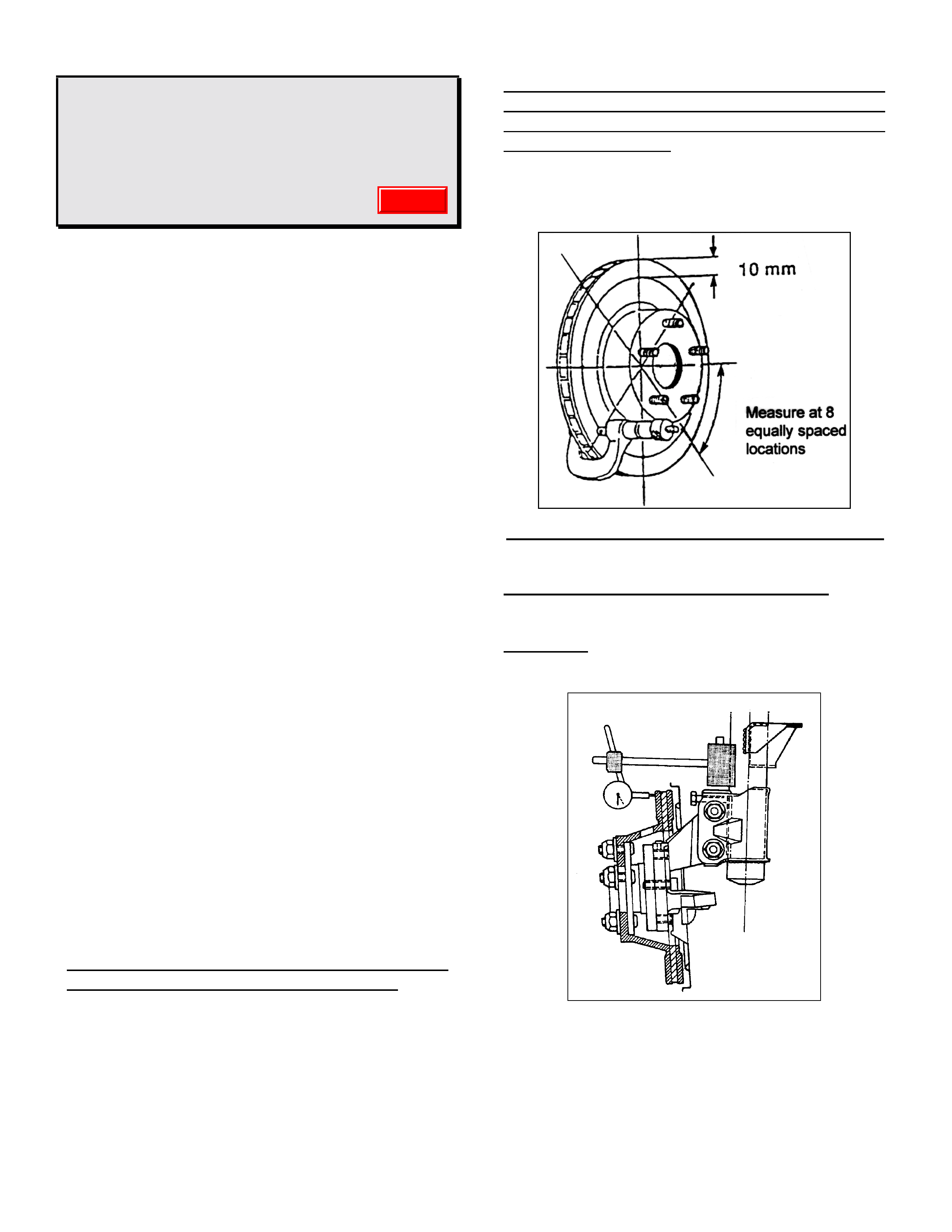
The variation in thickness of the disc can be
measured with a micrometer as shown in Fig 1.
NOTE. A disc that varies in thickness by more
than .015mm (15 micron) will cause brake
shudder.
New discs develop Disc Thickness Variation
(DTV) as a r esult of excessive lateral runout in the
disc combined with caliper drag during non-
braking running time. On each revolution of the
disc a portion of the disc comes into contact with
the pad. Eventually the disc wears at the point of
contact thus cr eat ing thickness variation.
FIGURE 1 Measuri ng Disc Thickness Variati on
[DTV = Maximum thickness – Minimum thickness]
What is Assembled “Lateral Runout”
The term “lateral” literally means “sideways”.
Assembled lateral runout is measured with a dial
indicator whilst rotat ing the disc on the vehicle.
FIGURE 2. Measuring disc lateral runout
This Service Techline item further enhances ADL
88/98 on the same subject. Please note additions
to ADL 88/98 are in italic text. The dial indicator
mounting plate dimensions have also been
revised (Figure10) .
Update
HOLDEN SERVICE TECHLINE _______________________________________________________________ FEBRUARY 1999
5
Apart from accident damage, excessive
assembled lateral runout of discs may result from
one or more of the following:
1. Disc not machined to specification
Defective machining may result in lateral runout
and/or DTV above specification.
2. “Tolerance Stackup”
This term is best described by the following
example.
A front hub/bearing unit may show a runout of
0.030 mm near the outer edge of the mounting
face. The brake disc itself may have lateral
runout of 0.030 mm near its outer diameter.
These runouts taken separately are within
allowable tolerances. However, if the disc is
placed on the hub so that the high point on the
disc is aligned with the high point on the hub then
the combined result is an excessive lateral runout
(at the disc outer diameter) of about 0.090 mm.
To minimise the effect of “tolerance stackup” refer
to the Disc & Hub Indexing Procedures on pages
5 and 8.
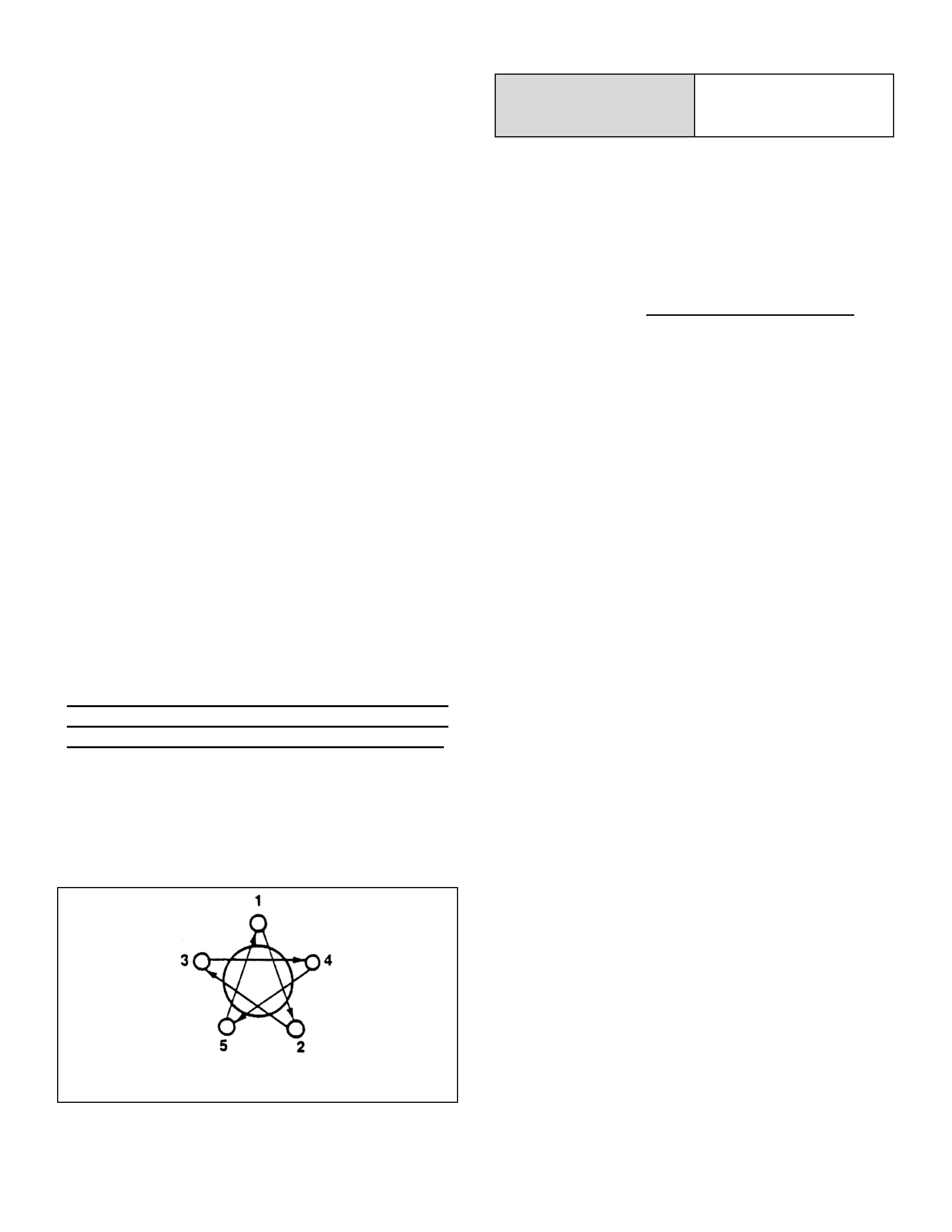
3. Incorrectly Tightened Wheel Nuts
Over-tightened wheel nuts or those tightened
in the wrong sequence will cause distortion of
the disc and result in excessive lateral runout.
To prevent distortion of the disc and hub
assembly, wheel nuts must be tightened to the
specified torque in two steps, using a suitable
torque wrench. Follow the nut tightening
sequence as shown in Figure 3.
FIG. 3 Wheel nut tightening sequence
Road Wheel attaching
nut tight eni ng t orque 110 – 140 Nm
IMPORTANT!
DO NOT USE AN AIR IMPACT GUN TO
TIGHTEN WHEEL NUTS UNLESS IT IS
FITTED WITH A TORQUE LIMITER BAR.
Failure to observe this may result in warped
discs which lead to development of brake
shudder.
Torque limiter bars can be obtai ned f r om most
automotive tool suppliers.
4. Foreign Material at disc to hub
interface
Foreign material between the disc and hub
mounting faces will contribute to assembled
runout.. It is vital that any foreign material such
as corrosion, dirt, burrs on hole edges etc are
removed.

HOLDEN SERVICE TECHLINE _______________________________________________________________ FEBRUARY 1999
6
2. RECOMMENDED SERVICE PROCEDURES
2A. MACHINING DISCS
To eliminate brake shudder, the discs must be
machined to meet the following Holden
specifications for runout and Disc Thickness
Variation (DTV).
Note: The specifications shown in the following
table are for a stand-alone disc mounted
between machining centres (do not confuse with
disc to hub assembled later al r unout).
VT - Brake disc
machining
specifications
Front
Discs Rear
Discs
Lateral runout max..040 mm .050 mm
DTV max..005 mm .013mm
Dealers must ensure that in-house machining
equipment is at least capable of achieving the
specified lateral runout.
Due to the extremely small DTV specification,
which only precision laboratory equipment will be
capable of measuring, dealers are NOT expected
to check f or DTV. NOTE: On most modern lathes
that machine both sides of t he disc simultaneously,
DTV will normally be below the limits specified.
If discs are sublet for machining, dealers should
advise the sublet repairer of the above run- out and
DTV requirements.
Failure of discs to meet these specifications
indicates that either the machining technique
and/or the equipment is deficient .
The two options for machining discs are to use
an on car lathe or an off car lathe.
There are advantages and disadvantages for
each type of lathe. It is not proposed in this
article to cover every aspect of these lathes such
as price, durability, ease of use, etc. It is the
dealer’s responsibility to carefully consider all
these before making a final decision to purchase.
This art icle is only intended t o highlight f or each
type of lathe some of the more important issues
related to achieving an accurately machined disc.
When machining discs to eliminate DTV, only the
absolute minimum amount of material should be
machined from the discs. Only properly maintained
precision cutting tools should be used. Dull or worn
tools leave an unsatisfactory disc surface finish. It
is recommended that following a light final cut
machining operation involving removal of between
.025 and .050 mm of material, final surface finish
should be obtained by lightly rubbing with fine
emery paper. This rubbing helps smooth out
microscopic grooves ensuring a non-directional
finish.
OPTION 1. Off-Car Brake Lathes
Historically, brake discs have been machined on
off car lathes. Many of the older lathes used for
this work may be worn to the point where they are
no longer capable of achieving, the lower
machining tolerances specified for current discs.
Therefore, dealers must ensure that the
dealerships lathe (or that of your sublet repair er) is
regular ly maintained and checked for accuracy.
To achieve accurate disc ma chining, it is vital t hat
discs are mounted correctly in the lat he. Some of
the older cone mounting methods require tedious
setup time t o m inim ise r unout pr ior to machining.
On some of these older lathes an excellent
method for reducing disc mounting and setup time
is to bolt the disc to a tool (mounted to the lathe
chuck) that simulates the hub in the vehicle. The
following paragraph describes one such tool.
Disc Mounting Tool
Farrely Brothers Toolmakers, manufacture a tool
that simulates the wheel hub mounting face. The
tool is mounted to the lathe chuck and is trued to
the lathe spindle by machining a cut across
thedisc mounting face. This tool can be used for
front and rear discs for all models VR to VT.
HOLDEN SERVICE TECHLINE _______________________________________________________________ FEBRUARY 1999
7
For further details contact Farrely Brothers
Toolmakers, 5 Lemmon Avenue East Keilor VIC
3033, phone 03 9336 1870.
IMPORTANT: Whenever discs are machined
off-the-car they must be indexed to the hub to
achieve minimum assembled runout. Refer to
procedure on pages 5 and 8.
OPTION 2. On-Car Disc Lathes
The main advantage of on-car lathes is that
because the discs are machined on the hub,
they do not require indexing to the hub for
minimum runout.
However, if the disc is to be removed for any
reason, it must first be marked in relation to the
hub to enable it to be reinstalled in the minimum
runout position.
On car lathe designs fall into 2 t ypes as follows.
Hub mounted cutting head
The main disadvantage of t his type of lat he is that
the runout and DT V of the machined disc are f ully
dependant on the wheel hub runout com pensat ion
adjustment performed prior to machining. If this
adjustment is not done correctly, the disc runout
and DTV may not m eet Holden’s specifications.
Caliper mounted cutting head
The main advantage of this type of lathe is that
there is no need to compensate for wheel hub
runout prior to machining because the cutting
head is mounted where the caliper is normally
situated.
CAUTION: The minimum thickness of a re-
machined disc must always be greater than the
scrap thickness. Refer to the following chart for
recommended minimum thickness after
machining.
DISC THICKNESS
INFORMATION VT Front Rear
New disc 28.0mm 16.0mm
Mi n. thickn ess aft er
machining 25.5mm
(refer note a.) 14.4mm
(refer note b.)
Scrap thickness 25.0mm 13.9mm
Note a. This dimension is calculated on the basis
that the normal disc wear rate with new genuine
Holden brake pads should not reduce the disc
thickness below the minimum disc operating
thickness of 25.0 mm before the next pad
replacement.
Note b. This dimension is calculated on the basis
that the normal disc wear rate with new genuine
Holden brake pads should not reduce the disc
thickness below the minimum disc operating
thickness of 13.9 mm before the next pad
replacement.
HOLDEN SERVICE TECHLINE _______________________________________________________________ FEBRUARY 1999
8
2B. FRONT DISC & HUB INDEXING PROCEDURE
IMPORTANT: This procedure must be used whenever reinstalling discs that have been
removed for machining off car. It must also be used when installing new discs or discs that
have been removed for any reason and where disc to hub/trunnion matching is not evident.
Disc and hub indexing is requir ed in order to obt ain
the minimum installed disc runout.
Disc and hub indexing involves aligning the point of
maximum runout on the hub with the point of least
runout on the disc.
The procedure consists of three steps as follows:
Step 1. Clean mating surfaces.
Step 2. Measure and Match disc high point t o hub
low point. If not OK go to ste p 3.
Step 3. Checking hub mounting face runout
STEP 1. Clean mating surfaces
Ensure that disc and hub mating surfaces are free
from dirt, corrosion, etc. If required, use fine emery
paper to clean surfaces.
STEP 2. Indexing disc to hub
2.1 Fasten the disc onto the hub with wheel nuts
reversed to avoid damage to the tapers, and
nip up with a spanner.
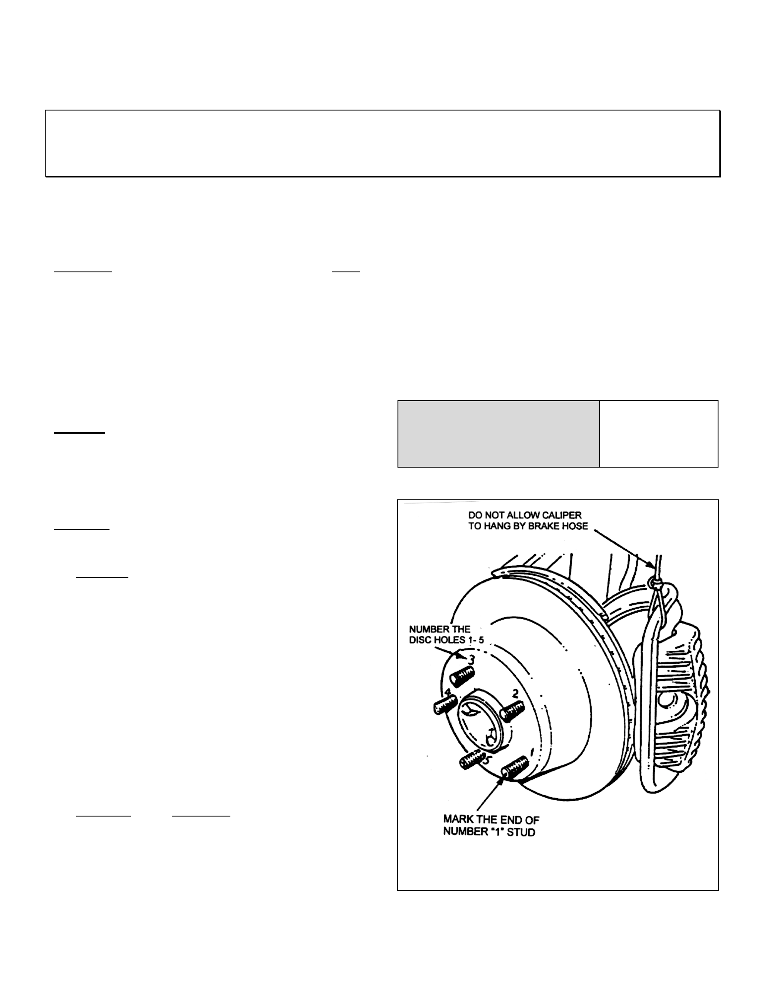
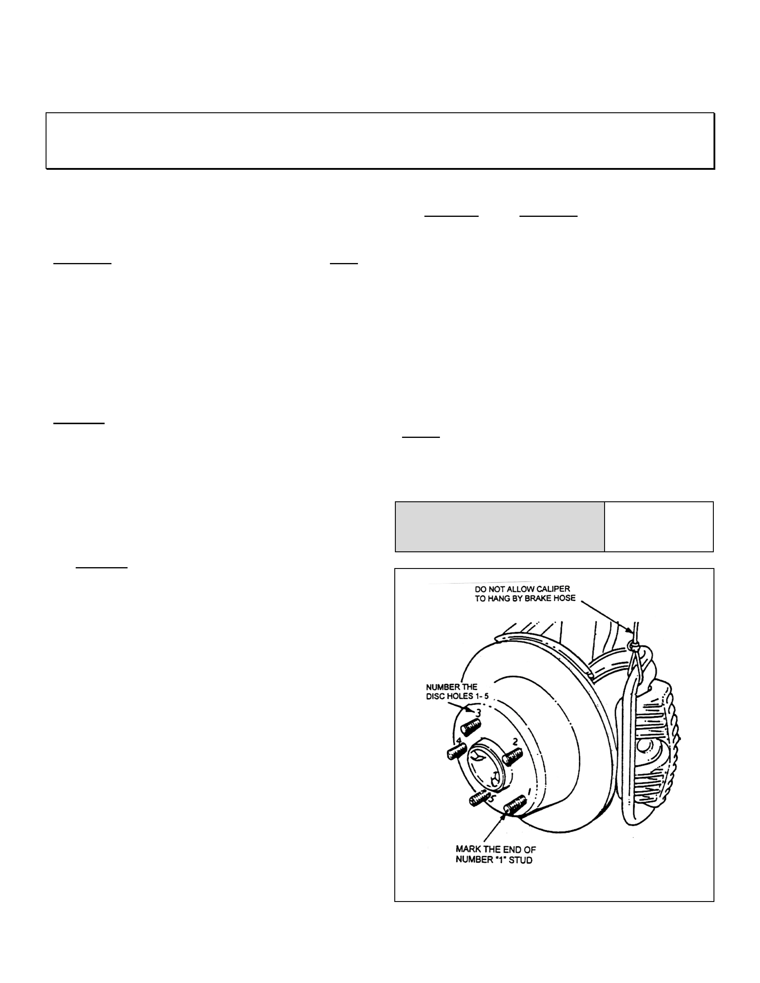
2.2 Number each of the wheel stud holes on the
fr ont surface of disc f rom 1 to 5. Place a chalk
mark on the end of the wheel stud adjacent to
number “1” hole. Refer Figure 4.
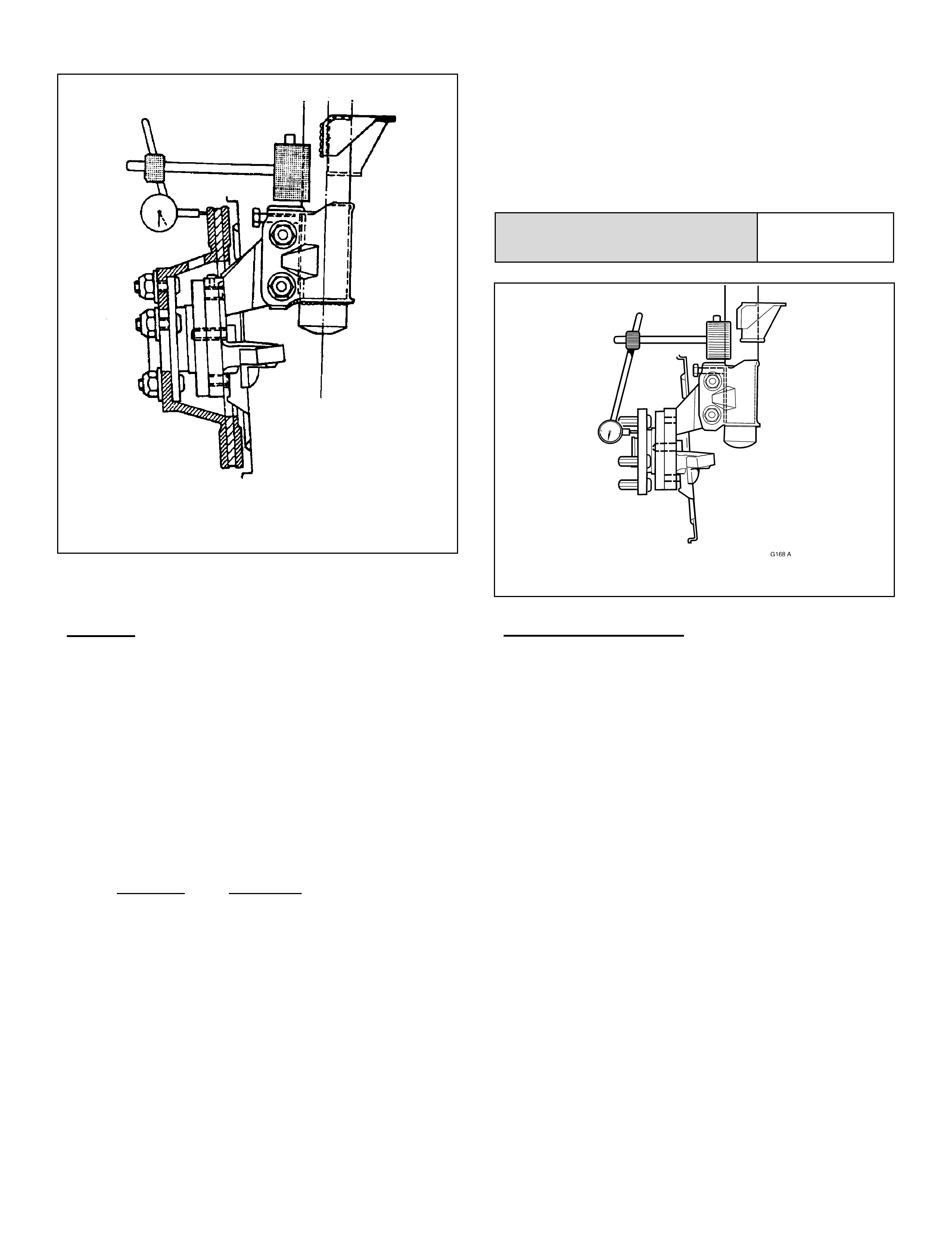
2.3 Set up a dial indicator on a magnetic base and
attach to the strut tube above the brake disc.
Position the pointer about 10 to 15 mm inboard
from the outer diameter of the disc. Refer
Figure 5.
2.4 Carefully rotate the disc and note the points of
minimum and maximum runout on the dial
indicator. The number of divisions between
these two points is the total indicated runout.
Record this figure together with the number on
the disc aligned with the chalk-marked stud.
2.5 Remove and reinstall the disc with hole number
“2” over the marked stud. Repeat STEP 2.4.
This procedure is to be repeated for all 5 hole
positions.
2.6 Mount the disc to the hub in the stud position
with least runout.
NOTE: If the lowest assembled disc runout
achieved is more than 0.050 mm ( 50 micron) then
the hub runout should be checked as shown in
step 3.
Maximum assembled disc &
hub runout at disc outer
diameter – FRONT 0.050 mm
FIGURE 4. MARKING THE HUB & DISC
HOLDEN SERVICE TECHLINE _______________________________________________________________ FEBRUARY 1999
9
FIGUR E 5. MEASURING INSTALLED
DISC RUNOUT
STEP 3. Hub runout check
3.1 Clean the front hub face by rubbing lightly with
fine emery paper.
3.2 Locate the dial indicator on the strut tube and
position the pointer on the hub face about
midway between the spigot and the studs.
Refer Fi gure 6
3.3 Carefully rotate the hub by the hub spigot (to
avoid loading the bearing) and note the points
of minimum and maximum runout on the dial
indicator. The number of divisions between
these two points is the total indicated runout.
3.4 If the runout measured in STEP 3.3 exceeds
0.025 mm (25 micron) then the hub unit
should be replaced. (If replacement is done
under warranty, the runout figure measured
must be recorded on the Defective Material
Tag.)
Maximum runout at hub face –
FRONT HUB 0.025 mm
FIGURE 6 HUB RUNOUT MEASUREMENT
Production Indexing
NOTE: On the vehicle assembly line the disc high
point is aligned with the hub low point.
IMPORTANT:- ALWAYS MARK DISCS
PRIOR TO REMOVING !
Whenever discs are removed from hubs for
reasons other than brake shudder rectification, the
disc and hub must be marked to enable
reinstallation of the disc ont o the hub in the orig inal
position.
This practice will avoid the development of shudder
if the discs are reinstalled in a position which
causes excessive runout.
Disc to hub marking must become a standard
operating practice for all service technicians.
HOLDEN SERVICE TECHLINE _______________________________________________________________ FEBRUARY 1999
10
2C. REAR DISC TO TRUNNION-HUB INDEXING PROCEDURE
IMPORTANT: This procedure must be used whenever reinstalling discs that have been
removed for machining off car. It must also be used when installing new discs or discs that
have been removed for any reason.
Disc and hub indexing is requir ed in order to obt ain
the minimum installed disc runout.
Disc and hub indexing involves aligning the point of
maximum runout on the hub with the point of least
runout on the disc.
The procedure consists of three steps as follows:
Step 1. Clean mating surfaces.
Step 2. Measure and Match disc high point to
trunnion hub low point. If not OK go to
Step 3
Step 3. Checking hub mounting face runout
STEP 1. Clean mating surfaces
Ensure that disc and trunnion hub mating surfaces
are free from dirt, corrosion, etc. If required, use
fine emery paper to clean surfaces.
STEP 2. Indexing disc to trunnion hub
2.1 Fasten the disc onto the hub with wheel nuts
reversed to avoid damage to the tapers, and
nip up with a spanner.
2.2 Number each of the wheel stud holes on the
fr ont surface of disc f rom 1 to 5. Place a chalk
mark on the end of the wheel stud adjacent to
number “1” hole. Refer Figure 7.
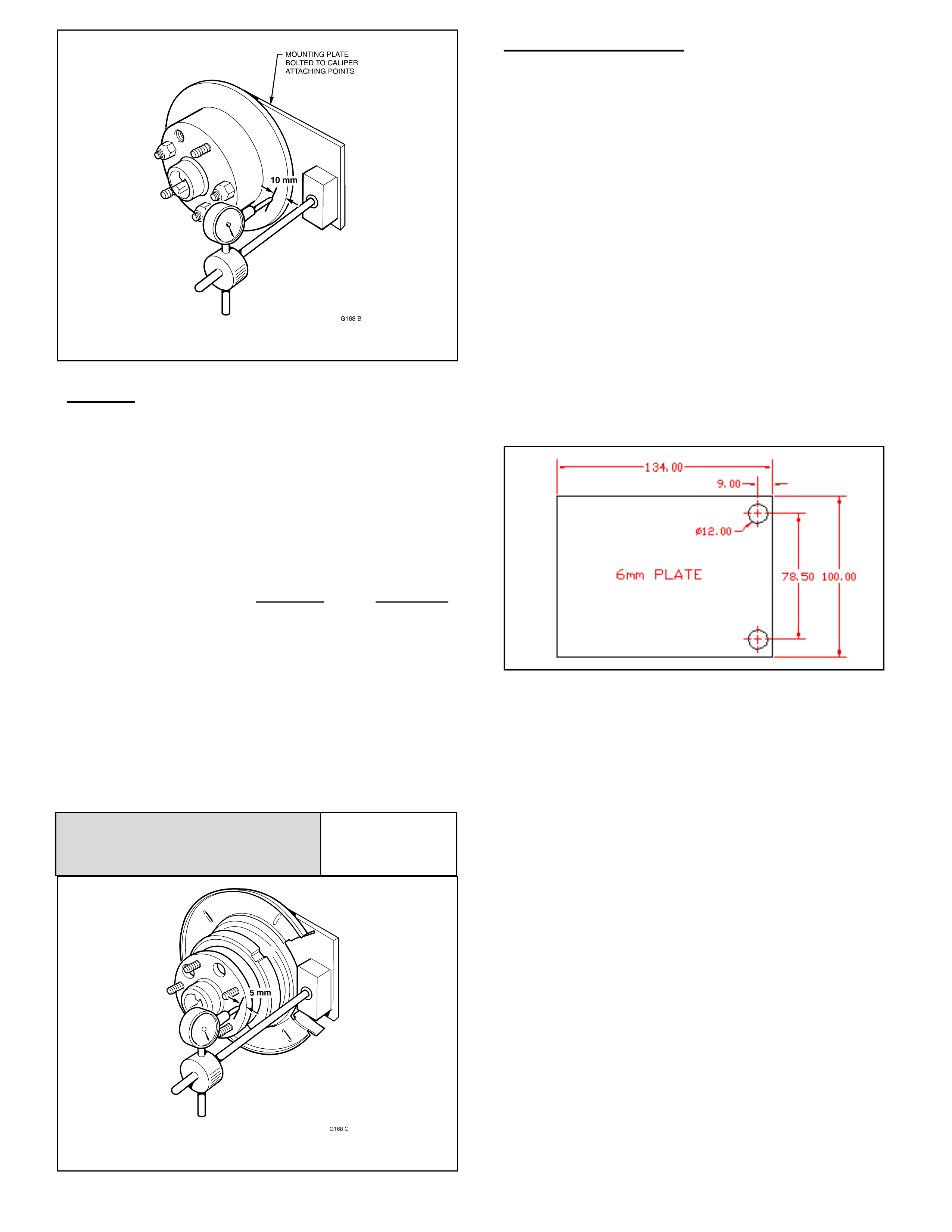
2.3 Set up a dial indicator on a magnetic base and
attach to a mounting plate (refer Figure 10 for
details) bolted to the caliper attaching points.
Position the pointer about 10 to 15 mm inboard
from the outer diameter of the disc. Refer
Figure 9.
2.4 Carefully rotate the disc and note the points of
minimum and maximum runout on the dial
indicator. The number of divisions between
these two points is the total indicated runout.
Record this figure together with the number on
the disc aligned with the chalk-marked stud.
2.5 Remove and reinstall the disc with hole number
“2” over the marked stud. Repeat STEP 2.4.
This procedure is to be repeated for all 5 hole
positions.
2.6 Mount the disc to the trunnion hub in the stud
position with least runout.
NOTE: If the lowest assembled disc runout
achieved is more than 0.080 mm ( 80 micron) then
the trunnion hub runout should be checked as
shown in step 3.
Maximum assembled disc &
trunnion hub runout at disc
outer diameter REAR 0.080 mm
FIGURE 7. MARKING THE DISC & HUB
HOLDEN
SERVICE
TECHLINE
_______________________________________________________________
FEBRUARY
1999
11
FIGURE 8. MEASURING ASSEMBLED RUNOUT
STEP 3. Trunnion Hub runout check
3.1 Clean the front hub face by rubbing lightly with
fine emery paper.
3.2 Locate the dial indicator on the mounting plate
bolted to the caliper mounting points and
position the pointer on the hub face as shown
in Figure 6.
3.3 Carefully rot ate t he hub by the wheel studs and
note the points of minimum and maximum
runout on the dial indicator. The number of
divisions between these two points is the total
indicated runout.
3.4 If the runout measured in STEP 3.3 exceeds
0.060 mm (60 micron) then the trunnion
assembly must be replaced. (If replacement is
done under warranty, the runout figure
measured must be recorded on the Defective
M a te rial Tag.)
Trunnion hub
Total Indicated runout 0.060 mm
max.
FIGURE 9. MEASURING TRUNNION HUB RUNOUT
Production indexing
Disc high point to t runnion hub low point matching
was introduced to the vehicle assembly line on
the 25/01/1999. Breakpoint to be advised.
IMPORTANT :- ALWAYS MARK
DISCS PRIOR TO REMOVING !
Whenever discs are removed from hubs for
reasons other than brake shudder rectification, the
disc and hub must be marked to enable
reinstallation of the disc ont o the hub in the orig inal
position.
This practice will avoid the development of shudder
if the discs are reinstalled in a position which
causes excessive runout.
Disc to hub marking must become a standard
operating practice for all service technicians.
FIGURE 10: DETAILS OF DIAL INDICATOR
MOUNTING PLATE FOR CHECKING REAR
RUNOUT (use caliper bolts with spacers)

12
WARRANTY CLAIM INFORMATION
1. R & R Discs, (Machine off car or fit new discs) & Index Disc to Hub
Description Rem ove & Reinstall discs
machined of f car (or new
discs) & index disc to hub
FRONTS & REARS
Remove & Reinstall discs
machined of f car (or fit new
discs) & index disc to hub
FRONTS ONLY
Remove & Reinstall discs
machined of f car (or new
discs) & index disc to hub
REARS ONLY
Labour Op.No. H000195 H000198 H000201
Standard Time
Add time for
machining
discs
1.4 hrs
0.5 hrs♠
0.8 hrs
0.3 hrs♠
0.8 hrs
0.3 hrs♠
♠ These times are on the basis t hat while the disc machine is on aut ofeed, the technician cont inues with
runout check s , disc indexing and other related work on the vehicle.
NOTE: If discs are sublet for machining, claim expense in “net items” column. Please note that add t imes
cannot be claimed when work is sublet.
1. Machine Discs On Car
Description Rem ove & Reinst all wheels
& rear calipers & r unout
checks.
FRONTS & REARS
Remove & Reinstall wheels
& runout check s
FRONTS ONLY
Remove & Reinstall wheels
& calipers & runout checks
REARS ONLY
Labour Op.No. H000204 H000207 H000210
Standard Time
Add time for
machining
discs
0.5 hrs
0.6 hrs ♠
0.3 hrs
0.4 hrs ♠
0.4 hrs
0.3 hrs ♠
♠ These times are on the basis t hat while the disc machine is on aut ofeed, the technician cont inues with
runout check s, and other related work on t he vehicle.
NOTE: If on-car machining is sublet, claim expense in “net it ems” column. Please note that add t imes cannot
be claimed when work is sublet.

HOLDEN
SERVICE
TECHLINE
_______________________________________________________________
FEBRUARY
1999
13
SUMMARY OF SPECIFICATIONS
Refer page 8. VT Brake disc
specifications. Front Discs Rear Discs
Lateral runout max..040 mm .050 mm
DTV max..005 mm .013 mm
Refer page 10. Maximum assembled disc & hub runout at
disc outer diameter – FRONT 0.050 mm
Refer page 11 Maximum runout at hub face outer diameter –
FRONT 0.030 mm
Refer page 12 Maximum assembled di sc & t r unni on hub
runout at disc out er di amet er - REAR 0. 080 m m
Refer page 13 Trunnion hub
Maximum Total Indicat ed runout 0.060 mm
Refer page 9 DISC THICKNESS
INFORMATION - VT Front Rear
New disc 28.0mm 16.0mm
Min. thickness after
machining (new pads) 25.5mm
(refer note a.) 14.4mm
(refer note b.)
Scrap thickness 25.0mm 13.9mm
Note a. This dimension is calculated on the basis that the normal disc wear rate with new genuine Holden
brake pads should not reduce the disc thickness below the minimum disc operating thickness of 25.0 mm
before the next pad replacement.
Note b. This dimension is calculated on the basis that the normal disc wear rate with new genuine Holden
brake pads should not reduce the disc thickness below the minimum disc operating thickness of 13.9 mm
before the next pad replacement.

HOLDEN
SERVICE
TECHLINE
_______________________________________________________________
FEBRUARY
1999
14
PULLEY TO CRANKSHAFT BOLT
REPLACEMENT
SB, TS (All Engines)
(GROUP 6A)
PROBLEM DESCRI PTION
Investigations have shown that the crankshaft
pulley retaining bolt is being reused in lieu of
being replaced.
This Torx-head bolt is a “one use only” bolt,
which should be discarded, as per ser vice manual
instructions, whenever removed for any reason.
Re-use of this bolt can result in subsequent bolt
failur e and possible pulley or crankshaft dam age.
SERVICE PROCEDURE TO O BSERVE:
Whenever a crankshaft pulley retaining bolt is
removed for any reason, discard the old bolt
and fit a new bolt.
Replace the crank shaft pulley bolt when:
• A vehicle is presented for the 120,000 Km
service which requires replacement of the
engine toot hed belt .
• When fitting an A/C kit to a vehicle without
power steering, using Supplementary Pack,
part No. 92142015, DO NOT RE-USE THE
“EXIST ING TORX BOLT ” as noted on Page 3
of the instructions, DISCARD IT AND FIT A
NEW BOLT. This kit and instructions are
currently being re-written to advise NOT to re-
use the existing T or x bolt, but fit a NEW bolt.
• Ot her servicing of the vehicle that req uires the
crankshaft pulley to be removed.
Service instructions specify that the crankshaft
pulley bolt should be replaced, except however in
the SB Series Service Instructions (DOHC),
Volume 4, Page J-85. Please mark-up your copy
of the service manual t o read “* Use new bolts”, so
that this instruction is also clear for future repairs
on DOHC engines.
ENGINE DRIVE BELT SQUEAL NOISE
VT with V8 Engine & A/C
(GROUP 6A)
PROBLEM DESCRI PTION
PIR’s have been received regarding a squeal
noise emanating from the eng ine dr ive belt.
The most common cause has been found to be a
slight misalignment of the A/C idler pulley
mechanism to the A/C drive belt, and in some
cases, the A/C compressor pulley has been out of
alignment with the dr ive belt t rack.
SERVICE RECTIFICATION
A/ C idler pulley mechanism:
The noise can be rectified by carrying out the
“Tension Adjustment” of the A/C drive belt, as
shown in VT Series Service Manual, Volume
No.2, Section 6A2, Page 6A2- 46.
When torqueing the Idler Pulley clamp nut –
ensure the idler pulley assembly is as square as
possible to the belt t rack – as misalig nment at this
point will cause recurring squeal noise.
A/ C compressor pulley:
If the A/C Compressor is found to be out of
alignment to the belt t rack, this may be caused by
clearance in the A/C com pressor and it s mounting
bracket . To adjust this, loosen the compressor- to-
mounting bracket bolts, align compressor pulley
with the drive belt track, and re-torque bolts -
Refer to VT Series Service Manual, Volume No.1,
Section 2B, Pag e 2B-40/41.
WARRANTY CLAIM INFORMATION
Use existing Labour T ime Manual inf or m ation as
follows, for these adjustment s.
Description A/C Belt Sq ueal Adjustment
Labour Op. No. J000604
Time 0.3 hr
Failure Code 90
Update

HOLDEN
SERVICE
TECHLINE
_______________________________________________________________
FEBRUARY
1999
15
ENGINE STALL CHECK LIST
SB w i th C14NZ Engine
(GROUP 6A)
PROBLEM DESCRI PTION
A number of “engine stall” complaints have been
received by TAS and in PIR’s. Investigation
continues into the root cause of engine stall on
C14NZ engines.
To assist technicians in rapid diagnosis of these
stalling complaints, the following checklist is
provided. The checklist was issued previously to
callers to T AS. Please utilise this check list for any
customer vehicles that experience engine stall
complaints.
When root cause investigations are finalised, a
fur ther, updated Techline it em will be released.
SERVICE DIAGNOSIS AND RECTIFICATION
Preliminary Inspections:
• Connect Tech 1 and check for any DTCs
that may exist. Rectify the cause of these
DTCs prior t o any further diagnosis.
• Connect Tech 1 and compare eng ine data
list parameters against QUICK CHECK
F0: DATA LIST SB Series, Service
Manual, Volume 3, page J226. Any data
errors can be further diagnosed in section
5.1.6 of SB Series, Service Manual,
Volume 3, pag e J234
• Install Tech 1, road test vehicle and
attempt to reproduce complaint.
SNAPSHOT engine data list when stall
occurs. Compar e capt ured data with :
- QUICK CHECK F0: DATA LIST, SB
Series, Service Manual, Volume 3, page
J226 - Section 5.1.6 SB Series, Service
Manual, Volume 3, page J234.
• Install a fuel pressure gauge to the
vehicle. Ensure that fuel pressure is within
specification and that no fuel system flow
restrictions exist. Fuel pressure gauge
may be left on the vehicle while road
testing to monitor any immediate loss of
pressure when stalling occurs. (When
these actions are carried out – ensure that
appropriate safeguards are made so no
damage occurs to any fuel line, and no
fuel leak exists before, during or after the
procedure.)
• Check for loose connections. Apply a
general “wiggle test” to engine and main
wiring harness connections as a means of
fault locat ion.
• Inspect spar k plug s for correct type, check
condition and gap to 1.1mm.
• Check base ignition timing setting as per
SB Series, Service manual, Volume 3,
page J-203
• Carry out a compression test with engine
cold - if a compression difference of 20%
or more is evident between any cylinders,
fur t her investigation should be carried out.
Specific I nspections:
1) Check connection of wires to terminals at
TPS plug .
Check for loose connections or damaged
terminals at TPS plug.
2) Check that fuel pump relay mating harness
terminals are not “backing out” of the
connector body, and that the relay fully seats
in the mating connector when fitted.
3) Check that wiring to ig nit ion m odule has ‘solid’
connections, and that no terminals on the
wiring are “backing out ” of the connections.
4) Check base idle air r ate:
Remove thrott le body if necessar y.
- Unscrew throttle valve stop screw – after
removing blanking plug – until there is visible
play, (approximately 0.5mm/0.02in)
between throttle stop scr ew and throt t le lever.
- Screw in throttle stop screw until it just
touches the thr ot tle lever (No visible pl ay).
- Screw in the thrott le stop screw a f urther 1½
to 1¾ turns. (throttle is now open by a
defined gap)
- Now check values of FO : DATA LIST at
idle speed (engine at oper at ing temperatur e) .
5) Check MAP sensor HOSE for leaks and
vacuum supply.
- Also check t hat the MAP sensor hose is fully
pushed on at both ends, is an original hose or
made of vacuum hose material and does not
collapse under vacuum.
6) Inspect Fuel Canister purge hoses for correct
connection and orientat ion.
Check operat ion of canister purg e valve with a
vacuum pump

HOLDEN SERVICE TECHLINE _______________________________________________________________ FEBRUARY 1999
16
7). Check the earth wire near the starter motor.
As you look at the vehicle from underneath,
on the driver side, the earth is above and to
the right of the starter (roughly at 1 o'clock
position).
During investigation of this problem, the
follow i ng has been observed:
- The car would not start with this earth
disconnected.
- Once started and the earth disconnected, the
car would idle very roughly.
- The car could be made t o stall by opening and
closing the t hr ottle.
- No DTC’s were logged.
8) Check vapour canister vent hose, to see if
blocked with mud, etc, .
9) Check all fuel hoses for kinking, or soft
sections which may indicate hose collapse or
cause intermitt ent blockages.
10) Check coolant temp sensor probe and
terminals for corrosion. If required, clean up
terminals and protect against corrosion.
Replace sensor if necessar y.
11) If the above checks do not help, check MAP
sensor connector for loose connections /
damaged terminals at sensor connector, if OK
– replace sensor.
12) If the owner still experiences stalling, and the
owner is able to demonstrate the problem, a
service adviser should accompany the owner
to ensure that there is not an unusual driving
style which may be contributing to the pr oblem .
NOTE: If the stall can be reproduced and
demonstrated to the dealer, and the stall
complaint cannot be resolved, TAS should be
contacted so that further investigation can be
initiated.
14) On completion of TAS instructions and
complaint rectification, submit a PIR giving full
details of the complaint , condit ions of oper ation
and rectification
WARRANTY CLAIM INFORMATION:
If the above testing defines a part replacement is
required, claim the relevant part’s labour
operation as per the Labour Time Manual. W here
additional time is required additional to published
labour time, seek authorisation from your Zone
Service representat ive.
TECH 1 & TECH 2 USAGE SERVICE HINT
VS with V8 P.O. LB9, XT9
(GROUP 6C)
PROBLEM DESCRI PTION
Tech-1 will not comm unicate with the PCM, and
Tech-2 will not communicate with all other
modules EG: SRS, ABS, BCM, on vehicles built
with 5.0 litre V8 engine, Production Option LB9,
XT9 which was introduced into VS vehicles as
follows:
Introduction Breakpoints: Build Date:
Statesman : L416103 21/12/98
Utility : L415544 19/12/98
Technicians may believe there is an engine
managem ent or PCM problem when att empting to
use Tech 1 on these vehicles.
SERVICE RECOM MENDATIO N
Technicians should be aware of the change in
usage of Tech 1 diagnostic hand tool - with
the introduction of 5.0 litre V8 engine
Production Option LB9, XT9 into VS models.
Information regarding this is specifically
covered in VS Series Service Manual,
Supplement No. 11, Section 0C.
NOTE specifically the need to “PRESS AND
HOLD THE “NO” KEY FOR 3 TO 5 SECONDS”
as shown in the third step on Fig ur e 0C-3 below.
To assist technicians, information from Section
0C, pages 21 and 22 is copied below:
17
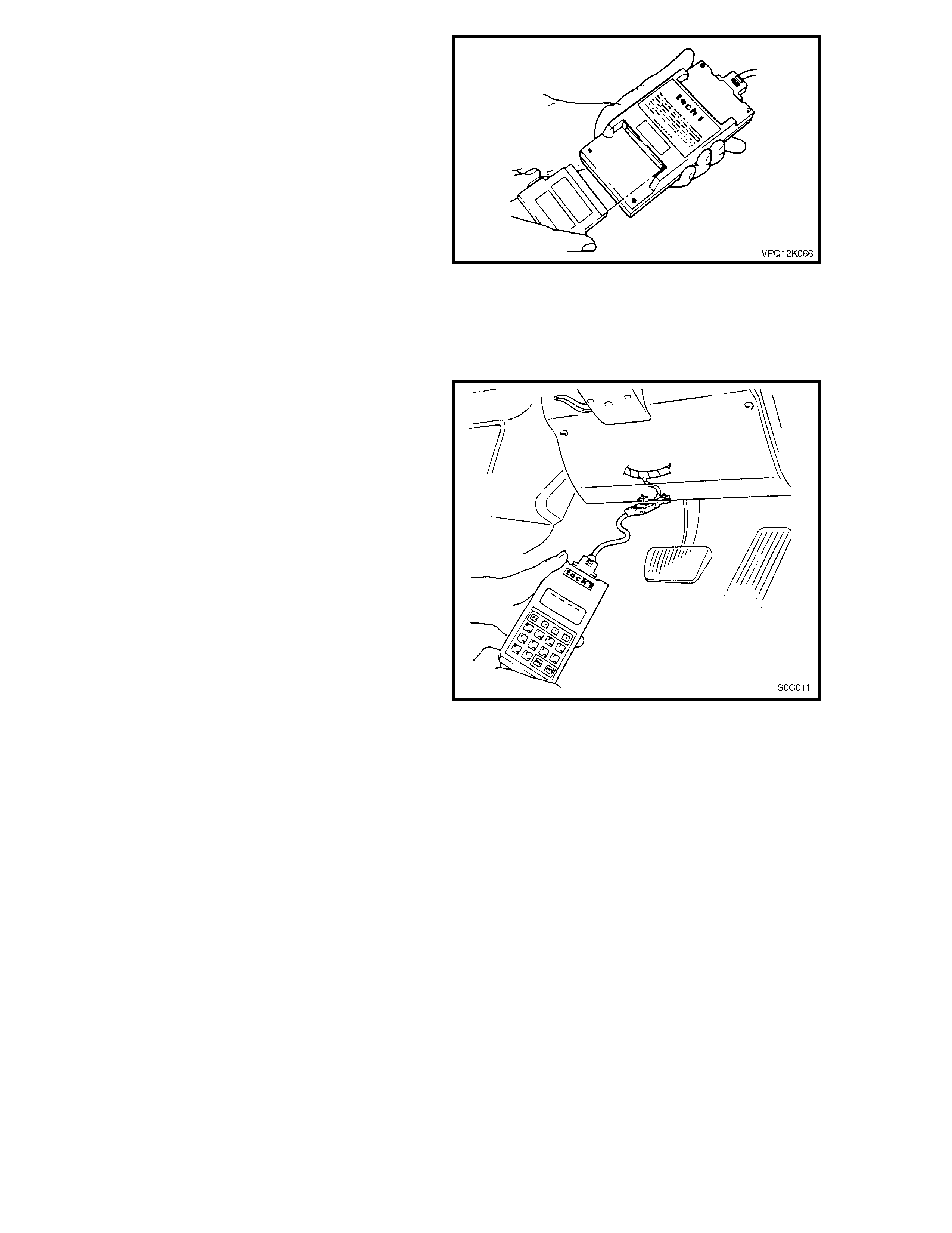
4.1 CONNECTING TECH 1 TO THE VEHICLE
1. Ensure the ignition switch is in the OFF position.
2. Install the 1995 VS/T4 SYSTEMS cartridge to TECH
1. Ensure that there is no other cartridge installed in
the opposite port of TECH 1.
3. Ensure the DLC adaptor is fitted to TECH 1 lead
and then connect the adaptor to the DLC.
4. Turn the ignition switch to the ON position.
5. TECH 1 is ready for operation.
NOTE 1: For additional general information on
connecting and operating TECH 1, refer to the TECH 1
OPERATORS MANUAL, supplied with the cartridge.
NOTE 2: Due to the differences in serial data
communication between the BCM and the PCM on
VS Series III Models with P.O. LB9, XT9, 5.0 litre V8
engine and other VS Series Models, the method for
selecting BCM, ABS or SRS information on the TECH
1 VS system select menu is unique (refer following
page).
Figure 0C-1 Installing systems cartridge
Figure 0C-2 Connecting TECH 1 to the DLC
HOLDEN
SERVICE
TECHLINE
_______________________________________________________________
FEBRUARY
1999
18
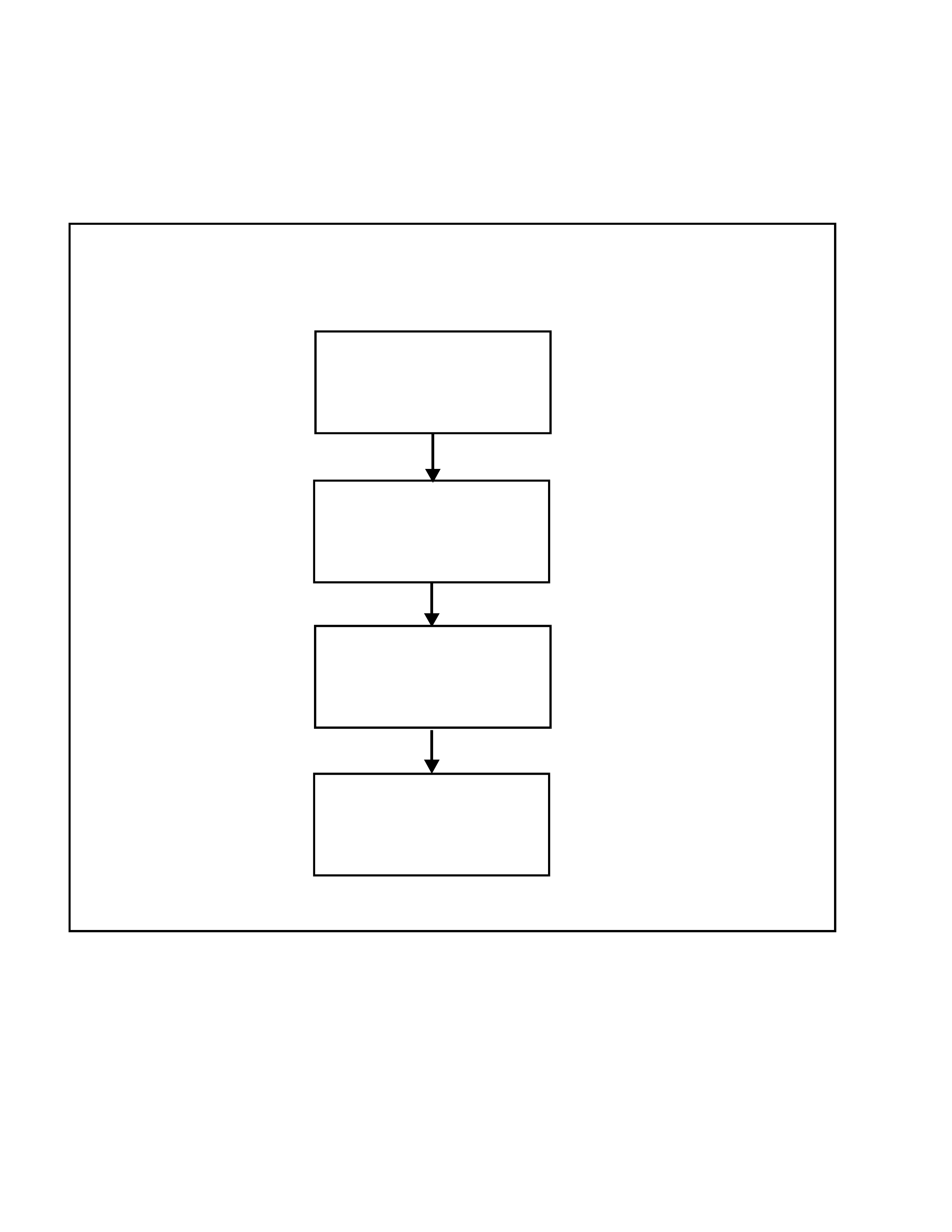
Fig. 0C-3 shows the correct procedure to
communicate with the BCM, ABS and SRS systems
using TECH 1.
Once the SYSTEM SELECT menu is displayed, TECH 1
will operate normally, as described in the TECH 1
OPERATORS MANUAL and the relevant Sections in the
VS Series Service Manual Supplement.
NOTE 3: Refer to 3. USING TECH 2 ON THE VEHICLE
in this Section to access PCM information on VS Series
III Models with P.O. LB9, XT9.
WITH THE VS/T 4 SYST EMS CARTRIDGE INSTALLED AND TECH 1 CONNECTE D TO THE DLC,
SWITCH T HE IGNITION ON.
VS/T4 CARTRIDGE
INTRODUCTION
SCREE N DIS P LAY
VS/T4 SYSTEM
OEM DEALER
(VERSION 1.0 )
[ENTER]
DETERMINE IF PCM
WAITING FOR DATA
VS SYSTEM
SELECT MENU
SELECT SYSTEM
F3: BCM
F4: ABS
F5: SRS
PRESS “ENTER” KEY
DETERMINE IF PCM
NO DATA RECEIVED
FROM PCM
S0C010
PRESS AND HOLD “N O”
KEY FOR 3 TO 5 SECONDS
PRESS RELEVANT FUNCTIO N
KEY TO SELECT SYSTEM
DATA AND OUTPUT TESTS
(I.E..PRESS THE “F3” FUNCTION
KEY FOR BCM DAT A)
Figure 0C-3 Process for selecting BCM, ABS or SRS systems
HOLDEN
SERVICE
TECHLINE
_______________________________________________________________
FEBRUARY
1999
19
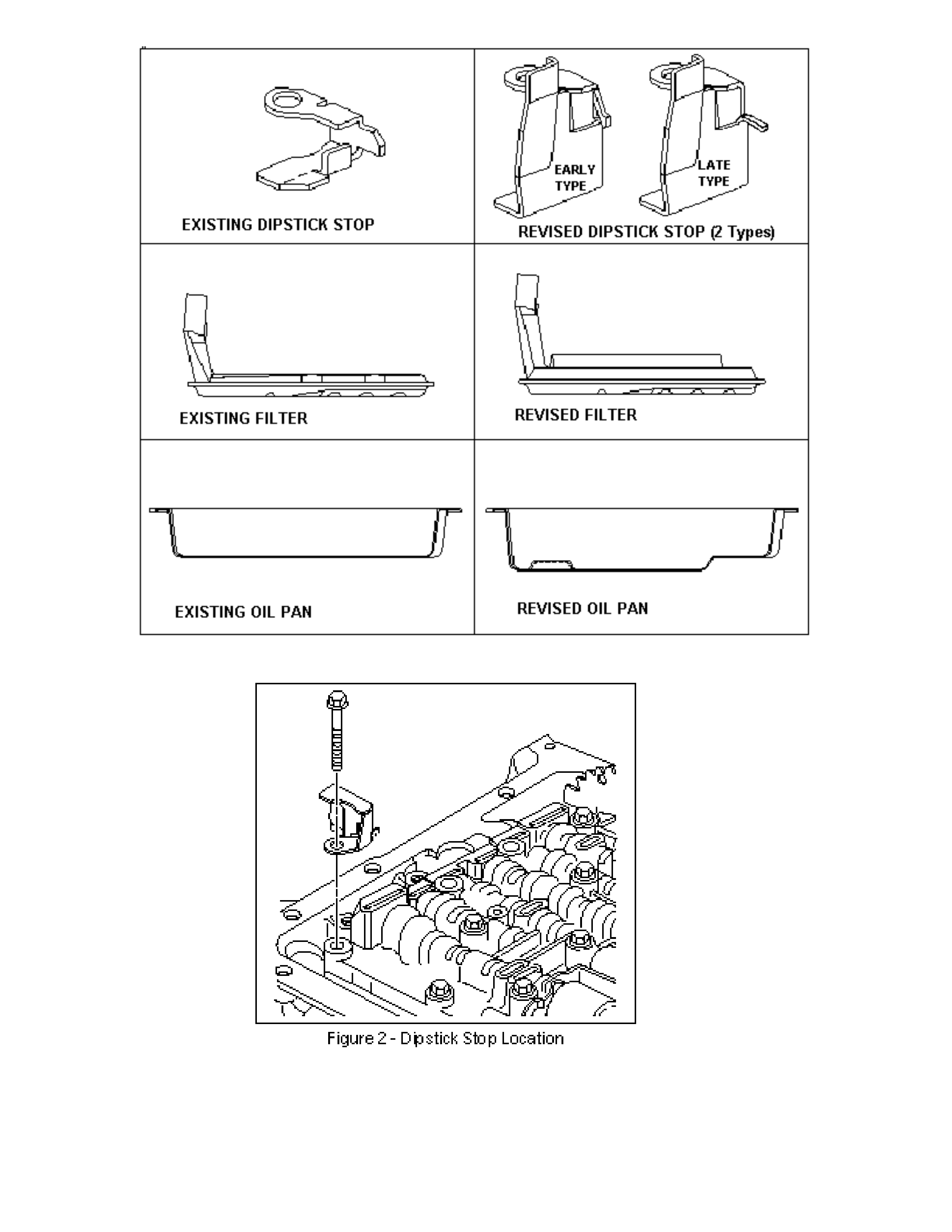
A/T “DEEP” PAN & FILTER SERVICING
VS with A/T & Deep Pan Kit fitted
(GROUP 7B)
PROBLEM DESCRI PTION
When servicing vehicles fitted with a Deep Pan
Kit, Part No. M41559 (also known as a “chuffing
kit”), it is possible to fit the earlier “shallow” filter
by mistake. This may result in loss of drive as a
consequence of the shallow filter dislodging from
the transm ission.
Under no circumstances should the shallow pan
type filt er be fitted to a vehicle with a deep pan.
In addition, if an oil level indicator (dipstick) is
replaced by the wrong part, over-filling of the
transmission fluid will result.
SERVICE PRECAUTIONS
The deep pan and associated parts were not
introduced into VS production. A Deep pan and
associated parts were introduced into VT at start
of production; however, the parts are different to
those used on VS. T her efore, VT par t s should not
be used when servicing a VS vehicle with a deep
pan fitted.
Filter Replacement: Whenever replacing the filter
on a VS – first identify whether a “deep” or
“shallow” pan is fitted, to ensure the correct
replacement filter is to be fitted.
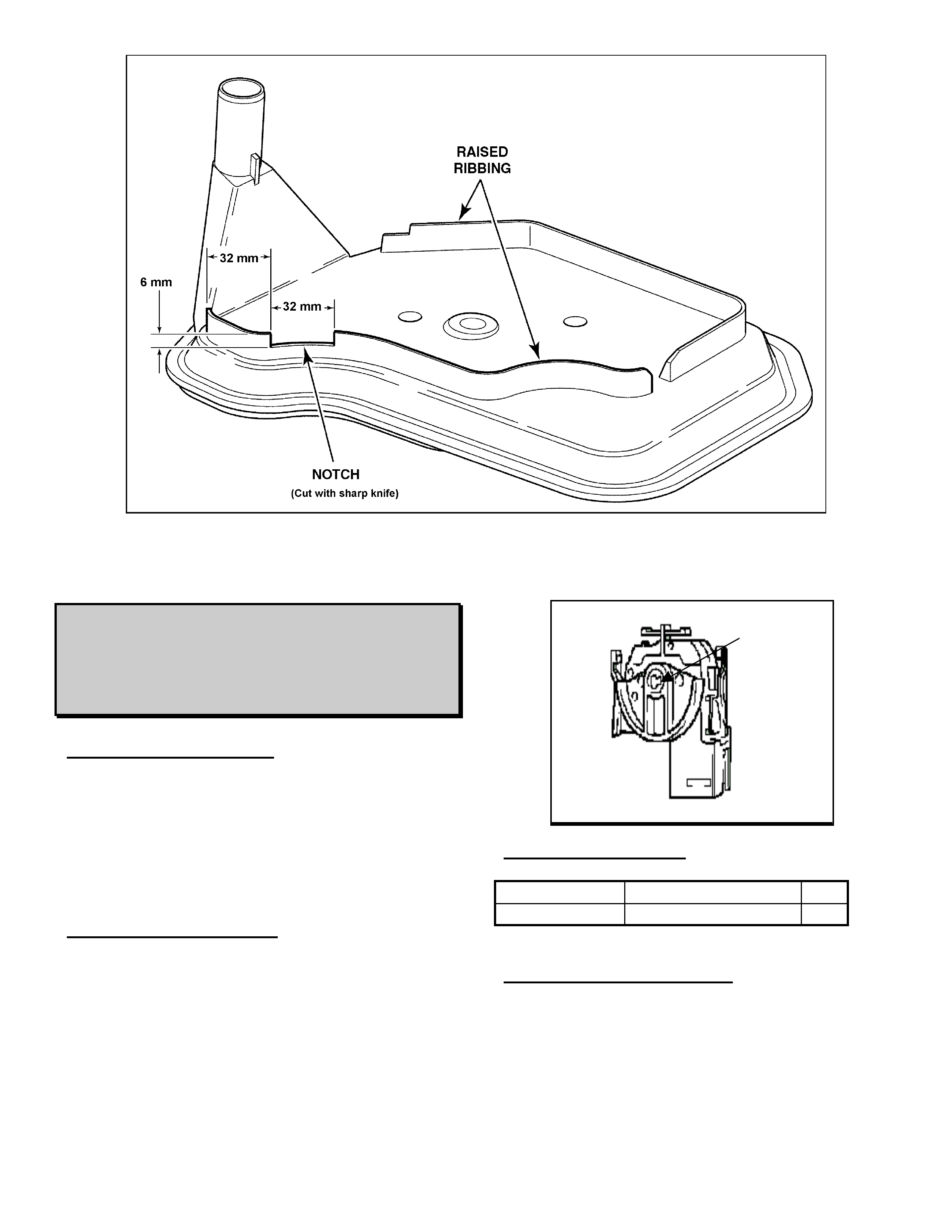
Filter Modification: When fitting a filter, identify
whether the new filter has a notch to clear the
wiring harness as shown in Figure 3. Some early
filters lacked this notch. If it does not have the
notch, it should have a notch cut out of the filter
ribbing with a sharp knife, as shown in Figure 3.
Failure to ensure this notch exists on the filter
may cause harness damage, and result in
intermittent transmission electrical or shift
complaints.
PARTS INFORMATION
The Deep Pan Kit (M41559) consists of the
following parts:
Part No.: Description: Qty
Req’d:
- Oil Pan Asm. (incl. Magnet) 1
- Oil Pan Gasket 1
- Bracket – Dipst ick Stop 1
- Filter Assem bly 1
- Seal – Filter 1
- Oil Level Indicator ( d ipst ick) 1
- Instruct ion Sheet 1
Refer to PartFinderTM for specific service part
numbers. These parts are identified with the
words “(DEEP PAN)” added to the part
description.
PARTS IDENTIFICATION
Oil Level Indicator (dipstick) – has a RED handle,
and part number 92057150 stamped on the shaft
of t he dipst ick.
Trans. Oil Pan – is deeper than original pan and
has a “step” pressed in the bottom surface of the
pan. (Original VS oil pans had flat bottom
surfaces). Refer Figure 1 that shows deep and
shallow pans.
Dipstick Stop – refer Figures 1 & 2 which show
the two types of stops possibly used with deep
pan, stop location, and the original shallow pan
stop.
Filter – The filt er used in the deep pan installation
has a longer neck than the original filter, and
ribbing on the top of the filter. Refer Figure 1,
which shows both deep and shallow pan filters.
HOLDEN
SERVICE
TECHLINE
_______________________________________________________________
FEBRUARY
1999
20
Figure 1 - Trans. Oil Pan, Filt er and Dipstick Stop Compar ison
HOLDEN
SERVICE
TECHLINE
_______________________________________________________________
FEBRUARY
1999
21
Figure 3 - Rework Details For Ear l y Type Deep Pan Fi lter
IGNITION SWITCH FAILURE
TS ASTRA
(GROUP 12)
PROBLEM DESCRI PTION
A no start, no crank condition experienced on
some TS Astra vehicles left standing in the sun
for extended periods has been traced to a heat
sensitive ignition switch. The heat penetrates
through the steering column cover and expands
the switch rotor.
SERVICE RECTIFICATION
A revised ignition switch has been introduced with
a material change and can be identified by a
black coloured r ot or.
Refer to the relevant section of the Astra G
service information in TIS for the removal and
replacement inst r uct ions.
PARTS INFORMATION
Part Number Description Qty
90589314 Ignit ion switch 1
WARRANTY INFORMATION:
Use existing inf or mation in Labour Time Manual.
Order the new part from HSPO - all parts at
HSPO are of the latest specification.
Black
coloured
rotor
HOLDEN
SERVICE
TECHLINE
_______________________________________________________________
FEBRUARY
1999
22
POOR “AM” RADIO RECEPTION
TS ASTRA
(GROUP 12)
PROBLEM DESCRI PTION
Some vehicles are reported to have poor radio
reception while listening to “AM” band stations.
Investigations have identified a loose antenna
connection as the primar y cause.
SERVICE RECTIFICATION
Rectification can be achieved by tightening the
antenna connector. Follow the procedur es below:
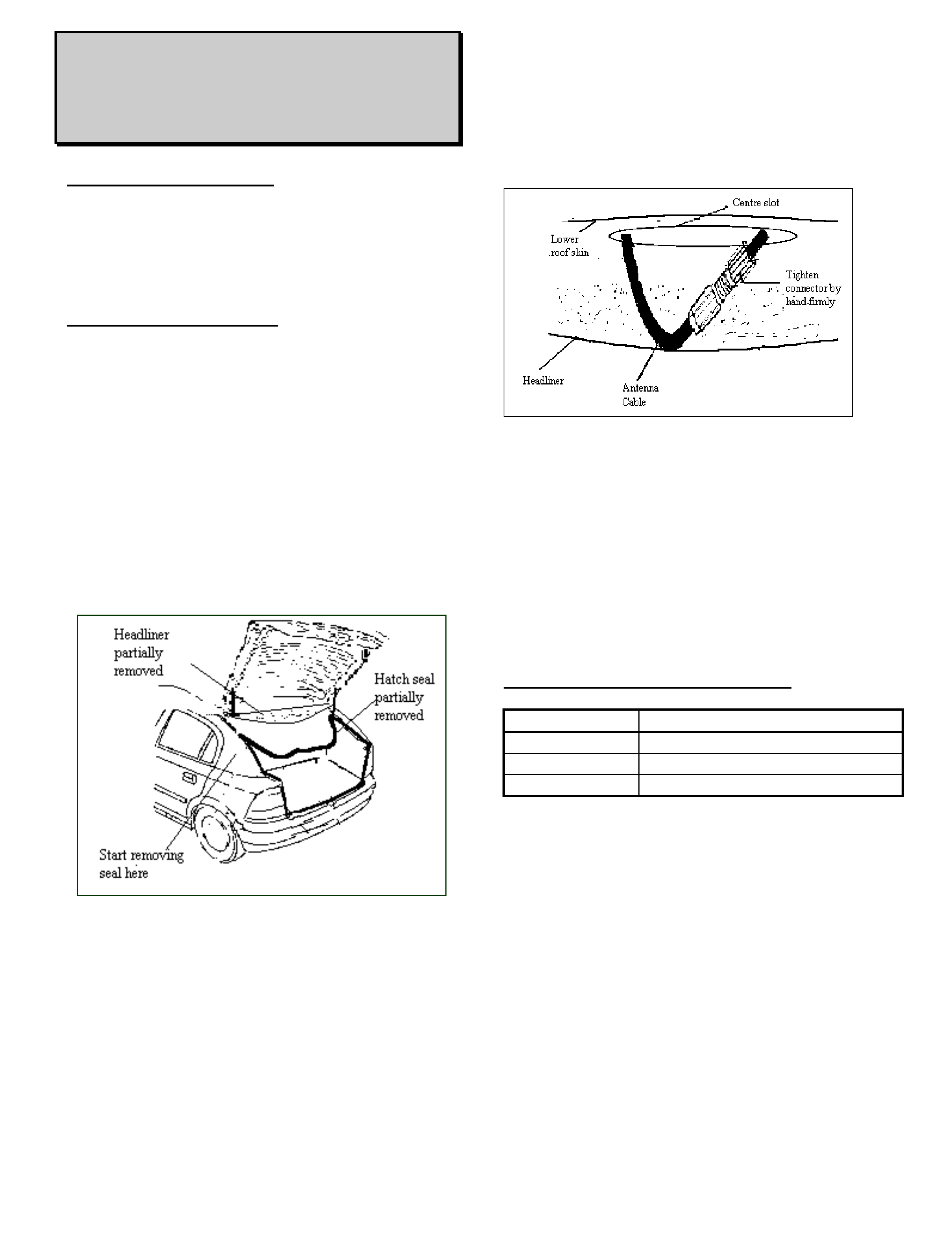
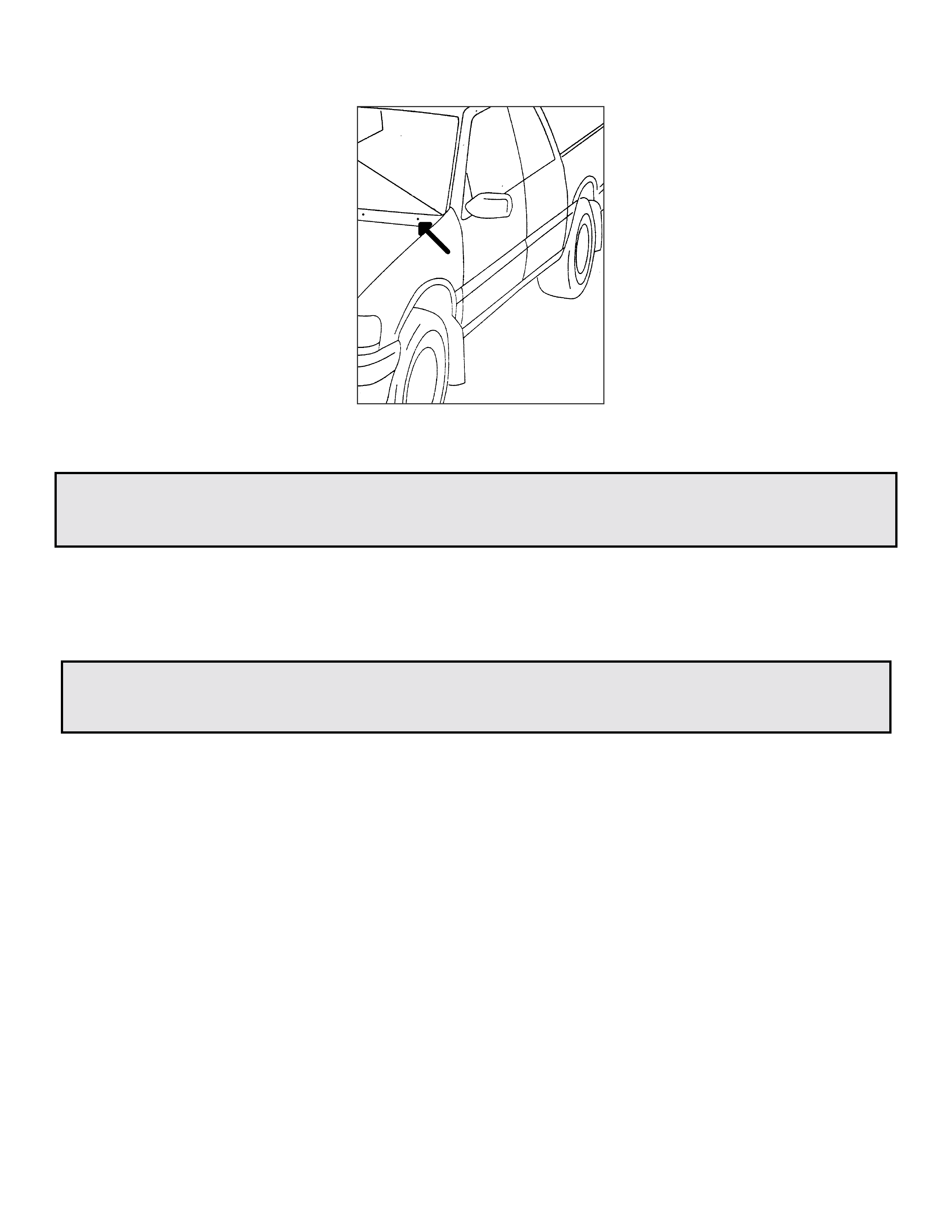
1. ACCESS TO ANTENNA CONNECTION
• Remove rear parcel shelf and place in
boot cavity.
• Partially remove the hatch weather seal from
the upper section of the hatch opening.
(Refer Figure 1)
• Carefully prise the rear of the head lining
away fr om t he r oof.
FIGURE 1
2. TIGHTEN CONNECTOR
• Locate the antenna connector inside the
centre slot of the lower roof skin.
(Refer Figure 2)
• Remove all the foam tape around the
connector and tighten threaded type fitting
firmly by hand.
Figure 2
3. RE-ASSEMBLY AND FINAL CHECKS
• St art the eng ine, set radio t o the AM band and
check that the reception is clear. Confirm
reception is still clear when wriggling the
connector.
• Apply foam tape to connector and place in
centre slot on lower roof skin.
• Refit headlining and hatch weather seal
firmly to hatch lip.
WARRANTY CLAIM INFORMATION:
Description Antenna Connector - Tighten
Labour Op. No. N000315
Time 0.5 Hrs
Failure Code 27
HOLDEN SERVICE TECHLINE _______________________________________________________________MARCH 1999
1
CREAK FROM LOWER LHS DASH
VT
(GROUP 1)
PROBLEM DESCRI PTION
A creak is heard from the lower left-hand side of
the dash when the vehicle travels over undulating
ground and t he body f lexes.
The creak is caused by the cockpit module f ouling
the rear edge of the glue track in the region near
the power train harness grommet. The primary
area that causes a creak is the highest point on
the vertical face of the firewall.
PRODUCTION RECTIF ICATION
Extra dimples were added to the edge of the
cockpit that rests in the glue track. This change
was introduced into production from;
PSN: Build Date:
L412371 12/12/98
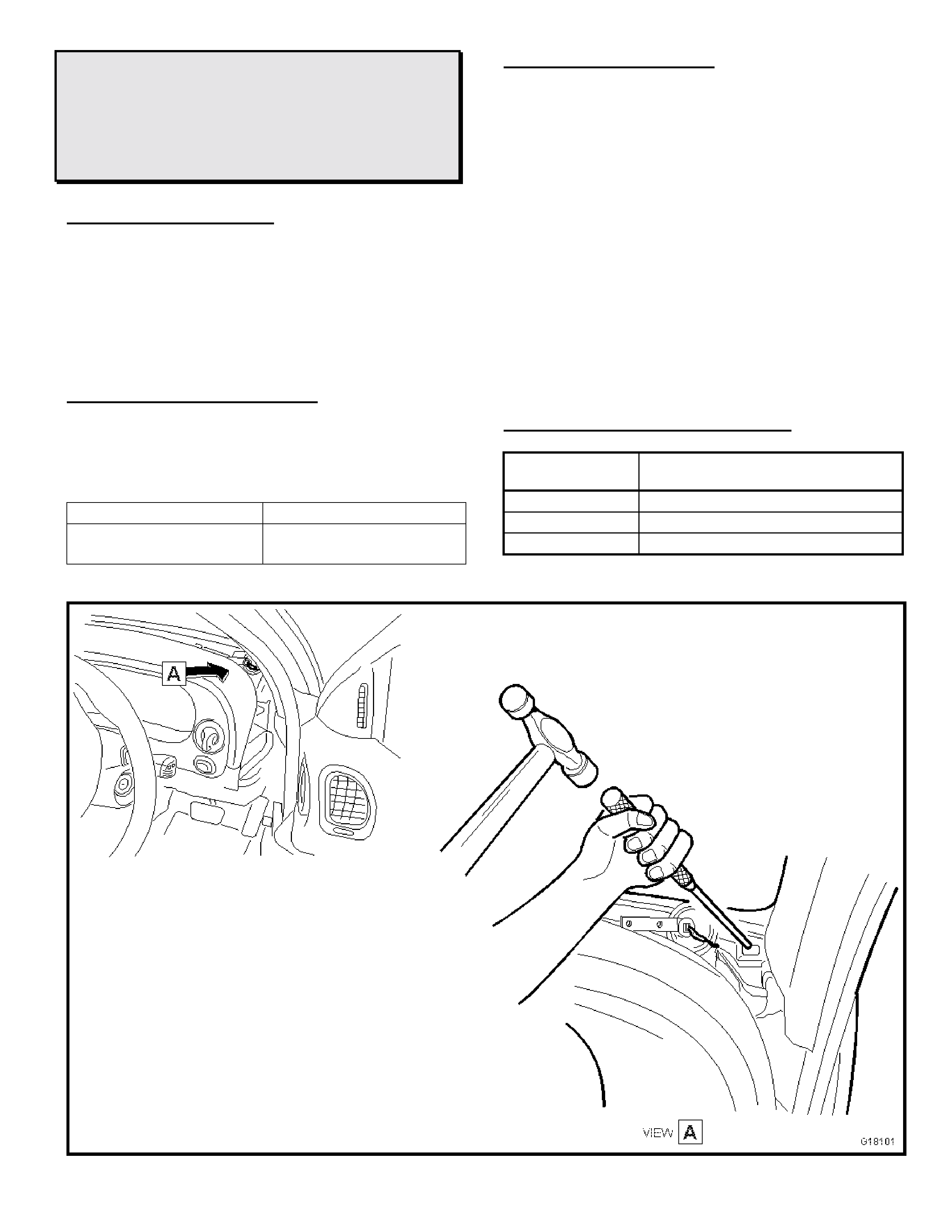
SERVICE RECTIFICATION
Aim: To move the firewall panel forward away
fr om t he r ear edge of the g lue t r ack.
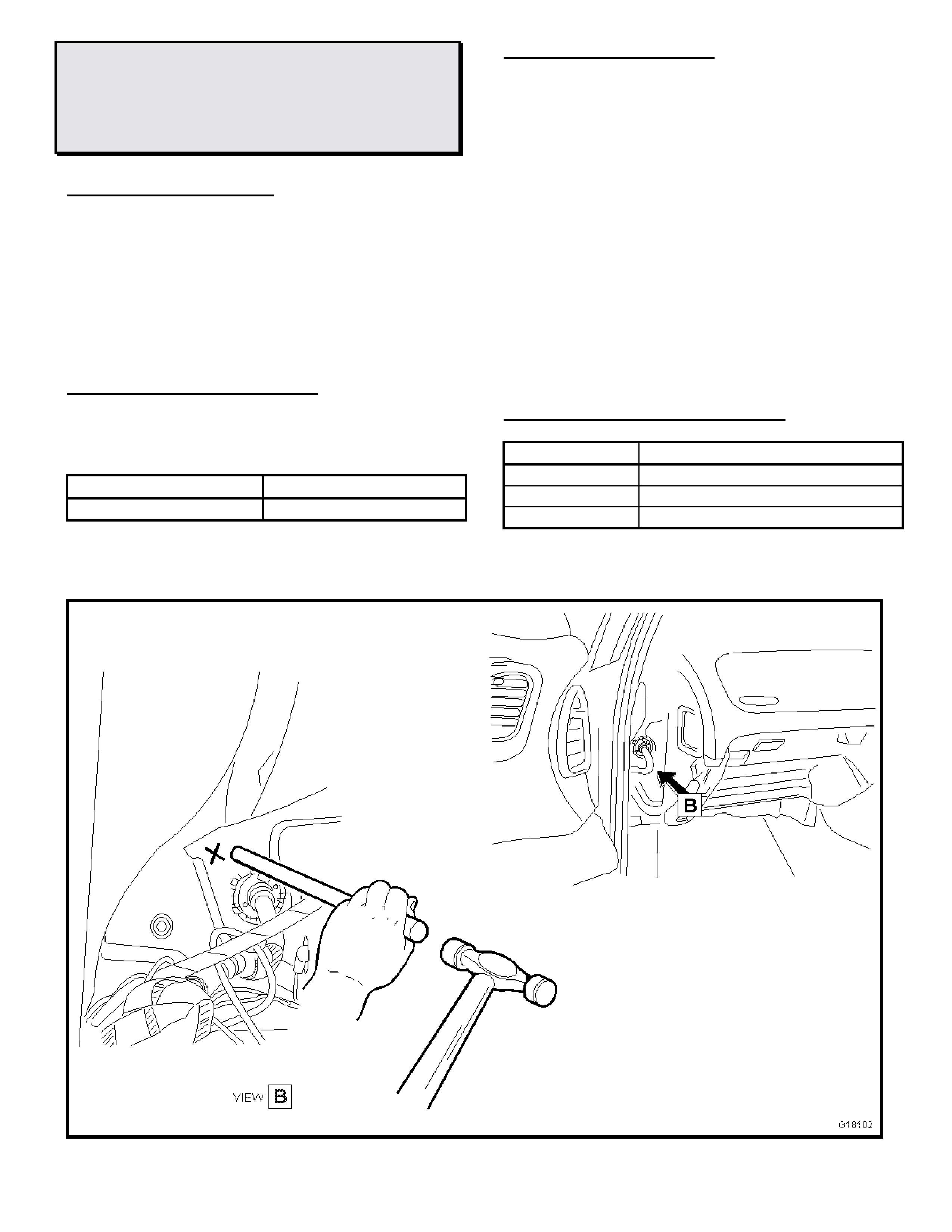
Procedure:
• Remove the glovebox and the LH instrument
panel dash end cover.
• Using a long blunt object and a hammer, hit
the panel with sufficient force to move the
firewall panel slightly forward away from the
rear edge of the glue track as indicated in the
Figure below. Hit in the area closest to the
glue track and as high as possible.
• Depending on the severity of the foul, it may
be necessary to hit at lower points also.
• Test drive to evaluate the vehicle and reinst all
the removed components if appropriate.
WARRANTY CLAIM INFORMATION
Description Creak Dash Lower LHS – Rectify
Labour Op. No. A000249
Time 0.5 hr
Failure Code 28
HOLDEN SERVICE TECHLINE _______________________________________________________________MARCH 1999
2
CREAK FROM THE RH LOWER CORNER
WINDSCREEN AREA
VT
(GROUP 1)
PROBLEM DESCRI PTION
On moderately rough roads that induce a small
amount of body flex, a creak or ticking noise is
heard from the lower right-hand corner of the
windscreen.
The creak is caused by two interfacing panels
located directly behind the right-hand tweeter that
can rub together.
PRODUCTION RECTIF ICATION
The spot weld in this area was relocated to stop
the relative movement between panels at this
point. T his change was introduced into production
from;
ISOVIN: Build Date:
6H8VTK35HWL31556
513/03/98
SERVICE RECTIFICATION
Aim: To knock the two panels together to prevent
movement.
Procedure:
• Lower the fuse panel cover and remove the
instrument panel end cover.
• Remove the demist grille. Unscrew the
tweeter brack et and move it to one side.
• Using a long punch, hit the near vertical face
behind where the tweeter usually locates as
indicated in the Figure below. Tr y to hit the t op
panel close to the top edge.
• Depending on the severity of the foul, it may
be necessary to hit at lower points also.
• Test dr ive to evaluate the vehicle and reinst all
the removed components if appropriate.
WARRANTY CLAIM INFORMATION:
Description Creak RH Lower Corner of
Windscreen – Rectify
Labour Op. No. A000246
Time 0.5 hr
Failure Code 28
HOLDEN SERVICE TECHLINE _______________________________________________________________MARCH 1999
3
EXCESSIVE PAG OIL IN A/C SYSTEM CAUSING FAST CYCLING OF THE A/C COMPRESSOR
VT
(GROUP 2)
PROBLEM DESCRI PTION
Fast cycling of the A/C compressor may occur due to excessively high refrigerant pressures
caused by too much refrigerant (PAG) oil in the system. This often occurs when technicians fail to
“balan ce the oil charge ” prior to in stalling a n ew A/C com pressor. “B alanc ing the o il cha rge” re fers
to adjusting the oil quantity in the new compressor to the same quantity remaining in the old
compressor.
Refer to the VT Series Service Manual, Volume 1, page 2C-7, Section 2C - Air Conditioning – Servicing
and Diagnosis.
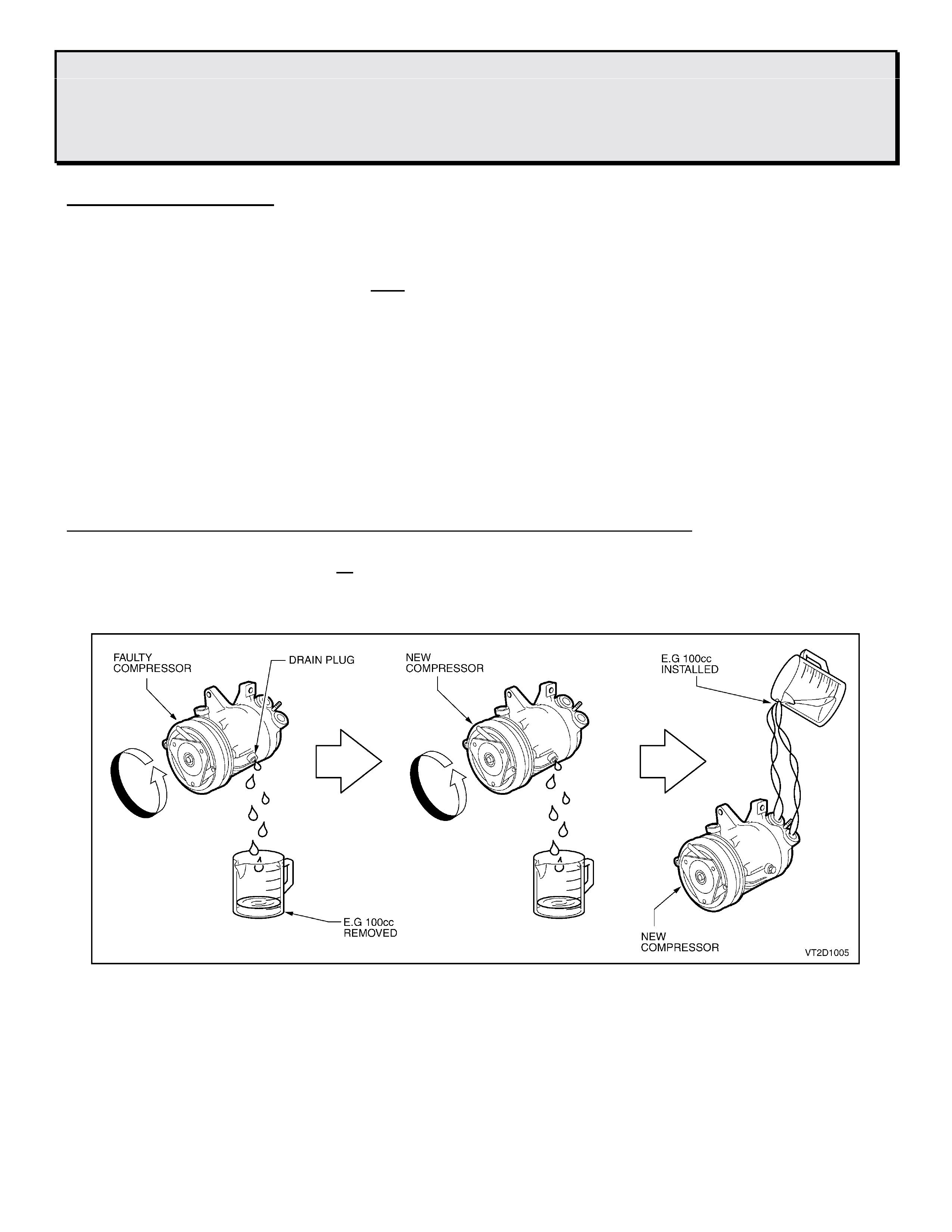
If a com pr essor is replaced previously and is suspected to have an overcharge of PAG oil then:
1. Remove and drain the compressor
2. Flush the entire system t o r emove any traces of the old PAG oil.
3. Refill com pr essor with new 265cc of PAG oil.
4. Reinstall compressor , recharge A/C system and re evaluate.
Import ant points to remember when installing a new replacement A/ C com pressor:
• Always drain and measure the PAG oil from the compressor t hat is being replaced.
• Drain the new compressor of all PAG oil. Add the same amount of PAG oil as removed from the
replaced compressor + 10cc to the new compressor. Ensure to use the new PAG oil that was drained
from the new compressor.

HOLDEN SERVICE TECHLINE _______________________________________________________________MARCH 1999
4
LSD “CHATTER” NOISE
VT w ith LSD
(GROUP 4)
PROBLEM DESCRI PTION
A number of final drive units have been replaced
for chatter noises. Investigat ion has revealed that
the cause of the complaint noise was LSD
lubricant related. Unnecessary replacement of
LSD units may result if the diagnosis
recommended by Holden and the LSD supplier is
not carried out.
SERVICE RECOM MENDATION
The following is an extract of a paragraph
regarding LSD checking in the VT Series Service
Manual, Volume 1, Page 4B- 77.
This diagnosis must be carried out to ensure
unnecessary replacement of rear axle assemblies
does not occur.
Once the diagnosis has been performed and the
rear axle assembly is found to be defective
requiring replacement, please note on the
Defective Material Tag that the test procedure as
shown below has been perfor m ed.
4.3 LSD NOI SE
If LSD stick-slip chatter is diagnosed, the
differential carrier lubricant should be
drained immediately after a run to warm
up the lubricant. This is to remove as
much old lubricant and wear debris as
possible. Refill carrier with the specified
lubricant and re-evaluate LSD operation
for a minimum of 20kms. Chatter will
usually disappear within this time.
Should chatter still occur, remove carrier and
overhaul LSD. Refer to 3.4 LIMITED SLIP
DIFFERENTIAL in t his Sect ion.
NOTE: Comments regarding overhaul ONLY
apply to vehicles not covered by warranty.
For vehicles covered by warranty, replace rear
axle assembly via changeover program, referred
to in Dealer Letter DL 37/98, entitled “Holden
Component Chang eover Programs”.
PULLEY TO CRANKSHAFT BOLT
REPLACEMENT
SB, TR, TS, JR, JS, YE, UT (All Engines)
(GROUP 6A)
This Service Techline supersedes (Issue 1,
February, 1999 page 16), advising technicians
that on further investigation, ALL MODELS
NOTED ABOVE ARE AFFECTED.
PROBLEM DESCRI PTION
Investigations have shown that the crankshaft
pulley retaining bolt is being reused in lieu of
being replaced.
This bolt, whether a Torx-headed or standard
hex-head bolt, is a “one use only” bolt, which
should be discarded, as per service manual
instructions, whenever removed for any reason.
Re-use of this bolt can result in subsequent bolt
failur e and possible pulley or crankshaft dam age.
SERVICE PROCEDURE TO O BSERVE:
W henever a crankshaft pulley retaining bolt is
removed for any reason, discard the old bolt
and fit a new bolt.
Replace the crank shaft pulley bolt when:
• A vehicle is presented for the relevant service
which requires replacement of the engine
toothed belt.
• Any other servicing of t he vehicle that req uir es
the crank shaft pulley to be removed.
• On SB Models - When fitting an A/C kit to a
vehicle without power steering, using
Supplementary Pack, part No. 92142015, DO
NOT RE-USE THE “EXISTING TORX BOLT”
as noted on Page 3 of the instructions,
DISCARD IT AND FIT A NEW BOLT. This kit
and instructions are currently being re-written
to advise NOT t o re-use the existing T orx bolt,
but f it a NEW bolt.
Service instructions specify that the crankshaft
pulley bolt should be replaced, except however in
the SB Series Service Instructions (DOHC),
Volume 4, Page J-85. Please mark-up your copy
of the service manual t o read “* Use new bolts”, so
that this instruction is also clear for future repairs
on DOHC engines.
Update

HOLDEN SERVICE TECHLINE _______________________________________________________________MARCH 1999
5
ENGINE – NO RESTART AFTER STOP
VT V8 with A/T
(GROUP 6C)
PROBLEM DESCRI PTION
Customers may complain of being unable to re-
start the engine af ter m oving the ignit ion key back
to the ‘accessory’ position, EG: For short term
stops where the ignit ion switch is not turned t o the
“of f” position for ignition key removal.
Vehicles suffering from this complaint can be
started by fully switching off the ignition, waiting
20 seconds, and then star t ing the engine.
The cause of this inability to restart is software
related, whereby the engine “run” injector pulse
width signals are retained in memory when the
key is not cycled to the “Off” position. This
minimal pulse width remains available in memory
for re-starting, but will not provide the “start”
injector pulse width (richness) to allow the engine
to re-start.
PRODUCTION RECTIF ICATION
Revised Memcals with revised programming have
been fitted to vehicles in production from:
MEMC AL CODE
& Prom Ident. PSN No.: Build Date :
CNPK – 3208 L413218 17/ 12/ 98
CNPJ – 3198 L421080 25/ 01/ 99
CNPF – 3178 TBA TBA
CNPH – 3188 L427671 12/02/99
CRNK - 7708 L419513 20/01/99
“TBA” PSN & Build date will be provided in a
fut ur e Techline Breakpoint pag e.
SERVICE RECTIFICATION
To correct this condition:
• Check the vehicle’s mem cal code, via Tech 2
• The “REPLACES: ????” note in the following
chart’s description column shows the memcal
code and it’s Prom Ident. which will be
displayed on Tech 2. The memcal code/Prom
identification must be checked on the existing
memcal in the vehicle, to ensure unnecessary
replacements do not occur .
• Fit a new Memcal Asm. - selected from the
following chart .
DO NOT replace a memcal if the code is the
same, or not as listed in the chart below:
PARTS INFORMATION
Part No.: Description: Qty
Req’d
09363180 Memcal Asm. – Code CNPK
For V/8 – 175Kw Auto.
REPLACES: CJDN
Tech 2 Prom Ident.: 1948
1
09363175 Memcal Asm. – Code CNPJ
For V/8 – 175Kw Manual
REPLACES: CJDP
Tech 2 Prom Ident.: 1958
1
09363166 Memcal Asm. – Code CNPF
For V/8 – 195Kw Auto
REPLACES: CFZB
Tech 2 Prom Ident.: 8288
1
09363171 Memcal Asm. – Code CNPH
For V/8 – 195Kw Manual
REPLACES: CFZC
Tech 2 Prom Ident.: 8298
1
16262659 Memcal Asm. – Code CRNK
For V/8 – 175Kw Police
Auto
REPLACES: CNUL
Tech 2 Prom Ident.: 3868
1
WARRANTY CLAIM INFORMATION:
Use the f ollowing information:
Description Fit V8 Hard Restar t Memcal
Labour Op. No. J000607
Time 0.4 hr
Failure Code 84

HOLDEN SERVICE TECHLINE _______________________________________________________________MARCH 1999
6
ENGINE MANAGE ME NT CALIBRATION
- DIAGNOSIS HINT
SB, JR, JS, TS
(GROUP 6C)
JS, TS models and late build SB and JR models
engine management systems have a “flash
programming” feature which allows upgrading of
an existing engine management calibration with a
later or upgraded calibration.
This is one of the advanced features of Tech 2,
and allows detailed improvement of various
features of engine management calibrations,
required for both general vehicle operating
conditions and specific customer reported
conditions.
SERVICE RECOM MENDATIO N
When investigating engine management
problems and customer complaints in vehicles
which have flash programm ing capabilit y – ensure
the vehicle is programmed with the latest ECU
soft ware for that vehicle configuration.
It is suggested that “re-programming” of the ECU
soft ware with the same software, OR upgrading of
the ECU software with a later version applicable
to the vehicle, may correct some ‘hard to
diagnose’ problems, without the need for further
time-consum ing diagnosis.
PUBLISHED INFO RMATION:
Flash Programming information, is shown on
page 23 of t he JR Vectra Ser vice Training m anual
(SD28316).
NOTE: ALL dealerships were supplied a copy of
this training manual in January, 1999.
The same information is repeated here for
technicians convenience:
Flash Programming
All Vectra engines are compatible with ‘Flash
program’ technology i.e. new software can be
transferred to the engine control unit using Tech
2. The programming data changes are available
on the latest TIS (Technical Information System)
CD-ROM.
Brief ly, the pr ocedure for Flash prog r amming is as
follows:
• Connect Tech 2 t o vehicle diagnostic plug.
• Select F1: Service Programming System
(SPS)
• From the two options within the SPS prog ram,
select F0: Req uest info
- vehicle specific information (Vehicle
Identification Number & ECU data) can now
be read by Tech 2
• Turn off Tech 2, disconnect from vehicle and
connect with TIS
- connect Tech 2 to TIS using the RS232
cable and register ed har dware k ey
• From the TIS main menu, select TECHLINE
• From the TIS TECHLINE menu, select ECU
(Control Unit) Programming
• From the TIS SPS menu, select Pr ogram ECU
• Ensure Basic Vehicle Identification details are
correct ( VI N & Engine) – alter if necessar y
• Select ‘Australia’ as Country of Registration
fr om t he Vehicle Identification O ptions menu
• The latest ECU software can now be
downloaded into Tech 2 from TIS
- once transfer is complete, turn off Tech 2
disconnect from TIS and reconnect to vehicle
diagnostic plug
• Select F1: Service Programming System
(SPS)
• From the two options within the SPS prog ram,
select F1: Program ECU
- the latest ECU software can now be
transferred to the vehicle ECU using Tech 2
Detailed Service Programming System information is
contained in the SPS MANUAL AVAILABLE ON TIS.
HOLDEN SERVICE TECHLINE _______________________________________________________________MARCH 1999
7
ENGINE STALL
TR, JR (4 Cyl.)
(GROUP 6M)
PROBLEM DESCRI PTION
Engine stalls, but is able to be restarted
immediately. Cause has been found to be a
sticking Idle Air Control Valve (IACV) pintle. The
sticking is caused by contamination build-up on
the pintle. A revised design IACV is now used
which is more resistant t o this build-up.
VEHICLES AFFECTED
TR Astr a with C18SEL engine,
Up to Engine No. 25004765 ( Manual)
Up to Engine No. 25012959 ( Aut o)
TR Astr a with X20XEV engine.
JR Vectra with C20SEL engine.
PRODUCTION RECTIF ICATION
Throt tle bodies incorporating a r evised IACV have
been introduced into pr oduct ion.
Identification is by reading suffixes “X” & “A” on
the numbers on t he I ACV as defined below.
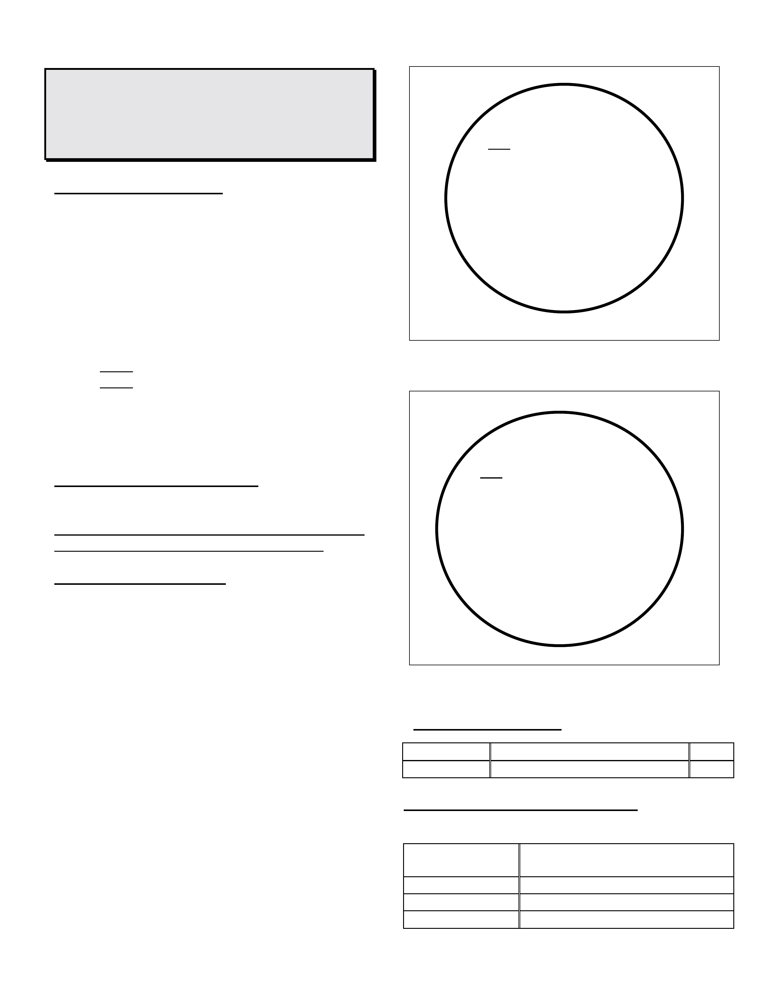
SERVICE RECTIFICATION
Fit a new IACV assembly from HSPO, after
identifying that the IACV fitted to the vehicle is of
the “OLD TYPE” as defined in the end views of
the IACV housing shown in the accompanying
diagrams.
NOTE: Prior to replacing the IACV, ensure
that all other possible causes of stalling have
been investigated.
“OLD” TYPE IACV
“CURRENT” TYPE IACV
PARTS INFORMATION
Part No.: Description: Qty:
90411546 Valve – Idle Air Control (IAC) 1
WARRANTY CLAIM INFORMATION:
Use existing Labour Oper ation Number as follows:
Description Motor Asm. (IAC) Idle Air -
Replace
Labour Op. No. J971800
Time 0.4 hr
Failure Code 47
GM
90 411 546
SIEMENS 5WK9 0631
A
ESP207 – 13
GM
90 411 546
SIEMENS 5WK9 0631 X
A
ESP207 – 13 A
HOLDEN SERVICE TECHLINE _______________________________________________________________MARCH 1999
8
INSTRUMENT CLUSTER WITH CHECKSUM
ERROR-DTC 24
VT
(GROUP 12)
PROBLEM DESCRI PTION
Some dealers have experienced difficulty when
attempting to recalibrate an instrument cluster.
The Tech2 begins to program the cluster and in
due course a “waiting for data” message flashes
on the Tech2 screen followed by a loss of
communications between the instrument cluster
and the Tech2. A DTC 24 is logged which is a
Checksum Error.
Vehicles with instrument clusters susceptible
to this condition are built after 26/11/98 with
Tag L406564.
SERVICE RECTIFICATION
Do not replace the cluster to remedy these faults.
The problem is due to a timing inaccuracy
between the software link from the cluster to the
Tech2 when recalibrating t he clust e r .
Revised Tech2 software has been written and will
be available in the next issue of t he TIS CD ie. CD
48 due mid March 99, which incorporates Tech2
software version 7.20. In the meantime, dealers
experiencing this problem are advised to contact
TAS who will supply the dealer with a Tech2
PCMCIA card programmed with the latest
software.
ENGINE COOLING DIAGNOSTIC LAMP
ILLUMINATES – FUSE 8 BLOWS
TS
(GROUP 12)
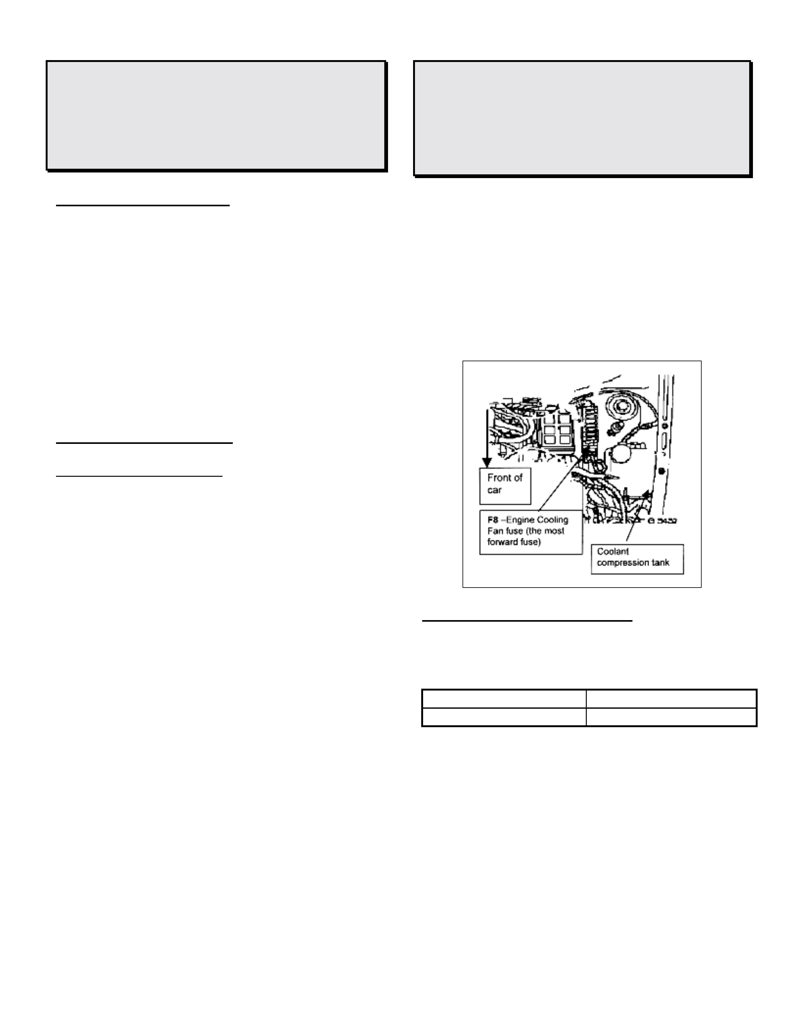
If investigating the cause of the engine cooling
diagnostic lamp illuminating, check for a blown
cooling fan fuse (number 8) in the engine
compartment fuse box. See the figure below.
Under certain operating conditions the radiator
cooling fan may draw current in excess of 20
amps causing the fuse to blow. If the fuse is 20
Amp (yellow colour) replace with a 30 Am p ( gr een
colour).
PRODUCTION RECTIF ICATION
Fitment of the 30 Amp f use was introduced int o
production f r om :
PSN: Build Date:
W5276965 10/08/98
HOLDEN SERVICE TECHLINE _______________________________________________________________MARCH 1999
9
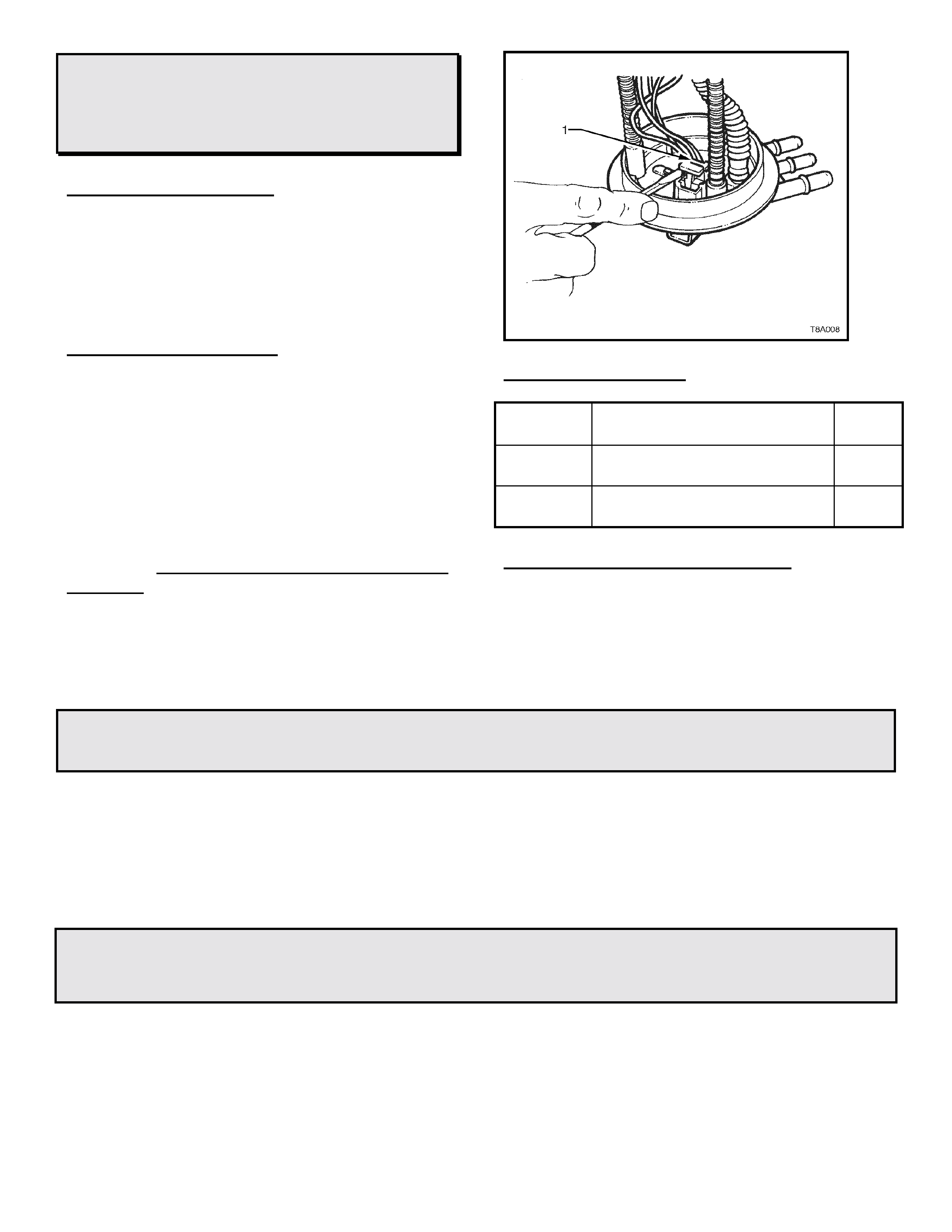
NO START – LACK OF FUEL PRESSURE
VT
(GROUP 12)
PROBLEM DESCRI PTION
A no start, no fuel pr essure condition experienced
on some VT vehicles has been traced to poor
terminal connections from the fuel pump cir cuit on
the fuel sender connector (black connector). See
Figure below.
SERVICE RECTIFICATION
W hen diagnosing vehicles with similar symptoms,
check for damage at the fuel pump terminals on
the 4 way fuel sender unit connector (black and
grey wires). Point 1 in the attached figure shows
the af fected area.
Hint: Removal of the red and grey locking tabs
with a small screw driver (as shown), will allow for
a better inspect ion.
If terminal or connector body damage is obvious
in this area replace the modular pump and sender
assembly.
PARTS INFORMATION
Part No.: Description: Qty
Req’d
25029962 Modular Pump & Sender asm
-Normal aspir at ed engine. 1
25170016 Modular Pump & Sender asm
-Supercharg ed engine 1
WARRANTY CLAIM INFORMATION:
Use existing information in Labour Time Manual
for Modular Pump and Sender assembly Rem ove,
Reinstall or Replace.
MONTEREY BULL BAR
MONTEREY/ JACKAROO GROUP 0B
The current bull bar (part no. 92141571) released for Jackar oo and Monterey models incorpor ates turn
signals and park lights which are necessary to comply with regulations.
When the bull bar is inst alled t he original bumper is discarded. O n the Monterey model the bumper bar
incorporates fog lamps and these will also be discarded as no provision has been made in the bull bar for
their fitment.
RODEO FAN MOTOR / RESISTOR FAILURE
1999 RODEO GROUP 2
Some Rodeo vehicles may experience repeated heater fan resistor or m ot or failure due to moist ur e ent ry.
Moisture can enter the mot or assembly through the cowling screw on the passenger
side (directly above motor) . Refer to diagram 1on the f ollowing page.
HOLDEN SERVICE TECHLINE _______________________________________________________________MARCH 1999
10
Please remove screw, apply silicone / sealant and refit screw.
Diagram 1
RODEO 4X4 & 4X 2 AIR CONDITIONER KITS INTERCHANGEABILITY
1999 RODEO GROUP 2
Confusion has arisen on the interchangeability of the A/C kit applicable for Rodeo vehicles. The
A/C kit part number M41682 can be installed on either the 4x2 or the 4x4 vehicle. A/C kit part
number 92141532 is for 4 x 4 only, and will be phased out once all stock is exhausted.
JACKAROO ANTI THEFT & IMMOBILISER
JACKAROO GROUP 12
1998 UBS THEFT DETERRENT SYSTEMS
Two separate theft deterrent systems are provided on the 1998 Jackaroo & Monterey:
• Anti-theft Warning – provided by the Anti-Theft Alarm/Keyless Entry system fitted to Jackaroo SE and
Monterey.
• Drive-away deterrent – provided on all models by the Engine I m mobiliser system.
W hen diagnosing a vehicle concern, it is important for the technician to have a basic understanding of the
operation of each system and be aware of t he correct diagnostic procedures.
The diagnost ic procedures are specif ic f or each system. Failure t o follow the corr ect pr ocedure will result in
lost time, possible replacement of serviceable component s and an aggrieved customer.
To deter m ine which system is at fault, the technician must r emember two very important point s:
• Except in exceptional circumstances, the Anti-theft Warning/key-less entry system cannot prevent the
vehicle from st ar ting.
HOLDEN SERVICE TECHLINE _______________________________________________________________MARCH 1999
11
• The Engine Immobiliser system cannot prevent the doors from locking or unlocking via the remote
keypads or the m echanical key.
Having determined which system has failed, t he correct diagnostic procedur es can t hen be applied:
• Anti-Theft Alarm/Keyless Entry System diagnosis is performed by referring to the charts in section
8D – 242/261 of t he service manual.
• Engine Immobiliser system diagnosis is performed with the aid of TECH-2 and the LATEST version of
the program card.
To assist in t he under st anding of the operat ion of these systems, a brief description of each follows.
ANTI-THEFT & KEYLESS ENTRY SYSTEM
The basic central locking system and anti-theft alarm system hardware carried over from the 1997
Jackaroo. The keyless entry system fitted t o SE and Monterey was new for 1998 Australian vehicles.
The Anti-theft Alarm system and Key-less Entry share the same module. The module is located in the
center dash, immediately above the PCM, and is identified by a black ABS plastic casing and a green 22-
pin harness connector.
The circuit consists of the ignition switch, anti-theft module, anti-theft horn, anti-theft indicator light, front
door and tailgate key switches, door lock switches, courtesy light switches, door lock actuators, engine
hood switch, and A/T m ode switch.
The module uses an “ear th-sensing” system f or monitoring of the doors and engine hood stat us – opening
of any of these items will cause the relevant circuit in the module to be grounded, triggering the alarm
function. The key switches & lock actuators provide the input signals required for arming or disarming the
system.
As a further safe guard, the front door locks and tailgate lock incorporate ‘tamper’ switches that will also
ground t he r elevant cir c uit should the lock be forc ed or ‘pulled’.
Armi ng O perat i on
• Remove the key from the ignit ion switch.
• Ensure all doors and the engine hood are closed.
• Lock the vehicle with either the mechanical key or the remot e keypad.
• 30 seconds aft er locking the vehicle, the Ant i- t heft LED will begin to f lash.
• The system is now armed with the module monit o r ing all doors and the engine hood.
• Triggered Operation
Anti-theft/Key-less Entry Module
HOLDEN SERVICE TECHLINE _______________________________________________________________MARCH 1999
12
Once triggered, the system will
• Pulse both the anti- theft and vehicle horns at a rat e of one pulse per second.
• Flash all indicator lig ht s at a rate of once per second.
• Disable the start e r m otor relay.
Triggered operation will continue for approximately 30 seconds. At the end of this period, the system will
rearm it self, and continue to m onitor the relevant circuits .
Disarming Procedure
• Unlock the vehicle with the correct mechanical key or the remote key.
• If t he alarm is sounding, insert t he key into the ignition switch and tur n t he switch to the “ACC” position.
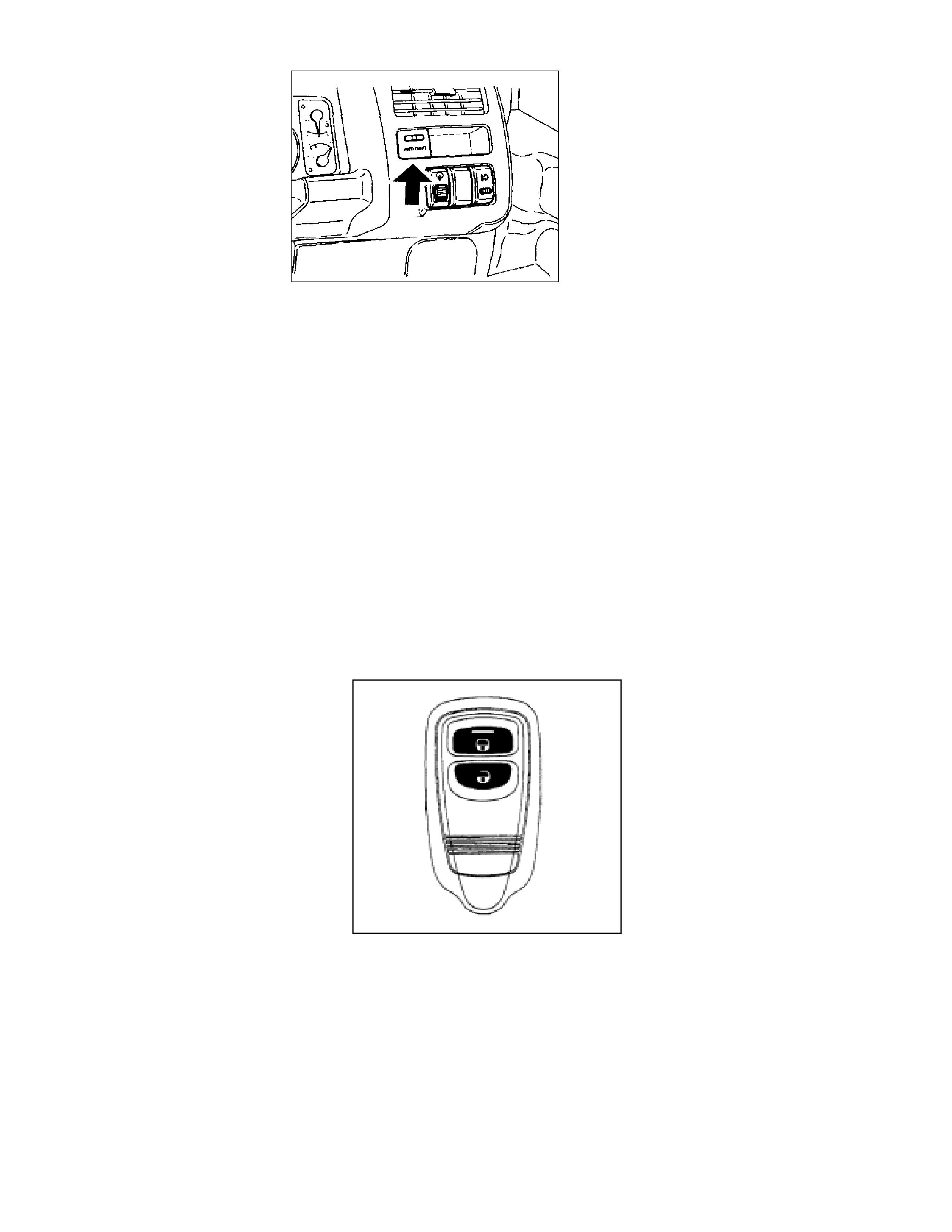
Keyless Entry
The keyless entry circuitry is incorporated in the anti-theft module. Two two-button radio remote
transmit ters are initially progr am med into the module.
Up to four t ransmitters can be programmed into the module, should an attempt be made to prog ram a fif th
key, the m odule will clear the first k ey code.
The tr ansm itters are of t he r olling code type, each transmission increment ing the code.
The minimum range of the transmitters is specified at 3 meters, although this can vary with proximity to
other radio or telephone transmitting towers. The estimated service life of the two lithium CR2016 cells in
each remote is at least t wo years with an average usage of 10 lock/unlock cycles per day.
Anti-theft LED
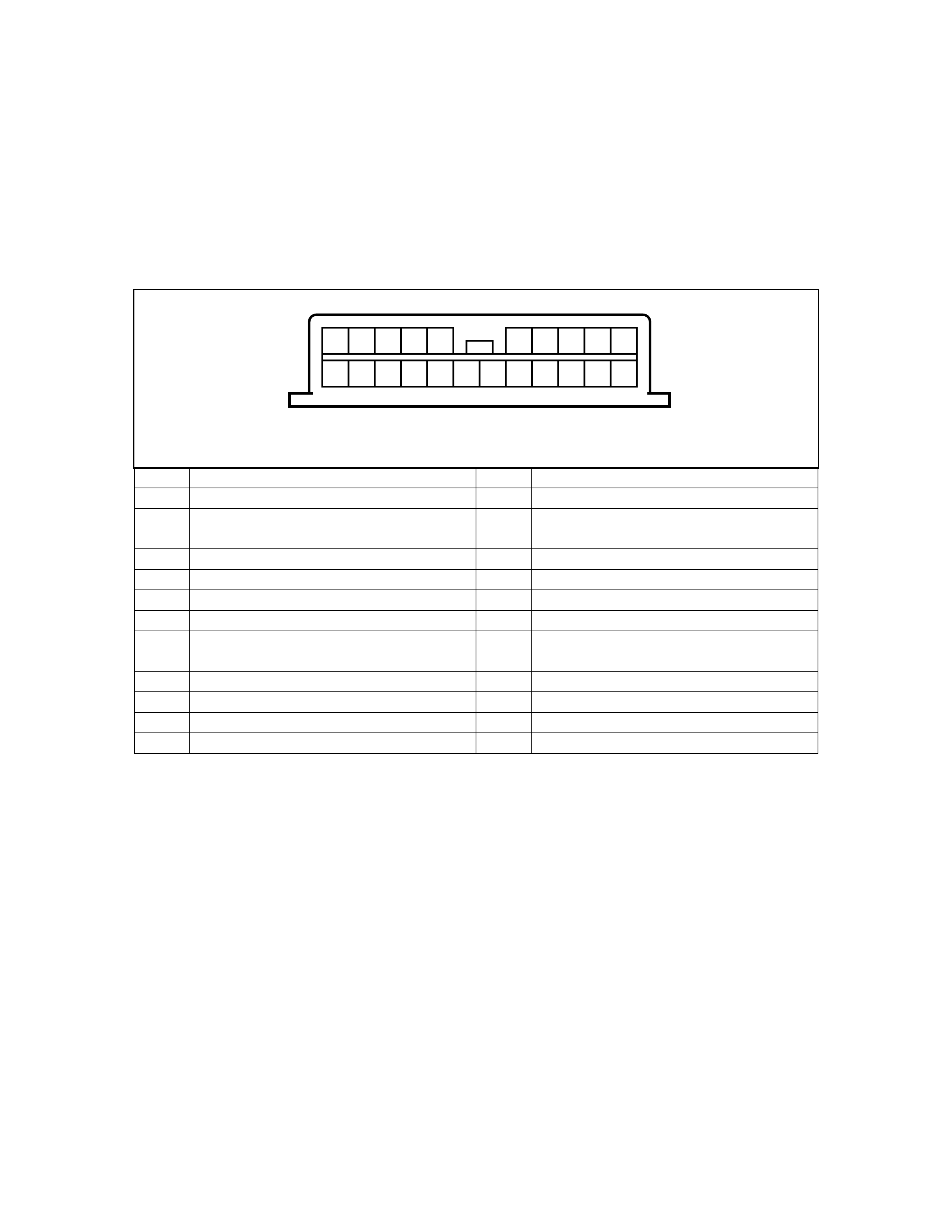
HOLDEN SERVICE TECHLINE _______________________________________________________________MARCH 1999
13
The key-less entry system is powered through the interior light circuit via the 10-amp ‘Room’ fuse (C16),
located in the I.P. fuse panel. This fuse must be fitted during pre-delivery inspection of the vehicle. Failure
of t he fuse will disable the key-less entry f unct ion and dom e light operation.
The anti- theft horn perf orms an ‘answer-back ’ funct ion when the remote keys are used. Locking the vehicle
will cause the anti-theft horn to ‘chirp’ once. Unlocking will result in the anti-theft hor n ‘chirping’ twice.
As an additional night - t im e safety measure, t he dom e light is turned ‘ON’ for 30 seconds when the vehicle is
unlocked. Should t he driver so desire the ant i- theft horn ‘answer-back’ function can be disabled.
Anti-Theft & Keyless Entry System – Initi al Diagnosis
PIN FUNCTION PIN FUNCTION
1 Door switches – f r ont 12 Engine hood switch
2 Door switches – rear 13 Key switch detect – front
doors/tailgate
3NA 14NA
4 NA 15 Key lock switches – unlock signal
5 Key Lock switches – lock signal 16 Lock tamper switch signal
6 Door switch – tailgate 17 Ground
7 Horn r elay 18 Power – ignition switch – ‘ACC.
ON’
8 Anti- theft horn 19 Anti-theft Indicator lamp
9 NA 20 Door switches – rear – dome
10 Power – B+ 21 Hazard Warning lamp relay
11 Door switches – unlock – all door s 22 Start er motor relay
Anti-Theft Alarm/Keyless Entry System diagnosis is performed by referring to the charts in section 8H of the
service manual.
However, there are several quick initial checks the technician can per f orm to narr ow down the area in which
the f ault has occur r ed.
Vehicle will not lock/unlock with the remote keypads
• Does the dome lig ht oper ate when a door is opened?
- If ‘NO’ check the Fuse C16 and the dome light switch position.
• Does the vehicle lock/unlock with the mechanical key and the driver door switch?
- If ‘YES’ t hen the central locking system is functioning.
• Can the alarm system be ‘ar m ed’ with the m echanical key?
- ‘NO’ would indicate a possible incorrect door/engine hood input to t he module.
‘YES’ would point to a keypad f ault or failure of the relevant circuit within the module.
• Perf or m the “Keypad Test” as outlined on the following page.
Anti-Theft/Keyless Entry Harness Connector Pin Arrangement
- Face View -
1 2 3 4 5 6 7 8 9 10
11 12 13 14 15 16 17 18 19 20 21 22
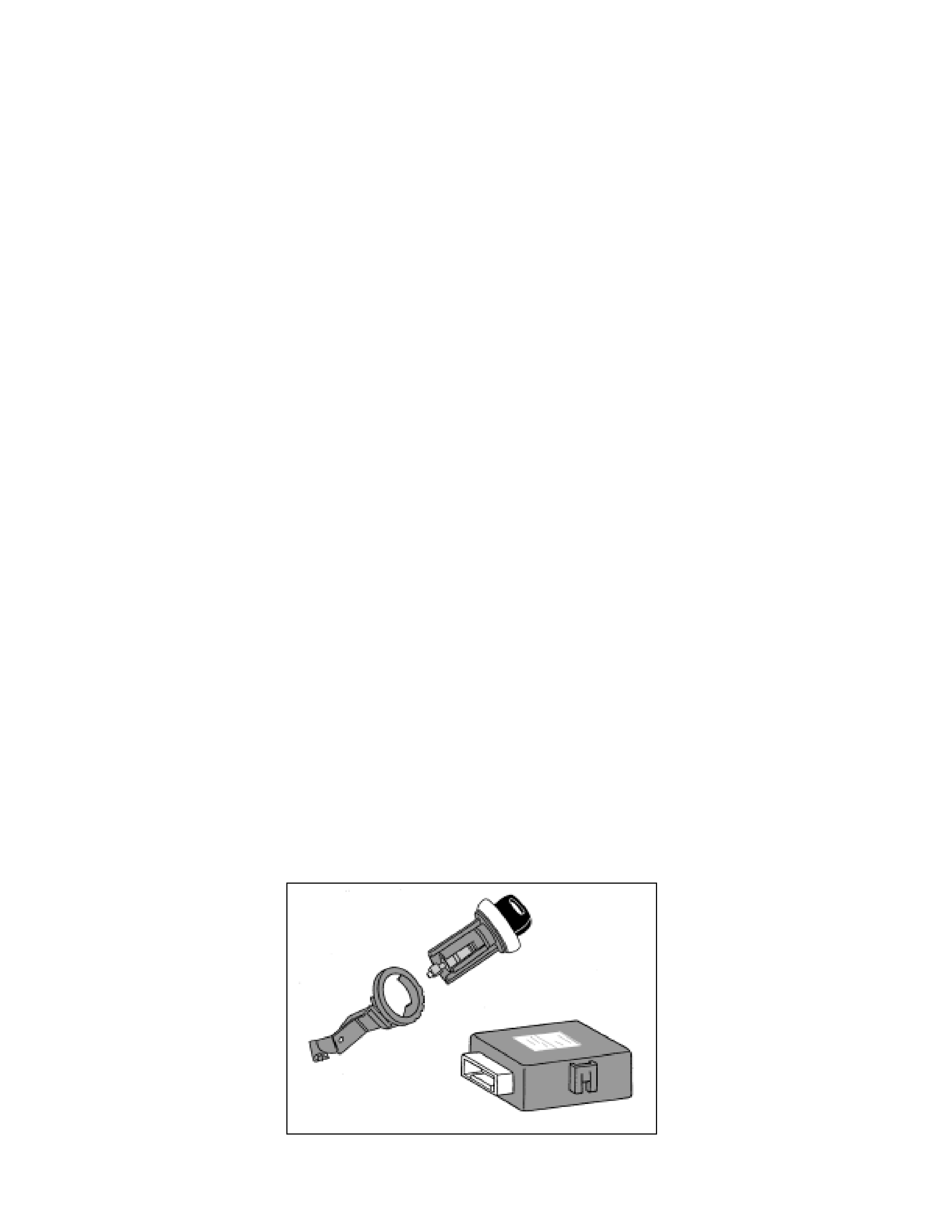
HOLDEN SERVICE TECHLINE _______________________________________________________________MARCH 1999
14
Keypad Testing
As the keypad transmits a FM radio signal, the vehicle radio can be used to check the operation of the
keypad. The actual frequency of the keypad may vary from 101mHz to 106mHz. It is best to commence
testing with the r adio set on 101mHz.
• Turn t he r adio ‘ON’ with the f requency set to 101mHz, and the volume contr ol at about ½ level.
• Hold the keypad against the base of the ant enna t hen press and hold the keypad ‘lock’ butt on.
• If a pulsing signal is heard from the speakers, t he keypad is functioning.
• Should you fail to hear a signal, try 102mHz and so on up to 106mHz.
• I f you have tried all the f r eq uencies without hearing a sig nal, r eplace t he t wo CR2016 lit hium cells in t he
keypad and repeat the frequency test.
Keypad Programming
The prog ramming sequence appear s in sect ion 8D - 258 of the 1998 UBS Work shop Manual.
Four prog r am m odes are available:
• ID Code New Registration – erases all pr ogrammed codes and regist er s new code.
• ID Code Additional Registration – registers addit ional ID codes.
• ID Code Check – checks how many ID codes are progr ammed in the module.
• Answer Back Change Mode – enables/disables the horn answer back function.
Note:
It is important to keep within the time frame stipulated for each operation – the system will time-out and
abort the pr ogramming seq uence if these times are exceeded.
IMM OBILISATION SYSTEM
The Engine I mmobiliser system is the second of the two independent thef t deterrent systems fit ted to 1998
UBS vehicles. The system is desig ned to provide “Drive-away” protection by electronically disabling t he fuel
and ignition systems and the starter motor relay. It is a passive system, requiring no action on the part of
the driver other t han r e m oving t he ignition key fr om t he switch.
The system uses a conventional mechanical-cut ignition key containing a miniature transponder in the
plastic handle. Within the transponder is an antenna and an integrated circuit. Each transponder is
progr am m ed with it’s own specif ic I D code dur ing manufactur e.
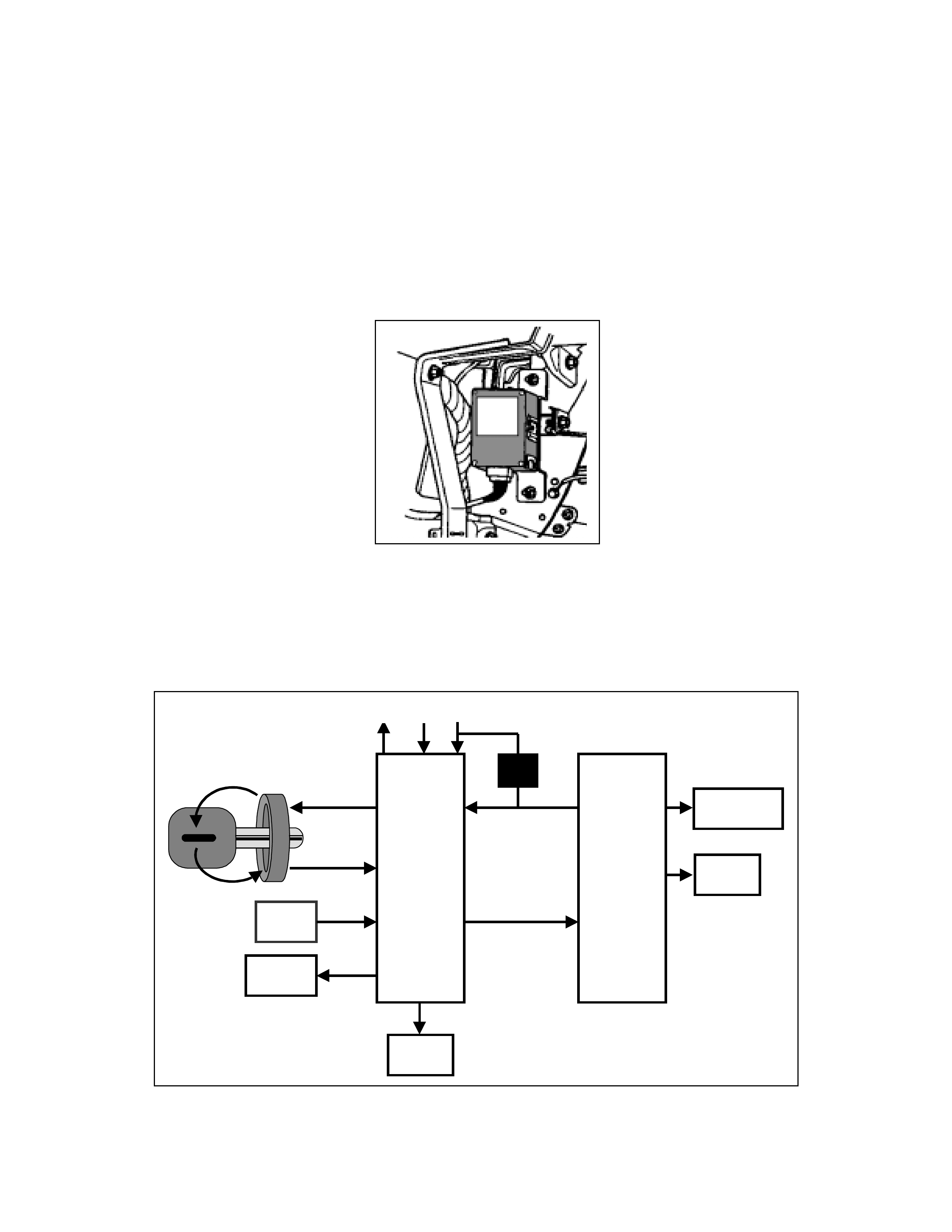
HOLDEN SERVICE TECHLINE _______________________________________________________________MARCH 1999
15
The main system components are:
• Ignition/transponder key
• Immobiliser antenna
• Immobiliser Control Unit
The antenna sur r ounds t he ignition switch lock barrel, and is accessed by removing t he steering column
shroud.
The Im m obiliser Control Unit is located to the right of the glovebox opening. Rem oving glovebox and the LH
lower instrument panel accesses the Immobiliser Contr ol Unit. The Imm obiliser Control Unit and the PCM
are prog r am m ed to the vehicle via TECH2.
A non-contact radio frequency is used to transfer information between the key and the Immobiliser Control
Unit. Surr ounding the ignition lock is a coil-type antenna, which is connected to the Imm obiliser transceiver
and module. The antenna is designed to have a very limited range, ensuring that only the key inserted in
the ignition can have its transponder code transferred. This excludes the possibility of interference from
other tr ansponder keys in the vehicle.
CEL
VSS
STARTER
RELAY
GND B+ IGN
INJECTORS
IGNITION
VSS / CODE
START STATUS
PCM
POWER
CODE ICU
DLC
Pin #7

HOLDEN SERVICE TECHLINE _______________________________________________________________MARCH 1999
16
W hen the ignition is turned ‘ON’, a radio frequency signal is sent from the antenna ring to the transponder
in the key. The transmitted energy powers the key’s integrated circuit, and the transponder transmits its
code back to the antenna ring. The transmitted code is received by the Immobiliser module and compared
with the stored codes. At the same time, the Powertrain Control Module (PCM) will request permission to
start. If the transponder and Immobiliser module codes match, the module will enable the Starter Motor
relay and send a coded signal to the PCM. Once the PCM recognizes the coded signal, it will enable the
fuel and cir cuits.
If the transmitted code from the transponder key is incorrect or the module receives no code, the starter
motor will not operat e and t he fuel and spark systems r em a in disabled.
If there is a malf unction – either incorrect transponder or no comm unication, the ‘CHECK ENGINE’ lamp in
the instrum ent cluster flashes and the r elevant t r ouble code is stored in both the ICU and the PCM.
The module is init ially programm ed as standard with two transponder codes, cor responding to t he two k eys
supplied with the vehicle. Should a key be lost, or an additional key required, uncoded keys are easily
programmed into the system with the aid of TECH-2. A maximum of 5 transponder codes can be stored in
the ICU.
System Programming
Progr am m ing of the Immobiliser system is perf ormed with TECH-2 when:
• The Im m obiliser Control Unit is replaced.
• The Im mobiliser Control Unit is reset.
• The PCM is replaced.
• Additional ignit ion keys are required.
• An ignition key has been lost.
To enable the com plet ion of the programming sequence, t he technician should have obtained:
• The Vehicle Ident ification Number.
• The vehicle security code.
• The mechanical key number.
• Permission from TIS.
Security Data
The following codes/data ar e st or ed in the ICU reference memory during vehicle production:
• The Vehicle Ident ification Number.
• The vehicle security code.
• The mechanical key number.
• Engine type
• Transponder code/s
The security code cannot be deleted or altered with TECH-2. The transponder code/s and engine type are
processed internally only and are not displayed on TECH-2. The Vehicle Identification Number and
mechanical key number are stored as further information for vehicle identif ication and can be displayed on
TECH-2.

HOLDEN SERVICE TECHLINE _______________________________________________________________MARCH 1999
17
Security Code
The 4-digit security code prevents unauthorized program ming and access to the dat a in the ICU via TECH-
2. The secur it y code is prog rammed into the ICU.
Program Security Code
New Immobiliser Control Units do not contain a programmed security code. If the ICU is replaced, the
security code for that vehicle must be obtained, and then pr ogrammed into the I CU with T ECH- 2.
Replacement of the Immobiliser Control Unit
Due to the complex nature of the coded signals transmitt ed between the key and the ICU, it is necessary to
replace both existing ignition keys when the ICU is replaced.
Resetting of t he I mmobi liser Control Unit
Resetting of the ICU may necessitate replacement of either of both existing ignition keys. This situation is
most lik ely to occur if the ICU is swapped from one vehicle to another.
Replacement of t he PCM
Once programmed to the vehicle Immobiliser system, the PCM cannot be removed and used in another
vehicle. The is no PCM reset procedure available at this point in time – the Service Programming System
(SPS) required for resetting a PCM does not apply to current Jack ar oo and Monterey.
Loss of a Transponder Key
If a transponder k ey is lost, all t ransponder codes in t he Im mobiliser Cont rol Unit mu st be er ased t o prevent
unauthorised use. This will ensure that, whilst the ‘lost’ key will allow access to the vehicle, it cannot be
used to start t he vehicle.
Aft er erasing all existing codes, the transponder codes of the remaining keys and the new transponder key
can be programmed.
NOTE:
Programming Approval must be obtained from TIS, using the ‘’Enable Programming” option, before either
control unit or transponder key progr am m ing is perform ed.
Once Programming Approval has been obtained, TECH-2 will allow five programming operations. Once all
five prog r am ming operations have been used, Prog r am ming Approval will then have to be obtained ag ain.
If the five programming operations are not used within two days, they will be cleared from TECH-2,
requir ing further Programm ing Approval to be obtained.
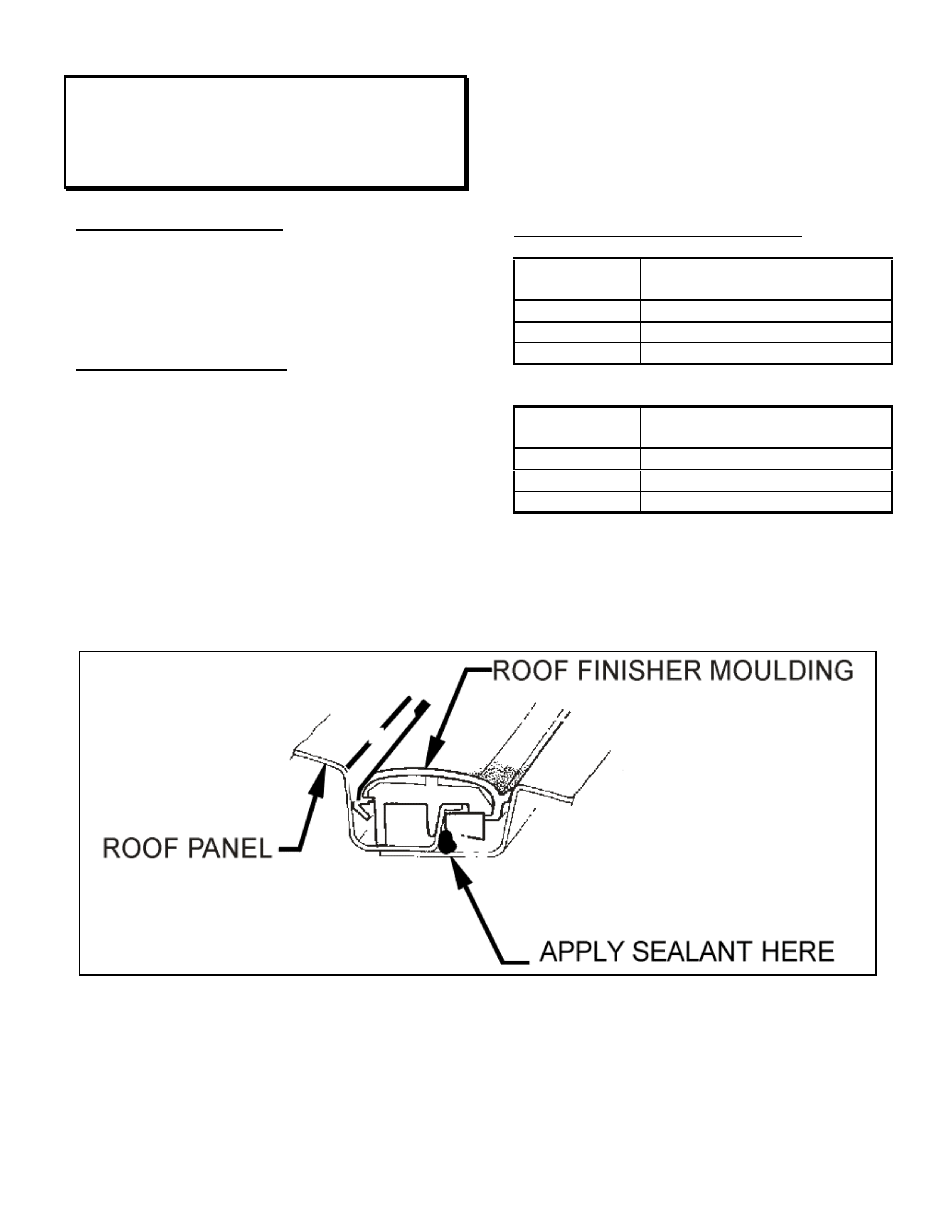
HOLDEN SERVICE TECHLINE ________________________________________________________________ APRIL 1999
WATER STAINED HEADLINING
VT
(GROUP 1)
PROBLEM DESCRI PTION
Water leaks through the sealer and seam where
the roof panel meets the door opening frame
panel assembly due to gaps or holes in the
sealant.
SERVICE RECTIFICATION
Determine whether the water leak originates from
the left or right side of the vehicle. Remove the
roof finisher moulding as per the VT Series
Service Manual Volume 1, Section 1A9, page
1A9-11. Reseal along the entire length of the
seam with Silastic RTV 732 Holden part number
92140051 or a similar silicon or polyurethane
product.
Refit the roof finisher moulding.
FIGURE 1 (roof finisher moulding must be
removed to apply sealant)
WARRANTY CLAIM INFORMATION:
Description Reseal Roof Panel Seam –
RHS
Labour Op. No. A000252
Time 0.5 hr
Failure Code 87
Description Reseal Roof Panel Seam –
LHS
Labour Op. No. A000255
Time 0.5 hr
Failure Code 87
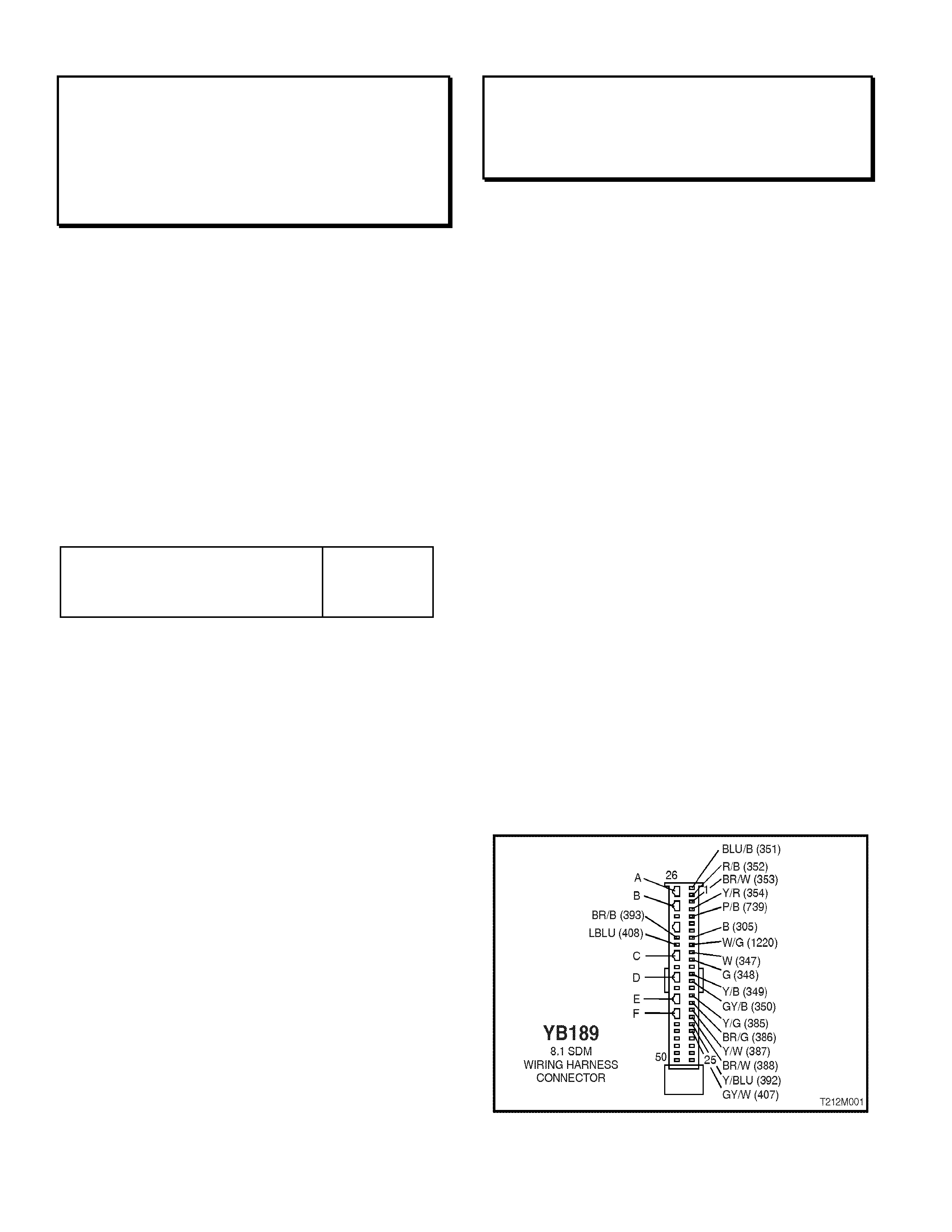
HOLDEN SERVICE TECHLINE ________________________________________________________________ APRIL 1999
SERVICE MANUAL CORRECTION - A/C
SUCTION/DISCHARGE HOSE ASSEMBLY
SECURING NUT TORQUE
VT
(GROUP 2)
In the VT Series Service Manual, Volume 1,
Section 2B Air Conditioning – Removal &
Installation, pages 2B-40 & 2B-43, the specified
torque for the compressor suction/discharge
hose assembly securing nut is incorrectly
quoted.
The specified torque should read 28 – 42 Nm
(as stated on page 2B-41 for the V8
compressor)
Please ensure the service manual is updated in
the relevant sections to show the correct torque
settings.
SUCTION/DISCHARGE HO SE
ASSEMBLY SECURING NUT
TORQUE SPECIFICATION 28 – 42 Nm
SIDE AIR BAG DIAGNOSI S (VERSION 8.1)
VT
(GROUP 12)
On vehicles with side air bags (SDM 8.1), it
should be noted that SDM connector YB189 is
equipped with shorting link busbars. While this
does not effect the operation of the SRS, it will
effect the diagnostic procedures detailed in
Volume 12 of t he VT Series Service Manual.
Whenever a diagnostic procedure asks a
technician to check a circuit f or an open or short
while SDM connector YB189 is disconnected,
the technician will need to open the short ing link
busbar f or t hat particular circuit.
To open the shorting link busbar for a particular
circuit, insert a spade type terminal,
approximately 3 mm in width (or alternatively,
use tool KM-609-9 from the KM-609 kit) into the
openings (nom inat ed as A, B, C, D, E or F in the
following diag ram) opposit e the cir cuits terminal,
ref er Fig. 1 below.
SHORTING LINK BUSBAR
A Terminals 1 & 2 - left hand pre-tensioner
circuit
B Terminals 3 & 4 - right hand pre-tensioner
circuit
C Term inals 10 & 11 - dr ivers air bag circuit
D Terminals 13 & 14 - passenger air bag
circuit
E Terminals 16 & 17 - left hand Side air bag
circuit
F Terminals 18 & 19 - right hand Side air bag
circuit

HOLDEN SERVICE TECHLINE ________________________________________________________________ APRIL 1999
ENGINE STALL
JR & JS; 4Cyl. Engines
(GROUP 6M)
PROBLEM DESCRIPTION
With vehicle stationary, the engine idle is too
high; EG: 1000 RPM+, and engine may later
stall or the idle may remain high.
This is caused by a build-up of engine by-pass
gasses and IACV solenoid shaft/bearing wear
particles on the IACV solenoid shaft, which
causes the IACV to stick at any point in its
operating range. This will result in either too
high or too low IACV air entry to the throttle
body and engine.
When the IACV subsequently “unsticks” and
returns t o normal operation, the result may be a
stall or higher than normal idle RPM. It is not
possible to effectively clean the IACV to correct
this condition.
SERVICE RECTIFICATION
To correct this condition, carry out the following
idle resetting procedure:
1. Connect Tech-2 and check for DTC’s. If any
are stored, correct the fault defined. (Refer
to Warranty Information below for claiming
for this work).
a/. If NO DTC exists – refer to previously
released Techline item: August, 1998, Issue 6,
page 7, regarding relay fitment and intermittent
power loss.
b/. If DTC P0100 exists – refer to previously
released Techline item: May, 1998, Issue 3,
page 14. NOTE: use of this service rectification
on a 4 cylinder vehicle will require soldering of
the smaller gauge wires to the terminals.
2. Remove air intake hose from throttle body,
to gain access t o t hr ot tle blade.
3. Install a new IACV and gasket . If g asket has
a “vee” notch on outer edge, it must f ace the
top of t he IACV flange on assembly.
4. Check for blow-by gas deposit in throttle
body – around IACV port and on lower side
and edges on the throttle blade. If deposits
are present, clean them off using a small
quantity of Top Engine Cleaner P/N
1050002 on a rag.
5. Reinstall air intake hose to throttle body.
6. Undo idle screw lock nut (at front RH side of
thrott le body).
7. Start engine and run until normal operating
temperat ur e is r eached.
8. With Tech 2 connected, engine running,
coolant temper ature g reat er than 85°, A/C (if
fitted) ON and active – turn in the idle screw
until engine idle is at 1400 RPM.
9. With one hand on the throttle cable,
disconnect the IACV connector – modulate
throttle opening to ensure engine does not
stall.
10. With IACV disconnected and the throttle
linkage resting against the throttle stop, the
engine should be idling at 500 – 600 RPM
approx.. Now adjust idle to 500 RPM (or as
close as possible) with the idle screw
(ensure A/C is O N and act ive).
11. Tighten idle screw lock nut and confirm idle
speed is still at 500 RPM.
12. Turn ignition off to stop engine.
13. Apply yellow paint to the idle screw and lock
nut at the thread mating point. Paint should
be visible from front of engine compartment
for inspect ion purposes
14. Reinstall IACV connector then turn ignition
ON and OFF and remove the key from the
ignition lock barrel – seven times with a
minimum of a five second pause after each
key removal. This action “teaches” the
system its new idle software switch position.
15. Start the engine and check using Tech 2
that the system has simulated idle active
and that the IAC integ rator steps ar e no less
than 25 once idle has been established.
(with A/C OFF and no load on eng ine).
16. Check using Tech 2 that engine idle is
correct (750+- 80 RPM).
The idle resetting procedure is now
complete.
Refer below for Warranty Claiming and Parts
Information.
Update
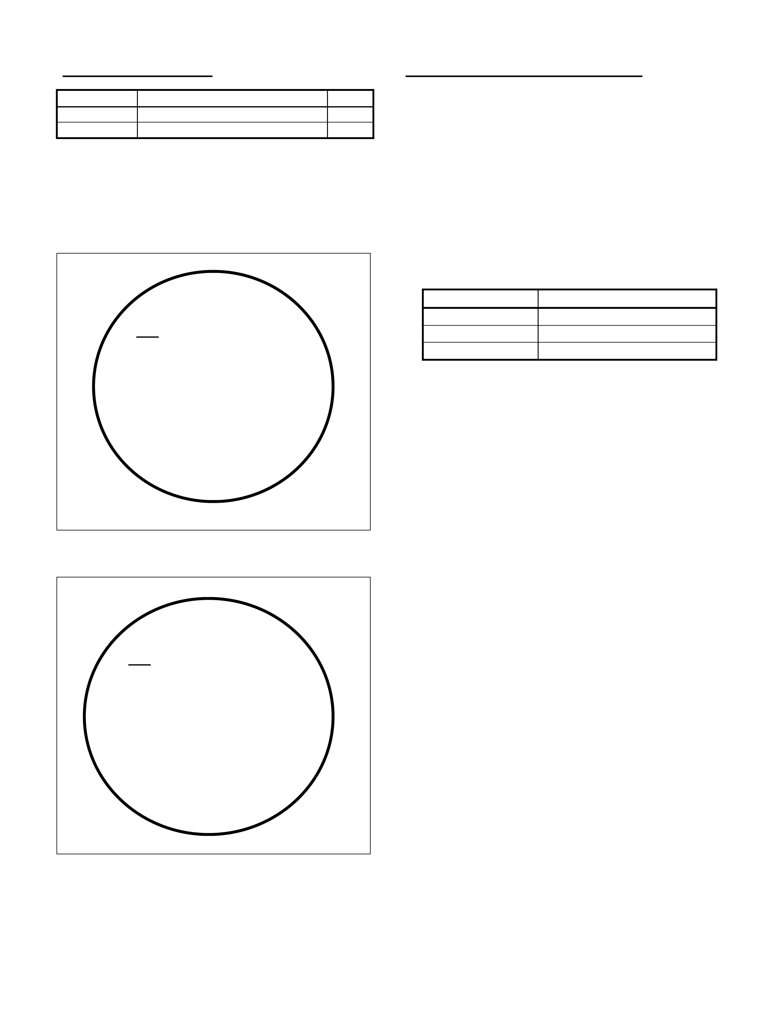
HOLDEN SERVICE TECHLINE ________________________________________________________________ APRIL 1999
PARTS INFORMATION
Part No.: Description: Qty
90411546 Valve – Idle Air Control (IAC). 1
90466220 Gasket - IACV 1
To identify latest type IACV, refer to the
following information - originally issued in
Techline Issue 2, March, 1999. DO NOT USE
“OLD” TYPE IACV’s. Only “CURRENT” TYPE
IACV’s are in stock at HSPO.
“OLD” TYPE IACV
“CURRENT” TYPE IACV
WARRANTY CLAIM INFORMATION:
When claiming for correction of any DTC’s that
may be found on initial check s – ref er t o section
99 of the Labour Time Manual, use the relevant
Labour Operation Number for the DTC. For
replacement of any component found faulty
during that DTC diagnosis – use the relevant
Labour Operation for remove and replace of the
fault y part .
To claim the idle resetting procedure detailed
above use the following information:
Description Reset Engine Idle
Labour Op. No. J000610
Time 0.6 hr
Failure Code 84
GM
90 411 546
SIEMENS 5WK9 0631
A
ESP207 – 13
GM
90 411 546
SIEMENS 5WK9 0631 X
A
ESP207 – 13 A
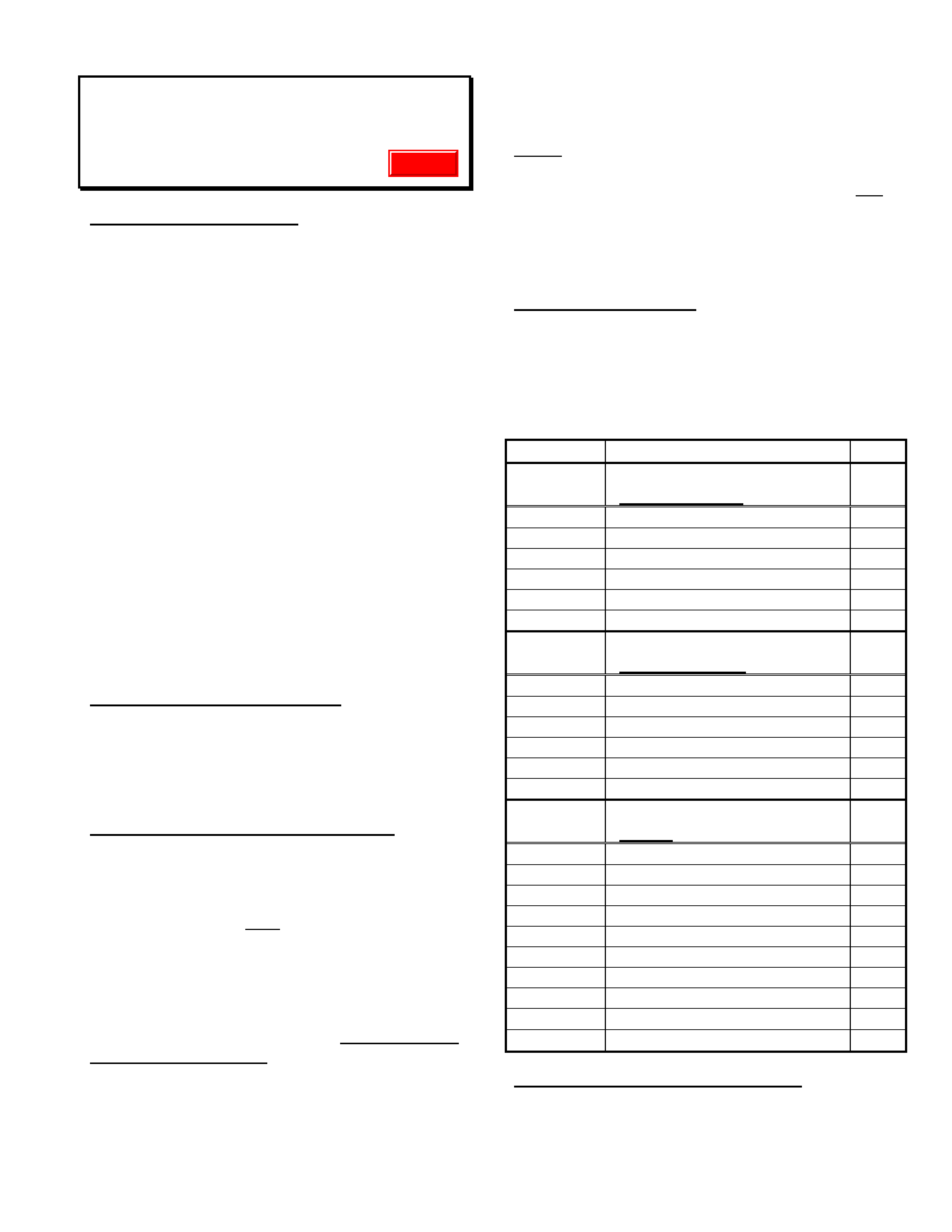
HOLDEN SERVICE TECHLINE ________________________________________________________________ APRIL 1999
SPARK PLUG LEAD REVISIONS
VT & VS
(GROUP 6Y)
GENERAL INFORMATION
As a product improvement, revised spark
plug leads are to be introduced as a running
change in production.
The colour change of the spark plug leads –
from grey to black - is the main identifying
feature of these improved leads. The leads are
also fitted with 45° angled spark plug boots (in
lieu of straight boots).
This Techline item is provided as an advance
warning of this impending change, and to make
Service and Parts personnel aware of the
changed appearance of VT spark plug leads.
Serviceability of VS Spark Plug Leads is also
affected, as these improved leads are to be
used on VS as service replacement parts.
Holden Service has taken steps to provide these
improved leads as soon as possible through
HSPO. Thus – stock is available now and the
new leads are being supplied in lieu of the
earlier grey coloured leads.
PRODUCTION RECTIFICATION
As these revised plug leads are progressively
introduced into production, the details will be
added to the “BREAKPOINT SUMMARY” page
in a future Techline issue/s.
SERVICE RECTIFICATION – VS & VT
V8 & V6 (non-Supercharged) Engine:
When replacing any failed grey coloured spark
plug leads, select the new lead assembly from
HSPO PartFinder. Only the improved (black)
leads are current ly available.
V6 Supercharged Engine:
In service, whenever a failure of an earlier
production (grey coloured) supercharged V6
engine spark plug lead occurs – Replace the full
set of spar k plug leads.
Failure of the latest type (black coloured)
leads requires replacement of the failed
lead only.
NOTE: Some technicians are removing the
locating spring f rom spar k plug boot s – DO NO T
REMOVE locating springs from any
supercharged V6 engine spark plug lead boots.
This does not address the root cause and may
result in a repeat failure which will
inconvenience customers.
PARTS INFORMATION
At the time of publication of this Techline issue,
new spark plug lead set part numbers were not
available on HSPO PartFinderTM. Use the
following chart for parts ordering until the part
numbers are available on PartFinderTM.
Part No.: Description: Qty
92142484 Lead Set – Spark Plug
(For non-S/C V6) 1
92065060 Lead Asm. – Cylinder 1 1
92065061 Lead Asm. – Cylinder 2 1
92065062 Lead Asm. – Cylinder 3 1
92065063 Lead Asm. – Cylinder 4 1
92065064 Lead Asm. – Cylinder 5 1
92065065 Lead Asm. – Cylinder 6 1
92142486 Lead Set – Spark Plug
(For S/C V6 only). 1
92065066 Lead Asm. – Cylinder 1 1
92065067 Lead Asm. – Cylinder 2 1
92065068 Lead Asm. – Cylinder 3 1
92065069 Lead Asm. – Cylinder 4 1
92065070 Lead Asm. – Cylinder 5 1
92065071 Lead Asm. – Cylinder 6 1
92142485 Lead Set – Spark Plug
(For V8) 1
92065072 Lead Asm. – Cylinder 1 1
92065073 Lead Asm. – Cylinder 2 1
92065074 Lead Asm. – Cylinder 3 1
92065075 Lead Asm. – Cylinder 4 1
92065076 Lead Asm. – Cylinder 5 1
92065077 Lead Asm. – Cylinder 6 1
92065078 Lead Asm. – Cylinder 7 1
92065079 Lead Asm. – Cylinder 8 1
92064857 Lead Asm. – Coil to Dist . VT 1
92064856 Lead Asm. – Coil to Dist . VS 1
WARRANTY CLAIM INFORMATION:
Use existing inf or mation in Labour Time Manual
Update
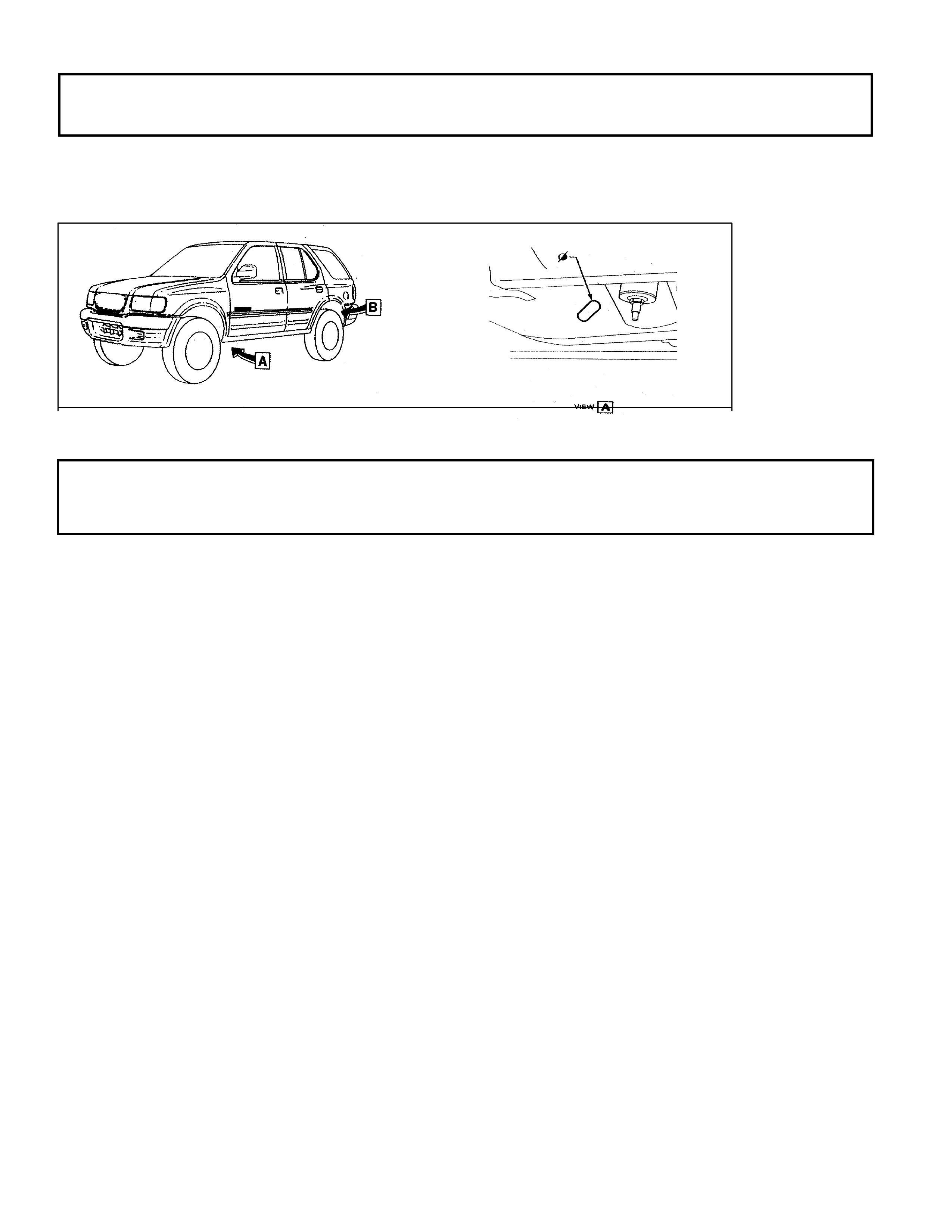
HOLDEN SERVICE TECHLINE ________________________________________________________________ APRIL 1999
CHASSIS PLUGS
FRONTERA GROUP 1
The 1999 model Frontera has four chassis holes that are used as tie down points during shipment. I –
GM request that these holes be filled with plugs that ar e supplied in the glovebox (ref attached drawing)
FUEL FILLER
RODEO CREW CAB GROUP 8
In instances where customer s com plain that a petrol engine Rodeo crew cab vehicle is difficult to fuel or
is blowing back thr ough the filler neck, improvement can be achieved by replacing the filler neck and
hose.
The cause of the problem is the fuel filler neck / hose com bination not allowing sufficient f low to the t ank
I–GM have released a modified hose to be used in conjunction with a space cab filler neck to rectify the
situation. Please r efer to details below for the special labor operation number and st andar d time.
Hose part number : 92074583
Filler neck par t number: 8971676480
Labor operation num ber : L000184
Standard tim e: 0:9 h

HOLDEN SERVICE TECHLINE ________________________________________________________________ APRIL 1999
S
y
stem
(w)
1998
F0:
Powertrain
F1:
Chassis
F2: Body
(w) 1999
(w) 1999
(w) 1999
(w) 1999
(w) 1999
Vehicle
Select one of the followin
g
Bod
y
Immobiliser
Airba
g
Anti Theft Warnin
g
Other
(w) 1999
(w) 1999
Immobiliser
Bod
y
F0: Dia
g
nostic Trouble
F1: Data Di s
p
la
y
F2: Sna
p
shot
F3: Actuator Tests
F4: Additional Functions
F5: Pro
g
rammin
g
(w) 1999
(w) 1999
3
JACKAROO IMMOBILISER
JACKAROO GROUP 12
In response to a high level of inquiries r e garding the process involved to program an additional ignit ion
key to a current m odel Jackaroo, a step by step outline has been produced t hat shows the tech 2 scr een
as it will appear as you move through the program.
NOTE: To code a new ignition k ey, a four-digit security number is requir ed r efer step 6.
The security number is obt ained from TAS using the form attached to dealer
letter 8/ 98. It would be advisable to obtain this number before coding the k ey.
Step 1) Connect t e ch 2 t o vehicle
Select diagnost ics, select t he vehicle as required, e.g.
1998 Jackaroo you will then see the screen as
displayed in picture 1.You must t hen select body.
Picture 1
Step 2)
Select immobiliser
Refer pict ur e 2
(Step 3)
Select programming
Refer pict ur e 3
Picture 2 Picture 3

HOLDEN SERVICE TECHLINE ________________________________________________________________ APRIL 1999
Step 4)
Select program
transponder keys.
Refer pict ur e 4
Step 5)
You will see the screen
as in picture 4. You will
then need TI S appr oval
Picture 4 before pressing confirm. Picture 5
Step 6)
Enter four digit security
number obtained using
the f or m attached to dealer
letter 8/98.
Refer pict ur e 6
Step 7)
Insert new k ey
And confir m .
Refer pict ur e 7
Picture 6 Picture 7
Pro
g
rammin
g
F0: Program Immobiliser
Function
F1: Program Transponder-
keys
F2: Program m echanical
Key Number
(w) 199
Jackar
) 1999
Jackaroo
(w) 1999
(w) 1999
(w) 1999
Jackaroo
Pro
g
ram
(w) 1999 Jackaroo
Electronic S ystem:
Immobilise
r
F2: Body
Please get programming
approval from
TIS!
(
(w) 1999
Jackaroo
Confirm
Program Immobiliser
Function
(W) 1998 Jackaroo
Electronic S ystem:
Immobiliser
Security Code
0 0 0 0
(w) 1999
Jackaroo
(Press ENTER key to
continue
Program
Transponder-
(W) 1998 Jackaroo
Electronic S ystem:
Immobiliser
Insert Non-Programmed
Transponder Key
Confirm
HOLDEN SERVICE TECHLINE ________________________________________________________________ APRIL 1999
Step 8)
You will see the screen
As shown in picture 8.
Tech 2 will request you
turn the ignition on, then of f.
Step 9)
At completion of the
Progr am m ing a final screen
will appear asking if more
keys are to be coded.
Refer pict ur e 9.
Picture 8 Picture 9
(w) 1999
Jackaroo
(w) 1999
Jackaroo
Pro
g
ram
(W) 1998 Jackaroo
Electronic S ystem:
Immobiliser
Programming Transponder
Key
(w) 1999
Pro
g
ram
(W) 1998 Jackaroo
Electronic S ystem:
Immobiliser
Program more Transponder
Keys ?
YES NO
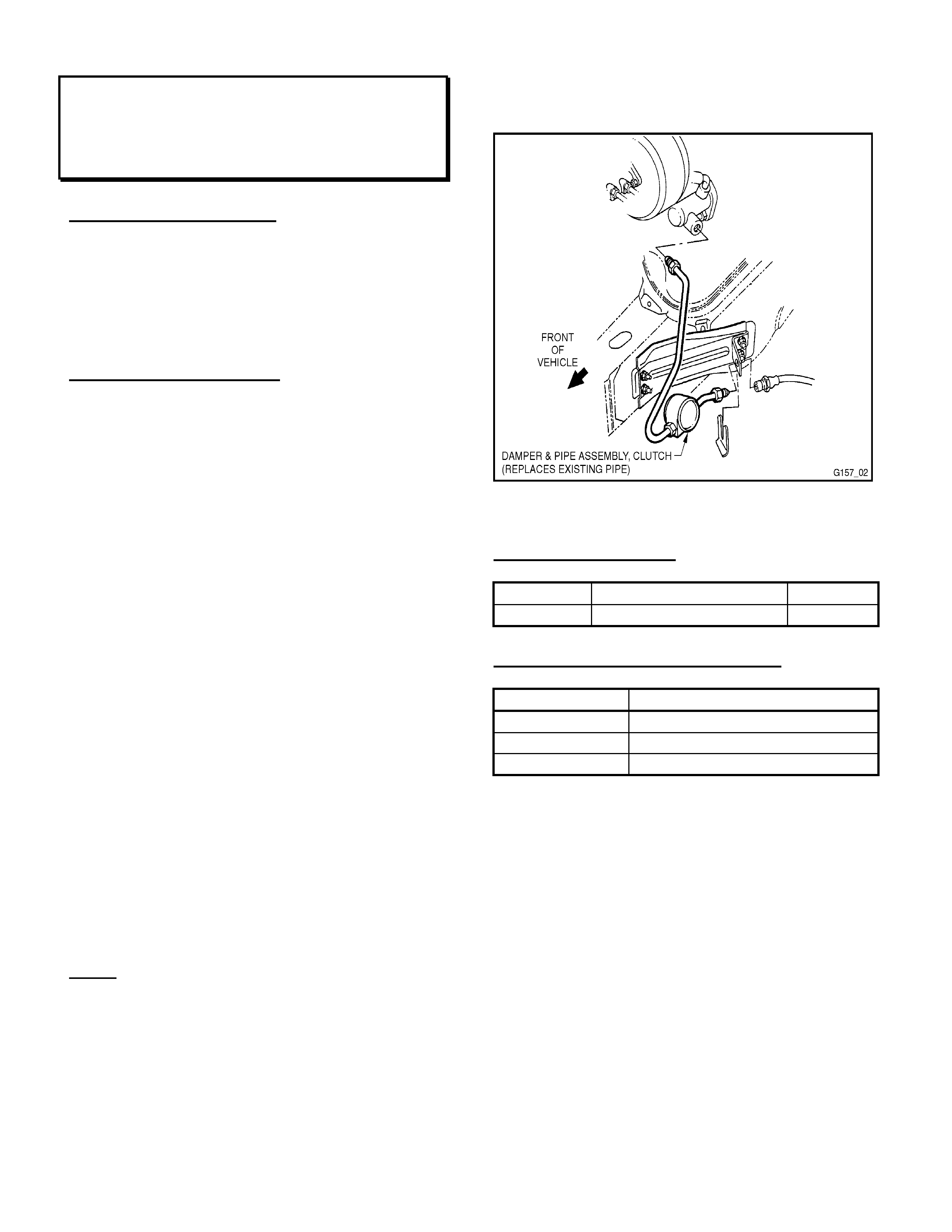
HOLDEN SERVICE TECHLINE ________________________________________________________________ APRIL 1999
DECLUTCH GROWL NOISE
VT with V8 & M/T
(GROUP 7A)
PROBLEM DESCRI PTION
A “growl” noise may be heard from the clutch
pedal area when de-clutching during gear
changes, with engine at high RPM ie. 3000
RPM and higher.
This noise is clutch pressure plate excitation
noise, transferred via the hydraulic system.
SERVICE RECTIFICATION
A new Damper and Pipe Assembly should be
fitted to any complaint vehicle in place of the
existing Pipe Assembly – Hose to Master
Cylinder as follows:
• Remove existing Pipe Assembly – Hose to
Master Cylinder (between clutch master
cylinder and slave cylinder).
• I nstall Dam per and Pipe Assem bly- Clutch in
place of pr eviously removed pipe assembly.
• Torq ue tube nuts to 12-14Nm.
• Bleed air f r om hydraulic system.
After fitting of the damper and pipe assembly,
the “growl” noise described will be effectively
reduced throughout the engine operating RPM
range.
In the event some level of noise remains, the
following information will be of assistance:
Ensure clutch hydraulic system is free from air
after damper fitment. Air presence will reduce
damper effectiveness. Rapid, repeated strokes
of the clutch pedal will assist in dislodging air
from the damper assembly. In severe cases, it
may be necessary to remove the damper from
the pipes, and reverse the damper unit to allow
fluid f low in the opposite direction – when this is
done, ensure orient ation of t he dam per is as per
the accompanying sk et ch.
NOTE: The damper and pipe assembly is of a
“tuned” design and is supplied in an assembled
condition to ensure correct orientation of the
damper. If the damper and pipe assembly, or
the pipe/s are removed for any reason, it is
important to ensur e that t he damper is r ef itt ed in
the same orientation as shown in the attached
sketch. I f the damper pipes are dam aged, they
should be replaced with a new assembly from
HSPO - new pipes should NOT be made f or this
installation.
PARTS INFORMATION
Part No.: Descripti on: Qty:
92082692 Damper and Pipe Asm. 1
WARRANTY CLAIM INFORMATION:
Description Fit V8 Clutch G r owl Damper
Labour Op. No. K000255
Time 0.4 hr
Failure Code 40
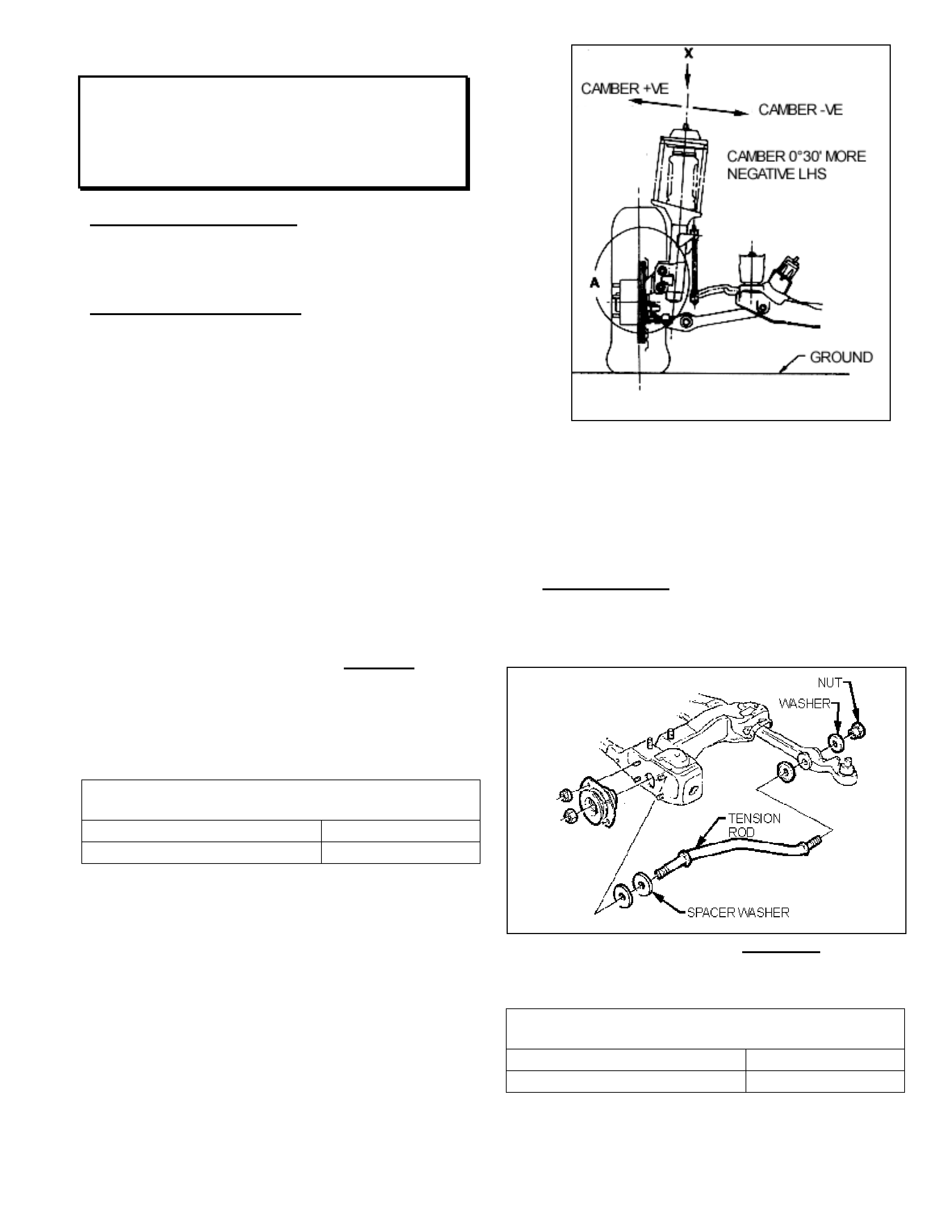
HOLDEN SERVICE TECHLINE ________________________________________________________________ APRIL 1999
VEHICLE VEERS LEFT
VT
(GROUP 3)
PROBLEM DESCRIPTION
When travelling over 80 km/h the vehicle tends
to drift/veer left.
SERVICE RECTIFICATION
VT Series Vehicles (non ‘S’ or ‘SS)
1. Check tyre pressures. Check for abnormal
tyre wear. Rotate tyres if necessary.
2. Check the front cross member alignment
and align as necessary (use the cross
member aligning tool). Replace the cross
member bolts if the cross member is
realigned.
3. Test dr ive and evaluate the vehicle.
4. If the vehicle still veers left, wheel align the
vehicle to achieve the following:
• The camber on the LHS should be more
negative than the RHS, but no more than
0°30’. Replace the lower strut attaching
bolts if the camber is adjusted.
• Set the front wheel toe as per the VT Series
specificat ions t abulated below.
FRONT WHEEL ALIGNMENT AT KERB
WEIGHT
Toe – in Degrees Total 0°10 ± 0°10’
Degrees per Wheel 0°05’ ± 0°05’
VT Series Vehicles (S & SS)
1. Check tyre pressures. Check for abnormal
tyre wear. Rotate tyres if necessary.
2. Check the front cross member alignment
and align as necessary (use the cross
member aligning tool). Replace the cross
member bolts if the cross member is
realigned.
3. Wheel align the vehicle to achieve the
following:
Figure 1.
• Set the camber 0°30’ more negative on the
LHS than the RHS. Refer to Figure 1.
Replace the lower strut attaching bolts and
nuts.
• Fit one spacer washer P/N 90075037 to the
right hand side tension rod as indicated in
Figure 2. Only one spacer washer should be
used to alter the caster setting (2 washers
total).
Figure 2 ( LHS shown, fit to RHS)
• Set the front wheel toe as per the VT Series
specificat ions t abulated below.
FRONT WHEEL ALIGNMENT AT KERB
WEIGHT
Toe – in Degrees Total 0°10 ± 0°10’
Degrees per Wheel 0°05’ ± 0°05’
4. Test dr ive the vehicle and evaluate.

HOLDEN SERVICE TECHLINE ________________________________________________________________ APRIL 1999
5. If the vehicle continues to veer left, further
checks may be required, including rear
cross member alignment. Ensure tyre
pressures have been checked.
PARTS INFORMATION
Select the following parts as required, defined
by the above procedures.
Part No.: Description: Qty
92138396 Bolt – Front Suspension
to Frame Upper 4
11090821 Bolt – Steering Knuckle to
Tube 4
92138205 Nut – Steering Knuckle to
Tube 4
90075037 Washer – Rod to Cr oss
Member 1
WARRANTY CLAIM INFORMATION
For VT Ser ies non S or SS vehicles:
Description Veer Left Correction –
non S or SS
Labour Op. No. E000332
Standard T ime 0.5 hr
Add Time for
Wheel Alignm ent *0.7 hr
Failure Code 25
For VT Ser ies S or SS vehicles :
Description Veer Left Correction
S, SS
Labour Op. No. E000335
Standard T ime 0.5 hr
Add Time for
Wheel Alignm ent *1.2 hr
Failure Code 25
*NOTE: If wheel alignment is sublet (including the
camber and caster adjustment) claim the sublet
expense in “net items” column. Please note that the
“add” time for wheel alignment cannot be claimed as
a labour expense when work is sublet.
ENGINE ROUGH IDLE (Diagnosis Hint)
TS
(GROUP 6C)
PROBLEM DESCRI PTION
Engine idles roughly in neutral in M/T equipped
vehicles, or when “N”, “D” or “R” select ed in A/T
equipped vehicles.
No DTC’s are found with Tech 2.
SERVICE RECTIFICATION
A cause of this complaint has been found to be
foreign material caught between the EGR Valve
pintle and its seat.
To correct this condition:
- Remove the EGR Valve f r om the engine.
- Connect Tech 2 and ‘drive’ the EGR Valve
fully open using Tech 2.
- Remove any foreign material from the valve
pintle and seat, inspect the pintle and seat for
damage ( r eplace if damaged).
- Refit EGR Valve to engine, start engine,
confir m idle quality and EGR operation is OK.
After this has been done, return the foreign
material removed – protectively packaged - with
a defective material tag to REPAC when
requested.
WARRANTY CLAIM INFORMATION:
Use existing information in Labour Time Manual
as shown:
Description EGR Valve - Replace
Labour Op. No. J980500
Time 0.4 hr
Failure Code 12

HOLDEN SERVICE TECHLINE ________________________________________________________________ APRIL 1999
REVISED ENGINE COOLING FAN
OPERATION
VT with V6 (non-S/C)
(GROUP 6K)
GENERAL INFORMATION
Engine cooling fan operation on V6 engines has
been revised to two single speed fans (one low
speed, one high speed) – replacing the previous
two dual speed fans.
In effect, either one or both fans will operate,
and fan speeds will not change.
NOTE: Supercharged V6 Engine cooling fans
and operation remains the same.
Identification of these new fans is by their two
wire connections in lieu of the four wire
connections on earlier built vehicles.
This change also affects parts replacement of
other associated components – refer “PARTS
INFORMATION” section below.
A new VT service manual, Volume 14A, will be
issued shortly. To assist technicians with
knowledge of the engine cooling fans operation
and diagnosis prior to issue of this service
manual - an excerpt from the draft version of
that service manual is included on the following
pages of this Techline issue.
PRODUCTION INTRODUCTION
ISOVIN: Build Date:
6H8VTL69HXL435513
(V6 with A/T) 05/03/99
6H8VTK69HXL435642
(V6 with M/T) 06/03/99
6H8VTK69HXL435439
(V6 with LPG – Option KL7) 06/03/99
PARTS INFORMATION
This change to cooling fans also affects:
- Radiator Assembly
- Engine Control Module (M/T)
- Powertrain Module (A/T vehicles & KL7 LPG
vehicles)
- Baffle, Air Chute Lower (Air Dam)
- Front Fascia (bumper)
- Harnesses and Relays
Please note: When ordering parts – until parts
are fully defined by the breakpoints shown – in
future issues of PartFinderTM – Dealership Parts
personnel should contact Parts Technical
Department in Melbourne for assistance in
selection of correct part numbers. Ensure
vehicle details are supplied when calling Parts
Technical for this information.
WARRANTY CLAIM INFORMATION:
Labour Operation numbers and times shown in
the Labour T ime Manual are not aff ected by this
revision.

HOLDEN SERVICE TECHLINE ________________________________________________________________ APRIL 1999
The following information is an excerpt from VT
Service Manual, Volume 14A, to be released
shortly.
1. GENERAL INFORMATION
The engine cooling system on VT Series II Models with V6
engine carries over from VT Series Models, noting the
following:
As a running change, approximately March 1999, two
single speed electric engine cooling fans were introduced
to vehicles with V6 engine; a low speed fan and a high
speed fan (as compared to; two, two speed electric cooling
fans).
As information about these new engine cooling fans has
not been published before, this Section has been compiled
to cover their introduction.
For information, including General Information, Service
Operations, Specifications and Torque Wrench
Specifications, that is not covered in this Section, refer to
Section 6B1-1 ENGINE COOLING - V6 ENGINE in Volume
2 of this Service Manual.
NOTE: The cooling system for vehicles with V6
supercharged engines does not change for VT Series II
Models.
1.1 COOLING FAN OPERATION
On VT Series II Models with V6 engines, the engine
cooling fan motors have two terminals; one positive and
one negative. The positive terminals are permanently
connected to battery voltage. When the negative terminal
is connected to earth through the low speed cooling fan
relay, the low speed cooling fan will operate. When the
negative terminal is connected to earth via the high speed
cooling fan relay, both cooling fans will operate.
The low speed cooling fan operation is enabled when the
low speed engine cooling fan micro relay (located in the
engine compartment relay housing, labelled Lo Fan) is
energised by the Body Control Module (BCM) via a request
from the Powertrain Control Module (PCM). The PCM will
request low speed fan enable and disable via serial data
communication to the BCM on circuit 1221 (Red/Black
wire). After the PCM requests a change in the state of the
low speed relay (i.e. OFF to ON or ON to OFF), the BCM
will send a serial data response message back to the PCM
confirming it received the message.
The PCM determines when to enable the low speed fan
relay based on inputs from the A/C request signal, Engine
Coolant Temperature (ECT) sensor and the Vehicle Speed
Sensor (VSS).
LOW SPEED FAN OPERATION
The low speed cooling fan relay will be turned ON when:
•Air conditioning request indicated (YES) and the
vehicle speed is less than 30 km/h or
•Air conditioning pressure is greater than 1500 kPa or
•Coolant temperature is greater than 104°C or
•An engine coolant temperature sensor failure is
detected by the PCM, refer to Section 6C1
POWERTRAIN MANAGEMENT - V6 ENGINE for
additional information.
•When the ignition switch is turned from ON to OFF
and the engine coolant temperature is above 117°C.
The BCM will continue to energise the low speed
engine cooling fan micro relay for approximately four
minutes.
The PCM will request the BCM to switch off the low speed
cooling fan relay when the following conditions have been
met:
•Air conditioning request not indicated (NO) and the
coolant temperature is less than 99°C or
•Air conditioning request indicated (YES) with pressure
less than 1170 kPa, vehicle speed greater than 50
km/h and coolant temperature less than 99°C.
HIGH SPEED OPERATION
The PCM determines when to enable the high speed fan
relay based on inputs from the ECT sensor. The high
speed cooling fan relay will be turned ON if the low speed
cooling fan relay has been energised for one second and
the following conditions have been met:
•If there is a BCM message response fault, setting a
DTC 92 or
•An engine coolant temperature sensor failure is
detected by the PCM, refer to Section 6C1
POWERTRAIN MANAGEMENT - V6 ENGINE for
additional information or
•Engine coolant temperature is above 107°C or
•Air conditioning pressure is greater than 2000 kPa.
NOTE: If the low speed cooling fan is off when the criteria
for turning the high speed cooling fan on are first met, the
high speed cooling fan will turn on 5 seconds after the low
speed cooling fan is switched on.
If both the high and low speed cooling fans are enabled,
the PCM will turn the high speed cooling fan off when:
•The engine coolant temperature is less than 103°C
and
•Air conditioning request is not indicated (No) or
•Air conditioning request is indicated (Yes) and the
pressure is less than 1500 kPa.
2. SERVICE OPERATIONS
Service Operations for the cooling system on vehicles with
V6 engine carry over from those detailed in Section 6B1-1
ENGINE COOLING - V6 ENGINE in Volume 2 of this
Service Manual, noting the following.
To accommodate the new engine cooling fans, a minor
revision to the lower baffle air chute was made, however,
this revision does not effect the way the air chute attaches
to the front of the vehicle.
If reinstalling a cooling fan, cooling fan motor or shroud
assembly to a VT Series II vehicle with a V6 engine, refer to
4. TORQUE WRENCH SPECIFICATIONS in this Section
for the correct torque wrench specifications.

15
3. SPECIFICATIONS
VT SERIES II ENGINE COOLING FAN 1 (LOW SPEED)
Number of blades................................................... 5
Spacing................................................................... Even
Material................................................................... Polypropylene (20% glass filled)
Diameter................................................................. 300 mm
Electric motor drive................................................. 80 watts (nominal)
VT SERIES II ENGINE COOLING FAN 2
Number of blades................................................... 4
Spacing................................................................... Even
Material................................................................... Polypropylene (7.5% glass filled)
Diameter................................................................. 340 mm
Electric motor drive................................................. 120 watts (nominal)
4. TORQUE WRENCH SPECIFI CATIONS
Nm
Cooling Fan and Shroud to Radiator Attaching Bolt............................................ 3.0 - 4.5
Cooling Fan Motor Shaft Attaching Nut............................................................... 4.9 - 7.4*
Cooling Fan Motor to Shroud .............................................................................. 1.8 - 1.3
* Apply Loctite 243 or equivalent to Holden Specification HN 1256

HOLDEN SERVICE TECHLINE __________________________________________________________________ JUNE 1999
FRONT DOOR CHECKLINK NOISE
VT, JR, JS
(GROUP 01)
This Service Techline supersedes the previous
Techline on this topic, Issue 9/98. The revised
checklink bolt P/N 09116434 is also to be used on
JR/JS Series Vectra vehicles. Please ensure
previous techlines on this topic are removed from
dealership circulation.
PROBLEM DESCRI PTION
When opening or closing the front doors, a
clicking noise is heard from the front door
checklink ar ea.
PRODUCT RECTIFICATION
The revised checklink bolt went into production as
indicated in the table below:
Series Tag # Build Date
VT L414099 16/12/98
JS L413368 17/12/98
Series VIN # Build Dat e
JR/JS Impor ted W7059751 22/12/97
SERVICE RECTIFICATION
Fit the revised door checklink bolt to both front
doors and torque to 14Nm.
Perform the following steps when installing the
revised checklink bolt.
1. Torque the BOLT first to 14Nm,
2. then Tor que the NUT to 14Nm .
NOTE: The process of torqueing the bolt before
the nut ensures t he bolt is seated complet ely prior
to f inal t or queing via the nut.
PARTS INFORMATION
Part No.: Descri pt i on: Qty
Req’d:
09116434 Bolt – Door Check Strap to
Support 1
WARRANTY CLAIM INFORMATION:
Description Door Check St rap Bolt Replace
– Both Sides
Labour Op. No. C000358
Time 0.3 hr
Failure Code 27
BLOWER MOTOR RESISTOR FAILURE
VT
(GROUP 2) HEATING AND A/C
This Service Techline supercedes the previous
techline on this topic, Issue 6/98. The previous
techline should be removed from dealership
circulation.
PROBLEM DESCRIPTION
The blower motor resistor may fail due to high
current draw from the blower motor and fan
assembly.
PRODUCT RECTIFICATION
A revised blower motor was introduced into
production f rom L352114, build date 01/07/98.
SERVICE RECTIFICATION
If a blower motor resistor fails, replace the blown
resistor with an auto resetting resistor, P/N
92142049.
DO NOT replace the blower motor.
The revised resetting resistor includes an auto
resetting circuit for fan speed 1 only. Fan speed 2
and 3 operate on a separate circuit using the
existing fusible link system. Fan speed 4 draws
power directly from the relay.
In the event that the resistor circuit breaker trips
on fan speed 1, the auto resetting resistor will
reset itself within a short period of time.
PARTS INFORMATION
Part No.: Description: Qty:
92142049 Resistor Assembly 1
WARRANTY CLAIM INFORMATION:
Use existing inf or mation in Labour Time Manual.
Update

HOLDEN SERVICE TECHLINE __________________________________________________________________ JUNE 1999
ENGINE MISFIRE/KNOCKING SOUND
HINT
VT with V8
(GROUP 6Y)
This hint (courtesy of Watson Holden, Traralgon)
is provided to reduce diagnosis time for the
unusual problem ment ioned below.
PROBLEM DESCRI PTION
Some vehicles have suffered an engine misfire
and/or a “knocking” noise from the engine
compartment.
This is caused by a powertrain harness retaining
bracket (used on V6 non-S/C engined vehicles
only) being fitted to a V8 engined vehicle, and
rubbing on the V8 ignition coil when the engine
moves rearward.
This V6 bracket serves no useful f unction on a V8
engined vehicle.
SERVICE RECTIFICATION
When investigating any V8 engine misfire
complaints or ‘knocking noise from the engine
compartment on acceleration, etc, - check
whether there is a met al har ness r etaining bracket
fitt ed to the dash panel (via the A/C case retaining
nuts) immediately rearward of the ignition coil. If
there is a bracket at this location, remove and
discard the bracket and refit the A/C case
retaining scr ew.
REAR MAIN OIL SEAL HOUSING
REPLACEMENT REQUIREMENT
VS V6 & VT V6
(GROUP 6A)
PROBLEM DESCRIPTION
Difficulty in removal of gasket remnants from
engine block and/or the rear main seal housing,
creates the possibility of damage to the cylinder
block or t he rear main oil seal housing.
This means t here is a possibility of a repeat r epair
after any removal and replacement of the rear
main oil seal housing and gasket.
SERVICE RECOM MENDATIO N
A new rear main oil seal housing and gasket
assembly – as noted in Parts Information below -
MUST be fitted.
Whenever a rear seal housing and/or gasket is
removed – for any reason – t he original rear ma in
oil seal housing and gasket must NOT be re-
used.
Great care must be exercised in the removal of
gasket remnants from the cylinder block, to avoid
any type of damage.
PARTS INFORMATION
Part No.: Description: Qty
Req’d:
24507385 Housing As m. – Rear
Main Oil Seal.
Consists of: Rear Main Oil
Seal Housing, Gasket and
Retaining Bolts.
1

HOLDEN SERVICE TECHLINE __________________________________________________________________ JUNE 1999
MISFIRE OR SPARK PLUG LEAD DAMAGE
DURING ASSEMBLY
“Service Precaution”
VS, VT
(GROUP 6Y)
PROBLEM DESCRI PTION
Misfire problems may be experienced short ly af ter
fitting the new spark plug or coil leads described
in Techline Bulletin, I ssue 3, April, 1999, page 9.
Engine assembly plant investigation of such
failures has shown that plug leads must be
centred to avoid incomplet e engagement.
SERVICE RECTIFICATION
W hen installing plug leads, engag e the boot, then
“feel” for centering of the lead terminal to the
spark plug or coil post. Once aligned, push the
terminal until fully seated and positively engaged
with the spark plug/coil post.
This is necessary because these new lead
terminals are a more exact fit to the mating
terminals.
RADIATOR HOSE ABRASION
“Service Precaution”
VT, V6
(GROUP 6K)
PROBLEM DESCRI PTION
The upper radiator hose may be abraded by the
power steering hose-to-reservoir retaining clamp,
if the “tail” of the power steering hose clamp
contacts the r adiator hose after tightening.
SERVICE RECTIFICATION
When vehicles are being serviced, ensure that
the power steering reservoir hose clamp “tail”
does not contact the upper radiator hose. If
necessary, bend the hose clamp “tail” down onto
the hose clamp so no further contact can occur.
When assembling power steering hoses to the
power steering f luid reservoir - ensure the “tail” of
the power steering hose clamp is not within 5mm
of t he r adiat or hose, after tightening. This can be
done by correct orientation of the clamp prior to
tight ening, or by bending the “t ail” of the hose
clamp away from the radiator hose, if necessary,
aft er tightening.
PRODUCTION PRECAUTION
As a result of PIR’s received, correct orientation
of hose clam ps occur r ed as follows:
ISOVIN: Build Date:
6H8VTK69HXL447198 13/04/99
ENGINE OIL PAN SEALANT
TS
(GROUP 6A)
PROBLEM DESCRIPTION
W hen ref itting an eng ine oil pan to an eng ine, the
quoted sealant on TIS is 90 543 772.
This sealant is not currently available from HSPO.
SERVICE RECOM MENDATIO N
The local comm er c ial equivalent to this sealant is:
“Dow Corning 1080”
– which is available from retail outlets that stock
Dow Corning products. Available in 310gm
cartridges which can be used for at least five
repairs.
For the address of your local retail outlet, call
Dow Corning Customer Ser vice on 1300 360 732
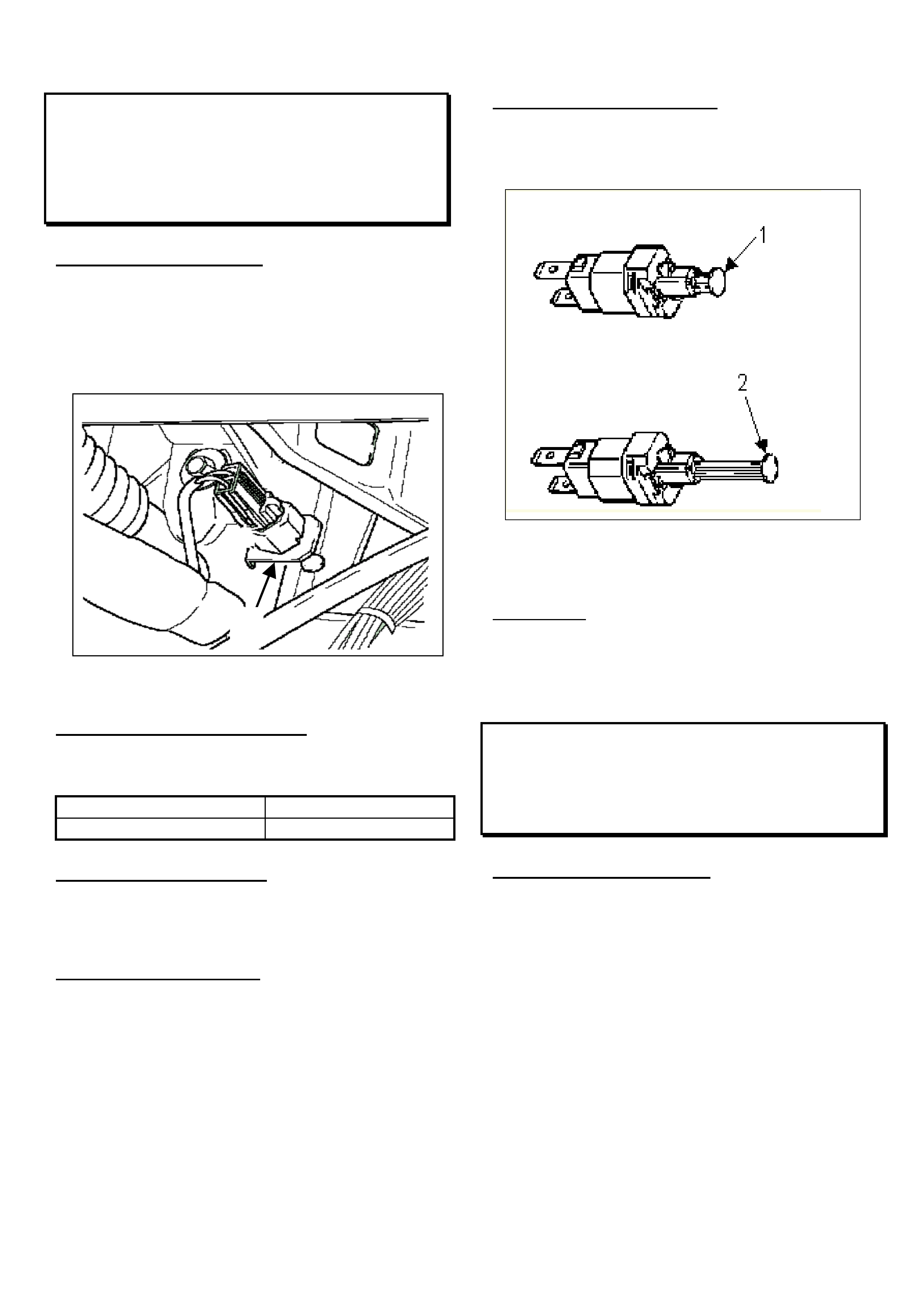
HOLDEN SERVICE TECHLINE __________________________________________________________________ JUNE 1999
BRAKE LIGHT / CRUISE CONTROL
MALFUNCTION
TS ASTRA
(GROUP 12)
PROBLEM DESCRI PTION
PIR’s have highlighted the incident of stop lamp
constantly illuminated with the ignition switched to
ON and the foot off the brake pedal. The switch
mounting bracket may be misadjusted during the
assembly process. (See Fig ur e A below)
Figure A-Brake Light Switch
1- Mounting brack et
PRODUCTION RECTIF ICATION
The switch has been correctly mounted in
production f r om :
ISOVIN: Build Date:
WOLOTGF48X8046633 O ctober ‘98
SERVICE RECTIFICATION
In service, do not replace the brake light switch.
Adjust it using the following procedure:
1. Test St op Lam p Switch
• Switch off ignition and remove the stop lamp
switch from its holder allowing it to hang from
its connector under t he dash.
• Ensure the electrical connector is fully home.
Turn on the ignition and check that the stop
lamps illuminate.
• Manually depress the plunger to check the
stop lamps switch off.
2. Set the Stop Lamp Switch
Fully extend the plunger by pulling it away from
the switch body. Refer to Figur e B “2”. A click ing
type noise should be heard. See Fig ur e B below.
Figure B
1- Non extended switch
2- Fully extended switch
3. Reinstall
With the brake pedal depressed install the switch
then allow the pedal to retract onto it.
Test t he st op lam p switch for correct operat ion.
SPEEDO “PPK” PROGRAMMING
VT
(GROUP 12)
SERVICE INFORMATION
The following information is repeated here for
technician reference, from VT SERIES II Service
Manual, VOLUME No. 14C, page 12C-75.
The information updates previous speedometer
PPK figures provided in VT SERIES
INSTRUMENTS Service Training manual
SD28323, issued to technicians during training
courses.
Tyre size 205 65 R15, select 6272 pulses.
Tyre size 215 60 R15, select 6285 pulses.
Tyre size 215 60 R16, select 6077 pulses.
Tyre size 225 50 R16, select 6391 pulses.
Tyre size 225 55 R16, select 6087 pulses.
Tyre size 225 60 R15, select 6238 pulses.
Tyre size 235 45 R17, select 6301 pulses.
1

HOLDEN SERVICE TECHLINE ___________________________________________________________________ JUNE 1999
10
DOORS HARD TO OPEN USING
EXTERIOR DOOR HANDLE
VT
(GROUP 01)
This Service Techline supercedes the previous
techline on this topic Issue 3/98. Previous
techlines on this subject should be removed from
dealership circulation.
This techline consolidates and includes all
the latest technical information and parts.
The part number of the revised door lock
grease is 92143013.
PROBLEM DESCRI PTION
On some vehicles the door will not open when the
exterior door handle is operated and/or excessive
effort is required to operate door handle. The
door handle may also feel notchy in operation.
These conditions may be caused by incorrect
adjustment of the door connecting rod, excessive
friction within the door lock assembly or incorrect
door strik er adjustment.
This condition mainly affects rear door s.
PRODUCTION RECTIF ICATION
A revised rear exterior door handle rod was
introduced into production from L324734, build
date 08/04/98, to improve the action and lessen
the ef fort req uir ed t o open rear doors.
A revised door lock grease was introduced into
production f rom L446583, build date 12/04/99.
SERVICE RECTIFICATION
On complaint vehicles perform the following
adjustment and greasing procedure to front doors
as required. Rear door complaints require both
doors to have revised exterior door handle rods
fitt ed, adjusted cor rect ly and door lock assem blies
greased.
PARTS INFORMATION
Part No. Description Q t y
92078026 Exterior Door Handle Rod RH 1
92078027 Exterior Door Handle Rod LH. 1
92143013 Optitemp LG2 Grease (400g) 1
Step 1.
Remove door trim and peel back the inner door
dust shield sufficiently to access the door lock
assembly. Do not cut the dust shield .
Step 2. (Refer Fi gure A)
REAR DOORS: Remove exterior door handle
connecting rods. Fit revised rods, adjust exterior
handle connecting nut clockwise (downwards) to
the point at which the locking lever just binds and
then back off by 2 full turns. Check snib button is
funct ioning cor rectly.
Without removing door lock assembly, liberally
apply MOLYBOND GCP Spraygrease (or
equivalent) to lock mechanism, see Figure B.
This grease is recommended because of its
excellent water resistance and high temperature
performance.
The above grease can be purchased from list of
distributors shown at end of this Techline.
NOTE: Do not use products like CRC, WD40
etc as they do not have the long term
durability required for this application.
Step 3.
FRONT DOORS: Adjust exterior handle
connecting rod using the same procedure as for
the rear doors.
Note: On front doors if the nut is backed off too
far, the bottom of the rod will foul the plastic
shield which covers the lock assembly.
Do not apply spraygrease to f ront door s unless all
the other steps fail to improve the condition. In
the unlikely event that this will be required, the
lock assembly will need to be removed from the
vehicle to lubricate it t horoughly.
Step 4. (Refer Figure C)
W it h the lock claw in the f irst cat ch position, apply
Optitemp LG2 Grease ( P/N 92143013) in t he area
shown as indicated in Figure C.
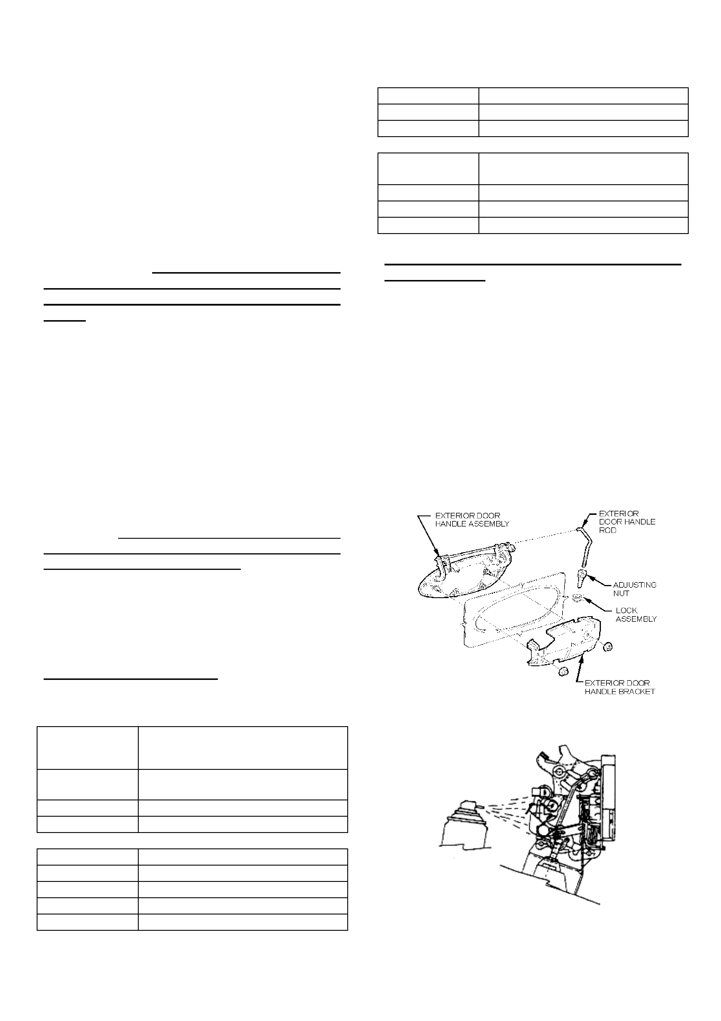
HOLDEN SERVICE TECHLINE ___________________________________________________________________ JUNE 1999
11
Note 1: Push claw inwards slightly to ensure
maximum passage size for grease
flow.
Note 2. Add sufficient grease until it just fills
the cavity.
Note 3. Grease is best applied with a small
syringe (20ml) available from most
chemists.
Step 5.
Return claw to fully open position by operating
door handle and wipe all excess grease from
around the claw so that no grease deposits
are left on the door striker when the door is
closed.
Step 6.
Check and adjust door strik er position as req uired
so that striker is located centrally within the lock
aperture. Also r em o ve clear tape ( if present) from
around strik er .
Step 7.
Check exterior handle for effort and opening feel.
Also check snib butt on oper ation.
Note: If above procedure does not adequately
improve handle effort and opening quality then
the door lock may be damaged and should be
replaced. Ensure that any replacement lock
assembly is adequately lubricated with both
greases specified in this Techline.
Step 8.
Re-adhere the inner door dust shield and reinstall
door trim. If extra adhesive is required to seal the
dust shield, use butyl tape P/ N 92142189.
WARRANTY INFORMATION
Use the f ollowing information for warranty claims
Description Fit Revised Rod, Adjust & Grease
Door lock to both rear doors
(prior to Tag # L324734)
Labour Op.No. C000313
Time 0.8hr
Failure Code 52
Description Adjust & Grease Door Lock RHF
Labour Op.No. C000307
Time 0.4hr
Failure Code 52
Description Adjust & Grease Door Lock LHF
Labour Op.No. C000310
Time 0.4 hr
Failure Code 52
Description Fit Rear Rods, Adjust & Grease
Door Locks 4Doors
Labour Op.No. C000319
Time 1.5 hr
Failure Code 52
DISTRIBUTORS OF MOLYBOND GCP
SPRAYGREASE
MOLYBOND GCP spraygrease is available from
most industrial hardware suppliers and some
bearing suppliers. Some of the major industrial
suppliers are as follows;
• ATKINS INDUSTRIAL (CARLYLE)
• J.BLACKWOOD & SON
• A.E.BAKER
• TOTAL TOOLS
For your nearest distributor, ring Morgan
Chemical Products:
- Rocol Division phone 1800-063-511.
Figure A – Adj ust Door Lock Rod
Figure B – Apply Spray Grease to Lock Assembly
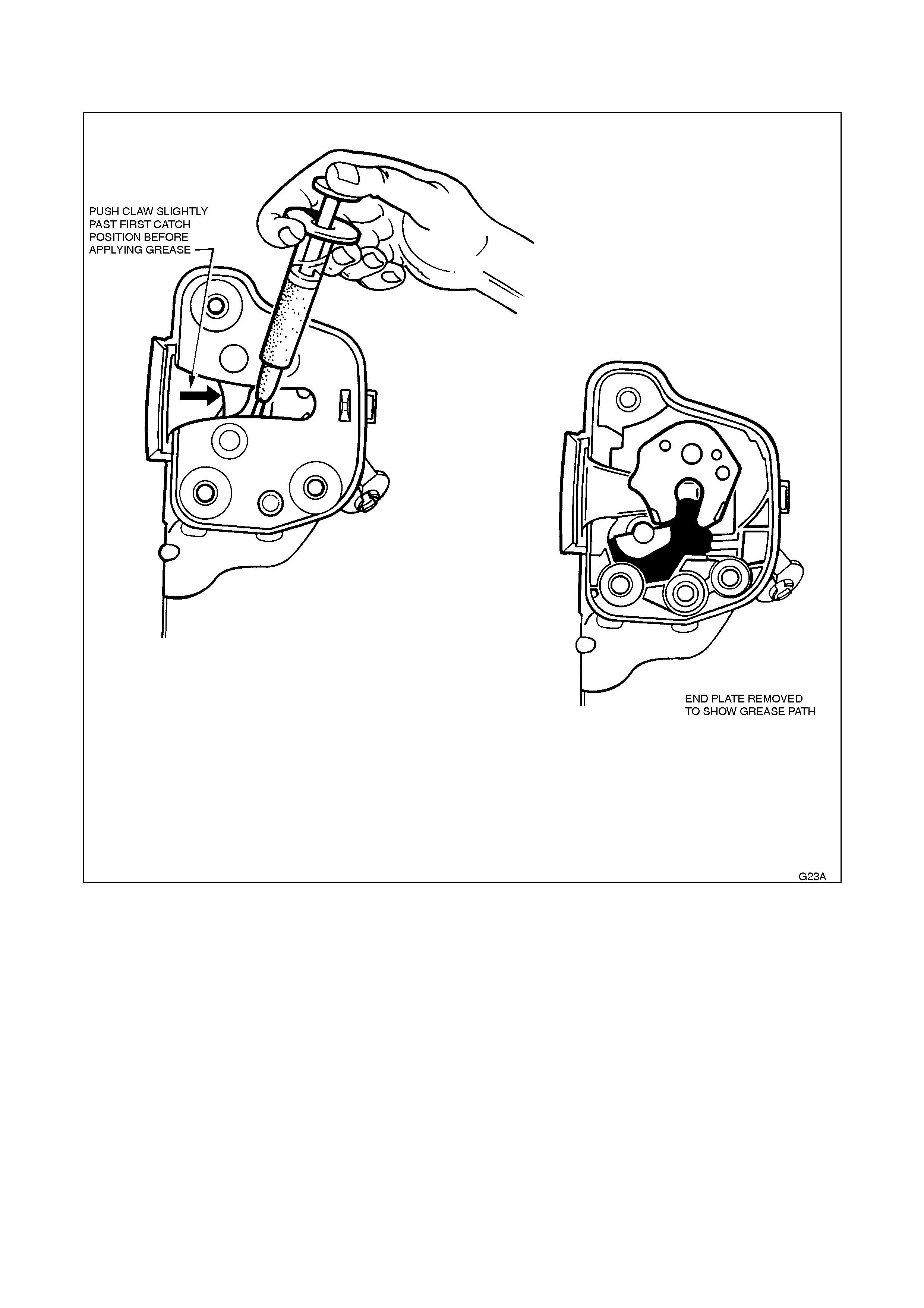
HOLDEN SERVICE TECHLINE _________________________________________________________ JUNE 1999
22
FIGURE C. Application of grease P/N 92143013 to lock claw.
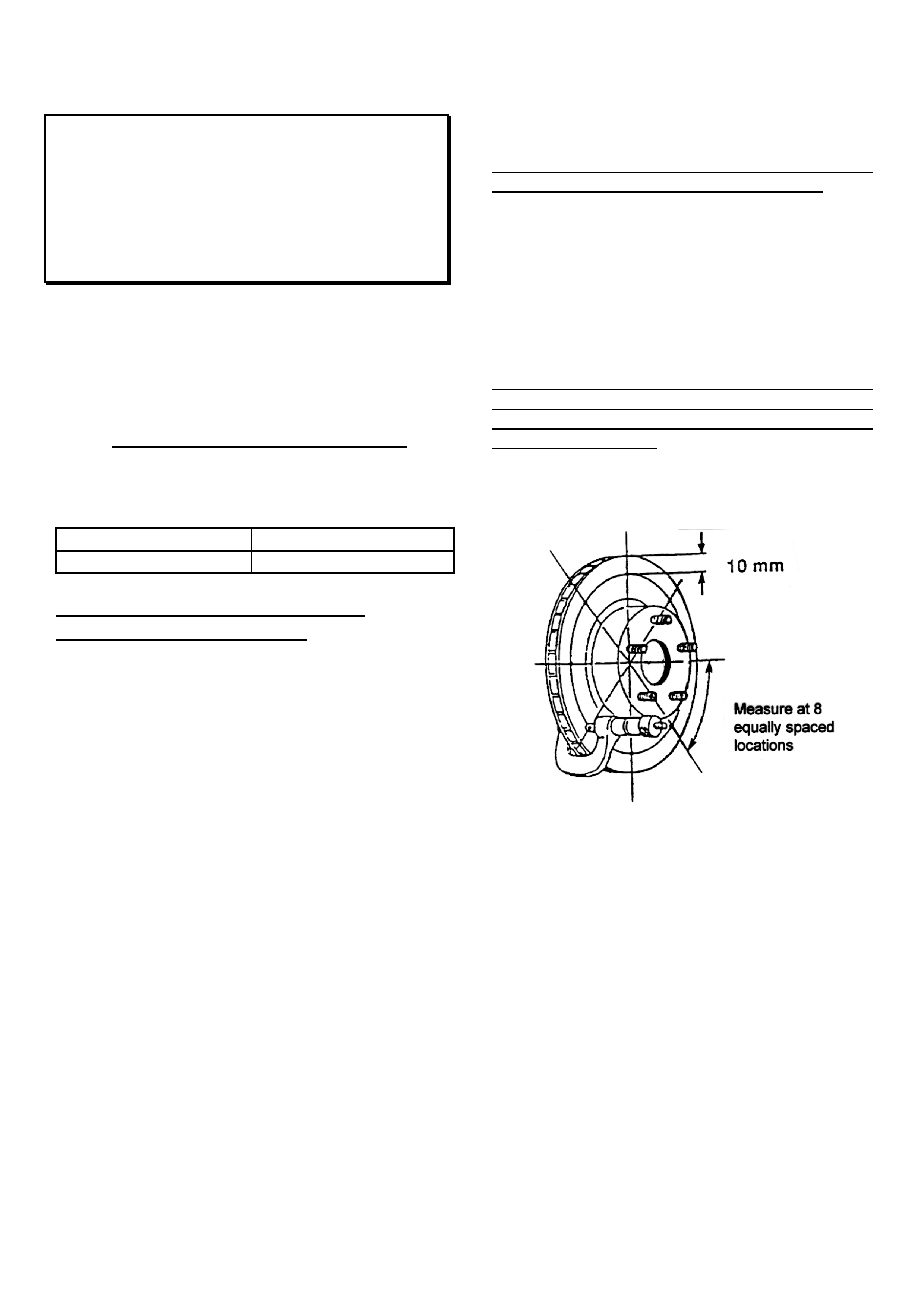
HOLDEN SERVICE TECHLINE ________________________________________________________________ JUNE 1999
13
BRAKE SHUDDER – RECOMME NDED
SERVICE PROCEDURES FOR DISC
MACHINING, INSTALLATION & PAD
REPLACEMENT
VT
(GROUP 5)
This Service Techline consolidates the
information from the previous techline on this
topic, Issue 1/99 and additional information
including caliper checks, pad replacement details
and amended warr ant y information.
1. PRODUCTION RECTIFICATION
Revised front pads have been f it ted to vehicles
since L413183, build date 15/12/ 98.
ISOVIN: Build Date:
6H8VTK69HXL413183 15/12/98
2. UNDERSTANDING BRAKE
SHUDDER & IT’S CAUSES
1a. Symptoms
Typically, shudder occurs under light/medium
braking from vehicle speeds of around 70 - 100
km/h.
The symptom of front brake shudder is a
pulsation felt in the brake pedal which is usually
accompanied by an oscillation of the steering
wheel.
The symptom of rear brake shudder is pedal
pulsation as well as a vibration that is felt through
the seat.
1b. Diagnosis
When a vibration/shudder condition is reported, a
road test should be done to confirm that the
condition is actually brake shudder. Brakes
should be tested while driving on a dry, clean and
reasonably smooth road surface. Perf or m at least
two, light/medium braking applications from 80 –
100 km/h down to 40 km/h whilst observing for
shudder symptoms.
1c. Cause of Brake Shudder
Brake shudder primarily occurs as a result of
variation in the thickness of the brake disc. This
in turn causes variations in brake surface
pressure as the varying thickness disc passes
between the pads during br aking.
The variation in thickness of the disc can be
measured with a micrometer as shown in Fig 1.
NOTE. A disc that varies in thickness by more
than .015mm (15 micron) will cause brake
shudder.
New discs develop Disc Thickness Variation
(DTV) as a r esult of excessive lateral runout in the
disc combined with caliper drag during non-
braking running time. On each revolution of the
disc a portion of the disc comes into contact with
the pad. Eventually the disc wears at the point of
contact thus cr eat ing thickness variation.
FIGURE 1 Measuri ng Disc Thickness Variati on
[DTV = Maximum thickness – Minimum thic kness]
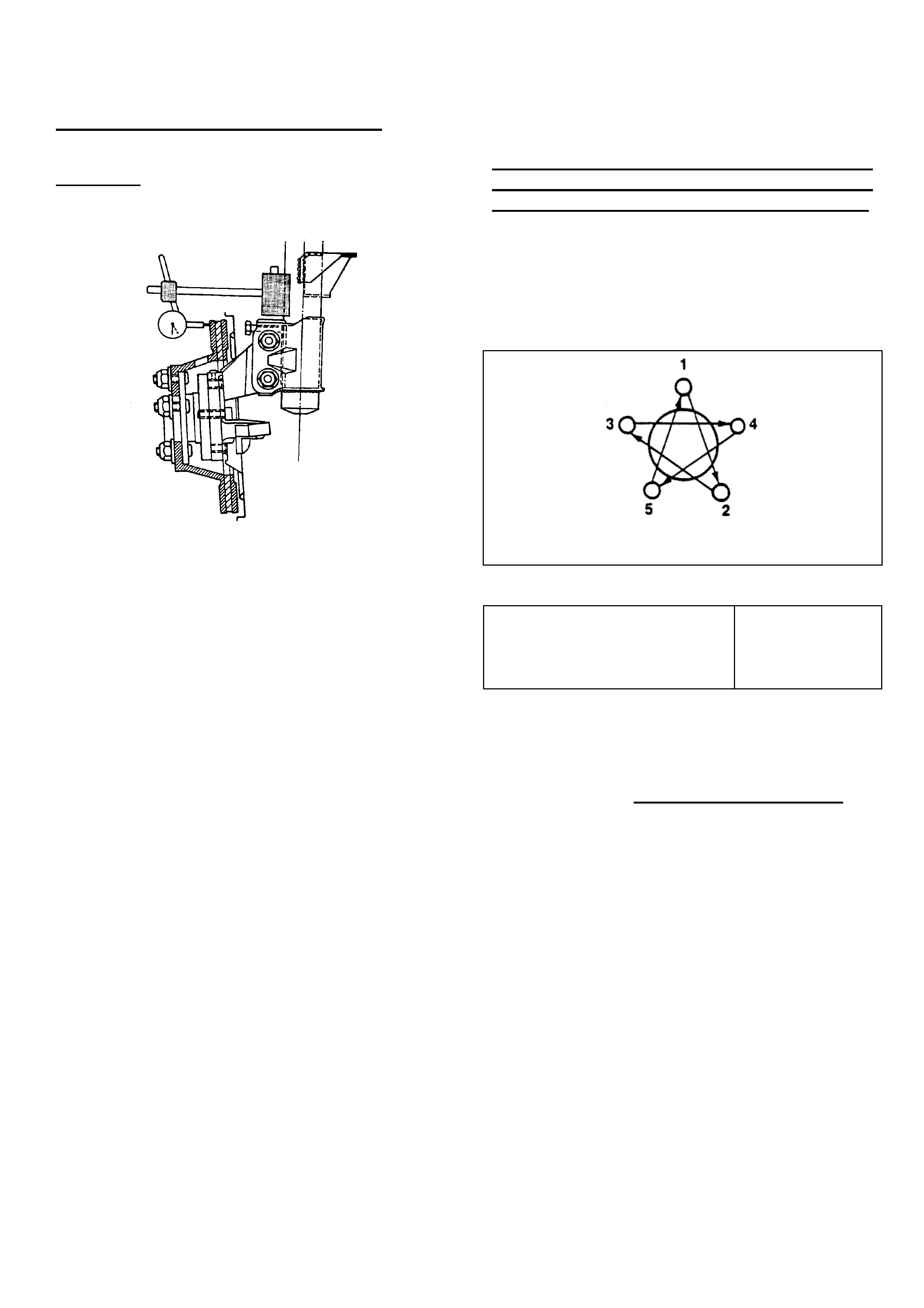
HOLDEN SERVICE TECHLINE ________________________________________________________________ JUNE 1999
14
What is Assembled “Lateral Runout”
The term “lateral” literally means “sideways”.
Assembled lateral runout is measured with a dial
indicator whilst rotating the disc on the vehicle.
FIGURE 2. Measuring disc lateral runout
Apart from accident damage, excessive
assembled lateral runout of discs may result from
one or more of the following:
1. Disc not machined to specification
Defective machining may result in lateral runout
and/or DTV above specification.
2. “Tolerance Stackup”
This term is best described by the following
example.
A front hub/bearing unit may show a runout of
0.030 mm near the outer edge of the mounting
face. The brake disc itself may have lateral
runout of 0.030 mm near its outer diameter.
These runouts taken separately are within
allowable tolerances. However, if the disc is
placed on the hub so that the high point on the
disc is aligned with the high point on the hub then
the combined result is an excessive lateral runout
(at the disc outer diameter) of about 0.090 mm.
To minimise the effect of “tolerance stackup” refer
to the Disc & Hub Indexing Procedures.
3. Incorrectly Tightened Wheel Nuts
Overtightened wheel nuts or those tightened
in the wrong sequence will cause distortion of
the disc and result in excessive lateral runout.
To prevent distortion of the disc and hub
assembly, wheel nuts must be tightened to the
specified torque in two steps, using a suitable
torque wrench. Follow the nut tightening
sequence as shown in Figure 3.
FIG. 3 Wheel nut tightening sequence
Road Wheel attaching nut
tightening torque
110 – 140 Nm
IMPORTANT!
DO NOT USE AN AIR IMPACT GUN TO
TIGHTEN WHEEL NUTS UNLESS IT IS
FITTED WITH A TORQUE LIMITER BAR.
Failure to observe this may result in warped discs
which lead to development of brake shudder.
Torque limiter bars can be obtained from most
automotive tool supplier s .
4. Foreign Material at disc to hub
interface
Foreign material between the disc and hub
mounting faces will contribute to assembled
runout.. It is vital that any foreign material such
as corrosion, dirt, burrs on hole edges etc are
removed.

HOLDEN SERVICE TECHLINE ________________________________________________________________ JUNE 1999
15
3. RECOMMENDED SERVICE PROCEDURES
3a. MACHINING DISCS
To eliminate brake shudder, the discs must be
machined to meet the following Holden
specifications for runout and Disc Thickness
Variation (DTV).
Note: The specifications shown in the following
table are for a stand alone disc mounted bet ween
machining centres (do not confuse with disc to
hub assembled lateral runout).
VT - Brake disc
machining
specifications
Front
Discs Rear
Discs
Lateral runout max..040 mm .050 mm
DTV max..005 mm .013mm
Dealers must ensure that in-house machining
equipment is at least capable of achieving the
specified lateral runout.
Due to the extremely small DTV specification,
which only precision laboratory equipment will be
capable of measuring, dealers are NOT expected
to check for DTV. NOTE: On most modern lathes
that machine bot h sides of the disc sim ultaneously,
DTV will normally be below the limits specified.
If discs are sublet for machining, dealers should
advise the sublet repairer of the above run-out and
DTV requirements.
Failure of discs to meet these specifications
indicates that either the machining technique
and/or the equipment is deficient .
The two options for machining discs are to use
an on car lathe or an off car lathe.
There are advantages and disadvantages for
each type of lathe. It is not proposed in this
article to cover every aspect of these lathes such
as price, durability, ease of use, etc. It is the
dealers responsibility to carefully consider all
these before making a final decision to purchase.
This art icle is only intended t o highlight f or each
type of lathe some of the more important issues
related to achieving an accurately machined disc.
When machining discs to eliminate DTV, only the
absolute minimum amount of material should be
machined from the discs. Only properly
maintained precision cut ting tools should be used.
Dull or worn tools leave an unsatisfactory disc
surface finish. It is recommended that following a
light final cut machining operation involving
removal of between .025 and .050 mm of material,
final surface finish should be obtained by lightly
rubbing with fine emery paper. This rubbing helps
smooth out microscopic grooves ensuring a non-
directional finish.
OPTION 1. Off-Car Brake Lathes
Historically, brake discs have been machined on
off car lathes. Many of the older lathes used for
this work may be worn to the point where they are
no longer capable of achieving, the lower
machining tolerances specified for current discs.
Therefore, dealers must ensure that the
dealerships lathe (or that of your sublet repairer) is
regularly maintained and checked for accuracy.
To achieve accurate disc machining , it is vital that
discs are mounted correctly in the lathe. Some of
the older cone mounting methods require tedious
setup time t o m inim ise r unout pr ior to machining.
On some of these older lathes an excellent
method for reducing disc mounting and setup
time is to bolt the disc to a tool (mounted to the
lathe chuck) that simulates the hub in the vehicle.
The following paragr aph descr ibes one such t ool.
Disc Mounti ng Tool
Farrely Brothers Toolmakers, manufacture a tool
that simulates the wheel hub mounting face. The
tool is mounted to the lathe chuck and is trued to
the lathe spindle by machining a cut across the
disc mounting face. This tool can be used for front
and rear discs for all models VR to VT.

HOLDEN SERVICE TECHLINE ________________________________________________________________ JUNE 1999
16
For further details contact Farrely Brothers
Toolmakers, 5 Lemmon Avenue East Keilor VIC
3033, phone 03 9336 1870.
IMPORTANT: Whenever discs are machined
off-the-car they must be indexed to the hub to
achieve minimum assembled runout.
OPTION 2. On-Car Disc Lathes
The main advantage of on-car lathes is that
because the discs are machined on the hub, t hey
do not require indexing to the hub for minimum
runout.
However, if the disc is to be removed for any
reason, it must first be marked in relation to the
hub to enable it to be reinstalled in the minimum
runout position.
On car lathe designs fall into 2 t ypes as follows.
Hub mounted cutting head
The main disadvantage of this type of lathe is that
the runout and DT V of the machined disc ar e f ully
dependant on the wheel hub runout
compensation adjustment performed prior to
machining. If this adjustment is not done
correctly, the disc runout and DTV will not meet
Holden’s specificat ions.
Caliper mounted cutting head
The main advantage of this type of lathe is that
there is no need to compensate for wheel hub
runout prior to machining because the cutting
head is mounted where the caliper is normally
situated.
CAUTION: The minimum thickness of a re-
machined disc must always be greater than the
scrap thickness. Refer to the following chart for
recommended minimum thickness after
machining.
DISC THICKNESS
INFORMATION VT Front Rear
New disc 28.0mm 16.0mm
Mi n. thickn ess aft er
machining 25.5mm
(refer note a.) 14.4mm
(refer note b.)
Scrap thickness 25.0mm 13.9mm
Note a. This dimension is calculated on the basis that
the normal disc wear rate with new genuine Holden
brake pads should not reduce the disc thickness below
the minimum disc operating thic k ness of 25.0 mm befor e
the next pad replacement.
Note b. This dimension is calculated on the basis that
the normal disc wear rate with new genuine Holden
brake pads should not reduce the disc thickness below
the minimum disc operating thic k ness of 13.9 mm befor e
the next pad replacement.
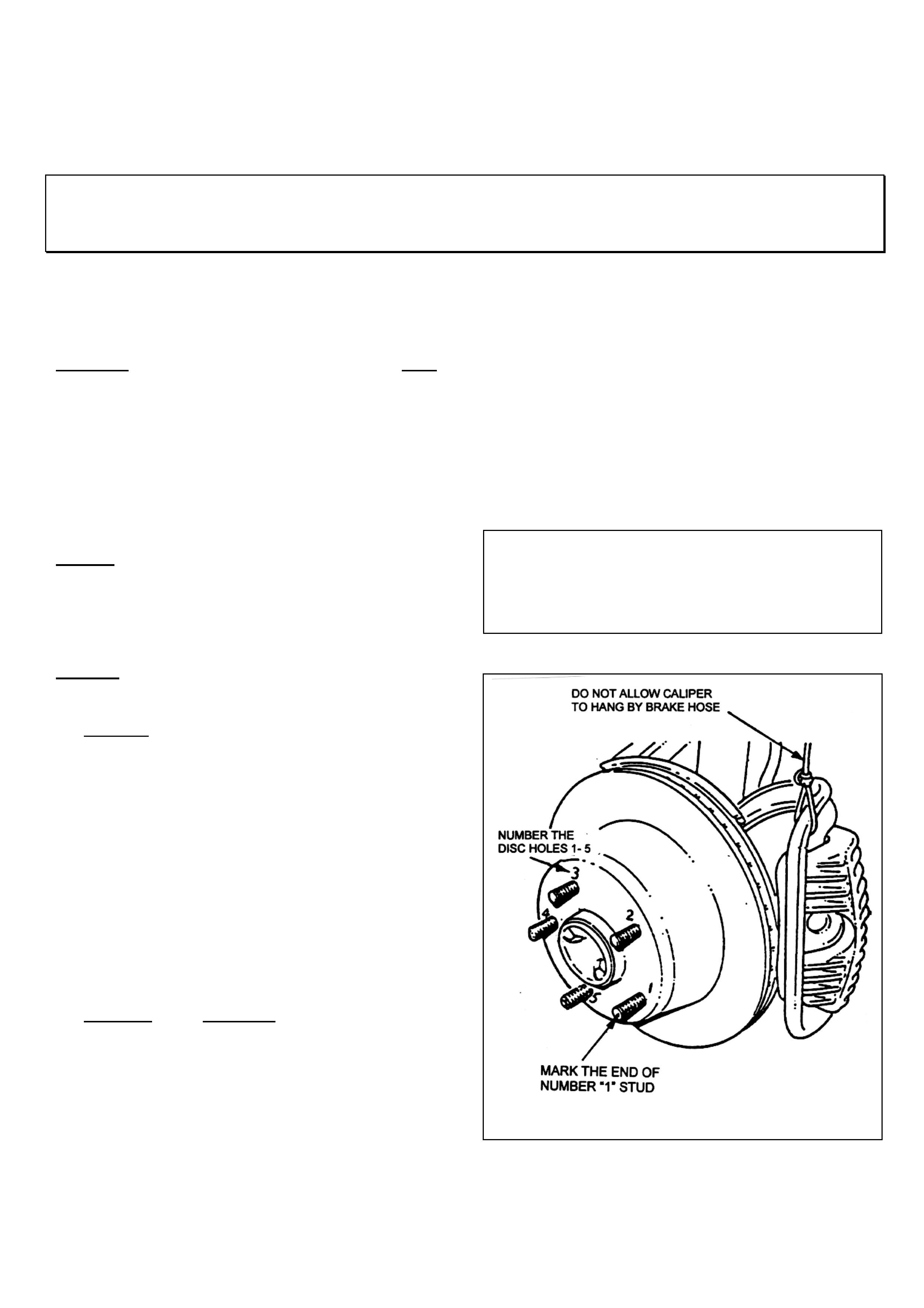
HOLDEN SERVICE TECHLINE ________________________________________________________________ JUNE 1999
17
3B. FRONT DISC & HUB INDEXING PROCEDURE
IMPORTANT: This procedure must be used whenever reinstalling discs that have been removed for
machining of f car. It must also be used when installing new discs or discs that have been removed f or any
reason and where disc to hub/tr unnion m at c hing is not evident.
Disc and hub indexing is requir ed in order to obt ain
the minimum installed disc runout.
Disc and hub indexing involves aligning the point of
maximum runout on the hub with the point of least
runout on the disc.
The procedure consists of three steps as follows:
Step 1. Clean mating surfaces.
Step 2. Measure and Match disc high point t o hub
low point. If not OK go to ste p 3.
Step 3. Checking hub mounting face runout
STEP 1. Clean mating surfaces
Ensure that disc and hub mating surfaces are free
from dirt, corrosion, etc. If required, use fine emery
paper to clean surfaces.
STEP 2. Indexing disc t o hub
2.1 Fasten the disc onto the hub with wheel nuts
reversed to avoid damage to the tapers, and
nip up with a spanner.
2.2 Number each of the wheel stud holes on the
fr ont surface of disc f rom 1 to 5. Place a chalk
mark on the end of the wheel stud adjacent to
number “1” hole. Refer Figure 4.
2.3 Set up a dial indicator on a magnetic base and
attach to the strut tube above the brake disc.
Position the pointer about 10 to 15 mm inboard
from the outer diameter of the disc. Refer
Figure 5.
2.4 Carefully rotate the disc and note the points of
minimum and maximum runout on the dial
indicator. The number of divisions between
these two points is the total indicated runout.
Record this figure together with the number on
the disc aligned with the chalk-marked stud.
2.5 Remove and reinstall the disc with hole number
“2” over the marked stud. Repeat STEP 2.4.
This procedure is to be repeated for all 5 hole
positions.
2.6 Mount the disc to the hub in the stud position
with least runout.
NOTE: If the lowest assembled disc runout
achieved is more than 0.050 mm ( 50 micron) then
the hub runout should be checked as shown in
step 3.
Maximum assembled disc &
hub runout at disc outer
diameter - FRONT
0.050 mm
FIGURE 4. MARKING THE HUB & DISC
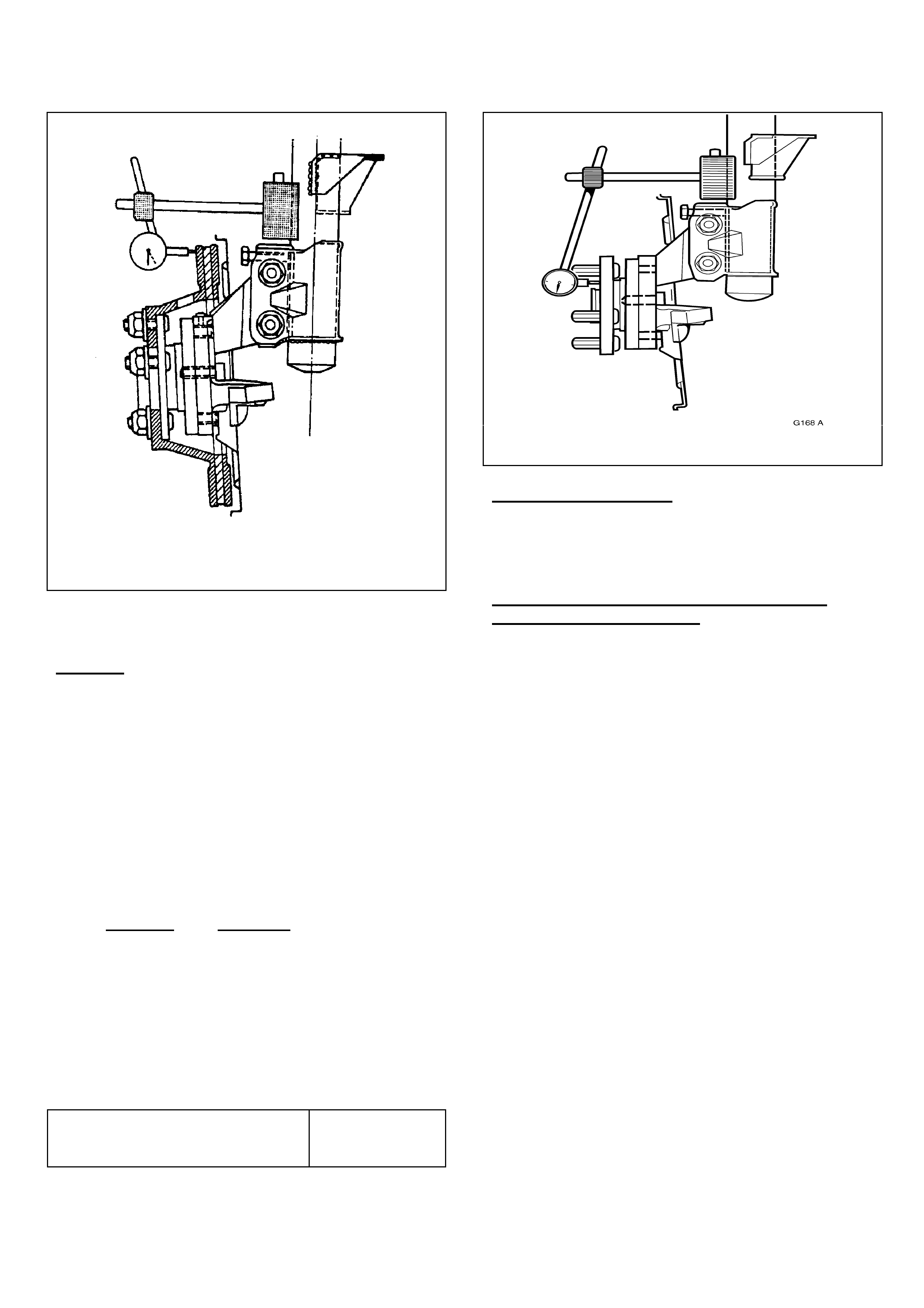
HOLDEN SERVICE TECHLINE ________________________________________________________________ JUNE 1999
18
FIGUR E 5. MEASURING INSTALLED DISC
RUNOUT
STEP 3. Hub runout check
3.1 Clean the front hub face by rubbing lightly with
fine emery paper.
3.2 Locate the dial indicator on the strut tube and
position the pointer on the hub face about
midway between the spigot and the studs.
Refer Fi gure 6
3.3 Carefully rotate the hub by the hub spigot (to
avoid loading the bearing) and note the points
of minimum and maximum runout on the dial
indicator. The number of divisions between
these two points is the total indicated runout.
3.4 If the runout measured in STEP 3.3 exceeds
0.025 mm (25 micron) t hen the hub unit should
be replaced. (If replacement is done under
warranty, the runout figure measured must be
recorded on the Defective Material Tag.)
FIGURE 6 HUB RUNOUT MEASUREMENT
Production Indexing
NOTE: On the vehicle assembly line the disc high
point is aligned with the hub low point.
IMPORTANT:- ALWAYS MARK DISCS
PRIOR TO REMOVING !
Whenever discs are removed from hubs for
reasons other than brake shudder rectification, the
disc and hub must be marked to enable
reinstallation of the disc ont o the hub in the orig inal
position.
This practice will avoid the development of shudder
if the discs are reinstalled in a position which
causes excessive runout.
Disc to hub marking must become a standard
operating practice for all service technicians.
Maximum runout at hub face –
FRONT HUB 0.025 mm
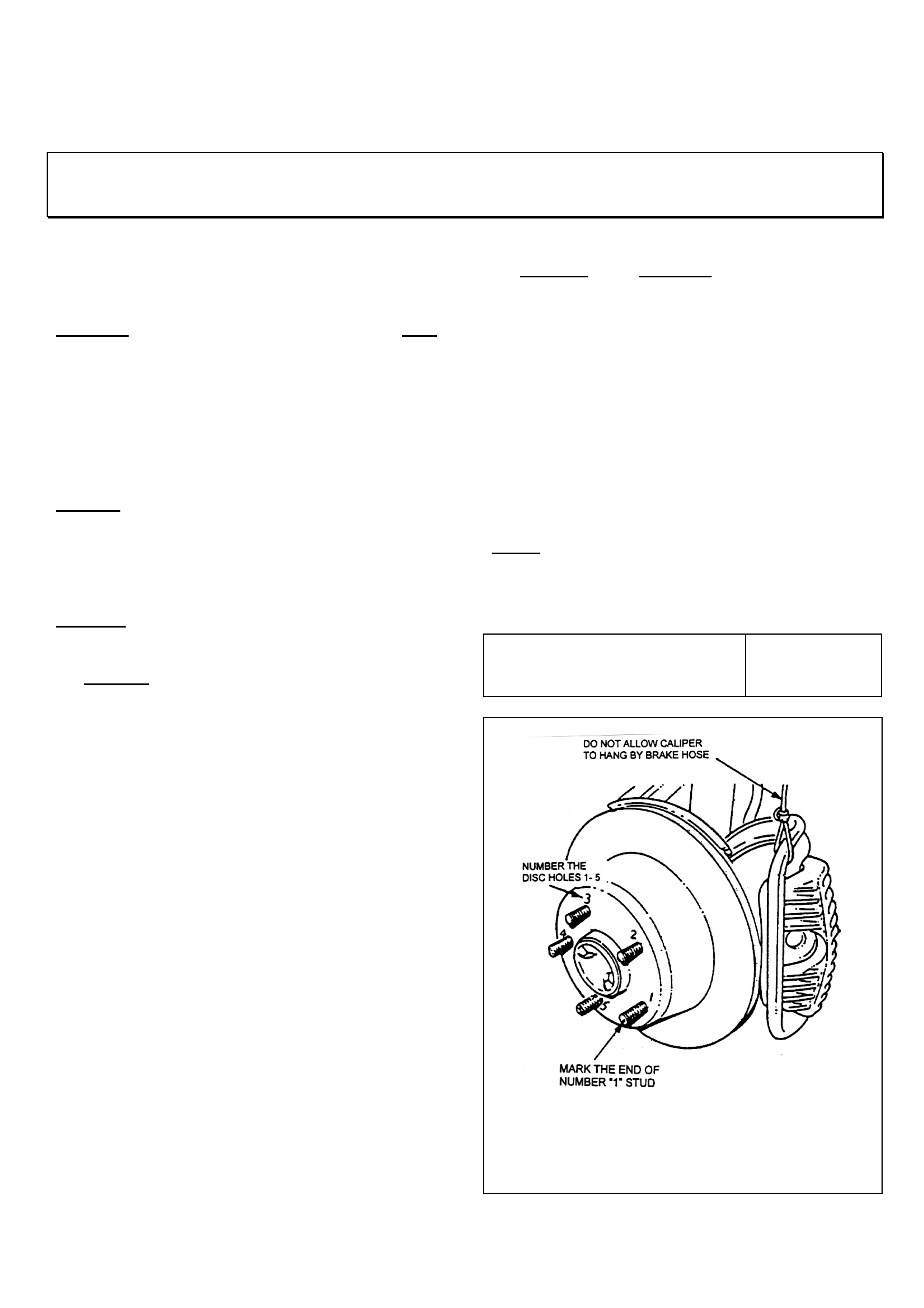
HOLDEN SERVICE TECHLINE ________________________________________________________________ JUNE 1999
19
3C. REAR DISC TO TRUNNION-HUB INDEXING PROCEDURE
IMPORTANT: This procedure must be used whenever reinstalling discs that have been removed for
machining off car. It must al so be used when instal ling new di scs or discs that have been removed
for any reason.
Disc and hub indexing is requir ed in order to obt ain
the minimum installed disc runout.
Disc and hub indexing involves aligning the point of
maximum runout on the hub with the point of least
runout on the disc.
The procedure consists of three steps as follows:
Step 1. Clean mating surfaces.
Step 2. Measure and Match disc high point to
trunnion hub low point. If not OK go to
Step 3. Checking hub mounting face runout
STEP 1. Clean mating surfaces
Ensure that disc and trunnion hub mating surfaces
are free from dirt, corrosion, etc. If required, use
fine emery paper to clean surfaces.
STEP 2. Indexing disc to trunnion hub
2.1 Fasten the disc onto the hub with wheel nuts
reversed to avoid damage to the tapers, and
nip up with a spanner.
2.2 Number each of the wheel stud holes on the
fr ont surface of disc f rom 1 to 5. Place a chalk
mark on the end of the wheel stud adjacent to
number “1” hole. Refer Figure 7.
2.3 Set up a dial indicator on a magnetic base and
attach to a mounting plate (refer Figure 10 for
details) bolted to the caliper attaching points.
Position the pointer about 10 to 15 mm inboard
from the outer diameter of the disc. Refer
Figure 9.
2.4 Carefully rotate the disc and note the points of
minimum and maximum runout on the dial
indicator. The number of divisions between
these two points is the total indicated runout.
Record this figure together with the number on
the disc aligned with the chalk-marked stud.
2.5 Remove and reinstall the disc with hole number
“2” over the marked stud. Repeat STEP 2.4.
This procedure is to be repeated for all 5 hole
positions.
2.6 Mount the disc to the trunnion hub in the stud
position with least runout.
NOTE: If the lowest assembled disc runout
achieved is more than 0.080 mm ( 80 micron) then
the trunnion hub runout should be checked as
shown in step 3.
Maximum assembled disc &
trunnion hub runout at disc
outer diameter REAR 0.080 mm
FIGURE 7. MARKING THE DISC & HUB
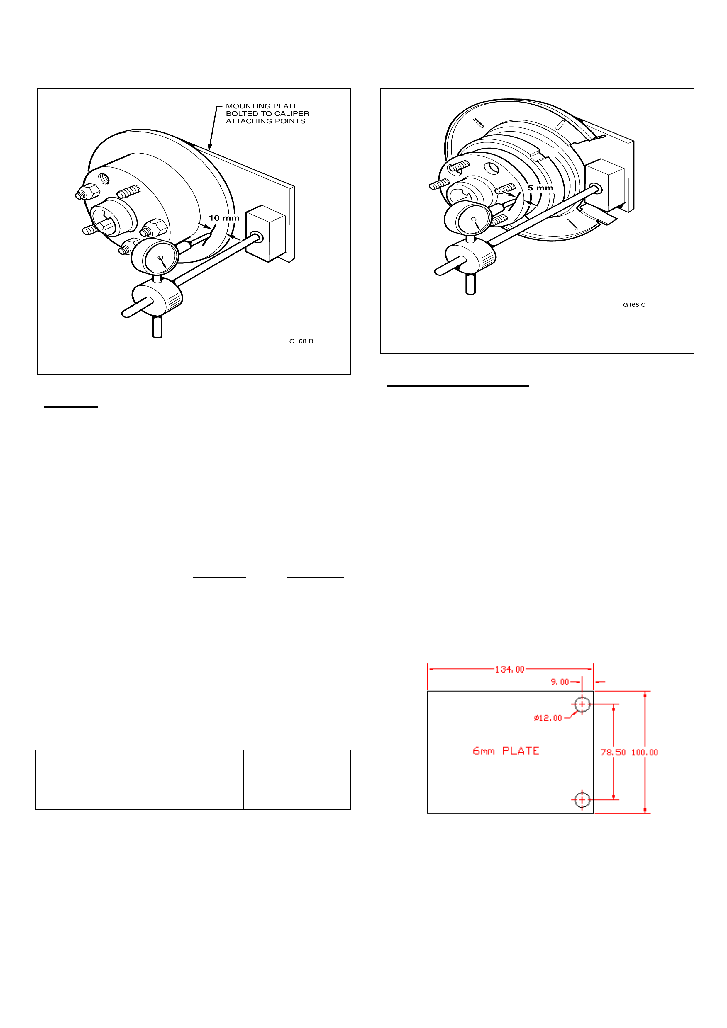
HOLDEN SERVICE TECHLINE ________________________________________________________________ JUNE 1999
20
FIGURE 8. MEASURING ASSEMBLED RUNOUT
STEP 3. Trunnion Hub runout check
3.1 Clean the front hub face by rubbing lightly with
fine emery paper.
3.2 Locate the dial indicator on the mounting plate
bolted to the caliper mounting points and
position the pointer on the hub face as shown
in Figure 6.
3.3 Carefully rot ate t he hub by the wheel studs and
note the points of minimum and maximum
runout on the dial indicator. The number of
divisions between these two points is the total
indicated runout.
3.4 If the runout measured in STEP 3.3 exceeds
0.060 mm (60 micron) then the trunnion
assembly must be replaced. (If replacement is
done under warranty, the runout figure
measured must be recorded on the Defective
M a te rial Tag.)
Trunnion hub
Total Indicated runout 0.060 mm
max.
FIGURE 9. MEASURING TRUNNION HUB RUNOUT
Production indexing
Production matching of the disc high point to the
trunnion low point was introduced on January 25,
1999.
IMPORTANT:- ALWAYS MARK DISCS
PRIOR TO REMOVING !
Whenever discs are removed from hubs for
reasons other than brake shudder rectification, the
disc and hub must be marked to enable
reinstallation of the disc ont o the hub in the orig inal
position. This practice will avoid the development of
shudder if the discs are reinstalled in a position
which causes ex cessiv e installed runout.
Disc to hub marking must become a standard
operating practice for all service technicians.
FIGURE 10: DETAILS OF DIAL INDICATOR
MOUNTING PLATE FOR CHECKING REAR
RUNOUT (use caliper bolt s with spacers).
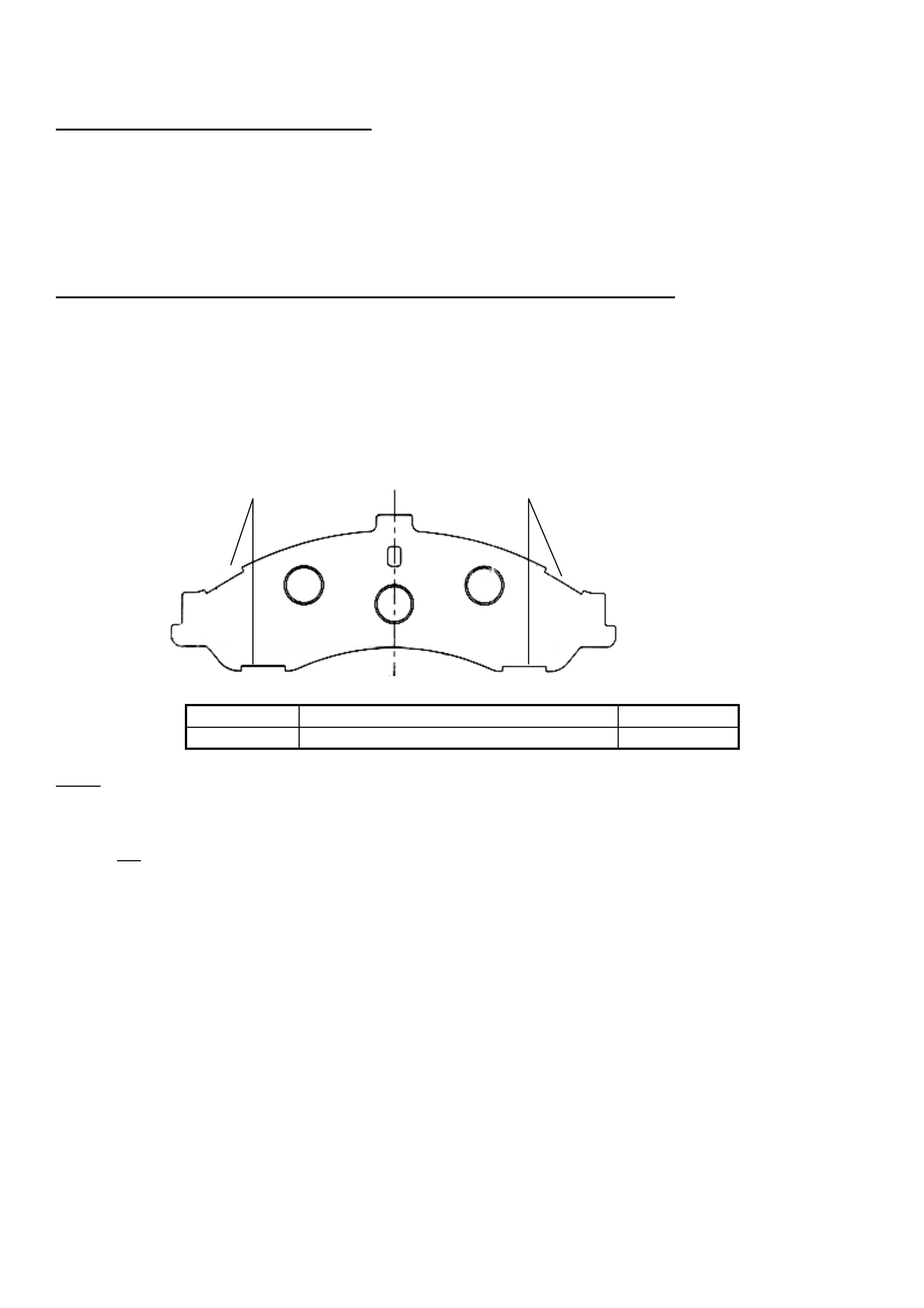
HOLDEN SERVICE TECHLINE ________________________________________________________________ JUNE 1999
22
4. INSPECTING BRAKE CALIPERS
Check the caliper guide pin boots f or damage or poor seat ing. If the boots are damag ed or split, the guide
pins must be inspected for signs of corrosion or pitting. If there are signs of corrosion sufficient to cause
the caliper to bind on t he guide pins, then the complet e caliper assembly should be replaced.
If removing the caliper slide assembly for any reason, always thoroughly clean all parts and reassemble
using Caliper Slide Pin G r ease P/N 92140230. Ensure the guide pin boot s ar e installed correctly.
5. INSTALLATIO N O F REVI SED BRAKE PADS (f r ont only) P/N 92080900.
a) Replace Front Brake Pads
Remove the “BM962” material Front brake pads and replace with the revised brake pad material, Part
Number 92080900.
The revised pads can be identified by the back ing plate outer prof ile chang e (bot h pads) as indicat ed in the
fig u r e below.
Part No.: Description: Qty Req’d:
92080900 Pad Package – Fr ont Disc (Akebono) 1
Notes
• The rear brake pad friction material composition is unchanged. Therefore, are not to be replaced to
rectify brake shudder.
• The rear brake pads should only be replaced when necessary due to normal wear.
• It is not recommended to face, linish or alter the f ace of brake pads (front or rear) when installing new
or re-using existing brake pads.
• Brake pads that show excessive or abnormal tapered wear need to be replaced. The cause of this
abnormal wear needs to be investig at ed and r ectified.
• Ensure the new micro-encapsulated g uide pin bolts included in the revised fr ont pad kit are used when
reassembling t he caliper.
REVISED PADS HAVE THESE “CUTOUTS”

HOLDEN SERVICE TECHLINE ________________________________________________________________ JUNE 1999
23
WARRANTY CLAIM INFORMATION
R & R Discs, (Machine off car or fit new discs) & Index Disc to Hub
Description Rem ove & Reinstall
discs to machine off car
(or fit new discs) &
index disc to hub
FRONTS & REARS
Remove & Reinstall discs to
machine of f car (or fit new
discs) & index discs to hub
FRONTS ONLY
Remove & Reinstall
discs to machine off car
(or fit new discs) &
index discs to hub
REARS ONLY
Labour Op.No. H000195 H000198 H000201
Standard Time 1.4 hrs 0.8 hrs 0.8 hrs
Add time for
machining
discs 0.8 hrs 0.4 hrs 0.4 hrs
Add time for
replacing front
pads 0.1 hrs 0.1 hrs n/ a
Machine Discs On Car
Descripti on FRONTS & REARS
Remove & Reinstall
wheels & rear calipers &
runout check after
machining.
FRONTS ONLY
Remove & Reinstall wheels
& runout check after
machining.
REARS ONLY
Remove & Reinstall
wheels & calipers &
runout check after
machining.
Labour Op.No. H000204 H000207 H000210
Standard Time 0.5 hrs 0.3 hrs 0.4 hrs
Add time for
machining
discs
0.9 hrs
(Additional 0.2 hrs if
LSD- refer note 3)
0.5 hrs 0. 4 hr s
(Additional 0.2 hrs if
LSD- refer note 3)
Add time for
replacing front
pads
0.3 hrs 0.3 hrs n/ a
NOTES:
1. If discs are removed and sublet for machining, claim the sublet expense in “net items” column.
Please note that the “add” time for machining cannot be claimed as a labour expense when work is
sublet.
2. If “on-car” machining is sublet, claim the sublet expense in “net items” column. Please note that the
“add” time for machining cannot be claimed as a labour expense when work is sublet.
3. Additional time is claimable to disconnect rear driveshafts from trunnions to allow “on-car” machining
when car has Limited Slip Differential (LSD) production option – G80.
4. Claim the “Standard T ime” plus t he “Add Times” where applicable. DO NOT claim the “Add T imes” as
“Other Hour s” .

HOLDEN SERVICE TECHLINE ________________________________________________________________ JUNE 1999
24
SUMMARY OF SPECIFICATIONS
VT Brake disc
specifications. Front Discs Rear Discs
Lateral runout max..040 mm .050 mm
DTV max..005 mm .013 mm
Maximum assembled disc & hub runout at
disc outer diameter – FRONT 0.050 mm
Maximum runout at hub face outer diameter –
FRONT 0.030 mm
Maximum assembled di sc & t r unni on hub
runout at disc out er di amet er - REAR 0. 080 m m
Trunnion hub
Maximum Total Indicat ed runout 0.060 m m
DISC THICKNESS
INFORMATION - VT Front Rear
New disc 28.0mm 16.0mm
Min. thickness after
machining (new pads) 25.5mm
(refer note a.) 14.4mm
(refer note b.)
Scrap thickness 25.0mm 13.9mm
Note a. This dimension is calculated on the basis that the normal disc wear rate with new genuine Holden brake pads
should not reduce the disc thickness below the minimum disc operating thickness of 25.0 mm before the next pad
replacement.
Note b. This dimension is calculated on the basis that the normal disc wear rate with new genuine Holden brake pads
should not reduce the disc thickness below the minimum disc operating thickness of 13.9 mm before the next pad
replacement.
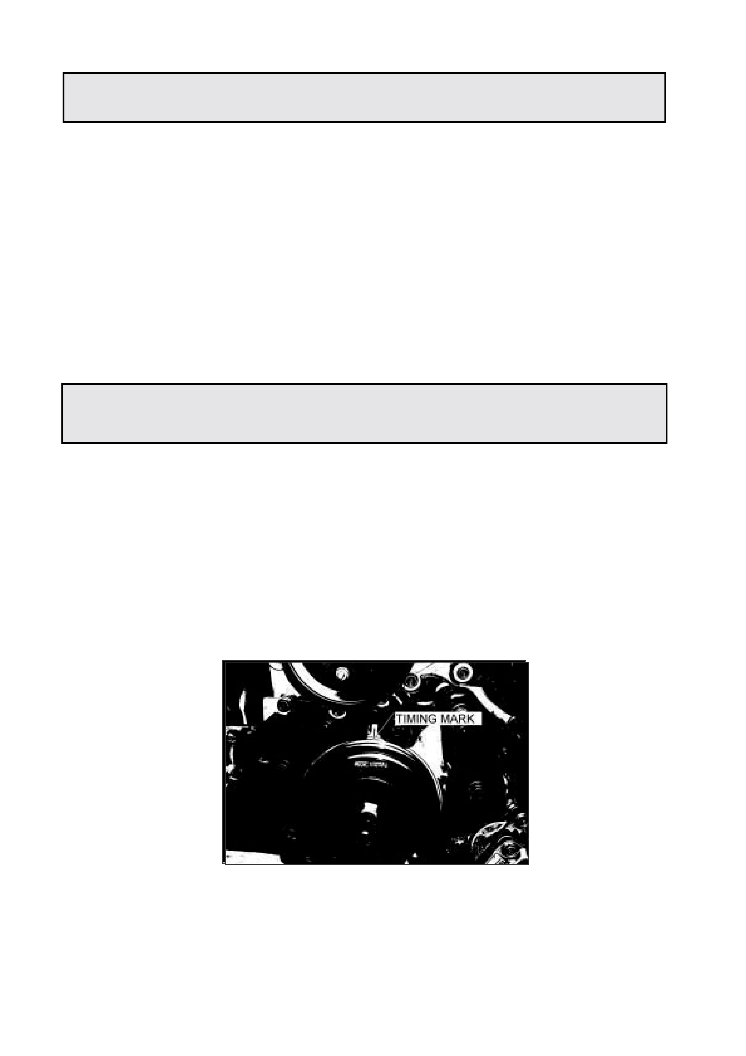
HOLDEN SERVICE TECHLINE _________________________________________________________ JUNE 1999
22
AIR CONDITIONING INFORMATION
1999 FRONTERA GROUP 2
1999 model Frontera three door and five door vehicles do not have air conditioner refrigerant
sticker s fitted in the eng ine bay area.
For your information the relevant details are:
CHARGE : 0. 65 kg HFC – 134a
LUBRICANT : 150 cc - 200PG
More detailed information on refrigerant recovery / recharge can be found in the relevant
section of t he work shop m anual
( Section 1A, page 49 – 53 )
4JX1 FLYWHEEL SETUP PROCEEDURE
JACKAROO GROUP 6A
When removing the flywheel on a 4JX1 engine, the flywheel should be marked to ensure
installation in the same position. The position of the flywheel in relation to the crankshaft is
critical for engine operation as the crankshaft position sensor reads off the toothed wheel
attached to t he flywheel.
In instances where assembly is required without reference marks the following procedure can
be used.
1. Align crankshaft pulley notch with mark on timing case to obtain T.D.C.
(ref drawing 1)
DRAWING 1
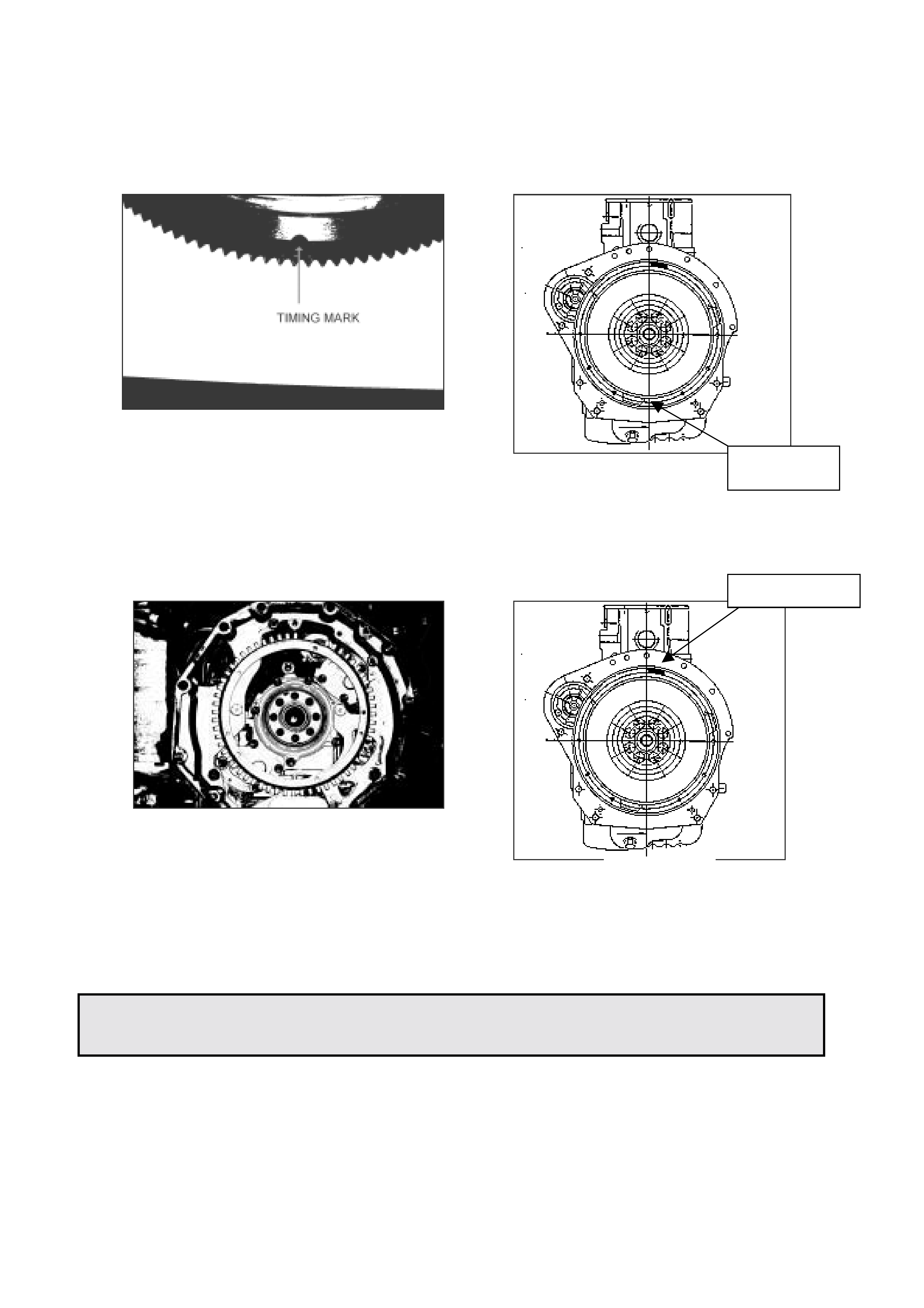
HOLDEN SERVICE TECHLINE _________________________________________________________ JUNE 1999
23
2. Fit f lywheel to crankshaft taking note that:
A) Timing mark is pointing downward (ref dr awing 2 & 2A ) .
B) Crank shaft sensor toot hed wheel is in correct posit ion
(ref drawing 3 & 3a).
4JX1 ENGINE OIL SPECIFICATION
JACKAROO GROUP 6A
Due to the diesel injection system used in t he curr ent Jack aroo diesel 4JX 1, eng ine oil is crit ical
to the correct operation of the engine. Incorrect spec engine oil may dramatically increase
cranking times, cause r ough idle, and in extrem e conditions cause a no st art / stalling situat ion.
The engine oil specification for the Jackaroo diesel 4JX1 engine is 15W/40 CG-4, however in
extreme cold operating conditions e.g. alpine areas, a lower cold viscosity rating is
recommended e. g. 5W/40.
TIMING MARK
POSITION
MISSING TEETH
DRAWING 2
DRAWING 2A
DRAWING 3A
DRAWING 3
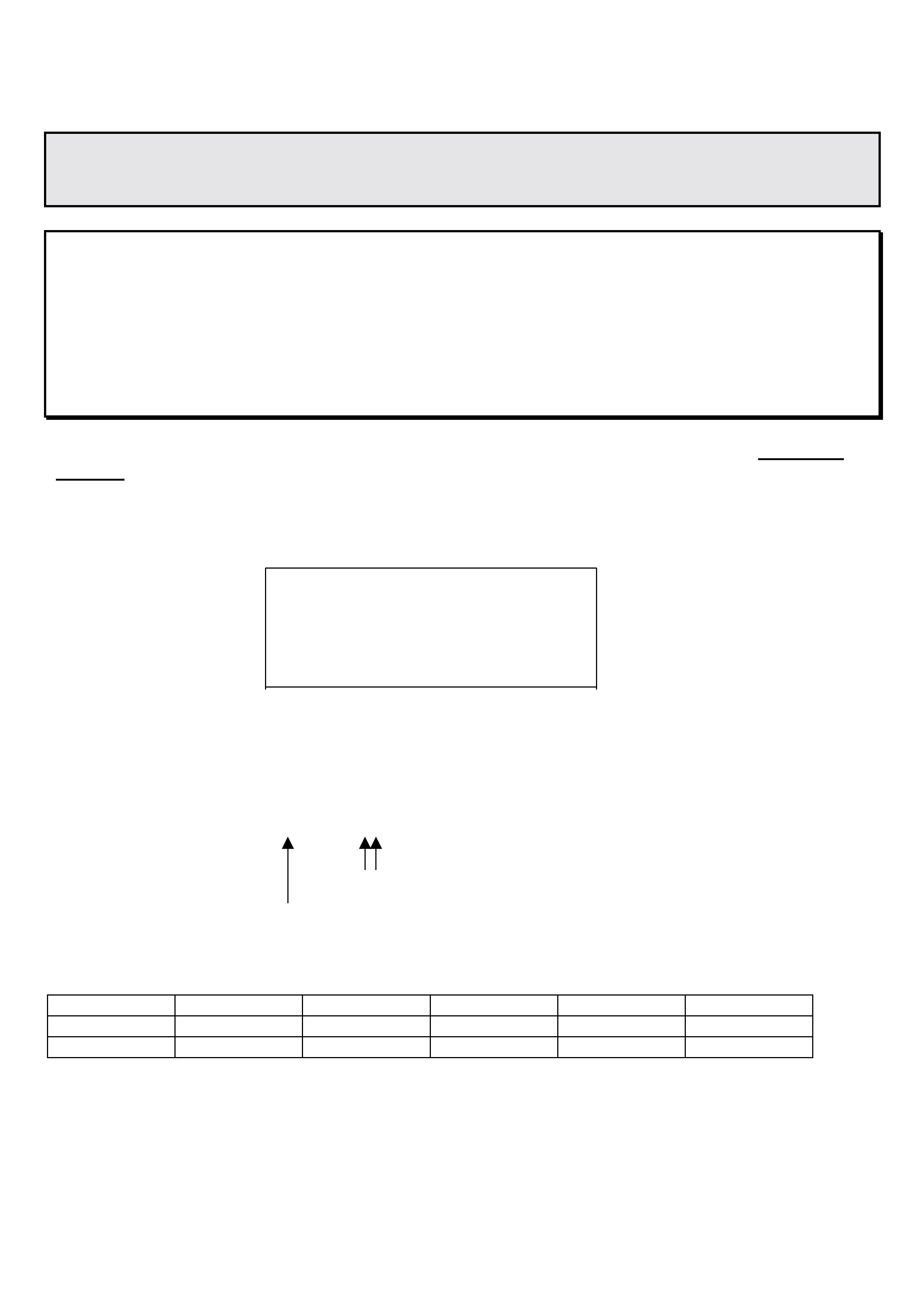
HOLDEN SERVICE TECHLINE ________________________________________________________________ JUNE 1999
23
4JX1 INJECTOR CALIBRATION
JACKAROO GROUP 6M
The 4JX1 diesel engine in the 1998 model Jackaroo has i njectors that are classified into 9 groups
according to fl ow rate. The ECM is cal i brat ed t o t he injectors that are fitt ed t o t he engine using tech
2.
Injector calibration is carried out at production, but will need to be checked at pre delivery and
after some service repairs. e. g. control unit replacement, i nject or repl acement, etc.
Incorrect injector calibration may cause unstable idle, engine vibrati on or excessi ve smoke.
When performing injector calibration difficulty may be experienced identif ying the injector calibration group.
The workshop manual indicates that identif ication is determined by markings on the injector. This is not
the case. T he only met hod for identif ication is to utilise the inject or identification sticker, situated on t he
noise insulator cover that is above the r ocker cover.
INJECTOR IDENTIFICATION STICKER
ENG. NO 489476 4JX 1
#1 82395420 #2 83395420
#3 83365520 #4 59395920
RP SENSOR 7565
The numbers on the identification st icker are production number s ( not par t numbers) used to identify
individual injectors. The 5th and 6th digits of the pr oduction number are used to classif y inject or s for
calibration. eg.
#1 82395420
CALIBRATION NUMBER ( 54 )
INJECTOR NUMBER (# 1)
The calibrat ion number is used in conjunction with the following chart.
A1 20 – 26 B1 40 – 46 C1 61 – 67
A2 27 – 33 B2 47 – 53 C2 68 – 74
A3 34 - 39 B3 54 - 60 C3 75 – 80
For example: Inj ect or num ber 1 has a calibration number 54. Number 54 cor r esponds to a B3.
Once the injector calibration number has been established and inj ector category determ ined, the
calibration procedure in the relevant workshop m anual ( s ect ion 6E )
can be followed.
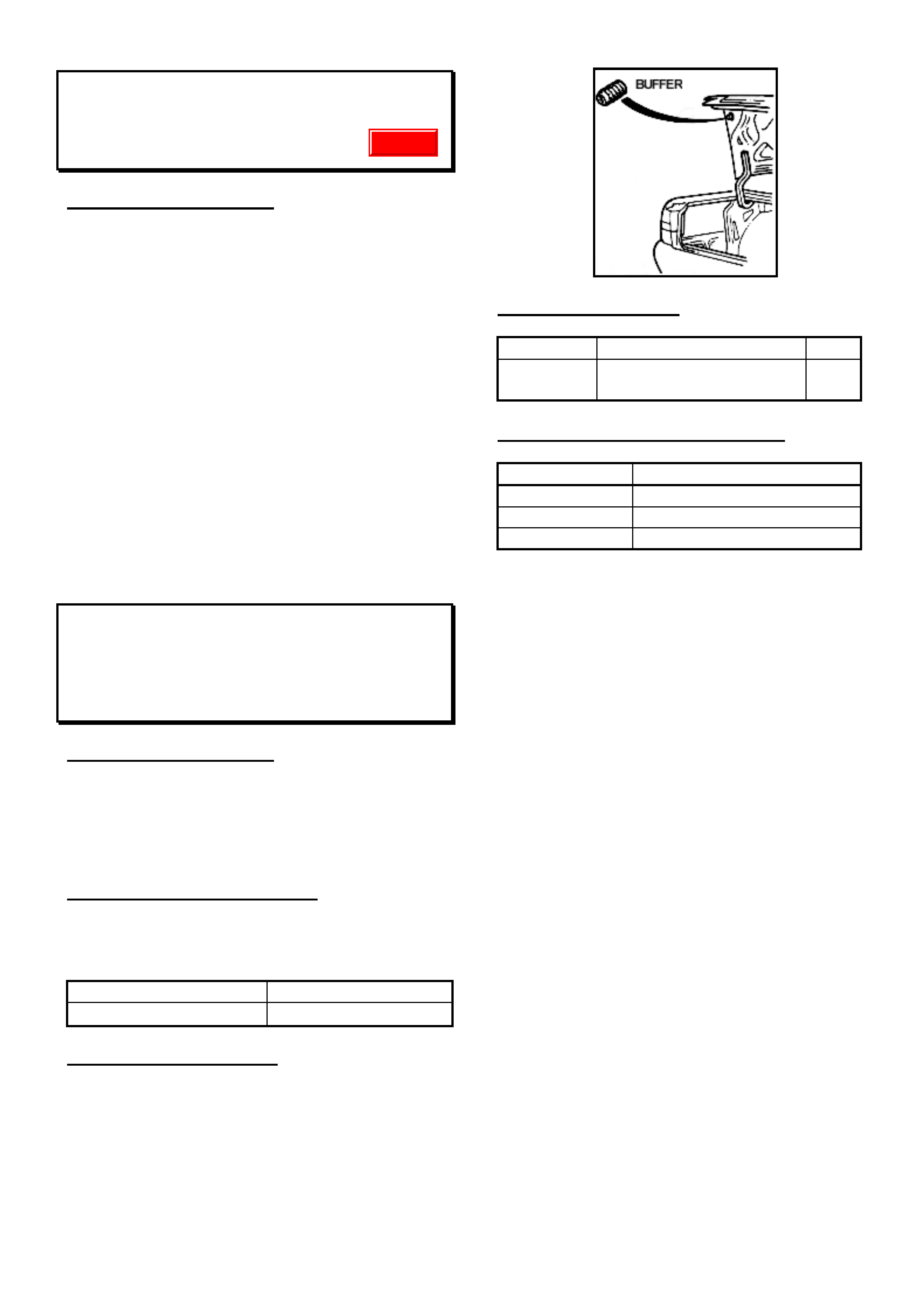
HOLDEN SERVICE TECHLINE _________________________________________________________________ AUGUST 1999
1
REGISTRATION PLATE RATTLE
WH
(GRO UP OB)
PROBLEM DESCRIPTION
Front and rear registration plates on WH Series
vehicles may rattle due to incorrect mounting.
For WH Series vehicles:
Four screws are required to mount each registration
plate securely.
The front registration plate must have four fasteners
located along the top of the plate, two on the ends and
two slightly inboard (same as VT Series vehicles).
The rear plate als o utilises four f asteners. T he two top
fasteners screw into a boss, while the two bottom
fastener s ‘self -tap’ into the bum per fac ia. T here ar e no
bosses in the facia at the bottom of the plate, but the
screws will hold.
To prevent plate rattles, please use four fasteners to
attach each registration plate.
OVERSLAM OF THE DECK LID CAUSING
PAINT REMOVAL FROM REAR BUMPER
VT, WH
(GRO UP 1)
PROBLEM DESCRIPTION
When the deck lid is closed, an over slam
condition can cause the bott om edg e of the lower
décor panel to contact the top of the rear
bumper, in some cases removing paint from the
bumper.
PRODUCTION RECTIF ICATION
Revised deck lid bump stops with increased
hardness have been fitted to vehicles from
L475263, build date 28/06/ 99.
ISOVIN: BUILD DATE:
6H8VTK69HXL475263 28/06/1999
SERVICE RECTIFICATION
On customer complaint vehicles, fit the revised
bump stops and adjust ensuring the deck lid
closes flush and even on both sides. Where
surface damage has occurred, repair paint as
required.
PARTS INFORMATION
Part No.: Description: Qty
92088910 Buffer Deck Lid
Adjustable 2
WARRANTY CLAIM INFORMATION:
Description Replace Deck Lid Buffers
Labour Op. No. C000379
Time 0.3 hr
Failure Code 19
Update

HOLDEN SERVICE TECHLINE _________________________________________________________________ AUGUST 1999
2
WATER LEAK INTO CABIN AREA – DOOR
BELT LINE END CAPS
VT
(GRO UP 1)
PROBLEM DESCRIPTION
W ater ent ers the vehicle through gaps creat ed in
the front or rear door primary seal when the belt
line end cap at the rear of the f ront door, and the
front of the rear door, can pinch the primary seal
and cause a water path into the vehicle.
PRODUCTION RECTIF ICATION
Revised front and r ear door belt caps to eliminate
a fouling condition to the door primary seal have
been fitted to vehicles from L478665, build date
08/07/99.
ISOVIN: BUILD DATE:
6H8VTK69FXL478665 08/07/1999
SERVICE RECTIFICATION
1. Water test to confirm water path into the
vehicle is through g aps creat ed in the prim ary
door seals near the belt line end caps.
2. Ensure the frame finisher on the front and
rear of all door s are not sitt ing proud pinching
the primary seal. Glue the frame finishers to
the doorframe if required, using an adhesive
such as Loctite 406 or similar .
3. I f the vehicle is built bef ore t he above ISOVIN
number, fit the revised belt line caps to the
vehicle (4 in total). Each respective belt line
cap can be identified by letters moulded into
the rear of each cap (LHF, RHF, LHR, RHR) .
Ensure to peel the white paper off the double-
sided foam patch on the front belt line end
caps.
4. If necessary, adjust the door striker to
increase the seal pressure on the door, but
ensure door opening and closing efforts are
not adversely affected.
Note: If complete sealing is not achieved, slightly
deform the primary seal sheet metal mounting
flange outboard to increase the seal pressure on
the door. Deform flange for approximately
300mm either side of the door belt line.
Figure 1: Belt Line End Cap (Front door)
PARTS INFORMATION
Part No.: Descript i on: Qty.
92087550 End Cap Clip Assembly RHF 1
92087551 End Cap Clip Assembly LHF 1
92087552 End Cap Clip Assembly RHR 1
92087553 End Cap Clip Assembly LHR 1
WARRANTY CLAIM INFORMATION:
Description Replace End Caps - All
Labour Op. No. C000373
Time 0.6 hr
Failure Code 87
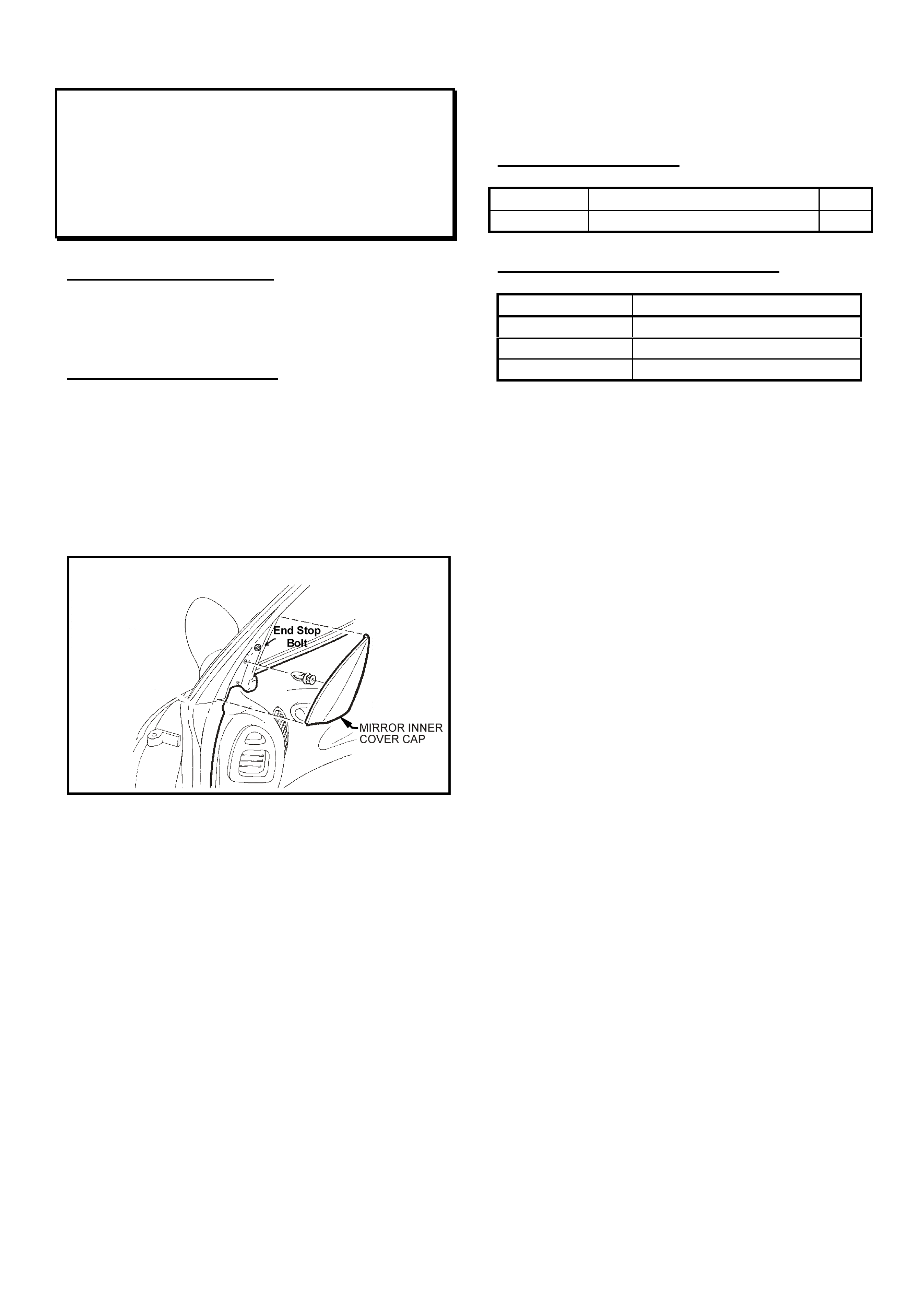
HOLDEN SERVICE TECHLINE _________________________________________________________________ AUGUST 1999
3
FRONT DOOR GLASS NOT FULLY
COVERED BY DOOR GLASS WEATHER
STRIP SEALING LIP
VT
(GRO UP 1)
PROBLEM DESCRIPTION
When the left-hand front door glass is in the full
‘up’ position, the weatherstrip sealing lip does not
cover the top of the glass along its ent ir e length.
SERVICE RECTIFICATION
To improve the condition, adjust the glass using
the f ollowing procedur e:
1. Remove the left-hand mirror inner cover cap.
The clip should be replaced.
2. Pull back the grey foam covering the end
stop bolt.
Figure 1: (Right-side shown)
3. Loosen the bolt and lower the window.
4. Move the end stop towards the top of the
stop and tight en.
5. Locate the door frame window stop bolt at the
rear of the doorframe and loosen with an
Allen key.
6. Wind the window up until the top edge of the
glass preloads the weatherstrip or when the
glass reaches it’s full travel.
7. Tight en t he window stop.
8. Once adjustment is complete, replace the
inner cover mirror clip, reposition the foam
and and ref it the inner mirror cover.
Note: When performing this adjustment, be
mindful of the aff ect that this adjust ment will have
on other issues such as door closing ef forts and,
wind noise and water leaks at other points
around the glass perimeter. It may be necessary
to repeat t he pr ocedur e, adjusting the stops
several times to ensure the best coverage
around the complet e glass perimeter is achieved.
PARTS INFORMATION
Part No.: Description: Qty:
90459628 Mirror I nner Cover Clip 1
WARRANTY CLAIM INFORMATION
Description Adjust Window Stops - LHS
Labour Op. No. C000376
Time 0.5 hr
Failure Code 26
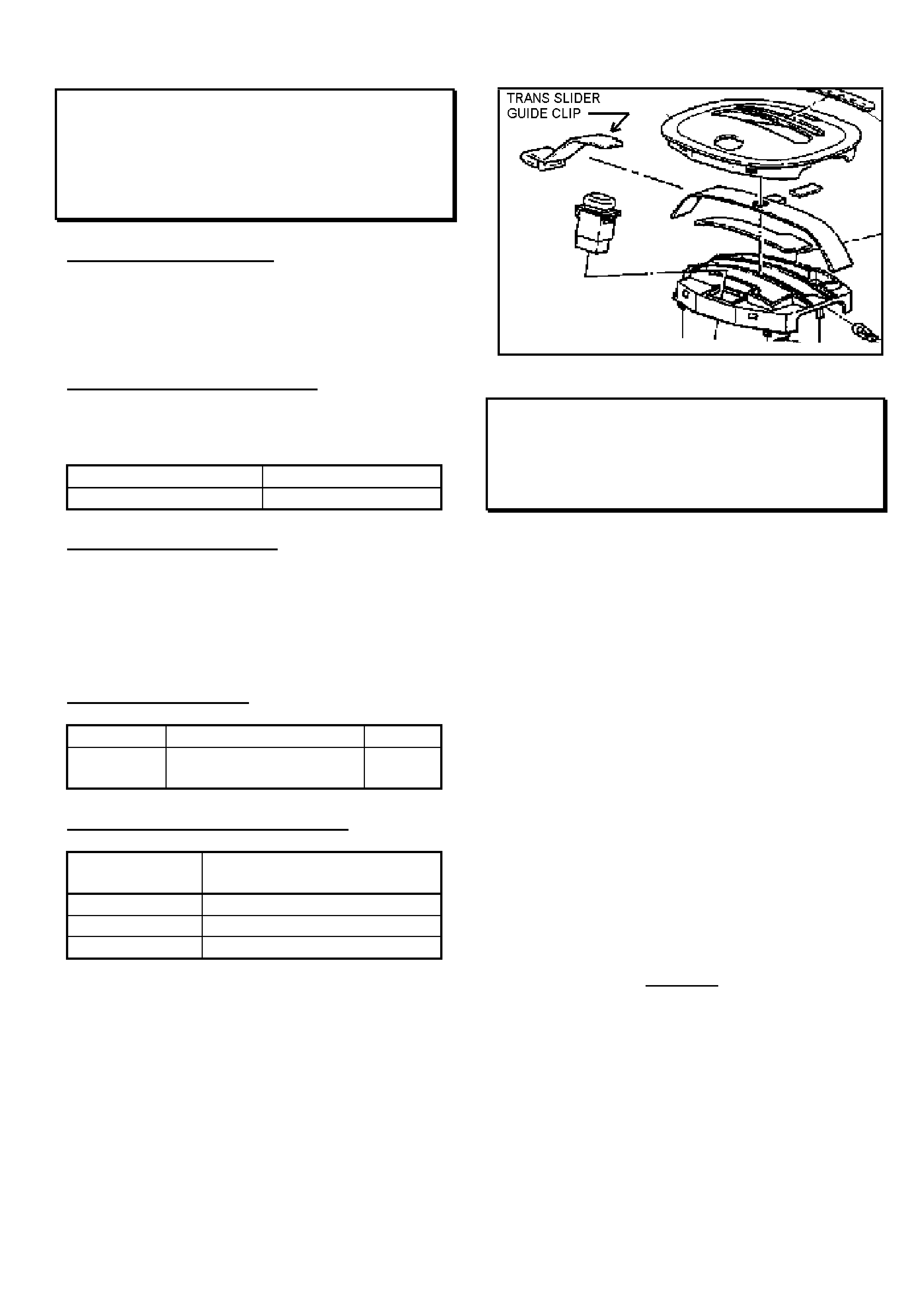
HOLDEN SERVICE TECHLINE _________________________________________________________________ AUGUST 1999
4
“CLUNK” WHEN SELECTING “PARK”
FROM THE CONSOLE AREA
VT wi th A/T
(GRO UP 7B)
PROBLEM DESCRIPTION
Complaints of a “clunk” noise heard when
selecting Park range. This condition may occur
when the Transmission Slider Guide has not
been fitted.
PRODUCTION RECTIF ICATION
A revised design was introduced into production
at the following breakpoint:
ISOVIN: Build Date:
6H8VTK35HXL447038 13/04/99
SERVICE RECTIFICATION
If complaints of a “clunk noise when selecting
Park” are received, on a vehicle built prior to the
above ISOVIN number, check for the pr esence of
a Transmission Slider Guide Clip. Fit the guide
clip if m issing.
PARTS INFORMATION
Part No.: Description: Qty:
92059509 Trans. Slider Guide
Clip 1
WARRANTY CLAIM INFORMATION
Description Scale, Trans. Cont. -
Replace
Labour Op. No. K508100
Time 0.8 hr
Failure Code 29
SPARK PLUG SERVICING
VT II & WH, Gen III Engine
(GRO UP 6Y)
This bulletin is to advise technicians of specific
precautions to observe, regarding spark plug
removal and installation, when servicing the VT I I
& WH Series vehicles with Gen III V8 engine.
The information is provided following queries on
spark plug removal, raised during recent product
training schools, when the importance of allowing
engines to cool down prior to any threaded
fast ener r em oval was covered.
Always allow the engine to cool before removing
the spark plugs. Attempting to remove spark
plugs from a hot engine may cause the
plug/cylinder head threads to bind, causing
tearing of the cylinder head threads.
The relevant servicing information which will be
of use to technicians is published on Page 2, for
ease of copying and distribution to technicians
and other inter est ed Dealership staff.
This information – additional to that provided by
the VT II & WH Service Manuals – has been
provided by GM Powertrain.
It is suggested that you place a copy of the
following page (Page 8) in your VT Service
Manual, Volume 14A, Section 6D3-3 - Ignition
System – Gen III V8, for permanent reference.

HOLDEN SERVICE TECHLINE _________________________________________________________________ AUGUST 1999
5
GEN III V8 ENGINE SPARK PLUG SERVICING
– VT II & WH MODELS
NOTE: ALLOW ENGINE TO COOL BEFORE REMOVING THE SPARK PLUGS. Attempting to remove
the spark plugs from a hot engine may cause the plug/cylinder head threads to bind, causing tearing of
the cylinder head threads.
NOTE: CLEAN THE SPARK PLUG RECESS AREA BEFORE REMOVING THE SPARK PLUG. Failure
to do so could result in engine damage because of dirt or foreign material entering the cylinder head, or by
the contaminat ion of the cylinder head thr eads. T he contam inated t hreads may prevent the proper seat ing
of the new or replaced spark plug. Use a thread ‘chaser’ to clean the threads of any contamination –
where contamination is suspected.
NOTE: W HEN REMOVING SPARK PLUG LEADS – O nly handle the boot on each lead. DO NOT pull on
the lead itself. Twist the boot first to break the seal, then pull to r emove.
Spark Plug Replacement
Removal Procedure
1. Remove engine dress cover retaining nuts (4), then r emove cover.
2. Remove spark plug lead/s.
3. Loosen spark plug and then re-tig hten before r emoving any further. This is necessary to break
away any carbon build-up on the spark plug thread, which may otherwise cause damage to the
thread in the alum inium cylinder head.
4. Loosen spark plug one to two turns.
5. Brush or use compr essed air t o r emove any dirt around spark plug/s.
Refitting
1. Inspect the spar k plug gap/s. Adjust gap to 1.5mm if needed.
2. Hand start t he spar k plug/s in the cylinder head thread.
3. Tight en t he spark plug/s:
Torques:
• On NEW Cylinder Heads ONLY: 20Nm
• On ALL SUBSEQUENT INSTALLATIONS: 15Nm
4. Refit spar k plug lead/s.
5. Refit engine dress cover.
Please place a copy of this information in your VT Service Manual, Volume 14A,
Section 6D3-3 - Ignition System – Gen III V8, for permanent reference
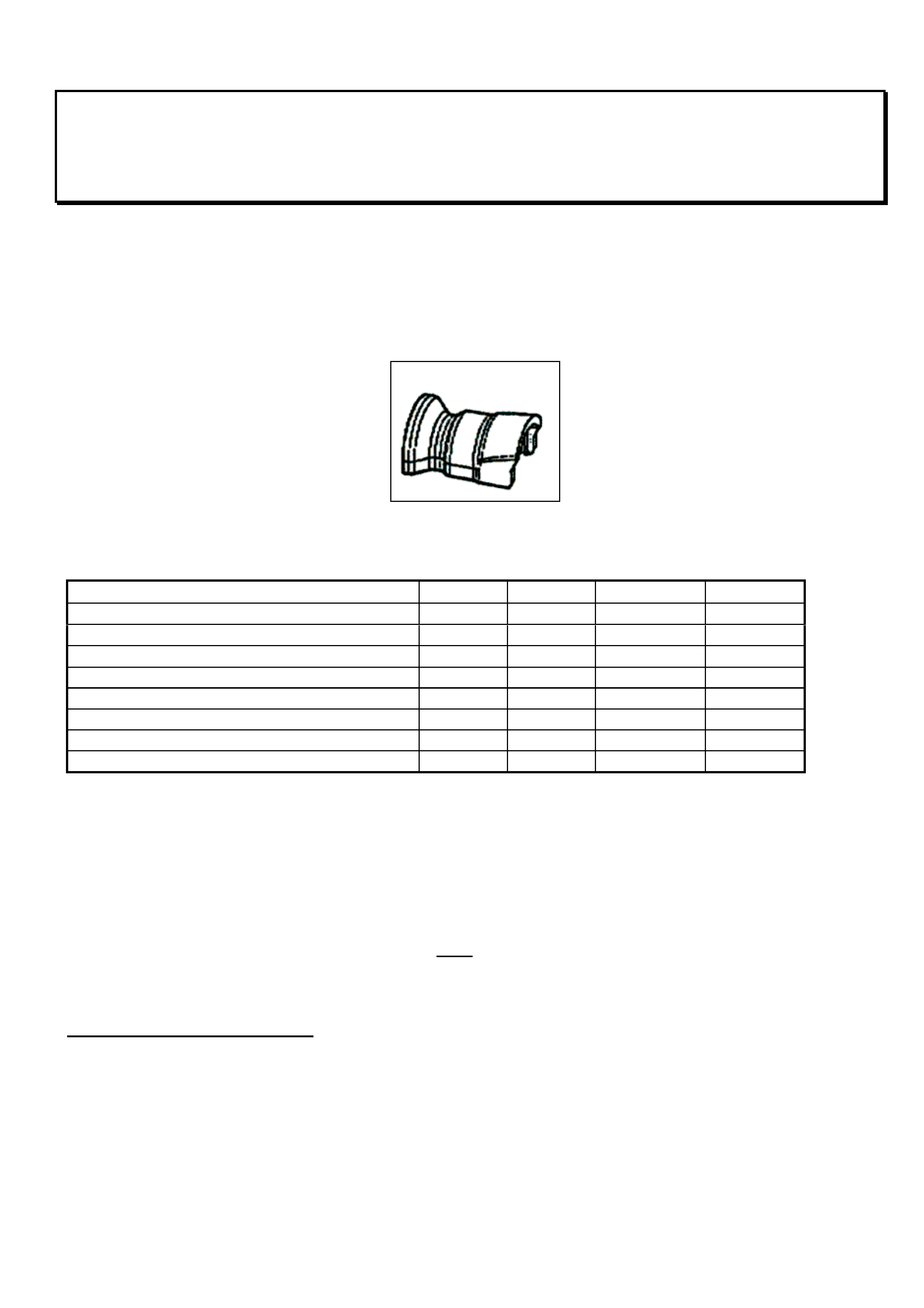
HOLDEN SERVICE TECHLINE _________________________________________________________________ AUGUST 1999
6
FUEL SYSTEM SPECIAL REMOVAL TOOL
VT, WH
(GRO UP 6M)
Fuel systems quick connect fittings manufactured by “NORMA”, have been used in production on VT
Series vehicle fuel systems since 20/9/97. For these vehicles, Holden has introduced and distributed two
special tools to aid in the removal of fuel line / fuel filter connectors and other fuel lines at the rear of the
vehicle.
The tools ar e supplied in a set which contains a 5/16” (red tool, sm aller fit tings) and 3/8” ( blue tool, lar ger
fittings).
Fuel System Removal Tool
Refer t o t he Table below for t he locat ion and size of fittings for respective engines.
V6 V6(S/C) V8(5.0 L) V8(5.7 L)
Engine Bay
Purge Hose 5/16" 5/16" 5/16" 3/8"
Rear Of Vehicl e
Fuel Filter (Bot h Sides) 5/16" 5/16" 5/16" 3/ 8"
Fuel Feed (Forward Of Filter) 5/16" 5/16" 5/16" 3/ 8"
Fuel Return (Forward Of Filter) 5/16" 5/16" 5/16" N/A
Fuel Feed (Top of pump/sender asm.) 3/8" 3/8" 3/8" 3/8"
Fuel Return (Top of pump/sender asm.) 5/16" 5/16" 5/16" 3/8"
For Fuel Filter removal:
• Tak e appr opr iate safety precautions as document ed in t he VT Series Service Manuals.
• Use compressed air to remove any foreign material, grit etc. within the release mechanism of the
quick connect .
• Place the removal tool over the quick connect.
• Push t he tool and clip t owards the f ilter and then pull t he f uel line away from t he f ilt er to disconnect the
quick connect .
• Replace the fuel filter and reconnect pipe. Note: There is no clicking sound to confirm the clip has
seated on the filter. To test that the connection is f ully seated and retained, rotat e the filter while applying
a pull off load to the quick connect.
SPECIAL TOOL AVAI LABILITY
Tools are available f r om:
SNAP ON TO O LS: [Par t Number AUSP45] - For distributor information, call 1800 811 480.
SPX TO OLS: [Part Number AU533] – Phone (03) 9544 6222.

HOLDEN SERVICE TECHLINE _________________________________________________________________ AUGUST 1999
7
ON-CAR HUB MOUNTED BRAKE LATHES
ALL
(GRO UP 5)
PROBLEM DESCRIPTION
Recent Dealer visits have highlighted that some
Technicians are not setting up hub mounted on-
car brak e lat hes correctly prior to machining .
Most hub mounted brake lathes have an
adjustment to compensate for wheel hub runout
or stacked tolerances. If not correctly adjusted
technicians will inadvertently machine runout into
the brake disc. Technician’s and Sub-
Contractors must ensure that lateral runout at
the cutting tool is eliminated prior to
machining. Failure to correctly set-up the hub
mounted disc lathe will cause lateral runout t o be
machined into the disc and brake shudder will
reoccur.
A dial indicator must be used to ensure correct
compensation is made. Use the dial indicator
mounting incorporated on the brake lathe to
ensure lateral runouts are at a minimum prior to
machining. If the mounting is not available, the
technician must improvise, as it is essential to
use the dial indicator when setting up the brake
lathe.
After machining discs on car, technicians must
validate the process by checking the runout of
the disc. DO NOT remove the disc from the hub
after machining. Reverse the wheel nuts, secure
the disc to the hub and check for disc / hub
installed runouts.
For furt her infor mat ion on the operation or set ting
up of your dealerships particular brake lathe,
contact the manufacturer or supplier of the
equipment for advice. If aftersales support is not
available, please phone Paul Rietveld at Holden
on (03) 9647 2823 (Holden Service Depart m ent).
Dealerships considering purchasing on-car brake
lathes should ensure caliper mounted t ype lathes
are trialled, such as the Far relly Bros. Disc Lathe
which will machine front and rear discs on VT
Series vehicles with minimal set up time. Ian
Miller from Far relly Bros. can be contacted on:
Phone: (03) 9336 1870 or FAX: (03) 9336 2554.

HOLDEN SERVICE TECHLINE _________________________________________________________________ AUGUST 1999
8
INJECTION TIMING ADJUSTMENT
RODEO with 4JB1T
(GRO UP 6M)
Current model Rodeo vehicles equipped with the 4JB1-T engine have six timing marks on the
crankshaft pulley as opposed to the four pictured in the workshop manual.
The following diagram should be used to update the current manual by inserting the extra two
marks in the relevant picture (Section 6A, Page 28) in a permanent marker.
Once workshop manuals have been updated, checks \ adjustment of the pump tim ing should be
done as per the workshop manual procedure.
0 4 10 12 14 16
REVISED E NGINE CRANKS BUT WILL NOT RUN PROCEDURE
JACKAROO with 4JX1T
(GRO UP 6M)
Engine Cranks But Will Not Run
Step Action Value Yes No
1 Was the “on board diagnostic (OBD)
system check” performed? - Go to step 2 Go to OBD
system check
2 Check the 15A stop light fuse and in the
engine compartment fuse panel the 15A
and 50A ECM fuses. Was a fuse blown?
- Go to step 3 Go to step 4
3 Check for a short to ground and replace
the fuse. Is action complete ? - Verify repair -
4 Is fuel tank em p t y? - Fill f uel tank Go to step 5
5 Is the right fuel being used? - Go to step 6 Replace fuel
6 Is the right engine oil being used? - Go to step 7 Replace
engine oil
7 Using the tech 2.
Is DTC P0192 or P0193 set? (check rail
pressure system)(Must have 4Mpa m in.)
- Go to DT C
P0192 or
P0193
Go to step 8
8 Using the tech 2.
Is DTC P0201 - P0204 set? (check
injector circuit fault)
-Go TO DTC
P0201-
P0204
Go to step 9

HOLDEN SERVICE TECHLINE _________________________________________________________________ AUGUST 1999
9
Step Action Value Yes No
9 Using the tech 2.
Is DTC P1657 set? (check ECM main
relay)
-Go to DTC
P1657 Go to step 10
10 Refer to Engine Mechanical Diagnosis to
diagnose the following conditions:
• Faulty camshaft drive belts
• Leaking or sticky valves or rings
• Excessive valve deposits
• Weak valve springs
• Incorrect valve timing
• Leaking head gasket
Is the action complete?
- Verify repair Go to step 11
11 Observe the engine speed data display
on the tech 2 while cranking the engine.
Is the engine RPM indicated?
- Go to step
23 Go to step 17
12 Using a digital multi-meter set on AC
volts, connect between ECM J3-5 and
one of the injector driver circuits and
crank engine.
Is there a voltage of approx. 4 volts?
- Go to step
13 Go to step 15
13 Using a digital multi-meter set on ohms,
check for a short to ground in the injector
driver circuits.
- Go to step
14 Go to step 16
14 Locate and repair the short to ground in
the injector driver circuit.
Is the action complete?
- Verify repair -
15 check for an open injector driver circuit.
Is the action complete? - Verify repair Go to step 16
16 Replace the ECM
Is the action complete? - Verify repair -
17 1. Disconnect the CKP sensor harness
2. Turn ignition on.
3. With a test lamp to ground, probe the
sensor
harness ignition feed terminal.
Did the test lamp illuminate?
- Go to step
19 Go to step 18
18 Check the ignition feed wire between the
sensor and the ECM for a short to ground
or open circuit.
Is the action complete?
- Verify repair -
19 Ignition on.
At the CKP harness connector, connect a
test light between the ignition and ground
terminals.
Did the ligh t illuminate?
- Go to step
21 Go to step 20
20 Check the sensor ground circuit for an
open or short to voltage.
Is the action complete?
-Verify
Repair -

HOLDEN SERVICE TECHLINE _________________________________________________________________ AUGUST 1999
10
21 Check the signal circuit between the
sensor and the ECM for a short to
ground, short to voltage or an open
circuit.
Was a problem found?
-Verify
Repair Go to step 22
Step Action Value Yes No
22 Replace the CKP sensor.
Is the action complete? -Verify
Repair Go to step 23
23 1. Disconnect the CMP sensor harness
2. Turn ignition on.
3. With a test lamp to ground, probe the
sensor
harness ignition feed terminal.
Did the test lamp illuminate?
- Go to step
25 Go to step 24
24 Check the ignition feed wire between the
sensor and the ECM for a short to ground
or open circuit.
Is the action complete?
-Verify
Repair -
25 Ignition on.
At the CMP harness connector, connect a
test light between the ignition and ground
terminals.
Did the ligh t illuminate?
- Go to step
27 Go to step 26
26 Check the sensor ground circuit for an
open or short to voltage.
Is the action complete?
-Verify
Repair -
27 Check the signal circuit between the
sensor and the ECM for a short to
ground, short to voltage or an open
circuit.
Was a problem found?
-Verify
Repair Go to step 28
28 Replace the CMP sensor.
Is the action complete? -Verify
Repair -
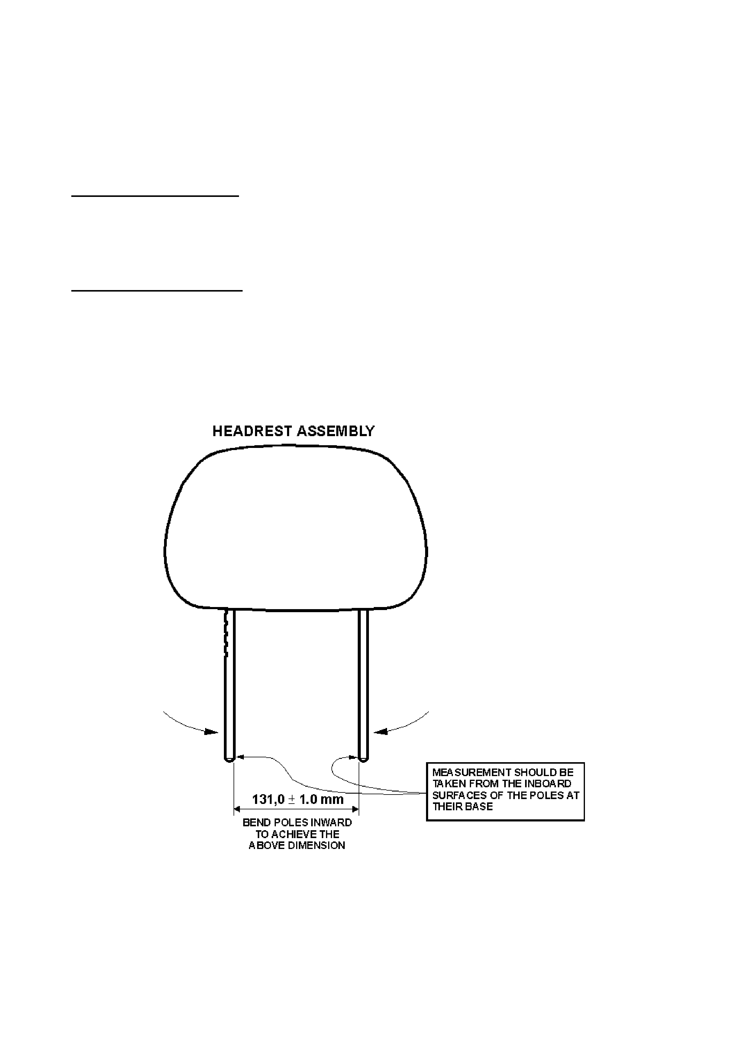
HEAD RESTRAINT RATTLE
VT
(GROUP 1) September 1999
PROBLEM DESCRI PTION
The front seat head restraint rattles when travelling over rough surfaces. The rattle usually
emanates from an unoccupied passenger seat.
SERVICE RECTIFICATION
1. Remove the headrest from the seat.
2. Bend poles inward at the bottom to the dimension of 131.0 1 mm as indicated in Figure 1.
3. Ref it the headrest to the seat.
4. Check the operation of the headrest, and verify the rattle has been eliminated.
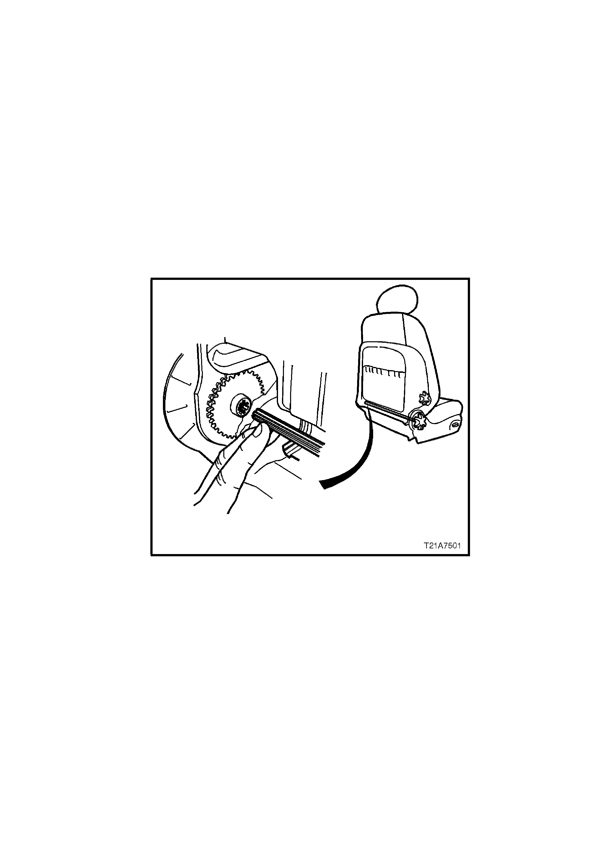
FRONT SEAT RECLINER SHAFT AND KNOB INSTALLATION
VT
(GROUP 1) September 1999
Whenever reinstalling the front seat recliner shaft and knob assembly, ensure the splines on the
shaft are aligned correctly, as per the following procedure:
NOTE: Do not force the recliner shaft into the recliner shaft sleeve until the splines are aligned
correctly as this will damage the plastic recliner shaft sleeve.
1. With your fingers inserted between the seat back cover and the seat back, on the inboard side
of the front seat, align the splines by guiding the recliner shaft into the recliner shaft sleeve.
2. With the recliner shaft aligned and seated in the recliner shaft sleeve, firmly press on the
recliner knob until the recliner knob snaps into position (a click will be heard).

FRONT SEAT ROCKING
VT (applicable to height adjustable seats)
(GROUP 1) September 1999
PROBLEM DESCRI PTION
A small rocking movement is felt in the seat when accelerating or braking or when deliberately
rocking the sea t.
PRODUCTION RECTIFICATION
A heavy spring has been fitted from the seat motor bracket to the track upper rail to address the
rocking condition. Refer Figure 1. Early build VT Series vehicles had no spring or only a very lig ht
spring fitted.
ISOVIN Breakpoint: Build Date:
6H8VTK69MXL407830 01/12/98
SERVICE RECTIFICATION
1. Raise the seat fully.
2. Remove the front seat inner and outer side covers as described in the VT Series I Service
Manual, Section 1A7. If the seat outer cover retaining clips break during the removal process,
replace the seat outer side cover.
3. Referring to Figure 1, locate and remove the existing smaller gauge spring (if fitted) and
discard.
4. Insert one end of the revised spring, P/N 92143092 into hole 1 and using pliers, pull the other
end and hook into hole 2.
5. Reinstall the front seat recliner shaft and knob. Refer to the item in this techline,
‘FRONT SEAT RECLINER SH AFT AND KNOB INSTAL LATION’.
Refit the inner and outer seat side covers.
PARTS INFORMATION
Part No.: Description: Qty:
92143092 Spring – Seat Height Adj. 1
WARRANTY CLAIM INFORMATION:
Description Fit Spring – Seat Height Adj.
Labour Op. No. C000385
Time 0.6 hr
Failure Code 27
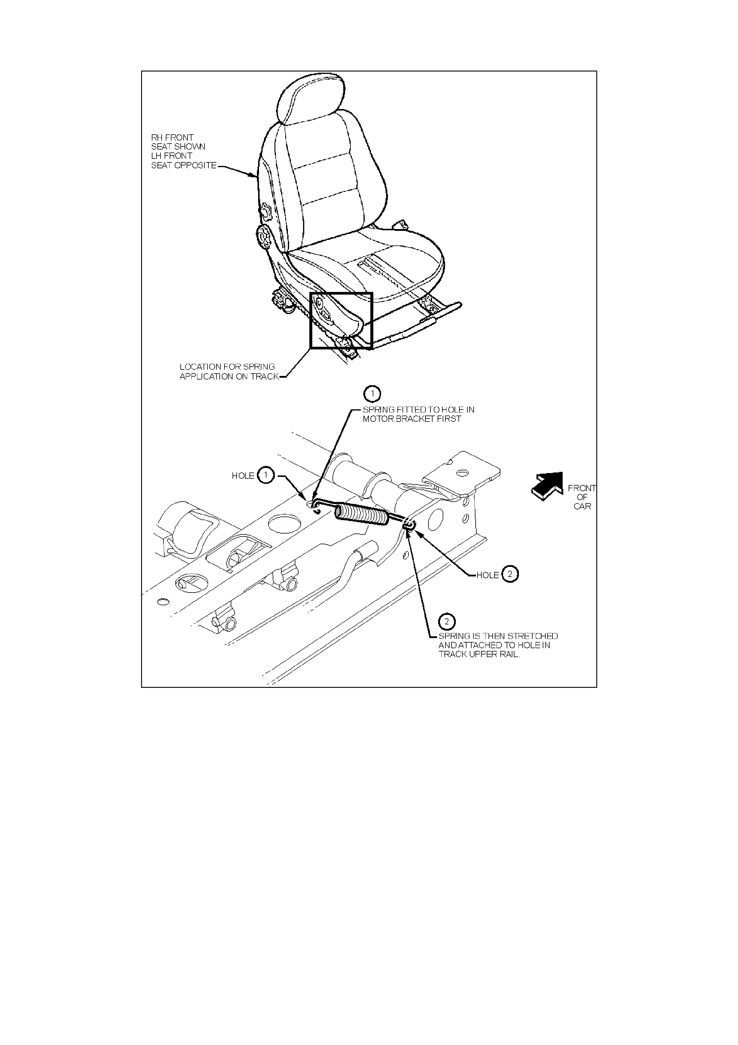
Figure 1
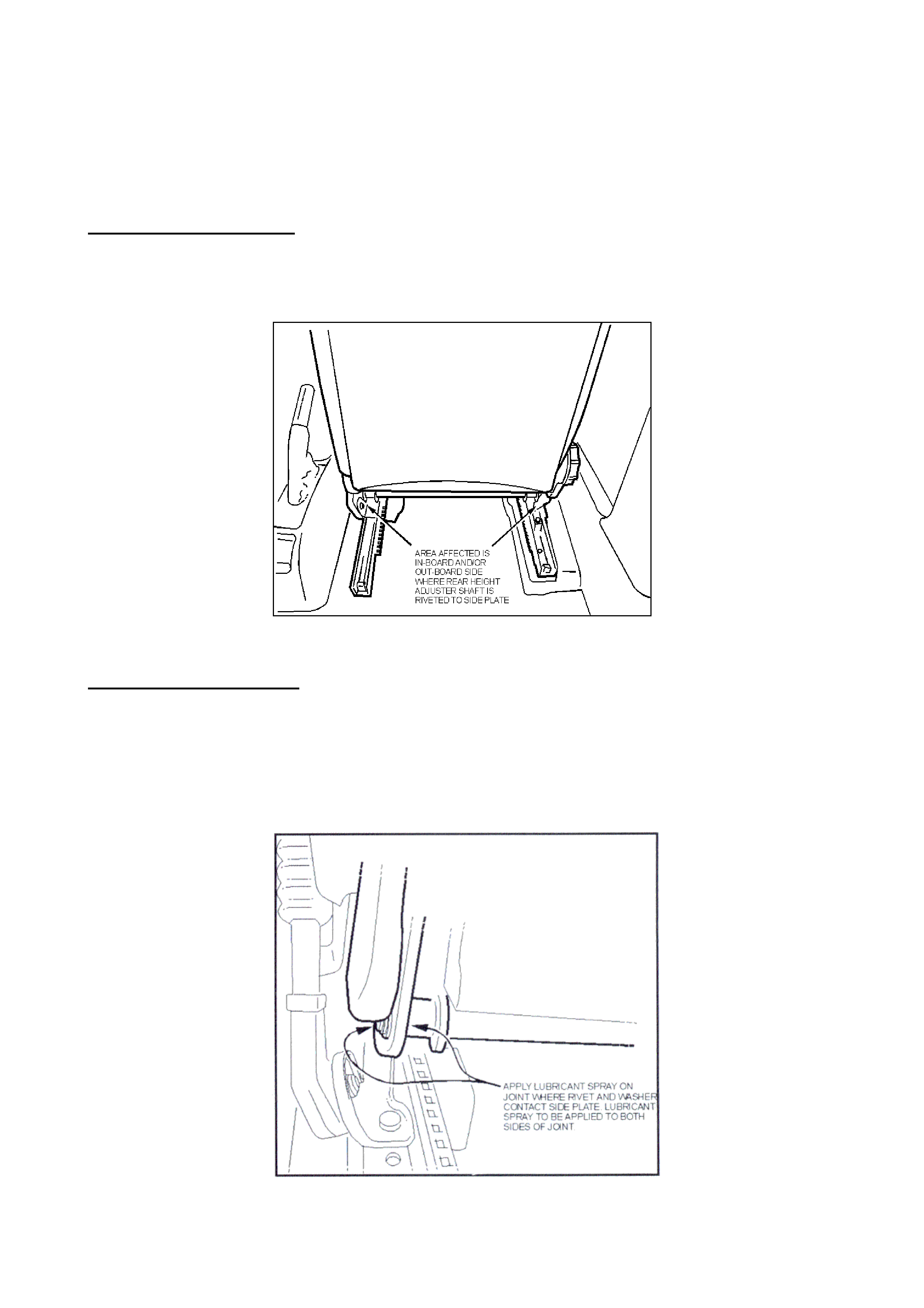
FRONT SEAT HEIGHT ADJUSTER CREAK
JR, JS
(GROUP 1) September 1999
PROBLEM DESCRI PTION
A creaking noise may be heard from the drivers’ seat when cornering as a result of insufficient
lubrication in the height adjuster mechanism joints.
Figure 1
SERVICE RECTIFICATION
Spray lubricant in the affected areas as indicated in Figure 2. Use a product such as MolyKote.
G-Rapid Spray which is a molybdenum disulfide aerosol which is packaged with an appropriate
applicator. Other t ypes of spray grease may not have the viscosity to provide long term lubrication.
Molykote G-Rapid Spray is available from outlets such as BSC Motion technology (ex Bearing
Service Centre) and Blackwoods and Sons.
Figure 2

EMBEDDED SE CURITY SYSTEM
HSV- VT SERIES II and WH
(GROUP 12) September 1999
HSV has introduced a new Embedded Security System (ESS) on all VT Series II and HSV WH
vehicles.
In the event of a vehicle non-start and after initial diagnostic checks have been performed the
dealer should contact Greg Warfe at Australian Arrow on the number below:
Telephone: (03) 9785 0792
Facsimile: (03) 9775 0954
Australian Arrow manufactur es the ESS system and will provide specialised diagnostic assistance
over the phone. A specific diagnostic check sheet may be forwarded to dealerships to further
assist in determining the “root cause” of the problem.
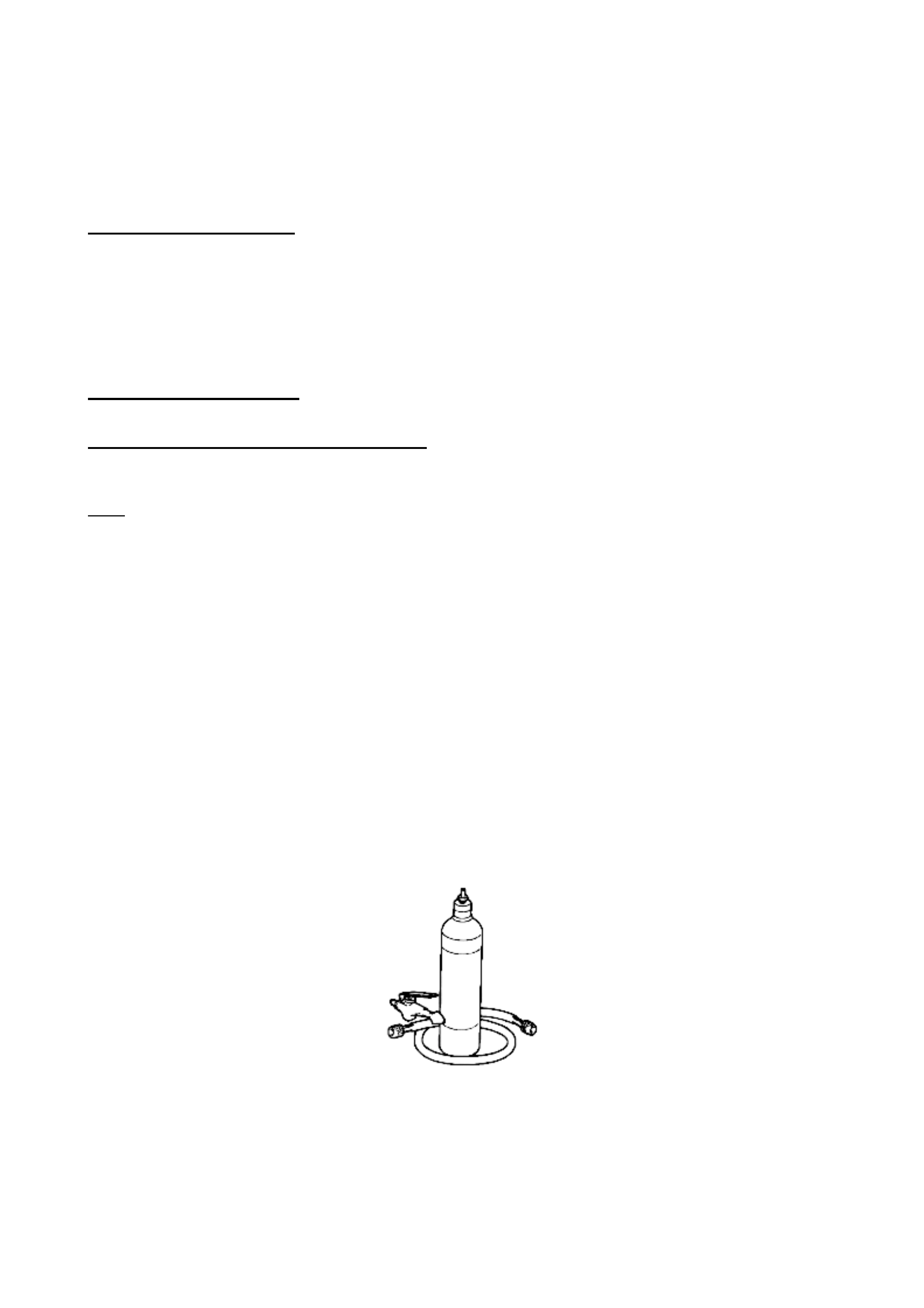
A/C COMPRESSOR, REPEAT FAILURES
1994 GMC AMBUL ANCE (6.5L DIESEL)
(GROUP 2) September 1999
PROBLEM DESCRI PTION
Repeat failure of the A/C compressor due to contaminants in the a/c system from previous
compres s o r fail u re s.
To avoid repeat compressor failures the following service procedure must be followed.
SERVICE RECTIFICATION
Component replacement and/or Flushing:
On any vehicle that has experienced major compressor failure the following system components
must be replaced and the remaining components i.e. evaporator and condenser, thoroughly
flushed, to prev ent repeat failures .
1. Compressor (and included seal washer kit)
2. Accumulator
3. Suction & Discharge Hoses & O-Rings (ex JAKAB Industries)
4. Orifice Tube (located at the condenser outlet)
5. Associated O-rings
6. PAG oil
See ‘Parts Information’ on next page for specific part numbers.
It is essential that the condenser and evaporator be thoroughly flushed of all oil and contaminants
prior to re-assembly. Flushing solvent such as ‘Gensol’ (Forane 141B) should be used with
compressed air to flush the system. ‘Gensol’ is available from C.I.G. and the flushing equipment
(see Figure 1) can be purchased from any auto air conditioning equipment supplier.
Figure 1: Typical flush gun and tank
Components should be flushed and then reverse flushed (opposite di rection of normal flow).
NOTE: Oil “balancing” will not be necessary once all the existing oil in the system is removed.

Condenser Cleanliness
The condenser must be checked for any organic debris or fin damage that will block airflow. Any
debris should be carefully removed from the front of the condenser. If the condenser is
excessively damaged or heavily impreg nated with organic debris, it should be replaced.
Re-assembly, Oiling and Refrigerant Charging:
•Add 265 ml (9 oz) of PAG oil and an appropriate R134a leak dye to the new compressor. The
leak dye will leave a ‘smoking gun’ trail in the event of a refrigerant leak.
NOTE: Many Delphi R-4 compressor failures can be attributed to refrigerant leaks that
cause a low system charge and hence restricts the amount of oil that returns to the
compressor.
•Re assemble all components.
•Evacuate the system and recharge with 900 grams of R134a refrigerant.
•Check for refrigerant leaks.
•Run the system and check for normal operation.
PARTS INFORMATION
The following parts are available through HSPO:
Part No.: Description: Qty
1134343 Compr essor Assembly – R134a 1
2724818 Accumulat or – A/C 1
52450548 Pressur e Relief O-r ing 1
3096068 Orifice Tube 1
52466778 O-ring ½” Tube Diameter 1
12345923 PAG r efr igerant Oil 1
The following parts are to be obtained through:
JAKAB Industries
PO Box 614 (Cook Street)
Tamworth, NSW 2340
Phone: (02) 6765 4155
Fax: (02) 6762 1546
Part No.: Description: Qty
47-1730 Discharge Hose & O-rings 1
48-1729 Suction Hose & O-Rings 1
WARRANTY CLAIM INFORMATION:
Use existing warranty claim procedures.

HARD START ON LPG
VT, V6 & A/T (LPG)
(GROUP 6C) September 1999
PROBLEM DESCRI PTION
Concern has been raised regarding intermittent hard starting on vehicles fitted with Option KL7 (LPG),
when LPG is selected.
PRODUCTION RECTIF ICATION
Memcals for VT, V6, LPG with revised calibration, which will correct this condition, were introduced
into production at:
ISOVIN: Build Date:
6H8VTK69HXL428799 17/02/99
SERVICE RECTIFICATION
Complaint vehicles built prior to the above breakpoint, can be rectified by installing the revised
Memcal.
NOTE: It is a characteristic of the LPG system, that if the engine stalls during an LPG start, the
solenoids will close after 3 seconds (as a safety precaution) and will not open again unless the ignit ion
is cycled off and on. W ithout cycling the ignition switch, the engine will not start, no matter how long it
is cranked.
Where customers complain of this condition, they should be advised to turn the ignition key fully off,
wait a few seconds, then turn the key on again and start the engine.
PARTS INFORMATION
Part No.: Description: Qty
16262785 Memcal – V6 (LPG), A/T
Code: CXWJ 1
WARRANTY CLAIM INFORMATION:
Description Fit Hard Start Memcal
Labour Op. No. J000622
Time 0.4 hr
Failure Code 83

COLD START HESITATION or STALL
VT, V6 & A/T (Petrol)
(GROUP 6C) September 1999
PROBLEM DESCRI PTION
Incidences have been reported of engine hesitation, poor performance or poor engine response –
when vehicles are started from cold.
In rare cases, an engine stall may result - at first throttle opening - and “Clear Flood” procedure
may be required to restart the engine.
These conditions are no longer noticeable after
1-2 minutes with the engine running.
Manual Trans. vehicles are not affected.
PRODUCTION RECTIF ICATION
Revised memcals with revised calibration, which will correct this condition, have been fitted to
vehicles from introduction of VT Series II vehicles as follows:
ISOVIN: Build Date:
First VT II , V6, A/T Built:
6H8VTK35HXL464495 31/05/99
First VT II, S/C V6, A/T Built:
6H8VTX69SXL456596 07/05/99
First VT II , LPG V6, A/T Built:
6H8VTK35HXL462081 21/05/99
SERVICE RECTIFICATION
Where this condition is reported, replace the vehicle’s existing memcal with a new memcal as
noted below.
PARTS INFORMATION
Part No.: Description: Qty
16262780 Mem c al – V6 ( non-S/C), A/T
Code: CXWB 1
16262784 Memcal – S/C V6, A/T
Code: CXWH 1
16262785 Memcal – V6 (LPG), A/T
Code: CXWJ 1
WARRANTY CLAIM INFORMATION:
Description Fit Cold Start Hes. Memcal
Labour Op. No. J000622
Time 0.4 hr
Failure Code 47

SPARK PLUG USAGE CORRECTION
VS, VT, WH with S/C V6
(GROUP 6Y) September 1999
PROBLEM DESCRI PTION
The type of spark plug used in Supercharged V6 engine has been changed in production during
the introduction of VT Series II. The previously used AC 41-919 (Platinum tipped) spark plug has
been replaced by an NGK BPR6EF “V-Groove” type spark plug for both original equipment and
service.
NOTE: Spark plug numbers were NOT correctly specified in the VT Series II Service Manual,
Volume 14A, in the following sections:
- 6D1 - Ignition System – V6 engine
- 6F1 – Engine Tune - V6 engine (label)
- 6E1 – Emission Control - V6 engine (label)
Future updates of these Service Manual sections will carry corrected informat ion.
SERVICE ACTION
NGK BPR6EF Spark Plugs should be used as service replacements on ALL V6 S/C engines.
For Reference:
Spark Plug Gap: 1.3 mm +0.0/-0.1 mm
NOTE: NGK BPR6EFS Spark Plugs are ONLY to be used in normally aspirated V6 engines (the
“S” refers to standard plug).
Please correct your copies of VT Series II Service Manual Volume 14A by marking the correct
spark plug number in the above sections, so technicians do not replace V6 S/C spark plugs with
incorrect parts.

RESETTING SERVICE RE MINDE R FUNCTION
VT SERIES II
(GROUP 12) September 1999
Some dealers have reported that they are unable to reset the service reminder function on VT
Series II vehicles via the trip computer buttons. Minor revisions to the instrument cluster effective
from VT Series II start of production has resulted in the need to revise the reset procedure for
these vehicles.
Refer to the steps outlined below.
SERVICE RECTIFICATION
The resetting procedure is described below:
1. Turn the ignition OFF.
2. Hold down the trip computer ▲ and ▼ buttons together.
3. Turn the ignition ON while still holding down both buttons.
4. After approximately 3 seconds, release both buttons.
5. Press and release the “MODE” button, once only. The service due screen appears on the
display. (Do not hold this button down for an extended time period).
6. Press and hold both ▲ and ▼ buttons for approximately 3 seconds, until a beep is heard.
7. Release both buttons.
8. Turn ignition OFF.
The Owners Handbook will be altered accordingly at the next opportune time.
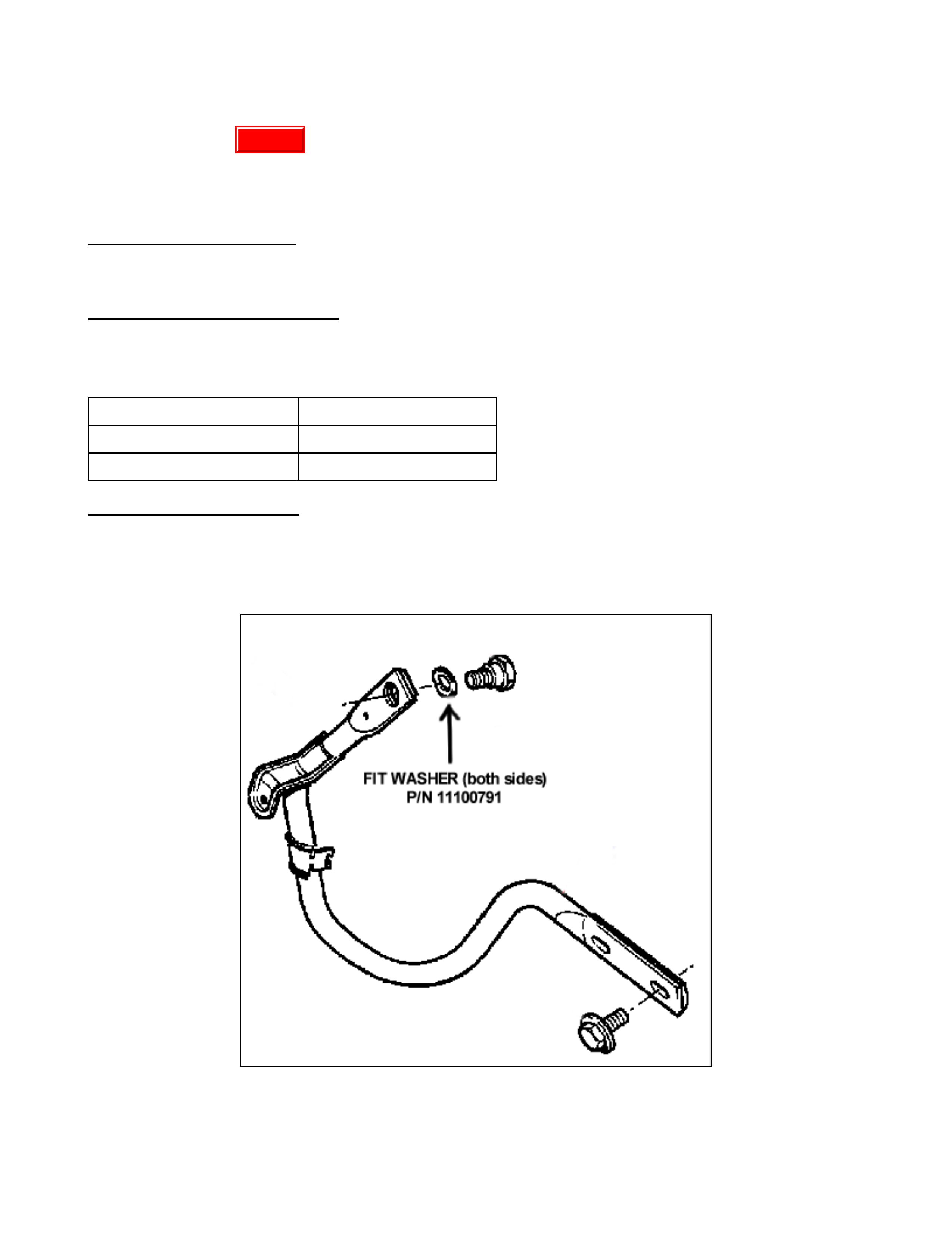
DECKLID BOUNCES AFTER OPENING
JR/JS (SEDAN)
(GROUP 1) October 1999
PROBLEM DESCRI PTION
Decklid ‘bounces’ when released af t er opening.
PRODUCTION RECTIF ICATION
Spring washers were introduced between the hinge and the pivot to increase friction to prevent
bouncing.
VIN: Build Dat e :
L482379 – local 22/07/99
W7154494 – import 17/08/98
SERVICE RECTIFICATION
Remove C-pillar trims and locate the decklid hinges. Remove collar screw and install spring washer
p/n 11100791 between hinge and pivot as indicated in Figure 1 (both hinges).
Replace removed components and check the operation of t he decklid.
Figure 1
Update

PARTS INFORMATION
Parts are expected in HSPO at the end of September.
Part No.: Descript i on: Qty
11100791 Washer – Spring , Hinge to
Panel Support 2
WARRANTY CLAIM INFORMATION:
Description Washer, Decklid Hinge - Replace
Labour Op. No. C000391
Time 0.6 hr
Failure Code 26
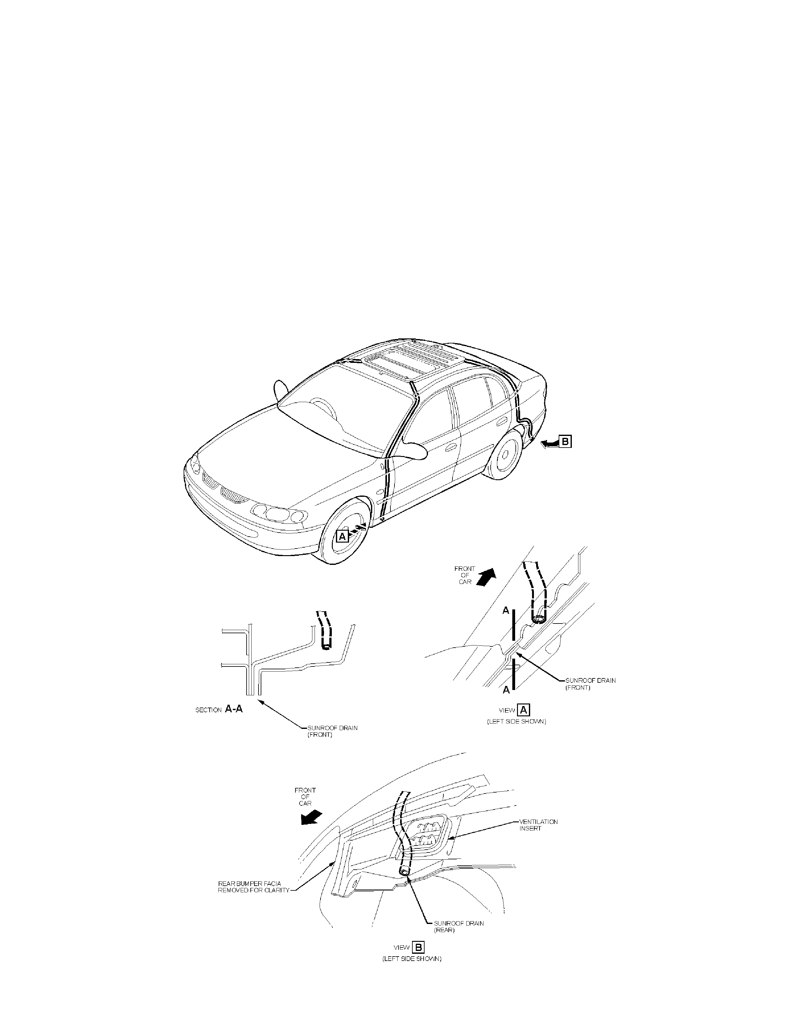
REGULAR SUNROOF DRAINAGE MAINTENANCE
VT
(GROUP 1) October 1999
To ensure all water that flows down the sunroof drainage tubes (connected to the sunroof cartridge)
exits the rock er panels, regular servicing of the outlet holes in the rocker panels is required.
The sunroof cartridge drainage tubes run down the ‘A’ and ‘C’ pillars. Refer to the figure below for
location of drainage holes.
The drainage holes need to be cleared of any mat erial that will inhibit the f low of water. If t he drainag e
holes do become blocked, water m ay rem ain in t he r ocker panels.
This service req uirement will be incorporated into the next owner’s handbook where applicable.

CENTRE REAR SEAT UNABLE TO RETURN TO THE UPRIGHT POSITION
VT WAGON
(GROUP 1) October 1999
PROBLEM DESCRI PTION
Investigations of wagon rear seats being unable to return to the upright position, have identified
damaged centre rear seat belt escutcheons as contributing t o the root cause. This allows the seat belt
‘stop’ button to pass through the escutcheon, causing the seat belt to fully retract and lock. This
prevents the seat from being returned to the uprig ht position.
PRODUCTION RECTIFICATIO N
A revised escutcheon with longer ‘guides’ has been fitted to vehicles from the breakpoint specified
below.
ISOVIN: Build Date:
6H8VTK35HXL491740 12/08/99
SERVICE RECTIFICATION
On complaint vehicles where the seat back cannot be returned to the upright position the following
procedure should be followed.
1. Remove the rear seat cushion as per VT ser vice manual, Volum e 1 section 1A7-23 refer 2.23
2. Remove the left hand bolster as per VT service manual, Volume 1 section 1A7-24 r efer 2.24
3. Gain access to the wagon rear seat back pivot. Detach the seat back pivot as described in VT
service manual Volume 1 section 1A7-25 refer 2.25
4. Gain access to the lower centre rear seat belt anchor mounting bolt. Remove the seatbelt
mounting bolt .
5. This will release the rear seat from the f olded position and allow the rear seatbelt to be retracted.
The f ollowing components should be inspected:
•Inspect the centre seat belt webbing to ensure that the upper button stop is still in place. If t he
button is damaged or missing, replace the seat belt assembly.
•If t he ‘stop’ button is still in place and the button is found to have passed throug h the escutcheon,
replace the escutcheon.
PARTS INFORMATION
Respective parts should be ordered through normal HSPO channels. All parts at HSPO are of the
latest manufacturer’s specification.

WARRANTY CLAIM INFORMATION:
W her e the seatbelt assembly req uires replacement, dealers should use existing inf ormat ion in Labour
Time Manual for r em oval and replacem ent of the seatbelt assem bly.
Where inspection and replacement of the seatbelt escutcheon is required dealers should use the
infor m ation supplied below.
Description Seat belt escutcheon - Replace
Labour Op. No. C000388
Time 0.6 hr
Failure Code 01

FLATSPOTTING OF TYRES
ISUZU ALL
(GROUP 10) October 1999
Flat spotting of tyres caused during vehicle storage and shipping is an ongoing problem in Australia.
This phenomenon has been noted where vehicles have been tightly secured and shipped over large
distances, and is further exacerbated by tighter st rapping and long term st orage.
Flat spotting of tyres alter s the ride and handling charact eristics; it m akes t he vehicle most unpleasant
to drive and affects customer sat isfaction as a result. Under inflation exacerbates the problem.
Dealers are advised not to rebalance tyres that are suspected of having flat spots, instead
tyres should be inflated to the recommended specifications and t he flat spot driven out of the
tyre. This could take in excess of 100km or more.
If t he pr oblem still persists after the above action please contact IGM TAS.
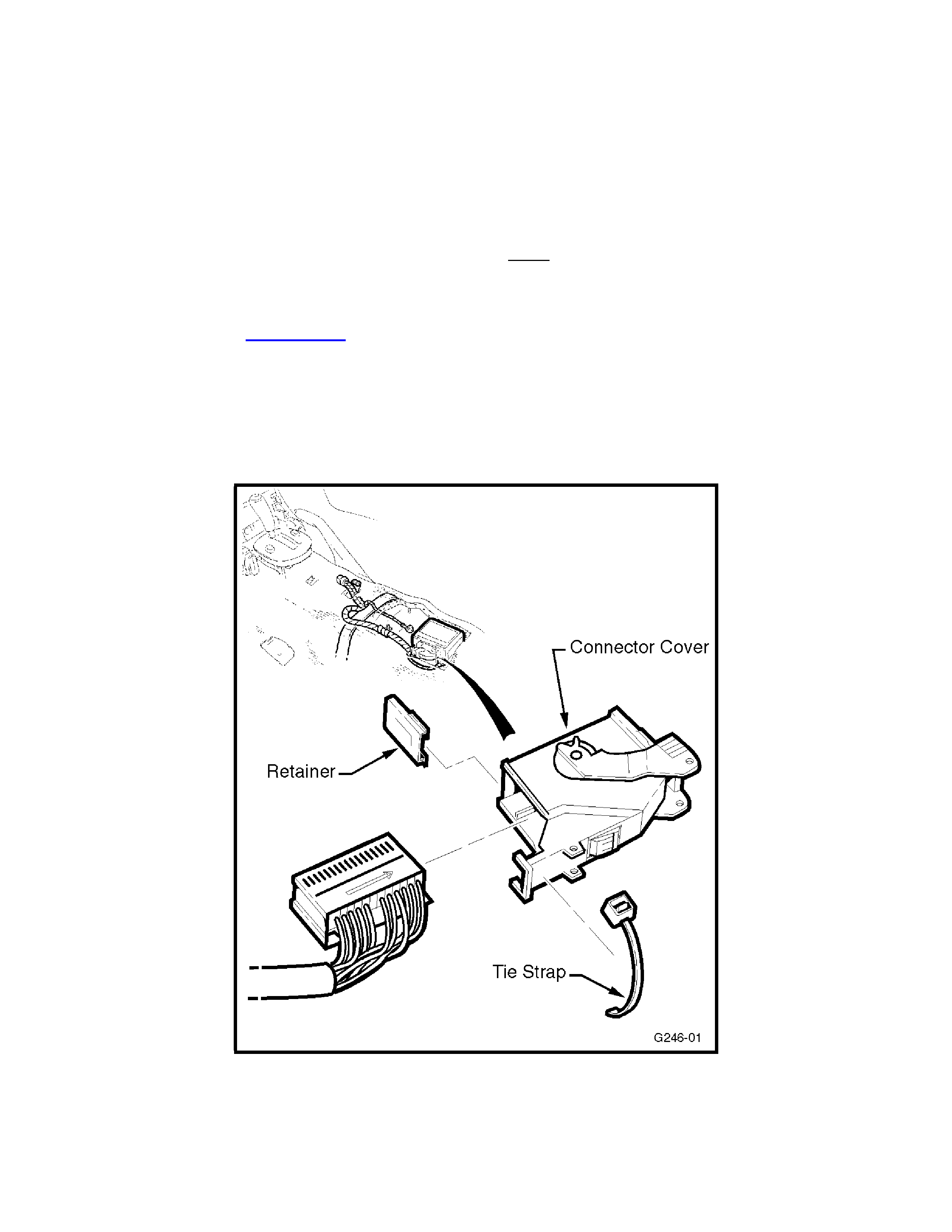
SDM MODULE CONNECTOR COVER
VT
(GROUP 12) October 1999
This Techline Service Bulletin is issued to advise the technicians t hat Holden has taken action to
seperately service the SDM (airbag) m odule connector cover.
This action was trig gered by reports that som e t echnicians were damaging the cover whilst removing
the SDM connector fr om the module, in which case an entire harness replacement was required.
In service, to disconnect t he airbag module connector, follow the procedures in the VT Ser vice
Manual, Volume 12, Section 12M , -34. Always release the lock ing lever before removing the
connector.
If t he connect or cover becom es dam aged:
•Snip off the tie strap
•Slide away the turquoise ret ainer
•Free the connector cover from the airbag module connector. Refer to Figure 1 below.
Note: T he r etainer is also separately serviced in case it is misplaced. See Part s I nformation.
Figure 1

PARTS INFORMATION
Part No. Description Qty
92143280 Cover - SDM connector
Driver / Pass Airbag 1
92143279 Cover - SDM connector
Side Airbag 1
92143289 Retainer 1
92060351 Tie Strap 1
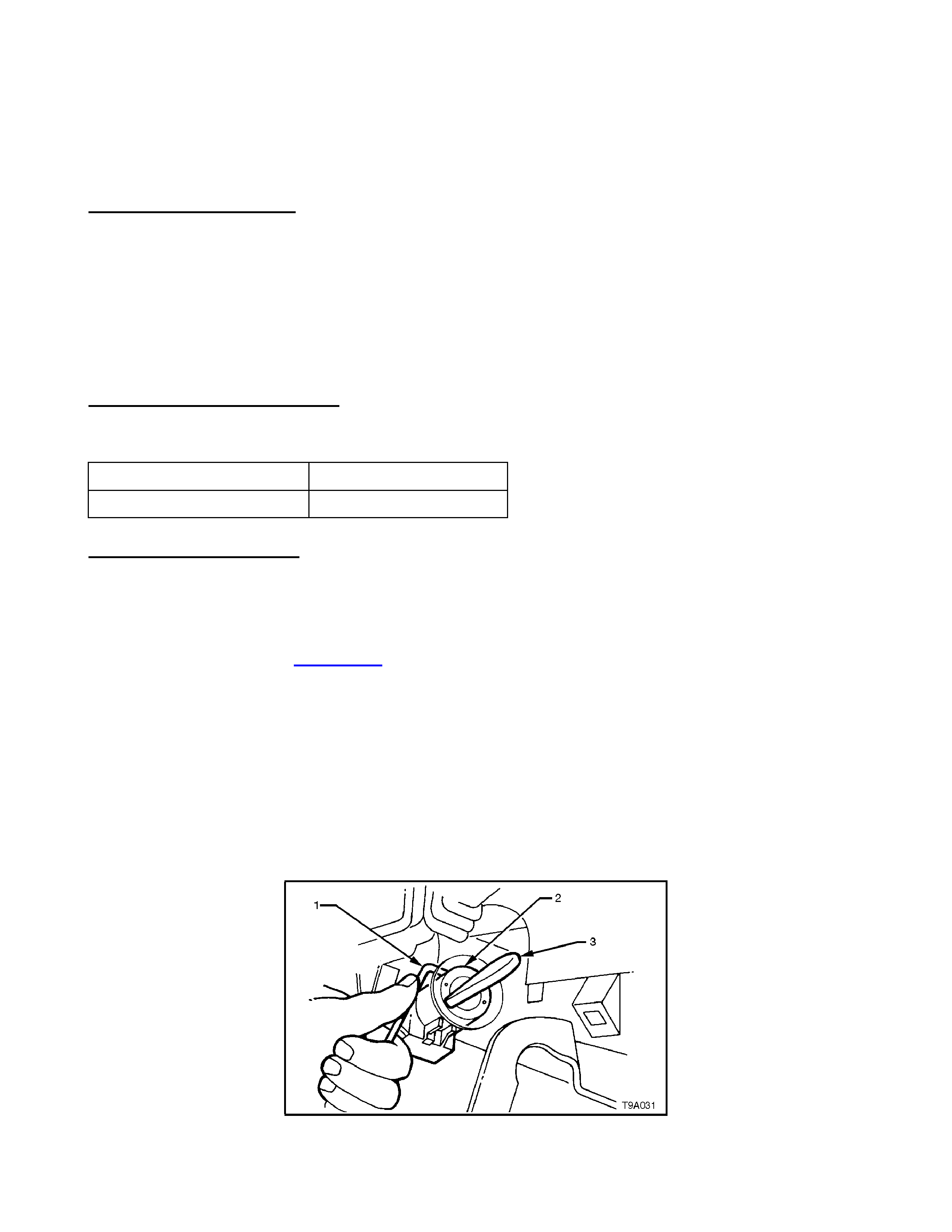
IGNITION BARREL STICKING
VT, VT SERIES II
(GROUP 12) October 1999
PROBLEM DESCRI PTION
Holden has been receiving PIR’s highlighting a condition where the ignition barrel is intermittently
jamming in the “CRANK” or “ON” position. This may lead to starter motor failure or instances where
the ignit ion cannot be r eturned to the “OFF” posit ion.
Investigat ions have shown that the pin and spring locat ed under t he dust shield cover, ref er to Figure
2, may become misalig ned causing the barrel to becom e j a m m ed in the “CRANK” or “ON” position.
The pin and spring are not required f or this applicat ion as these com ponents ar e carry over parts from
previous models.
PRODUCTION RECTIFICATIO N
Modified lock barr els with spring and pin removed have been fitt ed t o vehicles from:
ISOVIN: Build Date:
6H8VTL69HXL493701 16/8/99
SERVICE RECTIFICATION
If a vehicle is presented to the dealership with the key jamm ed in the barrel, tr y to manipulate the key
to the “ ACCESSO RIES” position. Th is will allow removal of the ignition barrel from its housing.
If the key cannot be freed, the entire steering column will need to be replaced. Refer to the VT
Service Manual Volume 5, Section 9A-20, 2.9 for Steering Column Replacement procedures.
For intermittent complaints, remove the spring (2) and pin (3) from the ignition barrel to eliminate the
cause of t he binding condition. Refer t o Figure 2. Follow the procedures as stated below.
Removal of igni t i on l ock barrel :
Refer to VT Service Manual Volume 5, Section 9A STEERING, -17. Follow Steps 1 to 11, then
continue with steps below:
12. Insert ignition key into barr el and turn to the ‘ACCESSORIES’ position, (3), as per Figure 1.
13. Insert a 2.5 mm diameter Allen key (1) into the locking pin hole, depress spring loaded barrel
locking lat c h t o r elease lock cylinder. Refer to Figure 1.
14. Remove Allen key and pull barrel ( 2) from lock housing.
Figure 1
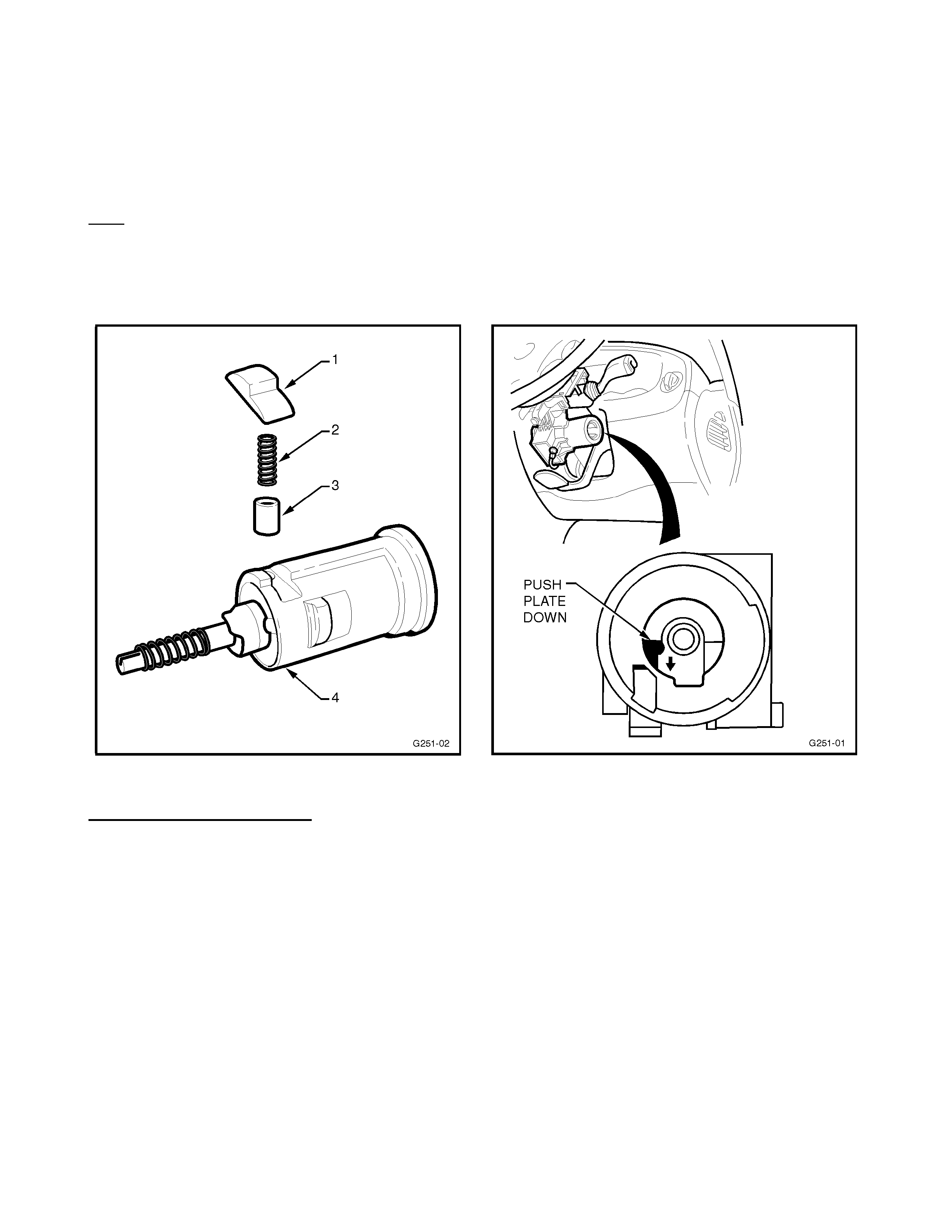
15. With barrel in hand ( 4), locate the plastic dust shield (1 ) as shown below. Remove the dust
shield, the spring (2) and pin (3).
16. Discard the spring and pin.
17. Reinstall the plastic dust shield.
Reinstall at ion of ignition l ock barrel :
Note: At this point you will notice the steer ing wheel is in the locked posit ion pr eventing the barrel from
being fully installed.
1. Using a small screw driver push the metal plat e down as shown in Figure 3 to free the steering.
2. Install ignition key into lock barrel and t urn key to the “ACCESSO RI ES” position.
3. Reinstall previously removed components.
Figure 2 Figure 3
WARRANTY INFORMATION
Use existing inf or mation in Labour Time Manual.

4JX1-TC DIESEL JACKAROO RADIO FILTER KIT
JACKAROO
(GROUP 12) October 1999
I – GM has released a radio f ilter kit (part number 92143177), to assist in t he reduction of AM radio
interference that may be experienced in some 1998 / 1999 diesel Jack ar oo vehicles fitted with the
4JX1-TC engine.
The inter ference is typically described as a buzzing noise that will increase relat ive to t hr ottle position.
E.g. as t he throttle is applied and the engine speed increases, the buzzing will increase in volume and
fr equency. However when the throttle is released t he buzzing will almost disappear, ir r espective of
engine speed.
Detailed f it t ing instructions and wiring diagr am s are included with the kit .
Filter k it par t number – 92143177
The k it consist s of : 2 x filters
2 x male bullet terminals with covers
2 x female bullet terminals with covers
1 x male spade terminal with cover
1 x female spade te r m inal with cover
1 x instruction page
1 x wiring diag r am

NEW A/C KIT FOR DIESEL 2000 MODEL YEAR RODEO
RODEO
(GROUP 2) October 1999
As of November 1999 a new air conditioning kit, part number 92142531 will be available to suit the
2000 model year diesel Rodeo. (T he part number for the pre November 1999 kit is M41496)
The changes implemented with the new kit include, a micro relay in place of the previous larger
standard type relay, and the condenser is now sourced from an alternative supplier.
A/C kit 92142531 can be used on vehicles pre November 1999 but an additional relay must be
purchased, part num ber VS 22089. The micro relay must be discarded.
Likewise A/C kit M41496 can be used on vehicles post November 1999 but an additional relay
(micro) m ust be pur chased, part number 92141431. T he lar ger standard relay must be discarded.
Vehicle Breakpoint A/C Ki t part
number Alternative kit
RODEO DIESEL Pre November
1999 M41496 92142531 + Relay
VS 22089
Post November
1999 (2000 M/Y) 92142531 M41496 + Relay
92141431

4JX1- TC MODIFIED TURBOCHARGER AND HOSE
JACKAROO
(GROUP 6A) October 1999
Jackaroo vehicles fitted with the diesel 4JX1 engine may exhibit a condition where the intake pipe
between the turbocharger and intercooler may continually blow off under boost pressure.
I-GM has released a modified turbocharger, with increased outlet duct length and an improved hose
lip, to be used in conjunction with a modified hose that indicat es hose clamp location, to overcome t he
above complaint. Refer to All Dealer Lette r I GM 25/99 for detailed fitting inst ructions.
Hose part number : 8972052041
Turbo part number: 8971371098
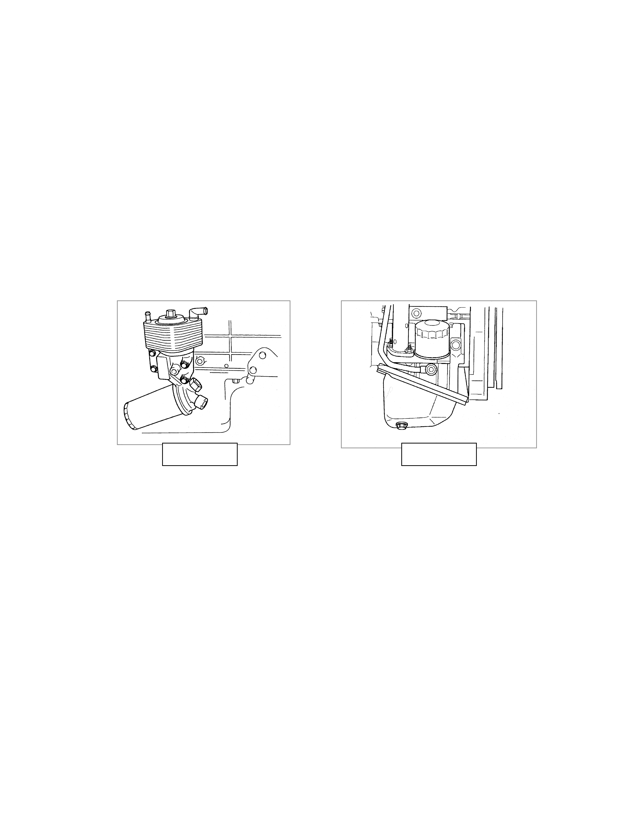
4JX1 - TC JACKAROO DIESEL SECOND OIL FILTER
JACKAROO
(GROUP 6A) October 1999
The 4JX1- TC diesel engine as fitted to the 1998/ 1999 model Jack ar oo vehicles is eq uipped with two
oil filt ers.
The service f ilt er is mounted on the drivers side of the engine and should be changed as per the
service schedule. ( refer picture A )
The second filter is mounted on the passenger side of the eng ine and is marked “2nd O/ F”.( ref er
picture B) The second filter shoul d not be changed in service, except in the event of engine r ebuild
or contaminat ion. This is a low volume filter that protect s t he injection system.
PICTURE A PICTURE B

DRIVE BELT TENSIONER REPLACEMENT
TC/TK Light Truck (Ambulance) with 6.5 Litre Turbo Diesel - MY 1996 onwards -
(GROUP 6K) October 1999
PROBLEM DESCRI PTION
Some vehicles may experience premature failure of t he dr ive belt t ensioner pulley at low exposure.
SERVICE RECTIFICATION
A revised tensioner assembly with greater durability has been released. Should a vehicle be
presented to t he dealership with a f ailed drive belt t ensioner pulley, technicians are re quir ed t o ensure
the revised type tensioner assembly is f itted during repair. Identif ication of the revised tensioner is by
date code as indicated below. Revised tensioners will be stamped with the number “238” or higher
(refer Figure 1).
Interpreting the Date Code:
“238” = 23rd week of 1998
(f ir st two digits are t he week of the year, 1-52;
third dig it is year of manufact ur e, 8 = 1998)
PARTS INFORMATION
Order t he new drive belt tensioner from HSPO - all par t s at HSPO are of the lat est date code.
Part No.: Description: Qty:
12561092 Drive Belt Tensioner 1
WARRANTY CLAIM INFORMATION:
Where a drive belt tensioner is replaced, use existing Labour Tim e Manual inf or m ation as follows:
Description Drive Belt Tensioner - Replace
Labour Op. No. J607250
Time ST
Failure Code 01
NOTE: Only JAKAB built ambulances are to have the drive belt tensioner replaced as per this
instruction. This is important , as there are other GM TC/TK Light truck-based Ambulances in use in
Australia. These vehicles have different belt drive systems, and are NO T covered by Holden warranty.
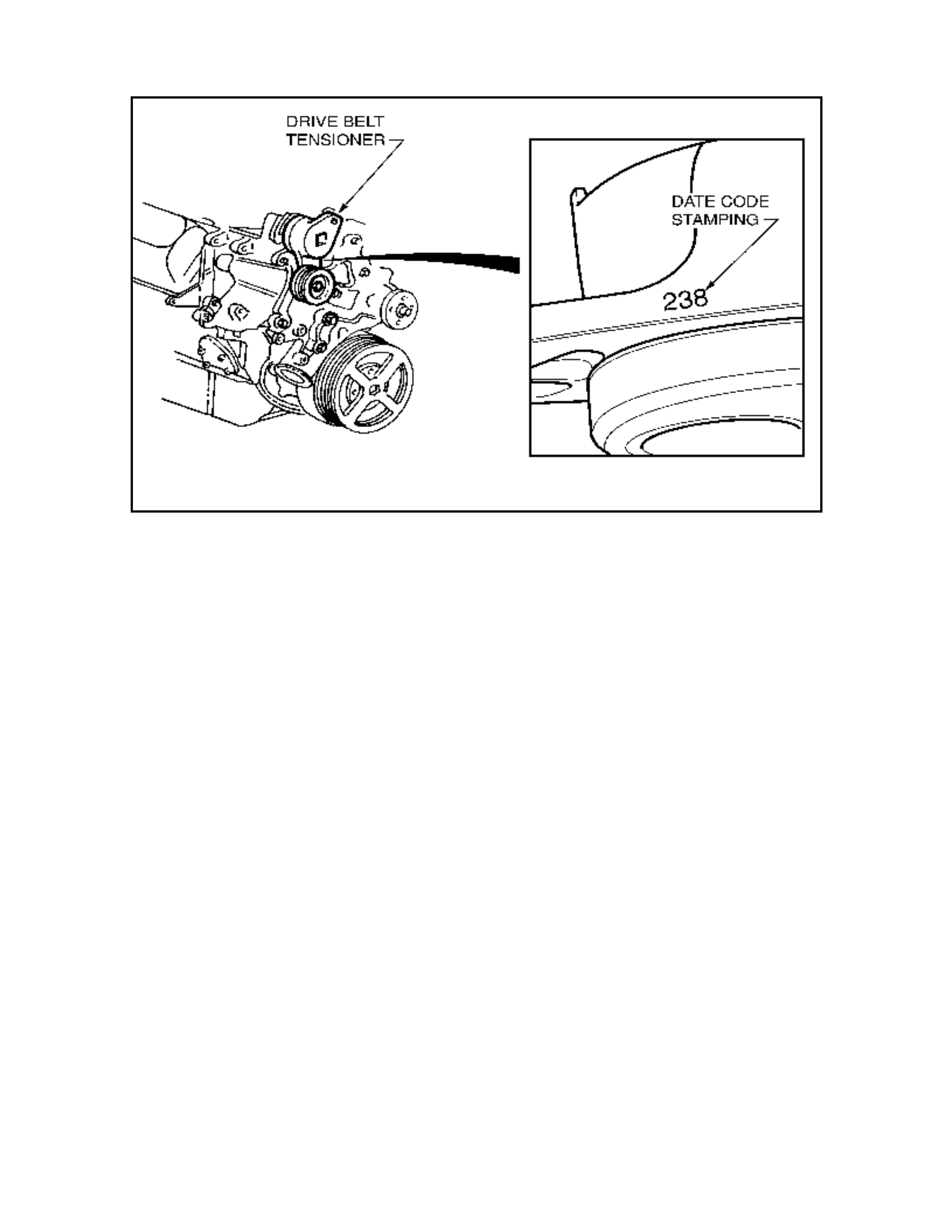
Figure 1

ENGINE STALL ON DECELERATION OR HIGH ENGINE IDLE
JR ,JS C20SEL, C22SEL
(GROUP 6M) October 1999
This Service Techline supersedes the pr evious Techline on this topic, Issue 3/99. Please ensure this
previous Techline is removed f r om dealership circulation.
This Techline has been republished to further incorporate revisions applied to JS Series 2 throttle
bodies which effect base idle adjustment.
PROBLEM DESCRI PTION
W ith vehicle stationary, the engine idle is t oo high; EG: 1000 RPM+, and engine m ay later stall or the
idle may remain high.
This is caused by a build-up of engine by-pass gasses and IACV solenoid shaft/bearing wear part icles
on the IACV solenoid shaft, which causes the IACV to stick at any point in its operating range. This
will result in either too high or too low IACV air entry to t he throttle body and engine.
W hen the IACV subsequently “unsticks” and returns to normal operation, the result may be a stall or
higher t han nor mal idle RPM. It is not possible to effe ct ively clean the IACV t o cor r ect this condition.
SERVICE RECTIFICATION
FOR C20SEL & C22SEL ENGI NES :
(UP TO ENG. NUMBER - C22SEL2501269)
To correct this condition, carry out the following idle resetting pr ocedur e:
1. Connect Tech-2 and check for DTC’s. If any are stored, correct the fault defined. (Refer to
Warrant y Information below for claiming for t his work).
a/. If NO DTC exists – refer to previously released Techline item: August, 1998, Issue 6, page 7,
regar ding relay fitment and int e r m it t ent power loss.
b/. If DTC P0100 exists – refer to previously released Techline item : May, 1998, Issue 3, pag e 14.
NOTE: use of this service rectif ication on a 4 cylinder vehicle will require solder ing of the smaller
gauge wires to t he t er m inals.
2. Remove air intake hose f r om t hrottle body, to gain access to t hr ottle blade.
3. Check for blow-by gas deposit in throttle body – around IACV port and on lower side and edges
on the throt tle blade. If deposits are pr esent, thor oughly clean throt tle body including any vacuum
related port s. This can be achieved by using a comm ercially available carburettor cleaner aerosol
spray pack.
4. Install a new IACV and gasket. If gasket has a “vee” notch on outer edge, it must face the top of
the IACV flange on assembly.
5. Reinstall air intake hose t o throttle body.
6. Undo idle screw lock nut ( at front RH side of throttle body).
7. Start engine and run until normal operating t em perature is reached.
Update

8. With Tech 2 connected, engine running, coolant temperature greater than 85, A/C (if fitted) ON
and active – turn in the idle scr ew until eng ine idle is at 1400 RPM.
9. With one hand on the throttle cable, disconnect the IACV connector – modulate throttle opening
to ensure eng ine does not stall.
10. With IACV disconnected and the throttle linkage resting against the throttle stop, the engine
should be idling at 500 – 600 RPM approx.. Now adjust idle t o 500 RPM (or as close as possible)
with the idle screw (ensure A/C is ON and active).
11. Tight en idle screw lock nut and confirm idle speed is still at 500 RPM.
12. Turn ignition off to stop engine.
13. Apply yellow paint to the idle screw and lock nut at the thread mating point. Paint should be
visible from front of engine compartment for inspection purposes
14. Reinstall IACV connector then turn ignition ON and OFF and remove the key from the ignition
lock barrel – seven times with a minimum of a five second pause after each key removal. This
action “teaches” the system its new idle software switch position.
15. Start the engine and check using Tech 2 that the system has simulated idle active and that the
IAC integrator steps are no less than 25 once idle has been established. (with A/C OFF and no
load on engine).
16. Check using Tech 2 that engine idle is corr ect ( 750+-80 RPM).
The idle reset t ing procedure is now complete.
Refer below f or Warranty Claiming and Parts Infor m a t ion.
FOR C22SEL :
(FROM ENG INE NUMBER C22SEL25012070 )
Modifications to the throttle body PCV port on JS Series 2 C22SEL engines already accommodate
for a preset amount of base idle. Technicians should not attempt to adjust base idle on JS Series 2
C22SEL engines after the break point specified below.
ISOVIN Breakpoint : Build Date:
W0L0JBF19YL497114 30/08/99
Engine No. Breakpoint: Bui l d Dat e:
C22SEL25012070 03/08/99
In the event that a post breakpoint JS Series 2 vehicle is presented t o the dealership with the above-
mentioned complaint , please follow the instruction set below.
1. Connect Tech-2 and check for DTC’s. If any are stored, correct the fault defined. (Refer to
Warrant y Information below for claiming for t his work).
2. Rem ove air int ake hose from t h r ot tle body, to gain access t o t hr ottle blade.
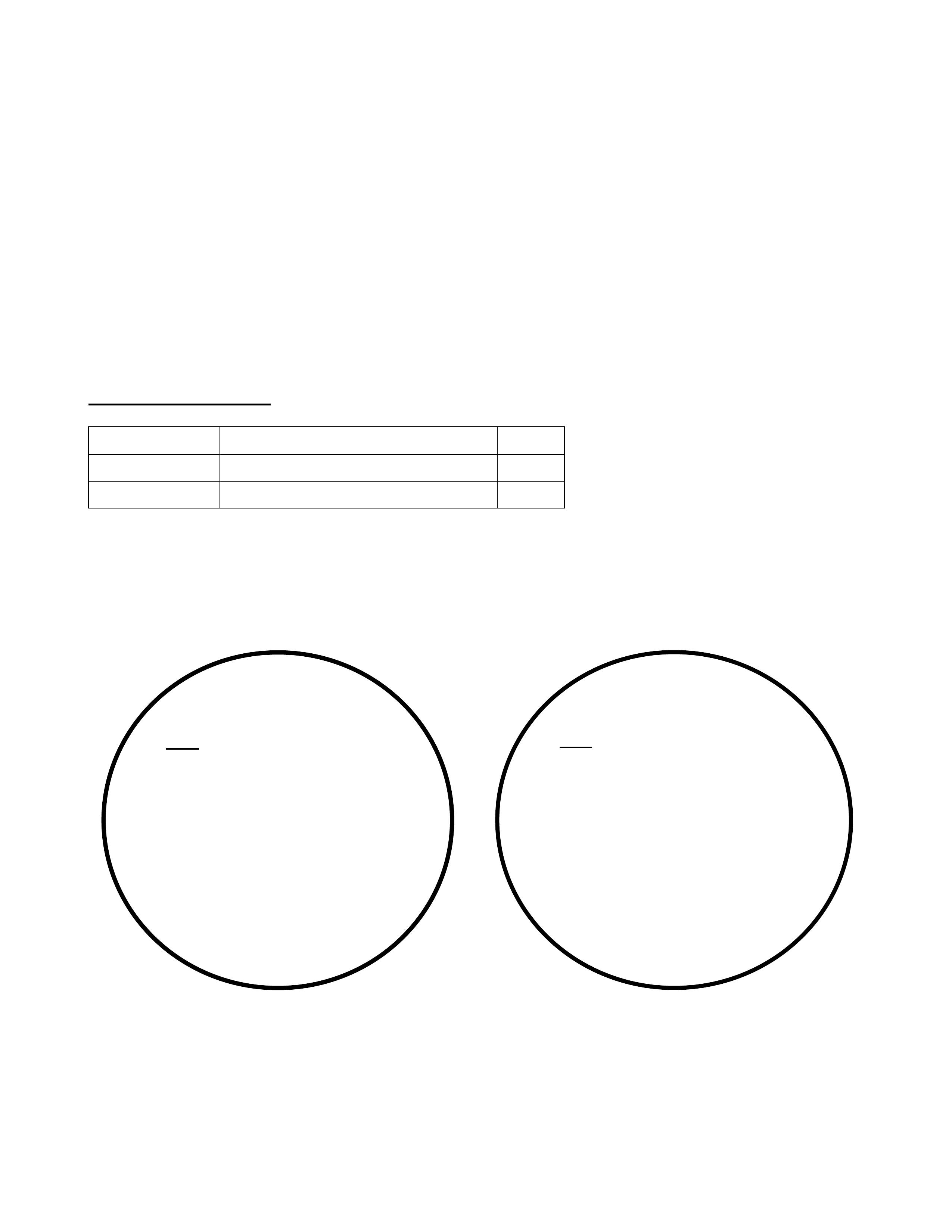
3. Check for blow-by gas deposit in throttle body – around IACV port and on lower side and edges
on the throt tle blade. If deposits are pr esent, thor oughly clean throt tle body including any vacuum
related port s. This can be achieved by using a comm ercially available carburettor cleaner aerosol
spray pack.
4. Install a new IACV and gasket. Ensure that the latest type IACV is obtained. Refer parts
infor mation below for ident if ication. If g ask et has a “ vee” notch on outer edge, it m ust f ace t he top
of t he I ACV flange on assembly.
5. Reinstall air intake hose to throttle body.
6. Start engine and using Tech 2 check that eng ine idle is cor rect (750+-80 RPM).
7. Road test vehicle to ensure no fur ther stall complaint is exists.
PARTS INFORMATION
Part No.: Description: Qty
90411546 Valve – Idle Air Contr o l ( IAC). 1
90466220 Gask et - IACV 1
To identify latest type IACV, refer to the following information - originally issued in Techline Issue 2,
March 1999. DO NOT USE “OLD” TYPE IACV’s. Only “CURRENT” TYPE IACV’s are in stock at
HSPO.
GM
90 411 546
SIEMENS 5WK9 0631
AESP207 – 13
“OLD” TYPE IACV
GM
90 411 546
SIEMENS 5WK9 0631 X
AESP207 – 13 A
“CURRENT” TYPE IACV

WARRANTY CLAIM INFORMATION
W hen claim ing f or correct ion of any DTC’s t hat may be found on init ial checks – r efer t o section 99 of
the Labour Time Manual, use the relevant Labour Oper ation Number f or t he DTC. For replacement of
any component found faulty during that DTC diagnosis – use the relevant Labour Operation for
remove and replace of the faulty part.
FOR C20SEL & C22SEL ENGI NES :
(UP TO ENG NO. - C22SEL2501269)
To claim for the JR and JS Series 1 idle resetting procedure and IACV removal and replacement
detailed above use the special operation num ber .
Description Reset Engine Idle
Labour Op. No. J 000610
Time 0.6 hr
Failure Code 84
FOR C22SEL ENGI NES :
(FROM ENG NO. C22SEL25012070 )
When claiming for removal and replacement of the IACV on JS Series 2 use the relevant Labour
Operation for removal and replacement of the IACV .
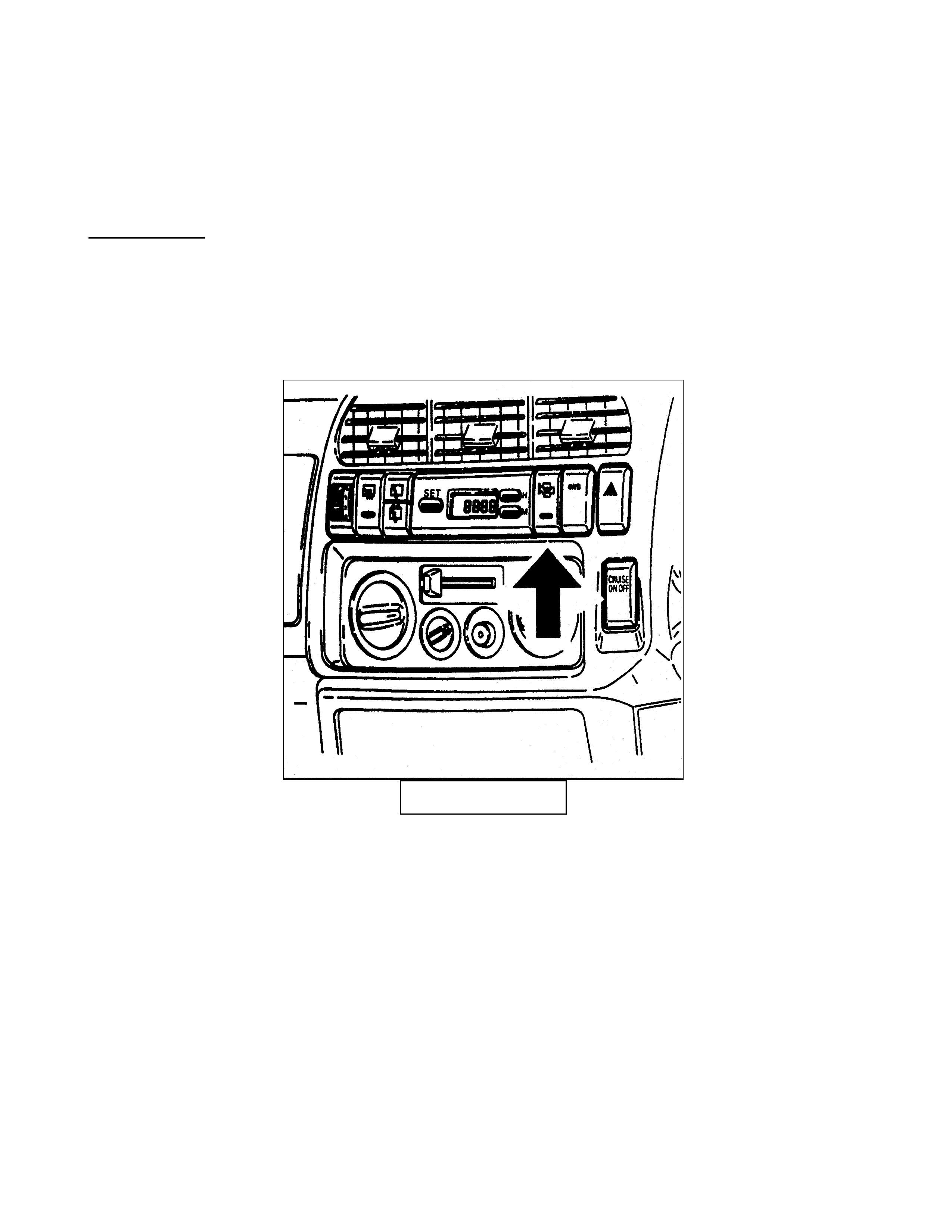
4JX1 - TC QUICK WARM UP SYSTEM
JACKAROO
(GROUP 6Y) October 1999
DESCRIPTION
The 4JX1 – TC is fitted with a quick warm up system that may be selected by depressing a dash
mounted switch.
The function of the quick warm up system is to decrease engine warm up time in cold conditions by
restricting air flow through the engine.
DASH SWITCH
To rest rict air flow, the ECU cont rols a butterf ly located on the exhaust engine pipe and the throttle
stepper mot or on the inlet manif old.
If the dash switch is depressed the ECM will activate / de-activate the system automatically as
engine tem per at ure conditions dictate.
When the system is activated the light located on the dash switch will illuminate, when the engine
temperature rises above 80C the ECM will override the switch to de-activate the system and the
light. The system contains an ambient temperature sensor located behind the grill that will override
the switch de-activating t he system and the light if t he ambient temper ature is above 15C. If coolant
temperature is above 50C on start up the ECM will override the dash switch and de-activate the
system.
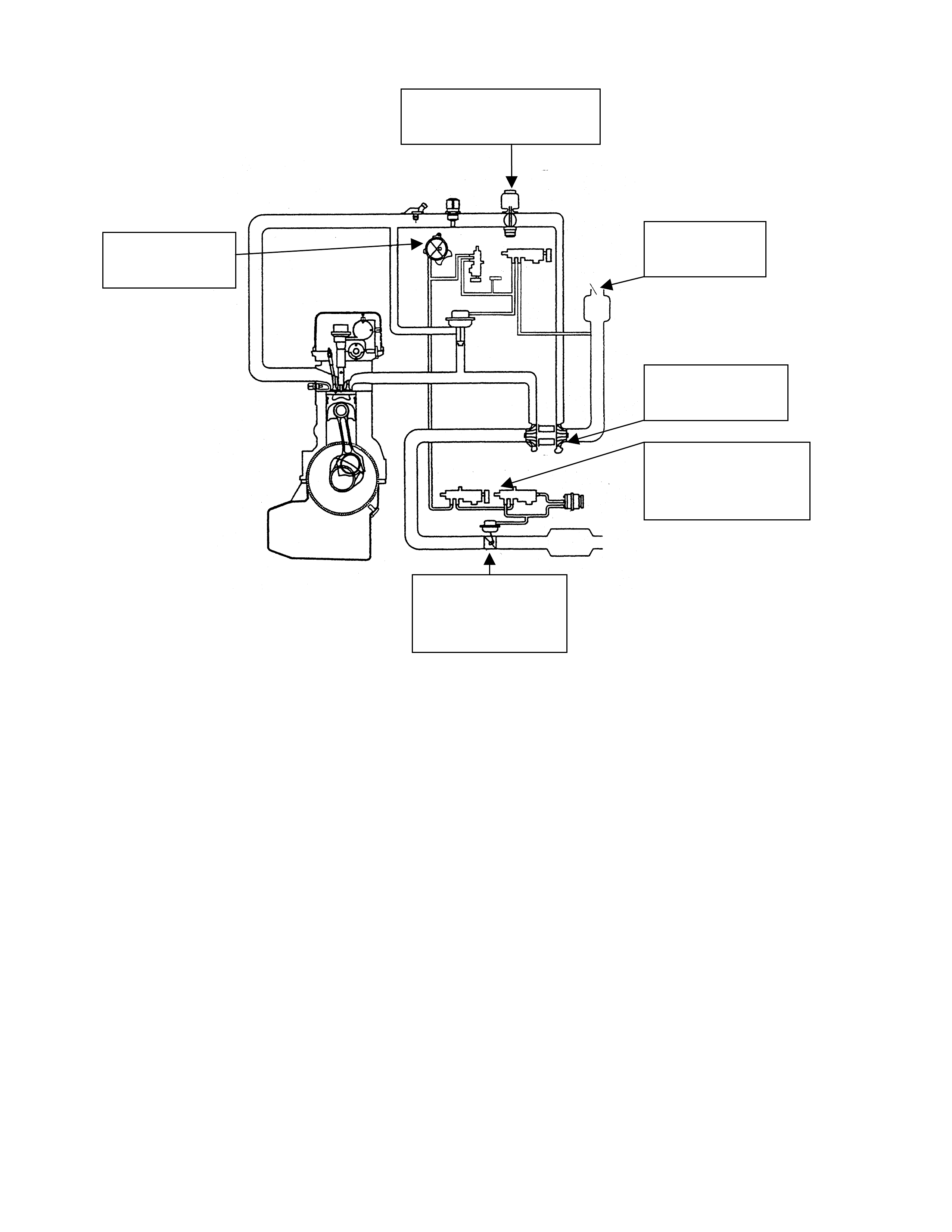
INTAKE THROTTLE
STEPPER MOTOR
VACUUM
PUMP
AIR
CLEANER
EXHAUST
BUTTERFLY
TURBO
EXHAUST
BUTTERFLY
VALVES

STEERING COLUMN INSTALLATION PROCEDURE
TS
(GROUP 9) October 1999
Whenever reinstalling or replacing the steering column assembly in TS series Astra built prior to
the production breakpoint shown below. It is critical the correct lower steering column mounting
clamp load is achieved. Failure to correctly set this clamp load may result in two separate
conditions. If too loose, a rattle condition at the base of the steering column may be experienced. If
too tight, failure of the lower steering column bearing may result.
PRODUCTION RECTIF ICATION
Tighter production tolerances to the lower steering column mounting bracket have eliminated the
requirem ent for this critical clamp load adjustment.
Vehicle breakpoint is as specified below:
ISOVIN: Build Date:
W0L0TGF48X5033674 21/09/98
SERVICE PROCEDURE
Technicians need to ensure that the procedures outlined below are applied at all times when the
steering column is reinstalled or replaced in TS series vehicles built prior to the above mentioned
breakpoint. .
1. Reinstall the steering column assembly as per removal and reinstallation procedures set out
on the TIS CD ROM, Group M – Steering “Remove and reinstall steering column assembly”
(Steering column assembly adjustable).
2. Centralise the steering wheel and engage the steering lock.
3. Move the adjustable steering lever out of the lock position so the steering column can be
moved up or down, in or out.
4. Locate the clamp bolt (1) that houses the lower steering column bearing and loosen to allow
the installation of the first shim package of 4.0mm (bolt (1) threaded end visible with a 7mm
hex on end of bolt) as indicated in Figure A (showing the steering column removed for clarity).
Shim in mm Number of shims
0.4 21-321-321
1.6 2221111- - -
Total 4.0 3.6 3.2 2.8 2.4 2.0 1.6 1.2 0.8 0.4
Update
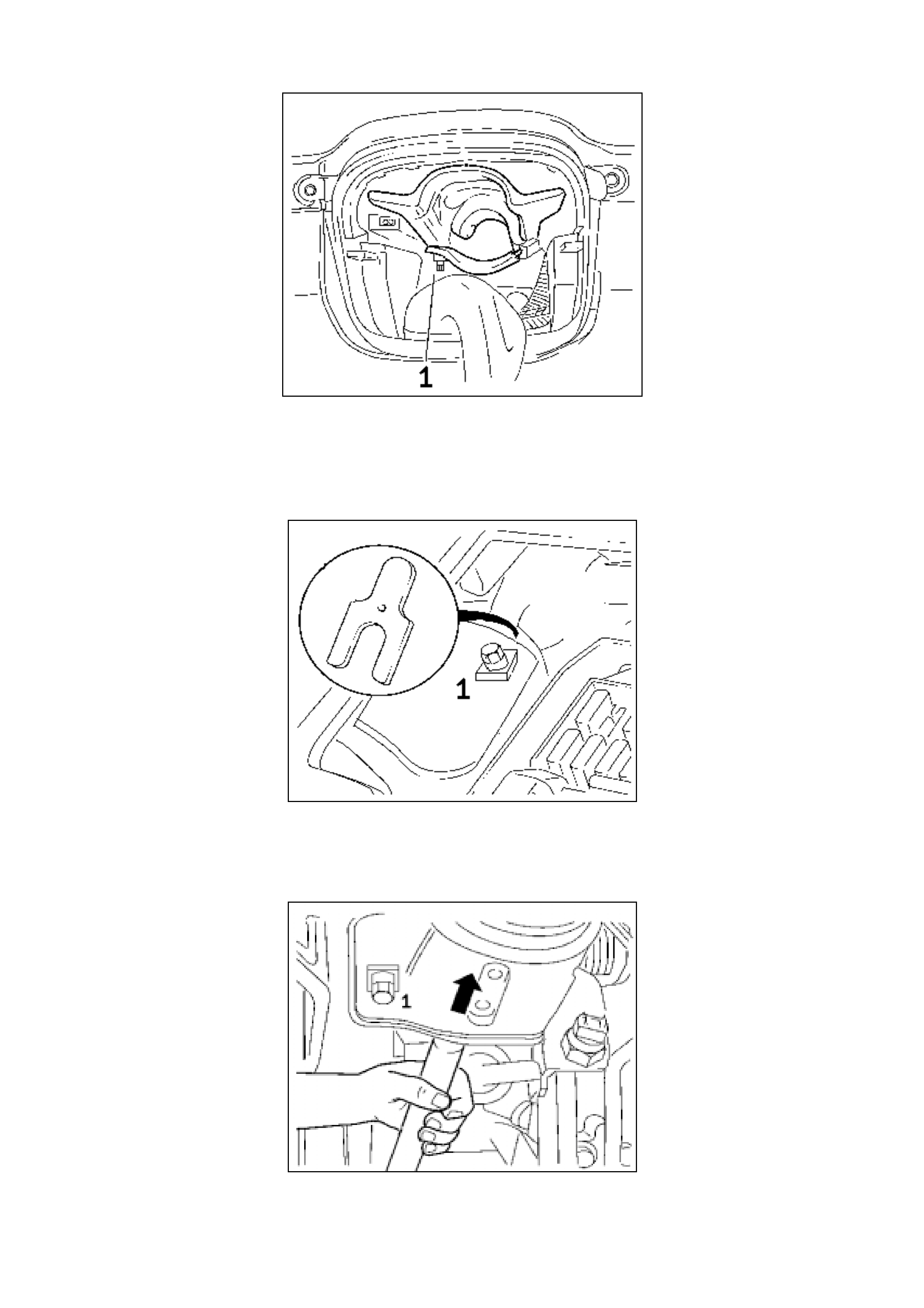
FIGURE A
5. Beginning with an overall thickness of 4.0 mm insert the package of 4 shims, as indicated in
Figure B, between the steering column bracket and the crossmember and tighten the clamp
bolt to 22 Nm/16 ft.lb.
FIGURE B
6. To check if the clamping force is correct, grasp the steering shaft at the intermediate shaft end
and push the steering shaft axially with moderate effort (in the direction of the arrow) as
indicated in Figure C.
FIGURE C

7. If the visible grey guide sleeve located in the clamp on the steering column is moved, release
the clamp bolt and remove one 0.4mm shim.
8. With the reduced shim package of 3.6 mm, tighten the clamp bolt again to 22 Nm/16 ft.lb.
Repeat the checking procedure, observing whether the grey guide sleeve continues to move.
Repeat the procedure of continually reducing the overall thickness of the shims by 0.4 mm
until the guide sleeve ceases to move while applying moderate effort as indicated.
9. Once the correct number of shims has been determined, push the steering column inwards as
far as it will go and check that the grey sleeve located within the clamp is positioned towards
the front of the vehicle as far as possible. It may be necessary to loosen the clamp bolt and
apply an axial force to the steering shaft towards the front of the vehicle until the grey sleeve
seats on the clamp in it’s forward most position. Ensure to tighten the clamp bolt to 22Nm/16
ft.lb.
10. Re-install all components. Move the steering column adjustment lever into the lock position.
PARTS INFORMATION
Shim kits to adjust clamping load are available via HSPO under the part number supplied below.
Part No.: Description: Qty
09192728 Shim kit 1

TILT/REACH HANDLE INSTALLATION PROCEDURE - SERVICE MANUAL REVISION
VT, WH
(GROUP 9) October 1999
When replacing the tilt/reach handle mechanism incorporated in the steering column assembly,
technicians are advised to perform the additional procedure and note the change in the required
installed ‘f or ce’ to push the lever closed.
Please add the following notation (changes are in bold Italics) to existing procedures in the VT
Series Service Manual, Volume 5, Section 9A, page 9A – 26.
STEP 3. Ensure steering column / steering wheel is in the fully forward position, i.e. push
steering wheel towards the front of vehicle until full forward adjustment has been achieved.
Reinstall through bolt and replacement handle (1) , through the inner cam .
and
STEP 6. Tighten the nut unt il a force of 60 N is r equired to push the lever closed.

SERVICING DOOR CHECK LINKS
VT II, WH
(GROUP 0B) October 1999
A revised front door checklink assembly was introduced with VT II and WH Ser ies vehicles.
VT II and WH series vehicles do not require the front door checklinks to be lubricated at anytime.
Only rear door checklinks should be lubricated as per the normal service schedule or as requir ed.
Lubricating the front door checklink lowers the maximum hold open force t hat the checklink can apply
to the door. Lubrication may also cause an ‘oil canning’ type noise depending upon the lubrication
used.
Please add the following notation (changes are in bold Italics) to existing procedures in the
appropriate sect ions in the VT II and WH Series Service Manuals:
Section 0B LUBRICATION AND SERVICE, Volume 1A, page 0B-17, Operation 7.2. Maintenance
Schedule, Car Exterior, "Lubricate hood catch, door hinges, rear door links and lock cylinders"
Section 0B LUBRICATION AND SERVICE, Volume 1A, page 0B-17, Operation 8. Lubricant
Recommendations, " Door hinge and rear door hold opens"
Section 0B LUBRICATION AND SERVICE, Volume 14A, page 0B-20, Operation 9.2. Maintenance
Schedule, Car Exterior, "Lubricate hood catch, door hinges, rear door links and lock cylinders".
Future updates of these Service Manual sections will carry corrected information.

SERVICE SCHEDULE REVISION
UES FRONTERA -
(GROUP 0B) October 1999
I-GM wish to advise technicians of two revisions to the service schedule of the current model UES
Frontera from the schedule shown in Chapter 12, Pag e 6 of the owners handbook.
1) Manual transmission and tr ansf er case oil is no long er t o be replaced at 10000 km as indicat ed in
the service schedule. The f irst manual t ransmission and transf er case oil chang e is now at 40000
km, and t hereafter as indicated in the service schedule.
2) Automatic transm ission and transfer case oil is no longer to be r eplaced at 10000 k m as indicated
in the service schedule. The first automatic transmission and transfer case oil change is now at
40000 km, and t hereafter as indicated in the service schedule.
The above revisions will apply for all 1999 UES model vehicles that have not already had a 10000 k m
service.

FUEL FILLER DOOR NOT OPENING
VT, WH
(GROUP 1) November 1999
PROBLEM DESCRI PTION
The fuel filler door fails to open when the fuel filler door lever is pulled.
The problem occurs due to the fuel filler door seal ‘sticking’ to the body preventing the
door f r om opening.
PRODUCTION RECTIF ICATION
W hite oil is applied to the fuel filler door seal to prevent the seal f rom ‘sticking’. This oil
application start ed at:
ISOVIN: Build Date:
6H8VTK69HXL493739 18/08/1999
SERVICE RECTIFICATION
Apply Solidoil – available from HSPO - to the fuel f iller door seal. (Note: Solidoil is used
because white oil is not available in container sizes suitable f or dealer ship use).
PARTS INFORMATION
Part No.: Description: Qt y:
M33028 Solidoil (27g) 1
Due to potential adverse effects on paint, silicon based spray greases or similar must
not be used in this location.
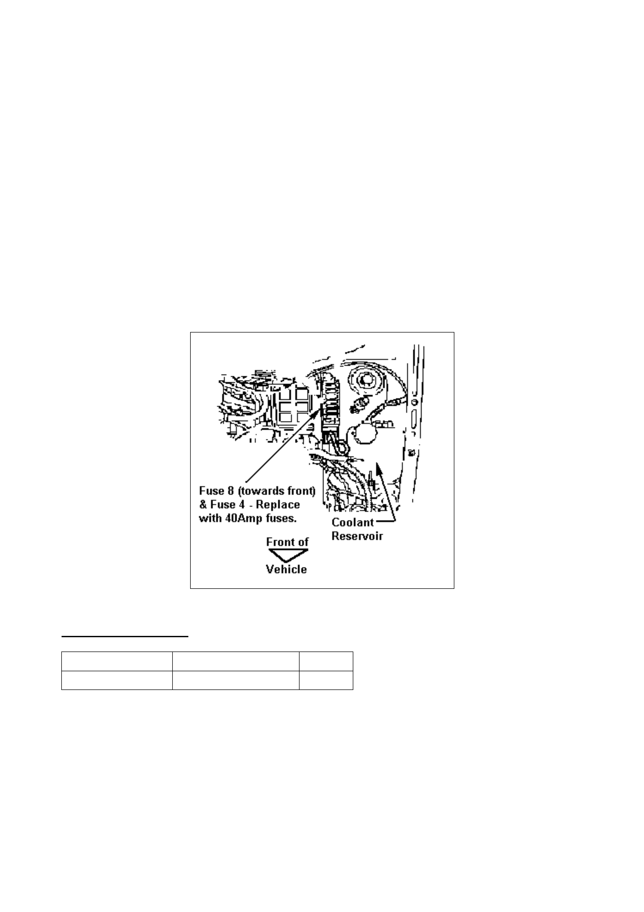
ENGINE COOLING DIAGNOSTIC LAMP ILLUMINATES - FUSE 8 OR 4 BLOWS
TS ASTRA
(GROUP 12) November 1999
This Techline item supersedes the previous Techline on this topic Issue 2, 1998. Please ensure
the previous Techline is rem oved from dealership circulation.
If investigating engine cooling diagnostic lamp illuminating, check fuse numbers 4 & 8 in the
engine compartment fuse box, located at the LH front of the vehicle. See figure 1 below.
NOTE: Fuses ar e numbered 1 to 8, read from the rear of the fuse panel.
The cause of the diagnostic lamp illuminat ion m ay be fuse failure during cooling fan st ar t -up.
Under certain operating conditions the cooling fan/s may draw sufficient current to cause fuse
failure.
If either of these fuses is 20 Amp (yellow colour) or 30 Amp (green colour), the fuse/s must be
replaced with a 40 Amp (Orange colour) fuse – r efer Parts Information below.
Figure 1
PARTS INFORMATION
Part Number Description Qty
90386022 Fuse - 40A 1

MULTI INFO DISPLAY UNIT (MID), CODE INDEX PROGRAMMING
JS SERIES II, C22SEL
(GROUP 12) November 1999
This Techline is issued to inform technicians of the correct multi info display (MID) program index
codes for JS Series II with C22SEL engines which did not appear in the T IS CD- ROM until Version
53.
W hen replacing MID units in these vehicles it is necessary to program the correct code index into
the new unit for oper ation.
Soft ware t hat will enable this programming is available in the curr ent TIS CD-ROM.
TRANSMISSION TYPE CODE INDEX
MANUAL 600
AUTOMATIC 601
Steps for programming are as fol l ow s :
1. Connect TECH 2 to the vehicle.
2. Select Diagnostics/Model Year (Y) 2000/ Vectra B/F3 : Body/Multi Info Display
3. Follow steps as request ed by TECH 2
4. Select F5: Programming/F0: Code Index programming.
5. Select the “Modify” soft key at the base of the TECH 2 screen.
6. Technicians will then be prompted f or the following options.
7. Select Multi Info Display Language - “ENGLISH”
8. Select Option - “WITH RADIO”
9. Select Country Code - “OT HER”
10. Select Consumption Unit - “LITRE / 100KM”
11. Tech 2 will then prompt t o enter the relevant Code Index fr om the table below with the TECH
2 keypad and press enter.
12. TECH 2 will verify when program m ing is complete.
PRODUCTION BREAKPOINT
The program index codes listed should be used when programming Multi Info Display units after
the break point specified below.
ISOVIN: Build Date:
W0L0JBF19YL482379 22/07/99

PROGRAM INDEX CODES
SB, TR, TS, JR, JS
(GROUP 12) November 1999
When replacing electronic control units in Barina, Astra, or Vectra models, technicians may be
prompted to enter a code index (from the TIS CD), via TECH 2, to enable the module to function
within the vehicle.
Some Technicians have had dif ficulty finding the index codes on the TIS CD and have resorted t o
calling TAS for the codes.
As these codes are called “Program memory codes”, “Index codes” or “Program Index Codes” in
TIS, update informat ion and clarification of t hat informat ion is currently being sought.
On the following page is a consolidated table of code indexes for the vehicles and models built to
date.

PROGRAM INDEX CODES – SB, TR, TS, JR, JS
ELECTRONIC
MODULE TYPE MODEL
YEAR MODEL TYPE ENGINE
TYPE TRANS
TYPE CODE
INDEX
MULTI INFO DISPLAY 97 JR VECTRA C20SEL MAN 007
MULTI INFO DISPLAY 97 JR VECTRA C20SEL AUTO 008
MULTI INFO DISPLAY 97 JR VECTRA X25XE AUTO 014
MULTI INFO DISPLAY 98 JR VECTRA C20SEL MAN 009
MULTI INFO DISPLAY 98 JR VECTRA C20SEL AUTO 010
MULTI INFO DISPLAY 98 JR VECTRA X25XE AUTO 012
MULTI INFO DISPLAY 98/99 JS VECTRA C20SEL MAN 009
MULTI INFO DISPLAY 98/99 JS VECTRA C22SEL MAN 009
MULTI INFO DISPLAY 98/99 JS VECTRA C22SEL AUTO 010
MULTI INFO DISPLAY 98/99 JS VECTRA X25XE AUTO 012
MULTI INFO DISPLAY 99/00 JS VECTRA Series 2 C20SEL MAN 600
MULTI INFO DISPLAY 99/00 JS VECTRA Series 2 C22SEL MAN 600
MULTI INFO DISPLAY 99/00 JS VECTRA Series 2 C20SEL AUTO 601
MULTI INFO DISPLAY 99/00 JS VECTRA Series 2 C22SEL AUTO 601
MULTI INFO DISPLAY 99/00 JS VECTRA Series 2 X25XE AUTO 012
TRIPLE INFO DISPLAY VECTRA (ALL) 031
TRIPLE INFO DISPLAY TS ASTRA 011
INSTRUMENT JR VECTRA C20SEL 013
INSTRUMENT JR VECTRA X25XE 017
INSTRUMENT JS VECTRA C20SEL 013
INSTRUMENT JS VECTRA C22SEL 013
INSTRUMENT JS VECTRA X25XE 017
INSTRUMENT JS VECTRA Series 2 C20SEL 021
INSTRUMENT JS VECTRA Series 2 C22SEL 021
INSTRUMENT JS VECTRA Series 2 X25XE 022
INSTRUMENT TS ASTRA X18XE1 007
CRUISE CONTROL VECTRA (ALL) C20SEL 010
CRUISE CONTROL VECTRA (ALL) C22SEL 050
CRUISE CONTROL VECTRA (ALL) X25XE 011
CRUISE CONTROL TS ASTRA X18XE1 013
RADIO – Blaupunkt 420 VECTRA (ALL) 001
RADIO – Blaupunkt 420 TR ASTRA 063
RADIO – Blaupunkt 420 TS ASTRA 031
RADIO – Blaupunkt 420 SB BARINA 063
RADIO – Blaupunkt 520 VECTRA (ALL) 003
RADIO – Blaupunkt 520 TR ASTRA 065
RADIO – Blaupunkt 520 TS ASTRA 033
RADIO – Blaupunkt 520 SB BARINA 065
RADIO – Blaupunkt 620 VECTRA (ALL) 002
RADIO – Blaupunkt 620 TR ASTRA 064
RADIO – Blaupunkt 620 TS ASTRA 032
RADIO – Blaupunkt 620 SB BARINA 064

REFRIGERANT CHARGE QUANTITY
TF RODEO
(GROUP 2) November 1999
Recent Air International in house charge determination testing has revealed an error in the
quantit y of refrigerant recommended for the Rodeo V6 4x2, 4x4 models.
The original specif ication as nominated on the A/C label and f itting instruct ions was 900 + or – 25
grams, we now realise that this should be 730 + or – 25 grams.
All dealers should alter their fitting instructions to reflect the new value. The specification label
supplied with new kits will also be altered accordingly.

WHISTLE NOISE FROM HVAC FRESH/RECIRC. DOOR
VT
(GROUP 2) November 1999
PROBLEM DESCRI PTION
A whistle noise is heard from the HVAC unit when in fresh air mode and fan speed is set to high
(or with increased airflow while driving).
The whistle is caused by incomplete sealing of the fresh/recirculation door in the “fresh air”
position.
PRODUCTION RECTIF ICATION
Revised actuator rods have been fit t ed to vehicles from:
ISOVIN: Build Date:
6H8VTL69HYL512679 06/10/99
SERVICE RECTIFICATION
To alleviate this whistle noise, replace t he fresh/recirculation door actuator rod as follows:
1. Remove the instrument panel lower compartment (glove box), the instrument panel end cap
cover left side and where fitted, the left side foot well upper closing panel.
2. Disconnect the vacuum actuator rod from the fresh/recirculation lever.
3. Remove the two screws securing the vacuum actuator (using a stubby Phillips head
screwdriver) as indicated in Figur e 1.
4. Pull the actuator rod black retaining collar f orward (away from the act uator body) and remove.
Note the position of the retaining collar and rod - f or later re-assembly.
5. Remove the rod from the vacuum actuator by pulling the rod away from the actuator body.
6. Attach the revised rod P/N 92143261 to t he vacuum actuator.
7. Re-install the black r etaining collar and ‘clip’ into posit ion.
8. Check operation of actuator, re- inst all all parts previously removed.
PARTS INFORMATION
As the original rod and revised rod are visibly similar, the revised rod is longer and can be
identif ied by its length of 72m m Approx., measured f rom centr e of the att aching hole to the end of
the rod.
Part No.: Description: Qty:
92143261 Fresh/Recir c. Actuator Rod 1
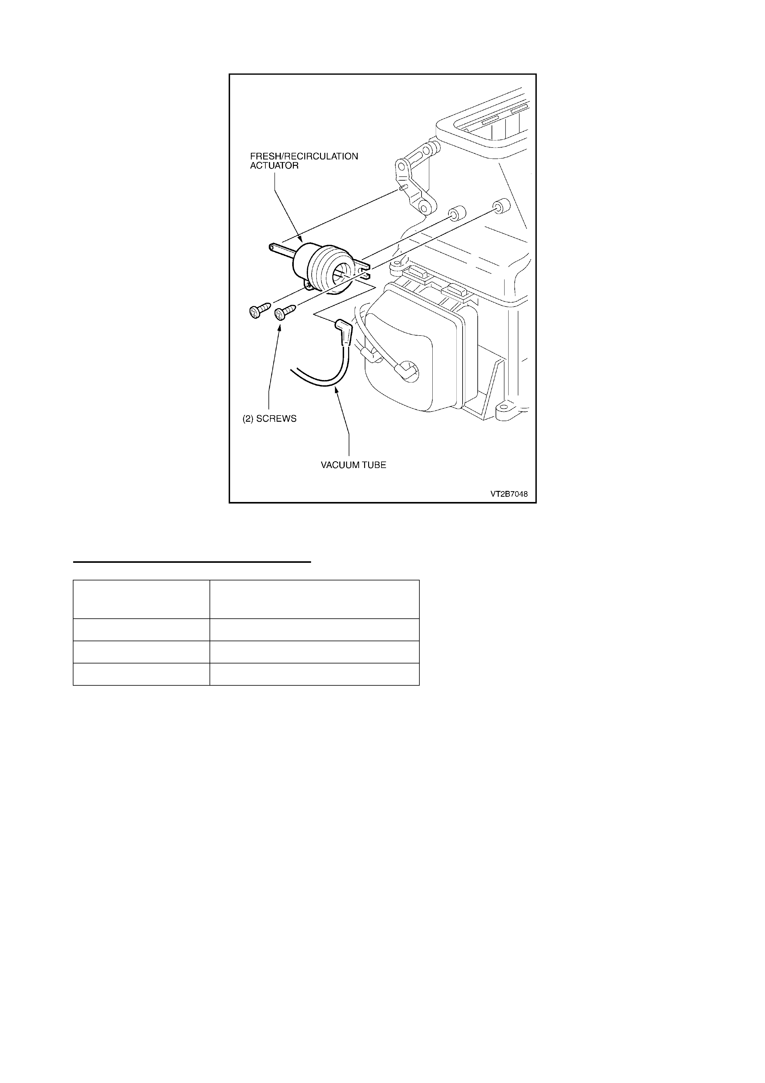
Figure 1
WARRANTY CLAIM INFORMATION:
Description Fresh/Recirc. Actuator Rod –
Replace
Labour Op. No. D000215
Time 0.5 hr
Failure Code 40

ABS BRAKE BLEEDING
SB, TR, TS, JR, JS
(GROUP 5) November 1999
When bleeding brake systems on the above-specified models fitted with ABS brake systems.
Technicians may experience difficulty in removing air from the ABS modulator assembly. This
results in a spong y or poor pedal feel.
To assist in relieving air trapped in the ABS modulator assembly, technicians are advised to use
the ABS retur n pump relay actuator te st in TECH 2, in conjunction with t he normal brake bleeding
procedure.
A normal brake bleeding procedure should be performed to remove air from the brake system
prior to using the actuator test. Once this primary brake bleed is complete, continue as follows for
the applicable vehicle model:
JR & JS VE C TRA, TS ASTRA
1. Connect TECH 2 to the vehicle
2. Select Diagnostics / Model Year / Model type / Chassis / ABS 5.3 ( + T C)
3. Follow the steps as req uest ed by TECH 2
4. Select “F3 : Actuator Test”
5. Select – “Return Pump Relay Test”
6. Push the “ON” sof t key at the base of the TECH 2 screen.
Note: The actuator test will time out after 3 seconds.
7. Perform anot her normal brake bleeding pr ocedur e. Observe any residual air being exhausted
fr om t he hydraulic br ake circuit.
8. Repeat above procedure, if necessar y, ( I E: Steps 1-7), until all air is removed from the br ake
system.
SB BARINA GSI, TR ASTRA GSI
The same procedure can be used on SB Barina GSI and TR Astra GSI models with ABS brake
systems, using t he TECH 1 Scan tool and associated actuator t est .

BRAKE PAD BEDDING IN PROCEDURE
VT, WH
(GROUP 5) November 1999
Whenever brake pads are replaced, they should be burnished, by the following bedding-in
procedure:
Perform a minimum of 10 moderate (0.3 to 0.4g deceleration) brake applications from 70 km/h
down to 40 km/h every 500 metres.
For example, a ‘panic’ stop would be classified as being a 0.9 g deceleration braking effort, so a
‘moderate’ deceleration rate of 0.4 g would be one that required approximately half the brake
pedal effort needed f or a ‘panic’ st op.
Important Note:
Do not perform this procedure at less than 500 metre intervals, as the excessive heat build-up,
may adversely affect t he frictional character ist ics of the new brake pad mater ial.

ENGINE REPAIR RECOMMENDATION
ALL MODELS
(GROUP 6A) November 1999
In recent times, engines have become increasingly more sophisticat ed and complex in design and
construction.
When the need arises to carry out major repairs, these engines rely on greater attention to
accuracy and detail - in measurem ent, machining and assembly - and adherence to m anufacturers
specificat ions is of paramount impor tance.
Holden Service recommends that when any major repair is to be car ried out by a sub-let repairer,
or where components are either machined, or repaired/remanufactured ‘off-site’ - that a copy of
the relevant Service Specifications be provided, to ensure the machine shop/repairer produces
finished products that align with the Holden Service Specification.
It is no longer acceptable to rely on a repairer to machine/repair components to an “industry
standard”, t hat may be “less controlling” than t he manufacturer’s specification.
Part of any agreement for sub-let repairs to be carried out, should be the instruction to complete
the task “ to the specifications pr ovided”.
This will assist Dealerships’ aims to “fix it right first time” and ensures the longevity and durability
of customer’s vehicles. Provision of this service data to r epairers also assists in education of their
technicians - a g ener al benefit to the aut om otive repair trade.

OIL LEAK DIAGNOSIS
ALL MODELS
(GROUP 6A, 7A, 7B) November 1999
PROBLEM DESCRI PTION
Unnecessary component replacements and repeat repairs are occurring because of incorrect
diagnosis of engine and transmission oil leak s.
SERVICE RECOM MENDATION
When diagnosing engine or transmission oil leaks, Holden Service recommends the use of Black
Light and Tracer Dye, as clean-up of existing leaks is not required, and exact leak sources will be
accurately defined.
MINIMI SING REPAIRS & REDUCING COMEBACKS:
Use of black light is especially important on lower engine oil leaks and A/T leaks – as returned
parts show that a simple r epair/seal replacement could have been carr ied out with m inimum work,
rather t han m ajor component replacement or multiple repairs.
This system can also assist in definition of casting porosity – defining the need for component
replacement – where a repeat com plaint may occur af t er previous leak clean-up and evaluation.
Refer to All Dealer Letter DL: 30/97, shown on page 87 of 1997 Service Communication Book.
The information provides questions & answers regarding usage of black light and tracer dye, and
purchase (from SPX) of all necessary equipment, including dye for engine, trans., A/C, and also
replacement par t s .

SPARK PLUG LEAD REPLACEMENT
VT, VS with S/C V6
(GROUP 6Y) November 1999
Techline Issue 3 - April, 1999, Page 9 advised of the introduction of new spark plug leads, and
recommendat ions for lead replacements.
To ensure that misfire complaints with S/C V6 engine are not continued, the following information
fr om the April Techline, with additional clarification, is brought to technicians attent ion:
SERVICE RECTIFICATION
Early Design (DARK grey) leads:
In service, whenever a failure of an earlier production (DARK grey coloured) supercharged V6
engine spark plug lead occurs – Replace t he spark plug leads with a f ull set of latest desig n leads.
(Refer Parts Info. Below).
DO NOT REPLACE SINGLE LEADS
This lead set replacement may be done once only - where a failure occurs on a DARK grey
coloured lead/s.
NOTE: T hese Dark gr ey coloured leads are also labelled with the word “CHAMPION” on the out er
insulation.
Latest Design ( BLACK) leads:
Failure of the latest design (black coloured, and the leads are labelled with the word “Bougicord”)
leads requir es r eplacement of the failed lead only.
CAUTION: Earl y & Latest Design Leads:
Some technicians are removing the locating spring from spark plug boots – DO NOT REMOVE
locating springs from any supercharged V6 engine spark plug lead boots. This does not address
the root cause and will result in a r epeat failure which will inconvenience customers.
PRODUCTION RECTIF ICATION
As a product improvement, revised spark plug leads were introduced in S/C V6 engine (and
vehicle) production as f ollows:
ISOVIN: Engine No. Build Date:
L460549 VS876563 20/05/99
PARTS INFORMATION
Part No.: Descript i on: Qty
92142486 Lead Set – Spar k Plug
(For S/ C V6 only). 1
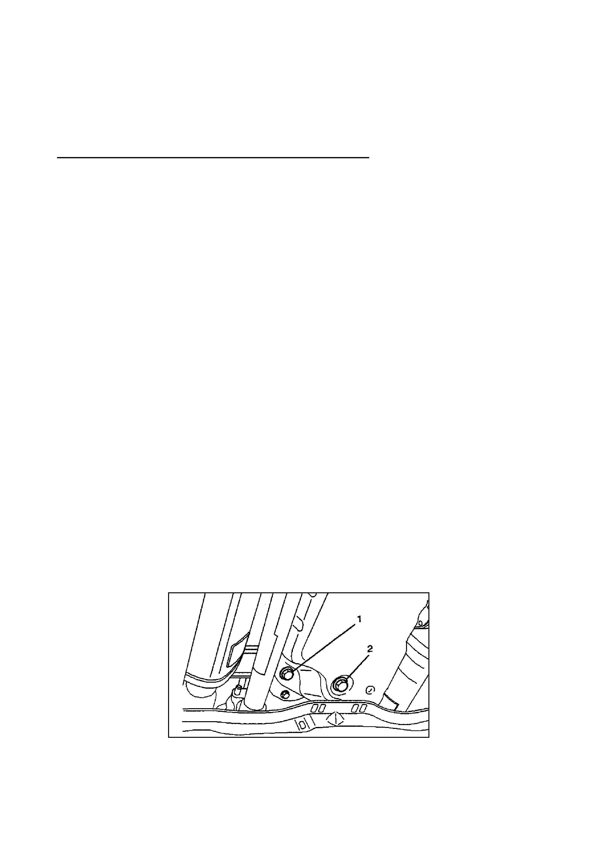
4L30E AUTOMATIC TRANSMISSION FLUID LEVEL CHECK PROCEDURE
JACKAROO, RODEO, FRONTERA
(GROUP 7B) November 1999
CHECKING TRANSMISSI ON FLUID LEVEL AND CONDITION
Checking fluid level and condition (colour and odour) at regular intervals will provide early
diagnosis inf ormation about the transm ission. This inf ormation may be used to correct a condition
that, if not detected ear ly, could r esult in m a j or transmission repairs.
IMPORTANT. W hen new, automatic transmission f luid is r ed in colour . As the vehicle is driven, the
transmission fluid will begin to look darker in colour. The colour m ay eventually appear light brown.
A dark brown colour with burnt odour may indicate excessive fluid deterioration and signal a need
for fluid change.
FLUID LEVEL
W hen adding or changing f luid, use only DEXRON 3. Ref er to Maintenance and Lubrication in the
relevant owners manual for ser vice inter vals.
CAUTION: DO NOT OVERFILL.
Overfilling will cause foaming, loss of fluid, abnormal shifting and possible damage to the
transmission.
1. Park the vehicle on level ground and apply the parking brake firmly.
2. Check fluid level with engine running at idle.
NOTE: Be sur e t hat transmission fluid t em per ature is below 30° C (86° F).
3. Move the selector lever through all gear ranges.
4. Move the selector lever to "park .
5. Let engine idle for 3 minutes and open the overfill scr ew (REFER DRAWI NG A).
6. Add released transmission f luid unt il it flows out over the overfill screw opening.
7. Let engine idle until a fluid temper ature bet ween 32° C (90° F) and 57 ° C (135° F) is r eached,
then close the overfill screw (1).
Torque: 38 Nm (3.9 kg.m128 lb f t )
NOTE: Check t r ansm ission fluid temperature with scan tool.
Minimum fluid level 57° C (135° F) Maximum fluid level 32° C (90 ° F)
DRAWING A
1 – FILL PLUG 2 – DRAIN PLUG
CAUTION: Do not open overfill screw with engine stopped.

CAUTION: DO NO T CHECK FLUID LEVEL UNDER THESE CONDITIONS:
• Immediat ely after driving at sust ained highway speeds.
• In heavy city traffic during hot weather.
• If vehicle is towing a t r ailer .
If the vehicle has been operat ed under t hese conditions, shut the engine off and allow the
vehicle to"cool" f or ( 30) minutes. Af t er t he cool down period, rest art vehicle and cont i nue
from step 2 above.

LSD "CHATTER" NOISE
VT with LSD (Additional Information)
(GROUP 4) November 1999
This Techline item is re-issued (previous Techline on this topic Issue 2, March, 1999, page 7).
because of the ongoing, unnecessar y, replacement of final drive unit s .
As all Technicians are now aware of the necessity to REPLACE OIL PRIOR TO ANY FINAL
DRIVE REPLACEMENT, any final drive unit replaced where the oil has not been r eplaced, will not
be accepted under warranty.
PROBLEM DESCRI PTION
A number of final drive units have been replaced for chatter noises. Investigation has revealed
that the cause of the complaint noise was LSD lubricant related. Unnecessary replacement of
LSD units may result if the diag nosis recom mended by Holden and the LSD supplier is not carr ied
out.
SERVICE RECOM MENDATIO N
The following is an extract of a paragraph regarding LSD checking in the VT Series Service
Manual, Volume 1, Section 4B, Page 4B-77.
This diagnosis must be carried out to ensure unnecessary replacement of rear axle assemblies
does not occur.
Once the diagnosis has been performed and the rear axle assembly is found to be defective
requir ing replacement , please note on the Defective Material Tag t hat the t est pr ocedure as shown
below has been performed.
4.3 LSD NOI SE
If LSD stick-slip chatter is diagnosed, the differential carrier lubricant should be drained
immediately after a run to war m up t he lubricant. This is to r emove as m uch old lubricant and w ear
debris as possible. Refill carrier with the specified lubricant and re-evaluate LSD operation for a
minimum of 20km s . Chatter will usually disappear w it hin this time.
Should chatter still occur, remove carrier and overhaul LSD. Refer to
3.4 LIM I TED SLIP DI FFERENTIAL in this Section.
NOTE: Comments regarding overhaul O NLY apply to vehicles not covered by warranty.
For vehicles covered by warranty, replace rear axle assembly via changeover progr am, ref erred t o
in Dealer Letter DL 11/99, entitled “Holden Com ponent Changeover Program s ” .
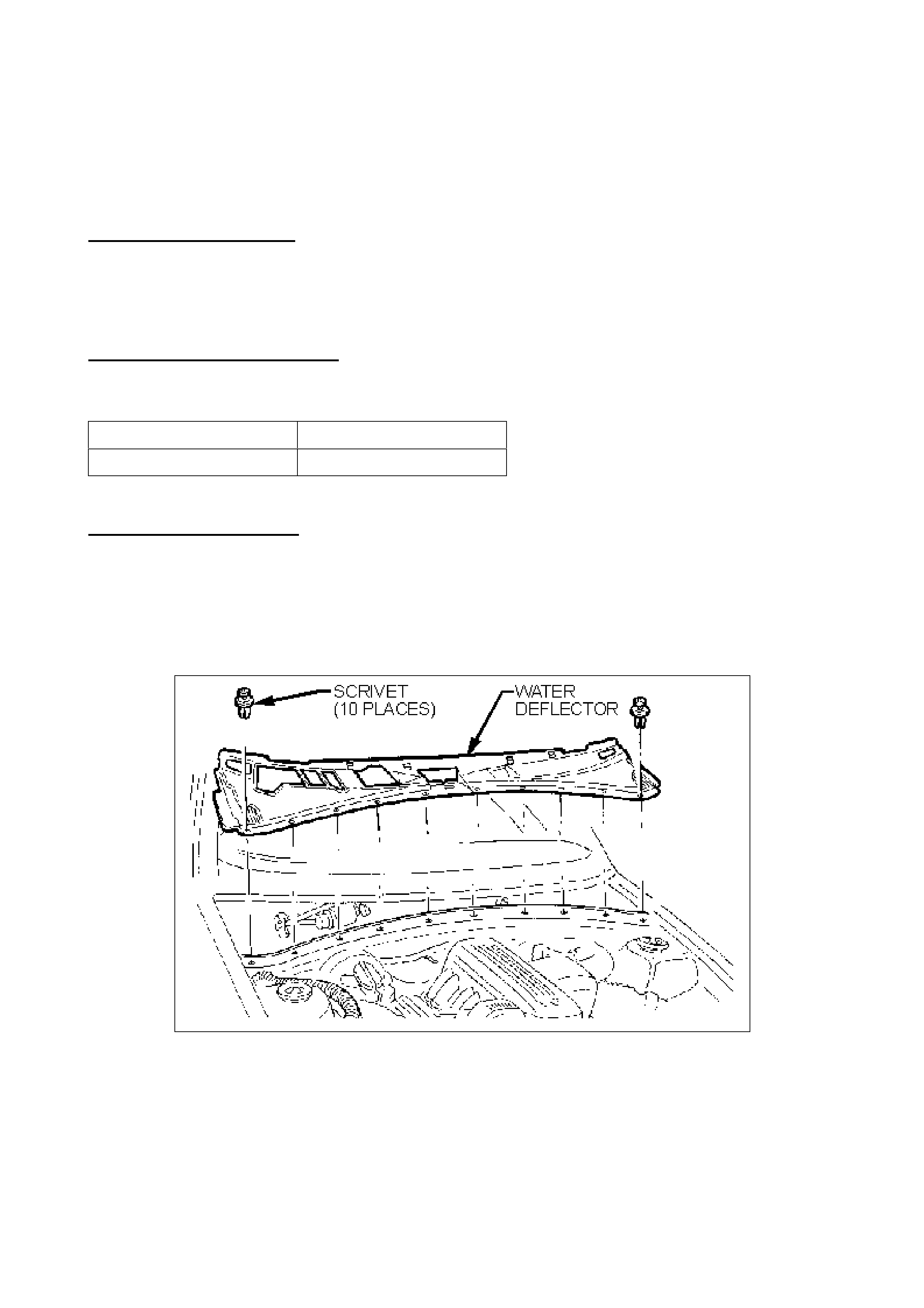
TICK NOISE FROM DASH PANEL AREA
VT, WH
(GROUP 1) November 1999
PROBLEM DESCRIPTION
When driving over rough surfaces, a ‘tick’ type noise can be heard from the dash panel plenum
(air intak e) area – shown in Figure 2. T his paint ‘tick ’ noise is the result of two painted panels with
a ‘slip-stick’ condition which is induced by body movement when the vehicle is driven over rough
surfaces.
PRODUCTION RECTIF ICATION
In production an extra line of weldable sealer has been added between the dash upper panel and
reinf or c em ent ( dash panel upper) as follows:
ISOVIN: Build Date:
6H8WHY19SXL496466 23/08/99
SERVICE RECTIFICATION
1. Remove windshield wiper arm and blade assemblies.
2. Unscrew six scrivets retaining bot h r ig h t and left plenum covers.
3. Unscrew ten scrivets retaining plenum water deflector , disengage locating t abs and r em ove
fr om vehicle as indicated in Figure 1.
Figure 1
4. Locate affected panel joints as indicated in Figure 2. Using a screwdriver or similar tool, located at the
intersection of the two panels, tap the tool with a light hammer to separate the two panels behind the
plenum air inlet, working towards the centre of the vehicle, separating the panels every 30mm over a
distance of 800mm approx. (as shown). This operation is only to provide a small gap between the two
panels – should any paint damage occ ur, the damaged ar ea mus t be protected against cor rosion, us ing
either FUSOR #800, 801, or 802; or 3M Automix 8306 Joint Sealers, or a commercially available
equivalent.
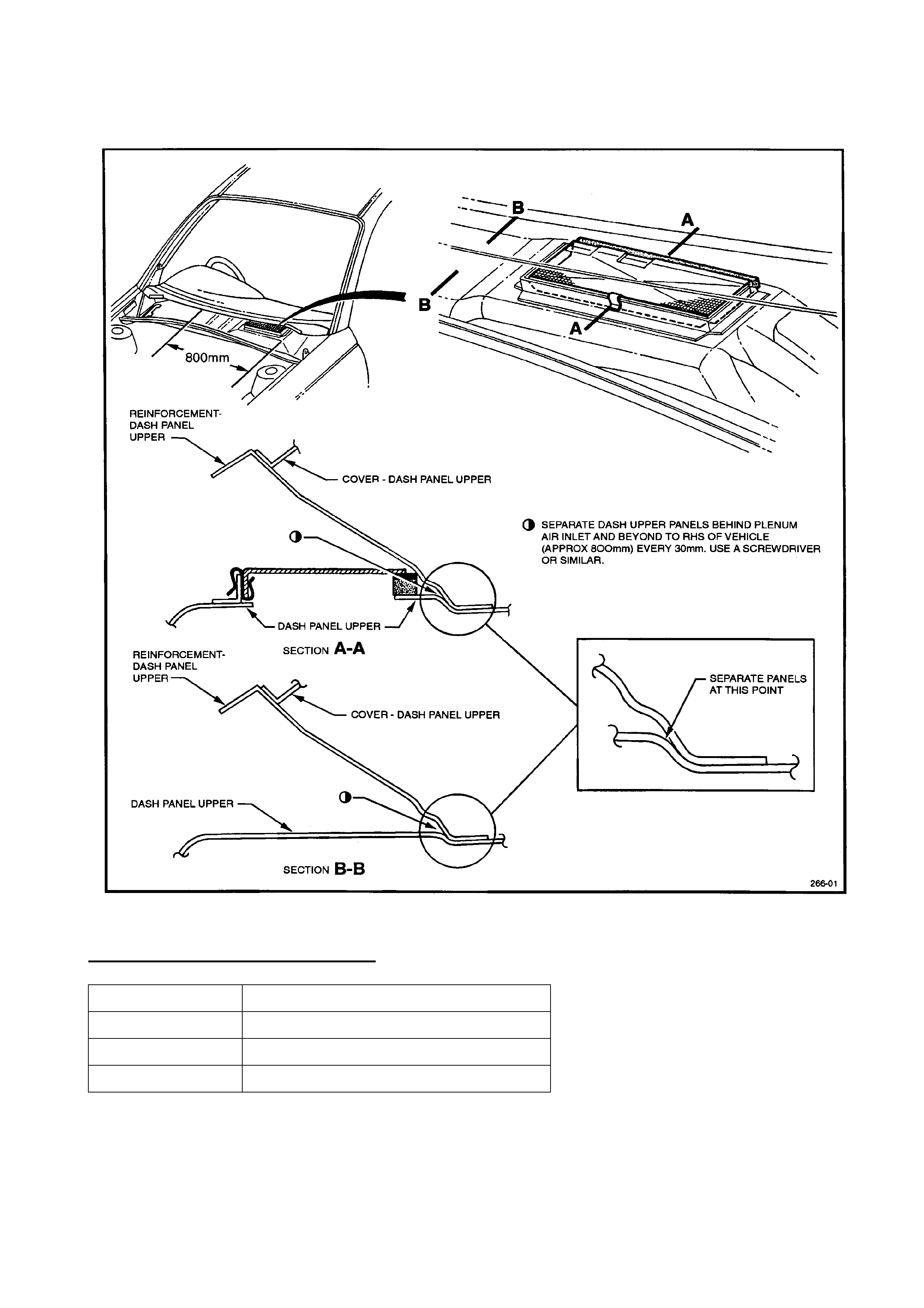
5. Test drive vehicle to confirm noise complaint is corrected (NOTE: Re-fit windscreen wipers temporarily
for road testing). Upon confirmation of correction, replace all previously removed components.
Figure 2
WARRANTY CLAIM INFORMATION:
Description Separ at e Dash Panels (Sheetmetal)
Labour Op. No. A000258
Time 0.7 hr
Failure Code 90

VALVE CLEARANCE SHIM CALCULATION
4JX1 JACKAROO
(GROUP 6A) November 1999
The following correction has been made to the valve clearance adjusting shim calculation
procedure for the 4JX1 engine.
Current Calculation
TA: T hickness of new adjuster
M: Valve clearance measurement
TO: Thickness of the r em oved adjust er
For Intake: TA=TO+(M+0.15) mm
For Exhaust: TA=T O + ( M+0.25) mm
Correct Calculation
TA: T hickness of new adjuster
M: Valve clearance measurement
TO: Thickness of the r em oved adjust er
For Intake: TA=TO+(M-0.15) mm
For Exhaust: TA=T O + ( M-0.25) m m
Workshop manuals should be corrected accordingly. The above information appears in Section
6A, page 64 of the 4JX1 workshop manual.
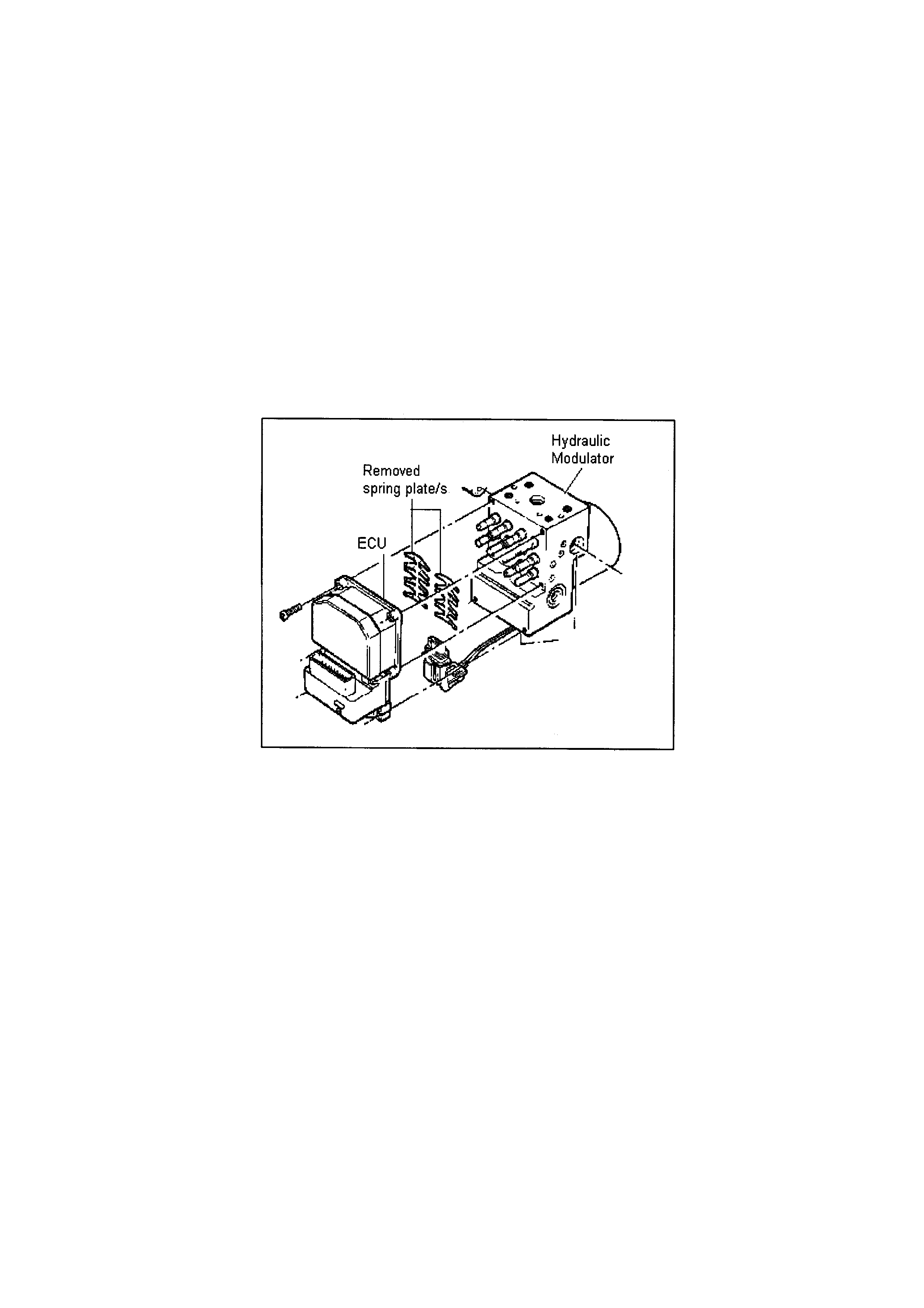
ABS MODULATOR SPRING PLATES DELETION
VT, WH, JS, JS, YE
(GROUP 5) November 1999
Whilst servicing the ABS module some dealers have queried the absence of the spring plates
located between the electronic control unit (ECU) and the hydraulic modulator. As a result they
have replaced the entire ABS/ ECU assembly.
Bosch has infor m ed Holden t hat these spring plates became r edundant as of July 1998.
Technicians should not be alarmed by the absence of the spring plates, nor attempt to retro-fit
them. Absence of, or inclusion of, these spring plates will have no effect on the vehicle braking
system.
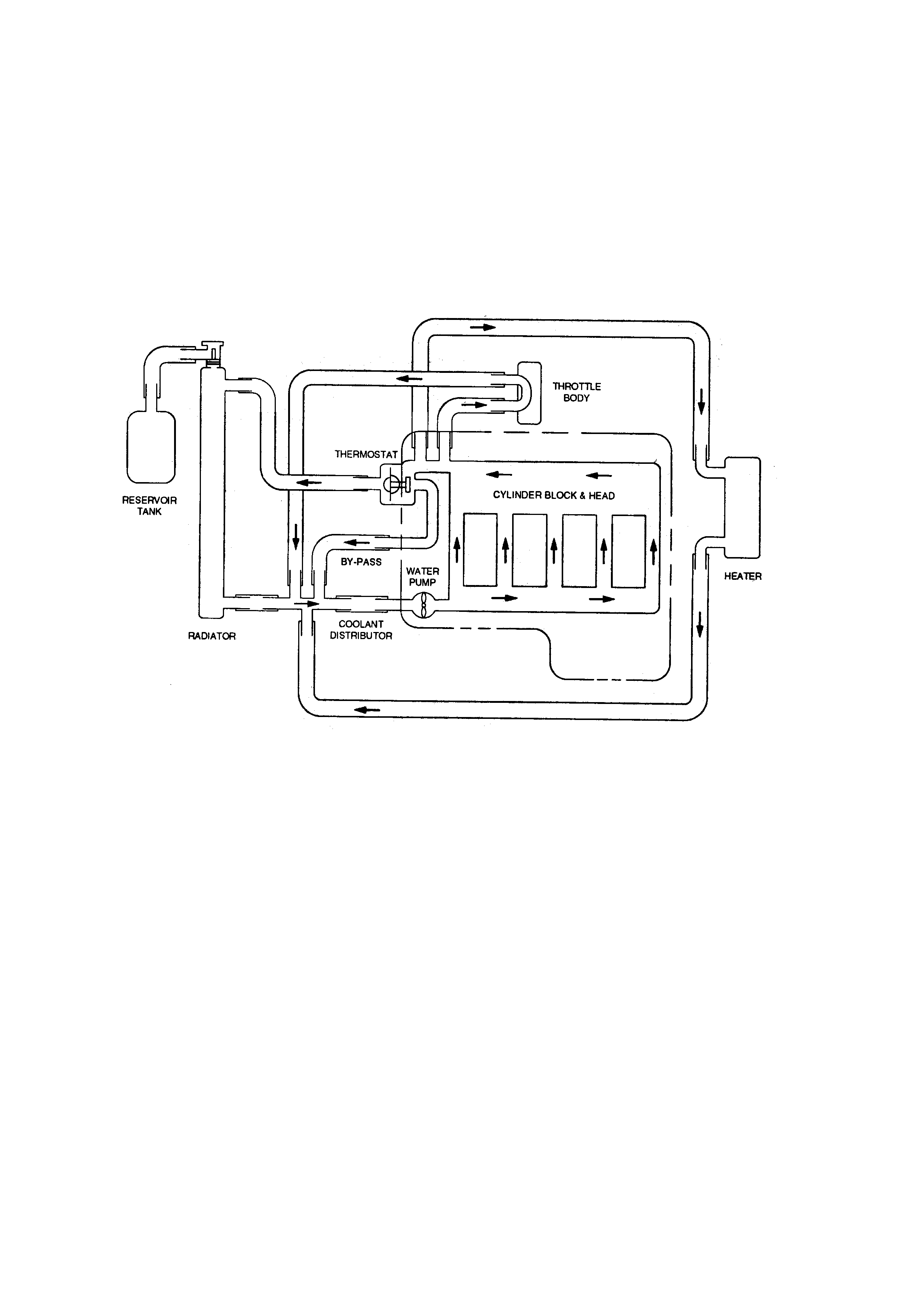
REVISION OF COOLING SYSTEM
2.2 TF RODEO
(GROUP 6K) November 1999
The following revision has been made to the cooling system diagram for 2.2 (C22NE) engined
Rodeos.
Workshop manuals should be corrected accordingly. The above information appears in Section
6B, page 2 of the 1999 TF 2.2 workshop manual.
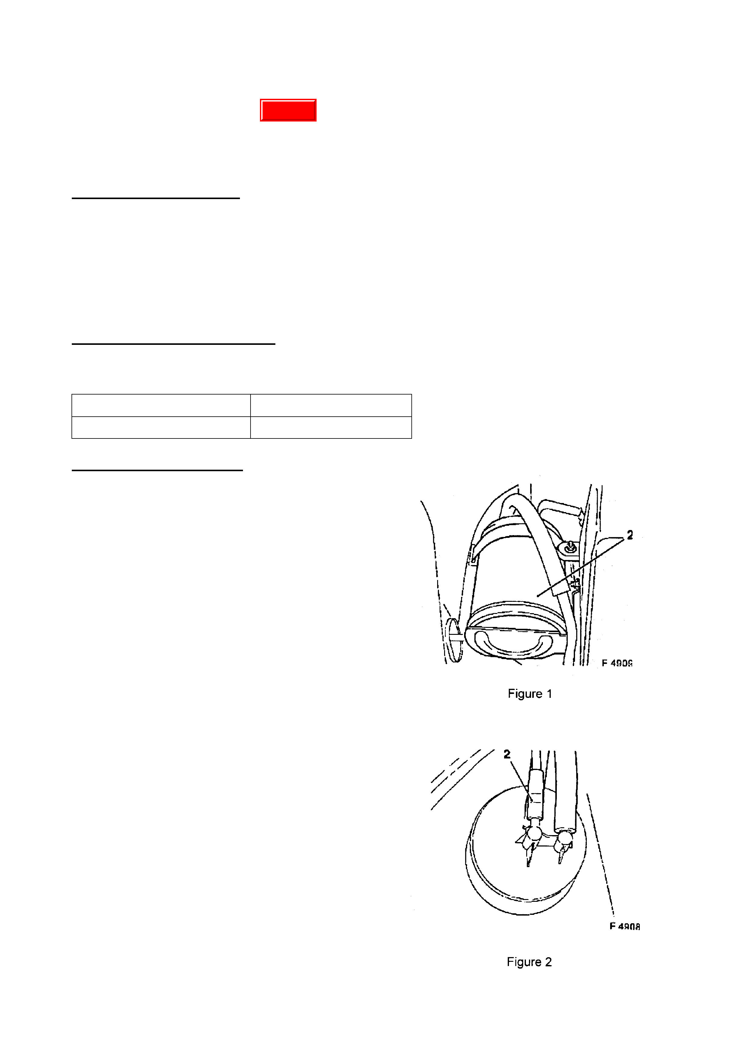
WHISTLE NOISE FROM ENGINE BAY
JR, C20SEL; JS, C22SEL
(GROUP 6M) November 1999
PROBLEM DESCRIPTION
Some customers may report a whistle noise that can be heard f rom the eng ine bay area at varying
speeds with light throttle application. The noise may emanate from the fuel evaporative carbon
canister purg e (transf er) hose (also called carbon canister t o f uel tank vent valve hose). T his hose
has a corrugated section, and when air passes through it, a whistle type noise is produced. To
verify this, the purge hose can be disconnected from the canister, and on road test the noise
should stop.
PRODUCTION RECTIF ICATION
Revised canister purge hoses have been introduced int o vehicle product ion from:
ISOVIN: Build Date:
W0L0JBF35YL496571 29/09/99
SERVICE RECTIFICATION
1. Locate the canister purge hose routed
along the engine firewall - (Canister t o fuel
tank vent valve)
2. Disconnect the canister purge hose joint,
located under the br ake master cylinder.
3. Turn vehicle steering wheel to the f arthest
right hand lock position, to gain access to
the rear end of the front inner wheel arch
cover.
4. Remove the two rearmost front wheel
arch cover plastic retaining nuts, and the
two lower plastic retaining clips.
5. Pull the rear section of inner wheel arch
cover away from its mountings to gain
access to the carbon canister (2) – Refer
Figure 1.
6. Disconnect canister purge hose (2) -
Refer Figure 2 - from carbon canister and
remove the hose f rom the vehicle.
7. Connect and route the revised type
canister purge hose as per the previous
hose.
8. Refit the inner wheel arch cover.
Update

PARTS INFORMATION
Revised canister purge hose can be or der ed from HSPO with the part num ber specified below:
Part No.: Descript i on: Qt y:
92081590 Hose, Canister Purge 1
WARRANTY CLAIM INFORMATION:
Description Canister Purg e Hose - Replace
Labour Op. No. L000187
Time 0.6 hr
Failure Code 40

“CREAK” OR “RATTLE” NOISE FROM ROOF AREA
JR
(GROUP 1) December 1999
PROBLEM DESCRIPTION
A “creak” or “rattle” noise may be heard from the roof area, during turns or when negotiating
driveways or rough r oads.
Investigat ions into these noises have defined the noise is emanat ing fr om the (centre) roof bow at
contact points with the roof panel. Hardening or crystalisation of the anti-flutter foam used results
in a “creak ” noise during normal body movement or a “ rattle” when anti-f lutter foam particles move
within the roof panels.
SERVICE RECTIFICATION
•Remove headlining retent ion material – trim panels, interior lamp, etc, for access to roof bow.
Headlining may then be dropped enough for access to r oof bow.
•Define areas of sealer (anti-flutter foam) hardening/crystalisation by lightly levering at panel
joints.
•Where the anti-f lutte r foam has brok en away - temporar ily lever the panels apart with a wedge
(take care not to distort roof panel) so that new anti-f lutter foam can be inserted between the
panels.
•Apply Fusor anti-flutter foam between roof bow and roof panel, along front and rear contact
area (see below for applicat or gun and foam).
•Remove the wedge temporarily holding the panels apart and allow panels to retur n to original
position - press t o gether if r equired, to spread ant i- flutter foam and attain original position.
PARTS INFORMATION
The following parts ar e r equired to carry out the above service rect ification:
“Fusor 300 50mm Sm all Dispenser Cartridge Gun” with 1-1 Plunger - 1 requir ed.
“#124 Fusor Anti-Flutter Foam” - 2 tubes r equired for t his t a sk). (Suitable for 50mm Gun).
NOTE: at the time of publishing, this material was approved for rectification of this condition.
W here Holden is able to determine additional, or equivalent materials, these will be published in a
fut ure Techline bulletin.
The mat erial specified is available from :
Australian War ehouse Dist ributors
239 Wickham Road
Moorabbin
VIC 3189
Phone : ( 03) 9553 1977
Fax : (03) 9553 1225
NOTE: for emergency use - TAS has a Fusor 300 gun which may be borrowed (Note: dealer to
procure anti- flutter foam).

WARRANTY CLAIM INFORMATION:
Use the f ollowing information when carrying out the service rectification in this Techline bulletin:
Description Reseal r oof bow to roof
Labour Op. No. C000394
Time 1.0 hr
Failure Code 28
Warranty Clerks Please Note:
•Purchase of #124 Fusor Ant i- Flut ter Foam may be claimed in Net It em expense, Type “M”.
•Purchase of t he Fusor 300 Cartridge Gun cannot be claim ed under warranty.

REAR WINDSCREEN MOULDING DISTORTION - SERVICE HINT
VT
(GROUP 1) December 1999
PROBLEM DESCRIPTION
Rear windscreen moulding distor t s along top of screen ar ea.
SERVICE RECTIFICATION
Service manual information does not advise moulding replacement but the removal is included in
removal of the rear screen. For this reason, dealerships have been removing and replacing the
rear screen assem bly to rectify the moulding dist or tion.
THIS IS NOT REQUIRED!
The moulding can be removed from the rear screen opening usually by pulling the moulding, but
may need careful cutting of t he ur ethane, to remove the distor t ed m oulding.
After removing the moulding, apply a bead of urethane to the window opening and insert a new
moulding.
WARRANTY CLAIM INFORMATION:
Use existing labour time manual information as follow s:
Description Rear m oulding replace
Labour Op. No. C860400
Time 1.9 hr
Failure Code 11

REAR BRAKE S Q UE AL NOISE
TS
(GROUP 5) December 1999
PROBLEM DESCRIPTION
Rear brak es exhibit a “ s queal” noise during lig ht brake application.
During extensive investigation into the root cause/s of this squeal noise, it has been defined that
the main causes are:
• Brake pad friction material char act er ist ics.
• Restricted movement of the brake pads in t he guides
• Jamming of hand brake mechanical com ponents at the caliper through insufficient lubr ication.
When rectif ying any rear brak e sq ueal complaint , the “ Service Rectif ication” procedure below must
be fully carried out to ensure all potential causes of brake squeal are addressed and rectified
where required.
PRODUCTION RECTIF ICATION
Revised brake pads installed:
VIN: Build Date:
Y5018694 01/09/99
SERVICE RECTIFICATION
1. Raise vehicle to a suitable working height, rem ove rear wheels and support r ear suspension
so suspension does not “hang ” and hand br ake cables do not apply tension to the rear caliper
hand brake m echanism s.
2. Check operation of handbr ake mechanical components for free movement . Detach handbrake
cable fr om handbr ake lever at the caliper. Push brake caliper actuation lever downwards with
a screwdriver.
3. Depending on the r esult of the above check, carr y out one of the 3 following alte r nat ives:
I. If the handbrake lever fully returns back against the stop at the caliper, when the lever is
released, only the brake pads have to be replaced. Install new brake pads – Refer Note B.
NOTE: After replacement of brake pads, clean the brake pad guides in the caliper and the
caliper itself with a soft wire brush. Apply anti-squeak grease to the guides as shown in
Figure 1.
II. If the handbrake lever does not return to its stop on the caliper because the mechanism is
seized, or if the brake pads can not be removed the from the brake caliper, the brake pads
and caliper should be replaced. – Ref er Note C. NO TE: Dur ing the installat ion process - apply
anti-squeak grease to the guides as shown in Figure 1, and ensure free movement of the
pads in the caliper.
4. A symptom of a seized or stick ing handbrake lever is excessive wear of pads/discs. Check
rear brake discs for excessive wear (measure thickness) and replace if necessary – Ref er
Note A.
5. Adjust hand brake lever tr avel, r e- assem ble parts removed and road test vehicle.
Notes
A. See work procedure in TIS "Check brake pads and brake discs for excessive wear", unit "H" in
Service Instruction for Astra-G.
B. See work procedure in TIS "Replace and install brake pads - rear wheel brake" unit "H" in
Service Instruction for Astra-G.
C. See work pr ocedur e in TI S "Replace and install caliper - rear w heel br ake" unit "H" in Service
Instruction for Astra-G.
Update
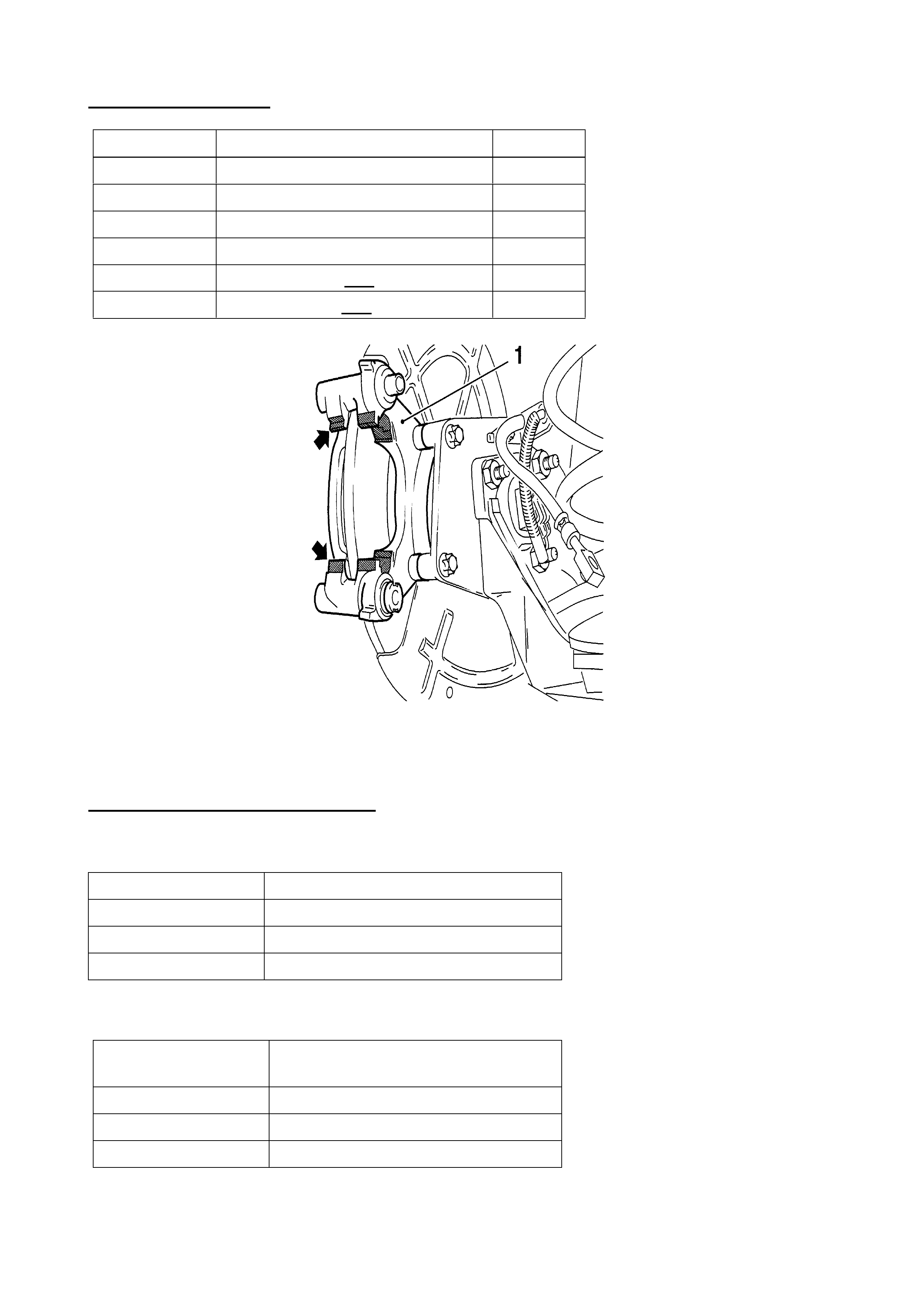
PARTS INFORMATION
Part No.: Description: Qty
09195685 Brak e Pads, Rear Brake 1
90166282 Anti-sq ueak paste 1
09193977 Caliper, RHR – non ABS 1
09193976 Caliper, LHR – non ABS 1
09193979 Caliper, RHR – with ABS 1
09193978 Caliper, LHR – with ABS 1
Figure 1. – Apply anti-squeak grease t o shaded ar eas.
(Item “ 1” = Caliper suppor t)
WARRANTY CLAIM INFORMATION:
WHERE BRAKE PADS (ONLY) ARE REPLACED – as in Step 3, alternat ive I.:
Description Rear disc brake pads - Replace
Labour Op. No. H125000
Time 0.7 hr
Failure Code 90
WHERE BRAKE PADS & CALIPERS ARE REPLACED – as in Step 3, alternative II. :
Description Rear disc brake pads & calipers -
Replace
Labour Op. No. H127000
Time 1.0 hr
Failure Code 15

SERVICE INFORMATION IN-DEALERSHIP PROCESS
ALL
(GROUP 0B) December 1999
Service Managers are reminded that service information updates are included in successive
releases of Ser vice Information CD’s.
Technicians must refer to the latest released CD when technical information/specifications are
requir ed in ser vice.
It is apparent that many Service Managers do not update or remove service literatur e in circulation
upon receipt of new and revised service informat ion.
When new service information, and in particular when CD’s are received, Service Managers
should give technicians the opport unity to review all new and revised inform at ion.

SERVICE MANUAL REVISION – STEERING GEAR TO CROSS MEMBER
MOUNTING NUT TORQUE
VT, WH
(GROUP 9) December 1999
VT Series Service Information CD Version 3 (released during the week of December 21, 1998)
contained a revised specificat ion for the steering gear to cross member mounting nut torque..
Please advise technicians and update relevant literature in dealership circulation to highlight the
following torque revision:.
STEERING GEAR HOUSING TO
CROSSMENBER MOUNTING NUT 70-85 Nm
TORQUE SPECIFICATION

ENGINE COVER RATTLE NOISE
VT, WH wi th LS1 GEN III
(GROUP 6A) December 1999
PROBLEM DESCRIPTION
Reports have been received of engine cover “rattle” at idle, or just above idle speed.
This rattle is caused by the main engine cover contacting the coil/bracket, at the rear of the
engine.
Revisions to the engine cover mounting brackets to alleviate this interference condition are being
carried out – br eakpoint inform ation will be advised in a future Techline issue.
SERVICE RECTIFICATION
1. Remove four engine cover ret aining nuts and remove the engine cover.
2. Loosen the two nuts retaining t he engine cover RH & LH mounting brackets.
3. Remove the two nuts retaining the rear ends of the eng ine cover RH & LH m ounting bracket s.
4. Lift the rear ends of the engine cover RH & LH mounting brackets and fit a new nut
(P/N 09440004) to each engine cover mounting brack et rear stud - torque to 4-6Nm.
5. Re-fit engine cover RH & LH mounting brackets, refit bracket mounting nuts - torque to
4-6Nm.
6. Re-fit main engine cover - torque r etaining nuts to 8-12Nm .
PARTS INFORMATION
Part No.: Description: Qty
09440004 Nut – Engine Cover Mtg. . 2
Update

DTC P0115 - ENGINE COOLANT TEMPERATURE SENSOR VOLTAGE HIGH
TS
(GROUP 6C, 6K) December 1999
PROBLEM DESCRIPTION
Investigation into reports of check engine lamp illuminated, engine cooling module lamp
illuminated, and engine cooling fans on continuously, have been found to be related to diagnostic
trouble code P0115 (engine coolant temperature sensor voltage high). DTC 164 may also be
stored in the eng ine cooling module. The pr oblem has been ident if ied as poor internal connections
within the coolant temperature sensor body. This has the potential to cause an intermittent high
resistance or open cir cuit in the coolant temperat ur e sensor cir c uit .
SERVICE RECTIFICATION
Technicians should follow the appropriate diagnostic chart outlined within the TIS CD ROM
relevant for diagnostic trouble code P0115. After confirmation that the sensor requires
replacement, fit a new coolant temperature sensor carrying a date code as defined below, or
higher:
Date Code Interpretation: Date Code 2499 sets the breakpoint for improved sensor manufacture.
The date code stamping can be found on the sensor hexagonal flats (on early parts) or on the
plastic sensor body (on later par t s with thinner hexagon flats) as f ollows:
“2499” where, “24” = week of the year,
and “99” = the year of m anufacture.
Parts date coded prior to this code are not to be fitted to vehicles.PARTS INFORMATION.
All parts at HSPO are of the latest specification.
Part No.: Description: Qt y
90530444 Sensor, Coolant Temp. 1
WARRANTY CLAIM INFORMATION:
Use existing inf or mation in Labour Time Manual.

DTC P0327 SETTING - KNOCK SENSOR SENSITIVITY REVISION
VT, WH with LS1 GEN III
(GROUP 6C) December 1999
PROBLEM DESCRIPTION
Reports have been received of DTC P0327 being set repeatedly. This has led, in some cases, to
time consuming diagnosis with no rectification resulting .
The cause of DTC P0327 setting (when no definable problem exists with eng ine, knock sensor or
knock sensor har ness) is an over-s ensit ive k nock sensor diagnostic system.
SERVICE RECTIFICATION
Revised software contained in the next T IS 2000 CD, to be r eleased in December, 1999 will r ectif y
vehicles in the field. Use of the software contained in the new CD, to flash program PCM’s will
rectify this complaint on non-HSV vehicles only.
For HSV vehicles which suffer this complaint – fax a “Holden Special Vehicles W arranty Request
Form No . 9861” with full details, to HSV “Attention: John Volarich” (Fax No. (03) 9265 9555), who
will supply a change-over PCM.
Update

ECU RESETTING PROCE DURE
TS
(GROUP 6C) December 1999
When the need arises to replace an engine control module in a TS Astra, technicians should be
made aware of the requirement t o r eset the security feature of the module prior to rem oving it f r om
the vehicle.
If the module is not reset prior to removing it, the module remains security linked to that specific
vehicle and cannot be reprogr ammed until reset accordingly.
This procedure is necessar y on warranty replaced modules – which must be reset to allow Holden
to investigat e cause of failure.
Similarly, the same procedure should be followed when installing a module from another vehicle,
or where dealership stock is used t o confirm diagnosis.
Engine Control M odul e Resetting Procedure
The engine control unit must always be reset in the vehicle it was initially progr a m m ed to.
1. Connect TECH 2 and select the following.
2. F0: Diagnostics / Model year / Astra G / F3: Body / Immobiliser
3. F3: Additional Functions
4. F2: Reset Engine Control Module
5. When security code is requested, enter secur it y code and press ent er .
6. When you have entered the correct secur it y code press okay to proceed.
7. The following warning will appear, “Warning: Engine will not start after reset! Do this only
before replacing the Engine Control Module”. Press the CONFIRM soft k ey at the base of the
TECH 2 screen to continue.
8. Program Completed, the engine control module is now reset, press the CONFIRM soft key at
the base of t he TECH 2 screen to exit.
Update

SPECIFIC OIL LEVEL CHECKING & REFILLING PROCEDURE
JS Series II (F23 M/T)
(GROUP 7A) December 1999
This Techline is issued to ensure that technicians are aware of the specific procedures for
checking, drainage and refilling of this transmission, which is detailed in the current TIS CD.
(Select Vectr a B, MY 2000. NOTE: Do not select an engine type).
The level check plug in the F23 transmission does not indicate an accur at e trans. oil level.
2.2 CHECKING/DRAINING TRANSMISSION LUBRICANT
NOTE: Unless a fluid leak has been observed and corrected, there is no requirement to check the
transmission fluid level.
Important: The level check plug on the F23 transmission fitted to Vectra B, MY 2000, does not
indicate an accurate transmission fluid level condition.
1. Clean all dirt and debris from the filler and drain plugs on the transmission, then blow dry with
compressed air.
CAUTION: Wear eye protection during this operation.
2. Using an 8 mm Allen key socket and suitable equipment, loosen then remove the transmission filler
plug, located at the top of the transmission case.
3. To gain access to the drain plug, it will first be necessary to modify a standard, 8 mm Allen key by
reducing the short leg to a length of 10 mm.
NOTE: The drain plug is located under the left hand driveshaft, in the transmission case.
4. W ith the modified Allen key inserted into the drain plug, install a suitable length of pipe over the longer
end of the Allen key to develop sufficient leverage.
5. Loosen and remove the transmission drain plug, draining the transmission lubricant into a clean
container with a capacity of at least 2 litres.
NOTE: Depending on the reason for draining the transmission lubricant, careful inspection of the drained
lubricant f or evidence of bras s or s teel m aterial, m ay assist in the early identification of a potential m ajor
problem.
6. After cleaning the transm ission drain plug, fit a new sealing ring, then reins tall and tighten the drain plug
to the correct torque specification.
TRANSMISSION
DRAIN PLUG 35 Nm
TORQUE SPECIFICATION
7. Refill the transmission with a measured, 1.6 litres of the recommended lubricant, through the
transmission filler plug hole. See 5. SPECIFICATIONS in this Section for lubricant details.
8. After cleaning the trans mission filler plug, f it a new sealing ring, then r einst all and tighten the f iller plug to
the correct torque specification.
TRANSMISSION
FILLER PLUG 35 Nm
TORQUE SPECIFICATION
F23 transmissions are identified by the “F23” cast onto the top of the main transmission housing,
visible in engine bay from above and behind the battery. F23 transmissions also have Reverse
gear t o t he RHS of the shift gate; previous tr ansm issions had r everse posit ioned to the LHS.

PRODUCTION INTRODUCTION
The F23 Manual Transmission was introduced into pr oduction with start of JS Vectra (Series I I) as
follows:
ISOVIN: Build Date:
W0L0JBF19YL482379 30/07/99

M/T OIL SPEC. REVISION
JS, JR, TS, SB (GSI)
(GROUP 7A) December 1999
This Techline is to advise technicians of a new manual transmission oil specification for the
following models, which is also a specific oil for use in JS Series II, F23 M/T:
SB Barina GSI – F13 Trans. ONLY
TS Astra – F17 Trans.
JR Vectra – F18 Trans.
JS Vectra – F18 & F23 T r ans.
Oil now specified for these transmissions is:
CASTROL SMX-O
This oil must be used for service replacement or replenishment of oil in the above manual
transmissions.
Castrol SMX-O r eplaces previously released oils MTF1067, MTF1067+ & MTF0063.
SERVICE USAGE & PRECAUTION
Dealers holding old st ock of MTF1067, MTF1067+, or MTF0063 can use this oil in:
SB Barina GSI – F13 Tr ans. ONLY
TS Astra – F17 Trans.
JR Vectra – F18 Trans.
JS Vectra Series I – F18 T rans. ONLY
This oil MUST NOT be used in JS Series II Manual Transmissions for durability reasons.
Castrol SMX- O must be used in JS Series II manual transmi ssions.
PRODUCTION INTRODUCTION
Oil to this specification was introduced into JS Vectr a ( Ser ies I I) vehicle production as follows:
ISOVIN: Build Date:
W0L0JBF19YL482379 30/07/99
Update

M/T SERVICE INFORMATION
VT wi th LS1 GEN III
(GROUP 7A) December 1999
The following manual transmission information for LS1 (GEN III) manual trans. is repeated from All
Dealer Letter DL 57/99 – for the benefit of service technicians. This information supersedes the
information shown in VT Series II Service Manual, Volume 14C, Sections 2.1, 2.2 and 3.1 on
pages 7B3-8 & 9, and Section 3. 6 on page 7B3- 16.
For detailed service procedures refer to the VT Series Service Manual, Volume 14C,
Section 7B3-1.
Please note the f ol l owing im port ant points on servicing this transmission:
•This transmission is classified as being a "Fill for Life" transmission and periodic checking of
the lubricant level is not required. In production, a sticker is placed next to the normal filler
plug on the transmission advising technicians: - “DO NOT OPEN THE FILL PLUG – REFER
SERVICE MANUAL”.
•The only time that fluid level checking is appropriate, is after correction of a fluid leak that
does not req uir e the transmission to be f ully drained and/ or removed from t he vehicle.
•The VT Ser ies II Owners Handbook Pr int No 3 will have the req uirement to periodically check
fluid levels in this tr ansmission deleted.
•The VT service manual (CD version only) has also been revised in line with the above. The
CD with these revisions is planned for automatic distribution in December 1999. The
attachment to this letter is an extract from this CD detailing information on transmission fluid
capacity, checking & filling procedures. There is also information on the addition of an
insulator sock to the control lever. The additional oil level and insulator sock have been
introduced as noise reduct ion init iat ives.
PRODUCTION BREAKPOINTS
Insulator sock (as shown in Section 3.6 attached) was introduced into production at:
ISOVIN: Build Date:
6H8VTK69FXL500253 31/08/99
Oil level was increased (as noted in Section 2.2 at t ached) in the transmission at:
ISOVIN: Build Date:
6H8VTK69FXL505387 14/09/99
The TREMEC “T56” 6-speed manual transmission, in VT Series II vehicles (NON-HSV) with Gen
III V8 engine was introduced into production at:
ISOVIN: Build Date:
6H8VTK69FYL511966 29/09/99
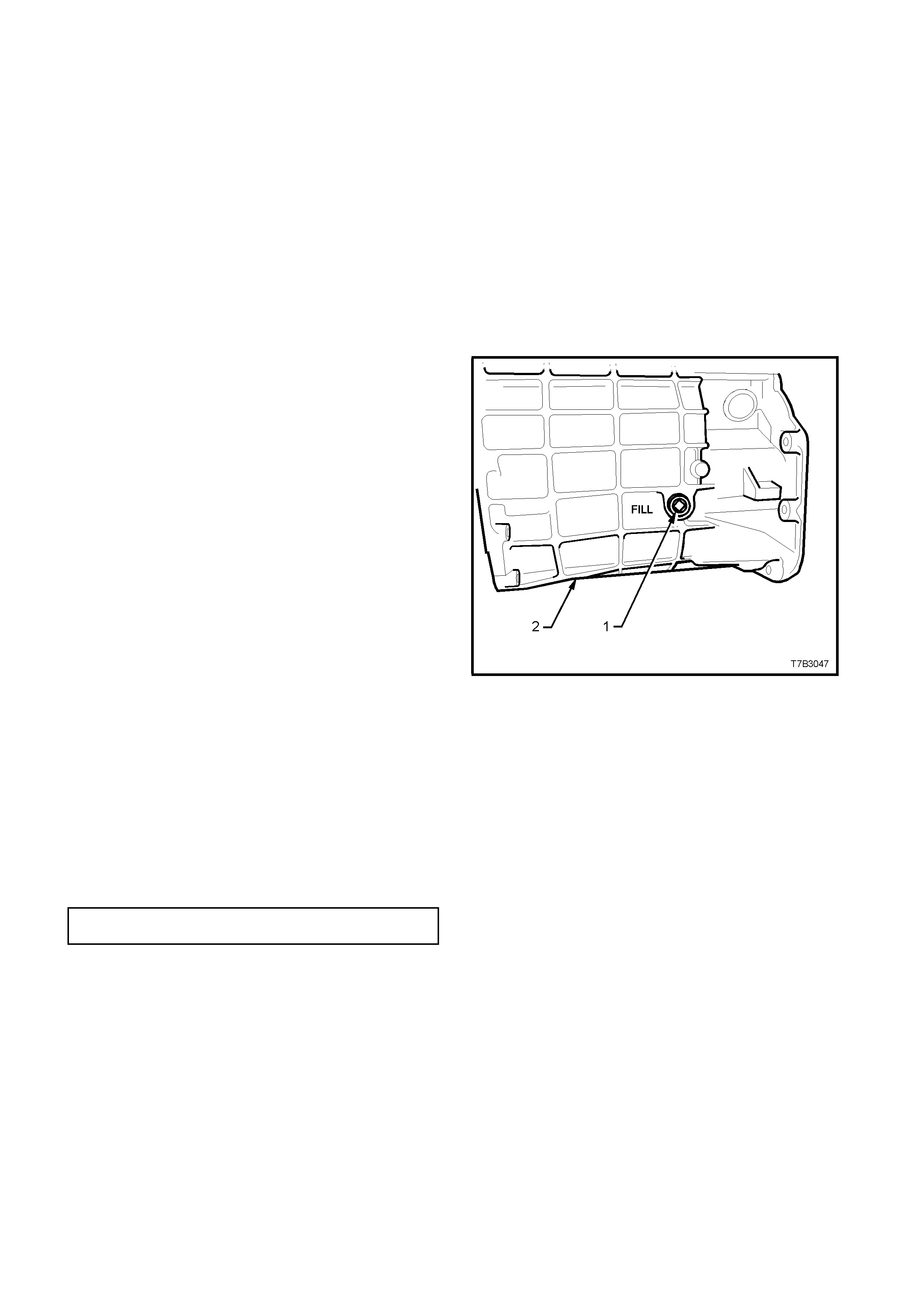
2. SERVICI NG I NFORMATI ON
2.1 RECOMMENDED LUBRICANT
The recommended lubricant for the ‘T56’ manual
transmission is Dexron III® automatic
transmission fluid to Holden’s Specification HN
2126.
The transmission lubricant capacity is
approximately 4.4 litres.
2.2 CHECKING TRANSMISSION
LUBRICANT LEVEL
Important: This transmission is classified as
being a “Fill for Life” transmission and
checking the lubricant level is not
recommended.
The only time that fluid level checking would be
appropriate, would be after correction of a fluid
leak that did not require the transm iss ion to be fully
drained and/or removed from the vehicle.
1. Raise the vehicle front and rear and support on
safety stands, ensuring that the vehicle is level.
Refer to Section 0A GENERAL INFORMATION
in Volume 1 of this Service Manual, for the
location of jacking points.
2. Place a drain tray beneath transmission and
remove transmission filler plug (1) from left
hand side of transm ission c ase (2), using a 3/8”
drive socket bar.
NOTE: Depending on the severity of the loss, fluid
will probably flow from the filler plug hole, following
removal.
3. Allow excess fluid to drain until flow stops. If
required, top up fluid level until it does flow out.
4. Clean the threads of the filler plug, apply thread
sealant such as Loctite 565 or equivalent (GM
P/N 12346004), then reinstall filler plug,
tightening to the correc t tor que s pecif ic ation. Do
not apply Teflon thread tape to the plug
threads.
TRANSMISSION FILLER PLUG 20 - 34
TORQUE SPECIFICATION Nm
5. Remove the back -up lamp switch as detailed in
3.1 BACK-UP LAMP SWITCH, Replace in this
Section.
6. Using commercially available fluid dispensing
equipment, add a measured, 0.5 litres of the
recom mended lubricant to the transmission, via
the back-up lamp switch threaded hole in the
transmission case.
7. Reinstall the back-up lam p s witch, as detailed in
3.1 BACK-UP LAMP SWITCH, Replace in this
Section, then lower the vehicle to the ground.
Figure 7B3-7
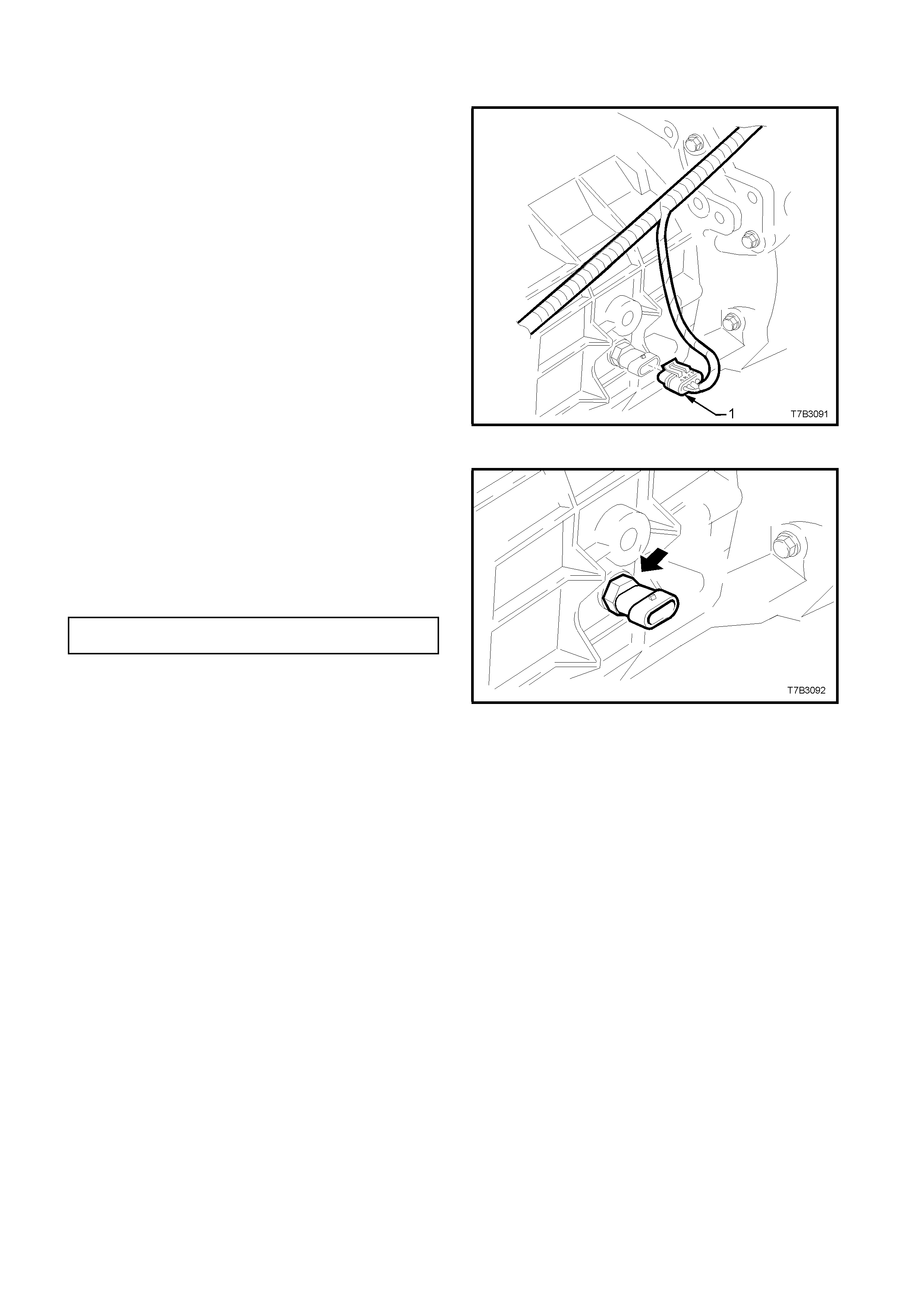
3.1 BACK-UP LAMP SWITCH
REPLACE
1. Raise front of vehicle and support on safety
stands. Refer to Section 0A GENERAL
INFORMATION in Volume 1 of this Service
Manual, for the location of jacking points.
2. Remove wiring harness connector (1) from
switch, located on the right hand side of the
transmission case.
Figure 7B3-9
3. Loosen, then remove switch (arrow) from the
transmission case.
4. Apply Loctite 565 or equivalent (GM P/N
12346004), to the cleaned threads of the back-
up lamp switch.
5. Install switch to transmission case and tighten
to the correct torque specification.
BACK-UP LAMP SWITCH 20 - 34
TORQUE SPECIFICATION Nm
6. Install wiring harness connector to switch.
7. Remove safety stands and lower vehicle to
ground.
8. Check back-up lamp operation. Figure 7B3-10
3.6 GEARSHIFT CONTROL LEVER AND
REMOTE SHIFTER SHAFT BOOT
REMOVE
1. Disconnect the battery earth lead.
2. Remove the gearshift lever knob and boot
assembly, from the gearshift lever. Refer to 3.5
CONTROL LEVER KNOB AND BOOT
ASSEMBLY in this Section, for the necessary
procedure.
3. Remove the centre console assembly, including
the console cap. Refer to 1A3, INSTRUMENT
PANEL AND CONSOLE, in Volume 1 of this
Service Manual for the necessary procedure.
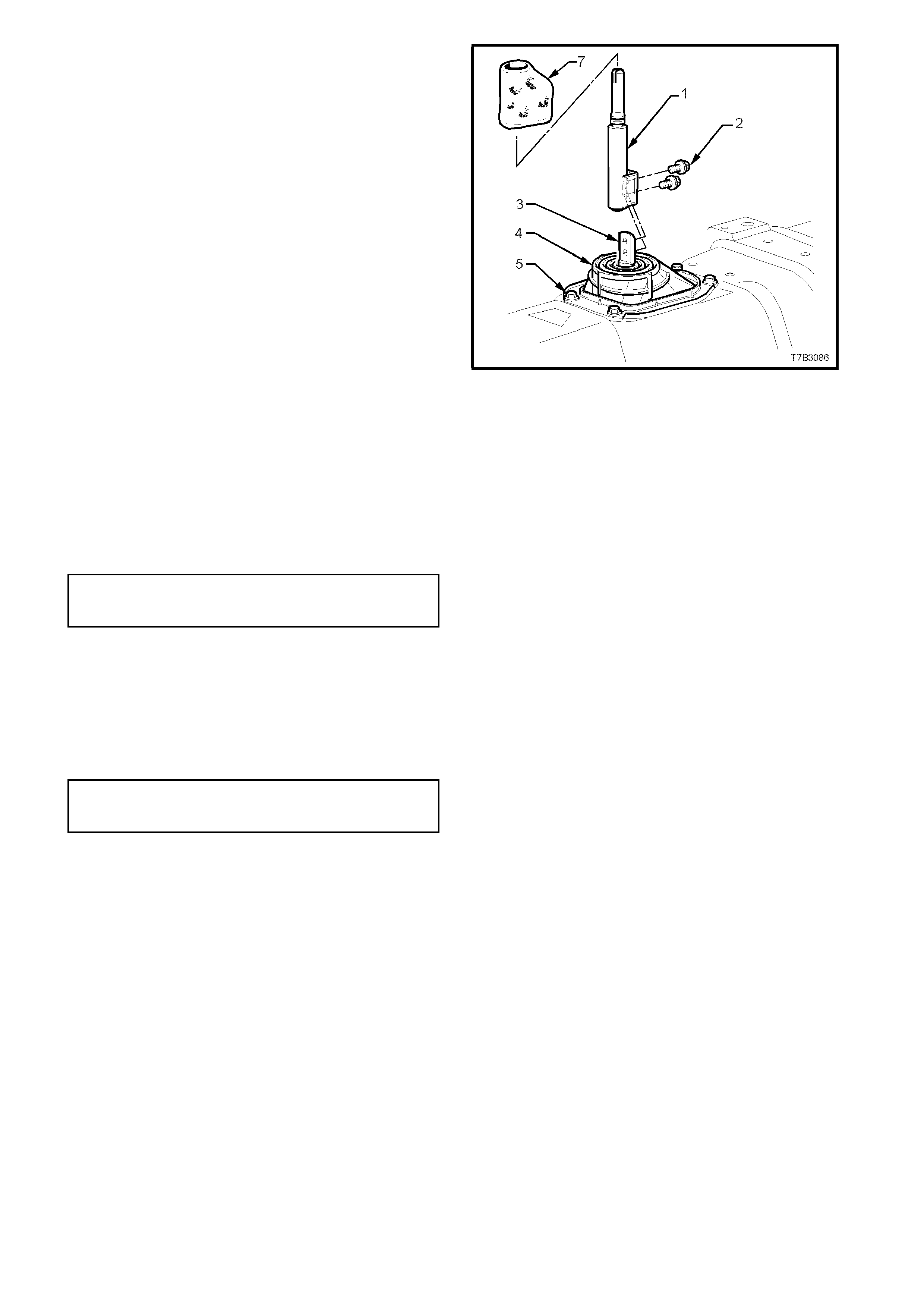
4. Slip the insulator soc k (7) f rom the contr ol lever
(1) and set to one side.
5. Using a 10 mm soc ket, remove the two bolts ( 2)
securing the control lever (1) to the gearshift
remote shift lever shaft (3), then lift the control
lever free.
6. If required, remove the four bolts (5) securing
the gearshift remote shift lever boot retaining
plate (6) to the floor pan, then remove the boot
(4) and retaining plate (6).
CLEAN AND INSPECT
1. Inspect the gearshift remote shift lever boot (4)
for tears or other damage, replacing as
required.
2. Clean the threads of the control lever bolts (2)
and check for thread damage. Figure 7B3-26
REINSTALL
1. If removed, install the gearshift remote lever boot
(4) and plate (6) and secure with the four bolts
(5), tightening to the correct torque specification.
GEARSHIFT REMOTE LEVER
BOOT PLATE BOLT 6.0 - 14.0 Nm
TORQUE SPECIFICATION
2. Apply thread sealant such as Loctite 242 or
equivalent (to Holden’s Specification HN 1256
Class 2, Type 2), to the cleaned threads of the
control lever retaining bolts (2).
3. Install the control lever (1) over the remote shift
lever shaf t (3), ins tall the two bolts ( 2), tightening
to the correct torque specification.
GEARSHIFT LEVER TO REMOTE
SHIFT LEVER SHAFT BOLT 15 - 35 Nm
TORQUE SPECIFICATION
4. Reinstall the insulator sock (7) over the remote
shift lever (1).
5. Reinstall centre console assembly, including the
console cap. Refer to 1A3, INSTRUMENT
PANEL AND CONSOLE, in Volume 1 of this
Service Manual for the necessary procedure.
6. Reinstall the gearshift knob and boot assembly
over the gearshift lever, align the knob in the
correc t attitude and then bump the knob onto the
gearshift lever until the retaining claws engage
with the groove in the lever.
7. Align the gearshift boot retaining clips with the
hole in the console cap, then carefully seat the
boot retainers into the c ons ole c ap until each c lip
engages correctly.
8. Reconnect battery earth lead.
9. Road tes t vehicle and check for c orrect gears hift
operations.

EXHAUST HEAT INSULATORS - FITTING INFORMATION
VT, WH
(GROUP 8) December 1999
VT & WH Service manuals do not carry information on fitting of self-adhesive (reflective foil)
insulators, located on the underside of the front floor pan above the front exhaust pipes.
The insulator locations are shown in VT Service Manuals:
VT - Volume 5, page 8B-18/19
VT Series II - Volume 14C, page 8B-8/9.
WH – Refer to VT Series II Service Manual.
When installing these insulators to a floor pan, the floor pan must be cleaned in the heat shields’
adhesion area to remove any traces of old adhesive, sealer overspray, or paint overspray if vehicle
has been repaired. Use a solvent soaked rag to assist removal of this material.
When replacing heat shields for any reason, install a new heat shield as serviced by HSPO.
Additional Notes:
1. To assist in acquiring parts: the insulators are called “REFLECTIVE FOIL – FRONT FLOOR
(ADHESIVE)” in PartFinderTM.
2. The insulators are called “Self-adhesive Insulators” in the VT Service Manual, Volume 5, Page
8B-19 – where the Service Manual indicates these insulators are used on “all except V6” – this
is incorrect – t hey are used on all vehicles.

INTERIOR LAMP/S REMAIN ON WITH DOORS CLOSED
WH, VT
(Group 12) December 1999
PROBLEM DESCRIPTION
PIR’s describe complaints of interior (dome) lamps or door courtesy lamps remaining on when the
doors are closed.
The cause has been defined as the RH rear or LH rear door jamb switch wires being ‘pinched’ by
the f r ont door upper striker attaching screw, which is fitted after switch installation:
- white wire pinched = dome lamp remains on.
- white/blue wire pinched = door courtesy lamps rem ain on.
SERVICE RECTIFICATION
Remove LH rear & RH rear door jamb switches and inspect wires for damaged insulation. Add
extra insulation to any damag ed wires and refit door jamb switches.
WARRANTY CLAIM INFORMATION:
Use existing inf o r m ation in Wiring & Connector Warranty Claim Submission Manual, as follows:
VT - Refer Figure 25 - Select the number for the appropriate wire (pinched) from the list at View A.
WH - Refer Figure 22 - Select the number for the appropriat e wire (pinched) from the list at View C.

BOOT REMOTE (KEY) OPENING DELAY
VT, WH
(GROUP 12) December 1999
PROBLEM DESCRIPTION
Some owners complain of the boot “not opening when they press the remote key button”. Some
complain that t hey have to “push the button several times” befor e the boot opens.
These complaint s m ay be caused by a misunderstanding of the remote key boot opening f eat ur e:
When using the button on the ignition key – the button needs to be pressed for more than half a
second (rather than the boot opening instantly any time the remote button is pressed). This time
delay is a feature of the vehicle’s electronic system, to ensure that the boot is not opened
inadvertently, when keys are being handled or placed in pockets, bags, et c.
Feedback fr om some customers sugg ests the leng th of the t ime delay may be of concer n, and this
is currently under review for r eduction.
SERVICE RECOM MENDATIO N
Should a customer complain about this boot remote opening time “delay”, or the need to press t he
remote key button several times – please explain the time delay feat ur e to them.
The relevant information in vehicle Owner’s Handbooks is shown on:
VT – Page 2-10
WH – Page 2-7
- and advises: “The button on t he key must be pressed f or more t han hal f a second…. ”
This f eature should also be explained when vehicles are being delivered to new owners or vehicle
operators, so they are aware of the small time delay and the benefit of this feat ur e.

ENGINE STALL ON DECELERATION OR HIGH ENGINE IDLE
JR, JS with C20SEL or C22SEL Engine
(GROUP 6M) December 1999
This Service Techline supersedes the previous Techline Issues 3/99 & 8/99 on this topic, and is
issued to include installation instructions for a PCV oil separator, which addresses IACV ‘sticking’
cause. Please ensure these pr evious Techlines ar e r emoved from dealership circulat ion.
PROBLEM DESCRIPTION
W ith vehicle stationary, the engine idle is t oo high; EG: 1000 RPM+, and engine m ay later stall or
the idle may remain high.
This is caused by a build-up of engine by-pass gases and IACV solenoid shaft/bearing wear
particles on the IACV solenoid shaft, which causes the IACV to stick at any point in its operating
range. This will result in either too high or too low IACV air ent r y to the throttle body and engine.
W hen the IACV subsequently “unsticks” and returns to norm al operation, the result may be a stall
or higher than normal idle RPM. It is not possible to effectively clean the IACV to correct this
condition.
PRODUCTION RECTIF ICATION
PCV oil separators have been fitted to vehicles from t he following breakpoints:
JS: Engine Number:
C22SEL25013594
ISOVIN: Build Date:
W0L0JBF19YL518348 30/08/99
C20SEL Engines:
Engine Number: Engine Build Dat e
C20SEL25031355 15/09/99
SERVICE RECTIFICATION
FOR ALL C20SEL & C22SEL ENGI NES UP TO THE ABOVE BREAKPO I NTS.
To correct this condition, carry out the following procedure:
Before carrying out the procedure - Connect Tech-2 and check for DTC’s. If any are stored,
correct t he fault defined before progressing.
1. Remove air intake hose f r om throttle body, to gain access t o t hr ottle blade.
2. Check for blow-by gas deposit in throttle body – around IACV port and on lower side and
edges on the throttle blade. If deposits are present, thoroughly clean throttle body including
any vacuum related ports. This can be achieved by using a commer cially available carburettor
cleaner aerosol spray pack.
3. Reinstall air intake hose t o throttle body.
4. Install a new IACV and gasket. If gasket has a “vee” notch on outer edge, it must face the
top of t he IACV flange on assembly.
5. Install a PCV oil separator ( r efer to Fig ur e 1. ) , P/N 09193502, as follows: Rem ove Hose – vent
tube to camshaft cover and discard.
6. Remove all traces of oil from exterior surfaces of camshaft cover/tube and engine vent tube.
Update
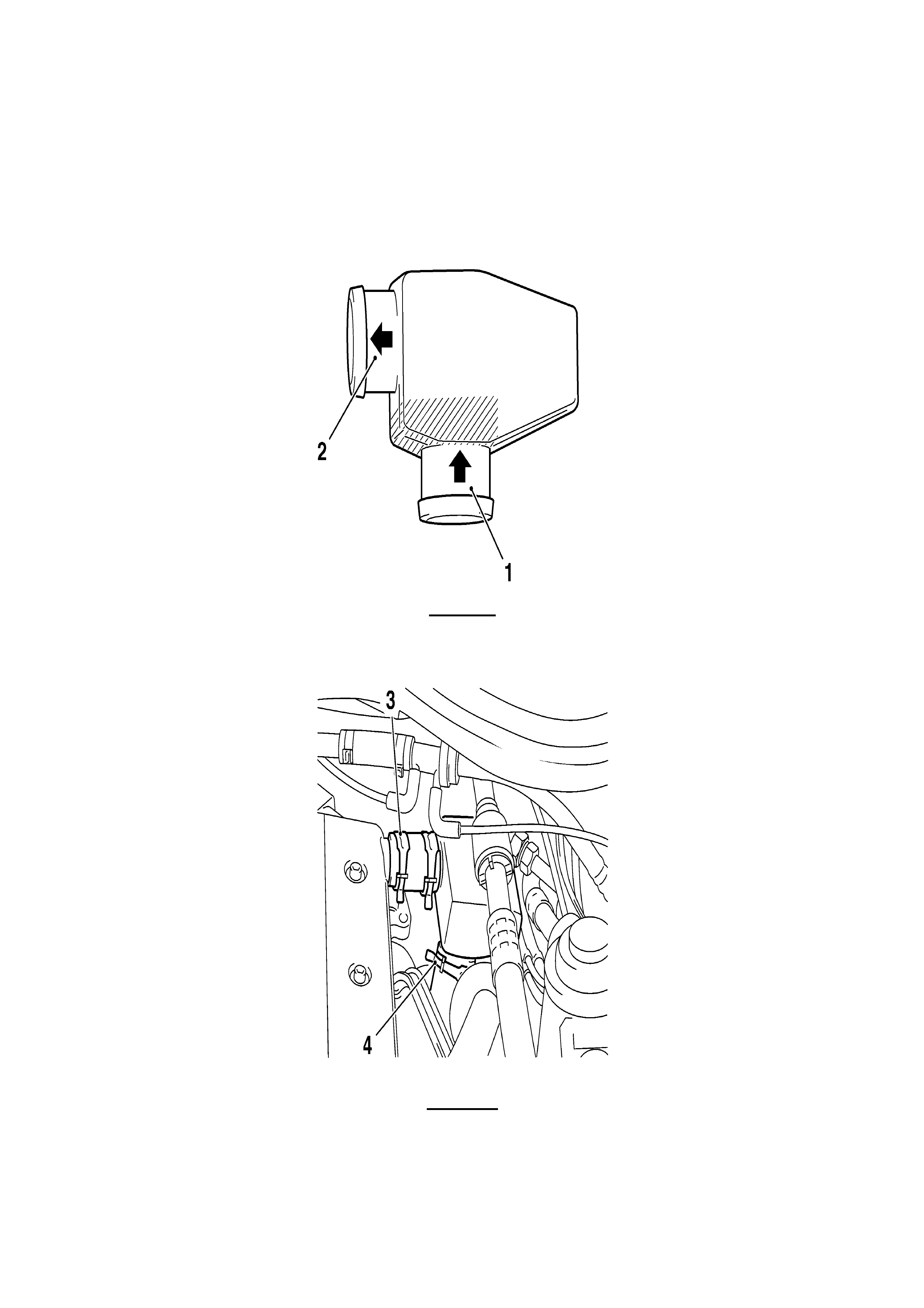
7. Install two hoses, P/N 24421017, onto oil separator, using two clamps, P/N 90467971, to
secure the hoses to t he separ at or . .
8. Install the oil separator between the engine vent tube and the camshaft cover, using hose
clamps (fr om original removed hose). Refer to Fig ure 2. (The white dot on t he separator must
face upwards).
9. Road test vehicle and confirm or iginal complaint does not exist.
Figure 1
“1” = Lower vent tube connection (steel mesh visible).
“2” = connection to cam cover hose.
Figure 2.
(Showing installed position of PCV oil separator)
“3” = hose connection to cam cover
“4” = hose connection to vent tube

PARTS INFORMATION
Part No.: Description: Qty
90411546 Valve – Idle Air Control (IAC). 1
90466220 Gasket - IACV 1
09193502 Separator – PCV Oil 1
24421017 Hose – PCV Vent 2
90467971 Clamp – Vent Hose 2
WARRANTY CLAIM INFORMATION:
Claiming for correction of any DTC’s that may be found on initial checks – refer to the relevant
section of the Labour Time Manual which carries DTC claiming information at the end of the
section. Use the r e levant Labour Operation Number for the DTC.
Claiming for replacement of any component found faulty during that DTC diagnosis – use the
relevant Labour Operation for rem ove and replace of the faulty part .
To claim for the rectification procedure detailed above, use t he following inform at ion:
Description Fit PCV Oil Separator
Labour Op. No. J000631
Time 0.8 hr
Failure Code 84
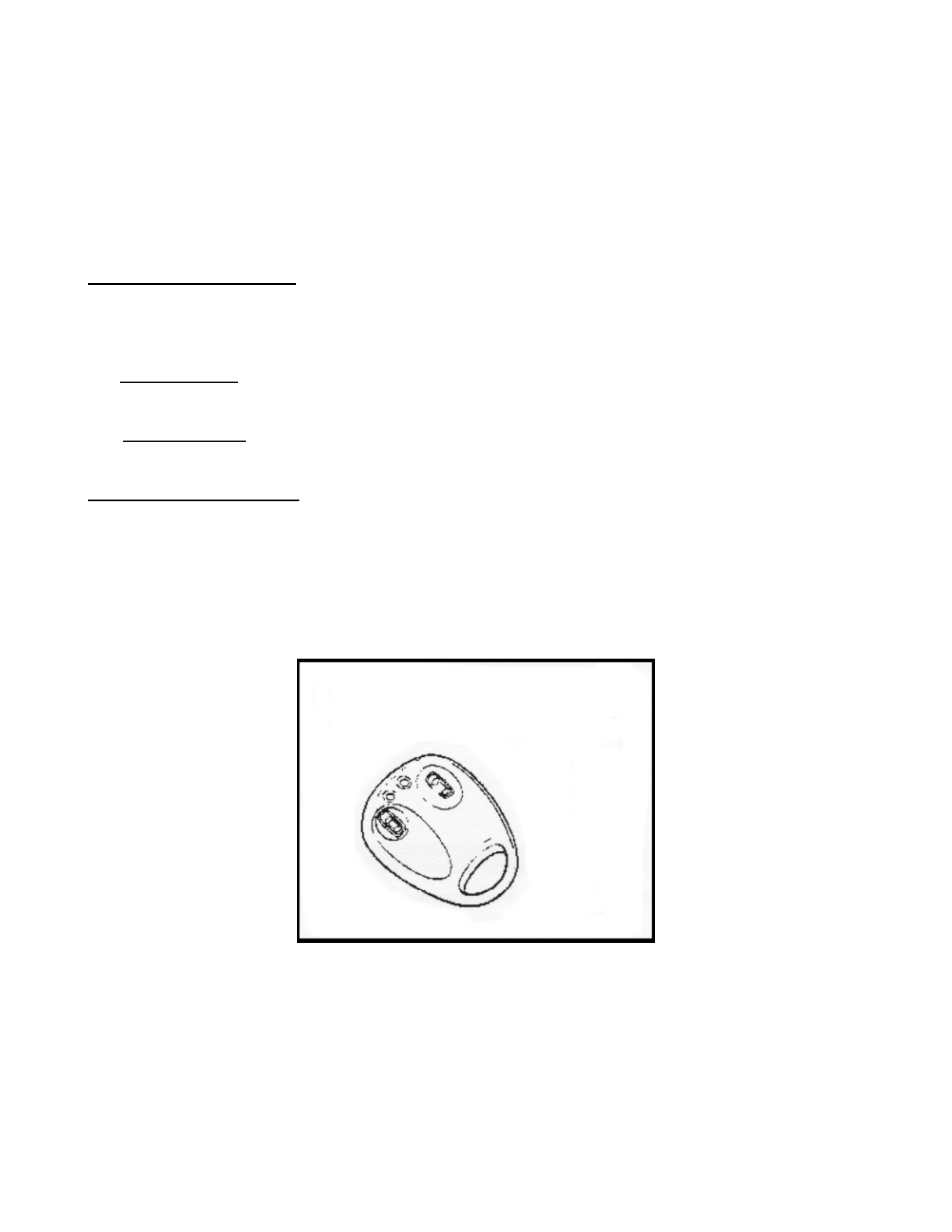
REMOTE KEY INOPERATIVE
JR MY97’, JS MY98’
(GROUP 12) October 1999
This Techline item supersedes the previous Techline on this topic (Page 53, 1998 Service
Communication handbook). Refer to this Techline.
PROBLEM DESCRI PTION
Further investigation into failures of the remote keys identified two distinct causes depending on the
vehicle model year.
For Model Year 97’, the thickness of the battery cover was found insufficient to withstand high loads
and caused damage t o t he bat tery. This results in poor bat t er y contact .
For Model Year 98’, the battery holder material within the remote sender unit absorbs moisture,
expands and causes a poor connection between the battery and the positive contact .
SERVICE RECTIFICATION
In service firstly determine the type of remote. A Model Year 98’ remote has sender unit and key
combined, refer to Figur e 2, as opposed to the Model Year 97’, refer to Figure 1.
For MY97’:
1. Locate t he battery cover on the underside of the remote as shown in Figure 1 below, replace the
battery cover.
2. Replace the batter y.
Figure 1
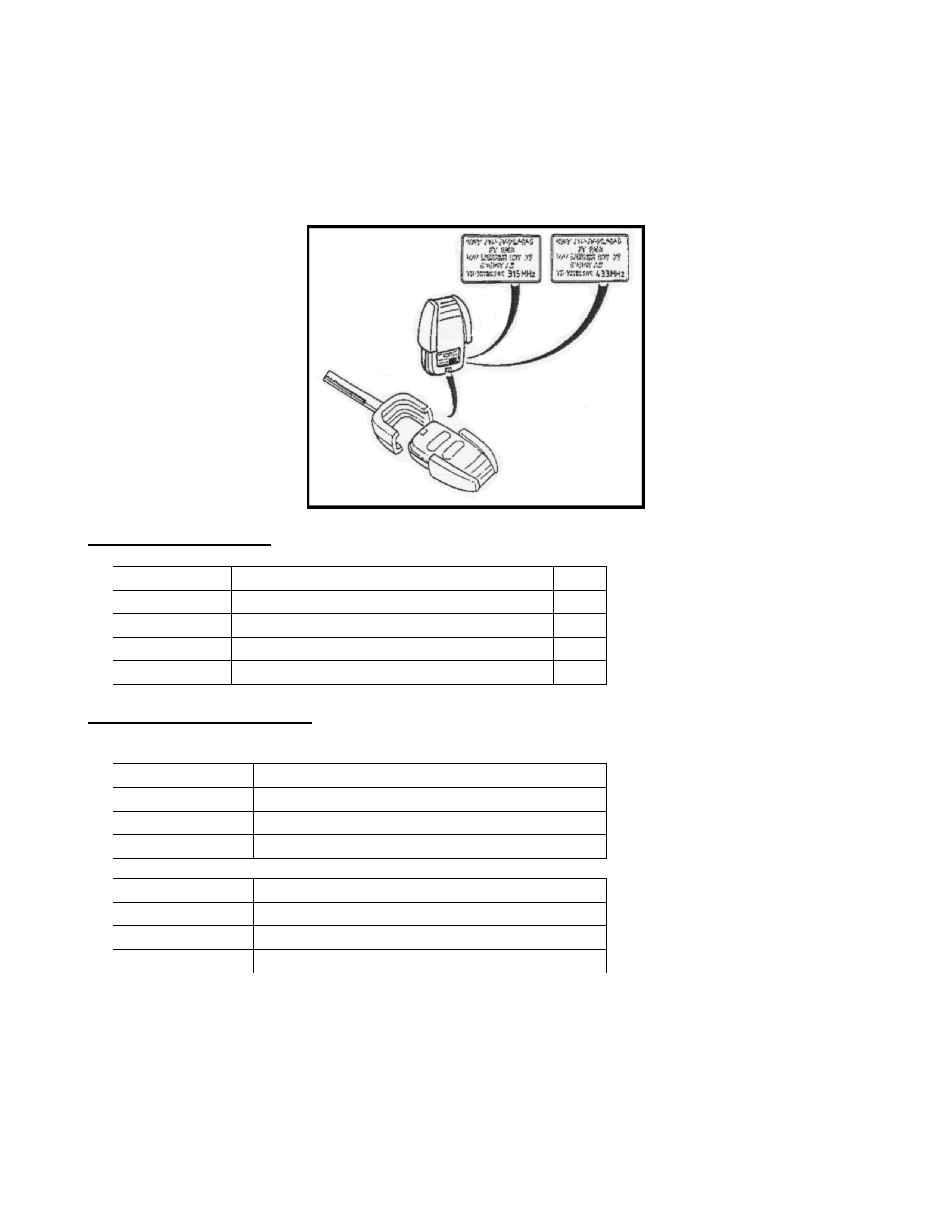
For MY98’:
1. Determine the transmitter frequency. It should be labelled as either 315 MHz or 433 MHz
transmitter. Use Figure 1 t o ident ify the correct frequency.
2. Replace the sender unit with the revised parts. A more durable battery holder has been
introduced as a running change.
To verify this, check the label on the bag that the part comes in. A level identifier “01” depicts
revised parts.
Figure 2
PARTS INFORMATION
Part No. Description Qty
90569366 Sender, Central locking - 315 MHz 1
90564345 Sender, Central locking - 433MHz 1
92143042 Battery cover 1
90541381 Battery 1
WARRANTY INFORMATION
Use the inf or mation applicable for warranty claims.
Description : Replace Remote Key, Anti Theft
Labour Op. No. : N501600
Time : 0. 3 Hr s
Failure Code : 50
Description : Replace Battery and Cover
Labour Op. No. : N000291
Time : 0. 2 Hr s
Failure Code : 50

HOLDEN SERVICE TECHLINE _____________________________________________________________________July 2000
1
WATER LEAK – WAGON REAR LOAD
COMPARTMENT
VT
(GROUP 1)
PROBLEM DESCRI PTION
Water leaks into the vehicle load
compartment through the rear side stationary
glass panels. W ater ingress occurs due to the
integrated foam seal compressing over time
allowing gaps to occur in the seal.
PRODUCTION RECTIF ICATION
Revised seals manufactured from compression
resistant foam have been fitted to vehicles from
L442876, build date 25/03/ 99.
ISOVIN: Build Date:
6H8VTK35HXL442876 25/03/99
SERVICE RECTIFICATION
Remove the interior trim around the rear
compartment glass panel and seal any gaps with
sealer Holden P/N 92140051 or equivalent.
WARRANTY CLAIM INFORMATION
Use existing Labour T ime Manual inf or m ation.
HINT: SQUEAK FOM STEERING GEAR
INPUT SHAFT SEAL
JR
(GROUP 9)
This hint (courtesy of Penrith City Holden) is
provided to highlight an area that may cause a
difficult to diagnose ‘squeak’ that emanates from
the steering column / steering gear area on some
JR Series vehicles.
PROBLEM DESCRI PTION
Some vehicles when turning the steering wheel
exhibits an annoying squeak that is difficult to
diagnose. The noise should not be confused with
the clockspring squeak highlighted in a previous
Techline (I ssue 10, 1998).
The squeak is caused by friction between the
input shaft seal and the input shaft when the
steering wheel is turned.
Access to the seal is difficult and will require the
intermediate steering shaft to be removed and
insulation pulled back. Locate the input shaft seal
and carefully pull back on the lip of the seal.
Using a thin slender object (free of burrs and
sharp edges) apply rubber grease or equivalent
under the lip of the seal.
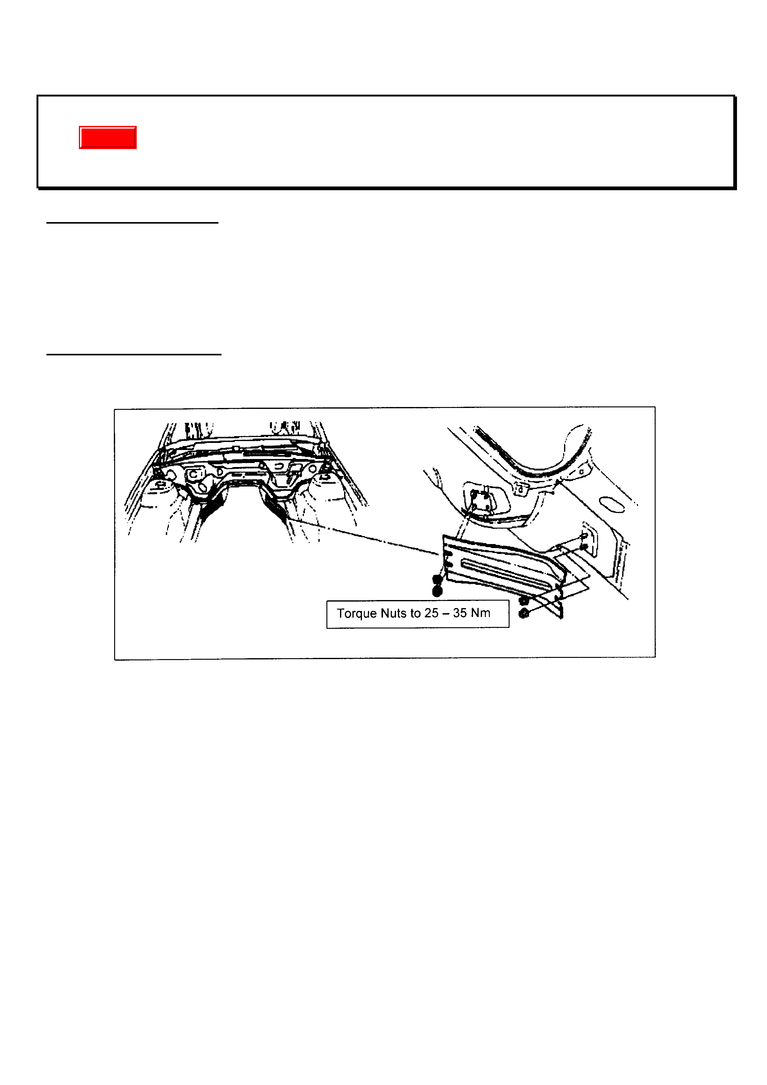
HOLDEN SERVICE TECHLINE _____________________________________________________________________July 2000
HINT: KNOCK/CREAK FROM FOOTWELL AREA
VT
(GROUP 1)
PROBLEM DESCRI PTION
A knocking or creaking noise maybe heard from around the footwell area when the vehicle travels over
undulating ground and the body flexes.
The k nock or cr eak is caused by the f ront long it udinal brace att aching nut s becoming loose causing relat ive
movement between the body and the braces.
SERVICE RECTIFICATION
To rect ify, torque t he longitudinal to f r ont floor nuts to 25 – 35 Nm as indicated in Figure 1.
Figure 1
Update

HOLDEN SERVICE TECHLINE _____________________________________________________________________July 2000
SIDE AIR BAG CONNECTOR DAMAGE
VT
(GROUP 12)
PROBLEM DESCRI PTION
PRI’s received have highlight ed a condition where
the connector on the side air bag module
dislodges, causing the air bag light to illuminate
and log a DT C.
Investigation of returned parts revealed the side
air bag container may distort and cause fractures
to the connector lugs. Enough movement of the
connector can cause an open circuit .
PRODUCTION RECTIF ICATION
Revisions to the side air bag assemblies include
changes to the orientation of the connector, an
extension to the harness and the removal of the
rib on the container.
These assemblies have been fitted to vehicles in
production f r om :
ISOVIN: Build Date:
6H8VTK69HXL455978 5/5/99
SERVICE RECTIFICATION
When diagnosing for a DTC 101, or DTC 85
perform normal wiring connection checks by
following the diagnostic charts in the manual.
It is possible the side air bag connector has
been damaged. The air bag assembly must
be replaced
Refer to VT Service Manual Section 12M -
Supplemental Restraint Systems for
installation procedures
PARTS INFORMATION
Part No.: Description: Qt y
92087554 Airbag Assem bly – RH Side 1
92057871 Airbag Assembly – LH Side 1
WARRANTY CLAIM INFORMATION
Use existing inf or m ation in Labour Times Manual.
DTC P0706 (PRNDL) – FALSELY SETS
VT, WH wi th Gen III (5.7l) Engine & A/T
(GROUP 6C)
PROBLEM DESCRI PTION
DTC P0706 (PRNDL or Transmission Range
Switch fault) is found dur ing Tech 2 analysis – but
no faults are found with Transmission Range
Switch system.
SERVICE RECTIFICATION
PARTS MUST NOT BE REPLACED in any
attempt to correct this DTC, unless diagnosis
proves there is a fault existing in the vehicle.
When DTC P0706 is found during diagnosis
or service work, the code should be ignorded,
unless the customer has complained of a
fault with the auto. trans. selector or trans.
shifts.
Refer to VT Service Manual Volume 14B
page 6C3-2A-306, which provides details of
how this code sets and relevant diagnosis
details for DTC P0706.
PRODUCTION RECTIF ICATION
Revised software for this engine is under
development and will be released in
production as soon as possible. Dealerships
will be notified by a Techline Bulletin when
this software upgrade occurs. The revised
software will also be released on an updated
TIS CD – Version 52 currently timed for
release in early August, 1999.
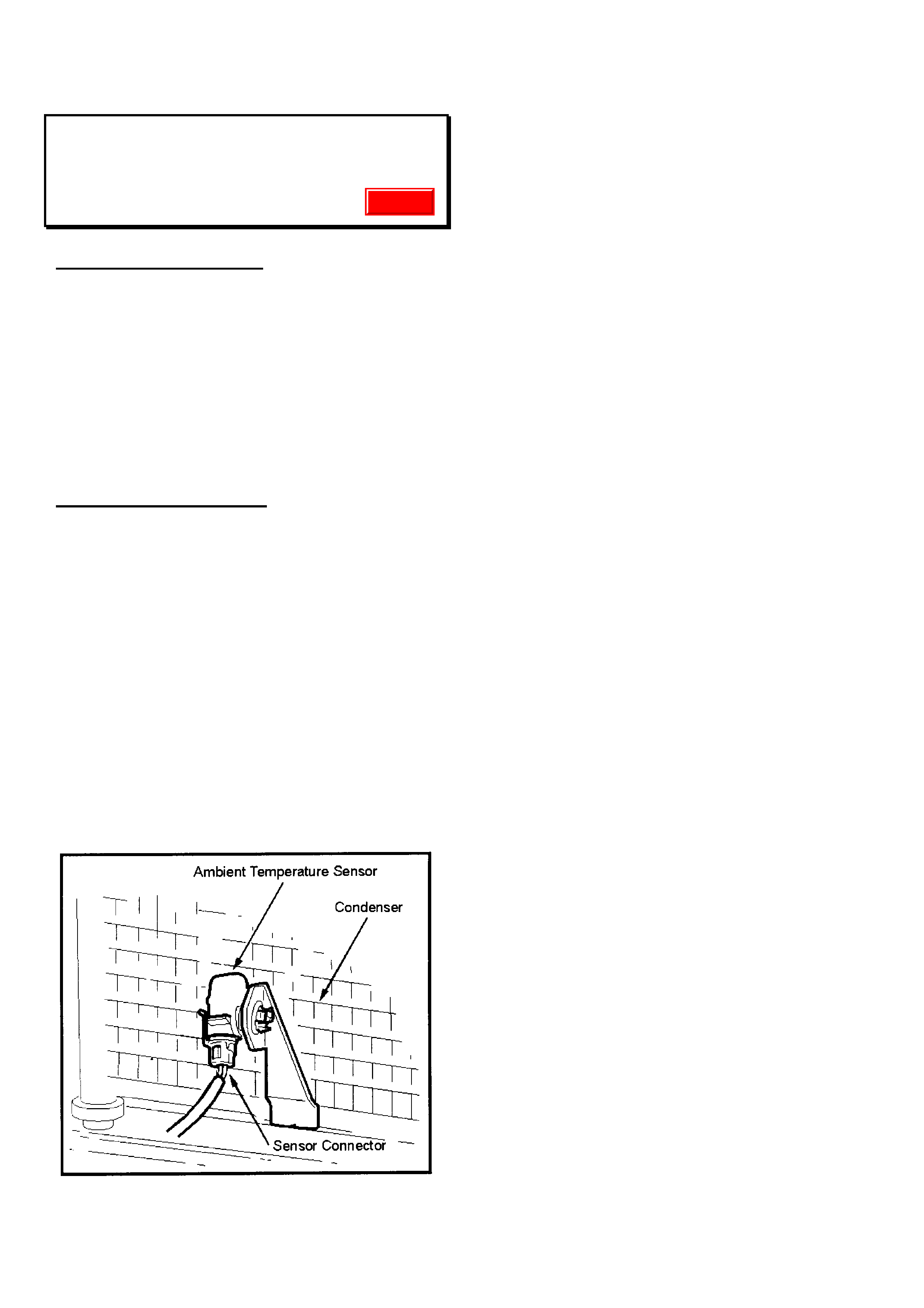
HOLDEN SERVICE TECHLINE _____________________________________________________________________July 2000
POOR HEATER PERFORMANCE
VT & WH WITH E CC
(GROUP 2)
PROBLEM DESCRI PTION
The out put temperature of the HVAC unit and t he
resulting cabin temperature does not represent
the temper ature selected via the ECC control.
This condition may be caused by water ingress
into the ambient temperature sensor located in
front of the A/C condenser. The water short
circuits the sensor (low resistance) causing the
HVAC unit to believe the outside temperature is
high causing relative (cool) heater performance.
SERVICE RECTIFICATION
Through the front bumper bar opening,
detach the ambient temperature sensor
electrical connector.
Using a flat blade screwdriver, gently pry the
sensor away from the retaining bracket.
Check the sensor for water ingress. Dry and
clean the connector and sensor. Generously
apply Molykote 111 grease to the connector
cavities, sensor and then reassemble.
Molykote 111 grease can be obtained from
any Bearing Service Centre outlet.
Check heater performance
Update