
2
20
00
00
0
S
SE
ER
RV
VI
IC
CE
E
T
TE
EC
CH
HL
LI
IN
NE
ES
S
© 2006 GM Holden LTD. A.B.N. 84 006 893 232
Service Department
A “HOLDEN” Product.
BRISBANE SYDNEY MELBOURNE ADELAIDE PERTH
For the latest and/or any missing Techline bulletins,
please refer to Holden Lionheart

SERVICE TE CHNICIAN REFERENCE INFORMATION
ALL
(GROUP 0B) February 2000
This Techline is published to provide Dealership Service personnel with a list of commonly
requir ed Holden cont act Fax number s and som e helpful additional information.
HOLDEN SERVICE RELATED FAX No’s
HOLDEN TAS 03 9647 2495
HOLDEN SECURITY INFO. 03 9647 2865
IGM TAS/CAS 03 9644 6622
PIR’s (EDAG FUTURE) 03 9552 8104
REPAC 03 9647 1198
TECHNICI AN’s GUILD 03 9876 5797
CENTRAL SERVICE 03 9647 2525
HOLDEN CAS 03 9647 1237
WARRANT Y ADMIN. 03 9647 2525
Other Information:
PIR forms: request a pad ( 100 forms) by q uot ing “SD 28331” on a Merchandising Material
Order For m and fax to Salmat, on ( 03) 9251 6352.
Security Number Request Form: photocopy form attached to All Dealer Letter DL 63/99.
Tech 1 Repairs: Ref er HSPO Parts Techline Bullet in PT31, dated May 5, 1999.
Update

REAR WINDSCREEN MOULDING DISTORTION "HINT"
VT
(GROUP 1) REISSUE/DELETION February 2000
A Service Techline with t he same title as above was issued in Issue 10, Decem ber , 1999 page 6. That
previous Techline should be destroyed.
The previously issued Techline item recommended removal and refit of distorted mouldings without
glass removal.
The earlier information was released to assist technicians in rectifying vehicles quickly in the pre-
Christmas period, where distortion may have occurred to the mouldings on some vehicles at pre-
delivery and very low kilometres. The procedure quoted was viable only for mouldings not correctly
fitted – and an in-plant rework was carried out using the same information.
It is no longer necessary to use this recommendation. Further replacement of mouldings must be
done as per the released Ser vice information (glass must be removed).
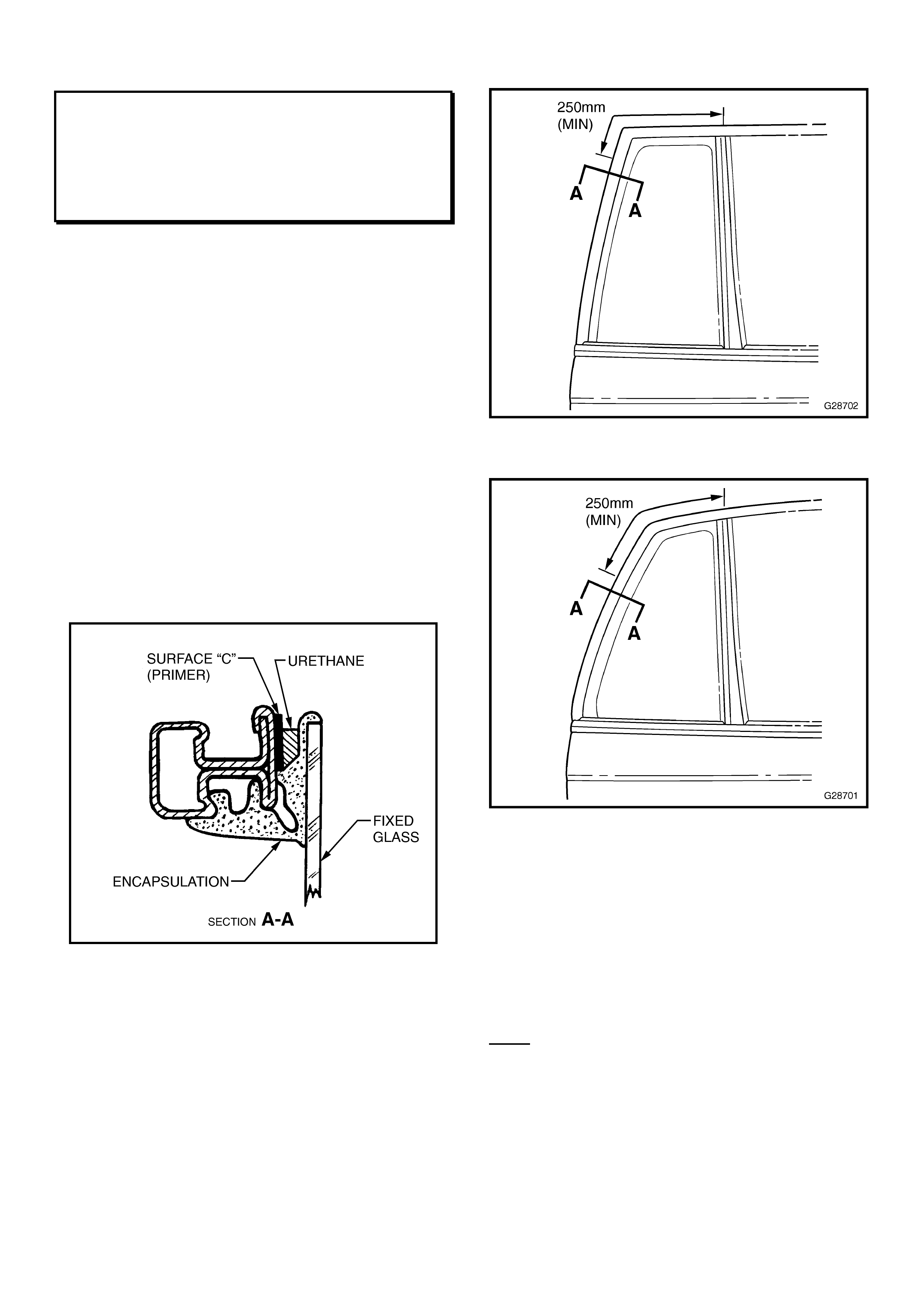
REVISED PROCEDURE FOR FITME NT OF
REAR DOOR FIXED WINDOW GLASS
VT (w agon) & WH
(GROUP 1) February 2000
In addition to the rear door fixed window glass
fitment procedure in VT Series Service Manual,
Volume No.1, page 1A5-19, and WH Series
Service Manual Supplement, Volume 1A, page
1A5-24 - when refitting the rear door fixed glass
for any reason, please perform the following
additional procedure.
The removal of the rear door fixed window is the
same as outlined in the service manual. When
reinstalling the window, perform the additional
steps outlined below:
• Using a small br ush, apply primer BETASEAL
43532, or a similar product to the door frame
painted surface "C" as shown in Section A-A
over a minimum length of 250m m as indicat ed
in Figures 1 & 2.
Section A - A
• Ensure the prim er is dr y before proceeding.
• Using a urethane product available from
HSPO P/N VS18319, or alternatively,
BETASEAL 58702, or BETASEAL 15685 -
apply a small, continuous bead in the cavity
between the encapsulated glass and the
primed area of the door frame.
Figure 1. – VT Wagon
Figure 2. - WH
• Reinstall the door frame seal ensuring to
clean up any excess urethane.
Suitable sealants and primers required and
noted in this procedure can be obtained from
windscreen fitment out lets.
Note: for revised procedure for VT sedan rear
door fixed window glass replacement –– Refer to
Techline Bulletin shown on page 93 of 1998
Service Communication Book .
100mm
150mm
REVISED EVAPORATOR THERMISTOR POSITION
TF RODEO V6
(GROUP 2) February 2000
Information from the field has revealed that V6 Rodeo vehicles may experience evaporator ice –
up on 100km+ distance trips. Evaporator ice up is usually described as poor blower fan output
with large quant it ies of water draining from the evaporat or when the vehicle is stationar y.
Air International has developed a revised thermistor position to prevent the evaporator
temperature dropping below zero degrees which causes the condensation on the evaporator to
freeze.
Refer to the diagram below for the revised thermistor position, and disregard any prior bulletins
referring to this subject.
Note- Evaporator viewed from the air
off side. Thermistor tip location
should be 150 mm from the upper
side and 100 mm (10 fins) from the
left side of the core.
The thermistor clip is approx. 20mm
from the plotted sensor tip point.
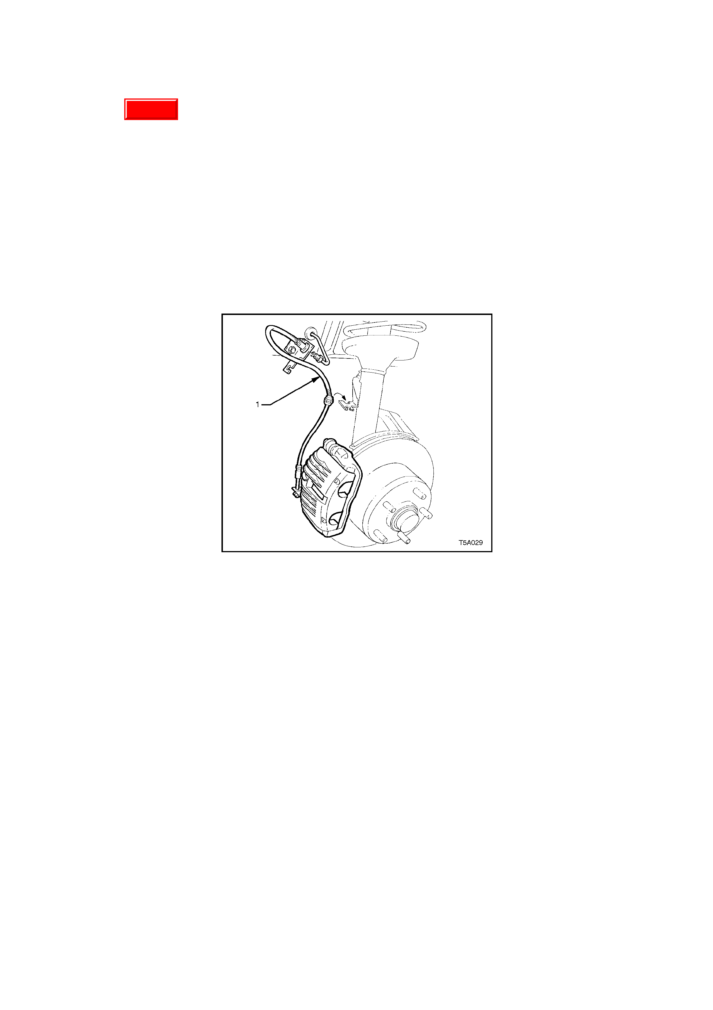
FRONT BRAKE HOSE RETENTION PRECAUTION
VT, WH
(GROUP 5) February 2000
This Techline item is a precautionary note to ensure correct reinstallation procedures are carried
out whenever front suspension, steering, or front br ake work is carried out on a vehicle.
Whenever front brake hose/s are removed from their retaining clip/s (on front suspension strut
body) during any service work, the br ake hose/s must be refitt ed int o t heir retaining clip/ s .
Refer to the sketch below for brake hose (1) location, showing its method of location in the strut
mounted clip.
Update
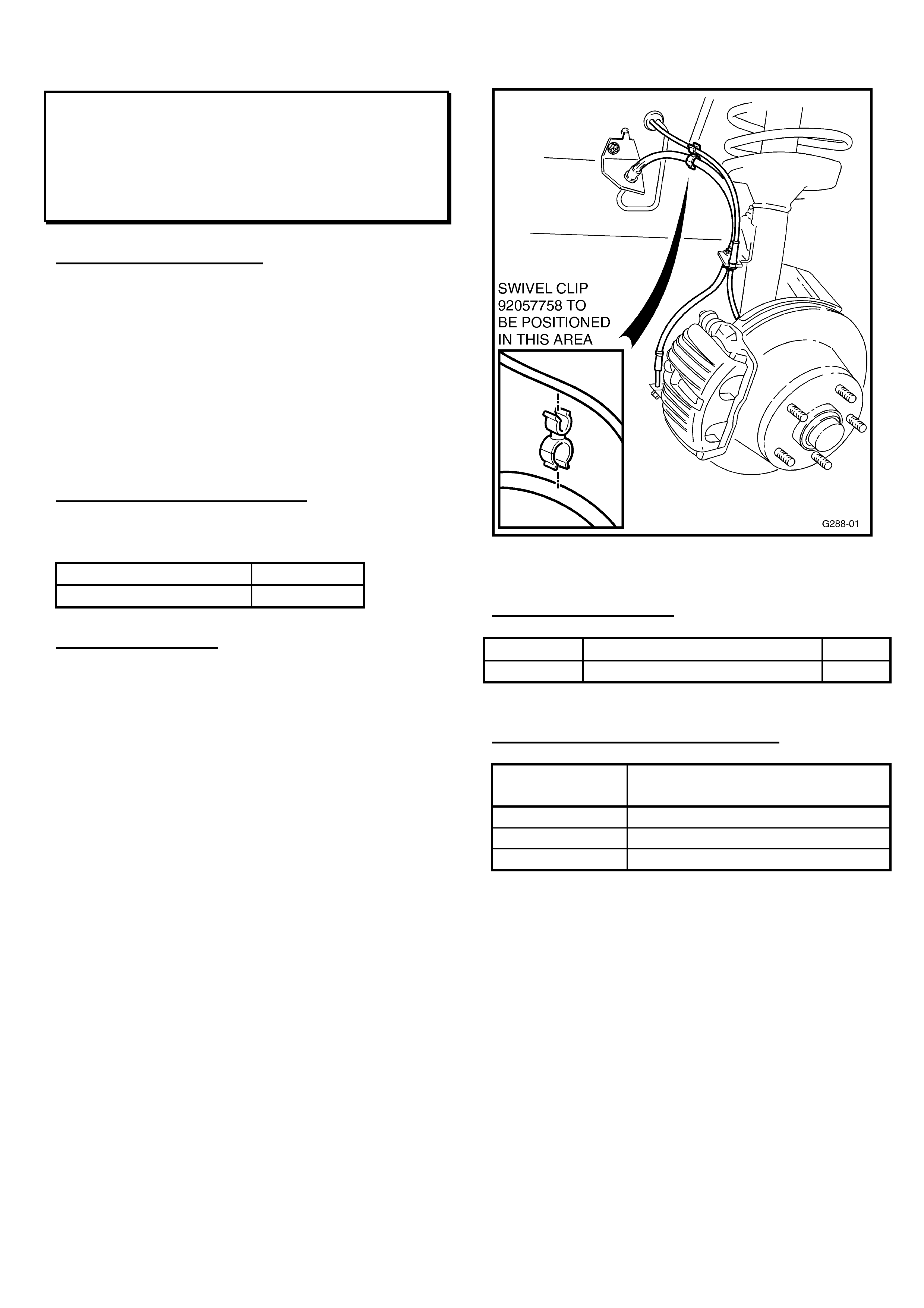
ABS WARNING LAMP ILLUMINATES - LHF
ABS SENSOR LEAD RETENTION
VT with ABS, & WH
(GROUP 5) February 2000
PROBLEM DESCRI PTION
On extreme suspension movement during turns,
excess length of the LHF ABS wheel sensor lead
may come into contact with the stabiliser bar
vertical link. The result of this may be an ABS
DTC 25 or 27, because the lead becomes
disconnected or stressed (causing poor terminal
contact) during suspension movement, resulting
in the ABS warning lamp on the instrument panel
illuminating, and ABS function being eff ect ed.
PRODUCTION RECTIFICATION
A retaining clip has been fitted to vehicles from:
PSN No.: Build Date:
L536320 01/12/99
SERVICE ACTIONS:
Where a VT(with ABS) or a WH is presented for
service with an ABS warning lamp illuminated, or
DTCs 25 or 27 stored in the ABS module, the
following procedur e should be car r ied out :
1. Turn vehicle steering to the furthest left
position.
2. Locate the left -hand front ABS sensor lead.
3. Inspect the sensor lead for damage, poor
routing, connector engagement or
disconnection, correct as necessar y.
4. Fit sensor lead retaining clip to brake hose
and sensor lead to ensure routing of lead as
per Figur e 1.
5. Connect Tech 2 and clear any existing ABS
DTCs.
6. Roadtest vehicle to ensure fault has been
rectified. Should any fault reoccur further
diagnosis should be carried out to determine
cause.
NOTE: This condition only affects VT/WH (with
ABS), from: L384387 to L536319, (built 29/09/98
to 01/12/99). An ABS retention clip should NOT
be fitted to vehicles built prior to L384387, as the
ABS lead length on those vehicles is shorter and
does not req uir e r etention.
Figure 1.
PARTS INFORMATION
Part No.: Description: Qty
92057758 Clip – Sensor Lead Retaining 1
WARRANTY CLAIM I NFORMATION:
Description Install re t aining clip to LHF ABS
sensor lead
Labour Op. No. H000216
Time 0.3 hr
Failure Code 51

CRANKSHAFT PULLEY BOLT
RODEO with 4JB1 –T
(GROUP 6A) February 2000
From engine number: 586429 (build - December 99), the crankshaft front pulley bolt tension for
the 4JB1- T engine has been increased to 24+/- .5kg.m (174+/- 4lb.ft, 235+/-5N.m) from 21+/- 2
kg . m (152+/- 14lb.ft, 206+/- 20 N. m).
All relevant workshop manuals should be chang ed accor dingly.
Dealers aware of any failed or loose bolts in engines manufactured after the above breakpoint
should notif y I-GM TAS immediately. (PH: 1800 032 608 )
Modified
insertion
p
oin
t
Early insertion
point
TURBOCHARGER FAILURE
JACKAROO with 4JX1 –TC
(GROUP 6A) February 2000
Jackaroo’s fitted with the 4JX1 –TC diesel engine may experience turbocharger failure due to air
leaking int o the suction side of t he primary oil pump at the oil st r ainer o ring.
Isuzu have modified the insertion point of the strainer for improved installation and sealing from
VIN no. JACUBS73GW7101646. Please refer to Diag ram A
All 4JX1 engines with turbocharger f ailure t hat are before the br eak point (JACUBS73G W7101646)
must have the following proceedure carried out t o pr event r epeat failure.
1) Check for two punch marks on the lip of the lower sump, adjacent to the drain plug. (refer
diagram B). If present the seal has already been replaced,do not proceed further,
contact IGM TAS.
Diagram A
Main sump
Lower sump
Front axle
Drain plug
Punch marks
Front of engine
N
ote – As viewed from underneath of vehicle.
Diagram B

2) Drain engine oil.
3) Remove lower sump
4) Remove primary oil pump str ainer and discar d
Note - There are two strainers visable when the lower sump is removed. The primary oil pump
strainer is fitted into the cylinder block and has a mounting bolt that attaches to main
bearing cap. T he secondar y oil pump st r ainer is fitted t o t he alum inium main sump.
5) Clean strainer inser t ion point
6) Fit new oil strainer ( Par t #. 8971370363) and seal ( Part #. 8971377980)
Note - W hen fitting new strainer and seal apply three bond 1207b ( HSPO part #.0882600080A )
sealant, to the seal.
7) Tension str ainer m ount bolt (20Nm)
8) Refit lower sump ( Use t hr ee bond 1207b on sealing surfaces)
9) Fill engine with oil
10) Test engine oil pressure with master gauge (refer 4JX1 workshop manual, section 6G,
page 3)
11) Center punch two marks into the lip of the lower sump adjacent to the drain plug as depicted
in diagram B.

ENGINE FRONT & REAR SEAL INSTALLATION TOOL CAUTION
VT, WH (GEN III V8)
(GROUP 6A) REISSUED February 2000
This Service Techline supersedes the previous Techline on this topic (Issue 10, December, 1999
page 9). This previous Techline should be dest r oyed.
This Techline item provides a revised service procedure regar ding engine f r ont seal replacement.
REVISED PROCEDURE:
W hen inst alling a f ront seal, or fr ont engine cover - Cent ralising t ool J41476 m ust not be at tached
with bolt/s.
The tool must be installed on the shaft and held in position by hand - using bolt/s to retain the
tool and over-tightening the bolt/s will result in tool breakage.
Please check the updated information in the current VT Service Manual CD. A revised page
6A3-92 copy is included (following this page) to attach over VT Series II Service Manual, Volume
14A, Page 6A3- 92 t o show this revision.
6A3-92 ENGINE MECHANICAL – GEN III V8 ENGINE
5. Install centralising Tool J 41476 as shown and hold
in position by hand.
NOTE: DO NOT install the crankshaft balancer bolt to
retain. If the bolt is installed and over-ti
g
htened the
alignment tool will be destroyed.
Important: Ali
g
n the tapered le
g
s of the tool with the
machined alignment surfaces on the front cover.
6. Ti
g
hten the two bolts
(
1
)
securin
g
Tool J 41480 to
the front cover, to the specified torque.
ALIGNMENT TOOL TO FRONT
COVER BOLT 25 Nm
TORQUE SPECIFICATION
7. Ti
g
hten the en
g
ine front cover bolts to the correct
torque specif ic atio n.
ENGINE FRONT COVER BOLT
TORQUE SPECIFICATION 25 Nm
8. Remove the alignment tools.
Figure 6A3-1
9. Measure the oil pan surface to front cover fo
r
flatness, as follows:
a. Place a strai
g
ht ed
g
e across the en
g
ine bloc
k
and front cover oil pan sealin
g
surfaces. Avoid
contact with the portion of the
g
asket tha
t
protrudes into the oil pan surface.
b. Insert a feeler
g
au
g
e between the front cove
r
and the strai
g
ht ed
g
e tool. The cover must be
flush with the oil pan surface or no more than
0.25 mm below flush (dimension ‘A’).
c. If the front cover-to-engine block oil pan surface
alignment is not within specifications, repeat the
cover alignment procedure.
10. If the correct front cover to en
g
ine block ali
g
nment
cannot be obtained, replace the front cover.
Figure 6A3-2

ENGINE VIBRATION ON ACCELERATION
JS VECTRA with C22SEL (A/T only)
(GROUP 6A) February 2000
PROBLEM DESCRIPTION
Some vehicles fitted with C22SEL engines and automatic transmission, may exhibit an engine
vibration or “boom”, upon medium to heavy acceleration from a stationary position at 1300 –
1700 rpm.
SERVICE RECTIFICATION
When presented with a customer complaint vehicle having the symptoms described above,
technicians should apply the following t hr ee- step procedure.
A. - Replace rear engine mount
Replace the rear eng ine mounting with the revised part detailed below. Follow instr uctions set out
in TIS 2000, Service Information section, Engine and Engine aggregates, Repair (remove, install,
adjust).
B. - De - stress engine and exhaust system
De-stress procedur e m ust be carried out on a 4 post hoist.
1. Drive vehicle onto vehicle hoist and disconnect battery. Select PARK and apply the
HANDBRAKE
2. Loosen the bolts securing the engine tor que rod, located at the RHF strut tower.
3. Raise vehicle on hoist to gain access to the RHF eng ine mount undercover, to g ain access to
engine mount at t achm ents.
4. Remove RHF engine mount under cover.
5. Loosen all engine mount t o sub- frame at t achm ents.
6. Loosen exhaust bolts at the joining interfaces
-Manifold to front pipe
-Front pipe to int ermediate pipe
-Interm ediate pipe to rear muffler
7. Lower vehicle on hoist, re-connect t he vehicle batt er y and star t the engine.
8. With the foot brake depressed, and engine idling repeatedly shift transmission between
reverse and drive a minimum of 10 times.
9. Select PARK, tur n engine off, disconnect t he vehicle batt er y.
10. Re-t or que the engine torque reaction rod bolts to specified torque.
11. Re-t or que the vehicle engine mounts t o the specified tor que.
12. Re-torque the vehicle exhaust system bolts to specified torque. Starting from the front of the
exhaust system through t o t he r ear .
NOTE: Refer TIS 2000, Service Information / Standard Information / ‘Other Information’
section for torque specs.
13. Re-fit RHF engine m ount undercover.
14. Lower hoist, re-connect the vehicle battery and adjust the engine idle speed as defined below.

C. - Adjust engine idle speed
1. With engine at normal operat ing temperat ur e, Connect Tech 2 to t he vehicle.
2. Select – Diagnostics / Model Year / Model type / Engine / Additional Functions / Adjust Idle
Speed.
3. Adjust eng ine idle speed to achieve 896 RPM, press the “confirm” soft key at the base of the
Tech 2 screen to com plet e.
4. With Tech 2 still connected, return to the additional functions menu and select Adjust Idle
Drive.
5. Adjust idle drive setting to achieve 896 RPM press the “confirm” soft key at the base of the
Tech 2 screen to com plet e.
6. Remove Tech 2 fr om the vehicle and road test to confirm success of pr ocedur e.
PARTS INFORMATION
Part No.: Description: Qty
90538303 Damper Block – Rear Mount 1
WARRANTY CLAIM I NFORMATION:
Description Tak e- off Vibr at ion Cor rection
Labour Op. No. J000636
Time 1.5 hr
Failure Code 28

HOLDEN ENGINE OIL AVAILABILITY
VS, VT, WH
(GROUP 6A) February 2000
This Techline bulletin is released to ensure technicians are aware of the following oils that are
available from HSPO:
Part No.: Description: Size
92142396 GF2 10W- 30 OIL 5 Litre
Preferred oil for use in all V6 (normally aspirated) and V6 Supercharged engines and Gen III V8.
Its use provides fuel economy benefits over the originally recommended 20W-50 SG/SH/SJ oil.
Not recommended for use in 5.0 l i t re V8 engine.
Holden recommends the use of 10W/30 GF2 engine oil for all VS & VT V6 engines with the
exception of LPG fuelled engines.
Part No.: Description: Size
92140105 20W-50 SJ/ CF O IL 5 Litre
For use in all V6 (normally aspirated) and V6 Supercharged engines and 5 litre V8 – normal
operating conditions – this oil is still a recommended oil f or V6 engines, but does not allow the f uel
economy benefits of GF2 10W-30 oil (as noted above).
Part No.: Description: Size
92142397 15W-40 SJ/ CF O IL 5 Litre
For use in all V6 (normally aspirated) and V6 Superchar ged engines and 5 lit re V8 – f or prolonged
use in snow areas - is still a recom mended oil f or V6 engines, but does not allow the fuel econom y
benefit s of GF2 10W-30 oil (noted above).
Part No.: Description: Size
92142398 LPG 15W-40 OIL 5 Litre
For use specifical ly in LPG equipped V6 vehicles.
Full HSPO information regarding these oils was published in Parts Bulletin M434, dated
26 October, 1999. Refer to your Parts Department to view HSPO Parts Bulletin M434, which
includes a Product News Brochure regarding these oils.

INTERMITTENT COLD STALL
SB with C14NZ
(GROUP 6A) February 2000
PROBLEM DESCRIPTION
Some vehicles fitted with C14NZ engines may experience an intermittent stall condition on
deceleration, shor tly after cold start. Some reports also suggest that intermitt ent stall may occur if
the engine is left idling for long per iods during engine warm up. Af ter t he stall condition occurs the
engine may appear to cr ank fast, have a lack of compression or be hard to restart. This condition
will be more pronounced in colder climates or during the winter months where ambient
temperat ur es below 10 degr ees exist.
SERVICE RECTIFICATION
1. Service personnel should thoroughly question the customer to ensure that the symptoms of
the stall complaint meet with the symptoms described above.
2. Connect Tech 1 and inspect vehicle for any DTC’s that may exist. Rectify the cause of these
DTC’s prior t o any further diagnosis.
3. Connect Tech 1 and compare engine data list parameters against QUICK CHECK F0: DATA
LIST SB Series, Service Manual, Volume 3, page J226. Any data errors can be further
diagnosed in section 5. 1. 6 of SB Series, Ser vice Manual, Volume 3, pag e J234
4. Install T ech 1, road test vehicle and attempt t o reproduce com plaint. SNAPSHOT engine data
list when stall occurs. Compar e captured data with :
- Q UICK CHECK F0: DATA LIST, SB Series, Ser vice Manual, Volume 3, page J226
- Section 5. 1.6 SB Series, Service Manual, Volume 3, page J234.
5. Install a fuel pressure gauge to the vehicle. Ensure that fuel pressure is within specification
and that no fuel system flow restrict ions exist. Fuel pressure gaug e may be left on the vehicle
while road testing to monitor any immediate loss of pressure when stalling occurs. (When
these actions are carried out – ensure that appropriate safeguards are made so no damage
occurs to any f uel line, and no fuel leak exists before, during or af t er the procedure.)
6. Check for loose connections. Apply a general “wiggle t est” to engine and m ain wiring har ness
connections as a means of fault location.
7. Check base ig nit ion t im ing setting as per SB Series, Service manual, Volume 3, page J-203.
Aft er com pleting the above inspections if no fault can be identified carry out the following:
8. Replace engine hydraulic lifters with revised part number detailed below. Refer SB Series
Service Manual, Volume 3, Page J 117.
9. After fitting revised hydraulic lifters ensure that engine oil fill meets Holden specification
15W-40 or 15W-50 meeting ACEA A2 or A3. Refer 1998 service communication book.
Page 103.
10. Roadtest vehicle and ensure no further st all exists.
11. Should any stall be evident after fitting of revised parts, refer to Service Techline, Issue 1,
February 1999, page 17 for f urther rectification and specific inspections.

PARTS INFORMATION
Part No.: Description: Qty
92065681 Hydraulic Lifter 8
A “H” etched on t he m achined land of the hydraulic lif ter plunger ident ifies the revised type lift er.
WARRANTY CLAIM I NFORMATION:
Where r eplacement of hydraulic lifters is r equired, use Warranty Claim information detailed below.
Description Cold Stall - Lifter Replace
Labour Op. No. J000639
Time 1.3 hr
Failure Code 83
W here a preliminary inspection identifies a fault and requirement for part replacement, other than
hydraulic lifter replacement, claim the relevant part labour operation as per the Labour Time
Manual. Where additional time is required, additional to published time, seek authorisation from
zone service representative.

DTC P0341/ P0342/ P0343 SET - CAM POSITION SENSOR FAULT
VT, WH with GEN III V8
(GROUP 6C) February 2000
PROBLEM DESCRIPTION
Investigation into reports of DTCs P0341, P0342, P0343 have identified a potentially faulty
camshaft position sensor. Separation of the camshaft position sensor internal circuit board can
cause the fault to occur. Customers may report that the check engine lamp is illuminated or that
extended cranking times exist.
SERVICE RECTIFICATION
Should the fault occur, inspect the date code stamped on the camshaft position sensor - Refer
Figure 1.
Replace fault y camshaft position sensor s with date codes numerically lower than t he following:
Camshaf t Position Sensor Date Code - 99246 ( r epr esent s day 246 of 1999)
Clear any existing DTC’s and roadt est the vehicle.
Where the DTC re- occurs af t er r eplacement of a fault y camshaf t sensor , or the sensor fitted t o the
vehicle is post breakpoint of the dates advised above, carry out existing diagnostic procedures in
current ser vice inf ormation relevant to the code/ s st or ed.
PRODUCTION RECTIFICATION
A vehicle ISOVIN or PSN No. is not available. The appr oximate eng ine number, f or int roduction of
post breakpoint camshaft position sensors into engine production is:
Engine No.: Build Date:
VF99263XXXX 20/09/99 (=day 263)
NOTE: this Engine No. defines that any engines built on day 263 of 1999 are “OK”.
W here “99” = 1999, “263” = day 263, and “XXXX” represents the serial number of the engine built
that day.
PARTS INFORMATION
All camshaft position sensors in HSPO stock have been inspected and are post breakpoint of the
dates advised.
Any camshaft position sensors found in dealer parts st ock with date codes earlier than t hat shown
above must not be used, but r eturned to HSPO for credit.
Sensor part num ber ( for reference) is:
Part No.: Description: Qty
12561211 Sensor, Camshaft Position 1
WARRANTY CLAIM I NFORMATION:
Use existing inf or m ation in Labour Time Manual.
Figure 1
1. Camshaft Position Sensor
2. Date Code (Replace if Date Code “XXXXX” is lowe r than 99246)

DTC P0335/ P0336 SET - CRANK POSITION SENSOR FAULT
VT, WH with GEN III V8
(GROUP 6C) February 2000
PROBLEM DESCRIPTION
Investigat ions into reports of DTCs P0335 and P0336 have identif ied a pot entially f aulty crank shaf t
position sensor. Separation of the crankshaft position sensor internal circuit board can cause the
fault to occur. Customers may report that the engine is unable to be started, an engine stall
condition has occurred or that the check engine lamp is illuminated.
SERVICE RECTIFICATION
Should the fault occur, inspect the date code stamped on the, crankshaft position sensor - Refer
Figure 1.
Replace crankshaft position sensor s with date codes numerically lower than t he following:
Crankshaft Position Sensor Dat e Code – 99237
(Represents day 237 of 1999)
Clear any existing DTC’s and roadt est the vehicle.
Where the DTC re-occurs after replacement of a faulty crankshaft position sensor or the sensor
fitted to the vehicle is post breakpoint of the dates advised above. Carry out existing diagnostic
procedures in curr ent Ser vice information relevant t o the code/s stored.
PRODUCTION RECTIFICATION
A vehicle ISOVIN or PSN No. is not available. The appr oximate eng ine number, f or int roduction of
post break point crankshaft position sensors int o engine production is:
Engine No.: Build Date:
VF99263XXXX 20/09/99 (=day 263)
NOTE: this Engine No. defines t hat any eng ines built on day 263 of 1999 are “OK”.
W here “99” = 1999, “263” = day 263, and “XXXX” represents the serial number of the engine built
that day.
PARTS INFORMATION
All crankshaf t position sensor s in HSPO st ock have been inspected and ar e post break point of the
dates advised.
Any crankshaft position sensors found in dealer parts stock with date codes earlier than that
shown above must not be used, but returned to HSPO for cr edit .
Sensor part num ber ( for reference) is:
Part No.: Description: Qty
12560228 Sensor, Crankshaft Posit ion 1
WARRANTY CLAIM I NFORMATION:
Use existing inf or m ation in Labour Time Manual.
Figure 1
1. Crankshaft Position Sensor
2. Date Code (Replace if Date Code “XXXXX” is lowe r than 99237)

M/T OIL SPEC. REVISION
JS, JR, TR, TS, SB
(GROUP 7A) REISSUED February 2000
This Service Techline supersedes the previous Techline on this topic (Issue 10, December, 1999
page 12). This previous Techline should be dest r oyed.
This Techline is to advise technicians of a new manual transmission oil specification for use in
JS Series II, with F23 M/T.
Oil specified for these transmissions is:
CASTROL SMX-O
This oil is also recom m ended for the following models - by transmission type:
Model
&
Trans. Type
Castrol
SMX-O Current Holden 92140007
and Previously available oils
MTF1067, MTF1067 & MTF0063
SB – All M/T ✔
✔✔
✔✓
TR – All M/T ✔
✔✔
✔✓
TS – All M/T ✔
✔✔
✔✓
JR – All M/T ✔
✔✔
✔✓
JS Series I,
F18 Trans. ✔
✔✔
✔✓
JS Series II,
F23 Trans. ✔
✔✔
✔✖
✔
✔✔
✔ = RECOMMENDED
✓ = MAY BE USED
✖ = DO NO T USE
SERVICE USAGE & PRECAUTION
Castrol SMX-O oil MUST be used at all times in JS Vectra Series II with F23 M/T, and may be
used for ser vice replacem ent or ‘top-up’ of oil in t he above manual t r ansm issions.
Holden oil Part No. 92140007 remains available from HSPO, and can be used as per
recommendat ions in t he chart above.
Castrol SMX-O r eplaces pr eviously released Castrol oils MTF1067, MTF1067 & MTF0063
These previously released oils MUST NOT be used in JS Series II, F23 M/T, for durability
reasons.
At the time of release of this bulletin, there are no commercially available equivalents to Castrol
SMX-O for this JS Series II usage.
PRODUCTION INTRODUCTION
Oil to this specification was introduced at st ar t of JS Vectr a Ser ies I I vehicle production as follows:
ISOVIN: Build Date:
W0L0JBF19YL482379 30/07/99
FUEL TANK/CAP REPLACEMENT REQUIREMENT
JR (All), JS (Hatch)
(GROUP 8) February 2000
SERVICE REQUI REMENT
Whenever a fuel tank is replaced on:
JR - all models
JS - Hatch models only with compliance Plate dated up to and including 31/12/98.
the f uel t ank filler cap should also be r eplaced with a later filler cap.
PRODUCTION RECTIFICATION
The later filler cap (vented type) has been fitted to all JS Sedan and Wagons from start of JS
production, and t o JS Hat c h m odels with Compliance Plat es dat ed after 01/ 01/ 99.
Compliance Plates are locat ed on RHF strut tower.
PARTS INFORMATION
Part No.: Description: Qty
92078849 Cap, Fuel Filler 1
To identify early (non-vented) and later (vented) filler caps fitted to vehicles – the following
sketches ar e pr ovided. Ear lier design f iller caps ar e no longer available from HSPO .
Early Filler Cap
Do NOT re-fit when replacing a fuel tank
Later Filler Cap
Fit when replacing fuel tank (as noted).

POOR AM RADIO RECEPTION
JS
(GROUP 12) February 2000
PROBLEM DESCRIPTION
Some vehicles are reported to have poor radio reception and excessive levels of vehicle induced
interference while listening to “AM” band stations. Investigations have identified ignition noise and
poor antenna connections as the pr im ar y causes.
Various root causes have been identified and f ixes introduced to overcome recept ion problems on
the “AM” band.
PRODUCTION RECTIFICATION
•Ignit ion system ear t h st rap installation for JS:
Introduced Start of Production
•Antenna lead routing on the right hand side of the vehicle:
Introduced 12/11/98, Tag L396309.
•Installation of turn sig nal relay to overcome popping noise:
Introduced 11/ 01/ 99, W1361702.
•Assembly plant test t he r eception signal:
Introduced May 99.
SERVICE RECTIFICATION
•For vehicles built prior to 12/11/98, L396309 refer to the September 98’ Techline (Page 80 of
1998 Service Communicat ion Book) on the same subject and f ollow the procedures to rer oute
the antenna cable. Then continue with the checks out lined below.
•Vehicles built af ter 12/11/98, L396309 will have the antenna cable re r outed. Technicians are
advised to commence with antenna circuit connection and earthing checks.
1. Use the Vectra radio rem oval k eys, to detach the radio from the cr adle.
2. Remove the radio cradle and ensure the antenna connector at the back is inserted correctly
and the centre m etal pin of the ant enna is not broken or bent .
Note: The antenna connection may become dislodged whilst reinstalling the radio. Apply
some tape to the connection preventing the antenna from dislodging during the radio
installation.
3. On sedan models, remove the parcel shelf and ensure that the two antenna amplifier box
attaching nuts are tight (1). Also check that the 2 pin power connector to the amplifier is f ully
home (2). (Refer to Figure “A” following).
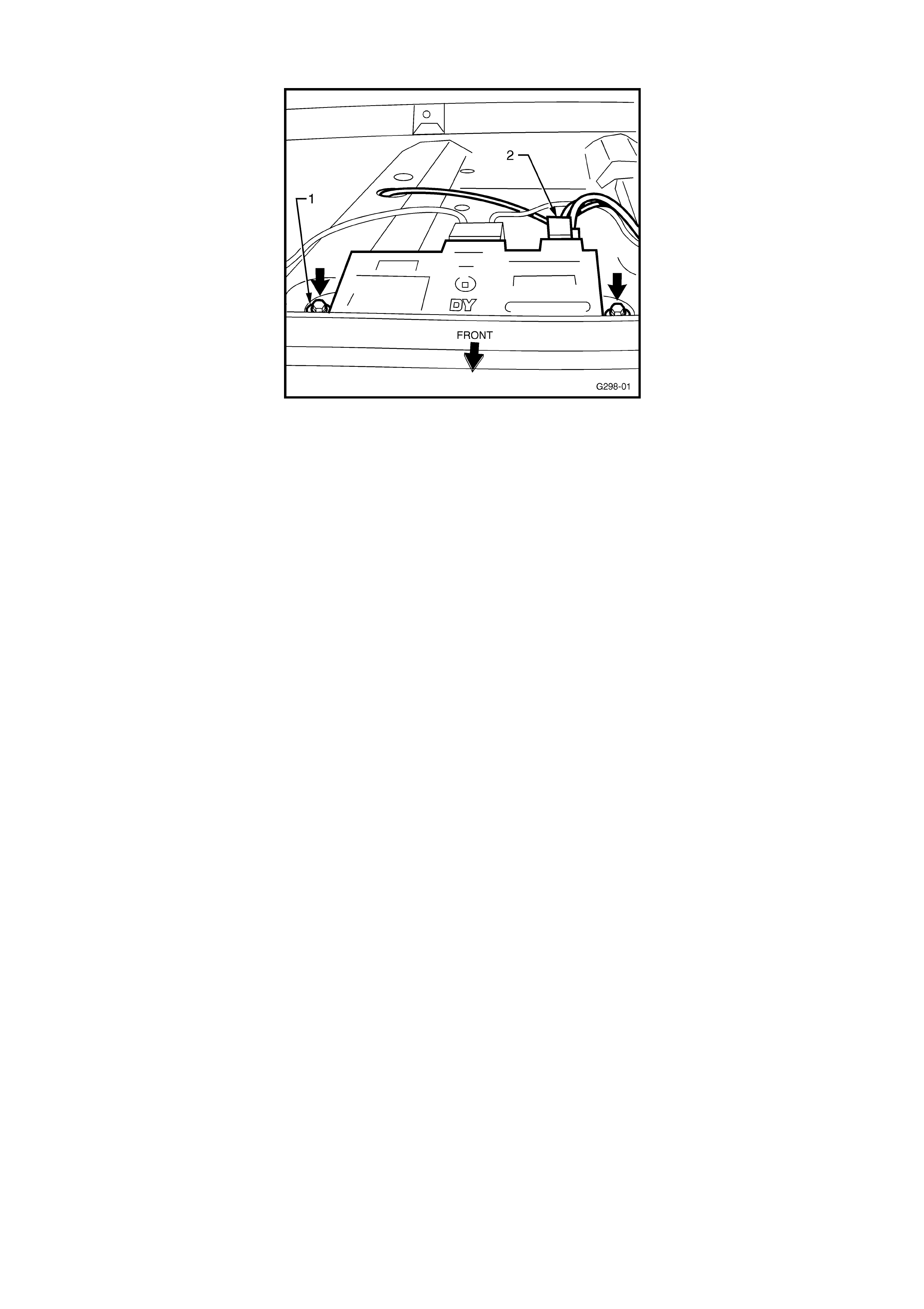
Figure “A”
4. On hatch and wagon models, ensure the attaching nut that holds the antenna amplifier to the
roof panel is not loose. This nut and stud is the earth path for the ant enna amplifier so a good
earth is crit ical.
5. Also on hatch and wagon models, check the coaxial cable where it enters the amplifier for
damage such as a f rayed coaxial cable shield or exposed bare copper. To check coaxial cable
integrity at this location, tune the radio to a weak “AM” band station and increase the volume.
Then wrigg le t he ant enna lead and listen for changes in the level of inter ference.

TURN SIGNAL LAMPS INOPERATIVE AT LOW AMBIENT TEMPS.
VT
(GROUP 12) February 2000
PROBLEM DESCRIPTION
Investigation into reports of turn signal lamps inoperative at low ambient temperatures, have
identified the cause as being the hazard warning switch being partially dislodged in the instrument
panel fascia. This is caused by the lower locking tang of the switch distorting the switch case,
which in turn causes an interruption in the turn signal circuitry through the hazard switch.
PRODUCTION RECTIFICATION
Hazard warning switches with revised locking tangs have been fitted to vehicles from:
ISOVIN: Build Date:
6H8VTK69HYL543303 16/12/99
SERVICE RECTIFICATION
If presented with a vehicle that exhibits the symptoms described above, technicians should replace
the switch assembly with a post breakpoint part.
PARTS INFORMATION
Order the new part from HSPO PartFinderTM - all parts at HSPO are of the latest specification.
Revised hazard switches can be identif ied by date code. T he date code is hot st amped, par allel to
the lower edge of the switch body, on the left side of the switch body, when viewing t he switch as it
would be mounted in the instrum ent panel fascia.
OK parts ar e dat e coded: 06M9 and higher.
Where: 06 = Day; M = December; 9 = 1999
WARRANTY CLAIM I NFORMATION:
Use existing inf or m ation in Labour Time Manual.
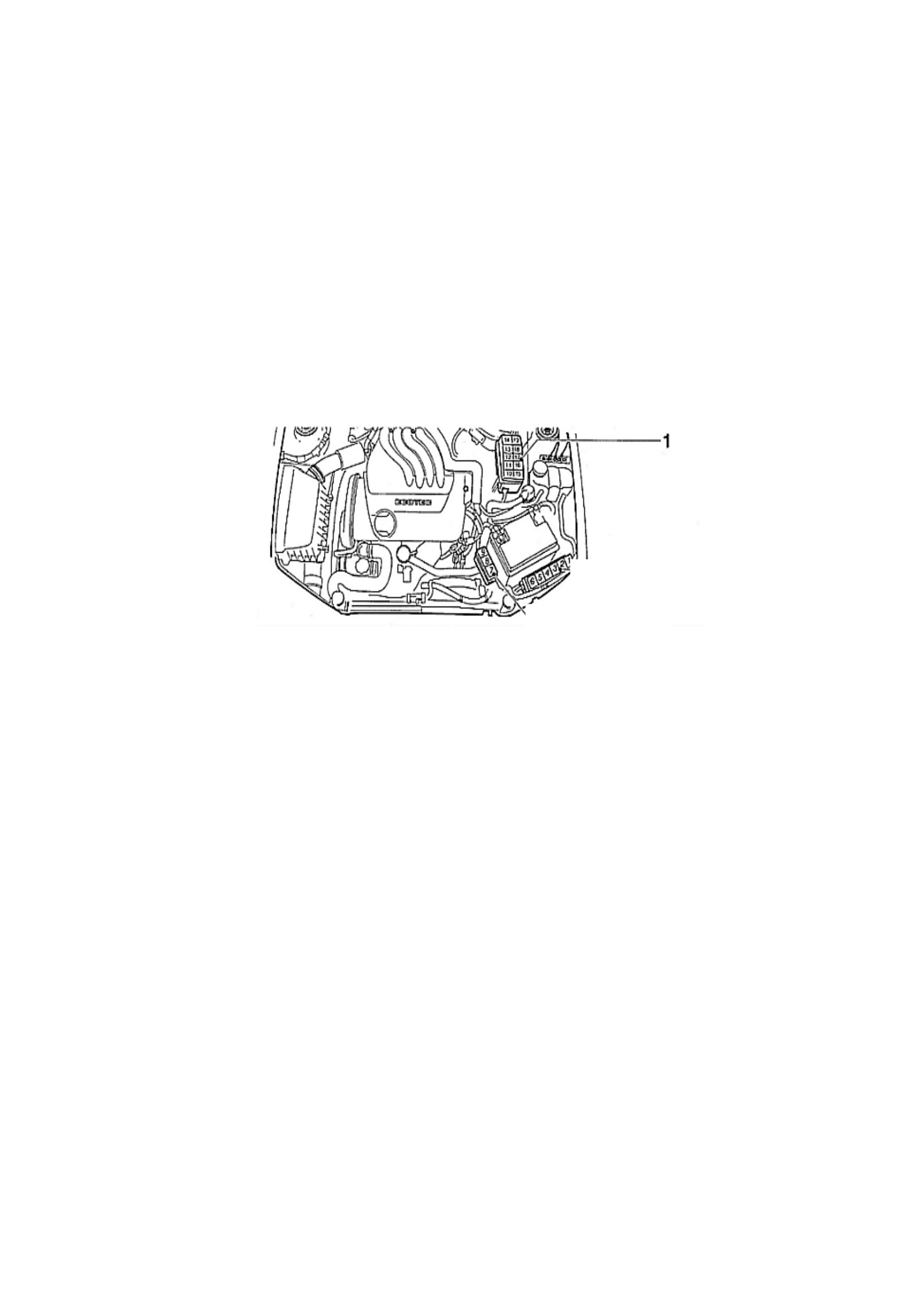
SPEED SIGNAL CONVERTER MODULE
JS (non-ABS)
(GROUP 12) February 2000
Some technicians have experienced difficulty in locating the speed signal converter module fitted
to JS Vectra vehicles without ABS. The JS series circuit diagrams indicate that the module is
located in the passenger compartment in the vicinity of the instrument panel, this information is
incorrect.
The speed signal converter module is in fact fitted in the relay box mounted in the engine
compartm ent (ref er k ey 1 figur e 1). The speed convert er module can be identif ied by its dist inctive
orange colour. Dealerships should update their copies of the JS Circuit Diagram Manual - Vehicle
Electrical System, “Views of relays and fuses” section, page 31 to reflect the correction in this
Techline issue.
Figure 1

POOR AM RADIO RECEPTION – TURN SIGNAL RELAY INTERFERENCE
JS
(GROUP 12) February 2000
PROBLEM DESCRIPTION
Some customers have complained that when using the turn sig nals with the radio t uned to an AM
radio station, they can hear indicator “popping” noise through t he r adio.
PRODUCTION RECTIFICATION
A revised relay was introduced into production in the impor ted model only.
ISOVIN: Build Date:
W0L0JBF68W1361702 11/01/99
This relay was not introduced into local pr oduction.
SERVICE RECTIFICATION
A revised turn signal relay with a noise filter installed, has been released to suppress the
interference.
Dealers are advised to fit this relay to rectify complaints of turn signal interf erence. The relay can
be distinguished by its yellow colour.
Note: The revised relay combines both left and right side turn signal relays. Technicians only
need to f it one r eplacem ent relay when fitting the r evised type.
PARTS INFORMATION
Part No.: Description: Qty
09134880 Flasher, T ur n Signal 1
WARRANTY CLAIM I NFORMATION:
Use existing inf or m ation in Labour Time Manual.

DOOR SNIB (LOCK) BUTTON BINDING
VT, WH
(GROUP 1) HINT March 2000
PROBLEM DESCRI PTION
On some vehicles, the door snib (lock) button may appear to bind up in its mechanism when it is
operated by remote button or manually. The snib button may also feel ‘notchy’ during manual
operation.
This condition may be caused by excessive friction within the door lock, or incorrect adjustment
(too long) of the exterior door handle rod.
SERVICE RECTIFIC ATION
Before attempting any other rectification, ensure locks have been:
1. Lubricated as per Techline Bulletin June, 1999, Issue 4, page 8, then check for OK snib button
operation,
2. Checking lock rod adjustment as per Techline Bulletin June, 1999, Issue 4, page 8.
NOTE: incor r e ct lock rod adjustment (too long) can result in the lock mechanism binding.

REGISTRATION PLATE RATTLE
WH
(GROUP 1) REISSUED March 2000
This Techline item was previously published in Service Techline Issue 6/99 to advise technicians
and pre-delivery departments of the need to correctly mount registration plates to WH Series
vehicles. Field reports indicate that correct registration mount fixing procedures are not being
adhered to and customers continue to complain about rattles f rom incorrectly mounted registr ation
plates. Please ensure this Techline item is distributed to the correct dealership personnel to
prevent further occurrence of registration plate rattle.
PROBLEM DESCRI PTION
Front and rear registration plates may rattle due to incorrect mounting.
Four screws are required to mount each registration plate securely.
The front r egistration plate must have four fasteners located along the top of the plate, two on the
ends and two slightly inboard (same as VT Series vehicles).
The rear plate also utilises four fasteners. The two top fasteners screw into a boss, while the two
bottom fasteners ‘self -tap’ into the bumper facia. There are no bosses in the facia at the bottom of
the plate, but the screws will hold.
To prevent plate rattles, please use four fasteners to attach each registration plat e.

FRONT SEAT BELT WEBBING CATCHES ON RECLINER/ LUMBAR KNOB/S
VT, WH
(GROUP 1) March 2000
PROBLEM DESCRI PTION
Customer survey results indicate that some customers have experienced a condition where the
front seat belt webbing did not freely slide over t he front seat recliner knob or lumbar knob.
PRODUCTION RECTIFICATION
As a continuous product improvement, the surface finish to both knobs has been revised and
introduced into production. The revised knobs feature a hard surface finish compared to the earlier
“soft feel” knobs. This enables the seat belt webbing to slide more easily over the knob.
Revised knob/s were introduced into VT/WH production as follows:
For Pewter Colour Knobs:
PSN: Build Date:
L521331 25/10/99
For Shale Colour Knobs:
PSN: Build Date:
L527046 07/11/99
Note: Taupe colour trim (and knobs) was not carried into VT Series II (introduction L464495,
31/05/99).
SERVICE RECTIFIC ATION
Where a customer complains of seat belt webbing “catching” on recliner or lumbar knobs, on
vehicles built prior to the above breakpoints, the revised knobs should be installed to both front
seats.
Parts requir ed are detailed in Parts Information below.
Whe n replacing the knobs, refer to the following service information:
Recliner Knob:
VT Service Manual, Volume 12, Page 12M-21,
Ref. 2.3
Lumbar Knob (non- Side Air Bag):
VT Service Manual, Volume 14A, Page 1A7-5,
Ref. 2.2
Lumbar Knob (Side Air Bag):
VT Service Manual, Volume 14A, Page 1A7-6,
Ref. 2.4
Update
PARTS INFORMATION
Part No.: Description: Qty:
92143234 Recliner Knob - Shale 1
92143235 Recliner Knob - Pewter 1
92143238 Recliner Knob - Taupe 1
92143230 Lumbar Knob, (non-SAB)
- Shale 1
92143231 Lumbar Knob, (non-SAB)
- Pewter 1
92143236 Lumbar Knob, (non-SAB)
- Taupe 1
92143232 Lumbar Knob, (SAB)
- Shale 1
92143233 Lumbar Knob, (SAB)
- Pewter 1
92143237 Lumbar Knob, (SAB)
- Taupe 1
* “SAB” – Side Air Bag
WARRANTY CLAIM INFORMATION:
Use the following information:
Description Rod, Selector Control - Replace
Labour Op. No. C000397
Time 0.3 hr
Failure Code 39

FRONT BRAKE SQUEAL NOISE
TS
(GROUP 5) March 2000
PROBLEM DESCRI PTION
Front brakes may exhibit a “squeal” noise during light brake application.
PRODUCTION RECTIFICATION
Revised brake pads installed:
VIN: Build Date:
Y5000001 13/08/99
SERVICE RECTIFIC ATION
1. Test drive vehicle and determine that the squeal is orig inat ing from the front brakes.
2. Replace front brake pads (as per TIS instructions).
IMPORT ANT NOTE: Ensure to clean the brake pad guides in the caliper and the caliper itself with
a soft wire brush. Apply anti-sq ueak paste to the guides as shown in TIS.
PARTS INFORMATION
Part No.: Description: Qty
09195607 Brake Pads, Front Brake
without ABS 1
09192157 Brake Pads, Front Brake
with ABS 1
90166282 Anti-squeak paste 1
WARRANTY CLAIM INFORMATION:
Use existing Labour Time Manual info. as follows:
Description Fr ont disc brake pads - Replace
Labour Op. No. H105000
Time 0.9 hr
Failure Code 90
Update

P0335 - CRANKSHAFT REVOLUTION SENSOR REVISION
TR, JR (4Cyl); JS (4Cyl)
(GROUP 6C) March 2000
PROBLEM DESCRI PTION
Investigation into reports of DTC P0335 (incorrect RPM signal) stored in the Engine Control Unit
(ECU), have been identified as failure of the Crankshaft Revolution Sensor (CRS). In some
instances DTC P0340 may also be stored.
PRODUCTION RECTIFICATION
A revised CRS was introduced into JS production at:
ENGINE No.: Build Date:
C22SEL25014889 Jan. , 2000.
SERVICE RECTIFIC ATION
When presented with a vehicle storing DTC P0335, technicians should follow the relevant
diagnosis for this code - Refer TIS 2000, Checking Procedures. Care should be taken to ensure no
fault exists with the CRS circuit or mounting. Full, correct diagnosis must be carried out to ensure
there is no unnecessary replacement of either the CRS, or an ECU. If no fault is identified on
inspection, the CRS should be replaced with t he revised part detailed below.
PARTS INFORMATION
This revised Crankshaft Revolution Sensor should be used in all cases requiring replacement, on
TR, & JR/JS 4 Cyl. Engine vehicles.
Part No.: Description: Qty
09174621 Crankshaft Rev’n Sensor 1
New Part Identification:
The part number is moulded into the plastic body of the sensor.
Any Crankshaft Revolution Sensors found in dealer parts stock with previous part number
90506103, must not be used, but ret urned to HSPO for credit.
WARRANTY CLAIM INFORMATION:
Use existing information in Labour Time Manual
Update

STEERING COLUMN INSTALLATION PROCEDURE
TS
(GROUP 9) REISSUED March 2000
This Techline is re-published because:
•a number of steering shaft and related parts have been replaced unnecessarily,
•a number of steering shaft lower bearings have been damaged as a result of
technicians NOT following this procedure.
The following information was previously released in Techline Issue 8, October, 1999, page 8.
Whenever reinstalling or replacing the steering column assembly in TS series Astra built prior to
the production breakpoint shown below. It is critical the correct lower steering column mounting
clamp load is achieved. Failure to correctly set this clamp load may result in two separate
conditions. If too loose, a rattle condition at the base of the steering column may be experienced. If
too tight, failure of the lower steering column bearing may result.
PRODUCTION RECTIFICATION
Tighter production tolerances to the lower steering column mounting bracket have eliminated the
requirem ent for this critical clamp load adjustment.
Vehicle breakpoint is as specified below:
ISOVIN: Build Date:
W0L0TGF48X5033674 21/09/98
SERVICE PROCEDURE
Technicians need to ensure that the procedures outlined below are applied at all times when the
steering column is reinstalled or replaced in TS series vehicles built prior to the above mentioned
breakpoint. .
1. Reinstall the steering column assembly as per removal and reinstallation procedures set out
on the TIS CD ROM, Group M – Steering “Remove and reinstall steering column assembly”
(Steering column assembly adjust able).
2. Centralise the steering wheel and engage the steering lock.
3. Move the adjustable steering lever out of the lock position so the steering column can be
moved up or down, in or out.
4. Locate the clamp bolt (1) that houses the lower steering column bearing and loosen to allow
the installation of the first shim package of 4.0mm (bolt (1) threaded end visible with a 7mm
hex on end of bolt) as indicated in Figure A (showing the steering column removed for clarity).
Shim in mm Number of shims
0.4 21-321-321
1.6 2221111- --
Total 4.0 3.6 3.2 2.8 2.4 2.0 1.6 1.2 0.8 0.4

FIGURE A
5. Beginning with an overall thickness of 4.0 mm insert the package of 4 shims, as indicated in
Figure B, between the steering column bracket and the crossmember and tighten the clamp
bolt to 22 Nm/16 ft.lb.
FIGURE B
6. To check if the clamping f orce is correct, grasp the steering shaft at the intermediate shaft end
and push the steering shaft axially with moderate effort (in the direction of the arrow) as
indicated in Figure C.
FIGURE C

7. If the visible grey guide sleeve located in t he clamp on the steering column is moved, release
the clamp bolt and remove one 0.4mm shim.
8. With the reduced shim package of 3.6 mm, tighten the clamp bolt again to 22 Nm/16 ft.lb.
Repeat the checking procedure, observing whether the grey guide sleeve continues to move.
Repeat the procedure of continually reducing the overall thickness of the shims by 0.4 mm
until the guide sleeve ceases to move while applying moderate effort as indicated.
9. Once the correct number of shims has been determined, push the st eering column inwards as
far as it will go and check that the grey sleeve located within the clamp is positioned towards
the front of the vehicle as far as possible. It may be necessary to loosen the clamp bolt and
apply an axial force to the steering shaft towards the front of the vehicle until the grey sleeve
seats on the clamp in it’s forward most position. Ensure to tighten the clamp bolt to
22N m/1 6 ft.lb.
10. Re-inst all all com ponents. Move the steering column adjustment lever into the lock position.
PARTS INFORMATION
Shim kits to adjust clamping load are available via HSPO under the part number supplied below.
Part No.: Description: Qty
09192728 Shim kit 1

SERVICE TE CHNICIAN REFERE NCE INFORMATION
ALL
(GROUP 0B) UPDATED March 2000
This Techline is published to provide Dealership Service personnel with a list of commonly required
Holden contact Fax numbers and some helpful additional information.
HOLDEN SERVICE RELATED FAX No’s
HOLDEN TAS 03 9647 2495
HOLDEN SECURITY INFO. 03 9647 2865
IGM TAS/CAS 03 9644 6622
PIR’s (EDAG FUTURE) 03 9552 8104
REPAC 03 9647 1198
TECHNICIAN’s GUILD QUESTIONNAIRES,
Tech. Guild Issue content,
and Questionnaire queries ONLY: 03 9876 5797
TECHNICIAN’s GUILD ADMINISTRATION
For all other Tech. Guild queries (enrolments,
prizes, dates, exam venues, etc): 03 9647 2525
CENTRAL SERVICE 03 9647 2525
SERVICE ENGI NEERING 03 9647 2525
HOLDEN CAS 03 9647 1237
WARRANTY ADMIN. 03 9647 2525
Othe r In fo rmation :
PIR forms: request a pad (100 forms) by quoting “SD 28331” on a Merchandising Material Order
Form and fax to Salmat, on (03) 9251 6352.
Security Number Request Form: photocopy form attached to All Dealer Letter DL 63/99.
Vehicle Security Info. Change Advice Form: photocopy form attached to All Dealer Letter
DL 63/99.
Tech 1 Repairs: Refer HSPO Parts Techline Bulletin PT31, dated May 5, 1999.
Tech 2 Repairs: Refer All Dealer Letter DL 43/97
Tech 2 Cable Repairs: Refer All Dealer Letter DL 06/00
JS Vectra Circuit Diagram Manual Update Pages: Refer All Dealer Letter DL 58/99
TS Astra Circ uit Di agram Update Pages: Refer All Dealer Letter DL 01/99

INSTRUMENT CLUSTER - TRIPME TER FUNCTION
JR, JS
(GROUP 12) March 2000
Some customers may report that their tripmeter is intermittently resetting to zero without command
- mainly on long distance trips. To reduce the possibility of unnecessary instrument cluster
replacement, this Techline has been issued to define the counting/reset parameters of the
tripmeter fun c tion.
JR & JS SERIES 1
All JR, and JS Series 1 instrument cluster tripmeters are designed to count to 1999 kilometr es and
reset to zero at the 2000 kilometre mark.
JS SERIES 2
JS Series 2 instrument cluster tripmeters are designed to count to 999 kilometres and reset t o zero
at 1000 kilometre mark.

INSTRUMENT PROGRAMMING - TRIPLE WINDOW TYPE
VT
(GROUP 12) March 2000
Included in Tech 2 software version 8.100, TIS 2000 CD 7.0B, is a new function that allows
instrume nt clusters to be configured for vehicles with and without Elect r onic Climate Control (ECC).
This function should be used when fitting or replacing instrument clusters. Failure to correctly
program the instrument configuration may result in an “X” being displayed in the instrument right
side display window, along with instrument DTC 10.
In Particular, this is relevant where triple window display type instruments are fitted to vehicles
without electr onic clim ate control ie. HSV or HBD upgrade.
To correctly configure the instrument clusters ECC option follow the steps detailed below.
1. Select Diagnostics / Model Year / VT Commodore / F3: Body / Instrument / F5: Program / F0:
Instrument Config uration.
2. Press the NEXT soft key at the base of the Tech 2 screen to scroll to the ECC option
configuration.
3. Press the MODIFY soft key at the base of the Tech 2 screen.
4. Select the DISABLE soft key at the base of the Tech 2 screen (for vehicles without ECC).
Select the ENABLE soft key at the base of the Tech 2 screen (for vehicles with ECC).
5. After the configuration has been modified the Tech 2 will display the current configuration.
Select the PROGRAM soft key at the base of the Tech 2 screen to accept the configuration
settings.
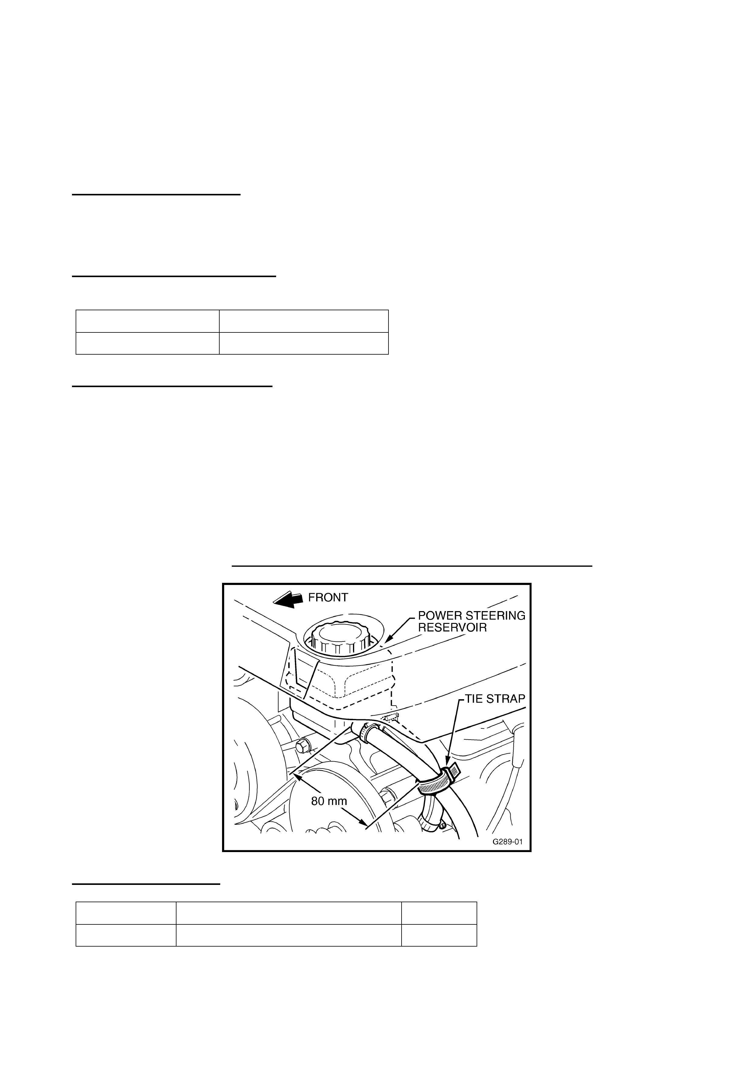
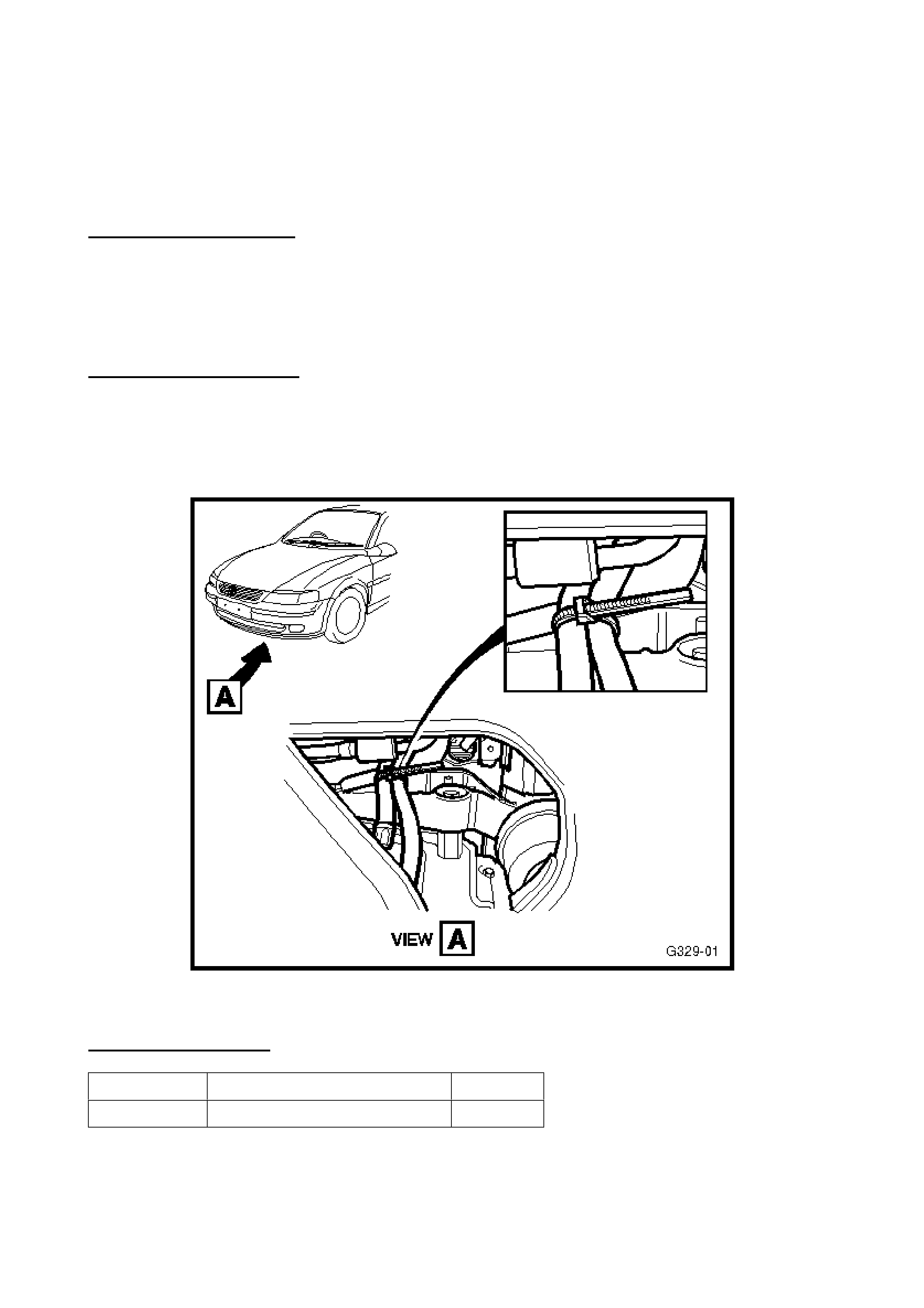
POWER STEERING HOSE RETENTION
VT, WH with GEN III V8
(GROUP 9) February 2000
PROBLEM DESCRIPTION
PIR’s have been received, which advise of a power steering (P/S) fluid leak, caused by the P/S
return hose cont acting with the power steering pump pulley.
PRODUCTION RECTIFICATION
A tie strap has been added in pr oduct ion from:
PSN No. : Build Date:
L493683 14/08/99
SERVICE RECOM MENDATION
When fitting or re-fitting a P/S return hose for any reason, carry out the following hose
replacement pr ocedur e:
•On fitting the new P/S return hose, turn the upper (reservoir) end away from the P/S pump
pulley, before tightening the hose clamp.
•Re-f it the existing tie st rap (p/ n 92138212) t o the power steering hoses, 80m m f r om t he power
steering reservoir - as shown in the accompanying sketch. If the vehicle is built before
L493683 – fit a tie strap during this hose replacement. (Refer ‘Warranty Claim Information’).
Addition of this tie strap ensures t hat the hose cannot contact t he P/ S pum p pulley.
When fitting the t ie st r ap, ensur e t he P/S hoses are not compressed by the tie str ap.
PARTS INFORMATION
Part No.: Description: Qty
92138212 Strap –Tie, P/S Retention 1

WARRANTY CLAIM INFORMATION:
The following labour operation number m ay be used ONLY for addition of a tie strap, to vehicles built prior to
L493683, when replacing a damaged P/S return hose, or re-fitting a P/S return hose.
Description Add Strap to P/S Hoses
Labour Op. No. M000172
Time 0.3 hr
Failure Code 25
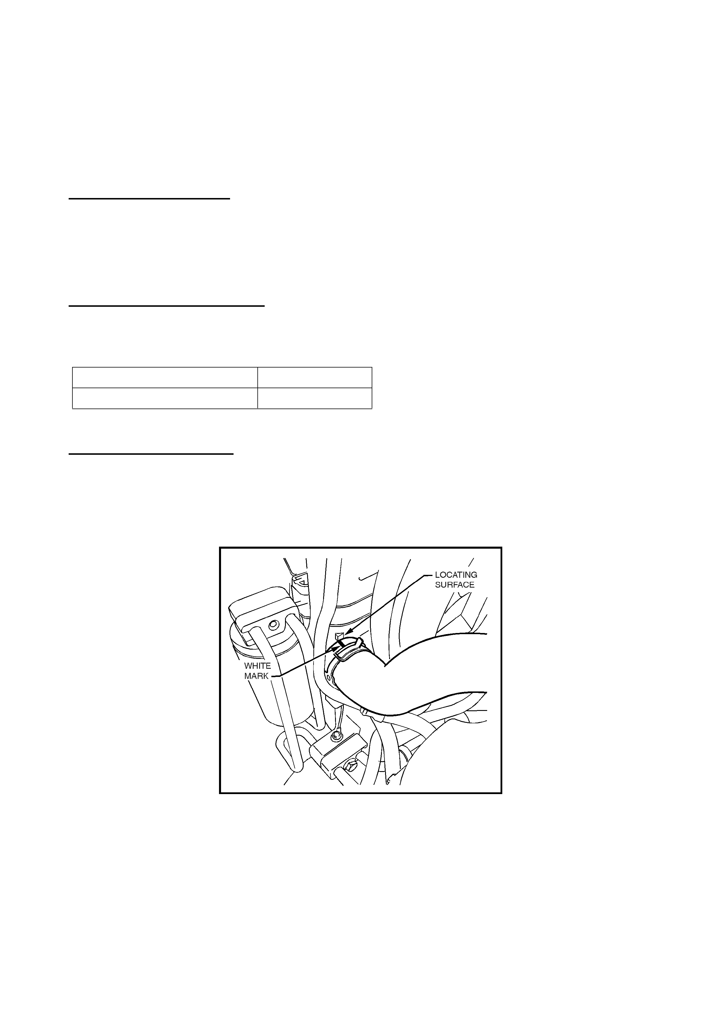
LOWER RADIATOR HOSE INSTALLATION PRECAUTIONS
JR, JS (4 Cyl. Engines)
(GROUP 6K) March 2000
PROBLEM DESCRI PTION
The following precautions must be observed during lower radiator hose installation, to ensure no
abrasion occurs, that may result in a coolant leak. In addition, a protective cap has been added to
A/T filler tube retaining studs to ensure no abrasion can occur.
PRODUCTION RECTIFICATION
The installation precautions noted below are existing procedures in the vehicle assembly plant.
The protective cap (as mentioned in Figure 3 below) was introduced into production at:
ISOVIN: Build Date:
W0L0JBF19XL430814 01/03/99
SERVICE RECTIFIC ATION
W hen installing a lower radiator hose, ensure correct positioning of the lower radiator hose by:
1. Aligning the white paint mark on the lower end of the hose, with the moulded boss on the
radiator end tank – Refer Figure 1 which shows the correct hose positioning .
Figure 1.
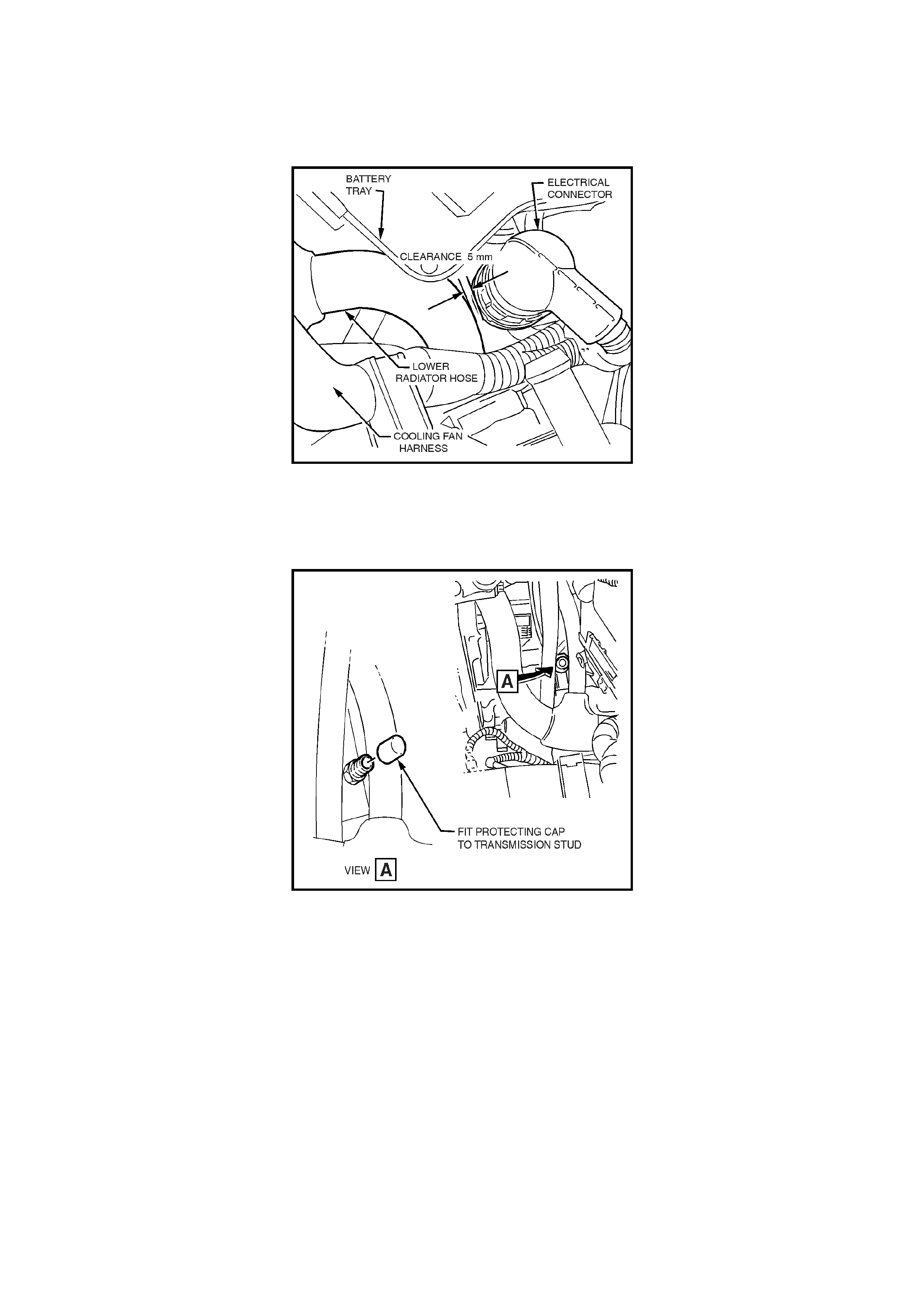
2. Adjusting the position of the hose (by loosening connections and twisting the connections) so
that adequate clearance exists between the electrical harness connector – Refer Figure 2 for
details of clearance and hose positioning.
Figure 2.
3. On A/T equipped vehicles: where the branch of the lower hose runs past the A/T filler tube
retaining bracket nut, add a protective cap – P/N 90539656 – Refer Figure 3.
Figure 3.
View from front of engine compartment towards A/T."

INTERIOR RATTLE NOISE DIAGNOSIS
ALL MODELS (MELBOURNE BASED VEHICLES)
(GROUP 1) April 2000
PROBLEM DESCRIPTION
When investigating instrument panel “rattle” complaints, where a vehicle is fitted with an “e-TAG”
unit ( electronic sig nal transm itter f or use on t he Melbourne CityLink electr onic tollway system), f irst
remove the e-T AG unit.
Any rattle that may emanate from the “e-TAG” unit could lead to misdiagnosis of the noise, in the
belief t hat interior trim or com ponents in the instrument panel may be the cause.
NOTE: “ e-TAG’s” ar e normally attached to the inside of the front windscreen behind the rear view
mirror, via a mounting bracket, and are detachable. The “e-TAG” can be detached from the
bracket by g r ipping the “e-T AG” and rotating the top rearwards and downward.
Should an “e- TAG” be def ined as the cause of a rat t le noise – t he customer should be advised that
the ratt le is em anat ing fr om t he “e-TAG” , not the vehicle.
Update
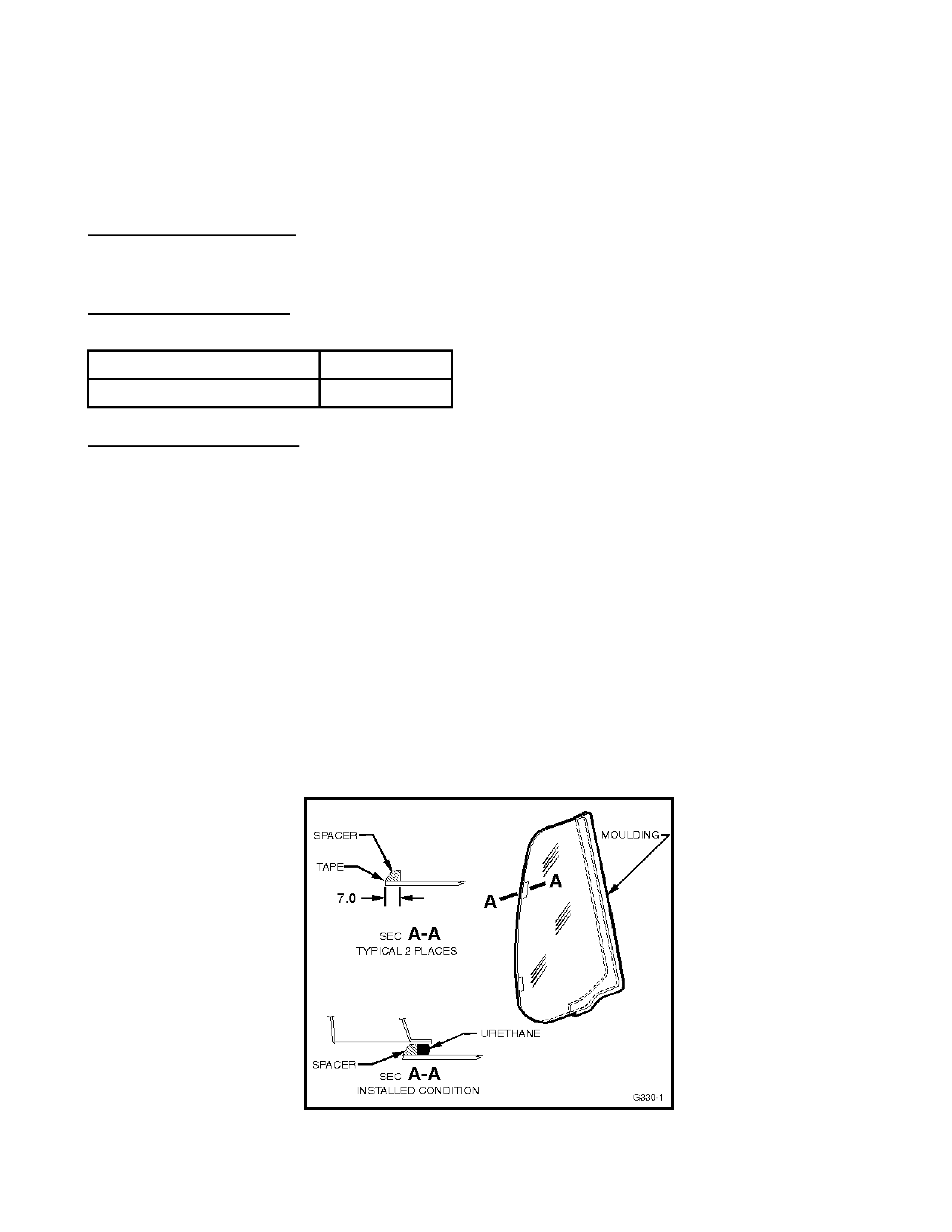
QUARTER WINDOW GLASS – IMPROVING GLASS FIT
VS Utility
(GROUP 1) April 2000
PROBLEM DESCRI PTION
Poor appearance of utility quarter window fixed glass - a gap at the top of the glass between glass and
rear side window cover - is caused by the locat ion of the glass in the body opening.
PRODUCTION REVI SION
Revised glass and mouldings were fit ted to vehicles in production fr om :
ISOVIN: Build Date:
6H8VSK80HXL454372 30/04/99
SERVICE RECTIFICATION
To improve the fit of the quarter window glass on complaint vehicles, the following procedure should
be carried out.
On vehicles built before L454373 - discard old glass and moulding and use NEW glass and NEW moulding,
fitted as per these instructions:
On v ehicles built after L454373 – glass and moulding (with moulding shape as per Figure 2) m ay be re-used,
and fitted as per these instructions:
IMPO RTANT NOTE: If the procedure below is to be carried out as a sub-let repair, provide a copy of
this Techline t o t he sub-let repairer.
1. Remove quarter window glass, using existing removal procedures in the VR Service Manual,
Volume 1, Pag e 1A7- 11.
2. Remove remnants of old urethane from glass and body aperture flange, then clean the quarter
window glass and body opening with a lint free rag wetted with Prepsol.
3. Apply spacers - p/ n 92039967 – as shown in Section A-A in Figure 1.
NOTE: spacers MUST be applied or poor glass fit t o body and outer cover will result.
Figure 1 –Spacer locati on and uret hane i n ‘fitted’ l ocat i on.
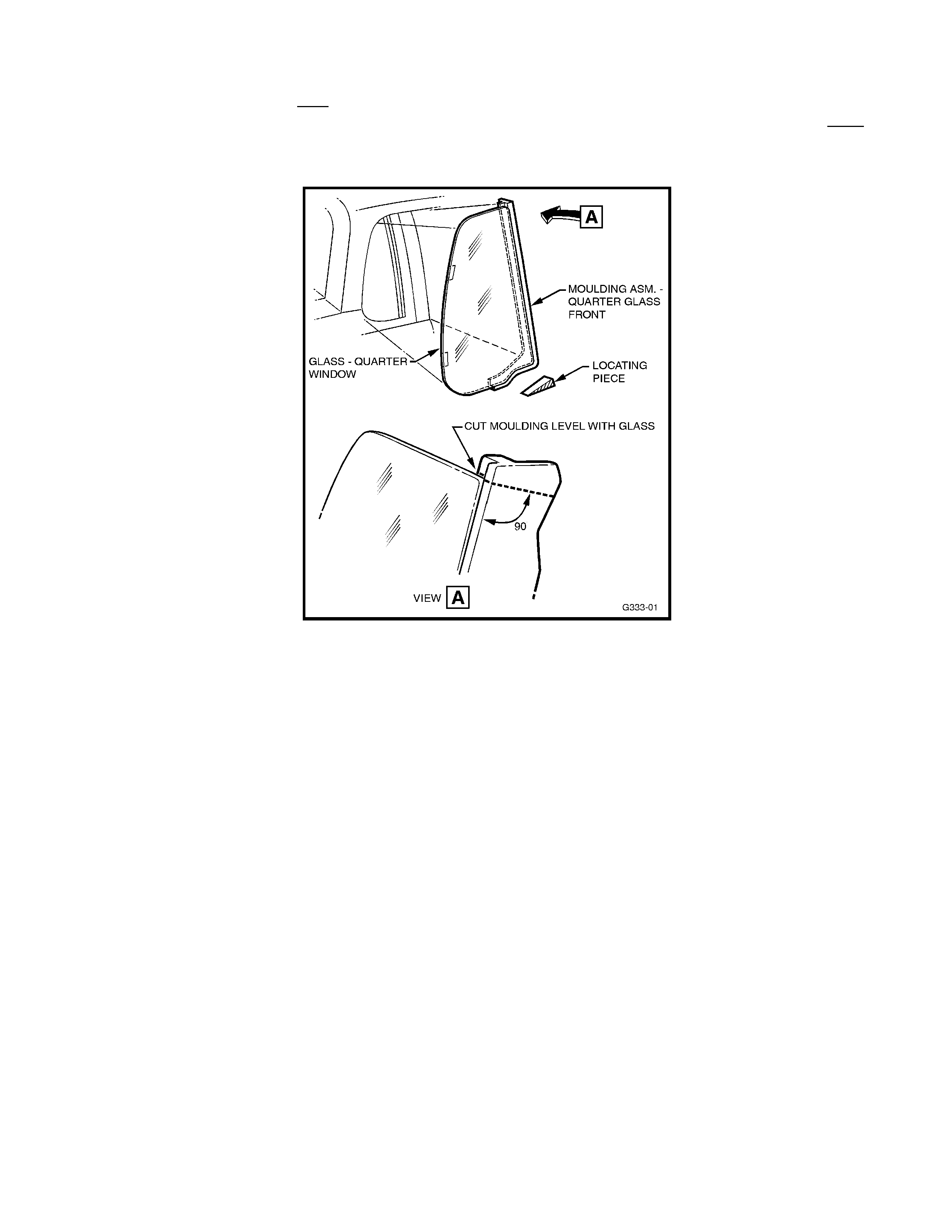
4. Fit moulding to glass, if new glass and moulding are being f itted.
5. Using a hack saw, cut of f any excess moulding protruding above the top of the glass until it is f lush
with the top of the glass, and follow a ‘cut’ line perpendicular (90°) to t he glass. Refer to Figure 2.
NOTE: Take care with these operations, or glass breakag e m ay result .
Figure 2
6. Perform a trial fitment of the glass assembly. Ensure there is no interference between the
moulding and t he dr ip gutter. Refer to figure 3.
NOTE: There must be a small gap between the glass and the drip gutter sheet metal. Refer to
Figure 3.
7. Apply urethane to the body aperture flange. Urethane should be inboard of spacers – Refer to
Figure 1.
8. Install the quarter window glass to the body aperture flange, ensure the top, forward corner
locates as per the trial f it, then press glass firmly into position. Do not f orce the glass to sit flush
with the drip gutter. Refer Figure 3.
9. Insert a locating piece – p/n 92075426 – under the lowest portion of the glass to hold the glass
during t he ur et hane curing process. Refer to figure 2 f or location.
10. Check ef fect iveness of sealing from inside the vehicle. Should any gaps in the sealing exist, apply
additional urethane on t he out side to fill these gaps. Using a flat bladed tool, sm oot h the surface of
the urethane ar ound the edge of the outside of t he glass to ensure ef fective sealing.
11. Reinstall quarter window inner trim moulding (Refer 1A9 HEADLINING AND REAR END TRIM
Section in VR Series Service Manual, Volume 1).
12. Tighten q uar ter window drip moulding attaching screws and refit the rear side window cover (Refer
1A5 LOAD COMPARTMENT AND ENDGATE Section in VR Series Service Manual, Volume 1).
Figure 3
PARTS INFORMATION
The quantities quoted below are for one side only:
Part No.: Description: Qty:
92056371 Glass - Qtr Window (RH) 1
92056372 Glass - Qtr Window (LH) 1
92056373 Moulding - Q t r Window (RH) 1
92056374 Moulding - Q t r Window (LH) 1
92039967 Spacer - Qtr Window 2
92075426 Locating Piece - Qtr Window 1
WARRANTY CLAIM I NFORMATION:
Use existing information in Labour Time Manual as shown:
Description Glass Asm. Side Panel RH – Repl.
Labour Op. No. C004100
Time 1.1 hr
Failure Code 25
Description Glass Asm. Side Panel LH – Repl.
Labour Op. No. C004200
Time 1.1 hr
Failure Code 25
WATER LEAK INTO HEADLINING
SB CABRIO
(GROUP 1) April 2000
PROBLEM DESCRIPTION
Damp patches in the headlining material around the top of the A pillar may be evident after a
vehicle roof has been soaked for extended periods of time. The water entry that causes this
condition has been found to be via the headlining m aterial extending too far into a wet area along
the roof and door weatherstrip flanges.
SERVICE RECTIFICATION
To rectify this water entry condition, it is necessary to trim excess headlining material from the
upper door weatherstrip flange, and the roof weatherstrip flange, as follows:
Refer to Figure 1 for location of the typical section through both flanges, as noted in the following
Figures and t ext.
Figure 1.
Refer Figure 2 for Secti on A-A.
Figure 2 – Typical sect i on
(door opening shown, roof secti on same)
1 = Edge of headlining exposed to water from outside vehicle.
2 = Excess headlining material extending into wet area.
3 = Weatherstrip.
Update
1. Open doors and roof.
2. Remove roof weatherst r ip and t op por t ion of door weatherstrip.
3. Caref ully remove the portion of the headlining material that is folded over and glued to the r oof
and door weatherstrip flanges (Only remove the material that is glued to the flange ends and
extends into the outside “wet” area). Take care not to tear or stretch the material during this
removal process. Figure 3 shows the headlining material removed from the flanges, and the
areas of excess (5m m appr ox.) m at er ial.
]
Figure 3
Shows excess headlining material on both the door
weatherstrip fl ange ( l ower) and t he roof weatherstr i p f l ange ( upper)
4. Clean any remnants of headlining material or glue from the flanges, so no air or water entry
gaps exist.
5. W ith a sharp k nif e, neatly trim t he excess headlining mater ial flush with the f langes, as shown
in Figure 4, t aking care not to damage paint finish.
Figure 4
“A” Shows tr i mmed headl i ni ng areas
6. If the headlining material separates from the inboard side of the flange during this process,
add glue behind the material to retain it, or use waterproof tape to retain the material to the
flang e edge. Make sure any tape used is not visible when the weatherstrip is ref it t ed.
7. Caref ully refit the weatherstrips t o the roof and door flanges.
WARRANTY CLAIM I NFORMATION:
Description Correct headlining water leaks
Labour Op. No. B000400
Time 0.6 hr
Failure Code 87

ACCESSORY POWER SOCKET LOOSE
VT, WH
(GROUP 12) April 2000
PROBLEM DESCRIPTION
The accessory power socket loosens in console mounting hole, due to insufficient
retention t orque capability of the existing nut and shell.
PRODUCTION RECTIFICATION
A revised (shorter) power accessory sock et shell has been fitted t o vehicles f r om:
ISOVIN: Build Date:
6H8VTK69HYL551551 01/02/00
SERVICE RECTIFICATION
Vehicles presented with a loose power accessory socket should have a new power
accessory socket shell – P/ N 92094030 - fitted.
PARTS INFORMATION
Part No.: Descri pt i on: Qty
92094030 Shell – Accessory Access. 1
WARRANTY CLAIM I NFORMATION:
Use existing inf or m ation in Labour Time Manual as shown:
Description Accessory Power Socket – Repl.
Labour Op. No. N311700
Time 0.5 hr
Failure Code 27

CRUISE CONTROL “DROP-OUT”
VS UTILITY
(GROUP 12) April 2000
PROBLEM DESCRIPTION
Some customers may experience an intermittent disengagement of the cruise control, particularly
when driving for long periods. A change to the speedometer operating mechanism on later built
VS Utility vehicles has raised this concern.
Electrical “noise” generated on the speedometer voltage supply has been identified as the cause.
This inter ference af fects t he vehicle speed signal being supplied to the cruise control module. The
module is sensitive to this int er ference, causing a cruise control dropout condition.
PRODUCTION RECTIFICATION
Revised speedometer assemblies, with increased capacitance to rectify this condition, have been
introduced into pr oduction from:
ISOVIN: Build Date:
6H8VSK80HYL560257 24/02/00
SERVICE RECTIFICATION
The following replacement recomm endation affects vehicles built in the f ollowing ranges:
V6 Utility
From :6H8VSK80HWL345970, 12/6/98
To :6H8VSK80HYL560257, 24/02/00
V8 Utility
From :6H8VSK80UWL346473, 15/6/98
To :6H8VSK80HYL560257, 24/02/00
(This is a V6 Isovin, and is supplied for “limiting” the affected range only)
When presented with a VS Utility from the breakpoint specified above that exhibits intermittent
cruise control dropout, technicians should perf orm a basic inspection of t he cruise control system.
These inspections should include all circuit connections and adjustments of both of the cruise
control stop lamp switches. If no faults are identified replace the speedometer assembly with the
revised part specif ied.
PARTS INFORMATION
Revised speedometer assemblies can be identif ied by locating the VDO date code label, adhered
to the rear f ace of the assem bly. This label shows the date of manuf acture and should have a date
code “210200” or lat er .
NOTE: T here are t wo labels located on the rear of the speedom eter assem bly. The one on t he top
face of the assembly should not be used t o ident ify breakpoint parts.
All parts in stock in HSPO warehouse, at time of publication, are of the latest specification.
Distributor or Dealership parts stock , found t o be date coded prior to the date code shown above,
should be returned t o HSPO for cr edit .

Part No.: Description: Qty
92142867 Speedometer Asm. 1
92142866 Speedomet er Asm . (Police) 1
WARRANTY CLAIM I NFORMATION:
Use existing information in Labour Time Manual f or removal and replacement of the speedometer
assembly.

CRUISE CONTROL INOPERATIVE - HINT
VR, VS, VT
(GROUP 12) April 2000
When presented with a “cruise control inoperative” condition in any of the above model vehicles,
technicians should inspect the stop lamp circuit for correct oper at ion.
In some instances failed stop lamp globes have been the cause of the cruise control system
becoming inoperative, resulting in unnecessary replacement of parts and unnecessary or
excessive diagnosis times.
A pull up type resistor cir cuit is at tached to t erm inal “G” of the cr uise contr ol module. This monitor s
the stop lamp cir c uit via the stop lamp globes to eart h.
In the event that this circuit becomes int errupted, IE: Poor connections (open circuit) or failed stop
lamp globes, this disables the operation of the cruise contr ol system .
Every eff ort should be made to def ine the cause of t he stop lamp circuit failure, to ensure that this
fault does not r eoccur .

FINAL DRIVE/REAR AXLE OIL - NAME CHANGE
VP, VQ, VR, VS, VT, WH
(GROUP 4) April 2000
OIL NAME CHANGE
Spicer Axle Australia, Holdens final drive unit/rear axle supplier, and Mobil Oil Australia Ltd.,
advise that Mobilube SHC 80W/140 ID oil is now known as:
Mobilube SHC ID
This nam e change was effect ive fr om December 1, 1999, and has tak en place to avoid confusion
with another Mobil product bearing a sim ilar nam e.
USAGE
This oil is recom m ended for use in:
VP/VQ:
All V8
All Utilities
VR/VS:
V6 with LSD
All V8
VT/WH:
All S/C V6 & V8
Wagons with V6 & M/T
The oil is Synthetic Hypoid Gear Oil to Holden’s Specificat ion HN2040. Refer to individual Service
Manuals for equivalents, where available.
Please ensure all Service and Parts personnel are aware of this name change, to ensure the use
of t he cor r ect oil in the above vehicles.

LEAK DETECTION DYE ADDED TO ENGINE OIL
JS, V6
(GROUP 6A) April 2000
PRODUCTION CHANGE:
This T echline bullet in is an inf ormat ion item t o advise that f r om eng ine number 08 480 202 built on
09/03/00, a sm all amount of fluorescent dye has been added to the first fill engine oil.
This dye confor m s t o GM Mat erial Specifications.
It is possible that a small number of engines, built for validation, prior to the breakpoint will also
have dye.
The chang e has been made as a q uality improvement to enable bet ter leak detection capability, in
the engine assem bly plant.
IN SERVICE:
It should be noted that under normal lighting the engine oil with have a red/brown appearance,
somewhat different t o nor mal engine oil.
Please advise all pre-delivery and service technicians of this change, so there is no concern that
oil in these engines is “ contaminated”.
PRODUCTION INTRODUCTION
A small amount of fluor escent dye has been added to t he first fill engine oil from:
Engine No.: Build Date:
08 480 202 09/03/00

DTC P0340 - CAM SENSOR INCORRECT SIGNAL
TR, JR (4 Cyl), JS (4 Cyl)
(GROUP 6C) April 2000
PROBLEM DESCRIPTION
Investigations into unnecessary ECU replacement, where DTC P0340 (camshaft sensor incorrect
signal) is stored, have identified the camshaft posit ion sensor as the cause of the f ailure. In some
instances DTC P0335 m ay also be stor ed.
SERVICE RECTIFICATION
When presented with a vehicle storing DTC P0340, technicians should follow the relevant
diagnosis for this code - Refer TIS 2000, Checking Procedures. Care should be taken to ensure
no fault exists with the Camshaft sensor circuit or mounting. If no fault is identified on inspection,
the Camshaft sensor should be replaced with the revised part detailed below.
PARTS INFORMATION
Revised Camshaft posit ion sensors can be identified by a manufactur ing date code located on the
rear face of the sensor (sensor in position on engine). The date code is stamped in white ink and
should be “2098b” or higher.
Date Code Int er pr e t ation:
“20” = week 20; “98” = 1998; “ b” = disr egard
All part s in stock in the HSPO warehouse at time of publication ar e of the lat est specification. Any
old stock found in Distributor or Dealership parts stock date coded prior to the date code above
should be returned t o HSPO for cr edit .
Any Camshaft Revolution Sensors in Distributor or Dealership parts stock – under previous part
number 90506103, m ust not be used, but ret ur ned t o HSPO for cr edit .
Part No.: Descripti on: Qty
90458252 Camshaft sensor 1
WARRANTY CLAIM I NFORMATION:
Use existing inf or m ation in Labour Time Manual
A/ T COOLER HOSE RETENTION
JS w ith A/T
(GROUP 7B) April 2000
PROBLEM DESCRIPTION
All A/T oil cooler hoses are r etained by a tie str ap (fitt ed in production), located ar ound the hoses,
between the A/T body and the radiator, visible from under the vehicle
If the hose retaining strap is not replaced - after removal for any reason, the A/T oil cooler hoses
may rub on the front engine/ trans. mount, causing hose damage, and pot entially, a leak.
SERVICE RECTIFICATION
The A/T oil cooler hose retaining tie strap must be replaced after removal for any reason. If any
vehicle is found, during servicing, to have the t ie st r ap m issing, a new tie strap should be f it t ed.
The sketch below shows the location of t he tie strap.
Figure 1 – Showing tie st rap location
PARTS INFORMATION
Part No.: Description: Qty
9275610 Strap – Hose Retaining 1

A/T REPLACEMENT REQUIREMENT - COOLER FLUSH & FLOW RATE CHECK
VR, VS, VT, WH
(GROUP 7B) April 2000
Analysis of SRTA returned automatic transmissions, and the incidence of repeat transmission
failure/replacement, highlights the need for technicians to ensure an A/T cooler flush and flow
check is done.
It is recommended that Service Managers, Workshop Controllers or Service Advisors
advise technicians to carry out the procedure – by adding the wording “Cooler Flush &
Flow Rate Check Required” to Repair Orders - w henever:
• a changeover or replacement tr ansmi ssion is installed.
• fluid contaminat i on i s suspected.
The procedure appears in the VT Service Manual, Volume 14C, Page 7C4-5 (last printed version) or in the
latest version of Holden SIP CD, Section 7C4 - 2.3 TRANSMISSION COOLER REVERSE FLUSH AND
FLOW RATE CHECK

STEERING WHINE NOISE
TS (TRW Steering Gear)
(GROUP 9) April 2000
PROBLEM DESCRIPTION
Some cust omers may complain of a light “whine” noise f rom steering , when steering is turned j ust
off-centre, at low speed.
Investigations have revealed that noise can be transferred into the vehicle body, if the P/S pump
body contacts the pump m ount ing bracket (beneath the pump).
PRODUCTION RECTIFICATION
To correct noise complaints as described above, as an interim action, washers were added at
three locations bet ween the P/S pum p and it s mounting bracket f r om :
ISOVIN: Build Date:
Not Available 12/08/99
As a final corr ective action, a r evised power steering pump m ounting brack et, with upward swaged
lower mounting holes, has been int r oduced into vehicle production at:
ISOVIN: Build Date:
Not Available 01/03/00
As the revised bracket is not yet available from HSPO, the following Service Rectification will be
required on complaint vehicles where interference between P/S pump and mounting bracket is
defined.
When parts are available from HSPO, a Techline Bulletin will be released, advising to fit the
revised bracket in lieu of this procedur e.
SERVICE RECTIFICATION
If an abnormal P/S “whine” noise is reported on a vehicle with TRW steering system; where the
noise occurs when steering wheel is turned “just off-centre” at low speed – the following check
must be carried out :
Raise vehicle on a hoist and check that clearance exists between the P/S pump and the pump
mounting bracket, at the inboard (RH) side of the pump. This can be done by raising the vehicle
on a hoist and passing a feeler strip or piece of thin card between the pump and bracket, to
ensure clearance exists. NO CO NTACT SHO ULD BE EVIDENT AT THE INBOARD SIDE OF THE
PUMP/BRACKET.
If clearance exi st s - furt her diagnosis is required to define the cause of the noise.
If no clearance exi st s - carry out the following procedure:
1. Loosen the single upper mounting nut, accessible from engine compartment and located
horizontally on the outboard (LH) side of the pump body. Loosening this mounting nut allows
pump movement lat er .
Refer View A in Figure 1 below.
2. Raise vehicle on a hoist.
3. From under vehicle, loosen and remove the three pump t o mounting bracket mounting nuts –
the third mount is accessible from behind LHF wheel. (rubber mounts above nuts should be
held during loosening, with a 14mm spanner).

4. Have an assistant lif t t he power st eering pump up of f the mount ing bracket , providing enough
clearance to fit a washer – P/N 11035613 – on the mounting bracket at all three lower
mounting holes between the pump and its mounting bracket (glue washers to bracket if
required, to assist assembly).
NOTE: the washers requir ed ar e a specific size – do not use any other washers.
Refer View B in Figure 1 below.
5. Lower the pump onto the washers/mount ing bracket .
6. Reinstall the three lower mounting nut s to the mounting studs, torque to 7Nm (rubber mounts
should be held during t or quing, with a 14mm spanner ) .
7. Torque the upper mounting stud (in engine compartment) to 7Nm (rubber mount should be
held during t or quing, with a 14mm spanner ) .
PARTS INFORMATION
Part No.: Descript i on: Qty:
11035613 Washer – P/ S Spacer 3
WARRANTY CLAIM I NFORMATION:
Description Fit P/S Spacer Washers
Labour Op. No. M000178
Time 0.4 hr
Failure Code 40
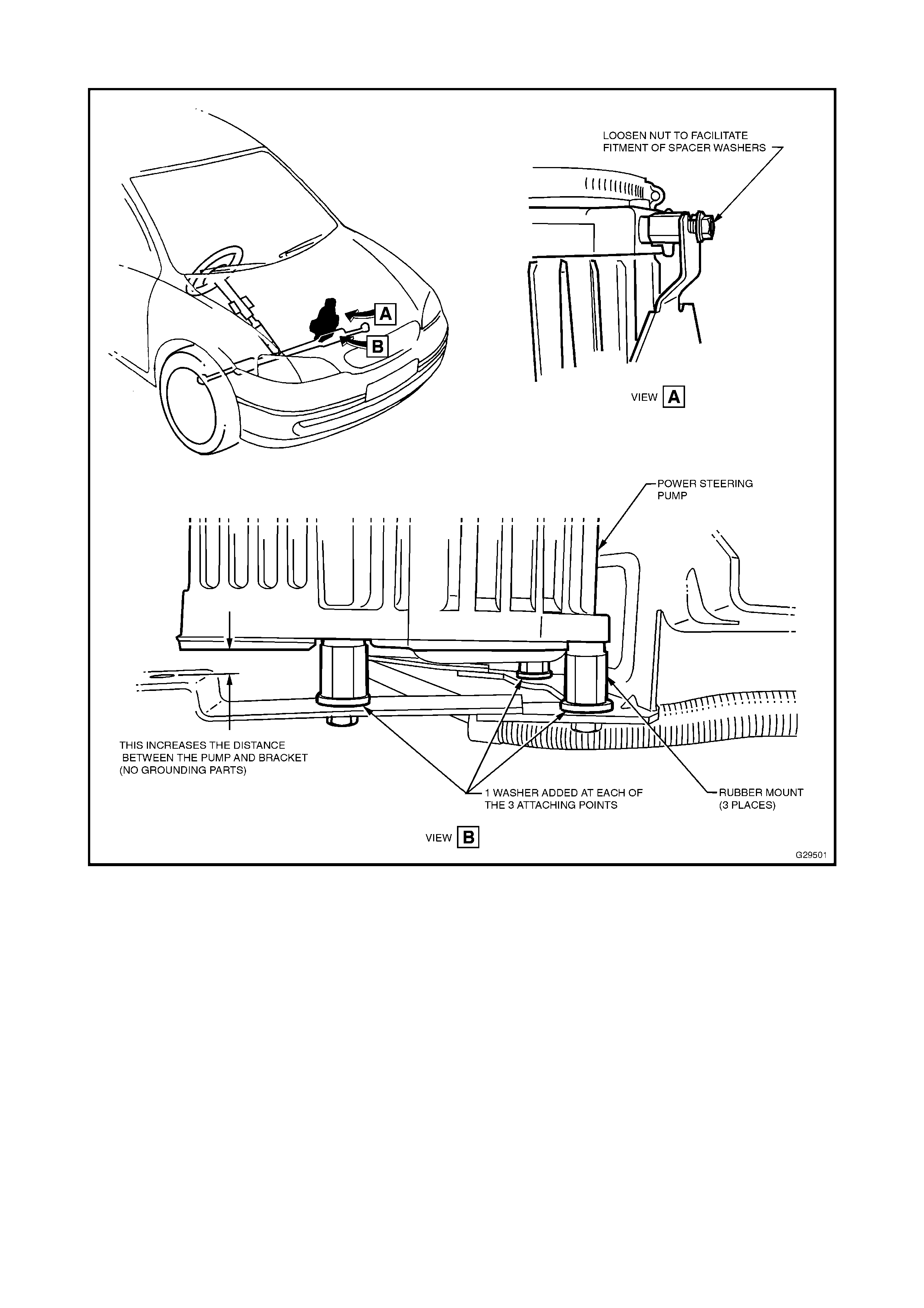
Figure 1

1
INLET MANIFOLD – ALTERNATIVE PART
USAGE
VT & WH with Gen III V8
(GROUP 6A) May 2000
PROBLEM DESCRIPTION
TAS has received calls regarding replacement
engine assemblies ex-HSPO, being fitted with an
alternative inlet manifold that appears different to
the manifold on the original engine.
An alternative inlet manifold (that has a plugged
hole at the top, front of the manifold) has been
fitted to engines in vehicle production, and for
HSPO supply (this plugged hole is used for a
derivative of the Gen III engine used in other
market areas).
This manifold is different only by the addition of a
“plugged hole”, and is totally interchangeable with
the “non-plugged’ manifold.
PRODUCTION RECTIFICATION
No breakpoint information is required for this
alternative manifold, as it is used intermittently.
SERVICE RECTIFICATION
Do not replace the manifold, as both manifolds
are fully interchangeable.
Technicians should not be concerned that there is
any additional component to be fitted at the
plugged hole location.
PARTS INFORMATION
No specific parts information is required – existing
parts and part numbers are unchanged, and
interchangeability is not affected.
ENGINE STALL ON DECELERATION/HIGH
ENGINE IDLE SPEED
JR, JS with C20SEL or C22SEL Engine
(GROUP 6M) May 2000
This Service Techline updates the previous
Techline on this topic (Issue 10, December, 1999
page 15) – by providing new part number
information.
PARTS INFORMATION
Since release of the original Techline item on this
condition, a kit comprising necessary components
has been made available.
For initial fitment of PCV oil separator as per the
previously issued Techline, order:
Part No.: Description: Qty
92065659 Kit, PCV Oil Separator 1
90411546 Valve – Idle Air Control (IAC). 1
09240103 Gasket - IACV 1
For reference, kit 92065659 contains:
1 x Oil Separator
2 x Vent Hose
2 x Hose Clamps
For Service replacement of PCV oil separator
and related components, these individual
parts will be shown in a future issue of
PartFinderTM:
Part No.: Description:
90411546 Valve – Idle Air Control (I AC).
09240103 Gasket - I ACV
09193502 Separator – PCV Oil
24421017 Hose – PCV Vent
90467971 Clam p – Vent Hose
Update
IGNITION KEY REMOVAL DIFFICULTY
JR, JS with A/T May 2000
(GROUP 7B & 12) HINT
PROBLEM DESCRI PTION
Some customers may report that they have
difficulty in removing the ignition key from the
ignition bar r e l.
Investigation into these reports has identified that
the problem r elates to the PBSL ( Park Br ake Shift
Lock) mechanism. Excessive preload/incorrect
adjustment of the automatic transmission selector
cable prevents actuation of the PBSL microswitch,
fur t her preventing rem oval of the ignit ion key.
Other symptoms include the automatic
transmission select or lever release but ton not f ully
returning to the rest position or the selector lever
does not align cor r ect ly in its selected position.
SERVICE RECTIFICATION
1. Shift the automat ic transmission selector lever
into the “P” ( par k) position.
2. Locate the selector lever cable in the engine
bay, refer Figure 1.
Figure 1.
(View of engine compartm ent f r om LH si de)
3. Locate and remove the selector lever cable-
retaining clamp from the cable connector,
refer Figure 2.
Figure 2.
4. Push forward and pull back on the cable to
minimise any preload present in either
direction, r efer Figure 3.
Figure 3.
5. Insert the cable-retaining clamp back into the
cable connector.
6. Move the selector lever to the “D” (drive)
position.
7. To confirm that the correct adjustment has
been achieved, inspect f or t he following:
- The white line on the gear selector
lever should be in line with the “D”
(drive) position;
- It is possible to access all gears with
the selector lever, i.e. P-R-N-D-3-2-1;
- The selector lever release button
travels all the way to its rest position
when “P” (park) is selected, refer
Figure 4;
- The key can be removed from the
ignition bar r e l freely.
Figure 4.
A/ T EXTERNAL OIL COOLER DELETION
VT, WH (with V6 & A/T)
(GROUP 7B) May 2000
PROBLEM DESCRI PTION
TAS calls have been received requesting
information on vehicles being pre-delivered –
where technicians have noted no external A/T oil
cooler is f it t ed.
As from vehicle build of April 10, 2000, the
external A/T oil cooler fitted to V6 (non-S/C)
engined VT and WH vehicles has been replaced
by two “in-tank” oil cooler s located in the RH & LH
radiator end t anks.
Vehicles carrying this r evision are identifiable by:
- NO exter nal A/ T oil cooler;
- Oil cooler connect ions t o bot h ends of the
radiator;
- Crossover pipe on radiator between A/T cooler
connections.
(Supercharged V6 engined vehicles remain
unchanged.)
PRODUCTION INTRODUCTION
The above revisions were introduced fr om :
VT:
ISOVIN: Build Date:
6H8VTK35HYL579900 10/04/00
WH:
ISOVIN: Build Date:
6H8WHY19HYL580005 10/04/00
SERVICE RECTIFICATION
On vehicles identified as being built after the
breakpoints above, and carrying revisions noted
above:
• An auxiliary (external) A/T oil cooler must not
be fitted.
• NO auxiliary (external) A/T oil cooler is
required when fitting tow bars (ALL tow bars).
All V6 (A/T) vehicles are able to tow 2100kg
without additional A/T cooling hardware.
WARRANTY CLAIM I NFORMATION:
The revisions noted have no effect on warranty
claiming.

HIGH CURRENT DRAW/FLAT BATTERY –
REAR DEMISTER RELAY STICKING
JR, JS
(GROUP 12) May 2000
PROBLEM DESCRI PTION
Investigations into reports of “flat battery” or high
standing current draw, on some vehicles, has
been identified as a sticking Rear Window
Demister Relay. This condition has become more
apparent during colder weather, where there is
increased use of t he r ear demister.
SERVICE RECTIFICATION
If there has been a complaint of a ‘flat batter y’ or,
during diagnosis, a high standing current draw
exists with no identifiable cause:
1. Remove fuse/relay panel cover from the right
hand side, lower instrument panel – Refer to
page 6-20 of Vectra Owner Handbook .
2. Move the fuse panel down by depressing the
lower release lever/handle and pulling towards
rear of vehicle.
3. Locate and remove the Rear Window
Demister Relay. Refer JS Wiring Diagrams,
Views of Relays and Fuses, Page 41 – Key
number 13.
4. With the demister relay removed from the
vehicle and with an Ohmmeter, probe
terminals 87 and 30 of the Rear Window
Demister Relay. If continuity exists, replace
the relay with the revised part specif ied below.
5. Should continuity not exist, further diagnosis
should be carried out to determine the source
of t he excessive current draw.
PARTS INFORMATION
The revised relay is black in colour, which is
distinctively different from the original, which is
blue in colour.
Part No.: Description: Qty
90464760 Rear Window Demister
Relay Asm 1
WARRANTY CLAIM I NFORMATION:
Use existing inf or m ation in Labour Time Manual

HOLDEN SERVICE TECHLINE _______________________________________________________________June 2000
1
PIR SUBMISSION PRECAUTION
ALL
(GROUP OB)
PROBLEM DESCRI PTION
PIR numbers reported at Foremen’s and Service
Managers Association Meetings do not match the
number believed to have been sent by Service
Managers, Foremen and Technicians.
As a consequence:
• Holden Service Engineering do not receive
vital product information;
• PIR conditions mentioned are not able to be
reported;
• PIR conditions are not able to be addressed
and production action or Techline action
cannot be initiated;
• Majority of PIR’s sent t o “old” fax numbers are
not f or warded to Holden Ser vice Eng ineer ing;
• Complaints are received from people owning
the “old” fax numbers.
Dealership personnel may also suffer reduced
PIR numbers, aff ect ing Zone incentive program s.
PROBLEM CAUSE
Old PIR pads with “old” fax numbers being used.
Incorrect “ old” or wrong f ax numbers programmed
in Dealership f ax machines.
PRODUCTION RECTIFICATION
Service Engineering provided a list of Holden fax
numbers – including t he PI R fax:
SEND PIR’s TO: (EDAG FUTURE)
ON 03 9552 8104
- in Techline Issue 2, 2000, Page 4 for use of all
Dealership Service Personnel.
Method of ordering correct PIR forms was also
supplied in that T echline item:
PIR forms: pads of PIR f orms ar e currently being
reprinted – Dealerships will be advised by All
Dealer Letter when new pads are available.
SERVICE RECTIFICATION
Applying the rectification below will help both
Holden, and Dealers, in the pro-active reporting,
assessment and correction of customer complaint
conditions.
Service Managers and Foremen should:
1. Find all copies of PIR f orms or pads with “old”
fax num bers and chang e the f ax number t o 03
9552 8104;
2. Ensure PIR’s are only sent via the latest fax
number – change all pre-programmed fax
machine numbers t o 03 9552 8104;
3. Make sure all Dealership staff who may write
PIR’s or have blank PIR forms – receive a
copy of this bulletin and change/use the fax
number.
A/C COMPRESSOR LUBRICANT
QUANTITY REVISED
VT & WH; V6 Engines
(GROUP 2)
CURRENT CONDITION
A revised quantity of A/C refrigerant oil is now
installed in compressors used on V6 engines.
These compressors now contain 220cc of oil in
lieu of t he pr evious 265cc.
PRODUCTION REVI SION
Revised V6 A/C compressors with reduced oil
quantit y have been fit t ed to vehicles from:
ISOVIN: Build Date:
6H8VTK69HYL574428 28/03/00
SERVICE RECTIFICATION
When servicing ANY VT or WH, V6 A/C
compressor, the quantity of oil added, or
calculated using existing service instructions,
should be 220cc not 265cc as per Service
Manuals.
NOTE:
For V8 Compressor, the oil quantity remains at
265cc and Service Manual compressor servicing
details remain t he sam e.

HOLDEN SERVICE TECHLINE _______________________________________________________________June 2000
FRONT SEAT BELT WEBBING “CATCHES”
ON RECLINER/LUMBAR KNOB/S
VT, WH
(GROUP 1)
This Service Techline supersedes the pr evious
Techline on this topic (I ssue 2, March, 2000 page
6). Parts Information is revised. The previous
Techline should be destroyed.
PROBLEM DESCRI PTION
Customer survey results indicate that some
customers have experienced a condition where
the front seat belt webbing did not freely slide
over the front seat recliner knob or lumbar knob.
PRODUCTION RECTIFICATION
As a continuous product improvement, the
surface f inish to both knobs has been r evised and
introduced into production. The revised knobs
feature a hard surface finish compared to the
earlier “sof t f eel” k nobs. This enables the seat belt
webbing to slide more easily over the k nob.
Revised knob/s were introduced into VT/WH
production as follows:
For Pewter Colour Knobs:
PSN: Build Date:
L521331 25/10/99
For Shale Colour Knobs:
PSN: Build Date:
L527046 07/11/99
Note: Taupe colour trim (incl. knobs) was not
carried into VT Series II (introduction L464495,
31/05/99).
SERVICE RECTIFICATION
Where a cust omer complains of seat belt webbing
“catching” on recliner or lumbar knobs, on
vehicles built prior to the above breakpoints, the
revised knobs should be installed to both front
seats.
Parts required are detailed in Parts Information
below.
When replacing the knobs, refer to the following
service information:
Recliner Knob:
VT Service Manual, Volume 12, Page 12M-21,
Ref. 2. 3
Lumbar Knob (non- SAB) :
VT Service Manual, Volume 14A, Page 1A7-5,
Ref. 2. 2
Lumbar Knob (SAB) :
VT Service Manual, Volume 14A, Page 1A7-6,
Ref. 2. 4
∗ “SAB” = Side Air Bag
PARTS INFORMATION
Part No.: Description: Qty:
92143234 Recliner Knob - Pewter 1
92143235 Recliner Knob - Shale 1
92143238 Recliner Knob - Taupe 1
92143230 Lumbar Knob, (non-SAB)
- Pewter 1
92143231 Lumbar Knob, (non-SAB)
- Shale 1
92143236 Lumbar Knob, (non-SAB)
- Taupe 1
92143232 Lumbar Knob, (SAB)
- Pewter 1
92143233 Lumbar Knob, (SAB)
- Shale 1
92143237 Lumbar Knob, (SAB)
- Taupe 1
WARRANTY CLAIM I NFORMATION:
Use the follow ing inf or m ation:
Description Replace Recliner & Lumbar
Knobs
Labour Op. No. C000397
Time 0.3 hr
Failure Code 39

HOLDEN SERVICE TECHLINE _______________________________________________________________June 2000
HVAC VACUUM RESERVOIR “BUZZ”
NOISE
JR, JS
(GROUP 2)
PROBLEM DESCRI PTION
PIR’s advising of a “buzz” noise – emanating from
the lef t hand side of the inst rument panel or glove
box area have been received. This noise may be
caused by two possible conditions:
1. Loose mounting of the Vacuum Reservoir
(described as “Recirculating Air Flap Vacuum
Tank” in TIS) – causing vibration of the
reservoir on the vehicle body mountings ;
2. “Shuttling” of the one-way valve inside the
HVAC vacuum reservoir.
PRODUCTION RECTIFICATION
A revised HVAC vacuum reservoir assembly and
Hose Asm. - Elbow have been fitted in JS
production f r om :
ISOVIN: Build Date:
W0L0JBF19YL540148 14/12/99
SERVICE RECTIFICATION
When a vehicle is presented with a complaint of
“buzz” noise from t he HVAC r e ser voir:
On Post-Breakpoi nt vehicles:
1. Open the engine hood and remove the
plenum chamber t o engine hood weatherseal;
2. Lift the LH side of the plenum chamber cover
to gain access to the vacuum reservoir.
3. Check reservoir mount ing nuts for tightness, if
loose, tighten the nuts. If the noise is
corrected after this step, no further work is
required.
4. Reinstall the plenum cover, plenum chamber
to engine hood weatherseal and close engine
hood.
On Pre-Breakpoint vehicl es:
1. Open the engine hood and remove the
plenum chamber t o engine hood weatherseal.
2. Lift the LH side of the plenum chamber cover
to gain access to the vacuum reservoir.
3. Check reservoir mount ing nuts for tightness, if
loose, tighten the nuts and attempt to
reproduce the noise before completing this
procedure. If the noise is corrected after this
step, no further work is required.
4. Diagnose the noise by listening to the HVAC
reservoir while an assistant operates the
Fresh/Recirc. control to reproduce the noise.
If this does not reproduce the noise, remove
both vacuum hoses from the reservoir and
apply vacuum to the LH side vacuum port,
using a “Mityvac” or similar tool. (The “buzz”
noise should now be heard from the
reservoir).
5. On confirmation of the HVAC vacuum
reservoir as the source of the “buzz” noise,
replace the vacuum reservoir and the hose
elbow that connects the vacuum line to the
reservoir – using the parts noted below.
NOTE: Because of the revisions to the
vacuum reservoir and the hose, for any
replacement of either part, both HVAC
vacuum reservoir and hose MUST be
replaced.
6. Reinstall the vacuum hoses, plenum cover,
plenum chamber to engine hood weatherseal
and close engine hood.
If the “buzz” noise persists, additional
diagnosis must be carried out to define
cause.
PARTS INFORMATION
W henever a vacuum reservoir is replaced for any
reason, a specific reser voir and hose combination
must be fitted if the reservoir is replaced for any
reason. Early type reservoirs are no longer
available from HSPO .
The earlier reservoir had an internal one-way
valve that can cause the “buzz” noise, and the
Hose Elbow was a plain rubber 90° elbow.
The later reservoir has NO one- way valve, but the
Hose Asm. - Elbow which MUST be used with the
reservoir has a one-way valve added to it .
To identify an early or late type reservoir, apply
vacuum to the LH side (larger) vacuum port - a
later reservoir will NOT hold vacuum at all – an
early reservoir will hold minimal residual vacuum,
and most lik ely exhibit a “buzz” noise.
If technicians suspect that a later type reservoir is
incorrectly fitted to a vehicle with a plain rubber
90° Hose Elbow, the elbow must be replaced by

HOLDEN SERVICE TECHLINE _______________________________________________________________June 2000
the later Hose Asm. - Elbow noted below, to
ensure correct Recir c . Control/f lap oper at ion.
Part No.: Descripti on: Qty
24412538 Vacuum Reservoir 1
24416795 Hose Asm. - Elbow, Air
Recirc. 1
WARRANTY CLAIM I NFORMATION:
Use existing information in Labour Time Manual,
as shown:
Description Reservoir Asm. Vacuum -
Replace
Labour Op. No. D907000
Time 0.3 hr
Failure Code 36
REVISED FUEL FILTER ASSEMBLY
JACKAROO 4JX1 DIESEL
(GROUP 6 M)
When used in cold conditions ( Below 0°C) some
4JX1 Jackaroo vehicles may experience fuel flow
difficulties through the filter assembly upon cold
start up.
The rest r ict ion is due t o trapped air f r eezing on
the f ilt er element creating a barrier thr ough which
the f uel is unable t o flow. To overcome this
concern, Isuzu has released a r evised f ilt er
assembly that has impr oved air
breathing / b leeding abilities.
The part num ber for the r evised f ilter assembly is
8972245600.
FRONT END ALIGNMENT SPEC.
HSV VT I, VT II & WH GRANGE
(GROUP 3)
The following information is repeated from HSV
bulletin of Feb. 9, 2000, for use by technicians
when servicing HSV VT Series I, VT Series II,
and WH Grange vehicles.
PLEASE ENSURE ALL TECHNICIANS
INVOLVED IN FRONT END ALIGNMENT
WORK ARE MADE AWARE OF THESE
REVISED HSV SPECIFICATIONS.
FRONT END ALIGNM ENT SPECIF ICATIO N:
The information below supersedes information
provided in SIP CD ROM Version 1.1, relating to
HSV vehicles.
FRONT WHEEL ALIGNMENT AT KERB
WEIGHT
Toe-in Degrees Total 0° 10’ ± 0° 10’
Toe-in Degrees Per Wheel 0° 05’ ± 0° 05’
Camber - 0° 30’ ± 0° 20’
Caster 7° 45’ ± 1° 15’
Note: Front toe and front camber have been
reduced to optim ise front t yre life.
FUEL GAUGE INACCURACY
UES FRONTERA
(GROUP 12)
I-GM is current ly investigat ing fuel gauge
inaccuracy in current model Frontera vehicles.
The fuel gauge will tend to t ravel through its r ange
fr om full to empt y unevenly (i.e. the am ount of
gaug e m ovement for 50k m from full will not be the
same as 50km from ½ full ), also an excessive
amount of usable fuel will remain in t he t ank when
empty is indicated.
If a vehicle is present ed t o your dealer ship with
the above complaint, please advise your customer
that the issue is cur rently being investigated by I –
GM. Do not commence diagnosis of the
system. All developments regarding this issue
will be published through the dealer let ter system.
Update

HOLDEN SERVICE TECHLINE _______________________________________________________________June 2000
BRAKE SQUEAL – ANTI-SQUEAL PASTE
REVISION
TS
(GROUP 5) Info. Update
PROBLEM DESCRI PTION
Previously issued Techlines of Issue 10, 1999,
page 7 and Issue 2, 2000, page 11, on this same
subject, advised use of a specific Anti-Squeal
Paste.
The material recommended has been revised.
The size of t he tube of anti-sq ueal paste has also
been increased from 4ml tube to a 100 gm tube,
to allow for multiple vehicle applications from the
one tube.
A new part number has been assigned to this
anti-squeal paste and is shown in parts
infor m ation below.
Please use only this anti-squeal paste - when
rectifying brake “squeal” - as mentioned in
Techlines noted above.
PARTS INFORMATION
Part No.: Descripti on: Qty
90512280 Anti-Sq ueal Past e - 100gm 1
DTC P0327 SETTING – KNOCK SENSOR
SENSITIVITY REVISION
VT & WH with LS1 (Gen III) V8 engine
(GROUP 6C) Re-Issued
This Service Techline supersedes the pr evious
Techline on this topic (I ssue 10, December, 1999
page 11). Breakpoint info. added. The previous
Techline should be destroyed.
PROBLEM DESCRI PTION
Reports have been received of DTC P0327 being
set repeatedly. This has led, in some cases, to
time consuming diagnosis with no rectification
resulting.
The cause of DTC P0327 setting (when no
definable problem exists with engine, knock
sensor or knock sensor harness) is an over-
sensitive knock sensor diagnostic system.
PRODUCTION RECTIFICATION
Revised PCM calibration was introduced to
vehicle production fr om :
ISOVIN: Build Date:
6H8VTX69FYL523541 02/11/99
SERVICE RECTIFICATION
Revised software has been released in the TIS
2000 CD-ROM Version 54, via DL 68/99 dated
December 6, 1999 which will rectify vehicles in
the field. Use of the software contained in this
new CD, to flash program PCM’s will rectify this
complaint on non-HSV vehicles only.
For HSV vehicles which suffer this complaint – fax
a “Holden Special Vehicles Warranty Request
Form No. 9861” with full details, to HSV
“Attention: John Volarich” (Fax No. (03) 9265
9555), who will supply a change-over PCM.

HOLDEN SERVICE TECHLINE _______________________________________________________________June 2000
PCV SYSTEM REVISION
JS with C22SEL Engine
(GROUP 6M)
PROBLEM DESCRIPTION
Oil separators are no longer fitted to C22SEL
engined JS vehicles. Refer breakpoint information
below.
JS C22SEL engined vehicles are now built with a
revised PCV system that feeds PCV gas into the
lower part of the inlet manifold. This new system
does not require use of an oil separator.
PRODUCTION RECTIFICATION
JS C22SEL engined Vehicles using this new PCV
system were built from:
ISOVIN: Build Date:
WOLOJBF19YL557427 16/02/00
For reference:
Engine No.:
C22SEL25015395
SERVICE RECTIFICATION
Technicians may believe vehicles have been built
incorrectly – “without an oil separator” – several
have called TAS to ask if a plant build error has
occurred, and whether an oil separator should be
installed as per previous Techline bulletins. (EG:
Techlines issued on “Engine Stall on
Decel./High Engine Idle” in Issue 10, December,
1999, page 15 & Issue 4, May, 2000, page 5.
Technicians MUST NOT fit oil separators to post
breakpoint C22SEL engined vehicles.
P/S OIL COOLER INSTALLATION WHEN
FITTING TOW BARS
VT/WH, with V6 ENGINES
(GROUP 9 & OB)
PROBLEM DESCRIPTION
No mountings are provided for the Power
Steering (P/S) oil cooler that is required to be
fitted with 1600Kg & 2100Kg tow bar packages
on:
• Auto. Trans. (A/T) equipped vehicles with V6
engines built after L579900 (VT) & L580005
(WH). (Refer Techline item, Issue 4, May,
2000, page 7 advising of A/T oil cooler
deletion).
This P/S oil cooler mounts on the external A/T oil
cooler mounting brackets on V6, A/T equipped
vehicles built prior to the above breakpoints.
NOTE: S/C V6 equipped vehicles are not
affected, as external A/T oil coolers are retained
on these vehicles.
SERVICE RECTIFICATION
When ordering a tow bar package that requires a
P/S oil cooler addition to the vehicle, assess the
vehicle engine/trans. configuration - where the
vehicle is built after the breakpoints noted above
– order P/S oil cooler mounting brackets and
mounting hardware from HSPO PartFinderTM.
HOLDEN SERVICE TECHLINE ____________________________________________________________________ JUNE 2000
KNOCK/CREAK FROM FOOTWELL OR STEERING GEAR AREA
VT & WH
(GROUPS 1 & 9) HINT
This Service Techline supersedes the previous Techline on this topic (Issue 5, July, 1999 page 6). Text
and torque specificat ions have been revised. This previous Techline should be destroyed.
PROBLEM DESCRI PTION
A knocking or creaking noise maybe heard from around the footwell area, or from the steering gear
assembly or its mount ings, when the vehicle travels over undulating gr ound and t he body flexes.
This knock or creak may be caused by the front longitudinal brace attaching nuts becoming loose,
causing relat ive movement bet ween the body and the braces.
SERVICE RECTIFICATION
NOTE: Because exact location of the noise source may be difficult, carry out the following procedure
befor e consider ing replacement of any steering g ear assembly.
To rect ify, torq ue the longitudinal to front floor brace nuts t o 31 ± 4Nm as indicated in Figure 1.
Figure 1.
PRODUCTION TORQ UE REVISION
Retaining nut t orque was increased from :
ISOVIN: Build Date:
6H8VTK35HYL588344 10/05/00
Torque Nuts to 31±4Nm

HOLDEN SERVICE TECHLINE _____________________________________________________ JUNE 2000
8
RADIO INOPERATIVE – DIAGNOSIS
PRECAUTION
GMC TC/TK Light Truck (Ambulance)
(GROUP 12) HINT
This Techline bulletin applies only to GMC
TC/TK vehicles imported under the
Holden/JAKAB agreement specified in
Warranty Processing letter WD 06/98, dated
August 28, 1998.
Warr anty Clerks should refer to the above letter
for warrant y claiming details, when required.
The f ollowing informat ion is provided by JAKAB
and has been circulated to Am bulance Services
who operate these vehicles nationwide.
This information is provided to assist Holden
Dealership technicians who work on these
vehicles.
PROBLEM DESCRI PTION
Radio is inoperative, even though no problem
can be found with the radio assembly, IE: fuse
OK, wiring (power and earth) to radio is OK.
SERVICE RECTIFICATION
On presentation of a vehicle with this condition
–– technicians should be aware that if one
speaker is shorted out, the radio will cease to
function.
Fitting a new radio will result in the same
condition.
Trace the radio speaker wiring to define the
location of any short circuit in the wiring, and
repair the shor t circ uit – PRIOR to attempt ing to
replace a radio assembly.
WARRANTY CLAIM I NFORMATION:
When claiming any warranty work on these
vehicles - use existing Labour Operation
numbers and times for Commodore in the
Passenger Labour Time Manual, or contact
JAKAB, as per the information provided in
W ar ranty Processing let ter WD 06/98 regarding
these vehicles.
STEERING TOE CONVERSION FROM
DEGREES/MINUTES TO MILLIMETRES.
ALL
(GROUP 3) Re-Issued
This Techline Bulletin has been re-issued to
ensure all technicians are aware of the
conversion dat a contained in the att ached chart
(ON PAGE 24).
This Service Techline has been issued to aid
dealers in converting wheel alignment toe
figures from degree/minutes to decimal
degrees or t o m illimetres and vice-versa.
The table on the back of this Service Techline
shows toe readings as measured at the rim
edge for 13”, 14”, 15”, 16”, 17” diameter rims.
Also included are toe readings for a 28” tyre.
This is included for those wheel alignment
machines that are calibrated to read toe at the
old convention of 28” diameter.
Most modern wheel alignment equipment,
allows the operator to ‘dial in’ the actual
diameter of the rims of the vehicle being
measured. Some machines which do not allow
the rim diameter to be dialled in, may default to
measuring t oe at a 14” rim diameter .
When reading the output from the wheel
alignment equipment, ensure the operator
knows the difference between a readout in
degrees/minutes (0°00’) format or in decimal
degrees (0. 00°) format.
Since the introduction of VT, all wheel
alignment specifications are given in a
degree/minute format as per the VT Series
Service Manual, Volume No.1.
Note: 1 deg r ee ( 01°00’) = 60 m inutes ( 00°60’) ;
1 minute (0°01’) = 0.0167° decimal
degree.
IF THE MACHINE DOES NOT CALL FOR THE
EXACT RIM DIAMETER OF THE VEHICLE BEING
MEASURED, IT IS ESSENTIAL FOR THE
TECHNICIAN TO KNOW WHICH CALIBRATION
DIAMETER APPLIES TO THEIR MACHINE i.e. 14”
OR 28” DIAMETER SO T HAT T HE CORRECT TOE
SPECIFICATIONS CAN BE ACHIEVED.

HOLDEN SERVICE TECHLINE _____________________________________________________ JUNE 2000
9
M/T NOISE
HSV VT with GEN III & MM6 M/T
(GROUP 7A)
PROBLEM DESCRI PTION
Some customers may be concerned about the
noise levels from the MM6 6-speed Manual
Transmission (M/T) fitted to Gen III V8
equipped HSV vehicles.
Engine firing pulses input into this high torque
capacity trans., with its low friction design, can
result in a gear “rattle” or “buzz” noise while
driving.
This noise and other normal gear noises can
also be transferred into the gear lever, where
they may be am plified by the gear lever boot or
a loose gear lever k nob.
Holden took steps to reduce these noise levels
as much as possible, by the use of a noise
reduction package, in later built VT MM6 M/T
equipped vehicles – the package consists of :
- Additional 0.5 litre of Dexron III® Automatic
Transmission Fluid (ATF) required as
‘normal fill’. – Provides additional noise
absorption.
- Additional insulator on gearshift control
lever. – Reduces noise transfer into
passenger compartm ent .
- Revised gear lever dimension – Stops loose
gear lever knob vibration and noise transfer
into passenger compar t m ent.
This pack age is now used in ALL VT, MM6 M/T
equipped vehicles.
PRODUCTION INTRODUCTION
The noise reduction package was added to
ALL VT vehicles (including HSV vehicles) fitt ed
with MM6 M/T from:
ISOVIN: Build Date:
6H8VTK69FYL511925 28/09/99
However – to fill HSV orders in a timely
manner, early built HSV MM6 equipped
vehicles were released prior to availability of
the noise reduction package.
The MM6 M/T, in VT Series II HSV
vehicles, was introduced into production at:
ISOVIN: Build Date:
6H8VTK69FXL446731 29/04/99
Additional ATF ( 0. 5 litre) was added at:
ISOVIN: Build Date:
6H8VTK69FYL505387 14/09/99
SERVICE RECTIFICATION
Dealerships may receive complaints regarding
transmission noise levels in early built HSV
MM6 M/T vehicles. Carry out the revisions
requir ed t o affected vehicles, as shown:
Affected Vehicle
Range: Revisions Required:
L446731 to L505386 Trans. & Lever
Revisions and Oil
“Overfill”
L505387 to L511924 Trans. & Lever
Revisions only
NOTE: some vehicles may already have some
of the additional parts fitted through
recommendations from TAS – where partial
application of this package is found – add only
the parts required.
Trans. & Lever Revisions
For vehicles from L446731 to L511925
1. Remove gear lever knob and attached boot
– DO NOT attempt to remove knob by
rotating - Refer VT Service Manual
Volume 14C, page 7B3-15. NOTE: If
difficulty is encountered removing the gear
lever knob, a small flat blade screwdriver
may be inserted inside the lower end of the
knob to detent the retaining lugs, allowing
easier removal.
2. Measure t he top of the gear lever as shown
in Figure 1. Early build levers are
13.30/13.70mm Dia. Later levers are
13.90/14.00m m Dia. . If the lever Dia. is less
than 13.90mm – the lever (P/N 92075003)
must be replaced. (All HSPO stock is of the
later type).
Aft er the g ear lever diamet er is check ed as O K,
or a new lever is installed – fit a G ear
3. Lever Asm. Isolator (P/N 92087709) over
the lever, pressing the isolator onto the
HOLDEN SERVICE TECHLINE _____________________________________________________ JUNE 2000
10
lever and attaching screws to ensure
maximum noise reduction is achieved.
Refer Figure 1.
Figure 1.
4. Before re-fitting the knob and boot
assembly -–ensure the cable tie retaining
the boot to the knob is as tight as possible,
to ensure no noise “leak paths” remain.
5. Refit the gear lever knob and boot
assembly.
“Oil Overfill”
For vehicles from L446731 to L505386
1. Raise the vehicle on a hoist, ensuring that
the vehicle is level. Refer to
Section 0A GENERAL INFORMATION in
Volume 1 of VT Service Manual, for the
location of jacking point s.
2. Place a drain t ray beneath transmission and
remove transmission filler plug from left
hand side of transmission case, using a
3/8” drive sock et bar .
3. Allow excess fluid to drain until flow stops. If
required, top up fluid level until it reaches
the bottom of the thr eaded filler plug hole.
4. Clean the threads of the f iller plug and hole,
apply thread sealant (GM P/N 12346004),
then reinstall filler plug, torque to 20 – 34
Nm. Do not apply Tef lon thread tape to the
plug thr eads.
5. Remove back-up switch wiring harness
connector (1) from the back-up switch,
located on the right hand side of the
transmission case. Refer Figur e 2.
Figure 2.
6. Remove back-up lamp switch from the
transmission case – shown by arrow in
Figure 3.
Figure 3.
7. Add a measured, 0.5 litres of Dexron III®
ATF to the transmission, via the back-up
lamp switch threaded hole in the
transmission case.
8. Apply Sealant (P/N 12346004) to the
cleaned threads of the back- up lam p switch.
6. Install switch to transmission case and
torque to 20 – 34 Nm, then refit electrical
connector.
7. On the left hand side of the trans. at the
“old” filler plug – wipe the existing label
under the plug with a solvent to remove all
traces of dirt and contaminants, then apply
a “DO NOT OPEN….” sticker (P/N
92095432) OVER the existing label. This
ensures the plug is not opened, which
would result in loss of the added ATF, in
future. Refer Figure 4.
HOLDEN SERVICE TECHLINE _____________________________________________________ JUNE 2000
11
Figure 4.
Full details of lubricant level checking and
addition, removal and replacement of the back-
up lamp switch, gear lever, knob and boot are
contained in VT Series II Service Manual,
Volume 14C, pages 7B3- P8 & P9, and pages
7B3- P15 & P16.
Should the noise described in this bulletin
continue after application of the above
procedure, contact HSV Technical Assistance
Department on telephone number (03) 9265
9500.
NOTE: The gear rattle, or “buzz” noise will not
be reduced by gear or transmission
replacement.
PARTS INFORMATION
Part No.: Description: Qty
92087709 Boot – Shift Asm.
Isolator 1
92095432 Label – Trans. 1
12346004 Sealant ( Rev. Sw.) As
required
M41089 Dexron III® ATF (1 litre) 1
92075003 Lever - Shift 1 - If
required
NOTE: If Sealant 12346004 is not available -
Permatex “Pipe Thread Sealant With Teflon”
P/N 27838 - 50ml t ube size – may be used.
WARRANTY CLAIM I NFORMATION:
NOTE: some vehicles may already have some
of the additional parts fitted through
recommendations from TAS. Where partial
application of this package is found – add the
additional parts required and claim the reduced
amount of time requir ed for those t asks.
Use the f ollowing information to claim the work
defined above.
Description Fit HSV Noise Reduction
Package
Labour Op. No. K000261
Time 0.8 hr
Failure Code 40

HOLDEN SERVICE TECHLINE _____________________________________________________ JUNE 2000
12
CHECKING M/T LUBRICANT LEVEL
VT w ith LS1 (Gen III) V8 & M/T
(GROUP 7A)
The following manual transmission information
for LS1 (GEN III) manual trans. is repeated
fr om All Dealer Lett er DL 57/99 – for t he benefit
of service technicians. This information
supersedes t he information shown in VT Series
II Service Manual, Volume 14C, pages 7B3- P8
& P9.
Please note the following important point s on
servicing this transmission:
• This transmission is classified as being a
"Fill for Life" transmission and periodic
checking of the lubricant level is not
required. In production, a sticker is placed
next to the normal filler plug on the
transmission advising technicians: - “DO
NOT OPEN THE FILL PLUG – REFER
SERVICE MANUAL”.
• The only time that fluid level checking is
appropriate, is aft er cor r ection of a fluid leak
that does not req uire the transm ission to be
fully drained and/or removed from the
vehicle.
• The VT Series II Owners Handbook Print
No 3 will have the requirement to
periodically check fluid levels in this
transmission delet ed.
• The VT service manual (CD version only)
has also been revised in line with the
above. The CD with these revisions
released via automatic distribution in
December 1999. The attachment to this
letter is an extract from this CD detailing
information on transmission fluid capacity,
checking & filling procedures. The
additional oil level was introduced as a
noise reduction initiat ive.
• Update your VT Series II Service Manual,
Volume 14C – by photocopying the
following two pages and sticking them
over existing pages 7B3-8 & 9.
PRODUCTION BREAKPOINT
Oil level was increased (as noted in revised
Section 2.2 attached) in the transmission
at:
ISOVIN: Build Date:
6H8VTK69FYL505387 14/09/99
HOLDEN SERVICE TECHLINE _____________________________________________________ JUNE 2000
13
Photocopy this page
– cut of f excess paper above dotted line -
stick over existing infor m ation on VT SERIES II SERVICE MANUAL, VOLUME 14C, PAGE 7B3- 8
- - - - - - - - - - - - - - - - - - - - - - - - - - - - - - - - - - - - - - - - - - - - - - - - - - - - - - - - - - - - - - - - - - - -
2.1 RE COMMENDED LUBRICANT
The recommended lubricant for the ‘T56’ manual
transmission is Dexron III® automatic transmission fluid to
Holden’s Specification HN 2126.
The transmission lubricant capacity is approximately 4.4
litres.
2.2 CHECKING TRANSMISSION
LUBRICANT LEVEL
Important: This transmission is classified as being a
“Fill for Life” transmission and checking the lubricant
level is not recommended.
The only time that fluid level checking would be
appropriate, would be after correction of a fluid leak that
did not require the transmission to be fully drained and/or
removed from the vehicle.
1. Raise the vehicle front and rear and support on safety
stands, ensuring that the vehicle is level. Refer to
Section 0A GENERAL INFORMATION in Volume 1 of
this Service Manual, for the location of jacking points.
2. Place a drain tray beneath transmission and remove
transmission filler plug (1) from left hand side of
transmission case (2), using a 3/8” drive socket bar.
NOTE: Depending on the severity of the loss, fluid
will probably flow from the filler plug hole, following
removal.
3. Allow excess fluid to drain until flow stops. If required,
top up fluid level until it does flow out.
4. Clean the threads of the filler plug, apply thread
sealant such as Loctite 565 or equivalent (GM P/N
12346004), then reinstall filler plug, tightening to the
correct torque specification. Do not apply Teflon
thread tape to the plug threads.
TRANSMISSION FILLER PLUG
TORQUE SPECIFICATION 20 - 34 Nm
5. Remove the back-up lamp switch as detailed in 3.1
BACK-UP LAMP SWITCH, Replace in this Section.
6. Using commercially available fluid dispensing
equipment, add a measured, 0.5 litres of the
recommended lubricant to the transmission, via the
back-up lamp switch threaded hole in the
transmission case.
7. Reinstall the back-up lamp switch, as detailed in
3.1 BACK-UP LAMP SWITCH, Replace in this
Section, then lower the vehicle to the ground.
Figure 7B3- 7
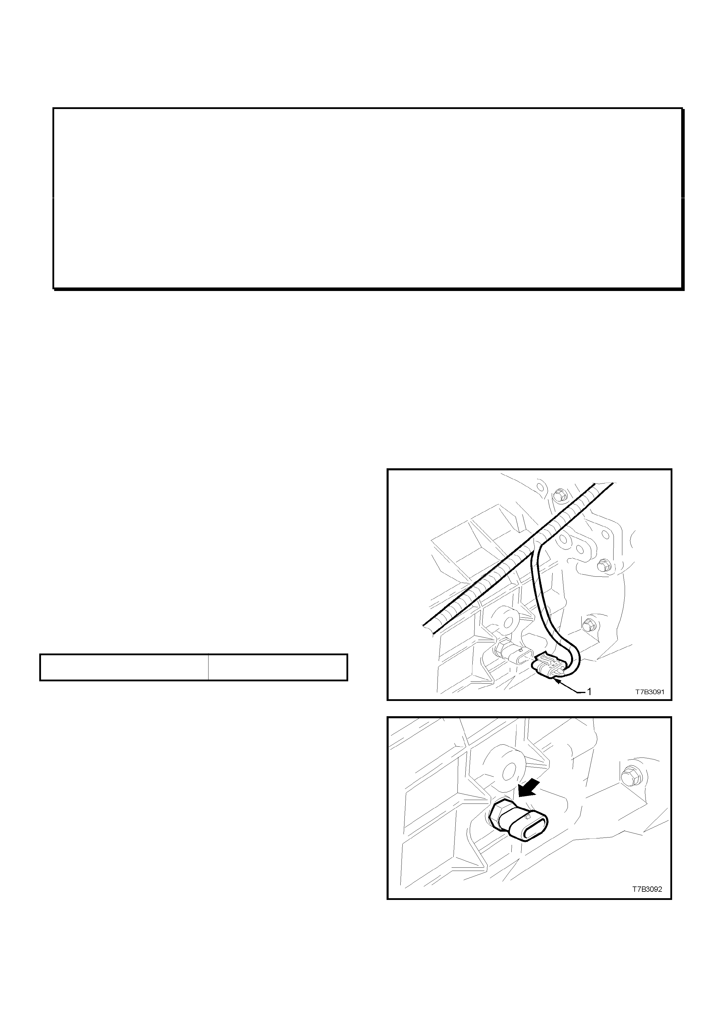
HOLDEN SERVICE TECHLINE _____________________________________________________ JUNE 2000
14
Photocopy this page
– cut of f excess paper above dotted line -
stick over existing infor m ation on VT SERIES II SERVICE MANUAL, VOLUME 14C, PAGE 7B3- 9
- - - - - - - - - - - - - - - - - - - - - - - - - - - - - - - - - - - - - - - - - - - - - - - - - - - - - - - - - - - - - - - - - - - -
3.1 BACK-UP LAMP SWITCH
REPLACE
1. Raise front of vehicle and support on safety stands.
Refer to Section 0A GENERAL INFORMATION in
Volume 1 of this Service Manual, for the location of
jacking points.
2. Remove wiring harness connector (1) from switch,
located on the right hand side of the transmission case.
3. Loosen, then remove switch (arrow) from the
transmission case.
4. Apply Loctite 565 or equivalent (GM P/N 12346004), to
the cleaned threads of the back-up lamp switch.
5. Install switch to transmission case and tighten to the
correct torque specification.
BACK-UP LAMP SWITCH
TORQUE SP ECIFICAT I O N 20 - 34 Nm
6. Install wiring harness connector to switch.
7. Remove safety stands and lower vehicle to ground.
8. Check back-up lamp operation.
Figure 7B3- 9
Figure 7B3- 10
HOLDEN SERVICE TECHLINE _____________________________________________________ JUNE 2000
15
ANTI THEFT/KEYLESS ENTRY DIAGNOSIS
JACKAROO
(GROUP 12)
The chart s below are q uick reference material that is int ended to be used in conjunction with the relevant
workshop manual section ( 8H) and wiring diagrams (8D – 242) in the current Jack ar oo work shop manual.
DOOR SWITCH DIAGNOSIS
Front Door Key Swit ch
Detect Switch Circuit - Open
FUNCTION OPERATION
Anti – Theft LED No effect
Remote Lock ing No effect
Mechanical Locking No effect
Alarm System ( Arming ) Mechanical key will not arm system
Alarm System ( Disarm ) Mechanical key will not arm system
Note Unlocking the door with the mechanical key will activate the alar m system .
Detect Switch Circuit – Short to Gr ound
FUNCTION OPERATION
Anti – Theft LED No effect
Remote Lock ing No effect
Mechanical Locking No effect
Alarm System ( Arming ) No effect – (see below)
Alarm System ( Disarm ) No effect – (see below)
Note Locking / Unlocking the door with the snib button will arm / disarm the alarm
system
Tamper Switch Cir cuit - Open
FUNCTION OPERATION
Anti – Theft LED No effect
Remote Lock ing No effect
Mechanical Locking No effect
Alarm System ( Arming ) No effect
Alarm System ( Disarm ) No effect
Note Open circ uit is the normal state for this switch. For cing the lock will not activate t he alar m
when this condition exists
Tamper Switch Circuit – Short to G r ound
FUNCTION OPERATION
Anti – Theft LED Flashes at constant 2Hz with doors closed
Remote Lock ing Inoperative
Mechanical Locking No effect
Alarm System ( Arming ) Inoperative
Alarm System ( Disar m ) I noper ative

HOLDEN SERVICE TECHLINE _____________________________________________________ JUNE 2000
16
Door Lock Key Switch
Door Lock Key Switch - Open
FUNCTION OPERATION
Anti – Theft LED No effect
Remote Lock ing No effect
Mechanical Locking No central lock ing from failed door
Alarm System ( Arming ) No effect
Alarm System ( Disarm ) No effect
Note Central locking is still available from arm – rest master switch
Door Lock Key Switch (Lock ) – Shor t to Ground
FUNCTION OPERATION
Anti – Theft LED No effect
Remote Locking Remote unlock only
Mechanical Locking No central locking from failed door
Alarm System ( Arming ) No effect
Alarm System ( Disarm ) No effect
Note Central locking is still available from arm – rest m aster switch
Door Lock Key Switch (Unlock) – Shor t To Ground
FUNCTION OPERATION
Anti – Theft LED No effect
Remote Lock ing Remote lock only
Mechanical Locking No effect
Alarm System ( Arming ) No effect
Alarm System ( Disarm ) No effect
Hood & Dome Lamp Switches
Hood Switch Circuit - O pen
FUNCTION OPERATION
Anti – Theft LED No effect
Remote Lock ing No effect
Mechanical Locking No effect
Alarm System ( Arming ) No effect
Alarm System ( Disarm ) No effect
Note Open circuit is the normal state for this switch. For c ing the hood will not activate the
alarm when this condition exists
Hood Switch Circuit – Short to Ground
FUNCTION OPERATION
Anti – Theft LED Normal operat ion with doors open, but off when
doors locked
Remote Lock ing No effect
Mechanical Locking No effect
Alarm System ( Arming ) Inoperative
Alarm System ( Disar m ) I noper ative
HOLDEN SERVICE TECHLINE _____________________________________________________ JUNE 2000
17
Dome Lamp Switch ( Door Sw.) Circuit - Open
FUNCTION OPERATION
Anti – Theft LED No effect
Remote Lock ing No effect
Mechanical Locking No effect
Alarm System ( Arming ) No effect
Alarm System ( Disarm ) No effect
Note Open circuit is the normal state for this switch. The dome lamp will not activate when the
door is opened
Dome Lamp Switch (Door Sw.) Circuit – Short t o G round
FUNCTION OPERATION
Anti – Theft LED See note below
Remote Lock ing Inoperative
Mechanical Locking No effect
Alarm System ( Arming ) Inoperative
Alarm System ( Disar m ) I noper ative
Note The Ant i – t heft LED will flash at 2Hz for 30 secs. After a remot e keypad button is
depressed, then go out. The LED will remain on continuously while the unlock button is
depressed on the k eypad.

HOLDEN SERVICE TECHLINE _____________________________________________________ JUNE 2000
18
COOLANT SPECIFICATIONS
ALL IGM MODELS
(GROUP 6K)
The att ached t able is a reference guide to coolant specifications for all Isuzu vehicles.
Vehicle Model Factory Fill
Spec Recommended
Change at Alternative
Replacement
Coolant Spec
Recommended
Change at
~1998, R7 Rodeo
~1997, L5 Jackaroo
1996, UT Frontera
~1996, Isuzu Truck
HN2043
2 Years / 40 000
HN2217
Or
GM6277m
5 Years / 100 000
(Max)
5 Years / 100 000
(Min)
1997~, Isuzu Truck
HN2217
2 Years / 40 000
GM6277m
5 Years / 100 000
(Min)
1999~, R9 Rodeo
1998~, U8 Jackaroo
1997, UT Frontera
MX, Frontera
HN2217
5 Years / 100 000
(Max)
GM6277m
5 Years / 100 000
(Min)
Suburban
GM6277m
(Dexcool)
5 Years / 100 000
(Min)
Note – An inspection of cooling system component s for corrosion should be car ried out prior to r efilling with
new coolant. Failure to identify a problem at this point may be a costly experience at a later date. When
using an alternative to the factory fill coolant the cooling system must be thoroughly flushed prior
to refilling.

TOE
(MINUTES)
TOTAL
(DECIMAL
DEGREES) 13"
rim 14"
rim 15"
rim 16"
rim 17"
rim
28"
Normal
Tyre TOE
(MINUTES)
TOTAL
(DECIMAL
DEGREES) 13"
rim 14"
rim 15"
rim 16"
rim 17"
rim
28"
Normal
Tyre
0o01' 0.02o0.10 0.10 0.11 0.12 0.13 0.21 0o31' 0.52o2.98 3.21 3.44 3.66 3.89 6.41
0o02' 0.03o0.19 0.21 0.22 0.24 0.25 0.41 0o32' 0.53o3.07 3.31 3.55 3.78 4.02 6.62
0o03' 0.05o0.29 0.31 0.33 0.35 0.38 0.62 0o33' 0.55o3.17 3.41 3.66 3.90 4.14 6.83
0o04' 0.07o0.38 0.41 0.44 0.47 0.50 0.83 0o34' 0.57o3.27 3.52 3.77 4.02 4.27 7.03
0o05' 0.08o0.48 0.52 0.55 0.59 0.63 1.03 0o35' 0.58o3.36 3.62 3.88 4.14 4.40 7.24
0o06' 0.10o0.58 0.62 0.66 0.71 0.75 1.24 0o36' 0.60o3.46 3.72 3.99 4.26 4.52 7.45
0o07' 0.12o0.67 0.72 0.78 0.83 0.88 1.45 0o37' 0.62o3.55 3.83 4.10 4.37 4.65 7.65
0o08' 0.13o0.77 0.83 0.89 0.95 1.00 1.66 0o38' 0.63o3.65 3.93 4.21 4.49 4.77 7.86
0o09' 0.15o0.86 0.93 1.00 1.06 1.13 1.86 0o39' 0.65o3.75 4.03 4.32 4.61 4.90 8.07
0o10' 0.17o0.96 1.03 1.11 1.18 1.26 2.07 0o40' 0.67o3.84 4.14 4.43 4.73 5.02 8.28
0o11' 0.18o1.06 1.14 1.22 1.30 1.38 2.28 0o41' 0.68o3.94 4.24 4.54 4.85 5.15 8.48
0o12' 0.20o1.15 1.24 1.33 1.42 1.51 2.48 0o42' 0.70o4.03 4.34 4.65 4.97 5.28 8.69
0o13' 0.22o1.25 1.34 1.44 1.54 1.63 2.69 0o43' 0.72o4.13 4.45 4.77 5.08 5.40 8.90
0o14' 0.23o1.34 1.45 1.55 1.66 1.76 2.90 0o44' 0.73o4.23 4.55 4.88 5.20 5.53 9.10
0o15' 0.25o1.44 1.55 1.66 1.77 1.88 3.10 0o45' 0.75o4.32 4.65 4.99 5.32 5.65 9.31
0o16' 0.27o1.54 1.66 1.77 1.89 2.01 3.31 0o46' 0.77o4.42 4.76 5.10 5.44 5.78 9.52
0o17' 0.28o1.63 1.76 1.88 2.01 2.14 3.52 0o47' 0.78o4.51 4.86 5.21 5.56 5.90 9.72
0o18' 0.30o1.73 1.86 1.99 2.13 2.26 3.72 0o48' 0.80o4.61 4.96 5.32 5.67 6.03 9.93
0o19' 0.32o1.82 1.97 2.11 2.25 2.39 3.93 0o49' 0.82o4.71 5.07 5.43 5.79 6.15 10.14
0o20' 0.33o1.92 2.07 2.22 2.36 2.51 4.14 0o50' 0.83o4.80 5.17 5.54 5.91 6.28 10.34
0o21' 0.35o2.02 2.17 2.33 2.48 2.64 4.34 0o51' 0.85o4.90 5.28 5.65 6.03 6.41 10.55
0o22' 0.37o2.11 2.28 2.44 2.60 2.76 4.55 0o52' 0.87o4.99 5.38 5.76 6.15 6.53 10.76
0o23' 0.38o2.21 2.38 2.55 2.72 2.89 4.76 0o53' 0.88o5.09 5.48 5.87 6.27 6.66 10.96
0o24' 0.40o2.31 2.48 2.66 2.84 3.01 4.97 0o54' 0.90o5.19 5.59 5.98 6.38 6.78 11.17
0o25' 0.42o2.40 2.59 2.77 2.96 3.14 5.17 0o55' 0.92o5.28 5.69 6.10 6.50 6.91 11.38
0o26' 0.43o2.50 2.69 2.88 3.07 3.27 5.38 0o56' 0.93o5.38 5.79 6.21 6.62 7.03 11.58
0o27' 0.45o2.59 2.79 2.99 3.19 3.39 5.59 0o57' 0.95o5.47 5.90 6.32 6.74 7.16 11.79
0o28' 0.47o2.69 2.90 3.10 3.31 3.52 5.79 0o58' 0.97o5.57 6.00 6.43 6.86 7.28 12.00
0o29' 0.48o2.79 3.00 3.21 3.43 3.64 6.00 0o59' 0.98o5.67 6.10 6.54 6.97 7.41 12.21
0o30' 0.50o2.88 3.10 3.32 3.55 3.77 6.21 0o60' 1.00o5.76 6.21 6.65 7.09 7.54 12.41
WHEEL ALIGNMENT CONVERSION CHAR
T
(DEGREE/MINUTES TO DECIMAL DEGREE TO MILLIMETRES)
Millimetres of Toe Millimetres of Toe

HOLDEN SERVICE TECHLINE ____________________________________________________________________ JULY 2000
6 6
M/T REVERSE LAMP SWITCH FAILURE
SB, TR, TS, JR, JS, YE (M/T)
(GROUP 7A)
PROBLEM DESCRI PTION
PIR’s have been received, advising of
inoperative M/T (manual trans.) reverse lamp
switches. Cause of failure is a switch internal
connection fault.
SERVICE RECTIFICATION
Whenever an inoperative M/T reverse lamp
switch is encountered, it should be replaced with
a new switch ex-HSPO.
During any switch replacement, fit a new seal to
the switch.
PARTS INFORMATION
The part number f or the reverse lamp switch has
not been changed, but switches in HSPO stock
at the time of this Techline release are from an
alternative supplier with revised inter nal design.
Any switches, in Dealership parts stock, which
carry a date st amp ear lier than “ 26.05.00” on t he
HSPO box label, should not be used, but be
returned to HSPO for credit.
Part No.: Description: Qty
90482454 Reverse Lamp Switch
(M/T) 1
11015219 Seal - Reverse Lamp
Switch 1
WARRANTY CLAIM I NFORMATION:
Use existing inf or m ation in Labour Time Manual
ALTERED TOOTHED BELT
INSTALLATION PROCEDURE
JR, YE - 1997 MY’ WITH X25XE V6
ENGINE
(GROUP 6A)
This Techline item, replaces the item previously
published in December, 1997 Issue 8, to ensure
technicians are aware of the altered procedure
shown, and that the procedure also applies to
YE Calibra wit h X25XE V6 engine.
Various alterations were introduced to the
toothed belt drive on 1997 MY’ JR Vectra, & YE
Calibra with X25XE (V6) engine. These
alterations involved the introduction of a new
toothed belt t ension roller with an additional fr ont
flanged wheel and a modified toothed belt
tension roller base plate (identified by a letter E
stamping).
These alterations were implemented to reduce
engine noise and increase t he toothed belt lif e to
120,000 km (or 8 years). However, in making
these changes, the procedure for installing the
toothed belt was also altered.
Contrary to the previous installation sequence
instructions, the introduction of these alterations
means that the toothed belt is now installed
clockwise.
This is necessary, as the toothed belt can no
longer be pushed onto the toothed belt tension
roller from the front.
Whenever removing or installing a toothed belt
onto an X25XE engine in JR and YE models,
ref er ence should be m ade to:
Service procedure TIC 54 “Altered Toothed Belt
Assembly Sequence” in TIS 2000 CD.
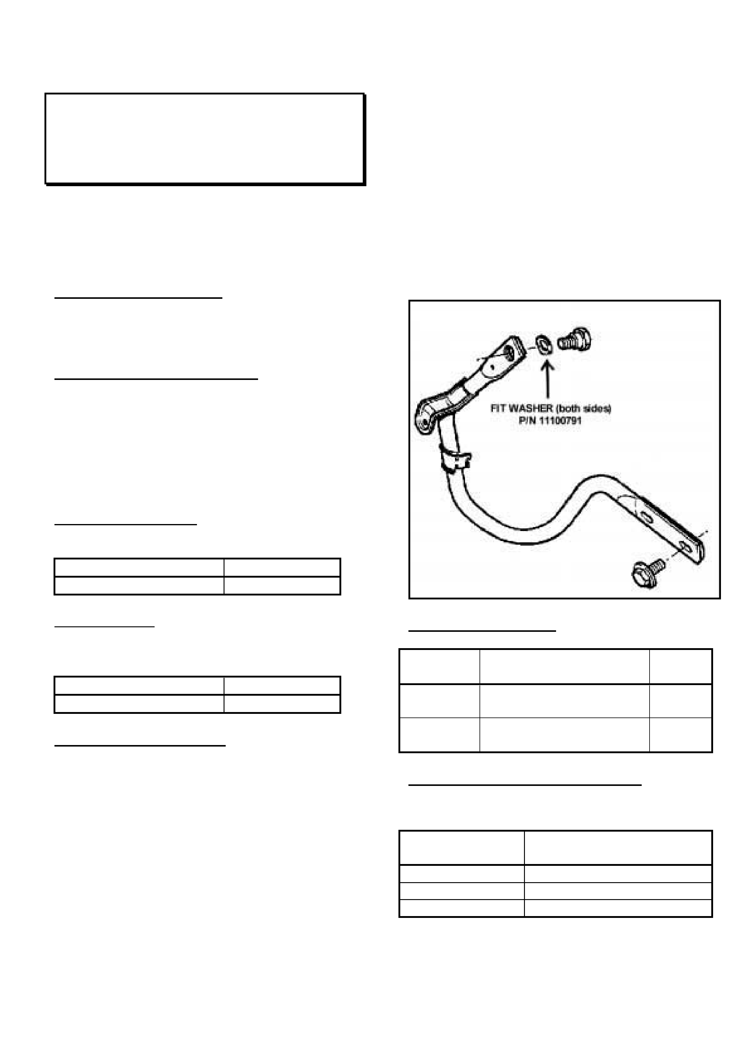
HOLDEN SERVICE TECHLINE ____________________________________________________________________ JULY 2000
7 7
DECKLID BOUNCES AFTER OPENING
JR, JS (Sedan)
(GROUP 1)
This Service Techline supersedes the previous
Techline on this topic (Issue 8, October, 1999
page 5). This previous Techline should be
destroyed.
PROBLEM DESCRI PTION
Decklid ‘bounces’ or ‘rebounds’ when released
aft er opening.
PRODUCTION RECTIFICATION
JR Model:
No production revisions were introduced for this
condition, so all complaint vehicles must be
corrected as per the procedure below (replace
screws & washers).
JS Model:
Revised collar screws (with 4mm head) were
introduced into vehicle product ion as follows:
PSN: Build Date:
L392114 22/10/98
Spring washers were introduced between the
hinge and the pivot screw, to increase friction to
prevent bouncing, as follows:
PSN: Build Date:
L482379 22/07/99
SERVICE RECTIFICATION
If a complaint of decklid ‘bounce’ or ‘rebound’ is
received, carry out the following procedure:
JR Models – replace both collar screws and fit
spring washers.
JS models – assess parts requirements with
reference to the above breakpoints and this
procedure.
1. Remove C-pillar t r ims
2. Locate the decklid hinge on one side and
remove the collar screw f r om the hinge.
3. Measure screw head thickness – if thick ness is
6mm, replace the collar screw with a new collar
screw P/N 90463254 (of 4mm head thickness) .
NOTE: The screws used in this installation
must have a 4mm head thickness, or
insufficient clamp load will be applied to the
spring washer/s.
4. Install spring washer p/n 11100791 between
hinge and pivot as indicated in Fig ure 1.
5. Repeat Steps 3 & 4 for the remaining hinge.
6. Replace removed components and check the
operation of the decklid.
PARTS INFORMATION
Part
No.: Description: Qty
11100791 Spring Washer – Hinge
to Panel Support 2
90463254 Screw, Hinge to Panel
Support 2 (IF
Req’d)
WARRANTY CLAIM I NFORMATION:
Use the f ollowing information:
Description Washer, Deck lid Hinge -
Install
Labour Op. No. C000391
Time 0.6 hr
Failure Code 26
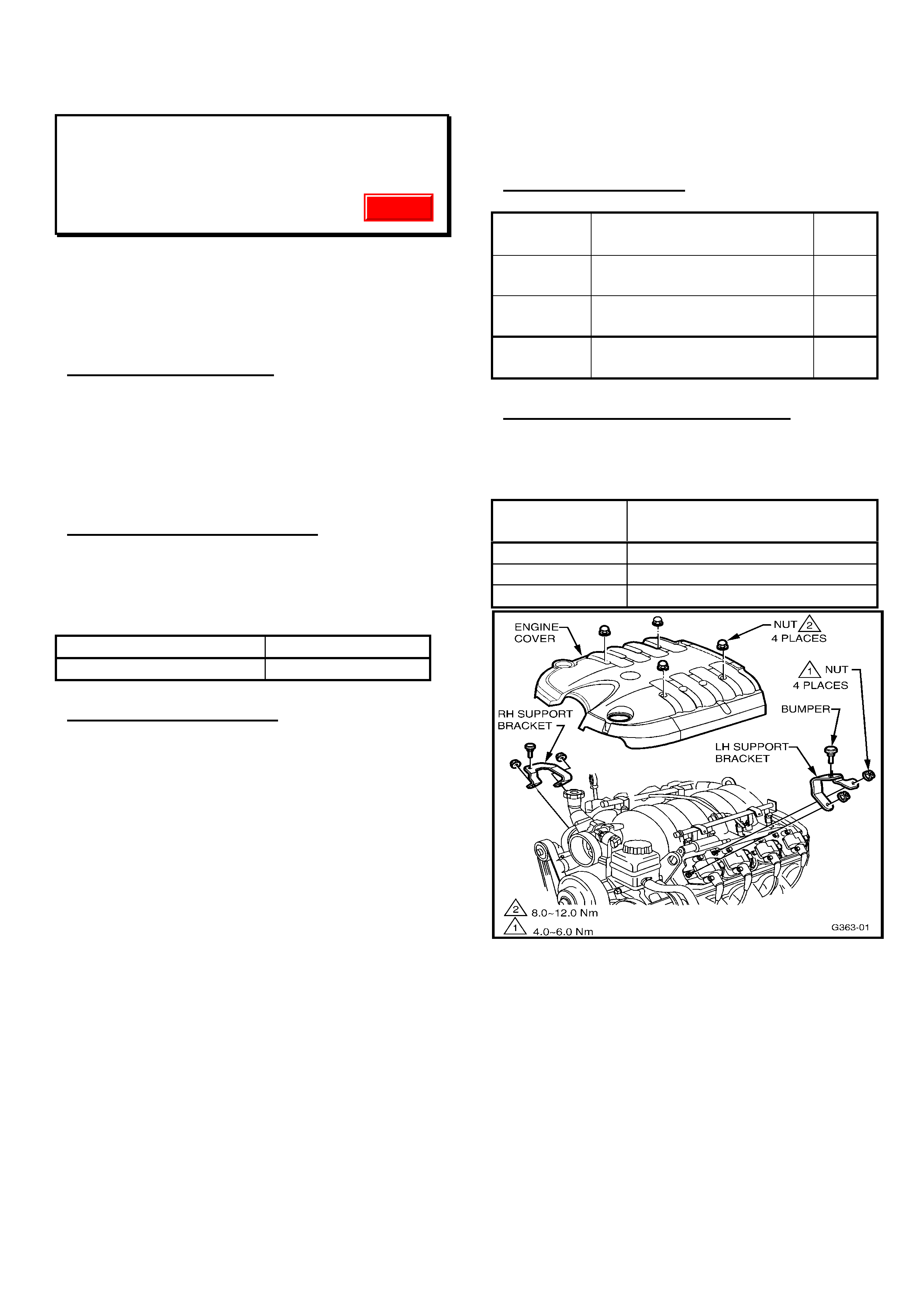
HOLDEN SERVICE TECHLINE ____________________________________________________________________ JULY 2000
8 8
ENGINE COVER RATTLE NOISE
VT & WH with LS1 (Gen III) V8
(GROUP 6A) Update
This Service Techline supersedes the previous
Techline on this topic (Issue 10, December,
1999 page 10) on adding spacer nuts. This
previous Techline should be destroyed.
PROBLEM DESCRI PTION
Reports have been received of engine cover
“ratt le” at idle, or just above idle speed.
This rattle is caused by the main engine cover
contacting the coil/bracket, at the rear of the
engine.
PRODUCTION RECTIFICATION
Additional engine cover support brackets, to
alleviate this condition, have been fitted to
vehicles from:
ISOVIN: Build Date:
6H8VTL35FYL579679 10/04/00
SERVICE RECTIFICATION
For complaints of “engine cover rattle” noise on
any Gen III V8 engined vehicle built prior to the
above breakpoint, additional support brackets
may be added as per the f ollowing procedure:
1. Remove four engine cover retaining nuts and
remove the engine cover.
2. Fit engine cover support bracket P/N 92087580
to RH front coil mounting studs as shown in
Figure 1.
3. Attach with two new nuts P/N 09440004, and
torq ue t o 4 – 6 Nm .
4. Fit engine cover support bracket P/N 92087581
to LH front coil mounting studs as shown in
Figure 1.
5. Attach with two new nuts P/N 09440004, and
torq ue t o 4 – 6 Nm .
6. Remove foam pads from front RH & LH
underside of engine cover (pads are no longer
necessary, as new support brackets carry
insulating bumper s).
7. Re-fit main engine cover - torque retaining nuts
to 8-12Nm.
PARTS INFORMATION
Part
No.: Description: Qty
92087580 Support Bracket, Engine
Cover RH 1
92087581 Support Bracket, Engine
Cover LH 1
09440004 Nut, Support Br acket
Retaining 4
WARRANTY CLAIM I NFORMATION:
Use the following information, for vehicles built
prior to t he above noted br eakpoint:
Description Add Engine Cover Support
Brackets
Labour Op. No. J000651
Time 0.3 hr
Failure Code 28
Figure 1
Update

HOLDEN SERVICE TECHLINE ____________________________________________________________________ JULY 2000
9 9
POWER STEERING PUMP FRONT DRIVE
SHAFT SEAL LEAKS – SEAL
REPLACEMENT
VS, VT, WH
(GROUP 9)
PROBLEM DESCRI PTION
Power steering fluid leaks from the power
steering pum p front dr ive shaft seal.
PRODUCTION RECTIFICATION
Revised front drive shaft seals with a more
durable material (HNBR) were released into
production f r om :
ISOVIN: Build Date:
6H8WHY19FYL528223 11/11/99
SERVICE RECTIFICATION
When any vehicle is presented with a “power
steering pump leak” – the leak source must be
defined, and appropriate repairs initiated – EG:
hose connections, or pump seal/ s, etc.
If the leak point is defined as being from the
power steering pump dr ive shaft (front) seal, the
following rectification procedure must be carried
out in lieu of Pum p Assembly replacement:
1. Identify the leak is originating from the front
drive shaft seal.
2. Remove power steering pump from vehicle
and remove pulley and pulley hub. Refer to
VT Series Service Manual, Volume 5 Page
9A-63.
3. After removal of the pulley and hub, make
sure the pulley hub bore and the pump drive
shaft are free from burrs. Should any shaft
damage have occurred during the pressing
process - which cannot be corrected, and
may damage the new seal on installation -
the pump should be replaced. Clean all
foreign material from the vicinity of the front
drive shaft seal.
4. Remove the front drive shaft seal by
carefully collapsing the seal, by using a
centre punch or similar to deform the metal
part of the seal. Deform the seal around it’s
entire circum ference.
5. Remove the seal by prying out the seal
between the seal outer diameter and the
pump housing using a flat blade screwdriver
and hammer.
6. Inspect the drive shaft for damag e in the seal
running ar ea. If the shaf t is damaged or worn,
the pump should be replaced.
7. Clean the seal seating ar ea and drive shaft.
8. Lubricate new seal P/N 26089245 using
power steering oil. Using tool number E1460-
1 or similar mandrel to suit the shaft and seal
diameters, install seal until fully seated.
9. Ref it pulley hub and pulley and reinstall pump
to vehicle.
PARTS INFORMATION
Part
No.: Description: Qty
26089245 Seal – Drive Shaft. 1
WARRANTY CLAIM I NFORMATION:
Use the f ollowing information for warranty claims
for seal r eplacem ent, as per the procedur e
above.
This Labour O per at ion Number and times will
appear in future issues of the Labour Times, as
issued via the SIP CD.
Description Pump Asm. P/S R&R,
Replace Front Seal
Labour Op. No. M147100
Time (Gen III) 0.9 hr
Time (a ll ot her ) 1.1 hr
Failure Code 42
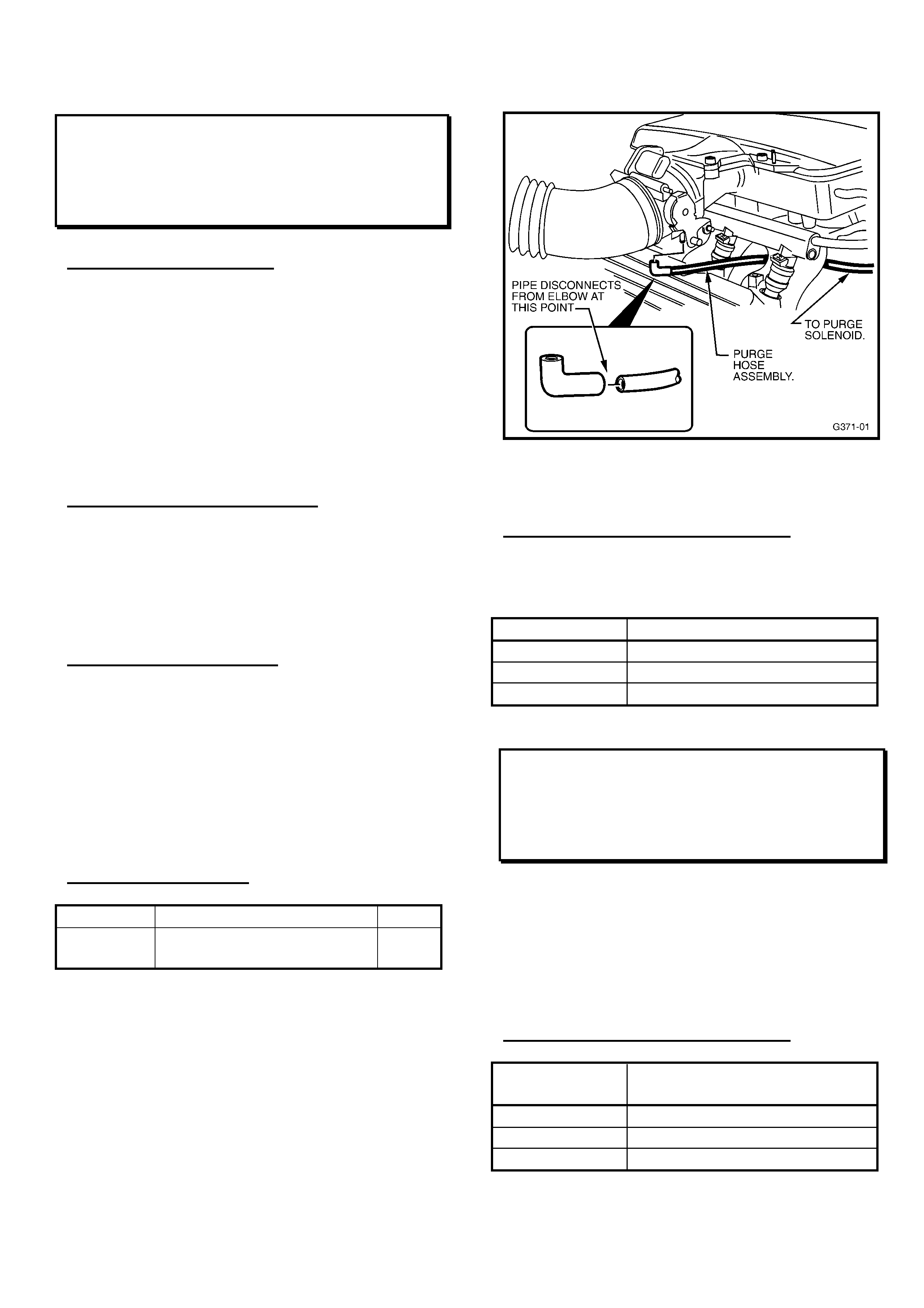
HOLDEN SERVICE TECHLINE ____________________________________________________________________ JULY 2000
10 10
ENGINE ROUGH IDLE OR HISS NOISE
VT & WH with V6 Engine
(GROUP 6 M)
PROBLEM DESCRI PTION
Engine rough idle may be experienced, or an
audible “hiss” noise may be heard from the
engine compartment – the purge hose between
thrott le body and pur g e solenoid may disconnect
from the elbow that attaches the hose to the
throttle body. Refer to Figure 1 for location of
disconnection. This is caused by insufficient
temperature tolerance of the adhesive used to
retain the hose t o the elbow.
PRODUCTION RECTIFICATION
A new hose assembly, with improved
temperature tolerance adhesive, is currently
being phased into pr oduct ion.
Breakpoint for this introduction will be supplied
in a fut ure Techline Break point Summary.
SERVICE RECTIFICATION
If a disconnected purge hose is defined on any
vehicle, the purge hose should be replaced with
a new purge hose obtained from HSPO.
This pur ge hose replacem ent is requir ed until an
adhesive of the required temperature tolerance
is readily available nationwide. When this
availability is established, a “Revised” Techline
item will be published.
PARTS INFORMATION
Part No. : Description: Qty
92102345 Purge Hose Asm.
Solenoid to Thr ottle Body 1
Figure 1
(LH Side of Engine Showing Disconnection Point)
WARRANTY CLAIM I NFORMATION:
Use existing information in Labour Time Manual
as shown:
Description Purge Hose - Replace
Labour Op. No. J589300
Time 0.3 hr
Failure Code 71
WATER LEAK INTO HEADLINING
SB CABRIO
(GROUP 1) UPDATE
This Service Techline provides a correction to
the Warranty Information provided in the
previous Techline on this topic (Issue 3, April,
2000 page 5). Please update your previous
Techline with the corrected Labour Operation
Number as shown below:
WARRANTY CLAIM I NFORMATION:
Description Rectif y headlining water
leaks
Labour Op. No. C000400
Time 0.6 hr
Failure Code 87

HOLDEN SERVICE TECHLINE ____________________________________________________________________ JULY 2000
11 11
FIXED GLASS SEALANT AVAILABILITY
ALL MODELS
(GROUP 1)
CURRENT CONDITION
Urethane for use as a fixed glass sealant is
referred to in various Service Manuals and
Techline Bulletins – most recently:
”Revised Procedure for Fitment of Rear Door
Fixed Window Glass – VT wagon & WH” in
Techline Issue 1, February 2000, page 5,
and
“Quarter Window Glass – Improving Glass Fit –
VS Ute” in Techline Issue 3, April 2000, page
11.
Urethane has also been ref erred to by “VS” part
number and alternative products are sometimes
quoted.
Urethane sealant f or f ixed glass r etention is now
available from HSPO under the following part
number:
Part No.: Description: Qty
92143609 Sealer – Urethane
(300ML Cartridge) 1
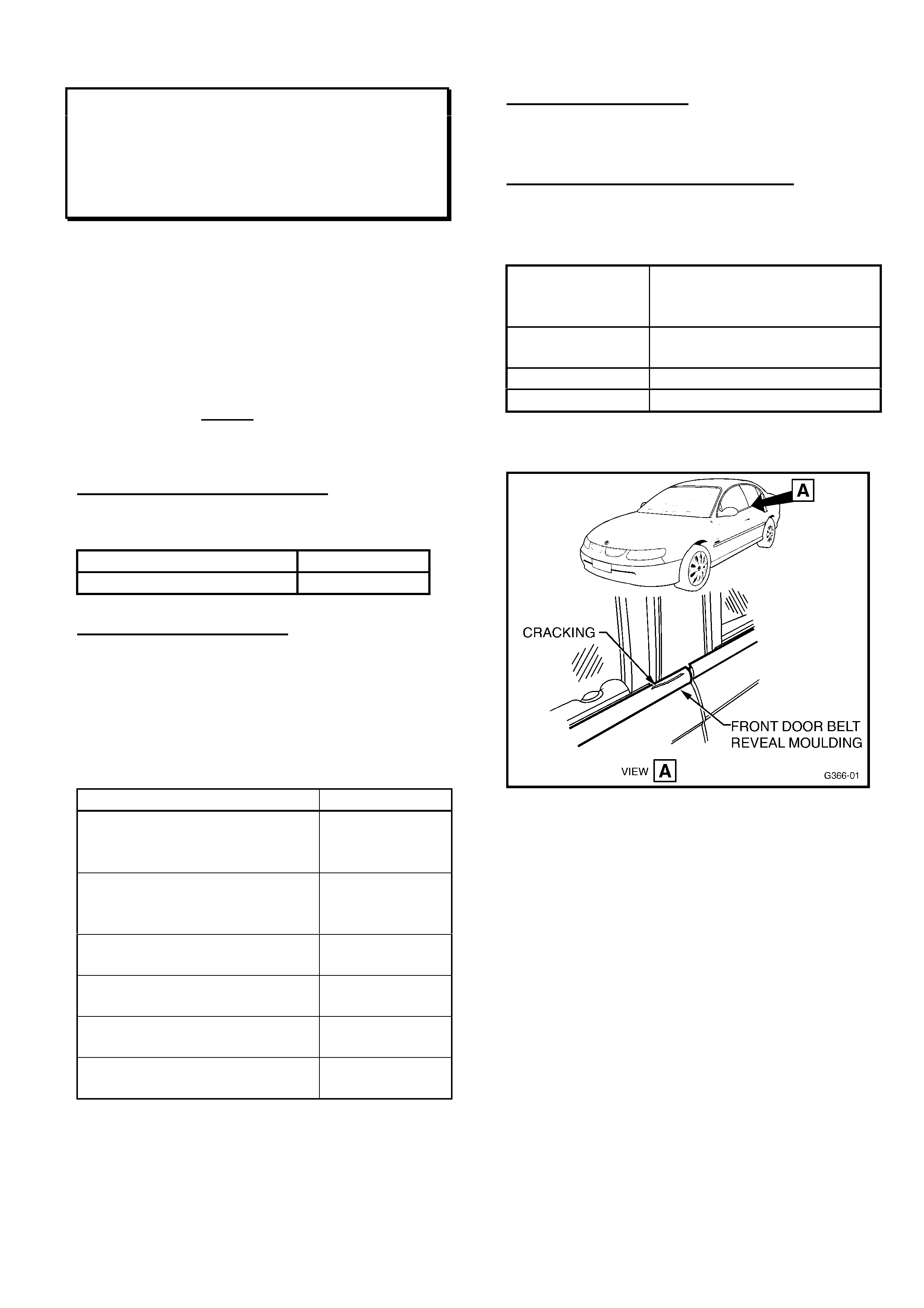
HOLDEN SERVICE TECHLINE _________________________________________________________________ AUGUST 2000
6 6
FRONT DOOR BELT REVEAL OUTER
MOULDING REPLACEMENT
VT
(GROUP 1)
PROBLEM DESCRIPTION
Reports have been received that some front
door belt line reveal outer mouldings “split” or
“tear” prematurely – at the rear end of the
moulding. Refer Fig ur e 1 for location.
This is caused by door “overslam” (the
distance the door travels past its normal
stationary, closed posit ion)
“Overslam” is a normal occurrence during door
closing, and depends on door inertia and force
used to close the door.
PRODUCTION RECTIFICATION
Revised front door belt line reveal outer
mouldings have been f it t ed to vehicles from:
ISOVIN: Build Date:
6H8VTK35HYL560628 25/02/00
SERVICE RECTIFICATION
Fit new front door belt line reveal outer
mouldings, following procedure in the SIP CD -
VT Series Service Manual, Volume 1, Page
1A5-24.
Because of specific finish/appearance detaiI, it
is necessary t o select t he appropriat e moulding
fr om t he following usage chart :
Vehicle Detail: Part No.:
Series I 8VK
SEDAN or WAGON up to
L560628
RH, 92093952
LH, 92093953
Series I 8VL
SEDAN or WAGON up to
L464494
RH, 92093952
LH, 92093953
Series II 8VL WAGON
- f r om L464495 to L560628 RH, 92093952
LH, 92093953
Series II 8VL SEDAN
- f r om L464495 to L560628 RH, 92093954
LH, 92093955
Series I 8VX SEDAN
- up to L464494 RH, 92093954
LH, 92093955
Series II 8VX SEDAN
- f r om L464495 to L560628 RH, 92093956
LH, 92093957
NOTE: Only damaged mouldings require
replacement.
PARTS INFORMATION
Order par t s as specified in the chart above.
WARRANTY CLAIM I NFORMATION:
Use existing information in Labour Time Manual
as shown:
Description Moulding Asm. Door Belt
Reveal Outer Fr ont RH/LH -
Replace
Labour Op. No. C832100 (RH) OR
C832200 (LH)
Time 0.3 hr
Failure Code 05
Figure 1.

HOLDEN SERVICE TECHLINE _________________________________________________________________ AUGUST 2000
7 7
SQUEAK FROM FRONT SUSPENSION
SB
(GROUP 3)
This bulletin supersedes all previous Techline
bulletins released on this t opic.
PROBLEM DESCRIPTION
Squeak or creak noise from front of vehicle
when travelling over low-speed bumps, etc.
The sour ce of this sq ueak /cr eak is f rict ional drag
of the stabiliser bar on the rubber bush and
support piece that clamps it to the suspension
torsion rod.
PRODUCTION RECTIFICATION
Revised supports and inner stabiliser bar bushes
have been fitted t o vehicles from:
ISOVIN: Build Date:
W0L0SBF08X4326084 06/05/99
SERVICE RECTIFICATION
To eliminate this frictional drag, thin wall bushes
are now available which should be fitted to the
stabiliser bar. These bushes reduce the friction
loading between the bush and the bar, and
eliminate the noise. Revised supports (t o suit the
resulting larger diameter) are required when
these bushes are fitted. It is necessary to also
replace the self-locking nuts that retain the
supports.
For vehicles suffering from this noise complaint,
the f ollowing procedur es should be car ried out:
For Vehicles Wit h 18/ 20/ 22mm Di a.
Stabili ser Bars:
Vehicles fitted with 18mm, 20mm, or 22mm
diameter stabiliser bars, may be corrected by
fitting specific parts from the accompanying
“Parts Information” chart, as follows:
1. Unbolt (lower) supports from front right and
left torsion rods. Remove stabiliser bar.
Leave rubber bushes in place on torsion
rod. Inspect rubber bushes for damage,
replace only if necessary.
2. Clean stabiliser bar ends up to the forward
support/rubber bush location – remove all
dirt, scale, etc, which may stop installation of
the new inner bushes.
3. Slide new Stabiliser Bar Inner Bushes (2 per
side) onto the stabiliser bar, using silicone
grease (P/N M40347) to assist assembly.
Refer Figure 1 for illustration. Locate each
bush at the flattened area of the stabiliser
bar.
4. Refit stabiliser bar to original location, using
new supports, and retain with new self-
locking nuts.
5. Maintain a dimension of 121mm between the
centre of the bush support stud and the
centre of the torsion rod to control arm
mounting nut. Refer to SB Series Service
Manual Volume 2, page E-63, or instructions
on TIS CD. Torque nut s t o 20Nm.
For Vehicles Wit h 21 or 24mm Di a.
Stabili ser Bars:
Vehicles with 21mm or 24mm diameter stabiliser
bars have N/A shown in New & Additional parts
columns, in the accompanying Parts Information
chart, as there are no revised parts available for
these size stabiliser bars.
These vehicles should be rectified as follows:
1. Unbolt (lower) supports – one at a time - f rom
front right and left stabiliser bar mounts.
Leave rubber bushes and top mounts in place
on torsion rod. Inspect rubber bushes for
damage, r eplace only if necessary.
2. Apply a coating of grease to the inside
surface of each stabiliser bar (lower) support
(4 places). (The recommended grease is any
Molybdenum Disulphide grease that
conforms to Holden specification HN1271.
Two such greases are: Shell M.L. 10 and
Molybond GA 10. )
3. Re-assemble each support to its original
position on the stabiliser bar, fit eight (8) new
self- locking nuts. T or que nuts to 20Nm.
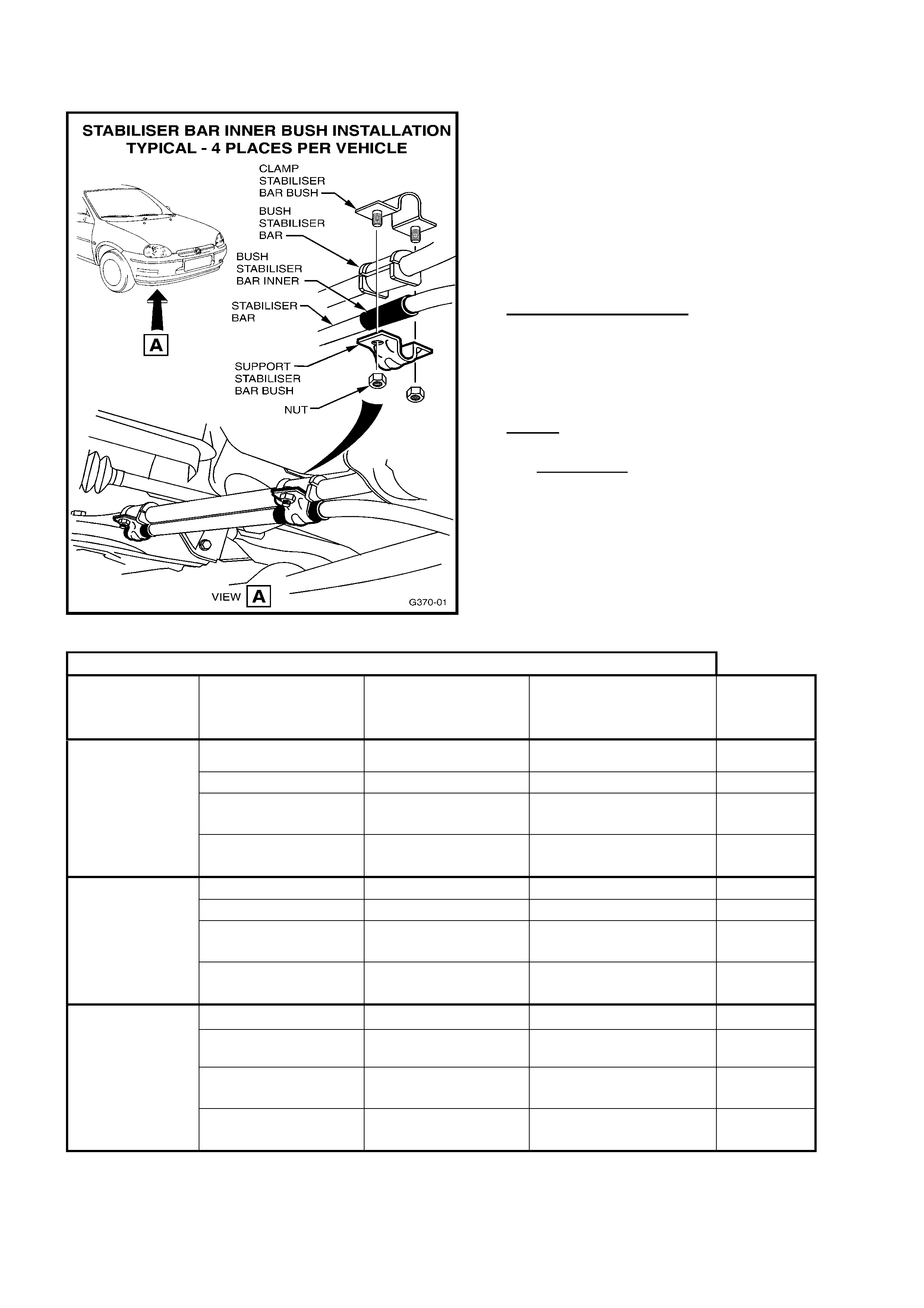
HOLDEN SERVICE TECHLINE _________________________________________________________________ AUGUST 2000
8 8
PARTS INFORMATION
Select parts and quantities required for the
above service procedure, from the chart below,
using the st abiliser bar diameter as a guide.
NOTE: Silicone Grease noted in the chart below
can be used for several installations of bushes,
but MUST NOT be used as a lubricant in place
of the Molybdenum Disulphide grease
(Holden spec. H1271) noted for 21 & 24mm
stabiliser bars.
N/A = Not Available.
Figure 1
18, 20 & 22mm Dia. St abi l i ser bar – Part s Required:
Stabiliser
Bar
Diameter:
Replace Existing
Parts:
Replace With
New Part No.: Fit Additional Part: Qty:
18 mm Support 90539923 - 4
Self Locking Nut 11094293 - 8
- - 92094620
Stab. Bar Inner Bush 4
- -
M40347 Silicone
Grease (150gm) As Req’d
20 mm Support 90539924 - 4
Self Locking Nut 11094293 - 8
- - 92094621
Stab. Bar Inner Bush 4
- - M40347 Silicone
Grease (150gm) As Req’d
22 mm Support 90447948 - 4
(GSI with
X16XE) Self Locking Nut 11094293 - 8
- - 92094622
Stab. Bar Inner Bush 4
- - M40347 Silicone
Grease (150gm) As Req’d

HOLDEN SERVICE TECHLINE _________________________________________________________________ AUGUST 2000
9 9
WARRANTY CLAIM INFORMATION:
For vehicles with 18/20/22mm dia. stabiliser
bars:
Use the following special Labour Operation
Number for this task:
Description Install Inner Stabiliser Bar
Bushes – to 18, 20 or 22mm
Dia. Stabiliser bar.
Labour Op. No. E000344
Time 0.7 hr
Failure Code 40
For the above Labour Operation – return
removed Supports and Self Locking Nuts when
requested by REPAC.
For vehicles with 21 or 24mm dia. stabiliser
bars:
Use existing information in Labour Time Manual
as follows:
Description Install Inner Stabiliser Bar
Bushes
Labour Op. No. E109100
Time 0.6 hr
Failure Code 40
For the above Labour Operation – return
removed Self Locking Nuts when requested by
REPAC.
WINDSCREEN “DOT FADE” AREA
REVISED
VT, WH
(GROUP 1)
Technicians should be aware of the following
revision – when replacing windscreens:
An increased “dot fade” area has been added to
windscreens, above the interior rear view mirror
and between the sunvisors, to provide additional
central light glare reduction.
PRODUCTION RECTIFICATION
This change took place at:
ISOVIN: Build Date:
6H8VTK69HYL588410 10/05/00
PARTS INFORMATION
Refer to PartFinderTM for parts information.

HOLDEN SERVICE TECHLINE _________________________________________________________________ AUGUST 2000
10 10
DECK LID HEAVY TO LIFT/WILL NOT
STAY OPEN – CAUSED BY POST
PRODUCTION SPOILER FITMENT
VT
(GROUP 1)
PROBLEM DESCRIPTION
Customer com plains t hat the deck lid (boot lid) is
heavy to lift and/or will not stay open.
In majority of these cases the complaint is
caused by adding deck lid spoilers to vehicles
after vehicle production without changing the
decklid struts. NOTE; In vehicle production,
vehicles built with spoilers have different
specification struts to those built without
spoilers.
SERVICE RECTIFICATION
Where a spoiler is fitted to a vehicle after
production, the deck lid struts should be
changed to suit the spoiler t ype. T he chart below
defines the correct struts to use for each spoiler
type available through HSPO .
PARTS INFORMATION
Spoiler Type Strut Part No.
Required Qty
“S” or “SS” type
(weight up to 3 Kg.) 92081251 2
HSV Senator type
(weight above 3 Kg. &
up to 5.4 Kg . )
92047962 2
WARRANTY CLAIM I NFORMATION:
The change of strut s det ailed in this Bulletin, f or
the purpose ment ioned, is NOT claimable under
warranty.
CENTRE HIGH MOUNTED STOP LAMP
WARPAGE
JS Series II, Sedan & Hatch
(GROUP 12)
PROBLEM DESCRIPTION
Significant warpage, causing poor appearance,
can occur to the Centre High Mounted Stop
Lamp (CHMSL) when subjected to continuous
high tem per at ures or sunload.
PRODUCTION RECTIFICATION
A revised CHMSL, manufactured from higher
temperature compliant material, has been
introduced into pr oduction:
ISOVIN: Build Date:
W0L0JBF19YL584953 09/05/00
SERVICE RECTIFICATION
Where a customer reports significant signs of
warpage of a CHMSL – the CHMSL should be
replaced.
Refer ident ification below for latest parts.
PARTS INFORMATION
Part No.: Descri ption: Qty
09192293 Lamp Asm., High Mount
Stop. USAG E: Hatch 1
09192294 Lamp Asm., High Mount
Stop. USAG E: Sedan 1
These new CHMSL’s are made from revised
material and are identified with “ABS/PC” on the
back of the assembly. NOTE: As part numbers
have not been revised, return any parts –
without “ABS/PC” identification – to HSPO for
credit.
WARRANTY CLAIM I NFORMATION:
Use existing information in Labour Time Manual
as shown:
Description Lamp Asm. St op, High
Mounted - Replace
Labour Op. No. R902400
Time 0.4 hr
Failure Code 11
HOLDEN SERVICE TECHLINE _________________________________________________________________ AUGUST 2000
11 11
OIL LEAK FROM A/T REAR SEAL
VS, VT, WH
(GROUP 7B) HINT
PROBLEM DESCRIPTION
Investigation into complaints of “oil leakage”
from Auto. Trans. (A/T) extension housing seals
has defined that a number of seals are being
replaced unnecessarily.
During vehicle assembly, a small amount of
assembly oil (ATF) is retained in the extension
housing seal between the inner and outer seal
lips. If enoug h ATF is ret ained in the seal, it can
be “pumped” out of the seal, onto the extension
housing, propshaft yoke, and onto the vehicle
floor pan – by the nor mal prop shaf t rotat ion and
stroking movement.
This condition can lead technicians to an
incorrect diagnosis of a “leaking seal” and
unnecessary seal replacement.
SERVICE HINT
On any vehicle inspected during Pre-Delivery
Inspection or at t he 1500km service where there
is minimal oil deposited on the area surrounding
the extension housing seal – do not replace the
extension housing seal:
- W IPE the seal area, pr op. shaft yoke and f loor
(if required) to remove all traces of ATF. Ensure
no dirt, et c is wiped into the seal r unning area.
- Do NOT use a solvent – only a clean, dry rag.
By carrying out this process, and an inspection
of the extension housing seal at the next
service, any leak that warrants replacement will
be defined.
Should any extension housing seal display more
than minimal ATF leakage, EG: If ATF is
dripping from seal area – then seal replacement
is warranted.
FRONT END ALIGNMENT SPEC.
HSV VT I, VT II & WH GRANGE
(GROUP 3) UPDATE
This Service Techline supersedes the previous
Techline on this topic (Issue 5, June, 2000 page
8), by revision of Caster figures. Please revise
your previous Techline and any copies of HSV
bulletin of 9/2/ ’00 you may have.
The following information is repeated from HSV
bulletin of Feb. 9, 2000, for use by technicians
when servicing HSV VT Series I, VT Series II,
and WH Grange vehicles.
PLEASE ENSURE ALL TECHNICIANS
INVOLVED IN FRONT END ALIGNMENT WORK
ARE MADE AWARE OF THESE REVISED HSV
SPECIFICATIONS.
FRONT END ALIGNM ENT SPECIF ICATIO N:
The information below supersedes information
provided in SIP CD ROM Version 1.1, relating to
HSV vehicles.
FRONT WHEEL ALIGNMENT AT KERB
WEIGHT
Toe-in Degrees Total 0° 10’ ± 0° 10’
Toe-in Degrees Per Wheel 0° 05’ ± 0° 05’
Camber - 0° 30’ ± 0° 20’
Caster 7° 45’ ± 1° 15’
Note: Front toe and front camber have been
reduced to optim ise front t yre life.
HOLDEN SERVICE TECHLINE _________________________________________________________________ AUGUST 2000
12 12
RIDE HEIGHT SPECIFICATIONS
RODEO & JACKAROO GROUP 3
Detailed below are the ride height specifications for Jackaroo (UBS) and Rodeo (TF). For details
on adjustment refer to the relevant workshop manual ( section 3 ).
Note- All measurements should be made when the vehicle is at curb weight and with bump stops
in good condition. (Curb weights can be found in the relevant owners handbook)
Current model Rodeo
Front- There are two settings, one for TFS (4x4) and TFR25 (4x2, V6), the other for TFR (4x2).
There is a simpler method that requires the construction of a measuring tool. The tool can then be
placed between the bump stop and the lower control arm to indicate the trim height. The diameter
of the tool for 4x2 excluding V6 is 45mm, for 4x4 and V6 17mm (refer below)
Note- this method can only be used if the vehicles bump stops are in good condition.
Z =56mm
TFR (4x2) EXCLUDING V6
ENGINE
Z=130mm
TFS (4x4) & TFR V6 (4X2 WITH
V6 ENGINE
)
TFS & TFR V6 TFR EXCLUDING V6
17 mm 45mm
HOLDEN SERVICE TECHLINE _________________________________________________________________ AUGUST 2000
13 13
Rear- The ride height is measured as a clearance between the bump stop and the top of the
axle(refer below)
Current model Jackaroo
Jackaroo t r im height is 139 +/- 5m m ( r efer below).
The trim height can also be checked by placing a tool between the bump stop and the lower
control arm. The Jackaroo tool diameter is 24mm.(refer below)
The ride height for TFS (4x4) and TFR25 (4x2 V6) is 95mm, and for
TFR (4x2)is 9 0mm
Z = 139mm +/- 5 mm
T= 24mm

HOLDEN SERVICE TECHLINE _________________________________________________________________ AUGUST 2000
14 14
INTERCOOLER/AIR DUCT OIL CONTAMINATION
DIESEL JACKAROO & RODEO GROUP 6A
I-GM has recently received a large number of inquiries regarding acceptable oil contamination on
4JX1 and 4JB1 engine air intake systems.
It should be noted that crankcase ventilation may cause a light coating of oil throughout the intake
ducting as part of normal engine operation, however it is not normal to have oil collecting or
pooling.
If confronted with an engine that has excessive oil contamination in the intake system, it is
suggested that thorough examination be undertaken to determine the origin of the oil, e.g.
crankcase breather or turbo seal. If not immediately obvious, the contaminated parts should be
cleaned and the vehicle monitored at short intervals.
CHECK ENGINE LIGHT ILLUMINATING
V6 LPG RODEO GROUP 6C
Rodeo vehicles fitted with approved LPG kits may experience a situation where the check engine
light is illuminated and DTC P0171 is present in the ECM. When confronted with the above
situation, please refe r to the relevant information below.
PARNELL SUPPLIED KITS.
1) The Parnell system will set a lean code after the vehicle has been operated until the LPG
cylinder is empty. During this running period the engine is operating on vapor only, as the liquid
has been consumed and all that remains is indeed vapor. This scenario is a function of the
ECM performing correctly as the engine has experienced a lean condition (as it would when
running out of petrol) and has recorded the appropriate DTC.
Customers should be informed of the above condition and advised not to run on LPG empty.
2) Parnell systems fitted with the CLS2000 processor (located behind the drivers kick panel) may
need a software upgrade, to version V65 (printed on the processor). The upgraded processor
will be supplied by Parnell on a change over basis.
IMPCO
The impco system sets a lean code as a direct result of set operating parameters. This code is
apparent mainly on automatic TF's, it normally sets during coast or when the system is leaning off.
At this stage there is no repair for this condition, Impco are investigating the concern and IGM will
advise when a field fix is developed.
Dealers are advised to confirm if the code sets on petrol. If the code sets while the vehicle is on
petrol, normal diagnosis should be performed. However if the code does not set on petrol the car
should be released, the owner advised and rebooked when a repair is advised.
HOLDEN SERVICE TECHLINE _________________________________________________________________ AUGUST 2000
15 15
4JX1 DIFFICULT S TART PRE – CHECK
DIESEL JACKAROO GROUP 6C
IDENTIFY OIL
VISCOSIT
Y
GRADE
MANUFACTURER
OPERATE FUEL
PRIMING PLUNGER
UNTIL FIRM.
CRANK VEHICLE
DEFINE CRANK
Time: secs.
Engine crank RPM:
LOCATE SOURCE OF
AIR AND REPAIR AS
PER SHEET No. 2
HIGHER
THAN
10 SECS.
TURN ON IGNITION
WAIT FOR GLOW INDICATOR
TO GO OUT.
STARTS O.K.
O.K.
DRAIN / FILL
WITH CORRECT
SPEC. (2 TIMES)
REPLACE BOTH
OIL FILTERS
VERIFY
CHECK BATTERY
RE-CHARGE
CHECK TERMINALS
REPLACE AS
NECESSARY
O.K.
CONFIRM
START O.K.
NO START
OBD1
SYSTEM CHECK
AS PER MANUAL
BELOW
10 SECS.
MORE THAN
100 RPM
LESS
THAN 100 RPM
INCORRECT
NO START BELOW
5 SECS.
CORRECT
INSTRUCTIONS
COMPLETE
RING - TAS.
Note- Copy this sheet and mark the box in the
top right corner as each step is completed.
4JX1
–
DIFFICULT START PRE - CHEC
K
HOLDEN SERVICE TECHLINE _________________________________________________________________ AUGUST 2000
16 16
4JX1 - DIFFICULT START
(Sheet 2)
Step 1) Fit clear hose between filter housing outlet and lift pump.
Step 2) Fit clear hose on Tank return at rear of head.
Step 3) Fit clear hose between tank & filter housing inlet.
CONFIRM FILTER SEAL
CONFIRM FUEL FILTER
HOUSING (JUNE T/L )
PRODUCTION CHANGE
VERIFY REPAIR
INSPECT FUEL PIPES
FOR LEAKS AND
REPAIR
INSPECT INLET
FITTING TO HEAD FOR
TIGHTNESS AND
LEAKS.
CONFIRM INJECTOR
"O" RING
REWORK AS PER ADL
AIR OR OIL IN
SYSTEM AT THE
TANK RETURN
AIR IN SYSTEM
BETWEEN TANK AND
FILTER HOUSING
AIR IN SYSTEM
BETWEEN
FILTER HOUSING AND
LIFT PUMP
AIR IN FUEL
VERIFY REPAIR
CHECK INJECTOR
COPPER SEALS,
"O" RINGS AND
RE-TORQUE
VERIFY REPAIR
HOLDEN SERVICE TECHLINE ________________________________________________________ SEPTEMBER 2000
9 9
A/C PIPE RUBBING ON AIR CLEANER
INLET DUCT
JR/JS w ith A/C
(GROUP 2)
PROBLEM DESCRI PTION
A/C pipe may rub on the air cleaner inlet duct at
right hand front of engine compartment. In the
long term, this may result in pipe rub through
and loss of A/ C gas.
PRODUCTION RECTIFICATION
A refrigerant pipe to radiator cowl bracket was
introduced to pr ovide clearance from:
VIN: Build Date:
W7154494 17/08/98
SERVICE RECTIFICATION
For all vehicles built prior to the above
breakpoint , during servicing:
• Inspect A/C pipes f or abrasion damag e at the
air cleaner air inlet duct - replace if damaged,
and:
• Fit Ref rigerant Pipe T o Radiator Cowl Bracket
(p/n 09152421) to the vehicle, using existing
fan cowl bolt, and attach to pipe with new bolt
(p/n 11093973). Refer Figure 1 for det ails.
PARTS INFORMATION
Part No.: Description: Q t y
09152421 Brack et – Refrigerant Pipe
to Radiator Cowl 1
11093973 Bolt - Refriger ant Pipe to
Radiator Cowl 1
WARRANTY CLAIM I NFORMATION:
To claim for the addition of the above bracket and
bolt – use the following inform at ion:
Description Add A/C Pipe Retaining Br acket
Labour Op. No. D000221
Time 0.8 hr
Failure Code 19
Note: For dam aged pipe replacement, use
existing inf or m ation in Labour Time Manual – on
SIP CD.
Figure 1.

HOLDEN SERVICE TECHLINE ________________________________________________________ SEPTEMBER 2000
10
RECIRC & DEMIST SW ITCH
OPERATION
TS
(GROUP 2)
PROBLEM DESCRI PTION
A number of Heater Control Unit assemblies
(which contain all HVAC controls) returned to
Repac have proven to have “no fault found”
when tested.
Defective Material Tags indicate “Air Intake
Button (Recirc/Fresh switch) will not operate
when the vents dial is rotated to Dem ist m ode.
This is the designed method of operation for
the Air Intake Button and Demist switches, to
ensure ef ficient demisting .
This char acteristic of switch operation was not
explained in the original print of TS Astra
Owner Handbook (Noted as: “Part No.
92077117, June 1998 (Astra, TS print 1)” on
the inside f r ont cover).
This om ission has been cor rected in the lat est
version of the Owner Handbook (Noted as:
“Part No. 92077118, March 2000 (Astra, TS
print 2)” on the inside front cover).
Wording has been added as follows:
“Note: air intake will automatically switch from
recirculation to fresh when vents dial is rotated
to demist mode.”
SERVICE RECTIFICATION
NO service rectification is necessary, should
this condition be queried by a customer.
Please explain the switch operation to the
customer, as per the note above, and if
necessary, supply a copy of page 1-16 of TS
Astra Owner Handbook (part No. 92077118)
containing that note – to ensure they have
knowledge of the correct demist/fresh air
switch operation.
In future, any Heater Control Unit
assemblies returned to Repac for this
condition w ill be subject of debit action.
ENGINE MANAGEMENT SYSTEM -
REVISED CALIBRATION DATA
TS with M/T
(GROUP 6C)
CURRENT CONDITION
Some customers may complain of:
- “jer ky” or “rough” gear changes
- “bump” dur ing tip-in acceleration at gear
changes
- “stum ble” when engine slows down to idle
- poor accelerat ion from a standing start,
especially in high ambient temperatures.
PRODUCTION RECTIFICATION
A revised calibration ECU has been
introduced into pr oduction at:
Engine No.:
X18XE20P68391
SERVICE RECTIFICATION
NOTE: Flash Programming is ONLY to be
carried out to cust omer complaint vehicles.
To impr ove driveability of these vehicles:
Using Tech 2 & TIS 2000 Version 12B (or
later), reprogram the vehicles’ ECU using the
Service Programming System (SPS) with the
latest software version.
WARRANTY CLAIM I NFORMATION:
Flash Programming is ONLY to be carried out
to customer complaint vehicles. Use the
following claim informat ion where this is done:
Description Reprogram ECU
Labour Op. No. J000666
Time 0.4 hr
Failure Code 47

HOLDEN SERVICE TECHLINE ________________________________________________________ SEPTEMBER 2000
11
HARD STARTING/STALLING – FUEL
PUMP FAILURE
VT/WH with Gen III V8
(GROUP 6 M)
PROBLEM DESCRI PTION
A number of fuel pump failures have been
reported – this has lead to customer
complaints of “hard to st ar t” or “eng ine st all”.
Investigation into these failures shows they
have been caused by dropping or mishandling
of the fuel pumps, prior to assembly into
vehicles.
PRODUCTION RECTIFICATION
Revised fuel pump and sender units, with
more robust internal components, were
introduced into pr oduction as follows:
ISOVIN: Build Date:
6H8VTK69FYL608654 30/06/00
SERVICE RECTIFICATION
Pump and sender assemblies requiring
replacement, should be replaced with the part
noted below.
When diagnosing hard starting – use the
diagnosis procedure that is provided in the
Supplier Prior Approval Process (SPAP)
binder supplied to Dealerships with All Dealer
Letter DL 48/00. This binder carries a section
relating to fuel pump diagnosis.
PARTS INFORMATION
Part No.: Description: Qty:
25337050 Pum p & Sender Asm. 1
NOTE: Any stock of old pump and sender
units – Part No. 25324949 - in dealership
stock must not be used, but be returned to
HSPO for credit.
WARRANTY CLAIM I NFORMATION:
Use existing information in Labour Time
Manual.
REAR WIPER LINKAGE LOCK-UP
VT Wagon
(GROUP 12)
PROBLEM DESCRI PTION
Rear wiper will not operate because internal
linkag e “lock-up” (may also cause wiper motor
seizure).
PRODUCTION RECTIFICATION
Revised wiper motor and linkage assemblies
with revised linkage geometry have been
fitted to vehicles from :
ISOVIN: Build Date:
6H8VTK35HYL623038 03/08/00
SERVICE RECTIFICATION
If a vehicle is presented with the wiper motor
assembly “locked-up” or the motor is seized,
replace the assembly with a new part as noted
below.
PARTS INFORMATION
Part No.: Description: Qty:
92103204 Rear Wiper Motor Asm. 1
NOTE: Do NOT fit previously released part
92058738 – if any of these parts are held in
Dealership Parts Department stock, they
should be returned t o HSPO for cr edit .
WARRANTY CLAIM I NFORMATION:
Use existing information in Labour Time
Manual in SIP CD.
Update
HOLDEN SERVICE TECHLINE ________________________________________________________ SEPTEMBER 2000
12
MAN. TRANS. OIL AVAILABILITY
JS, JR, TR, TS, SB
(GROUP 7A)
PROBLEM DESCRIPTION
Castrol SMX-O has been in short supply since
the issuing of previous Techline Bulletins
advising use of t he oil.
To ensure this does not result in technicians
using non-approved oil in these transmissions,
availability of the oil has been improved.
PARTS INFORMATION
Castrol SMX-O oil is now available from HSPO
as follows:
Part No.: Description:
92143771 O il – M/T ( 1 lit re)
Previously released information from Techline
Issue 1, February, 2000, Page 14 is repeated
here to reinforce the importance of the oil
usage:
Oil specified for these transmissions is:
CASTROL SMX-O
This oil is also recommended for the following
models - by transmission t ype:
Model
&
Trans.
Type
Castrol
SMX-O Current Holden
92140007 and
Previously available oils
MTF1067, MTF1067 &
MTF0063
SB – All M/T
✔
✔✔
✔
✓
TR – All M/T
✔
✔✔
✔
✓
TS – All M/T
✔
✔✔
✔
✓
JR – All M/T
✔
✔✔
✔
✓
JS Series I,
F18 Trans.
✔
✔✔
✔
✓
JS Series II,
F23 Trans.
✔
✔✔
✔
✖
✔
✔✔
✔
= RECOMMENDED
✓
= MAY BE USED
✖
= DO NOT USE
SERVICE USAGE & PRECAUTION
Castrol SMX-O oil MUST be used at all t imes in
JS Vectra Series II with F23 M/T, and may be
used for service replacement or ‘t op-up’ of oil in
the above manual transmissions.
Holden oil Part No. 92140007 r emains available
from HSPO, and can be used as per
recommendat ions in t he chart above.
Castrol SMX-O replaces previously released
Castrol oils MTF1067, MTF1067 & MTF0063
These previously released oils MUST NOT
be used in JS Series II, F23 M/T, for
durability reasons.
At the time of release of this bulletin, there are
no commercially available equivalents to
Castrol SMX-O for this JS Series II usage.
HOLDEN SERVICE TECHLINE ________________________________________________________ SEPTEMBER 2000
13
M/T GEARSHIFT ADJUSTMENT
JS with F23 M/T
(GROUP 7A)
PROBLEM DESCRI PTION
The procedure shown in the TIS CD has lead
to confusion when technicians attempt to
adjust the gearshift mechanism on F23
manual transm ission ( introduced at JS SII).
SERVICE RECTIFICATION
To assist technicians in adjusting this
gearshift mechanism – the following
infor mation is provided which must be used in
conjunction with instructions found in the TIS
CD, section headed “Adjust Transmission
Remote Shift Linkage (F23)” - which
provides illustrations for the clarified text
below. NOTE: When accessing this
infor m ation in TIS, specify “X25XE” engine.
1. Place gear lever in neutral (resulting
position of external linkage is shown in
fir st TIS illustration).
2. Carefully unclip gear lever cover and fold
up around gear lever to gain access to
gear shift cables. Refer to View A in
Figure 1 below.
3. Carefully unfasten holding sleeves (clamp
blocks) of the shift cables. Ensure the
cable is free to move in the sleeve, but do
not disconnect the clamp blocks from the
cables. Refer to Figure 1 below showing
how to unfasten the clamp blocks with a
thin, flat bladed screwdriver.
4. Press in the gearshift lever locking clip
(Refer to TIS illustration). This positions
the gear lever in a central (neutral)
location, changing the shift cable
positioning.
5. Lock both the holding sleeves (clamp
blocks) by pressing down HARD on the
tabs on the sleeves (Refer to TIS
illustration).
6. Return gearshift lever locking clip to
original posit ion.
7. Refit gearshift lever cover
Figure 1.
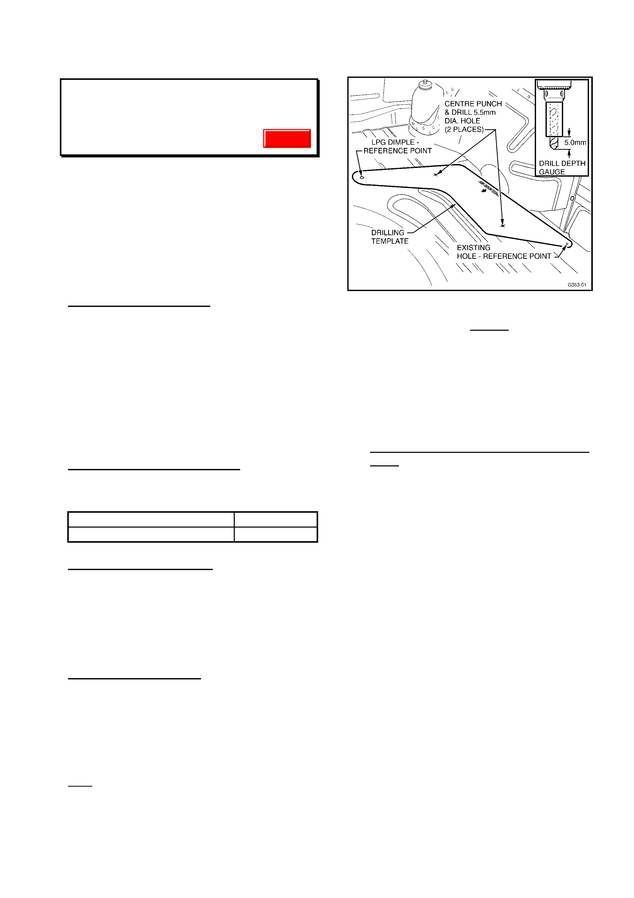
HOLDEN SERVICE TECHLINE ________________________________________________________ SEPTEMBER 2000
14
6 DISC CHANGER SKIPPING CD’s
WH
(GROUP 12)
The following information is repeated from All
Dealer Letter DL: 32/00, and is repeated in
this Techline only to ensure t hat all Dealer ship
Service personnel are aware of the
procedures noted. Please refer to the Dealer
Letter for original information. Please also
circulate this bulletin to Warranty Claims
personnel.
PROBLEM DESCRI PTION
Field complaints have been received of the
CD player fitted to WH Series vehicles
‘skipping’ tracks when the vehicle is driven
over rough road surfaces. To address this
problem, an alternative CD player with a 10
disc cartridge and triple beam laser has been
released for vehicle production as this unit is
less susceptible to sk ipping CD’s. The existing
6 disc changer features only a single beam
laser.
PRODUCTION RECTIFICATION
The vehicle assembly plant introduced the 10
disc player into production as follows:
ISOVIN: Build Date:
6H8WHZ19FYL592679 23/05/00
SERVICE RECTIFICATION
This information provides service fix
instructions for installation of the 10 Disc
changer to customer complaint vehicles with
the above described condition.
Please follow the instructions below to install
the 10 disc changer.
Installation Instructions:
1. Refer to the WH Service Manual to
remove the existing 6 disc chang er .
2. Take t emplate and lay it down on the floor
pan, ensuring to position it to the
reference points. (ie. LPG dimple and
existing 6 disc changer bracket screw).
See Figure 1 below.
Hint: Use masking tape or equivalent to hold
templat e in position.
Figure 1.
3. Take the changer bracket and position it
on top of t he template, ensuring t he holes
in the bracket line up with the holes
marked on the template and the existing
hole in the side panel.
4. Lift bracket f r om template.
5. Centre punch the two marked hole
positions on the tem plate.
6. Remove template of f floor pan.
7. Drilling instructions & precautionary
notes:
The fuel t ank is directly beneath the
position of t he holes. To protect the tank
fr om dam age, place a piece of rubber
hose over a 5.5mm drill bit so that only
the top 5mm of the drill bit is exposed.
Drill both holes to a depth not exceeding
5 mm. See Figure 1 above.
8. Fit the changer bracket and install pop
rivets in the three locations. See Figure 2
below.
9. Connect the lead to the changer.
10. Secure the excess changer lead with a
cable tie to the body harness. See Figure
2 below.
11. Take the piece of foam block, peel away
the sticky back cover and adhere it in
place of the pr evious 6 disc changer. See
Figure 2 below.
Update
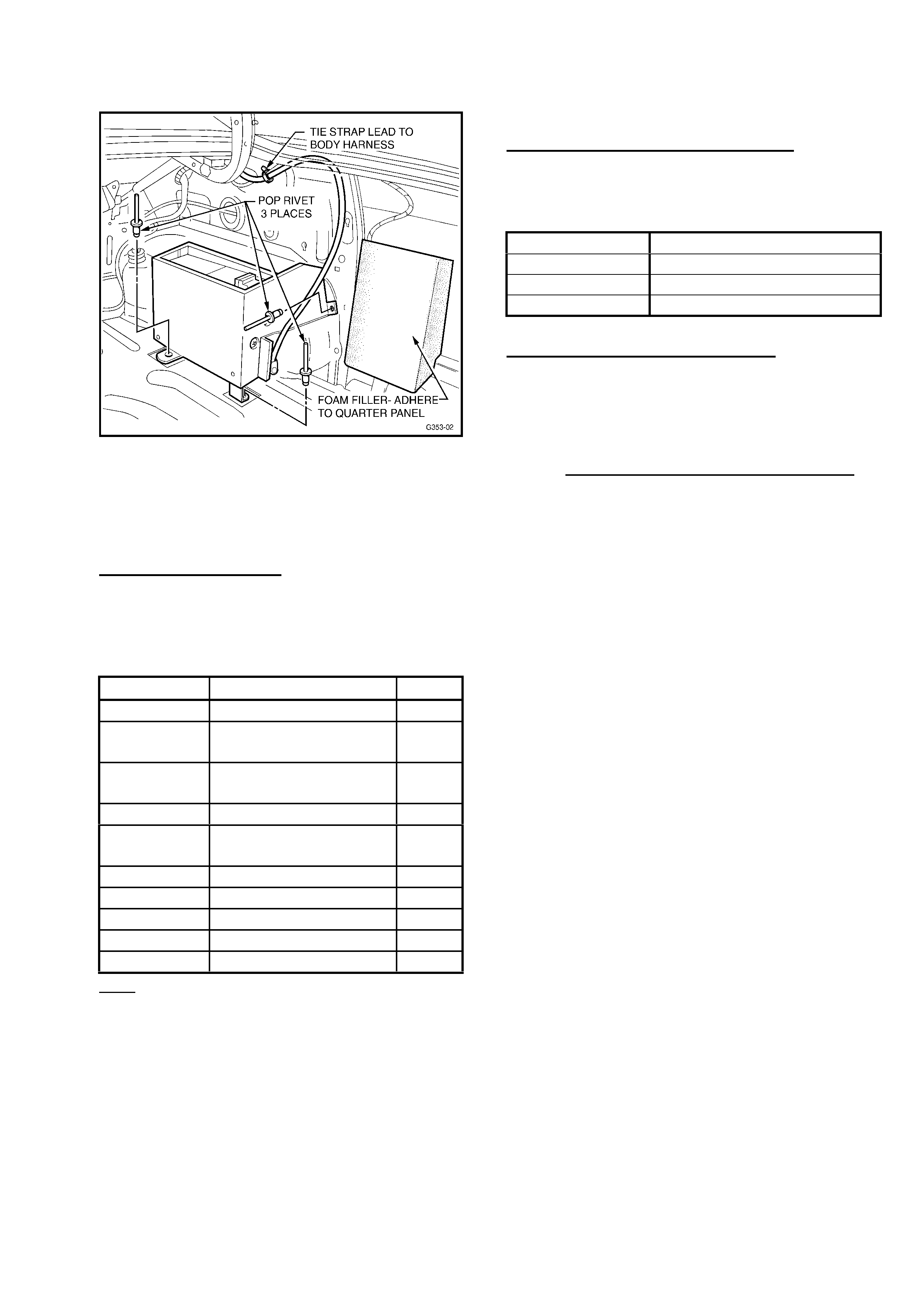
HOLDEN SERVICE TECHLINE ________________________________________________________ SEPTEMBER 2000
15
Figure 2.
12. Seal the two existing 6 disc changer
mounting holes with butyl patches.
13. I nst all the revised rear compartm ent trim.
PARTS INFORMATION
Dealers should order parts from HSPO, as
there is no change-over program t o cover this
process.
Part No.: Description: Qty
92080354 10 Disc Changer 1
92053301 Br acket- 10 disc
changer 1
92088915 Foam piece, rear
compartment 1
92088903 Car pet, CD cover 1
92088904 Car pet and spare
wheel cover 1
92138380 Rivet- br acket to body 1
92138381 Rivet- br acket to floor 2
92143627 Template 1
92060351 Tie strap 1
92018621 Butyl sealing patch 2
Note: But yl Patch 92018621 supersedes
Patch 92055234 quoted in DL 32/ 00 –
92018621 will need to be trimmed for use as
noted above, and will provide enough material
for several inst allations.
WARRANTY CLAIM I NFORMATION:
Use the following information when claiming
for t he above rect ification procedur e:
Description Install WH 10 Disc Changer
Labour Op. No. R000088
Time 0.8 hr
Failure Code 56
Warranty Personnel Please Note:
The replaced 6 Disc Changer unit is to be
returned to Repac together with other parts
when requested via the Repac report. Please
ensure replaced units are kept in a secure
area and appropriately packaged for return to
Repac. Do not send CD chang er s to Eurovox.

HOLDEN SERVICE TECHLINE ________________________________________________________ SEPTEMBER 2000
16
CALIBRATION REVISIONS AFFECTING
STARTING & A/T SHIFTS
VT/WH with Gen III V8
(GROUP 6C)
PROBLEM DESCRI PTION
Engine poor or hard starting:
– Manual & Auto vehicles
Customer m ay complain of:
- Engine star t s and r uns r ough for a few
seconds (gener ally 1-3 seconds),
- Engine has excessive crank time after hot
soak (engine stopped) of appr ox. 15- 45
minutes.
A/T shifts:
Customers may also complain of:
- “harsh” 1- 2 and 2- 3 auto shifts on light to
medium throttle,
- Excessive driveline “clunk” noise from rear of
vehicle during a 2-1 shift on closed throt tle
coastdown.
Research into these complaints has proven
that the calibration of the Desired Shift Time
(DST) and Shift Energy Management (SEM)
values are less than optimum for this
powertrain combination.
PRODUCTION RECTIFICATION
A revised calibration has been developed and
was introduced into production as follows:
Auto. Trans. Vehicles:
ISOVIN: Build Date:
6H8VTK69FYL584849 02/05/00
Manual. Trans. Vehicles:
ISOVIN: Build Date:
6H8VTK69FYL584822 02/05/00
SERVICE RECTIFICATION
NOTE: Flash Programming is ONLY to be
carried out to customer complaint vehicles.
Does NOT apply to HSV vehicles.
For customer complaint vehicles i n
service:
Using Tech 2 and TIS2000 Version 12B,
reprogram the vehicle’s PCM using the
Service Programming System (SPS) with
software Part Number:
92100254 for Aut o. Trans. - ( non- HSV):
92100255 for Manual Trans. - (non-HSV):
HSV VEHICLES:
Should you require further information
regarding HSV vehicles affected by this
bulletin, then please call HSV Technical
Assistance Department on telephone number
(03) 9265 9500.
WARRANTY CLAIM I NFORMATION:
Use the following claim information where
Flash Programming is carried out to any
customer complaint vehicle:
Description Reprogram PCM
Labour Op. No. J000669
Time 0.4 hr
Failure Code 47

HOLDEN SERVICE TECHLINE ________________________________________________________ SEPTEMBER 2000
17
A/T ELECTRICAL CONNECTOR
“LIMITED” REPAIR PROCEDURE
VR, VS, VT
(GROUP 7B)
PROBLEM DESCRI PTION
Some neutral start & back-up switch
connector/s may be “hard to remove”. This
may occur in vehicles that have been in
service for a long time, and subjected to long
periods of idling. Heat build-up causes the
internal heat sink material in the switch to
‘migrate’ into the electrical connectors and to
act like a glue between the switch body and
the connector.
SERVICE RECTIFICATION
CONNECTOR REMO VAL:
Should this “hard t o remove” situation occur in
any vehicle, the method of removal sugg ested
is:
Apply heat (with a commercially available heat
gun) to the connector area of the neutral start
& back-up switch where it mates with the
vehicle harness connector. Only apply
sufficient heat t o soften the “ glue-like” m at erial
in the connections – IE: repeatedly heat and
check the connection for looseness, until the
connection breaks free.
Aft er r emoval of the connector / s:
• Clean terminals in the vehicle harness.
Should the neutral start & back-up switch
connector be heavily contaminated, the
switch should be replaced.
• After switch replacement, check switch
operation in workshop, then road test
vehicle to ensure the switch has not been
damaged dur ing the above procedure.
CONNECTOR REPAI R:
In addition to the above removal procedure,
for vehicles which are out of warranty, the
following repair method is offered as a cost-
eff ective repair for customers, should damage
occur to the vehicle’s harness connectors
during r em oval as noted above.
As the above procedure is recognised as
being for higher kilometer and older vehicles,
the following repair procedure is not to be
used for vehicles in warranty.
Use of this procedure assumes that the vehicle
harness connector/s have been disconnected
from the trans. and are damaged beyond
repair. The procedure applies equally to 7-way
connector and 4-way connectors used on later
transmissions.
1. Cut the wires of the harness in a
stagg ered f ashion, ref er to Fig ure 1, below
– this allows creation of a small diameter
repaired har ness, where the wire joints are
not likely to short/earth. Retain the old
connector – to use as a pattern to ensure
correct wire/terminal location.
2. Bare the cut ends of the harness wires, to
allow joining and soldering to a new
connector assembly (refer Parts Info.
Below for p/n’s) .
3. Define (using t he old connector/wiring as a
pattern) where the replacement wires will
attach to t he vehicle harness.
4. Cut the wires on the new connector to
match the ‘staggered cut’ of the wires on
the vehicle wiring harness.
5. If Connector Pin Assurance (CPA)
securing pins are fitted, attach the ‘ring’
end over t he new connector wires near t he
connector body.
6. Bare the wire ends, join and solder each
wire. DO NOT use the crimp–type
terminals provided with the new connector
assembly.
7. Insulate each wire joint individually with
tape to fully seal out moisture.
8. Tape over the entire repaired section to
fully seal out moisture.
9. Assemble connector to neutral start &
back-up switch connection.
10. Refit Connector Pin Assurance (CPA)
securing pins where f itt ed.
11. Check operat ion of neut ral start & back-up
switch in workshop then road test to
confir m cor r ect operation.
Update
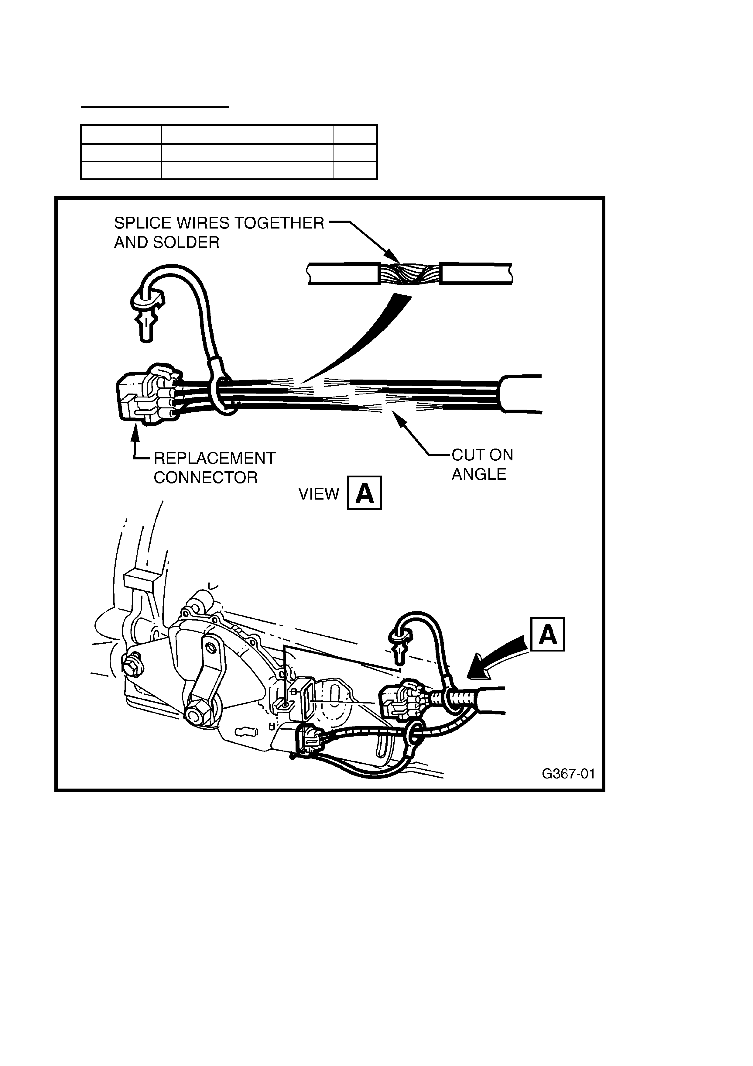
HOLDEN SERVICE TECHLINE ________________________________________________________ SEPTEMBER 2000
18
PARTS INFORMATION
Part No.: Description: Qty:
15305887 7 Way A/T Conn. Asm. 1
15305925 4 Way A/T Conn. Asm. 1
Figure 1.
Shows repair to one connector – repair i s t ypical for both connect ors shown.

HOLDEN SERVICE TECHLINE ___________________________________________________________ OCTOBER 2000
9 9
HARD STARTING/STALLING - FUEL
PUMP FAILURE
VT/W H w i th Ge n III V8
(GROUP 6M) RE-ISSUED
This Service Techline supersedes the
previous Techline on this topic (Issue 8,
September, 2000 page 11) – by correcting
production breakpoint date. This previous
Techline should be corrected or destroyed.
Index page information will be updated to
show this item only.
PROBLEM DESCRIPTION
A number of fuel pump failures have been
reported – this has lead to customer
complaints of “hard to start” or “engine stall”.
Investigation into these failures shows they
have been caused by dropping or mishandling
of the fuel pumps, prior to assembly into
vehicles.
PRODUCTION RECTIFICATION
Revised fuel pump and sender units, with
more robust internal components, were
introduced into product ion as fo llows:
ISOVIN: Build Date:
6H8VTK69FYL608654 30/06/00
SERVI C E RECTIFICATION
Pump and sender assemblies requiring
replacement, should be replaced with the part
noted below.
When diagnosing hard starting – use the
diagnosis procedure that is provided in the
Supplier Prior Approval Process (SPAP)
binder supplied to Dealerships with All Dealer
Letter DL 48/00. This binder carries a section
relating to fuel pump diagnosis.
PARTS INFORMATION
Part No .: Description: Qty.:
25337050 Pump & Sender Asm. 1
NOTE: Any stock of old pump and sender
units – Part No. 25324949 - in dealership
stock must not be used, but be returned to
HSPO for credit.
WARRANTY CLAIM INFORMATION:
Use existing information in Labour Time
Manual.
BRAKE HOSE/CALIPER SEAL RING
REPLACEMENT PROCEDURE
TS
(GROUP 5)
CURRENT CONDITION
As a standard procedure – quoted in TIS -
when replacing brake hoses or brake calipers
for any reason, it is necessary to replace the
seal rings (copper washers) used at the
caliper and hose interface/s.
SERVICE RECTIFICATION
This bulletin is to draw Technicians attention
to this requirement - to replace the seal rings
(copper washers) used at the caliper and
hose interface/s - whenever a brake hose or
caliper is replaced.
PARTS INFORMATION
Confusion has arisen because the seal rings
(copper washers) for rear brake installations
were not shown in earlier versions of
PartFinder.
The current issue of Par tFinder addr esses this
missing information – the seal rings (copper
washers) for rear brake installations have
been added. The seal rings used in rear brake
installations are in fact the same as those
used in front brak e inst allations.
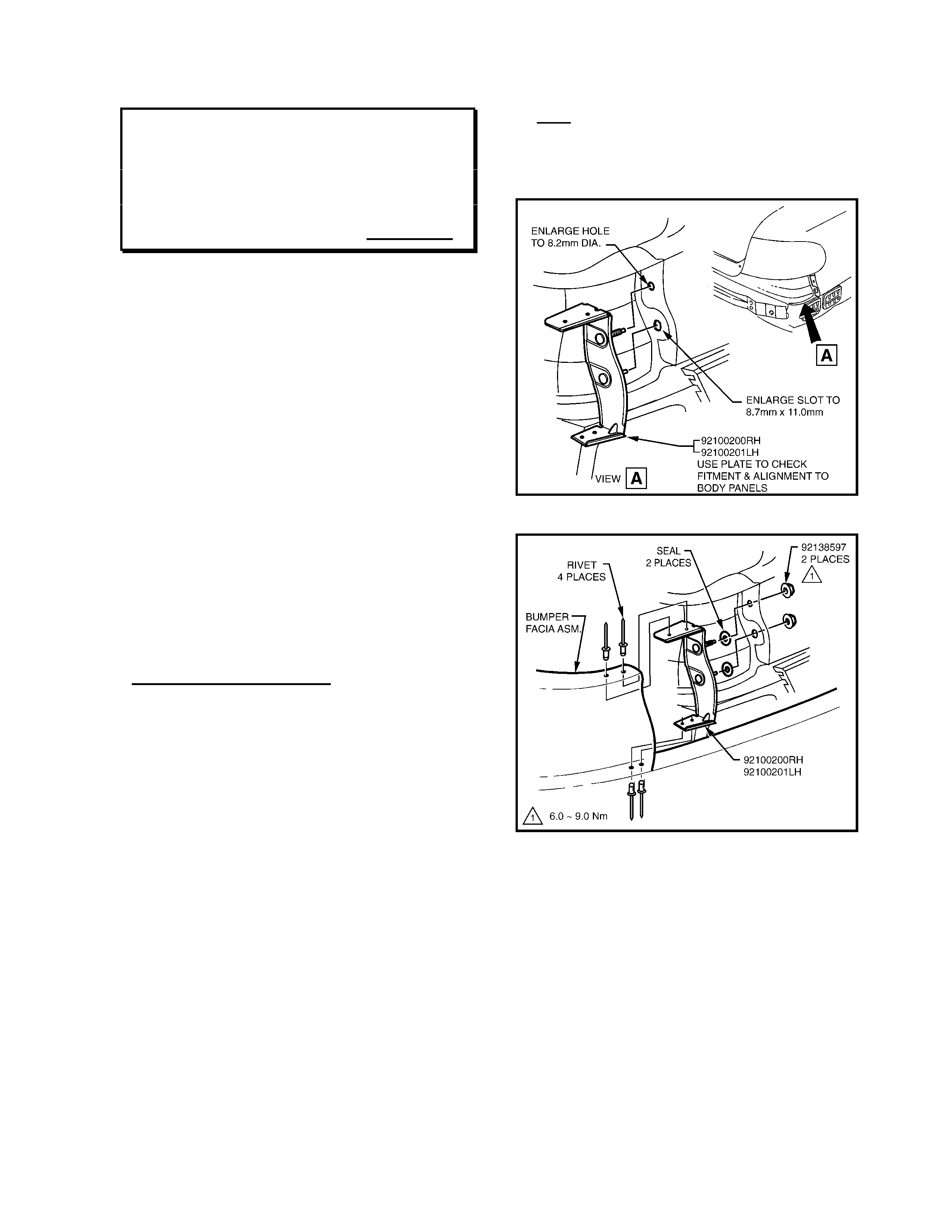
HOLDEN SERVICE TE CHLINE ___________________________________________________________ OCTOBER 2000
10
PLATE - REAR BUMPER FACIA TO QTR
PANEL – MODIFIED PART/FITTING
INFO..
VT Sedan
(GROUP 1) Parts Info.
The information in this Techline bulletin is
repeated from HSPO Bulletin PT50, dated 21
August, 2000 – to ensure technicians are
aware of this part supersession and
replacement requirement.
CONDITION
Plate assembly (p/n 92052174/5) – rear facia
to quarter panel for VT, will soon be
superseded in HSPO parts stock, to the VX
plate assembly (p/n 92100200/1), for
commonisation.
Note: Following this supersession, only the
VX part will be available for vehicle repairs.
This part is only req uired if the orig inal plate is
damaged.
Future VT plate replacements will require a
specific plate replacem ent procedure as noted
below.
SERVI C E RECTIFICATION
The following procedure is applicable to VT
vehicles where the Plate Assembly - Rear
Facia requires replacing and a VX part (p/n
92100200/1) is the only part available:
1. Enlarge holes in rear quarter panel in
which Plate Assembly - Rear Facia
mounts. The top hole to 8.2 mm dia. and
the lower slot 8.7 mm wide by 11.0 mm
long. Refer Figure 1.
2. Repeat procedure to opposite side, if that
part is also being replaced.
3. Check fitment and alignment of Plate
Assembly studs.
4. Vacuum up swarf and f ilings.
5. Rustproof modified holes, using Zinc
Chromate or equivalent.
6. Inst all Plate Assem bly - Rear Facia to Rear
Bumper Facia with rivets (p/n 92138058), 4
places each side. Refer Figure 2.
7. Reinstall Rear Bumper Facia. Refer to
Service Manual Section 1D - Bumper Bars.
Note: New nuts 92138597 are also
required for the attaching of the Plate
Assembly-Rear Facia to Quarter Panel.
Refer Figure 2.
Figure 1.
Figure 2.
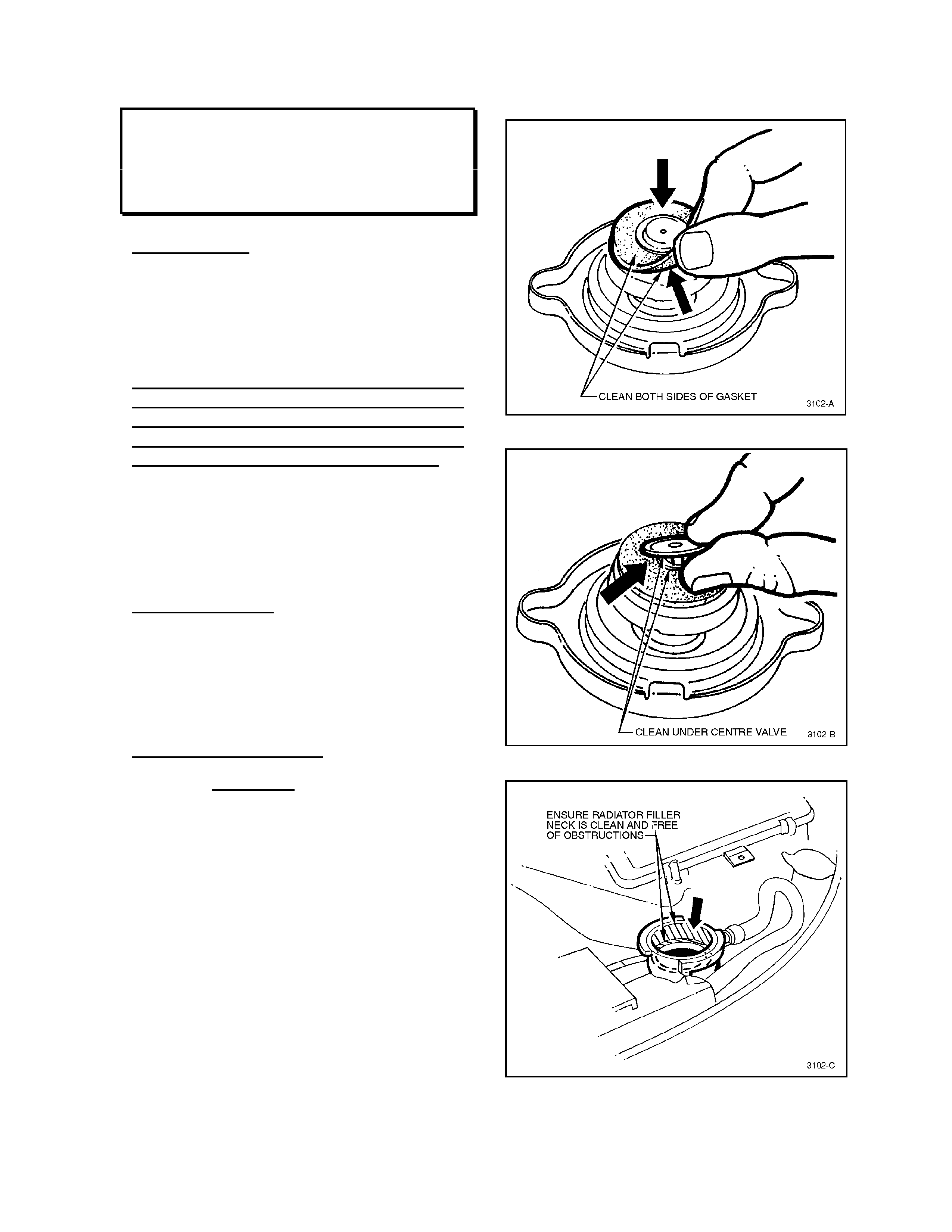
HOLDEN SERVICE TE CHLINE ___________________________________________________________ OCTOBER 2000
11
RADIATOR CAP CLEANING & TESTING
VS, VT, VX, WH
(GROUP 6K)
BACKGROUND
The majority of radiator caps returned to
Repac have been replaced unnecessarily.
The supplier of these radiator caps reports
that after cleaning the gasket, these
radiator caps hold pressure. Repac has
also confirmed this to be the case.
If, after carrying out this procedure, the
radiator cap is replaced because it will not
hold pressure, note on the Defective
Material Tag that this procedure has been
carried out, or a charge-back will result.
IMPORTANT Warranty claims will not be
accepted for radiator caps replaced
unnecessarily where the cap can be
successfully cleaned and pass a pressure
test.
SERVICE ACTION:
When investigating a radiator cap that does
not hold pressure, the radiator cap centre
valve gasket must be cleaned, prior to
carrying out a pressure test on the radiator
cap. If the radiator cap holds pressure after
cleaning it should be refitted to the vehicle.
CLEANING PROCEDURE
1. Clean both sides of radiator cap gasket
with a wet cloth (Use water only to wet
the cloth). refer figure 1.
2. Lift centre valve and clean gasket area
under the valve, refer figure 2.
3. Ensure the r adiator filler neck cap seating
surface is clean and free from
obstruction, refer figure 3.
4. Pressure te st radiator cap t o the pressure
marked on cap.
5. If radiator cap holds pressure refit to
vehicle.
6. Replace radiator cap if pressure test fails
after cleaning.
Figure 1
Figu re 2
Figu re 3

HOLDEN SERVICE TE CHLINE ___________________________________________________________ OCTOBER 2000
12
SPEEDO “PPK” PROGRAMMING
VT, VX, WH
(GROUP 12) UPDATE
This Service Techline supersedes all previous
Techlines on Speedo PPK Programming.
Previous Techlines should not be used for
PPK values, and should be destroyed.
SERVICE INFORMATION
The following information is supplied for
technician reference.
Previous PPK values were based on tyre
sizes only – selection of PPK values based on
tyre size is no longer possible.
This is because PPK values vary according to
trans. type and final drive ratios (which also
change with trans . type) – thus it is necessary
to refer to the following chart to determine
exact PPK values for the body style, engine,
trans type and tyre size being worked on.
PPK values shown must be used whenever
speedo PPK programming is required.
Refer VT Series Service Manual Volume 14C,
Section 12C, 5.15 F5: PROGRAM for
programming basic information.
Body Style Engine Trans. Type PP K Value Tyre Size
Sedan/Wagon V6 Auto/Manual 6272 205/65 R15
Sedan/Wagon V6 Auto/Manual 6238 225/60 R15
Sedan (Police 9C1) V6 Auto 6285 215/60 R15
Sedan/Wagon V6 Auto/Manual 6077 215/60 R16
Sedan/Wagon V6 Auto/Manual 6087 225/55 R16
Sedan/Wagon V6 Auto/Manual 6391 225/50 R16
Sedan/Wagon V6 Auto/Manual 6301 235/45 R17
Sedan/Wagon/Ute V8 Auto/Manual 6272 205/65 R15
Sedan/Wagon/Ute V8 Auto/Manual 6238 225/60 R15
Sedan/Wagon/Ute V8 Auto/Manual 6087 225/55 R16
Sedan/Wagon/Ute V8 Auto/Manual 6301 235/45 R17
HSV All Auto 6355 225/50ZR16
HSV All Auto 6210 235/45ZR17
HSV All Auto 6210 235/40ZR18
HSV All M/T - T56
6300 235/45ZR17
HSV All M/T - T56
6300 235/40ZR18
HSV All M/T - Getrag 6355 225/50ZR16
HSV All M/T - Getrag 6210 235/45ZR17
HSV All M/T - Getrag 6210 235/40ZR18
HSV (GTS) All M/T (3.91 axle) 6180 245/35ZR19
Update
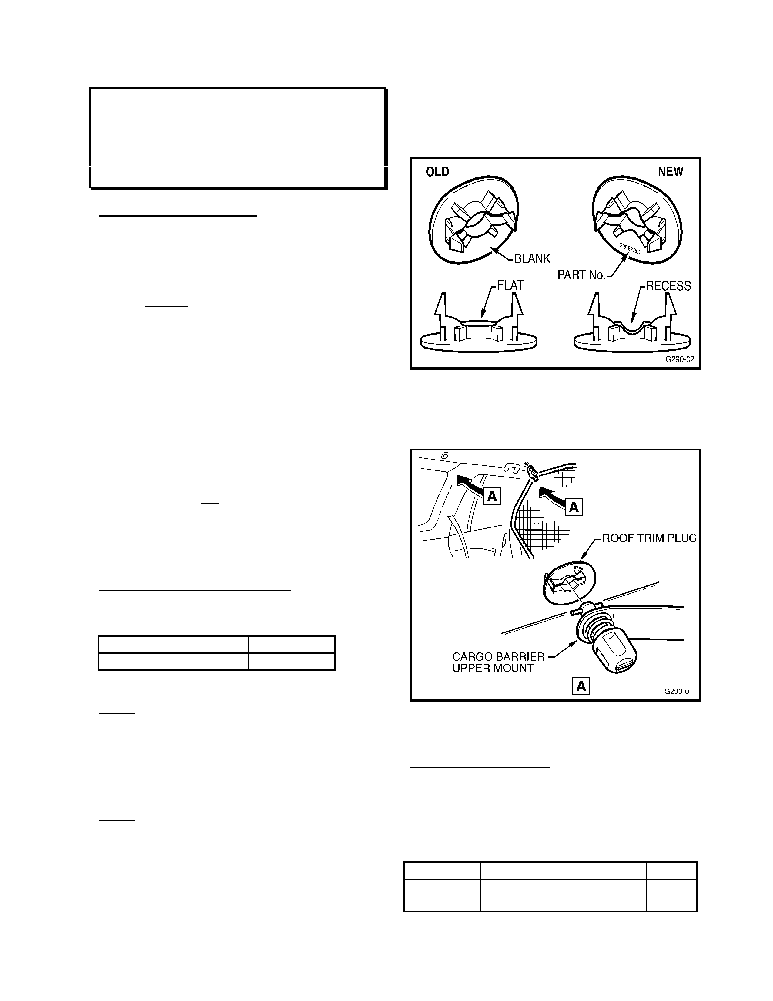
HOLDEN SERVICE TE CHLINE ___________________________________________________________ OCTOBER 2000
13
CARGO BARRIER ROOF TRIM PLUG
DISLODGES
VT WAG ON
(GROUP 1)
PROBLE M DES CRIP TIO N
The Holden accessory cargo barrier kit includes
four “roof trim plugs” that are used to retain the
two upper mounts of the cargo barrier in either
of two locations - Refer Figure 2 below.
Station wagon owners/operators may complain
of the unused cargo barrier roof trim plugs
dislodging or not retaining in the r oof/headlining
panel. This may occur on vehicles built from
17/05/’00 where a revised roof mounting
bracket (under the headlining) was introduced.
A revised design roof trim plug was released in
the cargo barrier kit at the sam e time.
For this reason, some carg o barrier kits fit ted to
vehicles built after 17/05/’00 may be from
earlier stock and may not have the revised
design roof trim plug.
“Old” design roof trim plugs will not retain
permanently in later build roof brackets.
“New” trim plugs will retain correctly in both old
and new design roof brackets.
Lack of, or loss of these roof trim plugs does
not cause a problem with the security of the
cargo barrier mounting or its retention.
PRODUCTION RECTIFICATION
The revised roof bracket (on the vehicle
roo f panel) w a s fitted to wagons from:
ISOVIN: Build Date:
6H8VTK35HYL590221 17/05/00
SERVICE RECTIFICATION
NOTE: Only vehicles built after
6H8VTK35HYL590221 are affected by this
complaint.
If any vehicle is reported to have trim plugs
which “will not retain in the roof/headlining” - the
trim plugs must be replaced with “new” trim
plugs.
NOTE: “old” design clips that do retain in roof
brackets do not require replacement. Confirm
this with ISOVIN/Build Date info. above and by
checking engagement.
Figure 1 below shows difference between old
and new trim plugs.
“New” trim plugs are identified by the part
number 92088207 moulded into the plug.
“Old” trim plugs have no identification except
shape as shown in Figure 1 below.
Figure 1.
W hen r eplacing trim plug s, fit new trim plugs to
(up to four) lo cations in the roof panel.
Fig ure 2. (showing two possible front/rear
locations, RH Shown, LH Opposite)
PARTS INFORMATION
This plug was previously only available in
the Cargo Barrier Kit and is now available
as a separate part for replacements as
noted, as well as for normal customer
service replacement.
Part No.: Descripti on: Qty
92088207 Roof Trim Plug - Cargo
Barrier Mounting 4
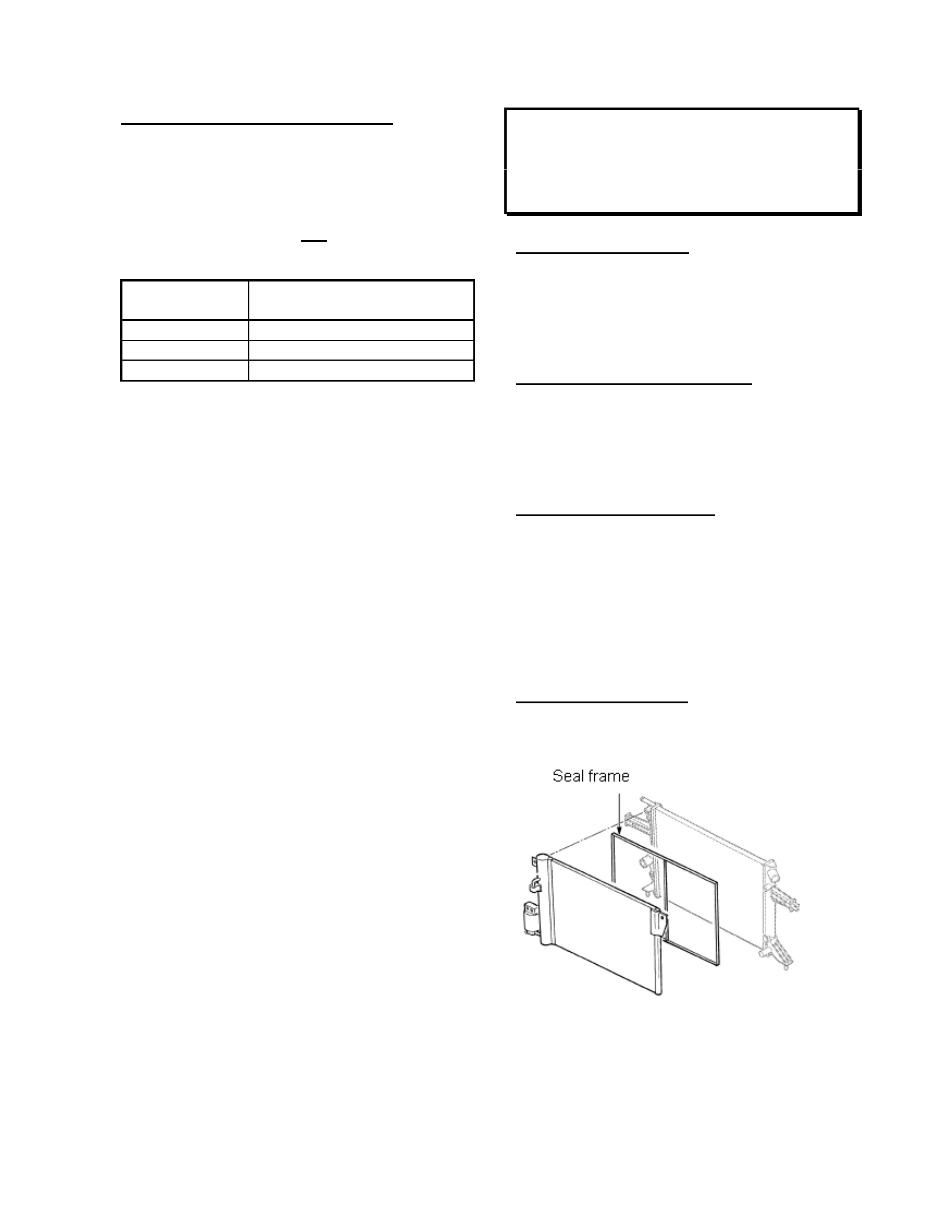
HOLDEN SERVICE TE CHLINE ___________________________________________________________ OCTOBER 2000
14
WARRANTY CLAIM INF OR M ATION:
Use the following labour operation and time
to claim for “once-only” fitment of four
(max.) roof trim plugs:
New trim plugs with “92088207” moulded into
the rear of the clip must not be replaced under
this Techline instruction.
Description Carg o barrier trim plug -
replace
Labour Op. No. R000091
Time 0.2 hr
Failure Code 37
Return old trim plugs removed from vehicles
when requested by REPAC under this labour
operation number.
RADIATOR SEAL FRAME DELETION
TS with A/C
(GROUP 2)
CURRENT CONDITION
A seal f rame is fitt ed between the radiator and
the A/C condenser, on A/C equipped vehicles
built prior to Model Year 2000 build.
Refer Figure 1 below for exact location.
PRODUCTI O N RECTIFICATION
The seal frame between the radiator and the
A/C condenser is no longer used. The seal
fr ame was deleted f rom product ion with Model
Year 2000 build.
SERVICE RECTIFICATION
When removing this seal frame for any
reason, or dismantling components that allow
access to the seal frame – the seal frame
should be removed and discarded.
After removing the seal frame, fit the A/C
condenser directly to the radiator during re-
assembly.
PARTS INFORMATION
The seal frame i s no longer carried by HSPO.
Figure 1.
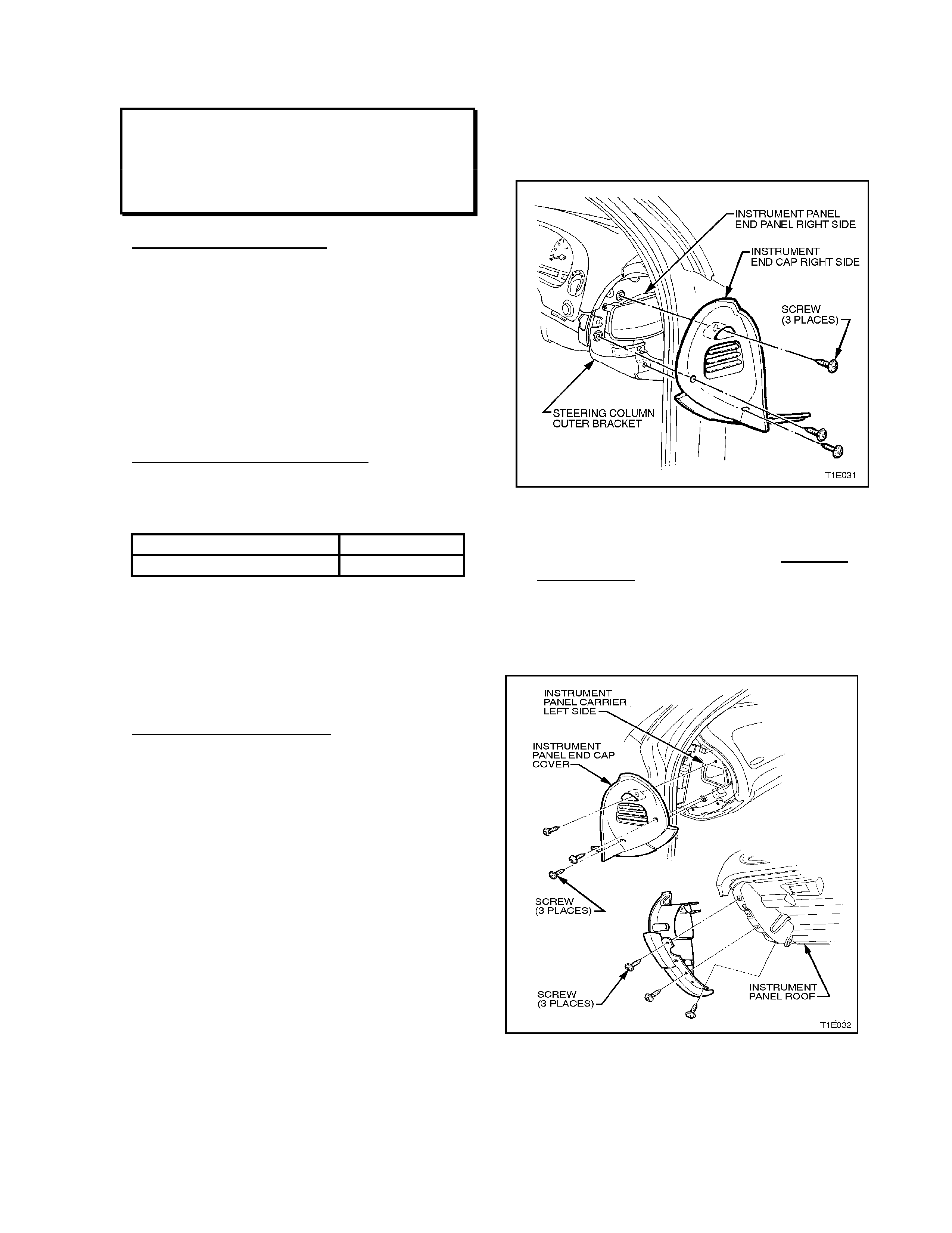
HOLDEN SERVICE TE CHLINE ___________________________________________________________ OCTOBER 2000
15
INSTRUMENT PANEL “CRACK” NOISE
VT, WH
(GROUP 1)
PROBLEM DESCRIPTION
An instrument panel “crack” noise may be
heard during instrument panel expansion or
contraction – IE when cooling down a vehicle
interior after being parked in high sun load or
when heating up a cold vehicle interior.
Investigations have shown the cause of the
noise is the instrument panel thermal
expansion/contraction stress being relieved at
its mount ing points .
PRODUCTION RECTIFICATION
Modified instrument panel retaining
screws/washers have been fitted to vehicles
from:
ISOVIN: Build Date:
6H8VTL69HYL616569 19/07/00
These modified screws carry additional
polypropylene washers that reduce friction, to
allow instrument panel “stress” movement
under high thermal expansion/contraction
loads, and thread sealant to ensure mounting
screw torque is maintained in all conditions.
SERVI C E RECTIFICATION
Complaint vehicles where customers complain
of a “crack” noise during rapid vehicle interior
temperature chang es, can be corr ected by the
replacement of the five (5) instrument panel
retaining screws with the modified screws
ment ioned above.
The procedure below should be used to
replace the screws – the procedure is an
abbreviated version of t he proc edure s hown in
SIP CD/VT Series Service Manual, Volume 1,
Pages 1A3-8 to 1A3-15. Use the SIP
CD/Service Manual as reference while
carrying out the procedure. Some of the
illustrations from these pages are included
here to assist in the procedure.
1. CAUTION – Disable the SRS (Air Bag).
Refer to “DISABLING THE SRS”, Section
12M SRS in Volume 7 of the VT Service
Manual/SIP CD.
2. Remove instrument panel lower cover right
side (under steering column).
3. Remove instrument panel end panel right
side (Refer Figure 1A3-13 below).
Figure 1A3-13
4. Remove demist nozzle grille – right side,
by removing end screw and moving fuse
panel down for access. Caution: Pull grille
rearward only (NOT upward or damage will
occur). Ref er Figure 1A3-19 if req uired).
5. Remove glove compartment (Refer Figure
1A3-2 if required).
6. Remove instrument panel end panel left
side (Refer Figure 1A3-14 below).
Figure 1A3-14
7. Rem ove footwell upper closing panel – left side
(under glove box).
HOLDEN SERVICE TE CHLINE ___________________________________________________________ OCTOBER 2000
16
8. Refer to Figure 1A3-14 – there are a total of 5
screws down the left hand glove compartment
opening – remove the top screw, third screw
from top, and fifth screw from top.
9. Remove demist nozzle grille – left side, by
removing end screw. Caution: Pull grille
rearward only (NOT upward or damage will
occur). Move solar sensor for access to
instrument panel mounting screw. Refer Figure
1A3-19 if required).
Figure 1A3-19.
10. Access is now gained to the five instrument
panel mounting screws across the front edge
of the instrument panel (near windscreen).
Remove the existing screws one at a tim e and
replace with new mounting screws (p/n
92138601).
11. Refit solar sensor.
12. Refit left side demist nozzle grille – Caution:
Take care not to damage the A pillar trim with
grille retaining lugs/clips when refitting grilles.
Ensure the retaining clips on the grille are
centred on the retaining lugs or dam age to the
grille may result, push down on the grille on a
45° angle, or grille will not ‘sit’ correctly on
instrument panel.
13. Refit instrument panel end panel – left side.
Hint: Align the end panel before fitting screws,
and use a magnetic tip screwdriver to hold
screws until started in threads.
14. Refit glove compartment.
15. Refit right side demist nozzle grille – Caution:
use same care as noted in Step 12 above.
16. Refit instrument panel end cap – right side.
Hint: use a magnetic tip screwdriver to hold
screws until started in threads.
17. Refit instrument pa nel lower cover right side.
18. R econnect SRS ( A ir Ba g) system as r equired.
PARTS INFORMATION
Part No.: Description: Qty.:
92138601 Screw – Instrument
Panel Retaining 5
WARRANTY CLAI M INFO RMATION:
Description Replace Instrument Panel
Retaining Screws
Labour Op. No. A000276
Time 0.4 hr
Failure Code 28
HOLDEN SERVICE TE CHLINE ___________________________________________________________ OCTOBER 2000
17
WHISTLE NOISE FROM ENGINE BAY
JR C20SEL, JS C22SEL, JS X25XE
(GROUP 6M) RE-ISSUED
This Service Techline supersedes the
previous Techline on this topic (Issue 9,
November, 1999 page 13), by providing
additional info. for V6 engined vehicles. This
previous Techline should be destroyed.
PROBLEM DESCRIPTION
Some customers may report a whistle noise
that can be heard f rom t he engine bay area at
varying speeds with light throttle application.
The noise may emanate from the fuel
evaporative carbon canister purge (transfer)
hose (also called carbon canister to fuel tank
vent valve hose). This hose has a corrugated
section, and when air passes through it, a
whistle type noise is produced. To verify this,
the canister purge hose can be disconnected
from the purge valve (at the valve end), and
on road test the noise should stop.
PRODUCTION RECTIFICATION
Revised canister purge hoses have been
introduced into vehicle production f rom:
ISOVIN: Build Date:
W0L0JBF35YL496571 29/09/99
SERVI C E RECTIFICATION
1. Locate the canister purge hose routed
along the engine firewall - (Canister to fuel
tank vent valve)
2. Disconnect the canister purge hose joint,
located under the brake master cylinder.
3. Turn vehicle steering wheel to the farthest
right hand lock position, to gain access to
the rear end of the front inner wheel arch
cover.
4. Remove the two rearmost front wheel arch
cover plastic retaining nuts, and the two
lower plastic retaining clips.
5. Pull the rear section of inner wheel arch
cover away from its mountings to gain
access to the carbon canister (2) – Refer
Fig u r e 2 .
6. Disconnect canister purge hose (2) - Refer
Figure 3 - f rom carbon canist er and remove
the hose from the vehicle.
7. Connect and r oute the revised type canist er
purge hose as per the previous hose.
8. Refit the inner wheel arch cover.
Figure 2.
Figure 3.
PARTS INFORMATION
Revised canister purge hose can be ordered
from HSPO with the part number specified
below:
Part No.: Description: Qty:
92081590 Hose, Canist er Purge (4 Cyl.) 1
92089339 Hose, Canist er Purge (V6) 1
WARRANTY CLAIM INFORMATION:
Description Canister Purge Hose - Replace
Labour Op. No. L000187
Time 0.6 hr
Failure Code 40
HOLDEN SERVICE TE CHLINE ___________________________________________________________ OCTOBER 2000
18
WHISTLE NOISE/DRIVEABILITY
COMPLAINTS
JS with X25XE Engine
(GROUP 6M)
PROBLEM DESCRIPTION
Some customers may report a whistle noise
that can be heard f rom t he engine bay area at
varying speeds with light throttle application.
In addit ion to this, t he custom er may comp lain
of poor driveability and hot start complaints.
Both these conditions can be caused by
incorrectly routed and re-assembled purge
valve hoses, following a previous workshop
procedure.
SERVI C E RECTIFICATION
Should a customer complain of an engine bay
whistle noise, or poor driveability, carry out the
following procedure:
Check f or correct routing of the canister purge
valve hoses at the purge valve - to ensure
correct operation of the purge valve and
correct installation of the purge hose, ensure
the existing purge valve hoses are routed as
shown below - Refer Figure 1.
Figure 1.

HOLDEN SERVICE TE CHLINE ___________________________________________________________ OCTOBER 2000
19
FLUID LEAK DIAGNOSIS
ALL MODELS
(GROUPS OB, 2, 6A, 7A, 7B)
PROBLEM DESCRIPTION
Dealers must assume responsibility for the
completion of thorough and accurate
diagnosis of fluid leaks prior to commencing
any rectification work or removing major
components.
Components must NOT be replaced for
“leaks” without thorough definition of leak
sources.
Use of Black Light Dye and Black Light is
highly recommended to trace leak sources.
For extensive information on the use of Black
Light and Black Light Dye, refer to the
following inf orm ation repeated f rom a previous
All Dealer Letter.
Holden strongly recommends the use of the
black light and dye method to diagnose fluid
leak sources . This meth od of leak detection is
a proven, reliable method that identifies the
specific leak sour ce and/ or location. T he black
light and dye method can be used for various
types of leak detection, when used with the
appropriate tracer dye it can be used for
detecting engine and transmission fluid leaks,
R12 & R134A leaks, fuel leaks, and coolant
leaks.
The following pages provide answers to
technicians’ questions about the various
aspects of black lig ht and tr acer dye, and how
dealerships may use this tool to their
advantage.
Black Light & Tracer Dye and Accessori es
There are different types of tracer dye for different applications, plus for air-conditioning systems
tracer dyes, an injector, used to infuse the dye into the system, is required. The following tracer
dyes and accessories are available direct from SPx Australia.
Contact SPx Australia – Ph.: (03) 9544 5222; Fax: (03) 9544 6222 - for normal dealer pricing.
Application Part Number
R134a Air Conditioning Tracer Dye
(24 X ¼ oz bottles) J41447
R12 Air Conditioning Tracer Dye
(24 X ¼ oz bottles) J39475
R134a Air Conditioning Injector
J41459
R12 Air Conditioning Injector
J41709
Petrol & Diesel Engine Fluid and
Transmission Fluid Tracer Dye
(24 X 1 oz bottles)
J28431-B
Coolant T racer Dye
(24 X 1 oz bottles) J29545
Replacement Black Light Bulb
BSL-752
Black Light Leak Detection Lamp
J42220

HOLDEN SERVICE TE CHLINE ___________________________________________________________ OCTOBER 2000
20
Basi c Black Light and Dye Leak Diagnosis Method:
The following information pages will answer most questions you may have about Black Light and
Tracer Dye usage:
The fo llowing is a summary of the steps involved i n detecting a fluid lea k using black light and dye:
1. Pour specified amount of dye into the system.
2. Road test the vehicle und er normal oper ating conditions, to allow the dye to mix wit h the host fl uid/gas.
3. Define the leak source by directing the Black Light towards the suspect area. The fluid leak will appear as a
brightly coloured path leading to the source. Note: The colour of the dyed fluid can be checked on the
dipstick, or oth er component dir ectly in contact wit h the host fl uid/gas.
4. Repair f l uid leak caus e and recheck to ensure that leak has been rect ified.
General Information
How much dye do you use?
Engine, Transmission, F u el
J28431-B Engine & Trans. Fluid Dye shou ld be used as f ollows:
Petro l En gine Oil - 7.4 ml per 3.79litres of oil ( ¼oz per 4-5 quarts)
Diesel Engine Oil - 7.4 ml per 3.78litres of oil (¼oz per 4 quarts)
Automati c Trans . Fluid - 14.8ml per 5.68litres of flui d (2x¼oz per 6 quarts)
Manual Trans. Fl uid/Oil - 7.4 ml per 5.68lit res of fluid (¼oz per 6 quarts )
Petrol or Diesel Fuel - 7.4ml per 7.57litres of fuel (¼oz per 2 gallons)
A/C Systems
J41447 R134a A/C Dye should be used as follows :
R134a A/C System - 7.4ml per A/C system (¼oz per system)
J39475 R12 A/C Dye should be us ed as follows:
R12 A/C System - 7.4ml per A/C system (¼oz per system)
Power Steering
J28431-B Engine & Trans. Fluid Dye can be used in Power Steerin g as follows:
Power Ste ering Fluid - 7.4ml per 5.68lit r es of fluid (¼oz per 6 quar ts)
Engine Coolant Systems
J29545 Coolant Dye should be used as follows:
Coolant System Radiator Fluid - 7.4ml per 15.14litres (¼oz per 16 qu ar t s)
Note: These amounts are based on various tests - there may be occasions when good fluorescence
is not obtained with these amounts of dye, due to the condition of the host oil/fluid or the nature of
certain additive packages in the oil/fluid itself. If this occurs, use additional dye.
Black Light & Tracer D ye Usage Information

HOLDEN SERVICE TE CHLINE ___________________________________________________________ OCTOBER 2000
21
Q A
Do you need to use the
Fluoresce nt Enha ncer Safety
Goggles?
Yes - they not only protect the technician, but also visually optimise the dye
fluorescence for enhanced leak detection. They are scientifically designed
to enhance fluorescence by eliminating light at wave lengths that might
interfere with the eye’s ability to view the dye’s fluorescent light emission.
Once you look at the dye with and without the goggles, you will see the
difference.
What life does the dye have
when lef t in c o o lant , ATF,
R12 and R134a refrigerant ?
Indefinit e - unless t he ATF is burned in an A/T cl utch fail ure or i n an A/C
com pressor failure.
What life does the dye have
when left in engine oil? Depends on how dirty the oil was when the dye was added. In clean petrol
engine oil, it will last 500+km. In diesel engine oil, it will not last as long
because of rapid carb on build-up.
Are there any adverse effects
of leaving dye in systems too
long?
None - and A/C dyes especially are very thermally stable and should last
100,000 km.
Is there a preferred method
of cleaning t he dye from a
vehicle, if spilt?
IMPORTANT - Do NOT get dyes on any painted surfaces - use guard
cover s when pourin g dyes i nto a ny vehic le syst em or inj ect ing A/C dyes. A
good cleaning solvent should clean any dye off any metal surfaces. A/C
dyes cannot be cleaned off hoses or plastic components.
What is the shelf life of the
dyes? Indefinite, but it is r ecommende d they be used within five years.
PETROL & DIESEL ENGINE & TRANSMISSION OIL LEAKS
Use J28431-B dye in quantities as specified in “General Information” section.
Putting dye into oil that is fairly clean will achieve the best fluorescence for leak inspection because the greater
the carbon build-up in the oil, the more difficult to obtain good fluorescence from the dye. Therefore, if the oil
appears to be extremely dirty on the di pstick, additional dye may be required to obtain good fluorescence and
can be added without harm to the e ngi ne.
Q A
How do I know if the
dilution ratio of dye added is
correct?
After addin g dye at th e reco mme nded diluti on rati o, oper ate the en gine 3 to
5 minutes to allow dye to mix with oil. Then check the oil dipstick with
bla ck light for the yellow-gre en fluores cent glow of the oil/dye mix t ure.
What is the proper proc edure
for adding dye to the engine? Wi th the engine OFF. This will prevent possible splashing of the dye over
an area of the engine that may need inspecting.
How long do es it normally
take for the dye to work? Most leaks will ap pear a f ter opera ting the engine 5 to 10 minutes. Howe ver ,
it is r ecommended that the vehicl e be taken for a short roa d test in order to
allow th e dye to penetrat e all lea k s.
How long will it take for the
dye t o penetrat e very small
pinholes or porosity leaks?
To accurate ly detec t leaks of thi s type, the vehicl e should be operated for 1
to 3 hours under normal operating co nditions. Suggestion: If su ch a leak i s
suspected, add dye to the engine oil. Then have the vehicle owner use the
vehicle for the time recommended above. The owner should then return for
leak inspection with the black light.

HOLDEN SERVICE TE CHLINE ___________________________________________________________ OCTOBER 2000
22
Q A
Do I have to clean engine
surfaces prior to using the
dye?
NO! Under black light, all petroleum-based products such as oil, grease,
and AT F wil l fluo resce blue. The dye will pe netrate surf ace oil , gre ase and
grit to leave a yellow-green fluorescent trace (under black light) at the
source of th e le ak.
Do I have to clean the engine
after repai ring the le ak? YES! But only at the source of the leak in order to allow the technician to
operate the engine and then re-inspect the leak repair to insure the job was
done r ight the first time. Su ggesti on: Th e dye/oil mi xture can be removed
by usin g any engi ne degreaser or solvent-type shop cleaner.
After adding dye to t he
engine oil, is it necessary to
change the oil prior to
retu r n ing the vehicle to the
customer?
NO! The dye is 100% compatible with engine oil and can remain in the
system without harm until the next oil change.
How long will it take for
ATF dye to work? Most l eaks will appear aft er operating the transmission for 5 to 10 minutes.
However, it is recommended that the vehicle be taken for a short road test
in order to allow A T F d y e to pe netrate all leaks. NOTE : All o t her
appl ication and leak-detection procedures remain the same as given under
the Engine Dye Section (above). It is not nece ssary to clean transmissi on
exterior surfaces prior to using ATF dye. To detect small pinhole or
porosity leaks, the vehicl e s hould be operated for 1 to 3 hour s. The AT F
dye mixture should be cleaned fr om the source of the leak, and it is not
necess ary to cha nge ATF after adding dye.
How long will ATF dye be
effective in the transmission? Because the tr an s mission remains fairly clean inte r n ally an d d o e s not hav e
the carbon build-up problem present in petrol and diesel engines, the ATF
dye will be effective as long as the ATF is not changed or the AT F is not
“burnt” or discoloured by a transmission failure. Remember to check the
dipstick with the black light prior to inspecting for leaks to check
fluorescence, and do not forget t o check the AT F cooler line for leaks.
BRAKE SYSTEM LEAKS
Q A
Can I use a fluorescent dye
in a brake sy s t em?
Never use any type of a fluorescent tracer dye in a brake system.
POWER STEERING LEAKS
Q A
How much dye should I use
for finding power steering
leaks?
Check the fluid c apacit y of the power steerin g system. You will pro bably
need to add only a sm all am ount of dye at a diluti o n ra ti o o f 7.4ml (¼ oz) to
5.68l (6 quar ts) of power steer ing fluid. Run the syste m, t hen check the cap
or dipstick for fluorescence with the black light.

HOLDEN SERVICE TE CHLINE ___________________________________________________________ OCTOBER 2000
23
FUEL SYSTEM LEAKS
When a fuel system leak is suspected, it is recommended that the vehicle being tested have a quarter tank or
less of fuel. Trucks and larger capacity systems should be estimated as close as possible in order to keep the
dye requirement at a minimum and to keep the test procedure as economical as possible. If a difficult leak is
suspected, adding more dye than nor mal ( a higher concentration) will pr oduce the best res ults and will not ha r m
the system.
Q A
How do I know if e n ough
fuel dye has been added? A ny di ps tick device that can be ins erted into the fi ller tube can be use d and
then inspected for fluorescence with the black light.
On a fuel-injected (PFI)
vehicle, can I use the fuel
rail for injecting dye?
NO! The small volume of petrol that will receive the dye is probably
insufficient for the dye to show up a t an “O” ring injecto r leak for example.
COO LANT SYSTEM LEAKS
J295 45 dye is totally compatible wit h anti-freeze.
Q A
What is the proper proc edure
for adding dye to the cooling
system?
Add dye with the engine off a nd radiat or “c old”. Th is will prevent splashing
of dye and possible false readings. Also, add the coolant dye directly into
radiato r and not into the reserve/surge tank found on som e v eh i cl es.
How do I clean the coolant
with dye of f the radiator and
engine surfaces?
Use water with detergent and a small scrub brush.
How can I check for a
suspected coolant leak into
the engine oil?
Perform test as follows:-
Pull the engine oil dipstick and confirm the blue fluorescence of the engine
oil with the black light. (This is oil to which no dye has been added.)
With t he e ngine o ff and t he ra di ator c old , pour co ola nt dye i nto t he r adi at or,
and operate vehicle for at least one day to allow coolant to leak into engine
oil.
With the engine off, pull engine oil dipstick and fluoresce dipstick with
bla ck light.
If coolant is leaking into the engine oil, the dipstick should show some green
fluorescent droplets of coolant. Also, the engine oil might fluoresce a slight
whitis h bl ue col our in ste ad of the normal stron g blue fl uoresc ence of engine
oil.
R134a A/C SY STEMS DYE FOR R12 A/C SYST EMS
When R134a or R12 dye is injected into an A/C system and the system has been operated under full pressure
for 5 to 10 minutes, t he dye wil l remain i n the s ystem even thou gh the R134a or R12 has been evacuated for a
repair. The only time R134a or R12 dye must be put back into the A/C system is when the A/C system is
flus hed of refrigerant oil.
Q A
How do I put R134a or R12
dye into an automotive car or
truck A/ C syst em?
Pu t 7.4ml (¼ oz) of dye in the dye inject or reser voir, and use a r efrigerant
sour ce to injec t th e dye into the A/C system .

HOLDEN SERVICE TE CHLINE ___________________________________________________________ OCTOBER 2000
24
Q A
How long will it take the
R134a or R12 dy e to
circulate thro ugh the typical
automotive A/C system?
Operating the A/C system under full pressure, it will take the dye
approximately 5 to 10 minutes to circulate through most A/C systems.
However, this does not mean that the A/C leak will show up in that time
period.
How long after putting
R134a or R12 dy e into the
A/C syst em and running th e
system under full pressure
can I begin looking for the
A/C leak with the black
light?
This depends on the size and location of the leak. As the refrigerant escapes
under pressure, it carries with it a very small amount of refrigerant lubricant.
This trace of lubricant is what you are looking for with the black light.
Therefore, the size of the leak will determine how long it takes for the
lubricant dye to appear and fluoresce under the black light. A hose porosity
leak would, therefore, take longer to appear than a fracture/fitting leak.
Example: A high-pressure side leak may take over a week or more to have
enough refrigerant escape to affect the cooling capacity of the A/C system,
return the car to the customer, and tell them to bring it back for leak
inspection when they again notice a lack of cooling by the A/C system.
When this car returns, the refrigerant that has escaped will leave a trace of
refri gerant lubric ant with dye, which is what you will be looking for with the
black light.
How do I know if I have a
leaky service valve on the
low-pressure side if I just
use d that valve to put dye
into the A/C system?
After putting the R134a or R12 dye into the A/C system through the low-
pressure service valve, clean the valve with a solvent if the refrigerant taking
the dye into the A/C system did not clean off the service valve, sufficiently
to remove all trace of dye. Do this before starting the A/C system.
How do I clean the R134a or
R12 d y e off A/C com p onents
and engine surfaces?
Use any sho p degr easer or solvent to cle an dye off A/ C co mponents or
engine s u r face s.
Are these A/C dyes
compatible with my
refrigerant recovery and
recycle equipment?
These dyes have been tested and proven compatible by major manufacturers
of recovery and recycle equipment. When refrigerant is evacuated from an
A/C system, a small amount of compressor lubricant is also removed from
the system. The R134a or R12 dye is in solution with the syst em compressor
lubricant, therefore, is separated in the recovery/recycle unit along with the
compressor lubricant. Because of the small amount of compressor lubricant
removed by the rec over y/ r ecycle unit, there is no need to a dd additional
R-134a or R-12 dye to the A/C system for future l eak detectio n.
How do I know i f a vehicle’s
A/C system co ntain s eith er
R134a or R12 dye?
Remove the low-side service port sealing cap and direct the black lamp into
the valve stem area. If you do not see dye/lubricant in this area, depress the
valve stem only for an instant to help bring out some lubricant with the
refrigerant. Again direct the black light at the valve stem for traces of the
fluoresc en t dye/lubricant. Clean dye off serv i ce p ort .
How do I check for
ref r igeran t leaks in th e
evaporator when I cannot
use the black light to see the
leak?
Use the black light to fluoresce the drain hole and see if a trace of the yellow
green dyes has washed down with the condensation. When the evaporator is
removed from the vehicle, use the black light to determine the exact location
of the le ak on the evap or ato r . Remember t o chec k the fi t ti ngs t o and from the
evaporator to be sure they ar e no t th e cau se o f th e le ak.

HOLDEN SERVICE TE CHLINE ___________________________________________________________ OCTOBER 2000
25
Q A
How do I check for the
dye/lubricant when I cannot
direct ly shine the blac k light
on all suspected leak areas?
Use a mirror to reflect the black light to the underside of a fitting, hose or
component. Also if a mirror cannot be used, a white cloth can be used to
wipe the suspected area, and then fluoresce the cloth with the black light to
check for traces of the yellow-green dye.
Can the dyes rem ain in the
A/C system after it has been
used for the initial leak
detection?
Dyes can safely and effectively remain in the A/C system after the initial
repair. Dyes can be used to detect future refrigerant leaks and can only be
removed from the A/C system by flushing out the system compressor
lubricant.

HOLDEN SERVICE TECHLINE _________________________________________________________ NOVEMBER 2000
8
REAR SHOCK ABSORBER “KNOCK”
OR “RATTLE” – UPPER BUSH
PREMATURE WEAR
WH
(GROUP 4)
PROBLEM DESCRIPTION
PIR’s have reported premature wear out of
the rear shock absorber upper rubber
bushes.
SERVI C E RECTIFICATION
Should a vehicle be presented with
premat ure shock absorber upper rubber bush
wear (usually with a knock/rattle noise) the
upper bushes and plates should be replaced
with the parts shown below.
These parts are made from a more durable
rubber compound when subjected to
constant usag e on rough or undulating roads.
The compound may result in a slightly
increased road noise on very smooth roads,
but this will only be noticeable to critical
customers .
Refer to WH Series Service Manual/SIP CD,
pages 4A-9 to 11 for details of shock
absorber top mount rubber bush and plate
replacement.
PARTS INFORMATION
Part No .: Description: Qty.:
92040086 Plate, Shock Abs. to
Underbody (Upper &
Lower).
4
92040065 Bush, Shock Abs.
(Upper) 2
92040066 Bush, Shock Abs.
(Lower) 2
WARRANTY CLAIM INFORMATION:
Description Replace Rear Shock Abs.
Upper Rubbers/Washers
Labour Op. No. F000168
Time 0.4 hr
Failure Code 28
TIMED OVER-RIDE CORRECTION (SIP
CD INFO. ERROR)
VT II
(GROUP 6C)
PROBLE M DES CRI PTI O N
Current SIP CD – VT Series II, Section 6D1-2
“Starting System”, Part 3. Diagnosis, states:
“Turn ignition switch to the ON position and
security override will occur in two hours.” –
THIS IS INCORRECT!
The information was carried over from
previous model information.
There is no longer any “timed override”.
VT Series II Service Manual on SIP does
carry information regarding timed over-ride
deletion in Sections 12F, 12J-1 & 12J-2.
This deletion occurred in:
July, 1998 – BCM’s;
Oct., 1998 – V6 PCM’s;
Nov., 1998 – V8 PCM’s.
In the event of “no crank” conditions,
remember to refer to Section 12J-1, or
Section 12J-2 (4. Diagnosis/Theft
Deterrent).
HOLDEN SERVICE TECHLINE _________________________________________________________ NOVEMBER 2000
9
HSV LEVEL RIDE SUSPENSION –
FUSE LOCATIONS
VT II & WH
(GROUP 12)
The following information is repeated from
HSV bulletin of Feb. 9, 2000, for use by
technicians when servicing HSV - VT Series
II, and WH vehicles.
PROBLEM DESCRIPTION
HSV Fuse locations not shown in published
service manuals.
SERVI C E RECTIFICATION
The HSV Level ride suspension fuse details
are as follows:
Fuse
Position Fuse
Rating Usage
F8 25 Amp Level Ride Relay
(label on fuse cover)
F15 10 Amp Level ride sensor
F6 10 Amp Solenoid power
Should you require further information
regarding this bulletin, then please call HSV
Technical Assistance Department on
telephone number (03) 9265 9500.
FRONT DOOR LOCK ROD DETACHES
FROM LOCK
VS
(GROUP 1)
PROBLE M DES CRI PTI O N
Front door remote lock rod becomes
detached from front door lock mechanism,
resulting in front door not able to be opened
via the remote (interior) handle.
SERVICE RECTIFICATION
If a vehicle is found to have the remote lock
rod detached from the door lock mechanism,
the remote rod retaining clip must be
replaced with a new retaining clip and washer
assembly, as follows:
1. Remove the door window regulator
handle, door pull handle and door inner
trim panel (refer VR Service Manual,
Volume 1, page 1A6-4/5 for procedure).
2. Rem ove existing door remot e rod clip from
the door lock mechanism (by depressing
the retaining barbs).
3. Assemble a new washer (p/n 11011616)
over t he barbed ends of a new remote rod
clip (p/n 90120387).
4. Fit this new clip and washer assembly to
the door lock in place of t he old clip – refer
Figure 1 below.
5. Fit the rod through the centre of the clip
assembly, then rotate the clip end upward
until it “snaps” onto the remote rod.
Note: As the clip can be used on RH or LH
door locks by reversing the orientation of
the clip, both installations are shown in
Figure 1.
6. Re-fit previously removed components
and confir m correc t lock operation.
Refer to further information and
illustrations on following page.
HOLDEN SERVICE TECHLINE _________________________________________________________ NOVEMBER 2000
10
Figure 1.
PARTS INFORMATION
Part No.: Description: Qty:
90120387 Clip, Linkage to Outer
Handle 1
11011616 Washer, Door Handle
Linkage 1
This clip is made from a harder material than
the original clip, and features a double barb
design to improve retention to the remote rod.
WARRANTY CLAIM INFORMATION:
Use existing “W arranty Information” in SIP as
shown:
Description Rod, Remote Control
Front RH - Replace
Labour Op. No. C622800
Time 0.5 hr
Failure Code 55
Description Rod, Remote Control
Front LH - Replace
Labour Op. No. C622700
Time 0.5 hr
Failure Code 55
HOLDEN SERVICE TECHLINE _________________________________________________________ NOVEMBER 2000
11
SAFETY TRIANG LE N OT R E TAINING IN
BOOT LID
WH
(GROUP 1) Pre-Delivery Hint
PROBLEM DESCRIPTION
During pre-delivery, the safety triangle,
mounted on the underside of the rear
compar tment (boot) lid, m ay not retain f ully on
its upper retainer. This can be caused by a
misaligned hole in the boot lid carpet, which
stops the triangle from engaging in the
retainer correctly.
SERVI C E RECTIFICATION
Inspect the clearance hole around safety
triangle upper retainer – Refer Figure 1.
• If any carpet material is located over the
base of the upper retainer, trim the material
away.
• Only trim enough material to ensure the
safety triangle can fully seat on the upper
retainer and the retainer pin locks into
place.
• Trimming off too much material may cause
the underlying painted panel to be visible
and unsightly.
Figu re 1.
COOLANT LEAK FROM CROS S-OV ER
PIPE HOSE CONNECTIONS
VT/WH with Gen III V8
(GROUP 6K)
PROBLE M DES CRIPTIO N
PIR’s have reported coolant leaks from the
ends of the radiator cross-over pipe hose
connections, located below and behind the
radiator. The hoses were connected using
spring band type clamps until VX start of
production (SOP).
PRODUCTI O N RECTIFICATION
Worm drive hose clamps for the cross-over
pipe hose connections (larger radiator hoses)
have been fitted to vehicles from VX start of
production:
ISOVIN: Build Date:
6H8VXK69F1L641840 18/9/00
SERVICE RECTIFICATION
On VT & WH vehicles with spring band
clamps on the crossover pipe end
connections:
Any vehicle with a coolant leak from the
cross-over pipe hose connections, where no
defects in hose, pipe or clamp can be defined
– should have both the existing spring band
clamps on the cross-over pipe ends replaced
with worm drive clamps (p/n 92138604).
PARTS INFORMATION
Part No.: Descr i ption: Qty:
92138604 Clamp, Hose 2
WARRANTY CLAI M INFO RMATION:
Use the following information to claim for the
above replacement:
Description Replace Cross-over Pipe
Hose Clamps (2)
Labour Op. No. J000681
Time 0.3 hr
Failure Code 27
HOLDEN SERVICE TECHLINE _________________________________________________________ NOVEMBER 2000
12
CLUTCH FLUID RESERVOIR CAP
REPLACEMENT
VS, VT
(GROUP 7A)
PROBLEM DESCRIPTION
PIR’s have reported clutch master cylinder
caps failing by cracking – with the top of the
cap crack ing where it at tac hes t o t he threaded
section of the cap. Failure is related to the
type of material used, and a new design cap
assembly, is now available.
PRODUCTION RECTIFICATION
Revised clutch master cylinder cap and seal
assemblies have been fitted in production
from:
ISOVIN: Build Date:
6H8VTK69HYL629048 16/08/00
SERVICE RECTIFICATION
Whenever replacing a clutch master cylinder
cap on VS or VT models built prior to the
above breakpoint, fit a new clutch master
cylinder cap – p/n 92144027. Figure 1 below
shows the new (“OK”) cap & seal asm. and
old (“Not OK”) cap.
DO NOT OV ER FILL MASTER CYLINDER S
Note: this new cap assembly “breathes”
through the cap thread (not through a
breather hole as in the previous part) and
because of this it is important not to overfill
the reservoir when adding brake f luid.
PARTS INFORMATION
Part No.: Description: Qty
92144027 Cap & Seal Asm. –
Clutch Master Cylinder 1
The cap and seal that make up this new cap
assembly are not available separately.
Figure 1.
WARRANTY CLAIM INFORMATION:
Use existing “Warranty Information” in SIP as
shown:
Description Cap, Clutch Master
Cylinder – Replace.
Labour Op. No. K013750
Time 0.2 hr
Failure Code 05
HOLDEN SERVICE TECHLINE _________________________________________________________ NOVEMBER 2000
13
DOOR CHECK LINK SERVICEABILITY
VT Series I & II
(GROUP 1)
This Service Techline Bulletin carries
information repeated from Parts Techline
PT40, dated 11 Oct., 1999 – so technicians
are aware of changes m ade and the methods
of replacement.
PROBLEM DESCRIPTION
The front door check link assembly and
mounting were changed at start of production
of VT Series II. Subsequently, HSPO has
superseded Series I components with Series
II com ponents .
The information in Parts Techline PT40
provides procedures that are to be performed
to repair the various combinations of
door/bodies and check link s.
The following drawing provides details of the
two different check link installations:
G256-01
SERIES 1
SERIES 2
SERVICE RECTIFICATION
Methods of fitting check links and doors as
per the not es above – are more com plex t han
normal replacements, so if this work is
required – refer to the copy of PT40 held in
your Parts Department - which provides
detailed instructions and illustrations.
PRODUCTI O N RECTIFICATION
Revised check links were fitted to vehicles
(VT Series II intro.) from:
ISOVIN: Build Date:
6H8VTK35HXL464495 31/05/99

HOLDEN SERVICE TECHLINE _________________________________________________________ NOVEMBER 2000
14
OIL LEAK FROM ENGINE OIL COOLER
YE, JR, JS – all with V6
(GROUP 6A)
PROBLEM DESCRIPTION
If there is any failure of the engine oil cooler,
(located on the engine, called “heat
exchanger” in TIS) or t he sealant used on the
lower face of the oil cooler - oil and coolant
may be m ixed. Reports have been received of
various parts being replaced, varying
diagnoses being performed, resulting in
confusion regarding the source of the leak
and causing repeat repairs.
Investigations currently show that the main
cause is deterioration of the sealant used on
the underside of the engine oil cooler. This
possibility should be considered before any
major engine dismantling or repairs are
attempted. If leak point/s cannot be
confirm ed, re-seal the oil cooler bef ore further
dismantling/repair. DO NOT assume head
gaskets are the cause!
A reminder of the existing service informat ion:
- DO NOT machine cylinder heads on these
engines!
SERVI C E RECTIFICATION
When replacing or re-installing the engine oil
cooler – use newly released Sealant
09163307 from HSPO.
This part number may not be shown in the
PartFinder issue that is current at the time of
release of this bulletin, but the sealant is in
stock at HSPO.
Previously released sealant (90511124) or
other sealants should NOT be used in this
installation!
PARTS INFORMATION
Part No.: Description: Qty:
09163307 Sealant, Engine Oil
Cooler. 1
FRONT DOOR CHECK LINK NOISE
JR, JS
(GROUP 1)
This Service Techline supersedes the
previous Techline on this topic for JR & JS
models.
PROBLE M DES CRIPTIO N
When opening or closing the front doors, a
clicking noise is heard from the front door
check link area.
PRODUCTI O N RECTIFICATION
Revised check link strap to suppor t nuts have
been fitted to vehicles from:
ISOVIN: Build Date:
W0L0JBF19YL515815 13/10/99
SERVICE RECTIFICATION
Fit new door check link bolts, and revised
check link nuts to both front doors.
Perform the following steps when installing
these check link bolts/nuts:
1. Torque the BOLT first – while holding the
nut - to 14±1Nm,
2. Then Torque the NUT – while holding the
bolt - to a final torque of 16±1Nm .
NOTE: The process of torqueing the bolt
before the nut ensures the bolt is seated
completely prior to final torqueing via the nut.
PARTS INFORMATION
Part No.: Description: Qty:
09116434 Bolt – Door Check
Link to Support 2
92138580 Nut – Door Check
Link to Support 2
WARRANTY CLAI M INFO RMATION:
Description Door Check Strap Bolt
Replace – Both Sides
Labour Op. No. C000358
Time 0.3 hr
Failure Code 27
HOLDEN SERVICE TECHLINE _________________________________________________________ NOVEMBER 2000
15
TOW BAR RATTLE (1600 & 2100K g
TOW BARS) – ADD LOCK SCREW
VS, VT, WH
(GROUP 1)
Ensure this bulletin is circulated to Pre-
Delivery personnel and Technicians
involved in accessory fitting.
PROBLEM DESCRIPTION
A rattle noise may be heard from the tow bar
tongue of a Holden Accessory 1600Kg. or
2100Kg. tow bar, when ther e is no towing load
on the tow bar.
This rattle is caused by free-play between the
tow bar tongue and tow bar main tube.
PRODUCTION RECTIFICATION
HSPO accessory 1600Kg. and 2100Kg. tow
bar kits have been upgraded to include an
anti-rattle screw/nut on the underside of the
tow bar.
Note: Some k its in Dealer parts stoc k may not
have this ant-rattle screw/nut included. If one
of these kits is to be fitted, the screw and nut
should be added as described in this bulletin.
SERVI C E RECTIFICATION
In service, if customers complain of a rattle
noise from the tow bar tongue, when there is
no load on the tow bar, the following
procedure can be used to add an anti-rattle
screw/nut to the tow bar:
1. Remove the tongue from the tow bar.
2. On the underside of the central tow bar
tube, mar k and centre punc h a point on the
centre of the tube, 70mm forward of the
rear end of t he tube – Ref er Figure 1, View
A, for exact location.
3. Drill an 8.5mm hole at this point.
4. Tap an M10 x 1.25 thread in the hole.
Clean inside of central tube to remove any
burrs around the new hole, and any swarf
or iron filings remaining from the drilling
and tapping process.
5. Apply an anti-corrosion paint, such as
metallic zinc primer, to the threaded hole –
inside and outside of the tow bar tube.
6. Re-assemble the tongue to the tow bar.
7. Fit lock nut (p/n 92138590) to anti-rattle
screw (p/n 11078491) and run it down the
screw thread for clearance.
8. Assemble anti-rattle screw and nut into the
new threaded hole in tow bar central tube
and torque the screw to 5 - 10Nm.
9. While holding the anti-rattle screw, tighten
the lock nut on t he screw to apply suff icient
torque to lock the screw in place.
Advise the vehicle operator:
• this anti-rattle screw must be torqued to
5 – 10 Nm and t he lock nut torq ued to lock
the screw, when there is no load on the tow
bar tongue.
• this anti-rattle screw and nut must be
removed whenever a load is applied to the
tow bar, and refitted when the load is
removed.
PARTS INFORMATION
Part No.: Description: Qty:
11078491 Screw, Tow Bar Anti-
Rattle 1
92138590 Nut, T ow Bar Anti-
Rattle. 1
WARRANTY CLAI M INFO RMATION:
Description Fit Tow Bar Anti-Rattle
Screw
Labour Op. No. R000094
Time 0.4 hr
Failure Code 28
Update
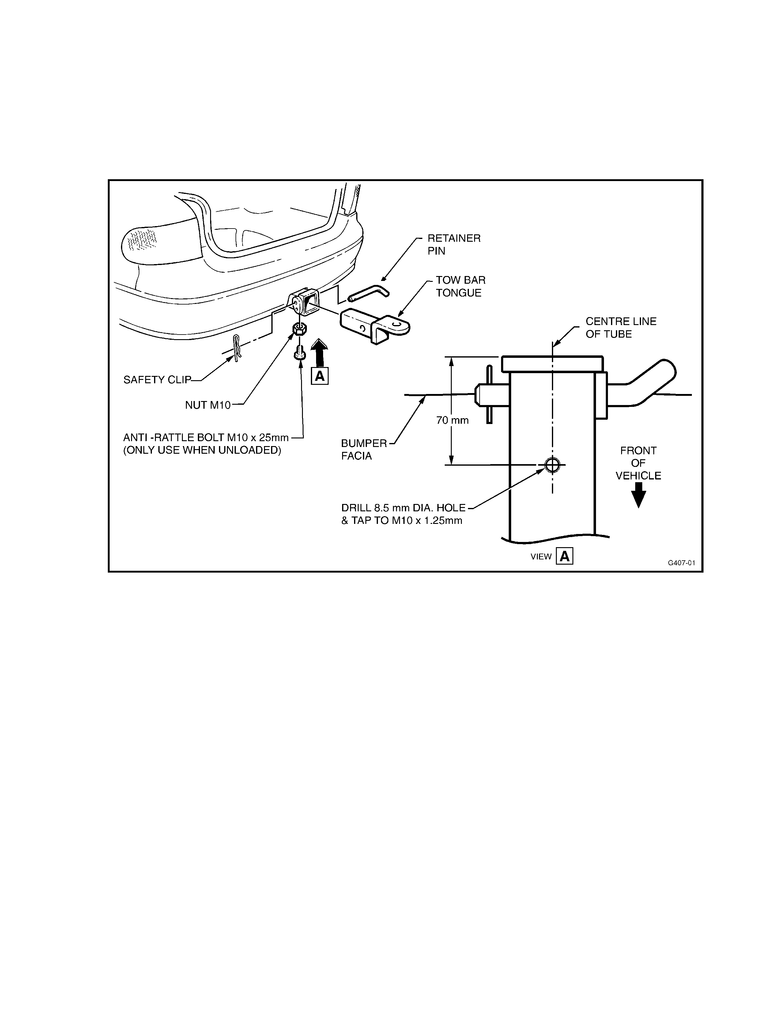
HOLDEN SERVICE TECHLINE _________________________________________________________ NOVEMBER 2000
16
TOW BAR RATTLE (1600 & 2100Kg TOW
BARS) – ADD LOCK SCREW - Continued
Figure 1.
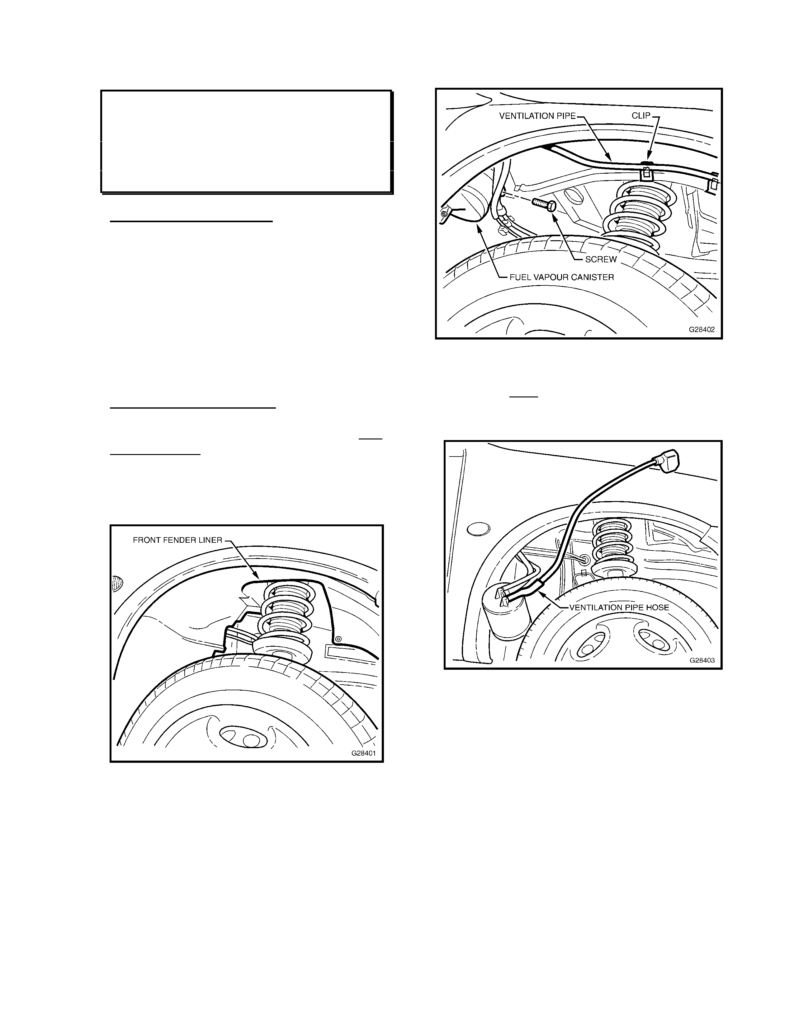
HOLDEN SERVICE TECHLINE _________________________________________________________ NOVEMBER 2000
17
FUEL ODOUR IN HIGH AMBIENT
TEMPERATURES
SB with C14SE Engine
(GROUP 8)
PROBLEM DESCRIPTION
On high ambient temperature days (EG:
30°C or higher), odour from fuel vapour may
be smelt in the vehicle passenger
compartment, (via the ventilation system)
when insufficient air flows over the vehicle;
IE: when parked with engine idling, or when
stopped or moving slowly in traf fic.
Vehicles built with C14NZ engines are NOT
affected by this condition.
SERVI C E RECTIFICATION
Revised Canister Ventilation Pipe Installation
for SB Barina and Combo (A/T & M/T) with
C14SE engine:
1. Remove Right Hand front fender liner. Do
this by removing 4 plastic rivets, 2 screws
and 2 plastic nuts. Refer Figure 1.
Figure 1
2. Detach canister ventilation pipe from metal
clips.
3. Remove carbon canister from vehicle by
the screw that retains the clamp. Refer
Fig u r e 2 .
Figure 2
4. Remove ventilation pipe hose from
canister. Note: Some force is required to
remove the hose, take care t o not dam ag e
the plastic canister fitting. Refer Figure 3.
Figure 3
5. Install new canister ventilation pipe hose
to canister and feed through the hole in
inner guard. Make sure it also feeds
through the inner panel. Refer Figure 4.
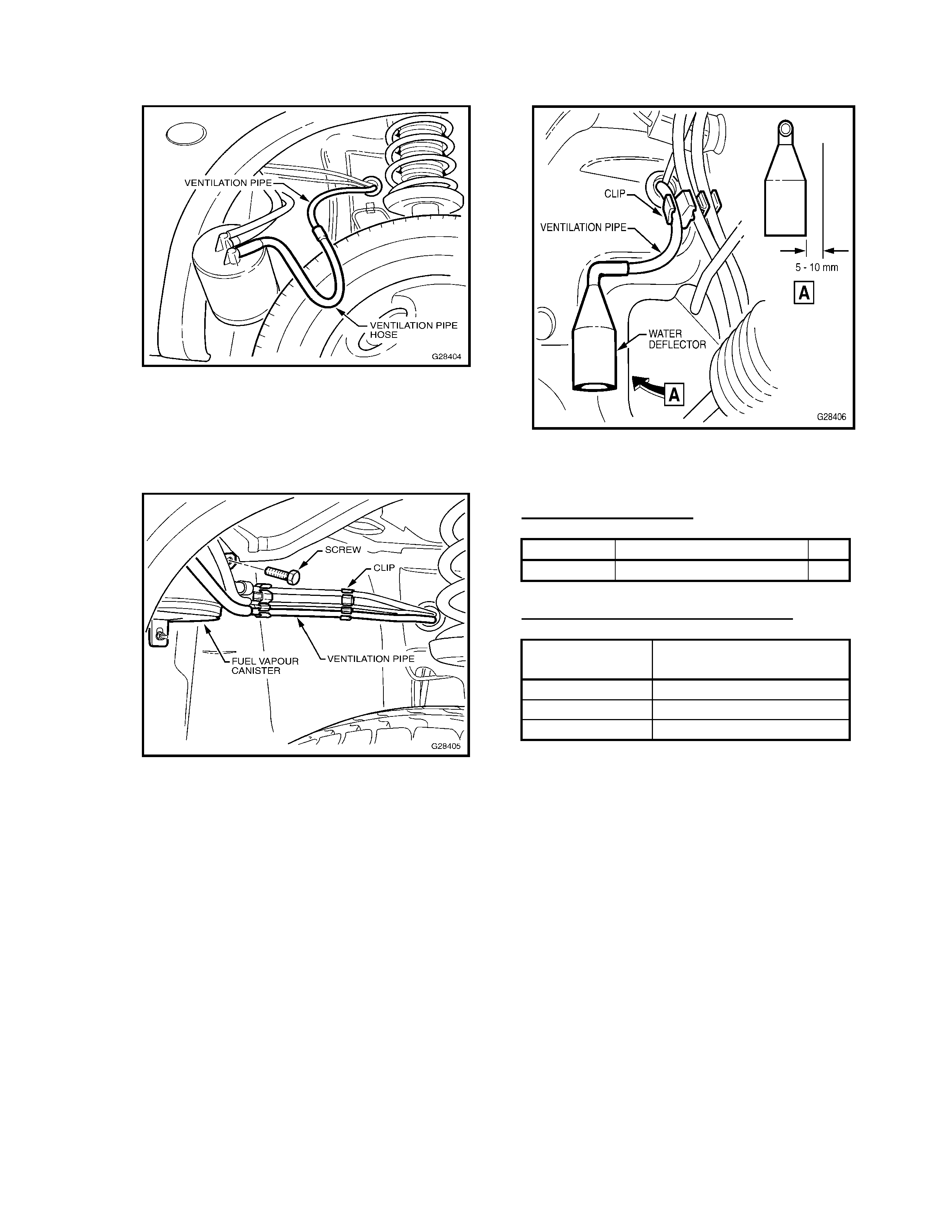
HOLDEN SERVICE TECHLINE _________________________________________________________ NOVEMBER 2000
18
Figure 4
6. Ref it carbon canister and clip canister vent
pipe into the two white clips as shown in
Figure 5 below, ensuring there are no
kinks or twists in the hoses.
Figure 5
7. Push the pipe into the white clip on the
engine compartment side of the inner
guard. Fit the rubber water deflector onto
the end of the pipe approx. 25mm. Ensure
that there is a 5 - 10mm clearance
between the water deflector and body.
Refer Fig ur e 6.
Figure 6
8. Refit the Right Hand f ront fender liner.
PARTS INFORM ATION
Part No.: Description: Qty
92143482 Canister Vent Pipe Kit 1
WARRANTY CLAIM INFORMATION:
Description Fit Revised Canister
Vent Pipe
Labour Op. No. L000190
Time 0.7 hr
Failure Code 74

HOLDEN SERVICE TECHLINE _________________________________________________________ NOVEMBER 2000
19
LACK OF POWER/PO OR RESPONSE
FROM ENGINE ON HILLS
VT/WH with V6 (non-S/C) & A/T
(GROUP 6C)
PROBLEM DESCRIPTION
Customers may complain about a “lack of
power”, or “lack of res ponse”, when driving at
approx. 70-85km/h in 4th gear (IE: in
“Economy” mode with TCC applied) –
generally when driving up inclines.
With the existing trans. and memcal
calibration, the transmission holds 4th gear
with TCC applied, and under these driving
conditions, the engine power output is near
its maximum (until a 4-3 downshift is forced
by greater throttle opening, or by manual
gear selection – this is also unacceptable to
some cust om ers).
The existing calibration is designed to
achieve optimum fuel economy at such
driving speeds and conditions, and while
most customers are able to accept the
perceived “lack of power” or “response” that
results, and adjust their driving style to suit,
some customers may complain.
PRODUCTION RECTIFICATION
A revised memcal with revised shift
calibration has been fit ted to vehicles fr om:
ISOVIN: Build Date:
6H8VTK69HYL621245 28/07/00
SERVI C E RECTIFICATION
If a customer complains of this perceived
“lack of power”, or “lack of response” and
does not accept the condition, a DJLX
Memcal may be f itt ed as an improvement.
This memcal disengages TCC in 4th gear
prior to the point at which the engine stops
increasing power.
Please note however:
Using this memcal will only affect driving in
Economy mode, and will not change
perceived power or response in either Power
mode or during Cruise Control use. The
memcal must not be used in vehicles with
S/C V6 engine.
PARTS INFORM ATION
Part No.: Descri ption: Q ty:
12203180 DJLX Memcal 1
WARRANTY CLAIM INFORMATION:
Description Fit Memcal for Lack of
Response Complaint
Labour Op. No. J000678
Time 0.4 hr
Failure Code 47
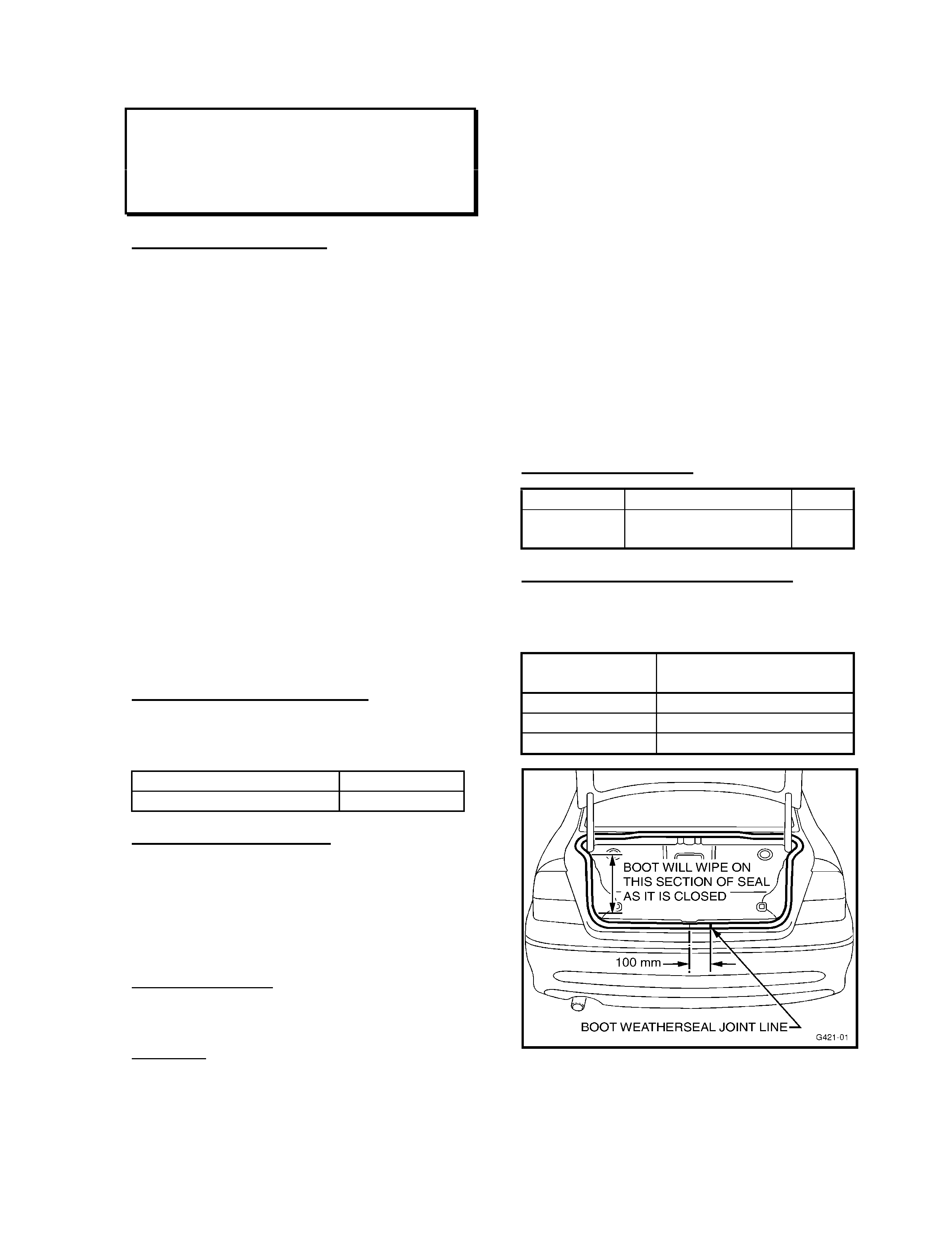
HOLDEN SERVICE TECHLINE _________________________________________________________ NOVEMBER 2000
20
BOOT (DECK LID) HARD TO CLOSE
JS Sedan
(GROUP 1)
PROBLEM DESCRIPTION
Deck lid (boot) is hard to close, requiring
considerably high effort to close.
The cause of this com plaint can be:
- Striker out of alignment/adjustment,
- Weatherseal over-compression –
which can be caused by either the
weatherseal not being seated fully on its
mounting flange; or excess body sealer
under the weatherseal.
If striker adjustment is the cause – the deck
lid will travel freely through its range of
movement until the latch comes in contact
with the striker.
If weatherseal over-compress ion is the cause
– the deck lid will NOT move freely through
some part of its travel. This indicates deck
lid/seal “drag ”. I n the JS deck lid/seal des ign,
the vertical sect ion of the s eal – Ref er Figure
1 below – is susceptible to seal drag when
the deck lid (boot) ‘wipes’ on the seal during
closing.
PRODUCTION RECTIFICATION
Revised (reduced) sealer application and
improved weatherseal fitting occurred to
vehicles from :
ISOVIN: Build Date:
W0L0JBF19YL611000 06/07/00
SERVI C E RECTIFICATION
For vehicles with deck lid (boot) “hard to
close” complaints, car ry out the following:
Move deck lid up and down to determine if
the deck lid is catching (dragging on the
weatherseal) at any point of its travel.
If NOT catching – carry out striker
adjustment. Closing effort should now be
corrected, no further action is necessary.
If catching –
1. Remove deck lid weatherseal from deck
lid opening flange.
2. Clean excess body sealer from the deck
lid opening flange. Note: - Minimal sealer
is required on this flange to stop water
entry and excessive sealer will “pack out”
the weatherseal and apply loading to the
deck lid during closing.
3. Fit a new weatherseal (p/n 90462614) to
the deck lid opening flange (a new
weatherstrip is required as the original
production weatherseal cannot be fitted
using a mallet as noted below, as damage
will occur). Take care to:
- align the butt joint in the weatherseal
100mm to the right of the centre of the
vehicle, nearest the lock striker;
- use a rubber mallet to firmly seat the seal
on the whole perimeter of the deck lid
opening f lang e.
PARTS INFORM ATION
Part No.: Descr i ption: Qty:
90462614 Weatherstrip, Deck
Lid 1
WARRANTY CLAIM INFORMATION:
Use existing “Warranty Information” in SIP –
ONLY when deck lid weatherseal requires
replacement - as follows:
Description Weather strip, Deck Lid
- Replace
Labour Op. No. C125500
Time 0.4 hr
Failure Code 58
Figure 1.
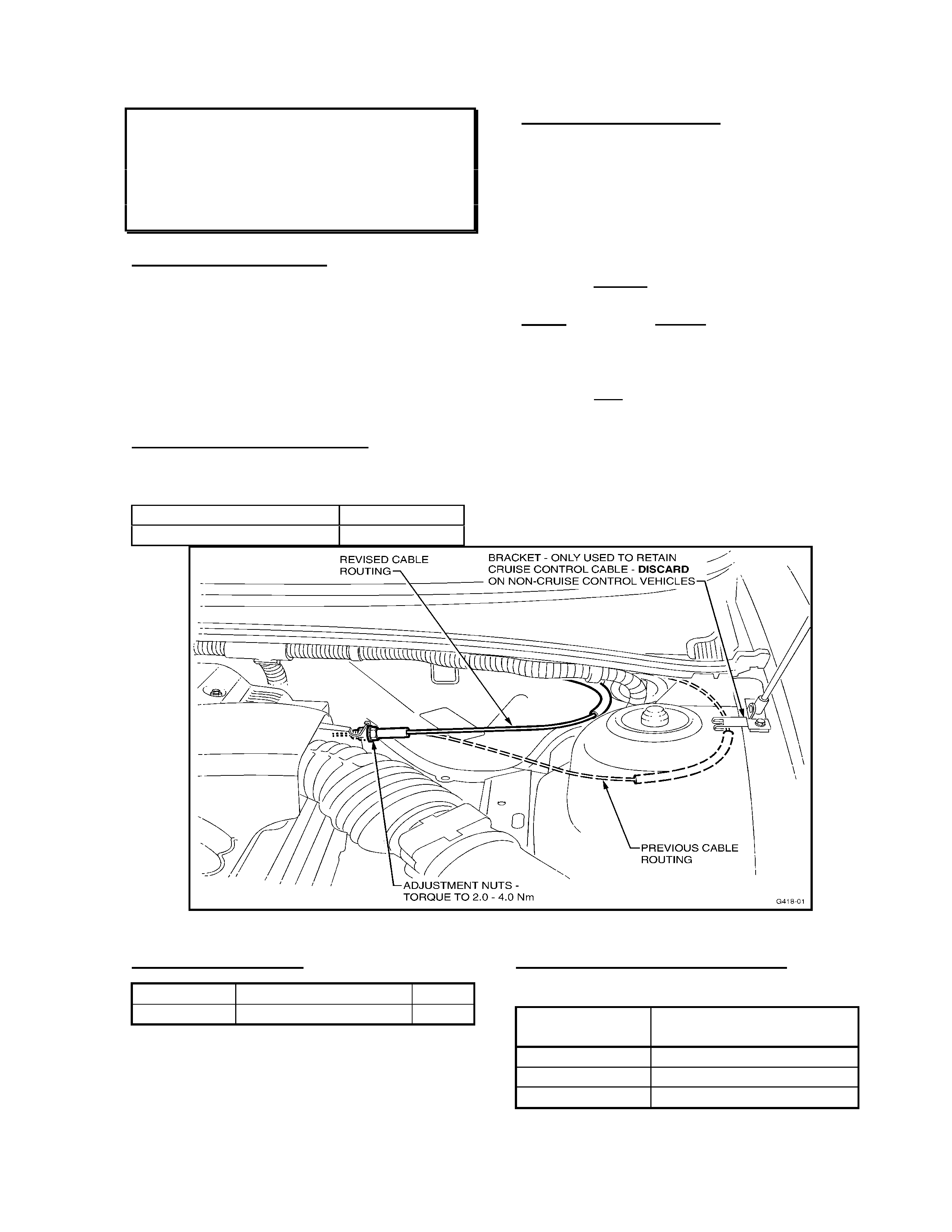
HOLDEN SERVICE TECHLINE _________________________________________________________ NOVEMBER 2000
21
ACCELERAT OR PEDAL - “NOTCHY”
FEEL
VT (All V6 Engines)
(GROUP 6A)
PROBLEM DESCRIPTION
Accelerator pedal response may be
described as “notchy” by some customers.
Replacement of cable, or attem pts to re-rou te
the cable do not improve the feel.
The cause has been defined as internal
friction between the inner and outer cables,
accentuated by the sharp bends in existing
cable routing.
PRODUCTION RECTIFICATION
A shorter, revised accelerator cable, with
revised cable routing, has been fitted to
vehicles from :
ISOVIN: Build Date:
6H8VTK69HXL487036 28/07/99
SERVICE RECTIFICATION
On vehicles subject of this complaint, carry
out the following procedure:
1. Remove existing accelerator cable from
vehicle.
2. Fit new cable (p/n 92082648) – cable
routing is same as previous, except, as
the cable is shorter, the cable must be
routed inboard of the LH strut tower – Ref.
Figure 1 showing “revised cable routing”.
NOTE: Vehicles without Cruise Control –
remove the (now) unused cable retaining
bracket near the LH engine hood strut -
noted on Figure 1.
Vehicles with Cruise Control – the cable
retaining bracket - Refer Figure 1 - is to be
left in place – it still retains the cruise control
cable as per previous installation.
3. When attaching the new cable to throttle
body – Torq ue the adj ust ment nuts - not ed
on Figure 1. - to 2.0 – 4.0Nm.
Figure 1.
PARTS INFORMATION
Part No.: Description: Qty:
92082648 Accelerator Cable 1
WARRANTY CLAI M INFO RMATION:
Use existing “Warranty Information” in SIP as
shown:
Description Cable Asm., Accel. -
Replace
Labour Op. No. J816900
Time 0.3 hr
Failure Code 39
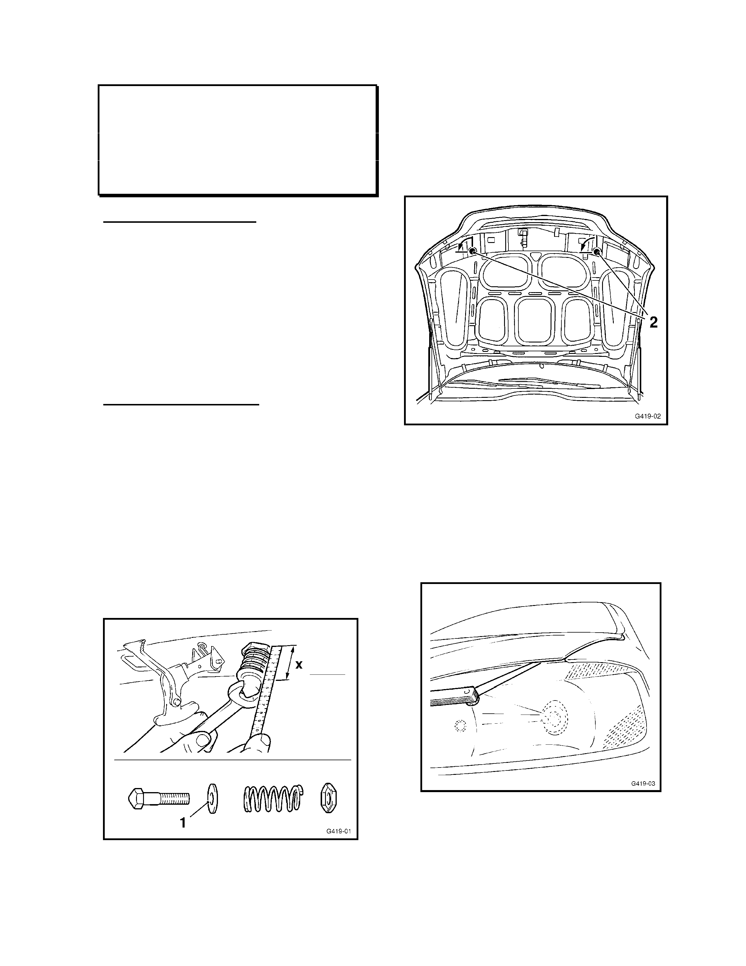
HOLDEN SERVICE TECHLINE _________________________________________________________ NOVEMBER 2000
22
CONDENSATION IN HEADLAMPS –
HEADLAMP CLEARANCE
ADJUSTMENT PROCEDURE
TS
(GROUP 12)
PROBLEM DESCRIPTION
Headlamp glass becomes ‘fogged’ with
condensation, or has visible water droplet s on
the glass from moisture entry. The cause has
been found to be insufficient clearance
between the headlamp and eng ine hood. This
leads to contact between engine hood and
headlamp dur ing closing, and constant engine
hood pressure on the headlamp glass,
resulting in moisture entry through damaged
sealing.
SERVI C E RECTIFICATION
For any vehicle presented with moisture or
condensation in headlamp/s:
BEFORE CLOSING THE ENGINE HOOD
after replacing the affected headlamp
assembly, carry out the following procedure
to ensure adequate clearance exists, to avoid
a repeat failur e:
1. Loosen the engine hood striker bolt lock
nut and measured the existing dimension
(Dimension “X” on Fig ure 1) . Measure fr om
the bonnet plate to the end of the spring
retaining washer – Item 1 on Figure 1.
Figu re 1.
2. Adjust striker bolt until dimension “X” is
1.5mm longer than existing dimension –
lightly tighten lock nut to maintain the
dimension until final tightening (end of
procedure).
3. Turn out the engine hood rubber bumpers
by ¼ turn – refer items 2 on Figure 2.
Figure 2.
4. Lower engine hood carefully and press
down until hood catch eng ag es.
5. Using a 0.5mm feeler gauge, check the
clearance between the engine hood and
the headlamp rubber seal – Refer Figure 3
- the feeler has to pass through without
resistance. If required, adjust clearance by
turning hood catch striker bolt in or out.
Figure 3.
6. When the 0.5mm clearance is achieved,
torque the hood catch striker bolt lock nut
to 22Nm.
HOLDEN SERVICE TECHLINE _________________________________________________________ NOVEMBER 2000
23
WARRANTY CLAIM INFORMATION:
Use existing “W arranty Information” in SIP for
the above clearance adjustment – during
headlamp replacement - as follows:
NOTE: the labour time has been increased on
these labour operation numbers to allow for
the clearance procedure described above.
SIP will be updated as soon as possible to
ref lect t his revision. The clearance adjustment
procedure MUST be carried out whenever a
headlamp or any front bodywork is disturbed.
Description RH Headl amp Asm. -
Replace
Labour Op. No. N104100
Time 1.4 hr
Failure Code 62
Description LH Headlamp Asm. -
Replace
Labour Op. No. N104200
Time 1.4 hr
Failure Code 62
KNOCK NOISE FROM EXHAUST ON
COLD START
JR, JS, with 4 C yl. Engine
(GROUP 8)
This Service Techline supersedes the
previous Techline on this topic (Issue 1,
February, 1999 page 5) by updating the
silencer date code information. This previous
Techline should be destroyed.
PROBLE M DES CRIPTIO N
Customers complain of a metallic knocking
noise after engine is started from cold. Noise
can be misdiagnosed easily as being an
engine internal or drive belt related noise.
Actual noise cause is a rattle noise from
internal baffles in the intermediate silencer,
which stops when the exhaust system
reaches operating temperature.
PRODUCTI O N RECTIFICATION
The silencer has been revised internally from
late 1998. Silencers are identified by date
code of 99/04 or later (99/04 = April, 1999), -
stamped on the identification/part number
plate on the lower, outside surface of the
silencer. No vehicle breakpoint was set for
this change.
SERVICE RECTIFICATION
Fit a new Silencer – Intermediate & Centre
Pipe.
Order the new part from HSPO - all parts at
HSPO are of the latest specification.
PARTS INFORMATION
Part No.: Description: Qty:
90500030 Silencer – Intermediate
& Centre Pipe 1
WARRANTY CLAI M INFO RMATION:
Use existing “Warranty Information” in SIP.
Update

HOLDEN SERVICE TECHLINE _________________________________________________________ NOVEMBER 2000
24
SRS WARNING LAMP ON– DTC’s 36/ 38
– WATER ENTRY AFTER CLEANING
VT, VX, WH
(GROUP 1)
Please ensure this Techline is circulated
to: Service Advisors – For liaison with
customers, and Dealership personnel who
organise detailing or interior cleaning.
PROBLEM DESCRIPTION
This is a prec autionary bulletin to alert service
personnel of the possibility of the SRS
warning lamp illuminating (and thus SRS
DTC’s being set) - if excessive moisture is
allowed to enter SRS system connector s.
Investigations into reports of SRS warning
lamps illuminating intermittently have proved
to be caused by moisture entry to SRS
connectors.
In the cases reported, vehicles had recently
had:
- carpet s and seats st eam cleaned, or
- interiors “detailed”, or
- water entry to seat lower trim/s, or
- liquid spills around seat lower trim/s
(these are examples of moisture entry, and
not the only methods of entry).
These resulted in:
DTC 36 – driver’s pre-tensioner short circuit,
loop capacitance too high or,
DTC 38 – passenger pre-tensioner short
circuit, loop capacitance too high, were found
during diagnosis, however, no faults in the
SRS system or components could be defined.
SERVI C E RECTIFICATION
Interior cleaning using steam or excessive
water can cause moisture entry to the SRS
connectors in the vehicle interior.
Accidental rain water entry through open
windows can also contribute to this.
Water, soapy detergent, other cleaning
agents can enter the SRS connections.
Any of the above will short the circuits, which
will allow the resistance and capacitance
values to fall outside their tolerances, and
illuminate the SRS warning lamp.
In cases caused by this water entry, once the
connections are dried out, the condition does
not re-occur.
If a customer presents a vehicle with SRS
warning lamp illuminated, check with the
customer to define if the vehicle interior was
cleaned just prior to the warning lamp coming
on.
If a vehicle is being serviced and has an SRS
warning lamp come illuminated – check
whether the vehicle (during its time in the
dealership) has been detailed/cleaned - where
water may have entered the interior SRS
connections.
The notes below and illustrations in Figure 1
on the following page provide information on
the most likely moisture entry points to the
SRS connections:
1. SRS warning lamp is illuminated – check
which DTC’s are set. Are they DTC 36 or
DTC 38?
If YES – Go to Step 2
If NO – Go to Service Manual Volume 7
(or SIP CD), Section 12M for SRS
Diagnostics for appropriate DTC/s, as
problem is not related to this information.
2. Remove front seat rail end (rear) cover –
Refer to View A showing the possible
moisture entry point – at the seat rail cover
joints - between the driver and passenger
seats and doors.
3. Check for moisture in and around the
Yellow YB207 connector – Ref er Views B
& C that show connector location on seat
rail, and probable moisture entry “track”. If
moisture is present, disconnect the
connector and blow out connector,
terminals, harness wires with compressed
air or heated air to dry out the moisture.
Ensure the terminals are free from
corrosion. Any corrosion will necessitate
replacement of the com ponent to which the
corroded terminals are attached.
4. Check for moisture in and around the
Green seat belt pre-tensioner connector
– Refer to View D for location (between
seat and console).

HOLDEN SERVICE TECHLINE _________________________________________________________ NOVEMBER 2000
25
NOTE: IF the DTC is logged as a HISTORY
code, the moisture that entered to cause the
code may have dried out and will not always
be present. IF the DTC is logged as a
FROZEN code, the moisture may still be
present and will require thorough drying out
and cleaning. Use of warm air will speed up
the drying out process.
5. Clear the DTC/s with Tech 2. Cycle
ignition once to confirm the DTC has been
cleared and does not reset.
IF YES – Go to Step 6
IF NO – Go to Service Manual Volume 7
(or SIP CD), Section 12M for SRS
Diagnostics for appropriate DTC/s, as
problem is not related to this information.
6. With the ignition ON, check for loose
connections, faulty wiring (at connectors
noted above) by wriggling/moving the
connectors.
7. Start and run the engine. Ensure the SRS
warning lamp does not stay illuminated.
8. Re-fit the previously removed trim
covers.
CLEANING PRECAUTIONS
It is suggested that you advise your
customers and your cleaning staff (including
any contracted cleaners) of the following
precautions:
Seat Belt Pre-Tensioner Connector (YB
207) Area: (between seat outer edge and
door, both sides)
• Do NOT use excessively wet cleaning
cloths, sponges or high powered steam
cleaning equipment on or around the seat
rail end covers and cover joints – Refer
View A.
• Clean this same area with a MOIST (not
dripping) cloth and wipe over the area to
remove any excess moisture.
• If steam cleaning, shampooing, etc, the
seats and carpets – place a rag over the
seat rail cover joint area to ensure no
moisture enters the joints and connectors
below them.
Seat Belt Pre-Tensioner Connector Area:
(between seat inner edge and console, both
sides)
• W hen cleaning in this area – place a small
plastic bag, split on one side - over the
Green connector to ensure no moisture
entry.
• If steam cleaning or shampooing the seats
and/or carpets – take extra care not to
allow any moisture near this connector.
WARRANTY CLAI M INFO RMATION:
As the conditions mentioned in this
“precautionary” bulletin are related to care and
cleaning procedures, the procedures advised
cannot be claimed under warranty.
Component replacement caused by care and
cleaning procedures as noted in this bulletin
must not be claimed under warranty.
Refer to f ollowing page f or all illustrations.
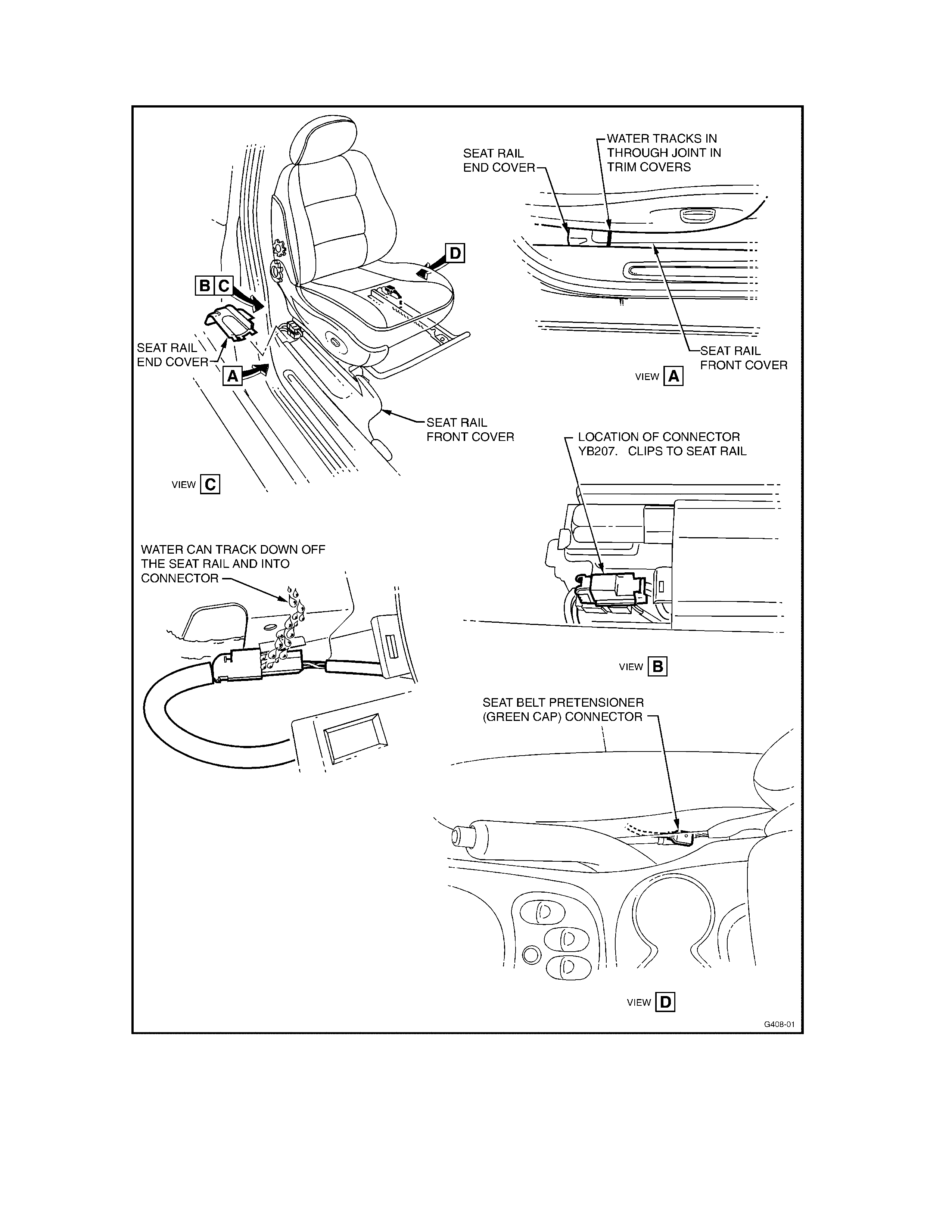
HOLDEN SERVICE TECHLINE _________________________________________________________ NOVEMBER 2000
26
Figure 1.
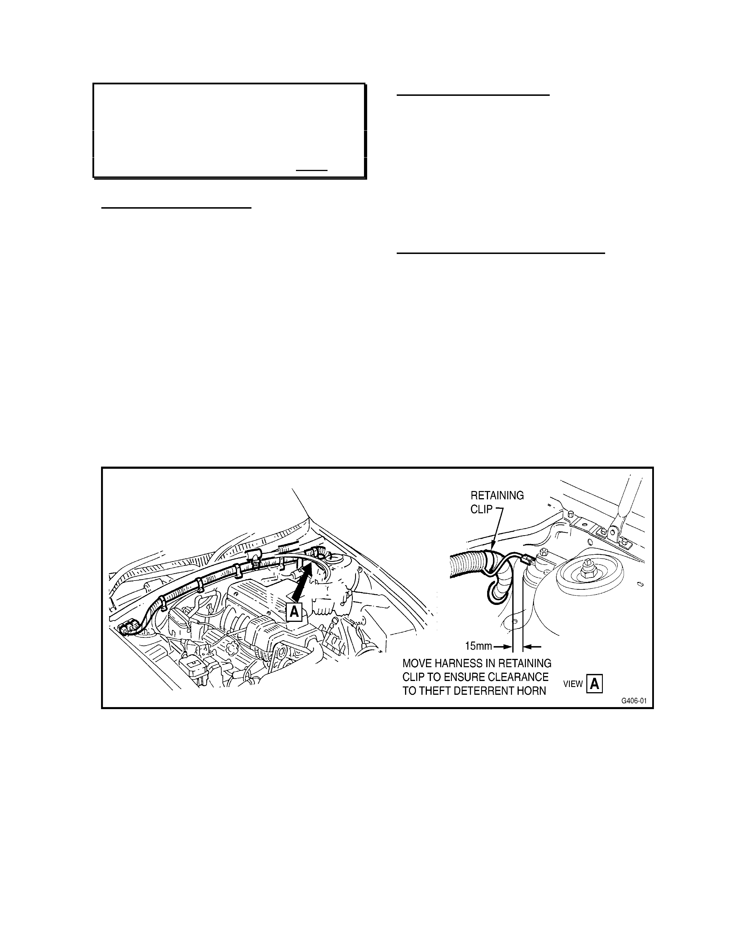
HOLDEN SERVICE TECHLINE _________________________________________________________ NOVEMBER 2000
27
WIRING ABRASION – INTERMITTENT
FAULTS
VT, WH
(GROUP 12) HINT
PROBLEM DESCRIPTION
A PIR has repor ted a possible cause of wiring
abrasion and intermitt ent elect rical faults.
The condition report ed is the wiring harness at
the LH rear of the engine compartment
rubbing on the body of the theft deterrent
horn. Refer Figure 1 for exact location.
The condition has the potential to cause
numerous intermittent faults, depending on
which wire is damaged.
This Techline is released to draw technicians’
attention to the possibility that some
intermittent faults may be caused by abraded
wires at the location shown. The harness
shown in Figure 1 should be inspected before
any extensive diagnosis work is undertaken.
SERVICE RECTIFICATION
Should a vehicle be found with the wiring
harness contacting the theft deterrent horn:
- Repair the harness as necessary,
- Move the harness away from the theft
deterrent horn by at least 15mm – Refer
Figure 1. Move the harness in it s retaining
clip if required, to ensure harness is
retained away from the horn.
WARRANTY CLAI M INFO RMATION:
Select appropriate Labour Operation Number
from the Wiring and Connector Warranty
Claim Submission Manuals in SIP, for VT
series, Figur e 7 , and WH series, Figure 7.

HOLDEN SERVICE TECHLINE _________________________________________________________ NOVEMBER 2000
28
FRONT SEAT INNER REAR RAIL
COVER DISLODGES
VT, WH
(GROUP 1)
PROBLEM DESCRIPTION
Front seat inner rear rail covers may be
dislodged by actions of rear seat passengers,
or items carried in rear footwell areas.
It is possible for the moulded retaining lugs in
the cover to be d amaged, and as a result, not
retain properly on the inner seat rail.
PRODUCTION RECTIFICATION
Revised front seat inner rear rail covers with
revised retention (metal spring clips) have
been fit ted to vehicles fr om:
ISOVIN: Build Date:
6H8VTX69SYL587197 08/05/00
SERVI C E RECTIFICATION
On complaint vehicles (built prior to the above
break point) where the f ront seat inner rear rail
cover/s dislodge - and the dislodged cover/s
do NOT have a metal retaining clip - the
following rectification should be carried out to
both covers:
1. Remove both front seat inner rear rail
covers – Refer Figure 1 for location.
2. Turn covers over, and using a sharp knife,
cut the two retaining lugs from the
underside of both covers – Refer Figure 2,
Diagram A, below.
3. Fit a spring clip (P/N 92144035) to both
covers as shown – Refer Figure 2,
Diagram B.
4. Refit the covers, which now appear as per
Figure 2, Diag ram C, to the seat inner rear
rails.
PARTS INFORMATION
NOTE: All VT & WH front seat inner rear rail
covers at HSPO have been superseded to the
new parts with metal retaining clips. Any parts
in Dealership parts s tock WITHOUT the metal
retaining clip should NOT be used for
repairs/replacement, but may be modified
prior to fitment to vehicles, as per the above
procedure.
Part No.: Descr i ption: Qty:
92144035 Clip, front seat inner
rear rail covers 2 (Per
Car)
WARRANTY CLAI M INFO RMATION:
Description Fit Clips to Both Front Seat
Inner Rear Rail Covers
Labour Op. No. C000415
Time 0.3 hr
Failure Code 55

HOLDEN SERVICE TECHLINE _________________________________________________________ NOVEMBER 2000
29
Fig ure 1. Showing RH Front Seat (LH opposite)
Fig ure 2. Showing Revisions to Pre-Breakpoint Cover

HOLDEN SERVICE TECHLINE _________________________________________________________ NOVEMBER 2000
30
REAR LICENCE PLATE ATTACHMENT
SCREWS REVISION
VX SEDAN
(GROUP 1)
Please pass this information on to your
Pre-Delivery personnel for action.
PROBLEM DESCRIPTION
Rear licence plate attaching screws provided
in standard licence plate fittings envelopes
(carry-over VT) are not long enough for VX
sedan rear licence plate installation. This is
because the décor panel thickness has been
revised.
In the first 1000 (approx.) VX vehicles
produced, there will be two longer scr ews (p/n
11045121) taped to the clear plastic bag
containing the “glovebox” material. These
screws are to be used for attaching the rear
licence plate on sedans only.
This action is being taken only until the
screws are added to the standard licence
plate attachments env elope.
PRODUCTION RECTIFICATION
The two longer screws (p/n 11045121, 19mm
long) will be included in the brown licence
plate attachments env elope from:
ISOVIN: Build Date:
6H8VXL69A1L639557 12/09/00
AT PREDELIVERY:
VX Sedans up to L639556:
Attach sedan rear licence plates with the two
longer screws (p/n 11045121) taped to the
clear plastic “glovebox” material bag.
VX Sedans from L639557 onward:
Attach sedan rear licence plates with the two
longer screws (p/n 11045121) that are
supplied in the brown licence plate
attachments envelope.
DOOR HANDLE & LOCK ROD – CO-
ORDINATED REPLACEMENTS
VT
(GROUP 1)
The information in this Techline bulletin is
reproduced from HSPO Parts Techline PT47,
dated May 18, 2000. Please refer t o that lett er
(retained by your Parts Department) for full
details.
PROBLE M DES CRIPTIO N
Door handles were revised in production
(refer breakpoint below), and earlier design
parts are no longer available.
W hen later design door handles are fitt ed, the
matching door rod must also be fitted.
PRODUCTI O N RECTIFICATION
Revised and strengthened door handles were
fit ted to vehicles fr om:
ISOVIN: Build Date:
6H8VTK69HYL526300 05/11/99
SERVICE RECTIFICATION
When fitting a new door handle to a vehicle
built prior to L526300 - –fit the door handle/rod
combination as shown below.
PARTS INFORMATION
Vehicles Up to L526299
Handle Rod
Front Door
Outer, RH 92085571 92087513
Rear Door
Outer, RH 92085573 92087515
Front Door
Outer, LH 92085574 92087513
Rear Door
Outer, LH 92085574 92087514
WARRANTY CLAI M INFO RMATION:
Use existing “Warranty Information” in SIP.

HOLDEN SERVICE TECHLINE _________________________________________________________ NOVEMBER 2000
31
LOW OIL PRESSURE WARNING
(INTERMITTENT)
VT/WH with Gen III V8 Engine
(GROUP 6A)
PROBLEM DESCRIPTION
Customers may complain of oil pressure
warning lamp and audible warning chime
coming on intermittently, or complain of “ noisy
valve train” – EG: during starting, on heavy
acceleration, or even at random times. These
complaints may be intermittent and occur for
variable lengths of time - it may not be
possible f or technicians to diagnose the cause
as the complaints are not easily “repeatable”.
PRODUCTION RECTIFICATION
Oil pumps with verified OK machining have
been used in production from Engine No.:
VF002061072 (for reference) - this engine
was used in:
ISOVIN: Build Date:
6H8VXK35F1L638782 08/09/00
SERVI C E RECTIFICATION:
Caution Notes:
• Diagnosis to define possible causes other
than oil pump (Steps 1 & 2) must be done.
• Where the full procedure is carried out, the
engine must be removed f or this procedure,
to ensure correct oil pan fitting. DO NOT
attempt to carry out this procedure with
engine “in – vehicle”.
• Fit a new O ring on pickup tube to pump
joint.
• Ensure all fasteners on the oil pump,
pickup, oil pan, etc, are torqued as per the
service Manual/SIP CD instructions.
• Clean out the oil pan before re-assembly to
ensure there is no possible contamination.
Any vehicle presented with the any of the
above complaints should have the following
diagnosis and repair procedure carried out:
1. Check engine oil level – correct if
required, or continue to Step 2 if level OK.
2. Check oil pressure with a mechanical oil
pressure gauge and with Tech 2 and
compare results of both checks to confirm
correct oil pressure sender signal. If a
sender fault is defined, replace the sender
unit.
Note: The mechanical gauge can be
connected at one of three possible locations:
- Remove oil filter and use adaptor J42907
as per VT Service Manual, page 6A3-20,
Section 2.4.
- At oil gallery plug at RH rear of engine
block, directly in front of crank angle
sensor.
- At oil gallery plug at LH front of engine
block directly above oil filter.
Following a cold start, with engine running at
idle in Park or Neutr al, the oil pressure should
be in excess of 150 k Pa.
Should Tech 2 AND the mechanical gauge
both indicate that the pressure (150 kPa) is
NOT reached immediately following start-up,
carry out the following procedure:
3. Remove engine and then remove oil pan
– as per VT Series Service Manual/SIP
CD, Volume 14A, Page 6A3-85 (Engine &
Oil Pan), and pages 6A3-101 (Oil Pump).
4. Check for loose retaining bolts - oil
pump to block , and oil pickup tube t o pum p
– looseness indicates possible pressure
loss points.
5. Remove oil pickup tube and ensure O
ring is correctly fitted between pickup tube
and pump – damaged or missing O ring
indicates a leak point.
6. Ensure oil pickup tube is not blocked or
partially blocked by any foreign material –
this would create a pressure reduction in
the oil system.
NOTE: Steps 4, 5, 6 are required to ensure
identification and correction of any conditions
that may contribute to loss of oil pressure.
7. Replace oil pump, regardless of findings
in Steps 4, 5, 6 above - with a new oil
pump assembly.
8. Fit a new O ring – oil pickup tube to pump;
ensure it is pr operly installed and lubricated
with clean engine oil prior to assembly to
ensure no damage occurs during
assembly.
9. Measure oil pressure, after re-assembly
and fitting engine to vehicle, confirm that it
exceeds 150 kPa at idle.

HOLDEN SERVICE TECHLINE _________________________________________________________ NOVEMBER 2000
32
PARTS INFORMATION
Select parts from PartFinder. All oil pumps in
HSPO stock, and those previously sold to
Distributors/Dealers have verified OK
machining.
WARRANTY CLAIM INFORMATION:
Use existing “W arranty Information” in SIP as
shown:
Description Pump Asm. Engine Oil,
Replace (Gen 3 V8).
Labour Op. No. J316500
Time 6.5 hr
Failure Code 61
HEAT SHIELD FOR DUAL COUPLING
PROPSHAFT - 1600 & 2100KG TOW
BAR PACKAGES
WH, VX & VT
(GROUP 1)
The following information is repeated from All
Dealer Letter: DL 46/00, to ensure all
Dealership Service personnel are aware of the
information noted. Please also circulate this
bulletin to Pre-Delivery personnel and any
technicians involved in accessory fitting (tow
bar heat shield information).
When fitting 1600 kg or 2100 kg HSPO
Accessory Tow Bar Packages to VX vehicles,
or VT vehicles fitted with dual coupling
propshaft (only), a new centre bearing heat
shield (p/n 92143924) must also be fitted as
shown on the instruction drawing shown on
Page 37 of this bulletin.
HSPO tow bar packages are currently being
updated with the new heat shield and revised
instruction drawings.
DOOR LOCK ACTUATOR WIRING
DIAGRAM
VS with VT LOCK ACTUATORS
(GROUP 12)
PROBLE M DES CRIPTIO N
Late build VS Series vehicles were fitted with
VT door lock actuators.
A wiring diagram for this installation has not
previously been published.
PRODUCTI O N RECTIFICATION
VT door lock actuators were fitted to VS
vehicles from:
ISOVIN: Build Date:
6H8VSK80UVL221394 13/03/97
SERVICE RECTIFICATION
During diagnosis – check the type of lock
actuator s fitted to the vehicle – the break point
above will define this.
NOTE: there may be a small number of
vehicles built out of sequence that will still
have VS lock actuators, and thus a visual
check of actuators may be required – to
ensure VS or VT actuators are fitted. In
addition, in this installation, a small “patch”
harness is f itted between the actuator and the
door wiring harness – where VS actuators
connect directly to the wiring harness..
The following page carries a wiring diagram
for diagnosis of VS Series III vehicle lock
circuits.
HOLDEN SERVICE TECHLINE _________________________________________________________ NOVEMBER 2000
33
DRIVER'S DOOR
JAMB SWITC H
YB175
IGNITION
F14
E20
P/ B (39)P (3)
YB176
YB174
YB173
YB57
YB77
YB90
YB26
YB90
YB25
YB76
YB57
YB76
LOC. E 3
YB57
YB90
YB90
YB76
YB57
YB29
YB25
YB26
YB77
YB173
YB174
YB173
YB173
YB173
YB173
YB1
YB173
YR10
YR35
YB176
YB173
BCM
BATTERY
FS
FJ
F20
F31
B11
A5
C9
UNLOCK
REQUEST
DO OR LOC K POWER
BATTERY MAIN POWER
VS CENTRAL DOOR LO CKING WITH VT ACTUATORS
DRIVER'S
DOOR
LOCK
SWITCH
2
1
UNLOCK
LOCK
M
I
C
R
O
P
R
O
C
E
S
S
O
R
O/B (7 4 0 )
BR/O (194)
DRIVER'S
DOOR
LOCK
ACTUATOR
O/V (44 0)
(1040)
R (2 )
REAR
COMPARTMENT
LOCK A CTU ATOR
(WAGON ONLY)
ELECTRONIC
EARTH
T12J2136
A1
B/ Y (155)
LOC. E 3
LOC. E 3
DRIVER'S
DOOR UNLOCK
RELAY
HIGH
CURRENT
EARTH
DOOR
UNLOCK
DRIVE
DOOR LOCK
DRIVE
C13
C26
B10
B/ Y (295)
B\ BLU
(394)
BR/O
(194)
B/ R (29 4 )
B/ G (151)
UNLOCK RELAY
LOCK RELAY
DRIVER'S
DOOR
REQUEST
UNLOCK
LOCK
REQUEST
LOCK &
DEAD LOCK
REQUEST
DRIVER'S
DOOR OPEN
C22
C8
BR/W ( 197)
GY/W (12 6)
C21
BR/R (1 9 5 )
C20
LG/ Y (193)
DRIVER'S DOOR
UNLOCK DRIVE
BLU/ B (293)
C3
L.H.R.
DOOR
LOCK
ACTUATOR
L.H.F.
DOOR
LOCK
ACTUATOR
FROM
IGNITION
SWITCH
R.H.R.
DOOR
LOCK
ACTUATOR
B/ BLU (156)
C12
DE AD L OCK
RELAY
DEADLOCK
DRIVE
V/W (394)

HOLDEN SERVICE TECHLINE _________________________________________________________ NOVEMBER 2000
34
FUEL PUMP ELECTRICAL CIRCUIT
DIA GNOSTIC CHART CORRECTION
VT/VX (non-S/C V6)
(GROUP 6M)
PROBLEM DESCRIPTION
The previously published CHART A4.1 V6
PCM – NON SUPERCHARGE ENGINE
FUEL PUMP ELECTRICAL CIRCUIT,
contained a number of errors regarding fuse
and terminal numbering.
SERVI C E RECTIFICATION
Revised diagnostic chart A4.1, on the
following page, rectifies these errors and
contains additional steps to improve electrical
circuit diagnosis.
Revisions to the c hart are shown in bold text,
and two new steps (16, 17) have been
inserted into the procedur e.
It is recommended that this chart is copied
and pasted over the existing chart in VT
Series Service Manual, Volume 3, Section 6C
POWERTRAIN MANAGEMENT – V6
ENGINE.
As this chart also applies to VX Series
vehicles, refer to this Bulletin for diagnosis
until the Service Information Package (SIP) is
updated to include this revised chart.

DIAGNOSTIC CHARTS - V6 ENGINE 6C1-2A-57
CHART A-4.1 V6 PCM NON-SUPERCHARGED ENGINE
FUEL PUMP ELECTRICAL CIRCUIT
STEP ACTION VALUE YES NO
1. Was the "On-Board Diagnostic" (OBD) System Check
performed? Go to Step 2. Go to OBD
System Check in
this Section.
2. Check Fuel Pump fuse. ("F/PMP" fuse F28 in
engine compartment fuse and relay centre)
Is the Fuel Pump fuse blown ?
Go to step 3 Go to step 8
3. 1. Ignition "OFF".
2. Disconnect Fuel Pump electrical connector to pump.
3. Backprobe Fuel Pump Relay harness connector for
Fuel Pump power feed circuit with a test light
connected to + battery terminal.
Is the test light "ON" ?
Go to Step 15 Go to step 4
4. 1. Ignition "OFF".
2. Reconnect Fuel Pump electrical connector.
3. Replace Fuel Pump fuse F28 ("F/PMP").
4. Ignition "ON".
5. Recheck fuse.
Is Fuel Pump fuse OK ?
Problem was an
intermittent short
to earth.
Go to step 5
5. Check for short to earth in Fuel Pump power feed circuit.
Was a problem found? Verify Repair Go to step 6
6. Check for shorted to earth Fuel Pump .
Was Fuel Pump shorted to earth ? Verify Repair Go to step 7
7. Replace Fuel Pump Relay.
Is action complete? Verify Repair
8. 1. Ignition "OFF" for 10 seconds:
2. Disconnect Fuel Pump Relay connector from relay
housing bracket.
3. With Fuel Pump Relay connected, probe relay
connector terminal "5" with test light connected to
earth.
4. Using TECH 2 scan tool, Select FUEL PUMP .
5. Turn Fuel Pump "ON" and "OFF"
Is test light "ON" and "OFF" when Fuel Pump is
"ON" and "OFF" ?
Go to Step 9 If Test
Light stays
"OFF", Go to
Chart A-4.2 in
this Section
-----------------------
-
If Test Light
stays "ON", Go
to Step 16
9. 1. Ignition "OFF".
2. Disconnect Fuel Pump Relay.
3. Apply +12 volts to Fuel Pump Relay terminal "5".
4. Check that the Fuel Pump is running, check by
listening for Fuel Pump operation in fuel tank.
Is Fuel Pump running ?
Go to Step 10 Go to Step 11
10. 1. Fuel Pump electrical circuits are OK.
2. Reconnect Fuel Pump Relay.
To complete testing of the fuel delivery pressure
system, continue to Chart A-4.3
Go to Chart
A-4.3 in this
Section
11. Check for faulty connection at Fuel Pump and relay.
Is connection faulty? Verify Repair Go to Step 12
12 Check for open in Fuel Pump power feed circuit.
Was a problem found? Verify Repair Go to Step 13
13. Check for open in Fuel Pump .
Is Fuel Pump open? Verify Repair Go to Step 14
14. If both circuits check OK, replace Fuel Pump .
Is action complete? Verify Repair
15. Check for and repair short to earth in Fuel Pump power
feed circuit.
Is repair complete?
Verify Repair
16. 1. Ignition "OFF".
2. Disconnect Fuel Pump Relay.
Is the test light "OFF"?
Go to Step 17 Go to Step 18
17. Repair short to voltage in circuit 465.
Is action complete ? Verify Repair
18. Repair short to voltage in circuit 120.
Is action complete ? Verify Repair
Page 35 (Nov,. 2000 Techline)

HOLDEN SERVICE TECHLINE _________________________________________________________ NOVEMBER 2000
36
WH UPGRADE (OPTION A8A)
WH
(GROUP OB)
The following information is repeated from All
Dealer Letter: DL 46/00, and is repeated in
this Techline only t o ensure that all Dealership
Service personnel are aware of the
information noted. Please also circulate this
bulletin to Pre-Delivery personnel and any
technicians involved in accessory fitting (tow
bar heat shield information).
This is t o advise dealers hips of chang es being
introduced into WH Statesman models with
Gen 3 V8 engines under production option
code A8A. These changes commenced in
vehicle production:
ISOVIN: Build Date:
6H8WHY19FXL626038 09/08/00
Some of the more significant changes are as
follow s :
Upgraded Gen 3 V8 Engine
Includes revised inlet manifold, injec tors , f uel
rail, flexplate, etc.
Powertrain Control Module
The Powertrain Control Module (PCM) and its
calibration are both new and are not
interchangeable with earlier (MY2000) engine.
The new PCM calibration software is in TIS
version 13B.
Dual Coupling propshaft
The propshaft is a new design which helps
reduce driveline disturbances. Holden’s
warranty policy on this new propshaft is the
same as for current model, IE: if a propshaft
develops a fault within warranty it is to be
replaced with a complete new propshaft
assembly ex HSPO. Note that the rubber
couplings are included as part of the
assembly. Replaced propshafts are to be
tagged and held until called back via the
REPAC report.
For retail repairs, a limited range of
component parts are replaceable with parts
obtained from HSPO or if required,
changeover propshaft assemblies may be
obtained from Hardy Spicer outlets - as shown
on page 38 of this Bulletin.
FITMENT OF 1600 & 2100KG TOW BAR
PACKAGES
NOTE: When fitting 1600 kg or 2100 kg tow
bar packag es t o WH with A8A upgrade, a new
centre bear ing heat shield p/ n 92143924 must
also be fitted as shown on the instruction
drawing on the next page of this bulletin.
HSPO tow bar packages are currently being
updated with the new heat shield and revised
instruction drawings. Should you require
further information or clarification on tow bar
packages please call Alan Baker on telephone
number (03) 9797 7094.
NOTE: A further package of changes known
as production option code U4B will be
introduced into WH models at the same time
as VX commences product ion.
Please ensure your pre-delivery and service
staff are made aware of the contents of this
letter.
HOLDEN SERVICE TECHLINE _________________________________________________________ NOVEMBER 2000
37
37

HOLDEN SERVICE TECHLINE _________________________________________________________ NOVEMBER 2000
38
HARDY SPICER BRANCHES
Information current as at August 2000
QLD
259 Cullen Avenue
EAGLE FARM 4009
PH: (07) 3868 2344
FAX: (07) 3868 2110
319 Nebo Road,
MACKAY 4740
PH: (07) 4952 3488
FAX: (07) 4952 2048
728 Ingham Ro ad
BOHLE 4818
PH: (07) 4774 5399
FAX: (07) 4774 4200
388 Newbridge Road
MOOREBANK 2170
PH: (02) 9600 6333
FAX: (02) 9602 1947
NSW
METROPOLITAN DRIVESHAFTS
11 Ja me s Ru se Dri ve
GRANVILLE 2142
PH: (02) 9637 7933
FAX: (02) 9682 6105
NEWCASTLE
Lot 30 Rural Drive
SANDGATE 2304
PH: (02) 4968 0400
FAX: (02) 4968 0407
1/9 Monterey Road
DANDENONG STH. 3175
PH: (03) 9792 4744
FAX: (03) 9792 3911
VIC
1488 Hume Highway
CAMPBELLFIELD 3061
PH: (03) 9357 1675
FAX: (03) 9357 2400
TAS
Duncan Street,
MONTROSE 7010
PH: (03) 6272 6907
FAX: (03) 6272 0671
SA
56-58 Churchill Rd. North
DRY CREEK 5094
PH: (08) 8349 6400
FAX: (08) 8349 5264
493 Gr eat Eastern Highway
REDCLIFFE 6104
PH: (08) 9277 2966
FAX: (08) 9478 2945
WA
7 Keogh Way,
KALGOORLIE 6430
PH: (08) 9091 1443
FAX: (08) 9091 1463

HOLDEN SERVICE TECHLINE ___________________________________________________________DECEMBER 1, 2000
8 8
FRONT SEAT LUMBAR SUPPORT ASM.
– REPLACEMENT PROCEDURE
VT, VX, WH (with Lumbar Adjuster)
(GROUP 1) TL011-0105
PROBLEM DESCRI PTION
The f ront seat lum bar support has recently been
made available as a replacement part. Prior to
this, the complete front seat back had to be
replaced for any lumbar support failure. Some
common complaint s are:
- Lumbar support does not operate (due to
deformation of the lumbar support upper
bracket).
- An audible “click” noise due to contact
between front seat back cover and lumbar
support assembly.
SERVICE RECTIFICATION
The following procedures describe replacement
of the lumbar support assembly. Removal of
seat f r om vehicle is NOT required.
Removal of lumbar support asm.:
1. Disconnect the battery earth and positive
leads.
NOTE: If the vehicle is equipped with side
impact air bag s (SIAB), wait at least 10 seconds
befor e per forming any work on t he vehicle.
2a. For all VT vehicles without SIAB:
Remove the lumbar support knob by pushing
seat back cover in far enough to expose circlip,
remove circlip and remove lumbar support
adjusting knob - Refer Figure 1a.
Figure 1a.
2a. For all VT with SIAB, all WH and all VX
vehicles
Pull the seat side cover away from seat cushion,
forward of the lumbar support adjuster knob - the
lumbar support adjuster knob is part of the side
cover assembly and will come off with the seat
back cover when the sides are pulled apart. Ref er
Figure 1b (without deflector ring) or Figure 1c
(with deflect or r ing).
T12M137
Figure 1b.
Figure 1c
3. Insert a screwdriver between the front seat
back cover and seat back and push up on the
retaining clip (2 places) while pulling the
bottom of the back cover out, away from seat,
to release lower retaining clips, and then pull
back cover down to release top retainers.
Remove front seat back cover. Refer Figure 2
below.
Update
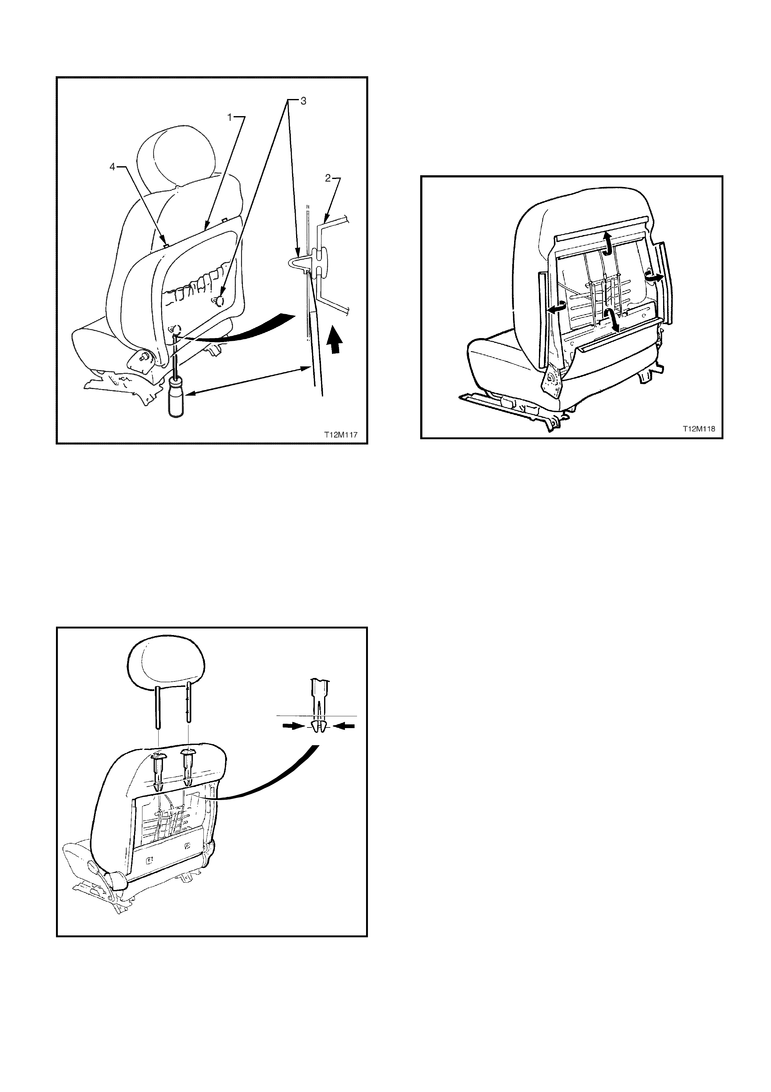
HOLDEN SERVICE TECHLINE ___________________________________________________________DECEMBER 1, 2000
9 9
Figure 2.
4. While holding head restraint height adjuster
lock in, pull head restraint completely out of
guide. Refer Fig ur e 3 below.
5. From the back of the seat, squeeze the
locking prongs of head restraint guide together
while pulling top of guide out of seat back
assembly. Ref er Figure 3 below.
T12M110
Figure 3.
6. Pull the four ‘J’ strips away from the seat
frame, then move cover and pad assembly
forward, well clear of seat back frame. Refer
Figure 4 below.
Figure 4.
7. Release the tie strap on the lumbar support
actuator cable by squeezing the tangs on the
cable tie retaining clip (“3” in Figure 5 below)
together and pushing tie strap retaining clip
throug h seat back fr am e hole.
8. Push down the top of the lumbar support to
disengage the two friction guides/retainers (“2”
in Figure 5 below) from the guide rails (“4” in
Figure 5 below) on the seat back, allowing
lumbar support t o swing freely.
9. Move the lumbar support forward and push
the lumbar support downward on each side, in
turn, to release the bottom hooks from the seat
frame.
10. While slightly compressing lumbar support
assembly by hand to release cable (“5” in Fig ure
5 below) tension, disengage cable from the top
of t he lum bar support.
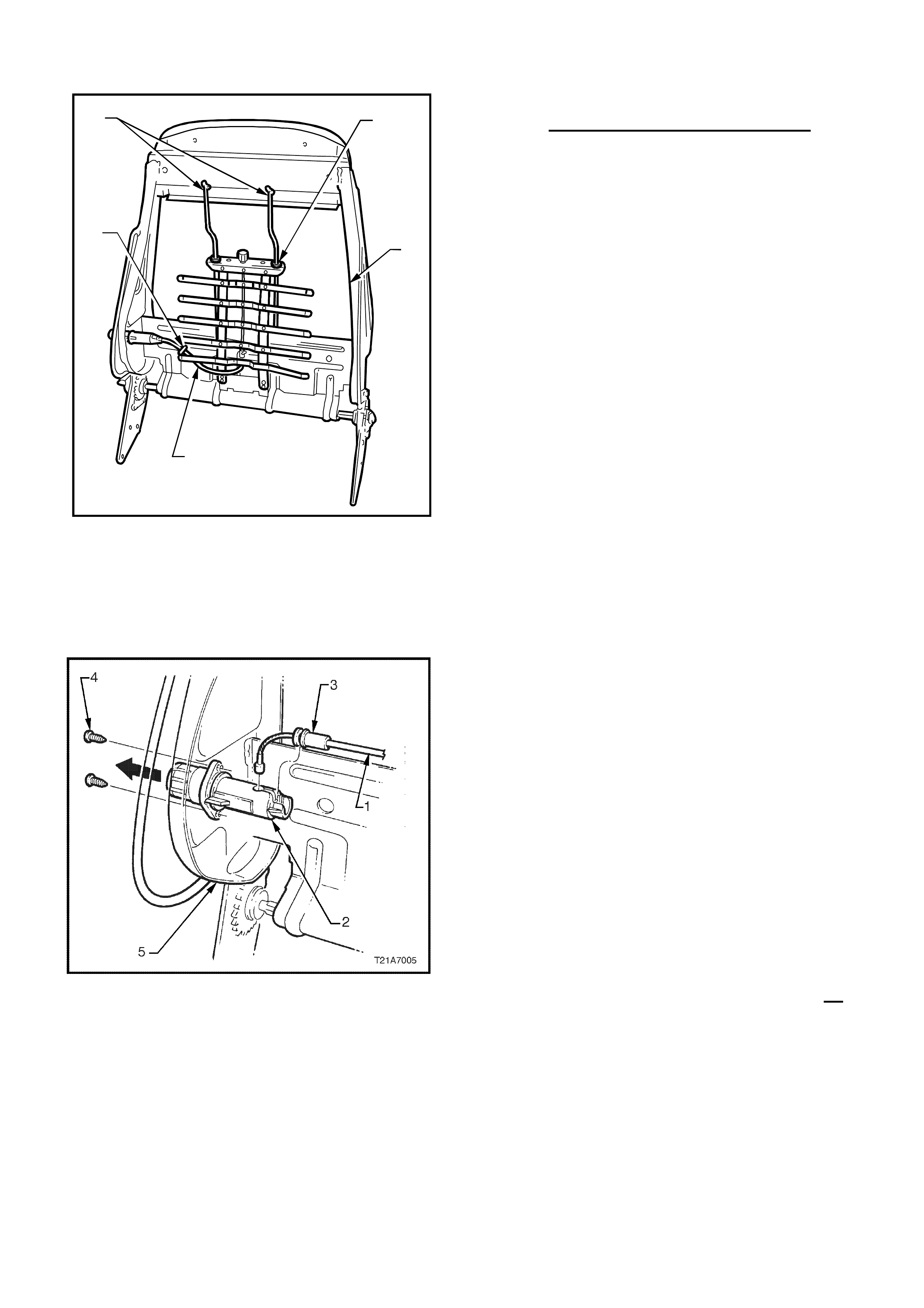
HOLDEN SERVICE TECHLINE ___________________________________________________________DECEMBER 1, 2000
10 10
T21A7004
42
31
5
Figure 5.
11. Remove adjusting cable (1) f rom adjust er (2)
by unclipping outer casing (3) of cable from
adjuster and removing cable assembly. Refer
Figure 6 below.
Figure 6.
12. Remove lumbar support unit fr om seat.
Replacing lumbar support asm.:
1. Attach new lumbar support (p/n 92143625) to
the lumbar support actuator (knob end) and
lumbar adjusting cable (Refer to Figure 5 above
for locations).
2. Locate the bottom hooks of the lumbar
support to the bar on the seat frame. Pull each
side upwards, in turn, to “click” into the position
on the bar.
3. Ensure plastic friction guide/retainers are
installed (supplied with new lumbar support) at
the two points (“2” in figure 5) at the top of the
lumbar support assembly. Push the top of the
lumbar support to engage the two retainers with
the guide r ails ( “4” in figure 5)
4. Locate cable tie (supplied with new lumbar
support assembly) t o the hole in the brace panel
(“3” in figure 5) and close the tie around the
actuator cable, tighten strap to secure, and cut
off excess length of t he strap. (Ref er to Figure 5
for locations).
5. Reinstall the seat back foam to the seat
frame, and attach with the four “J” strips. (Refer
to Figur e 4 above.)
6. Replace the two head restraint guides by
pushing t hem throug h the holes in the t op of the
(refer to figure 3 above) and reinstall the head
retraint.
7. Replace the seat back cover to the seat frame
using the or iginal seat back cover clips. I f these
clips are damaged replace with new clips
92140918. (Ref er to fig ure 2 above)
8a. For all VT vehicles without SIAB:
Reinstall the lumbar support spacer and adjuster
knob to the splined shaft and refit circlip. Refer
Figure 1a.
8b. For all VT with SIAB, all WH and all VX
vehicles. Carefully align and reinstall the
lumbar adjusting knob (part of seat back
cover/side cover assembly) back onto the
splined adjuster shaft. Refer Figur es 1b or 1c.
Reinstall ation Precautions:
1. Ensure the head r estraint g uide with adjusting
lock is installed on the correct side, ie. side with
notches on the head rest r aint .
2. Reconnect battery earth and positive leads,
switch ignition on, and obser ve the SRS warning

HOLDEN SERVICE TECHLINE ___________________________________________________________DECEMBER 1, 2000
11 11
lamp in the instrument cluster. The warning
lamp should be illuminated for approximately
five seconds. During this period the SDM
perfor m s a wiring and system self check.
PARTS INFORMATION
Part No.: Description: Qty
92143625 Lum bar Support Asm. 1
WARRANTY CLAIM I NFORMATION:
Description Lumbar Support - Replace
Labour Op. No. C502750
Time 0.6 hr
Failure Code As applicable
INSTRUMENT CLUSTER LENS
REPLACEMENT
TS
(GROUP 12) TL011-1207
PROBLEM DESCRIPTION
Some technicians are not aware that the
instrument cluster lens is replaceable, as TIS
instructions and a Warranty Labour Operation
Number have not been available – to date.
SERVICE RECTIFICATION
If an instrument cluster requires a lens
replacement:
- Remove the instrument cluster as per TIS
2000 instructions,
- Depress the nine retaining lugs around the
outside of the lens and remove the lens fr om
the cluster,
- Fit a new lens – taking care to insert the
odometer reset button through the hole in
the lens, then evenly push the lens lugs into
the cluster receptacles until they “snap” into
place.
- Refit the cluster t o the vehicle.
PARTS INFORMATION
The instrument cluster lens is available from
HSPO – refer PartFinder for part num ber .
WARRANTY CLAIM I NFORMATION:
Use existing information in Labour Time Manual
as follows – this new labour time for TS will be
added to a f uture SIP CD release:
Description Lens, Inst. Clust er -
Replace
Labour Op. No. N300600
Time 0.7 hr
HOLDEN SERVICE TECHLINE ___________________________________________________________DECEMBER 1, 2000
12 12
ELECTRONIC CLIMATE CONTROL
ILLUMINATION GLOBE REPLACEMENT
VT, VX, WH
(GROUP 2 & 12) TL011-0203
PROBLEM DESCRI PTION
There have been instances where ECC module
assemblies have been replaced for complaint of
“poor illumination”. In all these cases the
assemblies were fixed by replacement of faulty
globes.
All six globes in the ECC control module are
serviceable and may be obtained through
HSPO. The replacement procedure is
described below.
SERVICE RECTIFICATION
1. Remove the ECC module as per procedure
in SIP CD.
2. Place the ECC module onto a clean rag or
cardboard (t o avoid scratching) face down.
3. Remove the 5 screws retaining the rear
housing. Detach the rear housing carefully.
NOTE: Do not lift the facia panel, turn
upside down or remove the circuit board
as damage may occur.
4. Identify where the suspect faulty globes are
located (There are four, clear globes for
buttons and two, green globes for LCD
screen.)
5. Insert a small flat blade screwdriver into the
slot provided at the rear of the globe holder
then twist anticlockwise until the holder
stops. Gently lift out t he globe holder.
6. Measure the resistance across the globe. A
correctly operating globe should be in the
range of 10 to 13 ohms. I f outside this r ange
replace the globe. If globe resistance is
within 10-13 ohms then the globe circuit is
suspect. First try another known good g lobe
befor e r eplacing module.
7. After globe replacement, reassemble the
rear housing to the front facia with the 5
screws, reconnect the 2 ECC electrical
connectors and reinstall module into
instrument panel.
PARTS INFORMATION
Part No.: Description: Qty:
92140515 Globe and holder
illumination - clear . As
reqd
92140514 Globe and holder
illumination – g r een. As
reqd
WARRANTY CLAIM I NFORMATION:
Use infor m at ion as shown:
Description Globe Heater & A/C
Control - Replace 1 or all
Labour Op. No. N221990
Time 0.4 hr
Failure Code 50
Update

HOLDEN SERVICE TECHLINE ___________________________________________________________DECEMBER 1, 2000
13 13
LOWER DÉCOR PANEL CONTACTS
REAR BUMPER FASCIA
VT SEDAN
(GROUP 1) TL011-0103
PROBLEM DESCRI PTION
The lower décor panel contacts t he rear bumper
fascia when the decklid is closed which can
result in damage to the paint finish. Damage
usually occurs at corners.
This condition can be caused by a number of
factors: e.g. Slamming the decklid shut
(overtravel); incorrectly adjusted striker;
incorrectly adjusted decklid bumpers; or
clearance between décor panel and rear fascia
is below assembly specification.
PRODUCTION RECTIFICATION
Revised lower décor panels which provide
increased clearance have been fitted to vehicles
from:
ISOVIN: Build Date:
6H8VTK69FYL620686 28/07/00
SERVICE RECTIFICATION
On complaint vehicles do the following. Adjust
decklid striker and bumpers up as high as
possible whilst ensuring that decklid is not
overflush to r ear quarter panels. Now recheck if
décor panel still contact s r ear fascia on closure:
• If not contacting: check that decklid still
seals okay. Repair any paint damage¯ on
fascia prior to return to customer.
• If still contacting: fit a new lower décor
panel. Revised lower décor panels are
identif iable by their chamf ered corners. Repair
any paint damage¯ on fascia prior to return to
customer.
¯Obtain zone approval prior t o paint r epair.
PARTS INFORMATION
Part No.: Description: Qty:
92094365 Panel asm lower
decor 1
WARRANTY CLAIM I NFORMATION:
Use existing information in Labour Time Manual
in SIP, as shown. Claim for paint repairs in
usual manner.
Description Lower décor panel asm
Replace
Labour Op. No. C896950
Time 0.3 hr
Failure Code 62
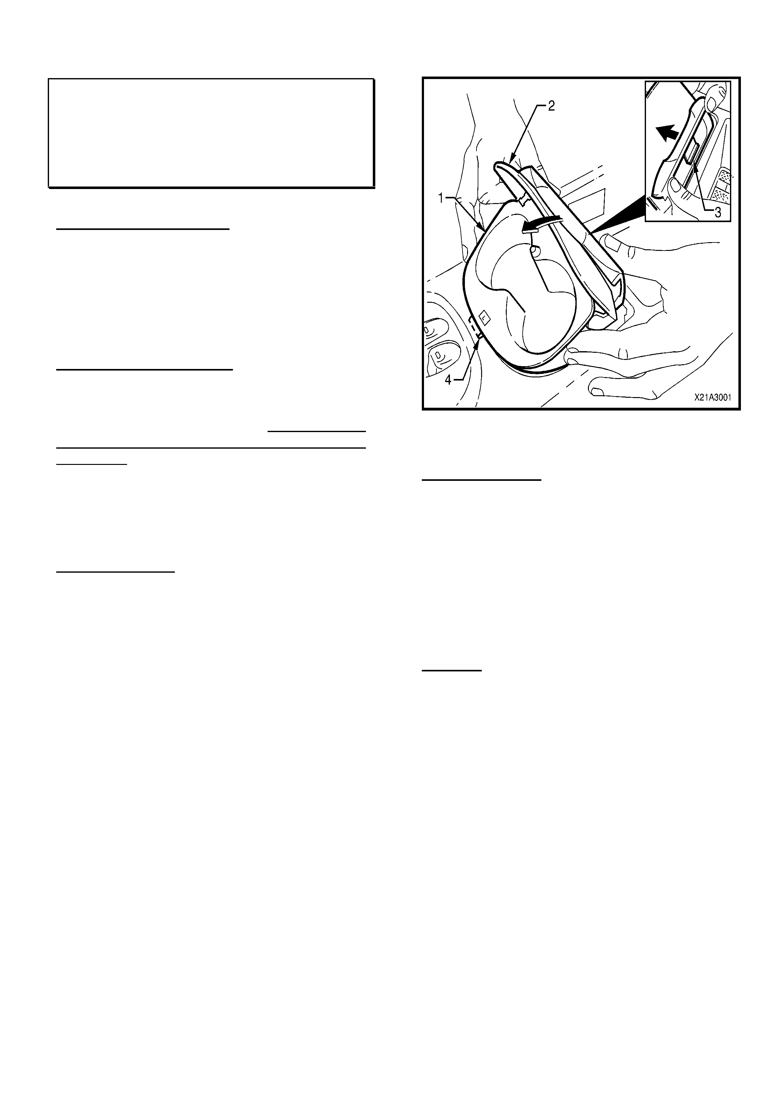
HOLDEN SERVICE TECHLINE ___________________________________________________________DECEMBER 1, 2000
14 14
FRONT CUP HOLDER LATCH
REPLACEMENT
WH, VX
(GROUP 1) TL011-0106
PROBLEM DESCRI PTION
The front (console mounted) cup holder cover
latch mechanism may fail to latch properly
(cover may not ‘latch’ open or ‘lat c h’ closed) .
Technicians are replacing the whole cup holder
assembly – when only the latch requires
replacement.
SERVICE RECTIFICATION
If you have a cup holder where the latch only
has failed (it does not open properly, or will not
hold the cup holder closed, et c,) fit ONLY a new
latch assembly – DO NOT replace the whole
cup holder!
The following advance copy of cup holder/latch
removal and installation procedures should be
used for replacements. This information will be
added to f uture versions of SIP.
1.4 CUP HOLDER
Remove
1. Open the cupholder lid ( 2) .
2. Grasp the rear of the cupholder assembly (1)
and press forward to disengage the rear
retaining t ang (3) from the centr e console.
3. Withdraw the cup holder from the centre
console, taking care not to damage the front
locating tab (4). (Refer to Figur e 1A3- 5)
Figure 1A3-5
LATCH REPLACE
1. With the cup holder removed from the centre
console and the lid (2) open, grasp with both
hands and press the latch ( 1) f ir mly up out of
cup holder with thumb.
2. Carefully press replacement latch into place
by hand, ensuring the latch locking tabs are
correctly engaged.
CAUTION: Do not press directly on the latch
jaws.
Reinstall
1. Engage the cup holder front locating tab in
the slot in the centre console and press the
rear edge firmly into place until rear locking
tab is correctly engaged.
NOTE: If the rear locking tab on the cup
holder does not correctly engage, open the
cup holder lid to gain access. (Refer to
Figure 1A3- 6 below)
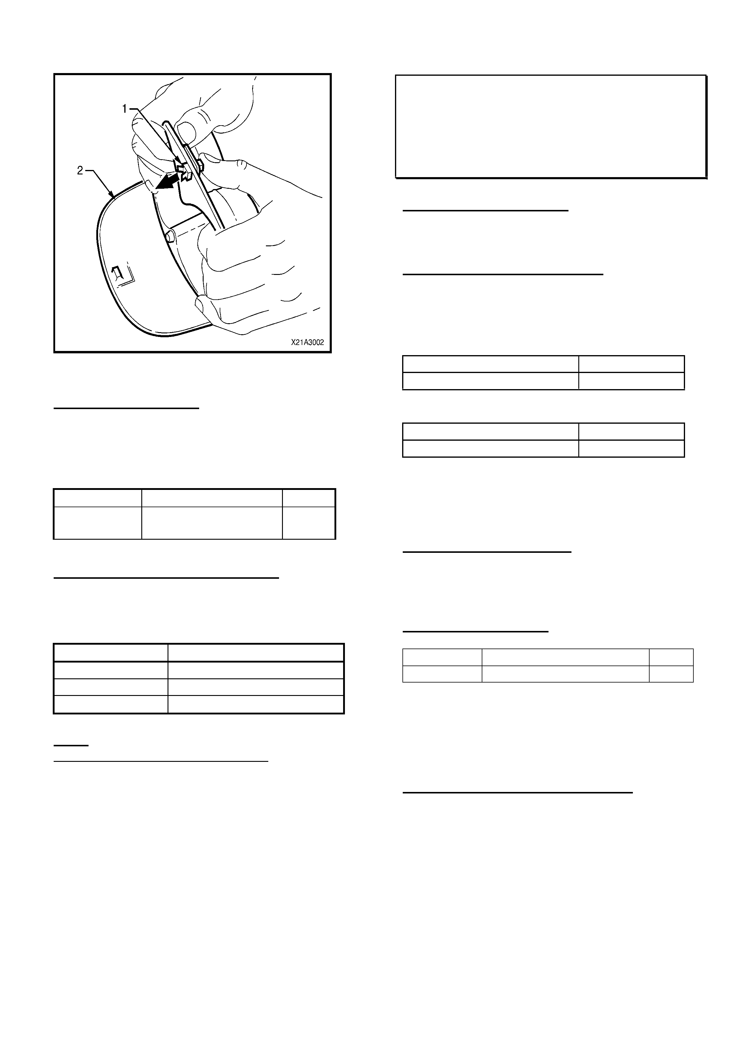
HOLDEN SERVICE TECHLINE ___________________________________________________________DECEMBER 1, 2000
15 15
Figure 1A3-6
PARTS INFORMATION
Order a new latch from HSPO using the
following part number (which will be added to
fut ure Part Finder information) .
Part No.: Descri pt i on: Qty:
92103515 Latch Asm . – Cup
Holder 1
WARRANTY CLAIM I NFORMATION
Use existing Labour Time information in SIP
“Warranty Information” as follows:
Description Cup Holder - Replace
Labour Op. No. C457300
Time 0.2 hr
Failure Code 37
Note: Replacement of cup holder assemblies
where only the latch is at fault will not be
accepted under warranty.
INTERIOR REAR VIEW MIRROR LOOSE OR
DISLODG ES FROM PIVOT
JS, TS
(GRO UP 1) TL011-0101
PROBLEM DESCRIPTION
Interior rear view mirror becomes loose (will not
retain adjustment) in its m ounting ball socket .
PRODUCTION RECTIFICATION
Revised rear vision mirror assemblies with
revised mounting ball sock et material have been
fitted to vehicles from :
For JS 5-Door Hatch Model s:
ISOVIN: Build Date:
W0L0JBF68Y7097903 22/06/00
For JS Sedan/Wagon (Local Built):
ISOVIN: Build Date:
WOLOJBF19YL633325 07/09/00
TS Model: No breakpoint information is
available.
SERVICE RECTIFICATION
If a rear vision mirror is presented which will not
hold its adj usted position, r eplace the mirror with
a new part fr om HSPO .
PARTS INFORMATION
Part No.: Description: Qty:
90541140 Rear View Mirror Asm . . 1
All parts in stock at HSPO, at time of bulletin
printing, have been manufactured after a
“revised material” breakpoint date as advised by
our supplier (not visible on part) .
WARRANTY CLAIM I NFORMATION:
Use existing information in Labour Time Manual
in SIP.

HOLDEN SERVICE TECHLINE ___________________________________________________________DECEMBER 1, 2000
16 16
CRUISE CONTROL “CLUNK” NO ISE ON
ENGAGE/DISENGAGE
WH, VT, VX
(GROUP 12) TL011-1209
PROBLEM DESCRI PTION
Some critical customers may be concerned
about a very light “clunk” noise when cruise
control is engaged or disengaged.
Disengagement noise is generally louder than
engagement noise.
SERVICE RECTIFICATION
When customers complain of a “clunk” noise on
cruise control engagement or disengagement,
carry out the following procedure:
1. Remove the three cruise control module
mounting grommets and screws (located on
the RHF fender skirt in the engine
compartment).
2. Fit three new mounting grommets (p/n
25074502) and screws (p/n 92138227).
3. Torque scr ews to 2-5Nm O NLY.
Note: over-torque of the screws will result in
great er noise t ransfer.
4. Road test to confirm reduced
engagement/disengagement clunk noise.
Aft er application of this procedure, t here may be
a minimal engage/disengage noise that may be
noticed by very critical customers only.
Should this occur – please advise by PIR.
PARTS INFORMATION
Part No.: Description: Qty:
25074502 Grommet, Cruise
Control Mounting 3
92138227 Screw, Cruise
Control Mounting 3
WARRANTY CLAIM I NFORMATION:
Use the f ollowing information to claim for the
above procedure:
Description Fit Revised Cruise Control
Module Mountings
Labour Op. No. N000327
Time 0.3 hr
Failure Code 40
BLAUPUNKT SECURITY CARD –
REPLACEMENT CARDS
JS, TS, SB
(GROUP 12) TL011-1202
PROBLEM DESCRIPTION
Until release of this Techline bulletin,
replacement Blaupunkt audio unit security cards
have not been available. No replacement card
could be supplied to owners who lost cards.
SERVICE RECTIFICATION
Replacement Blaupunkt audio unit security
cards are now available from HSPO .
PARTS INFORMATION
Part No.: Descri ption: Qty:
92057960 Security Card 1

HOLDEN SERVICE TECHLINE ___________________________________________________________DECEMBER 1, 2000
17 17
ENGINE STALL ON DECELERATION OR
HIGH ENGINE IDLE
JR, JS, with C20SEL or C22SEL Engine
(GROUP 6 M) T011-6M01
This Service Techline must be used in conjunction
with the previous Techline on this same subject,
in Issue 10/99, page 15. This Techline provides
an additional procedur e (Base idle adjustment) as
an interim action prior to availability of a revised
IACV and software, planned for introduction in
2001.
PROBLEM DESCRI PTION
With vehicle stationary, the engine idle is too
high; EG: 1000 RPM+, and engine may later stall
or the idle may remain high.
This is caused by a build-up of engine by-pass
gases and IACV solenoid shaft/bearing wear
particles on the IACV solenoid shaft, which
causes the IACV to stick at any point in its
operating range. This will result in either too high
or too low IACV air entry to the throttle body and
engine.
When the IACV subsequently “unsticks” and
returns to normal operation, the result may be
a stall or higher than normal idle RPM. It is
not possible to effectively clean the IACV to
correct this condition.
PRODUCTION RECTIFICATION
PCV oil separators have been fitted to vehicles
fr om t he following breakpoint s:
JS:
Engine Number: C22SEL25013594
ISOVIN: W0L0JBF19YL518348
Build date: 30/08/99
C20SEL Engines:
Engine Number: C20SEL25031355
Engine build date. 15/ 09/ 99
SERVICE RECTIFICATION Part 1:
FOR COMPLAINT VEHICLES WITH C20SEL &
C22SEL ENGINES BUILT PRIOR TO THE
ABOVE BREAKPOI NTS,
These vehicles should have an oil separator f itted
as per the instructions provided in Techline Issue
10, 1999, Page 15 (same title) which is readily
available on the SIP CD.
NOTE: A revised PCV system routing that
enabled deletion of the PCV oil separator was
introduced from the following breakpoint: (For
more details refer Issue 5/2000, page 10)
ISOVIN: W0L0JBF19YL557427
Build date: 16/02/00
SERVICE RECTIFICATION Part 2:
BASE IDLE SETTING FOR ALL VEHICLES:
Before carrying out the following procedure, with
engine stopped and ignition ON, connect Tech 2
and check for DTC’s. I f any are stored, correct the
fault defined before progressing. This procedure
provides a “base idle” to prevent stalling in case
of a sticking IACV, however, the potential exists
for other idle quality problems – EG: “hunting”
high idle speed, etc, but these generally will be
‘transparent’ to the customer. If complaints arise
regarding hunting or high idle speed, the above
(complete) procedure can be repeated. DO NOT
clean the throttle blade or throttle body internally
during t his pr ocedur e!
Aft er a PCV oil separator has been f it ted:
1. Inst all a new IACV and gask et . I f gask et has a
“vee” notch on outer edge, it must f ace the top
of t he I ACV flange on assembly.
2. Start engine and warm up to operating
temperature.
3. With Tech 2 connected, engine running
(coolant temp. gr eater than 85°), A/C (if fitted)
ON and active – loosen the idle stop screw
lock nut and wind up the idle screw (throttle
stop) until the engine idles at approx.
1400RPM.
4. With one hand on the throttle cable,
disconnect the IACV connector and modulate
the engine RPM with the cable so that the
engine does not st all.
5. With the IACV now disconnected, and the
throttle resting against the stop, the engine
should idle at approx. 500-600RPM. Fine tune
the idle speed using the throttle stop screw –
to 512RPM (as near as possible), make sure
the A/C is active to allow f or maximum load.
6. Tighten throttle stop screw lock nut and
confirm that idle RPM is still 512RPM. Re-
adjust if required to maintain 512RPM.
7. Apply a spot of yellow paint on interface of
throttle stop screw/lock nut/throttle body (as
per original seal) for identification of retention
of adj ust m ent.
8. Turn the engine OFF. Reinstall IACV
connector then turn the ignition ON & OFF
(removing the key from ignition) – seven

HOLDEN SERVICE TECHLINE ___________________________________________________________DECEMBER 1, 2000
18 18
times with a five second pause after removing
the key from the ignition. This teaches the
engine management system its new idle
software switch position.
9. Start the engine and check, using Tech 2,
scroll through the Engine Data List to
Simulated Idle Switch. Ensure that this
parameter reads “Active” and that the IAC
integrator steps are no less than 25, once idle
has been established. (Note: A/C OFF, no
load on engine, and in Neut r a l) .
10. Check with Tech 2 that idle speed is correct,
IE: engine idle speed is within ± 80RPM of
“Desired Idle Speed” .
11. Using Tech 2 – still in the Engine Diagnostics
area, select Programming/Reset init. ECU
Code - this will reset t he I ACV lear nt values.
12. Road test vehicle and confirm original
complaint does not exist.
PARTS INFORMATION
For Part 2, Base Idle Procedure ONLY:
Part No.: Description: Qty
90411546 Valve – Idle Air Control (IAC). 1
90466220 Gasket - IACV 1
For Procedure I Part 1 & 2: where PCV Oil
Separator is r equired:
Part No.: Description: Qty
90411546 Valve – Idle Air Control (IAC). 1
90466220 Gasket - IACV 1
09193502 Separator – PCV Oil 1
24421017 Hose – PCV Vent 2
90467971 Clamp – Vent Hose 2
WARRANTY CLAIM I NFORMATION:
Claiming for correction of any DTC’s that may
be found on initial checks – refer to the relevant
section of the Labour Time Manual that carries
DTC claiming information at the end of the
relevant section. Use the relevant Labour
Operation Num ber for the DTC found.
Claiming for replacement of any component
found faulty during that DTC diagnosis – use the
relevant Labour Operation for remove and replace
of t he faulty part.
For all Warranty Information, Labour Times in
your latest version of the SIP CD.
To claim for the rectification procedures detailed
above, use the f ollowing information:
Part 2 – Base Idle O NLY:
Description Reset Engine Idle
Labour Op. No. J000610
Time 0.6 hr
Failure Code 84
Part 1 & Part 2:
Description Fit PCV Oil Separator
Labour Op. No. J000631
Time 0.9 hr
Failure Code 84
NOTE: the time allowance for this Labour
Operation No. has been increased t o allow for the
additional Part 2: Base I dle Pr ocedure.
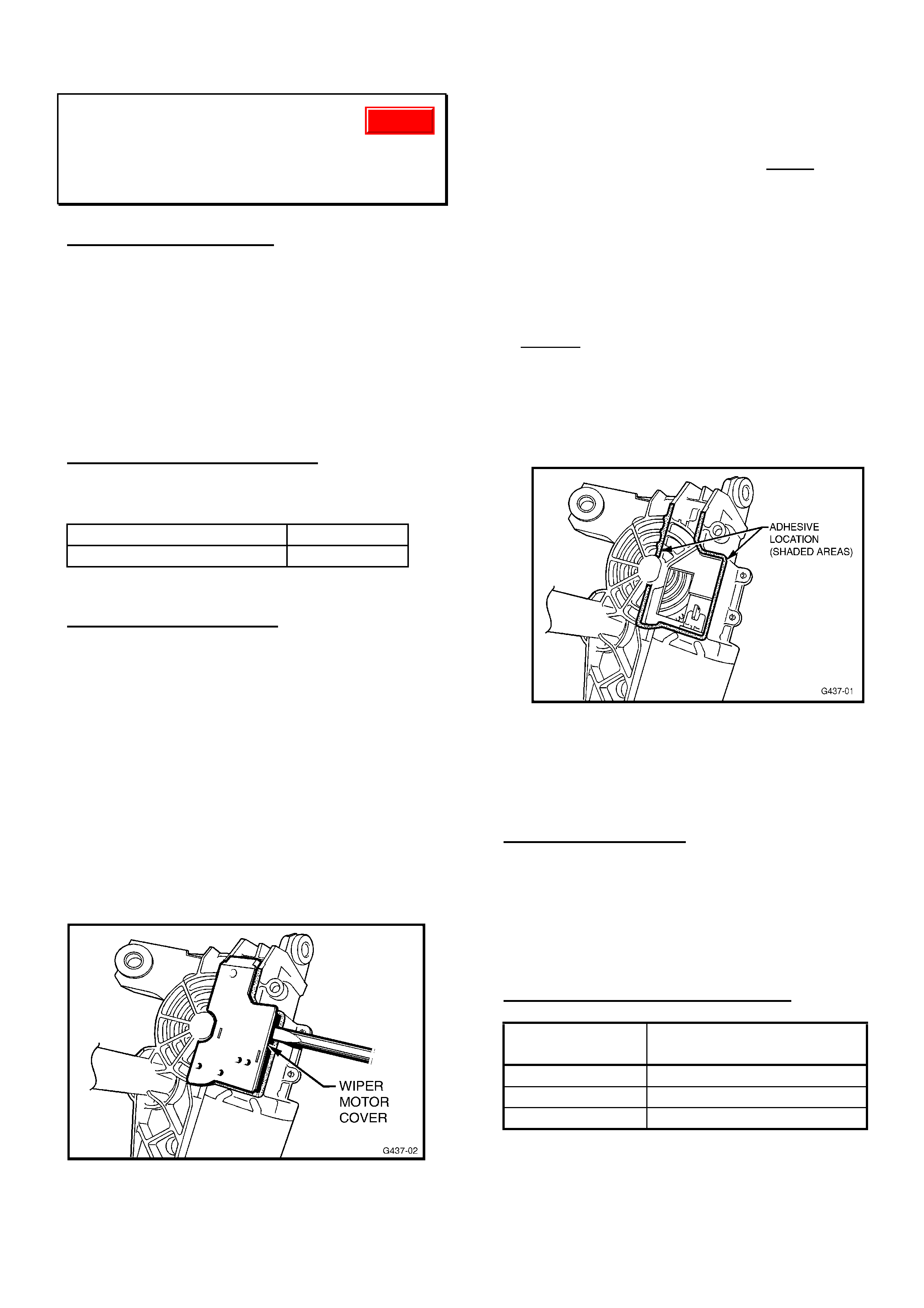
HOLDEN SERVICE TECHLINE ___________________________________________________________DECEMBER 1, 2000
19 19
REAR WIPER INOPERATIVE
TS Hatch
(GROUP 12) TL011-1203
PROBLEM DESCRI PTION
Rear wiper may fail to operate when the wiper
switch is operated, or may stop during operation
for no appar ent r eason.
The cause has been defined as poor adhesive
bonding of the wiper motor cover (carrying the
electrical contact s ) to the wiper motor housing.
No damage is suffered to the contacts or motor
assembly, and it can be reassem bled.
PRODUCTION RECTIFICATION
Rear wiper motors, with improved adhesive
bonding, were intr oduced from:
ISOVIN: Build Date:
W0L0TGF4815059976 18/10/00
SERVICE RECTIFICATION
To rectify cases of “wiper inoperative” where no
electrical wiring fault is found, the wiper motor
can be r emoved and the motor cover can be re-
adhered to the wiper motor body as follows:
1. Remove wiper motor assembly from tailgate
as per TIS 2000 instructions in TS Astra
Electrical Equipment and Instruments,
section: “Rear Screen W iper Motor, Remove
and Install”.
2. Remove the wiper motor cover (black plastic)
by carefully prising it off with a flat bladed
screwdriver – Refer Figure 1 below - do not
damage the cover, as it is to be re-fitted to
the wiper motor.
Figure 1
3. Remove all traces of oil/grease from the
attaching surfaces of the cover and motor
using an organic solvent such as Acetone or
MEK (Methyl Ethyl Ketone). NOTE: As a
standard procedure, use these solvents only
in a well ventilated area: it is recommended to
keep skin contact to a minimum, or use
impervious gloves when using such solvents.
4. Apply adhesive (either “Loctite 480 Instant
Adhesive”, or “Permabond C737 Black
Magic”) to the wiper motor surface previously
cleaned – Refer Figure 2 below - and quickly
fit the cover to the motor, ensuring it is
correctly aligned. Hold the two parts together
for one minute and apply enough pressure to
ensure the adhesive spreads evenly over the
mating surfaces.
Figure 2
5. After the one minute curing time, the wiper
motor assem bly can be re- fitted t o t he vehicle.
PARTS INFORMATION
Solvents and adhesives mentioned are available
from commercial suppliers, they are not stocked
by HSPO.
A rear wiper motor assembly should only be
replaced if t he pr ocedure above is unsuccessful.
WARRANTY CLAIM I NFORMATION:
Description Re-Adhere Rear Wiper
Cover to Motor
Labour Op. No. N000324
Time 0.9 hr
Failure Code 58
Update

HOLDEN SERVICE TECHLINE ___________________________________________________________DECEMBER 1, 2000
20 20
LSD CHATTER NOISE
VT, VX, WH (V8 Engines only)
(GRO UP 4) TL011-0401
The following information is repeated from All
Dealer Letter: DL 65/00, and is repeated in this
Techline only to ensure that all Dealership
Service personnel are aware of the information
noted. Refer to DL 65/00 for all actions.
PROBLEM DESCRI PTION
This letter is to advise Holden Dealerships of a
corrective fix for LSD (Limited Slip Differential)
final drive units that exhibit a “chatter” noise
when turning. This noise may be present in
some VT, VX and WH vehicles with V8 engine.
LSD chatter may be heard when the vehicle is
turning left or right when travelling in a forward
or reverse direction, and is most pronounced
when negotiating sharp bends at low speeds
and parking manoeuvres where differential
action is initiated. The occupants of the vehicle
typically hear a noise originating from the LSD
drive unit (axle). Chatter can also be
experienced by the driver as a “grabbing” feel
during the operation of the LSD. The chatter
noise is caused by diminished sliding lubrication
qualities (using the existing oil) of the LSD cone
fr ict ion sur faces within the final dr ive unit.
Holdens supplier of LSD final drive units, Spicer
Axle Australia (SAA) - previously named BTRE,
has assisted in the definition of the cause of
LSD chatter, and provided a rectification
process, described below, for application to
complaint vehicles.
Affected Vehicles
For reference, V8 LSD final drive units with the
following codes/part numbers are af fected:
VT: EB 92053537, EH 92053542, EM
92078300, EP 92078301, ET 92082622.
VX: FA 92085123, FC 92085125, FE
92085127, FH 92085129, FF 92085136.
WH: EH 92053542, FH 92085129
(Refer to SIP Service Information, Group 0A for
location of final drive unit identification label).
Dealership Action
A rectification procedure is to be carried out to
add an approved friction modifier (supplied by
SAA) to improve lubrication. As the friction
modifier required is not compatible with the
currently f itted Viton material pinion seal, a new,
high performance, Polyacrylic material pinion
seal must be fitted to prevent possible future
leaks through seal degradation. Both friction
modif ier and new seal will be supplied in a “Field
Fix Kit” supplied by SAA.
On examination of a customer complaint vehicle,
and confirming LSD Chatter is evident – fill out
all requested details on a photocopy of the SAA
Rear Axle Assembly Diagnosis & Changeover
Request For m (Attached t o DL 65/00) and f ax to
SAA on Fax Number: (02) 9754 9310.
On receipt of a fully completed SAA Rear Axle
Assembly Diagnosis & Changeover Request
Form, SAA will contact your Dealership by
telephone to confirm acceptance of the request,
advise that a “Field Fix Kit” is being sent by
courier to your dealership, and the approximate
delivery date/time.
If diagnosis to confirm LSD chatter noise has not
been carr ied out, a simple Diag nosis Procedure,
provided below, must be carried out to confirm
the noise cause, and ensure that the rectif ication
procedure will correct t he com plaint.
If any complaint vehicle is presented which
carries a filler plug I.D. tag containing the words
“FIELD FIX” or “& FRICTION MODIFIER” – the
procedure has already been carried out to the
unit and it must NOT have the procedure carried
out again. In a case such as this, a fully
completed SAA Rear Axle Assembly Diagnosis
& Changeover Req uest For m should be f axed to
SAA to req uest a replacement final drive unit.
Parts Information
To carry out the rectification procedure – the
following parts are requ ir ed:
“Mobilube SHC ID” oil. Quantity: 1.5 litres –
Dealership to procur e.
A Field Fix Kit - Supplied by SAA, which
contains the following items:
1. One new Polyacrylic pinion seal.
2. One bottle (100 ml) of friction modifier.
3. A replacement I.D. tag .
4. An extract from the VX and VT SIP Service
Information, referring to seal replacement.
(Also applies to WH. Copies are included as
Attachment s to DL 65/00).
5. T he Material Saf et y Data Sheet f or t he f rict ion
modifier.
6. The diagnostic and rectification procedures
detailed below.
Diagnosis Procedure to define LSD Chatter
(if pr eviously not able to confirm):

HOLDEN SERVICE TECHLINE ___________________________________________________________DECEMBER 1, 2000
21 21
LSD chatter can be temperature dependent, so,
prior to the following diagnosis, customer help
should be sought to determine if the chatter
occurs when the final drive is hot or cold, so the
vehicle can be tested for confirmation in the
same temper at ur e range.
Find a driving area large enough to allow the
vehicle to be oper ated, in a safe m anner , at near
full lock, up to a speed of 20km/h in both
forward and reverse direction. The driving
surface of the area should be in good condition
i.e.: free from dips, loose g r avel, et c.
Apply foot brak e and place t he vehicle on full lef t
lock - without activating the power steering
pump pressure r elief valve.
For A/T equipped vehicles, select “D”; for M/T
equipped vehicles - select 1st gear.
Release the foot brake and allow the vehicle to
slowly roll forward/release the clutch. Increase
the speed of the vehicle gradually up to 20km/h
approx..
Listen for an audible rumble sound emanating
from the final drive unit, as the vehicle starts to
roll forward, this noise may change f requency to
a chatter as t he vehicle speed increases.
When the vehicle reaches 20km/h put the A/T
selector or M/T gear lever into neutral and allow
the vehicle to coast down to a stop.
LSD chatter, if present, will be noticed as the
vehicle rolls to a stop.
Other sources of driveline noise such as clutch
shudder are isolated when using t his m et hod.
Repeat the above procedure for full left lock in
reverse, full right lock forward and full right lock
in reverse.
When chatt er noise is confirm ed:
Fill out all requested details on a photocopy of
the SAA Rear Axle Assembly Diagnosis &
Changeover Request Form and fax to SAA on
Fax Number: (02) 9754 9310. SAA will contact
your Dealership by telephone to confirm
acceptance of the request, advise that a “Field
Fix Kit” is being sent by courier to your
dealership, and the approximate delivery
date/time.
Rectifi cat ion Procedure
On receipt of a Field Fix Kit from SAA:
1. Remove the final drive unit drain plug and
drain the oil from the final drive unit.
2. Change the pinion oil seal as per the
instructions provided. CAUTION: The pinion
shaft, pinion flange and pinion nut MUST be
marked prior to removal, and realigned to
these marks on re-assembly, as per Step 3 &
Figure 4B-1, in each of the instructions
provided, and as shown in SIP. It is
recommended that Loctite 243 Nut Lock be
used on re-assembly of pinion nut to pinion.
3. Reinstall the drain plug.
4. Remove the filler plug and add 1.5 litres of
“Mobilube SHC ID” oil. NOTE: this is the only
oil validated through exhaustive testing, as
compatible with the friction modifier required
in this procedure – do NO T use any other oil.
5. Add the contents of bottle of friction modifier
to the axle unit via the filler plug hole.
6. Fit the supplied I.D. tag to the filler plug and
reinstall t he filler plug.
7. Road test to confirm complaint is corrected.
NOTE: The friction modifier requires a run-in
to become effective. The friction modifier
should reduce chatter severity significantly
within a few kilometers of driving. Some
vehicles may require at least 100 km of
driving for the friction modifier to have
maximum effect.
Warranty Claim Information
Use the following information to claim for the
above rectification procedure:
Labour Operat ion No.: F000171
Description: Fit V8 LSD Chatter
Fix Kit
Time: 0.7 Hour
Add For Dual Exhaust: 0.5 Hour
Trouble Code: 41
SAA “Rear Axle Assembly Diagnosis &
Changeover Request Form”
A new copy of the SAA (previously BTRE) Rear
Axle Assembly Diagnosis & Changeover
Request Form is att ached to DL 65/00 f or use in
request ing the Fix kit mentioned above.
The form is also provided for future changeover
final drive unit requests. Please retain a copy of
this form in your files. The new form will be
included in fut ure SIP releases.
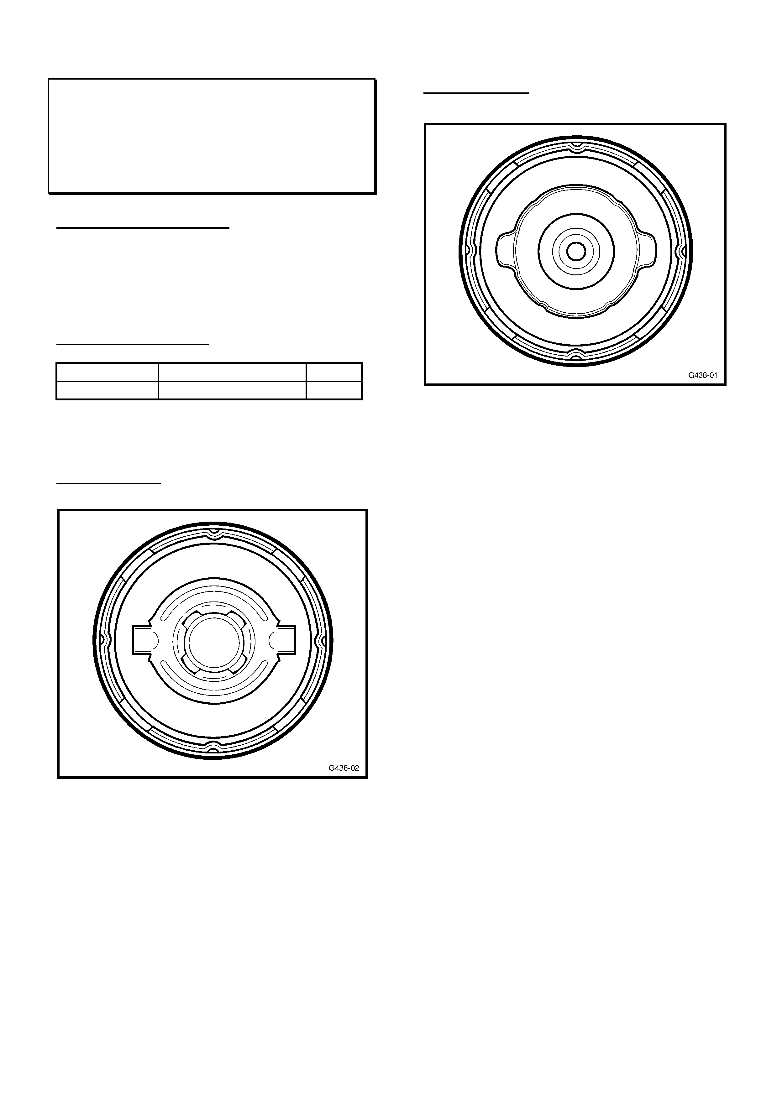
HOLDEN SERVICE TECHLINE ___________________________________________________________DECEMBER 1, 2000
22 22
FUEL TANK/CAP REPLACEMENT
REQUIREMENT
TR
(GROUP 8) TL011-0804
SERVICE REQUI REMENT
W henever a fuel tank is replaced on a TR Astra
- the fuel tank filler cap should also be replaced
with a revised design filler cap, as noted below
in Parts Information.
PARTS INFORMATION
Part No.: Description: Qty
92088959 Cap, Fuel Filler 1
To identify early and later filler caps fitted to
vehicles – the following sketches are provided.
Early Filler Cap
Do NOT re-fit when replacing a fuel tank
Later Filler Cap
Fit when replacing fuel tank.
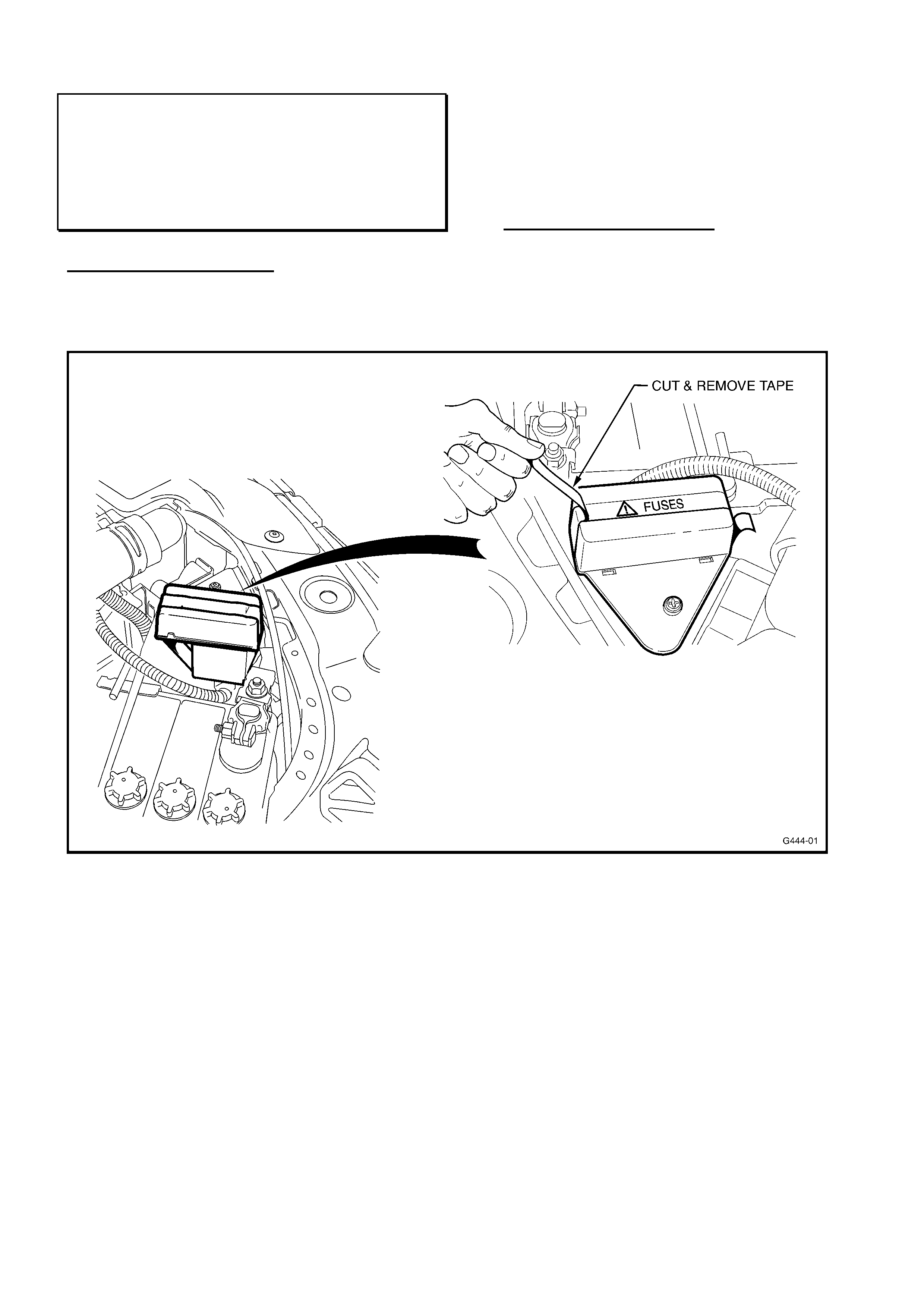
HOLDEN SERVICE TECHLINE ___________________________________________________________DECEMBER 1, 2000
23 23
COOLING FAN FUSIBLE LINK HOLDER –
REMOVAL OF ASSEMBLY TAPE
VT VX WH
(GROUP 12) TL011-1208
PROBLEM DESCRI PTION
Assembly aid t ape may be left on the cooling f an
fusible link holder cover. As well as obscuring
the wording on the cover, the tape looks
unsightly af ter a period of time.
The location of the tape is shown in Figure 1
below.
SERVICE RECTIFICATION
Remove tape. Also ensure that the cover is
secure.
Figure 1.

HOLDEN SERVICE TECHLINE ___________________________________________________________DECEMBER 1, 2000
24 24
KNOCK NOISE FROM EXHAUST ON COLD
START
JR, JS
(GROUP 8) TL011-0802
This Service Techline supersedes the previous
Techlines on this topic (Issue 1, February, 1999
page 5, and Issue 10, November, 2000, page 23)
by correcting the model/engine usage details.
These previous Techlines should be destroyed.
PROBLEM DESCRI PTION
NOTE: The condition described below only
affects:
JR vehicles with C20SEL engine;
JS vehicles with C20SEL engine up to
breakpoint Y7054589 as noted in Part Fi nder.
Customers may complain of a metallic knocking
noise after engine is started from cold. Noise can
be misdiagnosed easily as being an engine
internal or dr ive belt r elated noise.
Actual noise cause is a rattle noise from internal
baffles in the intermediate silencer, which stops
when the exhaust system reaches operating
temperat ur e.
PRODUCTION RECTIFICATION
The silencer has been revised internally from late
1998. Silencers are identified by date code of
99/04 or later (99/04 = Apr il, 1999), - st amped on
the identification/part number plate on the lower
surface of the silencer body. No vehicle
breakpoint was set for this change.
SERVICE RECTIFICATION
Fit a new Silencer – Intermediate & Centre Pipe.
As part numbers and breakpoint information may
be revised, always refer to current PartFinder
information.
Order the new part from HSPO - all parts at
HSPO are of the latest specification.
PARTS INFORMATION
Part No.: Descripti on: Qty:
90500030 Silencer – Int er mediate
& Centre Pipe 1
WARRANTY CLAIM I NFORMATION:
Use existing information in Labour Time Manual
on SIP CD.
TECH 2 COMMUNICATION
SB w i th C14NZ Engine
(GROUP 6C) TL011-6C01
Previously there were some Tech 2
communication difficulties with early ’96 SB,
C14NZ engine vehicles.
To communicate with the engine ECU, Tech 1
and the mass storage cartridge from the Zone
office was required.
As f rom TIS 2000, CD 12b, the T ech 2 software
version 9.400 is able to communicate with the
engine ECU in these vehicles.
PLEASE NOTE: This Tech 2 software is unable
to communicat e wit h 96 Model Year GSI X16XE
vehicles. These vehicles will still require the
Tech 1 mass storage cartridge available from
individual Zone off ices.