
2
20
00
01
1
S
SE
ER
RV
VI
IC
CE
E
T
TE
EC
CH
HL
LI
IN
NE
ES
S
© 2006 GM Holden LTD. A.B.N. 84 006 893 232
Service Department
A “HOLDEN” Product.
BRISBANE SYDNEY MELBOURNE ADELAIDE PERTH
For the latest and/or any missing Techline bulletins,
please refer to Holden Lionheart

HOLDEN SERVICE TECHLINE ___________________________________________________________JANUARY 2001
5
SERVICE TECHNICIAN REFERENCE
INFORMATION
ALL
(GROUP OB) TL101-OB01
This Techline is published to provide
Dealership Service personnel with a list of
commonly required Holden contact Fax
numbers and some helpful additional
information.
HOLDEN SERVICE RELATED FAX No’s
HOLDEN TAS 03 9647 2495
HOLDEN SECURITY INFO. 03 9647 2865
IGM TAS 03 9644 6622
PIR’s (EDAG FUTURE ) 03 9552 8104
REPAC 03 9647 1198
TECHNICIAN’s GUILD 03 9876 5797
CENTRAL SERVICE 03 9647 2525
HOLDEN CAS 03 9647 1237
WARRANTY ADMIN. 03 9647 2525
Other Information:
PIR forms:
request a pad (100 forms) by quoting “SD
28331” on a Merchandising Material Order
Form and fax to Salmat, on (03) 9251 6352.
Campaign Labels
Extra campaign identification labels SD28156
are available free of charge by contacting
Moore Customer Care on 131896.
or
by Facsimile: to (03) 9270 8900
Attention: Mr. Bob Curry
Quote stock No. SD 28156 on a Moore
Business Systems ‘packaged goods’ order form
(or facsimile if not available) for a box of 100
labels.
Rework Labels (Vehicle Service History
Label)
Additional labels SD28177 can be obtained by
contacting Moore Customer Care on 131896.
Security Number Request Form: photocopy
form attached to All Dealer Letter DL 63/99.
Vehicle Security Info. Change Advice Form:
photocopy form attached to All Dealer Letter
DL 63/99.
Tech 1 Repairs: Refer HSPO Parts Techline
Bulletin PT31, dated May 5, 1999.
JS Vectra Circuit Diagram Manual Update
Pages: Refer All Dealer Letter 58/99
TS Astra Circuit Diagram Update Pages:
Refer All Dealer Letter DL 01/99

HOLDEN SERVICE TECHLINE ___________________________________________________________JANUARY 2001
6
ENGINE IDLER PULLEY “RINGING”
VT, VX, WH - V6 Normally aspirated
(GROUP 6A) TL101-6A04
PROBLEM DESCRIPTION
Customers may complain of a “ringing” type
noise at idle. Investigations have shown that
this noise results from the action of the drive
belt slapping/striking the A/C idler pulley
causing it to resonate. The noise is more
noticeable with an increase in engine load, i.e.
in drive, A/C on etc. Only normally aspirated
engines are affected.
PRODUCTION RECTIFICATION
Revised A/C idler pulleys (smaller diameter),
pulley supports and drive belts (shorter) have
been fitted to vehicles from:
V6 (Normally Aspirated)
ISOVIN: Build Date:
6H8VXK69A1L661776 10/11/00
SERVICE RECTIFICATION
On complaint vehicles fit a new A/C idler
pulley, idler support and drive belt using parts
listed in Parts Information and service
procedures given in SIP CD.
PARTS INFORMATION
V6 (Normally Aspirated)
Part No.: Description: Qty:
92094003 Idler pulley Asm. 1
92065824 Idler pulley support 1
92100691 Drive belt 1
WARRANTY CLAIM INFORMATION:
Use existing information in SIP CD Warranty
Information/Labour Times.
FRONT CROSS MEMBER MOUNTING
BOLT REVISION
WH, VT, VX
(GROUP 3) TL101-0301
DESCRIPTION OF REVISION
Stepped bolts have been introduced to the two
front mounting holes of the front suspension
cross member. These replace the ‘plain’ shank
bolts used previously.
The stepped bolts were introduced to improve
the location of the cross member for production
and front end alignment purposes.
NOTE: The two rear mounting bolts in the
cross member remain unchanged.
The torque of the new bolts is unchanged. i.e.
120 – 125Nm.
PRODUCTION RECTIFICATION
An 18mm head stepped bolt (92138567) was
introduced into production from:
ISOVIN: Build Date:
6H8VTK69HYL630604 19/08/00
Note: This is a VT vehicle, but L630604 can
also be used as a breakpoint for WH.
All VX vehicles are built with this stepped bolt.
A 16mm head stepped bolt (92138605) will be
introduced into vehicle production in early
2001. This change in head size is being done
only as an aid to production.
PARTS INFORMATION
Either of the bolts listed below may be used
as replacements for existing bolts.
Part No.: Description: Qty
92138567 Bolt, Stepped, 18mm
head , Front Cross
Member
2
92138605 Bolt, Stepped, 16mm
head , Front Cross
Member
2
HOLDEN SERVICE TECHLINE ___________________________________________________________JANUARY 2001
7
ENGINE SURGING – SUSPECT EGR
VALVE
TS & X18XE1 Engine
(GROUP 6C & 8) TL101-6C02
PROBLEM DESCRIPTION
Engine surges while driving at constant speed
between 40 - 80 km/h and also under light
acceleration up to 3000 RPM. Sometimes
DTC P0400 or P1405 is set.
This problem may be due to a faulty EGR
valve if it was manufactured before the
breakpoint date given below.
SERVICE RECTIFICATION
To confirm that condition is due to faulty EGR
valve, with vehicle at normal operating
temperature, disconnect EGR wiring
connector and road test. If complaint
condition disappears check the production
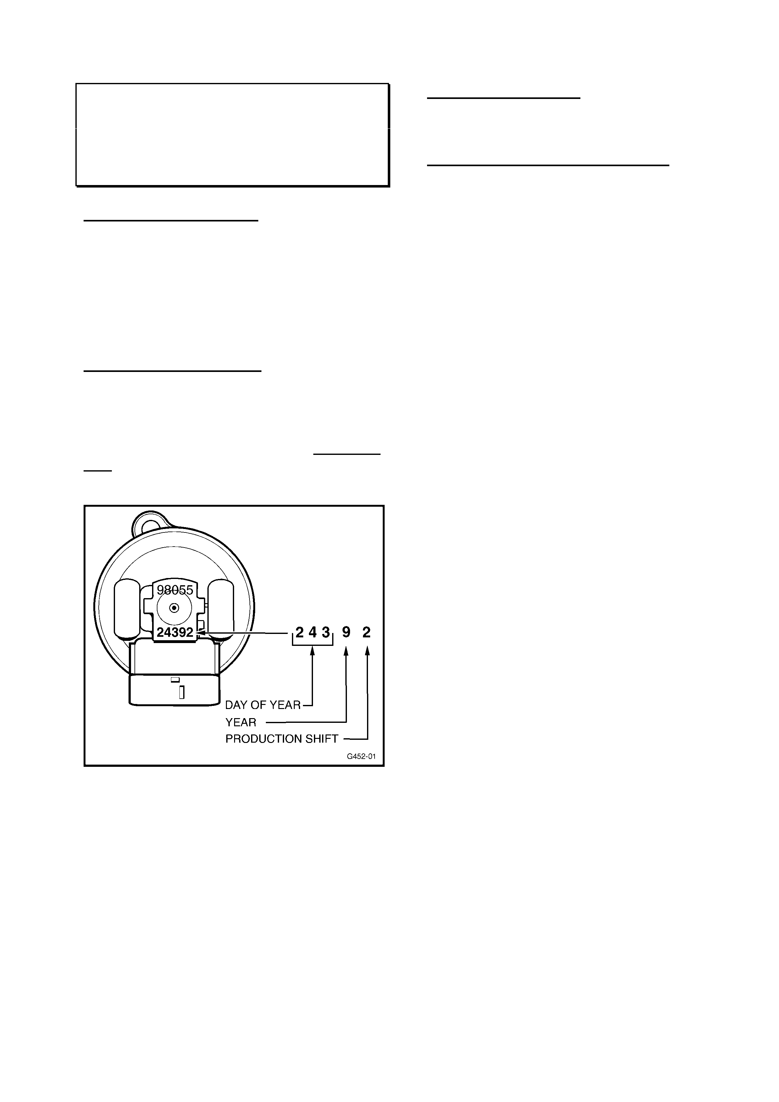
date (5 digit number) on top of valve as shown
below.
Viewed from above the valve (as shown) you
will find several number/letter combinations.
The first number on a suspect valve should be
98055 (last 5 digits of part no.) Below this is
the production date of the supplier. If the
production date is before 24392
(243rd day of 1999) valve should be
replaced.
Removal and refit of EGR-valve is described
in TIS under model Astra-G .
PARTS INFORMATION
If new valve is required order from HSPO. All
HSPO stock is okay.
WARRANTY CLAIM INFORMATION:
Use existing information in SIP Warranty
Information/Labour Times.
HOLDEN SERVICE TECHLINE ___________________________________________________________JANUARY 2001
8
FUEL PUMP and LOW BEAM
HEADLAMP RELAY FAILURES
VT, WH, VX
(GROUP 12) TL101-1203
The information in this Techline was
previously published in All Dealer Letter
76/00.
PROBLEM DESCRIPTION
Diagnosis of engine not starting or no low
beam headlamp operation (possibly
intermittent), may establish the cause as a
defective Fuel Pump relay or Low Beam relay.
Investigation of such failures has shown the
cause to be internal distortion of the relay
switching mechanism due to misaligned
terminals in the relay mounting block.
PRODUCTION RECTIFICATION
This problem has been addressed in 2 stages:
• The relay has been resourced to an
alternative manufacturing facility which
produces a relay more tolerant of the relay
block misalignment condition.
The relay was introduced into production:
ISOVIN: Build Date:
6H8VXK69A1L666348 22/11/00
• Revisions to the engine compartment
relay/fuse block housing will be introduced
as soon as practicable.
SERVICE RECTIFICATION
When dealer diagnosis reveals the relay has
failed, (according to the current SIP diagnosis
procedures), install the new relay serviced by
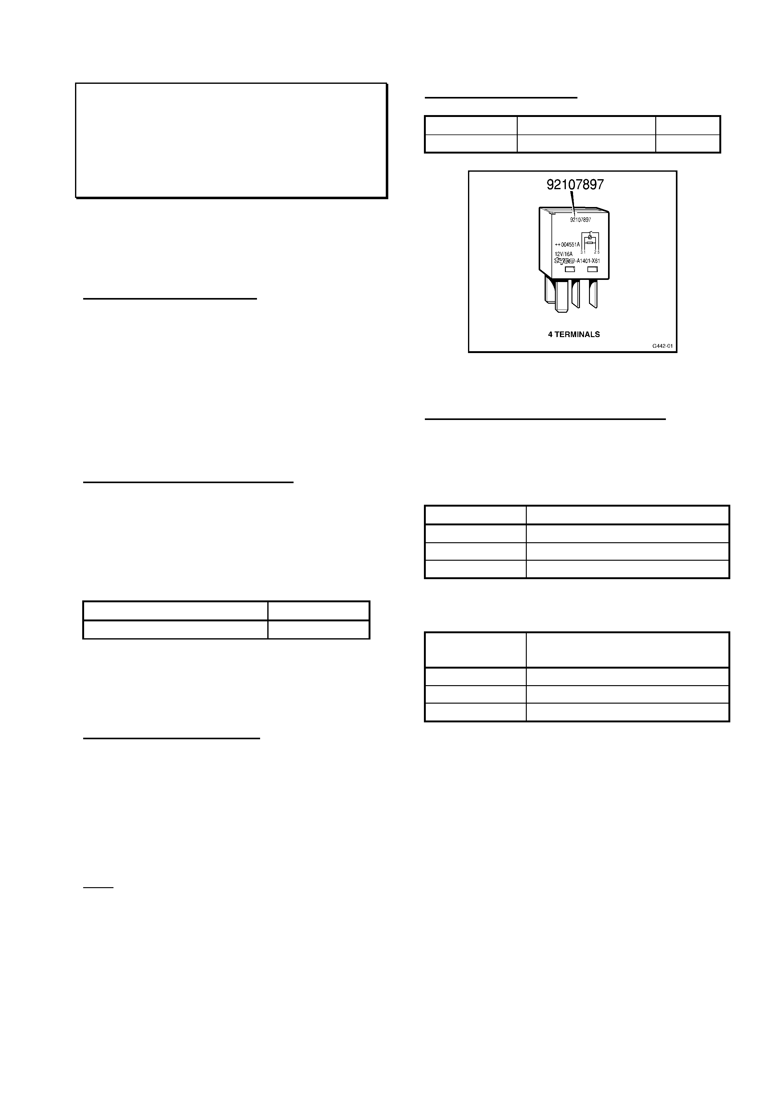
HSPO under part number 92107897.
The new part number identifies the revised
relay. See Figure 1.
Note: Do not use the existing relay (part
number 92047112) in the fuel pump and low
beam headlamp applications.
PARTS INFORMATION
Part No.: Description: Qty:
92107897 Relay 1
Figure 1. Revised 4 pin micro relay.
WARRANTY CLAIM INFORMATION:
Use existing information in SIP Warranty
Information/Labour Times as shown:
• For fuel pump relay replacements:
Description Relay-Fuel Pump, Replace
Labour Op. N001830
Time 0.2 hr
Failure Code 50
• For low beam headlamp relay
replacements:
Description Relay-Headlamp Low
Beam, Replace
Labour Op. N001880
Time 0.2 hr
Failure Code 50

HOLDEN SERVICE TECHLINE ___________________________________________________________JANUARY 2001
9
ENGINE HESITATION/STALL AT LOW
FUEL LEVELS
JS
(GROUP 8) TL101-0801
PROBLEM DESCRIPTION
Engine hesitation or stalling when:
- cornering
- travelling uphill
- driving with wide open throttle with 20
litres of fuel or less in the fuel tank.
Investigations have shown that this condition
can be caused during vehicle assembly, by
pressure application to the fuel tank upper
surface, that may break a piece from the vent
pipe retaining clip (inside the fuel tank). This
can become lodged in the swirl pot fuel intake
during times of high fuel demand, restricting
the flow of fuel into the swirl pot/pump. When
fuel demand is lessened (eg: at idle) the
broken piece dislodges and the vehicle will be
driveable until high fuel demand occurs again.
PRODUCTION RECTIFICATION
Tanks with internal revisions to reduce
potential for breakage of the vent pipe
retaining clip were fitted in Elizabeth built
vehicles from:
ISOVIN: Build Date:
W0L0JBF19YL598784 08/06/00
SERVICE RECTIFICATION
When a vehicle displays the above symptoms:
1. Confirm the complaint by checking fuel
pressure. On checking, the fuel pressure may
be erratic when this occurs. While the
condition may be intermittent – the fuel
pressure may not be erratic until a high fuel
demand is created EG: rev the engine to
create a high fuel demand.
2. Remove the fuel tank from the vehicle,
taking normal safety precautions for fuel
draining and handling.
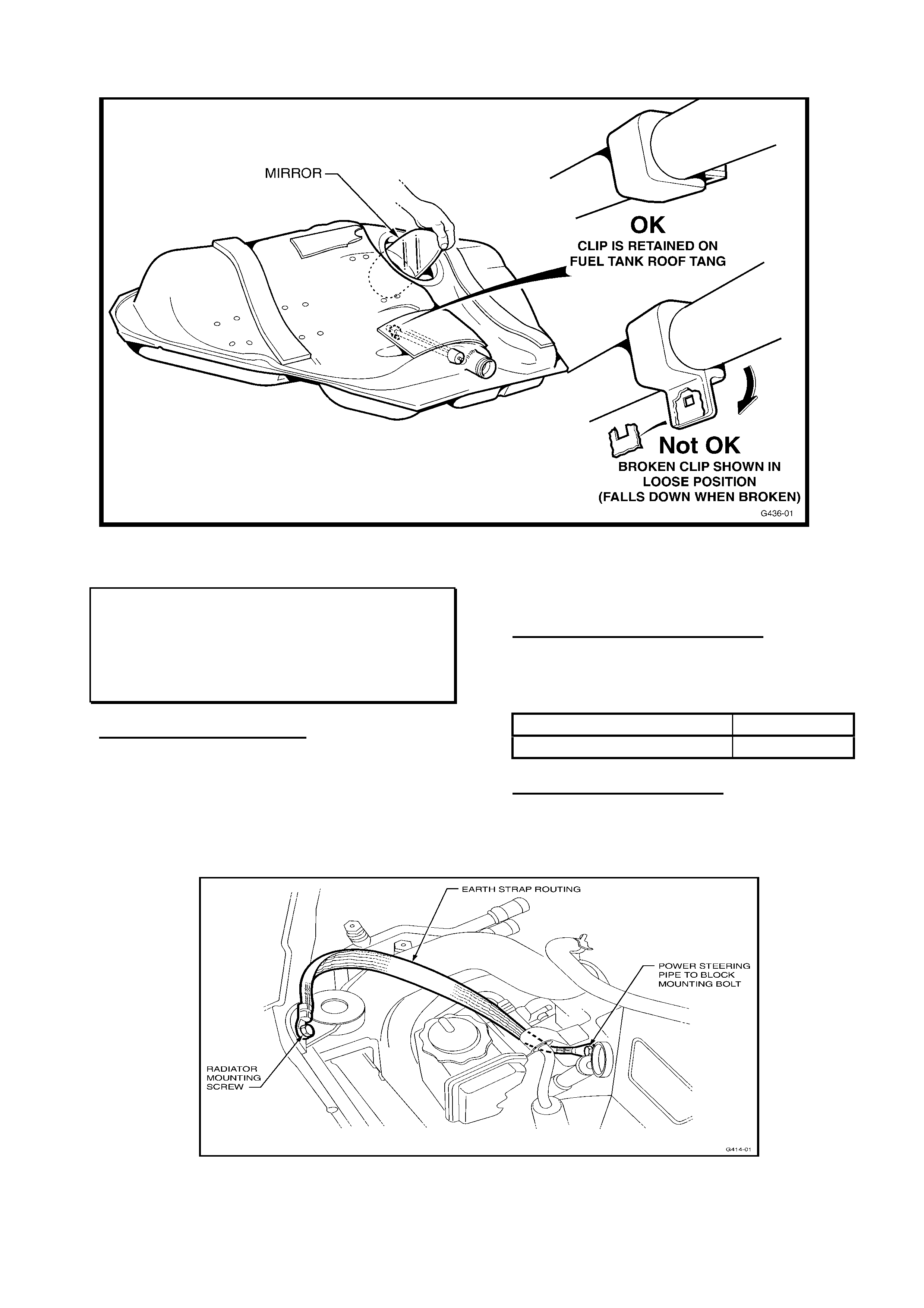
3. In a well-lit and ventilated area, use a mirror
to view the vent pipe retaining clip through the
fuel sender hole - as in Figure 1. If the clip is
broken (it will be loose and sliding on the vent
pipe, and will appear as shown in the “Not
OK” view) - then replace the fuel tank.
NOTE: If the clip is not broken and is as
shown in the “OK” view in Figure 1, further
diagnosis will have to be carried out to define
cause.
To assist with this, if required: There is
another pipe retaining clip, of similar design in
the fuel tank located close to the fuel gauge
opening and on the opposite side to the vent
pipe mentioned. While this clip has not been
cause for any concern or been reported
broken, view the clip and pipe in the mirror
and ensure the clip has not broken.
If it has been broken and appears as in the
“Not OK” view in Figure 1 the (broken) clip will
be hanging loose on the pipe as shown - the
“U” shaped broken part of the clip is also
shown -this restricts the fuel flow - the fuel
tank should be replaced.
An “OK” (undamaged) clip will be located on
the underside of top of fuel tank, as shown in
Figure 1.
PARTS INFORMATION
If replacement tank is required refer to
Partfinder for details.
WARRANTY CLAIM INFORMATION:
Use existing information in Labour Time
Manual SIP CD.
When filling out the Defective Material Tag for
any fuel tank replaced, note your findings on
the tag IE: clip has broken, and which clip.
HOLDEN SERVICE TECHLINE ___________________________________________________________JANUARY 2001
10
Figure 1.
REVISED EARTH STRAP ROUTING
JR, JS Series I, 4 Cyl Models
(GROUP 12) TL101-1207
PROBLEM DESCRIPTION
The Techline on the subject of poor AM radio
reception issued in Sep. 1998 recommended
fitment of an additional engine earth strap on 4 cyl
engine models only. The routing shown in that
Techline could result in fraying of the strap due to
contact with the top of the radiator.
A modified routing which avoids this problem is
shown in the following Figure1.
PRODUCTION RECTIFICATION
Revised routing of the radiator/engine earth
strap was introduced into Elizabeth built
vehicles from:
ISOVIN: Build Date:
W0L0JBF19XL457291 07/05/99
SERVICE RECTIFICATION
Apply revised earth strap routing as shown
on vehicles built prior to above breakpoint.
Figure 1. Revised earth strap routing.

HOLDEN SERVICE TECHLINE ___________________________________________________________JANUARY 2001
11
BODY CONTROL MODULE - LOCK UP
VTII, VX
(GROUP 12) TL101-1205
This information was first published in All
Dealer Letter 79/00. The information is
repeated here for technicians.
PROBLEM DESCRIPTION
PIR’s have been received describing a ‘BCM
Lock Up ‘ condition.
Symptoms of this condition are loss of all
BCM security related functions resulting in
engine wont start, no central locking, etc.
This is usually accompanied by a ‘buzzing’
noise emitted from the BCM.
When the BCM ‘locks up’ the microprocessor
inside the BCM starts its own self test routine
where part of this test includes switching all
BCM internal relays - hence the ‘buzzing’
sound.
Investigations have found the ‘lock up’
condition is caused by a static voltage
discharge that enters the BCMs’ internal
circuitry which in turn causes the BCM to
malfunction.
The suppliers’ testing continues to isolate the
source of the ESD (Electro Static Discharge).
SERVICE RECTIFICATION
When presented with a vehicle that has all of
the symptoms described above (engine no
start, central locking inoperative and a
buzzing sound from BCM), proceed as
follows:
1. Request a replacement BCM via a
Warranty Changeover Request Form.
Refer to All Dealer Letter 79/00 for copy of
form which is to be faxed to Australian
Arrow.
Ensure that the form is completed with all
detail as requested. Also record the
customer comments prior to the failure (if
applicable).
2. Temporarily return vehicle to service by
removing Fuse 31 to reset the BCM.
3. Submit a PIR on each case. Include
customer comments on the failure
symptoms where applicable.
PARTS INFORMATION
Part No.: Description: Qty:
92078313 Body Control Module-
Mid Series
1
92078315 Body Control Module-
Low Series
1
WARRANTY CLAIM INFORMATION
Use existing information in SIP Warranty
Information/Labour Times as shown:
Description Module – Body Control
Replace
Labour Op. N506600
Time 0.5 hr
Failure Code 50
Update
HOLDEN SERVICE TECHLINE ___________________________________________________________JANUARY 2001
12
ENGINE IDLE VIBRATION
VT, WH, Gen III Auto - Standard Engine
(GROUP 6C & 8) TL101- 0802
PROBLEM DESCRIPTION
Excessive vibration or buzz felt within the
vehicle, under any of the following conditions:
(1) Vehicle stationary at idle with
transmission in Drive/Reverse with a/c on
(2) Idle speed drop when Drive/Reverse
selected and/or steering load applied.
(3) Slow acceleration or low speed driving in
1st gear, with engine speed between 650 and
1000 rpm
SERVICE RECTIFICATION
To improve the level of vibration on complaint
vehicles for any of the above conditions, the
following action is recommended.
Step 1. Flash Revised Calibration
Flash revised calibration (idle speed revised to
620rpm) p/n 92103007 into complaint vehicles
only. The description on TIS 2000 is
“Continuous Improvement Calibration –
Improved Idle Quality”. Note this revised
calibration was first released on TIS CD No.14.
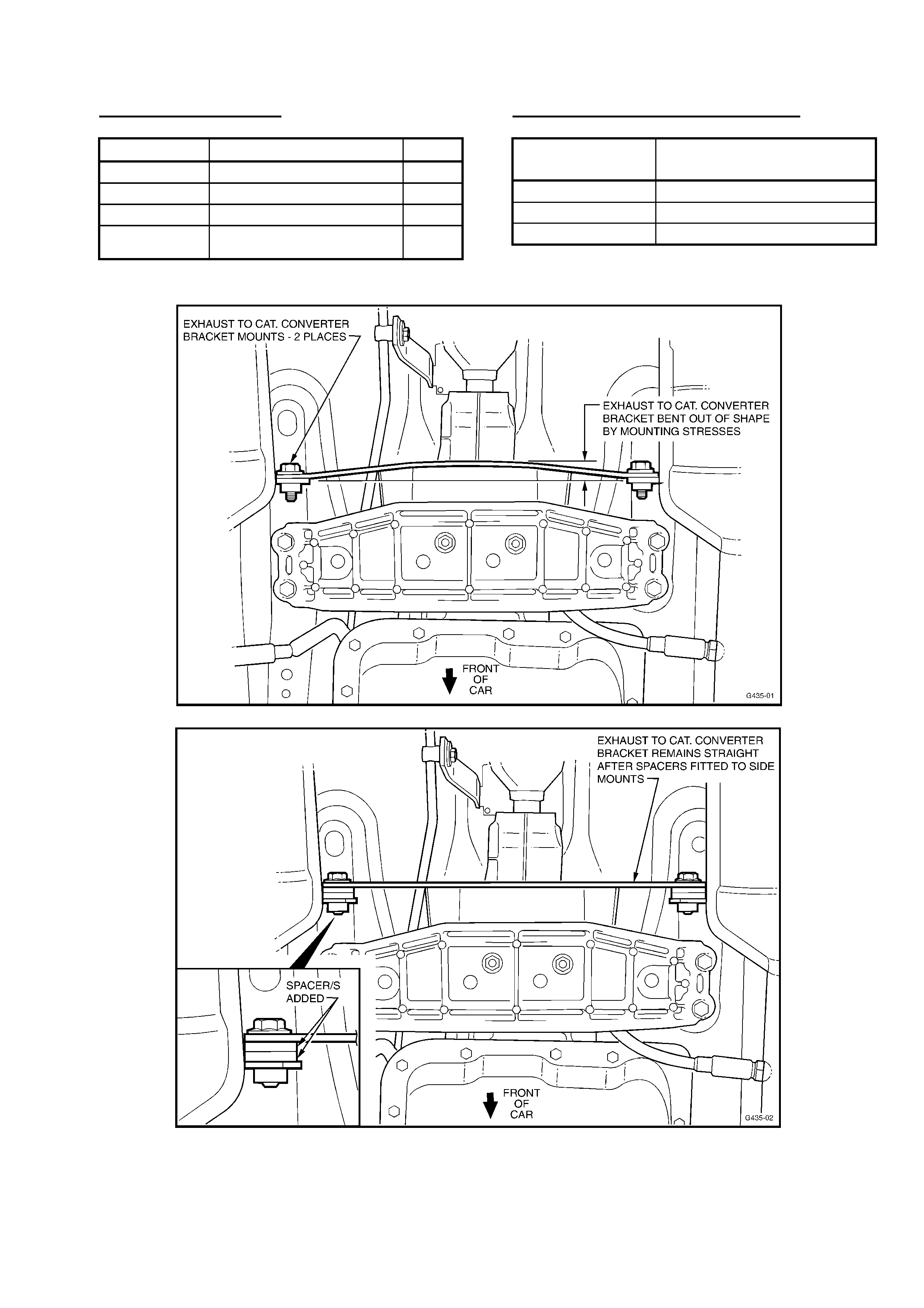
Step 2. De-stress Exhaust & Powertrain
An indication that the exhaust/powertrain is
stressed is a bent catalytic (cat.) converter
bracket as shown in Figure 2.
The following MUST be completed in
sequence
1. Loosen (by approx 1 turn) engine mount
nuts, front pipe/exhaust manifold nuts and
intermediate muffler/front pipe bolts.
2. Support transmission, and remove cross
member complete with cat. converter bracket
and transmission (trans.) mount.
3. Remove trans. mount and cat. converter
bracket.
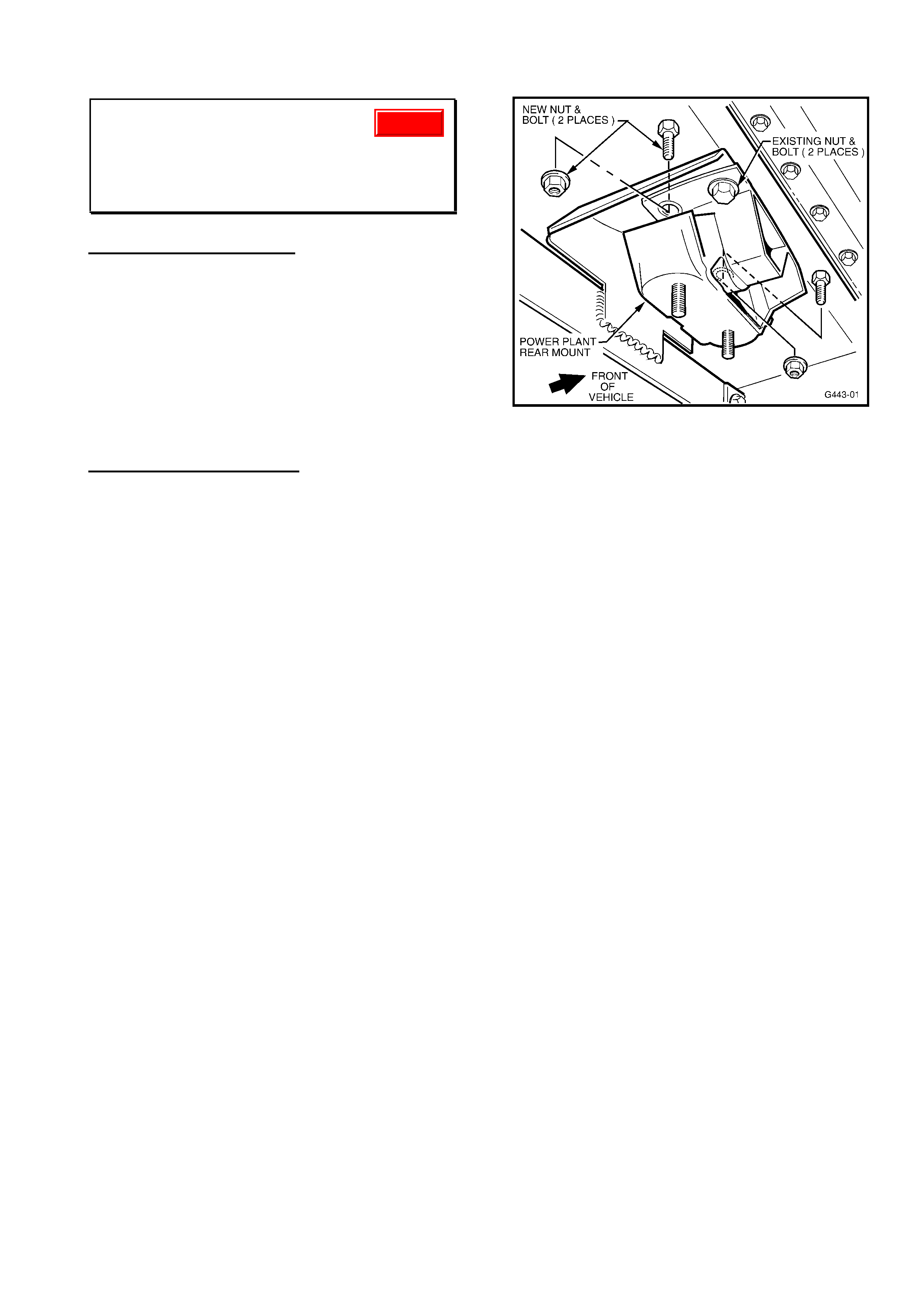
4. Fit two additional bolts/nuts to rear trans.
mount holes (use P/N: bolts:92138301,
nuts:11086962 ) and torque to 45-55 Nm (See
Figure 1).
Figure 1.
5. Fit trans. mount and cat. converter bracket
to transmission and torque bolts to
specification.
6. Refit cross member and torque four outer
bolts (ie, cross member to body rails) to
specification. Leave the two trans. mount to
cross member nuts loose at this stage.
7. Lower vehicle back onto the ground, start
the engine and cycle through the gears, ie, R-
N-D five times and then rev the engine in
neutral up to 4000 rpm five times.
8. Raise vehicle on hoist.
9. Torque engine mount nuts to specification.
10. Torque trans. mount to trans. cross
member nuts to specification.
11. Torque intermediate to front pipe bolts to
specification.
12. Torque front pipe-to-exhaust manifold nuts
to specification.
13. Add spacers to take up the clearance
between trans. to cat. converter bracket and
cat. converter (see Figure 2), refit bolts and
torque to specification. Flat washers p/n
120394 (1.6mm thick) may be used as
spacers.
Note: If longer bolts are required, use p/n
90495649. Ensure bracket is straight and not
bowed. (see Figure's 2 & 3)
Update
HOLDEN SERVICE TECHLINE ___________________________________________________________JANUARY 2001
13
PARTS INFORMATION
Part No. Description: Qty
92138301 Bolt rear trans mt. 2
11086962 Nut rear trans mt. 2
90495649 Bolt cat conv brkt 2
120394 Flat washer (spacer) As
reqd
WARRANTY CLAIM INFORMATION:
Description Reflash PCM & Destress
Exhaust/Powertrain
Labour Op. No. J000683
Time 0.8 hr
Failure Code 36 (vibrates)
Figure 2.
Figure 3

HOLDEN SERVICE TECHLINE _____________________________________________________________JANUARY 2001
14
4JX1 INTAKE THROTTLE VALVE STICKING
DIESEL JACKAROO (UBS)
GROUP 6C TL101-6C01
Condition
Some 4JX1 engines may develop a “Hard to start” and “Lack of Engine Response” caused by the Intake
Throttle Valve sticking, the engine RPM will not increase immediately when the accelerator pedal is
depressed and the problem may disappear once the engine has warmed up. DTC 1486 (Intake throttle
position sensor high voltage) will be set. The check engine light may also illuminated.
NOTE: It is normal for the 4JX1 engine to experience some acceleration lag when cold due to oil
viscosity.
Possible Cause
Sticking butterfly valve in the Intake Throttle Valve assembly, due to an excessive build up of carbon.
Correction
After confirming the symptom and after conducting thorough investigation using the workshop manual,
Section 6 “Hesitation” it may be necessary to remove and thoroughly clean the Throttle Body.
NOTE: Do not remove or immerse the sensors into any form of cleaning agent.
AIR IN FUEL
4JX1DIESEL JACKAROO (UBS)
GROUP 6M TL101-6M01
I-GM TAS has received a large number of calls regarding air in 4JX1 fuel systems, investigations have
revealed that the fuel inlet fitting at the front of the engine was loose.
The fuel inlet has a BANJO fitting that mates to the fuel inlet pipe, the pipe has a locking nut that
tightens itself against the inlet manifold. This nut is not a locking device, it is to stop lateral movement of
the fuel pipe.
In order to check the security of the fuel pipe it is necessary to remove the cap nut and tighten the pipe
itself. However if the pipe is found to be loose replace the aluminium washer with a new one available
through HSPO. Part number 1096300830.
TORQUE SPECIFICATIONS:
FUEL PIPE: 4 Nm.
CAP NUT: 13 Nm.
BANJO FITTING: 14 Nm.

HOLDEN SERVICE TECHLINE ___________________________________________________________JANUARY, 2001
15
INJECTOR REWORK
UBS JACKAROO 4JX1 DIESEL
GROUP 6M TL101-6M02
IGM TAS continues to receive phone inquiries in regards to the Injector O – ring rework, dealers are
requested to refer to I-GM All Dealer Letter DL 04/00 for more detailed information.
Condition
Some 4JX1 engines (up to engine number 676517) may experience Diesel fuel dilution causing “Hard to
Start” and excessive smoke.
Possible Cause
The original injector O – ring hardens with age, allowing fuel to bypass and enter the crankcase.
Correction
Install the injector sealing ring kit referring to the previously released DL 04/00. From November 3rd
1999 production, engine number 676517 onwards, the material for the O - rings was changed, therefore
engines post this breakpoint should not be reworked. If an engine post this breakpoint develops fuel
dilution, a PIR should be raised.
4JX1 RAIL PRESSURE CONTROL VALVE DIAGNOSIS
DIESEL JACKAROO (UBS)
GROUP 6M TL101-6M03
Some 4JX1 engines may develop a rough idle or hesitation caused by an intermittently sticking RPCV.
An intermittently sticking RPCV is sometimes very difficult to diagnose. Therefore, to enable easier
detection of a faulty/sticking RPCV please refer to the attached graphs.
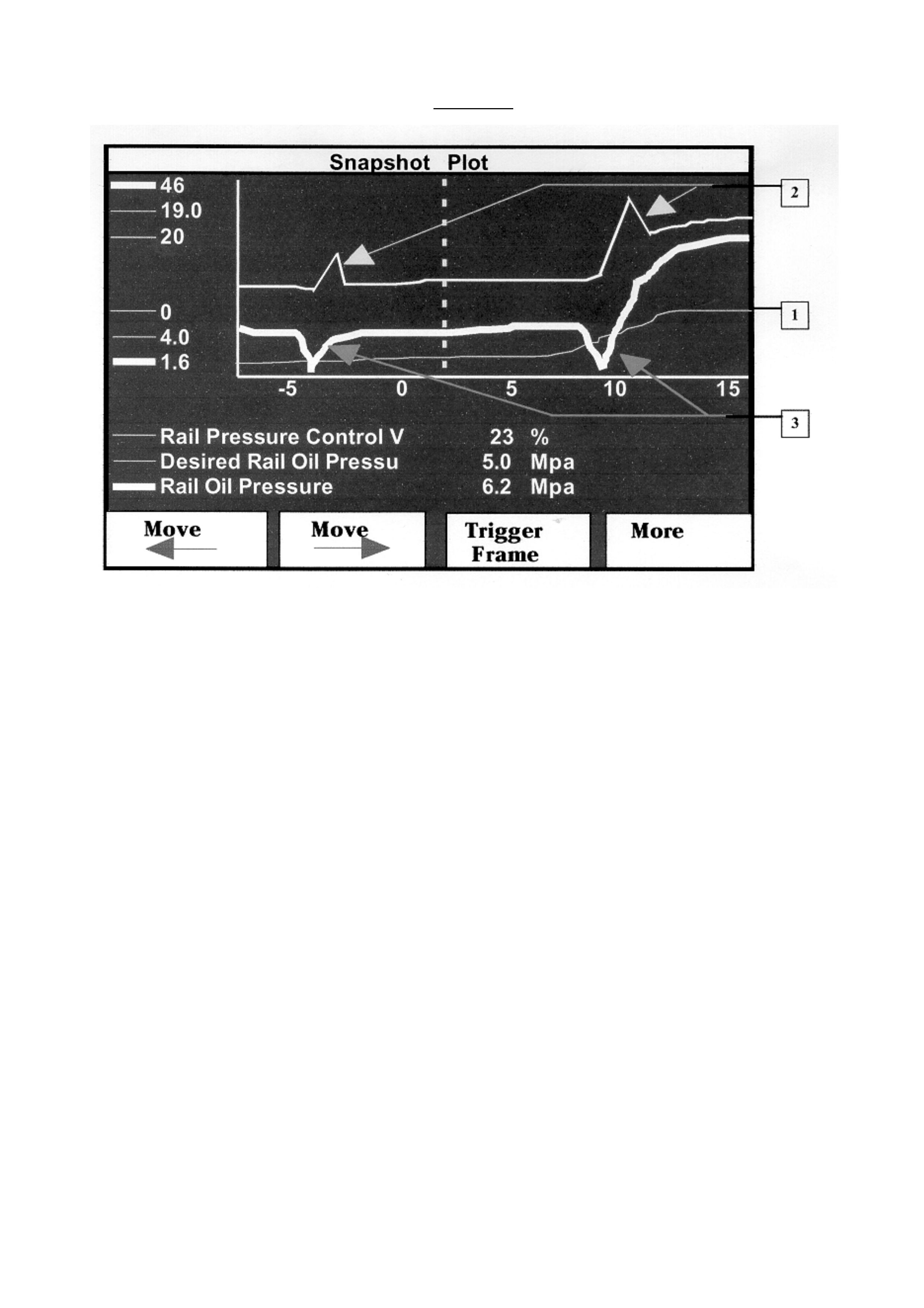
Graph 1: The graph outlines a sample of Tech 2 snapshot data that shows a faulty/sticking RPCV.
TECH 2 snapshot is most effective for checking this condition.
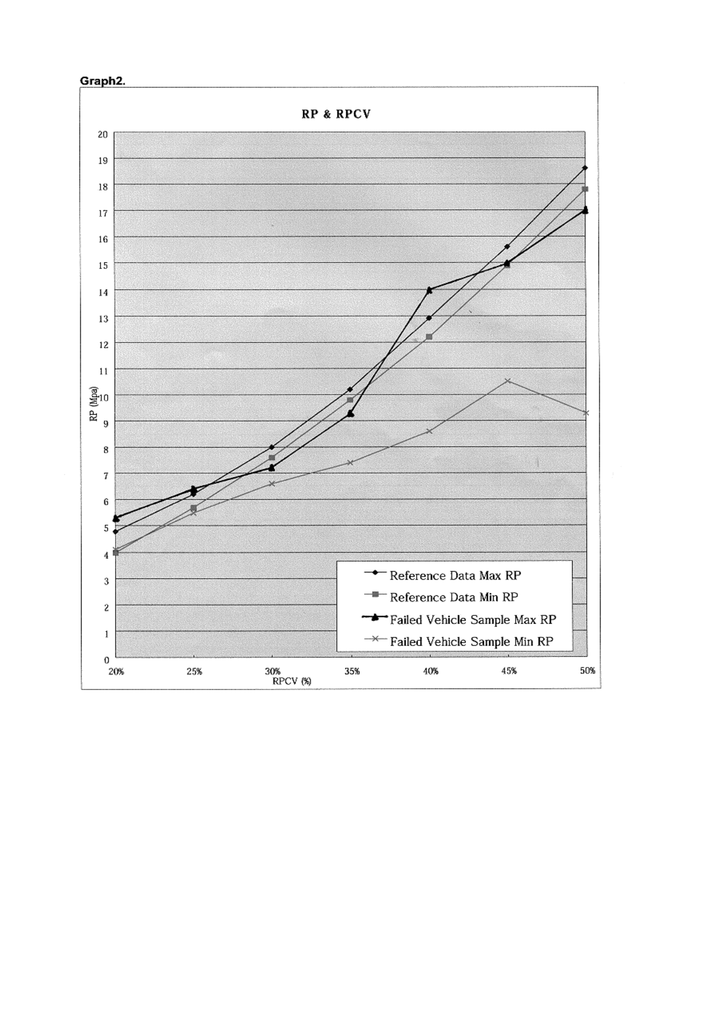
Graph 2: The graph outlines the relationship between the “Rail Oil pressure”, and the percentage of the
RPCV operating range. All of these parameters can be found using TECH 2.
NOTE: Actual pressures recorded by TECH 2 may differ slightly than those displayed on the graph; this
is due to different grades/ viscosity of engine oil and operating temperatures.
After confirming the symptom and after conducting thorough investigation using the workshop manual,
section 6 “Rough Idle”, it may be necessary to replace the RPCV, PT No: 8 97174 872 0.
HOLDEN SERVICE TECHLINE ___________________________________________________________JANUARY, 2001
16
GRAPH 1.
This graph shows a sample of a Snapshot Plot Data as displayed on Tech 2.
The graph shows the relationship between the Rail Pressure Control Valve, Desired Rail Oil Pressure
and Actual Rail Oil Pressure.
Due to an intermittently sticking RPCV, the Actual Rail Oil Pressure does not meet the Desired Rail Oil
Pressure.
1. The Desired Rail Oil Pressure increases due to engine load.
2. The PCM controls the RPCV in order to meet the Desired Rail Oil Pressure. Due to the sticking
RPCV there is a delay in the movement of the RPCV.
3. The Actual Oil Pressure is not within the tolerance of the desired Rail Oil Pressure due to the
sticking RPCV. The Actual Oil Pressure drops, that can clearly be seen from the graph.
If the above condition is displayed on Tech 2, a Hesitation or rough idle could be the result of a sticking
RPCV due to contamination or an internal failure.
HOLDEN SERVICE TECHLINE ___________________________________________________________JANUARY, 2001
17
Graph 2 clearly demonstrates the rail pressure difference between a sticking (faulty) RPCV and a good
example.

HOLDEN SERVICE TECHLINE ___________________________________________________________JANUARY, 2001
18
CLUTCH PEDAL HEIGHTS
1998 & ONWARD - JACKAROO, RODEO AND FRONTERA
GROUP 7A TL101-7A01
Recent enquiries from dealerships in regard to premature clutch wear and failure has prompted
I-GM to take this opportunity to remind all Dealership Service staff of the importance of clutch pedal
adjustment in relation to clutch durability.
Correct clutch adjustment is critical to ensure clutch life and correct operation. Dealers are advised to
ensure that clutches are adjusted as per service schedules.
TF RODEO
WITH 4JB1T WITH 6VD1 WITH 4ZE1 WITH C22NE
CLUTCH PEDAL
FREEPLAY
5.0 mm -15 mm
5.0 mm -15 mm
5.0 mm -15 mm
5.0 mm -15 mm
CLUTCH PEDAL
HEIGHT
185.5 mm –
195.5 mm
216 mm –
226 mm
216 mm –
226 mm
216 mm –
226 mm
CLUTCH SWITCH
TO CLUTCH
PEDAL
CLEARANCE
(IF FITTED)
.5 mm – 1.5 mm
.5 mm – 1.5 mm
.5 mm – 1.5 mm
.5 mm – 1.5 mm
JACKAROO
WITH 4JX1TC WITH 6VE1
CLUTCH PEDAL FREEPLAY 5.0 mm -15 mm 5.0 mm -15 mm
CLUTCH PEDAL HEIGHT 231 mm –
241 mm
238.5 mm –
248.5 mm
CLUTCH SWITCH TO CLUTCH
PEDAL CLEARANCE
(IF FITTED)
.5 mm – 1.5 mm
.5 mm – 1.5 mm
FRONTERA
WITH X22SE WITH 6VD1
CLUTCH PEDAL FREEPLAY 5.0 mm -15 mm 5.0 mm -15 mm
CLUTCH PEDAL HEIGHT 178 mm –
188 mm
178 mm –
188 mm
CLUTCH SWITCH TO CLUTCH
PEDAL CLEARANCE
(IF FITTED)
.5 mm – 1.5 mm
.5 mm – 1.5 mm

HOLDEN SERVICE TECHLINE ________________________________________________________JANUARY, 2001
19
REMOTE KEY AND KEY READER
DIAGNOSIS
VT/WH
GROUP 12 TL101-1208
The following information was previously
released in All Dealer Letter DL 30/00. The
information is repeated to ensure technicians
have ready access to the diagnosis included.
Problem Description
A significant number of remote keys are
being replaced under warranty as
rectification for various problems and when
tested by Holden supplier – Australian Arrow,
cannot be faulted.
This All Dealer Letter provides dealerships
with improved and simplified remote key
diagnostic procedures that have been
developed and made available for
technicians to use when diagnosing remote
key function related customer complaint
conditions.
There are two diagnostic charts included with
this letter. These are applicable to VR & VS
also.
• Attachment 1- is to be referred to when
diagnosing ‘intermittent no start
complaints or traction control light
illumination’.
• Attachment 2 – is to be used to diagnose
complaints of central locking problems.
• Attachment 3 – is a form for reporting the
diagnosis carried out by the technician
when rectifying remote key related
complaints.
Dealers are requested to complete the
‘Remote Key Diagnosis Form’ (Attachment
3), ticking the appropriate boxes to identify
the steps followed during the diagnosis.
Please attach this form to the Defective
Material Tag, when a remote key is replaced
and returned to Repac. This is a mandatory
requirement affecting parts returned to
Repac with Repair Order dates from June 15,
2000.
The supplier will use this data when
analysing returned parts so that the fault can
be reproduced in order to develop a
corrective action plan.
A customer information checklist is currently
being developed to help the Service
Reception staff at your dealership gain
necessary information from the customer, to
diagnose and rectify the customers’ concern.
This checklist will be sent to all dealerships in
the near future under cover of another all
dealer letter.
Please ensure all Service Personnel involved
in the diagnosis, replacement and return of
remote keys are aware of this information
and requirements.

HOLDEN SERVICE TECHLINE ________________________________________________________JANUARY, 2001
20
VR/VS/VT/WH - KEY READER CIRCUIT DIAGNOSIS
‘INTERMITTENT NO START’
Preliminary Checks
• Check for loose key shaft.
• Check for correct screws.
• Correct length of remote key shaft. (Check shaft against a known good key).
• Remove the key shaft, clean the earth contact, key shaft and reinstall the key shaft. If screws
won’t retain or if the screw threads are deformed, then replace the screws.
Please tick appropriate box.
STEP
ACTION
YES
NO
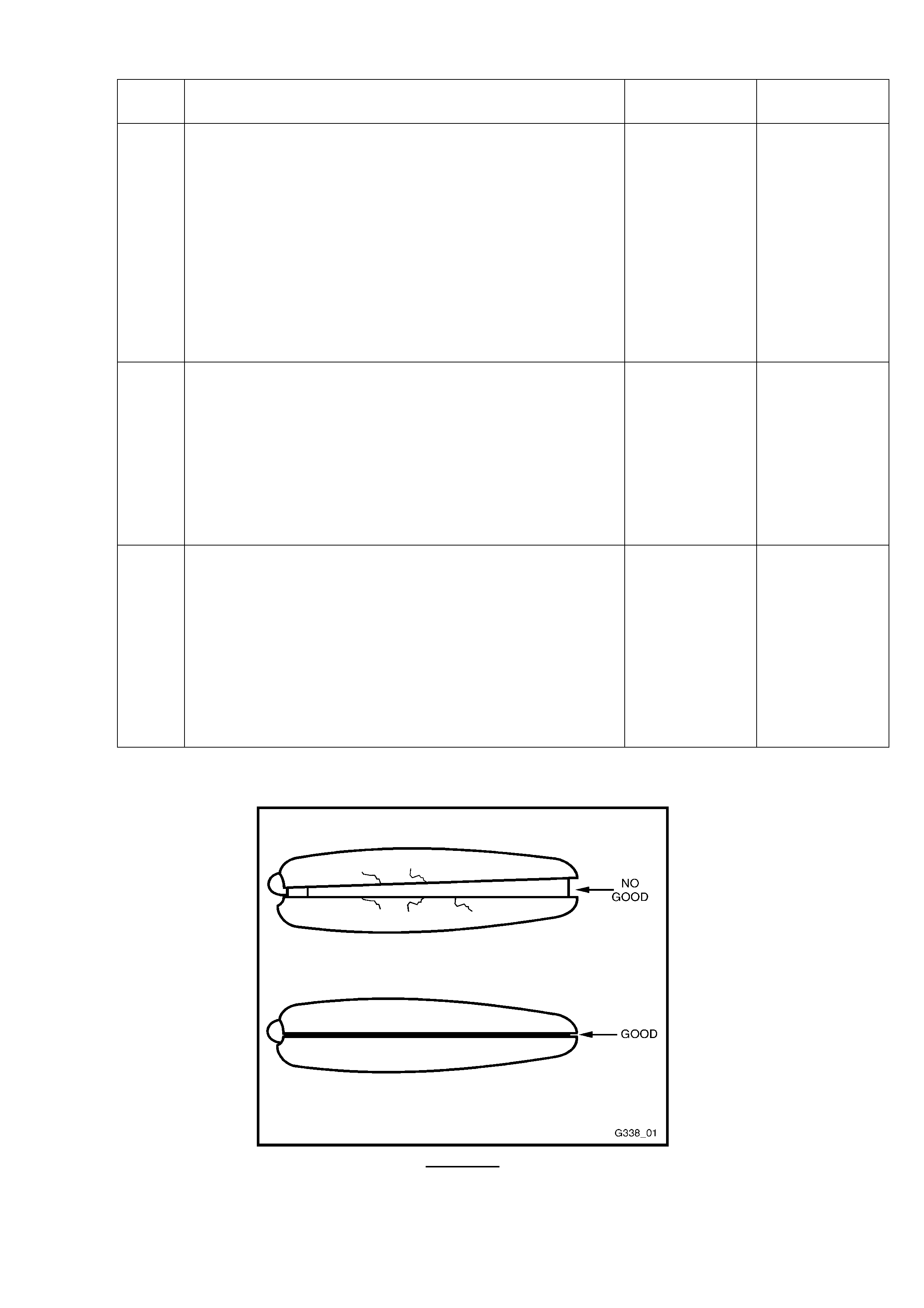
1. • Is the case cracked along the weld line, or are there
visible gaps (at the sides only)? Refer to Figure 1
on Attachment 2.
Replace Key.
Go to step 2.
2.
• Are any of the buttons collapsed , depressed or
damaged?
Replace Key.
Go to step 3.
3. • With the Theft Deterrent LED (TDL) flashing, insert
the remote key into the ignition switch and slowly
turn to the ‘ON’ position.
• Does the TDL stop flashing?
Go to step 4.
Go to step 6.
4. • With the TDL off, turn the remote key to the
‘START’ position.
• Does the vehicle start?
Go to step 5
Refer to
relevant
Service
Manual ie
VR. VS VT.
Follow Theft
Deterrent
System
Diagnosis.
5 • VT/WH ONLY. Does the customer complain that
occasionally the Traction Control Light remains ‘ON’
or TDL continues to flash at a quicker rate after
starting?
Check the
slip ring
circuit.
Go to step 7.
Problem is
intermittent
Go to step 6.
6. • Connect a multimeter between a known good earth
and one of the reader slip rings.
• Apply a thick tape over the remote key contact pin
and insert into the ignition switch.
• Is there 12V DC on the slip ring for approximately 2
seconds (VR/VS) or 4-6V AC constantly (VT/WH)
when the remote key is turned to the ‘ON’ position?
• At end of test, remove tape from the remote key.
Go to step 7.
Go to step 8.
7. • Check integrity of ignition barrel earth by-:
Visually inspecting earth strap on ignition lock housing.
Checking tightness of earth strap.
Checking for continuity to known good earth.
• Is ignition barrel earth OK?
Go to Step
10.
Repair or
replace faulty
components.
Recheck
circuit to
verify repair.

HOLDEN SERVICE TECHLINE ________________________________________________________JANUARY, 2001
21
STEP ACTION YES NO
8.
• Refer to the appropriate Service Manual, and with a
multimeter check for continuity between BCM/TDM
and remote key reader.
• Is there continuity?
Go to step 9.
Repair open
circuit.
Recheck
circuit to
verify repair.
9. • Disconnect appropriate BCM connector (Refer to
Wiring Diagrams)
• With the ignition switch in the ‘OFF’ position check
for a short to B+/Earth on the slip ring.
• Is there a short?
Repair short
circuit.
Recheck
circuit to
verify repair.
Call
Australian
Arrow
Customer
Service on
03 9785 0792
10. • Check for a misaligned Key Reader as per following
procedure -:
- Remove starter relay from the engine bay to
prevent the vehicle from cranking.
- Disconnect Remote key reader connector by
access from under steering column cover.
- Ensure TDL is flashing, and slowly turn key and
hold in crank position.
- While holding in crank position, reconnect the
reader connector.
- Does the TDL switch off (has key been read)?
- Remove ignition key, rotate it 180 degrees,
insert into the ignition switch and check contact
with the second slip ring with the same method.
• Is the remote key contact pin making contact i.e.
Has the TDL switched off?
Go to step
11.
Align Key
Reader.
Remove key
reader and
align the
locating rib
on the
Reader with
Ignition
barrel.
Verify repair.
Return
vehicle to
customer and
monitor.
11. • Check for worn or relaxed Reader contacts as per
following procedure -:
- With TDL flashing, turn key to Accessories
position.
- Apply outward pre-load to key, by pulling on key
gently away from reader.
- While monitoring TDL, quickly turn key from
Accessory to crank position.
- Check if the key contact pin is making contact
with the slip ring, by checking if TDL stops
flashing (reads key OK).
- Remove ignition key, rotate it 180 degrees,
insert into the ignition switch and check contact
with the second slip ring with the same method.
• Is the remote key contact pin making contact i.e. did
the TDL stop flashing at the full crank position?
For vehicles
built pre May
1998:
Replace
Remote Key
Vehicles-
For vehicles
built post
May 1998:
Call
Australian
Arrow
Customer
Service on
03 9785 0792
Replace slip
ring contacts
and verify
repair.

HOLDEN SERVICE TECHLINE ________________________________________________________JANUARY, 2001
22
VR/VS/VT/WH - REMOTE OPERATION
Diagnostic Aids:
Prior to further diagnosis, technicians should be aware of the following system
functions:
• There is a 2 second delay on the remote boot release
• The central locking system will time-out as a result of multiple activation of the lock or
unlock remote buttons.
• Metal objects such as other keys on the key ring or key tags can effect range if folded
over the remote key head.
• If the reported problem is specific to one area, radio or TV towers can effect key range
and performance.
• Damaged key casing may cause moisture ingress resulting in premature key failure.
Please tick appropriate box.
STEP
ACTION
YES
NO
1. • Is the case cracked along the weld line, or are there
visible gaps (at the sides only)? Refer to Figure 1.
below.
Replace Key. Go to step 2.
2. • Are any of the buttons collapsed , depressed or
damaged?
Replace Key. Go to step 3.
3. • With all doors closed and unlocked, insert the
remote into the driver’s door lock barrel and turn
anti-clockwise.
• Do all doors lock?
Go to step 5. Go to step 4.
4. • Does the Dome lamp remain on with the ignition in
the ‘ON’ position and all the doors closed?
Inspect door
jamb switches
or circuit for
short to earth.
Refer to
Service
Manual. Check
Central Door
Locking
Diagnosis
Section.
5 • With all doors closed and unlocked, operate the
DOOR/LOCK button on the remote key within 5
metres of the driver’s side ‘B’ pillar.
• Do all doors lock?
Go to step 6. Go to step 7.
6. • With vehicles with remote boot operation, operate
the BOOT button on the remote key for at least 2
seconds within 2 metres of the rear of the vehicle.
• Does the boot solenoid activate?
Intermittent
problem
System OK.
Refer
diagnostic aids
above.
Contact
Holden TAS
VS/VT/WH
Go to step 8
VR
Go to step 9.
HOLDEN SERVICE TECHLINE ________________________________________________________JANUARY, 2001
23
STEP ACTION YES NO
7.
• For VS/VT/WH: Check if the remote key operates
intermittently while tapping it, or was the vehicle
built prior to May 1998?
• For VR: Are the remote key battery terminals
corroded, or is the battery discharged?
Internal battery
tab failure or
internal earth
failure.
VS/VT/WH
Replace Key.
VR:
Replace
battery
VS/VT/WH
Go to step 8.
VR
Go to step 9.
8. • Refer to Service Manual. Connect the TECH Tool.
• Proceed to Data List mode and select REMOTE
KEY SIGNAL (VS) or REMOTE DOOR and BOOT
signals (VT/WH).
• Operate the UNLOCK/LOCK/BOOT button on the
remote key.
• Does the Screen Display change to show either
‘UNLOCK’or ‘LOCK’ or ‘OPEN’?
Call Australian
Arrow
Customer
Service on
039785 0792
Go to Step 9.
9. • Connect the TECH tool to another fully functional
VS/VT/WH vehicle.
• Proceed to Data List mode and select REMOTE
KEY SIGNAL (VS) or REMOTE DOOR and BOOT
signals (VT/WH).
• Operate the UNLOCK/LOCK/BOOT button on the
remote key.
Does the Screen Display change to show ‘INVALID
KEY’?
Call Australian
Arrow
Customer
Service on
039785 0792
Replace
Remote Key.
Figure 1.
HOLDEN SERVICE TECHLINE ________________________________________________________JANUARY, 2001
24
COMPLETE THIS FORM AND ATTACH IT TO THE DEFECTIVE MATERIAL TAG TO SUPPORT YOUR
REMOTE KEY WARRANTY CLAIM.
AUSTRALIAN ARROW (AAPL) REMOTE KEY DIAGNOSIS FORM -VR/VS/VT/WH COMMODORE
REPAIR ORDER NUMBER: _____________________
TECHNICIANS NAME: _____________________________ BCM/TDM Barcode Number :
_____________________
(located on BCM/TDM label)
CUSTOMER COMPLAINT: INTERMITTENT NO REMOTE/BOOT OPERATION )
INTERMITTENT NO START POOR RANGE
OTHER : _____________________________________________
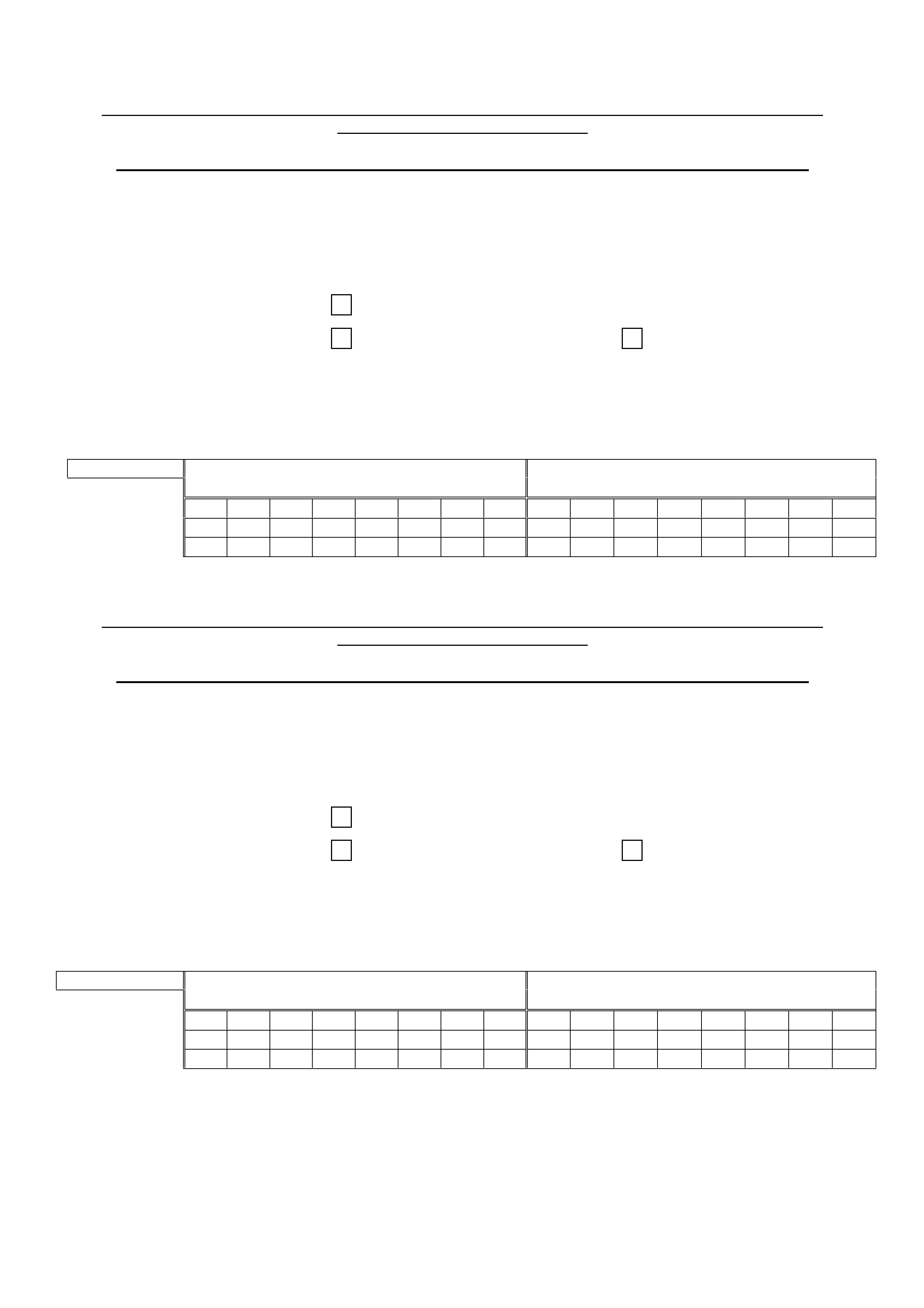
Use the appropriate matrix below (depending on the customer complaint), and indicate which steps
you took to diagnose the customers’ complaint-
COMPLAINT KEY READER CIRCUIT FAULT NO REMOTE/BOOT OPERATION
1 2 3 4 1 2 3 4
5 6 7 8 5 6 7 8
9 10 11 12 9 10 11 12
-----------------------------------------------------------------------------------------------------------------------------
COMPLETE THIS FORM AND ATTACH IT TO THE DEFECTIVE MATERIAL TAG TO SUPPORT YOUR
REMOTE KEY WARRANTY CLAIM.
AUSTRALIAN ARROW (AAPL) REMOTE KEY DIAGNOSIS FORM -VR/VS/VT/WH COMMODORE
REPAIR ORDER NUMBER: _____________________
TECHNICIANS NAME: _____________________________ BCM/TDM Barcode Number :
_____________________
(located on BCM/TDM label)
CUSTOMER COMPLAINT: INTERMITTENT NO REMOTE/BOOT OPERATION )
INTERMITTENT NO START POOR RANGE
OTHER : _____________________________________________
Use the appropriate matrix below (depending on the customer complaint), and indicate which steps
you took to diagnose the customers’ complaint-
COMPLAINT KEY READER CIRCUIT FAULT NO REMOTE/BOOT OPERATION
1 2 3 4 1 2 3 4
5 6 7 8 5 6 7 8
9 10 11 12 9 10 11 12

HOLDEN SERVICE TECHLINE ________________________________________________________________ FEBRUARY 2001
6
MUDFLAPS (REAR MOULDED) – MOUNTING
HOLE CORRECTED
VX
(GROUP OB) TL102-OB01
The following information was previously
released in HSPO Parts Techline PT 52,
dated 28 Sept., 2000.
Please ensure your pre-delivery manager
and technicians involved in accessory fitting
are made aware of this bulletin and the
above letter. Basic details only are
summarised here.
PROBLEM DESCRIPTION
In Moulded Mud Flap Packages 92142466,
92142467 & 92142468, a manufacturing fault
was detected in the lower mounting bracket.
One of the mounting holes is too large, and the
mounting screw supplied is not thick enough to
self-thread and retain properly.
RECTIFICATION OF PACKAGES
All stock of these packages at HSPO were
reworked by October 4, 2000, by the addition of
larger mounting screws.
SERVICE RECTIFICATION
Larger screws are available via phone contact
with HSPO.
When fitting one of the above mud flap
packages, if the lower mounting screw does not
retain properly, check with your Parts Manager
who can supply the correct screws, or order a
package of correct size screws, as per HSPO
Parts Techline PT 52.
BRAKE COMPONENT ‘ASSEMBLY’ FLUID
ALL
(GROUP 5) “HINT” TL102-0501
PROBLEM DESCRIPTION
Several brake components have been returned
to Repac where testing has determined there is
no fault in the components.
Investigation also has shown that the
components were replaced – at very low km’s
travelled - because there was fluid on the
components. This fluid was assumed to be
brake fluid.
Technicians should be aware that an assembly
fluid is used in assembly of brake system
hydraulic lines, calipers, etc.. On a quick
assessment, any excess of this fluid may be
mistaken as brake fluid, resulting in the
component being replaced unnecessarily.
SERVICE RECTIFICATION
To ensure that brake systems and components
are not disturbed or replaced unnecessarily, if a
suspected leak or ‘wetness’ is being assessed,
technicians should:
- clean off any fluid around the brake
components;
- apply pressure to the system via the brake
pedal (engine running);
- assess whether any leak actually occurs.
Should a leak be evident, replace components
as required.

HOLDEN SERVICE TECHLINE ________________________________________________________________ FEBRUARY 2001
7
LIGHT COMMERCIAL VEHICLE
INTEGRATION INTO HOLDEN
UBS, TF, UT, Suburban
(GROUP 7B) TL102-OB02
The summarised information below is
published in fuller detail in All Dealer Letters
DL 09/01 & DL 03/01.
TAS & Security Enquiries
LIGHT COMMERCIALS VEHICLES – Rodeo,
Jackaroo, Frontera, Suburban – and the
associated work that surrounds them, have been
‘integrated’ back into Holden.
Look forward to hearing more about these
vehicles from Holden Service Engineering, in
Service Techlines and All Dealer Letters, etc,
provided by Holdens Service Head Office.
From your Service Department’s point of view –
the support for these “light commercials” is now
carried out by:
HOLDEN PASSENGER & LIGHT
COMMERCIAL VEHICLE
TECHNICAL ASSISTANCE:
PHONE : 1800 033 417
(Existing Holden TAS phone No.!).
FAX : (03) 9647 2495
(Existing Holden TAS fax No.!).
In future, if you need to call TAS about any
passenger OR Light Commercial vehicles, you
just call or fax the one number!
In addition, the people in your department who
may have to request Security Numbers for these
vehicles can now contact:
HOLDEN PASSENGER & LIGHT
COMMERCIAL VEHICLE SECURITY
ENQUIRIES
FAX NUMBER: 03 9647 2865
(Existing Holden Security Enquiries Fax No.!).
TAS Procedures
With the release of All Dealer Letter 3/2001,
Nominated Contacts should now have their
copy of the TAS Procedures Manual. This
manual contains all the necessary information
required to communicate with TAS.
Please ensure that you have access to the
manual when speaking to TAS on the phone.
Nominated Contacts should also be aware that
Holden TAS now provide technical support for
Light Commercial vehicles which include
Jackaroo, Rodeo, Frontera.
Please ensure when contacting TAS that the
correct phone selections are made to reduce
your waiting times.
FLYWHEEL MACHINING
VT, VX, VU; all Gen3 & M/T
(GROUP 6A) TL102-6A01
PROBLEM DESCRIPTION
SIP information does not actually say whether
you can machine the Gen 3 engine flywheel or
not.
The answer is: you CANNOT!
The following statement will be added to Holden
SIP as soon as possible:
"Important: In order to maintain the proper
component balance, contact surface taper,
and heat transfer, manual transmission
flywheels are NOT to be machined."
HOLDEN SERVICE TECHLINE ________________________________________________________________ FEBRUARY 2001
8
TECH 2 FLASH PROGRAMMING
PRECAUTIONS
ALL
(GROUP 6C) TL102-6C01
Please circulate the following information to
all Pre-delivery and Service Technicians.
TECH 2 FLASH PROGRAMMING
PRECAUTIONS:
Please ensure that when Flash programming
any Holden product with TECH 2, that the
following conditions are met prior to
commencing:
1. Ensure that the vehicle has an acceptable
battery voltage - acceptable battery voltage
is a minimum of 12.4 volts.
2. Ensure that all power consuming devices are
turned off EG: blower fans, radios, etc.
3. Ensure that the TECH 2 cable and adapter
are in serviceable condition.
4. Do not place a battery charger on the vehicle
whilst flash programming under any
circumstances.
CLUTCH MASTER CYLINDER PUSH ROD
ADJUSTMENT PRECAUTION
VT, VX, VU – All with M/T
(GROUP 7A) TL102-7A01
PROBLEM DESCRIPTION
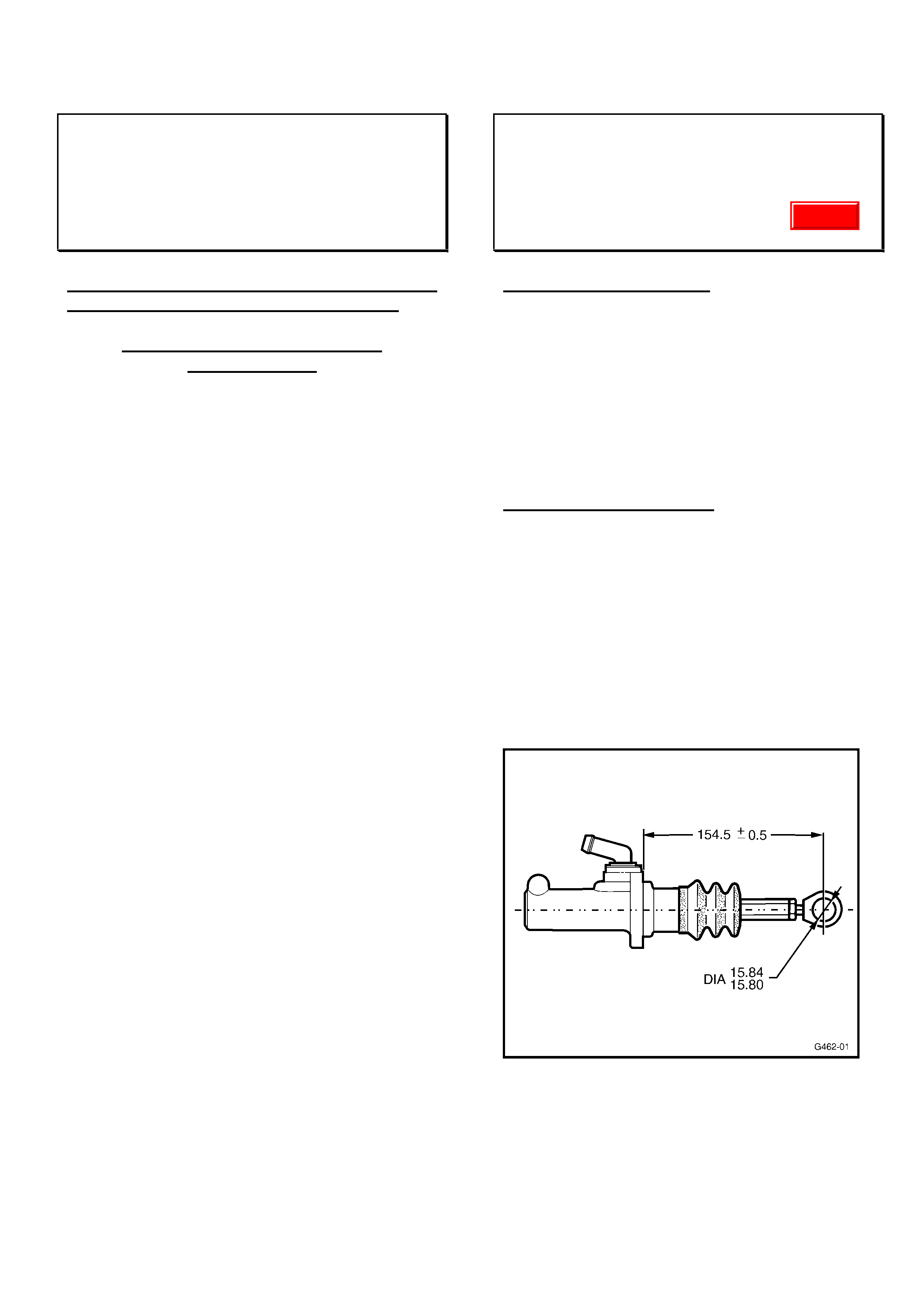
The clutch master cylinder push rod should NOT
be adjusted in any way.
The push rod lock nut and rod end positioning
are pre-set in master cylinder production.
This dimension must remain unchanged to
assure correct clutch hydraulic system
operation.
SERVICE RECTIFICATION
As there is a possibility that technicians may
attempt to adjust this push rod length, the
following drawing with correct setting dimension
is provided to allow correct setting.
Setting this dimension will require master
cylinder removal.
The dimension provided is specifically for VT,
VX & VU models.
Update

HOLDEN SERVICE TECHLINE ________________________________________________________________ FEBRUARY 2001
9
EXHAUST NOISE IN THE PASSENGER
COMPARTMENT
JR & JS with V6
(GROUP 8) “HINT” TL102-0801
PROBLEM DESCRIPTION
Customers may complain about “excessive
exhaust noise in the passenger compartment”,
which may prompt some exhaustive searching
or exhaust system diagnosis.
TAS have received a few calls about this, and
they have advised the following “HINT”.
SERVICE RECTIFICATION
Please do not go to too much trouble diagnosing
this complaint until:
- you have checked the steering column to floor
seal!
The seal may never have been seated correctly,
or may not have been refitted properly after
some service work?
As a quick diagnosis, wrap a rag around the
column seal, and if the noise reduces – you
have found the cause!
When this has been defined, refit the seal
correctly and check for acceptable noise level in
the passenger compartment.
If seal installation is OK, further diagnosis can
then commence to determine the cause.
Please PIR all cases investigated – whether
caused by the seal or other components, to
determine if further Service Engineering work is
required.

HOLDEN SERVICE TECHLINE ________________________________________________________________ FEBRUARY 2001
10
HEADLAMP FOGGING OR WATER
ENTRY
VX
(GROUP 12) TL102-1201
PROBLEM DESCRIPTION
PIR’s have been received which mention
headlamp fogging or water entry into
headlamps.
As a result, this Techline item is provided to
ensure technicians understand:
The VX headlamp design
Clearing minor fogging from headlamps;
Criteria for headlamp replacement due to water
entry.
Headlamp Design:
These vented lamps, with clear lenses (no
optics), are more prone to display visible
fogging. They are subject to minor fogging
under certain operational and climatic (high
humidity) conditions, when vehicles are parked
after use (the vent system will draw moisture
laden air into the lamp via it’s vent system which
condenses on the lens as it cools down). This
minor fogging will usually disperse when the
vehicle is driven, or if the headlamps are left on
for 3-4 minutes
SERVICE RECTIFICATION
Extensive research has shown condensation is
most likely to form when the headlamp is
switched off, and under high humidity conditions
- EG: If a customer uses their headlamps on a
rainy day, or washes the vehicle after having the
headlamps on, they could expect to notice
headlamp fogging some time after the vehicle
has been parked – this is normal.
On Complaint Vehicles:
Inspect the headlamp to determine if there is
normal fogging, or water entry due to leakage:
Clearing Minor Fogging
This “normal” fogging will be in the form of mist
on the lens, but will not have distinguishable
water droplets.
This needs no dealership action, as the fogging
will disperse during the time the vehicle is left
standing, OR when the vehicle is next driven.
Fogging will disperse within 3-4 minutes.
Water Entry
Should a lens feature severe fogging with water
droplets, or a visible amount of water in the
bottom of the headlamp, then investigation into
the cause of water entry must be carried out.
• Any obvious cause of water entry should be
corrected and the lamps dried out as per the
following “Clearing Minor Fogging”
procedure above.
Causes may be:
a) Vent tubes, dust caps and/or dust cap
seals missing, or incorrectly fitted,
b) Turn signal and/or six pin electrical
connector is incorrectly fitted,
c) Lens housing seal path has a leak (this is
unlikely as the supplier pressure tests every
production headlamp). If this is suspected –
the lamp will require replacement.
NOTE: it may be necessary – where water
may have leaked in via a connectors, caps,
etc, that have been re-fitted – to leave the
headlamps on for up to 20 minutes to clear
the remaining fogging.
✵ Should the headlamp not clear, the lamp
will require replacement.
• If visible “water marks” or “droplet marks” are
left on the inside of the lens, the lamp will
require replacement.
If lamp replacement is necessary, a clear
description of diagnosis and amount of water
entry should be quoted on the defective material
tag on the replaced part.
WARRANTY CLAIM INFORMATION:
Use existing Labour Operation/s and times as
shown in Warranty Information in SIP, if
headlamp replacement is required.
Warranty Managers, Please Remember: If
headlamp replacement is necessary, a clear
description of diagnosis, and amount of water
entry seen, should be quoted on the defective
material tag on the replaced part.
Update
HOLDEN SERVICE TECHLINE ________________________________________________________________ FEBRUARY 2001
11
REAR SIDE SEAT BELT ESCUTCHEON
REPLACEMENT
VT, VX
(GROUP 1) TL012-0102
PROBLEM DESCRIPTION
Rear side seat belt escutcheon may dislodge
from the rear side trim panel, and if damaged,
may not retain in the panel when re-fitted.
Until release of this Techline it was necessary to
replace the whole seat belt assembly to correct
this condition.
SERVICE RECTIFICATION
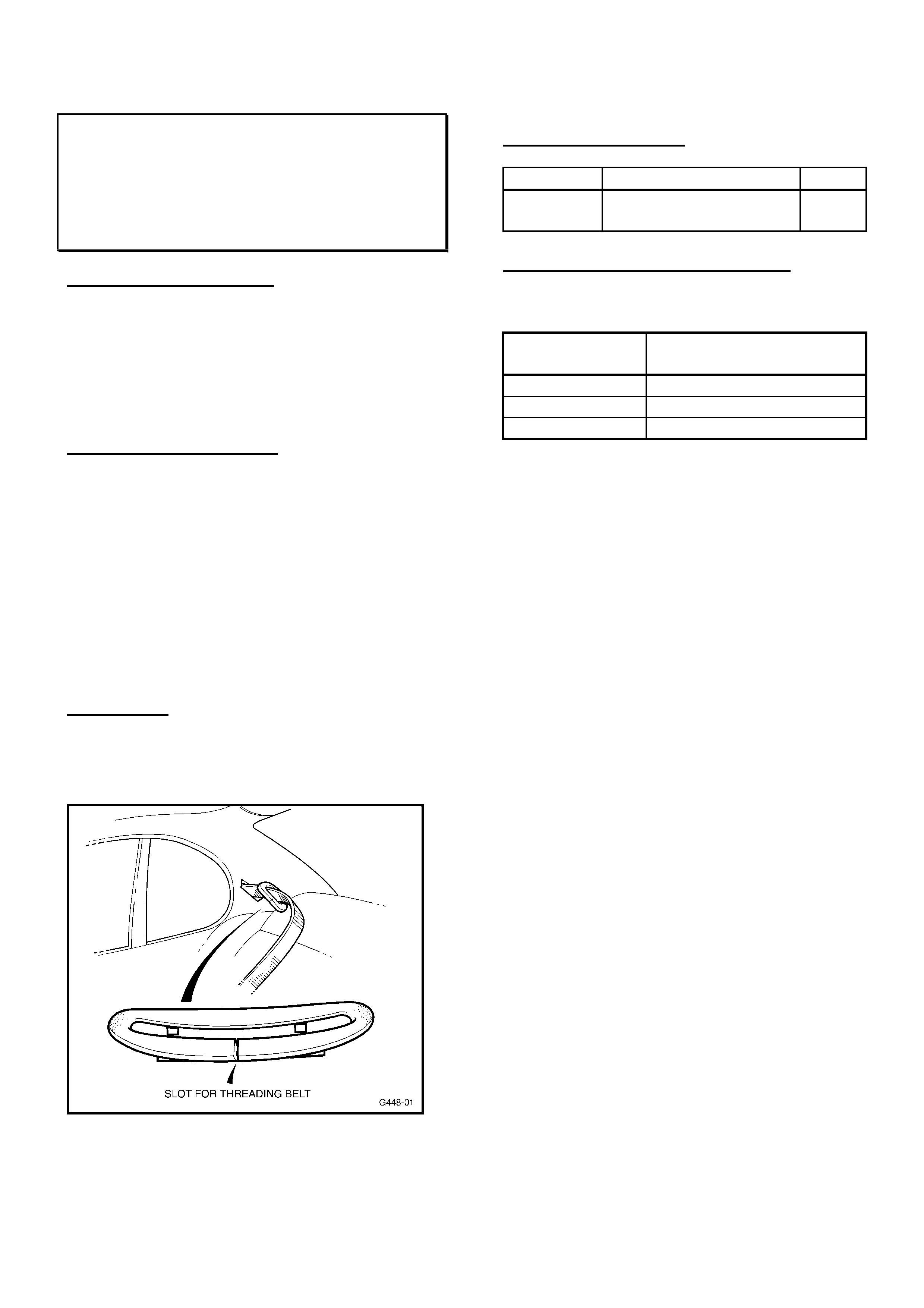
A new split, “service” escutcheon has been
made available for replacement of damaged
escutcheons, so that replacement of complete a
seat belt assembly is not necessary.
Any broken or damaged escutcheon – which will
not retain in the trim panel - should be replaced.
The damaged escutcheon must be removed by
carefully breaking the escutcheon through one
end (if not already broken) and slipping it off the
belt.
TAKE CARE not to cause any damage to the
seat belt while removing the escutcheon.
Fit the new Escutcheon – Rear Side Seat Belt –
refer Figure 1 for details.
Figure 1.
PARTS INFORMATION
Part No.: Description: Qty:
92144275 Escutcheon - Rear
Side Seat Belt
1
WARRANTY CLAIM INFORMATION:
Use the following information to claim for fitment
of the above escutcheon:
Description Escutcheon rear side
Seat Belt - Replace
Labour Op. No. C000421
Time 0.2 hr
Failure Code 01
HOLDEN SERVICE TECHLINE ____________________________________________________________ MARCH 2001
6
SHORTENING OF TONNEAU FLOOR
DRAIN TUBES
VU
(GROUP 1) TL103-0101
PROBLEM DESCRIPTION
Utilities have two drain tubes which allow
water to drain out of the tonneau floor area.
These drain tubes may protrude too far below
the vehicle and look unsightly, because of
their overall length.
PRODUCTION RECTIFICATION
Shorter tonneau floor drain tubes are to be
introduced into production in the near future.
When this occurs, the breakpoint information
will be added to the “Breakpoint Summary”
pages in the next Techline to be published.
SERVICE RECTIFICATION
If any complaints are received of tonneau
drain tubes protruding too far below the
vehicle, cut sufficient of the excess length
from the drain tubes – to leave 15mm
protruding below the lower floor panel:
NOTE:
- DO NOT cut the tubes too short,
- Cut the tubes parallel to the lower floor
panel.
WARRANTY CLAIM INFORMATION:
Description Shorten Tonneau Floor
Drain Tubes
Labour Op. No. C000424
Time 0.3 hr
Failure Code 55
PREMATURE REAR TYRE WEAR
JR, JS
(GROUP 4 & 10) TL103-0401
PROBLEM DESCRIPTION
Some vehicles may exhibit premature wear
across the tyre tread surface of the rear
tyres.
This premature wear, may be caused by
incorrect rear suspension alignment settings,
(excessive toe in) or from the vehicle
regularly carrying heavy loads.
SERVICE RECTIFICATION
Please remind pre-delivery staff of the
importance of checking rear wheel alignment
at pre-delivery inspection (Rear wheel toe
referred to in Part C of “New Vehicle Pre-
Delivery Check-List”.
When incorrect toe is detected at predelivery
or identified as a possible cause of the
premature wear condition, dealers should
1. Complete a Tyre Condition Report (refer
SIP) to report the condition and
2. Adjust the rear suspension toe in settings
to the “bottom end” of the existing
specification as shown below:
Set Toe-in to:-
Total:
0.28° +0.04°
-0.00°
This equates to a
toe in per side of:
0.14° +0.02°
-0.00°
Update
HOLDEN SERVICE TECHLINE ____________________________________________________________ MARCH 2001
7
TYRE CARE – BRIDGESTONE SO2
TYRES
HSV
(GROUP 10) TL103-1001
The following information is repeated from
HSV Bulletin 88/00 of December 22, 2000,
for use by ALL Service personnel when
dealing with HSV customers.
To: HSV Retailers Bulletin No. 88/00
HSV Sales/Service Specialists
TYRE CARE
With the holiday season approaching it is
timely to remind all HSV Retailers and
customers of the recommendations for tyre
care.
The Bridgestone SO2 tyres are a soft
compound, high performance tyre. Therefore:
• The inflation pressure in your tyres
determines the size and shape of the tyre’s
“footprint”.
• (Tyre pressure)…affects the ways your
car rides and handles, but will also
determine the way the tyres wear and how
long they will last.
• The tyre pressures on the tyre placard will
provide you wi th the best balance between
ride, handling and wear, if correctly
maintained.
• Remember to increase tyre pressures for
high loads and/or sustained high-speed
operation as this reduces the operating
temperature of the tyre in these extreme
conditions.
• Tyre pressures should be checked weekly
using an accurate tyre gauge (HSV
provided). Check when tyres are cold.
• Wheel alignment needs to be checked
regularly (refer Owner’s Handbook).
• Front to Rear tyre rotation should be
carried out, ideally, every 5,000kms to
maximise tyre life.
Please ensure this information is
circulated to your sales staff and
customers at every opportunity. A
customer version of this letter will also be
included in future Owner Compendiums.
AIR CONDITIONING SERVICE
TF RODEO (APPROVED IMPCO GAS
FITTED)
(GROUP 2) TL103-0201
PROBLEM DESCRIPTION
When initially charging or servicing the A/C
system when IMPCO gas has been fitted, the
positioning of the gas converter can limit
access to the low pressure service valve.
PRODUCTION RECTIFICATION
The low-pressure service valve has been
relocated. The valve is now located at the
compressor end of the low pressure hose
rather than at the dash panel end.
SERVICE RECTIFICATION
When charging or servicing the A/C system,
access to the low pressure service valve is
best obtained through the wheel arch while
the front wheels are positioned on full-lock.
HOLDEN SERVICE TECHLINE ____________________________________________________________ MARCH 2001
8
STOP LAMP SWITCH REVISION
JS, TS
(GROUP 12) TL103-1203
PROBLEM DESCRIPTION
It is possible for some stop lamps to remain
“on” - without the brake pedal being
depressed - because of an incorrect internal
clamp load within the stop lamp switch.
This condition may also result in cruise
control not engaging.
PRODUCTION RECTIFICATION
Stop lamp switches of the current design
were introduced in vehicle production from:
TS:
ISOVIN:
W0L0TGF08X5000001
JS:
ISOVIN:
W0L0JBF19XL396309
Switches in earlier built vehicles are not
affected by this Techline.
SERVICE RECTIFICATION
If complaints are received of:
- Stop lamp staying on
- Cruise control will not engage:
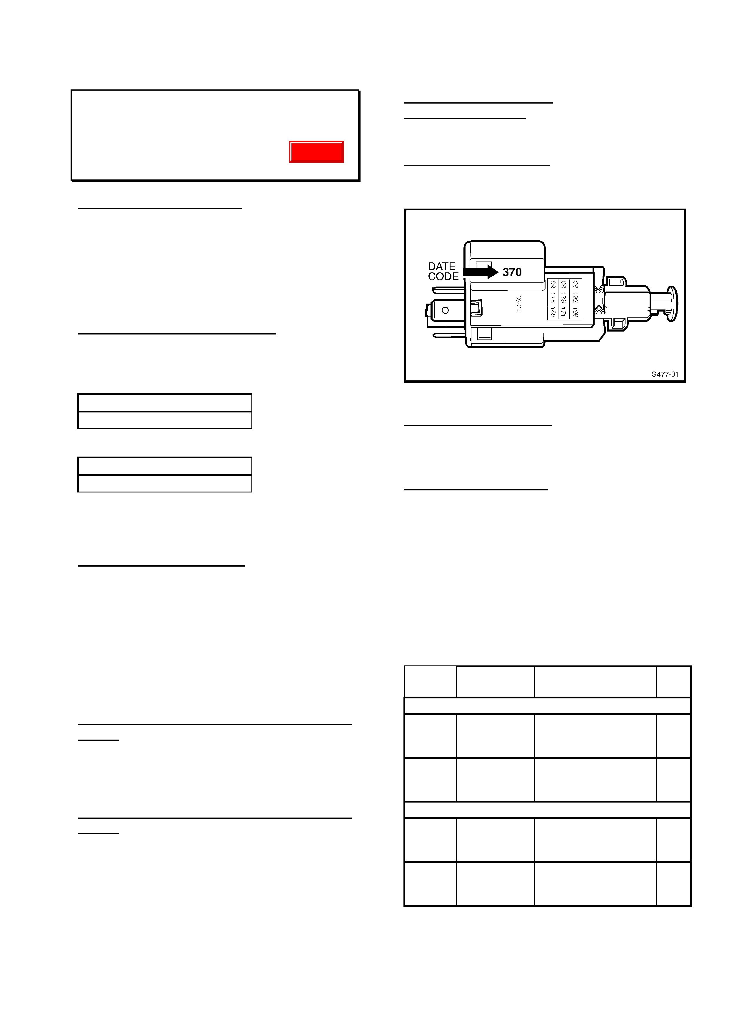
the stop lamp switch should be identified by
the Date Code information below.
Check – that the vehicle has an ISOVIN
greater than those shown above.
If ISOVIN is LOWER than the ISOVIN’s
above: adjust switch to correct the complaint.
(Adjustment procedure is shown at the end of
this Techline item). If adjustment does not
correct the complaint, replace the switch
(Refer to PartFinder for switch part number).
If ISOVIN is HIGHER than the ISOVIN’s
above: The stop lamp switch should be
checked for date code as per the following
information below.
Date Code “370 Sets the Breakpoint for
OK switches. See Figure 1 for Date Code
interpretation.
Switches with date code:
LESS THAN “370” must be replaced, as
adjustment will not result in a permanent
correction;
GREATER THAN “370” should be adjusted,
as per the procedure at the end of this
Techline item.
Figure 1.
Date Code interpretation: 370
First two digits (week) - 37 = Week 37
Third digit (year) - 0 = Year 2000
PARTS INFORMATION
Refer to HSPO PartFinder for switch part
numbers when ordering new switches.
For your reference only – the parts revised
are noted below with relevant identification.
This information will assist technicians in
identifying switches for replacement, as all
three switches noted have the same
appearance, apart from plunger colour and
terminals.
Model Part No.: Description: Qty
:
JS (from XL396309 onward)
09175172 Stop Lamp Switch
(4 terminal, with
BLUE plunger)
1
09132299 Stop Lamp Switch
(2 terminal, with
BLACK plunger)
1
TS (from X5000001 onward)
09132299 Stop Lamp Switch
(2 terminal, with
BLACK plunger)
1
09175185 Stop Lamp Switch
(4 terminal, with
GREY plunger)
1
Update
HOLDEN SERVICE TECHLINE ____________________________________________________________ MARCH 2001
9
STOP LAMP SWITCH ADJUSTMENT
Adjust the stop lamp switch using the
following procedure:
Test Stop Lamp Switch
Switch off ignition and remove the stop lamp
switch from its holder, allowing it to hang
from its connector under the dash.
Ensure the electrical connector is fully home.
Turn on the ignition and check that the stop
lamps illuminate.
Manually depress the plunger to check the
stop lamps switch off.
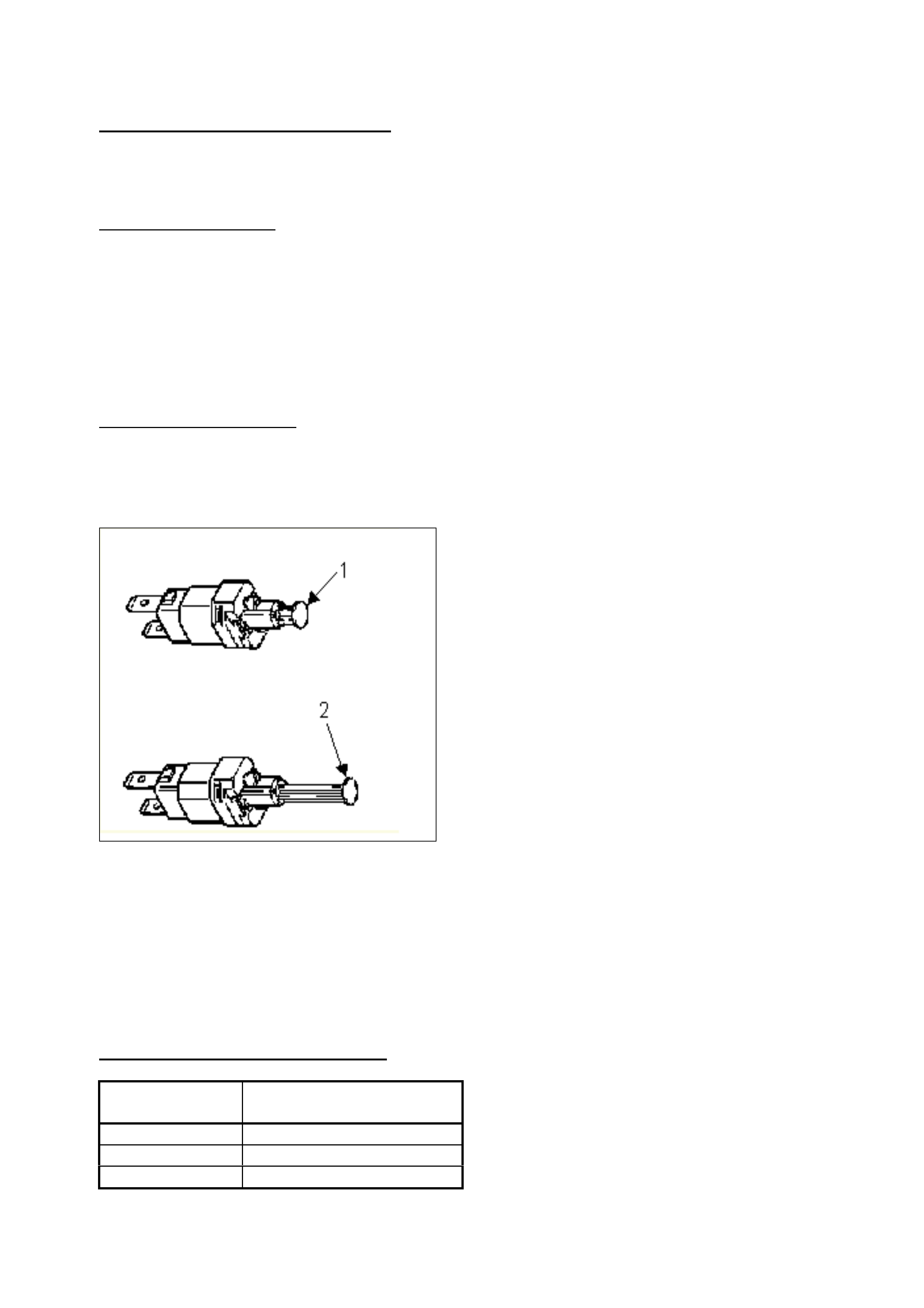
Set the Stop Lamp Switch
Fully extend the plunger by pulling it away
from the switch body. NOTE: a high “pull”
load will be required! A clicking type noise
should be heard. See Figure 2, below:
Figure 2
1- Non adjusted switch
2- Fully adjusted switch
Reinstall
With the brake pedal depressed, install the
switch and allow the pedal to retract onto it.
Test the stop lamp switch for correct
functionality.
WARRANTY CLAIM INFORMATION:
Use existing information in SIP as shown:
Description Stop Lamp Switch,
Replace
Labour Op. No. N207500
Time 0.4 hr
Failure Code 37
HOLDEN SERVICE TECHLINE ____________________________________________________________ MARCH 2001
10
A/C DISCHARGE MUFFLER PIPE
INSULATION
TS
(GROUP 2) TL011-0204
PROBLEM DESCRIPTION
PIR’s have been received of radiator leaks
caused by the A/C Discharge Muffler
abrading the bottom of the radiator. The
A/C Discharge Muffler may come into
contact with the radiator if the insulation
sleeves on the A/C Discharge Muffler pipes
fails or the sleeves dislodge.
SERVICE RECTIFICATION
If any vehicle is presented with a radiator
coolant leak adjacent to the A/C Discharge
Muffler Assembly – damaged components
should be replaced and the following
procedure should be carried out to ensure
the A/C Discharge Muffler insulation
sleeves are positively attached to the
muffler pipes:
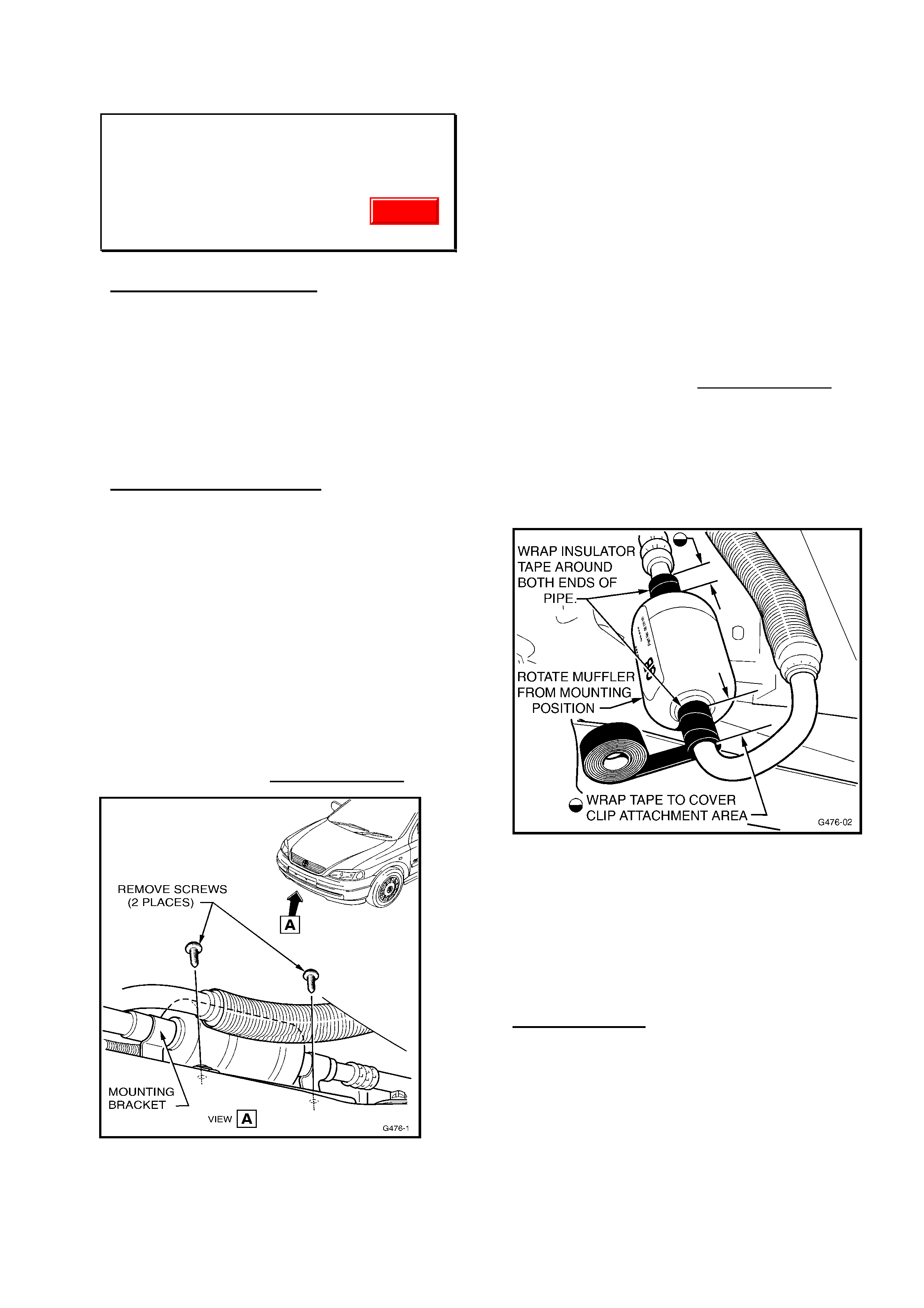
1. Raise the vehicle on a hoist and remove
the two Torx head screws that retain the
A/C Discharge Muffler Assembly to it’s
mounting brackets. TAKE CARE! – the
muffler is close to the exhaust manifold,
which may be hot. Refer to Figure 1.
Figure 1.
2. Twist the muffler so it is located between
the subframe and the exhaust manifold.
3. Remove the muffler from it’s mounting
bracket. NOTE: Do NOT bend the
retaining clips or they will not firmly retain
the muffler when it is refitted!
4. Apply tape (as per the attached approved
tapes list) to both insulation sleeves on
each end of the muffler body. The tape
should be wound around the pipe and
insulation sleeve, attaching first to the
pipe from the end of the sleeve, then fully
covering the insulation sleeve and ending
on the muffler body. Refer to Figure 2.
NOTE: During the removal process – should
the insulation sleeve/s be badly damaged or
missing, replace the sleeve/s or fit a new
sleeve/s – using P/N 09131825 Damper Strip
(which provides enough material to make two
sleeves).
Figure 2.
5. Return the muffler to its original position
and clip the mounting bracket back onto
the muffler.
6. Reattach the muffler mounting bracket
using the previously removed Torx head
screws.
Approved Tapes
For the above procedure, ONLY tape
conforming to Holden Specification HN 1230
(specific thickness, heat resistance, cloth
based) must be used. The following tapes
are readily available from the retail outlets
shown:
Update

HOLDEN SERVICE TECHLINE ____________________________________________________________ MARCH 2001
11
Supplier Description/Size
Cling
Adhesives
Cloth Tape - Cling C25, or Part
No. RB46, 48mm x 20Meters.
Available
from:
Bunnings Store
Bursons
Dick Smith Stores
3M 3M Y389 Cloth Tape, Silver or
Black (also known as “Gaffer
Tape”) 50mm x 50Meters,
Available
from:
Bunnings Stores
Blackwoods
A. E. Baker
WARRANTY CLAIM INFORMATION
Description Re-Attach A/C Discharge
Muffler Insulation
Labour Op. No. D000227
Time 0.4 hr
Failure Code 27
PARTS INFORMATION
The following part must only be used if
sleeve/s are severely damaged or have
dislodged from the muffler pipe/s or
dislodged:
Part No.: Description: Qty:
09131825 Damper Strip, A/C Pipe 1
REVISED ALTERNATOR REGULATOR
VS/VT/VX/VU with V6 Engines
(GROUP 6Y) TL103-6Y01
The information below was provided to Bosch
Agents via Bulletin AESM/A/0018, dated 6/00
CURRENT CONDITION
VS, VT, VX & VU V6 engine alternators are
fitted with a new Bosch ‘hybrid’ voltage
regulator. The new regulator is functionally
similar to the previously used RE70
regulator except that:
• Warning lamp operation is revised.
• The regulator setting has been raised to
14.5 volts.
• The operation of the phase input requires
an AC signal to switch the regulator from
active standby mode to excitation mode;
This feature prevents the regulator from
possibly being turned on due to reverse
leakage via the power diodes at high
temperatures.
PRODUCTION RECTIFICATION
For Reference: alternators with these new
regulators were fitted in production from:
For V6 (LN3) Engine:
ISOVIN: Build Date:
6H8VTK69HYL585074 03/05/00
For S/C V6 (L67) Engine:
ISOVIN: Build Date:
6H8WHY19SYL587216 08/05/00
The above breakpoints were initial
introduction points during production of
VT/WH – the alternators were ‘carried-over’
into VU & VX.
SERVICE INFORMATION
Note: Regulator replacement only affects
vehicles out of warranty, as only alternator
assemblies must be fitted for any regulator
failure – refer to Supplier Prior Authorisation
Process binder held by your Service
Manager.
Replacement of warning lamp globes may
affect vehicles in warranty.

HOLDEN SERVICE TECHLINE ____________________________________________________________ MARCH 2001
12
Warning Lamp Globe Precaution:
With this new alternator, the warning lamp
driver is current limited, to protect against
short circuit, and the design is for a nominal 2
to 3 watt globe. If a larger globe is fitted,
current limiting of the lamp inrush current
may result in much reduced brightness, and
a slight delay may be detected in the lamp
illuminating.
Fitting the correct wattage globe will increase
the brightness to the correct level.
Interchangeability:
The previously used RE70 will not service the
new regulator, but the new regulator can be
used as a replacement for an RE70
regulator.
NOTE:
If an RE70 regulator is used to replace the
new regulator, the RE70 regulator may ‘turn
on’ under certain conditions, drawing field
current and resulting in a flat battery.
REAR BRAKE SQUEAL
RODEO (4x4 and V6 4X2)
(GROUP 5) TL103-0502
PROBLEM DESCRIPTION
Excessive squeal noise emanating from rear
brakes on application.
PRODUCTION RECTIFICATION
Revised brake shoes fitted in production:
ISOVIN: Build Date:
JAATFS25HY7103377 25/01/01
JAATFS55HY7120056 25/01/01
JAATFR25HY7108590 25/01/01
* MPATFS25 TBA
* MPATFS55 TBA
* MPATFR25 TBA
* B/P’s for vehicles manufactured in
Thailand have not yet been established,
they will be included in the Breakpoint
Summary once available.
SERVICE RECTIFICATION
For pre-breakpoint vehicles the service fix
described below, which is the same as in
Dealer Letter IGM 13/99, can be applied.
I - GM has released a modified rear brake
shoe set (part number 5878317230) to
overcome the above complaint.
Before installation of the modified shoes the
rear brake assemblies should be de-dusted
and inspected for correct operation, if no
faults are observed the drums should be de-
glazed and the new shoes installed.
To effectively monitor the success of the
revised brake components, a PIR should be
submitted for any post-breakpoint vehicles
that exhibit squeal from the rear brakes.
PARTS INFORMATION
Part No.: Description: Qty:
5878317230 Brake Shoe Set 1
WARRANTY CLAIM INFORMATION
Use existing Warranty Information from SIP
as shown:
Description Shoes and Lining
Labour Op. No. H025700
Time 1.2
Failure Code 40
HOLDEN SERVICE TECHLINE ____________________________________________________________ MARCH 2001
13
BODY CONTROL MODULE
REPLACEMENT DUE TO A ‘LOCK UP’
CONDITION
VTII, VX
(GROUP 12) TL103-1202
This Service Techline supersedes the
previous Techline on this topic (Issue 1,
January, 2001, page 11). This previous
Techline should be destroyed.
For Reference: The following information is
repeated from All Dealer Letter DL 10/01.
PROBLEM DESCRIPTION
All Dealer Letter DL 10/01 advises that,
further to dealer letter DL 79/00, dated
December 6th, 2000 on the subject of “BCM
Lock Up”, the key reader circuit has been
identified as a potential source of a voltage
spike, causing the BCM to lock up.
To address this condition, a patch harness
has been developed for installation in the key
reader circuit.
Effective immediately Australian Arrow will
supply a patch harness with every
replacement BCM supplied for this lock up
condition.
Installation instructions for the Patch Harness
are included with this letter. Refer to
Attachment 1.
As previously indicated in the Dealer letter on
this subject, Fuse 31 can be removed and
reinstalled to reset the BCM. This will
mobilise the vehicle until the replacement
BCM and Patch Harness arrives.
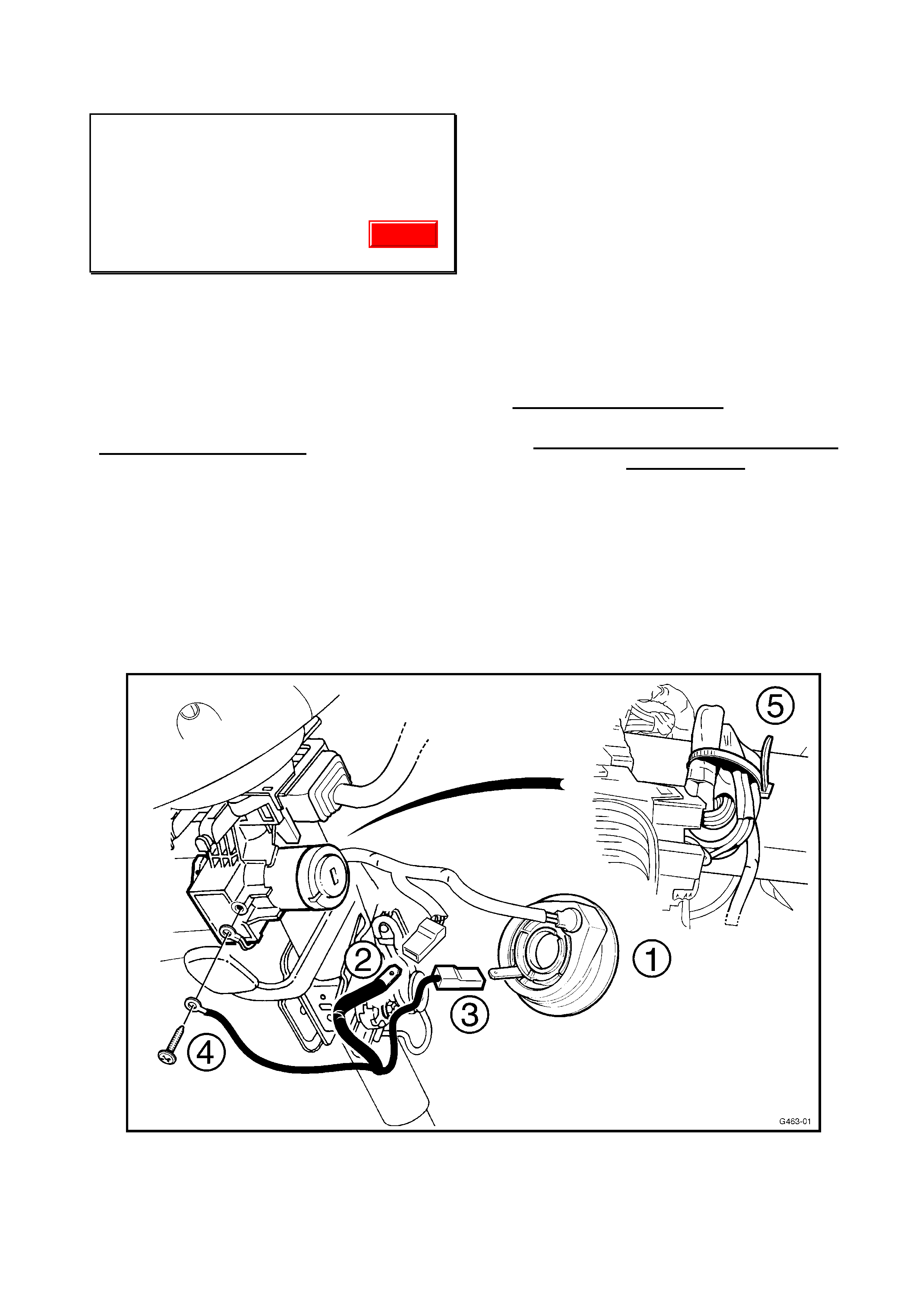
SERVICE RECTIFICATION
Installation Of Transient Suppression
Patch Harness
The numbered steps below refer to the
caption numbers in Figure 1.
1. Remove the Remote Coded Key Reader,
(refer to SIP CD VT SERIES Service
Manual, Section 12J-1, 2.4 Remote
Coded Key Reader).
Figure 1
Update

HOLDEN SERVICE TECHLINE ____________________________________________________________ MARCH 2001
14
2. Remove the key reader wiring harness
connector from the key reader and connect
it to the male terminal of the patch harness.
3. Connect the patch harness terminal with
black connector to the key reader terminal.
4. Connect the earth lead to the ignition lock
housing earth (underside of steering
column).
5. Collect and cable tie the excess wiring
neatly with the cable tie provided, ensuring
that there is no interference when
operating the Steering Column lever with
the steering wheel closest to the
Instrument Cluster.
Feed Remote Coded Key Reader globe
circuit over the top of the Ignition lock
housing.
Reinstall the upper and lower steering
column covers and Remote Coded Key
Reader ensuring that the Reader is aligned
correctly (refer to SIP CD VT SERIES
Service Manual, Section 12J-1, 2.4 Remote
Coded Key Reader).
WARRANTY CLAIM INFORMATION:
Use the following warranty claim information
for the installation of the BCM and the Patch
Harness to vehicles experiencing the BCM
lock-up condition:
Description BCM Replacement and
Patch Harness Installation
Labour Op. No. N000336
Time 0.7 hr
Failure Code 48
PARTS INFORMATION
Supplied by Australian Arrow:
1 x BCM
1 x Transient Suppression Patch Harness
1 x Cable tie
RUNNING ROUGH - MISFIRE
JACKAROO (4JX1 DIESEL ENGINE)
(GROUP 6M) TL103-0601
PROBLEM DESCRIPTION
Vehicle will miss or run rough which may be
caused by a defective injector. Investigations
have shown that a manufacturing process
problem may cause the injector tip/nozzle to
crack or fracture.
PRODUCTION RECTIFICATION
A revised manufacturing process was
introduced from:
ISOVIN: Build Date:
JACUBS73GX7102072 26/02/99
Eng. 618151 -
INJ. SERIAL No. 144903 -
SERVICE RECTIFICATION
Isolate which cylinder is misfiring using the
injector isolation test on Tech 2. Once
confirmed which cylinder displays the
problem, then confirm the injector as the fault.
The easiest way to do this is to swap the
injector with one from another cylinder and
see if the misfire moves with the injector.
While swapping the suspected faulty injector
inspect the tip/nozzle for any damage. Should
the injector show signs of damage replace all
four injectors. If there is no sign of damage
continue with swapping the injectors and
replace the individual injector if required. If
the misfire does not move with the injector
then further diagnostic work is required
concentrating on the wiring loom between the
injectors and ECU.
For correct injector calibration refer to the
article in the Engine Fuel System section of
this Techline.

HOLDEN SERVICE TECHLINE ____________________________________________________________ MARCH 2001
15
PARTS INFORMATION
Part No.: Description: Qty:
5873105640 Inj. Kit – Grade A Kit of 4
5873105650 Inj. Kit – Grade B Kit of 4
8972279030 Inj. Single 1
NB* When ordering a single injector individual
seals will need to be ordered separately, refer
PartFinder.
WARRANTY CLAIM INFORMATION
Use the existing information from SIP as
follows:
Description Injector, Fuel – R & R
or Replace (Diesel)
Labour Op. No. J592600
Time 1.0 hr (1 injector)
Time 1.3 hr (4 injectors)
Failure Code 05

HOLDEN SERVICE TECHLINE ____________________________________________________________ MARCH 2001
16
SPEEDO “PPK” PROGRAMMING
VT, VX, WH, VU
(GROUP 12) TL013-1201
This Service Techline supersedes the
previous Techline on this topic (Issue 9, Oct.,
2000 page 11). The previous Techline should
be destroyed.
SERVICE INFORMATION
The following table is supplied for
technician reference, and includes
information for VU utility.
In some previous information that may be
still available to technicians, PPK values
were based on tyre sizes only – selection
of PPK values based on tyre size is no
longer possible, and is not accurate!
This is because PPK values vary
according to trans. type and final drive
ratios – thus it is necessary to refer to the
following chart to determine exact PPK
values for the body style, engine, trans
type and tyre size being worked on.
PPK values shown must be used whenever
speedo PPK programming is required.
Refer VT Series Service Manual Volume 14C,
Page 12C-75, or SIP, for programming basic
information.
Body Style Engine Trans. Type Tyre Size PPK Value
Sedan/Wagon V6 Auto/Manual 205/65 R15 6272
Sedan/Wagon V6 Auto/Manual 225/60 R15 6238
Sedan (Police 9C1) V6 Auto 215/60 R15 6285
Sedan/Wagon V6 Auto/Manual 215/60 R16 6077
Sedan/Wagon V6 Auto/Manual 225/50 R16 6391
Sedan/Wagon V6 Auto/Manual 235/45 R17 6301
Sedan/Wagon/Ute V6 Auto/Manual 225/55 R16 6087
Sedan/Wagon/Ute V8 Auto/Manual 205/65 R15 6272
Sedan/Wagon/Ute V8 Auto/Manual 225/60 R15 6238
Sedan/Wagon/Ute V8 Auto/Manual 225/55 R16 6087
Ute V6 M35 Manual 205/65 R15 6403
Ute V6 M35 Manual 225/55 R16 6214
Sedan/Wagon/Ute V8 Auto/Manual 235/45 R17 6301
HSV All Auto 225/50ZR16
6355
HSV All Auto 235/45ZR17
6210
HSV All Auto 235/40ZR18
6210
HSV All M/T - T56 235/45ZR17 6300
HSV All M/T - T56 235/40ZR18 6300
HSV All M/T - Getrag 225/50ZR16 6355
HSV All M/T - Getrag 235/45ZR17 6210
HSV All M/T - Getrag 235/40ZR18 6210
HSV (GTS) All M/T (3.91 axle) 245/35ZR19 6180
HOLDEN SERVICE TECHLINE ____________________________________________________________ MARCH 2001
17
INJECTOR CALIBRATION
JACKAROO (4JX1 DIESEL ENGINE)
(GROUP 6M) TL103-6M01
The 4JX1 diesel engine in the 1998, and onward, model Jackaroo has injectors that are classified into 9
groups according to flow rate. The ECM is calibrated to the injectors that are fitted to the engine using
tech 2.
Injector calibration is carried out at production, but will need to be checked at pre delivery and after some
service repairs. e.g. control unit replacement, injector replacement, etc.
Incorrect injector calibration may cause unstable idle, engine vibration or excessive smoke.
When performing injector calibration difficulty may be experienced identifying the injector calibration
group. The workshop manual indicates that identification is determined by markings on the injector. This is
not always the case. Later vehicles may have the injector calibration number, as shown below, identified
on the top of the injector.
The only sure method for identification is to utilise the injector identification sticker. The sticker is situated
on the noise insulator cover fitted over the rocker cover, the sticker should always be update whenever
different calibration injectors are fitted. A new sticker will be provided with new injectors, if the sticker
should become unavailable then the old sticker should be updated with a permanent marker.
INJECTOR IDENTIFICATION STICKER
ENG. NO 489476 4JX1
#1 82395420 #2 83395420
#3 83365520 #4 59395920
RP SENSOR 7565
The numbers on the identification sticker are production numbers (not part numbers) used to identify
individual injectors. The 5th and 6th digits of the production number are used to classify injectors for
calibration. eg:
#1 82395420
CALIBRATION NUMBER ( 54 )
INJECTOR NUMBER (# 1)
The calibration number is used in conjunction with the following chart.
A1 20 - 26 B1 40 - 46 C1 61 - 67
A2 27 - 33 B2 47 - 53 C2 68 - 74
A3 34 - 39 B3 54 - 60 C3 75 - 80
For example: Injector number 1 has a calibration number 54. Number 54 corresponds to a B3.

HOLDEN SERVICE TECHLINE ____________________________________________________________ MARCH 2001
18
Once the injector calibration number has been established and injector category determined, the
calibration procedure in the relevant workshop manual (section 6E ) can be followed.
Since the introduction of this engine, injector group C has been deleted from HSPO and will supersede to
injector group A. Regards of the injector group calibration fitted to a vehicle from production it can be
replace by any calibration of injector providing the ECU is re-programmed to reflect the injectors fitted to
the vehicle.
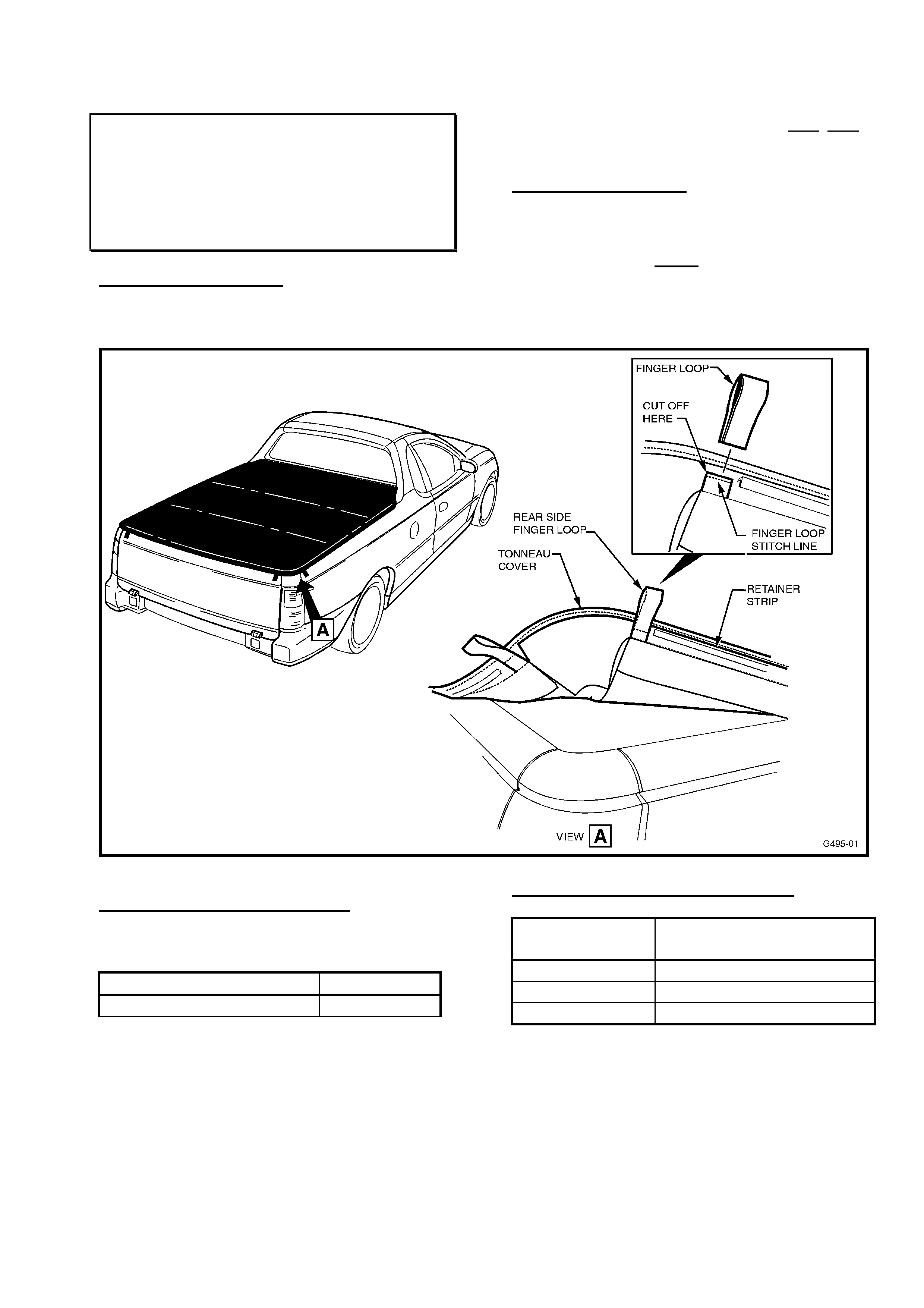
HOLDEN SERVICE TECHLINE ______________________________________________________________ APRIL 2001
6
PAINT ABRASION FROM TONNEAU
FINGER LOOPS
VU
(GROUP 1) TL104-0101
CURRENT CONDITION
The finger loops at the rear sides have been
shown to cause minor paint abrasion on
some vehicles. NOTE: ONLY the rear side
finger loops have been subject of complaints.
Service Rectification:
Raise the side of the tonneau cover at the
rear and cut off the finger loop located on
both LH & RH sides – just before the
stitching line. Refer Figure 1 showing exact
location.
Figure 1.
PRODUCTION RECTIFICATION
Tonneau covers with 4 finger loops ONLY
(2 x endgate, 2 x front side) were introduced
in production from:
ISOVIN: Build Date:
6H8VUK80A1L705982 17/03/01
WARRANTY CLAIM INFORMATION
Description Remove Rear Side
Tonneau Finger Loops
Labour Op. No. C000430
Time 0.3hr
Failure Code 20

HOLDEN SERVICE TECHLINE ______________________________________________________________ APRIL 2001
7
TONNEAU NOISE CONCERNS –
CUSTOMER ADVICE
VU
(GROUP 1) TL104-0102
PROBLEM DESCRIPTION
This Techline is published to highlight some
PIR reported complaints, provide feedback
on changes and provide service rectifications.
The concerns raised are related to
installation of the tonneau (initial fitment and
during normal usage) and day-to-day usage.
The following “suggestions” are provided so
Dealership Service personnel may explain to
customers how they can adjust tonneau
covers to improve noise levels and improve
tonneau installation.
‘FLAPPING’ NOISE FROM THE TONNEAU:
This can occur with wind turbulence while
driving, with cross winds, wind gusts, etc.
The current tonneau cover design allows for
three different slots for locating the front bar
(fitted directly behind the rear screen glass) –
to change the tension on the tonneau.
Current Owner Handbook advises to position
the front bar in the front slot.
Suggestion:
It is now recommended that the front bar be
located in the central of the three possible
slots when the front bar is first fitted.
This front bar slot allows sufficient tension on
the tonneau to stop ‘flapping’ noises. Owners
may choose to relocate the front bar to
increase/decrease the tension on the
tonneau
This recommendation will be added to the
Owner Handbook at next reprint.
‘Rattle’ (light metallic type tapping) noise
from inside the load compartment while
driving:
Such a ‘rattle’ noise can be caused by the
tonneau ‘high load’ clips (under the tonneau),
swinging on some excess length of the
elastic retaining cord, pulled unevenly on the
tonneau, and hitting the sides of the load
compartment.
Suggestion:
Pull the elastic cord through the retaining
loops to ‘even up’ the cord position around
the tonneau, this will keep the clips away
from the cargo bay sides.
Clips that contact the sides, are usually on
excess lengths of the elastic cord, and may
be tucked inside the closest cord retaining
loop stitched to the tonneau cover.
If this is not sufficient to stop the noise, the
excess length of the elastic cord can be
pulled through to the front retaining loop on
the tonneau and the cord shortened by tying
a new knot in the end.
PRODUCTION RECTIFICATION
For the ‘rattle’ noise mentioned above, the
‘high load’ cord and clips have been located
further inboard on the tonneau from:
ISOVIN: Build Date:
6H8VUK80F1L696359 02/03/01
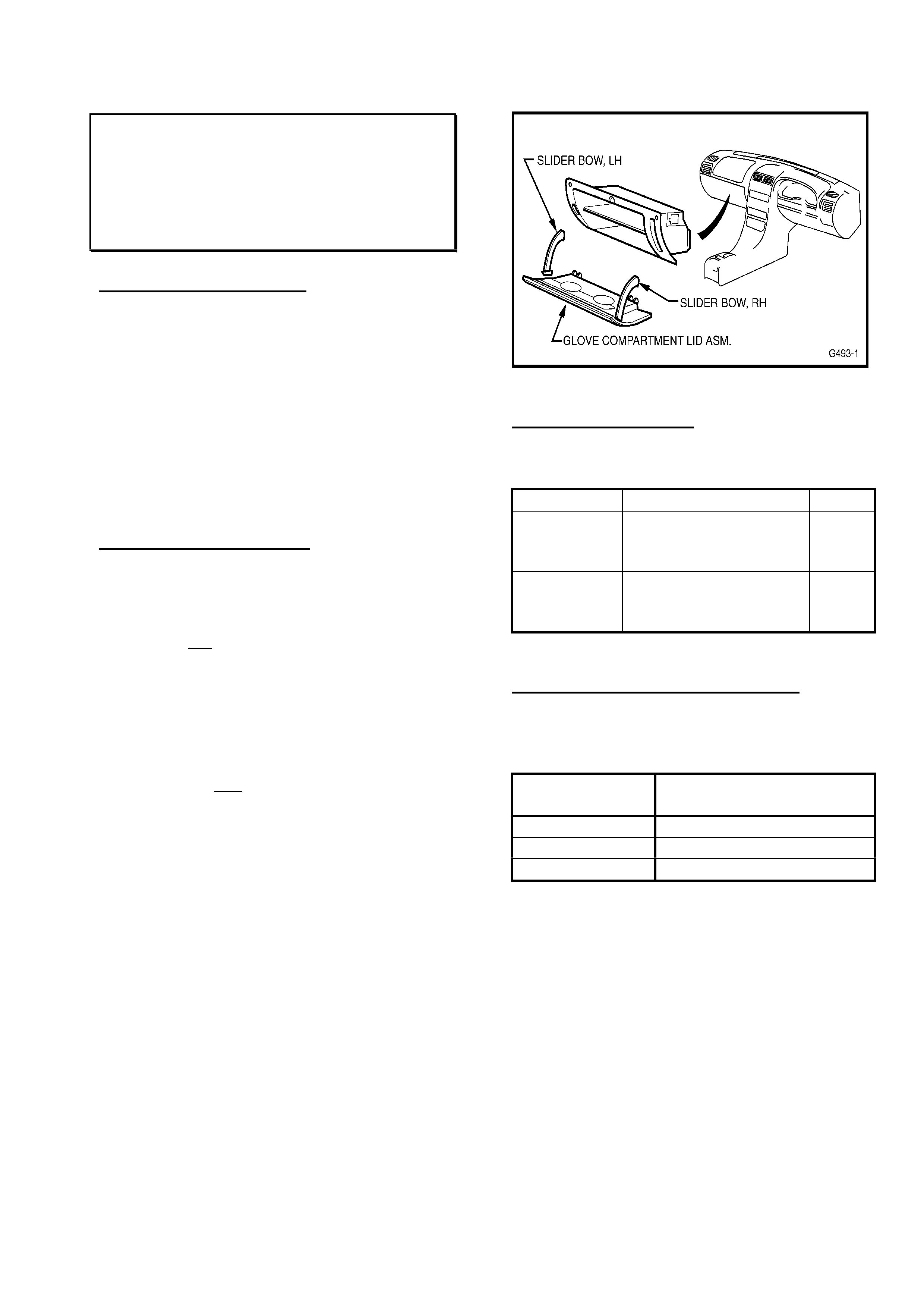
HOLDEN SERVICE TECHLINE ______________________________________________________________ APRIL 2001
8
GLOVE COMPARTMENT SLIDER BOW
REPAIR/S
TS
(GROUP 1) TL104-0103
PROBLEM DESCRIPTION
Warranty returned parts show that complete
glove compartment lids are being replaced
when ONLY a slider bow is damaged.
Glove compartment slider bows (RH or LH),
are connected from the glove compartment
lid to the glove compartment, to enable “two-
stage” opening of the glove compartment.
These slider bows are replaceable
individually.
SERVICE RECTIFICATION
Should one of the slider bows on the glove
compartment lid be damaged and require
replacement – ONLY replace the individual
slider bow, not the whole glove compartment
lid.
For remove and replace instructions access
TIS 2000 and select:
• Service Information,
• Standard Information (& NEXT),
• Astra-G
• 2000 (select any year) (& NEXT),
• C. Body Equipment,
• Seats, Upholstery, Inner Trim Panels,
• Glove Box,
• All (& NEXT),
• Items KTA-1946, 00023088 & 00017699
provide remove/replace information.
Figure 1 shows the location of the slider
bows.
Figure 1.
PARTS INFORMATION
For reference, the slider bow part numbers,
shown in PartFinder, are repeated here:
Part No.: Description: Qty:
24447201 Slider - Bow, Lid to
Glove Compartment,
RH
1
24447198 Slider - Bow, Lid to
Glove Compartment,
LH
1
WARRANTY CLAIM INFORMATION:
Use existing warranty information (from SIP
CD) as follows:
Description Glove Compartment
Slider Bows - Replace
Labour Op. No. C459300
Time 0.6 hr
Failure Code 33
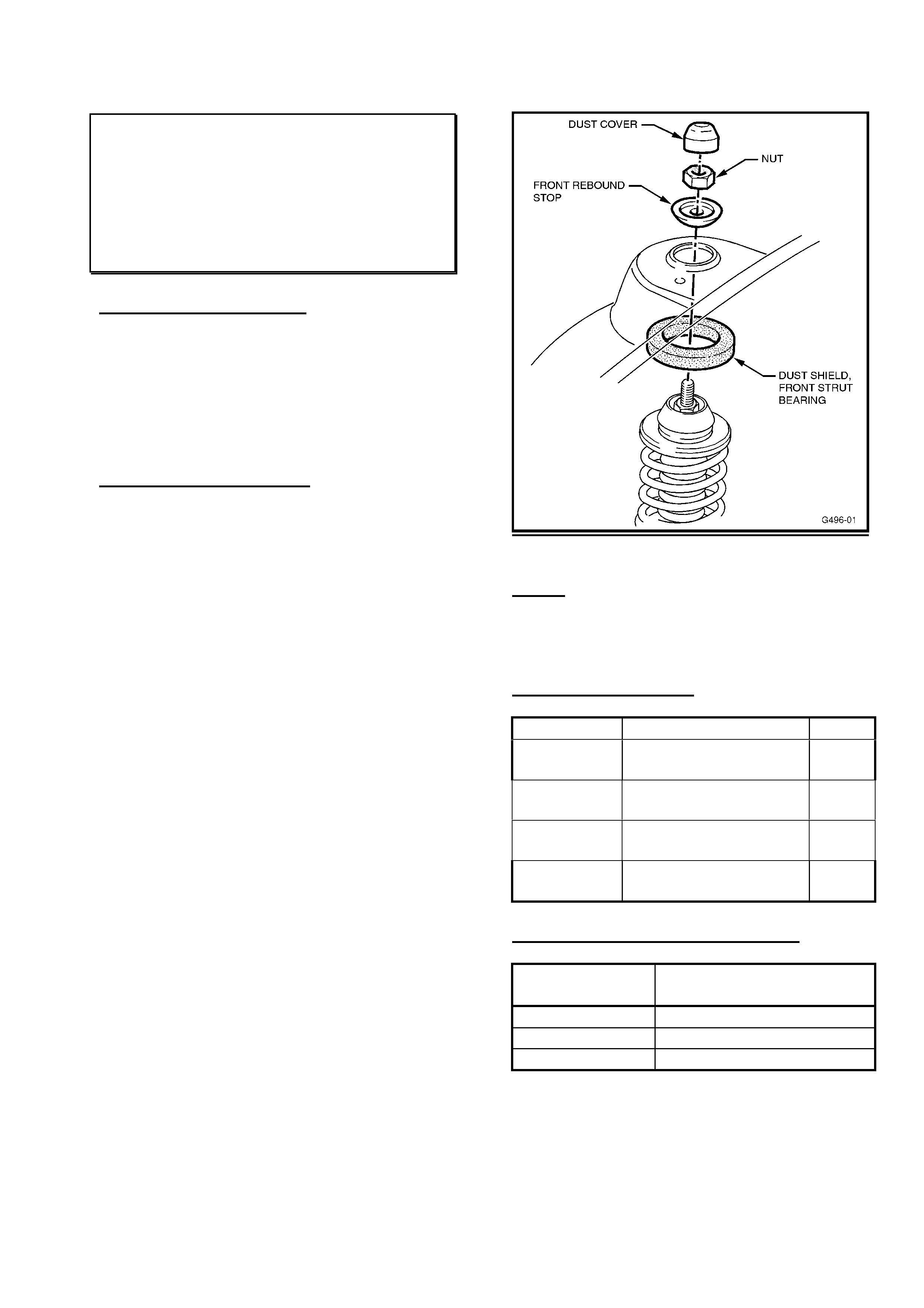
HOLDEN SERVICE TECHLINE ______________________________________________________________ APRIL 2001
9
FRONT STRUT “GRINDING” NOISES
WHEN TURNING –STONES/DIRT
ENTRY
VT, VX, VU, WH
(GROUP 3) TL104-0301
PROBLEM DESCRIPTION
In certain road conditions with loose
surfaces, some customers may complain of a
“grinding” noise when turning.
This may be caused by small stones or dirt
being thrown into the front strut upper
support bearing.
SERVICE RECTIFICATION
On complaint vehicles, where stones/dirt
have entered the upper strut bearing area,
during rectification, fit Front Strut Bearing
Dust Shields, p/n 92144452, to both sides of
the vehicle to stop stones entering the strut
bearing.
Remove the front strut from the vehicle to fit
the dust shield. Refer to the applicable
Service Information section in SIP.
Fit the shield onto the upper spring seat as
shown in Figure 1.
Reinstall the front strut to the vehicle.
This re-installation will compress the shield
approximately 5mm to provide the sealing
required.
Figure 1.
NOTE: New Rebound Stop Nuts, Steering
Knuckle Bolts and Brake Caliper Anchor
Bolts must be fitted, as directed by the
service manual.
PARTS INFORMATION
Part No.: Description: Qty:
92144452 Dust Shield - Front
Strut Bearing
2
90251985 Nut, Rebound Stop
Asm to Strut
2
11090821 Bolt, Steering
Knuckle to Tube
4
92138557 Bolt, Caliper to
Knuckle
4
WARRANTY CLAIM INFORMATION:
Description Fit Front Strut Upper
Dust Seal (Both Sides)
Labour Op. No. E000347
Time 1.2 hr
Failure Code 12

HOLDEN SERVICE TECHLINE ______________________________________________________________ APRIL 2001
10
DTC’s P1571 & C74 SET - TRAC/PCM
LIGHT “ON”
VX, VU, WH with V6 & ETC
(GROUP 6C) TL104-6C01
PROBLEM DESCRIPTION
Technicians are reporting Trac/PCM light on,
and both DTC’s P1571 & C74 being set on
some vehicles with V6 engine and Electronic
Traction Control (ETC).
These codes are sometimes found to be set
numerous times in history.
Investigation shows the cause to be a
software timing issue within the PCM.
Revisions to the software, to rectify this
‘incorrect’ code setting, have been made.
PRODUCTION RECTIFICATION
PCM’s with revised software will be fitted to
vehicles in production in early April, 2001 -
after publication of this Techline – the
breakpoint will be advised in the next
Techline issue Breakpoint Summary:
SERVICE RECTIFICATION
TIS 2000, CD 20 (to be distributed late
March, 2001) will carry information to allow
flash programming of such complaint PCM’s,
to correct this complaint.
For Confirmation during flash programming:
VX/VU/WH V6 - Software number is:
92108760
VX/VU V6 with LPG - Software number is:
92108762
NEW INSTRUMENT CONFIGURATION
PROGRAMMING
VT, VX
(GROUP 12) TL104-1203
When fitting a new instrument cluster to a
vehicle, it is essential that it be correctly
configured.
Technicians should be aware that when
configuring replacement instrument clusters, it
is necessary to not only configure the cluster in:
F0: “Instrument Configuration” of Tech 2,
but to also program the:
Instrument Options
“Instrument Options” are defined as the F1:
option below instrument cluster configuration
within the instrument program area of TECH 2.
Failure to do this may cause “SERVICE
ERROR” to be displayed on the instrument
window and LPG fuel gauge DTC’s to log,
without reason.
NOTE:
Instruments will not be accepted by
Repac where only incorrect configuration
programming is defined.
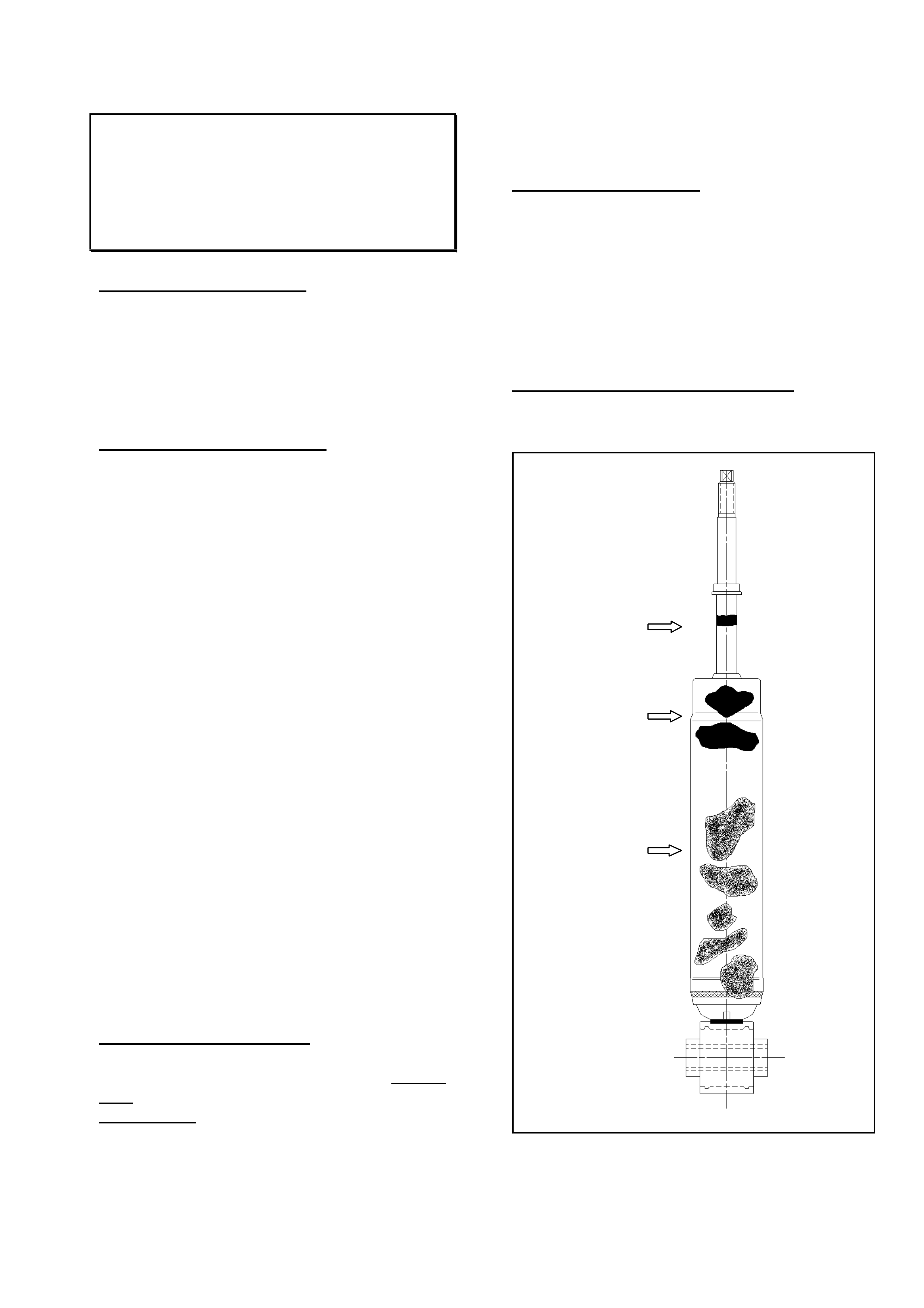
HOLDEN SERVICE TECHLINE ______________________________________________________________ APRIL 2001
11
REAR SHOCK ABSORBER LEAK
DIAGNOSIS
WH, VT, VX, VU
(GROUP 4) TL104-0401
PROBLEM DESCRIPTION
Based on incorrect shock absorber returns to
REPAC, this previously published bulletin is
being released again to help technicians
identify the difference between normal shock
absorber weeping, and leakage (that would
necessitate replacement).
TECHNICAL BACKGROUND
The normal operation of all shock absorbers
allows for a thin film of shock absorber oil to
adhere to the piston rod surface to allow for
lubrication of the seal during operation. In
certain operating environments this oil film
becomes contaminated with foreign matter
such as road dirt and sand. The seal is
designed to exclude this contaminated oil film
in the compression stroke and a build up of
“sludge” results.
During the life of all shock absorbers this oily
“sludge” will create a film on the shock
absorber body. This film is normal and in no
way compromises the function of the shock
absorber.
The criteria outlined below identifies the
acceptable conditions that may be observed
when inspecting shock absorbers at various
times during the life of the product.
PLEASE ALSO NOTE THAT:
In the event of a faulty shock absorber:
- the faulty unit may be replaced without
replacing a matching pair.
- faulty shock absorbers must NOT be
cleaned prior to them being returned.
SERVICE RECTIFICATION
If a shock absorber displays worse conditions
than that shown in the drawing (ie: greater
than 10mm band of “grime” on piston rod, or
greater than 40mm build up of “sludge” on
body), the shock absorber is classified as
LEAKING, and should be replaced. If the
shock absorber on the other side of the
vehicle is NOT leaking, it should be left in
service.
PARTS INFORMATION:
Refer to HSPO PartFinder for shock absorber
part numbers when ordering.
When ordering, PartFinder defaults to a
quantity of “2” in the parts selected
quantity – this quantity can be changed to
“1” when required – it is NOT necessary
to order “2” shock absorbers unless they
are required.
WARRANTY CLAIM INFORMATION
Use existing information in Labour Time
Manual.
Oily grime build up
at end of stroke up
to 10mm wide band
Oily “sludge”
accumulated from
normal operating
conditions to 40mm
down the body of
the shock absorber
Shock absorber body
may be discoloured
by road grease and
oil, sand and dust, but
this does not
constitute a leaking
shock absorber. In
this event the shock
absorber should be
wiped clean and
checked at the next
service

HOLDEN SERVICE TECHLINE ______________________________________________________________ APRIL 2001
12
6 DISC CHANGER SKIPPING (10 DISC
CHANGER TEMPLATE INFO.)
WH
(GROUP 12) TL104-1201
This Techline provides information
additional to that provided in DL 32/00 &
2000 Techline 8-14 (Sept., 2000) for all
service personnel involved in 10 Disc
changer fitting. Please circulate this
Techline throughout your Service & Parts
Departments.
PROBLEM DESCRIPTION
All Dealer Letter 32/00 & Techline of
September, 2000, Issue 8, page 14 advised
to replace the existing 6 Disc changer with a
10 Disc changer when a “CD Skipping”
complaint occurred.
One of the parts noted in that Letter and
Techline is:
92143627 – Template
This hole drilling location template is made
from durable Mylar film and packaged in a
cardboard tube for delivery AND storage by
Dealerships.
THESE TEMPLATES ARE INTENDED FOR
REPEAT USAGE.
DO NOT ORDER A NEW TEMPLATE FOR
EACH 10 DISC CHANGER INSTALLATION.
To ensure the template is kept in optimum
condition, it is suggested the template is
returned to the storage tube immediately
after use, and is retained by either the
Workshop Foreman or Service Manager for
easy accessibility.
PARTS INFORMATION
To assist in your future parts ordering for 10
Disc changer installation, the following
revised parts ordering list (template quantity
revised) is provided – so that a template is
not ordered for each 10 Disc changer
installation:
Each Installation Requires the Following
Parts:
Part No.: Description: Qty
92080354 10 Disc Changer 1
92053301 Bracket- 10 disc
changer
1
92088915 Foam piece, rear
compartment
1
92088903 Carpet, CD cover 1
92088904 Carpet and spare
wheel cover
1
92138380 Rivet - bracket to body 1
92138381 Rivet - bracket to floor 2
92060351 Tie strap 1
The following parts are multiple usage
parts, to be ordered ONLY as required:
Part No.: Description: Qty
92018621 Butyl sealing patch
- for multiple installations
1
92143627 Template, Drilling –
Order 1 - only when your
existing template is
unusable.
A.R.
Note: Butyl Patch 92018621 (superseded
Patch 92055234 originally quoted in DL
32/00) needs to be trimmed for use in the
installation procedure, and provides enough
material for at least two installations.

HOLDEN SERVICE TECHLINE ______________________________________________________________ APRIL 2001
13
STEERING GEAR INNER TIE ROD
CLUNK NOISE
VT, VX, WH
(GROUP 9) TL104-0901
PROBLEM DESCRIPTION
Under high temperatures or after long drives,
a clunk/knock may be felt through the
steering wheel on turns, or sufficient body
movement occurs. On examination of the
rack, the knock can be heard/felt coming
from the inner tie rod end.
PRODUCTION RECTIFICATION
An improved inner ball joint with new high-
temperature grease and revised cap material
have been fitted to steering racks in vehicles
from:
ISOVIN: Build Date:
6H8VXL69A1L683674 22/01/01
SERVICE RECTIFICATION
Where diagnosis confirms this complaint, fit a
new steering rack ensuring the rack serial
number is higher than the following
breakpoints:
PARTS INFORMATION/BREAKPOINTS
Standard Power Steering (Option N40)
Part No.: Breakpoint Serial No.: Qty:
92092815 N137524 1
Variable Effort Power Steering (Option NV7)
Part No.: Breakpoint Serial No.: Qty:
92092816 P017429 1
WARRANTY CLAIM INFORMATION
Use existing information in Labour Times
shown in SIP.
BOOT RELEASE, TURN SIGNAL,
HAZARD WARNING INOPERATIVE
(FUSE 7 FAILURE)
VT, VX, WH
(GROUP 12) TL104-1205
PROBLEM DESCRIPTION
Diagnosis of inoperative boot release, turn
signals and hazard warning may be
confusing to technicians as circuit diagrams
for these components do not refer back to
the feed fuse – Fuse No.7.
Technicians may not believe these
components’ problems/failures are related in
any way – but they are, as :
All three items are powered by Fuse 7.
The boot release is not mentioned on fuse
panels – and could be the confusion in
diagnosis that may make technicians believe
a BCM is faulty.
While these components are also shown to
be part of BCM circuitry, in circuit diagrams,
DO NOT ASSUME THE BCM IS AT FAULT.
SERVICE RECTIFICATION
When investigating failure of any of the
above components, check Fuse 7 first!
For reference - a circuit diagram showing the
Fuse 7 relationship to these components is
available in VT Service Manual Volume 6,
Page 12J-1-25.
Update

HOLDEN SERVICE TECHLINE ______________________________________________________________ APRIL 2001
14
TOW BAR RATTLE (1600/2100kg) –
ADD LOCK SCREW
VS, VT, WH
(GROUP OB) TL104-OB02
PROBLEM DESCRIPTION
A Techline Bulletin on this subject was
released in Issue 10, Nov. 2001 Techline,
page 15.
Since release of that Service Techline, a
parts packaging issue has been defined,
and a Parts Techline PT58, dated February
8, 2001 was issued to explain the concern:
“Due to a packaging error, a batch of part
number 92138537 has been incorrectly
labelled as part number 11078491.
Incorrectly labelled screws can be identified
by the physical difference – the incorrectly
labelled screws have a spigot at the end.
Refer attached illustrations. (The Parts
Techline carries photographs of the screws
for identification).
Any existing stock of the screws with a spigot
at the end, labelled as part number 11078491
must be returned to HSPO via the CRRM
system, prior approval is not required.”
SERVICE RECTIFICATION
If the screw 11078491 your Parts Department
provided for the Tow Bar Rattle fix does not
fit – refer to the above information to ensure
you obtain the correct screw.
For reference: Complaints have been
received that the screw noted in the original
Techline will not fit the installation without
cutting/grinding off the end of the screw.
Should you receive one of these screws –
arrange for your Parts Manager to return
screws as per PT58 and obtain the correct
screw for the installation.
15,000km SERVICE COUPON
CORRECTION
TT Zafira/XC Barina
(GROUP OB) TL104-OB01
The information in this Service Techline is
repeated from All Dealer Letter DL 30/01,
dated 21st March, 2001. Please circulate to
all Service Personnel. If it is necessary to
clarify this matter with vehicle
owners/operators - use your Service
Department’s copy of All Dealer Letter DL
30/01.
This letter is to advise of an error regarding
engine coolant in the 15,000km service
coupon for XC Barina and TT Zafira.
The service coupon is incorrectly advising to
replace the engine coolant.
The correct wording is, check level, check
coolant % as shown in the Maintenance
Schedule of the Owner’s Handbooks.
Please use the letter (DL 30/01) in
conjunction with the Maintenance Schedule
to answer any Customer enquiries. This will
be corrected in the next print of the Owner’s
Handbooks.
We apologise for any inconvenience caused
by this error.

HOLDEN SERVICE TECHLINE ______________________________________________________________ APRIL 2001
15
TECH 1 REPAIRS – “REMINDER”
ALL
(GROUP OB) TL104-OB03
PLEASE ENSURE THAT RELEVANT
PARTS AND SERVICE PERSONNEL ARE
AWARE OF THESE DETAILS:
The following information is repeated from
Part Techline PT61, of March 14, 2001 - a
copy is held by your Parts Manager should
you wish to view it.
Previous information was provided to
Dealerships via Service Techline of Issue 1,
January 2001, page 5; and Parts Techline
Bulletin PT31, dated May 5,1999.
HSPO (and other Holden departments) are
still receiving telephone enquiries on the
wrong numbers.
Holden Service Parts Operations (HSPO)
continues to be the point of contact for
arranging repairs to TECH 1 units.
The contact at HSPO is:
RAY CHALKLEY - Phone: 03 97977464
Fax. 03 97977310
Guidelines for arranging repair of TECH 1
units:
1. First check if the cartridge or cable is
causing the fault. Please note: Cartridges
and Cables cannot be repaired. To identify
the replacement number, please refer to the
accessories section of PartFinder.
2. Pack the unit in a way that it will not get
damaged. Forwarding address is:
Attention: R. CHALKLEY.
Holden Service Parts Operations
PO Box 162
Dandenong 3175 VIC
PLEASE USE AUSTRALIA POST AIR BAG
AS YOUR METHOD OF TRANSPORT
3. Provide EXACT details of what is
wrong with the unit, it would be of great
assistance and save you money for
unnecessary repairs.
4. Temporary loan unit - you must state if a
temporary loan unit is required.
These loan units are only available to
customers whose business will be adversely
affected while the faulty unit is being
repaired.
Loan units cannot be provided until the
customer’s faulty unit is received at HSPO.
TECH 1 units can only be repaired by the
USA manufacturer. The turn around time for
repairs is between 4 to 6 weeks.
Average cost is $580 to $600 (Australian
dollars). The total repair cost will be charged
to your account.
TECH 2 REFERENCE NOTE:
The above information does NOT apply to
Tech 2 units!
TECH 2 unit Repairs – Refer to DL 43/97 for
details of Tech 2 repairs.
For TECH 2 Cable Repairs – Refer to
DL 06/00
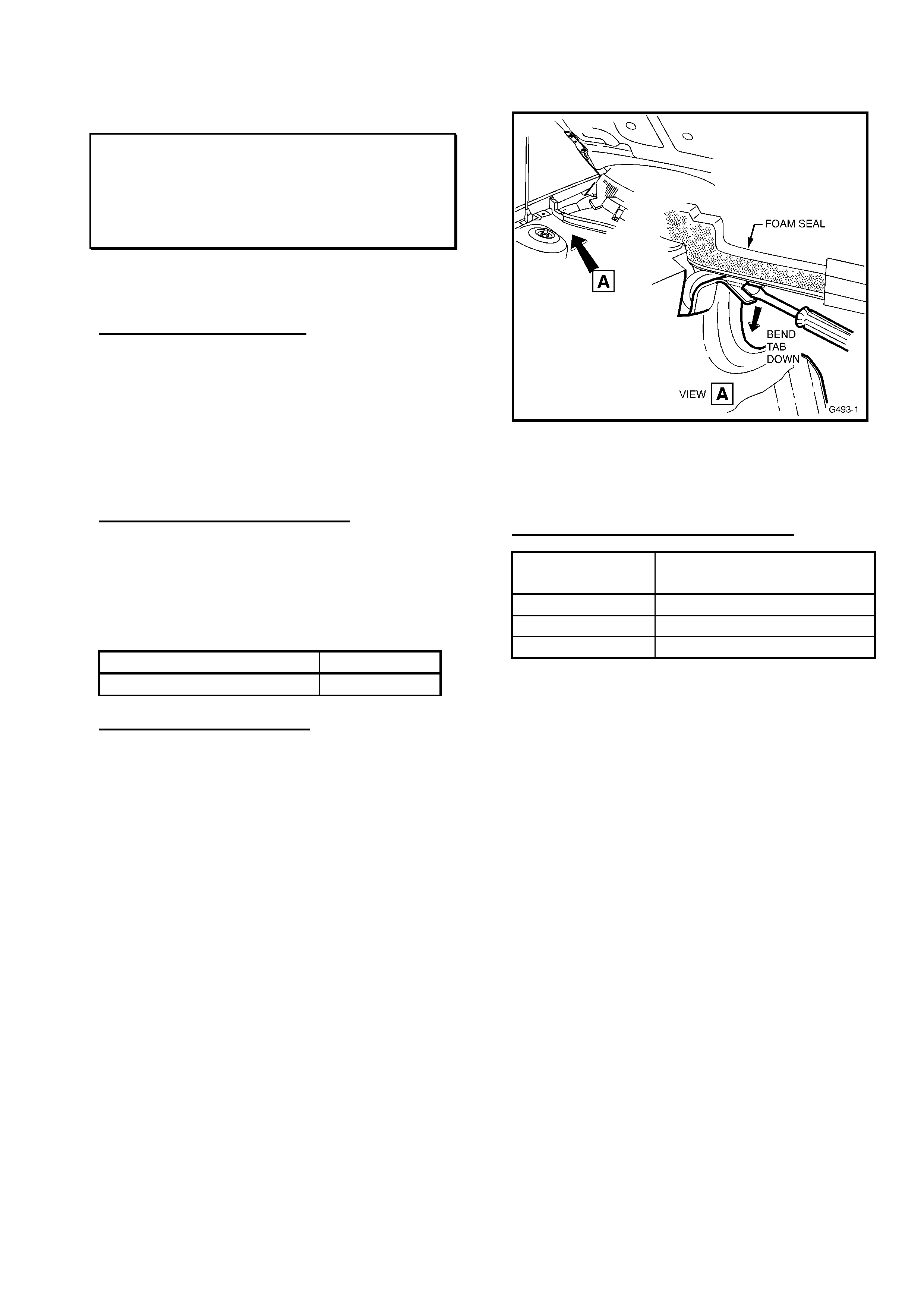
HOLDEN SERVICE TECHLINE ______________________________________________________________ APRIL 2001
16
INSTRUMENT PANEL “CREAK” NOISE
VX, VU, WH
(GROUP 1) TL104-0104
Thanks - Guy Formica of McGrath’s, Liverpool,
NSW - for PIR info. on this concern.
PROBLEM DESCRIPTION
Complaints of “creak” noises from behind the
instrument panel, especially when travelling
over bumps, have been investigated. The
cause has been defined as a metal tab at the
end of the cockpit module glue track, used as
an assembly aid, rubbing on the underside of
the plenum chamber panel.
PRODUCTION RECTIFICATION
A revised cockpit module panel with an
insulating pad added between the cockpit
module panel and plenum chamber panel, to
stop the complaint creak noise, has been
fitted to vehicles from:
ISOVIN: Build Date:
6H8VXK69A1L689910 12/02/01
SERVICE RECTIFICATION
For vehicles built prior to the above
breakpoint:
If any customer complaint is received of
“creak” noises emanating from behind the
instrument panel – worse over bumps, etc, -
bend down the metal tab located at each end
of the cockpit module glue track – as shown
in Figure 1, View A below. The metal tab
must be bent down far enough to stop
contact with the plenum chamber/cockpit
module panel directly above it.
Figure 1.
- Shows RHS rear of Engine compartment,
LHS is opposite.
WARRANTY CLAIM INFORMATION
Description Modify Cockpit Module
Panel Tab
Labour Op. No. A000279
Time 0.3 hr
Failure Code 55
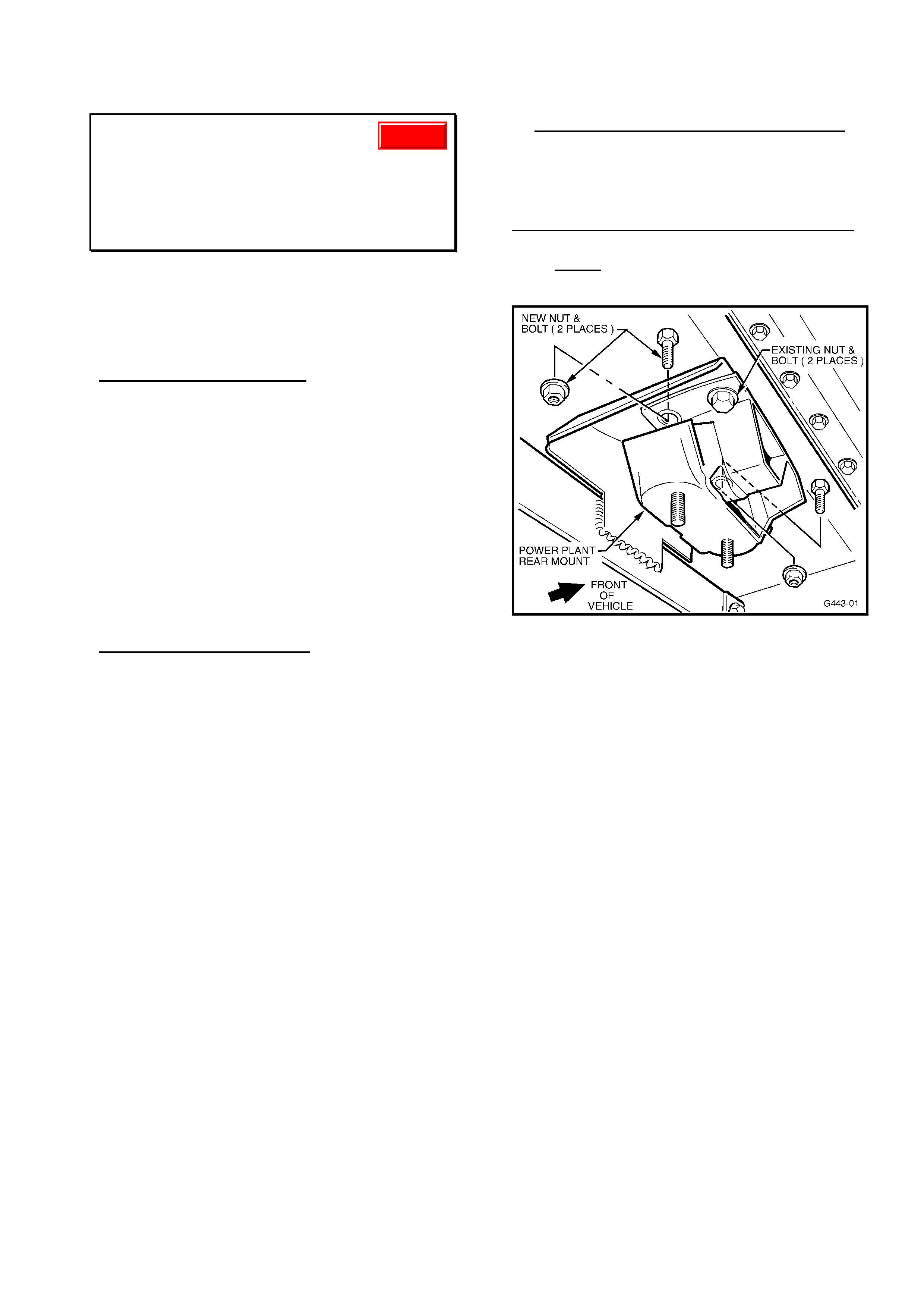
HOLDEN SERVICE TECHLINE ______________________________________________________________ APRIL 2001
17
ENGINE IDLE VIBRATION
VT, WH, VX, VU, - Gen III A/T (Standard
Engine)
(GROUP 6C & 8) “RE-ISSUE” TL101- 0801
This Service Techline supersedes the
previous Techline on this topic (Issue 1,
January, 2001 page 12). This previous
Techline should be destroyed.
PROBLEM DESCRIPTION
Excessive vibration or buzz felt within the
vehicle, under any of the following
conditions:
(1) Vehicle stationary at idle with
transmission in Drive/Reverse with A/C
on
(2) Idle speed drop when Drive/Reverse
selected and/or steering load applied.
(3) Slow acceleration or low speed driving in
1st gear, with engine speed between 650
and 1000 rpm.
SERVICE RECTIFICATION
To reduce the level of vibration on complaint
vehicles for any of the above conditions, the
following action is recommended.
Step 1. Flash Revised Calibration
Flash revised calibration (idle speed revised
to 620rpm) p/n 92103007 into complaint
vehicles only. The description on TIS 2000 is
“Continuous Improvement Calibration –
Improved Idle Quality”. Note this revised
calibration was first released on TIS CD
No.14.
Step 2. De-stress Exhaust & Powertrain
An indication that the exhaust/powertrain is
stressed is a bent catalytic (cat.) converter
bracket as shown in Figure 2.
The following MUST be completed in
sequence
1. Loosen (by approx 1 turn) engine mount
nuts, front pipe/exhaust manifold nuts and
intermediate muffler/front pipe bolts.
2. Support transmission, and remove cross
member complete with cat. converter bracket
and transmission (trans.) mount.
3. Remove trans. mount and cat. converter
bracket.
4. Vehicles built before L647630,14/10/00 -
Fit two additional bolts/nuts to rear trans.
mount holes (use P/N: bolts: 92138301,
nuts:11086962 ) and torque to 45-55 Nm
(See Figure 1).
On Vehicles built after L647630,14/10/00,
-studs have been added to the trans. mount
and ONLY two nuts, p/n 11086962 are
required to be fitted to these studs.
Figure 1.
5. Fit trans. mount and cat. converter bracket
to transmission and torque bolts to
specification.
6. Refit cross member and torque four outer
bolts (ie, cross member to body rails) to
specification. Leave the two trans. mount to
cross member nuts loose at this stage.
7. Lower vehicle back onto the ground, start
the engine and cycle through the gears, ie,
R-N-D five times and then rev the engine in
neutral up to 4000 rpm five times.
8. Raise vehicle on hoist.
9. Torque engine mount nuts to specification.
10. Torque trans. mount to trans. cross
member nuts to specification.
11. Torque intermediate to front pipe bolts to
specification.
12. Torque front pipe-to-exhaust manifold
nuts to specification.
13. Add spacers to take up the clearance
between trans. to cat. converter bracket and
cat. converter (see Figure 2), refit bolts and
Update
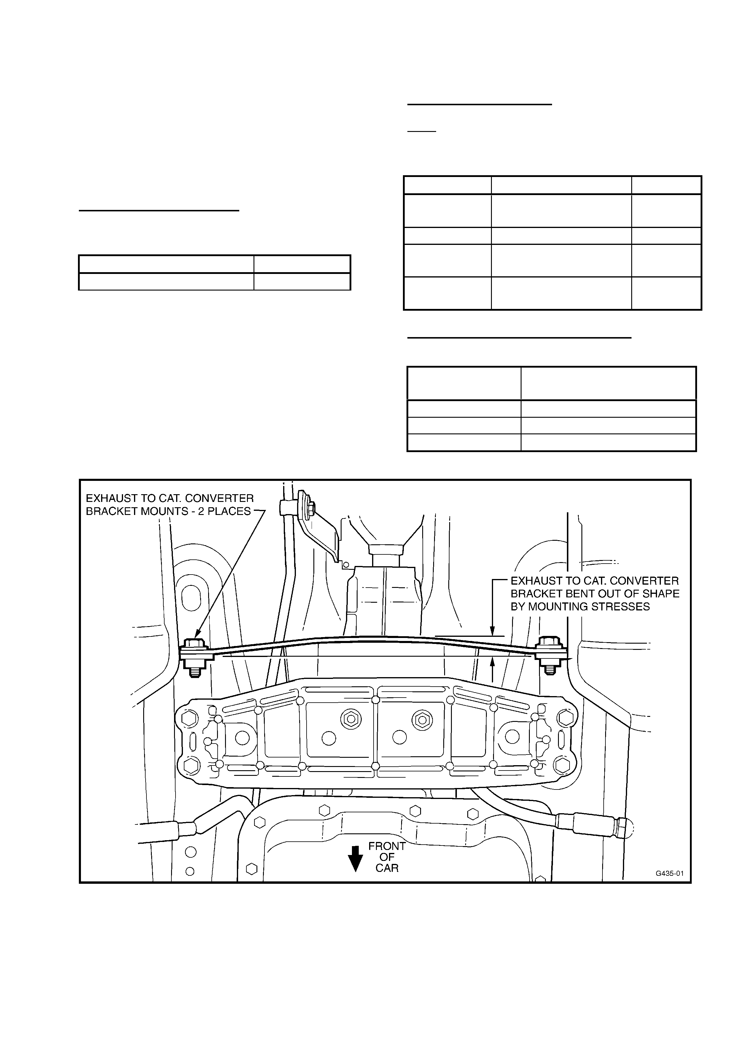
HOLDEN SERVICE TECHLINE ______________________________________________________________ APRIL 2001
18
torque to specification. Flat washers p/n
120394 (1.6mm thick) may be used as
spacers.
Note: If longer bolts are required, use p/n
90495649. Ensure bracket is straight and not
bowed (see Figure's 2 & 3)
PRODUCTION REVISION
Revised rear trans. mounts with studs added
have been fitted to vehicles from:
ISOVIN: Build Date:
6H8VXK69F1L647630 14/10/00
PARTS INFORMATION
Note: When ordering parts, select all bolts,
as required, by information shown in the
procedure above.
Part No. Description: Qty
92138301 Bolt - rear trans.
Mount.
2
- If req’d
11086962 Nut rear trans. mt. 2
90495649 Bolt - cat converter
Bracket.
2
- If req’d
120394 Flat washer (spacer) No. - As
Req’d
WARRANTY CLAIM INFORMATION
For normal rework numbers:
Description Reflash PCM & Destress
Exhaust/Powertrain
Labour Op. No. J000683
Time 0.8 hr
Failure Code 36
Figure 2.
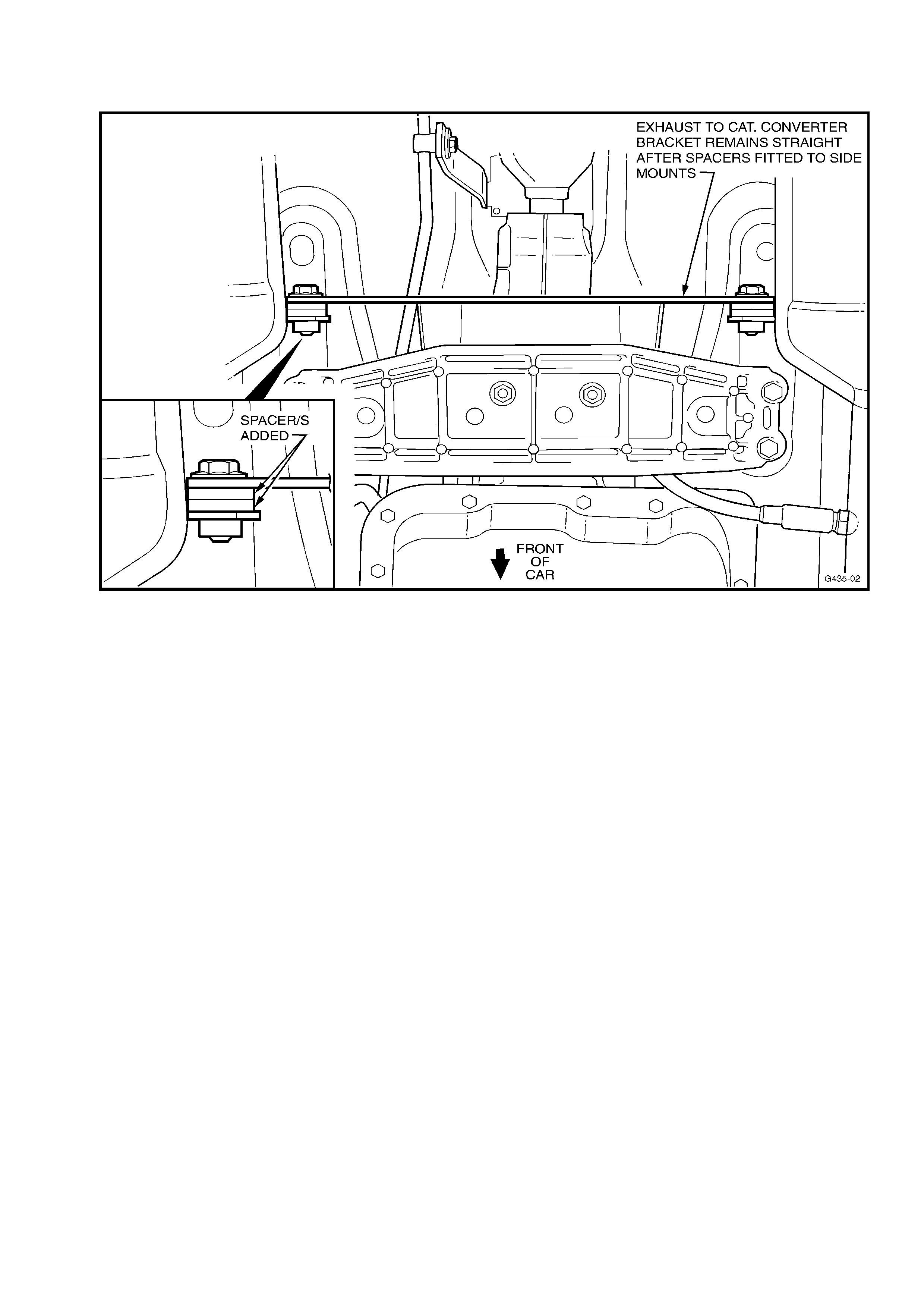
HOLDEN SERVICE TECHLINE ______________________________________________________________ APRIL 2001
19
Figure 3

HOLDEN SERVICE TECHLINE ______________________________________________________________ APRIL 2001
20
EXHAUST MANIFOLD ATTACHING
NUT TORQUE
TS with Z18XE Engine
(GROUP 6A) TL104-6A01
PROBLEM DESCRIPTION
Exhaust manifold attaching nut torque
specification shown in the current TIS 2000
CD is incorrect (too high).
Application of the torque shown (29Nm) in
lieu of the actual torque required (12Nm) may
result in possible future warping of the
exhaust manifold.
SERVICE RECTIFICATION
During any service work requiring the
removal of the exhaust manifold, during
reinstallation of the manifold, ensure exhaust
manifold nuts are torqued to correct
specification, and in the process described
below:
Torque Specification for Exhaust Manifold to
Cylinder Head nuts:
12Nm
Torque Process:
• Torque nuts starting from the centre studs
of the manifold and work outwards in a
“spiral” manner, until all nuts are torqued
to spec..
• Repeat this process - in the same
sequence. This repeat torquing assists in
sealing, when refitting a used and
possibly deformed exhaust manifold – the
repeat torque application reduces
deformation that may occur after the first
torque sequence.
This (corrected) torque specification will be
revised in a future TIS CD.
Note also: whenever an exhaust manifold is
removed, new attaching nuts and a new
gasket must be fitted. Refer to PartFinder for
part numbers.
POWER STEERING HOSES - FLUID
LEAKS AT CLAMP CONNECTIONS
VT, VX, WH
(GROUP 09) TL014-0901
PROBLEM DESCRIPTION
Power steering fluid weeps/leaks at the hose
clamp connections on the return line (low
pressure line) and specifically at the first
connection of the return pipe (from the
steering gear) to the rubber hose.
PRODUCTION RECTIFICATION
An improved hose clamp and revised flexible
hoses have been introduced in production.
The new clamp has improved clamping
characteristics (stays round when tightened)
and the hoses have reduced internal
diameters, to provide an increased
interference fit on the pipe spigots).
These changes were fully effective from:
ISOVIN: Build Date:
6H8VXX69A1L688097 06/02/01
SERVICE RECTIFICATION
On complaint vehicles (built before the above
breakpoint) with leaks from these hose
connections, replace the hose and hose
clamp at leaking connections (only) with a
new hose and clamp.
New Clamp Identification: The new hose
clamps have been sourced from a different
supplier. Ensure the clamp is stamped with
“GEMI” on the band beneath the drive screw.
The previously used clamps are stamped
with “NORMA” on the band, and should not
be used in this application.
PARTS INFORMATION
Refer to Holden PartFinder for hose part
numbers when ordering new hoses
Part No.: Description: Qty:
11088301 Hose clamp As req’d
WARRANTY CLAIM INFORMATION
Use existing information in Labour Time
Manual.
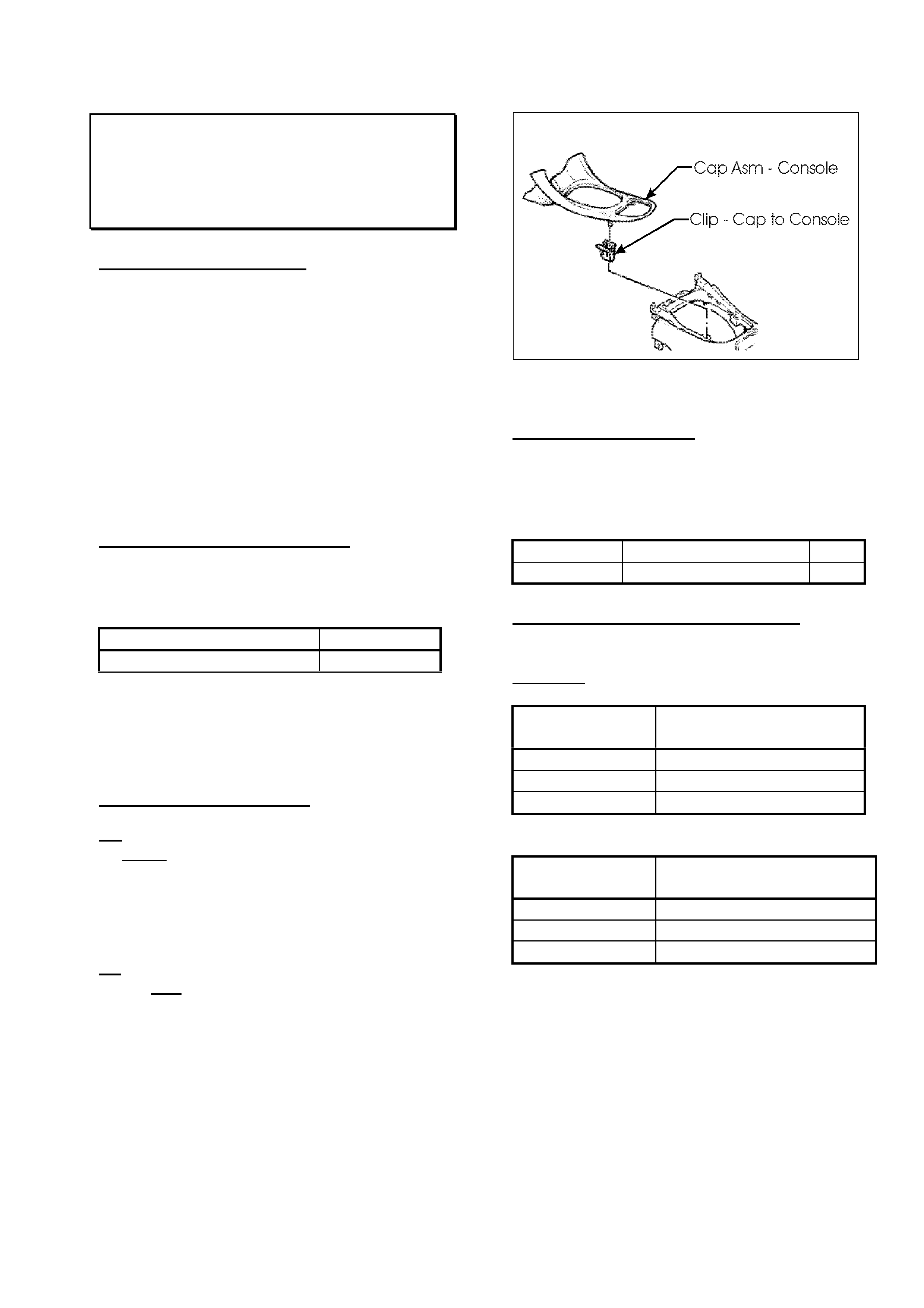
HOLDEN SERVICE TECHLINE ______________________________________________________________ APRIL 2001
21
CONSOLE CAP DISLODGES
VT, VX
(GROUP 1) TL104-0101
PROBLEM DESCRIPTION
The VX console cap (surrounding trans. shift
lever, shown in Figure 1 below) may dislodge
from the console on hot days.
The VT console cap may lift at the rear edge
(behind the power window switch/tray area)
on hot days.
Both these conditions are caused by reduced
retaining clip retention during thermal
expansion.
To correct this condition, a stronger retaining
clip is being used in production on VX.
PRODUCTION RECTIFICATION
Revised retaining clips have been fitted to
vehicles from:
ISOVIN: Build Date:
TBA TBA
NOTE: Breakpoint Information is not
available at date of Techline publication, and
will be added to future Techline Breakpoint
Summary page.
SERVICE RECTIFICATION
VX
If side/s of the console cap dislodge in
service and will not properly retain in the
console using the existing clips, remove the
console cap and fit two new retaining clips.
Refer Figure 1 below for location.
VT
If the rear of the console cap dislodges in
service, and will not properly retain in the
console using the existing clips, the condition
may be rectified by replacing the existing
console cap with a VX console cap (Refer to
PartFinder for correct part number) using the
new retaining clips.
Figure 1.
PARTS INFORMATION
NOTE: These new parts are identified by
their SILVER colour (old clips were yellow
colour).
Part No.: Description: Qty:
92138618 Clip, Cap to Console 2
WARRANTY CLAIM INFORMATION:
Use the existing Labour Operation numbers
as shown for:
Manual Trans. Vehicles:
Description Cap, Console – Replace
(M/T)
Labour Op. No. C474100
Time 0.3 hr
Failure Code 33
Auto. Trans. Vehicles:
Description Cap, Console – Replace
(A/T)
Labour Op. No. C474200
Time 0.3 hr
Failure Code 33
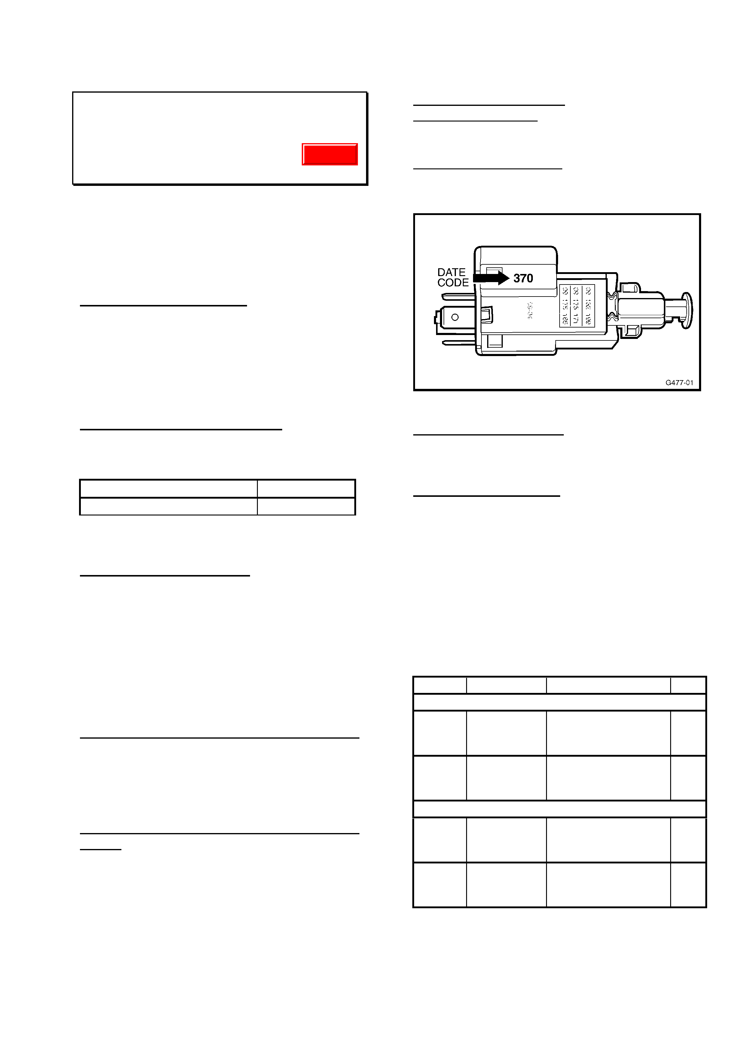
HOLDEN SERVICE TECHLINE ______________________________________________________________ APRIL 2001
22
STOP LAMP SWITCH REVISION
JS, TS
(GROUP 12) TL104-1206
This Service Techline supersedes the
previous Techline on this topic (Issue 3,
March, 2001 page 8). (Breakpoint Info.
Revised). This previous Techline should
be destroyed.
PROBLEM DESCRIPTION
It is possible for some stop lamps to remain
“on” - without the brake pedal being
depressed - because of an incorrect internal
clamp load within the stop lamp switch.
This condition may also result in cruise
control not engaging.
PRODUCTION RECTIFICATION
Stop lamp switches of the current design
were introduced in vehicle production from:
TS:
ISOVIN: Build Date:
W0L0TGF0815065069 23/10/00
JS: Breakpoints are not available for JS
model. Refer to switch date code only.
SERVICE RECTIFICATION
If complaints are received of:
- Stop lamp staying on
- Cruise control will not engage:
the stop lamp switch should be identified by
the Date Code information below.
Check – that the vehicle has an ISOVIN
greater than those shown above.
If ISOVIN is LOWER than the ISOVIN above:
adjust switch to correct the complaint.
(Adjustment procedure is shown at the end of
this Techline item). If adjustment does not
correct the complaint, replace the switch
(Refer to PartFinder for switch part number).
If ISOVIN is HIGHER than the ISOVIN
above: The stop lamp switch should be
checked for date code as per the following
information below.
Date Code “370” Sets the Breakpoint for
OK switches. See Figure 1 for Date Code
interpretation.
Switches with date code:
LESS THAN “370” must be replaced, as
adjustment will not result in a permanent
correction;
GREATER THAN “370” should be adjusted,
as per the procedure at the end of this
Techline item.
Figure 1.
Date Code interpretation: 370
First two digits (week) - 37 = Week 37
Third digit (year) - 0 = Year 2000
PARTS INFORMATION
Refer to HSPO PartFinder for switch part
numbers when ordering new switches.
For your reference only – the parts revised
are noted below with relevant identification.
This information will assist technicians in
identifying switches for replacement, as all
three switches noted have the same
appearance, apart from plunger colour and
terminals.
Model Part No.: Description: Qty:
JS (from XL396309 onward)
09175172 Stop Lamp Switch
(4 terminal, with
BLUE plunger)
1
09132299 Stop Lamp Switch
(2 terminal, with
BLACK plunger)
1
TS (from X5000001 onward)
09132299 Stop Lamp Switch
(2 terminal, with
BLACK plunger)
1
09175185 Stop Lamp Switch
(4 terminal, with
GREY plunger)
1
Update
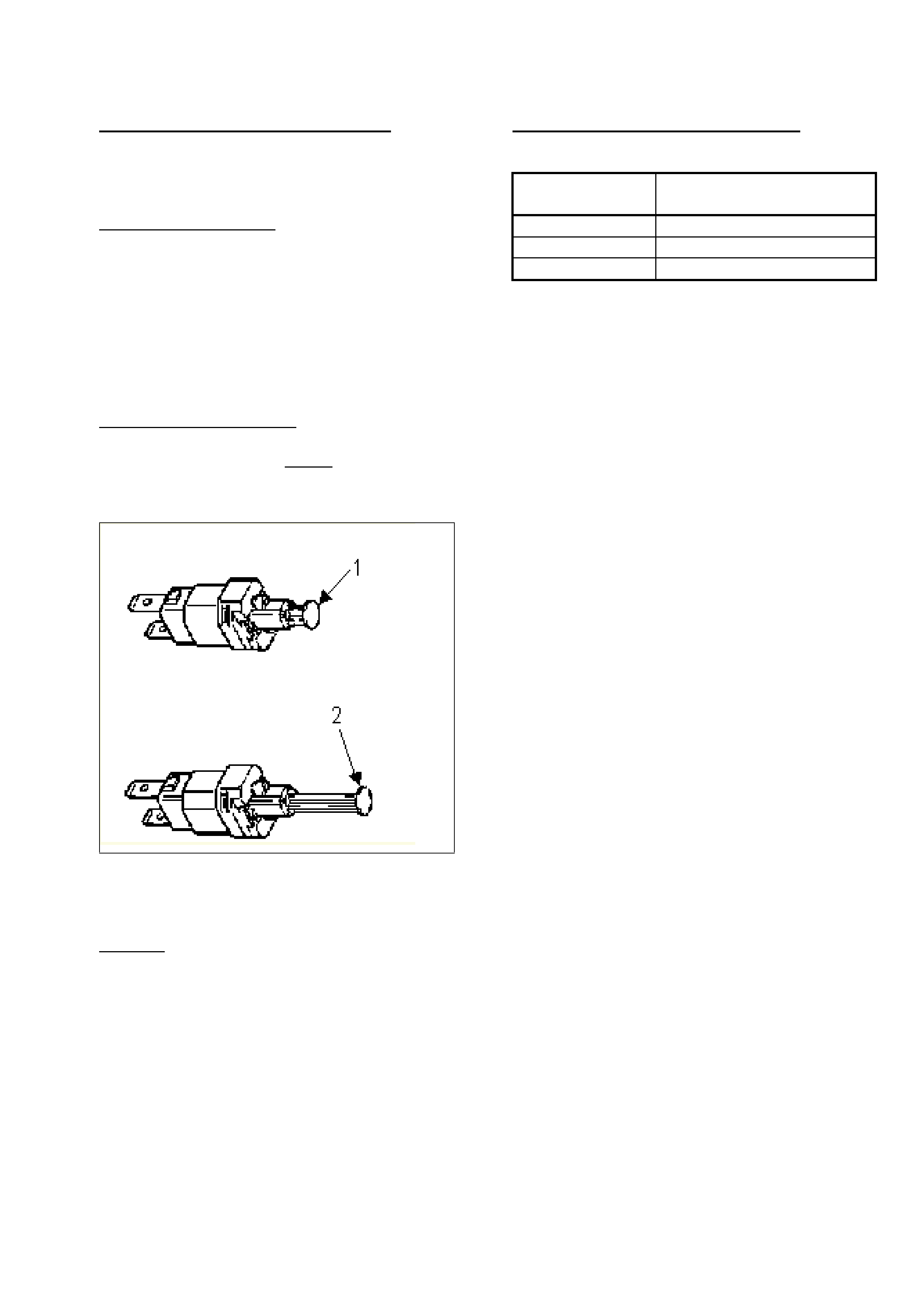
HOLDEN SERVICE TECHLINE ______________________________________________________________ APRIL 2001
23
STOP LAMP SWITCH ADJUSTMENT
Adjust the stop lamp switch using the
following procedure:
Test Stop Lamp Switch
Switch off ignition and remove the stop lamp
switch from its holder, allowing it to hang
from its connector under the dash.
Ensure the electrical connector is fully home.
Turn on the ignition and check that the stop
lamps illuminate.
Manually depress the plunger to check the
stop lamps switch off.
Set the Stop Lamp Switch
Fully extend the plunger by pulling it away
from the switch body. NOTE: a high “pull”
load will be required! A clicking type noise
should be heard. See Figure 2, below:
Figure 2
1- Non adjusted switch
2- Fully adjusted switch
Reinstall
With the brake pedal depressed, install the
switch and allow the pedal to retract onto it.
Test the stop lamp switch for correct
functionality.
WARRANTY CLAIM INFORMATION:
Use existing information in SIP as shown:
Description Stop Lamp Switch,
Replace
Labour Op. No. N207500
Time 0.4 hr
Failure Code 37
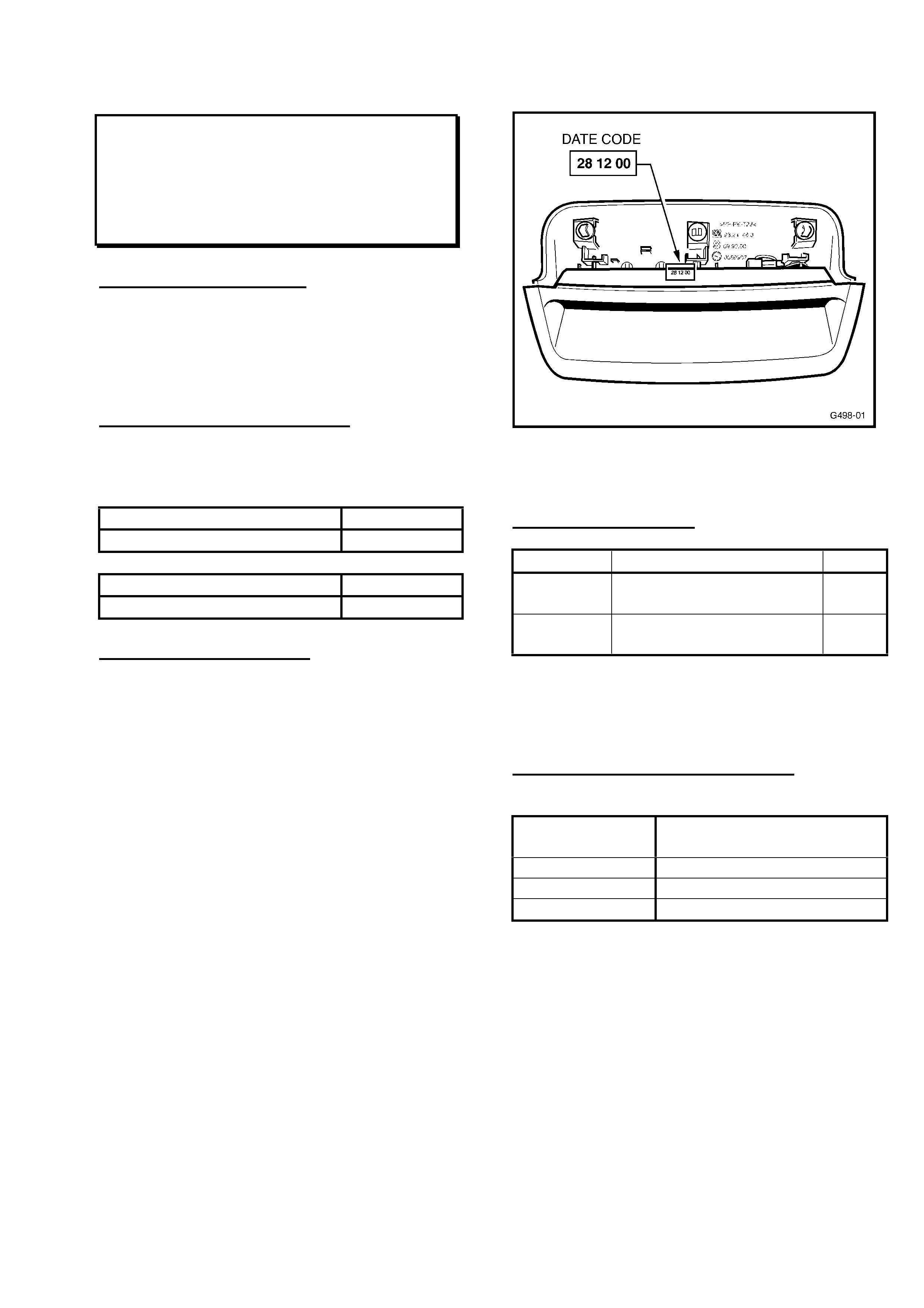
HOLDEN SERVICE TECHLINE ______________________________________________________________ APRIL 2001
24
CENTRE HIGH MOUNTED STOP LAMP
WARPAGE
TS
(GROUP 12) TL104-1202
PROBLEM DESCRIPTION
Significant warpage, causing poor
appearance, may occur to the Centre High
Mounted Stop Lamp (CHMSL) when
subjected to continuous high temperatures or
sunload.
PRODUCTION RECTIFICATION
A revised CHMSL, manufactured from higher
temperature compliant material, has been
introduced into production, as follows:
ISOVIN - Hatch Build Date:
W0L0TGF4815137152 11/01/01
ISOVIN - Sedan Build Date:
W0L0TGF6915137059 12/01/01
SERVICE RECTIFICATION
Where a customer reports significant signs of
warpage of a CHMSL – the CHMSL should
be replaced.
Revised material lamps may be identified by
the date code that is stamped on the lamp as
shown in Figure 1, below.
Date code of 28 12 00 sets the breakpoint for
use of revised material.
The date code is literally the date of
manufacture, IE 28 December, 2000.
Figure 1. (Showing lamp removed from
vehicle).
PARTS INFORMATION
Part No.: Description: Qty
09118408 Lamp Asm., High Mount
Stop. USAGE: Hatch
1
09118406 Lamp Asm., High Mount
Stop. USAGE: Sedan
1
If any Pre-Breakpoint lamps are found in
Dealership parts stock, the parts should be
returned to HSPO on CMR (see your Parts
Manager).
WARRANTY CLAIM INFORMATION
Use existing information in SIP CD as shown:
Description Lamp Asm. Stop, High
Mounted - Replace
Labour Op. No. R902400
Time 0.4 hr
Failure Code 11
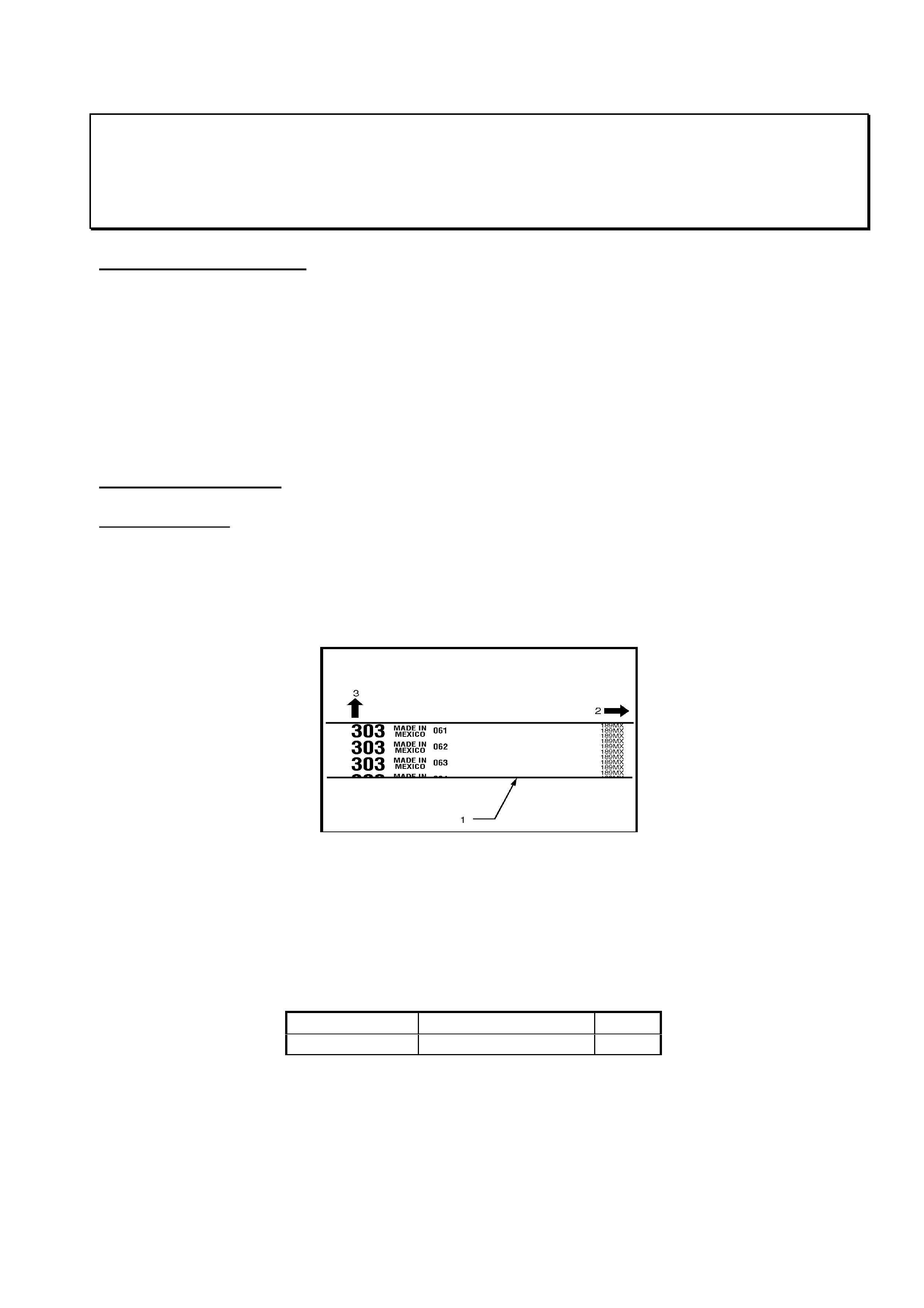
HOLDEN SERVICE TECHLINE ______________________________________________________________ APRIL 2001
25
TIMING BELT INSTALLATION OR REPLACEMENT
UBS, UES, TFS – All with V6
(GROUP 6A) TL104-6A01
PROBLEM DESCRIPTION
Vehicle does not run or runs rough after timing belt replacement or installation.
Alignment marks on timing belt do not line up with alignment marks on engine during timing belt
installation.
Correction and clarification of workshop manual timing belt fitting procedures are contained in this
Techline. SIP will be updated in the next issue (July).
Relocation of alignment marks on timing belt to allow fitment as described in this Techline.
PARTS INFORMATION
Belt Identification
The correct belt can be identified by the number 303 as shown in the diagram below. The previous
belt was marked with T200; this belt has the incorrect installation alignment marks and should not
be used.
Figure 1
LEGEND
(1) Timing Belt.
(2) Engine Rotation Direction.
(3) Cylinder Head Side.
All belts with the incorrect installation alignment mark have been removed from HSPO stock.
Part No.: Description: Qty:
8971363210 Timing Belt (303) 1

HOLDEN SERVICE TECHLINE ______________________________________________________________ APRIL 2001
26
SERVICE RECTIFICATION
SUMMARY
The procedure included in this Techline can be summarised into the following simple points. The
purpose of this summary is to provide an overview of important points required to fully understand the
following procedure.
- The V6 engine fitted to Rodeo, Jackaroo and Frontera from 98 has a cam drive system where the
reduction is partly obtained through the timing belt pulleys and partly through the cam drive gear
located in the cylinder head. The two ratios combined form a reduction ratio of 2:1.
- Due to the two-stage reduction three timing reference points are required when setting the cam
timing. They are the (1) crankshaft (2) camshaft belt pulleys (3) actual camshaft position. The
timing marks on the belt pulleys will line up every 3 crankshaft rotation while the timing marks and
actual camshaft positions will only line up every 6 crankshaft rotations.
PREPARATION PROCEDURE
Remove all components required to gain access to the timing belt as listed below:
- Battery ground;
- Air intake assembly;
- Upper radiator fan shroud;
- Serpentine belt;
- Cooling fan, cooling fan clutch and bracket
- Serpentine belt tensioner and idler pulley assemblies;
- Power steering pump assembly;
- Crankshaft pulley;
- Timing belt covers, right side first.
NOTE: If the timing belt is being replaced as part of regular servicing and there is no reason to
suspect a fault with the cam timing, follow the ‘Belt Service’ procedure.
If the timing position of the engine is unknown or in doubt ie. broken timing belt or head
removal, follow the ‘Unknown Cam Timing’ procedure.
PROCEDURE 1 - BELT SERVICE
- Rotate the engine until the notch on the crankshaft timing pulley aligns with the mark on the oil
pump housing (TDC Cyl #2, Figure 2). At the same time, the painted marks on each of the
camshaft pulleys must align with the marks on the cylinder head covers. Refer Figure 3. This
should require no more than 3 rotations of the crankshaft. The marks on the belt will not line up
with the timing marks.
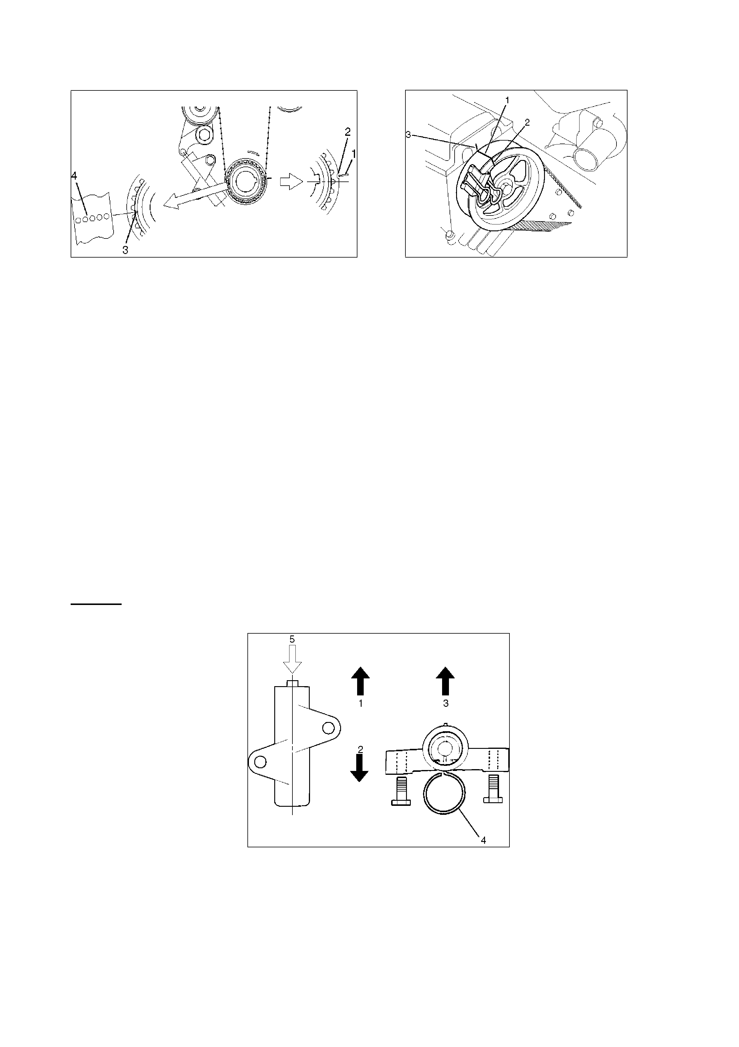
HOLDEN SERVICE TECHLINE ______________________________________________________________ APRIL 2001
27
Figure 2 (Crankshaft Alignment) Figure 3 (Camshaft Alignment, mirror
image for left side)
Legend Legend
(1) Mark on oil pump (TDC Cyl #2) (1) Alignment mark on timing belt (for
(2) Notch on crankshaft timing pulley. belt installation only).
(3) Alignment mark on crankshaft timing pulley (2) Alignment mark on camshaft timing pulley
(for belt installation only). (3) Alignment mark on head cover.
(4) crankshaft alignment mark on timing belt
(for belt installation only).
- Remove the timing belt. While removing the belt be sure that the camshaft pulleys do not move.
If a camshaft pulley should move for any reason it must returned to exactly the same position ie. if
the pulley should move in a clockwise direction it must be returned to the same position by
rotating the pulley in the anti-clockwise direction and vice versa.
The camshaft will be in different position if rotated forward two revolutions. If the position of the
camshafts becomes unknown for any reason the ‘Unknown Cam Timing Procedure’ should be
used to complete the timing belt installation.
- Remove the timing belt pusher (tensioner).
Caution: To prevent air entering the oil chamber the pusher must be stored with the rod
facing upward.
Figure 4
Legend
(1) Up Side.
(2) Down Side.
(3) Direction for Installation (Engine Side).
(4) Apply force of 980Nm (220Ib) to compress the pusher (tensioner).

HOLDEN SERVICE TECHLINE ______________________________________________________________ APRIL 2001
28
BELT INSTALLATION
NOTE:
Do not bend or twist the belt otherwise, its core could be damaged. The belt should not be
bent to a radius of less than 30mm.
Do not allow oil or other chemical substances to come in contact with the belt.
Do not attempt to pry or stretch the timing belt during installation.
Store the timing belt in a cool dark place. Never expose the belt to direct sunlight or
excessive heat while in storage.
- Install the new timing belt in the direction shown in Figure 1. When installed correctly you wil be
able to read the writing on the belt during installation as seen from the front of the engine.
- Install the timing belt on the crankshaft first; align the white dotted line on the timing belt with the
alignment mark on the crankshaft pulley, refer Figure 2. Secure the belt onto the pulley using a
‘bulldog’ clip.
- Align the appropriate solid white lines on the timing belt with the respective camshaft pulleys and
secure with ‘bulldog’ clips, refer Figure 3. You may need to slightly rotate (one tooth) the L/H
camshaft pulley anticlockwise to assist with fitting the belt to the camshaft pulley, once fitted the
timing marks can then be realigned.
- Compress the belt pusher slowly in a press, be sure to maintain a light resistance on the press
handle so the hydraulic pusher is not damaged. Install an appropriate locking pin into the pusher
eg. meat skewer.
- Rotate the crank clockwise to obtain maximum belt slack for fitting the pusher.
- Install the pusher and release the locking pin.
- Remove ‘Bulldog’ clips from the crankshaft and camshaft pulleys.
NOTE: The belt installation procedure above is the same procedure as that used since 1992 on V6
Jackaroo.
- Install the crankshaft pulley and rotate the crankshaft 3 complete revolutions until the timing notch
on the crankshaft pulley again aligns with the mark on the oil pump housing, the timing marks on
the camshaft pulleys should realign with the marks on the head covers.
NOTE: The marks on the timing belt are for installation purposes only and will not realign
with the cam timing marks.
- Check that the rod projection on the timing belt tensioner is approximately 5mm (Refer Figure 5).
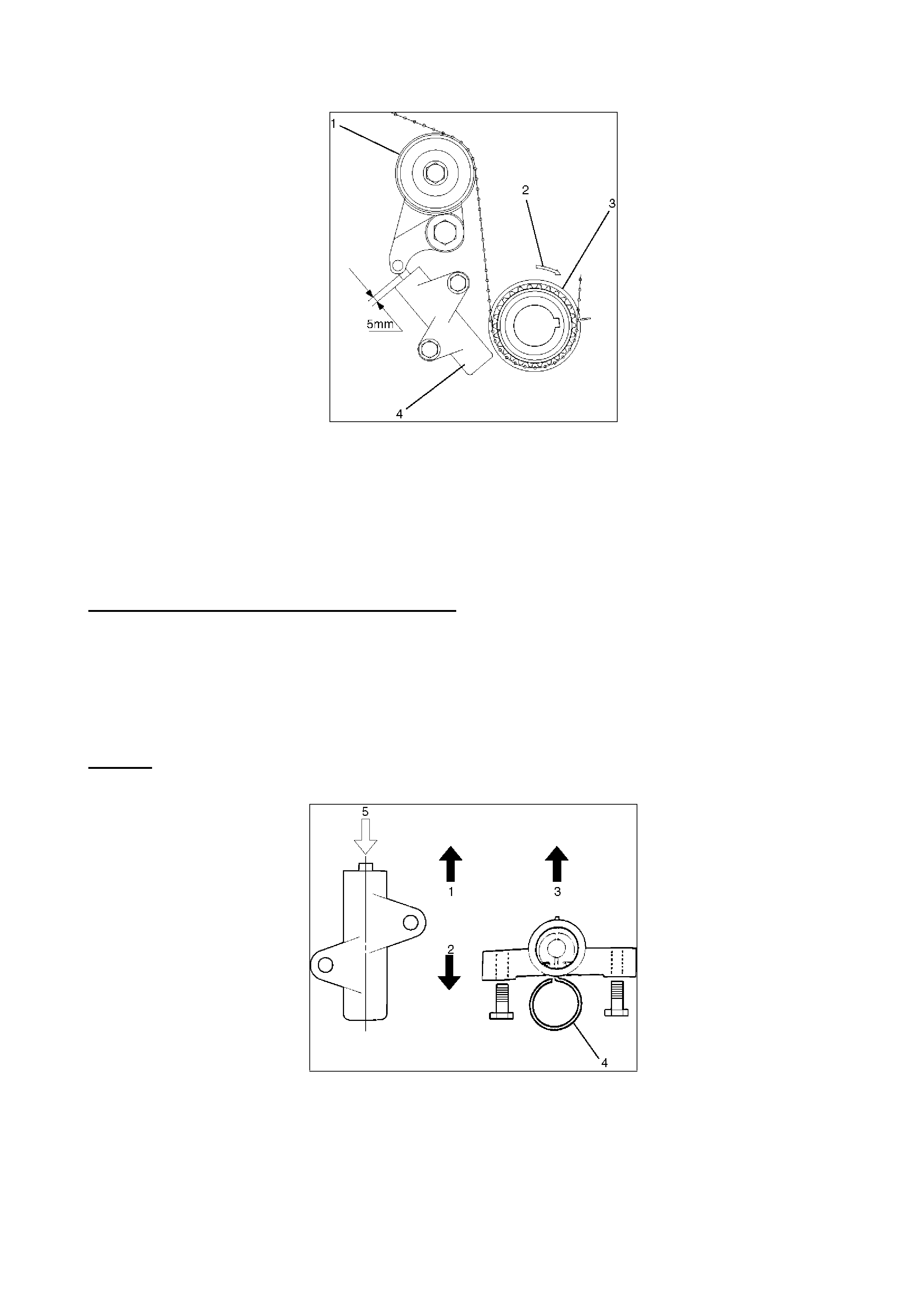
HOLDEN SERVICE TECHLINE ______________________________________________________________ APRIL 2001
29
Figure. 5
LEGEND
(1) Tensioner Pulley
(2) Crankshaft Direction of Rotation
(3) Crankshaft Pulley
(4) Pusher Assembly “Tensioner”
- Re-assemble the engine in the reverse order as described in the ‘Preparation Procedure’.
PROCEDURE 2 - UNKNOWN CAM TIMING
- Gain access to the front of the engine by using the ‘Preparation Procedure’ as described above.
- Remove broken belt or re-install repaired cylinder head as required. Be sure to remove any
foreign material form around the timing belt drive area.
- Remove the timing belt pusher (tensioner).
Caution: To prevent air entering the oil chamber the pusher must be stored with the rod
facing upward.
Figure 6
Legend
(1) Up Side. (2) Down Side.
(3) Direction for Installation (Engine Side). (4) Lock Pin
(5) Apply force of 980Nm (220Ib) to compress the pusher (tensioner).
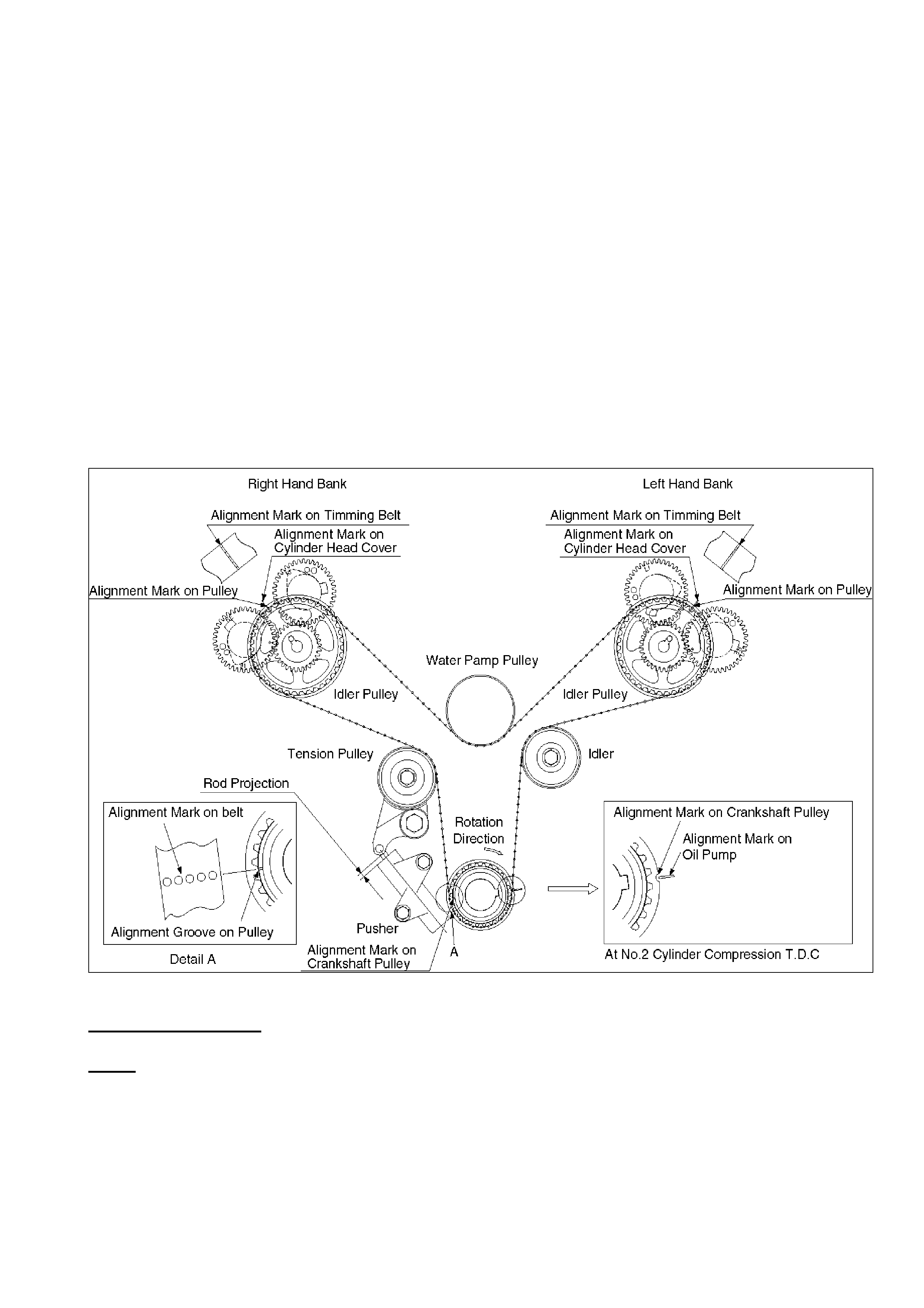
HOLDEN SERVICE TECHLINE ______________________________________________________________ APRIL 2001
30
- Remove cylinder head covers.
- Align the timing marks as shown in Figure 7 noting the following 3 points.
- Align the notch on the crankshaft timing pulley with the mark on the oil pump housing (TDC
Cyl#2).
- Rotate the right side camshaft pulley until the timing mark is at the 12 o’clock position relative to
the cylinder head mounting surface (Refer Figure 7). While in this position the cam lobes for
cylinder #1 (directly behind the cam pulley) must be in the position shown in Figure. 7. Up to four
rotations of the cam pulley may be required to achieve correct alignment.
- Rotate the left side camshaft pulley until the timing mark is at the 12 o’clock position relative to
the cylinder head mounting surface (Refer Figure 7). While in this position the cam lobes for
cylinder #2 (directly behind the cam pulley) must be in the position shown in Figure. 7 (Firing). Up
to four rotations of the cam pulley may be required to achieve correct alignment.
Figure. 7
BELT INSTALLATION
NOTE:
Do not bend or twist the belt otherwise, its core could be damaged. The belt should not be
bent to a radius of less than 30mm.
Do not allow oil or other chemical substances to come in contact with the belt.
Do not attempt to pry or stretch the timing belt during installation.
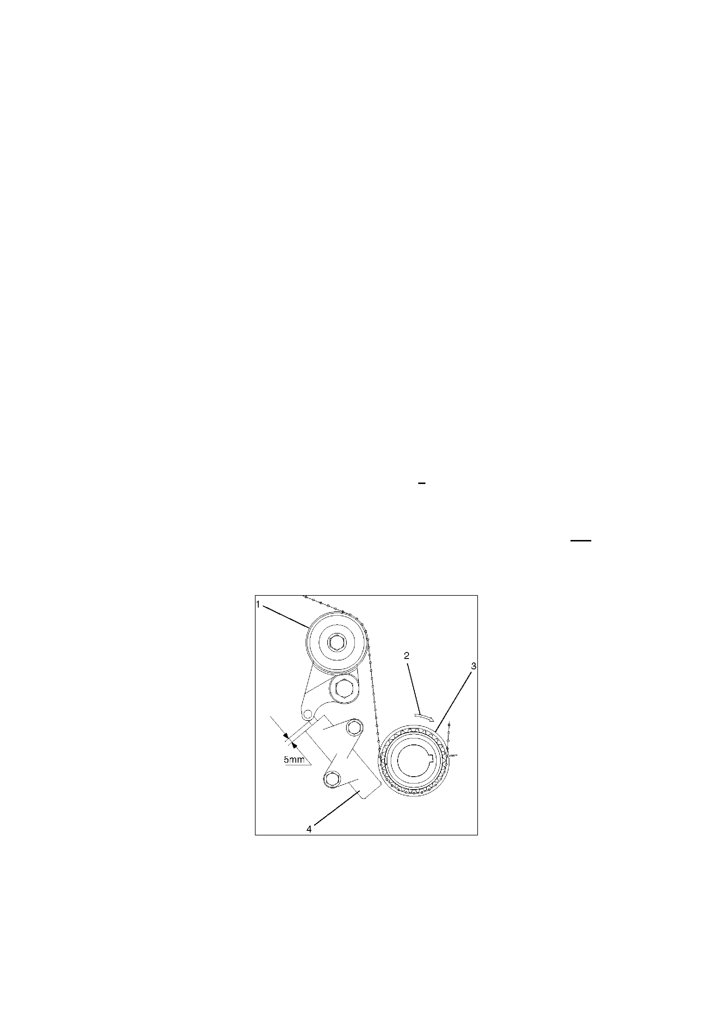
HOLDEN SERVICE TECHLINE ______________________________________________________________ APRIL 2001
31
Store the timing belt in a cool dark place. Never expose the to direct sunlight or excessive
heat while in storage.
- Install the new timing belt in the direction shown in Figure 1. You must be able to read the writing
on the belt during installation as seen from the front of the engine.
- Install the timing belt on the crankshaft first; align the white dotted line on the timing belt with the
alignment mark on the crankshaft pulley, refer Figure 7. Secure the belt onto the pulley using a
‘bulldog’ clip.
- Align the appropriate solid white lines on the timing belt with the respective camshaft pulleys and
secure with ‘bulldog’ clips, refer (Figure 7). You may need to slightly rotate (one tooth) the L/H
camshaft pulley anticlockwise to assist with fitting the belt to the camshaft pulley, once fitted the
timing marks can then be realigned.
- Compress the belt pusher in a press, be sure to maintain a light resistance on the press handle
so the hydraulic pusher is not damaged. Install an appropriate locking pin into the pusher eg.
meat skewer.
- Rotate the crank clockwise to obtain maximum belt slack for fitting the pusher.
- Install pusher and release the locking pin.
- Remove ‘Bulldog’ clips from the crankshaft and camshaft pulleys.
NOTE: The belt installation procedure above is same procedure as that used since 1992 on V6
Jackaroo. It is the method of positioning the cams and cam pulleys that differs.
- Install the crankshaft pulley and rotate the crankshaft 6 complete revolutions. The crank timing
pulley mark, cam timing pulley marks and cam lobe positions should return to that shown in
Figure.7.
NOTE: The marks on the timing belt are for installation purposes only and will not align again
with the cam timing marks.
- Check that the rod projection on the timing belt tensioner is approximately 5mm (Refer Figure 8).
Figure. 8
LEGEND
(1) Tensioner Pulley
(2) Crankshaft Direction of Rotation
(3) Crankshaft Pulley

HOLDEN SERVICE TECHLINE ______________________________________________________________ APRIL 2001
32
(4) Pusher Assembly “Tensioner”
- Re-assemble the engine in the reverse order as described in the ‘Preparation Procedure’.
LC6A0401.DOC
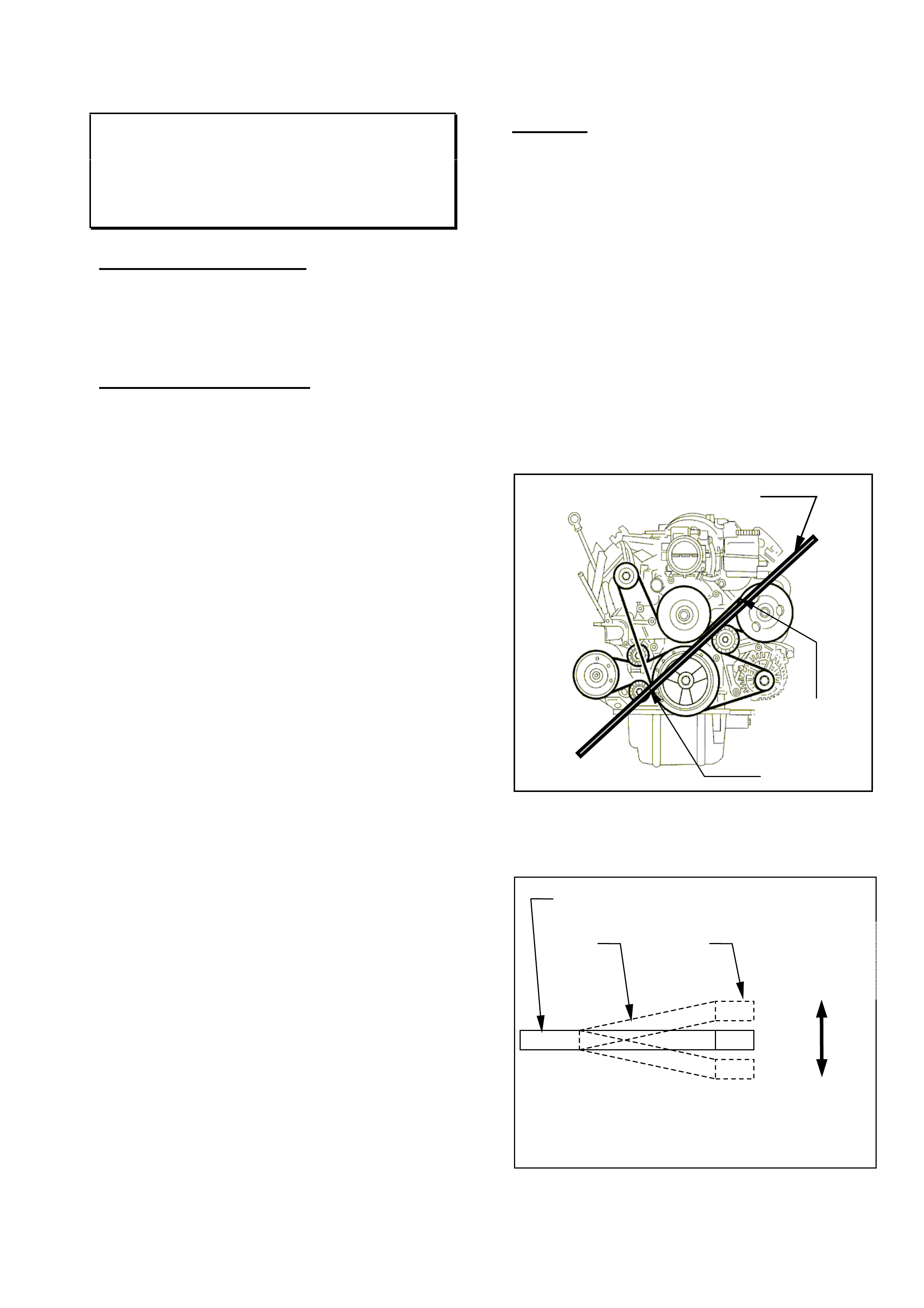
HOLDEN SERVICE TECHLINE ___________________________________________________________________MAY 2000
6
ENGINE DRIVE BELT SQUEAL
Gen III V8 - VT, VX, WH, VU
(GROUP 6A) TL105-6A01
PROBLEM DESCRIPTION
Some customers may complain of a belt
squeal or chirp noise around 1500 to 1900
rpm generally when the engine is at
operating temperature.
SERVICE RECTIFICATION
This issue is under investigation to determine
the root cause of the problem.
This squeal generally emanates from the
power steering pump pulley due to
misalignment with the crank pulley and
alternator pulley. The pump pulley will either
be too close to the pump body or too far
forward. This means the belt will not track
straight and will rub on the front or rear
flange of the pulley. An adjustment of
between 1 – 3mm may be required.
To address the squeal, use the following
procedure:
Special Tools required:
• 150mm (6”) steel ruler with 0.5mm
increments
• 450 to 600mm long engineering straight
edge
• Dial indicator (and mounting clamp or
magnetic base)
• Tooling for installing the power steering
pump pulley, either:
§ E9239A, or
§ 7005
• Tooling for removing the power steering
pump pulley, either:
§ AU188, or
§ 7185
(Refer to Section 9A of SIP for more detailed
usage of these tools)
1. Remove the engine dress cover and intake
pipe. It may also assist to remove the air
cleaner upper housing.
2. Remove the upper radiator shroud, and the
fan and shroud assembly to permit access
to the pulleys. Refer to Section 6B3 for VT
II in SIP for details.
Caution! If you need to remove any
coolant hoses, don’t spill coolant onto
the belt. This will cause further belt
squeal.
3. Grasp the pump pulley and firmly pull and
push the pulley. The power steering pump
has an allowable maximum end float of
2.0 mm. Ensure the end float is within
specification.
4. Use the long straight edge to check
whether the pump pulley is misaligned.
Place one end of the straight edge across
the power steering pump pulley and the
other end across the crank pulley. The
straightedge should run between the water
pump pulley and the idler pulley as shown
below.
5. Determine where the pump pulley is in
relation to the crank pulley. Refer to the
diagram below.
Top View of Crank & Power Steering
Pump Pulleys
Crankshaft pulley
Power
steering
pump
pulley
Belt CHECK FOR
PUMP PULLEY
MISALIGNMENT
WITH CRANK!
Place straight edge in this position
Measure from
straight edge
to belt in
these places
(refer Step 7)
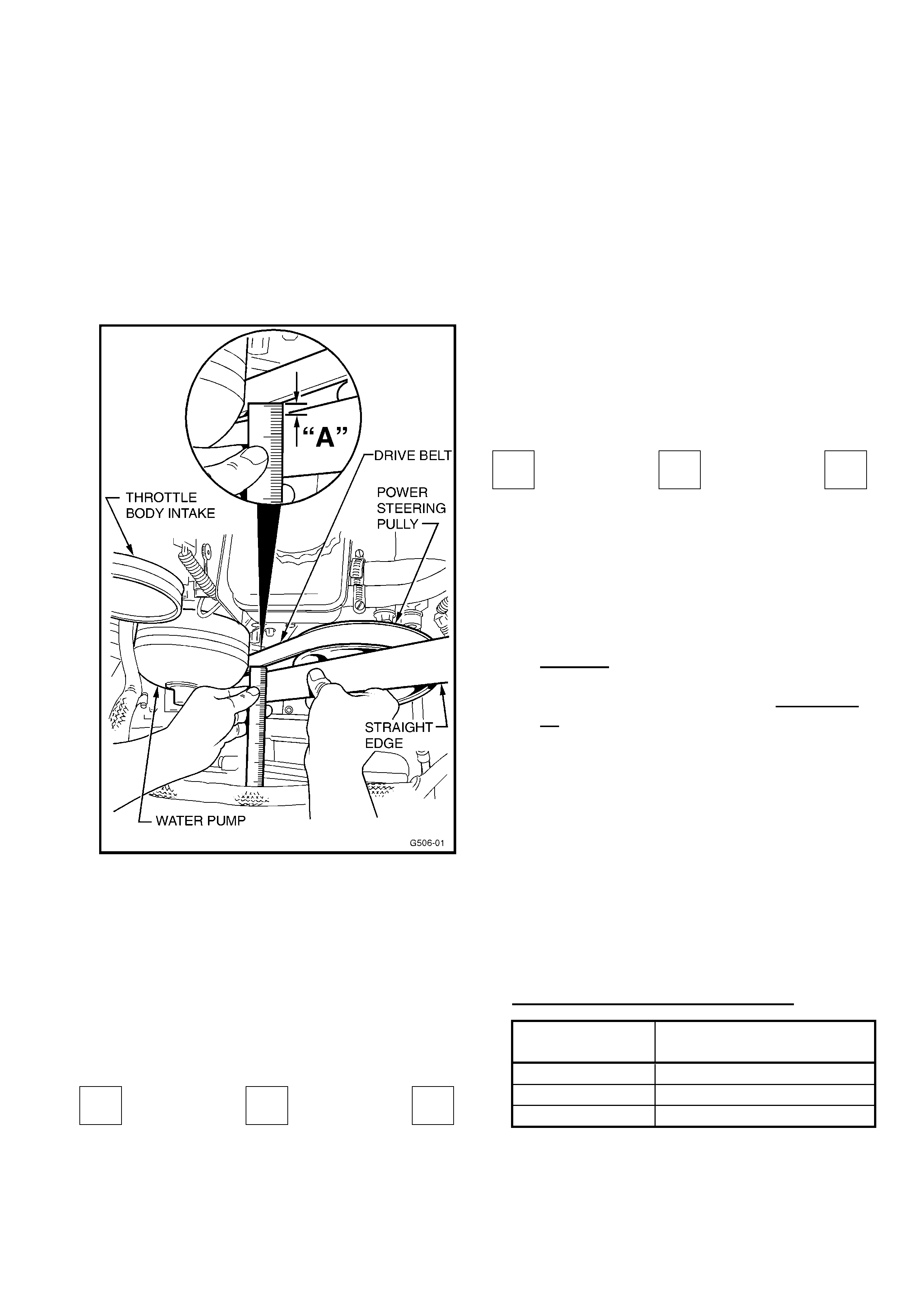
HOLDEN SERVICE TECHLINE ________________________________________________________________ MAY 2001
7
6. Now, using the 150mm ruler, take two
measurements from the edge of the belt to
the edge of the straight edge. Refer to
dimension “A” in the diagram below. One
of these measurements should be close to
the pump pulley and the other should be
close to the crank pulley. This step is
necessary because the crank and pump
pulleys have different front flange
thicknesses.
7. If the two measurements are equal or
within 1mm, no adjustment should be
necessary. If the measurements differ by
more than 1mm, adjustment of the pump
pulley will be required to bring it in line
with the crank pulley.
Photocopy this page and use the
calculation boxes below to work out the
required pulley adjustment:
- =
Crank
End
subtract Pump
End
equals Total
Adjustment
If the total adjustment is a positive
number, the pump pulley needs to be
adjusted back towards the pump housing.
GO TO STEP 8.
If the total adjustment is a negative
number, the pump pulley needs to be
adjusted forward away from the block.
GO TO STEP 9.
For Example:
Belt to straightedge at crank pulley
= 4mm
Belt to straightedge at pump pulley
= 6mm
4 - 6 = -2
Crank
End
Subtract Pump
End
equals Total
Adjustment
8. For a positive adjustment figure: Use
one of the special tools listed above to
press the pulley further onto the pump
shaft.
Caution! If the pulley is pressed on too
far it will contact the pump housing!
Consider the pump end float! Go to step
10.
9. For a negative adjustment figure: Shim
the entire pump outwards with washers to
achieve the desired belt position.
Alternatively, if the required adjustment is
only between 1mm and 2mm, use the
special tools listed above to pull the pulley
off the end of the shaft by this amount.
10. Once the pulley position has been
adjusted satisfactorily, reassemble the
removed components.
11. Warm the engine and confirm the squeal
has been eliminated.
WARRANTY CLAIM INFORMATION
Description Align Power Steering
Pump Pulley
Labour Op. No. M000181
Time 0.7 hr
Failure Code 25
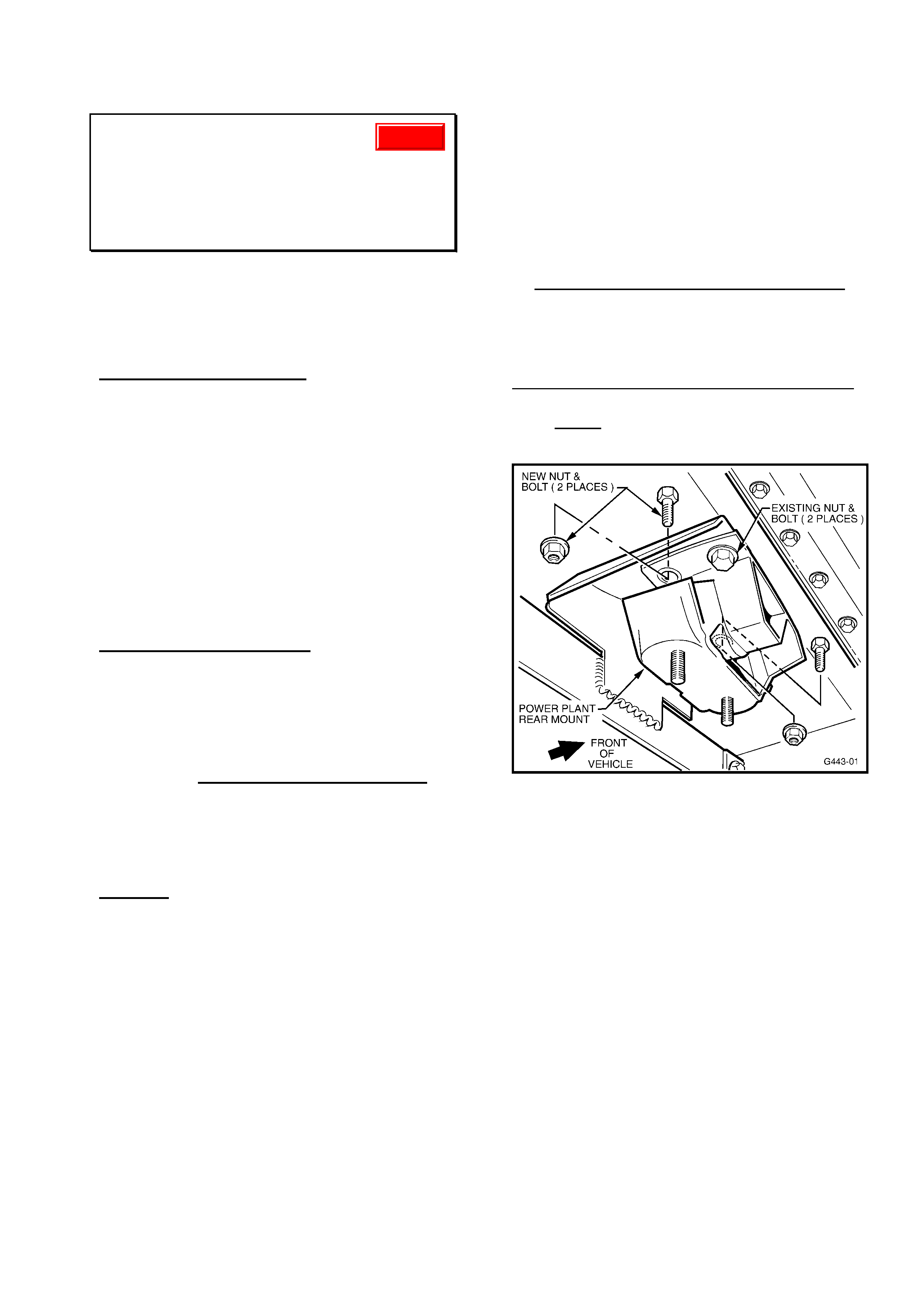
HOLDEN SERVICE TECHLINE ________________________________________________________________ MAY 2001
8
ENGINE IDLE VIBRATION
VT, WH, VX, VU, - All with Gen III & A/T
(Standard Engine)
(GROUP 6C & 8) “RE-ISSUE” TL105- 0801
This Service Techline supersedes the
previous Techline on this topic (Issue 1, April,
2001 page 17). This previous Techline should
be destroyed.
PROBLEM DESCRIPTION
Excessive vibration or buzz felt within the
vehicle, under any of the following
conditions:
(1) Vehicle stationary at idle with
transmission in Drive/Reverse with A/C
on
(2) Idle speed drop when Drive/Reverse
selected and/or steering load applied.
(3) Slow acceleration or low speed driving in
1st gear, with engine speed between 650
and 1000 rpm.
SERVICE RECTIFICATION
To reduce the level of vibration on complaint
vehicles for any of the above conditions, the
following action is recommended.
FOR ALL VT VEHICLES, AND WH
VEHICLES UP TO VIN L626037 ONLY:
Flash Revised Calibration
Flash latest calibration from most recent TIS
CD (EG: No. 20.0B at time of publication of
this Techline) into complaint vehicles only.
Caution: This calibration flashing CANNOT
be carried out to WH vehicles built from
L626038, or any VX or VU vehicle.
In Addition:
FOR ALL VEHICLES:
DE-STRESS EXHAUST & POWERTRAIN
An indication that the exhaust/powertrain is
stressed is a bent catalytic (cat.) converter
bracket as shown in Figure 2.
The following MUST be completed in
sequence
1. Loosen (by approx 1 turn) engine mount
nuts, front pipe/exhaust manifold nuts and
intermediate muffler/front pipe bolts.
2. Support transmission, and remove cross
member complete with cat. converter bracket
and transmission (trans.) mount.
3. Remove trans. mount and cat. converter
bracket.
4. Vehicles built before L647630,14/10/00 -
Fit two additional bolts/nuts to rear trans.
mount holes (use P/N: bolts: 92138301,
nuts:11086962 ) and torque to 45-55 Nm
(See Figure 1).
On Vehicles built from L647630,14/10/00,
-studs have been added to the trans. mount
and ONLY two nuts, p/n 11074604 are
required to be fitted to these studs.
Figure 1.
5. Fit trans. mount and cat. converter bracket
to transmission and torque bolts to
specification.
6. Refit cross member and torque four outer
bolts (ie, cross member to body rails) to
specification. Leave the two trans. mount to
cross member nuts loose at this stage.
7. Lower vehicle back onto the ground, start
the engine and cycle through the gears, ie,
R-N-D five times and then rev the engine in
neutral up to 4000 rpm five times.
8. Raise vehicle on hoist.
9. Torque engine mount nuts to specification.
Update
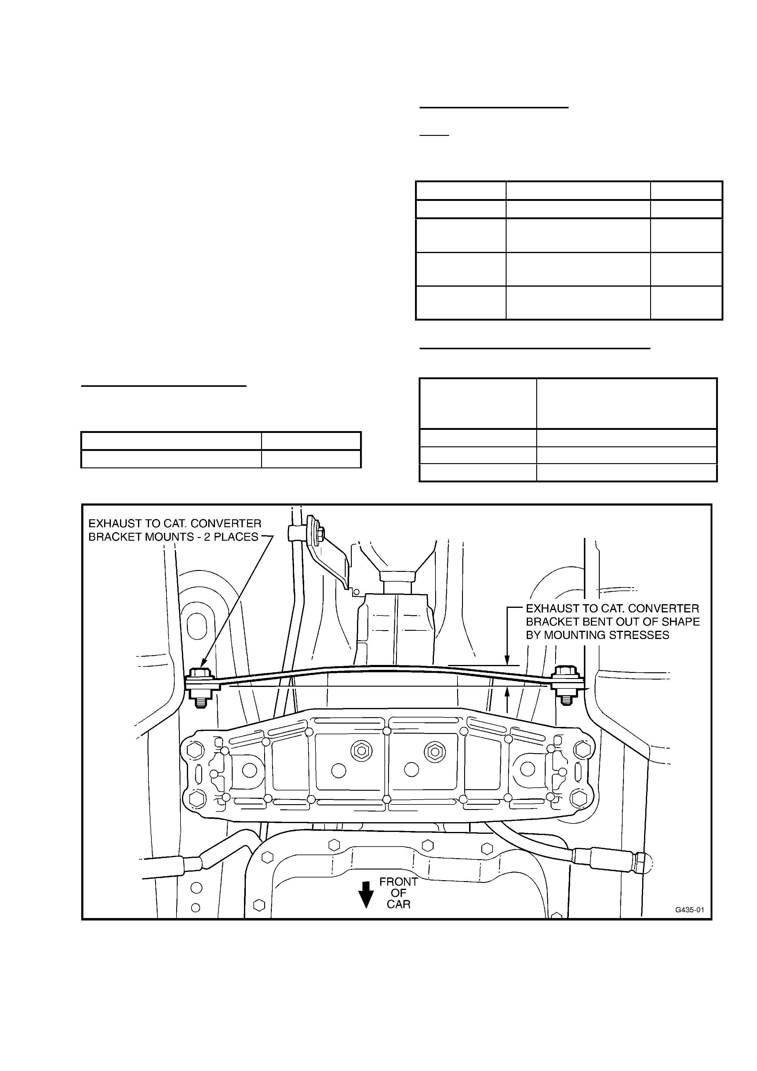
HOLDEN SERVICE TECHLINE ________________________________________________________________ MAY 2001
9
10. Torque trans. mount to trans. cross
member nuts to specification.
11. Torque intermediate to front pipe bolts to
specification.
12. Torque front pipe-to-exhaust manifold
nuts to specification.
13. Add spacers to take up the clearance
between trans. to cat. converter bracket and
cat. converter (see Figure 2), refit bolts and
torque to specification. Flat washers p/n
120394 (1.6mm thick) may be used as
spacers.
Note: If longer bolts are required, use p/n
90495649. Ensure bracket is straight and not
bowed (see Figure's 2 & 3)
PRODUCTION REVISION
Revised rear trans. mounts with studs added
have been fitted to vehicles from:
ISOVIN: Build Date:
6H8VXK69F1L647630 14/10/00
PARTS INFORMATION
Note: When ordering parts, select all bolts,
as required, by information shown in the
procedure above.
Part No. Description: Qty
11074604 Nut rear trans. mt. 2
92138301 Bolt - rear trans.
Mount.
2
- If req’d
90495649 Bolt - cat converter
Bracket.
2
- If req’d
120394 Flat washer (spacer) No. - As
Req’d
WARRANTY CLAIM INFORMATION
For normal rework numbers:
Description Destress
Exhaust/Powertrain &
Reflash PCM (if req’d)
Labour Op. No. J000683
Time 0.8 hr
Failure Code 36
Figure 2.
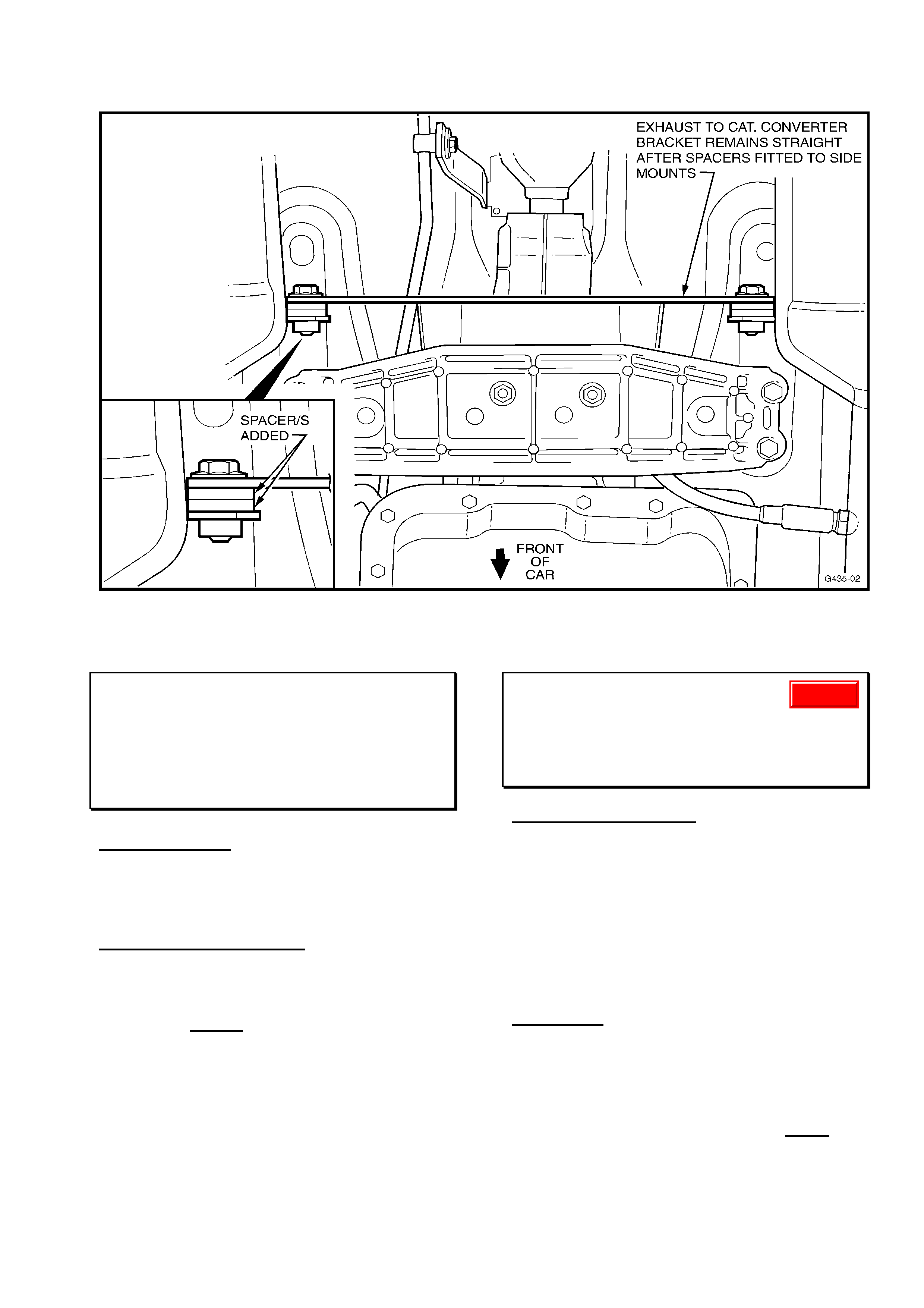
HOLDEN SERVICE TECHLINE ________________________________________________________________ MAY 2001
10
Figure 3.
STEERING WHEEL RETAINING BOLT
TORQUE REQUIREMENT
TS
(GROUP 9) TL105-0901
SPECIFICATION
Steering wheel retaining bolt requires a
torque of 22 Nm (16.2 ft.lbf) on installation.
SERVICE REQUIREMENT
When installing a steering wheel the
specified torque (as noted in TIS information,
and above) MUST be applied to the retaining
bolt.
LSD CHATTER NOISE
VT, VX, WH, all with V8
(GROUP 4) TL105-0401
CURRENT CONDITION
Refer to All Dealer Letter DL65/00 entitled
“V8 LSD CHATTER”.
During re-assembly of pinion nut to pinion,
after installation of revised seal, the Pinion
Oil Seal replacement process – Step 15
“recommends” the use of Loctite 243 Nut
Lock.
IN FUTURE: following receipt of this Techline
bulletin:
During this re-assembly process, the
following revised procedure applies:
“NOTE: Loctite 243 Nut Lock must be
used on re-assembly of pinion nut to
pinion.”
Update

HOLDEN SERVICE TECHLINE ________________________________________________________________ MAY 2001
11
REMOVING PULLEYS & HUBS FROM
POWER STEERING PUMPS – REPAC
RETURNS PRECAUTION
VS, VT, VX, VU, WH
(GROUP 9) TL105-0902
This information in this Techline bulletin is
repeated (previously released May, 1998) for
the benefit of technicians and Warranty
personnel – to ensure power steering pumps
are dismantled and returned in the correct
manner – this will avoid charge-back action
being taken by REPAC.
Please circulate this Techline item to your
Warranty personnel.
-----------------------------------------------------------
A number of power steering pumps returned
to REPAC under warranty still have hubs (on
V6 pumps) and pulleys (on V8 pumps)
assembled to them.
This is a reminder to dealers that hubs and
pulleys can be easily removed from pumps
using a standard workshop hydraulic press
with special press plates. For special tools
and removal procedures refer to VR Service
Manual volume 5, page 9A-70 (for VS); VT
Service Manual Volume 5, page 9A-63, or
SIP CD, VT Series I Service Information,
Section 9A, Parts 3.10 (V6) & 3.11 (V8).
Provided there are no obvious signs of
damage, a “removed” hub or pulley can be
reinstalled onto the new pump following the
installation procedures shown in service
manual.
NOTE: The standard time for pump R & R
(labour op. M147000) includes an allowance
for hub removal.
In light of the above, dealers are requested to
remove pulleys and hubs from pumps before
returning them to REPAC.
FACTORY FITTED LPG – PRE-
DELIVERY CONNECTION
REQUIREMENT
WH, VX, VU – All with LPG
(GROUP OB & 6M) TL105-6M01
The purpose of this Techline item is to advise
dealers that vehicles with factory fitted LPG,
either Option KL7 or HAG (Holden
Aftermarket Gas), may be arriving in
dealerships with the LPG disabled.
The Vehicle Assembly Plant safety
procedures require Holden By Design (HBD)
to disable the LPG system after fitment, in
the event a vehicle needs to be returned to
the assembly plant.
After commissioning the LPG system, HBD is
disconnecting the power supply wire from the
LPG Lock Off Valve (fitted to the LPG
Converter).
In situations where the vehicle is left in the
assembly plant overnight, the LPG Service
Valve (fitted to the LPG Cylinder) will also be
turned off. This is a mandatory requirement
in accordance with the Australian Standards
for LPG Fuel Systems.
DEALER ACTION:
During Pre Delivery dealers are requested to:
• Reconnect the power supply wire to the
Lock Off Valve;
• Turn on the LPG service valve (if
necessary).
Please ensure your Predelivery Manager
receives a copy of this letter and implements
the required action, avoiding unnecessary
customer complaints.
Update

HOLDEN SERVICE TECHLINE ________________________________________________________________ MAY 2001
12
BRAKE SHUDDER DIAGNOSIS
VT, VX, WH, VU
(GROUP 5) TL105-0501
Service Advisors, Road Testers and
Technicians – this Techline item is
provided to assist your diagnosis, to
determine whether shudder is from front
or rear brakes.
PROBLEM DESCRIPTION
Warranty data analysis shows a
disproportionate amount of claims using the
labour code for “Front + Rear” disc
machining. In many cases only front, or rear
machining is required, but “Front + Rear” disc
machining is carried out, often because of
confusion in diagnosis of the shudder. The
following information is being provided to
assist technicians in diagnosing whether
shudder is from the front or rear of the
vehicle
SERVICE INFORMATION
Steering shake is a good indication of front
brake shudder. During a road test steering
shake will only be evident to the driver at
speeds above 75km/h under light braking.
Fore/aft shake (also known as “galloping” or
“lunging” of the vehicle at lower speeds with
the gear selector moving back and forth) is
not only caused by rear shudder. Front brake
shudder will cause this behaviour at speeds
below 60km/h under light braking.
Rear shudder may also cause a high
frequency vibration while braking which is felt
through the floor. This condition is also more
obvious when braking at speeds above 60
km/h.
SERVICE RECTIFICATION
The customer is often a reliable evaluator!
Service advisors and technicians should find
out as much information as possible when
booking a vehicle for brake shudder repairs.
Ask the customer a question such as:
Have you experienced any steering wheel
shake when slowing down from speeds
above 75km/h?
Answer: “Yes” - repair front brakes only and
confirm with a road test.
Answer: “No” - road tester should try to
evaluate at speeds above 80km/h and
observe for steering shake.
If a road test results in steering shake and
fore/aft galloping it is most likely that
front brakes are the cause – for cases
such as this, repair front brakes first and
confirm with a road test.
FRONT SEAT LUMBAR SUPPORT
ASM. – REPLACEMENT PROCEDURE
VT, VX, WH (with Lumbar Adjuster)
(GROUP 1) TL105-0105
A Techline Bulletin was released under the
same heading in December, 2000. The
information below is additional information to
that bulletin.
PROBLEM DESCRIPTION
Previously released bulletin information –
Step 4 of “Replacing Lumbar Support Asm.”
advises that a tie strap is included with the
new lumbar support assembly (ex-HSPO).
This is not the case – the lumbar support
assembly package does not currently include
a tie strap.
SERVICE RECTIFICATION
Until advised by a further Techline bulletin,
technicians should either re-use the existing
tie strap (if removed undamaged) or select a
suitable size tie strap from Dealership parts
stock.
Update
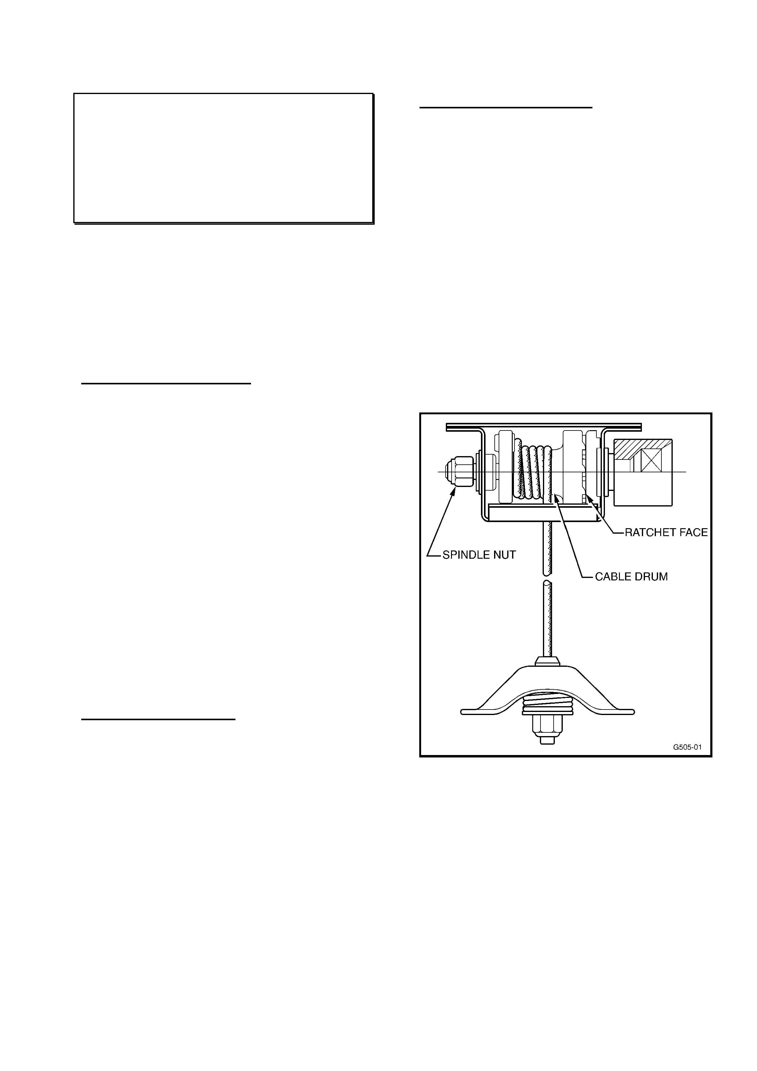
HOLDEN SERVICE TECHLINE ________________________________________________________________ MAY 2001
13
SPARE WHEEL HOIST RATCHET
DISENGAGEMENT DUE TO
INCORRECT OPERATION
VS, VU
(GROUP 10) TL105-1001
This information is repeated from previously
released Techlines – to ensure technicians
are aware of correct operation of the utility
spare wheel hoist.
This information should be circulated to
Service Advisors, etc, who may deal with
customer problems with hoist operation.
PROBLEM DESCRIPTION
Some spare wheel hoist assemblies are
being replaced by dealerships because the
ratchet fails to engage and subsequently fails
to hold the spare wheel in place.
Investigation of these failed hoists has shown
that the problem is caused by the hoist
handle being rotated in the wrong direction
(anti-clockwise) while attempting to store the
spare wheel. If the operator fails to recognise
this mistake and applies an excessive force
to the handle when the ratchet fails to
engage, the cable drum will tighten firmly
against the spindle bush at the opposite end
of the ratchet mechanism. Subsequent
operation of the hoist in the correct direction
of rotation will not cause the drum to rotate
into position against the ratchet face.
The hoist is then diagnosed as being faulty.
PROBLEM SYMPTOMS
The normal ratchet clicking noise will not be
heard while raising the spare wheel with the
correct handle rotation direction (clock-wise).
In addition, the ratchet fails to hold the spare
wheel in position against the underbody.
SERVICE RECTIFICATION
If hoist has symptoms described as follows:
(Figure 1 below shows location of parts
mentioned in this procedure).
1. Check cable for damage. Replace if
required. For remove/replace, refer:
SIP CD Section 10, Part
2.1 SPARE WHEEL HOIST.
2. Loosen spindle nut a quarter of a turn while
an assistant prevents spindle rotation with
the hoist handle.
3. Remove spanner from nut and rotate hoist
handle clock-wise to move drum away
from spindle bush.
4. Return nut to its original position by
tightening a quarter of a turn.
5. Check for correct operation of hoist
assembly.
Figure 1.
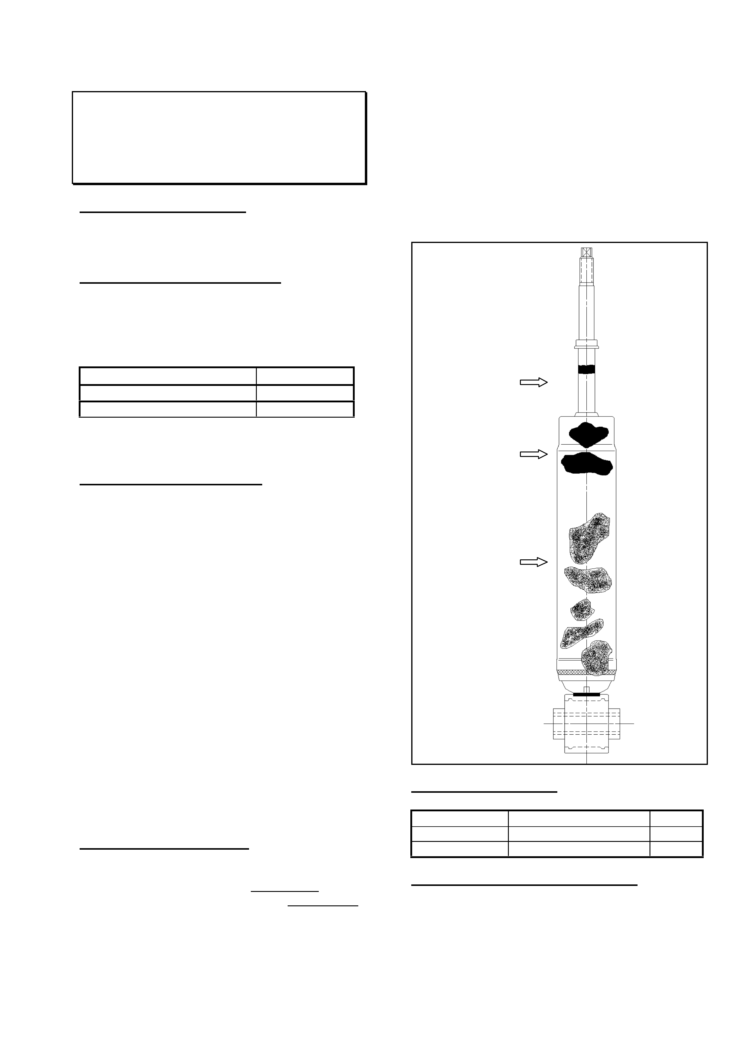
HOLDEN SERVICE TECHLINE ________________________________________________________________ MAY 2001
14
SHOCK ABSORBER LEAKAGE
UBS JACKAROO
(GROUP 3 & 4) TL105-0301
PROBLEM DESCRIPTION
Shock absorber leaks excessive oil from between
the piston rod and seal
PRODUCTION RECTIFICATION
A Teflon bush has been added in production to
reduce the amount of lateral stress placed on the
piston rod and oil seal. The seal has also been
revised to increase service life.
ISOVIN: Build Date:
JACUBS26GY7101358 (Pet) 23/02/00
JACUBS73GY7104579 (Dies) 23/02/00
Please PIR any post - breakpoint vehicles that
exhibit a leakage condition.
TECHNICAL BACKGROUND
The following information is repeated from April
2001 Passenger Techline and although it initially
referred to passenger vehicles, it can also be
applied to light commercial vehicles as a general
reference.
The normal operation of all shock absorbers
allows for a thin film of shock absorber oil to
adhere to the piston rod surface to allow for
lubrication of the seal during operation. In certain
operating environments this oil film becomes
contaminated with foreign matter such as road dirt
and sand. The seal is designed to exclude this
contaminated oil film in the compression stroke
and a build up of “sludge” results.
During the life of all shock absorbers this oily
“sludge” will create a film on the shock absorber
body. This film is normal and in no way
compromises the function of the shock absorber.
The criteria outlined below identifies the
acceptable conditions that may be observed when
inspecting shock absorbers at various times
during the life of the product.
SERVICE RECTIFICATION
If a shock absorber displays worse conditions than
that shown in the drawing (ie: greater than 10mm
band of “grime” on piston rod, or greater than
40mm build up of “sludge” on body), the shock
absorber is classified as LEAKING, and should be
replaced. If the shock absorber on the other side
of the vehicle is NOT leaking, it should be left in
service.
PLEASE ALSO NOTE THAT:
In the event of a faulty shock absorber:
- the faulty unit may be replaced without replacing
a matching pair;
- faulty shock absorbers must NOT be cleaned
prior to them being returned.
PARTS INFORMATION
Part No.: Description: Qty:
8970393193 Frt Shock Absorber 1
8970438172 Rr Shock Absorber 1
WARRANTY CLAIM INFORMATION
Use existing information provided in SIP.
Oily grime build up
at end of stroke up
to 10mm wide
band
Oily “sludge”
accumulated from
normal operating
conditions to 40mm
down the body of
the shock absorber
Shock absorber body
may be discoloured
by road grease and
oil, sand and dust, but
this does not
constitute a leaking
shock absorber. In
this event the shock
absorber should be
wiped clean and
checked at the next
service

HOLDEN SERVICE TECHLINE ________________________________________________________________ MAY 2001
15
EVAPORATOR FREEZE UP
UBS JACKAROO
(GROUP 2) TL105-0201
PROBLEM DESCRIPTION
While driving with the air conditioning on for approximately two hours at highway speeds, customers
may report that the air conditioning stops working and the air flow through the vents is reduced.
Usually this occurs in areas that are experiencing humid weather. These are typical conditions that
can promote ‘evaporator freeze up’.
PRODUCTION RECTIFICATION
A revised thermistor is available, however it will not be added to production due to the low incidence.
Revised thermistors are to be fitted to vehicles on a case by case basis.
The above condition can be rectified by replacing the thermistor, a revised thermistor (refer Parts
Info. below) will cut the compressor out at approximately 1.5oC higher temperature. This
temperature difference is sufficient to prevent the air conditioning evaporator from ‘freezing up’,
while having negligible effect on the air conditioning efficiency.
SERVICE RECTIFICATION
1. Confirm the condition.
2. Recover the refrigerant.
3. Remove - The glove box
- Glove box surround
- Dash panel support
- Cooling unit assembly (disconnect harness)
4. Disassemble the evaporator case to remove the thermistor.
5. Fit the revised thermistor to the correct position as shown in Figure 1. Note: the diagram is
not to scale.
6. The clamp for the thermistor wire must be pushed fully between the evaporator cores. This will
prevent the thermistor wire from coming adrift, which will dramatically effect the air conditioning
operation.
7. Refit the cooling unit assembly in the reverse order as described in Step 3.
8. Charge the system with refrigerant as described in the air conditioning kit fitting instruction
(650 ± 50 gm).
9. Confirm air conditioning operation.
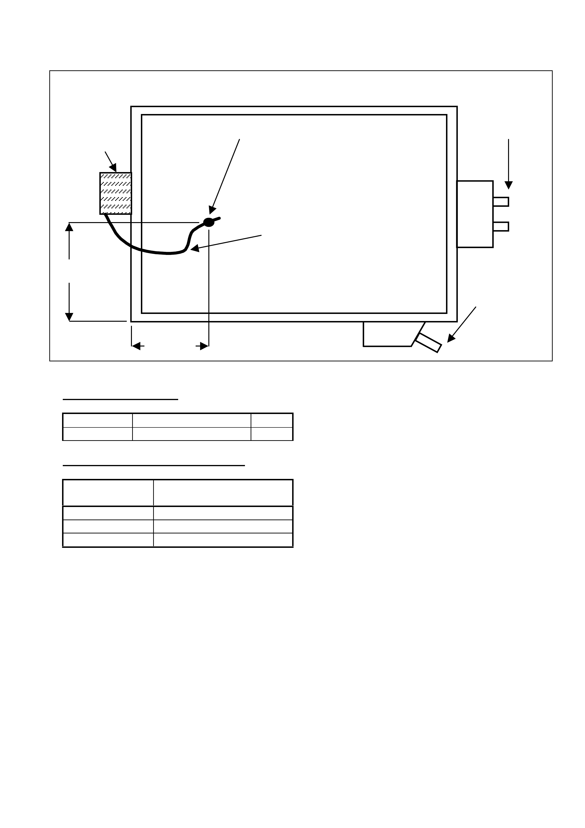
HOLDEN SERVICE TECHLINE ________________________________________________________________ MAY 2001
16
Figure 1
PARTS INFORMATION
Part No.: Description: Qty:
92144460 Thermistor 1
WARRANTY CLAIM INFORMATION:
Description Switch, thermostatic
control - Replace
Labour Op. No. D114000
Time 1.2 hr
Failure Code 26
Thermistor
46mm
Evaporator
Evaporator
Drain
Please ensure that
thermistor wire loops
down to prevent
condensation from forming
on the tip of the wire.
Clamp must be pushed fully into
the evaporator to maintain the
correct thermistor position
Refrigerant
Lines
133mm

HOLDEN SERVICE TECHLINE _______________________________________________________________ JUNE 2001
TURN SIGNAL FUSE BLOWN -
“DIAGNOSIS HINT”
VU & VX Wagon
(GROUP 12) TL106-1202
PROBLEM DESCRIPTION
Turn signal fuse may “blow” – the cause may
be excess wiring being trapped between the
tail lamp mounting stud/s and the vehicle
body.
PRODUCTION RECTIFICATION
Excess wiring has been taped back to the tail
lamp globe holders in VU & VX (wagons)
from:
TAG No.: Build Date:
L730731 22/05/01
SERVICE RECTIFICATION
When diagnosing the cause of turn signal
fuse blowing, before any lengthy analysis or
parts removal:
1. Remove tail lamps and inspect wiring for
damage between the tail lamp mounting
studs and the vehicle body.
2. Should any chafing or damage be found
on the harness, repair the wiring if
required, and cover with insulation tape.
3. Excess wiring can be taped to the lamp
while the lamp is held close to the tail
lamp cavity, to ensure the wiring does not
catch on the tail lamp mounting studs
during lamp re-assembly.
WARRANTY CLAIM INFORMATION
The following special labour operation
number can be used for vehicles built prior to
the above breakpoint:
Description Correct Tail Lamp Wiring
Short Circuit
Labour Op. No. N000354
Time 0.4 hr
Failure Code 48
PREMATURE REAR TYRE WEAR
JR, JS
(GROUP 4 & 10) “RE-ISSUED” TL106-0401
This Service Techline supersedes the previous
Techline on this topic (Issue 3, March, 2001
page 6). This previous Techline should be
destroyed.
PROBLEM DESCRIPTION
Some vehicles may exhibit premature wear
across the tyre tread surface of the rear
tyres.
This premature wear, may be caused by
incorrect rear suspension alignment settings,
(excessive toe in) or from the vehicle
regularly carrying heavy loads.
SERVICE RECTIFICATION
Please remind pre-delivery staff of the
importance of checking rear wheel alignment
at pre-delivery inspection (Rear wheel toe
referred to in Part C of “New Vehicle Pre-
Delivery Check-List”. ALSO - Vectra wheel
alignment procedures require 70kg/154 lbs.
on each front seat and half full fuel tank, as
stated in manuals and TIS 2000 CD.
When incorrect toe is detected at predelivery
or identified as a possible cause of the
premature wear condition, dealers should
1. Complete a Tyre Condition Report (refer
SIP) to report the condition and
2. Adjust the rear suspension toe in settings
to the “bottom end” of the existing
specifications as shown below:
Set Toe-in to:
Total: +0° 17’
Or in decimals: 0.28° +0.04°
-0.00°
This equates to a
toe in per side of:
+0° 8’
Or in decimals: 0.14° +0.02°
-0.00°
These figures may be used for all JR & JS
models and are based on setting minimum toe
- in.
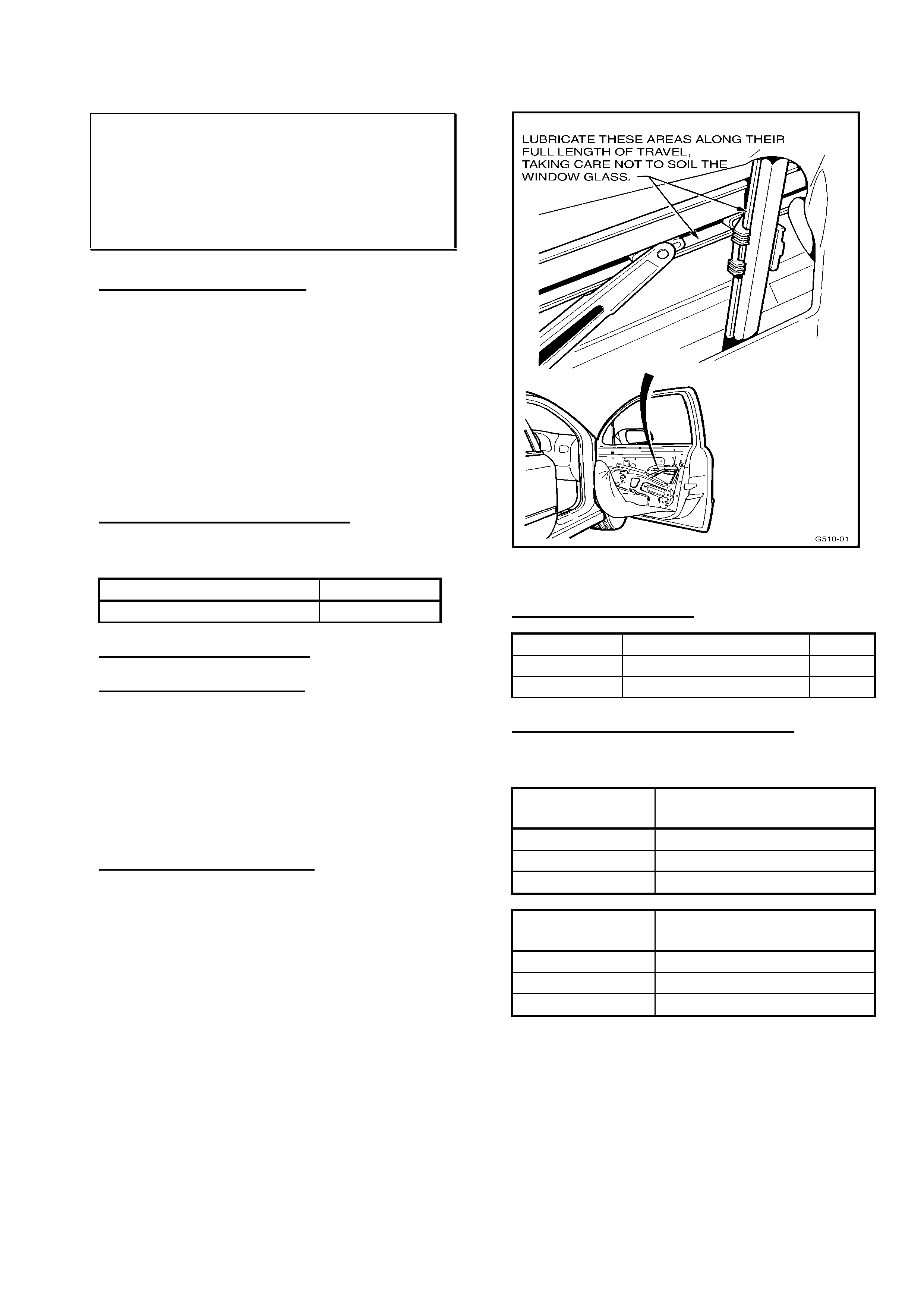
HOLDEN SERVICE TECHLINE _______________________________________________________________ JUNE 2001
FRONT DOOR WINDOW REGULATOR
SQUEAK/SQUEAL NOISE
TS
(GROUP 1) TL106-0103
PROBLEM DESCRIPTION
A “squeak” or “squeal” noise may emanate
from the front door window regulator during
raising or lowering of the window.
This is caused by insufficient lubrication of
the slides/guide rails of the regulator
mechanism.
In addition to this, a revision to the guide rail,
to reduce friction, has been introduced in
production.
PRODUCTION RECTIFICATION
Revised guide rails with reduced friction have
been fitted to vehicles from:
ISOVIN: Build Date:
W0L0TGF69Y5291640 01/09/00
SERVICE RECTIFICATION
In Pre-Breakpoint vehicles:
1. Replace the existing guide rail with a new
guide rail, p/n 24443811. For all removal
and reinstallation instructions, refer to TIS
2000 CD.
2. Before re-assembly lubricate window
regulator sliders and guides as shown on
Figure 1, with spray grease, p/n M39760.
In Post-Breakpoint vehicles:
1. Remove door trim, carefully remove door
inner seal and lubricate window regulator
sliders and guides as shown on Figure 1,
with spray grease, p/n M39760.
NOTE: In either of the above repair
procedures, take care not to allow any spray
grease to deposit on the window glass during
lubrication.
Figure 1.
PARTS INFORMATION
Part No.: Description: Qty:
24443811 Guide Rail - Front 1
M39760 Spray Grease A.R.
WARRANTY CLAIM INFORMATION
Use existing information in Labour Time
Manual as shown:
Description LH Guide Rail Asm., Front
Drop Window - Replace
Labour Op. No. C008240
Time 0.7 hr
Failure Code 90
Description RH Guide Rail Asm., Front
Drop Window - Replace
Labour Op. No. C008260
Time 0.7 hr
Failure Code 90
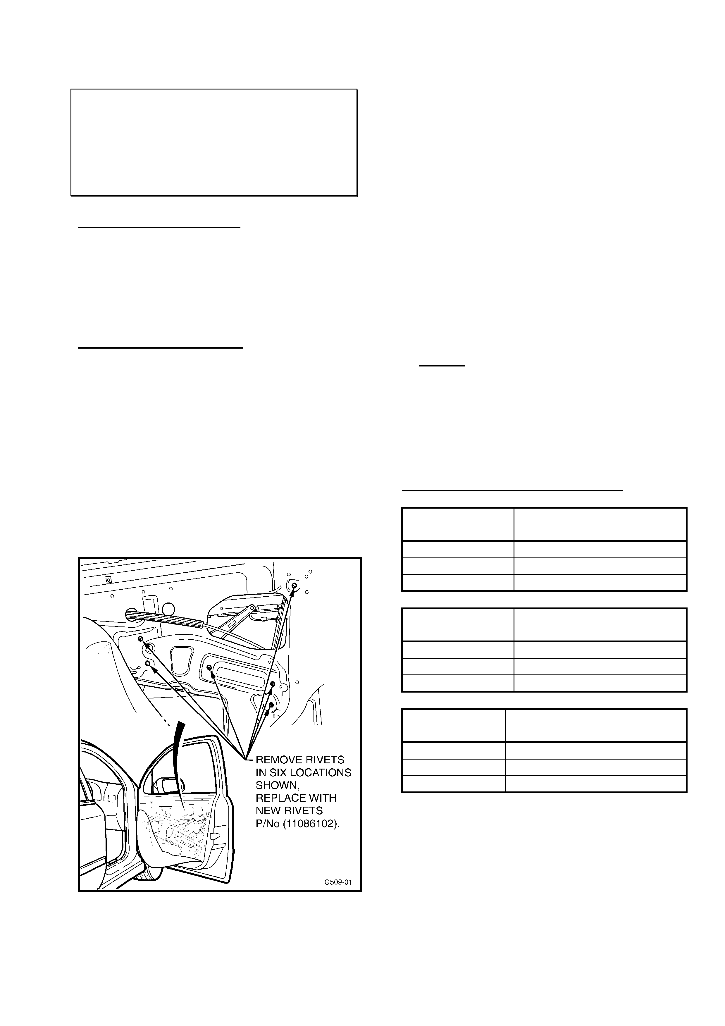
HOLDEN SERVICE TECHLINE _______________________________________________________________ JUNE 2001
FRONT WINDOW REGULATOR
KNOCK NOISE
TS
(GROUP 1) TL106-0104
PROBLEM DESCRIPTION
Front door window regulators may exhibit a
“knock” or “click” noise during operation, up
or down. These noises are caused by loose
window regulator attaching rivets (which hold
the window regulator to the door).
SERVICE RECTIFICATION
On identification of such a noise during
window regulator operation, carry out the
following procedure for the complaint window
regulator:
1. Remove door trim as per TIS instructions.
2. Carefully peel back door inner water
shield to gain access to window regulator
mechanism.
3. Identify the six (6) window regulator
attaching rivets (shown in Figure 1,
below).
Figure 1.
4. Drill out and remove the first rivet, using a
4.5mm drill. Ensure no paint or rivet
material is left in the remaining hole.
5. Fit a new, closed end rivet, p/n 11086102.
Ensure the rivet is securely applied, as an
insecure riveting operation will result in a
repeat “clunk” noise from the regulator.
6. Repeat this rivet removal and
replacement procedure – one at a time -
for the remaining five (5) rivets.
7. Confirm complaint correction by operating
the window winder mechanism up and
down.
8. Ensure horizontal (upper) guide channel
and slider, and vertical guide rail and slider
are properly lubricated. If required -
lubricate with Spray Grease p/n M39760.
Caution: Ensure that grease does not
come in contact with window glass.
9. Operate window regulator up and down to
ensure complaint noise is rectified and
grease is evenly distributed.
10. Refit door inner water shield to door.
11. Refit door trim.
WARRANTY CLAIM INFORMATION
Description Front Window Reg. -
Replace Rivets, RH
Labour Op. No. C000436
Time 0.8 hr
Failure Code 28
Description Front Window Reg. –
Replace Rivets, LH
Labour Op. No. C000439
Time 0.8 hr
Failure Code 28
Description Front Window Reg. –
Replace Rivets, Both Sides
Labour Op. No. C000433
Time 1.4 hr
Failure Code 28
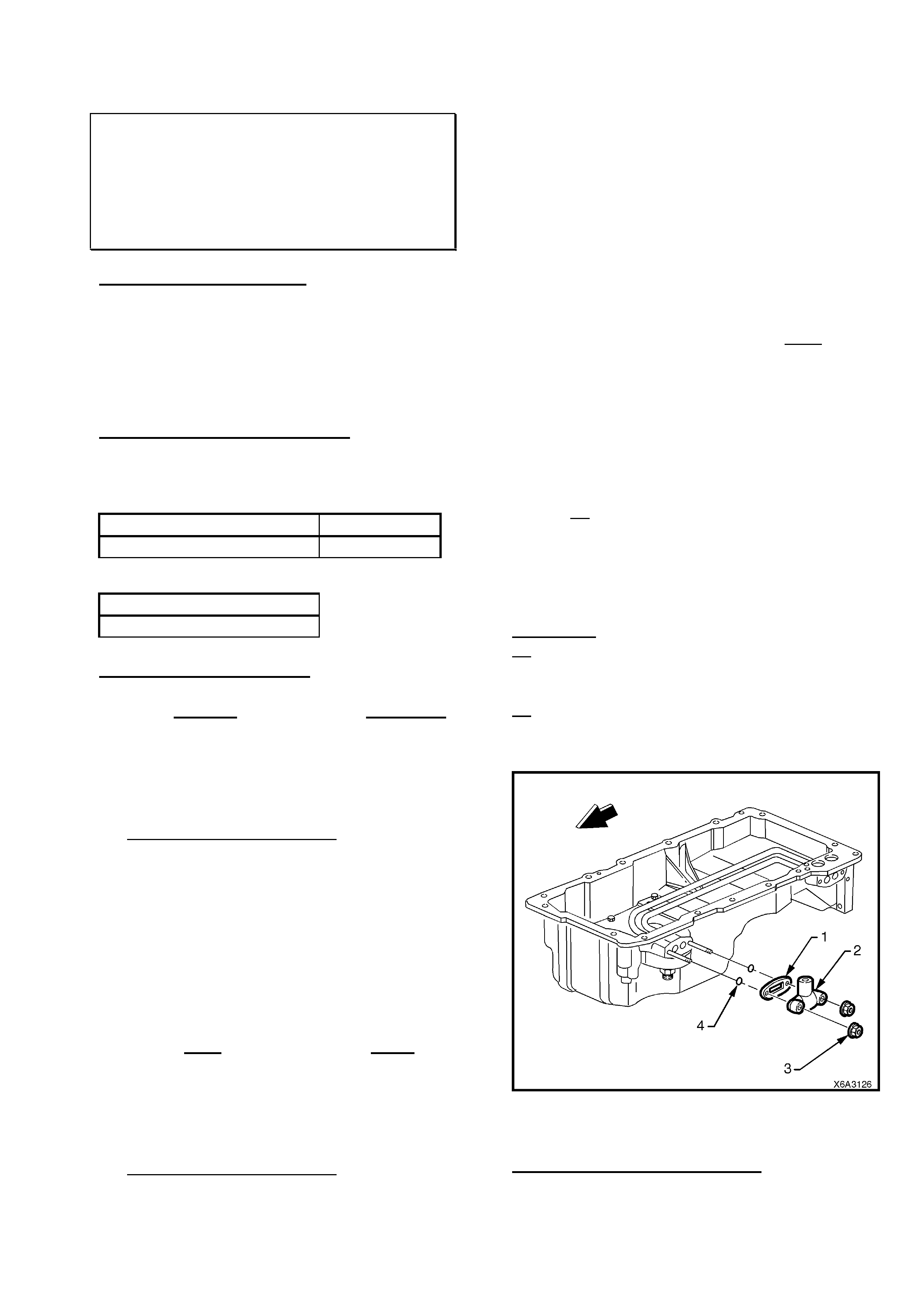
HOLDEN SERVICE TECHLINE _______________________________________________________________ JUNE 2001
OIL PAN TRANSFER COVER O RING
REPLACEMENT
WH, VT, VX, VU; with Gen3 Engine
(GROUP 6A) TL106-6A01
PROBLEM DESCRIPTION
An oil leak may be evident from the oil pan
transfer cover, located on the LH front of the
oil pan. This can be caused by porosity in the
oil pan transfer cover stud holes. To alleviate
leakage via this porosity, O-Rings have been
added to the oil pan transfer cover studs.
PRODUCTION RECTIFICATION
Revised oil pans with O rings on the oil
transfer cover studs were fitted to
engines/vehicles from:
ISOVIN: Build Date:
6H8VTK69FYL563410 01/03/00
For Reference, this vehicle has:
Engine No.:
VF000119504
SERVICE RECTIFICATION
Oil Leaks from the oil pan transfer cover:
Engines prior to VF000119504 (WITHOUT
O rings):
• Define the leak source by use of Black
Light & Dye as described in Techline of
October 2000, Issue 9 page 18.
• If the leak emanates from the
cover/gasket/pan interface, replace the
transfer cover gasket.
ü This will correct any gasket related
leakage.
• If leakage persists from the transfer cover
area, this is most likely through porosity –
replace the oil pan with a later part
(containing O-rings). Refer to PartFinder
for oil pan part number. Current oil pans
in stock at HSPO contain O Rings.
Engines after VF000119504 (WITH O
Rings:
• Define the leak source by use of Black
Light & Dye as described in Techline of
October 2000, Issue 9 page 18.
• If the leak emanates from the
cover/gasket/pan interface, replace the
gasket and O-Rings.
ü This will correct any gasket or O-ring
related leakage.
• If leakage persists from the transfer cover
area, this is most likely through porosity –
replace the oil pan with a new part. Refer
to PartFinder for oil pan part number.
Service Replacements
- whenever the oil transfer cover is removed
from an oil pan, the gasket must be replaced,
and on oil pans with O-rings fitted to the oil
transfer cover studs – new O rings must also
be fitted on re-assembly of the cover.
When fitting O rings (Refer item 4 in Figure
1, below), ensure oil transfer cover nuts are
torqued to 12Nm.
The following note is repeated from the
SIP CD to ensure technicians are aware of
this precaution:
NOTE: 1/. If removal of the oil transfer cover
nuts (3) is required while the oil pan is still
installed (e.g. during fitment of an external oil
cooler), the studs MUST NOT be removed.
Otherwise the transfer pipes and gasket
inside the oil pan, may become dislodged.
In addition:
2/. The studs have a Torx head which should
be held while removing nuts, to ensure the
studs do not unscrew from the oil pan.
3/. Take care during any removal of the
transfer cover assembly – oil will drain from
the oil passages behind the cover.
Figure 1.
1 = Gasket, 2 = Oil Transfer Cover,
3 = Nut, Oil Transfer Cover,
4 = O Ring, Oil Transfer Cover.

HOLDEN SERVICE TECHLINE _______________________________________________________________ JUNE 2001
NOTE: O-rings cannot be retro-fitted to
earlier build oil pans (without O-rings), as
machining differences exist to accommodate
the O-rings. The counterbore around the
transfer cover mounting stud also allows
identification of an O ringed oil pan.
PARTS INFORMATION
Part No.: Description: Qty:
92144564 O Ring, Oil Transfer
Cover Stud.
2
WARRANTY CLAIM INFORMATION
Use existing Labour Time Information (as
shown in SIP CD) as follows:
Description Fit Oil Transfer Cover O
Rings
Labour Op. No. J315700
Time 0.4 hr
Failure Code 30
PCM FLASH PROGRAMMING
CAUTION
VT, VX, VU, WH
(GROUP 6C) TL106-6C01
CAUTION NOTE
Isolated reports have been received by TAS
of PCM’s “crashing” when using the TIS 2000
CD Service Programming System (IE: when
flash programming, the program down-
loading stops – messages: “Error - No
Communication With Vehicle”, “Check
Diagnostic Cable”, “Check Ignition On/Off”
and a soft key “Continue” will appear).
At this point – do not continue!
This Techline Bulletin is a caution note to
advise – until further notice - flash
programming of PCM’s should be avoided
unless absolutely necessary.
Flash programming should only be carried
out when advised by a Techline Bulletin or by
TAS.
As a precaution - During flash programming,
disconnect the Powertrain Interface Module
(PIM) - this avoids the possibility of PIM
intervention during the programming
sequence.
Should flash programming be undertaken
and a failure occur during the process (as
noted above) – contact TAS immediately for
assistance – DO NOT CONTINUE.
This condition is currently being investigated
and further information will be released
regarding this condition, as soon as possible.

HOLDEN SERVICE TECHLINE _______________________________________________________________ JUNE 2001
REPAIR PROCEDURE FOR FAULTY
TECH 2 DIAGNOSTIC TOOLS
ALL
(GROUP OB) TL106-OB01
The information in this Techline Bulletin is
repeated from All Dealer Letter DL 49/01,
dated 22 May, 2001 – to ensure Service
Personnel are aware of Tech 2 repair
procedures.
Prior to carrying out either of the following
procedures – ensure you have done as much
as possible to isolate the problem to the Tech
2 tool, for example:
1. Refer to the Tech 2 Handbook, Section IV
Self Tests & Troubleshooting and carry out
the Tech 2 “Self-Test”.
2. If Tech 2 failed during a specific task on a
vehicle -– try to do the same task on an
identical vehicle to confirm it is the Tech 2,
or the vehicle.
3. Fill out the “Tech 2 Problem Report Form”
located in the back of the Tech 2 handbook
before calling TAS or HPA.
Procedures have been established with
Hewlett Packard Australia (HPA), to cater for
the repair or replacement of Tech 2
Diagnostic tools. The procedure was initially
published in DL 43/97 - that procedure is
superseded by this letter. Please use the
procedure noted below that applies to your
particular requirement.
Tools Covered By The Two Year Warranty
Qualifications:
1. A Two (2) Year Warranty only applies to
Tech 2 Diagnostic Tools from the original
unit’s delivery date. You should ensure you
are able to verify this if called upon.
2. The Warranty will carry over to any
replacement unit, but will only begin from the
original purchased unit’s delivery date.
3. Freight will be covered during the
Warranty period.
Primary Contact:
1. Your first contact should be Technical
Assistance Service (TAS) to verify the
problem is actually with Tech 2 and not with
the operator or other hardware/software
applications.
2. Once the Tech 2 has been established as
faulty, the TAS representative will instruct the
Dealership caller to log the fault with HPA.
3. TAS will allocate a TAS case number,
and the Dealership caller can then call the
HPA Support Centre.
Secondary Contact
- Dealership Responsibility:
1. Place a call to the HPA Support Centre -
Phone No.: 131147.
2. When prompted by the HPA Support
Centre phone system – “If you have a
Support Agreement covering the
equipment…, etc? – please press 1” –
PRESS 1, as there is a support agreement
for Tech 2 Diagnostic Tools. You will then be
answered by a HPA Support Centre
representative.
3. When requested by the HPA Support
Centre representative, provide the product
number, serial number, delivery date and the
fault details.
4. The HPA Support Centre representative
will then provide a job number.
5. You will then have to provide your
Dealership name, address, and contact
details.
6. HPA will deliver a replacement unit to
you.
7. Immediately place the faulty unit in the
container the replacement unit was delivered
in, and return it to the courier for return to
HPA.
Turn around time for the above replacement:
1. Metropolitan Areas – next working day.
2. Country Areas – two (2) working days.
Tools NOT Covered By The Two Year
Warranty
Qualifications:
1. Repair of Tech 2 Diagnostic Tools that
fall outside the two year warranty established
by the original unit’s delivery date.
2. Repairs and Freight will be paid by the
owner of the Tech 2 Diagnostic Tool.

HOLDEN SERVICE TECHLINE _______________________________________________________________ JUNE 2001
Primary Contact:
1. Your first contact should be Technical
Assistance Service (TAS) to verify the
problem is actually with Tech 2 and not with
the operator or other hardware/software
applications.
2. Once the Tech 2 has been established as
faulty, the TAS representative will instruct the
Dealership caller to log the fault with HPA.
3. TAS will allocate a TAS case number,
and the Dealership caller can then call the
HPA Support Centre.
Secondary Contact
- Dealership Responsibility:
1. Place a call to the HPA Support Centre -
Phone No.: 131147.
2. When prompted by the HPA Support
Centre phone system – “If you have a
Support Agreement covering the
equipment…, etc? – please press 1” –
PRESS 1, as there is a support agreement
for Tech 2 Diagnostic Tools. You will then be
answered by a HPA Support Centre
representative.
3. When requested by the HPA Support
Centre representative, provide the product
number, serial number and the fault details.
4. The HPA Support Centre representative
will then provide a job number.
5. You will then have to provide your
Dealership name, address, and contact
details.
At this point – two Out Of Warranty Repair
Options are available:
1. HPA will send you a replacement unit (as
per the warranty procedure). Pay one fixed
price (will be advised by HPA during call)
covering cost of repair, including a provision
for return freight. Dealer to pay freight to HPA
or deliver unit to HPA.
OR
2. Return the faulty unit to HPA for repair,
paying actual cost of repairs, plus the cost of
delivery and return freight.
Turn around for the above options:
1. Replacement units: Metropolitan
Areas – next working day.
Country Areas – two (2) working days.
2. Repairs :From three (3) minimum to five
(5) working days.
NOTE: for all the above repair “Turn around
times”, Dealer calls logged at HPA before
12:00 noon (E.S.T.) will receive next day
response, calls logged after 12:00 noon
(E.S.T.) will be responded to one day later.
For Tech 2 cable Repairs/replacement – refer
All Dealer Letter DL 06/00, of 21 Feb., 2000.
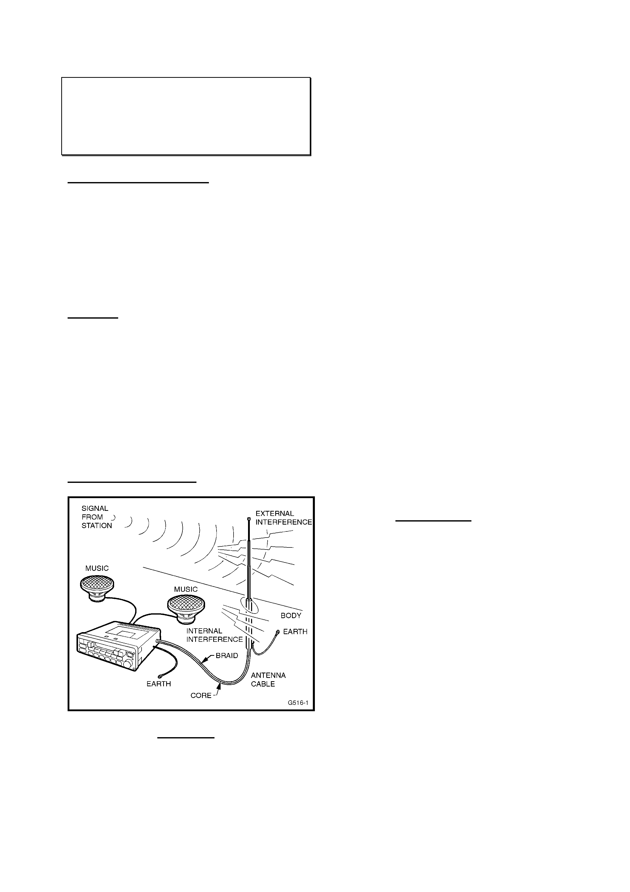
HOLDEN SERVICE TECHLINE _______________________________________________________________ JUNE 2001
RADIO PROBLEM DIAGNOSIS GUIDE
ALL
(GROUP 12) TL104-1204
PROBLEM DESCRIPTION
Radio interference caused by earths, short-
circuits, in-vehicle or external to vehicle, etc,
can occur in any radio.
These complaints are, at times, hard to
identify and to diagnose.
This Techline is issued to assist technicians
in the identification and diagnosis of such
complaints.
Contents
Part 1.
Principles of Operation
Part 2.
Basic Checks – for earthing & short circuits
Part 3.
Static – what is it, what causes it, how to fix it
Part 1.
Principles of Operation
FIGURE 1.
As illustrated by the diagram below, signals
from radio stations are picked up by the
antenna and fed to the radio while being
shielded from interference sources by the
braided antenna cable. This is a complete
electrical circuit, and any breaks in the circuit,
such as poor connections, will result in poor
reception.
Interference is due to the antenna system
picking up signals other than those from the
desired station. These undesirable signals
may be produced by electrical equipment in
the car itself, such as the ignition, which is
termed “internal interference”. Conversely,
interference from sources outside the vehicle,
such as from power lines, is known as
“external interference”.
Internal interference is minimised by the
shielding around the antenna cable, which
prevents internal “noise” being picked up and
fed to the radio. The shielding around the
core takes the form of a “braid”, which
completes the electrical circuit along which
signals travel to the radio. Faults in this
shielding system allow interference to reach
the radio and hence be reproduced at the
speakers as noise.
It is therefore important that the shield of the
antenna cable is effectively earthed at both
the radio end (to the radio case) and at the
antenna end (to the vehicle body), to ensure
that:
A/. minimal interference is received by the
radio,
B/. the optimum radio sensitivity is achieved.
Part 2. - Basic Checks
With an ohm meter, the resistance, or
connection quality, can be checked for the
major parts of the radio, as per Figure 2
below.
1/. Check continuity of the path from the
antenna cable core to the antenna mast
by disconnecting the antenna lead from
the radio and measuring the resistance.
2/. Check the braid continuity by measuring
the resistance from where the braid
connects to a substantial earth, such as
the vehicle body, where the earth is
connected.
3/. Measure the resistance of the connection
from the metal radio body to the part of
the vehicle body where the radio is
supposed to be earthed.
In each case, the resistance measured
should be 1.0 Ohms or less. Values
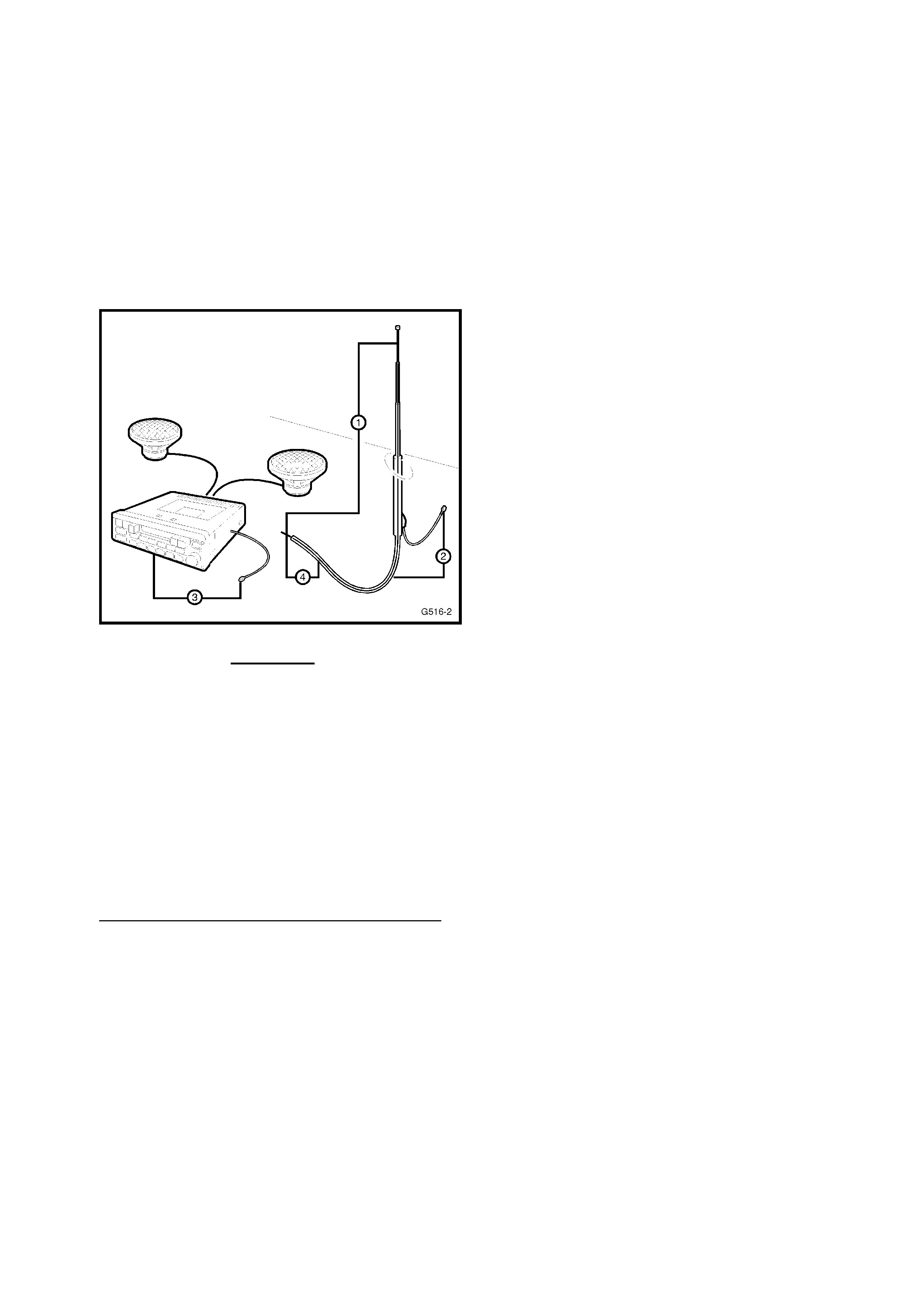
HOLDEN SERVICE TECHLINE _______________________________________________________________ JUNE 2001
significantly higher than this indicate poor
connections that must be rectified before
proper radio performance will be obtained.
4/. Check for shorts between the antenna
core and braid by disconnecting from the
radio and measuring the resistance
between the two. The measured value
should indicate an open circuit – that is – a
very high or infinite resistance.
FIGURE 2.
In addition to these basic locations – the
following antenna connection differences
exist, meaning checking of multiple antenna
leads, where fitted:
JR CD Hatch – 2 piecec antenna lead
JR GL Hatch – 1 or 2 piece lead depending
on connection to amplifier.
JS GL/CD Hatch – 2 piece antenna lead
JS GL Wagon – 1 or 2 piece antenna lead
Part 3.
Static – what is it, what causes it, how to fix it
This is a buzzing or crackling noise caused
by the radio picking up unwanted radio waves
and converting them to a noise transmitted
by the speakers.
The unwanted radio waves (interference)
come from several sources, which can be put
into two groups: internal or external. As the
names suggest, external interference comes
from outside the vehicle, and is difficult to
control, while internal interference is
generated by the vehicle.
It must be emphasised that a radio system in
good condition will protect itself from much
static. Before trying to locate and remove a
source of interference, it must first be
determined that the shielding and earthing of
the radio is in good working order. This can
easily be done by performing the tests
detailed in the previous section – “Basic
Checks”.
It should be noted that static may occur on
weak stations, or when driving under bridges
because signals from ignition and the like
become relatively stronger than the radio
station signal, causing the ignition
interference to become quite strong. This
could also be due to stronger than normal
ignition interference or a poorly-functioning
antenna.
If the cause cannot be isolated after
performing the tests and trying to isolate a
source of interference, as detailed in the
following pages, it may be that the radio has
an internal fault and requires repair.
A/. External Interference
Static which occurs only while travelling in
certain localities, such as near electrical
transformers, is undoubtedly external
interference.
If there is any doubt as to whether the
suspected source is in fact causing
interference, a simple check is to stop the
vehicle and turn off everything but the radio.
If the source is external, the interference will
continue and little can be done to eliminate it.
B/. Internal Interference
Static may be caused by many internal
sources, some of these sources are:
- Stop Lamp Switch/es
- Ignition Coil/Distributor
- Spark Plugs
- Horn
- HVAC Blower Motor
- Windscreen Wipers
- Windscreen Washers
- Gauges with Voltage Stabiliser
- Alternator
If static is at ignition frequency, varying with
engine speed, the ignition is the culprit.
However, many electrical faults will cause
static which otherwise would not be heard.

HOLDEN SERVICE TECHLINE _______________________________________________________________ JUNE 2001
Examples of ignition interference sources
are:
- Plug Leads Breaking Down
- Carbon Tracking (Arcing) to Earth
- Faulty Spark Plugs
- Inoperative Interference Shields
- Distributor Cap/Rotor, Coil connections
The actual cause of the interference can be
isolated through carefully noting the
circumstances under which the problem
occurs. For example, if it occurs only at
speeds above approximately 80 km/h in an
automatic transmission vehicle, quite possibly
it is an electrical signal being sent to the
torque converter clutch.
Other sources of static can be:
- Electric Cooling Fan/s
- Electric Fuel Pump
- Normal Computer “Noise” at Certain
Frequencies.
Previously released Techline Bulletins on
Radio Interference which may be helpful are:
2001
Jan. 1-10 - Revised Earth Strap Routing –
JR,JS 4Cyl.
2000
Jan. 1-6 – Poor “AM” Radio Reception - JS
Jan. 1-16 - Poor “AM” Radio Reception – JS
1999
Jan. 1-4 – Revised Alternator B+ Nut/Starter
motor Nut – VT
Jan. 1-24 – Poor “AM” Radio Reception – TS
1998
Mar. – Radio Static – Diagnosis Hint - VT
Sept. - Poor “AM” Radio Reception – JR
Vehicle Evaluation for poor AM Reception
The following data sheet allows collection
vehicle details prior to attempting to improve
AM interference on a vehicle. The information
gathered will be useful in determining the
improvement achieved after basic checks
and/or parts replacements, determined as
necessary by the above basic checks and
specific Techline information.
(NOTE: The data sheet and the basic
procedure has been structured for JR/JS, but
can also be used for other models – to collate
your diagnosis data to understand where
systems are “OK” or need correction).
A/. Vehicle/Customer
Experience/Environment Identification:
Vehicle Details
• Model (eg JS)
• Body Style (eg sedan / hatch / wagon)
• Level (eg GL / CD)
• ISO VIN
Record the above details in the data sheet
provided below.
Customer Experience
Record in the data sheet the customer’s
experience (radio station/when static was
noticed). This will identify if the interference is
external and/or internal.
Environment Identification
The vehicle’s environment must be
established prior to improving AM static on a
JR/JS Vectra.
Measure the signal intensity strength for the
AM station that the customer has a problem
with. If possible this should be measured as
close as possible to any specific location
specified by the customer. Under no
circumstances should this measurement be
made inside a workshop or garage. Record
the magnitude on the data sheet provided.
• Units: Volts.
• Measurement tool: Tech 2
A value greater than 3.0 volts (maximum is
5.0 volts) is necessary for a reasonable
signal.
Note: This measurement should be
performed as detailed in the Bosch Supplier
Prior Authorisation Process. Refer to that
process in your Service Manager’s Supplier
Prior Authorisation Process binder, for
details.
B/. Radio Average Resistance Between
Radio Ground and Antenna Ground
Measure radio average resistance between
radio ground and antenna ground, as
described in “Part 2. Basic Checks” above.

HOLDEN SERVICE TECHLINE _______________________________________________________________ JUNE 2001
Procedure:
1. Disconnect vehicle battery.
2. Turn ignition on and allow vehicle
electronic systems to discharge for 5
minutes.
3. Record resistance using a multimeter.
Note negative sign if applicable.
4. Again record resistance, this time with
probes swapped.
5. Take average of the two readings.
An average value greater than 1.0 ohms
indicates that there are earth problems within
the antenna system which must be corrected.

HOLDEN SERVICE TECHLINE _______________________________________________________________ JUNE 2001
Radio AM Interference Diagnosis Data Sheet
Vehicle Detail
Model
Body Style
(Sedan/Wagon/Hatch)
Level
(GL/CD/City/Swing)
ISO VIN
AM Station With Poor Reception
Interference Observations (tick)
Interference Experience Yes No
External
(Ignition Off / Radio On)
Internal
(Ignition On / Radio On)
Worse with ignition on?
Environment
Signal intensity reading from Tech
2 for AM station with poor
reception
______________ Volts
Note – if the signal strength is weak, there is little that can be done as any internal/external
interference will dominate the weak signal.
Radio Average Resistance Between Radio Ground and Antenna Ground
Resistance Reading
1st Reading
2nd Reading
Average
_______ Ohms
_______ Ohms
_______ Ohms

HOLDEN SERVICE TECHLINE _______________________________________________________________ JUNE 2001
LPG KIT INSTALLATION FLASH
PROGRAMMING CONCERNS
VX
(GROUP 6M) TL106-6M01
PROBLEM DESCRIPTION
When fitting accessory LPG to VX V6
vehicles technicians will be required to flash
program the appropriate software from TIS
2000 to complete the fitment of LPG to the
vehicle.
The procedure on the following pages
outlines the programming process:
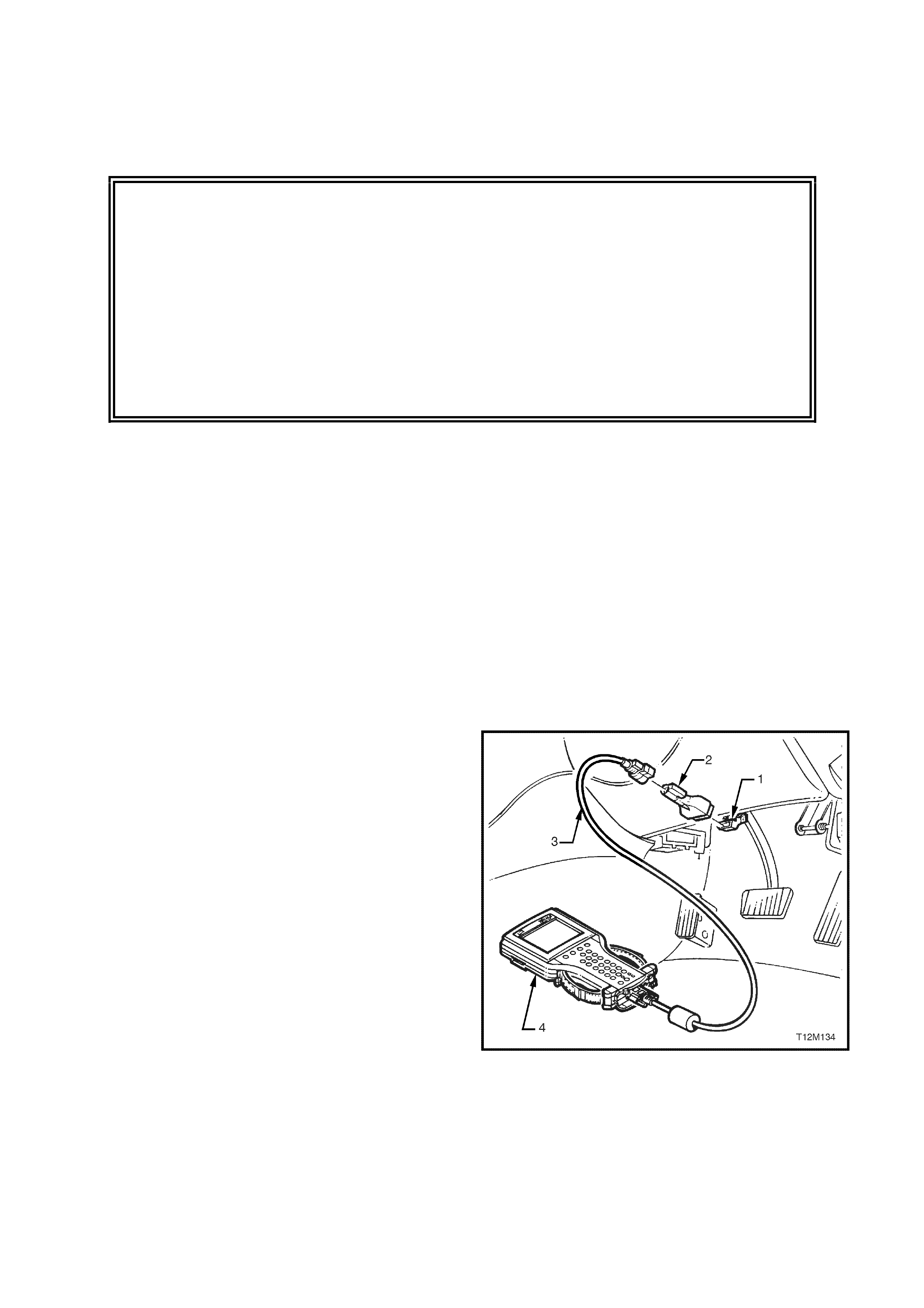
SECTION 3
CAUTION:
This vehicle is equipped with a Supplemental Restraint System (SRS). A SRS
will consist of either seat belt pre-tensioners and a driver’s side airbag, seat
belt pre-tensioners and a driver’s and front passenger’s airbags or seat belt
pre-tensioners, a driver’s, front passenger’s and left and right hand side
airbags for the front occupants. Refer to CAUTIONS, Section 12M, in the VX
Series Service Information before performing any service operation on or
around SRS components, the steering mechanism or wiring. Failure to follow
the CAUTIONS could result in SRS deployment, resulting in possible
personal injury or unnecessary SRS system repairs.
TECH 2 LPG SET-UP & ENABLE PROCEDURES
CONTENTS
Ref. Subject Page
3.1 PCM SERVICE PROGRAMMING WITH LPG CALIBRATION....................3-1
3.2 INSTRUMENT CLUSTER LPG LAMP ENABLE PROCEDURE .................3-4
3.2 PCM SET-UP PROCEDURE........................................................................3-6
The following procedures are required to enable the
vehicle to operate on LPG and are best performed in the
order they appear in this Section.
Prior to beginning, connect TECH 2 to the data link
connector (DLC).
1. DLC
2. DLC Adaptor
3. DLC Cable
4. TECH 2
Figure 3-1
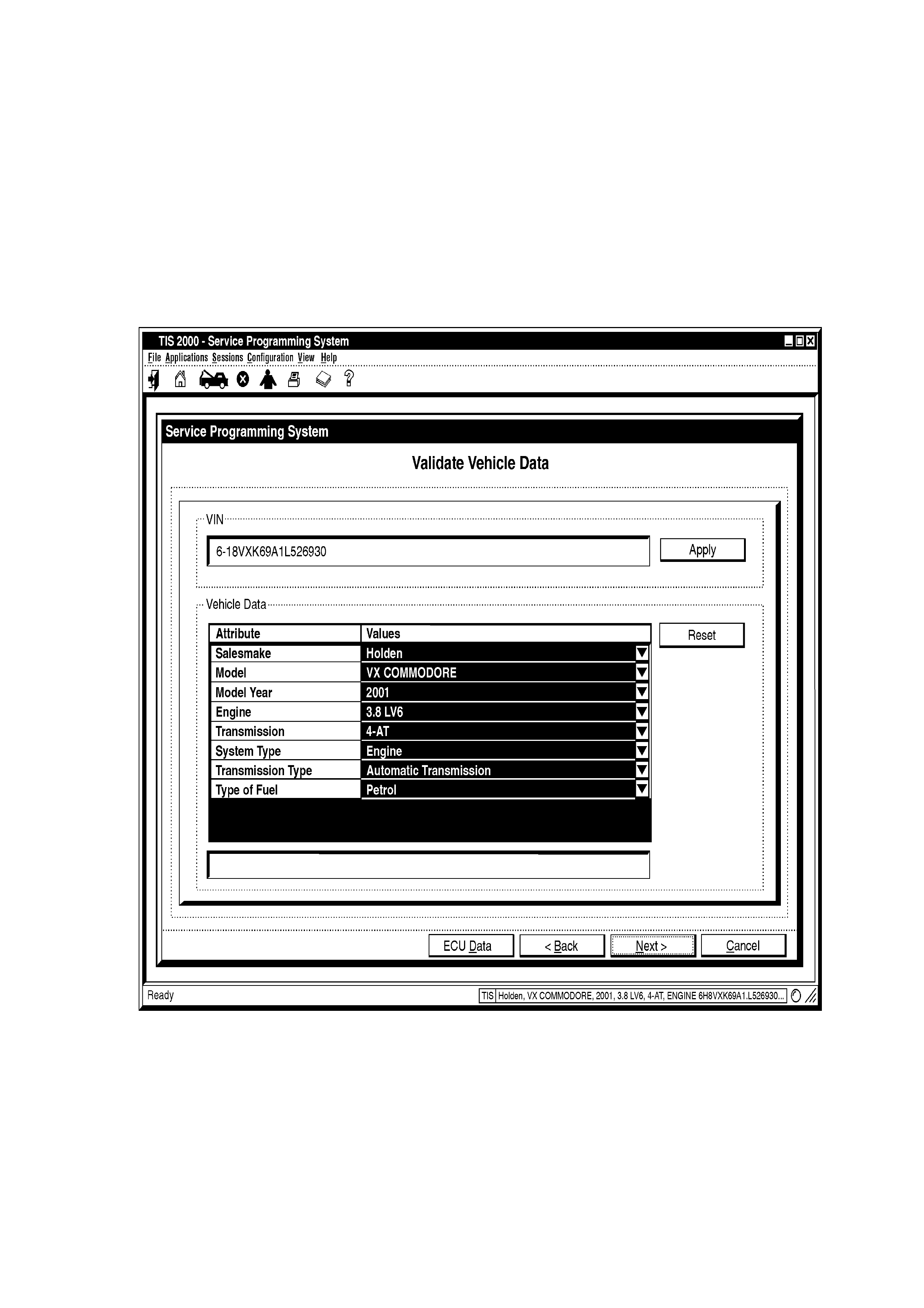
3.1 PCM SERVICE PROGRAMMING
WITH LPG CALIBRATION
NOTE: The following PCM service programming must
be performed following LPG system installation or when
a PCM has been replaced.
1. Connect Tech 2 as previously described.
2. Refer to the VX Series Service Information Package
(SIP) CD-ROM and follow procedure 4.2 SPS
PROCESS in Section OC – TECH 2 until the
Validate Vehicle Data screen is displayed, refer
Fig. 3-2.
Figure 3-2
3. Select Type of Fuel (petrol), refer Fig. 3-3.
4. Press the DELETE button.
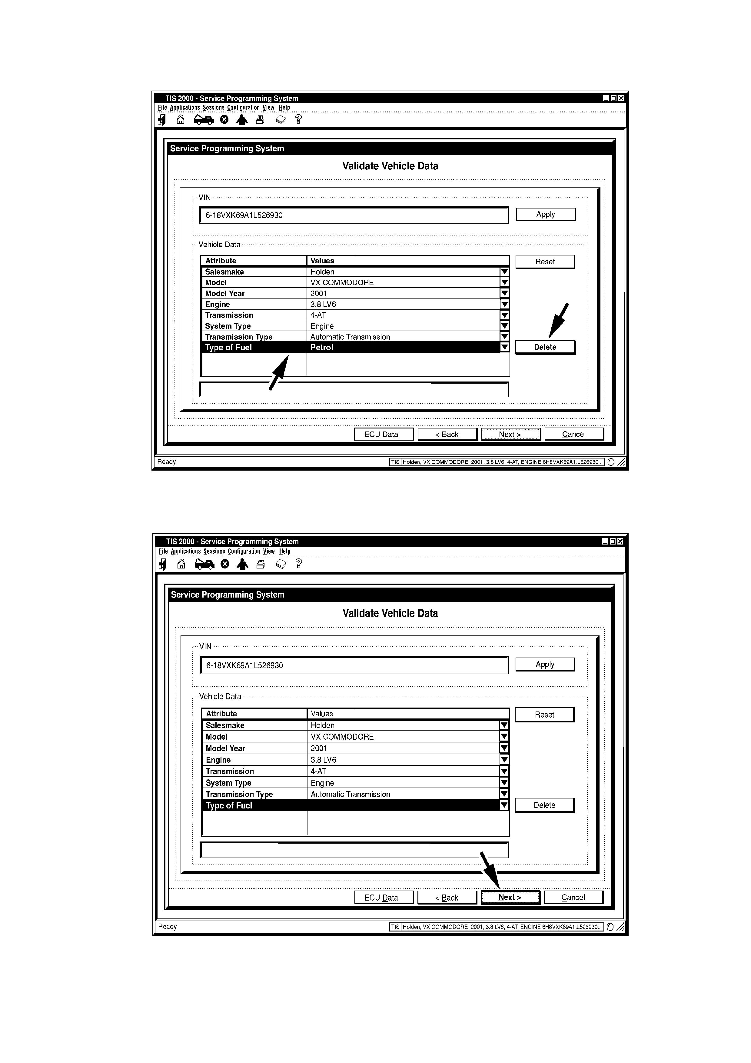
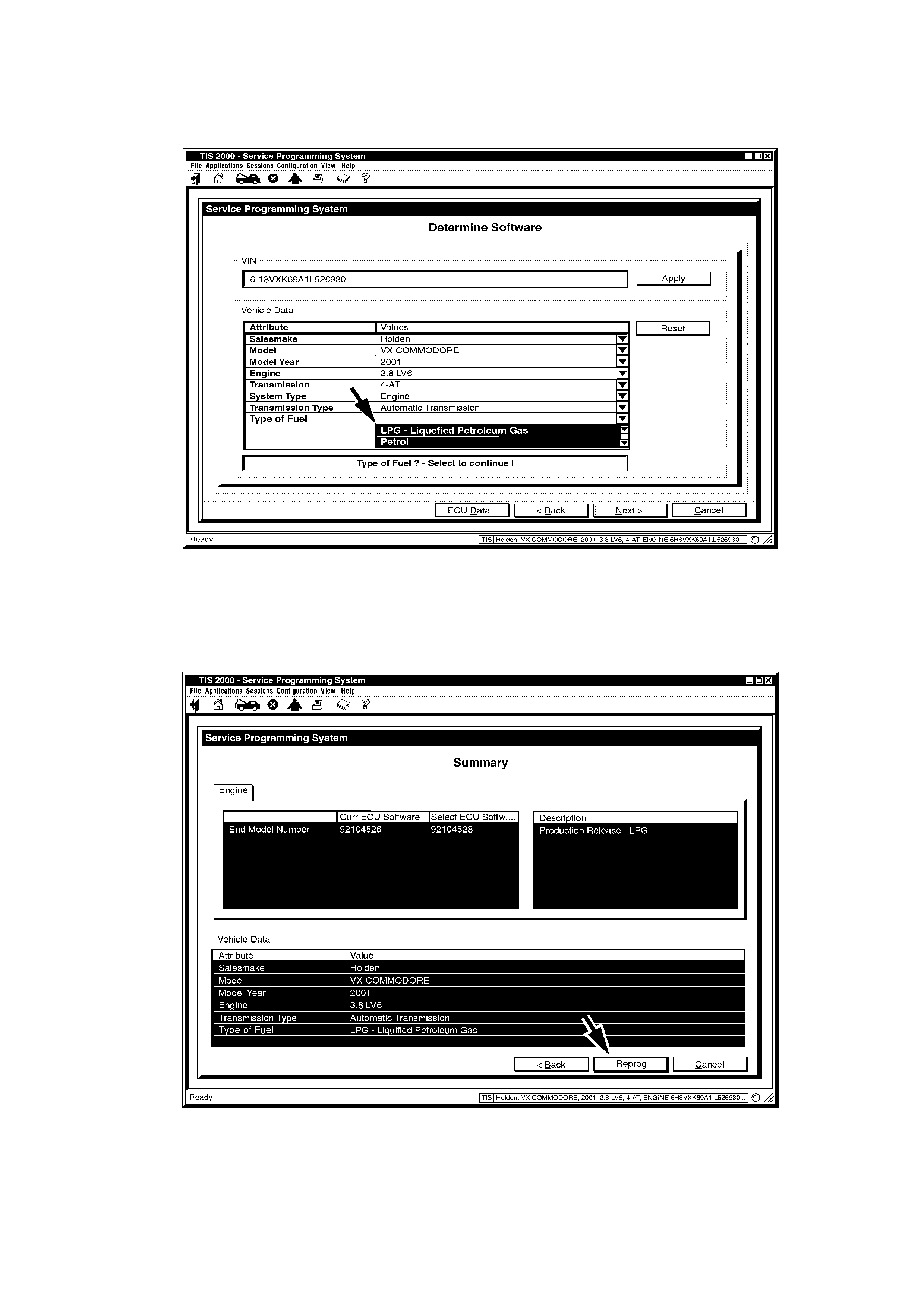
6. From the Type of Fuel drop-down list select LPG –
Liquefied Petroleum Gas, refer Fig. 3-5.
Figure 3-5
7. A summary screen will be displayed allowing the
details to be confirmed, refer Fig. 3-6.
8. Select the REPROG button.
9. Continue the steps in 4.2 SPS PROCESS
procedure on the SIP CD-ROM.
Figure 3-6
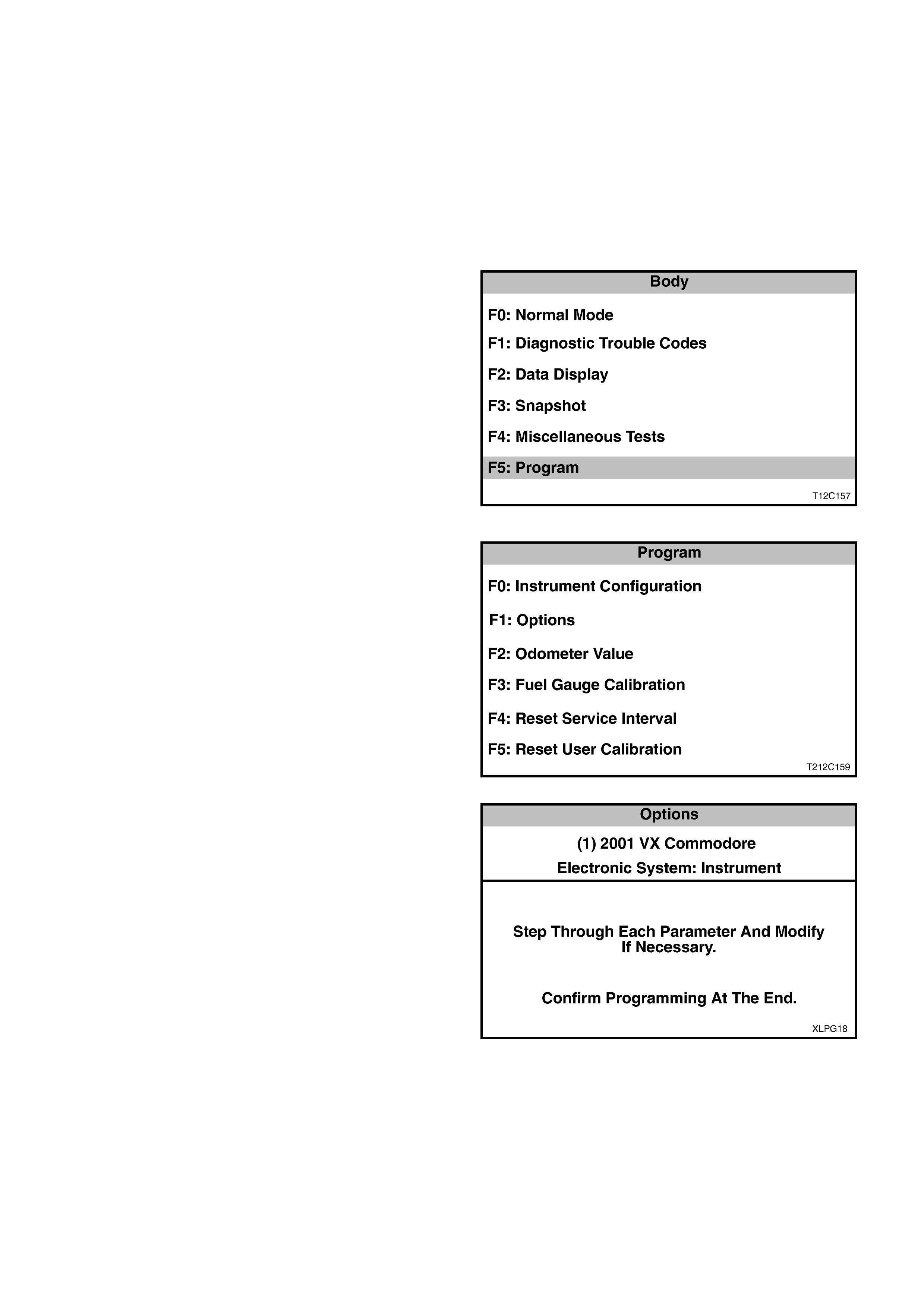
3.2 INSTRUMENT CLUSTER LPG LAMP
ENABLE PROCEDURE
NOTE: The following instrument cluster LPG lamp
enable procedure must be performed following LPG
system installation or when an instrument cluster has
been replaced.
1. Ensure the ignition is off.
2. Connect Tech 2 as previously described.
3. Navigate through the Tech 2 menus to display the
Body Menu.
4. Select F5: Program.
Figure 3-7
5. From the Program Menu, select F1: Options.
Figure 3-8
6. At the Options Menu, press the NEXT soft key and
scroll through the following series of screens to the
LPG Lamp screen:
- Rear Lamp Failure,
- Traction Control Off Lamp,
- LPG Lamp,
- Cruise On Lamp,
- Police Mode,
- Low Coolant Lamp,
- High Temperature Lamp,
- Program Options Confirm.
Figure 3-9
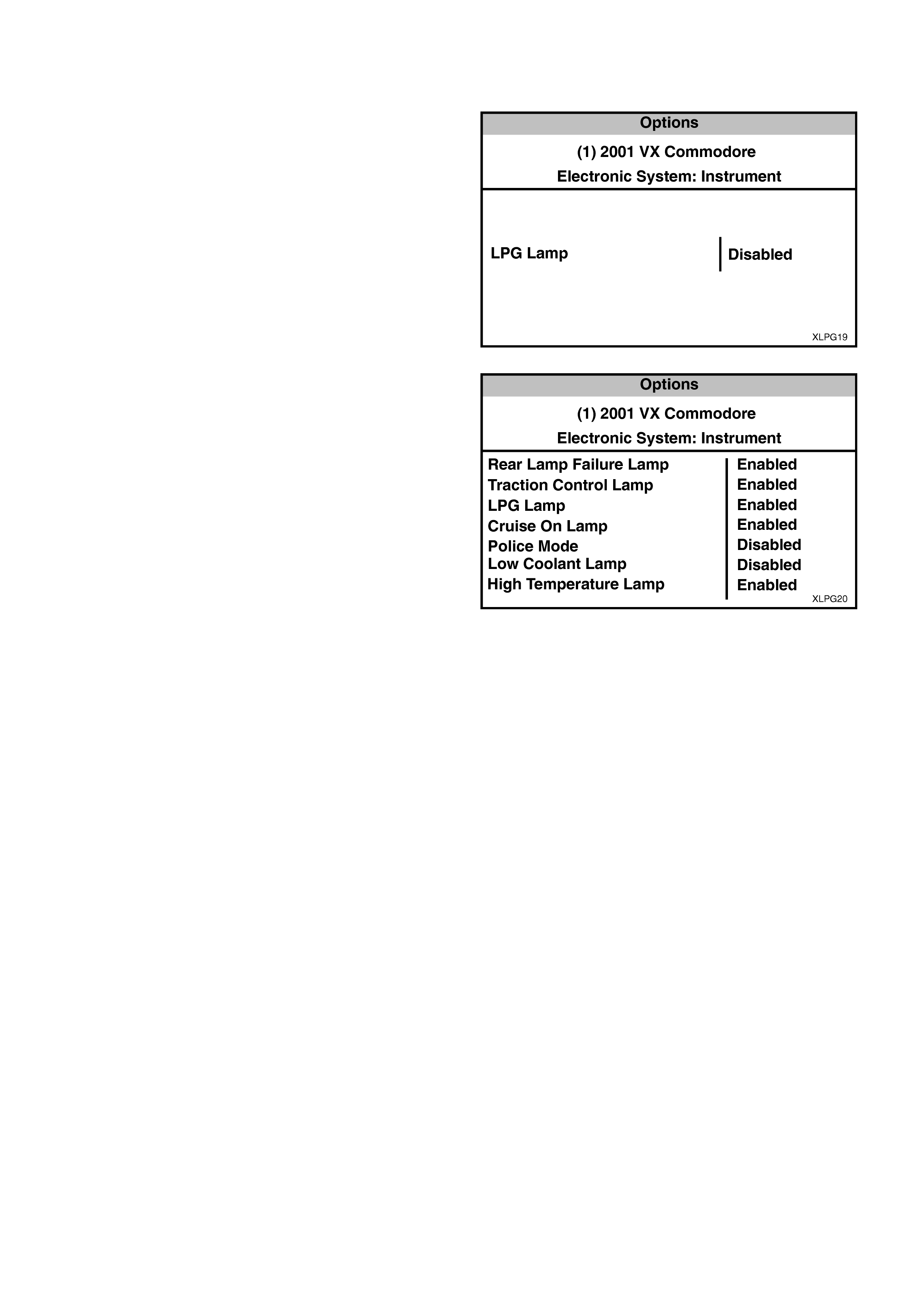
7. At the LPG Lamp screen, press the MODIFY soft
key to change Disabled to Enabled.
8. Use the NEXT key to scroll to the Program Options
Confirm screen.
Figure 3-10
9. At the Program Options Screen, ensure the LPG
Lamp is Enabled.
10. Press the ABORT soft key to abandon the process
or press the PROGRAM soft key to confirm the
parameters.
11. Press the CONFIRM soft key when the
programming is completed.
Figure 3-11
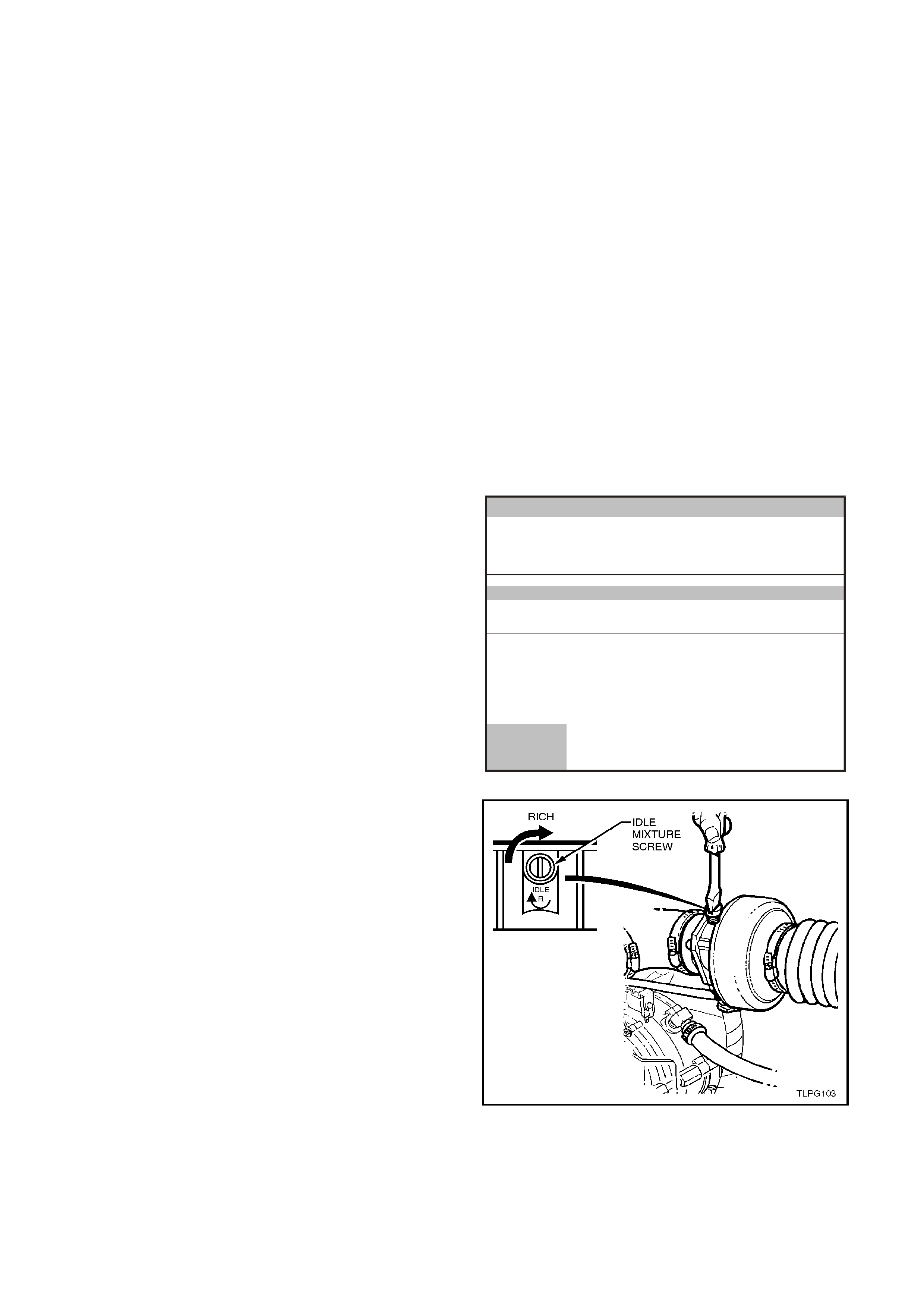
3.3 PCM SET-UP PROCEDURE
NOTE: The following LPG Set-up Procedure must be
performed following LPG system installation and when
any LPG system component (mixer, converter, FCV or
PCM) has been replaced, overhauled, reprogrammed, or
when the engine assembly has been replaced or
overhauled.
The LPG Set-up procedure allows adjustment of the idle
mixture under the following controlled conditions:
- Short and Long-Term Fuel Trim Cells set to zero.
- Fixed Spark advance.
- Fixed idle air control valve steps.
- Fuel control valve duty cycle fixed at 40%.
1. Connect TECH 2 as previously described.
2. Switch the vehicle to LPG mode, if not already done
so.
3. Start the engine and allow it and the oxygen
sensors to reach operating temperature, with no
load on the engine, air conditioning off (if fitted), all
electrical consumers turned off and park position
selected.
4. On Tech 2 Select: Diagnostics / Appropriate Model
Year ((1) 2001) / VX Commodore / Engine / V6 /
Function Tests/ LPG Set-up.
During the set-up procedure, Tech 2 ensures the
follow engine operating conditions are met and
maintained:
- Engine Coolant Temperature greater than
91°C
- Operating in closed loop.
- Right hand oxygen sensor is ready.
- The engine cooling fan is off (engine coolant
temperature less than 104°C).
Once all the preconditions have been met, Tech 2
will display the Right O2 Sensor Voltage and Status.
Engine
LPG Setup
Righ t O2 Sen sor
Righ t O2 Status 500 mV
Rich
VXLPG001
Confirm
Figure 3-12
5. Adjust the idle mixture screw until the right hand
oxygen sensor voltage is as close to 500 mV as
possible and the status of the right O2 Sensor is
constantly toggling between rich and lean.
Oxygen sensor voltages greater than 500 mV
indicates a rich mixture, turn the idle mixture screw
anti-clockwise to lean off the mixture.
Oxygen sensor voltages less than 500 mV indicates
a lean mixture, turn the idle mixture screw clockwise
to richen the mixture.
If the engine coolant temperature exceeds 104°C,
the engine cooling fan will be turned on and Tech 2
will suspend the set-up procedure. When the engine
cools down and the cooling fan is turned off, Tech 2
will continue with the set-up procedure.
Figure 3-13

HOLDEN SERVICE TECHLINE ____________________________________________________________ JULY 2001
3
ROOF FINISHER MOULDING END CAP
DISLODGES
VT Sedan, VX Sedan
(GROUP 1) TL107-0101
PROBLEM DESCRIPTION
Roof finisher moulding end caps, located on
the rear end of the roof finisher moulding, at
the lower corners of the rear screen glass,
may become dislodged in service.
Investigation into the causes of this dislodging
has resulted in the creation of revised roof
finisher mouldings, and new roof finisher
moulding end caps to repair vehicles where
the end cap has dislodged. These new end
caps will also be used for service
replacement on vehicles built before the
breakpoint below.
The service end cap (‘hard’ material) will allow
replacement of the (early build, soft material)
roof finisher end cap, where previously the
whole roof finisher moulding had to be
replaced.
PRODUCTION RECTIFICATION
Revised roof finisher mouldings have been
fitted to vehicles from:
ISOVIN: Build Date:
6H8VXK69A1L735897 29/05/01
These revised mouldings are changed in both
manufacture and material, and do NOT have
end caps. Vehicles fitted with these revised
mouldings, have retainer and end caps (of
‘hard’ material) fitted to the sides of the rear
screen glass. During assembly, this revised
roof finisher moulding engages with the end
cap on the lower corner of the rear screen
glass.
SERVICE RECTIFICATION
On all VT, & VX sedans fitted with “soft”
material end caps - where one of these end
caps has partially or fully dislodged, BOTH
end caps should be replaced with the new
“hard material” end caps.
To replace roof finisher moulding end caps,
refer to the following procedure, and Figure 1,
below, for location and detailed drawings of
end cap fitment:
1. If end cap has not fully dislodged from
moulding – tear off the end cap by hand -
horizontally, from glass (inner) side of end
cap towards the quarter panel (outer)
side. This leaves the appearance as
shown in View A of Figure 1.
2. If necessary, remove any moulding “flash”,
or excess damaged material from the end
of the remaining roof finisher moulding,
with a sharp knife or razor blade. This is
required to ensure good appearance and
to prevent the material from impeding the
fitting of the new end cap (new end caps
will locate in the same position on the
moulding as the removed end caps).
3. Insert a small piece of thick card under the
end of the roof finisher moulding – as
shown in View B of Figure 1 – this acts as
a support during the following procedure.
(HINT: a new body filler “wiper” card is
ideal).
4. Slide the ‘tongue’ of a new end cap (p/n
92111720/1) into the roof finisher
moulding – as shown in Views B & C of
Figure 1 – pushing firmly upward until the
end cap seats on the existing moulding.
5. After fitting, if the curved cut-out in the end
cap does not match the shape of the rear
screen lower glass moulding, ensure the
lower glass moulding is pushed firmly
upward onto the glass. After this, if the
cut-out does not fit, push the roof finisher
moulding forward/backward until the cut-
out in the end cap fits, allowing sufficient
operational clearance to the deck lid
during opening and closing.
6. Repeat steps 1 to 5 for roof finisher
moulding end cap on opposite side of
vehicle.
This completes the installation of the new end
cap/s.
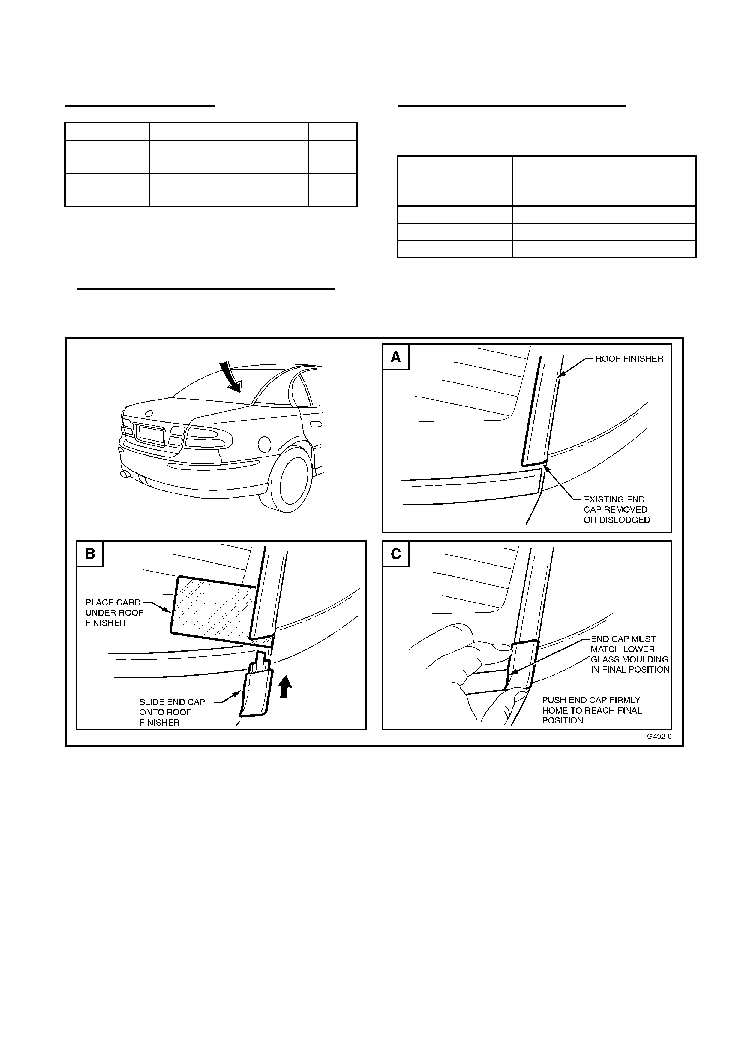
HOLDEN SERVICE TECHLINE ____________________________________________________________ JULY 2001
6
PARTS INFORMATION
Part No.: Description: Qty:
92111721 Roof Finisher Moulding
End Cap, RH
1
92111720 Roof Finisher Moulding
End Cap, LH
1
NOTE: Parts were not available at time of
publication of this Techline Bulletin – parts will
be in HSPO stock on July 9, 2001
– do not order parts until July 9, 2001.
WARRANTY CLAIM INFORMATION
Use the following information to claim for the
above procedure:
Description Replace Roof Finisher
Moulding End Caps (both
sides)
Labour Op. No. C000427
Time 0.3 hr
Failure Code 55
Figure 1.

HOLDEN SERVICE TECHLINE ____________________________________________________________ JULY 2001
8
IACV (STALL) CAL IN TIS CD 21
CAUTION
JR/JS with 4 Cyl Engine
(GROUP 6C/6M) TL107-6C01
This Techline is released to advise
technicians that the “NEW IACV”
calibrations for C20SEL and C22SEL
engines in TIS 2000 CD Version 21 should
NOT be used until further advice is
provided.
Under no circumstances should the
software calibrations noted as “NEW
IACV” be used - until further notice, as it
will be detrimental to engine idle quality
and Tech 2 Diagnostics will NOT be
functional.
Background:
TIS CD 21 has been released – advice was
provided via All Dealer Letter DL 51/01, dated
May 31, 2001.
The CD carries new software calibrations that
are defined for use with “NEW IACV” or “OLD
IACV” on C20SEL and C22SEL engines.
All engines are currently fitted with the “OLD”
IACV, and use of the “NEW” software
calibrations will be detrimental to engine idle
quality and will disrupt Tech 2 Diagnostics, as
the “NEW” calibrations are not intended for
use with the “OLD” IACV.
These software calibrations have been
released in anticipation of the future use of the
revised (“NEW”) IAC Valves and harnesses to
correct engine idle concerns. This condition
was initially addressed by Techline bulletin of
December, 2000, page 17 (base idle
adjustment) – the use of that procedure must
continue for any complaint vehicles.
Full information on the revised IAC Valve and
related components, plus the use of these
new software calibrations will be advised in a
further All Dealer Letter and Techline bulletin.
LSD “CHATTER” NOISE – UPDATE
VS, VT, VX, VU, WH
(GROUP 4) TL107-0401
This Techline Bulletin is published to advise
technicians of an update to the LSD “Chatter”
Noise information previously released.
All Dealer Letter DL 54/01 was distributed on
June 13, 2001 with updated information as
below.
Major changes are addition of more affected
models, and distribution of a bank stock of kits
to dealerships.
In addition, the following notes are copied
from SIP CD 3.3, VX pinion flange removal
(suits VTII, VX & WH). Revisions are required
to existing special tools (to be carried out by
dealerships) and procedural changes exist
with the new tools - so that the tools are used
correctly. Please make sure your tools are
modified as noted, and technicians are aware
of the procedures noted in the latest
procedure in SIP CD version 3.3 (or later).
At step 4.:
NOTE 1: If not previously done so, drill out
holes stamped ‘B’ on Tool No. KM620-1A to
12.5 mm.
NOTE 2: Use either the rear coupling to
pinion flange retaining bolts with a 25 mm
spacer (e.g. flat washers) installed first or use
three bolts M12 x 1.5 x 40, with the thread
extending to within 12 mm of the head.
At step 8.:
NOTE: If not previously done so, drill out the
flange holes on Tool No. KM628-A to 12.5
mm.
IMPORTANT: If using the original propeller
shaft coupling bolts, they must have a 25 mm
spacer fitted to each, so the tool is clamped to
the pinion flange. If this is not done, the screw
thread on the extractor Tool No. KM628-A will
not be long enough to fully remove the pinion
flange.
A copy of the revised SAA Axle order form is
also attached on Page 11 of this Techline
issue for your convenience, and will be
included in future SIP CD’s.

HOLDEN SERVICE TECHLINE ____________________________________________________________ JULY 2001
9
DL 54/01 details:
SUBJECT: VS/VT/VX/VU/WH – LSD
“Chatter” Noise - UPDATE
This letter (DL 54/01) updates and replaces
All Dealer Letter DL 65/00, issued in
November, 2000 covering this complaint
condition. DL 65/00 should no longer be used
for LSD Chatter complaints. Mark up your
copy of DL 65/00 to reflect this.
Updates to the published information:
• Affected vehicles – ALL engine types, as
well as VS are now included in the affected
vehicle list.
• New Distribution Method – SAA will
supply a “bank stock” of kits – beginning June
18, 2001 –allowing your Dealership to
respond immediately to customer
complaints;also allows the creation and
maintenance of an electronic database at
Spicer Axle Australia (SAA) for automatic
replenishment of Dealership stock.
Distribution of Field Fix Kits from SAA will be:
5 kits for Metro. Dealerships,
3 kits for Regional Dealerships,
1 kits for Country Dealerships.
SAA will automatically replenish your bank
stock when notified of usage:
Metro. Dealers - when 3 kits have been used,
Regional Dealers - when 2 kits have been used
Country Dealers - when 1 kit has been used.
A requirement of this distribution method is
that Dealerships must fax SAA a fully
completed copy of the order form
(Attachment 4 to this letter) for each kit
USED – this identifies kit usage, and ‘flags’
the need for automatic stock replenishment
by SAA when sufficient kits are used. The
order form has been revised to allow
identification of “kit used” and also “stock
required” – should your Dealership require
kits immediately.
NOTE: without this fax reporting –
Dealership Kit stock will not be replenished
automatically, and Kits will no longer be
supplied on demand. It is important that the
Service Manager manages this fax reporting
task to ensure ongoing Field Fix Kit stock
supply.
• Mobil Oil Availability – Mobil contacts
have been supplied to ensure Dealerships
can obtain the correct oil, that is mandatory
when using the Field Fix Kits.
• Loctite Usage – “Loctite 243 Nut Lock”
MUST be used when re-assembling pinion
nut to pinion.
Information previously released in DL 65/00
has been extensively revised and is
reproduced below (refer dealership copy of
DL 54/01). It is important that this letter is
circulated to your Service Personnel, and DL
65/00 is no longer used for LSD Chatter
complaints.
FRONT SEAT LUMBAR SUPPORT
ASM. – REPLACEMENT
VT, VX, WH
(GROUP 1) UPDATE TL107-0102
A Techline Bulletin is further information
to Issue 5, May, 2001 information bulletin
with the same heading.
For a short time, Lumbar Support Asm. (p/n
92143625) did not include a tie strap, required
during installation of the lumbar support.
This situation has now been corrected – all
Lumbar Support Asm. packages (p/n
92143625) at HSPO now include the required
tie strap.
May, 2001 Techline Bulletin, page 12 should
be disregarded – please mark up your copy to
reflect this new information.
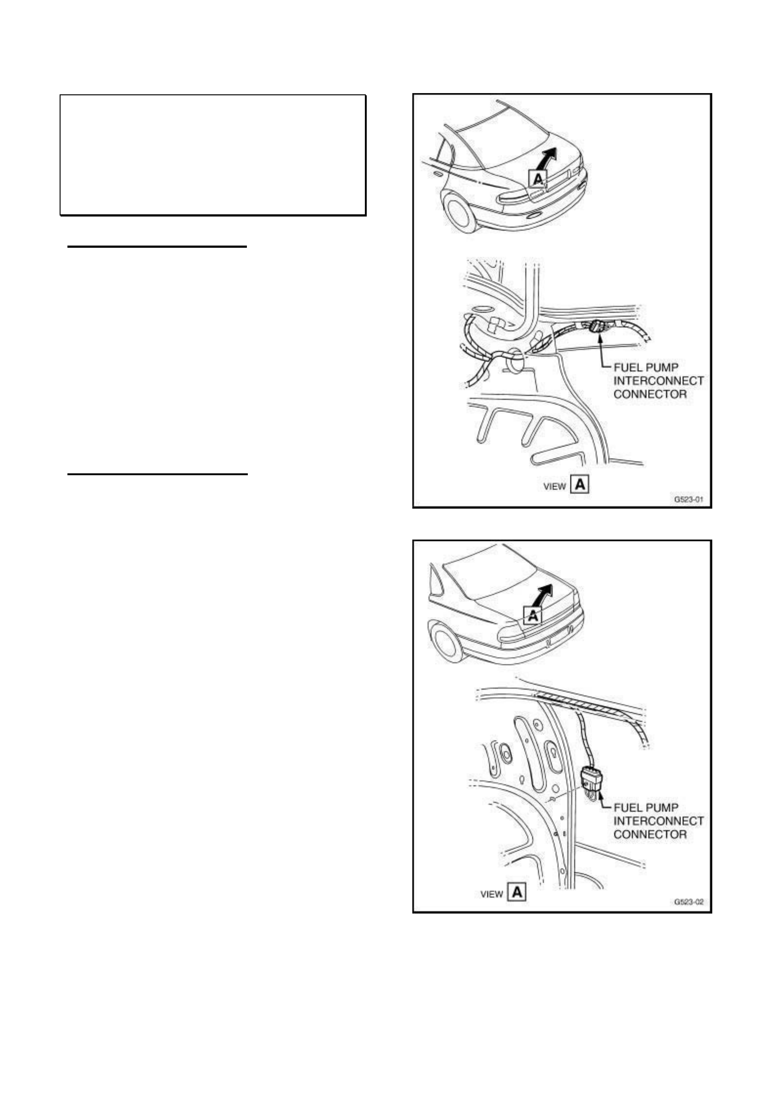
HOLDEN SERVICE TECHLINE ____________________________________________________________ JULY 2001
10
FUEL PUMP INTERCONNECT
CONNECTOR
VS, VT, VX, WH
(GROUP 12) “HINT” TL107-1201
PROBLEM DESCRIPTION
During any diagnosis of a vehicle fuel pump
related problem -– the fuel pump interconnect
connector may be overlooked.
Some vehicles (depending on options
incorporated) will have this interconnect
connector located in the rear compartment as
shown in accompanying drawings.
(For Reference: The interconnect connector
is a “bridging” connector piece, used in place
of the fuel pump speed controller, fitted only to
Supercharged V6 engined vehicles).
SERVICE RECTIFICATION
The following diagrams show the location of
the harness connector and the interconnect
connector – when fitted.
Technicians should check this connection
when diagnosing any fuel pump/sender/fuel
feed related problems.
Updated VT, VX & WH wiring circuit diagrams
will be provided in a future issue of SIP.
Figure 1 – VT, VX (VS similar)
Figure 2 – WH
HOLDEN SERVICE TECHLINE _________________________________________________________________JULY 2001
11
REAR AXLE ASSEMBLY DIAGNOSIS & CHANGEOVER
REQUEST FORM
RETURN TO: ATTN.: MR CHRIS HEALY
SPICER AXLE AUSTRALIA
58 LISBON ST
FAIRFIELD NSW 2165
FAX: (02) 9754-9310
Dealer Code: Dealer Name:
Repair Order Number: Contact Name:
Serial Number: ISOVIN Number:
Veh. Build Date: Odometer:
DIFF PART NUMBER:
VEHICLE USAGE:
Is the vehicle operational? ❑ YES ❑ NO
Main vehicle usage: ❑ Private ❑ Police ❑ Taxi ❑ Other….
CUSTOMER COMPLAINED OF:
❑ Diff Noise ❑ No drive
❑ Oil leak at: ❑ Pinion Seal ❑ Axle Seal ❑ Carrier ❑ Other….
❑ LSD (chatter) ❑ Clunk
❑ Other (describe):
HOW WAS COMPLAINT DIAGNOSED?
❑ Road Test ❑ Visual Insp. for oil leak
❑ Noise at: 10-20-30-40-50-60-70-80-90-100-110km/h
❑ Other (describe):
COMMENTS:
❑ LSD (chatter) Kit Used From Stock –
Information for SAA Database ONLY ❑ LSD (chatter) Kit Required – Bank Stock
Exhausted

HOLDEN SERVICE TECHLINE ____________________________________________________________ JULY 2001
12
TAS CASE CLOSURES
ALL
(GROUP OB) TL107-OB01
PROBLEM DESCRIPTION
TAS personnel are concerned about a
number of Dealerships that are not making an
effort to close TAS cases, even after repeated
requests from TAS, via faxes and phone calls.
Dealerships enlisting the assistance of TAS
are aware – via the TAS Procedures Manual
issued to dealerships - that Holden expects
TAS cases are updated or closed within a 30
day period.
This update or closure of cases is important,
not only to assist dealerships during
communications with TAS and the
dealership’s Aftersales District Managers, but
is also a vital source of stored information to
assist other dealerships who call for
information on similar problems.
The TAS Procedures Manual has been
provided to each dealership. This is a guide to
using the TAS system and allows service
departments to manage TAS cases within
their dealerships. If you are unsure of how to
use this manual or do not have a copy then
please contact TAS for direction in obtaining
one of these useful manuals.
Service Managers: Please ensure the TAS
Procedures Manual is readily available to your
Foreman and others who may be prime TAS
contacts – as there are various forms and
procedures that will be referred to by TAS
during calls.
Please Also Note:
TAS personnel will draw your attention to your
‘open’ (non-closed) cases when you call –
please assist them in updating or closing your
outstanding cases AS SOON AS POSSIBLE.

HOLDEN SERVICE TECHLINE ____________________________________________________________ AUGUST 2001
3
BREAKPOINT INFORMATION
ALL
(GROUP OB) TL108-OB01
This Techline provides some insight into
breakpoint numbers, their format and how they
are established.
CURRENT CONDITION
Breakpoints are often provided in Techline
Bulletins for several reasons:
- to identify upgraded or revised vehicle
components;
- to identify whether a specific condition or
complaint (or rework) is, or can be, carried out
on a specific vehicle;
- so that if a certain condition is encountered,
technicians can report the condition via a PIR
IE: if a vehicle is post (after) or pre (before) the
breakpoint – important for gauging whether
further work on a particular condition is
required.
FORMATS
ISOVIN’s:
Where possible, ISOVIN numbers and build
dates are provided.
TAG Numbers:
Tag numbers are quoted – as many Holden
systems (EG: the One Line Warranty claim
system your warranty clerk uses) utilise the Tag
number – and it has always been an easy
vehicle definer within Holden and Holden
dealerships. A complication caused by using
the Tag number is: while locally manufactured
vehicles’ Tag numbers are the last seven digits
of their ISOVIN, imported vehicles’ Tag
numbers are not. Imported vehicles have a
Holden assigned Tag number plate attached at
Port of Entry (POE). This plate provides the
model and Tag number – used for warranty
claiming, and wherever the Tag number is
required. This is required because the
ISOVIN’s are international numbers and each
one is unique – however – the last seven digits
can repeat – within a vehicle model, and each
year of the model! Using these numbers would
create much confusion because of the repeated
seven digit numbers that dealerships would
have on vehicles.
This confusion will eventually be removed (in
the future) when all systems requiring vehicle
identification move to ISOVIN only.
Build Dates:
Sometimes it is only possible to provide a build
date, as revisions to vehicle build or actual
parts introduction are carried out on a specific
date, but an ISOVIN is not recorded.
Engine/Trans. Numbers:
At times, a revision to an engine or a
transmission is carried out and because the
prime revision has taken place in those parts.
Also - any of these engines/trans’ may be fitted
to any vehicle – so the engine or transmission
number is quoted as the breakpoint. In these
cases, the known ISOVIN for the engine
number quoted is also provided – but this is a
“rough guide” or “for reference” ONLY – as
vehicles may be built with “lower” ISOVIN’s and
a post-breakpoint engine number.
Breakpoint Summary Pages:
This section in each Techline carries “TAG”
numbers only, mainly for space reasons.
Where a Tag number is quoted, the vehicle
model it applies to is also provided.
Where these are “L” numbers – locally
manufactured vehicles - in many cases the
number is ‘universal’ for locally built vehicles;
EG: today this would cover VX, VU, WH; where
the component mentioned is used in all the
models, and only “V,W” will be quoted in
‘Model’ area.
Where only ISOVIN numbers are known for
imported vehicles, the last 8 digits are shown
alongside the model – this is not exact, but
allows technicians the best chance to define
whether a vehicle is pre or post breakpoint of a
change. This situation occurs as the
breakpointed vehicle may not be imported to
Australia and thus a Tag number is not
assigned to it.
Export vehicles:
Holden exports vehicles to various overseas
markets and, at times you may see an ISOVIN
number that is unusual – EG: Starts with “6G1.”
but ends in a familiar seven digit “L” tag
number. The Tag numbers (only) of these
ISOVIN’s should be used as breakpoint
numbers, as the vehicles are built on-line with
Australian vehicles.
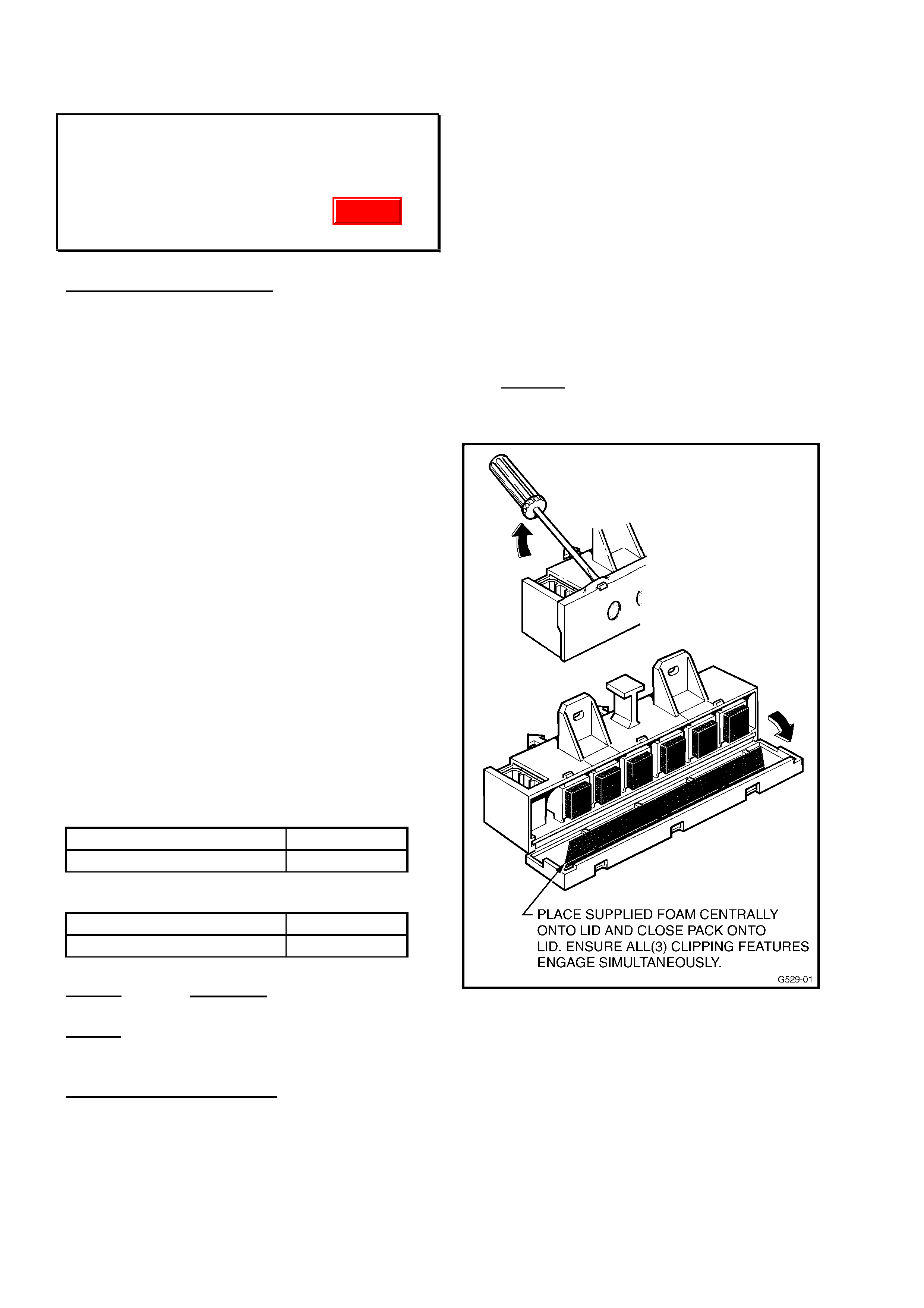
HOLDEN SERVICE TECHLINE ____________________________________________________________ AUGUST 2001
7
THUMP NOISE FROM HEATER or A/C
CASE (MODE DOOR SLAMMING)
VT/VX/WH all with ECC
(GROUP 2) TL013-0201
PROBLEM DESCRIPTION
A light “thump” or “bang” noise may be heard
from the HVAC case on Electronic Climate
Control (ECC) equipped vehicles - when the
ignition is turned off, or intermittently, during
HVAC mode changes.
The cause of this “thump” (or “bang”) noise is
the rapid closing of the previously open mode
door. The speed of closure is controlled by the
air entry into the vacuum solenoid module (it is
reduced, by restriction, via a foam pad over the
vacuum ports in the vacuum solenoid pack).
This noise condition is limited to VT Berlina and
Calais vehicles, all VX Calais and all WH
Statesman vehicles built with the six (6)
solenoid vacuum module assembly (previously
modules had 5 solenoids)
Refer to SIP CD, VT Series II, Section 2E for
explanation of the new module, vacuum
harness, wiring and diagnosis.
HVAC vacuum solenoid modules – with six (6)
vacuum solenoids (previously 5) were fitted to
vehicles from:
VT Berlina:
ISOVIN: Build Date:
6H8VTL69HYL514226 07/10/99
VT Calais:
ISOVIN: Build Date:
6H8VTX69HYL513521 06/10/99
All VX vehicles with ECC are fitted with this 6
solenoid vacuum module.
All WH vehicles are fitted with this 6 solenoid
vacuum module.
SERVICE RECTIFICATION
Fitting a specifically designed, additional foam
pad, over the existing foam pads in the vacuum
solenoid module - will correct the condition.
Follow the procedure below to fit this additional
foam pad:
1. Remove blower motor access cover – Refer
SIP CD, VT Series I, Section 2B, Part 5 – to
gain access to the vacuum solenoid
module.
2. The vacuum solenoid module should be
removed - by disconnecting the vacuum
manifold connection behind the module,
then removing the two self-tapping screws
retaining the module.
3. Open vacuum solenoid module front cover
carefully with a small, flat-bladed
screwdriver as shown in Figure 1 (3 places
across top).
Figure 1.
4. Place a new solenoid foam pad (p/n
92144689) on the open lid of the module –
ensuring it will cover the existing foam
pads, visible in the front of the module,
when the module and lid are closed - Refer
Figure 1 above.
Update
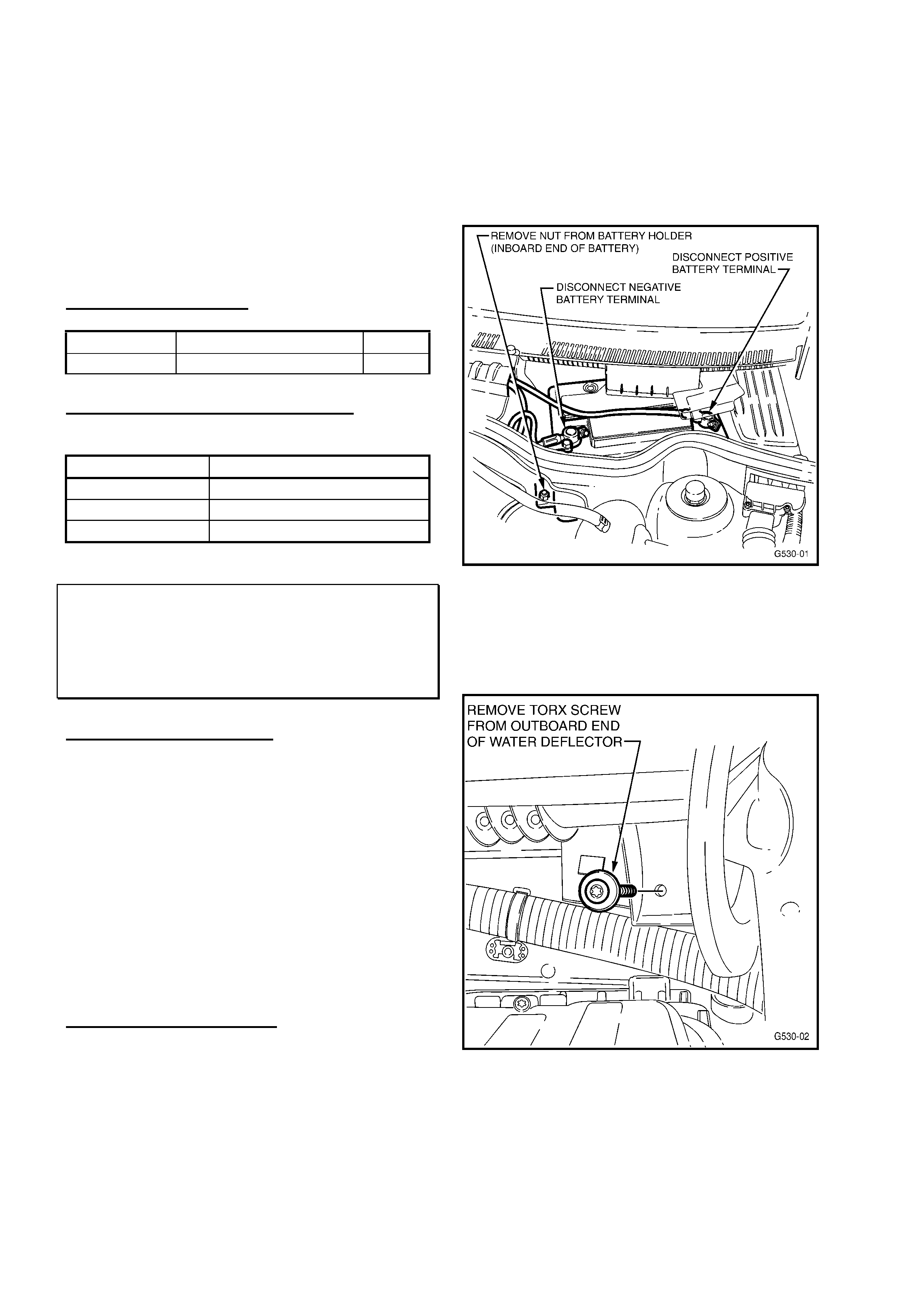
HOLDEN SERVICE TECHLINE ____________________________________________________________ AUGUST 2001
8
5. Close the module slowly onto the module lid
– ensuring the foam pad does not slip out of
place - and ensure that all three locking
features engage, and the lid remains
closed.
6. Refit the module and other components – in
reverse order to the procedure above.
This completes the procedure.
PARTS INFORMATION
Part No.: Description: Qty:
92144689 Solenoid Foam Pad 1
WARRANTY CLAIM INFORMATION:
Use the following information:
Description ECC – Foam Pad Added
Labour Op. No. C000442
Time 0.3 hr
Failure Code 52
BATTERY REMOVAL PROCEDURE
XC
(GROUP 12) TL108-1203
PROBLEM DESCRIPTION
Some technicians may experience difficulty in
removing a battery from these vehicles, or the
removal may seem complicated.
NOTE: The battery removal procedure is only
shown in TIS 2000, under battery holder
replacement - which includes battery removal.
This procedure is accessed as follows:
Go to: Standard Information
A - Maintenance, Body & Chassis
Metal Parts
Sheet Metal Parts – Bolted
SERVICE RECTIFICATION
The following procedure is provided until TIS
2000 CD information is updated to show a
procedure.
1. Disconnect battery Negative terminal. Refer
Figure 1.
2. Disconnect Positive battery terminal. Refer
Figure 1.
3. Remove nut from battery holder (inboard
end of battery) and remove holder. Refer
Figure 1.
Figure 1.
4. Remove Torx screw from outboard end of
water deflector (located next to LH engine
hood hinge). Refer Figure 2 below.
Figure 2.
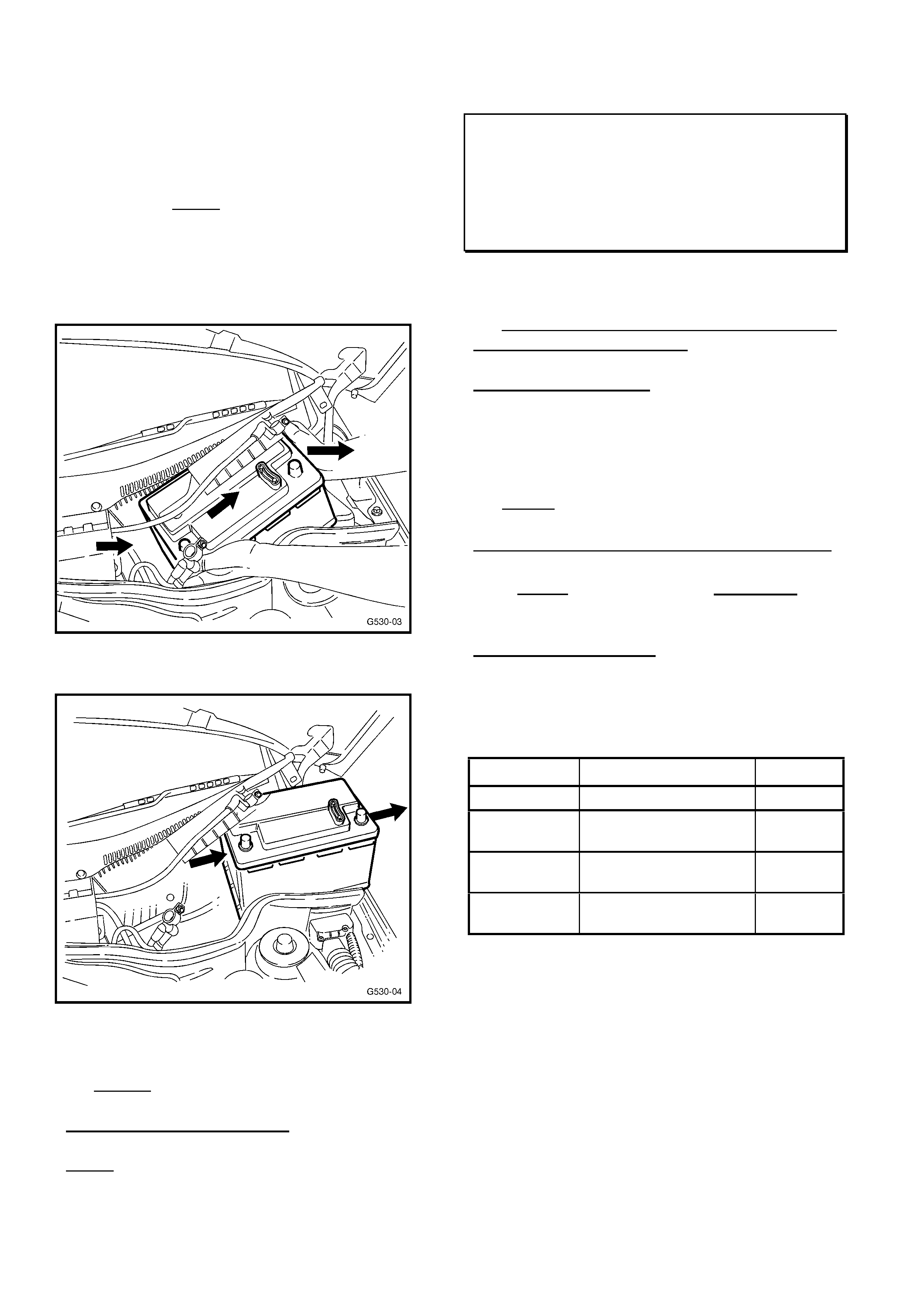
HOLDEN SERVICE TECHLINE ____________________________________________________________ AUGUST 2001
9
5. Slide battery sideways towards LH side of
vehicle then upwards to remove from
vehicle – minimise the bending of the water
deflector during this operation, to avoid
damage. NOTE: while battery should be
kept at a minimum angle during removal,
there is little risk of electrolyte loss, as it is a
“maintenance free” battery and the drain
hole is on the LH (higher) side of the
battery. Refer Figures 3 & 4 below.
Figure 3.
Figure 4.
6. Reinstall battery (or fit new battery) in
reverse procedure to above steps 1-5.
WARRANTY INFORMATION
NOTE: Warranty claim information/time is not
affected by this revised procedure.
ENGINE IDLE VIBRATION
VT, WH, VX, VU, - All with Gen III & A/T
(Standard Engine)
(GROUP 6C & 8) “UPDATE” TL108- 0801
This Service Techline updates the previous
Techline on this topic (Issue 5, May, 2001 page
8). This previous Techline should be modified
to show correct part number.
PARTS CORRECTION
The following instruction was provided in the
April Techline bulletin (with the same title):
NOTE: the wording here is revised to provide
the correct nut part number.
On Vehicles built from L647630, 14/10/00,
-studs have been added to the trans. mount
and ONLY two nuts, p/n 11074604 are
required to be fitted to these studs.
PARTS INFORMATION
An updated parts information table for this task
is shown below, with the correct nut part
number in bold:
Part No. Description: Qty
11074604 Nut rear trans. mt. 2
92138301 Bolt - rear trans.
Mount.
2
- If req’d
90495649 Bolt - cat converter
Bracket.
2
- If req’d
120394 Flat washer (spacer) No. - As
Req’d
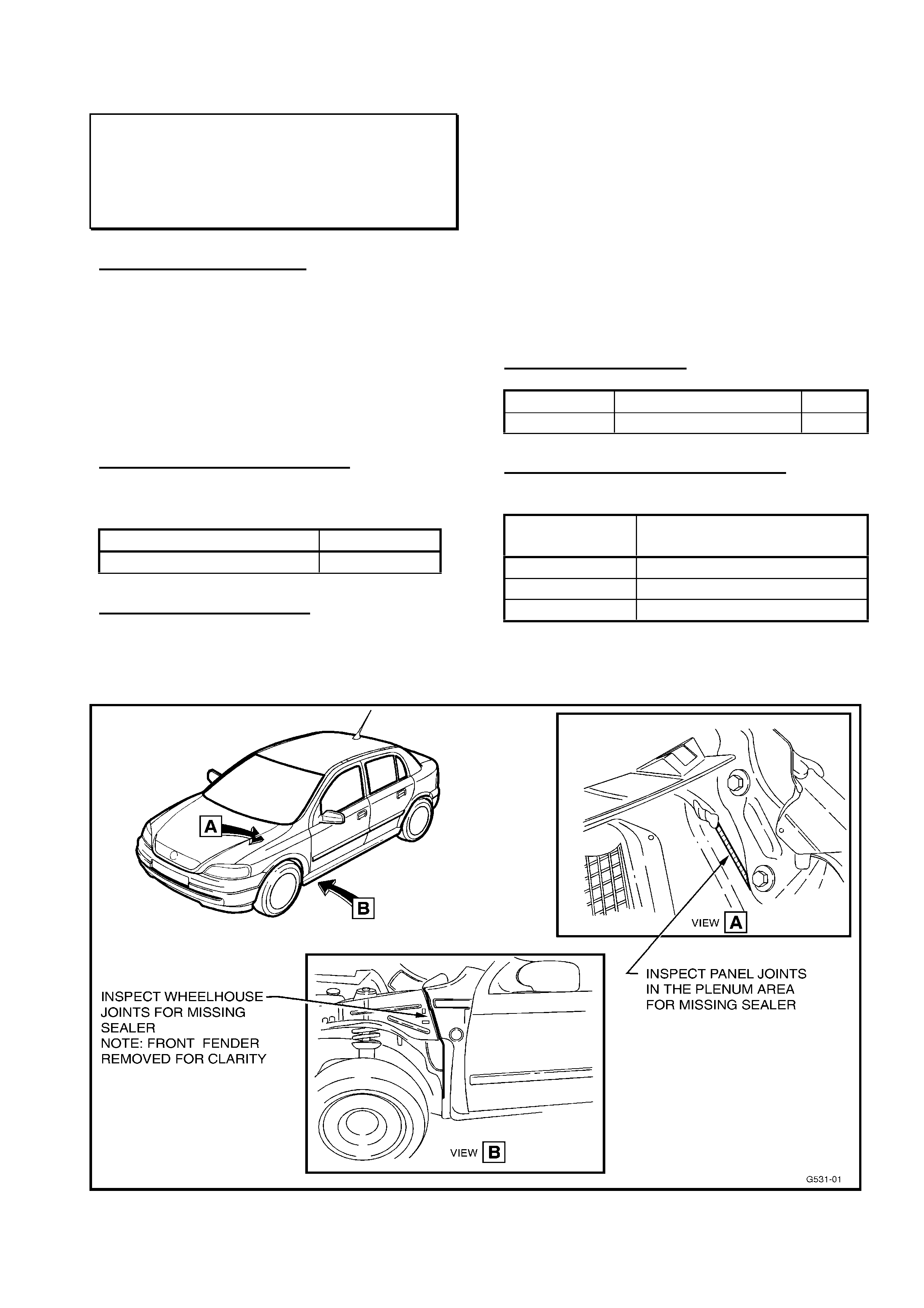
HOLDEN SERVICE TECHLINE _______________________________________________________SEPTEMBER, 2001
8
WATER ENTRY INTO FOOTWELL
TS (Astra)
(GROUP 01) TL0109-0101
PROBLEM DESCRIPTION
On some vehicles water may enter into the
vehicle interior through gaps in the sealer at
body panel joints in the plenum area or in the
wheelhouse area. Refer Views A & B below.
This condition could effect LH or RH side of
vehicle although most cases have been
observed to occur on the LH (passenger) side
of the vehicle.
PRODUCTION RECTIFICATION
Improvements to the application of sealer at
these panel joints were introduced from:
ISOVIN: Build Date:
W0L0TGF08Y5300411 15/06/00
SERVICE RECTIFICATION
Inspect suspect panel weld seams (refer
Figure 1) for signs of missing sealer. In some
instances it may help to apply a small quantity
of water to the suspect area to test for leaks.
Once the leak area has been located, any
loose sealant should be removed (take care
not to damage paint primer coat) and the area
cleaned thoroughly with a solvent cleaner
such as acetone. After cleaning, apply
urethane sealer 92143609 to the affected
area. After drying, recheck for leaks.
PARTS INFORMATION
Part No.: Description: Qty:
92143609 Urethane 1
WARRANTY CLAIM INFORMATION
For vehicles repaired under warranty:
Description Panel asm cockpit/cowl -
reseal
Labour Op.No. A206098
Time ST
Failure Code 87 (water leak)
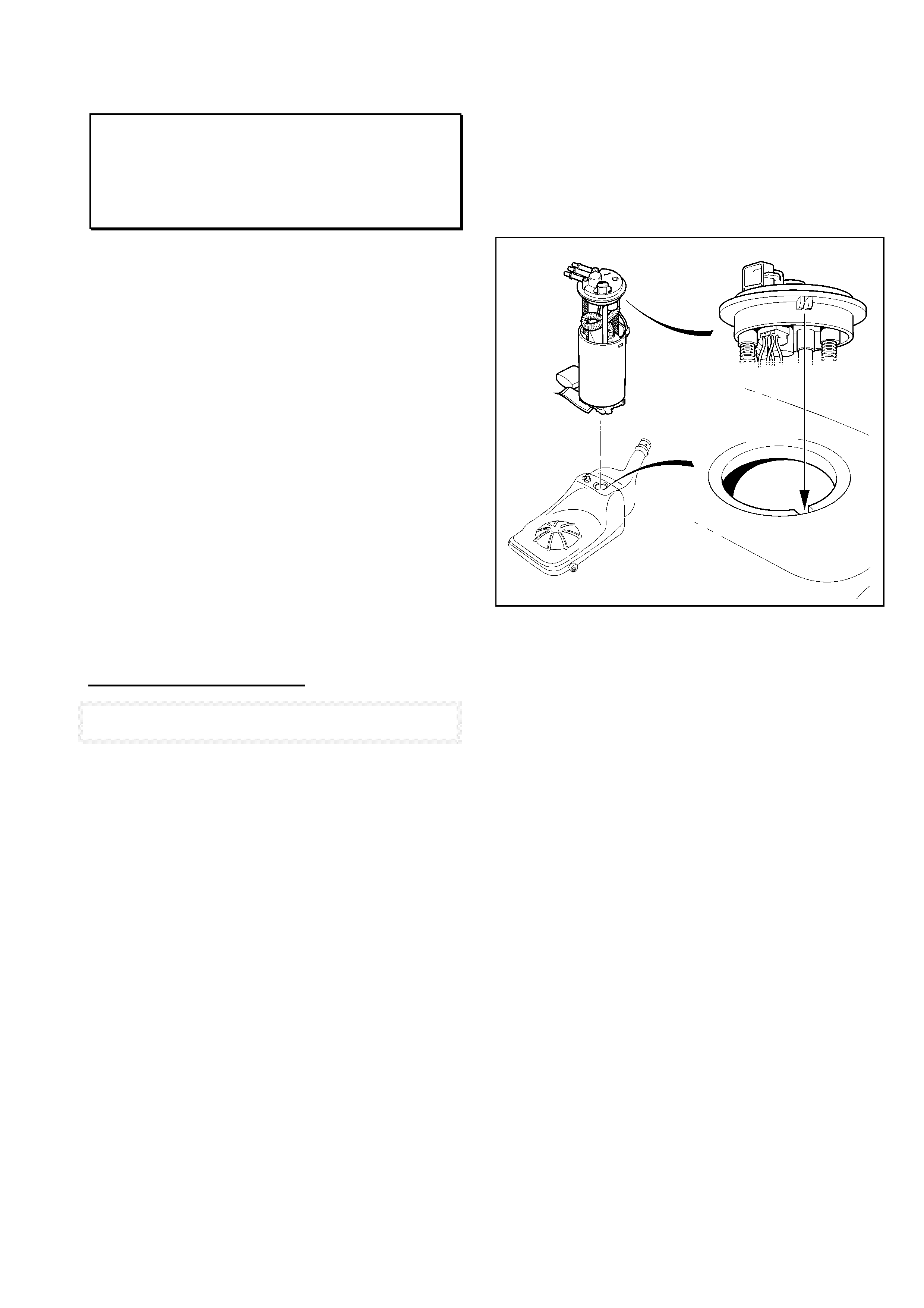
HOLDEN SERVICE TECHLINE _______________________________________________________SEPTEMBER, 2001
9
FUEL GAUGE- READS INCORRECTLY
VT, VX, VU, WH
(GROUP 8 & 12) TL0109-0801
PROBLEM DESCRIPTION
Some customers may complain that their fuel
gauge needle is stuck at about the 1/3rd full
level. Driving with this condition for too long will
result in the vehicle running out of fuel.
Investigation into this complaint shows
there is potential for the MRA (modular
reservoir assembly) to be incorrectly
installed into the tank causing the float
arm to foul on the inside wall of the fuel
tank.
Complaints of this nature generally arise
after the MRA has been removed and
reinstalled.
SERVICE RECTIFICATION]
NOTE: For any service procedures/information not given in
this Techline, technicians should refer to the current SIP CD.
When diagnosing such complaints :
1. Inspect installation of MRA to check if
the locating lug is correctly positioned in
the notch as shown in Figure 1. If not
located correctly, remove MRA and use
a torch, to look for evidence of float arm
scrape marks on the inside wall of the
fuel tank.
2. Replace MRA if locating lug is broken.
3. Install MRA taking care to ensure that
the locating lug is aligned with the slot in
the tank opening.
INSTALLATION HINT. Prior to
installing MRA, use a marking pencil to
mark a line on the top surface of MRA
and another on the tank in-line with the
lug. After tightening the MRA locking
ring with tool J39765, ensure that the
pencil lines remain in alignment.
NOTE: Future versions of the SIP CD will
contain these installation guidelines.
Figure 1

HOLDEN SERVICE TECHLINE _______________________________________________________SEPTEMBER, 2001
10
KEY READER FAULTS
VS, VT, VX, VU, WH
(GROUP 12) TL0109-1201
PROBLEM DESCRIPTION
Some dealers have reported complaints of
“Full Circle” key readers coming apart, thus
preventing the engine from starting.
(Note: Full circle key readers were introduced
into vehicle production from tag L733809 25th
May 2001.)
Investigation of failed parts by the supplier
has resulted in a revision to the manufacturing
process to eliminate this condition.
PRODUCTION RECTIFICATION
Key reader assemblies produced from the
revised process were introduced into vehicle
production from:
ISOVIN: Build Date:
6H8VXK69A1L755820 25/7/01
SERVICE RECTIFICATION
In the event the key reader assembly falls
apart, order a replacement part from HSPO.
INSTALLATION NOTE. When connecting
wire to key reader blade terminal be sure to
use other hand to provide support behind the
metal slip ring cover.
PARTS INFORMATION
The part number of the key readers has not
changed.
Part No.: Description: Qty:
92092099 VT, VX, VU, WH
Key Reader Assembly-
Remote Coded Key
1
92100734 VS
Key Reader Assembly-
Remote Coded Key
1
To confirm if parts are from improved process
check the packaging date printed on the label.
A date of 25.7.01 (25th July 2001) or later
represents okay parts.
WARRANTY CLAIM INFORMATION
Use existing Labour Times information in
Warranty Information section of current SIP
CD
RETURNED ANTENNA ASSEMBLIES
VT, VX, VU, WH
(GROUP 12) TL0109-1206
PROBLEM DESCRIPTION
Many of the antenna assemblies returned
to Repac under warranty have bent masts.
Dealers are reminded :
• Bent masts are a customer responsibility
and warranty claims should not be
submitted.
• Masts are serviced separately and do not
warrant total assembly replacement if mast
is bent.
SERVICE RECTIFICATION
If a customer complains that their antenna
mast does not extend fully, technicians should:
1. Check for cleanliness of mast. If mast is
dirty it should be cleaned with a soft cloth,
water and mild detergent. Recheck for
correct operation of antenna.
2. If mast still does not extend fully, check for
signs of kinking or distortion of mast
segments. Look for shiny patches. If mast
has evidence of this damage it should be
replaced at the customers expense.
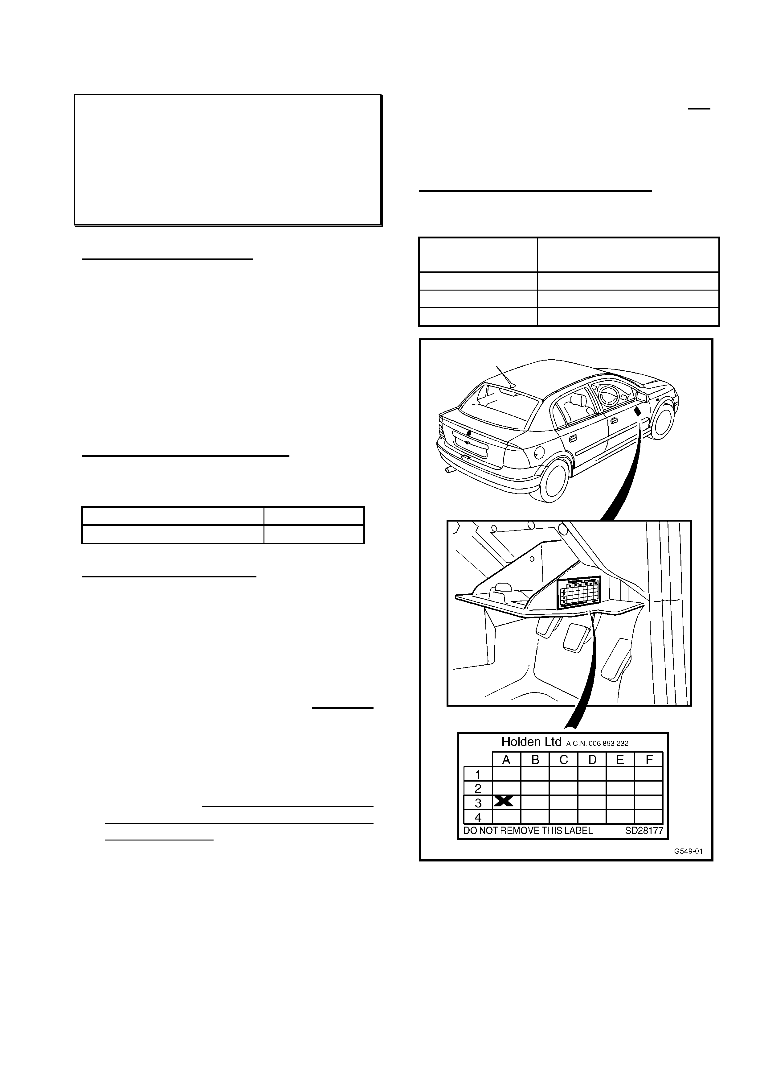
HOLDEN SERVICE TECHLINE _______________________________________________________SEPTEMBER, 2001
11
INTERMITTENT NO-START & DTC
P1612 or P1613 LOGGED IN ECU
TS - Model Year 2001 with Z18XE
Engine ONLY
(GROUP 6C) TL0109-6C02
PROBLEM DESCRIPTION
Vehicles with Z18XE1 engine may suffer a
complaint of “crank but no start”. On
investigation, the Engine Control Unit (ECU) is
found to contain the Diagnostic Trouble
Codes (DTCs) P1612 or P1613 in history.
This problem is due to an intermittent
communications failure between the
immobiliser and the ECU.
PRODUCTION RECTIFICATION
Revised ECU software has been flashed into
vehicles at Port of Entry from:
ISOVIN: Date:
W0L0TGF6915264225 03/08/01
SERVICE RECTIFICATION
On vehicles where this “crank but no start”
condition and DTC’s P1612/P1613 are
logged, carry out the following procedure:
1. Check for a Vehicle Service History Label
(SD28177) fitted to the drivers side, lower
storage compartment lid (in the open
position) on the right hand side outboard
vertical edge. If an “X” has been marked
in the A-3 co-ordinate, the ECU has been
previously reprogrammed.. If a “no start”
condition is still present, contact TAS for
diagnostic assistance.
2. Using Tech 2 updated with TIS2000 CD
Version 23 (or later) and Tech 2 software
10.300 (or later), clear all trouble codes
from ECU.
3. Reprogram the vehicle ECU using the TIS
Service Programming System (SPS).
4. Use a Vehicle Service History
Identification Label (SD 28177) to identify
this vehicles ECU has been
reprogrammed. Position the label (if not
already fitted) as shown in Figure 1.
Place an “X” with a ballpoint pen in the A-3
co-ordinate once the work has been
performed.
WARRANTY CLAIM INFORMATION
Use the following information to claim for the
above procedure:
Description Reflash Engine Control
Unit – DTC P1612/P1623
Labour Op. No. J000689
Time 0.4 hr
Failure Code 83
Figure 1

HOLDEN SERVICE TECHLINE _______________________________________________________SEPTEMBER, 2001
12
RECEIVER/SUNSENSOR
MALFUNCTION- HIGH AMBIENTS
VT, VX, WH
(GROUP 12) TL0109-1202
PROBLEM DESCRIPTION
Customers may complain of poor range or that
their remote is inoperative when attempting to
unlock their doors. This predominantly occurs
in warm/hot weather.
Root cause investigation has found high
ambient temperatures can cause a malfunction
of one of the capacitors on the
sunsensor/receiver circuit board.
PRODUCTION RECTIFICATION
Revised sunsensor/receivers with a higher
tolerant capacitor have been introduced into
production from;
ISOVIN: Build Date:
6G1HL52FX2L765433 28/08/01
SERVICE RECTIFICATION
To diagnose this condition:
1. Confirm normal 4 metre remote range is
achievable with passenger compartment
cool.
2. Use a 150 Watt lamp applied to the remote
receiver for 5 mins maximum.
3. Recheck remote range – if less than 4
metres from the drivers side door when hot
but more than 4 metres range when cold,
then remote receiver is defective.
4. Replace part.
5. Contact Australian Arrow (03 9785 0792) if
further assistance is required in diagnosing
the remote receiver.
PARTS INFORMATION
Part numbers of the revised
sunsensor/receivers have not changed but
are labelled with the following identifiers:
“VX RX” on part number 92051734
“VX SUN” on part number 92050898
Part No: Description: Qty:
92051734 All VT & VX Exec, VU
Receiver (remote key)
1
92050898 VX (Berllna & Calais),
WH
Receiver/Sunsensor
(remote key)
1
WARRANTY CLAIM INFORMATION:
Use existing Labour Times information in
Warranty Information section of current SIP
CD
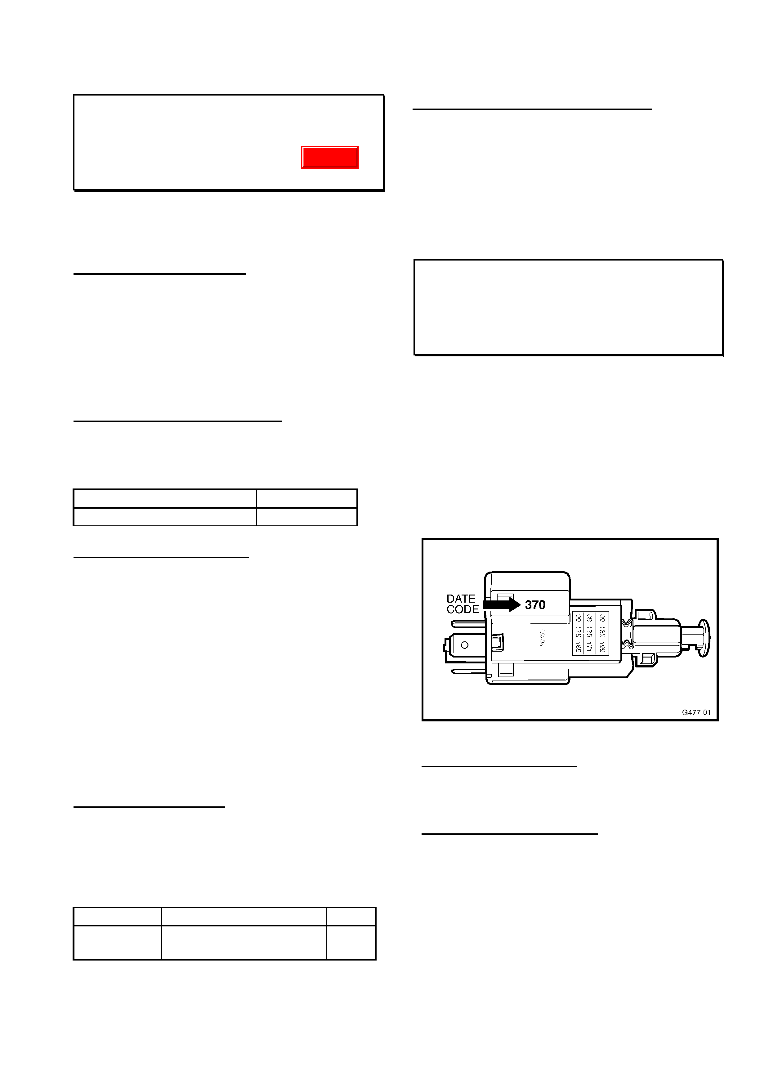
HOLDEN SERVICE TECHLINE _______________________________________________________SEPTEMBER, 2001
13
FRONT WIPER BLADES-NOISY
XC BARINA
(GROUP 1) TL0109-0103
An advanced copy of this bulletin was
published in All Dealer Letter 68/01
PROBLEM DESCRIPTION
PIRs received describe complaints of front
windscreen wiper blade operating noise
excessive, as a result of wiper blade judder.
Investigations have shown the wiper blade
profile and material causes an incorrect attack
angle and high noise level as a result of blade
deformation.
PRODUCTION RECTIFICATION
Wiper blades with a revised profile and
manufactured from an improved rubber
material were introduced into production from:
ISOVIN: Build Date:
WOLOXCF6814272636 29/5/01
SERVICE RECTIFICATION
On vehicles with complaint of noisy front wiper
blades:
• Clean windscreen glass and rubber wiper
blade to remove all pollution deposits and
foreign material contamination.
• Activate wipers and listen for wiper blade
noise.
• If this fails to provide satisfactory wiper
blade noise levels, replace blades with new
parts.
• Revised wiper blades are temporarily
identified by a yellow dot affixed to the part
number label.
PARTS INFORMATION
To identify the revised parts a yellow dot has
been affixed to the packaging label. This is
only a temporary measure. As of October 1
2001, parts procured from HSPO will not have
the yellow dot identifier.
Part No: Description: Qty:
09196102 Set- Front windscreen
wiper blades
1
WARRANTY CLAIM INFORMATION:
Use existing Labour Times information in the
Warranty Information section of current SIP
CD.
STOP LAMP SWITCH REVISION
JS, TS
(GROUP 12) TL0109-1205
Refer to previous Service Techline on this
subject contained in issue 4/2001, page 22.
As highlighted in the previous Techline
technicians are requested to only use parts
with date codes of 370 or greater.
The switch date code is located as shown in
Figure 1.
Figure 1.
Date Code interpretation: 370
First two digits (week) - 37 = Week 37
Third digit (year) - 0 = Year 2000
Attention Parts Managers.
New switches with date codes less than 370
must be returned to HSPO for credit. Refer
HSPO Parts Techline PT72 dated 24 Aug
2001
Update

HOLDEN SERVICE TECHLINE _______________________________________________________SEPTEMBER, 2001
14
HEADLAMP FOGGING OR WATER
ENTRY
VX, VU
(GROUP 12) RE-ISSUE TL0109-1204
This Service Techline supersedes the previous
Techline on this topic Issue 2, Feb, 2001 page 10.
This previous Techline should be destroyed.
PROBLEM DESCRIPTION
PIR’s have been received which mention
headlamps with fogging or water entry.
REPAC also receive many headlamps
replaced under warranty for complaint of
fogging/water entry. As a result, this
Techline is provided to ensure technicians
understand:
- The VX vented headlamp design
- How to clear minor fogging.
- Criteria for headlamp replacement due to
water entry.
Headlamp Design….
These are vented lamps with clear lenses (no
optics) and therefore are more prone to
showing signs of any moisture present within
the lamp.
The design of vented lamps can result in the
formation of minor condensation (fogging) on
the inside surface of the lens under certain
operational and climatic conditions.
For example, in humid weather, when vehicles
are parked and headlamps turned off after
prolonged usage, moisture laden air is drawn
into the lamp via it’s vent system and
condenses on the lens as it cools down. This
minor condensation (fogging) will usually
disperse after 3-4 minutes driving with the
headlamps on.
SERVICE RECTIFICATION
If an owner complains of condensation in
headlamps the first thing to do is determine if
there are signs of normal fogging, or if the
lamp has water entry due to leakage.
Minor Condensation/Fogging…..
This will be in the form of a mist on the interior
surface of the lens. This needs no dealership
action, as the fogging will disperse during the
time the vehicle is left standing or after 3-4
minutes driving with the headlamps on.
Service advisors should be advising
customers of this headlamp characteristic to
avoid future complaints of minor fogging.
Water Entry….
A headlamp lens with severe fogging with
water droplets, or a visible amount of water in
the bottom of the headlamp must be
investigated to determine the cause of water
entry.
Possible causes of water entry are as follows:
a) Vent tubes, dust caps and/or dust cap
seals missing, or incorrectly fitted.
b) Turn signal and/or six pin electrical
connector is incorrectly fitted.
c) Lens housing seal leak. (this is unlikely as
the headlamp supplier pressure tests every
production headlamp). If this is suspected –
the lamp will require replacement.
NOTE: Where water has leaked in via
connector, caps, etc, that have been re-fitted
it may be necessary to leave the headlamps
on for up to 30 minutes to clear the remaining
condensation. If this does not clear water
droplets or if visible “water marks” are left on
the inside of the lens, the lamp will require
replacement.
If a lamp is replaced for water entry, a clear
description of diagnosis and approximate
amount of water entry should be quoted on
the Defective Material Tag on replaced part.
Engine bay cleaning precaution….
High pressure water should not be directed at
the rear of the lamp as this can lead to water
entry through the lamp’s vent system.
WARRANTY CLAIM INFORMATION:
Use existing Labour Operations and times as
shown in Warranty Information in SIP, if
headlamp replacement is required.
Warranty Managers, Please Note:
A clear description of diagnosis, and estimate
of amount of water entry seen, should be
quoted on the defective material tag on the
replaced headlamp.
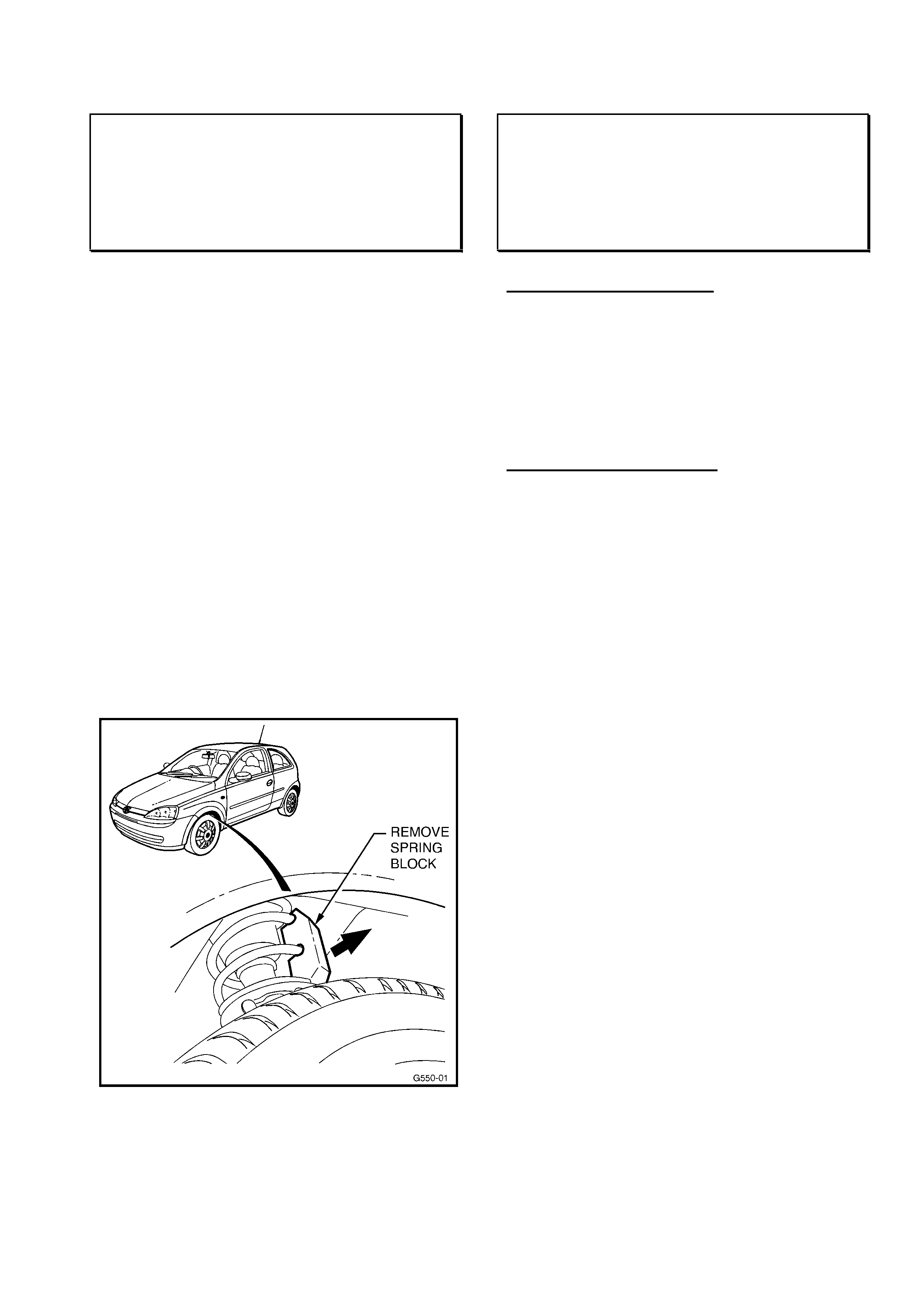
HOLDEN SERVICE TECHLINE _______________________________________________________SEPTEMBER, 2001
15
SPRING BLOCK REMOVAL DURING
PRE-DELIVERY CHECK
XC SRi
(GROUP 3) TL0109-0301
This information is repeated from All Dealer
Letter 67/01.
This is to advise Holden Dealerships that
spring blocks need to be removed from the
front suspension of SRi series XC Barinas.
This model is fitted with a body kit that
includes a front spoiler. The spoiler has
reduced ground clearance compared to
standard Barina, to the point where blocks are
fitted to the springs in order to move them
safely on and off transporters.
Vehicles will still have the spring blocks in
place when received by your Dealership, and
will require removal before delivery to the
customer (in much the same way as HSV
cars). This involves hoisting the car so the
front springs are unloaded, and removing one
moulded plastic block from each front spring.
Figure 1 depicts the typical design and
location of the spring blocks.
Figure 1
Please ensure you remove the spring blocks
from all SRi Barinas your dealership receives.
IGNITION KEY - LOSS OF
SYNCHRONISATION
XC, TS, JS, TT
(GROUP 12) TL0109-1203
PROBLEM DESCRIPTION
Many remote keys from above models,
(particularly J car) returned to REPAC under
warranty cannot be faulted. A possible
reason for this is that the keys may have lost
“Synchronisation”.
SERVICE RECTIFICATION
When investigating complaints of remote key
not working the first step should be to perform
the following synchronising procedure which is
in the owners handbook; refer Section 2 –
Locks.
• Switch on ignition. (system will remain in
synchronising mode for 30 seconds ).
• Briefly press any button on the key while it
is in the ignition.
• The central locking system will lock and
unlock to show that the remote control unit
has been “resynchronised”.
If the central locking system does not
operate as described this means that the
key is already synchronised.
If the remote key still does not work after
performing this procedure, further fault
diagnosis will be required.
Warranty Replacement
When replacing a remote key for any reason
please state the customer’s actual complaint.
(i.e. what feature is not working, when,
intermittent fault etc.). This information is vital
for proper analysis of returned parts.
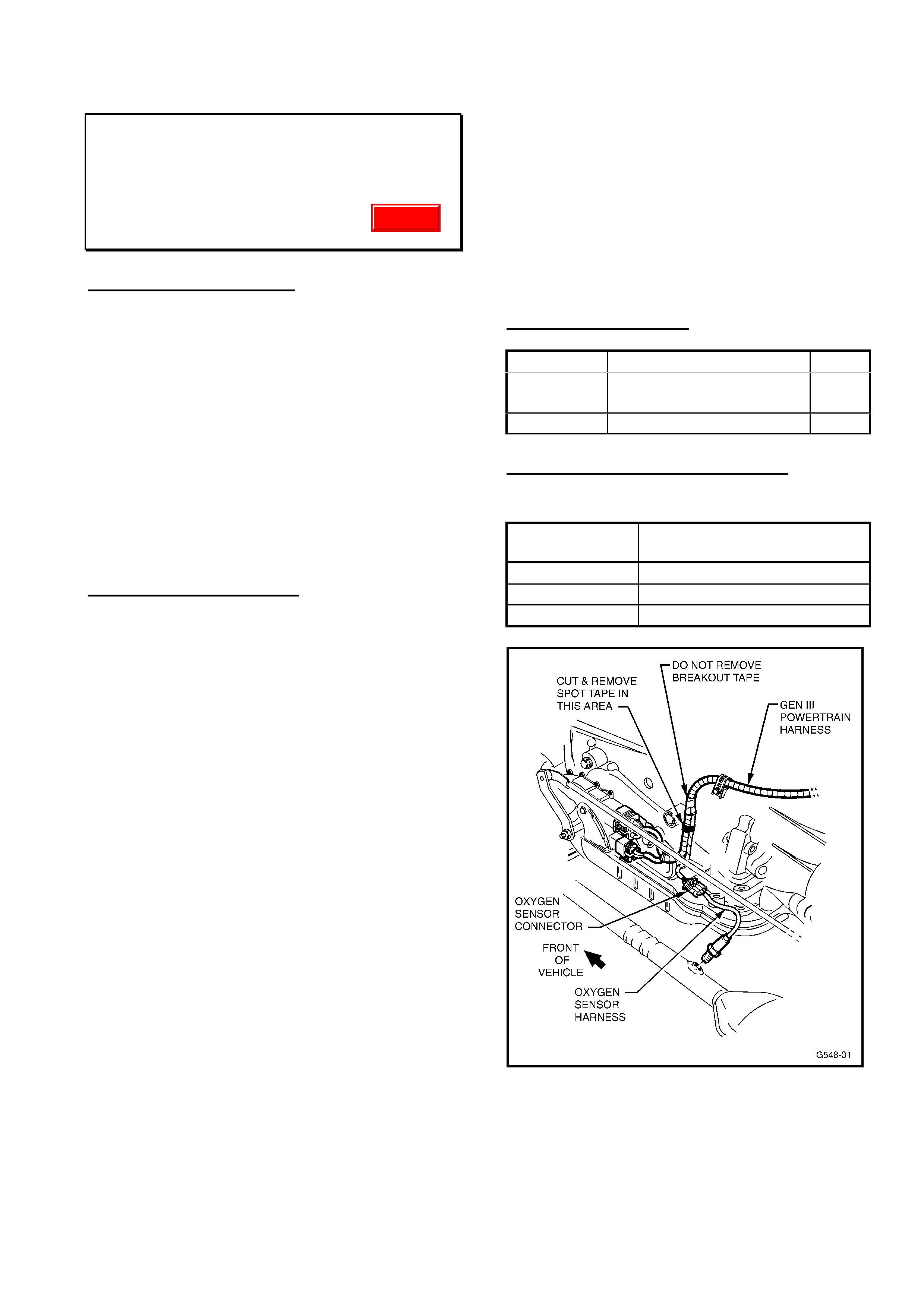
HOLDEN SERVICE TECHLINE _______________________________________________________SEPTEMBER, 2001
16
LHS O2 SENSOR CONNECTOR -
WATER ENTRY
VTII, VX, VU, WH – All with GEN3 & A/T
(GROUP 6C) TL0109-6C01
PROBLEM DESCRIPTION
The proximity of the left hand side (LHS)
oxygen sensor wiring to the HVAC drain can
result in O2 sensor malfunctioning. An oxygen
sensor connnector that has had water ingress
causing terminal corrosion may result in the
check engine lamp illuminating while driving
&/or a noticable loss in performance. Typical
symptoms of a malfunctioning LHS oxygen
sensor will be the logging one of the following
DTCs:
P0131
P0132
P0134
SERVICE RECTIFICATION
On any vehicle where the LHS O2 sensor has
logged the above trouble codes it is
recommended that as well as fitting a new O2
sensor, the sensor harness connector should
be relocated as per the following procedure.
1. Remove old / damaged sensor on the
LHS ONLY. Inspect & verify the condition of the
electrical terminals on the harness. Harness
replacement may be necessary if terminals are
corroded.
2. Carefully slice the spot tape that keeps
the Neutral Start Back Up Switch & the Oxygen
sensor wiring branches together. Ensure not to
slice through the convoluted tubing as wiring
damage may occur. Refer Figure 1.
HINT. Access to the harness to cut the spot
tape is improved by pulling the harness
through the spring clip to take up any slack.
3. Mount the bracket & the bolt from kit
92145044 to the spare threaded boss on the
LHS rear of the transmission (Refer Figure 2).
Bolt torque should be 5 - 12 Nm. The bracket
has an anti-rotation tab.
4. Mount the new sensor into the exhaust
and tighten between 38 - 48 Nm. Route wiring
as illustrated in Figure 2.
5. Connect the sensor plug from the
vehicles wiring harness.
6. Mount the sensor connector to the new
bracket via the arrow head clip.
7. Clear fault DTCs & complete testing for
further fault DTCs.
PARTS INFORMATION
Part No.: Description: Qty
92145044 Mounting Kit –
contains bracket & bolt
1
25326439 O2 sensor asm LHS 1
WARRANTY CLAIM INFORMATION
For vehicles repaired under warranty use:
Description Fit LHS O2 sensor & relocate
harness connector.
Labour Op No. J000692
Time 0.5 hr
Failure Code
Figure 1
Update
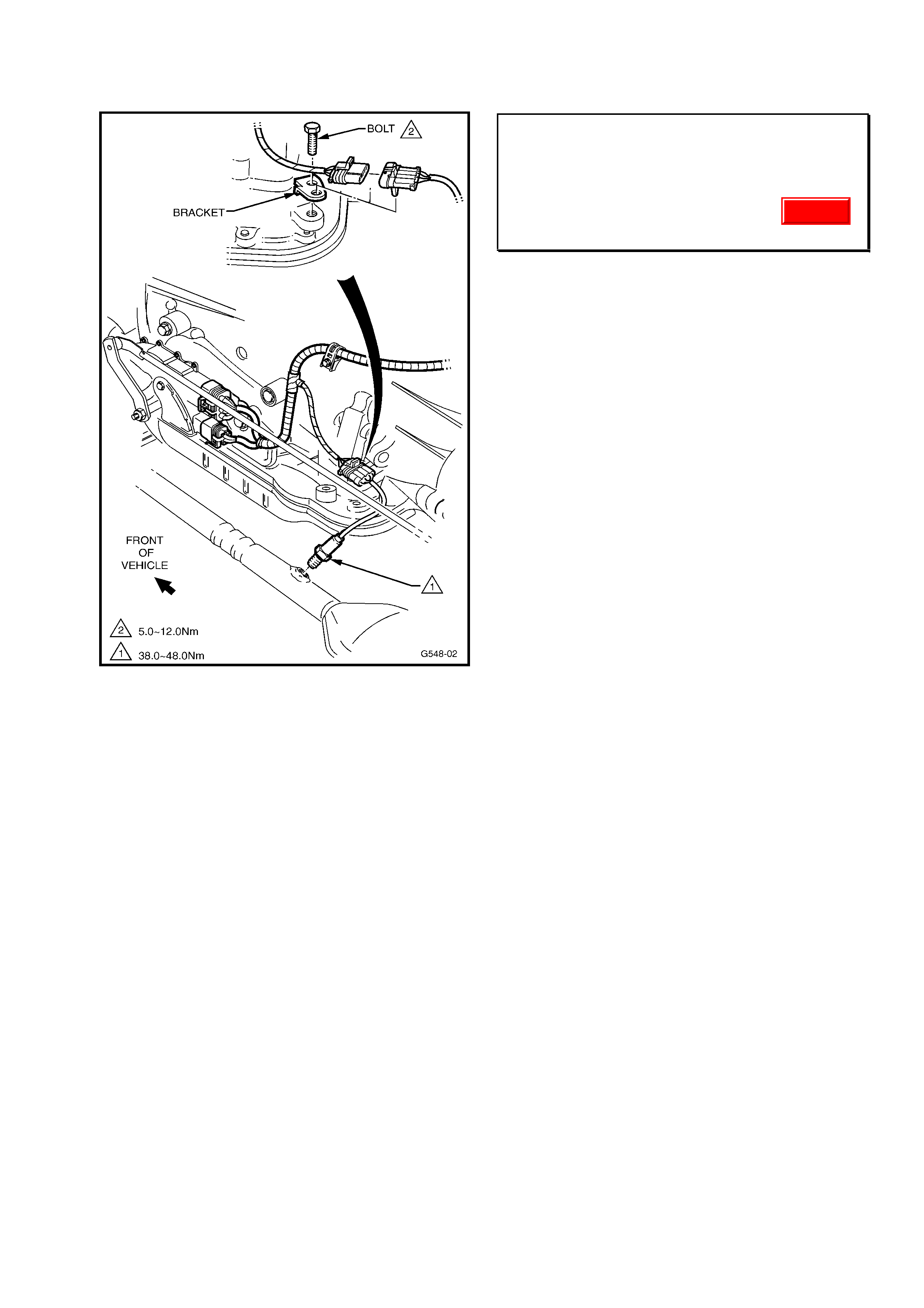
HOLDEN SERVICE TECHLINE _______________________________________________________SEPTEMBER, 2001
17
Figure 2
DRIVELINE NOISE, VIBRATION
REPORT FORM
VT,VX,VU,WH
(GROUP OB) TL0109-OB01
To assist our investigations, we request that
should you have an owner complaint of
driveline noises/vibrations, instead of
submitting a PIR, fill out the Report Form
attached to the rear pages of this issue and
fax to EDAG FUTURE on 03 9552 8104.
(This form will be counted as a PIR in the
normal manner).
The information provided on this report will
help to more accurately identify what owners
are complaining about so that Holden can
address these issues.
Update
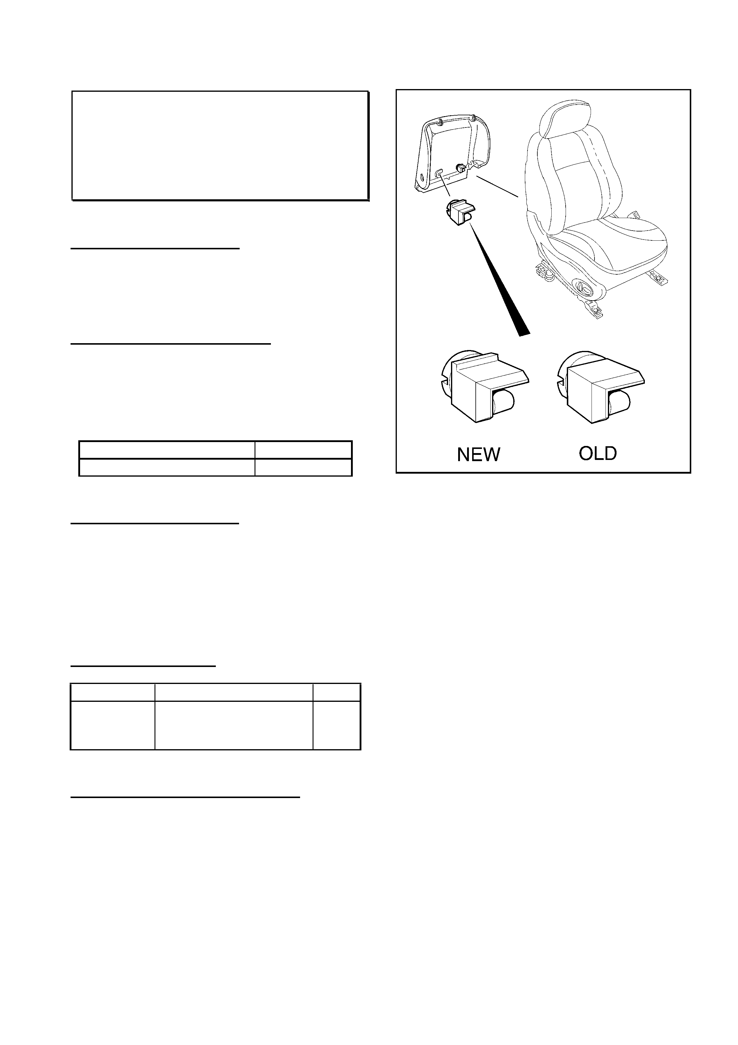
HOLDEN SERVICE TECHLINE _______________________________________________________SEPTEMBER, 2001
18
FRONT SEAT BACK PANEL RETAINING
CLIPS BREAK
VT, VX, VU, WH
(GROUP 1) TL0109-0102
PROBLEM DESCRIPTION
Front seat back panel retaining clips break on
removal.
PRODUCTION RECTIFICATION
A new clip design with added rib (see Figure 1)
made from a more durable material was
introduced into production from vehicle
breakpoint:
ISOVIN: Build Date:
6H8VXK69A1L735911 29/5/01
SERVICE RECTIFICATION
Replace broken clips with new parts from
HSPO. The part number has not changed
however all stock of clips has been checked to
ensure that only the revised clips are serviced.
Revised parts are shipped in HSPO packaging
with a packaging date of 25.06.01 or later.
PARTS INFORMATION
Part No: Description: Qty:
92140918 VX, VT, WH, VU
Retainer, Front Seat
Back Cover
1
WARRANTY CLAIM INFORMATION:
Use existing Labour Times information in
Warranty Information section of current SIP CD
Figure 1
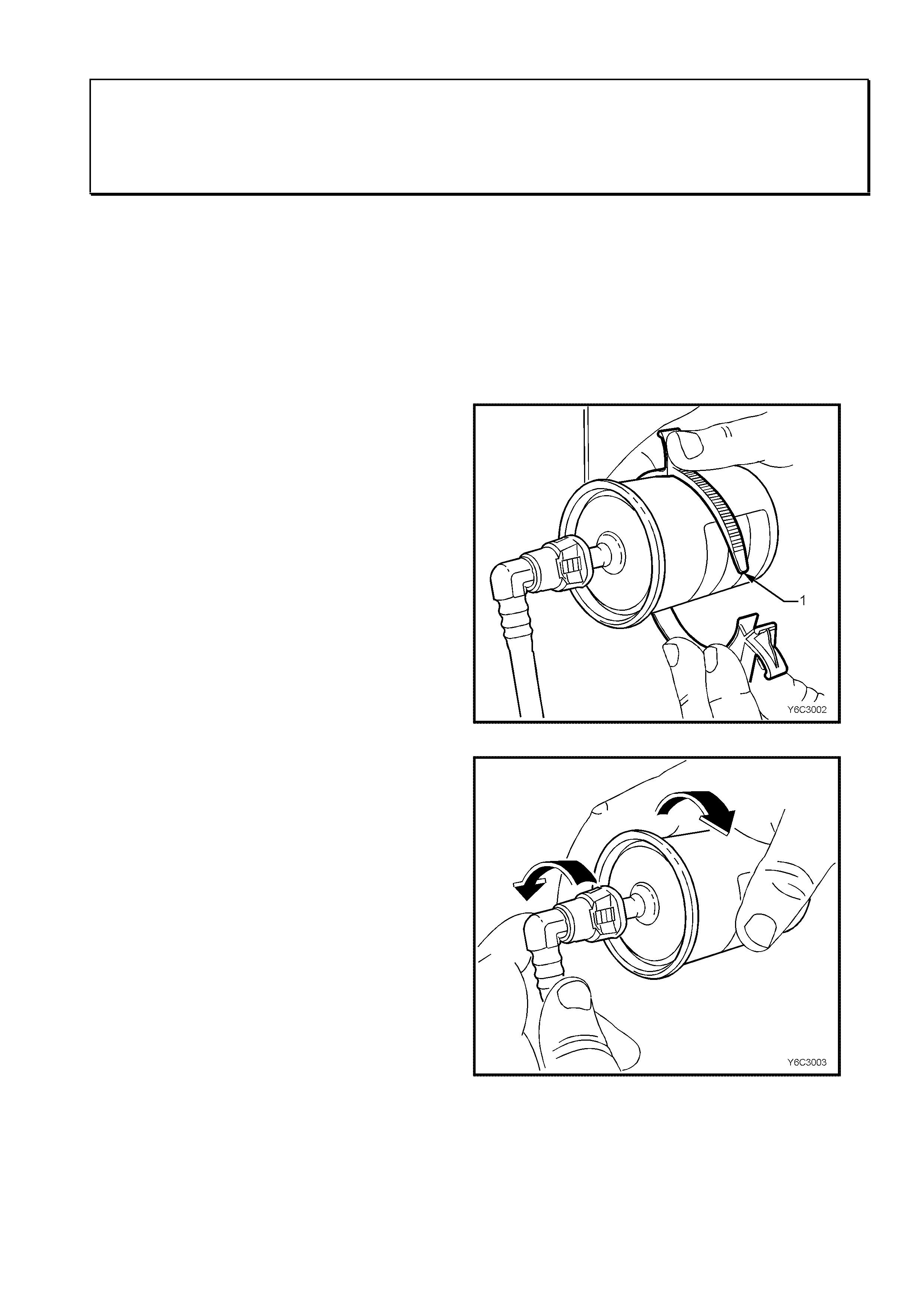
HOLDEN SERVICE TECHLINE _______________________________________________________SEPTEMBER, 2001
21
FUEL FILTER REMOVAL INSTRUCTIONS
VT, VX, VU, WH
(GROUP 8) TL0109-0802
PROBLEM DESCRIPTION
PIRs received from dealerships highlight that
the fuel filter quick connect fittings can become
damaged during the course of filter
replacement.
This techline provides service personnel an
advanced copy of the service procedures
necessary to successfully remove the fuel
filter and avoid any damage to the
connections. These instructions will be
included in the next Passenger SIP CD.
version 3.8
FUEL FILTER
REMOVE
IMPORTANT Relieve the fuel system pressure before
servicing any fuel system connection. Refer to the Fuel
Pressure Relief Procedure in 3.11, FUEL CONTROL
SYSTEM in this Section.
1. Relieve fuel pressure as described in 3.11, FUEL
CONTROL SYSTEM - Fuel Pressure Relief
Procedure in this Section.
2. Disconnect battery earth lead.
3. Raise rear of vehicle and support on safety stands,
refer to Section OA, GENERAL INFORMATION in
the VT Service Information.
4. Place a drain tray beneath fuel filter.
5. Remove the fuel filter from the retaining bracket (1)
with the fuel lines still connected to the fuel filter to
allow easier access.
Fuel Filter Retaining Bracket
QUICK CONNECT FITTINGS
(PLASTIC COLLAR)
6. Grasp the quick-connect fittings both sides of the
fuel filter. Twist the female connectors 1/4 turn in
each direction in order to loosen any dirt within the
quick-connect fitting.
Fuel Filter & Quick-connect Fittings
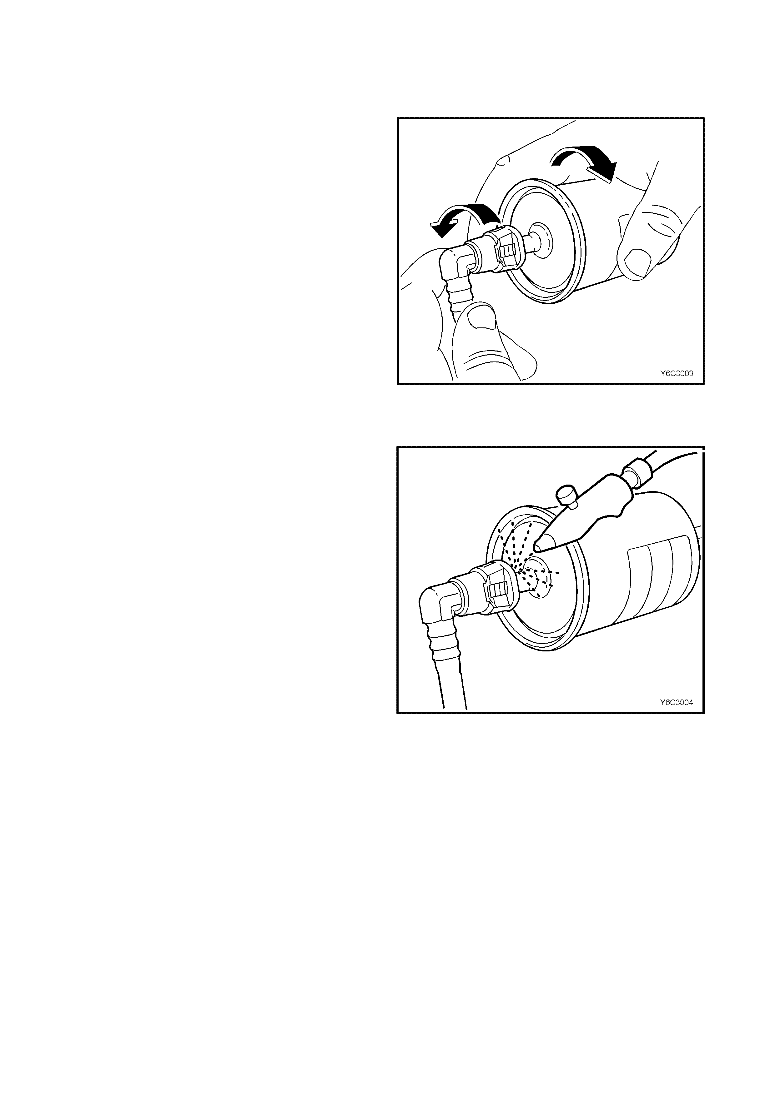
HOLDEN SERVICE TECHLINE _______________________________________________________SEPTEMBER, 2001
22
FUEL FILTER
QUICK CONNECT FITTINGS
(PLASTIC COLLAR)
7. Grasp the quick-connect fittings both sides of the
fuel filter. Twist the female connectors 1/4 turn in
each direction in order to loosen any dirt within the
quick-connect fitting.
Fuel Filter & Quick-connect Fittings
8. Using compressed air, blow any dirt out of the
quick-connect fitting to aid the release of any
tension or binding on the release tabs .
IMPORTANT:
Wear safety glasses when using compressed air in
order to prevent eye injury.
Cleaning Quick-connect Fittings
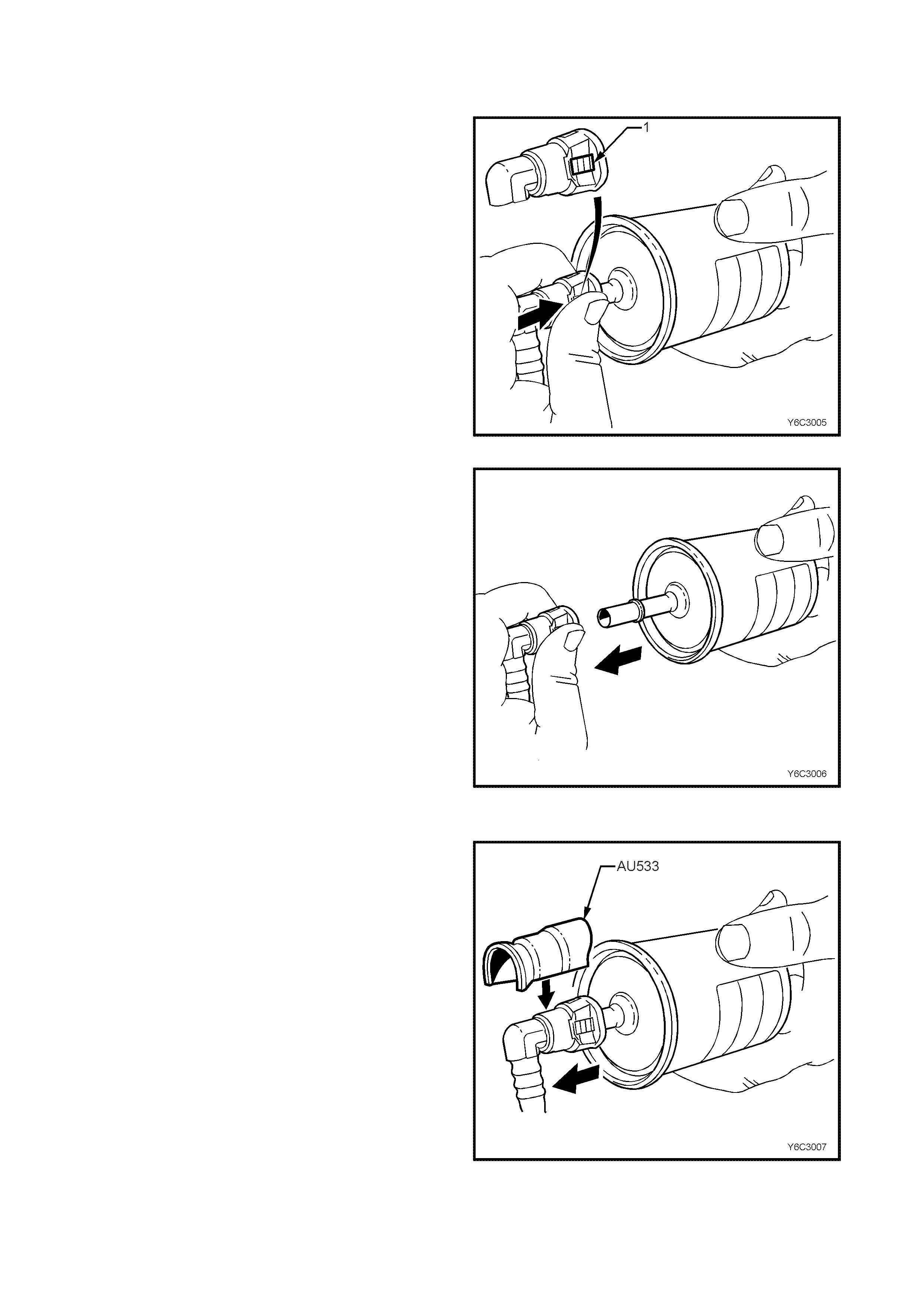
HOLDEN SERVICE TECHLINE _______________________________________________________SEPTEMBER, 2001
23
9. Hold the fuel filter firmly in one hand to support the
filter.
10. Using your other hand, grasp one of the quick-
connect fittings.
11. Squeeze the plastic retainer release tabs (1) on
each side of the fitting while pushing the fitting firmly
toward the fuel filter to release any tension on the
release tabs.
Quick-connect Fitting Release Tabs
12. With the tension release tabs still held in the
squezed position, move the complete quick-connect
fitting away from the fuel filter to separate the
connector fitting from the fuel filter.
13. Apply the same method from step 8 to 11 for the
remaining quick-connect fitting.
Disconnecting Quick-connect Fittings
Without Special Tool
14. Alternately for steps 8 to 11, use tool AU533 to
squeeze the release tabs, release the quick connect
fittings and remove both fuel pressure hoses from
the fuel filter.
15. Remove fuel filter from vehicle and disguard safely
remembering that some fuel will still remain in the
filter.
Disconnecting Quick-connect Fittings With
Special Tool
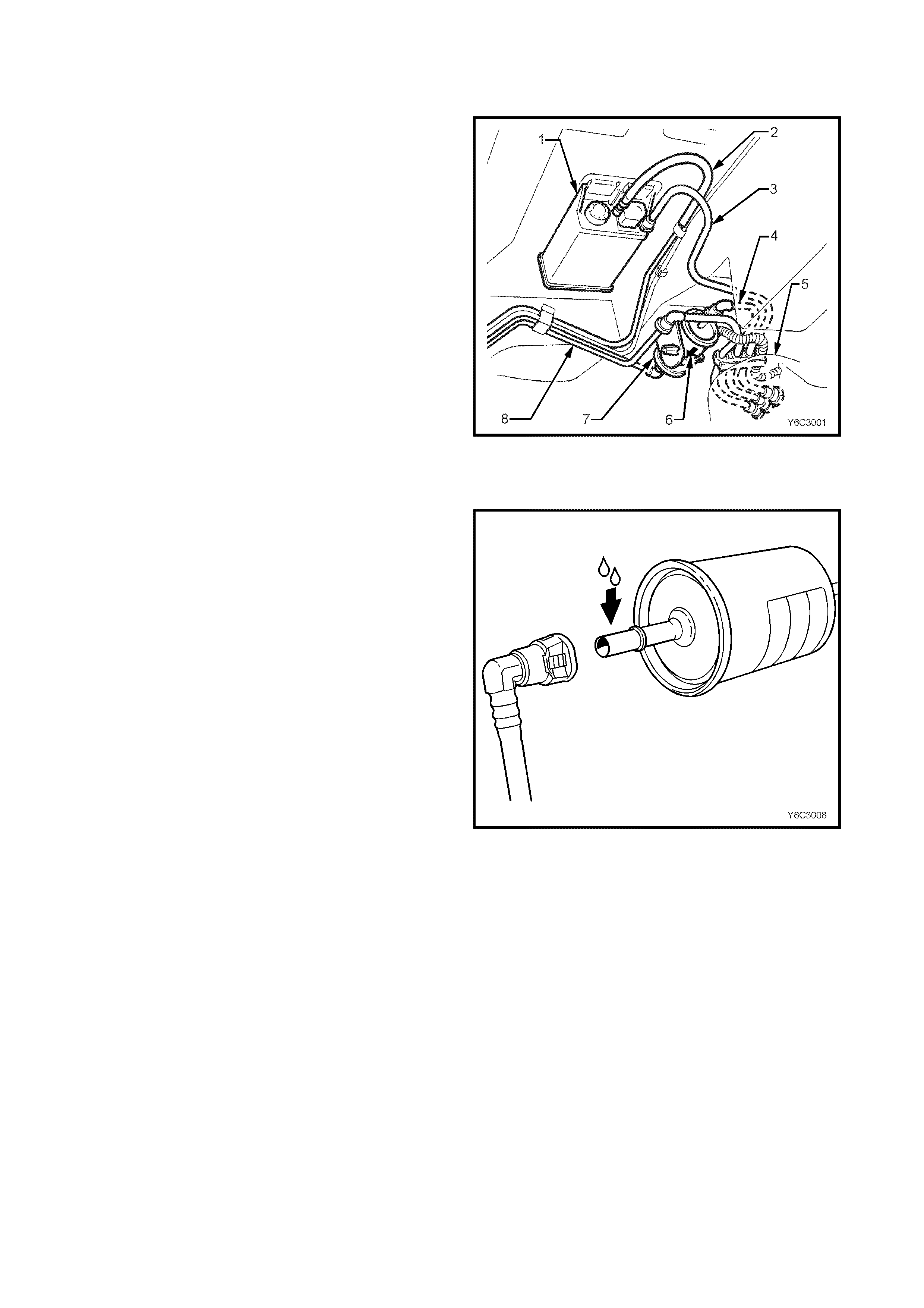
HOLDEN SERVICE TECHLINE _______________________________________________________SEPTEMBER, 2001
24
REINSTALL
IMPORTANT The fuel filter (7) must be installed with the
flow arrow (6) on its body pointing in the same direction
as the fuel flow to the front of the vehicle.
Fuel Filter Installation
IMPORTANT Before connecting fuel filter quick-connect
fittings, always apply a few drops of clean engine oil to
the male ends of the fuel filter.
This will ensure proper reconnection and prevent a
possible fuel leak.
During normal operation, the O-ring located in the
female connector will swell and may prevent proper
reconnection if not lubricated.
1. Apply a few drops of clean engine oil to each male
fuel filter end.
Quick-connect Fitting Seal lubrication
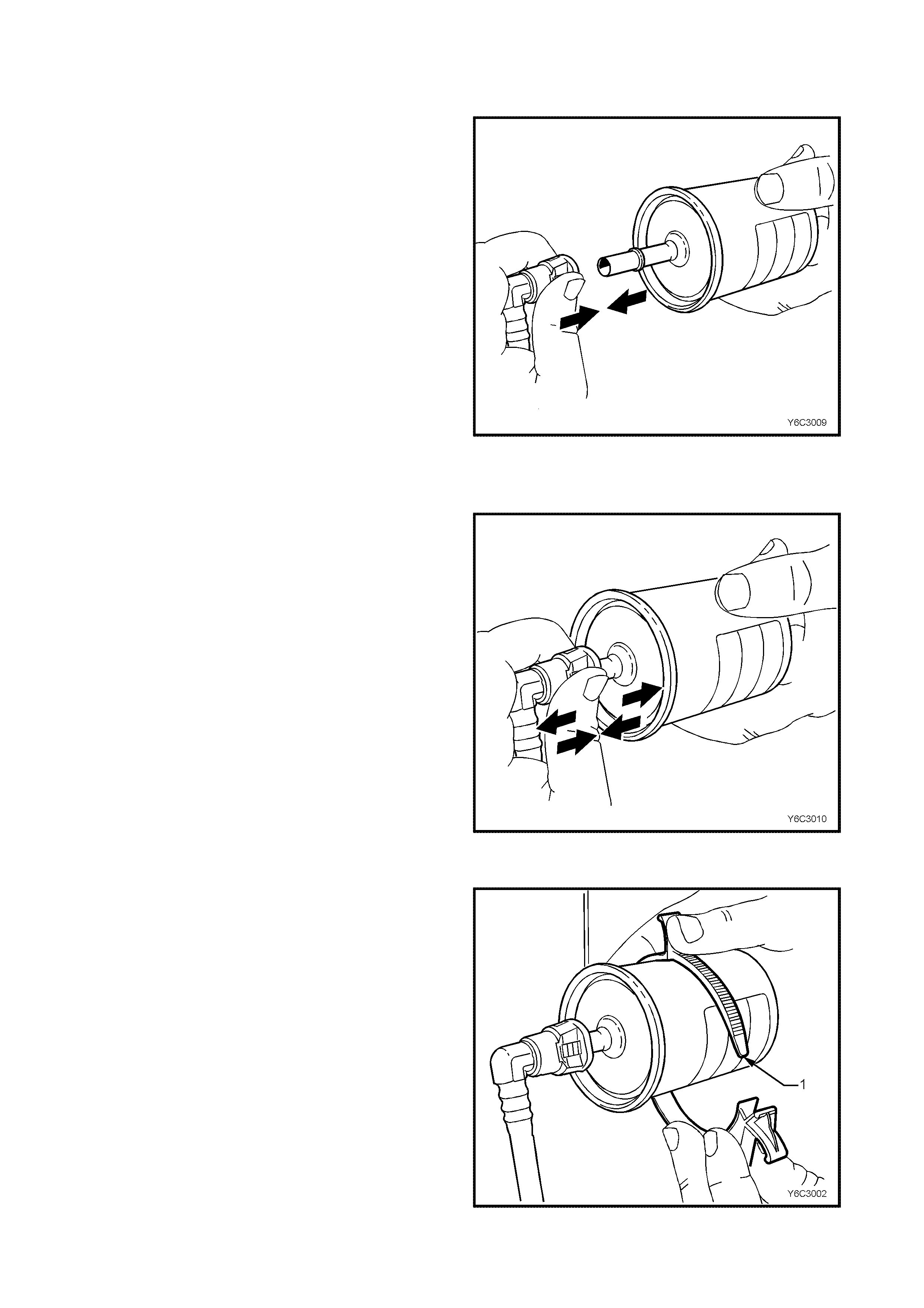
HOLDEN SERVICE TECHLINE _______________________________________________________SEPTEMBER, 2001
25
2. Push both the quick-connect fitting and the fuel filter
together in order to cause the retaining tabs to snap
into place. Apply this method to both ends of the fuel
filter and the respective quick-connect fittings.
Re-installation Of Quick-connect Fitting To
Fuel Filter
3. Once installed, pull and push on both the quick-
connect fitting and the fuel filter in order to make
sure the connection is secure. Apply this method to
both ends of the fuel filter and the respective quick-
connect fittings.
Quick-connect Fitting To Fuel Filter Check
4. Install a new fuel filter with a new retaining bracket
(1).
5. Connect battery earth lead.
6. Check for fuel leaks, refer to 3.11, FUEL CONTROL
SYSTEM – Leak Testing in this Section of the VT
Service Information.
7. Remove safety stands and lower vehicle.
Re-installation Of Fuel Filter To Retainer Bracket

TICK ALL BOXES THAT ARE RELEVANT TO YOUR CONDITION!
DEALER
Date: Dealer Name: Dlr Code:
VEHICLE DATA
ISOVIN: Odometer:
Vehicle Model: VT VX VU WH Build Date:
ENGINE
Engine: V6 V6 S/C V8
DRIVETRAIN
Transmis sion: Manual Automatic
Rear Axl e: Standard LSD
Wheels/Tyres:
Standard wheels and OE tyres
Standard wheels and replacement tyres
Tyre brand, type, size:
Non-Standard wheel s and tyres
Rim size, ty r e br and, type, size:
COMPLAINT
What did your customer complain about (in t heir words)?
Can you reproduce the customer complaint? Yes No
How would you describe the compl aint?
Is the complaint evi dent at ALL road speeds or s pecific road speeds?
All Specific (please list all road speeds if more than one) :
a) km/h b) km/h c) km/h
Is the complaint evi dent at ALL engi ne s peeds or speci fic engine speeds ?
All Specific (please list all engine speeds if more than one):
a) rpm b) rpm c) rpm
Driveline Noise, Vibration
and Refinement Report

Is the complaint evi dent in ALL gears or specifi c gears?
All Specific (please list all gears if more than one) :
a) gear b) gear c) gear
Engine Load:
No load Light Load Medium Load Heavy Load Any Load
When does it occur ?
Stationary Accelerating from stationary
Light Accelerati on Heavy Acceleration
Cruising at constant speed Coasting
Light Decelerati on Heavy Deceleration
Braking After Braking
Forward travel Reversing
Steering wheel straight ahead Steering wheel of f centre
Steering wheel at full lock
Transmission Upshif t Transmission Downshift
VIBRATION
Can the condit ion be felt (v ibrati on)? If yes, what word do you feel describes it?
Shake Roughness
Buzz Tingling
Where can you feel it?
Body Floor
Seats Brake Pedal
Accelerator Clutch Pedal
Gear Lever Steering Wheel
NOISE
Can the condition be heard (noise)? If yes, what word do you feel descr ibes it ?
Boom Moan or Drone
Howl Whine
Squeal or squeak Thump
Beat Shudder
Chatter Clunk
From which dir ection does t he noise appear to come from?
Front Left Front Centre Front Right
Centre Left Centre Centre Right
Rear Left Rear Centre Rear Right
Can’t determine
Please pri nt your name:
Fax this form directly to EDAG FUTUR E on Fax N o. (03) 9552 8104
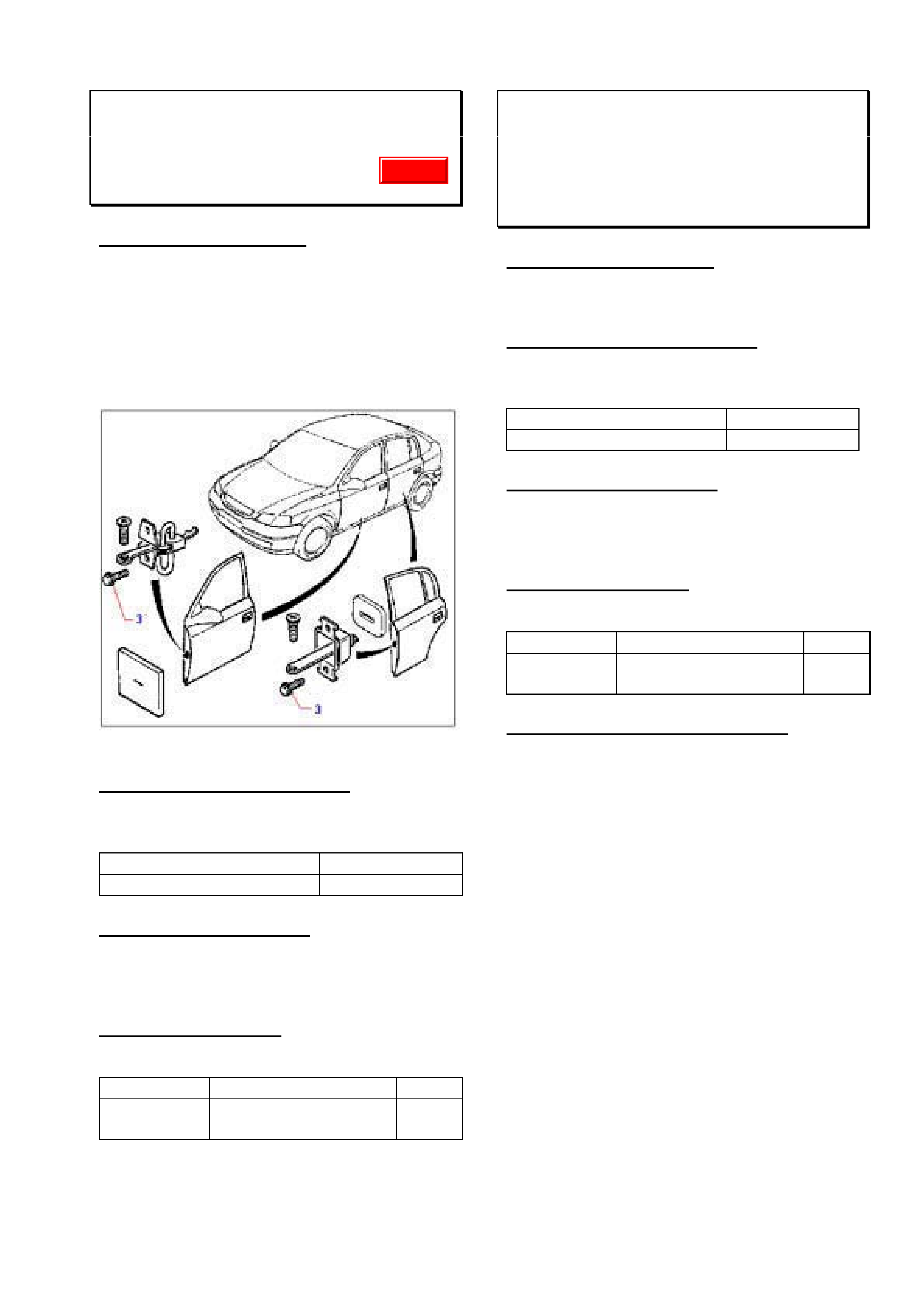
HOLDEN SERVICE TECHLINE___________________________________________________________OCTOBER, 2001
9
DOOR CHECKLINK BOLTS LOOSE
TS
(GROUP 01) TL0110-0101
PROBLEM DESCRIPTION
Door checklink attaching bolts loosen.
Investigations show root causes to be:
• Attaching bolts (item 3 in Figure 1) not to
specification
• Relaxation of clamping torque ex factory.
• Stripped threads caused by overtightening
of bolts (above 6.5Nm)
Figure 1.
PRODUCTION RECTIFICATION
Revised checklink attaching bolts with closer
controls on tightening torque have been fitted
to vehicles from:
ISOVIN: Build Date:
W0L0TGF4815283442 05/06/2001
SERVICE RECTIFICATION
On complaint vehicles fit revised checklink
attaching bolts part number 13104167 and
torque to 4.5 to 5.0 Nm.
PARTS INFORMATION
Obtain following parts from HSPO:
Part No.: Description: Qty:
13104167 Bolt Checklink to
door.
2 per
door
Note: These same bolts are now also used
on TT, JS and XC models.
WINDSCREEN WASHER NOZZLE AIM
INCORRECT
VX, VU, WH
(GROUP 01) TL0110-0102
PROBLEM DESCRIPTION
On some vehicles the washer nozzle may
direct water too high on the windscreen.
PRODUCTION RECTIFICATION
Revised washer nozzles with revised aim
(lowered) have been fitted to vehicles from:
ISOVIN: Build Date:
6H8VTX69F1L673317 8/12/00
SERVICE RECTIFICATION
As the twinjet nozzles are non adjustable,
complaints of this nature can only be rectified
by fitting new nozzles.
PARTS INFORMATION
Use following parts from HSPO.
Part No.: Description: Qty:
92092007 Nozzle - twin jet. As
reqd.
WARRANTY CLAIM INFORMATION
Use existing Labour Times information in
Warranty Information section of current SIP
CD
Update
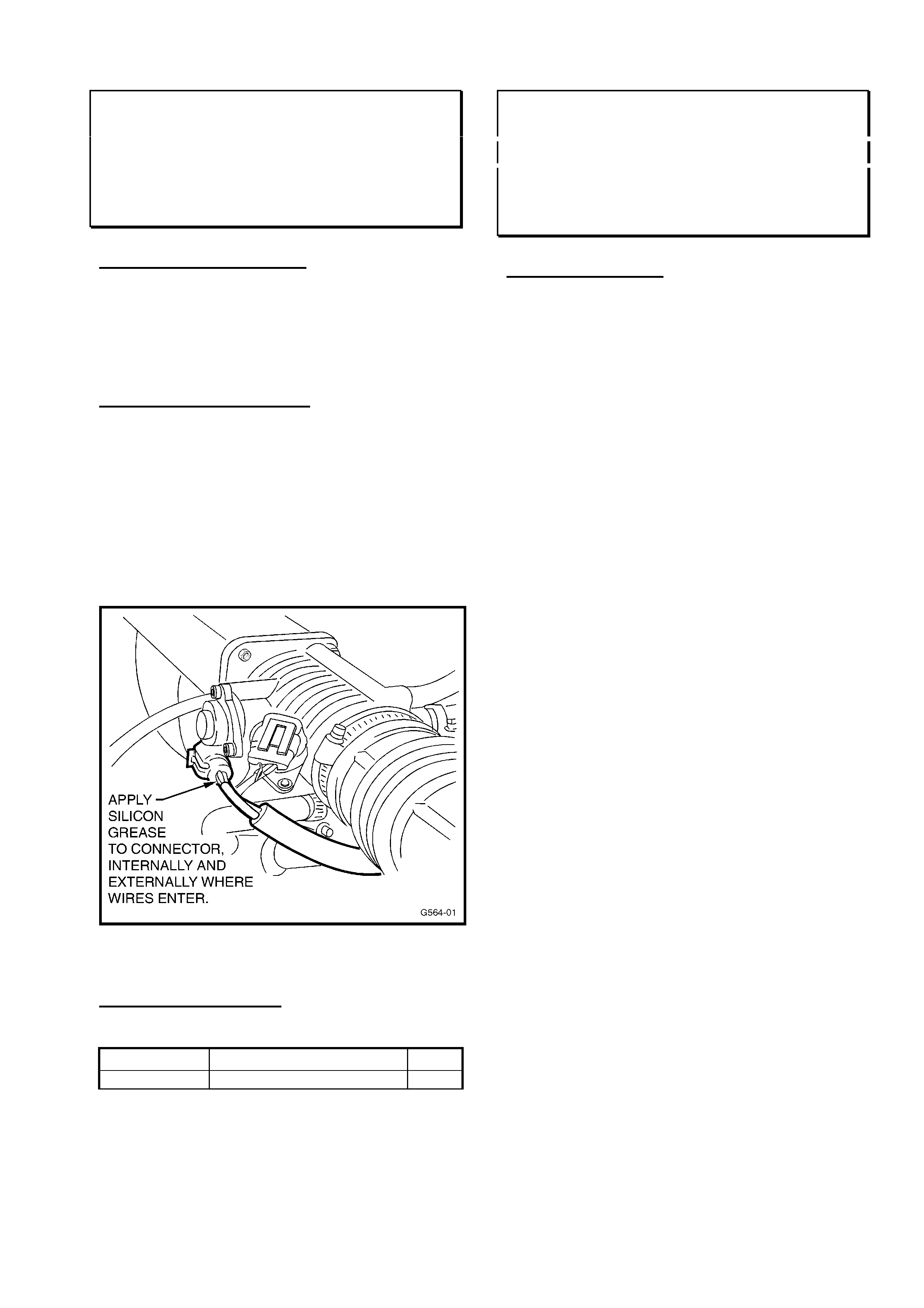
HOLDEN SERVICE TECHLINE___________________________________________________________OCTOBER, 2001
10
THROTTLE POSITION SENSOR –
WATER ENTRY
SB with C14SE engine
(GROUP 6C) TL0110-6C02
PROBLEM DESCRIPTION
Analysis of failed Throttle Position Sensors
from SB Barinas shows that water has been
entering the electrical connector and migrating
to the sensor assembly causing it to fail.
SERVICE RECTIFICATION
Whenever removing the Throttle Position
Sensor connector for any reason, liberally
apply silicon grease (part number M40347) to:
1. the internals of the electrical connector.
and
2. the outside of the connector where the
wires enter the connector. Refer Figure 1 for
location.
Figure 1
PARTS INFORMATION
The silicon grease is available from HSPO.
Part No.: Description: Qty:
M40347 Grease Silicon 1
WATER ENTRY INTO ELECTRICAL
CONNECTORS IN ENGINE BAYS
ALL
(GROUP OB) TL0110-OB01
SERVICE CAUTION
On some VT, VX and WH models, dealers
have submitted PIRs describing customer
complaints of various warning lights
illuminated on the dash.
Dealer investigation has found water entry into
the electrical connector on the ABS
modulator.
Further investigation has found the cause of
water entry to be steam cleaning of engine
bays by dealers during pre-delivery or
servicing.
As far as practicable, avoid unnecessary
steam cleaning or high pressure washing of
the engine bay of ANY Holden vehicle.
Vehicle engine bays contain many electrical
modules and connectors. These are
designed to protect electrical circuits from
water entry under normal driving conditions (ie
“splash” from the road), but not water from
high pressure and high temperature washing
equipment.
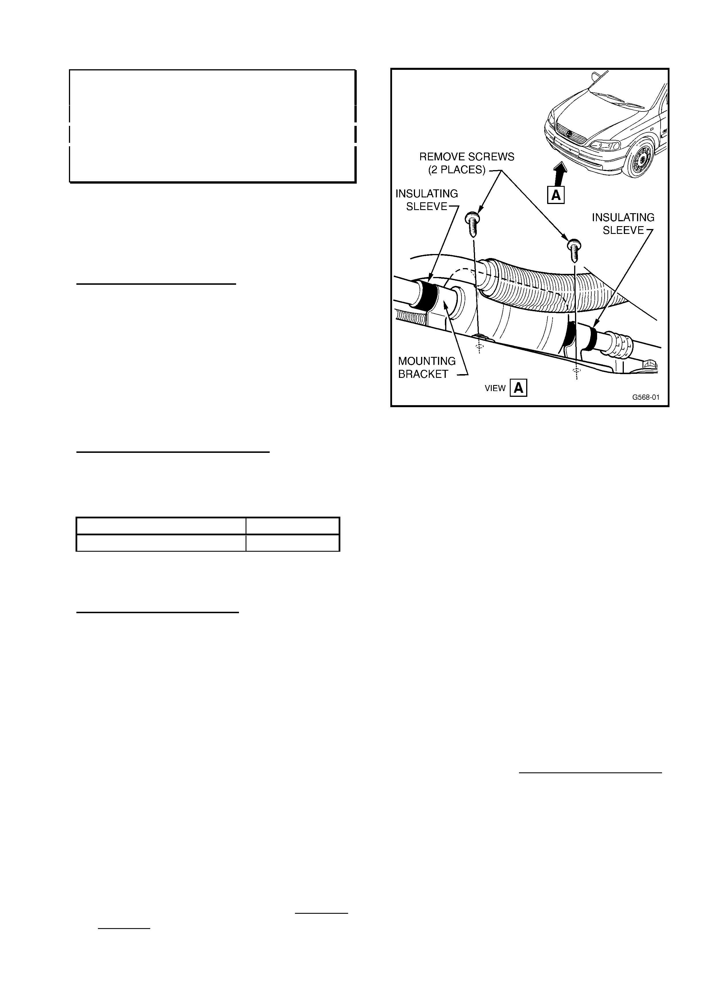
HOLDEN SERVICE TECHLINE___________________________________________________________OCTOBER, 2001
11
RADIATOR DAMAGED BY A/C
DISCHARGE PIPE MUFFLER
TS with X18XE1 engine & A/C
(GROUP 2) REISSUED TL0110-0201
This Techline supersedes the previous Techline on
this subject (Issue 3, March 2001, page 10) which
should be discarded. It is revised by adding cable
ties to prevent the muffler dislodging from bracket.
PROBLEM DESCRIPTION
On some vehicles the A/C Discharge Muffler
may come into contact with the radiator if the
insulation sleeves on the A/C Discharge
Muffler pipe fail or the sleeves dislodge. This
condition has the potential to cause radiator
leaks by abrasion of the radiator core.
This problem only effects TS models built
prior to MY01.
PRODUCTION RECTIFICATION
The A/C discharge pipe muffler has been
removed from Model Year 01 vehicles
commencing from:
ISOVIN: Build Date:
W0L0TGF4815000001 15/08/2000
SERVICE RECTIFICATION
Whenever a pre - MY01 TS model Astra is
presented to dealerships for service work of
any type the following inspection and
procedure should be performed. (This is
shown in flowchart form on the next page.)
1. Raise the vehicle on a hoist.
2. Inspect radiator for signs of abrasion from
the A/C Discharge Muffler Assembly. If
the radiator core is damaged, the radiator
should be replaced. If only fin damage is
observed, do not replace radiator for this.
3. Remove the two Torx head screws that
retain the A/C Discharge Muffler Assembly
to it’s mounting brackets. TAKE CARE! –
the muffler is close to the exhaust
manifold, which may be hot. Refer to
Figure 1.
Figure 1.
4. Twist the muffler so it is located between
the subframe and the exhaust manifold.
5. Remove the muffler from it’s mounting
bracket. NOTE: Do NOT bend the
retaining clips or they will not firmly retain
the muffler when it is refitted!
6. Inspect A/C pipe insulation sleeves. – If the
insulation sleeve/s are damaged or
missing, fit new sleeve/s – using P/N
09131825 Damper Strip (which provides
enough material to make two sleeves).
7. Apply tape (from approved tapes list) to
both insulation sleeves on each end of the
muffler body. The tape should be wound
around the pipe and insulation sleeve,
attaching first to the pipe from the end of
the sleeve, then fully covering the
insulation sleeve and ending on the
muffler body. Refer to Figure 2.
Return the muffler to its original position
and clip the mounting bracket back onto
the muffler.
8. Attach 2 cable ties p/n 92138154, one each
side of the muffler, as shown in figure 3.
Ensure the cable ties are firmly in place
around the clip.
9. Reattach the muffler mounting bracket
using the previously removed Torx head
screws.
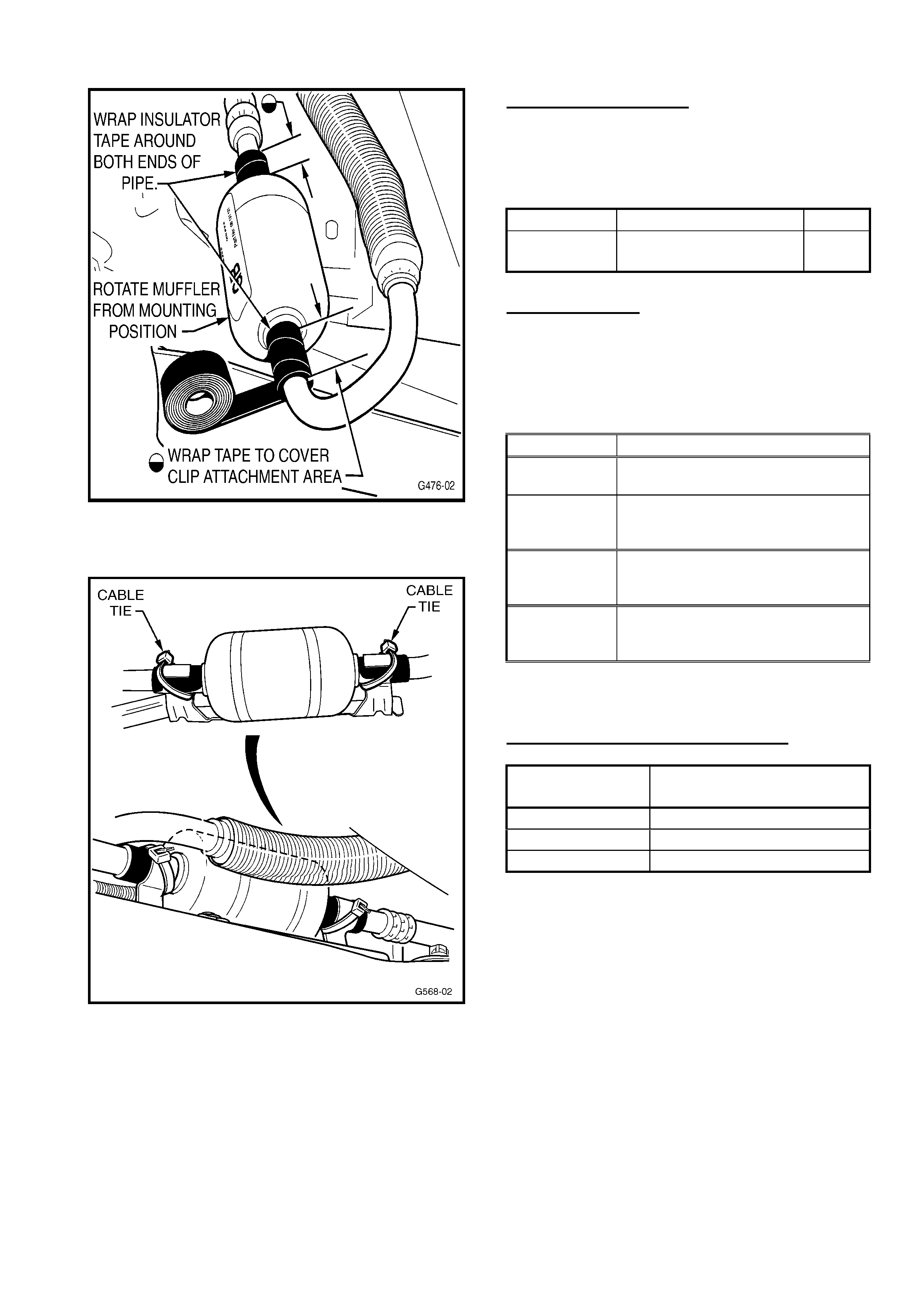
HOLDEN SERVICE TECHLINE___________________________________________________________OCTOBER, 2001
12
Figure 2.
Figure 3
PARTS INFORMATION
Use the following part if the sleeve/s are
severely damaged or have dislodged from the
muffler pipe/s or dislodged:
Part No.: Description: Qty:
09131825 Damper Strip, A/C Pipe 1
92138154 Cable tie 2
Approved Tapes
For the above procedure, ONLY tape
conforming to Holden Specification HN 1230
(specific thickness, heat resistance, cloth
based) must be used. Tapes that meet this
specification are shown in following table.
Supplier Description/Size
Cling
Adhesives
Cloth Tape - Cling C25, or Part
No. RB46, 48mm x 20Meters.
Available
from:
Bunnings Store
Bursons
Dick Smith Stores
3M
3M Y389 Cloth Tape, Silver or
Black (also known as “Gaffer
Tape”) 50mm x 50Meters,
Available
from:
Bunnings Stores
Blackwoods
A. E. Baker
WARRANTY CLAIM INFORMATION
Description Re-Attach A/C Discharge
Muffler Insulation
Labour Op. No. D000227
Time 0.4 hr
Failure Code 27
If replacing damaged radiator use existing
Labour Times information in Warranty
Information section of current SIP CD

HOLDEN SERVICE TECHLINE___________________________________________________________OCTOBER, 2001
13
HEATER CORE & RADIATOR
FAILURES CAUSED BY LACK OF
COOLING SYSTEM SERVICE
V & W MODELS
(GROUP 2) TL0110-0202
PROBLEM DESCRIPTION
There have been several cases recently
brought to our attention where radiator and
heater core failures (due to corrosion) have
occurred because of poor maintenance of the
coolant and cooling system.
In some cases there have been repeat
failures of radiators or heater cores soon after
replacement.
The main causes for corrosion failure of
radiators and heater cores are:
1. System filled with coolant not meeting
Holden specifications for the model.
2. System contaminated by mixing coolant of
different types.
3. Coolant diluted by topping up with water.
4. Repeat failures result from not thoroughly
flushing out system prior to fitment of a
new radiator or heater core.
SERVICE RECTIFICATION
To reduce the risk of corrosion failures of
radiators and heater cores we strongly
recommend the following points be observed:
1. Only fill the cooling system with coolant
meeting Holden specifications for the
model.
2. Never mix coolants of different types.
3. Only top-up with premixed coolant
(50%water + 50%coolant).
4. Conduct regular cooling system service as
per maintenance schedule in owners
handbook.
5. Always thoroughly flush out cooling system
prior to fitment of a new radiator or heater
core. For information on cooling system
flushing procedures refer to Holden SIP CD
under section on Cooling System
Maintenance for the specific engine type.
(V6, V6 s/c, 5.0l V8 or Gen3)
BRAKE SQUEAL RECTIFICATION
TS – Non-ABS models only
(GROUP 5) TL0110-0501
PROBLEM DESCRIPTION
Some non-ABS equipped TS Astra vehicles
may exhibit a squeal noise under braking.
New front brake pads have been released to
address this squeal.
The new pads have the leading and trailing
edges of the friction material chamfered to
move the squeal frequency outside the
audible range.
PRODUCTION RECTIFICATION
The revised brake pads are due to be fitted
sometime during Model Year 2002. When
this happens, details will be added to the
Service Techline Breakpoint Summary.
SERVICE RECTIFICATION
To address customer complaints, fit the
revised brake pads. These brake pads are
available from HSPO.
PARTS INFORMATION
Part No.: Description: Qty:
93171035 Pad Set-Front Brake 1
WARRANTY CLAIM INFORMATION
Use existing Labour Times information in
Warranty Information section of the current
SIP CD.
Update

HOLDEN SERVICE TECHLINE___________________________________________________________OCTOBER, 2001
14
CRANK ANGLE SENSOR
INSTALLATION PRECAUTION
JS 4 Cyl.
(GROUP 6C) TL0110-6C04
A Service Techline published in Issue 2,
March 2000, page 5, advised of the
introduction of a revised crank angle
sensor (09174621) into engine production.
That production breakpoint is repeated as
follows:
CRANK ANGLE SENSOR 09174621
PRODUCTION BREAKPOINT
Revised crank angle sensors p/n 09174621
with increased harness length have been
fitted to engines from:
ENGINE NO. Build Date:
C22SEL25014889 Jan 2000
The length of wiring on crank angle sensor
p/n 09174621 has been increased over that
on the superseded sensor p/n 90506103. The
reason for this increase in length is to improve
allowance for engine movement whilst
retaining the original harness routing.
Therefore, whenever installing a new sensor
DO NOT route or retain the harness any
differently to the original harness. Failure to
comply with this may result in stress to the
harness and the internal connections of the
sensor - resulting in a repeat failure, or an
intermittent connection problem that would be
difficult to diagnose.
INLET MANIFOLD GASKET LEAKS
(CRACKING)
ALL ISUZU V6 ENGINES
(GROUP 6A) TL0110-0601
PROBLEM DESCRIPTION
Customers may report that the engine runs
rough or makes a “hissing sound”.
The inlet manifold to head gasket may be
cracked due to stresses caused by heat
expansion and contraction.
PRODUCTION RECTIFICATION
A revised inlet manifold has been introduced
in production from the following breakpoint.
ENGINE No.
845194
SERVICE RECTIFICATION
Replace the inlet manifold gasket as per the
appropriate workshop manual.
Note: There is no need to separate the inlet
manifold into two halves unless the common
chamber gasket is suspected to be leaking.
Please PIR any post breakpoint failures on all
vehicle models fitted with this engine.
Indicate if the vehicle is fitted with an
approved LPG system (LPG Rodeo only).
PARTS INFORMATION
Part No.: Description: Qty:
8972375380 Gasket – Inlet
Manifold to
Cylinder Head
2
WARRANTY CLAIM INFORMATION
Description Gasket, Intake - Replace
Labour Op. No. J020700
Time 1.8 hr
Failure Code 42
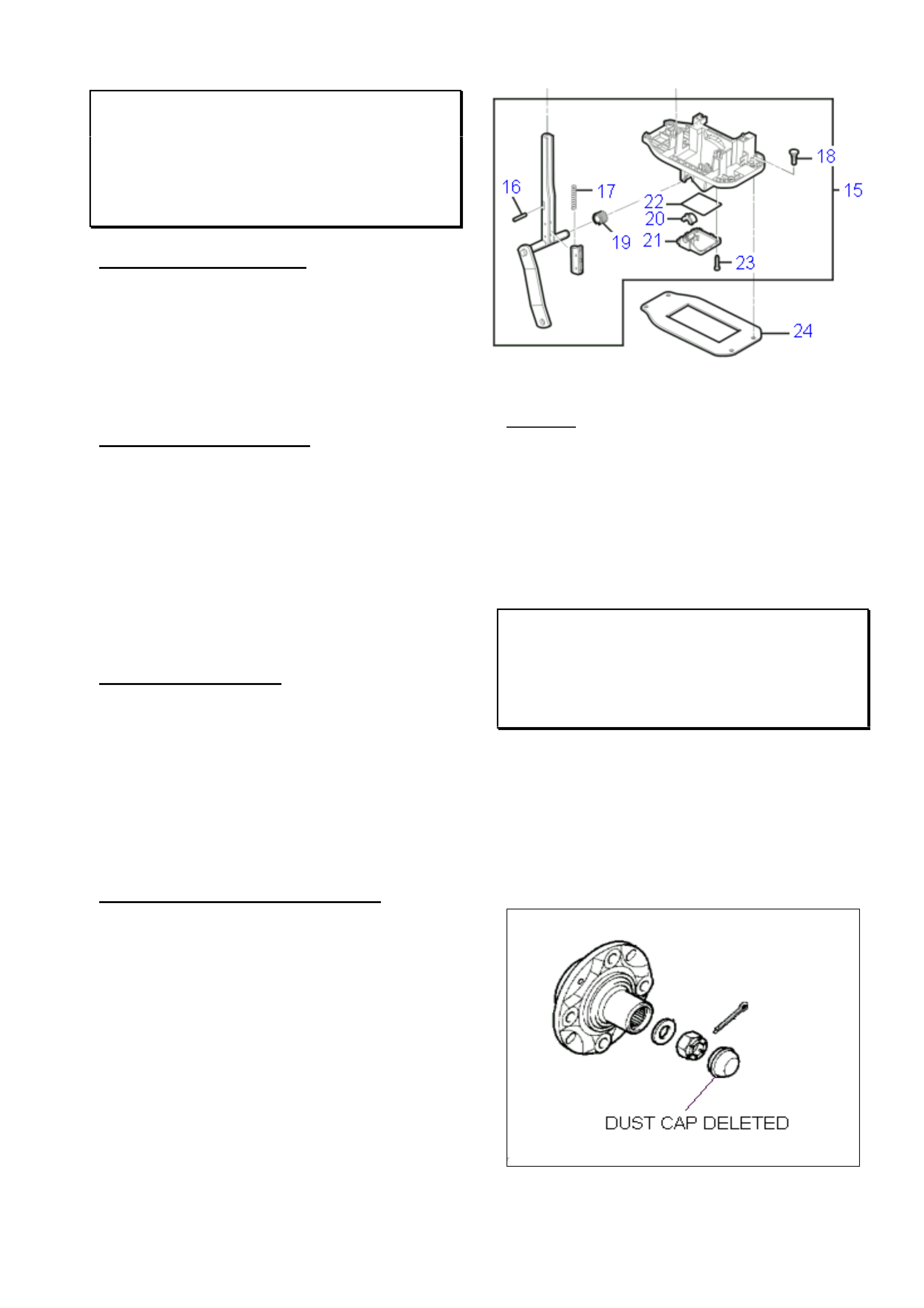
HOLDEN SERVICE TECHLINE___________________________________________________________OCTOBER, 2001
15
A/T SHIFTER ASSEMBLY –
UNNECESSARY REPLACEMENT
VT, VX, VU, WH
(GROUP 7B) TL0110-7B01
PROBLEM DESCRIPTION
Investigations into returned parts at Repac
show that A/T Shift Control Bases are being
replaced for only minor component damage –
which can be repaired by replacement of
these components within the shift control base
assembly.
SERVICE RECTIFICATION
Where a damaged component is found within
the A/T Shift Control Base Assembly –
replace the damaged part ONLY – do NOT
replace the complete assembly. Figure 1
(extract from Partfinder,VX) shows those
minor components that are available as spare
parts.
PARTS INFORMATION
It is suggested that your Parts Department
retain a small stock of the individual
components within the A/T Shift Control Base,
as shown in Figure 1 for those situations
where only a minor component requires
replacement. Refer to PartFinder for part
numbers.
WARRANTY CLAIM INFORMATION
REPAC will continue to monitor returned A/T
Shift Control Bases to determine the reason
for replacement, and in future, REPAC will not
accept warranty claims where a complete
base is replaced when only a minor internal
component requires replacement.
Figure 1.
Key Nos.
15- Base assembly –A/T shift control
16- Pin,handle 17- spring-button
18- attaching stud 19- split bush
20 Bush 21- Cap lower base
22- Seal O ring 23- Screw cap retainer
24- Seal
FRONT HUB DUST CAPS DELETED
XC MODEL YEAR 2002
(GROUP 03) TL0110-0301
The front wheel hub dust caps p/n 90539001
are no longer fitted to XC Barinas. This
change applies to all vehicles built from the
middle of July 2001.
NOTE: Vehicles built without these caps are
not to have them fitted.
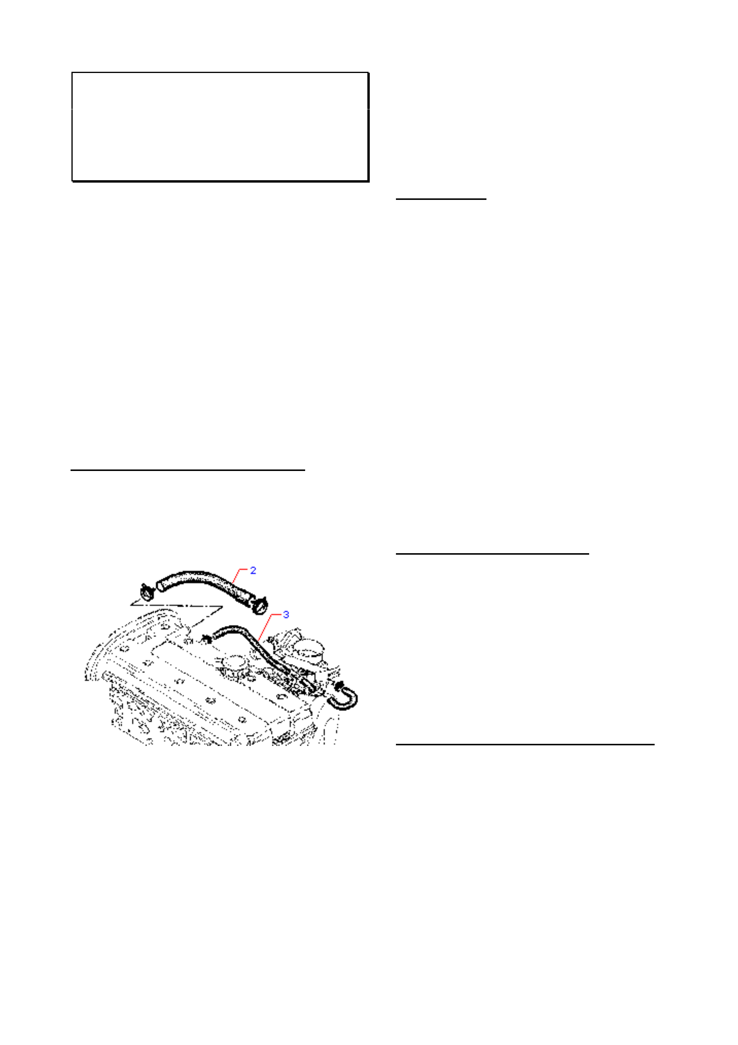
HOLDEN SERVICE TECHLINE___________________________________________________________OCTOBER, 2001
16
ENGINE STALL DIAGNOSIS
NON - IACV RELATED CAUSES
JR, JS, C20SEL, C22SEL
(GROUP 6C) TL0110-6C01
When diagnosing engine stall complaints on
the above models the following potential
causes of stall must be investigated prior to
focussing on the IACV.
• Secondary PCV hose (damaged)
• MAF sensor (electrical problems)
• Relays. (poor engagement)
• Crankshaft or camshaft sensor. (pre
breakpoint parts)
NOTE: As a general rule, any stall that occurs
above 4km/h is not IACV related, and requires
diagnosis to ensure a cause is found and
corrected.
DAMAGED SECONDARY PCV HOSE
Stalling may be caused if the secondary PCV
hose (Item 2 shown in the diagram below) is
split or torn, or the inner hose walls deteriorate:
Damage (split or torn): allows air to by-
pass the mass airflow sensor, leading to
incorrect airflow readings which affect the
engine fuel ratio (runs lean). A DTC P0100
may be set.
Deterioration of hose inner walls: allows
particles of the deteriorated hose material
to separate from the hose, and these may
become lodged in the ‘early design’ or “old”
IACV leading to a stall. This will not occur
with the ‘later design’ or “new” IACV –
however, the hose should be examined and
replaced where necessary.
NOTE: Kinking, or clamping any other
components to the secondary PCV hose is
NOT permitted.
MAF SENSOR
Stalling associated with the MAF Sensor can
occur either while vehicle is moving or
stationary. Usually a DTC P0100 is set. (this
DTC may also be set by a fluctuating idle, so
correct diagnosis of type of stall is required).
Some findings on failed MAF Sensors have
been:
♦ Fretting corrosion of the MAF Sensor
terminals. (Replace suspect terminals.)
♦ Connectors not fully or correctly installed.
(Check connections and re-install if required.)
♦ Incorrect routing or attachment of sensor
wiring. (Check wiring against a known OK
vehicle to ensure the wiring is not run in an
incorrect routing, so it does not pick up any
‘stray’ electrical signals from other wiring or
components.)
RELAY INCORRECT FITMENT
If the “Fuel pump” or “injection valves” relays
are not properly fitted – with their terminals fully
engaged in the mating connector/wiring, a stall
may be caused. Check relays for full and
proper connection, re-install if required. Some
relays are a very tight fit and may not have
been fully seated on fitting or subsequent
replacement.
CRANKSHAFT OR CAMSHAFT SENSOR
Refer to Techline bulletins of February and
March, 2000 relating to these sensors –
available on your SIP CD. Replace pre-
breakpoint parts.
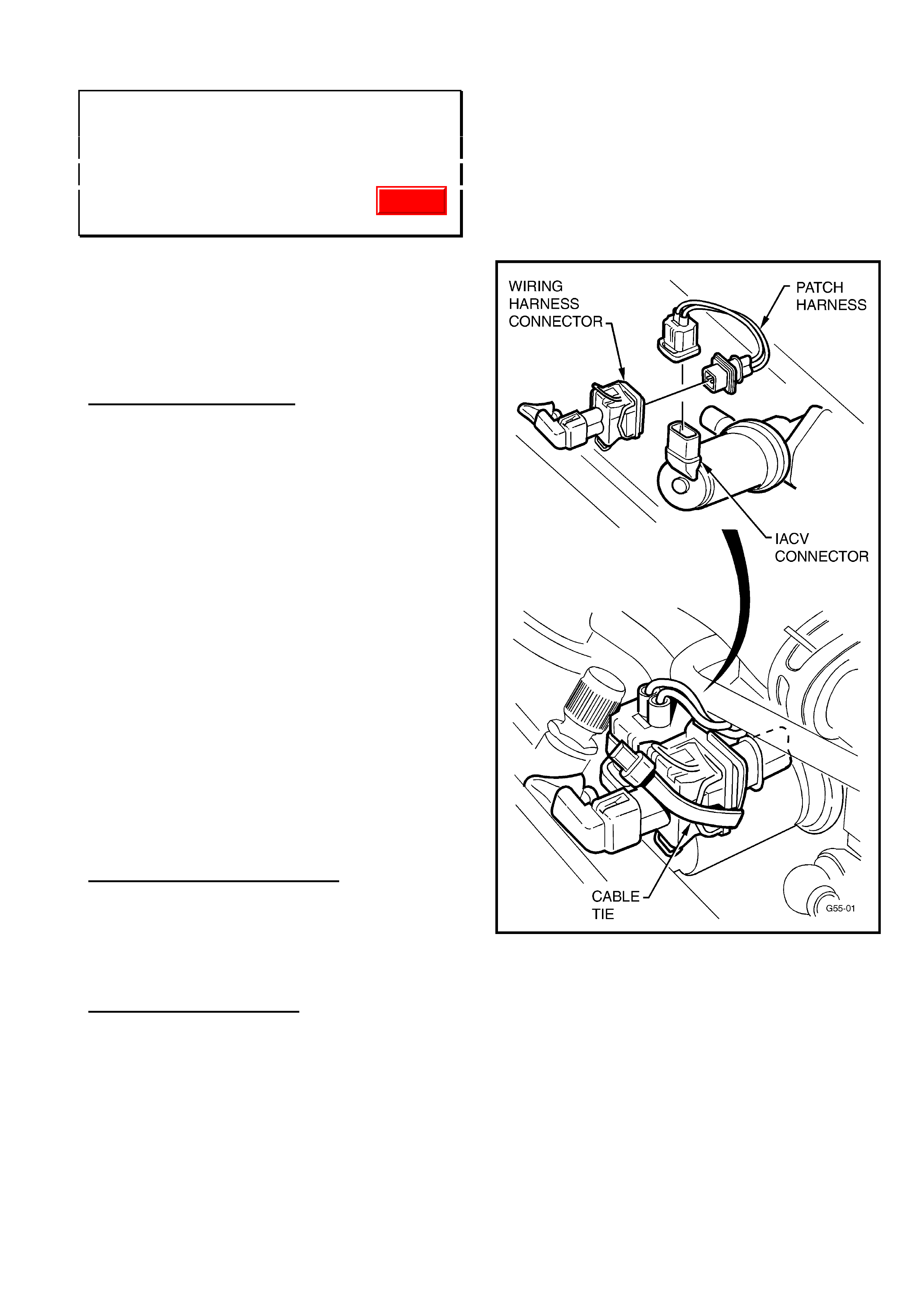
HOLDEN SERVICE TECHLINE___________________________________________________________OCTOBER, 2001
17
ENGINE STALL AT IDLE OR HIGH
ENGINE IDLE SPEED
JR, JS, C20SEL, C22SEL
(GROUP 6C) TL0110-6C02
This Techline supersedes the Draft copy sent
out with All Dealer Letter 69/01. It includes a
revised method for checking and resetting Base
Idle (by IACV step method) and a table showing
Old & New ECU calibration numbers for
reference.
PROBLEM DESCRIPTION
Some owners may complain of the
following symptoms:
With vehicle speed less than 3km/hr or vehicle
stationary, the engine idle is too high; e.g. 1000
RPM+, and engine may later stall or the idle
may remain high.
This is caused by a build-up of engine by-pass
gases and IACV solenoid shaft/bearing wear
particles on the IACV solenoid shaft, which
causes the IACV to stick at any point in its
operating range. This will result in either too
high or too low IACV air entry to the throttle
body and engine.
When the IACV subsequently “unsticks”
and returns to normal operation, the result
may be a stall or higher than normal idle
RPM. It is not possible to effectively clean
the IACV to correct this condition.
PRODUCTION RECTIFICATION
Revised Idle Air Control Valves (IACV’s) have
been fitted to all vehicles despatched from Port
Of Entry facilities commencing 24th Sep. 2001.
SERVICE RECTIFICATION
On vehicles with the above symptoms perform
diagnosis to determine if the IACV is in fact the
cause of the problem. Refer to previous
Techline item in this issue titled “Engine Stall
Diagnosis - Non IACV related causes”. After
confirming that nothing else is causing the stall,
proceed to fit the latest “diaphragm type” IACV
using the following procedure.
1. Remove old IACV and install new
diaphragm type IACV and gasket as per
procedures shown in TIS CD.
2. Fit the patch harness (refer Figure 1) – this
is an interface patch harness to connect the
existing vehicle wiring harness to the new
IACV.
Figure 1.
3. Use a tie strap to firmly bind the wiring
harness connector to the IACV connector
as shown in Figure 1. Cut off any excess
strap.
4. Use TIS 2000 CD version 23 or later (and
Tech 2 Software Version 10.300 or later), to
flash program the “New IACV” calibration
into the vehicle via TIS Service
Programming System (SPS).
Refer to Flash Programming Details and
Calibration Part Numbers below.
Update
HOLDEN SERVICE TECHLINE___________________________________________________________OCTOBER, 2001
18
Flash programming Details:
Select the vehicle parameters that apply to
the vehicle being programmed.
For example: Holden; VECTRA-B; 2000;
C22SEL Engine,
THEN, for “Type of Idle Air Control Valve”
select “New IACV (PN.: 92 065 903)”,
THEN, select the “Type of Transmission”.
When type of Trans. is selected, if you are
prompted for either “Short Y” or “Long Y”
types of exhaust system:
“Short Y” exhaust front engine pipe has a “Y”
(2 into 1) joint directly below the front of the
engine block; “Long Y” exhausts have the Y
joint further rearward approximately in line
with the sump plug.
NOTE. “Short Y” is used with F18 M/T.
“Long Y” is used with later F23 M/T
introduced in JSII from L482379 22/7/99.
Model Old
Calibration No.
New
Calibration No.
JR & JS C20SEL 90569364.**** 92066071.2657
JS 1, C22SEL
(Short Y front
pipe)
92059405.**** 92066073.2658
JS 2, C22SEL
(Long Y front
pipe)
92085493.2659 92066074.2660
After reprogramming is completed proceed as
follows.
5. CHECK FOR AND REMOVE
PREVIOUSLY SET BASE IDLE AS PER
FOLLOWING STEPS (a) to (d).
Failure to remove any previously set base
idle could affect the operating
characteristics of the new IACV.
(a). With Tech 2 connected select the Data
Display screen, start the vehicle and allow it
to come to operating temperature (greater
than 70 deg C coolant and inlet air temp
between 20 - 30 deg C) with moderate to
high underbonnet temperatures)
(b). With A/C OFF check "IACV steps" at
idle. If "IACV steps" is less than 20 a base
idle was previously applied. If greater than
20 steps no adjustment is required.
(c). Loosen the idle screw and decrease
the Throttle Position until the IACV steps
are above 20-25 steps with the A/C OFF.
(d). Re-tighten idle screw and conduct a
final check of the IACV steps.
6. Apply a Service History Label (SD-28177)
to the back of the fuse panel cover (lower
left corner) and mark the A-3 co-ordinate on
the label.
PARTS INFORMATION
Obtain following IACV kit from HSPO.
Part No.: Description: Qty:
92066066 IACV Kit 1
Following is a list of individual parts in the kit.
92065903 Diaphragm type IACV.
09240103 Gasket
92065904 Patch harness
92138154 Cable tie
WARRANTY CLAIM INFORMATION
Use the following information to claim for the
installation of the new IACV and flash
programming the ECU.
Description Replace IACV
Labour Op. No. J000686
Time 0.6 hr
Failure Code 84
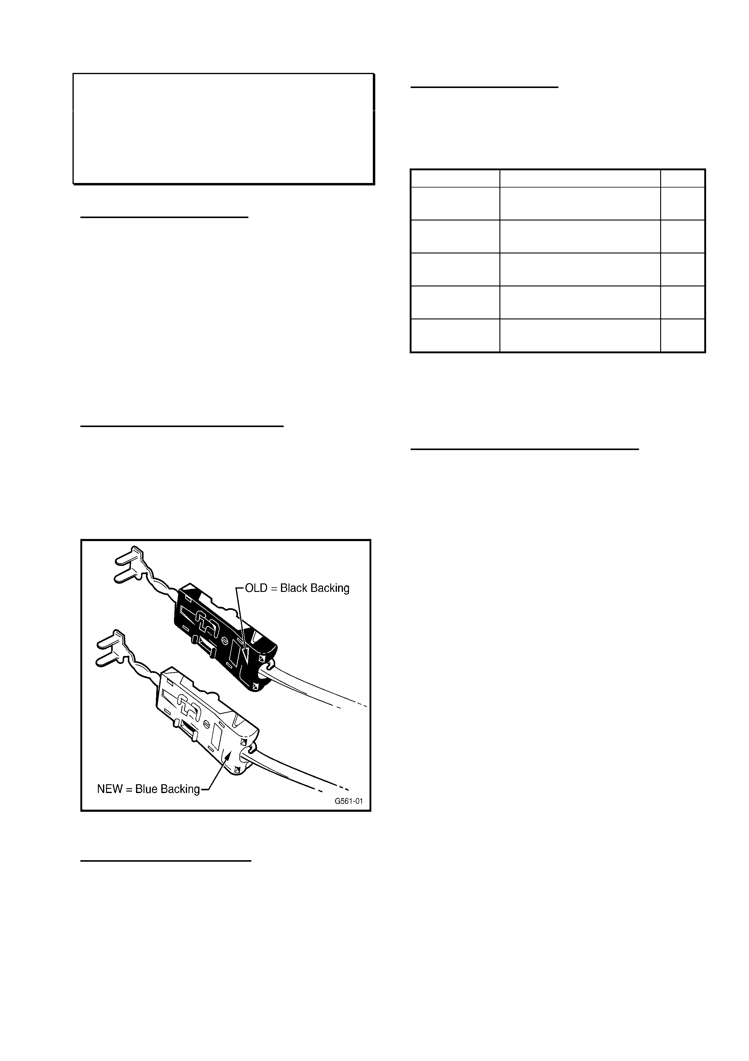
HOLDEN SERVICE TECHLINE___________________________________________________________OCTOBER, 2001
19
AIRBAG WARNING LIGHT
ILLUMINATED - DTC 31
SB, TS & JR/JS
(GROUP 12) TL0110-1201
PROBLEM DESCRIPTION
In some vehicles the airbag warning light may
illuminate and on checking with Tech 2, the
DTC 31 (Drivers Airbag Squib Circuit High
resistance) is found to be present. This
condition usually occurs intermittently.
Investigations of this condition highlighted the
need for improvements to the crimping of
wires within the clockspring harness
connector.
PRODUCTION RECTIFICATION
Clockspring harness connectors with crimping
modifications were introduced into vehicle
production progressively from November
1999. Modified connectors are identified by
their blue backing as shown in Figure 1.
SERVICE RECTIFICATION
The first step in diagnosing the above
condition should be to remove the drivers
airbag and inspect the clockspring harness
connector. If the connector has a “black”
backing the clockspring should be replaced
with a new clockspring from HSPO with the
modified connector (Blue backing).
PARTS INFORMATION
Part numbers of clocksprings were not
changed with introduction of blue backed
connectors.
Part No. Description Qty.
09179297 SB
Contact Unit - Air bag
1
90535552 SB 3 spoke wheel
Contact Unit – Air bag
1
90588757 TS
Contact Unit - Air bag
1
09152055 JR/JS (GL)
Contact Unit - Air bag
1
09152056 JR/JS (CD)
Contact Unit - Air bag
1
All HSPO stocks of above parts have been
verified to have connectors with blue backing.
WARRANTY CLAIM INFORMATION
If replacing clocksprings use existing Labour
Times information in Warranty Information
section of current SIP CD.

HOLDEN SERVICE TECHLINE___________________________________________________________OCTOBER, 2001
20
STEERING GEAR INNER TIE ROD
CLUNK NOISE
VT, VX, WH
(GROUP 9) “REISSUED” TL0110-0901
This Service Techline supersedes the previous
Techline on this subject (refer Issue 4, April 2001)
which should be discarded. Breakpoint details for
rack 92057321 have been added.
PROBLEM DESCRIPTION
Under high temperatures or after long drives,
a clunk/knock may be felt through the steering
wheel on turns, or sufficient body movement
occurs. On examination of the rack, the knock
can be heard/felt coming from the inner tie rod
end.
PRODUCTION RECTIFICATION
An improved inner ball joint with new high-
temperature grease and revised cap material
have been fitted to steering racks in vehicles
from:
ISOVIN: Build Date:
6H8VXL69A1L683674 22/01/01
SERVICE RECTIFICATION
Where diagnosis confirms this complaint, fit a
new steering rack ensuring the rack serial
number is higher than those shown in the
table in Parts Information as follows.
PARTS INFORMATION / BREAKPOINTS
The following information is provided for
dealers to confirm that replacement steering
racks are post-breakpoint parts. Racks with
serial numbers prior to those shown in the
table should be returned to HSPO.
Standard Power Steering (Option N40)
Part No.: Breakpoint Serial No.: Qty:
92057321
up to L492504
12/08/99
K20214
1
92092815
from L492505
12/08/99
N137524
1
Variable Effort Power Steering (Option NV7)
Part No.: Breakpoint Serial No.: Qty:
92092816 P017429 1
WARRANTY CLAIM INFORMATION
Use existing Labour Times information in
Warranty Information section of the current
SIP CD.
DRIVELINE NOISE & VIBRATION
REPORT FORM
VT,VX,VU,WH
(GROUP OB) REISSUED TL0110-OB02
In the previous issue of Service Techlines
(9/2001) we introduced a special form for
reporting of driveline noises/vibrations.
A number of dealers have already used this
form to report problems to Holden. These
reports are essential in helping define
problems that customers are experiencing in
the field.
A slight modification has been made to the
form to allow you to comment on the action
you have taken while trying to resolve the
customer's complaint. Revised forms are
attached to the rear of this document for you
to make copies of.
We encourage you to continue using this
report when you are faced with a driveline
noise or vibration issue. Please complete the
form with as much information you can and
fax it to EDAG Future as you would for a
normal PIR.
Update

HOLDEN SERVICE TECHLINE________________________________________________________NOVEMBER, 2001
8
AMBIENT TEMPERATURE SENSOR
MALFUNCTION – WATER ENTRY
VT, VX, WH
(GROUP 2) TL0111-0201
This Service Techline supersedes the previous
Techline on this topic (Issue 5, July, 1999)
which should be destroyed.
PROBLEM DESCRIPTION
The output temperature of the HVAC unit and
the resulting cabin temperature does not
represent the temperature selected via the
ECC control.
This condition may be caused by water entry
into the ambient temperature sensor located
in front of the a/c condenser. The water short
circuits the sensor (low resistance) causing
the HVAC unit to believe the outside
temperature is high causing relative (cool)
heater performance.
PRODUCTION RECTIFICATION
Improved waterproofing/shielding of the sensor,
connector and harness, has been fitted to
vehicles from:
ISOVIN: Build Date:
6H8VXX69A1L674976 15/12/00
SERVICE RECTIFICATION
Summary: Install a revised design ambient
temp. sensor connector with improved
waterproofing. Also install a new ambient
temp. sensor.
Procedure:
1. Place vehicle on hoist and raise to
shoulder level
2. Remove Ambient Air Temp. Sensor from
bracket. Refer Figure 2.
3. Cut harness 100 mm from end of Ambient
Temp. Sensor connector on vehicle
harness and discard. Refer Figure 3.
4. Remove 40 mm of PVC tube from vehicle
harness.
5. Cut 10 mm off green wire on vehicle
harness. (Figure 3)
6. Strip 10 mm off both black and green
wires on vehicle harness. (Figure 3)
7. Obtain white heatshrink tubing from kit
and pre-fit to black wire on vehicle harness.
This heatshrink tubing will need to be slid
up under the vehicle harness PVC tubing.
(Figure 4).
8. Obtain large black heatshrink tubing from
kit and pre-fit to Ambient Temp. Sensor
Connector sub assembly. (Figure 4).
9. Obtain white heatshrink tubing from kit
and pre-fit to green wire on Ambient Temp.
Sensor Connector sub assembly side.
10. Now join corresponding wires of same
colour by neatly twisting exposed copper on
both wires. For a standard twist joint refer
to VR Service Manual Volume 8 page 12P-
12.
11. Solder each twist joint. (the copper ends
should not be left protruding away from the
solder).
12. Slide both white heatshrink tubes so they
cover the exposed copper on both wires.
(Figure 5).
13. Use heat-gun to shrink both white tubes
taking care not to apply heat to the large
black heatshrink tubing at this stage.
14. Slide large black heatshrink tubing over
both wires. The heatshrink tubing should
cover both ends of the PVC tube. Refer
Figure 6.
15. Use heat-gun and shrink the tube
completely.
16. Fit new Ambient Temp. Sensor to harness
connector and refit to bracket.
17. Lower vehicle and check outside
temperature function operates correctly.
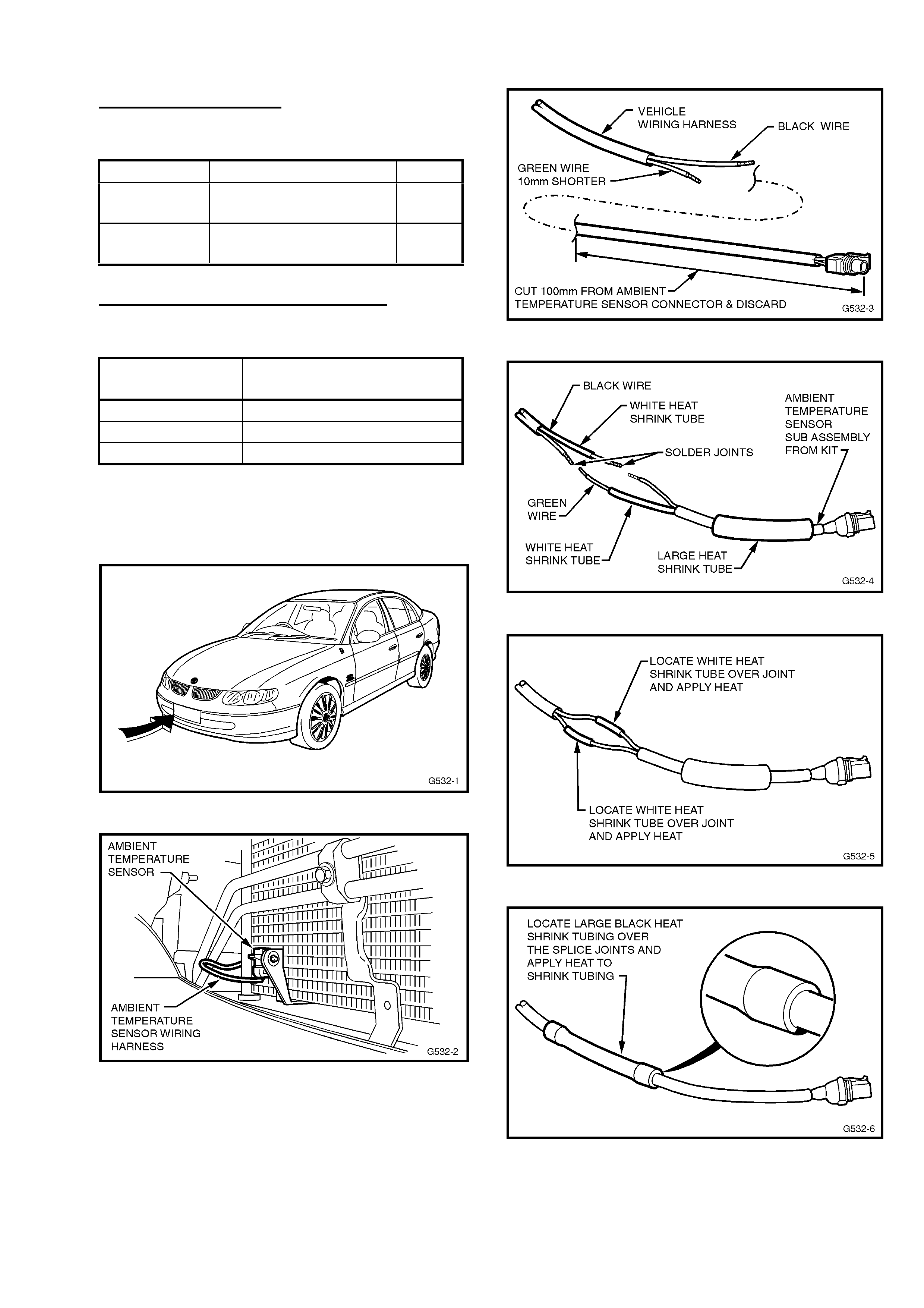
HOLDEN SERVICE TECHLINE________________________________________________________NOVEMBER, 2001
9
PARTS INFORMATION
Obtain the following parts from HSPO.
Part No.: Description: Qty:
92144967 Kit, Ambient Temp.
Sensor Repair
1
09152245 Sensor Asm. –
Ambient Temp.
1
WARRANTY CLAIM INFORMATION:
For warranty claims use following.
Description Replace Ambient Temp
Sensor Connector
Labour Op. No. N000360
Time 0.5 hr
Failure Code 51
Figure 1.
Figure 2.
Figure 3.
Figure 4.
Figure 5.
Figure 6.
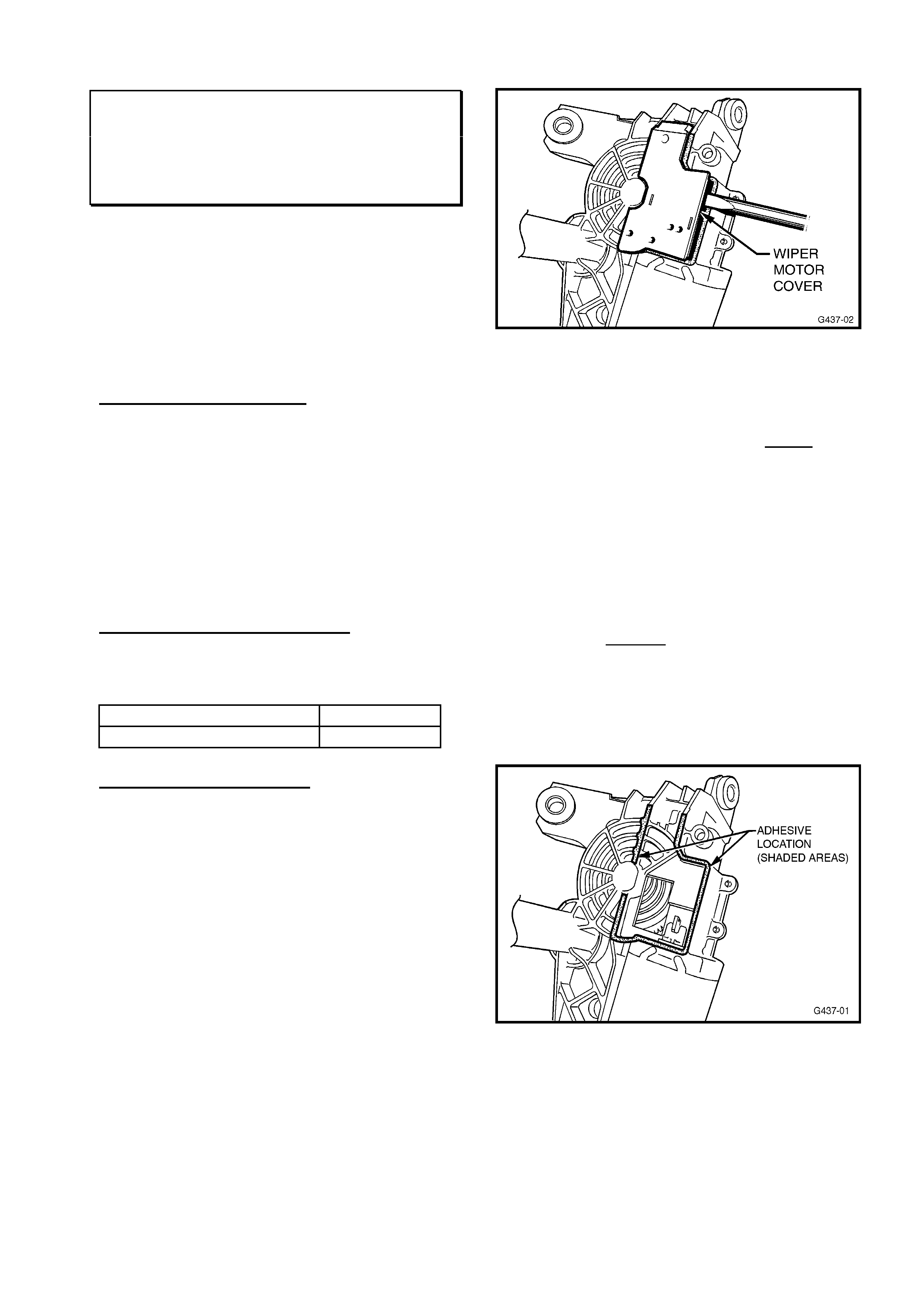
HOLDEN SERVICE TECHLINE________________________________________________________NOVEMBER, 2001
10
REAR WIPER INOPERATIVE
TS (Hatch)
(GROUP 12) REISSUED TL0111-1201
This Techline is reissued for the purpose of
highlighting to dealers that this service fix
must be applied in preference to replacing the
wiper motor assembly. REPAC will monitor
returned parts and in future, will not accept
warranty claims where it is obvious that this
service fix has not been applied.
PROBLEM DESCRIPTION
Rear wiper may fail to operate when the wiper
switch is operated, or may stop during
operation for no apparent reason.
The cause has been defined as poor adhesive
bonding of the wiper motor cover (carrying the
electrical contacts) to the wiper motor
housing.
No damage is suffered to the contacts or
motor assembly, and it can be reassembled.
PRODUCTION RECTIFICATION
Rear wiper motors, with improved adhesive
bonding, were introduced from:
ISOVIN: Build Date:
W0L0TGF4815059976 18/10/00
SERVICE RECTIFICATION
To rectify cases of “wiper inoperative” where
no electrical wiring fault is found, the wiper
motor can be removed and the motor cover
can be re-adhered to the wiper motor body as
follows:
1. Remove wiper motor assembly from
tailgate as per TIS 2000 instructions in TS
Astra Electrical Equipment and
Instruments, section: “Rear Screen Wiper
Motor, Remove and Install”.
2. Remove the wiper motor cover (black
plastic) by carefully prising it off with a flat
bladed screwdriver – Refer Figure 1 below
- do not damage the cover, as it is to be
re-fitted to the wiper motor.
Figure 1
3. Remove all traces of oil/grease from the
attaching surfaces of the cover and motor
using an organic solvent such as Acetone
or MEK (Methyl Ethyl Ketone). NOTE: As a
standard procedure, use these solvents
only in a well ventilated area: it is
recommended to keep skin contact to a
minimum, or use impervious gloves when
using such solvents.
4. Apply adhesive (either “Loctite 480 Instant
Adhesive”, or “Permabond C737 Black
Magic”) to the wiper motor surface
previously cleaned – Refer Figure 2 below -
and quickly fit the cover to the motor,
ensuring it is correctly aligned. Hold the two
parts together for one minute and apply
enough pressure to ensure the adhesive
spreads evenly over the mating surfaces.
Figure 2
5. After the one minute curing time, the wiper
motor assembly can be re-fitted to the
vehicle.

HOLDEN SERVICE TECHLINE________________________________________________________NOVEMBER, 2001
11
PARTS INFORMATION
Solvents and adhesives mentioned are
available from commercial suppliers; they are
not stocked by HSPO.
A rear wiper motor assembly should only be
replaced if the procedure above is
unsuccessful.
WARRANTY CLAIM INFORMATION:
Description Re-Adhere Rear Wiper
Cover to Motor
Labour Op. No. N000324
Time 0.9 hr
Failure Code 58
TRANSPONDER AVAILABILITY
ALL OPEL MODELS with
IMMOBILISERS
(GROUP 12) TL0111-1202
PROBLEM DESCRIPTION
Most Opel vehicles from 1996 Model Year
have an Immobiliser system which
incorporates a transponder chip in the key
head. Previously, if the transponder was lost
out of the key or it was not functioning, you
had to buy a new blank key with transponder
attached.
The transponder chip is now available as a
separate service part from HSPO.
PARTS INFORMATION
Part No.: Description: Qty:
90543441 Transponder chip 1
CHANGE TO “DEXCOOL”COOLANT IN
ALL OPEL VEHICLES FROM MODEL
YEAR ‘01
TS, JS, SB Combo, TT, XC
(GROUP 6K) TL0111-6K01
This techline is provided to inform those service
personnel who may not be aware of the change
in coolant specification which was introduced
into the above models from commencement of
Model Year ‘01 (i.e. from September 2001).
Prior to this change of model year, the vehicles
were filled with 50% water and 50% coolant to
Holden specification HN2217. This coolant was
silicate based and green in colour.
All vehicles built after Model Year ‘01
introduction point, (Sept. 2001) are filled with
50% water and 50% coolant to specification
GM6277M. This coolant, known as Dexcool, is
silicate free and red in colour.
NOTE: All TT Zafiras and XC Barinas have
used Dexcool coolant since their introduction.

HOLDEN SERVICE TECHLINE________________________________________________________NOVEMBER, 2001
12
ELECTRONIC CLIMATE CONTROL
ILLUMINATION GLOBE REPLACEMENT
VT, VX, WH
(GROUP 2&12) “REISSUED” TL0111-0202
This techline is reissued as a reminder due to
the continuing replacement of ECC module
assemblies for blown globes!.
PROBLEM DESCRIPTION
There have been instances where ECC module
assemblies have been replaced for complaint of
“poor illumination”. In all these cases the
assemblies were fixed by replacement of faulty
globes.
All six globes in the ECC control module are
serviceable and may be obtained through
HSPO. The replacement procedure is
described below.
SERVICE RECTIFICATION
1. Remove the ECC module as per procedure
in SIP CD.
2. Place the ECC module onto a clean rag or
cardboard (to avoid scratching) face down.
3. Remove the 5 screws retaining the rear
housing. Detach the rear housing carefully.
NOTE: Do not lift the facia panel, turn
upside down or remove the circuit board
as damage may occur.
4. Identify where the suspect faulty globes are
located (There are four, clear globes for
buttons and two, green globes for LCD
screen.)
5. Insert a small flat blade screwdriver into the
slot provided at the rear of the globe holder
then twist anticlockwise until the holder
stops. Gently lift out the globe holder.
6. Measure the resistance across the globe. A
correctly operating globe should be in the
range of 10 to 13 ohms. If outside this
range replace the globe. If globe resistance
is within 10-13 ohms then the globe circuit
is suspect. First try another known good
globe before replacing module.
7. After globe replacement, reassemble the
rear housing to the front facia with the 5
screws, reconnect the 2 ECC electrical
connectors and reinstall module into
instrument panel.
PARTS INFORMATION
Part No.: Description: Qty:
92140515 Globe and holder
illumination - clear.
As
reqd
92140514 Globe and holder
illumination – green.
As
reqd
WARRANTY CLAIM INFORMATION:
Use information as shown:
Description Globe Heater & A/C
Control - Replace 1 or all
Labour Op. No. N221990
Time 0.4 hr
Failure Code 50

HOLDEN SERVICE TECHLINE________________________________________________________NOVEMBER, 2001
13
INSTRUMENT CLUSTER WARNING
LAMPS ILLUMINATE, SPEEDOMETER
or TACHOMETER DROPS to ZERO
JS with 2.2L engine
(GROUP 12) HINT TL0111-1203
PROBLEM DESCRIPTION
Instrument cluster warning lamps illuminate
intermittently or speedo/tachometer drops to
zero intermittently.
There have been a small number of cases
where these symptoms have been caused by
the voltage regulator (in the alternator) being
faulty and overcharging.
SERVICE RECTIFICATION
If a vehicle experiences the above symptoms
the first step should be to do electrical fault
diagnosis on the instrument cluster,
speedometer, and tachometer harness
connectors, wiring etc. If this doesn’t show up
any obvious fault then we suggest checking the
voltage regulator as follows:
1. First check the condition of the battery;
i.e. state of charge, electrolyte level, etc. as
overcharging can deplete electrolyte through
excessive gassing.
2. Measure the alternator regulated
voltage as per checking procedure in TIS. If it
is greater than 15.0V at 4000 rpm then it is
overcharging and the voltage regulator should
be replaced.
PARTS INFORMATION
JS Series 1 - Fitted with Bosch 100A alternator
92057903
Part No.: Description: Qty:
92142457 Voltage regulator 1
JS Series 2 - Fitted with Bosch 120A alternator
90542981
Part No.: Description: Qty:
90486255 Voltage regulator 1
NOTE: REPAC will not accept warranty claims
where a complete alternator is replaced when
only the voltage regulator is faulty.
DRIVERS AIR BAG - REVISED
MOUNTING TO STEERING WHEEL
VX,VU, WH
(GROUP 9) TL0111-0901
DESCRIPTION OF CHANGE.
Driver’s airbag assemblies are now produced
with “threadless” mounting nuts.
As a result, the airbag is now assembled to the
steering wheel using “thread forming, tri-
lobular” Torx head screws part number
92138274.
VEHICLE PRODUCTION BREAKPOINT
Driver’s airbags with threadless mounts were
introduced into vehicle production from:
ISOVIN: Build Date:
6H8VXK69A1L758487 30/7/01
PARTS INFORMATION
Whenever ordering an airbag assembly, order
the following “thread forming” screws as well:
Part No: Description: Qty:
92138274 Screw- airbag asm to
steering wheel
4
HOLDEN SERVICE TECHLINE________________________________________________________NOVEMBER, 2001
14
THUMP NOISE FROM HVAC CASE
(MODE DOOR SLAMMING)
VT/VX/WH with ECC
(GROUP 2) “REVISED” TL0111-0203
This Service Techline supersedes the previous
Techline on this topic (Issue 8, August, 2001 page
8) which should be destroyed. Revisions include
adding a breakpoint for introduction of the six-
solenoid vacuum module into WH as well as a
breakpoint for introduction of revised six-solenoid
vacuum modules into production.
PROBLEM DESCRIPTION
A light “thump” or “bang” noise may be heard
from the HVAC case on Electronic Climate
Control (ECC) equipped vehicles - when the
ignition is turned off, or intermittently, during
HVAC mode changes.
The cause of this “thump” noise is the rapid
closing of the previously open mode door.
The speed of closure is controlled by the
speed of air entry into the vacuum solenoid
module (it is reduced, by restriction with a
foam pad over the vacuum ports in the
vacuum solenoid pack).
This noise condition mainly affects vehicles
built with the six (6) solenoid vacuum module
which was fitted to vehicles from:
VT Berlina: (Single zone system)
ISOVIN: Build Date:
6H8VTL69HYL514226 07/10/99
VT Calais: (Dual Zone system)
ISOVIN: Build Date:
6H8VTX69HYL513521 06/10/99
WH: (Dual Zone system)
ISOVIN: Build Date:
Built after Tag No. L513521 06/10/99
All VX vehicles with ECC are fitted with the 6
solenoid vacuum module.
NOTE. ALL vehicles with ECC built prior to
the above breakpoints were fitted with the
5 solenoid vacuum modules.
PRODUCTION RECTIFICATION
Revised six pack solenoids were introduced
into vehicles from:
ISOVIN: Build Date:
6H8VXK69A1L755739 23/7/2001
SERVICE RECTIFICATION
NOTE: This procedure is strictly for the 6
solenoid vacuum modules. DO NOT attempt
to apply this fix to the 5 solenoid modules.
For problems with these units contact TAS for
assistance.
Procedure:
1. Remove blower motor access cover – Refer
SIP CD, VT Series I, Section 2B, Part 5 –
to gain access to the vacuum solenoid
module.
2. The vacuum solenoid module should be
removed - by disconnecting the vacuum
manifold connection behind the module,
then removing the two self-tapping screws
retaining the module.
3. Open vacuum solenoid module front cover
carefully with a small, flat-bladed
screwdriver as shown in Figure 1 (3 places
across top).
4. Place a new solenoid foam pad (p/n
92144689) on the open lid of the module –
ensuring it will cover the existing foam
pads, visible in the front of the module,
when the module and lid are closed -
Refer Figure 1.
5. Close the module slowly onto the module lid
– ensuring the foam pad does not slip out
of place - and ensure that all three locking
features engage, and the lid remains
closed.
6. Refit the module and other components – in
reverse order to the procedure above.
This completes the procedure.
NOTE: For details on the 6 solenoid module,
vacuum harness, wiring and diagnosis refer to
SIP CD, VT Series II, Section 2E.
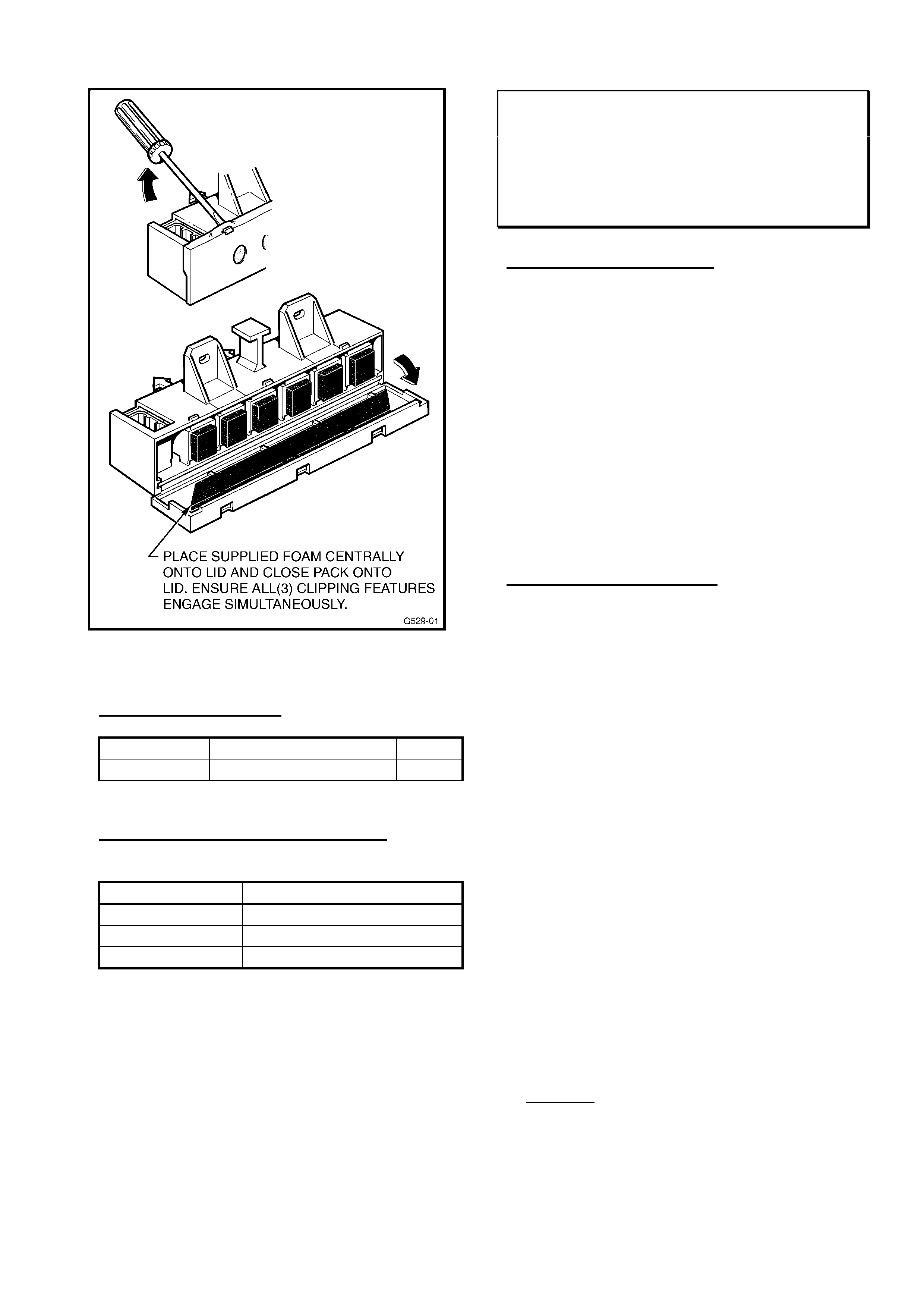
HOLDEN SERVICE TECHLINE________________________________________________________NOVEMBER, 2001
15
Figure 1.
PARTS INFORMATION
Part No.: Description: Qty:
92144689 Solenoid Foam Pad 1
WARRANTY CLAIM INFORMATION:
Use the following information:
Description ECC – Foam Pad Added
Labour Op. No. C000442
Time 0.3 hr
Failure Code 52
SQUEAKS & RATTLES RESULTING
FROM WINDOW TINTING
VT, VX, WH, VU
(GROUP 1) TL0111-0101
PROBLEM DESCRIPTION
Investigation into vehicle squeaks and rattles
(S & R) complaints has found that some
vehicles develop squeaks and rattles after
they have been through the window tinting
application process.
Usually, door trims are removed from doors
during the window tinting process which
requires removal and reinstallation of interior
remote handles and snib buttons. Some
window tinters also remove and refit glass run
weatherstrips.
These actions increase the risk of squeaks
and rattles developing as a result of disturbing
the original build condition.
SERVICE RECTIFICATION
Dealers are advised to check for any squeaks
and rattles after the vehicle is returned to the
dealership by following the procedure below:
1. Perform a visual inspection of all doors for
general fitment of parts and potential nicks or
marks, particularly on door trims, inner remote
handles and on snib buttons
2. Operate all door handles taking note of any
loose feel or backlash and unusual noises
within the locking system.
3. Cycle all windows through their full travell
taking note of any unusual operating noises
such as clicks (window catching components)
or squeaks and graunches potentially
associated with glass to seal interfaces.
4. Open and shut each door with the window
in fully closed, half closed and fully open
position, taking note of any unusual rattles or
buzzes from loose electrical connections,
loose parts or inadequately tensioned lock
rods.
5. Perform a light thump on each door
checking for any other noises not noticed in
the step above.
6. Optional: Perform a Road test of the vehicle
over a variety of imperfect road surfaces
check for any door noises present.
7. Rectify any squeaks and rattles observed.
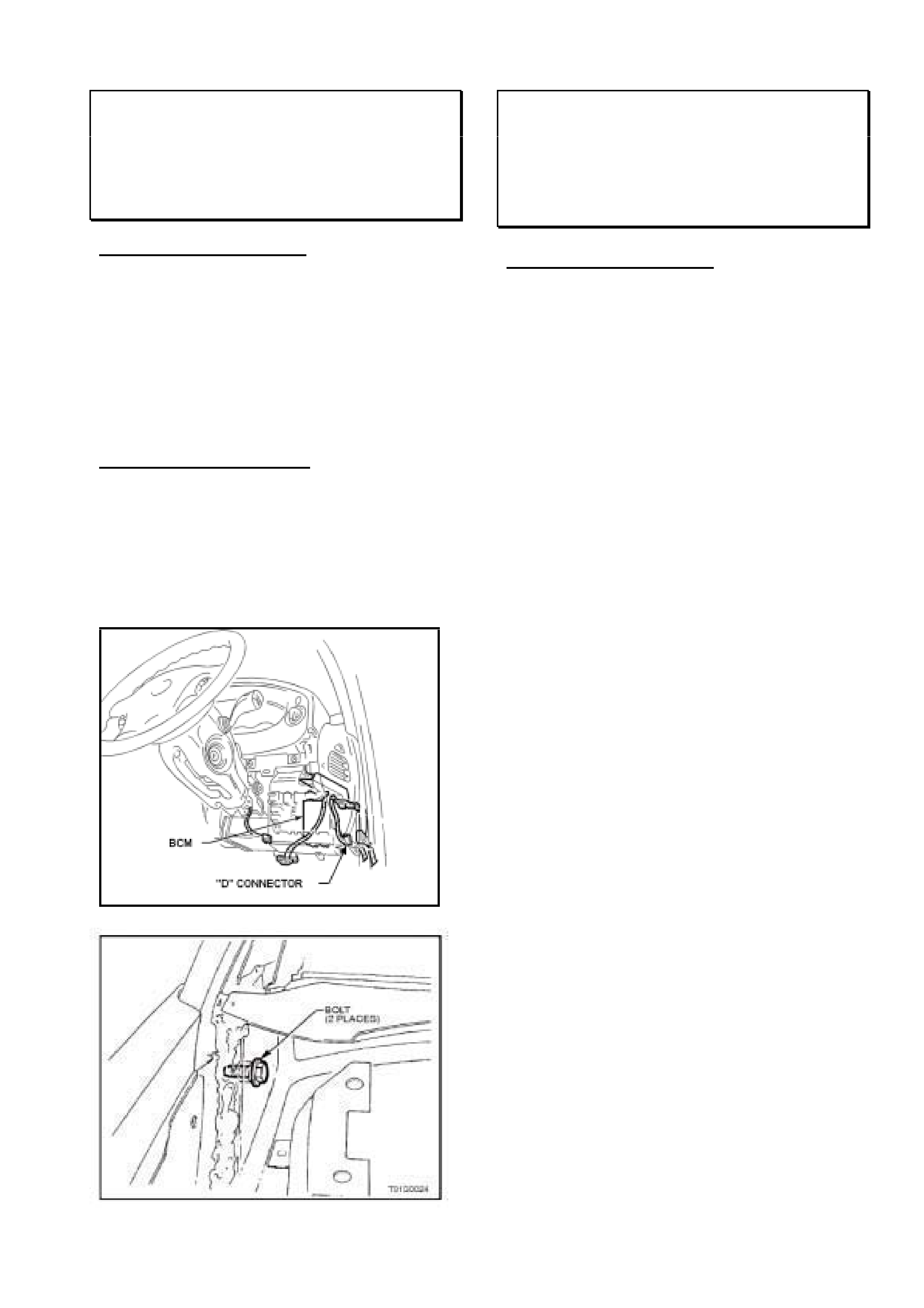
HOLDEN SERVICE TECHLINE________________________________________________________NOVEMBER, 2001
16
BCM MALFUNCTION DUE TO
WATER ENTRY
VT, VX, VU, WH
(GROUP 12) TL0111-0104
PROBLEM DESCRIPTION
Holdens’ supplier, Australian Arrow P/L,
reports that many of the BCMs returned for
fault analysis show signs of corrosion in the
“D” connector. Refer Figure 1.
Investigation has shown that it is possible that
BCMs could be affected by water entry
coming from the cockpit-module drivers-side
retaining bolt in the plenum as shown in
Figure 2.
SERVICE RECTIFICATION
Whenever replacing a BCM for a fault
condition check for evidence of water entry
particularly at the “D” connector. If there is
evidence of water entry, check the bolt (Figure
2) for tightness and seal around the bolt with a
sealer such as silicone RTV 732 part number
92140051.
Figure 1.
Figure 2.
SPARK PLUG LEADS DAMAGED
DURING REMOVAL
V & W ALL
(GROUP 6Y) TL0111-6Y01
PROBLEM DESCRIPTION
Many of the spark plug leads returned under
warranty show signs of damage caused
through the use of incorrect procedures to
remove spark plug leads from spark plugs.
Technicians are reminded of the following
extract from the Service Manual.
“WHEN REMOVING SPARK PLUG LEADS
Only handle the boot on each lead. DO NOT
pull on the lead itself. Twist the boot first to
break the seal , then pull the boot to remove.”
Where possible, use a proprietary type spark
plug boot removing tool. These are available
from most good automotive tool suppliers.
Pliers, multigrips etc should never be used for
this operation as they can damage the spark
plug terminal which may result in misfire when
lead is reinstalled.
REPAC will monitor returned parts and in
future, will not accept warranty claims where it
is obvious that leads have been damaged by
not following proper practice.

HOLDEN SERVICE TECHLINE________________________________________________________NOVEMBER, 2001
17
ROUGH IDLE, LOSS of POWER, STALL
DURING IDLE and HARD to RESTART -
DTC P0400 set
XC with Z14XE
(GROUP 6C) TL0111-6C01
PROBLEM DESCRIPTION
Some vehicles may experience rough idle,
loss of power, stalling during idle, hard to start
after a stall condition. Tech 2 may also show
the following DTC is present:
P0400 - EGR Circuit Range/Performance or
EGR flow excessive.
Vehicles with these symptoms generally have
been found to have EGR valves contaminated
with foreign particles.
PRODUCTION RECTIFICATION
The ECU software has been reprogrammed to
provide a “self cleaning” (low frequency
shake) routine to the EGR valve. Engines
with this revised ECU software were produced
from:
Engine No: Build Date:
20W68679 15/11/01
Engine No. Identification.
20 = Manufacturing plant (SZENTGOTTHARD)
W68679 = serial number. When 99,999 is reached
the W will change to the next letter of the alphabet.
SERVICE RECTIFICATION
Summary: Remove and clean EGR valve and
reflash ECU with revised software which
includes an EGR self cleaning routine.
Procedure:
(Refer to TIS CD for EGR valve removal and
replacement procedure)
1. Remove the EGR valve and inspect for
foreign material that may be holding valve
open.
2. Use compressed air to remove foreign
material from EGR valve seat area and
ports in the EGR - Engine adapter plate.
3. Clean sealing surface and remove all
gasket remnants.
4. Reinstall EGR valve with new gasket.
5. Reprogram the vehicle ECU using latest
TIS CD. The new ECU software (available
from TIS 25.0B onwards) includes a low
frequency EGR shaking routine. The
software part number is 09115113.
NOTE: DO NOT replace EGR valve unless
foreign material cannot be removed or valve
has been damaged. Also, DO NOT replace
Catalytic Converter or Exhaust Manifold with
new parts for this condition.
WARRANTY CLAIM INFORMATION
Description Remove, clean, reinstall
EGR valve & reflash ECU
Labour Op. No. J000701
Time 0.7 hr
Failure Code 12 “Foreign Material”
Update
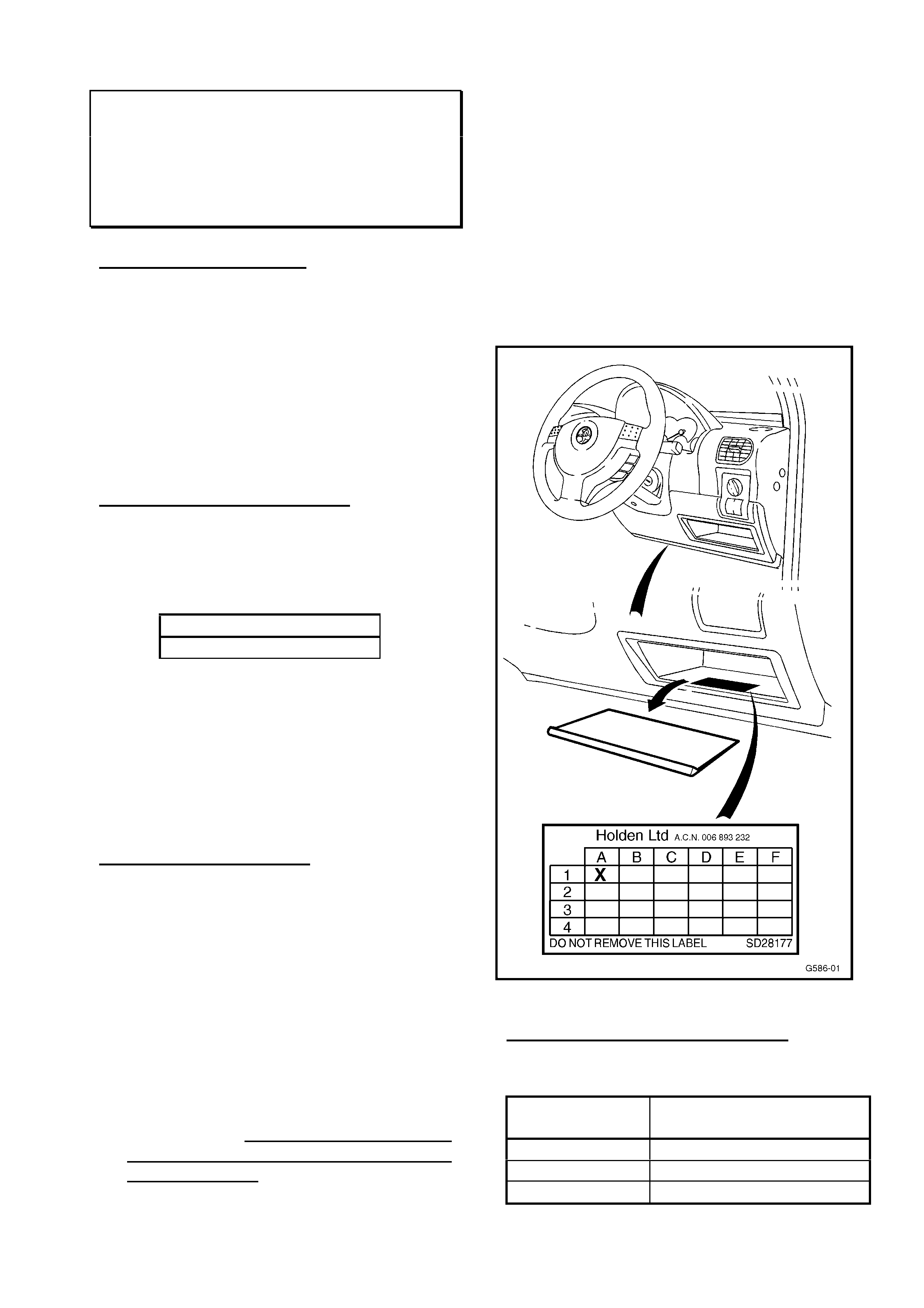
HOLDEN SERVICE TECHLINE________________________________________________________NOVEMBER, 2001
18
INTERMITTENT NO-START & DTC
P1612 or P1613 LOGGED IN ECU
XC SRi - Z18XE Engine
(GROUP 6C) TL0111-6C02
PROBLEM DESCRIPTION
Engine may suffer complaint of “crank but no
start”. On investigation, the Engine Control
Unit (ECU) is found to contain the Diagnostic
Trouble Codes (DTCs) P1612 or P1613 in
history.
This problem is due to an intermittent
communications failure between the
immobiliser and the ECU.
PRODUCTION RECTIFICATION
Factory Breakpoint.
Revised ECU software is installed into
vehicles with engine numbers commencing
from:
Engine No:
Z18XE20V98397
Port Of Entry Breakpoint
Vehicles reworked with latest ECU software
are identified with an “X” in the A-1 co-
ordinate of a Vehicle Service History Label
(SD28177) fitted to the drivers side, lower
storage compartment under the rubber mat.
Refer Figure 1 for location.
SERVICE RECTIFICATION
On vehicles with this “crank but no start”
condition and DTC’s P1612/P1613 logged,
carry out the following procedure:
1. Check if a Vehicle Service History Label is
fitted as shown in Figure 1. If label is
fitted, and an “X” is marked in the A-1 co-
ordinate, the rework has previously been
completed. In these cases contact TAS
for diagnostic assistance. If label is not
fitted proceed to step 2.
2. Using Tech 2 updated with TIS2000 CD
Version 23 (or later) and Tech 2 software
10.300 (or later), clear all trouble codes
from ECU.
3. Reprogram the vehicle ECU using the TIS
Service Programming System (SPS).
Select software part number 09115113.
4. Use a Vehicle Service History
Identification Label (SD 28177) to identify
this rework action has been completed.
Position the label (if not already fitted) in
the drivers side, lower storage
compartment under the rubber mat. Place
an “X” with a ballpoint pen in the A-1 co-
ordinate. Refer Figure 1.
Figure 1
WARRANTY CLAIM INFORMATION
Use the following information to claim for the
above procedure:
Description Reflash Engine Control
Unit – DTC P1612/P1623
Labour Op. No. J000689
Time 0.4 hr
Failure Code 83
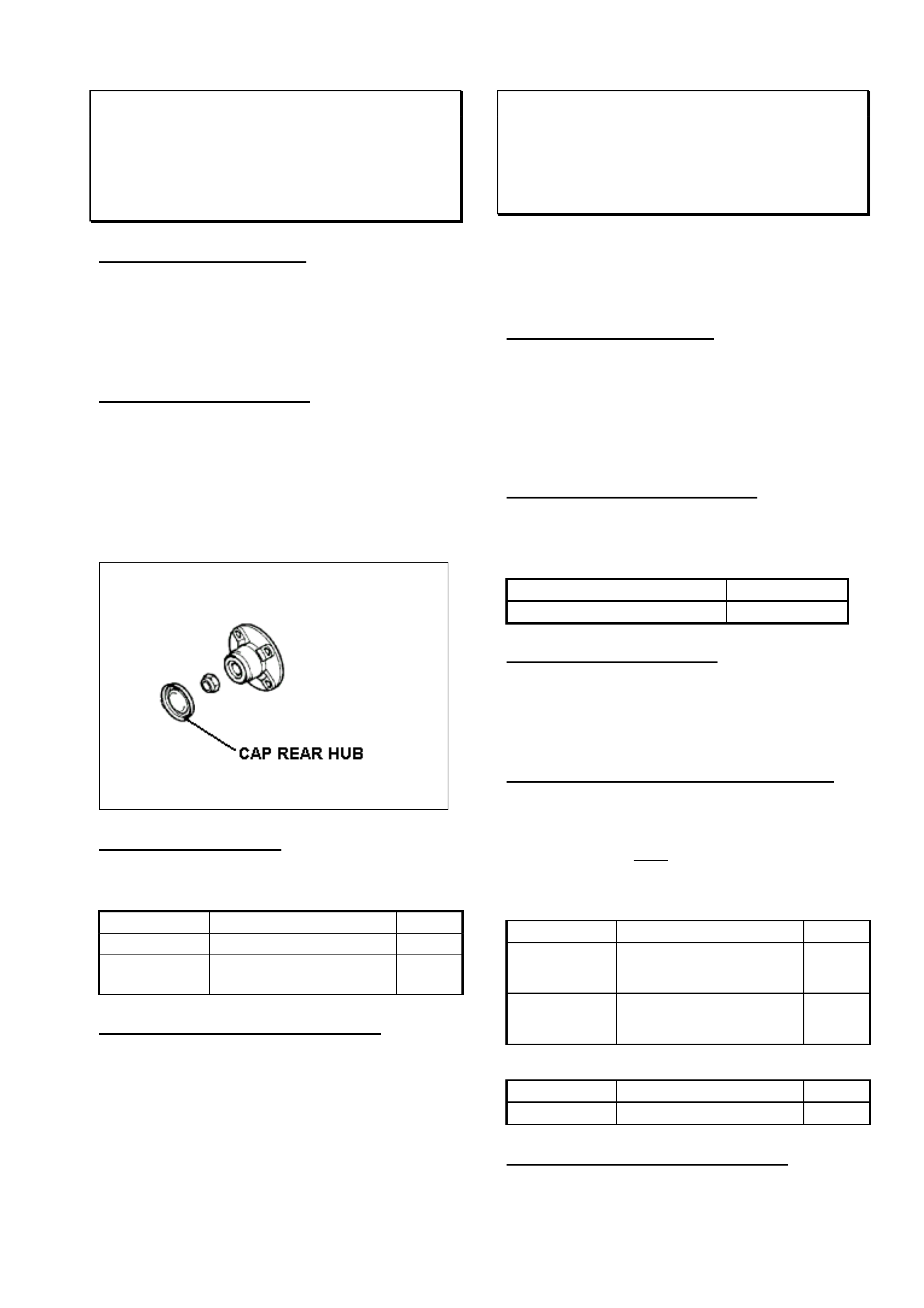
HOLDEN SERVICE TECHLINE________________________________________________________NOVEMBER, 2001
19
REAR WHEEL BEARINGS –WATER
ENTRY
XC
(GROUP 4) TL0111-0401
PROBLEM DESCRIPTION
There have been isolated cases of rear wheel
bearings with signs of corrosion resulting from
water entry. Poor sealing of the cap p/n
09156692 in the hub has been found to be the
cause.
SERVICE RECTIFICATION
Whenever installing a cap, it is recommended
that a smear of bearing mount compound
such as Loctite 641 (or equivalent) be applied
to both the hub and cap contact areas. This
compound has adequate sealing properties
but still allows the cap to be removed at a
later date without the use of excessive force.
PARTS INFORMATION
The cap comes as part of a new rear wheel
bearing kit or may be ordered as a separate
part.
Part No.: Description: Qty:
09156692 Cap rear hub 1
09196298 Kit – rear wheel
bearing
1
WARRANTY CLAIM INFORMATION
Use existing Labour Times information in
Warranty Information section of current SIP
CD
STEERING GEAR INNER TIE ROD
CLUNK NOISE
VT, VX, WH
(GROUP 9) “REVISED” TL0111-0902
This Service Techline supersedes the previous
Techline on this subject (Issue 10, October 2001)
which should be discarded. Breakpoint serial nos.
for racks have been revised
♠
.
PROBLEM DESCRIPTION
In high ambient temperatures or after long
drives, a clunk/knock may be felt through the
steering wheel on turns, or sufficient body
movement occurs. On examination of the
rack, the knock can be heard/felt coming from
the inner tie rod end.
PRODUCTION RECTIFICATION
An improved inner ball joint with new high-
temperature grease and revised cap material
have been fitted to steering racks in vehicles
from:
ISOVIN: Build Date:
6H8VXL69A1L683674 22/01/01
SERVICE RECTIFICATION
Where diagnosis confirms this complaint, fit a
new steering rack ensuring the rack serial
number is higher than those shown in the
following table in Parts Information.
PARTS INFORMATION & BREAKPOINTS
The following information is provided for
dealers to confirm that replacement steering
racks are post-breakpoint parts. Racks with
serial numbers prior to those shown in the
table should be returned to HSPO.
Standard Power Steering (Option N40)
Part No.: Breakpoint Serial No.: Qty:
92057321
up to L492504
12/08/99
K020214
1
92092815
from L492505
12/08/99
♠ N079454
1
Variable Effort Power Steering (Option NV7)
Part No.: Breakpoint Serial No.: Qty:
92092816 ♠ P011078 1
WARRANTY CLAIM INFORMATION
Use existing Labour times information in
current SIP CD.
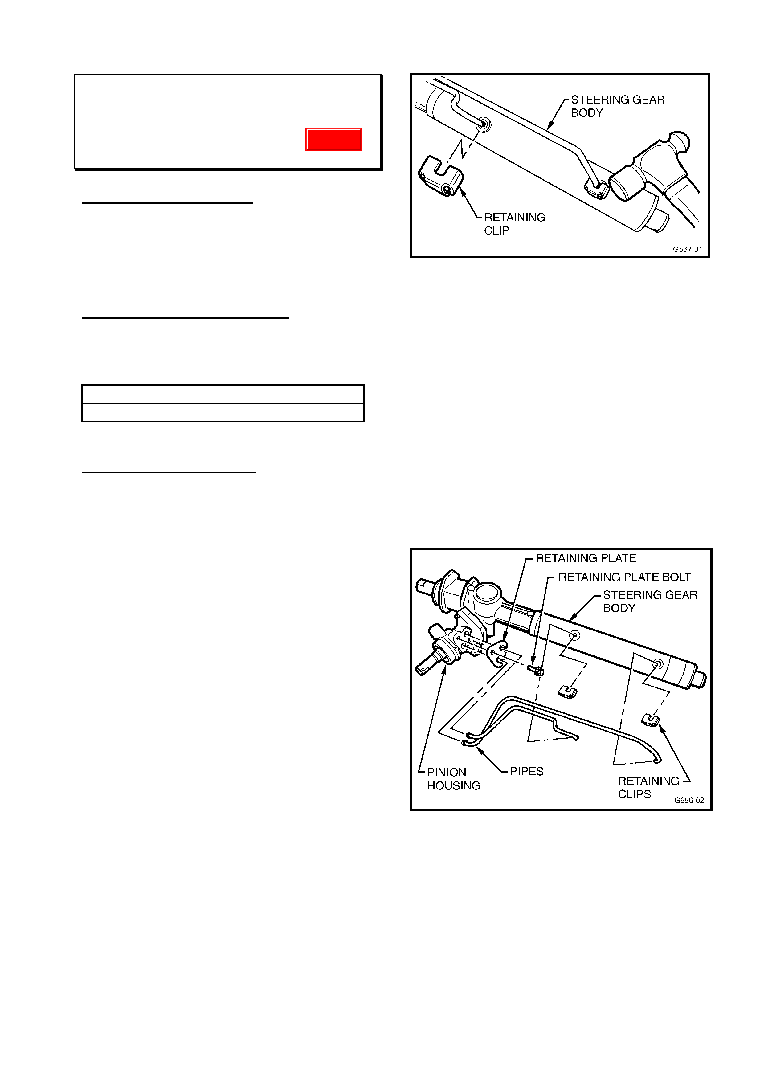
HOLDEN SERVICE TECHLINE________________________________________________________NOVEMBER, 2001
20
STEERING GEAR SQUEAK
JR, JS, JS II
(GROUP 9) TL0111-0903
PROBLEM DESCRIPTION
Customers may complain of a squeak noise
from the steering column/rack area when
turning the steering wheel from side to side.
Dealer investigation narrows the source of the
squeak to the steering gear.
PRODUCTION RECTIFICATION
Revised pinion housing seals made of a
different material have been fitted to steering
gears in production from:
ISOVIN: Build Date:
W0L0JBF6817005134 06/09/00
SERVICE RECTIFICATION
A complaint steering gear can be repaired
with the fitting of a rebuild kit that contains the
revised seals.
1. Obtain a repair kit as detailed in the “Parts
Information” section and ensure the
contents of the kit are as follows:
a. 1 x Valve Housing
b. 1 x Lower Housing Pinion Seal
c. 1 x Needle Bearing Sleeve
d. 1 x Upper Housing Pinion Seal
e. 1 x Retaining Washer
f. 1 x Large O-ring
g. 2 x Retaining Clips
h. 4 x Small O-rings
Parts a) to e) should already be assembled.
2. Remove the steering gear from the vehicle
as per the procedures detailed in the latest
TIS2000 CD. This repair should be
conducted in a clean environment to
minimise the chance of contamination.
3. Mark the steering gear pipes with a
permanent marker or paint pen to clearly
identify where to reinstall them.
4. Using a small hammer (16 oz or 450gm ball
pein is ideal), carefully tap the pipe
retaining clips to remove them from the
steering gear body. Discard these clips.
Refer to Figure 1.
Figure 1
5. Remove the pipe retaining plate bolt from
the pinion housing using a Torx T30 bit.
Remove the pipe retaining plate from the
steering gear.
6. Carefully pull the pipes from the steering
gear body and pinion housing. THESE
PARTS ARE NOT SERVICED
SEPARATELY AND CANNOT BE
PURCHASED IF DAMAGED! Remove
the sealing O-rings from the pipes and
discard them. Refer Figure 2.
Figure 2
7. Remove the two bolts securing the pinion
housing to the steering gear body using
5mm internal hex bit.
8. Twist the housing to break the seal and
remove it from over the pinion shaft. Refer
to Figure 3.
Update
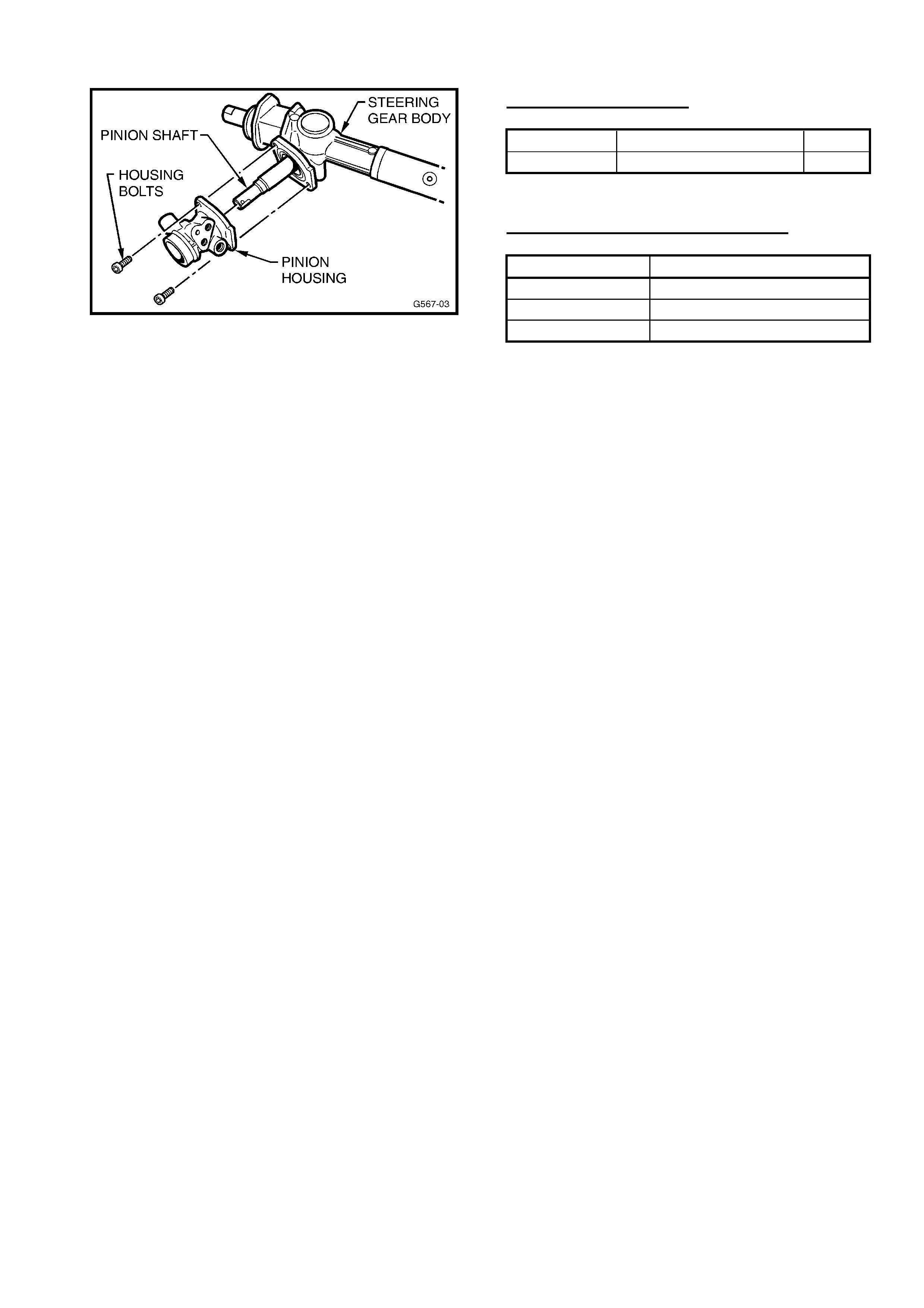
HOLDEN SERVICE TECHLINE________________________________________________________NOVEMBER, 2001
21
Figure 3
9. Remove the large O-ring installed in the
steering gear body that seals the pinion
housing and discard it.
10. Locate the replacement large O-ring in the
rebuild kit and lubricate it with power
steering fluid.
11. Carefully install the large O-ring over the
spigot in the steering gear body.
12. Inspect the seals fitted to the valve
housing for grease between the sealing
lips. If none is present, fill the space
between the sealing lips with an Extreme
Pressure Grease to NLGI # 00
specification, such as Castrol EPL00.
Details for obtaining this grease will be
provided in an All Dealer Letter.
13. Carefully fit the new pinion housing over
the pinion shaft.
14. Install the two bolts through the pinion
housing and into the steering gear body.
Torque these bolts to 17 Nm.
15. Locate the replacement small O-rings in
the rebuild kit and lubricate them with
power steering fluid.
16. Carefully install the small O-rings onto the
steering gear pipes.
17. Install the long pipe back into the correct
ports in the steering gear body and pinion
housing.
18. Install the short pipe back into the correct
ports in the steering gear body and pinion
housing.
19. Install the pipe retaining plate and bolt
back onto the pinion housing. Torque the
retaining bolt to 12 Nm.
20. Locate the new pipe retaining clips in
position on the pipe to gear interface.
Using the small hammer, lightly tap these
clips onto the rack until they are home
against the pipes.
21. Reinstall the steering gear into the vehicle
as per the procedures detailed in the latest
TIS2000 CD.
PARTS INFORMATION
Part No.: Description: Qty:
92144993 Repair Kit – P/S 1
WARRANTY CLAIM INFORMATION
Description Rebuild Steering Gear
Labour Op. No. M000184
Time 3.7 hr
Failure Code 40

HOLDEN SERVICE TECHLINE________________________________________________________NOVEMBER, 2001
22
FIXED WINDOW CREAK OR RATTLE
TS 3 DOOR HATCH
(GROUP 1) TL0110-0102
PROBLEM DESCRIPTION
Some TS Astra 3 door vehicles may exhibit a
rattle or creak from the fixed rear quarter
glass when driving over uneven surfaces.
This is due to relative movement between the
body and the fixed glass when the body twists
under driving conditions.
SERVICE RECTIFICATION
Summary: Remove & Reinstall rear quarter
window using anti squeak tape.
Procedure.
1. Remove the rear quarter window as per the
instructions in the latest TIS2000 CD.
2. Make sure the sheet metal flange is
thoroughly cleaned with a solvent cleaner
such as Prepsol and wipe with a clean
cloth to remove any residue.
3. Place anti-squeak tape (10mm wide)
around the entire body window opening, in
a position corresponding to where the seal
will contact. It may be useful to use the
edge of the flange as a guide for the edge
of the tape. Where the tape crosses a
stud hole, carefully cut a cross in the tape
with a knife. Do not under any
circumstances attempt to pierce the tape
with the stud on re-assembly. This is liable
to displace the tape.
4. Re-assemble window using new plastic self
locking nuts (90306649).
5. Check for leaks with a hose directed around
the edge of the window.
PARTS INFORMATION
Obtain following nuts from HSPO:
Part No.: Description: Qty:
90306649 Nut self locking
plastic
10
The following anti squeak tape has been
found to be suitable for use in this repair
procedure. Other equivalent tape may be
used in its place.
Part No.: Description: Qty:
7052747 Anti-Squeak Tape 10m
roll
The above tape is available from:
Preston Motors Parts Sales -
CAMPBELLFIELD, VIC. Phone 03 9359 3999
or Fax 03 9359 6330. When ordering from
Preston Motors quote their part number
7052747.
WARRANTY CLAIM INFORMATION
Use existing Labour Times information in
Warranty Information section of current SIP
CD, as follows:
Description Glass asm. Quarter
window -Replace
Labour Op. No. C000445 - RHS
C000448 - LHS
Time 0.7hr per side
Failure Code 28 Rattle
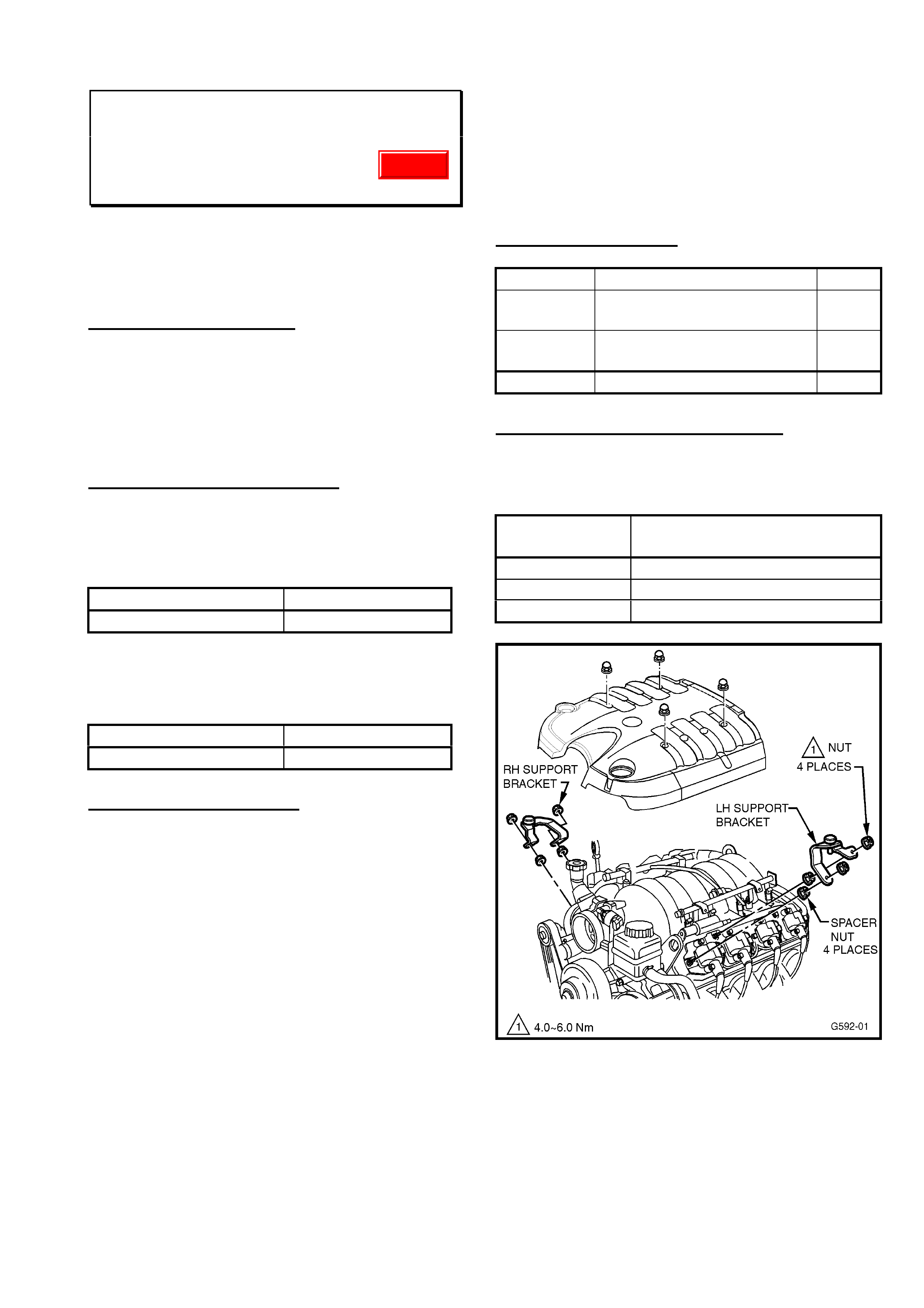
HOLDEN SERVICE TECHLINE________________________________________________________NOVEMBER, 2001
23
ENGINE COVER RATTLE
VTII,VX & WH with Gen III V8
(GROUP 6A) Update TL0111-6A01
This Techline supersedes the previous Techline on
this topic (Issue 6, July 2000) which should be
destroyed. This Techline now includes addition of
spacer nuts when fitting new support brackets.
PROBLEM DESCRIPTION
Reports have been received of engine cover
“rattle” at idle, or just above idle speed.
This rattle is caused by the main engine cover
contacting the coil/bracket, at the rear of the
engine.
PRODUCTION RECTIFICATION
Additional engine cover support brackets
92087580 & 92087581 were fitted to vehicles
from:
ISOVIN: Build Date:
6H8VTL35FYL579679 10/04/00
A further measure has been to add spacer nuts
underneath each support bracket. Fitted to
vehicles from:
ISOVIN: Build Date:
6H8VXL69F1L750721 3/7/2001
SERVICE RECTIFICATION
For complaints of “engine cover rattle” noise on
any Gen III V8 engined vehicle built prior to the
first breakpoint above (10/04/00), additional
support brackets and spacer nuts should be
added as per the following procedure: Refer
Figure 1 for locations.
1. Remove four engine cover retaining nuts
and remove the engine cover.
2. Fit engine cover support bracket P/N
92087580 to RH front coil mounting studs..
Prior to fitting bracket install spacer nut p/n
09440004 to each stud.
3. Attach bracket with two new nuts P/N
09440004, and torque to 4 – 6 Nm.
4. Fit engine cover support bracket P/N
92087581 to LH front coil mounting studs..
Prior to fitting bracket install “spacer” nut p/n
09440004 to each stud.
5. Attach bracket with two new nuts P/N
09440004, and torque to 4 – 6 Nm.
6. Remove foam pads from front RH & LH
underside of engine cover (pads are no
longer necessary, as new support brackets
carry insulating bumpers).
7. Re-fit main engine cover - torque retaining
nuts to 8-12Nm.
PARTS INFORMATION
Part No.: Description: Qty
92087580 Support Bracket, Engine
Cover RH
1
92087581 Support Bracket, Engine
Cover LH
1
09440004 Nut 8
WARRANTY CLAIM INFORMATION:
Use the following information, for vehicles built
prior to the above noted breakpoint:
Description Add Engine Cover Support
Brackets
Labour Op. No. J000651
Time 0.3 hr
Failure Code 28
Figure 1
NOTE: On any complaint vehicle that has
support brackets fitted without spacer nuts,
these should then be added.
Update

HOLDEN SERVICE TECHLINE _______________________________________________________________ JANUARY, 2001
4
ENGINE HESITATION/STALL AT LOW FUEL
LEVELS
JS
(GROUP 8) TL101-0801
PROBLEM DESCRIPTION
Engine hesitation or stalling when:
- cornering
- travelling uphill
- driving with wide open throttle with 20 litres of
fuel or less in the fuel tank.
Investigations have shown that this condition can
be caused during vehicle assembly, by pressure
application to the fuel tank upper surface, that
may break a piece from the vent pipe retaining
clip (inside the fuel tank). This can become
lodged in the swirl pot fuel intake during times of
high fuel demand, restricting the flow of fuel into
the swirl pot/pump. When fuel demand is
lessened (eg: at idle) the broken piece dislodges
and the vehicle will be driveable until high fuel
demand occurs again.
PRODUCTION RECTIFICATION
Tanks with internal revisions to reduce potential
for breakage of the vent pipe retaining clip were
fitted in Elizabeth built vehicles from:
ISOVIN: Build Date:
W0L0JBF19YL598784 08/06/00
SERVICE RECTIFICATION
When a vehicle displays the above symptoms:
1. Confirm the complaint by checking fuel
pressure. On checking, the fuel pressure may
be erratic when this occurs. While the
condition may be intermittent – the fuel
pressure may not be erratic until a high fuel
demand is created EG: rev the engine to
create a high fuel demand.
2. Remove the fuel tank from the vehicle, taking
normal safety precautions for fuel draining and
handling.
3. In a well-lit and ventilated area, use a mirror to
view the vent pipe retaining clip through the
fuel sender hole - as in Figure 1. If the clip is
broken (it will be loose and sliding on the vent
pipe, and will appear as shown in the “Not OK”
view) - then replace the fuel tank.
NOTE: If the clip is not broken and is as shown in
the “OK” view in Figure 1, further diagnosis will
have to be carried out to define cause.
To assist with this, if required: There is another
pipe retaining clip, of similar design in the fuel
tank located close to the fuel gauge opening and
on the opposite side to the vent pipe mentioned.
While this clip has not been cause for any
concern or been reported broken, view the clip
and pipe in the mirror and ensure the clip has not
broken.
If it has been broken and appears as in the “Not
OK” view in Figure 1 the (broken) clip will be
hanging loose on the pipe as shown - the “U”
shaped broken part of the clip is also shown -this
restricts the fuel flow - the fuel tank should be
replaced.
An “OK” (undamaged) clip will be located on the
underside of top of fuel tank, as shown in Figure
1.
PARTS INFORMATION
If replacement tank is required refer to Partfinder
for details.
WARRANTY CLAIM INFORMATION:
Use existing information in Labour Time Manual
SIP CD.
When filling out the Defective Material Tag for
any fuel tank replaced, note your findings on the
tag IE: clip has broken, and which clip.
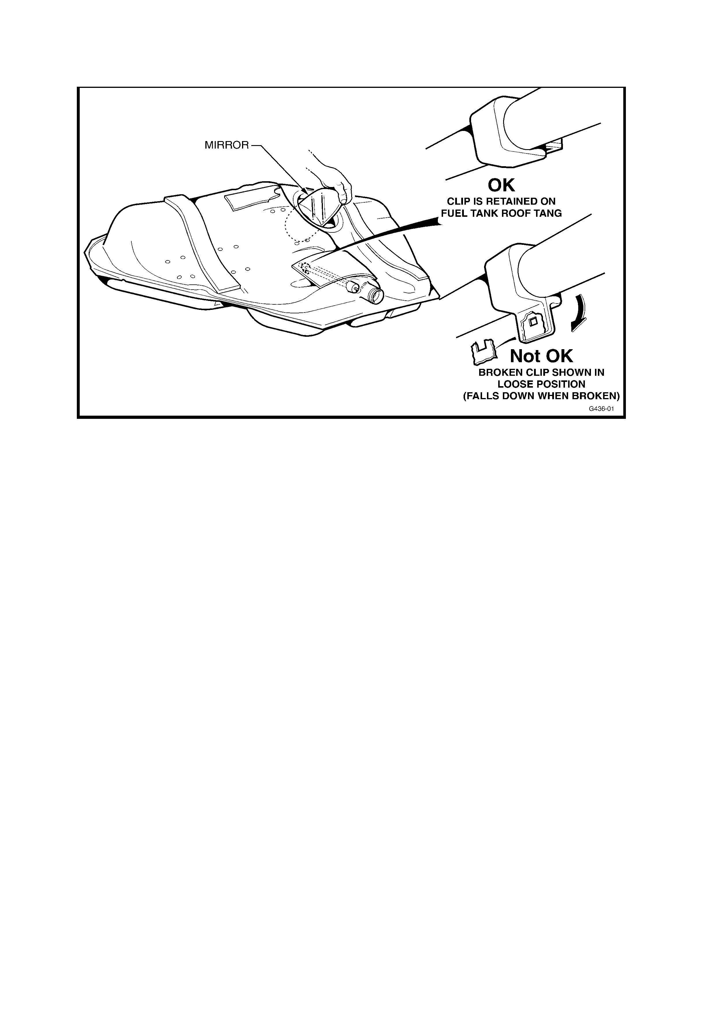
Figure 1.